A Yokogawa Company
A Yokogawa Company
A Yokogawa Company
A Yokogawa Company
KBC’s Profit Improvement Program and implement untapped opportunities to boost refinery margins - fast.
KBC’s Profit Improvement Program® helps refiners identify and implement untapped opportunities to boost refinery margins - fast.
For over 40 years KBC has implemented 150+ Profit Improvement Programs, focusing on both non-investment quick wins for an immediate margin improvement and long-term strategic initiatives that maximize ROI. Using proven simulation tools like Petro-SIM® and Visual MESA®, best practices and deep industry expertise, we help you reduce energy use and emissions, increase high-value products, reduce crude costs, optimize your supply chain and enhance asset availability and utilization. Achieve measurable, sustainable results and boost your bottom line with a Profit Improvement Program.
For over 40 years KBC has implemented 150+ Profit Improvement Programs, focusing on both non-investment quick wins for an immediate margin improvement and long-term strategic initiatives that maximize ROI. Using proven simulation tools like Petro-SIM® and Visual MESA®, best practices and deep industry expertise, we help you reduce energy use and emissions, increase high-value products, reduce crude costs, optimize your supply chain and enhance asset availability and utilization. Achieve measurable, sustainable results and boost your bottom line with a Profit Improvement Program.
Discover how KBC turns opportunity into profit www.kbc.global/pip
Discover how KBC turns opportunity into profit www.kbc.global/pip


08
Miro Cavkov, Euro Petroleum Consultants (EPC), Bulgaria, explores how carbon capture, utilisation, and storage technology can be used by refiners as a tool for decarbonisation, by preserving and reusing the carbon molecule.
13
The journey toward low-carbon competitiveness is a marathon of discipline, not a sprint of innovation. Sanjay Bhargava and Michelle Wicmandy, KBC (A Yokogawa Company), consider how refinery profit improvement programmes (PIPs) can substantially increase margins and sustain real-time performance.
Cody Falcon, ABB Energy Industries, considers how industrial operations are evolving from traditional automation to autonomous systems that can adapt, learn, and operate with minimal human intervention.
21 Improvement through collaboration
Yoshito Sato, Yokogawa, details the collaboration between Shell and Yokogawa in machine vision and robotics.


31
Aadam F. Aryan, Distillation Equipment Company Ltd, UK, discusses the necessary process and mechanical considerations for successfully revamping distillation columns to improve efficiency.
Muhammad R. Tariq and Taib B. Abang, Saudi Aramco, discuss LPG mercaptan sweetening technologies and present their findings.
36
Bert Klussmann, Sulzer, USA, considers developments in heat technology that can improve heater efficiencies alongside reducing emissions.
Al Geraskin, Integrated Global Services (IGS), Czech Republic, examines challenges facing steam cracker performance, and provides solutions that can maximise olefin production and ensure sustainability.
Hani Taan, NanoTech Materials Inc., USA, examines the properties and applications of spray-applied coatings that can protect industrial tank and piping systems from corrosion under insulation and safeguard personnel throughout operations.
Fadi Bachir, Owens Corning, outlines key factors to consider when designing an insulating system that defends against corrosion under insulation, while supporting the longevity of equipment used in hydrocarbon processing applications.
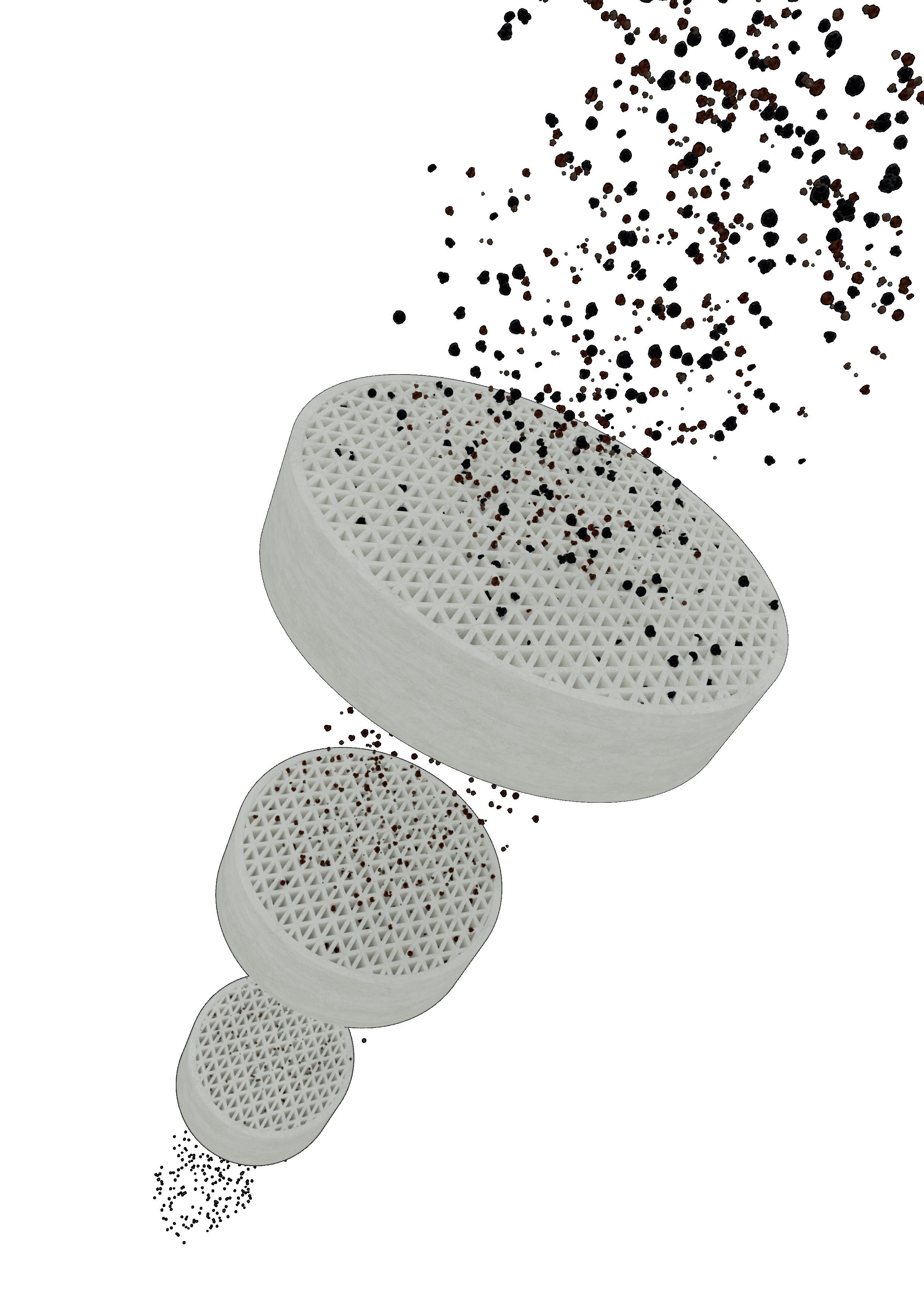
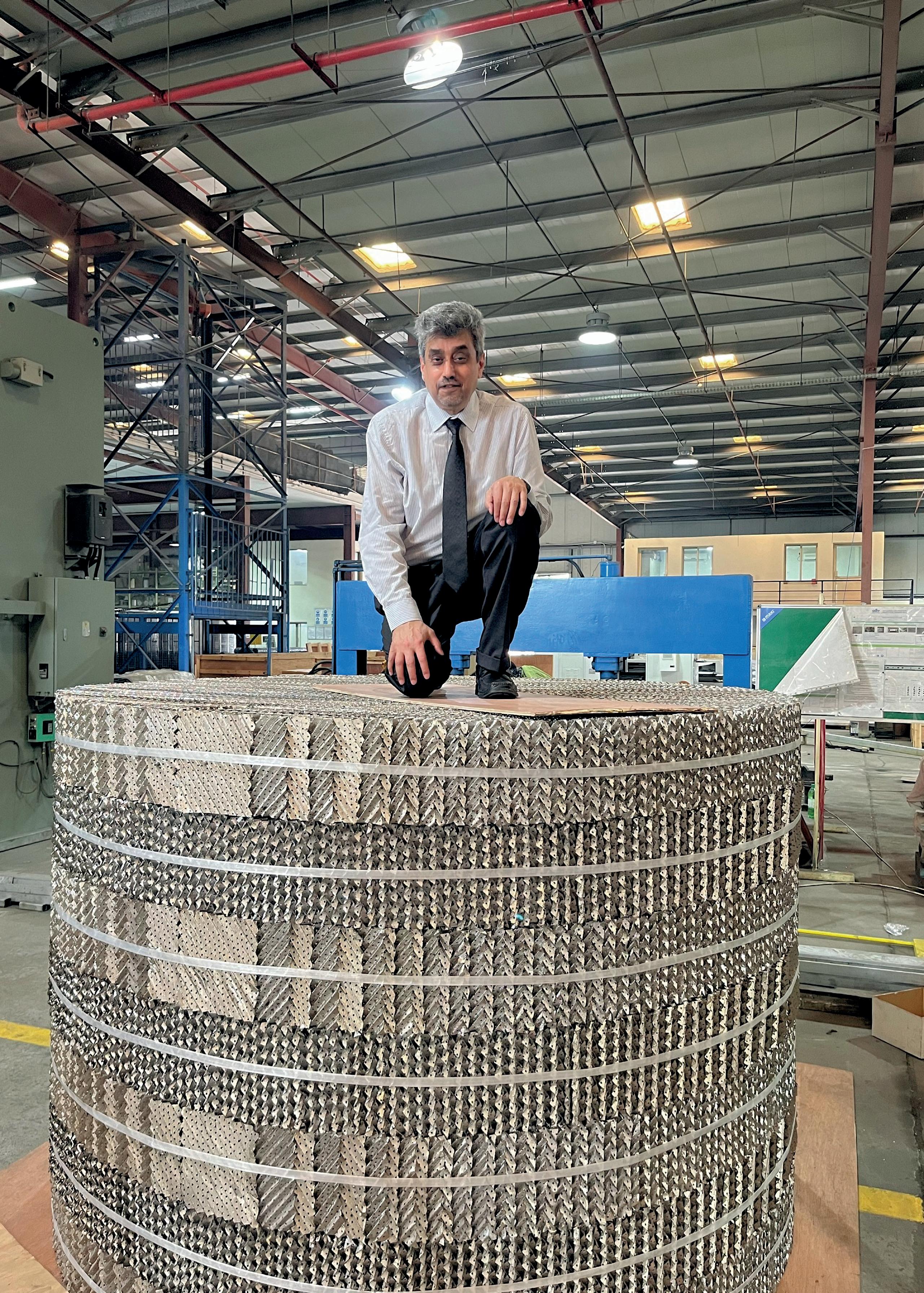
Distillation Equipment Company Ltd (DtEC) is a UK chemical engineering company, established in 1998, specialising in the design, manufacture, and supply of mass transfer equipment. With decades of experience in trays, packings, internals, and mist eliminators, whatever type and material, the company’s mission is to improve the performance of distillation and absorption columns.
Cut your CO2 emissions by 50% with the future of carbon black production
Compliant and innovative
Meets stringent environmental regulations, keeping your business future-ready

Unparalleled flexibility
Produce all ASTM grades and specialty grades seamlessly in a single plant
Sustainable Uses thermal decomposition of aromatic oils for cleaner production
MANAGING EDITOR James Little james.little@palladianpublications.com
SENIOR EDITOR Callum O'Reilly callum.oreilly@palladianpublications.com
EDITORIAL ASSISTANT Ellie Brosnan ellie.brosnan@palladianpublications.com
SALES DIRECTOR Rod Hardy rod.hardy@palladianpublications.com
SALES MANAGER Chris Atkin chris.atkin@palladianpublications.com
SALES EXECUTIVE Ella Hopwood ella.hopwood@palladianpublications.com
PRODUCTION MANAGER Kyla Waller kyla.waller@palladianpublications.com
HEAD OF EVENTS Louise Cameron louise.cameron@palladianpublications.com
DIGITAL EVENTS COORDINATOR Merili Jurivete merili.jurivete@palladianpublications.com
DIGITAL CONTENT COORDINATOR Kristian Ilasko kristian.ilasko@palladianpublications.com
DIGITAL ADMINISTRATOR Nicole Harman-Smith nicole.harman-smith@palladianpublications.com
JUNIOR VIDEO ASSISTANT Amélie Meury-Cashman amelie.meury-cashman@palladianpublications.com
EVENTS COORDINATOR Chloe Lelliott chloe.lelliott@palladianpublications.com
ADMIN MANAGER Laura White laura.white@palladianpublications.com
CONTRIBUTING EDITORS Nancy Yamaguchi Gordon Cope
SUBSCRIPTION RATES
Annual subscription £110 UK including postage/£125 overseas (postage airmail). Two year discounted rate £176 UK including postage/£200 overseas (postage airmail).
SUBSCRIPTION CLAIMS
Claims for non receipt of issues must be made within 3 months of publication of the issue or they will not be honoured without charge.
APPLICABLE ONLY TO USA & CANADA
Hydrocarbon Engineering (ISSN No: 1468-9340, USPS No: 020-998) is published monthly by Palladian Publications Ltd GBR and distributed in the USA by Asendia USA, 701C Ashland Avenue, Folcroft, PA 19032. Periodicals postage paid at Philadelphia, PA & additional mailing offices. POSTMASTER: send address changes to HYDROCARBON ENGINEERING, 701C Ashland Ave, Folcroft PA 19032.

CALLUM O'REILLY
SENIOR EDITOR
This year’s Nobel Peace Prize captured more headlines than usual – largely because of President Donald Trump’s high-profile campaigning to secure the award. Ultimately, the prize was awarded to María Corina Machado, the Venezuelan opposition leader, for her “tireless work promoting democratic rights for the people of Venezuela”. While Trump’s very public ambitions to win the Peace Prize dominated media coverage, the winners of one of the other Nobel Prize categories caught my attention. Susumu Kitagawa, Richard Robson, and Omar M. Yaghi received the Nobel Prize in Chemistry for the development of a new type of molecular architecture: metal-organic frameworks (MOFs).
These molecular constructions have large cavities through which gases and other chemicals can flow. By varying the building blocks used in the MOFs, chemists can design them to capture and store specific substances, and MOFs can also drive chemical reactions or conduct electricity.
The origins of MOFs started in 1989, when Richard Robson initially tested utilising the inherent properties of atoms in a new way. He combined positively charged copper ions with a four-armed molecule, and this had a chemical group that was attracted to copper ions at the end of each arm. When combined, they bonded to form a spacious crystal that was like a diamond with innumerable cavities. However, this constriction was unstable and collapsed easily. Susumu Kitagawa and Omar Yaghi then made a series of revolutionary discoveries. Kitagawa showed that gases can flow in and out of the constructions and predicted that MOFs could be made flexible. Yaghi then created a very stable MOF and showed that it can be modified using rational design, giving it new and desirable properties.
Since these discoveries, chemists have built tens of thousands of different MOFs which can be used in lots of different applications, e.g. to harvest water from desert air, separate PFAS from water, and break down traces of pharmaceuticals in the environment. MOFs can also be used to catalyse chemical reactions, capture carbon dioxide, and store hydrogen and toxic gases.
Given this rapid revolution, it is no surprise that MOFs are now making their way into industrial decarbonisation strategies. Indeed, regular readers of Hydrocarbon Engineering may recall that our November 2025 issue featured an article exploring how one MOF in particular – TAMOF-1 – is emerging as a practical, scalable solution for CO2 capture in real-world downstream applications.1 You can read the article now by logging into your account over at our website or by signing up to a free subscription to the magazine (www.hydrocarbonengineering.com/magazine).
15 South Street, Farnham, Surrey
GU9 7QU, UK
Tel: +44 (0) 1252 718 999
As the momentum behind MOF research continues to build, these materials are poised to play an increasingly important role in shaping the industry’s path toward lower emissions and greater efficiency. Future editions of Hydrocarbon Engineering are sure to feature even more insights into the growing potential of MOFs. In the meantime, this issue kicks off with an article from Euro Petroleum Consultants (EPC) looking at how CCUS is emerging as one of the defining technologies of the energy transition.
We’d like to thank all our readers and advertisers for their continued support throughout 2025, and wish you all a joyful and restful holiday season.
1. GALÁN-MASCARÓS, J. R., GIANCOLA, S., CAPELO-AVILÉS, S., and VILA-FONTES, M., ‘High performing carbon capture by TAMOF-1’, Hydrocarbon Engineering, (November 2025), pp. 40 - 44.

A Mechanical Integrity Solution With A 360-Degree View of Your Risks, Assets, & Costs To Elevate Your Outcomes
• Comprehensive API-580/581 RBI, API-970 CCD, and API-584 IOW compliant methodologies to determine risk and set inspection priority
• Improved data accuracy and efficiency to support smarter, faster decision-making at the point of work

TA’ZIZ has announced the award of a US$1.99 billion engineering, procurement, and construction (EPC) contract to China National Chemical Engineering & Construction Corp. Seven Ltd (CC7), to build the UAE’s first, and among the world’s largest, integrated single-site polyvinyl chloride (PVC) production complexes.
The contract, announced at ADIPEC, marks a major step forward in delivering TA’ZIZ’s strategic mandate to drive industrial growth,
localise supply chains, and enable new value chains in the UAE.
Located within the TA’ZIZ industrial ecosystem in Ruwais, the facility will produce 1.9 million tpy of marketable PVC, ethylene dichloride (EDC), vinyl chloride monomer (VCM), and caustic soda. These chemicals are critical to serving growing demand in sectors such as construction, infrastructure, packaging, and healthcare, in the UAE and internationally. The project is expected to be completed by 4Q28.
Enbridge Inc. has announced that it has reached a final investment decision (FID) on the Mainline Optimization Phase 1 project (MLO1). MLO1 will add capacity to the company’s Mainline network and Flanagan South Pipeline (FSP) to meet customer demand for incremental egress, increasing deliveries of Canadian heavy oil to key refining markets in the US Midwest (PADD II) and Gulf Coast (PADD III).
“MLO1 is expected to add capital-efficient and timely egress capacity from Canada, supporting Canadian production and increasing connectivity to the best refining markets in North America,” said Colin Gruending, Enbridge’s Executive Vice President and President of Liquids Pipelines. “This project demonstrates the advantage of leveraging existing networks to meet growing customer demand, supporting energy security and affordability across North America.”
Mitsubishi Heavy Industries Compressor International Corp. (MCO-I) has been awarded a contract by ExxonMobil to supply a footprint replacement steam turbine for its olefins plant in Baton Rouge, Louisiana, US.
Personnel from MCO-I and its parent company, Mitsubishi Heavy Industries Compressor Corp. (MCO), will collaborate on the project with both teams supporting the manufacturing, testing, commissioning, and installation of the turbine. During the project, virtual assembly will be provided during the manufacturing stage and throughout the installation stage to support an efficient turnaround and help maintain continuity in plant operations.
A key technology, virtual assembly, will be used during manufacturing and installation to support an efficient turnaround and maintain plant continuity. This innovative approach involves creating a precise digital model of the components before they arrive on-site. By pre-assembling the parts in a virtual environment, the team can identify and resolve potential fit issues ahead of time, ensuring a smooth and rapid installation.
Bharat Petroleum Corp. Ltd (BPCL) and Oil India (OIL) are set to build an integrated greenfield refinery and petrochemical plant in Ramayapatnam, India, with an estimated investment of IR1 lakh crore (US$11 billion).
BPCL has signed three landmark memoranda of understandings (MoUs) with OIL, Numaligarh Refinery Ltd (NRL), and Fertilisers & Chemicals Travancore Ltd (FACT).
These partnerships mark significant milestones in BPCL’s integrated growth
strategy – spanning refining, petrochemicals, green energy, and logistics infrastructure – and reaffirm its commitment to building a sustainable and self-reliant energy future for India.
BPCL and OIL have signed a non-binding MoU to explore collaboration in developing BPCL’s upcoming greenfield refinery and petrochemical complex near Ramayapatnam Port in Nellore district, Andhra Pradesh, India. The proposed
facility, with a refining capacity of 9 - 12 million tpy, will be a cornerstone of India’s downstream expansion.
Under the MoU, the companies will evaluate opportunities for collaboration, including the possibility of OIL taking a minority equity stake in the proposed joint venture.
The project has already secured key statutory clearances and 6000 acres of land from the government of Andhra Pradesh, with pre-project activities in progress.
02 - 05 February 2026
21st International Conference & Exhibition on Liquefied Natural Gas (LNG2026) Doha, Qatar www.lng2026.com
10 - 12 February 2026
NARTC Houston, Texas, USA worldrefiningassociation.com/event-events/nartc
17 - 20 February 2026
Laurance Reid Gas Conditioning Conference Norman, Oklahoma, USA www.ou.edu/pacs/lrgcc
24 - 26 February 2026
ESF Europe: Energy & Sustainability Forum Antwerp, Belgium https://europetro.com/esfeurope
15 - 17 March 2026
AFPM Annual Meeting New Orleans, Louisiana, USA www.afpm.org/events
15 - 19 March 2026
AMPP Annual Conference + Expo Houston, Texas, USA ace.ampp.org
29 - 31 March 2026
AFPM International Petrochemical Conference San Antonio, Texas, USA www.afpm.org/events
28 - 30 April 2026
Sulphur World Symposium Vancouver, British Columbia, Canada www.sulphurinstitute.org/symposium-2026/
19 - 21 May 2026
Asia Turbomachinery & Pump Symposium Kuala Lumpur, Malaysia atps.tamu.edu
09 - 11 June 2026
Asia Turbomachinery & Pump Symposium Calgary, Alberta, Canada www.globalenergyshow.com
Pengerang Biorefinery Sdn. Bhd., a joint venture (JV) between Petronas, Enilive S.p.A, and Euglena Co. Ltd, marked a milestone with the groundbreaking ceremony for the development of the new biorefinery in Pengerang, Johor, Malaysia.
The biorefinery will have the processing capacity of up to 650 000 tpy of renewable feedstock
and is projected to produce sustainable aviation fuel (SAF), hydrogenated vegetable oil (HVO), and bio-naphtha. Feedstocks for the biorefinery will include wastes such as used vegetable oils and animal fats, and residues from the processing of vegetable oils. The new facility is targeted to commence operations by 2H28 in line with the schedule.
OMV, Austria’s integrated energy, fuels, and chemicals company, and Masdar, a global clean energy leader, have signed a binding agreement to establish a joint venture (JV) for the financing, construction, and operation of the 140 MW green hydrogen electrolyser plant in Bruck an der Leitha, Austria.
This landmark project will be one of Europe’s largest green hydrogen production facilities and marks a major step in OMV’s commitment to decarbonising its Schwechat refinery
and accelerating the energy transformation. Construction of the facility began in September 2025 and it is expected to be operational in 2027.
The JV between OMV and Masdar will be majority-owned by OMV with Masdar owning 49%. The partnership combines OMV’s strategic leadership under its integrated fuels and chemicals business and Masdar’s commercial, financial, and technical expertise in developing and operating clean energy projects worldwide.
Aether Fuels and Aster have signed an agreement to develop the first next-generation, commercial-scale SAF production facility in Southeast Asia at Aster Pulau Bukom in Singapore. Project Beacon, Aether’s commercial demonstration facility, will utilise the company’s AuroraTM technology to produce up to 50 bpd of fuel (2000 tpy of fuel). It will convert industrial waste gas and biomethane into CORSIA-certified SAF, achieving a reduction of more than 70% in greenhouse gas (GHG) emissions compared to conventional
jet fuel, making it the first commercial facility of its kind. Project Beacon is expected to commence construction in 2026 and begin commercial operations in 2028.
Locating the plant on Pulau Bukom underscores Aster’s commitment to fostering breakthrough innovation within its asset ecosystem. Aster will provide renewable power, waste carbon feedstock, utilities, and site support to accelerate the development and commercialisation of Aether’s scalable solution.
By adopting advanced distillation technologies, you can significantly reduce energy consumption, enhance product quality, and improve overall process reliability. These innovations help you meet environmental targets while unlocking potential subsidies and lowering operational costs.
Our energy optimization strategies include advanced distillation design, thermal coupling, heat integration, and cutting-edge electrification technologies. Solutions like Divided Wall Column reduce energy consumption by more than 30%, VoltaSplit™ offer electrified distillation with up to 10× lower CO2 emissions, while Sulzer 95+ Heater Tech delivers ≥95% efficiency with minimal maintenance and fast ROI. Sulzer provide the tools to transform your plant into a model of sustainable performance.
Contact us for more information chemtech@sulzer.com


Miro Cavkov, Euro Petroleum Consultants (EPC), Bulgaria, explores how carbon capture, utilisation, and storage technology can be used by refiners as a tool for decarbonisation, by preserving and reusing the carbon molecule.
As the race to net zero accelerates, carbon capture, utilisation, and storage (CCUS) is emerging as one of the defining technologies of the energy transition. Beyond simply cutting emissions, CCUS offers a way to preserve and reuse the carbon molecule by turning a waste product into a valuable resource and forming an essential pillar of a circular, lower-carbon economy.
Achieving net zero emissions by 2050 will require ambitious mitigation actions, and large scale deployment of CCUS technologies is among the most critical. The focus is shifting from concept to implementation, with energy and industrial players deploying carbon capture systems to lower the carbon intensity of existing downstream assets while building new business models around third-party emitters.
Worldwide, CCUS projects are gaining momentum from large scale hubs in Europe and North America to emerging initiatives in Asia and the Middle East. Each represents a step towards integrating carbon management into mainstream industrial operations. Yet the challenge remains immense: industries such as refining, chemicals, and power generation still account for a significant share of global CO2 emissions.
Meeting this challenge will depend on a combination of technological innovation, strong policy frameworks, and cross-sector collaboration. For many, CCUS is no longer a distant option but a practical pathway to decarbonisation and a key enabler of the sustainable industrial ecosystem needed for the decades ahead.
CCUS is rapidly becoming one of the most critical technologies in the global effort to achieve net zero. At its core, the concept is simple: capture CO2 before it reaches the atmosphere, and either reusing it to create valuable products or storing it safely and permanently underground in depleted oilfields. The execution, however, demands sophisticated infrastructure, strong policy frameworks, and cross-sector collaboration to bring it to scale.
In practical terms, CCUS encompasses three key stages. First, CO2 is captured directly from industrial operations such as refineries, petrochemical complexes, and power plants or even removed from the air through direct air capture systems. Next, the captured carbon can be utilised as a feedstock to produce fuels, chemicals, polymers, and building materials, embedding it back into industrial value chains rather than allowing it to contribute to global warming. Alternatively, the CO2 can be stored deep underground, injected thousands of feet beneath the surface into carefully selected geological formations such as depleted oil and gas reservoirs or saline aquifers, where it remains securely trapped for the long-term.
Far from a theoretical solution, CCUS has a proven safety record. The large scale injection and storage of CO2 has been practised for decades, particularly in enhanced oil recovery (EOR) operations, where captured CO2 is injected into oilfields to boost recovery rates while simultaneously storing the gas underground. The safety of these operations hinges on robust standards and decades of geological and engineering expertise.
When it comes to transportation, CO2 is an inert, non-flammable gas. It can be safely moved in smaller quantities by trucks as seen in everyday uses like carbonated beverages or in much larger volumes through dedicated pipeline networks. For storage, the selection of sites is meticulous. Engineers target stable rock formations more than half a mile underground, typically sealed by an impermeable cap rock that prevents the gas from migrating back to the surface.
Beyond storage, utilisation opens up new economic and environmental opportunities. Captured carbon can serve as a building block for a range of sustainable materials, ranging from synthetic fuels and sustainable aviation fuel (SAF) to chemicals, polymers, and construction materials. In doing so, CCUS not only mitigates emissions but also supports a circular carbon economy, where CO2 becomes a resource rather than a liability.
This dual role, as both a decarbonisation tool and a value-creation mechanism, makes CCUS uniquely important to achieving the goals of the Paris Agreement. By lowering the carbon intensity of hard-to-abate sectors such as refining, petrochemicals, and heavy manufacturing, CCUS bridges the gap between today’s industrial infrastructure and the low-carbon systems of the future. Ultimately, the challenge now is one of scale and speed. The technology exists and has been proven to work safely and effectively, while currently the task ahead lies in expanding deployment through collaborative frameworks between industries, governments, and technology providers. As the world moves from climate pledges to practical action, CCUS stands out as one of the most tangible pathways to balance industrial progress with environmental responsibility.
The downstream refining sector sits at the crossroads of the energy transition, simultaneously as one of the largest
industrial emitters and as a crucial enabler of cleaner fuels and feedstocks. CCUS technologies are now reshaping how refiners approach decarbonisation, offering a realistic pathway to lower emissions while protecting the value of existing assets.
For decades, refineries have relied on steam methane reforming (SMR) to produce hydrogen, a key component in hydroprocessing, desulfurisation, and numerous hydrogen addition downstream reactions. Traditionally, this process emits significant amounts of CO2, resulting in what is commonly known as grey hydrogen. However, integrating carbon capture into SMR units transforms this process into blue hydrogen production, a major leap forward in emissions reduction. By capturing and storing CO2 generated during hydrogen production, refiners can produce lower-carbon hydrogen while continuing to leverage existing infrastructure.
This shift does not just merely reduce emissions, but it extends the lifespan of CAPEX-heavy process units such as reformers, crackers, and auxiliary pre-heat trains, allowing them to continue operating at optimal efficiency while meeting tightening regulatory and environmental requirements. For operators, the value is twofold: maintaining reliability in their core operations and simultaneously positioning their assets for a carbon-constrained future.
Beyond hydrogen, CCUS offers downstream producers an opportunity to turn captured carbon into new business value. When combined with renewable hydrogen, captured CO 2 becomes a versatile feedstock for creating specifically designed synthetic hydrocarbons varying from SAF and clean transportation fuels to chemicals, packaging materials, and even construction inputs. These carbon-to-value pathways are gaining traction, especially as alcohol(ethanol)-to-jet (ATJ) and methanol-to-jet technologies advance.
Methanol, for instance, can be synthesised via the Fischer-Tropsch process, where carbon and hydrogen react over a catalyst to produce liquid hydrocarbons. Once methanol is produced, refiners can leverage a well-established set of downstream conversion routes to create renewable fuels and sustainable chemicals. This integration not only creates circular carbon loops but also enables refiners to diversify their product portfolios in alignment with new sustainability mandates.
Regulation is a powerful driver of this transformation. Across Europe and beyond, SAF mandates are rising sharply, requiring an increasing share of aviation fuel to come from low-carbon or carbon-neutral sources. These mandates, coupled with corporate net zero commitments, are rapidly creating a market for high-quality carbon utilisation and offsets. Companies that once viewed CO2 purely as a waste stream are now recognising it as a valuable raw material, which will be one of the cornerstones of the future low-carbon product strategies.
The financial world is reinforcing this momentum. The growing weight of environmental, social, and governance (ESG) factors in investment decisions have made emissions performance a key determinant of corporate competitiveness. Investors are increasingly

Long days in the lab, late nights in the limelight. From sample analysis to pressure drop prevention, our tech service team is the science behind the show. Microscopes. Metrics. Mullets (optional). That’s the Crystaphase Experience.
rewarding companies that adopt technologies like CCUS, which demonstrate measurable, science-based pathways to decarbonisation. For refiners, the message is clear: innovation in emissions management is no longer optional, but rather a serious prerequisite for capital access, brand resilience, and long-term viability.
Carbon capture is not just a technology investment, it becomes a licence to operate in the energy system of tomorrow.
Ultimately, CCUS in refining and petrochemicals is not about replacing the sector’s foundation but reinventing it. By coupling existing process efficiency with digitalisation, hydrogen integration, and circular carbon utilisation, the downstream industry is building the bridge between today’s fossil-based operations and a net zero future. The molecules may remain the same, but the way they are produced, captured, and reused is being fundamentally transformed.
As carbon management technologies move from concept to commercial deployment, one truth has become increasingly clear: scaling CCUS will require more than adopting technology innovation, it will demand broader coordination, higher capital investment, and conviction. Despite remarkable progress in capture efficiency and integration with refining processes, cost, scalability, and regulatory clarity remain the largest barriers to mass adoption.
Globally, the scale of the challenge is immense. To reach net zero emissions by 2050, the world will need to remove up to 10 billion tpy of CO2, according to the Intergovernmental Panel on Climate Change (IPCC). No credible pathway to net zero exists without large scale carbon dioxide removal (CDR) technologies, so within that portfolio, direct air capture (DAC) and carbon capture from industrial sources are poised to play central roles.
However, cost remains the critical bottleneck. Today, the end-to-end expense of capturing and permanently storing a ton of CO2 through DAC ranges between US$600 - 1000/t, depending on the region, which is far above what most industrial emitters or investors can absorb. To reach commercial viability, these costs must fall below US$200/t, and ideally closer to US$100/t, by 2050. The race to achieve that cost curve compression will determine whether CCUS becomes a mainstream industrial solution or remains confined to isolated demonstration projects.
This is not unprecedented. Solar energy costs have fallen by more than 90% over the past four decades, and similar economies of scale and innovation cycles could accelerate CCUS cost reductions. To make that happen, industry leaders argue that governments, technology providers, and refiners must work in lockstep to build the commercial and regulatory frameworks that give investors the confidence to act.
For refining, the challenge is particularly complex but also full of opportunity. Integration of CCUS within modern refinery clusters where multiple emitters can share capture, transport, and storage infrastructure offers
one of the most cost-effective routes forward. In Europe, for instance, projects are exploring regional CO2 networks that connect hydrogen reformers, power plants, and petrochemical sites to shared storage basins in the North Sea. This hub-and-spoke model allows refiners to reduce costs through shared infrastructure while creating a clear investment case for scaling up capture capacity.
Financial mechanisms are also evolving. The rise of carbon trading systems such as the EU Emissions Trading Scheme (ETS) has created a liquid market for carbon allowances, allowing refiners and industrial players to hedge against future carbon price increases or monetise captured CO2 through verified offset credits. These market-based tools, alongside carbon contracts for difference (CCfDs) and targeted tax incentives, can play a decisive role in closing the cost gap between emitting and capturing carbon.
Yet technology alone cannot deliver success. Regulatory coordination and standardisation are equally vital. Risks can stall investments where carbon storage, accounting, and crediting rules differ across borders. Industry stakeholders are calling for clear, long-term policy signals, transparent carbon accounting standards, and cross-border recognition of carbon credits to ensure consistent market dynamics.
Beyond economics and policy, the human and technological partnerships needed for CCUS success are equally critical. No single entity, whether a refiner, technology provider, or government can deliver large scale CCUS alone. Refiners bring operational experience and infrastructure, technology firms provide capture, compression, and digital monitoring solutions, while policymakers and investors supply the frameworks and financing that make these ventures possible. Only collaborative ecosystems, not isolated efforts, can turn CCUS from an engineering ambition into a functioning pillar of industrial decarbonisation.
Meanwhile, digitalisation and data transparency are emerging as powerful enablers. Advanced process simulation, digital twins, and predictive analytics are helping operators design and optimise capture units, track CO2 flows in real time, and verify emissions reductions with precision. This digital backbone builds trust in performance data, which is a crucial factor for investors and regulators, and can accelerate scaling by ensuring projects are both verifiable and financially auditable.
Ultimately, the pathway ahead hinges on a mix of technology maturity, market liquidity, and global alignment. Reducing CCUS costs to below US$150/t of CO2 will be a formidable challenge, but not an impossible one. It will require massive investment, international collaboration, and bold policy frameworks to catalyse the industrial demand and economies of scale that can drive prices down.
As the refining sector stands on the front line of industrial transformation, it is uniquely positioned to lead this charge. By embedding CCUS into existing refining, chemicals, hydrogen, power, and process networks, refiners can transform one of the world’s most carbon-intensive industries into a cornerstone of climate progress.
The journey toward low-carbon competitiveness is a marathon of discipline, not a sprint of innovation. Sanjay Bhargava and Michelle Wicmandy, KBC (A Yokogawa Company), consider how refinery profit improvement programmes (PIPs) can substantially increase margins and sustain real-time performance.
Refining today sits at the crossroads of market volatility and structural transformation. Margins have slipped back to pre-pandemic levels, with refining earnings down by approximately 50% in 2024 compared with 2023 and roughly 60% lower than in 2022. Over the next decade, refining capacity is projected to decline by up to 30% depending on region.1
Beneath those numbers lies a deeper shift. Refiners are being asked to do more with less – to run cleaner, leaner, and smarter – without the luxury of large capital expansions. The challenge is not merely economic; it is structural, operational, and human, all at once.
Operators are now expected to maximise margins with minimum CAPEX while facing a web of operational constraints. These include increasingly complex feedstocks, lower energy intensity, stricter emission obligations, and shifting product-demand patterns tied to mobility, biofuels, and the circular-economy. One empirical study found that refinery complexity, specific-energy consumption, and distillate yield

positively correlated with gross refining margin, while fuel and loss factors had negative impacts.2
For decades, the default response was to build bigger. Today, expansion alone is no longer the answer. Leadership now hinges on disciplined operational excellence – the art of extracting more value from the same assets. Increasingly, refiners are turning to structured improvement frameworks, known as profit improvement programmes (PIPs). These programmes systematically identify, quantify, and implement operational, process, and refinery-wide improvements to generate value with minimal incremental capital.
PIPs focus on enhancing yield, reducing energy use and emissions, minimising crude costs, strengthening reliability, optimising turnarounds, and building human-performance capability. They emphasise a phased, cross-functional approach: baseline definition, opportunity discovery, modelling and prioritisation, rapid implementation of quick wins, and a comprehensive sustainment programme.
Running parallel to this methodological rigour is a wave of digital transformation to sustain implemented opportunities and transform a PIP into a continuous improvement programme. Advances in digital-twin modelling, high-fidelity simulation, and advanced analytics are transforming operations. Model-based AI-driven hybrid optimisation ensures real-time performance by tightening the link between operations, planning, and maintenance. Recent research in refining operations with digital twins reports average return on investment timelines of 12 - 36 months, efficiency gains of 15 - 42%, and maintenance cost reductions of 25 - 55%.3
What began as a series of isolated improvement projects has evolved into a strategic performance-management discipline –one that connects margin recovery, operational resilience, and decarbonisation readiness into a unified agenda.
Refining margins have always been a balancing act between efficiency and volatility, but the fulcrum has grown narrower. Industry benchmarking suggests that incremental inefficiencies in energy use, yield, and reliability may quietly erode a few percent of total operating expenditure – equivalent to millions of dollars of lost value annually. While market crack spreads largely dictate external margin swings, operational inefficiencies within the refinery often represent the most addressable source of lost value.4 Closing that gap through systematic improvement has become essential.
Across the industry, benchmarking shows that structured improvement programmes can reverse this silent leakage.
Typical implementations yield between US$30 and US$60 million in annual benefits, with payback achieved in under 12 months and internal rates of return often exceed 100%. The outcomes are tangible: 5 - 15% reductions in specific energy consumption, 2 - 5% higher availability, and measurable improvements in crude costs, process yields, reliability, and emissions intensity. These results suggest that the next competitive advantage will not come from scale, but from acting on the big-impact-creating prioritised quick-win projects that collectively define refinery performance.
The traditional PIP has evolved from a one-time operational review into a continuous, digitally enabled performance-management system. At the heart of this transition is the ability to merge engineering models, plant data, and human decision-making into a unified improvement framework. The digital AI/ML layer enables refiners to quantify, implement, and sustain performance gains across yield, energy, reliability, and emissions metrics more effectively than ever before.
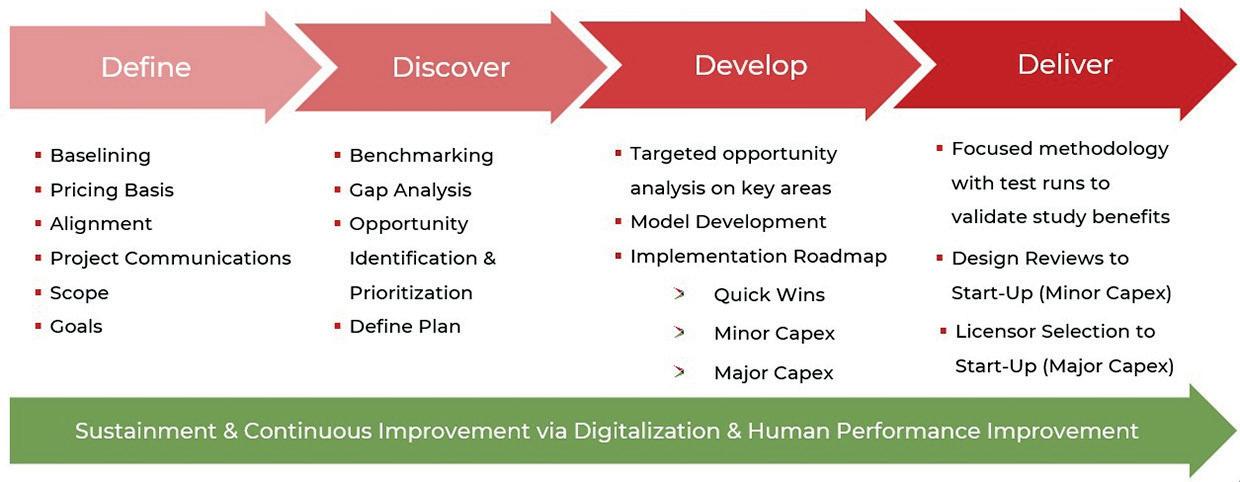
Digital profit improvement programmes (D-PIPs) typically follow a five-stage methodology – define, discover, develop, deliver, and sustain – linking opportunity identification with execution and continuous improvement, as shown in Figure 1. This agile, sprint-based approach accelerates benefit realisation while embedding digital capability across the organisation.
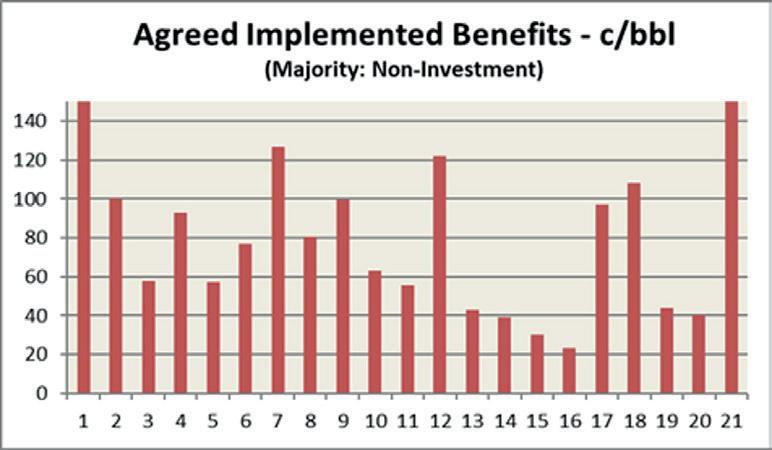
The shift is not purely technological. PIPs are increasingly designed to deliver dual dividends: economic performance and environmental progress. Many refiners track carbon reduction directly alongside margin improvement, with potential benefits ranging from US¢35 - 70/bbl in margin uplift and US¢5 - 15/bbl in energy and emissions reduction. This dual-focus approach aligns profitability with sustainability, a defining characteristic of the sector’s new performance model.
By combining advanced analytics with empowered teams, refiners can move from reactive troubleshooting to proactive optimisation. Across implemented programmes, typical results show 40 - 80% of total benefits from yield improvements, 5 - 40% of total benefits from yield improvements from capacity utilisation gains, and 5 - 8% of total benefits from energy cost reduction (up to 15% with capital enhancements). Supply-chain alignment
commonly delivers a further 5 - 20% improvement in value realisation.
The result is not only sustained profitability but also improved reliability, energy performance, and emissions management – key metrics for competitiveness in a decarbonising market. The evolution toward digital PIPs positions refiners to achieve higher margins while building the operational resilience required for a low-carbon economy.
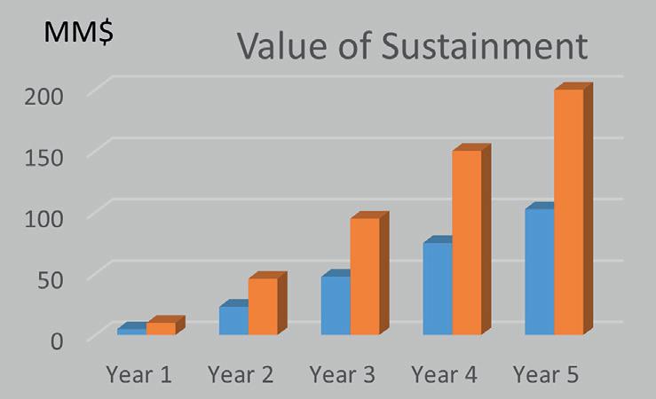
Industry-wide benchmarking shows typical improvement distribution and value-sustainment behaviour across domains, as shown in Figure 2.
A large refinery embarked on a modernisation initiative that combined structured performance improvement with digital transformation. The approach, which is now becoming common across the industry, aimed to enhance profitability, reliability, and energy performance while advancing low-carbon operations. This example demonstrates how a structured improvement framework, supported by digital tools, can deliver parallel gains in financial and sustainability outcomes.
The site launched a full-scale transformation that brought together digital tools, operational-excellence practices, and sustainability. The initiative integrated advanced process-simulation, control, and optimisation technologies to enable higher profitability and energy efficiency while reducing emissions.
With its digital backbone in place, leadership advanced toward data-driven, semi-autonomous decision-making.
The refiner combined first-principles simulation software, upgraded advanced process control (APC) systems, and real-time optimisation dashboards to shift from reactive responses to predictive operations, as shown in Figure 3.
A multi-period utility-plant optimiser reduced energy use while increasing profits, and automating a compressor-control strategy eliminated chronic hydrogen flaring, closing a gap in both emissions and margin.
Operational planning also evolved. Linear programming models were overhauled and backcasting introduced to bridge the gap between planned and actual performance. Improved crude selection increased profits by US$30 million/yr in additional profit.
Through more than 25 targeted process improvements, the team enhanced yields and reliability while lowering energy intensity. Focused upgrades in crude separation, catalyst use, and stream routing lifted middle-distillate yields by 6.5 vol%. Refined catalyst and constraint management reduced lower-value fuel-oil production in favour of higher-value distillates, generating US$100 million in incremental profit.
Energy efficiency became a defining metric of progress. Early benchmarking revealed substantial opportunity and, within months, overall energy performance improved by about 10% through low- or no-CAPEX measures. Continued optimisation – pinch analysis, energy real-time optimisation, heat-exchanger monitoring, and multi-period optimisation – pushed performance into sustained double-digit improvements.
Hunter modular solutions help you meet sustainability standards and bottom-line goals in one build. With reduced material waste, shorter project timelines and lower lifetime energy use, our steel structures offer lasting value — protecting your people, your investment and the environment.

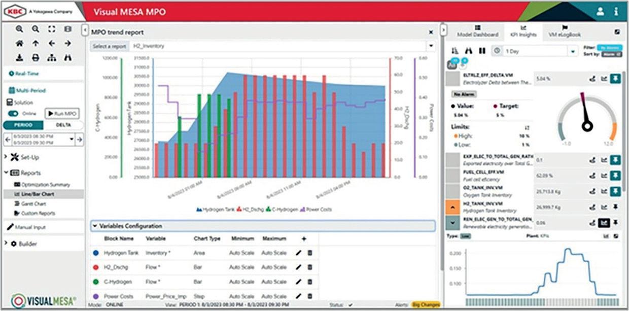
Figure 3. Real-time optimisation dashboard supports predictive operations and KPI tracking.
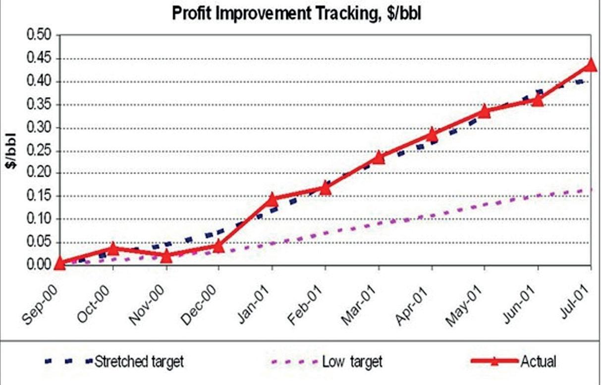
Figure 4. Profit-tracking dashboard showing how digital monitoring aligns operational actions with realised and sustained value.
Structured turnaround reviews and a dedicated gatekeeper avoided over US$8 million in unnecessary work.
Reliability-centred maintenance (RCM) and root cause analysis (RCA) programmes reduced an estimated US$30 - 45 million in production losses, increasing mechanical availability and safety performance.
Modernisation also aligned with broader regional investments in renewable-fuel capacity, including hydrotreated vegetable oil (HVO) and sustainable aviation fuel (SAF) production, reinforcing the link between refinery optimisation and future clean-fuel infrastructure. The results were as follows:
n US$150 million in validated annualised benefits across process, energy, reliability, and supply-chain performance.
n 6.5 vol% increase in middle-distillate yield.
n >10% energy efficiency improvement driven by low-CAPEX solutions.
n Over US$30 million/yr in potential profits via PIMS LP upgrades.
n Downtime reduction through RCA and RCM, and lower maintenance costs via gatekeeper controls.
This case demonstrates that operational performance and decarbonisation are complementary forces.
Technology initiates change, but sustained value depends on a workforce able to interpret data, act, and adapt. Industry
experience shows that up to 70% of potential value can be lost without proper sustainment and organisational alignment.
Human-performance improvement remains central to sustaining results. Continuous coaching, competency development, and structured problem-solving ensure that improvements achieved through digital tools are retained through disciplined execution. Leading operators embed structured work processes, digital dashboards, and capability-development programmes that reinforce accountability and knowledge transfer.
Digital tools such as model-based profit tracking systems now provide a live view of realised and sustained value, capturing every opportunity from identification through execution, as shown in Figure 4. They monitor progress, track benefit leakage, and maintain alignment between operational actions and financial outcomes.
Continuous-improvement mechanisms – supported by near-real-time performance tracking – help ensure that gains remain visible and measurable. Training programmes focused on operational awareness, problem-solving, and energy stewardship cultivate a performance culture that adapts to new digital tools rather than resists them. Over time, this integration of technology and human capability transforms short-term profit-improvement projects into ongoing strategic disciplines.
Field experience shows that properly executed PIPs can yield implemented profits of 5 - 10 times programme cost, generating internal rates of return exceeding 100%. Cumulative benefits of US$100 - 200 million are achievable in large, integrated sites when quick wins and minor investments are fully realised.
As the refining sector adapts to a more complex and carbon-constrained environment, PIPs have become both a business necessity and a sustainability enabler. The same model-based data-driven frameworks that uncover process inefficiencies also identify opportunities to cut energy use and lower emissions. They improve asset utilisation while accelerating the speed to margin.
Digital technologies – ranging from process simulation and optimisation to AI-enabled analytics – extend the impact of these programmes by making improvement measurable, repeatable, and scalable. Coupled with strong organisational alignment and workforce capability, they transform short-term efficiency projects into a culture of continuous improvement and a bridge to sustainable competitiveness.
The journey toward low-carbon competitiveness is not a sprint of innovation but a marathon of discipline. Digital tools illuminate the path ahead, but it is human expertise – the judgement, creativity, and operational rigour of people – that keeps progress steady.
References
1. DE MUR, A., FOLLETTE, C., GOYDAN, P., HOOD, R., and MCMILLAN, G., ‘Costs and margins dictate the future for refiners’, Boston Consulting Group (BCG), (1 April 2025).
2. JAFARI, H.R.S., ‘Report: refining margins: refinery margin systems (RMS)’, (January 2009).
3. MAHESHWARI, R.K., ‘digital twins and financial ROI: assessing tech investments in refinery operations’, Journal of Information Systems Engineering and Management, pp. 826 - 838, (September 2025).
4. SHOKOUHI, M.R., KHADEMVATANI, A., and BEIKY, F., ‘Analyzing economic and financial risk factors affecting profitability of oil refinery investment projects: a case study from an Iranian oil refinery’, Energy Strategy Reviews, Vol. 52, (March 2024).
Cody Falcon, ABB Energy Industries, considers how industrial operations are evolving from traditional automation to autonomous systems that can adapt, learn, and operate with minimal human intervention.
Industrial operations are undergoing changes not seen since distributed control systems transformed the industry in the 1970s. Facilities are transitioning from rule-based automation to intelligent and adaptive systems capable of handling unexpected situations, learning from operational history, and functioning with reduced direct human oversight. This evolution addresses challenges that have reached a critical point across heavy industry.
The people that built and operate most complex facilities are leaving the workforce faster than the industry can replace their expertise. Meanwhile, the data these facilities generate has increased to a point beyond human capacity to process effectively.
Where an operator might have monitored 500 sensors 15 years ago, today’s plants can generate input from over 500 000 data points.
Processing this volume of information in real-time while making operational decisions within seconds has become impossible for human operators alone.
The barrier to implementation has shifted over the past decade. Eight years ago, the industry questioned whether the technology was ready. That debate has been settled. Now the challenge is not whether the systems work, but how much operators can trust them to make critical decisions.
Experienced operators, with decades of expertise, can approach these systems with scepticism. They have

built careers on institutional knowledge and an intuitive understanding of plant behaviour. Deferring critical decisions to software naturally creates resistance.
Consistent performance changes perspectives. When these systems repeatedly recommend correct actions, identify potential issues before they become problems, and provide troubleshooting guidance that works, that scepticism gives way to acceptance. Within six months, operators are often asking why the system is presenting recommendations rather than simply implementing them automatically. This progression from resistance to advocacy reflects the trust-building process essential for autonomous operations.
Traditional control systems excel at maintaining setpoints and responding to deviations that can be programmatically defined, but they cannot synthesise complex patterns across thousands of variables, external sources, and data types to predict future states or identify subtle indicators that precede significant problems.
Energy management is a great example. Modern industrial and downstream facilities, such as refineries and petrochemical complexes, now source power from multiple inputs: grid electricity, on-site generation, solar and wind, and battery storage to ensure a stable and reliable power supply. Optimising this selection requires real-time analysis of weather forecasts, grid pricing that changes every few minutes, predicted facility loads,
and equipment availability. A human operator might manage this decision-making for one or two sources, but the computational requirements for multiple sources with constantly changing variables exceed human processing capability.
Energy management optimisation technology handles this automatically, enabling facilities to respond to market pricing changes in real-time, shift to renewable sources when available, and maintain cost optimisation while maintaining production targets, all without dedicated personnel monitoring inputs and manually making the operational adjustments. In downstream operations, similar optimisation is increasingly applied to energy and utilities management. Integrated management systems at a refinery, for instance, can automatically balance power generation, ensuring continuous optimisation of both cost and carbon intensity.
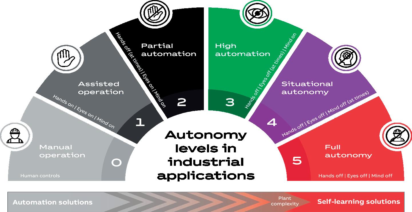
The progression toward full autonomy follows a structured framework that helps assess where facilities currently operate and plan advancement strategies. This six-level approach progresses from manual operations (Level 0) through various automation stages to full autonomy (Level 5), where systems can handle all anticipated and unanticipated situations without human intervention.
Most energy facilities currently operate between Levels 2 and 3. At Level 2, basic automation handles routine processes, but humans remain responsible for setting parameters and responding to anything outside normal operations. Level 3 introduces more sophisticated control systems that can manage complex processes and alert operators to issues but still requires human decision-making for abnormal situations.
The transition to Level 4 represents the most significant operational change. Here, the technology begins demonstrating situational autonomy – the ability to recognise and respond to conditions not explicitly programmed during system design. This requires incorporating learning capabilities that can identify patterns from historical data and apply successful strategies to new but similar situations.
State-based control (SBC) illustrates how these capabilities translate into operational benefits. Traditional automation systems require manual reconfiguration when process conditions
change. For example, automatically adjusting distillation column controls as a refinery unit transitions between start up, steady state, and shut down; or managing process trains within a petrochemical cracking unit as feedstock composition changes. Contrast these examples to the traditional approach that relies on an operator’s manual control adjustments during changing conditions.
SBC can recognise these state changes automatically and implement all necessary adjustments without human intervention. The system recognises and adapts to the shifts. When market conditions, operating environment, asset availability, or production targets shift, the entire adjustment process that previously required hours of skilled operator time occurs in minutes.
Anomaly detection represents another significant advancement within process control. Rather than simply alerting operators when variables exceed preset limits, systems such as ABB AbilityTM PlantInsight continuously monitor plant behaviour against learned patterns of normal operation. When subtle deviations appear, often hours or days before they would trigger traditional alarms, the system can identify potential root causes by comparing current conditions with historical events. The technology has evolved over the last decade to reduce the investigative burden on the operator with explainability in context and recommendations for resolution.
This capability proves particularly valuable during shift transitions or when less experienced operators are on duty. Instead of relying solely on individual expertise, every operator has access to institutional knowledge captured from decades of operations across all sites. When abnormal situations arise, systems can identify similar historical events and recommend proven solutions, effectively providing every operator with the guidance of the most experienced personnel, even when they are not physically present.
Such capability dramatically improves response times. Where operators previously might spend 30 minutes researching solutions to complex problems, these systems can provide proven recommendations in 30 seconds, enabling faster resolution of critical situations.
The relationship between autonomous technology and plant personnel represents evolution rather than replacement. Operators consistently report that automation of routine tasks allows them to focus on higher-value activities: process optimisation, strategic planning, and complex problem-solving that requires human judgement and creativity.
This shift addresses the skills shortage facing
A podcast series for professionals in the downstream refining, petrochemical, and gas processing industries


Sponsored by

EPISODE 14
Rob Benedict, Vice President, Petrochemicals and Midstream, American Fuel & Petrochemical Manufacturers (AFPM), discusses the outcomes of the final round of UN negotiations for a Global Plastics Treaty.
EPISODE 15
David Wilson, CEO, Energy Exemplar, considers the role that oil and gas is currently playing in the booming data centre industry, and what the future holds.
EPISODE 16
Andrea Bombardi, Executive Vice President, RINA, offers technical and operational insight into some of the key challenges and opportunities of CCUS implementation.
EPISODE 17
Alec Cusick, Owens Corning Technical Lead, Technical Insulation, talks about the risks of LNG pool fires and methodologies to mitigate these risks.

industrial operations. As experienced operators retire, they take irreplaceable knowledge with them. Traditional training programmes can transfer procedural knowledge but struggle to capture the intuitive understanding that develops over decades of doing the job. Autonomous systems provide a mechanism for institutionalising this experience in software that remains available regardless of personnel changes.
The most successful implementations involve collaborative development where experienced operators work directly with system designers to capture decision-making patterns. This process benefits both parties: operators see their expertise valued and preserved, while systems gain access to knowledge that would otherwise be lost.
Industrial applications often operate in unforgiving environments where errors can have significant consequences. This high-risk reality demands different approaches to system design, testing, and implementation compared to consumer applications.
Industrial systems require fail-safe mechanisms, comprehensive override capabilities, and integration with existing safety systems. The testing and validation processes extend over years rather than months, and deployment occurs in carefully planned phases that maintain operational continuity.
These requirements explain why many industrial customers prioritise vendors with operational experience over technology startups. While startups may offer innovative algorithms or user interfaces, industrial facilities need partners who understand the operational context, regulatory requirements, and risk management strategies essential for safe implementation.
The business case for autonomous operations extends far beyond theoretical benefits to measurable operational improvements. Facilities implementing comprehensive optimisation systems typically report positive improvements in process and reductions in lifecycle cost.
Safety performance improvements prove equally significant. Autonomous systems reduce human exposure to hazardous environments, eliminate human error during critical operations, and provide consistent response to emergencies regardless of operator experience level or shift timing.
The operational efficiency gains compound over time as systems accumulate experience. These systems maintain consistent performance 24 hours per day, continuously optimising operations based on current conditions and learned patterns.
Refineries and petrochemical plants increasingly demonstrate the practical application of these technologies. For example, in refinery operations these advances in control systems have enabled the continuous optimisation of hydrocracking and distillation units, reducing unplanned downtime and improving energy efficiency.
Similarly, in petrochemical complexes, automated shutdown and start up sequences have significantly reduced manual interventions, enhanced safety, and delivered more consistent product quality.
Comparable benefits have also been achieved in offshore environments where platforms that once required hundreds of personnel can now operate with one-button start-up procedures.
In the short-term future, agent-based operations will likely become standard across industrial operations. Rather than simply providing recommendations that require human approval, systems will independently execute complex operational strategies while maintaining appropriate human oversight.
Code generation represents a particularly significant development. Current projects require two to three years for engineering and commissioning. Systems trained on millions of lines of proven control logic could generate facility-specific automation code in a fraction of the time, dramatically accelerating project timelines while maintaining proven operational patterns.
The infrastructure requirements for these advances are already emerging. Cloud, edge, and hybrid architectures enable real-time processing of massive data volumes while maintaining the security and reliability standards essential for industrial operations. Industrial cybersecurity standards and frameworks continue evolving to address the unique challenges of operating in critical infrastructure environments.
Successful implementation requires a realistic assessment of current capabilities and systematic progression towards higher autonomy levels. A facility with basic process control might achieve significant benefits from implementing advanced process control before considering more sophisticated systems. For downstream operators, phased implementation has proven particularly valuable. For example, integrating advanced analytics into existing distributed control systems within refineries can result in improvements without major system overhauls. Conversely, facilities already operating with sophisticated automation systems can progress to integrated analytics and augmented operations on the path toward autonomous operations.
This approach preserves existing investments while providing clear advancement pathways. Rather than requiring wholesale system replacement, modern architectures allow integration of advanced capabilities with existing distributed control systems, enabling phased implementation that maintains operational continuity.
Autonomous operations address industry performance challenges around productivity, safety, reliability, and quality. Success requires intelligent augmentation of human capabilities with systems that capture, preserve, and apply decades of operational expertise.
Companies leading this transition focus on meeting customers at their current automation maturity and providing clear paths toward higher autonomy levels. As trust builds through demonstrated performance, facilities move towards complex industrial processes that operate safely and efficiently with minimal human intervention.
These developments are happening now in facilities worldwide. The question for individual operations is how quickly they will adapt to realise these benefits before the competitive gap becomes difficult to close.
Yoshito Sato, Yokogawa, details the collaboration between Shell and Yokogawa in machine vision and robotics.
As the oil and gas industry continues to pursue operational excellence, safety, and sustainability, digital innovation has become a critical enabler for transformation. Within the downstream sector, leading companies are increasingly turning to intelligent automation, machine vision, and data-driven insights to improve efficiency, reduce operational risk, and meet environmental goals.
A prominent example of this shift is a strategic collaboration between Shell and Yokogawa. Shell has developed an advanced machine vision tool based on extensive experience in integrity management, remote inspections, and corrosion monitoring. Yokogawa is now integrating this capability into its platform with

the aim of making it available to industrial facilities globally in the future. As deployments expand, insights from real operating environments will inform the joint evolution of machine vision capabilities, enabling continuous improvement through collaboration. This cycle supports safer, more efficient, and more reliable operations across the global energy and manufacturing industries, contributing to the advancement of industrial operations worldwide.
This article explores the essence of this collaboration, the technology and vision behind Operator Round by Exception (ORE), and the broader implications for the downstream oil and gas sector.
Downstream facilities operate under complex, tightly regulated environments. Plant operators are responsible for performing regular rounds, visually inspecting gauges, valves, pumps, pipelines, and other equipment to ensure optimal and safe functioning. Traditionally, these inspections have been labour-intensive, prone to human error, and limited in their frequency and accuracy.
As energy markets face growing pressure to reduce emissions, improve energy efficiency, and maintain high safety standards, plant operators require more than incremental improvements. They need transformation. Digital innovation – particularly in the form of robotics, sensor networks, and AI-powered analytics – is enabling a shift from reactive to predictive operations.
Within this landscape, the collaboration between Shell and Yokogawa exemplifies how a legacy industry can adopt transformative technologies without compromising its core operational reliability.
The inefficiency of routine manual inspections is a key bottleneck in plant management. Traditionally, operators follow predetermined routes and checklists regardless of actual equipment status. This often leads to unnecessary work and delayed detection of abnormal conditions.
The ORE solution developed by Shell and integrated by Yokogawa addresses this problem. Using autonomous robots equipped with cameras and sensors, the system continuously monitors field assets. Images, thermal signatures, and audio cues are analysed in real time using AI-powered machine vision algorithms. These algorithms can detect deviations such as analogue gauge drift, valve misalignment, leakage, or unusual sounds, triggering alerts and providing contextual data to the control room.
This approach shifts operator activity from scheduled rounds to exception-based interventions. When no anomalies are detected, operators are not dispatched. When an issue is identified, ORE delivers actionable insight with supporting imagery and diagnostics, allowing targeted and timely responses.
The solution converges several technology layers:
ORE uses sophisticated image recognition models trained on vast datasets of plant imagery. These models can detect subtle visual changes that indicate abnormal operating conditions. For example, AI can quantify analogue gauge readings, recognise corrosion patterns, or detect liquid pooling near pumps. By integrating deep learning and supervised training, the system improves over time – adapting to lighting conditions, environmental variables, and asset ageing.
Autonomous mobile platforms – either wheeled or legged –serve as carriers for the sensors. These robots are capable of navigating complex industrial terrain, avoiding obstacles, and reaching equipment that may be hazardous or inaccessible to human workers.
While the current scope does not include a broad deployment of a robotic fleet, the system architecture is designed to be modular and adaptable to various robotic platforms in the future.
Data collected from field inspections are streamed to a centralised platform where it is processed, visualised, and acted upon. Edge computing is leveraged to handle real-time detection, reducing latency, while cloud systems enable scalable data storage and long-term analytics.
This infrastructure ensures that the insights generated by ORE are integrated into plant information systems, work management platforms, and digital twins.
By automating the normal and flagging the abnormal, the solution enables plants to operate with leaner staffing and faster incident response. This is particularly valuable for high-throughput, 24/7 facilities where early detection of failure modes can prevent costly shutdowns.
Digital innovations, such as the one addressed in this article, can yield tangible benefits across multiple dimensions: n Safety: reducing the need for humans in potentially hazardous areas lowers risk exposure and supports safer operations.
n Efficiency: operators can focus their expertise on addressing real problems, rather than spending time on routine checks.


A special supplement focusing on decarbonisation pathways for the downstream sector, highlighting innovative technology and solutions that will help you thrive within the energy transition.
This special supplement focuses on decarbonisation pathways for the downstream sector, highlighting innovative technology and solutions that will help you thrive within the energy transition.

Scan the QR code to download your free copy of EnviroTech 2025.
Scan the QR code to download your free copy of EnviroTech 2024.
n Asset reliability: early anomaly detection allows for predictive maintenance, reducing unplanned downtime and extending equipment life.
n Data-driven decision making: continuous visual inspection builds a historical record, which can be used to improve asset strategies and training programmes.
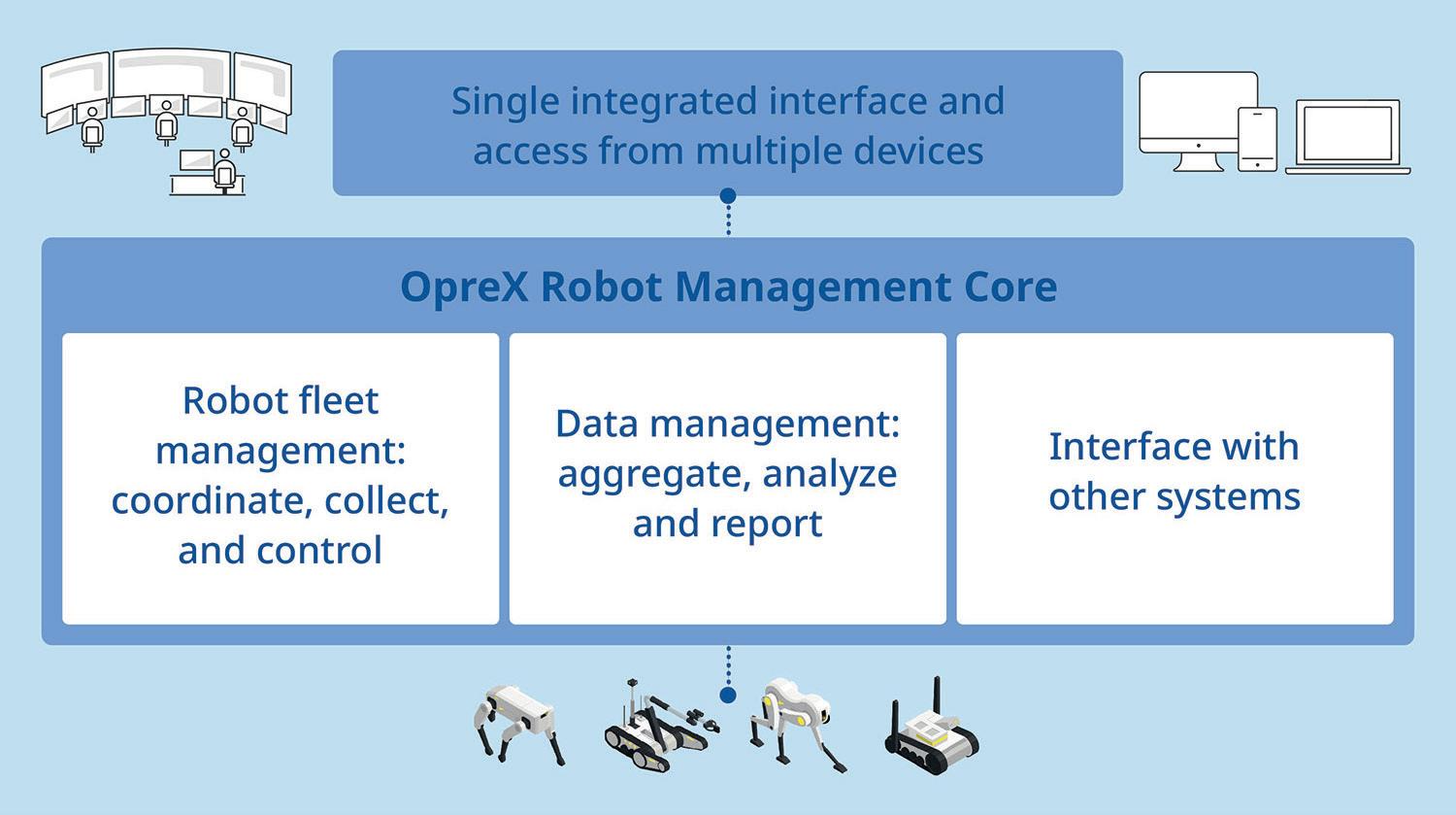
One of the critical considerations in the collaboration between Shell and Yokogawa is scalability. The design of the ORE system takes into account the diversity of downstream operations across different geographies and regulatory environments. To that end, Yokogawa has worked to develop standardised templates, deployment processes, and support structures that can be applied across multiple sites. This includes integration with Yokogawa’s OpreXTM Robot Management Core (RMC) and other digital platforms, ensuring that data from ORE can flow into plant systems without custom engineering for every deployment. Such an approach lowers the total cost of ownership and accelerates return on investment.
From the journey so far, several lessons have emerged that are applicable to the broader downstream industry:
n Start with operational use cases: technology should follow the problem, not the other way around.
n Balance standardisation with flexibility: standard templates and architectures are essential for scale, but solutions must
also adapt to local conditions and evolving customer needs.
n Organisational change is as important as technology: training, mindset shift, and cross-functional collaboration are critical for adoption.
n Cloud and AI are enablers – not solutions by themselves: the real value comes from how data is used, not just how it is collected.
Looking ahead, Yokogawa aims to further enhance the intelligence and autonomy of the ORE system, potentially incorporating more advanced diagnostics, multi-modal sensing, and tighter integration with plant control systems. Shell continues to support this journey by contributing real-world operational expertise, governance structures, and a vision for digital transformation.
The collaboration outlined in this article reflects a broader shift in how industrial operations address increasing regulatory pressure, ageing assets, market volatility, and workforce constraints. In this environment, earlier anomaly detection, remote inspection, and smarter deployment of human expertise are essential. Such collaborations, including a joint R&D roadmap for the future, help to enable safer, more efficient, and cost-effective autonomous monitoring and maintenance.


Aadam F. Aryan, Distillation Equipment Company Ltd, UK, discusses the necessary process and mechanical considerations for successfully revamping distillation columns to improve efficiency.
Although distillation is energy intensive, it is still the most widely used separation method, and will remain so for many years. To reduce our carbon footprint, it is incumbent upon all engineers involved in the refining and chemical process industries to optimise the design of such columns. The performance of any distillation column can be improved with respect to capacity, separation efficiency, pressure drop, energy efficiency, fouling tendency, and mechanical integrity.
Ultimately the key consideration is cost vs benefits of the improvement.

The mass transfer equipment market divides into three segments approximately equally: new columns, revamps, and maintenance.
Revamping an existing column offers opportunities to improve the performance with respect to all of the aforementioned aspects.
Process engineers have a choice of using trays or packing (random or structured) within a distillation column. The appropriate mass transfer device to use will depend on the service and is a compromise between: n Capacity (through-put).
n Efficiency (separating power).
n Pressure drop.
n Fouling resistance.
The key difference between trays and packing is pressure drop (ΔP). The maximum recommended ΔP for a trayed column is about 20% of the tray spacing. For a 24 in. tray spacing, this is 4.8 in. of hot liquid and for an air-water system 4.8 in WG (12.0 mbar) per tray, i.e. 2.4 in. WG per ft (6.0 mbar/m) of column. Random packing (for non-foaming systems) is usually designed for a maximum ΔP of 0.5 in. WG per ft (4.0 mbar/m) whereas structured packing maximum ΔP is usually 0.25 in. WG per ft (2.0 mbar/m). Thus random packing and structured packing ΔP is approximately 20% and 10% respectively of a trayed column. Hence, when minimising ΔP is significant, packing is the preferred choice of mass transfer device.
Fouling is a perennial problem in the refining and chemical process industries. In the Kister1 2003 survey it was the top cause of column malfunctions. Packing is rarely a good choice in a fouling service except in some rare cases where ΔP is very critical (e.g. the wash zone bed of a crude vacuum tower). Here, packing is used even with the expectation that the bed will foul up. A well designed wash zone bed may achieve a run length of approximately 5 years before replacement is required, whilst a poorly designed arrangement may fail after just a couple of months.
Structured packing also offers a significant increase in capacity and efficiency. A comparison is given in Table 1 from Chen2 1984.
The comparison given in Table 1 is for standard trays and makes no distinction between the type. Capacity and efficiency rankings for the various tray types are:
n Bubble cap trays: lowest capacity and least efficient.
n Sieve trays: intermediate capacity and intermediate efficiency.
n Valve trays: highest capacity and highest efficiency.
Since 1984, high performance trays have also been introduced into the market which significantly increase both the capacity and reduce the ΔP.
Structured packing is available in two generic variants –with a 45° crimp (high efficiency) or a 60° crimp (high capacity). The relationship between crimp heights (depth) and the specific surface area (SSA) is given in Table 2.
For atmospheric operation, a comparison of typical capacity and efficiency is given in Table 3. Higher loadings and efficiency are possible for operation under vacuum. Structured packing is not recommended for high pressure (high liquid loading) systems due to reduced efficiencies.
Where pressure drop is not critical, trays remain the best choice and are the most economical. They are the most widely used mass transfer device. Anecdotal evidence suggests approximately 4 out of 5 operating columns worldwide use trays. Therefore, when revamping an existing column, it usually involves going from a trayed to a packed column or combination thereof.
Structured packing is supplied in blocks (layers). Typical layer heights are given in Table 4.
Structured packing has inherent redistribution characteristics as opposed to random packing since, when installed, each layer is rotated 90° to the preceding one. Nonetheless, liquid will migrate towards the periphery and wall wipers are required to redirect liquid back into the packed bed as well as providing a seal to prevent vapour by-pass flow around the periphery of the packed bed. Some vendors provide only one wall wiper (to minimise cost) tack welded to the periphery of each block at the base. This is a false economy and can lead to operational problems. Rafi and Mnyapara3 2025 presented a trouble-shooting case study, where a structured packing bed using large block heights with only one wall wiper (welded at the bottom of the block) suffered a significant loss of separation efficiency due to poor initial liquid distribution. The loss in efficiency would have been mitigated if two wall wipers had been used.
The ASME pressure vessel code states that the difference between measured diameters at any given cross-section cannot exceed 1% of the nominal diameter. This tolerance must be considered when designing mass transfer equipment (including structured packing) for new and revamped columns. For example, for the 1825 mm nominal diameter column, in the case studies given later in this article, the actual diameter at any given location may be 1806.8 mm to 1825 mm or 1825 mm to 1843.3 mm,
a difference of 36.5 mm between absolute minimum and maximum diameters. As such, two wall wipers for each block are recommended to ensure sealing at the periphery, particularly for revamps.
The image on the front cover of this issue of Hydrocarbon Engineering, taken during the dimensional inspection, shows a bed of M-Pak 200Y structured packing without any wall wipers. After the inspection, two wall wipers were tack welded to each block – see Figure 1. An alternative is to provide the second wall wiper loose for installation at site – see Figure 2.
A packed column, whether random or structured, is only as good as the liquid distributor. Careful consideration needs to be given to selecting and designing the appropriate type. The requirements are:
n Appropriate number of drip (distribution) points.
n Maximum uniformity of flow rates of the drip points (e.g. by maximising the operating and turndown liquid heads).
n Operating flexibility vis-à-vis liquid level at operating and turndown conditions.
n Avoid formation of drops and mists (e.g. by using drip tubes to avoid re-entrainment of liquid).
n Avoid splashing (e.g. by using drip tubes to discharge liquid close to the top of the packing).
n Avoid merging of single jets generated by the distributor (e.g. by using drip tubes).
n Maximise the open area for vapour/gas flow thus minimising ΔP (e.g. by using narrow troughs).
n Maximise fouling resistance (e.g. by elevating discharge holes from the deck).
n Reasonable cost.
Pertinent characteristics of various types of liquid distributors are given in Table 5.
For a liquid distributor, what is an appropriate number of drip points? Industry guidelines are between 40 - 100 per m2 Larger size (low surface area) packings requiring less points than smaller size (high surface area) packings. Fitz et al4 1993 of FRI presented results (C6-C7 system, column diameter 1200 mm) for a 250Y structured packing using a drip tube pan distributor showing very little if any difference in the packing efficiency for drip point densities of 26, 36, and 103 points/m2. For the same type of packing, Olujić and Jansen5 2015 reported similar results (air-water system, column diameter 1400 mm) where the distribution quality was not affected by reducing the drip point
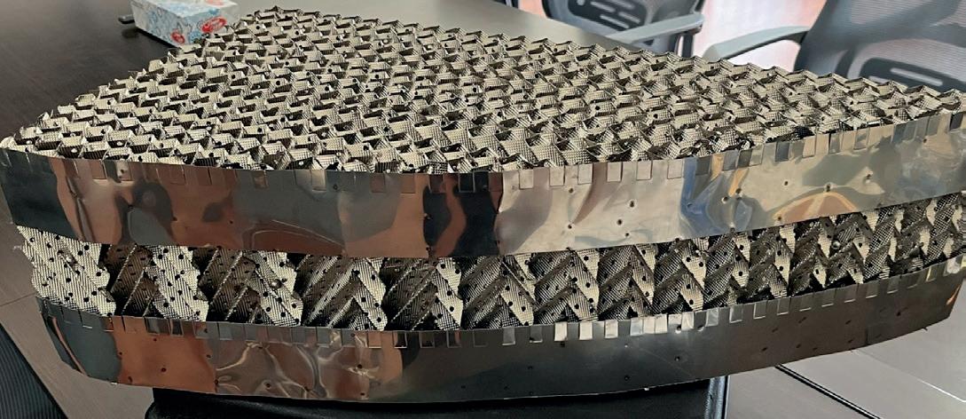
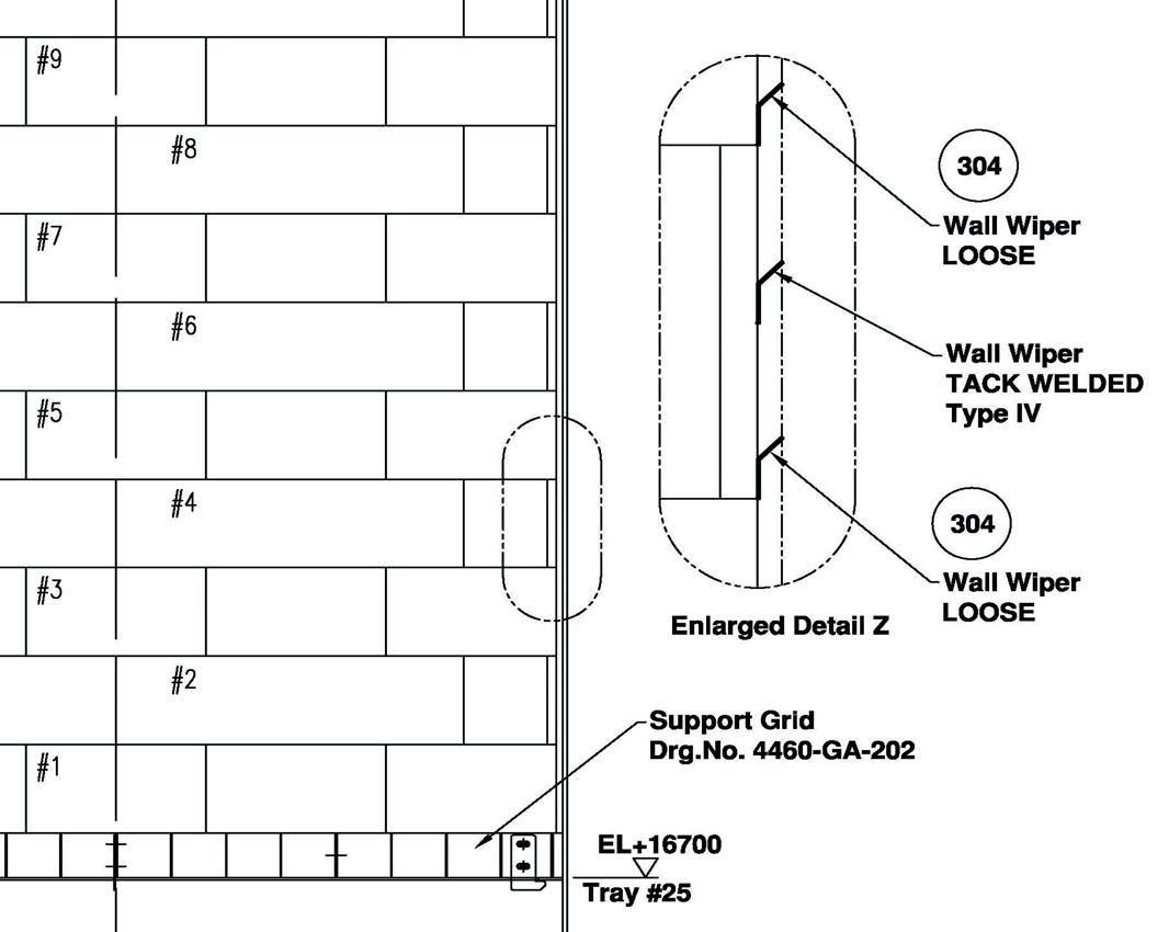
density from 100 to 50/m2. Rukovena and Cai6 2009 of FRI reported results for 25 mm pall rings where there was only minor improvement in packing performance with liquid distributor pour point densities greater than 5/ft2 (54/m2).
Table 6.
of an existing trayed column
For a given liquid rate, the distribution point size (hole diameter) will depend on the number of points selected. Generally, it is more prudent to maximise the hole diameter to reduce fouling risk rather than maximise point density. A good starting point is 50 points per m2
An existing column was re-trayed in 2011 with optimised NCD cage and disc valve trays to improve separation efficiency. Summary details of the column are given in Table 6.
Trays below the feed had baffles to reduce the active area, thus reducing weeping. The use of baffles was discussed by an article in 2025.7 The trays above the feed in addition to the baffles had blocked exit weirs – see Figure 3 showing the installation of the trays. Tray efficiency optimisation in the spray regime has also been discussed previously in 2022.8
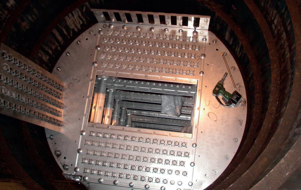
In 2020, the column described in case study C3043 above was re-purposed for a new duty – separation of an undisclosed chemical mixture. The distillation to be carried out under vacuum with a top pressure of 320 mbar a. The arrangement of the revamped column is shown in Figure 4.
Pressure dop becomes significant if not critical for a column operating under vacuum. Hence, structured packing was used above the feed. To achieve 13 number of theoretical stages (NTS) above the feed, a 3762 mm bed of M-Pak 350Y structured packing was used. Maximum Fs = 2.5 Pa0.5, jet-flood 76.2%, and average ΔP = 2.6 mbar/m. Tower attachments occurring within the packed bed were cut-back to 6 mm of the column shell. To maximise packing efficiency, the best type of liquid distributor to use is a narrow trough type c/w drip tubes – as shown in Figure 5 for this column. Distribution point density of 57/m2 with 5 mm diameter holes. Two holes per point were used to give a 5 to 1 operating range. The bottom hole elevated from the deck by 25 mm, distributor ΔP = 1.3 mbar. The total section pressure drop (including the internals) 13.5 mbar.
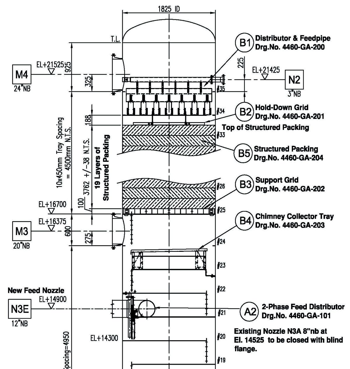
Feeds to vacuum columns are very often two-phase. The two phases being created due to flashing after a control valve or flashing upon introduction into the column itself. Care needs to be taken in designing an appropriate arrangement as many columns have been prematurely bottlenecked due to inadequate arrangements, with guidelines previously outlined.9 To prevent vibration, the feed pipe was securely bolted to existing downcomer bolt-bars of tray #21. The final arrangement used is shown in Figure 6.
The existing 8 in. nb feed nozzle, located above tray support ring (TSR) #20, was too small for the 40% vapour and 60% w/w liquid feed (ρV2 = 13 647 kg/ms2). It was increased to 12 in. nb
Whether you are designing a new column or revamping an existing design, let our decades of experience and expertise assist you in making and implementing the most appropriate solution, at minimum cost, not only to achieve the desired throughput but also to accommodate feed rate variations and minimise operating costs and downtime.
DtEC design standards are based on many years of proven experience in the mass transfer field and are used to design the trays, packing & internals to suit the specific process requirements, resulting in consistent and reliable performance.
Sieve Trays
Bubble Cap or Tunnel Cap Trays
Fixed Valve Trays (4 Types)
Mobile Valve Trays (8 Types)
Bolting
Hardware (Clamps & Washers)
Replacement Trays (All Types)
Shutdown Planning & Spares
S-Wave Trays (SPS) Service
Uniflux Trays
Parallel Flow Trays
T-Wave Trays (Patents Pending)
Raschig Rings & Saddles
Pall Rings
DMTP High Performance
DMR High Performance
Packing Support Plates
Packing Support Grids
High Capacity X-Type
High Efficiency Y-Type
High Performance Type
Mesh Type
Vane (Chevron) Type
Liquid Distributors Fibre Type
Feed Distributors (Single & Two-Phase)
Bed Limiters (Hold Down Grids)
Chimney (Collector) Trays
Molecular Sieve Support Grids
Inlet Feed Diffusers
Scale Catching Trays or Baskets
… quality and service with a passion…
Distributor Trays (Sieve, Bubble Cap or Distribution Tube Type)
Catalyst Support Grids (Lattice Bar + Mesh Screen or Wedge Wire Type)
Remixing + Quench Assemblies
Outlet Collectors
From receipt of your enquiry, our team of dedicated professionals are here to help and give you a fast, efficient, knowledgeable and friendly response.
Distillation Equipment Company Ltd, The Boat Yard, Newcastle Road, Stone, Staffordshire ST15 8JZ, UK
Tel: 0044 1785 602810
Fax: 0044 1785 602811
Email: sales@traysrus.com
Web: www.traysrus.com
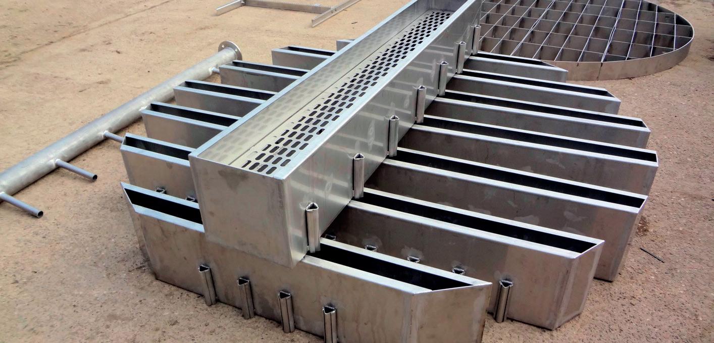
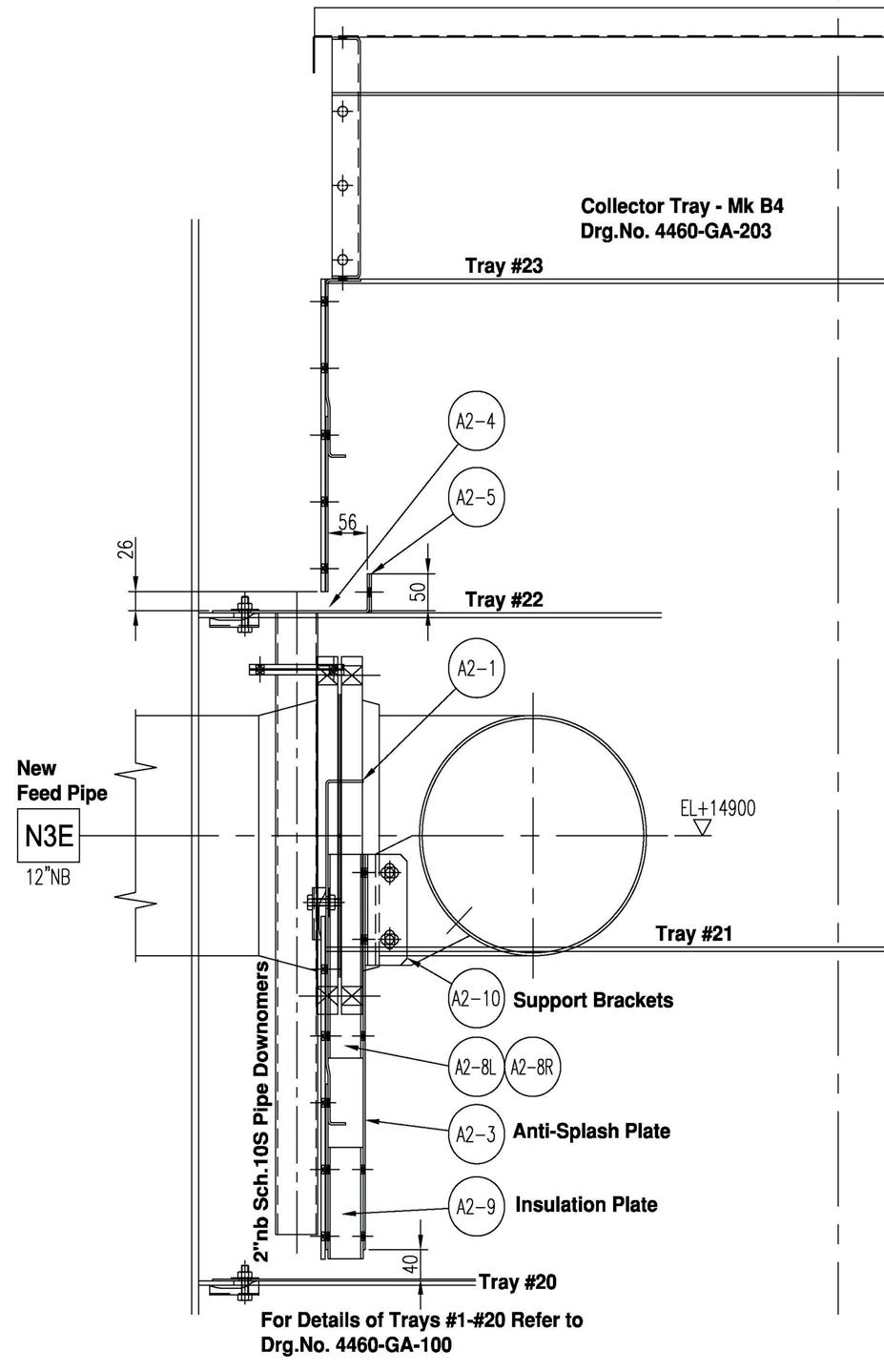
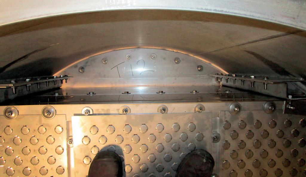
7. Installation of optimised MV1 Valve Trays in a revamped column.
(ρV2 = 2726 kg/ms2) reducing to 10 in. nb (ρV2 = 5493 kg/ms2) inside the column.
A feed introduced above the chimney collector tray at TSR #23 would have been ideal. However, piping constraints outside the tower did not allow this. The maximum increase in elevation possible was from 14 525 to 14 900 (above TSR #21). At this elevation the orientation was such that the feed pipe had to be introduced through the downcomer of tray #21. The arrangement used allowed the external 2-phase feed to be disengaged correctly at the inlet of tray #20 and to be mixed with the liquid collected from the packed bed. This maximises the flow path length (FPL) of feed tray #20 thus maximising the tray efficiency.
Structured packing through-out the column would have been a logical choice. However, quite often a compromise is required between minimising ΔP and the need to have something fouling resistant. Since it is usually the bottom of a column that fouls up due the inherently higher temperatures, trays were kept below the feed. This also considerably reduced the capital cost of the revamp.
The reboiler for the column used a hot oil circuit which limited the bottom temperature to a maximum of 260°C. Thus it was essential to minimise the tray pressure drop. The trays used (shown in Figure 7) were designed for an average ΔP of 5.4 mbar/ tray (total section ΔP 108 mbar), maximum Fs = 1.38 Pa0.5, maximum jet-flood 70.4% with the following optimisation features:
n Z-bars utilising existing downcomer bolt-bars to increase downcomer area.
n Mini mobile valves to increase capacity.
n Light valves to reduce dry pressure drop.
The revamped column achieved all the objectives required – capacity, efficiency, and pressure drop.
Packing is the preferred choice when minimising pressure drop is significant or critical. However, quite often a combination can be used, with packing above the feed and trays below the feed where there is a risk of fouling. Appropriate internals need to be used to maximise packing efficiency. Also feed arrangements, particularly two-phase, need an appropriate design. Careful consideration of all these aspects leads to a successful revamp.
1. KISTER, H. Z., ‘What Caused Tower Malfunctions in the Last 50 Years?’, Trans IChemE, Vol. 81, (January 2003).
2. Chen, G. K., ‘Packed Column Internals’, Chem. Eng, (1984).
3. RAFI, B., and MNYAPARA, D. M., ‘Which one of these is the usual culprit? High-quality distributor or high-quality packing?’, AIChE Spring Meeting – Kister Distillation Symposium, (April 2025).
4. FITZ, C. W., Jr. et al, ‘Controlled Liquid Maldistribution Studies on Structured Packing’, Trans IChemE, Vol. 77, (September 1993).
5. OLUJIĆ, Z., and JANSEN, H., ‘Large-diameter experimental evidence on liquid (mal)distribution properties of structured packing,’ ChERD, Vol. 99, (2015).
6. RUKOVENA, F. Jr., and CAI, T. J., ‘Packed Tower Internals Important to Tower Efficiency’, AIChE Spring Meeting – Distillation Symposium, (April 2009).
7. ARYAN, A. F., ‘Improving Tray Efficiency by Reducing Weeping,’ Hydrocarbon Engineering, (March 2025).
8. ARYAN, A. F., ‘Improving Tray Efficiency in the Spray Regime,’ Hydrocarbon Engineering, (January 2022).
9. ARYAN, A. F., ‘Two-Phase Feed Distributors for Distillation and Absorption Columns’, Hydrocarbon Engineering, (September 2023).
Muhammad R. Tariq and Taib B. Abang, Saudi Aramco, discuss LPG mercaptan sweetening technologies and present their findings.
Liquefied petroleum gas (LPG) is a critical product in refining, and ensuring its quality is essential for meeting regulatory standards and customer specifications. One of the primary processes in refining LPG is the removal of sulfur compounds, particularly mercaptans (R-SH), to ensure the final product is free from unpleasant odours and complies with environmental regulations. The LPG mercaptan removal unit (MRU) plays a key role in this desulfurisation process. The process employed is known as mercaptan oxidation (MEROX),

which uses a caustic solution to oxidise mercaptans into less harmful disulfides, thus reducing sulfur content.
The process of mercaptan sweetening involves treating sulfur-containing mercaptans with oxygen, typically in the presence of an alkaline solution such as sodium hydroxide (NaOH), resulting in the conversion of mercaptans into disulfides (RSSR) and water. While this process is effective, it is not without its challenges. LPG mercaptan sweetening units usually face operational problems such as feedstock
quality variations, maintaining the appropriate process conditions, and managing product quality specifications.
As global LPG markets grow and environmental regulations become more stringent, optimising mercaptan sweetening unit operations is becoming more critical. Refinery operators are increasingly tasked with maximising the efficiency of the unit while minimising downtime, reducing operational costs, and ensuring that the final LPG product meets both regulatory standards and customer specifications.
This two-part article explores the various operational challenges faced by LPG mercaptan sweetening units and provides an in-depth analysis of strategies for overcoming these issues. Through this discussion, this article aims to contribute to the knowledge available to refining engineers, operators, and process designers working to optimise LPG desulfurisation operations in a complex and regulated environment.
Part one of this article will provide analysis and findings on LPG feed contaminations. The subsequent part will provide further details on other contributing factors, as well as provide final recommendations.
The MRU at oil refineries typically utilise extraction caustic mercaptan sweetening process technology, designed to remove hydrogen sulfide (H2S) and mercaptans from LPG streams. This ensures that the treated LPG product complies with sulfur content specifications before being introduced into the de-ethaniser and C3/C4 splitter for further processing into useful light hydrocarbons such as propane and butane.
The MRU processes straight-run LPG is derived from various refinery units, including the crude distillation unit (CDU), hydrocracking unit (HCK), and the gas saturation and treatment unit (GSTU). This is typically part of grassroots refinery setups or hydrocarbon terminal facilities. Figure 1 provides an overview of the main sections of the LPG MRU process.
n Amine absorption section: this section includes the amine absorber column, amine water wash settler, and lean amine cooler, designed to remove H2S from LPG feedstock. The amine absorber facilitates H2S absorption into the amine solution, which is later regenerated for reuse, ensuring clean LPG for downstream processes.
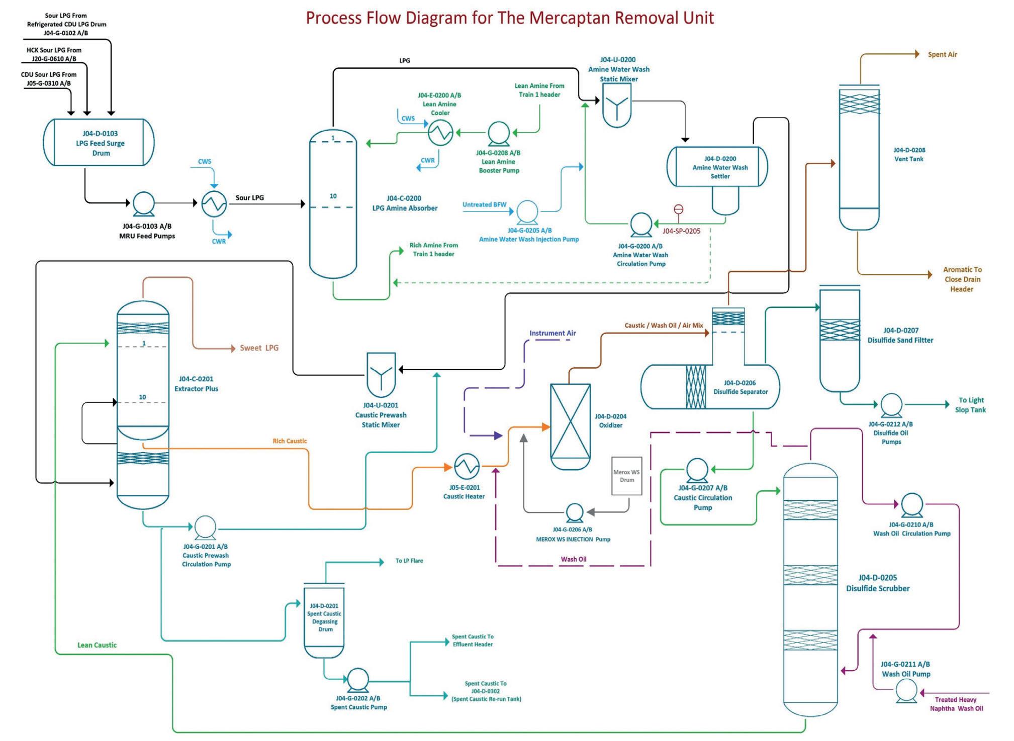
n Caustic extraction system: the Extractor PlusTM column, featuring a continuous prewash step, eliminates residual H2S before the main extraction. Mercaptans are then extracted from LPG via caustic solution contact, transferring them to the aqueous phase.
n Caustic regeneration section: this section comprises the oxidiser, disulfide separator, sand filter, scrubber, and vent tank. The rich caustic solution undergoes oxidation with air and a mercaptan sweetening catalyst in the oxidiser, converting mercaptides to disulfides. The regenerated caustic is recirculated to the Extractor Plus column, while disulfide oils are separated and stored in a light slop tank.
The mercaptan sweetening process relies on the ability of an organo-metallic catalyst to accelerate the oxidation of mercaptans into disulfides, which are much less toxic and odorous. The reaction is simplified as follows:
4 R-SH + O2 → 2 RSSR + 2 H2O
This reaction occurs in an alkaline environment, typically with sodium hydroxide (NaOH). In the mercaptan sweetening process, the mercaptans in the LPG stream are contacted with a strong NaOH solution. The mercaptans react with NaOH to form sodium mercaptide (NaSR), which is water-soluble:
4 R-SH + 4 NaOH → 4 NaSR + 4 H2O
After the extraction phase, the aqueous caustic phase, rich in mercaptides, is sent to the regeneration section, where air is bubbled through the solution in the presence of the mercaptan sweetening catalyst. This step oxidises the sodium mercaptides into disulfides and regenerates the caustic solution:
4 NaSR + O2 + 2 H2O → 2 RSSR + 4 NaOH
Disulfide oil is separated from the aqueous caustic phase, while the regenerated caustic is returned for further use in the extraction column.
This section provides comprehensive analysis for MRU issues using actual lab data, plant operating data, and simulation modelling results.
H2S content in LPG feed
Hydrogen sulfide (H2S) is a primary contaminant in LPG feed, posing corrosion, toxicity, and safety risks while dictating regulatory compliance. To completely remove H2S in LPG feed stream, an amine absorber system is provided as part of the MRU, where H2S is absorbed by a chemical amine solution. As shown in Figure 2, the amine system is generally efficient at removing H2S typically less than 100 ppm for LPG. This process selectively captures H2S but can be affected by feed composition, sulfur content, temperature, and pressure variations.
It is essential to monitor the H2S concentration both upstream and downstream of the amine absorber to ensure that the system operates within specified limits. Regular monitoring helps in maintaining the performance of the absorption process, particularly when there are changes in
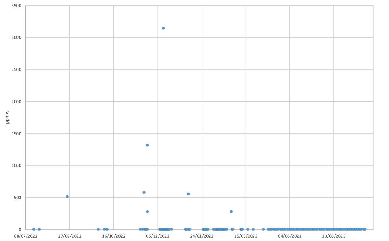
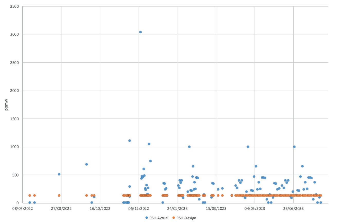
the feed composition. Failure to maintain the desired H 2 S levels can result in poor product quality, potential
corrosion in downstream equipment, and environmental non-compliance.
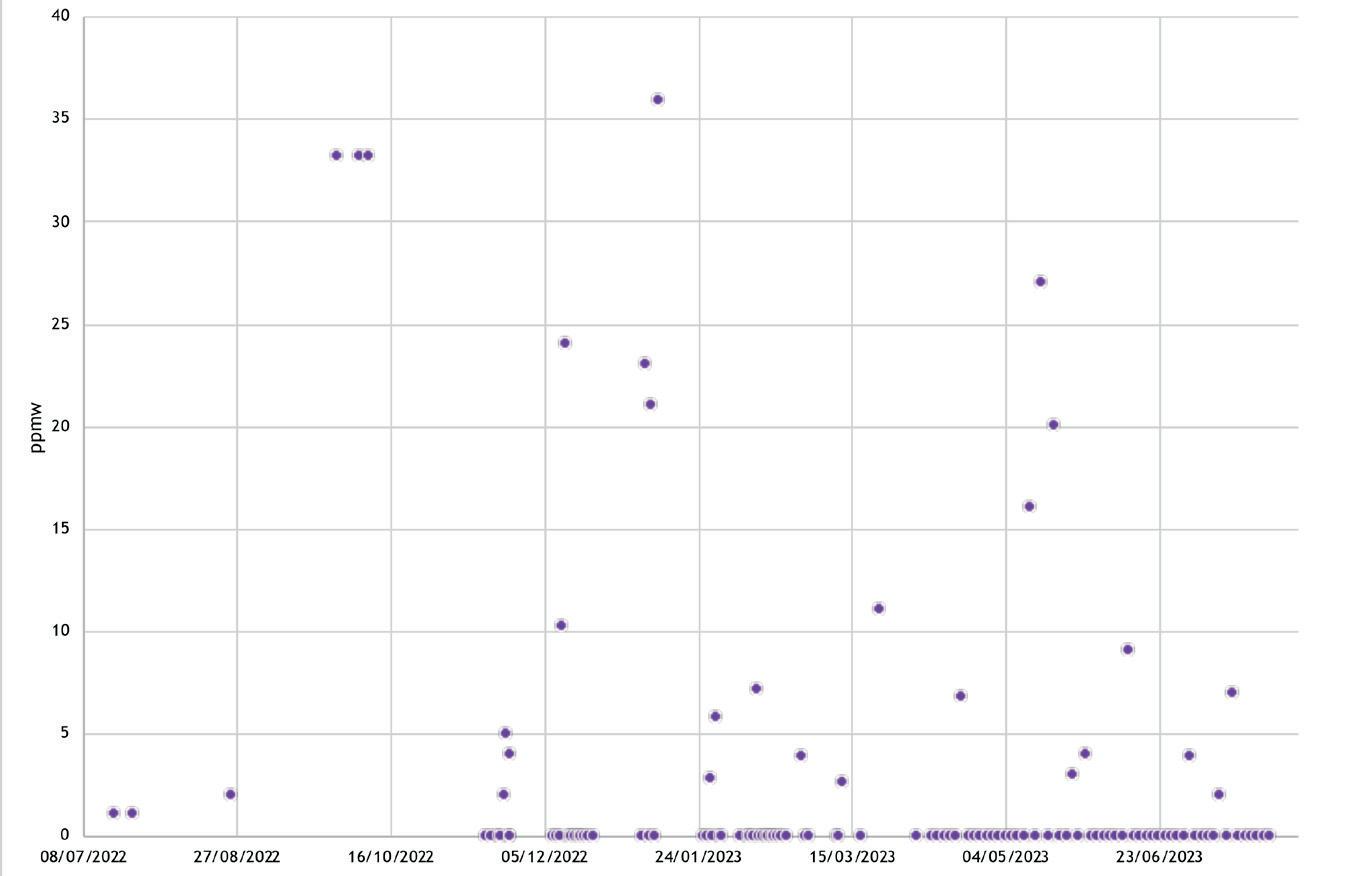
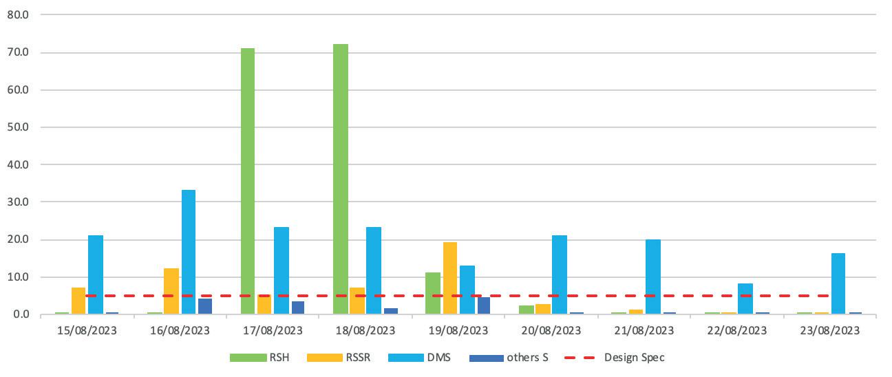
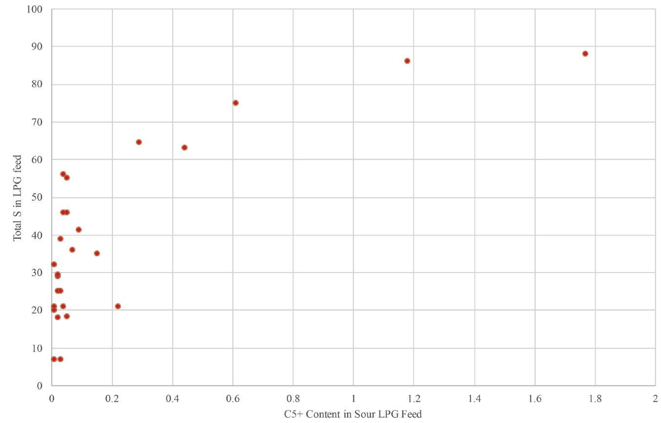
Mercaptans in LPG feed
Mercaptans are sulfur compounds responsible for the foul odour in LPG. They are harder to remove than other sulfur species and pose a challenge in the MRU process. The mercaptan sweetening process is designed for mercaptan concentrations up to 124 ppmw, ensuring the final product meets sulfur specifications.
However, as demonstrated in Figure 3, real-world operating conditions show that the actual mercaptan concentration in the feed exceeds many times the design specification. The observed concentration varies from 200 - 1000 ppmw, which is two to eight times higher than the target value. This increase in mercaptan concentration in the feed poses several challenges for the MRU. The excess mercaptans lead to the formation of additional mercaptides in the caustic solution, which must be oxidised to disulfides through the mercaptan sweetening reaction. This increased demand for oxidation requires additional air and catalyst injection to ensure that the mercaptans are fully converted to less harmful disulfides.
The higher mercaptan concentration can go unnoticed if monitoring is delayed, so real-time sulfur analysers and predictive modelling are essential for early detection and operational adjustments.
In addition to mercaptans, the LPG feed often contains other sulfur compounds, such as carbonyl sulfide (COS). COS is a highly stable sulfur species that cannot be removed by the mercaptan sweetening unit. As Figure 4 illustrates, there are instances where COS concentrations exceed the design expectations, leading to an increase in the overall sulfur content of the LPG product. Since the mercaptan sweetening process does not treat COS, its presence in the feed must be considered when evaluating the total sulfur content in the final product.
COS cannot undergo the same oxidation reactions as mercaptans, and therefore it contributes directly to the sulfur load in the treated LPG. Refinery operators need to account for COS levels when setting product sulfur specifications. This may require additional treatments, such as downstream desulfurisation units or modifications to the feedstock processing, to control the sulfur content and meet environmental standards.
Dimethyl sulfide (DMS) is another sulfur compound found in the LPG feed that poses a challenge in sulfur removal. DMS is particularly troublesome because it cannot be removed by the mercaptan sweetening unit, as shown in Figure 5. The typical concentration of DMS in LPG feed is around 20 - 30 ppmw, although it can vary depending on the crude source and upstream processes. DMS is a naturally occurring sulfur compound found in crude oil,1,2 and it is typically present in the heavier fractions (C5+).
Unlike mercaptans, which can be treated through the mercaptan sweetening process, DMS remains in the treated LPG product. Consequently, DMS contributes to the overall sulfur content in the final product. Since the mercaptan sweetening unit cannot address DMS, refinery operators may need to consider alternative treatment methods, such as downstream desulfurisation processes or specific DMS removal technologies, to reduce DMS levels and meet product sulfur specifications.
C5+ content in LPG feed
C5+ refers to heavier sulfur species found in crude oil’s heavier fractions, particularly in CDU outputs. These high-molecular-weight sulfur compounds contribute significantly to sulfur levels in the LPG product, as shown in Figure 6. When present in high concentrations, C5+ compounds complicate meeting sulfur specifications in the MRU process.
To control sulfur content, it is essential to minimise C5+ in the LPG feed. This can be done by optimising CDU operating conditions and incorporating additional separation or distillation steps. Reducing C5+ content improves MRU performance and enhances desulfurisation efficiency and cost-effectiveness.
The first part of this article has provided analysis and findings on LPG feed contaminations.1 Part two will provide further details on other contributing factors, as well as final recommendations.
1. HARRUFF, L.G., MARTINIE, G.D., and RAHMAN, A., ‘Improving fractionation lowers butane sulfur level at Saudi gas plant’, Saudi Arabian Oil Co. Dhahran.
2. HARRYMAN, J.M., and SMITH, B., ‘Update on sulfur compound distribution in NGL: Plant test data GPA Section A committee, plant design,’ 75th Annual Convention of the Gas Processors Association, March 11 - 13, 1996, Denver. BALOWS, A., et al., The Prokaryotes, 2nd Ed., Vol. 1, p. 437, Springer-Verlag, (1992).


Bert Klussmann, Sulzer, USA, considers developments in heat technology that can improve heater efficiencies alongside reducing emissions.
Improving the thermal efficiency of fired heaters, furnaces, and boilers beyond conventional limits remains a key challenge in industrial energy optimisation. Traditional configurations typically achieve efficiencies between 85% and 92%, constrained primarily by the acid dew point of flue gas, which limits the extent of heat recovery.
This article presents a system-level approach that integrates fuel gas purification with enhanced heat recovery to enable fired heater efficiencies of 95% or greater. By removing sulfur compounds from the fuel gas prior to combustion, the formation of SOX in the flue gas is eliminated, thereby removing the acid dew point constraint. This allows for deeper heat recovery and reduces the flue gas exit temperature to as low as 80 - 85 °C.
The resulting efficiency gains lead to measurable reductions in fuel consumption and associated CO2 emissions. Additionally, the system contributes to lower SOX and NOX emissions and mitigates corrosion risks associated with acid condensation in downstream equipment.
Fired heater thermal efficiency is the heat absorbed by the process stream divided by the heat input to the fired heater, which means that it is determined by how much

heat is lost (heat not absorbed by the process stream). Heat is lost in various places in the fired heater system –through the heater wall, flue gas duct, and hot flue gas emitted to the atmosphere. Among those, most of the heat is lost through the hot flue gas emitted to the atmosphere. Operators have tried to recover heat from the hot flue gas by exchanging its heat against cold air or other mediums, such as boiler feed water to generate steam. However, the amount of heat recovery is limited by the acid dew point of the flue gas. When sulfur in the fuel gas is oxidised during combustion, SO2 and SO3 are formed in the flue gas. Of the SOX combustion products, between 2 - 5% consist of SO3 with the remaining balance comprising SO2. At the acid dew point, SO3 in the heater flue gas begins to condense to form sulfuric acid, and acid dew point corrosion occurs. The acid dew point temperature depends on the concentration of SOX in the flue gas and is generally between 120 - 150°C. At 25 ppmv SOX in the flue gas, the acid dew point is about 120°C. At 160 ppmv SOX in the flue gas, the acid dew point is about 135°C. If flue gas is cooled below the acid dew point, corrosion of equipment that processes cooled flue gas from the fired heater, such as the air preheater (APH), will occur. The corrosion can also extend to the flue gas duct, draft fan, and chimney after the APH when the sulfuric acid is carried over.
Maintaining the flue gas temperature above 150°C, often 200°C or higher, is necessary to avoid reaching the
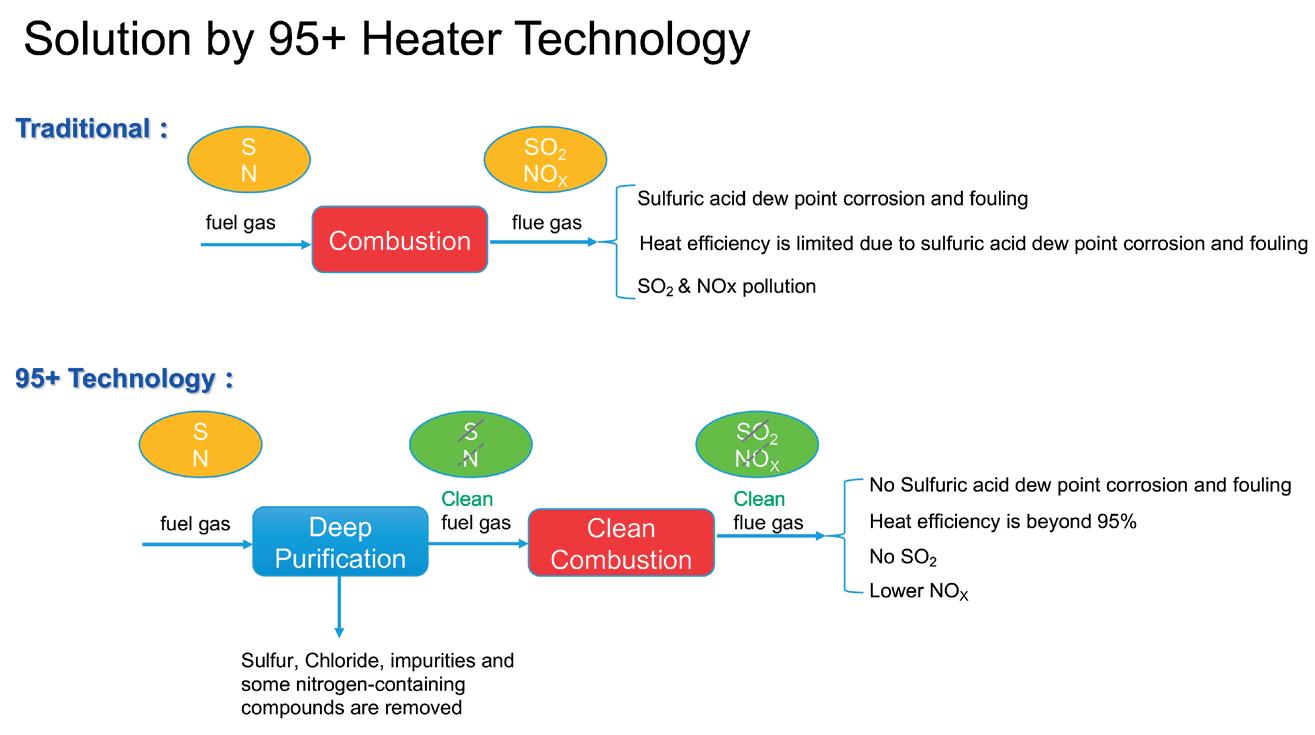
acid dew point. Higher flue gas exhaust temperature results in a maximum fired heater thermal efficiency of 85 - 92%.
Acid dew point corrosion concerns prevent full recovery of available heat from the flue gas and limit the fired heater efficiency. If the risk of acid dew point corrosion is eliminated, the flue gas exhaust temperature can be reduced by more heat recovery, and thermal efficiency of the fired heater is increased.
Lower thermal efficiency means more fuel gas consumption for the same absorbed process duty requirement, resulting in higher carbon emissions, higher NOX, and higher SOX. As the world strives to decarbonise and minimise harmful emissions, improving the efficiency of fired heaters is one essential solution.
Conventionally utilised methods of minimising acid dew point corrosion and/or improving heater efficiency include:
n Monitoring the process temperature of the flue gas and improving feed and process control alongside corrosion monitoring can prevent dew point corrosion, but this method does not allow the flue gas to be cooled below the acid dew point and therefore does not significantly improve the efficiency of the fired heater.
n Corrosion inhibitors can prevent surface corrosion at the point of condensation but do not neutralise the acid.
n Chemical treatments and additives can be used to remove SOX from the flue gas, but these generally have large effluents and may not improve heater efficiency or reduce carbon footprint.
n Polymeric materials of construction can be used to prevent corrosion, but do not neutralise the acid, and corrosion and fouling of draft fans and ducts may still be a problem. They also do not eliminate SOX from the flue gas.
This article proposes a system-level approach, 95+ Heater technology, that combines fuel gas purification with enhanced heat recovery to overcome the efficiency limitations of conventional fired heaters. The approach,
as illustrated in Figure 1, introduces a deep desulfurisation step upstream of combustion to remove sulfur compounds and other contaminants from the fuel gas. This prevents the formation of SO2 and SO3 during combustion, effectively eliminating the acid dew point constraint in the flue gas and enabling deeper heat recovery.
Purification of fuel gas enables the fired heater system to recover as much heat from hot flue gas as possible, allowing the exhaust flue gas temperature to be as low as practical, without sulfuric acid fouling and corrosion. This solution achieves maximum heat recovery from flue gas and increases the heater efficiency to more than 95%.
It also reduces maintenance issues and risk of failures related to sulfuric acid corrosion and fouling. The equipment and hardware in the fired heater system offer a long lifespan for operations.
The fuel gas purification and heat recovery technology is designed to be a simple, drop-in solution for existing fired heaters, furnaces, or boilers without modification of the fired heater body. The added hardware is limited and mainly external, and there are no special materials used, so the overall project cost is kept small. It is also possible to have a single system to serve multiple closely located heaters or furnaces, so they all can achieve 95% or greater efficiency. The control of the fuel gas purification and heat recovery technology is also simple, intuitive, and fail-safe.
Common refining and petrochemical applications include:
n Reforming heaters.
n Crude distillation unit and vacuum distillation unit heaters.
n Coker heaters.
n Hydroprocessing heaters.
n Hydrocracker heaters.
n Xylene column heaters.
n Various chemical heaters.
The technology is applicable to both grassroots and retrofit applications and has been implemented in over 25 industrial units globally, where field data consistently demonstrates thermal efficiencies exceeding 95%.
Decarbonisation has become a global focus in the effort to reduce greenhouse gas (GHG) emissions. Countries have implemented different systems for pricing carbon to incentivise lower carbon emissions. Carbon taxes and carbon trading systems are common methods for creating a cost for carbon. These systems vary from region to region and continue to evolve.
Refineries, chemical plants, and other industries are major sources of CO2 emissions, with industrial sources contributing about 30% to global CO2 emissions.


Table
Table 2. Case study 2
Combustion of fuel in fired heaters is the main contributor to the CO2 emissions from refineries and petrochemical plants with fired heaters releasing an estimated 400 - 500 million tpy of CO2 into the atmosphere.1 By reducing fuel consumption through improved thermal efficiency, the system contributes to lower CO2 emissions. Typical reductions range from 3 to 12% or more, depending on heater duty, fuel composition, and air preheater (APH) performance. Additionally, the elimination of SOX formation and reduction in NOX emissions promote cleaner emissions goals.
Two case studies that applied 95+ Heater technology are shown in Tables 1 and 2. These provide key parameters for operating fuel gas fired heaters implementing Sulzer’s fuel gas purification and heat recovery technology for their existing heaters.
Table 1 is for a fired heater system with no existing APH. A new APH is required for implementation of the solution, resulting in a higher investment cost. Table 2 is the revamp of a fired heater system with an existing APH that is reused for the revamp, resulting in a lower investment cost than the case study in Table 1. The heater efficiency prior to implementation of the fuel gas purification technology is also higher for the case study in Table 2 as waste heat is recovered in the existing APH.
Values from before and after the fuel gas purification technology revamps are reported in Tables 1 and 2.
In the case study in Table 1, thermal efficiency improves from 87.5% to over 95%. This represents a reduction of almost 9% in both fuel gas consumption and CO2 emissions. Payback is 2.1 years without considering CO2 credits and 1.6 years when taking CO2 credits into account, assuming CO2 pricing of US$50/t as the basis.
In the case study in Table 2, thermal efficiency improves to over 95%; fuel gas consumption is reduced; and CO2 emissions are also significantly reduced. For the fired heater shown in this example, the payback period is 1.7 years without considering CO2 credits and 1.4 years when taking CO2 credits into account, assuming CO2 pricing of US$50/t as the basis.
The 95+ Heater technology has been deployed in many refineries, offering a practical method for improving fired heater efficiency through fuel gas purification and deep heat recovery. By enabling thermal efficiencies of 95% or greater, the system contributes to reduced fuel consumption, lower CO2 emissions, and the elimination of SOX formation. It also mitigates acid dew point corrosion and associated maintenance challenges. Applicable to both grassroots designs and retrofit projects, this approach provides a practical pathway for refineries and petrochemical facilities to enhance energy performance and support long-term decarbonisation objectives.
Reference
1. MARTIN, M., ‘Carbon dioxide emissions from fired heaters’, Digital Refining, (June 2021).
Al Geraskin, Integrated Global Services (IGS), Czech Republic, examines challenges facing steam cracker performance, and provides solutions that can maximise olefin production and ensure sustainability.
Steam cracking is the primary process used to convert hydrocarbon feedstocks, such as ethane, propane, and naphtha, into high-value olefins like ethylene, propylene, and butadiene. These olefins serve as critical building blocks for a vast array of products, including plastics, resins, and synthetic rubbers, positioning steam crackers as essential assets in global petrochemical supply chains. The process operates at extreme temperatures (typically 750 - 900°C / 1382 - 1652°F) and involves the rapid thermal decomposition of hydrocarbons in fired tubular reactors. Cracked gas is then rapidly quenched to stop secondary reactions, followed by compression and complex separation to recover target olefins.
Harsh operating environments and unavoidable byproducts continually challenge steam cracker reliability and efficiency.

The most critical operational challenges are outlined in this article.
The steam cracker convection section is arguably the most critical part of the process. It preheats and vaporises the feedstock before it enters the cracker. It generates and superheats steam. It minimises coke formation. Fouling from environmental dust, ceramic fibre particles, and combustion byproducts in the convection section impairs its efficiency. The result is not limited to reduced energy recovery. Operators have to increase fuel firing to keep the feedstock inlet temperature according to the design and increased radiant section temperature results in accelerated coking. If fouling continues to be unaddressed, the amount and quality of steam starts to decline, creating downstream problems.
Coke formation in steam crackers leads to the buildup of carbonaceous deposits inside furnace tubes and transfer line exchangers (TLEs), significantly reducing heat transfer efficiency and increasing tube metal temperatures. This results in higher energy consumption, lower feedstock conversion, shorter run lengths due to frequent decoking, and elevated pressure drops requiring more compression energy. The localised overheating also accelerates tube degradation through creep, carburisation, and potential rupture.
Corrosion in the downstream pressure vessels is a persistent challenge, particularly in downstream units exposed to high-temperature, chemically aggressive environments. Key mechanisms include; sulfidation from sulfur compounds in feed or fuel; and corrosion-erosion driven by coke particles. Stress corrosion cracking (SCC) can occur under tensile stress in corrosive conditions, especially in cracked gas compression drums. Internal corrosion is also prevalent in critical areas such as

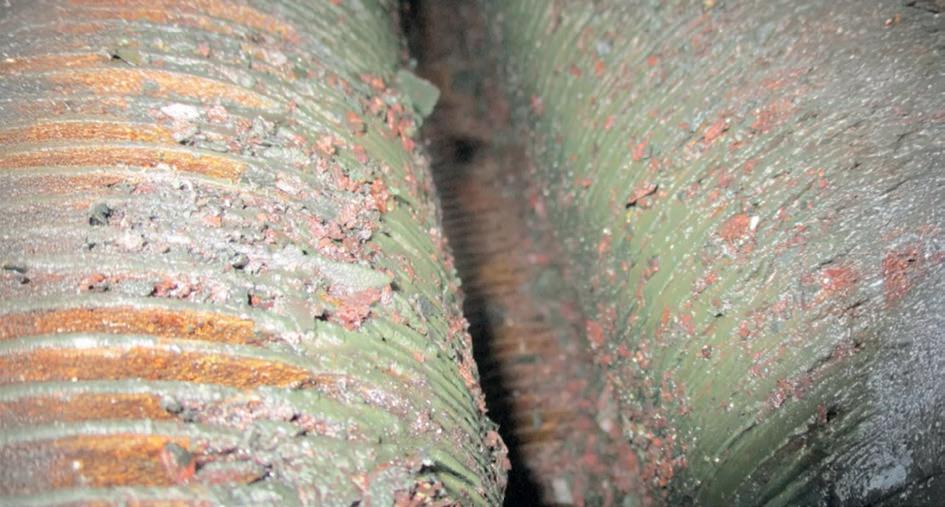

water quench towers, de-ethanisers, and de-butanisers, compromising equipment integrity and reliability.
Steam crackers are significant sources of carbon dioxide (CO2) from fuel combustion, and other pollutants like nitrogen oxides (NOX) and volatile organic compounds (VOCs). Reducing emissions is a growing priority due to environmental regulations and corporate sustainability goals.
The harsh operating conditions and complex equipment in steam crackers necessitate frequent and challenging maintenance activities. At the same time, steam crackers handle highly flammable and potentially explosive hydrocarbons, making equipment integrity and leak prevention critical to safe, reliable operation.
Addressing these challenges requires an integrated approach combining operational best practices with innovative maintenance technologies to sustain uptime, efficiency, and long-term asset integrity. This article explores such strategies with a focus on proven, field-tested solutions.
Optimising steam cracker operations requires a holistic approach that addresses all process aspects, from feedstock selection to product separation.
Precise temperature control
Maintaining optimal temperature profiles within the radiant coils is critical to maximising cracking efficiency and minimising coke formation. Advanced process control systems and accurate temperature monitoring are essential to achieve this balance. Keeping the convection section clean further enhances heat transfer and overall furnace performance.
In steam crackers, unplanned outages due to fouling, corrosion, or refractory failure can result in millions of dollars in lost production. Effective maintenance strategies emphasise proactive, data-driven approaches that minimise downtime, extend asset life, and improve safety.
RCM principles
A shift from reactive to reliability-centred maintenance (RCM) is essential for high-availability operations. RCM is a systematic approach to developing maintenance strategies that focus on preventing failures that have the greatest impact on plant performance and safety.
Inspection-driven planning
Aligning maintenance schedules with findings from boroscopic inspections, thermography, and corrosion mapping ensures targeted, efficient interventions.
Coke and fouling are inevitable but manageable through advanced techniques that improve safety and reduce downtime.
Mechanical and chemical decoking
Traditional steam-air decoking can be augmented or replaced with mechanical or chemical methods to reduce turnaround time and improve coil longevity.
Robotic convection cleaning
Remotely operated robotic cleaning systems can carefully restore up to 95% of the original heat transfer surface area, improving superheat and reducing stack temperatures, without damaging refractory. Online variants allow targeted fouling removal without taking the furnace offline.
Hot convection cleaning
This online technique removes fouling from convection tubes using specialised lances, improving thermal efficiency and extending run lengths between shutdowns. Engineered access ports enable repeatable cleaning and reduce reliance on shutdown windows.
Hot vacuum for SCR units
SCR catalyst banks are prone to fibrous fouling, increasing pressure drop and reducing NOX control efficiency. Online hot vacuum services restore flow and are complemented
by dual-stage filtration screens that extend catalyst life and performance.
Refractory encapsulation
Ceramic encapsulation coatings help significantly reduce refractory abrasion by flue gases, thus extending both the refractory life and cleanness of the convection section and SCR.
Corrosion mitigation strategies
Operating in high-temperature, corrosive environments demand a proactive defence against asset degradation.
High-performance claddings
Advanced thermal spray claddings such as high velocity thermal spray (HVTS) create dense, stress-free alloy barriers without introducing heat to the base material. Applied in-situ, they protect critical assets such as TLEs, cracked gas compressor drums, quench towers, and fractionation equipment, from carburisation, sulfidation, oxidation, and erosion.
planning and execution
Effective turnarounds depend on planning precision, disciplined execution, and rapid learning cycles.
Pre-turnaround planning
Detailed planning includes work scopes, access strategies, refractory assessments, and cleaning logistics. Engineered entry points created during online cleaning phases can streamline turnaround operations.


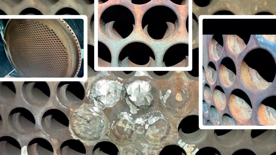
Online maintenance services
Technologies such as in-situ hot refractory repair and inspection allow for addressing hot spots and refractory degradation during normal operations. These interventions maintain thermal integrity, avoid steam quenching, and help defer full shutdowns.
Effective execution
Turnaround success hinges on skilled personnel, proven technologies, and close coordination between operations, maintenance, and external service teams.
Post-turnaround review
Conducting post-turnaround reviews to identify lessons learned and update maintenance protocols is crucial for continuous improvement.
When deployed together, these maintenance practices increase asset availability, reduce lifecycle costs, and build a safer, more predictable operational environment.
A steam cracker facility producing over 700 000 tpy of ethylene experienced persistent limitations in steam superheat due to fouling in the convection sections of the primary furnaces. The resulting drop in superheated steam quality led to turbine blade erosion, operational inefficiencies, and elevated maintenance risks.
Conventional water-based cleaning trials conducted in 2015 and 2018 did not yield measurable improvements in heat transfer. Superheat temperatures and steam output remained below design targets, prompting further investigation.
A robotic convection section cleaning system was deployed to remove fouling without requiring manual entry. Multiple furnace units were cleaned between 2020 and 2024 using both offline and online methods.
Outcomes:
n 2020: steam production increased by 4 tph; superheated steam temperature increased by 35°C.
n 2024 (second furnace): increased steam production by 4 tph and raised steam temperature from 420°C to 460°C (+40°C).
n 2024 (online cleaning, third furnace): superheat increased from 415°C to 475°C (+60°C).
Superheat control systems (desuperheaters) were able to maintain target setpoints post-cleaning. Improvements were observed immediately after cleaning, with positive energy balance and equipment protection implications.
A major olefins complex in Mexico observed accelerated erosion and corrosion at the weld seams and inlet zones of transfer line exchangers Tubesheet in its Unit 4 cracker. The most severe degradation occurred in transition regions, where turbulent flow and coke-laden gases led to localised metal loss.
Temporary mitigation using welded plugs and protective sleeves increased pressure drop and only partially addressed the degradation. A longer-term solution was sought to extend run length and reduce maintenance intervention.
HVTS cladding was applied to critical zones, including tube face, protrusion areas, weld seams, and the inner diameter (ID) of inlet tubes.
A modified Inconel alloy was selected based on erosion and corrosion resistance properties validated in similar operating environments.
n Full cladding coverage achieved on all vulnerable zones. n Protective overlay thickness validated in-situ.
n Project completed within six days.
n Furnace returned to service earlier than scheduled.
This approach eliminated the need for welded plugs and significantly reduced metal loss at known erosion sites. Future inspections will assess coating performance over successive runs.
Coke formation, fouling, refractory degradation, and corrosion continue to challenge steam cracker performance, undermining furnace reliability, run lengths, and profitability. If left unaddressed, these issues lead to increased fuel consumption, higher emissions, and a higher risk of unplanned shutdowns. By applying proven best practices alongside advanced technologies, such as robotic cleaning, ceramic coatings, online hot services, and corrosion-resistant cladding, operators can extend run lengths, reduce costs, and lower CO2 and NOX emissions. With fast payback and reduced downtime, integrated, reliability-focused strategies provide a practical path to protecting assets, improving efficiency, and ensuring sustainable olefin production.
Hani Taan, NanoTech Materials Inc., USA, examines the properties and applications of spray-applied coatings that can protect industrial tank and piping systems from corrosion under insulation and safeguard personnel throughout operations.
In the harsh operational environments of industrial facilities – refineries, petrochemical complexes, and chemical processing plants – thermal insulation is more than just an energy-saving measure. It is a critical line of defence against heat-related injuries, energy loss, and one of the industry’s most insidious threats: corrosion under insulation (CUI). Industrial tanks and piping, constantly exposed to thermal cycling, high humidity, and corrosive atmospheres, are particularly vulnerable to this hidden form of degradation.
Traditionally, the insulation strategy for such assets has involved metal jacketing over mineral wool or calcium silicate insulation. Today’s operational pressures, such as

increasing maintenance costs, safety risks, and environmental exposure, are driving asset owners to explore integrated alternatives – particularly high-performance coatings that combine thermal insulation and anti-corrosive functions in a single-layer system.
This article examines the technical foundation, operational advantages, and field applications of these coatings, with an emphasis on how they address CUI and personnel protection in tanks and piping systems. Recent developments in nanotechnology, energy band-based insulation, and NACE-compliant testing protocols suggest that the future of insulation may look very different than its past.
CUI occurs when water becomes trapped beneath insulation systems, allowing oxygenated moisture to remain in contact with the steel substrate. For tanks and piping operating between 50 - 175°C – a common temperature range for process vessels, steam lines, and heated storage – this wet/dry cycling provides ideal conditions for corrosion.
The issue is exacerbated by:
n Frequent thermal expansion and contraction (causing mechanical damage and gaps in insulation).
n Difficulties inspecting insulated components without removal of jacketing.
n Porous insulation materials that retain moisture.
n Environmental contaminants like chlorides, which accelerate electrochemical reactions.
According to NACE International, CUI is responsible for billions in global damage annually, with downstream facilities spending an average of US$3 - 10 million/yr on monitoring, repair, and replacement activities. For piping systems and tank shells where insulation must conform to complex geometries and weld seams, the risk of undetected corrosion is particularly high.
To reduce the risk of CUI and improve thermal performance, a new generation of spray-applied coatings has emerged. These products integrate low thermal conductivity, high emissivity, and robust mechanical properties into a single system that can be applied directly onto steel substrates. These coatings form an impermeable barrier that both insulates and protects against corrosion.
Coatings developed using nanoceramic additives, glass flake reinforcements, or hollow bead fillers have demonstrated temperature stability up to 350°F (177°C) or more, while maintaining cool surface temperatures to meet personnel protection guidelines. When applied over a corrosion-inhibiting primer, they eliminate the insulation cavity that CUI thrives in.
For industrial tanks and piping systems that demand reliability, inspectability, and performance in
space-constrained or retrofit environments, these coatings are proving to be a technically sound alternative.
One of the most promising scientific developments underpinning this class of coatings is the use of energy band theory. Ceramic-based coatings are engineered with energy band principles that inhibit phonon movement within the material. This reduces conductive heat transfer at the molecular level without requiring bulky thicknesses.
Coupled with high surface emissivity (>0.92 at ambient and reaching 1.0 at elevated temperatures), these coatings effectively radiate heat away from the substrate, significantly lowering surface temperatures. It maintains a low thermal conductivity of 0.05 W/m·K at ambient, with only a slight increase to 0.0735 W/m·K at 135°C, ensuring consistent insulation performance even under thermal load. Additionally, the formulation exhibits a high specific heat capacity of 1.5 J/g·K, enabling it to absorb and buffer thermal spikes without rapid temperature rise. This combination – low and stable thermal conductivity, high heat capacity, and high emissivity – makes the coating effective for protecting personnel, reducing energy loss, and resisting heat-driven degradation in industrial environments.
Performance claims for personnel protection and thermal efficiency are only as credible as the standards used to verify them. In this regard, NACE TM21423-2020 has become a benchmark for assessing insulative coatings designed for human touch safety.
This standard measures how quickly a coating transfers heat to the skin under defined contact conditions (TM/5s). For example, one water-based ceramic coating system maintained surface temperatures well below the 58°C safety threshold, even when the underlying substrate reached 135°C, with only 40 - 41 mils dry film thickness (DFT). At 80 mils, it passed at 177°C substrate temperatures – demonstrating burn protection at common pipe and tank wall operating ranges. This data-driven validation is critical for facilities under OSHA, API, or insurance-driven personnel safety mandates.
The utility of integrated insulative coatings for tanks and piping in industrial settings is broad.
Field applications include:
n Aboveground storage tanks (ASTs): heated asphalt, fuel oil, and process tanks often operate above 100°C and can lose significant heat through uninsulated surfaces. A 100 ft2 tank shell operating at 200°F may lose up to 40% of its thermal energy, representing tens of thousands in energy costs annually. Applying a ceramic insulative coating reduces heat loss while minimising the risk of corrosion and burn injury.
n Steam and condensate lines: these high-temperature pipelines are traditionally wrapped in multiple layers of insulation and jacketing, making them labour-intensive to maintain. An insulative coating offers a streamlined alternative, especially in pipe racks or pipe bridges where access is limited.

Durable, corrosion-free insulation built to optimize high-heat operations and safeguard your team.
Designed for maximum thermal efficiency, this high-performance insulative coating delivers meaningful heat-loss reduction with fast, low-labor application. A single 40-mil coat protects substrates up to 275 °F (135 °C) with protection up to 350 °F (177 °C) in only two coats. By bonding directly to metal with no cavities or moisture traps, it eliminates the CUI risks inherent to modern jacketing systems while also providing reliable personnel burn protection across high-heat assets.
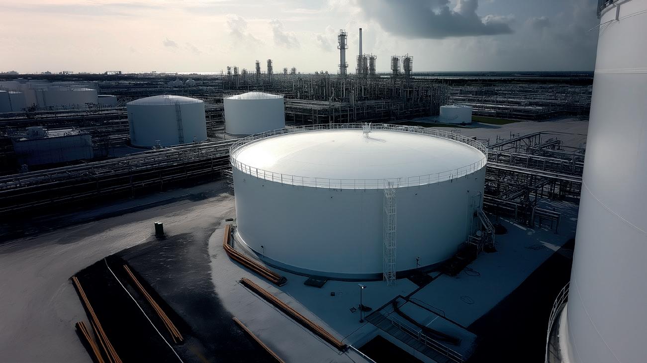
Figure 1. Representative industrial tank configuration suitable for advanced insulative coatings used to reduce heat loss, prevent corrosion under insulation, and improve personnel safety in high-temperature environments.
n Refinery process lines: in caustic or high-chloride environments, such as alkylation units or desalters, the risk of CUI is elevated. Coatings validated to ISO 12944 and ISO 6270-1 provide protection against salt spray and condensation, mitigating the corrosion risk even in severe environments.
n Original equipment manufacturer (OEM) skid systems and retrofits: packaged equipment skids often lack the space or configuration for traditional insulation. Thin-profile insulative coatings – applied at 40 - 80 mils – allow thermal and safety requirements to be met without modifying the asset.
Coatings with dual-function thermal and anti-corrosive capabilities offer performance advantages (Table 1). These also extend to environmental and safety considerations. Many coatings are water-based and contain no reportable volatile organic compounds (VOCs), reducing emissions and simplifying permitting. Their durability and repairability reduce lifecycle waste, and their non-combustible properties can contribute to fire safety planning.
To ensure success, several best practices should be followed:
n Surface preparation: for carbon steel, abrasive blasting and application of a corrosion-inhibitive primer are typically required. Coatings should be applied within the recoat window of the primer.
n Thickness control: wet film and dry film thickness gauges are essential. Each layer is generally applied at ~50 mils wet film thickness (WFT) and allowed to cure for 4 - 6 hrs before additional passes.
n Live system application: some products allow application on surfaces up to 200°F, enabling coating of operational piping or tank exteriors without shutdown.
n Curing and inspection: coatings generally cure in under 48 hrs and can be inspected using standard adhesion and DFT protocols.
While once considered novel, insulative coatings for tanks and piping are gaining mainstream acceptance. A growing number of Fortune 500 facilities and international refining operators have deployed these systems, often reporting:
n 30 - 40% faster installation compared to jacketing systems.
n Verified surface temperature reductions of 70 - 100°C.
n No CUI development over multi-year inspection intervals.
n Reduced worker injuries and improved safety compliance.
As the industry transitions toward decarbonisation, coatings that reduce energy waste while improving safety will play a central role in thermal infrastructure strategy. Especially in ageing facilities with limited space or constrained budgets, these coatings offer a low-disruption pathway to modernisation.
In chilled water systems, condensation and freezing are persistent challenges – especially on exposed piping or in high-humidity environments. Traditional solutions rely on thick insulation layers combined with vapour barriers or costly heat tracing, which add bulk, complicate installation, and often degrade over time. High-performance insulative coatings offer a streamlined alternative. With low thermal conductivity (0.05 W/m·K at ambient) and high emissivity (>0.92), the coating minimises heat gain while radiating surface warmth effectively, preventing cold spots that lead to condensation. The water-resistant finish act as both an insulator and vapour barrier in one, while the high specific heat capacity (1.5 J/g·K) buffers against rapid thermal changes that could trigger freezing. These technologies are ideal for retrofitting chilled water lines in mechanical rooms, data centres, or constrained spaces –eliminating the need for bulky insulation or heat tracing, while maintaining system efficiency and surface dryness.
Industrial tanks and piping represent some of the most heat-intensive and corrosion-prone assets in any process facility. Traditional insulation approaches have served the industry well, but they come with inherent liabilities – from hidden corrosion to labour-intensive repairs.
Integrated insulative coatings offer a science-backed, field-proven alternative. By combining advanced ceramic technology with validated safety and durability metrics, these systems eliminate the root causes of CUI and reduce surface temperatures to personnel-safe levels. As real-world deployments grow and standards like NACE TM21423 become more widely adopted, coatings will be increasingly implemented – not just for new builds, but for the retrofit challenges that dominate today’s industrial landscape.
Fadi Bachir, Owens Corning, outlines key factors to consider when designing an insulating system that defends against corrosion under insulation, while supporting the longevity of equipment used in hydrocarbon processing applications.
While the conditions that lead to corrosion on industrial pipes, tanks, and equipment are generally well understood by professionals in the hydrocarbon processing sector, defending against the effects of these conditions has proven to be a difficult challenge. In a marketplace offering a wide range of insulation systems featuring different value and performance propositions, even experienced specifiers can be uncertain about the optimal system to protect piping, tanks, and equipment used in hydrocarbon processing applications from corrosion.
As a specification manager working with the technical insulation team at Owens Corning, the author

works with facility owners and engineers to help bridge the knowledge gap between the scientific principles that inform the requirements of their projects, and the materials and services that are available in the marketplace. Bridging this knowledge gap early in the design of an insulating system can result in significant savings and potentially increase productivity, safety, and reliability at facilities.
This article will start by considering insulation that can both perform and protect. Insulation is often thought of in the context of supporting thermal energy efficiency or acoustic performance criteria. In order to
reduce thermal losses, it is important to prevent water from remaining inside an insulation system. The thermal conductivity of water is approximately 14 - 25 times higher than most industrial insulation materials. As little as 1% water moisture content in an insulation system can result in a 23% increase in thermal conductivity.
However, beyond the typical thermal performance properties, insulation can also guard against the harmful effects of corrosion under insulation (CUI). Since the presence of liquid water at the metal surface is required for corrosion to occur, an insulation system can defend against CUI if it is able to keep water from reaching or remaining at the surface of a pipe, tank, or other metal substrate.
While it is the liquid form of water that will take part in the corrosion reaction, the actual ingress of the moisture can occur while the water is in liquid or vapour form. It is moisture ingress in vapour form that is particularly difficult to defend against, as the only way to prevent it is to build a vapour-tight system at all locations, even at challenging geometries such as angle iron protrusions and pipe clamps.
For professionals specifying insulation systems at hydrocarbon facilities, industry standards are a common resource. However, there is no comprehensive industry standard for guarding against CUI. The Association for Materials Protection and
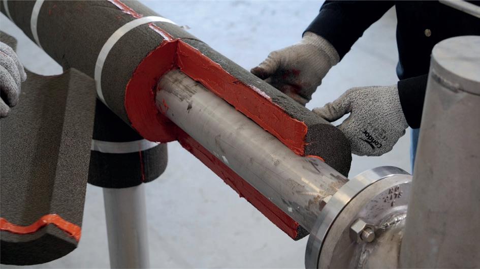
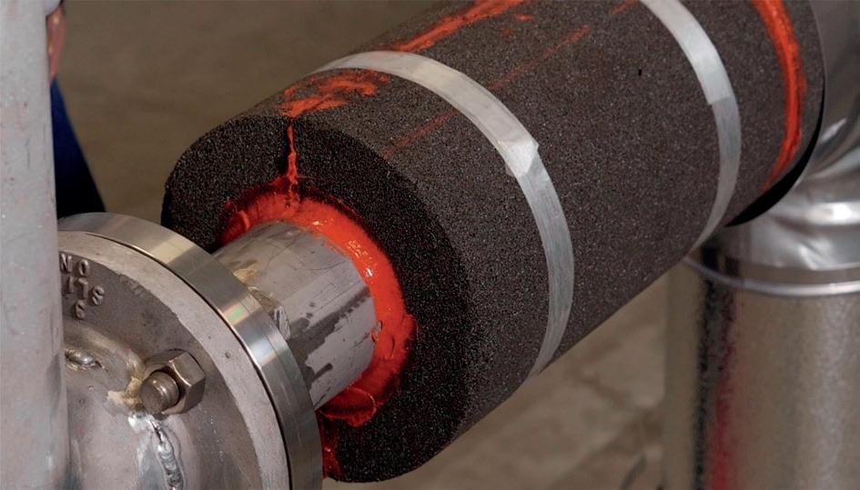
Performance (AMPP) helps to fill this gap. AMPP has a mission and vision to advance material performance to protect society, assets, and the environment, and is a global authority on corrosion mitigation.
AMPP issued document SP0198 ‘Control of Corrosion Under Thermal Insulation and Fireproofing Materials – A Systems Approach’, which states: “the insulation system that holds the least amount of water, and dries most quickly, should result in the least amount of corrosion damage ...” It is important to understand that these are two different objectives. An insulation system can meet one objective or both. SP0198 also does not provide clear instructions for how to ensure that a particular insulation system complies with these objectives. Finally, it should be noted that this document does not address all possible causes of CUI, such as the chemical composition or pH of an insulation system. With this in mind, SP0198 should be considered a broad resource for avoiding CUI, rather than a comprehensive guide addressing all the needs of a specifier.
So, what is the optimal insulating system for hydrocarbon processing facilities? There is no best insulating system for all industrial applications. The material composition, performance properties, and applications of different insulating systems vary greatly. For example, a fibrous material, such as mineral wool, can provide exemplary performance to mitigate industrial noise, but it is not impervious to moisture ingress. Specifying the ideal insulation system requires understanding all the factors at play for the facility and given equipment.
Addressing one or both of the objectives described in SP0198 – holding the least amount of water and/or drying quickly – is a first step in designing an insulating system that defends against moisture. A first question should be: “How robust is the insulation system in defending against moisture ingress? In addition, is it depending only on the caulking on the jacketing?”
Installing a closed-cell, impermeable insulating material in a sealed configuration will help keep moisture from getting into the system where it can contact metal surfaces. Cellular glass insulation is a completely impermeable insulation material that has been in use for more than 60 years and is installed in hydrocarbon processing environments around the globe, including in aggressive environments, such as offshore facilities. Within the insulation system, it is also important to consider how the insulation material works with other system components, such as accessories and coatings, to support the longevity of pipes, tanks, and equipment.
Cellular glass insulation works well with other system components. For example, its compressive strength and closed-cell nature mean that cellular glass insulation can be used with sealants to reliably seal against moisture ingress at susceptible locations (such as protrusions, low points, etc.).
Owens Corning has developed specific CUI mitigation accessories that complement cellular glass, including spacers and a low-viscosity sealant. The sealant is formulated to flow easily across the entire thickness of the insulation material during installation, delivering durable protection against water ingress.
In contrast, fibrous or dusty materials may prevent achieving good adhesion or reliable sealing against moisture ingress.
Soft materials compress and place additional movement requirements on other sealing components like caulking.
Working with engineers and specifiers at hydrocarbon facilities, it is not uncommon to come across catastrophic CUI damage on above-ambient tanks. In most instances, these damaged tanks are insulated with a permeable and compressible insulation system that is not installed in a sealed configuration. Although engineers are typically advised that water in vapour form should eventually find its way out of such unsealed insulation systems, experiences have shown that in many cases the insulation system never fully dries. Furthermore, a permeable insulation material may actually facilitate moisture ingress through condensation, as protrusions can introduce a cool surface inside the insulation system, especially during cold weather, even for an above-ambient system. Once moisture enters the system, it can spread through the permeable material and damage large areas, unless additional compartmentalisation is specified.
These unsealed systems typically rely on metal jacketing and caulking to provide the primary defence against liquid water infiltration. Caulking can present a particular concern. Over time, UV exposed caulking will begin to degrade, and even recently installed caulking materials have limited contraction/expansion capabilities. Due to the compressible nature of the insulation underneath the jacketing, mechanical force or wind may also generate movement beyond what the caulking can accommodate. For these reasons, an unsealed system is likely to cause problems over the long term. Eventually, water will find its way in. With tanks, liquid generally infiltrates at protrusions or unrepaired openings from maintenance activities. Once inside, water accumulates at the tank base. An unsealed approach goes against the AMPP principle of holding “the least amount of water” and results in lower energy efficiency compared to a sealed system.
Even when such insulation systems are designed to dry out quickly, the recurrence of water repeatedly entering the system and drying out can result in substances being leached and deposited on the metal surface. The increasing concentrations can cause extreme pH values, potentially threatening assets and processes.
Impermeable cellular glass insulation is an excellent material to control moisture. For decades, the impermeable nature of FOAMGLAS® insulation has made it a proven choice for below-ambient applications, where vapour drive will be towards the metal surface. In these situations, the best choice is to build a sealed system to prevent moisture ingress. These same proven practices can often be the best defence against CUI. Owens Corning offers both a Sealed and a Spacer FOAMGLAS® system to meet the corrosion mitigation objectives described in AMPP document SP0198.
The sealed system ensures that the insulation material –not caulking on the jacketing – serves as the primary defence against moisture ingress. In the FOAMGLAS® sealed system, due to the compressive strength of FOAMGLAS®, caulking only has to accommodate the movement in the jacketing and not the physical compression of the insulation material itself. Sealant is applied underneath the jacketing, shielded from UV exposure, to maintain its performance for many years. If a breach occurs,
the inherent compartmentalisation in the system helps to limit the area where CUI damage can take place.
For environments where water presents a constant concern – such as offshore applications – the Spacer System uses spacer technology to create a drainage path in the air gap between the insulation and pipe. This gap helps minimise the potential for water to remain in contact with the pipe. Drain holes are used to allow the moisture to exit the system.
While material science and the physics of water migration help explain the benefits of a sealed system, some of the most resounding examples come from the field. An energy facility in Canada seeking to save on material costs opted for a permeable mineral wool insulation on an ambient process line. When moisture ingress was discovered, it was found that the permeable, fibrous insulation was very damp, reducing process efficiency and contributing to performance issues that necessitated a premature replacement of the system. The facility replaced the permeable insulation with a sealed cellular glass insulation system and the moisture ingress was eliminated.
While keeping moisture out of the system is the top priority when defending against corrosion, compressive strength, thermal performance, manufacturer support, and safety should also be considered when specifying insulating systems.
The compressive strength of an insulating material can be a key factor to consider when insulating tank bases in hydrocarbon applications. The high compressive strength of Owens Corning FOAMGLAS® cellular glass insulation is well suited for installation in the tank base, where it can help withstand the weight of contents and support thermal performance. The hot tank base is generally the one part of the system that is constantly in contact with stored contents. As such, thermal loss is an ever-present risk. By insulating the tank base, energy efficiency is dramatically improved. In comparison to soil or sand, insulating the tank with this insulation typically saves 67 - 73% more energy.
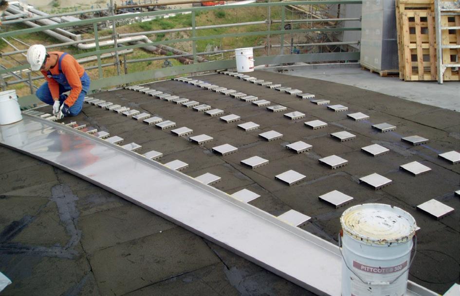
Figure 3. As each piece of insulation is adhered to the surface, should any part of the system be damaged, or even removed for inspection/maintenance and left without being repaired, water can only reach that specific piece of insulation.
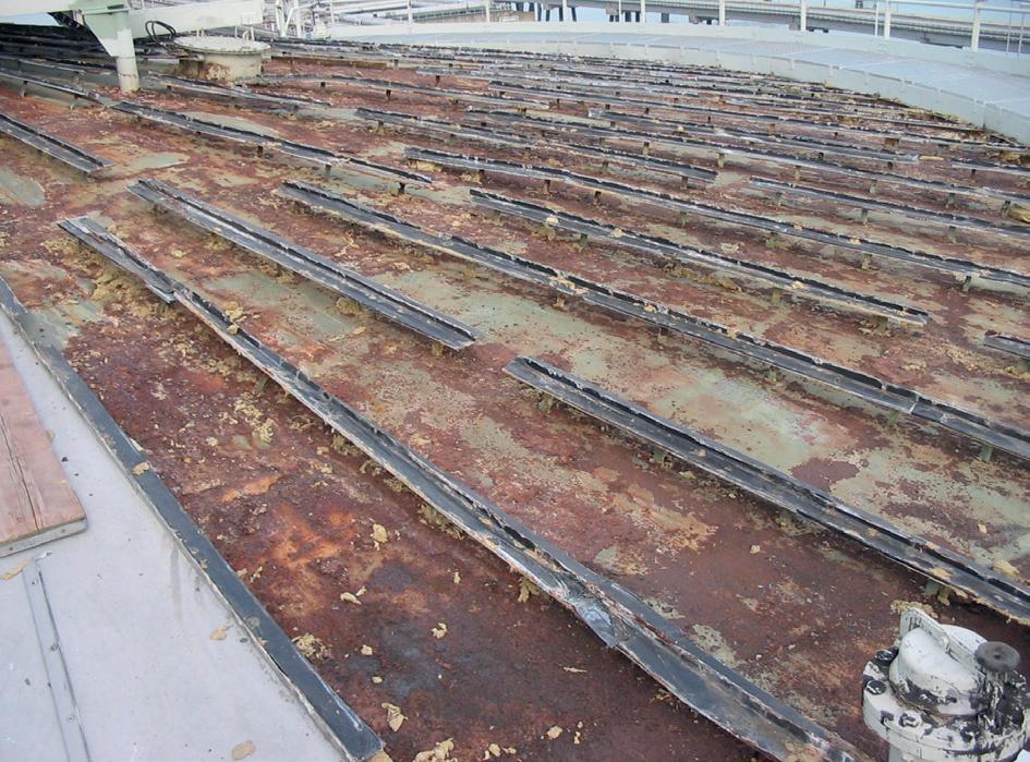
An often overlooked but important component when specifying materials is manufacturer support during the specification, construction, and post-construction phases, and whether the insulation manufacturer offers support and guidance through its people and resources. It is important to support material specification, including on-site energy audits, technical services consultation, and installation training programmes. Owens Corning can provide NIA-certified energy appraisers and insulation inspectors who work with customers to inspect in-service insulation systems and identify areas to
improve process efficiency and reliability. A manufacturer who is willing to inspect a system when a problem is suspected is a tremendous asset to a facility owner. Ice build-up or ongoing problems with CUI are telltale indicators that a facility should have its system inspected.
Safety will always be the top priority on a hydrocarbon processing jobsite or facility. These facilities involve high-temperature processes and may store volatile and combustible chemicals. Again, material composition matters. FOAMGLAS® cellular glass insulation is composed of millions of sealed glass cells. It is inorganic, non-combustible, and does not absorb liquids. The cellular glass insulation can be configured as a solution for various fire-related standards, such as UL1709 for structural steel and pipelines, API 521 for PRV sizing, and ISO 22899 for jet fire. Assemblies are tested in accredited labs to ensure compliance with standards As just one material can meet the various criteria, specifying FOAMGLAS® can reduce the number of different materials on a site. This tends to correlate with higher installation quality, as installers become more accustomed to working with that one material.
Specifying the ideal insulation system for hydrocarbon processing facilities requires attention to numerous, integrated factors. The behaviours and practices of the manufacturer also affect safety and influence safety culture. Industry guidelines, material science, and manufacturer support are all important for engineers to consider in designing an insulating system that defends against CUI while supporting the longevity of piping, vessels, and equipment used in hydrocarbon processing applications.