ENERGY GL BAL

ENERGY GLOBAL
CONTENTS
03. Comment
04. Africa's energy paradox
Prakash Sharma, Vice President, Head of Scenarios and Technologies, and Roshna N., Research Analyst, Energy Transition, Wood Mackenzie, explore the various pathways for Africa’s energy future as it attempts to power development in a climate-restrained world.

10. Magnetic gears: A game changer for wind turbines
The global expansion of renewable energy is accelerating the search for solutions that are efficient, resilient, and sustainable. Among the range of emerging technologies, magnetic gears are increasingly attracting attention. Gary Rodgers, CEO of Magnomatics, explains the benefits of magnetically-geared systems for the wind industry.
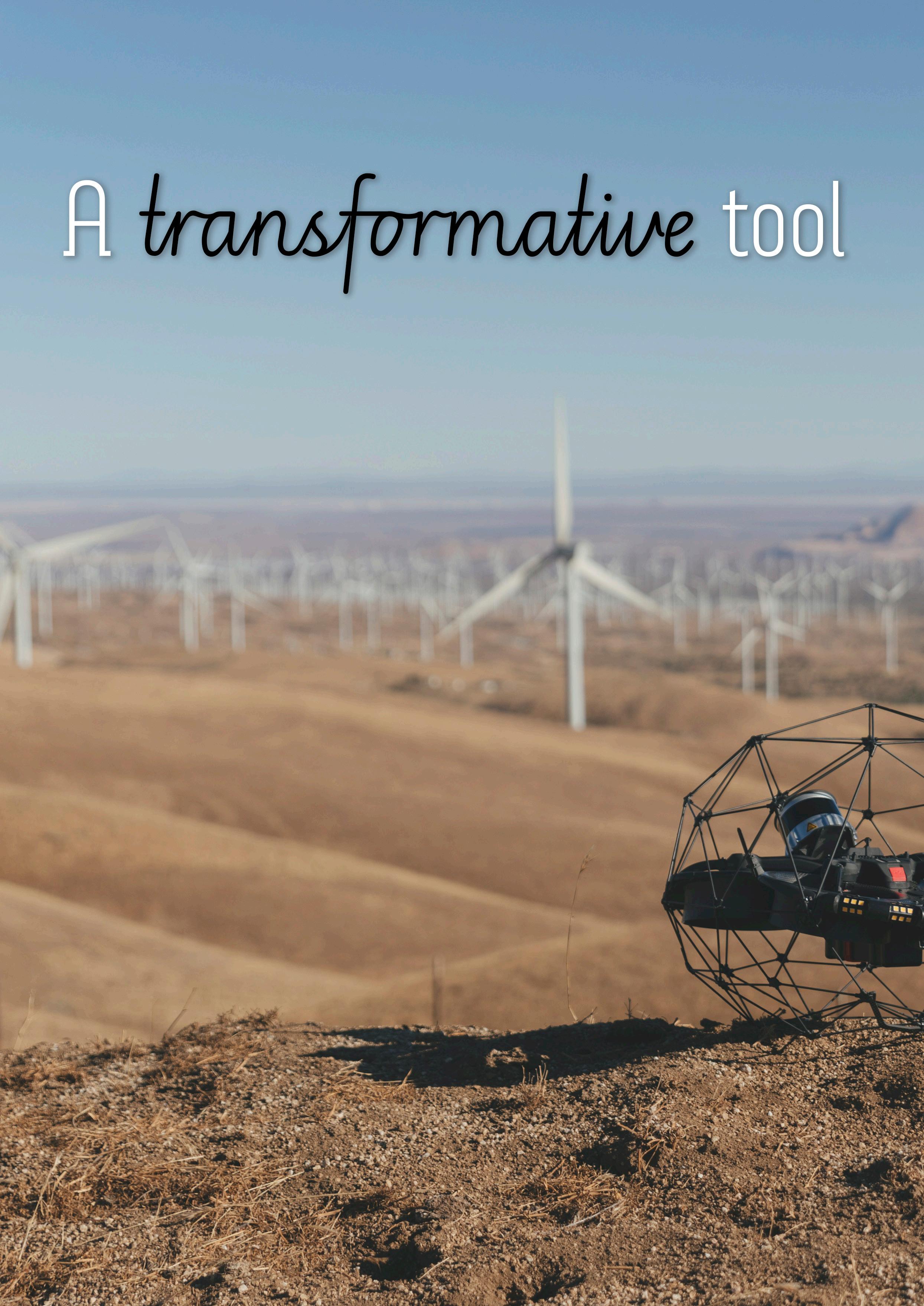
14. A transformative tool
Matteo Saglia, Flyability, Switzerland, answers the question: How can drones help maintain critical energy infrastructure?
20. Enabling next-generation mega turbines with innovations in offshore floating wind platforms
Jon Salazar, CEO, Gazelle Wind Power, addresses the growing need for larger turbines, and considers the challenges and opportunities that come with them.
24. When the ocean delivers the current Although commercial exploitation of wave energy is still in its infancy, it has the potential to contribute substantially to a stable and reliable electricity grid based on renewable energies

being attained within just a few years, argue Michael Kocher and Frank Fladerer, Bachmann electronic GmbH.
30. Taking centre stage in the energy transition
Fernando Gimenez, Product Manager, Sulzer, examines current developments in geothermal energy plants and how the company is supporting the growth of enabling technologies.
34. Keeping fluids cool in the hottest wells
Michael Adams, Mark Canlas, and Ted Moon, NOV, highlight groundbreaking temperature management technologies that improve drilling efficiencies in the deepest, hottest geothermal applications.
40. Preventing water wastage in the geothermal energy industry
To reach its full potential, the geothermal energy sector cannot afford to be wasteful – especially with water.
Alasdair Carstairs, Business Unit Manager, OSSO, identifies the changes that must be made within the geothermal energy industry to achieve progress.
44. Charging ahead
Dr Dustin Bauer, Associate, Reddie & Grose, provides an overview of the race to innovate battery energy storage systems.
50. The economics of electrification
Paul Cairns, Charge Offshore and MJR Power & Automation CEO, discusses the economic case for electric operations and maintenance fleets and explores the need for robust charging infrastructure to support the transition.
54. Global news
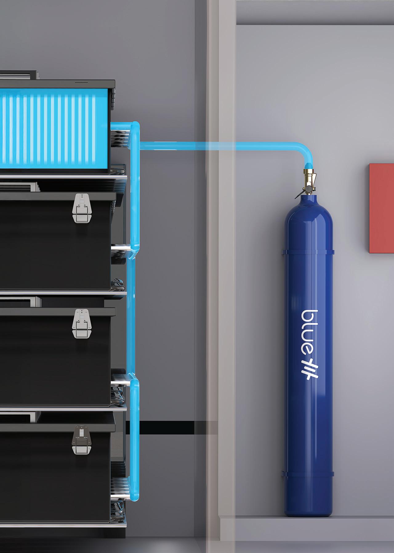
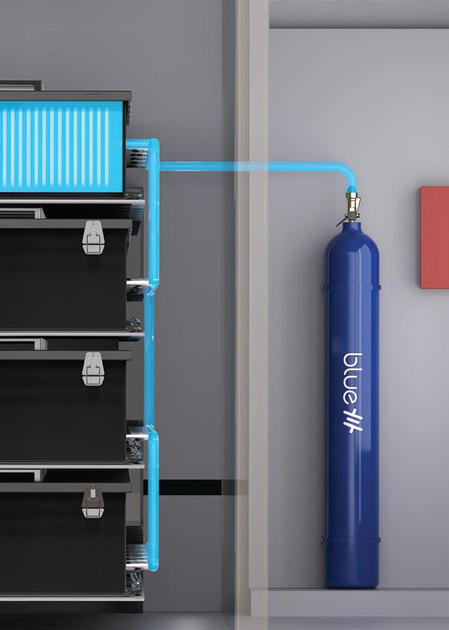
Thermal runaway of a lithium-ion battery within a battery energy storage system (BESS) is an extremely dangerous hazard that can strike at any time. To protect nearby people, property, the environment, and meet UL9540A compliance, Fike is the only organisation in the world that offers comprehensive BESS consultancy, testing, system design, explosion control, gas detection, and thermal management solutions, including Fike Blue: the first third-party tested system proven to suppress battery fires and cascading thermal runaway. Learn more: fike.com/battery-protection
Still pioneers.
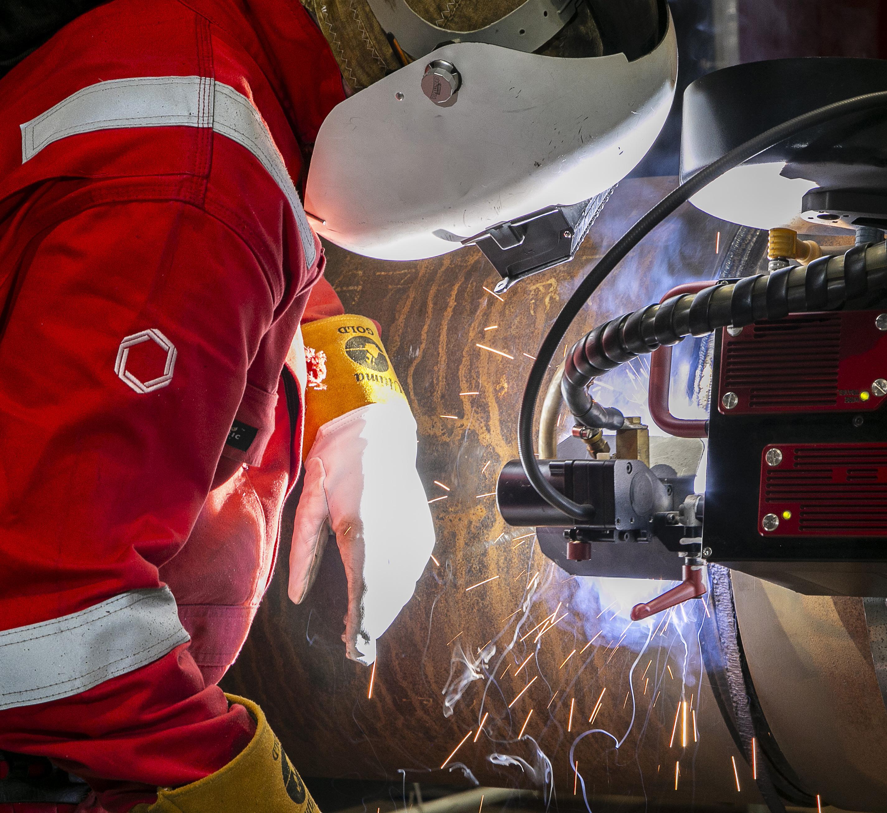
Across energy and critical infrastructure, we bring expertise where complexity is highest, partnering with globally local teams and leveraging unrivalled proprietary technologies. Like the M-500 Single Torch External Welding System, seamlessly integrated with Data 360 our cloud-based digital platform that analyses, and visualises your project performance data in real time. We move projects forward, no matter the challenge. We’re here to partner on how our specialist welding and coating solutions can help you power tomorrow.


MANAGING EDITOR
James Little james.little@palladianpublications.com
SENIOR EDITOR
Elizabeth Corner elizabeth.corner@palladianpublications.com
EDITOR
Jessica Casey jessica.casey@palladianpublications.com
EDITORIAL ASSISTANT
Abby Butler abby.butler@palladianpublications.com
SALES DIRECTOR
Rod Hardy rod.hardy@palladianpublications.com
SALES MANAGER
Will Powell will.powell@palladianpublications.com
PRODUCTION DESIGNER
Siroun Dokmejian siroun.dokmejian@palladianpublications.com
HEAD OF EVENTS
Louise Cameron louise.cameron@palladianpublications.com
EVENT COORDINATOR
Chloe Lelliott chloe.lelliott@palladianpublications.com
DIGITAL EVENTS COORDINATOR
Merili Jurivete merili.jurivete@palladianpublications.com
JUNIOR VIDEO ASSISTANT
Amélie Meury-Cashman amélie.meury-cashman@palladianpublications.com
DIGITAL ADMINISTRATOR
Nicole Harman-Smith nicole.harman-smith@palladianpublications.com
DIGITAL CONTENT COORDINATOR
Kristian Ilasko kristian.ilasko@palladianpublications.com
ADMINISTRATION MANAGER Laura White laura.white@palladianpublications.com
Editorial/Advertisement Offices: Palladian Publications Ltd
15 South Street, Farnham, Surrey, GU9 7QU, UK +44 (0) 1252 718 999 www.energyglobal.com
COMMENT
Jessica Casey Editor
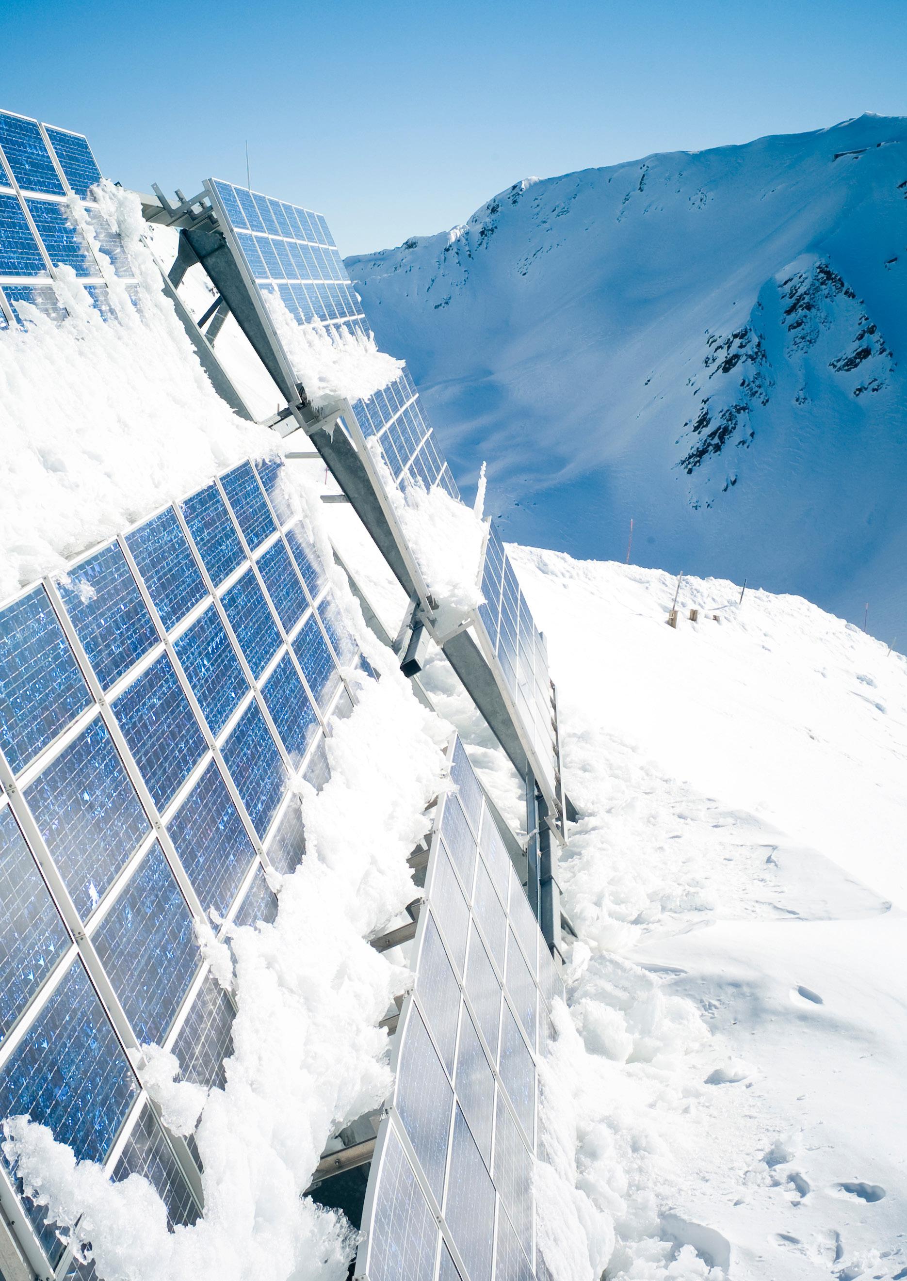
Winter is finally here in the Northern Hemisphere. As we wind down towards the end of 2025, the days are darker, shorter, and colder. With this comes a higher demand for energy and grid stability.
The EU’s primary energy consumption (total energy demand within a country, including losses) in 2024 is estimated to have increased by 1.3% compared to 2023.1 The share of renewable energy in the EU has more than doubled since 2005,1 with one-quarter of all final energy consumed in the EU obtained from renewable sources in 2024.2 However, meeting the new minimum EU target for renewable sources of 42.5% by 2030 will still require a vast expansion of renewable deployment,2 despite the progress and additional capacity that has been actualised in recent years.
According to the European Environment Agency, solid, liquid, and gaseous biomass formed the largest category in 2024, with wind, hydropower, and solar photovoltaics (PV) accounting for the other three largest sources of renewable energy. However, with the population growing and no indication that electricity demand will decrease anytime soon, the energy mix will have to be diversified even more in order to ensure that this is met, sustainably.
There are some renewable sources that are currently being underutilised or are currently being developed. For example, ocean energy (wave and tidal). While currently more expensive than other renewables, tidal is moving towards a cost reduction. Although dependent on location and available landscapes, current statistics suggest a low operational capacity compared to potential. With 25 GW of accessible wave energy capacity and 11 GW of tidal stream energy,3 the UK is one of most promising regions for marine renewables,
and a leader in the wave and tidal sector – it is estimated that tidal could provide 11% of the UK’s electricity by 2050.4 In 2025, the UK government launched the Marine Energy Taskforce (MET) with the aim of unlocking the country’s vast wave and tidal energy potential. The initiative will focus on site development, financing, innovation, and supply chain growth.3 In this issue, Bachmann electronic GmbH outlines wave energy’s potential to contribute to a stable and reliable electricity grid, and looks at some current projects that provide a positive outlook for this energy source.
Another underutilised but abundant resource is geothermal energy. Several technologies exist, with varying degrees of maturity. The overall share in the EU’s renewable energy mix is small in comparison to others (e.g. wind and solar), but it has the potential to grow. However, geothermal has the second-largest potential for electricity-generating capacity after solar PV, and almost three times that of onshore wind and more than five times that of offshore wind. With the energy potential increasing as you reach deeper and hotter resources, almost every region has technically suitable resources once they hit 7000 m.5 Articles from Sulzer, NOV, and OSSO examine current developments in geothermal energy plants, look at temperature management technologies that improve drilling efficiencies in the deepest geothermal applications, and discuss the changes that need to be made within the industry to achieve progress, respectively.
The world is full of renewable resources for us to meet demand without compromising on sustainability and emissions targets; it’s just up to us to figure out how we can best utilise them.
References
References available upon request.
Prakash Sharma, Vice President, Head of Scenarios and Technologies, and Roshna N., Research Analyst, Energy Transition, Wood Mackenzie, explore the various pathways for Africa’s energy future as it attempts to power development in a climate-restrained world.
As Africa’s economy surges towards US$7.7 trillion by 2050, up from US$3 trillion in 2024, the continent stands at an unprecedented energy crossroads. Development imperatives collide with climate urgency. With 42% of the continent’s 1.4 billion people lacking electricity access and abundant untapped resources in gas, oil, and renewable energy, Africa faces a unique challenge: providing energy to hundreds of millions of people whilst contributing to global climate goals.

Wood Mackenzie’s ‘Energy Transition Outlook: 2024 – 25’ reveals four distinct pathways for Africa, ranging from a catastrophic 3˚C delayed transition to an ambitious 1.5˚C net-zero scenario. The continent’s emissions share will nearly double from 3.5% to 6.5% globally by 2050 in the base case. This trajectory makes Africa’s energy choices crucial for a sustainable future.
Improving clean energy access remains a clear priority across the continent. African nations must meet soaring

demand whilst lowering indoor air pollution and mitigating health risks. This dual challenge requires immediate action and long-term strategic planning. The stakes extend far beyond regional boundaries.
Realising Africa’s climate and development objectives requires unprecedented low-cost financing innovation. Strategic deployment of the continent’s vast untapped renewable resources offers one pathway forward. Fossil fuel reserves could also fund the transition through careful management. These resources represent Africa’s competitive advantage in the global energy transformation. This extends beyond an African story alone – it represents the defining energy transition of current times.
Economic development vs climate change
Africa’s energy story defies simple narratives. The continent that holds nearly 10% of global LNG supply also has 630 million people without electricity access. This paradox defines both the challenge and extraordinary opportunity ahead.
Recent trends underscore the complexity. Oil and gas production in Sub-Saharan Africa grew 5% in 2024, driven by Nigeria, Senegal, Congo, Mozambique, and Côte d’Ivoire. Yet renewable installations declined, with solar capacity additions dropping to 3.5 GW from 4 GW in 2023. Most clean energy development remains concentrated in South Africa, highlighting uneven progress.
Africa’s GDP will grow from US$3 trillion in 2024 to US$7.7 trillion by 2050, driven by its service sector and burgeoning working-age population. This economic expansion occurs as the continent’s population increases 1.7 times by 2050, creating massive energy demand precisely when the world demands rapid decarbonisation. However, Africa’s per capita energy consumption remains far below global averages – roughly one-seventh that of China and one-tenth that of the US.
Four pathways to Africa’s energy future
Wood Mackenzie’s integrated analysis presents four distinct scenarios illuminating the complexity of Africa’s energy future. Each pathway reflects different levels of global co-operation, policy ambition, and investment commitment.
Delayed transition scenario
The delayed transition scenario paints a sobering 3˚C warming world where geopolitical tensions and reduced policy support stall decarbonisation efforts for five years. Governments prioritise energy security over global co-operation, driving up technology costs and delaying the transition. Africa reaches net zero only by the early 2080s, with emissions continuing to rise until the early 2030s.
Base case scenario
The base case scenario represents Wood Mackenzie’s most likely outcome, assuming current policies evolve gradually towards a 2.5˚C warming trajectory. Africa achieves net zero by 2080, with emissions beginning to decline around 2027. This scenario incorporates natural policy evolution and
technology advancement, reflecting the inertia inherent in global energy systems.
Country pledges scenario
The country pledges scenario assumes announced net-zero commitments materialise despite near-term challenges. This pathway aligns with below 2˚C warming, with Africa achieving net zero by 2070 through incentive-based policies driving technological innovation and competition.
Net-zero
scenario
The net-zero scenario requires immediate global action to limit warming to 1.5˚C. Africa could potentially achieve net zero before 2060, benefitting from unprecedented global co-operation, rapid technology deployment, and massive investment flows. This pathway demands that sovereignty, security, and sustainability challenges are addressed in time and at the required pace.
The bioenergy transformation imperative
Perhaps nowhere is Africa’s energy complexity more evident than in its relationship with bioenergy. Traditional biomass currently accounts for 81% of residential, commercial, and agricultural energy demand across the continent. Whilst this might appear sustainable, the reality involves significant health risks from indoor air pollution and environmental degradation from unsustainable harvesting practices.
The transition away from traditional bioenergy presents both opportunity and challenge. Moving to electricity offers substantial efficiency gains, reducing primary energy required to meet demand whilst eliminating health risks. However, even in the base case scenario, bioenergy’s share in the residential sector only declines to 70% by 2050, primarily because clean fuel alternatives fail to scale rapidly enough to match population-driven demand growth.
Under the net-zero scenario, more aggressive action reduces bioenergy’s share to 50% by 2050, accompanied by significant deployment of efficient cookstoves. This transition requires not just technology deployment, but fundamental changes in energy infrastructure, financing mechanisms, and consumer behaviour.
Transforming Africa’s mineral potential into prosperity
Africa holds vast reserves of critical minerals including cobalt, manganese, graphite, platinum, and rare earths. These resources are essential for batteries, electric vehicles, and other clean technologies. However, limited local processing capacity has long restricted Africa’s participation in higher-value global supply chains.
The Democratic Republic of Congo (DRC) produces 70% of the world’s cobalt, yet nearly 60% is processed in China. This imbalance limits economic gains and job creation within Africa. The continent exports wealth whilst importing finished products at premium prices.
Several nations are now adopting policies to restrict unprocessed mineral exports. Namibia, Zimbabwe, the DRC, and Gabon aim to capture more value domestically.


Thermal Runaway Solutions
LAB-TESTED, FIELD-APPROVED


Fike delivers complete BESS protection – thermal management, explosion control, custom gas detection, system design, testing, and consultancy – all engineered to perform when it matters most. Our solutions meet UL 9540A requirements and safeguard people, first responders, and the environment from the risks of thermal runaway.
These policies represent a strategic shift towards downstream processing that could transform Africa’s position in global supply chains.
Realising this potential requires substantial investment in mineral processing and battery manufacturing. Related infrastructure development remains equally critical. Strategic co-operation among African leaders will prove vital for success.
Electricity demand: The critical multiplier
Electricity demand emerges as the critical metric across all scenarios. By 2050, demand will exceed 2200 TWh in the base case – double current generation. Under more ambitious scenarios, demand increases three-fold to four-fold, primarily addressing the existing energy deficit whilst supporting economic growth.
This surge reflects Africa’s fundamental development challenge. The continent’s burgeoning working-age population and service sector growth create massive energy needs at a time when rapid decarbonisation is being demanded. Traditional approaches that separate energy access from climate goals are no longer viable.
Gas demand increases from 157 billion m3 in 2024 to 201 billion m3 in 2050 in the base case, mainly due to growing consumption in the power sector. In the net-zero scenario, gas demand peaks around early 2030 and declines long-term as renewables gain prominence in power generation. Oil demand grows in the base case, with internal combustion engine vehicles increasing from 36 million units to 63 million by 2050.
Untapped potential across the energy spectrum
Africa’s renewable energy potential remains largely under-utilised despite abundant solar, wind, and hydroelectric resources. Kenya exemplifies this potential, ranking among the world’s lowest-cost geothermal developers with 90% of electricity generated from non-fossil sources. The country’s estimated 10 000 MW geothermal potential remains largely untapped, with current installed capacity below 985 MW.
Similar opportunities exist across Africa’s diverse energy resources. The continent already accounts for nearly 10% of global LNG supply, with expansion potential in West Africa and Mozambique offering pathways to boost export revenue whilst supporting domestic demand. The challenge lies in creating enabling environments that attract investment whilst ensuring benefits reach those who need them most.
Africa’s future contribution to the global energy transition will increasingly come through hydrogen exports and nature-based solutions. By 2050, the continent has the potential to significantly scale blue and green hydrogen production, positioning it as a key player in the global clean energy economy whilst generating export revenues to fund domestic energy access. However, limited policy support and weak regulatory frameworks risk undermining competitiveness.
The financing bottleneck
The transition’s biggest obstacle remains financing. Africa desperately needs substantial external sources of low-cost capital, yet project costs often reach three times those of
other regions. The continent has received only a fraction of the promised annual US$100 billion in climate finance from OECD countries, creating a critical bottleneck.
This financing gap reflects deeper structural challenges. Energy security concerns highlighted by geopolitical tensions, growing discomfort with Chinese clean technology dominance, and the mounting US$3.5 trillion annual investment requirement for global low-carbon infrastructure all constrain capital flows to African projects.
The interconnected nature of these challenges demands innovative solutions. Fossil fuel and critical mineral revenues could provide the capital needed to finance renewable energy deployment and grid infrastructure. However, this approach requires careful management to avoid carbon lock-in and ensure that hydrocarbon revenues genuinely support rather than delay the energy transition.
The interconnected imperative
For European energy leaders, Africa represents both opportunity and responsibility. Success requires addressing the three critical factors currently holding back the transition discussed above; energy security concerns, discomfort with Chinese clean technology dominance, and the investment requirements for low-carbon infrastructure.
These challenges are deeply interconnected. Energy security concerns drive continued fossil fuel investment, whilst technology supply chain concentration creates vulnerability. The scale of required investment demands innovative financing mechanisms that can mobilise both public and private capital at unprecedented levels.
Africa’s share of global emissions is projected to increase from 3.5% currently to 6.5% by 2050 under current trajectories. Getting the transition right will determine not only the continent’s prosperity, but its contribution to global climate goals. The interconnected nature of today’s energy system demands integrated analysis and co-ordinated action across commodities, technologies, and markets.
Decoding the transformation ahead
More than just hitting climate targets, clean energy can help bring real prosperity to Africa whilst closing the huge energy gap that a reliance on fossil fuels has not solved. At the same time, Africa’s clean energy transition plays a vital role for the world’s path to net zero, from critical minerals and green hydrogen to nature-based carbon offsets.
Understanding how oil and gas revenues can fund renewable deployment, how industrial development affects electricity demand, and how global supply chains impact local energy costs requires an interconnected view of the energy landscape. Only by understanding these connections can Africa’s energy crossroads be navigated and the US$7.7 trillion opportunity ahead unlocked.
The stakes could not be higher. As Africa’s emissions share is projected to nearly double, the continent’s energy choices will play a pivotal role in determining whether climate goals can be achieved. The transition to low-carbon technologies offers Africa an unprecedented opportunity to expand energy access in ways that fossil fuels have failed to deliver.


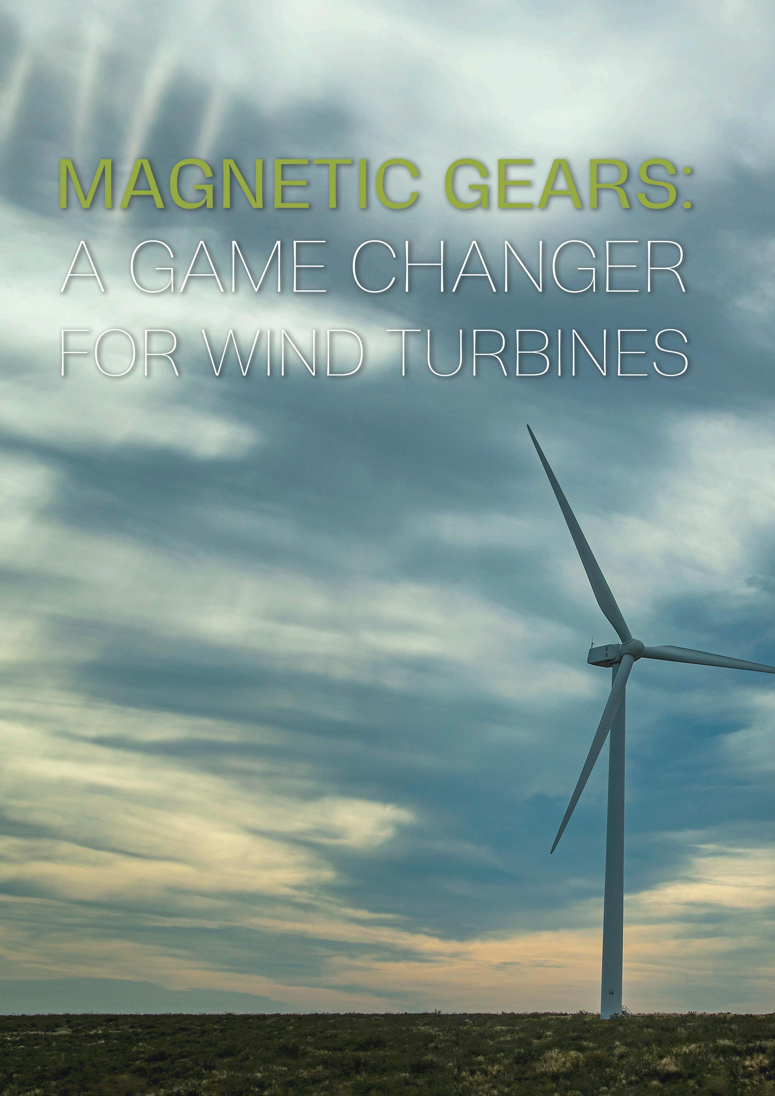
Figure 1 . Magnetic gears are proving to be a defining technology for wind turbine efficiency, robustness, and sustainability.
The global expansion of renewable energy is accelerating the search for solutions that are efficient, resilient, and sustainable. Among the range of emerging technologies, magnetic gears are increasingly attracting attention. Gary Rodgers, CEO of Magnomatics, explains the benefits of magnetically-geared systems for the wind industry.
The wind industry is experiencing unprecedented growth, cementing its role as one of the cornerstones of the global energy transition.
Across onshore and offshore markets, installed capacity continues to rise y/y, driven by falling costs, government policy, and the urgent need to decarbonise power systems.
As turbines scale ever larger and are deployed in more challenging environments, drivetrain performance has emerged as a decisive factor in the industry’s success. The drivetrain is the beating heart of every turbine: it must transform the relatively slow rotation of blades into usable electrical power with high efficiency, robustness, and longevity. Yet existing solutions present difficult trade-offs.
Mechanical gearboxes can multiply torque effectively, but they remain one of the most common points of failure. Direct-drive systems eliminate gears altogether, but at the cost of very large, heavy machines and an increased reliance on rare-earth magnets. The search for drivetrain technologies that combine efficiency, reliability, and scalability is therefore critical to unlocking the full potential of wind energy.
Magnetic gears, a technology that has matured significantly over the past two decades, are emerging as

a third way – one that blends the compactness of geared systems with the simplicity and reliability of direct drive.
How magnetic gears work
Unlike conventional gears, which transmit torque through physical contact between gear teeth, magnetic gears use magnetic fields to couple input and output shafts. Torque is transferred without contact, eliminating friction, lubrication, and wear. This seemingly simple change offers profound implications for performance, durability, and cost.
Magnetically-geared systems are especially suited to applications where high torque and low speed are required. Their topology maximises the torque capability of the drivetrain, overcoming the limitations of standard direct-drive electrical machines. In practice, the magnetic gear element provides the same uplift in output torque as a single-stage mechanical gear. Furthermore, with the central gear element fully integrated, the dual use of the inner rotor – combined with the relatively modest mass of the pole-piece rotor array and outer magnets – produces a design that
is compact, lightweight, and less prone to failure than its mechanical equivalent.
A magnetic gear typically consists of three key elements: a high-speed rotor, a low-speed rotor, and a modulating pole-piece rotor that sits between them. The arrangement of permanent magnets and pole pieces creates a field interaction that couples the rotors and multiplies torque in much the same way a mechanical gearbox does, yet without direct contact.
This architecture delivers several inherent advantages. Since there is no contact, there is no wear on gear teeth, and no requirement for lubrication systems. Vibration and noise are reduced, improving operational smoothness. Efficiency is typically higher, especially at low speeds.
Reliability is also enhanced by the fault-tolerant nature of magnetic gearing. The coupling behaves as a passively resettable torque fuse, slipping under overload conditions to protect the drivetrain without the need for shear pins or clutches. At the same time, advances in winding design contribute to improved thermal management. Precision wire placement and modular stator construction increase thermal conductivity and minimise eddy current losses, reducing heat rejection requirements and further enhancing overall efficiency.
Advantages for wind turbines
For wind energy applications, these benefits align directly with the industry’s most pressing needs. Reliability is enhanced because the primary failure modes of mechanical gearboxes – gear tooth wear, lubrication breakdown, and bearing damage – are eliminated. As a result, maintenance costs are reduced, which is particularly valuable in offshore settings where intervention is costly and logistically challenging.
The compactness of magnetic gear systems translates into smaller nacelles, reducing loads on towers and foundations. At the same time, efficiency improvements increase energy yields, contributing to lower levelized cost of energy (LCOE).
From a manufacturing standpoint, magnetic gear systems are cost-effective. However, they do not just
tend to be less expensive to produce, but also more sustainable since they use fewer materials overall.
Case study: The CHEG project
While magnetic gears are conceptually elegant, demonstrating their practicality at utility scale has required concerted research and development. A landmark initiative in this regard was the Compact High Efficiency Generator (CHEG) project, part of the EU Horizon 2020 DemoWind programme funded by the Department for Business, Energy & Industrial Strategy (BEIS).
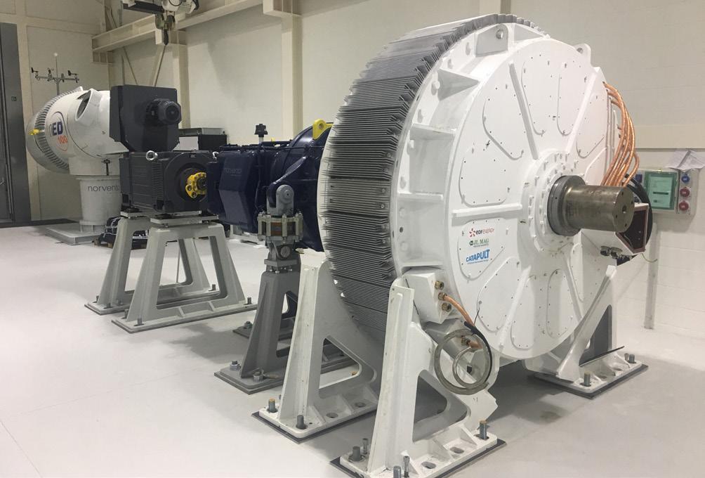
The project’s aim was to advance generator technology for wind turbines by reducing both capital costs and operating costs. At its heart was the innovative Magnomatics Pseudo Direct Drive (PDD)® generator incorporating the largest magnetic gear ever built, rated at 200 000 Nm of input torque. The previous largest had been just 20 000 Nm.
Building a machine of this scale posed several challenges. Innovative modular assembly techniques were developed for stators, pole-piece rotors, and high-speed rotors, enabling construction at size while remaining scalable for even larger machines. The manufacturing phase, carried out in partnership with Wolong Laurence Scott, required specialist tooling to handle powerful permanent magnets safely and effectively, all under ISO 9001:2015 quality management standards.
Testing took place at the ORE Catapult facility in Blyth, UK, using a 1 MW dynamometer. Results were highly encouraging: the generator delivered high efficiencies, exhibited low vibration, and responded dynamically to torque and speed changes. Independent validation by BVG Associates concluded that at the 10 MW scale, PDD technology could reduce LCOE by 2.6% compared with direct-drive systems and 2.8% compared with mid-speed geared drivetrains.
The project’s success demonstrated feasibility at scale and generated strong interest from turbine manufacturers. For developers and operators, the benefits are tangible. Reduced maintenance requirements directly translate into lower operational costs, particularly offshore where interventions are expensive and logistically challenging. Improved efficiency leads to higher energy yields, while compactness reduces structural demands on towers and foundations. Importantly, these advantages combine to lower the LCOE – a critical metric that underpins project financing and government policy decisions.
Wider applications
While wind energy is one of the leading sectors driving uptake of magnetic gear systems, the potential applications extend far beyond.
In tidal and ocean energy, conditions are harsh: equipment must operate underwater, exposed to
Figure 2 . The PDD generator has an input torque of 200 000 Nm and includes the largest magnetic gear ever made.
saltwater corrosion, fluctuating currents, and difficult access for servicing. Here, the advantages of contactless torque transfer are particularly significant. Magnetic gears require no lubrication and minimal maintenance, reducing the need for expensive offshore interventions. Their ability to deliver torque efficiently at low speeds makes them ideally suited to tidal environments, where currents may be variable and relatively slow. By improving reliability and reducing costs, magnetic gears could help unlock the commercial viability of tidal power.
The push to decarbonise shipping is also creating strong demand for efficient electric drive systems. Magnetically-geared thrusters can provide the compactness, scalability, and reliability required, whether for subsea vehicles, ferries, or larger ocean-going vessels. By eliminating complex mechanical gear trains, they reduce maintenance demands while improving environmental performance.
Additionally, in mobile and off-grid power generation, the compactness and durability of magnetically-geared machines make them well suited to challenging environments which require resilient systems that can deliver power reliably with limited maintenance support. Magnetic gears, with their vibration tolerance and contactless design, provide precisely this capability.
In industrial plants, where continuous operation is essential and downtime is costly, magnetic gears offer high reliability and low maintenance. Industries such
as chemicals, steel, and cement, which rely on high-torque machinery, could benefit from systems that minimise wear and mechanical losses. Contactless torque transmission ensures robust performance even in harsh environments, while improved efficiency reduces energy consumption and emissions.
Across all these sectors, the unifying theme is resilience and sustainability. By reducing wear, eliminating lubricants, and improving efficiency, magnetic gears contribute to more robust and environmentally responsible power generation systems.
Next generation wind turbines
The wind industry’s trajectory is clear: larger turbines, higher capacities, and lower costs. Achieving this will require not only larger blades and taller towers, but also drivetrain technologies that are more reliable, efficient, and sustainable.
Magnetic gears represent a significant step forward. By addressing many of the shortcomings of both mechanical gearboxes and direct drive – and combining efficiency, compactness, fault tolerance, and sustainability – they offer a compelling path for the next generation of wind turbines.
For wind energy, and indeed for a host of other renewable and industrial applications, magnetic gears could prove to be a defining technology of the next generation. June 9-11,


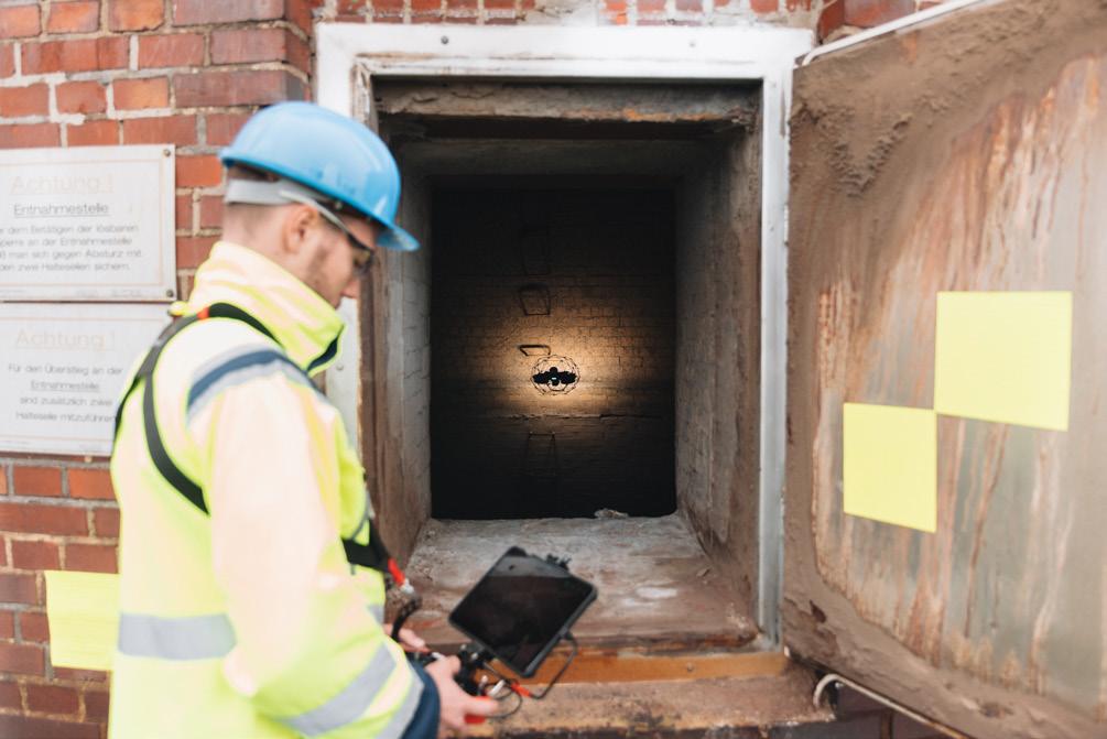
Matteo Saglia, Flyability, Switzerland, answers the question: How can drones help maintain critical energy infrastructure?
The energy sector encompasses many types of power production facilities, whether it is traditional thermal plants, wind farms, or hydropower plants. Although all these facilities are very different in nature, they are all highly complex environments that require constant monitoring and inspection to guarantee their reliability and reduce unexpected downtimes. With growing
demand for energy and a rising strain on the power plants’ infrastructure, inspecting them and making sure any issues are found on time is becoming increasingly important.
Traditionally, people inspecting these areas are required to access many confined, elevated, or hazardous spaces and perform the inspections manually (when this is possible). However, this often exposes workers to
Figure 1 The Elios 3 drone ready to perform an internal blade inspection.
fall risks, asphyxiation, toxic gases, and other risks. Additionally, manual inspections are prone to incomplete data acquisition, human error, and long inspection times, which can result in costly downtime. To reach these areas, scaffolding may require several days or even weeks to be built and dismantled, and carries the risk of dropped or forgotten objects and work at height. For these reasons, many energy companies around the world are looking for new tools to carry out these inspections remotely without having to put people in danger or having to build scaffolding.
An example of someone invested in finding safer and more efficient ways of performing inspections in these types of environments is Joseph Valenzuela, Co-Founder of Pathfinder Optics. He explains that “the benefit of using drones [for an internal wind blade inspection] compared to having a human enter the blade is safety. The biggest thing is safety, but also efficiency. Having a wind turbine down for a full day can be very costly for the owners.” He is one of the many industry experts who identified drones as an ideal tool to collect critical data remotely. Inspection drones, like Flyability’s Elios 3, are designed specifically to address these challenges, providing a safer,
faster, and more efficient alternative for data collection in challenging environments.
Wind turbine blades are just one of the many examples where people put themselves at risk to carry out inspections and make sure energy production remains consistent and reliable. Other examples include thermal power plant assets like boilers, chimneys, steam pipelines, condensers, and cooling towers. Hydroelectric plants also require their penstocks, surge tanks, and water pipes to be inspected. But use cases for remote inspection tools in the energy sector are many more, with new applications for drones being discovered almost daily by unmanned aerial vehicle (UAV) pilots around the world.
Could drones be the future of inspections in the energy sector?
Among several innovative remote inspection tools brought to the energy market, the most effective appear to be drones, and more specifically confined space drones. But why? As mentioned earlier, many areas that require frequent monitoring happen to be very complex environments, which can be enclosed, at height, or filled with pipes or other components, making it difficult for many people and solutions to move around them freely. On the other hand, drones built to inspect confined spaces can easily navigate these environments and also fly at heights where other ground robotic solutions cannot reach. This means they have a high level of versatility that allows them to inspect pretty much any type of asset.
For these reasons, inspection drones are transforming the way energy facilities monitor and maintain their critical infrastructure. In fact, the energy/utilities industry has the highest use of drones among all major industries, and according to data from Drone Industry Insights, it is estimated that the drone market in this sector will reach US$4.4 billion by 2030. Clearly, drones cannot replace human work and maintenance, but they are able to provide a complete assessment of an area to determine whether human intervention is in fact required and whether an environment is safe to enter before sending in people. For instance, a 50-m-tall boiler may be in perfectly good condition to continue operating; traditionally, the boiler would have to be shut down for weeks, with thousands of dollars spent on scaffolding, and then have people work at height for multiple days just to get that information. Drones, on the other hand, can remotely collect that very same data in hours, record it, and store it for future evaluation and comparison. It allows inspectors to share what they see with anyone around the world in a matter of seconds, reducing risks of human error and miscommunication. Then, only if an issue is discovered, will humans have to be involved to
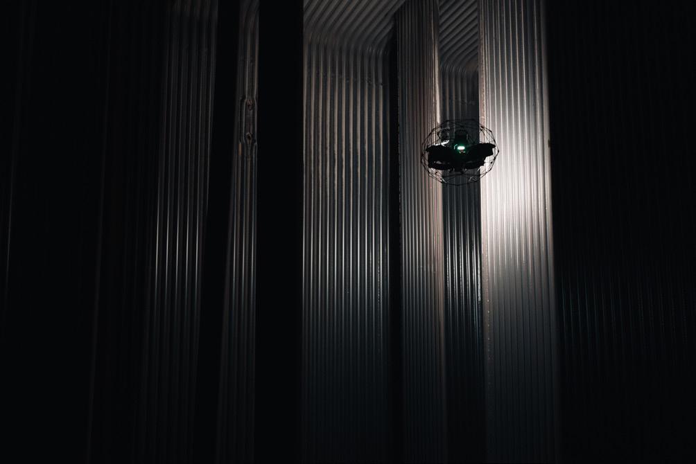
Figure 2 The Elios 3 drone performing a visual and UT inspection inside a 50 m tall boiler.
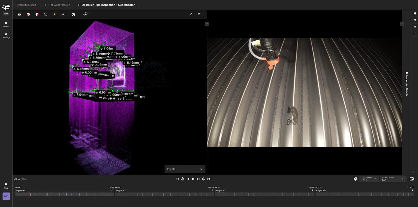
Figure 3 . Visual of the data collected by the Elios 3 and visualised in the Inspector software.

perform the repair work, and even then, this can be limited to the specific area where a defect was found.
Experienced drone pilot and power plant inspector, Scott Paul from Dominion Energy, believes that “the biggest benefit [of using drones for inspection] is without a doubt safety! Not putting people at height for inspections is second to none, and not having to secure equipment to perform an inspection means we maintain maximum output for the grid. We also see benefits including time and cost savings, increasing efficiency, and reducing outages.”
Equipped with advanced sensors and protective cages, inspection drones like the Elios 3 by Flyability can navigate tight and complex environments that would otherwise require workers to enter hazardous areas, climb scaffolding, or simply be impossible to reach. Onboard lighting and high-resolution imaging enable detailed visual inspections even in dark or confined spaces, and LiDARs create accurate 3D models (also known as digital twins) of the assets where defects can be precisely localised for better monitoring and maintenance planning. In addition, the integration of UTM payload on board highly specialised drones allows inspectors to collect thickness measurements remotely and localise them inside the very

same digital twin, creating a more comprehensive view of the asset that is being inspected.
“The Elios 3 has been a breakthrough in the inspection of penstocks for the hydro sector. What previously took weeks can now be safely accomplished in a day with far more data acquired than was previously possible,” says Bryce L. Kohler from Cirrus Design. Bryce has been inspecting penstock and other energy assets for several years now and, according to him, there is no other tool able to collect the same quality data as an inspection drone like the Elios 3. Specifically for penstocks, which are extremely confined, dark, and wet environments, people would often have to be lowered hundreds of metres into these pipes via rope access, equipped with only a torch, and try to visually identify any defects. If any were found, they would then have to try to provide an estimation of where they were located within the pipe. Needless to say, these inspections proved to be very complex. A drone can simply fly inside the penstocks, and, thanks to their powerful lighting and high-quality cameras, detect the presence of damage or concerns.
The ability to rapidly inspect confined areas minimises downtime, enhances safety, and supports predictive maintenance strategies, ultimately reducing operational costs and improving asset reliability. As power generation facilities face increasingly stringent safety and efficiency requirements, solutions like the Elios 3 illustrate how inspection drones are becoming an integral part of modern plant management.
What makes a drone fit to perform inspections?
It is important to consider that not every drone is suited for the complex and often dangerous environments found in the energy sector. Consumer-grade drones, for example, may excel outdoors in open spaces but lack the stability, resilience, and sensor payloads required for industrial inspections. Confined space drones, such as the Elios 3, are purpose-built for these environments but are not suited for high altitude outdoor flights. Just like with other tools, for each application, the best UAV should be determined for those specific circumstances.
For any indoor or outdoor complex environment that needs inspecting, key characteristics of an inspection drone should include collision tolerance, allowing drones to bump against structures without compromising flight stability, and the ability to fly in GPS-denied areas (usually LiDAR-based stabilisation). This typically requires a collision-tolerant design or obstacle detection, and live situational awareness for operations beyond the visual line of sight. Equally as important is the data quality that the drone can collect. For purely visual inspections, drones should be equipped with 4K cameras and powerful lighting, and for more complete assessments, drones can now also be equipped with UTM payloads for remote thickness measurements, gas sensors for additional safety and detecting the presence of toxic or flammable gases, LiDAR scanners for digital twinning, and more. Last but
Figure 4 . The Elios 3 drone performing a visual inspection inside a wind turbine blade.
Figure 5 A pilot expertly flying the Elios 3 to perform an internal chimney inspection.
not least, durability is an essential trait for a reliable inspection solution. Drones should be able to withstand dust, temperature variations, elevation, low visibility, and other challenging conditions, making the pilot feel comfortable with the tool they are controlling.
Digital twins are becoming increasingly relevant for energy companies looking to adopt predictive maintenance strategies. By repeatedly scanning the same assets, operators can monitor the progression of defects over time and make data-driven decisions on when to perform maintenance, extending asset lifespan and avoiding unexpected failures. Additionally, an integrated LiDAR on the drone provides the ability to localise defects within the digital twin of the asset, making it much easier for maintenance teams to know exactly where to start. This also enables the possibility to perform accurate comparisons over time to see how a defect evolves and determine the best time to intervene.
Ongoing developments in the tech world are also opening up advanced new possibilities for inspection drones. Innovations like automation and artificial intelligence are proving to be a real game-changer for the inspection world. Additional abilities for drones to fly tethered or untethered give them the flexibility to operate for long periods of time, but also to reach where the tether cannot reach. Additional data management capabilities such as real-time streaming, automated reporting,

and integration with inspection software platforms further increase the value of drones for asset integrity programmes.
Conclusion
As energy infrastructure continues to age and global demand for power increases, ensuring the reliability, efficiency, and safety of energy production facilities has never been more critical. Traditional inspection methods, though still widely used, come with significant drawbacks, from safety risks and prolonged downtimes to incomplete or inconsistent data. On the other hand, drones, particularly those designed for confined and complex environments, are proving to be transformative tools in the inspection space. They drastically reduce the need for hazardous human entry, cut down inspection time and associated costs, and provide high-quality, repeatable data that can be used for predictive maintenance and long-term asset management. With their ability to access hard-to-reach areas, integrate advanced sensors, and create detailed digital twins, inspection drones like the Elios 3 are quickly becoming an essential part of modern energy infrastructure maintenance. As technology continues to evolve, the role of drones in the energy sector will likely expand even further, helping operators meet growing safety, efficiency, and reliability demands with confidence.


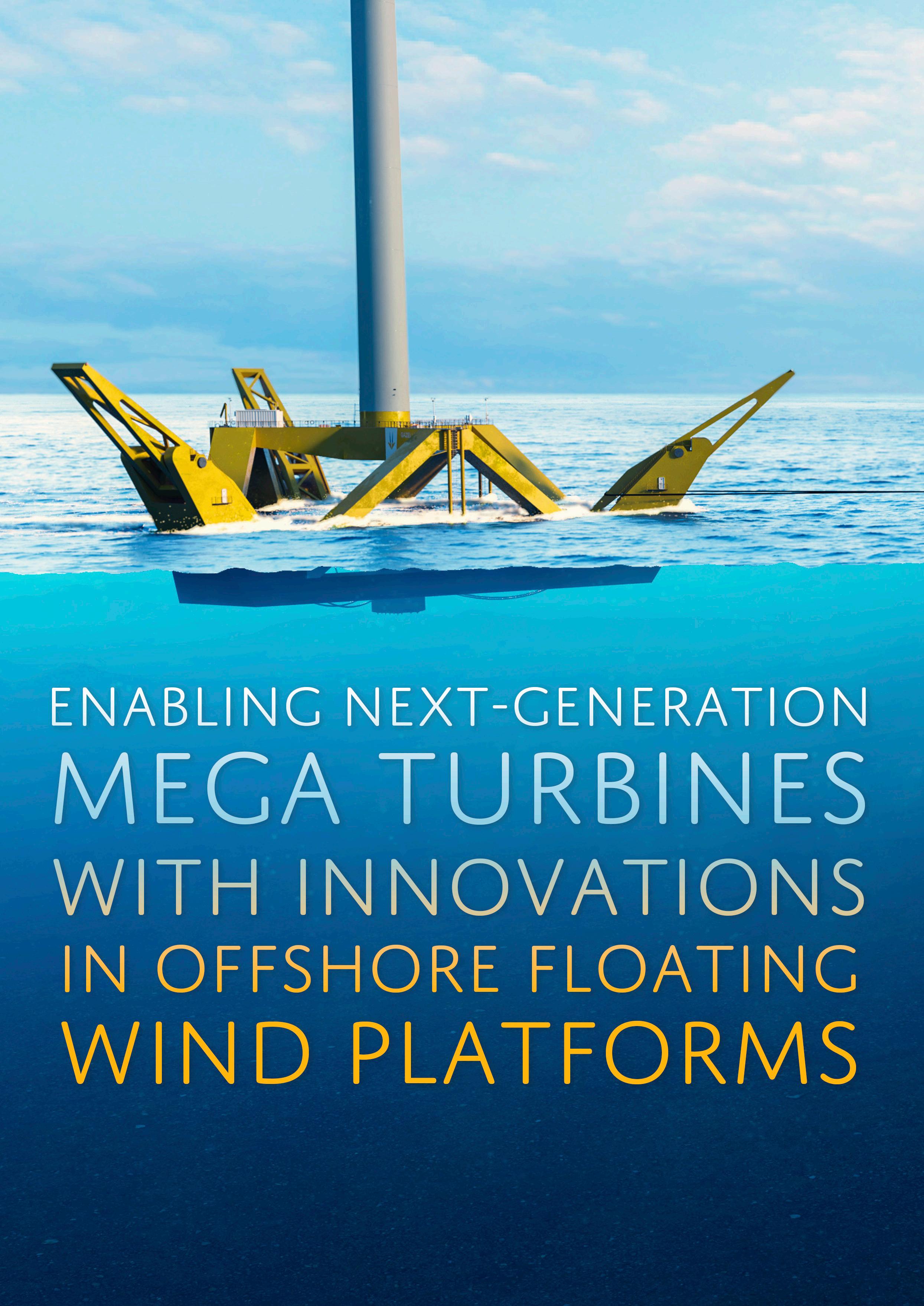
Jon Salazar, CEO, Gazelle Wind Power, addresses the growing need for larger turbines, and considers the challenges and opportunities that come with them.
As the world races towards what the International Energy Agency (IEA) has called the “age of electricity”, the potential of wind energy remains strong both in driving the energy transition and enhancing energy security.
As part of this, offshore wind has demonstrated its unique ability to become the main engine for the future growth of wind energy despite several obstacles. The most recent report by the Global Wind Energy Council (GWEC) shows that there is now already 83 GW of offshore wind installed worldwide. There is also currently a further 48 GW of offshore wind under construction worldwide.
What is more, in 2024, a total of 56.3 GW of offshore wind capacity was awarded worldwide. Europe led the way, with 23.2 GW awarded while China awarded 17.4 GW. Other markets also had landmark years, with South Korea awarding 3.3 GW, Taiwan 2.7 GW, and Japan 1.4 GW. Even France, which has historically relied on nuclear energy, is now getting serious about offshore wind, setting an ambitious target of 18 GW of installed capacity by 2035.
Offshore wind energy is gaining recognition not just for its role in delivering clean, renewable power, but also as a vital element in strengthening energy independence and security – especially important in today’s uncertain geopolitical climate. Despite facing hurdles such as supply chain bottlenecks, increased investment costs, and global

political shifts, the sector’s strategic value continues to rise, reinforcing its importance to developers, investors, and decision-makers alike.
The bigger the better: The potential of 15 MW and beyond
One of the sector’s most pressing issues is the need to improve the economic viability of offshore wind projects. Although technological advances have helped bring costs down over time, offshore wind remains capital-intensive compared to other renewables. The logistical demands of constructing and maintaining turbines at sea, in deep waters, and under extreme weather conditions, can sometimes result in higher levelized costs of energy (LCOE) than land-based alternatives.
To address this issue, developers and manufacturers have embraced a strategy of scale. By deploying increasingly larger turbines capable of producing more energy per installation, project developers can reduce the overall number of installations needed, simplify supporting infrastructure, and improve overall project economics.
The latest frontier in this race is the deployment of 15 MW+ turbines. Indeed, DEC recently unveiled a prototype 17 MW floating offshore wind turbine and, in 2024, the company also announced a 26 MW fixed bottom wind turbine. This new class of larger turbines are gargantuan
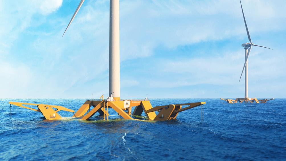
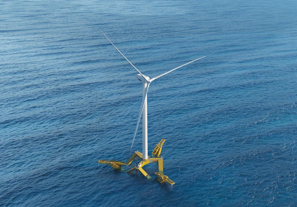
Figure 1 . Innovative platform technology can simplify manufacturing, speed up assembly, and streamline installation.
machines that can generate enough electricity to power tens of thousands of homes each, dramatically increasing the output of individual offshore wind farms.
However, while the energy-generating potential of these machines is clear, their size and weight pose new challenges. Transporting, installing, and operating 15 MW+ turbines in offshore environments is not an easy task. The turbines are taller than structures like the Shard or the Eiffel Tower, with some blades now exceeding 150 m in length. The logistics involved in port assembly, at-sea installation, mooring, and long-term maintenance become increasingly complex as turbine sizes grow. The harsh marine environment only adds to the difficulty, with powerful waves, strong currents, and saltwater corrosion exerting continuous pressure on both the turbines and their foundations.
Fixed-bottom foundations, which have historically supported offshore turbines in relatively shallow waters, quickly become uneconomical or physically unviable in deeper sites. This constraint limits where offshore wind farms can be located, often excluding areas with the highest wind resources – typically found farther offshore, in water depths beyond 60 m.
As a result, the industry is increasingly turning towards floating wind platforms, which can unlock these deepwater zones and bring offshore wind to regions previously
considered inaccessible. Floating wind is not a new concept, but until recently it remained a niche application. That is now changing.
Unlocking 15 MW+ through innovative floating technology
Early floating wind projects served as test beds rather than commercial scale power producers, and high costs limited their wider adoption. However, recent years have seen a shift. As engineering knowledge increases and supply chains become more experienced, floating wind is edging closer to commercial competitiveness. Industry projections suggest that global floating wind capacity could reach 21 GW by 2035, potentially transforming the offshore wind map and expanding its reach to new coastal geographies.
Additionally, according to WindEurope, floating foundations could have a transformative impact on the European market, where 80% of offshore potential lies in waters deeper than 60 m.
Key to this evolution is the development of floating platform technologies that can support larger turbines, including the 15 MW+ class, while remaining cost-effective and scalable. Platform design, though often less visible than turbine technology, plays a crucial role in floating wind success. A well-designed platform must provide the necessary stability to ensure turbine performance and longevity, while also being logistically viable to manufacture, transport, assemble, and maintain. At the same time, it must meet increasingly stringent environmental requirements and minimise disruption to marine ecosystems.
Achieving all these goals simultaneously is a formidable engineering challenge. However, recent technological progress in floating offshore wind has opened the door to turbine installations in deeper waters, supported by cutting-edge anchoring methods and enhanced stability frameworks. As the industry moves to deploy ever-larger turbines in harsher offshore conditions, new designs are emerging that seek to reconcile the limitations of previous generations.
Portugal: The perfect test bed for new floating offshore wind technology
One illustrative example of this innovation can be found off the coast of Aguçadoura, Portugal, where a next-generation floating wind demonstrator is currently under development. The project, known as Nau Azul, is spearheaded by Gazelle Wind Power, which is working to validate a new floating platform. Though the demonstrator will initially support a 2 MW turbine, its underlying design is intended to serve as a blueprint for much larger deployments, including those in the 15 MW+ range.
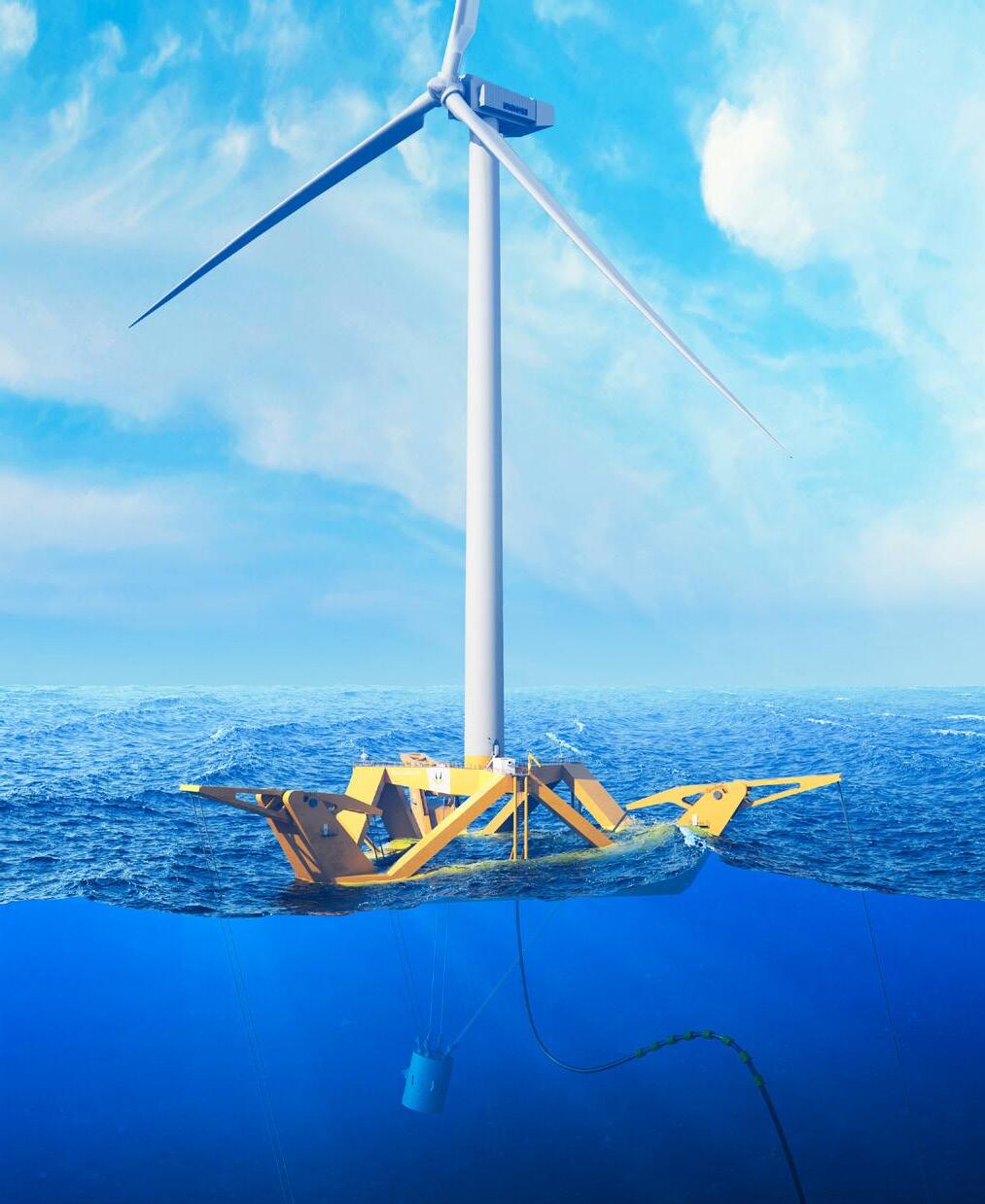
What sets this technology apart is the way it achieves stability. Instead of relying only on buoyancy, it separates flotation from stability using what is known as the Gazelle principle. This involves a counterweight connected to levers or balancing arms, which are attached to outer mooring lines.
Figure 3 Floating wind moves towards commercial competitiveness.
Figure 2 New platform technology is being developed for floating offshore wind.
This method is both flexible and reliable. Whether the user swaps out the arms for pulleys, changes the shape of the platform, or comes up with new ideas, the core principle still works well. Unlike older systems, which have struggled to scale affordably over the past 20 – 25 years, this design offers strong potential for improvement and efficiency. Its ability to be refined and improved is what makes it a potential game-changer in the industry. The focus is on reducing the LCOE, primarily by lowering CAPEX, especially through minimising steel usage. Less steel means lower CAPEX through reduced transport and installation costs. The ability to assemble the platform in shallow ports also means greater deployment flexibility, making it suitable for regions without specialised deep-water port infrastructure.
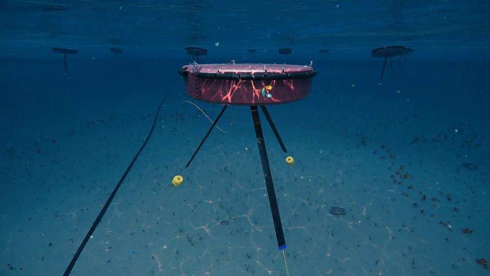
This approach is also notable for its focus on environmental integration. By minimising seabed disturbance and offering a smaller physical footprint, the platform design seeks to reduce the impact of offshore wind development on marine life and ecosystems, an issue of growing concern as more projects are sited in previously undisturbed ocean areas.
In essence, this technology retains the strengths of traditional offshore wind systems while eliminating many of their limitations. The Gazelle principle is the foundation of these improvements, which simplifies manufacturing, speeds up assembly, and streamlines installation, all essential in reducing the cost of clean energy.
Although still in its early stages, the platform’s development underlines a broader shift in how the industry approaches the deployment of large scale offshore wind turbines. Rather than focusing solely on turbine efficiency or energy output, there is a growing recognition that the infrastructure beneath the turbine, the floating platform and the mooring systems, will play a decisive role in determining the economic and technical feasibility of offshore wind in the next decade.
A successful demonstration could pave the way for commercial scale projects that deploy 15 MW+ turbines in deeper waters, far from shore, where wind speeds are more consistent and capacity factors are higher. Such projects would not only increase energy yields, but also reduce visual impact and competition for nearshore space, a consideration that is becoming more important as public resistance to large coastal infrastructure grows.
How to scale floating offshore wind to enable bigger turbines and more energy
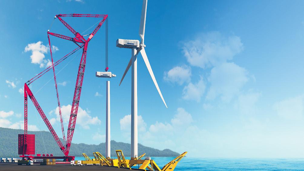
Engineering breakthroughs on their own are not enough to drive the integration of larger turbines with floating platforms. Success will also depend on improvements in infrastructure. Ports, installation ships, and power grid connections will need to handle bigger parts and more complex operations. At the same time, regulations must be updated to make permitting easier and give developers more long-term clarity. Financing models will also need to reflect the higher upfront costs of floating wind, while recognising its potential to provide higher returns over time.
Individual countries are also making positive changes. The UK has launched dedicated funding streams for floating wind manufacturing and port upgrades, while countries like Portugal and Spain are integrating floating wind into their broader maritime spatial planning frameworks.
Despite recent challenges in the industry, installed offshore wind is constantly growing as the industry seeks to make good on its enormous potential. However, in order to do so, developers must continue to deliver greater scale – which means bigger, 15 MW+ turbines on floating platforms, in windier environments. The innovations in floating platform technology that will enable this scale are being developed right now. These innovations will allow countries around the world to truly harness the full potential of this vast source of zero-carbon electricity and guarantor of energy security.
Figure 4 Floating platforms enable turbines in deeper waters.
Figure 5 . New designs use the Gazelle principle.


Although commercial exploitation of wave energy is still in its infancy, it has the potential to contribute substantially to a stable and reliable electricity grid based on renewable energies being attained within just a few years, argue Michael Kocher and Frank Fladerer, Bachmann electronic GmbH
Ocean wave movements contain hydrokinetic energy. The magnitude of this energy is considerable: according to the U.S. Ocean Energy Council, a wave breaking along a mile of coastline releases almost 36 000 kW of power. It can be captured by means of wave energy converters, which are anchored to the seabed. These convert the energy into electric current, which is then transported to the coast by cable.
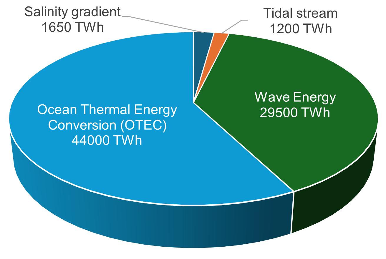
The global potential of wave energy is estimated at 29 500 TWh/y, which approximately equates to current global electricity consumption. Wave energy is also more constant and predictable than other forms of renewable energy. Furthermore, the production profile of wave energy is countercyclical to that of wind and solar energy.
Technical approaches
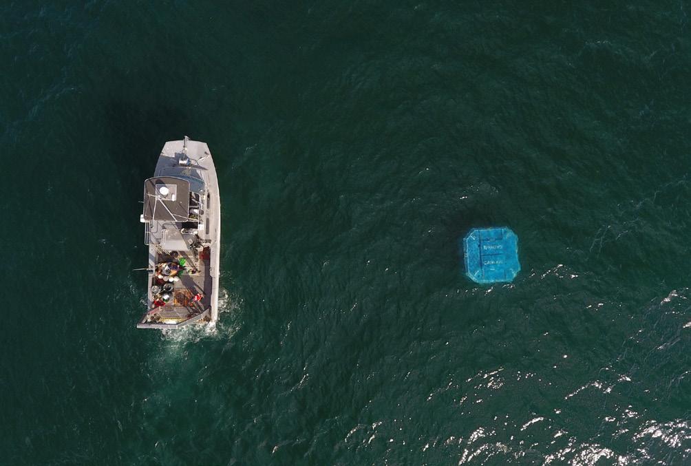
Several different technical approaches to harnessing wave energy are being trialled around the world. Those currently most significant are described in this article. Point absorbers, such as Carnegie Clean Energy’s CETO system, are floating devices that generate electricity from the vertical movements of waves. Unlike other systems for this purpose, they function independently of the wave’s direction
of propagation and can absorb energy irrespective of it. A rod-shaped buoy or ring-shaped float converts the oscillating up-and-down movement directly into electrical energy. Point absorbers are primarily used at sites near the coast.
In oscillating water columns (OWCs), air is compressed and decompressed. OWCs feature a chamber, with a submerged opening through which water flows into and out of the chamber. The air trapped in the chamber serves as a medium for driving a turbine. A key advantage of this design is the use of special turbines which generate electricity during both ingress and egress of the water into and from the chamber (compression and decompression of the air respectively). These ‘pneumatic chambers’ are used primarily on steep coasts where strong waves occur.
Attenuators are elongated devices oriented in the axis of wave propagation. They exploit the rising and falling motion of the waves. They typically consist of several interconnected segments that float parallel to the axis of wave propagation and can move relative to each other. The movement at the joints between the segments is used to activate hydraulic cylinders, whose energy is used in turn to generate electricity. The modular design of the attenuators enables them to be scaled easily for high power classes, making them ideal for large offshore projects.
Overtopping devices are power generators that exploit the flow of water over a ramp into a reservoir. The difference in elevation is used to generate electricity, in much the same way as in small hydroelectric power plants. This technology resembles that of pumped storage power plants, and is particularly suitable for locations with high tidal ranges.
Some companies have opted for oscillating attenuator technology: one of these is CalWave in California. Converters of this type are fully submerged and exploit the pressure differential created by the wave motion. The platforms are anchored to the seabed. The wave movements, which also occur below the surface, give rise to changes in their buoyancy. Drivetrains convert the constant movement into electrical energy. Their submerged location protects the systems against storms, and their impact on the environment is lower than that of wave energy converters above the surface.
Wave energy converters are currently being tested and developed further worldwide, primarily on a small number of test and pilot farms. However, the production of electric power that has been attained is increasing with each new generation of converters, and suppliers are now attaining magnitudes of economic significance.
Besides economic viability, the issue of grid integration must be resolved, and the systems’ impact on marine ecosystems has also not yet been fully researched. Finally, many countries have extremely complex approval procedures and far-reaching regulatory frameworks.
Control: A success factor
All these issues are made critical by the harsh environmental conditions; wave energy systems must withstand storms and the corrosive effects of salt water. The components are subject to temperature fluctuations, shock, and vibration. Difficulties of access require the systems to exhibit high operational reliability and a long service life. The development of robust and low-maintenance designs is therefore essential.
Figure 1 Point absorbers, such as Carnegie Clean Energy’s CETO system, are floating devices that harness the vertical movement of waves to generate electricity. Source: Carnegie Clean Energy.
Figure 2 . Companies such as CalWave in California rely on the principle of oscillating attenuators. These converters are fully submerged, and exploit the pressure differential created by the wave motion. Source: CalWave.
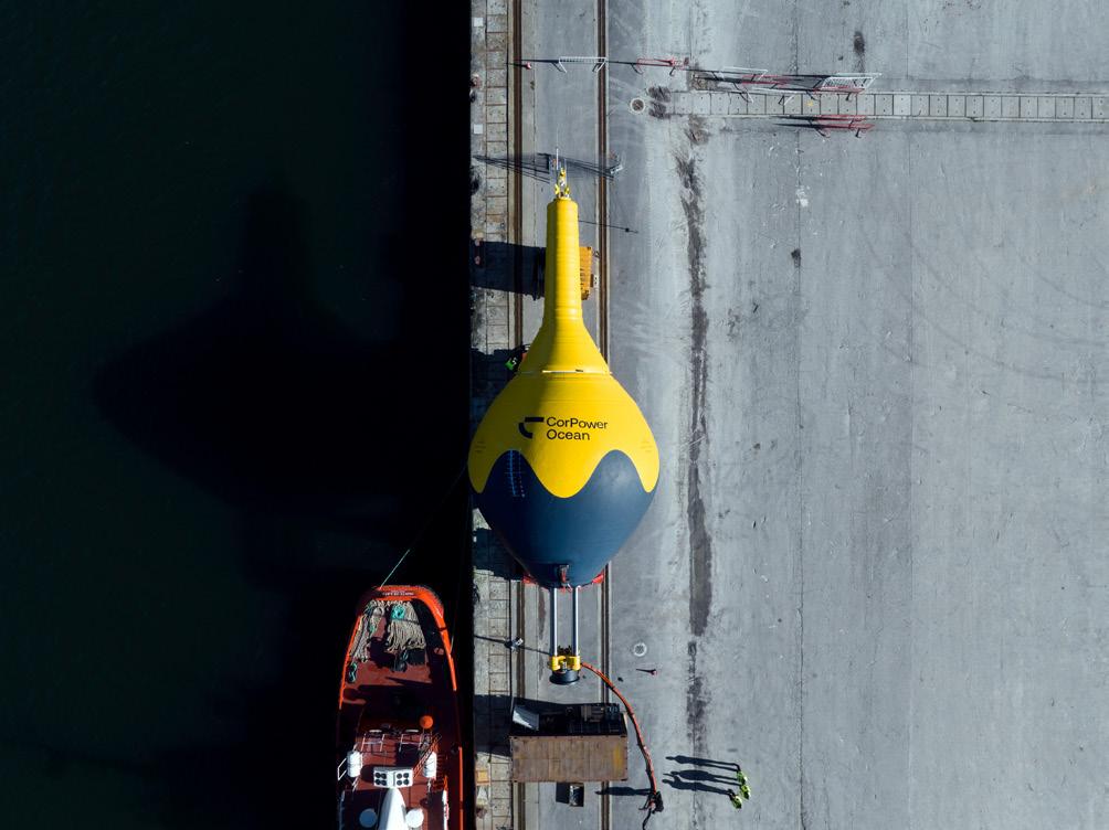
Figure 3 CorPower Ocean’s C4 has a diameter of 8 m, a height of 40 m, and a weight of 70 t. As a result, the wave energy converter can withstand even extreme storm waves. Source: CorPower Ocean.
JOIN US IN LONDON!


A full day event dedicated to the UK’s CO2 pipeline build-out: uniting pipeline operators, engineers, contractors, and decision-makers.
The programme will cover the UK’s rapidly evolving CCS infrastructure plans, proposed and confirmed projects, safety codes, technical challenges, international case studies, and the technologies enabling safe, efficient CO2 transport.

WITH SUPPORTING ASSOCIATION

Delegate takeaways from this exclusive one day conference:
Learn
Hear from industry leaders on planning, safety, design, construction, and environmental considerations for CO2 pipelines.
Be informed
Updates on key UK CCS projects, with sessions on buildout and delivery, integrity, and international insight.
Understand
Understand government support, regulatory frameworks, and permitting processes.
Network
Meet the companies driving the UK’s CCS pipeline future.


One particular technical aspect is the control systems used. These are crucial in wave energy converters, for the energy yield to be maximised and, at the same time, the mechanical stresses presented by the weather conditions to be reduced to a minimum. Control algorithms enable the converters to be adjusted dynamically to different wave heights and frequencies, thereby always delivering the optimum yield. In addition, intelligent control protects the systems from overload, for example during storm surges, and extends their service life.
Successful test in California
CalWave, a US provider, has conducted an initial long-term trial 0.5 km off the coast of San Diego, California.
Thomas Boerner, Chief Technology Officer at CalWave Power Technologies, Inc., explained: “The Bachmann team considered the automation requirements in detail in consultation with us and gave us sound advice on the optimum configuration of the systems.”
The system operated autonomously round the clock during the 10-month pilot project, which was conducted under real-world conditions. The control system mastered the challenges and contributed significantly to an availability of over 99% being attained for the system as a whole. No intervention was necessary during the project.
Multiple drivetrains converted the energy from the waves into electricity. In addition, the system was able to change the geometry of the absorber body. The aim here was to exploit each wave to the full. “By means of these mechanisms, we were able to keep not only the drive within the optimum operating range, but the whole unit – very similar to the approach used in wind energy,” said Boerner.
The xWave system, with its rated output of 15 kW, was controlled through a Bachmann main device with an MC220 processor module. Several subdevices of the controller, connected to the main device over FASTBUS, assumed the complex task of drive control. The wave energy converter also featured load management: xWave could be raised or lowered relative to the seabed according to the instantaneous wave propagation, thus exploiting the wave energy at the ideal depth for absorption.
Within the control system, the control tasks were shared between the four available processor cores. This allowed loads such as sensor data processing, control, or communication with peripheral devices to be processed simultaneously and in parallel rather than sequentially.
The elegant distribution of tasks increased the response speed of the controller – already very powerful – still further. This is important for optimum energy yield in complex applications such as the adaptive control of wave energy converters under dynamic sea conditions. Although over 1000 variables were exchanged between the application programs running in parallel during completion of the complex control tasks, the system load of the four available processing cores never exceeded 50%, even when only a single processing core was in use at a given time.
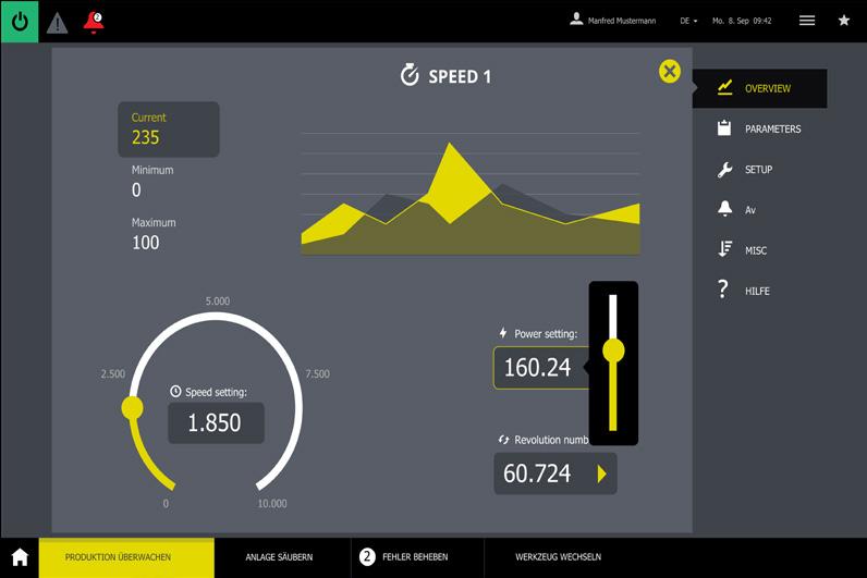
The task of providing CalWave with a full picture of the instantaneous status of its pilot plant always fell to the Scope 3 software oscilloscope. In contrast to a conventional hardware oscilloscope, the signals are recorded by hardware but are displayed, analysed, and saved in a software application. A major advantage here is the close integration with the control software, which permits simultaneous visualisation of process data, storage of large data volumes, and the use of complex evaluation logic. The use of webMI pro to visualise the data permitted comprehensive system diagnostics and selective control of all-important parameters – from any location. 12-hour data sampling of all relevant signals enabled the company to track the processes on the platform conveniently and without post-processing.
Complex development
CalWave opted for a model-based approach for development of the pilot plant. The complexity of the drivetrain and controller, and organisation of signalling and data, posed particular challenges in this process.
Model-based development enabled the
Figure 4 . A study by the International Renewable Energy Agency (IRENA) estimates the global potential of ocean energy at around 80 000 TWh/y. The potential of wave energy alone could cover global electricity demand.
Figure 5 . Visualisation with webMI pro enabled comprehensive system diagnostics and selective control of all important parameters, from any location.
company to use the simulation model itself to study the mutual influences between the waves and the mechanical and electrical components precisely. Parallel to this work, the MATLAB Simulink development tool was used for design of, for example, the required control algorithms and signal processing. As part of this process, the wave energy specialists generated new, tailored control programs automatically using M-Target for Simulink.
This architecture proved to be of crucial benefit as the project progressed and during field testing. It enabled CalWave to replace the existing control core with an optimised version, for example, by loading new software at any time. The remaining software components were not affected by the update; operation of the system was uninterrupted, as a controller restart was not required.
Another major advantage was that the Bachmann controller supports the C++ programming language. In demanding applications such as wave energy, where real-time processing and hardware access are crucial, this enables engineers to implement powerful control strategies, tailored to the application and surpassing the capabilities of traditional PLC programming.
Next step and the digital twin
In the next step, CalWave is working on construction of a 100 kW version of the xWave architecture. This is to be operated for two years in ‘PacWave South’, the first accredited, grid-connected, and approved test facility for wave energy
in the open sea off the US coast. The expectation is that from mid-2026 onwards, 20 MW of power will be fed from there over pre-installed cables into the local grid on the mainland.
Besides increasing the output, CalWave also plans to use a digital twin: a simulation model trained on data from the real system. Control and simulation are then to run in parallel in real time, and the results of the real system are to be compared with those of the simulation. The long-term goal is to develop wave energy converters rated at over a megawatt per system. However, platforms with lower rated outputs, such as those in the pilot project, are also important for the utilisation of wave energy; for example, they could be used in the future to supply energy to offshore measuring stations.
Industrialisation requires stable framework conditions
The present course of wave energy exploitation is promising. However, it will continue to require considerable research and development effort in the years to come. Some island countries and territories, such as the Faroe Islands, Orkney, and Tahiti, have already set their own goals, putting an end to the expensive imports of fossil fuels by ship and intending to have their power needs met entirely by renewable ocean energy by 2030. This creates a major incentive for manufacturers to scale up wave energy to industrial levels soon.
LNG Industry magazine


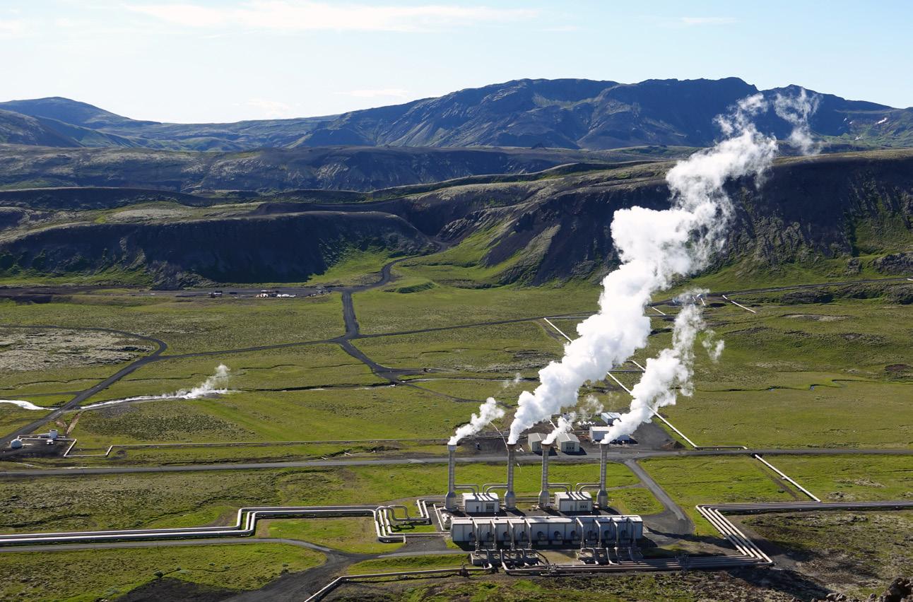
Fernando Gimenez, Product Manager, Sulzer, examines current developments in geothermal energy plants and how the company is supporting the growth of enabling technologies.
As the world accelerates its transition away from fossil fuels, attention is increasingly turning to the vast, untapped energy beneath our feet. Geothermal power, long viewed as a niche renewable energy source, is now emerging as a critical component of global decarbonisation strategies. According to the International Energy Agency (IEA), global geothermal capacity had a utilisation rate over 75% in 2023, compared with less than 30% for wind power and less than 15% for solar photovoltaic (PV).1 Now, more regions can take advantage of geothermal energy and deliver significant
growth for an industry traditionally overshadowed by solar, wind, and hydropower.
With more fossil fuel-powered generating plants coming out of service, maintaining national grid stability and meeting peak demand is crucial – a task that geothermal can now support in more areas than it has in the past. The fact that geothermal power plants can operate flexibly also means that they can enable the further integration of variable renewables such as solar PV and wind, supporting the decarbonisation of the energy sector.
Geothermal energy, derived from the natural heat of the Earth’s interior, offers continuous, stable power generation, unlike many other renewables that are intermittent by nature. Yet the path to scaling geothermal is complex, requiring not only advanced drilling and thermal technologies, but also innovative engineering solutions to ensure plant efficiency and long-term reliability.
Developing technology in geothermal power
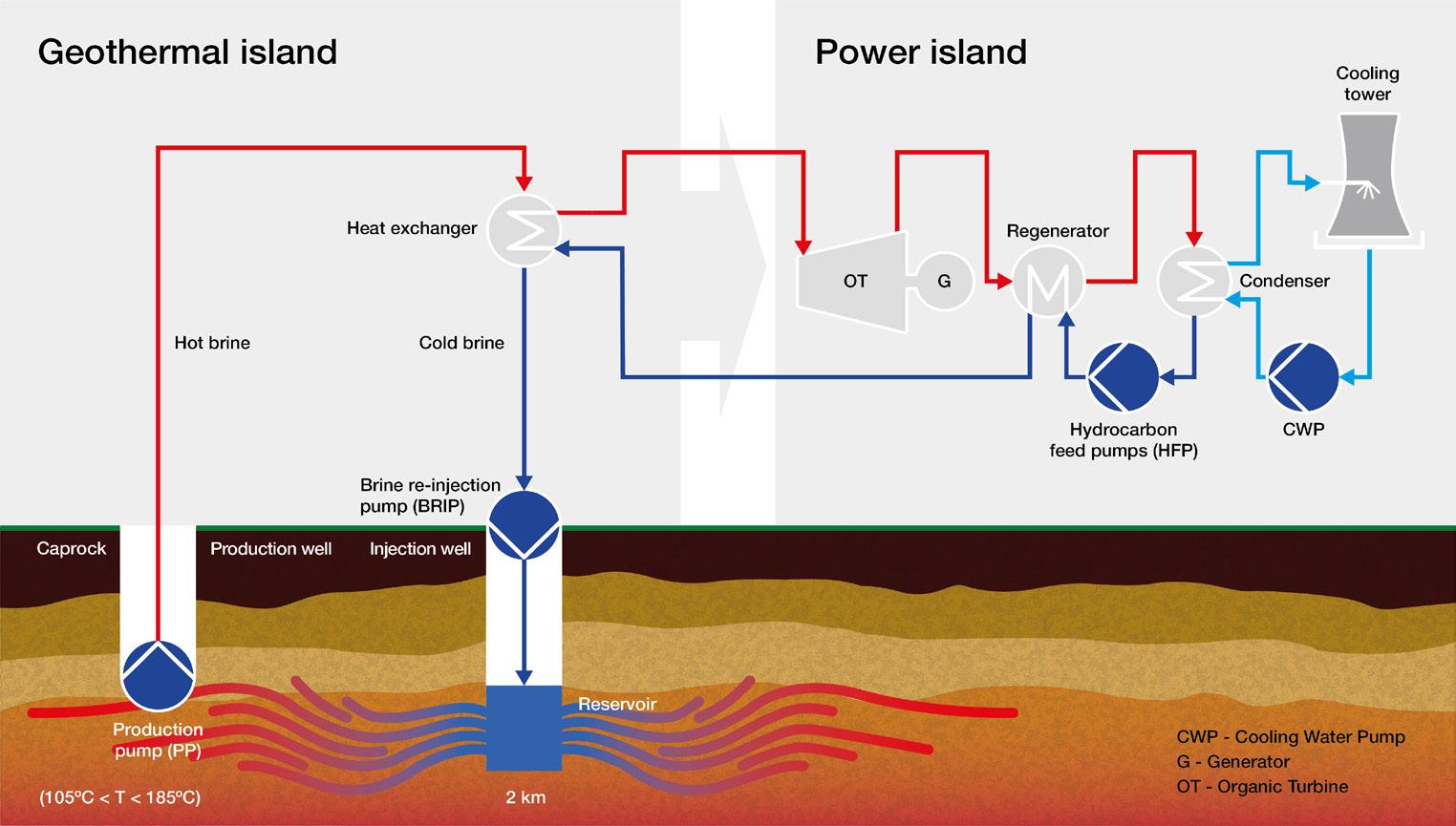
One of the most significant technological trends in the geothermal sector is the increasing use of the Organic Rankine Cycle (ORC). Unlike conventional geothermal plants, which operate using high-temperature steam, ORC systems can function at lower temperatures ranging from 105˚C – 185˚C. This makes them ideal for regions without extreme geothermal gradients.
In an ORC system, geothermal fluid is used to heat an organic working fluid with a lower boiling point via a heat exchanger. This fluid vaporises, drives a turbine connected to a generator, and then condenses back into liquid form, completing a closed-loop cycle. Due to the ability to use lower temperature resources, these systems are unlocking vast new areas for geothermal development. With more flexible siting and a lower environmental impact, ORC systems offer a number of advantages.
Enhancing efficiency and reliability
As a typically modular design, ORC plants are scalable, enabling operators to tailor the capacity to local demand and expand incrementally, which reduces the initial capital investment. These plants can also be integrated with existing power generation facilities to recover waste heat and supply local district heating systems, enhancing overall efficiency.
Furthermore, as ORC systems operate at lower temperatures and pressures, they experience less thermal stress and corrosion. This leads to longer equipment life, lower maintenance requirements, and a better return on investment (ROI).
The challenge with ORC systems lies in their technical complexity, particularly regarding fluid handling. The organic fluids used (while non-corrosive) have high vapour pressures and low boiling points, making them difficult to seal and contain during operation. Pumping systems must be both precise and robust to handle the unique thermodynamic properties involved.
Engineering precision
These challenges are most prominent for the pumps that are deployed in the heat transfer processes. Multi-stage, vertical pumps are commonly used to pressurise the organic working fluid, and their design needs to be precisely engineered to achieve long-term reliability and efficiency. These pumps have some interesting characteristics. The fluid is constantly trying to escape the pump, and the design engineers need to engage
Figure 1 Geothermal power is now emerging as a critical component of global decarbonisation strategies.
Figure 2 . Geothermal fluid powers an organic turbine by heating a secondary organic fluid (like brine) via a heat exchanger.
technologies and expertise accordingly to overcome these unique challenges. Original equipment manufacturers (OEMs), such as Sulzer, engineer their pumps to operate with high efficiency and exceptional reliability.
These attributes are critical for geothermal projects, which face high capital costs and require uninterrupted operation to maximise ROI. OEM pump testing facilities provide customers with assurance that the units meet strict performance criteria before deployment.
In addition to technical excellence, OEMs need to deliver complex solutions under tight project timelines. Geothermal plants, particularly those using ORC technology, are typically smaller in scale than conventional thermal power stations. This results in compressed development cycles and response time becomes critical.
However, for the operators, the benefits are numerous. Producing a reliable and continuous source of energy with zero emissions, regardless of the weather or time of day, ORC plants complement intermittent renewable sources, such as wind and solar PV. As such, they offer an excellent addition to baseload power supplies.
Case study: Retrofitting a Turkish geothermal plant
In addition to new facilities, assets in existing geothermal facilities can be upgraded, enabling them to benefit from modern technologies too. During a recent retrofit of an ORC geothermal facility in Türkiye, the customer wanted to enhance energy efficiency without modifying the existing infrastructure. The performance bar was set high; the pumps had to achieve a minimum of 82% efficiency, while conforming to specific mechanical constraints like flange dimensions and pipeline pressure limits.
In a brownfield project like this, the challenge is in adapting a pump to the existing dimensions while ensuring that the equipment meets the required operational conditions.
Sulzer delivered customised VS6 pumps that met all specifications, revitalising the plant’s performance and extending its operational life. This project exemplifies how modern engineering solutions can breathe new life into older facilities, reducing emissions while improving output.
Expanding the net-zero energy mix
While retrofits are crucial for legacy systems, new build geothermal projects are increasingly gaining momentum. Sulzer recently secured a contract to supply VS6 pumps to several carbon-free energy installations in the US. These projects integrate wind, solar, and geothermal power into hybrid systems that produce zero emissions, serving as blueprints for future renewable energy ecosystems.
ORC systems also hold potential beyond the power sector. In Canada, Sulzer participated in a project to capture and reuse waste heat from a refinery using ORC technology. This not only reduced energy consumption, but also contributed to the facility’s broader sustainability goals. Such applications highlight geothermal’s role in industrial decarbonisation.
Global scale
Scaling geothermal power is not just a technical challenge, it is a global endeavour. Nowhere is this more evident than in Indonesia,
a country rich in geothermal potential thanks to its location along the Pacific Ring of Fire. With a national goal of achieving net-zero emissions by 2060, geothermal energy has become central to Indonesia’s energy strategy.
Sulzer is playing a key role through a five-year strategic service agreement with PT Pertamina Geothermal Energy Tbk. The agreement covers maintenance and technical support for rotating equipment across multiple geothermal facilities, which collectively generate 330 MW, enough to power more than 600 000 homes.
Sulzer’s field services provide everything from outage optimisation and turbomachinery overhauls to advanced repair technologies. These services are essential to ensure improved uptime and efficiency, both of which are crucial in meeting Indonesia’s climate targets.
Regulatory challenges
Despite promising trends, the geothermal industry faces challenges on its growth journey, particularly around regulation. Each country pursuing geothermal development has unique technical codes, safety standards, and environmental regulations. However, as a global supplier, Sulzer is able to customise each solution to meet local requirements, including ATEX certification, specific material standards, and pressure ratings.
The ability to provide localised solutions also presents opportunities. Countries like Türkiye, New Zealand, Canada, Germany, and the US are expanding their geothermal portfolios not only for climate goals, but also for energy security – a priority amplified by geopolitical tensions and fossil fuel price volatility.
A resource for a sustainable future
Geothermal energy stands out among renewables for its baseload capability, small physical footprint, and near-zero emissions profile. Its ability to operate 24/7 gives it an edge in stabilising power grids increasingly reliant on intermittent sources like solar and wind. Moreover, the Earth’s core heat is inexhaustible on human timescales, making geothermal a long-term asset in the clean energy mix.
However, unlocking geothermal’s full potential requires overcoming significant engineering and logistical challenges. Sulzer, with its in-depth technical expertise and global infrastructure, is at the forefront of this transformation. Whether by designing high-efficiency pumps for cutting-edge ORC systems, retrofitting ageing infrastructure, or providing essential long-term service agreements, the company is proving invaluable in enabling geothermal’s growth.
As more nations embrace this underutilised energy source, and technologies continue to evolve, geothermal power has the potential to move from the fringe of the energy conversation and take a central role. As fossil fuel generation is displaced, ORC plants will contribute to the reduction in greenhouse gases and support countries in the obligations to meet the climate targets outlined in the Paris Agreement.
References
1. ‘The Future of Geothermal Energy: Executive Summary’, International Energy Agency, www.iea.org/reports/the-future-of-geothermal-energy/executivesummary

Michael Adams, Mark Canlas, and Ted Moon, NOV, highlight groundbreaking temperature management technologies that improve drilling efficiencies in the deepest, hottest geothermal applications.
Effective temperature management is a well-known challenge in high-temperature oil and gas reservoirs, but geothermal wells can take that challenge to the extreme.
Operators in those areas routinely encounter bottomhole temperatures that push the limits of what drilling tools in the bottomhole assembly (BHA) can tolerate, making drilling fluid temperature management critical.
For geothermal drilling, keeping BHA tools below about 150˚C (302˚F) is often the difference between consistent performance and expensive downtime. Without adequate cooling, electronics fail, elastomer seals degrade,

and premature trips downhole drive up costs. At the same time, geothermal projects aim to preserve heat in the produced fluids to maximise the energy delivered to the surface.
This dual challenge – protecting downhole tools while retaining reservoir heat in the produced fluids – has pushed operators to seek new thermal management strategies. One promising approach combines insulated coatings for drillpipe with a surface mud chiller, creating a closed-loop system that helps drilling fluids start cooler, stay cooler, and safeguard tools throughout the well.
Managing downhole heat with insulation advances
Drillpipe coatings have a long history in oilfield operations. For more than 80 years, TuboscopeTM has advanced coating technologies to extend tubular life and improve operating efficiencies downhole. As drilling environments became harsher, coating advances kept evolving to protect tubulars from corrosion, chemicals, wear, and deposit build-up while improving hydraulic efficiencies to reduce pumping horsepower and frictional losses.
The latest challenge is thermal management. Ultra-high-temperature wells – both geothermal and unconventional oil and gas – demand drillpipe that slows heat transfer between the fluid inside and the rock outside.
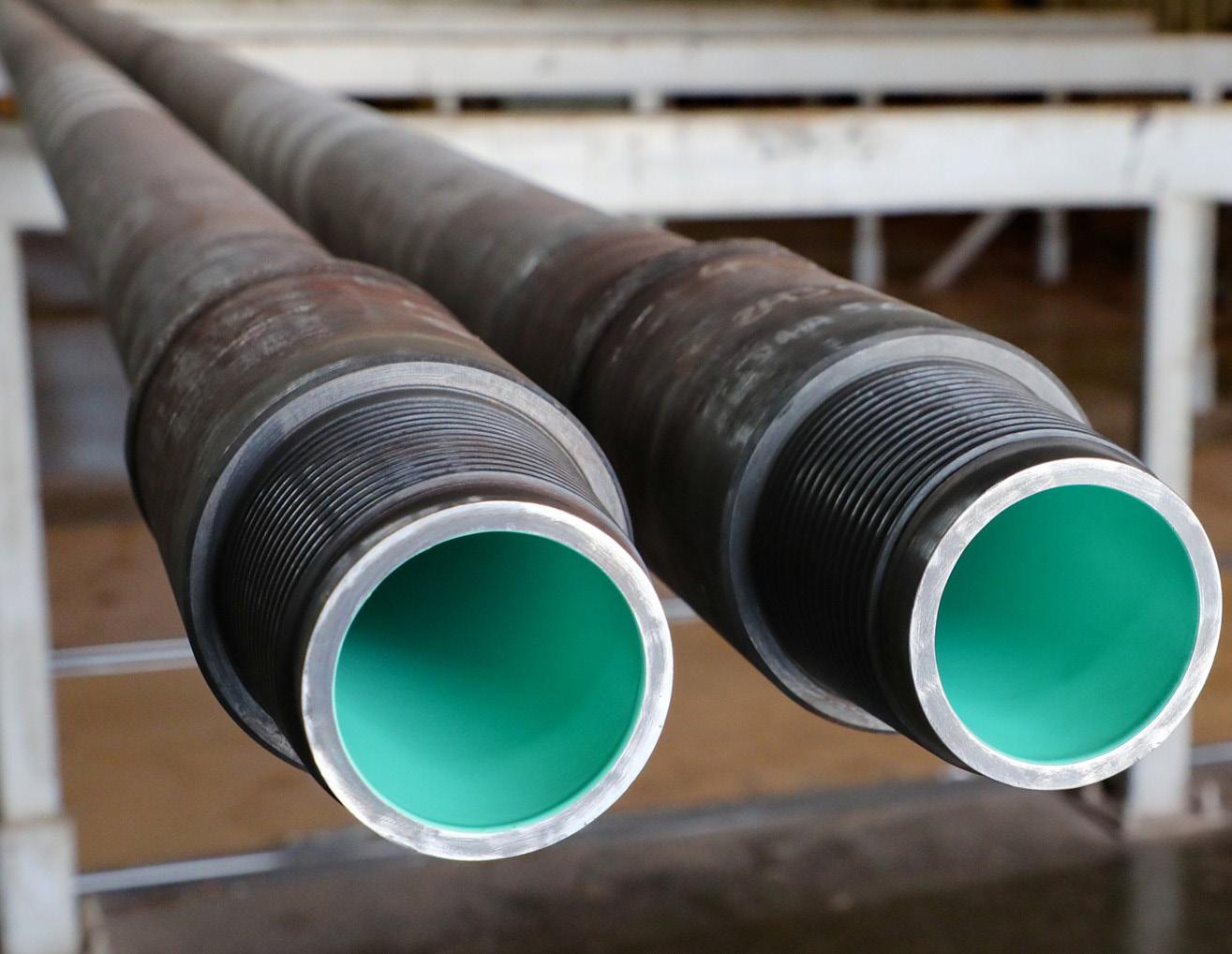
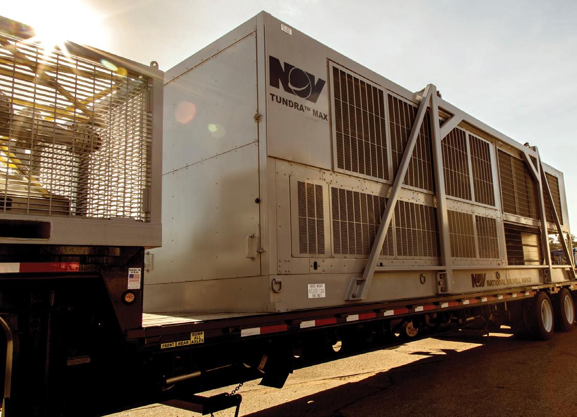
Even modest improvements in thermal insulation can protect sensitive tools downstream.
Developing a low-conductivity coating
To meet this need, NOV Tuboscope developed its Tube-KoteTM (TKTM)-Drakōn insulating coating, designed specifically to minimise thermal conductivity while maintaining the protective features of earlier coatings. The development began in consultation with operators in the Haynesville shale, who required solutions to keep mud cooler and extend the life of BHA electronics while drilling long oil and gas laterals in high-temperature reservoirs. Achieving these goals required a coating with a thermal conductivity (k) of 0.5 W/mK or lower.
The development process began by using current coatings as a starting point. Thermal conductivity testing was performed according to the ASTM E1530-19 test method, an industry standard for measuring the thermal conductivity of coatings in a temperature range of 20˚C – 310˚C (68˚F – 590˚F). Per this test method, the current coating class had an average thermal conductivity that was significantly higher than the target value.
A series of iterative formulation adjustments was conducted to decrease the coating’s thermal conductivity to below the target. The modified coatings were also evaluated in industry-standard laboratory tests to measure their physical properties and resistance to chemical and corrosive attack.
This work produced a coating with a k value of 0.1620 W/mK, three times lower than the target. The new coating not only lowers thermal conductivity to keep colder fluids (i.e. the drilling mud) cool and hotter fluids (i.e. the produced fluids) hot, but it also retains the same features of previous coatings – reliable protection against corrosion, wear, and deposit build-up – while improving hydraulic efficiencies.
The TK-Drakōn insulating coating’s combined low thermal conductivity and enhanced chemical and abrasion resistance help keep mud cooler while boosting drilling efficiency. The coated drillpipe helps extend tool life and, on average, reduces BHA-related issues by almost 50%, lowering costs, minimising unplanned trips downhole, and delivering the well in fewer days.
Starting with a cooler mud at surface
Starting with a cooler drilling mud at the surface is critical to keeping the BHA tools within safe operating limits for longer and reaching deeper into the reservoir before picking up excessive heat.
Operators have long relied on three types of surface mud cooling systems:
> Evaporative mud coolers use water sprayed across coils carrying the hot mud. Heat is removed as the water evaporates. While effective in drier climates, these coolers lose efficiency in high-temperature, high-humidity, ambient conditions. Since water evaporates during heat extraction, a large, continuous water supply is required at all times.
Figure 2 . The single-skid, trailer-mounted Tundra Max mud chiller is set up and operates in parallel with the active mud system.
Figure 1 The insulating coating, TK-Drakōn, on drillpipe provides three times lower thermal conductivity than the target value, at a thickness of just 20 – 30 mils (thousandths of an inch) with minimal surface roughness for improved hydraulic efficiency.
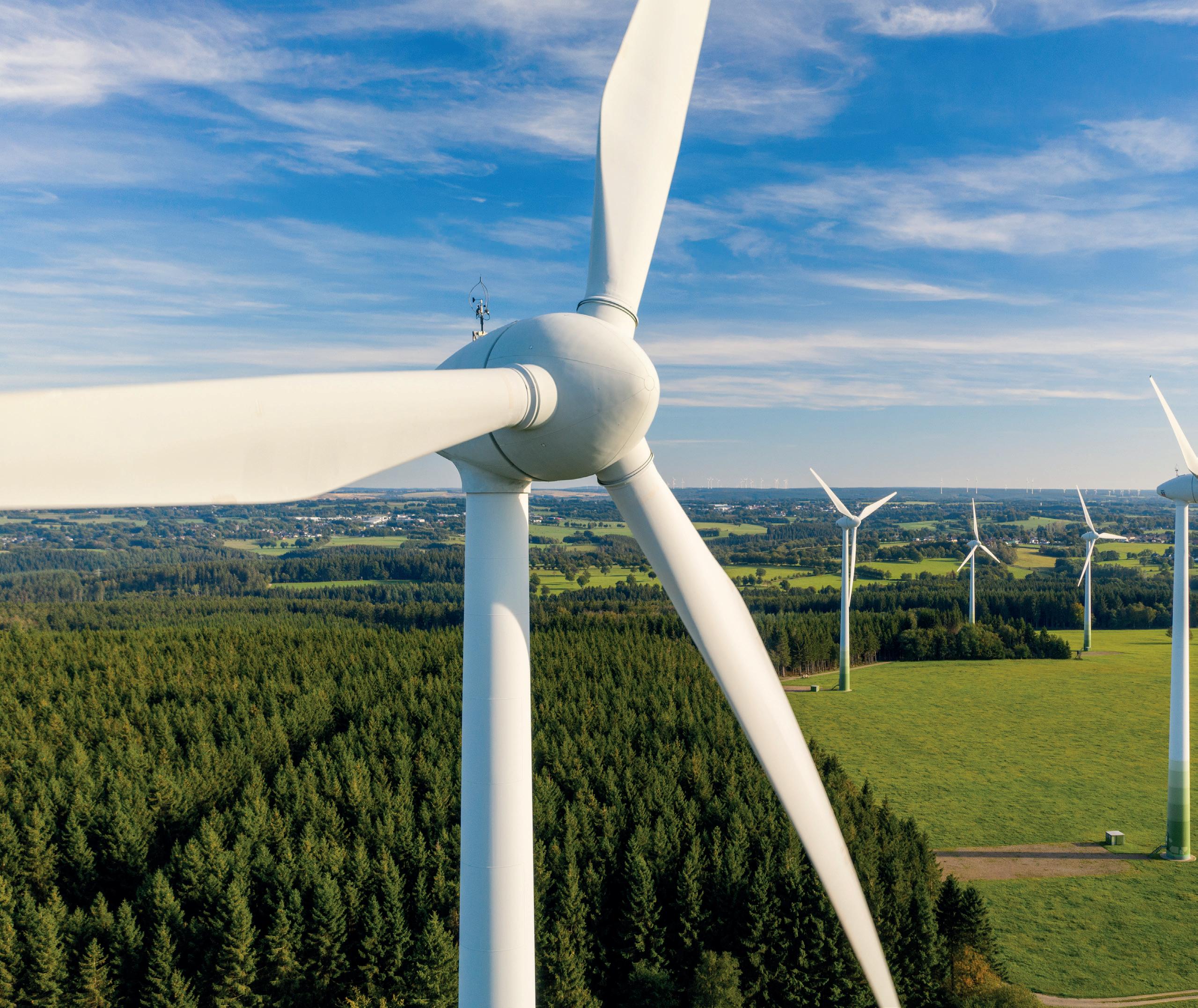
As a result, these units are typically placed near a large water source, or the necessary water is trucked in through the drilling process.
> Air blast coolers use air as the primary cooling medium, which passes across a series of finned heat exchangers that carry the heated drilling mud, cooling the mud in the process. While air blast coolers do not require a water source, they are also less efficient in higher ambient temperature conditions.
> Mud chillers use HVAC refrigeration systems to extract the high-temperature heat from the drilling mud. Chillers do not require a dedicated water source to operate and are effective in high-temperature ambient environments. They also provide precise temperature control, making them uniquely capable of targeting a specific temperature.
Among these options, mud chillers stand out as the most reliable cooling option in extreme geothermal environments.
Maximising surface cooling with a dual-stage design
To further enhance mud cooling at the surface and thereby improve the insulated drillpipe’s effectiveness at keeping
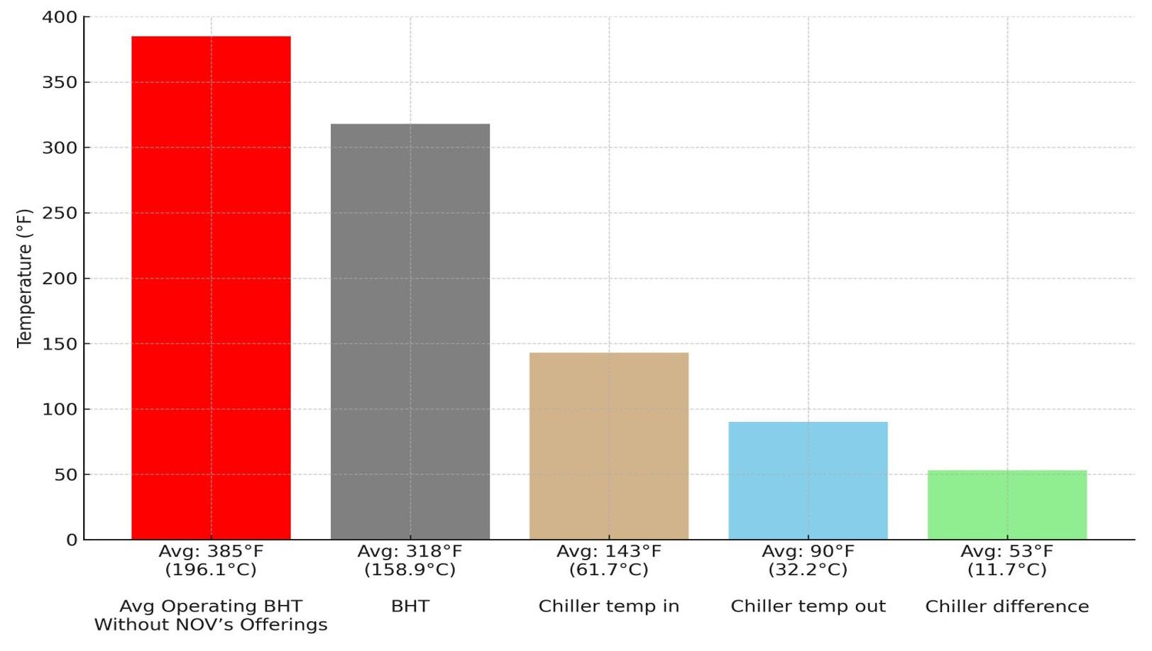
the drilling mud cool downhole, NOV developed the TundraTM Max Mud Chiller (Figure 2). A fully contained, skid-mounted unit, this novel design combines an air blast cooler and mud chiller in series.
The process works as follows:
> Drilling mud from the suction tank first passes through the air blast cooler, which removes the initial kick of the heat from the mud.
> The mud then flows into the chiller, where it is further cooled before being returned to the active system.
Both systems utilise titanium plate-and-frame heat exchangers – well-established and efficiently designed exchangers that expose more of the heated mud to the cooling fluid (Figure 4). Both systems use water as the cooling medium, which is cooled by the chiller and the air blast. Since the same volume of water moves through the unit in a closed loop, no external water source is required.
The system optimises heat transfer in several ways:
> Mud from the suction tank has already been exposed to ambient temperatures and is therefore cooler before it ever enters the Tundra Max system.
> The system has a counterflow design, with hot mud entering from the bottom and cooling fluid entering from the top, which maximises heat exchange.
> Each of the titanium plates has ridges that are in a corrugated herringbone pattern. These ridges help to create more turbulence in the fluid which further maximises heat transfer.
> As the cooled mud exits the system and is reintroduced to the suction tank, it creates a passive heat sink that lowers the overall fluid temperature in the tank.
> When this cooler fluid is returned to the well, it stays cooler for longer and can reach deeper into the wellbore for further drilling efficiency gains.
The Tundra Max system works effectively to cool both oil-based and water-based muds. Depending on the fluid and operating conditions, the Tundra Max has reduced drilling mud temperatures by as much as 70˚F (40˚C).
Proving its potential in the field
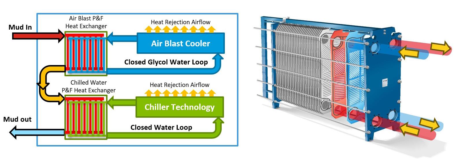
TK-Drakōn-coated pipe and the Tundra Max chiller have been deployed in several high-temperature applications, both in oil and gas and geothermal sectors, for several years. More recently, operators in North America have expressed growing interest in deploying the integrated cooling system into their high-temperature drilling operations.
Figure 3 . The combined TK-Drakōn/Tundra Max cooling solution helped to significantly reduce the temperature of the mud entering the well and lowered the average bottomhole temperature by nearly 70˚F compared to wells without either NOV cooling system installed.
Figure 4 The dual-stage system, which integrates an air blast cooler as the first stage and chiller technology as the second stage, effectively cools high-temperature drilling mud whilst using less energy.
In the South Texas Eagle Ford shale, a major operator faced extreme downhole conditions during extended lateral drilling, with bottomhole temperatures reaching 196.1˚C (385˚F). These conditions posed significant risks to downhole tools, electronics, seals, and mud properties, raising the risk of non-productive time (NPT) from unplanned trips to retrieve or replace damaged equipment.
To counter the potential of these challenges, the operator deployed NOV’s integrated Tundra Max/TK-Drakōn temperature control solution. The Tundra Max system’s closed-loop, dual-stage chiller dropped mud temperatures by an average of 29.5˚C (53˚F), from 61.7˚C (143˚F) inlet to 32.2˚C (90˚F) outlet (Figure 3).
This substantial surface cooling immediately improved the quality of the fluid circulated downhole, creating a cooler and more stable drilling environment. When used on its own, the mud chiller helped reduce bottomhole temperatures to approximately 186˚C (366˚F). However, when paired with the TK-Drakōn-coated pipe, the bottomhole temperature dropped even further, averaging 158.9˚C (318˚F). This combination not only preserved the performance of high-value downhole electronics, but also allowed tools to operate closer to their maximum rated lifespans, including batteries and sensors critical for automated drilling and formation evaluation.
In addition to extending tool life, the solution enhanced fluid rheology control, reducing reliance on costly chemical additives to compensate for heat-related breakdown. The improved thermal consistency minimised both surface and downhole risks, enhancing health, safety, and environmental (HSE) performance by lowering exposure to hot fluid returns.
The combination of surface cooling and thermally-coated drillpipe allowed the client to avoid tool-related trips, maintain higher rates of penetration, and reduce overall NPT. These performance gains will translate into faster, more efficient wells with reduced operational risk, enabling the operator to meet its project goals on time and within budget.
Staying cool in the hottest wells
The drive towards renewable geothermal energy depends on pushing the limits of drilling technology. Extreme heat is one of the most formidable barriers.
By pairing insulated coatings for drillpipe with a dual-stage surface mud chiller, operators can create a complete cooling strategy – from the rig floor to the bottom of the well. Together, these technologies keep fluids cooler for longer, protect critical tools, and improve drilling safety and efficiency.


To reach its full potential, the geothermal energy sector cannot afford to be wasteful – especially with water. Alasdair Carstairs, Business Unit Manager, OSSO, identifies the changes that must be made within the geothermal energy industry to achieve progress.
Geothermal energy has been an integral part of global energy systems for more than a Century, yet, historically, its role has been limited, largely confined to specific regions and considered a niche

resource compared to other low-carbon sources like solar or wind power.
However, the global energy landscape has shifted enormously in this decade, not least because of the war in
Ukraine and subsequent efforts by governments across Europe to bring online alternative sources of energy to gas imports from Russia. This, coupled with the urgent need for decarbonisation, rising tensions, and economic uncertainties, has prompted governments worldwide
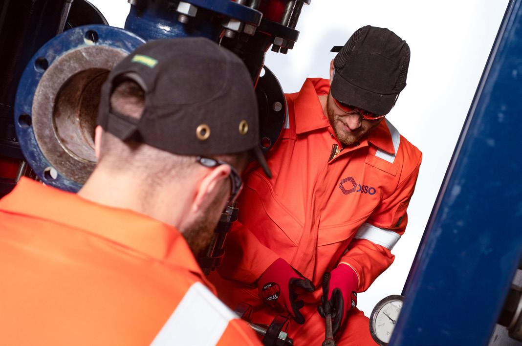
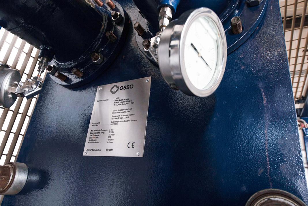
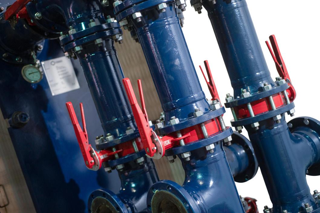
to seek new, dependable, low carbon domestic sources of energy.
It is in this context that geothermal energy has now emerged from the background. In 2024, the EU Energy Council took a decisive step towards promoting geothermal energy as a central component of Europe’s transition, endorsing conclusions to accelerate its deployment. The Middle East is not only adopting the technology for power generation but is also pioneering its use in cooling solutions. Additionally, the U.S. Secretary of Energy, Chris Wright, has named geothermal energy as a prime area for the U.S. Department of Energy’s research and development, signalling that the ‘drill baby, drill’ mandate may not just be applicable within oil and gas.
The potential is significant, with the International Energy Agency (IEA) estimating up to US$140 billion in annual investments with geothermal potentially meeting 15% of global electricity demand growth by 2050. Yet, challenges around operational efficiency remain in a sector that is still developing its best practices.
Water is a precious resource
Water is becoming an increasingly precious resource globally and, in areas like the Middle East, it is already a critical issue. For projects in these locations, efficient water management during geothermal production is essential as geothermal plants use water for cooling and re-injection, requiring between 1700 – 4000 gal. of water/MWh.
Technologies that enable fluid reuse and reduce wastage are vital for sustaining operations in the future. Meanwhile, in typically wetter areas such as parts of Europe, climate changes are leading to more frequent flooding and unpredictable rainfall, making wastewater management just as important.
Wastewater discharge is becoming a key regulatory issue. The UK is leading with tighter controls, driven by growing public and government concern over water as a limited resource. The UK Environment Agency has stepped up enforcement, fining companies for breaching discharge standards or causing contamination. Construction firms have already faced heavy penalties –the geothermal energy sector will not be immune. With the UK setting the pace, other European countries are likely to follow. For geothermal operators, smart fluid and wastewater management is now critical for compliance, public trust, and avoiding fines.
Water you doing?
One of the biggest opportunities lies in smarter fluid management. Geothermal projects can generate large volumes of waste water depending on the specific technology and operational practices used. This is from drilling processes, often containing contaminants like drilling mud, heavy metals, and salts, making it
Figure 3 . Mud cooling technology.
Figure 2 . Mud cooling technology.
Figure 1 . Mud cooler with two engineers.
unsuitable for direct discharge and requiring treatment to meet environmental standards.
Many projects still rely on tankering this water off site for treatment and disposal. While this approach gets the job done, it is expensive, time-consuming, and significantly increases the project’s emissions. This is particularly pertinent in a low-carbon sector, where relying on high-emission transport methods undermines one of its core benefits.
Sometimes the sheer volume of waste water can overwhelm local treatment facilities, forcing operators to use even more tankers, travelling greater distances. It is not uncommon for six, eight, or more tankers to operate simultaneously to keep up. This situation also impacts the project’s social license to operate. Rural communities, which many sites are close to, often oppose the constant presence of heavy vehicles on small roads, causing noise, vibration, and disruption.
One way to overcome these challenges is to move away from relying solely on tankering and instead focus on treating water directly on site. This approach cuts down on transport costs and emissions and addresses the practical difficulties of managing large volumes of waste water. Whether projects are in remote areas or closer to populated places, on-site treatment reduces disruption and helps maintain community relations.
Solutions proven in other industries, like OSSO’s WTS20 system used in construction, enable effective on-site water treatment in a practical, automated, and reliable way. These technologies efficiently treat and remove contaminants, making the treated water safe for release back into the environment. By adopting this approach, projects can massively cut down on tankering, reduce costs, manage emissions, and minimise the risk of contamination incidents –such as when heavy rain causes overflow or spread of untreated wastewater.
Cooling matters
Effective fluid management goes beyond handling waste water; it also involves making cooling processes more efficient and cost-effective. During geothermal drilling, cooling fluid is vital for maintaining equipment integrity, managing downhole temperatures, stabilising the wellbore, and carrying cuttings to the surface. However, it can become contaminated with drilling mud, cuttings, and naturally-occurring substances from the reservoir over time. Once this reaches a certain level, the fluid becomes unusable, creating a significant cost burden as it must be replaced with fresh coolant – a process that is expensive and can slow down operations.
The good news is that a proven solution already exists; recycling cooling fluid by treating it and enabling reuse. This reduces the volume of waste, addressing both cost and environmental concerns.
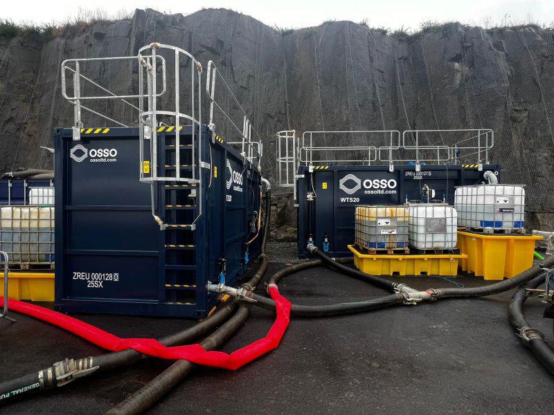
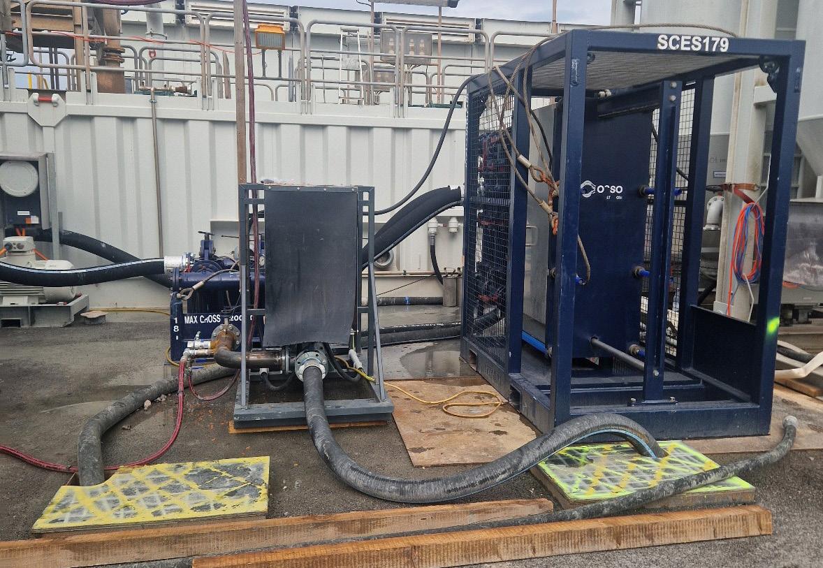
It is known from experience that cooling management is a huge efficiency for projects. OSSO separation and treatment units can ensure cooling fluids are treated to meet the necessary requirements for safe reuse, significantly extending their lifespan. These technologies are already proven in other industries, but their application in this sector is clear, where tighter margins make exploring every angle for efficiency essential.
Final thoughts
Geothermal has huge potential, but it is a lower-margin sector, so keeping costs down is critical. Smarter water management is not just a nice-to-have, but is key to making projects commercially viable and live up to their lower carbon credentials.
With regulations tightening and water availability becoming less predictable, taking a proactive approach could be a key differentiator between success and failure. Projects that focus on efficient cooling and wastewater strategies will be better positioned to cut costs, lower emissions, and meet their potential in a changing world.
Figure 4 . WTS20 technology on site.
Figure 5 . OSSO technology on site.

Dr Dustin Bauer, Associate, Reddie & Grose, provides an overview of the race to innovate battery energy storage systems.
Battery energy storage systems (BESS) are widely considered to be a cornerstone technology for grid flexibility, renewables integration, and energy resilience. But how can the state of progress in this space be assessed?

A useful indicator of innovation is the volume and nature of patent filings, which may serve as a bellwether for technological advancement and commercial intent. Published patent filings provide a useful window into the most promising areas of BESS innovation.
Innovation in BESS
BESS are essentially large groupings of batteries which are integrated into the power grid. BESS are sometimes referred to as battery power stations, or grid storage – and they are considered one of the most important technologies for the transition to net zero: the UK’s National Grid believes they “are essential to speeding up the replacement of fossil fuels with renewable energies”,1 a recent House of Commons Research Briefing concurs, 2 and The Economist claimed that “grid scale storage is the fastest-growing energy technology.” 3
Grid scale storage (particularly via BESS) is essential for decarbonising the electricity grid because renewable
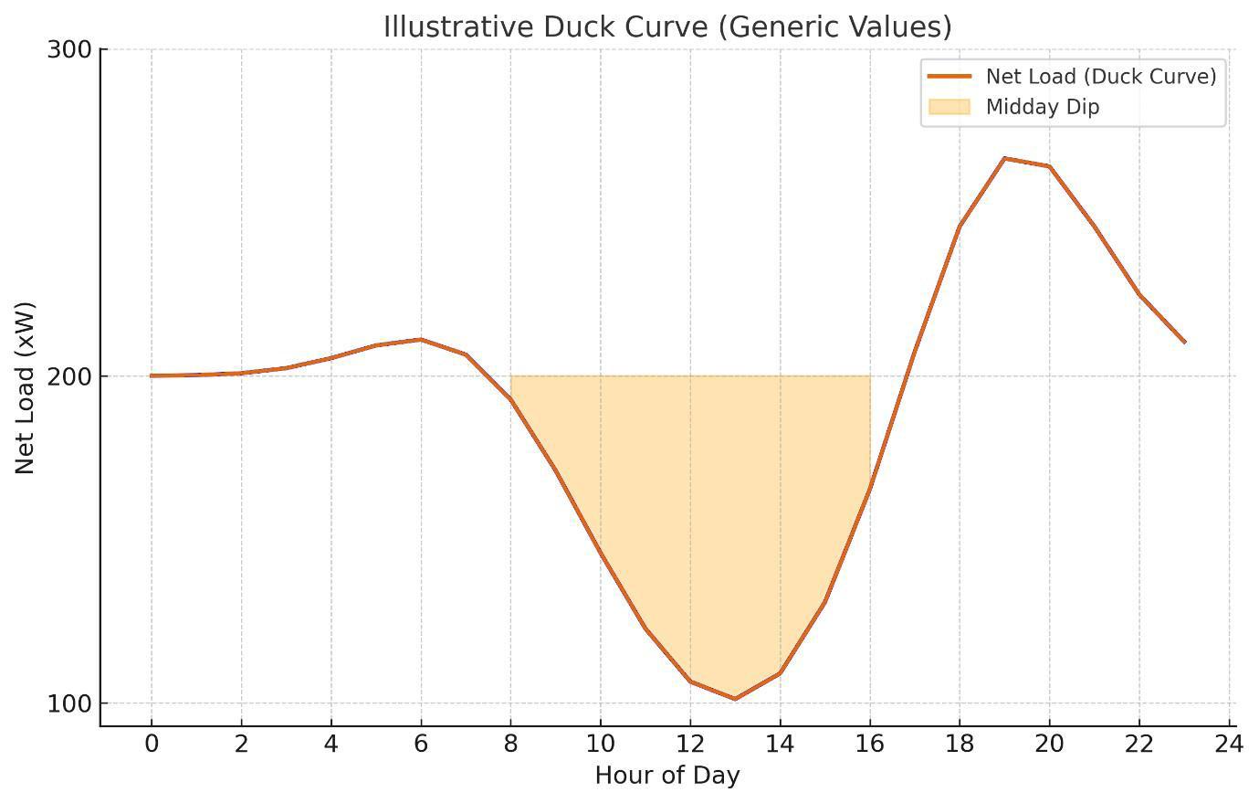
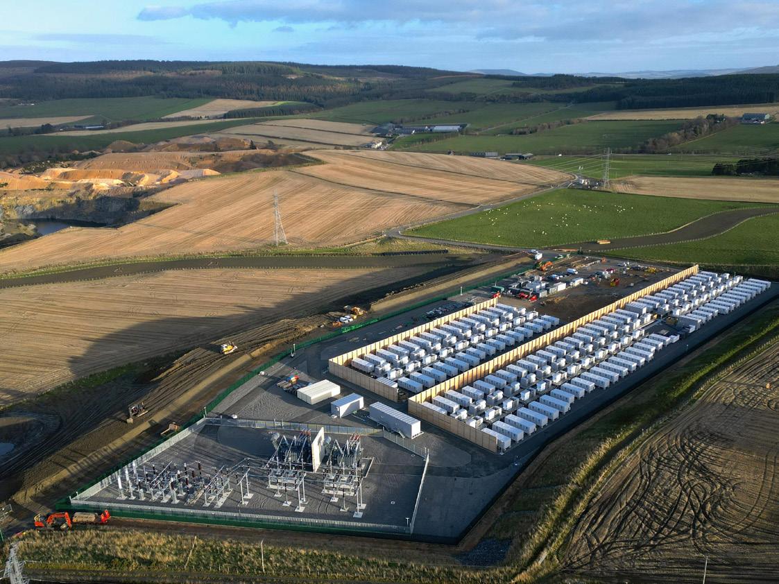
energy sources are intermittent. BESS may allow for an increased share of wind and solar in the electricity mix by balancing the grid at very short (seconds) timescales and by load shifting, i.e. storing excess energy during the day and releasing it when demand is high, at medium (hours to days) timescales. While BESS are still helpful for longer timescales (e.g. during a so-called dunkelflaute of prolonged low wind and solar), other long timescale grid scale storage systems and demand control measures may be more suitable.
Why BESS have an advantage
At very short and medium timescales, BESS are unbeatable. BESS can respond to changes in the electricity grid in seconds to balance the grid, for example by smoothing short-term fluctuations (e.g. gusts of wind, passing clouds) and for frequency regulation. Similarly, BESS may be essential in addressing the mismatch between peak solar generation (around midday) and electricity demand (dipping around midday, rising in the evening when solar generation falls). This phenomenon is commonly represented by the ‘duck curve’, (Figure 1) showing a generic example of a net load (electricity demand, less solar generation) curve.
Because of this role in addressing the mismatch between solar generation and electricity demand, it is perhaps not surprising that some of the biggest BESS in the world are the Bisha BESS in Saudi Arabia (single-phase project boasting 500 MW/2000 MWh) and the Edwards & Sanborn solar-plus-storage project in California (3287 MWh of battery capacity). In the UK, the Thurrock BESS that was connected to the grid in August 2025 is the largest BESS (300 MW/600 MWh), having taken the crown from Blackhillock BESS in Scotland.
Innovation in the BESS space
Connection and grid integration
The Thurrock BESS is notable not only because it is the largest in the UK, but also because the substation to which it has been connected used to serve coal-fired power stations Tilbury A and B, with National Grid stating that the substation had been “reinforced… to ensure the network in the region could safely carry the battery’s significant additional load, with new protection and control systems installed.”4
This makes Thurrock BESS a poignant symbol of the energy transition – and it also emphasises one of the areas in which BESS are driving innovation: electrical integration.
By way of example, Tesla’s 2019 patent US10277029 describes a BESS with a dual-active-bridge converter, which enables a modular, scalable BESS wherein each pod includes a number of cells and a power electronics unit, the cells floating relative to the system and galvanically isolated therefrom. In other words, by isolating individual pods, the system
Figure 1 ‘Duck curve’ of net load (electricity demand, less solar generation).
Figure 2 . Blackhillock battery energy storage system (BESS) (Phase 1), formerly the largest BESS in the UK and Europe, an example of a modern BESS. Source: Shutterstock.

Visit our website today: www.globalhydrogenreview.com
described in US10277029 may allow many modules to be paralleled without requiring tight voltage characteristic matching.
A more recent 2024 patent in the name of Shenzhen Hopewind Electric (US 12095268) describes a directly-connected high-voltage BESS. Put simply,
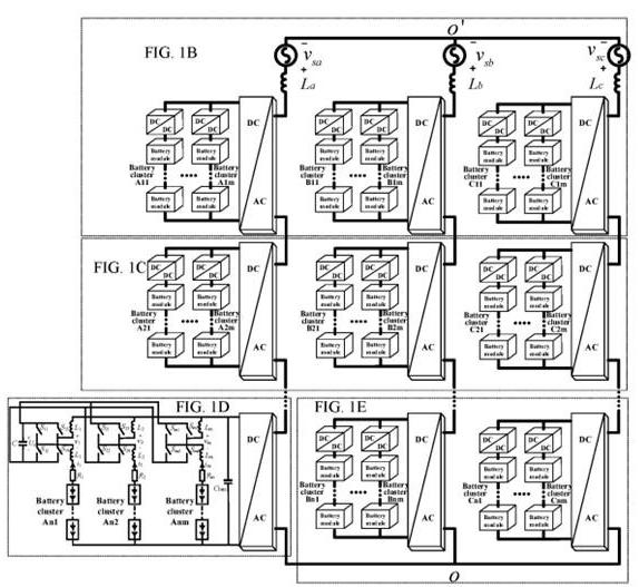

it describes a BESS in which AC ports of each battery submodule (battery, isolated DC/DC stage, DC/AC) are series-connected to form a chain-type phase converter. Such a system may not require a separate step-up transformer, avoiding transformer losses and providing modular redundancy.
Chemistry level innovation
Connection of BESS to the grid is important, but so are the individual battery cells and modules making up the BESS.
While batteries are discussed in the press a lot, this is often in the context of electric vehicles (EVs). EV batteries often rely on nickel-rich lithium (Li)-ion chemistries, such as nickel (Ni)-manganese (Mn)-cobalt (Co) (NMC) and Ni-Co-aluminium (Al) (NCA), because the focus is typically on high energy density and fast charging. The downsides of nickel-rich chemistries are that they are comparatively higher cost and can have a shorter cycle life.
For BESS, on the other hand, the focus is typically on longevity (longer cycle life), safety, and cost – energy density is less of a priority. For this reason, lithium iron phosphate (LFP) is often the first-choice cathode material, because it is very stable, cheap, safe and has a long cycle life. Sodium (Na)-ion batteries and flow batteries are also being explored as alternatives to lithium-ion batteries.
It is notable that over the last few years, price fluctuations and increases in nickel and cobalt, and improvements in LFP batteries (in materials, cell design, and manufacturing), have resulted in increased use of LFP batteries in EVs, up from about 20% market share in 2020 to over 40% market share in 2024. 5 These improvements are naturally also improving the competitiveness of BESS.
LFP/LiFePO4
LFP is often the first-choice cathode material for BESS, 6 and its market share in batteries for EVs has increased significantly in the last few years.
LFP’s olivine structure makes it extremely stable, with oxygen tightly bonded, resulting in long cycle life compared to layered cathodes such as NMC or NCA. While LFP’s lower voltage compared to NMC/NCA contributes to the lower energy density of LFP batteries, the lower voltage may also minimise undesirable side reactions of the cathode active material or electrolyte, further supporting longevity.
The concurrently growing demand for BESS, and increased use of LFP in EVs since 2020, has led to resurgent and expanding LFP research and development (R&D) activity. Looking at patent publications related to LFP batteries since 2015 (Figure 4), there is a dip in patent publications around 2016 – 2019, but since 2020, there has been a significant uptick.
The number of patent publications related to LFP has more than doubled from 719 in 2020 to 1822 in 2024. This trend appears set to continue in 2025.
Figure 3 Shenzhen Hopewind Electric’s US patent no. 12095268, as represented by Figure 1A of US’268, showing a circuit diagram of a directly-connected high-voltage BESS.
Figure 4 . Number of patent publications related to lithium ion phosphate batteries, sodium-ion batteries, and flow batteries, per year.
Na-ion batteries
Na-ion batteries are being explored as an alternative to Li-ion batteries because sodium is an abundant, low-cost, and geographically distributed element. For this reason, Na-ion batteries are seen as a possible lower-cost alternative to Li-ion.
Because Na-ion batteries typically use hard carbon anodes and stable cathodes, they are seen as safe, with good thermal stability and a low risk of thermal runaway. Cost per kWh is often the primary focus for BESS, rather than volumetric and gravimetric energy densities, and so Na-ion batteries may be most suited to BESS applications. Indeed, hybrid Na-ion/LFP systems are being explored, for their beneficial trade-off of cost and performance.
The overall patent publication trend over the past decade for sodium-ion batteries is similar to that for LFP (Figure 4). While there is no dip, as there is for LFP-related patent publications, the bulk of the increase in the number of patent publications has been over the past few years, from 425 in 2020 to 1437 in 2024.
The story behind this apparent significant increase in R&D interest is driven by the continued growth in BESS, as well as a renewed interest in Na-ion as a potential alternative in short range, low-cost EVs and in heavy duty vehicles (HEV). CATL suggests that its Naxtra battery has a similar energy density (175 Wh/kg) to LFP, while being particularly suited to use in cold environments.7
Flow batteries
An entirely different proposition for battery-based grid storage are flow batteries. These differ from Li-ion and Na-ion batteries in various ways and are seen as an attractive candidate for long-duration energy storage. Like Li-ion batteries, flow batteries are rechargeable electrochemical systems. However, while in Li-ion batteries energy is stored in solid active electrode materials, in flow batteries, energy is stored in liquid electrolytes which are circulated through a cell stack. Flow batteries generally have much lower energy densities than Li-ion batteries and Na-ion batteries but their overall energy storage capacity is limited only by tank size. Therefore, while energy and power are fixed by the electrode size in Li-ion and Na-ion batteries, in flow batteries, energy can be independently scaled by increasing tank size.
In redox flow batteries, such as vanadium flow batteries, fluids (anolyte and catholyte) are pumped to respective porous electrodes which are separated by a membrane which allows for ion exchange between the electrodes, to produce an electrical current. During charging, the anolyte is reduced, and the catholyte is oxidised. During discharge, the anolyte is oxidised (e.g. from V 2+ to V 3+ ), and the catholyte is oxidised (e.g. from V 5+ to V 4+ ), requiring a charge carrier to migrate through the membrane from catholyte to anolyte to maintain charge neutrality, balancing the electron flow via an external circuit from anode to cathode.
The patent numbers for flow batteries show a mixed picture, with the number of patent publication rising modestly from 298 in 2015 to 366 in 2024 (Figure 4). However, patent publications peaked at over 500 in 2019, and so it would appear that unlike for LFP and Na-ion batteries, R&D interest in flow batteries has not increased as consistently. This perhaps highlights opportunities for further improvements.
Take home messages
Clear trends are emerging in the battle to prepare electricity grids for the integration of increasing renewable electricity, and the increasing power requirements from, amongst other things, EVs. BESS are an essential piece of the puzzle, because they can react at very short time scales to balance the grid, and at medium time scales by load shifting.
How BESS are connected to the grid is a question of great importance, and development is underway across the world to address any challenges. As for batteries for EVs, the battery chemistry used is fundamental for BESS. Unlike EV batteries, the focus for BESS is generally on lower-cost systems, with less focus on gravimetric and volumetric energy density.
LFP is currently the dominant cathode chemistry used in BESS, and the increased demand for BESS has resulted in increased LFP-related R&D activity, which may be inferred from the significantly increasing numbers of related patent publications. A similar trend may be observed for Na-ion batteries, which are also of great interest for BESS, and are seen as an alternative which may offer lower cost and greater safety in future. How much of the increase in R&D activity for LFP and Na-ion batteries can be attributed to growing demand for BESS, and how much is related to the renewed interest in LFP and Na-ion batteries for EV batteries, is difficult to say. However, more likely than not, the improvements brought by the increased interest will help these technologies in both fields.
An increasing value of the BESS market, fiercely competitive incumbents in battery manufacturing for EVs and BESS, and new entrants, make R&D, and protection of intellectual property, ever more important in this space.
References
1. ‘What is battery storage?’, National Grid, www.nationalgrid.com/stories/energyexplained/what-is-battery-storage
2. ‘Research Briefing: Battery energy storage systems (BESS)’, UK Parliament (23 June 2025), https://commonslibrary.parliament.uk/research-briefings/cbp-7621
3. VAITHEESWARAN, V., ‘Grid-scale storage is the fastest-growing energy technology’, The Economist, (20 November 2024), www.economist.com/the-worldahead/2024/11/20/grid-scale-storage-is-the-fastest-growing-energy-technology
4. ‘National Grid connects UK’s largest battery storage facility at Tilbury substation’, National Grid, (18 August 2025), www.nationalgrid.com/national-grid-connects-ukslargest-battery-storage-facility-tilbury-substation
5. ‘Global EV Outlook 2025: Electric vehicle batteries’, International Energy Agency (2025), www.iea.org/reports/global-ev-outlook-2025/electric-vehicle-batteries
6. ONSTAD, E., ‘Energy storage boom drives battery shift, leaving nickel, cobalt behind’, Reuters, (21 May 2025), www.reuters.com/business/energy/energy-storage-boomdrives-battery-shift-leaving-nickel-cobalt-behind-2025-05-21
7. ‘Naxtra Battery Breakthrough & Dual-Power Architecture: CATL Pioneers the Multi-Power Era’, CATL, (21 April 2025), www.catl.com/en/news/6401.html
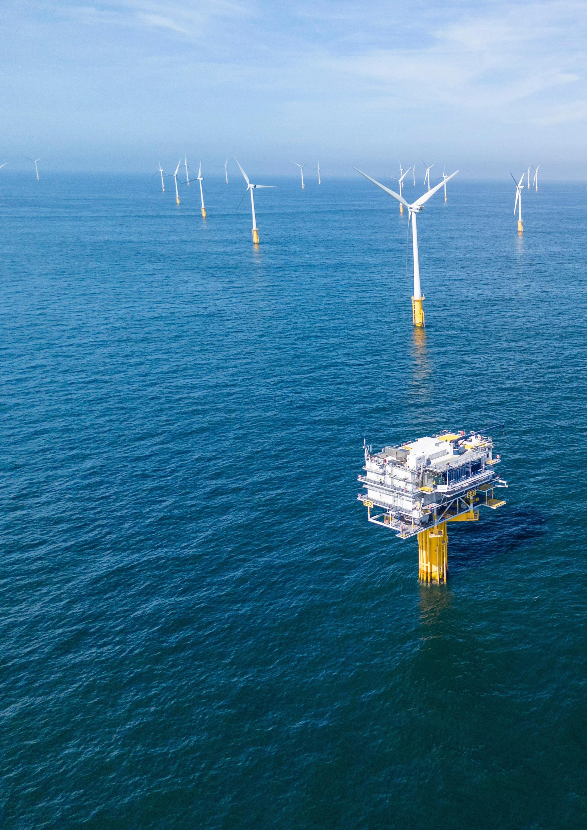
Figure 1 . Operations and maintenance (O&M) vessel approaching offshore wind farm.
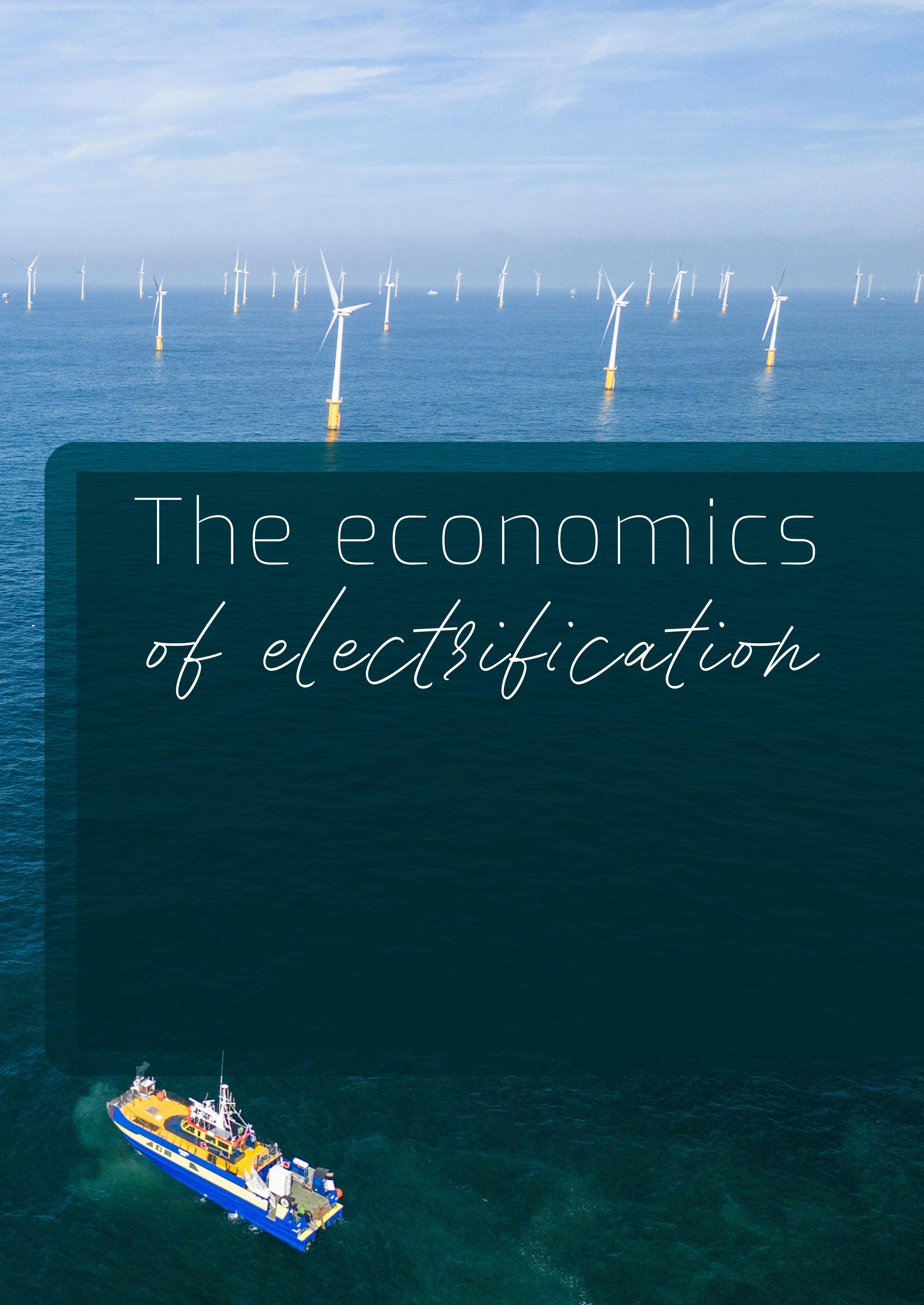
Paul Cairns, Charge Offshore and MJR Power & Automation CEO, discusses the economic case for electric operations and maintenance fleets and explores the need for robust charging infrastructure to support the transition.
The offshore wind industry continues to scale at pace, driven by ambitious net-zero targets and rising demand for clean energy as an alternative to oil and gas.1 According to The Global Wind Report 2025,2 a record 28 GW of offshore wind capacity is currently under construction worldwide, 94% of which comes from current global leaders in offshore energy: China, the UK, Taiwan, Germany, and France. However, recent geopolitical tensions have spurred wind developers to seek alternative ways to improve return on investment (ROI) on new developments and for upgrades
to existing sites; operational electrification is rapidly emerging as one pragmatic solution for achieving this. Operations and maintenance (O&M) fleets, essential for offshore wind logistics, remain largely reliant on high-emissions marine gas oil (MGO) to operate. This heavy dependence on oil adds unnecessary layers of economic risk to an industry already under pressure, not only due to the continued volatility of oil prices, but also because the UK government has made multiple policy recommendations aimed at disincentivising the use of fossil fuels.
For example, the Department for Transport (DfT) published a call for evidence on decarbonising small vessels under 400 gross t.3 This means that, pending consultation, O&M fleets would be subject to the same regulations as larger vessels under the Maritime Decarbonisation Strategy.4 These include the
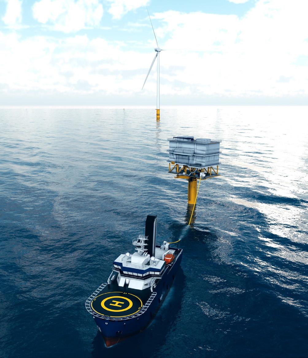
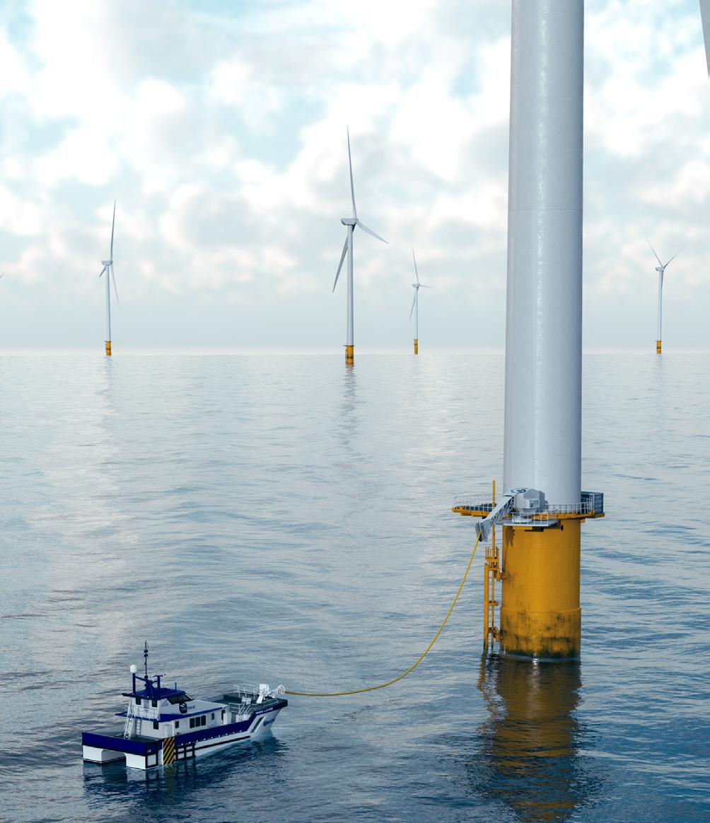
UK Emissions Trading Scheme (ETS) expanding to cover domestic maritime greenhouse gas emissions from 2026, and the likely introduction of domestic fuel regulations aimed at driving the uptake of net-zero fuels and energy sources.
Additionally, the EU’s ETS will extend to service operation vessels (SOVs) from 2027, and the International Maritime Organization (IMO) is also considering carbon pricing of up to US$380/t of carbon dioxide (CO2) for vessels exceeding emission quotas.
It has become clear that MGO as a fuel source is fast becoming outdated, costly, and a real challenge for the industry. While alternative fuels like green methanol and ammonia are being explored, they remain expensive and are unlikely to be widely available in the near term. In contrast, electricity, particularly from offshore wind, is increasingly affordable, local, and predictable.
Electrification key to decarbonising offshore wind
Battery-electric crew transfer vessels (CTVs) and SOVs are designed with the ability to charge regularly at offshore energy production sites and shore-based quay sides. By charging up with clean, near-unlimited energy on site, these vessels can operate for extended periods without the need to return to shore to refuel.
Aside from operational convenience and significant reduction in carbon emissions, electrifying offshore fleets introduces many economic advantages. While current CAPEX for electric vessels is estimated at 10 – 20% above that of traditional diesel units, this premium is narrowing rapidly. Battery costs are on a steep downward curve and the integration of automotive-grade marine batteries from manufacturers like BYD and CATL is helping accelerate parity at rapid pace.
OPEX is even more encouraging. Electric vessels avoid unstable fuel costs and benefit from lower maintenance demands due to fewer moving parts. For SOVs on long-term charters, the annual savings in energy costs alone can approach £1 million, easily offsetting the initial investment. CTVs are close behind, with breakeven OPEX expected as early as 2027.
Looking at some of these figures in more detail,5,6 diesel-powered SOVs burn around 5 tpd of fuel, representing an approximate daily fuel cost of US$3750. This generates about 15 tpd of CO2-e emissions which, based on current emissions taxation, equates to a daily carbon cost of US$1500. This means that a standard SOV costs around US$5250 daily to operate in fuel and emissions taxation alone. Based on 300 operational days per year, this results in an annual cost of over US$1.6 million, or over US$39.3 million across the 25-year lifespan of a single vessel.
An e-SOV, on the other hand, would cost just US$1162/d to run (based on current electricity prices) and without suffering carbon taxation. This equates to US$348 600/y or US$8.7 million over the lifespan of an e-SOV – over 75% less than diesel.
With around 50 new SOVs required by the industry over the next two years alone, running the next wave of diesel-powered vessels is set to cost the industry nearly US$2 billion; in contrast, adopting electric vessels would cost just US$435 million, creating an industry-wide saving of over US$1.5 billion.
The economic case for electrification is certainly there, but how can it be fully achieved? Electric vessels are commercially available and indeed steadily reaching price parity with diesel, while marine battery technology is evolving fast. However, without proper
Figure 2 . Render of service operation vessel drawing power from offshore substation.
Figure 3 Render of crew transfer vessel drawing power from offshore substation.
charging infrastructure in place to keep e-CTVs and e-SOVs running, wind operators cannot maximise economic and environmental benefits.
Maximising electrification
Both offshore and onshore charging solutions are critical for the transition to vessel electrification. A key milestone came in 2024, when MJR Power & Automation completed live offshore trials of its Aquarius ECO charging system at Parkwind’s Nobel wind offshore farm. The system delivered multiple safe and successful power transfers to CTVs without any interruption to field operations.
The charging system, alongside its larger e-SOV counterpart Aquarius PLUS, is modular, automated and designed for rapid integration into offshore assets including wind turbine generators (WTGs), offshore substations (OSS), and dedicated monopiles. Installation of these systems requires only minimal structural modification, making them an easy inclusion in the design stage of new wind farm developments.
Importantly, the charging process is fully automated and hands-free even in challenging metocean conditions. This enhances both operability and crew safety, while supporting high vessel availability and mission flexibility – integral factors in the demanding offshore wind environment.
Scalability and strategic benefits
Offshore charging systems are designed to scale. A single unit, rated between 2 – 6 MW, can serve multiple vessels daily. By integrating several ‘charger-ready’ locations into wind farm designs, operators gain flexibility to expand or adapt over time, supporting a phased transition from hybrid to fully electric fleets.
While possible, retrofitting chargers to existing WTGs can be technically challenging at higher power levels. That makes forward-thinking design essential. Developers who act now can future-proof assets, avoid regulatory headaches, and reduce lifetime O&M costs.
To help accelerate rollout of such systems, offshore charging infrastructure is eligible for a range of funding streams. Programmes like Innovate UK, Offshore Wind Growth Partnership, Horizon, and the UK’s Contract for Difference (CfD) mechanism can significantly reduce upfront costs, particularly for first movers engaging in demonstrator projects.
Globally, other European nations are also moving fast in the transition to electrification. Belgium, the Netherlands, and Germany have all established frameworks for offshore power vessel charging. The UK is expected to follow suit, with Ofgem and the Department for Energy Security and Net Zero (DESNZ) now engaged in active consultations.
To safeguard the long-term economic and environmental viability of offshore wind, developers must not only commit to pilot projects for O&M fleet electrification and offshore charging infrastructure, but also design in electrification as standard practice. The business case has matured, the technology is proven, and the strategic benefits are clear enough to demonstrate a sound ROI. Project deployments will not only deliver near-term emissions savings, but provide the operational insights and stakeholder confidence needed to accelerate full scale adoption.
To achieve this, industry collaboration is key. Partnerships between wind farm developers, vessel operators and
charger manufacturers, all underpinned by public funding, can help unlock real momentum. In the race to decarbonised offshore wind expansion, fleet electrification is no longer simply a concept, but a commercially ready, critical enabler of the industry’s long-term and sustainable future.
Notes
This article uses data from the recent whitepaper, Offshore Charging: Wind Farm O&M Fleet Electrification Enabler, which was created by MJR Power & Automation and commissioned by ScottishPower Renewables, with support from Operation Zero.7
References
1. SUTHERLAND, D. and BRADBURY, M., ‘UK wind and global offshore wind: 2024 in review’, RenewableUK, (7 February 2025), www.renewableuk.com/energypulse/blog/ uk-wind-and-global-offshore-wind-2024-in-review/
2. ‘Global Wind Report 2025’, Global Wind Energy Council, (23 April 2025), www.gwec.net/reports/globalwindreport
3. ‘Decarbonising smaller vessels’, GOV.UK, (14 July 2025), www.gov.uk/government/callsfor-evidence/decarbonising-smaller-vessels/decarbonising-smaller-vessels
4. ‘Maritime Decarbonisation Strategy’, Department for Transport, (2025), https://assets.publishing.service.gov.uk/media/67f4dcb3c2fea2548f4eff64/dftmaritime-decarb-strategy-25.pdf
5. Data provided by Bibby Marine (www.bibbymarine.com/).
6. Figures based on current data. Tax allocation subject to change pending International Maritime Organization (IMO) resolution in 2026.
7. ‘MJR Power & Automation unveils whitepaper on acceleration pathways for offshore fleet electrification’, Charge Offshore, (2025), www.chargeoffshore.com/news/mjrpower-automation-unveils-whitepaper-on-acceleration-pathways-for-offshore-fleetelectrification
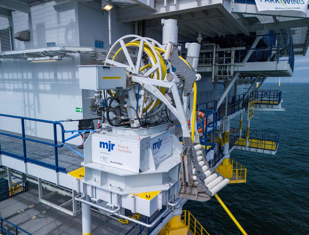
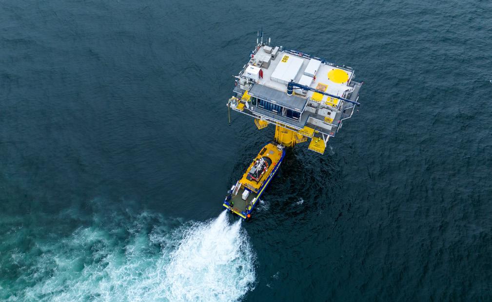
Figure 4 . Close up of offshore charging device.
Figure 5 O&M vessel docking with offshore substation.

GLOBAL NEWS
Offshore Wind Growth Partnership awards £2.4 million to scale up UK supply chain
The Offshore Wind Growth Partnership (OWGP) has awarded £2.4 million to nine supply chain companies, aimed at enhancing their capabilities and increasing capacity within the offshore wind sector.
This funding, made available through OWGP’s Development Funding programme, will provide critical support for UK supply chain companies as they scale up operations.
The programme supports projects that align with Industrial Growth Plan priorities to address key supply chain growth areas. Applications supported cover a broad range of growth areas including; electrical systems and cables, foundations and substructures, smart environmental surveys and installations, and O&M.
These applications underwent a thorough evaluation process, with priority given to proposals featuring near-to-market solutions, customer interest and engagement, and a clear and credible ambition for growth within the sector.
Nine companies have been selected to receive support from OWGP. These include, Airspection Ltd, BPP Cables Ltd, Fennex Ltd, HydroSurv Unmanned Survey (UK) Ltd, Innovair Ltd, Kinewell Energy Ltd, MJR Controls Ltd, SeaThor Ltd, and Slipform Engineering Ltd.
Infinity Power breaks ground on 200 MW wind project in Egypt
Infinity Power, Africa’s largest renewable energy provider, has broken ground on its latest wind farm, the 200 MW Ras Ghareb wind project in Egypt’s Gulf of Suez region.
Work will begin on construction with Infinity Power having recently signed an EPC contract with POWERCHINA Huadong Engineering Corp. Ltd (HDEC). The agreement was signed at the China-Africa Economic, Trade & Cultural Forum, by Nayer Fouad, Co-Founder and CEO of Infinity Power, and Liu Jiajin, Vice President of POWERCHINA HDEC.
The Ras Ghareb wind farm is a flagship project under Egypt’s renewable energy programme, part of the European Bank for Reconstruction and Development-led Energy Pillar of the Nexus Water-Food-Energy (NWFE) initiative.
Once complete, the 200 MW wind farm is expected to provide clean electricity to more than 300 000 homes and save over 400 000 tpy of carbon dioxide. It will play a critical role in advancing the country’s sustainability ambitions and accelerating the shift towards a low-carbon economy.
This step also marks a further move towards Infinity Power’s target of operating 10 GW of renewable energy across Africa by 2030, which in turn will supply approximately 12 million homes with clean electricity.
Port of Rotterdam Authority develops new terminal for offshore wind activities
The Port of Rotterdam Authority is planning to develop a 45-ha. site in the north-western corner of the Maasvlakte, the Netherlands, for offshore wind activities.
The terminal will offer opportunities for storage, transport, (pre-)assembly, and delivery of components for both wind turbines and foundations. The terminal will have direct nautical access to the sea and will be equipped with heavy-duty quays and high-quality logistics facilities. The terminal is expected to be operational in mid-2029.
The Port Authority will equip the 45-ha. site with 835 m of quay where the latest generation of offshore wind installation vessels can moor. This quay will be suitable for jack-up vessels and pre-assembly activities on the quay, among other things. A roll-on/roll-off facility is also planned so that
the terminal can facilitate all modes of transport. In addition to focusing on the construction of offshore wind farms, the terminal will also be equipped for the decommissioning of offshore wind farms.
With this project, the Port of Rotterdam Authority aims to provide the offshore wind industry with the necessary capacity and stimulate growth in the sector. Offshore wind farms play an important role in the transition from fossil fuels to sustainable energy sources. More wind farms will be built in the North Sea in the coming years. The required port capacity at the right specifications is currently a limiting factor. With the completion of the terminal, the Port Authority is providing the large scale, high-quality infrastructure that the market demands.


GLOBAL NEWS
Sendai-ko Biomass Power starts operation of biomass power plant
Sendai-ko Biomass Power GK, jointly funded by Sumitomo Corp., Tokyo Gas Co., Ltd, Hokuriku Electric Power Company, and Sumitomo Corp. Tohoku Co., Ltd, has commenced commercial operations of the Sendai Port biomass power plant following completion of construction.
With an output of 112 MW and an expected annual generation of approximately 800 000 MWh, the plant is among Japan’s largest dedicated biomass power facilities. It will provide a long-term, stable supply of renewable energy in the Tohoku region and contribute to the advancement of carbon neutrality.
The plant uses wood-based biomass fuels, including pellets and chips, derived from thinning timber, mill residues, and lower-grade wood generated during forest management. All fuels are sourced from forests under recognised forest certification programmes.
Sumitomo Corp. oversees fuel procurement, ensuring proper utilisation of forest resources and maintaining full traceability.
Diary dates
Energy Storage Summit 2026
24 – 25 February 2026
London, the UK
https://storagesummit.solarenergyevents.com
Energy Storage Summit USA 2026
24 – 25 March 2026
Texas, USA
https://storageusa.solarenergyevents.com
Biofuels International Conference & Expo 14 – 15 April 2026
Brussels, Belgium
https://biofuels-news.com/conference
TLT advises Eiffel Investment Group and BTS on financing for biomethane plants in Italy
TLT has advised Green One, a joint venture between BTS DevCo (BTS Group) and Eiffel Gaz Vert (Eiffel Investment Group), on a multimillion-euro debt project financing provided by Deutsche Bank to support the development of nine biomethane plants across Italy.
The financing enables the construction and conversion of 10 biomethane plants across multiple regions. The assets will valorise agricultural waste and residues into renewable gas, supporting local farmers and SMEs while advancing Italy’s circular economy and energy independence.
TLT advised Green One on the negotiation of the English law finance documents and managed all aspects of the project finance transaction, including co-ordination with Studio Legale Volpe Italian counsel acting for Green One to achieve a successful financial close. The transaction was led by Victoria Quek, Partner in TLT’s Project Finance team, with support from Winnie Ma, a Senior Associate in TLT’s Banking Department.
WindEurope Annual Event 2026
21 – 23 April 2026
Madrid, Spain
https://windeurope.org/annual2026
All-Energy Exhibition and Conference 2026
13 – 14 May 2026
Glasgow, Scotland www.all-energy.co.uk
Global Energy Show Canada 2026
09 – 11 June 2026
Calgary, Canada www.globalenergyshow.com

GLOBAL NEWS
Elgin invests in Italian agrivoltaic plants
Elgin has announced new initiatives in Italy to develop two large scale agrivoltaic plants in Sicily and Lombardy. The projects will have a total capacity of over 190 MW and an estimated construction value of €150 million.
In Sicily, Elgin plans to develop a 30 MW agrivoltaic plant equipped with a 30 MW battery energy storage system, which will help stabilise the energy fed into the grid. Thanks to an elevated modular structure and monitoring technologies, the plant will minimise soil impact while optimising existing agricultural activities, enhancing the productive potential of the area while generating sustainable energy.
The second project is in the Lombardy region, where Elgin will propose a 130 MW agrivoltaic plant built on rice fields. Through digital control systems and careful land management, the plant will combine energy efficiency, agricultural continuity, and protection of the local ecosystem, fully complying with the latest national agrivoltaic guidelines.
The Copper Mark and SSI sign agreement
The Copper Mark and the Solar Stewardship Initiative (SSI) have signed a memorandum of understanding that provides a framework for collaboration promoting responsible production and sourcing of copper across the solar energy value chain.
Copper is a major component in solar energy generation and transmission and as the demand for renewable energy increases so too does the need for co-operation between key stakeholders in the copper value chain.
One of the ambitions of the collaboration will be a sector leadership project that maps value chains, identifies environmental, social, and governance risks and provides solutions to enhance sector-wide performance. This work will be a key component of the Copper Mark’s Initiative for Responsible Renewable Energy Value Chains and its forthcoming Responsible Metals Value Chain Platform launching in 2026. It will create opportunities for direct engagement between copper value chain actors that mine, smelt, refine, recycle, fabricate copper products, and downstream actors that manufacture components, products, and operate grid systems in the solar energy industry. It will also invite contributions from civil society organisations, regulatory experts, and academics.
ARENA to fund solar manufacturing facility in NSW
The Australian Renewable Energy Agency (ARENA) has announced up to AUS$151 million in conditional funding under the Australian government’s AUS$1 billion Solar Sunshot Program for the establishment of a 500 MW/y solar module manufacturing facility in the Hunter Valley, New South Wales.
The funding will support the development of the Hunter Valley Solar Foundry project, an initiative of the Sunman Group (Sunman) founded by Dr Zhengrong Shi. The project will develop a new, advanced manufacturing facility while drawing on Sunman’s pioneering technology and track-record as a lightweight solar innovator.
Construction of the facility is expected to create up to 200 jobs, with another 100 ongoing roles once operational.
THE RENEWABLES REWIND
> AFRY to conduct key studies for hydropower plant in Zambia
> Global Hydro joins IHA
> RWE to build its largest UK battery energy storage facility
> Root-Power wins planning appeal for BESS in Wakefield
> ENGIE enters India’s utility scale energy storage market
> Planning consent granted for Lewis Hub HVDC connection project
> Plug Power to supply equipment for Carlton Power
Follow our website and social media pages for more updates, industry news, and technical articles. www.energyglobal.com

GLOBAL NEWS
Greenvale and SRL Hot Rocks agree farm-in and JV for geothermal project
Greenvale Energy Ltd has entered into a farm-in agreement with SRL Hot Rocks Pty Ltd, a wholly-owned subsidiary of Sunrise Energy Metals, setting the pathway for a future joint venture (JV) to develop the Millungera Basin geothermal project in north-west Queensland.
Located approximately 120 km east of Mount Isa, within the North-West Minerals Province, the Millungera Basin geothermal project sits over one of the most prospective areas for geothermal energy in Queensland.
The targeted heat source for the Millungera Basin is high heat producing intrusives underlying the basin. Granitic bodies have been inferred from geophysical data to underlie the Millungera Basin and are possible Williams Supersuite equivalents.
At the completion of the farm-in, the parties may form a JV to continue to advance the project. The JV will initially be split 80/20 to SRL-HR/Greenvale. The future JV agreement terms and commercial construct have been negotiated and agreed in-principle.
Arverne launches first geothermal drilling for Lithium de France project
Arverne, a leading French supplier of geothermal solutions, has announced the start of drilling of the first geothermal doublet at the Schwabwiller site in Alsace.
In accordance with the established schedule, following site preparation work, Arverne’s teams are beginning drilling operations. On the surface, the two wells will be spaced 10 m apart and will gradually move further apart to reach a spacing of 1 km at a depth of 2400 m.
These initial drillings will confirm the flow rate, temperature, and lithium content of the geothermal fluid at this site. This phase will be crucial for collecting data that will help refine geological models and adapt technical protocols.
The Lithium de France project will actively contribute to the energy transition by providing carbon-free geothermal heat to businesses, farms, and local communities in northern Alsace via a short supply chain. The geothermal brines, rich in critical metals, will also be used to produce low-carbon lithium to support electric mobility.