
February 2023

Meet the fuel of the future today. Produce blue ammonia at the highest capacity with the lowest possible levelized cost. Decarbonize at mega scale while increasing the value of your ammonia product. Integrate blue ammonia solutions today to meet the demand of tomorrow.
Blue Ammonia. Tomorrow’s fuel. Ready today.

plant data.
Robert B. Fedich and Amalia Pantazidis, ExxonMobil Catalysts and Licensing LLC, USA, outline the benefits of a flexible initial process design for an amine unit on an offshore platform.
Klaus Brun, Elliott Group, USA, explains why the decarbonised energy economy requires customised compressor solutions for three primary value stream gases: hydrogen, carbon dioxide, and natural gas.

Craig Martin, Paul Modern and Juan Moreno, Cook Compression, explore two potential pathways to decarbonisation for energy companies.

Lea Clauson, DeZURIK Inc., USA, presents a number of valve selection considerations for a refinery.

Luke Perry, Rotork, UK explains how maintenance of flow control assets can not only prevent failure, but also improve overall plant efficiency.
In part one of a two-part article, Prashanth Chandran, Nathan Hatcher and Ralph Weiland, Optimized Gas Treating, Inc., USA, detail the two perspectives that should be considered when setting expectations from simulation.
Ted Huck, MATCOR Inc., USA, explains why cathodic protection is a proven technology and a viable strategy for corrosion control and mitigation in hydrocarbon processing facilities.
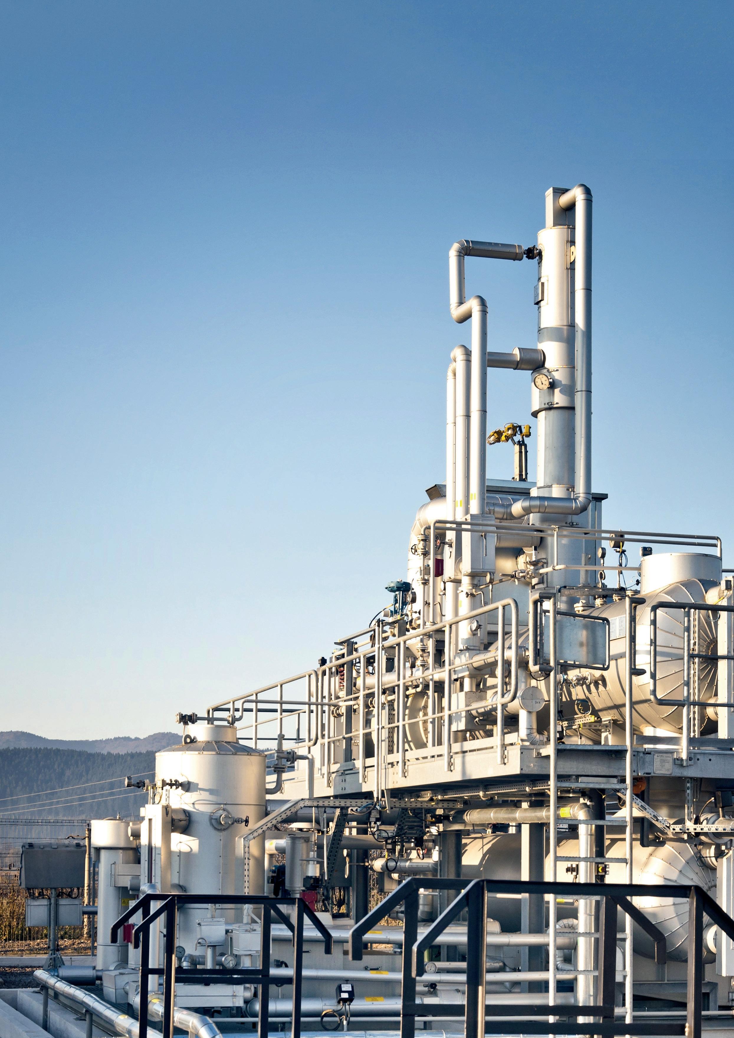
Elliott Group: a natural gas compression processing plant for dehydration.
For more information, please visit: www.elliott-turbo.com

ET Black™ is a state-ofthe-art technology that complies with the most stringent environmental regulations now and in the future.


Plus, the flexibility to produce all ASTM grades, and specialty grades, in a single plant. ET Black™, the technology of reference for producing carbon black obtained by thermal decomposition of highly aromatic oils.


Find out more at: www.igoforETBlack.com
MANAGING EDITOR James Little james.little@palladianpublications.com
SENIOR EDITOR Callum O'Reilly callum.oreilly@palladianpublications.com
ASSISTANT EDITOR Bella Weetch bella.weetch@palladianpublications.com
EDITORIAL ASSISTANT Isabelle Keltie isabelle.keltie@palladianpublications.com
SALES DIRECTOR Rod Hardy rod.hardy@palladianpublications.com
SALES MANAGER Chris Atkin chris.atkin@palladianpublications.com
SALES EXECUTIVE Sophie Birss sophie.birss@palladianpublications.com

PRODUCTION MANAGER Kyla Waller kyla.waller@palladianpublications.com
EVENTS MANAGER Louise Cameron louise.cameron@palladianpublications.com
EVENTS COORDINATOR Stirling Viljoen stirling.viljoen@palladianpublications.com
DIGITAL CONTENT ASSISTANT Merili Jurivete merili.jurivete@palladianpublications.com
DIGITAL ADMINISTRATOR Leah Jones leah.jones@palladianpublications.com
ADMIN MANAGER Laura White laura.white@palladianpublications.com
CONTRIBUTING EDITOR
Nancy Yamaguchi Gordon Cope
SUBSCRIPTION RATES
Annual subscription £110 UK including postage /£125 overseas (postage airmail).
Two year discounted rate £176 UK including postage/£200 overseas (postage airmail).
SUBSCRIPTION CLAIMS
Claims for non receipt of issues must be made within 3 months of publication of the issue or they will not be honoured without charge.
APPLICABLE ONLY TO USA & CANADA
Hydrocarbon Engineering (ISSN No: 1468-9340, USPS No: 020-998) is published monthly by Palladian Publications Ltd GBR and distributed in the USA by Asendia USA, 17B S Middlesex Ave, Monroe NJ 08831.
Periodicals postage paid New Brunswick, NJ and additional mailing offices. POSTMASTER: send address changes to HYDROCARBON ENGINEERING, 701C Ashland Ave, Folcroft PA 19032.
15 South Street, Farnham, Surrey
GU9 7QU, UK
Tel: +44 (0) 1252 718 999
Chapters 1 and 2 of the World Economic Forum (WEF)’s ‘Global Risks Report 2023’ are entitled ‘Today’s Crisis’ and ‘Tomorrow’s Catastrophes’, respectively. Whilst this is a rather solemn outlook for the year ahead, the reality is that we are faced with the continued threat of cost-of-living crises, political conflict, and social polarisation – among other things.
Specifically, the report states that “most respondents to the 2022-2023 Global Risks Perception Survey (GRPS) chose ‘energy supply crisis’; ‘cost-of-living crisis’; ‘rising inflation’; ‘food supply crisis’ and ‘cyberattacks on critical infrastructure’ as among the top risks for 2023 with the greatest potential impact on a global scale”.1 And so, amid the noise of economic recovery from COVID-19, the continued Russia-Ukraine conflict, and persistent cyberattacks, the issue of decarbonisation failed to make it into one of the top spots.
However, Saadia Zahidi, Managing Director of the WEF, notes that “the health and economic after-effects of the pandemic have quickly spiralled into compounding crises. Carbon emissions have climbed, as the post-pandemic global economy fired back up”.1 Despite the number of distracting dilemmas that we are up against today, it is clear that climate change remains a concern – perhaps more than ever. And in the wake of Davos 2023, we thought it fitting to reflect on how the energy sector is adapting to this catastrophe of tomorrow.
Several of the articles in this issue are cognisant of the oil and gas industry’s role in mitigating emissions. Elliott Group (p. 35) explores the development of new and optimised turbomachinery solutions to support the decarbonisation of the energy economy. On p. 41, Cook Compression discusses two potential pathways to decarbonisation – emission reduction and hydrogen fuel – and how new technologies are being developed to support energy companies. Similarly, Comprimo, part of Worley (p. 19) studies the options available for recovering carbon dioxide emissions and hydrogen from sulfur plants, and Bechtel Energy (p. 14) discusses the integration of an amine-based, post-combustion carbon capture unit with an LNG facility.
Additionally, our regional report, which focuses on Central and South America, begins by stating that one of the challenges that is set to inform the future of the region’s downstream sector is the global race to net zero. As such, there are moves to develop the hydrogen economy in Brazil in particular.
Whilst the WEF’s outlook for 2023 may seem glum, we hope that the key takeaway from this issue is that there are signs of recognition and progress towards a sustainable future within the oil and gas sector. There is an awareness of the fact that climate change is a worrying reality, and companies are looking at ways of adapting their operations in response to this.
Indeed, a recent headline from The Guardian read ‘What we learned at Davos: signs of hope emerge from the pessimism’. The article notes that whilst we have “become hard-wired for pessimism […] after surviving the horrors of the past three years there [is] a sense that there can’t be much more bad stuff out there and that, as a result, the only way is up from here”.2 Perhaps it is time to attempt a shift away from pessimism towards cautious optimism, instead.
1. ‘The Global Risks Report 2023’, World Economic Forum, 18th Edition.
2. ‘What we learned at Davos: signs of hope emerge from the pessimism’, The Guardian, (22 January 2023), https://www.theguardian.com/business/2023/jan/22/what-we-learnedat-davos-global-economy
End-to-end systems from receipt of molten sulphur to loading of solid material – single source supply by IPCO.

• Premium Rotoform pastillation.
• Duplex steel belts specifically alloyed to resist corrosion.
• High capacity drum granulation.
• Downstream storage – silo and open/closed stockpiles.
• Custom-built reclaimers for any location.
• Truck, rail and ship loading and bagging systems.
• Large scale block pouring.
Technip Energies has been awarded a contract to upgrade sulfur recovery facilities at Aramco’s Riyadh refinery.
This contract covers the implementation of three new tail gas treatment (TGT) units, improving the performance of the existing three sulfur recovery units (SRUs) to comply with more stringent regulations for sulfur dioxide (SO2) emissions, with recovery efficiency at more than 99.9%.
The project will be executed locally, leveraging Saudi economic resources and infrastructure.
The existing SRUs in the Riyadh refinery were designed and built by Technip Energies in the early 2000s.
Bhaskar Patel, Technip Energies’ SVP Sustainable Fuels, Chemicals & Circularity, commented: “We are pleased to be entrusted by Aramco to work on the upgrading programme of their refinery in Riyadh.
“By leveraging our long-standing relationship, which has been in place since the mid-1990s, we are committed to [making] this project another success, while utilising local resources and supply chain.”
Phillips 66 has announced that it has received ISCC PLUS certification for its Sweeny Refinery in Texas, US, to process oil made from waste plastics into feedstocks for new plastics.
ISCC is a sustainability certification system that covers all sustainable feedstocks, including circular feedstocks produced from plastic waste. Its ISCC PLUS certificate covers bio-based and recycled, or circular, raw materials.
The certification verifies that the refinery meets the standards to process pyrolysis oil made from hard-to-recycle waste plastics into circular ethane, circular propane, circular propylene and other sustainable feedstocks and petrochemical building blocks. The products will be used to support polymer producers that are advancing a circular economy for plastics.
BASF has broken ground on the third and final phase of the methylene diphenyl diisocyanate (MDI) expansion project at its Verbund site in Geismar, Louisiana, US, announced in July 2022. The company will increase production capacity to approximately 600 000 tpy by the middle of the decade.
The investment for this final expansion phase, which takes place from 2022 to 2025, amounts to US$780 million. Including the first and second phases, the investment volume totals around US$1 billion, making the MDI expansion project BASF’s largest wholly-owned investment in North America.
BASF welcomed Clay Schexnayder, Speaker of the House for the Louisiana State Legislature, for a ceremonial ‘tilling-of-the soil’ to officially mark the ground breaking of the final phase of the expansion.
Leveraging state-of-the-art technology, the expansion will showcase the highest safety standards combined with advanced digitalisation in its operations.
Irving Oil and Anaergia Inc. have announced a partnership that will supply Canada’s largest refinery with carbon-negative renewable natural gas (RNG), as well as Irving Oil’s other operations such as delivered natural gas.
The RNG, which is made from organic matter instead of fossil fuels, will be produced at Anaergia’s Rhode Island bioenergy facility, where food waste and other organic wastes that would otherwise have been
landfilled are transformed into renewable fuel. The facility is designed to divert over 100 000 tpy of waste from landfills, and it is the largest anaerobic digester processing organic waste in New England.
Approximately 350 million ft3 of RNG will be supplied annually from Anaergia into the regional pipeline, where it will reduce the need for conventional natural gas supply to Irving Oil’s operations, including the
Saint John Refinery in New Brunswick, Canada.
This RNG is recognised as carbon-negative due to its ability to capture more methane emissions than the organic waste would have otherwise created when landfilled. In this way, Anaergia’s Rhode Island bioenergy facility prevents the release of more than 40 000 tpy of carbon dioxide (CO2)-equivalent greenhouse gas emissions.
14 - 16 March 2023
StocExpo Rotterdam, the Netherlands www.stocexpo.com
19 - 21 March 2023
AFPM Annual Meeting
San Antonio, Texas, USA www.afpm.org/events
19 - 23 March 2023
AMPP Annual Conference & Expo Denver, Colorado, USA ace.ampp.org
12 - 14 April 2023
25th International Aboveground Storage Tank Conference & Trade Show Orlando, Florida, USA www.nistm.org
25 - 27 April 2023
Sulphur World Symposium Edinburgh, Scotland www.sulphurinstitute.org/symposium-2023
08 - 12 May 2023
RefComm
Galveston, Texas, USA events.crugroup.com/refcomm
07 - 08 June 2023
Valve World Americas Expo & Conference Houston, Texas, USA www.valveworldexpoamericas.com
07 - 08 June 2023
Downstream USA 2023
Galveston, Texas, USA events.reutersevents.com/petchem/downstream-usa
13 - 15 June 2023
Global Energy Show Calgary, Alberta, Canada www.globalenergyshow.com
10 - 13 July 2023
LNG2023
Vancouver, British Columbia, Canada www.lng2023.org
05 - 08 September 2023
Gastech Singapore www.gastechevent.com
TotalEnergies has announced the start-up of the Deutsche Ostsee LNG import terminal, which will be operated by Deutsche ReGas and located in Lubmin, Germany.
TotalEnergies is contributing a floating storage and regasification unit (FSRU) and supplying LNG to the project.
In December 2022, TotalEnergies delivered one of the company’s two FSRUs to Deutsche Regas. The vessel has an annual regasification capacity of 5 billion m3 of gas – enough to cover approximately 5% of German demand.
Following Deutsche Regas’ open season procedure, in October 2022, TotalEnergies also contracted a regasification capacity of 2.6 billion m3/yr of gas, and began to deliver LNG from its global integrated portfolio to the Lubmin terminal.
“Thanks to the start-up of the Lubmin terminal, TotalEnergies will be able to [...] increase its imports to Europe to over 20 million tpy, or about 15% of the continent’s regasification capacity,” said Stéphane Michel, President Gas, Renewables & Power at TotalEnergies.
USD Clean Fuels LLC has announced its intention to build a new biofuels terminal in National City, California, US, that will have the capability to transload renewable diesel, biodiesel, ethanol and sustainable aviation fuel (SAF). The terminal will be served by the BNSF Railway and will provide efficient transportation of clean fuels to the area from the Midwest and US Gulf Coast. Pending receipt of all local and state permits, the terminal is
expected to be operational by early 2024.
The terminal development is supported by two investment-grade rated parties that signed long-term terminal service agreements. These agreements provide for the inbound shipment of renewable diesel, biodiesel, ethanol and SAF on rail, self-switching of the rail rack, and four truck loading spots that are equipped with in-line injection capabilities to provide quality finished products to customers.
Emerson will provide automation technologies, software and analytics for the Ras Laffan Petrochemical Complex in Qatar, as part of a consortium with Viasat Energy Services. The US$6 billion integrated polymers project, a joint venture (JV) between QatarEnergy and Chevron Phillips Chemical, is currently under construction and scheduled to go online in late 2026.
The project is QatarEnergy’s largest investment ever in the country’s petrochemical sector. The complex will include an ethane cracker with a capacity of 2.1 million tpy of ethylene, making it the largest ethane cracker in the Middle East and one of the biggest in the world. It also includes two high-density polyethylene derivative units with a total capacity of 1.7 million tpy.

According to the UN’s Economic Commission for Latin America, the population for Central and South America reached approximately 660 million in 2022, and is expected to rise to around 750 million by mid-century.1

While the trend would normally inspire investment in refining capacity and related infrastructure, the future of the region’s downstream sector is muddied by several complications: the global movement towards net zero emissions, the ongoing Ukraine war, politics, and hydrogen development. Depending on the jurisdiction, some factors will have a beneficial effect, others deleterious.
Colombia is South America’s third largest oil producer, with an output of over 700 000 bpd. It has only eight years left of reserves, however, and needs to significantly increase exploration in order to maintain production.
In September 2022, the country elected Gustavo Petro as its new President. The left-wing candidate had run on a platform of eliminating contracts for oil and gas exploration and a ban on fracking. Upon inauguration, he wasted little time replacing the board of directors of state-owned Ecopetrol with his own slate of candidates, cementing control over the largest producer and refiner in
the country. In addition to focusing on a transition to renewables such as wind and solar, Ecopetrol will be paying significantly higher revenues to the government. The changes will inevitably redirect expenditures away from maintenance of conventional energy assets. In early 2021, Ecopetrol announced that it was spending US$780 million over the next several years to modernise the century-old, 250 000 bpd Barrancabermeja refinery in the Caribbean port of Santander. An upgrade and expansion of its hydrocracking unit will reduce sulfur content in gasoline to 10 ppm. Water treatment and sulfur dioxide (SO2) reduction are also planned for the facility.

The ultimate fate of the refinery is now uncertain. In October 2022, President Petro visited the Barrancabermeja community (which is located at the mouth of the Magdalena River), and suggested that they begin switching their economic priorities from oil to the opportunities of monetising potable water; Colombia’s future energy needs would be supplied by renewables.
While a focus on renewables is admirable, the repercussions in several EU countries from over-dependence on wind and solar point to the hazards. Colombia, which relies on oil and gas for one-quarter of its revenues, can ill-afford missteps; protests from the
Gordon Cope, Contributing Editor, reflects on happenings in Central and South America’s downstream oil and gas sector in 2022, and forecasts what lies ahead for the region.
disaffected poor and violence from guerrilla groups already engulf many parts of the country.
Venezuela, with an estimated 304 billion bbl of reserves, has seen its output plummet from over 3 million bpd to an estimated 527 000 bpd in late 2021.
The lack of investment in maintenance has had a profoundly negative impact on the downstream sector. The Paraquana refinery complex, with a nameplate capacity of 940 000 bpd, has been the scene of a score of failures, including a crack in a holding tank that resulted in 3.6 million l of fuel spilling into the Gulf of Venezuela marine environment. Following a substandard refurbishment, the 140 000 bpd El Palito refinery in Carabobo State has been largely shut due to a leaking catalytic cracker.
Thanks to the disruptions and sanctions arising from the Ukraine war, the Biden administration has recently made overtures to Venezuela in regards to lifting sanctions (in November 2022 it granted US-based Chevron permission to resume operations at its oilfields for six months), but the downstream sector needs an estimated US$200 billion in investments to restore viability. Considering that most major oil companies have abandoned their assets in Venezuela, any comprehensive revitalisation is highly unlikely.
For the last several years, Brazil has been privatising many different parts of its economy, including the energy sector. State-controlled Petrobras has been divesting itself of major assets, including petrochemical plants, pipelines and refineries.
Eight refineries are on the disposal list. In December 2021, Petrobras finalised the sale of its 333 000 bpd Mataripe refinery in northeast Brazil to Arcelen. For the last year, the plant had been operating at under 70% capacity. The Abu Dhabi-based company, which paid US$1.8 billion for the facility, intends to return the plant to full capacity and to explore biorefining potential. In 2022, Petrobras also concluded the sale of its 6000 bpd SIX (Regap) refinery to the Canadian-based Forbes & Manhattan (F&M) for US$41.6 million.
Two other sales are pending final approval: the 46 000 bpd Isaac Sabbá refinery, sold to Atem Distribuidora for US$190 million, and the 800 bpd Lubrificantes e Derivados do Nordeste (Lubnor) refinery, acquired by Grepar Participações for US$34 million.
Petrobras is also instigating changes to produce biofuels. In 2020, it reconfigured its Repar refinery to produce 110 000 tpy of renewable diesel made from soybean oils. Between 2022 – 2026, it plans to spend US$600 million to add 505 000 tpy further capacity to its Paulinia and Cubatao refineries.
In October 2022, Brazil elected Luiz Inácio Lula da Silva (Lula), a former president, who formally took power in January 2023. Lula’s campaign platform had several planks affecting the energy sector. He vowed to rein in rising energy costs to the public (which had been passed on
during the previous Bolsonaro administration) by shielding them from international prices. While not looking to reverse finalised sales of Petrobras assets, re-examination of pending transactions has not been ruled out. The remaining four refineries, Abreu e Lima (Rnest), Presidente Getúlio Vargas (Repar), Alberto Pasqualini (Refap) and Gabriel Passos (Regap) are still technically up for sale, but the new, left-leaning administration increases the risk factor for potential buyers.
While Lula’s administration may attempt to slow privatisation of Petrobras’ downstream assets, upstream exploration is expected to continue largely unabated. During his first presidency from 2003 to 2010, Lula was a champion of pre-salt development. In October 2022, thanks largely to the pre-salt play, total crude production exceeded 4 million bpd (of which 3.4 million bpd came from offshore). Petrobras has committed a further spending of US$68 billion over the next five years to boost production further toward 5.3 million bpd by 2030.
Thanks to the populist policies of Mexican President, Andrés Manuel López Obrador (AMLO), the privatisation trend under the previous administration has been significantly reversed. New licensing rounds and joint ventures (JVs) between cash-strapped Pemex and deepwater operators have been cancelled.
In addition to this, the downstream sector has been impacted. In order to be more energy self-sufficient, AMLO has decreed an end to crude exports in order to supply Mexico’s fuel needs domestically. Pemex manages six refineries with a nominal capacity of approximately 1.5 million bpd – enough to meet domestic demand for gasoline, diesel and jet fuel. Most have been operating at reduced capacity due to lack of maintenance, however. The 315 000 bpd Tula refinery, near Mexico City, has operated at half capacity for the last several years. Pemex has earmarked US$2.6 billion in renovation funds to increase output, including a new coker.
Further, Pemex is constructing a new refinery. The 340 000 bpd Dos Bocas plant is being built in AMLO’s home state of Tabasco. Costs have soared from the original US$8 billion budget, and the refinery is now expected to cost US$12.5 billion. It was officially inaugurated on 1 July 2022 – the fourth anniversary of AMLO’s election. The refinery is now in its testing phase, but is not expected to begin producing significant amounts of fuel for several years. Although curtailing crude exports will provide the new refinery with sufficient feedstock when it is finally completed, the region has a shortage of natural gas, which could hinder production unless new gas pipelines to the Yucatan are completed over the next several years.
Mexico is also positioned to indirectly benefit from the surge in LNG demand due to the Ukraine war. Sempra Energy’s Energía Costa Azul (ECA) LNG, located in Baja California, is a former LNG import site. The 3 million tpy train was originally scheduled for completion in 2024, but the company says that construction delays have pushed the commissioning date into 2025. Sempra is
Effective asset management is more than digital tools and data. It requires the behind-the-scenes use of best practices and a deep understanding of heavy industry infrastructure.

When decades of EPC experience meets data analytics, our clients have a integrated solution for the reliability they require.
• Full-service solutions from design and construction to operations & maintenance
• Enhanced diagnostics to rapidly achieve your goals

• Data-driven operations & maintenance for maximized ROI
Let’s find ways to help you.
in talks with partners for a potential Phase 2 with a capacity of 12 million tpy.
The Mexico Pacific Ltd (MPL) LNG project is located south of ECA on the Sea of Cortez in Sonora State. The latest plan is to build three trains totalling 14.1 million tpy capacity in Phase 1, and a further three trains in Phase 2, doubling capacity to 28.2 million tpy. The company notes that it has secured Memorandum of Understanding (MoU) sales and purchase agreements from Asian utilities and supermajors seeking to diversify sources. Pending a final investment decision (FID) later in 2022, initial LNG is expected by 2026.
Both ECA and MPL are already served by major pipelines that are connected to Permian gas hubs. While LNG output is unlikely to enter the European market to displace Russian gas, their positions on the Pacific coast make them highly attractive to the energy-hungry Asian market.
Over the last decade, Guyana has transformed into one of the largest exporters of crude on the continent. Over 30 deepwater offshore discoveries by ExxonMobil and partners in the Stabroek Block have resulted in an estimated 11 billion bbl of recoverable oil resources, with the potential for far more discoveries. Several floating production, storage and offloading (FPSO) facilities are already in place. Liza Phase 1 and Liza Phase 2 are now producing an average of nearly 360 000 bpd of oil. It is projected that there will be a total of 12 FPSOs producing up to 1.5 million bpd by 2027.
The boom in production has attracted widespread interest in building new energy-related projects in Guyana. US-based Delta Energy and Petroleum Corp. (DEPC), for instance, has offered to construct four modular refineries, each with a 60 000 bpd capacity and the potential for 10 000 permanent jobs. The government, however, has noted that it does not wish to develop large-scale energy projects because they emit unacceptable levels of greenhouse gases (GHGs). Instead, they have invited proposals to finance and build a 30 000 bpd refinery in order to provide a safe, reliable source of fuel for the country. “This is for national security purposes to have energy security at home where we don’t run out of gas or diesel or anything like that” said Vice President, Bharrat Jagdeo.2 The government is looking for the successful bidders to begin construction in 2023, and complete it by 2025. Feedstock will be provided from the country’s share of oil production.
Over the last decade, investments in the unconventional Vaca Muerta shale play have resulted in significant growth of domestic crude production. Output has almost doubled from 100 000 bpd in mid-2020 to over 220 000 in mid-2022; total domestic production is now exceeding 600 000 bpd. The growth is expected to gradually help displace imports.
Argentina has approximately 600 000 bpd of domestic refining capacity. State-controlled YPF accounts for
around half, including the 189 000 La Plata refinery near Buenos Aires, and the 105 000 bpd Lujan de Cuyo refinery in Mendoza. In 2019, the company announced that it would spend more than US$2 billion to carry out a desulfurisation process at both plants. The work is expected to be finished in 2024.
The growth in gas production is also expected to offer opportunities for LNG exports. The Vaca Muerta produced 1.6 billion ft3/d of associated gas in early 2022, and is expected to exceed 4 billion ft3/d by 2030. For several years, YPF has been working to establish a floating LNG plant in the Atlantic port of Bahia Blanca. Now, with the planned construction of the US$1.6 billion Néstor Kirchner Gas Pipeline from Neuquén province to Buenos Aires in the populous north, other plans are emerging for land-based LNG export plants.
Latin America produces approximately 4 million tpy of hydrogen, primarily for crude upgrading in refineries. While many jurisdictions have announced grand plans to develop green hydrogen economies, relatively few have advanced to the planning stage. In 2021, Australian firm Enegix announced plans to take advantage of northeast Brazil’s abundant wind and sunshine in Ceará state to construct a 600 000 tpy green hydrogen plant. The US$5.4 billion project is expected to take up to four years to construct after all construction permits are issued; most of the output is destined for the export market. During 2022, Ceará state also signed two MoUs, one with Japan-based Mitsui for the production of green hydrogen and ammonia at the port of Pecém, and the other with ABB Automation, a Swedish-Swiss company that specialises in the hydrogen value chain – from production and transport, to consumption.
While the repercussions of the Ukraine war are being felt in Central and South America, politics still play a major role in the region’s energy sectors. Venezuela has confiscated assets and Mexico has cancelled future international energy investments. This has led to severe deterioration of downstream assets in the former, and the diminishment of upstream activities in the latter. While the coffers of state-owned oil companies swell from increased export revenues, so does the political desire for net zero. What might have been a boon to countries in urgent need of infrastructure investment and modernisation may now be redirected toward environmental goals.
1. ‘Latin America and the Caribbean lost nearly 3 years of life expectancy at birth between 2019 and 2021 as a result of the COVID-19 pandemic’, ECLAC - United Nations, (22 August 2022), https://www.cepal.org/en/notes/latin-america-and-caribbeanlost-nearly-3-years-life-expectancy-birth-between-2019-and2021#:~:text=By%202022%2C%20estimates%20place%20 the,a%20total%20of%20751.9%20million.
2. ‘Oil refinery is to ensure Guyana does not run out of fuel, says Vice President’, OilNOW, (6 November 2022), https://oilnow.gy/ featured/oil-refinery-is-to-ensure-guyana-does-not-run-out-offuel-says-vice-president/
Jaleel Valappil, Bechtel Energy, USA, looks at how to ensure operability of hydrocarbon facilities with post-combustion carbon capture.

Global warming and climate change caused by greenhouse gases (GHG) have received widespread and growing concern in recent years. The challenge of meeting increasing global energy demands while mitigating climate change is an urgent one that the world needs to address. The natural gas/LNG industry has seen tremendous growth over the years, with several grassroots plants having been built around the world in order to meet global energy needs, and natural gas demand is expected to grow over the next decade. Most of the facilities use gas turbine drivers which emit a significant amount of flue gases that contain carbon dioxide (CO2). Fired heaters used in these facilities also emit CO2; and CO2 is also emitted by acid gas removal processes in the pre-treatment of feed gas prior to liquefaction.
Carbon capture and storage technology (CCS) is one opportunity to capture CO2 emissions from flue gases as a result of combustion processes. The captured CO2 can be stored in underground formations afterwards. CCS is becoming more popular in the power industry, where more than 30 power generation projects are currently under construction, or at various stages of development. LNG facilities are also expected to be designed or retrofitted with CCS in the future. However, most of the LNG plants that are currently in operation are not designed for carbon capture. For this reason, post-combustion CO2 capture (PCC) has an advantage over other alternatives because the technology can simply be implemented as an ‘end-of-the-pipe’ retrofit, without the need for significant changes to existing facilities. The most widely used technology for post-combustion CO2 capture is the amine solvent-based process.

The retrofitting of existing natural gas facilities with CO2 capture offers a promising opportunity to achieve a global reduction in CO2 emissions. With this, any operational disturbances in the hydrocarbon facility can impact the operation of carbon capture in an adverse way, and vice versa. Accounting for these interactions in the design of a carbon capture facility is important to ensuring reliable facility operation after start-up.
This article will discuss the integration of an amine-based, PCC unit with an LNG facility, and the effect of the integration on the LNG facility’s operation.
In order to obtain a full understanding of the transient characteristics of a hydrocarbon facility with PCC, both units can be combined in an integrated dynamic model for analysis. Dynamic simulation can play a pivotal role in identifying any operational bottlenecks under transient conditions for the integrated hydrocarbon and CO2 capture plants. The integrated model can also be a valuable means to establish operational strategies on both sides to account for the various upstream scenarios. As an alternative, individual unit models can be used to develop boundary conditions for each other in order to obtain a representative behaviour of the entire facility.
This article will present a case study where the exhaust from an LNG facility is sent to a carbon capture unit. The dynamic model of the waste heat recovery unit (WHRU), duct work and the associated equipment is used to ensure that the various transient scenarios in an LNG facility or in the PCC unit do not adversely impact the LNG plant’s operation. This is valuable for verifying the design of the PCC unit/integration, and identifying any operational recommendations for the integrated facility.
The three main options for carbon capture in hydrocarbon facilities are pre-combustion, post-combustion, and oxyfuel combustion. When compared to pre-combustion and oxyfuel combustion, post-combustion capture is considered to provide comparable performance with reduced technical risk and process complexity. Post-combustion can be installed without affecting the performance of the liquefaction process. Additionally, this option requires a minimum number of modifications to existing equipment, hence reducing risk. This makes post-combustion attractive for new LNG plants, or as a retrofit to existing plants. There is also a good amount of experience to support post-combustion capture in power plants, which makes it a less risky option. Additionally, downtime in a carbon capture plant does not have to affect LNG production, as the flue gas can be diverted to the atmosphere with an appropriate design.1
The use of amine-based solvent for PCC has attracted considerable interest in CO2 capture. This is a proven technology – existing PCC pilot plants already demonstrate the feasibility of
CO2 removal with amine solvent from flue gas, albeit at a modest scale. Monoethanolamine (MEA) is the most commonly used solvent in chemical absorption processes for CO2.
The integration of PCC with LNG plants is carried out by directing the flue gas from gas turbines to an amine-based carbon capture unit. This will include additional ducting, dampers, and possibly a blower to increase flue gas pressure. A WHRU unit may be used to further recover the heat from flue gas. The heat requirements for the reboiler can be provided by the existing hot oil or steam system in the facility. When integrating PCC into an existing facility, the following aspects must be considered in order to ensure reliable and safe operation:2
n Flexibility of operation: the ability to operate in an acceptable manner over a range of steady-state conditions. For example, this can include:
§ Operation at turndown rates (half rate/other) due to changing ambient conditions or other operational reasons.
§ Operation with no LNG production – with refrigeration compressors running in recycle, with gas turbines partially loaded.
n Controllability: ability to recover from process disturbances and move to new set points in a measured and timely fashion. This is dependent on both the design of the process and the underlying process control schemes.
n Start-up and shutdown: the start-up and shutdown of an LNG facility/PCC unit is a key operating scenario for the amine system that can induce major changes.
n Reliability/safety of operation: the ability to accommodate equipment failures and trips in a safe
manner. This includes trips of various equipment, e.g. valves failing to close, etc.
The design and integration of PCC needs to account for the various operational scenarios and disturbances in the LNG facility and the carbon capture unit. One of the main concerns with integration is the impact of upsets in a PCC facility affecting the LNG production. Large variations in gas turbine exhaust pressure can cause the turbine driver to trip, bringing LNG production to a halt and subsequently incurring very significant economic costs. The following are some of the key scenarios that impact the integrated system, and that should therefore be considered during design:
n LNG train trip/facility-wide shutdown.
n Trip of individual gas turbines.
n Turndown to half rate and to standby mode, with refrigeration compressors in recycle.
n Start-up of refrigeration compressors/PCC unit.
n Trip of flue gas blower.
n Failed closing of a flue gas damper.
n Operational upsets in the PCC unit.
The operability of the integrated LNG/PCC plant can be studied with advanced modelling tools to ensure that the design can handle these scenarios.
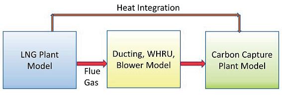
Dynamic simulation by way of utilising rigorous mathematical models has become influential in process design, design validation, control system verification, start-up support, and troubleshooting. Many recent developments in the simulation software and technology have led to the development of large-scale dynamic models and their use during the entire project life. The scope of the dynamic modelling for the integrated LNG/PCC facility can be divided into three areas, as shown in Figure 1. There are different options (model scope/methodology) to study the overall behaviour of the integrated LNG/PCC facility. This can be selected based on the scope and objectives of the analysis.
For a rigorous understanding of the transient characteristics of an LNG plant with PCC, a combined dynamic model is preferred. The transient responses of the LNG plant are well understood, and this has been studied over the years. The behaviour of an integrated LNG/PCC facility is a relatively recent development and can benefit from integrated model-based analysis. Another option is to have individual models of the three sections of the integrated facility, which can be run and used as the boundary condition for the next model. The upcoming case study looks at upsets in the interconnecting units affecting the LNG facility, and vice versa.
The modelling of LNG facilities is normally carried out during the detailed design phase. The use of these


We are a global market leader in reaction, separation, purification, static mixing as well as polymer processing technologies. With a comprehensive offering that includes process components all the way to complete process plants and technology licensing, we can serve a broad range of industries with key solutions to intensify processes, increase efficiency and improve product quality. With an ever-expanding portfolio of cutting-edge products that supports circularity while reducing material and energy use as well as emissions, we are the ideal partner to support the net zero transition of businesses across the chemical and polymer value chains. We also offer our technology innovations to support the sustainable manufacturing of bioplastics, renewable fuels, chemical recycling for unrecyclable materials as well as carbon capture technologies. www.sulzer.com
models for design and operation of LNG plants has become more widespread in recent years.3 The dynamic modelling of interconnecting ductwork, WHRU, and a flue gas blower can also be performed with available commercial dynamic modelling tools.
Much of the commercially-available process simulation software can be used to develop a dynamic model of amine-based CO2 capture processes.4 The first option to model this is to use an equilibrium-based modelling approach. Equilibrium-based modelling assumes that liquid and vapour phases reach equilibrium at theoretical stages, and that perfect mixing occurs at each stage. Equilibrium is rarely acquired in a reactive CO2 absorption process – especially during dynamic operation. The rate-based approach is more rigorous and considers the actual rates of mass and heat transfer, including chemical reactions. A rate-based approach is preferred for modelling reactive columns, as in the PCC process. The disadvantage of this approach is the computational requirements, as the rigorous rate-based approach results in extended systems of equations to be solved at each integration step.
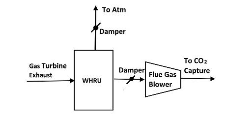
This case study evaluates the integration of an amine-based PCC unit with an LNG facility, utilising gas turbines to drive refrigeration compressors. The normal design of such a facility routes the flue gas from turbines through WHRU to the exhaust stack and to the atmosphere. The addition of the PCC unit involves the introduction of additional ductwork, bypass dampers (to the atmosphere and the PCC unit), and a flue gas blower to increase pressure. The flue gas is further cooled in a heat exchanger and then routed to the absorber, where it is contacted with amine solvent to remove the CO2 from flue gas. The CO2-depleted flue gas is then released to the atmosphere (see Figure 2).
The main concern with the addition of a PCC unit is the possibility of impacting LNG production during various transient upsets in the PCC unit. The gas turbine exhaust outlet must be maintained within a pressure range to avoid a reduction in power output or a total turbine shutdown. Several scenarios were studied to evaluate the transient impact on the gas turbine outlet conditions.
A dynamic simulation model of the interconnecting unit (WHRU, flue gas blower, other equipment, and associated
piping) was developed to perform this study. This model was sufficient for this analysis, as the main interest was to evaluate the effect of upsets on GT outlet pressure (and to identify any mitigations needed). The following scenarios were studied with this model:
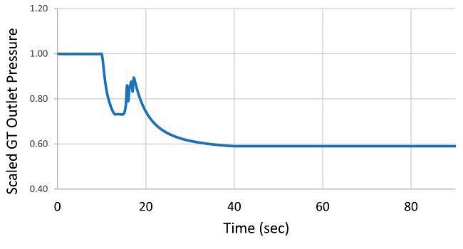
The flue gas blower trip is simulated to verify that the pressure at the GT outlet can be maintained within limits so that LNG plant operation is not affected. As soon as the flue gas blower is tripped, the damper to stack is signalled to open in order to avoid the excessive pressure increase in the system. The blower will coast down with speed response based on the rotational inertia of the string. The pressure at the GT outlet is shown in Figure 3. As can be seen, the pressure drops rapidly as the damper is opened along with the blower trip. This pre-emptive action prevented the pressure at the gas turbine outlet from increasing, due to trip of the blower. The pressure stabilises with the flue gas diverted entirely to the stack. An intermediate increase in pressure is due to the reduction in blower capacity while the damper is still opening.
The trip of a gas turbine will result in a rapid change in temperature and flow rate of flue gas at the inlet of the WHRU. The performance of the system during this scenario was studied. The profile of flue gas flow rate and temperature vs time from turbine vendor was used as the boundary condition.
Once the gas turbine is tripped, the flue gas flow reduces, decreasing the pressure at the inlet of the flue gas blower. The flue gas blower must be shut down to prevent significant vacuum formation at the suction. Shutting the flue gas blower too early can result in over pressuring the duct as the flue gas flow continues for some time. The appropriate time to shut down the blower was identified from simulation.
Several other scenarios were also evaluated with this model to identify any operability concerns. This included dampers fail closing, shutdown of the PCC unit, start-up of the PCC unit, and others. The transition from operation without PCC unit to PCC unit was simulated to verify the operating procedure for this transition. The starting point for this case was the operation with the flue gas diverted to the atmosphere with gas turbine flow rate at normal conditions. The right sequence and timings to open the main damper to the PCC unit, start up the flue gas blower, and close the damper to the atmosphere was verified using simulation.
1. ‘Techno-economic evaluation of CO2 capture in LNG’, IEAGHG Technical Report, (October 2019).
2. BUI, M., GUNAWAN, I., VERHEYEN, V., FERON, P., MEULEMAN, E., and ADELOJU, S., ‘Dynamic modelling and optimisation of flexible operation in post-combustion CO2 capture plants – a review’, Computers and Chemical Engineering, (2014).
3. MOKHATAB, S., MAK, J., VALAPPIL, J., and WOOD, D., ‘Handbook of Liquefied Natural Gas’, (2014).
4. CHUKUKWA, A., ENAASEN, N., KVAMSDAL, H. M., and HILLESTAD, M., ‘Dynamic modeling of post-combustion CO2 capture using amines – a review’, Energy Procedia, (2012).
Camille Ventham and Gerrit Bloemendal, Comprimo, part of Worley, detail the process behind recovering carbon dioxide and hydrogen from sulfur plants.
As carbon dioxide (CO2) emissions are becoming an increasing issue in the oil and gas industry, and alternative fuels are being investigated, CO2 capture and hydrogen production technologies are under continuous development for improvement. One of the sources of CO2 emissions is the flue gas from sulfur recovery units (SRUs), especially in gas plants where substantial amounts of CO2 are present in the feed gas
to the SRU. This article will study the options that are available to recover this CO2 from the SRU, and in parallel recover hydrogen – a carbon-free fuel.

In order to maximise the potential for CO2 capture and hydrogen recovery, modifications have to be made to the SRU. This article will also present a case study highlighting these modifications, and evaluate the available technologies for optimised CO2 capture and hydrogen

recovery – both from a technical and a commercial perspective.
The line-up considered in this article is commonly applied in a natural gas plant, consisting of an amine base acid gas removal unit (AGRU) which removes the acid gas components from the main gas stream, resulting in an acid gas feed to the sulfur plant typically consisting of more than 60% hydrogen sulfide (H2S) and approximately 30% CO2, with the remainder being some hydrocarbons and water vapour.
The SRU considered is a standard modified Claus unit, consisting of a thermal stage followed by two catalytic stages. The tail gas of the Claus unit is routed to a tail gas treating unit (TGTU), in which the remainder of the sulfur species is converted to H2S, absorbed, and recycled to the Claus section. The overall recovery of the SRU and TGTU is more than 99.9%, which ensures that the flue gas from the incinerator section
contains less than 500 mg/Nm3 sulfur dioxide (SO2), which is considered to be state-of-the-art.
The potential locations that were identified for CO2 capture were the following:
n Front-end capture in the acid gas.
n Pre-combustion capture in the TGTU off gas.
n Post-combustion capture in the flue gas from the incinerator.
Previous studies showed that the optimum/preferred location for CO2 capture is in the off gas from the TGTU absorber, as front-end capture will require substantial modification to the AGRU, whereas post-combustion capture has to deal with strongly-diluted CO2 streams and requires flue gas pre-treatment before the gas can be handled in the CO2 capture system. In addition to this, neither front-end capture nor post-combustion technology are able to recover any hydrogen, as hydrogen is not present in the AGRU gas, whereas any produced hydrogen in the Claus unit is burned in the incinerator for post-combustion.
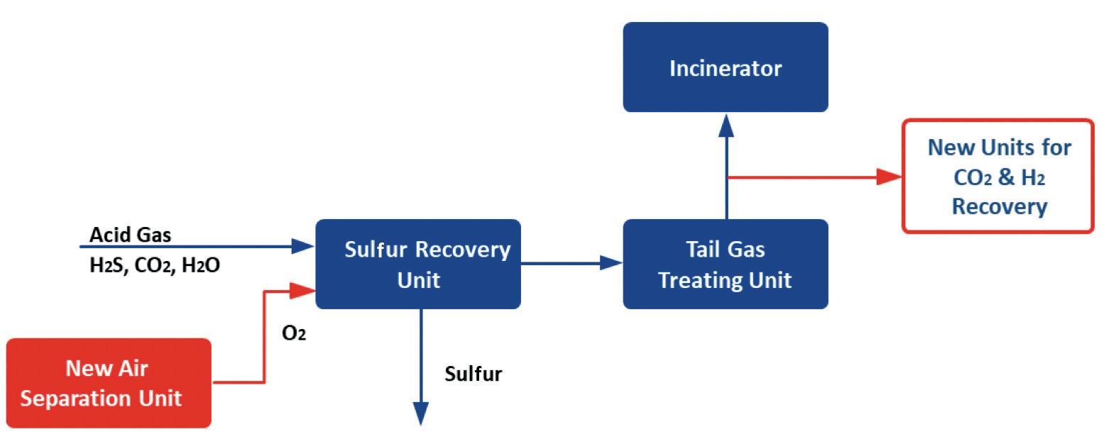
To maximise the production of hydrogen and minimise the dilution of the CO2, it is possible to convert the SRU from standard air operation to high level oxygen enrichment, such that the flow of inerts (mainly nitrogen) through the SRU is minimised. Figure 1 illustrates the proposed line-up with the optimum CO2 and hydrogen recovery unit.
For the plant that was studied, the sulfur processing capacity was considered to be adequate, and capacity increase was not required. The proposed modifications to the SRU/TGTU equipment were minimal, as less gas needed to be processed. Retrofitting the SRU/TGTU for a high level of oxygen enrichment only required modification of the burner to introduce the oxygen. The thermal reactor temperature was still within acceptable operating limits, as the acid gas was relatively lean. Single stage combustion in the thermal reactor could be retained.
The SRU is provided with a degassing system to remove dissolved H2S from the liquid sulfur, such that a premium sulfur quality is produced with less than 10 ppmwt H2S. This degassing system produces a vent air stream which is routed to the incinerator, where any sulfur species are converted to SO2. In air operation this results in a marginal increase of SO2 in the flue gas, but since the gas flow from the SRU is strongly reduced when there is no nitrogen in the TGTU off gas, the


Save time and cost by changing control valve quickly with a single seat ring versus a plug seat ring, bonnet gasket and seat gasket with a globe valve.

~20-50% lighter weight than same size globe valve and 30% more capacity to meet increased demand in throughput.
Erosive and cavitation resistant design with lower friction and higher precision above 450°.
Less leak path utilizing an integral bonnet to reduce the chance of emission(1).
(1) As compared to conventional positioners.
For more information, contact your local Baker Hughes representative or visit valves.bakerhughes.com
© Copyright Baker Hughes company. All rights reserved

SO2 resulting from the vent air is not diluted, leading to increased SO2 concentrations in the small flue gas stream, even though the absolute emission in kg/hr is reduced. For this reason, it is advised to align the emission values with the industry standard, and use the equations in the Environmental Protection Agency (EPA)’s New Source Performance Standards
– 40 CFR 60 Subparts J & Ja that cover SRUs.
With the above conversion to oxygen blown SRU, the gas from the TGTU absorber contains approximately 65% CO2, 16% hydrogen, 6% nitrogen, and traces of carbon monoxide (CO), H2S and carbonyl sulfide (COS). The absorber off gas is saturated with water vapour.
The options considered for CO2 recovery were the following:
n Chemical (amine-based) absorption.
n Cold flash.
n Adsorption.
n Physical solvent absorption.
n Membrane technology.
n Cryogenic separation.
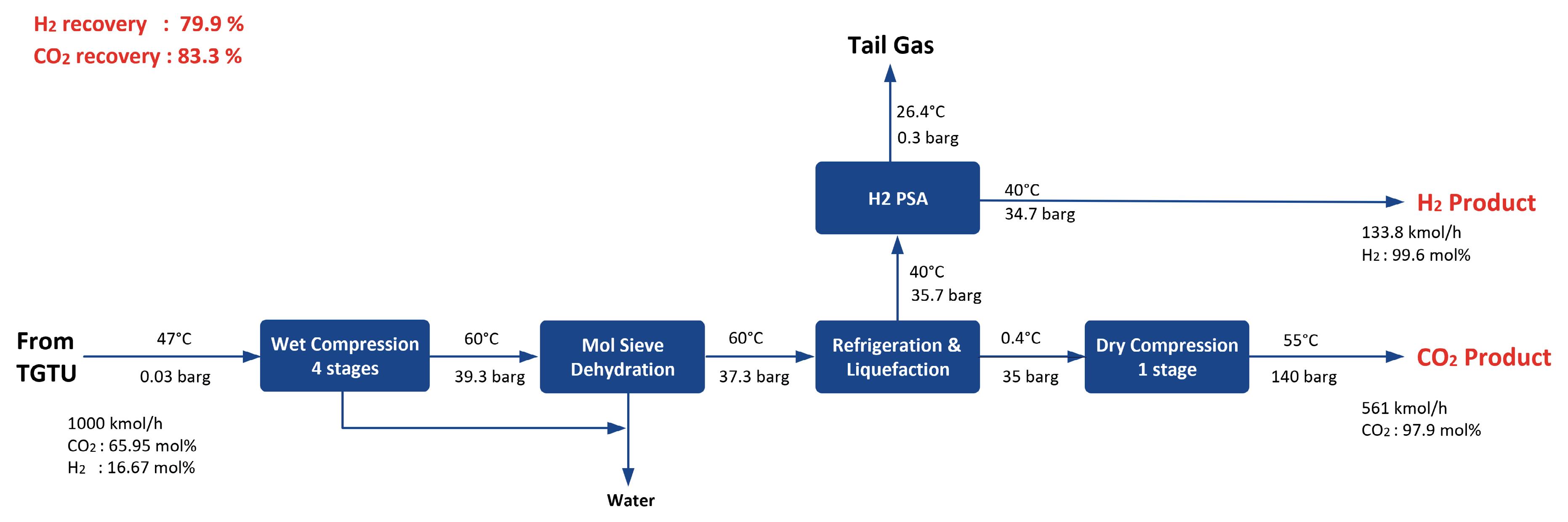
From these options, a first screening showed that chemical absorption and cold flash were the most viable options, and these options were further evaluated in this study. For hydrogen recovery, pressure swing adsorption (PSA) was considered. Figure 2 shows a simplified block flow diagram for the cold flash option.
Cold flash Chemical solvent
Pros n Simplicity of the process
n Low equipment count
n No proprietary solvent – no license fee
n Lower utility consumption
n Inherent safety
The gas from the TGTU absorber is compressed to approximately 40 bar, and dried in a mol sieve unit. The dry gas is then cooled and partly liquefied by cooling against propane. In this step, the liquid CO2 is separated from the gas in a flash vessel. After separation, the CO2 is evaporated again and routed to a dry CO2 compression stage where it is boosted to 140 barg, which is the preferred pressure for the CO2 injection facilities. The non-condensed gas, which mainly consists of hydrogen, is routed to the PSA unit, where the hydrogen is separated with a purity of more than 99.5%. The remainder of the gas (mainly nitrogen, with traces of CO, H2S and COS) is routed to the incinerator before emitting the gas to atmosphere. The overall hydrogen recovery from the TGTU tail gas is around 80%, whereas the CO2 recovery is nearly 85%.
Cons
n Technology readiness and maturity
n Proven technology
n High CO2 and hydrogen recovery
n Product quality
n Limited known applications for CO2 removal
n Lower CO2 and hydrogen recovery
n COS specification is not met
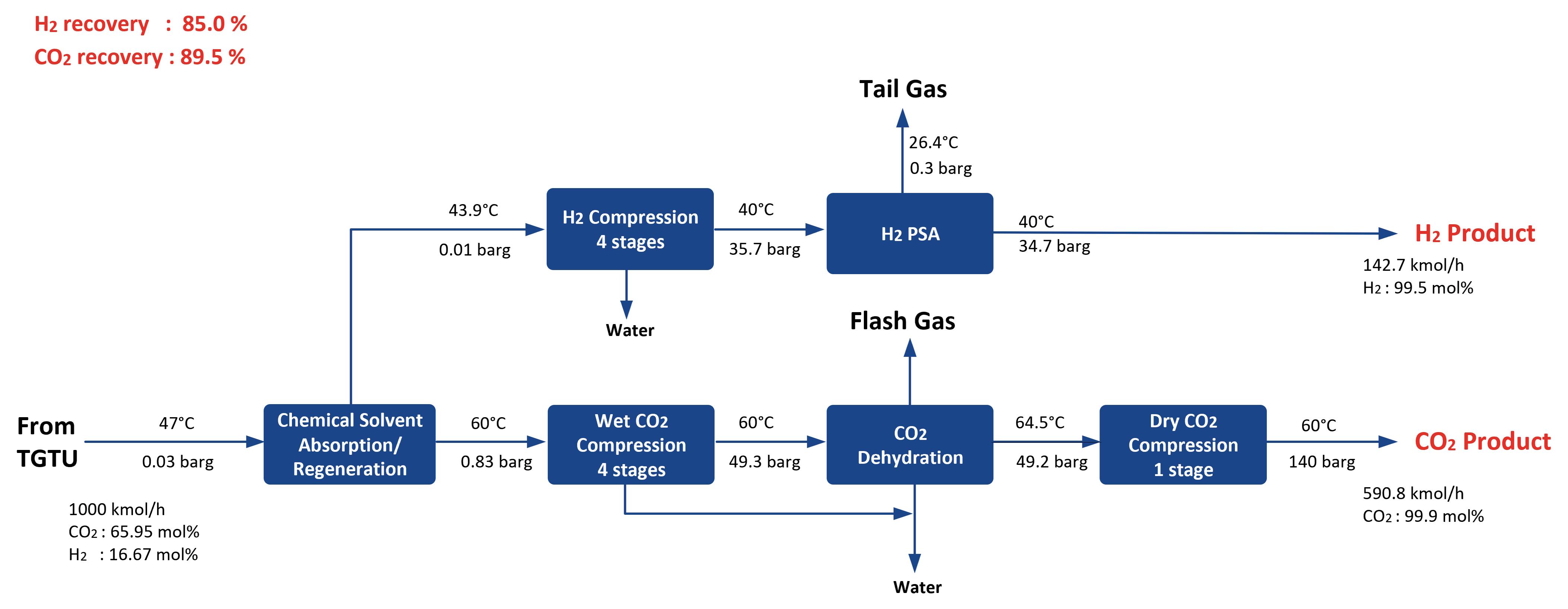
Figure 3 represents a simplified block flow diagram for the chemical absorption option. For this option, the gas from the TGTU absorber is routed to another absorber, which operates at near atmospheric pressure. The bulk of the CO2 is absorbed in the absorber, and that loaded solvent is stripped in a regenerator. From the regenerator the CO2 is routed to a compressor, and dehydrated. Ultimately, the CO2 is delivered to the injection facilities at 140 barg and a very high purity of 99.9%. The off gas from the CO2 absorber, which mainly consists of hydrogen, is compressed to nearly 40 barg. During compression, condensed water is separated, and the gas is routed to the PSA unit, where the hydrogen is separated with a purity of more than 99.5%. Similar to the cold flash option, the remainder of the gas (mainly nitrogen, with traces of CO, H2S and COS) is routed to the incinerator before emitting the gas to the atmosphere. The overall hydrogen recovery from the TGTU tail gas is around 85%, whereas the CO2 recovery is nearly 90%. With that, the performance of the chemical absorption is marginally better than for the cold flash option, but that can be tweaked at a later stage. Note that for Figures 2 and 3, a ‘normalised’ tail gas flow of 1000 kmol/hr from the TGTU absorber has been assumed.
n High equipment count
n More plot space required
n Construction logistics are more challenging due to higher equipment count and larger diameters
n COS hydrolysis uncertainty limits H2S content allowable in the TGTU off gas
A qualitative first assessment of the cold flash and chemical solvent option is provided in Table 1.
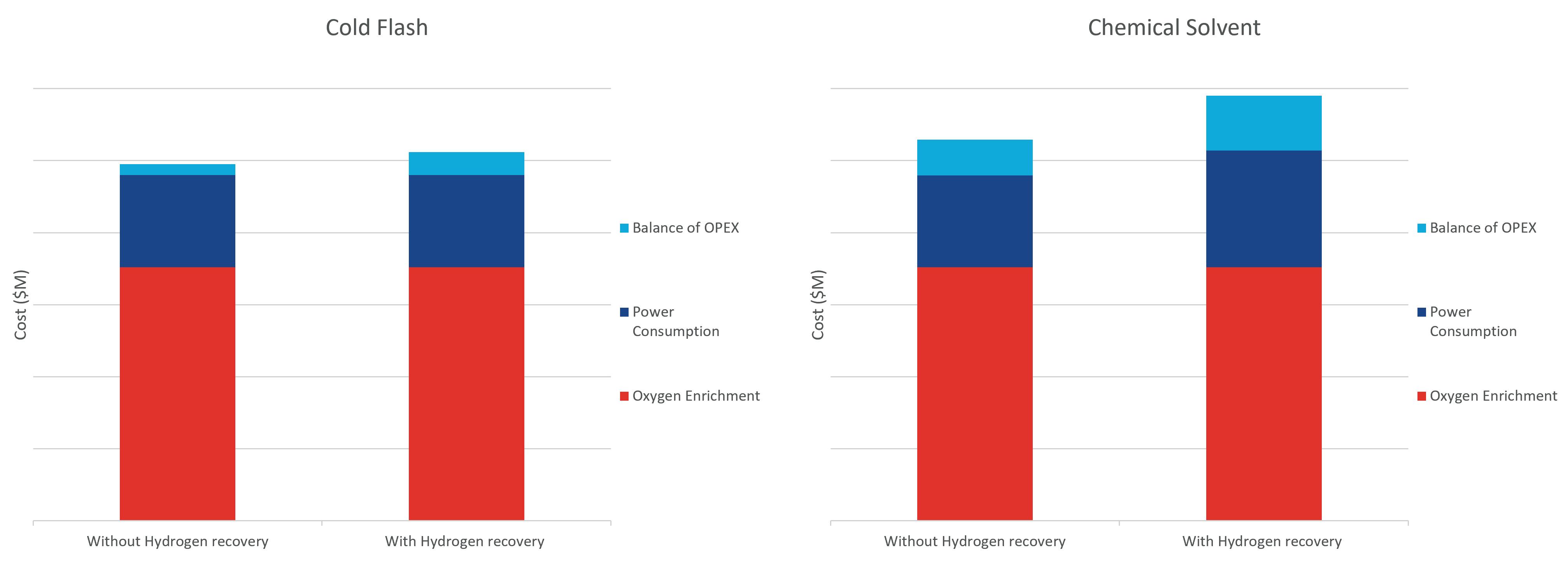
As in other comparison studies, a first step is to make a sized equipment list and a high-level capital cost estimate. For the cold flash option and for the chemical absorption option, this results in Figure 4.
From this graph it can be seen that the simple cold flash option without hydrogen recovery has the lowest investment cost, partly because it has the least amount of equipment and a high refrigeration cost for the chemical solvent option. The lower investment cost is determined by the fact that in the cold flash option only one compressor is required to compress the gas from the TGTU absorber to 40 barg. The addition
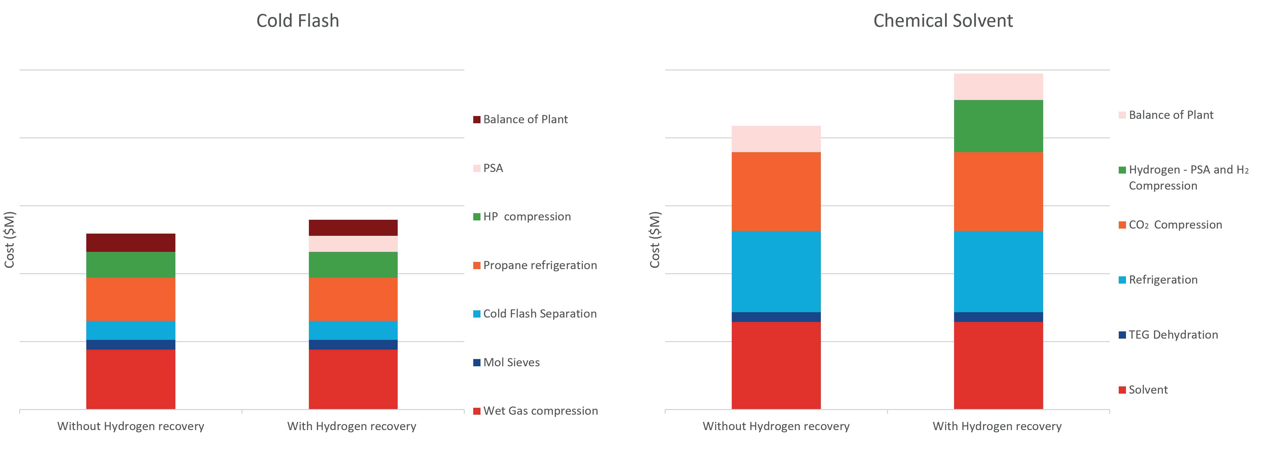
Chart is at the heart of midstream natural gas processing
Air Cooled Heat Exchangers
Integrated Process Plants
Brazed Aluminum Heat Exchangers
Nitrogen rejection, NGL recovery, liquefaction, compression, condensing and helium recovery rely on Chart engineered and built specialty equipment and systems.
www.Chart-EC.com
achx@ChartIndustries.com
of hydrogen recovery adds extra cost, but this will be paid out rapidly when the additional value of the recovered hydrogen is considered.
In a similar way, the operational cost can be estimated, resulting in Figure 5. Here, a similar trend as for the investment cost can be seen, with cold flash without hydrogen recovery resulting in the lowest operational cost, and chemical absorption with hydrogen recovery leading to the highest operational cost.
The capital cost and operating cost were subsequently used to develop the so-called Unit Technical Cost (UTC), which is the calculation of the cost per unit of product produced (in this case CO2 and hydrogen), taking into account the required investment cost and 20 years of operating cost. This UTC is normalised against the UTC for chemical absorption without hydrogen recovery, and is summarised in Table 2.
From Table 2 it can be seen that the cold flash option with hydrogen recovery results in the lowest UTC. Despite the higher investment cost and the higher operating cost, the revenue from the recovered hydrogen yields a substantial improvement in the cash flow position, resulting in the lowest UTC for that option.
Although the economic criteria are a large factor in deciding which technology to select, other factors come into
play as well. The criteria considered are outlined below, each with their weight factor in the total evaluation:
n Inherent safety – 10%.
n Economic (UTC) – 50%.
n Technology maturity – 15%.
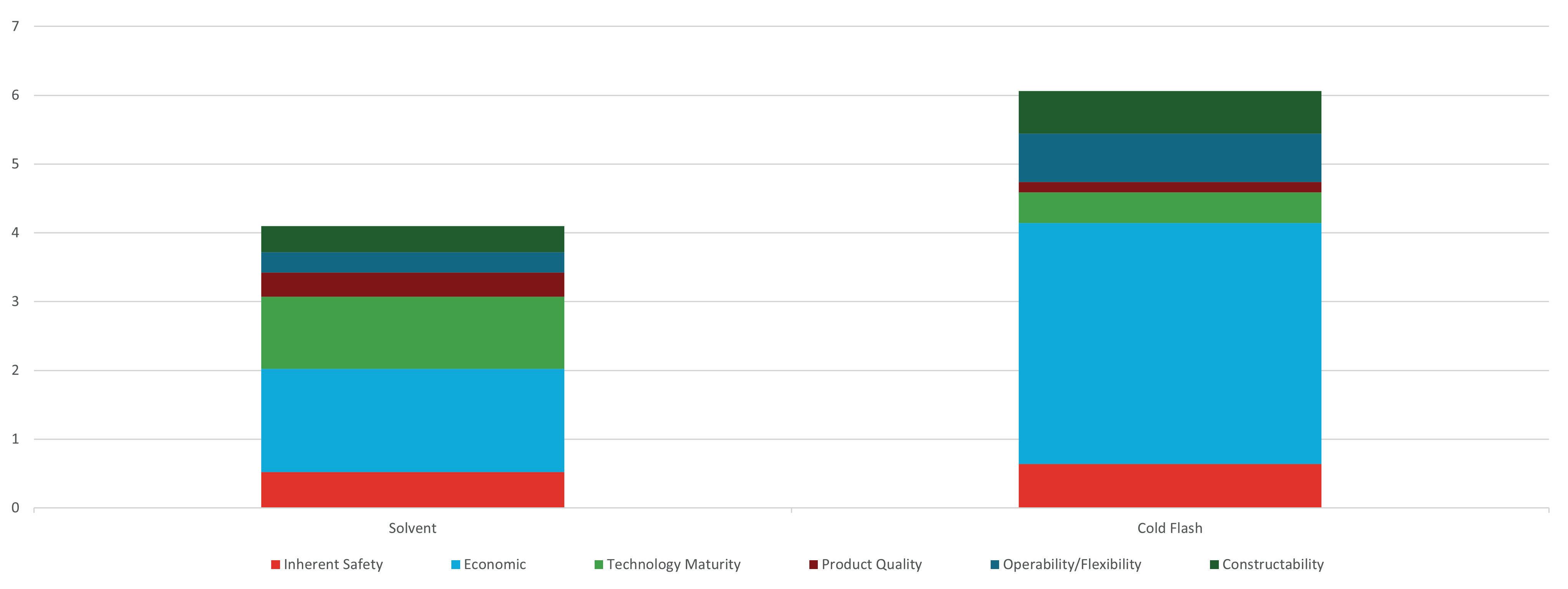
n Product quality – 5%.
n Operability/flexibility – 10%.
n Constructability – 10%.
These criteria are each ranked with a figure of between 1 and 10. Combined with the above weightage, this results in Figure 6. From this graph it can be concluded that the cold flash technology with PSA is the preferred technology for CO2 and hydrogen recovery.
This study concluded that 100% oxygen enrichment is the preferred route for processing the acid gas in the SRU when CO2 and hydrogen capture is to be considered, as it will result in the most concentrated/least diluted gas stream for the CO2 and hydrogen recovery, and minimise the investment cost and operating cost. In addition to this, 100% oxygen enrichment will result in the highest hydrogen formation in the thermal reactor, making hydrogen recovery an economical option. Considering the relative ease at which hydrogen can be recovered as a product, this additional processing step is highly recommended.
For the CO2 capture, the cold flash option seems to be the most promising one, as it results in the lowest (relative) UTC for the CO2 produced, and because of the simplicity of the process. Additionally, the operability, flexibility and constructability are considered more positive for the cold flash technology when compared to the chemical absorption technology.
It should be noted that this study was performed at a high level, and optimisations have not yet been addressed – and with no specific CO2 recovery target. In the next phase, the reduction of the cooling/refrigeration duty could be further evaluated, as well as potential reduction in equipment count. This might change the individual contributions for these criteria somewhat, but it is expected that it will not change the final conclusion that oxygen operation with cold flash and PSA is the preferred option for CO2 and hydrogen recovery downstream of an SRU/TGTU complex.
Diego Scilla, Siirtec Nigi S.p.A, Italy, introduces an atmospheric liquid sulfur degassing solution that has been developed based on plant data.
As safety and emission requirements from sulfur plants receive increasing attention, liquid sulfur degassing technology continues to play an important role in the sulfur recovery industry. The recovered liquid sulfur, produced and condensed by the Claus process, contains dissolved hydrogen sulfide (H2S) and chemically-bonded hydrogen polysulfides (H2Sx), which may evolve during storage and transportation.
H2S is a colourless, poisonous, corrosive and flammable gas. Furthermore, the dissolved H2S in liquid sulfur increases the friability of any type of its solid form (crushed bulk or prills). Degassing of liquid sulfur, i.e. the removal of the dissolved H2S and H2Sx, is aimed at reducing the hazards exposed to operating personnel in handling and transport operations, as well as increasing the quality of the final product.

Siirtec Nigi has experience in designing sulfur degassing systems – both atmospheric and at pressure. With this experience, a proprietary design of atmospheric sulfur degassing has been developed and realised, based upon plant data obtained over several operations and supported by the development of mathematical models of degassing principles.
Specific features of the Siirtec Nigi DegaSN process are the very high stripping efficiency that is capable of guaranteeing less than 10 ppm wt residual H2S in the liquid sulfur at very limited operating costs, with a compact design that does not require any extra plant area or the addition of catalyst/chemicals.
The liquid sulfur from the Claus process typically contains 300 – 500 ppm wt of dissolved H2S, mainly in the form of H2Sx. The total residual H2S concentration is influenced by the H2S vapour concentration (partial pressure), and the temperature at which the sulfur product is condensed. Most technology applications for liquid sulfur degassing on the market are grouped into three categories:
n Liquid catalyst application.
n Solid catalyst application.
n Air degassing.
Catalytic degassing presents known drawbacks such as low liquid sulfur quality due to the presence of impurities in the degassed sulfur; solid sulfur with a weaker strength;
environmental concerns associated with sulfur handling; higher operating costs compared to conventional air degassing; and higher plant complexity.
Moreover, even if injected catalyst quantity is limited, sulfur buyers often require sulfur from non-catalytic degassing. Misoperations, such as the excessive addition of liquid catalyst, can lead to the formation of salts, with consequent fouling of pumps, piping, etc.
Air degassing usually takes place in concrete pits or columns, where oxygen is the catalytic agent for polysulfides dissociation. The majority of these processes utilise a sweep air stream to remove H2S from the vapour space above the sulfur as it is released from the liquid phase.
The chemistry behind the degassing process is outlined below, as a two-step reaction:
n Decomposition of H2Sx to sulfur and H2S:
§ H2Sx (liquid) → H2S (dissolved) + (x-1)S (liquid)
n Desorption of H2S from liquid to gas phase:
§ H2S (dissolved) → H2S (gas)
As H2S is removed from the system, the equilibrium is driven to the right, resulting in a further breakdown of H2Sx with subsequent degassing of more H2S. Air degassing occurs through a combination of mass transfer of H2S to air bubbles, and through the decomposition of H2Sx
In particular, air acts as stripping gas for H2S separation, whilst oxygen acts as a catalyst for the H2Sx decomposition reaction and, to a minor extent, to oxidise H2S to sulfur dioxide (SO2), which further increases the liquid sulfur production of the plant (via the Claus reaction).
Stripping air shall be adequately distributed in the liquid sulfur to improve the contact with the hydrogenated sulfur species. The presence of oxygen is a key factor for H2Sx decomposition, while low operating pressure in the degassing system is the key parameter for H2S desorption.
When air degassing is performed at almost atmospheric pressure, as is the case for the DegaSN design, initial H2S mass transfer is slightly less effective compared to degassing processes under pressure, but it is nevertheless enough to promote required reactions in any commercial scenario, while final stripping is enhanced when compared to the other processes.
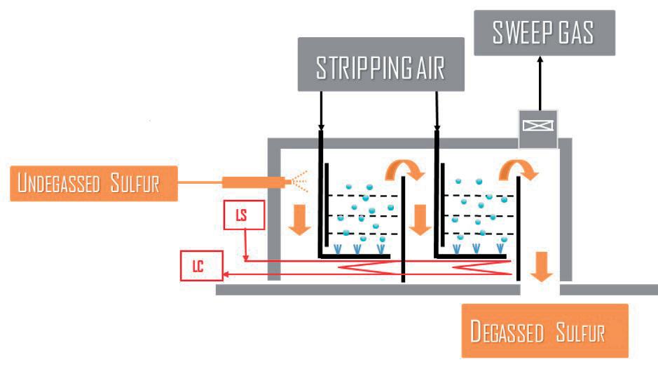
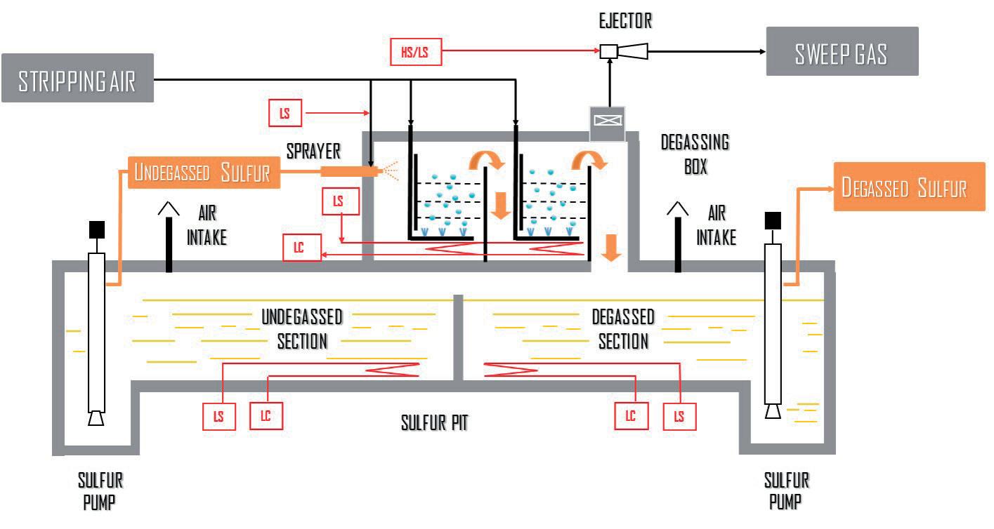
The DegaSN process consists of a concrete degassing box (see Figure 1), with an internal stainless steel lining equipped with two degassing sections with trays, where liquid sulfur flows upward co-currently with the stripping air, and then flows downward by gravity to the receiving vessel.
Liquid sulfur is fed to the degassing box through a sprayer before being contacted with the stripping air within the degassing sections. A fixed amount of low pressure (LP) steam and a slipstream of stripping air are mixed in the sprayer with the liquid sulfur. With such configuration, initial, significant separation of H2S from liquid sulfur occurs.
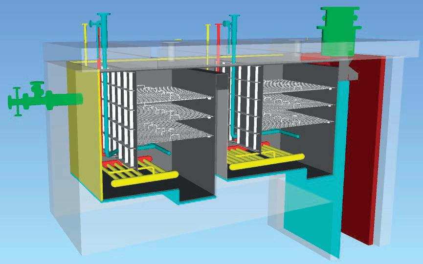
Each degassing section is equipped with rectangular mass transfer elements and can be easily designed with almost any aspect ratio, where limitations in plot space are restrictive. Stripping air is bubbled through the degassing elements, with the aim of providing intimate mixing between the gaseous and the liquid phase, and promoting mass transfer between the two phases.
As shown in Figure 2, liquid sulfur is initially collected in a chamber created against the first steel plate. It then flows upward through the first degassing stage, where atmospheric air is injected from the bottom of the section.
Overflowing from the second steel plate, sulfur is then collected in another chamber from where it feeds the second degassing stage where air injection is re-instated. Overflowing from the last steel plate, sulfur is then discharged to the receiving system.
The stripping air is distributed by means of dedicated spargers located below the mass transfer elements. The air is fed through heated nozzles located at the top of the concrete box (heating is typically recommended to be extended 10 – 15 m back on the stripping air feed line) to avoid cold spots – especially during start-ups and shutdowns. Spargers provide uniform distribution of the stripping air through the contacting volume crossed by the flowing liquid sulfur. The configuration of the spargers in terms of the shape and number of branches depends on the size of the contacting area, as well as the amount of stripping air fed into the system.
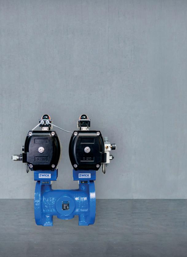
The temperature is maintained through dedicated steam coils, fed by LP steam. In principle, the steam coils should cover the entire floor of the degassing box in order to provide uniform heating. Draining of the degassing box is performed by the two external draining valves (one for each degassing section). The draining lines route the potentially off-spec liquid sulfur to the undegassed section of the sulfur pit. The routing takes into account the general requirements for liquid sulfur lines, these being slope, no pockets and jacketing. The draining valves are ball type, full bore, and steam jacketed, in compliance with liquid sulfur piping class requirements.
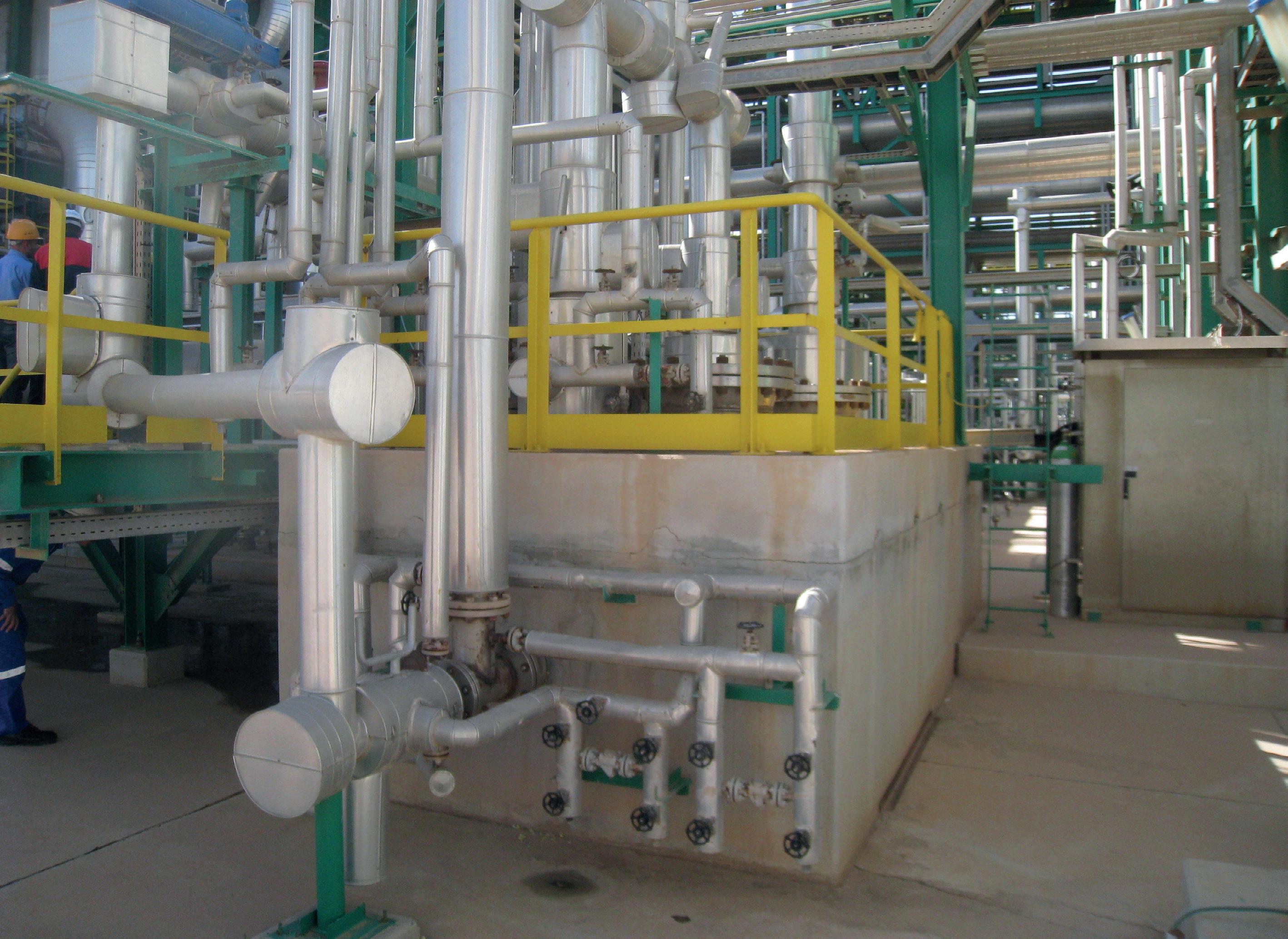
In most applications, the degassing box is installed above a concrete sulfur storage pit, saving plot space (Figure 3). However, the degassing box can also be installed externally from the pit depending on the layout constraints. An example of an integrated degassing system is represented in Figure 4.
Typically, the sulfur pit is divided into two sections separated by a partition wall: the undegassed sulfur section and the degassed sulfur section. The sulfur pit provides the operating storage capacity for the undegassed and degassed liquid sulfur. The sulfur pit and degassing box sizes are based on the specific project requirements, in terms of maximum load and storage capacity. The configuration may be adapted due to project contingencies requiring, for example, two standalone pit sections (undegassed/degassed), or integration with existing storage/degassing facilities.
The elemental liquid sulfur produced in the Claus process is discharged by gravity from the sulfur condensers to the sulfur pit. From the undegassed sulfur section, liquid sulfur is pumped to the degassing box where the degassing process takes place. The now degassed sulfur flows from the degassing box to the degassed section of the underlying sulfur pit.
After degassing, sulfur can be pumped from the pit –either directly to the tank truck, or to intermediate liquid sulfur storage. If the final sulfur product is handled as a solid, it is pumped to a storage block (where the sulfur is allowed to cool and solidify), or to sulfur-forming facilities.
The sulfur pit and degassing box are connected on the gas side, and both operate under slight vacuum. One or more ejectors, driven by saturated steam, are provided to ensure adequate sweeping of the sulfur pit through dedicated atmospheric air intake(s) located on the pit roof, resulting in a negative operating pressure.
Under these conditions, H2S is continuously released by the flowing liquid sulfur, accumulating in the vapour space of the sulfur pit, and causing an explosion hazard. Sweeping is then required to prevent the formation of explosive mixtures, and to ensure that H2S concentration in the vapour space remains below the lower explosive limit.
Stripping air is typically fed by the upstream Claus unit combustion air blowers, and so no extra blowers are needed. In a generic application, the stripping air flow rate is in the range of 2 – 4% of Claus combustion air requirements. Moreover, the low operating pressure of the DegaSN system results in very low operating duties required by the
already installed machine. This is an advantage over degassing systems at pressure, which require dedicated high duty blowers.
The degassing box sweep gas containing stripped H2S, together with the sweep air present in the sulfur pit vapour space (in case the two systems are connected), is moved by the steam ejector and routed to a thermal incinerator, or alternatively recycled back to the Claus process with minimal use of motive steam. Sweep gas recycle to the Claus process has the potential to maximise the sulfur recovery efficiency (SRE) of the unit, with minimal or no disturbances to the Claus reaction furnace operation.
As aforementioned, in typical sulfur degassing system applications, sweep gas contains a certain amount of sulfur (in the form of H2S and S-vapour) that can be recovered/recycled to the upstream Claus process in order to enhance the overall SRE.
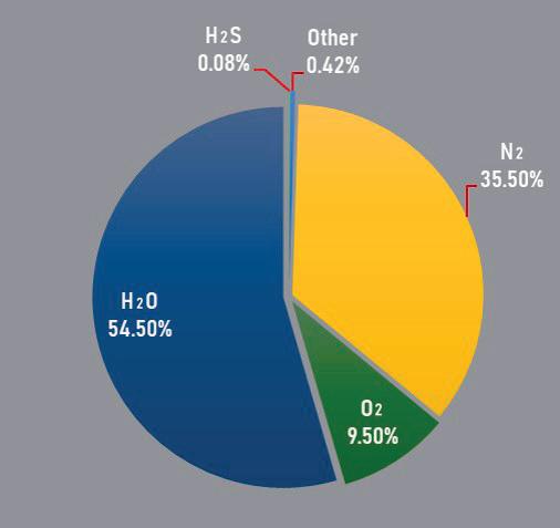
Figure 5 shows a typical sweep gas composition for an atmospheric liquid sulfur degassing system with air stripping. A conventional approach in recycling the degassing sweep gas is to route it back to the thermal stage of the Claus process, i.e. to the reaction furnace. The main component of this stream is water, which acts as a diluent for the reaction furnace operation. Consequently,
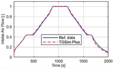
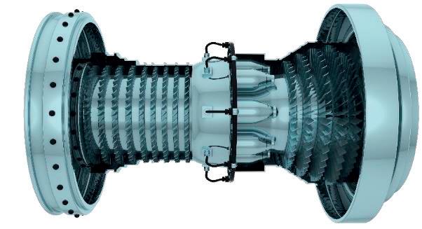
A REAL-TIME DYNAMIC SIMULATOR OF GAS TURBINES
DESIGN AND ANALYSIS OF GT MAIN SYSTEM AND AUXILIARIES
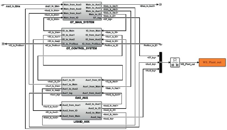
GT CONTROL SYSTEM VERIFICATION & VALIDATION BY HIL TESTING

SCENARIOS
Verify and validate the real GT Control System (GTCS)
Hardware-in-the-Loop (HIL) full system testing
Whole system performance analysis:
Accurate performance envelope

Start-up sequences
Normal and emergency shutdowns
Load rejection
Investigation of fault events
TECHNICAL DETAILS
0-D modelling
GT component modules libraries
Real-time compatibility at millisecond scale
User friendly GUI & pre-/post-processing tools
Split stages or whole compressor maps management
Single or bi-fuel combustion chambers
the impact of sweep gas recycle on Claus reaction furnace combustion is typically a 50°C (approximately) decrease in reaction temperature, which can be easily compensated by other unit adjustments (e.g. acid gas split or combustion air preheating).
On the other hand, the expected increase in overall SRE is around 0.05%, which allows for a significant reduction in the resulting SO2 emissions through the stack. In these cases, the combustion air demand to the reaction furnace has to be adjusted accordingly, as the sweep gas also contains some amount of oxygen.
The sulfur pit and degassing box are provided with heating coils to compensate for heat losses and keep the sulfur in liquid form. Therefore, the main utility required for a sulfur degassing system is typically steam.
Considering sulfur degassing system integration with the upstream Claus process, a valuable steam source comes from the heat recovered in the thermal and catalytic stages.
In particular, LP steam produced by sulfur condensers can be used in heating coils and ejectors (when sweep gas is routed to the incinerator); high pressure (HP) steam produced by the Claus waste heat boiler can be used for the ejectors when sweep gas is recycled to the Claus process.
In a typical SRU energy balance, where sweep gas is recycled to the Claus process, LP steam consumption for
the sulfur degassing system heating coils is around 3% of sulfur condenser production, while HP steam consumption for ejectors is less than 5% of waste heat boiler production.
The development of the DegaSN process dates back to the early 2000s. Its first application was in a gas field in North Africa, where its performance was tested during operation. Later on, additional tests on live plants in Italy were conducted at different loads with the aim to validate a theoretical model developed by Siirtec Nigi’s Research & Development department, based on the equilibrium and kinetics mainly between oxygen, H2S and H2Sx inside the liquid sulfur.
The model first evaluates the actual initial amount of H2S/H2Sx absorbed in the undegassed sulfur, which is defined by the following effluent conditions from each sulfur condenser:
n Liquid sulfur flow rate.
n Partial pressure of H2S.
n Condensers’ outlet temperature.
This data is then used to calculate the liquid sulfur load to the degassing system, the average sulfur temperature, and the average H2S partial pressure. The calculation of the total amount of H2S and H2Sx dissolved in undegassed
sulfur is based on Henry’s law, and corrected with specific coefficients.
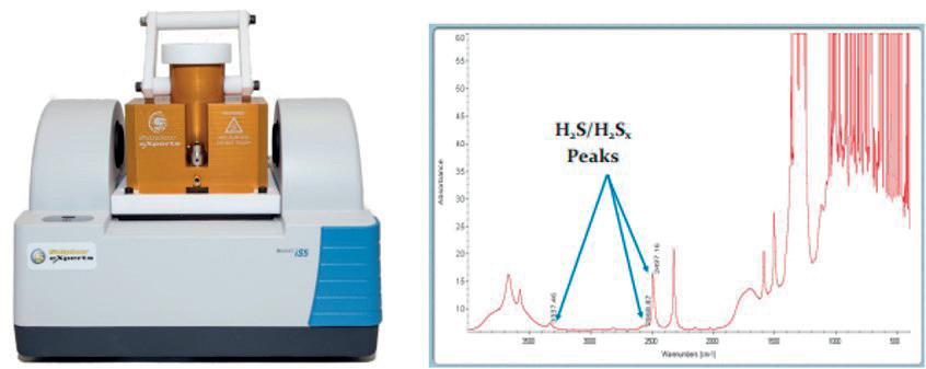
The rate of H 2 S x decomposition reaction and the relevant mass transfer are then calculated based on the velocity of liquid sulfur flowing through the degassing box contacting volume, together with stripping air, to promote the subsequent H 2 S stripping. The theoretical model used to design the DegaSN system has been tuned with field data suiting the required results. The performances were tested using Sulphur Experts’ FTIR. This technology is specifically designed for the measurement of H 2 S and H 2 S x dissolved in liquid sulfur (see Figure 6).
Siirtec Nigi has designed and built more than 30 sulfur degassing units around the world. This has increased over time with experience and optimisation of the process, improving operability and unit availability. The capacity range for a single unit is 5 – 500 tpd. As experience has been gained, a number of design specifics have been made:
n Keeping the liquid sulfur temperature within the correct temperature range has been proven successfully by using a dedicated steam pressure control for the steam supply to the heating coils, and can be considered as part of the design of the DegaSN system.
n In some cases, depending on the Claus unit design capacity and the operating conditions of the Claus process, a dedicated sulfur cooler is provided between the undegassed sulfur pumps and the degassing box in order to reach a stable degassing temperature and optimum sulfur viscosity, all while recovering sensible heat.
n All metal items in contact with the liquid sulfur and gas atmosphere are made in stainless steel.
n This is due to corrosion occurring when flowing liquid sulfur removes the protective layer accumulated on the metal surface.
The atmospheric DegaSN process has been specifically developed to provide a competitive technology for degassing of liquid sulfur, with the advantages of a simple, robust process with a compact layout. It has been implemented on several SRUs of different capacity.
This process offers a combination of air stripping and improved sulfur agitation, as well as very high stripping efficiency (achieving as low as 5 ppm wt of residual H2S), and limited operating cost. The system is designed to safely contain and process the liquid sulfur at the correct temperature and at near atmospheric pressure, thus allowing all DegaSN components to be designed as civil structures provided with internals, heating coils and valves.
Robert B. Fedich and Amalia Pantazidis, ExxonMobil Catalysts and Licensing LLC, USA, outline the benefits of a flexible initial process design for an amine unit on an offshore platform.

When an offshore gas platform was designed more than 20 years ago, the engineers knew they had to face many challenges due to its location in about 300 ft of water and the inclement weather conditions in the Central North Sea. The reservoir itself is about 15 000 ft below the sea bed and is a high temperature, high pressure reservoir. A gas treating technology was required to produce export gas offshore which would meet sales gas quality specifications.
This is a joint venture license holder. Design gas production was less than 500 million standard ft3/d and condensate production was less than 100 000 bpd. The gas export pipeline is a
shared pipeline that requires both a low temperature separator and an amine plant to be installed on the offshore platform. The original sweetening duty of the amine plant is to remove hydrogen sulfide (H2S) from about 53 vppm to less than 1 vppm, while simultaneously controlling the export carbon dioxide (CO2) content in the sales gas within a limited range. The H2S specification of less than 1 vppm is very low compared to the typical range of 3 – 4 vppm, depending upon the region. The Wobbe index (heating value) of the export gas must be tightly controlled. The CO2 must be removed in the amine unit, designed for 3.4 mol% in the feed gas to 1.7 mol% in the treated gas. All of these requirements lead to a very
demanding duty of the amine plant, complicated by the fact that the amine plant will be installed in an offshore environment.
The contractor solicited bids from major amine licensors to ensure the final selection of an amine-based solvent was the correct solution for the platform. The final decision was based on life cycle costs and minimisation of platform footprint and weight. ExxonMobil’s FLEXSORB SETM technology offered the lowest circulation rate of all the proposals including the methyl diethanolamine (MDEA) bids. The lower circulation rate results in smaller regeneration facilities and lower energy consumption, as well as a smaller footprint and less weight, which is very important for an offshore platform. The proprietary process utilises a severely hindered amine, offering high selectivity for H2S removal.
In aqueous amino alcohols, steric hindrance is the dominant factor, resulting in high thermodynamic capacity for acid gases and slower CO2 reaction rate. The FLEXSORB SE amine has a high basicity (high pKa), resulting in high absorption capacity for acid gases. The high mass transfer rates and high rich loadings allows FLEXSORB SE to achieve the required H2S specification in a shorter contact time and lower circulation rate than MDEA.1 Because the mass transfer required for the H2S removal is so low, additional mass transfer area is added to reliably meet the requirement of the controlled CO2 in the treated gas. The lower circulation rate and higher rich loadings results in reduced hydrocarbon absorption compared to MDEA.
To achieve the highest selectivity, the more basic the amine, the faster it will react with acid gases. Primary and secondary amines (MEA, DEA, etc.) are more basic and have fast reaction rates. Tertiary amines (MDEA) are less basic and have slower reaction rates. If the amine forms a stable carbamate, it loses capacity (CO2 consumes two molecules of amine). Primary and most secondary amines (MEA, DEA, etc.) form stable carbamates. Hindered and tertiary amines do not form stable carbamates. Decreasing the CO2 reactivity reduces the amount of CO2 picked up, thereby increasing the capacity. Primary and secondary amines react quickly with CO2 and are non-selective.
Changing the amine structure can change the chemistry. The structures of a tertiary and a hindered amine are given in Figure 1. Hindered amines are formed by placing a bulky substituent group close to the amino nitrogen site to lower the stability of the carbamate ion. This bulky group provides the steric hindrance to the CO2 molecule and lowers the CO2 reaction rate. Severely hindered amines (FLEXSORB SE) have
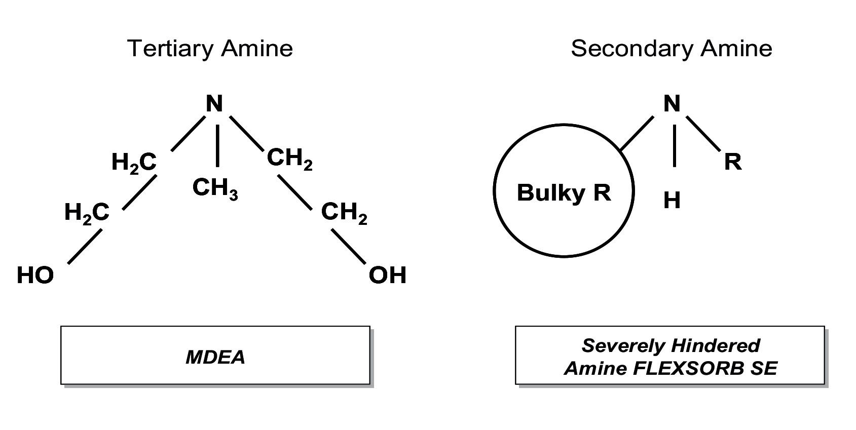
better selectivity for H2S over CO2 compared to conventional MDEA.
Steric hindrance reduces carbamate formation. The steric hindrance of the nitrogen atom is the primary factor in H2S selectivity over CO2 reaction with the amine. The severe steric hindrance of the amino group is the dominant factor in providing high thermodynamic capacity for H2S, and slower CO2 reaction rate.
In order to capture the maximum processing flexibility, the team developed a range of feed compositions. There were 120 possible feed gas compositions to the amine unit, as it was initially fed from five separate wells (either individually or in any combination, depending on the onshore demands). It was also recognised that the production facilities could be used as a future processing centre for other fields in the area. This flexibility was achieved using multiple packed beds with a number of lean amine feed points to the absorber tower. The amine plant was designed for a gas turndown to 30% of the full design and a liquid turndown to 20% of the full design. The ExxonMobil team provided a complete operating envelope and philosophy to guide the operations. The appropriate lean amine injection location and lean amine circulation rate was defined to achieve the treating objectives covering the range of the original five wells. The operator engaged ExxonMobil throughout all project phases including operator training courses, the hazard and operability study (HAZOP), degreasing operations, and tower internal inspections, as well as operating envelopes and operating philosophy documents.
The platform was asked to treat gases from other fields in the area. If the amine feed gas was significantly different from the operating envelope created, the operator contacted ExxonMobil as the technology licensor to offer new recommendations for amine strength, amine flow rate, reboiler duty, and other key operating parameters. ExxonMobil has a kinetic model, rather than a theoretical stage or HETP model, for carrying out FLEXSORB SE amine treating simulations. This model uses the actual feet and type of packing, and tower diameter, to develop the treated gas composition for a specified amine flow rate.
The latest gas nomination for treatment posed several new challenges. The first proposal was to treat the native gas and the new nomination gas to meet a lower export gas specification of less than 2 mol% CO2, with the CO2 from the regenerator offgas being vented to the atmosphere. Due to CO2 emission concerns offshore, slipping more CO2 from the amine absorber into the export gas is now a requirement. The new CO2 specification for the treated gas was 1.9 mol%, with this higher CO2 export gas being sent via pipeline. This CO2 specification should be achieved as close as possible to the target; it is not a maximum nor a minimum amount. The new H2S treated gas specification was a maximum of 2 vppm, which is not to be exceeded.
A series of cases was provided with flow rates ranging from a turndown case to the 90% probability case. These gas rates are less than the original design and therefore will have a higher residence time in the absorber tower. The inlet CO2 concentration varied from 3.4 mol% (less than the original design) to 4.2 mol% (higher than the original design). The feed gas H2S concentration was 50 vppm, which is very
Electric actuators for all types of industrial valves
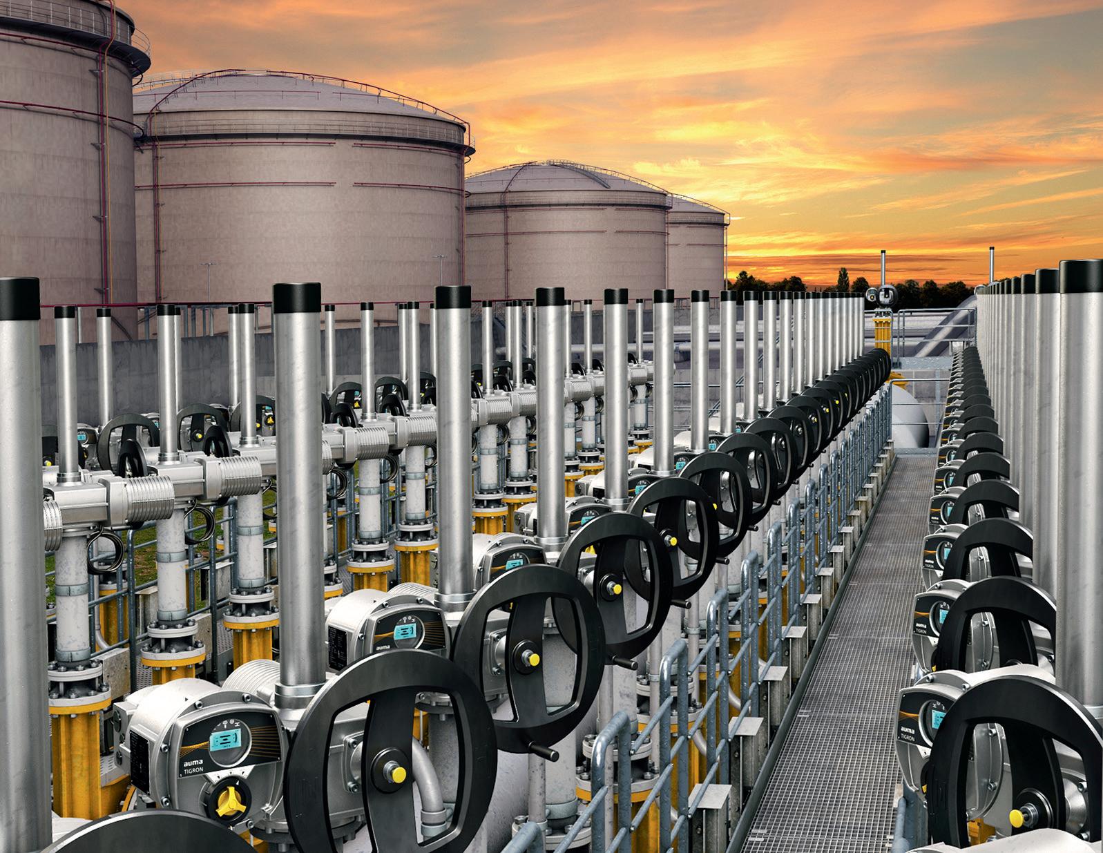
Reliable and long-term service.
AUMA offers a comprehensive portfolio.
Q Customised solutions thanks to the modular scheme
Q Corrosion protection with offshore certification
Q Temperatures up to +75 °C, down to –60 °C
Q Integration into all conventional distributed control systems
Q Worldwide certifications and vendor approvals
Q Service worldwide
similar to the original design. The information requested by the operations group included:
n Recommended lean amine concentration and flow rate.
n Temperature leaving the top of the absorber.
n Rich amine temperature leaving bottom of absorber.
n Rich/lean exchanger duty.
n Lean amine cooler duty.
n Regenerator reboiler duty.
n Overhead condenser duty.
The assessment of the items listed above should be at the limits of the installed equipment, plus any design margins provided in the original design for the flexibility discussed earlier.
Using simulation tools and benchmarking data from actual unit operations, ExxonMobil estimated that the FLEXSORB SE unit may be able to treat a feed gas flow rate of
up to 44% of the original design rate at 4.2 mol% CO2, or 75% of the original design rate at 3.43 mol% CO2. The new CO2 specification of 1.9 mol% should be achievable using the existing facilities utilising FLEXSORB SE with a few changes in operation.
The joint venture license holders made the decision to provide a flexible initial process design for the offshore platform. As a result, they have successfully monetised 20 years of reliable operations. The built-in flexibility demonstrated that the current FLEXSORB SE solvent can handle new gas nominations without a solvent changeover. This is important offshore in order to avoid potential environmental impacts. As the operators are already familiar with the current technology, no management of change is required.
The selective removal of H2S over CO2 with amine solvents is an important application area for gas treating, as illustrated with this project. Capacity, operational flexibility, reliability, and the ability to achieve treated gas specifications (emissions) at low energy consumption were all considered during the technology selection process. The sterically-hindered amine FLEXSORB SE solvent, with enhanced selectivity for H2S, has been in commercial use for 39 years in high H2S selectivity applications such as tail gas clean up (TGCU), acid gas enrichment (AGE), onshore/offshore natural gas treating, and FLEXICOKINGTM Flexigas
Reference
Klaus Brun, Elliott Group, USA, explains why the decarbonised energy economy requires customised compressor solutions for three primary value stream gases: hydrogen, carbon dioxide, and natural gas.

Centrifugal compressors are widely used in the energy industry for the production and transportation of hydrocarbon gases. Compressors must be customised for the particular service or duty since they have to be aerodynamically designed for a specific flow, gas, pressure, and pressure ratio. Over the past
30 years, however, there has been a trend toward standardisation of compressors to reduce parts count, simplify inventory management, and lower maintenance costs. While most compressor manufacturers have developed compressor product lines with standardised casing, sealing, and rotor support elements, the
compressor’s internal flow path must be performance customised for a specific application. To address this requirement, compressor manufacturers have developed families of scalable impeller designs that are performance optimised for certain head and flow ranges. Few compressors have identical internals.
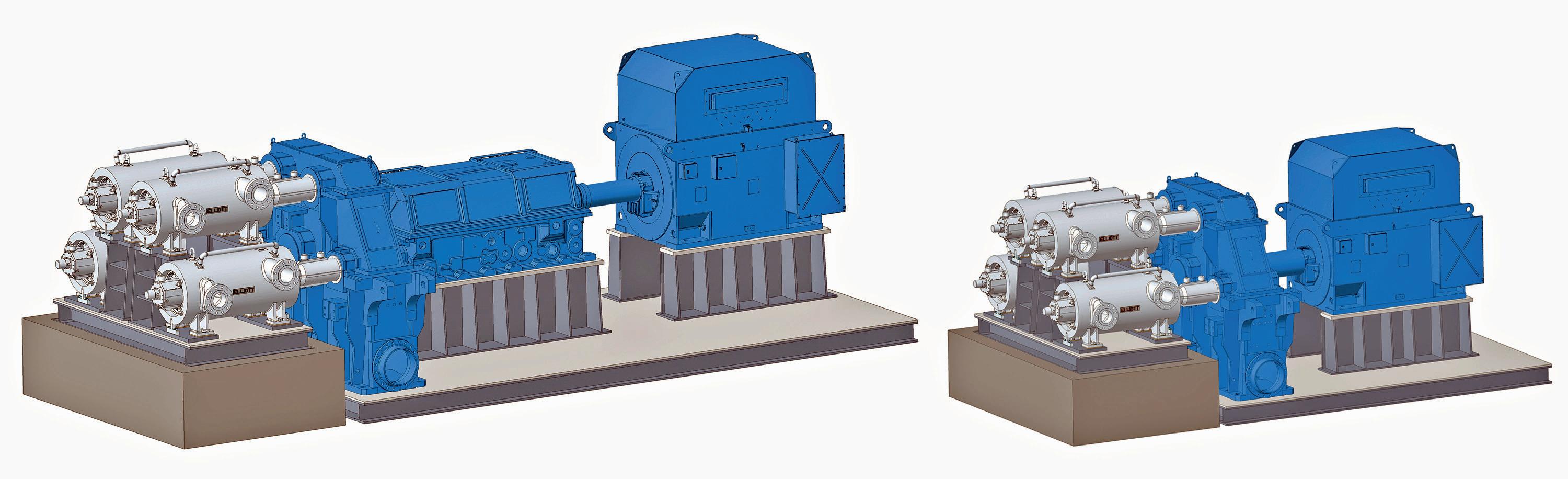
With the movement toward decarbonising the energy economy, there has been a recent trend away from standardisation toward individually optimised compressor designs for specific applications. This trend is primarily driven by a need to achieve further performance and efficiency improvements for working fluids such as hydrogen, carbon dioxide (CO2), and even natural gas. Although hydrogen and CO2 compression is not new, the movement toward more widespread compression applications for these gases demands new and advanced technology solutions.
In a carbon-constrained economy, the main energy carriers will be electricity and hydrogen. Hydrogen has the advantage in that it can be easily stored, while electricity does not have to be re-converted to be useful for most power applications. For the near future, most hydrogen will be derived from natural gas, since converting electricity from alternative energy sources to hydrogen is too expensive in terms of capital cost and roundtrip efficiency. Several prominent studies have shown that, even if the supply cost of electricity from alternative sources is zero, the total cost of producing hydrogen via electrolysis is still higher than producing it from natural gas because of the high initial and ongoing maintenance costs of electrolysers.
Natural gas is cheap and abundant, and the methane steam reforming and gasification processes to convert natural gas to hydrogen are proven and relatively inexpensive. For this reason, in a decarbonised energy economy, most hydrogen will be blue from widely-available natural gas, rather than green hydrogen from curtailed alternative energy sources. But for every tonne of hydrogen produced from natural gas, approximately 8 – 12 t of CO2 will also be produced. Consequently, CO2 will have to be transported and injected into an appropriate geological sequestration end-storage site.
Although the natural gas to hydrogen conversion can be performed at either the natural gas well site or near the end use location, because of the existing natural gas infrastructure and the cost of developing a completely new
hydrogen transport infrastructure, it is likely that in most cases, the conversion will be performed near the site where the hydrogen will be utilised, such as near a power plant that utilises hydrogen fuel for combustion, or close to a fuel-for-transportation distribution hub. To minimise the cost and complexity of having to transport the hydrogen, the existing natural gas pipeline and storage infrastructure will dominate the economics and the natural gas to hydrogen conversion. This then creates the critical need to develop an infrastructure to transport the CO2 to a geologically-appropriate sequestration site.
It is clear that the decarbonised energy economy value stream requires the transport and thus compression of the three key gases: hydrogen, CO2, and natural gas. Unfortunately, the physical properties of these gases are radically different, and there is no standard compressor that can be optimised to efficiently handle all three duties using a single arrangement or design. For example, the density of CO2 at ambient conditions is three times higher than that of natural gas, which in turn is eight times higher than that of hydrogen. Clearly these are very different gases, and the compressor arrangement and design must be customised for each of them so as to be able to provide an efficient compression process. Specifically, new technology options are required.
As previously noted, there is no single optimal compressor solution that can efficiently cover all three critical gas streams of the decarbonised energy economy. Three different compression solutions are required.
Hydrogen is the lightest of all gases and poses some significant technical challenges from a compression perspective. The key challenges include:
n Light gases are thermodynamically difficult to compress. Very little pressure ratio is produced per head, which results in the requirement for either a very large number of compression stages or very high speed impellers.
n Hydrogen can cause embrittlement in ferrous alloys. Material and coatings must be carefully selected to ensure long operating life.
n Hydrogen molecules are very small, making sealing and containment difficult. Both dynamic shaft seals and static casing seals must be designed to reduce the potential for hydrogen escape.
n There are safety issues because of hydrogen’s explosivity, low auto-ignition temperature, and wide flammability range. This is especially a concern since hydrogen leakage is also difficult to control.
As noted, light or low molecular weight gases are
difficult to compress, and result in a low head rise per centrifugal stage in the compressor. Even at relatively high impeller tip speeds of 350 m/sec., typical pressure ratios per stage seldom exceed 1.1. For rotordynamic reasons, there are finite limits to shaft length in any compressor. Centrifugal compressors can mechanically fit a limited number of stages per casing – usually no more than 10 – 12. Also, the impeller and shaft material must have sufficient strength, while being light enough to minimise hoop stresses at high rotational speeds. Theoretically, impellers with very high tip speeds above 2000 ft/sec. (fps) are possible by using non-metallic materials, magnetic or gas bearings, and special seals. Shaft and impeller material can include titanium alloys, continuously wound carbon fibre, and ceramics.
Unfortunately, most of this technology is currently in the development stage and is not practical for rugged industrial applications that require very high reliability, such as pipeline or storage service. There are some critical research gaps that must be addressed before this technology can be applied commercially. Until this technology is ready to be deployed on an industrial scale, more conventional compression technologies will have to be utilised. Consequently, with currently-available impeller technology, long compression trains with many stages per casing are required if a significant hydrogen pressure rise is needed.
Elliott developed the Flex-Op® compression arrangement to improve the head, flow, reliability, and operational flexibility capabilities of hydrogen compressors. This arrangement is comprised of four compressors on a single gearbox. Originally designed for high-pressure ratio and high-flow compression, this arrangement has the flexibility to allow individual compressors to run in series or parallel (or both).
As previously noted, hydrogen compression requires a large number of compression stages to achieve a reasonable head. With up to four casings, more than 40 impeller stages can fit into a linear footprint that traditionally only fits 10. This shrinks the linear footprint of the compressor section from upwards of 40 ft to approximately 10 ft. Flex-Op can utilise the four compressor casings in parallel or in a series, with multiple extractions and sidestreams. Since each rotor is connected to its own pinion via a flexible shaft coupled to the central gear, the rotor speeds can be individually optimised for the highest aerodynamic efficiency. A barrel casing coupled with a single, multi-pinion gearbox allows the whole assembly to be powered by an electric motor with a variable frequency drive, a variable speed drive motor, a steam turbine, or a single/two-shaft gas turbine.
Figure 1 shows two of these possible arrangements.
Engagement/disengagement of individual compressors is also possible for additional operational flexibility if clutch or torque converter couplings are implemented at the compressor shaft ends. The casing arrangement allows it to operate in parallel for high throughput, or in series with intercooling between bodies for the highest pressure ratios. Finally, the arrangement provides easy access to all four compressors for maintenance and repair using a single mezzanine or platform and crane.

Elliott’s compressor arrangement offers a practical solution for most industrial hydrogen compression applications in the hydrogen transport and storage sectors. It is rugged and reliable, and relies on proven industrial compression and gear technology. Unlike many novel hydrogen compression solutions that are currently under development, the Flex-Op arrangement components are all designed within well-known industrial operational limits, and are commercially available.
Compressors are installed in natural gas pipelines to inject the gas into the pipeline at its operating pressure and then to recompress the gas at certain distances along the pipeline to compensate for its viscous pressure drop. Typical pipeline operating pressures range from several hundred psi to about 1500 psi for standard pipe diameters of a few inches up to greater than 60 in. In the US alone, there are currently over 7000 compressors installed in natural gas pipeline compression service on over 2.6 million miles of pipelines. Approximately 25% of these compressors are old, low-speed integral reciprocating machines that were originally installed between 1940 and 1970, and which are technically outdated and mostly obsolete. This, in combination with additional natural gas demand driven by
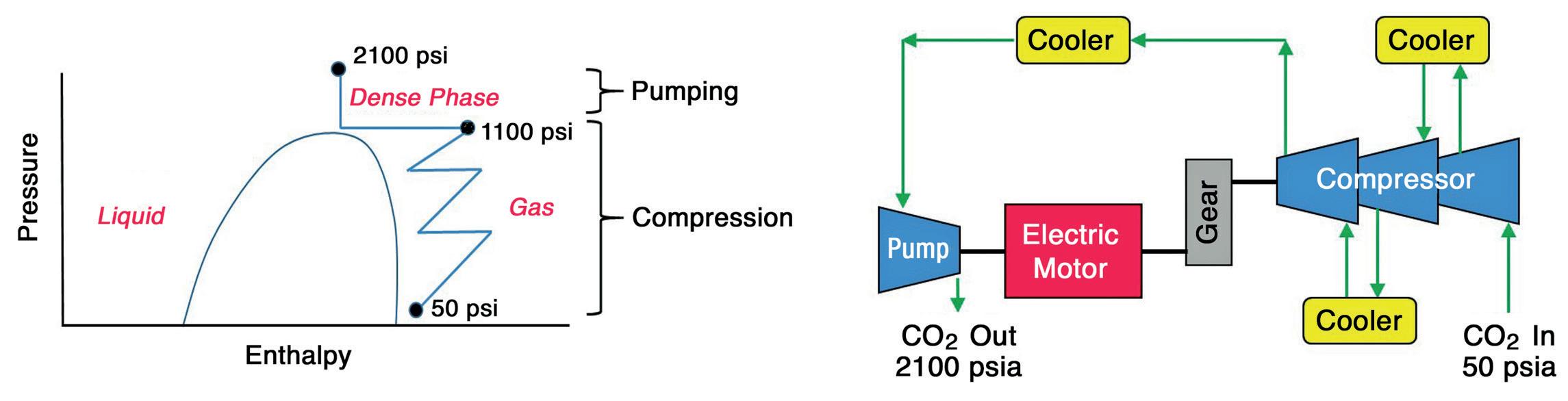
increasing LNG exports, new/refuelled fossil power plants, and increasing domestic consumption, has led to the need to rapidly increase the North American pipeline compression capacity, both by the installation of new units and by replacing older low-power units with modern higher-power units. At the same time, environmental regulations require the reduction of carbon emissions and gas leakage from pipeline operations, which has resulted in the preferred installation of electric motors rather than gas engines or gas turbines as pipeline compressor drivers. Most centrifugal compressors that are currently being installed in pipelines were originally derived from process gas barrel beam style compressors. For this design, a long multi-stage impeller shaft is mounted on bearings and seals at both ends of the casing, and a balance piston and thrust bearing are used to limit axial movement of the shaft. This design evolved from classical refrigeration, refinery, and chemical process compressors that were originally intended for handling high pressure ratios, and a wide range of different gases at high pressures. However, this design style is sub-optimal for basic pipeline service where the pressure ratios are relatively low, the gas composition is fairly constant, but the operating conditions are highly variable, and the design must be reliable to operate for long periods without scheduled or forced outages. Furthermore, because of pipeline operators’ traditional preference to utilise gas turbine drivers, most current pipeline compressor designs are speed matched to provide optimal performance at high gas turbine speeds rather than lower speeds of electrical motors. This requires the use of a gearbox when driving centrifugal compressors with electric motors for most pipeline applications.
To address some of these shortcomings, Elliott has developed a medium-speed direct drive compact overhung rotor compressor design with features that are specifically designed for natural gas pipeline service (Figure 2). The Elliott 140TCH compressor uses a single- or dual-stage impeller overhung design to reduce the number of bearings and seals; it is speed matched to conventional induction electric motors without the need for a gearbox; it has an axial inlet for optimal aerodynamic performance and reduced leakage; and it does not require a balance piston. The compressor impellers are designed to match the typical head requirements of natural gas pipeline service at medium speeds between 5000 – 7500 RPM for 15 – 35 MW applications, which can be reached using conventional electric induction motors as a direct drive. This design approach results in higher efficiency, reduced leakage from a single, dry gas seal, and the avoidance of a balance piston.
The 140TCH comes with a direct connect, variable speed (VFD) motor and a standard footprint, in addition to custom aerodynamics for optimum efficiency and extended operating time between scheduled overhauls.
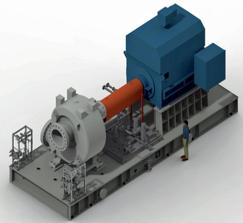

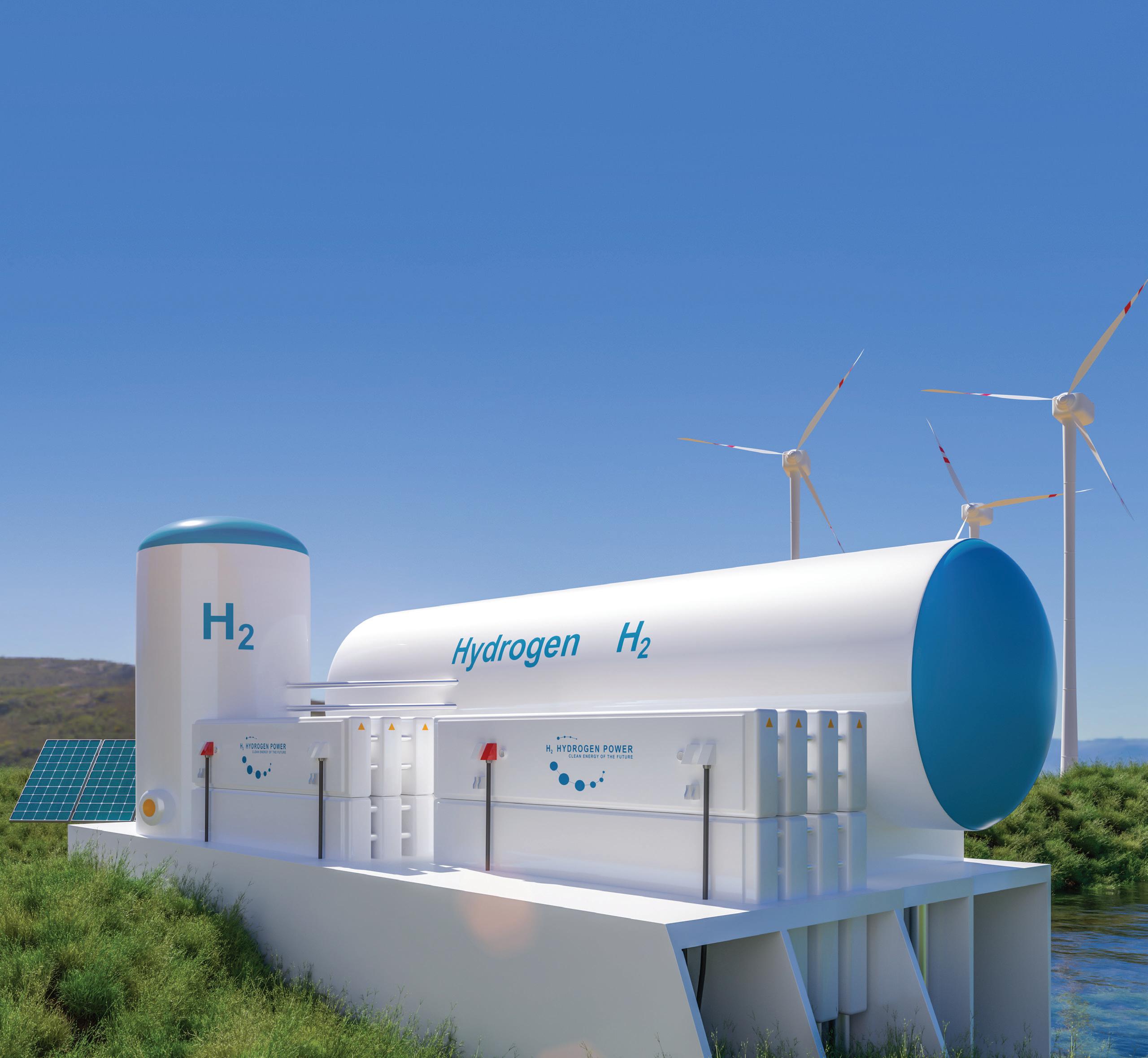
Elliott’s Flex-Op® Hydrogen Compressor features flexible, configurable, and economical compression options for hydrogen applications. Designed with proven Elliott compressor technology, the Flex-Op’s compact arrangement of four compressors on a single gearbox maximizes compression capability with enough flexibility to run in series, in parallel, or both. Who will you turn to?
n Learn more at www.elliott-turbo.com
The World Turns to Elliott COMPRESSORS |
|
The gearless configuration provides several advantages, including a smaller footprint, reduced lube oil requirements, and higher net efficiency. The high-speed VFD-powered motor significantly reduces CO2 and NO x emissions as compared to a gas turbine driver. The VFD addresses starting issues and allows for adjustable operation to match load/capacity requirements. The pipeline compressor’s single lift plug-and-play design includes auxiliaries such as lube oil, a buffer gas panel, and integrated, customised controls.
The 140TCH is designed to handle most modern, mid-size and large pipeline compression applications. Its design is lean and simple and focuses on making pipeline compression efficient, reliable and cost-effective. The impeller aerodynamics are based on Elliott’s advanced and proven EDGE technology. With the axial inlet and flexible or customisable aerodynamic design, efficiencies of greater than 85% can be obtained. The direct drive compressor with a variable speed electric motor provides a wide operating range, including efficient turndown operation. With three standard frame sizes, 15 MW, 25 MW and 35 MW, the 140TCH centrifugal compressor is designed for applications up to 7000 million ft3/d, with a pressure ratio ranging from 1.15 to 1.8.
There are many technical challenges when compressing CO2, including dry ice formation, strong thermodynamic path dependence, carbonic acid formation in the presence of water, low sonic speed, and solubility in elastomeric materials. From a thermodynamic perspective, however, as CO2 is a very heavy gas, it is relatively easy to compress. This means that the pressure ratio per compressor impeller stage is high. However, because of the high pressure ratio per stage, CO2 also has a significant specific volume decrease with pressure, and a very high heat of compression. Consequently, CO2 will heat up when compressed, which requires stage intercooling to maintain the gas temperature at reasonable levels so as to not damage the seals and bearings of the compressor. Furthermore, because of its rapid density change with pressure, there is a significant flow volume reduction that requires a wide range of aerodynamic high-to-low flow compression stages.
The most challenging problem with CO2 compression is that the critical point for most CO2 applications lies in the middle of the desired operating range. Most carbon capture and sequestration (CCS) compression duties for CO2 require compression from near atmospheric pressure to a discharge of several thousand psi, which means that the compression process has to pass through the critical point of CO2 around 1100 psi. That is, CO2 will undergo a phase change from the gas phase to the liquid or supercritical phase during the compression process. From a design perspective, this means that the compressor impellers must be optimised for gas behaviour below the critical point, and also for what is effectively liquid behaviour above the critical point. One approach to addressing this challenge is to combine a compressor and pump into a hybrid package, as shown in Figure 3.
Elliott’s CO2Phase compressor layout provides a solution to this design concept by combining a single 6-stage barrel type compressor for the sub-critical compression, and a 12-stage centrifugal pump for the supercritical pumping. Figure 4 shows a typical layout for the CO2Phase hybrid CO2 compressor and pump selection, including ancillaries, auxiliaries and coolers. There are several other packaging options specific to the application, location, maintenance strategy, and available utilities. In some cases, a more compact, single-lift module may be desired, whereas in cases where there are no footprint limitations, a larger, more distributed packaging design may be preferred.
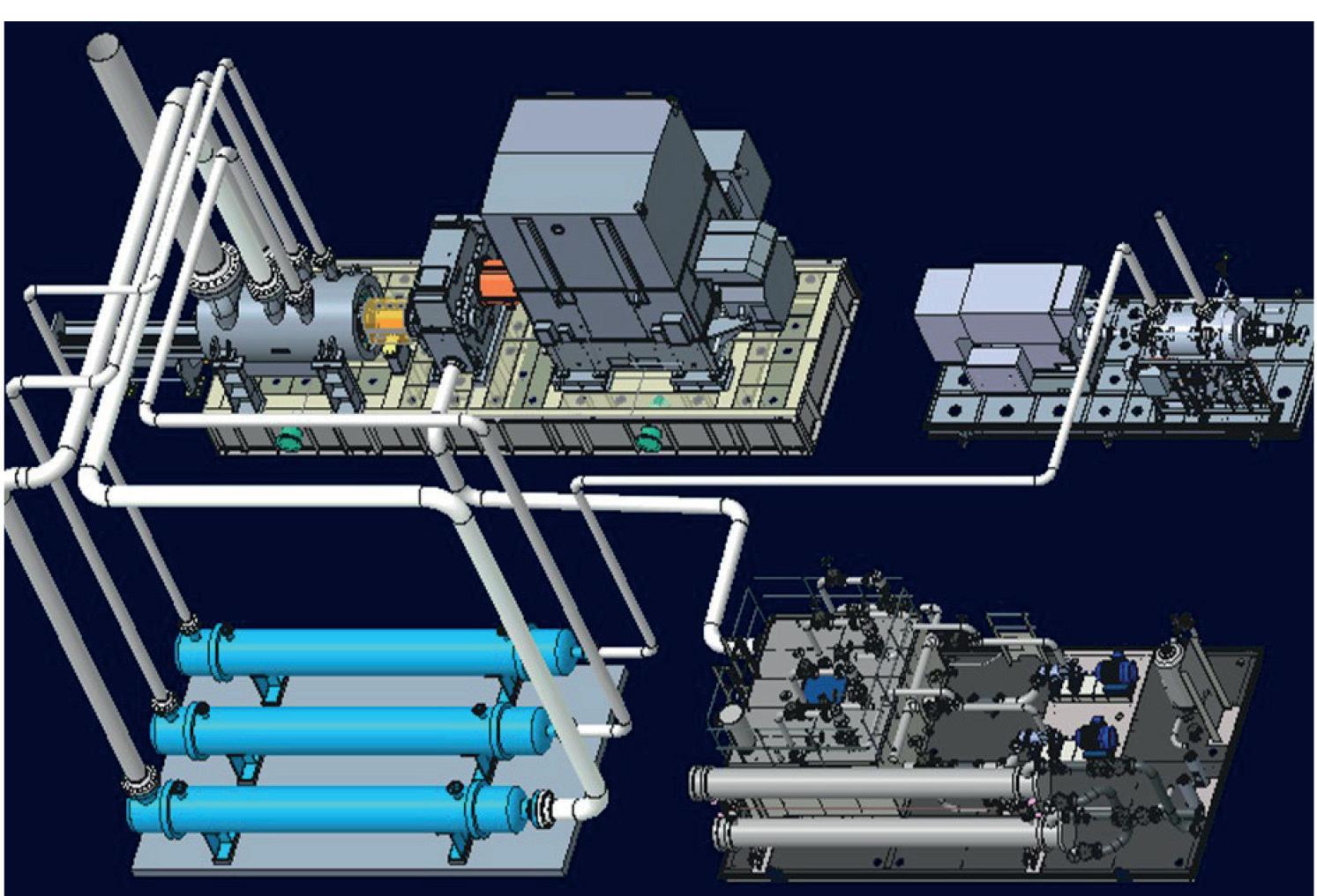
This compressor/pump design is equipped to handle any project and/or equipment related to CO2 compression needs, from atmospheric pressure to typical piping pressure of around 2200 psi and higher for sequestration requirements. While each package configuration may vary slightly based on the operator’s specific conditions or needs, a typical CO2Phase compressor package includes the compressor, pump, motor(s), gear, lube system, and buffer or seal system. Configurations are available with a double ISO-cooled compressor with a pump and two motors, or a compressor and pump configuration with a single electric motor.
The decarbonised energy economy requires the development of new and optimised turbomachinery solutions for the transport and storage of its three primary value stream gases: hydrogen, CO 2, and natural gas. Specifically, optimised solutions must be found for each one of these gases to provide for efficient, economic and reliable compression. Elliott has provided customised turbomachinery products for the energy industry for the last 70 years, and has developed three new products to individually address these gas compression applications. These solutions address the needs for three very different applications. They are adapted for the specific requirements of the gas and operating conditions to provide operators with the highest efficiency and most reliable turbomachinery required to successfully operate in the decarbonised energy economy.
In response to climate concerns, most countries around the world have goals to reach net zero by 2050. This means that all greenhouse gas (GHG) emissions produced are balanced by an equal amount of emissions that are eliminated. As a result, governments are establishing more stringent regulations to encourage companies to accelerate their
decarbonisation efforts. For example, the US Environmental Protection Agency (EPA) announced forthcoming regulations that will usher a path for companies to increase the urgency to reduce their carbon footprints – primarily GHG emissions.
So, how can energy companies bring new and existing equipment into compliance? What impact will

Craig Martin, Paul Modern and Juan Moreno, Cook Compression, explore two potential pathways to decarbonisation for energy companies.
green technology and alternative fuels have? Energy companies will have to address these and other difficult questions in order to determine their best pathway to decarbonisation. This article will explore two potential paths – emission reduction and hydrogen fuel – and how new technologies are being developed to support energy companies as they navigate these decisions.
In the natural gas sector, piston rod packing on reciprocating compressors is a major source of methane emissions. In 2019, the Pipeline Research Council International (PRCI) determined that, on average, compressors in storage and transmission emit 2458 and 3012 ft 3 /d of methane gas per unit, respectively.
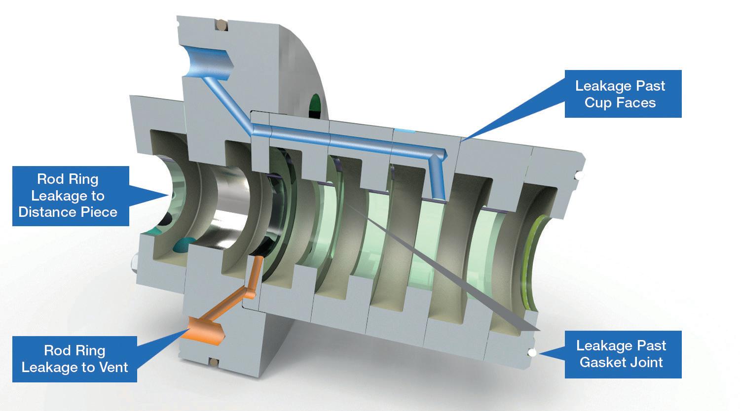
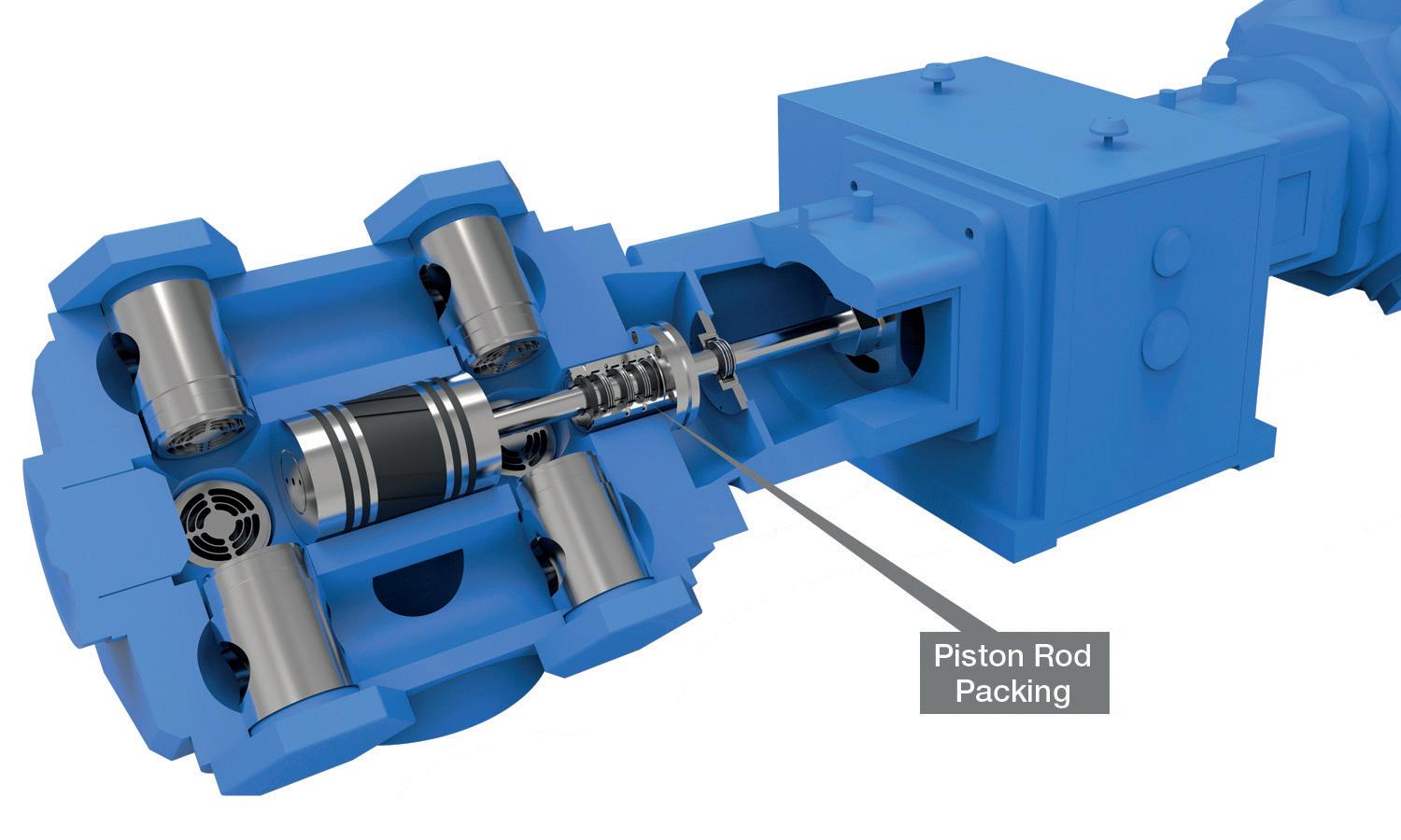
Methane emissions at the rod packing tend to come from one of three sources. The first and most conspicuous is leakage that occurs along the piston rod past the seal rings. Some gas loss here is expected, as
packing rings shuttle back and forth with the reciprocating action, but this can increase greatly as the packing wears over time, or possibly due to process upsets that damage the wear components.
Second, leakage can occur between cups in a rod packing case. Damage to cup faces over time, poor repair procedures, or insufficient clamping force can result in a loss of cup-to-cup contact. Though less attention is paid here, research has shown that emissions between cups can equal or exceed those past the rod rings. Finally, the nose gasket seal can be a significant leak source if there is damage or a loss of clamping force.
In addition to emission sources during operation, rod packing can leak significantly when in standby mode. This can be addressed with standby seals, which activate a positive seal upon shutdown of a compressor. One natural gas distributor recently recorded a reduction in standby emissions of 86% by employing a standby seal on multiple units. However, these standby seals are optional packing case features that are utilised on only a small fraction of units in the field.
Methane emissions from reciprocating compressors have been subject to increasing levels of regulation in recent years. Following a joint resolution by the US Congress in June 2021, the EPA has proposed revisions to the new source performance standards under the Clean Air Act for the oil and natural gas sector, aimed at more comprehensive emissions reductions. The existing OOOO and OOOOa standards established in 2016 require rod packing to be replaced on or before three years, or 26000 run hours. The new rules will shift to a performance-based standard of 2 ft 3 /min. The new subparts, OOOOb and OOOOc, would require monitoring on an annual basis (8760 run hours), with replacement and/or repair of the packing in order to maintain the required emission rate.
Alternatively, a vapour recovery system can be implemented to capture and re-route these emissions.
Meeting these new regulations can be challenging for natural gas utilities. At present, the regulations do not prescribe a standard system or test method for monitoring, and these systems can be costly to implement and maintain. Changing regulations and uncertainty can be major hurdles to selecting a path to

As companies establish decarbonization policies, reciprocating compressor owners must work to meet more stringent emission requirements.
COOK CLEAN sealing systems leverage field-tested technologies, such as BTUU or BTRR uncut rings, and engineering innovation to offer a best-in-class system proven to lower fugitive emissions to near-zero levels.*
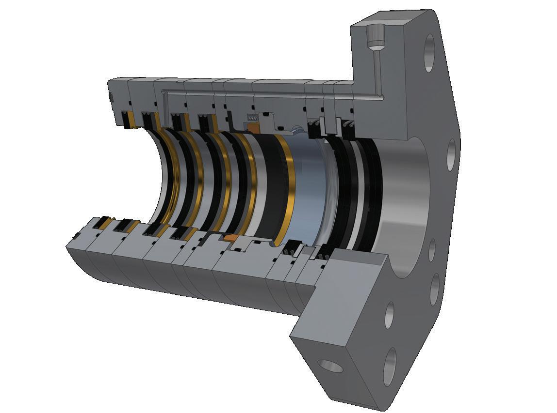
Surpass emission targets with COOK CLEAN sealing systems.
*Learn more at www.cookcompression.com/cookclean
decarbonisation. In order to support those companies working to reduce emissions either as their chosen pathway to decarbonisation or to meet regulations, Cook Compression has developed the COOK CLEAN TM sealing system to reduce fugitive emissions in reciprocating compressors. By incorporating proprietary design elements, this sealing system has documented leakage rates of below 0.75 ft 3 /min per throw – well below the defined EPA limits.
Many experts see hydrogen as the best pathway to decarbonising energy. It makes sense to use a storage and energy vector medium with no GHG impact if released, and that only produces small amounts of nitrogen oxides (NO x ) emissions if used as a direct combustion fuel source. The technology readiness level is also high. Considering fuel cell applications, conversion to ammonia, use in biofuels, and other historic industrial use cases, these are easily achievable right now from a technical standpoint.
So, how does this hydrogen transition play out over time? What needs to happen to accelerate change?
Where are the current technical hurdles?
The first and most important factor for many is cost. Industries are challenged to drive down the cost of green or blue hydrogen vs traditional grey hydrogen from natural gas sources. This will require changes to policy, taxation, and tariffs, coupled with a ramp-up of renewable electricity production from wind/solar.
The market must also develop a structure to support global supply and demand transactions. Geographical constraints will affect how this plays out. For example, the current natural gas price in Europe may restrain the transition to blue hydrogen production and force a green hydrogen pathway, whereas the US has natural gas in abundance which might make carbon capture and blue hydrogen production a better option. Asia has ambitious targets regarding infrastructure that will change the shape of the region’s transition.
Any energy transition should target the biggest GHG emitters first. For example, steel production facilities are huge global GHG emitters that could potentially change production methods and integrate hydrogen into their processes. Power generation would reap huge benefits by simply swapping from coal-fired to natural gas-fired power production, without the additional step of transitioning an entire infrastructure to hydrogen. Indeed, hydrogen as a pure fuel for this type of application is a poor substitute in terms of calorific value when simply burned. Natural gas in its many forms (CNG, LNG, etc.) must therefore continue to play a huge role during this transition and beyond.
Currently, there is a push to reduce vehicle tailpipe emissions for local air quality reasons. However, it should be noted that modern petrol/diesel-fuelled engines for road use are already quite efficient in this respect. The shipping industry, with its reliance on cheap, low-grade
fuel oils, is potentially a much better target to achieve a reduction globally, but this is more difficult to implement. Using biofuels or even ammonia as fuel stock has been suggested, but this demands a huge effort to produce the required quantities at a reasonable cost point and to retrofit or convert fleets.
Technically, there are challenges with materials for pure hydrogen, especially at elevated pressures. Standards development is ongoing but needs to keep pace with the desire to implement quickly. Marrying up renewable, intermittent capacity and sourced production methods with existing equipment that relies on a constant rate feed source is also a challenge.
Transportation from locations with good resources for renewable production to demand centres will require new storage and transportation technologies, along with the infrastructure to support them.
So, how will this all play out in the next 5 – 10 years? The current industries that use hydrogen –petrochemical, refining, fertilizer – will not go away. In fact, these users are likely to be the first adopters in this transition, moving from grey production to carbon-captured blue or green hydrogen where available. Many projects are already in motion. Beyond that, policy by region needs to drive change in other sectors. The cost of cleaner hydrogen must be driven down, but there will eventually be a crossover point where it makes economic sense to choose the greener path for industries such as power generation and steel manufacturing. This will take time. The same can be said for hydrogen use in vehicles. Without a large hydrogen refuelling infrastructure investment, battery electric vehicles will continue to dominate in the near-term. Fleet vehicle applications with a single point of origin for hydrogen fuelling will be the most logical path to using hydrogen as a direct fuel source, whether that means a fuel cell or an internal combustion engine.
Cook Compression has prepared for the coming hydrogen transition by investing in research capabilities and expanding the portfolio of TruTech® advanced materials to include formulas engineered to withstand high-pressure hydrogen environments.
As government regulations continue to evolve, the future is going to be an exciting and challenging mix, with some winners and some losers. Although the future is difficult to predict, energy demand is not going away. Whether an energy company chooses to focus on emission reduction or the introduction of new technologies via hydrogen, it will have to partner with suppliers who are committed to innovation and thinking creatively to meet the decarbonisation challenges.
To tackle the operational and transformational obstacles associated with decarbonisation, Cook Compression is investing in the research and development of new technologies, such as COOK CLEAN products, that help meet current and pending regulatory requirements.

Valve specification and selection is an important part of the success of a new petroleum refinery. A considerable amount of time is invested in and dedicated to specifying the correct valves for the defined operating conditions and piping arrangement. Equally as important to consider, however, are undefined conditions such as capacity changes, product changes, and operational variations. These undefined variations often cause problems in the system that demand detailed analysis, and a costly production shutdown may be required to resolve the issue. The undefined operating variations may relate to start-up and shutdown processes, the cleaning
process, and emergency and upset conditions. These undefined operating conditions are typically more severe than the actual defined operating conditions. Additionally, there are expectation variations between isolation and control valves that should be considered, as well as process growth capabilities. As a result, the following undefined and overlooked considerations should be assessed during valve selection in order to ensure optimum valve performance and future growth adaptability.
Many valve sizing programmes can predict damaging situations such as cavitation, flashing, and
noise under various flow conditions. A misleading assumption is that start-up and shutdown conditions are rare events that will not harm the valve. If start-up and shutdown flow conditions are excluded from valve sizing, then the selected valve may fall out of the capability range during start-up and shutdown, and perform poorly.
It is common for start-up and shutdown concerns to be addressed with a control scheme during initial system commissioning. The specification process usually does not account for short-term, potentially-damaging service conditions, such as pump control. Typically, pump control is not addressed in the control scheme. For example, a low-concentrate slurry may have little effect on standard control valve surfaces under normal operating conditions. However, during start-up, the control valve may be left slightly open intentionally in order to prevent piping damage from filling the system too quickly. During this start-up, the increased velocity across the seat of the valve causes the slurry to erode the internal surfaces of the valve, thereby prematurely degrading the valve and impacting its performance and longevity.
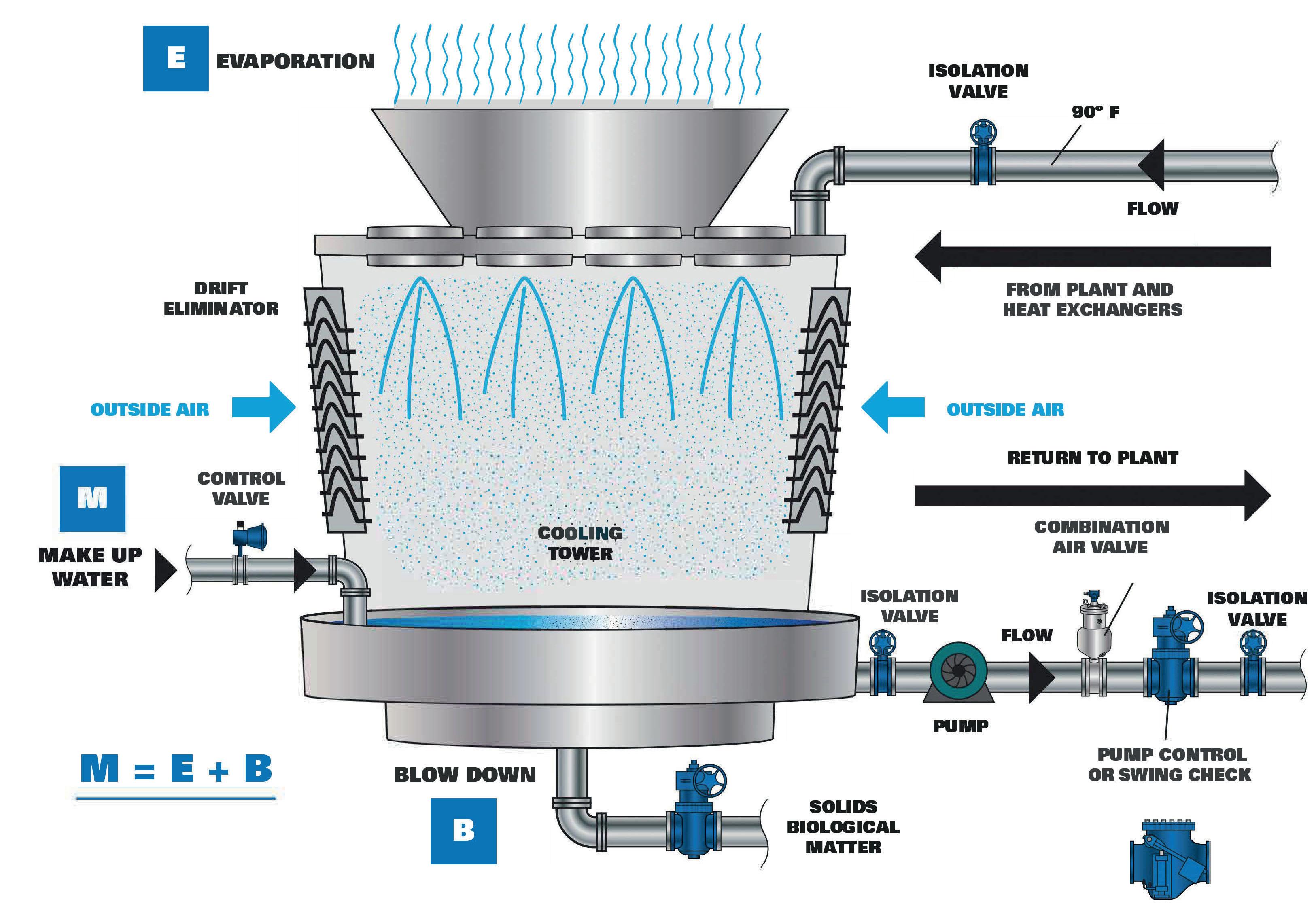
If overlooked, cleaning processes can have a dramatic impact on valve performance. This is especially true with valves that use elastomeric components for sealing. As cleaning processes typically incorporate steam and/or chemicals to clean the lines, care must be taken in selecting materials that are compatible with the cleaning media and process conditions. It is best practice to ask about the cleaning process during valve selection to avoid compromising valve performance.
Loss of power and emergency shutdown procedures also impact valve operation. In the case of isolation valves, manual overrides may be required for critical applications when solenoid valves are inoperable due to power failure. Control valves are often equipped with spring-diaphragm style actuators that have a mechanical fail position. However, control valves can also utilise double-acting cylinders or electric motor actuators. These actuators will fail in ‘last position’ upon air or power failure. Because terminology and understanding are not universal, it is important to clearly define what should happen during air or power failure.
For example, the valve positioner will lose signal during power failure, thus driving the output to fully open or close the valve, depending on designation. Although the air compressor will also lose power, residual supply pressure in the system can continue to cycle the valve to an undesirable position.
Upset conditions, including pressure, temperature and media abnormalities that may occur during an upset event, need to be considered and reviewed. Surge protection may be required for pressure upsets; elastomer selection may be affected by temperature spikes; and slurries may settle and plug piping, potentially causing a variety of issues – from spills to dangerous exposure.
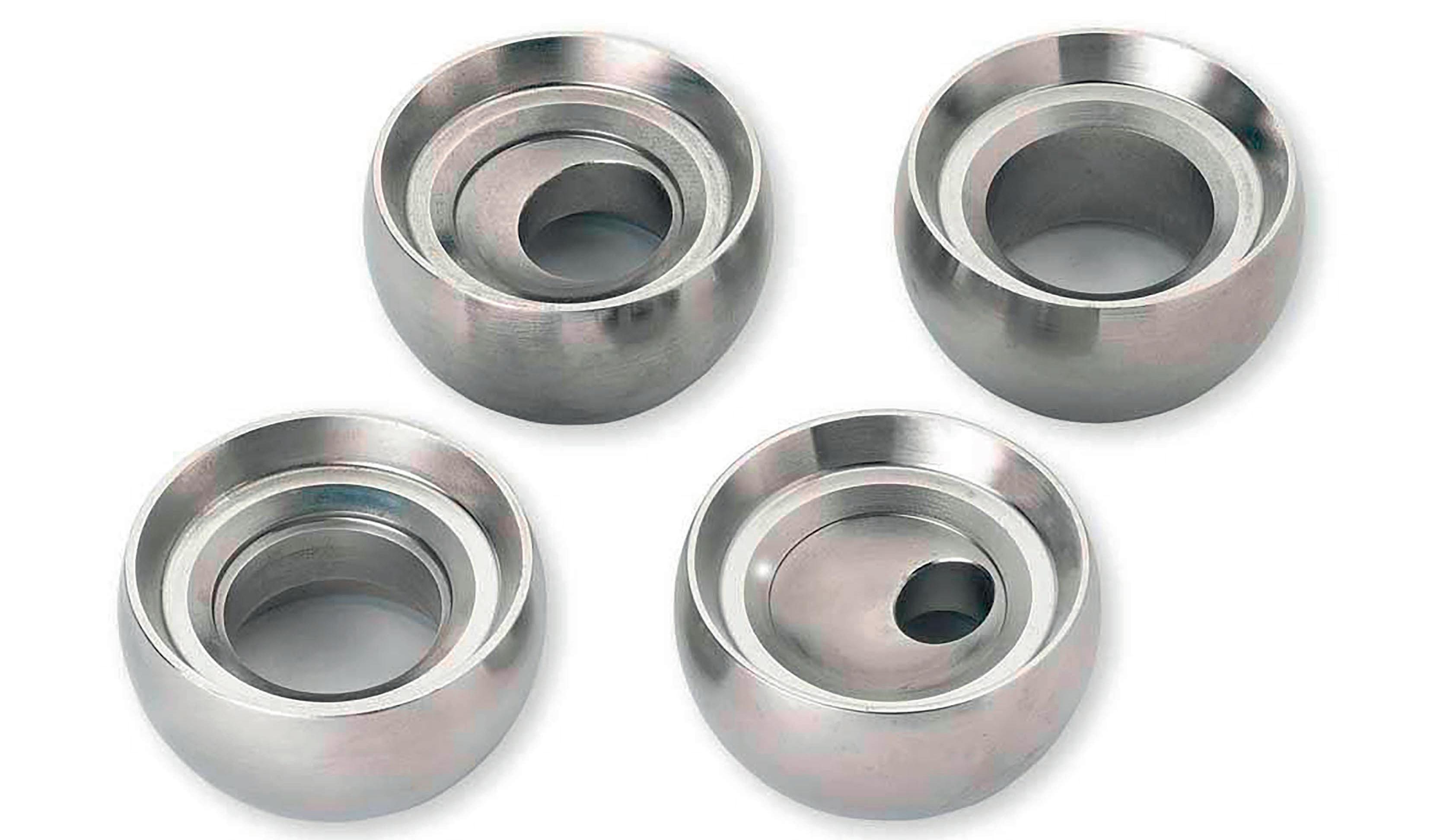
Valve manufacturers reference applicable standards in their documentation but do not typically publish the actual test criteria from the standard. Rather, they state whether the valve meets or exceeds the standard. The standards are published by organisations such as the American Petroleum Institute (API), and these define the test procedures and acceptable leakage rates for various valve types. It is up to the specifying engineer to understand the application criteria and apply the correct valve type based on the isolation capability requirement for the system.
If a testing standard clearly meets the application criteria, such as API 598 for the oil and gas industry, the selection may be as easy as choosing a valve that meets that standard. Other standards to consider pertain to pressure relief codes such as the PED 97/23/EC, which is the Pressure Equipment Directive developed by the Commission’s Working Group ‘Pressure’ (WGP), and EN4126, which documents safety devices for protection against excessive pressure.
However, when considering a knife gate valve for isolation in a fluid catalytic cracking (FCC) wet scrubber
application, the valve selection decision may not be clear. Under the Manufacturers Standardization Society of the Valve and Fittings Industry (MSS), the MSS-SP81 standard states that a unidirectional metal-seated knife gate valve permits leakage of 40 ml/min per inch of valve diameter with 40 psi line pressure against the gate. With an elastomer-seated, unidirectional valve, the leakage rate must be specified or may refer to MSS-SP61, which has a lower leakage rate. If the system has only minimal line pressure available to assist in seating the valve (less than 40 psi), this should be communicated to the valve manufacturer so that testing under actual service conditions can be conducted. Otherwise, a bidirectional elastomer-seated valve may be considered.

A clear understanding of the isolation requirement is necessary when specifying a valve, as requirements can vary greatly. For example, a metal-seated knife gate valve with an allowable leakage rate may be suitable for handling catalyst fines solids in the wet gas scrubber purge stream to clarifier isolation, but would not be suitable for isolating recirculating water pumps where a resilient seated knife gate valve is preferred for zero leakage.

A valve that is used for isolating a bulk feeder from a hopper under normally-flowing conditions will not be able to shut off under a static condition or through a standing column of media. Under normal flowing conditions, a standard knife gate would slice through the flowing column and isolate. However, if the bulk feeder stalls and the column fills, the standard knife gate will
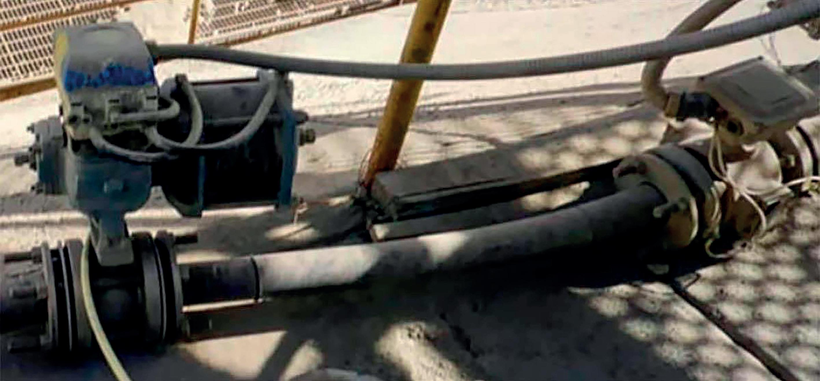
Figure 3. A facility installed a 2 in. rotary control valve body with a trim size at reduced capacity to control acid flow. When the facility was ready to increase flow capacity, it changed the valve seat to a higher capacity trim size, thereby eliminating labour-intensive and expensive piping changes (source: DeZURIK Inc., 2022).
not be able to successfully cut through the column of material to adequately isolate the feeder from the hopper for maintenance. Other possible valve solutions would be an O-port knife gate or a specialised, tapered body knife gate with space fabricated into the valve body to displace the column of material.
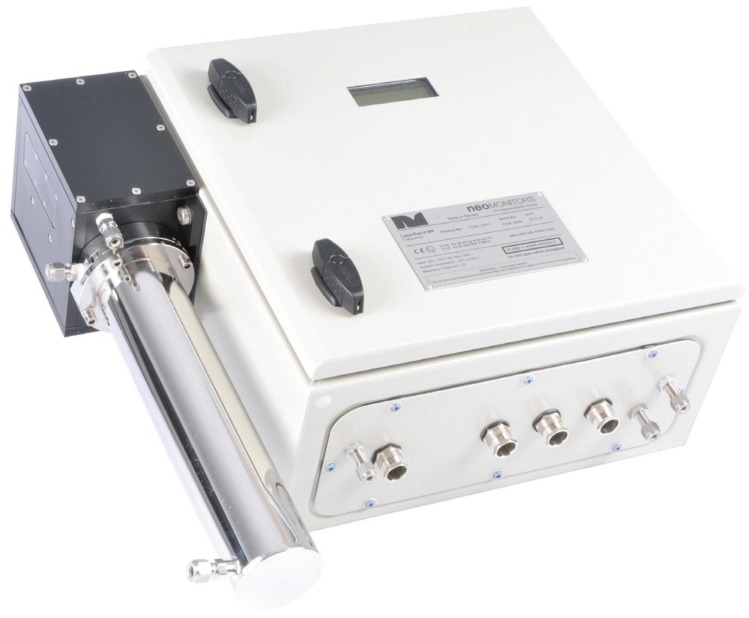
Double block and bleed or double isolation and bleed valves are often specified for increased safety in many industries, and are common in the oil and gas industry. These valves provide a detection port to verify acceptable shut off from the isolation valves. It is important to consult the valve manufacturer that is
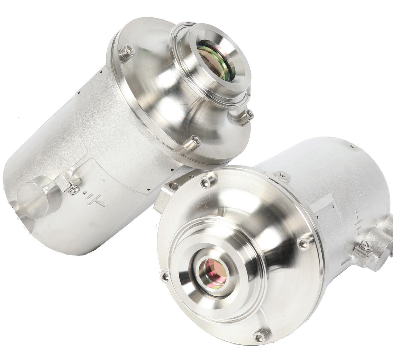
familiar with this style of valve and application since terminology, understanding and expectations can vary greatly.
Aside from a few exceptions, control valves should not be expected to perform double duty as both a control valve and an isolation valve. They are available with various seat options for different media and application requirements. For example, soft seats such as polytetrafluorethylene (PTFE) for make-up water entering the cooling tower; metal seats for scraping the ball or plug in scaling services; and other special seats for critical or unique capabilities, such as fire-safe requirements, are all available. In some applications such as slurry control, the flow control component may never contact the seat and is referred to as a ‘clearance seat’. These variations in seat requirements may make the control valve unsuitable for isolation. Figure 1 shows an example of a cooling tower used in the downstream market, which includes both isolation and control valves.
Occasionally, a control valve is sized for current conditions with the idea that it will also work for future planned expansions and alternate product runs. The assumption that the selected valve will work for future expansion may produce unsatisfactory results, as actual service conditions may be outside the ideal control range. A better solution is to specify a control valve with multiple internal, replaceable control components to accommodate the current application, as well as future expansion.
Recently, a process facility selected a rotary control valve that could be equipped with four interchangeable flow capacity range seat designs (see Figure 2).
This allowed the facility to install a 2 in. rotary control valve body for acid flow control, as shown in Figure 3. When the facility was ready to increase flow capacity, it simply changed the trim size of the valve seat. This straightforward component change eliminated an additional valve purchase, labour costs, and expensive piping changes.
When specifying and selecting a valve for a new refinery, it is essential that as much time and attention be given to the undefined or overlooked operating conditions as is given to the defined operating conditions. The undefined operating conditions such as start-up and shutdown processes, the cleaning process, and emergency and upset conditions, may be more detrimental to the valve than the defined operating conditions. If overlooked, these conditions may require a costly shutdown to execute a detailed analysis in order to resolve the problem.
It is also important to understand valve requirements related to isolation or control, and whether the control valve is expected to accommodate process growth changes. Inquiring about this additional information upfront while specifying and selecting the valve will ensure that the best valve is selected to handle both defined and undefined operating conditions, and will provide the best-performing valve for the refinery.


The new SERVOTOUGH SpectraExact 2500 upgrades the photometric gas analysis of its trusted predecessor, delivering an advanced solution to your process, in an easier-to-use package, leading the way for application solutions in a range of industries.
• Ethylene production
• Ethylene dichloride
• Carbon capture and storage
• Direct reduction iron production
Poor flow control maintenance can lead to operational disruption. The term ‘flow control’ describes how liquids and gases are managed in various applications. Actuators are essential pieces of equipment used across a number of industries, including oil, gas, water, power, chemicals, industrial, and process control, and they can be found all over the world.
Keeping flow control assets such as actuators in peak condition is critical. Inefficient asset management will increase the potential for
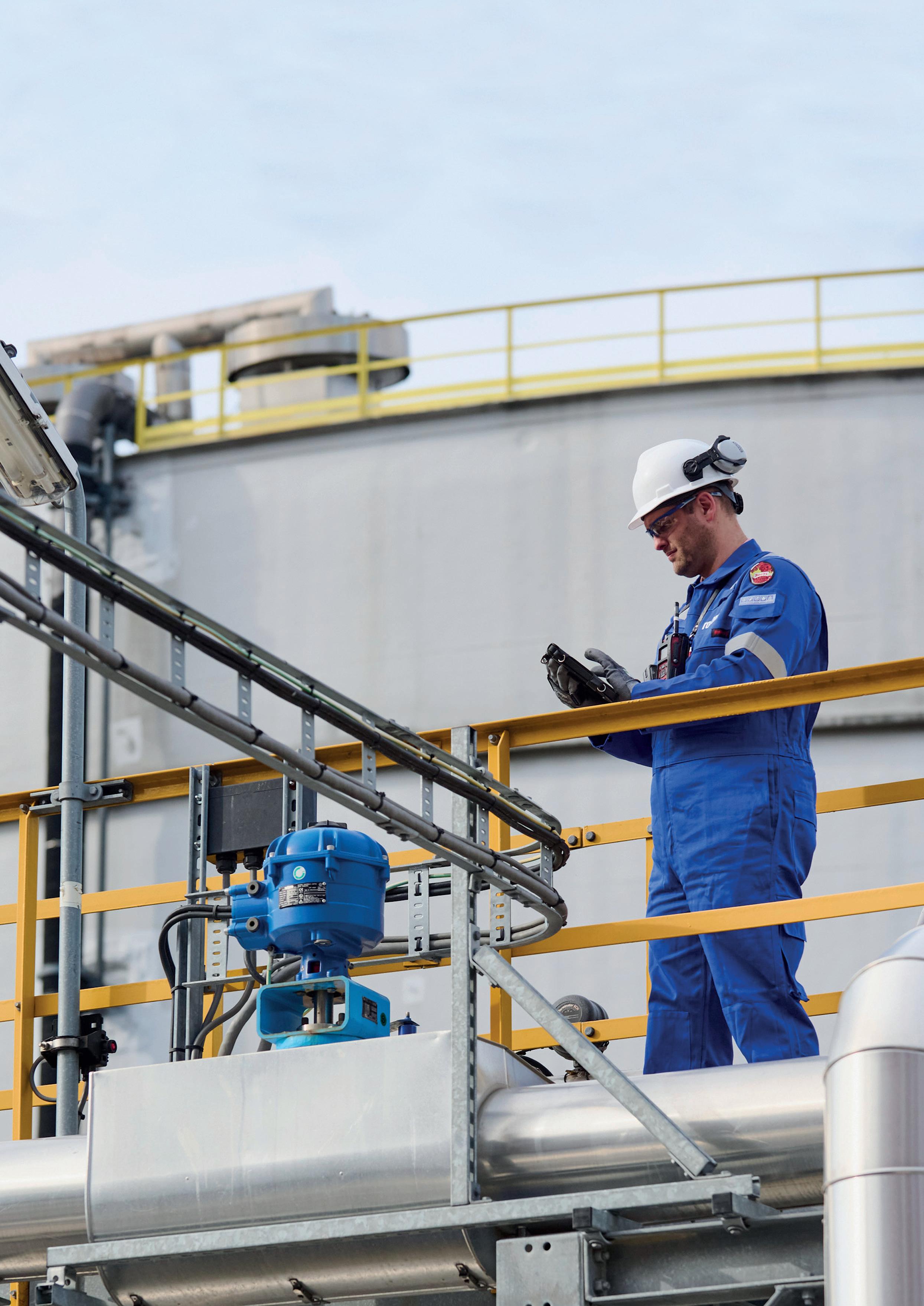
Luke Perry, Rotork, UK explains how maintenance of flow control assets can not only prevent failure, but also improve overall plant efficiency.
faults that may incur disastrous environmental and financial costs.
Failure of the key assets that keep a site running can result in operators’ reduced productivity, poor performance, and a drop in quality. Unintended downtime is the most serious consequence of ineffective maintenance. For example, according to a Markets and Markets study in 2016, a supertanker stuck in downtime can cost as much as £100 000/hr. 1 At chemical plants, the potential losses are even more significant. 13% of businesses experience serious monthly downtime, so figuring out what causes this and how best to prevent it is essential.
Therefore, effective management of flow control assets is an essential consideration for long-term reliability and viability.
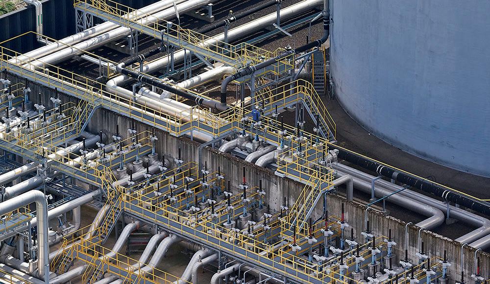
The ultimate aim is to reduce downtime and optimise the required maintenance. The problem can be that taking the equipment out of operation is costly, in addition to the cost of parts and labour. On the other hand, insufficient maintenance increases the risk of breakdowns, leading to loss of yield, environmental damage, and potential health and safety hazards.
An asset management service and maintenance plan that concentrates on an asset’s complete life cycle is vital in order to guarantee the long-term dependability and
viability of the flow control assets onsite. Critical assets can run optimally with the help of a thorough maintenance programme, always guaranteeing their availability. Such a programme should be comprehensive, considering the full life cycle of each asset, how to handle any possible obsolescence, and the effects on the entire site. A complete life cycle asset management programme will likely provide improved performance, increased uptime, and a decrease in unexpected expenses.
An effective and holistic site service programme is fundamental to approaching any potential issues that actuators might face. The programme must be accessible, provide value for money, and be flexible and malleable enough to cater to multiple businesses.
Rotork provides a tiered approach to maintenance, segmenting the service into three levels that provide progressively-improved coverage and support. The bespoke nature of these programmes increases reliability and availability while reducing possible downtime. Additionally, there are a variety of optional extras to fit the customer’s needs. Having this sort of flexibility can improve a site’s overall performance.
Service programmes of this kind provide a set cost to operators, allowing for easy management of budgets. They offer maintenance programmes that will not simply send an engineer to fix a broken or underperforming actuator; rather, they plan for the likelihood of such an event, focusing on long-term maintenance and support.
The most important part of such a service programme is the consideration of the entire life cycle of an asset. The risks of ageing equipment can be considerable. Still, with dedicated service and maintenance programmes, operators can manage potential obsolescence and keep a site running at an optimum level, with minimal-to-no unplanned downtime.
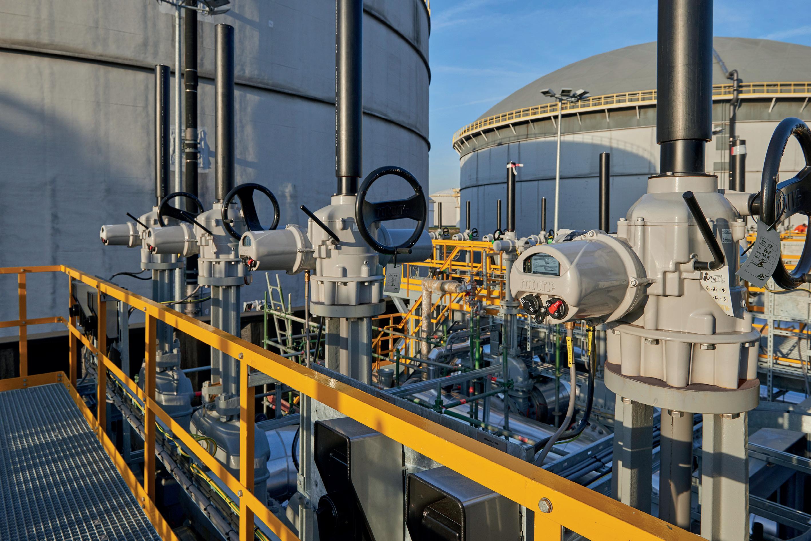
Prevention through sound asset management and maintenance is the key to site uptime. One of the ways to do this is through analytical insights from data. Regular, accurate information about site assets will allow for lower costs from maintenance in the long-term, and a better idea of how the operation is performing holistically.
Intelligent asset management is a key component of asset operations, and it allows for the coordinated activity of an organisation to realise the true value of its assets.
A system such as Rotork’s Intelligent Asset Management (iAM) cloud-based system can be used to collect information from the data within the intelligent actuators. It is a reliable, secure and easy-to-use web platform that works with all operating systems and has a user-friendly, intuitive layout. Colour-coded maps and summary displays condense complicated statistics into simple images. The user may quickly and easily view a complete picture of the condition of the valves and related flow control equipment.
Gas pipeline feeding. Gas power generation stations. Gas peak shaving plants and LNG transfer in small to medium size shore terminals.
The experience acquired through the complete pumping systems supply launched Vanzetti Engineering in the development of systems and components dedicated to any type of LNG and LBG applications.

VANZETTI ENGINEERING. Widening the horizons of LNG sustainability.
www.vanzettiengineering.com
These service programmes offer operators a fixed cost, making budget management simple. They also provide plans focusing on long-term maintenance and support rather than merely dispatching an engineer to repair a damaged or failing actuator. This strategy helps with the management of long-term sustainability of a whole facility, and boosts uptime while reducing unexpected repair expenses.
A service programme helped improve a site’s uptime and optimised its processes at a major aircraft fuelling station in India.
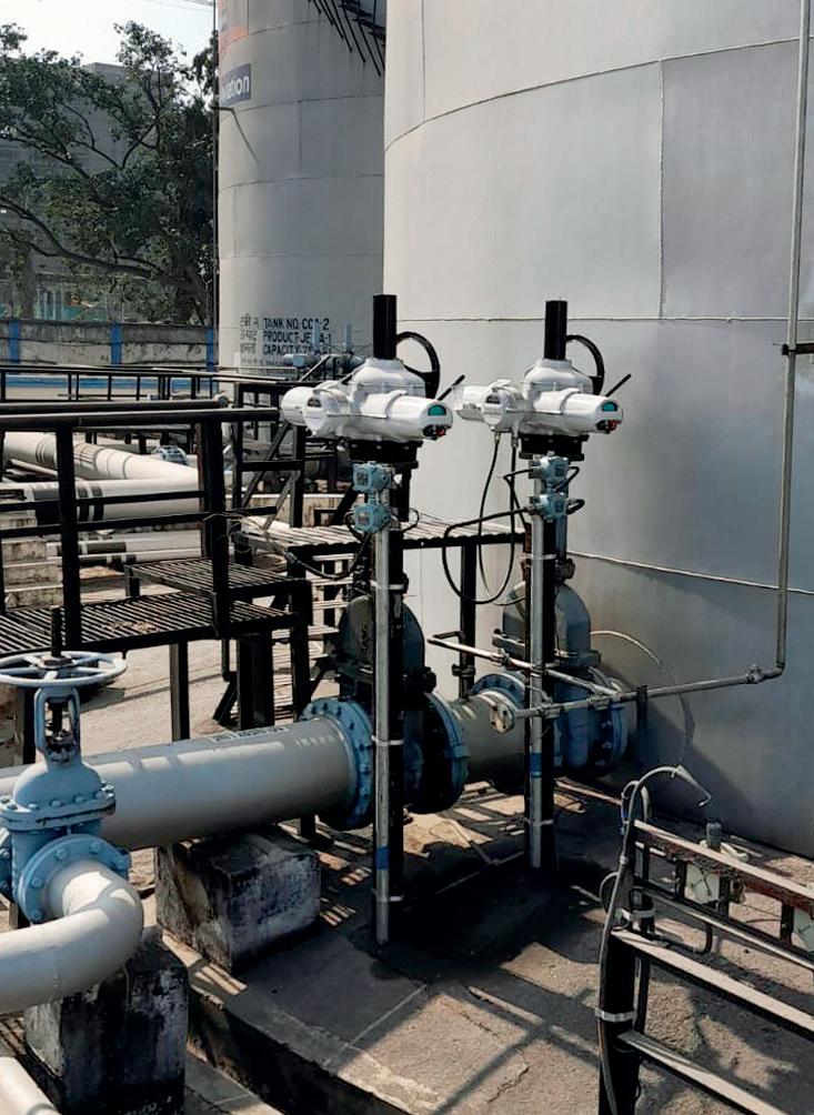
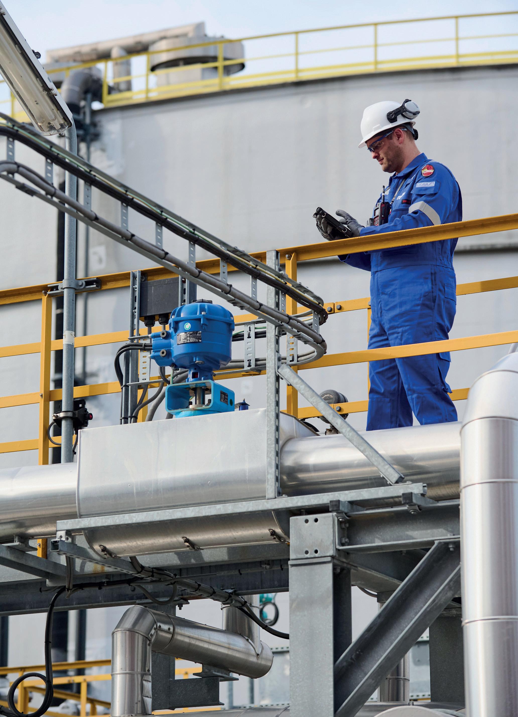
The end user wanted to upgrade to intelligent actuation technology so that they could take advantage of its high degree of accuracy and dependability, as well as benefitting from the ability to gather data to plan for maintenance activities in advance.
Local engineers demonstrated the features of IQ3 actuators to Indian Oil Corp. Ltd (who run the aviation fuel network at Netaji Subhas Chandra Bose Airport), highlighting operational accuracy, data logging functions, and power supply options – including the ability to install without a power supply. IQ3 actuators are ATEX certified as explosion-proof, suitable for use in Safety Integrity Level 2/3 applications, and watertight to IP66/68.
The end user signed a service agreement as part of Rotork’s Lifetime Management programme, ensuring ongoing service support and reduced downtime for maintenance activities through health checks and periodic maintenance.
The importance of an efficient and functional site service programme cannot be understated. Beyond the importance of financial and efficiency considerations, maintaining smooth operations at a site is paramount. The maintenance of site assets through intelligent actuation is a strong and proven solution to potential unplanned downtime.
A system is future-proofed when the asset’s whole life cycle is considered. It eliminates the need to upgrade current cables or control systems, reduces the danger of failure, and enhances the capacity to continue operating. Customers have greater access than ever to the most recent flow control technologies.
We all depend on certain companies, such as those that deal with manufacturing, power and water – and flow control technology is essential to those industries. An efficient asset management plan must address obsolescence issues in order to boost dependability and ensure ongoing operation.
Understanding what a customer needs is essential; once understood, it is possible to create a plan to keep assets continuously available in order to reduce their downtime and improve performance. Asset management programmes should include bespoke spares programmes, site surveys, and maintenance options.
Considering an asset’s whole life cycle cannot be overstated in such a servicing programme. The dangers associated with outdated equipment can be significant. Still, operators can control possible obsolescence in addition to the crucial work of maintaining a site’s operation at a peak level with little to no unexpected downtime with the use of specialised service and maintenance programmes.
1. ‘Industrial Analytics Market by Component (Software, Service), Analytics Type (Descriptive, Diagnostic, Predictive, and Prescriptive), Deploymnet Model, Organization Size, Industry Vertical, and Region – Global Forecast to 2022’, MarketsandMarkets, https://www.marketsandmarkets.com/ Market-Reports/industrial-analytics-market-90118141.html


In part one of a two-part article, Prashanth Chandran, Nathan Hatcher and Ralph Weiland, Optimized Gas Treating, Inc., USA, detail the two perspectives that should be considered when setting expectations from simulation.
especially when reported to 8 or 10 figures. But if the methodologies remain the same and the calculations have only been relegated to a computer, then the computer merely takes the drudgery out of the work. So, what should be expected from a simulator, and what advantages does simulation offer?
Computer simulation affords: faster computation, the ability to look at interactions between process units, the ability to perform detailed sensitivity analyses, and the implementation of more realistic models – enabled by


greater computing power. That simulation offers increased speed is unquestioned, so unless the calculations are either trivial or superfluous, the first advantage is always realised. Today, one can run more simulations and carry out more computations on a laptop computer in a day than was once possible by slide rule and calculator in 10 years of 24 hour days. But if that is all that simulation provides, it falls well short of its real potential. Expectations from simulation can be viewed from two perspectives: realism of models, and reliability of results.
Both must be considered if a simulator is to deliver what it should.
A computational model of any unit operation is just a set of equations representing one or more principles underlying our understanding of the processes occurring within the operation. For example, a centrifugal pump can be conceptualised as a unit providing a pressure increase. At the process level, it is not necessary to model the pump using computational fluid dynamics (CFD) simply to provide the pressure rise and the associated temperature increase. Thermodynamics work nicely for that. However, a pump designer will want a much more realistic model of the pump, maybe even going to the extent of carrying out CFD analysis of the flows and potential cavitation within the casing.
The necessary level of complexity or realism of a model depends on one’s needs, objectives and expectations.
If one is involved in specification and detailed design of heat exchangers, access to advanced software would be of great value. But if it is enough to know that an exchanger in a flowsheet is only there to raise or lower the temperature of a stream, all that needs to be computed is the duty required for a given temperature change (or the temperature change for a given duty), and possibly the pressure drop. Such a model can be extremely simple, involving nothing more than the computation of stream enthalpies. However, if the interest is in exchanger design, then one is in the business of predicting performance based on exchanger geometry, metallurgy, fluid properties, and the fundamentals of heat transfer. Heat exchangers have been designed in detail for well over 75 years, using a model based on heat transfer rates and additivity of resistances.1
The model uses individual film coefficients for heat transfer found from generalised charts that are constructed using parameters in the form of dimensionless groups. In today’s software, those charts are digitised into correlations. Accurate provision is made for two-phase flows, boiling heat transfer, condensation in the presence of inert gases, and a host of other embellishments such as extended heat transfer surfaces and turbulence promoters. Models based on heat transfer rates use databases of fundamental information to allow one to actually predict performance with a high degree of reliability. As a concept, an ideal-stage heat exchanger is an absurdity – as is the efficiency of an exchanger modelled this way. Yet in mass transfer separations equipment, with its enormous cost, many consider ideal stages, stage efficiencies,
and height equivalents to a theoretical plate to be state-of-the-art.
In parallel with heat transfer, if process or revamp guarantees must be made and design fat kept to a minimum, true mass transfer rate-based simulation is essential for column design.
To some extent, then, perhaps the question ‘what do you expect from simulation?’ should be turned around to read ‘what do you need from simulation?’ Matching what is wanted with what is given requires an operator to match the simulator to their requirements, i.e. to their expectations. To help answer this question, it may be worth pointing out that there are two types of models: those that perform automated heat and material balances (lumped parameter models); and those that predict performance (distributed parameter models). In the world of separations, ideal-stage-based column models usually must be viewed as little more than automated heat and material balancers, combined with a (maybe complex) thermodynamic model for the component distribution between the phases.2 Truly predictive models must be based on mass and heat transfer rate principles, just like their heat exchanger brethren. They are essential to trimming excess fat from a design.
Conclusion 3
Match the simulator to its purpose. A sledgehammer is not required to crack a walnut, but rocks cannot be broken with a stick either.
If the model is not rate-based then it is in some sense fitted because adjustments are required. These might take the form of efficiency factors, kinetics factors, heat transfer efficiency, height of a theoretical stage, etc., to force a match between the simulation and known or expected performance. Fitted simulators are best used when tuned to an existing facility where an engineer wants to explore the potential effects of relatively modest operating parameter changes. However, the farther one moves from the set of fitted conditions, the less reliable the results become. The benefit of this type of simulator is that a user can apply adjustments that force the simulator to perfectly match their plant data, but in grassroots design this can be completely misleading – or even dangerous – if the deviation from fitted conditions falls outside of a stable operating range. They are certainly not predictive.
Predictive simulators are necessarily mass transfer rate-based and calculate results without user-specified adjustments. These simulators are best for designing new facilities, identifying unstable operating conditions, or determining how existing equipment or designs would perform in a new service or under a new set of operating conditions. Examples are revamp projects, or for selection of a modular plant for a given service. The advantage of a real mass transfer rate-based simulator is that it provides results based on sound engineering principles and thermodynamic properties rather than on the user (or software developer’s) experience.
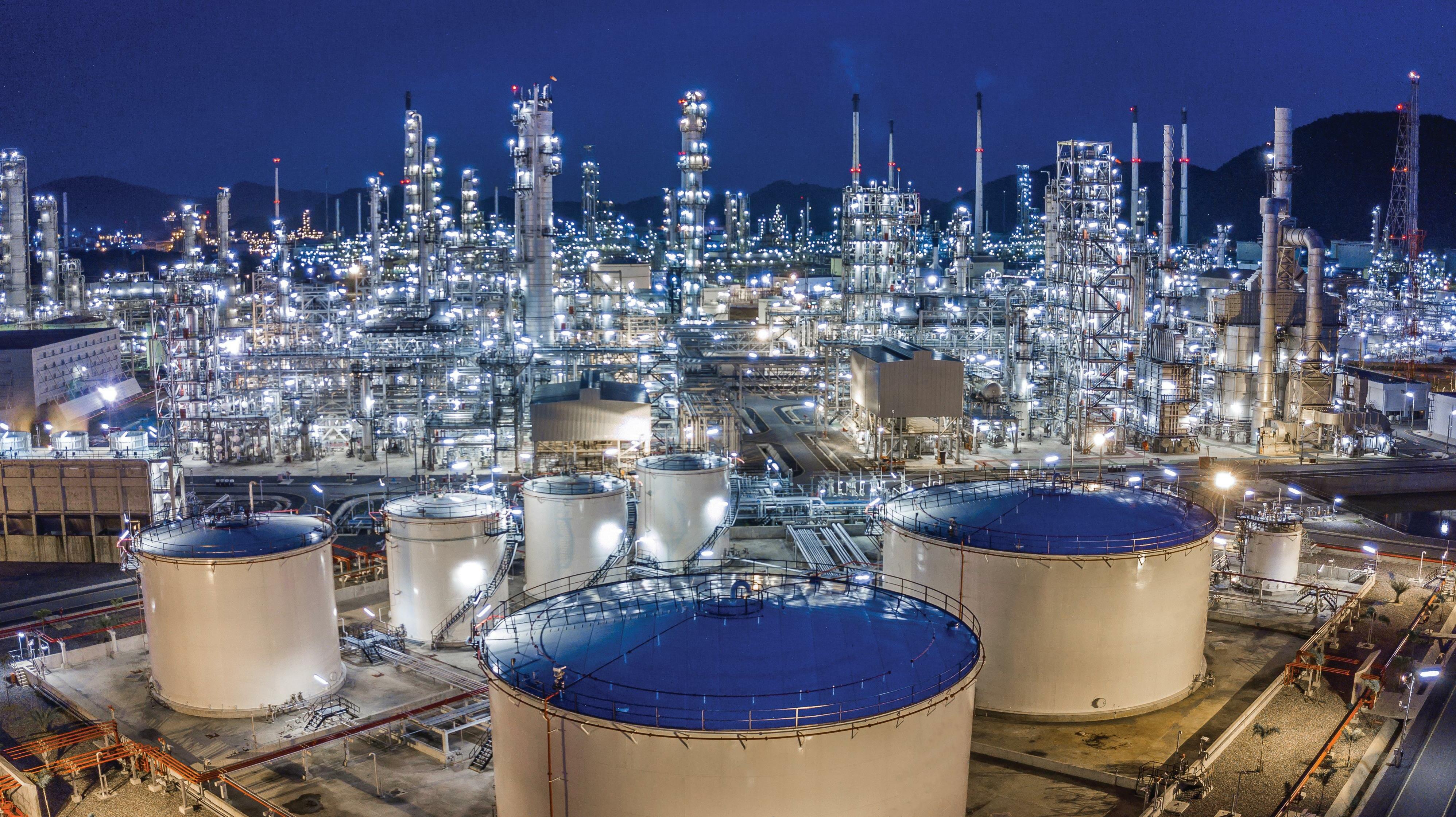


Predictive simulators, whether for heat transfer or mass separations, are necessarily truly rate-based. If there are stages, efficiencies, or stage calculations, it is not predictive.
Whether an idealised or mechanistic model is most suitable for a simulator’s separations calculations depends on the intended use for the simulation results. If all that is needed is to fit the model to plant data and then run what-if studies over limited ranges of certain parameters, a fitted model may fulfil the need quite nicely. If one must offer process design guarantees or guarantee the outcome of a revamp, a predictive simulator is an absolute necessity – unless there is room to add quite a bit of fat (and cost) to the design.
Engineers who use simulation tools are always concerned about whether the results of their simulations are correct or not, or whether they are even reasonably reliable. This kind of concern is only natural, and is certainly justified. After all, operators may be called upon to guarantee the design of a US$10 million column or a US$2000 million plant, the performance of certain tower internals, or indeed a solvent formulation. When troubleshooting, operators certainly do not want to be led unknowingly to a wrong solution – or even to no solution at all – because the simulation failed to model real behaviour. So, what are some of the approaches that people have used in trying to establish reliability of a simulator? What are you using for benchmarking, and is it valid?
Frequently, one hears of comparisons of one simulator with another, or with data from a solvent supplier or a process licensor. Sadly, comparisons between a simulator and real, measured plant performance data are made much less frequently. Most process simulators are intended to show what a column or unit should be doing if it has been correctly built and is operated properly. This is certainly the case for OGT’s ProTreat® and SulphurPro® simulators.3
One of the most common reasons for making comparisons between simulators is lack of reliable data; perhaps the hope is that two of the simulators will be close to each other, the assumption being that democratically this makes them both right. However, each may be as wrong as the other. From the point of view of an EPC contractor who has been using a specific simulator for years, the reason may be that it has always been done that way, and it has worked, so why change? Thinking like this encourages plants that are twice the size they need to be to continue to be built, and until such time as the contractor takes a look at some real plant performance data (or starts winning fewer bids), that is the way that they will continue to be built.
Two simulators will seldom produce the same answers. Simulation software principally consists of models for various unit operations, together with numerical methods or procedures for solving the sets of equations that pertain to each, and to the flowsheet as a whole. These equation sets consist of more than just heat and material balances. Even for a simple heat exchanger, physical properties are a necessary part of the model equation set, and the physical properties calculated by the model depend on the database used to fit
the properties’ models in the first place. So, there are two factors that will almost certainly differ between simulators: the properties database (which, incidentally, every user of software should always check against real data), and the model (regression) equations used for numerically representing the properties – and that is just for a simple heat exchanger with a single phase.
All commercial simulators will invariably provide different answers for the same problem. As such, making comparisons between simulators is an exercise in futility. At the conclusion of the exercise, all one can say with certainty is that they are different. On their own, comparisons between simulators tell you nothing more. So, are simulators data? The answer is no; one cannot be used for benchmarking another. They are models, and are most assuredly not data.
Simulations are not data, they are models. One cannot be used to benchmark another. Trying to do so makes the implicit assumption that the benchmark standard is right. If it is indeed right, why would anyone benchmark anything else against it; after all, one already has the ‘right’ simulator.
Comparisons are often made between a simulator and solvent supplier or process licensor data, but just what is this data? Solvent suppliers and process licensors, too, use simulators to assess the likely performance of their solvent or design in a particular plant configuration. In fact, many of them use a simulator with a mass transfer rate basis. In most cases, suppliers and licensors must provide performance guarantees. The performance they are guaranteeing is not what their simulator says, but with the results of simulation after a conservative safety factor has been applied. For example, a solvent supplier may project that a solvent carbon dioxide (CO2) lean loading of 0.01 moles/mole can be achieved, for instance, when the simulator says 0.003 would be reached. Is the value 0.01 moles/mole data? Indeed, is either value data? The answer is that neither one of them is data. The value 0.01 moles/mole is the guarantee. It is not data; rather, it is a very rare event when a supplier or licensor provides a customer with real data at all.
Comparisons between simulators and so-called supplier data are to some extent meaningless, although perhaps not quite as meaningless as comparisons between simulators themselves. If your simulation has better performance than the solvent supplier (or process licensor) is guaranteeing, both may be right; but, if simulated performance is considerably poorer than the solvent supplier’s guarantee, something is wrong and further investigation is warranted. The main point is that supplier guarantees should not be mistaken for data, which they most definitely are not.
Comparisons against solvent supplier and process licensor data are almost as meaningless as comparisons against another simulator. Commercially, suppliers and licensors tend to be conservative. They have to provide guarantees, and they do not want to have to replace the new solvent or equipment with another. Supplier reports, however long and official looking, are not data.
The loyalty rate expires on 21 February 2023
Book your delegate pass at the loyalty rate to hear from more than 600 expert speakers, including policy makers from the world’s leading energy economies, the industry’s pre-eminent leaders, and technical experts from the global natural gas, LNG, hydrogen, low-carbon solutions, and climate technologies industries.


delegates@gastechevent.com gastechevent.com @gastechevent #Gastech

4,000 delegates 300+ CEOs, Ministers and business leaders speaking
600+ technical and commercial speakers
40,000+ international attendees
100+ countries represented
So just what is data? Data is nothing more or less than what is measured in the field from an operating plant. This does not necessarily mean that the data is good data, but by definition it is data. However, if it has not been measured in the field (or the laboratory), it cannot be called data. At a minimum, data to be used for benchmarking a simulator must have been measured using reliable flow, temperature and pressure instrumentation, preferably calibrated (instruments that have been merely zeroed and spanned have not been calibrated). Piping line-ups must be correct, online analysers must be calibrated, laboratory procedures validated, trays installed level without too many valves missing, and packing properly installed with reliably-uniform liquid distribution. Measured pressure drop values should compare favourably with internals supplier calculations so as to minimise (but not eliminate) the possibility of foaming and fouling. Reasonable material and energy balance closure is a requirement. These are some of the things that characterise good data.
Data is what is measured in the field from an operating plant. Heat and material balances must be close to within reasonable tolerances for data to be strictly valid as a benchmark. Users of simulation tools want to be convinced that the tool that is being used is both reliable and accurate. The only truly valid benchmark for a simulator is real data measured in the field.
The simulator should agree reasonably closely with the measured performance data, without adjusting or providing any factors to force agreement (in other words, the simulator must be truly predictive).
If all that operators are doing is comparing with another simulator, or comparing with solvent-supplier or process-licensor data (or simulations), then they do not have a valid benchmark. This makes the comparison worthless for the intended purpose of validation. Results from simulations and solvent supplier guarantees are not data; only measurements are data.
Part two of this article will present several case studies involving real process and performance data as measured in operating plants, and compared with simulations that have not been fitted in any way. The comparisons will reinforce the conclusions enumerated here.
1. Taken from ‘Process Heat Transfer’, McGraw-Hill Book Co., New York, (1950).
2. There are exceptions, one being distillation involving three phases where the computations to determine even the existence of a third phase can be quite complex. Indeed, for many chemical systems, the phase equilibrium models are complex enough that high-quality computer models of the thermodynamics are necessary for accurate results.
3. ProTreat is a registered trademark of Optimized Gas Treating, Inc.
CORE TOPICS
Sulphur and SA Supply and Demand Outlook
-Fiona Boyd & Freda Gordon from Acuity Commodities

Phosphate Topic
-Andy Jung from The Mosaic Company
INTEREST TOPICS
Global Sulphur and Acid Projects

-Richard Hand from BC Insight
Sulphur, the 4th Major Crop Nutrient
-Dr. Ismail Cakmak from Sabanci University Istanbul, Turkey
20% OFF for industry representatives under the age of 35 Discounts also available for companies registering more than three delegates.

The hydrocarbon processing industry is keenly aware of the impact of corrosion on critical service process equipment and facility infrastructure. A landmark study commissioned by the US Department of Transportation Federal Highway Administration (FHWA) in 2002 estimated that the direct cost of corrosion to the chemical, petrochemical and pharmaceutical manufacturing industries was approximately US$1.7 billion annually.1
Most of the attention on corrosion within the processing industry is focused on materials and coatings to protect process equipment and infrastructure. Chemical, petrochemical and pharmaceutical manufacturing facilities utilise a wide range of corrosion-resistant materials, ranging from duplex stainless steels to exotic materials such as tantalum and zirconium. For some highly-corrosive processes, glass linings and carbon-based materials may be required. Coatings, both internal and external, are also used extensively in facilities to protect steel structures from corrosion.
Cathodic protection (CP) is not as prevalent, nor is it intuitively as well understood as a corrosion mitigation strategy, but it is a well-established science that has viable applications for chemical, petrochemical and pharmaceutical facilities.
Understanding the technology and its potential applications provides hydrocarbon processing engineers with another set of tools to apply against corrosion.
Visualising how a coating system works or understanding the role of exotic corrosion-resistant metals and alloys does not require a lot of explanation: something can be coated to provide a protective physical barrier, isolating the structure from the environment; or a corrosion-resistant metal can be used. But when the conversation surrounding how CP works starts with a discussion of electrochemical oxidation reduction reactions, Pourbaix diagrams, and ion transfers, the audience can easily be lost.
This article will offer a twist on how to conceptualise CP, and will present various applications within a facility where the technology is commonly applied.
Most engineers are familiar with some iteration of the Star Trek Enterprise as a fictional, faster-than-light, armed spacecraft travelling the galaxy on its quests for adventure. And every ‘would be’ star fleet officer understands that the first thing that the Enterprise, or any respectable armed interstellar

Ted Huck, MATCOR Inc., USA, explains why cathodic protection is a proven technology and a viable strategy for corrosion control and mitigation in hydrocarbon processing facilities.
vessel would do when encountering a potential threat is to ‘raise the shields’ using the appropriately-named shield generator. And without knowing anything about how the shield generator actually works, it is easy enough to conceptualise that once the shield generator is engaged it might take some period of time to form the protective shield. Conversely, once the shield generator is turned off it might take some time for the shield to fully dissipate. That, in a nutshell, is how CP works to prevent corrosion. The application of an electrical current from the anode (the shield generator) to the surface of the structure being protected or cathode (the hull of the starship) causes a negative shift in the potential of the steel structure, which is called polarisation. This polarisation takes some time to fully develop, and will stay in place as long as sufficient CP current continues to be applied to the structure surface. This polarisation results in an environment at the surface of the steel that cannot support the corrosion reaction, resulting in no appreciable corrosion on the protected structure – much like how space shields protect starships from phaser arrays and photon torpedo blasts. When this CP circuit is turned off, the surface of the structure being protected depolarises and is susceptible to corrosion (and photon torpedoes). The same basic physics are at play in the case of either interstellar space shields or CP application.
There are several important basic concepts to understand when discussing CP:
n CP requires physical separation of the anode and the structure being protected; the anode is projecting DC CP current onto the surface of the protected structure.
n The anode and the structure must be in direct contact with an environment that allows DC current to flow. This environment is called the electrolyte.
n The CP circuit consists of an anode, an electrolyte, a cathode, and cabling to close the circuit (also referred to as structure lead). DC current can be driven by a power supply or by the inherent natural potential of the anode material. Magnesium, zinc and aluminium are all anodic (more negative) to steel.
n The Ohms law applies: V = IR. When designing CP systems, the process usually starts by identifying how much current is required, and then determining the anticipated circuit resistance to assess how much voltage (or driving force) is needed.
n The environments (electrolytes) in which CP is commonly used include soil, water (fresh, brackish and seawater), and concrete.
There are four primary applications for CP inside process facilities:
Most of the process piping in a facility is aboveground piping; however, it is not uncommon to have a variety of underground pipelines for water, wastewater, natural gas, steam and other utility services. Buried metallic piping systems (carbon steel, stainless steel, ductile iron fire water piping, etc.) are all subject to external corrosion and would generally warrant CP systems, in conjunction with a coating suitable for direct burial.
There are a lot of challenges associated with designing and operating a CP system for buried piping in a complex facility with many possible buried structures, including foundation steel, piling systems, grounding networks, and other buried utilities and/or utility banks.
For simple segments of buried piping, it might be possible to electrically-isolate the piping from the plant grounding system where it transitions from buried to aboveground. This greatly facilitates the CP system design and cost, as losses to any other structures and/or the grounding grid would be zero. For large quantities of piping, trying to isolate the piping can be a very difficult thing to do. Even if the piping can be isolated during the CP system testing, isolation is difficult to achieve over the life of the piping. Any CP system that is designed based on the buried piping being isolated from the plant’s earthing network will not operate properly should there be a loss of isolation, as current will be diverted from the intended buried piping and instead be taken by other structures.
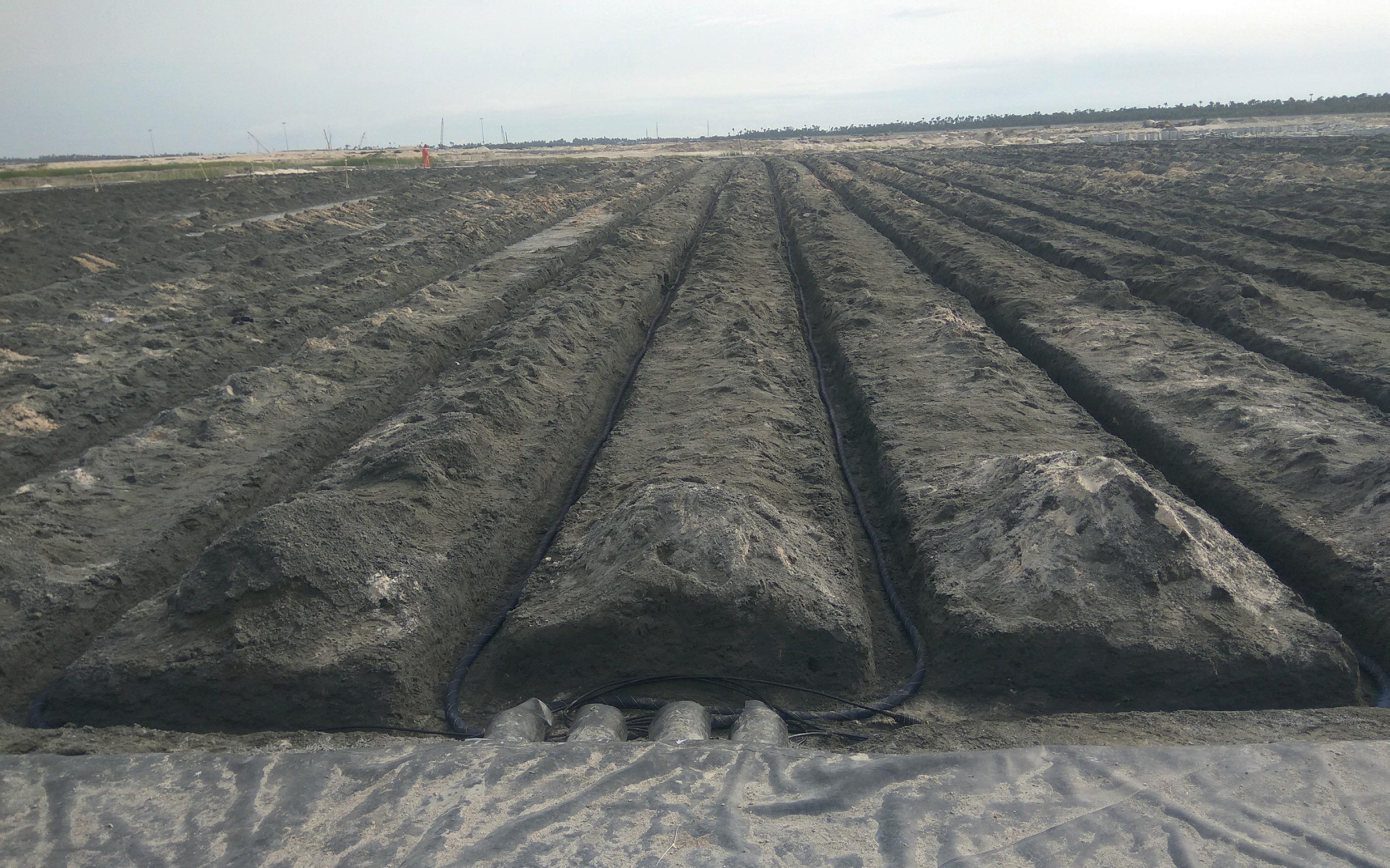
Many hydrocarbon processing facilities are located next to a waterway to allow for ship traffic that is delivering feedstock materials, or to facilitate the shipping of finished goods to customers. These docking structures may include sheet pile
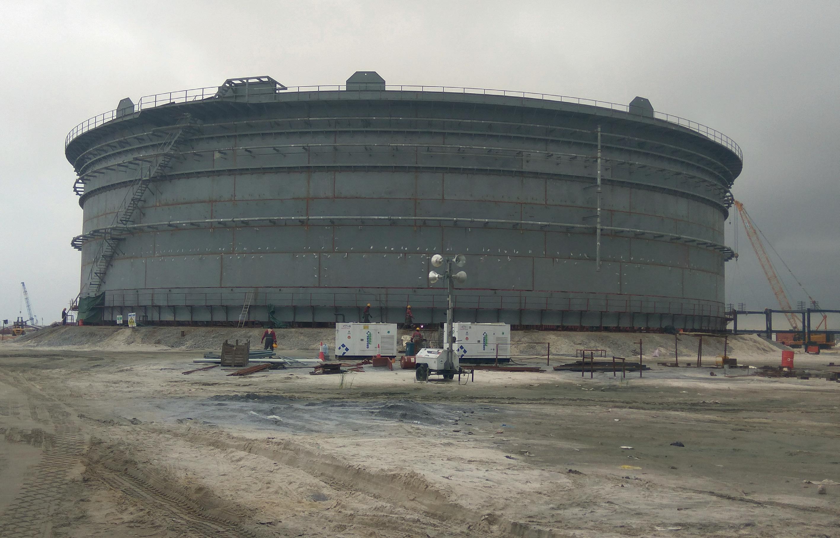
walls, jetties, piers, and mooring and turning dolphins. These are typically carbon steel structures and are subject to marine corrosion. CP is frequently employed to protect these structures from corrosion, and to extend their service life.
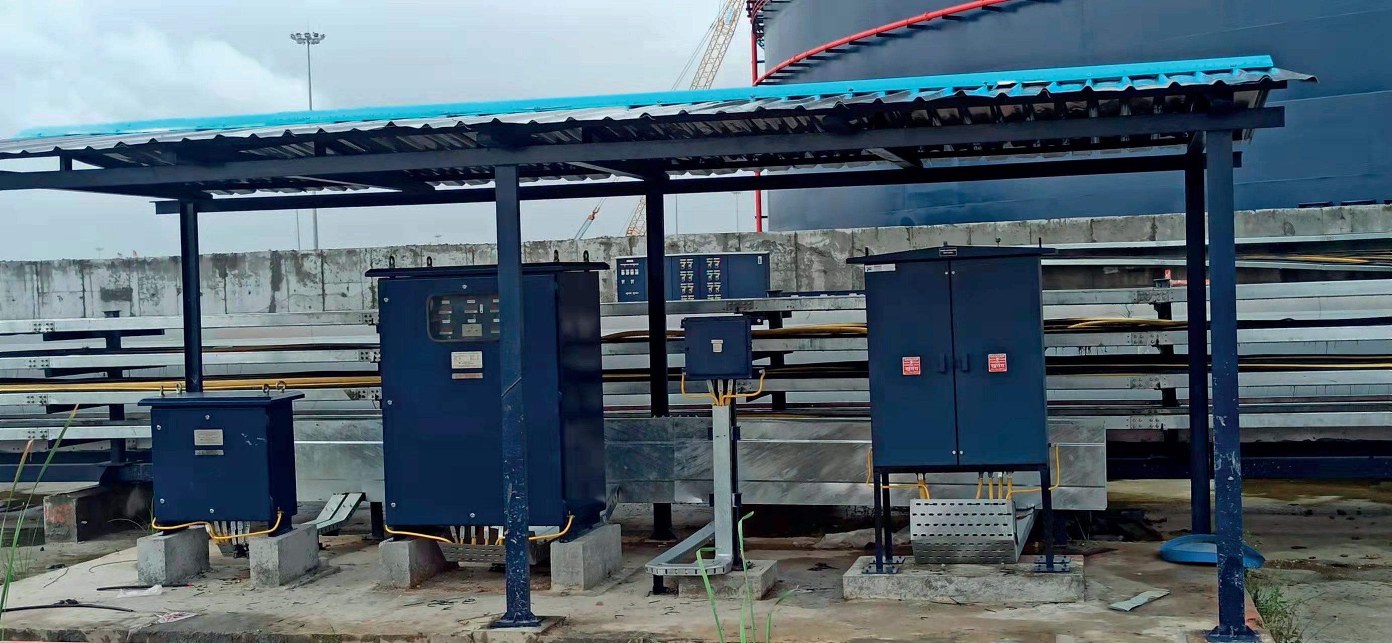
Large-diameter, aboveground storage tanks are typically built on ring wall foundations, and the tank bottom rests on a prepared soil/sand bedding material. The underside of the steel tank bottom is subject to corrosion, so it is good engineering practice to install CP systems to protect the underside of the tank. Smaller tanks on concrete foundations do not typically require any CP because concrete is normally a high pH environment that prevents the corrosion reaction from occurring when the steel is in intimate contact with the concrete slab. It is also important to maintain a good chime seal with these tanks, and to try and prevent the ingress of water and oxygen under tanks.
The internal wetted surfaces for water tanks, and a wide range of wastewater processing equipment (flocculators, aerators, digesters, separators, etc.), have corrosion issues that can be mitigated by the application of CP systems. These applications can be challenging as they often require customised solutions, given the wide variation in how the vessels are designed and fitted internally. When properly applied, CP can significantly extend the service life of water and wastewater vessels, and process equipment.
In addition to the four primary areas in which CP is commonly applied in hydrocarbon processing facilities, there may be a niche application that might warrant the use of CP. This would be concrete structures such as foundations and containment walls. Normal concrete has a very high pH which prevents the corrosion reaction from occurring on any reinforcing steel inside the concrete. If, however, chlorides are present, they can permeate the concrete matrix and lower the pH to a point where the reinforcing steel goes into active corrosion, resulting in cracking and spalling of the concrete. Many processing facilities are in areas where salt sprays may be present and/or are processing brine type solutions that can lead to concrete structures failing from corrosion of the reinforcing steel. CP can be applied to these structures to keep the chlorides away from the reinforcing steel and prevent any corrosion.
The world’s premier refining meeting. Assembling executives, decision-makers, investors, and technical experts from across the downstream sector.
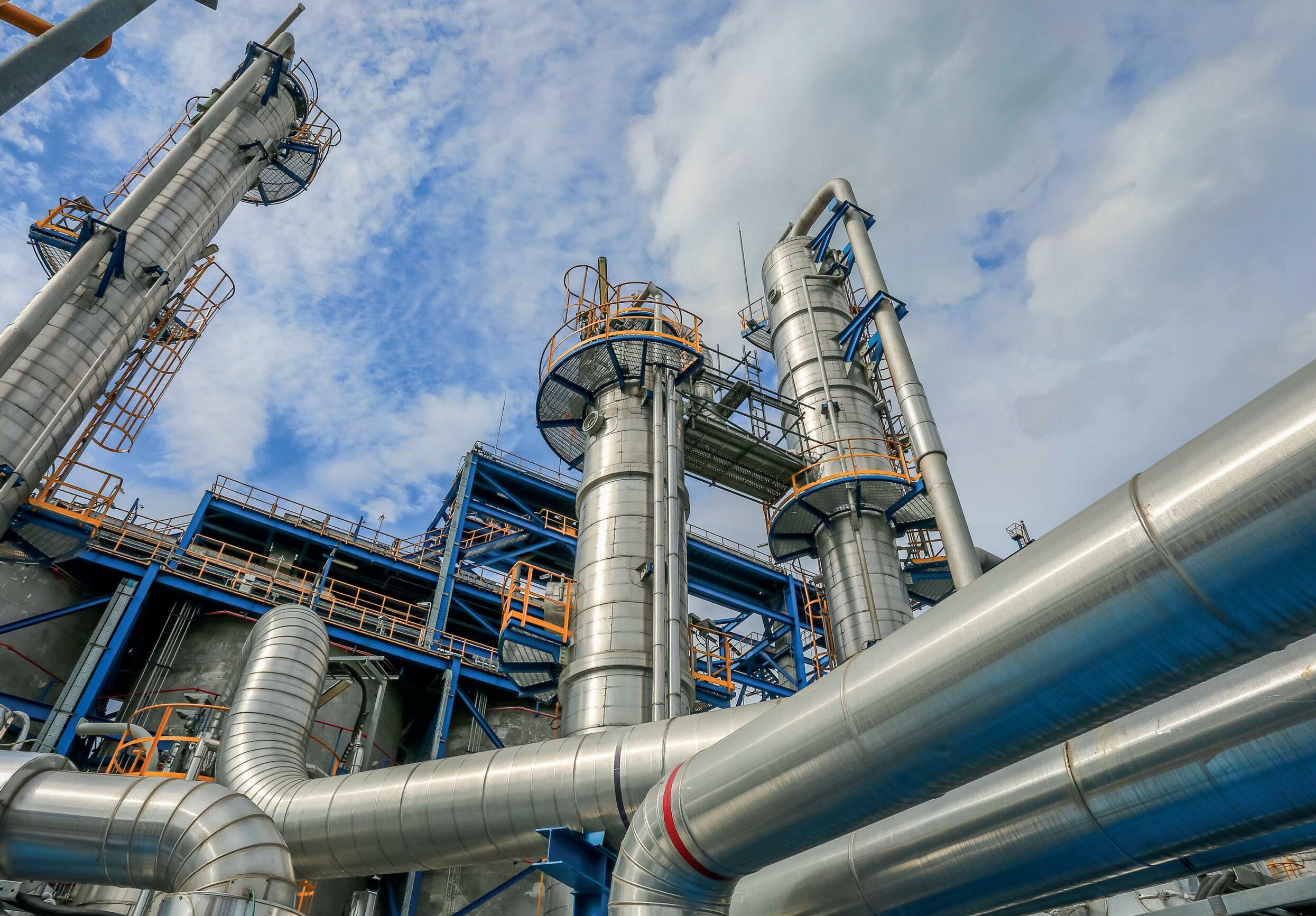
CP systems fall into two broad categories. The first is a galvanic CP system (often referred to as sacrificial), and the second is an impressed current CP system.
A galvanic system is a passive system in that there is no external power supply driving current from the anode, through the electrolyte, to the surface of the structure being protected. Typically, these are magnesium or zinc anodes for soil and freshwater applications, and zinc or aluminium anodes for brackish or seawater applications. These anode materials are naturally more electronegative than carbon steel, and when attached to a steel structure they will react to discharge current. This reaction results in the galvanic anode being consumed in the process (hence the term sacrificial). Many people erroneously believe that galvanic anodes are less expensive and require no maintenance or testing. This is not always true, and even though these anodes can be installed without an outside power supply, it is important to monitor the anode system’s performance, as well as its consumption rate, by way of annual testing.
In many applications, however, galvanic anodes are not the most economical option, and the use of higher output or longer life impressed current anodes, in conjunction with an external power supply, is a less expensive and more effective solution. One of the advantages of an impressed current CP system is that there is a power supply controlling the system output, and that output can be adjusted and monitored. Impressed current anodes are suitable for much higher current outputs and longer service life than galvanic
anodes, and are able to operate at much higher driving force (voltage). This makes them suitable for a broader range of applications.
For both systems, galvanic or impressed current, it is generally recommended that the system be tested every year to confirm that it is operating properly and providing the necessary shield power (polarisation) to protect the intended structure. This testing is usually performed by a certified CP technician, and should include a detailed report of the testing that was performed, as well as the results of that testing along with any appropriate recommendations.
Most CP systems are designed to operate for a long time; 5 – 10 years is a common benchmark for galvanic anode systems, and 20+ years of service life is common for impressed current systems. Due to the associated retrofitting challenges, under tank systems are typically designed for a minimum of 30 years of service, and 50+ years in many cases.
Corrosion is an ever-present concern in the hydrocarbon processing industry, costing facility owners billions of dollars annually in direct costs. CP is a proven technology and a viable strategy for corrosion control and mitigation in several applications within these facilities. When applied properly and maintained on a regular basis, this solution acts as a defensive shield against corrosion. Reference

Berndorf Band Engineering GmbH
T: +43 2672 800 0
E: engineering@berndorf.co.at
www.berndorfband-group.com
Low operating and maintenance costs
Product specific temperature profiles due to different cooling zones
High production output and uniform product quality