The Future is Fiber

2023
June

Refineries face unprecedented challenges as the world demands cleaner production. Now more than ever, your operation needs to safeguard more than just the bottom line.
With our eye on your conventional and renewable needs, Topsoe is committed to delivering catalysts with unprecedented activity, selectivity, and lifetime for every application. All with the goal of ensuring that your business does even more good, and even less harm.
Because the most important catalyst for a sustainable future isn’t actually a catalyst, at all. It’s you.
Miro Cavkov, Euro Petroleum Consultants (EPC), Bulgaria, discusses
produce cleaner liquid fuels
Alfred Haas, Marius Kirchmann, Simon Wodarz, Teo Trotus and Jean-Claude Adelbrecht, hte GmbH – the high throughput experimentation company, Germany, introduce a testing technique for co-processing novel renewable feedstocks by way of fluid catalytic cracking (FCC).
Ashley Cuthbertson, Alkegen, outlines how recent advances in fibre technology have made the material an attractive option for catalyst support media. 25

Jorge Cadena, Groome Industrial Service Group, USA, discusses the importance of selective catalytic reduction (SCR) maintenance.
29
Brad Cook, Sabin Metal Corp., USA, outlines the complexities of sampling precious metal catalysts, and explains why sample accuracy is so important.
33
Colin Bateman, Integrated Global Services (IGS), UK, explains how to prevent the corrosion that may result from conversion to renewables.
The

Marie-Sophie Haverkamp and Robin Wilmshöfer, BORSIG Membrane Technology GmbH, Germany, introduce a low-energy separation method to enhance the sustainability of alternative feedstock and circular processing.
43 Combatting challenging conditions
Rebecca O’Donnell, Baker Hughes, USA, offers a field-proven solution for an erosive control valve application.
49 Protecting LNG processes
Claire Lloyd, REMBE GmbH Safety+Control, considers how rupture discs can help to protect a number of processes within the LNG sector.
53 A streamlined solution
Aidan Doherty, Re-Gen Robotics, UK, introduces a safe and efficient solution for the future of tank cleaning.
57 Seeing green Stuart Bradbury, Carboline Global Inc., USA, explores safe and sustainable methods for optimising passive fire protection (PFP) strategies.
61 A closer look at thermal fluid degradation
Ryan Ritz, Paratherm Heat Transfer Fluids, USA, details the impacts of thermal fluid degradation, and how this can be prevented.
67 Diagnostic and prognostic solutions
A. Brighenti, C. Brighenti, M. Ricatto and A. Zorzi, S.A.T.E. Systems and Advanced Technologies Engineering S.r.l., Italy, and D. Evans, ESA/ESOC, Germany, discuss the use of data-driven diagnostic solutions to improve maintenance in the energy sector.
72 Q&A with ...
Hydrocarbon Engineering sits down with John T. Haley, President – Overseas, Rezel Catalysts Corp.

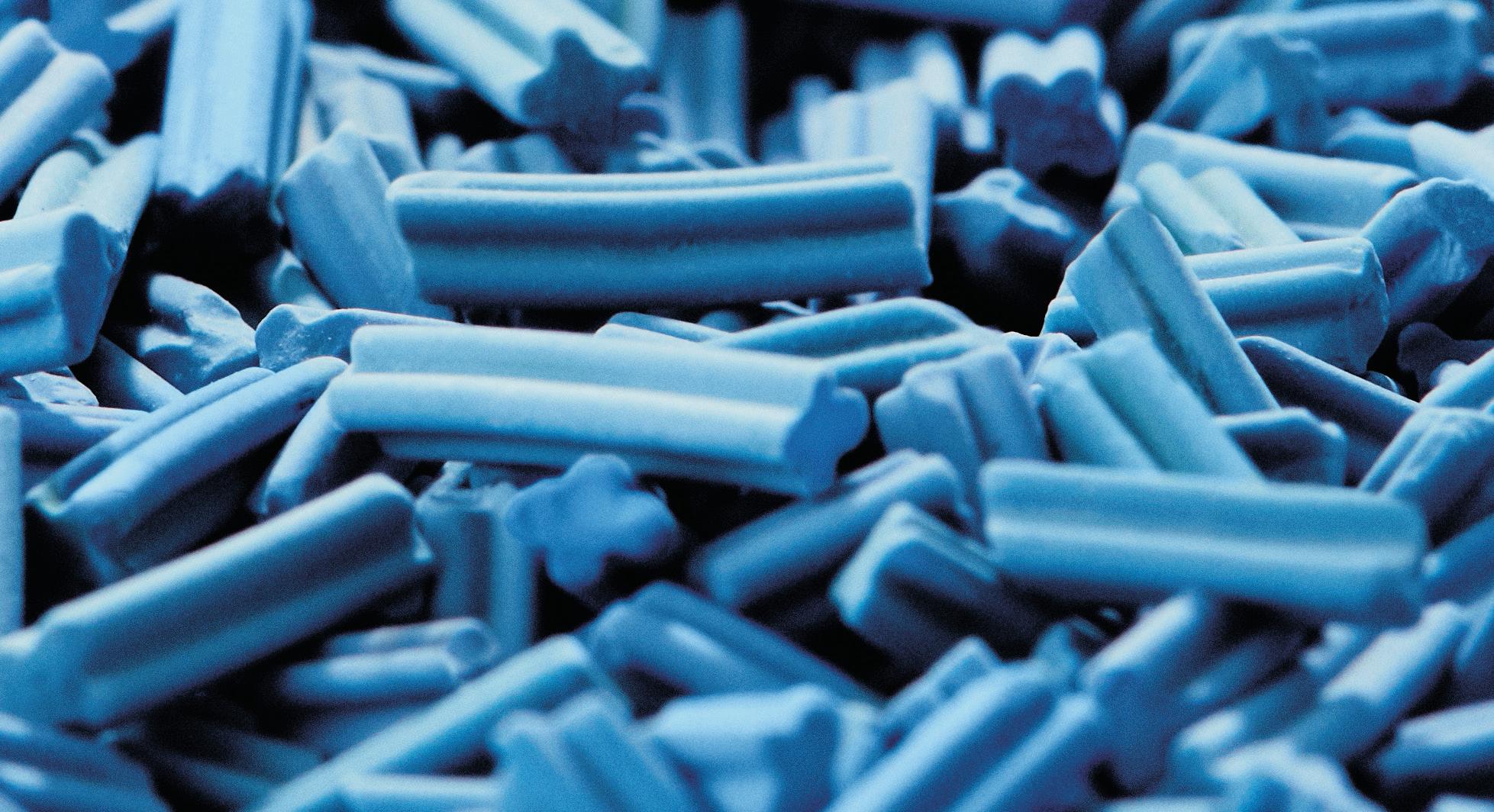
This issue’s cover story by Alkegen speaks to the emerging use of advanced fibre technologies in catalysis, particularly in catalyst support media, and explores the possibility that these technologies may hold the key to the step change in performance and efficiency for which the industry has been waiting.

ET Black™ is a state-ofthe-art technology that complies with the most stringent environmental regulations now and in the future.


Plus, the flexibility to produce all ASTM grades, and specialty grades, in a single plant. ET Black™, the technology of reference for producing carbon black obtained by thermal decomposition of highly aromatic oils.


Find out more at: www.igoforETBlack.com
MANAGING EDITOR James Little james.little@palladianpublications.com
SENIOR EDITOR Callum O'Reilly callum.oreilly@palladianpublications.com
ASSISTANT EDITOR Bella Weetch bella.weetch@palladianpublications.com
SALES DIRECTOR Rod Hardy rod.hardy@palladianpublications.com
SALES MANAGER Chris Atkin chris.atkin@palladianpublications.com

SALES EXECUTIVE Sophie Birss sophie.birss@palladianpublications.com
PRODUCTION MANAGER Kyla Waller kyla.waller@palladianpublications.com
EVENTS MANAGER Louise Cameron louise.cameron@palladianpublications.com
EVENTS COORDINATOR Stirling Viljoen stirling.viljoen@palladianpublications.com
DIGITAL CONTENT ASSISTANT Merili Jurivete merili.jurivete@palladianpublications.com
DIGITAL ADMINISTRATOR Leah Jones leah.jones@palladianpublications.com
ADMIN MANAGER Laura White laura.white@palladianpublications.com
CONTRIBUTING EDITOR
Nancy Yamaguchi Gordon Cope
SUBSCRIPTION RATES
Annual subscription £110 UK including postage /£125 overseas (postage airmail).
Two year discounted rate £176 UK including postage/£200 overseas (postage airmail).
SUBSCRIPTION CLAIMS
Claims for non receipt of issues must be made within 3 months of publication of the issue or they will not be honoured without charge.
APPLICABLE ONLY TO USA & CANADA
Hydrocarbon Engineering (ISSN No: 1468-9340, USPS No: 020-998) is published monthly by Palladian Publications Ltd GBR and distributed in the USA by Asendia USA, 17B S Middlesex Ave, Monroe NJ 08831. Periodicals postage paid New Brunswick, NJ and additional mailing offices. POSTMASTER: send address changes to HYDROCARBON ENGINEERING, 701C Ashland Ave, Folcroft PA 19032.
15 South Street, Farnham, Surrey
GU9 7QU, UK Tel: +44 (0) 1252 718 999
As summer starts to kick into gear, I’m eagerly anticipating a few months of al fresco dining and long evenings spent in the sunshine. However, as anyone who watched the recent coronation of King Charles III would have seen, the British weather has a habit of dampening expectations. Still, this doesn’t stop us Brits from firing up the barbecue whatever the weather, and catching up with friends and family.
It’s on social occasions such as these that I’m often asked about how my job is going and what the future holds for the energy sector. As well as trying to gauge how their energy bills are likely to be impacted in the coming months, and enquiring how Europe is going to cope without Russian gas, friends and family are often fascinated (or perplexed) by the idea that there is enough content to produce a monthly magazine dedicated solely to the downstream oil and gas sector. “Not only that”, I tell them, “we also have a website full of daily industry news, interesting white papers, and a library of fascinating webinars that can be watched on-demand.”
By this point, I have usually lost the interest of my companion, and I can see them looking around the garden for someone else to talk to...
However, I have a captive audience of like-minded individuals right here, so I will continue. Truth be told – and as you all know – there is so much going on in our industry right now that it is difficult to condense everything into just 12 monthly issues of this magazine. For that reason, we also publish Tanks & Terminals magazine, our supplement dedicated to the bulk liquids storage sector, as well as Global Hydrogen Review, a digital magazine focused exclusively on the burgeoning hydrogen market. And we regularly find ourselves wanting to explore the articles that we do publish each month in greater detail. For that reason, we launched a special ‘Spotlight interviews’ feature on our website a couple of years ago. During these interviews, we sit down with a recent contributor to Hydrocarbon Engineering magazine to discuss the content of their article in greater detail. These conversations often take off in unexpected directions and we find ourselves talking about a wide range of issues pertinent to the future of the downstream oil and gas sector. And I’m happy to report that none of our interviewees so far have actively sought an escape route from our conversations!
We have built up a library of interesting conversations with industry leaders, which you can access by heading over to www.hydrocarbonengineering.com/spotlight-interviews. And I’m pleased to say that we will shortly be sitting down with Brad Cook, Vice President of Sales and Marketing at Sabin Metal Corp., to discuss his article that features on p. 29 of this issue. This interview will be available to watch very soon, and we’ll be sure to drop you an email with details once it is live on our website (if you’re not already receiving a copy of our newsletters, you can sign up for free here: www.hydrocarbonengineering.com/newsletter).


Ketjen's advanced catalysts are the industry's gold standard. Our tailored solutions deliver ever-increasing performance and technology for our customers so they can be more competitive in the marketplace.

Long-term LNG contracting activity is off to a strong start in 2023, and Daniel Toleman, Principal Analyst for Global LNG at Wood Mackenzie, has said that the bullish conditions in the market are set to continue.
Since December 2022, a flurry of Omani LNG deals have been signed. Buyers include Japanese utilities, the oil majors, a Southeast Asian buyer, a Turkish buyer, and the trading arm of a Chinese national oil company. These deals signal the return of Japanese buyers to long-term contracting.
Wood Mackenzie expects further deals to be announced in the coming months, with additional deals from Qatar’s projects. Oman LNG may also announce new deals as all contracts in place are set to expire in 2025 – 2026. So far, the company has only re-contracted half the capacity, 6 million tpy, from its projects.
Additionally, it has been reported that China National Petroleum Corp. (CNPC) is close to finalising a deal with QatarEnergy to offtake LNG for around 30 years.
INEOS Olefins & Polymer Europe has signed a renewable power agreement with Skagerak Energitjenester to provide 100% green energy to its Rafnes and Bamble plants in Norway.
All of INEOS’ assets in the region are now supplied with 100% green power generated from hydroelectric production.
The Rafnes cracker produces ethylene for a wide variety of
applications, including the production of low-density polyethylene (LDPE) at the adjacent Bamble site.
These LDPE grades are used to produce essential products such as beverage cartons, medical bottles, and food packaging seals. By using renewable power, INEOS can reduce the product carbon footprint of a typical LDPE grade by up to 30%.

Lummus Technology has announced that Alujain National Industrial Co. has selected its C3 CATOFIN® propane dehydrogenation (PDH) technology for the company’s new propylene plant in Yanbu, Saudi Arabia.
This is the first time that Alujain will licence Lummus’ PDH technology at its Yanbu complex.
The scope of this award includes the technology license and basic engineering. Once complete, the plant will produce 600 000 tpy of propylene, which will serve as feedstock for Alujain’s new downstream polypropylene production.
In addition to the licenced technology, Alujain will have access to Lummus’ portfolio of life cycle services during the operation phase of the plant. This includes advanced operator training simulators, extended technical support, and digitalisation services.
“We are excited that Alujain has selected Lummus’ PDH technology and look forward to supporting their growth and expansion in petrochemicals,” said Leon de Bruyn, President and Chief Executive Officer of Lummus Technology.
Graforce, a leading provider of zero-carbon hydrogen plants, and Worley are cooperating to scale methane electrolysis (plasmalysis) starting in Australia, Pacific, Asia and China (APAC).
Plasmalysis is a technology that converts natural gas, LNG, flare gas and other hydrocarbons into hydrogen without emitting carbon dioxide (CO2) or any other
greenhouse gas into the atmosphere. This allows gas consumers to switch to clean-burning hydrogen without changing their energy supplier or mode of transportation.
Sustainable technologies such as plasmalysis are seen as an essential requirement to meet both economic and climate targets.
“The entire APAC region is looking for green technologies for
existing energy sources to achieve climate targets. The cooperation with Worley is an important step for us to quickly scale our methane plasmalysis and to open up these markets,” said Dr. Jens Hanke, CTO of Graforce.
Worley will provide engineering and project delivery services for plasmalysis plants customers in Australia and Asia.
13 - 15 June 2023
Global Energy Show Calgary, Alberta, Canada www.globalenergyshow.com
10 - 13 July 2023
LNG2023 Vancouver, British Columbia, Canada www.lng2023.org
05 - 08 September 2023
Gastech Singapore www.gastechevent.com
17 - 20 September 2023
GPA Midstream Convention San Antonio, Texas, USA www.gpamidstreamconvention.org
17 - 21 September 2023
World Petroleum Congress Calgary, Alberta, Canada www.24wpc.com
26 - 28 September 2023
Turbomachinery & Pump Symposia Houston, Texas, USA tps.tamu.edu
02 - 05 October 2023
ADIPEC
Abu Dhabi, UAE www.adipec.com
03 - 05 October 2023
AFPM Summit Grapevine, Texas, USA summit.afpm.org
06 - 08 November 2023
Sulphur + Sulphuric Acid 2023 New Orleans, Louisiana, USA www.sulphurconference.com
13 - 16 November 2023
ERTC Lake Maggiore, Italy worldrefiningassociation.com/event-events/ertc
05 - 07 December 2023
16th Annual National Aboveground Storage Tank Conference & Trade Show
The Woodlands, Texas, US www.nistm.org
The UAE’s economic growth prospects for 2023 face key obstacles, including a decline in oil output resulting from OPEC-agreed production cuts, a slowdown in the non-oil sector due to higher interest rates, and subdued external demand. The real GDP of the UAE is forecast to expand at a slower pace of 3% in 2023, compared to the robust growth rate of 7.6% observed in 2022, according to GlobalData.
GlobalData’s latest report, ‘Macroeconomic Outlook Report: UAE’,
reveals that the oil and gas industry plays a crucial role in the UAE’s economy, as it is responsible for around 30% of the country’s GDP and 13% of total exports. 2022 witnessed a significant economic upturn, with a growth rate of 7.6%, the highest since 2007, primarily fuelled by surging oil and gas prices. However, the decline in oil and gas prices since the beginning of 2023, expected to persist throughout the year, directly impacts the UAE’s economic growth prospects for the current year.
The American Petroleum Institute (API) has announced that it has signed two separate Memoranda of Understanding (MoU) with the American Society for Nondestructive Testing (ASNT) and the Nondestructive Testing Management Association (NDTMA). These agreements support the industry’s shared goal of promoting quality non-destructive testing (NDT) and examination, and enhanced safety for the natural gas and oil industry.
The agreement with ASNT will foster collaboration among the two organisations to identify non-destructive testing and examination needs, which would benefit the entire natural gas and oil industry.
The agreement with NDTMA establishes collaboration on training, conferences, assessments and quality programming, ensuring that future NDT professionals attain the necessary skills to achieve professional excellence.

Technip Energies has announced that a joint venture (JV), T.ENCCC JV, which is led by Technip Energies (T.EN) in partnership with Consolidated Contractors Co. (CCC), has won a major engineering, procurement, construction and commissioning (EPCC) contract from QatarEnergy for the onshore facilities of the North Field South (NFS) project. This award will cover the delivery of two mega trains, each with a
capacity of 8 million tpy of LNG. It will include a large CO2 carbon capture and sequestration (CCS) facility that has a 1.5 million tpy capacity, leading to more than 25% reduction of greenhouse gas emissions compared to similar LNG facilities.
The expansion project will produce approximately 16 million tpy of additional LNG, increasing Qatar’s total production from 110 to 126 million tpy.


Refineries are often cast in a bad light – as producers of fossil fuels and petrochemical polymers that contribute to global emissions. However, what is often overlooked is the positive impact that refineries have on our way of life. Without refining technologies making products widely available and affordable, modern life as it is today would simply not be possible. Even in a turbulent and disruptive market environment, successful refineries around the world manage to maintain operations and meet our daily energy needs.
Refineries will play an important role in the short-, medium- and long-term, depending on their location, local demand, and the export regions that they serve. Due to global climate targets, every industry is currently striving to reduce emissions, and the downstream industry is the one sector that stands between the hammer and the anvil. On the one hand, there are regulatory frameworks that aim to provide more clarity on the direction in which refineries will have to adjust their existing assets and focus their production investments. On the other hand, there are temporary technological limitations and challenges that they need to overcome in order to remain competitive in the market and continue to be able to offer refined products that meet the retail market requirements in terms of price and quality.
Given recent geopolitical events and the resulting disruptions to global crude oil flows and forecast scenarios, refineries are definitely
here to stay – albeit in a modified form. The refinery of the future will expand its role as an energy hub, incorporating highly-automated and technologically-advanced molecule management, and designed to precisely control the production of clean liquid fuels and chemical building blocks according to market conditions.
There will be a strong focus on new trends and new areas to further develop. These will include the use of renewable feedstocks and energy; automation optimisation and digitalisation; carbon capture, utilisation and storage (CCUS); and integration with chemical production or directly tuning and re-designing the processing facility to yield maximum chemical building blocks, through the so-called crude-to-chemicals (CTC) production scheme.
Refiners are striving to integrate more renewable energy sources into their operations, as the use of energy from low-carbon sources reduces the carbon footprint of the refining processes, making them more sustainable and reducing emissions as a result.
The feedstocks that will be processed in the refinery of the future will depend on a variety of factors, such as technological advancements, local regulatory requirements, and market demand. However, the most important factor remains the availability of renewable feedstocks.
Future refineries will process more renewable feedstocks into bio-based products such as biofuels and bioplastics, which are derived from renewable sources and have a lower environmental impact. Co-processing of biofeedstocks in fluid catalytic cracking (FCC) units, often referred to as the ‘heart of the refinery’, is one of the approaches for reducing the carbon intensity of the unit and its products. FCC units usually produce gasoline components, but with increasing flexibility towards the production of petrochemical components, the unit is being reinvented and gaining a lot of popularity as an asset that is suitable for retrofitting.
FCC is a refining process that is widely used in the petroleum industry to convert heavy hydrocarbons into lighter, more valuable products. Co-processing biomass feedstocks in FCC units offers potential benefits, such as reduced greenhouse gas emissions and decreased dependence on fossil feedstocks. However, feeding bio-feed into FCC plants comes with the following challenges, and these need to be considered:
Biofeedstocks, such as vegetable oil or animal fat, can vary widely in chemical composition, including their fatty acid profiles, moisture content, and impurities in particle size distribution. These variations can affect catalyst performance, reaction kinetics, and product yields.
Biomass feedstocks may contain impurities (e.g. alkali and alkaline earth metals) that can poison the FCC catalyst and reduce its activity. This increases the frequency of catalyst regeneration, resulting in higher operating costs.
In addition to this, depending on the type and source, biomass feedstocks can contain high levels of sulfur, nitrogen and oxygen compounds, which can lead to increased deactivation of the catalyst. These impurities can also lead to corrosion and fouling of the reactor and downstream equipment, which reduces the efficiency and lifespan of the plant. Co-processing of bio-crude feedstocks can also affect the quality and properties of FCC products.
Biomass-derived products may also have different properties to their petroleum-derived counterparts, which may affect their performance and compatibility with downstream refining processes. The co-processing of biomass feedstocks in FCC units requires careful integration with other refining processes to ensure that the quality of the final products meets the required specifications.
The use of biofeedstocks in FCC units is subject to various regulatory requirements and market constraints, as well as cost and sustainability criteria. For example, the use of biocommodities may compete with food and feed markets, and their production may require large amounts of land, water and energy, which could raise concerns about their environmental and social impacts.
Overall, the co-processing of biomass feedstocks in FCC units offers potential environmental and economic benefits, but it also presents significant technical challenges that need to be overcome before widespread adoption and scaling up to fully commercial and competitive levels can occur. In addition to renewable feedstock, the following classical and alternative products are also on the rise:
With the depletion of light crude oil reserves, refineries are expected to process more heavy oil and residues and reassess the value of non-fuel heavy products such as bitumen. As the main component of road construction, high-quality bitumen can only be obtained by processing heavy oils and residues. So, until other advanced technologies are developed for road construction, the bottom of the barrel will continue to play an important role.
The classical processes of hydrocracking and thermal cracking of raw materials usually require more advanced techniques and pose challenges in terms of emissions and environmental impact. However, with innovations and the deployment of carbon capture equipment, traditional refineries have the opportunity to reduce their emissions while continuing to deliver high-quality products to the market.
With the increasing availability of natural gas, future refineries will certainly process more natural gas liquids such as propane and butane, which can be used as
Carbon capture and storage or utilization (CCS/CCU) is a key strategy that businesses can adopt to reduce their CO2 emissions. By selecting the right technologies, pressing climate change mitigation targets can be met while benefitting from new revenue streams.

Sulzer Chemtech offers cost-effective solutions for solvent-based CO2 absorption, which maximize the amount of CO2 captured and minimize the energy consumption. To successfully overcome technical and economic challenges of this capture application, we specifically developed the structured packing MellapakCC™. This packing is currently applied in several leading CCS/CCU facilities worldwide, delivering considerable process advantages.
By partnering with Sulzer Chemtech – a mass transfer specialist with extensive experience in separation technology for carbon capture –businesses can implement tailored solutions that maximize their return on investment (ROI). With highly effective CCS/CCU facilities, decarbonization becomes an undertaking that can enhance sustainability and competitiveness at the same time. For more information: www.sulzer.com/chemtech

feedstocks for petrochemical production, as well as for gasoline components.
The refinery of the future will process a variety of feedstocks, including renewables, heavy oil and bitumen, natural gas liquids, and bio-based materials. These feedstocks will be processed using advanced technologies that maximise efficiency, reduce emissions, and minimise environmental impact.
The rapid development and implementation of Industry 4.0 and the use of advanced tools will enable refineries to operate in a more efficient and effective manner, allowing them to reach the next level in terms of process monitoring and molecule management. Properly implemented digital solutions can lead to lower production costs, higher output and conversion, and an overall improvement in process safety.
Such solutions can help refiners to optimise their production in a number of ways, including process optimisation, predictive maintenance, real-time monitoring, and supply chain management.
Digital technologies such as machine learning (ML) and advanced analytics can be used to analyse data from sensors and other sources in order to optimise refinery processes. This can help with the identification of areas in which improvements can be made to reduce energy consumption, increase efficiency, and improve product quality. Refineries can also use predictive maintenance algorithms to monitor operations and equipment in real time. This allows for potential problems to be detected and identified before they occur and become critical issues, helping to reduce downtime and maintenance costs while increasing reliability. Maintaining healthy end-to-end communication and synchronisation through advanced supply chain management systems is also critical to ensure that raw materials and other inputs are available at the right time, and that finished products are delivered to customers on time. By leveraging such digital technologies, refineries can improve their overall performance.
Stringent carbon regulations will force refiners to adopt advanced technologies to capture and sequester carbon emissions, while closing the production loop by using captured carbon for other processes. These processes include synthetically-derived products via the Fischer-Tropsch route, and classic hydrogenation or carbon rejection technologies for the development of certain recycled products such as fuels, chemicals, lubricating oils and other downstream specialty chemicals. This can help reduce the environmental impact of refining and refined products, and further contribute to meeting climate objectives.
Refining and petrochemical production are often integrated because they both involve the selective processing of crude oil into various higher-value and
higher-demand products, such as gasoline or diesel, where processes such as hydrocracking or hydrotreating are prevalent. Integration will be a must for the successful refiner of the future to create more efficient and cost-effective production, resulting in less waste, improved efficiency, and the creation of new opportunities for innovation such as secondary feedstock recycling.
The petrochemical industry uses hydrocarbons derived from crude oil, such as ethylene and propylene, as feedstock for the production of a wide range of chemical products, namely plastics, synthetic fibres, and detergents. Petrochemical production involves a variety of chemical processes, including steam cracking, FCC, hydrogenation and dehydrogenation, and polymerisation, to convert these feedstocks into valuable chemical products.
The best configuration for converting crude oil to chemicals depends on several factors, such as the specific types of chemicals being produced, the quality of the crude oil, the availability and cost of energy and other resources, and the desired level of environmental sustainability.
The integration of refining and petrochemical production offers significant advantages to producers, including maximum efficiency and flexibility, as production volumes of individual products can be adjusted to changing market demand. Other benefits of integrated production include improved economics and lower costs through the use of a common infrastructure, and a reduction in the need to duplicate certain static and rotating equipment and energy resources. By controlling the quality of raw materials used in petrochemical production, an integrated complex can ensure a consistent supply chain, optimise the use of resources, and minimise costs by using the byproducts of one process as feedstock for another.
The integration of refining and petrochemical plants has led to the trend of developing large-scale petrochemical complexes that are designed as such that they can convert crude molecules directly into chemicals. This is achieved by a combination of extractive distillation and the use of advanced and specific equipment and catalysts, now known as CTC processes.
CTC plant configurations can be designed with sustainability in mind by integrating processes that minimise environmental impact, such as carbon capture, recycling and further implementation of renewable energy sources and feedstocks. CTC plant configurations should be designed to be flexible so that they can adapt to changing market demands, technological advances, and regulatory requirements.
Future refineries will take advantage of the flexibility of modular constructions and technologies, allowing them to be easily reconfigured or scaled up or down as needed. This can help refineries to remain competitive and respond to changing market conditions and demand for different types of hydrocarbon products.
With best-in-class techniques and over seven decades of experience, we deliver the highest possible metal returns for our customers.
We recover and refine precious metals from petroleum catalysts and materials used in processing from various supports, including Carbon, Zeolite, Silica-alumina, and Soluble and insoluble alumina. Also, our proprietary Pyro-Re® process o ers the only pyro-metallurgical recovery of rhenium in the industry. With it, we recover total rhenium content from spent semi-regenerative and cyclic fixed-bed hydrocarbon processing catalysts—and get you a full return.
Find out more about Sabin Metal Corp’s services, operations, and why a partnership with us is the right choice at sabinmetal.com


There is an increasing incentive for refineries to process novel feedstocks from renewable or recycled sources such as biogenic oils, fats and pyrolysis condensates from various forms of waste. This complements refineries’ traditional purpose – converting crude oil into highly-specialised products, such as fuels, lubricants and/or olefins and aromatics, as petrochemical feedstocks. The chemical composition and molecular weight distribution of such feedstocks are strongly dependent on their nature, and sophisticated, optimised processes are required to ensure that products meet their targeted application quality, i.e., the correct composition of paraffins, isoparaffins, aromatics, naphthenes, olefins (PIANO), as well as boiling point or carbon number distribution. Conventional processing routes comprise desalting, distillation and de-asphalting, before the three principal catalytic conversion pathways are applied, i.e., hydrogen addition (hydroprocessing), dehydrogenation (naphtha reforming), or carbon rejection (fluid catalytic cracking [FCC]) technologies.
During hydroprocessing, contaminant metals, namely nickel, vanadium, nitrogen and sulfur, are removed by processes, e.g. hydrodemetalation (HDM), hydrodesulfurisation (HDS) and hydrodenitrogenation (HDN), and product composition is adjusted by way of hydrogenation, hydroisomerisation and hydrocracking. Hydroprocessing and naphtha reforming
comprise multifunctional catalysts in stacked beds in single or consecutive reactors at the same or different reaction temperatures. Relevant protocols have been implemented to investigate these processes in parallel trickle-flow or gas-phase reactors on a laboratory scale.1, 2
Going forward, further catalyst and process developments will be required to remove oxygen from renewable feedstocks, i.e., by decarbonylation/decarboxylation (carbon monoxide [CO], carbon dioxide [CO2]) or hydrodeoxygenation/dehydration (water), or chlorine from plastic waste (PVC contaminations), e.g., as hydrogen chloride (HCl). Adding to the challenges of catalyst and process development, other issues such as corrosion and catalyst decay initiated by novel contaminants (alkali, metals, phosphorus, organic acids, etc.) need to be investigated.
In the area of carbon rejection, aside from thermal cracking pathways such as delayed or flexicoking, FCC continues to be the most important process to upgrade the bottom of the barrel, i.e., vacuum gas oil (VGO) and atmospheric resid, to valuable gasoline and C2-C4 olefins for petrochemical processes. Additionally, alternative feeds can be co-processed. Utilising existing FCC assets in refineries provides attractive, direct drop-in solutions for renewable feedstocks and chemical recycling. Nevertheless, the co-feeding of novel feedstocks may have an effect on the reaction kinetics of conventional crude-based VGO and resid cracking.

Alfred Haas, Marius Kirchmann, Simon Wodarz, Teo Trotus and Jean-Claude Adelbrecht, hte GmbH – the high throughput experimentation company, Germany, introduce a testing technique for co-processing novel renewable feedstocks by way of fluid catalytic cracking (FCC).
Realistic laboratory testing is required to minimise the risk of processing new feedstocks within the constraints of a heat-balanced FCC unit. Testing of renewable feedstocks at 5 – 20 wt% with the incumbent equilibrium catalyst and VGO makes it possible to measure the effects on relative rates of LPG, gasoline, LCO and coke production, in particular. As such, major effects on catalyst activity and yield distribution can be predicted. By utilising renewable feedstocks in laboratory tests, biocarbon contents in the different reaction products or product lumps can be quantified and allocated using advanced analytics and workflows, such as radiocarbon analyses (14C tracing).3
Commercial FCC processes use entrained flow reactors to crack diverse feedstocks with short contact times (0.5 – 5 sec), high reaction temperatures of > 500°C, and reactor pressures of
< 4 barg. FCC reaction kinetics and catalyst deactivation are strongly dependent on reaction temperature, the hydrodynamics at the reactor inlet and outlet, and the plug flow of the catalyst and product vapours. To simulate commercial reaction conditions, continuous pilot Circulating Riser Unit (CRU) testing has been established, but this involves large pilot units utilising tens or hundreds of litres of feed per experiment.
More recently, a novel FCC catalyst testing technology based on the Micro Downflow Unit (MDU) became available, which provides realistic cracking conditions at laboratory-scale, and closely simulates the gradients in temperature, partial pressure, and contact time of commercial unit operations at affordable costs, requiring low amounts of catalyst (< 1 kg) and feedstock (< 1 l) for a detailed condition study.4
The MDU simulates short contact times and all unit operations of commercial steady-state riser/downer entrained-flow reactors, while standard laboratory-scale fixed fluidised bed testing (Advanced Catalyst Evaluation [ACE]) and fixed bed Micro Activity Tests (MAT) only provide time-averaged activity, selectivity and decay (coke on catalyst) data, generated in fully back-mixed or stationary catalyst beds, respectively.5, 6 In a nutshell, MDU FCC catalyst testing combines the features of a steady-state CRU with the cost benefits of an integral MAT and ACE.
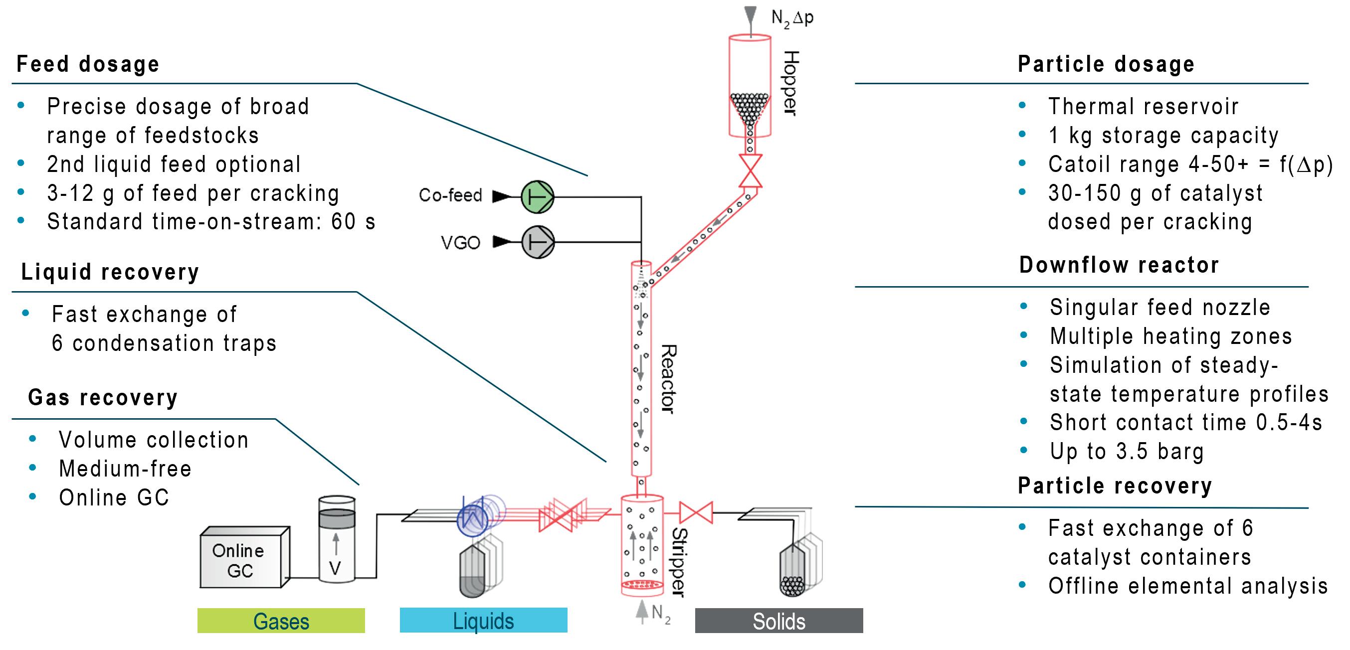
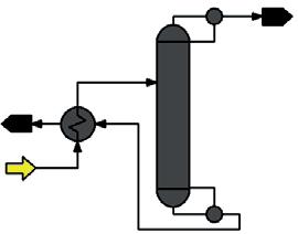
The simplified process scheme and a typical experimental workflow are illustrated in Figure 1. The MDU comprises a catalyst reservoir (hopper) with a fixed fluidised bed of regenerated FCC catalyst at 700°C. At zero time-on-stream, this reservoir can be opened by a high-temperature valve. Thereby, a constant mass flow of catalyst is transported to the inlet of the downflow reactor and is recovered in the stripping vessel. The catalyst mass flow rate is controlled by adjusting a pressure differential between the catalyst hopper and stripper. Nitrogen is used throughout the unit as the carrier gas and to control pressures. The catalyst particle temperature is equilibrated in a transfer line between the catalyst valve and the inlet of the MDU reactor, while the reactor wall temperature can be adjusted in five temperature zones.
For a cracking experiment, at time-on-stream zero, the feed valve is opened and a constant mass flow of preheated feed is delivered to the reactor inlet by a proprietary nozzle. This is simultaneous with the opening of the catalyst valve. The constant mass flow of feed and catalyst is maintained for 1 minute

Emerson’s precision, high-pressure Coriolis dispensing solutions reduce safety concerns without compromising capacity. Harness the power of alternative fuels to drive efficiency as you take your business to new distances.
Learn more at www.emerson.com/micromotionhighpressure
(range: 0.5 – 2 minutes), simulating the steady-state conditions of a commercial fluid catalytic cracking unit (FCCU) in terms of catalyst-to-oil ratio and temperature profile from reactor inlet to outlet. The independent variables for the temperature control are the reactor, catalyst pre-heat, feed pre-heat, and stripper temperatures. The cracked hydrocarbon products are quenched in the stripper and directed to the liquid condensation. The uncondensed gaseous hydrocarbons are passed through a back-pressure control valve to a heated, integral medium-free cylinder or a water burette, gathering the total gas volume for the cracking (1 minute) and post-stripping duration.
Because of this short experimental time, even difficult feeds with a strong tendency for oligomerisation, clogging or gum formation can be processed. The hydrocarbon partial pressure for the feed and cracking products are controlled by the back-pressure control valve and additional mass flows of nitrogen from the feed and catalyst transfer lines. Catalyst and gas residence times can be calculated from the average molar flow of cracking products and a slip velocity between catalyst and gas products. These contact times are dependent on the total pressure and the extent of cracking, and can be adjusted
to values of between 0.5 – 5 seconds, thus simulating the typical residence times of riser and downflow reactors.
The MDU typically works with a constant mass flow of 7 g feed oil per experiment (range: 3 – 12 g), and can cover the catalyst-to-oil ratio of 4 – 12 that is typical for riser units, or up to 20 for downflow units. If necessary, even higher catalyst-to-oil ratios of up to 50+ are possible in order to simulate the high severity required for deep catalytic cracking or light-cut naphtha cracking. After the experiment, the stripped, spent catalyst is drained and weighed to obtain precise data for the actual catalyst mass and catalyst-to-oil ratio delivered. The gas phase products and liquid syncrude are analysed by way of gas chromatography, while the coke on the catalyst is measured by offline LECO analysis. In regular VGO cracking, mass balances of 98 +/- 2 wt% are achieved based on fresh feed (ff). The unit is fully automated and safety-programmed to allow for up to six cracking experiments in sequence, and unobserved (overnight) operation.
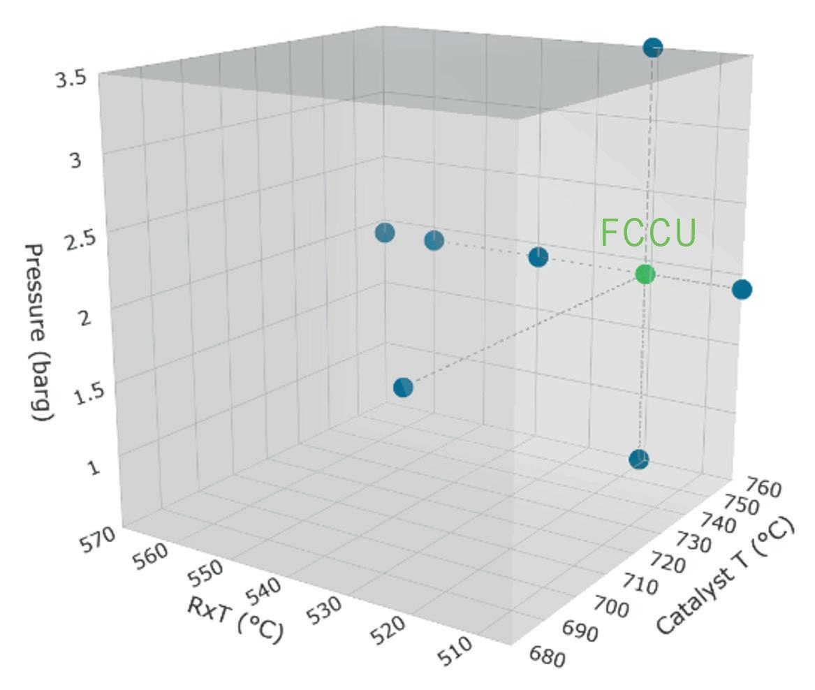
An exemplary Design of Experiment (DoE) to simulate the conversion and yield distribution of an incumbent equilibrium catalyst and feed in an FCCU is presented in Figure 2. This serves to establish an initial base case for a feed or catalyst screening study to investigate the possible effects on a commercial reference unit.
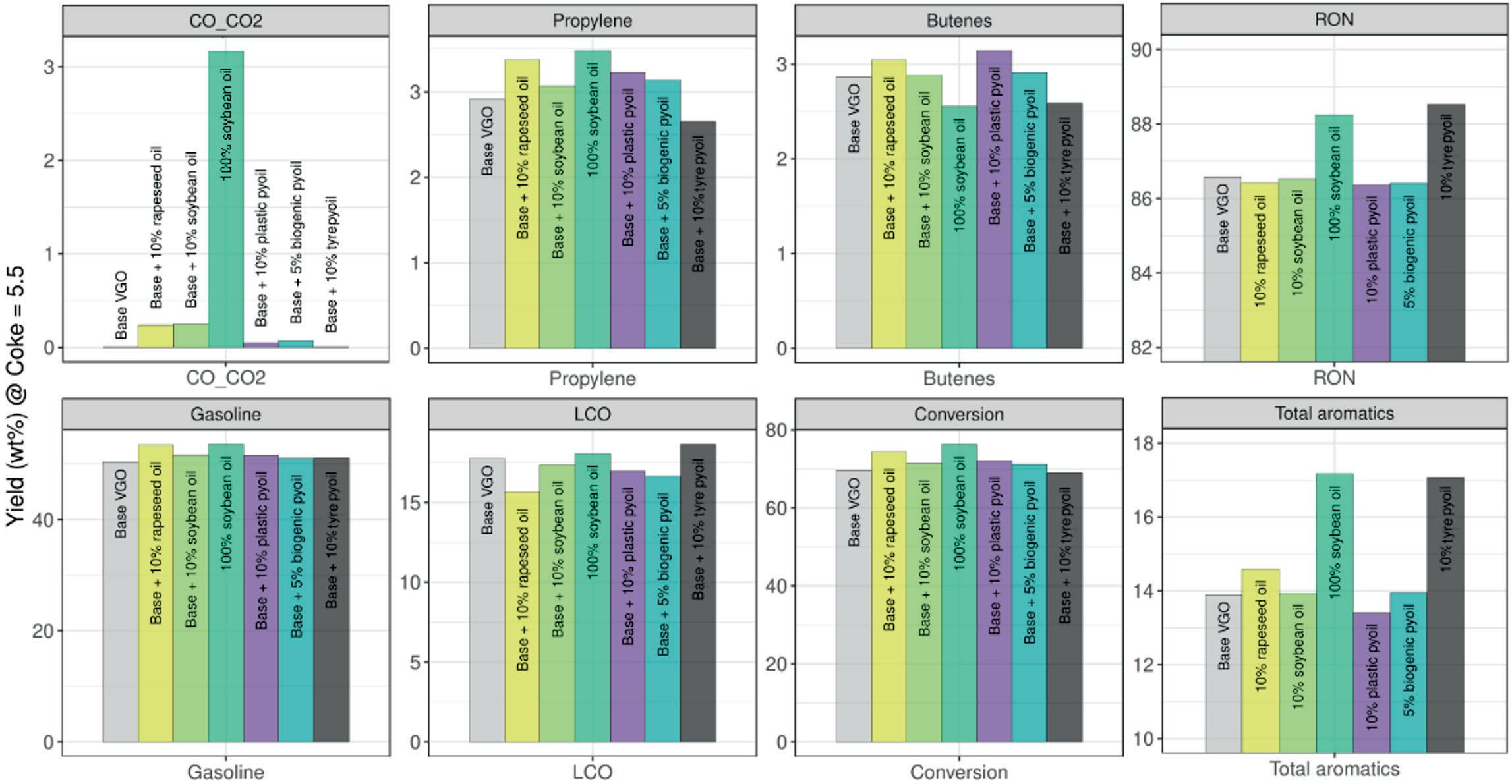
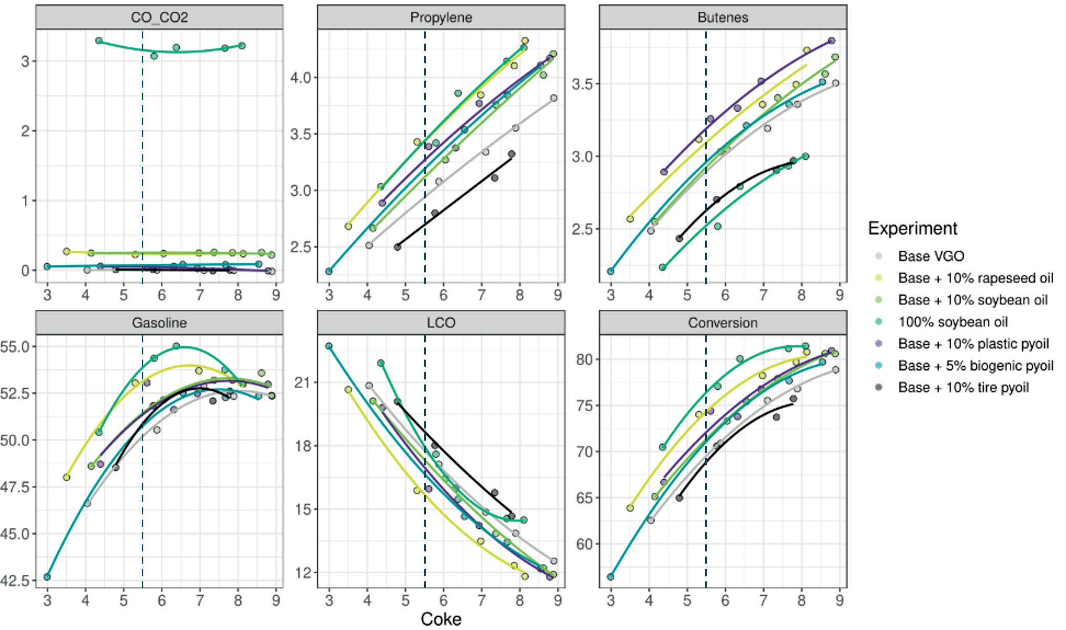
Once the independent variables for the control of reaction temperature and pressure are defined, several experiments at different catalyst-to-oil ratios are performed to measure the yield distribution of products with varying coke yield and conversion. The comparison with the FCCU is then usually based on the interpolated constant coke yield as the descriptor of choice for heat-balanced operation. A study using commercial equilibrium catalyst and a base VGO feed with different co-feeds under equivalent temperature and pressure conditions produces plots as depicted in Figure 3. Interpolated yields at constant coke are presented in Figure 4 to quantify the effects of the various co-feeds on the cracking kinetics and unit performance.
The data reveals that all co-feeds produce similar or much higher conversion at constant coke, indicating that the molecular nature of the different co-feeds has an equivalent or even higher crackability than the base VGO at increased dynamic activity. The decarbonylation/decarboxylation route is obvious for the 100% soybean oil case with > 3 wt% COx yield, while the 10% rapeseed and soybean co-feed experiments show a proportionally smaller COx yield. Long hydrocarbon
chains from deoxygenated fatty acids or within pyrolysis oils from plastics (PE, PP) can be cracked easily. Therefore, these hydrocarbons are shifted from the LCO to the gasoline and LPG range.
The crackability of the tyre pyrolysis oil is relatively low, and the LCO yield is elevated compared to the base VGO. This feedstock comprises considerable amounts of aromatics, entailing increased aromatics content in the gasoline. For the 100% soybean oil case, a similarly increased aromatics concentration in the gasoline is observed. However in this case these species are formed by cyclisation and aromatisation of the linear fatty acid chains, and are not already contained in the feed. In both cases, the increased gasoline aromatics content results in significantly enhanced research octane numbers (RON).
Overall, this selection of data shows that using these renewable co-feeds at the tested percentages in terms of estimated yield changes and selected product quality parameters, such as RON, is not expected to introduce large risk or major constraints in the operation of the FCCU. By optimising process conditions, molecular weight distribution could be shifted further from LCO to gasoline or, at high conversions and severity, to LPG olefins in order to enhance profitability.
To conclude, the MDU offers:
n Realistic simulation of mass-balanced yield distributions of pilot and commercial FCC units.
n A broad parameter space that cannot be simulated in riser units (CRU) due to limitations in the catalyst circulation and catalyst-to-oil ratio, enabling data to be generated for process modelling for high-severity, short-contact-time applications.
n An affordable tool for process optimisation on a laboratory-scale, using low catalyst and feed amounts.


n Clear distinction and quantification of the influence of co-feeds from various sources, even with difficult-to-process feedstocks.
n Sample generation for advanced analytics and a fully-integrated workflow allow for detailed product analysis, including simulated distillation, PIANO/RON analysis of gasoline, 2D-GC, as well as tracing renewable carbon in product fractions (14C radiocarbon analysis).

1. TROTUS, I.-T., et al., ‘Advances in catalyst testing’, Process Technology Quarterly (PTQ), Q4 (2019), pp. 79 – 83.
2. KIRCHMANN, M., et al., ‘Performance testing of naphtha reforming catalysts’, Process Technology Quarterly (PTQ), Q4 (2015), pp. 119 – 131.
3. LAMMENS, T. M., ‘Methodologies for Biogenic Carbon Determination when Co-Processing Fast Pyrolysis Bio-Oil’, BTG Bioliquid B.V., (11 February 2020).


4. ‘Addressing market challenges by redefining FCC catalyst testing’, hte, https://www.hte-company.com/en/news-events/webinars/ webinar-redefining-fcc-catalyst-testing
5. CORMA, A., et al., ‘Downflow test unit for the study of catalysts in short contact time reactions between the catalyst and the reagents’, (27 May 2008), https://patentimages.storage. googleapis.com/81/6c/7c/d4327d95495395/US7378059.pdf
6. CORMA, A., et al., ‘A new continuous laboratory reactor for the study of catalytic cracking’, Applied Catalysis A: General, (10 June 2002), pp. 247 – 263.

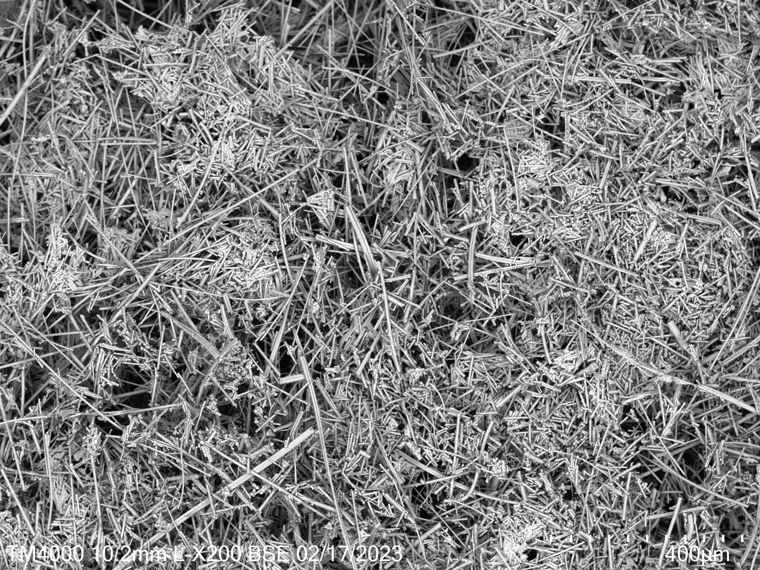
The oil and gas industry has seen tremendous growth and development in recent years, driven in part by the increasing demand for cleaner fuels and more efficient processes. However, despite numerous attempts over the years, traditional catalyst supports have not been able to offer significant improvement in performance. The use of fibres as the support material for catalysts could help to deliver a step change for the industry.
The use of fibres as support material for catalysts is not a new idea. In fact, it has been around for decades. However, recent advances in fibre technology have made this approach much more attractive. In 2018, Alkegen began exploring the use of fibre in the development of flexible fibre-based catalysts that
were capable of adapting to changing industry demands and improving process performance. Ultimately, this led to the creation of FlexCat, a new fibre-based technology with increased flexibility.
Fibres have several advantages over traditional porous support materials. For one, they have a much higher surface area than porous materials, which means that they can support more catalyst per unit volume. Additionally, fibres can be designed to have a specific size and shape, which can optimise their performance in a particular reaction, while managing pressure drop. The use of fibres in catalysis also allows for more efficient use of resources. Traditional catalysts are typically supported on spherical or tablet materials.

Ashley Cuthbertson, Alkegen, outlines how recent advances in fibre technology have made the material an attractive option for catalyst support media.
However, these materials are not very efficient at transferring heat or mass, which can lead to inefficient use of the catalyst metals. Fibres, on the other hand, have a much higher thermal conductivity, and can facilitate better mass transfer. This allows for more efficient use of the catalyst, translating to lower operating costs and higher yields.
Traditional catalyst support consists of spherical beads, pellets or extrudates. These structures can also create voids within the catalyst bed, resulting in poor mass transfer and inefficient reaction kinetics. In contrast, the fibrous catalyst support structure of FlexCat has a high surface area-to-volume ratio, allowing for increased
catalytic activity. The fibres are mechanically strong and have a higher flexibility than traditional catalyst support structures, resulting in less breakage and greater durability.
A primary advantage of FlexCat technology is its ability to reduce the catalyst weight required for a given reaction. Its greater surface area can allow for an increase in throughput and yield within the existing equipment footprint. Additionally, the increased surface area of the fibrous catalyst support structure enhances the reaction kinetics and increases the yield of the desired product.
There are several benefits to using flexible catalyst support materials in oil and gas applications, including the following:
n Increased flexibility: flexible catalyst support materials are designed to be more durable during changes in temperature, pressure, and feedstock composition. This allows the catalyst to maintain its effectiveness over a range of conditions, leading to improved process performance.
n Higher tolerance to impurities: flexible catalyst support materials are more tolerant of impurities in the feedstock, which can lead to fouling or poisoning of the catalyst. This allows the catalyst to maintain its effectiveness for longer periods of time, reducing downtime and maintenance costs.
n Improved catalytic activity: flexible catalyst support materials can be engineered to have specific properties, such as high surface area, tailored pore size, void space, and specific acidity, which can improve catalytic activity and selectivity.
n Reduced environmental impact: through longer catalyst lifetimes, flexible catalyst support materials create less waste over time, with the ability to use recycled materials, reducing the environmental impact of the oil and gas industry.
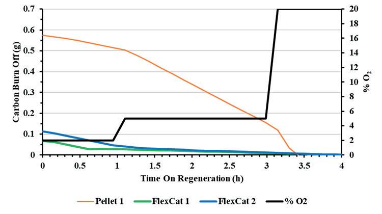
An evolving portfolio of catalyst solutions have emerged since the launch of FlexCat in mid-2021.
Starting with testing in the dehydrogenation space, FlexCat delivered 30 times more yield per catalyst mass with 2.5 times the lifetime of traditional substrates. The fibre-based solution was also able to maximise selectivity while minimising coke production.
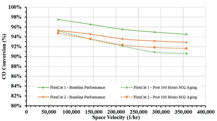


It then expanded into the emission control space, producing high conversion while using significantly lower metal loadings. The solution was able to reduce metal loading by 80% in both carbon monoxide (CO) oxidation and volatile organic compound (VOC) abatement applications, and convert at lower temperatures – saving energy costs and reducing carbon footprints.
In 2023, Alkegen launched FlexCat Defend, a patented catalyst solution for refining and petrochemical applications. The material is made from a blend of ceramic fibres, organic fibres, and inorganic binders, which are processed into a shape to meet the needs of the application. It offers a high surface area and high porosity, which makes it a suitable drop-in solution for absorbents for guard beds and other purification applications.
It is a fibre-based catalyst support media that enhances performance, efficiency and sustainability. It has been tested extensively, and has been shown to provide significant improvements in process efficiency and product quality. It is also designed to be easy to handle and install.
Fibre-based catalyst support media also provides a range of customisation options. The fibres can be tailored to specific process requirements, such as pore size, void space, surface area, and mechanical properties. This allows for more precise control over the catalyst performance and can result in process efficiency and product quality improvements.
FlexCat has the potential for drop-in use with existing reactor designs or new-builds, and can be customised for a myriad of catalysis operations. With its durability, it is poised to be a catalyst support solution for the chemical industry in the years to come.
One of the primary benefits of fibre-based catalyst support media is its high surface area. The 3D structure of the fibres provides a significantly larger surface area compared to traditional support media such as alumina or silica. This increased surface area allows for more active sites for the catalyst, leading to improved
performance and efficiency in the application.
Fibre-based catalyst support media also boasts increased mechanical strength and resistance to deformation. This makes it an ideal choice for high-severity processes, as the support media can withstand these conditions without breaking down or eroding, leading to longer catalyst life and reduced maintenance costs.
FlexCat Defend has excellent thermal stability, allowing it to maintain its structure and mechanical strength even at high temperatures of 900°C/1650°F. This makes it suitable for use in high-temperature applications such as guard beds and bed grading.
Another advantage of fibre-based catalyst support media is its high porosity. The pore structure of the individual fibres and between the fibres provides excellent diffusion pathways for reactants and products, allowing for more efficient mass transfer and faster reaction times. This leads to increased yields of valuable products and reduced waste.
Additionally, FlexCat Defend has excellent resistance to fouling and coking. Fouling is the build-up of unwanted material on the surface of the catalyst support media, which can decrease efficiency and performance of downstream, high-value catalyst. Coking is the deposition of carbon on the catalyst support media, which can also reduce efficiency and lead to catalyst deactivation. Its high porosity and 3D structure allow for better mass transfer and fluid flow to the catalyst, thus in some applications FlexCat can be suitable for eliminating coke precursors while being resistant to fouling with components in the stream. The high surface area also allows for a higher filtration capacity and in some cases, with a proprietary absorbent technology, can lead to increased foulant pick up and protect the valuable catalyst downstream. It has also shown longer product lifetime in testing, reducing environmental impact and waste.
The catalyst industry is entering a new era. The technology for using fibres as support materials is advancing rapidly, offering a number of benefits.
The use of fibres allows for more efficient use of resources, while creating higher yields and lower operational costs. It also opens up new avenues for innovative catalyst design, which can lead to even better performance and efficiency. Fibre-based media offer strong benefits in terms of performance, efficiency and sustainability.
As the catalyst industry continues to grow and evolve, fibre-based materials will continue to play a leading role in the development of advanced catalysts for cleaner, more efficient processes.
Jorge Cadena, Groome Industrial Service Group, USA, discusses the importance of selective catalytic reduction (SCR) maintenance.
In today’s environment, there are many approaches to system monitoring; we have never had so much information at our fingertips. However, with so much information, it is easy to overlook important data that may provide clues to underlying issues within our operations.

Emissions control systems are often on the back end of processes that drive the refining industry’s revenues. Regulations for the control of nitrogen oxides (NOx) dictate that selective catalytic reduction (SCR) systems are needed in order to meet emissions requirements. While not explicitly part of the income-generating activities, most plants would not be allowed to operate without these systems. As such, this equipment is some of the most critical, but also the most overlooked. While SCR systems can potentially cause a plant shutdown, this is a
preventable issue, as they have minimal rotating equipment and that which is present usually has redundancy incorporated into the design.
Monitoring of an emissions control system and performing minimal preventive maintenance ensures that operations will not be curtailed or taken offline due to emissions issues. This maintenance may also have positive financial impacts on overall operations, potentially resulting in hundreds of thousands of dollars in annual operating profits.
SCR technology has been used in refineries for over 30 years from a process standpoint, as well as to treat NOx emissions. The technology utilises a catalyst to initiate a reduction reaction
utilising ammonia (NH3), typically in an aqueous solution, to convert NOx to nitrogen and water.
Equations 1 and 2 are the reactions typically involved in the reduction of both nitrogen oxide (NO) and nitrogen dioxide (NO2):
4NO + 4NH3 + O2 → 2N2 + 3H2O (1) 8NH3 + 6NO2 → 7N2 + 12H2O (2)
These reactions are affected by operating temperature, oxygen and ammonia levels. The temperature range in which these reactions are most prominent is 500 – 750°F. Below this level, the speed of the reaction slows and other undesired side reactions may dominate. Above this range, sintering of the catalyst can take place, with irreversible effects that diminish catalyst effectiveness. Oxygen level should be above 8% and below 15%, typically. High oxygen levels can increase the formation of ammonia salts, while lower levels can decrease conversion efficiency. As aforementioned, an equivalent amount of ammonia is required for conversion of NO, and about 33% more for NO2. Above or below these levels, the reduction reactions shown in equation 1 and 2 may no longer be the predominant ones. Monitoring of these parameters can avoid an unforeseen compliance event and potential operational impacts.
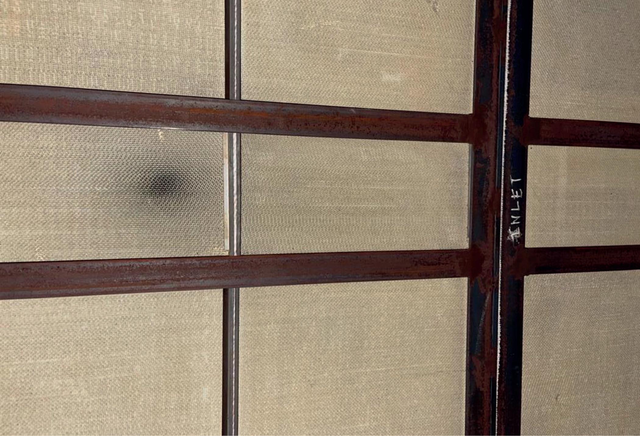
These reactions take place on the surface of the SCR catalyst blocks, which are manufactured to provide a large surface area where the catalysed reactions may take place. These blocks are made up of porous materials which act as support for the catalytic material – usually oxides of base metals (such as vanadium, molybdenum and tungsten). The support material has several pore structures, mesopores and macropores that provide high surface area and paths where the reactions can take place.
The microscopic pores are critical to the efficiency of the system, but are susceptible to plugging. They can become plugged with ammonia salts, created through a side reaction, or insulation and other fine particulates such as rust. Masking of the catalyst blocks the main channels and can be easily identified visually and through differential pressure readings. Plugging refers to the restriction on the micropores, which is not always easily visible or reflected by a large increase in back pressure. However, both of these constraints can have major impacts on the system’s operation.

Catalyst poisoning is another mechanism that can have a significant impact on SCR systems. This poisoning is typically due to alkali metals or sulfur. These contaminants can be present in water that may leak into the system, or in sulfur that may be present in the natural gas. These poisons can block active sites and even chemically degrade the active catalyst.
Catalyst shifting is another issue that often affects the conversion efficiency of SCR systems. Due to system starts/stops and thermal cycling, catalyst blocks can move over time. This can cause shifting and insulation movement, which can lead to gas bypass. Bypass allows unreacted NOx to move past the catalyst blocks, lowering overall system efficiency. This higher emissions level causes the control system algorithm to introduce more ammonia into the system, and any unreacted ammonia that goes beyond the catalyst is termed ammonia slip. This slip can result in increased ammonia salts impacting downstream operations, and may also cause plants with mandated ammonia slip limits to exceed mandates.
These salts can cause fouling on downstream structures, including HRSG boiler tubes. Not only can this cause an increase in back pressure, but it can also reduce heat transfer efficiency. This has the effect of decreasing gas turbine power output, increasing heat rate, and reducing steam production in cogeneration applications. The overall result is greatly reduced profitability of the overall operation.
Additionally, by injecting higher levels of ammonia throughout the catalyst, the catalyst loses its activation more quickly. This can have significant capital cost implications on a plant, as a result of the catalyst demanding more frequent, unexpected changeouts.
A proper maintenance protocol consists of inspections, testing and monitoring of data. By employing this practice, plants can ensure that their systems are operating within the required envelope of conditions, and minimise any unforeseen issues.
Inspections are critical to maintaining SCR systems. These routine inspections can uncover several of the aforementioned issues, i.e., masking, shifting of catalyst blocks, loss of seals/gaskets. This can relieve many issues that can result in

excessive emissions. Once discovered, these issues can often be remedied quickly, by an experienced service company.
Performing data analysis twice a year provides a baseline from which process levels can be monitored in order to anticipate any changes that can affect plant operation. The key parameters to monitor are operating temperature of the catalyst(s), pressure drop, oxygen levels, ammonia flow rate, and NOx levels. Coupling this with annual inspections anticipates any issues and avoids potentially catastrophic consequences.
Testing is the last component of a robust maintenance programme. A proper testing protocol can help to predict future maintenance needs, whether it be a change in operation, maintenance, or changeout of existing catalyst. A key to testing is ensuring a representative sample of catalyst(s). This demands that several samples from different locations within the catalyst bed(s) be tested. The variability in catalyst production, gas flow distribution, and potential upset conditions can greatly affect the results of a single sample. If this is taken as being representative of the whole catalyst system, it can lead to the assumption that remaining life is too long or too short. Either scenario can have adverse impacts. If too long, a situation where a system fails, causing plant shutdown or reduced capacity, may unfold. If too short, a catalyst is changed out too soon, incurring unnecessary costs. Best practice is to test three samples from each side of the catalyst (upstream face and downstream face) to obtain a solid overview. However, this depends on the size and configuration of the SCR module.
Catalyst cleaning is perhaps the simplest means to optimise SCR systems and to realise operational benefits. Fouling of the catalyst can take place for a variety of reasons: atmospheric conditions, poor-quality ammonia, insulation damage, or ductwork scaling. This fouling can result in decreased conversion efficiency and increased pressure drop across the catalyst bed. Some users may see this and change out the catalyst prematurely, or derate their operation until the problem can be resolved. Often, the problem is not that severe, and users can continue operating and meeting emission requirements. However, this is often achieved while operating at a higher pressure drop and/or while injecting extra ammonia. The implications of elevated ammonia slip have already been discussed, but the high back pressure has its own additional set of penalties.
Many users will not react to a slow increase in their back pressure of 1 or 2 in. of water column. However, this can have a huge impact, and can be easily remedied. Cleaning of a catalyst requires an experienced servicer to utilise the proper air pressure to remove the particulates that are fouling the catalyst. Depending on the nature of the fouling and catalyst composition, cleaning may require different pressure requirements in order to avoid damaging the active catalyst material. Medical-grade compressed air is utilised to avoid the introduction of additional contaminants into the catalyst bed. These situations can reduce SCR efficiency, and may even trigger the formation of NOx in some cases.

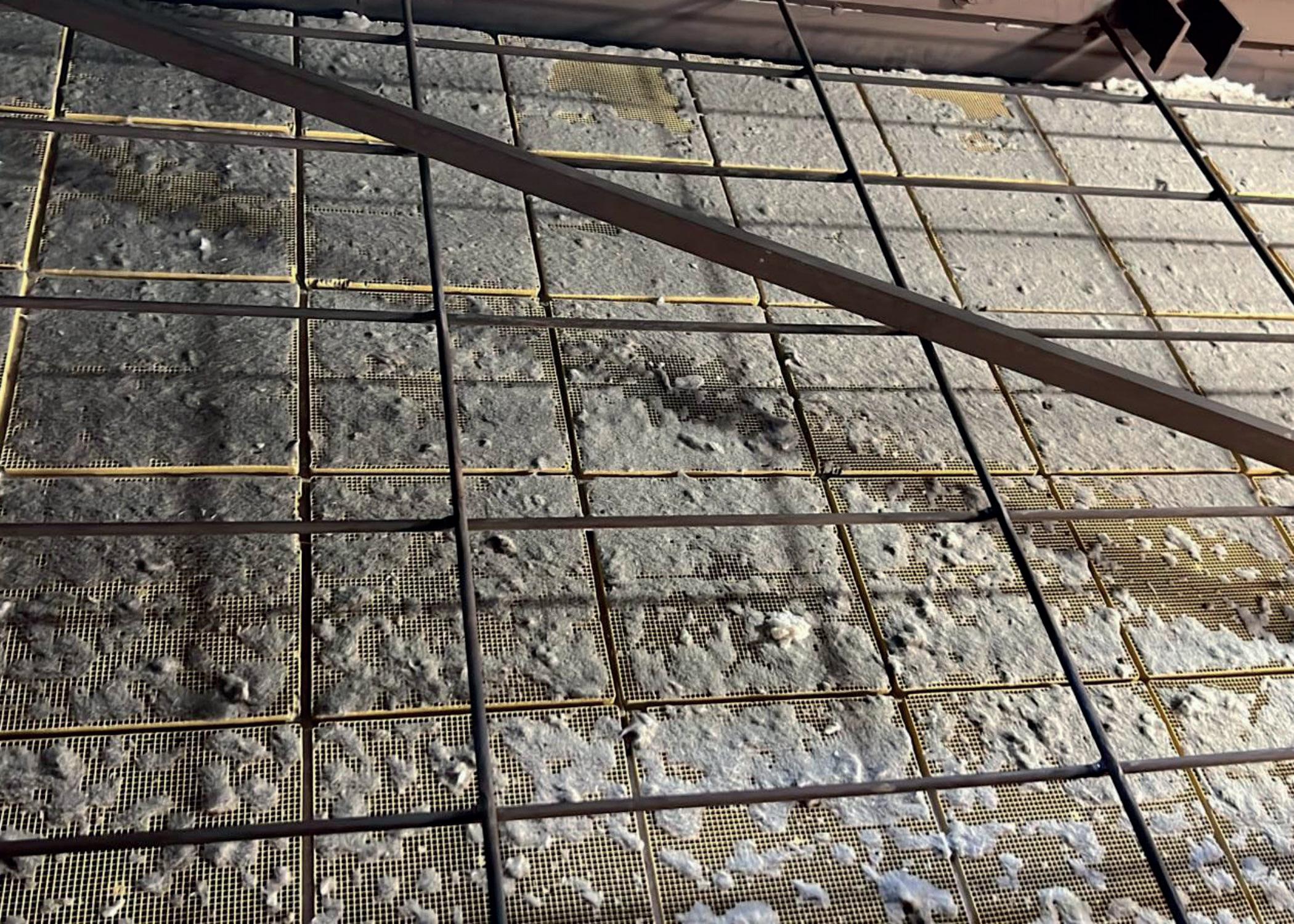
Each plant’s approach to cleaning and their ability to handle increases in differential pressure (dP) varies from plant to plant, and unit to unit. The Groome Industrial team was contacted by a client on the US West Coast to determine why they were experiencing elevated NOx emissions that had dictated that they turn down their operations. Upon review of SCR operations and operating data, it was determined that the client was likely experiencing masking due to insulation failure. This masking required that the plant run at below 50% capacity. It was determined that SCR cleaning was needed, which would entail an emergency outage.
In lieu of shutting down, Groome developed a plan to install insulated access ports which would allow online cleaning. Upon installation of the custom ports, the catalyst was cleaned, pressure drop was reduced by over 55%, and the plant’s capacity returned to normal. The recovered capacity and avoidance shutdown allowed the plant to realise profits that would otherwise have been lost.
These are only a couple of aspects that, with a little monitoring and maintenance, can result in significant savings. Performing these maintenance services on a regular basis can offer significant benefits to a site’s profits, operations and longevity. There are a number of companies that specialise in these areas and can perform this work on a scheduled basis, with guaranteed results. The key is to initiate a maintenance plan to understand where lost profits can be recovered.
Brad Cook, Sabin Metal Corp., USA, outlines the complexities of sampling precious metal catalysts, and explains why sample accuracy is so important.
Precious metals are likely among the most recycled substances on planet earth, as their value always seems to make it worth someone’s time and effort to retrieve regardless of the form they make take. For those of you whose day-to-day activity does not involve precious metals or catalysts, let us start with a brief introduction. Many petroleum and petrochemical processes use catalysts containing

precious metals such as platinum, palladium, ruthenium and rhodium – commonly referred to as platinum group metals (PGMs) – or another valuable precious metal, rhenium. Whatever their precious metals composition, all PGM and rhenium-bearing catalysts must eventually be replaced with fresh catalysts (or ‘changed out’) to restore efficacy to the process or speed up process reactions. Typically, this happens every three to five years. The spent catalysts are sent to a precious metals refiner to determine the value contained and return the precious metals (or the monetary equivalent) to the catalyst owner.
The phrase “it doesn’t matter what you know until you know what matters” is especially true in the precious metals industry. It is important to develop the ability to prioritise what truly matters and forget about everything else, which may go against conventional
wisdom. For example, in the world of purchasing and procurement, imagine trying to learn to ignore costs.
To compound this problem, current trends in the industry have seen workers move into new jobs and/or areas of responsibility at an increased rate. As such, the person in charge of purchasing and procuring PGM-related products and services might only see one or two catalyst changeouts in their current role. It is therefore more important than ever for companies to ensure that they have developed and formalised an in-house programme for precious metals. This will preserve the historical data and specialised knowledge that has been learned from every precious metal reclaim.
When it comes to determining the value inside your precious metal spent catalyst asset, what is it that truly matters? In this context, it is not the processing fees or the shipping charges; it is obtaining the correct value for your precious metals. That is quite literally where the money is. At the precious metals reclaimer, this breaks down into six fundamental service qualities (see Figure 1):
The no-compromise essentials:
n Having the technical knowledge and experience to accomplish the job.
n Following all proper regulatory, environmental and safety rules.
n Adhering to strict ethical standards.
The scope of work itself:
n The correct weight.
n A representative sample.
n An accurate and precise assay.
The PGMs are valued by processing the material, sampling it, and then assaying that sample for the appropriate metals. Weight x assay = the value. Without correct values for all three of these data points, there is no chance of determining the PGM value.
Weight accuracy is verified on the spot: the customer or their representative witnesses the certified

test weights that are being utilised, and checks each and every scale use for a proper zero at start. Great attention has been given to the precision and accuracy of the precious metals assay, and rightly so, however the best lab in the world is of no use if presented with a poor sample. Therefore, it is important to discuss sampling.
To underscore the importance of sample accuracy, note that, at the analytical stage, 1 g or less will eventually become the aliquot (the sample portion being used). It is not unusual at all for 8 or 10 t of catalyst, worth approximately €500 000 at today’s platinum prices, to be valued based on an aliquot of 1 g or less.
Proper sampling is highly misunderstood and taking a ‘good’ sample is a difficult thing to do on anything other than a completely molecularly homogeneous material. Sampling is essentially an error-generating activity, so there will never be a perfect sample, although we can certainly strive towards the best possible sample.

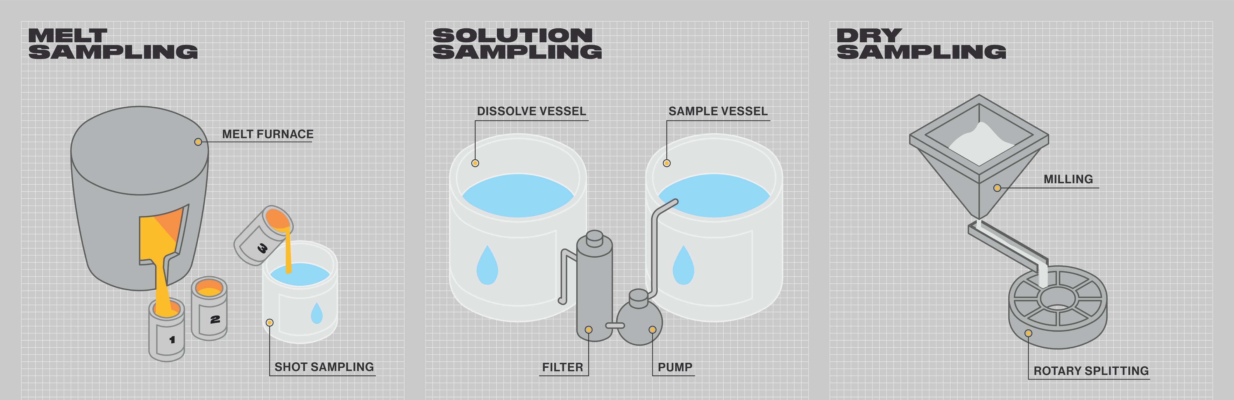
There are several ways to achieve the desired level of uniformity, depending upon the physical properties of precious metal-bearing materials (see Figure 2):
n Melting to a uniform molten form.
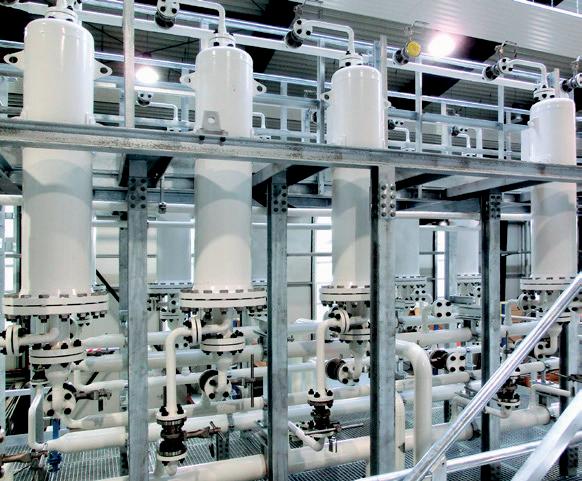
n Dissolving in acid or caustic solution to a uniform liquid form.

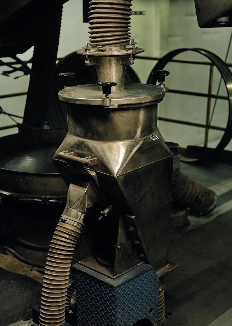
n Dry sampling, which is pulverising to a uniform powdered form.
For precious metal-bearing catalysts, dry sampling methods are usually employed as it is not cost-effective to melt or dissolve an entire shipment. It is in the best interest of all parties to process the material in question to the highest reasonable level of uniformity before proceeding to sampling. A useful illustration here is a swimming pool full of fruit. Let us picture hundreds of kilos of apples, watermelons, cherries, grapes, bananas, etc, all filling an Olympic-sized swimming pool. To take an accurate sample, one could mix well, take a long section of PVC pipe, and push it down into this fruit salad to get a core sample. However, is this really a representative sample?
This is where we should introduce one of the fundamentals of proper sampling: particle size reduction. Using a melon baller, we could reduce everything to the size of the cherries and the grapes. Now when we mix and take our core sample, we can see that we have got a better chance of accuracy. Best of all, of course, would be to juice the entire thing and separate out the seeds and pits, as we would then be that much closer to molecular uniformity, but that would be very expensive. The point here is that thought must be given to the overall value and difficulty in processing the precious metal-bearing material in order to determine the most appropriate processing method(s).
Before beginning the sampling process, other steps can be taken to create better uniformity. In the cases where organic contamination has become excessive, thermal treatment can volatise off the carbon, moisture, benzene, etc. Screening can remove spacer balls or other support media. The goal is to have a clean parcel of catalyst that is dry and free flowing.
Both ‘constitutional uniformity’ (defined by the similarity of each particle) and ‘distributional uniformity’ (how well mixed the particles are overall) is required.
Blending has been found to be of dubious value when sampling precious metal-bearing catalysts. Much greater success is achieved by using a sampling system that utilises a multiple aliquot philosophy to achieve statistical precision. Some of the crucial aspects of an effective sampling system include the following: n The consistent and constant flow of material. The aim is to transform the material into a one-dimensional object: a straight line.
-
n The entirety of the lot must go through the system. For true and complete accuracy, 100% of the customer lot must be sampled.
n Draw many small samples in equal amounts, at regular intervals.
n The smaller the device, the smaller the particle size (see Figure 3).
n The entire sampling system must be thoroughly cleaned both before (to prevent cross-contamination), and after (to ensure that the client receives every kilo of their catalyst weight).
It is important to differentiate between accuracy and precision. Many people use these words interchangeably, but they have different meanings in the sampling and lab context.
High accuracy is getting close to the centre of the bull’s eye every time. In a lab, this would translate to repeatedly getting the platinum assay close to correct. High precision is getting a very consistent ‘shot group’ on your archery target, or a set of assay results that are very close to one another. The high precision/low

accuracy lab is in effect precisely wrong. In the sampling process and the assay lab, both accuracy and precision are required.
When creating a sampling system, accuracy and precision can be proven by running the same material (with known content, such as a manufactured standard) through the sampling system three or four dozen times. The 40 or so samples can then go to the lab and see whether the results are both accurate (the results all very close together) and precise (close to the known metals content of the standard material). A great sampling system would achieve both accuracy and precision (see Figure 4).

In the analytical lab, every sample that arrives is run multiple times through multiple assay methods, alongside quality control standards and blanks. Consistent results, accurate and precise, must be confirmed before any final numbers are reported commercially.
Limiting the total monetary value that is represented by each assay lot protects everyone. It is in no one’s best interest to have too much monetary value within any one assay lot, because standard deviation and repeatability must always be considered. Lab accuracy does not increase simply because more money is at stake. It is important to ensure that a precious metals refiner creates a larger number of small-value assay lots (for example, US$500 000 maximum) rather than a lesser number of large-value lots.
Suffice to say that none of the above could be considered trivial. Once that sample is taken from the customer lot, any error or misstep is compounded proportionally. Each time the sample is reduced in size, the mistake is multiplied yet again, which means larger amounts of money moving in the wrong direction.
Important decisions must be made, some of which can be time consuming and may therefore appear expensive. The cost of proper execution should be evaluated with respect to the value of the material, which can be more than seven figures. Accuracy and precision in sampling and assay are well worth the effort.
Colin Bateman, Integrated Global Services (IGS), UK, explains how to prevent the corrosion that may result from conversion to renewables.
Many oil and gas companies are repurposing refineries in order to produce renewable diesel, sustainable aviation fuel (SAF), and other renewable biofuels and products. The replacement of fossil fuels will help to decrease greenhouse gas (GHG) and carbon dioxide (CO2) emissions.
There are several incentive schemes available to refineries to increase the production of renewable fuels. For example, the US offers the Renewable Fuel Standard (RFS) programme, which provides tax credits for the production of certain renewable fuels, including biodiesel and ethanol.

Process equipment designed to refine crude oil products will now be faced with new chemical compositions, pressures and temperatures. This new processing environment leads to new corrosion mechanisms that can detrimentally affect existing carbon steel, stainless steel, or internally-clad reactors, drums and other process equipment.
Corrosion mechanisms in renewable diesel processing are unique. Conventional base materials of columns, towers and reactors, as well as past corrosion mitigation strategies, are unsuitable in these new operating environments.
The processing of renewables, be it co-processing or switching to 100%, means that critical equipment such as reactors becomes susceptible to high-temperature free fatty acids (FFAs). These are a type of carboxylic acid, and will contribute to the acidification of the feed, increasing the total acid number (TAN), which leads to corrosion. Other types of corrosion include CO2 corrosion, wet chloride corrosion, sulfidation, and stress corrosion cracking.
Repurposed equipment is faced with asset integrity risks due to new corrodents and damage mechanisms. The original equipment design and/or mitigation strategy may no longer be sufficient to deal with any combination of FFA, naphthenic acid, carbonic acid, chlorides, etc. in the effluent and associated streams. Revised mitigation strategies must account for the differences between the old and new damage mechanisms, for both the asset base material and cladding (if installed). Depending on the process conditions, 3XX SS alloy overlays may not be resilient enough for these more aggressive service conditions.
Cladding materials based on alloys with a known tolerance (e.g. NiCrMo/W/XX) can provide the necessary corrosion resistance for renewable fuel processing.
To protect the existing equipment base material and pressure boundary, a metallurgy upgrade is required to prevent corrosion and potential asset integrity failure. There are several options available to achieve this.
This option involves replacing the existing assets with newly-built equipment designed for the latest operating environment. Replacement of small items can be relatively quick and cost-effective, but when operators consider medium/large processing equipment, such as pressure vessels, drums, reactors, columns etc., replacement becomes prohibitively expensive and slow, with lead times for the required high-nobility clad equipment often being a number of years.
Welding is a commonly-used solution in the wider oil and gas industry, both for rebuilding degraded areas of wall thickness and for providing a corrosion-resistant alloy barrier. However, welding carries some fundamental drawbacks. A common issue is the potential damage of the vessel shell or any existing internal cladding, due to the heat input required for the welding process (preheating, welding [heat affected zones (HAZ)] and post-weld heat treatment or bake out). The process also necessitates additional mechanical support for the equipment during the process to mitigate structural integrity risks, e.g. loosening any flanged connections, cranes, or laying down the column horizontally.
A high degree of stress is added into the process during welding, especially on thinner wall vessels, which can cause distortion or failure. Additionally, the weld procedure, code, or environmental conditions will typically require heat treatment prior to and after the application, adding further time and cost to the repair solution.
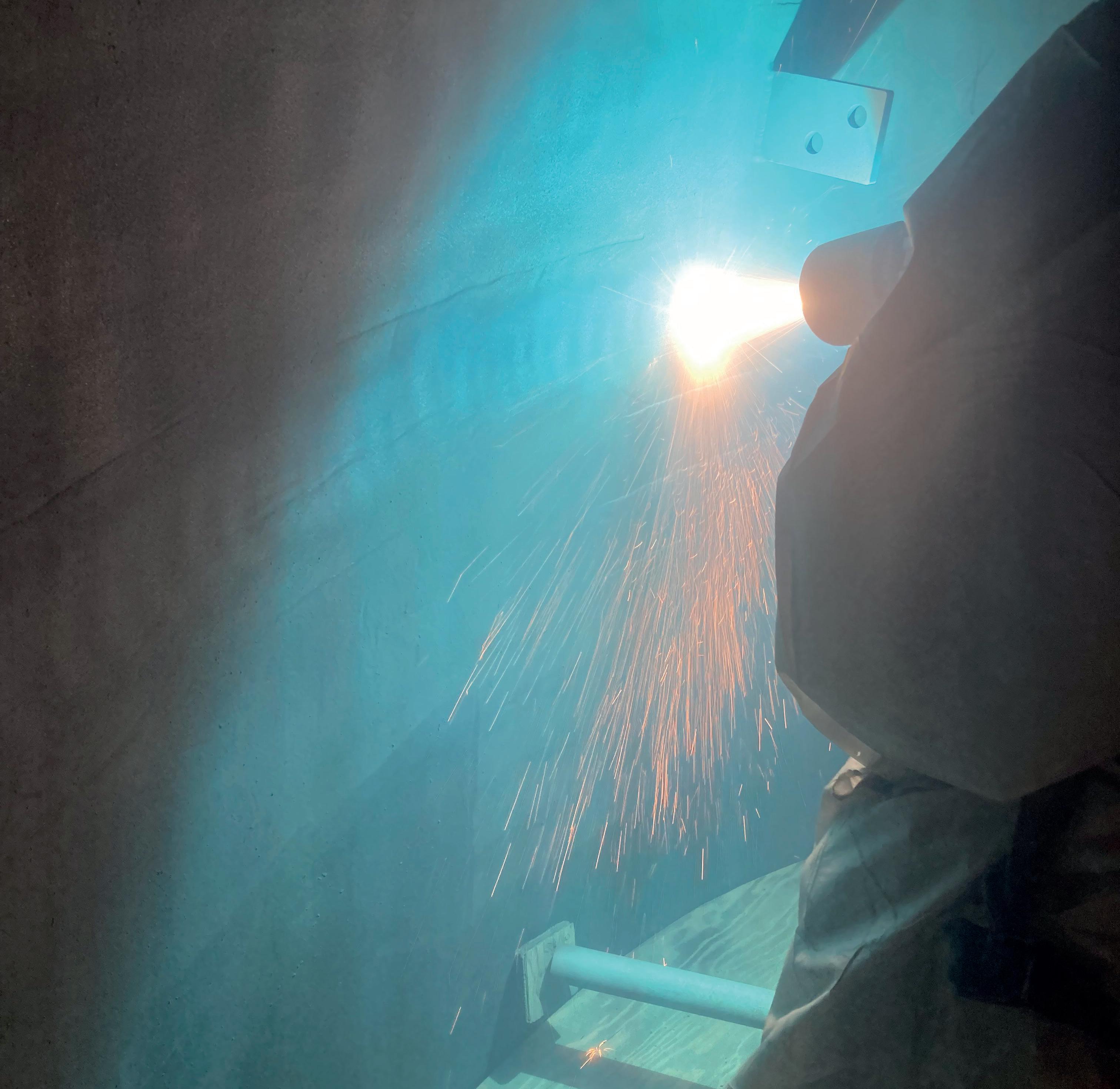
When it comes to time and cost, welding is a relatively slow process, with an application time of 10 – 16 ft2 (1 – 1.5 m2) per weld head per shift, and this can cause additional delays in bringing the asset back into service. Depending on the timeframe available for conversion to renewables, using the method of welding for corrosion protection can have a significant financial impact.
Developed by Integrated Global Services (IGS) in the early 2000s following decades of field application experience, High Velocity Thermal Spray (HVTS) is designed to protect the base metal in high corrosion environments, and involves the simple application of a non-porous, high-nobility metal alloy. This application upgrades the metallurgy of base materials, protecting them from new operating environments. Since the early 2000s, HVTS has been successfully installed, and its performance verified through inspection in hundreds of critical oil and gas process assets over thousands of square metres of internal surface.
The application process is considerably faster than welding and imposes no stress on the base material. For the substrate, application is effectively a cold process. Furthermore, HVTS application does not generate any dilution (the process does not require fusion or a metallurgical bond).
When selecting a contractor to protect mission-critical equipment against new processing environments, there are several things to consider. Firstly, the contractor should work with the EPC, asset owner and licensor to deliver a comprehensive pre-qualification engineering package to govern the quality of the applied surface technology solution and ensure that the protection solution is suitable for the new harsh corrosion mechanisms. Rigorous testing should be performed by the provider to verify the suitability of the selected solution in advance of application.
A good surface solutions provider should deliver a complete technical package of services, ensuring a turnkey site application within agreed timescales, including:
n Project plan.
n Method statement.
n Project safety analysis.
n Risk assessment and mitigation plan.
n Job-specific safety data sheets.
n Material selection.
n Surface preparation.
n Utilisation of the application process.
n Critical quality assurance (QA)/quality control (QC) controls.
n Post-project reports.
A former refinery in eastern Canada was performing a site-wide conversion in preparation for refining 100% renewable feedstocks instead of 100% petroleum oils. The Canadian government was partly financing the conversion. The refinery started processing SAF in the summer of 2022.
The new damage mechanisms associated with switching the processing from petroleum to 100% renewable feedstock were a major concern for the existing 347SS (stainless steel) weld overlayed reactors and associated equipment.
The two reactors and two drums required a metallurgy upgrade due to new operating conditions. With renewables processing, reactors are susceptible to high-temperature FFA corrosion, CO2 or carbonic acid corrosion, wet chloride corrosion, and stress corrosion cracking.
The drums had possible damage mechanisms, including wet CO 2 corrosion, wet chlorides, and potential

ammonium bisulfide (NH 4HS) and ammonium chloride (NH 4Cl).
The refinery, in conjunction with its EPC, opted for IGS’ HVTS solution, which resulted in around a 50% cost saving compared to automated welding. Approximately one-third of their time was also saved.

Another reason that the refinery did not choose automated welding was the fact that it would require preheat, which would take up more time and resources. This was an important factor as the facility is located in arctic conditions. The facility also appreciated the fact that IGS could work turnkey.
Furthermore, much higher deposition rates, without dilution or needed ‘butter’/intermediate layers to achieve surface chemistry, made HVTS the solution of choice for this application.
Modified alloys specifically designed for field application using the HVTS process were prequalified and specified for the reactors and drums. NiCrMoXX type materials were specified due to their excellent resistance to corrosion and erosion.
The EPC, asset owner and licensor required a comprehensive pre-qualification and adherence to a tight engineering standard to govern the quality of the cladding applied, and ensure that the HVTS protection
would hold up against the new harsh corrosion mechanisms. Numerous pre-qualification tests and application trials were performed on test panels and witnessed in the IGS laboratory in Richmond, Virginia, US, to alleviate any concerns including microhardness, bond strength, application standard, scanning electron microscopy (SEM) and energy dispersive X-ray spectroscopy (EDS) analysis, etc.
While material selection is important, it is only a small part of the technical package required to ensure durable long-term performance in cladding systems. Careful attention to surface preparation and accessibility, utilisation of high velocity process, and critical parameter control is necessary to ensure homogenous alloy cladding with the right mechanical properties. Management of environmental conditions and monitoring of field quality control with real-time production test plate assessments is also required.
IGS provide a turnkey application of the internal HVTS cladding for clients, utilising its experienced and certified operations team. The solution considers all of the necessary aspects to effectively protect the asset’s internal surface, including provision for the nozzles and manways.
The entire process is controlled by the IGS Quality Management System (QMS), which includes the HVTS cladding procedure, Inspection Test Procedures (ITPs), environmental requirements, surface acceptance criteria (including the evaluation of the existing cladding integrity, its restoration, and mechanical remediation methodology), surface preparation requirements, as well as site-applied production test plate creation and evaluation. All IGS personnel support the delivery of the QMS – the application technician, shift foreman, quality manager and project manager – and each critical requirement is checked and verified multiple times during the project execution in close coordination with the client, following the IGS Standard Operating Procedures (SOPs).
The project engineering package was successfully delivered, including the project plan, method statement, inspection test plan, project safety analysis, risk assessment and mitigation plan, and the job-specific safety data sheets. The project scope was completed on time.
With a rise in renewable conversions, there are a multitude of issues that oil and gas companies need to consider. Corrosion protection is critical for long-term asset performance, and a comprehensive mitigation strategy should be in place at the beginning of the conversion process. A preventative maintenance plan will ensure that asset life is prolonged, the risk of costly unplanned outages is reduced, and performance and efficiency are maximised.
Marie-Sophie Haverkamp and Robin Wilmshöfer, BORSIG
Membrane Technology GmbH, Germany, introduce a low-energy separation method to enhance the sustainability of alternative feedstock and circular processing.
Early developments of membrane technology in the 1960s and 1970s mainly focused on water applications. These technologies, such as reverse osmosis, were utilised for desalination.1 However, the applied membranes were barely solvent-resistant. Solvent and fuel-related applications were at an infant stage, especially when faced with challenges relating to chemical robustness and exposure to fouling-promoting components such as particulates, asphaltenes, and sticky gum-like molecules.

Even at an early R&D stage, the potential of siloxane-based materials was proven to be stable in jet fuel applications for metal removal, e.g. mitigating the undesired gum formation caused by metal-catalysed jet fuel thermal oxidation.2 One of the first large, commercial successes for membrane technology in the oil refining sector was its implementation for the recovery of methyl ethyl ketone (MEK) and toluene within a solvent-based dewaxing process, which was developed by Mobil Oil and W.R. Grace in the 1990s (MAX-DEWAXTM).3 This was soon followed up with application developments for the removal of sulfur molecules from gasoline.4
Meanwhile, significant progress was made with regards to the commercialisation of suitable membrane material, as well as membrane module developments to enhance performance, i.e., to be less prone to fouling effects.
Solvent-robust nanofiltration for separations at molecular level has many applications5, such as homogeneous catalyst separation, naphtha-like condensates, pyrolysis-derived feedstock, solvents6 and fuels.7, 8
Organic solvent nanofiltration (OSN) membranes are specifically designed to be stable in organic solvents. BORSIG manufactures polymeric membranes made of different layers – so-called thin-film composite (TFC) membranes. The upper layer is dense, with a thickness of a few microns, and forms the selective and semi-permeable separation barrier of the membrane. Due to the absence of pores in this top layer, no pore plugging can occur when sub-micron or small particulates are present in the feed. Mass transport through the dense selective layer takes place by way of solution-diffusion.1, 5 Larger molecules in the range of 300 – 1000 Dalton (Da) are retained, while smaller molecules such as solvents permeate through the membrane. The commercial membranes are available in a variety of molecular weight cut-offs (MWCO).5 The membranes are operated in cross-flow mode. A pressure difference from feed retentate to the permeate is the driving force. Typical pressures are in the range of 10 – 35 bar. An example is illustrated in Figure 1. The next section of this article will detail a few examples.
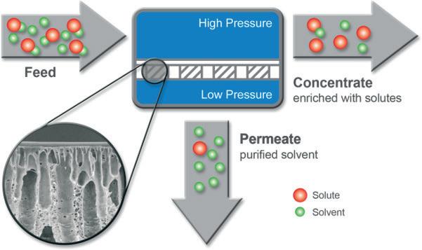
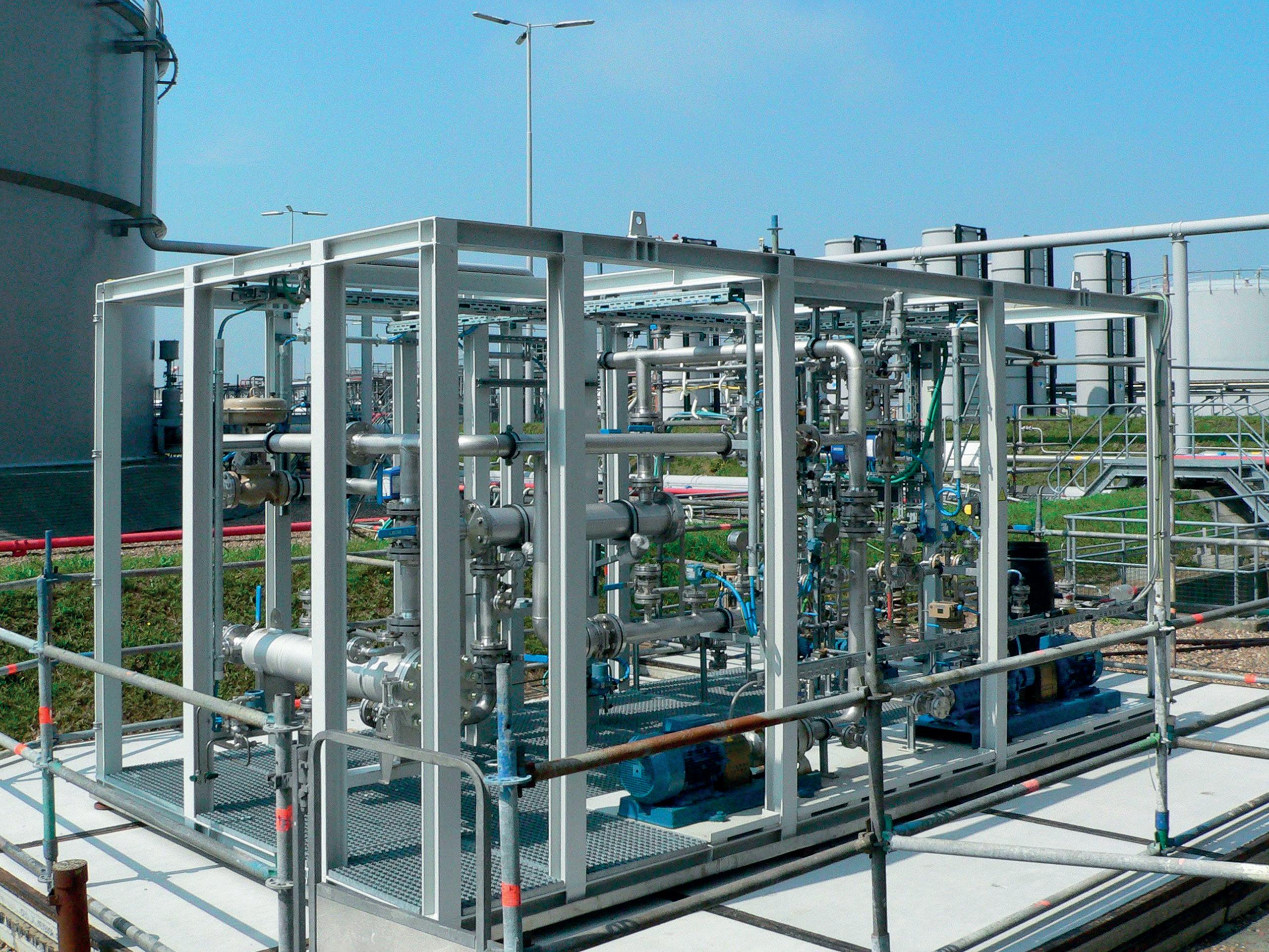
In the field of fuel applications, nanofiltration has been proven to be capable of providing quality improvement (thermal stability) by way of removing trace metals that are responsible for catalytic formation of gum in the jet fuel burner.2 Thereafter, fuel applications have evolved into gasoline and diesel applications, where fuel performance and fuel savings can be achieved.7 For diesel, typical zinc retentions of 99.9% were achieved.8 Its benefit was proven by significant engine fouling reduction. The removal of typical asphaltene-like contaminants resulted in a successful upgrade to so-called dark condensates, which are naphtha-like.9 After nanofiltration, contaminants are retained, resulting in a clear and bright permeate material. This ensures significant fouling reduction during further upgrading, such as for naphtha-cracker technology.9, 10
In parallel to this development, the retention of mercury from condensates was demonstrated. The patented results, shown in Table 1, were based on the stirred-cell lab tests to show the analytical accuracy and mass balance, which are between 95 – 97%.11 The feedstock consisted of a ‘sweet’ condensate (absence of hydrogen sulfide [H2S], and so the mercury is most likely to be present in metallic and/or ionic form).
The retention data in Table 1 was compared against larger field demonstration trials. These demonstration tests were performed in close collaboration between BORSIG and Shell, utilising a module demonstration facility, as shown in Figure 2, whereby permeabilities of approximately 2 kg/m2 hr bar were obtained at ambient temperatures.12 The resulting permeate was clear, bright and free of solids.
For nearly a century, Grace catalysts have kept fuel and petrochemical feedstocks flowing from the industry’s largest refineries to the trucks, trains, planes, and ships that keep our world running.
We are leveraging our long history of innovation in fluid catalytic cracking to develop products that enable lower carbon fuels and help meet the challenges of the energy transition.

This section will discuss a shale oil trial, conducted by Shell.13 This trial tested product stability and fouling robustness of nanofiltration. The feedstock was derived from an in-situ conversion process (ICP).14 ICP shale oil derived condensate is considered to be a worst-case feed material. Due to its instability through reactive precursor
molecules, gum/asphaltene-related solids drop out, even when inserted with nitrogen, for example. As such, the basic feed material is always black (see Figure 3).
A field trial was conducted, utilising a 2.5 in. spirally-wound membrane module configuration equipped with BORSIG siloxane-based nanofiltration material.13 Permeation was executed at a typical pressure of 10 – 25 bar at ambient temperature. Permeate material was collected as a clear and bright product, which immediately showed stability – even without blanketing. Significant analysis to prove the effect of feedstock stability and fouling tendency was carried out via the Alcor® test, which is a thermally-based fouling promotion test. This testing method showed that the permeate materials had a far lower – unmeasurable, in fact – fouling tendency in comparison to the original feed and reject material (retentate).
ICP shale oil fouling behaviour is significant, and fouling mitigation of such feed materials is unachievable using conventional filtration techniques. Figure 3 provides an indication of the heavily contaminated feed and reject material vs its purified and stabilised permeate material.
The significantly increased stability of the clear and bright permeate material (even without nitrogen blanketing) can be attributed to the retention of typical reactive, fouling precursor molecules.
Typical similar feed material properties are also observed in heat treatment and/or pyrolysis processes, e.g., the circularity of plastics.
The aforementioned examples show a variety of separation and retention techniques, utilising OSN membranes. BORSIG Membrane Technology has standard materials available with MWCO ranges of 300 –1500 Da and above. With the demonstrated hydrocarbon permeabilities of 1 – 3 kg/m2 hr bar, significant fluxes can be seen at feed pressures of 15 – 20 bar. Temperatures to a maximum of approximately 60 – 80˚C will increase flux. As such, viscous feedstock is also applicable, such as lighter crudes or alternative renewable and circularity-based feedstock, such as spent motor oils. As pressure is the key driving force, nanofiltration systems are low energy (electricity) dependent, and therefore more sustainable. Figure 4 shows two configurations that indicate the required footprint and modularity for typical hydrocarbon applications.
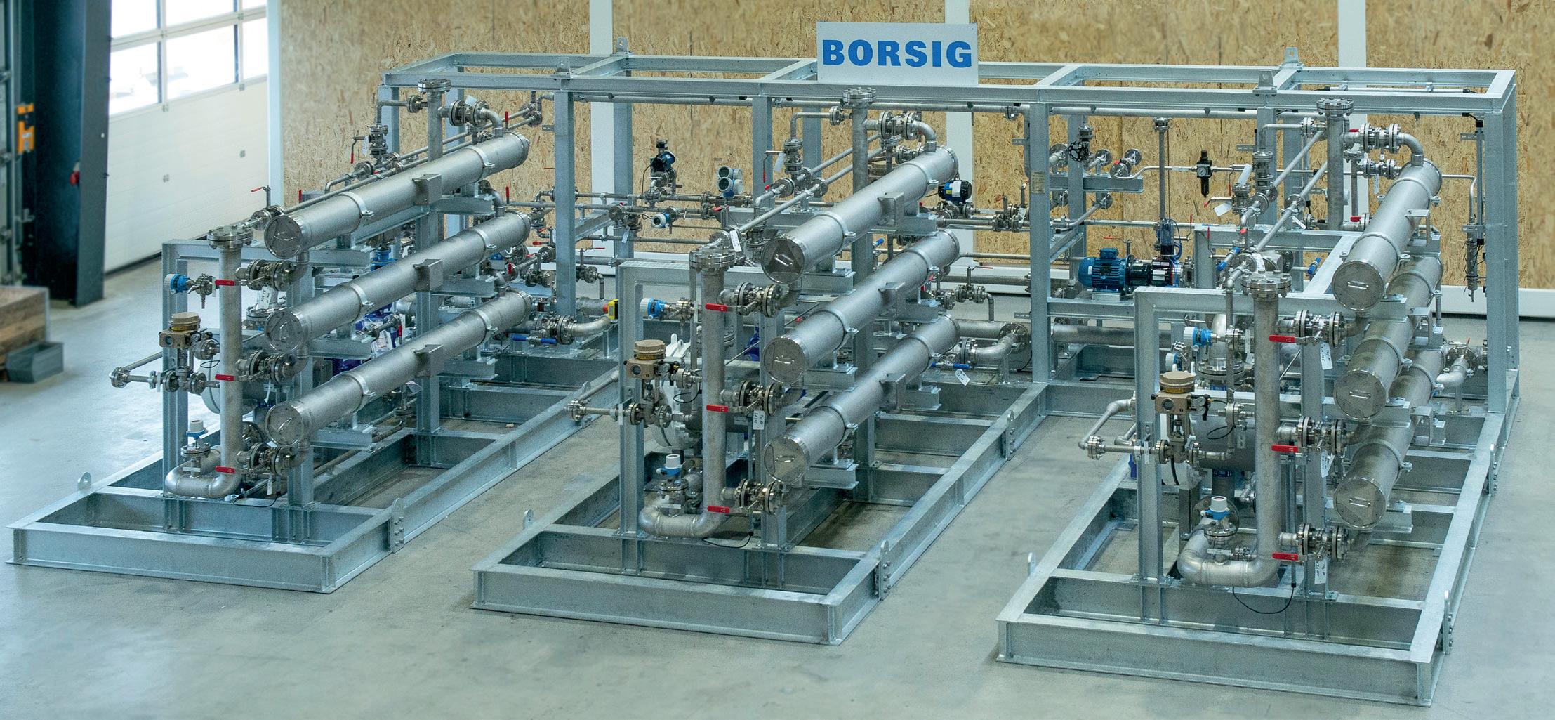
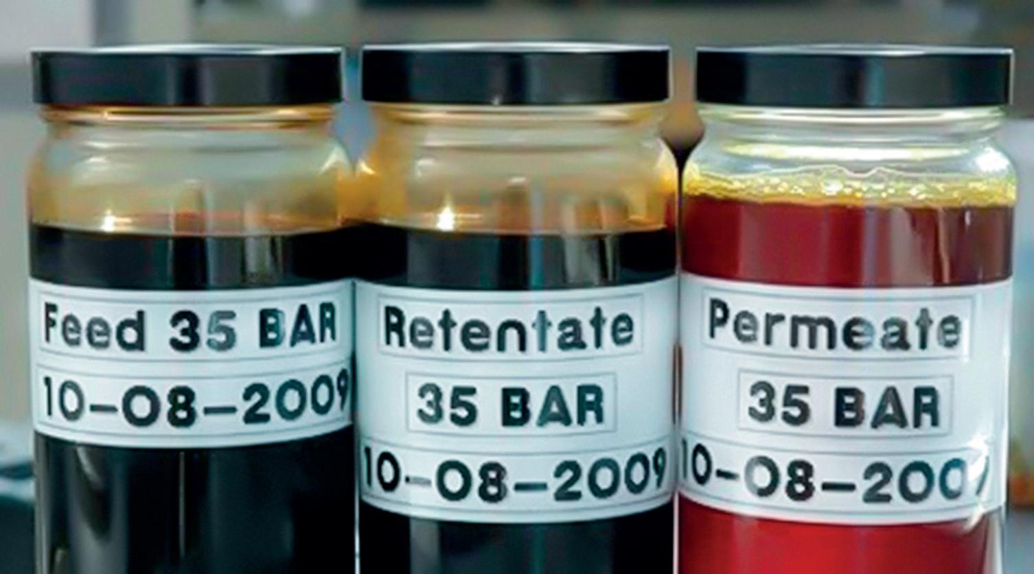
The design is fully modular and easy to stack in the case of restricted space, as well as extendable in the event of a required increase in capacity. Dependent on the application, the nanofiltration systems can be a standalone operation or combined, e.g. with specific filtration systems.12
As the membranes are dense, pore plugging cannot occur. Dependent on feed quality, a module’s typical lifespan is around three to five years. Often, this may correspond well with planned maintenance turnaround activities, which can significantly contribute to overall economics. Spacer materials are applied within the membrane modules to significantly impact turbulence promotion,1 and this
Click
Discover mature and reliable technologies to produce Sustainable Aviation Fuel (SAF)
positively affects mass transfer and fouling prevention subsequently. These can be designed spacer plates for plate and frame modules, or polymeric mesh applied for spirally-wound configurations. The selection of module configuration and spacer type is strongly dependent on application. Nonetheless, due to modularity, the design can be expanded when feed capacities are being increased.
Based on these technical results, and from demonstration/implementation experiences, OSN can be seen as a mature and robust separation method with a high technical readiness level (TRL). Nonetheless, there is still scope for various new or similar application options, such as in the field of hydrocarbon circularity. The system operations are relatively compact and modular. Additionally, due to its pressure-driven separation mechanism, the technology is sustainable. The resulting fuel characteristics, such as thermal stability and fuel economy, as for diesel, also contribute to sustainability considerations.
The authors and BORSIG Membrane Technology GmbH would like to acknowledge their collaboration with Shell through the various stages of application development. In particular, Shell’s Lead Technology Expert, Prof. Arian Nijmeijer, and Senior Technologist Special Separation, Jan den Boestert, who recently retired from Shell. Jan is active as a separation technology consultant and contributed to this article. The authors would also like to thank Evren Unsal, Executive Editor of Shell TechXplorer Digest magazine, who provided technical support and contributed several figures.
1. MULDER, M., ‘Basic Principles of Membrane Technology’, ISBN 0-7923-4248-8.
2. BITTER, J.G.A. et al, ‘Process for reducing the metal content of a hydrocarbon mixture’, Patent Application No. 5031881, (1991).
3. GOULD, R.M., et al, ‘Lubricating Oil Dewaxing with membrane separation’, Patent Application No. US 5651877.
4. WHITE, L.S., WORMSBECHER, R.F. and LESEMAN, M., ‘Membrane separation for sulfur reduction’, Patent Application No. US6896796.
5. VANDEZANDE, P., GEVERS, L.E.M., and VANKELEKOM, I. F. J., ‘Solvent resistant nanofiltration; separating on a molecular level’, Chemical Society Reviews, (8 October 2007).
6. COSSEE, R.P., et al, ‘Process for purifying a liquid hydrocarbon product’, Patent Application No. US6488856, (2001).
7. TARLETON, E.S., ROBINSON, J.P., and LOW, J.S., ‘Nanofiltration, a technology for selective solute removal from fuels and solvent’, Chemical Engineering Research and Design, 87 (3), (2009), pp. 271 - 279.
8. WARDLE, R., DEN BOESTERT, J. L., JONES, H., and ROUNTHWAITE, N., ‘Process for reducing injector deposits’, Patent Application WO 2021/058537.
9. CHANDRASEKHARAN, et al., ‘Producing light olefins from a contaminated liquid hydrocarbon stream by means of thermal cracking’, Patent Application No. WO1999027036.
10. DEN BOESTERT, J.L.W. and VAN WESTRENEN, J., ‘Process for separating colour bodies and/or asphaltenic contaminants from a hydrocarbon mixture’, Patent Publication Number 20090014359.
11. DEN BOESTERT, J.L.W., NIJMEIJER, A., and SMIT, K., ‘Method for reducing the Mercury content of a Natural Gas Condensate’, Patent Application No. WO 2008/116864 and US 20100147745.
12. ‘Developments in suitable separation methods for condensates’, Shell TechXplorer Digest (2021), https://www.shell.com/energyand-innovation/shell-techxplorer-digest-2021.html
13. ‘Low-energy nanofiltration for abating alternative feedstock’, Shell TechXplorer Digest (2021), https://www.shell.com/energyand-innovation/shell-techxplorer-digest-2021.html
14. BOND, W.M., DEN BOESTERT, J. L., and NAIR, V., ‘Methods of filtering a liquid stream produced from an in-situ heat treatment process’, Patent numbers WO2007050446 and US20070131428.

The crude unit is the first step in the process of refining crude oil downstream. This step provides feedstock to all other areas of the plant for further processing. When raw crude is transported into the unit, it is first treated to remove salt for corrosion prevention. It is then heated up to 750°F and is piped into the bottom portion of the atmospheric distillation tower. The tower operates at an atmospheric pressure of up to 30 psi, and has a series of trays with perforated holes and structured packing throughout.
As the preheated crude is fed into the bottom of the tower, the lighter hydrocarbon molecules vaporise, rising through the tower. Depending on the boiling and condensing points of the process media, it can change to liquid form as it rises in the tower. The lighter hydrocarbons (C1 – C4) rise to the top and are partially condensed into liquid by heat exchangers. Part of this flow stream is brought back into the tower as a liquid to cascade down through the tower at a lower temperature, purposefully encountering the rising vapour. This generates a cross flow that stabilises and creates an equilibrium throughout the column. There are streams with different boiling and condensing points at select heights in the column. Each stream is unique, and used to make different products. The streams of ‘distillation cuts’

or ‘fractions’ are syphoned off and piped from the outside to different areas of the plant, for further processing. Columns are designed and built for specific grades of crude, and the plant’s ultimate production is determined by how efficient these columns are. At the bottom of the distillation tower there is a liquified heavy mixture of leftover components from the crude separation process. The boiling point of these components is 650°F or higher. Known as ‘bottoms’, it is important to keep this mixture of heavy hydrocarbons at a controlled temperature so that they do not solidify or change composition. The process could be severely damaged if this does happen.
The ‘bottoms’ are taken from the bottom of the distillation tower to flash furnaces in preparation for the vacuum distillation unit (VDU). The transport and control of this fluid to the next step is a challenge. The temperature must be kept at 650 – 750°F in order for it to be maintained as a fluid, and abrasive particles suspended in the mixture, along with other corrosive components left over from the raw crude, must be considered. Additionally, the correct valve solution must be able to handle flashing, erosive particles, corrosion and high temperatures, while maintaining good control, shut-off and function for as long as possible between maintenance cycles.
The vacuum distillation tower further separates the heavy mixture into gas oils. With lower operating pressure, the media can vaporise and separate without raising the temperature, preventing thermal cracking, and avoiding the formation of petroleum coke, which is detrimental to equipment and piping. This is because the process mixture contains components with higher vapour pressures.
The process functions much like the atmospheric distillation column – except under pressure. The inlet fluid is kept at a temperature of no more than 370 – 380°C with a pressure of
10 – 40 mm of mercury (mmHg). This allows some of the heavy mixture to vaporise immediately, producing a viable product that would not be able to be extracted in the atmospheric tower. Operating at this temperature prevents cracking and further unwanted reactions, as a result. Operating at low pressures increases the volume of vapour, and is noticeable by the size of a typical vacuum column. With diameters of up to 46 ft and heights of up to 164 ft, the inside of the tower is mainly filled with packing to increase surface area between liquid and vapour. Trays are only present at levels where the product is extracted from the side of the tower.
The ‘bottoms’ that go into the vacuum resid bottoms valve are particularly harsh, and from this process go on to the coker or are cut into residual oil. At 630 – 680°F, this process is challenging to control based on the abrasiveness, flashing and temperature of the media. Proper configuration of control valves for this application should be selected to maximise efficiency and withstand a very harsh environment, and these should last five to seven years on a maintenance cycle.
Temperatures across these processes are high and need to be maintained to produce the best product with optimal output. The high temperature range creates challenges for control valves, but is required in order to keep the crude components flowing so that they do not solidify and clog the valve. This introduces complexity when selecting a control valve, because the supplier needs to consider the best valve geometry to ensure that it has minimal dead spaces for fluid to collect and build up. This leads to stiction (valve stickiness caused by excess friction), causing issues with control and flow, and reducing the life of the valve in turn.
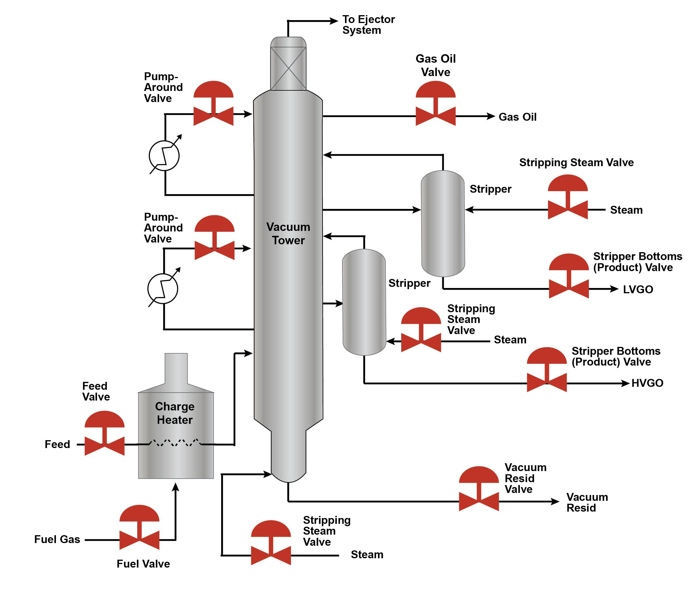
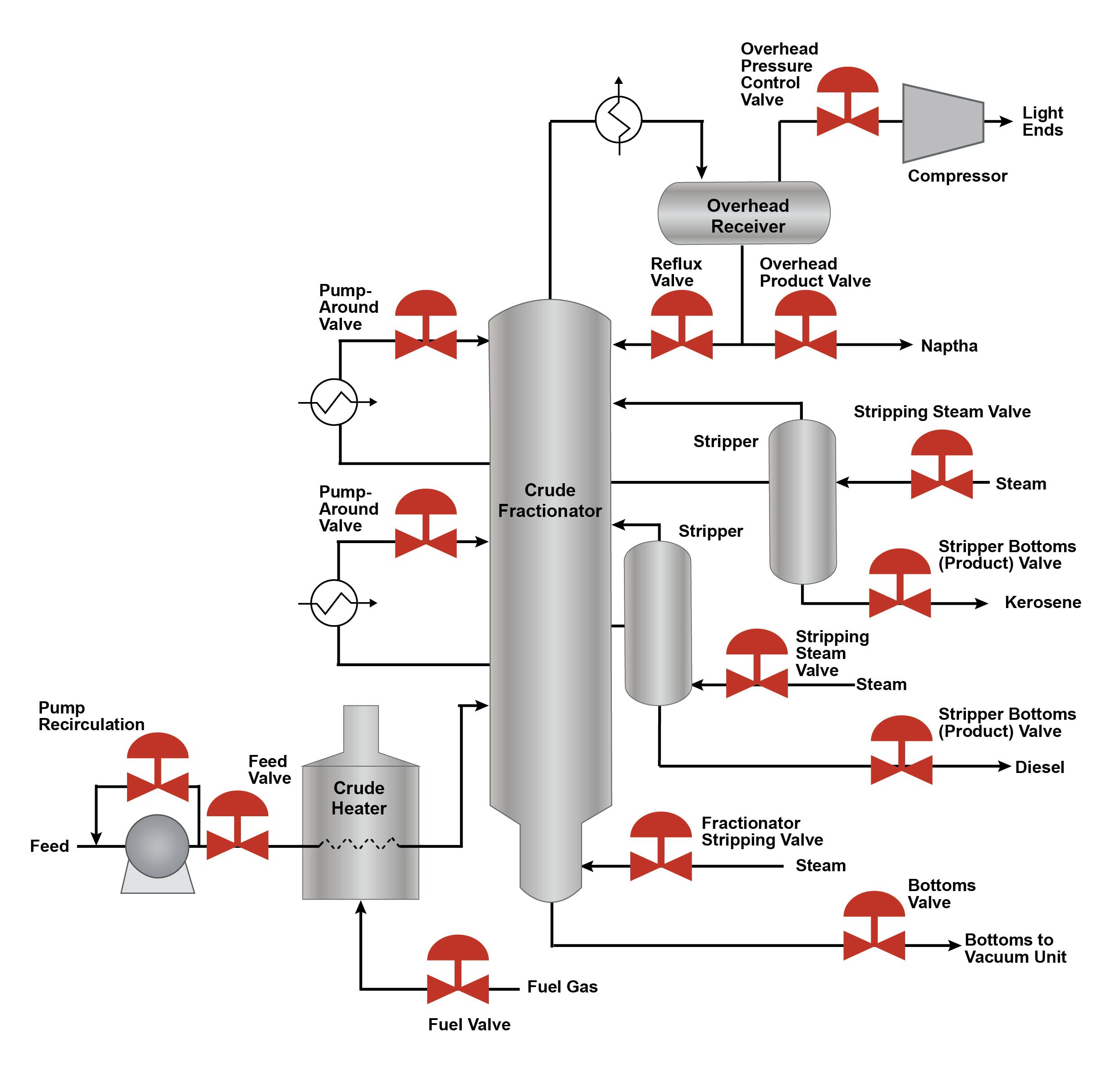
The other points to consider are trim components that are in close tolerance to one another. Thermal expansion can occur, thus causing dissimilar parts to expand at varying rates. This can lead to galling of internal valve parts, excessive wear, and irreversible damage, compromising valve function. Lastly, high temperature affects the packing materials being used. The bonnet length and temperature limits of a valve should be considered. Bonnet length is important as it creates a barrier between the control valve packing and process fluid. If the fluid exceeds the packing temperature rating, then the packing can be compromised and fail, leading to process leaks and fugitive emissions.
While the pressures are not significant by control valve standards, the media contains a number of hydrocarbon components with different vapour pressures, which can lead to flashing. Flashing

Save time and cost by changing control valve quickly with a single seat ring versus a plug seat ring, bonnet gasket and seat gasket with a globe valve.
~50% lighter weight than same size globe valve and an average of 30% more capacity to meet increased demand in throughput.
Erosive and cavitation resistant design with lower friction and higher precision up to 750°F.
One less leak path utilizing an integral bonnet to reduce the chance of emission(1).
(1) As compared to conventional reciprocating valves

For more information, contact your local Baker Hughes representative or visit valves.bakerhughes.com
© Copyright Baker Hughes company. All rights reserved

occurs when a process fluid in liquid form converts to gaseous form when it drops below its vapour pressure as it passes through the vena contracta and remains in gaseous form. The expansion of gas and the high velocity with which the remaining fluids and particulates are carried in the direction of metal boundaries can erode and damage anything in its path. Depending on the valve style and where the vena contracta occurs, this could mean erosion in the body and/or valve components. Valve geometry and metallurgy must be considered in order to extend valve life. It is always good to check any downstream piping, such as elbows, or other equipment that can be affected.
The elimination of fugitive emissions is becoming a standard in many refineries, especially with federal agencies monitoring, and most plants now impose a less than 100 ppm standard. As a result, choosing the right fugitive emission packing for temperature, pressure and plant specifications is a requirement. ISO 15848-1 certifies packing by cycles, leakage, and the temperature that a valve can maintain over time. This is a common certification that is accepted by most customers.
For these severe process conditions, a control valve such as the MasoneilanTM CamflexTM is an excellent solution for several reasons.
The simple design allows the plug to move away from the seat when the valve opens, eliminating contact until the valve closes. This means less potential for erosion and wear between the plug and the seat. The valve geometry is straight through, so there are no tortuous paths for points of impingement and wear in the body. Unlike other rotary solutions, the Camflex can be sized with reduced trim to position the plug open and further away from the seat. This helps to prevent throttling too close to the seat. To further mitigate wear in the body, the Camflex can be configured for ‘flow to close’ so that the fluid passes through the body and the pressure drops outside of the body, allowing for a higher velocity and for flashing to take place at the outlet of the body.
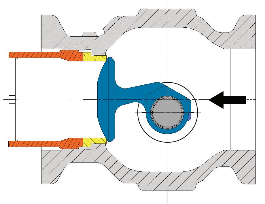
The Camflex has an extended retainer option to direct flashing downstream of the valve without any direct impingement on the valve surfaces. This protects the valve, as well as downstream piping. This extension can be manufactured from various materials based on customer requirements and best erosion resistance properties.
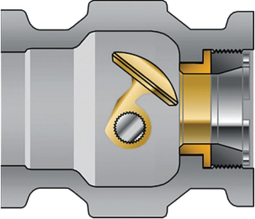
The EF seal design with double O-Ring sealed packing is designed into a single body and bonnet, allowing for a single leak path and better sealing rated to 750°F.
At half the size and half the weight of a traditional globe valve, the Camflex can go where many valves cannot. Its capacity is considerably larger than a globe valve at the same line size. Cost savings can be achieved by using smaller valves to maintain process efficiency with reduced piping stress.
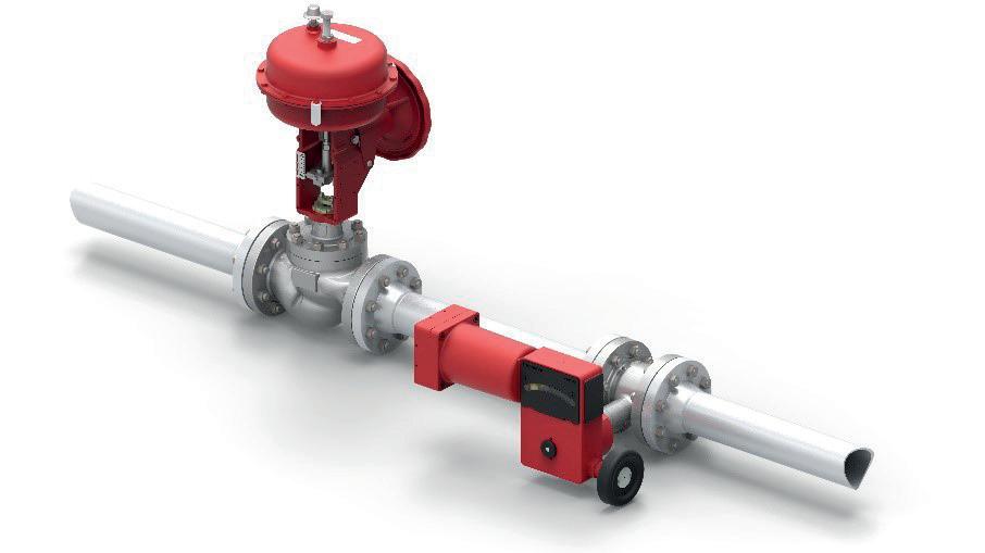
While the conditions are extreme in the crude unit, and there are many associated process challenges, efficiency and productivity can be maintained if proper consideration is taken for optimal valve selection.
FOR MAXIMIZING THE PRODUCTION OF PETROCHEMICALS FROM CRUDE OIL

CLG has more experience than any other licensor providing leading technologies, expertise, and innovative solutions for profitable residue upgrading projects. To get the performance and flexibility needed to keep pace with changing market dynamics, start by visiting www.chevronlummus.com


The LNG industry is relatively new; it is roughly 50 years old, but is one of the fastest growing segments of the global energy industry. The LNG process chain is complex and diverse, comprising a number of different processes – from extraction, liquefaction and transport, through to consumption. To ensure the safety of these processes, pressure relief devices such as safety valves and rupture

discs are required at various points along the LNG process chain to ensure that there are no serious accidents caused by overpressure.
A safety valve is a spring-loaded pressure relief valve (PRV) actuated by the static pressure upstream of the valve. A rupture disc is a non-reclosing pressure relief device activated by static differential pressure between the inlet and outlet of the device. 1, 2 Both safety valves
and rupture discs are possible solutions to the problem of overpressure in LNG processes, but each device has benefits and disadvantages. They are used separately or in combination, depending on the specific requirements of the process.
Safety valves are widely used within LNG trains for overpressure protection. However, PRVs can quickly reach their limits, particularly where there are major requirements in terms of tightness, or if the medium used is viscous, sticky or freezing. Additionally, each PRV has a certain level of leakage. Seat tightness requirements are defined in API 527 3 , in which the acceptance criteria allows for a certain number of bubbles, i.e., some level of leakage during normal
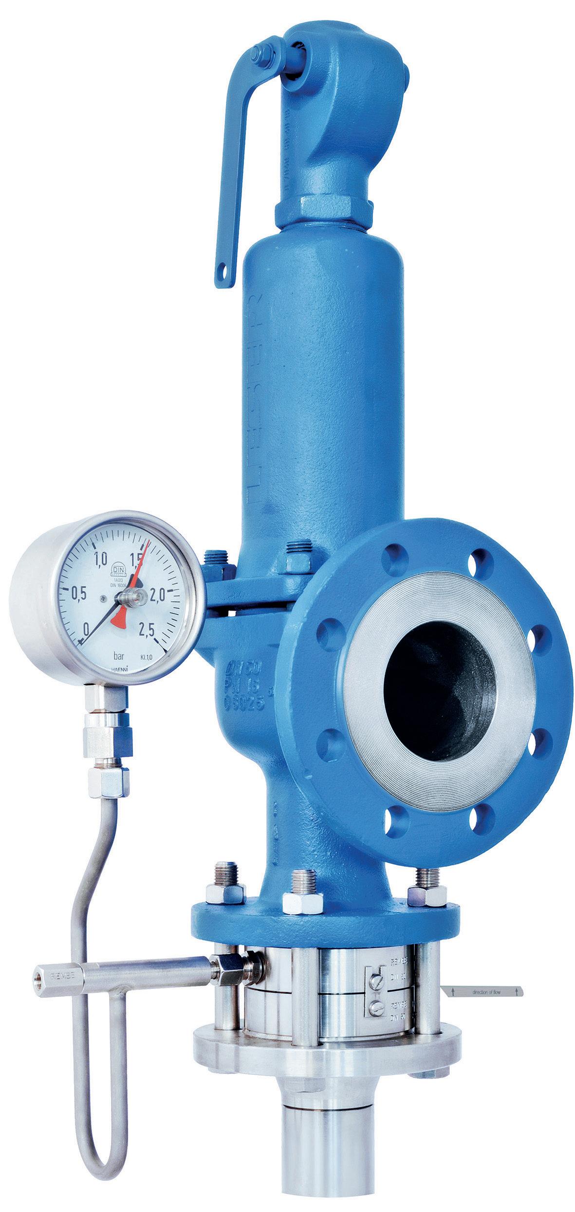
operation. It has to be considered that these leakage rates are established on a brand-new valve in a controlled factory environment.
A solution involving an upstream rupture disc unites the benefits of both devices. This arrangement is called a combination device, as per EN ISO 4126-3. 4 The combination is a reasonable and, above all, economic solution for a wide range of applications, for the following reasons:
n It is capable of 100% isolation of process fluids; there are no leaks until the disc opens.
n There is no product loss during normal operation, as the rupture disc is leak-tight.
n Prevention of rogue emissions.
n Isolation of PRVs from corrosive process media, with the benefits of substantial costs savings on PRV materials, and reduction of regular PRV maintenance costs.
n Prevention of PRV blockage.
n It can be used to pop test the PRV in situ; there is no need for removal of the PRV for testing in a maintenance workshop.
Based on these technical and economic benefits, the use of combination devices is recommended by the current codes and standards, and this approach is being applied to a growing number of applications and processes.
A typical application within an LNG process where a rupture disc is commonly found is in front of safety valves on the vaporisers in the regasification plant. However, as such processes frequently run on a duty, standby and redundancy basis (three sets) 5 , and as there are many on each asset, contractors, engineers and original equipment manufacturers (OEMs) often opt for less advanced, cross-scored, forward-acting rupture discs, predominantly due to their lower cost. Additionally, the effect of back pressure from adjacent relief and flare streams on the rupture discs can be ignored. As end users require ever-growing output, they process higher volumes with existing assets – to the point where the cycling and operating pressures increase, pushing the installed rupture discs beyond their operating limits. Ultimately, the rupture discs can fatigue, and fail prematurely.
To avoid this unnecessary, premature failure, rupture discs with a long lifetime are recommended. Reverse-acting, robust discs, such as REMBE’s KUB, provide longer-term cost benefits. This is one of the only rupture discs to be manufactured using Euler’s critical load formula to determine the burst pressure. As there is no specific weak point on the material, as with a cross-scored disc, the KUB is an extremely robust solution.
The disc is almost immune to damage caused by improper installation or handling, maximising its lifespan. The unique structure of the disc also ensures that it can withstand a high level of back pressure,

Want reactor performance that hits the mark time after time? Team up with Crystaphase and we can help you nail it.

We’ve got advanced filtration technology proven in some of the world’s toughest applications, and industry-leading analysts who are in it to win it with you. Game on.

without causing any damage to the disc. With an operating ratio of up to 98%, the KUB is not subject to fatigue, even at high operating ratios, and its non-fragmenting design is well-suited to direct installation in front of a safety valve.
Monitoring can also be used to report when the disc has ruptured. Conventional signalling devices require cables to be mounted on the rupture disc, which must then be routed out through the rupture disc holder. REMBE’s NIMU has a signal indicator attached to the rupture disc during the manufacturing process. The actual sensor is screwed into a blind tapping in the rupture disc holder, where it monitors the position of the signal indicator on the rupture disc. This means that the wiring only starts outside the rupture disc holder.
After an overpressure event, the outlet of the rupture disc holder must be removed, the rupture disc replaced, and the system placed back into operation. The days where the signalling cables also had to be routed to the respective switching box are now over.
The process is absolutely leak-tight. The blind tapping in the holder replaces the tapping that is usually required. The absence of cable glands means that they cannot become porous, thus preventing an escape of the process media.
End users now have access to an engineered solution that offers maximum vessel and personnel protection. The choice of the correct disc design and material leads to increased service life, with the elimination of requirements for frequent shutdowns for periodic maintenance. The user can profit from substantially reduced CAPEX and associated installation costs by using these rupture discs, as well as a reduction of overall emissions.
Another application whereby rupture discs are used rather than safety valves within the LNG process is to protect the compressors. Due to their compact, reliable design, centrifugal compressors are often used for the
offshore liquefaction process. Such turbomachinery utilises a dry gas seal, which uses clean gas under pressure on the external side of the seal, so that any leakage through the seal is the buffer gas into the compressor.
An important component of a dry gas seal is the vent system. For the primary vent system, a rupture disc is typically installed in parallel with the vent line to rupture at a set pressure and prevent excessive pressure to instruments on a primary seal failure. A signalling system on the primary vent system is recommended to enable integrity checks while the seal system is still online.
Customers using dry gas seals require rupture discs to be installed to vent excess pressure in the event that a catastrophic failure of the primary seal occurs. 6 If pressure ever increases beyond its predetermined limit, a higher gas flow or back pressure in the piping system is present and needs to be safely vented. A signalling device is also required to detect a change in the rupture discs’ status in order to initiate a shutdown of the process in the event of overpressure.
REMBE’s rupture disc, IKB, which has integrated signalling, is a cost-effective, reverse-acting rupture disc with an integrated polyamide signalling device that is suitable for the demanding conditions found in dry gas seal applications. Used extensively in oil and gas projects, the IKB is the only reverse-acting rupture disc to be manufactured using REMBE’s Contour Precision Lasering (CPL TM ) technology, ensuring high-quality, accurate, burst control even in the harshest of environments. The integrated signalling device ensures that operators are immediately informed that the disc has burst and can replace it. It is physically possible to restart the compressor with the damaged rupture disc in place, which is why it is critical that signalling is used to alert operators to the fact that the disc has burst.
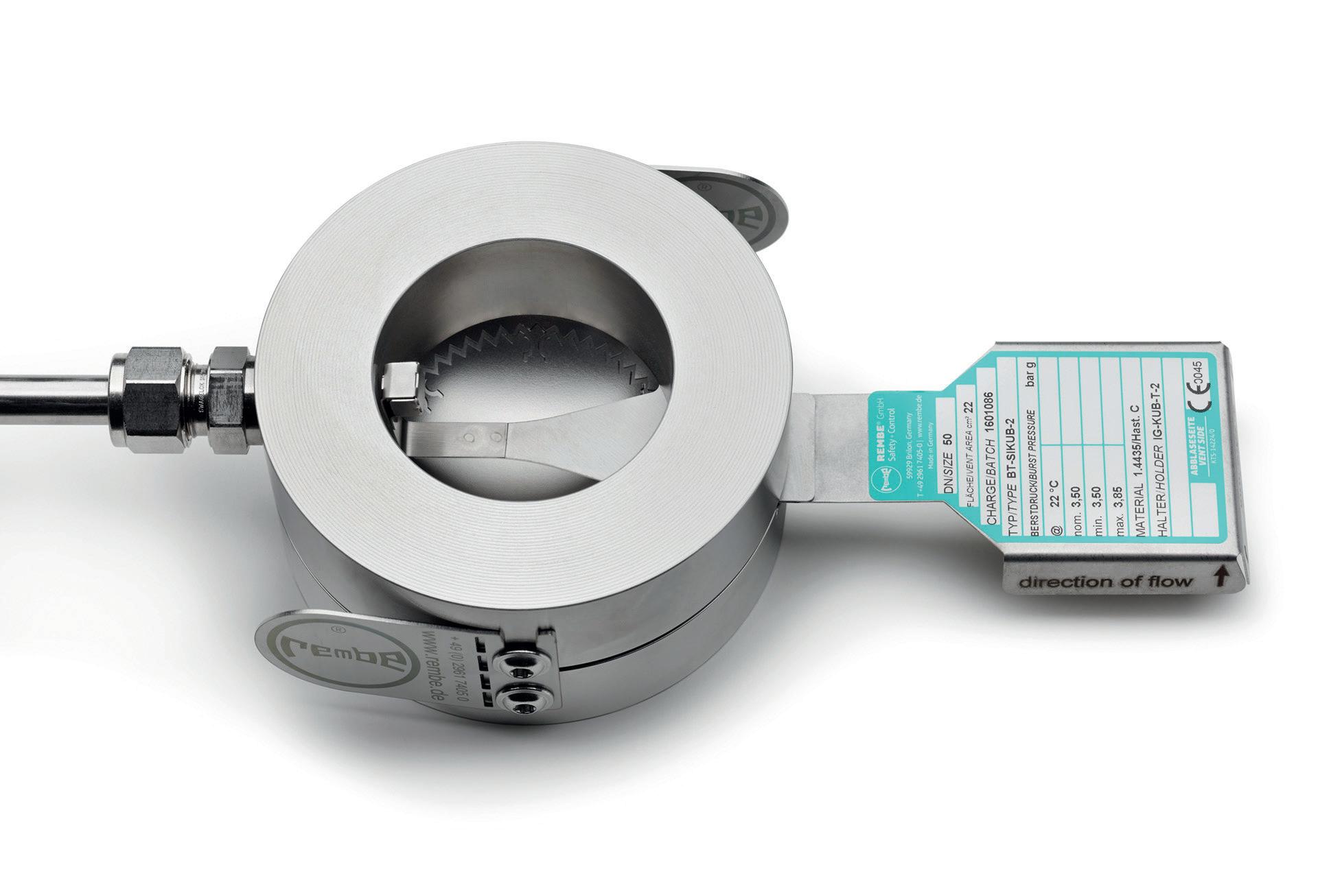
This article has only discussed two examples of how rupture discs are used within the LNG sector. However, there are many other examples of their utility – from the protection of heat exchangers, to use within cryogenic storage tanks. As LNG production is expected to double over the next two decades, with the US, Canada, Russia and Australia leading the development of global projects, it will become increasingly important for those involved in LNG contracts to understand the best and safest way to protect their processes.
1. API 520 – Part 1 Sizing, Selection and Installation of Pressure relieving Devices, 9 th Edition, (July 2014).
2. ASME Boiler and Pressure Vessel Code, Sec. VIII Div. 1, (2015).
3. API 527 Seat Tightness of Pressure Relief Valves, 4 th Edition, (November 2014).
4. EN ISO 4126 -3:2006 Safety devices for protection against excessive pressure - Part 3: Safety valves and bursting disc safety devices in combination.
5. API Standard 521 Pressure-relieving and Depressuring Systems, 6 th Edition, (January 2014).
6. STAHLEY, J. S., ‘Dry Gas Seal System Design Standards for Centrifugal Compressor Applications’, (2002).
Tank cleaning demands efficient and reliable methods and technology. Inefficient cleaning can result in product contamination, as well as loss of man hours and revenue. The cost of failure can be enormous, so operators of oil refineries and tank farms can be highly reluctant to consider innovative but more efficient methods of cleaning.

Historically, the oil and gas sector has been more risk averse and slow to adopt change than many other sectors. However, no man entry tank cleaning offers stakeholders a viable alternative.
Using remote-controlled autonomous robotic tank cleaning systems reduces water and energy consumption, chemical usage, and completion time, without compromising overall cleaning effectiveness. A sound understanding of these cost-effective solutions, and optimisation of each of the elements during cleaning, will generally increase the overall efficiency of the tank clean and reduce its associated costs.
A critical consideration to achieve an effective tank clean is the mode of cleaning and the dislodgement and disposal or reclamation of sludge and debris. The pressure of the wash fluid from the cleaning nozzles is vital for an efficient clean, and the power of the ADR tanker suction can cut the cleaning time by more than half.
Industry players are now being convinced of the financial viability of no man entry tank cleaning
services, and are adopting them rapidly. A core part of this technique’s success is the fact that it allows customers to minimise cost for cleaning because the tank is turned around quickly and more efficiently.
It should also be obvious how a reduction in the time spent physically cleaning the tank consequently reduces water consumption. The shorter the cleaning cycle, the less water will be used. Reducing water usage is a key driver for many businesses because it is an easy way to measure efficiency.
The cost of using water is often underappreciated. Each cubic metre of water used represents a raw utility bill, and there are costs associated with filtering and sanitising recycling sludge. If terminal operators can reduce water usage in tank cleans, they can lower pump running costs (electricity), lower maintenance costs, and generate a longer lifetime for the pump and its parts.
As the cost of energy and water are both increasing, and likely to continue in that direction, reductions in water usage have significant financial benefits for any operator. Additionally, the environmental benefits of using less water can only be good for an organisation’s environmental, social and governance (ESG) credentials.
Time is also money, so the time spent on maintenance and cleaning, whilst necessary, nevertheless represents tank downtime. This is time that the tank cannot be used for storing product, and the cost associated with this downtime can vary greatly depending on the function and product stored, but in almost all cases a reduction in tank cleaning time will have a direct financial benefit.
What terminal operators are looking for is a tank cleaning solution that instills confidence in the safety and compliance in the integrity of their assets, as well as a reduction of costs and risks. This can be achieved by using a trusted, sustainable solution for no man entry tank cleaning. It takes approximately two hours for a robot to enter a tank, from the time that it arrives onsite, and so the job can be carried out up to 60% faster in comparison to traditional methods.
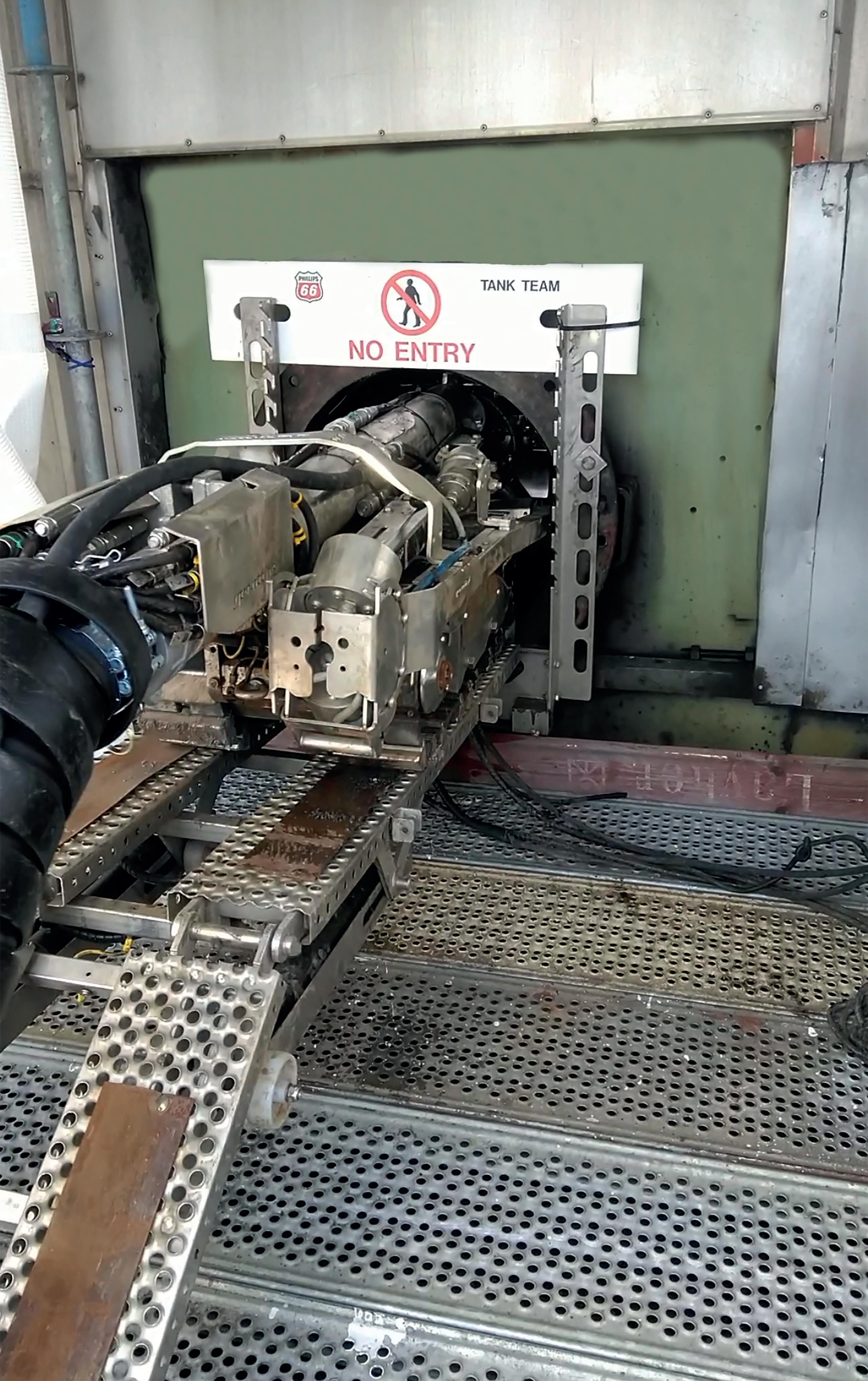
The substantial reduction in downtime of tanks leads to increased efficiencies for the client. The robotic cleaning system helps ensure production does not slow, as tanks are ready up to 50% faster than if human cleaning crews were to be used. This approach has moved the sector on from dangerous, outdated and time-consuming processes, enabling oil terminal operators to safely and efficiently manage tank cleaning schedules.
During the performance of all tank cleaning operations, generated waste material is either treated and returned to the tank or transported from the site using an ADR tanker and is safely treated in an authorised, licensed facility.
No man entry can be used for every tank design and type of material: crude, petrochemical, black oil and white oil. The following case studies demonstrate the variety of tanks and materials that Re-Gen Robotics can
clean, and details the challenges encountered, solutions implemented, and benefits conveyed.
Re-Gen Robotics was commissioned by Shell UK Oil Products Ltd to clean two 30 m floating roof, Jet A-1 fuel storage tanks at the Shell Haven terminal.
Both tanks had a resin lining applied to the floor and 1 m up the tank walls.
Magnetic tracks were removed from service for lined tanks and plain rubber tracks were fitted to the robot to protect the resin flooring. The following is an outline of the process:

n 12 – 14 t of sludge removed from each tank.
n Number of man hours eliminated onsite: 448 hours per tank.
n Number of robotic hours onsite: robot crew = 90 hours per tank.
n 2 t of water utilised for each tank.
n Difference of hours it would have taken a manned clean: confined space entry (CSE) clean would have taken eight days; a robotic clean took three days.
n Less paperwork and fewer permits necessary: medium risk contractor.
n No requirement to spade tanks.
n No requirement for capital outlay: scaffolding, cranage and vacuum jetting provided.
n No requirement for standby rescue team.
Overall feedback from Shell was very positive. These were the first tanks to be completely cleaned and inspected by Shell, worldwide, without the need for human presence in the tanks. Following this initial project, Re-Gen Robotics has been commissioned to clean more tanks at the terminal. Shell committed to end manned tank cleaning across its operations by the end of 2022.
Re-Gen Robotics was commissioned to clean three 15 m tanks at a gas terminal, which refines and purifies gas from a gas field on the west coast of Ireland. The first tank scheduled to be cleaned contained methanol, and the remaining tanks contained condensate – a low-density mixture of hydrocarbon liquids present as gaseous components in raw natural gas.
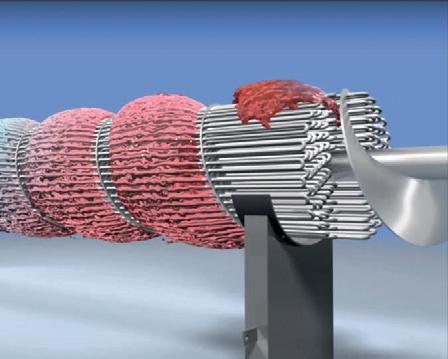

n Tanks were resin lined.
n Tanks contained a large amount of internal furniture including aluminium legs, skim arms and floating pontoons.
n Entry manholes were raised slightly higher than standard tanks and there was a great deal of piping situated on the ground around the tanks’ exteriors.
n Initial inspection verified that the height of the tank was considerably lower than most tanks, and that it would therefore be necessary to restrict the height of the telescopic camera bracket.
n Plain rubber tracks were fitted to the robot to protect the resin flooring.
n An offset suction head was deployed to clean around heating coils.
n The low-profile tool can access under pipes and has the ability to remove waste from below floor level. It can operate offset on the left, right and straightahead positions. This tool alone can decrease tank cleaning time by 10 – 12%.
n It was noted that a portable raised platform would be required to allow the robot to pass freely over the exterior pipework, to meet the manhole entry ramp. The platform was supplied by the client and was also used for the second tank clean.
n Arrangements were immediately put in place to fit rubber stoppers around the ATEX camera and restrict the height of the camera bracket with a length of chain.
The following is an outline of the process:
n 7 t of sludge removed from each tank.
n Number of man hours eliminated onsite: 280 hours per tank.
n Number of robotic crew hours onsite: 45 hours per tank.
n 1.5 t of water utilised for each tank.
n Difference of hours it would have taken a manned clean: CSE clean would have taken five days; the robotic clean took just one and a half days.
n Less paperwork and fewer permits necessary: medium risk contractor.
n No requirement to spade tanks.
n No requirement for capital outlay: scaffolding, cranage and vacuum jetting provided.
n No requirement for standby rescue team.
The speed and efficiency of the tank cleans exceeded Vermilion’s expectations, by finishing ahead of schedule and by significantly reducing the amount of tank downtime. Re-Gen Robotics continues to clean tanks for Vermilion.
Re-Gen Robotics carried out the first no man entry crude oil tank clean for Phillips 66 Ltd’s Humber refinery. Some 20% of all UK petroleum products come from this refinery, and Re-Gen Robotics was
commissioned to clean a 50 m fixed roof, cone-up floor crude oil (black) tank.
n Exact tank furniture details and volume of sludge were unspecified. The volume of waste inside the tank was understood to be approximately 135 t, and the product temperature was ambient.
n The tank had numerous steam coils which the robot was required to navigate around.
n The robot is fully submersible and has an auger system located at the front which breaks down heavy sludge, without the requirement to use water, thereby generating less waste. The sludge was then extracted by an ADR-certified jet/vacuum tanker with a 4800 m 3 /hr vacuum capacity.
n The robot uses an offset suction head to clean around heating coils. The low-profile tool can access under pipes and has the ability to remove waste from below floor level. It can operate offset on the left, right and straightahead positions. This tool alone can decrease tank cleaning time by 10 – 12%.
The following is an outline of the process:
n 536 t of sludge removed from tank.
n Number of man hours eliminated onsite: 12 160 hours.
n Number of robotic crew hours onsite: 1520 hours.
n 92 t of water utilised.
n Difference of hours it would have taken a manned clean: a six-man CSE clean would have taken 95 days, whereas a robotic clean took 43 days.
n Less paperwork and permits necessary: medium risk contractor.
n No requirement to spade tanks.
n No requirement for capital outlay: scaffolding, cranage and vacuum jetting provided.
n No requirement for standby rescue team.
Phillips 66 acknowledged the success of the no man entry tank clean because the system could be adapted to suit the company’s individual needs and timeframes. Following the initial contract, Re-Gen Robotics was commissioned to clean a further three tanks at the site.
Terminal operators are increasingly realising the benefits of using no man entry robotic tank cleaning to tackle their oil tanks. The service provided by Re-Gen Robotics is straightforward and transparent. Any challenges that arise are dealt with swiftly, with the appreciation that the efficiency of the clean is crucial to planning schedules so that the tanks can be brought back into operation within agreed timeframes.
Due to the processing, refining or storage of hydrocarbons, downstream and midstream facilities can produce a complex range of fire and explosion hazards. As such, it is important to define the hazard, quantify the risk, and implement the mitigation.
The design, specification, and installation of passive fire protection (PFP) materials, specifically those applied to safety-critical elements such as structural steel to
address hazards in the processing industry, are not novel. De facto approaches using prescriptive single protection thicknesses for hydrocarbon pool (ANSI/UL 1709) fire loads often lead to unnecessary cost or, in some instances, increased risk. Would it surprise you that according to research data, 98% of megaprojects experience cost overruns or delays?
What is astonishing is that the average cost increase is 80% of the original financial investment decision (FID),

and the average slippage is 20 months. Significant improvements in concept and design planning have gone some way towards improving inefficiencies. Furthermore, modularisation and optimised engineering processes in the pre-construction phases have improved execution and delivery. The question to ask is: do you consider PFP during the pre-construction phase? And is applying PFP to structural steel elements a critical path activity from an execution and delivery perspective? There is no wrong answer, but consider this: if you could apply less PFP material and improve throughput from the shipyard or fabrication shop to the project without compromising risk or performance, would you consider it?
To reiterate, globally-adopted practices infer PFP protection thickness using a single thickness approach based on the section factor ratio of Hp/A 160 (W/D of 0.84). This universal thickness approach makes no allowance for the heat sync response of the structural steel whatsoever. It directly contributes to the under or, in most cases, over-usage of PFP materials. In an overused scenario, there is a connection between overspending, schedule overrun, commission delays, and
additional unintended consequences such as premature material fatigue, which include significant challenges in their initial pre-service life implementation and post-in-service performance.
In some instances, the design and implementation of PFP material approaches to address credible hazards may be inefficient. There is built-in risk aversion here which, while understandable, has led to implementations that are far too generic in some cases, especially in the last few years. While comprehensive in general, industry-wide recommended practices do not provide the engineer, designer or facility operator with the specificity needed to support the most efficient approach.
The nature of such approaches simply highlights that efforts to address and mitigate risk inadvertently create more, with unintended consequences. To remedy this, the following needs to be considered systematically during the FEED and pre-construction stages of any project:
n What needs to be protected?
n What are the credible threats, probability and severity of release events?
§ Pre-fire durability.
§ Pressurised releases (hydrocarbon jet accidental load).
§ Non-pressurised releases (hydrocarbon pool accidental load).
n What PFP systems or safe practices can optimise the mitigation of credible threats?
§ Layout.
§ Member shape and sizing.
§ Multi-temperature and multi-section assessments.
§ Redundancy analysis.
n What is the impact of global warming potential on PFP system selection, and how will optimisation efforts contribute to a carbon-neutral future?
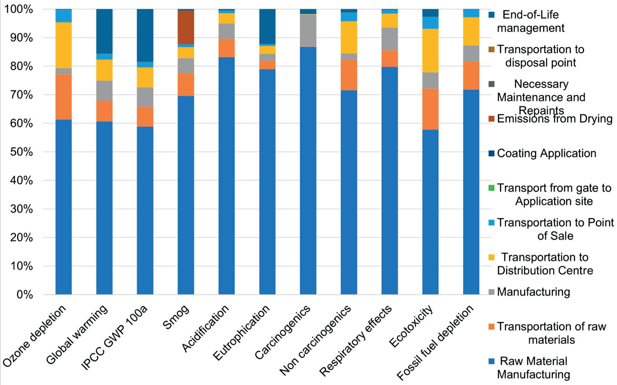
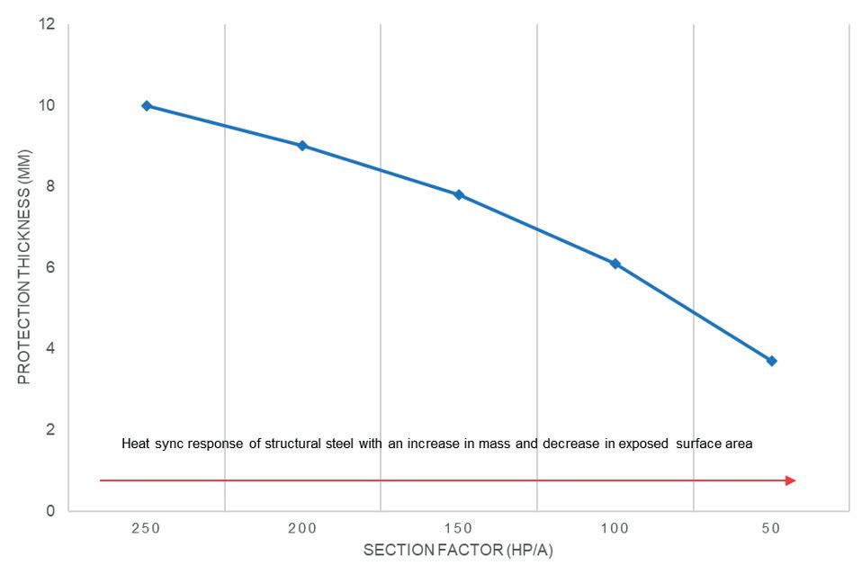
The versatility of structural steel based on its geometry, heated perimeter and volume will provide the means to optimise protection thickness for accidental design loads based on section factor ratios, striking the right balance between risk, cost, waste and productivity to provide the optimum solution to address the credible hazard(s). This is best illustrated in Figure 1.
The concept of section factor is the key to implementing protection thicknesses based on multi-section assessment certification. Section factor ratio is a measure of the rate at which a steel section will heat up with energy. A steel section with a large surface area (A) will receive more heat than a smaller surface area. Also, the greater the section volume (V), the greater the heat sync.
Multi-section assessments exist and can be found in third-party certification
Field-proven success has made our solid ring technology standard in all new units and upgrades. Join the thousands of compressors already operating sustainably at less than .75 scfm per throw.

directories. The assessment method is recognised in the latest ANSI/UL 1709 test standard, and has been adopted by multiple global projects. The protection thickness tables in the certification outline the required thickness vs section factor ratio and critical limiting temperature. There is no guesswork required.
Although some improvements in this area have been made, particularly in implementing material solutions with functional testing and related in-service performance through legacy installations, there is still work to do. The key lies in this: while testing and development are crucial, and continue to evolve, much has been learned in the last decade – particularly from what failed. These learnings must be adequately captured and shared before seeking to design and implement better solutions than in the past.
There is a second piece to implementing PFP strategies using section factor ratios and multi-section assessment data, reducing embodied carbon emissions for produced and installed PFP materials.
Is it possible to elevate safety considerations using optimised approaches to reduce the energy and carbon emissions associated with raw material acquisition, transportation, and manufacturing processes for PFP materials and systems? Should owner-operators and materials engineers use this philosophy to assess and make material selection considerations based on the environmental impact of PFP materials used to protect modules, sections, divisions or structural supports, in addition to current material selection methods?
To set and define measurable goals for a carbon-neutral future, the total global warming potential for indirect and direct emissions must be quantified. The last several years have focused heavily on Scope 1 and 2 emissions, which can be considered operational and measurable. More recently, there has been an additional emphasis on Scope 3 emissions relating to global warming potential, referred to as the embodied carbon content, expressed in carbon dioxide (CO 2 ) equivalent units for materials manufactured and installed in upstream and downstream facilities, including PFP.
The displayed carbon content for materials, including PFP, is best represented in a Type III Environmental
The Life Cycle Analysis will disclose the environmental performance (see Figure 2) of products that can then be promulgated to a third-party Environmental Product Declaration (EPD), and may not constitute a claim of ecological superiority from one product to the next. Still, it may assist with capturing and quantifying the global warming potential and provide a means for the contract chain to evaluate and implement safe, sustainable and optimised material approaches that can, in part, contribute to the carbon-neutral goals implemented by operators.
To best illustrate the effectiveness in combination with section factor ratio, corresponding thickness, and global warming potential, the example in Figure 3 serves as an indicator of what can be achieved by adopting environmental impact philosophies during material selection.
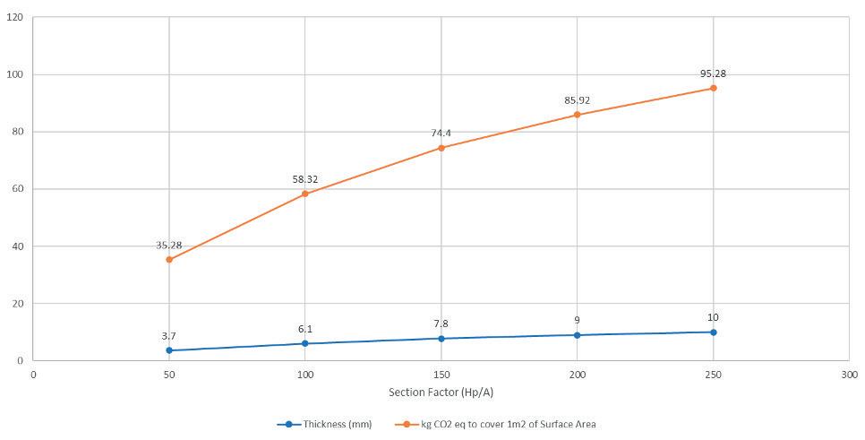
Consider the global warming impact on having to protect, for example, 10 000 m 2 of surface area to mitigate the credible risk of a pool fire accidental load for 120 minutes. The universal approach in this specific example will lead to ~744 000 kg of CO 2 equivalent units on a cradle-to-grave basis, assuming a functional unit of 1 m 2 of the covered and protected substrate at the universal single protection thickness for a reference service life of 60 years. Now ask yourself, what if, during the pre-construction phase, steel member sizes were iterated until suitable for load and acceptance criteria, resulting in a section factor of 100 Hp/A and a corresponding reduction in applied protection thickness? Would the reduction in protection thickness and the significant reduction in mass of CO 2 equivalent units provide value?
Value, in this sense, is equal to benefit over cost. Cost, in this instance, is less about monetary value and more about addressing a commitment to carbon-neutral goals. Although reducing emissions is not directly related to mitigating fire hazards, a systematic approach in defining risks and optimising the PFP material selection, as aforementioned, may result in less material being produced, manufactured and shipped, thus providing a sustainable approach that will reduce the risk of overspend, schedule overrun for a critical path activity, and install a degree of engineering practice to mitigation strategies.
The net benefits of implementing safe, optimised and sustainable PFP approaches are end-to-end transparency, consumer trust, and brand reputation. Anyone involved along the contract chain – not just the operator – can see the measurable and impactful difference resulting from one change in approach to the PFP philosophy. This single change can have a number of unintended positive and environmental impacts, without compromising on safety.

Ryan Ritz, Paratherm Heat Transfer Fluids, USA, details the impacts of thermal fluid degradation, and how this can be prevented.
Thermal fluids, also called heat transfer fluids (HTFs) or hot oils, have been widely used in liquid phase circulating systems to control process temperatures for decades. These systems are preferred because they are relatively low maintenance and provide consistent, efficient heating without generating high operating pressures. Continuous exposure to high temperatures means that thermal fluids will inevitably degrade over time, and their ability to effectively transfer heat will diminish as a result. The negative effects of this type of degradation are typically slow to transpire, often taking many months or even years before their impact on system performance becomes evident. Because of the low-maintenance ‘set it and forget it’ nature of these operating units, any build-up of degradation products can go completely unnoticed until a major failure occurs. Such failures are not inconsequential –from piping blockages and fluid leaks at a minimum, to complete system shutdowns, fires and bodily harm at
an extreme. This presents obvious challenges to the coveted values of predictability and damage control in plant maintenance operations.

To overcome these challenges, plant stakeholders need to prioritise gaining a greater upfront understanding of thermal fluid operations and the impacts of fluid degradation. What makes a thermal fluid uniquely capable of serving its purpose relative to any other industrial oils being used at the
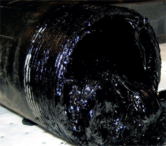
facility? How does fluid degradation occur? What are the products of degradation and where in the system are they most likely to be generated? How can we identify the occurrence of thermal breakdown and track its effect on fluid performance? A deeper appreciation of the what, how, where and when will create confidence in running an efficient, predictable heat transfer operation without diminishing the low maintenance advantages that these systems are designed to provide. With this goal in mind, this article will focus in on the critical aspects of thermal fluid degradation.
Thermal fluid degradation can be defined as the irreversible decomposition of a fluid as a result of thermal stress and/or prolonged contact with oxygen at elevated temperatures. Exposure to heat energy over time alters the inherent molecular structures of the fluid, ultimately resulting in substantial changes to its physical and physiochemical properties. The resulting accumulation of degradation products due to these reactions leads to critical disruptions in fluid performance, working life and equipment functionality. There are two main modes of fluid degradation: thermal cracking (overheating) and oxidation, both of which occur as reaction mechanisms and are therefore subject to the well-established principles of thermodynamics, reaction rates, and thermophysical property correlations.
The majority of industrial heat transfer products are formulated using hydrocarbon-based chemistries. Because degradation reactions occur at the molecular scale, it helps to understand the chemistry of the fluids from that perspective. Figure 1 provides visual representations of two common molecular structures seen in both natural organic hydrocarbon (mineral oil) and synthetic organic hydrocarbon (synthetic/aromatic) based thermal fluids. Specific molecular arrangements of the various hydrocarbon-based fluid types will determine performance, reaction dynamics, and degradation products.
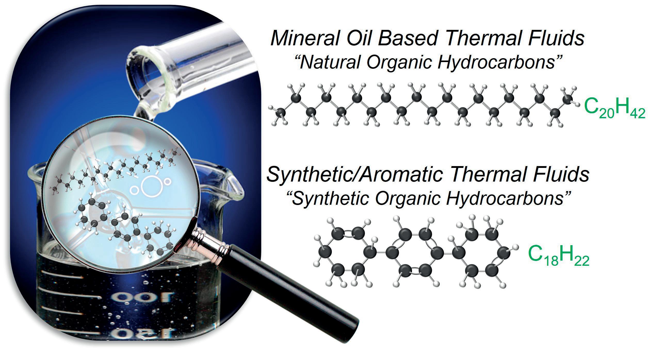
Mineral oil based thermal fluids (natural organic hydrocarbons) are a product of petroleum distillation and are made up of a ratio of refined alkanes (paraffins) and cycloalkanes (naphthenes) with a targeted array of chain lengths and arrangements. To avoid confusion, Figure 1 is simply showcasing the alkane C20H42 as just one example of a hydrocarbon chain that could be found within the bulk distribution of a mineral oil fluid. Synthetic aromatic hydrocarbons are products of chemical synthesis, and feature ring structures with some degree of double bonding. The chemical composition of each fluid type can be directly correlated to how they will behave in a thermal operation –both in terms of performance, and the manner in which they will degrade.
Truly legitimate thermal fluids are specifically engineered to prioritise quality, heat transfer efficiency, and thermal stability. Impurities and/or superfluous additives will foul out when exposed to heat, and can catalyse degradation reactions. The selective balance of physical properties determines how efficient a fluid will be at transferring heat
energy from the heat source into the fluid, and then out into the operating units. Products formulated using a foundation of robust chemistries will be more resistant to thermal degradation at elevated temperatures.


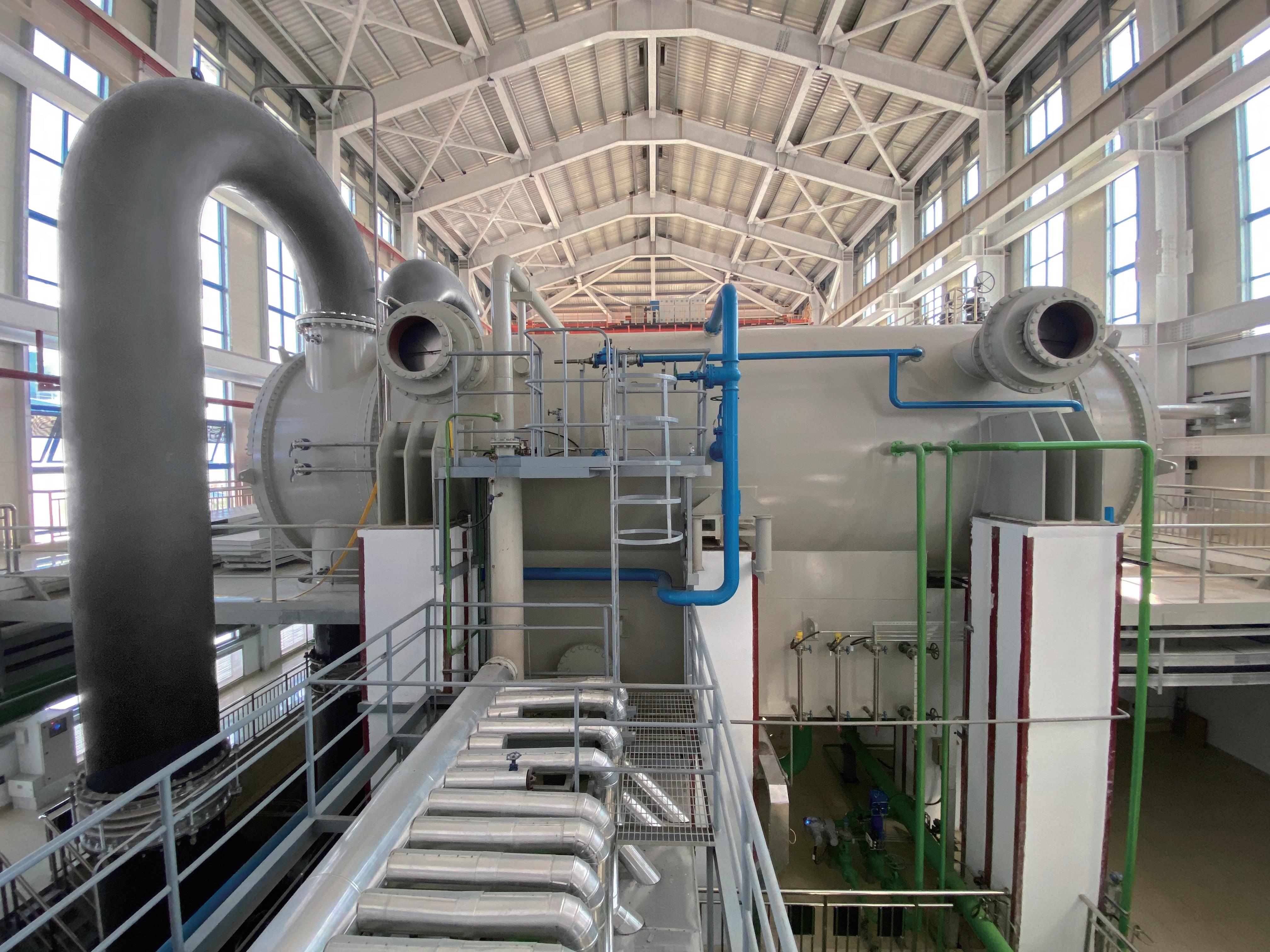
The degradation products that are most commonly generated as a result of thermal cracking and oxidation are the following:
n Low boilers: molecules generated when hydrocarbon chains are broken into smaller fractions that have boiling points lower than the original distribution of fluid molecules. An increase in low boilers generally results in decreased fluid viscosity.
n High boilers: molecules generated when hydrocarbon chains are broken and subsequently reacted with other
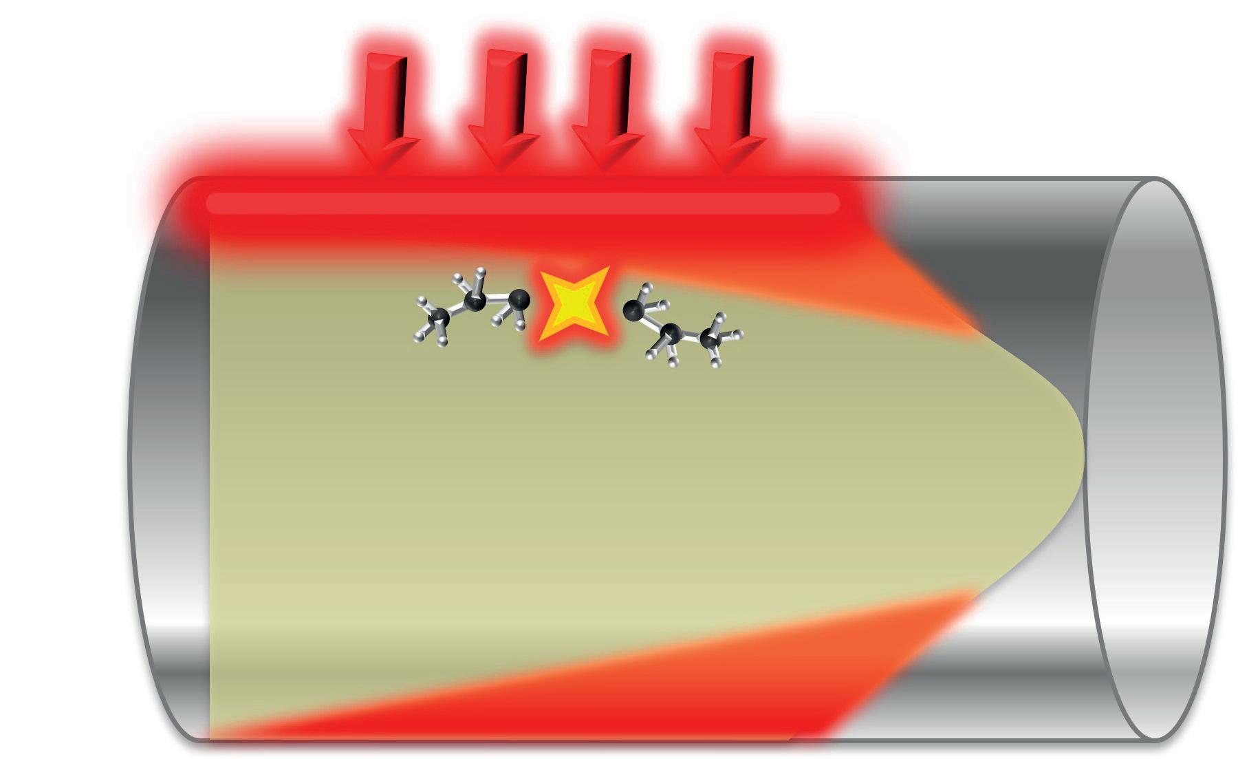 Figure 4. Degradation hot spot: thermal cracking at the fluid film layer.
and can cause pressure fluctuations, pump cavitations, and other operating challenges. Solids can block lines and foul equipment surfaces, creating an insulating layer between the heat source and the thermal fluid. Sludge and other high boiling materials will limit fluid flow, plug lines, and can completely solidify or ‘gel up’ when system temperatures drop. Degradation over time is inevitable, but understanding the factors that lead to more serious consequences helps to minimise the rate at which it happens.
At the most basic level, thermal fluids are designed to perform a somewhat complicated series of tasks. Energy in the form of heat is transferred from the heating source (fired heater, electric immersion element, etc.) through a conductive surface (i.e. the wall of a pipe coil) into the bulk fluid. The fluid then needs to hold onto that energy as it flows through the piping, until it reaches the operating unit and transfers the energy into the process.
Following the principles of the First Law of Thermodynamics, any heat energy that is not transferred out of the heater via bulk fluid movement to be consumed by the process application (or wasted out of a heat exhaust) will ultimately be consumed as energy to break fluid molecular bonds. This occurrence is known as thermal cracking or overheating of the fluid. The heat source is the area of highest energy concentration in the system and thus the primary area where
fluid is most prone to thermal cracking. More specifically, thermal cracking is prevalent at the ‘film layer’ where the thermal fluid is in contact with the heated surface (represented in Figure 4, as the inside wall of a heated pipe coil).
Not only is the film layer the area of highest heat flux, but it is also where the fluid friction is highest and flow is restricted the most. Turbulent fluid flow is critical to allow the fluid to ‘wash’ the heat energy away from the pipe, into the fluid, and out of the heater. Any factor that inhibits the fluid from effectively transferring the heat energy away from the heated surfaces will lead to some degree of localised thermal cracking. Examples of limiting factors can include insufficient fluid flow set points, poor heat transfer efficiency (inherent to a poorly designed thermal fluid or due to ongoing degradation altering original fluid properties), blocked lines, fouled transfer surfaces, and improper system start-up and shutdown procedures.
Using the previous example of C20H42 alkane representing a typical molecule in a basic paraffinic mineral oil thermal fluid, Figure 5 demonstrates that, as a result of overheating, the hydrocarbon chain is broken into smaller and smaller fractions, each with lower boiling points than the original molecule. The generated low boilers will continue to accumulate, and bulk fluid properties will change drastically as a result of cracking – diminishing heat transfer efficiency. This decrease in efficiency will eventually manifest itself as a loss of temperature output in the operation.
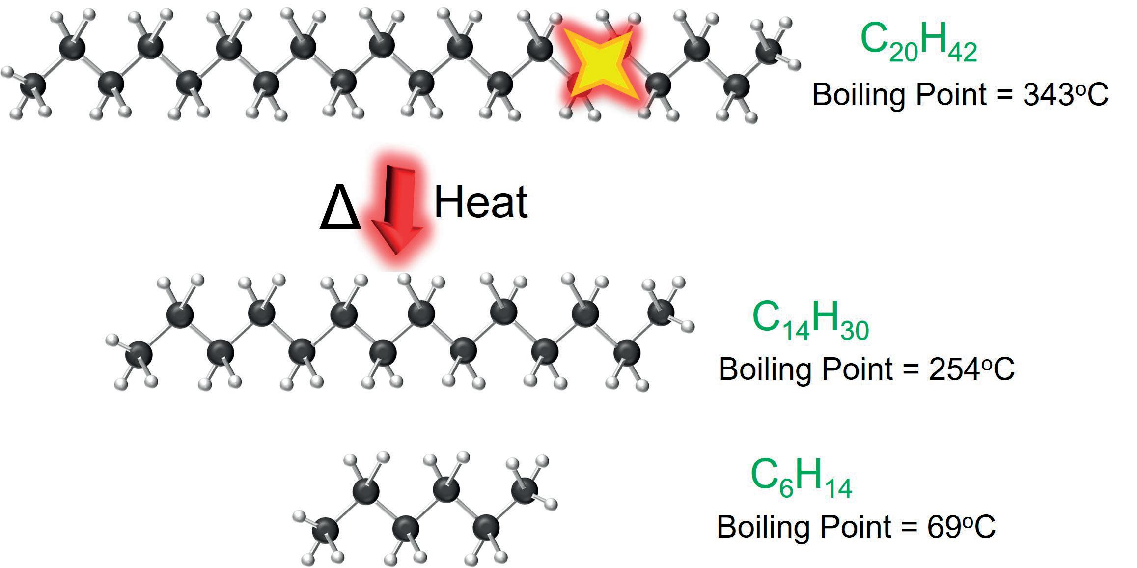
When this happens, the typical immediate reaction of a plant operator is to increase the heater outlet set point to compensate for the losses. This will only compound the problem and accelerate the degradation rate even more (the principles of the Arrhenius Equation apply to degradation, meaning every 10˚C increase in temperature doubles the rate of reaction). This downward spiral of events will continue to break down the fluid more and more, ultimately generating solid carbon and further compromising system functionality.
Focus on the factors: oxidation
Oxidation is a chemical reaction that occurs when heated thermal fluid is continuously exposed to fresh air. Heat energy initiates the breaking of hydrocarbon chains, making the molecules susceptible to further reaction. When in contact with fresh air at elevated temperatures, the degraded hydrocarbons react with oxygen molecules and other stable hydrocarbons to form a variety of new highly-reactive intermediates and byproducts. In a traditional thermal fluid system, the only area that creates the potential for these factors to come together is inside of the expansion tank (see Figure 6). Continued exposure to heat and air under these conditions will perpetuate chain reactions and result in the formation of acidic material (carboxylic acid).
These acids ultimately increase the viscosity of the bulk fluid, decrease the pH, and generate high boilers. The high-viscosity, acidic material can eventually combine with any fine carbon solids that are fouled out of the fluid, and create thermal fluid sludge. Referring back to Figure 3, the negative effects of accumulated sludge in the system become obvious due to the physical nature of this material.
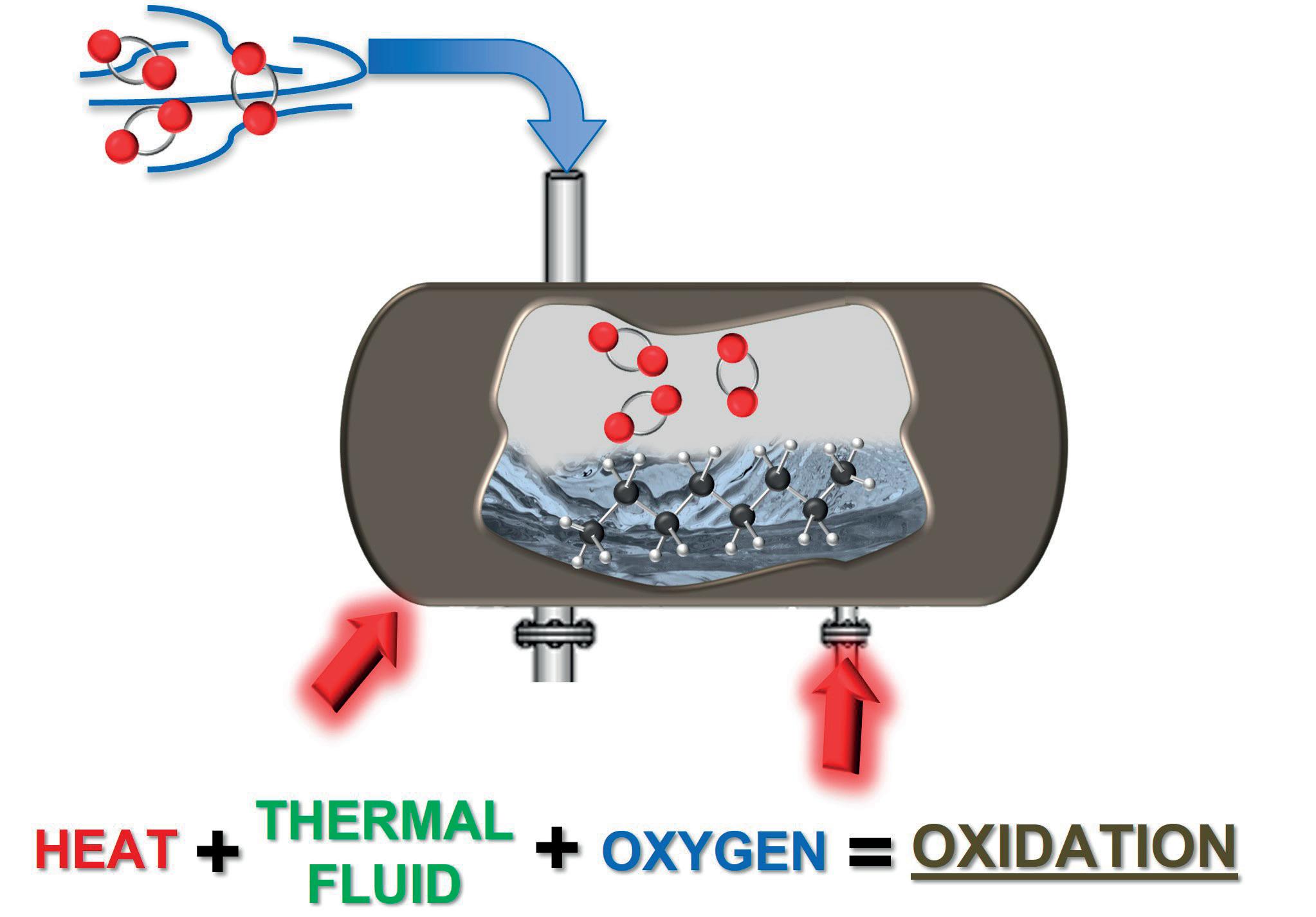


Decreased flow dynamics, plugged lines, system cold spots, and high potential for complete system shutdown and extensive maintenance procedures are common when unchecked oxidation reaches that extreme.

The purpose of this article was to offer a deeper understanding of how, where, when and why thermal degradation occurs. Fluid degradation over time is inevitable, but applying this knowledge to real-world operations limits the rate at which it happens, and significantly decreases the potential for unidentified issues to compound into a major failure. This knowledge is only effective if used to evolve approaches to running thermal fluid operations.
Knowing that chemistry matters, it is important to choose a fluid that is purposefully engineered to give the best combination of quality, efficiency and thermal stability. Thermal cracking at the heat source can be controlled by monitoring and maintaining design flow rates and temperature set points so that the maximum film temperature capability of the fluid is not exceeded. Fluid is most prone to overheating during system start-up and shutdown, so it is important to slowly ramp up system temperature set points until the fluid viscosity reaches a point where turbulent flow is possible (check with fluid suppliers for specifics on this). When shutting down a system, the system’s circulating pump should continue to run after the heater is shut off to remove residual heat from the
chamber. Otherwise, stagnant fluid will be left to ‘bake’ inside the pipe coils.
This article has taken a closer look at fluid oxidation, and examined exactly where it happens and under what conditions: thermal fluid + heat + air = oxidation. Additionally, it has discussed what thermal fluid sludge looks like and how detrimental it can be to a system. If the expansion tank is kept cool (ideally below 70˚C), oxidation reactions cannot be accelerated. One consideration could be purging the headspace in the expansion tank with an inert gas to eliminate the presence of oxygen, removing oxidation from the equation.
Operators should monitor the system, listen, look and make note of any red flags, and question changes in normal system operation, especially heat losses, pressure fluctuations and altered flow dynamics. Attempting to compensate for such changes with a simple temperature or flow adjustment will likely be a detrimental action (all it takes is a 10˚C increase in set point to double the rate of degradation). Find a testing laboratory partner that specialises in thermal fluids (as opposed to a standard lube oil analysis) and send fluid samples on an annual basis. This is the most effective way to catch the generation of degradation products early enough to make informed decisions to avoid major failures. Awareness is critical to maintaining an efficient, long-lasting and predictable thermal fluid operation, and it does not take much added effort to make a big difference.


Now in it’s 39th year, the event continues to be an essential annual forum for the global sulphur and acid community to learn, connect and do business.
You can expect an expanded market outlooks agenda, including expert insights from CRU’s analysis teams on major supply and demand markets, including sulphur, sulphuric acid and phosphates, plus additional industry updates from key players from across the supply chain.


The quality of the monitoring and diagnostics processes in the energy domain is affected by significant limitations. Specifically, the lack of automatic and reliable solutions for:
n Detecting anomalies before they evolve into failures.
n Providing sufficient prediction capability on the system’s performance.
n Accelerating the fault isolation process.
n Supporting maintenance plans.
These limitations are not strictly related to the energy domain; they also affect monitoring and diagnostics processes performed in the space and automotive domains. As a result, solutions that have been proved to

overcome these limitations in the space and automotive sectors can provide value to the oil and gas sector, particularly in the case of large hydrocarbon production processing and transportation facilities, or petrochemical plants.
This article will detail the results and achievements obtained by S.A.T.E. as a result of a technology transfer demonstration project, in which generic and transferrable data-driven and model-based approaches adopted in the space and automotive domains were successfully applied to real use cases in the energy domain, and encapsulated in a commercial solution.
The customer involved in this project is a well-known oil and gas company that provided real data for testing,
A. Brighenti, C. Brighenti, M. Ricatto and A. Zorzi, S.A.T.E. Systems and Advanced Technologies Engineering S.r.l., Italy, and D. Evans, ESA/ESOC, Germany, discuss the use of data-driven diagnostic solutions to improve maintenance in the energy sector.
the knowledge required for the validation of the results obtained, and a set of needs and requirements to be considered for the commercial solution. Throughout this article, the term ‘energy domain’ refers broadly to the whole chain of processes – from upstream to downstream facilities.
The following is a list of common problems that have been highlighted by experts involved in the reliability and control of complex systems in the energy domain:
n Operators may be affected by overload and potential stress due to the many signals that could be the symptoms of anomalies. These anomalies can be hidden behind thresholds, for instance:
§ Signals within normally acceptable thresholds might be anomalous under certain contexts.
§ The signal trend could be heading towards exceeding thresholds within a critical time horizon, despite being within expected minimum/maximum slopes in that moment.
n The operator’s experience may not be sufficient enough to quickly identify relationships or correlations among events and trends of different signals.
n The understanding of novel behaviour/anomalies and suitable reaction/remedial intervention may be late/delayed.
n There may be a lack of or insufficient predictive capability on the system performance/integrity degradation by the supervision system and team.
This list has been collated as a result of work in the automotive and space domains, collected by S.A.T.E. through several interactions and projects with stakeholders. A number of similarities can be found when describing the assets to be monitored. The following features can be identified in the three domains considered (energy, automotive and space), several of which could be common to all three:
n Co-existence of several interacting units and equipment components in a single facility.
n Similarity among different components within a single facility, or among facilities of the same operator.
n The need for high and long-term reliability and safety.
n The need for a high level of automation of the operation control.
n A large number of interconnected equipment and sensors, logging huge amounts of data.
n Sensitivity to failures or unplanned malfunctions of critical components, which may lead to service downtimes and/or have severe environmental or health impacts.
n The need for remote monitoring/control/operations due to a harsh environment.
n The need for a high level of reactivity to events.
With this in mind, the energy domain could greatly benefit from exploiting general monitoring and diagnostics solutions that have already been implemented and validated in the space and automotive sectors. This
potential value is underscored by the oil and gas company acting as technology receiver, who captured the benefits that can derive from this technology transfer.
The technology transfer carried out by S.A.T.E. aimed to transfer generic data-driven approaches initially applied to satellite constellations and large fleets of vehicles, to detect behaviour novelties of systems, identify correlated telemetries and events, and estimate the remaining useful life (RUL) of the components under analysis. The mentioned approaches are part of S.A.T.E’s Kernel Modules (KMs) library, which is a family of proprietary customisable solutions, resulting from more than 20 years of experience in different fields, such as the automotive industry, the hydrocarbon and petrochemical industry, medical applications, and the space industry. This library consists of:
n Diagnostic Kernel Modules (DKMs): these modules assess the health status of the monitored assets, which is represented by the Health Index (HI).
n Troubleshooting Kernel Modules (TKMs): these modules provide information that is useful to the anomaly troubleshooting, particularly in terms of identification of most likely failure modes or root causes, and identification of correlated events/signals.
n Predictive Kernel Modules (PKMs): these modules provide indications of the potential future evolution of the health status of the monitored assets.
The target application could be integrated into the control and supervision of large hydrocarbon production, processing, transportation and refining facilities.
The use case addressed in the technology transfer demonstration project was the detection of clogging events in process fluid filters. This unavoidable clogging phenomena slowly degrades the functionality of these filters, which then need to be cleaned or replaced before reaching failure condition.
By detecting the degradation of functionality, and estimating the RUL of the filters, an optimised plan for maintenance operations can be defined by the personnel, saving time, improving the quality of the overall monitoring process, and avoiding unscheduled shutdown.1
The technology transferred from the space domain consists of the DKM Contextualized Anomaly Detection and TKM Correlation Module. These technologies provide:
n Early identification of anomalies in the behaviour of the satellite relative to a contextualised standard, characterised by specific satellite operations or test conditions (e.g. spacecraft configuration, mission phase, spacecraft test environment, manoeuvres or specific known fault modes).
n Identification of correlated events, thus enabling fault isolation and mitigation strategies.
n Identification of critical operative conditions that may affect the satellites’ service performance.
These modules facilitate the improvement of satellite constellations monitoring and diagnostics, and for this reason they are incapsulated in Context Aware Spacecraft Telemetry Checking (CASTeC) – a software for constellations monitoring, developed under several European Space Agency (ESA) contracts.
The DKM Contextualized Anomaly Detection consists of:
n The FETCH module: this characterises the expected behaviour of the satellites. It exploits real historical or simulated data, is based on an innovative method, and results in the automatic definition of checks that are both ‘parameter-specific’ and ‘context-specific’. This approach is based on the analysis of the time series of each single telemetry parameter and of a set of features extracted from this raw data. These are either simple statistical features, such as average, maximum, minimum of the parameters in certain time windows, or other more innovative features. From the analysis of these features, the module automatically characterises the expected nominal behaviour.
n Check module: based on the behaviour characterisation extracted by FETCH, the check module detects incipient anomalies on the basis of the operative contexts identified, and computes an index that measures the health status at parameter level, subsystem level and satellite level. The health status is determined by the HI, which ranges from 100 (nominal condition) to 0 (failure condition).
Figure 1 shows a typical result obtained by this module in the aforementioned filter use case. In this figure, the first month of data is characterised by nominal values of the HI. Then, a degrading trend on the component is detected (when the HI decreases below the threshold set to 80, dashed blue line). This event occurred 64 days before the replacement of the component, which was performed by the operators (dashed magenta line). Such an early alert could have made the operators aware of degradation, and that maintenance intervention needed to be scheduled.
DKM Contextualized Anomaly Detection can be exploited during the test and operational phases to characterise and check the expected systems’ or subsystems’ behaviour by analysing the sensor’s telemetry time series trends and patterns. In addition, results can be input to the system design refinements.
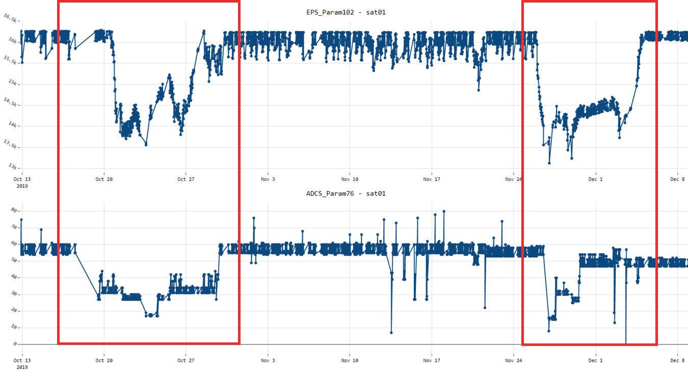
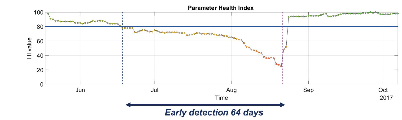
The TKM Correlation Module automatically identifies correlated telemetries and anomalies in order to discover potential cause/effects relationships among parameters or subsystems, during nominal or anomalous behaviour. In fact, considering that the effects of an anomalous event can often be observed in multiple parameters, also belonging to different subsystems, the identification of correlated anomalies is of importance in order to identify the causes of the anomaly events and to support the engineers in the interpretation of the behaviour detected. The advantage of this approach – one that combines early anomaly detection and correlated events detection – is that it also facilitates the extraction of new knowledge. Figure 2 illustrates a set of parameters from a real space mission. These parameters present some anomalies in the periods included in the red rectangles. These anomalies were identified as correlated by the TKM Correlation Module. These results were reported to engineers, who stated that pure engineering knowledge alone would not have led them to expect a correlation to exist among those parameters had it not been for the data, which then enabled an engineering explanation to be formed.
The technology to be transferred from the automotive domain is the ability to predict when a failure is going to occur (prognostic ability), i.e., the RUL of the component, subsystem or system for which an anomaly has been detected. This functionality was successfully implemented
and validated by S.A.T.E for the monitoring and diagnostics of large fleets of industrial vehicles (more than 15 000). One of the benefits of this functionality is that it optimises the maintenance plans, which is valid for the assets belonging to both the automotive and the energy fields.
The module that provides the estimate on the RUL of the component is the PKM RUL estimate; this estimate is based on the health status assessments of the component over time. As shown in Figure 3, with regards to the filter use case demonstration, the algorithm collects the information on the HI over time by modelling its trend and then estimating the RUL according to this trend.
When the parameter HI is higher than the alert threshold (HI ≥ 80 in this example), the behaviour of the components is nominal. As a result, the PKM RUL estimate outputs a default value (higher than the usual life of the component) that indicates that the estimate is not computed.
When the HI is decreasing and goes below the alert threshold (HI < 80), the alert is raised. At this point, the PKM RUL estimate is triggered and the RUL estimate (black dashed line) is computed.
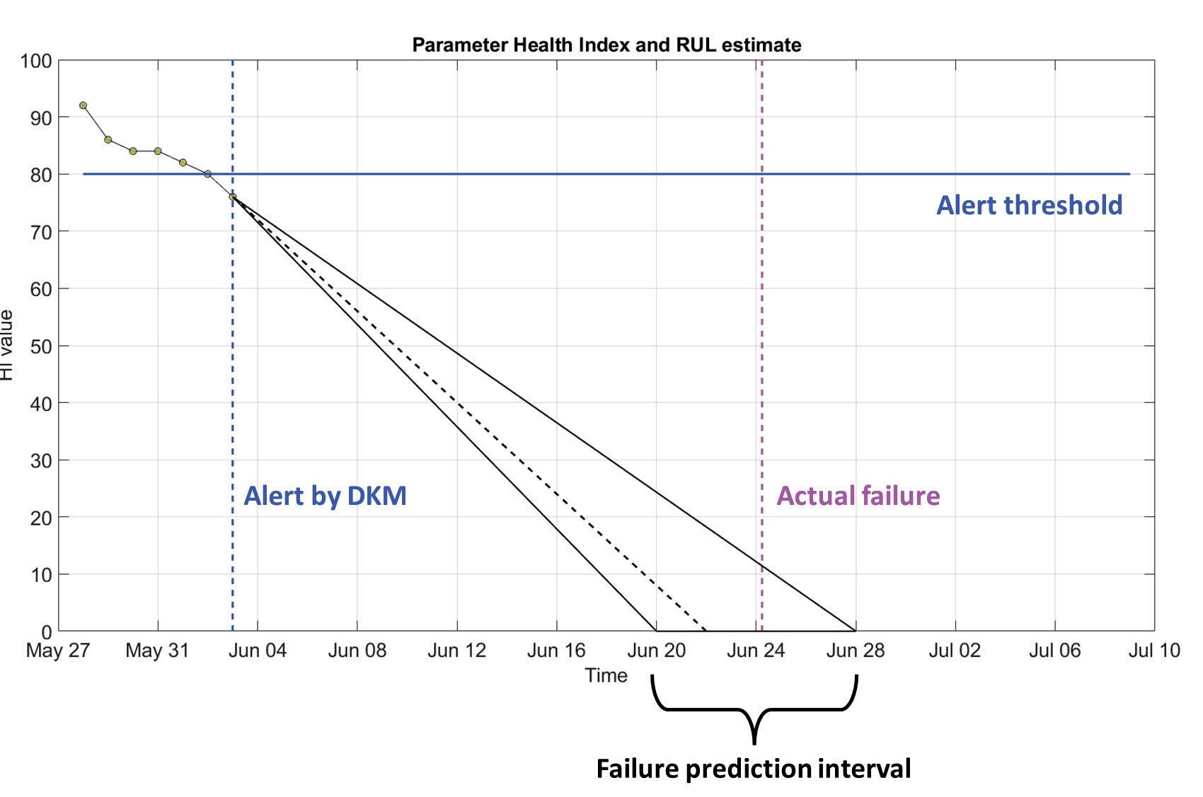
The information provided by this module is that the failure of the component will occur in ‘N’ days, and with ‘X’% probability that the failure will fall within a failure prediction interval (i.e. uncertainty boundaries shown by the black lines).2, 3, 4
In order to address the use case in question, the technical solution that has been applied consists of the aggregation of the described modules:
n DKM Contextualized Anomaly detection (space sector).
n DKM Correlation Module (space sector).
n PKM RUL estimate (automotive sector).
As a first step, the telemetries representing measures that are relevant for the analysis from a physical point of view were selected, together with the operative conditions that characterise the context for analysis. Then, a reference behaviour was built by exploiting the data from a single component, following the indications of the operators on when the behaviour of the filter was nominal. At this point, all of the available filters were checked against the reference behaviour, under the defined operative conditions, in order to assess their health status. Finally, the health status computed over time by the DKM Contextualized Anomaly Detection (i.e., HI) was provided to the PKM RUL estimate module, which produced the RUL estimate and uncertainty boundaries.
Figure 4 shows an overall view of the technical solution that was proposed. The KMs exploited for the energy domain are highlighted with an orange rectangle, derived partly from the space sector (light blue rectangle) and partly from the automotive sector (blue rectangle).
The KMs for the energy sector are intended as a solution to be integrated into the monitoring tools or dynamic digital twin already available at the end user’s premises, and it can be deployed in the cloud or on customers’ internal servers. The application can be launched by the operators, and input data can then be retrieved from the plant database
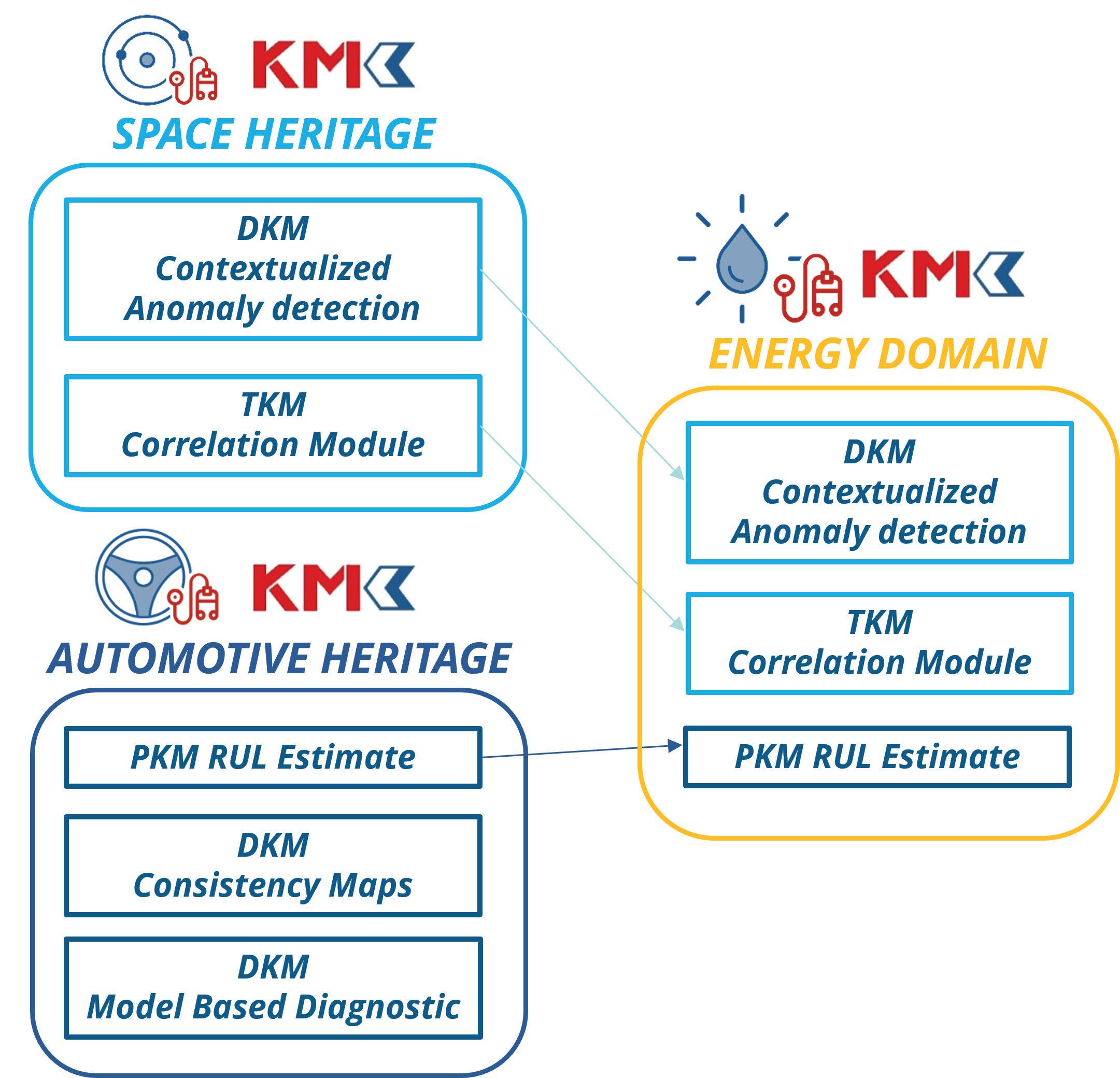
and made available to S.A.T.E. KMs. Finally, the results can be computed and written into the plant database.
The health status assessment performed by the data-driven solution developed for space applications proved its ability to raise early alerts of degradation of fluid filters in the oil and gas industry, based on enhanced analyses of features computed over the parameters with the S.A.T.E. FETCH approach. Preliminary statistics of early detection performance show that the alert is always triggered well before the filter failures or typical maintenance operations (even when maintenance is not carried out in response to failure events).
However, each failure event has its own duration. As such, in some cases it is possible to intercept the anomalous behaviour of the filter even two months before the loss of functionality; in other cases, the detection occurs some days before the critical event.
The RUL was effectively estimated using S.A.T.E.’s KM that had already been applied to automotive applications, computing time to failure with uncertainty boundaries and associated likelihood. However, in the case studied, the number of filter failures was insufficient for a relevant statistical definition of these limits. Therefore, these boundaries shall be updated and validated with more cases.
With the overall early detection and failure prediction performances obtained so far, the oil and gas company involved in the project will be able to develop enhanced
maintenance plans, as confirmed by the operators that interacted with S.A.T.E. They also acknowledged that this approach would bring value to any asset trying to optimise maintenance routines and intervals. This would result in reduced maintenance and downtime costs, with early enough alert times providing enough time to properly prepare and plan maintenance activities.
Another important achievement is that a unique configuration setting for checking telemetry and estimating the RUL was found to be common across all of the components of the same type. This means that once a configuration is built and tested for one component of a specific type, it can be applied when additional components of the same type are added to the plant, with no need for reconfiguration.
The technology transfer study presented in this article was performed with the support of the European Space Agency. The view expressed herewith shall in no way be taken to reflect the official opinion of the European Space Agency.
1. ‘Predictive maintenance in oil and gas: Key trends revealed’, Offshore Technology, (14 November 2019), https://www.offshoretechnology.com/comment/predictive-maintenance-oil-gas/

2. FINK, O., WANG, Q., SVENSÉN, M., DERSIN, P., LEE, W.-J., and DUCOFFE, M., ‘Potential, challenges and future directions for deep learning in prognostics and health management applications’, Engineering Applications of Artificial Intelligence, Vol. 92, (2020).
3. ISO 13381-1, ‘Condition Monitoring and diagnostics of machines –Prognostics – Part 1: General guidelines’, 2nd Edition.
4. ISO/IEC/IEEE 15288-2015, ‘Systems and Software Engineering –System Life Cycle Processes.’

With extensive global experience driving catalyst business growth, John and his team of international experts in the refining and petrochemical catalyst and process licensing market have supported the growth of Rezel and Rezel’s partners in the global market based on high-performance, competitive, cost-effective catalysts, and novel process solutions.

0 1 What are the most significant challenges facing the future catalyst market?
There are several factors at play in the current catalyst market. A tight supply-demand balance is increasing catalyst prices beyond what can be explained by inflation. Sole or limited start-up and ongoing catalyst supply options limit competition and inflate prices. A mixed scenario for transportation fuels will see slow growth in FCC/RFCC catalyst demand, limiting major catalyst company investment and further constraining supply. Meanwhile, demand for petrochemical catalysts will see the most robust growth, beyond the current catalyst supply expansion plans. Environmental regulations, renewables, and new environmental processes will drive demand in that segment. Overall, the catalyst market is heading into an era of limited investment and tight supply, increasing prices, and limited options. Catalyst users are right to be concerned about the long-term effect of these forces and the impact on their choices and costs.
02 What is the outlook for catalyst demand growth, and in which segments do you expect the most growth?
Over the next 5 – 10 years, we expect the demand growth for all catalysts to continue, approaching 3% per year. We expect the highest growth to continue in the refining and petrochemicals segment, with, for example, FCC/RFCC catalyst demand increasing annually at a high enough rate to fill a new world-scale catalyst manufacturing plant per year. Similarly, and while smaller scale compared to FCC/RFCC catalyst demand, we expect catalyst demand for petrochemical processes to support a medium- to large-scale catalyst plant addition per year. We expect to see increased growth in demand across the global market, but more so in the Middle East, Southeast Asia, and China, with slower growth in developed economies. Growth in the largest volume market, the US, will continue, although at a slower rate compared to these other high-growth regions.
03 What is Rezel doing to address industry challenges?
Rezel is an independent, publicly listed catalyst manufacturer, process licensor and EPC. We develop catalysts for our own licensed processes, including fixed bed and fluidised bed circulating propane and isobutane dehydrogenation processes, and methanol to olefins (MTO). We also develop catalysts independently and with our development partners for use in other licensor processes, mature segments such as FCC/RFCC
and DCC catalyst segments, and adsorbents and molecular sieves for the entire range of refining and petrochemical processes.
To fill the developing supply-demand gap, Rezel is investing; adding capacity directly and indirectly. Adding to our first fully integrated commercial catalyst plant commissioned in Leshan, Sichuan, China, in 2010, Rezel has continued to invest in new capacity. Over the past four years, Rezel’s catalyst capacity has expanded more than four times its original volume through acquisitions and the addition of a new, world-scale catalyst plant to produce a broad range of catalysts. The new plant will produce catalysts for reforming, isomerisation, hydrogenation, etc., as well as ethylene oxide (EO) catalysts. Most of the new plant is already in operation. The FCC/RFCC, hydrocracking, and hydrotreating catalyst lines will be commissioned in the coming months. Meanwhile, as an increasing number of large national oil companies are willing to develop their own catalysts and invest in manufacturing capacity, Rezel has licensed multiple catalyst plants to others, supporting the development of more capacity additions across the full range of catalyst technologies.
With the addition of new technologies to our portfolio, and an increase in our own catalyst production volume, Rezel is set to become the fourth largest independent catalyst manufacturer globally. Future catalyst improvements can only result from a strong R&D team and the latest, cutting-edge production technology. Rezel’s capacity investments and new product introductions offer the industry performance and price competition and, like our recently introduced EO catalysts, represent an alternative to traditional single or limited-source supply with equal or better performance.
04 How is Rezel progressing in a fairly mature and conservative market?
As a relatively new supplier in an established global market, Rezel brings together globally experienced technical and R&D expertise, and the latest, state-of-the-art production technology, which allows greater flexibility in manufacturing adjacent space and next-generation products. The combination brings fresh ideas and delivers to the market new, improved products. And foremost, it brings competition and expanded choices to a tight market. Through rigorous independent product development and working closely with our customers and partners to address challenging performance demands, Rezel has been qualified in customer and third-party laboratories and commercial applications. With more than 80% of our global revenue generated outside our home market China, the direct advantages of performance, combined with indirect advantages such as technology improvements and price rationalisation, have allowed Rezel rapid, double-digit growth across all market segments.
Our experienced team provides customized water and process treatments, dedicated engineering, and expert technical support to refineries worldwide.
We can help you improve reliability, increase throughput, and enhance the efficiency and flexibility of your operating units. We have a proven history of working with refineries to identify, deliver, and document process improvements and cost avoidance.
halliburton.com