August 2023


www.mercuryadsorbents.com Optimized Mercury Removal With MERSORB® mercury adsorbent pellets MERSORB® mercury adsorbent pellets – a Trademark of Nucon International, Inc. (NUCON®) • PROVEN RELIABLE – EVEN IN CRACKED GAS • HIGH MERCURY CAPACITY – HOT, COLD, WET or DRY • MORE PELLET SIZES – MORE PROCESS DESIGN FLEXIBILITY • LOW MOISTURE – FAST START-UP • 40 YEARS EXPERIENCE – ADSORPTION PROCESS DESIGN Your Experts for Mercury Removal – in Ethylene Plants PROVEN PROCESS – PROVEN PRODUCTS AntiMercure® is a Registered Trademark of Selective Adsorption Associates, Inc. for its Process Engineering Services MERSORB® is a Registered Trademark of NUCON International, Inc. for its mercury adsorbent pallets • Cracked Gas • Ethane Feed Gas • LPG, Naphtha, & Light Condensate Feed Liquid • Regen. Gas from Cracked Gas Driers • Light Olefin Gas from FCC Units • AntiMercure® Process Engineering • MERSORB® mercury adsorbent pellets
27 Gas analysis for process control
Australia: beyond coal


Klaus Brun, Elliott Group, and Timothy C. Allison and Natalie R. Smith, Southwest Research
Setting up for success
Joseph Doerfler, FS-Elliott, USA, reviews the development and design of an API 672-compliant centrifugal compressor for one of the world’s largest single-site ethylene facilities, and details the steps taken to reduce overall costs while increasing system efficiency.
THIS MONTH'S FRONT COVER
Rhys Jenkins and Maria-Katharina Mokosch, Servomex, look at the role of gas analysis in ethylene dichloride (EDC) and vinyl chloride monomer (VCM) production for polyvinyl chloride (PVC) manufacturing.
31 Answering the burning question of our time
Mark Naples, Umicore Coating Services Ltd, discusses the urgency of climate change, and suggests gas detection measurement as one way to reduce emissions from the oil and gas industry.
37 Safe combustion
Stuart Rye, NEO Monitors AS, Norway, considers whether methane can safely exist in a hot-fired process heater during normal operation.
43 Finding a fix
Johannes Poth, Integrated Global Services (IGS), Germany, explores five common causes of refractory failure, and outlines how to fix them.
49 Control valve selection for SAF production
Increasingly, refineries are starting to retool their infrastructure to produce sustainable aviation fuel (SAF). However, new processes are required, creating challenges for control valve selection. Scot Bauder and Janelle Prusha, Emerson, discuss.

55 Changing expectations
Fabrizio Delledone and Mike Semens-Flanagan, IMI Critical Engineering, examine various emerging valve designs to support the growing number of LNG applications.
59 The value of effective flow control
Dave Godfrey, Rotork, UK, discusses the importance of accurate and effective flow management within the growing LNG industry.
64 Q&A with...

Hydrocarbon Engineering talks to David Walsh, Product Director, Screw Compressor Products, Howden, a Chart Industries Company.
Elliott Group discusses on p. 16 how advancements in turbomachinery design will significantly improve performance of various energy storage systems through increased efficiency, operating range, and application-specific design for each system. Improvements in efficiency, transient response, and operating range can significantly enhance the commercial viability of both standalone energy storage systems and systems coupled synergistically with other industrial thermal/electrical processes. Visit elliott-turbo.com

CONTENTS Hydrocarbon Engineering Like Join Hydrocarbon Engineering @HydrocarbonEng Follow CONVERSATION JOIN THE 2023 Member of ABC Audit Bureau of Circulations Copyright© Palladian Publications Ltd 2023. All rights reserved. No part of this publication may be reproduced, stored in a retrieval system, or transmitted in any form or by any means, electronic, mechanical, photocopying, recording or otherwise, without the prior permission of the copyright owner. All views expressed in this journal are those of the respective contributors and are not necessarily the opinions of the publisher, neither do the publishers endorse any of the claims made in the articles or the advertisements. Printed in the UK. CBP019982 August 2023 Volume 28 Number 08 ISSN 1468-9340 03 Comment 05 World news 08
Nancy Yamaguchi, Contributing Editor, discusses the
of
energy market, and
the
are changing in line with carbon-neutrality
times
current state
Australia’s
how
fuel types
goals. 16 Adapting to the changing
discuss
advancements can improve the performance of various energy storage systems, including
22
Institute,
how turbomachinery
hydrogen.
Cut your CO2 emissions in half with ET Black™ Carbon Black Technology
ET Black™ is a state-ofthe-art technology that complies with the most stringent environmental regulations now and in the future.


Plus, the flexibility to produce all ASTM grades, and specialty grades, in a single plant. ET Black™, the technology of reference for producing carbon black obtained by thermal decomposition of highly aromatic oils.


Find out more at: www.igoforETBlack.com
CONTACT INFO
MANAGING EDITOR James Little james.little@palladianpublications.com
SENIOR EDITOR Callum O'Reilly callum.oreilly@palladianpublications.com
ASSISTANT EDITOR Bella Weetch bella.weetch@palladianpublications.com
EDITORIAL ASSISTANT Poppy Clements poppy.clements@palladianpublications.com
SALES DIRECTOR Rod Hardy rod.hardy@palladianpublications.com
SALES MANAGER Chris Atkin chris.atkin@palladianpublications.com

SALES EXECUTIVE Sophie Birss sophie.birss@palladianpublications.com
PRODUCTION MANAGER Kyla Waller kyla.waller@palladianpublications.com
EVENTS MANAGER Louise Cameron louise.cameron@palladianpublications.com
EVENTS COORDINATOR Stirling Viljoen stirling.viljoen@palladianpublications.com
DIGITAL CONTENT ASSISTANT Merili Jurivete merili.jurivete@palladianpublications.com
DIGITAL ADMINISTRATOR Leah Jones leah.jones@palladianpublications.com
ADMIN MANAGER Laura White laura.white@palladianpublications.com
CONTRIBUTING EDITOR
Nancy Yamaguchi Gordon Cope
SUBSCRIPTION RATES
Annual subscription £110 UK including postage /£125 overseas (postage airmail).
Two year discounted rate £176 UK including postage/£200 overseas (postage airmail).
SUBSCRIPTION CLAIMS
Claims for non receipt of issues must be made within 3 months of publication of the issue or they will not be honoured without charge.
APPLICABLE ONLY TO USA & CANADA
Hydrocarbon Engineering (ISSN No: 1468-9340, USPS No: 020-998) is published monthly by Palladian Publications Ltd GBR and distributed in the USA by Asendia USA, 17B S Middlesex Ave, Monroe NJ 08831. Periodicals postage paid New Brunswick, NJ and additional mailing offices. POSTMASTER: send address changes to HYDROCARBON ENGINEERING, 701C Ashland Ave, Folcroft PA 19032.
15 South Street, Farnham, Surrey
GU9 7QU, UK
Tel: +44 (0) 1252 718 999
COM MENT
CALLUM O'REILLY SENIOR EDITOR
Last winter, LNG played a starring role in keeping Europe’s lights switched on following the start of the Russia-Ukraine conflict.
The International Gas Union (IGU)’s latest ‘World LNG Report’ outlines how LNG demonstrated its essential value as a flexible, reliable and available energy resource during the most turbulent year in the history of gas markets. 1
Europe imported 66% more LNG in 2022, with 44% of the continent’s total imports coming from the US. Despite the Freeport LNG terminal being taken offline following an accident in June 2022, US producers exported 55.2 million t of LNG to Europe last year, a 148% increase compared to the previous year. This accounted for 69% of the country’s LNG exports in 2022.

Throughout the last year, record new regasification capacity was approved, with some projects fast-tracked. The IGU reports that more than 10 European markets have initiated the construction of new infrastructure since the outbreak of the war in Ukraine, including 26 projects with a combined regasification capacity of 104.5 million tpy. Of these projects, six have been commissioned, and four terminals have taken final investment decisions (FIDs) and are under construction. The IGU also notes that approximately 70% of this new capacity will come from floating terminals.
The fact that Europe could turn to LNG in its moment of need illustrates the fuel’s essential role in assisting with global energy security. The IGU’s report states that, as of April 2023, “the global LNG trade connected 20 exporting markets with 48 markets with importing infrastructure, and an increasingly globalised LNG market made it possible to re-route massive volumes of energy in a matter of months.”
But LNG’s special quality extends beyond its flexibility, which ultimately improves energy security worldwide. It also has a key role to play as a transition fuel in the push for cleaner energy. It can replace oil and coal, and accelerate the integration of renewables. The IGU also points out that there is a significant opportunity to minimise the lifecycle emissions of LNG today by decarbonising the liquefaction segment of the value chain. And, looking to the future, the sector is developing its decarbonisation pathways, with examples including renewable natural gas or biomethane, blue and green hydrogen, ammonia, e-methane, and carbon capture, utilisation and storage (CCUS).
However, a lack of investment is impacting both producers and consumers, and this needs to be addressed to ensure that LNG can continue to play its important dual role. The IGU’s President, Li Yalan, explains that a lack of sufficient supply drove the world spot prices to record highs last year, which resulted in many consumers choosing dirtier fuels or even shutting down operations altogether. Strategies to future-proof investments in gas infrastructure are key to ensuring that LNG can help the world securely continue on its path to net zero.
1. ‘World LNG Report’, International Gas Union (IGU), (2023).

Delivering sulphur and sulphuric acid solutions for a more sustainable world Improve uptime Decrease CAPEX & OPEX Optimize capacity Energy efficiency SO2 Contact our experts to learn more: sulphursolutions@worley.com Reduce emissions Everything sulphur and so much more Through our in-depth experience and complete lifecycle engineering capabilities, we find ways to make plants and processes more reliable and profitable. With our large technology portfolio, we deliver the right solutions for any challenge. worley.com/comprimo worley.com/chemetics Worley Group
WORLD NEWS
Saudi Arabia | TotalEnergies, Aramco and SABIC successfully process oil from plastic waste
For the first time in the MENA region, TotalEnergies, Aramco and SABIC have successfully converted oil derived from plastic waste into ISCC+ certified circular polymers.
The plastic pyrolysis oil was processed at the SATORP refinery, jointly owned by Aramco and TotalEnergies, in Jubail, Saudi Arabia. It was then used as a feedstock by Petrokemya, a SABIC affiliate, to produce certified circular polymers.

The project aims to pave the way for the creation of a domestic value
chain for the advanced recycling of plastics to circular polymers in Saudi Arabia. The process supports the use of non-sorted plastics, which can be difficult to recycle mechanically, and consequently contributes to solving the challenge of end-of-life plastics.
Sami Al-Osaimi, SABIC EVP Petrochemicals, said: “This project shows collaboration across the petrochemical value chain to overcome upstream and downstream challenges in circular plastics.”
Egypt | Studies underway for biofuel project
Within the framework of their strategy to provide practical solutions for cleaner energy, ECARU, Qalaa Holdings and Axens have signed a cooperation protocol in the presence of H.E. French Ambassador to Egypt, Marc Barety, to carry out technical and economic studies for a project to support the production of second-generation biofuel (advanced bioethanol) and sustainable aviation fuel (SAF).
The project will be carried out in two phases, the first of which will be the production of advanced bioethanol while the second will be the production of SAF. The project’s studies will take approximately seven months. The aim is to export production of second-generation biofuel, in line with Egypt’s strategy to maximise the use of various waste types and contribute to sustainability and waste recycling.
Global | The energy crisis has reshaped natural gas markets
The global energy crisis has transformed the structure of natural gas markets, requiring closer dialogue between producers and consumers looking to ensure both short and longer term security of supply, and reduce emissions.
According to the latest edition of the International Energy Agency (IEA)’s ‘Global Gas Security Review’, tensions in gas markets have eased significantly since the beginning of 2023. Yet the new analysis notes that deeper coordination among market participants remains essential.
The security of global gas supplies remains at the forefront of energy policy making, with growing complexity for both the short- and long-term. LNG has become a baseload source of supply for Europe, with its share in total EU demand rising from an average of 12% over the 2010s to close to 35% in 2022 – similar to the contribution from Russia’s piped gas before the invasion of Ukraine. Meanwhile, China’s balancing role in global gas markets is set to increase.
USA | NextDecade reaches FID for Rio Grande LNG
NextDecade Corp. has announced that it has made a positive final investment decision (FID) to construct the first three liquefaction trains (Phase 1) at the company’s 27 million tpy Rio Grande LNG (RGLNG) export facility in Brownsville, Texas, US.
The company has executed and closed a joint venture (JV) agreement for Phase 1, which included approximately US$5.9 billion of financial
commitments from Global Infrastructure Partners (GIP), GIC, Mubadala Investment Co., and TotalEnergies.
NextDecade has committed to invest approximately US$283 million in Phase 1, including US$125 million of pre-FID capital investments into Phase 1.
The US$18.4 billion project financing for RGLNG Phase 1 is some of the largest greenfield energy project financing in US history.
In conjunction with making a positive FID, RGLNG issued the notice to proceed (NTP) to Bechtel Energy Inc. to begin construction of Phase 1 under its lump-sum turnkey engineering, procurement, and construction contracts (EPC).
Phase 1, with nameplate liquefaction capacity of 17.6 million tpy, has 16.2 million tpy of long-term binding LNG sales and purchase agreements (SPAs).
August 2023 HYDROCARBON ENGINEERING 5
WORLD NEWS
DIARY DATES
05 - 08 September 2023
Gastech Singapore www.gastechevent.com
17 - 20 September 2023
GPA Midstream Convention San Antonio, Texas, USA www.gpamidstreamconvention.org
17 - 21 September 2023
World Petroleum Congress Calgary, Alberta, Canada www.24wpc.com
26 - 28 September 2023
Turbomachinery & Pump Symposia Houston, Texas, USA tps.tamu.edu
02 - 05 October 2023
ADIPEC
Abu Dhabi, UAE www.adipec.com
03 - 05 October 2023
AFPM Summit Grapevine, Texas, USA summit.afpm.org
09 - 12 October 2023
2023 API Storage Tank Conference & Expo Denver, Colorado, USA events.api.org/2023-api-storage-tank-conference-expo
06 - 08 November 2023
Sulphur + Sulphuric Acid 2023 New Orleans, Louisiana, USA www.sulphurconference.com
13 - 16 November 2023
ERTC
Lake Maggiore, Italy worldrefiningassociation.com/event-events/ertc
05 - 07 December 2023
16th Annual National Aboveground Storage Tank Conference & Trade Show
The Woodlands, Texas, US www.nistm.org
30 - 31 January 2024
NARTC
Houston, Texas, USA www.worldrefiningassociation.com/event-events/ nartc
USA | Refinery capacity increased at the start of 2023 for the first time since COVID-19

According to the annual ‘Refinery Capacity Report’ by the US Energy Information Administration (EIA), US refining capacity increased by 0.6% at the start of 2023, compared to the start of 2022. US operable atmospheric crude oil distillation capacity, the primary measure of refinery capacity, totalled 18.1 million barrels per calendar day (bpd) at the start of 2023, up by 117 000 bpd from 17.9 million bpd at the start of 2022.
The number of operable refineries in the US, including both idle and operating refineries, decreased to 129 refineries at the beginning of 2023, down from 130 refineries at the beginning of 2022. The single refinery closure reflects the loss of a small facility in Santa Maria, California, US. Despite the loss of this plant, overall capacity increased because PBF Energy reactivated a previously retired crude oil distillation unit at its refinery in Paulsboro, New Jersey, US.
UAE | Masdar, Mitsubishi Chemical Group and INPEX explore polypropylene production
Masdar, Mitsubishi and INPEX have signed an agreement to explore production of a commercial-scale polypropylene produced from carbon dioxide (CO2) and green hydrogen, in Abu Dhabi, UAE.
The green hydrogen and CO2 will be converted into e-methanol, which will subsequently be converted to propylene and polypropylene.
Mitsubishi Chemical Group’s CEO, Jean-Marc Gilson, said: “The chemical
industry is now faced with the dual challenge of reducing its greenhouse gas (GHG) emissions, while actively participating and leading the transition to a carbon-neutral economy. With that focus in mind, our ambition to use CO2 as a key starting raw material is a very important stepping stone towards a sustainable future and we are looking forward to using our expertise to contribute to the success of this project.”
North America | Wood Mackenzie reports growth in RNG market
According to a new report from Wood Mackenzie, the renewable natural gas (RNG) market saw huge growth in 2022. 60 million ft3/d of new production capacity was added, and 66 future projects were announced, confirming that the number of RNG projects has doubled in the last five years.
Activity has been spurred by mandates and incentives aimed at lowering greenhouse gas (GHG) emissions, such as investment tax
credits (ITC) in the Inflation Reduction Act (IRA) for RNG development, and low-carbon fuel programmes in the US Environmental Protection Agency (EPA)’s Renewable Fuel Standard programme.
Despite recent growth, RNG only makes up 0.5% of the natural gas market in North America. Nevertheless, with continued support, Wood Mackenzie projects it will grow to 3% of the market by 2050.
August 2023 HYDROCARBON ENGINEERING 6

Visit us at Offshore Europe in Aberdeen 5 - 8 September, stand 1R41 to see this next generation valve

8 August 2023 HYDROCARBON ENGINEERING
Within the Organisation for Economic Co-operation and Development (OECD), Australia stands apart – not only because of its distance from most of its fellow countries, but because of its abundant energy resources and its high per-capita emissions of carbon. Australia has significant fossil energy reserves (coal, natural gas and petroleum), as well as renewable energy (biomass, solar energy, wind and hydropower). The country also possesses the world’s largest reserves of uranium, but does not have any nuclear power plants, and exports its uranium.
Australia’s energy wealth could be considered an embarrassment of riches, except that so much of the riches are the wrong type: coal. The country is finding it impossible to abruptly stop using a fuel source that is so
plentiful and is so much a part of the existing energy infrastructure. If there was a sport called ‘The OECD Clean Energy Games’, Australia would be in the penalty box, holding hands with the US and Canada. These three countries possess abundant fossil energy reserves. They share a goal of carbon-neutrality by 2050, and they have a major fight ahead to transition to a clean energy economy. Among these three, Australia has the highest per-capita carbon dioxide equivalent (CO2e) emissions: approximately 16.46 CO2e/capita in 2022, relative to 15.82 CO2e/capita in the US and 14.77 CO2e/capita in Canada.1
Globally, critics are sceptical that Australia will be able to make the drastic cuts in fossil energy production and use that are needed. Recently, however, discussions between Australia and the US revealed potential to expand investment in renewable and clean energy.

August 2023 9 HYDROCARBON ENGINEERING
Nancy Yamaguchi, Contributing Editor, discusses the current state of Australia’s energy market, and how the fuel types are changing in line with carbon-neutrality goals.
Australian Prime Minister, Anthony Albanese, and US President, Joe Biden, met and agreed upon a new pact on clean energy policy and investment. The Biden Administration is devoting billions of dollars to clean energy development, and it is possible that Australia will be designated a ‘domestic supplier’ to the US, potentially allowing Australian companies to benefit from the huge investments being made in the US. Indeed, many Australians believe that the investments earmarked for natural gas would be better spent on strategic minerals, green hydrogen, solar energy, and wind turbines. In the near- and mid-term, however, it is more likely that Australia will continue to pursue success in natural gas production and LNG exports. According to the ‘Statistical Review of World Energy’, the industry standard long-published by BP and now produced by the Energy Institute (EI), in 2021, Australia gained the number one spot in global LNG exports, surpassing Qatar. In 2022, Qatar reclaimed the number one spot.
Australia has mineral wealth that is vital to the energy industry, including lithium, vanadium, cobalt, and rare earth metals. These strategic minerals are essential for batteries, turbines, solar panels, and computers that help make renewable energy technologies viable. Mining and processing are energy intensive, but channelling natural gas and ultra-low-sulfur petroleum fuels to these ventures may hasten a phase-out of coal. Australia is the world’s largest exporter of lithium, but it has yet to capture the value-added of processing its mineral wealth into finished batteries.
This article will explore Australia’s energy market, how the fuel types are changing, and how the oil industry is adapting.
Australian primary energy
Australia has faced international criticism over its dependence on fossil energy, yet in fairness this is a
herculean task given its vast fossil energy reserves and their contribution to national wealth. Historically, fossil energy contributed approximately 95 – 96% to Australia’s primary energy mix. According to BP and the EI, fossil energy accounted for 96.3% of Australia’s energy mix in 2008, and the country cut this to 85.6% in 2022. This has been achieved primarily by cutting coal use by an average of 3.2%/yr during the 2008 – 2022 period. In 2022, oil provided 34.6% of Australian primary energy, followed by coal at 25.9% and natural gas at 25.1%. Oil demand growth has been moderated in recent years, although part of this was caused by the COVID-19 pandemic. Demand has been recovering, but at a slower pace than that seen pre-pandemic.
During the decade 2012 – 2022, the Statistical Review of World Energy reported primary energy demand growth rates of:
n Coal: -2.5%/yr.
n Oil: -0.5%/yr.
n Natural gas: 2.3%/yr.
n Hydroelectricity: -0.5%/yr.
n Renewables: 17.0%/yr.
In 2021, The Australian Department of Climate Change, Energy, the Environment, and Water provided additional details on renewables growth rates of: 2
n Biofuels: -6.9%/yr.
n Hydropower: -1.0%/yr.
n Biomass: 0.2%/yr.
n Biogas: 2.5%/yr.
n Solar hot water: 5.4%/yr.
n Wind: 15.0%/yr.
n Solar PV: 33.6%/yr.
Coal remains relevant in Australia because of its vast reserves (the reserves-to-production ratio is over 300 years), and the fact that coal resources are located close to existing population centres and feed directly into the power sector. Australia has the world’s third-largest coal reserves, following the US and Russia, and it is the second-largest coal exporter, after Indonesia. Australia is successfully producing syngas from coal at its Leigh Creek project. There are plans to expand coal syngas production for power generation and fertilizer manufacture.
Natural gas consumption and export continue to grow, though production gains recently have slowed, causing concern to LNG exporters. Australia surpassed Qatar to become the world’s largest LNG exporter in 2021. According to BP, Australia exported 108.1 billion m 3 of LNG in 2021, vs Qatar’s exports of 106.8 billion m 3 . The EI reported that in 2022, Qatar reclaimed the top
August 2023 HYDROCARBON ENGINEERING 10
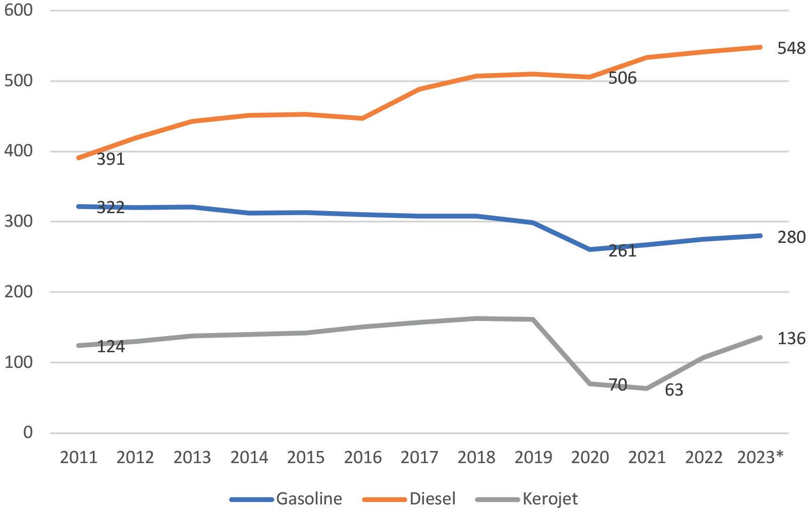
Figure 1. Australia key petroleum product sales, 2011 – 1Q23, ‘000 bpd (source: Australian Department of Climate Change, Energy, the Environment and Water).
We make chemistry happen
Sulzer Chemtech is the global market leader in innovative mass transfer, static mixing and polymer solutions for chemicals, petrochemicals and refining. We are steering the way in ecological solutions such as bio-based chemicals, polymers and fuels, recycling technologies for textiles and plastic as well as carbon capture and utilization/storage, contributing to a circular and sustainable economy.

We are solution provider for mass transfer equipment, its installation and upgrade, with solutions for all types of separation, from distillation and absorption to phase separation and liquidliquid extraction. In order to benefit from the high performance capabilities of the column internals, it is important that they are installed in the proper manner. Sulzer Chemtech can also assist you in installing the internals on site with our team of field services professionals.
For more information, please visit sulzer.com/chemtech
spot, exporting 114.1 billion m 3 of LNG vs Australia’s 112.3 billion m 3 . Australian LNG exports flow mainly to Japan, China, South Korea and Taiwan. There are plans to build new LNG capacity, including the Scarborough project scheduled for 2026. However, new projects may be delayed because of concerns over stagnating natural gas production. Without additional upstream natural gas development, the priority is to supply existing LNG plants rather than to build new ones.
Unlike coal, most of Australia’s natural gas reserves are in the northwest part of the country, while the population is centred in New South Wales (NSW) and Victoria. The government forecasts shortages of natural gas in NSW, and it is actively working to control domestic prices and supply. Australia’s first LNG import terminal, Port Kembla in NSW, is expected to open by the end of 2023, with the goal of bringing Queensland LNG to NSW – potentially supplying as much as 75% of the state’s demand.
Australian oil sector
Oil demand in recovery
Australia’s oil sector has changed dramatically. During the Asian Boom, Australian demand growth mirrored its neighbours far more than it did its OECD contemporaries. Prior to the COVID-19 pandemic, oil demand was still growing at a robust 1.3%/yr on average from 2011 to 2019, whereas OECD oil demand was shrinking by -1.9%/yr. Australia’s oil demand has remained strong in comparison to other OECD countries, although the pandemic hit the travel industry and transport fuel demand particularly hard. Figure 1 shows the pandemic’s impact on sales of key transport fuels. Jet fuel sales dropped from approximately 161 400 bpd in 2019 to 70 100 bpd in 2020, fell again to 63 500 bpd in 2021, and
began to climb back to 107 300 bpd in 2022. Data for 1Q23 shows demand continuing to recover, averaging 135 900 bpd.
Gasoline sales fell from 299 000 bpd in 2019 to 260 800 bpd in 2020. Demand rose modestly to 267 100 bpd in 2021, continued to recover to 275 300 bpd in 2022, and rose again to average 280 100 bpd during 1Q23.
Diesel sales were the least affected by the pandemic, declining slightly from 509 700 bpd in 2019 to 505 800 bpd in 2020, then resuming strong growth to 533 300 bpd in 2021, 541 600 bpd in 2022, and 548 000 bpd during 1Q23.
Total product sales in 2022 amounted to 985 200 bpd, rising to 1 022 500 bpd during 1Q23.
As Figure 1 illustrates, gasoline sales had been falling even before the COVID-19 pandemic hit, and this trend is expected to continue.
Drastic cuts in refinery capacity and output
The past decade has brought enormous upheaval to Australia’s refining industry. Refining companies had long foreseen a future of declining demand and tighter environmental regulations, including requirements for ultra-low-sulfur fuels, which would require significant investment. Australia’s refineries were typically mid-sized and gasoline-oriented, and they were becoming antiquated when compared to some of the giant new refineries in Asia and the Middle East. Yet the decision to close a refinery is a difficult one, and most companies held on for years despite low margins.
Over the past decade, however, refiners have been forced to cut capacity ruthlessly, often converting former refinery facilities to product import terminals and supplying their networks with fuel from refineries in Asia and beyond. Shell converted its Clyde refinery to a product terminal in 2013, and it sold its Geelong refinery to Vitol in 2014. In 2014, Caltex closed its Kurnell refinery. BP closed its Bulwer Island refinery in 2015 and converted its Kwinana refinery to a product terminal in 2021. BP plans to build renewable diesel and sustainable aviation fuel (SAF) production at the Kwinana site, with current plans to produce 10 000 bpd of these renewable fuels. ExxonMobil closed its Altona refinery in 2021.
Currently, only two refineries remain in Australia: Ampol’s Lytton refinery (formerly Caltex) and Vitol Viva’s Geelong refinery (formerly owned by Shell).
Even with this downsize, there are concerns about future
August 2023 HYDROCARBON ENGINEERING 12
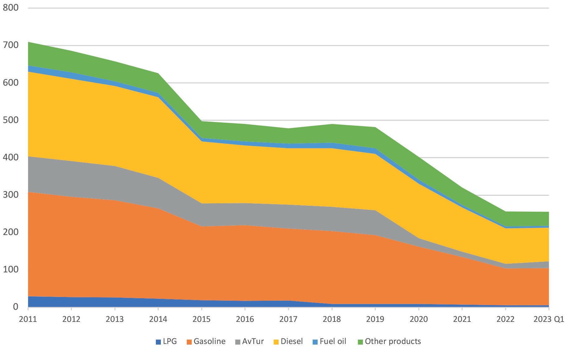
Figure 2. Dramatic downturn in Australian refined product output, 2011– 1Q23, ‘000 bpd (source: Australian Department of Climate Change, Energy, the Environment and Water).
Invisible. Invaluable.
Effective asset management is more than digital tools and data. It requires the behind-the-scenes use of best practices and a deep understanding of heavy industry infrastructure.

When decades of EPC experience meets data analytics, our clients have an integrated solution for the reliability they require.
Let
find ways to help you.

’s
• Fu l l -s e r v i ce s o l u ti o n s f r o m d e si g n an d c o n s t r u c ti o n t o o p e r a ti o n s & m a i n te n a n c e • E n h a n c e d d ia g n o s ti c s t o r a pi d ly a c h i eve yo u r g o a l s • D a t a - d r i ve n o p e r a ti o n s & m a i n te n a n c e f o r m a x i m ize d R O I
profitability. Australia’s two remaining refineries received government subsidies to remain in operation, lest the country be left without any refining capability. The government decided that the country needed a ‘sovereign fuel supply’. It passed the Fuel Security Bill in 2021, providing approximately AU$2.3 billion (US$1.8 billion) in subsidies to Ampol and Viva Energy to remain open until 30 June 2027, with a possible extension to 2030. The regulations call for minimum stockholding obligations (MSO) for gasoline, jet fuel and diesel. When margins are low, the government may provide a subsidy of up to AU$0.18/l to the refiners. The government is providing each refinery with up to AU$125 million to upgrade their facilities to produce ultra-low-sulfur gasoline (maximum 10 ppm sulfur) by the end of 2024.
Australia’s crude refining capacity is currently 236 000 bpd, down from its height of 829 000 bpd in 2002. The government reported total refinery input of 261 600 bpd in 2022, 26.8% of which was indigenous. Figure 2 displays the dramatic downturn in refinery production, which dropped from 710 000 bpd in 2011 to 256 000 bpd in 2022. In 2022, output was:
n LPG: 2.2%.
n Gasoline: 38.4%.
n Aviation turbine fuel: 4.8%.
n Diesel: 37%.
n Fuel oil: 2.0%.
n Other products: 15.6%.
Refined products imports balloon; exports vanish
Australia is becoming hugely dependent on imported fuels, as shown in Figure 3. In 2011, the country imported 343 000 bpd of refined products, juxtaposed against market sales of 941 500 bpd. Product imports grew to 868 000 bpd during 1Q23, vs demand of 1 022 500 bpd. In 2011, imports accounted for approximately 36% of
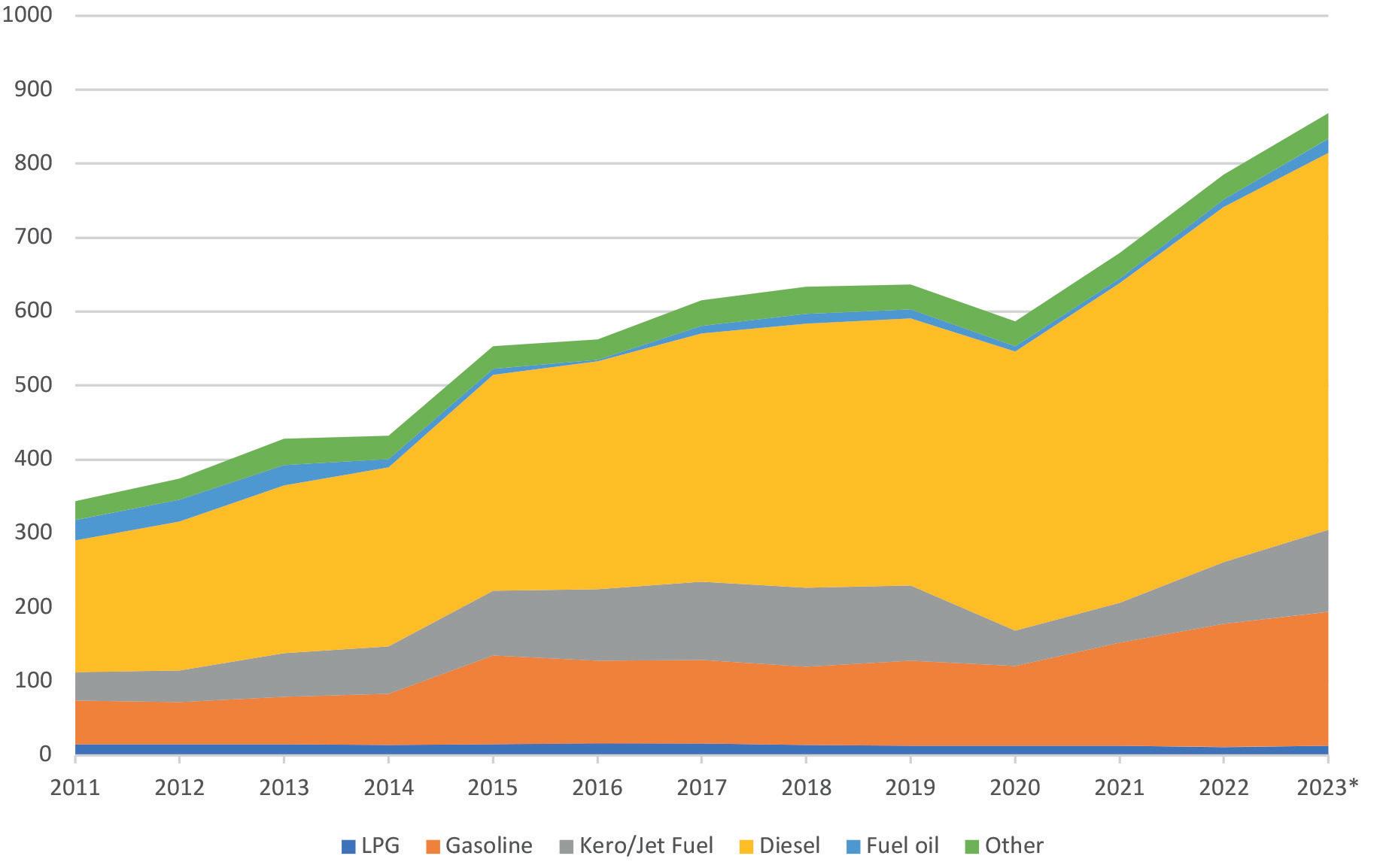
Australia’s demand. By 1Q23, this share had surged to 85%. Australia’s dependence on imported diesel is staggering, with domestic refining supplying less than 10% of market sales. During 1Q23, domestic sales of diesel averaged 548 000 bpd, and diesel imports were 510 000 bpd – 93% of demand. Diesel imports are sourced mainly from the Asia-Pacific region, including Singapore, South Korea, India, Malaysia, Taiwan, Thailand and China. Gasoline imports also come chiefly from Asia-Pacific refining centres, but cargoes have also arrived from more distant sources in Europe, the US, and the Middle East. During 1Q23, domestic sales of gasoline averaged 280 100 bpd, while imports averaged 181 000 bpd – approximately 64% of demand.
Australia’s shrunken refining capability has caused imports to soar and exports to dwindle. The demand collapse as a result of the COVID-19 pandemic caused a brief jump in product exports, which rose from 66 200 bpd in 2018 to 107 500 bpd in 2020, but exports retreated to 86 800 bpd in 2022. Of this, however, 80 200 bpd was LPG. Exports of higher-value gasoline, diesel and jet fuel have essentially vanished.
Conclusion
Australia’s energy markets continue to change and evolve. It is a complex process, but the presence of so many choices is more a blessing than a curse; a country with few choices is likely a country with few resources and capabilities. Australia has both the resource base and the capability to use it. With the benefit of hindsight, however, it is easy to say that devotion to coal eclipsed other development, and phasing out coal is now extremely difficult. Coal use has been shrinking at -2.5%/yr, but it still represented a hefty 25.9% of Australia’s primary energy in 2022. Given the technology of today, it is not possible for Australia to maintain this dependence on coal and still achieve its goal of carbon-neutrality by 2050.
During the decade from 2012 through to 2022, the EU managed to cut its CO 2 e emissions by an average of -1.6%/yr. 3 Australia is lagging far behind. The country achieved an emissions reduction of only -0.2%/yr during the decade. Efforts to reduce coal use are focused on expansion of natural gas use, government support for a slimmed-down oil refining industry, and a host of alternative and renewable energy developments which now appear to be gaining traction.
Natural gas and LNG continue to be viewed as the best near-term tactic to replace coal. The government recently unveiled its ambitious National Gas Infrastructure Plan (NGIP), designed to secure natural gas supplies over a 20-year time horizon.
August 2023 HYDROCARBON ENGINEERING 14
Figure 3. Australia’s rising dependence on imported fuel, 2011 – 1Q23, ‘000 bpd (source: Australian Department of Climate Change, Energy, the Environment and Water).
The government is also actively controlling price and supply, which is a comfort to consumers but worrisome to private companies. The government set a cap on natural gas prices to shield consumers from high prices, and it has established a ‘code of conduct’ intended to protect consumers while still providing what it considers certainty to producers. The government is also seeking to expand its ability to control LNG exports from east coast producers when supply shortfalls are foreseen. Australia’s first LNG import terminal is scheduled to open within the year, bringing supply to NSW.
Oil use is declining modestly, although diesel demand remains very strong. The market may be viewed as stabilising into a gentle downward trend. After the dramatic closure of five Australian refineries, the two remaining refineries must make the investments necessary to comply with government regulations, but they are considered vital to supply security. The government is subsidising its operations at least through to 2027, extendable to 2030. Although the government relies on imported feedstocks for 70 – 75% of refinery inputs, it has a slight advantage because the incremental barrel of refined fuel supply is an imported barrel. When margins drop below a specified level, the government will pay a direct per-litre subsidy. Most of the former refining companies are adept product traders, and they continue to compete at the retail level. Consumers will expect high-quality fuel and ample choice.
The largest potential for change in Australia’s energy economy is likely to be in strategic minerals that are vital to new energy technologies. Years ago, before the huge advances made in batteries and electric vehicles (EVs), Australia sold off vast amounts of its lithium. It remains the world’s largest exporter of lithium, but there is great potential to capture value-added by processing its own lithium and other vital minerals rather than relying on simple resource extraction. In February 2023, the government released a brief ‘National Battery Strategy’, championing the idea of developing a globally competitive battery industry. 4 Energy storage will be vital to Australia’s clean energy future. With Australia’s abundant sunshine, it is a natural site for virtual power plants. Australia could also become a major player in the global export market, diversifying the sources of supply to countries including the US.
Finally, a new agent of change is emerging in Australia: high-tech titans impatient with the slow pace of change. Of these, Mike Cannon-Brookes of software company Atlassian hit the headlines when he led a boardroom coup against AGL Energy Ltd, Australia’s largest electricity generator and its largest carbon emitter. Shareholders stunned the company by rejecting company board picks and voting in four new ‘green’ board members. Consequently, AGL is now closing a coal-fired power plant and conducting a feasibility study into converting the site into a clean energy hub.
Australia is resource-rich, and it is working to cut its fossil energy use. Will Australia’s approach mirror that of BP’s? As noted, BP’s Statistical Review of World Energy has been transferred to the EI, in partnership with KPMG, Kearney, and Heriot Watt University. BP continues to support the effort, which it launched in 1952. BP was one of the first to start publishing data on global CO2 emissions, which it added in 2010. The company is transitioning to a wider-ranging energy company, going ‘beyond petroleum’. Can Australia go ‘beyond coal’, and find the optimal use of its resources to ensure an ecologically and economically sound energy future?
References
1. Author’s calculation using CO2e data from the EI, and population data from the individual countries.
2. For more information on the Australia Department of Climate Change, Energy, the Environment, and Water, see: www.energy.gov.au/data/renewables.
3. CO2e are defined as “the sum of CO2 emissions from energy, CO2 emissions from flaring, methane emissions in CO2e and CO2 emissions from industrial processes.” The early years were calculated by BP, and this data is now tracked by the EI.
4. ‘National Battery Strategy’, Australian Department of Industry, Science and Resources, (February 2023).
capture.

Let´s get the future started today.
→ compressors e.g. for electrolyser projects, hydrogen, CO 2 and process gases
→ membrane systems for hydrogen separation and carbon capture

→ ball valves for midstream and downstream applications
→ heat transfer systems for hydrogen and syngas projects.
We look forward to welcoming you at our booths: Hydrogen Technology & Carbon Capture Expo, GASTECH and ADIPEC 2023.
www.borsig.de
BORSIG
Think. Create. Change.
Hydrogen and carbon
solutions for your processes.
Klaus Brun, Elliott Group, and Timothy C. Allison and Natalie R. Smith, Southwest Research Institute, discuss how turbomachinery advancements can improve the performance of various energy storage systems, including hydrogen.

16 August 2023 HYDROCARBON ENGINEERING
Global integration of renewable energy sources (with high variability) into the power generation mix requires the development of cost-effective, efficient and reliable grid-scale energy storage technologies. A number of energy storage technologies are being developed that can store energy when excess renewable power is available, and discharge the stored energy to meet power demand when renewable generation drops off, assisting or even displacing conventional fossil- or nuclear-fuelled power plants. The development and commercialisation of these technologies is a critical step for enabling high penetration of renewable energy sources.
Energy storage demands are complex, and the corresponding solutions may vary significantly with required storage duration, charge/discharge duty cycle, geography, daily/annual ambient conditions, and integration with other power or heat producers and consumers. Typically, commercial viability of an energy storage system is a function of both performance and cost.
Many mature and emerging energy storage technologies use combinations of thermal, mechanical and chemical energy to meet storage demands over a variety of conditions. These systems offer the potential for better scalability than electrochemical batteries. While recognising that a broad variety of machinery-based energy storage systems either exist or are under development to address the need for low-cost, long-duration storage, this article will focus primarily on hydrogen, including an overview of how hydrogen impacts compression and combustion in machinery, for both pure hydrogen and blended hydrogen applications.
Hydrogen energy storage

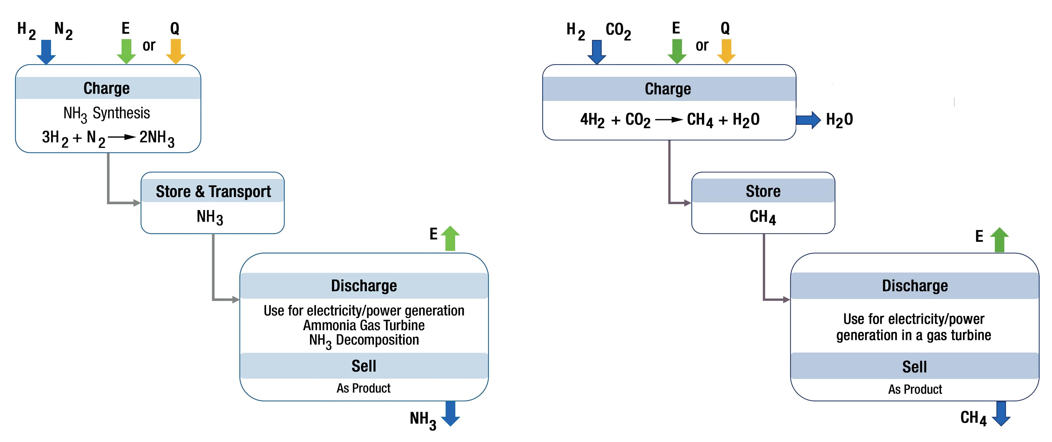
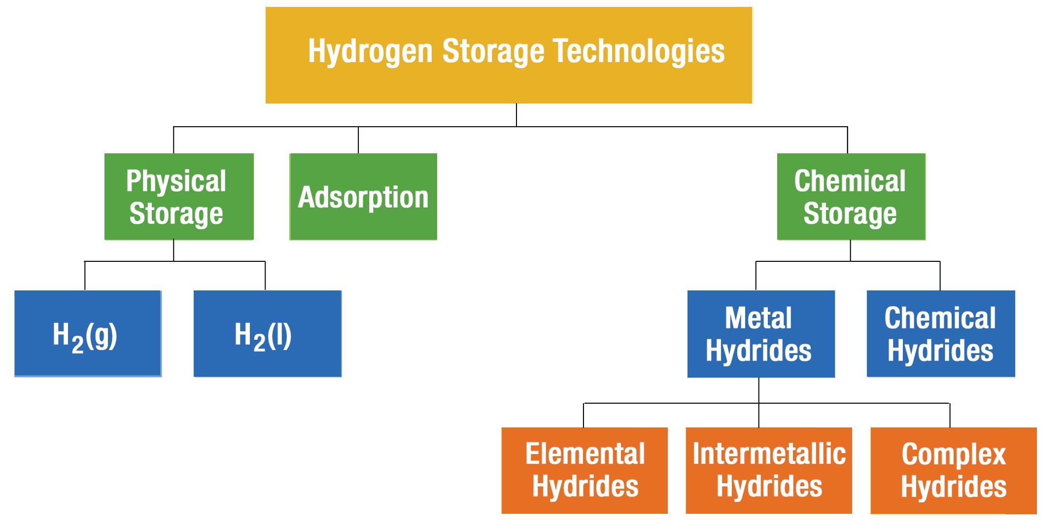
Hydrogen technologies are among the most well-known thermochemical storage options, and include a wide range of generation, storage, transmission, and electrical conversion systems. Thermochemical storage is an attractive storage medium due to its zero-carbon formulation and long-term stability, enabling seasonal storage. Most existing hydrogen is formed by steam reforming using coal or natural gas, although electrolysis of water via renewable or nuclear power is being developed for a carbon-free solution. Hydrogen is already stored in large volumes in underground salt caverns, but poses compression and transportation challenges due to its low mole weight, meaning that it requires significant compression power and lower heating value than methane. Various hydrogen carriers have been considered, including ammonia, metal hydrides, sorbents, formic acid and methane (see Figure 1). Power conversion with hydrogen and hydrogen products can be accomplished via combustion in a gas turbine or other process, or electrochemically via fuel cells.
Hydrogen can be stored in many forms, including as a high-pressure gas, liquid, adsorption with various materials, and metal (many materials including magnesium and aluminium) or chemical hydrides (formic acid, ammonia, methane, methanol, or liquid organic hydrides). Two carrier synthesis methodologies are shown in Figure 2: ammonia synthesis and natural gas synthesis.
August 2023 17 HYDROCARBON ENGINEERING
Ammonia is transportable as a liquid and has been explored as a gas turbine fuel, but is also valuable for fertilizer use in its own right. There is broad experience with methane transportation (carbon dioxide [CO2]-to-fuel or power-to-gas), which effectively uses the natural gas pipeline infrastructure as a storage system. Many challenges are linked to these approaches, including nitrogen oxide (NOx) formation associated with ammonia combustion, and the low efficiencies of the synthesis processes, coupled with the low efficiency of a hydrolysis or methane reformation process.
Many thermal-mechanical energy storage systems can use adaptations of relatively conventional turbomachinery. However, hydrogen energy storage is generally more complex for various reasons. Using centrifugal compressors to compress hydrogen or process gases with high hydrogen content poses special technical challenges because of the physical properties and flammability of hydrogen. Although hydrogen is processed in a variety of industrial applications, most hydrogen compressors are found in refineries for hydrotreating; hydrogen plants; and hydrocracker applications. Within these refinery applications, feed gas, recycle, net gas, and booster compressors are used to compress hydrogen over a wide range of pressures and flows. Other hydrogen compressors are found in gasification, electrolysis, and many chemical and petrochemical plants.
Hydrogen compression is challenging for the following three reasons:
n It is an extremely light gas.
n It can cause hydrogen embrittlement in ferrous alloys.
n It has a low auto-ignition temperature in the presence of oxygen.
Light or low molecular weight gases are difficult to compress, resulting in a low head rise per centrifugal stage in the compressor. Even at relatively high impeller tip speeds of 350 m/sec., typical pressure ratios per stage seldom exceed 1.1. This means that long compression trains with many stages per barrel are required if a significant pressure rise is desired. For example, Figure 3 shows a compression train for a refinery net gas application. Here, each of the compressor barrels operating in series has eight centrifugal impeller stages, which results in a total pressure rise from 7 bara to 18 bara. To achieve higher pressure ratios, either higher impeller tip speeds or longer compression trains with increased compression power are required.
Another centrifugal compressor prototype designed for hydrogen service required six stages, with tip speeds exceeding 700 m/sec. in order to achieve a 3:1 pressure ratio. 2 Kurz et al explored the effect of mixing up to 20% hydrogen into natural gas pipelines, noting a significant increase of up to almost 60% in power consumed vs transported due to the increased compression power and lower energy density, and also a requirement to add compression stages and/or units. 3
Hydrogen embrittlement is a metallurgical interaction between ferrous metals and hydrogen gas at certain pressures and temperatures that can lead to rapid yield strength deterioration of the base metal in the compressor. Special surface coatings are available to minimise exposure and direct penetration of hydrogen into the metal. However, as a safety precaution, the design yield strength of the exposed alloys must be limited to below 827 MPa. This further limits the operating speed of the compressor and its pressure rise per stage. Hydrogen molecules are small compared to most hydrocarbon gases, which makes case-end and inter-stage sealing challenging. Most hydrogen compressors use tandem dynamic dry gas seals and multiple static O-rings to minimise leakage flows. Nonetheless, hydrogen detection and scavenging is often required to minimise the risk of hydrogen exposure to the atmosphere and the associated explosive hazards.
Hydrogen combustion in gas turbines is an area that has been widely
August 2023 HYDROCARBON ENGINEERING 18
Figure 1. Hydrogen storage technologies.1
Figure 2. Ammonia (left) or methane (right) as hydrogen carriers.
Hydrogen Compression
Turn to Elliott Group for operational flexibility in hydrogen applications.


Elliott’s Flex-Op® Hydrogen Compressor features flexible, configurable, and economical compression options for hydrogen applications. Designed with proven Elliott compressor technology, the Flex-Op’s compact arrangement of four compressors on a single gearbox maximizes compression capability with enough flexibility to run in series, in parallel, or both. Who will you turn to?
n Learn more at www.elliott-turbo.com
The World Turns to Elliott COMPRESSORS |
|
CRYODYNAMICS®
GLOBAL
TURBINES |
SERVICE
explored and demonstrated by many original equipment manufacturers (OEMs), yet challenges remain. This topic is broadly covered in other literature, but in general the challenges associated with hydrogen combustion stem from its high flame speed and very broad flammability limit compared to methane.4 Hydrogen has a safely high autoignition temperature, but very low ignition energy, thus requiring significant safety precautions. The high flame speed and high combustion temperatures create combustor design challenges to avoid flashback, combustor instabilities, and NOx formation.
There is significant experience with hydrogen combustion in diffusion flame combustors, with good results, although NOx emissions increase to almost twice the levels experienced with pipeline natural gas combustion due to higher flame front temperatures. There is less experience with lean premixed combustion systems. The general consensus among OEMs is that existing lean premixed combustion systems can operate with 5 – 15% hydrogen mixed into natural gas, requiring no significant modifications. Commercial operating experience with lean premixed combustors has been documented, ranging from 5 to 33% hydrogen (by volume). Higher concentrations of hydrogen require more advanced combustor architectures, including multi-tube, multi-cluster or micromix designs that
can perform at concentrations of up to 50 – 65% hydrogen by volume, and in some cases have been tested with up to 100% hydrogen.
Machinery developments for energy storage systems
Turbomachinery for energy storage applications has to satisfy a number of operational and performance requirements. These are primarily driven by the type of energy application, the service duty, and the plant’s commercial and operational design requirements. Fundamentally, most energy storage applications aim for high round trip efficiency, low capital cost, wide operating range, frequent starts and stops, and very high availability. Some of these requirements are inherently contradictory and require compromised design decisions. For example, while it is desirable to keep the stage count in a compressor for Compressed Air Energy Storage (CAES) or Pumped Hydroelectric Energy Storage (PHES) to a minimum, in order to reduce capital costs, the resulting high stage loading will often lead to lower efficiency and limited operating range. Similarly, advanced technologies such as magnetic or gas bearings can help to reduce parasitic losses, but often have an impact on the reliability of the plant. Finally, the frequent starts and stops required for almost all energy storage applications can have a significant life-reducing impact on the turbomachinery, as a result of thermal-mechanical stresses.
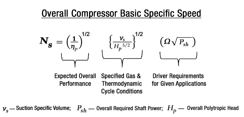
The objective for a thermal-mechanical energy storage scheme is not to isolate the design of turbomachinery components from the thermodynamic cycle, but to design them as an integrated system so as to increase the efficiency of the entire process rather than just the machine. This requires some customised solutions that are often not commonly available with off-the-shelf or turbomachinery products. Specific speed is a well-known design parameter that helps to determine the shape and size of turbomachinery for a given duty.
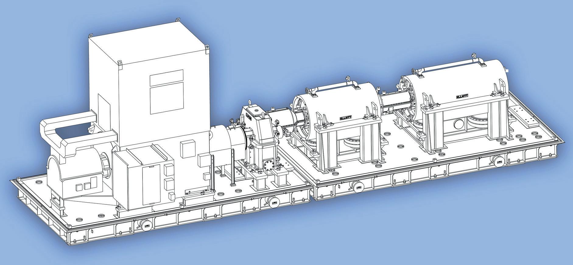
Figure 4 shows how the overall expected turbomachinery performance can be combined with the thermodynamic cycle to determine the overall specific speed of the system. In turn, this can be used for turbomachinery specific speed that works synergistically with the cycle to enhance overall efficiency. The specific speed can be effectively used to create a novel turbomachinery architecture that is highly customised to the chosen thermodynamic cycle.
August 2023 HYDROCARBON ENGINEERING 20
Figure 3. Two barrel tandem net gas hydrogen compressors driven by an electric motor (source: Elliott Group).
Figure 4. Connecting turbomachinery’s overall performance with thermodynamic cycle design.
The success of machinery-based energy storage systems requires the development of application-specific machinery in order to meet fast transient response requirements with high round trip efficiency, at low cost. The following list of design challenges that turbomachinery OEMs must consider clearly shows that some of these requirements are contradictory, and a fine balance is required for an optimal solution:
n System performance (efficiency) and operability (variability):
§ Efficient and flexible architectures, including blading shape.

§ Off-design performance matching, and flow range (surge).


n Cyclic operation:
§ Frequent start-ups and shutdowns at potentially high ramp rates.
§ Fatigue life.
§ Rotary inertia.
n High pressures and temperatures:
§ Materials.
§ Clearances, seals and bearings.
§ Thrust management.

§ Rotor assembly.
§ Equipment protection in hostile environments.
n Hostile environment:
§ Internal.
§ External.

§ Freezing concerns in expander.
Conclusion
Advancements in turbomachinery design will significantly improve the performance of various energy storage systems through increased efficiency, operating range, and application-specific design for each system. Improvements in efficiency, transient response, and operating range can significantly enhance the commercial viability of both standalone energy storage systems and systems that are coupled synergistically with other industrial thermal/electrical processes.
Note
• This article has been based on information from a short course given at the 2022 Asia Turbomachinery & Pump Symposium.5
References
1. DENNIS, R., ‘Hydrogen Storage: A Brief Overview of Hydrogen Storage Options’, Thermal-Mechanical-Chemical Energy Storage Workshop, (February 2020).
2. DI BELLA, F.A., and FAIRMAN, K.D., ‘Development of a 240,000 kg/Day Hydrogen Pipeline Centrifugal Compressor for the Department of Energy’s Hydrogen Delivery and Production Program’, Proceedings of ASME International Mechanical Engineering Congress and Exposition (IMECE), (2012).
3. KURZ, R., LUBOMIRSKY, M., and BAINIER, F., ‘Hydrogen in Pipelines: Impact of Hydrogen Transport in Natural Gas Pipelines’, Proceedings of ASME Turbo Expo 2020, Paper GT2020-14040.
4. KURZ, R., MILLER M., GOLDMEER, J., and MOORE, J., ‘Hydrogen Storage. In K. Brun, T. Allison, and R. Dennis, Thermal, Mechanical and Hybrid Chemical Energy Storage’, Unpublished manuscript, (2020).
5. ALLISON, T., TIMOTHY, C., BRUN, K., RIMPEL, A. M., and SMITH, N. R., ‘An Overview of Machinery in Energy Storage and Hydrogen Applications’, Short Course, Asia Turbomachinery & Pump Symposium, (2022).
Contact us for a free trial Optimized Gas Treating, Inc www.ogtrt.com +1 512 312 9424 CAPE-OPEN What it is What it can do for you Interface to combine & operate 2+ compliant software packages as one Keep using your favorite general purpose process simulator while integrating ProTreat® and SulphurPro ® the ultimate CAPE-OPEN compliant tools for simulating carbon capture, gas treating & SRUs Scan the QR code to view a demo of the wizardry https:// vimeo.com/826278213
Your Favorite Process Simulator
ProTreat®
SulphurPro®

August 2023 22 HYDROCARBON ENGINEERING
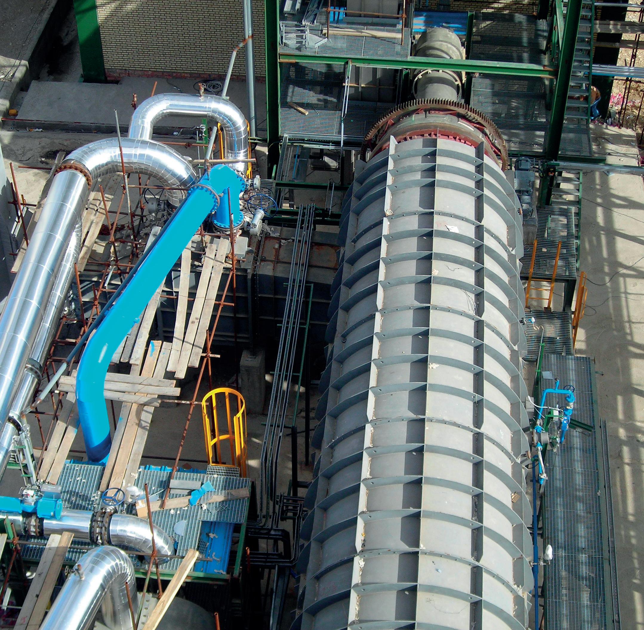
Ethylene is vital to the manufacturing industry as it is used in plastics, vinyl, rubber, and other common consumer products. Both US and global demand for ethylene has been growing steadily, and is expected to rise by over 5% annually up until 2030, at least. As a result, petrochemical companies have been investing in capacity expansions of ethylene crackers.
To keep up with increasing demand, one of the world’s largest single-site ethylene plants needed to increase air demand for the ethylene process. At this plant, compressed air is responsible for decoking the furnaces in the process of providing ethylene downstream of the chemical processing, supplying a rapidly growing demand for high-value polyethylene products. An important factor in determining the best solution was the customer’s desire to keep the existing foundation and reduce the civil engineering work that was required to upgrade the air system. However, the customer did not want to sacrifice key features required by API 672 that ensure the long-term reliability of the compressor package.
Project overview

The engineering and procurement team at the ethylene plant reached out to FS-Elliott in order to determine the best solution for their site. The customer wanted to save costs by using the existing layout, demanding minimal civil changes and avoiding the disturbance of key plant components. In addition to increasing air demand, the customer noted that the existing compressors were unreliable as they kept surging and shutting down as a result of high-temperature alarms on water coolers. The obsolete pneumatic control system was also unrepairable, and there were not enough instruments to monitor what was happening with the compressor during normal operation.
To gather a better understanding of what the customer wanted, FS-Elliott sent a sales engineer, who was the main point of contact, to visit the site and understand where the compressors would be placed. The sales engineer discovered that the customer’s current solution to increase air capacity was to rent diesel-driven screw compressors to keep up with the air demand. However, the diesel-driven
August 2023 23 HYDROCARBON ENGINEERING
Joseph Doerfler, FS-Elliott, USA, reviews the development and design of an API 672-compliant centrifugal compressor for one of the world’s largest single-site ethylene facilities, and details the steps taken to reduce overall costs while increasing system efficiency.
compressors were costly to operate and had limited daily runtime due to local regulations.
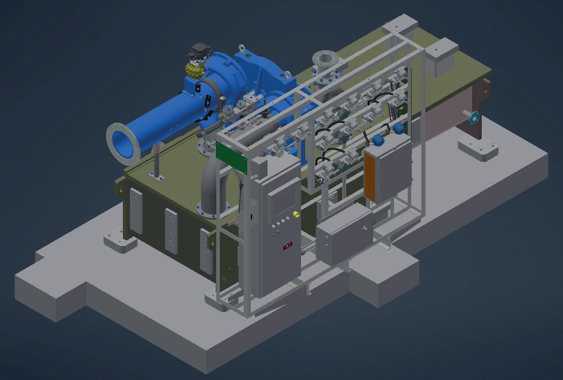
After completing the initial inspection, FS-Elliott reviewed the scope and provided a proposal for two 100% capacity PAP Plus compressors, highlighting the reduced operating costs of running a more efficient and reliable compressor package and the ability to install the new compressor on the existing foundation. Once the customer awarded the contract to FS-Elliott, initial meetings were scheduled to review preliminary drawings and unit outlines. These drawings outlined the custom designs of two separate, three-stage centrifugal compressors that would each provide a flow rate of 5000 ft3/m, a 10% increase over the existing units, and pressure of up to 125 psia. Both units were designed with NEMA 4X enclosures for the compressor control panel, junction boxes, and other instrumentation. The unit was also provided with additional features to increase reliability, including a dual oil filter, dual oil coolers, and SMART transmitters mounted in an instrument rack mounted to the compressor (see Figure 1).
Lower operating costs and reduce carbon footprint
The customer was not only excited about upgrading the air system, but was also looking forward to the opportunity to
significantly reduce operating costs. Being able to reuse the existing layout helped the customer make minimal civil changes, and limited any disruption to the process.
Not only would the customer save money by not significantly changing the layout in their plant, but they would also do so by returning the rented diesel-driven screw compressors. The replacement system would also help to reduce the customer’s carbon footprint, as diesel-driven units are harmful to the environment.
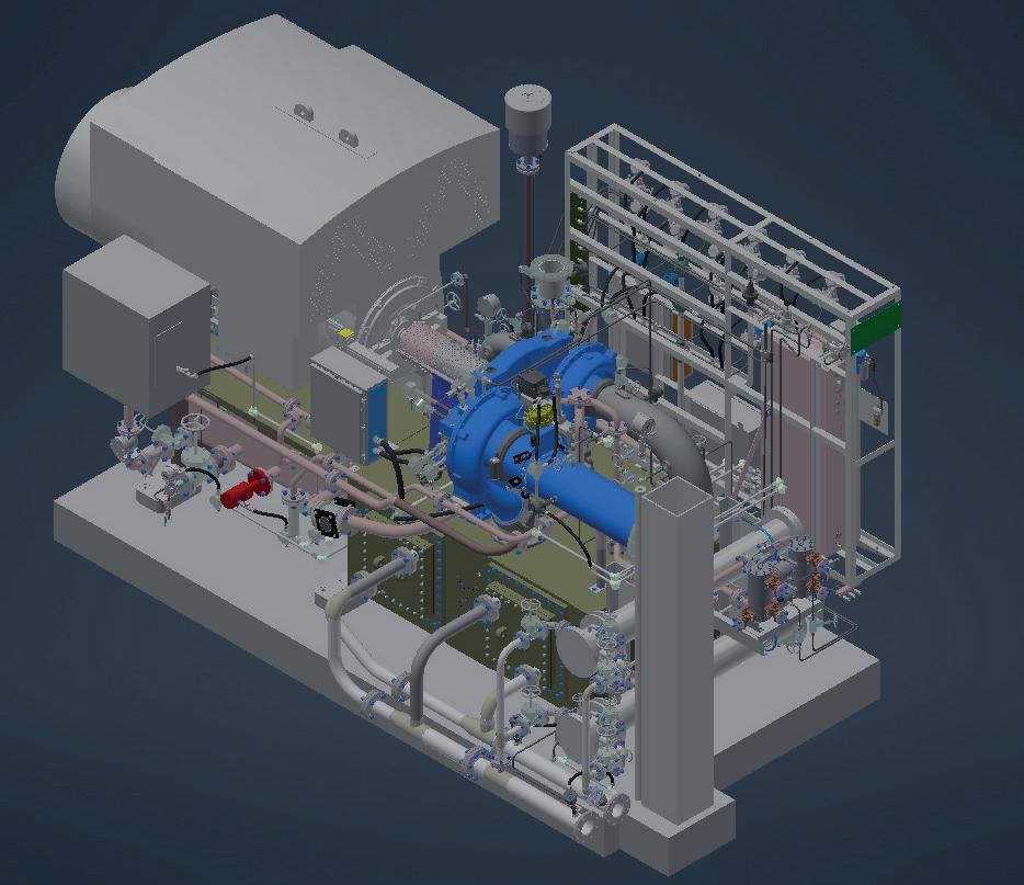
However, there were some challenges during the detailed engineering phase of the project, as the replacement compressors had to be designed as such that they would fit the existing plant layout. Since the foundation size could not be increased, FS-Elliott needed to shorten its standard baseplate design. To accommodate the existing foundation anchor locations, the baseplate mounting feet were increased in size to eliminate the need for drilling new holes in the foundation, as seen in Figure 2.
Redesigning the baseplate was the plan of action; but one major roadblock was that there was an existing piping support for the ethylene process that was located in front of the compressor. This had to be avoided so that the existing layout was not disrupted. Initially, there were two piping supports; FS-Elliott knew this might cause some creative layout problems on the PAP Plus package. The existing support ended up being unproblematic, as seen in Figure 3, as the compressor was placed as close as possible to save space for both units.
The other challenge was attempting to keep the existing piping that was provided by the general outline presented by the customer. The required connections were reviewed, and the necessary dimensions were taken into consideration to reduce the risk of complications onsite.
Customised control panel technology
To meet the customer’s scope of supply for its control system, FS-Elliott’s R2000 control panel was offered. This offered the plant the latest technology while including FS-Elliott’s Energy Advisor and maintenance notification system, ensuring that the compressor operated to its full potential without any unnecessary downtime. The Energy Advisor allows the customer to monitor the efficiency level of both PAP Plus compressors and provide recommendations for improved efficiency when required. As the reliability of the compressor was paramount to continuing operations of the ethylene plant, the maintenance notification system could provide proactive alerts for routine compressor maintenance. Additional options were added, including an NEMA 4X enclosure, 12 in. Allen-Bradley HMI, Simplex Power Supply and Allen Bradly Control Logix, and RS-422 Serial Modbus.
Project schedule
During the project, one of the end user’s project engineers served as the single point of contact, keeping communication open among all parties involved to ensure that the project was on schedule and within budget, avoiding miscommunication along the way. FS-Elliott and the customer’s engineering department worked hand-in-hand to ensure that the process was smooth.
August 2023 HYDROCARBON ENGINEERING 24
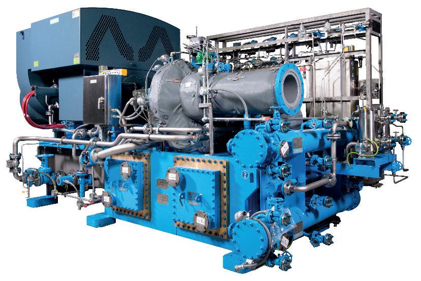
Figure 1. New FS-Elliott PAP Plus compressor.
Figure 2. 3D model of the FS-Elliott PAP Plus compressor with larger mounting feet to accommodate existing foundation holes.

Throughout the project, the customer wanted to ensure accessibility to key components in the compressor package, and requested that junction boxes be located on the right side of the main driver, and that the inlet air filter be bolted to the existing connection, amongst other specific details. 3D drawings were produced and inspected by the project

angle of the compressed air system allowed for the identification of areas that might have been overlooked in the project scope to be corrected before shipment. The customer experienced a slight delay onsite with regards to ensuring that the area was ready, so FS-Elliott held the PAP Plus compressors back at its warehouse until requested.
Testing and installation
FS-Elliott knew the requirements of the user’s industry and followed the API 672 standard to perform the full-speed, full-load mechanical tests. After completing the mechanical running test and sufficient cooling down, key parts, including bearings, seals and rotors, were visually inspected to identify possible quality issues. Testing on both units went smoothly, and there were no mechanical concerns. In order to minimise labour costs, the end user handled the entire installation process using its internal resources. Both units arrived at different staggered dates, to avoid space restrictions.
Conclusion
The PAP Plus centrifugal compressors that were deployed in this project have now been installed since early 2022. Since installation, the new units have helped the plant produce its product and provide the necessary air needed for the ethylene process. The close partnership between the customer and FS-Elliott resulted in a solution that delivered lower operating costs and a reduced carbon footprint, while
RUGGED, RELIABLE GAS ANALYSIS SERVOTOUGH SPECTRAEXACT 2500
• Flexible analysis for demanding process applications

• Accurate and stable real-time photometric sensing
• Designed for ease of use and low maintenance operation Learn
 Figure 3. A 3D model of an FS-Elliott PAP Plus compressor, including customer foundation and pipe support to prevent interference onsite.
more: servomex.com
Rhys
analysis in ethylene dichloride (EDC) and vinyl chloride monomer (VCM) production for polyvinyl chloride (PVC) manufacturing.

at the role of
One of the most widely produced polymers in the world, polyvinyl chloride (PVC), is a highly versatile material used in a wide range of applications. Its properties of chemical resistance and mechanical strength place it in high demand globally, and it is the third most produced polymer after polyethylene and polypropylene, being manufactured in both rigid and flexible forms for use in construction, electronics, transport, and healthcare products.
August 2023 27 HYDROCARBON ENGINEERING
Jenkins and Maria-Katharina Mokosch, Servomex, look
gas
Two routes exist for the industrial manufacture of PVC. The predominant manufacturing route involves the production of ethylene dichloride (EDC) and vinyl chloride monomer (VCM); these are intermediates with no direct applications themselves.
An alternative, acetylene-based route also exists, and is particularly popular in markets where there is a shortage of ethylene cracker feedstock, such as China, which is where more than half of VCM production capacity is acetylene-based.
Regardless of the method used to create it, the VCM is then mixed with water in the presence of polyvinyl alcohol, lauryl peroxide, or isopropyl percarbonate, where a catalytic reaction takes place. After a few hours, this produces PVC granules, which can be moulded to form a number of commercial products.
Gas analysis plays a vital role throughout these processes, helping to address the application challenges that arise. Effective gas and liquid phase measurements can assist operators to achieve precise control, ensure efficiency and safety, and maintain the quality of products.
Ethylene-based EDC-VCM production
EDC production begins with a direct chlorination process, with ethylene and chlorine being reacted together in a chlorination reactor. This typically involves a ferric chloride catalyst, used because of its high selectivity.
Ethylene is the controlling factor in the chlorination process, so it is important to measure its concentration levels for process control.
The reaction can be performed either at low (20 – 70˚C) or high (100 – 150˚C) temperatures. The low-temperature process results in the formation of fewer byproducts, but requires more energy to recover EDC. While the high-temperature process creates more byproducts, it utilises the heat of the reaction in EDC distillation, leading to considerable energy savings.
For safety reasons, oxygen must be monitored before the chlorination step in order to raise an alarm before any explosive conditions occur.
Another method of producing EDC is through oxychlorination. Later in the process, when EDC is converted to VCM, hydrogen chloride is also generated, and this can be utilised to produce more EDC by oxychlorination with ethylene and air (or oxygen).
Typically, the oxychlorination reactor is a fixed-bed reactor with cupric chloride catalyst packed in tubes while cooling water flows on the shell side for temperature control (a fluidised bed reactor can be used instead, but these do not offer heat recovery).
Temperatures above the optimum (around 300˚C) can lead to the formation of more byproducts, due to the increased oxidation of ethylene to carbon oxide, and cracking of EDC.
The crude EDC, whether it comes from direct chlorination, oxychlorination, or the recycle stream, must be purified to 99.5 wt% before pyrolysis. Purification includes washing with water or scrubbing with caustic soda to remove hydrogen chloride; drying to remove water; and removal of light ends and heavy ends by distillation.
The drying process is essential, as any trace of water in EDC is extremely corrosive and can damage plant equipment. To prevent this, the water level in the purified liquid EDC needs to be accurately monitored.
Next, the purified EDC is thermally cracked into VCM and hydrogen chloride in the pyrolysis furnace in the presence of a catalyst – usually charcoal pellets impregnated with iron oxide – under conditions of approximately 500˚C and 50 psig. At this temperature, purified EDC splits into VCM and hydrogen chloride, with conversion rates of between 50 – 65%.
Rapid cooling of the pyrolysis gases helps to reduce the formation of tar and heavy byproducts. The extremely high purity of the EDC feed – which, as mentioned, needs to be at least 99.5 wt% – reduces coke formation and fouling of the pyrolysis reactor.
Finally, the VCM produced through pyrolysis is purified. Quenching, splitting of hydrogen chloride, and fractionation are all used to separate the VCM from unreacted EDC, hydrogen chloride, and the remaining byproducts.
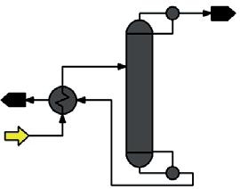
Quenching removes EDC from the stream and recycles it back into the EDC purification process. Hydrogen chloride is separated from the pure overhead product in the hydrogen chloride splitter, and then sent via the recycling stream to the ongoing oxychlorination reaction. The overhead product of the VCM fractionator is 99.9% VCM, which is transported to storage, while the bottom products of the VCM fractionator are recycled.
The oxygen concentration within the purified VCM product is measured to ensure product quality, and for safety.
Acetylene-based VCM production
An alternative route for VCM production is by reacting acetylene with hydrogen chloride. In this process, brine is first produced by mixing sodium chloride with water. The electrolysis of brine produces caustic soda, chlorine and hydrogen. Hydrogen chloride is then produced from hydrogen and chloride in the synthesis furnace. At this stage, it is necessary to monitor the purity of the hydrogen chloride and the unreacted chlorine.
Acetylene – produced from calcium carbide – and hydrogen chloride are mixed and fed into a catalytic reactor, where VCM is synthesised over a catalyst. The resulting VCM is purified, dried, and sent to storage or polymerisation.
As with the ethylene-based route, oxygen concentration is measured in the VCM product to ensure product quality, and for safety.
Gas analysis for process control
The ethylene concentration in the chlorination process is typically measured using an infrared analyser with a range of 0 – 100% in the feed and 0 – 40% in the crude EDC. The sampled gas is very corrosive and can contain significant levels of hydrogen chloride, chlorinated hydrocarbons, and water.
For this reason, nickel-based corrosion-resistant alloys, such as Hastelloy or Monel, are usually specified for the measurement cell and for the pipework used in the sample conditioning system.
The pressure and temperature of the process at the measurement point are usually above ambient, so the gas needs to be cooled before analysis. This allows any vapours that are present to condense and be removed. Drying the process gas also helps to reduce corrosion.
The measurement of liquid phase water in EDC is of critical importance, as the thermal cracking process produces
August 2023 HYDROCARBON ENGINEERING 28
BEST IN THE INDUSTRIAL
LNG application field
Gas pipeline feeding. Gas power generation stations. Gas peak shaving plants and LNG transfer in small to medium size shore terminals.
The experience acquired through the complete pumping systems supply launched Vanzetti Engineering in the development of systems and components dedicated to any type of LNG and LBG applications.

VANZETTI ENGINEERING. Widening the horizons of LNG sustainability.
www.vanzettiengineering.com
substantial amounts of hydrogen chloride and EDC, so any residual water will increase the corrosive nature of the process stream.
This will lead to damage of plant equipment, so minimising trace amounts of water in EDC is critical to the operation of any VCM plant. A specially configured infrared analyser can be used for this application.
Crude EDC from the oxychlorination reactor can contain a reasonable amount of hydrogen chloride and chlorine. As mentioned, a caustic scrubber, such as sodium hydroxide, is used to remove these from the process. Again, infrared analysis provides a solution, measuring the strength of sodium hydroxide both at the caustic scrubber inlet and after the acidic gas absorption.
The corrosive nature of the sample means that corrosive-resistant materials such as Monel, Hastelloy, PVDF and PTFE should be used. As the sample is in the liquid phase, temperature compensation is required on the infrared analyser. Temperature control of the sample may also be recommended in order to minimise errors due to sample temperature variations.
Additionally, any hydrogen chloride recycled from the stripper to the oxychlorination reactor must be clean and of high purity. Infrared analysis of this stream, in the range of 0 – 100% hydrogen chloride, is required to effectively optimise the reactor process control.
Infrared analysis for process control
Infrared sensing is a flexible measurement technology based on the unique light-absorbing properties of some gases. It delivers a non-contact, real-time detection of the selected gas’ concentration in a mixture, and is ideal for gas analysis for process control applications in EDC and VCM production.
The single-beam, dual-wavelength sensing technology uses a pair of optical filters mounted on a rotating disc, which pass through a beam of IR light alternately. The measure filter is chosen to pass light only at a wavelength that the gas to be measured absorbs, while the reference filter has a light passed through it at a wavelength that is unaffected by the gas to be measured. The difference in absorbance is measured by the detector and provides a direct output of the gas concentration.
This technique is virtually unaffected by common mode effects, such as contamination on the sample cell windows, as it influences both measure and reference signals equally.
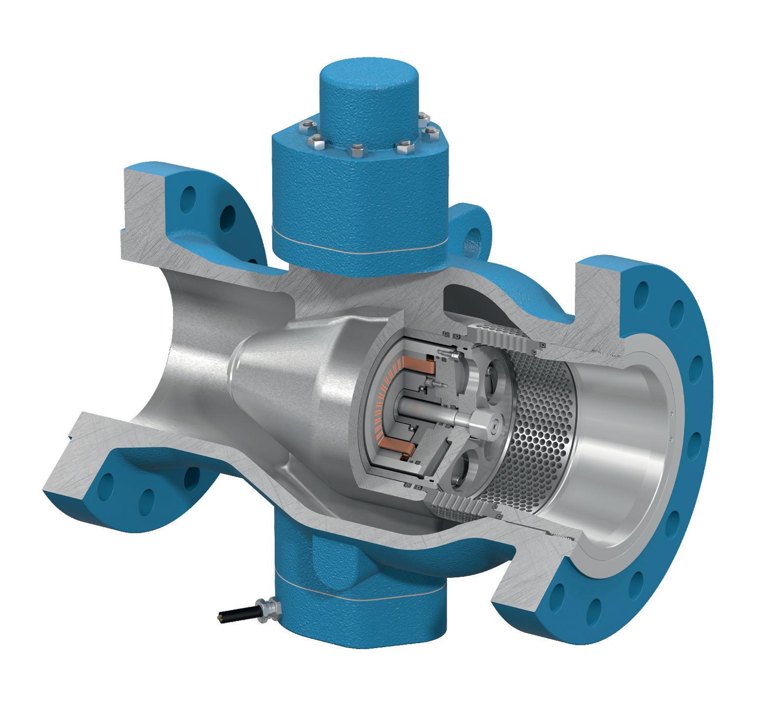
An industry standard in infrared sensing for EDC and VCM is Servomex’s SERVOTOUGH SpectraExact 2500 gas analyser, which has recently been updated with new electronics and ease-of-use features, meeting the latest European certifications and international safety approvals.
The analyser can also be configured for trace water measurements with a measurement cell designed for liquid samples. Typically, measurement ranges down to 0 – 50 ppm water in EDC are achieved. The instrument is calibrated using the Karl-Fischer titration method, a standard laboratory technique for trace water determination.
A special requirement in trace water measurement is the use of sample temperature compensation. Without compensation, sample temperature fluctuations will produce errors in the measurements.
As process uptime is of primary importance for plant operators, the ability to plan when to conduct analyser maintenance – and to increase the intervals between servicing points – is vital.
The SpectraExact 2500 typifies the latest developments in gas analysis, with a simplified user interface and increased focus on reliability and predictive maintenance, with built-in diagnostics.
Oxygen analysis for safety and optimisation
Oxygen measurement at the oxychlorination reactor is critical to the safety and efficiency of the reaction. Too little oxygen reduces efficiency, but too much can lead to the development of an explosive mixture in the reactor. VCM is a flammable gas, so it is also important to monitor any oxygen incursion into the VCM product as it is transported to storage and PVC manufacture.
A paramagnetic analyser is recommended to measure the oxygen concentration, typically in the range of 0 – 10%. For safety reasons, it is often necessary to install multiple analysers reporting to a voting system, prior to the chlorination stage, to ensure that the plant is fully protected in the event of an analyser failure.
Paramagnetic sensing is a well-proven oxygen measurement technology that offers an accurate and fast response. It is a physical measurement technique, with no chemicals or electrolyte to replace, and maintenance requirements are low.
Examples of paramagnetic oxygen analysers include Servomex’s SERVOTOUGH Oxy 1900 and OxyExact 2200 analysers. The Oxy 1900 is suitable for process gases with a dew point temperature of 10°C below ambient temperature, and can be used for measurements in the VCM gas line where the sample has a low hydrogen chloride level and dew point.
The OxyExact 2200 high-temperature model is suitable for process gases with a dew point of up to 105°C without removal of condensable vapours; therefore, it can measure oxygen in the process stream prior to chlorination. It also offers the capability to connect up to six transmitter units to a single control unit, and can be used to create a voting system.
The sample at this part of the process contains high levels of hydrogen chloride (about 30%) and water vapour (with a dew point of approximately 80°C). To prevent condensation, the sample line is maintained at 95 – 105°C, preventing corrosion and enabling a true reading of oxygen concentration to be obtained.
Conclusion
Process efficiency, product quality, and safety are all key considerations for plant operators manufacturing EDC and VCM for PVC production. Gas and liquid analysis solutions can help meet the challenges of these applications, delivering the accurate and reliable measurements required.
No less important are the issues of uptime and productivity. By utilising expert applications knowledge and best-fit technologies, gas analysis suppliers can help to avoid corrosion and condensation problems that affect sampling systems and plant equipment, delivering key measurements for a longer lasting process.
August 2023 HYDROCARBON ENGINEERING 30
Tackling global warming will mean persuading the world to abandon oil, coal and gas reserves worth many trillions of dollars. The burning question is whether that can be done. Will we wake up to the threat in time? What can we do to slow the rate of global warming? What mix of politics, psychology,

August 2023 31 HYDROCARBON ENGINEERING
Mark Naples, Umicore Coating Services Ltd, discusses the urgency of climate change, and suggests gas detection measurement as one way to reduce emissions from the oil and gas industry.
economics and technology might be required to slow its march?
Climate change is one of history’s most fascinating scientific, political and social puzzles. Carbon emissions are still accelerating upwards, following an exponential curve that goes back centuries, and one reason for this is that reductions in one place lead to increases elsewhere.
The search for low-carbon fuels, the impact of shale gas, the prospect of finite reserves, and the global political realities of the competing demands of oil-importing and oil-exporting countries make the sector high risk, but the economic rewards can be hugely lucrative.
As with everything in life, evolution is constant, and the gas detection industry is no different. Looking back to the industry’s origins 65 years ago, the first groundbreaking devices were developed to highlight how much things have changed. Not only has product innovation changed, but there has also been a massive evolution in the marketplace itself.
The price and performance of devices are following a trajectory that places technology in the hands of those who need it most. It is for this reason that Umicore Coatings Services’ infrared (IR) filters are used by a selection of the industry’s major players, helping customers to meet their health, safety and sustainability goals.


Clouded judgement
If the world is to come anywhere near to meeting its climate change goals, the oil and gas industry will have to play a big part. The industry’s operations account for 9% of all human-made greenhouse gas (GHG) emissions, and the fuels that are produced create another 33% of global emissions. The magnitude of this challenge underscores the difficult reality of having to operate, maintain and invest in old, diminishing oil and gas assets before eventually phasing some of them out.
Every day, tonnes of carbon dioxide (CO 2 ), methane, nitrous oxides (NO x ) and other unnoticed emissions leak into the atmosphere, untracked and unmeasured – but not without impact. According to The World Bank, the global economy loses more than US$8 trillion annually, but action to identify its presence and catalogue its make-up and levels still lags. 1
Integrating IR optical filters into a gas detection and analysis system enables any business to identify and monitor leaks of any size to help build a comprehensive emissions profile. This technology has placed manufacturing industries on the verge of a data-driven revolution, one where data sharing will enable manufacturers to establish a carbon emissions baseline and provide the foundation for initiatives to decarbonise production operations.

Worldwide, oil and gas companies squander at least 210 billion m 3 of natural gas yearly through leaks, flaring, and other sources that emit methane, a potent climate pollutant, into the atmosphere.
When countries are worried about keeping homes warm and lights on, plugging leaks and stopping gas waste is low-hanging fruit – a quick and cheap option for filling some of the energy gaps created by the loss of Russian gas. The good news is that technology capabilities now feature the ability to evaluate a greater number of wells and pipelines more frequently, and optimise or restore their production or transportation more successfully, becoming one of the more lucrative return on investment (ROI) activities for operating companies. Capturing the mind-boggling amount of methane wasted each year across the oil and gas industry would mean progress for both the climate and energy crises.
The first challenge is the complexity of the system. Hundreds of thousands of pieces of equipment owned
August 2023 HYDROCARBON ENGINEERING 32
Figure 1. Umicore designs and manufactures precision IR filters. Widely used to detect the presence of noxious or flammable gases in the atmosphere, IR filters are a key component of preventative maintenance safety systems that are critical to the oil, gas and energy sector.

AUMA CORALINK Discover our digital ecosystem coralink.auma.com AUMA SERVICE
AVAILABILITY Expert care for your actuators CORALINK
MAXIMISE
by various companies attempt to detect an invisible gas seeping out of a loose valve or compressor upstream. It is little wonder that many emissions go unnoticed by operators.
Routine operations in the oil and gas sector produce emissions from different environments and sources. To repair a pipeline, the gas must be turned off and the pressure must be let out, temporarily increasing emissions. These expected emissions are less of a problem; it is the unexpected emissions that need to be reduced.
Businesses extracting gas to sell do not want to vent that product into the atmosphere. On top of that, there is intense regulatory pressure, with most governments looking to reduce GHG emissions. The degree to which both shareholder and public pressure have also driven companies to think about and reduce their emissions as much as possible cannot be understated.
In the past, companies and regulatory bodies have relied on ‘bottom up’ or ‘engineering-based’ estimates, which factor in the number of components in the field. However, recent technological advances have led to a more advanced approach: measuring concentrations of GHGs in the air, and then inverting for emissions. A number of companies are still using the bottom up approach, but are trying to figure out the best technologies to supplement that.
Other technologies work better in different areas. Ground-based networks of sensors, and mobile sensors on vehicles or drones, can carry different instruments around a site, and using IR detectors is industry standard – and for a good reason.
The most important area to focus on is identifying easily solvable high-emission events. This means that it is essential to have sub-monitoring for upset conditions that are not planned. People are deploying different technologies to help with this process, and start-ups are experimenting with different methods.
The largest and most cost-effective opportunities are in the oil and gas sector. This is because fixing leaks can be as simple as tightening a valve, replacing a gasket, or tuning an engine. The challenge is not fixing but rather finding the leaks. Thankfully, the ability to detect methane has rapidly advanced in recent years. There are handheld instruments as well as sensors on aircraft and drones, and now there are some satellites orbiting to specifically detect methane. With these tools, the International Energy Agency (IEA) has found that global methane emissions from oil and gas operations could be cut by 75% with existing technologies. 2
Detecting excellence
Monitoring emissions from stationary sources of pollution, such as power stations, manufacturing plants and other industrial facilities, is essential for a whole host of reasons. This process allows the site operator to ascertain the concentration of various gases being emitted into the atmosphere, and enables the relevant authorities to check whether the site complies with its legal obligations.
Plant owners who must abide by certain regulatory frameworks invest in measuring equipment to report what and how much is being released from the stack. In the market for measuring emissions, there are a number of measuring technologies, and Umicore Coatings Services’ IR gas detection filters are one of the many options.
Most current applications trigger an alarm for the operator based on high readings from gas detectors. However, with the industry push to incorporate safety gas sensors into shutdown systems, the need to design, calibrate and commission these sensors correctly, in order to minimise nuisance trips, is increasingly important.
Optical laser technologies are central to most modern gas monitors. In such devices, a laser beam is passed through the gas sample of interest onto a detector or sensor that converts the incoming laser light into electrical signals. Laser-based sensing technologies have become widely adopted for gas detection and analysis due to their quick response times, high sensitivity, and reliability.
While laser sensors can be designed for any region of the electromagnetic spectrum, many gas analysis devices operate in the IR. This is because many small gaseous species, such as methane, CO 2 , and other hydrocarbons, absorb IR light very strongly, so it is easy to design devices with a sensitivity that extends to parts per billion. Their additional advantage is that many different spectral lines characterise the absorption profile of these gases in the IR. This means that many features in the spectra can be used to identify chemical species with greater accuracy, and the wealth of information that can be provided with laser sensors makes gas analysis a powerful tool.
IR emitters within the sensor generate beams of IR light. Having passed through a sampling chamber, a filter in front of the detector blocks out light that is not at the desired wavelength. In contrast, the sensor measures the intensity or attenuation. This is then used to determine the concentration based on the absorption of IR radiation as it passes through a volume of the gas.
Among their benefits are fast response times and accurate results, and they do not require oxygen or external gases to operate. Technological advances have also resulted in detectors continuously monitoring combustible gases and vapours within the lower explosive limit and providing alarm indications. These can be deployed within oxygen-deficient or enriched areas, require little calibration, and are immune to sensor poison, contamination, or corrosion.
Environmental monitoring and protecting against potentially dangerous conditions can be difficult to manage without reliable data streams and monitoring of a site perimeter that gathers environmental data. For this reason, an increasing number of companies are turning to boundary monitoring technology to measure the level of risk and ensure that they adhere to environmental limits and guidelines while protecting against health hazards.
Companies operating in fast-changing environments can also use a handheld particulate monitor to instantly
August 2023 HYDROCARBON ENGINEERING 34
detect dangerous concentrations of airborne particles during spot checks and walk-through surveys. This technology is not merely for preventing disasters; it can collect detailed emissions data and build a complete emissions profile around a business and its regional, national or international operations. With industries on the verge of a data-driven revolution, this data sharing will enable manufacturers to establish a carbon emissions baseline and provide the foundation for initiatives to decarbonise production operations.
Value in versatility
Energy creation and distribution have driven society’s progress for centuries. Increasingly, there is an urgency to move towards a cleaner, digitised and democratised energy economy. The energy industry has been built on invention and reinvention, and the energy transition is not a new concept. Several shifts have been witnessed – from coal to the rise of natural gas, to the shale revolution and the advent of renewable energy. Energy has always been an industry in transition – managing volatility, advancing technology, and innovation to power the world’s progress and economic development is simply what it does. That role has never been more important than it is right now.
Thankfully, industrial gas detection measurement is a mature market that expands as devices become cheaper at the compliance end, and smarter at the

top end. On the one hand, Umicore works with original equipment manufacturers (OEMs), stripping their devices back to basics, and focusing on functionality, cost and battery life for low-cost markets. On the other hand, the company assists in driving advances such as connectivity, which opens up new opportunities and allows end users to use their devices in ways that they have not before.
The company works closely with customers, through a consultative approach, to develop custom IR designs that balance performance reliability with production efficiency. In doing so, a range of bandpass optical filters suited to environmental, gas detection, and analysis applications are offered, with a centre wavelength anywhere on the near infrared (NIR) to far infrared (FIR) spectrum, with steep-edge and deep blocking capability.

By reducing fugitive emissions, organisations can do the right thing by proactively and transparently responding to the climate change crisis with tangible steps that lead to measurable results for both the environment and business.
References
1. ‘What You Need to Know About Climate Change and Air Pollution’, The World Bank, (1 September 2022), https://www. worldbank.org/en/news/feature/2022/09/01/what-you-needto-know-about-climate-change-and-air-pollution
2. ‘Methane abatement’, IEA, https://www.iea.org/fuels-andtechnologies/methane-abatement
Umicore Coating Services Ltd Tel: +44 1382 833 022 Email: coatingservices@umicore.com Website: eom.umicore.com/infrared-solutions From prototype design to production scale-up services NIR to FIR filter expertise on Ø100mm/4” wafers with deep blocking In-house dicing capability Complete filter wheel assembly manufacture 30+ years of optical coating experience D i scove r Keep Updated For the latest news visit: www.hydrocarbonengineering.com Keep up to date with us to read the latest downstream oil and gas news

Numerous published articles discuss the complexities of combustion measurement and process optimisation of gas-fired process heaters, with a focus on the merits of combustion efficiency and the correlated reduction in operating costs and emissions. Whilst these are obviously crucial factors, there is an overlooked safety consideration, due to the often unexpected presence of unburned methane (CH 4 ). This article will highlight the importance of a multi-component measurement approach to mitigate this hazard and provide true insight into the safe operation and control of any gas-fired process heater.
Industrial facilities across the globe, including petrochemical plants, fine chemical plants, and refineries, operate large numbers of process fired heaters, primarily to heat precursor materials, as part of a chemical reaction or for steam generation for use across the plant. Due to the vast quantities of fuel consumed and, increasingly, the cost involved in operating such highly energy-intensive processes, there has long been a necessity to optimise the combustion process to ensure optimal fuel consumption, while reducing plant emissions.
Figure 1 is an illustrated overview of combustion efficiency, demonstrating the ideal control point (crossover point) for
August 2023 37 HYDROCARBON ENGINEERING
Stuart Rye, NEO Monitors AS, Norway, considers whether methane can safely exist in a hot-fired process heater during normal operation.
maximum efficiency, thus saving fuel and reducing carbon dioxide (CO 2 ) emissions – which is of increasing importance due to ongoing decarbonisation programmes – while also maintaining the lowest possible levels of carbon monoxide (CO), nitrogen oxide (NO x ) and sulfur oxide (SO x ) emissions. These requirements have quite rightly led to a focus on the measurement of oxygen and the measurement of CO, or CO equivalent (COe), for optimal trim control.
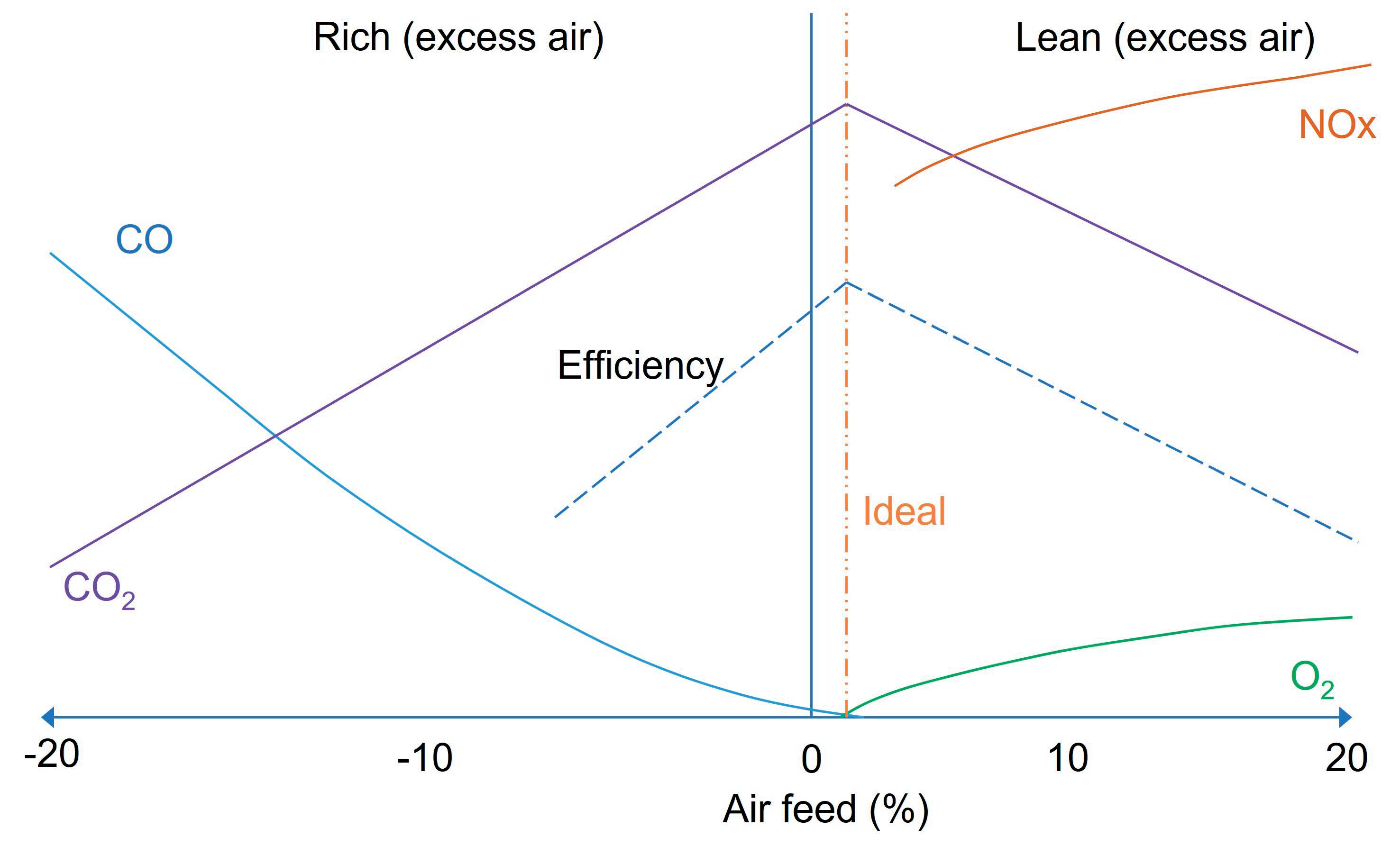
In order to ensure complete combustion, fired heaters are normally operated with a higher volume of combustion air than the stoichiometric combustion curve would assume. Without this ‘excess air’, in practice, not all of the fuel would be burnt, as not all of the oxygen would be available for combustion, leading to a fuel-rich condition, incomplete combustion, elevated levels of CO emissions, and increased fuel costs.
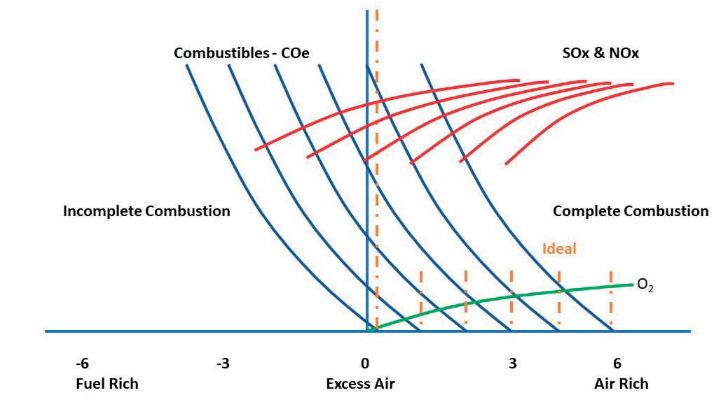
Regardless of the specific design of the heater, the key to optimal performance is to maintain the balance between the excess air and the detection and control of the emission of combustibles, principally CO or COe, and to operate within the design envelope of the heater, thus preventing instability.
The challenge, however, is that the ideal control point (crossover point) is not fixed, as seen in Figure 2. This point changes, depending on the following factors:
n Load variation.
n Fuel composition, particularly if waste gas fuel feed is used (which has a different heating value).
n Fuel density.
n Atmospheric humidity changes.
n Heater load variations.
n Burner fouling.
n Age and condition of the system.
It is clear that a multi-component measurement approach is needed in order to optimise the process. There are numerous combustion gas analysers that are available for the measurement of oxygen and optional COe to monitor and provide the trim control signal and maintain the desired air-to-fuel ratio. These are typically based on contact-based zirconia oxide and pellistor, or ‘thick film’ catalytic technologies, for oxygen and COe measurement, respectively.
Although these technologies are widely used, a significant drawback is that they cannot be installed in the radiant zone of the heater due to the high temperatures, and are therefore typically installed in the convection zone where measurement errors can occur due to air leakage. There is also a significant safety concern to consider, as zirconia cells operate at high temperatures (circa 700°C), so there is potential for flashback to occur, if unburnt fuel comes into contact with the measurement cell.
In recent years, these drawbacks have led to the increasing use of in-situ optical analysers based on tunable diode laser absorption spectroscopy (TDLAS) for combustion measurement, displacing traditional techniques (see Table 1). The drivers for this transition are the demonstrable benefits of using TDLAS analysers for combustion analysis, including measurement across the entire cross section of the radiant zone, ensuring analysis of the total heater profile is performed, the non-contact and safe optical measurement technique, and the flexibility of offering a combined multi-component analysis.
An evolution in TDLAS signal processing and hardware design
Large process heaters can have diameters of 25 – 30 m or even greater, equating to a long
August 2023 HYDROCARBON ENGINEERING 38
Figure 1. A typical combustion curve.
Table
TDLAS Zirconia oxide and COe catalytic sensors Across the burner average reading Point measurement only Fast response in seconds Response time typically 30 – 45 sec. True oxygen, CO and CH4 measurements Thermal response for CO and CH4 High temperature operation Typically 900°C maximum Safe non-contact optical measurement Potential for flash back from unburnt fuel Low maintenance High maintenance – typically monthly
Figure 2. Ideal combustion point variation.
1. Combustion measurement technique comparison
TRi-SHARk
cONTROL VALVE
zERO LEA k AGE*
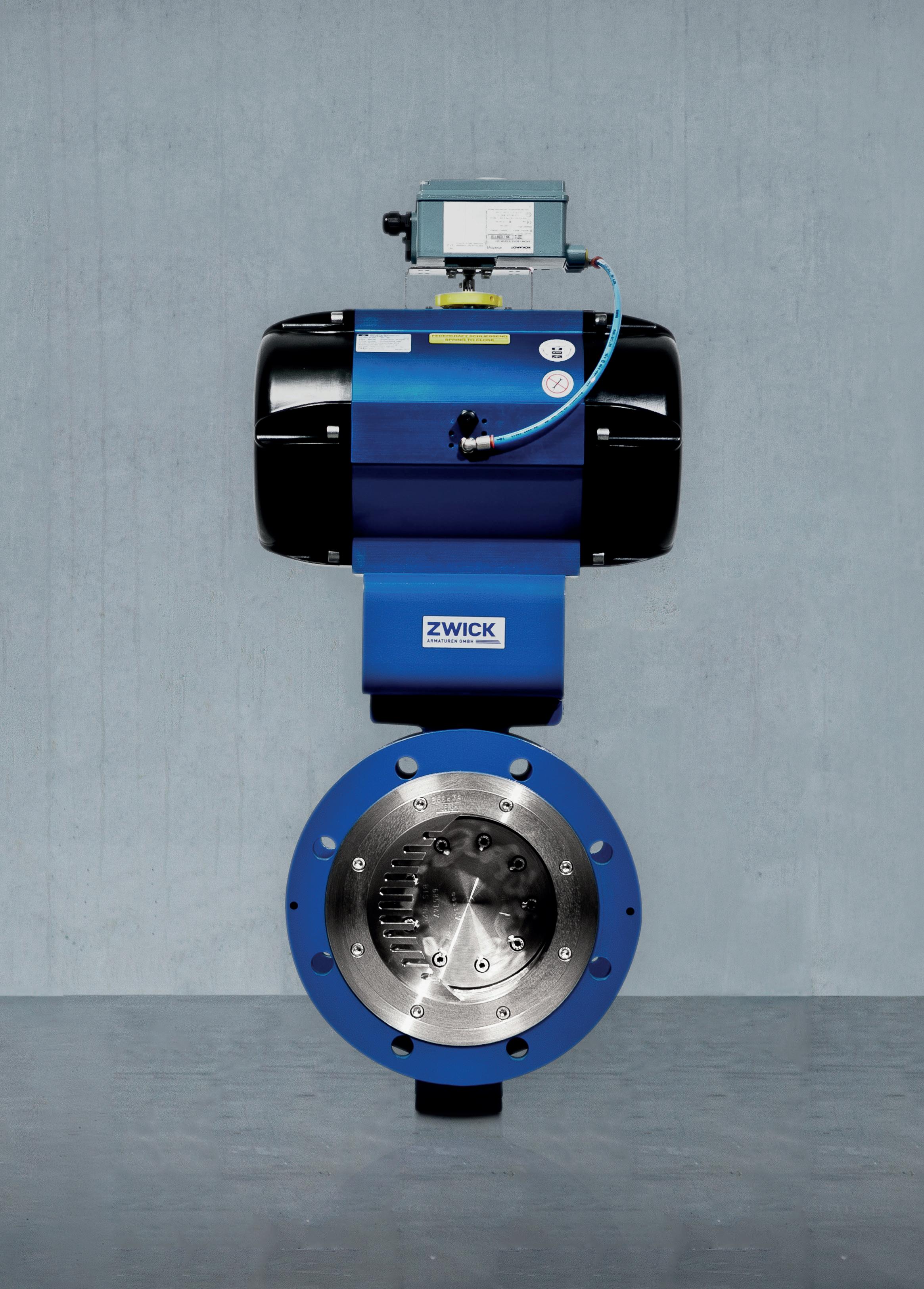
www.zwick-VALVES.cOM *acc. to API 598
optical path length (OPL) for the analysers, i.e., the distance from the laser transmitter to the receiver. Over such long OPLs, substantial signal attenuation occurs. For example, CH 4 is a very strong infrared absorbing gas, and over long path lengths it can affect and distort the adjacent CO absorption peak – and even more so if the fuel composition varies, leading to interference, due to baseline distortion within the scanning range of the laser.
Additionally, there is a requirement for a wide dynamic range for CO measurement, typically from ppm levels during normal operation up to percent levels for safety. Despite all of the obvious advantages of TDLAS analysers that have been highlighted in this article, these specific requirements create a challenge that has to be overcome in order to provide the required performance.
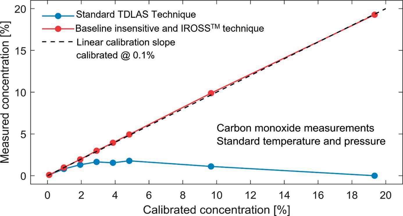
These requirements have led to the development of a new evolution in TDLAS signal processing, combined with innovations in hardware design, to offer a robust, comprehensive and high-performance multi-component combustion analysis.
The first task in doing so was to overcome the problem of baseline distortion, due to strong absorption nearby from the varying background gas compositions within the heater. TDLAS analysers typically work by scanning the laser across a range of wavelengths where the absorption peak of the measured gas resides. It is important that there is no absorption by other gases that are present in the process within this scan range, as a stable baseline is necessary to provide a reference
(a close wavelength where there is no absorption). If this baseline is not established, this will result in degraded measurement performance.
The solution was the development of a true innovation in signal processing, by combining multi-variate chemometrics and traditional TDLAS methodologies into a robust signal processing algorithm. This solution allowed for the real-time analysis of the gases of interest within complex spectra, even when there are adjacent interfering/overlapping absorption peaks, eliminating interfering species from the measurement in order to derive an accurate and reliable measurement.
This new, advanced in-situ real-time overlapping spectral separation (IROSSTM) signal processing technique is a standard feature of NEO Monitors’ LaserGasTM III Ultra analyser, and is utilised for combined CO/CH4 measurement.
This baseline-free measurement technique also allows for a greatly enhanced dynamic range compared to normal TDLAS techniques. Figure 3 illustrates this further. In traditional TDLAS methods, the dynamic range is limited (blue curve). Using the LaserGas III Ultra algorithm, a near linear response is maintained over a large dynamic range and OPL, which is essential for this application.
One further consideration when planning to utilise TDLAS analysers on a fired heater is the lack of availability of additional flange pairs to mount multiple analysers. Usually multiple opposing flange pairs is simply not an option in most cases, as this could potentially impact the integrity of the heater structure. This limitation has been overcome with the development of the T-Flange accessory, which enabled both the LaserGas III oxygen and LaserGas III Ultra CO/CH 4 analysers to be mounted across a single flange pair, as shown in Figure 4, reducing installation costs and offering a robust solution for any process heater, without modification.
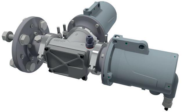
Safety considerations
Start-up and shutdown
It is well-documented that some of the most critical periods are during start-up and shutdown of a process heater. One of the greatest concerns at this juncture is the potential for a flame-out situation, where unburned fuel could cause severe damage to the heater if it were to ignite higher up in the structure, potentially damaging the internal tubes or their supports, and even leading to an explosion.
For safe operation of the heater, stability of the combustion is of paramount importance during this critical phase. If the air-to-fuel ratio exceeds the operating tolerances of the burner, instability will occur, which can lead to an unstable flame or a flame-out situation. If this occurs, it is imperative that it is acknowledged, and that action is taken to
August 2023 HYDROCARBON ENGINEERING 40
Figure 3. Comparison of dynamic ranges.
Figure 4. T-Flange dual analyser mounting accessory.
prevent a potential explosion risk. These scenarios have been increasingly recognised and better understood, and procedures are typically put in place to mitigate such occurrences.

Having a fast-response, in-situ CH 4 analysis tool, capable of detecting such an event, offers a considerable level of increased safety and should be considered as essential in any comprehensive burner management system (BMS). This is particularly important for CH 4 measurements, as the analyser can detect any unburnt fuel pockets across the entirety of the burner, which could otherwise go undetected during start-up and shutdown.
CH 4 present during normal operation
Such a multi-component measurement TDLAS system was recently installed at a customer’s site in the US on a three-cell natural gas-fired process heater. Due to the flexibility of the TDLAS technology, a secondary and specific CH 4 measurement was available from the CO analyser. Table 2 details the basic configuration of the two analysers that were installed: a LaserGas III analyser for oxygen and a LaserGas III Ultra analyser for combined CO/CH 4 measurement.
The Ultra version utilised the IROSS advanced signal processing algorithms to remove the background interfering gas influences, and provided the required large dynamic ranges across
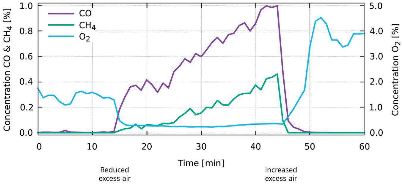
the very long optical path – ideal for this large process heater installation and beyond what would be typically viable if using traditional TDLAS analysers.
The CH 4 measurement was to be used principally to detect CH 4 during start-up and shutdown of the heater,
SAY GOODBYE TO MULTIPLE UNITS
LaserGas™ iQ2
the first multi-component in-situ analyzer for combustion control & safety.
Measure O2, CO, CH4, H2O and process temperature - with one single analyzer.
 Figure 5. Increasing CH4 levels detected during normal operation
Analyser type/configuration 1 x LaserGas III oxygen 1 x LaserGas III Ultra CO/CH4 Gas mix Natural gas fired Process temperature 700°C Process pressure 2.5 mm (0.1 in.) water below atmospheric OPL 27 m
Table 2. Installation configuration
Reliable, durable, fast and precise PERFORMANCE YOU CAN TRUST
www.neomonitors.com
as previously discussed. However, the operators soon discovered that the analyser was detecting increasing CH 4 levels during periods of normal operation (see Figure 5). From this graph, it can be observed that there is an instant CO breakthrough as the oxygen levels are reduced, as would be expected, followed by an increase in both CO and CH 4 concentration, as increased levels of fuel were introduced, whilst simultaneously maintaining a very low oxygen level.
Under these conditions, combustion was still taking place, but not to completion. However, no flame-out situation was occurring. It is clear from this specific operating profile that under such conditions, CH 4 can indeed be present in the heater, even during what is considered a normal operation cycle. As the autoignition temperature of CH is around 600°C, it is usually assumed
the operator to better understand the operational performance of the heater, and to proactively mitigate any potential explosion hazard.


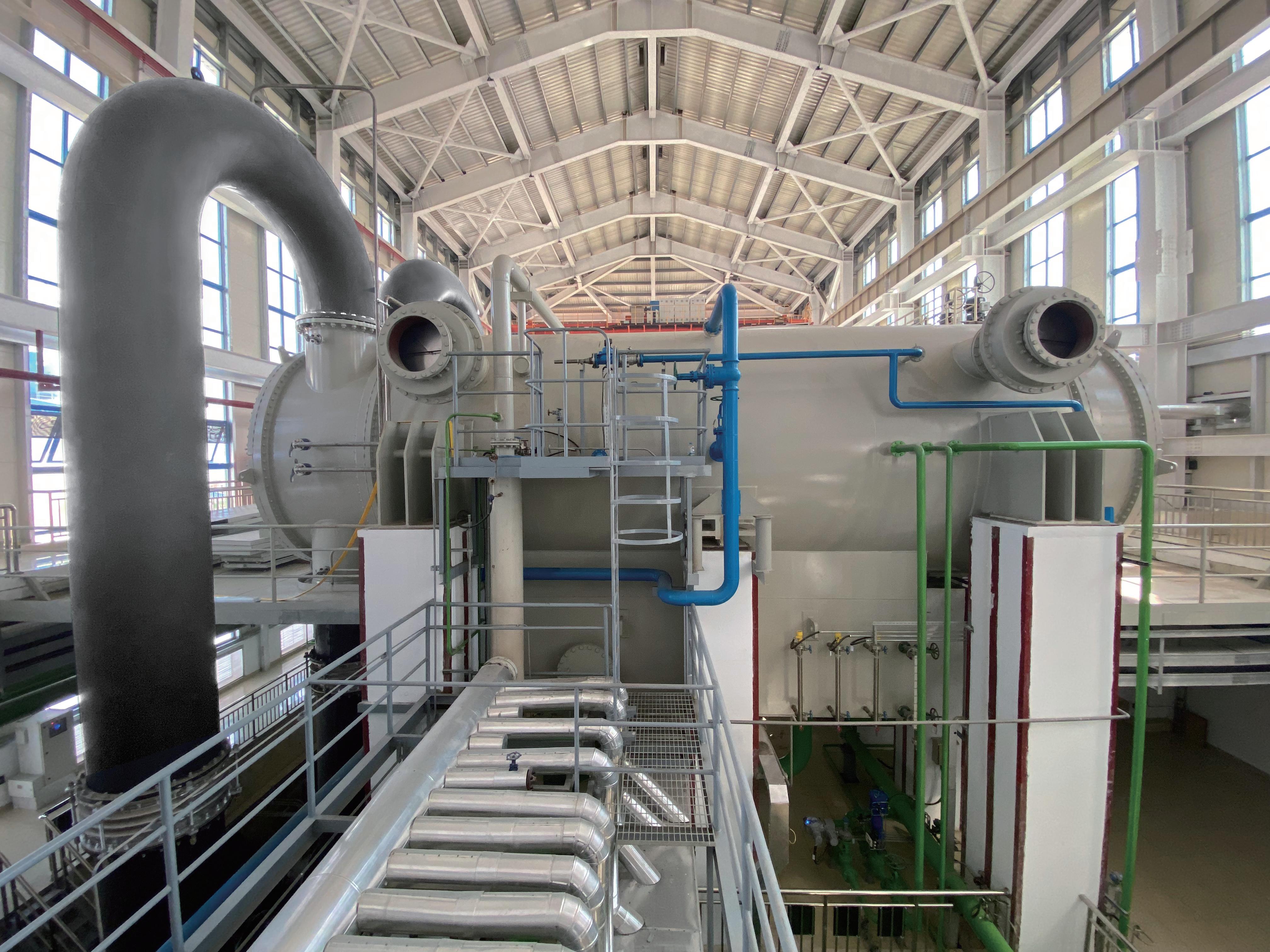
Conclusion
The real-world measurements in Figure 5, conducted on a large gas-fired process heater, clearly demonstrate that unburnt CH 4 can indeed be present during the normal operation cycle of the heater. The addition of a reliable and interference-free LaserGas III Ultra CH 4 measurement tool, combined into a multi-component measurement oxygen and CO/CH 4 TDLAS measurement solution, provides a true insight into efficient heater performance during all phases of operation, as well as detailed insight into the dynamic and fast-changing conditions within the heater, ensuring safe operation and invaluable protection
All process heaters operate at high temperatures and are constructed with process tubes inside a refractory-lined enclosure, which is heated by radiant heat from gas firing or, less commonly, oil firing.
Refractory linings are insulating and minimise heat loss, making them essential to retaining a high-temperature environment. However, when subjected to high temperatures, refractory can deteriorate and potentially lead to failure if remedial work is not carried out.

August 2023 43 HYDROCARBON ENGINEERING
Johannes Poth, Integrated Global Services (IGS), Germany, explores five common causes of refractory failure, and outlines how to fix them.
Types of refractory lining include refractory ceramic fibre, brick, and castable or concrete. If refractory failure results in an unplanned shutdown, this can cost plants more than US$1 million/d in lost production.
This article will discuss the most common causes of refractory failure, how to inspect fired heaters or furnaces for damage, and the methods of repairing refractories online without the need to disrupt normal operation.

Five common causes of refractory failure
Deterioration due to length of service
As refractory linings age, their physical properties change. The high-temperature environment causes microstructural changes to the binders within the materials, leading to a loss of surface or internal strength. If the refractory material carries a compressive load, such as bricks or castable linings, this can lead to local or widespread failure.
If the refractory is subject to flame impingement, which is common in many radiant wall applications, the useful life will be shorter.
In oil-fired heaters, refractory deterioration is accelerated by corrosive agents in the combustion products. Fortunately, there are few cases where oil firing is now used.
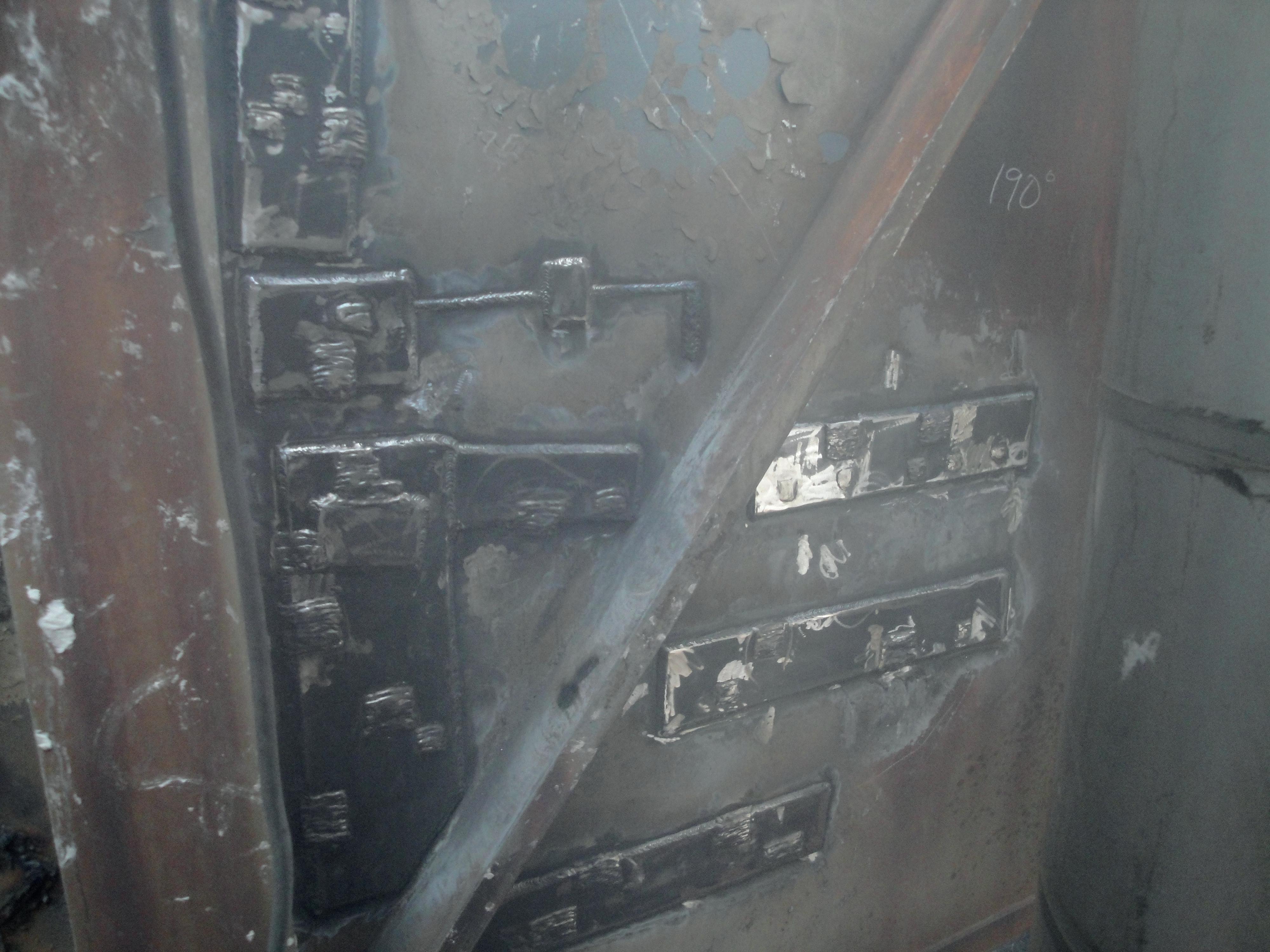
Incompatible refractory materials
A combination of refractory materials is a common feature in fired heaters. Openings such as doors often use fibre and brick material, and peep sights may use insulating fire bricks (IFB), castable, or fibre modules.
A standardised design using different materials can be challenging, as each material has varying properties at high temperatures. Therefore, refractory linings can become damaged, leaving the shell exposed to hot flue gases, and causing hot spots.
To lower the risk of mismatched refractory materials, it is a good idea to work closely with the refractory supplier to ensure that comparable materials are used around openings.
Loss of support
All types of refractory linings are attached to and supported by the external steel shell of the fired heater. The conventional support is provided by an anchoring system, which is welded to the shell.
Frequently, the welded joint between the shell and the anchor is compromised by corrosion, and support is lost. The corrosion is caused by hot flue gases penetrating the refractory lining and condensing upon reaching the cooler shell. The local environment is ideal for rapid oxidation, or corrosion of the weakest point: the weld.
Once support is lost, individual bricks, modules, etc. can fall away, leaving the metal shell exposed, which creates a domino effect and failure of the adjacent refractory lining.
At a plant in Europe, a hot spot was discovered on the transition shell ducting between the radiant and convection sections of a CCR Platformer. In this case, the failure of the ceramic fibre blanket in the roof left the shell exposed to hot flue gas. This caused the external shell temperature to exceed 560°C/1040°F.
To prevent overheating the shell until failure, the production rate on the CCR Platformer had to be decreased, resulting in a loss of production of more than US$400 000/d.
The plant used Hot-tek’s hot refractory repair service to fix the issue until the next planned turnaround. This service will be discussed in more detail later in this article.
Mechanical stress
There are several factors that can cause mechanical stress, which then leads to refractory failure. These include:
n Vibrations: vibration or interference from other equipment can cause refractory to become displaced and break down over time.
n Thermal expansion/spalling: this occurs when refractory linings expand and contract at different rates, due to thermal conditions. This often leads to cracking and spalling, which can cause failure if not repaired.
n Impact: mechanical impact from falling objects or components can also damage refractory.
Poor installation or maintenance
Improper installation or maintenance is a common cause of refractory failure. Factors such as installation techniques, curing time, inadequate support, or poor-quality materials can all weaken the refractory and contribute to its failure.
August 2023 HYDROCARBON ENGINEERING 44
Figure 1. Before Hot-tek refractory repair, showing shell exposed to high temperatures.
Figure 2. After Hot-tek refractory repair.
CLEAN PROCESS + CLEAR PROGRESS
Proservo NMS81:
Most accurate tank gauging instrument (±0.4mm) for SIL3 applications runs independent of boil-off gas.
We understand how you need to reduce complexities at your plant. Do you want to learn more? www.endress.com/oil-gas


You strengthen your plant’s safety, productivity and availability with innovations and resources.

Promass F 300: Mass flowmeter provides highest measurement performance for gases under demanding process conditions.


Field Xpert SMT77: Tablet PC allows mobile device configuration and plant asset management, even in hazardous areas Ex Zone 1.

Improve your processes with our comprehensive portfolio of measuring instruments, solutions and services:
Refractory installation begins at the manufacturing stage. Good communication between the manufacturer and the plant is critical to ensure that the refractory is fit for purpose. It should be resistant to thermal stresses and other processes caused by the operating environment. Parameters such as temperatures, start-ups and shutdowns, flue gas temperature and chemical components, and required heat loss should all be evaluated.
Once manufactured, the refractory should be stored in a dry, well-ventilated space, and installed within three months for high-temperature or high-abrasion operating environments. If installed and maintained correctly, refractory linings should last 20 years or more.
However, several characteristics could suggest issues at the installation stage. For example, if fibre modules have fallen from the roof, or gaps have appeared, this could be due to an issue such as insufficient stud welding. It could also be a sign of shell corrosion, which is more common if a protective alloy cladding, such as IGS’ High Velocity Thermal Spray (HVTS), has not been applied to the shell before installation.
Whilst there are a range of potential installation issues that can lead to refractory failure, regular and diligent inspections can help to identify damage early to allow for remedial work to be carried out.
How to inspect furnaces for damage
Often, the first sign of refractory failure is a hot spot on the external steel shell, as direct observation of the problem area is not possible. IGS has designed and developed Cetek’s LancescopeTM fired heater inspection tool, which allows for
the undertaking of a high-temperature furnace inspection to determine the scope of the problem, often avoiding an expensive shutdown of the heater.
The hot inspection system uses a digital camera system, which provides clear, detailed images of problem areas in temperatures of up to 3000°F (1650°C). The furnace inspection system can be inserted into openings that are as small as 2.75 in. (7 cm), and reach up to 30 ft (10 m). In applications below 1000°F (540°C), the heater inspection system provides illumination via a high-temperature light source, for optimum clarity.
The benefits of performing a hot inspection include:
n The unit can remain in operation.
n Insight into production availability.
n Identification of damage in the early stages.
n Reduction of maintenance costs.
n Minimised repair downtime.
n Maximised production.
Methods to repair refractory
Once the damage has been identified, there are usually options to fix the issue. Production can be interrupted to take the asset offline and carry out conventional repairs, or the furnace can continue to run at reduced performance until the next planned turnaround. However, this could exacerbate any existing damage.
Alternatively, an online refractory repair service is offered by Hot-tek, where there is no need to bring the heater offline, production will not be interrupted, and capacity will not be limited. This is a good option to temporarily fix damage until the next planned turnaround.
A team of refractory technicians can be mobilised at short notice, and the repair involves creating minimal access point openings to insert specially designed components and repair material, delivering a semi-permanent repair lasting at least until the next turnaround.
Case study: fired heater shutdown prevented with hot refractory repair
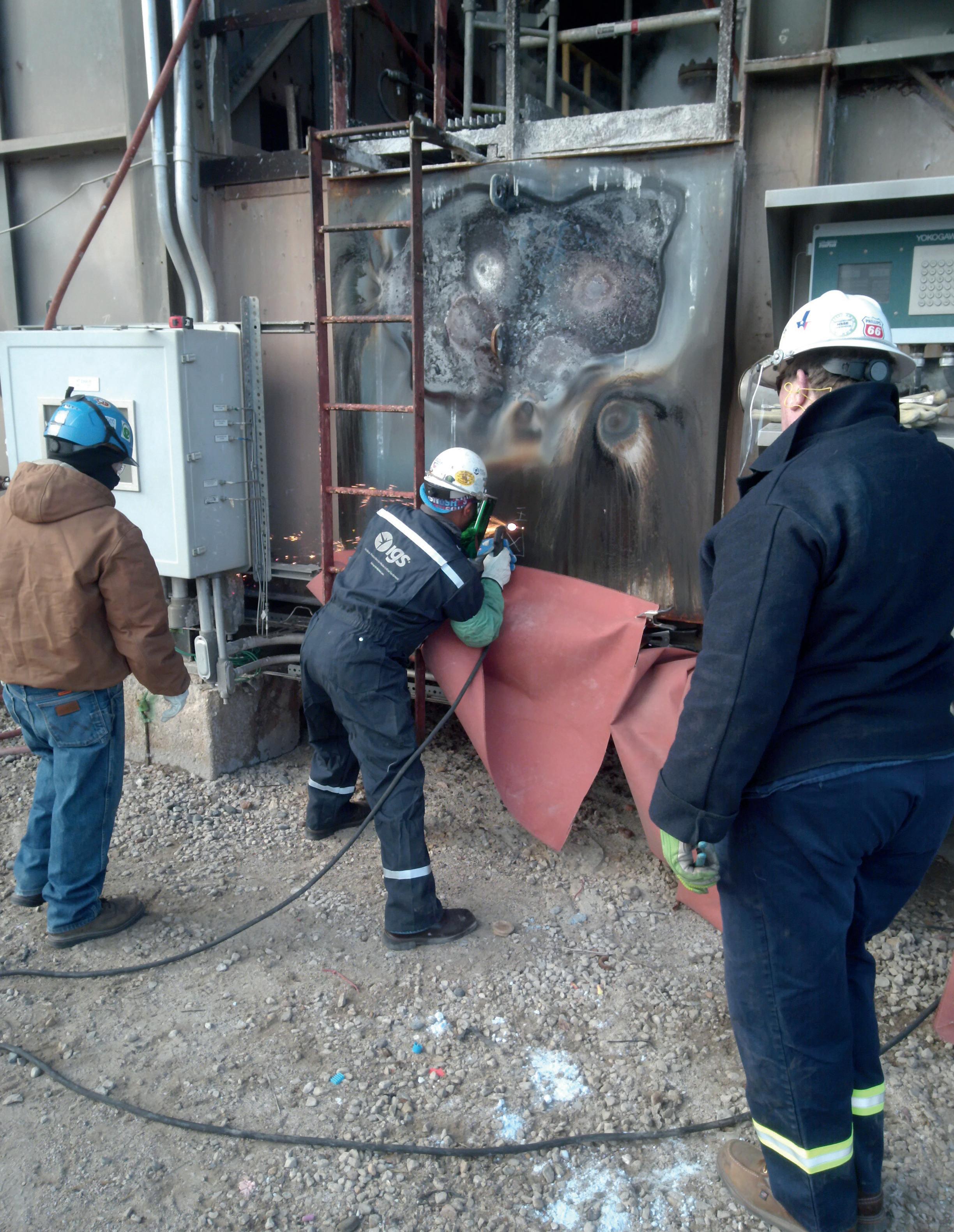
A refinery in the US discovered serious refractory integrity concerns on its catalytic reformer (CCR) heater unit. The refractory ceramic fibre was missing in a furnace. As a result, the outer steel shell was damaged due to exposure to high temperatures in multiple areas of the roof and sidewall.
Refinery furnace infrared images reveal problem areas
The company operating the refinery has assets in petroleum refining, logistics, convenience stores, asphalt and renewables, with a capacity of fewer than 150 000 bpd. The refinery produces types of gasoline, distillates and propane products.
The plant invited Hot-tek to inspect the unit and carry out hot refractory repairs. The team took infrared images of the hot spots on the CCR fired heater roof during the pre-project meeting.
Temperatures of more than 1500°F/815°C were being reached at the bridge wall – relatively high for a CCR fired heater. Material selection utilised in the previous repairs was not sufficient for these elevated bridge wall temperatures.
August 2023 HYDROCARBON ENGINEERING 46
Figure 3. A technician carrying out a hot refractory repair.
Repair solution
The damaged areas were repaired using two techniques: Hot-tek’s basket-style repair, and the larger module repair. The larger damaged furnace roof areas were cut into sections and removed one at a time. Then, prefabricated modules consisting of higher alloy plates and hardware, along with high-temperature ceramic fibre, created a long-term repair solution for the refinery. The basket-style repair method was used to seal around the perimeter of the modules. The following steps were taken to deliver the Hot-tek furnace repair using the module style on the ceiling of the installed dog boxes:
n The first tile was cut using a plasma cutter, and removed from the furnace ceiling. An approximately 1 – 2 in. area of the original furnace shell was left for support for the new Hot-tek module. After installing the module temporarily, the team then moved to the next tile.
n Installing prefabricated Hot-tek module, which was tack-welded into place.
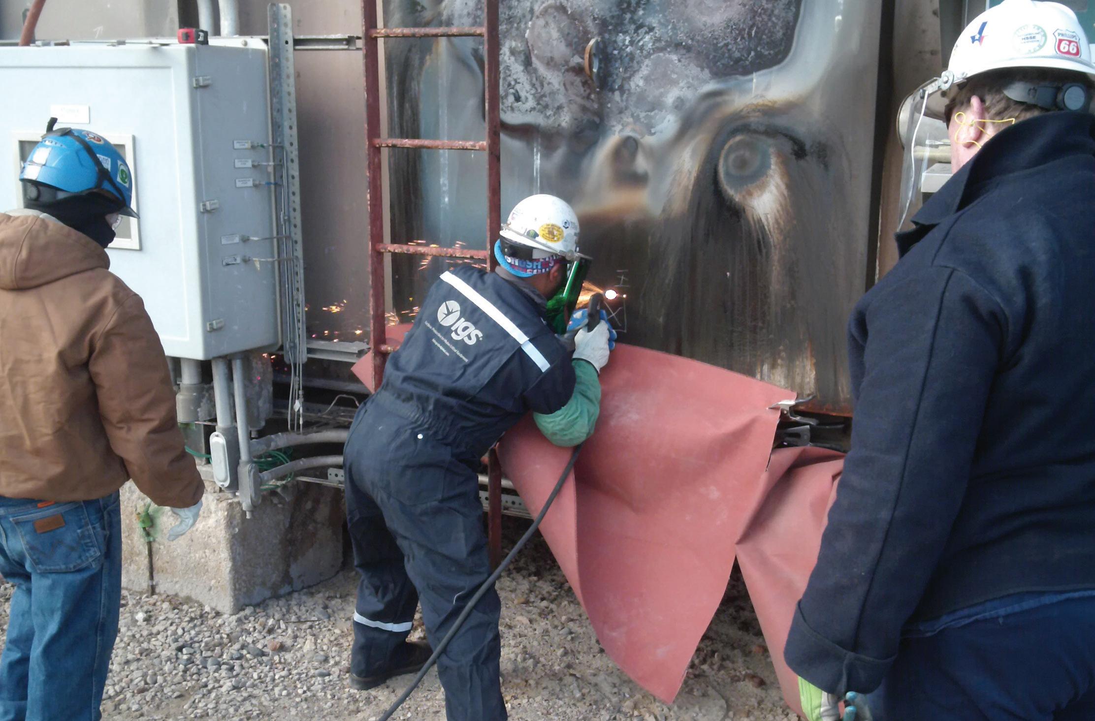
n A large module was installed in the next roof section. The module and technician were tethered for safety.
n The module was fitted and fully welded in place with an alloy rod for dissimilar metal welding.
n The large, damaged roof area was repaired with 16 in. square alloy Hot-tek baskets. The baskets were welded together to form the new ‘ceiling’ of the roof.
n Pourable/pumpable refractory was laid into the large opening. After curing, the surface became cool to the
touch. Once cool, an alloy plate was welded over the refractory.
The result
The project was completed within the agreed schedule of eight days. The refinery continued operations at full capacity, completely unaffected by the repairs taking place. A shutdown would have cost the refinery millions in lost production.
Conclusion
There are numerous causes of refractory failure, but shutting down the furnace should always be a last resort, as this has a huge impact on production and revenue. The operating environment is responsible for most refractory failures, and a common oversight is to increase the furnace temperature without assessing the impact that this will have on the design parameters of the refractory. Planning for over capacity can help to mitigate the risk of refractory failure if specifications change after installation.
Understanding and preventing refractory damage is key to the overall furnace performance. IGS recognises the effects of asset failure, and works in partnership with plants worldwide to optimise equipment reliability and performance. Identifying refractory damage early, and understanding the reasons behind it, will help operators to increase furnace uptime and maximise overall performance, which could save millions in otherwise lost revenue.
BRINGING EDUCATION AND INDUSTRY TOGETHER.
SHORT COURSES: SEPTEMBER 25, 2023


SYMPOSIA: SEPTEMBER 26 – 28, 2023

GEORGE R. BROWN CONVENTION CENTER • HOUSTON, TX
The Turbomachinery & Pump Symposia is recognized worldwide as the industry’s must-attend event. Connect with more than 4,750 delegates, meet with leading suppliers, observe product demos, and get answers to your technical questions. We look forward to seeing you in Houston!

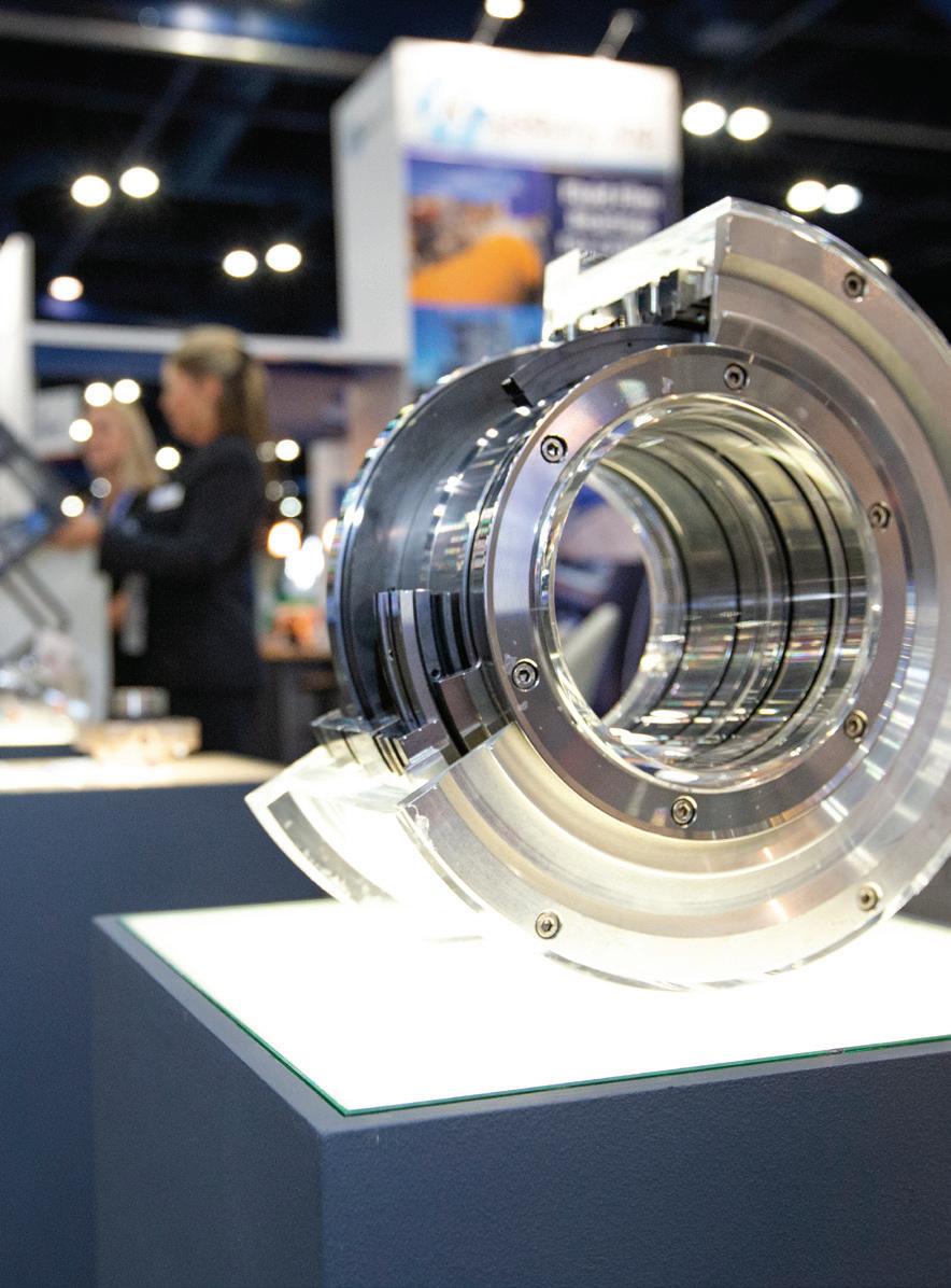

4,750 ATTENDEES
365 EXHIBITING COMPANIES


45 COUNTRIES
TPS.TAMU.EDU


#TPS2023
HOSTED BY
Green or sustainable aviation fuel (SAF) is a renewable replacement for the fossil-based aviation fuels that have historically powered most aircraft. SAF is a drop-in replacement for standard aviation fuel, but it is created from sustainable feedstocks, so it boasts significant carbon emission reductions over

its lifetime. Although it is currently more expensive than fossil-based aviation fuel, SAF does offer a variety of green fuel credits for both producers and aviation companies, so production rates are rising rapidly.
Similar to green diesel, SAF has process differences that can pose significant challenges for
August 2023 HYDROCARBON ENGINEERING 49
Increasingly, refineries are starting to retool their infrastructure to produce sustainable aviation fuel (SAF). However, new processes are required, creating challenges for control valve selection.
Scot Bauder and Janelle Prusha, Emerson, discuss.
control valves in the conversion units. This article discusses the SAF production process, and offers suggestions for choosing the best control valves for the more difficult applications.
SAF development
While the first flight using bio-based aviation fuels occurred in 2008, SAF did not become an approved fuel replacement until 2011 when ASTM International officially allowed commercial airlines to blend up to 50% of certain biofuels with their conventional jet fuel. Since then, a large number of bio-derived aviation fuels have entered the market and are being utilised by an increasing number of airlines. As of 2022, 450 000 flights have used some combination of sustainable fuels, although the price for these products can be as much as three times the cost of kerosene-based aviation fuel. SAF is different to other bio-based aviation fuels in that it must be certified by a third party to verify that the fuel satisfies certain environmental, social and economic considerations. This does elevate the cost of production, but has driven strong product demand as producers and consumers are offered an array of governmental credits for the fuel’s production and use. While it is technically possible to create SAF from a wide variety of feedstocks, including sugar-bearing
plants, algae, and even woody biomass, most of the SAF that is currently produced comes from the lipid conversion process. Extensive research is underway for the other pathways, but the similarity of lipids conversion to refinery hydrotreating/cracking makes it relatively easy to repurpose existing refining facilities for the production of SAF. Lipid feedstocks for SAF production are primarily used cooking oil, oil-bearing plants (such as rapeseed, carinata, soybeans, etc.), and tallow.
Lipid conversion utilises feedstocks that already contain significant amounts of oil, so the chemical processing methods and equipment are familiar and well understood in the refining industry.
Regardless of the pathway used, nearly all SAF feedstocks require some kind of pretreatment to refine and break down the feedstocks and convert them into the common intermediates that feed the hydrotreater processing units downstream. These pretreatment processes are quite different depending on the particular feedstock involved, but generally all pretreatment processes strive to eliminate contaminants that can poison the reactor catalysts and chemically break down the feedstock into common and consistent intermediates to feed the hydrotreater section.
SAF hydrotreatment
Once pretreated, the SAF intermediates are fed into a hydrotreating process that is very similar to that used in most refineries. Several different licensors are offering conversion methodologies. Honeywell’s Ecofining process includes a deoxygenation reactor followed by deisomerisation and hydrocracking, and then a product separation section to create light fuels, green diesel and SAF.
Another lipid conversion process uses the Axens Vegan HVO process to deoxygenate the feedstocks and hydrotreat the resulting intermediate to create SAF, green diesel, and naphtha.
In either of these processes, there are certain critical valves that are extremely important, must endure particularly gruelling service conditions, or both. Although similar to the standard hydrocracking process in many ways, there are differences that pose challenges for SAF production.
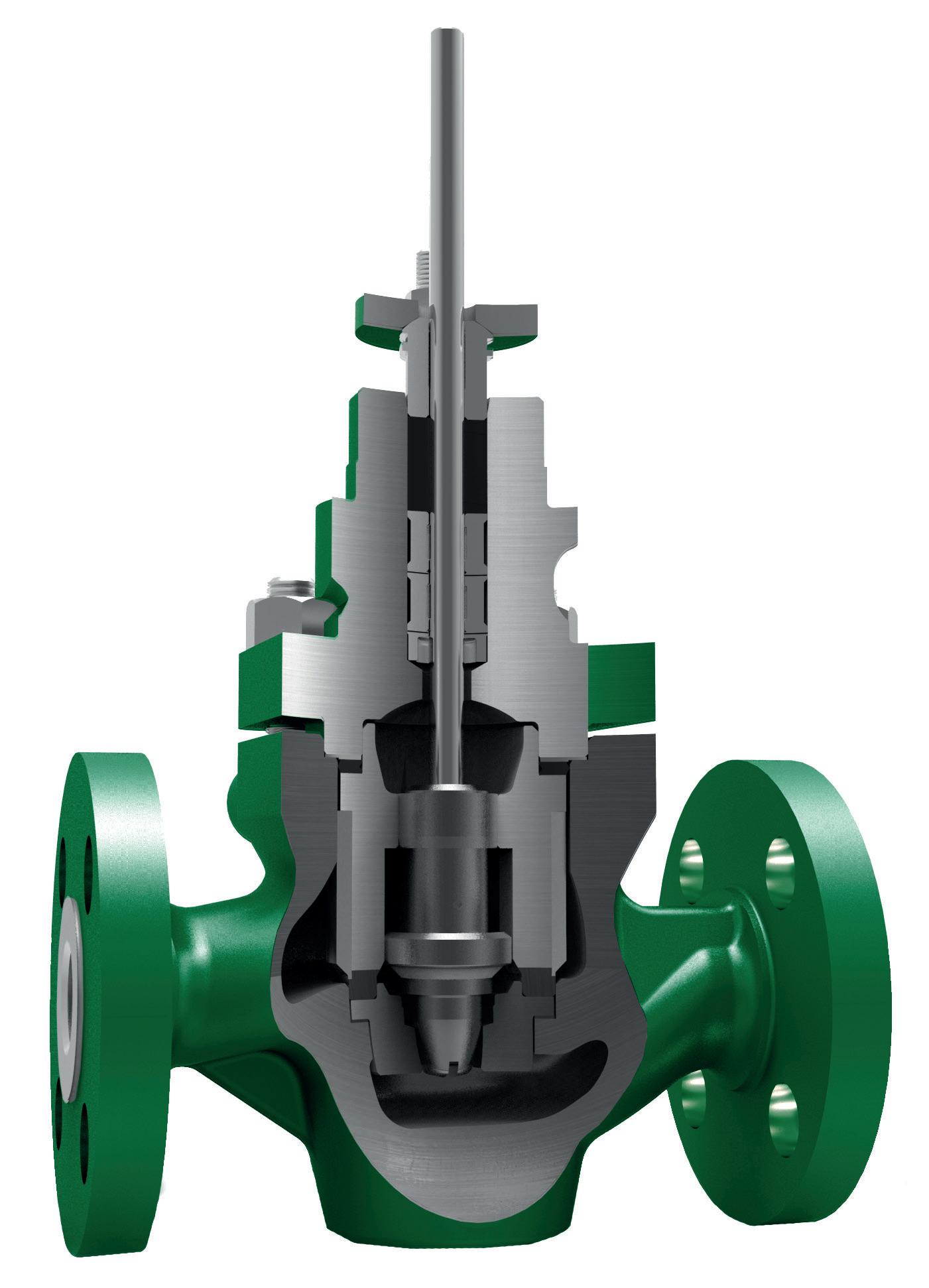
The intermediates tend to be more corrosive and stickier than with conventional feedstocks, and they are prone to paraffin and/or waxy build-up. The process also requires significantly more hydrogen, elevating process pressures and temperatures. Finally, the intermediate feed quality tends to be variable, so reaction chemistry is impacted and less consistent. All of these issues can complicate process control and increase the need for constant maintenance and intervention to keep the plant in operation.
Choosing the right control valves for these services is critical, as proper selection can extend time between outages and increase uptime. The more challenging applications will be discussed in the next section of this article.
August 2023 HYDROCARBON ENGINEERING 50
Figure 1. An unbalanced plug with tight shutoff is often employed in hydrogen quench valve service where product sticking/build up might occur. Material selection should account for the hydrogen service and possible corrosive attack from the reactor products.
G2R-Flex ™
BCCK’s G2R-Flex™ technology is a bolt-on enhancement to improve NGL recoveries in currently operating GSP cryogenic gas plants. Using a skidded design, G2R-Flex™ is added on to existing gas subcooled process (GSP) plants to increase propane recovery and ethane rejection. The technology improves current 200 MMSCFD GSP facilities propane recoveries to greater than 99 percent in ethane rejection and can also be applied to improve performance in ethane recovery.

Proven Process for Improving NGL Recoveries in Existing GSP Cryo Plants
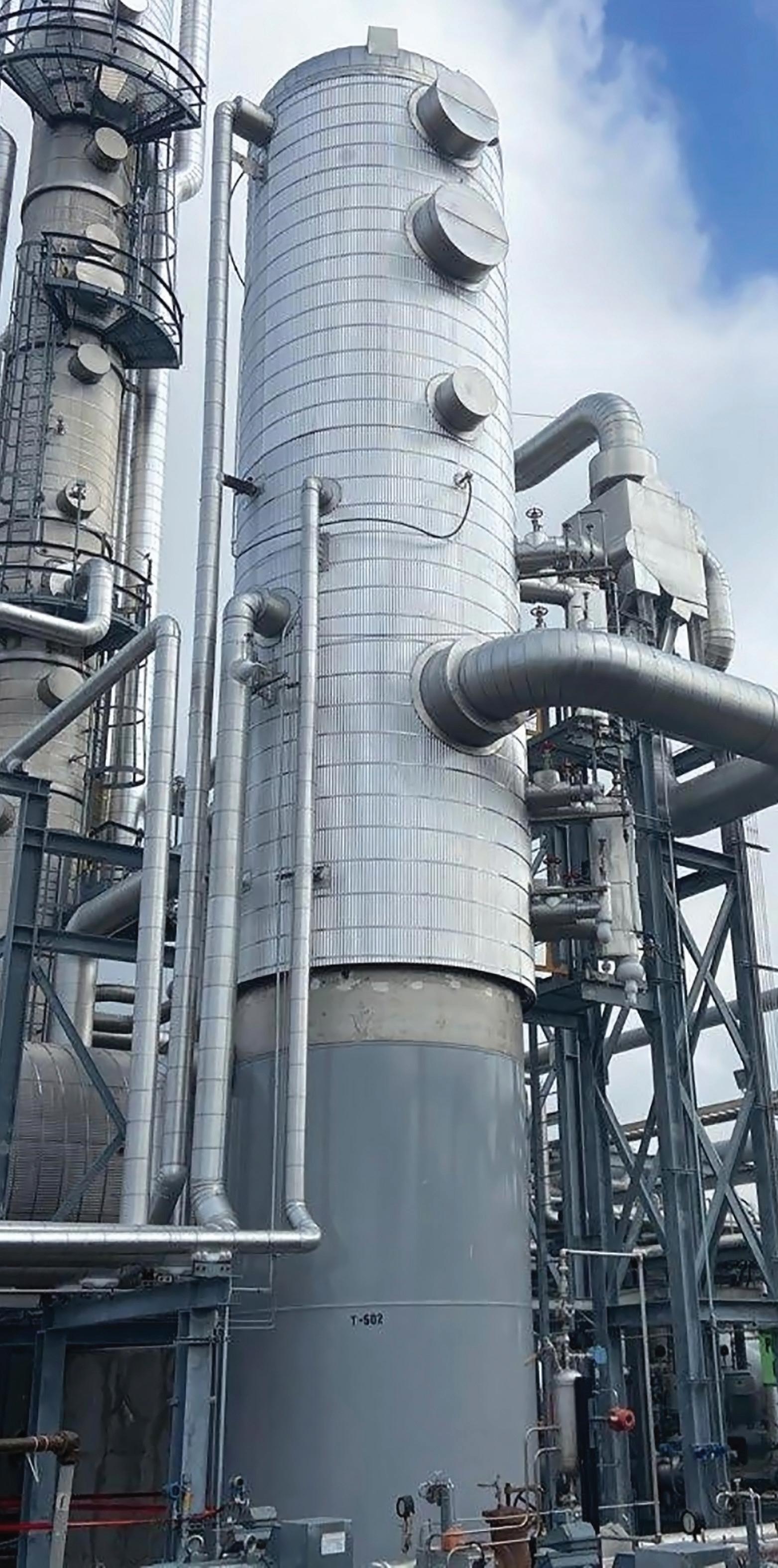
• 99+ percent propane recovery; 88+ percent ethane rejection


• Up to 50 percent* reduction in facility propane refrigeration requirements
* Will vary with composition
Let our engineers run a simple simulation using your plant specific performance to show you how we can improve your economics.
bcck.com/G2R-Flex
A Pipeline of Potential.
BCCK improves your process, which improves your profit.
BUILDING A BETTER PROCESS
Pretreatment control valves
While the specific process conditions will vary depending on the feedstock, all pretreatment processes generally involve corrosive fluids and gumming-type applications. As a result, any control valve in this application will require special alloys to resist corrosion, along with special body and trim coatings to minimise build-up. The best body designs also incorporate simple, unrestricted flow paths that are less prone to clogging.
These same rotary valve body styles also tend to shear away any build-up as they operate, allowing the valves to remain in service for longer between cleanouts.
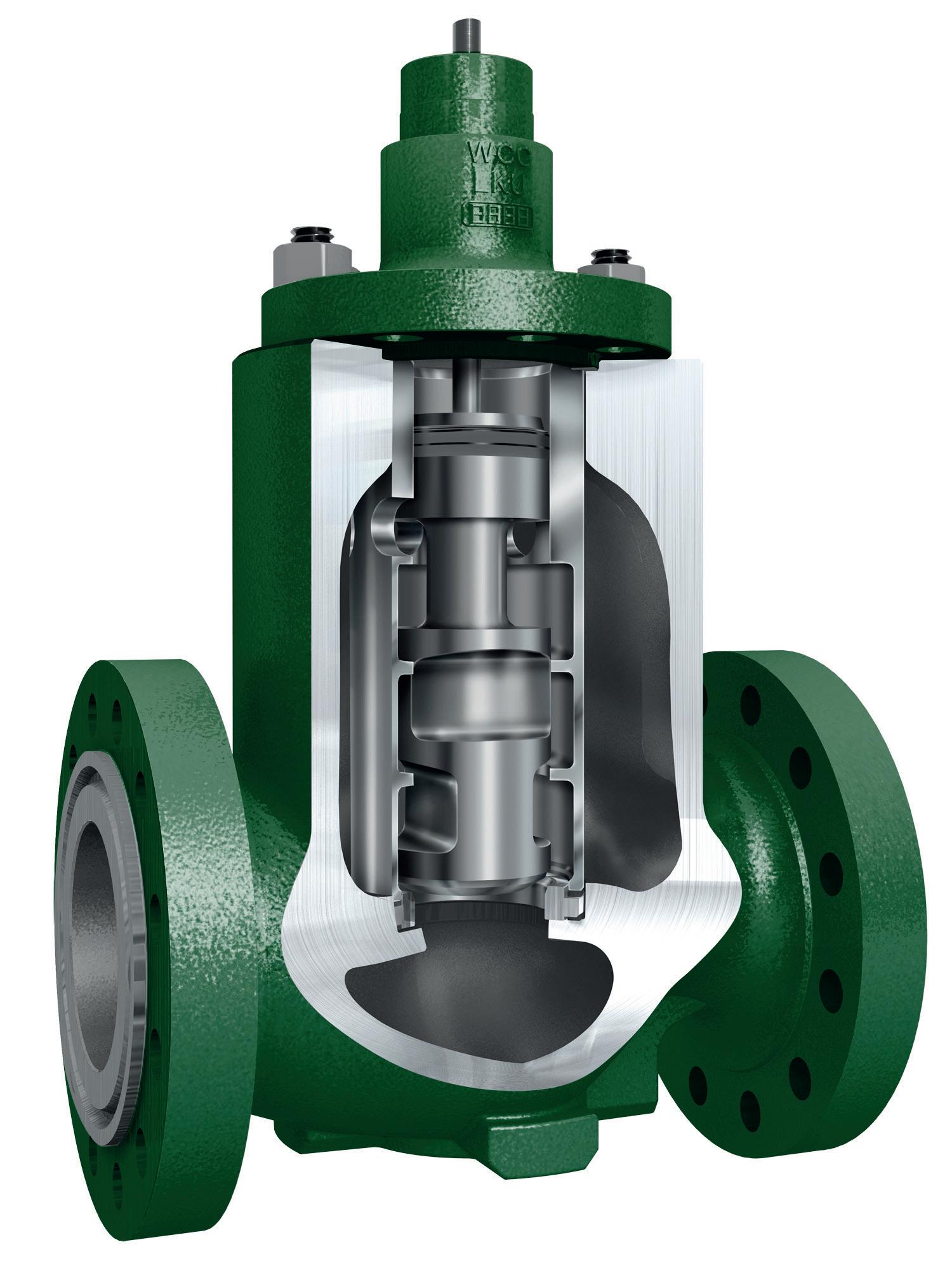
Reactor feed valves
The biofuel intermediate feed valves must provide a consistent and carefully controlled flow to the reactor in order to maintain stable operation and maximise catalyst life. This requirement is complicated by the corrosive and sticky nature of the feed. The best option for a specific reactor will depend upon the process temperatures and pressures, but regardless the valve will likely require carefully chosen alloy internals. A body design that addresses the specific reactor shut-off requirements and incorporates specific body styles to handle material build-up is also needed.
Reactor quench valves
Many of the reactors in an SAF process have quench valves that supply cooling hydrogen between the reactor catalyst beds to control the exothermic reaction. Tight temperature control is critical for catalyst life, so these valves must operate quickly and accurately. This requirement is made more difficult by the fact that the valves do not tend to move much once temperatures have stabilised, so they are prone to sticking over time.
Tight shut-off and elevated temperatures and pressures are typical in this service, so the valve must
be specified carefully (Figure 1). A post-guided unbalanced trim design will be less prone to sticking and can handle the temperatures and pressures of this service.
Careful material selection is critical for this valve as it involves pressurised hydrogen, and it might be subjected to reactor materials, which tend to be corrosive at certain points in the SAF process.
Separator/sour water letdown valves
Nearly all SAF processes include one or more high pressure letdown valves. These valves control the liquid level in a high-pressure separator and must pass a corrosive liquid containing significant amounts of entrained hydrogen gas and particulates, down to a much-reduced pressure downstream. As the material passes through the valve, the gases exit the solution, creating a three-phase mixture that is extremely challenging for any control valve.
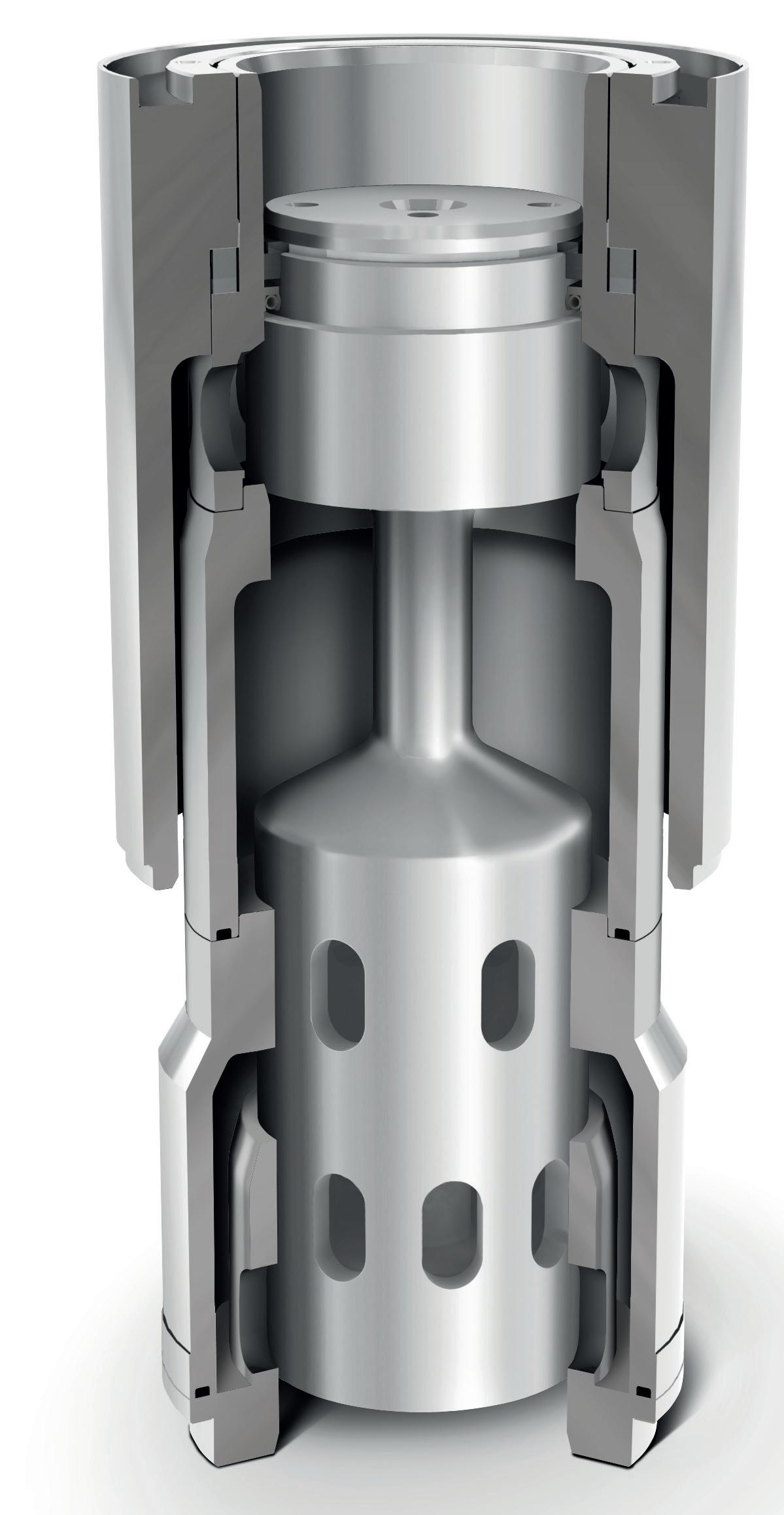
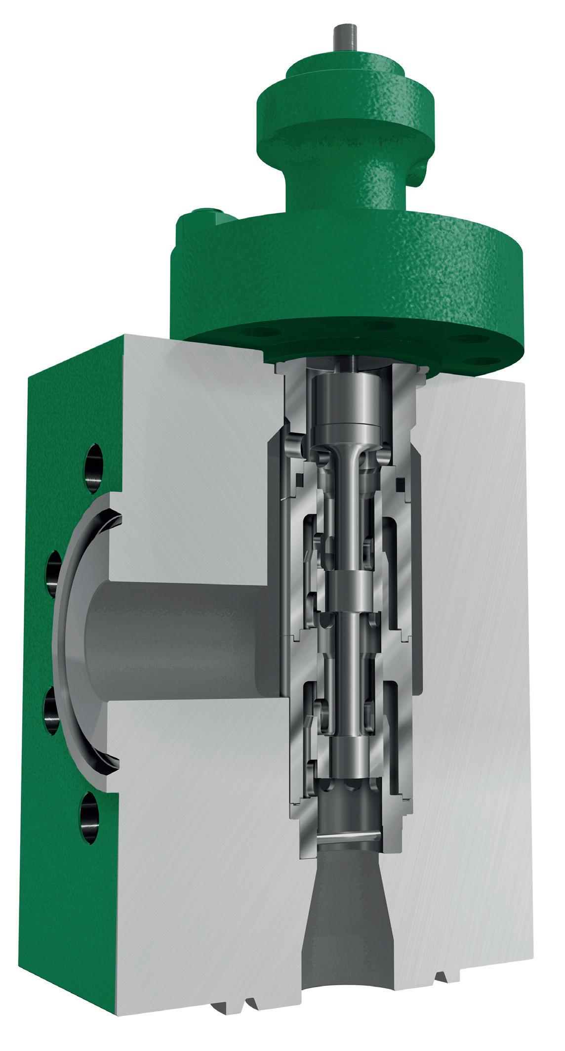
A typical high-pressure drop design would employ numerous small internal passages to stage the pressure drop and handle the flashing conditions, but such a valve would plug quickly in this application. A better valve design would incorporate a multi-stage letdown with large flow passages to avoid particulate plugging (Figure 2). The entire trim must be constructed of an appropriate hard alloy that can handle the corrosive and flashing nature of this difficult service.
Additive manufacturing has enabled production of a host of new body and trim designs that are well suited for this very difficult application. This same manufacturing methodology also creates a wider range of available high alloy options to suit most applications.
Conclusion
The very strong demand for increased SAF use has many refiners retooling older units to produce the product, but there are strong competitive pressures to drive down production costs.
Proper control valve selection can have a dramatic impact on how well a unit operates and how long it can run for between maintenance outages. The SAF lipid conversion process is similar to typical hydrotreating, but it certainly has special challenges that make valve specification more difficult.
If a refining unit is undertaking an upgrade to SAF production, it is important to carefully evaluate each valve application to fully understand the process and corrosion challenges. It is also worth consulting a valve vendor to investigate the wide range of new valve technologies, as proper control valve selection will have a direct impact on the productivity, longevity and profitability of the production unit.
August 2023 HYDROCARBON ENGINEERING 52
Figure 2. Separator letdown valves require multistage pressure drops, large flow passages, and high strength alloys to handle the flashing, entrained particulates, and corrosion of this service. Valves such as the Fisher™ DST-G (left) and Fisher™ NotchFlo DST (right) can be good options.
24TH WORLD PETROLEUM CONGRESS


Strategic Speaker Lineup


 Joelson Falcão Mendes Chief Exploration and Production Officer Petrobras, Brazil
Susannah Pierce
Country Chair Canada, GM, Renewables & Energy Solutions Canada Shell, Canada
Dr. Dong Sub Kim President & CEO Korea National Oil Corporation (KNOC), Korea
Cousins Director of Greenhouse Gas and Climate, ExxonMobil, USA
Nasser President and CEO, Saudi Aramco, Saudi Arabia
Darren Woods Chairman and CEO, Exxon Mobil Corporation, United States
Josu Jon Imaz Chief Executive Officer, Repsol, Spain
Sweet Chair & CEO, Accenture, USA
Adif Zulkifli
Executive Vice President and CEO Upstream, Petronas, Malaysia
Joelson Falcão Mendes Chief Exploration and Production Officer Petrobras, Brazil
Susannah Pierce
Country Chair Canada, GM, Renewables & Energy Solutions Canada Shell, Canada
Dr. Dong Sub Kim President & CEO Korea National Oil Corporation (KNOC), Korea
Cousins Director of Greenhouse Gas and Climate, ExxonMobil, USA
Nasser President and CEO, Saudi Aramco, Saudi Arabia
Darren Woods Chairman and CEO, Exxon Mobil Corporation, United States
Josu Jon Imaz Chief Executive Officer, Repsol, Spain
Sweet Chair & CEO, Accenture, USA
Adif Zulkifli
Executive Vice President and CEO Upstream, Petronas, Malaysia
REGISTER NOW
SEPTEMBER 17 - 21 24wpc.com


www.globalhydrogenreview.com A new magazine focused on the global hydrogen sector Read the issue here Subscribe for free: The Summer issue of GlobalHydrogenReviewis out now
Consistent growth has been a feature of the LNG market since the turn of the century. In 2000, the fuel accounted for approximately 26% of the world’s natural gas trade. Today, that figure is 45% and looks set to continue on a similar upward trajectory. The US, for example, is on course to more than double its gas liquefaction capacity over the next five years, with output expected to reach 169 million t by 2027.1
The US is an outlier in the LNG industry, with second-placed Qatar projected to be some way behind by the latter half of the decade. Nevertheless, this shows that LNG will remain a central pillar of the global energy market for the foreseeable future. This restates the need for effective specification throughout the liquefaction process, not least for the valves responsible for dehydration of the feed gas.
Why the right valve is critical

Dehydration of the feed gas is among the most critical stages of the liquefaction process. Efficiency of the site’s molecular sieve system is heavily dependent on valve performance, with tightness
and reliability being especially important factors for plant managers to monitor. During operation, the ‘wet’ gas flows through tanks, where a solid particle catalyst absorbs the medium’s water content. Dryness is critical for liquifying natural gas, as water will freeze during processing, leading to significant damage in other areas of the processing plant, such as the pipework.
Continuous thermal cycling is required to enhance the reaction and regenerate the catalyst. This is facilitated by valves found at the top and bottom of the tank, allowing the gas to flow in and out. Much like other components in severe service applications, these valves face several challenges during operation, from the volume of cycles through to the presence of solid particles in the fluid, as well as the thermal cycling itself.
These concerns are not theoretical, but rather issues that continue to hit the headlines despite plant managers having knowledge of them. In August 2022, for example, Reuters reported that unplanned disruptions at several LNG plants in the US, Nigeria and Australia had caught major traders off guard, forcing them to pay much higher costs for alternative supplies.2 The final figure is still unknown, but losses from this event easily
August 2023 55 HYDROCARBON ENGINEERING
Fabrizio Delledone and Mike Semens-Flanagan, IMI Critical Engineering, examine various emerging valve designs to support the growing number of LNG applications.
ran into the hundreds of millions of dollars. This story followed on from another major train outage at Qatar’s Ras Laffan plant earlier in the year, where a week-long delay impacted its 7.8 million tpy output.
It is difficult to place a definitive figure on the impact that poor valves have on LNG production, but broader estimates from analysts highlight the need for better specification. Kimberlite found that just 3.65 days of unplanned downtime a year costs the industry US$5.037 million.3 That being said, even shorter periods can lead to noticeable losses, so it makes sense for engineers to consider where improvements can be made even if the components themselves are only a small part of a much larger system.
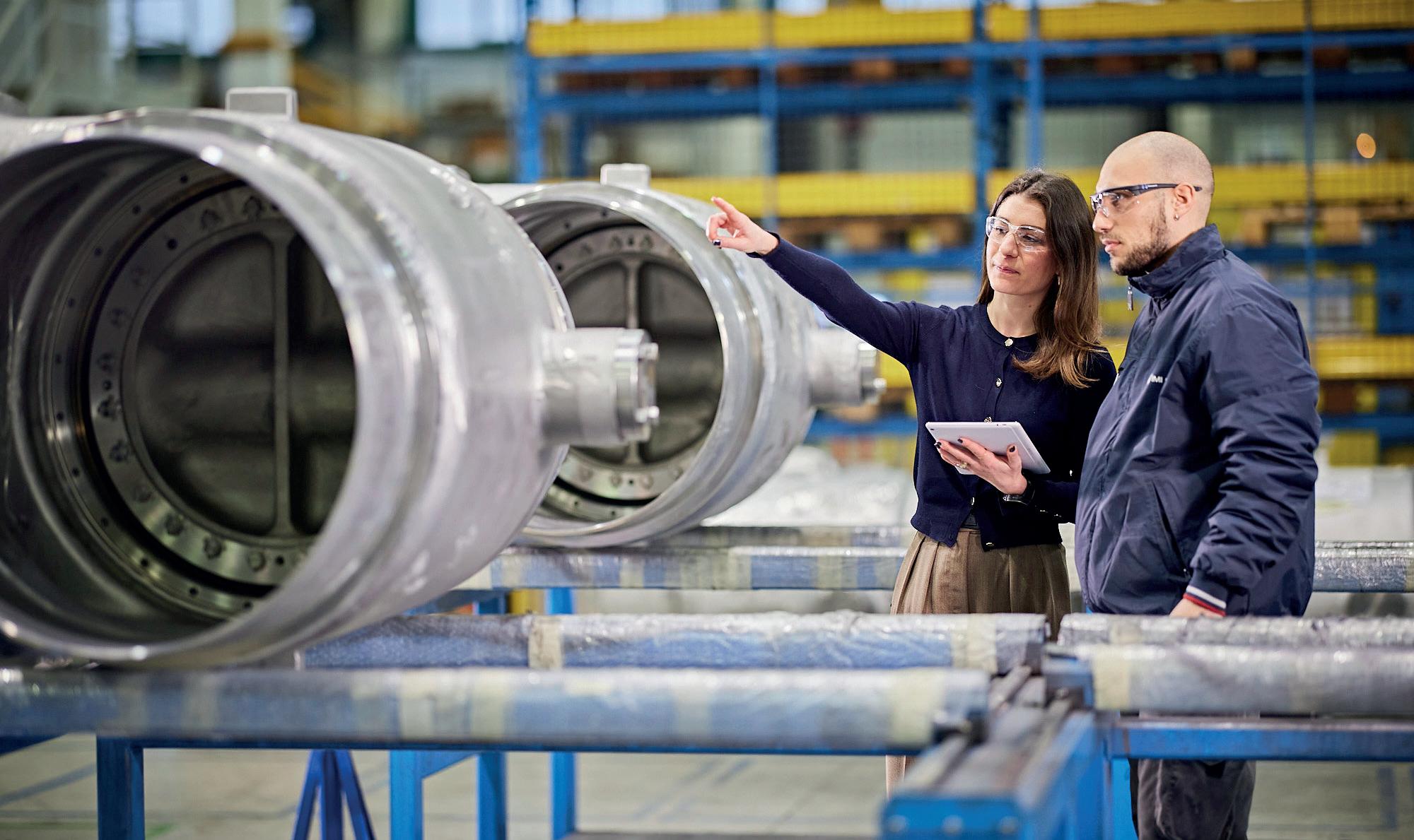
Changing expectations
Rising stem ball valves (RSBVs) are the most popular choice for molecular sieve systems used to make LNG. The roto-translatory movement design concept is not only capable of withstanding thermal cycling, but is also resistant to the wear associated with solid catalysts. It is for these same reasons that conventional ball and gate valves are avoided for liquefaction.
Ball valves, for instance, have continuous line contact between the closure member and the seats, which means that they wear out much quicker than RSBVs. They also lack a tight shut-off function, and continuous contact means that frictional resistance is high, putting needless pressure on the actuator.
RSBVs are popular, but they are not without their own set of challenges. First, a more complex design means longer downtime, and higher operation and maintenance costs – an issue that has been given closer attention since oil and gas prices have begun to fluctuate. Second, RSBVs are heavier and have a larger footprint when compared to other valve designs. Engineers need to factor in the higher material costs and longer installation times during the front end project phases.
Maintenance costs are also a concern. Plant managers may need to replace several trim components, including the stem, which in some cases could make an entirely new valve more cost-effective. High friction in the shaft can also lead to parts getting stuck, particularly in cases where abrasive fluid enters the guiding slots.
Hallmarks of a correct specification
There are many variables to consider when specifying a valve for dehydration of feed gas:
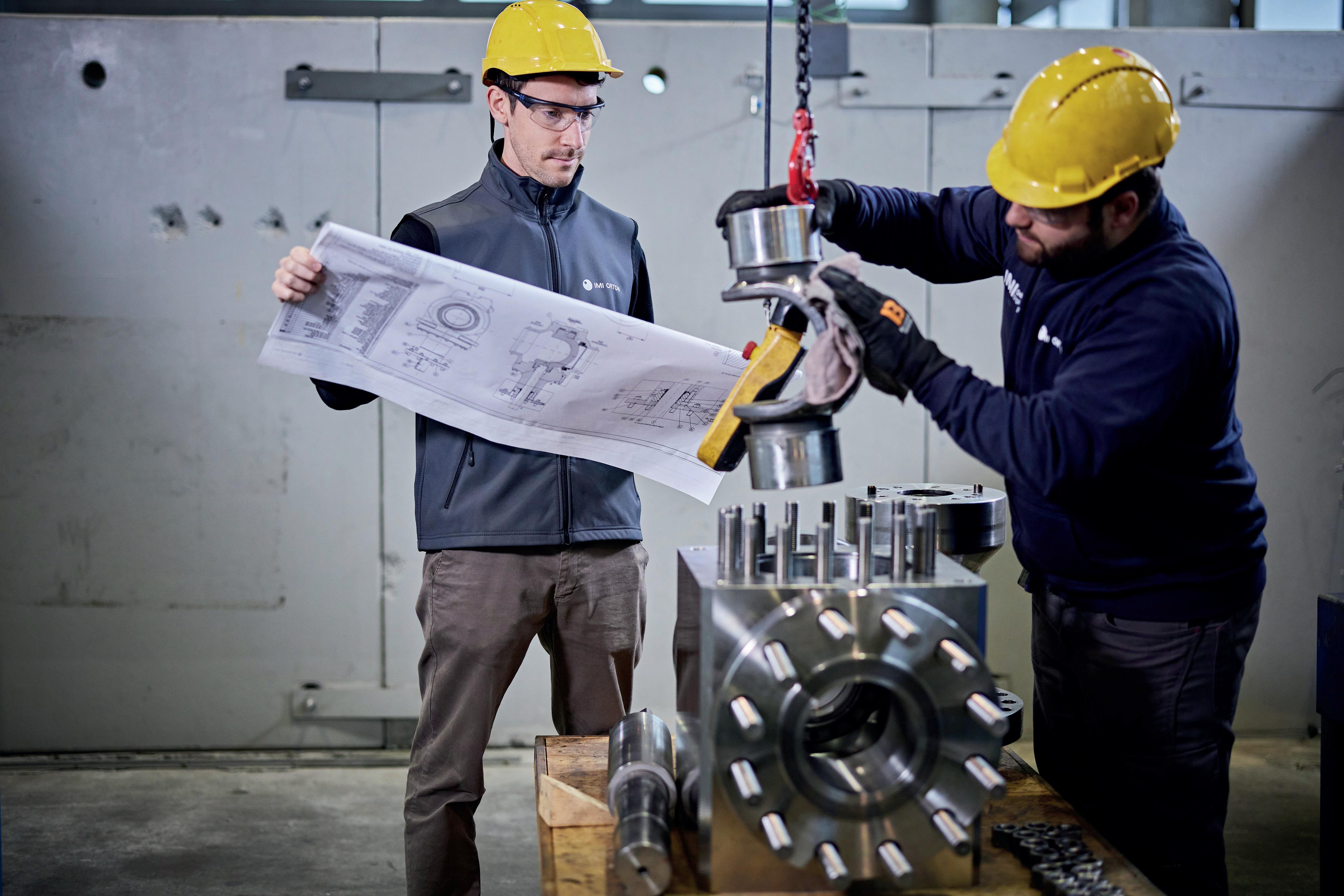
n Any valve used should be cavity free, as those that do have cavitation increase the likelihood of sieve particles becoming trapped.
n It is impossible to eliminate contact during shut-off, so it is vital to choose a valve with hard-faced seats, as this avoids any abrasion with the closure member. A design with less friction between sealing elements during rotation increases valve reliability. The sealing system should not be reliant on springs to avoid sieve particles becoming trapped in the backseat area.
n Hard-faced bushings should be used to avoid any abrasion by sieve particles. The use of bushing protectors is also recommended, in order to avoid the entry of any sieve particles between the stem and valve body.
The temperature of gas used for regeneration ranges from 200 to 350˚C. This means that an LNG plant’s valves undergo significant numbers of thermal cycles throughout their working life. As such, valve material and gap-tolerance calculations between closure member and seats should also be taken into account.
Emerging designs
Given the industry’s sustained growth and the need to extract greater value from existing systems, plant managers are now seeking alternative valve designs as a way to circumvent the challenges associated with RSBVs. While still in its earliest stages, this switch is being given serious attention by a number of oil majors, with the intention of delivering lighter, more compact valves that are easier to maintain, with a lower total cost of ownership.
Double eccentric segmented ball valve
Double eccentric segmented ball valves are simple, compact and easier to maintain, at lower operating costs. This type of valve, typified by IMI Critical Engineering’s C-REXTM, is characterised by a C-shape double eccentric ball. The cam action provides non-rubbing rotation, which is a prerequisite for valves operating in molecular sieve systems.
In operation, this valve offers low running torque and high-performance mechanical sealing. The C-REX also weighs up to 50% less than RSBVs, with a metal seated torque sealing
August 2023 HYDROCARBON ENGINEERING 56
Figure 1. Incorrect valve specifications can lead to serious downtime and losses at LNG plants.
Figure 2. The dehydration of feed gas is a vital part of the liquefaction process, with valves playing a major role.


ADIPEC in numbers 160,000 Energy professionals 15,000 Conference delegates 54 NOCs, IOCs, NECs and IECs 350 Conference sessions 30 Countr y pavilions Conferences 10 2,200 E xhibiting companies 1,600 Conference speakers Decarbonising. Faster. Together. ADIPEC, the world's largest energy exhibition and conference, brings together the ideas, ambition, technology and capital needed to accelerate the urgent, collective and responsible action that can decarbonise and future-proof our energy system. Register as a visitor Register as a delegate www.adipec.com Under The Patronage
2-5 October 2023 Abu Dhabi, UAE ADIPEC brought to you by Host cit y K nowledge par tner Technical Conference organised by Str ategic insights par tner Venue par tner O f ficial tr avel par tner O f ficial hotel par tner Suppor ted by Par tner sGold sponsor s Platinum sponsor s
of H.H. Sheikh Mohamed Bin Zayed Al Nahyan, President Of The United Arab Emirates
mechanism ensuring exceptional tightness in both directions. Crucially, this type of valve is a top entry design that offers easy access to the valve internals for inline maintenance, and is cavity-free to eliminate over-pressurisation.
Triple eccentric metal seated butterfly valve
Another alternative is the triple offset valve, such as IMI Critical Engineering’s MV series. Increasingly, this valve type is being adopted in molecular sieve service for its non-rubbing metal seat design, excellent tightness performance, compactness, and full metal construction.
Typically, the MV series has a full metal solid seal ring, which ensures consistent tightness even after heavy repeated use, and offers a long service life. Triple eccentricity makes it possible to achieve contact between the sealing surfaces only when the valve disc reaches a fully closed position. The floating resilient seal ring provides uniform contact pressure across the sealing circumference, ensuring tightness in both directions.
Special bushings offer immunity to dirt and polymeric media that can enhance service life and intervals between maintenance checks. The MV series is a simple design with a one-piece integrated body and a one-piece shaft and disc arrangement.
Looking ahead
Correct valve specification is important in the heavy industries, but it takes on extra significance in severe service applications
TGSim PlusTM
A REAL-TIME DYNAMIC SIMULATOR OF GAS TURBINES
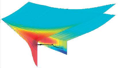
DESIGN AND ANALYSIS OF GT MAIN SYSTEM AND AUXILIARIES
GT CONTROL SYSTEM VERIFICATION & VALIDATION BY HIL TESTING

SCENARIOS
Verify and validate the real GT Control System (GTCS)
Hardware-in-the-Loop (HIL) full system testing
Whole system performance analysis:
Accurate performance envelope

Start-up sequences
Normal and emergency shutdowns
Load rejection
Investigation of fault events
TECHNICAL DETAILS
0-D modelling
GT component modules libraries
Real-time compatibility at millisecond scale
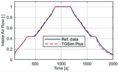
User friendly GUI & pre-/post-processing tools
Split stages or whole compressor maps management
Single or bi-fuel combustion chambers
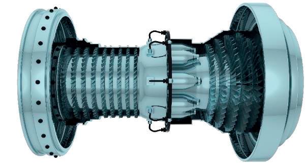
such as the dehydration of feed gas. Recently, there have been cases where legacy assets have generated unacceptably high annual costs, in turn causing processing plants to suffer from production losses far exceeding the purchase price of the valves and their ancillary components.
While the LNG market’s growth has helped to absorb these losses, it is clearly an untenable position for many businesses to work against, given recent volatility in the global gas market. Why leave imprecise specifications to chance when there are new designs that not only address current operating challenges, but also improve yields and minimise the threat of unplanned downtime?
This restates the need for plant managers to work collaboratively with OEMs and expert suppliers. The outlook for LNG is positive, but poorly specified valves could cap output when consistent, reliable production is needed most. This is where engineered solutions are now making the difference, offering facilities the necessary technology to meet increased demand, while using existing infrastructure.
Reference
1. ‘US to See Dramatic Growth in LNG Export Capacity’, BloombergNEF, (24 January 2023), https://about.bnef.com/blog/us-to-see-dramaticgrowth-in-lng-export-capacity/
2. ‘LNG traders absorb huge losses after supply outages’, Reuters, (10 August 2022), https://www.reuters.com/business/energy/lngtraders-absorb-huge-losses-after-supply-outages-2022-08-09/
3. Kimberlite International Oilfield Research, https://www. kimberliteresearch.com/
GT MODEL ARCHITECTURE
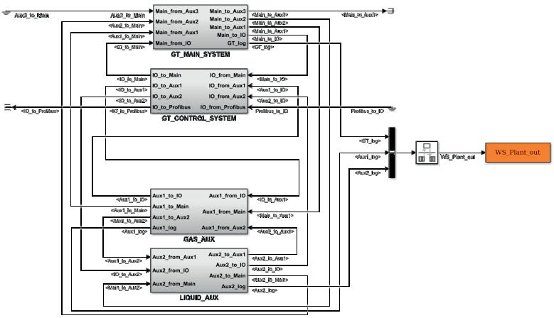
Modelling & Diagnostic software for process plants and machines Simulation services Consulting
www.sate-italy.com Venice - Italy
GVA 1 GVA 2
START-UP & SHUTDOWN
GT MAIN SYSTEM GT CONTROL SYSTEM GAS AUXILIARIES LIQUID AUXILIARIES
The amount of LNG in the world’s energy mix is rising. The export of LNG has increased dramatically in recent years, with the US alone expected to double shipments to Europe by 2022.1
Over 100 billion m3 of new LNG supply capacity is set to be commissioned between 2018 – 2023.2 By 2030, liquefaction capacity is expected to double, while regasification capacity is anticipated to increase by 50%, as a result of the rising demand for natural gas and the growing importance of LNG.
LNG is being accepted as the lower-emission hydrocarbon bridge of the energy transition, as seen by the anticipated investment in liquefaction, regasification and transportation infrastructure over the coming years. As the gas must be converted back from its liquid state in order to be usable, a number of regions do not have the infrastructure to handle the necessary quantities.
In order to effectively regulate the process at each stage – from liquefaction and extraction through to regasification, transport and distribution – this increasing infrastructure needs reliable flow control across the whole process.

August 2023 59 HYDROCARBON ENGINEERING
Dave Godfrey, Rotork, UK, discusses the importance of accurate and effective flow management within the growing LNG industry.
Controlling cryogenic valves
When storing and moving LNG, there are certain requirements. Valves and related equipment must withstand the extremely low temperatures involved in the process (-162°C is required to change a gas into a liquid state).
Cryogenically-safe valves are frequently constructed from 316 stainless steel, which retains body strength at these extremely low temperatures. Due to the hazardous environment, the valves used to regulate the flow of LNG must be suited to work at very low temperatures, dependably. They also have to adhere to safety regulations such as BS 6364. Additionally, actuators that control the valves must offer safe and dependable operation in continuously dangerous conditions.
The valves used to transport large quantities of raw gas are generally between 36 and 72 in. dia. and are required to work at extremely high pressures. By applying pressure to the natural gas and reducing its temperature using compression trains and cryogenic systems, it can be converted into a liquefied condition.
The high-pressure gas continues to be an extremely dangerous medium throughout this process, making the safety features connected to emergency shutdown systems crucial. As such, LNG operators must rely on tried-and-tested solutions. Large valves can close at the high speed and high
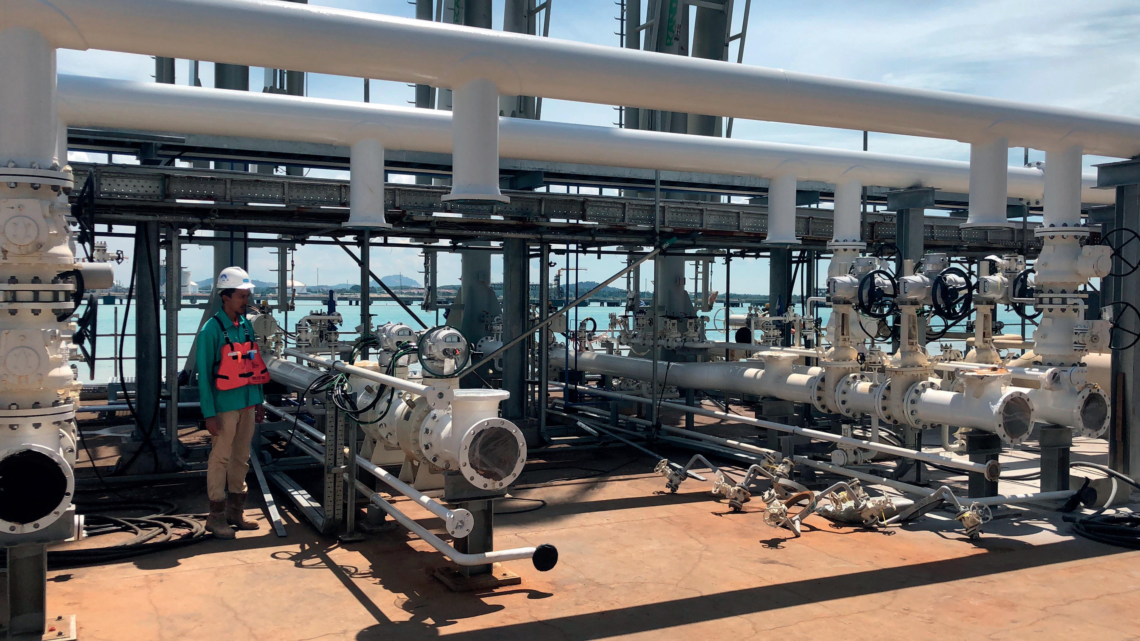
torque required for emergency shutdown (ESD) systems, using Rotork’s pneumatic actuators.
Ball and butterfly cryogenic valves used in storage and regasification facilities have been operated at LNG terminals all over the world using Rotork’s pneumatic scotch yoke GP and CP actuators. These actuators are suitable and appropriate for hazardous use; they have corrosion-resistant cylinders and are ATEX certified. GNL Quintero is one of Chile’s biggest energy security companies, and the company’s site, Quintero LNG, required reliable, heavy-duty pipeline valve actuators to provide routine operations and safety shutdown duties. The cryogenic valves were installed in challenging environments –ranging from saline coastal locations to arid desert areas, with extreme temperature fluctuations. In remote locations, the lack of conventional power supplies dictated the requirement for renewable energy sources, such as solar power.
The LNG complex at Quintero Bay encompasses the installation of a sea terminal to receive LNG from tankers, and a plant for regasification and distribution by pipelines to central Chile.
The pneumatic actuators supplied were from the CP and GP range, the majority of which are operating cryogenic service ball and butterfly valves at the Quintero Bay marine terminal and adjacent storage plant. The exposed marine environment also dictated the use of carefully selected, corrosion-resistant materials in the packaged control systems and components that were supplied.
The necessity of actuation across midstream LNG pipelines
The pipelines used to transport natural gas are large and cover hundreds/thousands of miles, often in remote and inaccessible locations. As such, electricity or even compressed air may not be available. Sometimes, the actuator’s only source of drive is gas from the pipeline. For the type of large valves found on pipelines, heavy-duty actuators perform routine and safety shutdown duties, especially in harsh environments such as salty coastal locations (where corrosion is a high possibility) and hot, arid, desert regions that experience extreme temperature fluctuations.
For instance, crucial locations on a cryogenic LNG pipeline in northern Venezuela installed actuators. The pipeline carries LNG and gas between several locations. The actuators provide the high degree of safety, dependability and security required at all phases of LNG production, by controlling the ball valves throughout the pipeline and offering ESD alternatives. The essential flow control involved maximises operational reliability and efficiency. The precision and control provided by actuators removes human error, increasing accuracy within an automated process.
The value of intelligent actuation for transportation
One of the most common methods for transferring LNG across large distances is via carriers. Process control actuators are installed on these specialised carriers. As an example, intelligent electric actuators, such as IQ actuators from Rotork, are essential for the safe, dependable and effective flow control management of liquefied gas into carriers during LNG shipping. Other advantages of using intelligent actuators for
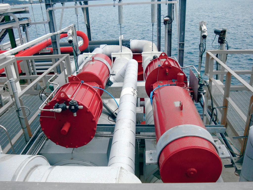
August 2023 HYDROCARBON ENGINEERING 60
Figure 1. Intelligent actuators in operation at a terminal.
Figure 2. Scotch yoke actuators in service at a marine terminal.
BE WISE
WHEN YOU ADVERTISE
Everyone wants to get what they paid for.
Hydrocarbon Engineering is independently verified by ABC, because we want our advertisers to know they’re getting the exposure they’ve been promised. ABC. See it. Believe it. Trust it.


www.abc.org.uk
LNG flow control include extensive real-time and historical feedback data through data logs (such as warnings, valve torque profiles, and the number of valve movements and/or operations). The explosion-proof certification of the actuators in the IQ product range ensures long-term dependability in even the most difficult conditions.
Another choice is electro-hydraulic actuators, which combine the ease of electrical operation with the accuracy of hydraulic control and the reliability of mechanical spring-return or accumulator fail-safe action. Typical applications for Skilmatic SI actuators include functional safety-related ESD inputs and Remotely Operated Shutoff Valve (ROSoV) duties, and they are hazardous area certified. They have ESD options with single or dual inputs and partial stroke testing (PST) for use in these applications.
The importance of actuation at the regasification stage
Regasification often takes place at coastal import terminals that have specialised requirements for handling LNG. The functionality of the actuators is a crucial component of safe and dependable operation throughout these processes, and the flow control products selected require high safety standards. At automated tank farms, actuators are a constant presence. They carry out isolating duties for regular flow control, modulating actions, and fail-safe activity for essential safety requirements. Tank farms also use intelligent electric actuators for safety-related tasks such as ESD, which is essential in the event of dangerous circumstances.
On LNG sites, control and monitoring centres are essential for simultaneously controlling hundreds of actuators. Throughout the world, LNG sites such as the Pengerang Deepwater Petroleum Terminal in Malaysia, which has a regasification unit, two 200 000 m3 LNG storage tanks, and berths for the loading and unloading of LNG vessels, use Rotork’s Master Station control system. A Master Station uses a field network (PakscanTM) to remotely manage the hundreds of intelligent actuators, while the actuators regulate the flow of LNG. This type of technology offers dependable and strong plant management and monitoring, which is crucial in the LNG sector.
Intelligent actuation to reduce emissions
Flow control products can also help in the reduction of emissions. One option for reducing needless emissions is electric actuators. By replacing spring diaphragm pneumatic actuators with electric ones, bleed gas emissions are removed. Methane and volatile organic compound (VOC) emissions can be decreased or completely eliminated by replacing natural gas-powered pneumatic actuators on control valves with electric actuators (also known as retrofitting).
Throughout the LNG process, emissions can be reduced significantly. In Belgium, an LNG terminal, a 4000 km pipeline, and an underground storage facility have all been upgraded by Rotork. The part-turn intelligent IQT actuators were installed at the site to control butterfly valves on boilers in unmanned gas pressure-reducing stations in Belgium, which lower the pressure of natural gas so that it can flow through a network that operates at a lower pressure, or be transferred to an end consumer facility.
This operation cools the natural gas and requires the gas to be preheated by boilers to keep the downstream temperature within specific ranges. The previous actuators at this site were pneumatics that were driven by gas, which resulted in the unintended release of greenhouse gases into the environment. To reduce the operation’s impact on the environment, Rotork Site Services installed the electric actuators on the site. The actuators control the valves, which now perform a more accurate regulating function, are more dependable, and avoid any emissions that the earlier pneumatic actuators would have produced.
Extremely accurate flow control, no emissions, simple set-up, diagnostics, and dependable operation were all made possible by the installation of IQT actuators. At several locations, Rotork Site Services adapted the IQTs onto existing valves. They provide continuous position tracking at all times, even when there is no power. They are protected against water ingress (double-sealed to IP66/68 at 7 m for 72 hours) and are explosion-proof to international standards.
Maintaining operations on an LNG site
While the importance of these assets within the LNG sector has been highlighted in this article, maintaining and properly operating these assets is equally important. Intelligent flow control assets within LNG processes optimise operational reliability and efficiency. These assets perform in challenging operations and environmental conditions every day. They frequently operate in abrasive, extreme-temperature conditions and excess vibration, and they must perform reliably. The effectiveness of assets depends on maintenance to ensure their availability at all points of the LNG trip. Asset failure or obsolescence has dangerous implications, including reduced quality, financial loss, and even reputation damage. Unplanned downtime is costly and undesired, but locations with a full life cycle asset management programme (such as Rotork’s Reliability Services programme) are likely to see improved performance, increased uptime, and a reduction in unexpected maintenance expenditures. These service plans provide plant operators with a consistent, fixed cost. A service plan for flow control products should take a comprehensive approach to an asset’s life cycle, be flexible, and allow customers to make their own maintenance decisions.
Conclusion
More natural gas will need to be extracted, liquefied, transported, and converted back into gas in order to fulfil the rising demand in the natural gas market. These processes require accurate and effective flow management that can operate in difficult conditions and minimise total emissions across the supply chain.
The LNG business is intricate, but with effective and dependable flow control assets such as actuators, it is possible to produce, transport and distribute LNG in a way that is safe, efficient and reliable.
References
1. ‘US doubles LNG exports to Europe in wartime gas market frenzy’, Washington Examiner, (7 November 2022), https://www. washingtonexaminer.com/restoring-america/courage-strengthoptimism/energy-environment/us-doubles-lng-exports-to-europe
2. ‘LNG Market Trends and Their Implications’, IEA, (June 2019), https://www.iea.org/reports/lng-market-trends-and-their-implications
August 2023 HYDROCARBON ENGINEERING 62
Sulphur + Sulphuric Acid 2023 Conference & Exhibition

November 6-8, 2023 • Sheraton New Orleans, Louisiana
Understand the key market and technical developments shaping the industry


Now in it’s 39th year, the event continues to be an essential annual forum for the global sulphur and acid community to learn, connect and do business.
You can expect an expanded market outlooks agenda, including expert insights from CRU’s analysis teams on major supply and demand markets, including sulphur, sulphuric acid and phosphates, plus additional industry updates from key players from across the supply chain.


For more information or to book your place, please visit: www.sulphurconference.com

August 2023 HYDROCARBON ENGINEERING 63
39th Oil | Gas | Fertilizers | Metallurgy | Industrial RETURNING TO THE UNITED STATES REGISTER TODAY Page Number | Advertiser 61 | ABC 57 | ADIPEC 33 | AUMA 51 | BCCK 13 | Black & Veatch 15 | BORSIG 04 | Comprimo OFC & 19 | Elliott Group 45 | Endress+Hauser 02 | Eurotecnica 25 | FS-Elliott 61 | GPA Midstream Convention IBC | Howden, A Chart Industries Company 42 | HTAC | HGT 47 | Integrated Global Services, Inc. (IGS) 07 | Mokveld Valves BV 41 | NEO Monitors 21 | Optimized Gas Treating, Inc. 35, 36, 54 | Palladian Publications 58 | S.A.T.E. IFC | Selective Adsorption Associates, Inc. 26 | Servomex 63 | Sulphur + Sulphuric Acid 2023 11 | Sulzer OBC | The Equity Engineering Group, Inc. 48 | Turbomachinery & Pump Symposia 35 | Umicore Coating Services Ltd 29 | Vanzetti Engineering 53 | World Petroleum Congress 39 | Zwick Valves NA LLC AD INDEX
Q&A WITH...
David Walsh, Product Director, Screw Compressor Products, Howden, a Chart Industries Company

David has recently completed 17 years of service and has held multiple roles throughout the business. From leading the Turbo and Rotary product line, to becoming the Global Product Director for Howden Screw Compressors, his technical and commercial acumen across Howden’s product range has been instrumental in driving business growth.
01 Talk us through the strategic combination of Howden and Chart Industries and the benefits that this offers the downstream oil and gas sector.
Howden, now part of the Chart Industries Group, provides full solutions across the Nexus of CleanTM clean power (hydrogen, helium, LNG, biogas), clean water (water and wastewater treatment, desalination), clean food and beverage (small-scale carbon capture, clean beverage) and clean industrials (carbon capture, hydrogen, helium).
The strategic combination of Howden and Chart Industries brings together their respective expertise and capabilities to offer significant benefits to the oil and gas sector. Howden brings our expertise in providing critical air and gas handling equipment, while Chart Industries contributes its proficiency in cryogenic storage and distribution solutions. This comprehensive approach allows for integrated offerings that address multiple aspects of downstream operations. Together, we can offer solutions that support the transition to cleaner fuels and solutions.
02 How does the company’s history in the oil and gas market contribute to the advancement of cleaner solutions?

Our products have always been utilised in critical applications that improve industrial processes. In turn, these products are increasing efficiency, reducing harmful emissions, and improving environmental outcomes to reduce carbon emissions.
We have long-standing relationships with traditional energy customers and proven technologies to enable the energy transition. For example, we help to produce clean fuels with our SG Turbo compressors that are installed in sulfur recovery units that prevent harmful H2S and SO2 gases from being emitted to the atmosphere. In the case of vapour recovery units (VRU) and flare gas recovery systems (FGRS), we are reducing and removing harmful gases from being flared off into the atmosphere. In hydrocracking and hydrotreating, we help break down heavy oils and gases, removing harmful contaminants and producing lighter, more efficient fuels that can then be further processed. These processes are enabled by our technology, creating vital petrochemical products that are utilised in our everyday lives.
In recent years, we have seen a step change in the oil and gas market with the introduction of second and third generation biofuels, driven by the need to produce our energy in a sustainable way and by an increased drive to decarbonise our energy resources. Traditional refinery processes are now being applied to create new fuels such as sustainable aviation fuel (SAF) and renewable diesel from sustainable biomass feedstocks like waste vegetable oil. A recent example of this is at Europe’s largest renewable hydrogen plant, Shell’s Energy and Chemicals Park in Rotterdam, the Netherlands,
where we installed Howden SG Turbo compressors and reciprocating compressor packages. The Howden product portfolio, specifically our reciprocating, screw and turbo compressors, is and will continue to be at the forefront of the energy transition.
03 What role will hydrogen play in the energy transition?
Hydrogen is expected to play a significant role in the energy transition due to its potential as a clean and versatile energy carrier. It offers opportunities for decarbonisation, energy storage and renewable energy integration as a clean alternative for industrial processes, as well as grid flexibility. This makes it a promising element in the transition towards a more sustainable future.
Our business plays a vital role in the shift towards clean energy by offering versatile products and equipment that are capable of accommodating any molecule. With over 165 years of experience, and references in hydrogen applications across multiple industries, our customers come to Howden for complete in-house solutions. In the case of hydrogen, we are equipped with all the essential supplies for hydrogen liquefaction, encompassing turboexpanders, brazed-aluminium heat exchangers, cold boxes, storage tanks, vacuum-jacketed pipe, and compression. This allows us to optimise hydrogen across the value chain from production to storage, distribution, transmission, and usage.
04 How can Howden’s products support companies looking to decarbonise and optimise their operations? With increasing environmental regulations, refineries are looking to decarbonise operations and produce cleaner fuels. Complex refineries, containing a large number of high-value conversion units, have a greater flexibility for the production of cleaner fuels and lighter products than crude oil, which contains higher sulfur levels. Our products support the decarbonsiation of customer operations by providing efficient and sustainable solutions for various industrial processes, such as ventilation, cooling, and compression systems. By using our energy-efficient equipment, companies can reduce their carbon footprint and minimise energy consumption, thereby contributing to decarbonisation efforts. Additionally, our products are designed to optimise operations by enhancing process efficiency and productivity. For example, our advanced control systems and automation technologies enable companies to monitor and manage their operations more effectively, leading to streamlined processes, reduced waste, and improved overall performance.
Furthermore, Howden products facilitate the integration of renewable energy sources into existing operations. Our solutions, such as wind turbine cooling systems and biomass combustion technologies, enable companies to harness clean and renewable energy, further supporting decarbonisation initiatives.
August 2023 HYDROCARBON ENGINEERING 64
Cornerstones of Compression
The Next Generation of Howden Compressors
Introducing the
Howden, a Chart Industries Company, is a global leader of compressor engineering, with a history of constant innovation. Utilising nearly 170 years’ experience, the company has recently developed the next generation of oil-injected rotary twin-screw compressors.
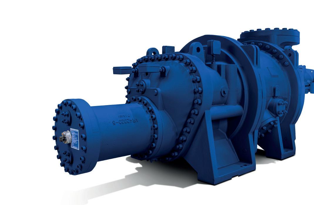
WPlatform
• Reduced CO2 footprint by up to 20%
• Over 100 customisable options from design, materials, control mechanisms, instrumentation, seals and bearings

• Instant product selection tailored to customer needs and applications


• Auto Vi comes as standard and provides a 7% power saving for varying temperature applications

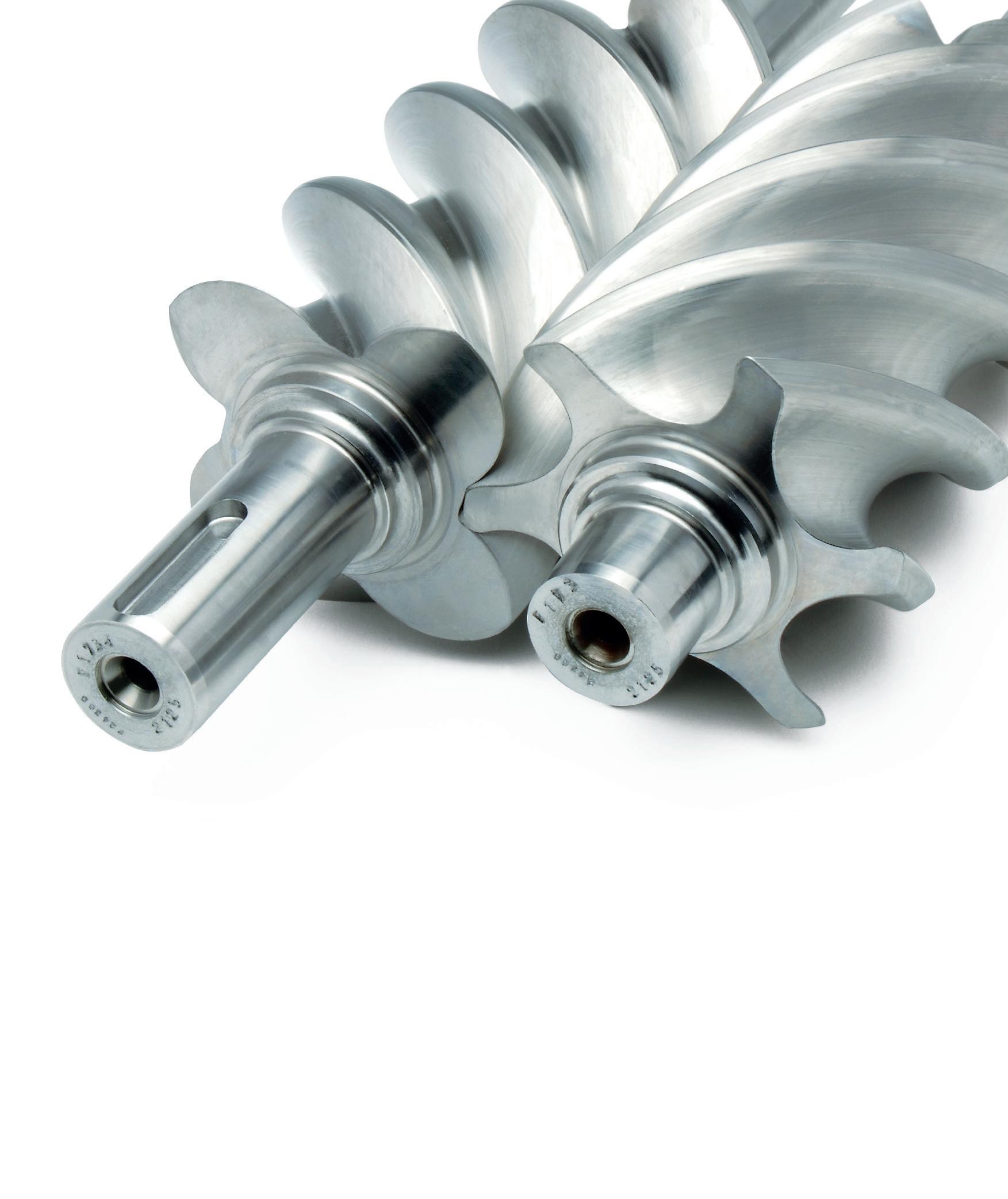
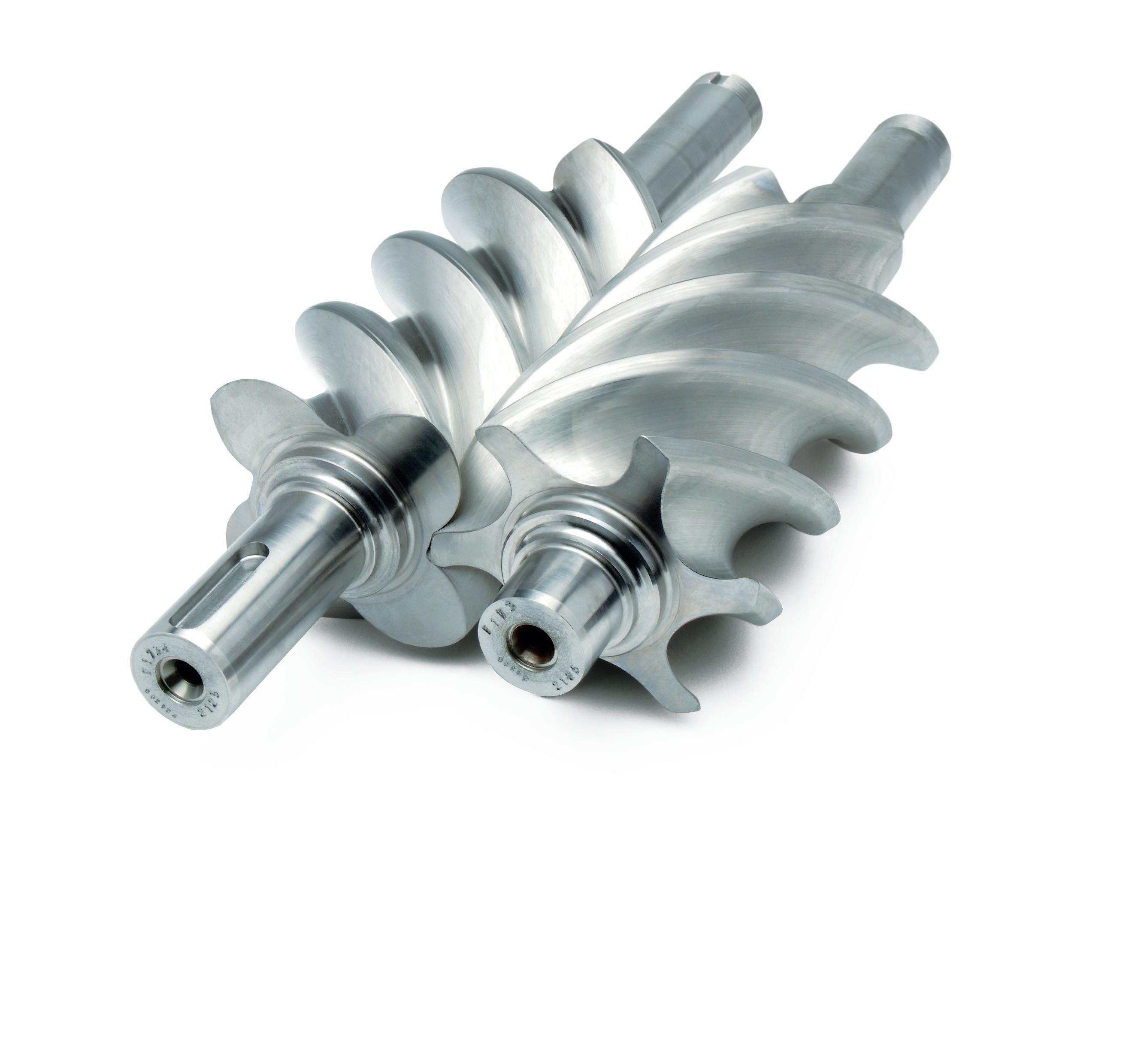
• Minimised noise vibration and reduced power consumption by up to 7%
• 30% weight reduction
• Reduced manufacturing lead times on configured machines
• Improved reliability and longer service intervals
www.howden.com Compression technology is in our DNA Scan to learn more
VIBRATIONS SOLVED.

Machinery and piping or structural vibration can lead to equipment degradation, failure, loss of production, or safety issues. But knowing whether the vibration is acceptable or needs immediate attention is often difficult to determine.
At E²G | The Equity Engineering Group, Inc., our team of certified ISO 18436-2 Category III and IV vibration analysts and engineers are deployed to the field with state-of-the-art equipment to perform data collection and system testing. We will identify the root cause of your vibration issues by applying our decades of experience with machinery, structural dynamics, acoustics, and system-level analysis.
We are focused on educating our clients and transferring knowledge; we will partner with you to develop the most practical and complete solution to even your most challenging problems.
BENEFITS
IMPROVE SAFETY AND RELIABILITY
AVOID COSTLY EQUIPMENT DOWNTIME
SERVICE AREAS
⊲ Onsite surveys and risk screening of piping and small-bore connections
⊲ Acoustic mechanical pulsation analysis
⊲ Piping vibration FFS evaluations
⊲ Machinery diagnostics - troubleshooting and reliability support
IDENTIFY AREAS OF VULNERABILITY
ANSWERS FOR TODAY. INSIGHTS FOR TOMORROW. P: +1.216.283.9519 © 2023 E²G | The Equity Engineering Group, Inc. VISIT CONTACT OUR TEAM www.E2G.com Sales@E2G.com
