
A SUP PLEMENT TO HYD ROCA RBON ENG INEE RIN G


Euromel® Melamine - the leading and most advanced technology for the production of high-quality melamine used in wood-based products, laminates, moulding compounds and fire-extinguishing foams in the last 40 years.
Delivers high purity, high consistency melamine with total zero pollution (TZP) with extremely lower energy consumption using 30% lesser steam import and 20% lower fuel utilisation than the closest competitor.
Euromel® Melamine Process is now used in 28 plants worldwide, accounting for more than 8 million tonnes of melamine produced cumulatively, making it the most traded and widely used melamine worldwide.


03 Comment
04 Plan to adapt
Alan Gelder, Wood Mackenzie, UK, discusses how refiners can stay ahead on the energy transition pathway.
11 Decarbonisation levers for downstream assets
Jock Hughson, Shell Catalysts & Technologies, Australia, discusses decarbonisation levers that refiners can pull to help them stay aligned with more stringent emissions regulations while staying competitive.
16 Sustaining momentum
Michael Connolly and Man Yiu Tse, ICIS, explore the evolving biofuels market, and examine how economic competition, regulatory dynamics, and shifting corporate strategies shape the industry.
22 Renewables on the rise
Richard Stambaugh, Merichem Technologies, USA, discusses renewable energy integration in refining and petrochemical processes and the rise of renewable diesel as a drop-in replacement for petroleum diesel.
28 Overcoming SAF hurdles
Nabil Ahmed, The Energy Industries Council (EIC), explains why sustainable aviation fuel (SAF) must overcome investment and scalability hurdles in order to prove its promising carbon reduction prospects.
33 Green skies ahead
Giacomo Rispoli and Alessia Borgogna, MAIRE, Italy, discuss the innovations and technologies that are driving
37 A cracking opportunity
Maninder Jit Singh, Topsoe, considers why ammonia cracking will be a key solution for efficient hydrogen transportation.
40 Nature as the blueprint
Thomas Winkler, Sulzer, Switzerland, explores how mimicking the circularity of natural ecosystems can provide an effective roadmap for the development of carbon capture and storage systems.
45 Three steps to CCUS success
Delivering cost-effective carbon capture and storage is critical to meeting climate change objectives. Dr. Marco Ernst, MAN Energy Solutions, explains why the role of scale and the right manufactured solutions cannot be overlooked as key steps to success.
49 Technology for life
Megan Hine, Dräger Safety, UK, outlines the critical importance of accurate carbon dioxide leak detection in onshore carbon capture and storage systems.
53 Empowering a cleaner future
Keith Warren, Servomex, UK, discusses gas analysis strategies for enhancing energy efficiency and reducing emissions.
57 Electrification: a vital step
Volker Metzger, Watlow, Germany, discusses the electrification of process heating in the oil and gas industry to lower carbon emissions.
61 Recycle, please!
Rasmus Rubycz, Atlas Copco Gas and Process, considers why the use of industrial heat pumps is a logical solution to help decarbonise the downstream sector.


65 At the heart of the matter
Piotr Kulisz and Andreas Pischke, Valmet Flow Control BL, explore the critical role of flow control technologies in the energy transition.
High-precision measurement devices and solutions enable operators to increase plant safety and availability while ensuring compliance with increasingly stringent environmental guidelines and standards. Endress+Hauser’s analytical reporting software and smart device diagnostics help save time and optimise processes. Partner with Endress+Hauser to make the right process decisions as you move towards a more sustainable future.

For nearly a century, Grace catalysts have kept fuel and petrochemical feedstocks flowing from the industry’s largest refineries to the trucks, trains, planes, and ships that keep our world running.
We are leveraging our long history of innovation in fluid catalytic cracking to develop products that enable lower carbon fuels and help meet the challenges of the energy transition.

MANAGING EDITOR James Little james.little@palladianpublications.com
SENIOR EDITOR Callum O'Reilly callum.oreilly@palladianpublications.com
ASSISTANT EDITOR Poppy Clements poppy.clements@palladianpublications.com
EDITORIAL ASSISTANT Emilie Grant emilie.grant@palladianpublications.com
SALES DIRECTOR Rod Hardy rod.hardy@palladianpublications.com
SALES MANAGER Chris Atkin chris.atkin@palladianpublications.com
SALES EXECUTIVE Ella Hopwood ella.hopwood@palladianpublications.com
PRODUCTION MANAGER Kyla Waller kyla.waller@palladianpublications.com
HEAD OF EVENTS Louise Cameron louise.cameron@palladianpublications.com
DIGITAL EVENTS COORDINATOR Merili Jurivete merili.jurivete@palladianpublications.com
DIGITAL CONTENT COORDINATOR Kristian Ilasko kristian.ilasko@palladianpublications.com
DIGITAL ADMINISTRATOR Nicole Harman-Smith nicole.harman-smith@palladianpublications.com
JUNIOR VIDEO ASSISTANT Amélie Meury-Cashman amelie.meury-cashman@palladianpublications.com
ADMIN MANAGER Laura White laura.white@palladianpublications.com
CONTRIBUTING EDITORS
Nancy Yamaguchi Gordon Cope
SUBSCRIPTION RATES
Annual subscription £110 UK including postage /£125 overseas (postage airmail).
Two year discounted rate £176 UK including postage/£200 overseas (postage airmail).
SUBSCRIPTION CLAIMS
Claims for non receipt of issues must be made within 3 months of publication of the issue or they will not be honoured without charge.
APPLICABLE ONLY TO USA & CANADA
Hydrocarbon Engineering (ISSN No: 1468-9340, USPS No: 020-998) is published monthly by Palladian Publications Ltd GBR and distributed in the USA by Asendia USA, 701C Ashland Avenue, Folcroft, PA 19032.
Periodicals postage paid at Philadelphia, PA & additional mailing offices.
POSTMASTER: send address changes to HYDROCARBON ENGINEERING, 701C Ashland Ave, Folcroft PA 19032.
15 South Street, Farnham, Surrey
GU9 7QU, UK
Tel: +44 (0) 1252 718 999

CALLUM O'REILLY SENIOR EDITOR
Welcome to EnviroTech 2024 , a brand new supplement to Hydrocarbon Engineering that is dedicated to exploring sustainability and decarbonisation initiatives within the downstream sector.
While Hydrocarbon Engineering has long been at the forefront of covering critical developments in this area – and will continue to do so –EnviroTech ’s mission is to place the spotlight firmly on the technologies, whether mature or emerging, that are propelling the energy transition toward a sustainable future.
EnviroTech will serve as an essential resource for professionals navigating the transformative changes, challenges and opportunities that are presented by the energy transition. It will dive deeper into some of the key issues facing our sector, gathering insights from leading industry experts and exploring the innovative technologies, services, and solutions that will not only shape the future of the downstream oil and gas industry, but the planet as a whole.
We have been overwhelmed by the positive response that we have received from the industry since announcing the launch of EnviroTech , and would like to thank all of our contributing authors and advertisers for their support. After a lot of hard work, I am delighted to say that this inaugural issue brings together a diverse range of articles from leading experts covering some of the most pertinent topics at the heart of the energy transition.
We start with a keynote article from Alan Gelder, Vice President of Refining, Chemicals and Oil Markets at Wood Mackenzie, who outlines strategic pathways for refiners to effectively adapt to the evolving energy landscape (p. 4). On p. 11, Jock Hughson, Shell Catalysts & Technologies, considers a number of decarbonisation levers that refiners can pull to help them stay aligned with more stringent emissions regulations. Other articles in this issue explore the rise of biofuels and renewable energy integration in refining and petrochemical processes; innovations in sustainable aviation fuel (SAF) and how to overcome investment and scalability hurdles in order to prove its promising carbon reduction prospects; the use of ammonia cracking as a solution for efficient hydrogen transportation; and roadmaps for the development of carbon capture, utilisation and storage (CCUS) projects. Within these pages you will also find articles exploring energy efficiency and emissions reduction strategies, the electrification of process heating, the use of industrial heat pumps, and the role of flow control technologies in the energy transition, plus much more.
I hope that you enjoy this issue of EnviroTech and find it a valuable tool on your journey to more sustainable operations. We welcome your feedback and editorial suggestions, so please feel free to reach out to us using the contact information on this page.

Alan Gelder, Wood Mackenzie,
discusses how refiners can stay ahead on the energy transition pathway
Global oil demand continues to set records.
3Q23 global oil demand hit 102.8 million bpd, 300 000 bpd higher than 3Q19 and continues to grow. Wood Mackenzie forecasts global oil demand growth of 1.5 million bpd for 2024 and 1.6 million bpd for 2025.
Geopolitical tensions abound – in late summer 2024, Ukraine has occupied Russian territory, peace talks have yet to resolve the Israel/Hamas conflict and a Greek-owned oil tanker was attacked in the Red Sea, continuing the diversion of inter-regional trade around the Cape of Good Hope.
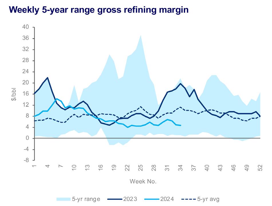
The oil market is languishing in the low US$80/bbl price range for North Sea dated crude, with OPEC+ restricting supply to keep the oil market balanced. Despite these factors, refining gross margins fell below the historical 5-year average during 2Q24 and have stabilised at ‘floor levels’, with low margins

limiting crude runs at weak sites in both Europe and Asia. (Figure 1).
The energy transition decouples the mobility of people and goods from oil demand. It is underway. Electric vehicles represented almost 50% of new vehicle sales in China in June 2024, with Europe at over 20%. Inter-fuel competition is also playing its part, as LNG trucks in China are displacing diesel demand.
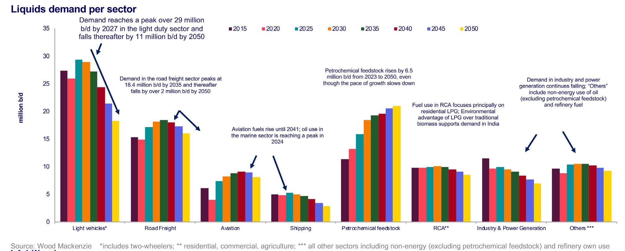
The composition of oil demand continues to evolve. The light duty vehicle sector is leading the energy transition. Heavy duty commercial vehicles, marine and aviation are hard-to-abate sectors due to the challenges of electrification, but they are not immune from fuel efficiency improvements and inter-fuel competition from natural gas or
liquid biofuels. Energy use for oil is projected to peak before the end of this decade.
Petrochemical feedstock demand, however, is forecast to continue to grow through to 2050. As income levels rise in developing countries, the rate of growth of petrochemical demand will slow from ‘GDP plus’ to eventually ‘GDP minus’ growth levels. Recycling and bio-based materials also reduce demand for oil-derived feedstocks, but these factors combine to slow the growth rate of petrochemical feedstock demand. Petrochemical feedstocks delay the onset of ‘peak oil demand’ until the early 2030s, but the sector is not big enough to counter demand declines in gasoline and diesel/gas oil (Figure 2).
From simply a demand perspective, refiners need to shift their focus away from transport fuels, towards petrochemicals. Petrochemicals are also more valuable than transport fuels, showed by the spread between the price of olefins and naphtha/LPG, which are the typical steam cracker feedstocks.
The demand for petrochemicals is far from uniform. Global polyethylene demand is expected to grow by 4.7% from 2023 to 1.2 billion t in 2024. The annual demand growth during 2024 - 2034 will average at 3.3%, higher than the 2.6% GDP growth in the same period. With population growth slowing in the long-term forecast years, polyethylene demand will slow to 1% AAGR during 2034 - 2050, lower than the 2.1% GDP growth.
Global paraxylene (PX) demand will increase to 55 million t in 2024, up from 51 million t in 2023. Robust polyester demand growth will drive PX consumption further, to over 66 million t in 2030 and 81 million t in 2040.
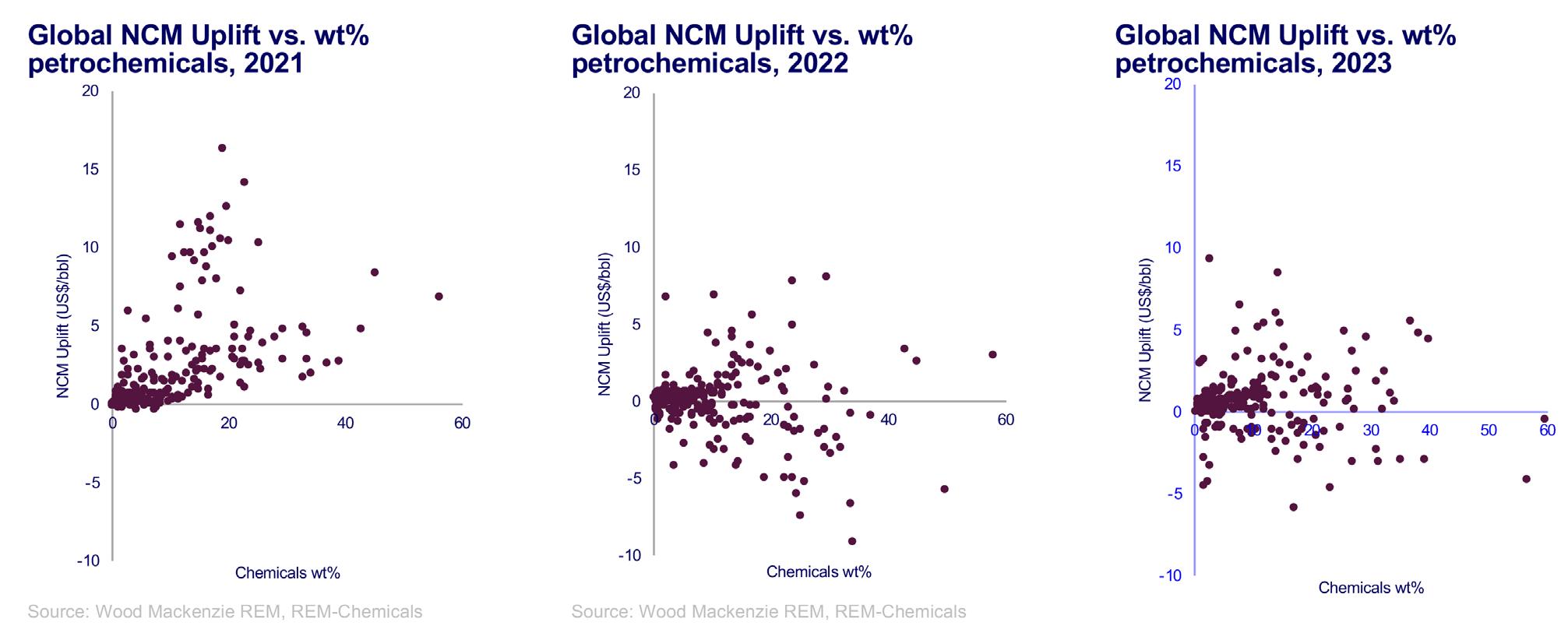
Many refiners are already integrated into petrochemicals, as Wood Mackenzie models over 200 integrated site locations, with several ‘second generation’ sites starting up in China in recent years. The value contribution from petrochemicals is a combination of the overall yield levels, profitability of the specific value chain and the location (as that determines CAPEX and the spread between petrochemical and feedstock pricing). Figure 3 shows the value contribution over the past three years:
n In 2021, petrochemicals added significant value to refining.
n This was not the case in 2022 due to the high value of transport fuels due to the Russia/Ukraine war.
n In 2023, refined product crack spreads declined, but the weak petrochemical margins from capacity over-build weighed on the value contribution.
Petrochemical integration is a ‘mega-trend’ for refiners, as demand for transport fuels declines. However, it is important to note the scale difference between the transport fuel demand and that for petrochemicals. Simply put, not all refiners can viably transition away from fuels to petrochemicals. For refiners to be commercially viable during the energy transition, they need to be strongly competitive, in terms of both earnings and emissions.
ADAM KADHIM Product Line Director, Hydrogen Topsoe

KNOWING YOUR LOW-CARBON POTENTIAL
As decarbonization requirements go up, refining companies are looking for cost-efficient ways to bring their carbon intensity down. One way to go is low-carbon hydrogen. Using low-carbon hydrogen has the potential to support refining businesses and the energy transition by reducing the carbon intensity of fossil transportation fuels. Discover the
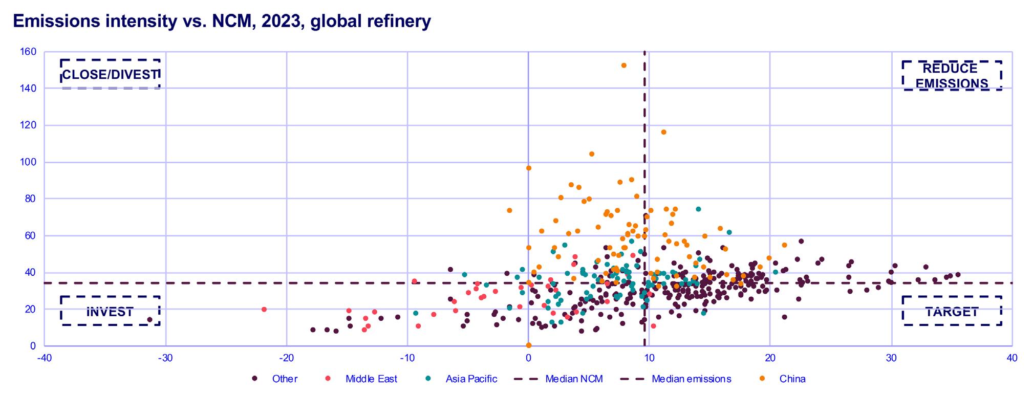
Refiners have traditionally measured their competitiveness in terms of net cash margin (NCM). As margin environment becomes challenging, refiners must continue to focus on improving their margins. However, refiners must now add another dimension to their competitiveness –carbon emissions. Net zero carbon emissions targets may lead to carbon policies which will have a material impact on refiners’ profitability. Using Wood Mackenzie’s PetroPlan simulation for refineries, it is possible to model the Scope 1 and 2 refinery emissions from the process operations used to convert crude oil into refined products.
Figure 4 plots the performance of global refining sites along two dimensions – margin and emissions, separating sites into four categories.
Refiners would want to be in the ‘target’ quadrant, where they achieve above average net cash margin and below average emissions intensity. Refiners with below average margins must first think about improving margin competitiveness, typically through upgrading investments. However, by making these investments, refiners must ensure
they do not move towards high margin and high emission quadrant. Refiners with low margins and high emissions are typically at high risk of closures or divestment.
Decarbonisation will become a necessity rather than a choice. Energy efficiency projects are early responses. For instance, improving furnace efficiency, low temperature waste heat recovery, FCC unit conversion and switching internal combustion fuel from fuel oil or coke to cleaner fuels. However, for a deeper decarbonisation, refiners will have to consider low-carbon technologies such as electric heating, carbon capture, use of renewable power and green hydrogen. There will not be a single solution, instead, a combination of these solutions to solve the complex decarbonisation problem is required. Improvements in technology, collaboration, partnering across multiple industries, and government subsidies will all be crucial to reduce the cost of deployment and accelerate adoption.
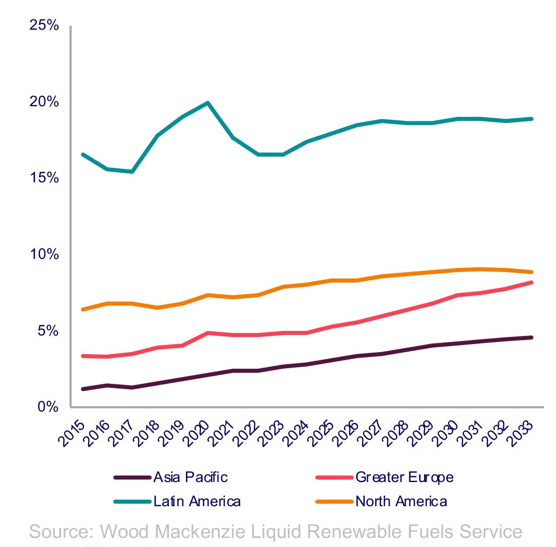
Demand for low-carbon liquids is to grow, driven by supportive government and industry policies aimed at
decarbonising the transport sector. Targets are increasing across most major economies, with the more developed regulatory requirements of Europe and North America leading the way, as shown in Figure 5. Three key policies shaping demand are:
n EU’s Fit for 55 package, which sets ambitious emission reduction targets for road, aviation, and marine transport.
n US Renewable Fuel Standard, which needs increasing volumes of renewable transport fuels.
n California’s Low Carbon Fuel Standard, which sets transport carbon intensity reduction targets.
In the rest of the world, policy-driven demand growth is more focused on energy security, reducing reliance on imports, and promoting regional agricultural development.
Robust demand growth is expected this decade for liquid biofuels. Investment in new capacity is required to meet the surging demand over the decade. The current main trend is the addition of hydroprocessing (HEFA) capacity to produce renewable diesel and sustainable aviation fuel (SAF) from oils and fats. HEFA projects account for nearly two-thirds of all announced liquid biofuel investments and over 80% for Europe and North America. This is familiar technology to refiners, producing a drop-in fuel, which can be easily integrated with existing supply chains. Many refiners already co-process small volumes of renewable fuels. However,
the biggest challenge for biofuel expansion is the availability of low-carbon feedstocks that meet stringent regulatory requirements. The ability to use a wider range of feedstock is a focus for bio-distillate projects as producers move away from virgin vegetable oils and
Ketjen’s ReNewFine Catalyst Portfolio for renewable diesel and sustainable aviation fuel is now commercially available.


instead seek alternative sources of waste. Access to secure waste feedstock supply is crucial to being competitive.
Long-term policy goals require the development of advanced renewable fuel technologies. E-fuels are the pinnacle of circularity and are recognised as key to the energy transition for the hard-to-abate maritime and aviation sectors. As e-fuels are reliant on the successful deployment of other technologies that are still nascent and expensive, such as green hydrogen and CO2 capture, Wood Mackenzie does not expect them to become commercially viable until the 2040s. However, there is potential for refiners to use their existing technical, commercial, and marketing capabilities to capitalise on the longer-term e-fuel opportunity. As with liquid biofuels, access to advantaged feedstock will be the main driver of success. Locations with low-cost sources of renewable electricity and CO2 could have that competitive edge.
Achieving a net zero world will require keeping the carbon in circulation or utilisation. This will demand that systems and applications are designed with sustainability and circularity in mind. In petrochemicals, being sustainable, however, can sometimes be out of reach, due to the nature of the polymer
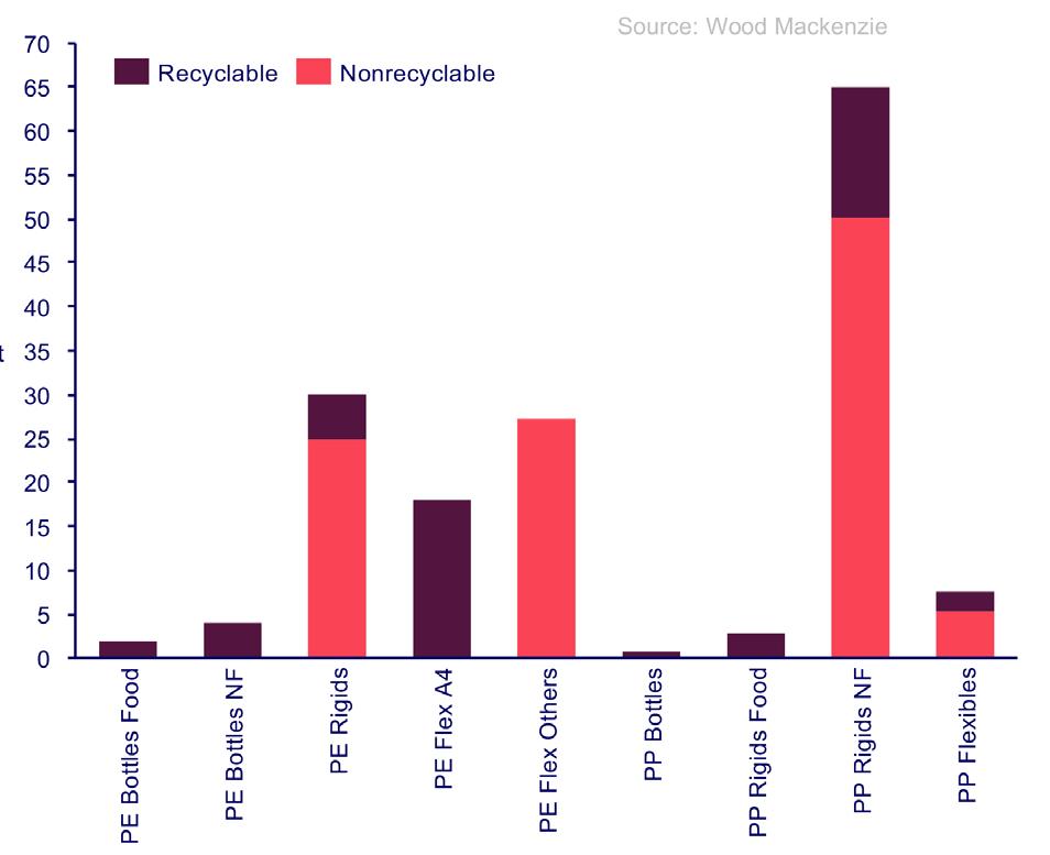
or the application. Innovation needs to be geared towards solving this. Where it might not be possible, it is important to keep the end goal in mind, and design recycling systems that can handle applications or materials regardless of how non-recyclable they may be mechanically, after having exhausted all measures possible to keep those materials in circulation.
The issue, in today’s market, is challenging in no other area more than polyolefins, as shown in Figure 6. Whether it is a car bumper or multilayered food packaging, mechanical recycling fails to deliver high-quality recyclates at high yields; this applies to almost 70% of polyolefin applications. Whether it is due to the application itself, or the linear value chain in which it exists, the market needs a solution that can deal with polyolefin waste on a molecular level, and this is where pyrolysis promises to solve the issue on a massive scale.
Pyrolysis is a recycling method that can retrieve concentrated carbon back from plastic waste. In doing so, the thermal breakdown of materials can turn plastic waste into oils, which, once purified and upgraded, can recycled into several applications. It is important to note here that despite the several challenges that lay in front of the pyrolysis industry, the benefits of having a scaled-up pyrolysis industry will be massive. Continuing to innovate to improve the yield and quality of pyrolysis will mean solving an important piece of the circularity puzzle.
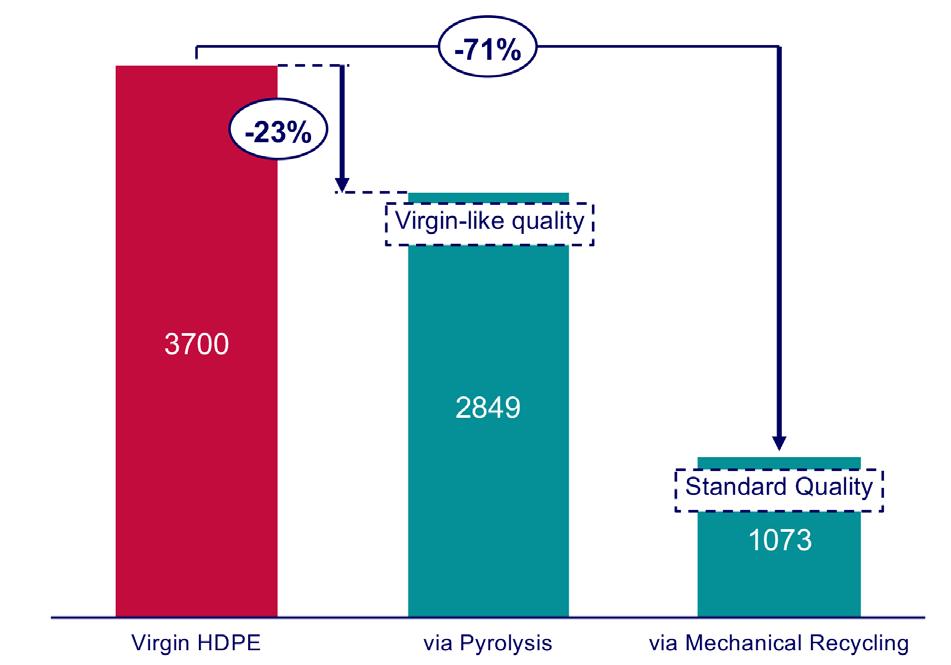
The main goal of pyrolysis is the recycling of polymers, especially mechanically nonrecyclable materials. To put things into context, circular high density polyethylene (HDPE) produces 25% less emissions than fossil virgin, as shown in Figure 7. There is a case for fuels, where pyrolysis oil can produce lower carbon fuels compared to fossil fuels. However, the case needs to be studied from several angles to design a new net zero system, regardless of the technology and application.
Refining margins have largely normalised despite significant geopolitical risk. For the refining industry, continued oil demand growth is supportive to its utilisation, margins and earnings, but an oil demand peak is on the horizon. The long-term viability of a refining asset requires it to be competitive on both earnings and carbon emissions. For many sites, ‘doing nothing’ is an option, but eventually closure will become inevitable for weak sites, particularly those exposed to the cost of carbon emissions. Petrochemicals are the obvious diversification choice for refiners, particularly with petrochemical margins to recover (slowly) from current lows. Integrated refinery/petrochemical sites are highly competitive, but petrochemical markets are, however, relatively small and project timing is often critical for investment success. Liquid biofuels can be attractive for those with secure advantaged feedstock, with the chemical recycling of petrochemical waste providing another opportunity. The ultimate pinnacle of circularity is e-fuels, but it is important to note the rules of competitive advantage remain, as does policy risk. Refiners need to plan to adapt in order to determine which option yields them an advantage to get ahead on the energy transition pathway.
Jock Hughson, Shell Catalysts & Technologies, Australia, discusses decarbonisation levers that refiners can pull to help them stay aligned with more stringent emissions regulations while staying competitive.
Refiners are under increasing pressure to reduce greenhouse gas (GHG) emissions from their operations and from the products they sell. But decarbonising assets is complex and can take many years to plan and implement – and getting it wrong may prove costly. This article will discuss three important decarbonisation levers – decarbonised (blue) hydrogen, carbon capture and storage (CCS) and

renewable fuels – that asset owners can pull to help them stay aligned with more stringent regulations while remaining competitive.
Around the world, oil and gas operations, including downstream refining, account for approximately 15% of global, energy-related carbon emissions, with a further 40% resulting from the use of oil and gas products. However, with atmospheric carbon dioxide (CO 2 ) still
rising and a rapidly shrinking carbon budget to limit global warming to 1.5°C above pre-industrial levels, there is a growing imperative to act – and act quickly.
And next year could prove pivotal for refiners (and hard-to-abate sectors such as steel and cement production) as governments party to the Paris Agreement get ready to announce what are expected to be the boldest updates to nationally determined contributions (NDC) ahead of COP29 in Azerbaijan.
With greater political ambition towards reducing GHG emissions, there is increasing urgency for refiners to develop and implement decarbonisation strategies to reduce direct (Scope 1) and indirect emissions (Scope 2) from onsite operations and those that result from the use of liquid and gas products sold (Scope 3) – which can account for as much as 90% of an asset’s total GHG emissions.
However, decarbonising an asset is complex and can take many years to implement. As the business case for decarbonisation strengthens, how can refiners reduce their carbon emissions while staying competitive?
Hydrogen is a vital fuel and feedstock for many refining applications; however, the majority of hydrogen produced today – natural gas (grey) hydrogen – is carbon-intensive. To decarbonise, industry needs to switch to low-emission sources of hydrogen, ideally renewable (green) hydrogen, produced by electrolysis using renewable power such as wind and solar. However, renewable hydrogen is currently costly to produce.
Alternatively, decarbonised hydrogen, produced from natural gas and using CCS, can offer a cost-effective, interim solution to help meet today’s growing demand while still lowering emissions. Of course, the choice between renewable and
decarbonised hydrogen will depend on the individual circumstances of a refinery.
Today, hydrogen project developers have three main decarbonised hydrogen technology options.
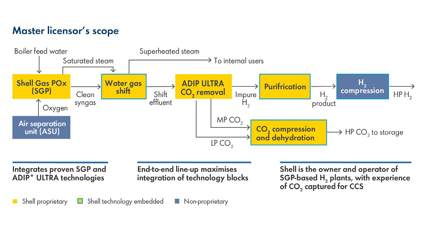
Steam methane reforming (SMR) and autothermal reforming (ATR) are well-established methods. A third option is gas partial oxidisation (POx), which sits at the heart of the Shell Blue Hydrogen Process (SBHP), and leverages Shell gas partial oxidation (SGP) (Figure 1). The SBHP captures CO 2 from high-pressure, precombustion gas streams with higher CO 2 concentrations, thereby making the carbon capture process cost and energy efficient.
According to the International Energy Agency (IEA), any serious ambitions to reduce a facility’s carbon intensity are likely to be spearheaded by CCS. However, capturing CO 2 can be costly, whether from precombustion processes, such as hydrogen production, or from post-combustion flue gases.
Reducing capture costs without compromising performance is crucial to accelerating CCS deployment, which is why Shell Catalysts & Technologies is engaged in continuous research and development to boost performance and efficiency of its amine-based ADIP ULTRA precombustion and CANSOLV * post-combustion capture technologies. Maturing these technologies focuses on:
n Lowering the overall cost of capture.
n Addressing new and evolving performance requirements.
n Improving operability.
Lowering the overall cost of capture means increasing capture efficiency. This can be done by increasing the amount of CO2 captured while decreasing energy consumption. For example, the company’s latest-generation ADIP ULTRA solvent can now capture up to 25% more CO2 from high-pressure, precombustion gas streams – such as those from hydrogen manufacturing units (HMUs) and gasification units – while lowering regeneration energy by up to 25%. This solvent was selected for the Quest CCS project (part of the Scotford upgrader) in Alberta, Canada, where it is capturing approximately 80% of CO2 emissions from the HMU process gas streams.
Similarly, by tailoring the ratio of amine in Shell’s CANSOLV formulations for each asset, the operating range of the solvent can be extended, thus reducing regeneration energy demand by as much as 25%. Moreover,
to keep up with stricter performance demands, CANSOLV can now achieve capture efficiencies of up to 99% – even for streams with relatively low CO2 concentrations. It also exhibits lower volatility and degradation characteristics and meets stringent emissions limits.
CANSOLV has recently been selected for the ADNOC Habshan CCS project, one of the largest post-combustion carbon capture projects in the world, where it will capture and permanently store 1.5 million t of CO2 from the asset’s sulfur recovery unit.
Shell is also increasing the operability of the CANSOLV technology by making it smarter. This means continually generating high-quality data that are monitored and analysed in real time. Examples include analysis of flue gas contaminants (e.g., nitrogen and sulfur oxides, oxygen and iron) and real-time solvent health monitoring for CO2 loading, amine concentration and the presence of degradation products and other contaminants, such as inorganic ions and metals.
High-performing capture technologies are just one part of a larger system that needs to work seamlessly to maximise capture performance and cost efficiencies. But integrating different parts of the systems can be complicated and cost inefficient.
This is why Shell Catalysts & Technologies and Technip Energies (T.EN) established a strategic alliance over a decade ago to offer turnkey carbon capture solutions that can unlock greater performance, as well as offer engineering and logistics benefits.
T.EN offers optimised solutions for CANSOLV units of a wide variety of sizes ranging from 1500 tpy pilot units to 10 000 - 150 000 tpy containerised units that are versatile, redeployable and easily transportable, through to 2 million tpy units for large-scale emitters.
Renewable fuel mandates across Europe and other parts of the world present
opportunities for fuel producers to support the growing demand for more sustainable fuels, such as bio- and renewable diesel and sustainable aviation fuel (SAF). For example, by 2030 the ReFuelEU initiative obliges a minimum of 6% SAF content in all aviation fuels made available at EU airports, increasing to 20% by 2035 and 70% by 2050. Likewise, the US aims to produce at least 3 billion gal. of SAF annually by 2030.
To capture this growing market, an increasing number of refiners are evaluating revamping their assets using the Shell Renewable Refining Process (SRRP) – a two-stage unit that offers higher SAF and renewable diesel yields, and a longer cycle length than a single-stage unit (Figure 2). For operators with a single or two-stage hydroprocessing unit (fossil service) or a single-stage hydrotreated vegetable oil (HVO)/hydrotreated esters
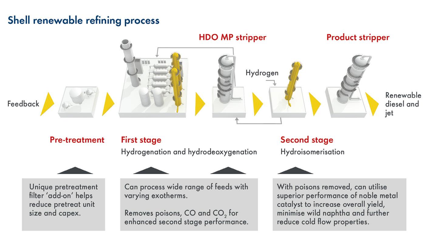
and fatty acids (HEFA) unit, revamping with the SRRP to maximise SAF production could have a significant and positive impact on margins.
Investing in biofeed processing technologies is an important decision; however, understanding the evolving landscape of biofeed availability and regulation is equally important.
For example, the EU’s RED II has introduced a more stringent cap on biofeeds that are easier to use, such as waste cooking oil and certain animal fats, which means that refiners will gradually need to process more challenging feeds like straw, algae and other types of biomass. This limits the amounts of biofuel that can be produced with current HVO units, unless they can be adapted to process more challenging feeds.
Decarbonised hydrogen, carbon capture and biofuels are important decarbonisation levers, but how can they be combined for even greater impact on CO 2 emissions? Knowing where the emissions are coming from and which ones to focus on is key.
The main CO 2 sources in a typical refinery include the crude distillation and vacuum distillation units, the fluidised catalytic cracker (FCC) and the catalytic reformer, each of which can account for up to 25% of the site’s CO 2 emissions. Additionally, utilities and the HMU contribute about 25 and 5% respectively. When there is a gasification unit in the line-up, this can also be a significant source of CO 2
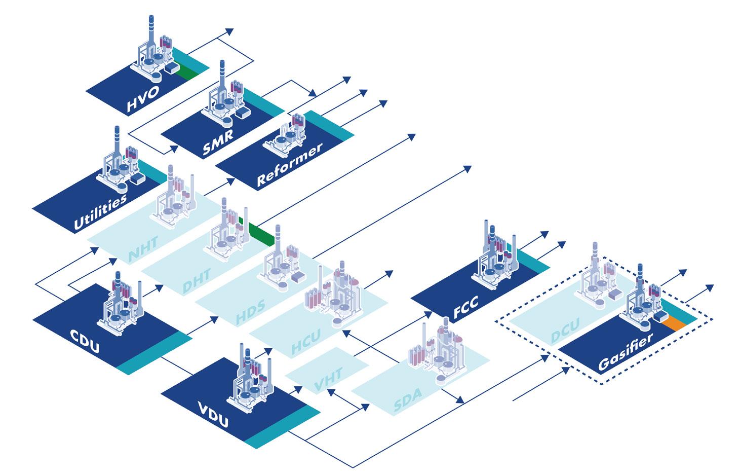
With different carbon intensities, a range of solutions are needed to avoid and/or capture CO 2 emissions. Figure 3 describes three possible response options. For example, blue stripes indicate where a refiner might use ADIP ULTRA to capture CO 2 from SMR
or gasification units, which produce high-pressure, relatively pure CO 2 steams ideal for carbon capture, or CANSOLV, which might be used to capture CO 2 from various low-pressure flue gases.
Alternatively, a refiner might also upgrade an existing gasifier to generate decarbonised hydrogen using the SBHP (orange stripe) or deploy coprocessing technology in their distillate hydrotreating unit to produce blended biofuels.
Figure 4 shows an example of how Shell’s hydrogen, carbon capture and biofuels technologies might be integrated to lower the carbon intensity of refinery products. By producing decarbonised hydrogen onsite using the SBHP, refiners can supplement or replace fuel gas (or piped natural gas) in fired equipment. Alternatively, in some cases it may be more economical to capture CO 2 from combustion flue gases using CANSOLV technology or to electrify fired equipment where a sufficient supply of decarbonised electricity exists.
In each case, switching to a decarbonised energy source and/or capturing CO 2 directly from combustion processes can help to significantly reduce operational (Scope 1 and 2) emissions and the carbon intensity of products. Combined with the production of blended biofuels or 100% renewable fuels, a refiner can also take significant steps to reduce emissions from the use of their products (Scope 3).
As countries around the world start drafting their updated NDCs, refiners should assess what bolder climate action and more progressive emissions policies could mean for their operations.
Many refiners are already implementing decarbonisation strategies, but for those yet to start, now is the time to take action to ensure that they are prepared for, and can capture, the market opportunities arising from the shift to low-carbon and more sustainable fuels and operations.
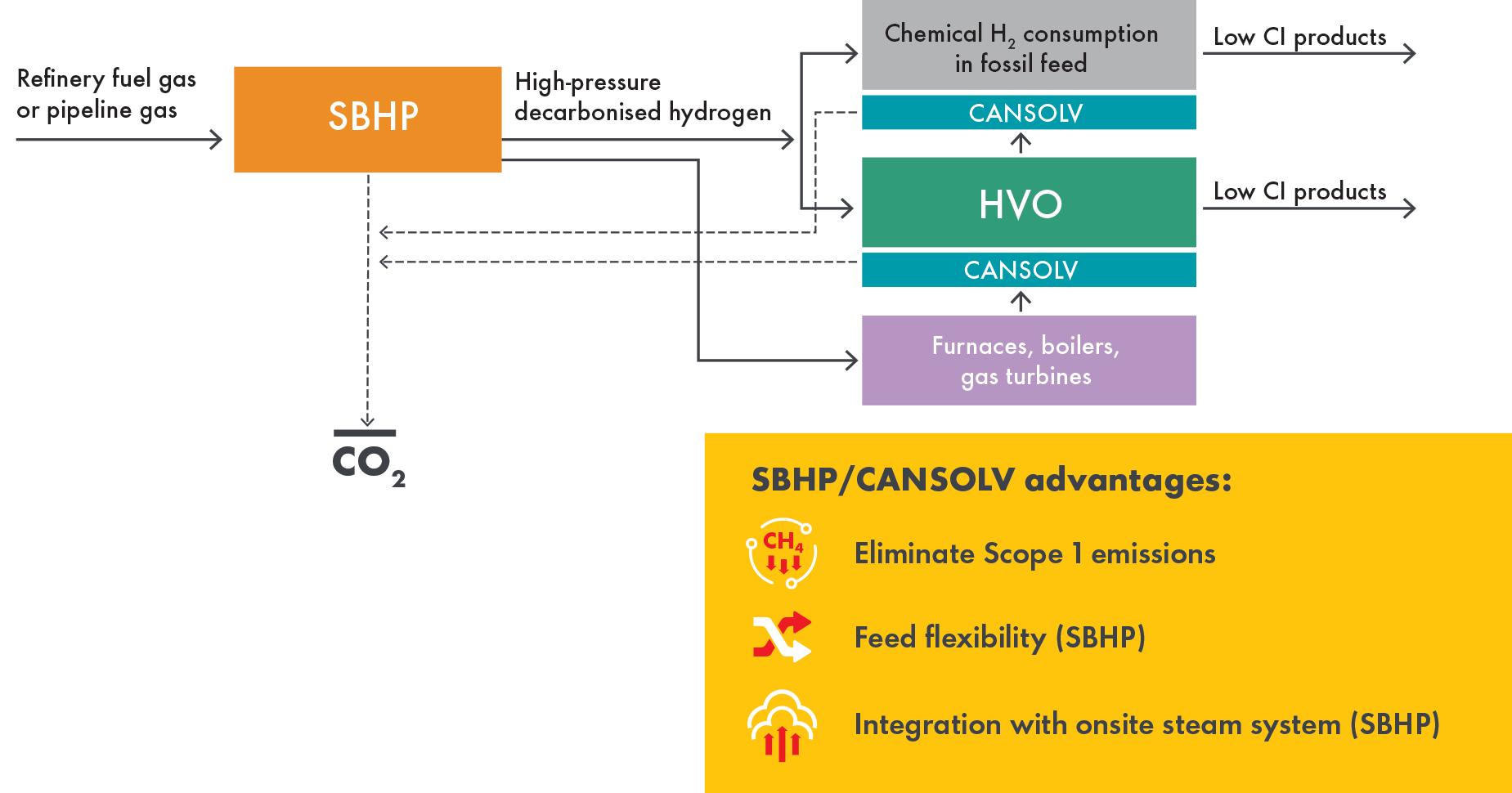
Decarbonised hydrogen using the SBHP and pre- and post-combustion carbon capture using ADIP ULTRA and CANSOLV technologies are proven solutions that can contribute to significant reductions in operational (Scope 1 and 2) emissions. Additionally, revamping HVO and HEFA units using the SRRP can help refiners shift their product slate towards lower-carbon renewable fuels.
Note *ADIP and CANSOLV are Shell trademarks.
The world’s energy system is changing. To solve the challenges, Shell Catalysts & Technologies is developing its Decarbonisation Solutions portfolio to provide integrated value chains of technologies to help industries navigate the energy transition. Our experienced teams of consultants and engineers draw on Shell’s owner–operator–licensor expertise to co-create pathways and technology solutions to address your specific decarbonisation ambitions – creating a cleaner way forward together.
Learn more at shell.com/decarbonisation.
Michael Connolly and Man Yiu Tse, ICIS, explore the evolving biofuels market, and examine how economic competition, regulatory dynamics, and shifting corporate strategies shape the industry.
The global energy transition, spurred by the urgent need to reduce carbon emissions, has placed biofuels at the centre of the decarbonisation agenda. Biofuels have the potential to mitigate climate change by significantly lowering the carbon emissions, particularly in aviation and shipping sectors where there are limited alternatives.
In regions such as the EU, biofuels have been instrumental in reducing carbon emissions, driven by stringent regulatory frameworks and policy support.

However, the landscape for biofuels is far from smooth. The industry faces mounting economic, regulatory, and strategic pressures that threaten to slow its progress despite its critical role in the energy transition.
Biofuels have long been touted as a critical solution for reducing greenhouse gas (GHG) emissions, but they are not immune to the economic pressures that challenge their viability. Rising production costs, volatile feedstock prices,
and market competition from cheap imports create a complex environment for biofuel producers, particularly in Europe.
The closure of Argent Energy, a significant player in the biofuels sector, due to competition from subsidised Chinese and US biodiesel imports and regulatory restrictions on EU feedstock imports, highlights the fragility of the biofuels market.
Neste, the largest biofuels producer by capacity in Europe, recorded its first negative profit in 2Q24, since 4Q14.

Strikingly, Neste reported that the sales margin for its renewable fuels business in 2Q24 fell by more than 50% year on year to US$382/t.
The influx of low-cost biodiesel from China, made possible by low production costs, coupled with state economic support and subsidies, has particularly distorted the market, leaving European producers struggling to compete.
To level the playing field and protect its biofuels industry, the EU imposed provisional anti-dumping duties
of between 12.8 - 36.4% on Chinese biodiesel from 16 August 2024, and will be replaced with definitive measure from February 2025.
Still, competition from imports is just one of many challenges the sector is facing. It is also blighted by the high cost of producing advanced biofuels, such as those derived from waste oils and lignocellulosic materials.
The EU aims to expand the use of advanced biofuels to meet long-term climate goals, in place of first-generation biofuels due to sustainability concerns. This requires a major scale-up of capacities in the region to meet demand. Yet, the high prices of advanced biofuels have been a barrier for producers to secure investments to reach Final Investment Decisions (FIDs). Long-term offtake agreements are key to secure finances. But it is challenging to enter into long-term contracts with potential buyers at high prices.
The lack of demand certainty compounds the challenges in capacity scale-up. The EU has put a limit on the contribution of food- and feed-based biofuels towards the renewable energy target and set a combined secondary target of 5.5% for advanced biofuels and renewable fuels of non-biological origin (RFNBO) in the share of energy supplied to the transport sector in 2030.
Advanced biofuels will also be needed to meet the ReFuelEU Aviation regulation which mandates a 2% share of sustainable aviation fuels (SAFs) in EU airports from 2025 and 6% from 2030, and progressively reaching 70% share by 2050.
However, mandates are a double-edged sword. While it can drive the market to adopt a certain level of demand, it can also become a limit on demand if there is no complementary policy support.
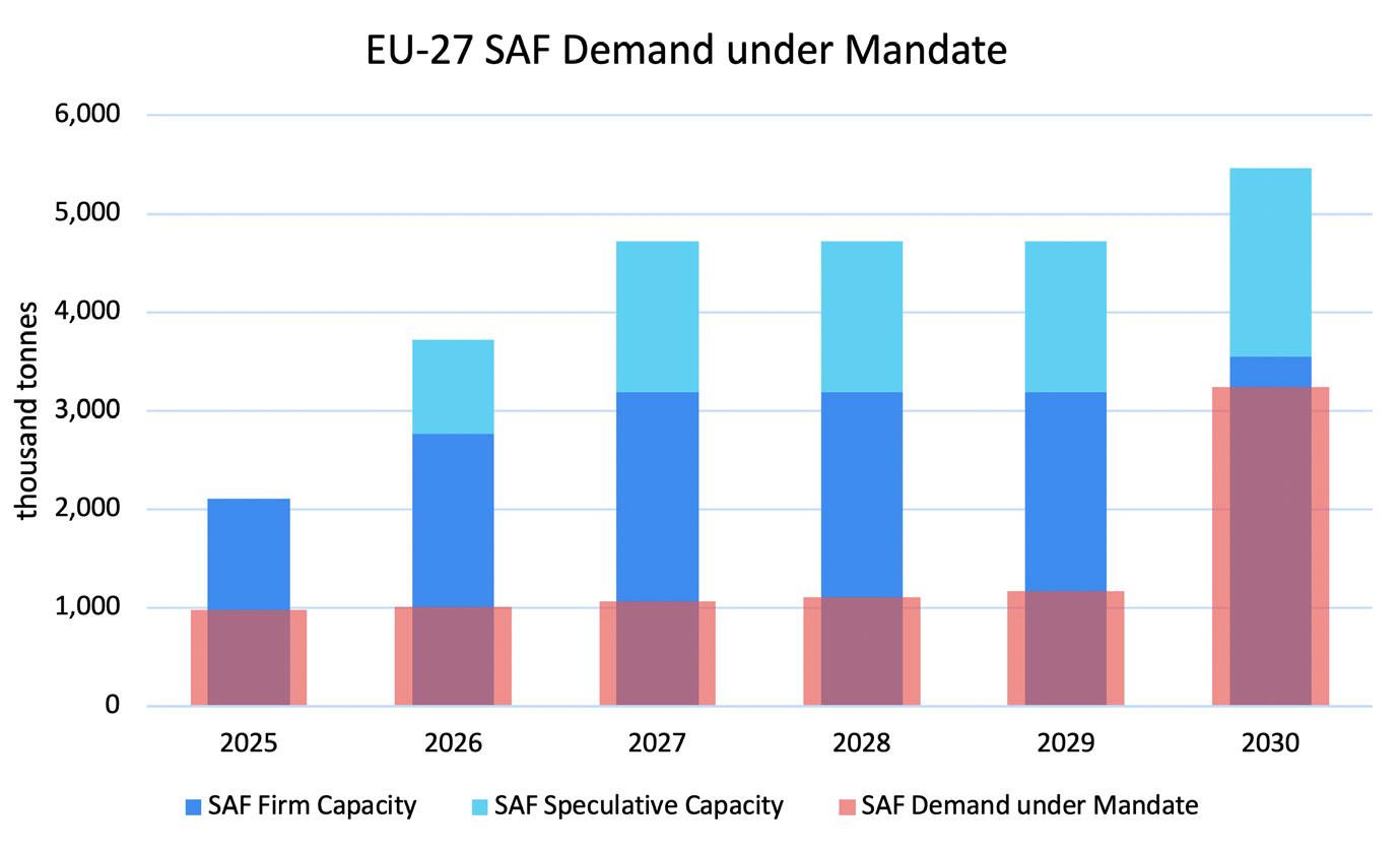
Take, for example, the ReFuelEU Aviation regulation, the unintended consequence of regulation design is that there will be a step change in SAF demand every five years
when there is an increase in SAF share requirement. This makes it challenging for producers to plan their capacity investments.
Meanwhile, SAF capacity is already more than demand under mandate in the EU. This weak market condition led Shell’s decision to pause the construction of its European biofuels facility in Rotterdam, the Netherlands. BP has also delayed its plans on a bio-refinery in Lingen, Germany, to ‘simplify portfolio and focus on value and returns’, underscoring the pessimism on the returns in the biofuels market.
There are also uncertainties on whether regulations on biofuels may change. Recent policy decisions underscore the tension between short-term economic pressures and long-term climate goals, posing new challenges for biofuel producers.
For example, the government’s decision to reduce the biofuel blending mandate in gasoline and diesel has sparked controversy in Sweden. The move, aimed at lowering consumer fuel costs, is expected to result in higher CO2 emissions, a step backward in the country’s ambitious climate agenda. This decision highlights the difficulty of balancing environmental objectives with economic realities, particularly as energy costs rise and inflationary pressures intensify. While Sweden has been a leader in renewable energy adoption, this policy reversal raises concerns about the stability of the regulatory framework for biofuels in Sweden and across Europe.
Amid these challenges, there are opportunities for biofuels producers to capture in the bio-based chemicals space as the emphasis on a circular economy continues to grow.
Bio-based chemicals, which are derived from renewable biomass, offer a sustainable alternative to traditional petrochemicals. These chemicals are used in a wide range of industries, from plastics and textiles to pharmaceuticals and personal care products. As demand for sustainable materials grows, biofuels producers can extract value from their co-products, bio-naphtha and bio-LPG, enhancing the overall value proposition of biofuels.
This synergy between biofuels and biochemicals drives research into new technologies and processes that can optimise renewable resources. For example, advancements in biorefining technologies enable the efficient conversion of biomass into biofuels and high-value chemicals, creating integrated value chains that maximise the use of feedstocks. This approach not only improves the economic viability of biofuels, but also supports the broader circular economy by reducing waste and promoting the sustainable use of resources.
The future of biofuels will depend on the industry’s ability to overcome the economic, regulatory, and operational challenges it currently faces. Coordinated policy support in every part of the supply chain is essential to sustain momentum. Governments must ensure that biofuel regulations are aligned with long-term climate goals, providing stable and predictable frameworks that encourage investment in sustainable production methods. Policies that level the playing field for domestic producers (like the carbon border adjustment mechanism [CBAM]), protect against unfair competition from subsidised imports, and incentivise the use of advanced feedstocks will be critical.
Innovation will also play a vital role in the future of biofuels. Continued research and development into non-food and feed crop feedstocks, such as agricultural residue and other lignocellulosic materials, as well as advancements in production technologies, will be essential for increasing efficiency and reducing costs. Collaboration between industry, academia, and government will drive these innovations forward.
Finally, increased financial incentives are needed to attract investment in biofuel projects. While biofuels are seen as a key solution to reduce carbon emissions, scaling up production will require significant capital. Governments can support this process through grants, subsidies, and tax incentives that reduce the financial burden on biofuel


producers and share the risk with investors to encourage the development of new projects.
Biofuels remain a pivotal component of the global energy transition, offering a sustainable alternative to traditional hydrocarbons. However, the industry faces significant challenges that must be addressed to unlock its full potential. Economic pressures from subsidised imports, regulatory inconsistencies, and operational hurdles have slowed progress, while strategic shifts by significant energy companies reflect the complexity of the current market environment.
Yet, these challenges also present opportunities for innovation and growth. By investing in advanced feedstocks, improving production technologies, and fostering synergies between biofuels and biochemicals, the industry can create new value streams and contribute more effectively to the global energy transition. To sustain momentum, a coordinated effort is required from policymakers, industry leaders, and investors to support biofuels through clear regulations, financial incentives, and ongoing innovation.
In the end, biofuels have the potential to serve as a bridge between today’s energy system and a future where carbon-neutral technologies dominate. With the proper support and strategic focus, biofuels can continue to play a crucial role in reducing global carbon emissions and driving the shift toward a more sustainable, low-carbon economy.


Superior process and water treatment solutions supported by service excellence
Superior process and water treatment solutions supported by service excellence
Halliburton Multi-Chem collaborates with customers to improve reliability, increase throughput, and enhance operating unit efficiency and flexibility. We offer a broad range of chemistries, equipment, automation, and services to help our customers maximize asset value.
Halliburton Multi-Chem collaborates with customers to improve reliability, increase throughput, and enhance operating unit efficiency and flexibility. We offer a broad range of chemistries, equipment, automation, and services to help our customers maximize asset value.
Our experienced team provides onsite technical services and engineering support. We listen to understand your challenges and respond with solutions.
Our experienced team provides onsite technical services and engineering support. We listen to understand your challenges and respond with solutions.


The world is experiencing the fundamental effects of global warming on the Earth’s climate system. The National Oceanic and Atmospheric Administration (NOAA), a division that provides environmental data, products, and services covering the depths of the ocean to the surface of the sun, reported in January 2024 that the global surface temperature was 2.29°F (1.27°C) above the 20th century average of 54.0°F (12.2°C), making it the warmest January on record. Above average temperatures were recorded across every continent.
A growing coalition of countries, cities, businesses, and other institutions and entities have pledged to combat global warming by getting to net zero emissions. The transition is an immense challenge and the energy sector, which is chronicled as the source of approximately three-quarters of greenhouse gas emissions, holds the key. Energy companies world-wide are sourcing or producing bio-feedstocks and converting or retrofitting operational and idle refineries for processing renewable diesel. It is the number one initiative for lowering the carbon intensity of the transportation industry.
According to the US Energy Information Administration (EIA), US production capacity for renewable diesel could increase significantly throughout 2024.1 Europe accounts for approximately 50% of the total global renewable diesel supply. The EIA also anticipates that, due to increased demand, Europe will transition from an exporter to an importer of renewable diesel over the next five years.
Globally, it is estimated there are currently more than 500 operational biodiesel and renewable diesel refineries across major commercial producing countries, with renewable diesel outpacing the other alternatives in production capability.
In the US market, biofuels consist mostly of ethanol, biodiesel, and renewable diesel. Ethanol accounts for the majority of these biofuels and is used as a blending stock with gasoline. Its production has been steady at approximately 400 million bbl/y since 2021. Biodiesel production likewise has been steady since 2021 but has been declining slightly at approximately 60 million bbl/y. In contrast, since 2021, renewable diesel production has grown considerably – from 15 million bbl/y to over 70 million bbl/y, slightly displacing the demand for biodiesel. The reason for the surge in renewable diesel is easy to explain.
Renewable diesel and biodiesel are both biofuels derived from similar feedstocks like vegetable oils and animal fats, but they differ in their production processes and properties.
Biodiesel is produced chemically through a process called transesterification where fats and oils react with an alcohol (usually methanol) and a catalyst to form fatty acid methyl esters (FAME) and glycerol. As a result, biodiesel contains oxygen in its chemical structure, which can affect its performance and compatibility with engines. Because of its lower energy density, biodiesel is typically blended with petroleum diesel at a ratio of 20% biodiesel to 80% petroleum diesel to minimise its inferior combustion properties.
Renewable diesel, on the other hand, is produced by hydrotreating the same fats and oils used in the production of biodiesel. Hydrotreating involves the introduction of hydrogen into the molecular structure which not only removes organic sulfur but also the oxygen. The result is a
biodiesel fuel that is chemically equivalent to petroleum-based diesel. This hydrogenation process yields a high-quality diesel that can be used as a direct replacement without any blending necessary. This chemical similarity also means that no engine modifications are required. Renewable diesel has the same energy density, providing comparable performance and efficiency.
Because renewable diesel contains no oxygen, the challenges associated with storage, cold temperature operation, and water attraction are eliminated. Its higher cetane number is calculated between 75 and 95, compared to biofuel, which is 50 and 60, which means faster startups in the cold, boosted throttle response, and less noise.
The makeup of the renewable diesel allows the fuel to combust with maximum efficiency while decreasing regenerations in the particulate filters and injector maintenance frequency – and because it does not contain impurities or aromatics, it is odourless.
Both biodiesel and renewable diesel offer environmental benefits by reducing greenhouse gas emissions and reliance on fossil fuels. Renewable diesel’s compatibility with existing infrastructure and engines; however, makes it a much more versatile option.
In the US, federal and state regulations such as the Renewable Fuel Standard (RFS) and California’s Low Carbon Fuel Standard (LCFS) are pivotal in incentivising the production and consumption of renewable fuels, including renewable diesel. Increased blending mandates are making the markets for renewable diesel even stronger, which encourages higher investments in production infrastructure and increases overall production volumes.
In Europe, ‘Fit for 55’ was adopted in 2022. It refers to reducing net greenhouse gas emissions by at least 55% by 2030 and includes two pillars adopted in October 2023. They are the revised Renewable Energy Directive (REDIII) and the ReFuelEU Aviation regulation – with an emphasis on waste-based and low-carbon biofuels in the transportation sector. Canada adopted a country-wide initiative, the Clean Fuel Regulation, which came into effect in 2023. It requires fuel producers and importers to reduce the carbon intensity of transportation fuels to decrease their carbon intensity by approximately 15% (below 2016 levels) by 2030. Asia mandated hikes to more than double regional biofuels demand by 2035.
Before it goes to market, however, renewable diesel must be treated to remove any sulfur and other impurities like nitrogen and olefins. The most common treatments for diesel include hydrotreating, gasification, pyrolysis, or other biochemical and thermochemical technologies. Sulfur may be present in the feedstocks to these processes or be added during a processing


Visual MESA® Greenhouse Gas Emissions Management is a certified Corporate Carbon Footprint software. It continuously monitors emissions and energy consumption across the entire plant operations, giving you accurate, real-time data and alerts for decision making.
Whether you choose cloud-based or on-premise, this solution with automated, auditable reporting enables you to both optimize energy and analyze Scope 1 and 2 emissions to identify and implement operational improvements for energy savings and to meet your emissions reduction targets.
Discover how your industrial plant can save over 25k tonnes of CO2 per year. www.kbc.global/emissions-management


step to facilitate specific reactions. For instance, treatment may include things like the sulfuric acid treatment of feedstocks or the use of sulfur to activate catalyst for a hydrotreating process. Feedstocks such as coal used for gasification could inherently contain sulfur compounds. Regardless, the sulfur either in the feedstock or added to the treatment process must be removed.
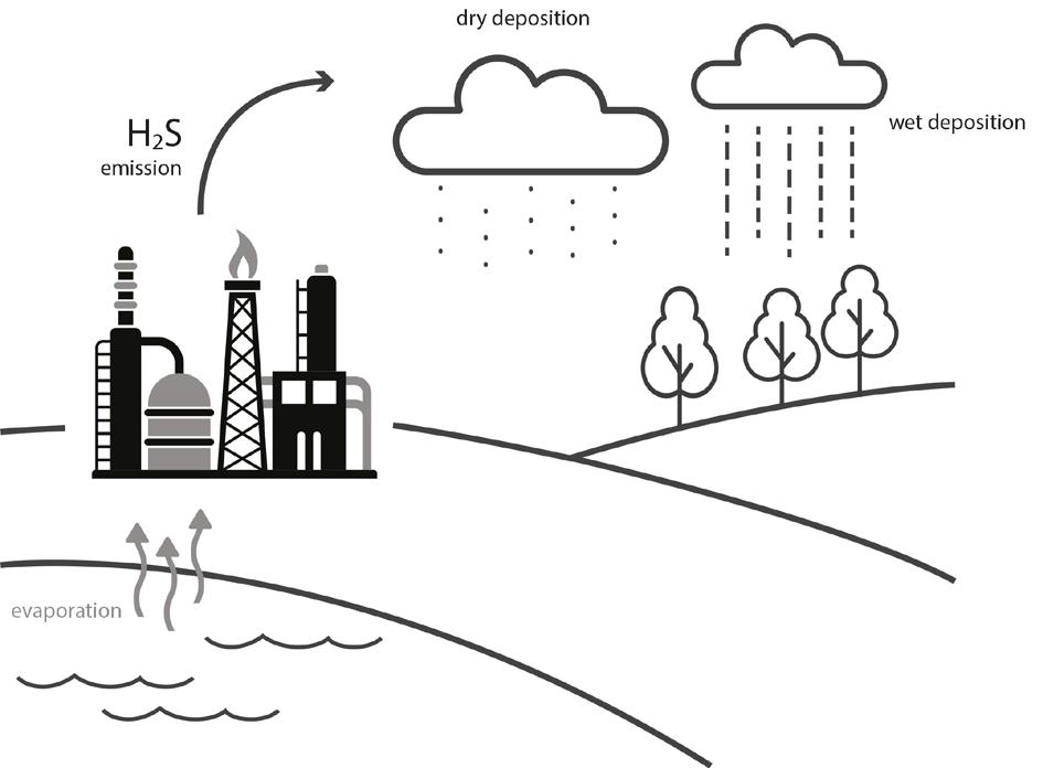
Sulfur varieties found in these processes could range from a heavier mercaptan sulfur, which would remain in the diesel, to light mercaptans or H2S, which would be split from the diesel and remain in the lighter hydrocarbon streams. The most effective treatment method is to use a proprietary technology unit specifically designed and fabricated to remove the sulfur species present in the hydrocarbon stream. This will ensure each client’s specifications can be met with a specific solution. Removal of the sulfur species is required to meet emissions requirements in finished products.
There are options when determining what treatment process is most effective and which is required. These are dependent on the hydrocarbon stream being treated, as well as the sulfur impurities present in the feed stream. An example is whether the stream being treated is the diesel stream, or the light end hydrocarbon that was split during the process to make the renewable diesel. This can impact whether the feed stream is a gas or a liquid and what is contained within it. A few options will be discussed below.
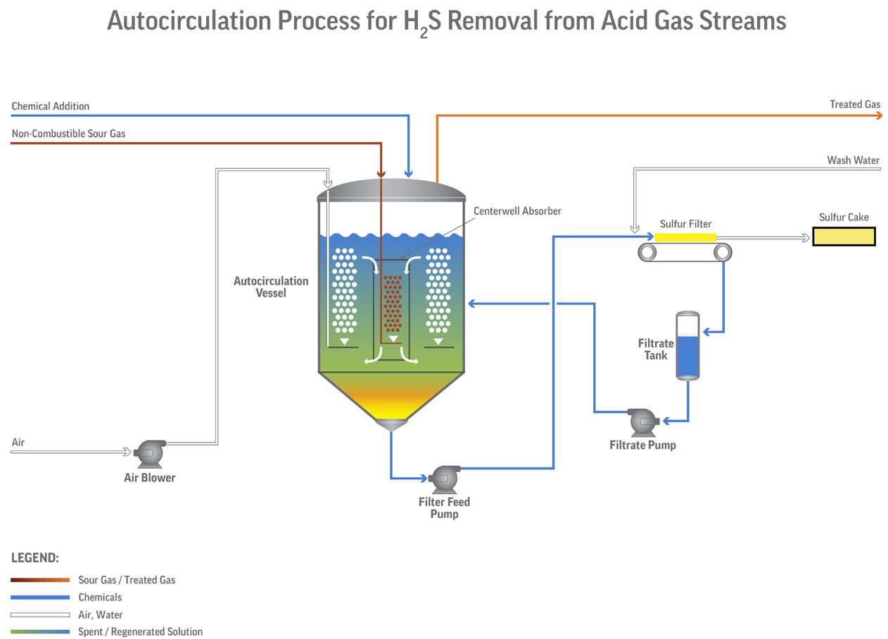
LO-CAT® is a desulfurisation technology for removing 1 to 20 tpd of H2S as sulfur from gas streams. The process chemistry of this technology is embedded in its name –LO-CAT, which stands for Liquid Oxidation CATalyst. The overall system oxidation reaction is as follows:
H2S (gas) + ½ O2 (gas) → H2O + S o
This is a well-known oxidation reaction. This overall reaction is sub-divided into two parts:
(i) Reduction: H2S gas absorption, ionisation and reaction to make solid sulfur in the liquid solution.
(ii) Oxidation: the liquid solution is then oxidised using air and regenerated for re-use.
Therefore, the LO-CAT® process is called a redox (reduction-oxidation) reaction process to reflect these two steps.
LO-CAT does not use any toxic chemicals or produce any hazardous waste byproducts. The environmentally safe catalyst is continuously regenerated in the process.
THIOLEXTM is a technology for removing H2S or mercaptans from gas and liquid streams using an alkaline solution in an acid-base reaction that may also be used depending on the feed and product specifications. THIOLEX units use proprietary, non-dispersive FIBER FILM® Contactors as mass transfer devices, with caustic and/or amine as the treating reagent in gas and liquid hydrocarbon streams. The FIBER FILM Contactor is a vertical vessel packed with proprietary fibre that achieves non-dispersive-phase contact without the problems inherent in conventional dispersive mixing devices, such as aqueous phase carryover, hydrocarbon losses, lack of turndown ability, long settling times, plugging, and flooding. Because the aqueous phase adheres to the fibres rather than being dispersed into the hydrocarbon phase, carryover and uncontrollable emulsions are virtually eliminated.
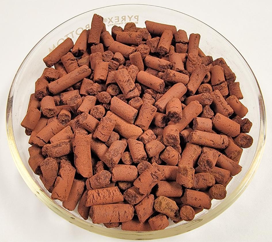
A further option for H2S removal from gas streams when there is less than 1 tpd of sulfur removal required is to use an adsorbent. SULFURTRAP® EX adsorbent differentiates itself from competing technologies for its ability to easily decrease the H2S content to <1 ppm with continuous low pressure drop (SOR to EOR), loading 2 - 3 times more sulfur than conventional products while keeping the cost of the media low. Low OPEX costs are easily achievable with SULFURTRAP EX due to fewer and easier changeouts. It also provides a safer turnaround experience for operations and maintenance personnel due to the ease of bed changeout, something the competition cannot provide.
These technologies can remove H2S and mercaptans and ensure the renewable diesel product meets its required specifications. The decision between the technologies depends on the inlet contaminant levels and types and the required product specifications.
Companies and government entities are transitioning their fleets to renewable diesel as a low-cost strategy to meet sustainability goals. Renewable diesel allows fleets to substantially reduce carbon emissions and petroleum use, and improve air quality without sacrificing power, performance, or range. Fleet owners and managers can convert their entire diesel-powered fleet to renewable diesel fuel overnight.
The savings may seem minimal at an average of US$0.21 less than diesel. However, the savings are quite substantial. In 2019, there were 3.91 million Class 8 trucks on US roads, which each drove an average of 62 571 miles. If they had all been fuelling and driving with renewable diesel, each truck would have saved an average of US$1317.77/yr. If all Class 8 trucks had used renewable diesel, it would have produced US$5.15 billion in annual savings. Those same trucks fuelled with renewable diesel would have reduced emissions by saving more than 297 million tpy of carbon dioxide (CO2).
With the potential savings and ease of use for renewable diesel, the production and treating requirements to generate it become infinitely doable.

Reliable Technologies for H2S, Mercaptan & COS Treatment or Removal
Turn yellow into green using our low OPEX, proven sulfur treatment technologies.
Merichem Technologies is a leader in sulfur treatment technologies, providing safe and eco-friendly solutions to remove H2S, mercaptans and COS from both liquid and gas streams. Whether it’s customized or standard, adsorbents or chemical processes, our robust technologies allow you to maximize profitability while meeting your specifications at any scale.
With over 50 years of experience delivering innovative solutions and excellence in service, you can trust we will do the same for you.
Let’s discuss your specific requirements and how we can help.

Nabil Ahmed, The Energy Industries Council (EIC), explains why sustainable aviation fuel (SAF) must overcome investment and scalability hurdles in order to prove its promising carbon reduction prospects.
The use of sustainable aviation fuel (SAF) is at the heart of efforts to reduce carbon emissions in aviation. The International Air Transport Association (IATA) has provided a definition that includes fuels made from biomass, and more recently from non-biomass sources through new technologies. SAF can reduce its lifecycle CO2 emissions by up to 80% compared with traditional jet fuel. However, it currently makes up less than 1% of all aviation fuel consumed.
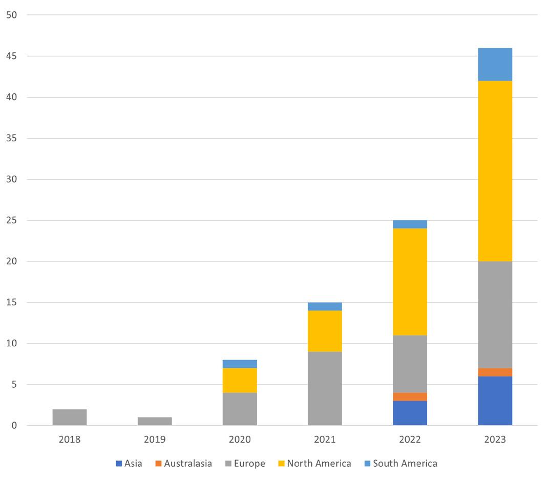
Because it relies on high density energy fuels that can function under extreme circumstances, the aviation sector – which produces between 2 - 3% of global CO2 emissions – faces significant challenges in reducing its carbon footprint. A minimum capital investment of US$10 million is required for each of the 104 SAF projects underway. This level of investment highlights a strong commitment to increasing SAF production, but also demonstrates some major financial and logistical hurdles ahead.
These are produced by varying sources such as agricultural waste, algae, plant-based materials and processing waste converted into ethanol for SAF use. Some advanced methods capture CO2 and combine it with green hydrogen from renewable energy to create ‘e-fuels’. This variety presents many paths for SAF production.
The process begins by selecting the right feedstocks which have to be sustainable, cheap and readily available. These feedstocks are then washed, dried or sometimes grinded. They can be converted into fuels using various techniques such as pyrolysis, gasification or fermentation depending on their types. One advantage is that SAF can be mixed with routine jet fuel and used in existing aircraft engines without any changes, therefore making it easier to incorporate it into the already existing fuel system.
Despite its high cost and difficulty in obtaining enough raw materials for production, SAF has faced a lot of challenges in terms of wider adoption. Currently SAF production costs between two and four times more than traditional aviation fuel, thereby presenting a serious problem to airlines that operate on slender profit margins. Fuel expenses cannot be increased that much.
Furthermore, although potential sources such as agricultural residues and algae exist for scaling up SAF production, these processes are not simple. It will also necessitate substantial investment in infrastructure including new manufacturing plants and improvements to the present fuel distribution network for effective handling of SAF blending, as well as its distribution. Financial incentives or subsidies from governments or companies
have the potential to ensure competitiveness with conventional jet fuel.
The path to the mass use of SAF is difficult, but it can greatly contribute to the sustainability of aviation. Applying new technologies and making substantial investments in them will help introduce a gradual shift towards a cleaner future.
The ‘2024 SAF Insight Report’ by the Energy Industries Council (EIC) highlights both optimism and significant hurdles in today’s SAF environment. While SAF has the potential to reduce carbon emissions from air travel, the current scale remains limited by economic, logistical, and technological obstacles. For SAF development to occur, governments, industries and research institutions should join hands.
North America – with the US in particular taking the lead – has been pioneering various projects involving SAF. The US government is spearheading several initiatives that will improve production of SAFs such as the Sustainable Aviation Fuel Grand Challenge, which has set aims to encourage production of 3 billion gal. annually by
2030 and encourage the use of 100% of aviation fuel from only biofuel sources by 2050.
Key projects in the US, such as Velocys’ Bayou Fuels Biomass to Fuels and GEVO’s Net Zero 1 (NZ1) Project, represent substantial investments in scaling up SAF production. These initiatives leverage advanced technologies to convert biomass and other feedstocks into high-quality aviation fuel, demonstrating SAF’s potential as a mainstream fuel source. The move manifests how the US is leading in shifting towards sustainable aviation.
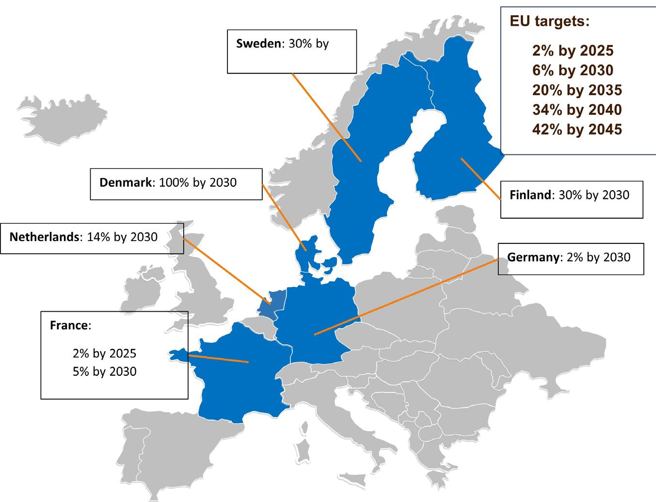
Europe has also made strides with an impressive portfolio of proposals for SAF, mainly driven by the EU’s ReFuelEU Aviation Initiative. One of its provisions in this project is a gradual increase in blends of SAF. For example, countries like Norway, Sweden and the Netherlands set ambitious national SAF blending targets supported by regulatory frameworks and large investments in infrastructure for SAF production. By 2030 Norway has set goals of 30% blending ratio of sustainable alternatives in the fuels used by airlines while at the same time using its renewable energy resources to produce green hydrogen, as well as other components that make up SAF elements. Similarly, Sweden aims at reducing its emissions from the aviation sector by 30% come 2030 via use of SAF among other sustainable technologies. In addition to these national endeavours, there are EU policies that put forward mandatory requirements for sustainability methods through which a country can involve itself in decarbonising their air travel industry
As an emergent industry, the UK is becoming increasingly important as a critical player in the SAF sector. The Jet Zero initiative of the UK government is aimed at accelerating the development and deployment of SAF with an objective to have 10% SAF blend in aviation fuel by 2030. This is a challenging but achievable target because of the nation’s technological expertise and policy framework.
One vital aspect of this plan is that by 2025, no less than five commercial plants for producing SAFs should be developed. These two projects – including Alfanar’s Lighthouse Green Fuels and Fulcrum BioEnergy’s NorthPoint –demonstrate private sector participation in this crucial area. Concurrently, the Jet Zero strategy emphasises research and development for process optimisation and feedstock expansion. The University of Sheffield has established a SAF Clearing House
in order to show commitment to technological leadership that enhances the research, certification and collaboration which will position the UK as a global hub for SAF innovation.
Among the approved alternative fuels are several types of Fischer-Tropsch synthetic paraffinic kerosene (FT-SPK) and hydroprocessed esters and fatty acids synthetic
increments in blending ratios of SAF, showcasing commitment towards the decarbonisation of aviation. Robust regulatory frameworks ensure that markets are stable for SAF. Governmental clear targets and financial support decrease investment risks, therefore stimulating the participation of the private sector. Policies such as tax credits, subsidies, and blending mandates make it


Explore our library of free-to-access On Demand Webinars, covering a range of topics in the downstream sector covering a range of topics in the downstream sector


Explore our library of free-to-access On Demand Webinars, covering a range of topics in the downstream sector Visit: www.hydrocarbonengineering.com/webinars


Alder Fuels, in concert with Honeywell, to produce carbon-negative SAF at scale. This work aligns with United’s goal of reducing carbon emissions intensity by 50% by 2035, from a 2019 baseline. Other United efforts include collaborations with other SAF producers and investments in pioneering technologies like direct air capture and electric aviation. The following are efforts in a critical direction toward more sustainable practices in aviation, underpinning broader environmental goals for the industry.
In the Asia-Pacific region, countries are starting to recognise the importance of SAF. Japan and Singapore are at the forefront, with Japanese efforts driven primarily by Japan Airlines and All Nippon Airways. Japan Airlines has collaborated with Fulcrum BioEnergy to convert municipal solid waste into SAF. The potential large production capacity of SAF is derived from this partnership, which will contribute to Japan’s aviation emissions reduction process. Singapore Airlines has partnered with Neste for the use of SAF. This agreement with Neste comes amidst the effort by Singapore to gain a place as one of the leading SAF production and deployment hubs in the Asia-Pacific region. Its strategic geographical position – backed up with a robust aviation infrastructure – gives Singapore a good
opportunity to be transformed into a SAF-producing and distribution hub.
The SAF market is also developing in Brazil, which is rich in biomass resources. GOL, a Brazilian airliner, has allied with local and international companies for the development of SAF from sugarcane and other biomass. This would be a significant step towards the reduction of carbon emissions by GOL and put Brazil on the map as a regional leader in SAF production. Brazil’s experience in biofuel production, particularly ethanol from sugarcane, could serve as a good platform in developing SAF. Its agricultural sector is better positioned to supply the required feedstocks, while existing facilities for biofuel production can be adapted to produce SAF. Finally, Brazil’s commitments to the use of renewable energy and sustainable development are consistent with the broader aspirations for SAF.
While the prospects for SAF seem encouraging, it shares similar problems common to most sustainability-linked industries: high production costs and a limited supply of feedstock. Overcoming such challenges will require cooperative efforts from governments and industry stakeholders in the form of supportive policies and investment in research and development. SAF financial incentives in the form of subsidies and tax credits are possible for its production to reduce cost disparities compared with conventional jet fuel. Investment in research and development can provide the needed technological advancement whereby the production cost of these fuels is lowered and efficiency in their production is increased.
Another solution is resilient feedstock supply chains. Combinations of more efficient logistics, better practices in sustainable sourcing, and the creation of regional hubs on feedstock collection and processing can help in setting up a supply of raw materials that are reliable and scalable, which may result in reducing production costs and raising SAF output.
The prospects for SAF look encouraging, with the likelihood of huge reductions in the carbon footprint of the aviation sector. As demand for air travel globally increases, the need to shift to sustainable jet fuel will, therefore, be key in the attainment of climate change goals set and building a sustainable future for the sector.
Another critical component will be technological advancement. Innovations in feedstock processing and fuel conversion technologies can enhance the production efficiency and cost-effectiveness of SAF. In the near-term, developing new feedstocks from algae and waste will make the source of SAF more sustainable.
SAF presents a huge opportunity for reducing the aviation sector’s carbon footprint. Despite the difficulties standing in its way at present, SAF has enormous potential for growth and development. With continuous support from governments and industries, SAF can be a game-changing solution to achieve global climate objectives and ensure a clean future for the world of aviation. As the world moves towards a more sustainable future, the aviation sector has to make SAF an integral part of its decarbonisation strategy.
Giacomo Rispoli and Alessia Borgogna, MAIRE, Italy, discuss the innovations and technologies that are driving sustainable aviation fuel (SAF) production.
The aviation industry stands on the brink of a major transformation as it grapples with the pressing need to reduce its carbon footprint. According to the International Air Transport Association (IATA)1, the best strategy to achieve net zero CO2 emissions from the aviation sector will require a combination of remediation actions: 65% of emissions must be cut by substituting jet-fuel with sustainable aviation fuel (SAF), whereas 35% must come from adopting new technologies (electric and hydrogen), by more efficient infrastructure and operation, by offsets and carbon capture. Therefore, SAF production plays a clear role in achieving net zero emissions.
One of the most promising pathways to achieving a sustainable future in aviation is the production of SAF through the gasification of residual feedstocks. This article delves into the potential of this innovative technology exploring its process, economic feasibility, and the challenges it aims to address.
Gasification of residual feedstocks into syngas is a technology poised for industrial use, offering significant potential for fostering sustainability in aviation.
The advantage of gasification technology lies in its ability to utilise a wide variety of waste types, creating a crucial pathway for the circular economy. Wastes that previously had no adequate recovery processes for their chemical elements,

such as carbon and hydrogen, can now be converted into valuable products with high efficiency. Additionally, waste-to-chemical pathways can address issues related to the limited availability of biogenic feedstocks for the hydro-processed esters and fatty acids (HEFA) process2, therefore providing a more robust and sustainable solution for the production of SAF.
Syngas produced by gasification is a versatile mixture of hydrogen, carbon monoxide (CO), and carbon dioxide (CO2), which serves as an intermediate for producing various fuels and chemicals.
Beginning with syngas, multiple technological pathways exist for the production of SAF. These include3:
n The Fischer-Tropsch (FT) process, which converts syngas into liquid hydrocarbons through catalytic reactions.
n The ethanol-to-jet process, which transforms ethanol into jet fuel via dehydration, oligomerisation, and hydro-processing,
n The methanol-based route, which involves either converting methanol to olefins and subsequently to jet fuel, or directly converting methanol to jet fuel using advanced catalysis techniques.
Among the several methods to convert syngas into SAF, the FT conversion stands out as the oldest and
most established. This process involves the chemical reaction of CO and hydrogen, producing light hydrocarbon condensate and waxes, which are subsequently upgraded into jet fuel.
The alcohol-to-jet (AtJ) technology has seen significant advancements in recent years, reaching high levels of technological maturity with the construction of the first industrial plants. This marks a pivotal moment in the journey towards more SAF options, highlighting the increasing viability and potential of such innovative processes.
The methanol-to-jet pathway remains the most underdeveloped pathway. Currently, there are no industrial reference plants available for the technologies that are still being developed, which further underscores the nascent stage of this particular approach. This pathway, however, holds significant promise and continues to be the subject of extensive research and development efforts aimed at enhancing its efficiency and feasibility for large-scale implementation.
One producer and licensor of waste-to-chemical plants is the Italian company NextChem4, part of the MAIRE group, through its subsidiary MyRechemical which develops and licences technological platforms to extract chemical products from non-recyclable and difficult-to-recover waste types, creating entirely new value chains.
MyRechemical has developed a process simulation for the specific design of gasification. The results from advanced and tailored process simulation tools for gasification are then integrated within optimised process schemes for SAF production, both through FT and AtJ, providing insights into the main consumptions and initial equipment capacities required for operation. These results form the foundation for crafting a
robust business case, enabling a rough calculation of investment costs, operative costs, and expected revenues. This financial assessment is crucial for determining the economic viability and sustainability of the proposed scheme.
The simulations reveal that, based on the lower heating value (LHV) of the solid feedstock, approximately 0.15 - 0.18 t of SAF can be produced from 1 t of solid feedstock with an LHV of 16 MJ/kg. This yield can be significantly enhanced by incorporating renewable hydrogen into the process. With the addition of renewable hydrogen, the output increases to 0.34 - 0.37 t of SAF from the same amount of feedstock. This improvement is due to the process’ ability to reuse all the carbon in the residual feedstock, maximising efficiency and sustainability. For both scenarios, the preliminary return on investment is highly promising.
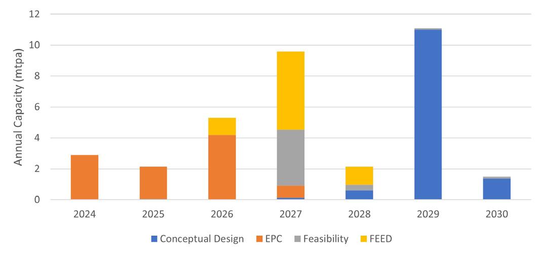
The company’s experience is not only based on simulations, but also on real projects that are underway for the production of SAF. In the case of the FT process, NextChem – in collaboration with Johnson Matthey (JM), selected for the FT technology – has been selected by DG Fuel for the development of the process design package (PDP) for its NX circular gasification technology for a SAF plant in Louisiana, US.5 The project aims to produce up to 450 million litres/yr of SAF from approximately 1 million t of bagasse (extraction residue from the crushing and squeezing of sugar cane). DG Fuel aims to have the plant operational by 2028. Following the PDP, a licence agreement with Nextchem was signed in June 2024.6
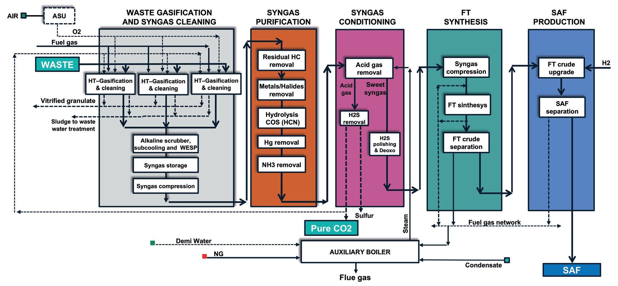
Additionally, Nextchem has several ongoing projects through the ethanol-to-jet pathway, particularly in collaboration with Lanzatech and Lanzajet. One example of this is the feasibility study conducted with a company from the UAE for the production of 120 000 tpy of SAF. This is among other projects that have reached a more advanced design phase but are currently not disclosed.7
Decarbonising the aviation sector presents a unique set of challenges due to the high energy density required for long-haul

Process improvement is like sailing. With an experienced partner, you can achieve more.
Optimizing processes and maximizing efficiency is important to remain competitive. We are the partner that helps you master yield, quality, and compliance. With real-time inline insights and close monitoring of crucial parameters, we support manufacturers to optimize processes, reduce waste, and increase yield.
flights and the stringent safety regulations governing fuel performance. Traditional fossil-based jet fuels have been considered as a standard in recent decades, ignoring the substantial environmental impact. The introduction of SAF is a shift towards reducing the carbon footprint of aviation. However, producing SAF at a scale that meets the industry’s demand remains a significant hurdle. Residual feedstocks (such as agricultural waste, forestry residues and municipal solid waste) offer a sustainable and abundant source of raw materials for SAF production. Utilising these feedstocks not only diverts waste from landfills, but also reduces reliance on fossil resources. The gasification of residual feedstocks into syngas is particularly advantageous as it can process diverse feedstocks, converting them into valuable products with high efficiency.
The economic feasibility of the proposed SAF production scheme hinges on several factors, including feedstock availability, process efficiency, and market conditions. Although the initial investment in equipment and infrastructure is substantial, the waste to chemical process is based on a double revenue scheme. In fact, together with SAF (which in order to comply with the ambitious decarbonisation target leads to a substantial increase of price), the business model must also call for generating revenue from the feedstock. Indeed, this revenue comes from disposing and using waste as raw material, by intercepting other common and less environmentally friendly markets for disposing. Meanwhile, this also delivers long-term benefits in terms of reduced carbon emissions and enhanced energy security. Furthermore, integrating renewable hydrogen into the process not only boosts SAF yield but also aligns with broader efforts to transition to a hydrogen economy.
The use of SAF produced from residual feedstocks can significantly reduce the carbon footprint of aviation. Given that the process reuses all the carbon in the feedstock and incorporates renewable hydrogen, the lifecycle emissions of
the resulting jet fuel are considerably lower than those of conventional fossil-based fuels. This reduction in emissions is crucial for meeting international climate targets and mitigating the environmental impact of air travel.
The market for SAF is poised for growth, driven by regulatory mandates and corporate commitments to sustainability. Airlines and fuel producers are under increasing pressure to adopt more sustainable practices, and SAF offers a viable solution. However, scaling up production to meet global demand presents several challenges, including securing a steady supply of feedstocks, optimising production processes, and navigating regulatory frameworks. Collaboration among stakeholders, including governments, industry players, and research institutions, is essential for overcoming these barriers and realising the full potential of SAF.
The gasification of residual feedstocks into syngas, followed by FT and refining conversion or syngas fermentation to ethanol and the AtJ process, represents a promising pathway for producing SAF. The process not only leverages abundant and renewable raw materials but also offers significant environmental and economic benefits. The proposed scheme is both technically feasible and economically viable, with a substantial return on investment. As the aviation industry strives to achieve net zero emissions by 2050, the development and deployment of innovative SAF production technologies will be critical.
1. https://www.iata.org/en/programs/sustainability/flynetzero/
2. https://task39.ieabioenergy.com/wp-content/uploads/ sites/37/2024/05/IEA-Bioenergy-Task-39-SAF-report.pdf
3. https://rhg.com/research/sustainable-aviation-fuels/
4. https://rhg.com/research/sustainable-aviation-fuels/
5. https://www.nextchem.it/en/newsroom/press-releases/detail/ nextchem-maire-group-awarded-a-process-design-contract by-dgfuels-for-a-bio-waste-to-saf-facility-in-the-usa/
6. https://dgfuels.com/2024/06/26/dg-fuels-and-nextchem-signlicensing-agreement-for-2028-louisiana-saf-facility/
7. https://www.nextchem.it/en/newsroom/press-releases/ detail/nextchem-awarded-new-project-in-the-uae-for-thetransformation-of-solid-waste-into-sustainable-aviation-fuel/

Maninder Jit Singh, Topsoe, considers why ammonia cracking will be a key solution for efficient hydrogen transportation.
In the search for low-carbon energy solutions, hydrogen – both low-carbon/blue and green – has emerged as a leading contender. Recognised as one of the fuels of the future, hydrogen offers some unparalleled benefits, including its good energy
content, zero-emission combustion, and potential for large-scale renewable production. But while hydrogen is in increasingly high demand, not all regions have the resources to produce it – and it is notoriously difficult to transport.
Hydrogen-derivative ammonia, however, is an energy-dense hydrogen carrier which is easy to store, easy to transport as a liquid, and has transportation infrastructure already in place.
Creating ammonia from hydrogen through the Haber-Bosch process is relatively uncomplicated. The long-standing method involves combining nitrogen gas with hydrogen to form ammonia. Once produced, ammonia can be transported to its destination more easily than hydrogen, as it is more energy dense. Once at the destination, the ammonia can undergo a process called ammonia cracking, where the ammonia is split back into hydrogen and nitrogen. The hydrogen can then be used as an energy source for local industries.
Using ammonia as a method to transport hydrogen is an available and viable solution for hydrogen transportation at scale. Leveraging its well-established infrastructure, scalability, and low-carbon production routes, ammonia presents itself as an ideal carrier for hydrogen over long distances. In fact, 20 million t of ammonia are currently transported annually. The ammonia market is expected to grow threefold, up to 700 million tpy by 2050, in line with the 1.5˚C scenario, with more than 200 million t of this being transported across geographies to be converted back to hydrogen.
Despite this opportunity, three perceived challenges are slowing down adoption. The first challenge is bankability, with many concerned about the lack of commercial
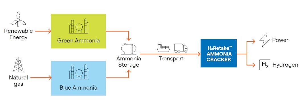
large-scale ammonia cracking units in operation. For investors and companies interested in ammonia cracking, this is a risk – but one that only arises due to a lack of awareness of ammonia cracking plants already in existence.
The second perceived issue is confusion about the type of catalyst that can be best used in the ammonia cracking process. Some believe that traditional reforming catalysts can be used, while others think that noble metal catalysts are required for an efficient reaction. Lastly, there is concern about efficiency. This pertains to the process’ energy efficiency and the hydrogen conversion efficiency from ammonia to hydrogen. Given the high costs involved in the production and transportation of low-carbon ammonia, high efficiencies are required to drive down costs and improve competitiveness.
Topsoe’s ammonia journey began in 1947 when the company delivered its first ammonia catalyst for industrial production, while in 1968, it designed its first ammonia plant. Topsoe’s first ammonia cracking technology was developed in 1978 with a focus on heavy water production. The largest ammonia cracking facility was built in Argentina in 1993, with a capability of cracking 2 x 2400 tpd of ammonia in two parallel lines. These plants crack ammonia into nitrogen and hydrogen, which in-turn is used to produce heavy water.
As a result, Topsoe developed ammonia cracking technology, infrastructure (including specific anti-corrodible materials) and a catalyst solution (with a lifespan that can exceed 100 000 hours). The company’s catalyst development, manufacturing experience and other general learnings from decades of operation, has placed it in a unique position when it comes to ammonia cracking. Topsoe launched the first large-scale ammonia cracking technology for commercial hydrogen production in 2022.
(75%
/
An iron-cobalt catalyst, such as Topsoe’s DNK-2R, has been proven to be effective on a large-scale for decades, with high activity and durability at a reasonable cost. Another reliable option is the iron-based catalyst, commonly used for ammonia synthesis. However, this catalyst performs best at low ammonia concentrations and can be poisoned at high concentrations.
Another option is the ruthenium-based catalyst, but despite being a high-activity catalyst, it is costly and less suitable for industrial applications.
An alternative to the cobalt-iron based catalyst is Topsoe’s tailored nickel-based ammonia cracking catalysts (DNK-20 and DNK-30), which provide techno-economic optimisation of the Topsoe H2Retake TM ammonia cracking solution.
Two key metrics are employed to assess the performance and effectiveness of the ammonia cracking process. The first is hydrogen efficiency, which measures the amount of hydrogen produced compared to the amount of hydrogen present in the original ammonia. Achieving 100% hydrogen efficiency means converting all ammonia to hydrogen. Any losses or use of ammonia as a fuel will result in a hydrogen efficiency below 100%.
The second metric is energy efficiency. Ammonia cracking is an endothermic chemical process, meaning it requires heat as an input to transform ammonia into nitrogen and molecular hydrogen. Like hydrogen efficiency, energy efficiency will also be below 100% as more energy cannot be generated in the hydrogen product than what is input as the energy of feed and fuel. Energy efficiency is determined by considering the inputs of process streams and any electrical power supplied.
Using ammonia as fuel, for instance, reduces hydrogen yield, but ensures all process energy comes from ammonia, resulting in zero carbon intensity hydrogen product (when using zero carbon intensity ammonia). External fuels increase hydrogen yield but may result in CO 2 emissions, while electrical power input allows for maximum hydrogen conversion and zero carbon intensity if sourced via renewable power.
Crucial to plant economics and viability, both metrics have therefore been the focus on Topsoe’s innovation in ammonia cracking. The technology, H2Retake TM , utilises the energy input in the side-fired ammonia cracker to drive the decomposition reaction and effectively preheat and evaporate the raw feed with minimal wastage. The efficiency is achieved through a streamlined ammonia cracking design, optimised heat and off stream integration and careful catalyst selection.
The cost of the ammonia feed is the dominating cost of hydrogen from ammonia cracking. The optimised energy and hydrogen efficiency of H2Retake ensures the best possible business case for the ammonia cracking plant. The optimised heat integration in H2Retake has eliminated the need for any cooling or steam generating system, which further reduces the total investment needed to realise the plant. It can also be centralised and implemented on large to mega-scale, or be deployed in a decentralised, large-scale manner, located near major hydrogen consumers.
The H2Retake technology optimises the process of ammonia cracking by pumping the liquid ammonia feed to a pressure above that required for hydrogen delivery. The ammonia is then vaporised and preheated, transferring heat directly from the hot process and flue gases. This innovative approach eliminates the need for a steam system, reducing both cost and complexity.
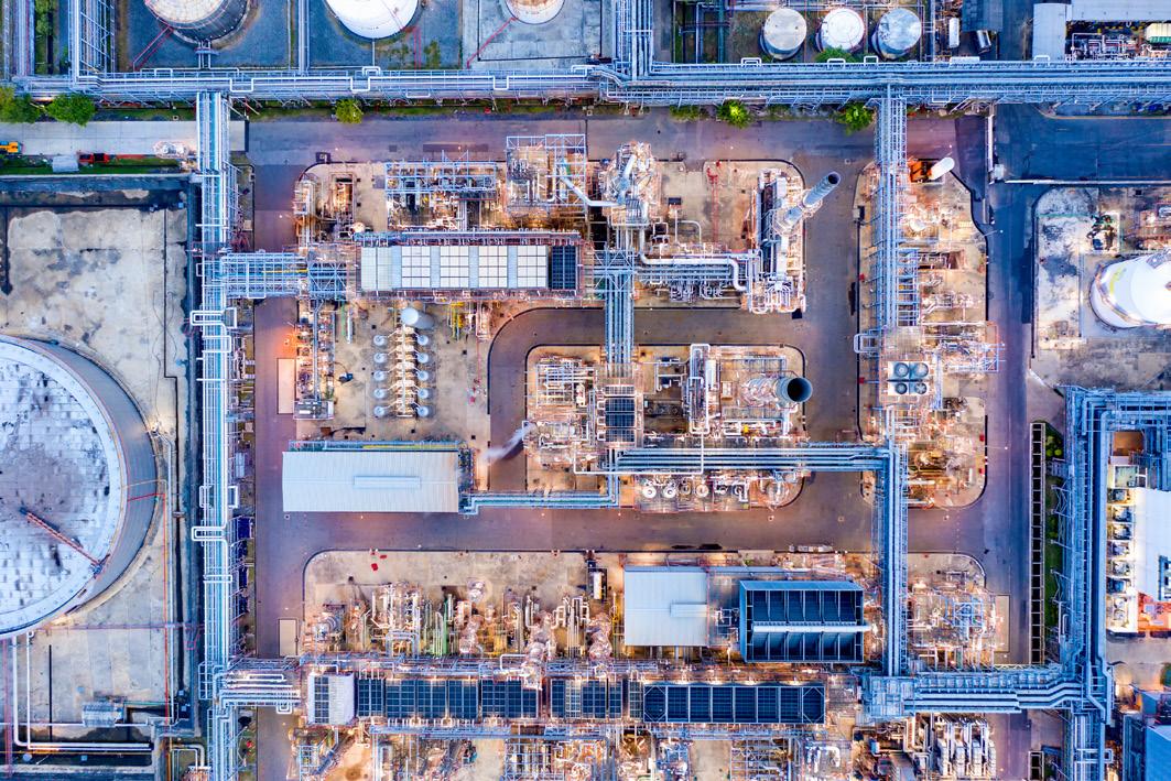
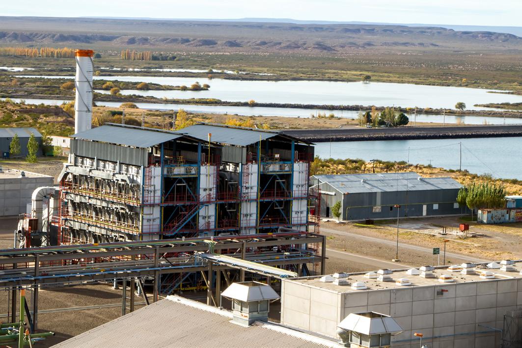
The decomposition of ammonia into hydrogen and nitrogen occurs in an adiabatic pre-converter and a fired tubular cracker. This pre-conversion process reduces the fuel demand of the fired cracker and optimises the use of flue gas energy. The cornerstone of this technology is the well-proven fired cracker, a component that has been successfully implemented in Topsoe’s referenced plants.
Through a combination of streamlined design, optimised heat integration, and careful catalyst selection, H2Retake achieves an impressive energy efficiency of 96%. This high efficiency ensures maximum utilisation of energy input and minimises waste, making it a highly viable solution.
As the world shifts towards sustainable energy solutions, ammonia cracking has emerged as a crucial facilitator of hydrogen transportation. This positions it as a key element in the transition to a low-carbon energy future. With the continued innovation of pioneering solutions, the vision of a economically-sound hydrogen-powered world can move ever closer to reality.


Thomas Winkler, Sulzer, Switzerland, explores how mimicking the circularity of natural ecosystems can provide an effective roadmap for the development of carbon capture and storage systems.
Over recent years sustainability has leapt up the priority list, and with good reason. Climate change takes a heavy toll not just on the environment and the economy, but also on society. Countries most vulnerable to climate change have incurred climate-change-related losses amounting to US$525 billion.1 The challenge of global decarbonisation and defossilisation is of the essence and a transition has to take place. Businesses operating in the process industries are uniquely positioned to act.
While several international climate targets have been set – such as the Paris Agreement – the window for achieving their goals is rapidly closing. To limit global warming to 1.5°C (above pre-industrial levels), global greenhouse gas (GHG) emissions must peak before 2025 at the latest and decline by 43% by 2030.
Meeting these ambitious climate goals requires solutions that are not only technically effective, but also economically viable.
Scalable and cost-effective sustainable technologies embedded in a globally harmonised regulatory framework are essential for broad adoption and real-world impact.
By prioritising such solutions, the challenge of decarbonisation can be transformed into an opportunity for innovation and sustainable growth.
The pursuit of sustainability takes many different forms, from reducing energy consumption to efficiently managing supply chains. These are all important and can contribute to a greener future, but one of the most effective methods –especially among the process industries – is increasing circularity.
Circularity is the principle of minimising waste and making the most of resources. Unlike the traditional linear economy, which follows a ‘take-make-dispose’ approach, the circular economy emphasises reuse, repair, refurbishing, and recycling – anything that helps the materials that go into a product become feedstock for a new one once they have reached the end of their useful life.
One of the great models that can be used as inspiration for a circular approach to manufacturing is that of nature itself. The water cycle, for example, uses energy from the sun to circulate water from oceans to the sky, to earth, to the rivers and back. Nothing is lost. Nothing is wasted.
And just like water, in nature, carbon cycles through the ecosystem, moving from the air into the earth through the intermediary of living creatures – plants capture CO2, and animals return it to the atmosphere. Even soil plays a critical role, acting as a carbon sink, thus influencing the climate.
Mimicking these natural systems provides a blueprint for efficiency and sustainability. In nature, there is no waste; what dies decomposes and becomes the resource for new life. These same principles can be applied to the use of CO2 in manufacturing, viewing it as a resource rather than a pollutant.
The reality is that there is already a remarkable existing market for CO2 in absolute numbers – each year, approximately 230 million t of it are used in various industries.2 The fertilizer industry uses around 130 million t of CO2 for urea manufacturing and could become an important uptaker of captured CO2. The oil and gas sector also uses between 70 and 80 million t primarily for enhanced oil recovery (EOR) techniques.
Beyond this, the market for CO2 is expected to grow steadily, driven by its use in new applications like sustainable aviation fuels (SAFs) along the synthesis routes of Fischer-Tropsch and/or alcohol-to-jet (ATJ) pathways and supported by technological advancements. The global market size was valued at US$10.27 billion in 2022 and is projected to grow at a compound annual growth rate (CAGR) of 5.2% from 2023 to 2030.3
The creation of this kind of circular economy – where carbon is captured from industrial processes and used as an effective resource – is not just theory, but already being put into place across the globe.
Sulzer has been able to use its technologies and know-how to support several major customers along their journeys.
Sulzer partnered with Messer, a leading industrial gas specialist, to implement an innovative carbon capture and utilisation (CCU) project at a plant in Landeck, Austria. This collaboration aimed to capture over 50 000 tpy of CO2 from calcium carbide production emissions and repurpose it for use in the food and beverage industry, greenhouse fertilizers, and fire extinguishers.
The project features BASF’s OASE® blue technology, combined with Sulzer’s advanced carbon capture solutions, designed for maximum CO2 capture rates with minimal energy consumption. Sulzer’s mass transfer technology enhanced the efficiency and effectiveness of the carbon capture process, ensuring that the captured CO2 could be economically and sustainably reused.
This project set a benchmark for future CCU initiatives, demonstrating the potential for industrial applications of CO 2 reuse technologies at scale to contribute to a circular economy and reduce carbon footprints in various sectors.
Sulzer and Blue Planet worked together to deliver advanced carbon capture utilisation and storage (CCUS) technology to produce carbon-negative concrete. This partnership involved a novel mineralisation process that sequestered CO 2 emissions from heavy industries into synthetic limestone aggregates, which could then be used to offset the CO 2 footprint of cement production.
Blue Planet’s proprietary Geomimetic® process captures CO2 and combines it with metal ions from industrial waste to form carbonate minerals, resulting in synthetic limestone aggregate. Each ton of this aggregate locks up to 440 kg of CO2, enabling the production of carbon-negative concrete.4
Sulzer’s advanced separation technology supported the efficiency and effectiveness of Blue Planet’s own carbon capture unit, which successfully operated at Blue Planet’s San Francisco Bay Aggregates plant, showcasing the feasibility and scalability of this technology.
For carbon capture projects to be viable, they must capture CO 2 affordably, which hinges on the efficiency of the technology used and the integrity of the whole value chain. Numerous technologies have been developed to enhance carbon capture and utilisation. These include advanced predominately solvents, membranes, and adsorption techniques that increase the capture rates and reduce energy consumption on a case by case assessment.
An example of innovative carbon capture technology is Sulzer’s MellapakCCTM structured packing solution. Designed specifically for carbon capture, this structured packing reduces both the column size and the pressure drop across the carbon dioxide absorber.
This optimisation leads to lower CAPEX and OPEX, making more projects financially viable. By improving the efficiency of carbon capture processes, MellapakCC not only enhances the economic feasibility of these projects,


At Black & Veatch, we’re all about innovation and impact. And now more than ever, sustainability is driving what we do. By reducing life-cycle carbon impacts globally, our expanding solutions portfolio—including carbon capture and clean fuel technologies—helps us help you enable a cleaner future climate. Find out how at bv.com/sustainability.
but also supports broader adoption of carbon capture technologies, contributing to significant environmental benefits.
Addressing the global decarbonisation and defossilisation challenge requires a collective effort from all market stakeholders. This means that suppliers, manufacturers, customers, and regulatory bodies must work together to foster sustainability. Each stakeholder plays a critical role in driving the adoption of sustainable practices and ensuring the successful implementation of carbon reduction technologies.
Suppliers must be innovative to create environmentally friendly materials and products. By offering sustainable options, they can help manufacturers integrate green practices into their production processes. Manufacturers, on their part, need to adopt these greener processes and invest in technologies that reduce their carbon footprint. This includes everything from improving energy efficiency to implementing advanced carbon capture and utilisation systems.
Customers also have a significant role to play. By prioritising sustainability in their purchasing decisions, they can drive demand for green products and encourage companies to adopt more sustainable practices. Regulatory bodies, meanwhile, are essential in creating the frameworks and incentives that promote environmental accountability. Governments should implement favourable policies and incentives that support research, development, and deployment of sustainable technologies.
Assuring plannability and setting a clear path forward is essential for the industry. This is the basis for building viable and long-lasting business models within the new ecosystems. Frontrunners of their respective industries shall be encouraged, and suitable risk mitigation measures shall be installed across the whole value chain.
Industry-wide collaboration and cooperation are vital. This involves partnerships between companies, research institutions, and government agencies to share knowledge, resources, and technology. Such collaborations can accelerate the development and deployment of innovative solutions, making it easier to meet climate targets.
Support from governments is crucial for this collaborative effort. Governments can facilitate the transition to a low-carbon economy by providing financial incentives, tax breaks, and subsidies for companies that invest in sustainable technologies. Additionally, they can create regulatory frameworks that mandate reductions in carbon emissions and promote the use of renewable energy sources.
Engaging and educating communities about the benefits of sustainable technologies is another important aspect. Public awareness campaigns can help communities understand the importance of reducing carbon emissions and the role they can play in achieving
this goal. By educating the public, a culture of sustainability that supports long-term environmental goals can be fostered.
The power of collaboration and the potential of innovative technologies cannot be overstated. Through concerted efforts and shared expertise, solutions that significantly reduce carbon emissions and drive sustainable practices can become a reality. The success of projects like Sulzer’s partnerships with Messer and Blue Planet exemplifies how collaborative innovation can lead to practical, scalable, and economically viable solutions for carbon capture and utilisation.
A call to action is essential for continued investment in, and adoption of, new technologies. To achieve climate goals, technologies that are both effective and economically viable need to be prioritised. This requires ongoing commitment from industry leaders to invest in research and development, governments to provide supportive policies and incentives, and communities to embrace and advocate for sustainable practices.
To achieve a vision of a future where efficiency and sustainability are practical realities, these technologies need to be advanced and integrated into current operations. Collaboration across industries, governments, and communities is also imperative not only to develop, but to also deploy these transformative solutions at scale.
Mimicking nature’s efficiency and resilience provides a blueprint for driving further innovation and prosperity. Nature’s cycles demonstrate the value of continuous reuse and transformation, principles that can revolutionise industrial practices. By viewing CO 2 and other byproducts as resources rather than waste, it is possible to unlock new opportunities for sustainable development in a new ecosystem.
Industry leaders must continue to invest in and adopt new technologies that reduce the environmental impact of their operations. Governments should support these innovations through favourable policies and incentives that facilitate research, development, and deployment. Communities must be engaged and informed about the benefits of these technologies, not only for the environment, but also for economic growth and job creation.
The importance of continued commitment to sustainability is paramount. By working together, it is possible to transform the decarbonisation challenge into an opportunity for innovation and sustainable growth. The power of collaboration together with the creation and implementation of innovative technologies, will help to ensure a resilient and prosperous future for all.
References
1. https://www.zurich.com/knowledge/topics/climate-change/threeways-insurers-can-support-business-in-their-climate-changestrategies
2. https://www.iea.org/reports/putting-co2-to-use
3. https://www.grandviewresearch.com/industry-analysis/carbondioxide-market
4. https://www.sulzer.com/en/shared/news/221130-sulzer-andblue-planet-deepen-collaboration-to-accelerate-decarbonization

Delivering cost-effective carbon capture and storage is critical to meeting climate change objectives. Dr. Marco Ernst, MAN Energy Solutions, explains why the role of scale and the right manufactured solutions cannot be overlooked as key steps to success.
With growing evidence that carbon capture, utilisation and storage (CCUS) will be required to reach climate goals –according to the International Energy Agency (IEA), geological storage of at least 6.2 Gt of carbon dioxide (CO2) per annum will be necessary by 2050 – it is clear that all measures to reduce the costs and complexity of the necessary technology should be embraced. Part of the transition to carbon neutrality using CCUS will inevitably involve proving the performance of real-world infrastructure. Reference projects build operator experience but also, crucially, support investor confidence in CO2 capture and use. Among recent carbon capture projects is Shell’s Quest CCS facility in Fort Saskatchewan, Alberta, Canada. North America’s first commercial-scale CCS facility, the project extracts CO2 from the Scotford upgrader hydrogen production process. This CO2 is then pressurised and compressed into a liquid that is transported by pipeline 65 km north to well sites where it is injected more than 2 km underground into a geological formation known as the Basal Cambrian Sands. Estimated to sequester some 881 000 tpy of CO2,
the Quest plant will remove well over 17 million t of emissions over its lifetime using a MAN Energy Solutions RG 90-8 compressor train. The RG range of integrally-geared compressor (IGC) trains features individual stages which operate at specific optimised speeds. This makes the design ideal for CO2 compression as seen in carbon capture and many industrial processes where the compression ratio may rise from 1 bar up to more than 200 bar.
Another key project demonstrating a real-world industrial application of CCUS is currently being commissioned at Brevik in Norway. Building materials company, Heidelberg Materials, launched its evoZero® product, the world’s first net zero cement, using carbon capture technology to remove CO2 from the process. This is a major breakthrough made possible through the capture and storage of around 400 000 tpy of CO2. The heart of the Brevik system is an amine-based carbon capture technology from Aker Carbon Capture and a high-pressure compressor train from MAN Energy Solutions, in this case an electrically-powered integrally geared RG 63-7. The captured CO2 is liquified and then transported to a receiving terminal at Øygarden on the west coast of Norway as part of the Northern Lights project being developed by Equinor, Shell and
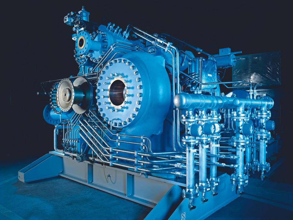
TotalEnergies. The liquified CO2 will then be injected some 2500 m below the seabed in the North Sea at pressures between 130 and 250 bar. These projects perfectly demonstrate that the compressor is absolutely critical to the carbon capture and storage process.
Following the signing of an engineering, procurement and construction (EPC) agreement with the Norcem subsidiary of Heidelberg Materials, in mid-2020 Aker and MAN Energy Solutions worked in partnership to deliver a CO2 capture, liquification and intermediate storage plant. Part of a demonstration project funded by the Norwegian government, work began on the full-scale plant after some 18 months of testing using a small-scale mobile unit which proved the technology is robust and flexible across the various operating conditions found at the cement plant.
Cement production, like many petrochemical processes, is highly carbon intensive and the new carbon neutral product is a major step forward on the road to net zero. Cement flue gas contains about 18% CO2 by volume and by deploying CCUS technologies, Heidelberg aims to make its entire product portfolio climate-neutral by 2050. Using Aker Carbon Capture’s S26 solvent and a 230 t absorber, the Brevik project will capture at least half of the plant’s emissions. The Brevik CCS project is the world’s first site to capture carbon emissions from clinker production and this is particularly significant given that cement production is responsible for around 6 - 7% of global CO2 emissions currently while demand is expected to substantially increase over the coming years.
By proving the effectiveness of carbon capture for an operational industrial process facility, it opens the door to the worldwide roll out of a new era of low carbon industrial processes. Such game-changing initiatives are crucial in advancing carbon capture efforts, but are just one part of the armoury in rolling out CCUS technology. Another key measure is rapid scaling. Again, MAN Energy Solutions is deploying its technology to prove CCUS capability at scale.
Most recently, the company announced a large-scale project in the Netherlands that will capture and permanently store some 2.5 million tpy of CO2emissions. The Port of Rotterdam CO2 Transport Hub and Offshore Storage (Porthos) project is the country’s first large-scale CCS project. It is also around three times the annual capacity of Quest, and more than double that of the Brevik project. With the region of Rotterdam port accounting for more than one sixth of the Netherlands’ total CO2 emissions, the CO2 will be sourced from various large industrial interests including Air Liquide, Air Products, ExxonMobil and Shell. Their respective CO2 emissions will be fed into a common 30 km long pipeline that will run through the port area before reaching a compressor station.
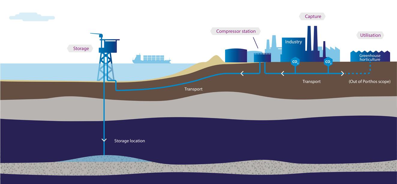
Developed in partnership with The Port of Rotterdam Authority, Energie Beheer Nederland B.V. (EBN) and N.V. Nederlandse Gasunie, the heart of the project will be supplied by
Gulftronic® Electrostatic Separators are significantly more efficient at reducing ash in support of decarbonization when compared to mechanical filtration systems. Greater efficiency means maximum per barrel returns from FCC/ RFCC and hydrocracking, with lower operating costs. The result is a higher yield and a better return from the bottom of the barrel.
gulftronic.info@ga.com
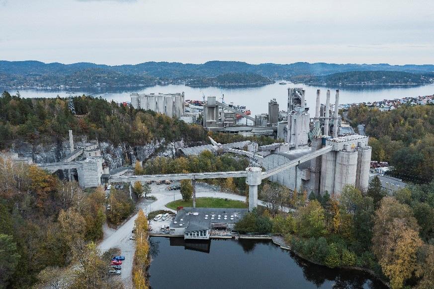
MAN Energy Solutions in the form of three RG 28-6 type compressor trains. These compressor trains are to be located at a station on Maasvlakte, the man-made, western extension to Europoort where the CO2 will be compressed to a maximum of 180 bar. Two additional units are intended to be added at a later stage and each compressor can compress up to 250 t of CO2 per hour. Part of the scope of supply from MAN Energy Solutions is also a dynamic process simulation, which will allow the compressor system to be operated at its maximum potential of process efficiency.
Once compressed, the CO2 will be transported to its final disposal site, a sealed and now exhausted natural gas reservoir 22 km away in the North Sea. The P18-A platform will be used to inject the gas into a geological structure of porous sandstone some 3200 to 3500 m below the seafloor. The subsea structure is expected to permanently store around 37 million t of CO2 over a 15 year operational lifespan. Recognised by the EU as a Project of Common Interest (PCI), the system is expected to be operational by 2026. The Porthos project will not only perform a key role in achieving net zero emissions for sectors that are known as being hard to abate, it is also innovative in its approach by establishing a CO2 capture and storage system that serves multiple companies.
Another important factor in driving CCUS development forward is the use of tried and tested technology with proven reliability and the opportunity for optimal performance. The RG compressor train, for example, has a long heritage of successful deployment in large volume, high compression applications. With more than 30 years of use in chemical industries such as urea production in which flows of CO2 are compressed to the same kind of pressures seen in CCUS applications, MAN Energy Solutions compressors already have at least 20 running references worldwide. Collectively, these projects have delivered more than 1 million hours of operations and compressed some 200 million t of CO2.
A programme of continuous improvement, backed by a dedicated test centre at Oberhausen in Germany, have seen compressor impellers substantially improve, boosting efficiency while reducing the frame sizes needed. First generation RG machines used 10 stages, whereas the latest generation requires only eight stages for the same performance, for example.
A more compact, simpler machine means lower capital costs and reduced maintenance requirements too.
At the same time, the relatively consistent operating conditions for CO2 sources present a significant opportunity for the development of modular designs that apply across multiple types of projects. In the case of the RG system, it has coalesced around an optimal standard platform sized at 1 million tpy, although the modular compression system that has emerged still covers mass flow ranges from 0.4 up to 2.75 million tpy. These modular designs can also accommodate gas, liquid, or supercritical CO2 applications without significant variations in the compression system and are still able to meet the varying and site-specific demands in flow and pressure. Off-the-shelf compression solutions are therefore available for every capture technology and application.
Standardisation allows economies of scale for core components as well as ancillary systems like gas coolers and the lubrication system to be simplified, reducing complexity and the need for additional project design. Lower production costs and faster delivery times in turn lower the cost of equipment, which has a direct impact on the cost of carbon reduction, a particularly important consideration given incentives often do not apply.
In addition, by focusing on core modular components, not only are costs reduced, but the production process can be optimised, enabling manufacturers to develop the rigorous quality control measures that can lead to better quality and more reliable systems. Engineered to reduce delivery and erection times, this approach also de-risks key logistics issues associated with deliveries as well as assembly and commissioning, even in remote and hard to access locations.
Furthermore, novel digital technologies, such as cloud-based simulation, digital twin modelling and virtual reality, allow the compression system to be further simplified and to support optimised plant assembly and operations. Meanwhile, artificial intelligence apps and neural networks that work with remote monitoring systems allow major service intervals to be stretched out to a decade with no loss of availability.
Manufactured, assembled and tested at locations in Berlin and Oberhausen, Germany, the complete CCUS compressor train can be deployed as a series of easily transported discrete modular packages that allows easy to assemble bolt-together components to be delivered to the operating site. This removes the need for welding and cuts the requirements for on-site assembly workers too.
Having proven the technology, established robust reliability operating in industrial environments, and demonstrated the capability to scale, the modular approach will play a key role in delivering CCUS at a low enough cost to ensure widespread adoption.
The race to fight climate change is evidently bringing new challenges, especially for global industries typically considered hard to abate like oil and gas, chemicals, cement or steel production. To meet those challenges and the demand for accelerated in-service lead times for the most efficient carbon capture and storage technology, original equipment manufacturers are also racing to new heights. From proof of concept to full-scale demonstration and beyond, modularisation is the next step on the journey to a successfully carbon constrained industrialised world.

Megan Hine, Dräger Safety, UK, outlines the critical importance of accurate carbon dioxide leak detection in onshore carbon capture and storage systems.
Carbon capture and storage (CCS) has a critical role in mitigating the impacts of climate change. The concentration of CO2 in the atmosphere is rising rapidly to more than 2 ppm per year, indicating an accelerating trend. The increase is contributing to a non-linear warming effect. This underscores the necessity for effective CCS systems and the role of CO2 detection in ensuring their safety and subsequent success.
As CCS becomes more widespread, regulatory frameworks are evolving. Currently, regulations primarily focus on the purity of CO2 for industrial use rather than emissions monitoring. However, this is likely to change, with stricter regulations on emissions and potential fines for non-compliance replicating what is being seen with US and EU adoption of LDAR practices for methane emissions. Companies must stay ahead of these regulations to avoid financial penalties and ensure the integrity of their carbon capture and storage processes.
Standard air composition is made up of 78% nitrogen, 20.9% oxygen, and 1% other components, which includes approximately 432 ppm of CO2 post the industrial revolution. However, the levels of CO2 in the atmosphere are rising at a faster rate than ever before. The increase between 2021 and 2022 was 2.13 ppm – the eleventh year in a row1 where the amount of CO2 in the atmosphere rose by more than 2 ppm.
The emphasis for industry should be to move beyond net zero for carbon emissions and more towards negative carbon removal. It is also important for the CCS industry to ensure that alongside its predicted rapid growth, safety is not overlooked.
From an environmental and operational standpoint, any leakage of captured CO2 undermines the objective of CCS. Leaks not only release CO2 back into the atmosphere but also pose risks to system integrity and financial investments related
to carbon capture initiatives. For instance, if CO2 leaks after it has been captured and accounted for under carbon taxation policies, it can lead to financial discrepancies and regulatory penalties. Failure to comply with regulations can impact the reputation of an asset or a company and potentially to deter investors.
CO2 is present in human blood under normal conditions (lung composition of exhaled air is 75% nitrogen, 14% oxygen, 6% water vapour, and 5% CO2).2
CO2 is one of the greatest influencing factors on the breathing rate of humans. While not acutely toxic in low doses, it poses significant health risks at elevated concentrations. It is essential to understand that CO2 can become dangerous well before oxygen deprivation becomes a concern. Therefore, it is crucial to monitor CO2 levels directly rather than relying on oxygen depletion as an indicator.
As CO2 levels rise, they can lead to hypercapnia, a condition caused by increased blood acidity due to elevated CO2 levels. As acidity increases, the respiration rate increases. Exposure to between 17% to 30% of CO2, or 300 000 ppm, can result in unconsciousness, coma, convulsions or even death in less than one minute.3
The UK Health and Safety Executive4 has set permissible exposure limits for CO2 at 5000 ppm over eight hours and 15 000 ppm over 15 minutes. Personal gas monitors are essential when CO2 exposure is a risk, alerting workers when these limits are exceeded.
The most common exposure to CO2 in midstream and downstream hydrocarbon industries occurs during the retrofitting of a carbon capture system to an existing asset. These systems are usually low-pressured and generally represent less risk than higher-pressure applications and super-critical conditions. However, system pressurisation is key to achieving cost efficiency in the movement of what is
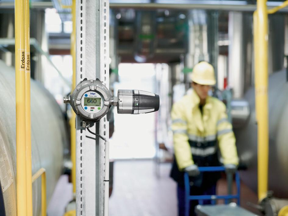
essentially a waste product. When a system operates at higher pressure, leaks become more likely.
The density of CO2 must be considered. The molecule is heavier than air by roughly 60% and will travel at low levels, displacing air and creating toxic conditions for humans. It can linger for long periods in depressions, pits, trenches and cellars, long after it has dispersed from the ground level. However, in supercritical applications with high pressure and temperatures, upon release the gas can tend to rise before falling, with a release being momentum driven.
It may be important to consider any potential initial rise and fall when implementing a CO2 detection system, noting also that grated flooring will not prevent the dispersion of CO2 to lower levels. It is generally recommended to position CO2 fixed gas detection monitors lower down – where the gas is likely to accumulate – alerting personnel before they enter an area. That being said, generally the focus of any toxic gas detection system should be to protect the breathing zone, so toxic gas detector placement is usually favoured around walkways and entrances. Personal gas monitors, normally clipped to a lapel or chest pocket, will detect a concentration of CO2 in the breathing zone, meaning personnel receive advanced warning of its presence and can react by leaving the area. Ultimately, every plant lay out will differ and may require a slightly different approach from site to site.
Common CO2 leak sources mirror those of most gases and are at flanged connections, valve stems of both manual and actuated valves, and small-bore tubing.5
The ongoing research and development in CO2 detection technologies aims to enhance the efficiency and reliability of these systems as more is learnt about the characteristics of CO2 release. In 2021, DNV released a new standard for the design and operation or conduct pipelines. Initiatives such as the Skylark6 joint industry project in the UK, led by DNV and the UK HSE Science Division and partners, are continuing this work. Further advances are being made in understanding the requirements for the storage and transportation of CO2
Fixed gas detection systems provide advanced knowledge and information on gas concentrations before personnel enter an area. Computational fluid dynamics (CFD) and other modelling software can be used to identify gas leak and dispersion scenarios, assisting in pinpointing the optimal locations for the positioning of fixed gas detectors and indicating percentage coverage achieved. CO2 gas detection therefore supplements process monitoring for information around process leaks. A major consideration in selecting the location of fixed gas monitors is whether personnel will be required to work in a certain area where they may be exposed to gas, such as walkways or entrances.
The safety of people is always the number one priority. However, if personnel will not be required on-site or there is no risk of their exposure to gas, the focus may be on protecting system integrity through leak detection. In many locations, gas leak risks to personnel through exposure and to the asset or system must be considered jointly.
Fixed gas detection systems can be divided into primary and secondary, or supplementary, systems. The main focus of the primary system is usually point detection. Secondary systems have traditionally included line-of-sight detection and acoustic gas detection.
Point detection is recognised as best practice for a fixed primary gas detection system because it is the only fixed system that can measure the exact concentration of gas at a location. For CO2 detection, infrared gas detection is considered best practice due to its reliability and minimal maintenance compared to electrochemical sensors. Infrared detectors are less prone to drift and are better suited for continuous monitoring in environments where they may be exposed to a constant concentration of their target gas, such as atmospheric CO2
The placement of CO2 detectors is critical for effective monitoring. Since CO2 is heavier than air, detectors should be placed in low-lying areas where CO2 is likely to accumulate. For point detectors, the recommended height is about 18 to 20 cm above the ground. An infrared point gas detector should be able to filter CO2 at 4.2 µm. It should also be able to measure the exact concentration within the cuvette and have a fast response option with easy infield maintenance.
The alternative to point gas detection is open path detection: open path uses a beam of light to detect CO2 across a distance. While it covers larger areas than point detection, the detectors must be carefully placed to avoid obstructions such as weeds that could create a false alarm or block the beam, known as ‘beam block’. Furthermore, open path detection requires a lower positioning of the gas detectors than point detection. This can affect the lenses due to the increased likelihood of dirt and lead to a requirement for more heavy maintenance than point detection systems. The final limiting factor is the detection methodology – an open path gas detector can only measure the average concentration across a beam path length. This means that it cannot tell the difference between a small high concentration gas cloud and a large low concentration gas cloud, nor the location of any cloud. With an EH40 STEL of 15 000 ppm, this limits the beam path length in order to be able to generate a useful measurement in ppm(m) and prevent potential over exposure, which in turn limits the efficacy of large area monitoring.
Acoustic or ultrasonic gas detection systems use a piezo microphone at height to listen for the sound of gas leaks. Ultrasonic sound waves are vibrations of frequencies greater than the upper limit of the audible range for humans – that is, greater than approximately 20 kHz – making such systems effective because the gas does not need to reach the detector. Instead, the sound waves from the leak trigger the microphone. Sound waves travel much more uniformly and quickly compared to gas molecules from a leak, making this an effective device in outdoor applications.
Ultrasonic systems act rapidly. They do not differentiate between the types of gas leak, meaning all gas hazards on
site can be covered. However, some additional provisions are recommended for best practice deployment of the technology. The response will be immediate (e.g., if the end is left off an air hose it can generate the sound of a leak and could trigger the system). Therefore, as appropriate, it is recommended to set a site-specific delay time of a few seconds on the device to identify expected and known ‘leaks’ that are likely to occur (such as at a pressure relief valve or a compressor pump). The required delay will be site specific and can be quantified with a ‘sound survey’ to identify known sources of ultrasonic sound.
To reduce the risks to the safety of personnel, portable gas detection devices must be bump tested before every shift to confirm sensor response. For multi-gas monitors, some manufacturers have a dual infrared CH4 and CO2 sensor which allows the detection of both gases simultaneously. Using a multi gas monitor has flexibility advantages in situations where personnel are working where both CO2 and CH4 are present, or in multiple locations where either of the gases exist. These devices also cover typical site gas hazards such as oxygen depletion due to inerting works using nitrogen or even other toxic gas hazards on site such as hydrogen sulfide (H2S), all in one device.
Regular maintenance and calibration of CO2 detectors are crucial to ensure their accuracy and reliability. This includes routine checks, cleaning, and recalibration to account for any drift in sensor accuracy. Proper maintenance ensures the detectors function correctly and provide timely alerts in case of CO2 leaks.
Effective CO2 detection can ensure the safety of personnel, help to reduce emissions, and maintain the integrity of a carbon capture system.
It is critical that asset operators ensure their CO2 gas detection system is designed to match their needs, is reliable and does not require excessive maintenance. Engaging a gas detection expert to design a fit-for-purpose system can support confidence in performance and help reduce unplanned maintenance costs over the asset’s lifetime.
By investing in advanced detection technologies and adhering to best practices for placement and maintenance, companies can achieve operational efficiency, regulatory compliance, and financial viability. They can also contribute significantly to greenhouse gas emissions reduction.
1. https://www.noaa.gov/news-release/greenhouse-gases-continuedto-increase-rapidly-in-2022#:~:text=2022%20was%20the%20 11th%20consecutive,more%20had%20never%20been%20 recorded.)
2. Guidance on CCS CO2 Safety and Environment Major Accident Hazard Risk Management – Level 3 DNV Report No.: I3IJLJW-2
3. Guidance on CCS CO2 Safety and Environment Major Accident Hazard Risk Management - Level 3 DNV Report No.: I3IJLJW-2
4. EH40/2005 Workplace exposure limits https://www.hse.gov.uk/ pubns/books/eh40.htm
5. Offshore hydrocarbon releases 2001 - 2008, RR672 HSE, Research Report
6. https://www.dnv.com/article/skylark-pioneering-excellence-in-co2pipeline-safety-250648/

Keith Warren, Servomex, UK, discusses gas analysis strategies for enhancing energy efficiency and reducing emissions.
The pressure on industry to reduce and eliminate the emissions of carbon dioxide (CO2) and other greenhouse gases into the atmosphere continues to grow. Industrial operators are continually looking to solve the challenges of sustainable development and the move towards carbon net zero.
Gas analysis is empowering operators to meet these challenges by supporting clean air strategies designed to reduce harmful emissions from industrial processes. The technological innovations available from gas analysis suppliers are helping their customers to reduce their global resource consumption, decrease atmospheric pollution, and meet regulatory requirements.
Gas sensors and analyser systems play an ever-increasing role in the technologies used to support low-carbon and carbon-free industries, including the research and development programmes that support clean air and hydrogen fuel initiatives.
Operating throughout industrial processes, gas analysis products already help to ensure greater efficiency, which in turn leads to fewer emissions and a cleaner environment.
To help ensure cleaner air, a three-stage approach that focuses on combustion efficiency, gas clean-up, and emissions monitoring is recommended. This also optimises processes to deliver reduced fuel consumption and higher yields.
In the combustion reaction, fuel is mixed with oxygen (O2) (usually from air) at the burner and ignited to create heat energy for use in the process. This reaction typically consumes a significant amount of fuel, creates potential safety hazards, and generates harmful emissions.
However, there are currently no realistic alternatives to combustion as a means of creating the high temperatures needed for many industrial applications, so achieving an efficient reaction is key.
Originally, fired heaters were run in conditions of high excess air. While this was inefficient and increased the level of fuel consumption, it did avoid the creation of unsafe, explosive conditions.
From the environmental perspective, a further drawback is that excess O2 combines with nitrogen and sulfur from the fuel to produce unwanted emissions such as oxides of nitrogen (NOx) and sulfur (SOx).
However, since the development of gas analyser technology, it has been possible to achieve accurate measurements of O2 and combustibles – principally carbon monoxide (CO) – within the combustion reaction.

1. The system consists of a laser light source, transmitting optics, an optically accessible absorbing medium, receiving optics and detector(s).
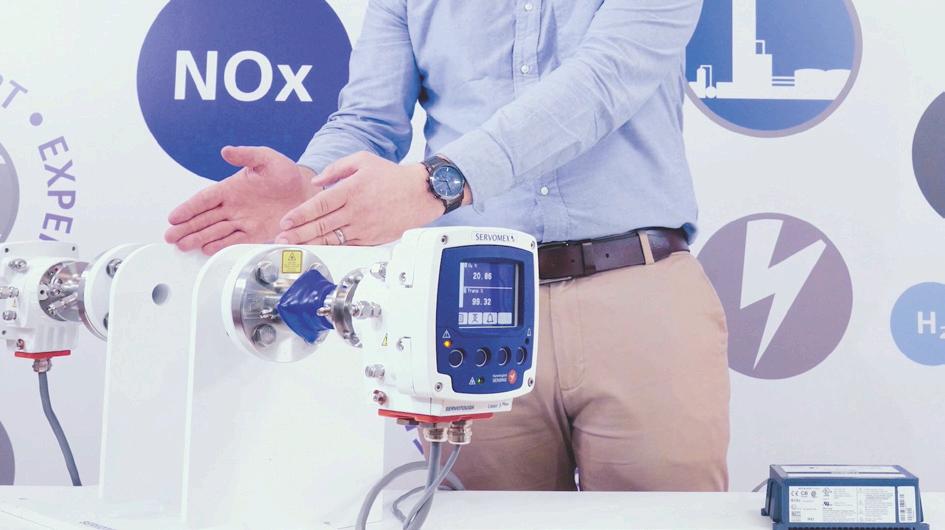
2. The SERVOTOUGH Laser 3 Plus Combustion TDL analyser can be configured to measure either O2 or CO.
The outcome of this is that the air-to-fuel ratio can be balanced to control the reaction and reduce fuel consumption. This also reduces emissions of NOx, SOx, CO, CO2.
By removing harmful substances from process gases, operators can ensure they cannot then be emitted by the plant. Typical examples of these applications include DeNOx (ammonia slip) treatment and flue gas desulfurisation.
In ammonia slip, ammonia (NH3) or urea is used in either a selective catalytic reduction (SCR) or selective non-catalytic reduction (SNCR) process to suppress harmful NOx emissions created by combustion.
Using insufficient NH3 means that NO x emissions are not properly suppressed, while an excess of only a few ppm leads to ammonium bisulfate (ABS) formation. ABS can plug the catalyst in SCR processes, damaging equipment and reducing the value of the fly ash by-product. Measurement accuracy, delivered through a gas analyser, is therefore vital to both methods.
Flue gas desulfurisation (FGD) systems remove sulfur compounds (SOx, mainly SO2) from exhaust gases – this process is often used by fossil-fuel power plants and waste incinerators.
The flue gas is typically sprayed with a wet slurry of lime, which reacts with SO x and scrubs up to 95% of the SO2 content from the gas. Measuring the SO2 content before and after treatment ensures that any remaining sulfur compounds fall within regulatory limits, and allows dosing to be accurately controlled.
Non-contact, photometric sensing technology provides the most effective and accurate measurement, because gases containing SOx can be corrosive.
Monitoring flue gas emissions helps determine the efficiency of a process and protects the environment. It also ensures that plant operators are complying with the necessary regulations. In order to measure all the necessary components of the flue gas and ensure compliance, a continuous emissions monitoring system (CEMS) is required. This system must be capable of offering the highest sensitivity and accuracy when dealing with multiple measurements for pollutants and greenhouse gases.
Multi-component gas analysers are ideal for this application, and depending on the process can either deliver all the necessary measurements in one device or form a key part of an integrated, comprehensive CEMS.
Zirconia (zirconium oxide) is a long-established and highly trusted sensing technology that is a proven solution for O2 measurements in combustion applications.
Delivering accurate measurements of O2 at ppm and percentage levels, it also has a fast response to changing conditions.
The zirconia sensor is built around a cell made of ceramic zirconium oxide, which is stabilised with an oxide of yttrium to form a lattice structure. The measure and reference sections of the cell are covered with catalytic, porous, electrically


conductive coatings that serve as electrodes on both sides of the lattice barrier between the sample and reference gas volumes.
At elevated temperatures, negatively charged O2 ions, formed at the catalytic electrodes, pass through the lattice at a rate dependent on the temperature and the difference in the O2 partial pressures of the sample gas and the reference gas.
The passage of these ions generates a voltage across the electrodes, the size of which is a logarithmic function of the ratio of the O2 partial pressures of the sample and reference gases.
The partial pressure of the reference gas is predetermined, so the O2 content of the sample gas can be determined from the voltage produced by the cell.
A combustibles sensor using calorimetry technology – also known as thick film catalytic sensing – can be added to a zirconia-based gas analyser, creating an all-in-one combustion control solution.
Calorimetry sensing provides sensitive, accurate measurements of combustibles based on the exothermic reaction of COe with O2 over a catalytic platinum surface, which produces CO2. The COe concentration is determined from the heat generated.
A four-quadrant bridge track is over-glazed to shield the circuit from the sample gas and two quadrants are then coated in a platinum catalyst. These quadrants form a Wheatstone bridge circuit, with the disc mounted in a cell heated to 300˚C (572˚F) or 400˚C (752˚F).
Upon the addition of a gas sample, any COe present in the sample will combust on the catalyst. This heats the respective quadrant and alters the output voltage of the Wheatstone bridge. The output voltage is directly proportional to the COe concentration, providing an accurate COe measurement.
An example of a combined gas analyser for combustion efficiency is Servomex’s SERVOTOUGH FluegasExact 2700 combustion analyser. This combines both zirconia and calorimetry sensing in one compact device, providing effective measurements of both O2 and COe in flue gases.
Meeting the most stringent requirements for combustion efficiency applications in the power generation and process industries, this device is easy to maintain and operate, and helps improve combustion efficiency and reduce flue gas emissions.
It has an integral sampling system which is custom-designed for operation in some of the most extreme industrial environments. This makes it ideally suited to the control of a wide range of combustion processes, including process heaters, utility boilers, thermal crackers, incinerators, and furnaces.
This analyser is designed for high-temperature processes up to 1750˚C (3182˚F), using an extractive measurement principle to keep both sensors out of the harsh process environment. This extends sensor lifespan significantly, and typically the zirconia sensor will operate effectively for at least seven to eight years.
Not only does the FluegasExact 2700 create environmental benefits through its support of efficient combustion reactions, but it has also been proven to save up to 4% of fuel costs per year. This benefits the operator’s bottom line and aids their sustainability goals by reducing the consumption of non-renewable fuels.
A more recent alternative sensing solution for combustion, tunable diode laser (TDL) technology provides an even faster measurement for this application, particularly for CO.
TDL analysers provide an average result across the measurement path, rather than the single-point result given by a zirconia analyser, and so ensure a better overall picture of conditions within the fired heater.
The single-line ‘monochromatic’ spectroscopic technique used by TDL sensing offers highly stable calibration, a continuous, fast, in-situ measurement, and the avoidance of optical cross-interference from other gases.
The system consists of a laser light source, transmitting optics, an optically accessible absorbing medium, receiving optics and detector(s).
The signal information is held in the gas absorption line shape, which is obtained by scanning the laser wavelength over the specific absorption line. This causes a reduction of the measured signal intensity, which is detected by a photodiode and used to determine the gas concentration and other properties.
Servomex’s TDL analysers use a second harmonic detection (2f) modulation technique that delivers greater accuracy, sensitivity and reliability of measurement, especially in low ppm-level measurements.
However, since TDL sensing is highly specific to the gas being measured, separate analysers are required for O2 and CO.
The SERVOTOUGH Laser 3 Plus Combustion TDL analyser, for example, can be configured to measure either O2 or CO. It can also be configured for a joint measurement of CO and methane, and provide a rapid-response measurement for safety in natural gas-fired heaters and boilers.
The Laser 3 Plus has an extremely compact design, providing instant benefits in terms of installation ease and flexibility. Developed to operate in hot and hazardous conditions, it is quick and easy for one engineer to fit the analyser to ducts, stacks, and reactors.
Line-lock technology ensures the measurement does not drift, allowing continuous and reliable results without the need to constantly recalibrate.
Gas analysis plays an essential role in cleaner industrial operations, helping to ensure more efficient processes, support the safe removal of pollutants from flue gases, and monitor the remaining emissions that are released to the atmosphere.
The production of current and future cleaner energy sources will also be dependent on innovative gas analysis technologies.
A wide range of sensing solutions will be needed to achieve all the necessary goals of a clean air strategy in order to ensure the best-fit and most cost-effective solution for each application.
By combining all three stages of an effective clean air strategy, plants and refineries can fully address the impact of their operations on the wider environment, and contribute to the creation of a cleaner, better world.

Volker Metzger, Watlow, Germany, discusses the electrification of process heating in the oil and gas industry to lower carbon emissions.
As the oil and gas industry grapples with the urgent need to reduce carbon emissions, electrification of process heating is emerging as a key strategy. This transition is not just about replacing fuel-burning systems with electric ones; it involves a comprehensive shift in technology, operational practices, and energy management. This article explores the complexities and opportunities associated with electrifying industrial processes, focusing on the technological, economic, and environmental impacts of this transition.
The push for electrification in the oil and gas sector is multifaceted, driven by regulatory mandates, market pressures, and corporate sustainability commitments.
The global effort to combat climate change has intensified regulatory pressures on industries to reduce greenhouse gas emissions. The Paris Agreement, signed in 2015, has been a pivotal catalyst, with countries committing to keep global temperature rise well below 2°C above pre-industrial levels. This agreement has propelled industries to adopt low-carbon technologies and practices.
In addition to international agreements, local regulations are increasingly stringent. For example, various US states have enacted laws to reduce emissions from oil and gas facilities. Wyoming, California, and New Mexico have all introduced regulations targeting emissions reductions in the energy sector.
Market pressures also play a significant role. Financial institutions are urging faster divestment from fossil fuels,
warning of potential financial risks associated with continued investments in high-emission technologies. For instance, BlackRock, the world’s largest asset manager, has led the charge by divesting from companies that fail to address climate change.
Many leading companies in the oil and gas and broader energy sectors have committed to significant carbon reduction targets. Indeed, over 700 companies, including major players in the industry, have made far-reaching climate commitments, driving innovation and investment in electrification technologies. These commitments are not only responses to regulatory and market pressures, but also reflect a strategic shift toward sustainable business practices.
The transition to electric process heating systems has been facilitated by significant technological advancements. Modern electric heat exchangers offer several advantages over traditional gas-fired systems, enhancing efficiency, safety, and control.
One of the most notable advancements is in heat exchanger design. Technologies like Continuous Helical Flow TechnologyTM and advanced fluid dynamics enable more uniform heat distribution, higher heat transfer rates, and
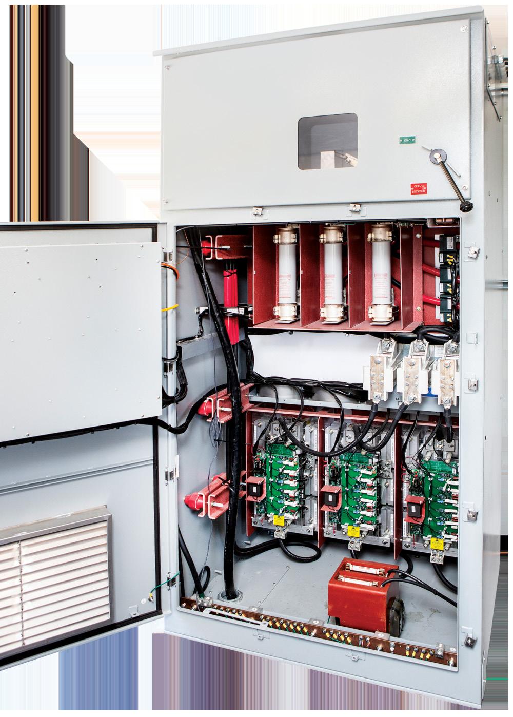
improved safety. These innovations reduce thermal lag and hot spots, which are common issues in traditional systems.
For example, modern electric heaters can achieve higher watt densities, making processes more efficient and cost-effective. This is particularly important for applications with stringent temperature control requirements, such as in petrochemical processing and refining.
The incorporation of advanced control systems further enhances efficiency. PID-type process temperature controllers provide stable control and faster response times compared to traditional on/off switching controls. This precision is crucial in maintaining consistent process conditions and ensuring product quality.
Innovations in medium voltage electric heating systems have also contributed significantly to the feasibility of electrification. These systems, such as Watlow’s POWERSAFETM solution, can tap directly into medium-voltage lines (up to 7200 V), reducing the need for large transformers and extensive cabling. This not only lowers installation and maintenance costs, but also enhances operational reliability.
Medium voltage solutions are especially beneficial for applications requiring high power levels but limited space. By eliminating the need for step-down transformers and reducing the number of connection cables, these systems offer a more compact and efficient solution.
Demand flexibility and PLM are critical technologies for managing energy consumption in electrified processes. Demand flexibility refers to the ability of industrial facilities to adjust their energy use in response to grid conditions, helping to balance supply and demand.
PLM takes this a step further by enabling precise control over energy distribution. PLM systems can balance loads across multiple processes, reducing peak load charges and enhancing grid stability. For instance, if a plant has several processes with varying energy demands, PLM can optimise the power usage to avoid exceeding grid capacity during peak times.
An illustrative example is a plant with 10 process lines, each drawing significant power. Without PLM, the plant might face hefty charges if all lines operate simultaneously during peak hours. With PLM, power controllers can synchronise across the network, ensuring that total power consumption stays within manageable limits, thereby avoiding additional tariffs and enhancing overall efficiency.
The shift to electric process heating systems supports decarbonisation and offers substantial economic benefits.
Despite higher initial costs, electric systems can lead to long-term savings through reduced energy consumption, lower maintenance costs, and avoidance of carbon taxes. Electric heaters typically have fewer moving parts and lower maintenance requirements compared to their gas-fired counterparts, resulting in lower operational costs over time.
Additionally, the ability to manage and optimise energy use through PLM and demand flexibility can lead to significant cost savings. For example, a plant that effectively manages its energy demand can avoid peak tariffs and reduce its overall energy bill, providing a quick return on investment for the electrification project.
A practical example of cost savings can be seen in a case where a customer exceeded its demand threshold in the first 10 minutes of the billing period, triggering a kilowatt-hour surcharge that doubled their energy costs for the entire month. By implementing PLM, they were able to monitor and manage power accurately, avoiding these surcharges and saving substantial amounts on their energy bills.
Electric heaters eliminate the need for fuel storage and transportation, leading to more compact and safer installations. This reduction in infrastructure requirements not only lowers costs but also minimises environmental risks associated with fuel handling and storage.
Modern electric systems also facilitate better data collection and analysis, contributing to overall process optimisation and energy efficiency improvements. Real-time data on energy use allows for more informed decision-making and continuous improvement of industrial processes.
This capability aligns with Industry 4.0 initiatives, whereby enhanced data collection and analysis lead to smarter, more
efficient operations. By integrating electric systems with advanced control technologies, plants can achieve higher levels of automation and efficiency, further reducing their environmental impact.
Several industries have successfully transitioned to electric process heating, demonstrating the practical benefits of electrification.
Large-scale implementations in refineries and petrochemical plants highlight the feasibility of electrification in energy-intensive processes. For example, electric heaters are now used in applications such as feed/product exchangers, molecular sieve regeneration, and crude oil heating, where they offer superior control and efficiency compared to traditional gas-fired systems.
In one notable case, a refinery replaced its gas-fired crude oil heater with an electric model. This change not only reduced the facility’s carbon emissions, but also improved process control, leading to higher product quality and reduced maintenance downtime.
Electrification also supports the production of renewable fuels and chemicals. In biofuel production, electric heaters provide the precise temperature control needed for various chemical reactions, enhancing product quality and process efficiency.

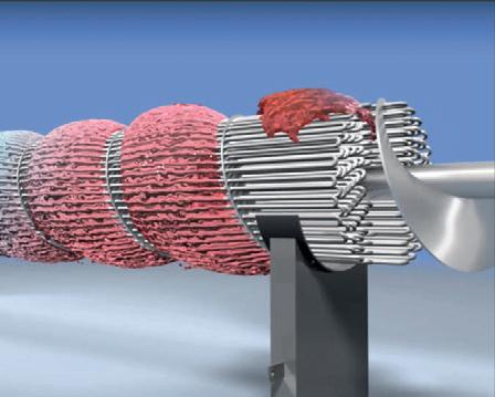

Similarly, in ammonia production and carbon recycling, electric heaters play a critical role in achieving the high temperatures required for these processes while minimising carbon emissions.
For instance, a biofuel plant implemented electric heaters for its distillation columns, resulting in more consistent product quality and significant reductions in energy consumption. The plant also benefitted from the enhanced safety of electric

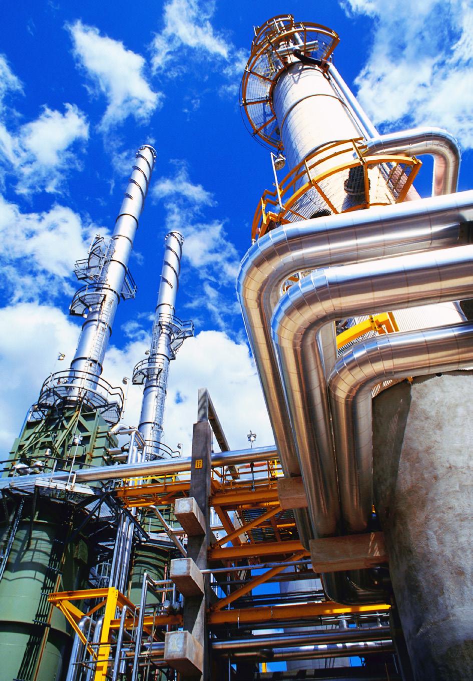
systems by eliminating the risks associated with combustible fuels.
Beyond oil and gas, other industries such as semiconductor manufacturing and aerospace have adopted electric heating technologies. These industries benefit from the precision and control offered by modern electric systems, which are essential for maintaining the high-quality standards required in advanced manufacturing processes.
In the semiconductor industry, electric heaters are used in processes such as wafer processing and chemical vapour deposition. The precise control provided by these electric systems ensures uniform heating, critical for maintaining product quality and yield.
While the benefits of electrification are clear, the transition also presents several challenges that must be addressed to ensure successful implementation.
One of the primary challenges is ensuring that the local utility grid can handle the increased load from electrified processes. This involves not only assessing the current grid capacity but also planning for future demand growth. Utilities and industrial facilities must collaborate to upgrade infrastructure as needed to support electrification.
The initial investment required for electrification can be substantial, including the cost of new equipment, installation, and potential grid upgrades. Companies must carefully evaluate the economic viability of these projects, considering long-term savings and benefits against upfront costs.
Adopting new technologies requires adapting existing processes and training the workforce to manage and maintain electric systems. This includes developing new skills and knowledge to handle advanced control systems, PLM, and demand flexibility technologies.
Navigating the regulatory landscape can be complex, with varying requirements and incentives across different regions. Companies must stay informed about relevant regulations and take advantage of available incentives to support their electrification efforts.
Selecting a technology partner with good experience in electrification can help to mitigate the risks associated with the move away from gas-fired heaters and ensure return on investment and process efficiency are fully optimised.
Electrification of process heating is a vital step for the oil and gas industry to meet its sustainability goals. While the transition poses challenges, the long-term benefits in terms of efficiency, cost savings, and environmental impact make it a compelling choice for forward-thinking companies.

Rasmus Rubycz, Atlas Copco Gas and Process, considers why the use of industrial heat pumps is a logical solution to help decarbonise the downstream sector.
It is no secret that the world is on the brink of a new era of how we will fulfil our energy needs. Many companies, individuals, and organisations have raised the awareness that not only is a less carbon-intense way of providing electricity critical to the success of the energy transition, but also that heat generation has become something of an overlooked challenge. As this article shows, however, this need not be the case: because industrial heat pumps are a logical solution for providing a more climate friendly and modern form of heat generation than conventional fossil-fuelled systems.
There is already consensus among energy experts and scientists on how to heat domestic homes in colder climate areas: the focus is on renewable heat from heat pumps, district heating or a combination of both and other sources (biomass and solar, for example). For high-temperature applications in excess of 500°C (930°F),
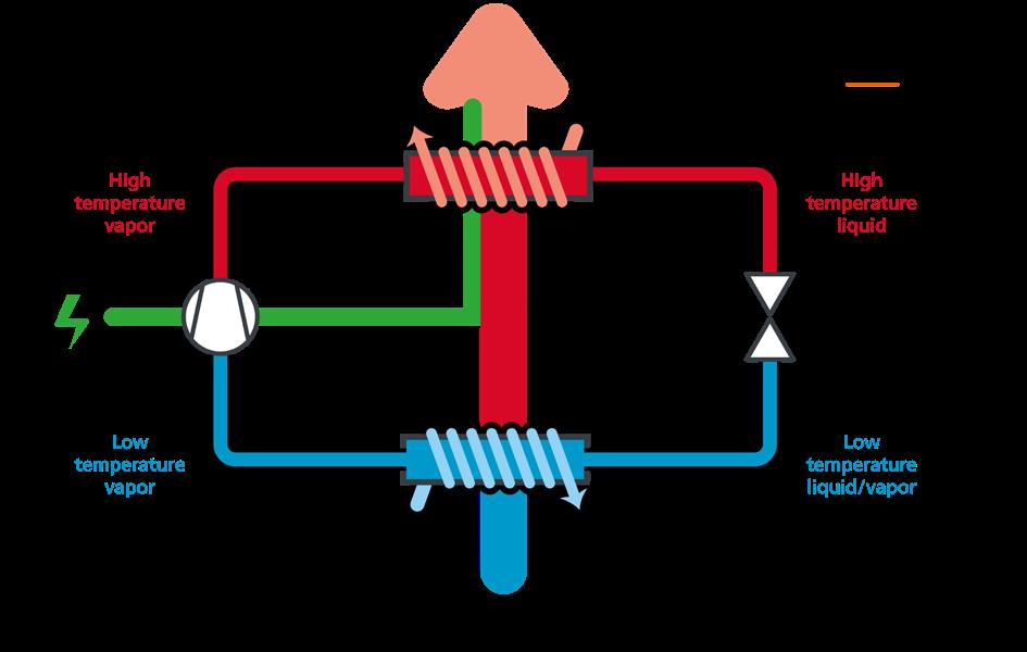
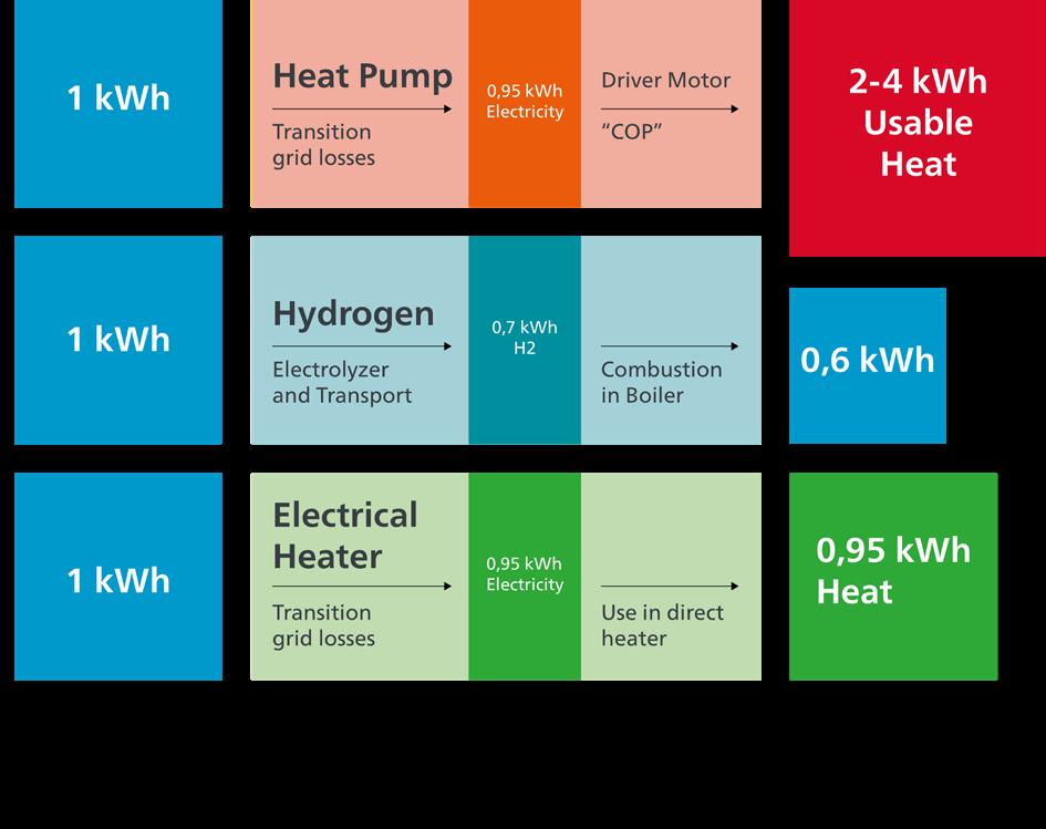
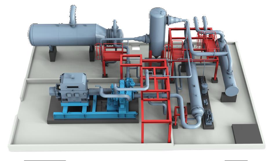
such as in metal and glass producing, and in the chemical industry, the consensus is direct electrification by arc, plasma, induction, resistance or other heater types.
And then there is hydrogen. While some people still see almost unbounded potential for hydrogen to be the universal energy carrier, it comes at the cost of tremendous conversion losses down the electrolysis process, which is especially inefficient when compared to heat pumps and even direct electrification. As a result, this universal energy carrier is now seen in roles where there are more demonstrable benefits: processes with direct chemical involvement of molecular hydrogen (steel), very high-temperature combustion or high-demand peak-load energy production, to name just a few.
Where the application of hydrogen makes economic sense, more waste heat is about to be created with the roll-out of more and more hydrogen electrolysers. The above-mentioned conversion losses are truly green waste heat, if the so-called product is ‘green hydrogen’ (made from renewable-based electricity). Upgrading the waste heat from typically the same temperature levels of around 40°C (104°F) opens the door for a full integration of the green hydrogen value chain.
However, discussions about ‘when’ green hydrogen may come to your house or in your plant and replace natural gas for heat generation 24/7 are getting less common. Instead, nowadays, the question in contexts such as these is: “Does hydrogen make any sense at all?” While the answer may be “it depends” in special applications (steel, glass fabrication, and chemical synthesis), it is very likely not the most economical choice for low-temperature heat production.
Very often energy integration concepts face limitations because of low temperatures, and the further use of this energy is considered as not economically viable – generally between 40 and 80°C. However, the large vapour clouds over cooling towers are tell-tale signs that large quantities of energy are thrown away here.
And this is the link between the conventional downstream industry and the energy transition towards low-carbon process heat, as these starting temperatures are a perfect fit for industrial heat pumps. The same technology that can harvest low-grade heat for heating domestic homes can readily grab heat from industrial cooling-tower water systems, overhead condensers or the waste heat from large compressor interstage coolers. At the cost of electricity to drive the heat pump, typically 50% to 80% of the heat is taken from the low-grade source. The relationship between the power to drive the heat pump and the thermal output is called coefficient of performance (COP).
Heat-pump technology is proven and not new, though innovations have improved its performance over many decades. The system works like a large version of an air conditioner, using a cycle with condenser, evaporator, expansion valve and most important: the compressor. Together with the electricity invested, the heat-pump system delivers a blend of recovered and electric heat that
is carbon-free, provided the electricity invested is from a carbon-free source. But even if driven with electric power from a fossil-fuel powerplant, the heat from a heat pump always has a lower carbon intensity than the same amount of fossil-fuel derived heat.
For the downstream industry, one of the most omnipresent auxiliaries is low-pressure steam of between 2 and 5 barg (30 to 80 psig). When thinking about decarbonisation, it makes sense to consider ways one can reach many energy consumers by changing only the production facility. So, instead of swapping out miles of steam-heat-tracing lines or distillation tower reboilers for electric alternatives, an industrial heat pump as an alternative steam generator may be a good idea. Furthermore, as it takes in otherwise lost low-grade waste heat from a cooling-water system, for example, it reduces the load on the cooling towers or even makes them obsolete. At the same time, continuing with a steam-based energy infrastructure allows the implementation of other heat sources, such as biomass, direct electricity, solar, and so on.
Modern heat-pump systems can provide steam directly at pressures up to 5 barg (80 psig), without the need for further steam compression. Of course, this industrial-scale plant looks more like a power plant than an air-conditioning unit and it uses different working fluids. Natural hydrocarbons, such as butane and pentane, are the preferred choices for high-performance heat pumps, while synthetic fluids – hydrofluorocarbons (HFCs) and hydrofluoroolefins (HFOs) – are possible options as well. Systems in the double-digit megawatt class have been in operation since the 1980s and are still running today, mainly for providing district heating to networks in Sweden.
If higher-steam pressures are required and electricity is available at relatively low cost (compared to the fossil-fuel alternative), a pressure boost of steam after the heat pump is possible by means of a steam compressor. Pressures up to 40 barg (600 psig) can be reached with commercially available technology.
Steam-booster compressors as well as heat-pump compressors in the power range between 150 kW and 20 MW are typically equipped with turbocompressors. Integrally geared radial turbocompressors come with a special feature that makes them a particularly good match for high-temperature heat pumps. In this type of compressor, it is possible to access the gas flow between the stages, allowing the insertion of cooling gas. This, in turn, improves the efficiency of the heat-pump cycle with a very high temperature lift (80 K and higher) compared to a simple cycle. The control of integrally geared turbocompressors is typically done using inlet guide vanes (IGVs), which are a proven and very efficient way of performing load and pressure control, without the need to utilise delicate and expensive high-power, semiconductor-based frequency drives.
Air and process gas compressors are often the workhorses of the downstream industry, such as with
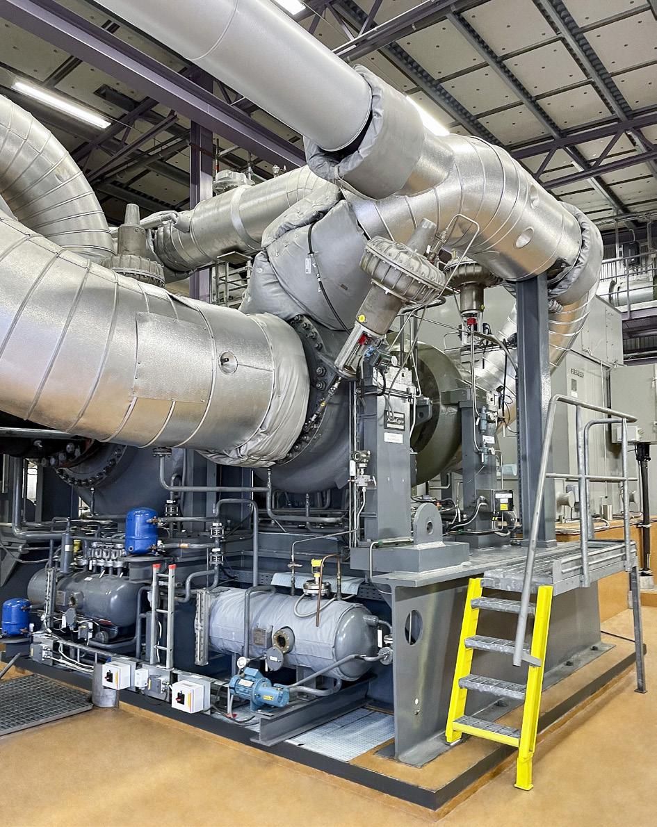
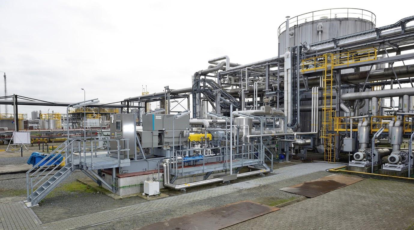
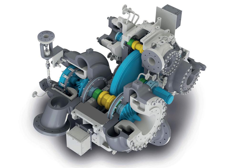
ammonia and polymer synthesis. The unavoidable waste heat transferred to cooling water in the intercoolers, which are required to lower the gas temperature after each compression stage, is a great feed for an industrial heat pump. Typical gas-cooling temperatures allow for a
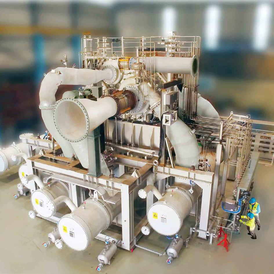
40°C (104°F) input temperature into the heat pump. Assuming a system with 20 MW thermal power and starting from 40°C, low-pressure steam of 2.5 barg (36 psig) can be generated by a heat pump at a COP of 2.6. This means that for every megawatt/ton of steam the heat pump produces, the operator must invest only about 38% of driving electricity.
A golden rule in heat recovery and heat pumps usage states: “collect the heat at the highest temperatures possible.” Take a distillation process, for example, in which the heat of an overhead condenser may be transferred to a cooling-water loop, to be recovered by a heat pump and brought back to useful temperature levels, such as for heating low-pressure steam for the bottom reboiler. Recovering the heat of the overhead vapour is directly possible by utilising a steam compressor, also known as mechanical vapour recompression (MVR). MVR technology allows direct recompression of most widely used fluids, such as hydrocarbons, water, organic compounds, and alcohols, and which then raises the vapour pressure and the condensation temperature. The subsequent condensation of the high-pressure vapour may take place in a (new) bottom reboiler. Only one heat exchanger is part of this process, which keeps the efficiency high: typical MVR applications can reach COP values up to 10.

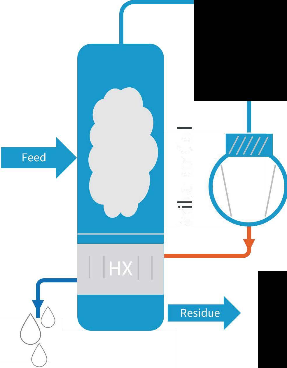
With carbon capture, utilisation and storage (CCUS) technology use on the rise and direct-air capture CO 2 plants under discussion, there will be a new frontier for industrial heat pumps. While lowering CO 2 emissions may be a topic to pursue in the traditional fossil-fuel downstream industries, not emitting any carbon emissions at all is at the core of carbon capture technologies. Unfortunately, the current CCUS technologies involve many process steps that require lots of heat, such as thermal desorption of adsorbed CO 2 and stripping processes of amine solutions, most involving steam at low pressure. Low-temperature energy streams of the CO 2-emitter (heat of flue gases, plant cooling water, and so on) or even the CO 2 export gas compressor waste heat can act as heat sources for an industrial heat pump.
This article has shown that industrial heat pumps are a logical solution for providing a more sustainable form of heat generation. Whether in homes, businesses or industries, consumers have to get used to the fact that heat is no longer just a burning flame, but increasingly a contained refrigerant running in circles. The same technology that recycles low-grade heat for heating domestic homes can utilise heat from industrial cooling towers. For higher-steam pressures, steam compressors can provide the necessary boost after the heat pump, while heat pumps are also successfully employed in CCUS projects. Fortunately, this technology is not new, and it has proven its reliability over decades – now it is time to widen its roll-out.
Piotr Kulisz and Andreas Pischke, Valmet Flow Control BL, explore the critical role of flow control technologies in the energy transition.
The outlook on energy transition is challenging to say the very least. It is important to explore what flow control technologies can bring to the table to address the many pressing challenges that must be faced. Valve solutions have a vital role in many crucial applications such as sustainable aviation fuel (SAF) production, carbon capture, utilisation and storage (CCUS), hydrogen, and plastics liquefaction – all segments which are directly contributing towards cutting carbon footprint and curbing global warming.
International Renewable Energy Agency (IRENA) reporting states that limiting global warming to 1.5°C requires cutting carbon dioxide (CO2) emissions by around 37 gigatonnes (Gt) from 2022 levels and achieving net zero emissions in the energy sector by 2050. This in itself is a huge task.

A 1.5°C compatible pathway requires an urgent and wholescale transformation of the way societies consume and produce energy. Global investments across all energy transition technologies reached a record high of US$1.3 trillion in 2022, yet fossil fuel capital investments were almost twice those of renewable energy investments. Consequently, it is imperative that the oil and gas, refining and chemical industry work hard and fast towards climate sustainable operations.
In supporting this endeavour, despite current challenges, leading technology companies have established R&D
programmes, where along with their ecosystems, they can come together to innovate, renew and aid their customer industries in the shift to carbon neutrality.
Circularity is at the core of these programmes and targets are closely connected to achieving a carbon neutral future. The following part of this article will focus on flow control technologies that enable the SAF, CCUS, hydrogen, and plastics liquefaction segments to contribute towards this objective.
While electric vehicles are expected to dominate road transport and methanol marine transport, the aviation sector holds the most promise for bio-refining and the subsequent shift to SAF.
In 2022, IATA estimated global SAF production at approximately 300 - 450 million litres (l), approximately 0.15% of total global jet fuel consumption. By 2030 it is projected to reach 30 billion l/y and further to 449 billion l/y by 2050, i.e. around 65% of the total global jet fuel consumption.
There are currently nine certified production pathways to produce SAF and many of them include processing units similar
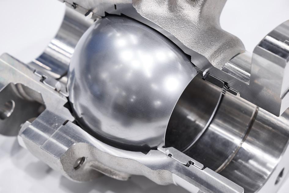
to conventional refining – for example hydrotreating, hydrocracking, isomerisation, and fractionation.
Diverse feedstocks including biomass, vegetable oils, animal fats and used cooking oils bring their own challenges to valves. Valves with special alloys and hard facing and firesafe designs are required to ensure safe and uninterrupted performance.
Dehydration is an integral part of some of these processes. To secure long-term reliability, metal-seated ball valves with unique closed and scraping seat designs and high cycle actuators, coupled with high-capacity intelligent controllers, are strongly recommended. Triple-offset eccentric disc valves with metal seats protected from the shear force of the process fluid and mechanically induced tightness can also be a viable option.
Flow control and high-quality valves also play an important role in modern carbon capture technologies. Each process to separate CO2 has its own set of challenges whether for post- and pre combustion or oxyfuel combustion. Low temperature challenges occurring in cryogenic separation require an additional focus on valve design and material selection.
Many of the CO2-removal processes are known and have been applied for decades in the refining industry, whether for production of hydrogen by steam methane reforming or for ethylene production by steam cracking.
The widespread amine-based absorption with its amine regeneration units also presents valves with challenges such as corrosion, high temperatures and pressures. High concentrations of H2S and CO2 require material selection according to NACE. Depending on the absorber pressure, the pressure drop across the valve can reach up to 170 bar. Two phase flow, flashing or outgassing can be expected in this application.
in severe service
Severe service control valves incorporating anti cavitation trims, either multi-stage disc stacks or self-flushing Q-trims have proven effectiveness in noise attenuation at source. Utilisation of evolving 3D printing technologies will allow these capabilities to be enhanced. At the same time, angle pattern globe valves or flow- to-open eccentric plug valves have been proven in flashing service.
Swing adsorption technologies mainly used to purify hydrogen in refineries now get more attention also in purifying carbon dioxide instead of releasing it straight into the atmosphere – but rather preparing it for further utilisation.
Pressure swing adsorption (PSA) requires highly reliable switching valves to remain gas-tight after hundreds of thousands of cycles at pressures of up to 100 bar. Valves in thermal swing adsorption (TSA) see temperatures of up to 400°C during the adsorbent regeneration phase and must be capable of maintaining the same tightness under these conditions.
High performance butterfly and ball valves have been proven in use in thousands of PSA and TSA operations around the world.
Half of the carbon emissions in a refinery come from the production, with the other half from power generation.
This requires new carbon dioxide capture systems that separate the carbon dioxide from the flue gases of heating systems powered by fossil fuels or, in the case of gas turbines, from the exhaust gases of the turbines.
Next to amine-based absorption there might be other technologies applied, such as oxyfuel combustion or pre-combustion technologies. Cryogenic separation should also not be forgotten, which makes sense where the CO2 is needed in liquefied state.
Hydrogen is playing an increasing role in the Power-to-X value chain, regardless of whether the hydrogen is produced in a refinery using carbon capture technology as blue hydrogen, or by electrolysis as green hydrogen.
Hydrogen presents a unique set of challenges to valves due to its characteristics. It is highly flammable, which obviously requires a fire-safe valve design. Additionally, the extremely small molecule size makes maintaining the valve’s internal tightness and controlling fugitive emissions more challenging.
Hydrogen is known to significantly deteriorate some material properties, resulting in a reduction of damage tolerance for some valve components. Liquid hydrogen service also involves extremely low temperatures.
Once again, fire-safe high performance butterfly valves capable of handling high temperatures of up to 800°C, as well as special cryogenic seat designs and special extensions including
3. Unique metal matrix composites perform well in sticky and abrasive situations.
high yield-strength shafts, and low emission packing designs, have proven themselves in these conditions.
Plastic is ubiquitous, and it is hard to envision modern life without it. Global production has exceeded 400 million t, with Europe alone contributing nearly 60 million t. These staggering figures highlight the scale of production, but they also draw attention to the significant threats posed by unchecked plastic production and poor waste management to the climate, the natural environment, and human health.

There is an ongoing cultural shift concerning how societies perceive this issue and are actively seeking ways to reduce the production of new plastic from fossil sources, minimise its disposal in natural environments, and increase recycling efforts. This shift aims to reduce the carbon emissions associated with the pervasive presence of plastic in our daily lives.
Plastics liquefaction is one of the pivotal methods for recycling, which will play an increasingly significant role over time. From a functional perspective, similar to bio-refining, these liquefaction processes require valves that handle diverse challenging feedstock and offer precise control, emergency shutdown capabilities to ensure plant safety, as well manual or automated on/off functionality that provides reliable, sustainable process performance and tight shutoff.
Regardless of the recycling technology – be it pyrolysis, gasification, depolymerisation, purification, or hydrothermal – all involve high (and sometimes extreme) temperatures and pressures, posing significant challenges for valve selection. These challenges include handling the viscosity of the medium, the presence of hard abrasive particles that can damage or block valve components, and the corrosiveness of the media.
Pyrolysis processes are frequently cited as the technology poised to dominate chemical recycling. While these processes differ in specifics, they commonly present similar challenges.
Plastic melt valves represent a critical application. The management of sticky fluids containing hard particles, temperatures up to 450°C, and a pressure class of ANSI 1500, makes heavy-duty ball valves with a hard-coated scraping seat design the optimal choice.
The gases released during pyrolysis are channelled to the subsequent stages of oil production. However, other byproducts formed in the reactors must also be removed. Metal matrix composite valve constructions necessary for removing these products from the reactor bottom, though operating at relatively low pressure, can withstand temperatures up to 650°C (depending on the technology), and handle media containing hard solid particles.
At the heart of every application discussed in this article are valves that regulate the flow of media throughout the veins and arteries of the process. The performance of these valves directly affects the performance of the entire process itself.
In conclusion, irrespective of the nature and challenges posed by the multiple prevalent energy transition technologies of today, field proven flow control solutions are available to address these reliably, efficiently, and sustainably.
Through deep understanding of the processes involved, intuitiveness and continued innovation, leading technology providers can and will continue to pursue new growth opportunities arising from this energy transition.


At Black & Veatch, we’re all about innovation and impact. And now more than ever, sustainability is driving what we do. By reducing life-cycle carbon impacts globally, our expanding solutions portfolio—including carbon capture and clean fuel technologies—helps us help you enable a cleaner future climate. Find out how at bv.com/sustainability.