BioFlux® Technology for sustainable aviation fuel

Autumn 2023


04. A snapshot of Australia's renewables


Jessica Casey, Editor, Energy Global, UK, provides a brief overview of some key renewable projects currently under development in Australia.

Dr John Coultate, Vice President, Advanced Sensing, ONYX, UK, explores how data driven operation and maintenance can optimise wind turbines.
14. Improving turbine downtime through
Osamu Nohara, Minoru Sakata, Hirofumi Komori, and Kenta Goto, Nabtesco Corporation, Japan, detail new technology developed to help keep yaw devices in wind turbines functioning properly.
22. All about the blade
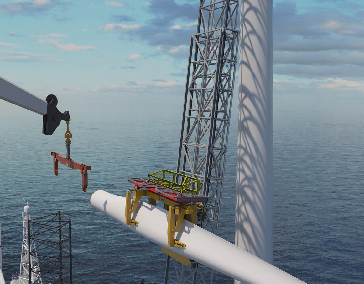
Marc Doorduin and Jessica Stump, NOV, look at how to enhance offshore wind turbine blade installation, transport, and logistics.
26. Safety offshore
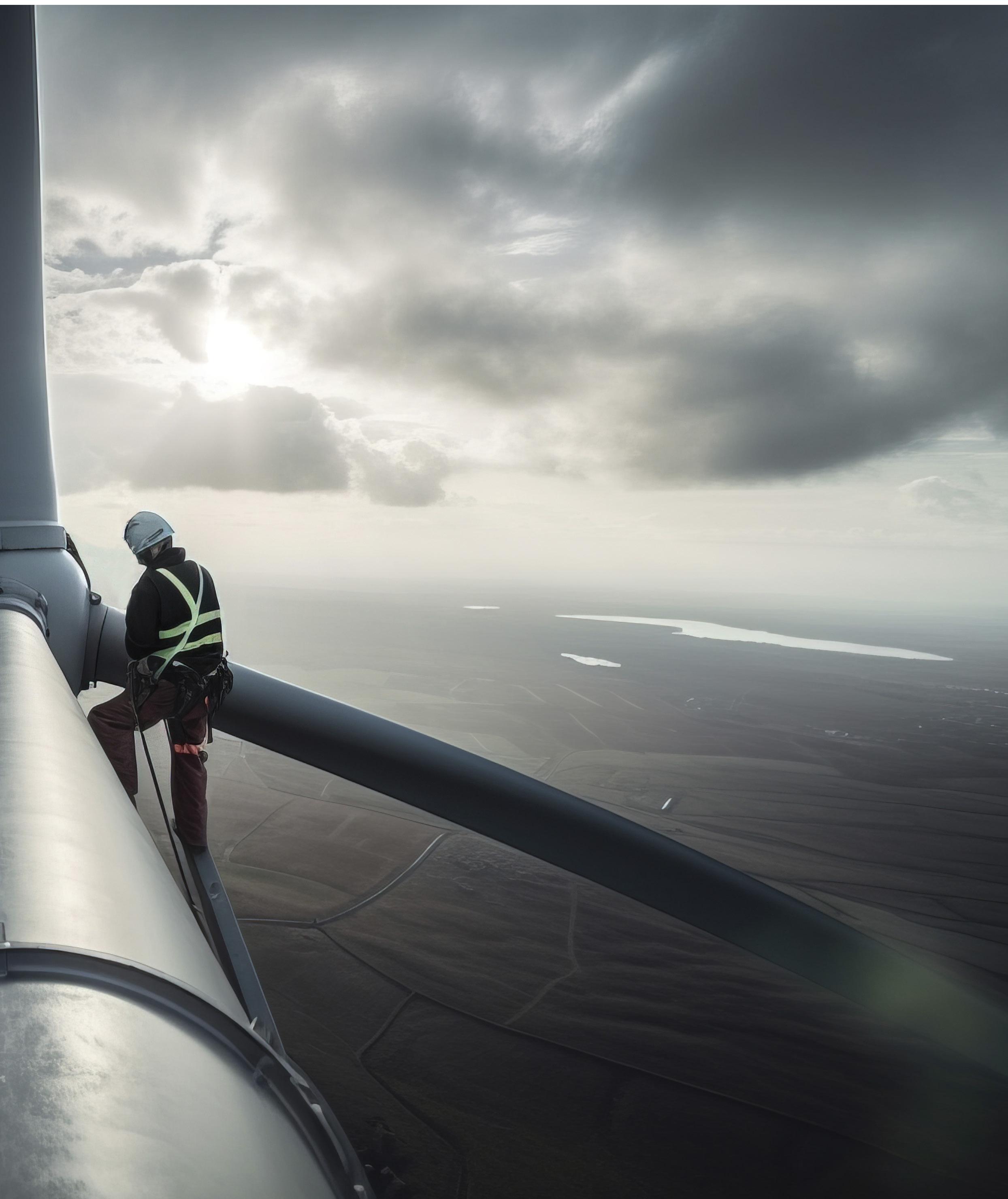
Dave Thompson, Director of UK Sales, RMI, outlines the steps that can be taken to ensure the safety and wellbeing of workers in offshore wind.
Reader enquiries [enquiries@energyglobal.com]
30. Why focus on digitisation when there are bigger fish to fry?
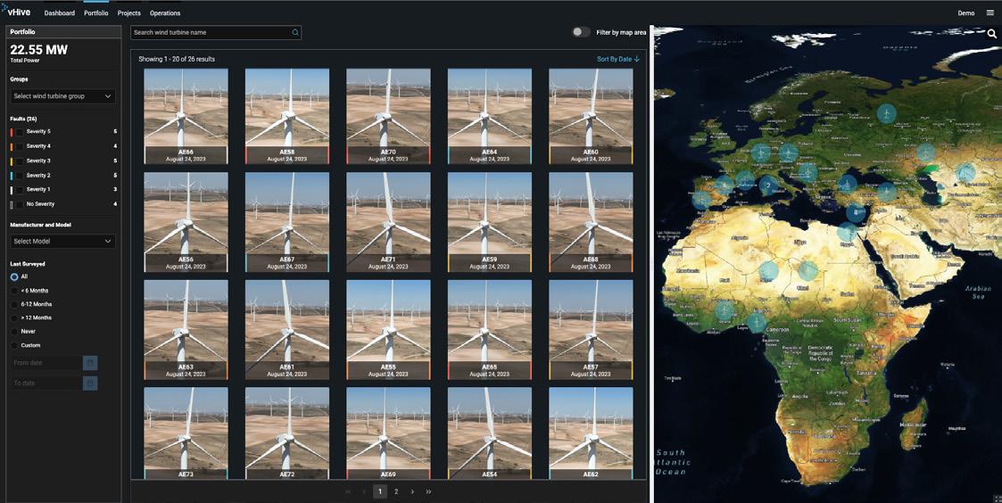
Yariv Geller, vHive, dives into the impact of automation and data democratisation on the wind turbine industry.
34. Powering affordable hydrogen
Nora Han, Head of Hydrogen Product Group, ABB System Drives, examines how the right choice of power supplies can enable more efficient and affordable green hydrogen production.

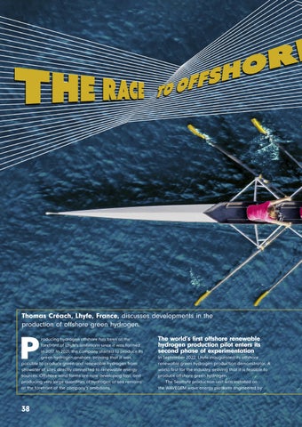
38. The race to offshore hydrogen production
Thomas Créach, Lhyfe, France, discusses developments in the production of offshore green hydrogen.
42. Waste to fuel the future
Patrick Clerens, ESWET, Belgium, considers a sustainable approach to waste management and energy generation.

46. Global news
Sulzer Chemtech is a global leader in state-of-the-art process technology and equipment expertise renewable fuels. BioFlux® Pretreatment technology is a low-CAPEX, low-OPEX solution for removing contaminants from bio-based materials that increases yield and significantly lowers hydrogen consumption. The technology offers superior operational stability, extended catalyst life and is suitable for grassroots, revamps, or co-processing units.
EDITORIAL ASSISTANT
Théodore Reed-Martin theodore.reedmartin@palladianpublications.com
MANAGING EDITOR
James Little james.little@palladianpublications.com
EDITOR
Jessica Casey jessica.casey@palladianpublications.com
SALES DIRECTOR
Rod Hardy rod.hardy@palladianpublications.com
SALES MANAGER
Will Powell will.powell@palladianpublications.com
PRODUCTION DESIGNER
Kate Wilkerson kate.wilkerson@palladianpublications.com
DIGITAL EVENTS MANAGER
Louise Cameron louise.cameron@palladianpublications.com
DIGITAL EVENTS COORDINATOR
Merili Jurivete merili.jurivete@palladianpublications.com
DIGITAL ADMINISTRATOR

Leah Jones leah.jones@palladianpublications.com
ADMINISTRATION MANAGER
Laura White laura.white@palladianpublications.com
Editorial/Ad vertisement Offices:
Palladian Publications Ltd
15 South Street, Farnham, Surrey, GU9 7QU, UK +44 (0) 1252 718 999 www.energyglobal.com
As summer gives way to autumn, the need for renewable energy has never been more apparent. Awkward small talk about the weather is becoming less avoidable, and all the more important, as harsher weather conditions become commonplace. After all, this summer was, in many places, one of sweltering heatwaves and record-setting temperatures. June was declared the hottest on record – 0.5˚C warmer than the 1991 – 2020 average1 – while July saw temperatures soar to over 50˚C in the Death Valley (the US) and the Sanbao Township in the north-west of the Turpan Depression (China). Numerous records were set across Southern Europe, China, the US, and Mexico for the longest duration of high temperatures. Experts have concluded that the frequency, duration, and pervasiveness of this summer’s heatwaves would have been virtually impossible in a pre-industrial climate.2
The end of July ushered in wildfires in Corfu, Rhodes (Greece), and later Lahaina, Maui (Hawaii), in August: a tragedy which so far has 115 confirmed fatalities.3 All of these wildfires made headlines as holidays were cancelled and videos of landscapes and buildings going up in flames surfaced. Yet the underlying question remains: what caused them? While these wildfires cannot be solely attributed to global warming, anthropogenic climate change has exacerbated the prerequisite warm and dry conditions of dangerous, fast-spreading, and long-burning wildfires.4 Essentially, more frequent wildfires are a symptom of a rapidly changing climate.5 To avoid worsening these conditions, a rise in renewable energy is needed. Though it is not all wildfires, heatwaves, doom, and gloom regarding climate change in 2023, as trends in the renewable energy industry are responding to these rising temperatures. Of the US$2.8 trillion globally invested in energy in 2023, clean energy sources are set to rise to US$1.7 trillion, with solar bypassing oil production for the first time.6 According to BNEF, US$239 billion was invested in large and small scale solar projects in 1Q23,
half of which was accounted for by China, with US$25.5 billion being invested in the US. Europe, the Middle East, and Africa also saw record-breaking investments.7 Similarly, global wind turbine orders have hit a 69.5 GW high in 1H23 which is a 12.5% increase y/y.8
New and innovative methods to commission renewable energy are more frequent as solar farms are being built in airports and opencast mines,9,10 turning emission hotspots into clean energy producers. New technologies, such as the Ocean Thermal Energy Conversion (OTEC) platforms used in Sao Tomé and Príncipe, harness ocean temperature gradients for clean energy, reducing the tropical island’s reliance on diesel.11 Similarly in Cincinnati, Ohio, Synthica uses anaerobic digesters, turning 500 t of food waste into renewable gas, cutting carbon dioxide emmissions;12 waste management is a topic closely covered by ESWET in the last article of this issue of Energy Global
Also featuring is an article from Lhyfe about the world’s first offshore renewable hydrogen production pilot, Sealhyfe, in St Nazaire, France: a step towards the sustainable production of offshore hydrogen. It is these developments in the renewable energy industry that are paving the way to a net-zero future.
Yet, challenges persist; for example, while wind turbines produce clean energy, the steel used to build them does not, and greener manufacturing is necessary in order to be truly renewable.13 Moreover, increased investment in green energy, particularly in small scale solar, must rise by 76% to meet net-zero by 2050 targets.14 Lastly, the need to sustainably produce hydrogen remains a hot topic in the industry, again this will be covered in the latter half of this issue. Addressing these matters are crucial in order to combat the intensity of heatwaves seen this summer, and so again, the need to invest in renewable energy has never been more apparent.

References
References available upon request.
Australia has an abundance of natural resources, and is well positioned to help itself, and potentially even other countries in Asia, to reach climate goals and aid with the decarbonisation of the world. For example, Australia has the world’s highest per capita solar resource in G20,1 and one of the highest in the world. The Australian regional report in the Winter 2022 issue of Energy Global provided insight into the different types of renewable energy being utilised in Australia.2 The article in this issue will provide a more in-depth look at some of the key renewable projects mentioned in previous report, focusing on solar, offshore wind, and hydropower.


Sun Cable is developing the world’s largest solar energy infrastructure network, and is located in Darwin in the North Territories, Australia. As mentioned in the previous regional report on Australia, the project is not expected to generate any electricity until 2026, but its large planned size, combined with a battery 150 times larger than the 150 MW Hornsdale Power Reserve in South Australia,3 will make it possible to power whole cities with renewable energy.
One such way Sun Cable is aiming to achieve this is via its AAPowerLink project. The idea is that it will harness and store solar energy from Darwin for 24/7 transmission to Singapore via a high voltage direct current transmission system.1 Asia’s renewables sector also has a lot of potential for growth, especially in light of the Paris Agreement targets and goals to decarbonise heavy industries. However, as Charlie Durant wrote in the Spring 2023 regional report on Asia, the continent will face challenges in regards to its energy transition away from fossil fuels.4 A couple of factors that are mentioned are the cost of commodities, and the supply-demand imbalances of critical metals, notably copper, which are crucial in the manufacturing of green technologies such as wind and solar. Singapore is currently reliant upon gas
Jessica Casey, Editor, Energy Global, UK, provides a brief overview of some key renewable projects currently under development in Australia.


for approximately 95% of its electricity generation; the proposed Powerlink by Sun Cable could be capable of supplying up to 15% of Singapore’s total electricity needs, as well as support the transition of the Northern Territory economy.3
An environmental impact statement (EIS) is being prepared by both the Northern Territory and Commonwealth governments, with the governments of Singapore and Indonesia also undertaking a separate EIS. The studies will look for ways to minimise, and possibly even avoid, any potential impacts to the environment and heritage values, as well as greenhouse gas emissions during the construction phase.3
Hydropower will be important in helping Australia achieve its net zero goals, and the Australian government is putting multiple schemes in place and investing in hydropower, as well as pumped hydro storage. One such way the government is achieving this is by providing additional equity to Snowy Hydro Ltd to construct Snowy 2.0.5
Snowy 2.0 is a 2000 MW/3500 MWh expansion project currently under construction in New South Wales, in the Snowy Mountains. It is strategically located between Sydney and Melbourne, and will link to existing dams via underground tunnels. A power station will be built almost 1 km underground.6
In 2022, the tunnel boring machine (TBM), Lady Eileen Hudson, became the first machine to start tunnelling on the pumped-hydro project, and the first to complete a tunnel (the 2.8 km main access tunnel). In July 2023, Snowy Hydro announced that the TBM had started carrying out her second tunnel excavation.7 The machine will excavate the 6 km tailrace tunnel to connect the underground power station complex to the Talbingo Reservoir, the lower of the dams.8 The tailrace tunnel is also where the water used to generate 2000 MW of power will flow out of. More than 27 000 concrete segments will be used to line the tailrace tunnel, with the segment erector, feeder, cranes, and sophisticated grouting system all onboard the TBM.
The Greatland Gippsland offshore wind project will be located in the Bass Strait, 10 – 43 km off the coast of Gippsland, in Victoria, between Woodside Beach and Seaspray.9 This was recently declared by the Australian government as the first area to be assessed for suitability for offshore wind developments in August 2022.9 The project also builds on the momentum for an accelerated retirement of brown coal projects in the Latrobe Valley, helping Australia move away from more traditional fossil fuels. Victoria has set targets of at least 2 GW of offshore generation capacity by 2032, 4 GW by 2035, and 9 GW by 2040. The offshore wind project includes approximately 140 wind turbines and 4 substations, which will produce 2.1 GW of electricity and will be connected to the National Energy Market in the Latrobe Valley via a shared transmission line.10
BlueFloat Energy’s feasibility licence application is well supported, with a number of letters from key local stakeholders. The Greater Gippsland offshore wind project
could see a AUS$35 billion increase in gross regional product for Gippsland, and is projected to create 2000 jobs during construction and over 300 ongoing jobs.9
The offshore wind sector could prove vital to Australia’s shift to renewable energy, as discussed in the Winter issue of Energy Global, especially considering its large coastline and southern parts of the country being situated in the ‘roaring forties’ – areas between latitudes of 40 – 50˚ south in the Southern Hemisphere with persistent winds from the west.11 Western Victoria is one of these areas that have good wind resources. In light of this, The University of Melbourne and Ørsted have partnered to bolster Australia’s move towards renewable energy.12 The memorandum of understanding will bring together Ørsted’s operational experience with the university’s knowledge of the local marine environment, biodiversity, and Indigenous Sea Country to help design and deliver the best offshore wind outcomes in the country. The partnership will also focus on enhancing and preparing students and researchers for careers in the growing renewables sector. Ørsted also has a proposed project off the coast of Gippsland, which comprises of two project sites, both 2.8 GW of generation capacity, 56 – 100 km from land. During development and construction phases, it is expected to create up to 6000 jobs in Victoria, and provide up to 25% of Victoria’s energy needs upon completion.13
Australia is well positioned to capitalise on the natural resources available to it, and these projects that have been briefly discussed are just a few examples of this. However, they show promising signs that the country is actively working towards its net-zero goals. A combination of all of these different types of renewable energy will be key in successfully achieving this and, as a result, it will certainly be exciting to see what Australia does next.
1. Sun Cable Australia-Asia PowerLink, https://aapowerlink.sg/
2. CASEY, J., and LARKIN, A., ‘Location, location, location: Australia’, Energy Global (Winter 2022), pp.4 – 8.
3. ‘Large Scale Solar’, Clean Energy Council, www.cleanenergycouncil.org.au/ resources/technologies/large-scale-solar
4. DURANT, C., ‘Commodity challenges facing Asia’s energy transition’, Energy Global (Spring 2023), pp.4 – 9.
5. ‘Pumped hydro’, Australian Government: Department of Climate Change, Energy, the Environment and Water, www.energy.gov.au/government-priorities/energysupply/pumped-hydro-and-snowy-20
6. ‘Snowy 2.0 – about the pumped-hydro project’, Snowy 2.0, (December 2018), www.youtube.com/watch?v=VwoJmtm47aY&t=52s
7. ‘Snowy 2.0 Project Update – July 2023’, Snowy Hydro, (28 July 2023), www.snowyhydro.com.au/news/snowy-2-0-project-update-july-2023/
8. ‘About’, Snowy 2.0, www.snowyhydro.com.au/snowy-20/about/
9. ‘Greater Gippsland Offshore Wind Project to boost the local Gippsland economy and create thousands of jobs’, Greater Gippsland Offshore Wind Project (27 April 2023).
10. ‘BlueFloat Energy and Energy Estate announce expansion of Greater Gippsland Offshore Wind Project to 2.085 GW’, BlueFloat Energy, (8 September 2022), www.bluefloat.com/bluefloat-energy-and-energy-estate-announce-expansion-ofgreater-gippsland-offshore-wind-project-to-2-085-gw/
11. ‘Solar Report Quarter 1, 2022’, Australian Energy Council, (2022), www.energycouncil. com.au/media/nb0fjq2z/australian-energy-council-solar-report_q1-2022.pdf
12. ‘New partnership to fast-track Australia’s offshore wind and renewable energy future’, The University of Melbourne, (29 August 2023), www.unimelb.edu.au/ newsroom/news/2023/august/new-partnership-to-fast-track-australias-offshorewind-and-renewable-energy-future
13. ‘Ørsted Gippsland Offshore Wind Farm Cluster’, Ørsted, https://orsted.com.au/ building-an-australian-industry/gippsland-offshore-wind-projects

In 2022, the cumulative capacity of installed wind power worldwide amounted to approximately 906 GW, with this number showing no sign of slowing down.1
As capacity and turbine sizes increase, and wind farms move further offshore, owners and operators are
presented with even greater challenges in maintaining their equipment to ensure ongoing productivity.
In 2020, the market for operations and maintenance (O&M) of wind turbines was estimated to be valued at US$15.4 billion. By 2031, this is expected to reach US$39.8 billion.1
 Dr John Coultate, Vice President, Advanced Sensing, ONYX, UK, explores
Reliability concerns continue to grow. Recently, issues around quality control led to Siemens Energy announcing that there had been a substantial increase in failure rates of wind turbine components. This resulted in its subsidiary Siemens Gamesa carrying out an extended technical review that will incur significantly higher costs than

previously assumed, estimated to be more than €1 billion (US$1.09 billion).
While there may be specific issues for the German giant to deal with internally, they do not appear alone in tackling major reliability issues. Discussion around turbine failure rates is a welcome sign that OEMs and operators
data driven operation and maintenance can optimise wind turbines.
are focusing on challenges that are having a major impact on profitability. While these issues are difficult to fully resolve, their impact can be managed and reduced via investment in condition monitoring and predictive maintenance tools. It is a symptom of a maturing industry that many large wind farms are now nearing the end of their planned 20-year design lives. Additionally, the rate of replacement of major components remains very high. Statistics show that in a typical operational wind turbine:
> More than 40% of gearboxes will have to be replaced in 20 years of project life.
> More than 20% of main bearings will have to be replaced within 20 years.
> More than 5% of blades will have to be replaced within 20 years.
While blades may make up a relatively small percentage of turbine failures, they are one of the most challenging and costly components to fix. They are undoubtedly one of the most exposed parts of any turbine, with the latest designs reaching
over 80 m in length. Damage or faults that go undetected can have catastrophic results so early detection is critical.
Blade failures can be categorised broadly as internal or external faults, and both pose different challenges. External failures are generally less critical to the structural integrity of the blade, and are typically identified through visual or drone inspection. With the turbines exposed to all elements, external damage is very common.
Damage to the blade tip can occur during lightning strikes and can lead to consequential delamination or cracks within the blade, rendering it non-operational until a repair can be performed.
Similarly, leading-edge erosion is also a frequent failure caused by continuous exposure to rain, dust and other airborne particles. As leading-edge erosion progresses, the blade surface can become increasingly rough, with greater drag affecting the aerodynamic performance and power production of the turbine.
While external failures typically develop slowly, as blade sizes continue to increase, this creates a greater challenge for operators to manage.
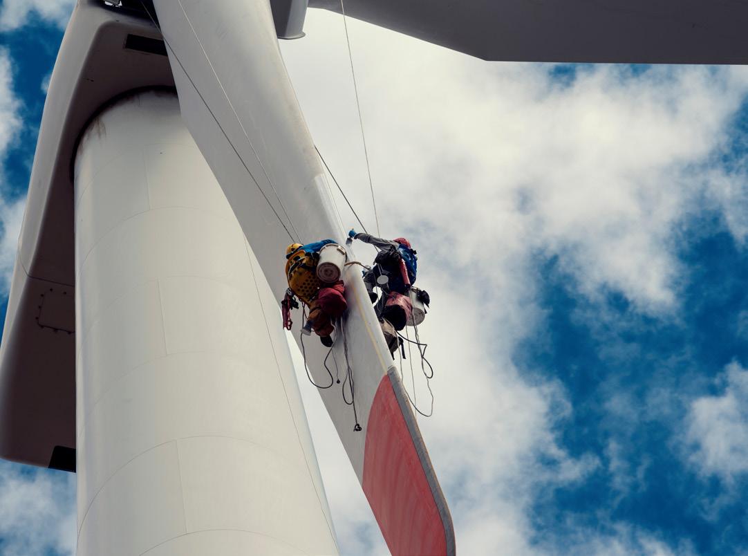
Visual inspection is the most efficient and effective method for identifying external damage. Rope-access inspection is a common method but can be time-consuming and is often hampered by weather conditions. Drone technology has delivered significant improvements in recent years, and by tapping into autonomous drone solutions, inspection downtime costs can drop by 70 – 90%.
On the other hand, internal blade failures are much more complex and can affect the structural integrity of the blade. Additionally, the industry currently lacks widely accepted approaches to monitoring these types of critical failure mode. Internal cracks in the main spar or bond lines can develop very quickly, growing from a few centimetres to 1 – 2 m in length within weeks or even days. As the internal structure is load bearing, unlike external failure modes, the blade cannot keep running safely for a long period of time. For instance, the shear web – a structural element in the blade of a wind turbine that helps to transfer shear forces between the blade – can become disbonded due to stress, halting operations immediately.
Drivetrains are one the biggest sources of major component failure, and typically make up the majority of unplanned wind turbine O&M costs. Main bearings, gearbox, and generator bearings all exhibit high failure rates and consequentially high O&M maintenance costs.
But not every failure is equal. Many drivetrain failures can be repaired up-tower at relatively low cost, without requiring a major component replacement. Pitch bearings on the other hand, cannot easily be repaired in-situ, and a replacement can be extremely costly – requiring the whole blade or rotor to be removed. If undetected, a pitch bearing failure can be catastrophic and in the worst cases can result in the loss of a blade. Therefore, detecting pitch bearing failures early and
Figure 1 . Blade failures can be categorised broadly as internal or external faults, and both pose different challenges.

optimising the replacement strategy before a catastrophic failure can deliver huge cost savings.
While major component failures have great potential to cause damage and consequential costs, relying on periodic inspections is not an effective method for detecting most problems. Additionally, as wind farms continue to increase in size and offshore wind grows, there is a drive to reduce the number of turbine visits and reduce the safety risk to personnel.
As the wind sector moves beyond monitoring single components in isolation towards a ‘holistic’ approach with monitoring the whole turbine, technology advancements mean owners and operators can extract increasingly more value from condition monitoring solutions (CMS).
The cost of replacing components is substantial and, if the turbine is offshore, these costs increase significantly. Drivetrain CMS detects faults early, and in many cases enables low cost up-tower repair, therefore preventing catastrophic failure of the gearbox.
Analogously, the emerging wider adoption of blade monitoring technology will enable increasingly early detection of internal blade faults – therefore enabling low cost up-tower repair of blade defects, avoiding the huge expense of a blade replacement.
By utilising advanced sensing inside the blade, alongside drone inspections and periodic internal inspections, operators have a great opportunity to drive down unplanned blade O&M costs.
An increasingly common failure mode in many types of wind turbine blades is a failure of the connection between the pitch bearing and the blade. Typically, this affects blade designs which feature studs or bolts attached to an ‘insert’ in the blade, which can fail over time and lead to catastrophic blade loss.
ONYX Insight, a leading global predictive analytics solution provider, monitors this type of blade root failure using its ecoPITCH system, an online condition monitoring system which is permanently installed in the hub. ecoPITCH is typically used to monitor pitch bearings with a variety of sensor types, and is connected to the cloud via 4G or through a Wi-Fi link to the nacelle and the turbine’s network connection. By extending the capability of ecoPITCH with additional sensors to monitor the blade root failure, existing hardware and networking capability can be leveraged to quickly deploy new solutions for monitoring critical types of failure which were previously not addressed. Without an online system such as ecoPITCH, operators would traditionally monitor the condition of the blade root manually, with technicians climbing the turbine to perform visual inspections and manual measurements. Such operations are extremely time consuming and costly, and can miss vital information if not performed regularly.
With demand for wind energy, and the size of turbines, growing every year, predictive maintenance must also adapt. Research and development is essential for establishing new
technologies which can support robust and cost effective O&M strategies. ONYX Insight recently secured a significant grant from the UK’s Offshore Wind Growth Partnership (OWGP), part of the Offshore Renewable Energy Catapult, to further develop its innovative solutions for blade condition monitoring. The awarded funding will support a major project over the next 18 months which will see the company further expand its predictive maintenance solutions from the drivetrain into the blades, as it rolls out new technology alongside partners owning and maintaining turbines at risk of blade failure.
Identifying when and where maintenance for blades is needed has been traditionally difficult, but predictive maintenance is allowing operators to tackle progressive blade faults faster, cutting downtime and costs. There is no doubt that a holistic approach to O&M, utilising an integrated combination of drone inspections and online monitoring will deliver the greatest benefits and value to asset owners and operators. Both technologies work in harmony, each delivering unique advantages depending on the type of failure mode and symptoms presented. However, a cultural shift is required within the industry to support this objective.
In the first of its kind, earlier this year ONYX Insight partnered with leading drone technology company, Nearthlab, to deliver a whole turbine predictive maintenance for wind operators. The partnership delivers even greater efficiencies in drone inspections by utilising Nearthlab’s experience with mobile drone technology to reduce reliance on the availability of trained drone pilots and enable self-performing operators to perform visual inspections of turbine blades, delivering substantially lower costs.
Combining this with ONYX Insight’s depth of experience in turbine reliability engineering, the integration of drivetrain, blade health monitoring, and fleet management systems it delivers a single business ecosystem to support robust O&M strategies.
Many turbine operators are still approaching O&M reactively, with 65% of O&M costs currently unplanned and 80% of these costs are typically attributed to blade and drivetrain failures, according to ONYX analysis. There are substantial gains to be made from adopting predictive maintenance strategies beyond the typical drivetrain CMS. As the demand for wind energy continues to increase, standardisation of O&M will also be imperative to increasing operational uptime and reducing project costs.
By utilising advanced sensing and online measurements, providing in-depth analysis on the health of blades, alongside low-cost inspections using portable drones, operators can significantly optimise their blade maintenance costs. Additionally, they will be able to create O&M strategies around the data they receive and plan ahead for anticipated downtime, rather than reacting to unexpected failures. With turbine failures making headlines, it’s clear the conversation around how best to fix them, is only getting started. References

Sulzer Chemtech, a global leader in supplying state-of-the-art process technology and equipment, is using expertise to deliver world-class performance to renewable fuels producers worldwide.
BioFlux® Pretreatment technology is a low-CAPEX, low-OPEX solution for removing contaminants from bio-based materials that increases yield and significantly lowers hydrogen consumption. The process offers superior operational stability for extended catalyst life and is suitable for grassroots, revamps, or co-processing units. To learn more about the BioFlux® pretreatment technology and to receive a preliminary assessment of your feedstock, please contact us at biobased@sulzer.com.
BioFlux® is a registered trademark of Duke Technologies LLC.

As a countermeasure against climate change, net zero greenhouse gas emission is a global issue, and the shift to renewable energy is of the utmost importance.

Wind power is expected to play an important part in renewable energy, and is about to be deployed worldwide, onshore and offshore. For onshore deployments, there will be an increase in the development of wind turbines in areas with severe wind
conditions, such as mountainous areas and strong wind areas, while offshore, there will be floating wind turbine developments in long-distance and deep-sea areas, as well as fixed-bottom wind turbines in coastal areas. If it is not possible to operate stably and safely even in such places, it will be difficult to deploy them on a large scale. This article will focus on the safety of wind turbine yaw devices, and reports on failure cause analysis, countermeasures, and verification of effectiveness based
Osamu Nohara, Minoru Sakata, Hirofumi Komori, and Kenta Goto, Nabtesco Corporation, Japan, detail new technology developed to help keep yaw devices in wind turbines functioning properly.

on field tests conducted in Japanese wind farms where the wind conditions are very severe.
The yaw device, which points the blades of a wind turbine squarely in the direction of the wind, plays an important role in following changes in wind direction and maintaining the turbine’s attitude.
This mechanism consists of a yaw ring gear directly connected to the tower and multiple yaw drives installed on the nacelle that mesh with the ring gear. The driving force is controlled by an electric motor installed at the input area on the upper part of the yaw drive, and braking force is controlled by an electromagnetic brake attached to the electric motor and a rotation brake installed on the ring gear.
When a wind turbine is not generating power, turbine safety is ensured by levelling the blade angles to prevent the blades from rotating under wind load, and by performing yaw rotations.
According to a survey of mechanical failures by the number of years in operation for yaw devices in Japan from 2011 – 2019,1 a total of 24% of all failures were due to sudden premature failure in less than five years of operation, with the remainder due to fatigue failures that occurred within a short period of time. While wind turbines are designed with a safety factor in accordance with design guidelines established by DNV-GL2 and other organisations to withstand 20 years of operation, 2 fatigue failures have occurred in a short period of times, either soon after installation or within just a few years. Yaw drive failure accounted for 48% of failure occurrences, ring gear failure for 9%, and others for 43%.
The repair cost for failure of the ring gear came to ¥3.17 million (€21 100), ¥4.95 million (€33 000) for the drive unit, and ¥2.31 million for others (€15 400). It has also been confirmed that there were large differences in ring gear repair costs depending on how repairs were carried out. In most cases covered by this set of data, repairs were made by welding following penetrant inspections. However, in some cases, the ring gear needed to be replaced, which required a large special work crane, incurring a cost of more than ¥100 million (€670 000).
Regarding yaw drive, damage to power transmission components of the output shaft reduction mechanism, and in the case of ring gear, damage to parts that contact the pinion, are cited. Both cases were one-shot breakdowns due to large loads or fatigue breakdowns that occurred within a short period of time.
Figure 1 shows the result of factorial explication for clarifying the causes of failure. Apart from the characteristics of the wind turbine itself and temporary control problems, two major factors were involved: the large rotational moment of the nacelle caused by large deviations in wind direction due to turbulence and upward-blowing wind, and the generation of concentrated and excessive loads due to unequal load sharing between multiple yaw drives.
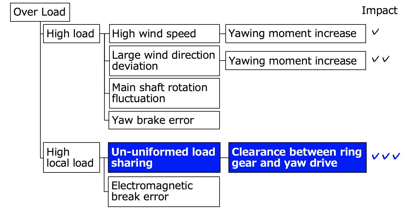
Figure 2 shows the relationship between wind speed and yaw loads as measured on an actual unit. The figure
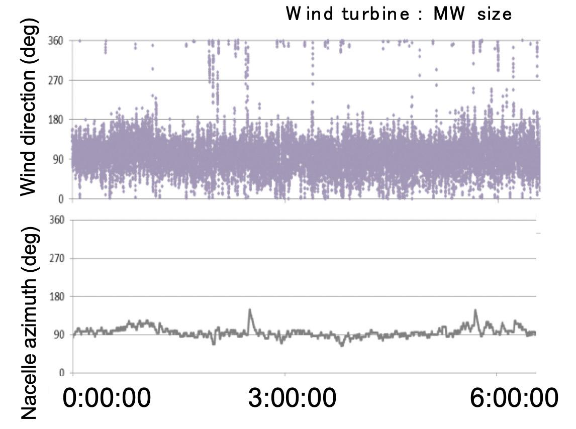
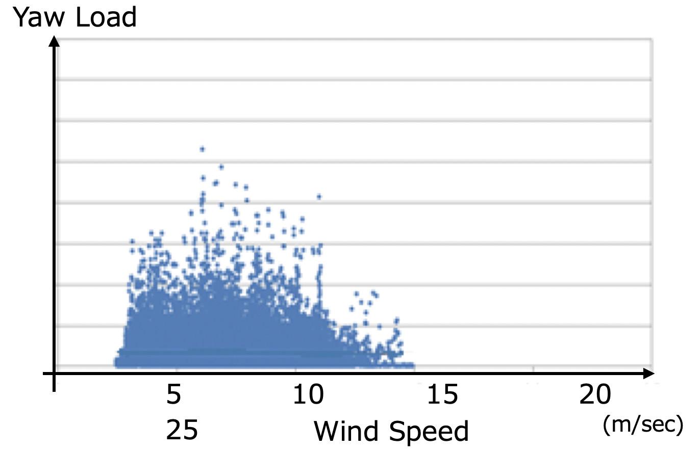 Figure 1 Factorial explication.
Figure 2 Relationship between wind speed and yaw load.
Figure 1 Factorial explication.
Figure 2 Relationship between wind speed and yaw load.
clearly shows that yaw load does not increase in proportion to wind speed.
Figure 3 shows a comparison of wind direction and nacelle azimuth in the same timeframe. Variations in wind direction are seen to be larger than variations in nacelle azimuth. Therefore, the reason why the aforementioned rotation load is not proportional to wind speed is likely that the nacelle azimuth is not adapting to changes in wind direction, which results in a large rotational moment, albeit momentarily, to the nacelle.
Unequal load sharing is caused by variations in meshing gaps between the pinions of multiple yaw drives and the ring gear. Gap variation is determined by the distance between the centres of both gears, and is related to:
> Errors in the mounting of yaw drives onto the nacelle.
> The amount of pinion shaft deflection.
> Ring gear circularity.
> Pinion shaft runout.
Along these lines, the factor ratios of gap variations by different pinion shaft support methods are shown in Figure 4.
The majority of gap variations are due to mounting errors in the mounting of yaw drives onto the nacelle, followed by the amount of pinion shaft deflection.
The amount of variations in meshing gaps between the pinion of multiple yaw drives and ring gears can have an effect on the allowable rotation load.
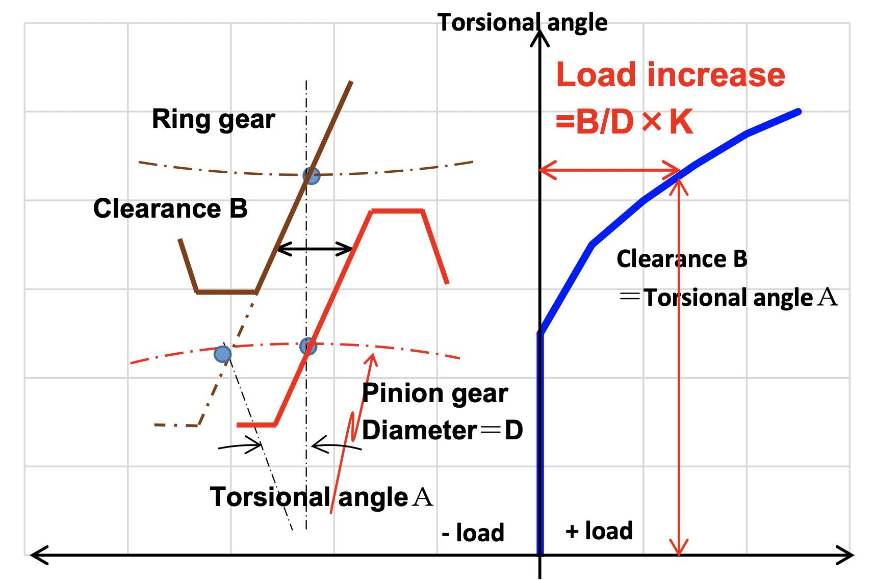
As an example, a comparison was made between a case where the pinion of one yaw drive unit was meshed with the ring gear and the pinions of the other units were not meshed due to gaps, and a case where the pinions of all units were meshed at the same time. The increase in load leading up to the point where a distortion corresponding to the amount of the gap created due to the pinion of one unit being meshed with the ring gear can be expressed as B/ D x K, where the gap amount is B mm, the pinion diameter is D mm, and the drive unit spring constant is K (kNm/min.). This relationship is shown in Figure 5, with the load on the horizontal axis and the angle of pinion shaft distortion on the vertical axis.

Where the allowable load per yaw drive unit is Tmax and the number of yaw drives is n, the allowable rotation load T can be expressed for a meshing gap of B as:
The variation of allowable rotation load T by the meshing gap amount is graphed in Figure 6. If there is a meshing gap of 1 mm, the allowable rotation load declines
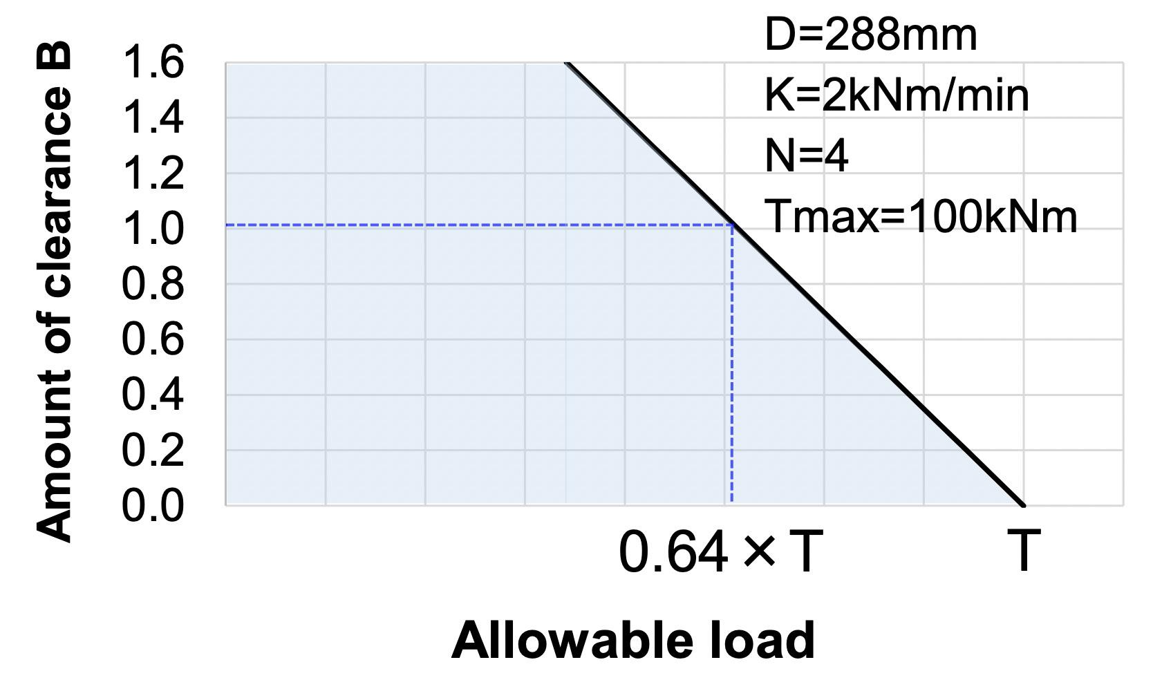
to 0.64 times that when there is a null gap, which will lead to premature damage.
The meshing stress of gears is calculated according to international standards (DIN3990-2 and ISO6336-2) using several factors, including gear specifications, lubrication, and surface roughness. Figure 7 shows the allowable number of cycles according to the gear material and its heat treatment. Slope p is determined by allowable static stress σ HPstat and allowable dynamic stress σ HP∞ that are applied, respectively. 3
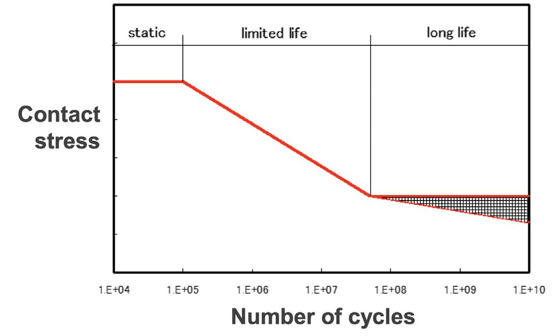
For example, the calculation of slope p for carburisation heat treatment will be σ HPstat = 1.6, σ HP∞ = 1.0, and therefore, p = 6.6 based on exp = 0.076.
Where the rated load per yaw drive unit is Tn, the life ratio R for a meshing gap of B can be expressed as:
R = [Tn/{Tn+B/(Dx π)xK}] P
At a meshing gap of 1 mm, the meshing life ratio between the ring gear and the pinions declines to 0.01, which will reduce a 20-year life to 0.2 years and result in fatigue damage within a short period of time.
Equally distributing the yaw rotation load among multiple yaw drives is important for the safe and reliable generation of power from wind turbine over the long term.
To address this issue, Nabtesco has developed a condition monitoring system with fail-safe (CMFS), a system that accurately captures the load generated in the yaw drives with a proprietary sensor to equalise load sharing and avoid excessive loads when the yaw rotation is at rest. Equalised load sharing is effective in reducing the load not only at rest, but also during rotation.
The CMFS equipment consists of bolt strain sensors that estimate external forces, control equipment that aggregates data from the sensors using a programmable logic controller (PLC) and outputs a signal that releases the electromagnetic brake when the sensor value exceeds a defined threshold value, and the equipment power supply.
When yaw rotation is at rest, the external load from the pinion shaft is arrested by the electromagnetic brake attached to the motor. If the external load exceeds the allowable load of the drive unit, this electromagnetic brake can be released instantly to reduce the load increase. Furthermore, load sharing among multiple yaw drives can be equalised. This process is roughly represented in Figure 8.
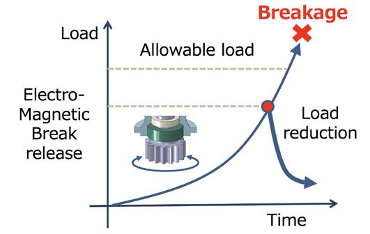
Table 1 shows a comparison of characteristics with torque limiters, which are generally used as safety devices for overload protection.
Torque limiters, which are installed at the input section, can only be set with a single limit value, so it is not possible to simultaneously set the two different threshold values of overload avoidance torque and load sharing equalisation torque.
Also, if the inside of the reducer malfunctions or seizes due to poor quality when yaw rotation is at rest, torque limiters will not be able to detect the external load from the output side because the load is not
 Figure 7 Relationship between tooth surface stress and number of cycles.3
Figure 8 . Relationship between meshing gap amount and life ratio.
Figure 7 Relationship between tooth surface stress and number of cycles.3
Figure 8 . Relationship between meshing gap amount and life ratio.
transmitted to the input section. As such, this increases the risk of ring gear damage.
As a result of measuring the rotation load over a year using the CMFS, the load tended to be high in winter and low in summer throughout the year.
Figure 9 shows the current-state load distribution at large loads in February (winter) and at small loads in September (summer), together with the effect of activating the CMFS function.
In this load distribution, because the wind turbine has four yaw drives, the 25% line on the vertical axis for the sharing ratio represents the equalised state.
As for the characteristics of the load distribution, it can be said that the sharing ratio is higher at small rotation loads, and it approaches 25% equalisation at large rotation loads. Nabtesco also verified that at large loads, unequal load sharing results in the distribution of loads in areas beyond allowable limits.
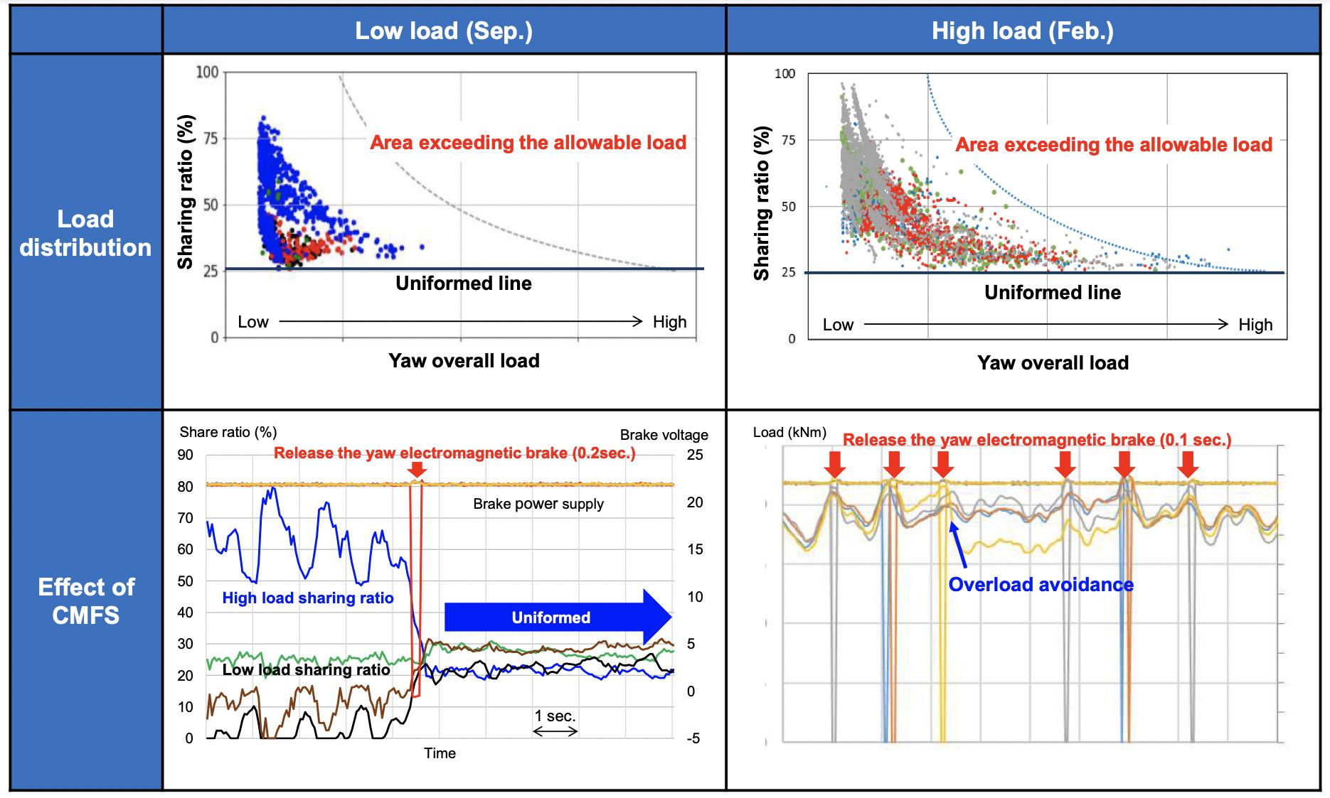
Changes in the sharing ratio and load are captured on the horizontal axis at 1 sec. per square. At small loads, while the load sharing ratio of the No. 1 yaw drive unit initially remained high, the instantaneous release of the electromagnetic brake equalised the sharing ratio. The instantaneous brake release time is short, at 0.2 sec. or less.
At large loads, it has been verified that while excessive loads were repeatedly being generated, instantaneous releases of the brake repeated over multiple times kept the rotation load from exceeding the specified value. Based on this, the company was able to prove that the CMFS equipment is capable of accurately detecting the load with its bolt distortion sensors, and its control equipment is capable of providing high-response control of the electromagnetic brake to reduce rotation load and equalise load sharing.
Finally, diagnostic service is to be introduced that allows real-time viewing of a distribution chart of rotation loads and load sharing ratios based on sensor-detected data.
The diagnostic site can be accessed from anywhere with an Internet connection. Additionally, users can select their registered sites and turbine unit numbers in a graphical setting, and check the aforementioned load distribution chart and an anomalies history table. An alarm notification function can also be added upon request.
The causes of failure in wind turbines’ yaw devices has been clarified by sorting out failure modes and through factorial explication. In addition, Nabtesco formulated effective countermeasures, developed the CMFS, and obtained the following results through filed tests:
1. Mechanical failures of the yaw device were observed to occur irregularly and ranged from sudden failures immediately after installation to premature fatigue failures.
2. External loads on yaw devices were found to not necessarily be determined by wind speed, but rotation loads increase due to deviations in wind direction caused by turbulence and upward-blowing wind.
3. It was found that unequal power loads between multiple yaw drives lead to increased rotation loads, resulting in damage and premature fatigue failure.
4. It was determined that unequal load sharing when yaw rotation is at rest can be equalised by instantaneous release of the attached electromagnetic brake.
5. It was also found that the excessive load when yaw rotation is at rest can be reduced by the instantaneous release action of the attached electromagnetic brake.
These results were achieved with the co-operation of Japanese wind power developing companies and wind turbine manufacturers, who provided wind turbines for measurement purposes. Nabtesco would like to thank them for their support.
1. ‘Wind Power Failure and Accident Investigation Results 2011 – 2017’, New Energy and Industrial Technology Development Organization (NEDO).
2. WOEBBEKING, M., ‘The New Guideline for the Certification of Wind Turbines’, Germanischer Lloyd Industrial Services GmbH, Renewables Certification (GL), (2010).
3. ‘Calculation of the load capacity of spur and helical gears’, DIN3990-1, -2, and ISO6336-1, -2
Figure 9
National offshore wind capacity and emissions reduction targets, increasing global power demand, and the expanding energy mix are propelling the offshore wind industry. As the industry rapidly grows and wind farms move farther offshore and into harsher environments, so do the size and complexity of the turbine towers, nacelles, and blades. Larger offshore wind turbines have reduced the levelized cost of energy, but they present installation, transit, and logistical challenges.
Wind turbine installation vessels (WTIV) – with ever-increasing lifting and carrying capacities – currently install all the components. However, these large jack-up vessels have high day rates.
Since blades are highly susceptible to wind loads, they take the most time to install. While blades weigh less than 100 t, these vast and costly jack-up vessels feature heavy-lift cranes with lifting capacities of up to 2600 t, resulting in inefficient use of resources.
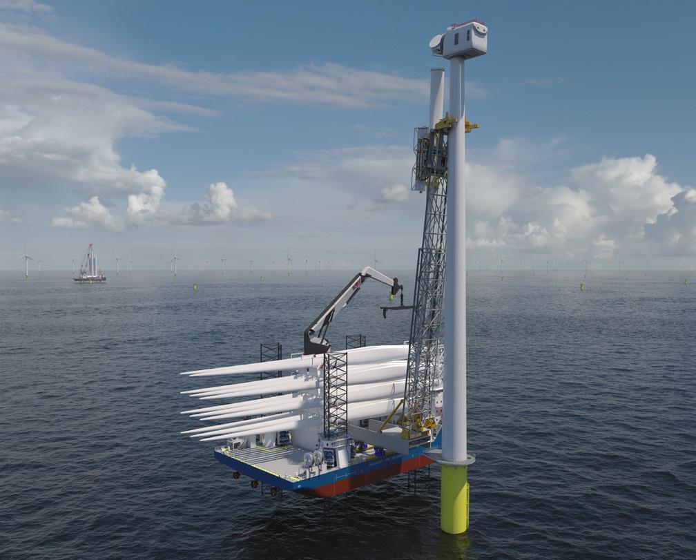
In response, GustoMSC and NOV Lifting & Handling in Norway have developed a new wind blade installation (WBI) solution that makes blade logistics, transportation, and installation safer, faster, and more efficient while minimising the environmental impact. Sjøhest, Norwegian for ‘seahorse’, consists of a newbuild GustoMSC TM NG-5500XL self-propelled jack-up vessel, or a smaller converted jack-up, with integrated equipment dedicated only to blade installation, loading, and transport.


The Sjøhest WBI solution creates the opportunity for logistics flexibility by splitting the tower/nacelle and blade mobilisation into separate onshore hubs. At more than 120 m (394 ft) in length, larger blades require more staging space. But unlike the heavy towers and nacelles, blades do not need a crane for loading.


On the quayside, 3 – 4 blade sets (9 – 12 blades) are rolled onto the deck from the aft of the vessel and
stored longitudinally. GustoMSC created more deck space – 2000 m 2 (21 528 ft 2 ) – on the NG-5500XL jack-up vessel by splitting the accommodation. Storing the blades in the same direction as the jack-up’s heading enables faster loading and allows the Sjøhest WBI vessel to sail and manoeuvre safely through the harbour. It also enhances wind loads on the jack-up during transit, thus, saving fuel and reducing carbon emissions.
WTIVs, however, transport blades transversely to accommodate the vertical towers and nacelles on deck. As a result, more than half of the blades, including the tips, hang off the vessel, obstructing harbour traffic, escalating the risk of collisions, and increasing costs.
The new WBI solution also offers an alternative offshore installation methodology. While the high-capacity WTIV installs the towers and nacelles, the smaller Sjøhest WBI jack-up – equipped with a telescopic leader boom, knuckle boom crane, blade-handling tool, and trolley –simultaneously installs the blades in another part of the wind farm.
Precision is vital but challenging for offshore wind turbine installation operations because of rising hub heights and harsher weather conditions. The installed tower moves separately from the blades during installation due to wind and waves. These dynamics not only increase downtime, installation time, and costs, but also risk damaging the blades and harming technicians and other crew personnel.
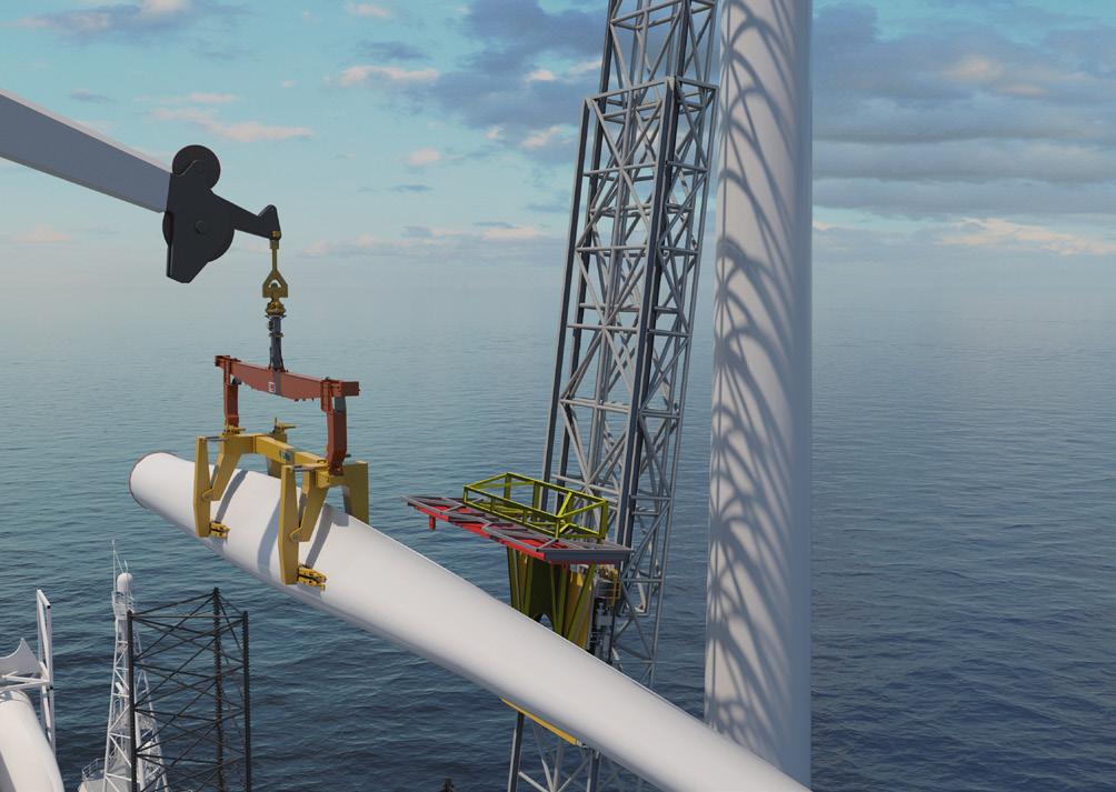
Just as a seahorse’s strong grasping tail enables it to resist ocean currents, the Sjøhest uses the telescopic leader boom to connect and align with the installed tower’s movements, reducing the effects of the wind and waves. By moving as one unit, the firm connection creates a stable platform for lifting operations. It also extends the weather window and workability of the jack-up vessel while enhancing the safety, speed, and precision of blade installation.
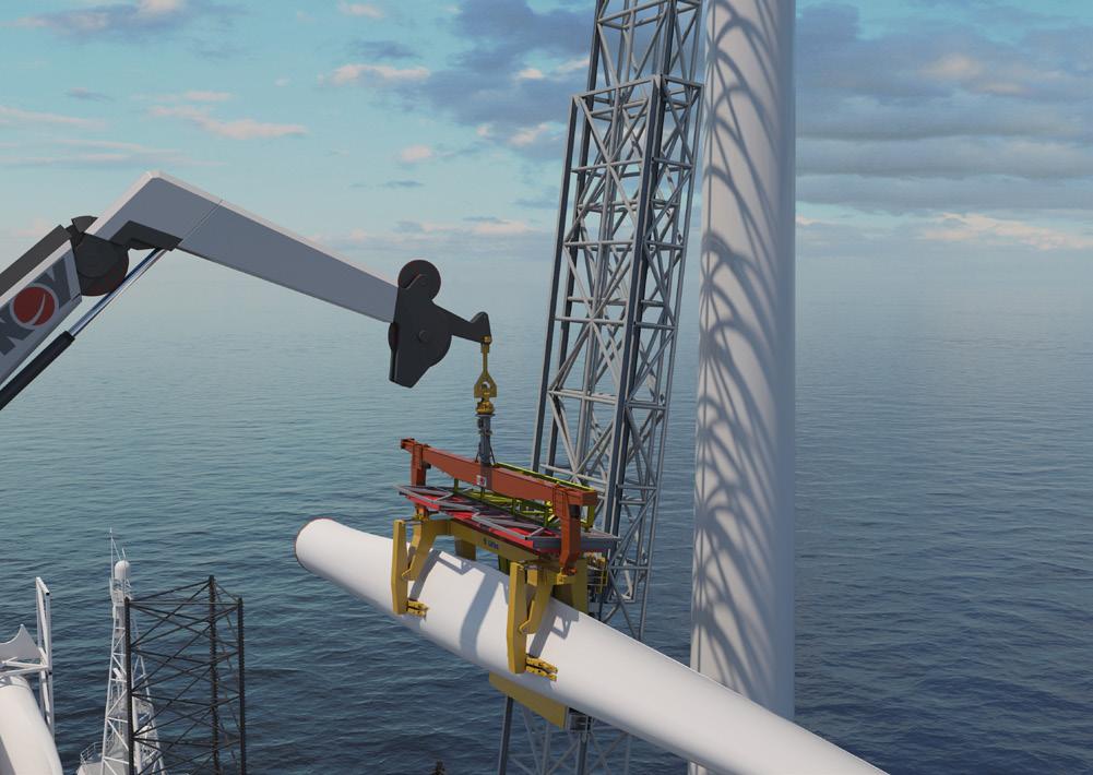
The WBI jack-up vessel also includes a knuckle boom crane that picks up each blade from the rack with the Liftra-designed blade-handling tool. This innovative tool securely yet softly grips the blade, and the knuckle boom crane carries the blade and tool package to a trolley on the leader boom. In an industry-first and patent-pending operation, the blade and gripper tool package is transferred to the trolley in one handover. Lifting and gripping the blade once not only helps maintain structural integrity but also saves time, resources, and emissions.
The trolley horizontally transports the package up along the leader boom toward the hub and nacelle, which can reach nearly 200 m (656 ft). As it ascends, the blade rotates into a vertical position and is connected to the rotor. When the trolley descends to pick up the next blade, the nacelle rotates so the next open slot on the rotor is above the leader boom. With no downtime or delays, all three blades per turbine can be installed in one day.
Figure 1 The Sjøhest wind blade installation solution consists of a smaller jack-up vessel, telescopic leader boom, knuckle boom crane, blade-handling tool, and trolley. Figure 2 A knuckle boom crane with the Liftra-designed blade-handling tool picks up the blade from the rack.Splitting tower/nacelle and blade installation decreases offshore wind farm installation times by 20 – 30% and reduces fuel usage, thus improving the project economics and timeline for the developer and lowering the operation’s carbon footprint.


Meeting global power demand and ambitious capacity and emissions reduction targets will require more and higher capacity offshore wind farms with ever-increasing turbines. By the end of the decade, 20 MW offshore wind turbines with more than 140 m (459 ft) long blades are anticipated.
Sjøhest provides a safe, efficient, and reliable solution for today’s and future offshore wind turbines. The WBI solution will easily adapt to rising hub heights for next-generation turbines by increasing the length of the telescopic leader boom.

Demand for specialised and expensive installation vessels rises as offshore wind projects increase in size, scale, and scope. Many jack-ups built more than 10 years ago will be obsolete in the next few years because of the higher lifting and carrying capacities required for bigger and heavier offshore wind turbines.

The new WBI solution, however, offers life extension and new opportunities for these smaller jack-up vessels. With the Sjøhest onboard, the retrofitted jack-ups will be able to not only install the next-generation
turbine blades, but also serve as an offshore wind maintenance vessel since the equipment can be used to exchange the blades.
As the offshore wind industry expands worldwide, new solutions, such as the Sjøhest WBI, will be designed to meet the installation, loading, and transport challenges of today’s and next-generation offshore wind turbines.
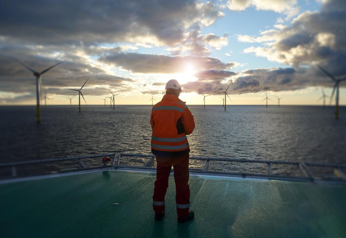
lobal offshore wind is expected to achieve a staggering 13% average annual growth from 2020 to 2050. In the UK, construction of the world’s largest wind farm, Dogger Bank, is currently underway off the North East coast of England, which will be capable of powering up to 6 million homes alone.
Offshore organisations are being relied upon to meet this increased demand in order to deliver climate goals and bolster energy security in an unstable global market. For the industry to operate at this heightened capacity, it also needs to be staffed effectively. Organisations will need to protect the safety of their workers in these remote and hazardous environments to ensure an efficient workforce to achieve this supercharged growth.
Access to qualified and robust medical services is crucial to ensuring the health, safety, and wellbeing of the workforce, and therefore, successful expansion of the industry to meet ever-increasing demand. Badly managed health and safety incidents have the potential to cause significant operational delays to offshore wind farms and supporting vessels. The nature of offshore wind farms means they face a unique set of health and safety challenges including distance from definitive care, environmental extremes, and limited resources.
This is where the support of companies, such as RMI, becomes invaluable. As a global health and safety organisation, RMI has extensive experience providing medical and safety solutions to offshore wind farms over the last 20 years, supplying topside and on-board medical and health and safety executive (HSE) services to the vessels supporting offshore wind projects around the world.
From the initial construction phase of projects such as the Dogger Bank wind farm, trained medical professionals must be deployed on service operation and jack-up vessels. For example, RMI, which is currently supporting the lives of the construction workers at Dogger Bank, provides 24/7 topside medical support, medical assistance services, and use of HSE offshore qualified medics to the offshore construction site, offering a high level of medical support and trust to the onsite workers.

Once an offshore wind farm moves into the operations and maintenance phase, there is a shift in the health and safety requirements of the site. Offshore workers will then require a long-term medical support team that works alongside them to deliver professional-level care to maintain day-to-day health as well as respond to emergencies.
Even with the best preventative measures in place, illness and injury are inevitable in offshore environments, and so being prepared for medical emergencies is essential to avoid costly delays. The three main recommendations to avoid such issues are medical screenings, preparing onsite medical support and a Medical Emergency Response Plan (MERP).
One preventative measure that companies can take is ensuring that all workers are medically screened prior to working offshore. RMI is an experienced provider of Offshore Energies United Kingdom (OEUK) medicals,
the industry-standard medical for workers in offshore environments. These are designed to identify major risk factors in individuals that would make it unsafe for them to work offshore, which can highlight serious medical conditions that would otherwise go unreported.
RMI also ensures its offshore medics have the necessary equipment and systems in place to maintain each crew vessel and provide the highest quality of support, all in one place. Offshore medical providers also play a vital role in providing education and encouragement for the adoption of healthy lifestyle habits among workers, to reduce the risk of injuries and illness. They also support with project management, clinical governance to ensure the delivery of quality care, and topside and medical diving support, which provides around-the-clock access to medical consultations. This type of support also limits the number of cases that require referral for further offsite medical care, saving time and resources, and reducing personnel downtime.
At certain points, medical evacuation is a necessary response. Having a MERP, which includes lists of local medical facilities, communication plans in the case of an emergency, and resources for medical evacuation, helps organisations to smoothly facilitate this – saving both time and avoiding any further illness or loss of life. Drawing up a plan may seem simple; however, it can be easy for organisations to make broad assumptions about imaginary situations. The best plans need to anticipate the worst-case scenario and consider the following elements: what happens if the helicopter is not available or cannot come for several hours and a worker needs to be evacuated by boat? What is the process for evacuating the worker by boat and getting them to shore? Who is trained to safely lower the worker from the turbine while administering first aid? Is the first aider able keep the patient alive for several hours? Is a working automated external defibrillator available?
A MERP considers various ‘what if’ scenarios for every type of incident. To develop these, organisations need to leverage the expertise of quality, health, safety, and environment (QHSE) advisors to ensure that plans include emergency action checklists and communication plans to keep teams safe and prepared to effectively handle a medical emergency.
Offshore medics are unique in that they are not only responsible for treating patients on supporting vessels; they must also be prepared to deliver care in a 200 ft turbine or be able to lower the patient to safety.
During the recruitment process, all offshore medics should be thoroughly assessed to ensure that they have the relevant training,
 Figure 2 . Manual high worker offshore climbing on a wind turbine on a ladder and transfer vessel.
experience, self-motivation, and ability to work independently in isolated offshore environments for potentially extended periods of time in a difficult and challenging environment.
RMI’s onsite medics have Global Wind Organisation training, if required, which includes climbing inside wind turbines. This additional experience allows medics to deliver a higher level of care no matter where the patient is located, especially if it is not possible to move the patient to a clinic.
Many offshore wind turbines projects may require divers to access underwater construction activity or minor repairs. While the safety of diving has dramatically improved, the challenges of treating a serious illness or injury still exist. Offshore organisations may want to consider specialised medical diving support, such as that offered by RMI, which provides expert dive doctors to provide qualified trained advice to offshore medics on site.
First aid training is also essential. Considering the size of offshore wind farms – which can span 145 km 2 — sometimes it could be hours before an offshore medic aboard a vessel is able to reach a turbine. This is where it is vital that organisations train workers in preventive health and emergency response, so that workers feel confident in using first aid skills whilst waiting for professional help to arrive.
An RMI client had an employee aboard an offshore support vessel off the east coast of the US who suddenly developed itchiness, hives, shortness of breath, and wheezing. The patient had a pre-existing allergy and had accidentally been exposed to the allergen.
The employee went to the medic on board who administered subcutaneous epinephrine and the patient’s symptoms improved and he was discharged from the clinic.
Unfortunately, an hour later his symptoms recurred and worsened. The onboard medic administered another dose of subcutaneous epinephrine along with supplemental oxygen, but the patient’s symptoms persisted. The onboard medic called in RMI’s topside support services for guidance.
The specialist who answered the medic’s call immediately contacted RMI’s on-call topside physician, who was able to provide clear direction and support on how to manage the situation.
The patient was in obvious distress and was struggling to maintain normal oxygen levels. He was breathing fast and was experiencing significant swelling of the airways, lips, and tongue. The patient developed biphasic anaphylaxis, whereby the initial allergic symptoms recurred at a greater severity. If not effectively managed, anaphylaxis of this magnitude can be fatal.
RMI’s on-call topside physician directed the onboard medic to administer epinephrine and to use a drug mist delivery device to address the wheezing and difficulty breathing. They then directed the medic to place an IV to administer other critical medications targeting the anaphylaxis.
While the epinephrine bought some time, RMI’s topside support realised this patient was having a life-threatening allergic reaction and advised the medic to administer a mixed epi drip. This is a mixed solution which can then be used as an IV infusion of epinephrine, which infuses at a rate over time to better control the allergic response.
A mixed epi drip is standard approach in resource-rich emergency departments until a pharmacy can supply a more stable dosing solution. The topside physician expertly coached the onboard team through creating the drip and successfully infusing it at a therapeutic rate.
The patient began to improve on the recommended course of medications. However, the team knew that remote medical evacuation services would be required from the onset of the incident due to the location of the vessel. The MERP in place allowed the team to safely stabilise the patient until the US Coast Guard arrived and evacuated the patient to mainland, where he was able to achieve a full recovery.

The above factors and this case study illustrate the specialist but vital considerations that must be made to ensure a productive and safe offshore operation within the rapid scale up of renewable energy delivery. The experience of a medic, their ability to access support services and resources, and the creation of an effective emergency prevention and management plan can all make the difference in protecting the lives of works in extreme and challenging environments. RMI has been a leader in this field for over 20 years, and is well placed to support the offshore industry as it grows across the world.

The wind power generation industry is no stranger to immediate and pressing challenges. From the surge in original equipment manufacturer (OEM) warranty claims to supply chain shortages and the intricacies of repowering, the industry’s plate is full. So, why focus on the seemingly abstract concept of digitisation when these substantial issues require attention?
The answer is simple.
It is precisely because of the above pressing problems that there is an urgent need to protect wind turbines, by better tracking, inspecting, and maintaining them. This can now be done faster and more precisely and frequently by automatically digitising assets. The vast investment in building wind turbine farms over the past decades further emphasises the importance of the twin forces of automation and data democratisation, which are key to understanding faults, improving performance, avoiding failures and subpar returns, and ultimately reducing warranty claims while supporting repowering projects.
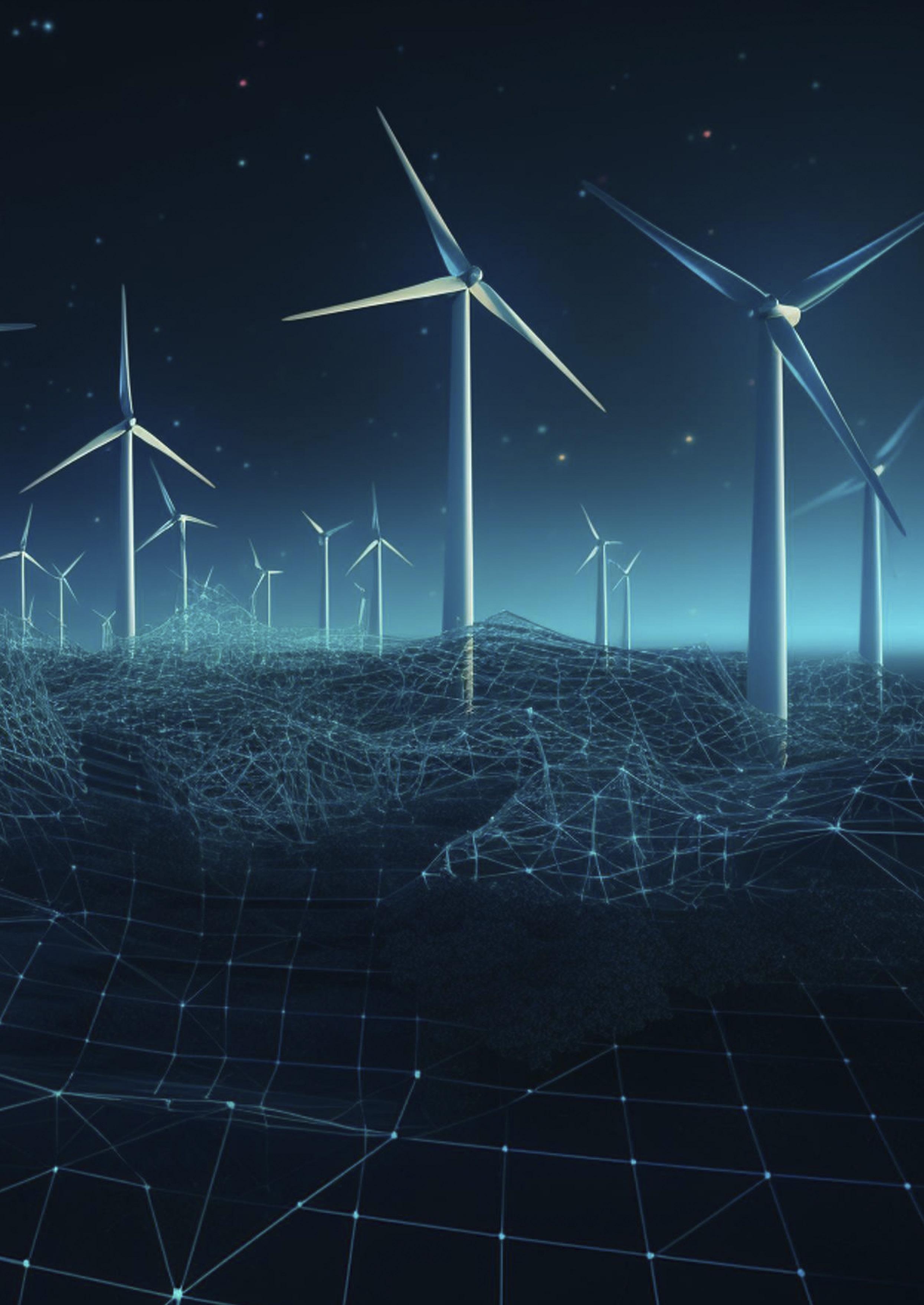
In other words, digitisation is the bridge that allows those ‘bigger fish to fry’ to be addressed effectively.
This article will take a deep dive into why automation and data democratisation are pivotal for the wind turbine industry and explore how these elements are already shaping its landscape. The article will also shed light on how the company’s offerings can leverage these elements to help wind turbine owners optimise longevity and operational efficiency, enhancing performance and productivity.
When discussing automation in wind turbine inspection, it can be categorised into two essential categories. The first is the swift and comprehensive collection of data across the entire wind farm, and the second involves the seamless processing of the collected data, providing valuable operational insights.
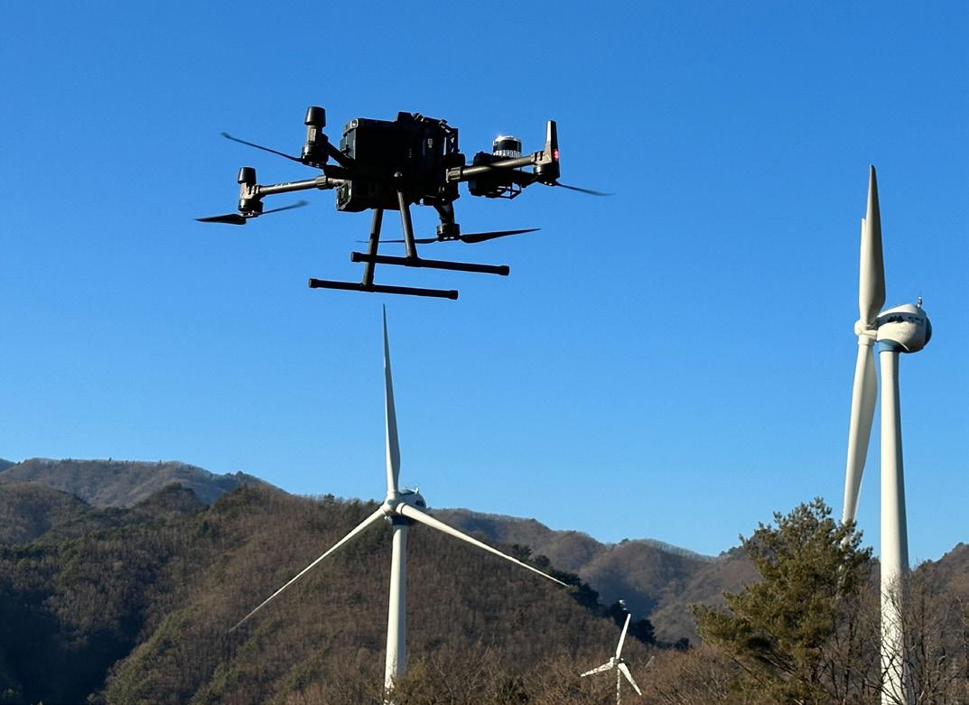
Automation revolutionises the ability to capture turbine data and allows stakeholders to know their assets better. It ensures that turbine surveys gather an optimal amount of highly accurate data systematically, easily, and at scale. Just imagine the difference between manually inspecting specific turbine features by climbing the turbine or manually flying a drone vs having a drone autonomously collect all available data within 30 mins. By eliminating the complexity of manual inspection methods, automation guarantees an easy, fast, and scalable way to gather consistent data from the field and turn it into insights, while being
independent of an external expert operator’s skill – automation sets a new standard for seamless data collection.
Automation not only saves time, but also accelerates processes. The wind turbine industry can now benefit from the same scalability seen in other sectors undergoing digital transformation. Autonomously capturing turbine data with drones allows field operations staff on the ground to launch and monitor surveys easily, whenever they need to, and as frequently as they need to, reducing downtime and enabling turbine inspections on a much larger scale.
Capturing data is one thing; managing and processing vast amounts of data from multiple wind turbine farms across numerous sites is another challenge altogether. Automated systems dedicated to turbine data inspection efficiently handle such large datasets. They ensure data is retrievable, analysable, and comparable over time.
Automation dramatically reduces the costs associated with manual inspection processes, which are time-consuming and often require highly skilled staff. By using low-cost, off-the-shelf drones connected to a powerful software platform, inspection times per turbine are dramatically reduced, eliminating the need for costly professional drone pilots and image inspectors. The cost reduction brought about by automation is simply too significant to ignore. In addition, a powerful data analytics platform helps focus attention where it matters the most, saving wasteful time and cost.
Democratising data in wind turbine inspection lies in the ability for anyone to be able to conduct a survey at any time, get fast, accurate, and automated answers independent of external experts, and for anyone to be able to understand the insights derived from the collected data and drive optimisation. This is where this industry’s digital revolution really comes into play.
Democratising data means creating a continuous flow of data from the field to the company, making it accessible to anyone in the organisation, and thus allowing team members from various departments to access, review, or inspect every aspect of the turbine using a web browser at any time. It fosters a comprehensive understanding of the turbine’s physical condition, which leads to the next point.
Data democratisation also involves turning numerous small pieces of data into a coherent operational story anyone can understand, with actionable insights that are comprehensible to multiple stakeholders across the organisation. It allows for the creation of a digital representation of the turbine that not only enables a comprehensive inspection analysis but also allows to easily derive tangible conclusions to optimise turbine performance.
Figure 1 . The company’s portfolio page.The article will now take a look into how the company’s technology offers advanced levels of automation and data democratisation.
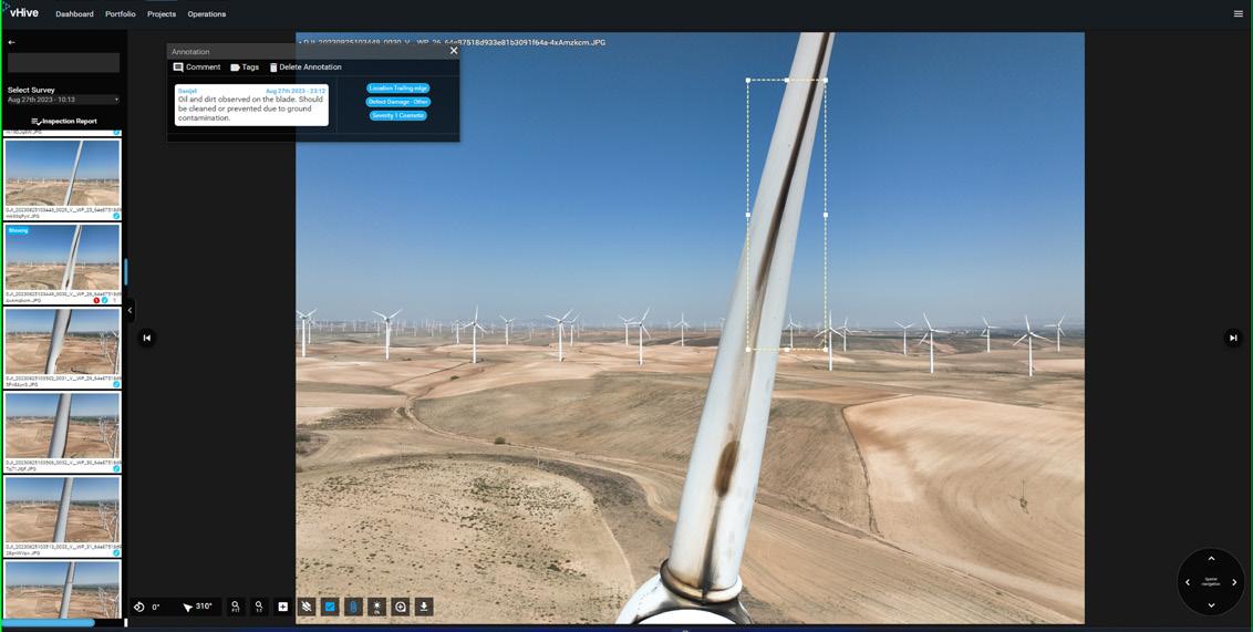
vHive’s solution deviates from conventional methods of low-quality ground photos, manual piloting, or the risky option of climbing. It allows for a single turbine pause (instead of the typical three), it automatically identifies the blade positions and orientation, and captures a comprehensive dataset with precision. With the ability to fully control the drone’s flight, it enables swift surveys that minimise downtime. The company has developed the ability to harness a hive of multiple drones to collect data from multiple sites simultaneously, optimising operational efficiency.
The company’s highly visual data platform allows a high-resolution digital representation of wind turbines. Artificial intelligence (AI) and computer vision algorithms help identify faults and filter them by severity levels, type and location, offering instant visibility into blade conditions. The company’s web-based platform allows users to access their global wind turbine portfolio – digitally, from anywhere, at any time, directing their focus toward critical areas within their portfolio to gain actionable insights on emerging issues by order of relevancy and
The company’s Digital Twin Platform exchanges data with partner application programming interfaces, serving as the communication bridge between vHive and other IT systems in the infrastructure. This facilitates effortless data sharing and potential collaboration with other Internet of Things systems to complete the SCADA picture.
By ensuring a continuous data flow from the capturing stage all the way to creating digital twins with advanced AI analytics and producing detailed reports on the condition of the blades, vHive covers the entire process of turbine inspection in a single platform.
As wind turbine manufacturers continue their exploration of new manufacturing methods and materials, and OEM warranty claims surge at an alarming rate, the need for expedited, precision-driven, and automated inspections conducted at higher frequencies becomes more pressing than ever before. Considering the substantial investments in wind turbine farms, it becomes paramount for stakeholders involved to maintain their optimal health, ensuring peak productivity and performance while averting downtime and failures to maximise return on investment.
Wind turbine digitisation, powered by automation and data democratisation, is key to ensuring turbine farms’ health, longevity, and high profitability. Embracing it is taking a proactive approach to tackle today’s challenges and seize opportunities for a more
Nora Han, Head of Hydrogen Product Group, ABB System Drives, examines how the right choice of power supplies can enable more efficient and affordable green hydrogen production.
Estimates from the Hydrogen Council and McKinsey suggest that clean hydrogen has the potential to reduce global carbon dioxide (CO2) emissions by 80 gt by 2050. This means that renewable and low-carbon hydrogen could contribute up to 20% of the annual emissions reductions required to reach net-zero by 2050.
However, today’s hydrogen production is not compatible with a sustainable future. This is because 99.6% of hydrogen comes from processes that involve petroleum and natural gas. The waste carbon released into the atmosphere negates hydrogen’s carbon-neutral benefits.
Fortunately, this is not the only option: hydrogen can also be produced using electrolysis. When the electricity comes from a renewable source, such as wind or solar, the process does not emit any carbon and the resulting product is green hydrogen.
Hydrogen must be generated sustainably if we are to successfully decarbonise, meet our climate goals, and improve the resilience of our energy systems. To achieve these essential goals and make green hydrogen production into a scalable and economically viable approach, operators depend on highly-efficient and reliable power supplies.

Assuming water is relatively affordable, electricity is the most significant operating expense, accounting for approximately
80% of OPEX. This means that energy efficiency is key to driving down the levelized costs of hydrogen production from electrolysis. By optimising energy usage, green hydrogen production becomes more affordable and accessible.
There are many components required to produce green hydrogen, and each introduce potential inefficiencies. Components include electrolysers, power supply systems, protection equipment, cooling systems, enclosures, auxiliary equipment, and more – and all of it must work in harmony to achieve optimal efficiency.
Among these components, an efficient power supply – which consists of transformers, rectifiers, compensation equipment, and more – makes up around 20 – 30% of the price of an electrolysis system. Therefore, it offers the greatest potential for reducing hydrogen costs. According to IRENA, as the scale of hydrogen production increases, standard utility scale power supply systems become available from leading manufacturers of electrical equipment. Using these can significantly reduce cost and increase the performance of the power supply for electrolysers.
Power supply systems convert alternating current (AC) from the grid to direct current (DC) at the
appropriate voltage for the electrolyser. The choice of power supply can affect overall system efficiency up to 20% in some cases.
There are several types of electrolyser technology. The three most common are alkaline/proton exchange membranes (PEM), and solid oxide electrolyser cell (SOEC) systems. Although specific requirements vary based on the technology, electrolysers today are classified as low-voltage (LV) equipment.
To power an electrolyser, electricity must be changed from medium-voltage (MV) AC to LV DC. There are several ways to achieve this. The first uses transformers to step down the voltage, and then rectifiers convert the LV AC directly to DC at the appropriate voltage for the electrolyser.
Other solutions combine a rectifier with a DC-DC converter to achieve greater overall performance. These solutions first convert the AC power to DC and then perform a DC-DC voltage conversion to achieve the appropriate voltage. Alternatively, if the electrolyser is connected to a DC distribution system, it only requires DC-DC converters to match the voltage level. Operators should consider modular options, as these make it easier to scale up production in the future.
The industry is still in need of standardisation. Analysis by IRENA finds that optimisation can be achieved by careful system
integration of different components in the electrolyser facility, optimising the entire facility rather than individual components. Therefore, to identify the appropriate solution to minimise costs and maximise reliability and performance, operators must work with expert partners to create an ideal solution.
Green hydrogen, by definition, uses electricity from a renewable source. These sources often behave dynamically and can be intermittent, which poses challenges for system integration. To overcome these, power supplies must react rapidly to input and output signals, even under challenging conditions. Specialised power electronics controls react quickly to unpredictable behaviour under even the harshest conditions, enabling plants to maximise uptime.
Reactive power is a critical consideration in the electrical network supplying electrolysis systems as it has a significant impact on energy efficiency. It represents the power that flows back toward the grid without doing any work while using up system capacity. The efficiency of the network is measured by the power factor (PF), which is the ratio of the true power (supplied by the network) to the actual power (used to do the work).
An ideal PF is unity. This is rarely achieved, with 0.95 generally considered an acceptable figure. It is often well below this, meaning that facilities are paying for power they do not use. In some cases, grid operators impose significant penalties for excess reactive power. The solution can be to install power factor correction equipment such as capacitors, STATCOMs and synchronous condensers.
Another power quality risk is harmonic distortion, which can significantly decrease the system’s energy efficiency. As a rectifier draws power, it introduces noise to the network. When this noise occurs at a multiple of the fundamental frequency, it is called a harmonic wave.
Harmonic content can cause several issues for a hydrogen production facility. For example, harmonic currents in the network can result in voltage distortion. In turn, this can cause equipment to malfunction, efficiency to decrease, and energy consumption to increase. Harmonics also increase losses – total harmonic distortion in the current (THDi) of 40%, which is not uncommon in industrial facilities, increases energy losses by 16%.
Other common issues associated with harmonics include overheating of electrical equipment, such as transformers, motors, and cables. Overheating can result in premature failure and increased maintenance costs. When harmonic frequencies interact with the natural frequencies of components on the network, they produce resonance. This results in excessive voltage or current levels, which can damage equipment and cause power outages.
Similarly, harmonics can cause power quality issues such as voltage fluctuations and flicker. These can disturb sensitive equipment such as computers and communication systems. Harmonics also increase the share of reactive power.
There are several technologies that can address harmonics. Multi-pulse technology cancels out harmonics using phase shift
 Figure 1 . A hybrid solution combines both Thyristor and IGBT building blocks.
and lowers THDi to around 6 – 10%. Passive filters use a choke and capacitors to filter out individual harmonics and this cuts THDi to below 10%. The third approach involves active filtering –generating the same harmonic in the opposite phase to cancel it out – which achieves THDi of below five percent.
In turn, these solutions depend on diodes, thyristors, and insulated-gate bipolar transistors (IGBTs). Diodes let current move in one direction, but they are not controllable. Thyristors do nothing until they are ‘turned on’ by a gate signal, at which point they act like diodes.
A 6-pulse thyristor rectifier, for example, is simple and relatively affordable, but risks introducing harmonic content on the grid side. A 12-pulse model will more effectively counter harmonics but requires a more complex transformer. Multi-pulse technology requires multi-winding transformers, which raises the cost. Two and three-level active rectifiers greatly reduce grid-side harmonic content but are less energy efficient and experience higher current stress.
Two-stage power supplies reduce harmonics more effectively. A 12-pulse diode rectifier followed by an interleaved DC/DC converter, for example, reduces harmonic content more than a 12-pulse thyristor rectifier. However, it is slightly less efficient.
Balancing the features of these solutions is essential to making electrolysis cost effective. Generally, more expensive options, such as 12-pulse thyristor systems, achieve lower THDi. However, combining these technologies – and a built-in control capability to balance them – can deliver effective mitigation at moderate cost. This approach is an effective tradeoff between CAPEX and OPEX.
IGBTs, like thyristors, are controllable using a fast-switching gate signal. They are different in that they are bidirectional and actively counteract harmonics, eliminating reactive power. This means that, while IGBTs are relatively expensive when compared to other solutions, they offer a simpler installation that can address power quality issues without the complexity of additional equipment.
A hybrid solution, built on both IGBT and thyristor technology (Figure 1), delivers the best features of both, making it ideal for electrolysis applications. For example, 5 MW IGBT-based rectifier could provide an electrolyser with 5 MW of active power while simultaneously compensating for up to 2 MVA of reactive power. By combining both technologies, it reduces or eliminates the need to use compensation equipment, such as additional capacitor banks, active filters, or increased cabling cross-sections, which results in lower total CAPEX and installation footprint.
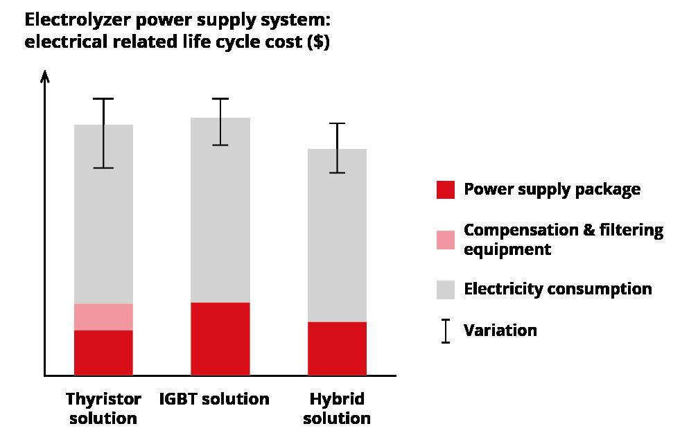
The life cycle cost benefits become even clearer as a system scales up. Based on an internal study, a hybrid system offers the cheapest way to power a 200 MW system that achieves a power factor greater than 0.97, harmonic content and DC ripple of under five percent, and an overall efficiency of over 98%. The hybrid system is cheaper in terms of CAPEX than comparable thyristor and IGBT solutions and uses less power throughout its lifetime, meaning that it requires lower OPEX (Figure 2).
However, total cost varies depending on the grid requirements and facility specification. To identify the ideal solution for a site, operators can bring in experts to conduct a simulation.
Electrical equipment for electrolysis must also be designed for safety and reliability, as hydrogen is a hazardous gas. It has low ignition energy, burns with an invisible flame, and is highly flammable over a wide concentration range. It can also be absorbed into metals.
Harmonics can cause components to heat up, potentially creating a hazard. When a facility successfully minimises harmonics, equipment will operate within its specified temperatures, which is essential for potentially explosive environments.
Systems designed for reliability and ease of maintenance by organizations with expertise in hazardous environments, such as ABB, also offer safety advantages. Some solutions increase reliability by minimising the number of components, including cooling hoses and bolted connections, and selecting materials with a high comparative tracking index (CTI) and appropriate ingress protection (IP) rating. A dedicated engineering partner can also work with a facility to perform safety assessments.
Electrolysis is the key to sustainable hydrogen production, but it depends on a consistent power supply that combines standard equipment to minimise the network’s harmonic content and footprint while maximising efficiency and power factor. Fortunately, hybrid solutions with real-time control software represent an affordable, effective way to mitigate harmonics, maximise energy efficiency, and improve grid integration.
In addition to greater efficiency, there are economic factors that will enable green hydrogen to become more competitive. The IRENA report estimates that economies of scale, for example, will drive down the cost of electrolyser hardware by as much as 80%. Designs grounded in greater familiarity with industrial electrolysis, meanwhile, are expected to extend electrolyser lifetimes from 10 – 20 years.
The result of all these factors will be a lower levelized cost of green hydrogen, bringing a sustainable, decarbonised future one step closer.
roducing hydrogen offshore has been at the forefront of Lhyfe’s ambitions since it was formed in 2017. In 2021, the company started to produce its green hydrogen onshore, proving that it was possible to produce green and renewable hydrogen from seawater at sites directly connected to renewable energy sources. Offshore wind farms are now developing fast, and producing very large quantities of hydrogen at sea remains at the forefront of the company’s ambitions.

In September 2022, Lhyfe inaugurated its offshore renewable green hydrogen production demonstrator. A world first for the industry, proving that it is feasible to produce offshore green hydrogen.
The Sealhyfe production unit was installed on the WAVEGEM wave energy platform engineered by
Geps Techno. The electrolyser for the system was supplied and optimised for these exceptional operating conditions by Plug Power. Sealhyfe has the capacity to produce up to 400 kg of renewable green hydrogen a day, equivalent to 1 MW of power.
During a first seven-month experimentation phase, Sealhyfe produced its first tonnes of renewable green hydrogen while moored at quay. While the system operated automatically, in the most extreme of conditions – on a floating platform – an extensive range of tests were run. Endurance, full-remote capabilities, maintenance-free operations, and peak production with high pan and tilt of
the platform were trialled, ensuring that the gas produced met the highest quality, complying with automotive purity standards.
In June 2023, Sealhyfe was towed to Centrale Nantes’ SEM-REV offshore testing hub operated by the OPEN-C Foundation, about 20 km off the coast of Le Croisic. Here, the floating device is supplied with electricity from the pioneering floating wind turbine – FLOATGEN (engineered and operated by BW Ideol) – installed within the offshore test site in 2018 and still unique in France today.
The results collected during the quay trial period will be used as a benchmark to compare with the behaviour of the
system in real conditions at sea, thanks to the data which is currently being gathered at the SEM-REV test site. These tests are expected to provide a high level of confidence in Sealhyfe so that it can offer a solution to several major and unprecedented challenges, including:
> Performing all stages of hydrogen production at sea, i.e. converting the electrical voltage from the floating wind turbine, pumping, desalinating and purifying the seawater, and breaking the water molecules via electrolysis to obtain renewable green hydrogen.
> Managing the effects of the platform’s motion on the system: list, accelerations, swinging movements, etc.
> Enduring environmental stress: Sealhyfe will have to survive the premature ageing of its parts (corrosion, impacts, temperature variations, etc.).
> Operating in an isolated environment: the platform must operate automatically, without the physical intervention of an operator, except for scheduled maintenance periods which have been optimally integrated from the design phase.
The logical next move for Sealhyfe is to ramp up to a 10 MW project and eventually cater for projects of several hundred megawatts. In this perspective, Lhyfe has proposed a renewable hydrogen production solution as part of a European call for projects, the HOPE project. This initiative – in partnership with Alfa Laval (Denmark), CEA (France), DWR (Germany), Element Energy (France), EDP (Portugal), Frames (Netherlands), POM (Belgium), and Strohm (Netherlands), and financed by the European programme Clean Hydrogen Partnership – will create synergies and capitalise on the know-how of each of the companies involved, in order to advance the offshore hydrogen production industry, in which everything remains to be done.
This first commercial demonstrator will integrate all the offshore-specific components. In addition to increasing Sealhyfe’s production capacity tenfold, an export pipeline will be installed between the platform, located about 1 km off the coast, and the compression and distribution base located in the port area of Ostend in Belgium, in order to supply local customers with green hydrogen. The structure hosting the production unit will be a self-elevating (jack-up) barge acquired second hand, demonstrating that it is possible to shift infrastructures previously used for oil and gas and give them a second life for the production of greener energy, while helping to reduce costs and lead time on this project. As the project will last at least five years, this unit will have to meet the criteria of durability and maintainability in an offshore environment in order to guarantee optimal production over the entire project lifespan.
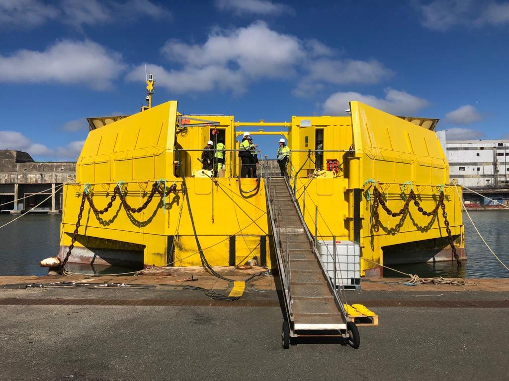
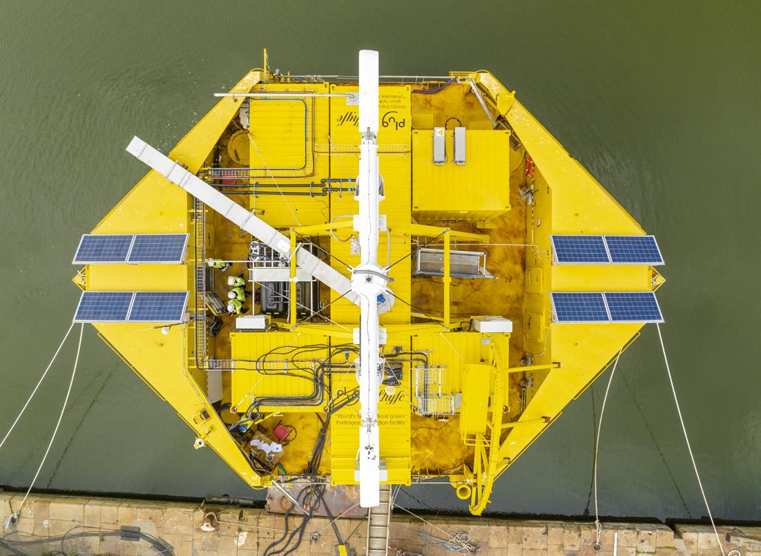
The HOPE project was officially launched last June with a schedule which foresees an initial study phase of about one-and-a-half years, followed by construction/integration in a shipyard over approximately 15 months. The jack-up barge will thus be installed off the coast of Ostend during the 1H26 and within a few months, once the final works and start-up operations are complete, it will be able to produce and market green hydrogen. This second ‘operational’ phase of the project will allow Lhyfe to optimise production, maintenance planning, and day-to-day operations.
Generally speaking, in order to make offshore projects economically viable, it is necessary to play on economies of scale, operating units with capacity in the region of 300 – 500 MW or even in the GW-class.
For Lhyfe, the HOPE project is also an opportunity to validate and converge the conceptual solutions for offshore projects of this scale, which represent the future of hydrogen production, as evidenced by the announcements of various governments (e.g. the future call for projects for a 50/100 MW demonstrator and then for a 500 MW production unit in the Netherlands, and the call for tenders for the concession of a 300 MW production unit coupled with an offshore wind farm in Germany, etc.).
Figure 1 Lhyfe’s world-first offshore hydrogen production pilot at quay.There is also strong potential in Scotland or Ireland, where the prospects and development programme for offshore wind far exceed the capacity of the onshore grid. The trend would therefore seem to be towards offshore wind projects coupled with in situ hydrogen production.

To be ready to respond to these different opportunities, Lhyfe is following its roadmap, which consists of ramping up with the Sealhyfe and HOPE projects and preparing conceptual solutions, with capacity in the region of a hundred megawatts per production unit.
To achieve this, Lhyfe is notably working in partnership with Chantiers de l’Atlantique, now a major player in the design and construction of electrical substations for offshore wind farms. The two players have taken advantage of their complementarity to design a 100 MW hydrogen production platform integrating the construction method and means of Chantiers de l’Atlantique, while adapting to Lhyfe’s production solutions, way of operating, and safety requirements.
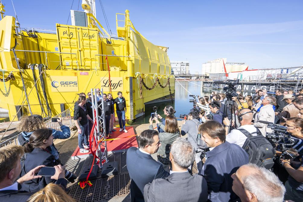
The ocean has an enormous capacity to buffer global warming, absorbing about 90 % of the warming of the earth system and about a quarter of anthropogenic CO 2 emissions. The ocean will warm, acidify, and lose oxygen in the future. This will change its physics, chemistry, and biology and will reduce its capacity to store carbon and take up oxygen.
Approximately 50% of the oxygen on earth originates from the ocean. It has a crucial role, defining marine habitat, chemistry, and ecosystems, which in turn have substantial impacts on fisheries and coastal marine economies. The rapidly-growing global population increases demand for energy, food, and wastewater treatment, all of which increase the input of nutrients such as nitrogen and phosphorous into coastal marine systems through run off and atmospheric deposition. This input will lead to a rising number of coastal (eutrophic) zones with very low oxygen concentrations (low oxic) or no oxygen at all (anoxic), partially toxic bottom conditions and potentially toxic algal blooms, which strongly affect local and regional economies and livelihoods. Low oxic to anoxic conditions can also lead to an outgassing of potent greenhouse gases, such as methane and nitrous oxide, from the aquatic environment. Scientists have observed declining dissolved oxygen levels in the global ocean and predict a further decrease of up to 7% by 2100 as a result of ocean warming and reduced deep ventilation, due to the climate crisis and an increase in the number of coastal eutrophic systems.1,2
There is thus a need for urgent emission reduction, nutrient limitations, and active stabilisation and/or restoring of ecosystems in order to limit global warming to 1.5˚C.1 Green hydrogen production is part of the road to decarbonising the energy system. During the production of 1 kg of hydrogen through the electrolysis of water, 8 kg of oxygen are produced as a byproduct.
This excess oxygen, injected into eutrophic ecosystems with low to no oxygen concentrations, could be a way to help stabilise aquatic ecosystems and increase its resilience against climate change. Such ‘reoxygenation’ measures are already used in restoring freshwater reservoirs but have not yet been tested in the marine environment. 3 For all aquatic ecosystems, the hydrographic structure of the local and regional system, the persisting currents as well as local biodiversity and biogeochemistry, are important parameters to estimate the future oxygen demand and potential benefits of the system. Lhyfe’s vision is to produce green hydrogen on a large scale offshore, and return oxygen to the ocean to support and/or restore marine ecosystem functions.
1. MASSON-DELMOTTE, V., P., ZHAI, A., PIRANI, S.L., et al., ‘Climate Change 2021: The Physical Science Basis. Contribution of Working Group I to the Sixth Assessment Report of the Intergovernmental Panel on Climate Change’, IPCC, (2021), pp.2391, doi:10.1017/9781009157896.
2. BREITBURG, D., LEVIN, L. A., OSCHLIES, A., et al., ‘Declining oxygen in the global ocean and coastal waters’, Science, (2018), Vol. 359, No. 6371.
3. BEUTEL, M. W. and HORNE, A. J., ‘A review of the effects of hypolimnetic oxygenation on lake and reservoir water quality’, Lake and Reservoir Management, (1999), Vol. 15, No. 4, pp.285 – 297.
4. CANFIELD, D. E., ‘The
history of atmospheric oxygen: homage to Robert M.
Annual Review of Earth and Planetary Science, (2005), Vol.33:1-36.
early Garrels’, Figure 3 . One the right: Sealhyfe offshore hydrogen production pilot on WAVEGEM platform (GEPS Techno). On the left: FLOATGEN floating turbine (BW Ideol), on the SEM-REV offshore testing site (Central Nantes/OPEN-C) Lhyfe©Patrick Clerens, ESWET, Belgium, considers a sustainable approach to waste management and energy generation.

In March 2023, the Brussels-based trade association representing the European Suppliers of Waste-to-Energy Technology (ESWET), published a comprehensive report titled Recovering the Non-Recyclable: From Waste-to-Energy to Integrated Resource-Recovery facility 1 The primary objective of this report was to highlight how integrating innovative technologies into existing waste-to-energy (WtE) plants can lead to additional environmental and climate benefits. With the support and contributions of ESWET members, the report presents a new concept for the future of non-recyclable waste management.
The Integrated Resource-Recovery Facility (IRF) represents a paradigm shift in waste thermal treatment and serves as a holistic project already introduced by the association in its 2050 Vision.2 The IRF goes beyond merely treating non-recyclable waste; it also focuses on generating partly renewable energy – including heat, electricity, and fuels, safeguarding energy security in Europe, and playing a pivotal role in climate change mitigation efforts through landfill diversion, resource recovery, and the integration of carbon capture, utilisation, and storage (CCUS) technologies.

WtE plants play a vital role in the circular economy and the renewable energy sector. These plants recover energy in the form of steam, electricity, or hot water, acting as a bridge between waste management and renewable energy generation. As a significant portion of the waste treated in WtE plants is of biogenic nature, it is recognised as a renewable source of energy. Studies estimate that more than 50% of the energy output from WtE plants is renewable,3 making a substantial contribution to substituting fossil fuels in various sectors, including electricity, district heating, industrial steam supply, and transportation.
According to calculations made by CEWEP – the Confederation of European WtE Plants – in 2019, WtE plants in Europe produced 43 billion KWh of electricity, providing power to approximately 20 million citizens.4 Moreover, the primary energy produced by WtE in the same year was equivalent to 13.8 billion m³ of natural gas.5 This corresponds approximately to 9% of the natural gas imports to the EU from Russia (155 billion m³ in 2021).6
Energy generated from non-recyclable waste offers several advantages, including energy security and baseload power.
Unlike other renewable energy sources like wind or solar, WtE plants provide a consistent and reliable energy supply that is not subject to price fluctuations of fuels, such as gas, and is less vulnerable to relative supply problems. This stability makes waste-derived energy financially reliable and reduces Europe’s dependence on fossil fuel imports. The integration of WtE with renewable and low-carbon technologies further enhances energy security and contributes to the energy transition.
WtE plants often employ cogeneration, also known as combined heat and power (CHP), to maximise energy efficiency. By utilising the waste heat generated during the incineration process, WtE plants can achieve high energy efficiencies, surpassing conventional power generation technologies. The recovered heat can be utilised in district heating networks, heating and cooling buildings, offices, hospitals, and industrial processes, further reducing the reliance on fossil fuels and increasing energy sustainability.
According to CEWEP, 60% of WtE plants function as combined heat and power plants, contributing approximately 10% of the energy supplied to European district heating and cooling networks, and supplying 99 billion KWh of heat to almost 17 million Europeans annually.4
The combination of district heating and cooling networks with WtE is a perfect match, allowing for the utilisation of waste heat throughout the year in both cold and warm climates. This approach is not only energy efficient but also enhances the EU’s energy security. Additionally, this combination leads to significant carbon dioxide (CO₂) emissions savings. The Torino district heating system in Italy serves as a prime example, consisting of 6800 km of dual piping and powered by three modern and efficient combined heat and power plants. This system efficiently covers the heating needs of over 640 000 residents, with Torino’s WtE plant feeding the grid with 136 935 MWh of thermal energy in 2022,7 by processing 565 000 tpy of non-recyclable waste. As a result, the city of Torino achieves a reduction of 500 000 t of CO₂ emissions through the utilisation of the district heating system.8
WtE technologies have proven to be versatile and advantageous in the European energy mix. In addition to producing heat and electricity, WtE processes can also generate waste-to-hydrogen (WtH) and waste-to-fuel (WtF). These technologies contribute
to climate objectives by providing renewable and low-carbon hydrogen and fuels, which are crucial for energy-intensive industries and transportation.
WtH can be achieved through the combination of combustion-based WtE plants with electrolysis or through certain gasification processes. WtF involves producing synthetic fuels, such as methane, methanol, and ethanol, through the hydrogenation of carbon dioxide. These fuels contribute to carbon capture and utilisation (CCU) efforts.
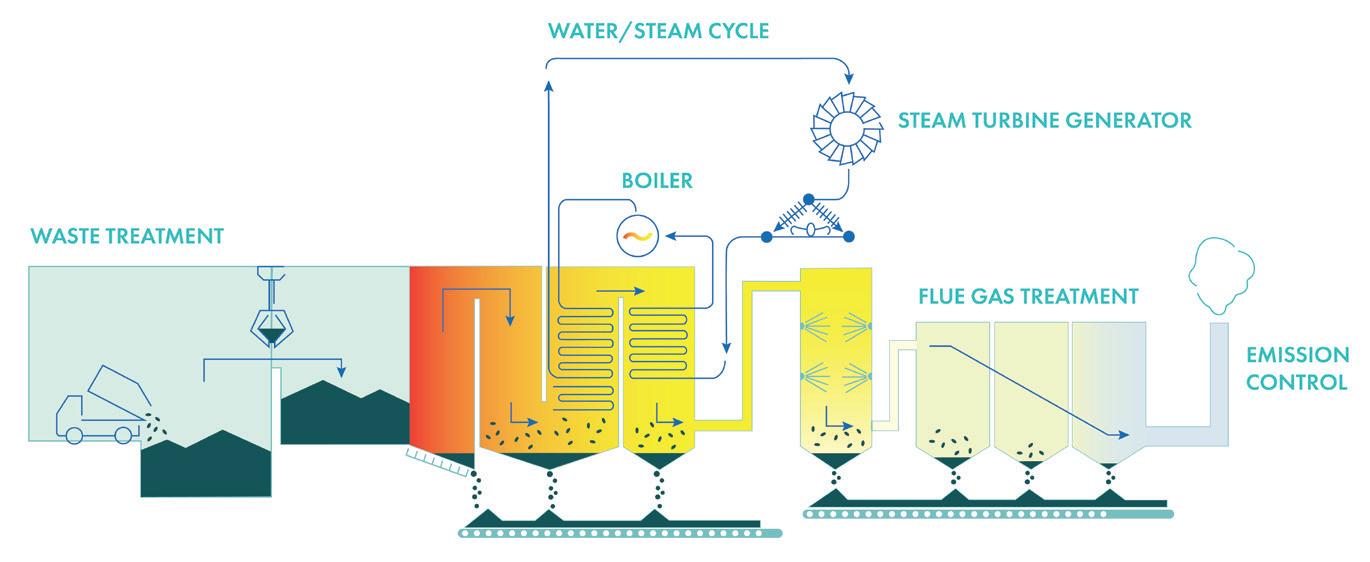
Renewable and low-carbon hydrogen and fuels derived from waste play a significant role in decarbonising Europe and reducing land competition between energy and food crops. Converting municipal solid waste to biofuels can result in substantial greenhouse gas (GHG) savings.9 WtH and WtF technologies have been successfully demonstrated in various projects, such as the WtE plant in Wuppertal, Germany, which generates hydrogen to power public transport buses, reducing CO2 emissions.10
Methane and methanol produced from WtH can be used as alternative fuels in transportation, contributing to decarbonisation efforts. For instance, the waste-to-methane project in Dietikon, Switzerland, produces synthetic gas for heating, cooking, and refuelling vehicles with compressed natural gas (CNG) engines, significantly reducing CO2 emissions.11
WtH has applications beyond transportation, including industries like steel, cement, and chemicals, where energy-dense fuels are needed for high-temperature heat. Hydrogen and methane can also be blended with natural gas, reducing the overall environmental footprint. Additionally, hydrogen coupled with nitrogen can produce ammonia for agricultural fertilizers, offering a carbon-free alternative.
Apart from the environmental benefits, WtH and WtF technologies offer other advantages. WtH can help manage fluctuating energy grid loads by using excess electricity for hydrogen production, contributing to a stronger and more stable grid. WtH also supports the integration of variable renewable energy sources by providing controllable baseload power. Moreover, WtH promotes a circular economy by powering waste collection trucks and municipal buses, decarbonising mobile equipment that may not be suitable for battery electrification.
In terms of market potential, WtF has an advantage over other renewable sources as it is a predictable energy source. Hydrogen produced from intermittent renewables requires larger plant capacities to compensate for their lower capacity utilisation factors. WtH can be economically competitive and locally produced, as WtE plants are often situated close to end-customers. The increasing demand for biofuels and low-carbon fuels creates a favourable market case for WtH and WtF projects.
However, the cost of WtH is still relatively high, requiring significant investments in electrolysis plants, storage, and distribution equipment. Standardisation and access to finance are crucial for cost competitiveness and scalability. Methanation, although requiring an additional conversion step, offers benefits such as higher energy density, better integration into existing gas infrastructure,
and lower safety risks. Recovering waste heat from the conversion processes can increase efficiency or be used for district heating or carbon capture.
While there are higher initial costs associated with installing and operating WtH and WtF facilities, the learning curve is expected to lead to more competitive prices over time. Therefore, a supportive legal framework and financial incentives are crucial to facilitate the development of WtH and WtF projects.
One of the potential advancements in the IRF is the deployment of carbon capture technologies. By capturing and storing CO2 emissions, the IRF has the potential to become carbon negative. The integration of CCUS technologies not only reduces the environmental impact, but also contributes to the circular economy by maximising the recovery and utilisation of incineration residues.
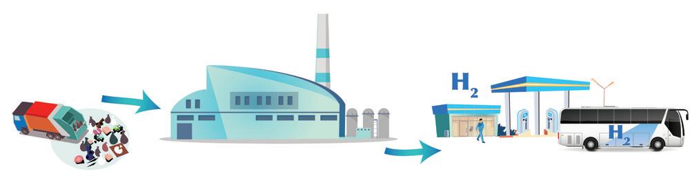
As stated by the IPCC, CO2 removal technologies are necessary to decrease GHG emissions and limit warming to 1.5˚C.12 What is more, the Sixth Assessment IPCC report recognises that the implementation of CCUS in WtE plants can enable waste to be a net zero or even net negative emissions energy source, with the potential to capture approximately 60 – 70 million tpy of CO2 in Europe.13
CCUS has gained momentum due to the EU Green Deal’s objective of achieving carbon neutrality by 2050. CCUS integration in WtE plants, specifically through bioenergy with carbon capture and storage (BECCS), offers a carbon-negative solution14 and is cost-competitive.15 Several advanced CCUS projects are underway in Europe,16 such as the Klemetsrud,17 and Amager Bakke18 plants.
The process of capturing CO2 emissions involves amine-based or enzyme-based capture technologies, with the former being more commonly deployed. The energy consumption during the capture process varies depending on plant-specific factors, but measures like heat recovery through heat pumps or post-capture flue gas condensation can offset electricity output reductions.
Transporting captured CO2 can be done through pipelines, ships, trucks, or rail freight. Pipeline transport is currently the most cost-effective option. CO2 can be permanently stored in geological formations like saline aquifers, with significant storage potential available in Europe.
Carbon utilisation of captured CO2 includes sending it to greenhouses to promote plant growth, mineralisation for building aggregates, and various other applications such as fertilizer production, carbonated soft drinks, and the production of synthetic fuels when combined with hydrogen, as explained previously.
Two successful cases of utilisation in greenhouses come from the Netherlands. The AVR Duiven plant can capture up to 100 000 tpy of CO2 and the Twence plant in Hengelo is developing a larger scale unit to also reach this capture capacity.19
Ongoing developments in solvent innovation, process integration, and intensification are expected to reduce the cost of CO2 capture over time. CAPEX and operation and maintenance costs depend on plant size, modularisation, prefabrication, and the chosen solvent. For a WtE plant processing 240 000 tpy of waste, CAPEX was estimated in 2020 to range from €50 – €65 million, and operation and maintenance costs to range from €1 – €2 million/y, depending on the use of a heat pump for energy recovery.20
Overall, CCUS technologies provide a viable solution for reducing GHG emissions from WtE plants. Continued advancements in CCUS will further improve its cost-effectiveness and environmental impact, supporting the transition to a more sustainable and decarbonised future.
The Integrated Resource-Recovery Facility represents a promising approach to waste management and energy generation, integrating innovative technologies and sustainability principles into WtE plants. By maximising resource recovery, incorporating renewable and low-carbon energy production, and integrating carbon capture technologies, the IRF offers a more comprehensive and environmentally friendly solution to non-recyclable waste management, generating value for communities, cities, and regions.
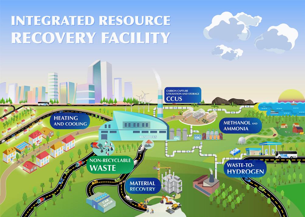
For sure, the successful implementation of WtE and IRF projects relies on effective public perception and community engagement. Transparency, open communication, and stakeholder involvement are crucial to address concerns and misconceptions regarding WtE technologies. Providing accurate information about the environmental benefits, energy generation potential, and resource recovery capabilities of WtE and IRF plants can help build trust and support among local communities.
With continued research, development, and collaboration between the various relevant stakeholders, WtE technologies, including the IRF concept, can contribute significantly to a circular economy, energy security, and emissions reduction, paving the way for a more sustainable future.
A comprehensive list of this article’s references can be found on the Energy Global website at: www.energyglobal.com/special-reports.
Figure 3 . The Integrated Resource-Recovery Facility concept.ACWA Power, has announced the financial close for the 200 MW Kom Ombo project, a utility-scale solar power plant in Egypt.
With an overall investment cost of US$182 million, the Kom Ombo plant is expected to be commercially operational in January 2024.
Financing institutions for this project include the European Bank for Reconstruction and Development (EBRD), OPEC Fund for International Development (the OPEC Fund), African Development Bank (AfDB), AfDB’s Sustainable Energy Fund for Africa (SEFA), Green Climate Fund (GCF), Arab Petroleum Investments Corporation (APICORP), and Arab Bank.
A financial package of US$123 million for the project was previously announced in April 2023. The package comprised of loans of up to US$35.6 million from the EBRD, US$14.4 million from the OPEC Fund, US$14.4 million from the AfDB, US$34.1 million from the GCF, US$14.4 million from Arab Bank and US$10 million from the SEFA under the COVID-19 IPP relief programme. The project already has equity bridge loans of US$14 million from the EBRD and US$45 million from APICORP.
Once fully functional, the new utility scale plant will serve 130 000 households, contributing to the Egyptian government’s target to generate 42% of the country’s electricity from renewable energy sources by 2035 while delivering one of the lowest generation tariffs in Africa.
Electrify America has announced that the beginning of commercial operation for the new 75 MW Electrify America Solar GlowTM 1 photovoltaic (PV) project in San Bernardino County. Electrify America Solar Glow 1 is the result of a 15 year virtual power purchase agreement (VPPA) with developer Terra-Gen.

Electrify America is the largest open network of DC fast chargers for electric vehicles in the US to enter into a VPPA for new renewable energy generation. This new construction contributes to ‘additionality,’ by producing new renewable energy that may not otherwise be available.
This investment is expected to generate 75 MW at peak solar capacity, which is comparable to the power drawn by 500 electric vehicles charging at once at an average speed of 150 KW. The total annual production is projected at 225 GWh.
In 2022, Electrify America powered more than 5 million customer charging sessions or 3.5 times the sessions in 2021. These sessions delivered roughly 173 GWh of electricity, enabling an estimated 493 million miles of electric driving and avoided consumption of roughly 21 million gal. of gasoline.
The Electrify America Solar Glow 1 project is located in San Bernardino County, CA. It has over 200 000 solar panels and encompasses an area over one square mile.
Keppel MET Renewables (KMR), an equal joint venture between Swiss-based MET Group and Singapore-based Keppel, completed the purchase of a 100% stake in a photovoltaic (PV) project in southern Italy. With an installed capacity of 38 MWp and total energy production of approximately 63 GWh per year, once constructed, the solar plant will generate power to supply the equivalent of more than 20 000 Italian households.
The project is in an early stage of development, expected to reach ready-to-build status during 2025 and start
KMR is an established player in the Italian renewable energy market with an existing portfolio of more than 200 MWp of early to mid-stage solar projects across southern Italy that are expected to achieve commercial operations within the next few years.
KMR is developing and constructing a geographically and technologically diversified portfolio of operating and ready-to-build PV and onshore wind renewable energy assets, playing an active role in the European energy transition.

Following a 14-month independent evaluation, the Hydropower Sustainability Council has awarded Hydro-Québec’s Eastmain-1 development with the highest-level certification under the Hydropower Sustainability Standard, which impartially assesses and rates hydroelectric projects for their sustainability performance.
Hydro-Québec applied for certification of its Eastmain-1 development in 2021. Located in the territory of the Eeyou Istchee James Bay Regional Government in northern Québec, this development includes two hydroelectric powerhouses with a total installed capacity of 1248 MW.
The Hydropower Sustainability Standard covers 12 environmental, social, and governance (ESG) topics. The assessors commented that “the assessment […] highlights the Eastmain-1 development’s effective management of environmental and social impacts, with specific areas of success identified in biodiversity and invasive species, labour and working conditions, cultural heritage, governance and procurement, and hydrological resources.”
Three independent assessors reviewed hundreds of reports and scientific journals, toured the facilities, and conducted approximately 50 interviews with local stakeholders, including members of the Wemindji and Waskaganish Cree communities who live in the vicinity of the infrastructure and participate in environmental follow up. Interviewees also included independent hydroclimatology and biodiversity researchers, local mayors, as well as Hydro-Québec staff members.
Hydro-Québec’s Eastmain-1 Development is the first North American hydropower facility to be certified under the Hydropower Sustainability Standard.
2023 Deloitte Renewable Energy Seminar
27 – 29 September 2023
Los Angeles, USA
www2.deloitte.com/us/en/events/energy-andresources/2023/deloitte-renewable-energy-seminar.html
Solar & Storage Live 2023
17 – 19 October 2023
Birmingham, UK
www.terrapinn.com/exhibition/solar-storage-live
BC Hydro has reached a major milestone on the Site C project with the completion of the earthfill dam. The earthfill dam stands about 60 m tall (the height of a 20-storey building), stretches more than 1 km across the Peace River and is about 500 m wide at its base.
The Site C project is being built and designed in accordance with international and Canadian safety practices to withstand a major (one in 10 000 year) earthquake.
The placement of material for the Site C earthfill dam began in 2021. In total, about 16 million m3 of earthfill material was placed. Most of the material for the earthfill dam was taken directly from the dam site, while other material was sourced locally offsite and transported to the dam on a 5 km-long conveyor belt.
With the earthfill dam complete, the next steps involve capping it and building roads across for crews to travel on once the project comes into operation.
Completion of the earthfill dam is one of the essential milestones required before filling the Site C reservoir. While BC Hydro is targeting to begin reservoir filling in fall 2023, there are still a number of key project areas that need to be completed. These areas include the approach channel, spillways, tailrace area, dam intake structures, and certain components of the powerhouse.
Another key component for reservoir filling is the conversion of one of the tunnels that currently divert the Peace River around the project site. This process requires the installation of constrictions (or large ring-shaped devices) inside one of the tunnels to restrict the flow of water. This work is now underway.
The project remains on-track to have all six generating units in-service by 2025. Once complete, Site C will provide the equivalent amount of energy needed to reliably power about 450 000 homes in British Columbia.
3rd Global Hydrogen Conference
02 November 2023
ONLINE
www.accelevents.com/e/3rdghc2023
Offshore Wind North East 2023
08 – 09 November 2023
Sunderland, UK
www.nof.co.uk/events/owne-2023/
The University of Melbourne Faculty of Engineering and Information Technology (FEIT) has partnered with Ørsted to bolster Australia’s shift towards renewable energy by combining extensive worldwide expertise with cutting-edge Australian research capabilities.

FEIT Dean, Professor Mark Cassidy, signed a memorandum of understanding (MoU) with Ørsted. The MoU will bring together Ørsted’s unique operational experience with the university’s deep knowledge of the local marine environment, biodiversity, and Indigenous Sea Country to help design and deliver the best offshore wind outcomes in Australia.
In addition to fostering academic and research cooperation within the offshore wind sector, the partnership will also focus on enhancing the preparedness of students and researchers for careers in the growing renewable energy sector.
The initial phase of Ørsted’s proposed project off the coast of Gippsland in Victoria will create up to 6000 jobs, with local workers and students able to tap into its technical knowledge and skills transfer programmes.

Boralex Inc. has announced the Scottish government’s approval for the proposed Shepherds’ Rig wind farm in Scotland.
An application to develop a wind farm near Carsphairn in Dumfries and Galloway has been given the green light by the Scottish Government, following a public inquiry in November 2021. The proposal, submitted to the Scottish Government under Section 36 of the Electricity Act in December 2018, consists of up to 17 turbines with an installed capacity in excess of 50 MW and is located to the east of Carsphairn within a commercial forestry plantation.

The Shepherds’ Rig project is being progressed by Boralex, a Canadian independent power provider with a large portfolio of operational wind farms, solar farms, and hydro schemes, who acquired UK-based renewables developers, Infinergy in July 2022 with an ambition to grow the portfolio of ready-to-build and operational renewable energy assets in the UK to 1 GW by 2030.
RWE, a leading offshore wind company globally, has been successful in the U.S. Department of the Interior’s (DOI) first-ever Gulf of Mexico offshore wind lease auction, securing Lease Area OCS-G 37334 with a winning bid of US$5.6 million. The DOI’s Bureau of Ocean Energy Management (BOEM) led the auction, which consisted of three lease areas with the potential to host a total installed capacity of over 3.7 GW in offshore wind.
RWE’s awarded site is 44 miles off the coast of Louisiana and has water depths of 10 – 25 m. The lease area has the potential to host up to 2 GW of new capacity, enough to power over 350 000 US homes with clean energy. The project is expected to be in operation by the mid-2030s, contingent upon permitting timelines.
Additionally, RWE has a signed memorandum of understanding with Entergy, which owns and operates one of the cleanest large scale US power generation fleets, to evaluate the delivery of clean energy from offshore wind to customers in Louisiana and Texas.
The next step for RWE is to ramp-up outreach with the local community, Tribal Nations, the commercial and recreational fishing industry, and other ocean users; engage with the domestic supply chain to localise content, create new local jobs and private investments.
> Clearstone Energy unveils first project in 2.2 GW UK BESS pipeline
> Geothermal Engineering Ltd awarded CfDs for geothermal energy
> Aker Solutions and Mocean Energy to explore low-carbon solutions
Lhyfe and VSB Energies Nouvelles have announced the signing of a long-term renewable electricity supply contract.
In 2021, VSB Energies Nouvelles commissioned the Buléon wind farm, which it now operates, in the heart of the Morbihan region of Brittany, with a total capacity of 13.2 MW. Lhyfe Bretagne, a green and renewable hydrogen production site for Brittany which Lhyfe has started building, is also located in Buléon. The facility, which will produce up to 2 tpd of hydrogen (with installed capacity of 5 MW), will be operational in late 2023.
Under this 16-year electricity supply contract, 100% of the green electricity produced by the VSB Energies Nouvelles wind farm in Buléon will be for the Lhyfe Bretagne site, which will supply the local area with green hydrogen for uses related to mobility and industrial processes.
For VSB Energies Nouvelles, this corporate power purchase agreement, which is the first in a long series to come, represents a real growth driver. It also illustrates the expertise of VSB’s teams and their ability to address the problem of intermittency in the production of electricity from renewable sources.
Following the signing of a memorandum of understanding, ACCIONA Energía will work with the Aruba-owned energy entities of Aruba to develop, construct, and operate a green hydrogen plant powered by a self-consumption renewable energy project. The electricity generated will be used to produce green hydrogen and the excess will be used internally on the island to reduce the use of imported fossil fuels. The project will utilise land currently owned by state-owned refinery, Refineria di Aruba N.V., and water will be supplied by WEB Aruba, whilst Elmar will manage energy distribution and transmission across the network.
ACCIONA Energía will support the state-owned energy entities of Aruba with the deployment of the necessary infrastructure to build a renewable hydrogen ecosystem on the island and explore supplementary uses for the green hydrogen, including export opportunities.
Aruba aims to transition away from traditional energy sources and has set an ambitious target of establishing renewable energy as the primary source by 2050.
