WORKING WITH CIRCUIT BREAKERS SAFELY

PRIMARY INJECTION TESTING ON LOW-VOLTAGE CIRCUIT BREAKERS PAGE 54
LOW-VOLTAGE AIR CIRCUIT BREAKERS — A MAINTENANCE MUST! PAGE 62


PRIMARY INJECTION TESTING ON LOW-VOLTAGE CIRCUIT BREAKERS PAGE 54
LOW-VOLTAGE AIR CIRCUIT BREAKERS — A MAINTENANCE MUST! PAGE 62

Megger is dedicated to supporting your electrical testing and maintenance needs by providing valuable tools and resources for your success
Educational Webinars: Monthly Testing Tactics (NETA accredited), Special Series, Industry Panel Discussions, and Best Practice Sessions. See our calendar at us.megger.com/webinars
FAQ Videos: Walkthroughs and answers to common testing questions. Visit youtube.com/meggerUS and search“FAQ”
Technical Library: Industry-focused articles, app notes, presentations, and newsletters. Visit the library at us.megger.com/support/technical-library
Technical Support Group: Expert engineers available to help solve testing issues and needs. Contact them at 214.330.3519 or TSG@megger.com
Equipment Rental/Leasing: Rent from a leader in the industry and get world-class testing solutions when you need them, where you need them. Contact us at us.megger.com/rentals, 1.800.728.6269 or at rentals@megger.com (U.S. & Canada only)
Test Equipment: We offer the broadest range of electrical test equipment backed by over 100 years of experience in the industry. Find your test solution at us.megger.com
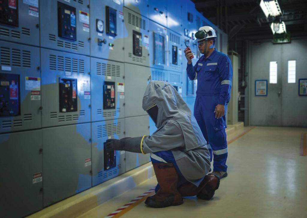
Working with Circuit Breakers Safely
Operating and racking circuit breakers should be done with care as well as the proper equipment and PPE. Section 1 of this article reviews pertinent NFPA 70E sections that apply to any task that could cause injury or even death and looks at the sometimes unpopular task of tackling the necessary paperwork designed to keep you safe. Special attention is paid to Article 110, which outlines safety requirements including an electrical safety program that features a job safety plan, risk evaluation, and risk mitigation. Section 2 looks at the various risks involved with operating and racking circuit breakers as well as how to use the tools that are available to help reduce the risk.
James R. White, Shermco Industries
54
Primary Injection Testing on Low-Voltage Circuit Breakers
Sanket Bolar, Megger
62 Low-Voltage Air Circuit Breakers — A Maintenance MUST!
Kerry Heid, Shermco Canada

7 President’s Desk
Scott Blizard, American Electrical Testing Co., LLC
NETA President
10 NFPA 70E and NETA
Looking at NFPA 70E 2021 — Part 2
Ron Widup and James R. White, Shermco Industries
20 Relay Column
Measuring Field Winding Insulation Resistance
Steve Turner, Arizona Public Service Company
26 In the Field
Animal Damage in the Field
Don Genutis, Halco Testing Services
30 Safety Corner
Portable and Mobile Ladder Safety
Paul Chamberlain, American Electrical Testing Co., LLC
36 Tech Quiz
Low-Voltage Circuit Breakers
James R. White, Shermco Industries
39 Tech Tips
Application of Crushed Rock in Substations
Jeff Jowett, Megger
TOPICS
68 Game Planning for Electrical Safety Success
Corey Hannahs, National Fire Protection Association
74 Practical Non-Invasive Partial Discharge
Cable Testing
William Higinbotham, EA Technology LLC
84 Motor Control Centers
Rodrick J. Van Wart, AVO Training Institute, Inc.
90 Advancements in the Industry
A Technician’s Approach to Impedance-Based Protective Elements
Ralph Parrett, AVO Training Institute
96 Insights & Observations — NETA CAP Spotlight
AVO Training Institute: Providing Customer Training in the Safest Possible Environment
100 ANSI/NETA Standards Update
103 Committee Report: NEC CMP-13, NFPA 70B, ASTM F18, NFPA 70E
James R. White, Shermco Industries
104 Committee Report: NFPA 70 Code Making Panel 10
Scott Blizard, American Electrical Testing Co. LLC
109 Committee Report: IEEE Transformers
Scott Reed, MVA
111 Committee Report: NFPA 70B
David Huffman, Power Systems Testing Company
112 JET Electrical Testing Recognized as New NETA Accredited Company
114 KT Industries Achieves NETA Accredited Company Status
116 NETA Welcomes QP Testing as New NAC
119 NETA Accredited Companies
126 Advertiser List
Protec is your source for electrical test equipment rental and sales, working with leading manufacturers
for your needs, call us for a consultation and quote. Our support line is open 24 hours and we can deliver equipment immediately in case of emergency
Our calibration labs Dallas and Chicago offer NIST-traceable calibration services for all makes and models of electrical test and measurement your electrical test instruments are working at peak performance and meet all manufacturer standards. Quick turnaround is standard, with most equipment completed in 5 business days or less.
Eliminate your overhead and minimize equipment downtime with Protec’s asset management services. We customize a unique solution for your business to store, calibrate and maintain your equipment for whenever you need it. Receive analytics for ROI, yield and utilization to drive educated business decisions.

3050 Old Centre Road, Suite 101
Portage, MI 49024
Toll free: 888.300.NETA (6382)
Phone: 269.488.NETA (6382)
Fax : 269.488.6383
neta@netaworld.org
www.netaworld.org
executive DiRectOR: Missy Richard
NETA Officers
pResiDent: Scott Blizard, American Electrical Testing Co., Inc.
fiRst vice pResiDent: Eric Beckman, National Field Services
secOnD vice pResiDent: Scott Dude, Dude Electrical Testing, LLC
secRetaRy: Dan Hook, Western Electrical Services, Inc.
tReasuReR: John White, Sigma Six Solutions, Inc.
NETA Board of Directors
Ken Bassett (Potomac Testing, Inc.)
Eric Beckman (National Field Services)
Scott Blizard (American Electrical Testing Co., Inc.)
Jim Cialdea (CE Power Engineered Services, LLC)
Scott Dude (Dude Electrical Testing LLC)
Dan Hook (Western Electrical Services, Inc.)
David Huffman (Power Systems Testing)
Alan Peterson (Utility Service Corporation)
Chasen Tedder, Hampton Tedder Technical Services
John White (Sigma Six Solutions)
Ron Widup (Shermco Industries)
nOn-vOting bOaRD membeR
Lorne Gara (Shermco Industries)
NETA World Staff
technicaL eDitORs: Roderic L. Hageman, Tim Cotter
assistant technicaL eDitORs: Jim Cialdea, Dan Hook, Dave Huffman, Bob Sheppard
assOciate eDitOR: Resa Pickel
managing eDitOR: Carla Kalogeridis
cOpy eDitOR: Beverly Sturtevant
aDveRtising manageR: Laura McDonald
Design anD pRODuctiOn: Moon Design
NETA Committee Chairs
cOnfeRence: Ron Widup; membeRship: Ken Bassett; pROmOtiOns/maRketing: Scott Blizard; safety: Scott Blizard and Jim White; technicaL: Alan Peterson; technicaL exam: Dan Hook; cOntinuing technicaL DeveLOpment: David Huffman; tRaining: Eric Beckman; finance: John White; nOminatiOns: Alan Peterson; aLLiance pROgRam: Jim Cialdea; assOciatiOn DeveLOpment: Ken Bassett and John White
© Copyright 2021, NETA
NETA World is published quarterly by the InterNational Electrical Testing Association. Opinions, views and conclusions expressed in articles herein are those of the authors and not necessarily those of NETA. Publication herein does not constitute or imply endorsement of any opinion, product, or service by NETA, its directors, officers, members, employees or agents (herein “NETA”).
All technical data in this publication reflects the experience of individuals using specific tools, products, equipment and components under specific conditions and circumstances which may or may not be fully reported and over which NETA has neither exercised nor reserved control. Such data has not been independently tested or otherwise verified by NETA.
NETA MAKES NO ENDORSEMENT, REPRESENTATION OR WARRANTY AS TO ANY OPINION, PRODUCT OR SERVICE REFERENCED OR ADVERTISED IN THIS PUBLICATION. NETA EXPRESSLY DISCLAIMS ANY AND ALL LIABILITY TO ANY CONSUMER, PURCHASER OR ANY OTHER PERSON USING ANY PRODUCT OR SERVICE REFERENCED OR ADVERTISED HEREIN FOR ANY INJURIES OR DAMAGES OF ANY KIND WHATSOEVER, INCLUDING, BUT NOT LIMITED TO ANY CONSEQUENTIAL, PUNITIVE, SPECIAL, INCIDENTAL, DIRECT OR INDIRECT DAMAGES. NETA FURTHER DISCLAIMS ANY AND ALL WARRANTIES, EXPRESS OF IMPLIED, INCLUDING, BUT NOT LIMITED TO, ANY IMPLIED WARRANTY OF FITNESS FOR A PARTICULAR PURPOSE.
ELECTRICAL TESTING SHALL BE PERFORMED ONLY BY TRAINED ELECTRICAL PERSONNEL AND SHALL BE SUPERVISED BY NETA CERTIFIED TECHNICIANS/ LEVEL III OR IV OR BY NICET CERTIFIED TECHNICIANS IN ELECTRICAL TESTING TECHNOLOGY/LEVEL III OR IV. FAILURE TO ADHERE TO ADEQUATE TRAINING, SAFETY REQUIREMENTS, AND APPLICABLE PROCEDURES MAY RESULT IN LOSS OF PRODUCTION, CATASTROPHIC EQUIPMENT FAILURE, SERIOUS INJURY OR DEATH.

It is January 20, 2021, and the country is in the midst of a resurgence of the COVID-19 virus. The Conference Committee, in consultation with the NETA Board of Directors, has decided to go totally virtual with PowerTest 2021, the premier electrical maintenance and safety conference intended for all electrical professionals and especially beneficial for field service technicians, inspectors, utility associates, project managers/developers, engineers, government personnel, reliability specialists, trainers, thermographers, and wind energy professionals.
PowerTest TV features high-powered on-demand content, the flexibility to participate from anywhere in the world, and the ability to earn NETA CTDs and industry credits. The agenda features technical presentations, live Q & A, a virtual expo, and more! PowerTest TV offers a more customizable conference experience, allowing an attendee up to 90 days after the conference to access more content than ever before.
The theme for this issue of NETA World is low-voltage circuit breakers. Check out “Working with Circuit Breakers Safely” by Jim White of Shermco Industries; “Primary Injection Testing on Low-Voltage Circuit Breakers” by Sanket Bolar of Megger; and “Low-Voltage Circuit Breakers — A Maintenance Must!” by Kerry Heid of Shermco Industries.
NETA Technicians have been identified as essential workers helping to support and maintain the critical infrastructure of our nation. Be sure to follow the COVID-19 policies set out by your company and your customers. Policies should include many of the preventative measures to limit the spread of the COVID-19 virus from the CDC in the United States and the Public Health Agency of Canada. Be safe and err on the side of caution.
Mark your calendar! PowerTest 2022 will take place February 28–March 4, 2022, in Denver, at the Hyatt Regency Hotel. We look forward to seeing you there.
Coach safe behavior … Living injury and disease free every day!

Scott A. Blizard, President International Electrical Testing Association
Safety First…No One Gets Hurt!
PRESIDENT’S DESK






Featuring quality, reliable, on-time service and support for all brands and types of solid state power electronics.
Power electronics are our business
Let us suppoort you with our quality repair, calibration and servicing of your solid state equipment. We also buy, sell and trade:
•Communications devices for power equipment
•Protective relays
•Circuit breaker trip devices
•Motor overload relays
•Rating plugs

BY RON WIDUP and JAMES WHITE, Shermco Industries
This issue of NETA World continues with the deep dive into the NFPA 70E revisions that went into the 2021 edition. Part 1 in the Winter 2020 issue covered the reorganization (which was not nearly as extensive as in previous editions); reviewed Article 100 Definitions; and began on Article 110 General Requirements for Electrical Safety-Related Work Practices with Section 110.1 Priority.
As we continue with this Part 2 article, we look at Article 110 and Article 130. As in Part 1, revisions are shown in legislative text: Deleted language is shown red and crossed through; added text is shown black and underlined.
120.2(A) Lockout/Tagout Principles (A), General, was moved to 110.2, along with its Informational Note. The Committee Statement explains the reasoning well:
The requirements found in 120.2 Lockout/Tagout Principles (A) General are relocated to Article 110 as these requirements are general in nature and are more appropriate for this section of the document. The relocated text is placed at 110.2 so as to create a logical progression of requirements
Locating the requirement to de-energize in Article 110 prioritizes and emphasizes the requirement: the requirement to de-energize is a requirement of an Electrical Safety Program; the requirement to de-energize should be located before lockout requirements; and Article 130 can be focused
on requirements related to work involving an electrical hazard.
This just made sense, as did relocating Section 105.4 Priority to Section 110.1.
130.2 Electrically Safe Work Condition was moved to 110.3 and was unrevised. The remainder of 130.2 was moved to 110.4 Energized Work, which comprises:
• 110.4(A) Additional Hazards or Increased Risk
• 110.4(B) Infeasibility
• 110.4(C) Equipment Operating at Less Than 50 Volts
• 110.4(D) Normal Operating Condition
All these revisions were made to create a logical progression of requirements. We know many 70E users felt the order of sections was fine the way it was, but as we get accustomed to the new order, we will see the benefits of the new organization.
110.1 Electrical Safety Program is now 110.5. 110.5(A), General was revised and now reads:
The employer shall implement and document an overall electrical safety program that directs activity appropriate to the risk associated with electrical hazards. The electrical safety program shall be implemented as part of the employer’s overall occupational health and safety management system, when one exists.
The deleted sentence was removed because it did not add anything to the first sentence.
No changes were made to Informational Note 1, Informational Note 3, and Informational Note 4 in Section 110.5(A). However, Informational Note # 2 was revised to read:
Informational Note No. 2: ANSI/AIHA Z10, American National Standard for Occupational Health and Safety Management Systems , provides a framework for establishing a
comprehensive electrical safety program as a component of an employer’s occupational safety and health program. See Informative Annex P for information on implementing an electrical safety program within an employer’s occupational health and safety management system.
The first sentence of Informational Note No. 2 was not in the correct location, and it interfered with the last sentence. Generally, 70E refers users to Informational Annexes without including other sentences in the same Informational Note.
110.5 Electrical Safety Program is structured the same as 110.1 was in the 2018 edition of NFPA 70E. Most of the following revisions are self-explanatory:
• 110.5(A) General. The revisions made in this sub-section have been discussed.
• 110.5(B) Inspection. No revisions.
• 110.5(C) Condition of Maintenance. No revisions.
• 110.5(D) Awareness and Self-Discipline. No revisions.
• 110.5(E) Electrical Safety Program Principles. No revisions.
• 110.5(F) Electrical Safety Program Controls. No revisions.
• 110.5(G) Electrical Safety Program Procedures. No revisions.
• 110.5(H) Risk Assessment Procedure.
• 110.5(H)(1) Elements of a Risk Assessment Procedure.
The risk assessment procedure shall address employee exposure to electrical hazards and shall identify the process to be used by the employee before work is started to carry out the following:
(1) Identify hazards
(2) Assess risks
(3) Implement risk control according to the hierarchy of risk control methods
Informational Note No. 1: The risk assessment procedure could include identifying when a second person could be required and the training and equipment that person should have.
Informational Note No. 2: For more information regarding risk assessment and the hierarchy of risk control, see Informative Annex F.
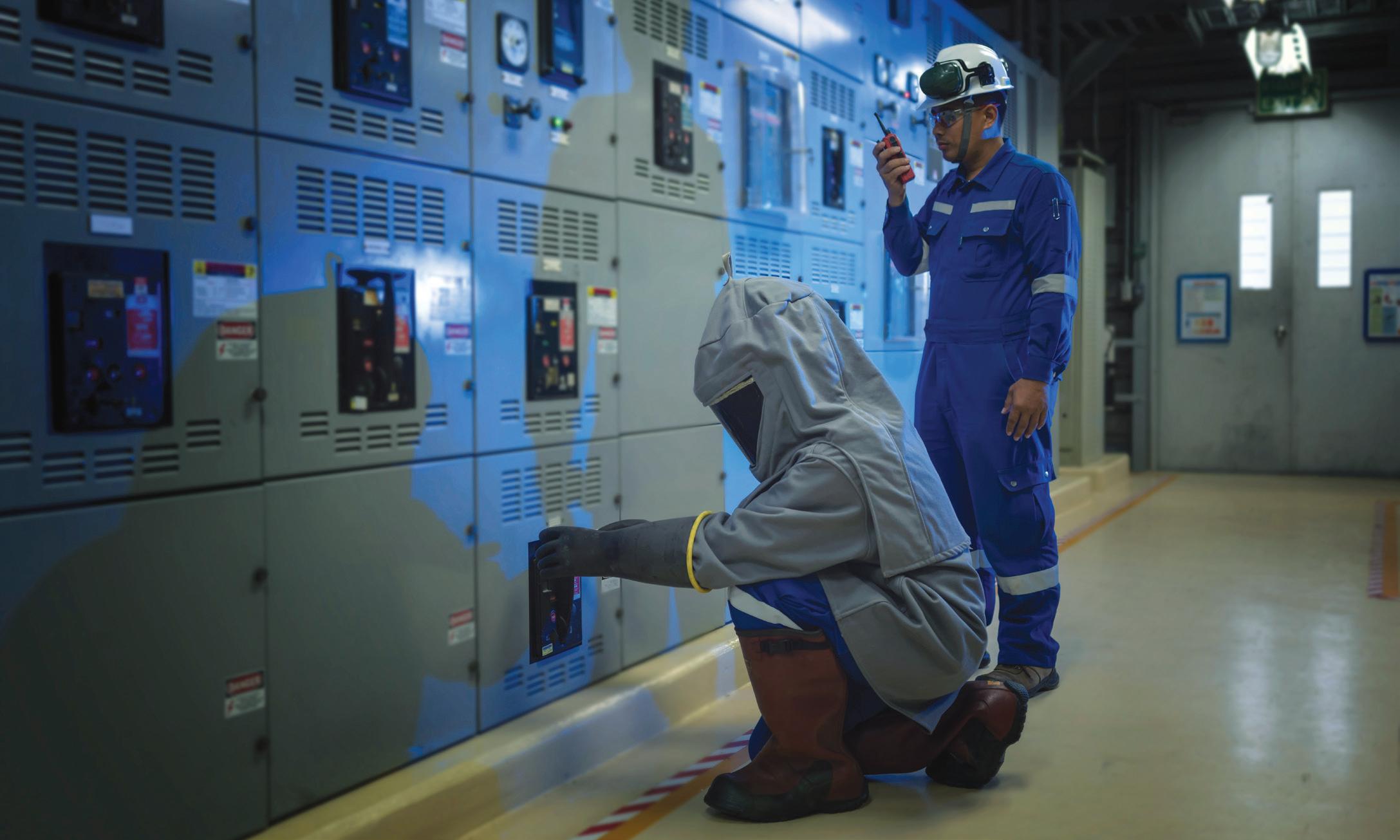
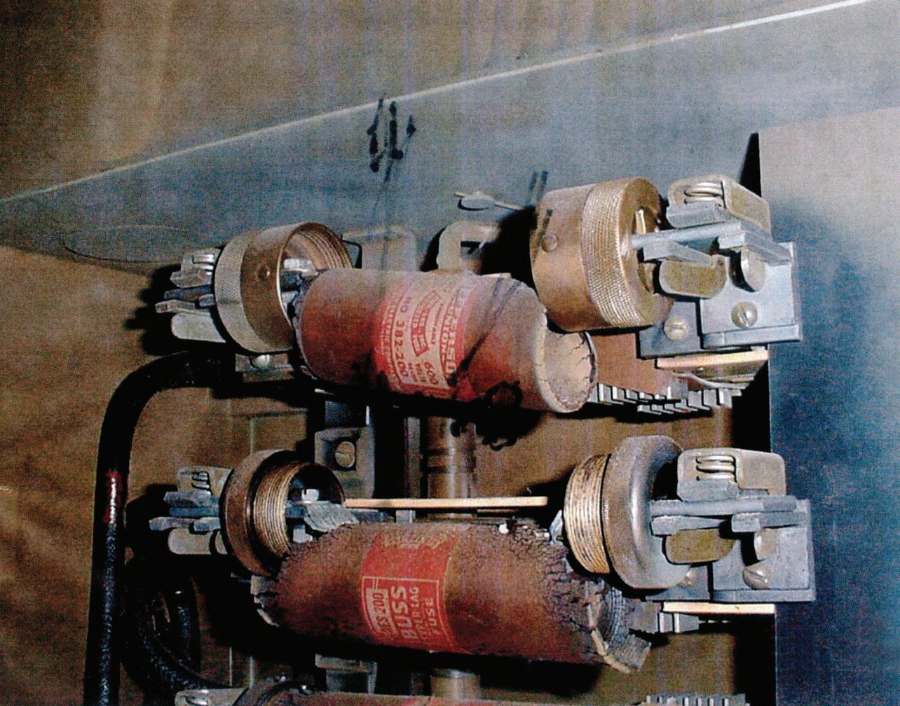
Informational Note No. 2 of Section 110.5(H)(1) is a good example of the way Informational Annexes are referred to in 70E. Figure 1 shows a safety backup as referred to in 110.5(H)(1) Informational Note No. 1.
• 110.5(H)(2) Human Error.
The risk assessment procedure shall address the potential for human error and its negative consequences on people, processes, the work environment, and equipment relative to the electrical hazards in the workplace.
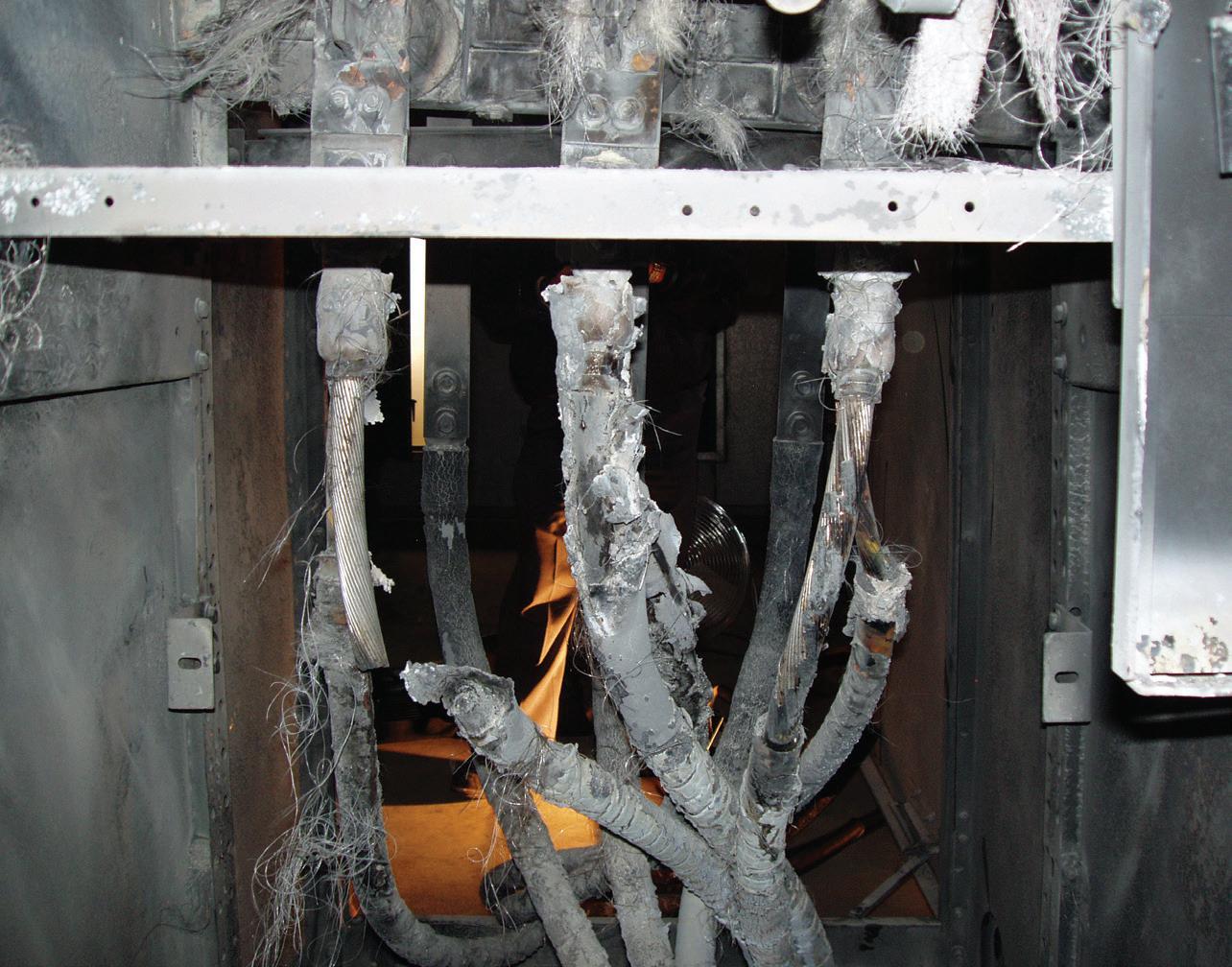
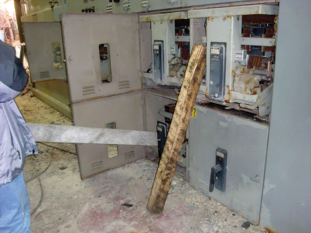
Figure 2a and Figure 2b are good examples of human error that could cause a technician injury or death without it being their fault. Remember that human error could be someone else’s error, not yours. Always do a professional job.
• 110.5(H)(3) Hierarchy of Risk Control Methods.
Informational Note No. 2: See Informative Annex F and ANSI/ AIHA Z10, American National Standard for Occupational Health and Safety Management Systems, for more information regarding the hierarchy of risk control methods and examples of those methods
Informational Note No. 3: The risk assessment procedure could include identifying when a second person could be required and the training and equipment that person should have.
Informational Note No. 4: For an example of a risk assessment procedure, see Informative Annex F.
• 110.5(I) Job Safety Planning and Job Briefing
• 110.5(I)(1) Job Safety Planning. No revision to text, but a new Informational Note.
Informational Note: For an example of a job safety planning checklist, see Figure I.2.
• 110.5(I)(2) Job Briefing
• 110.5(I)(3) Change in Scope. No revisions to text, but revision to Informational Note.
Informational Note: For an example of a job briefing form and planning checklist, see Figure I.1.
• 110.5(J) Incident Investigations. No revisions.
• 110.5(K) Electrically Safe Work Condition Policy. New Sub-Section.
An electrical safety program shall include an electrically safe work condition policy that complies with 110.3.
The Committee Statement on this revision is worthwhile:
The new subsection 110.5(K) requires that employer’s electrical safe work program include a policy on establishing an electrically safe work condition. This correlates with the requirement in Article 120 and provides clarity by ensuring it becomes part of the employer’s electrically safe program.
• 110.5(L) Lockout/Tagout Program. New Sub-Section.
The electrical safety program shall include information required by one of the following:
(1) A lockout/tagout program in accordance with 120.1(A)
(2) A reference to the employer’s lockout/ tagout program established in accordance with 120.1(A)
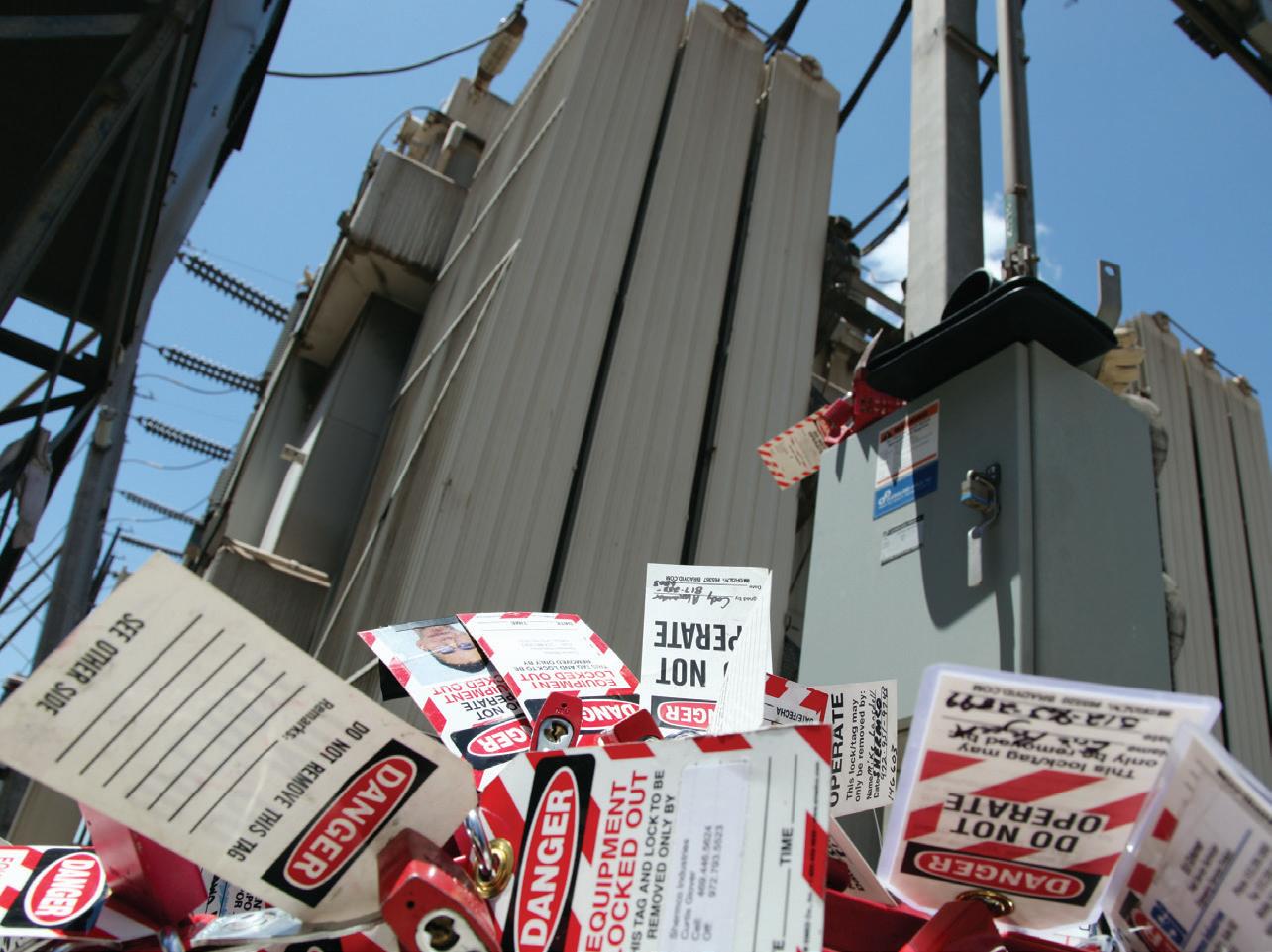
Up to this edition, there had been no specific requirement for a LOTO program in the electrical safety program. 120.1(A) General required a documented LOTO program (Figure 3a and Figure 3b). but did not state where it had to be. This SubSection corrects that oversight.
• 110.5(M) Auditing. No revisions in Section or Sub-Sections.
• 110.5(M)(1) Electrical Safety Program Audit
• 110.5(M)(2) Field Work Audit
• 110.5(M)(3) Lockout/Tagout Program and Procedure Audit
• 110.5(M)(4) Documentation
• 110.6 (moved from 110.2 Training Requirements) Electrical Safety Training
• 110.6(A)(1) Qualified Person. Revisions made to Sub-Section.
a. No revisions
b. No revisions
c. No revisions
(1) No revisions
(2) No revisions
(3) Change Table references from 130.4(D)(a) and 130.4(D)(b) to 130.4(E)(a) and 130.4(E)(b)
(4) Only revision is to (d):
d. Select the appropriate risk control methods from the hierarchy of controls identified in 110.5(G) 110.5(H)(3), including personal protective equipment PPE.
d. No revisions
e. No revisions
f. The employer shall determine through regular supervision or through regular inspections conducted on at least an annual basis that each employee is complying with the safety-related work practices required by this standard.
This sub-section was deleted during the First Draft, then reinstated during the Second Draft.
• 110.6(A)(2) Unqualified Persons. No revisions.
• 110.6(A)(3) Additional Training and Retraining
Retraining Additional training and Retraining in safety-related work practices and applicable changes in this standard shall be performed at intervals not to exceed 3 years. An employee shall receive additional training (or
retraining) if any of the following conditions exist:
• 110.6(A)(4) Only revision was to change reference from 110.2(A) to 110.6(A)
• 110.6(A)(5) Only revision was to change reference from110.2(A) to 110.6(A)
• 110.2(B) 110.6(B) Lockout/Tagout Procedure Training
(1) Initial Training
Employees involved in or affected by the lockout/tagout procedures required by 120.2(B) shall be trained….
Some readers may think the deletion of “or affected by” would be a mistake, but the Committee statement clarifies the reasoning behind the revision:
The phrase “or affected by” is deleted. While all employees must understand the purpose of a lockout, the requirement to train employees that are involved in the lockout is consistent with the requirement in 120.2(B) Employee Involvement:
“Each person who could be exposed directly or indirectly to a source of electrical energy shall be involved in the lockout/tagout process.
The Committee thought the deleted phrase was inconsistent and not needed.
• 110.7 Host and Contract Employer’s Responsibilities. Sub-Section 110.3 was renumbered to 110.7 Documentation, and a new Informational Note was added:
Informational Note to 110.7: On multiemployer work sites (in all industry sectors), more than one employer can be responsible for identifying hazardous conditions and creating safe work practices.
The Committee Statement provides some insight to the new Informational Note:
Although the informational note is located after 110.7(C), it applies to all of 110.7, not just 110.7(C). This revision provides clarity.
• 110.8(A) Test Instruments and Equipment. Testing was renumbered from 110.4(A):
Only qualified persons shall perform tasks such as testing, troubleshooting, and voltage measuring on electrical equipment operating at voltages equal to or greater than 50 volts where an electrical hazard exists.
The Committee Statement explains the reasoning for this revision:
The requirement was revised to apply to all electrical hazards, as testing and troubleshooting that involves any electrical hazard, not just a shock hazard, should be performed by a qualified person.
• Sub-Section 110.9 Portable Cord-andPlug-Connected Equipment. This subsection was renumbered from 110.5 with a few revisions:
110.9 This section applies to the use of cordand plug-connected equipment, including cord- and plug-connected test instruments and cord sets (extension cords).
This one is pretty clear as to why the addition was made.
• 110.9(C) Visual Inspection and Repair of Portable Cord- and PlugConnected Equipment and Flexible Cord Sets
(a) Frequency of Inspection
Exception: Stationary cord- and plugconnected equipment and flexible cord sets (extension cords) that remain connected once they are put in place and are installed such that the cord and plug are not subject to physical damage during normal use shall not be required to be visually inspected
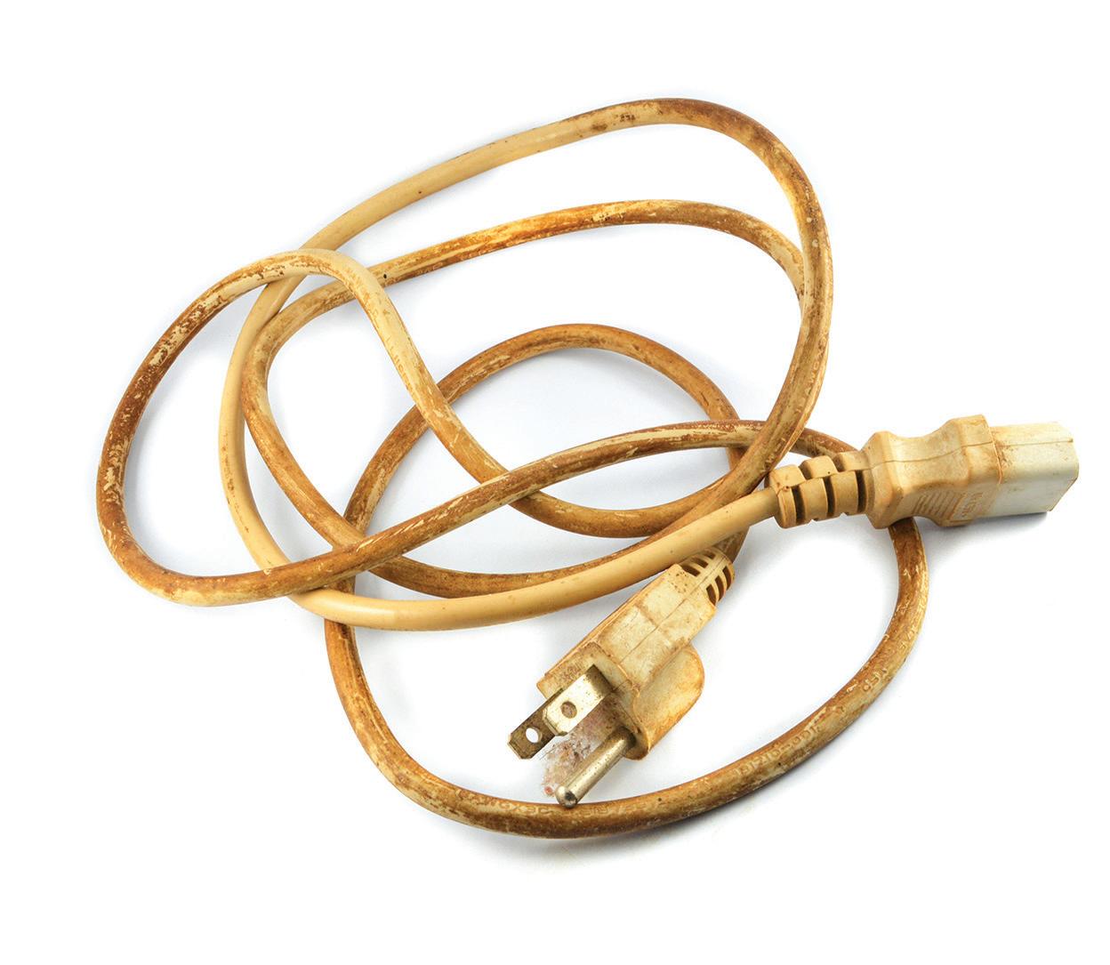
until they are relocated or repaired (Figure 4)
• 110.9(D) Conductive or Wet Work Locations. Portable cord- and-plugconnected electric equipment used in highly conductive or wet work locations (such as those inundated with water
or other conductive liquids) shall be approved for use in those locations. In job work locations where employees are likely to contact or be drenched with water or conductive liquids, ground-fault circuitinterrupter protection for personnel shall also be used.
• A new Sub-Section 110.12 Equipment Use was added. This statement is mandatory for almost all equipment and tools used by electrical workers.
• Equipment shall be used in accordance with the manufacturer’s instructions.
We were able to make it through Article 110 in Part 2, which wore us out, but hopefully not the readers of this column. We hope that detailing the revisions made to Article 110, along with the explanations, will further your understanding of this very important standard. All of us in the electrical field face hazards each and every day, and NFPA 70E goes a long way to help us all diminish the risks.
Ron Widup and Jim White are NETA’s representatives to NFPA Technical Committee 70E, Electrical Safety Requirements for Employee Workplaces. Both gentlemen are employed by Shermco Industries in Dallas, Texas, a NETA Accredited Company.

Ron Widup, Senior Advisor, Technical Services and Vice Chairman of the Board of Directors, has been with Shermco Industries since 1983. He is a member of Technical Committee on NFPA 70E, Electrical Safety in the Workplace; a Principal Member of National Electrical Code (NFPA 70) Code Panel 11; a Principal Member of the Technical Committee on NFPA 790, Standard for Competency of Third-Party Evaluation Bodies; a Principal Member of the Technical Committee on NFPA 791, Recommended Practice and Procedures for Unlabeled Electrical Equipment Evaluation; a member of the Technical Committee on NFPA 70B, Recommended Practice for Electrical Equipment Maintenance, and Vice Chair for IEEE Std. 3007.3, Recommended Practice for Electrical Safety in Industrial and Commercial Power Systems. Ron also serves on NETA’s board of directors and Standards Review Council. He is a NETA Certified Level 4 Senior Test Technician, a State of Texas Journeyman Electrician, an IEEE Standards Association member, an Inspector Member of the International Association of Electrical Inspectors, and an NFPA Certified Electrical Safety Compliance Professional (CESCP).

James (Jim) R. White, Vice President of Training Services, has worked for Shermco Industries since 2001. He is a NFPA Certified Electrical Safety Compliance Professional and a NETA Level 4 Senior Technician. Jim is NETA’s principal member on NFPA Technical Committee NFPA 70E®, Electrical Safety in the Workplace; NETA’s principal representative on National Electrical Code® Code-Making Panel (CMP) 13; and represents NETA on ASTM International Technical Committee F18, Electrical Protective Equipment for Workers. Jim is Shermco Industries’ principal member on NFPA Technical Committee for NFPA 70B, Recommended Practice for Electrical Equipment Maintenance and represents AWEA on the ANSI/ISEA Standard 203, Secondary Single-Use Flame Resistant Protective Clothing for Use Over Primary Flame Resistant Protective Clothing. An IEEE Senior Member, Jim was Chairman of the IEEE Electrical Safety Workshop in 2008 and is currently Vice Chair for the IEEE IAS/PCIC Safety Subcommittee.

intellirent is “on the job with you.” From prerental consultation, with technical support before, during and after the rental, to working with our shipping logistics experts - not just a rental source.
We support testing of…
Transformers | Protective Relays | Grounding Systems | Cables | Circuit Breakers | Power Quality | Batteries | Motors | Renewables



Programmable Scheduled Maintenance Interval
Remote QUICK-TRIP® Arcflash Mode Control
Remotely Close E/O Breakers
And More - All On Top of the Industry-Leading Features You Already Depend On


BY STEVE TURNER, Arizona Public Service Company

Multi-function numerical generator protection relays can calculate the insulation resistance of a synchronous generator field winding to ground. The calculation can be performed on an energized or de-energized generator. The particular relay discussed in this article uses a separate module located close to the rotor slip rings and brushes to monitor the field. The close proximity of the module to the rotor slip rings and brushes minimizes transient voltage induced on the metallic connections (see the connection diagram in Figure 2). The measurement module transmits the insulation resistance value to a generator relay via a fiber optic link. The relay compares the calculated insulation resistance with pickup settings to either alarm or trip.
The relay uses the calculated insulation resistance value to detect a ground fault in an ungrounded field winding of the protected generator. This allows the generator owner to avoid any significant damage to the generator by taking corrective actions before a second ground path occurs.
The measuring module (Figure 1) works with continuous field voltages as high as 750 Vdc and can withstand up to 1500 Vdc for 1 minute.
A generator field is an ungrounded singlecircuit winding that is wound on the rotor. A DC source is connected to the field winding
to produce the required magnetic field. This exciter DC voltage source typically ranges from 48 V to 825 V.
Insulation deterioration or breakdown can cause the field winding to contact the rotor iron. This first ground will not generally affect the operation of the generator. A second ground will cause a portion of the field winding to be shorted, resulting in unbalanced air-gap fluxes in the generator. This in turn can cause rotor vibration that can damage the generator. It is best to detect the first ground and take corrective action by programming the relay to alarm or trip following detection of a field ground.
Square-Wave Injection Voltage

Rotor Iron Field
Winding
FIELD (+)
SEL-2664
Field Ground Module
SEL-2664
Field Ground Module
FIELD (–)
Square-Wave Injection Voltage
FIELD (GND)
FIELD (+)
FIELD (–)
2: Diagram of Connections
Exciter (VDC) +
Exciter (VDC) +
Field Breaker
FIELD (GND)
The measurement module transmits a data packet to the relay that contains the insulation resistance and self-test status. Measurements are transmitted as fast as every half second. No settings are required for the module. The fiberoptic port in the module has a built-in fiberoptic transceiver transmit circuit. The relay has a fiberoptic serial port to directly connect to the measurement module.
Relay Word Bits
64FFLT
64F1P
Relay Word Bits
64FFLT
Rotor Iron Field
Winding
Ground Brush
Brushes
Field Breaker
Brushes
Ground Brush
The relay has two independent pickup levels to compare versus the calculated insulation resistance. Program the field ground protection elements to output contacts to alarm or trip. The field ground protection function covers a range of 0.5 to 200.0 kilo-ohms (Figure 3).
Relay Word Bits
If relay word bit 64FFLT equals logical one, this indicates a non-functional measuring
Relay Word Bits
64F1C
64F1
64F1T
64F2P
64F2P
Rf = Field ground insulation
Figure 3: Alarm (64F1) and Trip (64F2) Logic
*Delay of 4 Samples
Rf = Field ground insulation resistance in kilohms SEL-2664 Field (+) +
*Delay of 4 Samples
64F2C
64F2
64F2T
of 4 Samples = Field ground insulation resistance in kilohms

module or severed fiberoptic connection. The 64F elements are not calculated; 64F1, 64F1T, 64F2, and 64F2T relay word bits are set to zero; and all accumulated timer values are reset to zero.
Table 1: 64F Protection Settings Setting
64F1P — Alarm Pickup Level
64F1D — Alarm Delay on Pickup
64F2P — Trip Pickup Level
64F2D — Trip Delay on Pickup
0.5–200.0 kilo-ohms
0.00–99.0 seconds
0.5–200.0 kilo-ohms
0.00–99.0 seconds
64FTC — 64F Torque Control Logical 1 (typical)
To verify proper connection via fiberoptic link (Figure 4):
Fiber-Optic Cable to SEL-700G
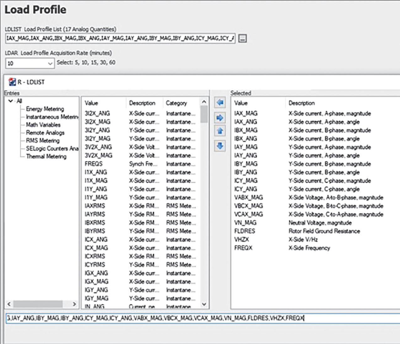
Figure 5: Data Recorder Configuration
• Step 1. Disconnect the field winding from the measuring module.
• Step 2. Connect the measuring module to the relay and enable 64F protection.
• Step 3. Record the value of Rf using the METER command for the relay. It should read 20,000 kilo-ohms.
• Step 4. Connect a resistor decade box between the field (+) and field (GND) terminals.
• Step 5. Short the field (+) and field (–) terminals.
• Step 6. Select the resistor value to be 100k ohms on the resistor decade box.
• Step 7. Wait 30 seconds and record the value of Rf using the METER command for the relay. Make sure the reported Rf value is within the stated accuracy limits.
The relay can periodically record the analog quantities it measures such as voltage and current. The relay stores these values in nonvolatile memory. Use this function to track the value of field insulation resistance over time. The relay for this example is programmed to record the phase current on both sides of

the stator winding, phase-to-phase voltage magnitude at the generator bus, neutral voltage magnitude, rotor field ground resistance, volts per Hertz, and frequency with respect to the generator bus every 10 minutes (Figure 5).
Implementing a multi-function numerical generator protection relay can calculate the insulation resistance of a synchronous generator field winding to ground and record the value over time. The relay uses the calculated insulation resistance value to detect a ground fault in an ungrounded field winding of the protected generator. This allows the generator owner to avoid significant damage to the generator by taking corrective actions before a second ground path occurs.

Steve Turner is in charge of system protection for the Fossil Generation Department at Arizona Public Service Company in Phoenix. After working with Beckwith Electric Company, Inc. for 10 years, Steve spent two years as a consultant in San Diego. His previous experience includes positions as an Application Engineer at GEC Alstom and in the international market for SEL focusing on transmission line protection applications. Steve also worked for Duke Energy (formerly Progress Energy), where he developed the first patent for double-ended fault location on overhead high-voltage transmission lines and was in charge of all maintenance standards in the transmission department for protective relaying. Steve has BSEE and MSEE degrees from Virginia Tech University. He has presented at numerous conferences including Georgia Tech Protective Relay Conference, Western Protective Relay Conference, ECNE, and Doble User Groups, as well as various international conferences. Steve is a senior member of IEEE and a member of the IEEE PSRC.














BY DON GENUTIS, Halco Testing Services
Emergencies always seem to occur on Fridays and weekends, and true to form, a panicked customer called about a power outage to a significant portion of a college campus on a Friday morning. It seemed likely to be a 4,160 volt cable or unit substation problem, so we pulled two technicians away from an acceptance testing project and got them on their way.

The technicians weren’t far into their investigation before I received a text photo of a deceased 25-pound raccoon. Everyone felt sorry for a moment but then focused back on the business of quickly procuring a 5 kV fusedload interrupter switch, as the raccoon had created massive unrepairable damage.
The memory of this event refueled my recollection of other animal-related failures, and every technician out there probably has their own stories.
Animals don’t have NFPA 70E training, and they ignore electrical equipment warning labels. Unfortunately, electrical enclosures provide ideal shelter for these animals. Keeping them out of the equipment is extremely important but easily overlooked.
One memorable event occurred on a Saturday morning (yet another weekend emergency) when a cat got into a 15 kV switchgear lineup
and across the pole of a vacuum bottle on a feeder breaker. The event ruptured the bottle and tripped the main. The cleanup didn’t take very long, and the customer had a spare breaker on hand, which minimized the outage duration, so focus turned to repairing the damaged breaker. Cats, like other mammals, are attracted to switchgear warmth and shelter.
A few months ago, our team performed successful VLF withstand and partial discharge acceptance testing of a solar facility circuit and were astonished when the customer called to tell us the recloser had tripped. Confident the cable was good, we suspected a protection programming issue, and some changes had been made more than once along the way by the owner. When our technician arrived at the pole where the relay enclosure was mounted, he found a large, deceased crow missing one wing. Apparently, the bird’s wing-span was wide enough to breach two phases at the riser terminations, which significantly damaged two of these components. This repair required an aerial lift truck and a splicer and replacement of all three terminations, which the customer fortunately had on hand. The total outage duration was less than 24 hours even with a lot of necessary travel time due to the site’s remote location.
Mice incidents are so common, one of our technicians once kept a dead-mice board with dozens of incident photos on display in the shop. Although the technicians seemed to be fascinated and amused by the display, the admin staff protested, and the board was eventually removed. Mice seem to have magical abilities to fit through very small spaces and will use unsealed conduits as their personal pedestrian tunnels for safely getting around. Sealing electrical enclosures as much as possible goes a long way to prevent micerelated outages.
A squirrel or bird guard is a reliable means of preventing animal-related flash-overs in
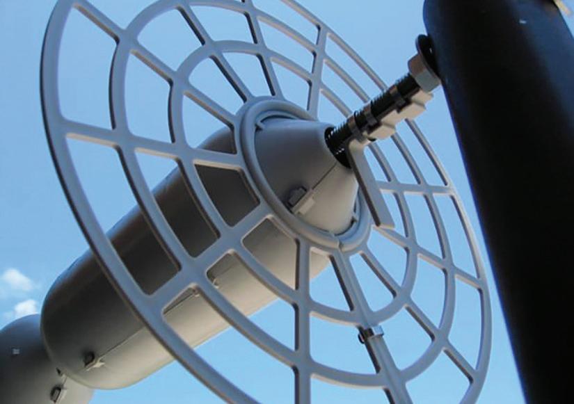
An animal guard can prevent damage.
outdoor substations, but care must be taken to ensure these components are installed correctly. Failure to install guards with proper clearances could result in eventual failures.
Several lessons can be learned from these experiences to help prevent unplanned outages:
1. Seal all equipment openings.
2. Seal all conduits.
3. Consider using animal guards for outdoor substation and overhead insulators and bushings.
4. Keep spare components available to minimize outage duration.

Don A. Genutis presently serves as President of Halco Testing Services, Inc., a NETA Accredited Company with offices in Los Angeles and Houston. He has held various principal positions during his 35plus year career in the electrical testing field, primarily focused on advancing no-outage testing techniques for the last 20 years, with emphasis on cable and switchgear on-line partial discharge testing techniques. Early in his career, Don acquired and operated the former Westinghouse East Pittsburgh Insulation Research Laboratory, where he gained valuable experience in understanding insulation material performance. Don holds a BS in electrical engineering from Carnegie Mellon University and is a NETA Certified Technician. Don has authored 50 technical articles for NETA World and has been featured in EC&M and Uptime magazines. Don’s work is summarized in his book, Partial Discharge & Other No-Outage Testing Methods, published in 2019.


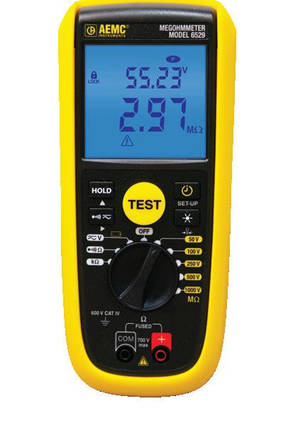

Economical & easy-to-use True Megohmmeters® built rugged for use in the field
• View the real-time insulation value and test voltage simultaneously
• DMM functions; volts, continuity, and resistance
• Programmable alar m thresholds
• 2-color backlighting easily shows alar m conditions
• DMR mode - relative resistance comparison to a reference value
• Automatic power-off function to optimize the batter y life
• Shockproof sheath for excellent handling
Selectable test voltages 250, 500 and 1000 V (available on both models) and 50 and 100 V (model 6529)


BY PAUL CHAMBERLAIN, American Electrical Testing Co. LLC
Falls from ladders account for 20% of all fatalities and lost-workday injuries in general industry according to Occupational Safety and Health Administration (OSHA) statistics. Ensuring that all ladders meet OSHA and American National Standards Institute (ANSI) standards is critical in mitigating this statistic.
OSHA published an update to its walkingworking surface rule (Subpart D) for general industry in 2016. Subpart D applies to all general industry workplaces, covers all walkingworking surfaces unless specifically excluded, and incorporates advances in technology, industry best practices, and national consensus standards to better address slip, trip, and fall hazards.
OSHA incorporated its previously separate regulations for portable wood ladders, portable metal ladders, and fixed ladders under one comprehensive ladder standard: 29 Code of Federal Regulations (CFR) 1910.23, Ladders, applies to all ladders used in general industry with a few exceptions that are outlined in that CFR.
Under the General Requirements section (29 CFR 1910.23(b)), OSHA addresses proper ladder-climbing technique. It requires that
employees always maintain three points of contact when ascending or descending a ladder by:
• Facing the ladder
• Using at least one hand to firmly grasp the ladder
• Not carrying any object or load that could cause them to lose balance and fall
Employers must ensure every employee follows this climbing technique.
The General Requirements also cover the design specifications for rungs and steps used on ladders and stepstools. Except for ladders used in elevator shafts and communication towers, the design for rungs and steps must meet the following criteria:
1. Parallel, level, and uniformly spaced when the ladder is in position for use
2. Spaced not less than 10 inches and not more than 14 inches apart
3. Minimum clear width of 11.5 inches for portable ladders and 16 inches for fixed ladders

4. Manhole-entry ladder rungs and steps supported by a manhole opening minimum clear width of nine inches
5. Minimum clear width of 8 inches for telecommunication-center rolling ladder rungs and steps
6. Minimum clear width of 10.5 inches on step stools
Additional requirements:
1. Wooden ladders must not be coated with any material that could obscure structural defects.
2. Metal ladders must be made with corrosion-resistant material or protected against corrosion.
3. Ladder surfaces must be free of puncture and laceration hazards.
4. Ladders must only be used for the purpose for which they were designed.
5. Ladders must be inspected before initial use in each work shift and more frequently as necessary to identify any visible defects that could cause employee injury.
6. Any ladder with structural or other defects must be immediately tagged “Dangerous: Do Not Use” or with similar language in accordance with 29 CFR 1910.145 and removed from service until repaired in accordance with 29 CFR 1910.22(d) or replaced.
Portable ladders, which can be readily moved or carried, usually consist of side rails joined at intervals by steps, rungs, or cleats.
Employers must ensure that portable ladders meet the following requirements.
1. Rungs and steps are slip resistant.
2. Ladders are equipped with a metal spreader or locking device that securely locks ladder in open position.
3. Ladders are not loaded beyond maximum intended load.
4. No single-rail ladders are used.
5. Ladders are secured to prevent accidental displacement or guarded by a temporary barricade when used in passageways, doorways, or driveways.
6. Ladders are secured and stabilized if used on slippery surfaces.
7. Ladders are not moved, shifted, or extended while being used.
8. Top step and caps of stepladders are not used as steps.
9. If used to gain access to upper landing surface, the side rails extend at least 3 feet above the upper landing surface.
10. Ladders are not fastened together to provide added length unless designed for such use.
11. Ladders are not placed on boxes, barrels, or other unstable bases to obtain added height.
A mobile ladder stand is a mobile, fixed-height, self-supporting ladder that usually consists of wheels or casters on a rigid base and steps leading to a top step. It may also have handrails and is designed for use by one employee at a time. A mobile ladder stand platform adds one or more standing platforms that are provided with means of access or egress.
Employers must ensure these stands and platforms conform to the following;
1. Step width must be at least 16 inches.
2. Steps and platforms must be slip-resistant.
3. Must support least four times the maximum intended load.
4. Wheels or casters under load must support their proportional share of four times the maximum intended load, plus their proportional share of the unit’s weight
5. With a top step height of 4 feet or above, must have handrails with a vertical height of 29.5 to 37 inches, measured from the front edge of a step. Removable gates or non-rigid members, such as chains, may be used instead of handrails in special-use applications.
6. Maximum work-surface height must not exceed four times the shortest base dimension without additional support. Stabilizing outriggers, counterweights, or comparable means to prevent overturning must be used for greater heights.
7. Must have wheels or casters that are equipped with a system to impede horizontal movement when an employee is on it.
8. Stand and platform steps must be uniformly spaced and arranged, with a rise of not more than 10 inches and a depth of not less than 7 inches. The slope of the step stringer must be less than 60 degrees as measured from the horizontal.
9. When the step spacing and arrangement is not feasible for platforms, stabilized units to prevent overturning with steeper slopes or vertical rung ladders are used.
10. Stands with a top step height above 10 feet must have the top step protected on three sides by a handrail with a vertical height of at least 36 inches; top steps of 20 inches or more, front to back; and have a midrail and toeboard. Removable gates or non-rigid members, such as chains, may be used instead of handrails in special-use applications.
11. A stand’s standing area must be within the base frame.
12. Platforms with a platform height of 4 to 10 feet must have handrails in the platform area with a vertical height of at least 36 inches and midrails. Removable gates or non-rigid members, such as chains, may be used instead of handrails in special-use applications.
13. Platforms with a platform height above 10 feet must have guardrails and toeboards on the exposed sides and ends of the platform. Removable gates or non-rigid members, such as chains, may be used instead of guardrails in special-use applications.
Ladder styles include:
• Ladder-type step stools
• Portable extension
• Step trestle
• Sectional
• Combination
• Single
• Platform
• Articulating
• Articulating extendable
• Telescoping
Ladders are rated as follows;
The proper use of portable ladders includes:
• Select the proper ladder for the job being performed.
• Inspect the ladder to verify proper operation and cleanliness.
• Ensure proper ladder placement so footing and top supports are secure and not creating a traffic hazard for pedestrians.
• Use proper climbing technique.
• Properly care for and store the ladder.
The user must read the manufacturer’s instructions before first use. The user should not use a ladder if sleepy or ill, taking medication, or if there is potential for high wind or lightening. Do not block doorways or other high-traffic areas. Ensure doors are locked and marked with warning signs or cones, and station an attendant at the doorway to keep pedestrian traffic away if possible. Do not use metal ladders near power lines or other sources of electricity to avoid electrical shock hazards. Inspect before use for damage or wear. If a ladder is found to be unsafe for use, remove it from service, and mark it with a “Do Not Use” tag.
Materials
ANSI is very specific in the design and construction of wood ladders due to the potential defects and types of wood species available. Metal ladder design and construction requirements are minimized because of the wide variety of materials and design possibilities. However, ladders must be of sufficient strength and stiffness to meet performance requirements and must not have any structural defects or hazards such as sharp edges, burrs, etc. Plastic or fiberglass ladders must use fully cured, commercial-grade, thermosetting, polyester resin with glass-fiber reinforcement.
Electrical hazards, temperature extremes, corrosion, outdoor weathering, etc., will help the user determine the proper ladder material.
Ensure the ladder is proper for the job and that it is properly rated. Ensure it is long enough for the work to be completed safely. Ladder feet should be firmly and evenly planted on the ground. Use boards on soft or uneven ground under the ladder’s feet. Tie off the top of an extension ladder and/or have another person foot the ladder by placing their feet up against the bottom of the rails where the feet contact the ground and placing their hands on a rung at a comfortable height. Rest both rungs of the ladder against the wall or other support. Stepladders must be spread fully and locked into position. Fixed-length and extension ladders must be placed at an angle so they are 1 foot from the wall for every 4 feet of working ladder height.
Make sure hands, shoes, and ladder rungs are dry. Always maintain three points of contact
on the ladder (two hands and one foot or one hand and two feet) when ascending or descending. Always face a ladder. Climb slowly. Keep your weight centered between side rails. Do not lean back, and never stand on the top two rungs of a stepladder or top four rungs of an extension ladder.
Ladders must be marked with size, type and/ or duty rating, maximum working length (if extension ladder), highest standing level, total length of sections (if extension ladder), model number or name, manufacturer’s or distributor’s name, manufacturer’s plant location (if multiple plants may be coded), month and year of manufacture, and ANSI compliance and warranty (if applicable). Usage guidelines and other warning statements must also be placed on the ladder in specific locations depending on ladder type.
Ladders have been proven to be a dangerous but necessary tool on the work site. Proper use and maintenance are required to ensure employees remain safe. As with any tool, the user is the last line of defense when it comes to their own safety. Inspect a ladder before use and be knowledgeable in what is required to ensure the ladder is in good condition and is the proper type.
Paul Chamberlain has been the Safety Manager for American Electrical Testing Co. LLC since 2009. He has been in the safety field for the past 17 years, working for various companies and in various industries. He received a BS in safety and environmental protection from Massachusetts Maritime Academy.







James (Jim) R. White, Vice President of Training Services, has worked for Shermco Industries Inc. since 2001. He is a NFPA Certified Electrical Safety Compliance Professional and a NETA Level 4 Senior Technician. Jim is NETA’s principal member on NFPA Technical Committee NFPA 70E®, Electrical Safety in the Workplace®, NETA’s principal representative on National Electrical Code® Code-Making Panel (CMP) 13, and represents NETA on ASTM International Technical Committee F18, Electrical Protective Equipment for Workers. Jim is Shermco Industries’ principal member on NFPA Technical Committee for NFPA 70B, Recommended Practice for Electrical Equipment Maintenance and represents AWEA on the ANSI/ISEA Standard 203 Secondary Single-Use Flame Resistant Protective Clothing for Use Over Primary Flame Resistant Protective Clothing. An IEEE Senior Member, Jim received the IEEE/IAS/PCIC Electrical Safety Excellence Award in 2011 and NETA’s Outstanding Achievement Award in 2013. Jim was Chairman of the IEEE Electrical Safety Workshop in 2008 and is currently Vice-Chair for the IEEE IAS/ PCIC Safety Subcommittee.

JAMES R. WHITE, Shermco Industries
This edition of the Tech Quiz discusses one thing we all deal with, either at home or at work: low-voltage circuit breakers. Typically, they can last for years without causing problems, but they do require some maintenance and care. Continue on to find out what’s in store for you!
1. When the topic of low-voltage circuit breakers comes up, what are we really discussing?
a. Low-voltage power circuit breakers
b. Insulated-case circuit breakers
c. Molded-case circuit breakers
d. All of the above types of circuit breakers
2. What type of circuit breaker has drawout construction?
a. Low-voltage power circuit breakers
b. Insulated-case circuit breakers
c. Molded-case circuit breakers
d. All of the above types of circuit breakers
3. Which ANSI/NETA MTS-2019 section covers low-voltage power circuit breakers (you do have your copy ready, right)?
a. 7.6.1.1 Circuit Breakers, Air, Low-Voltage Power
b. 7.6.1.2 Circuit Breakers, Air, Low-Voltage Power
c. 7.6.1.3 Circuit Breakers, Air, Low-Voltage Power
d. None of the above circuit breaker sections
4. How many subsections are there in the Circuit Breaker, Insulated-Case/MoldedCase requirements, and where is the second subsection?
a. 6 sub-sections; Visual and Mechanical Inspection
b. 5 sub-sections; Electrical Tests
c. 4 sub-sections; Electrical Tests
d. 3 sub-sections; Visual and Mechanical Inspection
See answers on page 118.
You can count on us for specialized experience in healthcare, data center, o ce complex, and commercial acceptance and maintenance testing. Absolutely Power generation, petrochemical, oil & gas, and heavy industries also look to us for high demand services such as start-up commissioning, maintenance testing, shut-down and turnarounds, and breaker shop repair. Get started today.


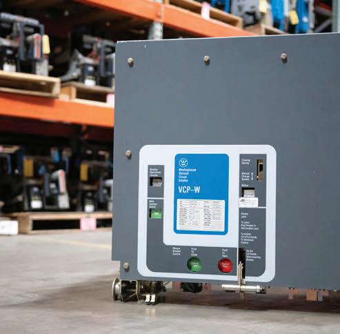

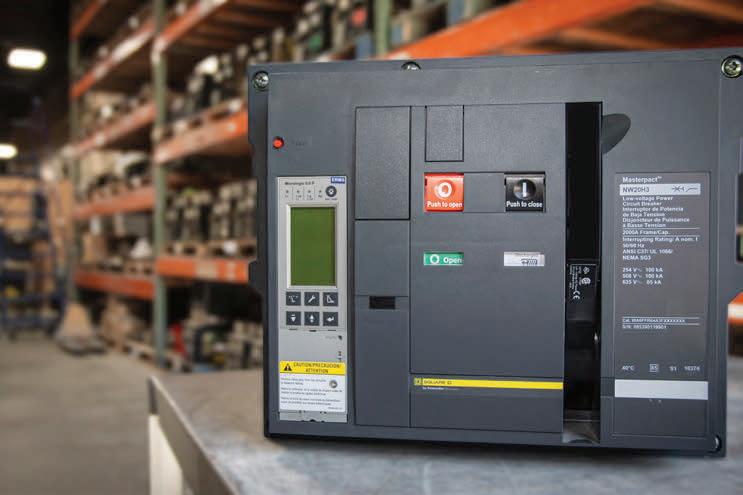

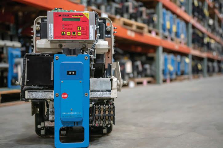
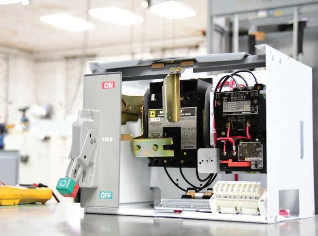

An extensive inventory of over 200,000 sq. ft. across the southeast means the Southland Group has the products you need most in stock and ready to ship! Our team of experienced technicians provide on-site field service support and engineering services to ensure that your products are safe, reliable and service ready. Contact us today and let us create the solutions you need most!


BY JEFF JOWETT, Megger
Although it can readily be overlooked, an important and fundamental consideration in any electrical application is safety, and one of the most effective tools in the application of safety is redundancy. If one safeguard fails, there’s another right there to act as a safety net. There’s hardly a greater necessity for redundant safety than in a substation, where arcing could otherwise electrocute an unprotected worker through many feet of nothing but air. Fortunately, industry-standard safety practices and construction preclude this.
Key elements in substation safety include maintaining safe step and touch potentials. Much of the dialogue in electrical testing and measurement deals with steady-state conditions. However, fault clearance can be dynamic in the extreme and so must be considered and effectively addressed. The typical measurement of resistance of a grounding electrode, in this instance a substation grid, is made to remote earth. This essentially means to a distance beyond which there is no further appreciable increase in
resistance. The expanse of the earth, relative to the point of grounding, has become so vast that current can spread out with no additional resistance.
But what about the time it takes for fault current to reach remote earth? This may be milliseconds, but that can be all it takes to be lethal for a human in the path. Hence, additional factors must be considered and measures must be taken. This brings into
account the concept of ground potential rise (GPR), defined by IEEE as:
The maximum electrical potential that a ground electrode may attain relative to a distant grounding point assumed to be at the potential of remote earth.
This GPR voltage is equal to the maximum grid current multiplied by the grid resistance. Put simply, how can it be assured that GPR won’t kill someone on its path to remote earth? This safety measure can be maximized by limiting step and touch potentials, and an effective means of doing that is through a crushed rock substrate.
Step potential is the voltage that some poor person walking inside or past a substation could experience between his or her feet during a fault clearance situation. By convention, it is

taken to be 1 meter or 3.3 feet — the accepted average length of an adult human stride. Current could be caused to flow from one foot through the body to the other foot. IEEE Standard 80 defines this as:
The difference in surface potential that could be experienced by a person bridging a distance of 1 m with the feet without contacting any grounded object.
Touch potential is similarly defined as:
The potential difference between the ground potential rise (GPR) of a ground grid or system and the surface potential at the point where a person could be standing while at the same time having a hand in contact with a grounded structure.
During a fault condition, remote earth is considered to be at 0 V, and a person standing on the substation surface will attain an elevated potential. When this person touches a grounded object (at 0 V), a shock hazard exists.
Body current drawn by touch voltage is given by:
Ib = (VTH)/ (ZTH + RB) (a)
IEEE defines conservative formulas for ZTH:
• ZTH = RF/2 for a touch voltage circuit, 2RF for a step voltage circuit
• Ib = body current
• ZTH = Thevenin impedance of the system from points H through F
• VTH = Thevenin voltage between terminals H and F when a person is not present
• RB = resistance of the human body (generally 1000 Ω)
• RF = ground resistance of one foot (Ω)
Equation [a] shows that the only parameter that can be controlled is ZTH, which is directly related to RF It can be seen that anything that increases RF thereby decreases body current and hence provides a means of insuring personnel safety. A thin layer of crushed stone or gravel spread over the substation surface substantially increases R F, the resistance between surface soil and a person’s feet. Crushed stone has higher resistivity than surface soil, and so the potentially dangerous ground current remains confined to surface soil and isolated from a worker’s or passerby’s feet. There will be very little current in the crushed rock; hence, surface voltage (step and touch potentials) will be negligible. For purposes of standardization, a common surface material is #57 crushed granite. This includes stones commonly in the range of ¾ to 1 inch. Much larger stones can simply pose a hazard to walking.
A layer of crushed stone has additional benefits. The spacing of buried ground grid conductors can sometimes be increased, thus saving copper and expense while still meeting step and touch criteria, and surface materials retard the evaporation of moisture from the top layer of soil. The resistivity of the rock itself depends on numerous factors that can be taken into consideration. These include size and moisture content of the stone, types of material available locally, and whether the stone has been washed to remove fine material that can make it more conductive. Wetness promotes conductivity, therefore lowering resistivity, so it is desirable for the stone to dry as quickly as possible after a rain. Washed stone dries more quickly. The nature of naturally acquired wetness, i.e. rainwater versus sea spray, can also be a factor. Salt spray, for instance, promotes electrical conductivity. The resistivity of the rock itself should be measured and considered. This can be done with a four-terminal ground tester in a Miller box. Typical values of washed granite are 1.5 x 10⁶ Ω when dry and 5,000 Ω wet. IEEE 80 provides typical values for various types of surface materials commonly available in different regions of the United States.

Figure 2: Soil commonly consists of layers of different composition at varying depths.
Resistivity measurement is integral to the safe and proper installation of crushed rock layers. In most cases, it is reasonable to expect surface soil to have a notably lower resistivity than the crushed rock, and everything will function as expected. However, if the opposite is the case, ground current will flow in the crushed rock and render its installation ineffective. This

1. Reduce step and touch potentials
2. Prevent accumulation of spilled oil
3. Prevent accumulation of water
4. Retain moisture in ground
5. Eliminate weeds and grass
6. Protect against snakes, lizards, and rats
7. Reduce earthquake vibration
8. Reduce vibration in transformer core
9. Absorb radiated heat
10. Improve working conditions
COURTESY POWER SYSTEM SIMULATION
reversal can be dramatic, because the current is now confined to the relatively thin installed layer, making surface potential an even greater hazard than in the deeper layer of natural soil below, where current has more room to travel.
This makes understanding and practicing resistivity measurement indispensable when installing and maintaining a protective rock layer. The Wenner Method is the most widely used and can be used to note changes in resistivity with different soil types at various depths. These measurements are carried out to different depths by varying test probe spacing. Carrying out vertical prospecting in this manner is a good, redundant safety measure to ensure the soil will carry the full fault current beneath the rock layer and safely isolated from substation workers or others in the vicinity.
Once the rock layer has been installed, the job is not finished. In a more general sense, there is a widespread problem in safe grounding: Out of sight, out of mind. Grounding systems — because they are not so visibly active as lighting, machinery, computers, transformers, and so on — are easily overlooked when it comes to routine preventive/predictive maintenance. Once the layer of stone is laid, it doesn’t seem terribly remiss to consider the job done.
But don’t. Maintenance is in order, just as anywhere else in the electrical facility. Watch for weed and plant growth, which indicates a shallow or weak spot in the otherwise uniform thickness of the protective layer. Step and touch potentials could be higher in that area than design allows and pose a threat. Weed killers are commonly used, but be careful not
to corrode conductors. Over time, the voids between stones can be filled in by dust settling from the atmosphere or by fine soil working its way toward the surface. This process replaces the air — a good insulator — between stones with more conductive solid material and thereby compromises the effectiveness of the protection. Additional layers of rock mitigate natural settlement.
A layer of crushed rock could be easily taken for granted, but it provides redundant protection against ground potential rise that could take a person’s life.
Voltage Disturbance Power Engineering Study Resource. Substation Grounding: Role of Crushed Rock. Accessed at Substation Grounding: Role of Crushed Rock – Voltage Disturbance (voltage-disturbance.com)
Institute of Electrical and Electronics Engineers. IEEE Std 80-2013, IEEE Guide for Safety in AC Substation Grounding. Power System Simulation. Top 10 Reasons to lay gravel/Stones in Switchyard | Gravel/Stones laid/used in Substation Switchyard. YouTube . May 13, 2020.

Jeffrey R. Jowett is a Senior Applications Engineer for Megger in Valley Forge, Pennsylvania, serving the manufacturing lines of Biddle, Megger, and MultiAmp for electrical test and measurement instrumentation. He holds a BS in biology and chemistry from Ursinus College. He was employed for 22 years with James G. Biddle Co., which became Biddle Instruments and is now Megger.


THE PREMIER ELECTRICAL MAINTENANCE AND SAFETY CONFERENCE
FEBRUARY 28 – MARCH 4, 2022
HYATT REGENCY DENVER, COLORADO
Exhibit to an audience of 500+ electrical testing professionals including leading decision-makers looking for new products and services.
For attendee profile and additional information, visit powertest.org

the industry, that never compromises


As North America’s largest independent electrical testing company, our most important Company core value should come as no surprise: assuring the safety of our people and our customer’s people. First and foremost.
Our service technicians are NETA-certified and trained to comply and understand electrical safety standards and regulations such as OSHA, NFPA 70E, CSA Z462, and other international guidelines. Our entire staff including technicians, engineers, administrators and management is involved and responsible for the safety of our co-workers, our customers, our contractors as well as our friends and families.
Our expertise goes well beyond that of most service companies. From new construction to maintenance services, acceptance testing and commissioning to power studies and rotating machinery service and repair, if it’s in the electrical power system, up and down the line, Shermco does it.

JAMES R. WHITE, Shermco Industries

Circuit breakers come in several types of operating styles differentiated by what they use to safely extinguish an arc in a circuit, including air, air-magnetic, vacuum, and SF6. While most older circuit breakers were manufactured in the United States, mostly by companies such as Westinghouse Electric, General Electric, and Federal Pacific, today many circuit breakers are imported. Older companies merged with others, were bought out, or just went out of business due to competition. But even though they may be out of business, their circuit breakers are still in use. The good news is that operation of these older units and newer ones is similar. That reduces the risk.
Air circuit breakers are commonly molded-case, insulated-case, and low-voltage power circuit breakers. They use arc chutes to extinguish the arc — nothing real fancy, but they have become more sophisticated through the years. Low-voltage power circuit breakers are no longer manufactured, probably due to cost and the maintenance required.
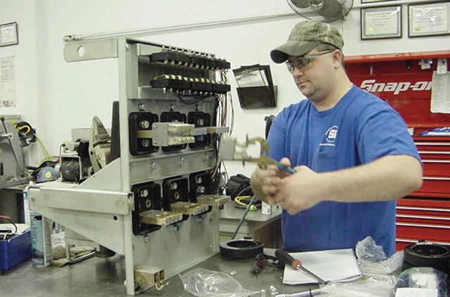
Some are referred to as LVPCB, but those are constructed differently.
When I refer to LVPCBs, I actually mean what are also referred to as low-voltage air circuit breakers (Figure 1). This was the industry standard for years, but insulated-case circuit breakers have taken their place for the most part. However, hundreds of thousands of LVPCBs are probably still in operation.
The first task involved in working on a circuit breaker, for example, taking it out of service, is to tackle the necessary paperwork. Many technicians dislike paperwork, but it serves its purpose to promote safety if it’s completed properly. NFPA 70E supplies the minimum requirements — not the best practices. Article 110 includes several requirements pertaining to circuit breaker operation, although it focuses on the electrical safety program.
Everything in Article 110 is from the 2021 edition of NFPA 70E. Beginning with Section 110.5(C) Condition of Maintenance, safe work practices are presented in Section 110.5(D) Awareness and Self-Discipline, 110.5(H) Risk Assessment Procedure, 110.5(H)(2) Human Error, 110.5(H)(3) Hierarchy of Risk Control Methods, 110.5(I) Job Safety Planning and Job Briefing, 110.5(K) Electrically Safe Work Condition Policy, and 110.5(L) Lockout/Tagout Program. Sections throughout 70E explain each of these electrical safety program requirements, but that’s a different NETA World article.
The first step in working on a circuit breaker is to complete a job safety plan where all steps are planned out and recorded. There are good reasons for this step:
• A job safety plan forces you to reason out what needs to be done: What equipment is needed, what steps will be followed as the task is performed, what PPE may be
needed, what condition is the equipment in, or is that unknown?
• It allows a second qualified person to read over the job safety plan and verify that it is accurate, safely doable, and complete.
The next step is to evaluate the risk and determine which risk control methods are needed. People tend to underplay this step, but it has tremendous importance. NFPA 70E defines risk as:
A combination of the likelihood of occurrence of injury or damage to health and the severity of injury or damage to health that results from a hazard.
We want to reduce the likelihood of an incident as much as possible. Risk of a task cannot be driven to zero unless the equipment is placed into an electrically safe work condition by de-energizing the entire bus. This may not be convenient for many reasons, but may be possible during a facility’s shutdown, after normal work hours, or during the weekend.
OSHA regulation 1910.333(a)(1) states:
Live parts which an employee may be exposed to shall be de-energized before an employee works on or near them…
To meet this requirement, the employee must be removed from the area of danger, such as by using remote operating devices or remote racking devices, wearing the proper arc-rated clothing and PPE, or other methods provided by 70E. In fact, some circuit breakers are just not safe to operate with just the use of PPE, so remote devices are needed.
When working with circuit breakers, risk increases with higher voltage, higher ampacity, higher fault current, longer tripping delay (such as short time delay), and unknown operating
conditions (i.e. past-due maintenance intervals, repeated mis-operations).
At some point, those factors may require the bus to be de-energized. As an example, opening and resetting a tripped 20 A molded-case circuit breaker in your house would not require any special steps unless it’s necessary to stand in water or some other unusual factor. Ramp that up to a 200 A or 300 A molded-case circuit breaker, and the risk increases substantially. PPE may be necessary due to the current rating of the circuit breaker, even though it is not specifically required in 70E. Determining the risk involved in operating that circuit breaker must be made in relation to factors the 70E Committee cannot foresee. Personally, at this current level and above, I would always wear adequate PPE. Electrical burns are very painful, and I like the idea of avoiding them.
With medium-voltage circuit breakers — or even older, drawout low-voltage power circuit breakers — the risk increases greatly because the voltage is higher (except for the LVPCB), the current handled is usually greater, there is no built-in overcurrent device, and they tend to run slower. For example, molded-case and insulated-case circuit breakers open in 1.5 to 3 cycles; in the current-limiting type, that time drops to 0.5 cycles. Medium-voltage circuit breakers open in 3 to 8 cycles, plus the operating time for protective relaying. LVPCBs open in about 4 cycles. These are their respective “instantaneous” operating times.
If an incident energy analysis has been performed, higher incident energy indicates greater risk. This is due not only to the incident energy, but also to the increased risk of arc blast at higher incident energies. This is why the 70E Committee deleted the informational note that indicated 40 cal/ cm2 was a maximum exposure level. That is not what it stated, but that is the way it was being interpreted by users of 70E. If the overcurrent device, such as the circuit breaker, was not maintained properly and its lubricants began to dry out, its operating time would increase. How much? There’s no way to tell. In an arc flash, time is critical, as incident energy is proportional to
opening time. Double the opening time, and the incident energy is doubled.
Another risk factor is human error. It may be someone else’s human error, not yours. It’s necessary to list all things human error could cause and what the result of each error would be. Unfortunately, people have a tendency to make errors. It’s not that they want to, but distractions, sleepiness, multi-tasking (people have a tendency to think they excel at this, which may not be true), performing the task incorrectly (what doesn’t injure or kill us becomes our way to do things), or dropping a tool, just to name a few, could cause an incident. It’s like getting on a rollercoaster: Once the ride starts, there’s no getting off. Once an incident begins, there’s no stopping it until it’s over.
Tools are available that can help reduce the risk.
Technicians often overlook using a winch to lower the circuit breaker from its cubicle. This is done on many drawout low-voltage power circuit breaker installations, and it is convenient if used properly. I found this out the hard way when a cable popped during a removal. Luckily, no damage was done when it occurred, but if I had kept going, who knows?
Figure 2 shows a winch as it is typically found. Looks ready to go, doesn’t it? It is, but not
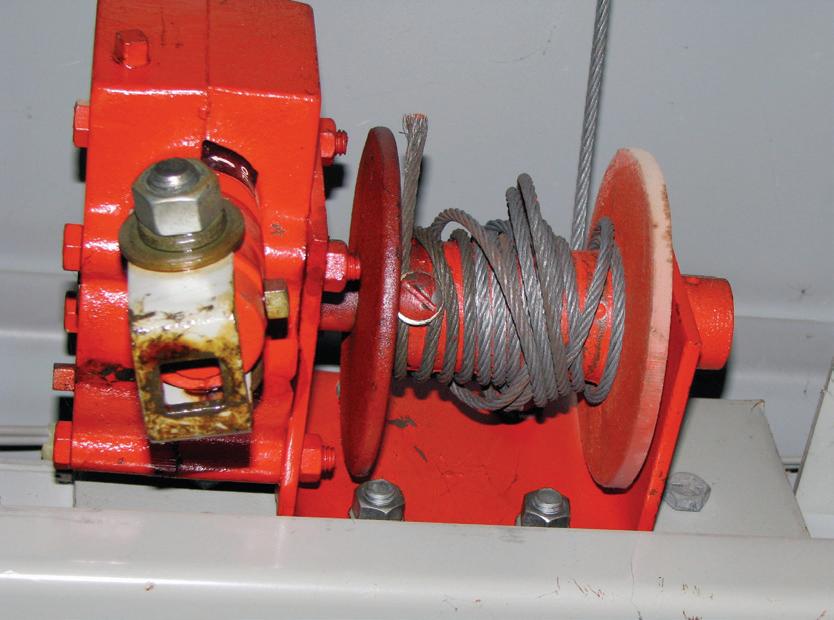
the way one would think. Notice anything wrong with the cable? Each winding of the cable is overlapping the one underneath. It looks innocent, but add the weight of a circuit breaker, and it becomes hazardous. As the cable unwinds, it pops or snaps, causing the circuit breaker to bounce — often (as in my case) bounce hard. Beyond the shock that occurs, if there’s any weakness in the cable, it could snap, letting the circuit breaker fall where it may. Trying to stop an LVPCB from falling would crush Superman, and it happens fast.
A simple fix (my favorite) is to take less than five minutes to unwind the cable from the reel and wind it back while pulling on it slightly so it is straight on the reel. The cable cannot be let loose until it is connected to the circuit breaker’s lifting bars.
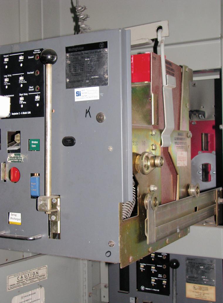
Figure 3a shows the lifting bars from one manufacturer, but they are all similar in the way they work. Figure 3b shows a typical LVPCB ready to be lowered properly by lifting it off its extension arms. The circuit breaker rollers must be checked before it is rolled out of its
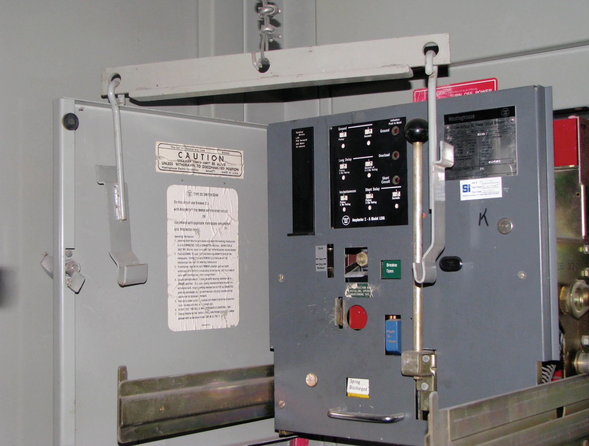
cubicle to verify they are on the extension arms and are attached properly to the circuit breaker. The cable is just out of sight in Figure 3b. It has been unwound from its reel and rewound so it is straight and any wound cable does not overlap.
It takes two technicians to attach the lifting bars to the carriage of the circuit breaker. It’s easy to see in Figure 3a that, as one side is attached, the other side may release.
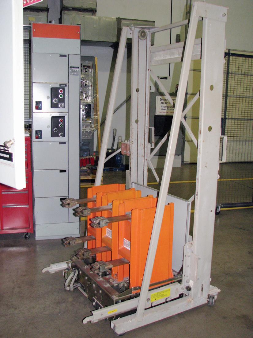
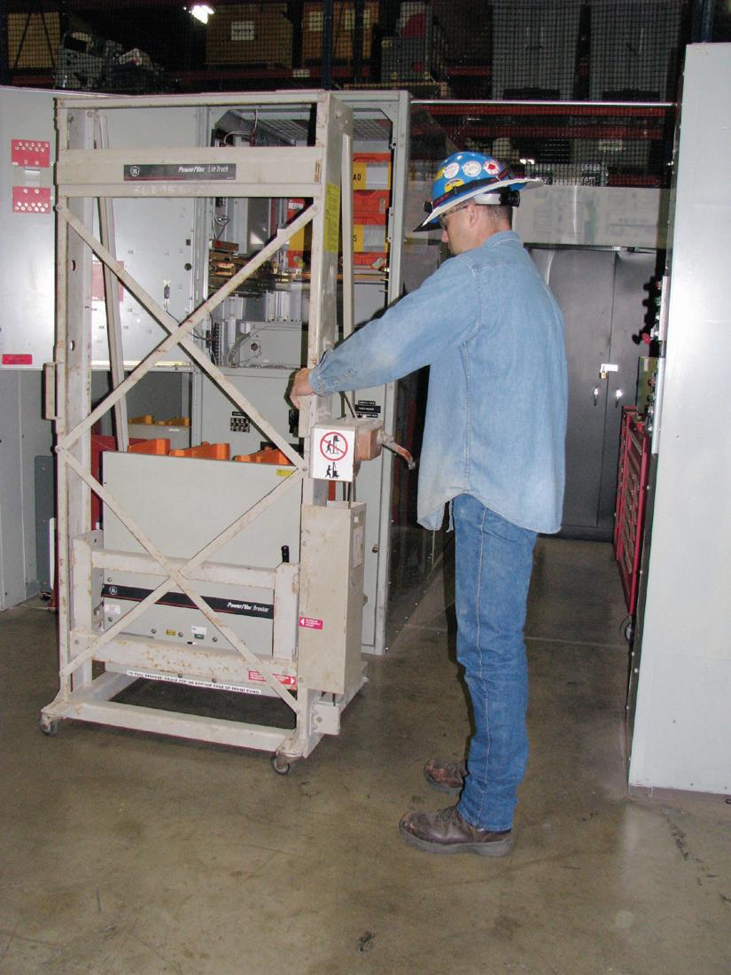
It’s no fun seeing a circuit breaker hit the floor. If no cable mechanism is available, a hydraulic lift or mechanical lift can be used. As Figure 4a and Figure 4b show, many medium-voltage manufacturers supply such a lift to install and remove their equipment. The equipment is deenergized, and the technician is wearing the correct PPE for this task.
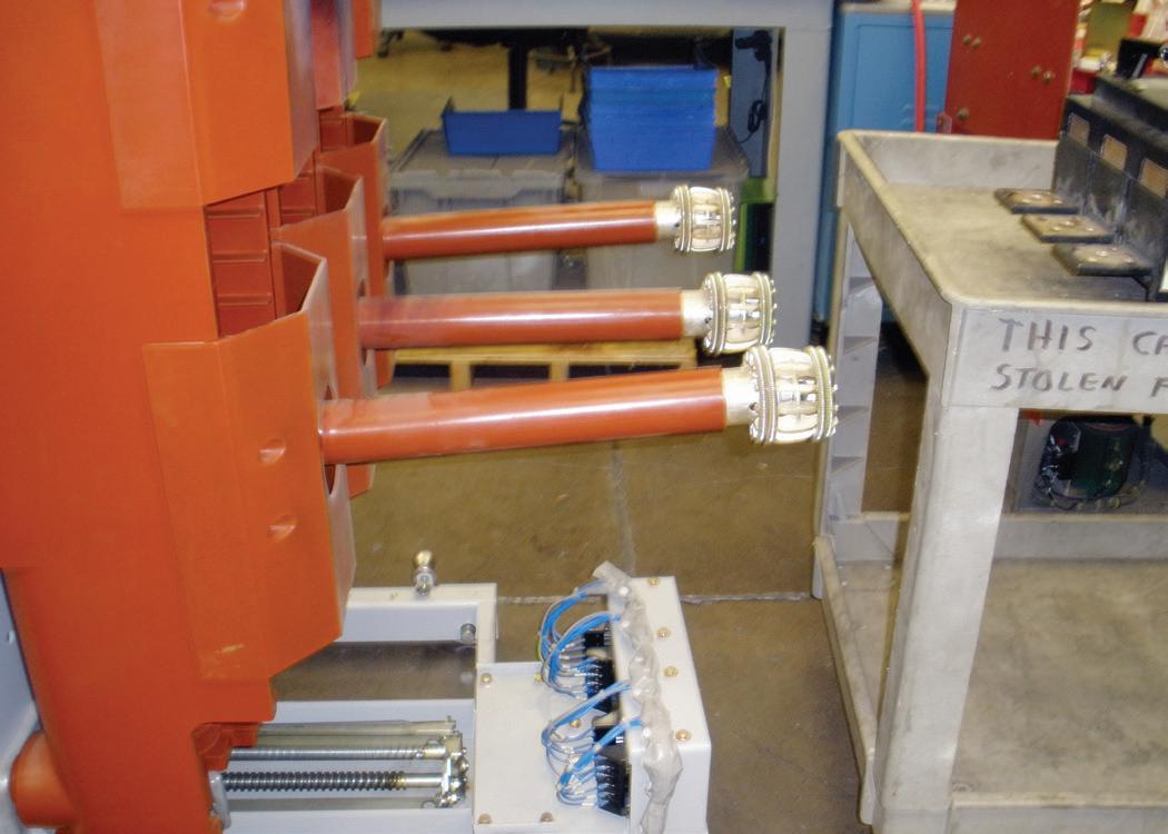
Figure 5a and Figure 5B illustrate why a remote operating device and a remote racking
device are usually needed when operating and racking a drawout circuit breaker while it is energized. Figure 5a shows that the arms of the bus connectors are out of alignment on this medium-voltage vacuum circuit breaker.
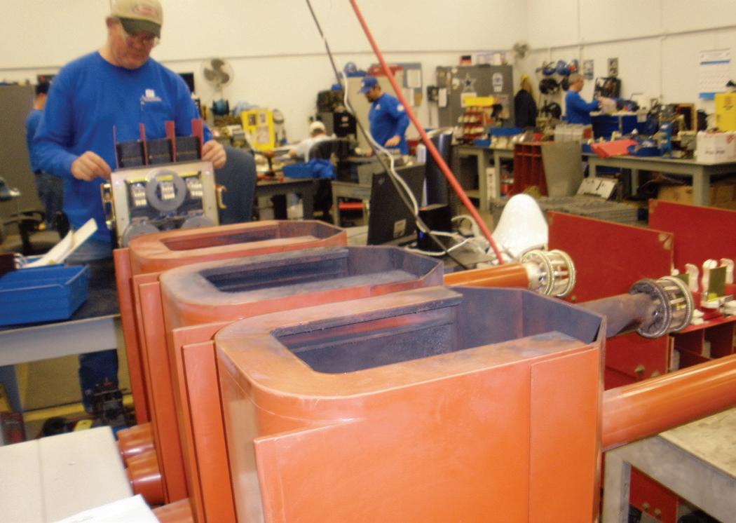
Figure 5b (the same circuit breaker) shows the results of a vacuum bottle failure, probably due to a racking incident. Any type of drawout circuit breaker can fail when the circuit
breaker bus connection makes contact with the bus. There’s no time to get out of the way. Remember the roller-coaster analogy.
Circuit breakers can also fail from being operated — opening or closing them. Figure 6a shows a bent racking gear pin from a low-voltage drawout power circuit breaker. Superman must have found his calling when he racked this circuit breaker! As a result of this

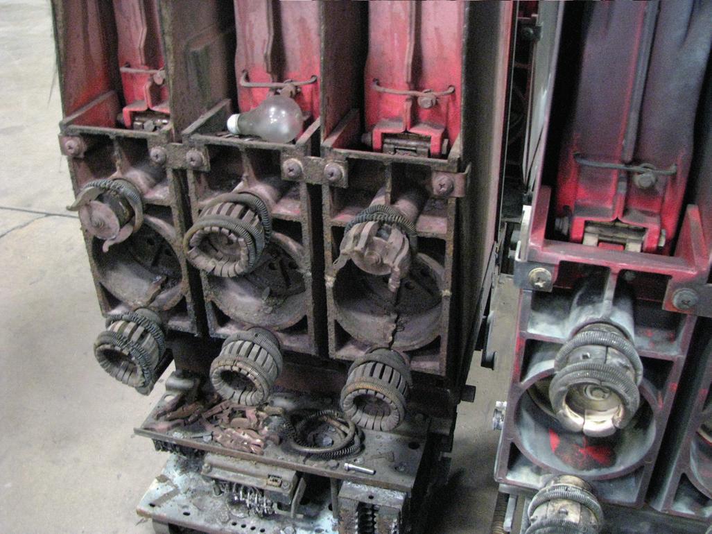
abuse, if the pin had sheared off, the circuit breaker would not stop where it should have at the full connected position; it would continue to move past that position and begin to rack out again. Amazing and dangerous, as it would break contact if the technician kept racking.
Figure 6b shows a medium-voltage airmagnetic circuit breaker. Note the light bulb on top of the contacts. This is not uncommon; I have personally seen pliers sitting on top of a 15 kV circuit breaker’s arc chutes. Note also how the contact clusters have fallen apart, causing the circuit breaker to fault. This is due to not lubricating the contact clusters, which is a good indication no maintenance had been performed.
Operating and racking circuit breakers should be done with care as well as the proper equipment and PPE. The first section in this article reviews pertinent NFPA 70E sections that apply to any task that could cause injury or even death. The second section looks at the various issues involved with operating and racking drawout circuit breakers. It’s not difficult to put the two together.
As NETA-Certified Technicians, take special care when performing tasks that could cause an incident. Remember the roller-coaster
analogy: When it begins, there’s no stopping it. A special concern should be equipment that is always used and always seems to be safe. Things happen unexpectedly and, as they used to say when I was a young lad, “Surprise! You’re it!” You did not want to be it then, nor do you want to be it now.
Work safe. Don’t rush or be distracted. The task is not worth doing quickly for any reason, and you certainly don’t want a phone call or loud noise to make you lose your attention, even for a moment.

James (Jim) R. White, Vice President of Training Services, has worked for Shermco Industries since 2001. He is a NFPA Certified Electrical Safety Compliance Professional and a NETA Level 4 Senior Technician. Jim is NETA’s principal member on NFPA Technical Committee NFPA 70E®, Electrical Safety in the Workplace; NETA’s principal representative on National Electrical Code® Code-Making Panel (CMP) 13; and represents NETA on ASTM International Technical Committee F18, Electrical Protective Equipment for Workers. Jim is Shermco Industries’ principal member on NFPA Technical Committee for NFPA 70B, Recommended Practice for Electrical Equipment Maintenance and represents AWEA on the ANSI/ISEA Standard 203, Secondary Single-Use Flame Resistant Protective Clothing for Use Over Primary Flame Resistant Protective Clothing. An IEEE Senior Member, Jim was Chairman of the IEEE Electrical Safety Workshop in 2008 and is currently Vice Chair for the IEEE IAS/PCIC Safety Subcommittee.


Rent any piece of Megger electrical testing equipment from our inventory for 30 days, and if you decide to buy it, we will discount the cost of your rental from the purchase price.
This is a limited time offer that ends June 30th, 2020.


BY SANKET BOLAR, Megger
Circuit breakers used in low-voltage applications include air circuit breakers, insulated-case and molded-case circuit breakers, and miniature circuit breakers. Air circuit breakers or low-voltage power circuit breakers typically function as the incoming device on a low-voltage switchboard. In the event of an overload condition or short circuit, current sensors in low-voltage power circuit breakers measure high currents and send the feedback to an electronic trip unit.
The trip unit is the brain of the circuit breaker; it causes the circuit breaker to act according to the logic programmed in the trip unit. The molded-case circuit breaker incorporates an electronic trip unit; however, in smaller frame sizes, the trip unit may not be as sophisticated as those found in air circuit breakers. Some MCCBs include an electromechanical thermal trip and electromagnetic trip in place of the electronic trip unit.


To properly isolate a fault, the circuit breaker must act in a timely and reliable manner. Failure of a circuit breaker to do so can result in a more widespread outage area, loss of revenue, damage to equipment, injury, or loss of life in a worst-case scenario. Hence, it is essential to carry out maintenance work at regular intervals throughout the service life of a circuit breaker. Various activities can be undertaken as part of preventive maintenance. This article focuses on electrical testing that can be carried out on lowvoltage circuit breakers.
ANSI/NETA MTS, Standard for Maintenance Testing Specifications for Electrical Power Equipment & Systems recommends the following electrical tests as part of maintenance testing on low-voltage circuit breakers:
By measuring the contact resistance on each pole of the circuit breaker, we can check for contact-related issues that can interfere with
the circuit breaker’s ability to conduct current adequately. For instance, contact erosion over time can lead to heating issues that eventually lead to breaker failure. Resistance values are typically measured in the range of µΩ, although resistance can exceed 1 mΩ in the case of some low-amp-rated MCCBs. As current rating increases, the resistance values measured on the poles typically tend to drop. Similar values should be measured on the poles of the same breaker, and any deviation of more than 50% warrants investigation. The breaker manufacturer can be consulted on the expected pole-resistance value.
Insulation resistance can be measured between phases and between phase-ground with the breaker closed and across each pole with the breaker open.
Primary injection testing involves injection of current through the poles of the circuit breaker
to verify that the breaker will operate as per the trip unit logic. Four tests can be carried out:
1. Long-time delay and pickup. The longtime delay characteristic provides overload protection. The pickup is typically set equal to the overcurrent protection device’s continuous current rating. The test current injected is typically three times the long-time pickup. The test current is injected through each pole, and the trip time is recorded each time. The results are validated by referring to the time-current curves provided by the manufacturer. The trip time recorded is typically in the order of seconds to avoid spurious tripping.
2. Short-time delay and pickup. The shorttime delay characteristic provides protection against short-circuit or fault conditions. An intentional delay is provided for coordination or selectivity with other protection devices. The short-time pickup is a multiple of the long-time pickup. The test current typically used is 1.5–2.5 times the short-time pickup. The test current is injected through each
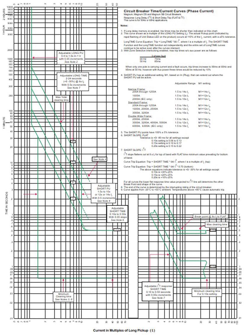
1: Sample Time-Current Curve from a Manufacturer
pole of the breaker and the trip time is recorded each time. The results are validated by referring to the time-current curves published by the manufacturer (Figure 1). The trip time recorded is typically in the order of cycles or milliseconds.
3. Instantaneous pickup. The instantaneous trip characteristic provides protection against short-circuit or fault conditions but doesn’t include any time delay. In this test, pulses of current (pulse duration between 5 and 10 cycles) with steadily incrementing magnitudes are injected through each pole until the circuit breaker trips. The starting pulse is set at around 70% of the expected pickup. The value of the pickup at which the breaker trips is recorded. Manufacturers typically provide a tolerance of ±10% to ±25% on the pickup.
4. Ground-fault delay and pickup. The ground-fault trip characteristic provides protection against ground faults. The ground-fault pickup is typically a fraction (20%–60%) of the continuous current rating of the overcurrent protection device. The test current injected is typically 1.5–2.5 times the pickup. This test is required for many service entrances by NFPA 70, National Electrical Code (NEC 230.95).
Several factors must be appropriately determined for a successful test.
The output of the primary injection test set depends on the input voltage. It is essential that the input voltage provided should be within ±5% of the specifications for the test set. The input breaker must be sized appropriately. As the test set is operated at higher currents, higher losses occur. As a result, the relationship between the input current and the output current for primary injection test sets is exponential (Figure 2). When procuring a high-current test
set, it is important to install an input breaker that is sized to handle the input power required for the maximum test currents that would be applied in the course of testing the breakers.
The connection leads between the input voltage supply and the input voltage terminals on the test set also must be appropriately sized and short in length. Unnecessarily long connections can result in a drop in voltage at the input voltage terminals, thus affecting the performance of the test set.
As high-current test sets have very-low opencircuit voltage (typically 5–10 V), the maximum output from a high-current source is limited by the circuit impedance, which in turn primarily depends on the test connections. For loweramperage breakers, the connection is typically done using cables. These cables need to have sufficient ampacity. This can be achieved by connecting multiple cables in parallel. The shortest possible cables should be used. The cables can be twisted together whenever possible to further reduce the impedance of the circuit.
High-current test sets used for testing draw-outtype circuit breakers use stab sets for connections to ensure the circuit impedance is negligible. Stab sets of various designs can be created for use with different types of circuit breakers.
To overcome high circuit impedance while testing at relatively lower currents, some highcurrent test sets have a modular design that allows multiple high-current sources to be connected in series to achieve a higher opencircuit voltage to drive the desired current through the breaker.
During an instantaneous trip test, an error can be introduced into the result because of the presence of a DC offset in the current pulse (Figure 3).
The asymmetrical nature of the first few current cycles results from a high X/R ratio in inductive
Figure 2: Input Current Measured for Primary Injection Test System at Various Output Currents
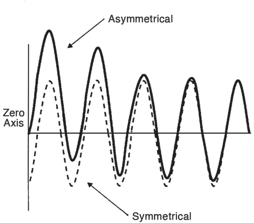
Figure 3: DC Offset as Shown in NEMA AB-4
DC offset vs voltage firing angle
Figure 4: Difference between Peak/√ 2 and True RMS Value Observed in Output Current for Various Firing Angle Values
circuits. The DC offset can be minimized by manually or automatically adjusting the firing angle (the point on the voltage wave at which the output is energized). A measure of the DC offset is the difference between the peak/√2 and RMS (Figure 4, Figure 5, Figure 6, Figure 7). They should be equal for a perfectly sinusoidal wave.
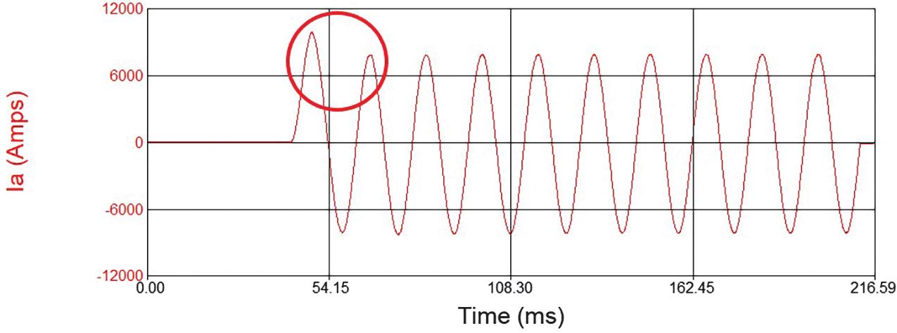
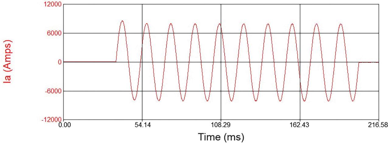

While testing circuit breakers equipped with trip units having ground-fault protection, it is important to disable the ground-fault protection to be able to run the other tests, as the currents involved in other tests tend to be higher than the ground-fault pickup. While some trip units provide the option of disabling ground-fault protection, a breaker without that option can still be tested by injecting current through two poles connected in series as shown in Figure 8.
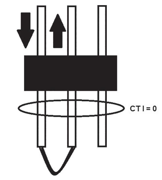
Primary injection testing has been done for decades. The traditional technology is still relevant, along with the introduction of newer technology with some advantages.
Primary injection test sets are available in various sizes depending on the output current range. Primary injection test sets used for testing power circuit breakers are typically large and weigh hundreds of pounds.
Primary injection test sets that operate at relatively lower currents can be mounted on carts, which enables testing outdoors in substations, for example. Still smaller portable primary injection test sets can put out current in the range of a few thousand amps. Having a portable test set certainly helps if testing needs to be done in elevated or difficult-to-access locations.
As mentioned earlier, primary injection test sets may have a modular design that provides the tester with some flexibility in achieving different output currents and output voltages. Higher currents can be achieved by connecting multiple sources in parallel, whereas a higher open-circuit voltage can be achieved by connecting multiple sources in series.
Some primary injection test sets include additional features like secondary measurement channels. This enables them to be used in
other applications such as CT ratio testing or measurement of other parameters (Z, R, , etc.) in a circuit.
Traditionally, output current control has been done manually, but newer technology permits automatic current control. This eliminates the additional step of adjusting the output setting to achieve the desired current prior to starting the test, as well as the need to manually adjust the output current to maintain a certain level during a long-time test.
Software with a library of time-current curves from various manufacturers means the user doesn’t have to spend time finding and then interpreting the manufacturer’s published timecurrent curves to determine the trip-time limits for a certain test.
The wide variety of primary injection test systems offers an informed choice based on multiple factors including portability, ease of use, size of breakers to be tested, and magnitude of test currents.
Primary injection testing is the complete test for a circuit breaker. It verifies the entire protection chain in a circuit breaker. The current flows through the pole(s) of the
circuit breaker, thus verifying the currentcarrying path. The current sensors and wiring are checked. The trip unit logic is verified. The operating mechanism of the breaker is also tested. Thus, it can be said that it is a complete test of the circuit breaker.
National Fire Protection Association. NFPA 70, National Electrical Code (NEC 230.95). Quincy, Massachusetts.
National Electrical Manufacturers Association. NEMA AB 4-2017, Guidelines for Inspection and Preventive Maintenance of Molded-Case Circuit Breakers Used in Commercial and Industrial Applications. Arlington, Virginia.

Sanket Bolar is a substation applications engineer at Megger. From the beginning of his professional career, Sanket was directly involved with testing and condition assessment of power transformers working for Siemens Ltd (India). While working on his MS, Sanket became part of Megger’s internship educational program. Upon graduation in 2015, he joined Megger as an applications engineer covering a broad spectrum of substation products from transformer to power quality applications. Sanket graduated from Mumbai University, India, in 2009 with a BS in electrical engineering and received his MS in electrical engineering specializing in power systems from North Carolina State University in 2015. He is a member of IEEE.



• Cables
• LV/MV Circuit Breakers
• Rotating Machinery
• Meters
• Automatic Transfer Switches
• Switchgear and Switchboard Assemblies
• Load Studies
• LV/MV Switches
• Relays - All Types
• Motor Control Centers
• Grounding Systems
• Transformers
• Insulating Fluids
• Thermographic Surveys
CoNSulTING AND ENGINEERING
• Transient Voltage Recording and Analysis
• Electromagnetic Field (EMF) Testing
• Reclosers
• Surge Arresters
• Capacitors
• Batteries
• Ground Fault Systems
• Equipotential Ground Testing
• Harmonic Investigation
• Replacement of Insulating Fluids
• Power Factor Studies

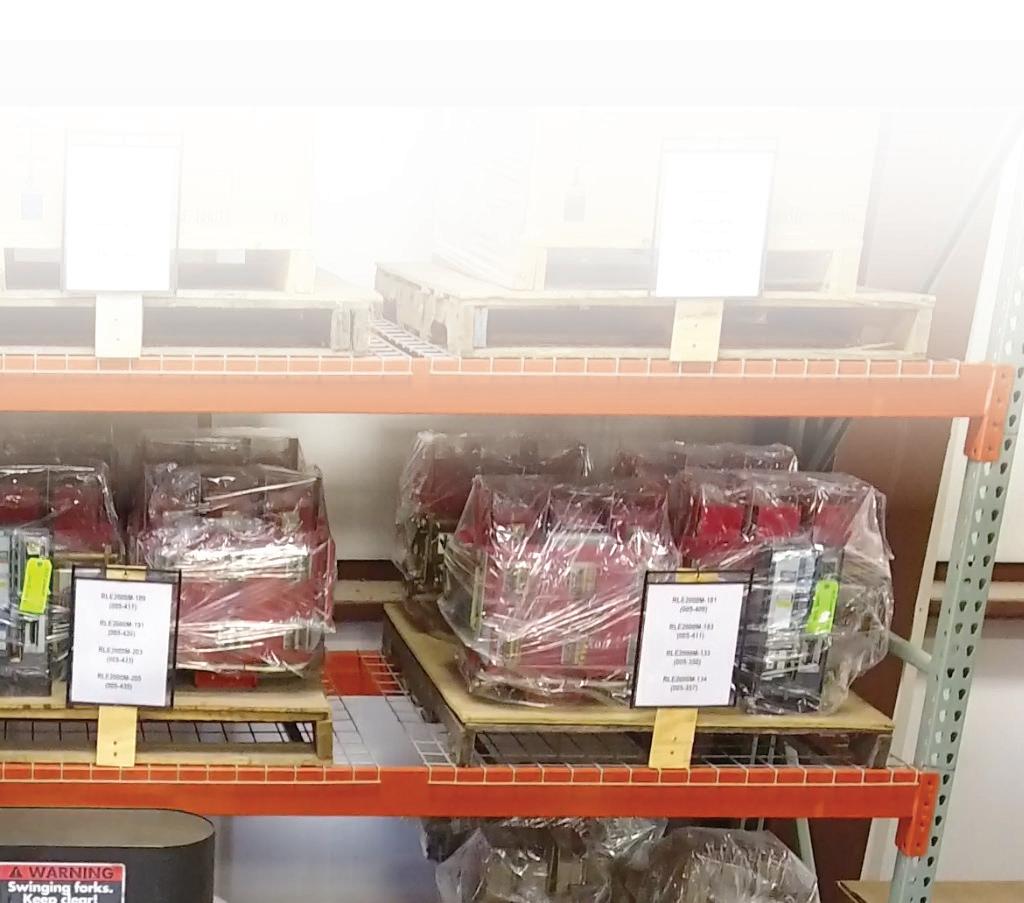
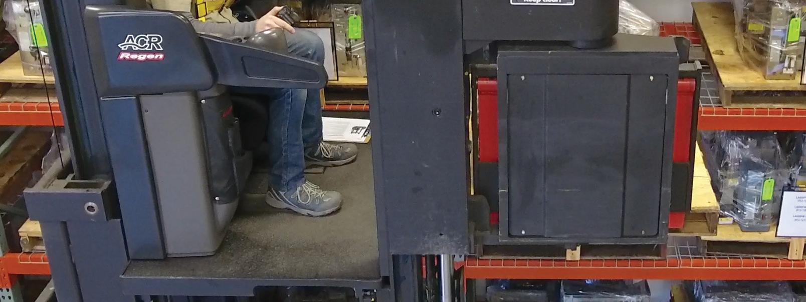

When equipment fails, every minute spent searching for what you need is bad for the bottom line. Our massive inventory of millions of new, surplus and repurposed circuit breakers, switchgear and related products is here for you. We have the expertise to see the big picture, understand your problem and recommend the best solution. Already know exactly what you need? Our website is constantly being updated with products and the online buying process is easy.
Tap into the power of National Switchgear at nationalswitchgear.com or call us today at (800) 322-0149.

BY KERRY HEID, Shermco Canada
Low-voltage circuit breakers are predominant in virtually every electrical power system. A 2008 NETA survey and associated IEEE paper showed that 22% of these breakers did not follow their time-current characteristics, and 10.5% did not operate at all when service-aged maintenance was undertaken. The majority of failures were mechanical in nature; this indicates regular maintenance must be a priority.
Low-voltage air circuit breakers come in a wide variety of ratings and styles from numerous manufacturers, and it can be a challenge to ensure these devices are tested to operate within their time-current bandwidth.
The 2021 edition of CSA Z462, Workplace Electrical Safety offers new requirements for these devices to be assessed on a case-by-case
basis as outlined in an electrical maintenance program such as the example in CSA Z463, Maintenance of Electrical Systems. It is always advisable to use competent maintenance personnel, such as those employed by NETA Accredited Companies, for testing that follows the latest ANSI/NETA specifications for electrical testing.
A recent assessment by the CSA Z463 Technical Committee deemed the rackable, low-voltage air circuit breaker (LVACB) a device that carries a higher risk than most other devices in a power system. This device can be operated on a regular basis by maintenance staff to create an electrically safe working condition. LVACBs have an on-board protection system including a series trip unit or an electronic trip unit consisting of current transformers, wiring harness, and protective relay, as well as some type of mechanical actuator. When not exercised on a regular basis, an LVACB can become inoperable without any warning. Combining the features of rackable, frequently operated, and on-board complete protection
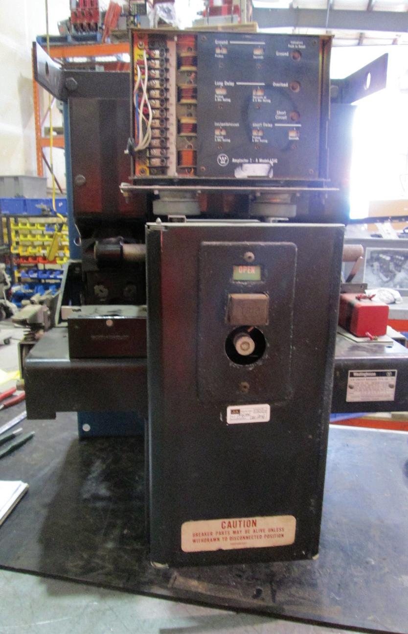
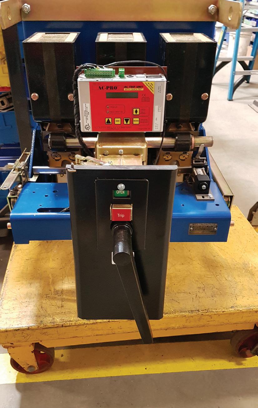
system make the likelihood and impact of failure one of the highest in the electrical power system.
The chapter on Safety Related Maintenance Requirements in the 2021 edition of CSA Z462 has been revised to emphasize electrical maintenance that directly affects worker safety. For instance, the 2018 edition specifically mentions that “molded-case circuit breakers shall be maintained free of cracks in their cases and cracked or broken operating handles.” While this is important, cases and handles are included under general maintenance of equipment kept in “good working order” along with various other items such as covers in place, lugs tightened, insulation resistance tested, etc.
Condition of maintenance is to be considered numerous times during the risk assessment process. Clearly, the biggest issue in the industry is whether the equipment actually trips to clear a fault at the time specified. To ensure this, maintenance personnel must perform inspection, testing, and verification to prove the method chosen to determine the incident energy is valid. These devices often operate slower (or in some cases, not at all), especially when service aged in an industrial operating environment or due to other factors. When protective devices do not follow their time-current characteristics, workers receive a false estimate of the incident energy and choose PPE accordingly whether from the arc flash and shock label or the table method.
The operating speed of a protective device is clearly a major factor. Maintaining protective devices is critical to a worker’s safety because it affects their ability to determine the true value of incident energy in the field. Tables list typical fault clearing times of overcurrent protection devices, all dependant on equipment maintenance. For this reason, Z462 has upgraded its safety-related maintenance clause to focus on items that affect worker safety, not just general maintenance requirements.
The 2021 edition references the maintenance requirements for low-voltage circuit breakers. A removable low-voltage air circuit breaker aligns with all these requirements for maintenance:
1. Protective devices “shall be maintained to function in accordance with their designed operating times.”
2. Overcurrent relays, commonly called trip units on low-voltage breakers, “shall be tested to operate in accordance with their time current characteristics.”
3. Ground fault protection “shall be inspected and tested to ensure they are functioning correctly and within the trip or alarm time specified.”
4. Key interlocks “shall be tested for proper operation.”
5. Mechanical systems that need regular exercising “shall be inspected, exercised, tested, and maintained to ensure proper electrical and mechanical operation and circuit isolation of the contacts and mechanical operation of the racking mechanisms and, where applicable, shutter mechanisms and safety interlocks.”
6. Settings “shall be reviewed to ensure they meet the protection coordination study and incident energy analysis.”
All of these factors directly correlate with the safety features of a low-voltage breaker. It is vitally important to this process to ensure the entire system functions properly, including current sensors, wiring harness, trip units, shunt coils, interlocks, and conducting surfaces.
At the end of calendar year 2020, we surveyed a group of NETA Certified Technicians about their issues and most recent failures with lowvoltage power circuit breakers. The breakers were from a wide variety of manufacturers, vintages, and industry types. Results showed:
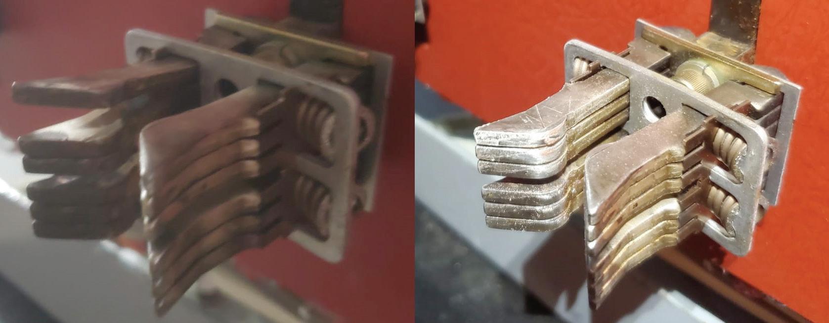
• Mechanical operation is always an issue, often due to improper lubrication, lack of exercise, wear on the main operating mechanism, or even overlubricating — particularly when applied to the finger clusters instead of the stabs, which may be energized or not accessible. It is extremely important to understand the consequences of lubricating the clusters versus the stabs or using dissimilar lubrications, as this frequently causes contact or racking problems.
• Sluggish initial operation for the first couple of operations can usually be avoided with regular maintenance on the operating mechanism and proper lubrication.
• Trip unit failures are common across the board with all types and manufacturers. These failures are discovered during time-currrent testing through primary or secondary injection.
• Damage to contact surfaces from years of maintenance scrubbing with scratch pads for no reason other than to make it shiny removes the silver plating. Be very careful when performing maintenance on silver-plated surfaces.
• Generator breakers, specifically those that are mounted on the same chassis as the generator itself, tend to have a higher failure rate. This is often a mechanical failure that causes the breaker to be inoperable.
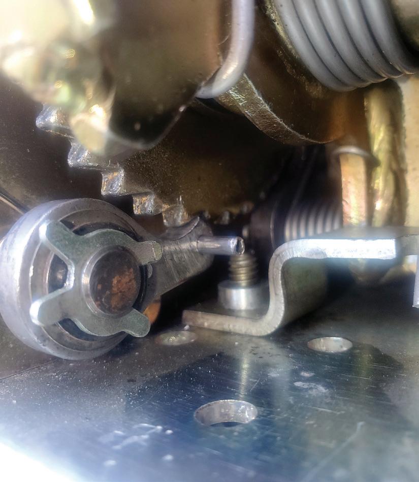
• Coil failures can include a failed undervoltage coil or trip coil as part of the trip and control scheme.
• Vintage parts are becoming more difficult to acquire from the original manufacturer; this applies to most makes and models. It is always good to have a local NETA service company or a NETA-affiliated usedequipment vendor available.
Not all low-voltage air circuit breakers are created equal. Many breakers can be quite easy to maintain, while others can be much more
difficult; it depends on the installation. In the author’s opinion, the following circuit breakers are listed from the easiest to hardest to perform electrical testing on. The list is based on ease of access, shutdown required, and testing with secondary injection versus primary injection among other factors.
1. Rackable power circuit breakers with solid state or electronic trip units
2. Bolt-in insulated-case power circuit breakers with adjustable solid-state trip units and manufacturer’s test sets
3. Bolt-in molded-case circuit breakers with electronic trip devices, adjustable settings, and secondary injection test ports
4. Rackable power circuit breakers with series trip units (oil or air dash pots or other electromechanical trip units)


5. Bolt-in power circuit breakers with oil or air dash pots or other electromechanical trip units
6. Bolt-in molded-case circuit breakers with electromechanical trip units
Low-voltage circuit breakers, which typically include trip units or inherent tripping devices, should be tested to operate within their timecurrent bandwidth or per alternative equivalent methods recommended by the manufacturer of the trip unit or circuit breaker. Industry standards are also great tools to use for proper maintenance requirements.
Assuming electrical power distribution equipment will operate as designed without verifying operating condition can result in an unexpected increase in incident energy. In some cases, devices do not operate at all. Lengthening operating time vastly increases incident energy values, arc flash boundaries, and PPE requirements. Regular performance of proper visual and mechanical inspections and electrical tests are essential to insure low-voltage circuit breakers can provide their important safety functions.

Kerry Heid is an Executive Consultant at Shermco Industries. After beginning his career with Westinghouse Service, Kerry founded the Magna Electric Corporation (MEC) office in Regina, Saskatchewan, in 1996 and became President of the company in 2001. The company grew to over 1,000 employees and won many awards as one of Canada’s 50 Best Managed Companies and Canada’s Top 100 Employers. MEC was acquired by Shermco Industries in December 2013, and Kerry served as CEO of Shermco Industries Canada until 2019. Kerry is a NETA Certified Level IV Test Technician and is active in Canadian standards development. He has served as Chair of the CSA Z463, Maintenance of Electrical Systems technical committee since 2010 and as a member of the CSA Z462, Workplace Electrical Safety technical committee since its inception in 2006. Kerry received the prestigious Award of Merit from the Canadian Standards Association in 2019. He served on NETA’s Board of Directors from 2003–2014, is a past-President, and received NETA’s Outstanding Achievement Award in 2010.

BY COREY HANNAHS, National Fire Protection Association
As I allegedly approach a half century on this earth, reflections on life lessons learned abound. Looking back, there is no question that the most impactful lessons I learned — those I still use every day — came on days that started in the blazing heat of summer and ended in the brisk chill of autumn spent between painted white lines on lush blades of green grass.
The football field is where I learned, along with young men who would eventually become my brothers, about courage, perseverance, accountability, sacrifice, and teamwork. We learned how to play for something more than ourselves; we learned how to play for one another. We were accountable to one another and came to understand that we were only as powerful as our weakest player; therefore, we had to push each other to be better. When toe met leather on those Friday nights under the lights, as Kenny Chesney’s song, The Boys of Fall says, you mess with one man, you got us all.
In more recent years, I have had the privilege of being the one to wear the whistle and begin to instill life lessons in my own son and the teammates he will no doubt one day consider brothers. From this side of the white lines, I can begin to understand more about the framework of success. Coaches must create a
game plan that, when executed by both players and coaches, achieves the desired outcome: Victory!
Transferring this to our day jobs, what does a victory look like? To me, working safely throughout the day, which in turn allows me to return home safely to my family each night, is like winning the Super Bowl. This isn’t going to happen without a proper game plan that is executed precisely as intended by both coaches and players. Business owners, acting as coaches, must put together a clear plan for safety and ensure their players have the proper resources to execute the plan.
Communication of the plan, proper training, and safety equipment for players or employees are critical to the plan being executed and success being attained. Owners and employees are equally accountable: A safety plan must not

only be established, but also must be followed as designed. Shortcuts by anyone could result in failure of the plan, which in this case is not signified by a lesser score than our opponent on the scoreboard, but potentially by whether we live or die. This is not a game we can take a chance on losing.
On the job, electrical opponents such as shock, electrocution, arc flash, and arc blast are all nipping at our heels trying to ensure we don’t reach the end zone at all, let alone achieve victory. NFPA 70E®, Standard for Electrical Safety in the Workplace® , is a critical resource when it comes to putting together a game plan for electrical safety success. When established by owners and followed by employees, the safety policies, procedures, and process controls found within NFPA 70E can help
ensure electrical safety success for all involved. Looking at some of the most dominant teams in the history of professional football, it has been their planning and the execution of that plan that has put them in elite company.
Exploring Section 110.5 of the 2021 edition of NFPA 70E, we find items specific to electrical safety that still have many similarities to the makeup of a winning game plan. Going top down through section 110.5, you will see terms such as awareness, self-discipline, principles, controls, procedures, assessment, planning, briefing, and auditing. These are some of the key components needed to achieve electrical safety success. Individuals must be aware of potential hazards within their working environment. Hazards can change and new hazards can arise; therefore, employees must stay cognizant and
aware of their ever-changing surroundings. Selfdiscipline is a foundational pillar of success. Qualified individuals performing the work must be prepared, know the proper procedures, and execute those procedures precisely without taking any shortcuts.
NFPA 70E Section 110.5, Informative Annex E gives some great examples of principles, controls, and procedures that should be implemented into your plan. Principles include anticipating unexpected events, using the right tools for the job, and assessing people’s abilities. One necessary control is ensuring employees are trained to be qualified for working within a specific environment influenced by the presence of electrical energy. Procedures consist of items such as identifying hazards and assessing risks of the task, determining personal protective equipment (PPE), and listing safe work practices to be used.
Another key component is the assessment of risk. Section 110.5(H) covers risk assessment procedures and states that before any work is started, we must:
1. Identify hazards
2. Assess risks
3. Implement risk control according to the hierarchy of risk control methods (more on this later)
An additional part of the risk assessment procedure is to address the potential for human error and understand that risk can be adversely affected by factors such as tasks and the work environment. Informative Annex Q delves deeper into human performance as it relates to electrical safety. Within Annex Q, a section on the principles of human performance includes a basic principle:
People are fallible, and even the best people make mistakes.
This couldn’t be truer and speaks even more to the need to have proper procedures in place and follow them precisely as intended.
Once the situation has been assessed and we are aware of the associated hazards and risks, we must put together a job safety plan and briefing. Within the job safety plan, we must determine a qualified person for the job and document the plan with specific information such as job tasks, hazards, shock risk assessment, arc flash risk assessment, and work procedures.
Once completed, a job briefing must cover the job-specific plan and information on the energized work permit if one is required. Any change in scope after these items are set requires additional planning, and a new briefing should be held.
The last piece to the winning game plan is auditing to ensure the plan continues to meet the safety needs of the users and any new requirements of NFPA 70E. A documented audit is required at intervals not exceeding three years.
Like any good plan, the processes and procedures within NFPA 70E can be evaluated and revised between editions through the standards development process. Although the 2021 edition of NFPA 70E was just released in September 2020, public input for modifications to the 2024 edition is already being submitted and will continue to be accepted through June 1, 2021. Between the 2018 and 2021 editions of NFPA 70E, public input significantly impacted the general requirements for electrical safety-related work practices as listed within Article 110.
Chapter 1 within NFPA 70E, which contains Article 110, is really where the details of our safety game plan are laid out including specifying both employer and employee responsibility in Article 105.
Section 110.5 is specific to the Electrical Safety Program, which requires the employer to both implement and document an electrical safety program that directs activity appropriate to the risk associated with electrical hazards.
Through public input, section 110.5(K) was added; it states:
An electrical safety program shall include an electrically safe work condition policy that complies with 110.3.
Section 110.3 states that conductors and circuit parts operating at 50 volts or more are required to be put into an electrically safe work condition if any of these conditions exist:
• The employee is within the limited approach boundary and
• The employee interacts with equipment where conductors or circuit parts are not exposed, but an increased likelihood of injury from an exposure to an arc flash hazard exists.
By definition, an electrically safe work condition is a state in which an electrical conductor or circuit part has been disconnected from energized parts, locked/tagged in accordance with established standards, tested to verify the absence of voltage, and temporarily grounded for personnel protection if necessary. The Informational Note that follows the definition goes a step further to state that an electrically safe work condition is not a procedure; it is a state wherein all hazardous electrical conductors or circuit parts to which a worker might be exposed are maintained in a de-energized state for the purpose of temporarily eliminating electrical hazards for the period of time for which the state is maintained.
While many think personal protective equipment (PPE) such as arc flash suits should be the means we use to keep ourselves safe, PPE should actually be the last resort. Turning power off and establishing an electrically safe work condition where there is no potential for exposure should always be the primary goal. The Hierarchy of Risk Controls is listed in section 110.5(H)(3):
(1) Elimination
(2) Substitution
(3) Engineering Controls
(4) Awareness
(5) Administrative Controls
(6) PPE
Informational Note 1 goes on to state:
Elimination, substitution, and engineering controls are the most effective methods to reduce risk as they are usually applied at the source of possible injury or damage to health and they are less likely to be affected by human error. Awareness, administrative controls, and PPE are the least effective methods to reduce risk as they are not applied at the source and they are more likely to be affected by human error.
The reality of public input to the 2021 edition of NFPA 70E changed our game plan for the better. While employers are already required to implement and document an electrical safety program, the addition of 110.5(K) now requires an electrically safe work condition policy within that program. If going home safely to our family every night is our ultimate measure of success, this change just puts us at first and goal. It’s now up to both employers and employees to fully execute the plan to put the ball into the end zone.

Corey Hannahs is an electrical content specialist at the National Fire Protection Association (NFPA). In his current role, he serves as an electrical subject matter expert in the development of products and services that support NFPA documents and stakeholders. Corey, a third-generation electrician, holds licenses as a master electrician, contractor, inspector, and plan reviewer in the state of Michigan. Having held previous roles as an installer, owner, and executive, he has also provided electrical apprenticeship instruction for over 15 years. Corey was twice appointed to the state of Michigan’s Electrical Administrative Board by former Governor Rick Snyder and received United States Special Congressional Recognition for founding the B.O.P. (Building Opportunities for People) Program, which teaches construction skills to homeless and underprivileged individuals.
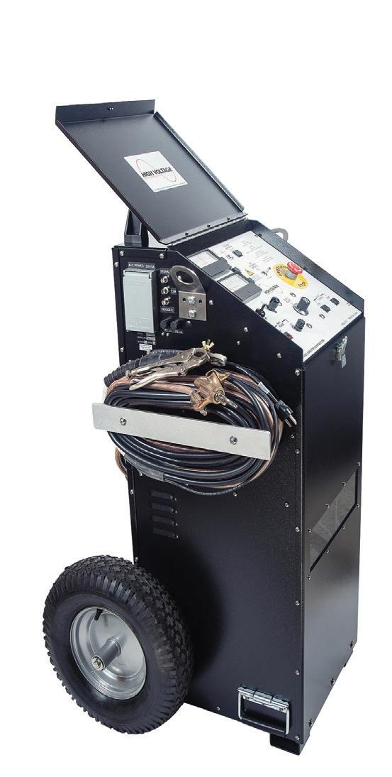

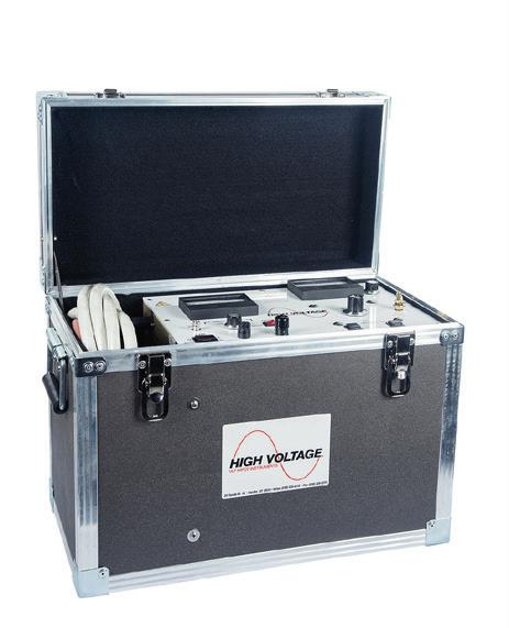
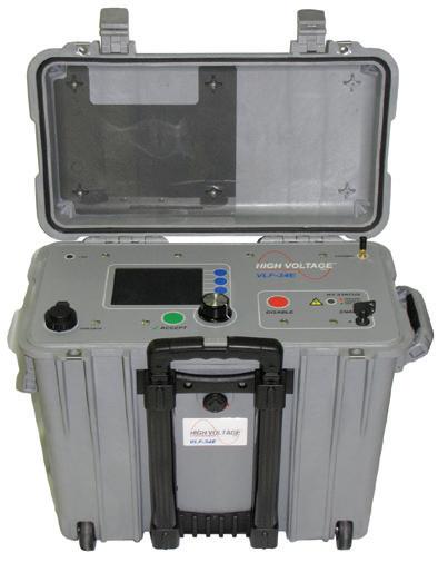
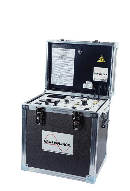


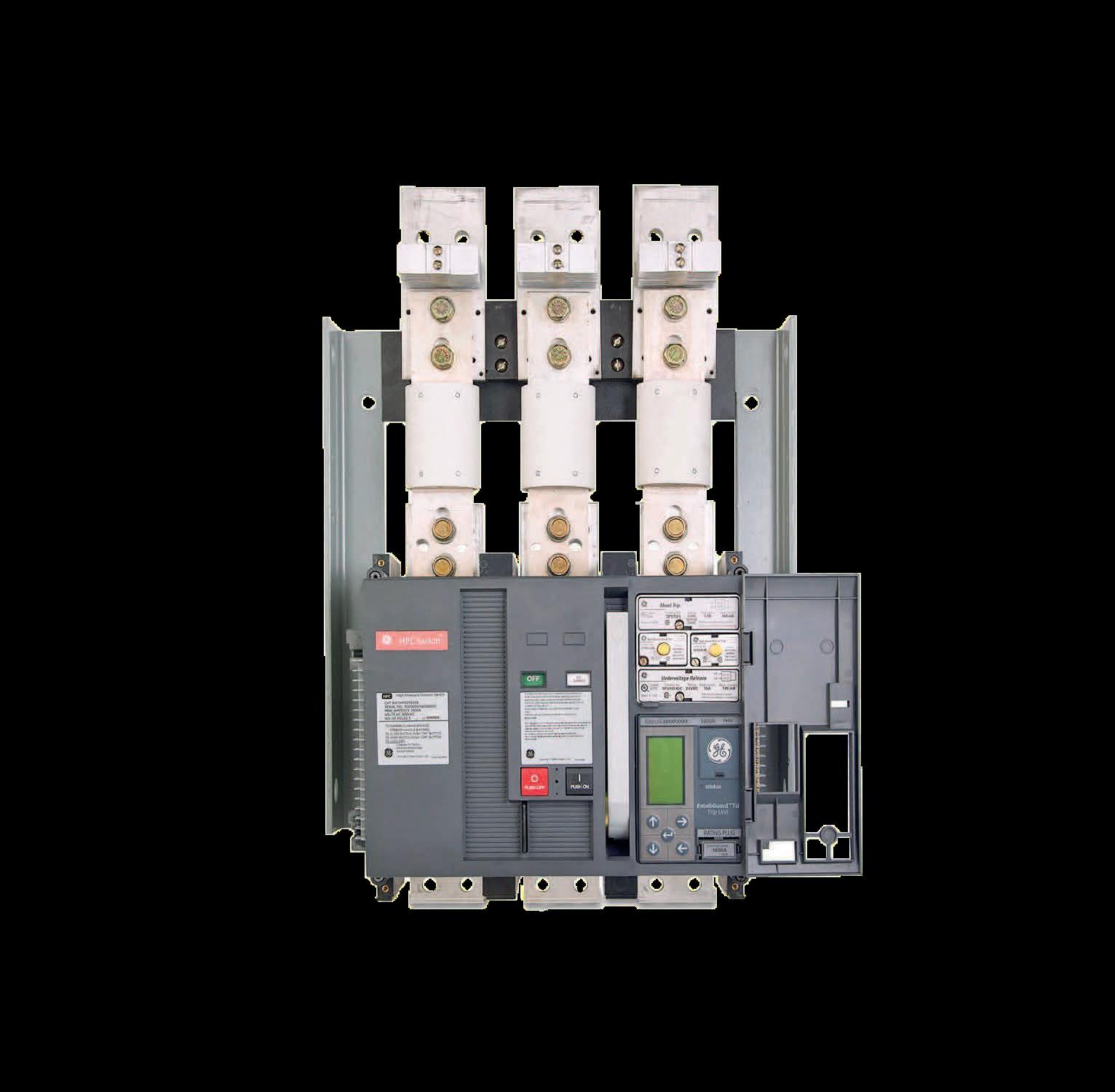


We’ve got answers. Discover page after page of comprehensive, component-specific, technical resources for training and reference purposes. Over 200 of the very best articles from NETA World Journal and technical presentations from NETA’s PowerTest conferences. To order, please visit netaworld.org or call 888.300.6382

BY WILLIAM HIGINBOTHAM, EA Technology LLC
Partial discharge (PD) is a poorly understood phenomenon that can cause catastrophic failure of electrical assets. It can exist at initial commissioning or occur only after decades of use. The dictionary defines partial discharge as:
a flashover of part of the insulation system due to a localized electric field greater than the dielectric withstand capability of that part where the overall insulation system remains capable of withstanding the applied electrical field
Partial discharge has been shown to be a leading indicator of impending failure in cables, switchgear, generators, transformers, and insulators. The discharge has a number of negative side effects, the most troubling being heat and nitrous oxide generated when surface discharge ionizes the air. Nitrous oxide combines with humidity to form nitric acid, and nitric acid causes irreparable harm to electrical insulation that, in turn, increases the discharge.
A number of discharge side effects are actually helpful. The discharge causes a high-frequency current pulse that is useful in detection along with ultrasonic emissions, radio emissions, and the presence of transient earth voltages.
Partial discharge can be caused by a variety of factors including age, insulation voids and contamination, physical damage, and workmanship. Each part of the electrical system suffers from discharge in different ways.
Medium- and high-voltage cables are key components in any electrical system, and
their reliability is important to maintaining continuity of supply to industrial, commercial, and residential customers. Cable systems are owned and maintained by utilities, renewable energy providers, and industrial customers. It has long been established that failure rates of aged cables can be reduced through periodic testing, as discussed in Y. Wang. Unfortunately, it has traditionally been very difficult to assess cable condition and determine whether there are impending failures. Cables may be buried or otherwise inaccessible for most of their length, and terminations are either wholly contained inside a sealed metal enclosure or, if exposed, offer limited access.
Testing cables for partial discharge in the field can be divided into on-line and offline methods. Traditionally, off-line methods require long outages, invasive techniques, and large and expensive test equipment. This limits its usefulness as a condition monitoring method, and testing has usually been done only at commissioning and after repairs.
On-line cable partial discharge testing and monitoring has been increasingly deployed over the past 10 years, and with advances in technology, it has become effective, safe, and relatively inexpensive. This article highlights the basics of on-line partial discharge testing in cables, covers the non-invasive on-line techniques available today in addition to periodic surveying and full-time monitoring, and provides case studies of successful detection of partial discharge in cables.
Partial discharge has long been accepted as a major cause of failure in high- and mediumvoltage switchgear, and non-intrusive instruments for PD detection are widely used by utilities with excellent outcomes. S. Shamuri provides details of results from a large national distribution company where the number of outages due to MV switchgear failure were reduced by 71% over a five-year period
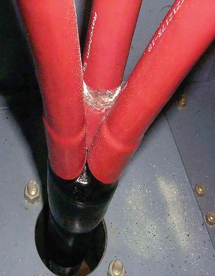
resulting in more than 470 fewer failures per year. A high proportion of these faults were identified on cable terminations (Figure 1). Whether cable termination problems are classed as cable issues or plant (switchgear/ transformer) issues is an ongoing debate. However, what is apparent is that non-intrusive detection of these defects using transient earth voltage (TEV) and ultrasonic techniques is well-established and effective in detecting termination faults. The rest of this article will therefore concentrate on the detection of faults over the length of the cable.
Once a PD event has occurred within the electrical insulation of a shielded cable, a set of radio frequency current pulses equal in magnitude but opposite in polarity is seen on the line conductors and the earth conductor/ shield. On-line PD detection utilizes this effect by measuring these pulses using radio frequency current transformers (RFCTs) placed on the cable’s earth sheath (Figure 2).

cable. As the current pulses transmit down the conductor and earth cable from the discharge source, the signals attenuate and flatten, effectively cutting off the higher frequencies to the point that they are filtered out. Despite the use of high-pass filters, simple measurements can still be prone to false alarms and have not been found to be particularly effective for initial widespread screening of cables for PD.
One very important and practical consideration must be taken into consideration when looking at the applicability of taking these on-line measurements: If the RFCT is placed over the line conductor and the earth cable at the same time, the discharge currents are cancelled. The connection must therefore always be made by monitoring the earth cable only (or the line conductor after the earth has been taken off, provided the line current is low).
When carrying out on-line testing with the cable in service, noise on the cable earth system will be encountered. Noise often occurs in the same frequency band as PD signals and will be detected by the RFCT sensor. Simply measuring amplitude can therefore provide false alarms of PD and will only have limited application. Simple devices such as a high-pass filter in the 1.4–1.8 MHz range will typically be utilized to overcome the effect of noise. This blocks much of the noise on the earth system, but at the same time reduces the ability of the instrument to detect PD signals far down the
Table 1 demonstrates this from the results of recent testing of a representative sample of circuits on a utility network. The circuits chosen were from a number of different substations in different geographic locations on primary and distribution networks using XLPE cables operating at 11 kV and 33 kV. The samples included a mixture of three-core cable measurements and single-phase cable measurements. Through more advanced analysis, it was determined that of the 14 sections tested, 12 (cable group A) had no PD, and 2 (cable group B) had moderate levels of PD.
Table 1 shows the classifications using only amplitude as a measure. Without the application of any filtering, all 14 falsely indicated red. With a 500 KHz filter, 11 indicated red and 3 amber, still all incorrect. Even with the application of a 1.8 MHz filter, one sample was classified erroneously as serious red-level discharge and three erroneously as amber-level discharge. To restate, with moderate filtering (500 KHz), all 14 still showed incorrect indications. With the highest level of filtering (1.8 MHz), 4 out of 12 or 33% of this small sample incorrectly identified the level of PD.
To improve diagnostic capability from this simple amplitude-only measurement, information on the pulse shape and reference captured signals to the 50/60 Hz supply frequency must be obtained. This requires additional processing capability (Figure 3).
To help with the analysis, the equipment uses a supply frequency reference; if one is not locally available, the instrument will detect the reference from the connected RFCTs. This particular instrument automatically applies a series of filters during the capture process as well as capturing raw, unfiltered data. In addition to enabling better subsequent interpretation of the data, applying an automatic filter makes the data-capture process simple, quick, accurate, and a non-specialized function.
The improved analysis is demonstrated in Figure 4 and Figure 5. The instrument recorded similar amplitudes of 3,000–4,000 pC, clearly in the red zone for XLPE cable. Looking at the waveform and phase-resolved plot in Figure 4, it is a relatively simple matter to conclude that there is no phase-related signal and the waveform is not consistent with partial discharge. Figure 5, on the other hand, shows clear, phase-resolved activity with a pulse shape indicative of PD.
Without the ability to look at the waveform or reference signals to the 50/60 Hz supply, both of these measurements would be classified as serious PD. Therefore, it is important to use equipment with this capability to screen the raw data. Without this, as demonstrated in Table I and Figure 4, there can be a high, potentially unacceptable number of false positives. Along with taking up valuable engineering resources and time to investigate false positives, it can quickly lead to loss of confidence in the use of on-line technology to detect PD and can become a barrier to adoption of a useful tool for the asset manager.
Another point to note about noise on the earth connection is that these measurements were taken on a utility distribution network. On
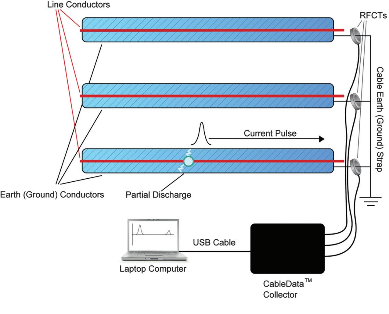
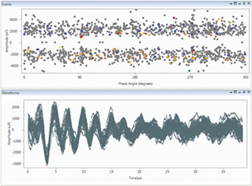

industrial networks with higher numbers of potential interference sources such as variable speed drives, the instances of high noise interference have typically been found to be worse.
When PD has been successfully detected, knowing the exact location of the problem on the cable is highly valuable. With limited access to the span of the cable, even an approximate location of a defect has great benefit. The use of time domain reflectometry (TDR) is well established for determining a change in properties in a great variety of linear assets. For example, TDR can be used in concrete pilings to determine their depth and the depth of any cracks. This uses ultrasonic pulses reflected back from discontinuities. In fiber optics, TDR using laser light pulses can show the distance to fiber damage.
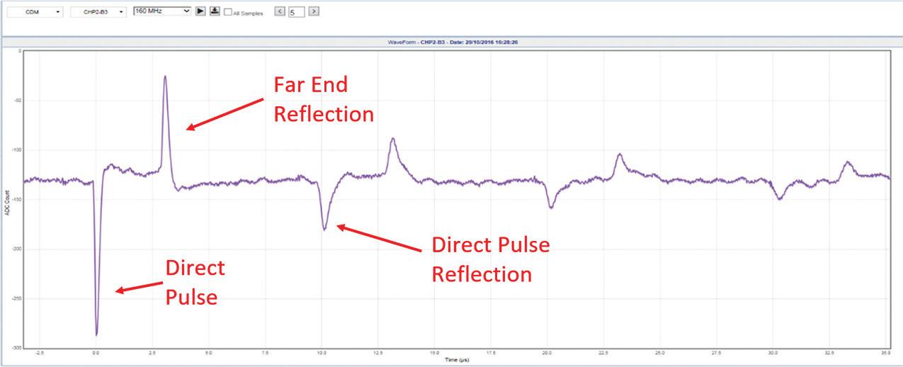
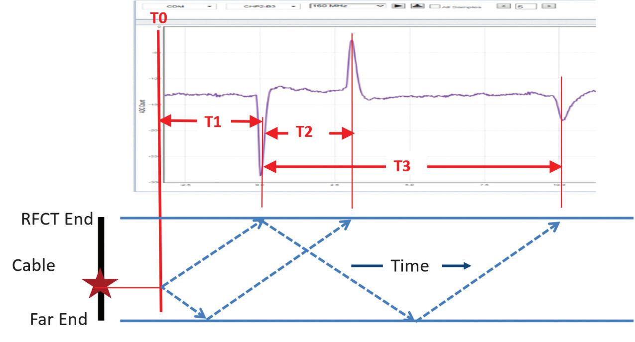
In shielded cables, the actual live PD current pulse can be used to find the location of the disturbance. Current pulses reflect from any point where there is a change in impedance, providing reflected waveforms we can use. TDR has long been part of off-line PD testing. In an off-line test, the cable is removed from service, disconnected at both ends, and a clean, PD-free waveform is applied. If PD occurs, the initial pulse and its reflections are analyzed. Figure 6 shows a PD current waveform with multiple reflections.
The waveforms represent current reflecting off the far end of the cable where a disconnected end results in a massive change in impedance. We can take a number of time measurements from the waveform and use them to calculate the location of the PD event. In Figure 7, T0 is the event start and T1 is the time from T0 to the first detected pulse. T1 cannot be measured directly. It can, however, be calculated by the following formulae:
= 2 * length of cable (L) propagation speed (Vp) (1)
T1 = (T3–T2) (2) 2
Distance to PD = T1 * Vp Ergo (3)
Distance to PD = (T3–T2)/2 * (2 * L) T3 (4)
When performing on-line testing, the goal is not necessarily to locate the distance to the PD event, but rather to identify at-risk cables for further study. Determining the location of PD in an on-line test is made more difficult by two factors:
1. The reflection from the far end of the cable is not as significant because the impedance change in a connected cable is much less.
2. The cable is likely to have higher noise level due to being in service as opposed to being off-line.
The ability to locate a smaller reflection among higher noise is not always possible. That said, when a reflection is detectable, the PD can be located precisely. It is our experience that online location is possible approximately 25% of the time. It should be noted that the waveform shown in Figure 6 and Figure 7 is actually from an on-line test. The noise floor is very low, and the reflection is very distinct. In this case, the PD was precisely located.
A major UK utility recently completed an evaluation of the technology with positive results. As this was a technology assessment, no attempt to address suspected cables was made during the trial. Over an 18-month period, 188 33 KV cables were tested with an on-line cable test device as described above. The cable results were classified into green, amber, and red as shown in Table 2. The classification was made using a combination of amplitude, phaseresolved plot, and waveform analysis.
Within the 18-month test period and six months afterward, 13 cables failed. The results below show that red and amber categories had significantly higher failure rates. This proved to the utility that this type of on-line testing was effective at identifying at-risk cables.
Table 3 shows that a very significant percentage of cables in the red and amber categories failed in this short time. Had the customer addressed only the red cables, they would have fixed less than 10% of the cables for a reduction in failures of over 50%. Had the user addressed all red and amber cables, they would have had to fix 16.5% of their cables and would have achieved a 94% improvement in failure rate.
The use of periodic measurement to understand cable condition immediately brings business benefits that enable more effective management and inform replacement or expenditure decisions. Progressing on to permanent monitoring systems enables the same assets to be monitored under a variety of operating and environmental conditions and can be a less labor-intensive way of collecting condition data. On-line monitoring also provides benefits by warning of developing failure modes. Early warning can provide an opportunity to minimize the negative effects of failure and therefore reduces the potential for negative consequences, such as loss of supply, or costs, such as damage to equipment, and secondary consequences.
Permanent monitoring is able to bring additional benefits to an organization, but a calculation must always weigh the balance of additional
Table 2: XLPE Cable PD Classification for pC Reading
pC
2,000 pC
Table 3: PD-Related Failures of 33 KV Cables
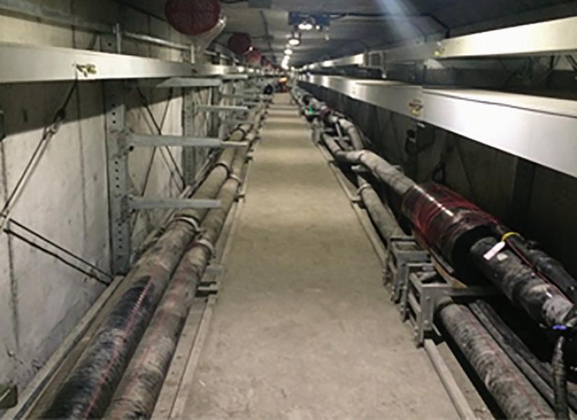
8: 220 kV Cables in Tunnel Requiring On-line PD Measurement
benefit and the cost of implementation. One way to quantify the economic benefits of online condition monitoring is to consider the decision in terms of risk reduction. P. Blackmore et al demonstrates how using a means to quantitatively evaluate risk and understanding how on-line condition monitoring can be used to mitigate the risk associated with electrical assets can often warrant the installation of permanent monitoring solutions in a significant proportion of asset population.
One asset group where this approach often concludes in favor of permanent asset monitoring is extra-high-voltage (EHV) cables because, for these assets, the high consequence of failure elevates the risk calculation (probability times consequence). Another factor adding to the justification of permanent monitoring is the difficulty of regularly accessing such installations.
Figure 8 shows a 220 kV cable tunnel where a power authority chose to install a permanent PD monitoring system for its cables. Three circuits installed in two adjacent parallel tunnels were monitored. Each circuit was 3.4 km in length with a total of eight sets of grounding boxes for each circuit. Each grounding box required RFCT sensors to be installed on each side of the grounding point for each phase, as PD signals will not pass
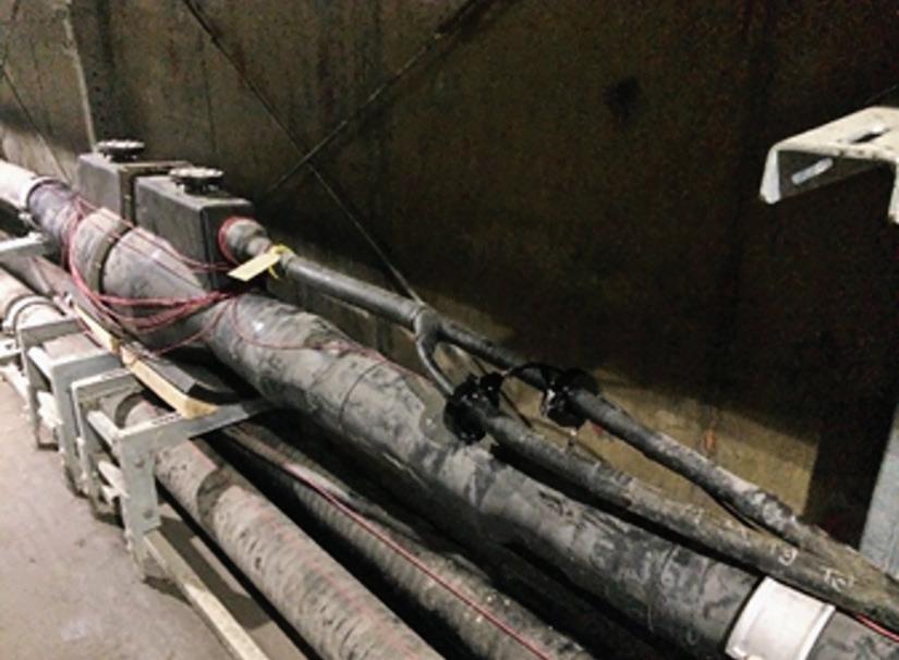
Figure 9: RFCT Sensors on Earthing of 220 kV Cables in Tunnel
along the total length of the cable circuit due to the change in impedance at these points. It is worth noting that due to these complex earthing arrangements on higher-voltage installations, distributed monitoring enables easier analysis of data when compared with individual spot-check measurements.
Figure 9 shows the RFCTs installed onto the earthing cables linking the cable joints to the grounding boxes. Each sensor connects to a local node unit near each grounding box. The daisychained nodes communicate back to a hub server installed at the substation. The hub controls and monitors the system, collects data for analysis, and provides some automatic configurable alarms to provide early warning of degradation. Due to the distances involved between nodes, links are made using fiber-optic cable. Each local node obtains a phase reference source.
Despite these significant changes in hardware, the principle of the analysis remains effectively the same with detection of amplitude, phase patterns, and waveform analysis. The obvious benefit of early warning of unexpected degradation was realized soon after the monitoring system was commissioned on these circuits: Phase-resolved PD was detected on one of the cable joints (Figure 10).
The ability to monitor and effectively screen cable networks for PD activity on-line is available
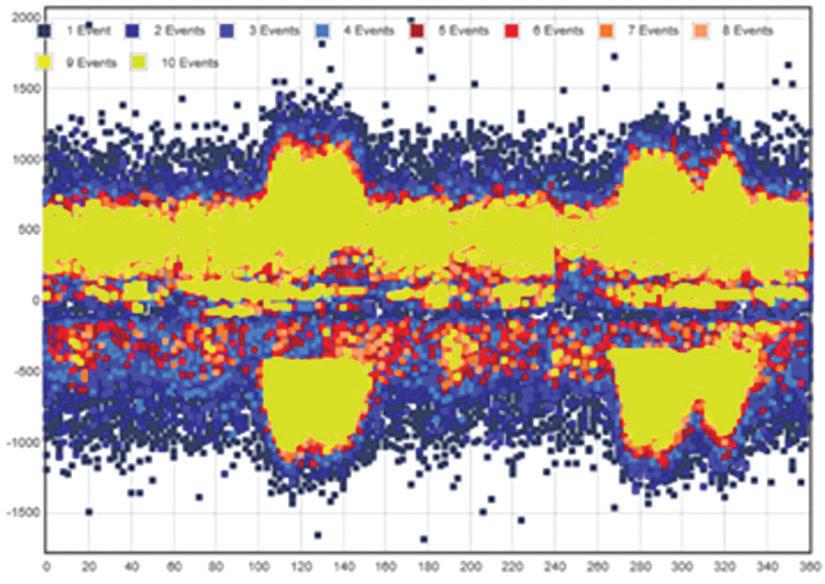
Figure 10: Phase-Resolved Plot from FullTime Monitor
and shown to be effective. The work shows that effective screening of cables cannot simply rely on measurement of PD amplitude, as noise on the earthing system can cause a significant level of false positives. Determining whether PD is present and assessing its severity requires measurement of amplitude, analysis of the waveform, and phase-resolved analysis of the signals.
Automatic filtering and simple data capture to allow remote analysis can reduce the need for a specialist resource at site and make best use of this valuable time. Using the most appropriate resource to carry out the various elements of the task enables up-to-date condition data for cable networks to be quickly and costeffectively gathered. This information allows better-informed asset management decisions to be made, may reduce or lessen the impact of failures, and improves network performance.
Finally, the article provides an example where the criticality and assessment of risk on three parallel 220 kV cable circuits led to a decision to install a permanent partial discharge monitoring system and showed how immediate benefit was delivered through early detection of a defective joint.
The author would like to acknowledge Neil Davies of EA Technology Pty Ltd and Victor
Chan of EA Technology Asset Management Pte Ltd for their contributions and encyclopedic knowledge of on-line PD testing.
Y. Wang. “Underground Cable Distribution System Management – Reduce Cable Failure Rate,” EEA Conference, Auckland, New Zealand, 2013.
S. Shamuri. “Enhancing TNB Medium Voltage Switchgear Condition Based Maintenance by Using Partial Discharge Application,” ISO 55000 and the Future of Asset Management, Asia Pacific Regional Conference, Bali, Indonesia, 2013.
P. Blackmore et al. “Quantifying the Economic Benefits of Online Monitoring,” Electricity Distribution Conference - South East Asia, KL, Malaysia, May 2014.

William G. Higinbotham has been president of EA Technology LLC since founding it in 2013. His responsibilities involve general management of the company, which is responsible for EA Technology activities in North and South America and the Caribbean/Bermuda. William is also responsible for sales, service, support, and training on partial discharge instruments and condition-based asset management. Prior to EA, William was Vice President of RFL Electronics Inc’s Research and Development Engineering group, where he led the development of numerous products in the areas of utility communications and system protection. Bill is an IEEE Senior Member and is active in the IEEE Power Systems Relaying Committee. He has authored or co-authored several industry paper, co-authored a number if IEEE standards in the field of power system protection and communications, and holds one patent in this area. Bill received his BS from Rutgers, The State University on NJ, School of Engineering in 1984 and worked in the biomedical engineering field for five years prior to joining RFL.
This work first appeared at the Doble International Conference of Doble Clients. Republication does not imply endorsement by Doble Engineering Company of any product or service other than its own. © 2016 Doble Engineering Company 83rd International Conference of Doble Clients. All Rights Reserved. Used with permission.




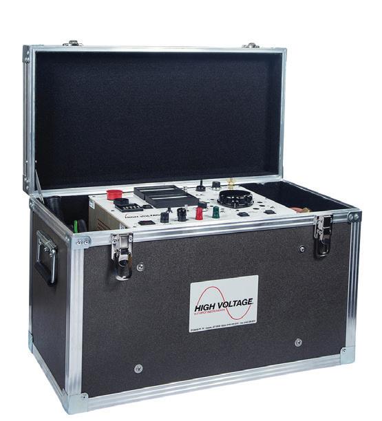
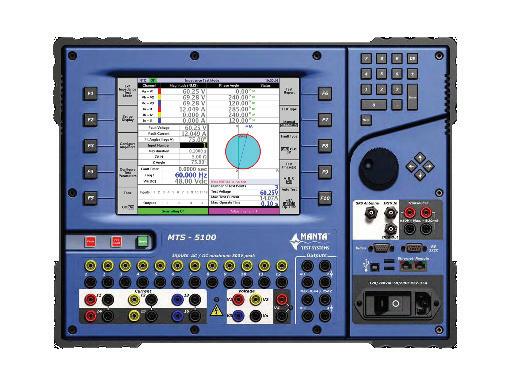
• Protective Relays
• Transformers & Motor Analysis
• Partial Discharge/Corona
• Current Injection
• Cable Fault Location
• Cost-Savings Versus Buying
• Available for Immediate Delivery
• Switchgear/Circuit Breakers
• Insulation Resistance
• Tan Delta/Power Factor
• Current Transformers
• Ground Grid
• Choose From a Variety of Manufacturer’s Top-of-the-Line Products
• Short-term Solutions for One-Off Tests
• Always Calibrated Equipment
ISO 17025 / NIST Cal / ANSI Z540



BY RODRICK J. VAN WART, AVO Training
Most electrical equipment manufacturers provide life and performance expectancies with their equipment in the form of operation and maintenance manuals. Life expectancy is based on the premise that equipment has been professionally installed, is maintained in accordance with the manufacturer’s guidelines and recommendations, and is being used per the manufacturer’s designed intent. This premise is also noted in NFPA 70 Article 90.1(B):
This Code contains provisions that are considered (the minimum installation requirements) necessary for safety. Compliance therewith and proper maintenance (manufacturers having precedence even over the code) result in an installation that is essentially free from hazard but not necessarily efficient, convenient, or adequate for good service or future expansion of electrical use.
Additionally, federal laws mandate the installation, safe operation, and maintenance of electrical systems. OSHA 1926, Safety and Health Regulations for Construction Subpart K Electrical, addresses everything from approval of the installed equipment through maintenance and inspection of the equipment. Specifically, OSHA 1926.403, General Requirements addresses issues with suitability, examination, mechanical strength, electrical insulation, heating and arcing effects, system classification, and system installation and use.
OSHA’s Hierarchy of Risk provides the three prime causes of electrical failures:
1. Equipment. As equipment ages, its components deteriorate over time caused by electrical stresses created under normal operation. Abnormal operation, typically overloading, serves to accelerate the physical stresses placed on the equipment. Failure to properly maintain the equipment and associated systems also causes undue premature equipment failure.
2. Environment. The environmental conditions in which equipment is installed and operated is often overlooked. Humidity, suspended airborne contaminants, and corrosives must be considered.
3. Employee. The key to employee performance is qualification to perform an assigned task. The qualification
standards clearly defined in NFPA 70E, Standard for Electrical Safety in the Workplace are sometimes not met, and this leads to employee error or shortfalls. Training is essential for long-term expectation of successful operational outcomes.
Motor control centers are subject to constant, ever-changing loads. The inrush of starting current during the locked rotor condition and the system’s response to the various torques in coming up to full operating speed have consequences for the supporting distribution system. Any associated wiring will be subject
to electrical stresses of transient high-current inrush and subsequent movement that cause physical damage to insulation and loosens terminations due to thermal stressing.
MCCs are often the epicenter of the manufacturing plant, providing power for equipment across the site. Moreover, their vital role often goes unrecognized for extended periods of time because of a buy-and-forget philosophy toward MCCs. It is a common belief that once an MCC is installed, it can be left to run independently, and maintenance is only needed in the instances of equipment failure. This approach to maintaining MCCs leads to downtime and often catastrophic failures that could have been avoided.

The primary issue with this approach is that an MCC fault, such as a starter failure, can lead to major downtime by causing loss of power to, or control of, plant equipment. The outcome of interruptions to production can mean significant financial losses to a business. If onsite system operational documents are not kept up to date or replacement inventory is not readily available, there may be considerable delay in getting plant operations back to full functional status.
Neglecting an MCC for extended periods of time can lead to catastrophic failure, which leaves companies not only with downtime, but also with a sizeable investment to replace the equipment.
Two photos depict the after-effects of an arc flash event within a lineup. The first photo clearly shows that one of the parallel B-phase motor conductors broke free from its termination and fell towards the A-phase connections that initiated the arc flash event.
The second photo shows that the force of the blast was sufficient to blow open the door to the motor connection, the adjacent door where the motor starter contacts and control circuits are located, and the door adjacent and above where the starter fuses and incoming leads are located. Investigation found that the fuses in the motor
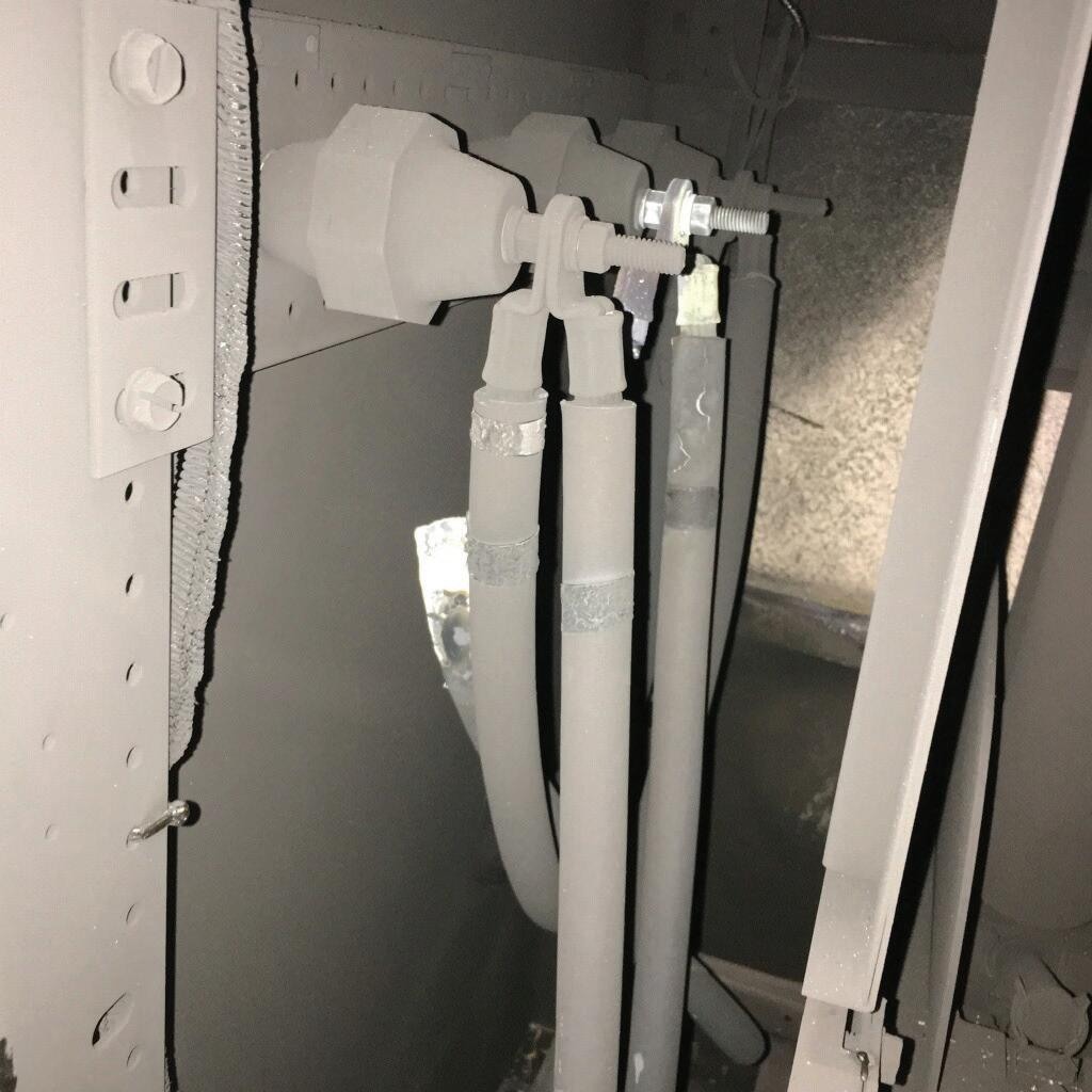
starter unit immediately upstream failed to clear; the fuses located on an air switch within the metal-clad switch gear finally cleared the fault.
Infrared scans would have been the primary way to detect this failure ahead of time; however, in this case, infrared windows had not been installed, so no infrared scan could be conducted on any of the lineup.
MCCs are a common safety concern because operators and maintenance personnel interact closely with the MCC. Recognition of arc flash as a unique electrical hazard has led to a new expectation for circuit protection devices: They must safeguard personnel from the hazards of thermal burns and explosive blasts.
Traditional arc flash mitigation is dependent on single-function circuit protection devices (like fuses) to operate as designed to limit arc flash energy. Unfortunately, overcurrent protection and other components in power system short-circuit protection schemes can fail with no indication that functionality has been compromised until an arc flash event occurs. In such events, the arc flash energy release can be magnitudes greater than expected or calculated. Work methods, tools, and personal protective
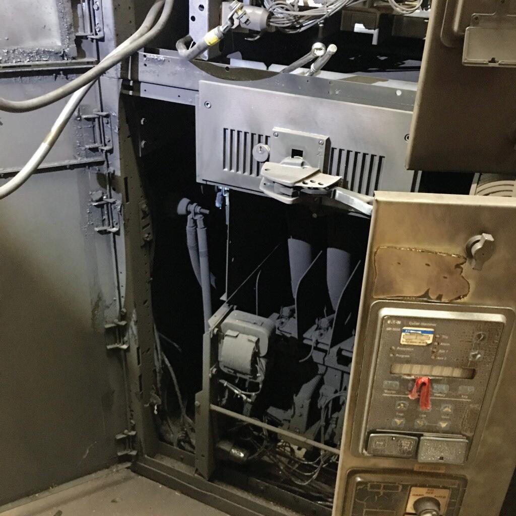

equipment selected based on predicted energy levels may be insufficient to protect workers within the arc flash zone from injury.
The key to conducting inspection and diagnostics is to remember that the arc flash calculations that may be provided are derived from engineering specifications of clearing times when the overcurrent protection devices were brand new. In all instances, it is important to dress not to a minimum, but to a higher arc hazard level to mitigate the slowing of clearing times created by aging and lack of proper and/ or inadequate maintenance. The information provided in NFPA 70E should be considered as a minimum in recommending equipment for personal protection.
So how are these types of events mitigated? The answer is proactive training for qualification, routine periodic and adequate inspection, and maintenance conducted in accordance with the manufacturer’s guidelines and recommendations.
Key players in the manufacturing of MCCs such as Allen-Bradley, Siemens, and Schneider / Square D recommend remarkably similar approaches to conducting inspection and maintenance on MCCs.
To identify the condition of an MCC, maintenance personnel should routinely conduct several checks in accordance with the manufacturer’s guidelines. These can be invasive or non-invasive tasks from simple visual checks to more complex analysis. It is important to conduct checks to establish cleanliness, verify software, and check and back up the operational parameters on programmable logic systems. Records of these parameters must be up to date. Maintenance personnel can conduct visual inspections to look for indications of overheating at terminations and conductor insulation points. In the absence of any direct guidance, NFPA 70B Chapter 16 can be used to initiate a starting point in establishing a basic motor-control maintenance program.
The goal of routine maintenance is to restore the MCC to its original condition. Any components that show signs of wear and tear can be serviced and/or replaced. Common routine maintenance tasks recommended by major manufacturers include:
• Operating mechanism. Check for proper functioning and freedom from sticking or binding. Replace any broken, damaged, or badly worn parts or assemblies. Check all mechanical fastening devices and return to manufacturer’s specified torque values.
• Contacts. Check contacts for excessive wear and dirt accumulation. Discoloration and slight pitting are acceptable. Do not use files to dress contacts. Do not use contact spray cleaners, as they leave a residue that can cause sticking and/or interfere with electrical continuity. Replace contacts only after the silver has become excessively worn. Always replace contacts in complete sets to avoid alignment issues and uneven contact pressure.
• Terminals. Loose connections can cause overheating that can lead to equipment malfunction and failure. Verify the tightness of all terminals and busbar connections to ensure these mechanical fasteners meet the manufacturer’s recommended torque specification. Replace any components or wiring damaged by overheating. Check the grounded conductor, equipment grounding conductor, and grounding electrode conductors for proper termination tightness.
• Coils. If a coil exhibits evidence of overheating (cracked, melted, or discolored insulation), it must be replaced. Check for and correct any detected over- or undervoltage conditions, which can initiate coil failure. Clean any residue of melted coil insulation from all other parts of the device. If it can’t be sufficiently cleaned, it may be necessary to replace those contaminated parts or assemblies as well.

• Pilot lights. Replace any burned-out lamps and/or damaged lenses.
• Solid state devices. Solid state devices require little more than periodic visual checks. Ensure that the printed circuit boards are properly seated in edge connectors. Board-locking devices must be in place. If electrically operated venting is incorporated, verify fan operation and replace any associated filters.
• Locking and interlocking devices. Check proper operating condition and capability to perform intended functions.
• Environment and physical condition. MCCs are often physically located in areas that allow animals to establish habitats; this increases the danger of vermin being present. This can cause damage or even destruction of cabling and terminations. Qualified staff should conduct routine visual inspections on the physical condition of the equipment. Once identified, the situation can be rectified to restore the MCC to its proper operating state.
• Replacements. Make any necessary replacements only with OEM materials. Ensure parts are properly matched to the model, series, and revision level of the equipment.
• Final checkout. After maintenance or repair of industrial controls, always test the control system for proper functional operation under controlled conditions that avoid any hazards associated with a control malfunction.
As is often the case when a breakdown occurs, maintenance personnel commonly employ quick-fix remedies to restore operations as quickly as possible. If previous maintenance was done as a quick fix, this must be addressed by restoring everything to the manufacturer’s specifications at the earliest possible time. This
maintenance aims to restore the MCC to its original condition. If any components show signs of wear and tear, these can be serviced and or replaced, as necessary.
AVO Training Institute. Electrical Safety Text
National Fire Protection Association. NFPA 70, National Electrical Code, 2020 Edition.
National Fire Protection Association. NFPA 70B, Recommended Practice for Electrical Equipment Maintenance, 2019 Edition.
National Fire Protection Association. NFPA 70E, Standard for Electrical Safety in the Workplace, 2018 Edition.
Occupational Safety and Health Administration. OSHA 1926.403 CFR, General Requirements.
Allen-Bradley. Preventive Maintenance Checklist of Industrial Control and Drive System Equipment. December 1999. Accessed at DRIVES-TD001A-EN-P.pdf www.rockwellautomation.com .

Rodrick J. Van Wart is a Senior Consultant and Instructor at AVO Training in Dallas, Texas, and an Instructor at the Omega Institute for Continuing Education. He has over 47 years of experience in the electrical industry that includes chairing test development for the International Code Council’s exams for inspectors, overseeing development of Iowa’s electrical licensing and permitting programs, and providing training for the state’s Electrical Examining Board members and support staff. Rod served several municipalities as an electrical and mechanical inspector, earned Public Management certification from Drake University, and is a Certified Building Official. A subject matter expert in adult learning precepts and instruction in a classroom setting, he designed and implemented new core curriculum subject matter and has been awarded Top Gun status at Mike Holt’s Instructor Training Conference. During his four years in the United States Navy, Rod certified apprentices and third-class nuclear electricians logging 336,800 hours of total student contact time. He currently serves as a member of the IEEE PES/ESSB Committee on Working Groups 450, 484 (Vice Chair), 485, 1188, 1578, and 1679.

THE PREMIER ELECTRICAL MAINTENANCE AND SAFETY CONFERENCE
FEBRUARY 28 – MARCH 4, 2022
HYATT REGENCY DENVER, COLORADO
POWERTEST.ORG 888.300.6382 HOSTED BY
Communicate your knowledge, assist the industry, and gain visibility. Presentations are sought in a number of categories:
–ELECTRICAL S AFETY –RELIABILITY –EQUIPMENT
–CASE STUDIES –TRANSFORMERS –RELAYS
Abstracts due May 3, 2021. To submit or learn more, visit powertest.org
–EMERGING TECHNOLOGIES –CABLES –CIRCUIT BREAKERS


BY RALPH PARRETT, AVO Training Institute
A power system uses various elements within protective relay schemes, and having a thorough understanding of the theory behind these protective elements is more than useful — if not required — for anyone who comes in contact with them. Design engineers who must execute calculations based on system characteristics and machine capabilities and field technicians who conduct testing, calibration, and troubleshooting on protective elements are the two roles most exposed to protective relay elements. Understanding the theory behind their operation is critical to their success in calculating settings and verifying the element is operating correctly according to those settings.
The function and purpose of common elements found in many applications generally remain the same no matter where in the system they are utilized. However, some elements were designed not only for specific applications, but also for a specific piece of machinery or apparatus within the grand scheme of the power system.
Two elements that were designed for a specific application, whether machine or apparatus, are the distance element and the loss of excitation element.
In addition to sharing common ground on the stigma of being complicated, the distance element and the loss of excitation element share a common characteristic that detects abnormal

system conditions regardless of their specific application. This common characteristic is changes in system impedance as plotted on an R-X diagram. The goal of this article is to establish the rules and fundamentals of the R-X diagram and then to walk through each element in a manner that is not typically used to explain them. A secondary goal is to break through the assumption that these elements are complicated.
Understanding the application of these elements requires a review of the R-X diagram. Figure 1 illustrates a Cartesian plane used to plot impedance (Z) values.
The x-axis quantifies resistive (R) values within an electrical circuit; the y-axis quantifies reactance (X) values. To explain the values within any Cartesian plane, we start with quadrant I. No matter how the Cartesian plane is used, we deem quadrant I the normal quadrant. The mathematics rules established in trigonometry inform us that positive angles rotate in a counter-clockwise direction starting from 0° (the x-axis). Quadrant I is the first quadrant passed through for a positive angle.
These exact rules are followed in phasor or vector diagrams used to quantify voltage and current. However, in an R-X diagram, we plot the combined resistance (R) and reactance (X) of a power system. The combined resistance and reactance of a power system is quantified as impedance (Z) and is dependent on the characteristics of the connected loads.
According to the U.S. Energy Information Administration’s Independent Statistics and Analysis, 48.2% of energy in the United States is utilized for machine-drive equipment. This only accounts for large industrial processes where inductive motors are used throughout
manufacturing processes; it does not account for the remaining inductive loads found in commercial and residential applications. Given this information, it is safe to assume that the majority of loads connected to the power system are inductive (XL). Inductive reactance loads have a characteristic that causes current to lag the applied voltage. Therefore, because the power system loading characteristic is made up of inductive loads, the “normal” quadrant I illustrates lagging load characteristics.
This information sets up the first rule we must follow: The counter-clockwise direction is for lagging angles (Figure 2). This is the opposite of phasor or vector diagrams used for voltage and current where counter-clockwise rotation quantifies the leading angles.
Within the R-X diagram, this allows us to understand that all angles in the clockwise
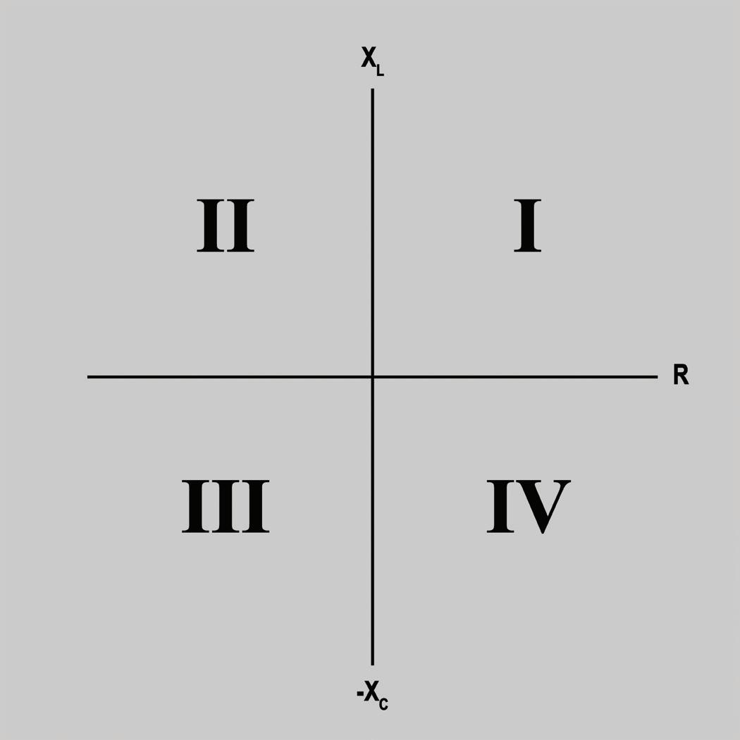

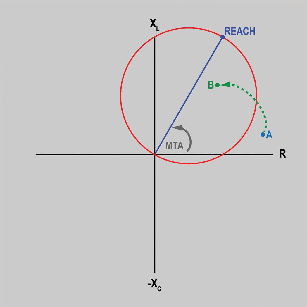
direction are leading. Impedance values found in the clockwise direction represent capacitive reactance values (-XC). Now, by understanding direction of rotation, we have established that inductive reactance (XL) is quantified as positive on the y-axis, and capacitive reactance is quantified as negative on the y-axis. With the established rules for the R-X diagram, we now take a look at our first protective element that utilizes changes in system impedance to detect system disturbances.
The distance element is found in power systems primarily to protect transmission lines that can extend for hundreds of miles and can also be found on distribution systems that extend considerable distances atypical for their normal application. When implementing distance protection during the design phase, the properties of the system must be considered. The reactance properties of the conductor plus the distance the conductor travels establish the foundation for what normal system condition appears to be. Furthermore, other environmental impacts, such as the manner in which the conductors are physically arranged
in relation to each other and their physical distance from the earth, contribute to the reactance of the conductors.
Traditionally, distance elements are configured into multiple zones. These zones are set at different impedance values that increase from the point of measurement or point of origin. For this discussion, the shape of the protective zone is the mho circle, illustrated in Figure 3. The distance element will operate for any value of system impedance that is located within the mho circle. For any value of impedance outside of the mho circle, the distance element will not operate, and in electromechanical relays, restraining torque will prevent the mechanical contacts from closing.
Reach. The first setting of the mho circle to discuss is reach. The reach of the characteristic is the primary property that sets up the diameter of the circle, and its value is set to equal the maximum impedance value at which the zone is to operate.
Maximum torque angle. The next property is the maximum torque angle (MTA). This quantity is determined by the normal
system impedance when unloaded for this application. Typical values for the angle found on transmission lines are between a lagging, counter-clockwise direction at 60–75 degrees. The values will match the unloaded impedance characteristic of the transmission line being protected. The reach of the characteristic extends from the point of origin at the MTA, which completes the properties of the protection zone discussed in this article.
System impedance. During normal conditions, system impedance will typically be located just above the x-axis, illustrated by point A in Figure 3. The distance of point A from the point of origin is directly proportional to the value of system impedance, and the angle in which it is located is proportional to system reactance. As shown, during normal system operation, the impedance of the system is outside of the mho circle; therefore, the element does not operate.
The fault condition(s) in which distance elements operate are faults between phases, i.e. phase-to-phase, phase-to-phase-to-ground, etc. In any case, when a phase-to-phase issue occurs, the associated phase currents will increase due to the decrease in line impedance and the possible loss of load impedance as well. With the increase in current, the impedance value will decrease. Therefore, the reactance of the system causes an angular shift toward the MTA. An example of how this condition appears is shown by the dashed green line landing at point B. The distance element will operate as soon as system impedance is within the mho circle and will not wait to operate until system impedance reaches point B.
Loss of excitation (LOE) elements, or loss of field, are found primarily on synchronous generators but can also be found on synchronous motors. The primary purpose of LOE protection is to prevent excessive reactance swings on the power system that will cause heating of all components within the system.
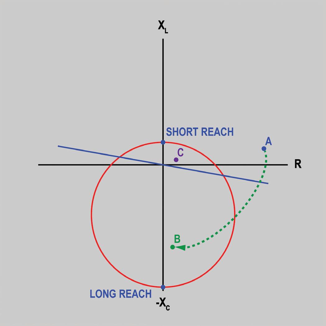
Within a synchronous generator, a regulator is utilized to maintain the produced voltage at a constant set value. Without a voltage regulator, the generator terminal voltage would not be capable of supporting load changes that would cause the voltage to either sag or spike as loads are applied or removed. The simplest way to look at this issue is that, if we cannot control the voltage on the power system, then current is going to change accordingly. Ohm’s Law and the nature of power flow establish that when voltage changes, current will change as well.
Maximum torque angle and the mho circle characteristic are also utilized by the LOE element as in the distance element. The MTA for LOE elements is typically located at 90 degrees in the leading clockwise direction. As shown in Figure 4, because the MTA is at this angle, the mho circle is found in a different region of the RX diagram when compared to the distance element.
In this example, the diameter of the mho circle depends on the location of the long reach and the short reach. The long reach sets the bottom point of the circle. The short reach sets the top
of the circle. Typically, the long reach has an individual setting. The short reach, however, is generally established through a setting termed “offset.” The offset not only determines the physical distance from the point of origin, but it also determines which direction on the y-axis the short reach point is located. With a negative offset, the short reach will be located below the x-axis; with a positive setting, the offset will be located above the x-axis. Figure 4 depicts an LOE characteristic that has a positive offset. The LOE element utilizes the mho circle exactly the same as the distance element: When system impedance is outside of the circle, the LOE element does not operate and send a trip signal.
The final property of the LOE is the directional unit shown as the blue diagonal line in Figure 4. The directional unit is used to prevent load encroachment caused when a generator is heavily loaded and the system impedance is very low. During this condition, the system impedance could very well be within the mho unit, point C. However, the directional unit will prevent the unit from tripping because the relationship between voltage and current is above the directional unit characteristic.
In a normal system, system impedance will typically land just above the x-axis shown as point A. During this state, system impedance is outside of the mho circle and above the directional unit, which prevents the LOE from sending the trip signal.
During a faulted system, loss of excitation will cause the voltage to decay at the generator terminals. This will cause the impedance of the system to decrease and swing toward the MTA as was shown as the dashed green line toward point B. As soon as the impedance enters the mho unit and is below the directional unit,
the LOE element sends the trip signal. Like the distance element, the LOE element does not wait to operate until reaching point B, but operates as soon as the impedance of the system breaks the edge of the circle.
While these elements are extremely proficient at identifying the conditions for which they are designed, it takes all elements together to provide complete protection for a power system. The most complex element can without a doubt have inefficient means of identifying a fault condition, whereas the simplest can. A final note about the elements: A number of additional options can be found within each of them that are not discussed in this article. My ultimate goal was to present the information in a manner some may not have been exposed to yet in their journey of learning about protective relay elements.
U.S. Energy Information Administration (EIA). Independent Statistics and Analysis, August 28, 2020. Retrieved September 29, 2020, from https://www.eia.gov/energyexplained/ electricity/use-of-electricity.php

Ralph Parrett is a United States Navy veteran with over 13 years of professional experience relating to electrical safety and maintenance training. During his time at AVO Training Institute, his proven dedication to training led to his position as Manager of Content & Delivery. His passion has always been to provide a topnotch training experience to ensure his students are more effective and safer when they return to the workplace. Ralph has extensive knowledge of maintenance, repair, and troubleshooting of control and instrumentation, relay logic systems, ABB control systems, central control station programs, power system equipment testing and maintenance, and other various types of equipment. He has developed and taught theory, operation, maintenance, and safety of various engineering systems.

NETA’s Corporate Alliance Partners (CAPs) are a group of industry-leading companies that have joined forces with NETA to work together toward a common aim: improving quality, safety, and electrical system reliability.

In our continuing CAP Spotlight series, we highlight some of their individual successes. In this issue, NETA World interviews Ralph Parrett, Manager of Content & Delivery, at AVO Training Institute in Dallas, Texas.
NW: What is something readers don’t know about your company?
Parrett: AVO Training has fewer than 25 employees, which creates a family work environment. Without question, each employee is dedicated to excellence and the success of AVO’s students. Each and every one of our employees takes extreme pride in their individual responsibilities and realizes the impact they have on the overall success of AVO and the students who attend our courses.
Since the onset of COVID-19, AVO has become very flexible in scheduling courses to meet customer needs. Our 2020 schedule was rattled by the quarantine as well as by keeping up with the federal, state, and local safety requirements that caused a lot of movement of students to help them be able to attend courses. We are now more flexible to provide courses for customers’ employees to meet their
training needs while keeping health and safety the highest priority.
AVO Training functions as a business within a business inside of Megger, an international electrical test equipment company based in Dover, England. This gives AVO access and collaboration to engineers leading the industry in test equipment and testing techniques. AVO’s name goes back to one of the groundbreaking electrical test meters capable of measuring amps, volts and Ohms.
AVO realizes that the future of electrical safety training is to adapt to the student’s evolving training needs and preferences by adopting modern learning strategies. Learning happens in classrooms, but it also happens in virtual classrooms, online environments, white papers, presentations, YouTube videos, discussions, forums, and chats. We find value in both formal and informal learning, as well as having our instructors contribute to the larger discussion
of arc flash hazards and general electrical safety. Our students work in jobs where they cannot afford to take chances and make mistakes. A split-second wrong decision can be deadly — and we want to be top of mind by constantly driving home the safety-first message through multiple information channels.
NW: What recent company achievement or milestone are you particularly proud of?
Parrett: In May 2019, AVO’s processes achieved IACET accreditation, which confirms that our policies and processes meet those similar to higher education providers equivalent to community colleges.
AVO’s headquarters in Dallas also relocated into new facilities — a daunting task in itself to get all the people and equipment moved and set up. The new facility provides more than twice the amount of classroom and lab space and provided an opportunity to upgrade technology and equipment in the classrooms and labs for years to come.
AVO’s greatest accomplishment in 2020 was pivoting our in-person instructor-led training to a virtual, online delivery method. This has allowed AVO to continue to provide safety and equipment training to help our customers stay safe and compliant.
NW: What evolution on the horizon do you expect to have a positive impact on your work?
Parrett: AVO is in the construction phase of a new, high-powered learning management system (LMS) that will greatly enhance our ability to provide customers with a stellar experience before, during, and after they attend training. Customers will be able to self-enroll and purchase courses; they will also have the ability to retrieve training records and certificates by simply logging into the system. The system will also permit AVO certifications to be maintained autonomously by sending reminders to technicians prompting them to renew their certification through the learning portal.
Another evolution the LMS will contribute to is replacing hardcopy textbooks with tablets. This will enable our graphics design team to include videos and interactive animations within the text that was not possible with textbooks. The tablets will produce a greater and more interactive experience for our students. It will also provide a viable tool available to students with an internet connection after they have completed training with AVO.
Internally, the LMS will permit AVO to update training materials quickly, effectively, and efficiently whenever needed. This will streamline adjustments based on feedback from instructors and students, industry changes, or acquisition of new equipment.
AVO is also investing in virtual reality training modules to supplement our training offerings. The VR modules will place students into an environment that can be difficult to create and control in real life when requiring the attendant to go through an evolution such as lock-out/ tag-out or applying personal protective grounds. This advancement will increase retention rates and result in higher safety and efficiency for students returning back to the workplace.
NW: What challenges do you see going forward for the industry?
Parrett: As in every industry right now, the most immediate challenge is COVID-19 and how to keep our students and staff safe and healthy while they learn and work. We’re taking steps by decreasing class sizes to allow social distancing in the classrooms and labs, adhering to a strict mask-use policy, and performing health checks for students and staff on a daily basis.
Another future challenge is continuing to expand our virtual training offerings. Since March of 2020, AVO has offered virtual classes to continue to provide training during the COVID pandemic. However, continuing to balance offerings that meet customer needs for training will be a great challenge to ensure the training meets industry standards and customer needs, while maintaining the safest environment possible.
• Acceptance Testing
• Planned Electrical Testing and Preventive Maintenance Programs
• Power Factor Testing
• Cable Testing
• Relay & Meter Calibration
• Ground Resistance Testing

Delivering Powerful Reliability Solutions
Power System Acceptance Testing
Commissioning and Start-up
Maintenance
Coordination and Arc Flash Studies
Troubleshoot and Repair Training and Engineering Services Planning and Operations Support


• Transformer Oil Analysis, Vacuum Degassing and Repair
• Circuit Breaker Retrofit and Repair
• Power Generation Systems Testing
• Load and Power Quality Recording/Analysis
• Chiller Systems Testing
• Infrared Inspections



REVISION


ANSI/NETA ATS–2021 REVISION COMPLETED
ANSI/NETA ATS–2021, Standard for Acceptance Testing Specifications for Electrical Power Equipment & Systems has completed an American National Standard revision process. ANSI administrative approval was granted September 18, 2020. The new edition is scheduled to be released in March 2021. This edition will supersede the 2017 edition.
New content for the ANSI/NETA ATS-2021 includes:
· Arc Energy Reduction System Test
Partial Discharge Survey for Switchgear Updates
ANSI/NETA ATS covers suggested field tests and inspections for assessing the suitability for initial energization of electrical power equipment and systems. The purpose of these specifications is to assure that tested electrical equipment and systems are operational, are within applicable standards and manufacturers’ tolerances, and are
installed in accordance with design specifications.
A project intent notification has been published in ANSI’s Standards Action announcing the opening of a 45-day public comment period. The initial ballot is expected in summer 2021. A second ballot is scheduled for issue in fall 2021. The revised edition of ANSI/NETA ATS is scheduled to debut at PowerTest 2022.
ANSI/NETA ETT establishes minimum requirements for qualifications, certification, training, and experience for the electrical testing technician. It provides criteria for documenting qualifications for certification and details the minimum qualifications for an independent and impartial certifying body to certify electrical testing technicians.
ANSI/NETA ECS, Standard for Electrical Commissioning of Electrical Power Equipment & Systems, 2020 Edition, completed the American National Standard revision process. ANSI administrative approval was received on September 9, 2019. ANSI/NETA ECS–2020 supersedes the 2015 Edition.
ANSI/NETA ECS describes the systematic process of documenting and placing into service newly installed or retrofitted electrical power equipment and systems. This document shall be used in conjunction with the most recent edition of ANSI/NETA ATS, Standard for Acceptance Testing Specifications for Electrical Power Equipment & Systems . The individual electrical components shall be subjected to factory and field tests, as required, to validate the individual components. It is not the intent of these specifications to provide comprehensive details on the commissioning of mechanical equipment, mechanical instrumentation systems, and related components.
The ANSI/NETA ECS–2020 Edition includes updates to the commissioning process, as well as inspection and commissioning procedures as it relates to low- and mediumvoltage systems.
Voltage classes addressed include:
• Low-voltage systems (less than 1,000 volts)
• Medium-voltage systems (greater than 1,000 volts and less than 100,000 volts)
• High-voltage and extra-high-voltage systems (greater than 100 kV and less than 1,000 kV)
References:
• ASHRAE, ANSI/NETA ATS, NECA, NFPA 70E, OSHA, GSA Building Commissioning Guide
ANSI/NETA MTS, Standard for Maintenance Testing Specifications for Electrical Power Equipment & Systems, 2019 Edition, completed an American National Standard revision process and received ANSI approval on February 4, 2019. The revised edition of ANSI/NETA MTS was released in March 2019 and supersedes the 2015 Edition.
ANSI/NETA MTS contains specifications for suggested field tests and inspections to assess the suitability for continued service and reliability of electrical power equipment and systems. The purpose of these specifications is to assure that tested electrical equipment and systems are operational and within applicable standards and manufacturers’ tolerances, and that the equipment and systems are suitable for continued service. ANSI/NETA MTS–2019 revisions include online partial discharge survey for switchgear, frequency of power systems studies, frequency of maintenance matrix, and more. ANSI/NETA MTS–2019 is available for purchase at the NETA Bookstore at www.netaworld.org.
Comments and suggestions on any of the standards are always welcome and should be directed to NETA. To learn more about the NETA standards review and revision process, to purchase these standards, or to get involved, please visit www.netaworld.org or contact the NETA office at 888-300-6382.

BY JAMES R. WHITE, Shermco Industries
NEC CMP-13 covers Articles 700 Emergency Systems, 701 Legally Required Standby Systems, 702 Optional Standby Systems and 708 Critical Operations Power Systems (COPS). The Task Group’s sessions on October 22-21 ran five hours due to the high workload. Earlier, the Correlating Committee asked Jim Dollard (CMP-13 Vice Chair) to develop a “Safety by Design” annex with a Task Group that included Lanny Floyd, myself, and about 17 others, many on the 70E Committee. This work began April 22, 2020, and ended the same week, having developed the needed annex.
The CMP-13 Committee’s work on a little more than 200 Public Inputs continued into late December. As of this writing, I am attending the January 11–16. Even though the meeting is again virtual via TEAMS teleconference due to the COVID-19 virus, NEC has their act together and it is going well.
The NFPA 70B Technical Committee’s Pre-First Draft Meeting for the 2022 Edition was held on September 23–26, 2019, at NFPA Headquarters in Quincy, Massachusetts. NFPA 70B, Recommended Practice for Electrical Equipment Maintenance was unanimously approved to become a standard, as opposed to being a recommended practice. Since then, the 70B Committee has met bi-weekly for two hours to complete the revisions needed to do so. Due to the COVID-19 virus, NFPA has scheduled its First Draft meeting in the Fall of 2022.
The F18 Committee met via teleconference on May 29, 2020, to follow up on some outstanding work. The normal October 2020 meeting was cancelled. ASTM has notified members that the April 2021 meeting will be virtual rather than in-person.
NFPA 70E 2021 was just released, so no meetings have been scheduled for the next edition. The closing date for Public Inputs (on-line only at nfpa.org/70E) is June 1, 2021. NETA members who would like something added, deleted, or revised are advised to do so before that date. The First Draft meeting is scheduled for 2022.

James (Jim) R. White, Vice President of Training Services, has worked for Shermco Industries since 2001. He is a NFPA Certified Electrical Safety Compliance Professional and a NETA Level 4 Senior Technician. Jim is NETA’s principal member on NFPA Technical Committee NFPA 70E®, Electrical Safety in the Workplace; NETA’s principal representative on National Electrical Code® Code-Making Panel (CMP) 13; and represents NETA on ASTM International Technical Committee F18, Electrical Protective Equipment for Workers. Jim is Shermco Industries’ principal member on NFPA Technical Committee for NFPA 70B, Recommended Practice for Electrical Equipment Maintenance and represents AWEA on the ANSI/ISEA Standard 203, Secondary Single-Use Flame Resistant Protective Clothing for Use Over Primary Flame Resistant Protective Clothing. An IEEE Senior Member, Jim was Chairman of the IEEE Electrical Safety Workshop in 2008 and is currently Vice Chair for the IEEE IAS/PCIC Safety Subcommittee.
BY SCOTT BLIZARD, American Electrical Testing Co. LLC
DESCRIPTION OF PANEL
CMP-10: Articles 215 Feeders, 225 Outside Branch Circuits and Feeders, 230 Services, 240 Overcurrent Protection, and 242 Overvoltage Protection New article
MEETING PURPOSE Report on First Draft Meeting 12/7–12/9/2020 2023 Code Cycle
REPRESENTATION: Scott Blizard, Principle; David Morrissey, Alternate
First Revision: Revision developed by a Technical Committee contained in Public Input of the First Draft. A First Revision must be accompanied by a panel statement supporting the reasoning for the First Revision. Resolve: Negative vote cast by a member of the consensus body or a comment submitted as a result of public review where the negative voter agrees to change his/her vote or the negative commenter accepts the proposed resolution of his/her comment. A Resolve must be accompanied by a panel statement supporting the reasoning for the resolve.
CMP-10 is a very well-organized and knowledgeable panel, with representation from many organizations including IAIE, IEC, IEEE, IBEW, EEI, ACC, NETA, UL, NEMA, and NECA. This diverse group brings various points of view to the code-making process.
For the 2023 cycle, Nathan Philips has been appointed chair of CMP-10. This will be Nathan’s first code cycle (2023) as chair. Nathan is a member of the National Electrical Contractors Association (NECA) and previously served as an Alternate on Code Making Panel 10 on the 2020 code cycle.
Due to significant effort by members of the panel in preparing suggested panel statements and Nathan’s work in organizing the comments
in a logical order to be addressed by the panel, the panel formed three separate task groups meeting from 10/12/2020 through 11/20/2020 on Mondays and Fridays, two hours per task group session. This allowed the committee to work through the 322 public input statements and proposed first draft comments in three days at the first draft meeting.
The first draft meeting took place December 7–9, 2020, via a video conference using Microsoft’s Teams platform. There were a few Public Inputs that would be of particular interest to NETA members. Some of these were rejected unanimously by the panel and therefore will have no impact on NETA at this stage of the code-making process.
Some actions taken during the first draft meeting would be of particular interest to NETA members. The following First Revisions were proposed and passed. The items that passed must be reviewed as do all committee actions prior to the first draft committee report scheduled to be published July 2, 2021. The public comment closing date for the first draft report will be August 19, 2021. The dates for the second draft meetings have not been published as of this report.
First Revision 7845 NFPA-2020
An abnormal connection (including an arc) of relatively low impedance, whether made accidentally or intentionally, between two or more points of different potential. (CMP-10)
Submitter Information Verification
Committee: NEC-P10
Submittal Date: Wed Dec 09 16:49:16 EST 2020
Committee Statement: The definition is added to improve the usability of the code. The words “or more” were added to recognize that more than two conductors could be involved in a short circuit. The Informational Note is not included because it does not increase usability.
Response Message: FR-7845-NFPA 70-2020
Public Input No. 3349-NFPA 70-2020 [New Definition after Definition: Service Point.]
Public Input No. 3356-NFPA 70-2020 [New Definition after Definition: Service Point.]
Public Input No. 4269-NFPA 70-2020 [New Article after 100]
215.9 Ground-Fault CircuitInterrupter Protection for Personnel
Feeders shall be permitted to be protected by a listed ground-fault circuit interrupter installed in a readily accessible location in lieu of the provisions for such interrupters as specified in 210.8 and 590.6(A).
Submitter Information Verification Committee: NEC-P10
Submittal Date: Mon Dec 07 10:51:35 EST 2020
Committee Statement: This revision mandates that GFCI protection be listed.
Response Message: FR-7686-NFPA 70-2020
Public Input No. 2209-NFPA 70-2020
[Section No. 215.9]
Barriers shall be placed such that no uninsulated, ungrounded busbar or terminal is exposed to inadvertent contact by persons or maintenance equipment while servicing load terminations in panelboards, switchboards, switchgear, or motor control centers supplied by feeder taps in 240.21(B) or transformer secondary conductors in 240.21(C) with the disconnecting device, to which the tap conductors are terminated, in the open position.
Submitter Information Verification
Committee: NEC-P10
Submittal Date: Mon Dec 07 11:12:21 EST 2020
Committee Statement: This revision adds a new section to reduce the hazards that exist when creating an electrically safe work condition in equipment supplied by tap conductors. The new requirement for barriers to provide protection against inadvertent contact mirrors the requirements in 230.62(C). This requirement is limited to panelboards, switchboards, switchgear, or motor control centers supplied by feeder taps in 240.21(B) or transformer secondary conductors in 240.21(C). Where the tap rules are applied, it is unlikely that the source of supply to the OCPD can be de-energized during maintenance and other tasks. This revision ensures the exposed energized parts on the line side of the OCPD are protected against inadvertent contact. When the disconnecting device to which the tap conductors are terminated is in the open position, the likelihood of contact with energized parts is significantly reduced.
Response Message: FR-7688-NFPA 70-2020
Public Input No. 2878-NFPA 70-2020 [New Section after 215.12]
Public Input No. 3346-NFPA 70-2020 [Section No. 215.11]
First Revision No. 8196-NFPA 70-2020 [ Section No. 230.95 [Excluding any Sub-Sections] ]
Ground-fault protection of equipment shall be provided for solidly grounded wye electric services of more than 150 volts to ground but not exceeding 1,000 volts phase-to-phase for each service disconnect rated 800 amperes or more. The grounded conductor for the solidly grounded wye system shall be connected directly to ground through a grounding electrode system, as specified in 250.50, without inserting any resistor or impedance device.
The rating of the service disconnect shall be considered to be the rating of the largest fuse that can be installed or the highest continuous current trip setting for which the actual overcurrent device installed in a circuit breaker is rated or can be adjusted.
Exception: The ground-fault protection provisions of this section shall not apply to a service disconnect for a continuous industrial process where a nonorderly shutdown will introduce additional or increased hazards.
Submitter Information Verification
Committee: NEC-P10
Submittal Date: Thu Dec 17 12:30:54 EST 2020
Committee Statement: The language is revised to reduce the current level from 1,000 A to 800 A.
Response Message: FR-8196-NFPA 70-2020
Public Input No. 3352-NFPA 70-2020 [Section No. 230.95]
If one or more feeder overcurrent protective devices are required to be selectively coordinated with a service overcurrent protective device by other requirements in this Code, all feeder overcurrent protective devices supplied directly by the service overcurrent protective device shall be selectively coordinated with the service overcurrent protective device.
Submitter Information Verification
Committee: NEC-P10
Submittal Date: Wed Dec 09 08:18:10 EST 2020
Committee Statement: The existing NEC allows an overcurrent condition on one of the feeders that are not required to selectively coordinated with the service device, to open the service overcurrent device. This revision assures that the service overcurrent protective device is less likely to open due to an overcurrent condition on a feeder that is not currently required to selectively coordinate with the service overcurrent protective device.
Response Message: FR-7807-NFPA 70-2020
Public Input No. 691-NFPA 70-2020 [New Section after 240.10]
(A) General. Ground-fault protection of equipment shall be provided in accordance with 230.95 for solidly grounded wye electrical systems of more than 150 volts to ground but not exceeding 1,000 volts phase-to-phase for each individual device used as a building or structure main disconnecting means rated 1,000 amperes or more.
This section shall not apply to the disconnecting means for the following:
• Continuous industrial processes where a nonorderly shutdown will introduce additional or increased hazards
• Installations where ground-fault protection is provided by other requirements for services or feeders
• Fire pumps
• (B) Reconditioned Equipment: Equipment providing ground-fault protection of equipment shall not be permitted to be reconditioned.
Submitter Information Verification Committee: NEC-P10
Submittal Date: Wed Dec 09 15:03:58 EST 2020
Committee Statement: Reconditioning GFPE is not dependent upon where these devices are installed. This section is being revised to establish
the general requirement for all equipment that provides GFPE not to be reconditioned and all equipment that provides GFPE to be listed.
Response Message: FR-7829-NFPA 70-2020
Public Input No. 3612-NFPA 70-2020 [New Section after 230.67]
Public Input No. 3611-NFPA 70-2020 [New Section after 215.7]
Where fuses rated 1,000 A or higher are installed, 240.67(A), (B), and (C) shall apply.
Submitter Information Verification
Committee: NEC-P10
Submittal Date: Wed Dec 09 15:48:47 EST 2020
Committee Statement: This revision editorially deletes the delayed implementation date and adds a reference to first level subdivision (C) in the parent text.
Arc energy reduction requirements for circuit breakers rated at 1,200 amps have been in the NEC since the 2011 edition. Means, methods and technologies to provide arc energy reduction for circuit breakers and fuses rated 1,200 amps or more have increased significantly. Therefore, the level of protection is increased by reducing the value to protect all to 1,000-amp installations.
Response Message: FR-7834-NFPA 70-2020
Public Input No. 1889-NFPA 70-2020 [Section No. 240.67 [Excluding any Sub-Sections]
Public Input No. 317-NFPA 70-2020 [Section No. 240.67]
Public Input No. 2886-NFPA 70-2020 [Section No. 240.67 [Excluding any SubSections]
First Revision No. 7818-NFPA 70-2020 [Section No. 240.87 [Excluding any SubSections]
Where the highest continuous current trip setting for which the actual overcurrent device installed in a circuit breaker is rated or can be adjusted is 1,000 A or higher, 240.87(A), (B), and (C) shall apply.
Submitter Information Verification
Committee: NEC-P10
Submittal Date: Wed Dec 09 11:03:43 EST 2020
Committee Statement: This revision editorially deletes the delayed implementation date and adds a reference to first level subdivision (C) in the parent text.
Arc energy reduction requirements for circuit breakers rated at 1,200 amps have been in the NEC since the 2011 edition. Means, methods and technologies to provide arc energy reduction for circuit breakers and fuses rated 1,200 amps or more have increased significantly. Therefore, the level of protection is increased by reducing the value to protect all to 1,000-amp installations.
Response Message: FR-7818-NFPA 70-2020
Public Input No. 316-NFPA 70-2020 [Section No. 240.87]
Public Input No. 1890-NFPA 70-2020 [Section No. 240.87 [Excluding any Sub-Sections]
Public Input No. 2867-NFPA 70-2020 [Section No. 240.87 [Excluding any Sub-Sections]
We are in the early stages of the code-making process; the actions taken by the CMP 10 will be reviewed and posted in the First Draft Report on July 2, 2021. The report will be out for public comment with a closing date of August 19, 2021. The Second Draft meeting dates for CMP 10 have not been scheduled as of the writing of this report.

Scott Blizard has been the Vice President and Chief Operating Officer of American Electrical Testing Co., Inc. since 2000. During his tenure, Scott also acted as the Corporate Safety Officer for nine years. He has over 25 years of experience in the field as a Master Electrician, Journeyman, Wireman, and NETA Level IV Senior Technician.

BY SCOTT REED, MVA
The IEEE Transformer Committee was forced to cancel the 2020 spring meeting due to the global pandemic but was able to conduct the fall meeting virtually. Within the Insulating Fluids Subcommittee, a new task force was formed for C57.104, IEEE Guide for The Interpretation of Gases Generated in OilImmersed Transformers (DGA). The task force will study how to improve the correlation between DGA status and the actual issues within the transformer as well as how to form a common database for all DGA data.
The working group for IEEE C57.166, Guide for Acceptance and Maintenance of Insulating Liquids in Transformers and Related Equipment expects to have a draft guide this year that will consolidate fluid-quality thresholds for all fluid types into one guide. Using this same philosophy, the subcommittee also formed a task force to evaluate revising IEEE C57.637, Guide for the Reclamation of Insulating Oil and Criteria for Its Use to include the maintenance of other fluids such as natural esters.
Because of the number of silicone-filled transformers that remain primarily in the industrial market, a working group was formed to evaluate C57.146, IEEE Guide for Interpretation of Gasses Generated in SiliconeImmersed Transformers. The working group is taking a similar approach as to how C57.104 analyzed DGA data and plans to potentially develop DGA statuses.
Within the Power Transformer Subcommittee, C57.93, IEEE Guide for The Installation and Maintenance of Liquid-Immersed Power
Transformers formed a task force in China that is specifically evaluating a cold-start procedure for transformers filled with natural esters. A concern with natural esters is the high pour point, which can cause the fluid to solidify at low temperatures. The task force hopes to adopt a procedure for safely energizing a transformer that can be incorporated into the guide.
In other areas of the Power Transformer Subcommittee:
• C57.170, Condition Assessment of Transformers. A working group was formed. The goal is to develop a guide that analyzes how to assess the critical components of a transformer.
• C57.162, Moisture in Insulation. The working group developing a guide has requested an extension to complete the project. Moisture in paper is a complex and important subject matter.
• C57.150, Guide for the Transportation of Transformers and Reactors Rated 10,000 kVA or Higher. The working group is currently evaluating comments from the circulated draft document and will be resolving the comments so the guide can be completed.
• C57.143, IEEE Guide for Application for Monitoring Equipment to Liquid-Immersed Transformers and Components. Work continues on updating the guide.
• C57.148, IEEE Guide for Control Cabinets for Power Transformers. The work was completed and should be published later this year.
Within the Performance Characteristics Subcommittee, work continues on the guide for C57.149, IEEE Guide for the Application and Interpretation of Frequency Response Analysis for Oil-Immersed Transformers, also known as SFRA. One area of focus is the effects of grounding and how it influences the test results.
Within the Standards Subcommittee, a PAR was approved so that a working group could be formed to revise C57.152, IEEE Guide for Diagnostic Field Testing of Fluid-Filled Power Transformers, Regulators, and Reactors. The working group has taken an approach to create three main sections for the testing of oil-filled transformers: the main tank, bushings, and tap changers.
Within the Bushing Subcommittee, work continues on C57.19.00, IEEE Standard General Requirements and Test Procedure for Power Apparatus Bushings. The group expects it will take one more meeting to finish the draft guide so it can go out for ballot.
Within the Dielectric Tests Subcommittee, work continues on resolving the draft comments for C57.160, IEEE Guide for the Electrical Measurement of Partial Discharges in High Voltage Bushings and Instrument Transformers.

Scott Reed is President of MVA, a company that specializes in the oil diagnostic analysis and vacuum filling and oil processing of substation transformers throughout the United States. He received his BS in Electrical Engineering from North Carolina State University with a concentration in power. Upon graduation, he joined Baltimore Gas & Electric performing relay system protection design work and worked for 30 years servicing transformers before starting MVA. Scott has written and published various papers for the industry and is very active with the IEEE Transformer Committee, where he serves as Chair of the IEEE Subcommittee on Insulating Fluids; Vice Chair of IEEE C57.166, Guide for Acceptance and Maintenance of Insulating Liquids in Transformers and Related Equipment; and Secretary of IEEE C57.93, Installation and Maintenance of Liquid-Immersed Power Transformers
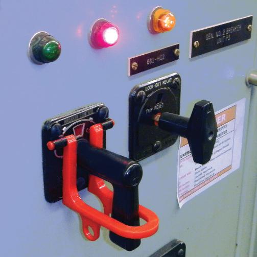
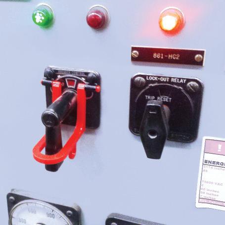
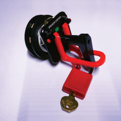
BY DAVID HUFFMAN, Power Systems Testing Company
The NFPA 70B Committee resumed bi-weekly meetings via video calls on January 8, 2021, to continue work on rewriting 70B as a standard, after just over a month break. The committee is currently working on various items that either need review or need better placement in the document.
The first draft meeting will be held in the next few months, depending on the other NFPA committee schedules. Public input closed on January 6, 2021, for the existing edition.

David Huffman has been with Power Systems Testing, a NETA Accredited Company, since January 1988 and is currently CEO. He graduated from California State University, Fresno, and is a licensed Professional Electrical Engineer in the state of California as well as a NETA Level IV Certified Technician. David is a NETA board member, NETA’s Principal Representative to the NFPA 70B Committee, and serves as a member of various NETA committees.


JET Electrical Testing LLC is proud to announce we are now a NETA Accredited Company after meeting the industry-leading crucial requirements to become a full member. JET Electrical Testing, LLC is a women-owned 24/7 full-service testing company founded upon the premise of accurate reporting, project dedication, and customer satisfaction. We are located in central New Jersey.
JET Electrical Testing’s team of project managers, engineers, support staff, and field technicians form a cohesive team clients rely on year after year. JET specializes in commissioning, preventative maintenance, equipment repair, apparatus testing, and emergency response and troubleshooting in compliance with NETA standards. Our mission is to ensure system uptime and failure reduction.
JET’s expertise includes protection and control system upgrades; low- and medium-voltage switchgear maintenance, testing and service; system protection capability; equipment diagnostic testing; and coordination studies for the utility, generation, data center, pharmaceutical, production, and water treatment sectors.
Since JET’s inception, we have continually trained and kept current with new technologies, providing our technicians the knowledge to perform testing across a wide variety of power systems. Our technicians are NETA Certified at Level 2 and Level 3. The collective knowledge and field experience they provide is vital to performing testing according to industry standards in all electrical power system testing and maintenance facets.
With a dedication to safety and the best practices put forth by NETA, OSHA, NFPA, IEEE, the National Safety Council, and others, JET continually strives to be a leader in electrical testing and Preventive Maintenance.
“JET Electrical Testing looks forward to becoming an active, contributing member of NETA in this new venture as a womenowned business,” says CEO Alexandra Jingoli. Dedicated to safety, quality, reliability, and continuous improvement, JET recognizes that upholding the industry’s highest standards is crucial to our operation. Being a NETA Accredited Company proves we are dedicated to setting and maintaining world standards in electrical maintenance and acceptance testing.”
“NETA recognizes the hard work that NETA Accredited Companies like JET Electrical
Testing must put in to achieve this important milestone,” says Scott Blizard, Vice President and Chief Operating Officer of American Electrical Testing Co. LLC. and current NETA President. “NETA Accredited Companies play a critical role in securing electrical power system safety and reliability for all, and NETA is a stronger organization due to these companies’ dedication to our industry.”

100 Lenox Dr, Suite 100 Lawrenceville, NJ 08648 (609) 285-2800


www.jetelectricaltesting.com JET Electrical Testing, LLC is a 24/7 full service testing company founded upon the premise of providing exceptional customer service and the most highly skilled technicians in the industry. The team of project managers, engineers, support staff, and field technicians form the cohesive team in which customers have relied on year after year. JET specializes in commissioning, preventative maintenance, equipment repair, apparatus testing, and emergenc y response/troubleshooting. Electrical system reliability is JET’s goal.


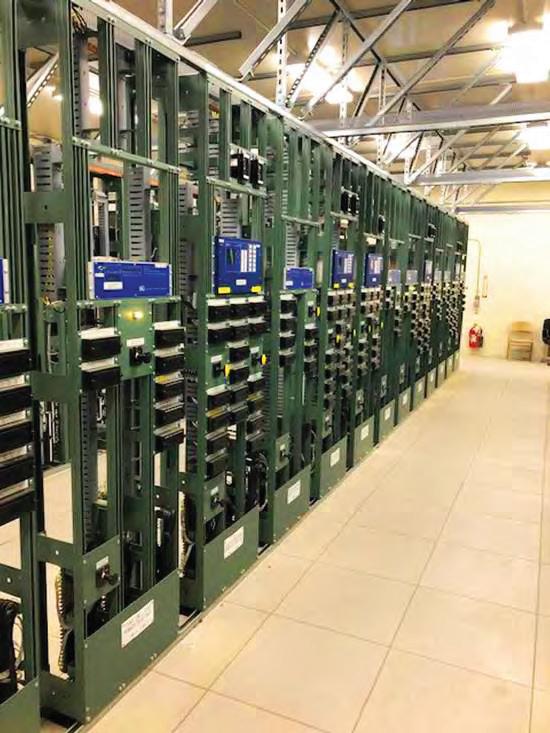


KT Industries Inc. (KTI) is proud to announce its acceptance into the NETA Accredited Company family. As a small, family-owned business, we have taken pride in our expertise, commitment, and personal attention to our customers for many years.
Founded in 1947 under its original name, WARCO Controls, KTI provided critical services and manufacturing to Westinghouse Engineering Services. After incorporating in 1983, KTI expanded its portfolio of capabilities by introducing a wide range of around-the-clock electrical field testing and troubleshooting services.
Our technicians offer 100-plus years of combined electrical experience in a wide range of services that include acceptance and commissioning testing, preventive maintenance and inspection, thermographic surveys, troubleshooting and field services from low to high voltage.
Our experienced staff also works to help customers avoid failure through short-circuit and coordination studies as well as arc-flash, load-flow, and power-quality analysis.
Conveniently located in the heart of Los Angeles, KTI has served customers all over the United States and abroad for over 70 years. Whether it’s a ground fault testing for a new local school or the commissioning of the first carbonate reservoir in the Wafra Field of Kuwait, no project is too big or too small.
“We look forward to continuing our longstanding dedication to the industry as a NETA Accredited Company,” says Susana Vaca-Pardo. “I am proud of the hard work put forth by our employees during the process of becoming fully accredited by NETA. We anticipate our accreditation will provide us with many new opportunities to expand our client base and service offerings. Successfully achieving this demanding certification provides our employees with a strong, industry-relevant training curriculum to augment our existing employee development program. My father, Frank Vaca, worked long hours for many years to help make KTI what it is today, and it is especially gratifying to him to see the company continue to grow with his children at the helm.”
“We see KTI as a staple of Los Angeles and a true testament to the American dream.” says owner Frank Vaca. “I came here as a young boy eager to learn and was given an opportunity by then owner, Kolbjorn Trydal, (the KT in KT Industries). I was able to continue his legacy in the 1990s and like to think Kolbjorn is still with us in spirit, guiding and protecting us. But above all, I think he’s proud.”
“We’ve been here since before the Dodgers moved here from Brooklyn,” says Project Manager, Eric Vaca. “We were here before Walt decided to build an amusement park down in Anaheim, and I’m happy to say that we’ve helped both venues keep their power on. It’s more than a job. It’s a passion. There’s a lot to say about figuring out what makes something tick and giving it life. It may not be for everybody, but I get excited to know I had a small hand in getting a satellite into orbit or saving a sold-out show from cancelling. I wouldn’t want to do anything else.”
“NETA extends a warm welcome to KT Industries,” says Scott Blizard, Vice President and Chief Operating Officer of American Electrical Testing Co., Inc. and current NETA President. “We applaud the important role all our NETA Accredited Companies have in advancing the electrical power systems industry and its safety. Achieving NETA accreditation is something KTI can be proud of, and this recognition is indicative of their accomplishments as an organization.”

3203 Fletcher Drive Los Angeles, CA 90065 (323) 255-7143 www.teamkti.com — eric@kti.la


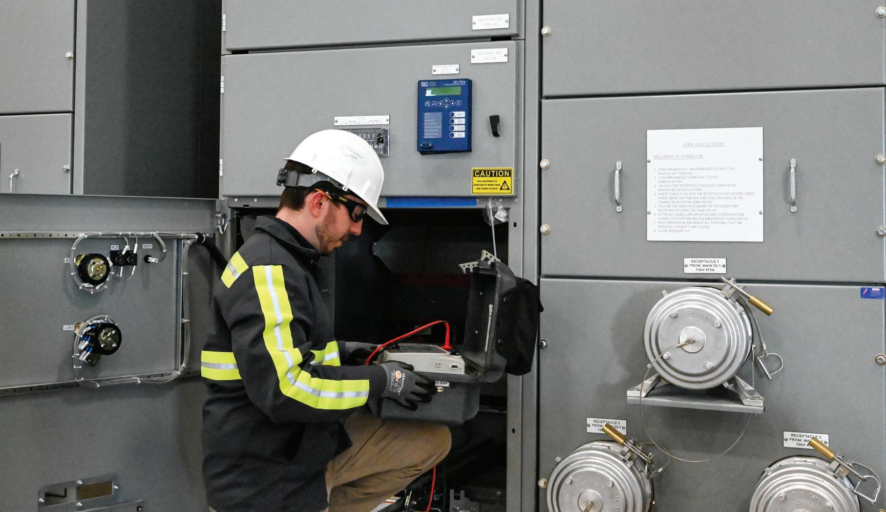
QP Testing is located in the Chicagoland area and provides electrical testing and field services to the utility, industrial, and commercial markets. Our NETA Accredited Technicians and Engineers are experts in testing, analysis, and maintenance of our customers’ electrical power systems, including primary and secondary injection testing of circuit breakers, transformer testing, relay calibration, cable testing, preventive maintenance, and outage service.
With a primary focus on helping our customers, we are the first and only PEARL-Certified circuit breaker testing and repair facility in the Chicagoland area. Our expertise includes breakers of every make and model and ranges from circuit breakers in excess of 80 years old through current breakers installed today. Whether circuit breakers require inspection, testing, refurbishing, or a full retrofit, our team provides the highest level of service and satisfaction in the market.
We perform all testing in accordance with ANSI/NETA standards and are committed to providing a culture of safety and technical expertise. Multiple QP Testing employees have over 40 years of experience in the field, and they are using that knowledge to train our next generation of engineers and technicians.
QP Testing General Manager Steve Pioppo says, “Our employees at QP Testing are passionate about their work, and we are thrilled to be part of a world-class organization like NETA. We have always put an emphasis on top-notch work and safety, but achieving our accreditation provides assurance to our customers of our quality, experience, and training. We anticipate our accreditation will provide us with many new and exciting opportunities.”
“NETA welcomes QP Testing LLC as a new NETA Accredited Company,” says Scott
Blizard, Vice President and Chief Operating Officer of American Electrical Testing Co. LLC and current NETA President. “NETA
Accredited Companies play an important part in advancing the electrical power systems industry and assuring electrical power system safety and reliability. Achieving NETA accreditation is no easy task, and we congratulate QP Testing on achieving this milestone.”

3535 165th St · Hammond, IN 46323
Office: (815) 724-2216
Mobile: (815) 277-6644
spioppo@qp-testing.com www.qp-testing.com
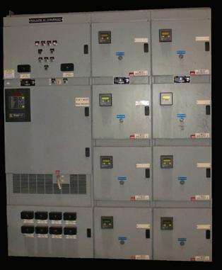
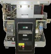
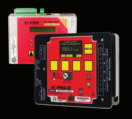
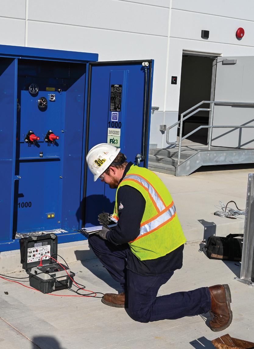
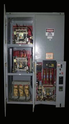
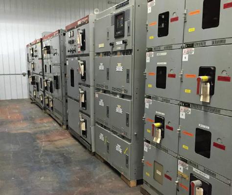
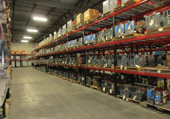
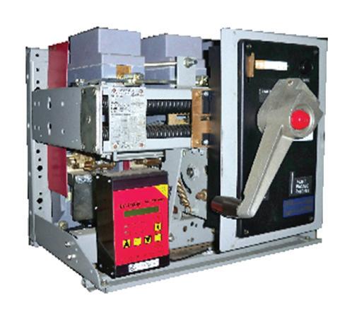

1. d. A low-voltage circuit breaker could be any of the above. Years ago, low-voltage power circuit breakers would have been the answer, but their cost and maintenance requirements have made them somewhat obsolete. Insulated-case circuit breakers are now the typical circuit breaker.
2. d. Actually, any of these types of circuit breakers can have drawout construction. When I was in the field, nothing but lowvoltage power and medium-voltage air circuit breakers were of drawout construction. Then medium-voltage vacuum circuit breakers came out.
3. b. Section 7.6.1.2 would be correct. What are the other sub-sections I listed?
4. c. There are four subsections in Circuit Breaker, Insulated-Case/Molded-Case; the second subsection is in Electrical Tests.
I purposely made it necessary to get a copy of ANSI/NETA MTS to complete this Tech Quiz. Its contents are very important to you as a NETA Certified Technician.
Now that you have your MTS-2019 out, look at the front sections for a wealth of good information. These weren’t written just for owners or managers, but for the technician. Look at Section 5.1 Safety and Precautions or Section 5.5 Test Decal. If you do have a good knowledge of the power system and want to learn more, there’s Section 6 Power Systems Studies. You might also want to be familiar with Section 3 Qualifications of Personnel. There’s a lot to learn from ANSI/ NETA MTS.
NFPA Disclaimer: Although Jim White is a member of the NFPA Technical Committee for both NFPA 70E, Standard for Electrical Safety in the Workplace, and NFPA 70B, Recommended Practice for Electrical Equipment Maintenance, the views and opinions expressed in this column are purely the author’s and shall not be considered an official position of the NFPA or any of its technical committees and shall not be considered, nor be relied upon, as a formal interpretation or promotion of the NFPA. Readers are encouraged to refer to the entire text of all referenced documents.
249th Engineer Battalion
249th EN BN S3 NCOIC 9450 Jackson Loop. Bldg. 1418 Fort Belvoir, VA 22060 (703) 805-9981
Rommel.f.gonzales.mil@mail.mil www.usace.army.mil/Home.aspx
Rommel Gonzales
249th Engineer Battalion, Alpha Company
1251 Pirowski Rd, Bldg 1407 Schofield Barracks, HI 96857 (808) 787-4604
ali.n.abubekr.mil@mail.mil
SSG Ali Abubekr
249th Engineer Battalion, Bravo Company Bldg 3-2631 Butner Rd Fort Bragg, NC 28310-0001 (571) 286-9816
benjamin.j.murphy26.mil@mail.mil
SSG Benjamin Murphy
249th Engineer Battalion, Charlie Company 9410 Jackson Loop Bldg 1416 Fort Belvoir, VA 22060-5116 (703) 806-1078
james.j.gray38.mil@mail.mil
SSG James Gray
249th Engineer Battalion, HHC 9450 Jackson Loop Bldg 1416 Fort Belvoir, VA 22060-5147 (765) 479-2447
hugo.contrerassandoval.mil@mail.mil
SSG Quentin Vanarsdel
A&F Electrical Testing, Inc.
80 Lake Ave S Ste 10 Nesconset, NY 11767-1017 (631) 584-5625
kchilton@afelectricaltesting.com www.afelectricaltesting.com
A&F Electrical Testing, Inc. 80 Broad St Fl 5 New York, NY 10004-2257 (631) 584-5625 afelectricaltesting@afelectricaltesting.com Florence Chilton
ABM Electrical Power Services, LLC 720 S Rochester Ste A Ontario, CA 91761-8177 (301) 397-3500 abm.com/Electrical abm.com/Electrical
ABM Electrical Power Services, LLC 6541 Meridien Dr Suite 113 Raleigh, NC 27616 (919) 877-1008 brandon.davis@abm.com Brandon Davis
ABM Electrical Power Services, LLC 2631 S. Roosevelt St Tempe, AZ 85282 (602) 722-2423
ABM Electrical Power Services, LLC 3600 Woodpark Blvd Ste G Charlotte, NC 28206-4210 (704) 273-6257
ABM Electrical Power Services, LLC
6940 Koll Center Pkwy Suite# 100 Pleasanton, CA 94566 (408) 466-6920
ABM Electrical Power Services, LLC
9800 E Geddes Ave Unit A-150 Englewood, CO 80112-9306 (303) 524-6560
ABM Electrical Power Services, LLC 3585 Corporate Court San Diego, CA 92123-1844 (858) 754-7963
ABM Electrical Power Services, LLC 1005 Windward Ridge Pkwy Alpharetta, GA 30005 (770) 521-7550
ABM Electrical Power Services, LLC 4221 Freidrich Lane Suite 170 Austin, TX 78744 (210) 347-9481
ABM Electrical Power Services, LLC
11719 NE 95th St. Ste H Vancouver, WA 98682 (360) 713-9513
Paul.McKinley@abm.com
Paul McKinley
ABM Electrical Power Solutions 4390 Parliament Place Suite S Lanham, MD 20706 (301) 967-3500
ABM Electrical Power Solutions
3700 Commerce Dr # 901-903 Baltimore, MD 21227-1642 (410) 247-3300
ABM Electrical Power Solutions 317 Commerce Park Drive Cranberry Township, PA 160666407 (724) 772-4638 christopher.smith@abm.com
Chris Smith - General Manager
ABM Electrical Power Solutions 814 Greenbrier Cir Ste E Chesapeake, VA 23320-2643 (757) 364-6145 keone.castleberry@abm.com
Keone Castleberry
ABM Electrical Power Solutions 1817 O’Brien Road Columbus, OH 43228 (724) 772-4638 www.abm.com
Absolute Testing Services, Inc. 8100 West Little York Houston, TX 77040 (832) 467-4446 ap@absolutetesting.com www.absolutetesting.com
Accessible Consulting Engineers, Inc. 1269 Pomona Rd Ste 111 Corona, CA 92882-7158 (951) 808-1040 info@acetesting.com www.acetesting.com
Advanced Electrical Services 4999 - 43rd St. NE Unit 143 Calgary, AB T2B 3N4 (403) 697-3747 accounting@aes-ab.com
Advanced Electrical Services Ltd. 9958 - 67 Ave Edmonton, AB T6E 0P5 (403) 697-3747 www.aes-ab.com
Advanced Testing Systems 15 Trowbridge Dr Bethel, CT 06801-2858 (203) 743-2001 pmaccarthy@advtest.com www.advtest.com
Pat McCarthy
American Electrical Testing Co., LLC 25 Forbes Boulevard Suite 1 Foxboro, MA 02035 (781) 821-0121 sblizard@aetco.us www.aetco.us
Scott Blizard
American Electrical Testing Co., LLC Green Hills Commerce Center 5925 Tilghman St Ste 200 Allentown, PA 18104-9158 (484) 538-2272 jmunley@aetco.us
Jonathan Munley
American Electrical Testing Co., LLC 34 Clover Dr South Windsor, CT 06074-2931 (860) 648-1013 jpoulin@aetco.us
Gerald Poulin
American Electrical Testing Co., LLC 76 Cain Dr Brentwood, NY 11717-1265 (631) 617-5330 bfernandez@aetco.us
Billy Fernandez
American Electrical Testing Co., LLC 91 Fulton St., Unit 4 Boonton, NJ 07005-1060 (973) 316-1180 jsomol@aetco.us
Jeff Somol
AMP Quality Energy Services, LLC
352 Turney Ridge Rd Somerville, AL 35670 (256) 513-8255
brian@ampqes.com
Brian Rodgers
AMP Quality Energy Services, LLC 41 Peabody Street Nashville, TN 37210 (629) 213-4855
Nick Tunstill
Apparatus Testing and Engineering 11300 Sanders Dr Ste 29 Rancho Cordova, CA 95742-6822 (916) 853-6280
jcarr@apparatustesting.com www.apparatustesting.com
Jerry Carr
Apparatus Testing and Engineering 7083 Commerce Cir Ste H Pleasanton, CA 94588-8017 (916) 853-6280
jcarr@apparatustesting.com
Jerry Carr
Applied Engineering Concepts 894 N Fair Oaks Ave. Pasadena, CA 91103 (626) 389-2108
michel.c@aec-us.com
www.aec-us.com
Michel Castonguay
Applied Engineering Concepts 8160 Miramar Road San Diego, CA 92126 (619) 822-1106
michel.c@aec-us.com
Michel Castonguay
BEC Testing 50 Gazza Blvd Farmingdale, NY 11735-1402 (631) 393-6800 ddevlin@banaelectric.com www.bectesting.com
Burlington Electrical Testing Co., LLC 300 Cedar Ave Croydon, PA 19021-6051 (215) 826-9400
waltc@betest.com www.betest.com
Walter P. Cleary
Burlington Electrical Testing Co., LLC 846 Waterford Drive Delran, NJ 08075 (609) 267-4126
C.E. Testing, Inc. 6148 Tim Crews Rd Macclenny, FL 32063-4036 (904) 653-1900
cetesting@hotmail.com www.cetestinginc.com/ Mark Chapman
Capitol Area Testing, Inc.
P.O. Box 259
Suite 614
Crownsville, MD 21032 (757) 650-0740
carl@capitolareatesting.com
www.capitolareatesting.com
Carl VanHooijdonk
CE Power Engineered Services, LLC
4040 Rev Drive Cincinnati, OH 45232 (800) 434-0415
info@cepower.net
Jim Cialdea
CE Power Engineered Services, LLC
480 Cave Rd Nashville, TN 37210-2302 (615) 882-9455
dave.mitchell@cepower.net
Dave Mitchell
CE Power Engineered Services, LLC 40 Washington St Westborough, MA 01581-1088 (508) 881-3911
jim.cialdea@cepower.net
Jim Cialdea
CE Power Engineered Services, LLC
9200 75th Avenue N Brooklyn Park, MN 55428 (877) 968-0281
jason.thompson@cepower.net
Cameron Dooley
CE Power Engineered Services, LLC 72 Sanford Drive Gorham, ME 04038 (800) 649-6314
mike.roach@cepower.net
Michael Roach
CE Power Engineered Services, LLC 8490 Seward Rd. Fairfield, OH 45011 (800) 434-0415
info@cepower.net
Jerry Daugherty
CE Power Engineered Services, LLC 1803 Taylor Ave. Louisville, KY 40213 (800) 434-0415
joe.psillos@cepower.net
Joe Psillos
CE Power Engineered Services, LLC 1200 W. West Maple Rd. Walled Lake, MI 48390 (810) 229-6628 www.cepower.net
Ryan Wiegand
CE Power Engineered Services, LLC 10840 Murdock Drive Knoxville, TN 37932 (800) 434-0415
don.williams@cepower.net
Don Williams
CE Power Engineered Services, LLC
3496 E. 83rd Place
Merrillville, IN 46410 (219) 942-2346
lucas.gallagher@cepower.net
Lucas Gallagher
CE Power Engineered Services, LLC 1260 Industrial Park Eveleth, MN 55734 (218) 744-4200
Joseph Peterson
CE Power Solutions of Florida, LLC 3502 Riga Blvd., Suite C Tampa, FL 33619 (866) 439-2992
robert.bordas@cepowersol.com www.cepowersol.com
Robert Bordas
CE Power Solutions of Florida, LLC 3801 SW 47th Avenue Suite 505 Davie, FL 33314 (866) 439-2992
robert.bordas@cepowersol.com
Robert Bordas
Control Power Concepts
3750 Las Vegas Blvd S. Unit 3303
Las Vegas, NV 89158 (702) 448-7833
jtravis@ctrlpwr.com www.controlpowerconcepts.com
Eastern High Voltage, Inc. 11A S Gold Dr Robbinsville, NJ 08691-1685 (609) 890-8300
bobwilson@easternhighvoltage.com www.easternhighvoltage.com
Robert Wilson
ELECT, P.C.
375 E. Third Street Wendell, NC 27591 (919) 365-9775
btyndall@elect-pc.com www.elect-pc.com
Barry W. Tyndall
Electek Power Services, Inc. 870 Confederation Street Sarnia, ON N7T2E5 (519) 383-0333
tvanderheide@electek.ca
Tim Vanderheide
Electric Power Systems, Inc. 21 Millpark Ct Maryland Heights, MO 63043-3536 (314) 890-9999 s.reed@epsii.com www.epsii.com
Steve Reed
Electric Power Systems, Inc. 11211 E. Arapahoe Rd Ste 108 Centennial, CO 80112 (720) 857-7273
Thomas Reed
Electric Power Systems, Inc. 120 Turner Road Salem, VA 24153-5120 (540) 375-0084
Virginia@EPS-International.com
Bruce Eppers
Electric Power Systems, Inc. 1090 Montour West Ind Park Coraopolis, PA 15108-9307 (412) 276-4559
Ed Nahm
Electric Power Systems, Inc. 6141 E Connecticut Ave Kansas City, MO 64120-1346 (816) 241-9990
Joe Dillon
Electric Power Systems, Inc. 1230 N Hobson St. Suite 101 Gilbert, AZ 85233 (480) 633-1490
Louis Gilbert
Electric Power Systems, Inc. 915 Holt Ave Unit 9 Manchester, NH 03109-5606 (603) 657-7371
Cindy Taylor
Electric Power Systems, Inc. 3806 Caboose Place Sanford, FL 32771 (407) 578-6424
Doug Pacey
Electric Power Systems, Inc. 1129 E Highway 30 Gonzales, LA 70737-4759 (225) 644-0150
Electric Power Systems, Inc. 684 Melrose Avenue Nashville, TN 37211-3121 (615) 834-0999
Larry Christodoulou
Electric Power Systems, Inc. 2888 Nationwide Parkway 2nd Floor Brunswick, OH 44212 (330) 460-3706
Garth Paul
Electric Power Systems, Inc. 54 Eisenhower Lane North Lombard, IL 60148 (815) 577-9515
George Bratkiv
Electric Power Systems, Inc. 1330 Industrial Blvd. Suite 300 Sugar Land, TX 77478 (713) 644-5400
Houston@eps-international.com
Electric Power Systems, Inc.
56 Bibber Pkwy # 1 Brunswick, ME 04011-7357 (207) 837-6527
Garth Paul
Electric Power Systems, Inc. 11861 Longsdorf St Riverview, MI 48193-4250 (734) 282-3311
t.lindemann@eps-international.com
Teresa Lindemann
Electric Power Systems, Inc. 8515 Calle Alameda NE Ste A Albuquerque, NM 87113 (505) 792-7761
Bill Lewis
Electric Power Systems, Inc. 3209 Gresham Lake Rd. Suite 155 Raleigh, NC 27615 (919) 210-5405
Ray Livingston
Electric Power Systems, Inc. 5850 Polaris Ave., Suite 1600 Las Vegas, NV 89118 (702) 815-1342
Devin Hopkins
Electric Power Systems, Inc.
7925 Dunbrook Rd. Suite G
San Diego, CA 92126 (858) 566-6317
Devin Hopkins
Electric Power Systems, Inc. 6679 Peachtree Industrial Dr. Suite H Norcross, GA 30092 (770) 416-0684
Jeremy Russell
Electric Power Systems, Inc.
306 Ashcake Road suite A Ashland, VA 23005 (804) 526-6794
Chris Price
Electric Power Systems, Inc. 7169 East 87th St. Indianapolis, IN 46256 (317) 941-7502
Daniel Douglas
Electric Power Systems, Inc.
7308 Aspen Lane North Suite 160
Brooklyn Park, MN 55428 (763) 315-3520
Paul Cervantez
Electric Power Systems, Inc. 140 Lakefront Drive Cockeysville, MD 21030 (443) 689-2220
Chris Myers
Electric Power Systems, Inc.
783 N. Grove Rd Suite 101 Richardson, TX 75081 (214) 821-3311
Thomas Coon
Electric Power Systems, Inc. 11912 NE 95th St. Suite 306 Vancouver, WA 98682 (855) 459-4377 www.epsii.com
Anthony Asciutto
Electric Power Systems, Inc. Padre Mariano 272, Of. 602 Providencia, Santiago
Electrical & Electronic Controls 6149 Hunter Rd Ooltewah, TN 37363-8762 (423) 344-7666 eecontrols@comcast.net
Michael Hughes
Electrical Energy Experts, LLC W129N10818 Washington Dr Germantown, WI 53022-4446 (262) 255-5222 tim@electricalenergyexperts.com www.electricalenergyexperts.com
Tim Casey
Electrical Engineering & Service Co., Inc.
289 Centre St. Holbrook, MA 02343 (781) 767-9988
jcipolla@eescousa.com www.eescousa.com
Joe Cipolla
Electrical Equipment Upgrading, Inc. 21 Telfair Pl Savannah, GA 31415-9518 (912) 232-7402 kmiller@eeu-inc.com www.eeu-inc.com
Kevin Miller
Electrical Reliability Services 610 Executive Campus Dr Westerville, OH 43082-8870 (877) 468-6384 info@electricalreliability.com www.electricalreliability.com
Electrical Reliability Services 5909 Sea Lion Pl Ste C Carlsbad, CA 92010-6634 (858) 695-9551
Electrical Reliability Services
1057 Doniphan Park Cir Ste A El Paso, TX 79922-1329 (915) 587-9440
Electrical Reliability Services
6900 Koll Center Pkwy Ste 415 Pleasanton, CA 94566-3119 (925) 485-3400
Electrical Reliability Services
8500 Washington St NE Ste A6 Albuquerque, NM 87113-1861 (505) 822-0237
Electrical Reliability Services
2275 Northwest Pkwy SE Ste 180 Marietta, GA 30067-9319 (770) 541-6600
Electrical Reliability Services
10606 Bloomfield Ave Santa Fe Springs, CA 90670-3912 (562) 236-9555
Electrical Reliability Services
400 NW Capital Dr Lees Summit, MO 64086-4723 (816) 525-7156
Electrical Reliability Services
7100 Broadway Ste 7E Denver, CO 80221-2900 (303) 427-8809
Electrical Reliability Services
2222 W Valley Hwy N Ste 160 Auburn, WA 98001-1655 (253) 736-6010
Electrical Reliability Services
221 E. Willis Road, Suite 3 Chandler, AZ 85286 (480) 966-4568
Electrical Reliability Services
1380 Greg St. Ste. 216 Sparks, NV 89431-6070 (775) 746-4466
Electrical Reliability Services
11000 Metro Pkwy Ste 30 Fort Myers, FL 33966-1244 (239) 693-7100
Electrical Reliability Services
245 Hood Road Sulphur, LA 70665-8747 (337) 583-2411
wayne.beaver@vertivco.com
Electrical Reliability Services
9736 South Sandy Pkwy 500 West Sandy, UT 84070 (801) 561-0987
Electrical Reliability Services 6351 Hinson Street, Suite A Las Vegas, NV 89118-6851 (702) 597-0020
Electrical Reliability Services
36572 Luke Drive Geismar, LA 70734 (225) 647-0732 www.electricalreliability.com
Electrical Reliability Services
9636 Saint Vincent Ave Unit A Shreveport, LA 71106-7127 (318) 869-4244
Electrical Reliability Services
1426 Sens Rd. Ste. #5 La Porte, TX 77571-9656 (281) 241-2800
Electrical Reliability Services
9753 S. 140th Street, Suite 109 Omaha, NE 68138 (402) 861-9168
Electrical Reliability Services
1402 Preston Road Ste 404. #706 Dallas, TX 75254 (972) 788-0979
Electrical Reliability Services
4833 Berewick Town Ctr Drive Ste E-207 Charlotte, NC 28278 (704) 583-4794
Electrical Reliability Services
324 S. Wilmington St. Ste 299 Raleigh, NC 27601 (919) 807-0995
Electrical Reliability Services
8983 University Blvd Ste. 104. #158 North Charleston, SC 29406 (843) 797-0514
Electrical Reliability Services
13720 Old St. Augustine Rd. Ste. 8 #310 Jacksonville, FL 32258 (904) 292-9779
Electrical Reliability Services
4099 SE International Way Ste 201 Milwaukie, OR 97222-8853 (503) 653-6781
Electrical Testing and Maintenance Corp.
3673 Cherry Rd Ste 101 Memphis, TN 38118-6313 (901) 566-5557
r.gregory@etmcorp.net www.etmcorp.net
Ron Gregory
Electrical Testing Solutions 2909 Greenhill Ct Oshkosh, WI 54904-9769 (920) 420-2986
tmachado@electricaltestingsolutions.com www.electricaltestingsolutions.com/ Tito Machado
Electrical Testing, Inc. 2671 Cedartown Hwy SE Rome, GA 30161-3894 (706) 234-7623
scott@electricaltestinginc.com www.electricaltestinginc.com
Jamie Dempsey
Elemco Services, Inc. 228 Merrick Rd Lynbrook, NY 11563-2622 (631) 589-6343 courtney@elemco.com www.elemco.com
Courtney Gallo EnerG Test, LLC 206 Gale Lane Kennett Square, PA 19348 (484) 731-0200
KMatthews@energtest.com www.energtest.com
Energis High Voltage Resources 1361 Glory Rd Green Bay, WI 54304-5640 (920) 632-7929
info@energisinc.com www.energisinc.com
EPS Technology 37 Ozick Dr. Durham, CT 06422 (203) 679-0145 www.eps-technology.com
Sean Miller
Giga Electrical & Technical Services, Inc. 5926 E. Washington Boulevard Commerce, CA 90040 (323) 255-5894
gigaelectrical@gmail.com www.gigaelectrical-ca.com/ Hermin Machacon
Grubb Engineering, Inc. 2727 North Saint Mary’s St. San Antonio, TX 78212 (210) 658-7250 rgrubb@grubbengineering.com www.grubbengineering.com
Robert Grubb
Halco Testing Services 5773 Venice Boulevard Los Angeles, CA 90019 (323) 933-9431 www.halcotestingservices.com
Don Genutis
Hampton Tedder Technical Services 4563 State St Montclair, CA 91763-6129 (909) 628-1256
chasen.tedder@hamptontedder.com www.hamptontedder.com
Chasen Tedder
Hampton Tedder Technical Services 3747 W Roanoke Ave Phoenix, AZ 85009-1359 (480) 967-7765
Linc McNitt
Hampton Tedder Technical Services 4113 Wagon Trail Ave. Las Vegas, NV 89118 (702) 452-9200
Roger Cates
Harford Electrical Testing Co., Inc. 1108 Clayton Rd Joppa, MD 21085-3409 (410) 679-4477
testing@harfordtesting.com www.harfordtesting.com
Vincent Biondine
High Energy Electrical Testing, Inc. 5042 Industrial Road, Unit D Farmingdale, NJ 07727 (732) 938-2275
judylee@highenergyelectric.com www.highenergyelectric.com
High Voltage Maintenance Corp. 5100 Energy Dr Dayton, OH 45414-3525 (937) 278-0811
www.hvmcorp.com
High Voltage Maintenance Corp.
24 Walpole Park S Walpole, MA 02081-2541 (508) 668-9205
High Voltage Maintenance Corp.
1052 Greenwood Springs Rd. Suite E Greenwood, IN 46143 (317) 322-2055
www.hvmcorp.com
High Voltage Maintenance Corp.
355 Vista Park Dr Pittsburgh, PA 15205-1206 (412) 747-0550
High Voltage Maintenance Corp.
8787 Tyler Blvd. Mentor, OH 44061 (440) 951-2706
www.hvmcorp.com
Greg Barlett
High Voltage Maintenance Corp. 24371 Catherine Industrial Dr Ste 207 Novi, MI 48375-2422 (248) 305-5596
High Voltage Maintenance Corp.
3000 S Calhoun Rd New Berlin, WI 53151-3549 (262) 784-3660
High Voltage Maintenance Corp.
1 Penn Plaza Suite 500 New York, NY 10119 (718) 239-0359
www.hvmcorp.com
High Voltage Maintenance Corp. 29 Diana Court Cheshire, CT 06410 (203) 949-2650
www.hvmcorp.com Peter Dobrowolski
High Voltage Maintenance Corp. 941 Busse Rd Elk Grove Village, IL 60007-2400 (847) 640-0005
High Voltage Maintenance Corp. 14300 Cherry Lane Court Suite 115 Laurel, MD 20707 (410) 279-0798
www.hvmcorp.com
High Voltage Maintenance Corp. 10704 Electron Drive Louisville, KY 40299 (859) 371-5355
Hood Patterson & Dewar, Inc. 850 Center Way Norcross, GA 30071 (770) 453-1415
info@hoodpd.com https://hoodpd.com/ Brandon Sedgwick
Hood Patterson & Dewar, Inc. 15924 Midway Road Addison, TX 75001 (214) 461-0760 info@hoodpd.com
Hood Patterson & Dewar, Inc. 4511 Daly Dr. Suite 1
Chantilly, VA 20151 (571) 299-6773 info@hoodpd.com
Hood Patterson & Dewar, Inc. 1531 Hunt Club Blvd Ste 200 Gallatin, TN 37066 (615) 527-7084 info@hoodpd.com
Industrial Electric Testing, Inc. 11321 Distribution Ave W Jacksonville, FL 32256-2746 (904) 260-8378 gbenzenberg@bellsouth.net www.industrialelectrictesting.com
Gary Benzenberg
Industrial Electric Testing, Inc. 201 NW 1st Ave Hallandale Beach, FL 33009-4029 (954) 456-7020
Industrial Tests, Inc. 4021 Alvis Ct Ste 1 Rocklin, CA 95677-4031 (916) 296-1200 greg@indtest.com www.industrialtests.com
Greg Poole
Infra-Red Building and Power Service, Inc. 152 Centre St Holbrook, MA 02343-1011 (781) 767-0888
Tom.McDonald@infraredbps.com www.infraredbps.com
Thomas McDonald Sr.
J.G. Electrical Testing Corporation 3092 Shafto Road Suite 13 Tinton Falls, NJ 07753 (732) 217-1908
h.trinkowsky@jgelectricaltesting.com www.jgelectricaltesting.com
JET Electrical Testing
100 Lenox Drive Suite 100
Lawrenceville, NJ 08648 (609) 285-2800
jvasta@jetelectricaltesting.com http://jetelectricaltesting.com
Joe Vasta
KT Industries, Inc. 3203 Fletcher Drive Los Angeles, CA 90065 (323) 255-7143 eric@kti.la ktiengineering.com
Eric Vaca
M&L Power Systems, Inc. 109 White Oak Ln Ste 82 Old Bridge, NJ 08857-1980 (732) 679-1800 milind@mlpower.com www.mlpower.com
Milind Bagle
Magna IV Engineering 1103 Parsons Rd. SW Edmonton, AB T6X 0X2 (780) 462-3111 info@magnaiv.com www.magnaiv.com
Virginia Balitski
Magna IV Engineering 141 Fox Cresent Fort McMurray, AB T9K 0C1 (780) 791-3122
Ryan Morgan
Magna IV Engineering 3124 Millar Ave. Saskatoon, SK S7K 5Y2 (306) 713-2167 info.saskatoon@magnaiv.com
Adam Jaques
Magna IV Engineering 96 Inverness Dr E Ste R Englewood, CO 80112-5311 (303) 799-1273 info.denver@magnaiv.com
Kevin Halma
Magna IV Engineering Avenida del Condor sur #590 Oficina 601 Huechuraba 8580676 +(56) -2-26552600 info.chile@magnaiv.com
Harvey Mendoza
Magna IV Engineering Unit 110, 19188 94th Avenue Surrey, BC V4N 4X8 (604) 421-8020 info.vancouver@magnaiv.com
Rob Caya
Magna IV Engineering Suite 200, 688 Heritage Dr. SE Calgary, AB T2H 1M6 (403) 723-0575 info.calgary@magnaiv.com
Morgan MacDonnell
Magna IV Engineering 4407 Halik Street Building E Suite 300 Pearland, TX 77581 (346) 221-2165 info.houston@magnaiv.com Aric Proskurniak
Magna IV Engineering 10947 92 Ave Grande Prairie, AB T8V 3J3 1.800.462.3157
info.grandeprairie@magnaiv.com
Matthew Britton
Magna IV Engineering 531 Coster St. Bronx, NY 10474 (800) 462-3157
Info.newyork@magnaiv.com
Midwest Engineering Consultants, Ltd. 2500 36th Ave Moline, IL 61265-6954 (309) 764-1561
m-moorehead@midwestengr.com www.Midwestengr.com
Monte Moorehead
MTA Electrical Engineers
350 Pauma Place Escondido, CA 92029 (760) 658-6098 tim@mtaee.com
Timothy G. Shaw
MUSE
1000 23rd Ave BLDG 1360 Port Hueneme, CA 93043 (805) 982-1178
luke.leifeste@navy.mil
Luke Leifeste
National Field Services 651 Franklin Lewisville, TX 75057-2301 (972) 420-0157
eric.beckman@natlfield.com www.natlfield.com
Eric Beckman
National Field Services 1760 W. Walker Street Suite 100 League City, TX 77573 (800) 420-0157
Jonathan.wakeland@natlfield.com
Jonathan Wakeland
National Field Services 1405 United Drive Suite 113-115 San Marcos, TX 78666 (800) 420-0157
matt.lacoss@natlfield.com
Matthew LaCoss
National Field Services
3711 Regulus Ave. Las Vegas, NV 89102 (888) 296-0625
tylor.pereza@natlfield.com
Tylor Pereza
National Field Services
2900 Vassar St. #114 Reno, NV 89502 (775) 410-0430
tylor.pereza@natlfield.com
Tylor Pereza
North Central Electric, Inc. 69 Midway Ave Hulmeville, PA 19047-5827 (215) 945-7632
bjmessina@ncetest.com www.ncetest.com
Robert Messina
Northern Electrical Testing, Inc. 1991 Woodslee Dr Troy, MI 48083-2236 (248) 689-8980
ldetterman@northerntesting.com www.northerntesting.com
Lyle Detterman
Orbis Engineering Field Services Ltd. #300, 9404 - 41st Ave. Edmonton, AB T6E 6G8 (780) 988-1455 accountspayable@orbisengineering.net www.orbisengineering.net
Orbis Engineering Field Services Ltd. #228 - 18 Royal Vista Link NW Calgary, AB T3R 0K4 (403) 374-0051
Amin Kassam
Orbis Engineering Field Services Ltd.
Badajoz #45, Piso 17 Las Condes Santiago +56 2 29402343 framos@orbisengineering.net
Felipe Ramos
Pace Technologies, Inc. 9604 - 41 Avenue NW Edmonton, AB T6E 6G9 (780) 450-0404 www.pacetechnologies.com
Pace Technologies, Inc. #10, 883 McCurdy Place Kelowna, BC V1X 8C8 (250) 712-0091
Pacific Power Testing, Inc. 14280 Doolittle Dr San Leandro, CA 94577-5542 (510) 351-8811 steve@pacificpowertesting.com www.pacificpowertesting.com
Steve Emmert
Pacific Powertech Inc. #110, 2071 Kingsway Ave. Port Coquitlam, BC V3C 6N2 (604) 944-6697 www.pacificpowertech.ca
Josh Konkin
Phasor Engineering
Sabaneta Industrial Park #216 Mercedita, PR 00715 (787) 844-9366 rcastro@phasorinc.com www.phasorinc.com
Rafael Castro
Potomac Testing 1610 Professional Blvd Ste A Crofton, MD 21114-2051 (301) 352-1930
kbassett@potomactesting.com www.potomactesting.com
Ken Bassett
Potomac Testing 12342 Hancock St Carmel, IN 46032-5807 (317) 853-6795
Potomac Testing 1130 MacArthur Rd. Jeffersonville, OH 43128
Power Engineering Services, Inc. 9179 Shadow Creek Ln Converse, TX 78109-2041 (210) 590-4936 dstaudt@pe-svcs.com www.pe-svcs.com
Daniel Staudt
Power Engineering Services, Inc. 1 Ellis Road, Suite 100 Friendswood, TX 77546 (210) 590-4936
Adam Straub
Power Engineering Services, Inc.
124 S West St. Suite 200 Alexandria, VA 22314 (703) 299-3430
Yohannes Daniel
Power Products & Solutions, LLC
6605 W WT Harris Blvd Suite F Charlotte, NC 28269 (704) 573-0420 x12
adis.talovic@powerproducts.biz www.powerproducts.biz
Adis Talovic
Power Products & Solutions, LLC 13 Jenkins Ct Mauldin, SC 29662-2414 (800) 328-7382
raymond.pesaturo@powerproducts.biz
Raymond Pesaturo
Power Products & Solutions, LLC 9481 Industrial Center Dr. Unit 5 Ladson, SC 29456 (844) 383-8617 www.powerproducts.biz
Power Solutions Group, Ltd.
425 W Kerr Rd Tipp City, OH 45371-2843 (937) 506-8444
bwilloughby@powersolutionsgroup.com www.powersolutionsgroup.com
Barry Willoughby
Power Solutions Group, Ltd. 251 Outerbelt St. Columbus, OH 43213 (614) 310-8018
sspohn@powersolutionsgroup.com
Power Solutions Group, Ltd. 5115 Old Greenville Highway Liberty, SC 29657 (864) 540-8434
fcrawford@powersolutionsgroup.com
Anthony Crawford
Power Solutions Group, Ltd. 172 B-Industrial Dr. Clarksville, TN 37040 (931) 572-8591
Chris Brown
Power System Professionals, Inc. 429 Clinton Ave Roseville, CA 95661 (866) 642-3129
jburmeister@powerpros.net
James Burmeister
Power Systems Testing Co. 4688 W Jennifer Ave Ste 108 Fresno, CA 93722-6418 (559) 275-2171 ext 15 dave@pstcpower.com www.powersystemstesting.com
David Huffman
Power Systems Testing Co.
600 S Grand Ave Ste 113 Santa Ana, CA 92705-4152 (714) 542-6089
Power Systems Testing Co. 6736 Preston Ave Ste E Livermore, CA 94551-8521 (510) 783-5096
Power Test, Inc. 2200 Highway 49 S Harrisburg, NC 28075-7506 (704) 200-8311 rich@powertestinc.com www.powertestinc.com
Rick Walker
PowerSouth Testing, LLC 240 Pine Pitch Road Cedartown, GA 30125 (678) 901-0205
samuel.townsend@powersouthtesting.com www.powersouthtesting.com
Powertech Services, Inc. 4095 Dye Rd Swartz Creek, MI 48473-1570 (810) 720-2280 mramieh@powertechservices.com www.powertechservices.com
Precision Testing Group 5475 Highway 86 Unit 1 Elizabeth, CO 80107-7451 (303) 621-2776 office@precisiontestinggroup.com www.precisiontestinggroup.com
Premier Power Maintenance Corporation 4035 Championship Drive Indianapolis, IN 46268 (317) 879-0660 kevin.templeman@premierpower.us
Premier Power Maintenance Corporation 2725 Jason Rd Ashland, KY 41102-7756 (606) 929-5969
jay.milstead@premierpower.us
Jason Milstead
Premier Power Maintenance Corporation 3066 Finley Island Cir NW Decatur, AL 35601-8800 (256) 355-1444
johnnie.mcclung@premierpower.us
Johnnie McClung
Premier Power Maintenance Corporation 4301 Iverson Blvd Ste H Trinity, AL 35673-6641 (256) 355-3006
Kevin.Templeman@premierpower.us
Kevin Templeman
Premier Power Maintenance Corporation 7301 E County Road 142 Blytheville, AR 72315-6917 (870) 762-2100
Kevin.Templeman@premierpower.us
Kevin Templeman
Premier Power Maintenance Corporation 7262 Kensington Rd. Brighton, MI 48116 (517) 715-9997
steve.monte@premierpower.us
Steve Monte
Premier Power Maintenance Corporation 4537 S Nucor Rd. Crawfordsville, IN 47933 (317) 879-0660
kevin.templeman@premierpower.us
Kevin Templeman
Premier Power Maintenance Corporation 1901 Oakcrest Ave., Suite 6 Saint Paul, MN 55113 (612) 430-0209
Zac.mrdgenovich@premierpower.us
Josh Vareberg
Premier Power Maintenance Corporation 119 Rochester Dr. Louisville, KY 40214 (256) 200-6833
Jeremiah.evans@premierpower.us
Jeremiah Evans
QP Testing, LLC
3535 165th Street Hammond, IN 46323 (219) 844-9214
spioppo@qp-testing.com
Steve Pioppo
RESA Power Service 46918 Liberty Dr Wixom, MI 48393-3600 (248) 313-6868 www.resapower.com
RESA Power Service
3890 Pheasant Ridge Dr. NE Suite 170
Blaine, MN 55449 (763) 784-4040
Michael.mavetz@resapower.com
Mike Mavetz
RESA Power Service
4540 Boyce Parkway Cleveland, OH 44224 (800) 264-1549
www.resapower.com
RESA Power Service
47119 Cartier Court Wixom, MI 48393-2872 (248) 896-0200
sam.mancuso@resapower.com
RESA Power Service
19621 Solar Circle, 101 Parker, CO 80134 (303) 781-2560
thomas.cervantes@resapower.com
RESA Power Service
40 Oliver Terrace Shelton, CT 06484-5336 (800) 272-7711
RESA Power Service
13837 Bettencourt Street Cerritos, CA 90703 (800) 996-9975
www.resapower.com
RESA Power Service
2390 Zanker Road San Jose, CA 95131 (800) 576-7372
RESA Power Service 1401 Mercantile Court Plant City, FL 33563 (813) 752-6550
RESA Power Service
6268 Route 31 Cicero, NY 13039 (315) 699-5563
RESA Power Service
#181-1999 Savage Road, Richmond, BC V6V OA5 (604) 303-9770
Gilda Pereira
Reuter & Hanney, Inc., a CE Power Company
Northampton Industrial Park 149 Railroad Dr Ivyland, PA 18974-1448 (215) 364-5333
www.reuterhanney.com
Greg St. Leger
Reuter & Hanney, Inc., a CE Power Company
11620 Crossroads Cir Middle River, MD 21220-2874 (410) 344-0300
Peter Earlston
REV Engineering Ltd.
3236 - 50 Avenue SE Calgary, AB T2B 3A3 (403) 287-0156
www.reveng.ca
Roland Nicholas Davidson, IV Rondar Inc.
333 Centennial Parkway North Hamilton, ON L8E2X6 (905) 561-2808
rshaikh@rondar.com www.rondar.com
Rajeel Shaikh Rondar Inc.
9-160 Konrad Crescent Markham, ON L3R9T9 (905) 943-7640
Saber Power Field Services, LLC
9841 Saber Power Ln Rosharon, TX 77583-5188 (713) 222-9102
bbodine@saberpower.com www.saberpowerfieldservices.com
Saber Power Services, LLC 9006 Western View Helotes, TX 78023 (210) 444-9514
www.saberpowerfieldservices.com
Saber Power Services, LLC
1908 Lone Star Rd. Suite A-D Mansfield, TX 76063 (682) 518-3676
www.saberpowerfieldservices.com
Saber Power Services, LLC
433 Sun Belt Dr. Suite C Corpus Christi, TX 78408 (361) 452-1695 www.saberpowerfieldservices.com
Saber Power Services, LLC 6097 Old Jefferson Hwy Geismar, LA 70734 (877) 912-9102 www.saberpowerfieldservices.com
Saber Power Services, LLC 9672 IH-10 Orange, TX 77632 (346) 335-7011 www.saberpowerfieldservices.com
Scott Testing, Inc. 245 Whitehead Rd Hamilton, NJ 08619 (609) 689-3400
rsorbello@scotttesting.com www.scotttesting.com
Russ Sorbello
Sentinel Field Services, LLC 7517 E Pine St Tulsa, OK 74115-5729 (918) 359-0350
gellis@spstulsa.com www.sentinelpowerservices.com
Greg Ellis
Shermco Industries 2425 E Pioneer Dr Irving, TX 75061-8919 (972) 793-5523 info@shermco.com www.shermco.com
Shermco Industries 112 Industrial Drive Minooka, IL 60447-9557 (815) 467-5577 info@shermco.com
Shermco Industries 233 Faithfull Cr. Saskatoon, SK S7K 8H7 (306) 955-8131
Shermco Industries 2231 E Jones Ave Ste A Phoenix, AZ 85040-1475 (602) 438-7500 info@shermco.com
Shermco Industries 1711 Hawkeye Dr. Hiawatha, IA 52233 (319) 377-3377 info@shermco.com
Shermco Industries 1705 Hur Industrial Blvd Cedar Park, TX 78613-7229 (512) 267-4800 info@shermco.com
Shermco Industries 3434 25th Street NE Calgary, AB T1Y 6C1 (403) 769-9300
Shermco Industries 5145 Beaver Dr Johnston, IA 50131 (515) 265-3377 info@shermco.com
Shermco Industries 4510 South 86th East Ave. Tulsa, OK 74145 (918) 234-2300 info@shermco.com
Shermco Industries 1375 Church Avenue Winnipeg, MB R2X 2T7 (204) 925-4022
Shermco Industries 1033 Kearns Crescent RM of Sherwood, SK S4K 0A2 (306) 949-8131
Shermco Industries 33002 FM 2004 Angleton, TX 77515-8157 (979) 848-1406 info@shermco.com
Shermco Industries 12000 Network Blvd Buidling D, Suite 410 San Antonio, TX 78249-3354 (210) 877-9090 info@shermco.com
Shermco Industries 3731 - 98 Street Edmonton, AB T6E 5N2 (780) 436-8831
Shermco Industries 417 Commerce Street Tallmadge, OH 44278 (614) 836-8556 info@shermco.com
Shermco Industries 3807 S Sam Houston Pkwy W Houston, TX 77056 (281) 835-3633 info@shermco.com
Shermco Industries 7050 109th Ave La Vista, NE 68117 (402) 933-8988 info@shermco.com
Shermco Industries 1301 Hailey St. Sweetwater, TX 79556 (325) 236-9900 info@shermco.com
Shermco Industries 2901 Turtle Creek Dr. Port Arthur, TX 77642 (409) 853-4316 info@shermco.com
Shermco Industries 5145 NW Beaver Dr. Johnston, IA 50131 (515) 265-3377 info@shermco.com
Shermco Industries 998 E. Berwood Ave. Saint Paul, MN 55110 (651) 484-5533 info@shermco.com
Shermco Industries 12796 Currie Court Livonia, MI 48150 (734) 469-4050
Shermco Industries 1720 S. Sonny Ave. Gonzales, LA 70737 (225) 647-9301 info@shermco.com
Shermco Industries 7136 Weddington Rd #128 Concord, NC 28027 (910) 568-1053 info@shermco.com
Shermco Industries 9475 Old Hwy 43 Creola, AL 36525 (251) 679-3224
Shermco Industries 5211 Linbar Dr. Suite 507 Nashville, TN 37211 (615) 928-1182 info@shermco.com
Shermco Industries #307-2999 Underhill Ave Burnaby, BC V5A 3C2 (972) 793-5523
Brad Wager
Shermco Industries 1411 Twin Oaks Street Wichita Falls, TX 76302 (972) 793-5523
Trey Ingram
Shermco Industries 11800 Jordy Rd. Midland, TX 79707 (972) 793-5523
Trey Ingram
Shermco Industries 6551 S Revere Parkway Suite 275 Centennial, CO 80111 (877) 456-1342 www.shermco.com
Sigma Six Solutions, Inc. 2200 W Valley Hwy N Ste 100 Auburn, WA 98001-1654 (253) 333-9730 jwhite@sigmasix.com www.sigmasix.com
John White
Sigma Six Solutions, Inc. www.sigmasix.com Quincy, WA 98848 (253) 333-9730
Chris Morgan
Southern New England Electrical Testing, LLC 3 Buel St Ste 4 Wallingford, CT 06492-2395 (203) 269-8778 www.sneet.org
John Stratton
Star Electrical Services & General Supplies, Inc. PO Box 814 Las Piedras, PR 00771 (787) 716-0925 ahernandez@starelectricalpr.com www.starelectricalpr.com
Aberlardo Hernandez
Taurus Power & Controls, Inc. 9999 SW Avery St Tualatin, OR 97062-9517 (503) 692-9004 powertest@tauruspower.com www.tauruspower.com
Rob Taurus
Taurus Power & Controls, Inc. 19226 66th Ave S. #L102 Kent, WA 98032-2197 (425) 656-4170 powertest@tauruspower.com
Tidal Power Services, LLC 4211 Chance Ln Rosharon, TX 77583-4384 (281) 710-9150
monty.janak@tidalpowerservices.com www.tidalpowerservices.com
Monty Janak
Tidal Power Services, LLC 8184 Highway 44 Ste 105 Gonzales, LA 70737-8183 (225) 644-8170
Darryn Kimbrough
Tidal Power Services, LLC 1056 Mosswood Dr Sulphur, LA 70665-9508 (337) 558-5457
Monty Janak
Tidal Power Services, LLC 1806 Delmar Drive Victoria, TX 77901 (281) 710-9150 monty@tps03.com
Monty Janak
Titan Quality Power Services, LLC 1501 S Dobson Street Burleson, TX 76028 (866) 918-4826 www.titanqps.com www.titanqps.com
Titan Quality Power Services, LLC 7630 Ikes Tree Drive Spring, TX 77389 (281) 826-3781
Titan Quality Power Services, LLC 7000 Meany Ave. Bakersfield, CA 93308 (661) 589-0400
Tony Demaria Electric, Inc. 131 W F St Wilmington, CA 90744-5533 (310) 816-3130 neno@tdeinc.com www.tdeinc.com
Neno Pasic
US Army Prime Power School Bldg 12630, Flw 28 Fort Leonard Wood, MO 65473 (253) 380-0194 russell.s.gaskin.mil@mail.mil
SFC Russell Gaskin
Utilities Instrumentation Service - Ohio, LLC 998 Dimco Way Centerville, OH 45458 (937) 439-9660 www.uiscorp.com www.uiscorp.com
Utilities Instrumentation Service, Inc. 2290 Bishop Cir E Dexter, MI 48130-1564 (734) 424-1200 gary.walls@UIScorp.com www.uiscorp.com Gary Walls
Utility Service Corporation PO Box 1471 Huntsville, AL 35807 (256) 837-8400
apeterson@utilserv.com www.utilserv.com
Alan D. Peterson
Western Electrical Services 14311 29th St E Sumner, WA 98390-9690 (253) 891-1995
dhook@westernelectricalservices.com www.westernelectricalservices.com
Dan Hook
Western Electrical Services 5680 S 32nd St Phoenix, AZ 85040-3832 (602) 426-1667 www.westernelectricalservices.com
Western Electrical Services
3676 W California Ave Ste C106 Salt Lake City, UT 84104-6533 (888) 395-2021 www.westernelectricalservices.com
Western Electrical Services 4510 NE 68th Dr Unit 122 Vancouver, WA 98661-1261 (888) 395-2021
Jason Carlson
Western Electrical Services 5505 Daniels St. Chino, CA 91710 (602) 426-1667
Matt Wallace
Western Electrical Services 620 Meadow Ln. Los Alamos, NM 87547 (505) 469-1661
Western Electrical Services 8985 Double Diamond Pkwy, #10B Reno, NV 98521 (602) 426-1667
Matt Wallace
This issue’s advertisers are identified below. Please thank these advertisers by telling them you saw their advertisement in NETA


Scott Cooper Application Engineer
quality leap through system-based protection testing
System-based protection testing – something new again? Yes, absolutely. This innovative approach makes it possible to check the correct functioning of the entire protection system and thus increase the testing quality. Instead of validating individual relay settings, RelaySimTest simulates realistic scenarios in the power system to reveal errors in the settings, the logic and the design of the protection system.
www.omicronenergy.com/relaysimtest