

SUBSTATION COMMUNICATIONS
DIGITAL SUBSTATION LAN DESIGN AND TESTING PAGE 52 A TSUNAMI OF FUNDING AFFECTING FIBER OPTIC PROJECTS PAGE 66
DISTRIBUTION AUTOMATION NETWORKS – APPLICATION & TESTING PAGE 72
NEW FOR 2023: NFPA 70B PAGE 82
why intellirent...
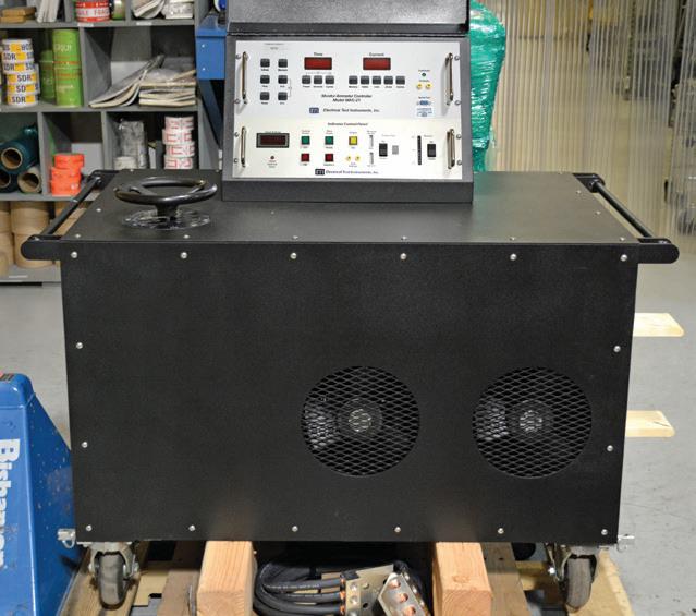
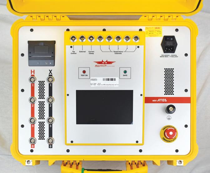
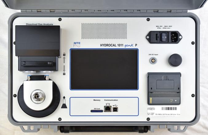
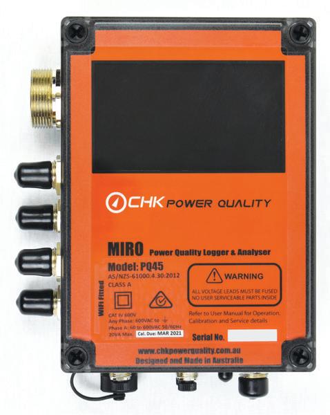
With the largest fleet in the industry, we provide rental and technical support on your preferred manufacturers, including Doble (Manta, Phenix, EnoServ, Vanguard), AEMC, CHK, Dilo, Drantz, ETI, Flir, Fluke, HV Diagnostics, HV Technologies, Megger, MTE, Omicron, Raytech, RH Systems, Trojan, and many more!
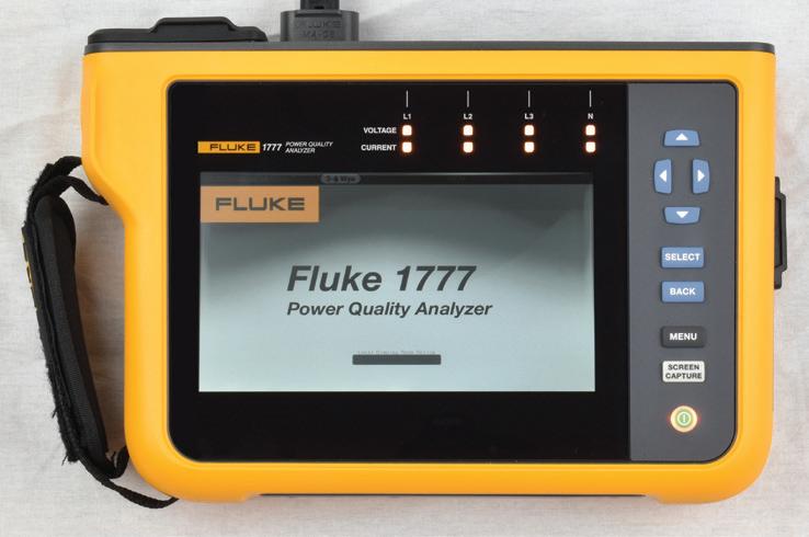
42 Substation Communications — A Primer
William Higinbotham, EA Technology LLC
Fiber optic communications have been deployed in substations since the late 1980s. Now, fiber is here to stay, and everyone should be versed in it. Here’s a primer to answer many of your questions.
52 Digital Substation LAN Design and Testing
Steel McCreery,
OMICRON electronics Canada Corp
Modern digital substation protection and control solutions sit on a foundation of a well-designed OT Ethernet LAN. This article explains IEC 61850 communications services as well as key aspects of design, testing, and commissioning.
66
A Tsunami of Funding Affecting Fiber Optic Projects
Jim Hayes, Fiber Optic Association
The tsunami of funding stemming from the Infrastructure Investment and Jobs Act (IIJA) has the fiber optic industry in a frenzy, but a myriad of challenges is slowing down the process. Learn how to plan a successful project.
72 Distribution Automation Networks — Application & Testing
Abel Gonzalez, Megger
Reclosers are used in distribution automation schemes to provide higher reliability for customers, but must be tested before being put into operation and during every maintenance cycle. Read about the various methods and equipment that can be used.
82 New For 2023: NFPA 70B
NFPA 70B has been a recommended practice for decades. The monumental task of rewriting it as a standard has resulted in a document that promotes the safe operation and maintenance of electrical equipment.
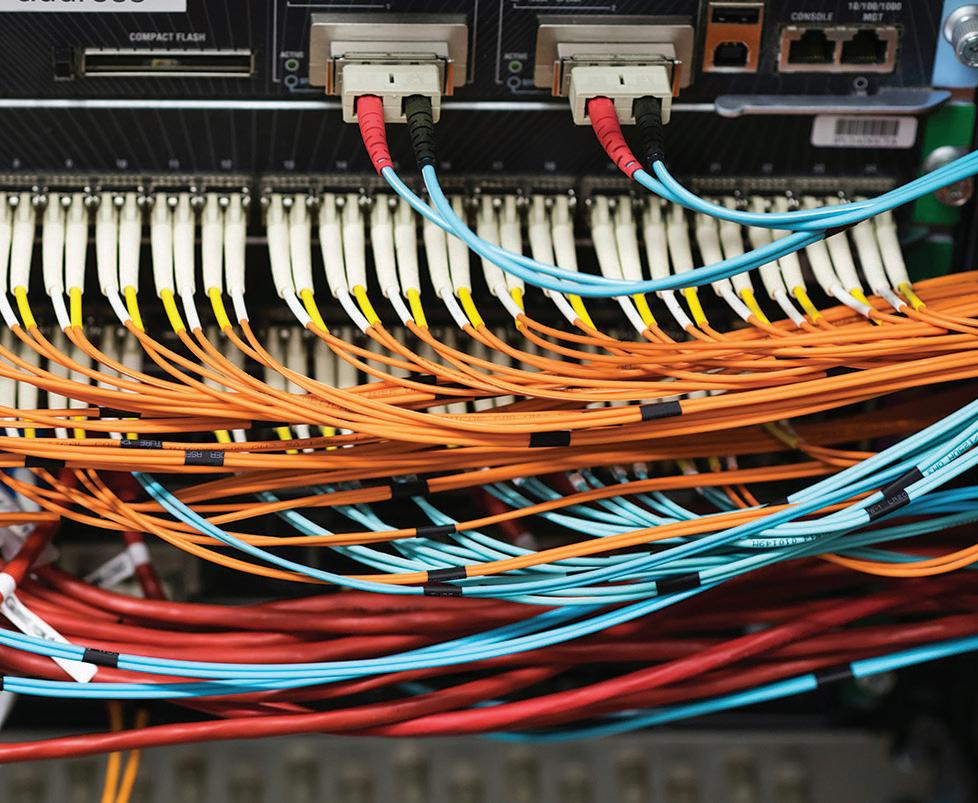

TABLE OF CONTENTS


INSIGHTS AND INSPIRATION
8 Stephanie McLaughlin: Promoting a Servant-Leader Culture
IN EVERY ISSUE
7 President’s Desk
NETA Congratulates Annual Award Recipients
Eric Beckman, National Field Services
NETA President
12 NFPA 70E and NETA
The Future of Electrical Safety and Maintenance Standards
Ron Widup, Shermco Industries
17 Relay Column
Selecting Overcurrent Protecting for Grounding
Transformers on Feeders for Renewable Sites
Steven Turner, Arizona Public Service Company
22 In the Field
Unraveling the Mystery of Baffling Transformer Trips
Mose Ramieh, CBS Field Services
30 Safety Corner
Communicating Hazards Using a Pre-Job Brief
Paul Chamberlain, American Electrical Testing Co. LLC
34 Tech Quiz
Communications and Fiber Optics
Virginia Balitski, Magna IV Engineering
36 Tech Tips
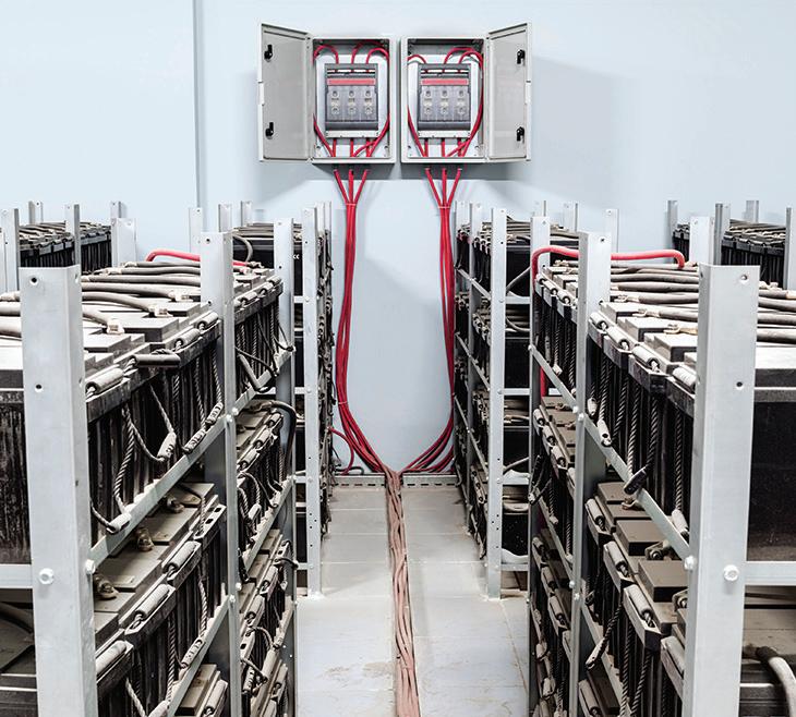
Advancements in Battery Ground Fault Location
Jeff Jowett, Megger
CORPORATE ALLIANCE CORNER
86 Advancements in Industry
Acceptance and Maintenance Testing for Medium-Voltage
Electrical Power Cables — Part 3 of 3
Thomas Sandri, Protec Equipment Resources
96 Partner Spotlight Protec Equipment Resources: Quality, Safety, Reliability
NETA NEWS
104 Outstanding Achievement Award — Steve Newton
113 Alliance Recognition Award — Charles Sweetser
118 Jim White Safety Award — Jim Dollard
119 Raytech USA Joins NETA as Corporate Alliance Partner
120 Lifetime Achievement Award — Alan Peterson
126 Lifetime Achievement Award — Roderic Hageman
132 PowerTest 2023 — A Record-Breaking Conference Generating Powerful Connections for the Future
SPECIFICATIONS AND STANDARDS
101 ANSI/NETA Standards Update
IMPORTANT LISTS
138 NETA Accredited Companies
142 Advertiser List


3050 Old Centre Road, Suite 101
Portage, MI 49024
Toll free: 888.300.NETA (6382)
Phone: 269.488.NETA (6382)
Fax: 269.488.6383
neta@netaworld.org
www.netaworld.org
executive director: Bryant Phillips
deputy director: Melissa York
NETA Officers
president: Eric Beckman, National Field Services
second vice president: Dan Hook, CBS Field Services
secretary: Chasen Tedder, Hampton Tedder Technical Services
treasurer: John White, Sigma Six Solutions, Inc.
NETA Board of Directors
Virginia Balitski (Magna IV Engineering)
Ken Bassett (Potomac Testing, Inc.)
Eric Beckman (National Field Services)
Scott Blizard (American Electrical Testing Co., Inc.)
Leif Hoegberg (Electrical Reliability Services)
Dan Hook (CBS Field Services)
David Huffman (Power Systems Testing)
Chasen Tedder, Hampton Tedder Technical Services
Ron Widup (Shermco Industries)
non-voting board member
Jim Cialdea (Sigma C Power Services)
Lorne Gara (Shermco Industries)
John White (Sigma Six Solutions)
NETA World Staff
technical editors: Roderic L. Hageman, Tim Cotter
assistant technical editors: Jim Cialdea, Dan Hook,
Dave Huffman
associate editor: Resa Pickel
managing editor: Carla Kalogeridis
copy editor: Beverly Sturtevant
design and production: Moon Design
NETA Committee Chairs
conference: Ron Widup; membership: Ken Bassett; promotions/marketing: Scott Blizard; safety: Scott Blizard; technical: Lorne Gara; technical exam: Dan Hook; continuing technical development: David Huffman; training: Virginia Balitski; finance: John White; nominations: Dave Huffman; alliance program: Jim Cialdea; association development: Ken Bassett
© Copyright 2023, NETA
NOTICE AND DISCLAIMER
NETA World is published quarterly by the InterNational Electrical Testing Association. Opinions, views and conclusions expressed in articles herein are those of the authors and not necessarily those of NETA. Publication herein does not constitute or imply endorsement of any opinion, product, or service by NETA, its directors, officers, members, employees or agents (herein “NETA”).
All technical data in this publication reflects the experience of individuals using specific tools, products, equipment and components under specific conditions and circumstances which may or may not be fully reported and over which NETA has neither exercised nor reserved control. Such data has not been independently tested or otherwise verified by NETA.
NETA MAKES NO ENDORSEMENT, REPRESENTATION OR WARRANTY AS TO ANY OPINION, PRODUCT OR SERVICE REFERENCED OR ADVERTISED IN THIS PUBLICATION. NETA EXPRESSLY DISCLAIMS ANY AND ALL LIABILITY TO ANY CONSUMER, PURCHASER OR ANY OTHER PERSON USING ANY PRODUCT OR SERVICE REFERENCED OR ADVERTISED HEREIN FOR ANY INJURIES OR DAMAGES OF ANY KIND WHATSOEVER, INCLUDING, BUT NOT LIMITED TO ANY CONSEQUENTIAL, PUNITIVE, SPECIAL, INCIDENTAL, DIRECT OR INDIRECT DAMAGES. NETA FURTHER DISCLAIMS ANY AND ALL WARRANTIES, EXPRESS OF IMPLIED, INCLUDING, BUT NOT LIMITED TO, ANY IMPLIED WARRANTY OF FITNESS FOR A PARTICULAR PURPOSE.
ELECTRICAL TESTING SHALL BE PERFORMED ONLY BY TRAINED ELECTRICAL PERSONNEL AND SHALL BE SUPERVISED BY NETA CERTIFIED TECHNICIANS/ LEVEL III OR IV OR BY NICET CERTIFIED TECHNICIANS IN ELECTRICAL TESTING TECHNOLOGY/LEVEL III OR IV. FAILURE TO ADHERE TO ADEQUATE TRAINING, SAFETY REQUIREMENTS, AND APPLICABLE PROCEDURES MAY RESULT IN LOSS OF PRODUCTION, CATASTROPHIC EQUIPMENT FAILURE, SERIOUS INJURY OR DEATH.
ISSN 2167-3594 NETA WORLD JOURNAL PRINT
ISSN 2167-3586 NETA WORLD JOURNAL ONLINE

NETA CONGRATULATES ANNUAL AWARD RECIPIENTS
PowerTest 2023 in Orlando, Florida, was a smashing success. Many of us escaped snow, heavy rain, and freezing temperatures at home, making it easy to enjoy the sunshine and warm weather. Thank you to everyone who participated in the premier electrical testing and safety conference.
In addition to excellent content, this issue of NETA World celebrates the recipients of NETA’s Annual awards. Please join me in congratulating them, and read their stories on pages 104 – 130.
• Lifetime Achievement Award: Alan “Al” Peterson
• Lifetime Achievement Award: Rod Hageman
• Outstanding Achievement Award: Steve Newton
• Alliance Recognition Award: Charles Sweetser
• Jim White Safety Award: Jim Dollard
This edition of NETA World announces the important release of NFPA 70B, Electrical Equipment Maintenance, 2023 Edition. The article highlights the efforts taken to produce the standard and take it from a “recommended practice” to a recognized standard.
Our cover story provides a historical look at the use of fiber optics in substations. Fiber is here to stay for our industry. The good news is that it is more reliable than many other communication channels, and it’s easier to work on once you understand it. An additional article drills down on the “tsunami of funding” available for fiber optic projects of all types and the challenges of delivering these projects.
Discussions on designing and testing substation LANs, distribution feeder schemes, and testing of medium-voltage electrical power cables are also featured. The modernization of protection and controls, now more than ever, relies on adequate design, commissioning, and testing of these schemes.
Plan ahead and always put safety first!
Eric Beckman, PE, President InterNational Electrical Testing Association

STEPHANIE McLAUGHLIN: PROMOTING A SERVANT-LEADER CULTURE
Stephanie W. McLaughlin is the Employee Development Manager for Hood Patterson & Dewar, Inc. (HP&D), where she recently led the development and implementation of HP&D’s employee development program that supports employees in offices in five states, including a large team of registered Professional Engineers (PEs), degreed engineers, and career test technicians.

McLaughlin specializes in analyzing learners’ needs and then designing and developing components to meet those needs. She has experience creating development initiatives in the automobile, hospitality, and cloud computing industries, as well as curriculum initiatives for the Gwinnett County (Georgia) Public Schools. Stephanie earned a BS in technical and professional communications at Southern Polytechnic State University and an MBA from Georgia Institute of Technology as well as an education certificate from Brenau University.
NWJ: Describe your current role with your company and your daily responsibilities.
McLaughlin: I like to say I am 90% employee development and that marketing is my side hustle. However, I must admit that my day-to-day responsibilities ebb and flow as appropriate to meet the needs of our people. At the end of the day, our employees are my
clients, and my job is to delight and support them. My days can vary significantly depending on the week. For example, here are the tasks I completed last week:
• Sent mentoring follow-up emails to a few mentors and mentees in our formal mentorship program; shared some positive feedback with the President of HP&D



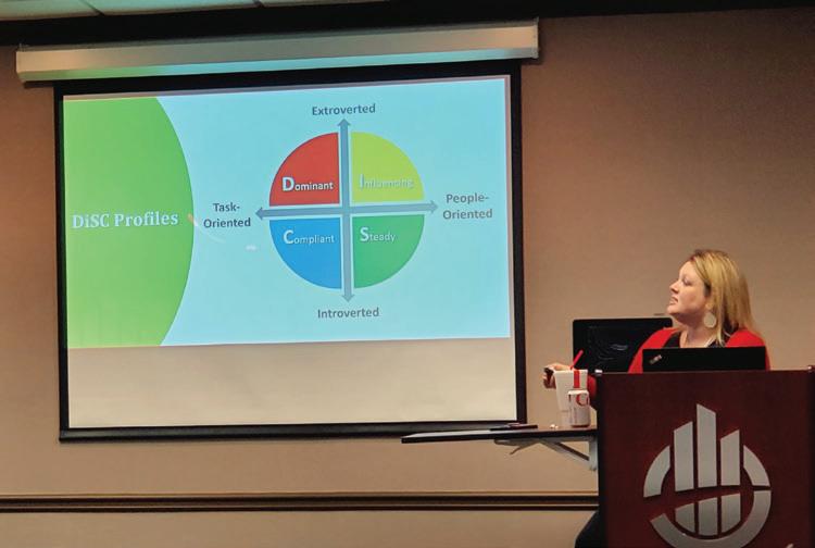

• Selected a mentor for a new employee and finalized his core competency book
• Completed the employee development orientation for another new employee
• Met with the VP of Engineering to discuss a participant guide (PG) for a client training class; created the first 65 pages of the PG using InDesign
• Attended a career fair at Kennesaw State University and talked to engineering students about summer internship opportunities
• Prepared for and facilitated a New Employee Boot Camp, which is a twoday class where we explore our history, culture, services, and what has helped us to be so successful over the last 75+ years
• Helped to interview a potential summer intern
• Wrote employee development content for the monthly newsletter


• Met with the Employee Development and Marketing teams to review the current projects and ongoing tasks
• Reviewed the social media calendar for April and sent my feedback
• Reviewed a contract for a DJ for the annual employee appreciation party
• Reviewed the new PowerPoint templates for the company and sent my feedback to the designer
• Coordinated with the voiceover artist who is recording narration for an NFPA 70E online training course that we are creating
While most of these tasks are in support of employee development, quite a few also support marketing. I love that my days vary so much. Since employee development and marketing are relatively small teams (three fulltime employees and one part-time employee
INSIGHTS & INSPIRATION
in total), everyone gets the opportunity to directly contribute to our outcomes. I find that in my role here, I am able to leverage all of the skills that I have acquired throughout my 20+ year career, which is incredibly satisfying professionally.
NWJ: In your opinion, does the electrical testing industry put enough emphasis on training?
McLaughlin: I am fortunate to have worked in a variety of interesting industries, including hospitality, tech, automotive, and now electrical testing. Since HP&D is my only experience in the electrical testing industry, I can only speak to what we do, and I must say I am very impressed with the emphasis that is placed on training here. In fact, it was only because of this commitment to developing our people that I am here. My role was created to help HP&D formalize and expand its commitment to learning and development, including leadership, soft skills, safety, and technical training opportunities.
We have an amazing safety team that creates the vital safety training courses our people need to work safely. We also have many subject matter experts (SMEs) who are willing to dedicate their time and effort to help us create and deliver technical training courses as needed. With my background, I have provided leadership, project management, sales, communications, and other soft skills training.
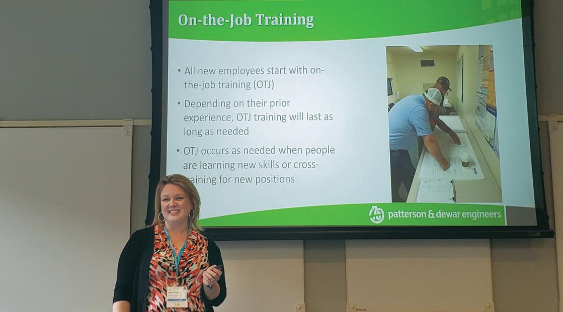
At HP&D, we realize the importance of on-the-job training and have committed to providing all new employees with the support and time that they need to fully train in their new roles with on-the-job training for as long as necessary.
Employee development is a long-term initiative, but it also leads to short-term benefits like increased loyalty and improved performance and engagement. We focus on making growth a priority because growth compounds and accelerates as you remain intentional about it.
NWJ: What are the biggest challenges you face in advancing the professional development of your employees?
McLaughlin: Time. Like everyone, our biggest hindrance to professional development is a lack of time. Our people are so busy, which is truly a blessing; however, it can make setting aside time to learn and grow challenging at times. Thankfully, our people tend to be very dedicated and will prioritize learning whenever and however they can.
NWJ: Retaining talent is tough these days. What advice do you have for organizations looking to help their people feel valued and invested in?
McLaughlin: Build an amazing culture. When people feel like they are a part of something special, when they feel connected and that what they are doing is important, they become more dedicated and committed to the shared vision of success.
A company that promotes a servant-leader mentality and focuses on strong personal relationships, client success, and employee satisfaction is much better positioned for longterm success. Interestingly, when employees and clients are the focus, the numbers take care of themselves. Instead of management trying to control and measure all aspects of a project, employees are empowered to make autonomous decisions daily without fear of reprisal. An employee-owned company is best positioned to take advantage of this type of culture — a relationship management approach instead of a KPI-driven approach.
NWJ: How do you assess what your employees need in terms of their professional development?
McLaughlin: We strongly believe that people must be involved in this process. We have embedded this discussion into the annual review process where employees are encouraged to create their own development plans, and supervisors are encouraged to support their people.
Since we promote servant leadership, our supervisors are encouraged to lead by caring for the people on their teams. When you care for someone, you spend time getting to know them and learn about what they want for themselves as they continue to progress in their careers. With this information, supervisors can advocate for their team members by requesting training courses or by helping to coordinate on-the-job training when needed. Employees are also encouraged to reach out to the employee development team directly should they need support.
Finally, we meet with senior leaders quarterly to discuss the employee development initiatives in progress and upcoming responsibilities so that we can ensure ongoing alignment in order to best meet the needs of our people.
NWJ: How do you incentivize employees to participate and take responsibility for their own development?
McLaughlin: We strongly believe in compensating our people based on the value that they bring to the company and our clients. We provide very generous bonuses, especially to people who are bringing the most value. We have found that the people who continue to learn and grow tend to bring the most value. Because we are rewarding this behavior, it tends to be repeated.
NWJ: Is there anything else you would like to share?
McLaughlin: There are so many good reasons to have a robust employee development program: increased employee retention, improved employee recruitment, and enhanced client satisfaction. I feel fortunate to be with an organization that truly values employee learning and development.



THE FUTURE OF ELECTRICAL SAFETY AND MAINTENANCE STANDARDS
BY RON WIDUP, Shermco Industries
What does the future hold for our industry — especially when it comes to those all-important standards that ensure reliability, protect property, and help us to avoid injury or death?
As we revise and update codes and standards from NETA, NFPA, IEEE, ASTM, NEMA, CSA, and OSHA, I think we should all read this very carefully, especially the summary.
WHAT IS THE FUTURE OF ELECTRICAL SAFETY AND MAINTENANCE STANDARDS?
The future of electrical safety and maintenance standards is likely to involve increased emphasis on the use of technology, automation, and datadriven approaches. As technology advances, there will likely be an increased focus on the use of smart devices and sensors to monitor electrical systems and identify potential safety hazards.
Additionally, there may be a greater focus on preventative maintenance as organizations recognize the importance of maintaining electrical systems to ensure their long-term reliability and safety. This may involve the use of advanced diagnostic tools and techniques to identify potential issues before they lead to equipment failures or safety hazards.
Another trend that is likely to shape the future of electrical safety and maintenance standards is increased collaboration and information sharing among stakeholders. This could involve greater involvement from regulatory bodies, industry associations, and other organizations to establish common standards and best practices for electrical safety and maintenance.
Overall, the future of electrical safety and maintenance standards is likely to be characterized by a greater reliance on technology and data-driven approaches, as well as increased collaboration and information sharing among stakeholders.
HOW WILL ELECTRICAL STANDARDS INCREASE RELIABILITY?
Electrical standards can increase reliability in several ways, including:
1. Ensuring consistent performance. Electrical standards provide guidelines for the design, installation, and maintenance of electrical systems. By following these

PHOTO: © WWW.SHUTTERSTOCK.COM/G/ZAPP2PHOTO
standards, electrical systems can be built and operated in a consistent manner, which can help to ensure that they perform reliably.
2. Improving safety. Electrical standards often include requirements for safety features and procedures, such as grounding, protective devices, and lockout/tagout procedures. By implementing these safety measures, the risk of accidents and equipment failures can be reduced, which can help to increase the reliability of the electrical system.
3. Encouraging proper maintenance. Electrical standards often include guidelines for the maintenance and testing of electrical equipment. By
following these guidelines, potential issues can be identified and addressed before they lead to equipment failures, which can improve the overall reliability of the system.
4. Promoting interoperability. Electrical standards can help to ensure that different electrical components and systems are designed to work together effectively. This can help to prevent compatibility issues that could lead to system failures or malfunctions.
Overall, electrical standards can help to ensure that electrical systems are designed, installed, and maintained in a consistent, safe, and effective manner, which can help to increase the reliability of the system.
THE NFPA 70E AND NETA
HOW WILL TECHNOLOGY AND AUTOMATION SAVE LIVES?
Technology and automation have the potential to save lives in a number of ways, particularly in fields where human error can lead to dangerous situations. Here are a few examples:
• Autonomous vehicles. Self-driving cars and trucks have the potential to greatly reduce accidents caused by human error, such as distracted driving or impaired driving.
• Robotics. Robots can be used in hazardous or dangerous environments, such as mines, factories, or disaster zones, to perform tasks that would be dangerous or difficult for humans to perform.
• Wearable technology. Wearable devices can monitor vital signs or detect changes in a person’s health, allowing for early detection and treatment of potentially life-threatening conditions.
• Smart home technology. Smart home devices can be used to monitor for dangerous situations such as fires, carbon monoxide leaks, or water leaks, and alert homeowners or emergency services.
• Medical technology. Advanced medical technology, such as artificial organs and precision medicine, can improve patient outcomes and reduce the risk of complications during procedures.
Overall, technology and automation can save lives by reducing the likelihood of human error, increasing efficiency, and enabling early detection and treatment of health problems or dangerous situations.
NOW FOR THE SUMMARY
The previous information in this article was 667 words, and while on the surface it sounds reasonable and maybe even on point — know this: All of the information was created in ChatGPT in just a few seconds. Click. Copy. Paste.
No human intervention, no subject matter expertise, no verified reference to an actual standard or real-life source.
It was a few words typed into a website, with results obtained in seconds. No research, no knowledge, no validation or verification.
Suzanne Massie, an American scholar of Russian history who advised Ronald Reagan on the Soviet Union during the final years of the Cold War as they prepared for talks with Mikhail Gorbachev, taught him this Russian Proverb: “Doveryai, no Proveryai” which translates to “Trust, but Verify.”

PHOTO: © WWW.SHUTTERSTOCK.COM/G/MARK+REINSTEIN
Ladies and gentlemen, we might want to think very carefully about the future of the electrical life-safety and maintenance rules, guidance, codes, and standards we are creating now and in the future….because things aren’t always as they seem.
Developing these very important documents for our industry and the betterment of the
electrical worker in the field, especially in this day and age of unverified and unnamed sources that are generated at the click of a mouse, we should always remember:
TRUST, BUT VERIFY
It is incumbent upon us all to be forever diligent in our sources of information and the facts that drive them as we continue our quest to ensure reliability and protect people.
Use technology to our advantage, but don’t get lazy. Trust, but Verify.
And oh, yeah. Before working on it — turn it off!
Article Sources:
225 words: Ron Widup
48 words: www.suzannemassie.com
667 words: ChatGPT

THE NFPA 70E AND NETA
Ron Widup is the Vice Chairman, Board of Directors, and Senior Advisor, Technical Services for Shermco Industries and has been with Shermco since 1983. He is a member of the NETA Board of Directors and Standards Review Council; a Principal member of the Technical Committee on Standard for Electrical Safety in the Workplace (NFPA 70E); Principal member of the National Electrical Code (NFPA 70) Code Panel 11; Principal member and Chairman of the Technical Committee on Standard for Competency of ThirdParty Evaluation Bodies (NFPA 790); Principal member and Chairman of the Technical Committee on Recommended Practice and Procedures for Unlabeled Electrical Equipment Evaluation (NFPA 791); a member of the Technical Committee Recommended Practice for Electrical Equipment Maintenance (NFPA 70B); and Vice Chair for IEEE Std. 3007.3, Recommended Practice for Electrical Safety in Industrial and Commercial Power Systems. He is a member of the Texas State Technical College System (TSTC) Board of Regents, a NETA Certified Level 4 Senior Test Technician, State of Texas Journeyman Electrician, a member of the IEEE Standards Association, an Inspector Member of the International Association of Electrical Inspectors, and an NFPA Certified Electrical Safety Compliance Professional (CESCP).


February 26 – March 1, 2024 | Monday – Friday

Hilton Anatole | Dallas, Texas
Promote your products and services to a valuable audience of key industry decision-makers while increasing brand visibility.
SETTING OVERCURRENT PROTECTION FOR GROUNDING TRANSFORMERS ON FEEDERS FOR RENEWABLE SITES
BY STEVE TURNER, Arizona Public Service – Generation System Protection
Grounding transformers are most frequently — but not exclusively — used in the renewable industry to provide a relatively lowimpedance path to ground in case of surges. This allows for safe maintenance of the grid without fear of damaging the electrical infrastructure.
If the grounding transformer is connected to a feeder, special considerations are required to set the protection to properly detect ground current present during ground faults. Figure 1 shows the one-line diagram for a feeder with a grounding transformer that will be used to calculate the protection settings for this guide.
GROUND FAULT CURRENT CALCULATIONS
This section shows how to calculate the ground current measured by the feeder relay during ground faults on the 12.47 kV bus. Figure 2 is the corresponding three-line diagram for the one-line diagram shown in Figure 1.
The feeder is served by a step-up transformer with this nameplate data:
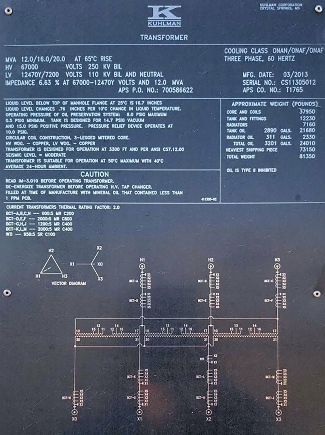
The step-up transformer MVA (12) will be used as the system base for the following ground fault current calculations. Step-Up Transformer Impedance
Positive-Sequence Network
Negative-Sequence Network
Zero-Sequence Network
Figure 4 illustrates the short circuit diagram using symmetrical components to calculate the ground fault current available for a single lineto-ground fault on the 12.47 kV bus. The red X denotes the location of the ground fault.
Per Unit Impedances
Network Per Unit Impedances
Ground Fault Current Calculation
Figure 4: Short Circuit Diagram (Symmetrical Components)
Ground Current Flowing Up the Step-Up Transformer Low Side Neutral:
Ground Current Flowing Up the Grounding Transformer Neutral (Per Unit):
Base Current
Ground Current Flowing Up the Grounding Transformer Neutral (Primary)
Neutral Current (IN) Measured by the Feeder Relay
RELAY COLUMN
The relay operates on the measured signal IN to detect the presence of a ground fault. Note that this value is equal to I0g since the measurement is taken inside the delta connection of the CTs protecting the grounding transformer. The CT ratio is 600:5.
DETERMINING GROUND FAULT OVERCURRENT PICKUP AND TIME DELAY ON PICKUP SETTING
Set the pickup to reliably detect the presence of a ground fault. The short circuit calculations presented were for the case of a ground fault on the 12.47 kV bus, but the ground fault could be located anywhere along a feeder. As the location of the ground fault is moved along the feeder towards the end, the fault current magnitude drops since the loop impedance increases. Wind farms have long feeders, so it is important to properly set the pickup so that the ground fault overcurrent protection can detect a ground fault located at the end of a feeder.
Set the time delay on pickup long enough to avoid nuisance trips during transient conditions.
CONCLUSION
Grounding transformers are commonly used in the renewable industry. If the grounding
CORRECTION
transformer is connected to a feeder, special considerations are required to set the protection to properly detect ground current present during ground faults. Additionally, the ground fault overcurrent protection must be set to reliably detect a ground fault located anywhere along a feeder. This article showed how to calculate the ground fault current magnitude for a delta/wye grounded grounding transformer; however, zigzag transformers are also commonly used.
ACKNOWLEDGMENTS
The author wishes to thank Jesus Vargas for his help in developing the ground fault short circuit calculations presented in this article.

Steve Turner is in charge of system protection for the Fossil Generation Department at Arizona Public Service Company in Phoenix. Steve worked as a consultant for two years, and held positions at Beckwith Electric Company, GEC Alstom, SEL, and Duke Energy, where he developed the first patent for double-ended fault location on overhead high-voltage transmission lines and was in charge of maintenance standards in the transmission department for protective relaying. Steve has BSEE and MSEE degrees from Virginia Tech University. Steve is an IEEE Senior Member and a member of the IEEE PSRC, and has presented at numerous conferences.
In the Spring 2023 edition of NETA World, a reference on page 10 was incorrectly cited. Reference [1] should read:
[1] Penrose, Howard W. “Why Wind Generators Die Young and How to Make Them Work Longer.” Windpower Engineering. Accessed at www.windpowerengineering.com/ why-wind-generators-die-young-and-how-to-make-them-work-longer/.
NETA has corrected the information in the online version of the article.

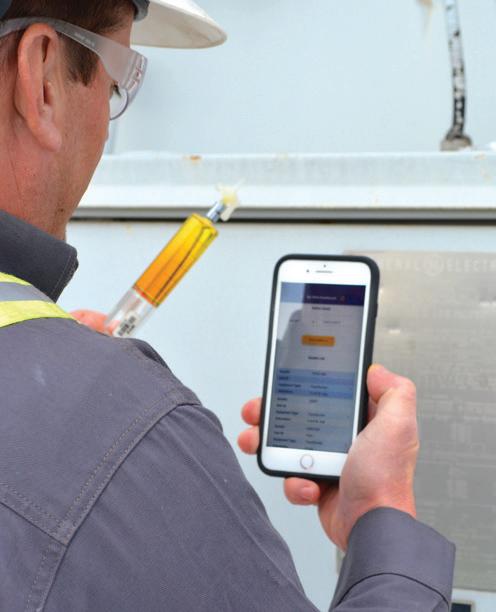
MVA Diagnostics’s unique patent pending app, XQOhm, allow our customers nationwide to sample transformers without filling out any paperwork.
Ǥ DGA and Ratio Analysis for Transformers, LTC’s and other Electrical Equipment
Ǥ MVA Dashboard—Customer Portal, PDF and CSV files
Ǥ XQOhm App to Sample Assets with NO Paperwork
Ǥ Certified PCB Testing
Ǥ Field Technicians for Site Sampling
www.mvadiagnostics.com www.mvasvcs.com

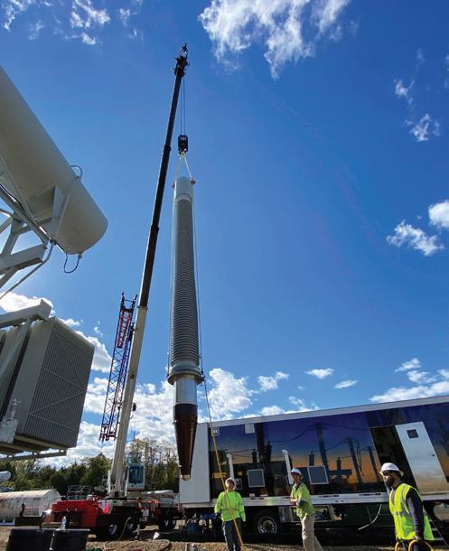

MVA Services provide nationwide coverage up to 1000 MVA and 765 kV.
Ǥ Assembly, Vacuum Filling and Commission Testing of Substation, Power and EHV Class Transformers
Ǥ LTC Inspection, Repair and Retrofit
Ǥ Re-gasket, Leak Repairs Bushing, CT and Pump Replacement
Ǥ Vacuum Dehydration Dry-Out, including Cold Trap
Ǥ Hot Oil Reclamation, Dehydration and Oil Degasification of In-Service Transformers
UNRAVELING THE MYSTERY OF BAFFLING TRANSFORMER TRIPS
BY MOSE RAMIEH, CBS Field Services
Modern substation control and communication have revolutionized the ability to troubleshoot system faults and mis-operations. Event fault records and documenting every input and output provide invaluable information to help answer the question, “What happened?”
However, there are hundreds of thousands of systems with legacy equipment. These systems can present seemingly baffling challenges that could necessitate several attempts (test and try) to work through various scenarios to resolve the issue.
Life in the electrical maintenance and acceptance testing business can throw strange situations your way. This is also true of my experience in the electrical testing business. These three stories occurred over the course of my career and might help you be more efficient at identifying and correcting issues without all the benefits of modern communication. These stories, focused on substation transformers, illustrate that regardless of the complexity of the situation and system, it is often the simplest of solutions that can be the hardest to find.
TWO TRIPS — ONE INPUT
Springtime in Tennessee can present some variable weather. Freezing cold mornings and bathing-suit temperatures in the afternoon are not uncommon. These temperature swings played an interesting role in the case of a mysterious transformer trip. Shortly after my third cup of coffee, the call came from the plant engineer. “Get over here now! T1 just tripped off.” Knowing little more than that we headed to the customer’s plant, where we found a flurry of activity and questions regarding why transformer (T1) had tripped off-line. Physical inspection of the system noted no protective relay targets and an 86T (transformer lockout relay) operation. No protective relay operations? That’s odd. Let’s dig deeper and review the HMI event records. As we reviewed the event log there was only one unrecognized item on the list: IN604.

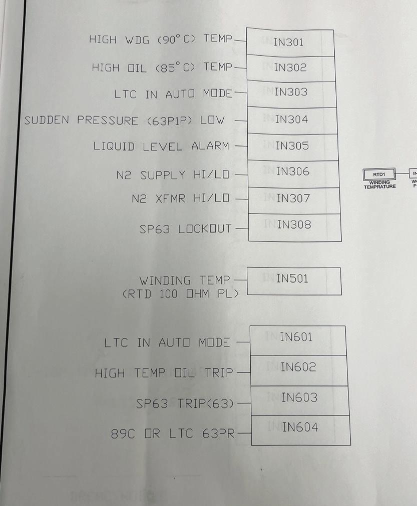
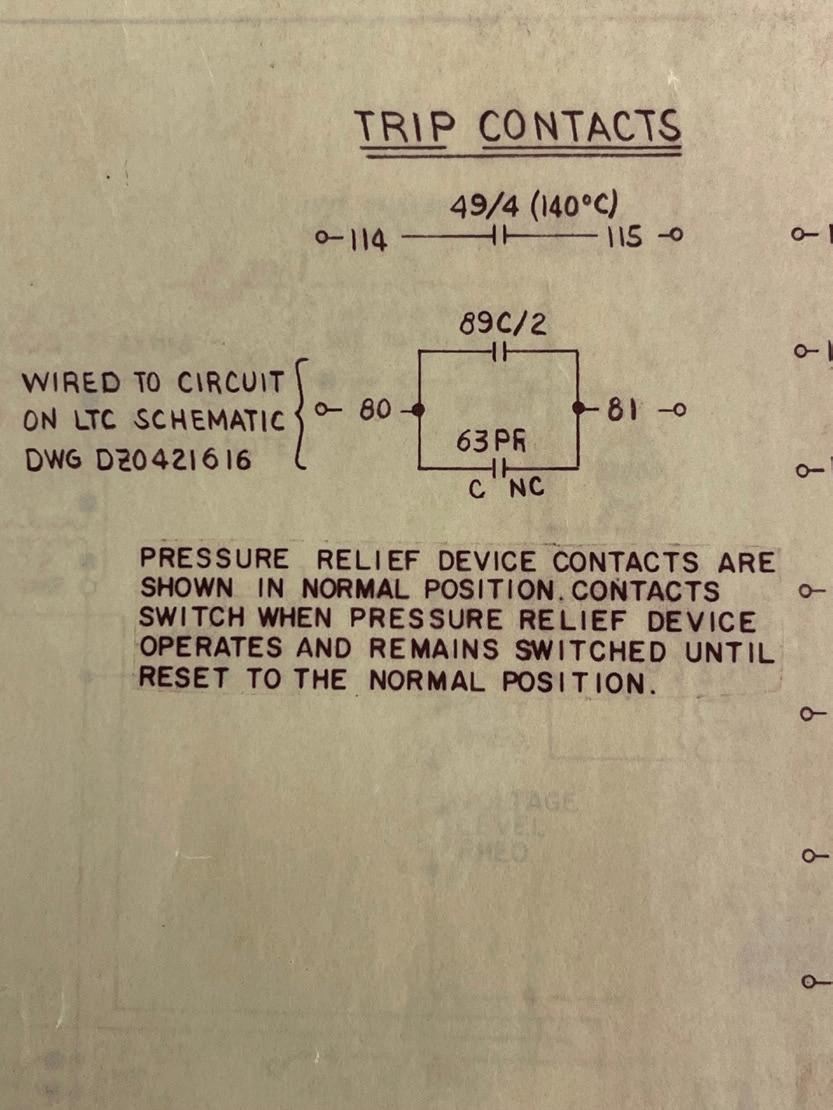
This input (IN106) is from the SEL 2411 that was installed to capture and communicate transformer trips and alarms. It was odd to note that the input was high on the event list and a short time later low. The input came in and then cleared (Figure 1).
A review of the drawings (Figure 2) illustrates that IN604 is tied to two fault conditions associated with the load tap changer (LTC): Did someone grab the manual LTC crank handle (89C), or was there a pressure relief operation (63PR)?
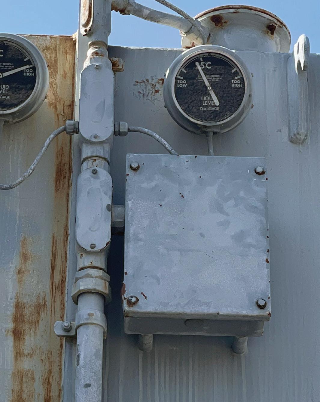
Noting that the LTC handle is behind a bolted cover (Figure 3) and that no one had opened the cover, we turned our attention to testing the pressure relief device (PRD). Tests and inspection proved that the switch operated properly and wasn’t the source of the issue.
With the mindset of “better safe than sorry,” we did some basic tests on the transformer and the LTC. All results were comparable to the previous maintenance results. After much discussion, a decision was made to energize the transformer. It was energized without issue and was left to soak overnight.
The following morning, however, the transformer tripped again. Once again, the event log documented IN106 going high and then going low. There was no PRD operation and no one had messed with the bolted cover that housed the LTC manual crank handle.
All sorts of ideas began to fly about how the system must be mis-operating. To leave no stone unturned, we opened the LTC handle cover to inspect the switch. Repeatedly removing and replacing the handle proved that the switch was doing its job: Handle out, IN106 went high; handle in its holder, IN106 went low. More tests, more ideas, more headscratching. No smoking gun. “Let’s turn it back on and let it soak overnight,” we decided.
The following morning, shortly after sunrise, another trip. Now I had enough information to see a pattern. What was causing a trip every morning shortly after sunrise? Then it dawned on me (pun intended) that perhaps the issue had something to do with the sun warming up the transformer from the overnight freezing temperatures. My theory was that there must be something wrong with the LTC handle or the PRD switch that only shows up in the transition from below-freezing to above-freezing.
Fortunately, the weather continued to cooperate and I had a chance to prove my theory. After all, the client wasn’t going to be confident in the solution unless we could prove the theory. Early the following morning, our team showed up before sunrise equipped with a hair dryer (not standard test equipment). We applied some heat to the LTC handle switch and noted that IN106 went high — but only for a moment and then it went low and stayed low. As the switch warmed, moisture created a moment that caused the trip input to go high.
With the theory confirmed, we were able to replace the switch and confidently bring the transformer online and restore the plant to normal service.
BLAME IT ON THE RAIN
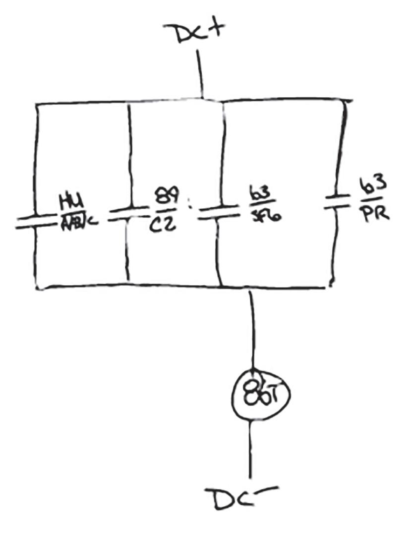
Another tricky example began with a call from a client that a transformer had tripped during a heavy rainstorm. A visual inspection found no protective differential or over-current relay targets, yet the 86T relay had been tripped. As in the previous example, you must investigate all the other protective device trips that could operate the 86T (Figure 4). The list of those items that could operate an 86T is typically short and includes devices like PRDs and a sudden pressure relay (SPR).
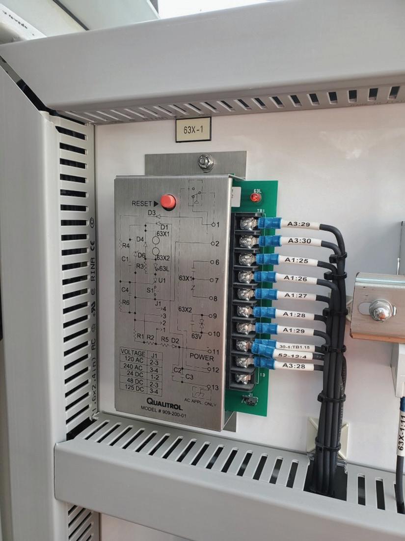
It should be noted that both devices provide targets. SPRs are used in conjunction with a seal-in relay (Figure 5). This device, typically located in the transformer control cabinet, provides a target and seals in the trip so that manual resetting is required.
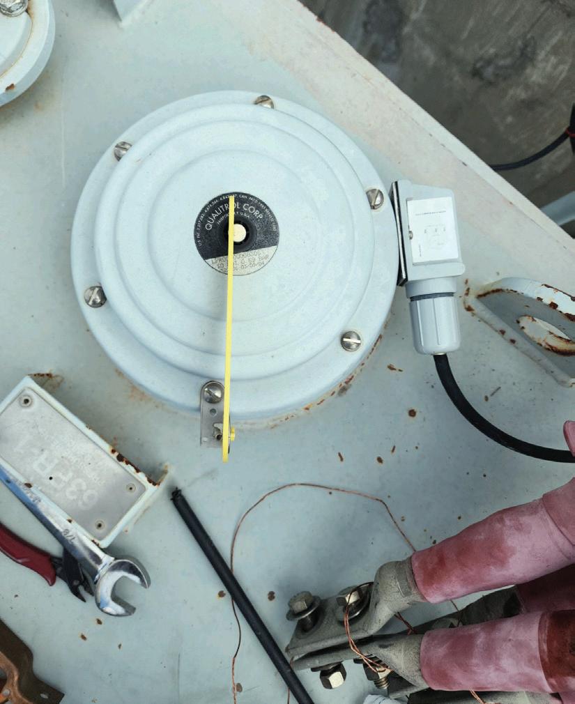
PRDs will flip up a yellow flag if they lift, assuming the flag isn’t missing or broken. The PRD switch is a latching device that also
requires a manual reset. The PRD isn’t as easy to access as it is typically located on the top of the transformer, and the switch is located under the bell housing of the device (Figure 6).
IN THE FIELD
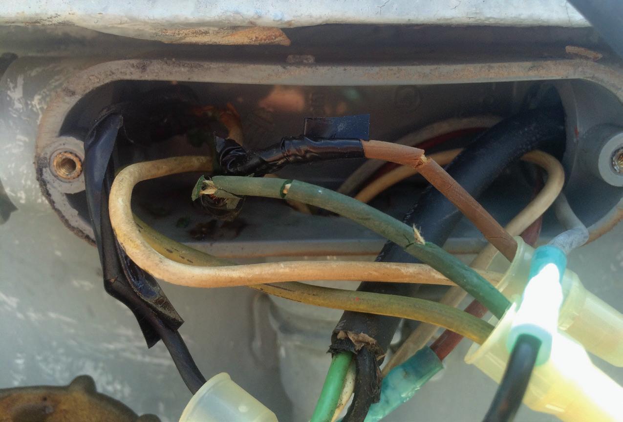
So how could an unflagged PRD or SPR operate the 86T relay, and what’s the weather got to do with it? Simply put, damaged wiring insulation and/or device connectors (Figure 7) combined with water intrusion can create a sufficient low-resistance path to complete the trip circuit. This failure mode is almost always related to the PRD since it operates on one normally open contact going closed. In comparison, the SPR has two contacts (one open and one closed), and both sets must change state to trigger an operation in the sealin unit.
IT TRIPS WHEN WE…
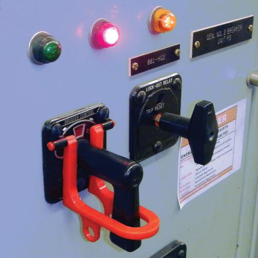
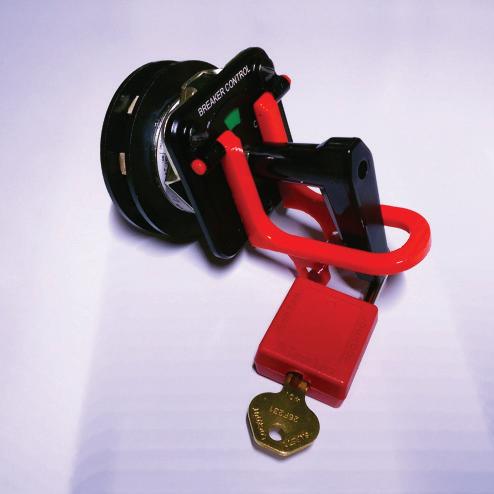
In this final story, a transformer (let’s call it T3) tripped on an 86T relay operation that opened the SF6 breaker ahead of the transformer and tripped the secondary main in a separate ehouse. Keeping with the theme, the strange part...no targets to help explain what caused the operation. A review of the drawings showed several items that could operate the 86T relay:
transformer differentials, low gas pressure in the SF6 breaker, and the sudden pressure relay (see Figure 4). We verified all the trips, and they all appeared to be operating and targeting properly.
We tested the transformer, and all results including a DGA came back acceptable. With no smoking gun, the decision was made to turn the transformer back on and load it, which was all done successfully and without any drama. The transformer serviced the plant fine for about 18 hours. Then, without warning, it tripped by the 86T relay with no targets on the protective devices. What’s going on here? It’s not the SF6 gas breaker low-pressure trip or sudden pressure relay. It must be the HU-model relays, but there were no targets. So we tested the relays and verified that the targets operated. Everything on the relays worked perfectly.
We energized the transformer and loaded it again without any issues. The transformer




carried the plant for about 18 hours and then, once again, the 86T rolled with NO targets!
The question now was what changed in the plant. Fortunately, one of the engineers spoke up and shared that both of the previous two trips occurred when they were attempting to start a large HP motor. Ahh, now we are getting somewhere. The transformer system was fine when lightly loaded. Only when a full load was being added did the problem reveal itself. Many readers know that it takes a minimum load (usually 30%) before a transformer differential will operate.


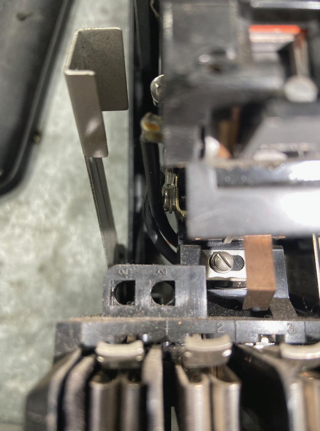
necessary equipment. Start with measuring the primary and secondary current into the relay. In most cases, you must do the math to compare the primary current magnitude to that of the secondary. In our case... there was NO secondary current. Now it wasn’t zero, but it wasn’t anywhere close to the amount we were expecting. With this new piece of information, our investigation turned to the secondary main current transformers (CTs).
When we walked into the e-house we could hear the audible groan of CTs that are in saturation because of an open CT secondary circuit (more specifically in this case, an extremely high burden/resistance). After making the system electrically safe, the CT secondaries to the remote e-house were tested, and it was confirmed that they had failed in the underground conduit. After pulling
and landing new CT secondary wires, the transformer was successfully returned to service.
Now I hope you are asking yourself, “So why didn’t the differential relays target?” It was a legitimate differential fault because of the lack of secondary current input. As it turns out, this issue goes all the way back to improper and incomplete commissioning of the system when installed a decade earlier. The relay targets were set to the 2.0 amp tap (Figure 8), which is an issue in this application because the current necessary to operate the 86T relay is much less than 2 amps. For that reason, no targets dropped when the HU relays operated the 86T relay.
After adjusting the relay targets to 0.2 amps and testing the system, we verified that if the HU relay operated and tripped the 86T relay, the targets would operate on all three relays.
CONCLUSION
Transformer trips are a common problem faced by engineers and technicians in the field. They can be caused by various factors, including weather conditions, faulty wiring, damaged insulation, and malfunctioning protective devices. In many cases, identifying the root cause of the problem can be a challenging task that requires a thorough investigation of all possible scenarios. As demonstrated by these examples, the process of troubleshooting transformer trips involves a combination of technical expertise, attention to detail, and persistence (lots of persistence).

Mose Ramieh is Vice President, Business Development at CBS Field Services. A former Navy man, Texas Longhorn, Vlogger, CrossFit enthusiast, and slow-cigar-smoking champion, Mose has been in the electrical testing industry for 24 years. He is a Level IV NETA Technician with an eye for simplicity and utilizing the KISS principle in the execution of acceptance and maintenance testing. Over the years, he has held positions at four companies ranging from field service technician, operations, sales, business development, and company owner. To this day, he claims he is on call 24/7/365 to assist anyone with an electrical challenge. That includes you, so be sure to connect with him on the socials.


COMMUNICATING HAZARDS USING A PRE-JOB BRIEF
BY PAUL CHAMBERLAIN, American Electrical Testing Co. LLC
Protection from hazards always begins with proper prior planning. An important aid to planning a job correctly and thoroughly includes using a tool known throughout the industry as a pre-job brief (PJB). These tools are commonly used at tailboards or tailboard meetings in construction parlance, but no matter what they are called, they are all designed to help you do the same thing: Identify the relevant hazards and communicate them to other workers on the job while creating and documenting your PJB. Accurate, concise, and understood communication is key.
Per the updated requirements in the 2021 edition of NFPA 70E, Standard for Electrical Safety in the Workplace, Article 110.1(I) states the following in regard to a pre-job briefing:
Before starting each job that involves exposure to electrical hazards, the employee in charge shall complete a job safety plan and conduct a job briefing with the employees involved.
(1) Job Safety Planning. The job safety plan shall be in accordance with the following:
(1) Be completed by a qualified person
(2) Be documented
(3) Include the following information:
a. A description of the job and the individual tasks
b. Identification of the electrical hazards associated with each task
c. A shock risk assessment in accordance with 130.4 for tasks involving a shock hazard
d. An arc flash risk assessment in accordance with 130.5 for tasks involving an arc flash hazard
e. Work procedures involved, special precautions, and energy source controls
(2) Job Briefing. The job briefing shall cover the job safety plan and the information on the energized electrical work permit if a permit is required.
(3) Change in Scope. Additional job safety planning and job briefings shall be held if changes occur during the course of the work that might affect the safety of employees.
NFPA even goes so far as to include a sample job briefing and job safety planning checklist under Informative Annex I. Although using this specific form is not required, a similar form should be created to help the employee identify and mitigate the potential hazards.

OSHA REQUIREMENTS
The Occupational Safety and Health Administration (OSHA), under 29 CFR 1910.269, Electric Power Generation, Transmission, and Distribution Standard, provides a requirement for conducting a PJB.
OSHA 1910.269(c)(1)(i):
In assigning an employee or a group of employees to perform a job, the employer shall provide the employee in charge of the job with all available information that relates to the determination of existing characteristics and conditions.
1910.269(c)(1)(ii):
The employer shall ensure that the employee in charge conducts a job briefing that meets paragraphs (c)(2), (c)(3), and (c)(4) of this section with the employees involved before they start each job.
OSHA also requires the PJB to cover:
…hazards associated with the job, work procedures involved, special precautions, energysource controls, and personal protective equipment requirements.
Additional PJBs may be required during the day should the task or workplace location change significantly enough to change the hazards involved in performing the work. Ensure that all workers who may be impacted by the change are notified of the changes by communicating those changes during a review of the new PJB.
The more hazards that may be present to the task performers, the more detailed the PJB should be. Additionally, more extensive PJBs may be necessary for inexperienced employees.
SAFETY CORNER
The only time a PJB DOES NOT need to be conducted, per OSHA 1910.269(C)(5), is if that employee will be working alone:
However, the employer shall ensure that the tasks to be performed are planned as if a briefing were required.
On OSHA’s website under eTools, it is suggested that a checklist be used to facilitate the PJB:
Keeping a written record of job briefings is not specifically covered by the standard, but it is a best practice to do so. A written checklist can include the hazards, procedures, precautions, and PPE requirements associated with a job, as well as a column for employee signatures indicating they are knowledgeable about job hazards and safety procedures. Such documentation can help ensure that proper briefings are held at the right times (for example, beginning of a shift) and that everyone has been informed. For an example checklist, see the Job Briefing and Planning Checklist in Annex I of the National Fire Protection Association’s NFPA 70E, Standard for Electrical Safety in the Workplace.
As can be seen in this quote, even OSHA refers back to the sample PJB in the NFPA 70E.
IDENTIFY AND MINIMIZE THE RISK
I have seen many versions and styles of PJBs. They come from utilities, large manufacturers, individual testing companies, and others. All of them are designed to do one thing, and they do it fairly well: They help the task performer(s) identify and minimize risks associated with the hazards of doing the task. Some PJBs focus strongly on physical hazards, others focus on task-specific procedures, and some help identify human-error traps. Since a PJB is designed to be a quick, and simple-to-use tool for the task performer, it is hard to develop a form that encapsulates all of those needs. The employer should be able to identify which hazards are greatest or are a more pressing need to address with the workforce and develop a PJB adequate to identify those hazards.
ELECTRICAL ENERGY
One item of concern that should be addressed on every PJB is the need to identify the means to prevent the inadvertent or unexpected release of electrical energy. Since that is one of the greater and most prevalent hazards within the testing industry, it is also a good idea to identify how it will be controlled, and the means of controlling it. Individual lock out/tag out, switching and tagging, live-line clearance, or the use of grounding should be indicated on the PJB. Additionally, it is a wise idea to provide a space within the form to indicate lock, or tag, or ground locations to ensure proper removal when the work is completed.
Addressing and indicating electrical shock and arc flash boundaries on the form is also advised. This will make it easier for performers to advise visitors to the work location about the various approach distances. The level and type of personal protective equipment (PPE) required to complete the task should also be indicated on the form.
CONDUCTING THE PRE-JOB BRIEFING
The crew leader, or the person who fills out a PJB form, must review all potential hazards with the performers of the task and give them ample opportunity to ask questions. A properly performed PJB should be a give-and-take discussion, not a dictation. The review of the PJB should be conducted with ALL personnel who may be affected by task performance, and with anyone else whose work may impact the task. This includes contractors, subcontractors, and peripheral workers on the job site.
Once the review is complete, all persons attending the briefing should indicate their understanding of the knowledge transferred. It could be as simple as printing their name on the PJB itself, or the PJB could include a separate sign-in sheet. Remember, if the task or the job location significantly changes, a new PJB must be filled out and a new briefing performed, or the old PJB form must be amended and reviewed as necessary. Should a
visitor arrive on-site, they should immediately be stopped from encroaching upon the work area, and the PJB should be discussed with them so they are apprised of the potential hazards on the job site.
SUMMARY
Identifying, mitigating, and communicating potential job hazards is important to prevent possible injuries or accidents. It is up to the employer to provide an adequate means of identifying and addressing those hazards. A PJB form is required in most cases and is an easy and effective means of identification and communication. The employer should ensure it is adequate for the tasks the employees will
be performing, and the employee should USE the provided form to aid in the prevention of potential injuries.
Should an employee have suggestions on improving the form, they should voice those suggestions to the employer. After all, it is the employee’s form to use.

Paul Chamberlain has been the Safety Manager for American Electrical Testing Co. LLC since 2009. He has been in the safety field since 1998, working for various companies and in various industries. Paul received a BS from the Massachusetts Maritime Academy.


COMMUNICATIONS AND FIBER OPTICS
BY VIRGINIA BALITSKI, Magna IV Engineering
Communication is vital in everything we do, and it isn’t just the funny phrases at the end of the telephone game as kids. As NETA Certified Technicians, we must be familiar with different communication systems since they are essential to proper power system operation. In this quiz, we discuss some communication systems and associated components.
1. Which of these is a control system that involves computers, data communication, and data acquisition and is used to monitor and control equipment?
a. PLC
b. SCADA
c. RTU
d. HMI
2. The time needed to transport information from a sender to a receiver in a communication network is known as:
a. Attenuation
b. Direct transfer tripping
c. Baud rate
d. Latency
3. Which of the following relaying schemes uses a communication network between relays to transmit information from one end of a transmission line to another?
a. Pilot wire
b. Annunciator
c. Permissive control
d. Reversing device
4. One of the advantages fiber optic cables have over copper cables is:
a. Fiber optic cables are resistant to damage during installation.
b. Fiber optics cables have varying baud rates.
c. Fiber optic cables can be used over long distances.
d. Fiber optic cables have a lower cost.
5. Which of the following tests is required in the ANSI/NETA MTS-2023, 7.25 FiberOptic Cables section?
a. Perform cable length measurements.
b. Perform connector and splice integrity test using an optical time domain reflectometer.
c. Measure cable attenuation loss with an optical power loss test set.
d. Perform transit and receive power readings from a local device and a remote device.
6. Signal losses in fiber optic cable occur due to:
a. Splices
b. Connectors
c. Contaminants
d. All of the above
See answers on page 131.

Virginia Balitski, CET, Manager –Training and Development, has worked for Magna IV Engineering since 2006.
Virginia started her career as a Field Service Technologist and achieved a NETA Level 4 Senior Technician certification. She has since dedicated her time to the advancement of training and safety in the electrical industry. She is a Certified Engineering Technologist through ASET – The Association of Science & Engineering Technology Professionals of Alberta. Virginia is the current Vice-Chair of CSA Z462, Workplace Electrical Safety, and is a member of NFPA 70E, Electrical Safety in the Workplace Technical Committee. She serves on NETA’s Board of Directors, is involved with many NETA committees, and represents NETA on the ASTM F18 committee.





ADVANCEMENTS IN BATTERY GROUND FAULT LOCATION
BY JEFF JOWETT, Megger
There is always room for improvement. In electrical testing, this is particularly true because of the rapid development and application of the underlying electronics. Although a job may be proceeding with maximum satisfaction, it may well be made easier, faster, more accurate, and safer.
For example, standby battery banks can develop ground faults over time through leaking electrolytes, accumulation of dirt, rodent damage, water ingress, faulty installation, and other problems. Over time, the battery system can become shorted to ground and lose power. When called on-line, it can fail to deliver, and the consequences can be catastrophic: interruption of production, lost data, fire, and shock.
Battery ground-fault tracers are specifically designed to pinpoint these faults. A quality unit can remain in service for many years, and it need not be replaced merely due to age. Now — especially on particularly complex and difficult systems — recent developments in technology can address the most difficult problems and notably enhance the speed and accuracy of fault tracing.
Ungrounded battery systems typically have ground-fault monitors that tell the operator a fault has occurred, but they cannot indicate where it is, and locating it can be a tedious, time-consuming, and frustrating job. A
maintenance technician can end up chasing a phantom fault all day long without success. Fortunately, technology has risen to the task.
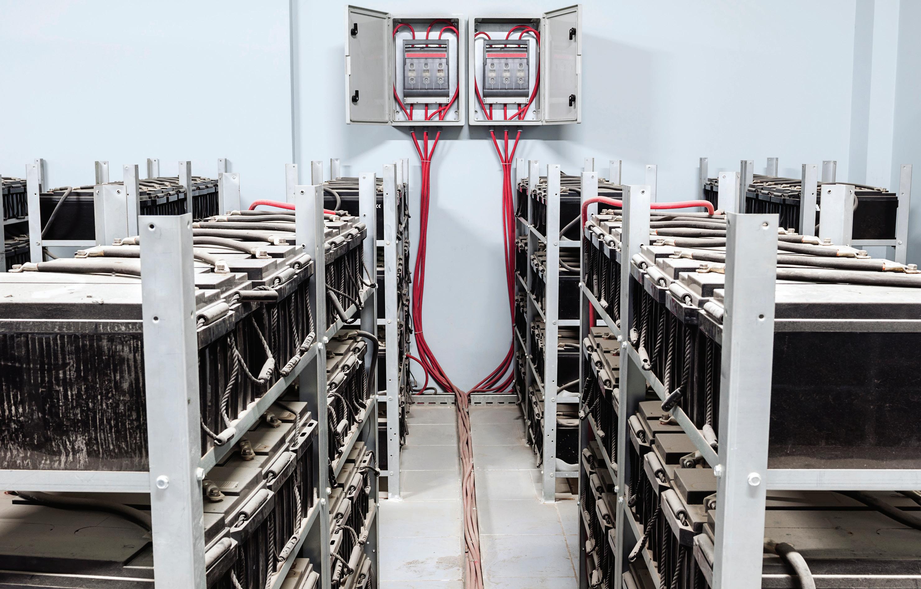
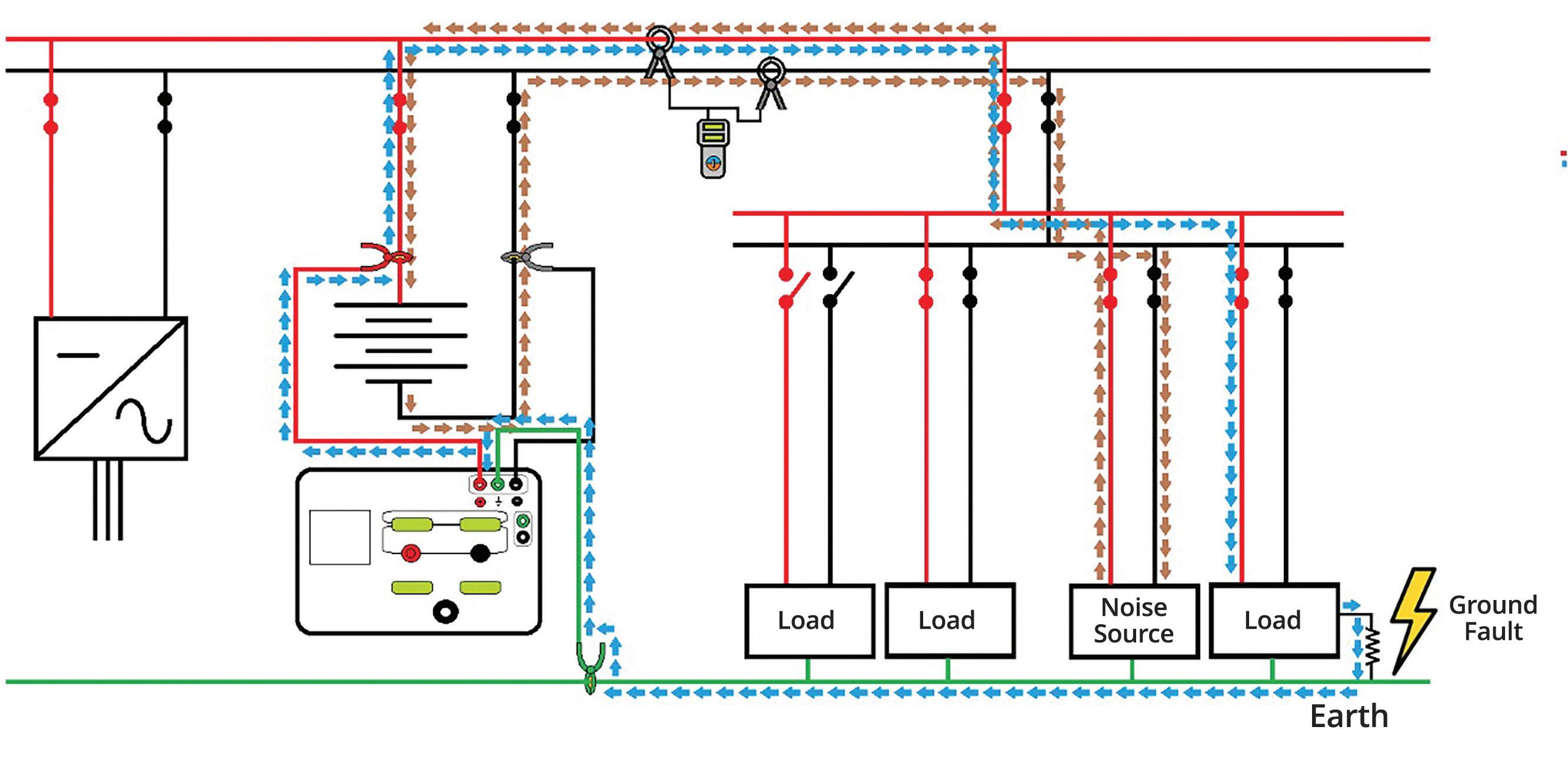
Specialized equipment is necessary to locate such faults. A transmitter applies a distinct signal that flows through the ground fault. A second piece of equipment, a receiver, is used to trace the signal (Figure 1). This is simple in concept but subject to pitfalls.
ISSUES WITH FAULT TRACING
Improvements are available to specifically address the most difficult fault-tracing problems. System noise can interfere with signal detection. Circuit capacitance can pull excessive current. A high-impedance fault may exist, or a breaker may trip. Current clamps can become magnetized and impossible to use. These can be major problems that can now be overcome.
Stray capacitance as part of cable construction will pull extraneous current that the operator might waste time following instead of the fault
current. Noise from SCADA can be severe and swamp the trace signal. Water ingress breaks down insulation and produces a highimpedance fault that requires more current to trace but at the same time can dry the cable and mask the fault. An ungrounded DC system can still have direct current flow that can interfere with fault tracing. The iron core of the CT that is tracing the flow of the ground-fault current can become magnetized. The strength of this force can make it nearly impossible to physically remove the CT without actually breaking it.
SOLUTIONS
Tracing battery ground faults often requires high sensitivity to extremely small leakage currents. High permeability makes CTs more sensitive but also more susceptible to magnetization. The problem can be effectively addressed by a core made of an appropriate mu-metal compound. A mu-metal is a nickel-iron alloy containing small amounts of other elements like copper,

chromium, or molybdenum. These can be precisely formulated for the best performance in a specific application. An effective formulation can produce high permeability with little magnetization.
Another technology that has proved useful is a flux gate. This works with small numbers and requires extraordinary sensitivity, hence it is relatively uncommon. A low-frequency signal
in the range of 5 Hz when clamped over the current-carrying fault will become distorted. This distortion in the signal allows the current clamp to measure very-low-amplitude signals. Such CTs can be kept notably small so as to fit into the tightest spaces while following a signal. A sliding opening can be kept small in comparison to the spreading jaws of standard CTs, thus enabling clamping over wires in the tightest spaces.
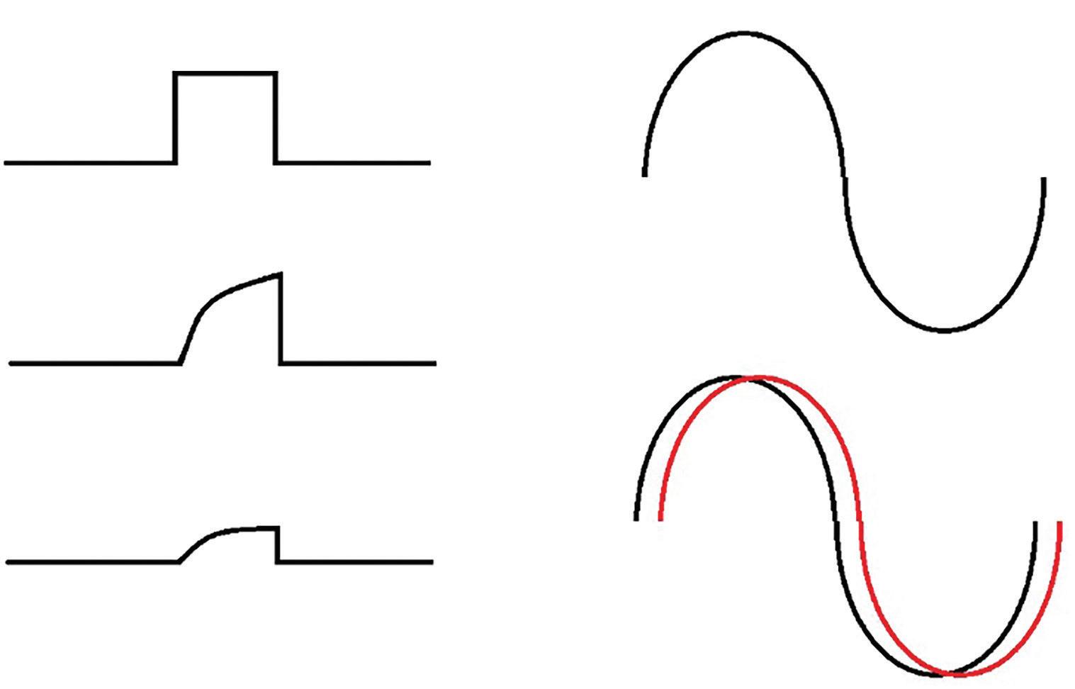
Stray capacitance is traditionally dealt with by tuning it out. The test circuit acts as a Wheatstone bridge by placing a signal 180 degrees out of phase with the fault. This works on systems with an AC injection current but can be tedious and time-consuming. Systems operating with pulse technology can be more challenging, as the pulse is dampened by capacitive charging. A remedy is to use an AC signal and measure the phase shift between voltage and current, which increases with capacitance (Figure 2). The phase angle can be measured, enabling the tester to distinguish between current drawn by the fault and that from capacitance, eliminating hours spent tracing the wrong path.
Noise is another problem because it destabilizes the tester’s readings. Noise can return on the
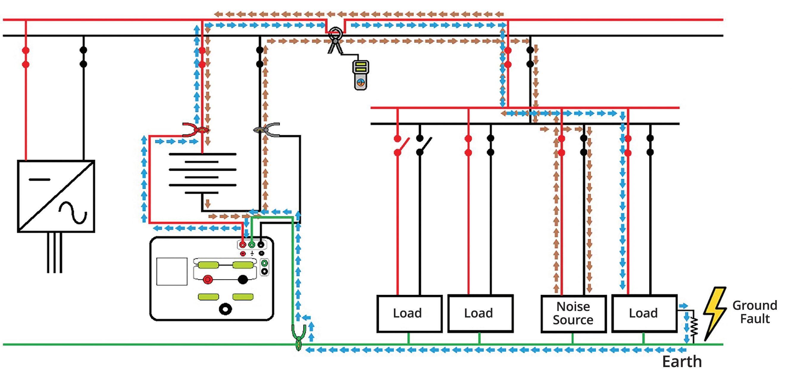
return line and interfere with the tracing signal. However, the trace signal returns on the ground and can be used to separate the signals during tracing. Therefore, if the tracing CT can be clamped over both paths, the noise cancels (Figure 3).
But what if the CT can’t be fitted around both paths simultaneously? Just use a second CT clamped on the return line. The CTs are in parallel, 180 degrees out of phase. Sophisticated testers will accommodate two CTs (Figure 4).
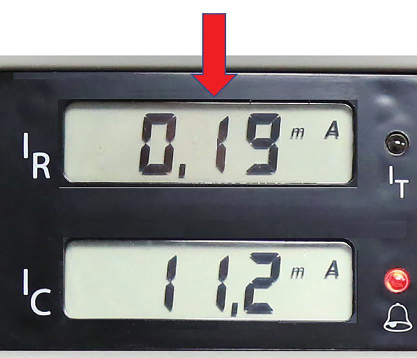
High-impedance faults are another challenge. Because impedance is high, little current is passing through the fault. Hence, tracing requires extra sensitivity. Modern test instruments can typically tolerate impedance levels on the order of 400 kΩ while still being able to sense and trace the fault. For illustration, the fault current may be on the order of 0.19 mA and orders of magnitude less than the current drawn by stray leakage capacitance. The differential could be narrowed by increasing the fault current by increasing the voltage on the transmitter.
Some instruments can increase the voltage to as much as 1,000 V, but this has attendant hazards.
It increases the risk to the operator and can trip breakers. And as we’ve seen, a moisture fault can be dried out before it’s been located, only to return on the next rainy day. An effective remedy is a hi-tech test instrument that can distinguish between actual fault current and reactive current drawn by the fault while indicating both to the operator on a dual display (Figure 5).
Tripping breakers can be a nuisance consequence of fault tracing. This happens when the output voltage of the tracing instrument is turned up
too high and then energized. A transient spike trips the breaker. A sophisticated instrument will enable limits to be set on voltage and current below values that will trip breakers and can be password protected.
CASE STUDIES
As an example of how tedious these unwanted grounds can be to locate, a major utility had been searching for a ground fault for two years using a standard locator. The panel was in a different room from the battery string, with a confusing plethora of circuits. All were contributing capacitive leakage that showed up as fault current on a standard tracing instrument. Distance made it impossible to use the feedback cable on the tracer, and even when the string was closer, there were still a prohibitive number of circuits. A sophisticated tracer that employs a special accessory, a capacitive pickup, was used. The pickup was placed on a return line. It measured a static field rather than current, so did not need to
be moved to all circuits. The CT could now be moved to each circuit. The receiver’s dual display was now able to show the fault current as well as the leakage current with a visual display and an audible tone when on the proper circuit. The transmitter was then left on the battery string while the receiver and capacitive pickup were moved to another floor. The fault was readily traced to a pump on that floor.
Another problem case appeared in a utility substation. Using multiple instruments, a fault was traced to a battery charger. The charger was replaced but the fault persisted. Using a stateof-the-art tracer and connecting to the battery string immediately revealed a negative to-earth fault. When fault current was applied, the measurement proved totally unstable. Turning off the transmitter revealed the presence of AC on the line. Setting the locator’s receiver to the 50/60 Hz mode enabled the AC to be traced to the battery charger, where a wiring issue that caused AC to get coupled onto the DC line

was identified. Once the DC line was isolated, the fault could be readily traced to a relay, successfully eliminating not only the suspected fault but also an AC wiring issue into the fix.
In yet another case, a major utility was experiencing a high-impedance ground fault they could not isolate. They were not able to disconnect the ground fault monitor. But the monitor’s impedance to ground was lower than that of the ground fault so that the majority of tracing current would flow through the monitor, making fault location difficult to trace. With the remaining tracing current already low, the situation was worsened by the presence of stray leakage capacitance. There seemed no way to distinguish the line with the ground fault on a standard tracing instrument. But a dual-channel hi-tech trace instrument displayed the real fault current as well as the capacitive leakage current, making it possible to distinguish the circuit with the ground fault.

Cables • LV/MV Circuit Breakers • Rotating Machiner y • Meters
• Automatic Transfer Switches
• Switchgear and Switchboard
Assemblies
Load Studies
SUMMARY
Many variables can make battery faults difficult to find and isolate. As illustrated above, sophisticated testing equipment has been developed to successfully deal with almost all of the potential problems. Full-featured ground fault tracers also alarm when the fault is reached, eliminating guesswork on the part of the operator. While backup battery systems provide the quintessential application, such sophisticated tracers are also useful on ungrounded DC and AC systems, protected IT networks, and control, signal, and supply systems such as those indispensable in railroad, power plants, and industrial facilities.

Jeffrey R. Jowett is a Senior Applications Engineer for Megger in Valley Forge, Pennsylvania, serving the manufacturing lines of Biddle, Megger, and MultiAmp for electrical test and measurement instrumentation. He holds a BS in biology and chemistry from Ursinus College. He was employed for 22 years with James G. Biddle Co., which became Biddle Instruments and is now Megger.
LV/MV Switches
Relays - All Types
Motor Control Centers
Grounding Systems
Transformers
Insulating Fluids
Thermographic Sur veys
Transient Voltage Recording and Analysis
Electromagnetic Field (EMF) Testing
Reclosers
Surge Arresters
Capacitors
Batteries • Ground Fault Systems
Equipotential Ground Testing
Harmonic Investigation
Replacement of Insulating Fluids
Power Factor Studies

SUBSTATION COMMUNICATIONS — A PRIMER

BY WILLIAM HIGINBOTHAM, EA Technology LLC
In the early days of protective relaying, it was recognized that communications between substations could improve relaying performance. Schemes such as power line telephony (1920s) and pilot wire relaying (1930s) evolved into digital time division multiplexers (TDMs) (invented in 1960s and used for power system communications in 1970s). TDM allowed audio teleprotection, audio-based relaying, SCADA, and telephony to share a single link from substation to substation. In the late 1970s, T1 channels could be leased from the phone company, but that was not ideal. Fiber optic communications became viable in the 1980s and began to be deployed in substations in the late 1980s. Over the past 35 years, the use of fiber optics in substations has exploded for both inter-substation and intra-substation purposes.
WHY DO WE NEED COMMUNICATIONS IN A SUBSTATION?
In the beginning, there were fuses, and it was good. Fuses developed into overcurrent relays and circuit breakers. Once the power grid became a mesh, selectivity (disconnecting
only the faulted section of a transmission line) became more important — and more difficult. The individual faulted line had to be isolated, and that meant communications were needed. Pilot wire relaying worked on a principle similar to a garden hose: Water (current) into one end had to equal water
(current) out the other end, or there was a leak (fault). To make this determination, you needed information from the far end of the line, hence communications of some sort. Even if you could make a decision based on the information at one end (impedance relaying), you had to instruct the breaker at the far end to open (direct transfer tripping).
Beyond relaying, there is a need for voice channels, metering data, SCADA data, and with intelligent electronic devices (IEDs), a plethora of data communications. Like everywhere else, the advent of Ethernet has caused an explosion of data traffic between substations and control rooms.
EARLY SUBSTATION COMMUNICATIONS
The first substation-to-substation communications were continuous wires carrying DC (transfer trip signals), AC (pilot wire relaying), and analog audio for voice and SCADA. This was okay but limited by cable impedance and noise to relatively short lines. Various techniques like audio tone teleprotection and power line carrier extended distances but were still limited in their application.
Telephone company communications channels could work over very long distances but providing them into a substation was costly, and inherent reliability and time delay issues made them less than ideal. The utility practice of not trusting the phone company for relaying unless absolutely necessary also limited its use.
Telephone systems were based on the principle of putting many different channels on one pair of wires. Early analog systems used frequency division multiplexing (FDM), and digital systems used time division multiplexing (TDM) in the 1960s. Deployed in a substation, a multiplexer could provide all the various types of communications with just two pairs of wires, and all the equipment could be owned by the utility. This was very close to a good solution, but wires between substations were still not an ideal solution.
WHY FIBER?
The limitations of copper-wired systems could be overcome with optical fiber systems. Optical fibers could go very long distances and were immune to ground potential rise, were virtually noise-free, and had very low latency. Direct relay-to-relay fiber systems
were developed, but using a pair of fibers for only one relaying channel is grossly inefficient. In the 1980s, this gave rise to substationgrade digital fiber multiplexers. Using T1 TDM at 1.544 Mb/s, 24 channels could be telephone, audio four-wire, synchronous data at 56/64 kb/s, or 19.2 kb/s asynchronous data. This was plenty for point-to-point communication between the substations at the time. Latency was low (~1 ms) and consistent, allowing differential relaying to be deployed using 64 kb/s synchronous channels. The major relay manufacturers offered RS-449 and G.703 interfaces that were designed for these channels.
Early Fiber Multiplexers
As time went on, these substation-specific multiplexers added channels and features such as built-in transfer trip modules and short-haul fiber interfaces for direct connection to relays. They were built to the C37.90.x standards for operation in the substation environment.
One limitation was that if a fiber was broken, all communication between substations was lost. This challenge required a backup system with alternate fiber paths, adding considerable complexity and cost. RFL Electronics, Inc. pioneered a self-healing fiber optic T1 ring that would reroute traffic in under 1 ms when
a fiber was lost. This eliminated the last reason not to use fiber between substations.
Modern Fiber Systems
While T1 self-healing fiber rings are still deployed in thousands of applications, the bandwidth is limited to 1.544 Mb/s, which is very slow by today’s standards. For a time, hardened telecomsgrade synchronous optical NETwork (SONET) multiplexers running at 155 Mb/s or higher provided all the needed bandwidth, but these were expensive devices adapted from telephone suppliers and were challenging to configure. The evolution of Ethernet over fiber allowed simpler network protocols to be adopted.
The ubiquitous Ethernet protocol allows easy communications by many devices over a single channel, which can be carried over fiber between substations. It is easy to deploy and inexpensive and works great for SCADA and IED traffic.
Unfortunately, standard Ethernet is not ideal for relaying for the following reasons:
• Communication delays vary based on traffic loading.
• Equipment is usually office grade and therefore not suitable for the substation environment.
• Typical IED interfaces like telephone, RS449, RS232, transfer trip, etc., are not available in typical Ethernet equipment.
• Self-healing rings can be formed but recovery from failures can take seconds.
• Testing the operation under one network loading condition does not ensure that the system will work under all loading conditions. This terrifies protection engineers.
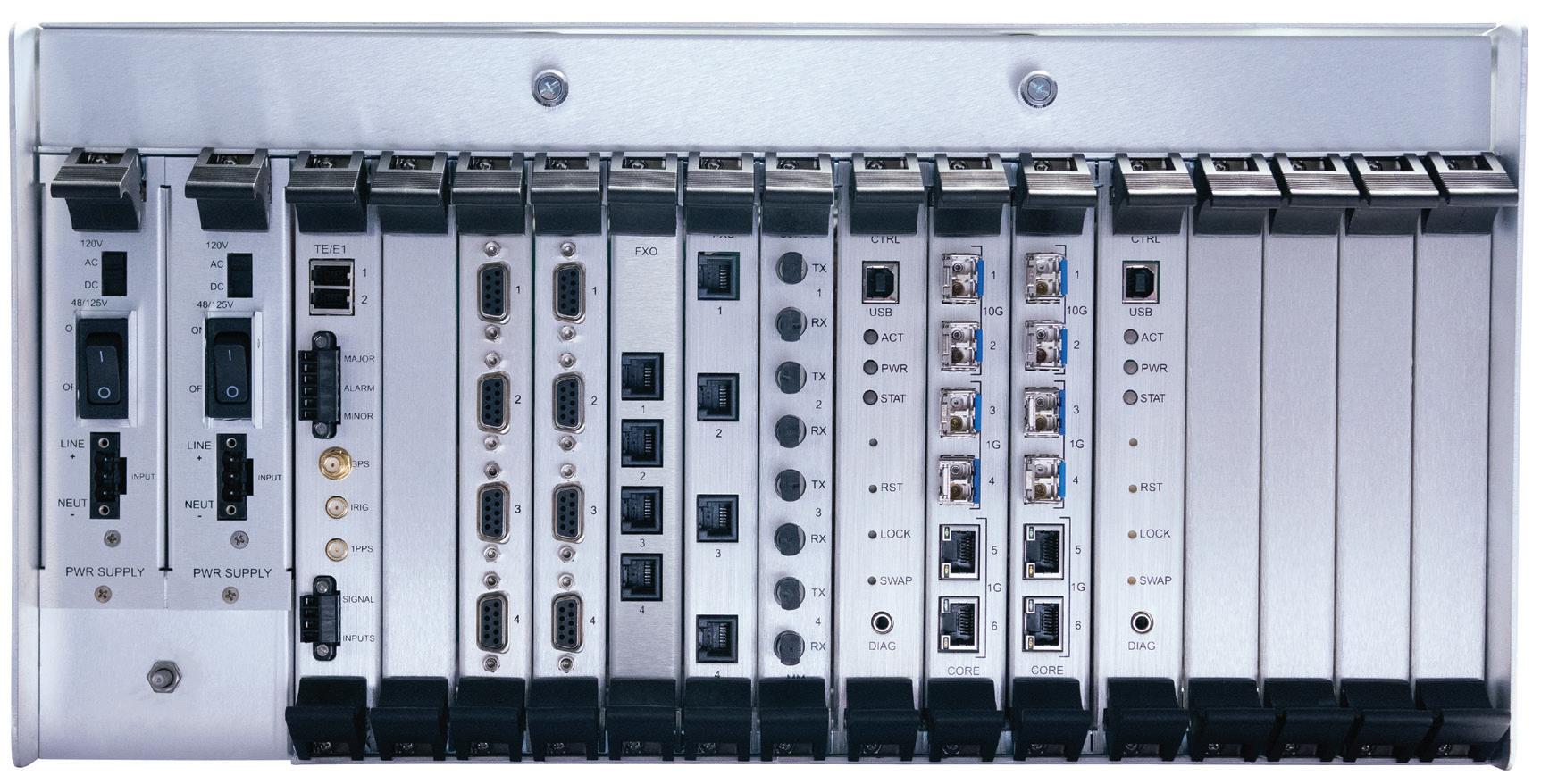
Many of these limitations have been overcome by the development of substation-specific devices for intra-substation and inter-substation communications. These continue to advance, and protocols such as MPLS multi-protocol label switching (MPLS) are even more suited to substation applications. Figure 1 shows the back of a modern packet-switched multiplexer with several channels.
INTRA-SUBSTATION FIBER
Within a substation, three typical fiber communications provide numerous benefits such as limitless bandwidth, noise immunity, elimination of ground potential rise issues, and simpler connections.
IEEE/ANSI C37.94
As described above, at one time, many relay manufacturers offered direct fiber point-topoint systems. They also offered short-haul versions with a fiber service unit that would convert the fiber back to electrical signals for long-haul communications over a multiplexer.
While this worked, it was cumbersome to connect a fiber to a box that needed power and a short cable to a multiplexer. It would have been helpful to have a universal protocol that allowed you to plug a fiber from any relay into any multiplexer — plug and play! After a bit of bickering, the multiplexer and relay manufacturers agreed to a short-haul protocol designed specifically for plugand-play connections at 56 kb/s — 1.5 mb/s between relays and multiplexers. In 2002, IEEE/ ANSI C37.94 was approved.
This standard took advantage of the huge bandwidth in short-haul multimode fiber,
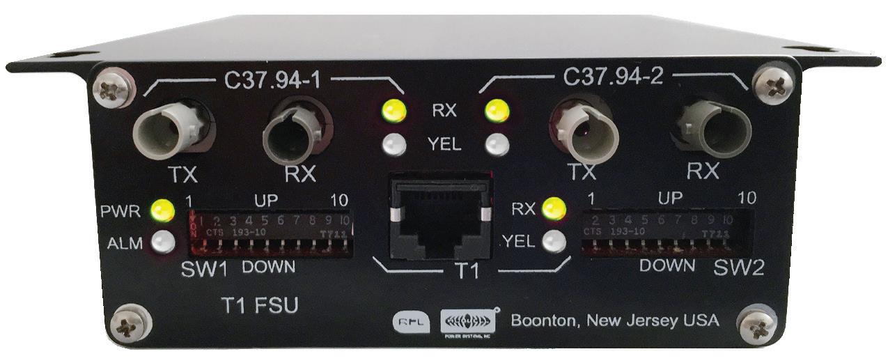
inexpensive sugar-cube fiber transmitter/ receiver pairs, and pre-terminated fiber jumpers. It was very quickly adopted by a variety of vendors and has been proven to solve that problem. It was the prevalent use of fibers in EHV substations until IEC 61850 came into its own. Figure 2 shows a C37.94 to T1 converter.
IEC 61850
No discussion of substation fiber would be complete without a bit of talk about IEC 61850. Numerous tomes have been written to describe this easy-to-use standard, and any detailed description is well beyond the space allotted for this article. More than 20 years ago, the IEEE PES PSRC and PSCC began an effort to consolidate all communications and tripping functions over a substation LAN. This initiative, called the utility communication architecture (UCA), was mirrored by a European initiative called IEC 61850. Eventually, the efforts were merged.
The goal of the new protocol was to remove all copper wiring for user interfacing, tripping, analog signals, etc., from a substation relay room. The cost and complexity of wiring all the intelligent devices would be eliminated and replaced with a redundant high-speed fiber Ethernet network with connection to all devices. The complexity would be built into the device software, and on-the-fly reconfiguration of tripping logic based on conditions would be possible. The complexity proved to be daunting, and IEC 61850 continues to roll out more slowly than hoped, but it is gaining acceptance.
Ethernet Over Fiber
Nearly all intelligent devices in a substation now have Ethernet ports for configuration, control, oscillography, and sequence of events. The days of RS232 ports plugged into a laptop have largely been replaced with an Ethernet cable plugged into a switch. It is inherently simpler for a technician to plug his laptop into a switch and have access to all the devices in the substation, even if it’s not running IEC 61850. Banks of Ethernet switches can connect hundreds of devices to a single laptop.
With devices all over a substation connecting to a central switch, the cabling becomes bulky and expensive. Replacing Ethernet cables with fiber cables can be less costly and is certainly less bulky.
OPTICAL FIBERS
One aspect of fiber communications is its capability for much higher bandwidth and greater distances than substations require. As such, the typical substation application is relatively simple and straightforward compared to telecommunications applications.
• Optical fibers are designed to work in multimode (MM) or single mode (SM). The mode refers to how light reflects and refracts in the fiber and can have an impact on very-high data rates over long distances. Multimode fibers can be 62.5 µm or 50 µm in diameter; single-mode fibers are 9 µm. From a user perspective, all you need to know is which type of interface the equipment has and deploy matching fibers.
• Users must be careful not to mismatch fiber types. A multimode fiber connected to a single-mode patch cord will lose nearly all of its power due to the differences in diameter.
• As can be seen in the Table 1 on page 8, multimode fibers also have significantly higher loss per kilometer. As a rule of thumb, multimode fiber is only used in intra-station applications. The heads for multimode are usually less expensive.
Fiber patch cords for multimode are usually orange and single mode are yellow, but this is not always the case.
FIBER TRANSMITTERS
• Fiber transmitter power obviously controls how far you can go. Fiber transmitters have conventional LEDs or laser diodes; the lasers have much more launch power.
• Lasers for substation equipment are typically under 1 mW for eye safety reasons but be sure to check the output power before staring into the transmitter.
• Optical wavelengths are 850 nm (red), 1300, and 1550 nm (infrared).
• Fiber optic transmitter output power varies considerably over temperature, so a safety margin of 3 dB must be taken into account when engineering or testing fiber systems.
FIBER OPTIC CONNECTORS
Fiber has many advantages over copper cables, but the connection points can be daunting. Inter-substation fibers are typically terminated into a junction box often called a patch panel. This is required because the raw fibers come in big spools and the connectors have to be installed once the fiber is run. This is a skilled job that is usually left to certified installers. Once landed at the patch panel, connections are made from the panel to substation devices via jumpers that can be purchased in any length so the technician does not have to be skilled in optical fiber termination.
Fiber jumpers (also called patch cords) usually have two fibers: one for transmit and one for receive. If they are terminated in individual simplex connectors, it is up to the installer to connect the correct fiber to transmit or receive as required. Some connectors are duplex, containing both fibers in one connector. Convention is that patch cords are rolled from end to end so proper connections are maintained. Figure 3 shows a typical patch panel with the bare fiber from the remote station at the top and fiber patch cords at the bottom.

The main fiber connectors used in substations are ST and LC. The SC connector is also used occasionally.
• ST is a simplex connector with a bayonettype retention. It comes in metal and plastic. It has been around for over 30 years. C37.94 specifically calls out ST connectors.
• LC is a smaller connector with a push lock retention. It is very common in Ethernet network equipment. It is available in simplex and duplex configurations.
• SC is a square plastic push-pull connector. It has largely been replaced by LC, which is half the size and more secure once connected.
Figure 4 shows fiber connectors LC, ST, and SC.
A small form-factor pluggable (SFP) device is not a connector but an electrical plug-in module that can provide an LC fiber port. It is available in many wavelengths, distances, and speeds. Modules also have various levels of diagnostics. It is important to confirm which SFP heads are
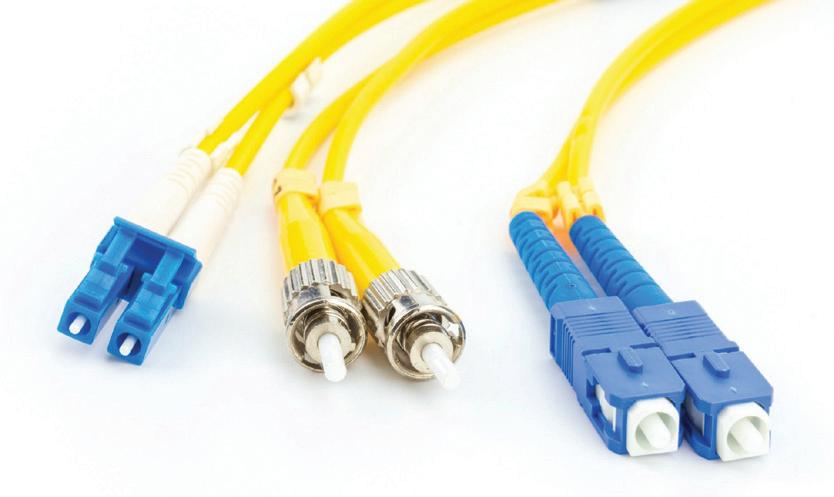
supported by the manufacturer. SFP heads are typically inexpensive and allow easy upgrades to higher speeds or longer distances if required. This type of head is most commonly used on networking equipment. Figure 5 shows simplex and duplex LC SFP heads.
OPTICAL POWER BUDGETS
The controlling factor in substation optical communications is usually the power budget. The bandwidth of most anything in a substation is so low compared to the limits of fiber optics that the only real question is, “Do I have enough
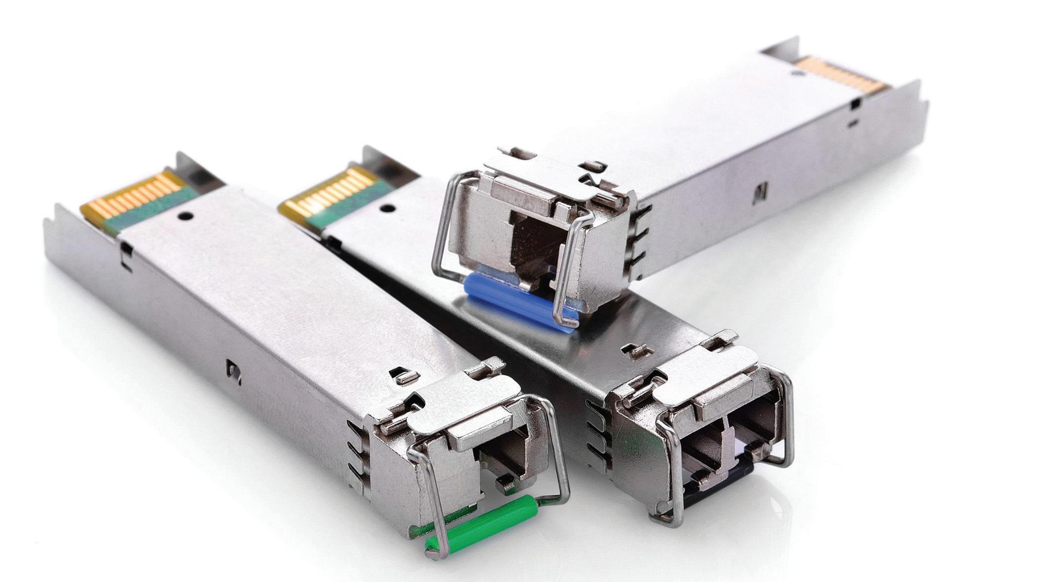
power to get there?” Canned intra-substation systems for short distances will often make it simple by giving the maximum length of a given type of fiber. It’s good to know how the budgets are built so you can build your own.
In principle, it’s quite simple: The transmit power, minus the loss in the media, must exceed the minimum sensitivity of the receiver. There are a few complications, but that’s essentially it.
To calculate the power budget, you need to know the loss per kilometer of fiber, loss per connector, and loss per splice. You will, of course, also need to know the length of the fiber, the number of connectors, and the number of splices. Table 1 shows the values most commonly used for budget calculations.
These are very conservative numbers from EIA/ TIA 568. Real-world numbers are typically lower.
Let’s do a sample calculation for inter-station fiber 15 km long. We’ll use single-mode 1310 nm fiber, which is very common for longer runs.
Fiber loss (15 x 0.4) = 6 dB
Splice loss (4 x 0.3) = 1.2 dB
Connector loss (2 x 0.75) = 1.5 dB
Total
This means the transmitter must put out at least 11.7 dB more power than the minimum sensitivity of the receiver. Transmitter/receiver pairs are specified with a minimum budget or transmit and receive levels. If you are given a budget, you are good to go as long as it’s greater than 11.7. If you are only given levels, do the following:
Minimum transmitter level = -9 dBm
Minus power budget = 11.7 dB
Minimum sensitivity of RX = -20.7 dBm
If the receiver is rated at -20.7 dBm or lower, this will work. From this, you can see that 850 nm multimode fiber over the same link would have a power budget of 55 dB, which cannot be achieved. This is why single-mode fibers are typically used inter-station and multimode fibers are used intra-station. The commonly provided maximum distance on multimode heads is 2 km.
The most common source of confusion when working with power calculations is average versus peak power. Digital fiber optic communications can use direct modulation
(on/off equals 1/0) or more complex methods such as phase shift keying where the relative phase of a carrier denotes 1s or 0s. Regardless, protocols are designed to provide lots of on/off transitions to provide easy clock recovery and therefore tend to have the transmitter on about the same amount of time as it’s off. This means that if you measure the average level, it will be one-half or 3 dB lower than the peak level.
It’s important to know that your transmitting device is outputting a normal protocol and how your light meter works. Some light meters measure average, some peak, and some are selectable. It’s also important to know the minimum and maximum sensitivity of your receiver. Transmitter and receiver device ratings are typically listed in peak, but most measuring devices will read average.
You also must not apply more signal to a receiver than its maximum or you risk distorting the pulses and getting bit errors. It is not as common today, but older devices designed for high sensitivity would have lower maximum input levels. Intrastation fiber applications are typically not a problem. If you have a high-power transmitter and a high-sensitivity receiver designed to work over 100 miles of fiber, they might not work with a 2-meter patch cord on the bench. This can cause real headaches when bench-testing a system before deployment. Physical attenuators may be necessary for short-range work.
FIBER HANDLING
One area where copper cables outperform fiber optics is ruggedness. It’s easier to damage fiber than cable. At its heart, the optical fiber is a piece of glass from termination to termination. Break that glass and you have very high losses. There is gentle cladding around the fibers to ruggedize them beyond bare glass, but they are still subject to breakage. Some of the things to keep in mind:
• Gentle bends. Do not do right-angle bends. Keep the minimum radius to 10x the cable radius (1–2” is typically safe).
• No tie-wrap guns. Whatever you do, don’t decide to neaten things up by tiewrapping everything down nice and tight.

Fiber should be loosely constrained and kept from being pinched when doors are moved.
• Dirt and dust. The terminations are a fragile point. The flat optical surface must be kept free of dirt, dust, and scratches. It is best practice to reinstall caps on fiber patch cords and into tx/rx connectors immediately upon removing the fiber.
FIBER TESTING
Fortunately, several tools are available for testing fiber optic power.
Power Level
Maintaining an adequate power level at the receiver is important for reliable operation. Any defects or damage in the fiber can greatly affect the received level. Fortunately, testing fiber optic power is quite easy. By selecting a standard meter with the correct wavelength, connector, and detector diameter, you can merely read off the received level. Most meters today use large-diameter detectors so that isn’t usually an issue.
As in the power budget calculations, pay attention to peak versus average levels. If you find a low level at the receiving end, you need
to go to the transmitter with a short patch cord and measure its output. That will tell you if the problem lies in the transmitter or the fiber.
Optical Time Domain Reflectometer (OTDR)
Once you’ve determined that the transmitter is outputting the proper level but insufficient power is coming out to the receiver, you know the fiber has a flaw. The trick is how to find it. For short lengths of fiber, it’s usually easier to just run a new fiber. For longer runs across substations or out into the switchyard, it might be worth finding the problem and splicing the fiber. The tool you need is an optical time domain reflectometer (OTDR). This is a handheld device that is fairly easy to use. It will send a pulse of light down the fiber and time how long it takes to find any reflections. A change in the fiber characteristic (typically a crack or the end of the fiber) will cause a reflection. Since light travels through fiber at a known speed, about 200 meters/microsecond, the device can calculate the distance to the feature causing the first reflection. Tracing out the fiber will often point to an obvious flaw (tie wraps are the usual suspect).
Bit Error Rate Testing
Now that we know we have enough, but not too much, power reaching the receiver, the communications should work flawlessly. If it doesn’t, you are pretty much at the mercy of the connected equipment to tell you why not. The problems at this point are unique to the equipment — it could be settings, protocols, timing, etc. Communications statistics and diagnostics are almost always built into the end equipment. Look for bit error rate values in the user interface. They should be virtually zero, and anything above 1 bit error per 1 million bits (BER=1e-6) is pretty bad. Minimum acceptable rates are typically 1 bit error per billion bits (BER=1e-9).
Ring Failover
It is also important to test what happens in a failover. If there are redundant communications and one path fails, do the communications recover in the specified time? In addition, you should ensure that the system recovers from
various failures around the ring. When doing various breaks, you must allow adequate time between failures per the manufacturer. It’s good to set up a communication path on a self-healing ring, randomly yank out and reinstall fibers, and then check to see that communications remain intact.
Some equipment like the T1 fiber ring can recover in less than 1 ms. Very specialized systems can perform what is known as hitless switching where there is no loss of communications at all during fiber breaks. The other end of the scale is spanning tree protocol (STP), which is the protocol used by ordinary Ethernet. STP can also be configured in a ring as well, and it will recover from fiber failures, but it can take up to 30 seconds.
SUMMARY
Using fiber for substation communications is here to stay, and everyone working on relays and communications equipment should be versed in it. The good news is that fiber is more reliable than many other communications channels and once you understand it, easier to work on.

William G. Higinbotham has been president of EA Technology LLC since 2013. His responsibilities involve general management of the company, including EA Technology activities in North and South America. William is also responsible for sales, service, support, and training on partial discharge instruments and condition-based asset management. He is the author or co-author of several industry papers. Previously, William was Vice President of RFL Electronics Inc.’s Research and Development Engineering Group, where his responsibilities included new product development, manufacturing engineering, and technical support. He is an IEEE Senior Member and is active in the IEEE Power Systems Relaying Committee. He has co-authored a number of IEEE standards in the field of power system protection and communication and holds one patent in this area. William received a BS in computer/electrical engineering from Rutgers, the State University of New Jersey’s School of Engineering, and worked in the biomedical engineering field for five years prior to joining RFL.
Some images courtesy of Hubbell Power Systems, Inc., a Hubbell Inc. company.
ETI Precision Dallas, Texas Field Of f ice
As a nationwide leader in onsite calibration services, we’re excited to offer more convenient, local support in the region.
When working with the Dallas field office, you can expect:
Local Support
With industry-leading calibration experts in your area, it's easier than ever to get onsite calibration service.
Improved Scheduling Availability
With a team of local experts, experience improved scheduling availability.
Minimized Equipment Downtime
Onsite calibration service minimizes equipment turnaround time, costs and shipping complications.
Contact our experts at info@etiprecision.com or 410-857-1880 to learn more about how ETI Precision can save you time and money with fast, onsite calibration services nationwide.
DIGITAL SUBSTATION LAN DESIGN AND TESTING
BY STEEL M c CREERY, OMICRON electronics Canada Corp.
Ethernet is considered a fast, reliable, and scalable local area network (LAN) technology that has become predominant within electrical utility substations. Unlike information technology (IT) LANs, which are used to move general non-critical information, operational technology (OT) LANs carry information that is used to directly perform critical control functions such as tripping, blocking, and interlocks.
To ensure that electrical utility substation OT LANs meet the performance requirements of critical applications, careful consideration must be given to every aspect of design and implementation from topology, media, and switch selection through to the configuration of primary and failover paths.
This article explains the IEC 61850 communications services supported within the digital substation and progresses on
to key aspects of the design, testing, and commissioning of the digital substation OT LAN. Cybersecurity is a very important consideration but is beyond the scope of this article.
DIGITAL SUBSTATION ARCHITECTURE AND IEC 61850
Figure 1 illustrates digital substation architecture and IEC 61850 communication services.


Within the digital substation, intelligent electronic devices (IEDs) are connected to the local human-machine interface (HMI), routers/ gateways, and engineering PCs on the station bus Ethernet LAN. The IEDs are also connected to the switchgear and merging units on a second communications bus known as the process bus.
IEC 61850 provides two low-latency or realtime communications services:
1. Generic object-oriented substation event messaging (GOOSE), which is intended to replace the hard wiring of signals between IEDs
2. Sampled values (SV) streams digitized currents and voltage quantities from merging units, which protective relay IEDs use as inputs to their protective elements.
TWISTED PAIR ETHERNET MEDIA
Let’s start by discussing the communications media used within digital substations. Twisted pair copper and fiber optic Ethernet cables are
the most common media within the substation. The twisted pair cables should have a minimal rating of Cat5e, which is a rating of the cable speed based on physical parameters such as shielding, twists per inch, and length. Today, Cat6 has superior performance to Cat5e and is now typically easier to source here in North America than Cat5e, making it a suitable and superior alternative to Cat5e. The maximum cable length should be no more than 100 meters. Beyond this length, the signal begins to degrade, reducing the speed and reliability of the
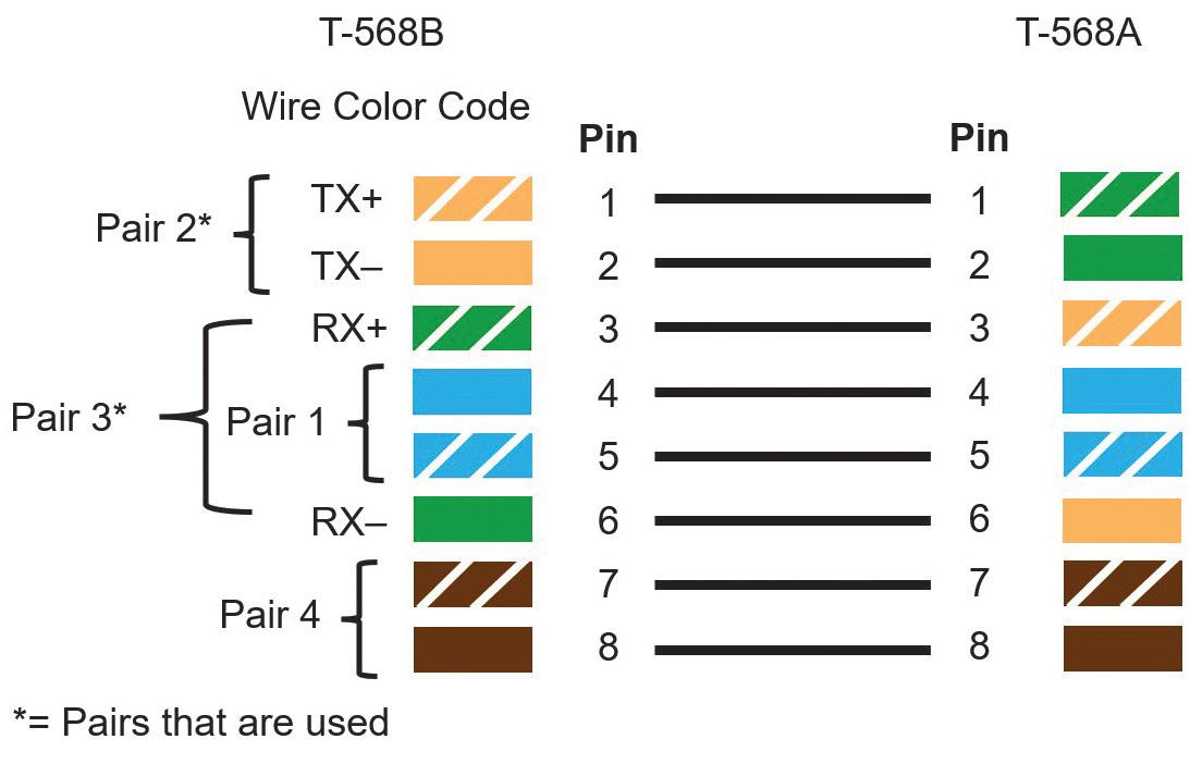
connection. Twisted pair copper Ethernet cables are made from four twisted pairs of conductors terminated in an eight-pin RJ45 connector. The wiring standards for the terminations are T568A and T568B (Figure 2).
The difference between the two standards is the pin assignment for the orange and green pairs. Cables with T568A wiring on one end and T568B on the other are known as crossover cables. You can identify a crossover cable by comparing the order of the wire color on each end.
• If the wire colors are in the same order on each end (regardless of which pin configuration is used), it is a straightthrough cable meant to connect data terminal equipment such as an IED to data communications equipment such as an ethernet switch.
• If the wire colors are in a different order at each end, the cable is a crossover cable meant to connect two data communications or data terminal pieces of equipment together.
Today, most Ethernet switches, IEDs, and routers support automatic medium-dependent interface crossover (auto-MDIX), which can detect which type of port or cable is connected and automatically swap the transmit and receive pins, accordingly, removing the need for crossover wiring. Given that most modern devices support auto-MDIX, it is still best practice to use a crossover cable to connect interposing switches and connect the drop ports of the switch to the IEDs using a straightthrough cable. Twisted pair Ethernet media is typically used within the electrical substation for the connection of HMIs and engineering laptops to the LAN, but the lack of isolation and limited electrical noise immunity does not lend twisted-pair copper Ethernet cable media well to other applications within the substation.
FIBER OPTIC ETHERNET MEDIA
The second and most common communication medium within modern substations is fiber optic cable. Two types of fiber optic cable are used within substations: single-mode fiber and multimode fiber. Several wavelengths of light are used as shown in Table 1.
These light wavelengths have very low attenuation as they propagate through fiber media, and transceivers can be manufactured that will operate efficiently at these wavelengths of light. It is very important to note that unlike copper wire ports, fiber optic ports have fixed baud rates, so the transceivers of the two devices must be at the same baud rate and use the same wavelength of light for transceivers to be able to see each other to communicate.
Designation
IEEE 802.3j 10 Mbps
IEEE 802.3u 100 Mbps
10BASE-F over fiber
10BASE-TX/FX (fast Ethernet – twisted pair Cat5e or 1,300 nm fiber
IEEE 802.3z 1 Gbps 10BASE-SX Gigabit Ethernet over 850 nm multimode fiber
IEEE 802.3z 1 Gbps 10BASE-LX Gigabit Ethernet over 1,310 nm single-mode fiber
IEEE 802.3i 10 or 100 Mbps 10/100BASE-T over twisted-pair copper, “twisted pair” (Cat5e or Cat6)
IEEE 802.3ab 1 Gbps
1000BASE-T Gigabit Ethernet over twisted-pair (Cat5e or Cat6)
Table 2 provides the designation for several commonly used fiber optic Ethernet port configurations. The designer should ensure that the fiber cable is compatible with the ports and that the ports of connected devices are compatible (have the same designation).
Single-mode fiber (Figure 3 and Figure 4) is ideal for runs of hundreds of kilometers, but the small core diameter is very sensitive to contaminants and requires strict adherence
to cleaning and handling to ensure reliable operation.
Multimode fiber optic cable has several advantages over single-mode fiber that have allowed it to become the dominant media within the modern substation. Multimode transceivers are available at a lower cost than signal mode transceivers, and multimode fiber optic cable has a much larger core, hence more tolerance to dirt and contaminants than singlemode fiber core.
It is still important to follow correct handling and cleaning procedures with multimode fiber components. The larger core of multimode fiber (Figure 5) does not come without a cost.
As the photons of light traverse the fiber, some photons take a longer path than others (Figure 6). Therefore, the pulses of light making up the data transmission tend to round and increase in width the farther they traverse the fiber. This is called dispersion.
Ethernet has very strict timing and as the baud rate increases, this timing becomes more and more critical. Dispersion is the primary factor that limits the maximum length of multimode cable to typically 2 km for 100 Mbps. This drops very quickly to only several hundred meters for speeds of 1 Gbps. Table 3 shows the rated maximum distance of several types of multimode fiber depending on the baud rate.
Single-mode fiber optic cable does experience chromatic and polarization mode dispersion.
• Chromatic dispersion occurs when the transmitting light source is not of one wavelength, and the transmission of different wavelengths of light is at different speeds within the fiber.
• Polarization mode dispersion is a phenomenon of light traveling in a medium as a wave with components at right angles.
Some materials, like glass optical fiber, have a different index of refraction for each of those
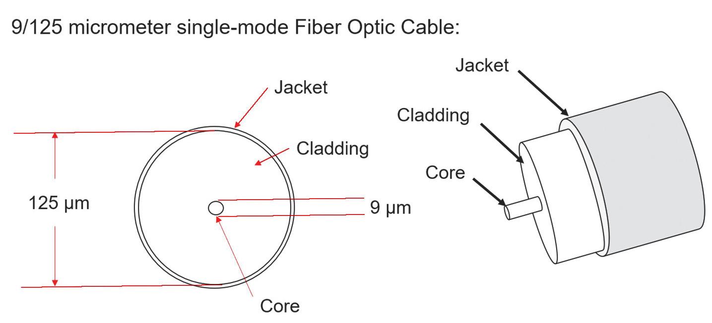

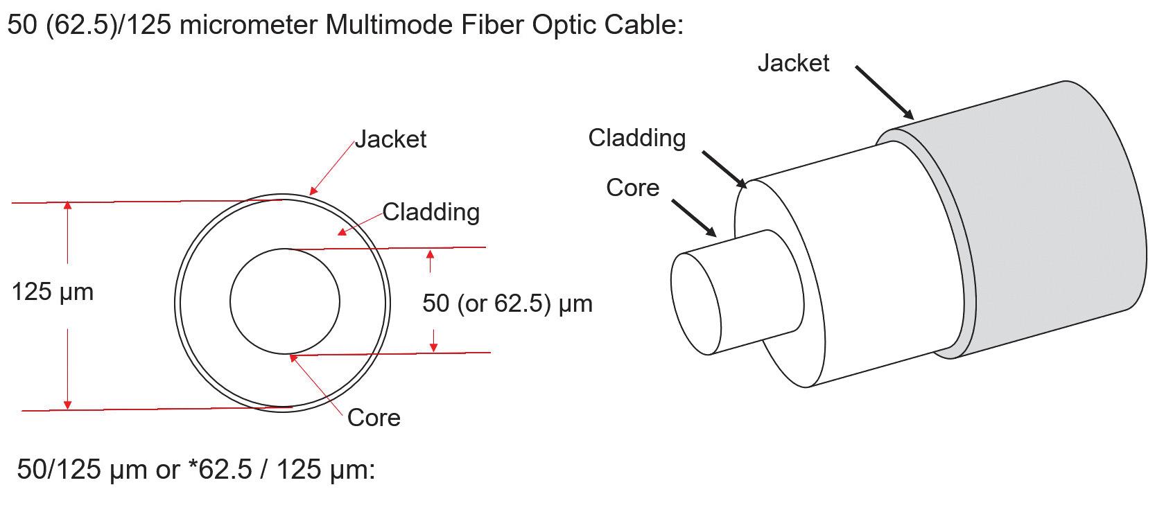
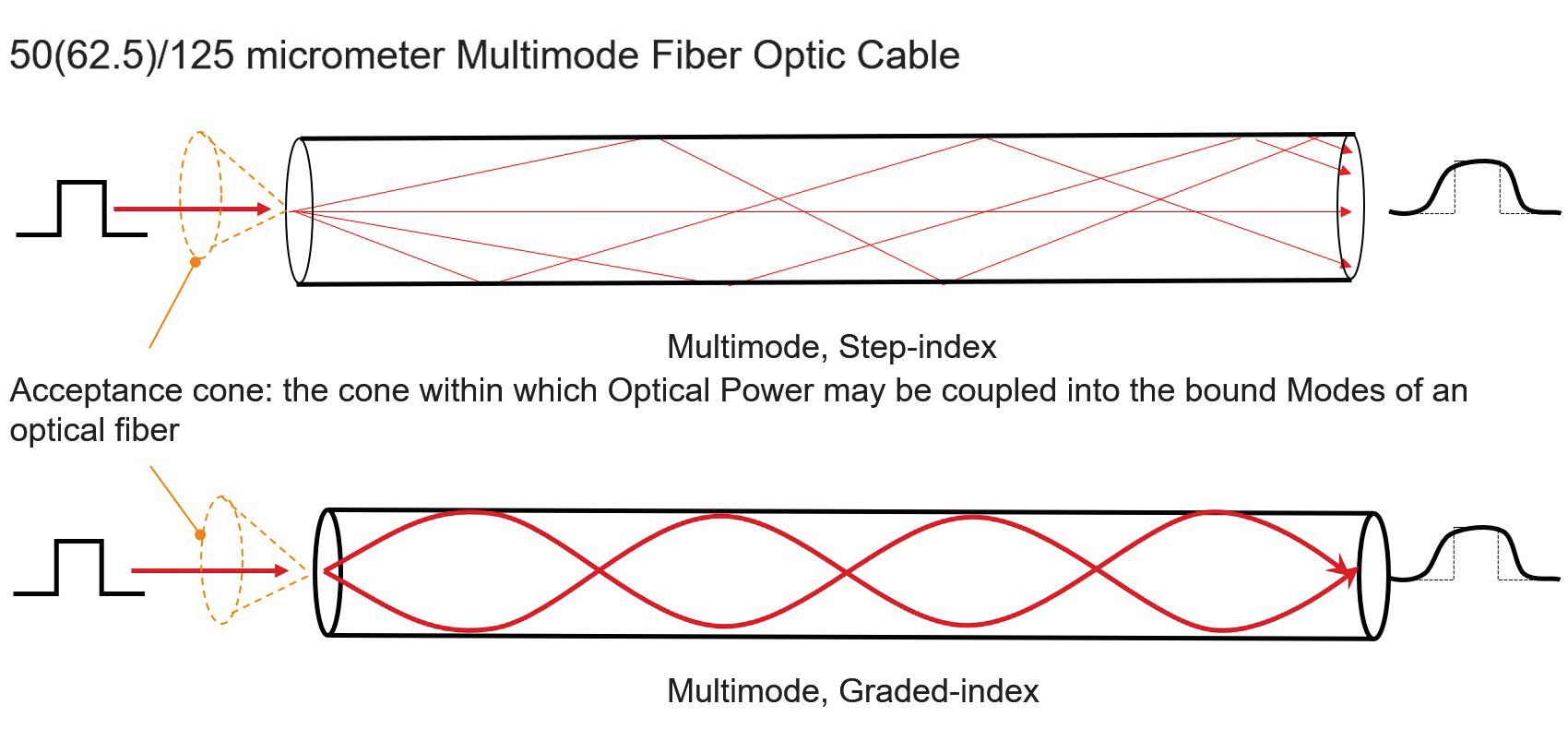
OM4 50/125
Aqua or violet
OM5 50/125 Multimode Lime green Not specified
*The distances shown in this chart are typical. The design must consider the actual transceiver’s worst-case optical power budget, fiber optic cable loss per unit distance, and connector loss to ensure the application will work for a specific transceiver and fiber optic cable combination.
components of the light wave; this is called birefringence. A different index of refraction means light travels at a different speed. Having said this, the dispersion of single-mode fiber is of no concern when we consider what the required length of single-mode fiber within the footprint of a typical substation would be.
The second factor limiting the length of single as well as multimode cables is the attenuation of the light as it traverses the fiber. The maximum cable length of the fibreoptic transceivers specified by the switch vendor does not consider the connector and splice losses of the fiber run. The amount of fiber optic cable plant loss that a datalink can tolerate while still operating correctly is called the optical power budget. Think of the optical power budget as the difference between the output power of the transmitter and the input power requirements of the receiver, both of which are defined as power coupled into or out of an optical fiber.
In some cases, the optical power budget has minimum and maximum values. This means a minimum value of loss is needed to prevent the transmit optical power from overloading the receiver, and a maximum value of loss is needed to ensure the receiver has sufficient
signal to operate properly. The loss budget is a calculation of the estimated loss a cable plant will have. This end-to-end, estimated total loss calculation is based on the estimated cumulative losses of the components used in the cable plant including the fiber, connectors, and splices.
During the design phase, the loss budget is used to ensure the cabling being designed will work. After installation, the calculated loss budget is compared to the actual measured loss to verify that the cable plant was installed correctly. This topic has much more depth than this very abbreviated summary. To provide further clarity, we will work through a typical multimode fiber optic cable run within a substation (Figure 7).
This is the longest cable run for the application. This run also has the maximum number of connectors of any run within the cable plant. In this example, there is no minimum loss as the transmit optical power is not strong enough to overload the receiver, which is typically the case for multimode ports. The transmitter has a minimum optical power rating of -20 dB and the receiver has a maximum receive sensitivity of -28 dB.
• Cable loss = 3 dB/1,000 meters for this specific example. Check your cable specifications for the loss per km.
• Optical power budget (OPB) = Tx min(dB) - Rx(max) = 8 dB. The switch manufacturer typically provides this specification.
• Worst case OPB (WOPB) = OPB - 1 dB = 7 dB. This is normally only applicable to single-mode applications but it does not hurt to be conservative.
• System gain equals cable loss plus connector loss where:
• Cable loss = cable length x attenuation per unit length (dB).
• Connector loss = number of connector pairs x 0.5 dB (0.3 to 0.5 typical).
Note that the TIA/EIA standard calls for 0.75 dB per connector, but for modern connectors, 0.3 dB to 0.5 dB have typically been found to be more accurate.
• System gain = 250 meters x -3 dB/1,000 meters + 4x - 0.5 dB
• = -2.75 dB
• Operating margin = WOPB + system gain = 7 dB - 2.75 dB = 4.25 dB
From this example, we can see that the operating margin (the difference between the system gain and the WOPB) is 4.25 dB. A rule of thumb is that the ideal operating margin should be 3 dB or greater for multimode applications to ensure reliable operation. Given that this is the longest multimode fiber link for this substation, the designer can be assured that the multimode cable plant will provide a reliable link between all devices if properly installed.
TESTING
There are many aspects of fiber optic links testing, and electrical utilities typically have access to installers that have the knowledge and equipment to test the cable plant. One of the simplest tests is the length loss test. In this test, a light source of the same wavelength as that of the application is connected by a 1-meter cable to a receiver. The source output is adjusted such that the receiver measures the signal as 0 dB. The
light source is then connected to one end of the run and the receiver is connected to the other end. The attenuation measured by the receiver indicates the actual attenuation of the link, which should be close to what you calculated using the procedure in the preceding paragraph.
Adding patch panels is a great way to manage fiberoptic cable runs. Devices terminate at a local patch panel and longer fiber runs are used for the interconnection between the patch panels. The only drawback to patch panels is the introduction of additional connectors, which introduces additional loss.
Selecting the Right Ethernet Managed Switch
The Ethernet switch is like a data manifold that in combination with Ethernet cables forms the LAN that provides the Ethernet communication connectivity between the IEDs, merging units, HMIs, gateways, routers, and PCs within the substation. Many manufacturers supply utility-grade managed switches that support numerous different features and physical form factors.
Many factors must be considered when choosing a managed switch for OT applications. In fact, there is enough to consider when selecting a managed switch for OT LANs to warrant an article on that topic alone. It is strongly recommended to go through a selection process when choosing the ideal OT-managed switch for your application, as not all claimed utility-grade managed switches are equal.
Following is a list of features that are strongly suggested to be considered during the evaluation process. The list is modest and so you may find it surprising that many utility-grade managed switches do not support all of these features, and compromises must therefore be made.
• Designed to meet IEEE 1613 Class 2 and IEC 61850-3.
• Supports an option for dual power supplies (AC and DC) that are hotswappable.
• All switch configurations are accomplished through a web interface to allow personnel to become proficient in a relatively short period of time.
• Default IP address, administrator account name, and password to allow easy initial access.
• Supports real-time day clock and calendar.
• Supports SNTP client/server.
• Supports IEEE 1588 transparent clock.
• Supports switch local diagnostic log.
• Supports Syslog to three agents.
• Supports IEC 61850 data model, MMS server, and report functionality (for SCADA/testing).
• Supports multiple user accounts with at least three levels of users:
• Administrator account can create user accounts.
• Multiple engineer accounts can configure all features of the switch, excluding creating or deleting user accounts.
• At least one operator account can look at the switch configuration/ operating menus but cannot make any changes.
• Supports twisted pair and fiber optic ports at port speeds of 100 Mbps with uplink ports (switch-to-switch connection) at 1 Gbps.
• Supports several hundred concurrent port-based VLANs. An x/y port-based VLAN configuration matrix is ideal (the x-axis being the port and the y-axis being the assignment of VLANs or vice versa)
Syslog
Syslog is a standardized way for networking equipment such as managed switches to send events to a central computer running a syslog agent. For example, if a device connects or disconnects from a switch port, the switch will send a message to the Syslog agent indicating that the status of a specific port has changed along with a time stamp. In this way, the status of all switch ports, in addition to major and minor events on the LAN, can be monitored at the Syslog agent with very little configuration effort (Figure 8).
Syslog is an extremely powerful troubleshooting tool for the OT LAN. Some switches have an IEC 61850 data model, and there is thought that this data model could be monitored by an IEC 61850 client to provide similar functionality to Syslog. The reality today is that the IEC 61850 data model within most managed switches is poor to nonexistent, and there is a substantial integration effort to allow the IEC 61850 client to provide rudimentary diagnostics. Syslog is universally supported by all major managed switch vendors and is an excellent diagnostic tool that should be implemented.
PATH REDUNDANCY
Redundancy is a key consideration for OT LANs. Ideally, in the event of a LAN component failure, the LAN can continue to provide acceptable performance. Many physical LAN topologies provide a redundant physical path such as a ladder topology.
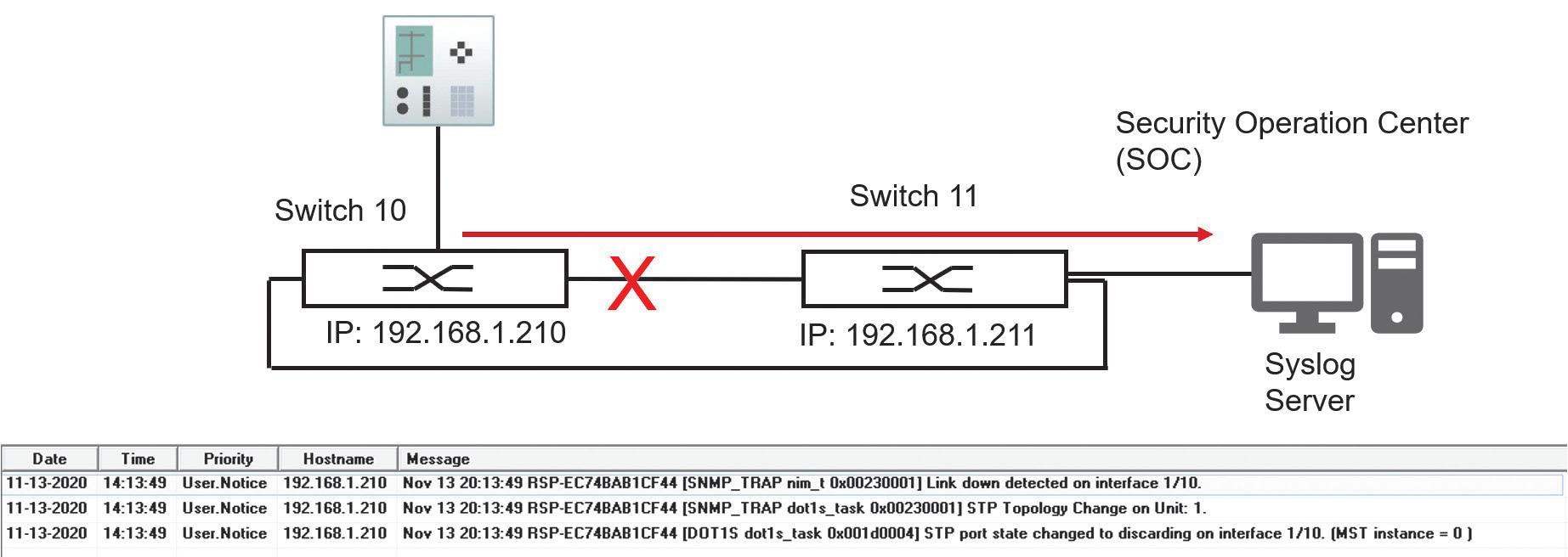
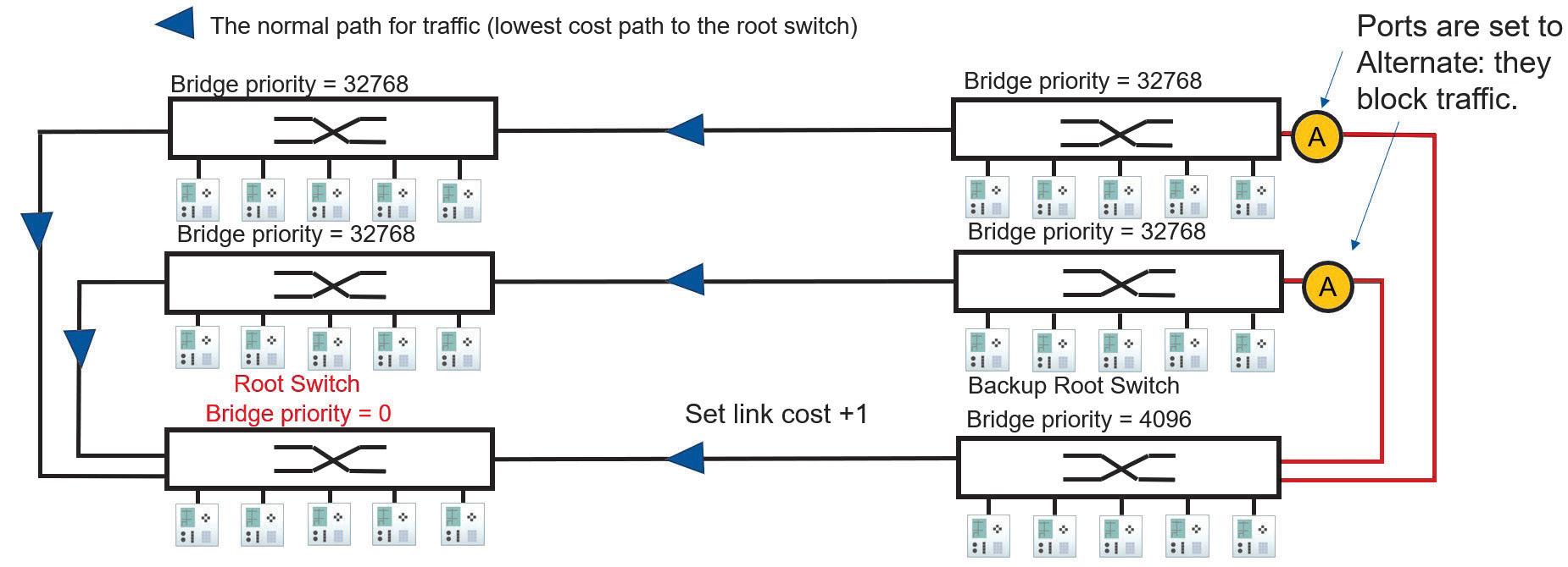
Ethernet frames do not have a maximum time to live, so a redundant link allows a broadcast message to be duplicated at each junction. Over a short period of time, this duplication will use up all available bandwidth of the LAN and can cause MAC table instability within the switch. This is known as a broadcast storm.
IEEE has standardized five redundancy algorithms:
1. Spanning tree protocol (STP)
2. Multiple spanning tree protocol (MSTP)
3. High-availability seamless redundancy (HSR)
4. Rapid spanning tree protocol (RSTP)
5. Parallel redundancy protocol (PRP)
These algorithms allow for the provision of redundant physical paths while eliminating broadcast storms. This article examines how RSTP and PRP (the last two redundancy algorithms listed) can work together to provide redundancy as well as a mechanism to plan the primary and alternate data path between devices.
Rapid Spanning Tree Protocol
Rapid spanning tree protocol (RSTP) is the most common redundancy protocol used today within Ethernet LANs. Even a short summary of RSTP operation would take considerable space, so this article provides a very high-level description of its operation to understand
how it can be used to configure normal and alternate data paths. The primary purpose of RSTP is to create a logical loop-free topology when physical redundant paths are present in the LAN. The loop-free topology or spanning tree is built based on the priority and costs of the different paths from each switch to the root switch. The links between switches can operate at different standard baud rates. Each of these baud rates is assigned a specific cost — the values of these costs are not important for this discussion.
The first step is to choose a topology of switches that allows for normal and failover paths to be easily configured using link cost. The ladder topology shown in Figure 9 is an ideal topology for this purpose.
The next step is to configure a root and backup root switch by setting a parameter called bridge priority within the switch from its default of 32,768 to 0 for the root and 4,096 for the backup root. The other managed switches will use the RSTP protocol to determine the most favorable loop-free path between each managed switch and the root switch. The lowest path cost is the first parameter used in this determination.
In the example topology in Figure 9, the links between all switches are operating at the same speed, hence they are said to have the same cost except for the link between the lower two switches whose cost has been raised by 1. The
active path from each switch to the root is negotiated in the following way:
• Switches with a link directly connected to the root switch will use that path as it is the lowest cost path to the root switch.
• The two switches to the right and above the backup root switch are not connected directly to the root switch and have two paths to the root: the path via the backup root switch and the path to the left.
• The path via the backup root has a cost of 1 more than the path to the left, so both switches will choose the path to the left as the normal path to the root switch (see Figure 10).
• The alternate paths via the backup root switch are logically blocked to create a loop-free topology.
By adjusting the cost of one link, we have planned the normal and failover path between all switches and the root switch. Therefore, we now know the normal and failover data flow between connected devices. Knowing the data path or the virtual wiring of traffic between devices is required during the commissioning phase to verify connectivity of the normal and failover path and enable parameters such as message latency from one location on the LAN to another to be measured. To troubleshoot, you need to know the data path between devices.
A failure of the normal path between managed switches is detected, and the RSTP protocol running on the switches re-enables a redundant path to restore the communications path between switches (Figure 10).
Parallel Redundancy Protocol
The disadvantage of using a single LAN with RSTP alone is that after a failure of a normal path, there is a short period of time when messages may not be able to get through the LAN until convergence to a new loop-free topology is complete. Parallel redundancy protocol (PRP) defined in the IEC 62439 standard provides seamless recovery and zero communication packet loss to address this issue (Figure 11).
The PRP network is composed of devices with double attached nodes (DANs) and single attached nodes (SANs). Depending on the application, only the critical nodes may need a double attachment. The DANs are connected to two independent LANs operated in parallel, referred to as LAN A and LAN B. A DAN will simultaneously send out each Ethernet packet on both networks. The recipient will process the information as soon as the first copy is received at one of its ports. If both networks are operating correctly, the recipient will receive the second copy of the message on the other PRP port after a short time delay. If one of the two networks is not operating correctly, the packet will still be received through the
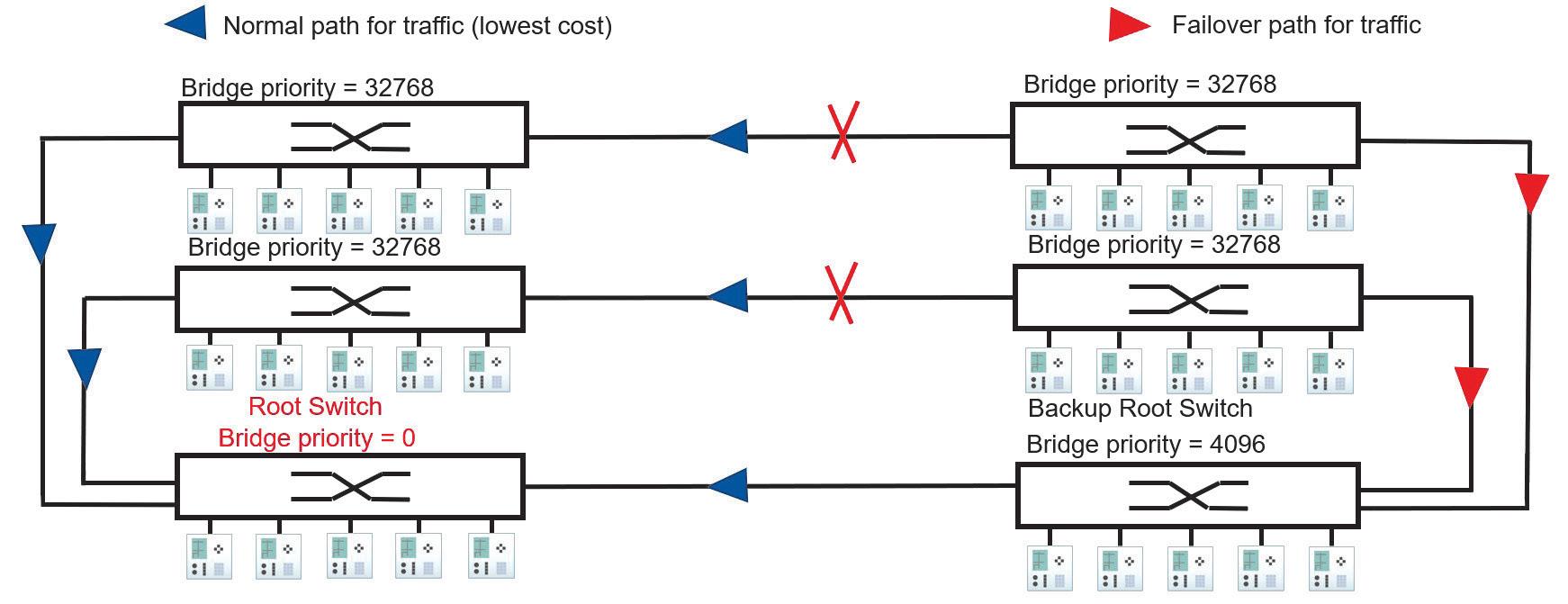
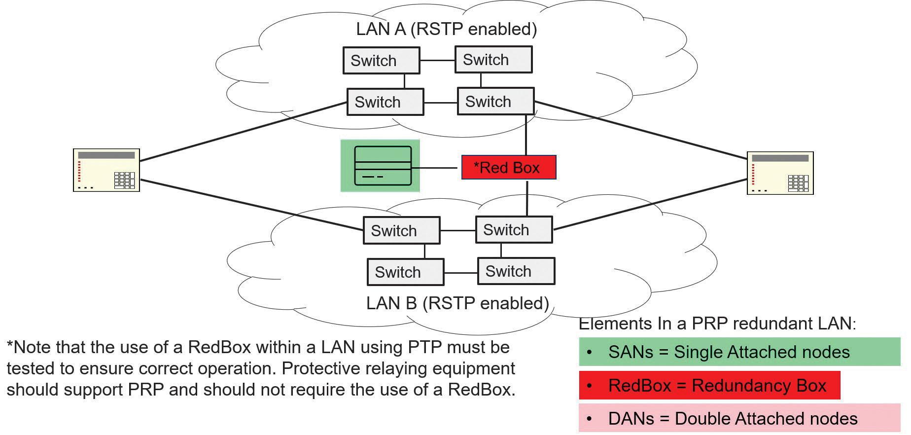
operating network. When a destination node receives a packet, the information from the first copy is taken and processed while the information from the second copy is discarded. For demanding real-time applications like time-critical GOOSE messaging and sampled values, using PRP is recommended.
PORT-BASED VIRTUAL LANS (VLANS) AND PRIORITY
Multicast messages used for real-time data such as GOOSE and SV are treated by the switches as broadcast traffic; this means they will be sent out on all ports except the port they are received on. When traffic is received at a device
port, some processing must be performed on the traffic to determine whether the traffic is for this device. Given the volume of multicast traffic, it is desirable to filter this traffic so that only the required traffic appears on the drop ports to reduce this processing to a minimum.
Two mechanisms can be used to filter multicast traffic: multicast filtering and VLANs. Given that the IEEE 802.1 header shown in Figure 12 supports VLANs and priority and that VLANs and priority are explicitly referenced within the IEC 61850 standards, this article explains the use of VLANs and priority to filter multicast messages.
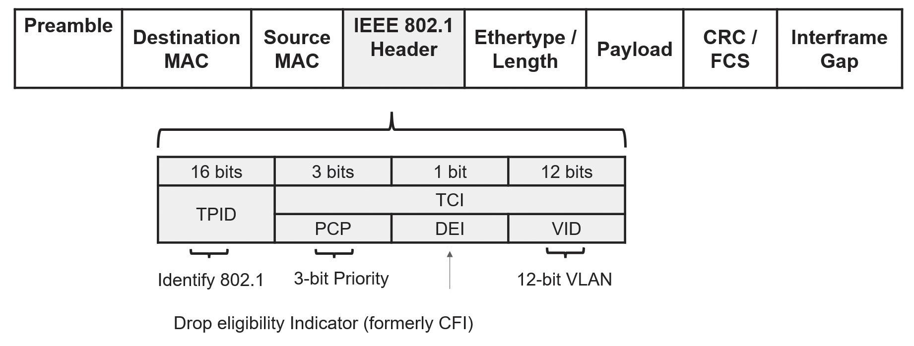
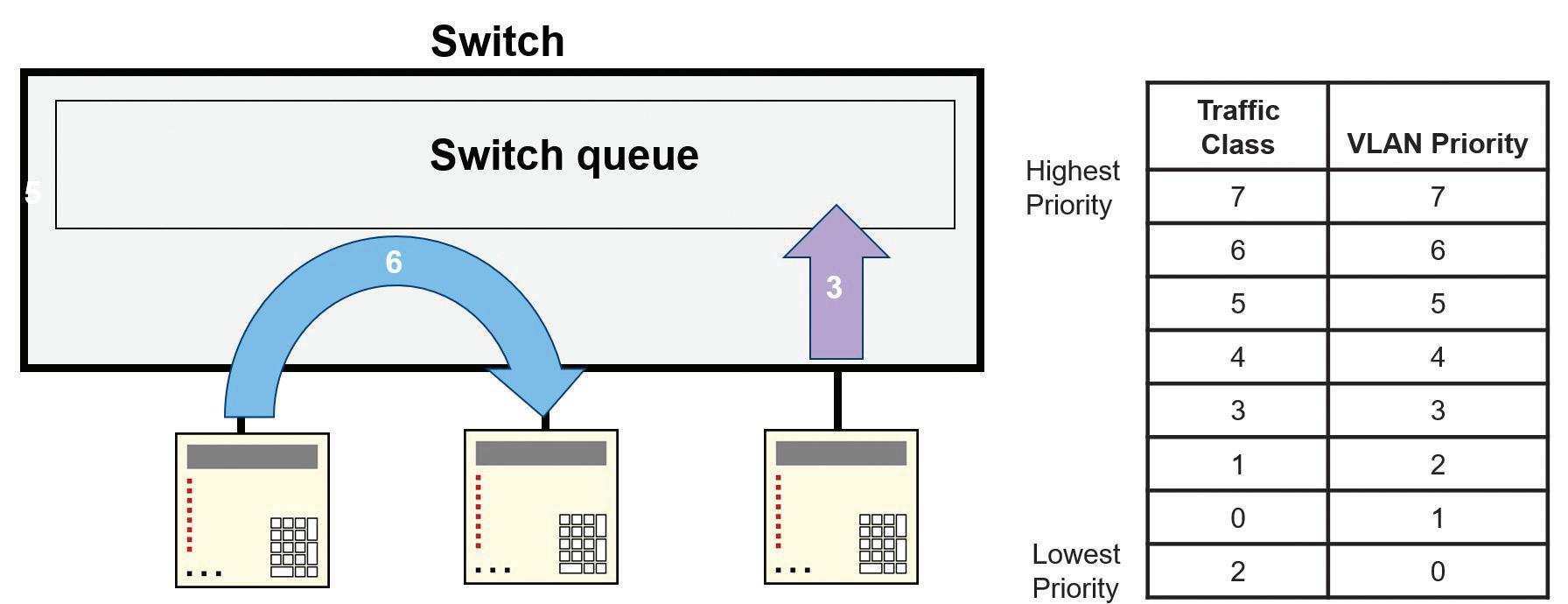
Figure 13: VLAN Priority
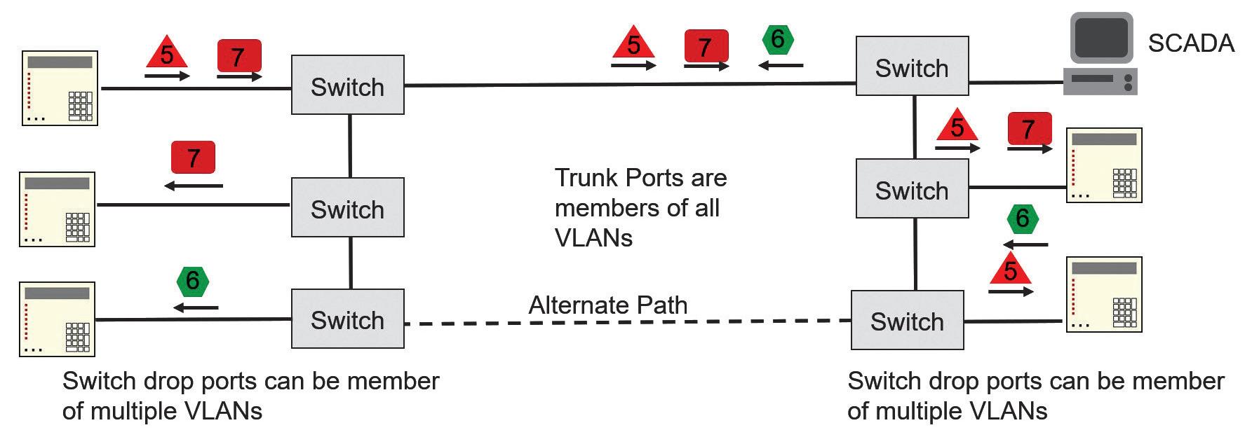
Figure 14: OT LAN Implementation of Port-Based VLANs

Figure 15: OT LAN Implementation of Default VLAN
Priority
When the switch is VLAN-aware, it will look for the 802.1 header as frames ingress the switch. If two messages ingress the switch at the same time and the switch determines both must egress on the same port, the switch will forward the frame with the higher priority to
egress the port, while the second frame will be buffered by the switch until the first frame is transmitted (Figure 13).
The OT LAN implementation of port-based VLANs is shown in Figure 14. The various shapes represent different multicast messages,
while the arrows indicate the direction of these messages on the LAN. The number within each shape/message indicates the VLAN assigned to the message.
The ports that are used to connect between switches are members of all VLANs used by GOOSE and SV multicast messages within the application such that all multicast messages can propagate to all switches. The drop ports of the switch are the switch ports connected to end devices. These drop ports are configured to egress only messages that have a VLAN ID that identifies the message as one of the messages the end device should receive. In this way, only the multicast messages intended for the IED will be received. The switch filters out all but the multicast messages intended for the IED.
SCADA messages shown in Figure 15 are not sent with the 802.1 header, so they do not contain a VLAN ID. All messages that ingress a VLANaware switch must have the 802.1 header, so the switch will automatically add the 802.1 header to the SCADA message with the default VLAN ID that has been assigned to the ingress port. When a message assigned to the default VLAN of the port egresses the switch, the 802.1 header is removed from the message. By ensuring that all switches use the same default VLAN for all ports, the SCADA system will be able to communicate with all devices on the LAN as if the switches were not VLAN-aware.
OT LAN TESTING AND COMMISSIONING
Now that the LAN is built and the devices are connected, we can focus on how to commission and test the LAN. Given that each application is different, only some general guidance is provided. The managed switches should be provisioned with at least two, but ideally three, spare copper ports for commissioning and troubleshooting.
The primary tool for commissioning and troubleshooting the OT LAN is an IEC 61850 protocol analyzer with analog inputs such that GOOSE, I/O status, SV, and actual analog signals can be conveniently placed on one
timing diagram to analyze faults and system performance. LAN connections should only be disturbed when performing precise timing measurements as required in the case of latency measurements. All other tests can be performed by configuring the managed switch to mirror the traffic of a specific port to one of the spare ports connected to the protocol analyzer. Switch port failures can be simulated by disabling a switch port through the switch web interface. The most common tests for a digital substation include:
• Verifying merging unit performance (Figure 16)
• Measuring latency (Figure 17)
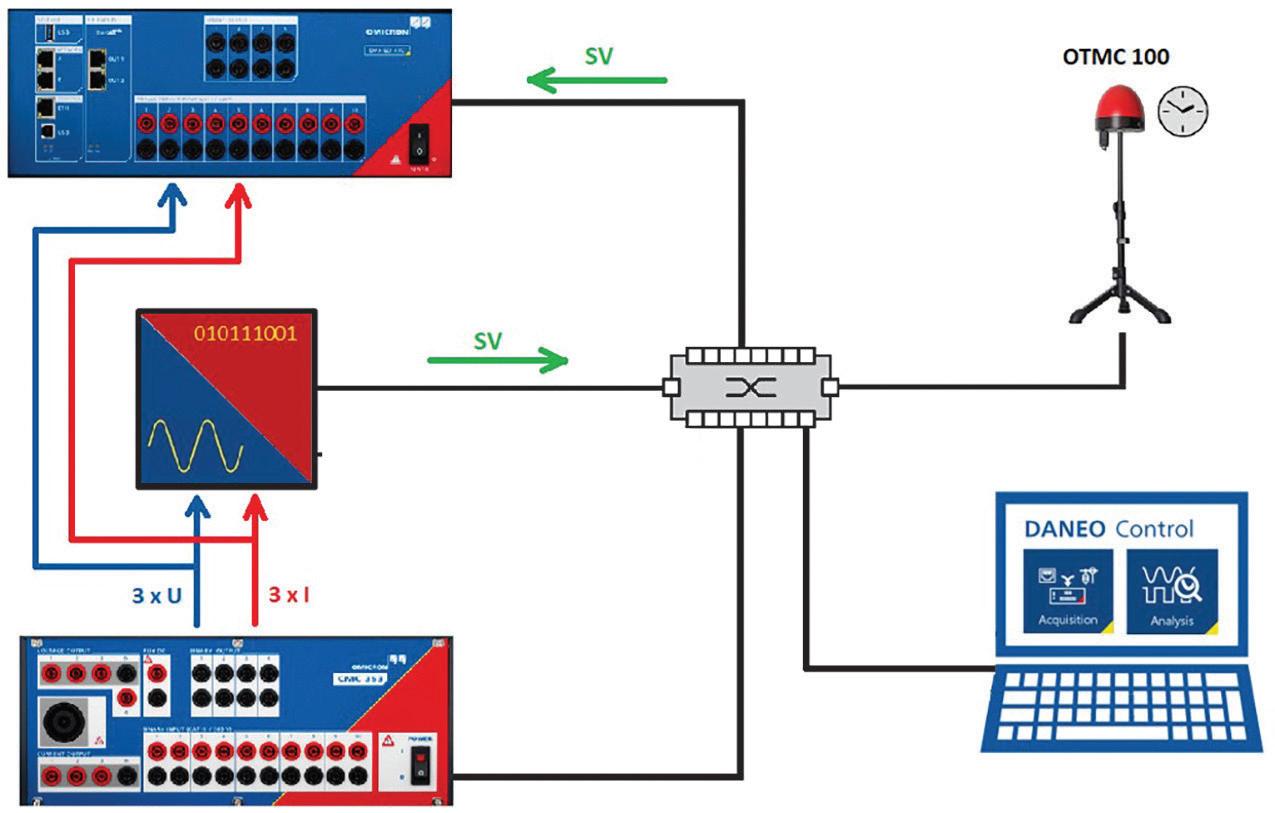
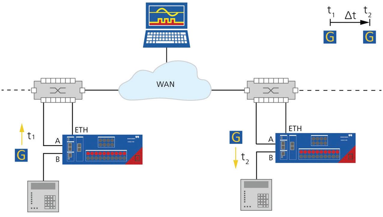
FEATURE
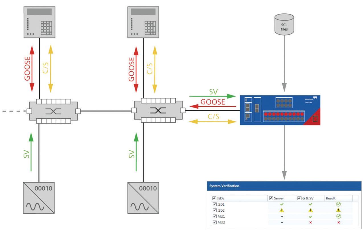
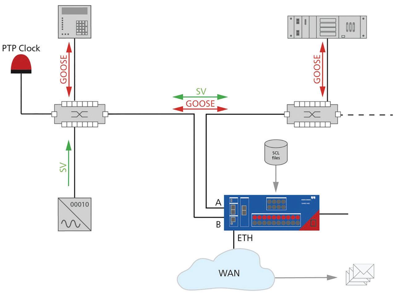
• The protocol analyzer should be able to load the substation SCL files and perform automatic verification of all data flows rather than performing such tasks manually which would be error-prone given the number of parameters to check within each message (Figure 18).
• The protocol analyzer should also be able to supervise GOOSE and/or SV messages and alarm and record when a loss of either is detected (Figure 19).
CONCLUSION
Modern digital substation protection and control solutions sit on a foundation of a well-designed OT Ethernet LAN. This article provides a very brief overview of some of the best practices for OT LAN design, commissioning, and testing. There is much more to cover, so you are encouraged to seek out courses on the design, commissioning, and testing of OT LANs to further your knowledge.

Steel McCreery joined OMICRON electronics Canada Corp. in 2020 as an Application Engineer for Power Utility Communications where he is focused on utility communications and substation cybersecurity. Steel began his career in factory automation while employed at various automation equipment manufacturers. He joined GE Multilin in 1999 to develop its international training center focused on protective relaying and substation automation. Over 14 years at GE Multilin, Steel’s role expanded into marketing and R&D before accepting an automation role at SEL focused on SEL’s communications products. Steel graduated from Humber College of Applied Arts and Sciences as an Electronics Engineering Technologist.

A TSUNAMI OF FUNDING AFFECTING FIBER OPTIC PROJECTS

The tsunami of funding stemming from the Infrastructure Investment and Jobs Act (IIJA) has the fiber optic industry in a frenzy, partially because sufficient workforce to build networks is lacking and supply chain problems are causing long delivery times for basic components like fiber optic cable.
Airports, Seaports ($33b)
Water, Wastewater ($55b)
Railroads ($66b)
Other ($54b)
Broadband ($65b)
Roads, Bridges ($111b)
Public Transport ($39b)
Highway Safety ($39b)
Energy, Power, Grid ($108b)
The need for broadband was brought to the forefront during the pandemic when work, school, doctor visits, and everything else moved to the home, showing how many areas had inadequate Internet coverage. The $43 billion for broadband in unserved and underserved areas of the US that has been the focus of the communications industry is just a drop in the bucket of the IIJA. There is more than $1 trillion (a staggering $1,000 billion) for other infrastructure projects. Here is how it breaks out (Figure 1).
That $1 trillion covers roads and bridges; highway safety; public transportation; railroads, airports, seaports; water and wastewater infrastructure; energy (electric transmission

and distribution as well as alternative energy projects); and natural disaster prevention. Note the $109 billion for energy projects. Practically every one of the projects in those categories will involve fiber optics.
Electrical utilities are familiar with many of these infrastructure projects and know how much fiber is used in transmission and distribution to manage the grid. Alternative energy projects use a lot of fiber locally and in integration into the grid. Utilities are also familiar with the current frenzy to install fiber for broadband and 5G. Some are already involved in or considering broadband projects themselves.
Because there are thousands of fiber optic projects being done all the time, the total value of current fiber projects is hard to estimate, but I expect the projects that will be included in all these IIJA-funded infrastructure projects to double the activity in fiber optics over the next few years.
My contacts in the fiber and cable business tell me they are already swamped with orders, many related to the pre-IIJA projects for fiber to the home, 5G wireless networks, and data centers. Delivery times of a year or more are being quoted. New fiber optic factories are being built to fill demand but will take time to come on-line.
Planning projects for the next few years will be a challenge. Unless some miracle happens, we’re all going to be scrambling for fiber optic components and installers. Compromises may have to be made, but some are not recommended.
Supply chain issues are a problem, but they need to be considered in light of the scheduling of a fiber optic project. A project to build a fiber optic communication network easily takes a year from concept to beginning installation.
FIBER OPTIC PROJECTS
A fiber optic project can be broken down into stages — planning, design, installation, and
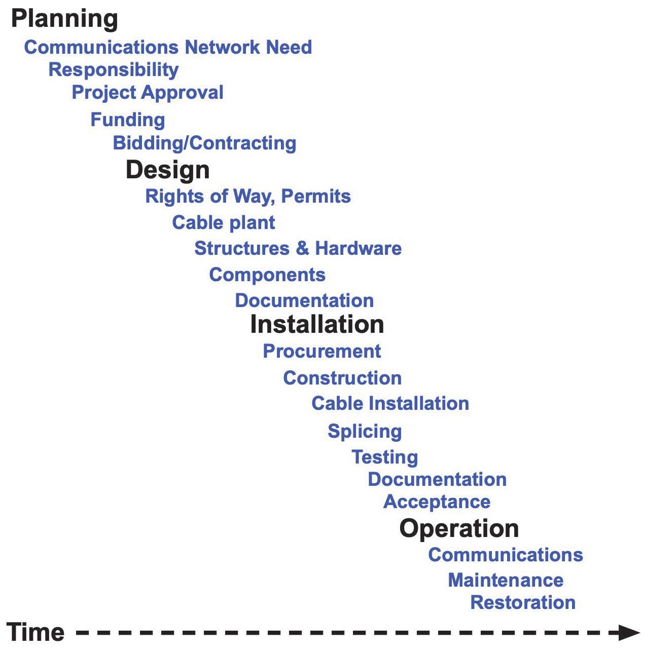
operation — with various subtopics like the ones shown in Figure 2. These stages operate in overlapping time frames and will have different timing depending on the size and complexity of the project as well as the issues that can occur at various stages.
For some projects, planning is the hardest part. It all begins with the need for communications services, which starts at the highest levels of management, but sometimes even the requirements may not be clear to all interested parties. One project might involve nothing but new fiber optic cable along transmission lines; another might include fiber to the home or wireless smart cells, while another might be an open access network intended for many service providers using the cable plant.
Next, the responsibility for the project must be assigned, easier on private projects, harder on public projects, and even more difficult
on public/private partnerships. Approvals and funding can be real bottlenecks.
The actual design process begins when the project is defined and approved and the project manager is chosen. Once the communications network is defined and we have a basic idea of its route, inside or outside plant or premises, we can start thinking about how the geography determines the design of the cable plant. Outside plant networks may be aerial, underground, or even underwater — all with multiple options for construction, depending on the surroundings.
At this stage, some critical decisions often need to be made. For outside plant networks, the first decision is aerial or underground. That choice can be affected by geography, local ordinances, or economics. Each option has additional construction options: lashed or alldielectric self-supporting (ADSS) for aerial cables, trenching, boring, or microtrenching for underground.
Once you know where and how the cable plant will be installed, you can begin tabulating the components you will need. The geographic distance of the link provides the basic data for ordering cable, but that is not enough. You need extra cable for service loops at each splice point and additional extra for unusable short ends on reels during installations. Just don’t throw those short lengths of cable away; they should be saved for use in restoring links after cable damage.
There are at least two ways to estimate the length of cable to buy, and your designer and estimator may have others. One method is to count all the splice points and add about 50 meters of length. The other is to order 10–12% extra cable.
Since the delivery times for cables and some other components may be long, it may prove wise to start the procurement process for cable at this point. That means making more decisions. Remember, the length of the cable is only one specification; you also need to
identify the type of fiber (if something other than standard G.652 single-mode), how many fibers in each cable, and what type of cable.
If you have not specified and ordered fiber optic cable recently, you need to understand that there have been some big changes in fiber optic cable technology in the last few years.
For aerial cable being installed on transmission towers, ADSS cable is often used. This cable can be installed without a messenger, simplifying construction. For distribution networks on current poles in the telecom space, standard outside-plant loose-tube cable can be lashed to a messenger, or ADSS cable can be used. Other cable designs can be installed by wrapping around power lines in some installations.
Underground cable offers more new options. The industry has been shrinking cable designs to get more fibers into smaller cables. These

microcables are very small, about half the size of conventional cables. Today, cables containing 864 fibers that are smaller than conventional 144-fiber loose-tube cables are available.
These microcables are typically installed in microducts, which are small-diameter plastic tubes. Microducts can be installed in some conduits that already have fiber optic cables or can be installed by microtrenching — sawing a narrow slot in a roadway or sidewalk. Once the ducts are installed, the cables are blown into the ducts, pushed instead of pulled. It’s a fast and easy installation process.
These new dense cable designs are ribbon fiber designs. With so many fibers in a cable, splicing individual fibers is too time consuming, so a dozen fibers are held together in the cable so they can be spliced at one time. Ribbon splicing is about four to six times faster than splicing individual fibers.

Once you estimate the cable length needs, understand all the specification options, and make choices, it’s time to start the cable purchasing process. Since there is a lot more work to do on the design of the project, plus getting permits and all those details involved in construction, that cable might arrive in time to start construction.
Be wary of trying to work around long delivery times. Recently, we have had conversations with users who have gone to importers for parts that were not available in the United States or were offered at lower prices. One is sitting on a large inventory of cables made with fibers that are breaking when installed. Another bought equipment that was held — and eventually disassembled — by customs when it arrived in the U.S. before being shipped to him as a useless box of parts. The lesson is to know your suppliers.
When the design is well along, it becomes time to request proposals (RFPs) and quotes (RFQs). Bidding and contracting sounds simple, but FOA is now receiving calls for help where projects are finding it hard to get bidders because contractors are already so busy or cannot find sufficient workforce.
FINDING QUALIFIED WORKERS
The big bottleneck is the fiber optic workforce. Even before the IIJA money showed up, the size of the fiber optic workforce was marginal. Last year, we were asked by a state agency to help them find bidders for a giant fiber optic backbone project because they were not getting enough responsive bidders. We called some contractors who should have been interested but they all said they were booked up and could not find workers to expand their business.
We all know that every job category has a problem finding workers. FOA has been helping contractors create on-the-job-training (OJT) programs that allow them to develop their own workers to a higher proficiency. Hundreds of schools are also teaching courses on fiber optic installation. All this is still inadequate.
Today, FOA is working directly with state workforce development agencies to create more programs to train and certify workers. In 2016, when Kentucky started its statewide Kentucky Wired fiber backbone project, there were two FOA-certified fiber techs in the state. The state set up nine community and technical colleges to teach fiber, and there are now 1,200 FOA-certified fiber techs in Kentucky who helped finish the backbone late last year and are ready to build out the networks in all of the 95 counties now connected on fiber.
FOA is already working to duplicate the Kentucky program in other states’ educational systems. These states understand they must work as rapidly as possible to expand educational programs to get ready for the coming rush of fiber optic projects needing a local workforce.
IS IT NECESSARY?
Perhaps it’s worth considering the necessity for the project itself. Another way to build communications capacity over current routes is to upgrade equipment. In many cases, you don’t need more fiber; just upgrade the equipment. New communications systems using coherent optics allow upgrades to 100 gigabits per second or more on older fibers, and wavelength division multiplexing allows multiple signals to share fibers.
One way to mitigate these bottlenecks is to avoid duplication where possible. One option is to combine separate projects into a larger one, even managing cooperation between users to share a common infrastructure. We once sat in a conference where two speakers showed maps of their companies’ fiber optic networks — they looked identical. The fiber optic networks needed for communications networks, transportation projects, and utility projects have a lot of overlap and could share cable plants.
It makes little sense to build duplicate cable plants or dig up the street again for each new project. That’s what Dig Once is all about:
Install a bunch of fiber ducts at once for future use but consider that one small fiber optic cable can contain numerous fibers that can provide capacity for many users.
CONCLUSION
One final thought: Think ahead. Today, we are using many fibers that are more than 20 years old. Fibers you install today may be in use for more than that. Before committing to a design, consider what might happen in 20 years. Are you installing enough fiber? To the right places? Would the additional cost of burying fiber over aerial get repaid in higher reliability and fewer outages in areas prone to bad weather or wildfires?
Nothing should be left on the table. Now is the time to get going!
Jim Hayes is President of the Fiber Optic Association (FOA), the international professional society of fiber optics. Jim and Karen Hayes started Fotec, one of the world’s first fiber optic test equipment companies, in 1981. Fotec was acquired in 2001 by Fluke Networks, and Jim now consults in fiber optics and is a writer and trainer on voice-datavideo (VDV) topics. Jim has been training cabling installation technicians since 1982 through Fiber U, now part of FOA. Jim and Karen also run VDV Works LLC, a consulting company. FOA provides instructors with complete training programs in fiber optics and cabling. Jim has authored nine books, written articles and columns on cabling for many publications, and is a frequent speaker at seminars and conventions.
RL PRODUCTS NEW?


DISTRIBUTION AUTOMATION NETWORKS –APPLICATION & TESTING
BY ABEL GONZALEZ, Megger

Reclosers play an important role in distribution networks, where their primary role is to automatically reclose following a trip operation due to a fault. This ensures that power restoration causes only a momentary disruption to customers, rather than an extended outage.
Over the years, distribution networks have been automated to enhance system performance. Network automation involves communication between the devices in the network to exchange information and make decisions for better performance of the system. In a distribution network, strategic placement of sectionalizers and switches in conjunction with reclosers and substation breakers constitutes a loop scheme.
Distribution feeder loop schemes are considerably more reliable compared to radial schemes. The loop scheme minimizes system downtime during a fault condition by quickly isolating the faulty portion of the network
and restoring service to the unfaulted portion. Proper protection coordination between multiple protective relays, feeder breakers, and sectionalizers present in the loop scheme should be tested and validated to ensure reliable and efficient operation.
This article discusses the operation of distribution feeder schemes. Applications, protection settings, test methods, test connections, and challenges are addressed in detail. End-to-end testing, which is used to validate such schemes, is explained.
RECLOSING
Reclosing is a protective function used to automatically restore power after a fault

PHOTO: © IHTTPS://WWW.SHUTTERSTOCK.COM/G/PRAKARN+CHIAOSARKORN
without human intervention. It is used in distribution as well as transmission systems and is based on the fact that a high percentage of faults are temporary in nature.
Even in the analog version without the benefit of microprocessor relays, reclosers are a form of intelligence applied to the protection and control of power systems.
Distribution Feeder Reconfiguration Schemes
A distribution feeder reconfiguration scheme can be applied when several feeders, each with multiple reclosers, can be connected so that there are multiple ways to provide power to each of the feeders. In the example shown in Figure 1, Recloser 4 operates as a normally open tie to provide an extra path of connection to either feeder in the presence of a fault.

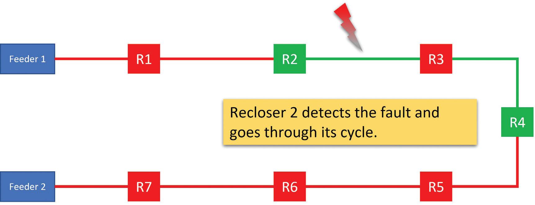
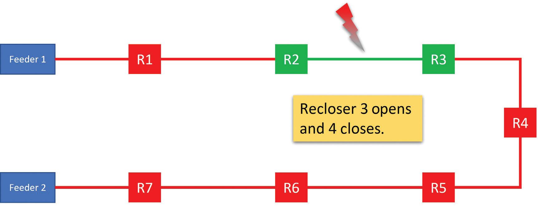
When a permanent fault occurs, e.g., between Recloser 2 and Recloser 3, Recloser 2 goes through its operation cycle and opens, leaving all customers between Recloser 2 and Recloser 3 without power as can be seen in Figure 2.
Since the fault happened between Recloser 2 and Recloser 3, only customers connected between those two reclosers should remain without power. An obvious solution is to open Recloser 3 and close Recloser 4 as can be seen in Figure 3.
In this example, after the fault between Recloser 2 and Recloser 3, the line section between Recloser 3 and Recloser 4 is now back in service. This can be done manually from a central control station but can be achieved without any human intervention if the proper algorithms are used.
Because of the reconfiguration operation presented in the example, Recloser 5, Recloser 6, and Recloser 7 now see a higher load than before the fault. This happens because they now see the additional load that corresponds to the line section between Recloser 3 and Recloser 4 that was previously fed from Feeder 1. Recloser 1 also sees a different albeit reduced load. Designing such systems also means making sure that both feeders can carry all the additional load from adjacent feeders.
Even the direction of the power flow at the recloser may be affected. For instance, if the fault occurred between Recloser 1 and Recloser 2, they will remain open at the end of the operation cycle and Recloser 3 will see an inversion in power flow as can be seen in Figure 4.


Also notice that for the TIE (Recloser 4), the direction of power flow depends on whether the fault happened on Feeder 1 or Feeder 2 as can be seen by comparing Figure 4 and Figure 5.
During regular operation, when no change has occurred on the network, a given recloser controller will maintain a fixed settings group. However, as soon as the network changes because of a reconfiguration operation, the protection and control settings on the controller must change to allow it to adapt to the new conditions. This means the settings group of the recloser will probably need to change owing to the new network conditions, and more than two settings groups may be required.
From the testing perspective, this means that all of the settings groups used in the automation will need to be tested for all reclosers that are affected by changes in the network.
Communications
Reconfiguration schemes can be implemented with or without any communication channels between the various reclosers.
In some algorithms that use a scheme without communications, the reclosers rely on the fact that whenever a recloser operates on a radial feeder, all other reclosers downstream suffer a momentary loss of voltage. In these cases, reclosers will count the number of times a loss of potential is detected and how long each loss of potential event lasts and use this information along with the direction of power flow at the time of the loss for their operation. When configuring and testing these schemes, it is important to adequately estimate and evaluate the limits — in magnitude as well as time — for a loss of potential.
In a scheme with communications, each recloser has a communications channel that is used to send status and permissive information
FEATURE
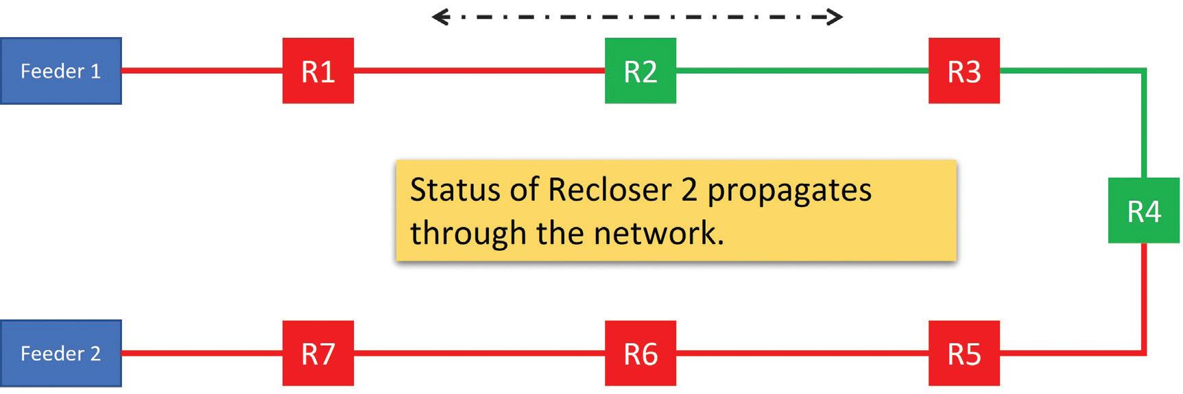
to a remote terminal unit as well as to other reclosers on the network as shown in Figure 6.
For security purposes, these communicationassisted schemes are preferred whenever communications channels are available.
The communication medium can be radio, leased lines, fiber optics, etc. Some of
these networks can use Ethernet, and the implementation of the algorithm can be done using proprietary communication protocols or standard protocols such as the distributed network protocol (DNP) or IEC 61850.
Testing
Testing the recloser itself is relatively wellknown and is not the focus of this article. A

typical recloser evaluation will include tests for insulation resistance, breaker contact resistance, operation sequence, minimum pickup, time current curves, operating time, single shot to lockout, reclosing time, total clearing time, and others. These types of tests are done on individual reclosers and should be performed as part of any commissioning or maintenance program. Methods for testing the recloser can be classified by the mode of signal injection: primary injection or secondary injection method.
Primary injection During primary injection, current is injected into the primary side of the recloser. This has the advantage of testing the functionality of the current sensors, and it can be considered a whole-system test for the recloser itself. However, this kind of testing requires the use of relatively large primary injection test sets capable of producing the high fault currents usually required to test this equipment. Additionally, when dealing with distribution automation schemes, it is often necessary for the tests to include the voltage inputs of the reclosers since they are part of the reconfiguration algorithms. This complicates testing using primary injection on these systems.
Secondary injection. Secondary injection, as the name implies, injects secondary values into the recloser controller’s current and voltage inputs. It has the advantage of using smaller, more flexible equipment with lower power requirements. These types of tests lend themselves to a high degree of automation. One challenge in testing reclosers with secondary injection is accessing the analog inputs and the digital inputs and outputs of the controller without significant rewiring. Modern test equipment exists that allows the user to connect directly to the controller’s connector and inject analog signals into the controller’s analog inputs while at the same time sending trip and reclose signals to the breaker and receiving breaker status information from the breaker. The breaker can also be bypassed altogether by simulating the 52a/b contacts directly from the secondary injection test set. Such a connection diagram can be seen in Figure 7.
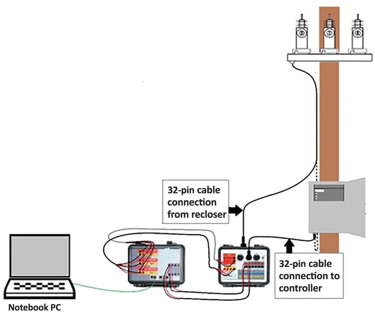

To test the recloser, a state sequencer is typically used to simulate a sequence of power system conditions like faults (trips) and idle (reclose) states as well as the operation of binary inputs and outputs. Figure 8 shows the changes in the root mean square (RMS) values of voltages and currents during the test as well as the expected operation of binary inputs and outputs. Binary Output 1 in this case is being used to simulate the 52a/b contacts. Binary Input 1 is being used for the trip signal.

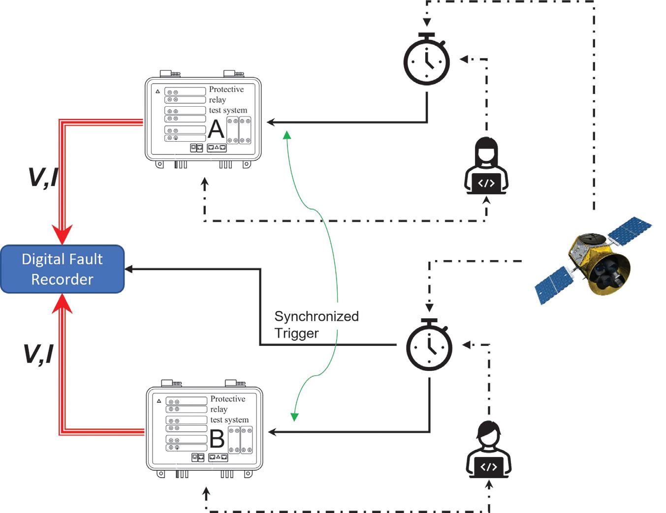
End-to-end testing. The purpose of testing distribution automation schemes goes beyond testing the individual elements of the scheme and should aim for verification of the whole system. For this purpose, end-to-end testing is used. During this type of test, the distribution automation scheme can be evaluated by simulating fault conditions simultaneously at different points of the feeders.
The relays inside the controllers receive currents and voltages from their own terminals and, in communications-assisted schemes, status and permissive data from relays on other parts of the scheme. For this reason, it is important to be able to synchronize the test systems on each end so that test quantities can be injected simultaneously into all the controllers involved.
A time signal from a global positioning system (GPS) clock can be used to synchronize multiple test systems. Time signals are available in various standards such as 1 pulse per second (PPS), precision time protocol (PTP), IRIG-B, etc. Using IRIG-B time
synchronization for end-to-end testing requires multiple relay test sets able to decode the IRIG-B signal. This signal is used to trigger the simultaneous injection of analog values. In some cases, the IRIG-B signal that is obtained from a GPS receiver can also be provided to the relays under test. During testing, the test sets can be synchronized independently of the timing mechanism used by the relays on the network.
In general, during an end-to-end test, the connections will be as shown in Figure 9.
As you can see, the typical setup consists of test sets and their operators on each of the terminals to be included in the test. A means of synchronization must be provided, in this case in the form of GPS clocks. Each operator must be able to communicate with its own test equipment, the relay under test, and the clock, as well as with the operators on the other end.
The sequence of tests to be injected into the reclosers on each end can be produced using a sequencer as was mentioned previously or, if dynamic testing is preferred, COMTRADE files containing transient waveform information from actual or simulated faults can be injected to perform the testing.
The test sets used on both ends will ideally have the same characteristics, i.e., the same brand, model, and firmware versions. When that is not the case, the synchronization procedure must include a means to compensate for the different injection delays caused by having dissimilar test sets. The measurement of such time delay can be done using the setup shown in Figure 10.
In the setup shown in Figure 10, simultaneous injection is triggered from both test sets, and the resulting waveforms are recorded in a digital fault recorder. The desired measurement will be the time difference between the injected signals from each test set as can be seen in Figure 11.


FEATURE
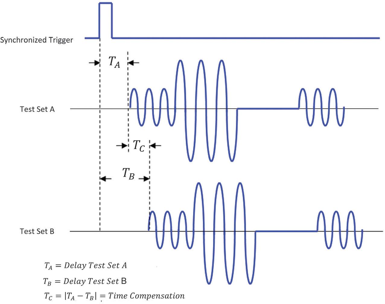
In Figure 9, only two terminals were shown for simplicity. A real-world test could consist of many terminals as can be seen in Figure 12.
SUMMARY
Reclosers are the brain and the muscle of the distribution system and must be tested thoroughly before being put into operation and again during every maintenance cycle.
Testing the recloser can be accomplished using a combination of primary and secondary injection methods. Modern test equipment allows for secondary injection testing of the recloser without any rewiring of the analog and digital inputs and outputs of the controller.
Reclosers are used in distribution automation schemes to provide higher reliability for customers. These schemes can be implemented using a variety of techniques. The most popular techniques involve means of communication between the reclosers in the field as well as the use of multiple settings groups on the recloser controllers.
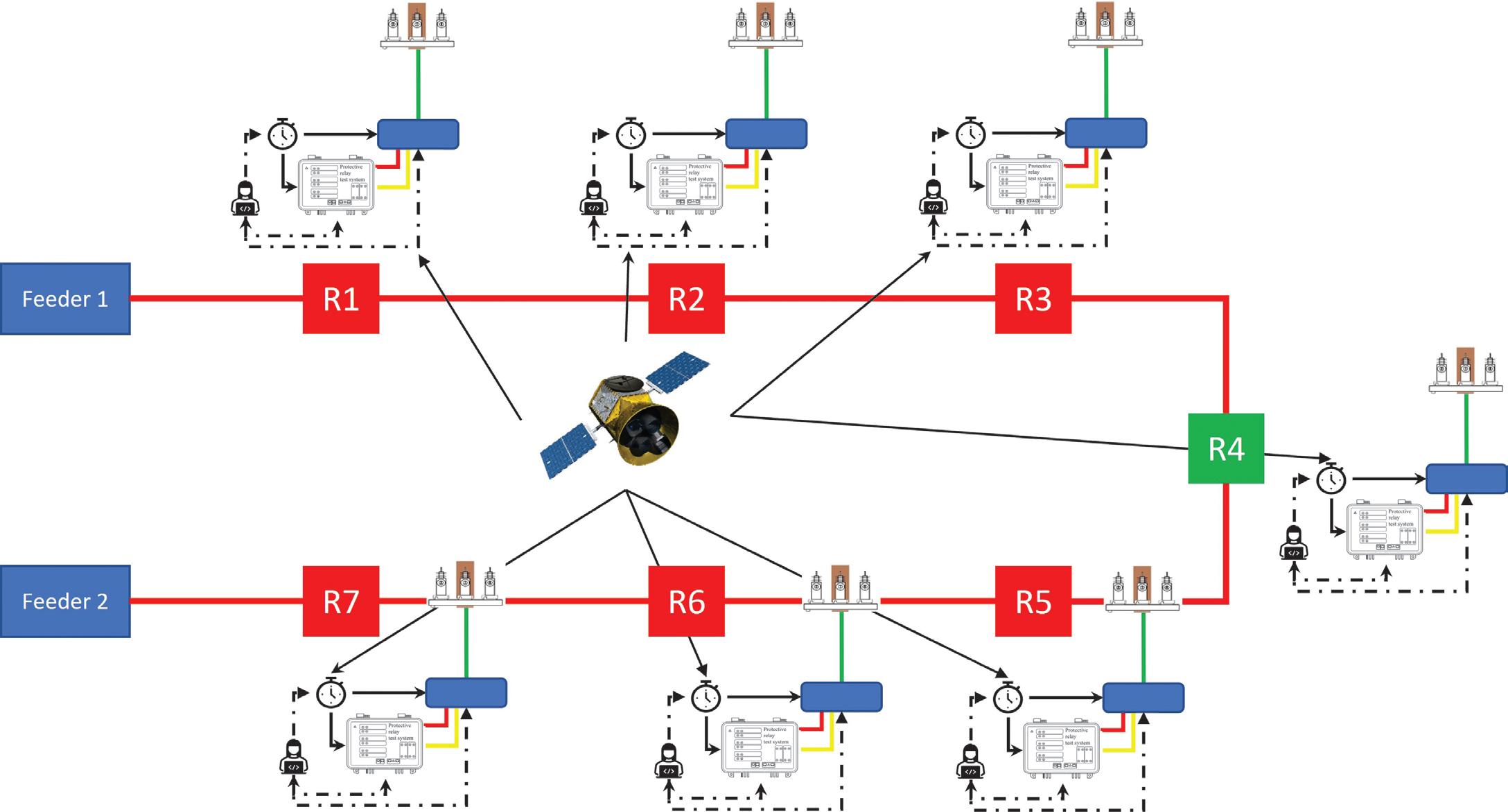
Testing these schemes can be accomplished using end-to-end tests. Using tools that allow for synchronized injection of signals at different locations is extremely important.
REFERENCES
[1] IEEE. IEEE Std. C37.104-2012, IEEE Guide for Automatic Reclosing of Circuit Breakers for AC Distribution and Transmission Lines.
[2] Robert E. Goodin; Timothy S. Fahey, PE; and Andrew Hanson, PE. Distribution
Reliability Using Reclosers and Sectionalizers. ABB. Available at https://library.e.abb. com/public/9a7bdfb0769f75c885256e2f004e7cd8/Reliability%20Using%20Reclosers%20and%20switches.pdf
[3] James Ariza, G. Ibarra. “Application Case of the End-to-End Relay Testing Using GPS-Synchronized Secondary Injection in Communication-Based Protection Schemes,” NETA PowerTest 2023
[4] Sughosh Kuber. “End-to-End Testing for Line Differential Protection,” NETA World, Winter 2019. Available at https:// netaworldjournal.org/end-to-end-testingfor-line-differential-protection/

Abel Gonzalez is a Senior Relay Applications Engineer with Megger LTD in Markham, Ontario. He previously worked as a Design Engineer for Arteche Medición y Tecnología in Zapopan and Jalisco, Mexico, and Curitiba, Brazil. Abel’s research areas are the analysis operation, control, and protection of electric power systems. Earlier in his career, he worked as a Tele-traffic Engineer, Control Engineer, and head of the Marketing Department for the Cuban Telecommunications Company. Abel is a member of IEEE-PSRC. He received his BS and MSc in electrical engineering from the Universidad Central de Las Villas, Cuba, and was later an Assistant Professor for the Faculty of Electrical Engineering at the Universidad Central de Las Villas, Cuba, where he taught courses in electrical drives and power electronics.

NEW FOR 2023: NFPA 70B
BY DAVE HUFFMAN, Power Systems Testing Company, and RON WIDUP, Shermco Industries
It was late in 2017 when the notice for the Second Draft meeting for the 2019 edition of NFPA 70B, Recommended Practice for Electrical Equipment Maintenance came out, and within the agenda was an item to discuss the 2023 edition. COVID-19 wasn’t even a thought for any of us. Social distancing, masking up, and quarantine were unheard of, and Teams/Zoom video conferencing wasn’t even a thing. (Ahh, the good old days!)
The meeting took place in January 2018 in San Antonio, Texas. Here, public comments were addressed, changes were made, and the document was prepared for the final Second Draft. It was at this point that task groups were formed, sections of the document were placed into a “sunsets” category, and rewriting the just-finalized edition of NFPA 70B began the journey from a recommended practice to a standard.
RECOMMENDED PRACTICE OR STANDARD – WHAT’S THE DIFFERENCE, AND WHY IS IT IMPORTANT?
For many decades, the previous editions of 70B, including the previous 2019 edition, were published as a “recommended practice.” The key point here is to know that a recommended
practice does not contain mandatory requirements. It is, by definition, just as it says: a recommendation on how to do things.
Statements such as “should” and “may” are cornerstones of the text within a “recommended practice” document.
With the release of the 2023 edition as a standard, that all changed. A standard is just that: “something established by authority, custom, or general consent as a model or example.” So now, NFPA 70B, as a standard, contains mandatory language for the maintenance of electrical equipment. You will see terms such as “shall” and “will” in the newest version of the document, and it is these actionable terms that make the outcomes mandatory and enforceable. You shall do it!

A MONUMENTAL TASK: THE REWRITE
The task groups proceeded immediately, working on segregating much of the “what to do” from the explanatory material, which proved to be more of a task than many originally thought. From a user’s standpoint, the new text structure and words may take some getting used to. All of the explanatory material has been moved to the Annex, so it was not lost from the original document as it includes material from a plethora of industry experts’ experiences and knowledge. The Annexes include the familiar Reliability Centered Maintenance, Power Quality,
Electrical Disaster Recovery, and Sample Forms sections, among other topics.
One of the next things to tackle was the formatting of the tests to be performed. Early on, the committee worked together to develop a table where tests would be listed down the Y (vertical) axis and equipment across the X (horizontal) axis. While not all tests would be required for a particular piece of equipment during routine maintenance, some may only be needed when other tests indicate a possible issue but are not conclusive. We differentiated these tests by calling them “enhanced” tests. And while most tests are performed while the
SPECIAL FEATURE
(EXAMPLE) Table 13.3.5
Panelboard and Switchboard Electrical Testing
No. Task
1 Check electrical hardware connections. NA See Chapter 7.
2 Measure insulation resistance of the main bus. 2 3 Measure insulation resistance of control wiring. 2A
4 Test protective devices and systems. 2
For surge protective devices, surge arresters, and arc-fault energy reduction systems, see the manufacturer’s instructions.
5 Perform system operational tests. 1 or 2 Includes emergency or standby power systems.
6 Test control power transformers, instrument transformers, and metering to ensure correct operation. 2
7 For individual components, refer to the chapter(s) of this standard. NA
8 Where environmental controls are provided, check for correct operating condition. 1 or 2
NA: Not applicable.
Includes, but is not limited to, fans, heaters, thermostats, and humidity control equipment and settings.
*Types specified in accordance with Section 8.3 as follows: Type 1 = online standard test; Type 1A = online enhanced test; Type 2 = offline standard test; Type 2A = offline enhanced test.
equipment is out of service and de-energized, some tests require the equipment to be operating and energized (a thermographic scan, for example).
Because of these testing variables, four testing category types were developed: Categories 1, 1A, 2, and 2A. A Category 1 test is an online standard test. Category 1A is an online enhanced test. Category 2 and Category 2A are the offline counterparts. Placing everything that might be performed on any piece of equipment into one table produced a very large table, so inspections and tests were divided between three tables: Visual Inspections, Mechanical Servicing, and Electrical Testing. Table 13.3.5: Panelboard and Switchboard Electrical Testing provides an example.
Going into 2020, each task group continued their work on various chapters. Bi-weekly, twohour, web meetings were held, and the 70B committee was fortunate to get accustomed to remote video meetings before COVID arrived as there were many hours of video meetings! This work continued into 2021 and then 2022. Some sessions were definitely easier than others, but some of the later ones were over eight hours long for the entire week. Even through all of that, the committee worked very well together.
After the first draft was published, the public comments had to be addressed. The newlyformed task groups would each review a certain number of public inputs and then present a proposed response to the entire committee.
Moving into a standard also meant certain wording couldn’t be used; for example, wording that was vague, ambiguous, or could have multiple definitions had to be replaced. Each task group began looking for and reworking text that was outside the style manual. Some examples include terms such as “generally,” “likely,” or “mostly.” These are all subjective in nature and will be interpreted differently between individuals — or even between moods for the same individual.
In the end, we ended up with a document that is a standard that promotes the safe operation and maintenance of electrical equipment. Safety is a cornerstone of the document. No maintenance activity should place a worker in harm’s way; that’s certainly never the intent. I recall a presentation regarding safety where the speaker suggested that anyone who holds safety as a first priority is simply wrong; priorities change in a heartbeat, but safety never should. So it’s not a priority, it’s a principle.
SUMMARY
The purpose of NFPA 70B is:
To provide for the practical safeguarding of persons, property, and processes from the risks associated with failure, breakdown, or malfunction and a means to establish a condition of maintenance of electrical equipment and systems for safety and reliability.
And that falls right into what we strive to do as an industry each and every day.
Get your copy of this very important document and read and understand the requirements of the 2023 edition of NFPA 70B, Standard for Electrical Equipment Maintenance at NFPA.org. Print copies will be available after April 14, 2023.

David Huffman has been with Power Systems Testing, a NETA Accredited Company, since January 1988 and is currently CEO. He graduated from California State University, Fresno, and is a licensed Professional Electrical Engineer in the state of California as well as a NETA Level IV Certified Technician. David is a NETA board member, NETA’s Principal Representative to the NFPA 70B Committee, and serves as a member of various NETA committees.

Ron Widup is the Vice Chairman, Board of Directors, and Senior Advisor, Technical Services for Shermco Industries and has been with Shermco since 1983. He is a member of the NETA Board of Directors and Standards Review Council; a Principal member of the Technical Committee on Standard for Electrical Safety in the Workplace (NFPA 70E); Principal member of the National Electrical Code (NFPA 70) Code Panel 11; Principal member and Chairman of the Technical Committee on Standard for Competency of ThirdParty Evaluation Bodies (NFPA 790); Principal member and Chairman of the Technical Committee on Recommended Practice and Procedures for Unlabeled Electrical Equipment Evaluation (NFPA 791); a member of the Technical Committee Recommended Practice for Electrical Equipment Maintenance (NFPA 70B); and Vice Chair for IEEE Std. 3007.3, Recommended Practice for Electrical Safety in Industrial and Commercial Power Systems. He is a member of the Texas State Technical College System (TSTC) Board of Regents, a NETA Certified Level 4 Senior Test Technician, State of Texas Journeyman Electrician, a member of the IEEE Standards Association, an Inspector Member of the International Association of Electrical Inspectors, and an NFPA Certified Electrical Safety Compliance Professional (CESCP).
ACCEPTANCE AND MAINTENANCE TESTING FOR MEDIUM-VOLTAGE ELECTRICAL POWER CABLES — PART 3 OF 3

BY THOMAS SANDRI, Protec Equipment Resources
In Part 2 of our three-part series on acceptance and maintenance testing for medium-voltage electrical power cables, we explored high-potential testing techniques, including tests performed with direct current (DC) and alternating current (AC) performed at power frequency and at very low frequency (VLF). We also explored diagnostic testing and reviewed dissipation factor (tan delta) testing.
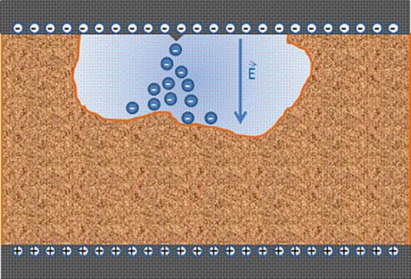
In Part 3, we peer into the world of on-line and off-line partial discharge (PD) testing.
PARTIAL DISCHARGE
Partial discharge is defined in IEC 60270 as:
…a localized electrical discharge that only partially bridges the insulation between conductors and which can or cannot occur adjacent to a conductor.
When the voltage stress exceeds the breakdown strength of that portion of the insulating
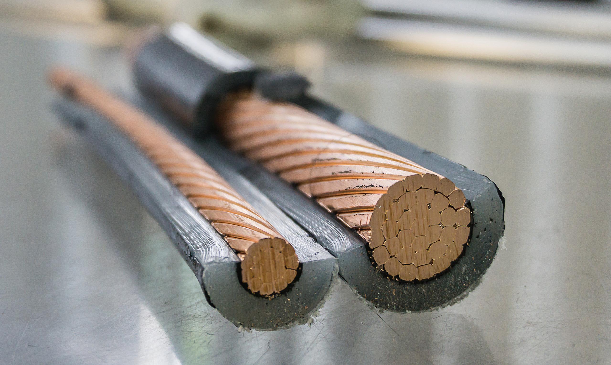
PHOTO: ©
material, a partial discharge begins (Figure 1) and continues to deteriorate that insulation. When partial discharges occur, various physical and chemical changes may also produce emissions that we can detect, localize, and characterize to provide the information needed to prevent insulation failure in medium- and high-voltage electrical equipment.
Partial discharge occurs in solid, liquid, or gaseous insulating mediums. PD can also occur in the form of corona, surface tracking, or floating-electrode metal-to-metal discharge, causing degradation of the insulation. NFPA 70B, Recommended Practice for Electrical Equipment Maintenance, states that insulation breakdown is the number-one cause of electrical failures, and once PD begins, it will always get worse.
There are two sets of resistances: materials and air voids. In some materials, the insulating medium is not completely solid or uniform, so there may be air voids. The resistance of the material is higher than the resistance of
the air gap, meaning the insulation has a higher dielectric strength than the air pocket. As voltage is applied, the voltage stress across the air gap is higher than on the insulation. The walls of the gap are stressed and begin to break down or ionize (Figure 2). Eventually, these ions build up, the resistance of the air
50/60 Hz phase-toground voltage
gap breaks down, and a discharge across the gap occurs. This can potentially leave semiconductive residue or carbon behind, which is conductive, kind of like a stress crack on the insulation.
Over time, this residue will build, creating a full discharge from one conductive surface to another.
PARTIAL DISCHARGE INCEPTION VOLTAGE AND EXTINCTION VOLTAGE (PDIV/PDEV)
For partial discharge to occur, sufficient voltage must be applied to the system under test to meet the minimum voltage required to initiate partial discharge activity. This is known as the partial discharge inception voltage (PDIV). Once the PDIV has been reached, the voltage may be lowered, and PD will remain present at the lower voltages until they finally extinguish at what is referred to as the partial discharge extinction voltage (PDEV). The PDEV is therefore less than the PDIV.
If the PDEV voltage level is lower than the system operating voltage (phase-to-ground), this implies that an over-voltage surge on the system could initiate PD, and the PD activity could continue even when the system voltage returned to normal. PD that can continue at operating voltage is therefore more likely to result in insulation failure than PD that extinguishes above normal operating voltage. PD that occurs at the operating voltage level can be detected through on-line detection methods. However, to gain a full understanding of PDIV and PDEV, you would need to adjust the voltage source, which can only be accomplished in an off-line test.
PARTIAL DISCHARGE PARAMETERS
Partial discharges are a consequence of local breakdown due to (a) an electric field enhancement within or on the surface of the insulation or (b) a region of low breakdown strength. Partial discharges appear as individual events of very short duration always
accompanied by emissions of light, sound, and heat, as well as electromagnetic pulses, and often result in chemical reactions.
The PD parameters usually measured during tests on installed cable systems include:
• PD inception voltage: PDIV (off-line tests)
• PD extinction voltage: PDEV (off-line tests)
• PD location
• PD magnitude (q)
• PD repetition rate (n)
• PD density: density of discharges measured per unit of time and per unit of length (laminated cable only)
• Phase angle of PD pulse (Φ) given by Φ = 360 (ti/T), where ti is the time measured from the preceding positivegoing transition of the sinusoidal test voltage through zero to the PD pulse, and T is the period of the test voltage
• Phase-resolved PD plot (n vs. Φ vs. q)
• PD magnitude vs. voltage plot (q vs. V), (off-line tests)
The characteristics of partial discharge parameters depend on:
• Type and location of defects, such as PD sources, in the insulation system
• Insulating material
• Operating conditions such as applied voltage, load, and time
• On-line tests can measure q, n, and Φ at operating temperature, whereas off-line tests are performed on cable systems that have cooled down.
UNDERSTANDING DIELECTRIC MATERIALS
Water treeing is an important form of degradation that can afflict older HMWPE and XLPE extruded cables. At the site of a water tree, the insulation is degraded, i.e., has a higher dielectric constant and lower dielectric strength than the original insulation (Figure 3). Water tree growth under service conditions is a very slow process, usually taking many years to
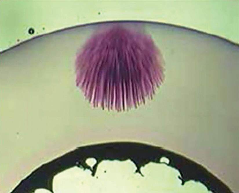
completely penetrate the insulation. Water trees do not generate partial discharge. However, when subjected to high electrical stresses, water trees can lead to electrical trees because of a lightning impulse, a switching or DC overvoltage, a high AC voltage, or when the tip of the water tree approaches a conductor or insulation shield. There is no evidence of water treeing being an important issue with EPR or TRXLPE cables.
It is important to know the materials being tested to better interpret PD data as the resistance to damage by PD depends on the insulating material. The order of PD resistance from least resistant to most resistant is XLPE << EPR << laminated (i.e., fluid-impregnated paper). Cable accessories, often made with filled rubber, may have high endurance to PD activity provided this does not occur adjacent to extruded cable insulation.
Shielded distribution cables fall into two classes: PD-free and PD-resistant. PD-resistant cable can sustain substantial amounts of PD over long periods of time without failure. PDfree cable can be formulated with a range of dielectrics, having low PD resistivity. However, for both types of cable, certain forms of PD will eventually cause failure, whereas other forms of PD can continue almost indefinitely without failure. Knowledge rules, which give objective guidance for the interpretation of measured data for the different materials in use, are necessary.
TESTING FOR PARTIAL DISCHARGE
Partial discharge pulses are very short, typically 1 ns to 5 ns wide, and they can have significant frequency components up to 1 GHz at their source. Two general approaches are available to detect PD pulses in installed cables: off-line and on-line detection. Off-line testing is normally carried out using a separate voltage source after the cable has been removed from service. Online (in-service) testing is carried out during normal operation of the cable system.
Advantages of off-line PD testing:
• PDIV and PDEV can be measured if a variable voltage source is used.
• PD characteristics can be obtained at various voltages, which can aid in identifying certain types of defects.
Advantages of on-line PD testing:
• PD characteristics can be obtained under varied load conditions, which can aid in the identification of certain types of defects.
• Tests can be performed without having to take an outage.
LOCATING PD IN CABLE SYSTEMS (MAPPING)
When PD activity occurs, high-frequency current pulses are created and will propagate along the cable. These high-frequency current pulses will propagate in both directions along the cable and can be used to locate the PD activity.
When partial discharge occurs in a cable system, two pulses of similar size and characteristics propagate away from the partial discharge site toward the terminations (Figure 4).
Depending on the cable insulation type, shield construction, and other factors, the speed at which the pulses travel is relatively consistent. For instance, partial discharge pulses travel at a speed of approximately 468 feet per microsecond (142.65 meters / u-sec.) in XLPE insulation.

cosine-pulse
Mapping can be a challenge when conducting on-line tests and may require multiple test points to assist in mapping. Off-line mapping offers the advantage of isolating the cable under test, thus making the mapping process easier and more accurate.
PHASE-RESOLVED PD PATTERNS
Using phase-resolved partial discharge patterns is a method of comparing incoming signals to the AC power frequency or AC test voltage.
The PRPD charts (Figure 5) are shown in realtime. The horizontal x-axis is the phase angle of the power system under test. The x-axis is labeled from 0 to 360 degrees. This is the same thing as 0 to 16.667 ms, which is the time it takes for one cycle of the AC power frequency. The vertical y-axis represents the amplitude of the signal. This amplitude depends on the strength of the signal and the distance from the sensor to the PD event.
We know that PD signals are produced as the sine wave reaches a positive or negative peak (or trough) or peak voltage stress. The sign wave peaks and troughs are exactly 180 degrees apart (16.66 / 2 = 8.3 ms). The PD pulses continue to arrive with intervals equal to 8.3 ms or multiples of 8.3 ms (180 degrees apart) with some fluctuation due to PD inception and extinguish points. As the insulation deteriorates, the PD will begin earlier and extinguish later as its ability to withstand the voltage stresses diminishes. Meanwhile, all the other noise and other signals in the detection bandwidth of the sensor will arrive at random time intervals that are not equal to 8.3 ms. Noise arrives at random points along the x-axis, whereas PD pulses only arrive 180 degrees apart.
EFFECTS OF SHIELD TYPE
In most industrial facilities, a large percentage of the cables are of the tape-shield design where overlapping layers of copper tape are wrapped around the insulation shield of the cable. In addition, widespread use of EPR insulation is found in industrial plants. In contrast, the electrical utility distribution sector tends to use concentric neutral wires instead of tape design for the ground shields and XLPE for the insulation.
The concentric neutral wires hold a certain advantage as the cable matures and begins to show signs of service age. As tape-shielded cable ages and corrosion of the copper tape occurs, particularly at the overlap of the consecutive tape layers, the cable starts to attenuate high frequencies. Even with slight corrosion of the overlapping layers, the cable shield starts to
CORPORATE ALLIANCE CORNER — ADVANCEMENTS
behave as a coil or inductor to high frequencies. The net effect of this attenuation is that a PD detection system connected to a cable may not always detect the high-frequency PD pulse as it would be so attenuated by the time it reaches the PD monitoring equipment. The further away the detection equipment is from the active PD site, the more severe this limitation. This limits the effectiveness of partial discharge testing on tape-shielded cable.
NOISE INFLUENCE
Another consideration when comparing on-line and off-line measurements is the effect of noise on the measurement. In the off-line approach, the detection equipment can be calibrated at the time of the test by injecting a known PD pulse level into the specimen under test. This is not possible with the on-line approach. Further, cables can be isolated during off-line testing.
When detecting PD activity using on-line methods, further analysis will typically be necessary to ensure that the suspect activity was not caused by external noise or activity generated upstream or downstream of the cable section under investigation. It will also be advantageous to locate the source of the partial discharge activity and to quantify and assess the severity of the problem. This can be accomplished by measuring and analyzing activity over time to detect deterioration and to raise an alarm or call to action if PD activity reaches a critical level. As an example, if PD activity that is intermittent or possibly influenced by environmental conditions (changing temperature, humidity, or electrical noise) is found, temporarily installed multisensor systems that automatically monitor your plant can be utilized.
ONLINE PARTIAL DISCHARGE TEST
As stated earlier, when PD occurs, small current pulses are induced onto the ground shield or case ground. These pulses will travel dozens of meters along the ground grid in the form of high-frequency current pulses ranging from 500 kHz to 50 MHz, usually centered near 10 MHz. Using high-frequency current
transformers (HFCT) is a reliable method to measure these high-frequency PD pulses, which spread out onto the ground grid like ripples in water. They are especially useful for quickly testing for internal PD in a large area such as an entire power transformer or an entire cable, or even an entire substation. The HFCT sensor has a split core, so it’s simply clamped around a lowresistance grounding lead. HFCT sensors have the distinct advantage of being able to detect PD signals on cables from long distances up to 1 km away (this limit depends on the type of ground shield and the strength of the PD pulse). This means multiple PD signals and noise signals can also be detected from many points on the ground grid where a grounding lead is exposed.
The test requires the attachment of these HFCTs to the metallic cable shields (Figure 6). This presents several safety risks and is considered energized work. To perform this task, the technician must enter the restricted approach boundary and, depending on the layout of the cable landing, restricted or blind reaching may be required. This is a violation of the NFPA 70E requirements for work involving electrical hazards. The task also requires connecting conductive materials within the restricted approach boundary, which raises the risk of shock or arc flash occurrence.
The challenge in performing the on-line partial discharge test on energized electrical power cables is safely connecting the HFCTs. Perhaps
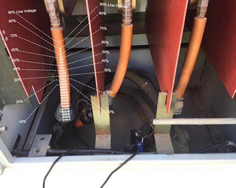
the best solution is to use engineering controls from the hierarchy of risk control methods.
One engineered approach would be to preinstall the HFCTs into the cable landing compartments. The coax cables can be safely routed along the inner panels of the compartment and then brought out through a bulk-head adapter. Testing can then be carried out safely at any time by simply connecting the scanning equipment to the test connector on the bulkhead adapter.
Another approach is to bring the cable shields out of the cable landing compartment. This can be accomplished by punching a small hole in the cabinet and extending the cable shields out of and then back into the cabinet, forming loops outside of the cabinet allowing HFCT attachment. The ground loops are then enclosed in a NEMA compartment mounted to the cabinet.
OFF-LINE PARTIAL DISCHARGE TEST
On-line PD testing has the obvious advantage that it does not require disconnecting or an outage. The main disadvantage when testing cables under operation is that the test is only performed at the operating voltage level and cannot be adjusted. Obviously, if the applied voltage is fixed and cannot be changed, the PDIV and PDEV voltages cannot be determined, and therefore, in comparison to off-line testing where voltages can be adjusted to simulate transients or other over-voltage conditions, a lower percentage of defects in the cable’s insulating system can be detected through on-line methods.
Power Frequency and Alternative Test Voltage Sources
As stated earlier, for partial discharge to occur, sufficient voltage must be applied to the system under test to meet the minimum voltage required to start partial discharge activity. When testing cables, the on-line testing approach uses a system voltage of a constant fixed magnitude. In an off-line approach, a temporary voltage source will be required.
Considerations for an off-line voltage source should include:
• The applied voltage should cause partial discharges in the insulating system under test that has characteristics close, if not identical, to those that occur when the insulating system is in service.
• The temporary voltage source should cause no appreciable damage to the insulating system during the time required to perform the measurements.
• The temporary voltage source should have a variable voltage output so that PDIV and PDEV tests can be performed.
• The size and weight of the equipment required to produce the voltage levels required for testing various assets must be considered. Is the equipment to be used in a fixed location or used in a field application?
Voltage sources that are used for commercially available field partial discharge measurement systems will fall into the general categories of power frequency and alternative voltage sources such as very-low frequency (VLF).
VLF Test Voltage
Depending on the type of defect, sinusoidal VLF voltage sources, usually 0.1 Hz, for extruded dielectric systems may require a higher test voltage to generate the same partial discharge level compared with tests performed with power-frequency voltages. For example, the conductivity of the surface of a cavity that has been exposed to PD increases, which allows any charges deposited on the surface by PD to leak away; this lowers the electric field in the cavity. As more charge can leak away between polarity reversals at VLF than at power frequency, the PDIV at sinusoidal VLF will be larger than that at power frequency (Figure 7). If there has been no previous PD activity to increase the conductivity of the cavity surface, the PDIV at sinusoidal VLF and power frequency will be similar (see IEEE Std. 400.3).
A VLF cosine-pulse waveform generates a 0.1 Hz bipolar pulse wave that changes polarity
CORPORATE ALLIANCE CORNER —
sinusoidally. Since the sinusoidal transitions are in the power-frequency range, the PDIV measurement will be comparable to power frequency. The VLF cosine-pulse voltage works according to the principle of 50/60 Hz slope technology.
This is particularly important for PD diagnosis since reliable evaluation of the measured results requires direct comparability with the power frequency. Partial discharge characteristics change in the case of large frequency differences, making reliable evaluation of power frequency impossible. The 50/60 Hz slope technology ensures comparability for both voltage wave shapes.
Figure 8 shows a typical example of how PD measurement is carried out during the slope of the applied voltage. The steepness of the VLF cosine-pulse slopes in comparison to the 0.1 Hz sine wave can be seen. It is precisely this rise in voltage that is so important for the PD inception voltage. Therefore, the 0.1 Hz sine wave test voltage cannot be directly compared to the 50/60 Hz power frequency, and critical partial discharge defects are therefore not always reliably detected.
Damped AC Voltage (DAC)
Another approach to reduce the size and weight of the test voltage supply from that of a conventional power frequency supply is the damped AC voltage (DAC) technique. For partial discharge analysis, the cable under test is charged to the pre-selected peak value by a direct current high-voltage source within a couple of seconds and then shorted with an electronic switch via a resonance coil.
Thus, a sinusoidal oscillating AC voltage with low damping is created (Figure 9). The frequency is fixed in a range from 50 Hz to several hundred Hz, depending on the capacitance of the test object. Since the frequency of the test voltage is close to nominal service conditions, all measured PD activities can be effectively evaluated and compared to that of power frequency. Due to the decaying amplitude of the test voltage,
sine wave
sine wave
VLF sine wave VLF sine wave
VLF sine wave
VLF sine wave
∆T cosine shape transition, approx. 2 to 6 ms
∆T cosine shape transition, approx. 2 to 6 ms
∆T cosine shape transition, approx. 2 to 6 ms
8:
Exponential decay curve
Exponential decay curve
Exponential decay curve
cosine-pulse 50/60 Hz
Hz
cosine-pulse 50/60 Hz
cosine-pulse
CORPORATE ALLIANCE CORNER — ADVANCEMENTS IN
the partial discharge extinction voltage can be easily determined.
SUMMARY
As we had seen in this three-part series, numerous insulation tests are available to assist in assessing the quality and condition of a cable’s insulation. The pass/fail tests provide the means to identify gross defects, while the diagnostic tests provide us with an understanding of the severity of degradation or the extent of contamination in the insulation.
Technology and philosophies toward testing have advanced over the past 30-plus years and push toward predictive maintenance solutions. A key element in predictive maintenance is monitoring the trend of diagnostic test results. Not all tests are appropriate to all circumstances, nor can any single test give you the complete answer. Each type of test serves

as a window looking into the condition of the cable, and by putting together several different tests, you build a more complete picture.

Thomas Sandri is Director of Training Services at Protec Equipment Resources, where his responsibilities include the design and development of learning courses. He has been active in the field of electrical power and telecommunications for over 35 years. During his career, Tom has developed numerous training aids and training courses, has been published in various industry guides, and has conducted seminars domestically and internationally. Thomas supports a wide range of electrical and telecommunication maintenance application disciplines. He has been directly involved with and supported test and measurement applications for over 25 years and is considered an authority in application disciplines including insulation system analysis, medium- and high-voltage cable, and partial discharge analysis, as well as battery and DC systems testing and maintenance. Tom received a BSEE from Thomas Edison University in Trenton, New Jersey.


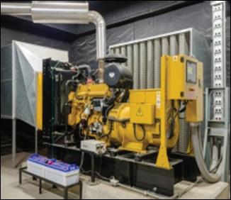


PREVENTATIVE ELECTRICAL MAINTENANCE PROGRAMS
DATA CENTERS, COMMERICAL HIGH RISES, CRITICAL ENVIRONMENTS & FINANCIAL INSTITUTIONS
DEVELOPMENT & UPDATES OF ELECTRICAL SINGLE LINE DIAGRAMS
EMERGENCY GENERATOR & PARALLELING SWITCHGEAR TESTING
SITE SPECIFIC SAFETY & TECHNICAL TRAINING 24 HR EMERGENCY SERVICE
INFRARED SCANNING
ACCEPTANCE TESTING
ENGINEERING STUDIES · ARC FLASH, SHORT CIRCUIT & COORDINATION STUDIES
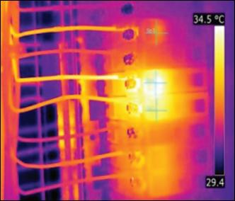
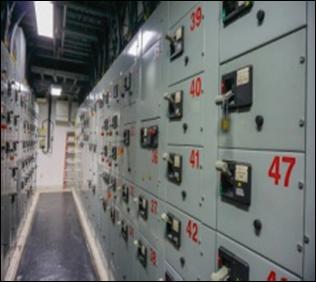

NFPA 70E Training
Get Your Workers Certified to the 2021 Standard!
Electrical Safety for the Qualified Worker training is aimed at qualified electrical workers to help them build capabilities, knowledge and safe work practices when working around energized electrical systems. Protec Equipment Resources now offers a live online instructor-led 2.5 day course that meets the NFPA 70E ® 2021 standard for electrical safety in the workplace!

Live Instructor-Led
People taking this class for the first time are required by the 70E 2021 standard to take it “live”. Whether online or in-person, to be compliant, there must be interaction and engagement with an instructor.


Great Price
Less expensive than in-person programs, with more curriculum and volume discounts!
Strongest Content Offering
20 hours (2.5 days) of practical tutorial that includes grounding as a topic!
Conveniently Consistent and Flexible
Virtual live online classes at a known date and time every month! Enroll 1 or 30.
Reduces Travel Time and Costs
Minimize workers’ time away from the office; eliminate the cost of travel and per-diems.
High Level of Instruction
Train with Tom Sandri, well-known in the electrical testing industry with over 30 years of experience. Tom was certified by a committee member and writer for the 70E certification.
FOR MORE INFORMATION
Scan the QR Code below with your phone’s camera and click the link that appears



Tom Sandri Director of Technical Services
PROTEC EQUIPMENT RESOURCES: QUALITY, SAFETY, RELIABILITY
NETA’s Corporate Alliance Partners (CAPs) are industry-leading companies that have joined forces with NETA to work together toward a common aim: improving quality, safety, and electrical system reliability.
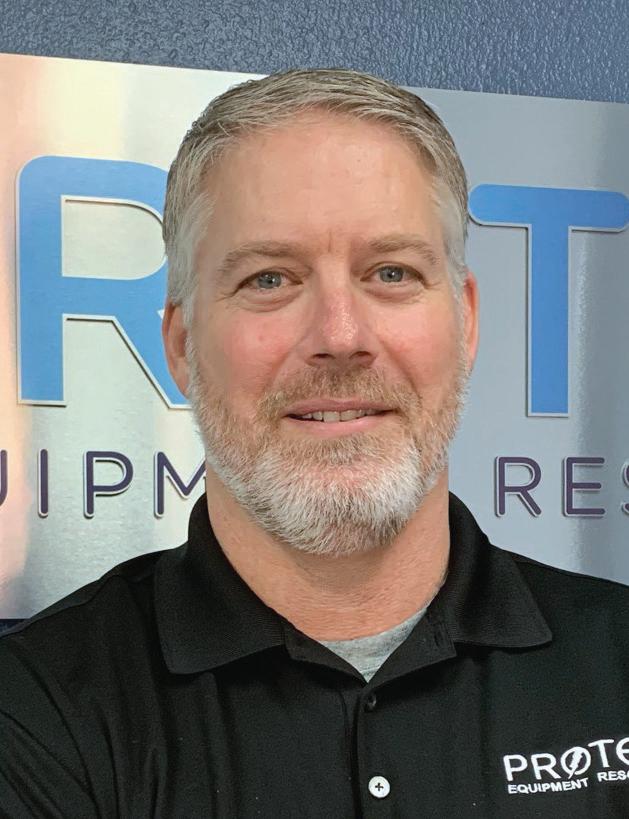
In our continuing Partner Spotlight series, NETA talks to President Jason Henry about the thought leadership and subject-matter expertise at Protec Equipment Resources. Henry spent 26 years working for a NETA company, including 15 years as a Field Service Technician; the remaining years were in leadership roles within operations. “The knowledge I acquired over the years working for a NETA company has helped me significantly with transferring into a role with Protec Equipment Resources, where I have been for the last year and a half,” Henry says.
NWJ: What are the biggest challenges facing your company right now?
Henry: The supply chain is still an issue we deal with constantly. It amazes me how fast the supply chain diminished, and how slow it is to recover.
Another challenge we face is the lack of people in the workforce who are willing to show up
to a job and put in a day’s work. It seems like a majority of the available workforce want to work from home, and there are very few positions in the electrical service industry that can accommodate this.
NWJ: What are the biggest challenges facing your customers?
Henry: I believe the biggest challenge facing our customers today is keeping the focus on two
CORPORATE ALLIANCE CORNER — PARTNER
things: 1) quality of work and 2) safety. Private equity is rapidly consuming this industry, and if checks and balances are not taken, quality of work, workforce development, and safety can drop in importance as corporate focus turns to profit margin and billable hours. I understand everyone wants to turn a profit, and I firmly believe that the quality of work, the knowledge and skills of a company’s employees, and the focus on safety drive this. However, in no way am I saying that private equity is a bad thing provided we do not sacrifice quality, training, and safety for profit and billable hours.
NWJ: Which industry trends are you keeping an eye on?
Henry: There is a big emphasis on renewable energy at this time in our industry. To be competitive, it is imperative that we stay up to date with the evolution of this technology. To better serve our customers, we have added several pieces of test equipment to our inventory that are unique to this market sector.
NWJ: Are any of the new technologies affecting the industry changing the way you work?
Henry: For years, a couple of test equipment manufacturers have cornered the market and created a monopoly. Now, several smaller test equipment manufacturers are putting out some high-quality test equipment that is seeing success in capturing a decent market share. I believe we will soon see some significant growth from some of these smaller manufacturers, giving technicians quality options that they have not had in the past.
NWJ: What do you predict will impact your business most in the near future?
Henry: I believe technology will have the largest impact on our business. Test equipment is getting much smarter. One negative consequence of this is that there are more button pushers out there who have less knowledge about what they are doing. If we want to be successful, we must be willing to
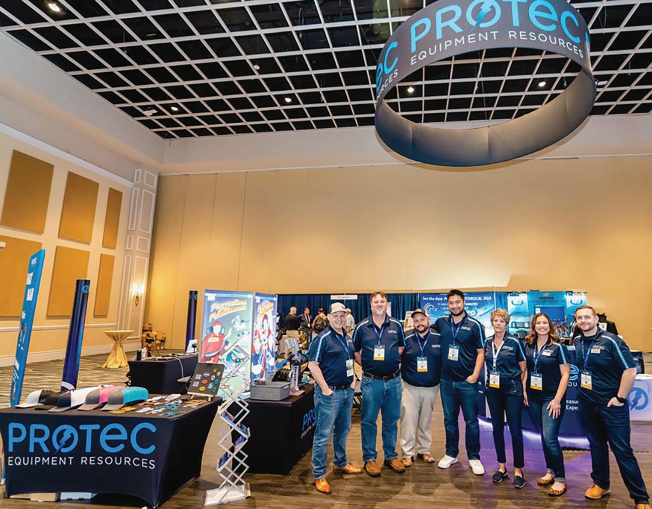
evolve along with the technicians in the field, stay up to date, and stock the latest and greatest test equipment.
NWJ: Is this a good time to be in the electrical power testing business?
Henry: It is always a good time to enter this field because it is not going anywhere. Everyone needs a dependable electrical system to be successful. It doesn’t matter whether it is a data center or a hospital, they will not be successful unless they have a dependable electrical system. This is why it is very important to perform preventative maintenance and testing on a regular basis. This gets overlooked too often, and it’s not until the customer has a major failure that they understand why preventative maintenance and testing are so important.
NWJ: If you could change one thing about how your business operates, what would it be?
Henry: I want to see us improve on our offerings to better fit our customer base and allow us to expand into other sectors of the market as well.
CORPORATE ALLIANCE CORNER — PARTNER SPOTLIGHT
NWJ: What advice do you have for young people entering the field? What do you wish someone had told you when you got started in electrical testing?
Henry: Stick to your decision to pursue the electrical field because, unlike other industries that fluctuate up and down, the electrical industry will always be here. This is a field you can build your career on. It will be as strong if not stronger on your last day of work before retiring as your first day in the industry.
NWJ: How important is mentoring in the electrical testing field and why? What has been your personal experience with mentoring?
Henry: Mentoring in the electrical testing field is crucial to a company’s success. This
should be emphasized not only for technical training but even more so for the safety side of things. You do not want your company’s safety to be based on a list of rules. Instead, you want safety to be part of the company’s culture that is passed down through mentoring. Every company should have a proven train–the–trainer system in place to maintain consistency in their mentoring program.
NWJ: What are your personal strategies to keep growing and learning as a professional?
Henry: We must all do our best to stay up to date with changes in our industry. We do this most effectively by staying engaged with our customers and utilizing other resources such as NETA.




ANSI/NETA STANDARDS UPDATE
ANSI/NETA MTS–2023 REVISION COMPLETED
ANSI/NETA – 2023, Standard for Maintenance Testing Specifications for Electrical Power Equipment and Systems, has completed an American National Standards revision process. ANSI administrative approval was granted on March 6, 2023. The new edition is available for purchase and supersedes the 2019 edition.
ANSI/NETA MTS contains specifications for suggested field tests and inspections to assess the suitability for continued service and reliability of electrical power equipment and systems. The purpose of these specifications is to assure that tested electrical equipment and systems are operational and within applicable standards and manufacturers’ tolerances, and that the equipment and systems are suitable for continued service. ANSI/NETA MTS–2023 revisions include a comprehensive update to the Cables section, as well as a new section for Electric Vehicle Charging Systems. ANSI/NETA MTS–2023 is available for purchase at the NETA Bookstore at www.netaworld.org.
ANSI/NETA ECS–2020 NEXT REVISION SCHEDULED
ANSI/NETA ECS, Standard for Electrical Commissioning of Electrical Power Equipment & Systems , will be revised following the American National Standard process. The next edition of the standard is scheduled to begin the American National Standard revision process in 2023, with a scheduled release in 2024. ANSI/NETA ECS–2020 supersedes the 2015 Edition.
ANSI/NETA ECS describes the systematic process of documenting and placing into service newly installed or retrofitted electrical power equipment and systems. This document shall be used in conjunction with the most recent edition of ANSI/NETA ATS, Standard for Acceptance Testing Specifications for Electrical Power Equipment & Systems . The individual electrical components shall be subjected to factory and field tests, as required, to validate the individual components. It is not the intent of these specifications to provide comprehensive details on the commissioning of mechanical equipment, mechanical instrumentation systems, and related components.

REVISION COMPLETE
The ANSI/NETA ECS–2020 Edition includes updates to the commissioning process, as well as inspection and commissioning procedures as it relates to low- and mediumvoltage systems.
Voltage classes addressed include:
• Low-voltage systems (less than 1,000 volts)
• Medium-voltage systems (greater than 1,000 volts and less than 100,000 volts)
PARTICIPATION
Comments and suggestions on any of the standards are always welcome and should be directed to NETA. To learn more about the NETA standards review and revision process, to purchase these standards, or to get involved, please visit www.netaworld.org or contact the NETA office at 888-300-6382.


SPECIFICATIONS

• High-voltage and extra-high-voltage systems (greater than 100 kV and less than 1,000 kV)
References:
• ASHRAE, ANSI/NETA ATS, NECA, NFPA 70E, OSHA, GSA Building Commissioning Guide
ANSI/NETA ATS–2021
LATEST EDITION
ANSI/NETA ATS, Standard for Acceptance Testing Specifications for Electrical Power Equipment & Systems, 2021 Edition, completed an American National Standard revision process and was published in the Spring of 2021.
ANSI/NETA ATS covers suggested field tests and inspections for assessing the suitability for initial energization of electrical power equipment and systems. The purpose of these specifications is to assure that tested electrical equipment and systems are operational, are within applicable standards and manufacturers’ tolerances, and are
installed in accordance with design specifications. ANSI/ NETA ATS-2021 new content includes arc energy reduction system testing and an update to the partial discharge survey for switchgear. ANSI/NETA ATS-2021 is available for purchase at the NETA Bookstore at www.netaworld.org
ANSI/NETA ETT–2022 LATEST EDITION
ANSI/NETA ETT, Standard for Certification of Electrical Testing Technicians , completed the American National Standard revision process. ANSI administrative approval was granted on January 7, 2022. The new edition was released at PowerTest in March 2022 and supersedes the 2018 edition.
ANSI/NETA ETT establishes minimum requirements for qualifications, certification, training, and experience for the electrical testing technician. It provides criteria for documenting qualifications for certification and details the minimum qualifications for an independent and impartial certifying body to certify electrical testing technicians.


Freedom isn’t usually a requirement when searching for a power system testing company. But it should be! Our relationally-focused freedom powers everything we do. As a locallybased, independently owned, third-party testing organization, we answer only to you.


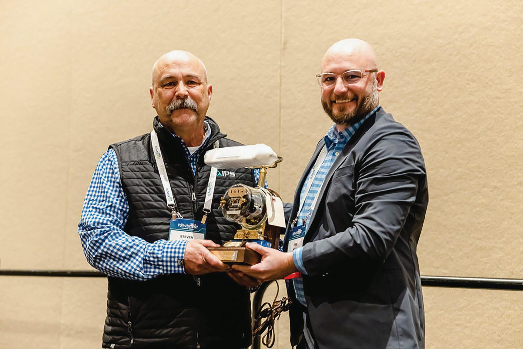
OUTSTANDING ACHIEVEMENT AWARD RECIPIENT STEVE NEWTON: NEVER GIVE UP
“The 2023 NETA Outstanding Achievement Award recipient holds a passion for the industry, especially when it comes to training electrical technicians and engineers,” said Eric Beckman, NETA President and Vice President of Engineering at National Field Services, as he announced Steve Newton’s name at the PowerTest awards ceremony. “For NETA, his influence is far-reaching: CTD Review Committee, Training Committee, exam development SME, NETA World author, and an annual presenter at PowerTest.”
“Steve Newton was a proud member of the U.S. Navy, specifically the Navy nuclear submarine program,” Beckman continued, “and he brings those experiences to us most notably through his work on the Training Committee in developing an apprenticeship program for the electrical testing industry.”
Newton says he was embarrassed, humbled, and amazed that so many people knew about the award but kept it under wraps. “My career path began when I was a self-serving, mean young man who enlisted in the Navy. The Navy sorted me out and I ultimately enjoyed a remarkable, unique, and decorated career based on the concept of selflessness. Don’t misunderstand, we constantly are at war with wanting, and sometimes choosing, to be selfish — me included,” he says. “It requires diligent self-examination to overcome it.”
“When I left the Navy in 1990, I was recruited by Martin Marietta to work on the ISS, but that program was suspended, and my only option was to ride submarines as a civilian technical representative. I couldn’t do that because of my children’s needs. My father, who was an executive and researcher at Dow Chemical, got me a job with a contractor who had a small testing division, and this was the start of my electrical testing career. We were eventually sold to a large nationwide construction company
specializing in building power plants, and I became a shareholder. We were later sold again to an even larger international construction company, and I ultimately retired in 2014. I was very fortunate to go to work for National Field Services because I had worked with Eric Beckman as an SME at a professional society. At National Field Services, I moved to technical support, training, and safety and have filled roles with increasingly higher responsibility through the years.”
“I’ve worked with Steve directly for the last eight years and indirectly for over 10 years, and you won’t find a more passionate individual when it comes to electrical testing and safety in our industry,” says Beckman. “He’s one of the few individuals to hold NETA Level 4 and NICET Level IV certifications. He never lets anything take away the focus on what will be his main contribution to the electrical testing industry: creating the apprenticeship program for NETA. It is worth more to him than this award.”
Newton credits his success to one motto: Never give up. “I was not exactly the best child — rebellious and self-centered — and I abused alcohol. When I joined the Navy to fulfill a dream of serving in submarines, my mother gave me a little wooden block engraved with these simple words: NEVER GIVE UP. Throughout
MEET STEVE NEWTON
Steve Newton, National Training Center Training Program Manager at National Field Service, is also a subject matter expert for the National Institute for Certification in Engineering Technologies (NICET); a certified National Center for Construction Education and Research (NCCER) Instructor; a Master Trainer for the Instructor Certification Training Program; and a Level IV NETA Certified Senior Engineering Technician in electrical power testing. In addition to his duties at National, Steve is a training consultant at Integrated Power Services (IPS). He is a certified instructor for electrical, instrumentation, electronic, solar, and various power curricula, holds several professional memberships including IEEE and NFPA, and is actively involved in reviewing and developing training and procedural materials for the electrical industry.

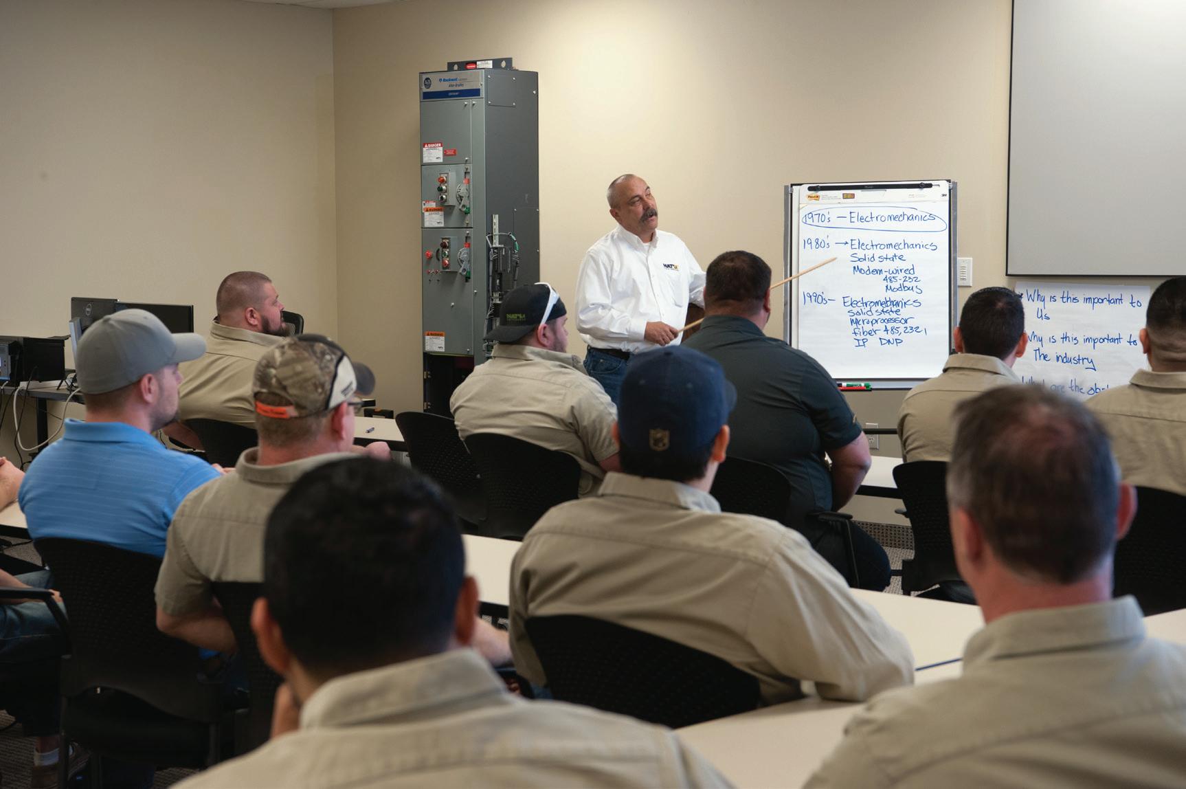
my career, everything I’ve achieved is founded on a deep abiding faith, a tenacious persistence to being the best at whatever I do, the continual pursuit of knowledge, and the realization that others must be more important than me.
“Steve’s curiosity stands out to me,” says National Field Service Engineering Manager Bibek Karki. “Even after all these years in the industry, he’s still very curious about the newest technology, test equipment, and apparatus. I also admire the way Steve has adapted and updated his knowledge with time and technology. He has seen so much evolution in technology and has been able to morph himself with it.”
National Field Services Senior Trainer David Drake remembers, “When I was managing power generation facilities, National Field Services (NFS) was our preferred company for performing electrical maintenance. Once I retired, I began researching part-time jobs and noticed NFS had an opening for a trainer. It was a good fit, so I began working for Steve as a part-time trainer in 2017. The
goal was for me to begin delivering electrical safety training. Steve was part of the team that developed this curriculum and is actually listed in the Acknowledgement section of the NCCER Managing Electrical Hazards Training Guide, but he insisted I work to be the primary person to teach this class, and he provided the resources and guidance to get it done. Our working relationship allowed Steve time to work on his true passion: developing electricians, technicians, and engineers capable of performing complex electrical tasks and testing.”
Steve Newton has earned tremendous respect for his contributions to organizations outside of NETA and National Field Services. Elizabeth Douglas, Director, Training and Development at Integrated Power Services, reflects, “Steve is one of those rare employees who are highly experienced, passionate about training and education, and willing to ensure the viability of the overall business. Ensuring the capability of employees is a priority for Steve, which can be directly witnessed in his
work in the apprenticeship program as well as other programs he has built over his lifetime. The apprenticeship program Steve has built will continue to assist IPS in its strategy to recruit and retain employees as it directly impacts the overall employee life cycle.”
“Steve has always been a passionate member of our Electrical Subject Matter Expert Committee and has worked on our four-year apprenticeship-style electrical curriculum, as well as specialty safety training such as Managing Electrical Hazards,” says Chris Wilson, Senior Manager of Curriculum Development at NCCER. “I have always leaned on Steve for help understanding the technical aspects of electrical safety and working around electrical hazards. Steve stayed on top of that subject matter on his own, so when it was time to help update our curriculum to new codes and standards, he was always well prepared, and he never failed to

deliver on anything he promised. He has also helped us understand various state licensing requirements for electrical work, particularly in the industrial sector. Steve has a passion for electrical work and training, and it really shows when you work with him”
Don Mitchell, a fellow Elder at the Eastside Church of Christ in Denton, Texas, remembers, “When Steve & Donna first moved to Denton, he sought us out as a congregation. He was very outgoing and demonstrated a n exemplary love for Christ, and we could see much spiritual growth after just a short time. Steve demonstrated a love for his fellow man and had a special love for the study of the Bible. He wasn’t afraid to roll up his sleeves and work with us whether it was yard maintenance or spiritual studies. We especially appreciate his Bible classes and his care for everyone in the congregation or anyone who visits with us.”


BET is an independent third-party testing firm with more than 50 years of experience serving industrial, commercial, and institutional facilities’ low- to high-voltage electrical testing and maintenance needs, including:
• Acceptance Testing & Commissioning
• Switchgear Reliability Testing
• Protective Relay Setting
• Transformer Repair
For scheduling call 215-826-9400 or email sales@betest.com Visit us at www.betest.com
• Transformer Oil Analysis
• Circuit Breaker Retrofits
• Battery Bank Testing
• Cable Fault Locating
• Meter Calibration
• Motor Testing & Surge Analysis
• Infrared & Ultrasonic Inspections
• Load Survey & Analysis
• Coordination & Short Circuit Studies
• Arc Flash Hazard Analysis
SERVANT LEADERSHIP
“Steve is one of the most dedicated individuals you will ever find,” says Beckman. “His integrity and ability to be a servant leader have fueled the growth and quality of work at National Field Services. Steve has a passion for training and workforce development, and his commitment has been a huge benefit not only to National Field Services but to the entire industry as a whole.”
Drake adds, “It’s obvious Steve is curious and passionate about the electrical industry and the personnel who work in it. The personal and professional lines are blurred. He loves the work so much that I believe he’d work for free if that was the only way he could participate. This is particularly true with developing electrical craft and electrical testing skills. Steve spent a good portion of his career commissioning electrical systems in industrial facilities. As a result, he’s been involved in resolving the complex problems that are often discovered during the commissioning process. All those problemsolving experiences have made him a subject matter expert. He’s brilliant.”
Newton shares what he believes has been important in his career path. “I never asked for a raise,” he remembers, “but always received

raises, stocks, bonuses, and advancement. I simply focused on being the best in the business, and it all came to me. I was lucky to work with a lot of professionals who were a whole lot smarter than me, and I learned from them, but I challenged everything I learned to ensure I had an accurate understanding. I was always studying, always learning.”
“I believe Steve’s work ethic, attention to minute details, and adaptability have led to his success as a power system professional,” recalls Karki. “His work ethic is second to none. I don’t think he allows himself to be bounded by time in his learning process. He also has an uncanny ability to pay attention to details. I have seen him write manuals and literature with very precise details.”
PAYING IT FORWARD
“Steve embodies the Association’s core value of servant leadership,” explains Beckman. If you’ve had the privilege to know him, you know that although he can be very direct, he’s one of the most caring individuals you will find. Even when challenged with health issues, he’s shown tremendous strength and perseverance.”
A common theme from admirers is Newton’s mentoring skills. “Personally, Steve has been a tremendous resource to my career growth,” says Karki. He’s been an excellent teammate, mentor, and friend to me. He might come off as a bit of a harsh guy but deep down, he genuinely cares about the people around him. Our National team is very lucky to have him.”
J.P. Keyes, Regional Instructor Manager/ NCCER ATS Sponsor at National Field Services, says Newton has been a mentor and friend since he recruited him from Houston to work in the Dallas area. “His inspiration and unwavering support were more than enough for me to move my family and start in an unknown area,” Keyes says. “Steve helped me transition from a career in the field to being a full-time instructor. Using the blueprint he has shown me by his actions — not just his words — to overcome any kind of adversity, I am the sponsor for NCCER and a successful electrical instructor
with LISD and National Field Services. Now it’s my turn to use my own words to continue his legacy using what he has taught me. My family and I are forever grateful to Steve.”
“In the time since he developed cancer, we have seen the determination and endurance of a person who loves the Lord through his good times and his bad,” says Mitchell. “Even when his pain was the most difficult to bear, he thanked God for the experience because of all that it taught him. When we hurt, we usually have great difficulty seeing the silver lining in the cloud. That’s not true with Steve. All through his ordeal, his focus was on Christ and what he could learn from the experience. He has learned to care for those who have experienced similar problems and is even more able now to help them see the light. He serves as an elder in our congregation and is a mentor to us all. No one could have a friend as loyal and valuable as Steve Newton.”

Always one to share what he learned, Newton has some advice for those new to the industry. “Participate — get involved with making the industry and the world a better place,” he says. “Strive for excellence in all you do, but serve others. Examine yourself, and always pursue a better you. Don’t be the problem, be the solution. Above all, never give up.”
NETA companies might also benefit from Newton’s experience. “We no longer have the luxury of spending decades to develop our talent,” he points out. “Our workforce has been decimated with the retirement of most of my peers. This field is massive in scope and requires a lot of education and experience to master. If we combine all of the knowledge and experience of NETA’s members, engineers, and technicians, there is still more we don’t know. We must endeavor to infuse our organization with young talent and provide an environment for them to thrive, and NETA needs to help its members


recruit and develop this talent, starting with high schools, trade schools, the military, and colleges.”
“Steve was so frustrated with the declining number of quality craftsmen coming into the industry that he developed an apprenticeship program and got it certified by the National Labor Relations Board (NLRB),” Drake recalls. “There are students in progress today, and he’s teaching them even though some classes are on nights and weekends.”
Beckman agrees. “Steve never lets anything take away the focus on what will be his greatest contribution to the electrical testing industry: creating the apprenticeship program for NETA. That is worth more to him than this award.”
Newton shares that working all over the country and the world took its toll on his personal life. He recalls that in the early years, bad food and too much alcohol also took their toll. “It took me a
few years to learn how to balance my professional and personal life. This is where my faith came from and developed.” In addition to open heart surgery in 2014 and cancer more recently, Newton faced personal issues with marriage, divorce, and raising children. “Life happens,” he points out. “We can either give up or stand up. My wife Donna and I now have six grown children and 12 grandchildren, and we have been married for over 20 years. I would not be successful without her. She deserves this award more than me.”
“I am not sure if this was an original thought or if I ran across it somewhere, but I have lived by it since my time in the military: Excellence is the driven pursuit of perfection with a humble understanding that you will never achieve it. I am and have been a work in progress my whole life. I believe that we all are.” The most successful and content people are those who recognize this, Newton says. His advice: “Embrace constant selfexamination, and always strive to improve.”








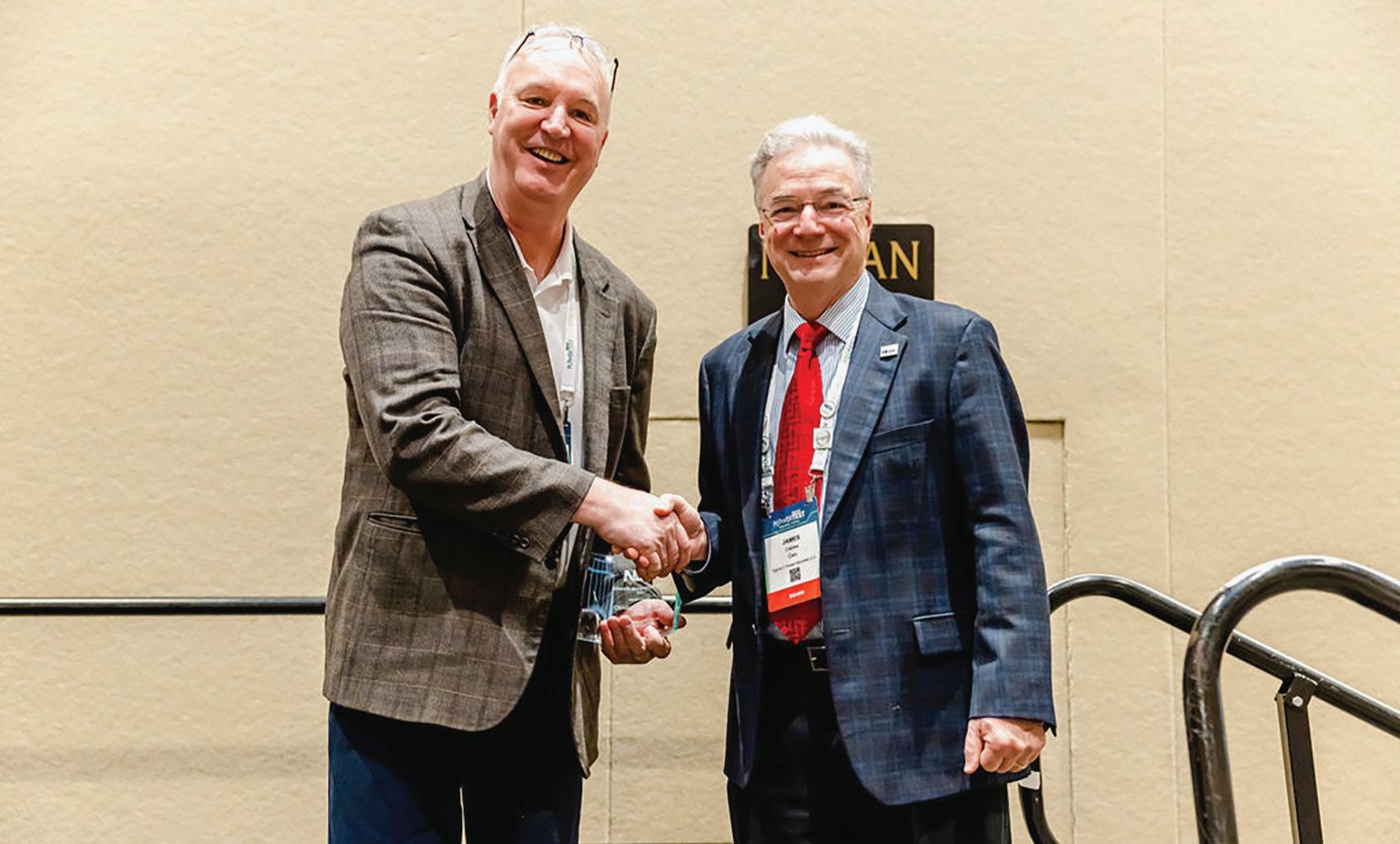
ALLIANCE RECOGNITION AWARD RECIPIENT CHARLES SWEETSER: LEADING BY EXAMPLE
Ron Widup, Vice Chairman, Board of Directors, and Senior Advisor, Technical Services at Shermco Industries, kept the mystery alive before he revealed the 2023 recipient of NETA’s Alliance Recognition Award at PowerTest 2023.
“ This year’s recipient is someone who has been well received here at PowerTest as well as throughout the industry,” Widup began. “Over the last 17 years, he has been a participant in the IEEE Transformer Committee, serving as chair of the FRA Working Group C57.149.
He has authored many technical papers that have appeared in various technical journals, including NETA World, and has been a highly regarded and frequent speaker at PowerTest. He is an authority on condition assessment of power apparatus and partial discharge.”
“In addition to all of that,” Widup continued, “this person continually supports testing companies and the industry. He recently assisted NETA’s NAMO chair with a very well-received presentation to the Navy Muse group in California. He took the extra trouble to source the exact equipment the group uses and provided specific training for them.”
Sweetser says he has always attended the PowerTest Luncheon as a NETA CAP member, so it was just business as usual until he realized what was happening. “I was very surprised, and it was the last thing I expected,” he says. “I felt honored to be recognized.”
Jim Cialdea, CEO of Sigma C, had the honor of presenting the award. “Charles Sweetser is an all-around great guy,” he says. “He is very knowledgeable, but also so approachable and generous with his time and experience. A strong supporter of our industry for many years, he has been involved with NETA by presenting papers and attending PowerTest and contributing to IEEE. I was very pleased to see him receive the Alliance Recognition Award.”

Charles Sweetser joined OMICRON electronics Corp USA in 2009 and is the PRIM Engineering Services Manager for North America. A 25-year veteran of the testing industry, Sweetser supports apparatus testing for many types of devices, including transformers and circuit breakers. Before joining OMICRON, he worked for 13 years in the electrical apparatus diagnostic and consulting business.
“I was fortunate to start my career in the electrical testing industry,” Sweetser says. He has held several roles, all in the substation discipline. “I started as an Electrical Testing Application Engineer supporting substation equipment,” he recalls. “This included application support and training. Still focusing on electrical testing and diagnostics, I moved into product development and product management. Now, coming almost full circle as the Engineering Services Manager, I manage, mentor, and foster a group that focuses on electrical testing and diagnostics of substation equipment. I hope that they have as great an experience as I have had over the years.”
“It is my pleasure to work with Chuck here at OMICRON. He is a treasured member of the OMICRON family and much appreciated by us all,” says Derek Brown, North American Regional Manager at OMICRON. “Chuck brings with him a wealth of technical knowledge and experience, and he consistently looks for ways to share this knowledge for the benefit of others. As a coach, he works rigorously to ensure his team has all knowledge and support they need to operate efficiently, effectively, and most importantly safely in the complex world of power system testing and monitoring.”
“I’ve had the privilege of knowing Charles Sweetser for 30 years,” explains Wayne Bishop, currently Quanta Technology Vice President and Vice President, Conferences, of the IEEE Power & Energy Society (PES). “Chuck has been one of my closest friends and colleagues in the industry. We worked together at Doble in the 1990s and joined OMICRON electronics
in 2009 when we opened their Boston-area office. I can’t think of anyone more deserving than Chuck to receive NETA’s Alliance Recognition Award. He embodies everything this award stands for and represents it well.”
“Chuck is truly an inspirational team member, and his receipt of the NETA Alliance
supported his team with marketing needs. In my new role as Marketing Manager, I continue to learn from him and have received quite a bit of insight from Charles on leading a team. I am grateful to have someone like Charles who has so much knowledge to share.”
“Chuck has a great dedication to the customers


MEET CHARLES “CHUCK” SWEETSER
Charles Sweetser joined OMICRON electronics Corp USA in 2009 and presently holds the position of PRIM Engineering Services Manager for North America. Before joining OMICRON, he worked for 13 years in the electrical apparatus diagnostic and consulting business. He has published several technical papers for IEEE and other industry forums.
As a member of the IEEE Power & Energy Society (PES) for 18 years, he actively participates in the IEEE Transformers Committee and is Chair of the FRA Working Group PC57.149. He is also a member of several other working groups and subcommittees.
Sweetser’s additional interests include condition assessment of power apparatus and partial discharge. He received a BS in electrical engineering in 1992 and an MS in electrical engineering in 1996 from the University of Maine, where he was involved with the IEEE Student Chapter.
support to me. Chuck has been a mentor and has helped shape the person I have become as a professional.”
NETA has always held a special place in Sweetser’s heart, Bishop remembers. “He has been active with NETA since the 1990s and is a huge proponent of PowerTest.

Dan Hook, President of CBS Field Services, says, “Charles has been a constant contributor to NETA for as long as I can remember. His entire career has been spent with Doble and OMICRON, and he has provided invaluable support to NETA’s Accredited Companies (NACs) and NETA Technicians. During the annual PowerTest conference, Charles always gives at least one presentation, and they are in depth. He puts in an enormous amount of effort to ensure his technical skills are as complete and accurate as possible.”
“I have been attending PowerTest for two decades now,” Sweetser says. “It is my favorite and most valued annual event. Each year, I submit and contribute to papers and tutorials for PowerTest. I also review and ballot the ANSI/NETA ATS and ANSI/NETA MTS standards during revisions.”
Recently, NETA was asked to provide specialized training on voltage regulators for the NETA Approved Military Organization (NAMO) program. “Charles was approached to see if he would be willing to support, and he accepted almost immediately and got to work,” Hook recalls. “It would have been
reasonable for him to present some theory and nice photos along with some testing routines for this piece of equipment, but Charles went much further. Traveling across the country, from Maine to California, Charles arranged onsite time with test equipment and a test specimen to learn more in-depth, gather realworld data, and include findings in the formal presentations to the sailors who are part of the MUSE Activity in Port Hueneme. Charles’s dedication to technical excellence, with a focus on field practicality, is invaluable to our technicians and to the industry as a whole.”
“Growth, recruitment, and retention are the big issues that I see for NETA companies,” Sweetser says. “As an industry, we must continue to promote and recruit talent to meet the growing demand. In the world of engineering career choices, our industry
New challenges such as efficiency, security, reliability, resiliency, and renewables are driving positive technological changes. Our industry and especially NETA companies need to embrace these changes and provide the best training and opportunities for entrylevel as well as existing professionals.”
SHARING KNOWLEDGE
Sweetser’s reputation extends to other companies in the electrical testing industry, and he is well known for his ability to share expertise and knowledge. He admits he has always focused on the training aspect in and around electrical testing. “We work in a very specialized industry that believes in the exchange of knowledge. Even though I am often in the instructor role, I am constantly learning from everyone involved in the process. Experience is the best teacher. I spent a significant amount of time in the field, and it was essential in my early development.”




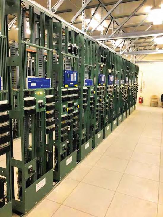


Electrical Testing, LLC is a 24/7 full service testing company founded upon the premise of providing exceptional customer service and the most highly skilled technicians in the industry. The team of project managers, engineers, support staff, and field technicians form the cohesive team in which customers have relied on year after year. JET specializes in commissioning, preventative maintenance, equipment repair, apparatus testing, and emergenc y response/troubleshooting. Electrical system reliability is JET’s goal.

“I first met Charles when he was working for Doble Engineering Company and was participating in the IEEE Transformers Committee as a transformer testing subject matter expert,” remembers Thomas Prevost, Vice President, Technology & Innovation at Weidmann Group. “Later, Charles invited me to visit his new company to demonstrate a new testing device they had developed. I was so impressed by OMICRON and the enthusiasm Charles had about the company that I joined them a few months later. Charles taught me many aspects of transformer testing.”
As a member of the IEEE Power & Energy Society (PES) for over 20 years, Sweetser actively participates in the IEEE Transformers
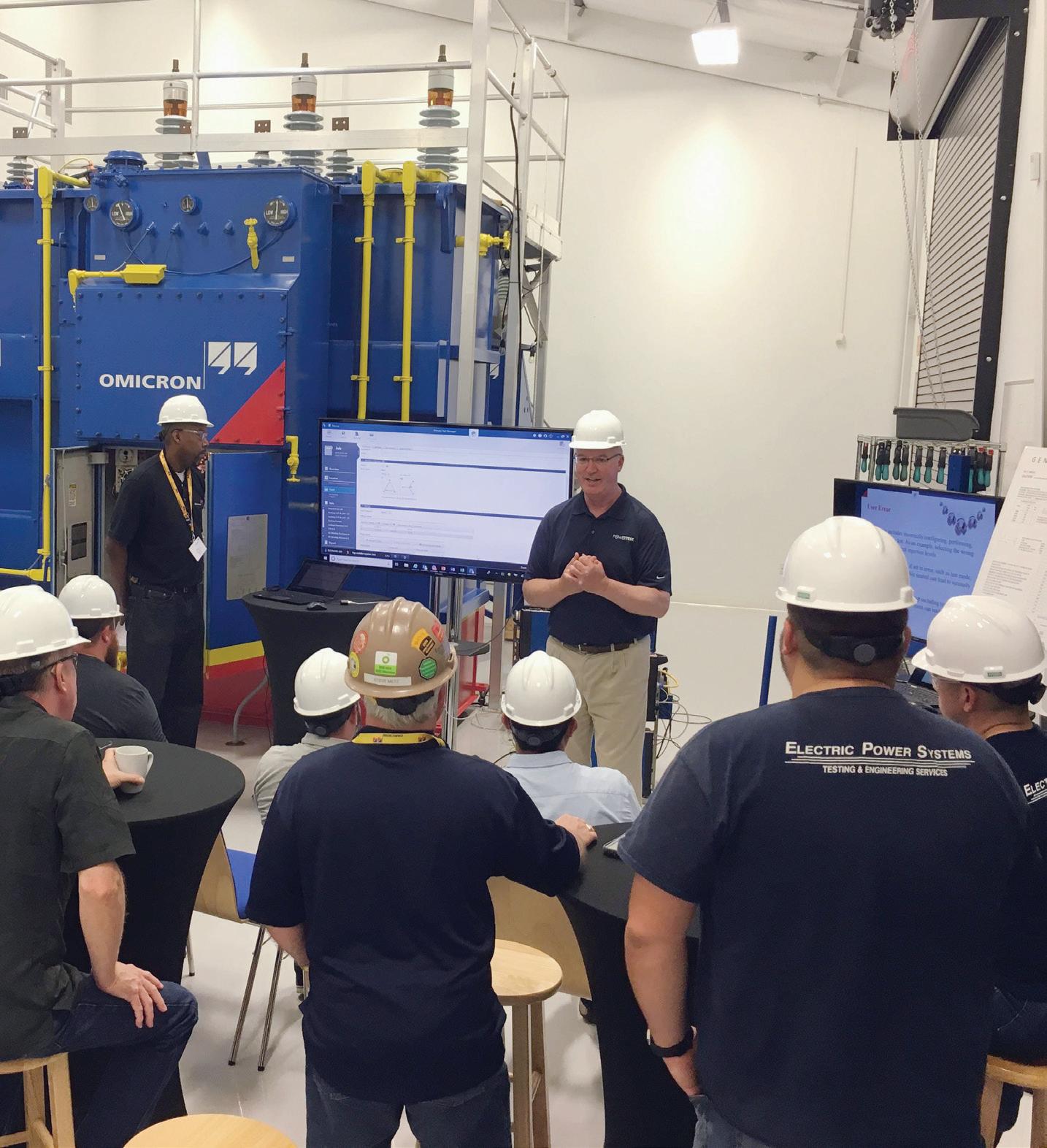
Committee and is Chair of the FRA Working Group PC57.149. He has published several technical papers for IEEE and other industry forums. “We expect to publish the newly revised FRA Guide within the next year,” he says. “I also enjoy participating in several other working groups and subcommittees regarding testing recommendations.”
“Chuck is a long-time volunteer with IEEE PES and is always willing to give his time to promote the great things happening in our industry. He is someone you can count on to get the job done,” Bishop says. “Whenever I need advice on something or a sounding board, I call upon Chuck. He has the highest ethics and integrity, is always professional, and above all else is a true gentleman. I have enjoyed traveling thousands of miles with Chuck for work trips in North America and around the world. Chuck is a master at giving presentations and is always willing to take the time to pass on his knowledge and expertise by mentoring the next generation of industry workers.”
“Chuck is a lead-by-example person and can set a very high bar we all strive to achieve,” Stelmach notes. “One of his best attributes is his teaching and communication skills. He has always been able to help others through his ability to teach people in a way that translates for them and allows the person to learn. Chuck goes above and beyond for everyone, which reflects his passion and dedication. He has vast knowledge and experience, and he continues to share it with everyone.”
“I admire many things about Charles,” Prevost adds. “Charles is a giver when it comes to sharing his knowledge. No matter what the circumstances, Charles will take the time and effort to explain the technical details of a test and the relevance of the results. I often joked that Charles should be a university professor, but he also knows how to have fun. He enjoys his work, and his enjoyment is infectious to those around him. When I picture Charles, I always think of him with a big grin on his face.”
ADVICE FOR THE FUTURE
“Staying involved and finding time for what is important is key,” Sweetser says. “As time goes on additional responsibilities follow, whether it be family or career. Focus on what’s important; communication, balance, and transparency are key components when facing challenges.”
“If I were to advise someone starting out in our industry, I would stress the value of hands-on field experience,” Sweetser says. “Investing your best efforts, time, and energy in all that you do will result in not only a sense of personal achievement but also industry recognition. Do not expect to be fast-tracked to the top. Learning and development take time, and it is a two-way street. Teach others along your learning journey. I always believed that the one in the room who is learning the most is the one who is preparing and presenting the lesson. Take advantage of those opportunities.”



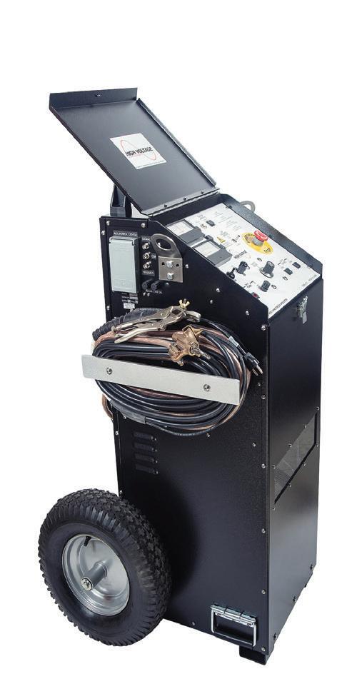


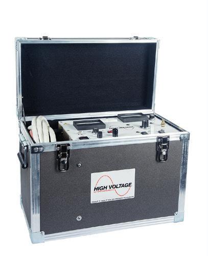
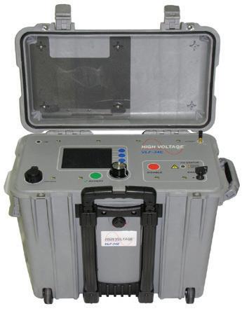

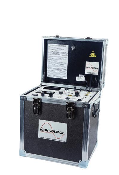


JIM DOLLARD RECEIVES JIM WHITE SAFETY AWARD
NETA’s annual James R. White Safety Award is named in honor of an industry icon. Each year, the recipient is chosen for their passion and dedication, and the award is a culmination of their never-ending quest for perfection in electrical safety, which is specifically for one purpose: the protection and well-being of the electrical worker.
“No
one is more qualified when it comes to
electrical
safety than
James ‘Jim’ Dollard,” said Ron Widup, Vice Chairman, Board of Directors and Senior Advisor, Technical
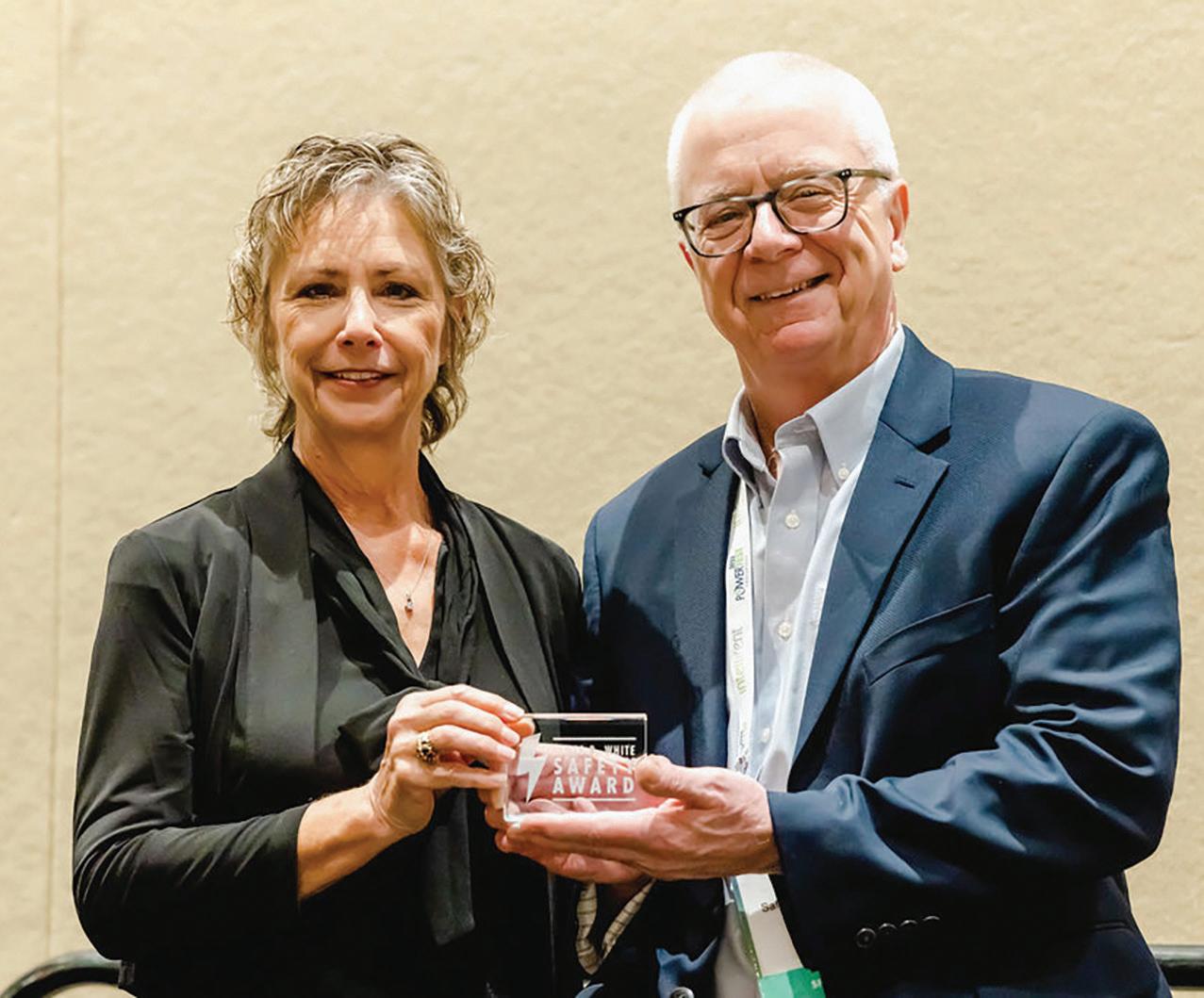
Services at Shermco Industries as he announced the winner. “With a long career in the electrical trades, Jim is a driven man who is always looking out for what is best for the worker in the field.”
“NETA’s Jim White was a safety professional who exemplified what a safety director should be, and Jim Dollard is cut from that same cloth,” Widup continued. “He has spent his life in the safety industry. His impact is immediately recognizable, and his passion for what we’re doing really stands out. Jim’s work in electrical safety begins at the genesis of it all — codes and standards — and he has made electrical power system installations and work practices better. There will be a room of 40 or 50 subject matter experts, and Jim Dollard will take an issue and distill it down into a common-sense, worker-in-the-field response to these codes and standards like no other.”
“When it comes to the National Electric Code, NFPA 70E,” Widup concluded, “it is most appropriate that Jim Dollard receive the James R. White Safety Award.”


February 26 – March 1, 2024 | Monday – Friday Hilton Anatole | Dallas, Texas
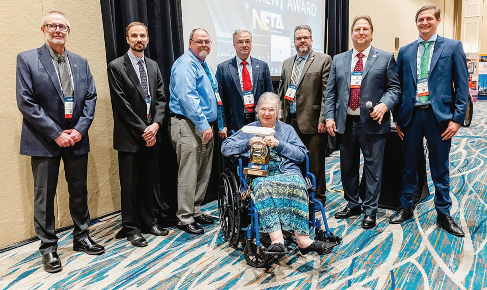
ALAN PETERSON: 2023 NETA’S LIFETIME ACHIEVEMENT AWARD
The audience at NETA’s PowerTest Awards Luncheon didn’t need a reminder that someone special was missing, but Ron Widup, Vice Chairman, Board of Directors and Senior Advisor, Technical Services at Shermco Industries, didn’t miss his chance to honor the recipient of a 2023 Lifetime Achievement Award.
“NETA and the electrical testing industry recently lost another giant whose influence across the industry and the love and respect he enjoyed from employees and friends point to a man with rare talents,” Widup began. “With volunteer members assisting in all aspects of our organization, there is one man who truly led the charge for technical excellence and
relevance. That man is Alan Peterson of Utility Service Corporation — a true visionary and leader.”
“NETA has a long history of leadership and volunteer contributors who have made the association what it is today, and at the top of that list is Al Peterson,” Widup continued. “As
chair of the Standards Review Council, Al was instrumental in the development, navigation, and ultimate publishing of NETA’s first ANSI standard, the 2000 Electrical Test Technician (ETT) standard. This started our journey into standards writing and forever changed NETA into a serious contributor to our industry. I was President of the Association at the time ETT was first published and was fortunate to announce the standard and recognize Al for his work. He was proud of it, and we were proud of him.”
Dr. Mary R. Jordan, NETA Executive Director from 1982 to 2006, was unable to attend the award ceremony but sent a letter. “It’s often said, so truthfully, that Alan Peterson was a technical giant of the electrical testing industry,” she shared. “Although NETA has always been a team effort, the Association is the highly respected, technically recognized entity it is today largely because of Al’s talent, dedication, and consistent hard work. He donated his time, talent, and expertise for the good of the industry to the great benefit of all.”
A NETA LEGACY
Eric Beckman, NETA President and Vice President of Engineering at National Field Services, says, “Al was such a highly respected person in the industry. I didn’t get the opportunity to know Al as well as some board members, but I could tell how much respect and knowledge he had in the industry just by the way people would talk about him. Al did so much for NETA and the electrical testing world. There’s no doubt that NETA has gained so much recognition and respect because of the work Al put in over the course of his career. I would say Al has done more for the electrical testing industry than maybe anybody.”
“Al led the Association from a group of likeminded individuals who wanted to make a difference to a professional standards-making organization that truly leads the electrical power system safety and reliability space,” Widup agrees. “NETA President, a member of the Board of Directors, Chair of the Standards
Review Council, and a representative on industry codes and standards committees, Al was a walking encyclopedia of knowledge. He was a special person and one of the most influential contributors to NETA’s success.”
“In the NETA tradition, Al worked hard and played hard — and often combined the two,” Jordan remembers. “We met for hundreds of hours examining NETA specifications line by line and comparing them to existing ANSI standards to confirm not only accuracy but also the necessary writing and presentation style.”
The late Charles K. Blizard Sr., a good friend and colleague for over 40 years, recognized Al’s achievements following the 2008 NETA Outstanding Achievement Award. “We worked together well on NETA’s Standard Review Committee because our perspective from the practical aspects of testing provided a balance to the electrical theorists on the committee,” Blizard says. “Al was really the one who was persistent with getting NETA involved with ANSI. He was the prime mover, and he promulgated our cause through his tact.”
“As chair of the NETA Technical Committee, later renamed the Standards Review Council, Al led the Association to worldwide technical respectability,” remembers Jordan. “He dedicated countless hours to actual SRC meetings and

personally wrote most of the high-voltage sections of the specifications, which are now American National Standards. Al was the major proponent of NETA’s earning the prestigious designation as a developer of ANSI standards.”
Scott Blizard, Vice President and Chief Operating Officer at American Electrical Testing Company, says, “He led us. He’s the one who helped us get where we are today with all of our standards. You can just thank Al Peterson for that. Al was NETA’s guru in the area of dealing with other professional associations like NFPA and IEEE. It was important to NETA to be able to interface with these other standard writing organizations, and Al developed both the contacts and the knowledge to guide NETA in the correct direction when dealing with them. Al is a man who will not be forgotten. His work at NETA will live on, and his legacy among our ANSI standards will be present forever.”
MENTORSHIP AND CHARISMA
“We lost a good one when we lost Al Peterson, but fortunately his work and legacy will continue to make NETA a great technical trade association and difference-maker for

our industry,” says Widup. “He will be greatly missed, but his mentorship, charisma, and laugh will never be forgotten by those who knew him.”
Eric Beckman, NETA President and Director at National Field Services, says, “Al always had a way of making the conversation interesting. I loved hearing his testing war stories and the interesting outcomes of various projects.”
“Al Peterson was a family friend as well as a mentor to a young man from Boston,”

MEET ALAN “AL” PETERSON
Established by Alan and Shirley Peterson in 1963, Utility Service Corporation (USC) specialized in electric power system testing and maintenance for over 50 years, working in utility, industrial, and commercial power applications, troubleshooting, and repair. As a team, they created legacies and established a high caliber of excellence in the industry.
Utility Service Corporation became a NETA Accredited Company in 1983, and Peterson served on the NETA Board of Directors from 1984 until his death, holding the offices of president, first vice president, and second vice president. He served on several NETA committees, was the Technical Committee chair and a member of the Standards Review Council until his death, and was instrumental in the writing and acceptance of NETA’s Acceptance and Maintenance Specifications as national standards.

Al represented NETA as a member of the National Fire Protection Association’s (NFPA) High Voltage Task Force, which was formed in 2008 for the purpose of adding provisions covering highand medium-voltage installations to the National Electrical Code (NEC) for 2011. This task force was extended to address changes and additions to the NEC for 2014 and 2017.
As a member of the Institute of Electrical and Electronic Engineers (IEEE), Peterson participated on various IEEE Technical Committee working groups, specifically ANSI/IEEE C-37, Power Switchgear, ANSI/IEEE C-57, Transformers, and ANSI/IEEE C-62 Surge Protection
In addition to serving on the National Board of Directors of AIECA, now Independent Electrical Contractors (IEC), where he held the offices of national vice president and national treasurer, Al was a member of the American National Standards Institute (ANSI) and served three terms as a member of the ANSI Board of Standards Review (BSR). Before his appointment to the BSR, he served on ANSI’s Electrical and Electronic Standards Board.
remembers Blizard, who served with Al on several NETA committees. “He possessed an amazing amount of knowledge and a memory to match, and he shared it with all who would listen. NETA is a much better organization today thanks to Al’s involvement.”
Huffman says, “Al Peterson inspired me to look past the superficial words of a standard and dive deep into how it would impact the industry.”
Jordan counts Al and Shirley Peterson among her dearest friends. “They were accepting,
Peterson received his formal education in electrical engineering at Northeastern University in Boston and completed various advanced studies at the Massachusetts Institute of Technology in Cambridge, Massachusetts. He was first employed by Brockton Edison Company (now National Grid) through Northeastern University’s Cooperative Program working in the meter, line, and engineering departments. Peterson was inducted into the U.S. Army and served his entire term of service as an instructor at the U.S. Army Ordnance Guided Missile School at Redstone Arsenal, Alabama. He held Journeyman and Master Electrician certificates in several states.
caring, and always kind,” she says. “We created beautiful memories together — scouting for remnants of undersea, high-voltage cables after a meeting at The Cape, enjoying the Tasting Menu at Emeril’s in New Orleans, whale watching in Key West, savoring crab cakes and lobster, toasting sunsets in Cabo, eating wild game in White Fish, Montana — and always laughter, laughter, laughter!”
“Al was always engaging and never short on stories on just about everything, and he was a phenomenal encyclopedia of information,”

recalls Widup. “It always amazed me how Al knew so much about so much… and his presentation skills were like no other. Especially when there was an element of humor in his stories — and there often was — his deep belly laugh and verbose delivery would turn heads from all around the room!”
Kristen Schmidt, former NETA technical services director, now a training specialist at RESA Power, remembers, “Al was someone you just couldn’t get enough of. His toothy smile, booming voice, and unmistakable laughter filled every room he occupied and made everyone want to be in on the joke. Al’s generosity of spirit always made you feel like you were capable of anything because, by gum, he believed in you. And if a man as accomplished and well-traveled as Al Peterson knew it to be true, then it must be so.”
“Al was known as a military historian,” says White. “He was your guy if you wanted to know anything about military history. He could quote military personalities from all the various wars in which the U.S. has been involved and discuss a certain U.S. general’s strategy down to minute detail.”
Sheppard says Peterson was quite the character, and his reputation spoke for itself. “When you talked to Al, you became so intrigued and involved that sometimes you didn’t know until the end whether it was a real thing or something he had just made up,” Sheppard recalls. “Al was one of those people who could tell you the type of material right down to the wood and the type of spray phenolic that was put on an insulating barrier from a 1932 General Electric switchboard, and he could convince you with compassion and intelligence that he was there when it was put on.”
Cialdea remembers, “I always enjoyed listening to Al’s stories. He did a lot of stuff with NASA, and he told us stories about some crazy stuff he found. We all love a good story.”
“His fingerprints are all over this community and this association,” Tedder points out.
“Al had a presence that was like no other,” Widup says. “He was smart. He was articulate. He was fun. All of those things benefited the Association so much, and we’re so grateful for what Al did for NETA throughout the years. He was truly one of the industry icons and a great guy. We all miss him.”
Helping Power a greener future


First released over 15 years ago, the Schneider MasterPact NW low voltage circuit breaker has a large global install base. When the Micrologic trip unit or sensors fail, think AC-PRO-NW™.

AC-PRO-NW™ brings all of the safety and reliability features you trust from URC to the MasterPact NW family of circuit breakers, including QUICK-TRIP® arc flash reduction, Sluggish Breaker®, and more.
Order AC-PRO-NW™ today:

RODERIC HAGEMAN: 2023 NETA LIFETIME ACHIEVEMENT AWARD
“When you have an organization that is based on technical excellence and accuracy, it requires attention to detail that must not waver,” began Ron Widup, Vice Chairman, Board of Directors and Senior Advisor, Technical Services at Shermco Industries, as he introduced NETA’s Lifetime Achievement Award for Rod Hageman. “From developing standards to ensuring the accuracy of authorcontributed content, it takes a special person with that attention to detail who will recognize the need, correct the parts that need correcting, and when needed, reject the parts that are not relevant or incorrect.”
“Roderic ‘Rod’ Hageman is the best of the best at ensuring the technical accuracy of our Association, but he is much more than that,” Widup continued. “He has held positions on the Board of Directors and as President of the Association, Technical Editor of NETA World, Examination Committee Chair, member of the Standards Review Council (SRC), member of codes and standards committees in the industry, technical presenter, and a whole host of other duties and responsibilities for the betterment of the association and our industry.”
“NETA is what it is today thanks to the passion and contributions of Rod Hageman,” Widup concluded. “At its core, NETA is about technical excellence, and for his entire career, Rod Hageman has been about technical excellence.”
Eric Beckman, NETA President and Vice President of Engineering at National Field
Services, notes, “Rod would challenge answers, and it showed the intelligence and the experience he has in the industry as an engineer.”
Chasen Tedder, NETA Secretary and Electrical Field Engineer at Hampton Tedder Technical Services, agrees. “ Rod really helped push NETA into a better position by holding all of the NETA community accountable and elevating all of the businesses to become better than they are as individual companies.”
“Hageman pushed everyone toward excellence,” explains Jim Cialdea, CEO of Sigma C Power Services. “Rod is very strong-willed and opinionated, which anyone who knows him understands, and he always set the bar so high.”
NETA Board Treasurer John White, President Emeritus, Sigma Six Solutions, summed it up.
“Rod exhibits a somewhat subtle approach to a discussion. Rather than bringing flair or flamboyance to the story, he brings wisdom and experience. He was often quiet in Board meetings, but when he spoke, it was like the old E.F. Hutton slogan: ‘Everybody listens.’”
A PASSION FOR SHARING KNOWLEDGE
Recently retired, Hageman says he was very pleased to learn he was receiving a Lifetime Achievement Award. He says he especially enjoyed his work with the SRC. “It’s a great group of highly skilled technical people who put away their egos and listen to each other,” Hageman says. The SRC is responsible for the technical oversight and review of NETA’s programs, products, and services including the ANSI/NETA standards and the NETA Certification Program, which is the industryleading certification program for this career path.
“I enjoyed them all,” Hageman continues. “The beauty of doing the work is that you are the one who gains the most from doing it. I worried the most about NETA’s technician exams. I was concerned about making the questions appropriate for the level and ensuring the answers were clearly the correct choice among the distractors. My work not only impacted the individual technicians but also the companies they worked for, so the questions needed to clearly sort out those candidates who were ready to advance to the next level and those who were not.”
Always willing to credit the team, Hageman says his guiding philosophy as he worked to help NETA gain recognition and respect across the industry was that, as individuals, each person has solved problems. “However, together we are a formidable source of problemsolving for even the most difficult problems,” he says. “When you have the opportunity to learn from and teach others in your association, everyone benefits.” He also gives credit to others for his success. “I learned from so many people that it would be difficult to sort out
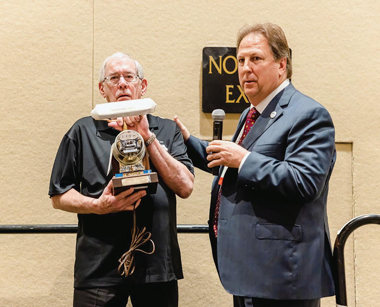
a few and give them all the credit. I think I learned something from almost everyone with whom I had significant contact.
Hageman has contributed to NETA in many ways but says his greatest contribution to NETA has been sharing his knowledge and experience. “Many of us did that for years, and it was key to the success of NETA as well as our individual companies,” he says. The technician exam, NETA World, ATS, and ETS were all important projects that many of us worked on.” Asked about current challenges to the electrical testing industry, he says he is not aware of an existing challenge to the testing industry. “In fact,” he explains, “if NETA’s active members continue to share knowledge and contribute, I see no reason why NETA shouldn’t continue to be a force in the industry, helping electrical systems owners keep their systems running and taking care of the occasional equipment failure.”
“I’ve known Rod for more years than either of us would like to admit,” says Mose Ramieh Sr., now retired as President of Power & Generation Testing, Inc. and a long-time member of NETA’s Board of Directors. “When

I joined NETA, Rod was the first Board member I met, and we hit it off from the start. Rod, John White, and I became known as the Three Amigos as we spent a lot of time working together. Rod was the real technical guy.”
Ramieh remembers Hageman as a lover of all things technical with a passion for sharing knowledge. “Rod has been a trendsetter in the technical side of NETA and the industry. He has been a pioneer in the protective relay world. His technical review and scrutiny of NETA World have given NETA a respected place in the industry. He has — like so many others in the NETA family — contributed much to make us the 800-pound gorilla in the testing industry.”
Dr. Mary R. Jordan, NETA Executive Director from 1982 to 2006, was unable to attend the award ceremony but sent a letter. “As Executive Director during NETA’s formative years, I fully understand the massive contributions you made not only to the Association but to the entire electrical industry,” she writes. “Everything we did in those early years was a massive team effort by the whippersnappers of the time. You were so very instrumental and extremely generous in donating your time, talent, and technical expertise to the NETA
Standards Review Council — and those results provided the recognition and respect of the entire electrical industry.”
Dan Hook, President of CBS Field Services, recalls, “Rod had the uncanny ability to have deep technical discussions — often passionate — and at the end of it all, respect others no matter who was right or wrong. In that sense, Rod was a true consensus participant. This showed during his tenure and irreplaceable contributions as a member of the Standards Review Council. Rod was serious in his approach to technical expertise, but in the end, he did not take himself too seriously.”
NETA World Technical Editor Tim Cotter reflects, “I remember working with Rod in the 1990s when he effectively was the technical exam committee. Because of his long-recognized technical expertise and unquestioned integrity, he was left to sign off on all exam details and control its distribution. He was also tasked with developing the first Level 4 exams because he clearly had capabilities far beyond what even a Level 4 Technician would be expected to embody. In all of his efforts on behalf of NETA, he worked hand in hand with his wife Diane, who was
MEET RODERIC “ROD” HAGEMAN
After graduating from Iowa State University with a BS in electrical engineering, Roderic L. Hageman took over Illinois-based PRIT Service, Inc. in 1972. His father, Lynn Hageman, an electrical engineer, had established the company in the 1950s as an independent testing and engineering services firm. Over the next 45 years, with Hageman as President, PRIT was part of a growing industry, servicing industrial and powerproducing companies throughout the Midwest with consulting and testing for electrical power distribution systems. PRIT joined NETA in 1986, and Hageman joined the NETA Board of Directors in 1988.

He has been a faithful contributor to the association ever since, including his service as NETA World’s Technical Editor (along with his respected and beloved late wife, Diane), and leadership roles on the Standards Review Council (SRC) and NETA Technical Exam Committee. He served two terms as NETA President and represented NETA on other industry committees, such as NFPA CMP-10.
another major contributor to the growth of the organization. NETA’s present-day stature would be greatly diminished if not for the efforts of Rod and Diane.”
“Your greatest contribution, in my opinion, was the creation of the technician certification requirements,” Jordan agrees. “You wrote the bulk of the initial examination questions, painstakingly checking references for your own questions as well as questions submitted by others. You ensured not only that the answer was correct but also that all the alternate answers sounded probable. Those who now use and work with the NETA exam process cannot begin to imagine the massive, tedious, timeconsuming effort that went into its creation. You devoted even more hours to creating
PRIT was acquired by Shermco Industries in 2016 and Hageman retired from the Board, but he continued to work on the SRC and NETA World and stayed connected to the industry.
A NETA volunteer for nearly 40 years, Rod also served as NETA Board President, a member of the Board of Directors, a member of the Standards Review Council, and a NETA representative on the Codes and Standards Committee. He is a highly respected relay expert having presented on behalf of NETA at countless industry conferences. Recently retired, Rod remains an invaluable source of knowledge and is available to NETA members whenever needed.
Hageman is a three-time recipient of NETA’s Man of the Year Award, which become the Outstanding Achievement Award. His PRIT partner and wife, Diane Johnson-Hageman, was the “Man” of the Year in 1993. Hageman was honored again in 2016 with a tribute to his dedication to NETA and the industry.
the NETA specifications that later became American National Standards. You, along with Diane, provided not only content but the consistent format used throughout.”
“Personally, Rod is thoughtful and caring. Professionally, he is a virtuoso,” says White. “Rod brought the term ‘professional’ to the NETA organization. He and Diane were instrumental in elevating NETA World to its current status — one that is superior to most technical publications. Rod is truly an expert among electrical power professionals, and he has earned the strongest of reputations in the industry.”
NETA’s quarterly journal, NETA World, started as a mimeographed fluff sheet, recalls Jordan. “Thanks to you and Diane, it became

a respected publication,” she says. “In addition to writing technical articles, you devoted uncountable hours to editing to confirm the technical accuracy of every detail published — a frustrating endeavor, I’m sure, as most articles were turned in at the last possible moment before (or after) the deadline.”
INTELLIGENT AND DEDICATED
Widup describes Hageman as a smart man who has directly impacted NETA’s technical competence and industry-leading position. “Rod’s attention to detail, his high expectations of accuracy and validation — for internal NETA activity as well as external contributors to the Association — and his relentless desire to assure that what we say in NETA World year after year is technically accurate and readable have helped the Association gain the respect and stature we currently have today,” notes Widup. “Our position of leadership in the industry is directly attributed in many ways to Rod’s efforts.”
“In addition to everything else, we all had time for fun!” Jordan says. Fulfilling their motto, “Work hard, play hard,” included sightseeing in Boston, touring glaciers in Alaska, whale watching in Key West, and getting drenched
under Niagara Falls. “In addition to contributing leadership in the technical arena, Rod enhanced the entire organization by serving on the Board of Directors and as President,” Jordan concludes. “Know that I honor not only your massive contributions to the entire electrical industry but also that I treasure the memories and, above all, cherish our friendship.”
Huffman says he especially admires Rod’s genuine personality. “On a personal level, Rod is a really genuine person who doesn’t judge other people. He’s inviting and warm, with no ulterior motives. Rod is just an all-around good person. Professionally, I admire how analytical he is while still not losing sight of the obvious. Sometimes, a very analytical person can miss the obvious.”
Considered a mentor by many NETA leaders, Hageman says, “My father, Lynn Hageman, was my initial mentor, but during the early years of NETA, the members mentored each other, combining the knowledge and experience we each had.”
Hook remembers that Rod was simultaneously extremely intelligent and hardworking. “Although he often knew a subject matter well based on his experience, he was tenacious in studying to bring his level of knowledge up if needed. He never assumed he knew the complete and correct answer, although often he did. He put in countless hours educating himself on subject matters, especially as Technical Editor for NETA World.”
Like many others, Widup was surprised and impressed to discover Hageman’s musical abilities. “When our meetings and travels took us to the Chicago area, we often ended up in the basement at his house, playing pool and listening to music. One time, he mentioned he hadn’t played the drums in a while and had decided to start up again. With some coaxing and encouragement, he played the drums for us, and everyone was like, ‘This guy is good!’ I don’t know why I was surprised because Rod excels in everything he does.”

ANSWERS
ANSWERS
1. b. SCADA (supervisory control and data acquisition). SCADA systems receive data from remote devices, transmit data to and from a central site, and provide control of remote devices. SCADA systems are used in a variety of environments from water treatment plants to supermarkets. PLC, RTUs, and HMIs are the main elements in SCADA systems.
2. d. Latency. Latency is the time it takes for a signal to travel from point A to point B. The latency of a communication network is fundamentally distance and speed. If the transmission media places limitations on the signal speed, it can cause an increase in latency. When the distance between the sender and receiver is significant, a higher latency will exist.
3. a. Pilot wire. For transmission lines, pilot wire relaying is utilized to transmit certain information from one end of a line section to another. This can ensure that selective tripping is possible. Historically, telephone twisted pair circuits were used for pilot wires.
4. c. Fiber optic cables can be used over long distances. Since fiber optic cables utilize light-based technology, there is less attenuation (signal loss). Therefore, information can travel much farther. As a result, fiber optic cables also have a higher bandwidth and can carry more data than copper cables of the same diameter.
5. d. Perform transit and receive power readings from a local device and a remote device. Reliable operation needs to be verified with an optical power meter. The results from this test should compare to previous test results and the manufacturer’s published data.
6. d. All of the above. Many factors can cause fiber signal loss. Each splice and connector will cause a certain amount of power loss. Improper bending radius will also cause signal losses. There will be fiber losses due to the intrinsic properties of the specific cable. Contaminants in the glass or in the accessories are another cause of fiber losses that may be due to improper handling during installation, flaws in the optical fiber, or moisture ingress.
A RECORD-BREAKING CONFERENCE GENERATING POWERFUL CONNECTIONS FOR THE FUTURE 2023
NETA’s 2023 PowerTest Conference drew more than 1,000 attendees to Orlando, Florida, March 8–12. Electrical power system experts and professionals attended over 40 training sessions covering all-new content and engaged in many relationship-building and networking opportunities.
PowerTest is recognized across the electrical power systems industry as the premier electrical maintenance and safety conference. It is the largest annual gathering of experts and professionals responsible for designing, installing, maintaining, and managing electrical power systems. NETA Accredited Companies, engineering firms, utilities, manufacturers, and commercial facility owners send their teams each year to train and grow their knowledge.
PowerTest was hosted by NETA — The InterNational Electrical Testing Association — and made spectacular by the NETA network of companies that volunteer their expert speakers, sponsor events, exhibit state-of-the-art products and services, and collectively contribute their creativity to make the event educational, fun, and engaging.

PRE-POWERTEST MEMBER AND MEMBER ALLIANCE MEETINGS
NETA Meetings Feature Peer Discussion and the Latest NETA Updates
More than 130 NETA Accredited Company representatives, Alliance Partners, and Corporate Alliance participants gathered on Tuesday, March 7, for NETA’s 2023 Annual Member and Alliance Meetings. The annual meetings are held on the day before PowerTest and are the traditional kickoff to the conference each year.
NETA Member Meeting
This gathering of representatives and technicians from NETA Accredited Companies brought reports from all sides of the association from updates on membership and strategic initiatives to a review of program plans for the
POWERTEST 2023 HIGHLIGHTS
Professional Training
This year’s conference was held at the Rosen Shingle Creek Resort. Attendees were excited to come together for five days of learning and industry advancement. Training sessions covered a broad set of topics including:
• Standard updates
• Circuit breaker testing and diagnostics
• Transformers
• Relay maintenance
• Life extension
• Cable health management
• Electrical reliability
• Risk mitigation
• Safety
• Sales and management
For professionals looking to earn educational credits, PowerTest attendees could earn up to 4.8 Continuing Educational Credits (applicable to engineers and electrical professionals)
coming year and recognition of volunteers and committee chairs. The meeting also included the nomination and election of officers to NETA’s Board of Directors: 1st Vice President Dan Hook, CBS Field Services; 2nd Vice President Chasen Tedder, Hampton Tedder Technical Services; Secretary Virginia Balitski, Magna IV Engineering; and Treasurer, John White, Sigma Six Solutions. Ron Widup, Shermco Industries; Jim Cialdea, Sigma C Power Services; and Bob Sheppard, Tony Demaria Electric were elected to three-year terms on the Board.
NETA Member and Alliance Meeting
NETA Corporate Alliance and Alliance Partners were invited to join NETA Accredited Companies for the second half of the Member Meeting. Among other updates, participants heard reports on industry activity from NETA technical representatives.
or as many as 48 Continuing Technical Development Credits, (applicable to NETA Accredited Company Technicians).
Keynote Speaker
PowerTest 2023 kicked off with keynote speaker Bob Koonce, the Founder of High Reliability Group and a U.S. Navy veteran

Keynote Speaker Bob Koonce Presents on the Criticality of Leadership, Culture, Management Systems, and Operational Feedback
who dedicated his military career to serving on and commanding fast attack submarines. In his presentation, “The Criticality of Leadership, Culture, Management Systems, and Operational Feedback,” Bob shared his knowledge of the importance of operational excellence and high reliability, which attendees applauded.
WEDNESDAY
45-Minute Tracks
Wednesday’s 30 engaging 45-minute sessions covered five critical areas providing insights, best practices, and updates along with case studies and tutorials. Expert presenters came from all sectors of the industry. Specific sessions focused on navigating today’s challenges and identifying tomorrow’s industry trends.
Hospitality Meet and Greet
The first night of the conference brought everyone together during PowerTest’s traditional Hospitality Suites Meet and Greet. Thank you to this year’s hosts: A-Rent, Group CBS, ECP

Solutions, EPS PowerTest, Megger, RESA Power, and Shermco! They outdid themselves, staging Around the World, a celebration with themed rooms including Canada, Cuba, Italy, Japan, Mexico, the United Kingdom, and the USA.
THURSDAY
Panel Discussions
Thursday started with a gathering for breakfast followed by early-morning panel sessions that covered transformers, relays, cables, and electrical safety. Attendees had the option to attend two, but many wished they could have attended all four. Discussion, debate, storytelling, and even a few confessions kept the participants engaged and able to take away valuable information and insights they could use in their day-to-day responsibilities.
PowerTest Trade Show
Exhibitors put on their best show during the PowerTest 2023 Trade Show. Record participation, interactive activities, games, new product demonstrations, sensational
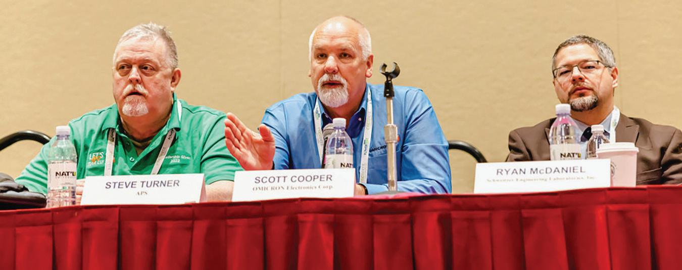


exhibits, and over 70 prize winners made for an electrifying atmosphere. Attendees mingled with customers, vendors, and colleagues, making this year’s expo an event to remember.
PowerBash Reception
Following the PowerTest Trade Show, exhibitors and conference attendees joined in an evening of NASCAR excitement. Raceway-themed food and music were the backdrop for good fun. Sponsored by A-Rent, event attendees stepped up to the pit crew challenge, played the giant Jenga game, paired up for the cornhole competition, and generally had a great time catching up and meeting new folks.
A highlight of the evening was the presentation of awards. Winners included:
Technical Track Presentation Winners
• Best Overall Presentation — Power Cable System Reliability and Longevity by Ben Lanz, IM Corp
• Best Electrical Safety Presentation — NFPA 70E: Critical Aspects and Revision Updates by Jim Dollard, IBEW Local 98
• Best Sales and Management Presentation
— Successfully Market Your Electrical Testing Services Firm by Paul Seppanen, A-Rent
• Best Equipment Presentation — Field Testing of Current Transformers: Challenges and Mitigation Techniques by Dinesh Chhajer, Megger
• Best Reliability Presentation — Power Cable System Reliability and Longevity by Ben Lanz, IM Corp
• Best Transformer/Cables Presentation — Test Setup Issues Impacting SFRA Results by Mike Anderson, Doble Engineering
Hospitality Suite Winners
• Most Technical — Megger
• Most Entertaining — Group CBS
• Most Creative — RESA Power
• Most Hospitable — Shermco
• Most Appetizing — Saber Power
Exhibition Winners
• Best In Show — Doble Engineering
• Most Innovative – Protec Equipment Resources
• Most Visited – AC Pro
THANK YOU TO OUR POWERBASH SPONSOR

NASCAR-Themed PowerBash Celebrates Electrical Power Professionals
FRIDAY
– SUNDAY
Seminars and Hands-On Learning
Friday and Saturday featured four-hour, in-depth technical training sessions. Attendees could choose from 14 unique seminar topics, each designed to deepen the understanding and skill set of electrical
power system professionals. Sunday, the final day of the conference, was one of the most well-attended training events. Transformer Fundamentals, hosted by Doble Engineering, was an interactive course combining theoretical background with practical field experience. The content was geared toward engineers, managers, and technicians who
work in the field. The course provided fundamental knowledge on how transformers are designed and manufactured; a review of major transformer components; installation, commissioning, in-service and off-line electrical testing; and insulation oil laboratory diagnostic testing. This session received one of the highest reviews.
NETA Exam Prep
The NETA Exam Prep Seminars were also available, back by popular demand. Open to NETA Certified Technicians, this twopart interactive seminar series reviewed Detail Content Outlines (DCOs) and offered an opportunity to participate in the NETA Practice Exam. Attendees developed their knowledge and boosted their exam confidence levels.

POWERTEST 2023 –THAT’S A WRAP!
PowerTest 2023 was truly a memorable event breaking all registration and participation records. Attendees came from across the country and around the globe to learn and connect. There were representatives from nearly all of the NETA Accredited Companies, engineering design firms, power producers, distributors, contractors, manufacturers, and commercial entities, along with hundreds of organizations that provide products and services in support of the electrical power industry — all part of the NETA network of companies committed to electrical reliability and safety.
The many training sessions and special events that are always a part of PowerTest delivered opportunities for learning, advancement, networking, and laying the groundwork for future collaborations.
POWERTEST 2024, FEBRUARY 26 – MARCH 1 IN DALLAS, TEXAS
Join NETA and leading electrical power systems professionals at the next premier electrical maintenance and safety conference, February 26 – March 1, 2024, at the Hilton Anatole in Dallas, Texas. At next year’s conference, we’ll be celebrating 45 years of PowerTest with expanded training categories, engagement events, and an eye on the future of our
Registration opens September 1, 2023. Be sure to mark your calendars and secure your place at PowerTest 2024. Save $100 on your trip to Dallas when you register before December 31, 2023.
Sponsorship and exhibitor opportunities are available for companies looking to grow their relationships and build industry leadership. NETA’s industry partners are encouraged to reserve exhibit space and confirm sponsorships as soon as possible. Inquiries should be directed to Julie Miller at 269-488-6382 or powertest@netaworld.org


NETA ACCREDITED COMPANIES Setting the Standard
ABM Electrical Power Services, LLC Ontario, CA 91761-8177
www.abmpowerservice.abm.com
ABM Electrical Power Services, LLC Raleigh, NC 27616
www.abmpowerservice.abm.com
ABM Electrical Power Services, LLC Tempe, AZ 85282-2017
www.abmpowerservice.abm.com
ABM Electrical Power Services, LLC Charlotte, NC 28269-7531
www.abmpowerservice.abm.com
ABM Electrical Power Services, LLC Pleasanton, CA 94566
www.abmpowerservice.abm.com
ABM Electrical Power Services, LLC Englewood, CO 80112-9306 www.abmpowerservice.abm.com
ABM Electrical Power Services, LLC San Diego, CA 92123-1844
www.abmpowerservice.abm.com
ABM Electrical Power Services, LLC Alpharetta, GA 30005
www.abmpowerservice.abm.com
ABM Electrical Power Services, LLC Austin, TX 78744
www.abmpowerservice.abm.com
ABM Electrical Power Services, LLC Vancouver, WA 98682
www.abmpowerservice.abm.com
ABM Electrical Power Solutions, LLC Lanham, MD 20706-1834 www.abmpowersolution.abm.com
ABM Electrical Power Solutions, LLC Baltimore, MD 21227-1642 www.abmpowersolution.abm.com
ABM Electrical Power Solutions, LLC Chesapeake, VA 23320-2643 www.abmpowersolution.abm.com
ABM Electrical Power Solutions, LLC Columbus, OH 43228-3866 www.abmpowersolution.abm.com
ABM Electrical Power Solutions, LLC Cranberry Township, PA 16066-6407 www.abmpowersolution.abm.com
Absolute Testing Services, Inc. Houston, TX 77040 www.absolutetesting.com
Accessible Consulting Engineers, Inc. Irvine, CA 92618-3201 www.acetesting.com
Advanced Electrical Services Calgary, AB T2B 3N4 www.aes-ab.com
Advanced Electrical Services Edmonton, AB T6E 0P5 www.aes-ab.com
Advanced Testing Systems Bethel, CT 06801-2858
www.advtest.com
A&F Electrical Testing, Inc. Nesconset, NY 11767-1017
www.afelectricaltesting.com
A&F Electrical Testing, Inc. New York, NY 10004-2257 www.afelectricaltesting.com
Alpha Relay and Protection Testing, LLC Billings, MT 59102-7460 www.arptco.com
American Electrical Testing Co., LLC Foxboro, MA 02035
www.aetco.us
American Electrical Testing Co., LLC Allentown, PA 18104
www.aetco.us
American Electrical Testing Co., LLC South Windsor, CT 06074-2931 www.aetco.us
American Electrical Testing Co., LLC Brentwood, NY 11717-1265 www.aetco.us
American Electrical Testing Co., LLC Boonton, NJ 07005-1060 www.aetco.us
AMP Quality Energy Services, LLC Somerville, AL 35670 www.ampqes.com
AMP Quality Energy Services, LLC Nashville, TN 37210 www.ampqes.com
Apparatus Testing and Engineering Rancho Cordova, CA 95742-6822 www.apparatustesting.com
Apparatus Testing and Engineering Pleasanton, CA 94588-8017 www.apparatustesting.com
Applied Engineering Concepts Pasadena, CA 91103 www.aec-us.com
Applied Engineering Concepts San Diego, CA 92126 www.aec-us.com
ARM CAMCO, LLC Ebensburg, PA 15931-4111 www.armcamco.net
BEC Testing Farmingdale, NY 11735-1402 www.bectesting.com
Blue Runner Switchgear Testing, LLC Cave City, KY 42127-9481 www.bluerunnerswitchgear.com
Brosz Technical Services Markham, ON L3R 8C3 www.brosz.net
Burlington Electrical Testing Co., LLC Croydon, PA 19021-6051 www.betest.com
Burlington Electrical Testing Co., LLC Delran, NJ 08075 www.betest.com
C3 Engineering Chandler, AZ 85225-7540 www.c-3engineering.com
Capitol Area Testing, Inc. Crownsville, MD 21032 www.capitolareatesting.com
CBS Field Services Sumner, WA 98390-9690 www.cbsfieldservices.com
CBS Field Services Livonia, MI 48150-1109 www.cbsfieldservices.com
CBS Field Services Phoenix, AZ 85040-3832 www.cbsfieldservices.com
CBS Field Services Salt Lake City, UT 84104-6533 www.cbsfieldservices.com
CBS Field Services Vancouver, WA 98661-1261 www.cbsfieldservices.com
CBS Field Services Chino, CA 91710 www.cbsfieldservices.com
CBS Field Services Los Alamos, NM 87547 www.cbsfieldservices.com
CBS Field Services Lakeland, FL 33811 www.cbsfieldservices.com
CBS Field Services Nashville, TN 37207-5534 www.cbsfieldservices.com
Control Power Concepts Las Vegas, NV 89120-2791 www.controlpowerconcepts.com
Eastern High Voltage, Inc. Robbinsville, NJ 08691-1685 www.easternhighvoltage.com
Electek Power Services, Inc. Sarnia, ON N7T2E5 www.electek.ca
ELECT, P.C. Wendell, NC 27591 www.elect-pc.com
Electrical & Electronic Controls Ooltewah, TN 37363-8762 www.eecontrols.com
Electrical Energy Experts, LLC Germantown, WI 53022-4446 www.electricalenergyexperts.com
Electrical Energy Experts, LLC Oak Brook, IL 60523 www.electricalenergyexperts.com
Electrical Engineering & Service Co., Inc. Holbrook, MA 02343 www.eescousa.com
Electrical Equipment Upgrading, Inc. Savannah, GA 31415-9518 www.eeu-inc.com
Electrical Reliability Services Westerville, OH 43082-8870 www.electricalreliability.com
Electrical Reliability Services Carlsbad, CA 92010-6634 www.electricalreliability.com
Electrical Reliability Services El Paso, TX 79922-1329 www.electricalreliability.com
Electrical Reliability Services Pleasanton, CA 94566-3119 www.electricalreliability.com
Electrical Reliability Services Albuquerque, NM 87113-1861 www.electricalreliability.com
Electrical Reliability Services Marietta, GA 30067-9319 www.electricalreliability.com
Electrical Reliability Services Santa Fe Springs, CA 90670 www.electricalreliability.com
Electrical Reliability Services Lees Summit, MO 64086-4723 www.electricalreliability.com
Electrical Reliability Services Denver, CO 80221-2900 www.electricalreliability.com
Electrical Reliability Services Auburn, WA 98001-1655 www.electricalreliability.com
Electrical Reliability Services Chandler, AZ 85286 www.electricalreliability.com
Electrical Reliability Services Sparks, NV 89431-6070 www.electricalreliability.com
Electrical Reliability Services Fort Myers, FL 33966-1244 www.electricalreliability.com
Electrical Reliability Services Sulphur, LA 70665-8747 www.electricalreliability.com
Electrical Reliability Services Sandy, UT 84070 www.electricalreliability.com
Electrical Reliability Services Las Vegas, NV 89118-6851 www.electricalreliability.com
Electrical Reliability Services Geismar, LA 70734 www.electricalreliability.com
Electrical Reliability Services Shreveport, LA 71129-3003 www.electricalreliability.com
Electrical Reliability Services Pasadena, TX 77503-2337 www.electricalreliability.com
Electrical Reliability Services Omaha, NE 68138 www.electricalreliability.com
Electrical Reliability Services Allen, TX 75002 www.electricalreliability.com
Electrical Reliability Services Charlotte, NC 28278 www.electricalreliability.com
Electrical Reliability Services Raleigh, NC 27601 www.electricalreliability.com
Electrical Reliability Services Jacksonville, FL 32258 www.electricalreliability.com
Electrical Reliability Services Moncks Corner, SC 29461 www.electricalreliability.com
Electrical Reliability Services Milwaukie, OR 97222-8853 www.electricalreliability.com
Electrical Testing and Maintenance Corp. Memphis, TN 38118-6313 www.etmcorp.net
Electrical Testing, Inc. Rome, GA 30161-3894 www.electricaltestinginc.com
Electrical Testing Solutions Oshkosh, WI 54904-9769 www.electricaltestingsolutions.com
Electric Power Systems, Inc. Maryland Heights, MO 63043-3536 www.epsii.com
Electric Power Systems, Inc. Centennial, CO 80112 www.epsii.com
Electric Power Systems, Inc. Salem, VA 24153-5120 www.epsii.com
Electric Power Systems, Inc. Coraopolis, PA 15108-9307 www.epsii.com
Electric Power Systems, Inc. Kansas City, MO 64117 www.epsii.com
Electric Power Systems, Inc. Gilbert, AZ 85233 www.epsii.com
Electric Power Systems, Inc. Manchester, NH 03109-5606 www.epsii.com
Electric Power Systems, Inc. Sanford, FL 32771 www.epsii.com
Electric Power Systems, Inc. Gonzales, LA 70737-4759 www.epsii.com
Electric Power Systems, Inc. Nashville, TN 37211-3121 www.epsii.com
Electric Power Systems, Inc. Brunswick, OH 44212 www.epsii.com
Electric Power Systems, Inc. Lombard, IL 60148 www.epsii.com
Electric Power Systems, Inc. Sugar Land, TX 77478 www.epsii.com
Electric Power Systems, Inc. Green Bay, WI 54304-5640 www.energisinc.com
Electric Power Systems, Inc. Riverview, MI 48193-4250 www.epsii.com
Electric Power Systems, Inc. Albuquerque, NM 87113 www.epsii.com
Electric Power Systems, Inc. Raleigh, NC 27615 www.epsii.com
Electric Power Systems, Inc. North Las Vegas, NV 89115 www.epsii.com
Electric Power Systems, Inc. San Diego, CA 91126 www.epsii.com
Electric Power Systems, Inc. Norcross, GA 30092 www.epsii.com
Electric Power Systems, Inc. Glen Allen, VA 23059 www.epsii.com
Electric Power Systems, Inc. Indianapolis, IN 46256 www.epsii.com
Electric Power Systems, Inc. Brooklyn Park, MN 55428 www.epsii.com
Electric Power Systems, Inc. Cockeysville, MD 21030 www.epsii.com
Electric Power Systems, Inc. Richardson, TX 75081 www.epsii.com
Electric Power Systems, Inc. Vancouver, WA 98682 www.epsii.com
Electric Power Systems, Inc. West Chester, OH 45069 www.epsii.com
NETA ACCREDITED COMPANIES Setting
Electric Power Systems, Inc. Pleasanton, CA 94588 www.epsii.com
Electric Power Systems, Inc. Santa Ana, CA 92705 www.epsii.com
Electric Power Systems, Inc. Yuba City, CA 95993 www.epsii.com
Electric Power Systems, Inc. Maryland Heights, MO 63043-3536 www.epsii.com
Electro Test, LLC Wahiawa, HI 96786 www.electrotest.pro
Elemco Services, Inc. Lynbrook, NY 11563-2622 www.elemco.com
EPS Technology Durham, CT 06422 www.eps-technology.com
ESR Electrical Services Tempe, AZ 85281-2346 www.esreliability.com
ESR Electrical Services Fife, WA 98424 www.esreliability.com
ESR Electrical Services Hillsboro, OR 97124 www.esreliability.com
ESR Electrical Services Hermiston, OR 97838 www.esreliability.com
ESR Electrical Services Ashburn, VA 20148 www.esreliability.com
Forefront Electrical Testing Co. Elk Grove Village, IL 60007-2215 www.forefronttesting.com
Giga Electrical & Technical Services, Inc. Commerce, CA 90040 www.gigaelectrical-ca.com
Grubb Engineering, Inc. San Antonio, TX 78212 www.grubbengineering.com
Halco Testing Services Los Angeles, CA 90019 www.halcotestingservices.com
Hampton Tedder Technical Services Montclair, CA 91763-6129 www.httstesting.com
Hampton Tedder Technical Services Phoenix, AZ 85009-1359 www.httstesting.com
Hampton Tedder Technical Services Las Vegas, NV 89118 www.httstesting.com
Harford Electrical Testing Co., Inc. Joppa, MD 21085-3409 www.harfordtesting.com
High Energy Electrical Testing, Inc. Farmingdale, NJ 07727 www.highenergyelectric.com
High Voltage Maintenance Corp. Dayton, OH 45414-3525 www.hvmcorp.com
High Voltage Maintenance Corp. Walpole, MA 02081-2541 www.hvmcorp.com
High Voltage Maintenance Corp. Greenwood, IN 46143 www.hvmcorp.com
High Voltage Maintenance Corp. Pittsburgh, PA 15205-1206 www.hvmcorp.com
High Voltage Maintenance Corp. Mentor, OH 44061 www.hvmcorp.com
High Voltage Maintenance Corp. Novi, MI 48375-2422 www.hvmcorp.com
High Voltage Maintenance Corp. New Berlin, WI 53151-3549 www.hvmcorp.com
High Voltage Maintenance Corp. New York, NY 10119 www.hvmcorp.com
High Voltage Maintenance Corp. Cheshire, CT 06410 www.hvmcorp.com
High Voltage Maintenance Corp. Elk Grove Village, IL 60007-2400 www.hvmcorp.com
High Voltage Maintenance Corp. Hanover, MD 21076 www.hvmcorp.com
High Voltage Maintenance Corp. Louisville, KY 40299 www.hvmcorp.com
High Voltage Maintenance Corp. New York, NY 10119 www.hvmcorp.com
High Voltage Maintenance Corp. Cincinnati/Kentucky Area Satellite Office www.hvmcorp.com
Hood Patterson & Dewar, Inc. Norcross, GA 30071 www.hoodpd.com
Hood Patterson & Dewar, Inc. Addison, TX 75001 www.hoodpd.com
Hood Patterson & Dewar, Inc. Chantilly, VA 20151 www.hoodpd.com
Hood Patterson & Dewar, Inc. Gallatin, TN 37066 www.hoodpd.com
Industrial Electric Testing, Inc. Jacksonville, FL 32256-2746 www.industrialelectrictesting.com
NETA ACCREDITED COMPANIES Setting the Standard
Industrial Electric Testing, Inc.
Hallandale Beach, FL 33009-4029 www.industrialelectrictesting.com
Industrial Tests, Inc.
Rocklin, CA 95677-4031 www.industrialtests.com
Infra-Red Building and Power Service, Inc. Holbrook, MA 02343-1011 www.infraredbps.com
JET Electrical Testing, LLC Lawrenceville, NJ 08648 www.jetelectricaltesting.com
J.G. Electrical Testing Corporation
Tinton Falls, NJ 07753 www.jgelectricaltesting.com
KT Industries, Inc. Los Angeles, CA 90065-2919 www.ktiengineering.com
Magna IV Engineering Edmonton, AB T6X 0X2 www.magnaiv.com
Magna IV Engineering Fort McMurray, AB T9H 4A6 www.magnaiv.com
Magna IV Engineering Saskatoon, SK S7K 5Y2 www.magnaiv.com
Magna IV Engineering Huechuraba, 8580676 www.magnaiv.com
Magna IV Engineering Langley, BC V2Y 0G9 www.magnaiv.com
Magna IV Engineering Calgary, AB T2H 1M6 www.magnaiv.com
Magna IV Engineering Grande Prairie, AB T8V 3J3 www.magnaiv.com
Magna IV Engineering Bronx, NY 10474 www.magnaiv.com
Midwest Engineering Consultants, Ltd. Moline, IL 61265-6954 www.Midwestengr.com
M&L Power Systems, Inc. Old Bridge, NJ 08857-1980 www.mlpower.com
MTA Electrical Engineers Escondido, CA 92029-1337 www.mtaee.com
National Field Services Lewisville, TX 75057-2301 www.natlfield.com
National Field Services League City, TX 77573-4888 www.natlfield.com
National Field Services San Marcos, TX 78666 www.natlfield.com
National Field Services Las Vegas, NV 89102 www.natlfield.com
National Field Services Reno, NV 89502-3293 www.natlfield.com
National Field Services Carson, CA 90810 www.natlfield.com
National Field Services Longview, WA 98632-1624 www.natlfield.com
National Field Services Lakeland, FL 33810-7804 www.natlfield.com
National Field Services Irondale, AL 35210-3701 www.natlfield.com
North Central Electric, Inc. Hulmeville, PA 19047-5827 www.ncetest.com
Orbis Engineering Field Services Ltd. Edmonton, AB T6E 6G8 www.orbisengineering.net
Orbis Engineering Field Services Ltd. Calgary, AB T3R 0K4 www.orbisengineering.net
Orbis Engineering Field Services Ltd. Santiago, www.orbisengineering.net
Pacific Powertech Inc.
Port Coquitlam, BC V3C 6N2 www.pacificpowertech.ca
Pacific Power Testing, Inc. San Leandro, CA 94577-5542 www.pacificpowertesting.com
Phasor Engineering Mercedita, 00715 www.phasorinc.com
Potomac Testing Crofton, MD 21114-2051 www.potomactesting.com
Potomac Testing Troy, MI 48083-2236 www.potomactesting.com
Potomac Testing Carmel, IN 46032-5807 www.potomactesting.com
Potomac Testing Jeffersonville, OH 43128 www.potomactesting.com
Power Engineering Services, Inc. Converse, TX 78109-2041 www.pe-svcs.com
Power Engineering Services, Inc. Friendswood, TX 77546 www.pe-svcs.com
Power Engineering Services, Inc. Cedar Park, TX 78613 www.pe-svcs.com
Power Products & Solutions, LLC Charlotte, NC 28269-2324 www.powerproducts.biz
Power Products & Solutions, LLC Mauldin, SC 29662-2414 www.powerproducts.biz
Power Solutions Group, Ltd. Tipp City, OH 45371-2843 www.powersolutionsgroup.com
Power Solutions Group, Ltd. Englewood, CO 80112-5311 www.powersolutionsgroup.com
Power Solutions Group, Ltd. Columbus, OH 43213 www.powersolutionsgroup.com
Power Solutions Group, Ltd. Liberty, SC 29657 www.powersolutionsgroup.com
Power Solutions Group, Ltd. Pearland, TX 77581-1901 www.powersolutionsgroup.com
Power Solutions Group, Ltd. Clarksville, TN 37040 www.powersolutionsgroup.com
Power System Professionals, Inc. Roseville, CA 95678
www.powerpros.net
Power Systems Testing Co. Fresno, CA 93722-6418 www.powersystemstesting.com
Power Systems Testing Co. Santa Ana, CA 92705-4152 www.powersystemstesting.com
Power Systems Testing Co. Livermore, CA 94551-8521 www.powersystemstesting.com
Power Test, Inc. Harrisburg, NC 28075-7506 www.powertestinc.com
Praetorian Power Protection, LLC Lynnwood, WA 98046 www.praetorianpower.com
Precision Testing Group Elizabeth, CO 80107-7451 www.precisiontestinggroup.com
Premier Power Maintenance Corporation Indianapolis, IN 46268-2588 www.premierpower.us
Premier Power Maintenance Corporation Ashland, KY 41102-7756 www.premierpower.us
Premier Power Maintenance Corporation Decatur, AL 35601-8800 www.premierpower.us
Premier Power Maintenance Corporation Brighton, MI 48116 www.premierpower.us
Premier Power Maintenance Corporation Saint Paul, MN 55113 www.premierpower.us
Premier Power Maintenance Corporation Louisville, KY 40214 www.premierpower.us
QP Testing, LLC
New Lenox, IL 60451 www.qp-testing.com
Qualus Services, LLC Lake Mary, FL 32746-4772 www.qualuscorp.com
Qualus Services, LLC Middle River, MD 21220-2874 www.qualuscorp.com
Qualus Services, LLC Nashville, TN 37210-2302 www.qualuscorp.com
Qualus Services, LLC Doylestown, PA 18902-1128 www.qualuscorp.com
Qualus Services, LLC Westborough, MA 01581-1088 www.qualuscorp.com
Qualus Services, LLC Brooklyn Park, MN 55428 www.qualuscorp.com
Qualus Services, LLC Fairfield, OH 45011-8651 www.qualuscorp.com
Qualus Services, LLC Louisville, KY 40213-1565 www.qualuscorp.com
Qualus Services, LLC Walled Lake, MI 48390-3432 www.qualuscorp.com
Qualus Services, LLC Knoxville, TN 37932-3232 www.qualuscorp.com
Qualus Services, LLC Merrillville, IN 46410 www.qualuscorp.com
Qualus Services, LLC Virginia, MN 55792 www.qualuscorp.com
Qualus Services, LLC La Porte, TX 77571-5200 www.qualuscorp.com
Qualus Solutions of Florida, LLC Tampa, FL 33619-8349 www.qualuscorp.com
Qualus Solutions of Florida, LLC
Davie, FL 33314-2816
www.qualuscorp.com
RESA Power Service
Wixom, MI 48393
www.resapower.com
RESA Power Service
Blaine, MN 55449
www.resapower.com
RESA Power Service
Macclenny, FL 32063-4036
www.resapower.com
RESA Power Service Cleveland, OH 44224
www.resapower.com
RESA Power Service Parker, CO 80134
www.resapower.com
RESA Power Service
Shelton, CT 06484-5336 www.resapower.com
RESA Power Service Cerritos, CA 90703 www.resapower.com
RESA Power Service San Jose, CA 95131
www.resapower.com
RESA Power Service
Plant City, FL 33563
www.resapower.com
RESA Power Service
Cicero, NY 13039-9217
www.resapower.com
RESA Power Service Vancouver, BC V6V OA5
www.resapower.com
RESA Power Service Green Bay, WI 54304 www.resapower.com
RESA Power Service Lebanon, TN 37090-6021 www.resapower.com
RESA Power Service Visalia, CA 93291 www.resapower.com
RESA Power Service Tempe, AZ 85281 www.resapower.com
RESA Power Service Butler, PA 16002-8913 www.resapower.com
REV Engineering Ltd. Calgary, AB T2B 3A3 www.reveng.ca
Rondar Inc.
Hamilton, ON L8E2X6 www.rondar.com
Saber Power Field Services, LLC Rosharon, TX 77583-5188 www.saberpowerfieldservices.com
Saber Power Field Services, LLC Helotes, TX 78023
www.saberpowerfieldservices.com
Saber Power Field Services, LLC Alvarado, TX 76009 www.saberpowerfieldservices.com
Saber Power Field Services, LLC Corpus Christi, TX 78413-1922 www.saberpowerfieldservices.com
Saber Power Field Services, LLC Geismar, LA 70734
www.saberpowerfieldservices.com
Saber Power Field Services, LLC Orange, TX 77632
www.saberpowerfieldservices.com
Saber Power Field Services, LLC Midland, TX 79706 www.saberpowerfieldservices.com
Scott Testing, Inc. Hamilton, NJ 08619-3250 www.scotttesting.com
Sentinel Power Services, Inc. Tulsa, OK 74115-5729 www.sentfs.com
Sentinel Power Services, Inc. Fort Worth, TX 76155-2750 www.sentfs.com
Shermco Industries Irving, TX 75061-8919 www.shermco.com
Shermco Industries Minooka, IL 60447-9557 www.shermco.com
Shermco Industries Saskatoon, SK S7K 8H7 www.shermco.com
Shermco Industries Phoenix, AZ 85040-1475 www.shermco.com
Shermco Industries Hiawatha, IA 52233 www.shermco.com
Shermco Industries Cedar Park, TX 78613-7229 www.shermco.com
Shermco Industries Calgary, AB T2E 8A2 www.shermco.com
Shermco Industries Johnston, IA 50131 www.shermco.com
Shermco Industries Tulsa, OK 74145 www.shermco.com
Shermco Industries Winnipeg, MB R2X 2T7 www.shermco.com
Shermco Industries RM of Sherwood, SK S4K 0A2 www.shermco.com
NETA ACCREDITED COMPANIES Setting
Shermco Industries Angleton, TX 77515-8157 www.shermco.com
Shermco Industries San Antonio, TX 78232 www.shermco.com
Shermco Industries Edmonton, AB T6E 5N2 www.shermco.com
Shermco Industries Tallmadge, OH 44278 www.shermco.com
Shermco Industries Houston, TX 77053 www.shermco.com
Shermco Industries La Vista, NE 68128 www.shermco.com
Shermco Industries Sweetwater, TX 79556 www.shermco.com
Shermco Industries Port Arthur, TX 77642 www.shermco.com
Shermco Industries Johnston, IA 50131 www.shermco.com
Shermco Industries Saint Paul, MN 55110 www.shermco.com
Shermco Industries Livonia, MI 48150 www.shermco.com
Shermco Industries Gonzales, LA 70737 www.shermco.com
Shermco Industries Concord, NC 28027 www.shermco.com
Shermco Industries Creola, AL 36525 www.shermco.com
Shermco Industries Nashville, TN 37211 www.shermco.com
Shermco Industries Burnaby, BC V5A 3C2 www.shermco.com
Shermco Industries Wichita Falls, TX 76302 www.shermco.com
Shermco Industries Midland, TX 79707 www.shermco.com
Shermco Industries Centennial, CO 80111 www.shermco.com
Shermco Industries Sulphur, LA 70665 www.shermco.com
Shermco Industries Corpus Christi, TX 78409-2229 www.shermco.com
Sigma C Power Services LLC Westborough, MA 01581 www.sig-c.com
Sigma Six Solutions, Inc. Auburn, WA 98001-1654 www.sigmasix.com
Sigma Six Solutions, Inc. Quincy, WA 98848 www.sigmasix.com
Star Electrical Services & General Supplies, Inc. Las Piedras, 00771 www.starelectricalpr.com
Taifa Engineering Ltd. Edmonton, AB T6N 1B2 www.taifaengineering.com
Taurus Power & Controls, Inc. Tualatin, OR 97062-9517 www.tauruspower.com
Taurus Power & Controls, Inc. Kent, WA 98031 www.tauruspower.com
Tidal Power Services, LLC Rosharon, TX 77583-4385 www.tidalpowerservices.com
Tidal Power Services, LLC Gonzales, LA 70737-8183 www.tidalpowerservices.com
Tidal Power Services, LLC Sulphur, LA 70665-9508 www.tidalpowerservices.com
Tidal Power Services, LLC Victoria, TX 77901 www.tidalpowerservices.com
Tony Demaria Electric, Inc. Wilmington, CA 90744-5533 www.tdeinc.com
Utilities Instrumentation Service, Inc. Dexter, MI 48130-1564
www.uiscorp.com
Utilities Instrumentation Service - Ohio, LLC
Centerville, OH 45458 www.uiscorp.com
Utility Service Corporation Huntsville, AL 35807 www.utilserv.com
VISTAM, Inc. Signal Hill, CA 90755 www.vistam.com


TEST with CONFIDENCE
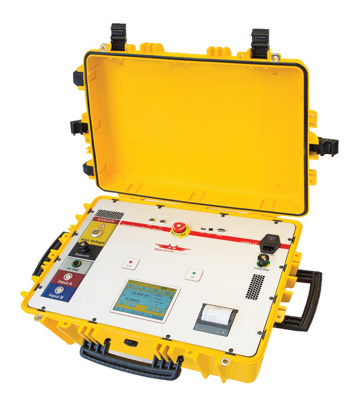
CAPO-12
12kV Capacitance Power Factor
• Safe + Compact + Simple + Low cost
• Test voltage up to 12kV | Built in Standard Capacitor
• Best accuracy and resolution in the industry
• Test frequency – 10 Hz to 400 Hz
• Easy to operate, no computer needed
• Highest output power available in a por table system
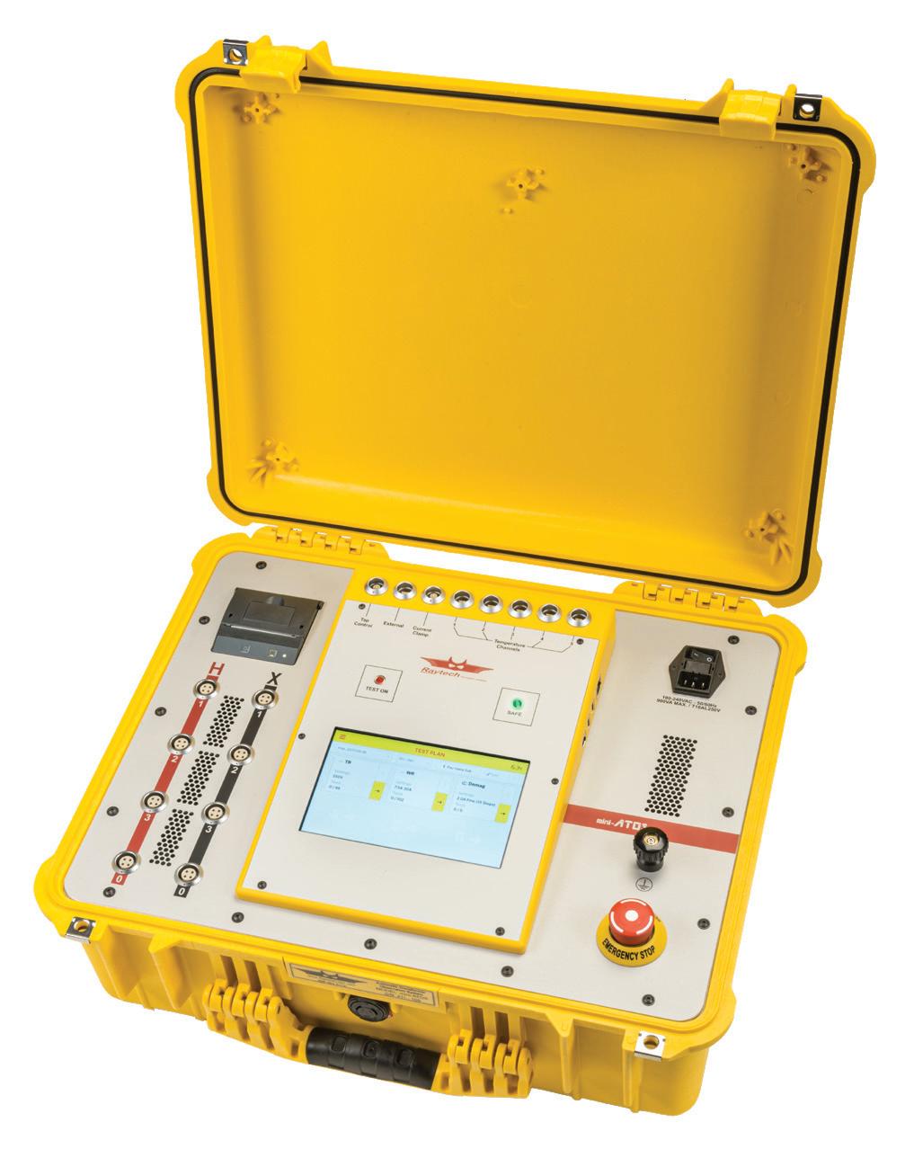
mini-ATOS
TR-WR Combo system
• Winding Resistance and Turns Ratio with a single hookup
• Demagnetization and Magnetic Balance
• Export complete Test Report via .pdf or CSV/Excel to USB drive or direct to PC Optional:
• Short Circuit Impedance
• Dynamic Resistance Measurement
• Frequency Response of Stray Losses


What’s going on in my Substation Automation System and SCADA?
As an expert in the world of IEC 61850, I know how important testing the SAS and SCADA is. StationScout provides a really simple and clear overview of the communication within automation and control. Both the behavior of IEDs and all signals transmitted are visualized transparently. The dedicated powerful test set establishes a cyber-safe connection to the station network. StationScout is the ideal tool during the entire lifecycle of IEC 61850 systems.

