PARTIAL DISCHARGE TESTS FOR MEDIUM-VOLTAGE POWER CABLE SYSTEMS
PD SECRETS, TIPS, AND TRICKS PAGE 48
ACCEPTANCE AND MAINTENANCE
TESTING PAGE 56 USING VLF AND PD TESTING PAGE 64
ISSN 2167-3594 NETA WORLD JOURNAL PRINT ISSN 2167-3586 NETA WORLD JOURNAL ONLINE FALL 2020
With the Megger MRCT and MVCT, 2 MINUTES is all the time you need for single ratio combined testing of your current transformers.
This includes winding resistance, excitation, demag, ratio, and phase error testing across all CT classes.
All it takes are 2 minutes and the Megger MRCT or MVCT Current Transformer Test Sets.


MRCT
Relay and current transformer tester

MVCT
VT and CT analyzer
1-800-723-2861 us.megger.com

Electrical Power Systems Industry Resource on Technical and Professional Training FALL 2020: VOL. 5. NO. 2
NE W

LIVE VIRTUAL ONLINE TRAINING
TRAIN LIVE WHILE REMOTE IN ORDER T O STAY SAFE & UP T O DATE
TRAINING INSTITUTE

VIRTUAL TRAINING OPTIONS
-NFPA 70E 2018
-NFPA 70E 2021*
-BASIC ELECTRICITY
-ELECTRIC PRINT READING
-SUBSTATION: COMPONENTS, TESTING & INTERPRETATION
-INTRODUCTION TO LOW VOLTAGE BREAKERS
-INTRODUCTION TO PROTECTIVE RELAY MAINTENANCE
Courses can be attended via Open Enrollment or by requesting dates for your personnel
For questions or to enroll, visit us at avotraining.com/virtual or call us at 877-594-3156
OMICRON Academy: An Engineer’s Playground
-ELECTRICAL SAFETY FOR INDUSTRAIL FACILITIES
-ELECTRICAL SAFETY FOR UTILITIES
-NATIONAL ELECTRICAL CODE 2020

OMICRON invites you to join our classes on Protection Testing, Digital Substations, Transformer Testing, Circuit Breakers, and more in our new on-line interactive trainings or in-person at the OMICRON Academy in Houston.


* available October 2020
Find additional training at omicronenergy.com/na-training

Benefit from professional courses with expert trainers, full-scale training equipment, e ective methodology and excellent customer care. Then, try what you have learned in the classroom with some practical testing at our indoor substation, and hands-on relay test lab.





Eugenio Carvalheira Engineering Manager, Protection and Control


A NETA World Journal
Special Publication
A publication dedicated to disseminating information on technical and professional training for the advancement of the electrical power systems industry

THE RACE TO VIRTUAL TRAINING
By Ralph Parrett, AVO Training Institute
RESPONDING TO COVID-19 WITH ONLINE EDUCATION AND TRAINING
By Dinesh Chhajer and Greg Valdez, Megger
TRAINING TECHNICIANS IN A PANDEMIC
By James R. White, Shermco Industries
FREE monthly webinars
*Earn 1 NETA CTD and 1 PDH or 0.1 CEU
Learn valuable testing tips and tricks
Can’t attend? View video recordings
Testing Tactics Webinar Series
Megger has partnered with NETA (International Electrical Testing Association) to present Testing Tactics, a special monthly webinar series that allows registrants to receive NETA CTDs (Continuing Technical Development Credits)* for attending the live webinar.
The Megger Testing Tactics Webinar Series provides valuable educational electrical testing knowledge in areas including theory and applications, best practices, industry standards / procedures, and safety. These FREE webinars are presented by Megger’s expert Applications Engineers and Product Managers, who utilize their experiences in the field and industry to give you greater insight into electrical testing so you can test with confidence.


Upcoming Webinars
Sep 18
Protection
MV and HV Circuit Breaker
Testing beyond Timing and Travel Measurements
Oct 23
Cable State-of-the-art diagnostics technologies for proactive cable condition assessment
us.megger.com/webinars
Nov 20
Rotating Machines
Fundamentals of motor protection
Dec 18
Protection
LV circuit breaker ground fault protection utilizing primary injection test method
04
FALL 2020
06 10
THE RACE TO VIRTUAL TRAINING
BY RALPH PARRETT, AVO Training Institute
Ihave worked in the electrical industry for nearly 15 years, and I never could have imagined being in the position we have all been thrown into. During my time in the electrical industry, I have worked in many capacities: maintenance and repair technician, project manager for critical system upgrades, technical instructor, curriculum developer, and now playing a key role in a private training company whose business foundation was based on face-to-face safety and hands-on training.
With the honor of a promotion in February, I had a big agenda of my own that I was excited to start on. Bringing our lab equipment up to par with industry standards, refreshing our curriculum, updating our delivery methods, creating classroom environments that are interactive from floor to ceiling — the list goes on and on. I did have plans to develop a learning delivery offering where the instructor would be remote from the learners and training would be provided through a virtual training platform. I had no idea that offering would have to be streamlined to also maintain a presence for our customers. The world’s population has faced adversity in many different ways, and the current situation has done quite the number on how every person has had to make some form of adaptation
to how they conduct their daily lives both professionally and personally. This article focuses on what to expect while attending virtual training courses delivered online as well as the benefits and challenges of virtual learning.
TECHNOLOGY
Virtual online training has grown rapidly to deliver learning opportunities to attendees from pre-K to university — and technical trades are no exception. Virtual online training permits the learner to have nearly the same experience they would in a physical classroom. Most of the information is delivered live by an instructor rather than in a prerecorded session. Attendees can ask questions to gain greater understanding of the topic or to clarify an area they may not feel they have fully grasped. To do this, virtual training platforms offer chat windows and the ability to turn on microphones and webcams that allow students to interact with the instructor and even other attendees. Sounds good right? The sales pitch is easy until you get into an environment you have never been exposed to.
INTERACTION
We are accustomed to and generally thrive on face-to-face interaction inside a classroom, but while attending a virtual online class, the learner is commonly alone, and that can dampen the learning experience. How can we fix this? The instructor is responsible for driving interaction while delivering the content, and the learners are responsible for interacting. The instructor has various methods available to encourage interaction with learners, but it is truly up to the attendee to invest in the interaction.
Understanding that remote learning differs from in-person learning is the best first step; the second step is to dive in. The first time I taught a virtual online course, there were just over 20 attendees. I explained the importance of interaction for their and my own experience and told them that without their interaction, I wouldn’t be able to identify adjustments that needed to be made to achieve learning. Because of their willingness, the objectives were accomplished, and we even had fun while covering the information. If you find yourself attending a virtual online session, I encourage you to open yourself up to this new
4 | TRAINING TALK | A NETA WORLD JOURNAL SPECIAL PUBLICATION
opportunity of learning. You may be surprised with the results.
SAFETY
With everything, there are always benefits and challenges. One major, and obvious, benefit to virtual training is the reduction in health exposure for participants, their families, and their co-workers. One challenge in the virtual training environment is the loss of physical presence. Attendees and the instructor can feel isolated at times, and everyone plays a vital role in breaking through that by participating. Another major benefit for the customer is that the training is delivered remotely. This further reduces health exposure during travel to a training location and reduces the costs of travel to the training location. Even though the information is delivered remotely, it is still possible to receive industry-leading training to increase their knowledge and skills.
Safety is the most vital element in providing the environment the learner needs to be successful. When a learner feels safe, the foundation for learning has been accomplished. Training environments

Understanding that remote learning differs from in-person learning is the best first step; the second step is to dive in.

must think with safety in the forefront, and thanks to entities such as OSHA and NFPA, we have always had great guidelines on how to do so. The integrity of an attendee’s health has always truly been a reflection on the safety of the learning environment. Prior to a global pandemic, there never was much thought about potential exposure to a virus. As a training professional, I can assure you that the health and safety of every individual participating in online learning has, and always will be, the number-one priority.
RALPH PARRETT is a United States Navy veteran with over 13 years of professional experience relating to electrical safety and maintenance training. During his time at AVO Training Institute, his proven dedication to training led to his position as Manager of Content & Delivery. His passion has always been to provide a topnotch training experience to ensure his students are more effective and safer when they return to the workplace. Ralph has extensive knowledge of maintenance, repair, and troubleshooting on control and instrumentation, relay logic systems, ABB control systems, central control station programs, power system equipment testing and maintenance, and other various types of equipment. He has developed and taught theory, operation, maintenance, and safety of various engineering systems.
A NETA WORLD JOURNAL SPECIAL PUBLICATION | TRAINING TALK | 5
RESPONDING TO COVID-19 WITH ONLINE EDUCATION AND TRAINING
BY DINESH CHHAJER and GREG VALDEZ, Megger
The global coronavirus outbreak and related social distancing, remote working, and employee health concerns have drastically altered the way business and training are conducted in a progressively changing landscape. The limitations put in place to prevent the spread of the virus directly affect the ability to adequately train employees in traditional face-to-face settings and call for implementing new digital tactics and educational procedures.
This article provides a picture of possible post-COVID training tools and content that enable technicians and engineers to continue their educational journey.
Our in-person Best Practices Seminars, the monthly Testing Tactics Webinar series, on-site customer training, the Technical Library on our website, and phone support from our technical support group worked well when travel and face-to-face meetings were the norm.
But as the coronavirus took hold, new ways of maintaining contact with our customers required converting from face-to-face to virtual meetings, increasing our digital content, and creating new ways to reach out online.
BEST PRACTICES SEMINARS
Our Best Practices Seminar series has been offered for more than 10 years to share testing concepts, advanced testing techniques, industry standards, and experiences from application engineers. Traditionally, these day-long, in-person seminars were split into two sections:
1. Testing and maintenance discussions related to transformers, batteries, relays, cables, and low-, medium-, and high-voltage circuit breakers
2. Educational hands-on sessions using equipment related to the topic at hand
Still free to all, the 2-day seminars are now comprised of two 1-hour technical presentations and a 30-minute question and answer session each day. The hands-on session has been replaced with a 15-minute description of the test instrument relative to the applications and techniques being discussed. Attendees ask questions and get answers during the Q&A session.
These webinars are held every four weeks and cover topics including battery maintenance, transformer winding condition assessment, partial discharge for assessing insulation condition, power factor and dielectric frequency response for insulation assessment, and cable diagnostics and fault location. Previous Best Practice Seminars remain available to watch online.
TESTING TACTICS WEBINARS
Testing Tactics Webinars provide valuable educational knowledge across several areas, including testing theory and applications, best practices, industry standards and procedures, and safety. These free webinars are presented by expert application engineers and product managers who use their field and industry experiences to provide insight into electrical testing, help users avoid common mistakes, and accelerate testing without sacrificing efficiency — and most important, safety. Held on the third Friday of every month, each 1-hour live webinar is followed by a 15to 30-minute Q&A session. For this series, we collaborated with NETA in North America to allow attendees to receive NETA Continuing Technical Development Credits (CTDs).
Over the years, we have used online webinars to share knowledge and industry experience with our
6 | TRAINING TALK | A NETA WORLD JOURNAL SPECIAL PUBLICATION
customers. The monthly Testing Tactics webinars have proven to be extremely successful, so as the virus shut down our ability to visit customers onsite, the decision was made to focus on broadening the assortment of webinars. From that initiative, several new webinar series addressing testing tactics, special applications, and case studies — and even one called You Ask, We Answer — have been added to meet our users’ educational needs.
Special Applications
The Special Application webinar series was conceived to answer the need to continue product operation trainings amid the coronavirus restrictions. The focus shifted to instrument operation, step-by-step procedures, safety recommendations, and best field practices, as well as the basics of results analysis. The sessions show users how specific instrument features are direct answers to industry-standard requirements and recommendations and/or to typical situations a user will encounter in the field while testing. The 1-hour broadcasts are followed by a live Q&A. Recordings of previous Special Application webinars continue to be accessible online.
You Ask, We Answer
The topical range of our webinars is expanding beyond traditional offerings with a series of webinars based around questions from users. These interactive webinars are all about customers and users and the questions and issues they run into in the field. Webinar attendees can ask questions in real time, and technical experts answer them live during the webinar. The webinar presentations are recorded, so attendees can refer back to the recordings as needed.
Case Studies
The power industry thrives on learning from each other’s experiences. Industry events and technical conferences are some of the best places to share field knowledge and real-world experiences, but most current and future conferences have been either cancelled or are going virtual.
The Case Studies webinars feature application engineers who share their field experiences and the test data that was collected. They walk through how the results were analyzed, outline the troubleshooting steps that were performed, and illustrate the process
of narrowing down the root cause of the problem. The series includes real-world examples collected from various sources, including consultations with utilities and service companies to help them troubleshoot asset problems and get back online safely and efficiently.
The Case Studies webinars cover topics on transformer testing such as winding resistance, turns ratio, power factor, and sweep frequency response analysis. Other assets such as circuit breakers and batteries are also covered.
Ultimately, our new solutions allow us to maintain contact with our customers, and that is the key component.
ONLINE MEDIA
Online media has come to the forefront, as people found themselves unable to travel or work in the field. We knew we had to make more use of online media channels to add content that educated and enhanced our current customers’ use of our equipment.
How-To YouTube Videos
We understand the nature of electrical maintenance activities where a technician might have a good understanding of the technique but does not possess total recall of the operating details of an instrument. These instances generate situations where a quick response from an expert becomes a partner in the job. Gaining easy access to the answers to common issues that arise in the field is imperative. To facilitate this, we created a series of how-to videos related to the frequently asked questions our technical support group (TSG) receives on a daily basis.
The TSG is a team of application engineers and specialists who help electric utilities and testing service companies understand how instruments operate and how to analyze the results from a variety

A NETA WORLD JOURNAL SPECIAL PUBLICATION | TRAINING TALK | 7
of electrical tests. We compiled commonly asked questions to create a series of 3- to 8-minute videos that walk through test procedures and software demonstrations to refresh a technician on operating details or instrument features.
Posted on YouTube, these videos are organized on playlists or can be added to user playlists for quick access while testing as if they were interacting with an applications specialist. The videos cover relay, transformer, instrument transformer, cable, and battery products and can be used as small training capsules on top of being a quick way to find answers to common questions.
Remote Customer Training
In-depth training has traditionally been conducted onsite with sessions conducted by applications engineers who cover the theoretical and practical aspects of the application in question. The need for in-depth training has not stopped, so we adapted to provide this type of training under the current circumstances. The use of platforms like Microsoft Teams has been instrumental, as it allows the same applications engineers to conduct remote sessions with customers, first by enabling remote, webinar-like presentations to cover theory, best practices, procedures, and testing recommendations, and then using audio- and video-enabled devices to conduct controlled-environment demonstrations and explanations using the instruments. The sessions are followed simultaneously on the customer side using their own instruments and test specimens or using demonstration boxes. This allows trainees to acquire knowledge of the application and the procedures, while still getting the experience required for field tests.
Technical Podcasts
Technical Podcasts are 15- to 25-minute discussions related to electrical testing theories, ideas, and practices that provide insight and educational information in an easy-to-digest format. Technical experts including product managers and applications engineers engage in lively discussions that focus on a single subject, or they might answer a series of questions that have been collected from customer interactions.
Technical Library
Our website’s technical library is the repository for the numerous application notes, articles, papers, and technical pieces we produce on an ongoing basis.
Application Notes
The library contains numerous documents related to products, testing, and education that include application notes. An application note addresses a technical topic and condenses the information into a relatively small number of easily digested pages. To date, more than 180 application notes have been released on topics ranging from explaining technology basics to performing a particular test on an apparatus to interpreting results.
Application notes save customers time researching complex technologies or scouring through a product user guide. While some application notes are longer, many are only 1–2 pages in length, making them convenient to provide to field personnel. Some customers print and laminate them for repetitive use.
Transformer Life Management Bulletin
Even during a pandemic, power must be delivered to consumers with a high degree of reliability. Transformers are an important asset for power delivery, and the transformers in our aging fleet need special attention through preventive and predictive maintenance. The Transformer Life Management (TLM) Bulletin goes into the details of diagnostic test methods as recommended in various international standards. The TLM Bulletin is for customers who need an in-depth understanding of transformer testing techniques in order to review test results and get involved in troubleshooting practices. Important topics such as power factor, excitation current, core demagnetization, OLTC dynamic resistance, and moisture in insulation are covered. The TLM series is a great learning resource for transformer operators and asset owners to gain the insight required to make informed decisions to optimize the life of a transformer.
VIRTUAL LEARNING PROGRAM
Our training arm was hit especially hard by the virus as training courses have always been held in person to provide individual attention to students. The inability to teach in that manner meant transitioning to online learning and assessment while maintaining the high level of education we have provided for more than 50 years. This necessity led to our Virtual Learning Program.
In March, we began providing safety and coderelated courses virtually via online platforms. Since
8 | TRAINING TALK | A NETA WORLD JOURNAL SPECIAL PUBLICATION
then, virtual offerings have been expanded to include maintenance-based training for protective relays, breakers, and substations. This platform allows attendees to receive the training required to maintain their qualifications and keeps them up to date on new industry standards. Attendees can interact with each other and the instructor through text, video, and audio chats to provide a learning environment as close to in person as possible.
Case Study
Georgia Power, which owns and operates over 12K miles of transmission and 75K miles of distribution lines, provides electric service to more than 2.5M customers in 155 Georgia counties. A key component to Georgia Power’s implementation of over 100 of our relay tests was a train-the-trainer program for education on the software component. The idea was for our technical and product management staff to train approximately 20 Georgia Power trainers and test engineers.
The original plan to begin in-person training in February 2020 was delayed until March. Then the beginning of the coronavirus eliminated the possibility of any in-person training for the near future. Both parties agreed to a revised plan using video conferencing. The first online training session was conducted in April, and subsequent sessions have continued for nine consecutive weeks of progressive training that has proven our ability to transfer knowledge through the use of video conferencing.


One attendee, Kevin Pierce, a Georgia Power senior protection and control test engineer, stated, “Megger custom-tailored their on-line training for GPC such that they go at our speed to train us on all the features of the core RTMS templates. Since our group supports RTMS for all field personnel, we require this foundation in order to meet our goal of being able to create our own test plans. It is obvious that Megger is committing significant time and effort to ensure we learn what we need to know to be successful.”
CONCLUSION
As we navigated this “new normal” and implemented these new forms of contact, we found we still needed to maintain personal contact with our customers in addition to offering materials online or on media channels. Individual conversations and interactions between people can never be replaced by impersonal media, so many of our daily interactions with clients occur via video conferencing, which has proven to be extremely successful and productive.
Ultimately, our new solutions allow us to maintain contact with our customers, and that is the key component that opens the door for us to share our knowledge and experience in support of the electrical testing industry. As we travel down this unforeseen road, we will continue to research and implement new and exciting ways to maintain a strong training regimen and educational program for our users.
DINESH CHHAJER is the Manager of the Technical Support Group at Megger USA. His responsibilities include providing engineering consultation and recommendations in relation to testing of transformers, batteries, circuit breakers, and other substation assets. Dinesh has presented numerous white papers related to asset maintenance and testing at various conferences within power industry. Dinesh previously worked as an Application Engineer at Megger and a substation and design Engineer at Power Engineers Inc. He is an IEEE member and a licensed Professional Engineer in Texas. Dinesh received his MS in electrical engineering from the University of Texas at Arlington.
GREG VALDEZ has been the Marketing Manager, NAFTA at Megger USA for six years. He previously was the Marketing Specialist at the AVO Training Institute, a Megger Subsidiary. Greg has been in marketing/advertising for over 20 year. He has a BA in advertising from Southern Methodist University and an MBA with a concentration in marketing and product/ brand management from SMU Cox School of Business.
A NETA WORLD JOURNAL SPECIAL PUBLICATION | TRAINING TALK | 9
TRAINING TECHNICIANS IN A PANDEMIC
BY JAMES R. WHITE, Shermco Industries
I’m like most everyone at this point. I’d like to go to a beach, pop a beer, and relax in the sun. Instead, I’m stuck at home writing articles like this because of COVID-19. While most of us are sick of this whole thing, the fact of the matter is that social distancing and masks in public seem to be necessary to keep the numbers reasonable. That’s why I just stay at home, cranking out articles and columns. I look bad in a mask, but wear one anyway.
The question now is how do we train our technicians when we have huge problems getting them to a class? Flying is an issue because, from what I’ve seen on TV, people are packed in because the airlines have to make a profit. Once your technicians get to the training site, will your vendor maintain social distancing by limiting class size, or do they put as many as they can into a class? A good question to ask the technicians you plan to send: Will you maintain social distancing including during breaks and lunch? We don’t want them to be carriers when they return, and younger people generally are not as worried about COVID-19 as older workers. These issues make it difficult to get the needed training in a safe and timely manner.
NFPA 70E’s 2021 edition has not been approved by the Standards Council yet, but I have no doubt it will be in June. All training has been moved to Section 110.6 in this new edition. A new Informational Note to Section 110.6(A)(4) includes provisions for interactive web-based and interactive electronic training. The key word in both of these types of training is “interactive.” The Committee wants such training to allow for immediate responses to questions — not training where questions are written down and answered sometime later. OSHA demands immediate answers and stated the requirement in their Letter of Interpretation dated November 22, 1994, which was published in the Summer issue of this Training Talk supplement to NETA World on page 11.
Our company faces the same problems as everyone else. Our Training Institute will open soon to provide the hands-on training needed so badly by new technicians, but they will be required to comply with a number of rules to keep students safe from the COVID-19 danger. We have also published a detailed operations guideline to keep all our employees safe. That takes care of the in-person hands-on training, but what about refresher and other types of training?
We are addressing this problem on a number of levels. When hands-on training is required for new technicians, we use web-based interactive training plus an environmental health and safety (EHS) or other suitable trainer to start conversations that can provide immediate answers to questions. This has shown to be as effective — possibly even more effective — than having a stand-up instructor fly to each location to present a course. The down side is the need to develop a web-based training program that includes the level of information to make this methodology practical. We have an entire department that does nothing but develop this type of program, so it involves definite cost. I’m not certain how valuable this is for smaller companies, but it is one option.
Another option is a revised program I first witnessed at Dallas County Community College (DCCC) years ago. I was part of a team exploring different options within the DCCC system to expand and more effectively use technology to present training
10 | TRAINING TALK | A NETA WORLD JOURNAL SPECIAL PUBLICATION
programs without live instructors. At the time, an instructor conducted hands-on training on a satellite, and students followed along by having the same type of equipment to work on during the lab sessions as the instructor. At the time, it was considered too expensive to install satellite dishes at all their locations.
Today, with web-based programs such as Microsoft Teams and Zoom, expense is no longer an issue. The idea of having an instructor conduct handson training over an interactive program is very doable. Such training can be delivered at low cost and still meet 70E and OSHA requirements for immediate answers to questions. As an example, a class on safety apparel could feature an instructor with a set of arc-rated and rubber-insulated PPE being transmitted to as many attendees as required. Those attendees would have the same PPE in front of them. The instructor would demonstrate the process of inspecting the PPE and ask for questions or concerns. Using the software, students would be able to ask their questions, and the instructor could provide immediate responses to the questions.

Training can be delivered at low cost and still meet 70E and OSHA requirements for immediat answers to questions.


CONCLUSION
Web-based interactive training is an inexpensive way to provide training to technicians who are not in the office, keeping them separated from each other in a time of virus control, and meeting all requirements to ensure the training is up to the required level. I’m certain this is not for everyone, and there is the issue of keeping the attendees focused on the training, but with a good instructor and proper preparation, it presents a practical way for even smaller NETAmember companies to present needed training to their employees.
JAMES (JIM) R. WHITE, Vice President of Training Services, has worked for Shermco Industries Inc. since 2001. He is a NFPA Certified Electrical Safety Compliance Professional and a NETA Level 4 Senior Technician. Jim is NETA’s principal member on NFPA Technical Committee NFPA 70E®, Standard for Electrical Safety in the Workplace®, NETA’s principal representative on National Electrical Code® Code-Making Panel (CMP) 13, and represents NETA on ASTM International Technical Committee F18, Electrical Protective Equipment for Workers. Jim is Shermco Industries’ principal member on NFPA Technical Committee for NFPA 70B, Recommended Practice for Electrical Equipment Maintenance and represents AWEA on the ANSI/ISEA Standard 203 Secondary Single-Use Flame Resistant Protective Clothing for Use Over Primary Flame Resistant Protective Clothing. An IEEE Senior Member, Jim received the IEEE/IAS/PCIC Electrical Safety Excellence Award in 2011 and NETA’s Outstanding Achievement Award in 2013. Jim was Chairman of the IEEE Electrical Safety Workshop in 2008 and is currently Vice-Chair for the IEEE IAS/PCIC Safety Subcommittee.
A NETA WORLD JOURNAL SPECIAL PUBLICATION | TRAINING TALK | 11
te
AVO Training Institute: The One Stop for Electrical Safety and Maintenance Training
If it’s electrical, AVO Training is focused on it. Electrical safety and maintenance training is not just part of our offering, it’s our sole focus. That’s why we offer more electrical training courses than any other training facility. Our training is available as hands-on at any one of our 12 training facilities throughout the U.S. or online through live virtual instructor-led training or self-paced learning.
Live Virtual Online Training Courses: www.avotraining.com/virtual
• NFPA 70E 2018 – 2-Day
• National Electrical Code Changes 2020 – 2-Day
• Electrical Safety for Industrial Facilities – 4-Day
• Electrical Safety for Utilities – 4-Day
Self-paced Online Training Courses: www.avotraining.com/online
• Arc Flash Online Safety Awareness Training
• Changes to the National Electrical Code
Hands-on Training Courses: www.avotraining.com/handson
Electrical Maintenance
• Substation 1 & 2
• Protective Relay (Basic & Advanced)
• Cable (Splicing & Terminating, Fault Location & Tracing, Testing & Diagnostics)
• Circuit Breaker (Low-Voltage, Medium-Voltage, Molded & Insulated Case, SF6)
• Transformer (Basic & Advanced)
• Motors (Motor Maintenance & Testing, Motor Controls & Starters)
• Microprocessor-Based Relay Testing (Generation, Feeder, Transformer)
• Battery Maintenance & Testing
Electrical Maintenance, cont.
• Power Factor Testing
• Grounding & Bonding
• Power Quality & Harmonics
• Programmable Logic Controllers, Maintenance & Troubleshooting
• Protective Device (For Industry & For Utilities)
• Short Circuit Analysis
• Protective Relay Maintenance (Generation & Solid-State)
• Infrared Thermography 1 & 2
• Advanced Visual Testing Software
• Energized Overhead Contact System Line Safety
Electrical Safety
• NFPA 70E 2018
• Electrical Safety for Industrial Facilities
• Electrical Safety for Utilities
• Electrical Safety for Inspectors
• Electrical Safety for Mining
• Electrical Safety for Overhead Contact Systems
• National Electrical Code 2020
• National Electrical Code Changes 2020
• OSHA Electrical Safety-Related Work Practices
• OHSA Generation, Transmission and Distribution
• Maritime Electrical Safety
Electrical Fundamentals
• Basic Electrical Troubleshooting
• Basic Electricity
• Electronics for Electricians
• Electrical Print Reading – ANSI
• Electronics Troubleshooting

WWW.AVOTRAINING.COM • 877-594-3156 *NETA continuing technical development (CTDs) units are required of NETA Certified Technicians. AVO Training Institute is accredited by the International Association for Continuing Education and Training (IACET) and is accredited to issue the IACET CEU.
DIRECTORY OF TECHNICAL AND PROFESSIONAL TRAINING

An Engineer’s Playground
“Icameinwithlittleexposuretoindustrypracticesandnow feelverycomfortable/competentwiththe standardproceduresaswellasrecommendedsafety measuresduringmaintenance.”
-N.
Mitchell, Electrical Diagnostic Testing of Power Transformers class participant
Excellence Through Education
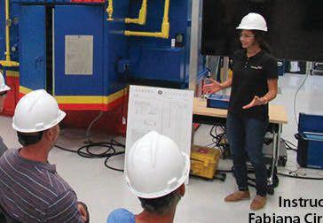
Many people refer to the OMICRON Academy in Houston as “An Engineer’s Playground.” This is because in addition to classrooms, we also have a state-of-the art indoor substation with a variety of apparatus to perform hands-on testing including transformers, circuit breakers, protective relays, indoor circuit, PD testing area and our recently installed distribution automation wall.
Training Topics
•Protection Relays and Meters Testing
•Circuit Breaker/Switchgear Testing
•Instrument Transformer Testing
•Power Transformer Testing & Diagnostics
•Partial Discharge Testing
•Protection Theory
•End-to-End Testing
•Reclosers and Distribution Automation
See our full list of courses at omicronenergy.com/na-training

Megger’s Testing Tactics Webinar Series 2020
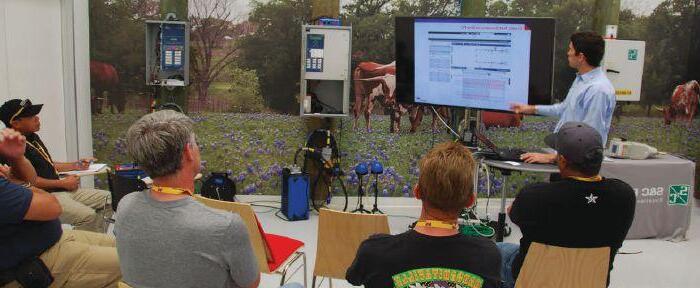
Learn valuable testing tips and tricks from Megger application engineers and product managers. In this webinar series, our experienced staff will show you how to make your testing more efficient by sharing their lessons learned in the field. You will find answers to frequently asked questions, learn how to avoid the most common mistakes, and accelerate your testing.
Upcoming Webinars
• MV and HV Circuit Breaker Testing beyond Timing and Travel Measurements
September 18, 2020 | Presenter: Volney Naranjo
• State-of-the-art Diagnostics Technologies for Proactive Cable Condition Assessment
October 23, 2020 | Presenter: Robert Probst
• Fundamentals of Motor Protection
November 20, 2020 | Presenter: David Beard
• LV Circuit Breaker Ground Fault Protection Utilizing Primary Injection Test Method
December 18, 2020 | Presenter: Daniel Carreno
Previous Webinars
• Best Field Practices for Testing Instrument Transformers: CTs, VTs, CVTs
November 15, 2019 | Presenter: Daniel Carreno
• Tan Delta Testing on Medium Voltage Cables
December 20, 2019 | Presenter: Javier Ruiz
• Fundamentals of Partial Discharge Measurements
January 24, 2020 | Presenter: Charles Nybeck
• DC Insulation Resistance Testing: Effective Use of Guard Terminal
February 21, 2020 | Presenter: Nick Rees
• Understanding Sweep Frequency Response Analysis and Best Field Practices
March 20, 2020 | Presenter: Sanket Bolar
• MV and HV Cable Fault Location Utilizing ARM Method
April 17, 2020 | Presenter: Javier Ruiz
• An Insight Into End to End Testing Philosophy
May 22, 2020 | Presenter: Sughosh Kuber
• Off-line Partial Discharge Testing of Rotating Machines
June 19, 2020 | Presenter: Charles Nybeck
• Feeder Protection in Power Distribution Systems
July 17, 2020 | Presenter: Abel Gonzalez
• Narrow Band Dielectric Frequency Response –Application on HV and EHV OIP Bushings
August 21, 2020 | Presenter: Diego Robalino
How to Join Megger Webinar Series
• Megger Webinars are held on the 3rd Friday of every month.
• Time: 10:00 AM Central Time
• Sessions are FREE
• Earn 1 NETA CTD and 1 PDH or 0.1 CEU
• us.megger.com/webinars
Earn Credits
Megger has partnered with NETA (International Electrical Testing Association) in North America to present the special monthly webinar series Testing Tactics that allows webinar registrants to receive NETA CTDs (Continuing Technical Development Credits) for attending the live webinar.
• Only attendees of the live Testing Tactics webinar sessions are eligible to receive 1 NETA CTD (Continuing Technical Development Credit) and 0.1 CEU (Continuing Education Units) or 1 PDH (Professional Development Hour) for each webinar attended.
• Live attendees of the webinar will also receive a PDF copy of the PowerPoint presentation.
Webinar Registration:
us.megger.com/webinars
Megger designs and manufactures portable electrical test equipment. Megger products help you install, improve efficiency, reduce cost, and extend the life of your or your customers’ electrical assets or your own. For more information, visit us.megger.com
DIRECTORY OF TECHNICAL AND PROFESSIONAL TRAINING
Shermco Industries: Your Electrical Safety Experts
Shermco is a leader in electrical power systems maintenance, repair, and testing, and for years, we have trained others in those skills. Offering onsite, classroom, and hands-on training, Shermco conducts a wide variety of courses covering Electrical Systems Maintenance, Electrical Safety, and Electrical Technical Skills. Some of the most influential leaders in electrical safety work at Shermco Industries, and now you have direct access to that experience and expertise! Shermco offers technical and electrical safety programs year-round and at multiple locations in the U.S. and Canada. NETA CTDs and CEUs through IEEE are available for most courses where applicable. Train with the experts. Train with Shermco.
Shermco University
Distance Learning Courses
• Electrical Safety Refresher
• Electrical Safety for Qualified Electrical Workers
• Electrical Safety for Managers
• Electrical Safety for Non-Electrical Personnel
• Electrical Safety for Utilities
• National Electrical Code
• Company Custom Courses
How Does Distance Learning Work?
Teleconference courses are taught face-to-face and allow live interaction between instructor and students even though they may be in different geographic locations. Synchronous tools such as text chat, audio chat, or video chat will provide students with real-time access to the instructor while the class is in session.
Class size limited to twenty (20) participants.
Call and reserve your seat today.

Enroll today by visiting www.shermco.com/training or call 888-Shermco.
For more information, to download our current course catalog, or to register online, go to www.shermco.com/training or email trainingservices@shermco.com SHERMCO.COM • 888-SHERMCO

DIRECTORY OF TECHNICAL AND PROFESSIONAL TRAINING
CEUs available from
www.shermco.com/training


To be the best in your field, train with the best in the field. Shermco Real-World Training.
COVER STORY
Partial Discharge Tests for MediumVoltage Power Cable Systems
Although the benefits of diagnostic testing in MV cable systems are widely applied during commissioning and maintenance, the main competition is the run-to-failure practice. Fortunately, more and more cable owners now accept diagnostic testing technologies to improve MV cable system reliability and to reduce lifetime asset management costs.
The partial discharge test has the unique advantages of distinguishing various types of defects and localizing the sites of those defects. But while performing a PD test is simple, using the PD data to diagnose the system that requires a wealth of knowledge and experiences. Hopefully, PD data interpretation will be simplified by rapid development of computer engineering and artificial intelligence.
Jim Guo, PhD, and Zhong Zheng, TechImp US Corp
FEATURES
7 President’s Desk
Scott Blizard, American Electrical Testing Co., LLC
NETA President
48
56
Partial Discharge Secrets, Tips, and Tricks
William G. Higinbotham, EA Technology LLC
Acceptance and Maintenance Testing
Medium-Voltage Electrical Power Cables
Thomas D. Sandri, Shermco Industries
64 Using VLF and PD Testing to Improve Commissioning Reliability
Javier Ruiz, Megger

TABLE OF CONTENTS TABLE OF CONTENTS NETAWORLD • 3
36
FALL 2020 · VOLUME 42, NO. 3 COVER
OF SHERMCO INDUSTRIES 56
IMAGE COURTESY
10 NFPA 70E and NETA
NFPA 70E–2021 is Here — How Did That Happen?
Ron Widup and James R. White, Shermco Industries
14 Relay Column
Archiving Protective Relay Settings
Steve Turner, Arizona Public Service Company
18 In the Field
Drones & Spaghetti Dinner
Don Genutis, Halco Testing Services
23 Safety Corner
Programs, Policies, Manuals, Procedures, and Training
Paul Chamberlain, American Electrical Testing Co., LLC
28 Tech Quiz
Cable Testing
James R. White and Thomas D. Sandri, Shermco Industries
31 Tech Tips
Medium-Voltage Grounding
Jeff Jowett, Megger
74 Protection Considerations for an Improperly Installed On-Load Tap Changer
Alex Rangel, Saber Power Services, LLC
84 Improved Safety Method for Measuring Dead Tank Circuit Breaker Operation Radenko Ostojić and Adnan Šečić, DV Power — Sweden
92 Power Quality, Reliability, and Sophisticated Automated Systems
Alan Ross, Electric Power Reliability Alliance
ADVANCEMENTS IN THE INDUSTRY
98 Onsite PD Measurement during Commissioning: Safe…Right from the Start Mathieu Lachance, OMICRON electronics Canada, and Tim Gannon, Advanced Electrical Services
INSIGHTS & OBSERVATIONS — NETA CAP SPOTLIGHT
104 Weidmann Electrical Technology: 143 Years of Global Impact
SPECIFICATIONS AND STANDARDS 108 ANSI/NETA Standards Update
110 ASTM F18 Committee Report
James R. White, Shermco Industries
111 NFPA 70B Committee Report
David Huffman, Power Systems Testing Company
114 In Memoriam — John Hauck
Accredited Companies
Advertiser List
4 • FALL 2020 TABLE OF CONTENTS TABLE OF CONTENTS IN EVERY ISSUE
INDUSTRY TOPICS
NEWS
IMPORTANT LISTS 117 NETA
122
NETA

Rental and Sales
Protec is your source for electrical test equipment rental and sales, working with leading manufacturers to offer flexible daily, weekly, and monthly lease rates. If you are not sure what equipment best fits for your needs, call us for a consultation and quote. Our support line is open 24 hours and we can deliver equipment immediately in case of emergency.
Calibration Services
Our calibration labs Dallas and Chicago offer NISTtraceable calibration services for all makes and models of electrical test and measurement equipment. Our qualified technicians will ensure that your electrical test instruments are working at peak performance and meet all manufacturer standards. Quick turnaround is standard, with most equipment completed in 5 business days or less.
Asset Management
Eliminate your overhead and minimize equipment downtime with Protec’s asset management services. We customize a unique solution for your business to store, calibrate and maintain your equipment for whenever you need it. Receive analytics for ROI, yield and utilization to drive educated business decisions.
Nobody Works Harder For You Than Protec
We understand that you need experienced people to align you with the proper electrical test and measurement equipment, in the right place at the right time.
That’s why we are the number one choice for mission critical equipment, where time, quality and service are vital.
Electrical test equipment is our specialtyyour satisfaction is our passion.
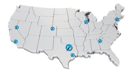
1517 W Carrier Pkwy, Ste 116 Grand Prairie, TX 75050
Angeles 2935 E Ricker Way Anaheim, CA 92806 Reno-Tahoe 924 Greg Street Sparks, NV 89431
E 45th Ave, Ste 400 Denver, CO 80239
Large Enough To Serve Your Needs, Small Enough to Care protecequip.com For a Quote Call 866-352-5550 Atlanta 880 Veterans Memorial Hwy Mableton, GA 30126 National Headquarters
New York City 70 Triangle Boulevard Carlstadt, NJ 07072 Denver 12050
Houston 14251 Gulfstream Park Drive Webster, TX 77598 Chicago 1501 Wright Blvd Schaumburg, IL 60193 The Electrical Test and Measurement Equipment Rental Experts
Los
3050 Old Centre Road, Suite 101
Portage, MI 49024
Toll free: 888.300.NETA (6382)
Phone: 269.488.NETA (6382)
Fax: 269.488.6383
neta@netaworld.org
www.netaworld.org
executive director: Missy Richard
NETA Officers
president: Scott Blizard, American Electrical Testing Co., Inc.
first vice president: Eric Beckman, National Field Services
second vice president: Scott Dude, Dude Electrical Testing, LLC
secretary: Dan Hook, Western Electrical Services, Inc.
treasurer: John White, Sigma Six Solutions, Inc.
NETA Board of Directors
Ken Bassett (Potomac Testing, Inc.)
Eric Beckman (National Field Services)
Scott Blizard (American Electrical Testing Co., Inc.)
Jim Cialdea (CE Power Engineered Services, LLC)
Scott Dude (Dude Electrical Testing LLC)
Dan Hook (Western Electrical Services, Inc.)
David Huffman (Power Systems Testing)
Alan Peterson (Utility Service Corporation)
Chasen Tedder, Hampton Tedder Technical Services
John White (Sigma Six Solutions)
Ron Widup (Shermco Industries)
non-voting board member
Lorne Gara (Shermco Industries)
NETA World Staff
technical editors: Roderic L. Hageman, Tim Cotter
assistant technical editors: Jim Cialdea, Dan Hook, Dave Huffman, Bob Sheppard
associate editor: Resa Pickel
managing editor: Carla Kalogeridis
copy editor: Beverly Sturtevant
advertising manager: Laura McDonald
design and production: Moon Design
NETA Committee Chairs
conference: Ron Widup; membership: Ken Bassett; promotions/marketing: Scott Blizard; safety: Scott Blizard and Jim White; technical: Alan Peterson; technical exam: Dan Hook; continuing technical development: David Huffman; training: Eric Beckman; finance: John White; nominations: Alan Peterson; alliance program: Jim Cialdea; association development: Ken Bassett and John White
© Copyright 2020, NETA
NOTICE AND DISCLAIMER
NETA World is published quarterly by the InterNational Electrical Testing Association. Opinions, views and conclusions expressed in articles herein are those of the authors and not necessarily those of NETA. Publication herein does not constitute or imply endorsement of any opinion, product, or service by NETA, its directors, officers, members, employees or agents (herein “NETA”).
All technical data in this publication reflects the experience of individuals using specific tools, products, equipment and components under specific conditions and circumstances which may or may not be fully reported and over which NETA has neither exercised nor reserved control. Such data has not been independently tested or otherwise verified by NETA.
NETA MAKES NO ENDORSEMENT, REPRESENTATION OR WARRANTY AS TO ANY OPINION, PRODUCT OR SERVICE REFERENCED OR ADVERTISED IN THIS PUBLICATION. NETA EXPRESSLY DISCLAIMS ANY AND ALL LIABILITY TO ANY CONSUMER, PURCHASER OR ANY OTHER PERSON USING ANY PRODUCT OR SERVICE REFERENCED OR ADVERTISED HEREIN FOR ANY INJURIES OR DAMAGES OF ANY KIND WHATSOEVER, INCLUDING, BUT NOT LIMITED TO ANY CONSEQUENTIAL, PUNITIVE, SPECIAL, INCIDENTAL, DIRECT OR INDIRECT DAMAGES. NETA FURTHER DISCLAIMS ANY AND ALL WARRANTIES, EXPRESS OF IMPLIED, INCLUDING, BUT NOT LIMITED TO, ANY IMPLIED WARRANTY OF FITNESS FOR A PARTICULAR PURPOSE.
ELECTRICAL TESTING SHALL BE PERFORMED ONLY BY TRAINED ELECTRICAL PERSONNEL AND SHALL BE SUPERVISED BY NETA CERTIFIED TECHNICIANS/ LEVEL III OR IV OR BY NICET CERTIFIED TECHNICIANS IN ELECTRICAL TESTING TECHNOLOGY/LEVEL III OR IV. FAILURE TO ADHERE TO ADEQUATE TRAINING, SAFETY REQUIREMENTS, AND APPLICABLE PROCEDURES MAY RESULT IN LOSS OF PRODUCTION, CATASTROPHIC EQUIPMENT FAILURE, SERIOUS INJURY OR DEATH.

MEDIUM-VOLTAGE CABLES
Welcome to the fall edition of NETA World. In this issue, our authors cover the various methods for performing testing on mediumvoltage cables. I recommend you start with the article by Tom Sandri of Shermco Industries, which lays out the current test methods for acceptance and maintenance testing of medium-voltage cables. Next, dive into the articles on specific testing methods including partial discharge, dissipation factor (tan delta), and VLF.
Fall is typically one of our busiest times of the year. Many of our customers are performing scheduled maintenance outages, and the workdays can be longer as well as more stressful than normal. Even if your days throughout the fall season are not that much different, one thing we must constantly do is evaluate and mitigate exposures to risk. This helps make the work environment safer for all. When working with medium-voltage cables, be sure the technician has all the documentation as well as a clear understanding of the testing method and the test equipment being used to perform the testing. Review the safety precautions needed to operate the equipment or device and ensure all recommended safety precautions are followed.
Today is July 16, 2020, and the country is in the middle of a COVID-19 resurgence. NETA Member Companies and their technicians throughout the United States and in Canada have been identified as essential workers as they support and maintain the critical infrastructure of our nations. Follow the COVID-19 policies of your company as well as your customers’ companies. The preventative measures to limit the spread of the COVID-19 virus that have been communicated by the CDC in the United States and the Public Health Agency of Canada should be included. Be safe, and err on the side of caution.
Mark your calendars! PowerTest 2021, the premier electrical maintenance and safety conference, will take place March 8–12, 2021, at the Rosen Shingle Creek in Orlando, Florida. We look forward to seeing you there.
Coach safe behavior…Living injury and disease free every day!
 Scott A. Blizard, President International Electrical Testing Association

PRESIDENT’S DESK PRESIDENT’S DESK



• Cables
• LV/MV Circuit Breakers
• Rotating Machiner y
• Meters
• Automatic Transfer Switches
• Switchgear and Switchboard Assemblies
• Load Studies
• LV/MV Switches
• Relays - All Types
• Motor Control Centers
• Grounding Systems
• Transformers
• Insulating Fluids
• Thermographic Surveys
• Reclosers
• Surge Arresters
• Capacitors
• Batteries
• Ground Fault Systems
• Equipotential Ground Testing
CoNSulTING AND ENGINEERING SERvICES
• Transient Voltage Recording and Analysis
• Electromagnetic Field (EMF) Testing
• Harmonic Investigation
• Replacement of Insulating Fluids
• Power Factor Studies

Electric Testing, Inc. EC13004105 • 24 Hour Emergency Service
Industrial
ACCEPTANCE AND MAINTENANCE TESTING AND REPAIR
11321 West Distribution Avenue • Jacksonville, Florida 32256 • (904) 260-8378 201 NW 1st Avenue • Hallandale, Florida 33009 • (954) 456-7020

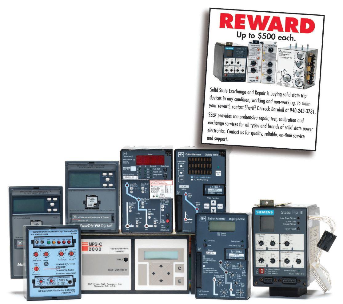
We Buy, Sell, Trade, Calibrate, Repair
Featuring quality, reliable, on-time service and support for all brands and types of solid state power electronics.
Power electronics are our business
Let us suppoort you with our quality repair, calibration and servicing of your solid state equipment. We also buy, sell and trade:
•Communications devices for power equipment
•Protective relays
•Circuit breaker trip devices
•Motor overload relays
•Rating plugs
4701 Spartan Drive • Denton, TX 76207 (877-874-7349) • Phone: 940-243-3731 • Fax: 940-387-8277 Email: info@solidstaterepair.com • Web: www.solidstaterepair.com
“SOLID STATE” INDUSTRIAL ELECTRONICS “SOLID STATE” INDUSTRIAL ELECTRONICS Toll Free 877-TRIP-FIX NOWRENTING TESTEQUIPMENT
NFPA 70E–2021 IS HERE — HOW DID THAT HAPPEN?
BY RON WIDUP and JAMES R. WHITE, Shermco Industries
In September 2020, the newest (2021) edition of NFPA 70E, Standard for Electrical Safety in the Workplace® will be available to the industry. So how is it that such an important safety standard, put forth as a national consensus document, is reviewed, revised, and improved every three years? We’ll look at the process a little later in this article.
But first, let’s talk about this very important safety document, which on issuance becomes immediately active and enforceable…including any changes that have taken place. Unlike a code, this is a work practices document; therefore, any new requirements are now in effect, and there are no grandfathered rules and regulations.
For background on 70E, the NFPA website (www.nfpa.org) states the following:
While the number of workplace electrical injuries has declined in recent years, the risks of shock, electrocution, arc flash, and arc blast remain a significant health and safety concern. Each week nearly three workers die, and annually thousands are injured by electrical hazards. Many of these incidents could have been prevented through compliance with the latest safety codes and standards.

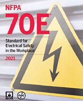
NFPA 70E, Standard for Electrical Safety in the Workplace is the quintessential resource for helping companies and employees reduce exposure to risks and reduce occupational injuries and fatalities. It was created to provide a document that meets the need of the Occupational Safety and Health Administration (OSHA) and is entirely consistent with the NEC and other applicable publications.
NFPA 70E provides provisions that help comply with OSHA 1910 Subpart S and OSHA 1926 Subpart K. This essential standard for anyone with interest in ending electrical-related accidents, liability, and loss offers expert information on subjects ranging from safety-related work practices to special equipment and maintenance requirements. Informative Annexes provide indepth coverage of personal protective equipment (PPE), developments in electrical design, risk assessment and control, human performance and electrical safety, and many other critical topics.
10 • FALL 2020 NFPA 70E-2021 IS HERE — HOW DID THAT HAPPEN?
NFPA 70E AND NETA n e
After months of work by the NFPA 70E Technical Committee, the new 2021 edition features extensive changes, including:
• Revisions to Article 110 to incorporate the general requirements for electrical safety-related work programs, practices, and procedures from other articles
• References to arc-resistant switchgear in Tables 130.5(C) and 130.7(C)(15)(a) changed to arc-resistant equipment to address the use of other types of arcresistant equipment
• Addition of Article 360, Safety-Related Requirements for Capacitors, and Annex R, Working with Capacitors, to address specific electrical safety requirements unique to capacitors
• Edits to Annex D, Incident Energy and Arc Flash Boundary Calculation Methods, to reference IEEE-1584-2018 as a method of calculation
WHAT’S THE PROCESS TO GET HERE?
For the 70E and other consensus-based standards to go from a current edition to “new and improved” is quite an involved process, involving many people and many hours of focused and passionate contribution to the change. (Shout-out to all those who contribute!)
In the current cycle, 344 Public Inputs resulted in 85 First Revisions, and 155 Public Comments resulted in 46 Second Revisions. Compared to previous cycles, the workload was quite a bit less, so NFPA 70E may be approaching a “tweaking-the-words” maintenance cycle where major changes are increasingly rare, and it is principally revised to improve its clarity and usability.
In 2015, NFPA introduced a new process that was used for the 2021 edition. Under the old process, proposals for change were referred to as Proposals. Under the new process, Proposals are
referred to as Public Inputs (PIs); Comments are now Public Comments (PCs); and the Report on Proposals (ROP) is now the First Draft (FD).
FIRST REVISION
Revisions made during the First Draft Meeting are balloted for acceptance in a First Revision (FR). The First Draft is circulated to committee members and posted on the NFPA website for public comments. It only takes a majority vote (51%) for an FR to be accepted by the committee during the meeting. However, a 66% majority vote is required to approve an FR when it is formally balloted by the committee. The First Draft is published on the NFPA website and is available at no charge to anyone who wants to submit a comment on a committee action. It is available for several months to ensure everyone has an opportunity to submit comments.
SECOND DRAFT
The Second Draft Meeting is different in that the committee is bound by any First Revisions and Public Comments (PCs) received. Any changes made at this meeting are Second Revisions (SRs). The Second Draft (SD), previously known as the Report on Comments, consists of committee actions that are balloted on and accepted from the Second Draft Meeting. These actions, known as Second Revisions (SRs), are used to create the Second Draft. Any First Revisions accepted by the committee at the First Draft Meeting that did not receive Public Comments are considered First Revisions, and no further action can be taken on them. People who wish to discuss PIs during the First Draft Meeting or PCs at the Second Draft Meeting can do so if they schedule a meeting in advance with the committee chairperson. Once the Second Draft Meeting has been completed, the standard is balloted. It takes a 66% majority vote to approve the Second Draft.
THE HOME STRETCH
The NFPA consensus process is very thorough, allowing full public input and comment on committee actions. Many people consider
NETAWORLD • 11 NFPA 70E-2021 IS HERE — HOW DID THAT HAPPEN?
AND NETA
NFPA 70E
NFPA 70E AND NETA
it to be the best methodology for standards publication currently used by any organization. Public input is critical to the consensus process, and public input is solicited by NFPA using open announcements in news releases and in publications such as print and online magazines and trade journals. Any person can submit a PI online at the NFPA website (www.nfpa.org).
NFPA’s electrical oversight committee, the Correlating Committee, reviews the actions of the NFPA 70E Committee to ensure there are no major issues or inadvertent conflicts with earlier actions or other NFPA standards. When a Second Draft has been published and committee members or proposers still have differences of opinion, a Notice of Intent to Make a Motion (NITMAM) can be submitted to NFPA. NITMAMs are published on the NFPA website for public review and are discussed at the annual NFPA World Safety Conference and Exhibition.
Even after the revision cycle closes, another avenue to change the stardard is a Tentative Interim Amendment (TIA). A TIA can be
submitted any time an error is found in the committee’s actions. For a TIA to be accepted, two conditions must be met: The change must correct an error, and the change must be an emergency in nature. For the 2021 cycle, no NITMAMs or TIAs have been submitted.
One final action that can be taken by the public is a Notice to Appeal. This does not occur often, as there is very-low probability that a Notice to Appeal will be considered once a NITMAM on the same committee action has already been considered. No Notice to Appeal actions were taken for the 2021 cycle.
SUMMARY
The new edition of the 70E is out — so purchase a copy, familiarize yourself with the changes, understand the content and the very important work practice rules, and go through the day in a safe and planful way while working on or near electrical energy…whether at work or at home.
Be safe out there — and test before touch!
Ron Widup and Jim White are NETA’s representatives to NFPA Technical Committee 70E, Electrical Safety Requirements for Employee Workplaces. Both gentlemen are employed by Shermco Industries in Dallas, Texas, a NETA Accredited Company.

Ron Widup, Senior Advisor, Technical Services and Vice Chairman of the Board of Directors, has been with Shermco Industries since 1983. He is a member of Technical Committee on NFPA 70E, Electrical Safety in the Workplace; a Principal Member of National Electrical Code (NFPA 70) Code Panel 11; a Principal Member of the Technical Committee on NFPA 790, Standard for Competency of Third-Party Evaluation Bodies; a Principal Member of the Technical Committee on NFPA 791, Recommended Practice and Procedures for Unlabeled Electrical Equipment Evaluation; a member of the Technical Committee on NFPA 70B, Recommended Practice for Electrical Equipment Maintenance, and Vice Chair for IEEE Std. 3007.3, Recommended Practice for Electrical Safety in Industrial and Commercial Power Systems. Ron also serves on NETA’s board of directors and Standards Review Council. He is a NETA Certified Level 4 Senior Test Technician, a State of Texas Journeyman Electrician, an IEEE Standards Association member, an Inspector Member of the International Association of Electrical Inspectors, and an NFPA Certified Electrical Safety Compliance Professional (CESCP).

James (Jim) R. White, Vice President of Training Services, has worked for Shermco Industries since 2001. He is a NFPA Certified Electrical Safety Compliance Professional and a NETA Level 4 Senior Technician. Jim is NETA’s principal member on NFPA Technical Committee NFPA 70E®, Electrical Safety in the Workplace; NETA’s principal representative on National Electrical Code® Code-Making Panel (CMP) 13; and represents NETA on ASTM International Technical Committee F18, Electrical Protective Equipment for Workers. Jim is Shermco Industries’ principal member on NFPA Technical Committee for NFPA 70B, Recommended Practice for Electrical Equipment Maintenance and represents AWEA on the ANSI/ISEA Standard 203, Secondary Single-Use Flame Resistant Protective Clothing for Use Over Primary Flame Resistant Protective Clothing. An IEEE Senior Member, Jim was Chairman of the IEEE Electrical Safety Workshop in 2008 and is currently Vice Chair for the IEEE IAS/PCIC Safety Subcommittee.
12 • FALL 2020
NFPA 70E-2021 IS HERE — HOW DID THAT HAPPEN?
Relay and Protective Devices
Batteries and UPS
Low Voltage Circuit Breakers
Medium/High Voltage Circuit Breakers
SF6 Analysis
Transformer Testing
Cable Testing

Cable Fault Location
Location

Power
Power Monitoring
Data and Recorders
Data Acquisition and Recorders


Online and Offline Partial
Online and Offline Partial Discharge
Low Resistance Ohmmeters
Low
Insulation
Insulation Resistance/Megohmmeters
Ground Test Equipment

Ground Test Equipment Test


Photovoltaic Test
Infrared Cameras
Cameras
Ultrasound and TEV



Online/Offline Motor
Online/Offline Motor Testing
AC and DC Load Banks
AC DC

AC and DC Hipots
AC and DC




VLF and Tan
VLF and Tan Delta
888.902.6111 info@intellirentco.com intellirentco.com





We rent equipment
support
rental |
| logistics

EFFECT OF CT SATURATION ON TRANSFORMER DIFFERENTIAL PROTECTION
BY STEVE TURNER, Arizona Public Service Company
This article demonstrates how CT saturation can adversely affect transformer differential protection and how to easily mitigate its effects via inbuilt relay functions. The solution is to provide calculations and simulation for a three-phase fault on the low side of the transformer just external to the CTs.
APPLICATION
The application is for a three-phase delta-wye connected transformer serving station load at a power plant.
Transformer Name Plate Data
Size = 1.5 MVA
XT = 6.77% on transformer base
kVwdg1 = 12.47 kV
kVwdg2 = 480 V
CTR1 = 500:5
CTR2 = 4,000:5
CT2 Data from manufacturer data sheets
RCT = 1.861 ohms (0.002326 ohms per turn)
VS = 190 V (saturation voltage at excitation current equal to 10 amps)
System Data
X/R = 6.777
14 • FALL 2020 EFFECT OF CT SATURATION ON TRANSFORMER DIFFERENTIAL PROTECTION
RELAY COLUMN
FAULT CURRENT CALCULATIONS
Calculate the low side fault current as follows (ignoring system impedance for worst case scenario):
Vnom ≔ 480 V
X��1 ≔ 0.0677 per unit on transformer base (actual value) per unit on 100 MVA base
Ibase = 1.203 x 10⁵A
Inom = 1.804 x 10³A
full load current wrt 480 V winding
three phase fault current at transformer low side bushings (ignoring system impedence), per unit on 100 MVA base
secondary fault current measured by relay (non-saturated)
primary fault current measured by relay
Figure 1: Low-Side Fault Current Calculations
SIMULATION
Obtain the corresponding secondary current using a CT saturation simulation.

Figure 2: CT Simulation Results for Full DC Offset
OBSERVATIONS
The secondary current is most distorted during the first cycle of the fault. To help mitigate unwanted tripping during the external fault condition, enable harmonic restraint for the transformer differential protection.
Figure 3: Harmonic Restraint
NETAWORLD • 15 EFFECT OF CT SATURATION ON TRANSFORMER DIFFERENTIAL PROTECTION
RELAY COLUMN
MVA
≔
MW MVA
��1
1.5
��1
Ibase ≔ –––––––––– Inom ≔ ––––––––––
Ibase CTR CTR ≔ X��01 ≔ X��1·–––––––––X��01 TAP ≔ TAP = 2.255 A CTR 4000 100 MW 100 MW MVA��1 X��01 = 4.513 I� ≔ 5 1 I� = 0.222 I� ·––––––– = 33.313
I� ·
base
Inom
A
I
= 2.665 x 10⁴ · A
RELAY COLUMN
Harmonic blocking is not enabled since it can delay tripping during internal faults. Note: The relay vendor’s specifications for this particular relay indicate the transformer differential protection operates slower when harmonically restrained, which can also help ride through the period of saturation.
Restrained Element (With Harmonic Blocking) Pickup Time: 1.5/1.6/2.2 cycles (Min/Typ/Max)
Restrained Element (With Harmonic Restraint)
cycles (Min/Typ/Max)
Figure 4: Transformer Differential Protection Operating Times
CONCLUSION
CT saturation can occur during faults external to transformer differential protection.
Use harmonic restraint to help mitigate unwanted tripping during such events. Test the transformer protection relay to ensure the harmonic restraint works properly.

Steve Turner is in charge of system protection for the Fossil Generation Department at Arizona Public Service Company in Phoenix. After working with Beckwith Electric Company, Inc. for 10 years, Steve spent two years as a consultant in San Diego. His previous experience includes positions as an Application Engineer at GEC Alstom and in the international market for SEL focusing on transmission line protection applications. Steve also worked for Duke Energy (formerly Progress Energy), where he developed the first patent for double-ended fault location on overhead high-voltage transmission lines and was in charge of all maintenance standards in the transmission department for protective relaying. Steve has BSEE and MSEE degrees from Virginia Tech University. He has presented at numerous conferences including Georgia Tech Protective Relay Conference, Western Protective Relay Conference, ECNE, and Doble User Groups, as well as various international conferences. Steve is a senior member of IEEE and a member of the IEEE PSRC.




An extensive inventory of over 200,000 sq. ft. across the southeast means the Southland Group has the products you need most in stock and ready to ship! Our team of experienced technicians provide on-site field service support and engineering services to ensure that your products are safe, reliable and service ready. Contact us today and let us create the solutions you need most!


Pickup Time:
2.62/2.72/2.86

THE PREMIER ELECTRICALMAINTENANCEAND SAFETYCONFERENCE SAVE THE DATE MARCH 8 - 12,2021 ROSENSHINGLECREEK ORLANDO,FLORIDA POWERTEST.ORG 888.300.6382
DRONES & SPAGHETTI DINNER
 BY DON GENUTIS, Halco Testing Services
May 2020 was a difficult month for our nation, and 2020 is certainly shaping up to be a difficult year. As essential service providers, many in our industry were called upon to maintain or continue building the nation’s infrastructure. We all understand and appreciate that hospitals, emergency services, government facilities, manufacturing, and even residences could not function without power, and NETA technicians across the country stepped up to ensure reliable power was, as usual, taken for granted. Thank you, NETA Technicians!
This article explores a few technologies that are useful for commissioning utility-scale renewable generation plants that were successfully used during the midst of the pandemic.
Six dedicated technicians scattered throughout the United States found themselves driving to a job site as airlines shut down or site-specific rules required a 14-day isolation period if mass travel transportation was used. Technicians from Dallas, Houston, Atlanta, Los Angeles, and Washington DC converged on a remote
area in West Texas that recently became more remote due to mandatory or voluntary business closures. Their task was to use infrared and partial discharge technologies to detect conductor and insulation defects that could lead to future unwanted failures at a 200 MW solar facility.
PARTIAL DISCHARGE
On-line partial discharge testing has been the focus of many previous NETA World articles
18 • FALL 2020 DRONES & SPAGHETTI DINNER
IN THE FIELD
and has proven to be a very good technique for detecting insulation defects in medium-voltage cable systems, switchgear, transformers, and other apparatus while the equipment remains in service. Specialized sensors are temporarily connected safely to grounded components to decouple the electromagnetic signals associated with the discharges, and sophisticated software is used to process the raw signals and remove noise using complex algorithms to assess insulation condition.
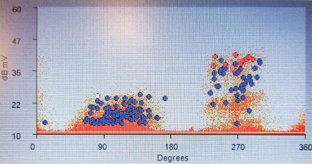
At renewable installations, this technology is capable of detecting insulation defects in cable, cable terminations, and apparatus connected to the cables including switches, circuit breakers, and transformers. One additional bonus for using online partial discharge technology is that it can readily discover loose medium-voltage connections, as the minor arcing that results creates readily detectable high-magnitude electromagnetic signals long before the problem can escalate to become distinguishable as a thermal defect that infrared technology can detect. Figure 1 displays the signal associated with this initially minor arcing phenomenon. For these reasons, online partial discharge testing can be an excellent tool for commissioning medium voltage renewable installations and should be considered for commissioning any type of medium-voltage systems.
INFRARED
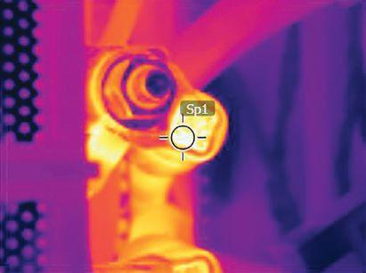
Infrared thermography has been regularly used for decades to detect conductor overheating and is the most widely used online tool second only to voltage and current indicating or sensing instruments. This technology provides thermal images of connections so that elevated temperatures are readily apparent. Actions can then be taken to rectify the problem before complete failure occurs. Figure 2 displays a typical connection problem.
At renewable installations, infrared techniques have proven valuable to detect conductor problems at the hundreds or even thousands
of DC wire and cable connections and inverter bus connections. Another valuable application for infrared imaging at solar facilities is to inspect the PV panels themselves for functionality. Nonfunctional panels will not generate power, and defects can range from open conductors, open connectors, or damage to the panel itself. Although solar panel thermal imaging can be performed on foot, using specialized drones equipped with infrared cameras has proven to be much more efficient at large installations.
DRONES
Unmanned aircraft systems (UAS) or drone usage has grown astronomically in recent years since it proved advantageous in a broad range of applications from construction to defense to social distancing. Combining infrared
NETAWORLD • 19 DRONES & SPAGHETTI DINNER
IN THE FIELD
Figure 1: Electromagnetic Signal from Minor 34.5 kV Arcing
Figure 2: Infrared Detects Loose Low-Voltage Connection
IN THE FIELD
technologies with drone use is a relatively new application that has already provided significant cost savings and safety benefits over conventional inspection techniques. Studies have shown that as much as 50% cost savings can be achieved by using drone technologies for PV panel inspections.
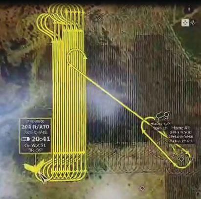
Utility-scale solar sites typically required veryfast, fixed-wing aerial hardware to efficiently weave back and forth along the countless rows of panels to collect infrared data (Figure 3). To maximize field efficiency, flight plans are preprogrammed and loaded into the hardware.
Drones fly at high altitudes to map large areas by taking hundreds of infrared images that are

then analyzed and compiled into a cloud-based report of deficiencies that consists of anomalies such as those displayed in Figure 4. The report includes GPS coordinates and the physical description and location of the anomalies so the problem can be expeditiously remediated.
SPAGHETTI DINNER
On one particularly comfortable May evening in West Texas, an unlikely group of a halfdozen technicians were pleasantly surprised by a thoughtful senior technician who took it upon himself to prepare a full-on spaghetti dinner. The team sat together on green picnic tables at the rear of the motel property but spaced themselves properly to abide by social distancing guidelines. The sky was silent — no aircraft flew above — reminding them of the weeks after the 9/11 crisis and making them all wonder which way the world will turn tomorrow. Soon, the air was filled with colorful and perhaps slightly exaggerated war stories plus the sweet smell of garlic. A few cans of beers were cracked open leading to peaceful comradery and a welcome escape from these stressful times. That evening, the faint sound of the Marshall Tucker Band playing “This Old Cowboy” could be heard in the distance from some cheap radio as the group ate the “best” spaghetti dinner they ever had.

Don A. Genutis presently serves as President of Halco Testing Services, Inc., a NETA Accredited Company with offices in Los Angeles and Houston. He has held various principal positions during his 35plus year career in the electrical testing field, primarily focused on advancing no-outage testing techniques for the last 20 years, with emphasis on cable and switchgear on-line partial discharge testing techniques. Early in his career, Don acquired and operated the former Westinghouse East Pittsburgh Insulation Research Laboratory, where he gained valuable experience in understanding insulation material performance. Don holds a BS in electrical engineering from Carnegie Mellon University and is a NETA Certified Technician. Don has authored 50 technical articles for NETA World and has been featured in EC&M and Uptime magazines. Don’s work is summarized in his book, Partial Discharge & Other No-Outage Testing Methods, published in 2019.
20 • FALL 2020
& SPAGHETTI DINNER
DRONES
Figure 3: Drone Flight Pattern
Figure 4: Open Inverter String


No
Knows Low-Voltage Circuit Breakers & Motor Controls
From a single part to a switchboard lineup, Advanced Electrical & Motor Controls’ inventory of low-voltage insulated case circuit breakers, molded case circuit breakers, motor controls, and custom switchboards are second to none in the U.S. No matter what you need — new, surplus, used, or reconditioned power distribution equipment, testing and repair, or an engineered solution — AEAMC will keep you up and running. In Stock for Emergency Delivery: New Switchboards up to 4000 amps; New Motor Controls
We can provide and repair the following:
Insulated Case Circuit Breakers
Molded Case Circuit Breakers
Motor Controls & Centers
Bolted Pressure Switches
Panelboard Switches & Bus Plugs
480 V Distribution Transformers
Replacement Parts
New Replacement Motor Control Buckets
Search. Click. Ship. Purchase AEAMC equipment online, anytime!


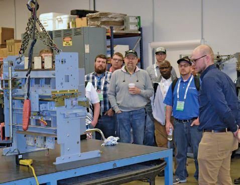

GET 3 TEST SETS FOR THE PRICE OF 1 WITH THE NEW VITS6 0 M
THE VITS6 0 M PERFORMS HIGH-POTENTIAL (HIPOT) TESTS FOR VACUUM INTERRUPTER TESTING UP TO 6 0 KV, AS WELL AS RESISTANCE, POLARITY INDEX, AND ABSORPTION RATIO TESTS.
Unlike other DC HiPot test sets on the market, the VITS60M not only performs specialized go/no-go tests on vacuum interrupters at up to 60 kV DC but also includes a 2.5/5/10 kV megohmmeter for Resistance, Polarity Index, and Absorption Ratio testing. Get 3 test sets for the price of 1 with the VITS60M.
This simple-to-operate set walks technicians through setup, generating a visual go/no-go result for testing the dielectric strength of various vacuum breaker components during regular maintenance, while offering fully programmable leakage current thresholds and test durations.
• Safety features with auto discharging, interlock, and safety control button
• Integrity test, Insulation Resistance test, Absorption test, and Polarity test all in one — lower price, more functions
Let us bring our equipment to your facility for an on-site demonstration. Contact us at info@vacuuminterruptersinc.com or (214) 442-5877. FEATURES AND BENEFITS INTERESTED IN A

• Operates in 1 kV DC increments instead of 5 kV DC
• Easy-to-use, programmable set walks technicians through setup, tests, and results
• Failure indicator LED makes it easy to interpret results (green light: pass; red light: fail)

Emergency
Advanced Electrical
1801 HURD DR. | IRVING, TX 75038 | 972-253-7783 | Sales@AEAMC.com | AEAMC.com 455-B SHEPARD DRIVE | ELGIN, IL 60123 | 224-856-5036 CHICAGO
support 24/7 800-289-2757
& Motor Controls
SERVICE CENTER NOW OPEN!
Chicago, IL
One
Like Advanced Electrical & Motor Control s
vacuuminterruptertesting.com | info@vacuuminterruptersinc.com
DEMO?


PROGRAMS, POLICIES, MANUALS, PROCEDURES, AND TRAINING

 BY PAUL CHAMBERLAIN, American Electrical Testing Co. LLC
Many regulatory agencies direct which documents are required to perform a company’s tasks. In some cases, federal and state requirements must be adhered to for the same task or hazard. For example, the United States Environmental Protection Agency (US EPA) and state environmental agencies, such as the Massachusetts Department of Environmental Protection (MA DEP), regulate potential environmental impacts that may occur while performing a task.
Currently, with the ongoing COVID-19 pandemic, companies must protect their workers using additional guidelines, such as those from the Centers for Disease Control (CDC). Workplace safety guidelines under COVID-19 also are available from the United States Department of Labor and their subdepartment, the Occupational Safety and Health Administration (OSHA).
Currently, 22 states have a state-approved occupational safety agency that is their own version of OSHA:
• Alaska
• Arizona
• California
• Hawaii
• Indiana
• Iowa
• Kentucky
• Maryland
• Michigan
• Minnesota
• Nevada
• New Mexico
• North Carolina
Oregon
Puerto Rico
South Carolina
Tennessee
Utah
Vermont
Virginia
Washington
Wyoming
This article explores the typical safety documents required to comply with federal OSHA standards. Each company must familiarize itself and comply with any additional regulations that apply to their business.
NETAWORLD • 23 PROGRAMS, POLICIES, MANUALS, PROCEDURES, AND TRAINING
SAFETY CORNER
•
•
•
•
•
•
•
•
•
SAFETY CORNER
GUIDELINES
OSHA provides guides to developing safety programs that are dependent upon whether the requirement is applicable to the work being performed. These guides can be found at OSHA.gov.
In addition to the CDC guidelines to minimize employee exposure to the current COVID-19 pandemic, OSHA has its own guidelines. More information can be found at www.osha.gov/ SLTC/covid-19/. Although OSHA guidelines are not considered law, if OSHA suggests you do something, it is generally advisable to do it. Appendix 5, the General Duty Clause, addresses when a company should protect employees from a known hazard using commonly known guidelines. Specifically, 29 USC 654 states:
(a) Each employer —
( 1) shall furnish to each of his employees employment and a place of employment which are free from recognized hazards that are causing or are likely to cause death or serious physical harm to his employees;
(2) shall comply with occupational safety and health standards promulgated under this Act.
(b) Each employee shall comply with occupational safety and health standards and all rules, regulations, and orders issued pursuant to this Act which are applicable to his own actions and conduct.
JOB SCOPE AND LOCATION
It is important for a company to know its scope of work and where the work is occurring prior to developing a program, policy, plan, or procedure, and the training that goes with them. Requirements change depending on where the work is conducted. For instance, work performed in a construction setting may not have the same requirements as work performed in a general industry setting. Additionally, not all the OSHA requirements
may be applicable. For example, if the company performs entry into enclosed spaces only, and does not enter into confined spaces that require a permit, the program must indicate such and training would have to include that information. The program would not need to cover entry into permit-requiring confined spaces, even though enclosed and confined spaces are found in the same OSHA regulation.
JOB HAZARD ANALYSIS
A job hazard analysis (JHA) is an important tool for analyzing the work to be performed and the hazard associated with each step in performing the work. Companies should take the time to create JHAs to better understand which hazards their employees will encounter. In some instances, such as in construction, a JHA will be required per OSHA. JHAs can be known by many other names, including job safety analysis (JSA) or even just hazard analysis (HA), but they all have essentially the same outcome: identification of known hazards associated with the completion of a task. Some pre-job briefs — if detailed enough — can be considered a suitable substitute for a JHA.
Once a JHA has been completed, the known hazards will be identified. The completed JHA should be reviewed with all personnel performing the work. Once a hazard is identified, the appropriate OSHA regulation can be located to aid in creating a program, policy, procedure, or training.
• Policies can be short and to the point. Think of these as a description sheet for a task or hazard. It is a position statement on how a company will address any issue, whether it is related to safety, environmental, procedural, or even human resources. It is usually not heavily detailed, although it may be if the topic can be covered succinctly, and will reference other pertinent information. For example, a policy for respiratory protection may only state that the company provides the respirator, training, and when wearing
24 • FALL 2020 PROGRAMS, POLICIES, MANUALS, PROCEDURES, AND TRAINING
the respirator will be necessary. If a topic requires greater detail, it will usually be encased in a procedure or program. Policies may outline who and when, but are not detailed when it comes to how it will be accomplished. They may also speak to what can occur should a task not be completed as required.
• Programs are designed for extensive detail. Think of these as a detailed instruction sheet, including components necessary for construction. A program highlights the requirements as set forth by the regulatory agency and reviews the training. It will get into the specifics of who, what, where, when, and why. The program highlights the documents (i.e. inspection forms) that must be filled out to comply with the regulations. Programs can be extensive, and often mimic a regulation line-forline to ensure compliance. For example, a program goes over what employees are required to do, where they can find information on performing the task, and how to remain in compliance with the requirement. It also reviews what the company is required to perform to maintain compliance with the regulation. Each applicable hazard will usually have its own program. To continue the example, a respiratory protection program will detail the training provided, what areas require a respirator, which types are used, how to determine a respirator is required, and how a respirator is issued to an employee.
• Procedures are task oriented. Think of these as the detailed steps in a set of instructions. They are very specific for each task performed. Procedures reference requirements as stated in programs and give physical direction line-for-line on how a task is to be performed. Procedures generally discuss the hazards associated with each step of performing the task. Continuing the example, a program on how to clean a respirator will state that respirators will be cleaned daily. The procedure will tell the employee in detail HOW to clean the respirator.
SAFETY CORNER
• Manuals provide a general overview. These are usually designed as a reference for the programs. In this instance, they may only contain the information pertinent to how the employee will comply with all of the company’s requirements. In some cases, a company may replace individual programs with a manual, essentially making the manual a collection of programs — each chapter becoming its own program. This depends on how much information must be relayed. If the chapter is extensive, or the regulation the company is attempting to comply with contains requirements that do not apply to all of the company’s tasks, it would make sense to summarize only the information critical to how the company will comply in the manual. A separate program would detail the specifics on what is required to be complied with and what is not, and why. Continuing the previous example, if the employee is required to use a new respirator, the manual may just tell them where to obtain one. Details as far as types used or requirements for type used may be contained in the program.
• Training must cover all information the employee will need to know in order to prevent the hazard while performing the task. The employee is not required to review the applicable programs, but some companies choose to perform training in this manner. Since programs are constructed similar to the regulation they are written to comply with, this can be pretty boring. Therefore, some companies choose to train using other methods, including a presentation, video, or even just on-the-job training (OJT). However, the company must ensure the employee is competent enough to perform the task prior to performing the task. Competency may need to be refreshed on a regular basis, dependent upon regulatory requirements. To document competency, a company can choose to use quizzes, tests, or just simple sign-off sheets indicating the employee reviewed and understood the information. No matter how training is conducted,
NETAWORLD • 25 PROGRAMS, POLICIES, MANUALS, PROCEDURES, AND TRAINING
SAFETY CORNER
documentation must be performed and must be maintained in a file so long as the employee works at that company.
CONCLUSION
Companies must comply with many regulatory requirements. A company may choose from many ways to go about complying with those regulations, but no matter HOW a company chooses to comply, it cannot avoid the eventual paperwork and documentation that must be created to reach compliance. A JHA is a good starting point for determining which hazards are present performing the job. Once the hazard is identified, it is easier to identify the regulation created to mitigate the hazard. Once a company fully complies with the regulation and relays those requirements to the employee, it will go a long way to preventing injuries. After all, knowledge is power. The more an
employee knows about a hazard and how to mitigate it, the less likely he/she will be injured by that hazard.
REFERENCES
Centers for Disease Control. www.cdc.gov/ coronavirus/2019-ncov/index.html.
Occupational Safety and Health Administration. www.osha.gov/dcsp/ compliance_assistance/sampleprograms.html.

Paul Chamberlain has been the Safety Manager for American Electrical Testing Co. LLC since 2009. He has been in the safety field for the past 17 years, working for various companies and in various industries. He received a BS in safety and environmental protection from Massachusetts Maritime Academy.


Delivering Powerful Reliability Solutions
Power System Acceptance Testing
Commissioning and Start-up
Maintenance
Coordination and Arc Flash Studies
Troubleshoot and Repair
Training and Engineering Services
Planning and Operations Support
Project Management
Sigma Six Solutions, Inc.
2200 West Valley Hwy North, Suite 100 | Auburn, WA 98001 | Sales: 425-293-1239 www.sigmasix.com


The Power of Positive Results


AET Brings Precision and Value to Electrical Testing, Commissioning and Engineering… and Positive Results to Our Customers. AET delivers the best value in the marketplace by offering the highest quality service at competitive prices. With a workforce and offices located throughout the country, AET is an industry leader and one of the largest independent electrical testing companies in the U.S. To learn more about AET’s full range of testing and engineering services, visit www.aetco.us WWW.AETCO.US • 800.992.3826
An Company A Subsidiary of
James (Jim) R. White, Vice President of Training Services, has worked for Shermco Industries Inc. since 2001. He is a NFPA Certified Electrical Safety Compliance Professional and a NETA Level 4 Senior Technician. Jim is NETA’s principal member on NFPA Technical Committee NFPA 70E®, Electrical Safety in the Workplace®, NETA’s principal representative on National Electrical Code® Code-Making Panel (CMP) 13, and represents NETA on ASTM International Technical Committee F18, Electrical Protective Equipment for Workers. Jim is Shermco Industries’ principal member on NFPA Technical Committee for NFPA 70B, Recommended Practice for Electrical Equipment Maintenance and represents AWEA on the ANSI/ISEA Standard 203 Secondary Single-Use Flame Resistant Protective Clothing for Use Over Primary Flame Resistant Protective Clothing. An IEEE Senior Member, Jim received the IEEE/IAS/PCIC Electrical Safety Excellence Award in 2011 and NETA’s Outstanding Achievement Award in 2013. Jim was Chairman of the IEEE Electrical Safety Workshop in 2008 and is currently Vice-Chair for the IEEE IAS/ PCIC Safety Subcommittee.

CABLE TESTING
JAMES R. WHITE and THOMAS D. SANDRI, Shermco Industries
Cable testing is one of the oldest forms of testing in the industry. At first, cables were tested using DC voltages, but this was found to damage newer cable types, so additional cable testing methods were developed. This issue’s Tech Quiz takes a look at cable testing.
1. During the early years of cable testing, which two primary types of cable were in use?
a. Cross-link polyethylene (XLPE)
b. Ethylene-propylene rubber (EPR)
c. Paper-insulated lead-covered (PILC)
d. Polyethylene
2. ANSI/NETA MTS 2019 lists three AC test sources for diagnostic testing. What are they? a.
3. Which cable tests are not recommended after an extruded dielectric cable (XLPE, EPR) reaches service life (5 years)?
a. VLF — very-low frequency
b. Power factor — tan delta
c. DC high potential
d. Damped alternating current
4. The main advantage of testing at very-low frequency (VLF) is that it significantly reduces the size, weight, and cost of the required power supply and thus offers greater attraction for testing mediumvoltage cables in the field.
a. True
b. False
See answers on page 112.
28 • FALL 2020 TECH QUIZ
TECH QUIZ
No. 131
b. c.

Superior Service for Optimal Performance


To learn more, visit HVMCorp.com or call 1-866-HVM-TEAM Experts Available Across Six Centers of Excellence: Commissioning | Electrical Engineering | DC Power Testing and Maintenance | Protection and Controls | Compliance © 2019 HVM CORP. All rights reserved. HVM and the HVM logo are trademarks or registered trademarks of HVM Corp. All other names and logos referred to are trade names, trademarks or registered trademarks of their respective owners. While every precaution Whether you need startup services, ongoing maintenance, or emergency response you need a partner you can trust. Rely on your High Voltage Maintenance team for expertise, responsiveness, and safety. • Consistent quality, service-delivery process • • National, regional, and local service center availability


MARCH 8 – 12,

2021
SHINGLE
FLORIDA POWERTEST.ORG 888.300.6382 HOSTED BY THE PREMIER ELECTRICAL MAINTENANCE AND SAFETY CONFERENCE
to an audience of 500+ electrical testing professionals including leading decision-makers looking for new products and services. information, visit powertest.org
ROSEN
CREEK ORLANDO,
Exhibit

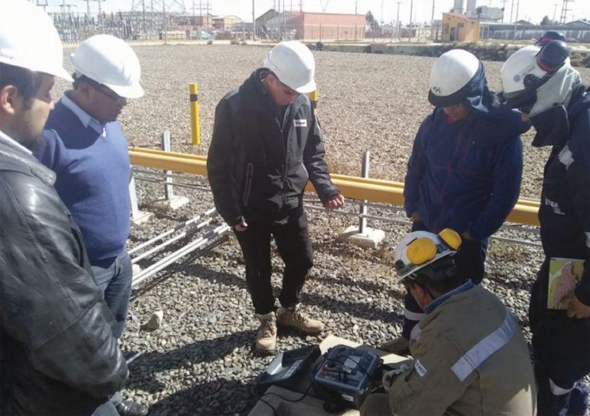
MEDIUM-VOLTAGE GROUNDING
BY JEFF JOWETT, Megger
First, let’s look at some industry-accepted definitions to establish context. Low voltage is anything below 1 kV. The common building-wiring voltages are 120, 240, 480, and 600 V. To the uninitiated, this can seem confusing and even ridiculous. Get across 600 V, and it can fry you like bacon, but in industry parlance, it is still low voltage. Put into perspective, low voltage must nonetheless be respected by following industry-standard safe working practices.
Above 1 kV, we enter the realm of medium voltage. Five thousand volts hardly sounds medium, but so it is. For organizational purposes on the power grid, systems like 4,160 V are no more than medium voltage. While the lower limit of this range is generally well accepted, definitions of the upper boundary differ. Generally, 66 kV begins the range into high voltage. However, in some contexts and in much of electrical instrumentation, this range is limited to 15 kV. Having defined the
boundaries, this article will focus on medium voltage and the grounding of these systems.
Grounding medium-voltage systems is accomplished in two ways: by standard resistance grounding and by high-resistance grounding. The determining factor for which method is applied depends on available fault current.
• Systems may be reactance grounded, meaning that a reactor is installed to introduce an impedance into the circuit.
TECH TIPS NETAWORLD • 31 MEDIUM VOLTAGE GROUNDING

This is preferred for protecting overhead circuits that are exposed to lightning and for rotating machinery where excessive ground fault currents will not develop.
• Grounding in industrial systems may include a resistor. The grounding conductor may also include a current transformer to activate a signal that a ground fault exists or to clear the circuit if a fault persists over a predetermined time. Such protection is not part of low-voltage grounding because not enough current will flow to make the current transformer effective. Systems above 15 kV are usually outdoors and not directly servicing rotating equipment and so may be solidly grounded and may include groundedneutral surge arresters.
GROUNDING OPTIONS
The grounded system neutral is the basis for all such protection in prevailing electrical distribution schemes. The system neutral can be derived from an ungrounded system by a grounding transformer of wye-delta, zigzag, or T-connected configuration. Solidly grounded neutral systems are permissible, as is multiple grounding for direct-buried feeders with a bare copper neutral, overhead portions of a system, and services.
Impedance grounded neutral systems are acceptable, with resistance grounding, highresistance grounding, and reactance grounding all employed in certain situations. High-resistance grounding may sound like a self-contradictory description but in fact is a proven technique for limiting fault currents within parameters that will allow for the protection of the electrical system from runaway fault currents and the generation of dangerous arcing ground faults.
Reactance grounded systems are similar in that they employ a means of reducing fault currents to a controlled level. In this case, a reactor is included so that the ground fault current should not be less than 25% of the three-phase fault current. This system allows for more than
the minimum current desirable in resistance grounded systems.
Surge arresters are critical components in a grounding system as they provide more sophisticated control of wildly varying fault currents than does a straight resistive connection into the earth. Somewhat resembling transformer bushings, these devices are typically made up of a metal oxide resistor enclosed in a porcelain or silicone rubber housing. They are mounted in parallel with the line they are protecting and grounded. A low impulse ratio allows the arrester to act as a bypass to ground around the protected equipment.
Lightning was a primal concern in substation protection as lightning strokes not only carried for miles in overhead conductors but also propagated through the earth in buried cable. By either means, it found its way to the substation. Initial substation protection therefore focused on lightning arrestors. In recent decades, more sophisticated power grids have made using surge arrestors farther downstream of parallel importance. While lightning arrestors are installed outside and at elevated positions, surge arrestors are installed inside the panel or on the protected equipment. Because it is a more specific device in its operational parameters, a surge arrester can be installed as a lightning arrester, but not vice versa. The surge arrestor is not to be confused with the surge suppressor, which is a more limited device installed in home distribution boards to protect wall outlets from switching surges that produce very short voltage transients. These are redirected from line to ground if over a preset limit. The surge suppressor has a low-voltage rating, only slightly above the rated voltage of the line being protected, while the surge arrestor is a more robust device capable of much higher energy dissipation.
OUTDOOR SUBSTATIONS
Outdoor substations are a bulwark of the utility system, and they are substantially regulated. But many commercial and industrial facilities have their own substations on site, and they
32 • FALL 2020 MEDIUM VOLTAGE GROUNDING TECH TIPS

must function with efficiency and safety. The fence and supporting structures, equipment and conducting enclosures, and the neutral all need to be properly grounded. The facility should be underlaid with a metallic grounding grid that extends three feet beyond the fence to extend complete safety to passersby not only during routine operation but in the potentially dangerous instances of fault clearance. Typically, many ground rods may be installed around the grid periphery. Connecting the entire structure to the water pipe system for additional reduction of resistance became common practice in the past but is not always standard practice at present in consideration of local regulations and water utility policies. Equipotential bonding of all equipment is critical so that voltage gradients do not develop during fault clearance and endanger personnel who might inadvertently come in contact with charged surfaces and become a path to ground.
Cable is sized based on the capacity of bare conductor in free air and copper bus by 1,200 amps per square inch. All metallic equipment inside the fence, such as transformer casework, switchgear including operating mechanisms for disconnects, and steel structures are bonded at no less than 4/0 and 25% of secondary capacity. The neutral is connected at two points to the ground bus for redundant security. Soldered connections are strictly precluded from such a system as unreliable and easily opened by the heat of fault clearance. Connections should be welded or brazed, and the cable must be protected from mechanical injury.
Two schemes have been described for the relationship between the substation fence and grounding system:
A. With the fence connected to station bus, a fault occurrence can elevate the fence above ground potential through IZ drop. Due to the enormity of available earth in which the fault current can disperse, the potential gradient drops off rapidly in the
area surrounding the fence. This could cause a lethal voltage to develop across the step of a nearby passerby.
B. In the counter condition of fence being isolated from ground bus, the fence will be elevated from station ground; during fault occurrence, anyone contacting the fence will be subjected to hazard.
The best resolution of these opposing conditions is to connect the fence to the grounding structure and rely on achieving a sufficiently low ground resistance in the grid so that such potentially dangerous voltages are limited below 50 V. This is the basis for the testing and measurement of the step- and touch-potentials that are widely practiced and mandated in the electrical industry.
CONCLUSION
Substation grounding is a broad field of investigation and application that cannot be substantially covered in a single article. It is hoped this glimpse provides a look into some key aspects that might otherwise be missed or taken for granted so that further inquiry will leave nothing overlooked or unexplored.
REFERENCES
International Association of Electrical Inspectors (IAEI). Soares Grounding and Bonding, 6th Edition, 2006.
Mike Holt Enterprises: https://www.mikeholt. com/.

Jeffrey R. Jowett is a Senior Applications Engineer for Megger in Valley Forge, Pennsylvania, serving the manufacturing lines of Biddle, Megger, and MultiAmp for electrical test and measurement instrumentation. He holds a BS in biology and chemistry from Ursinus College. He was employed for 22 years with James G. Biddle Co., which became Biddle Instruments and is now Megger.
NETAWORLD • 33 MEDIUM VOLTAGE GROUNDING
TECH TIPS






TONY DEMARIA ELECTRIC, INC. (310) 816-3130 www.tdeinc.com Greater Los Angeles Area MEMBER 24/7 EMERGENCY RESPONSE COVID-19 COMPLIANT ESSENTIAL BUSINESS SPECIALTY: Large Motor, Generator & Transformer Work NCSCB Certified Cable Splicers | VLF-TD & PD Cable Testing & Analysis Annual Preventive Maintenance | Relay Testing Power Systems Repairs & Troubleshooting | Power Quality Audits Engineering Services | Commissioning Industry and Custom Safety & Technical Training Available!
PARTIAL DISCHARGE TESTS FOR MEDIUM-VOLTAGE POWER CABLE SYSTEMS
 BY JIM GUO, PHD, and ZHONG ZHENG, PHD, TechImp US Corp.
Medium-voltage (MV) power cables are the backbone of the power distribution systems developed over two hundred years. Currently, 2.3 million miles of MV cables are installed in the USA, most with extruded insulation. Diagnostic testing technologies can differentiate MV cables by their operational condition and aging process prior to faults, thereby providing guidance for proactive maintenance and asset management.
36 • FALL 2020 PARTIAL DISCHARGE TESTS FOR MEDIUM-VOLTAGE POWER CABLE SYSTEMS
COVER STORY PHOTO: © ISTOCKPHOTO.COM/PORTFOLIO/CAPPAN
This article reviews popular MV cable diagnostic technologies, explains why the partial discharge (PD) test is an effective tool to diagnose MV cables, and summarizes typical PD test sensors used in onsite MV cable diagnosis. Interpreting data from onsite PD tests is also discussed because data interpretation is critical to achieving the expected advantages of PD tests.
Medium-voltage (MV) power cables are conventionally rated from 5 kV to 35 kV (phaseto-phase). Installation of MV power cables has soared since the 1960s. As shown in Figure 1, about 48,000 miles (250 million feet) of MV cable had been installed in the United States per year since 1965. Extrapolating the curve to 2020, more than 2.3 million miles (12 billion feet) of MV cable have been installed — more than 90 times longer than the Earth’s equator. Although some PILC, HMWPE, and XLPE cables remain underground, TR-XLPE and EPR cables dominate newly installed MV cables.
Despite continuous development of dielectric materials (including insulation, semiconducting

shield, and jacket) and cable configurations, MV cable degrades and eventually fails due to the aging process. More than 56.8% of faults occur in cable accessories such as splices and terminations (Figure 2a); poor workmanship is the major failure mechanism in MV cable systems (Figure 2b).
NETAWORLD • 37 PARTIAL DISCHARGE TESTS FOR MEDIUM-VOLTAGE POWER CABLE SYSTEMS
COVER STORY
Figure 1: Cumulative Length of Medium-Voltage Cables Installed in United States SOURCE: W. SHU, AND N. HAMPTON
SOURCE: N. HAMPTON
Figure 2a: Component Failure Percentages
Termination 1.4% Cable 43.2% Joints 55.4% Manufacturing problem 14% Dielectric breakdown 10% Aging 6% Overheat 4% Corrosion 4% Moisture 4% Event 3% Overload 2% Maintenance failure 2% Mechanical damage 1% Contamination 1% Poor workmanship 49%
Figure 2b: MV Cable Failure Mechanisms

Diagnostic testing technologies are therefore used to discriminate defects prior to premature failures in MV cable systems. Compared with other technologies, the partial discharge (PD) test is a more effective method to recognize types of defects and locate defective components.
WHY PARTIAL DISCHARGE TEST?
The most popular field diagnostic testing technologies for MV cable systems are DC and AC withstand tests, the dielectric loss test (Tan Delta), and the partial discharge test.
Withstand Test
The withstand test, also called high-potential (hipot) test, is the simplest testing technology for MV cable systems. The DC hipot test was first adopted in paper-insulated cables where testing voltage could be three to five times the rated voltage. Engineers quickly realized the DC hipot test could damage extruded cables due to high potential as well as space charge injection and accumulation.
The AC hipot test can be used in the field for extruded cables, although size requirements make it impractical for most circuits. This test normally applies two to three times the rated voltage to the cable system; the testing voltage needs to hold for one hour (1-hour withstand test). Since power cables are a capacitive load, the power required to energize the cable during the test is proportional to cable size and length, as well as the testing frequency.
The very-low-frequency (VLF) power supply has significantly reduced the size and power consumption compared with power frequency units. It is worth noting that VLF itself is not a testing technology. Instead, VLF is a type of power supply that typically provides a 0.1 Hz high-voltage sinusoidal waveform to energize the tested cable. VLF can be applied to all types of tests including the withstand test, dielectric loss test, and PD test.
The withstand test is a typical go-or-no-go test that requires minimum training to operate on-site. The test results are obvious, and no data interpretation is needed. However, the withstand test cannot recognize small defects that will not lead to an immediate fault but would significantly shorten the service life of an MV cable system.
Tan Delta Dielectric Loss Test
Tan Delta (TD) refers to measurement of dielectric loss, which is the ratio of resistive current and capacitive current in tested cables. In good electric insulation, resistive current is much smaller than capacitive current; thus, the dielectric loss is very small. In good XLPE insulation, the dielectric loss is in the range of 0.01–0.05%. Dielectric loss is higher in EPR — in the range of 0.2%.
Once the insulation system ages (i.e. contains water trees), TD values increase. The TD test evaluates the overall performance of the insulation system in the cable system. The advantage of the TD test is that it examines deterioration in the entire insulation, particularly if the insulation is in the process of water treeing. Disadvantages include that TD measurement cannot be performed in a hybrid circuit containing different insulation materials because the single measured TD value is a mixture of the entire circuit and cannot represent either individual segment. The TD test also cannot separate and recognize the type of defects — a large water tree and numerous small water trees may give the same TD values — and cannot localize the defect site.
Partial Discharge
Partial Discharge is defined as localized dielectric breakdown (discharge) of a small portion of a solid or fluid electric insulation system under high-voltage stress that does not bridge the space between the two electrodes. PD indicates defects or degradation in the cable system. When PD occurs, discharge activity erodes nearby insulation, which consequently
38 • FALL 2020
COVER STORY PARTIAL DISCHARGE TESTS FOR MEDIUM-VOLTAGE POWER CABLE SYSTEMS


3: Cable Fault Caused by Discharges between Broken/Corroded Copper-Tape Sheath
accelerates insulation aging and deterioration. Interestingly, PD sources during the aging process may not be limited to the insulation. The metallic grounding sheath could break during thermal cycling (common for coppertape sheath) or could be corroded (for neutral wires and copper tape). The broken neutral wires or copper tape may build up enough potential to ignite discharges, which erodes the semicon shield and the insulation and eventually leads to a fault. Figure 3 shows a cable fault caused by discharges between the broken/corroded copper-tape sheath.
Compared with other diagnostic testing technologies, the PD test has the unique advantages of distinguishing various types of defects and localizing the sources of those defects. One important feature for PD measurement is that different types of defects generate unique patterns with reference to the phase angle of the applied voltage, which is the so-called phase resolved PD (PRPD) pattern. Figure 4 shows discharge patterns for typical defects.
A PD test can also locate the discharge site by using either time domain reflectometry analysis or frequency domain analysis. Indeed, PD signals are electro-magnetic pulses propagating in MV cables from the discharge site to the PD sensor. During PD signal propagation, pulse magnitude and bandwidth decrease with the propagation distance. Therefore, the discharge source location can be estimated by comparing


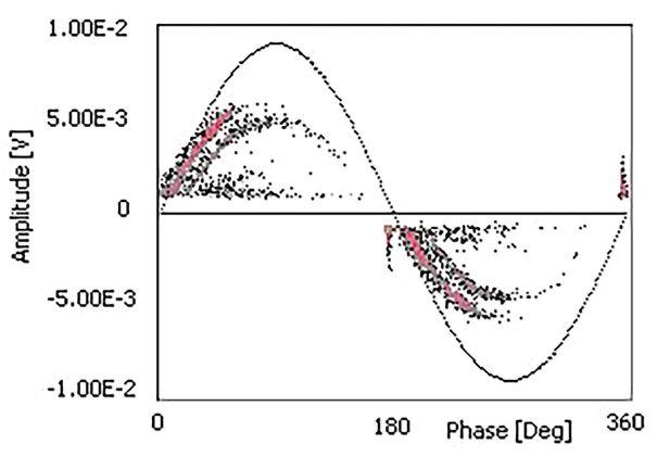
Figure 4: Discharge Patterns for Typical Defects: (top to bottom) Internal Discharges (void), Surface Discharges, and Corona Discharges.
NETAWORLD • 39
COVER STORY PARTIAL DISCHARGE TESTS FOR MEDIUM-VOLTAGE POWER CABLE SYSTEMS
Figure

measured PD magnitude at various locations or by calculating measured PD bandwidth. Alternatively, since PD pulses reflect at the splices and terminations, the discharge source location can be estimated by comparing the time difference of the first measured PD pulse and the reflected PD pulses (assuming total cable length and signal propagation velocity in the cable are known).
In the field, diagnostic technologies can be implemented individually or combined. For example, IEEE 400 recommends combining the simple withstand test with TD and/or PD tests. Called a monitored withstand test, this combination can tremendously improve diagnostic accuracy.
SENSORS FOR ONSITE PD MEASUREMENT
PD measurement is not difficult, and many PD testing instruments are commercially available. Selecting the proper PD instrument is critical and is determined by the purpose of the test, the equipment under test (EUT), and the skill of the operators. A PD instrument normally includes PD sensor(s), a data acquisition unit, and a data storage and processing unit.
Choosing the correct PD sensor is particularly important. Typical PD sensors for measuring MV cable systems in the field include capacitive coupler, high-frequency current transformer (HFCT), ultra-high frequency (UHF) antenna, transient earth voltage (TEV) antenna, radio frequency (RF) antenna, and ultrasonic (acoustic) antenna. All antennatype sensors are mainly used to test cable accessories and connected components such as cable terminations, splices, and connected MV switchgear. These antenna sensors effectively screen large-magnitude PD activities such as tracking discharges and are typically very directional to pinpoint discharging sites. Many handheld PD testers are equipped with these antennas, which can be a great addition to conventional PD measurement of MV cables. However, most antenna sensors are not
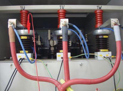
Figure 5: Capacitive Couplers on Each Phase of Cable Termination for a 15 kV Cable System
sensitive enough to recognize weak PD signals within cable insulation.
The capacitive coupler and HFCT are two of the most common sensors adopted for measuring PD in MV cable systems as well as other applications including HV/EHV cable systems, motors and generators, and transformers.
Capacitive Couplers
Capacitive couplers are installed in parallel with the EUT (Figure 5). Direct access to the cable conductor is required; thus, it is normally used in an offline test or permanently installed (online monitoring). A capacitive coupler achieves optimal PD detection sensitivity as it directly connects to the cable conductor. Moreover, capacitive couplers normally contain a voltage divider that can capture power frequency signals to synchronize with PD data acquisition as well as monitor the operating voltage of the tested circuits.
The disadvantage of using a capacitive coupler is that direct access to the cable conductors is required. Installing a capacitive coupler can be a challenge for certain cable configurations, such as if cable terminations are on a high riser pole. Since a capacitive coupler is a galvanic sensor, operational safety is another important consideration during on-site application.
40 • FALL 2020
COVER STORY PARTIAL DISCHARGE TESTS FOR MEDIUM-VOLTAGE POWER CABLE SYSTEMS

High-Frequency Current Transformers
HFCT may be the most popular sensor for testing PD in MV cable systems due to its high sensitivity and simple installation. As shown in Figure 6, open-core HFCTs can easily be clamped over the ground wires of MV cables. HFCTs are directional as they capture PD-induced current through the ground wires. When HFCTs are installed at cable terminations as in Figure 6, PD sources from a cable termination and a cable section can be simply differentiated by checking the polarities of the acquired PD pulses. PD detection sensitivity of an HFCT is evaluated with the ratio of detected voltage to current going through the core; this ratio is normally presented in units of mV/mA or dBΩ. The sensitivity of a good HFCT can reach 25 dBΩ or 1mA of current going through the HFCT could generate 19 mV voltage to be measured by the data acquisition unit.
An HFCT does not provide a power frequency signal for synchronization. Other synchronization sources are required for PD data acquisition. A separate low-frequency current transformer (LFCT or Rogowski coil
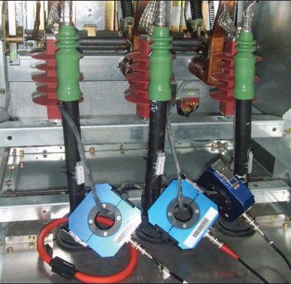
Figure 6: HFCTs Installed on Ground Wires of a Three-Phase 15 kV Cable System. The blue sensors are HFCTs; the red sensor is a Rogowski coil providing power frequency synchronization signal to the PD data acquisition.
— the red coil in Figure 6) was adopted to capture the synchronization signal. The LFCT can be placed around the ground wire or over the entire cable under test.
When the LFCT is placed over the ground wire, the measured power frequency current is the capacitive current going from the cable conductor through the insulation to the ground wire. This current has 90° phase shift to the conductor voltage, which needs to be compensated for during data analysis. If the LFCT is placed over the entire cable, the situation is more complicated as the measured current could be the load current (online test, cable with load) or capacitive current (offline test, cable without load). If the LFCT measures load current, the small phase shift from the voltage (power factor) must be compensated for during further analysis.
Measuring PD in a MV cable system is not difficult once a proper PD instrument/sensor is selected. Most PD instruments have simple procedures and user-friendly interfaces that a technician can master with self-learning or minimal training. Some handheld PD instruments feature various indicators (LED lights or audible sounds) to identify the existence of PD activities and illustrate the amplitude of PD events. If the purpose of the test is limited to these tasks, the PD test process could be stopped. However, the most significant advantages of a PD test — recognizing the type of defects and locating the defect sources — cannot be achieved without further data interpretation.
DATA INTERPRETATION FOR MV CABLE PD TEST
The first questions when looking at measured PD results from various instruments are “How can I ensure the measured or displayed signal is the PD in the MV cable system? What does the displayed value mean, and what should we do with those results?” These are two of the questions that must be solved during PD data interpretation, which is the most important but also most challenging step of MV cable PD tests.
NETAWORLD • 41 COVER STORY PARTIAL DISCHARGE TESTS FOR MEDIUM-VOLTAGE POWER CABLE SYSTEMS

PD data interpretation can be generalized in three steps: signal separation, signal identification, and diagnosis (S–I–D).
Signal Separation
Signal separation is fundamental for PD measurement. The most significant challenge for all PD measurement is to discriminate relevant PD signals from various noises and interferences. This is particularly difficult for online testing because cable systems are exposed to complicated field conditions with numerous types of interference. All PD testing instruments have implemented at least one noise separation technique. For example, frequency filtering is a conventional method to remove interferences if the PD signals have different frequency spectra from the noise. Almost all PD testing devices are equipped with varying filters to improve PD detection sensitivity, but they have limitations for noises that share a similar frequency spectrum with the PD signals. T-F Map analysis has proven to effectively separate signals from various sources. It categorizes observed signals by the equivalent pulse (T) and equivalent pulse bandwidth (F). Signals from the same source tend to have the same T and F, which form clusters in the T-F Map, as shown in Figure 7. T-F Map analysis performs well to discriminate PD signals from varying types of interference, as well as to separate PD signals from different sources.
Signal Identification
Signal identification recognizes the types of discharge sources using the phase resolved partial discharge (PRPD) pattern. The PRPD pattern is essentially the cumulative distribution of the PD occurrence in reference to one power cycle. The shape of the distribution is determined by the types of defects, as was shown in Figure 4. Identifying the types of defects is critical for any further assessment, as the severity of the discharge varies with the type of defect. For example, corona discharge may have great magnitude, but does not cause insulation degradation in
the short term, while internal discharge may lead to initiation and growth of an electrical tree, causing the insulation system to break down in a short time even if the discharge magnitude is low.
Signal separation and identification are intricately connected. Figure 7 shows an example of signal separation and identification for a set of PD data measured in the field. The PD test was performed on a 35 kV cable system with HFCT placed at the cable termination. The cable was energized with a 0.1 Hz VLF power supply, and the testing voltage for the results shown was 20 kV (operating voltage).
Figure 7-a is the entire measured data presented in the PRPD pattern. Figure 7-b shows the same PD data mapped by its equivalent pulse width and pulse bandwidth (T-F Map). Each dot in the PRPD pattern is one measured pulse, which has a corresponding dot in the T-F Map. The possible PD signals are all overwhelmed by the strong interferences in the overall PRPD pattern. However, the T-F Map clusters the signals from similar sources. By examining each cluster in the T-F Map, it was determined that all black dots in the T-F Map are noises (Figure 7-c), and the red dots are internal PD from the tested cable termination (Figure 7-d). Since the internal PD signal was detected only at the operating voltage, this cable was not recommended to be energized until the discharging defect has been mitigated.
Besides recognizing types of defects, the identification stage also includes locating the discharging elements in the MV cable system. The value of the PD test results would be limited if the PD sources could not be located with reasonable accuracy. The PD sources in MV cable systems are normally located using the following techniques:
• Time-of-arrival analysis. The principle of using time-of-arrival analysis to locate the PD site is the same as the time domain reflectometry (TDR) test. Once PD occurs in the MV cable system, the
42 • FALL 2020 COVER STORY PARTIAL DISCHARGE TESTS FOR MEDIUM-VOLTAGE POWER CABLE SYSTEMS

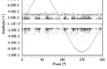


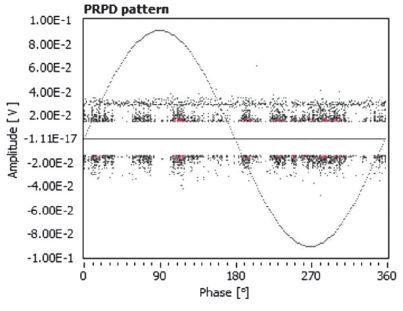
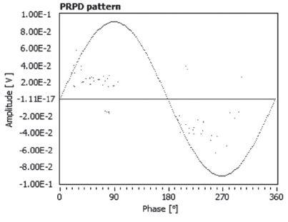
Figure 7: Signal Separation and Identification with T-F Map Analysis and Phase Resolved Partial Discharge (PRPD) Pattern. Data was measured from a VLF PD test for a 35 kV cable system: (a) the entire PRPD pattern of the acquired data; (b) T-F Map clustering for the acquired data; (c) PRPD pattern for the black cluster in the T-F Map; (d) PRPD pattern for the red cluster in the T-F Map.
PD pulse propagates along the cable in both directions. The discharge source location can be calculated by the time difference between the original pulse and the reflected pulse captured with one PD sensor, with prior knowledge about the PD pulse propagating velocity in the tested cable, the cable length, and/or the position of the splices.
• Frequency spectrum analysis . This method utilizes the knowledge that PD signal bandwidth attenuates with the propagation distance in the MV cables. This method is not as accurate as time-of-arrival analysis, but it has the advantage that no reflected PD pulse is required (which could be difficult to see for long cables).
Diagnosis
PD test results can be presented using two approaches:
1. Traditional indicators: numerical parameters from PD measurement such as PD magnitude, PD inception voltage (PDIV) and extinction voltage (PDEV), repetition rate, etc.
2. Diagnostic indicators: normally a levelscaled system to indicate condition levels, severity of defects, and the corresponding actions
Traditional indicators can be directly observed from the PD testing instrument, which has the benefit of simplicity. However, those numerical
NETAWORLD • 43 COVER STORY PARTIAL DISCHARGE TESTS FOR MEDIUM-VOLTAGE POWER CABLE SYSTEMS
(a) (c) (b) (d)

Table 1: Five-Level Diagnostic Indicators for PD Test of MV Cable Systems
LevelInsulation ConditionRecommendation
Level 1 The insulation in the cable system is not degraded.
Level 2 The cable system is aged but not in danger. The probability of failure within 2 years is negligible.
Level 3 The cable system has low to moderate deterioration and low probability of failure within the next 2 years.
Level 4 The cable system has medium probability of failure within the next two years.
Level 5 The cable system is at the end of economic life and has a high probability of failure within 1 year.
SOURCE: J. GUO AND W. SHU
values are not actional and still require interpretation for maintenance planning. Diagnostic indicators are the preferred PD test results for asset management.
Table 1 shows an example of a five-level diagnostic criteria that categorizes the cable system by the probability of failure in a certain time frame. The indicators provide clear reference to the circuit owners for maintenance planning.
The challenge in deriving the diagnostic indicator is that PD diagnosis does not rely on a single parameter (PD magnitude) for the condition assessment because:
1. The severity of discharge activities is determined by the types of defects.
2. The tolerance against PD activities varies between devices.
The analysis process includes all the collected information regarding the types of defects, the characteristics of the equipment under test, installation and operating conditions, and the quantified PD parameters. Unfortunately, there is no universal recipe that can be adopted. The diagnosis still depends on the knowledge and experience of the analyst.
No action needs to be taken.
Retest is recommended within two years for trending analysis.
Retest is recommended within one year.
Further discussion is required to determine the viability of repair or replacement.
Immediate attention is recommended
General guidelines for diagnosing MV cable systems:
• PD magnitude is not the only parameter to evaluate the severity of PD activities. The PD repetition rate (number of PD pulses per unit time), type of defects, PD site location, insulation materials, cable configuration, etc., are all required to rigorously evaluate the severity of PD activities.
• PD defect severity increases from corona discharges up to surface discharges up to internal discharges.
• Extruded insulation materials (PE, XLPE, EPR) have much lower PD tolerance compared with oil-paper insulation (PILC).
• Cable accessories normally can survive longer with PD than cables with extruded insulation.
• Trending analysis — comparing the growth of PD magnitude and repetition rate over time — yields more accurate information for the level of degradation and provides a better estimate of probability of failure within a certain time frame.
44 • FALL 2020 COVER STORY PARTIAL DISCHARGE TESTS FOR MEDIUM-VOLTAGE POWER CABLE SYSTEMS

CONCLUSION
Although the benefits of diagnostic testing in MV cable systems have been widely accepted in both installation (commissioning test) and operating (maintenance test), the main competition for all testing technologies is the run-to-failure practice. Over 40% of the MV cables operated in North America are not subjected to any diagnostic tests. Fortunately, the tide is turning as more and more cable owners accept diagnostic testing technologies as asset management tools to improve MV cable system reliability and to save lifetime asset management cost.
It is well-accepted that the PD test has the unique advantages of distinguishing various types of defects and localizing the sites of those defects. However, adopting the PD test to diagnose a MV cable system is controversial. Performing the PD test is quite simple, as a wide range of commercial PD instruments and sensors are available. However, performing the diagnosis with the measured PD data is a challenge that requires a wealth of training. Hopefully, in the near future, PD data interpretation can be simplified through rapid development of computer engineering and artificial intelligence.
REFERENCES
H. Orton. “History of Underground Power Cables,” IEEE Electrical Insulation Magazine, Vol. 29 (4), July/August2013, pp. 52-57.
W. Shu, and N. Hampton. “Evolution of MV Cable Designs in the US from 199 to 2014,” IEEE International Conference on Communications, Sub A, October2018.
N. Hampton, “Historical Overview of Medium and High Voltage Cables,” Online at https://www.neetrac.gatech.edu/publications/ Cable_History_Doble_Final_Website.pdf.
J. Guo and W. Shu. “Online Partial Discharge Diagnosis for Power Distribution and Transmission Systems,” NETA World, Fall 2018.

Dr. Jim (Jun) Guo joined TechImp US Corp as VP of Technology in 2015. His research interests focus on high-voltage dielectric aging and breakdown theories, partial discharge measurement and analysis, and high-voltage equipment diagnostic testing and monitoring. He received his PhD in material science at the Electrical Insulation Research Center, Institute of Material Science, University of Connecticut, Storrs in 2010. Jim previously was the Engineering Systems Analyst and Project Manager with CableWISE, where he focused on online diagnosis for power transmission and distribution systems. He has more than 30 publications in peer-reviewed journals and international conferences and holds four US and international patents. He is a senior member of IEEE and the IEEE Insulated Conductor Committee, and currently serves as Chair of the Membership/Chapter Committee in the IEEE Dielectric and Electrical Insulation Society. He is also an associate editor for IET Science Measurement & Technology.

Zhong Zheng, an IEEE senior member since 2011, received his PhD from the University of Toronto, Canada, in 2006 and joined TechImp the same year. He became a professor in North China Electric Power University in 2008. With a research interest in partial discharge and insulation material, he has published more than 100 technical papers and been awarded more than 20 patents.
NETAWORLD • 45 COVER STORY PARTIAL DISCHARGE TESTS FOR MEDIUM-VOLTAGE POWER CABLE SYSTEMS

LEARN WHAT YOUR OIL RESULTS REALLY MEAN.

DOBLE LABORATORY DIAGNOSTICS SEMINAR AT POWERTEST 2020 | FEBRUARY 28, 2020
Join us for a one day laboratory seminar on Friday, February 28 at PowerTest 2020. Doble’s laboratory expert will present an interactive session that combines theoretical background with practical experience. We will share case studies illustrating common problems found in the field.
PARTICIPANTS WILL
• Understand how to determine the condition of electrical apparatus using laboratory tests
• Discover how knowing about aging characteristics of insulating materials can help you extend asset life
• Learn how to take oil samples, avoid common pitfalls, save time and save money by sampling only once
•Detect the presence of incipient-fault conditions and categorize them
• Find out how to assess the condition of the paper insulation
• Establish the correct method of analyzing moisture-in-oil results
• Study the significance of dissolved metals, particulate metals and other particle contamination
• Learn about the quality of new and service aged oils
• Learn how to identify and mitigate issues with corrosive oils
REGISTER TODAY www.powertest.org 888-300-NETA Laboratory Seminar Fee is $445
www.doble.com
PARTIAL DISCHARGE SECRETS, TIPS, AND TRICKS
BY WILLIAM G. HIGINBOTHAM, EA Technology LLC

Most of us started our electrical careers with fairly good knowledge about the practical aspects of our jobs. We understood voltage, current, power, resistance, etc. We mastered the more esoteric areas such as electrical fields and stress control and only revisited these topics if our day-to-day job required it. Partial discharge (PD) is one of those areas where we might have learned how to identify it or how to use a test set, but most of our roles have not exposed us to the ins and outs of this topic.
In this article, I share some unexpected things I have learned while working with clients on partial discharge issues. I hope this includes the
secrets, tips, and tricks you always wanted to know about partial discharge but were afraid to ask.
48 • FALL 2020 PARTIAL DISCHARGE SECRETS, TIPS, AND TRICKS
FEATURE

CAN CABLE TERMINATION MISTAKES CAUSE PD?
When a termination containing multiple layers and different materials is exposed to an electric field, the voltage stresses are larger in the areas of lesser permittivity. Air has a permittivity about 2.3 times lower than insulation, so a void in the termination will have approximately 2.3-times-higher field stresses. Combined with a 10-times lower dielectric strength, this leads to discharge across the void.
Cable terminations are specifically engineered to ensure voltage stresses do not exceed the
insulation capability at any point. This is accomplished by ensuring the voltage gradients across the insulation are even (Figure 1).
Voids can be caused by common mistakes in terminations. Failure to completely fill gaps between insulation and conductors with mastic is very common. Imprecise trimming of semiconductor layers can leave a void where the stress tube cannot fill the poorly trimmed section. Failing to fully clear the semiconductor layer off the insulation causes a concentration of stress and results in PD even if there is no void. Figure 2 shows that electrical stress is greater in and around the void.
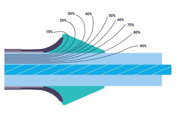
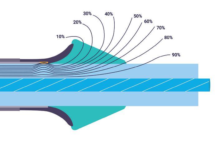
NETAWORLD • 49 PARTIAL DISCHARGE SECRETS, TIPS, AND TRICKS
FEATURE PH O T O: © I S T OC KPH O T O.COM/ P O RTF O LI O/ A N I GOW EB
Figure 2: Voltage Gradients in a Poor Termination
Figure 1: Voltage Gradients in a Cable Termination

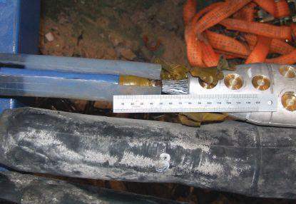
Cable termination procedures are precisely engineered, and any failure to follow them closely can lead to voids, field concentration, and partial discharge. An example of this can be seen in Figure 3, where an overly large gap that was not filled with mastic led to failure.
CAN INCORRECT RFCT PLACEMENT INDUCE PD?
When performing an online partial discharge test on a cable, a radio frequency current transformer (RFCT) must be attached to the cable ground strap. In placing the RFCT, think 95% about safety and 5% about getting a good signal. Improper placement of an RFCT can affect both safety and signal. For safety reasons, ensure you have a solid ground capable of withstanding any phase-to-shield fault current. Also ensure the RFCT is away
from the termination and close to the ground bar so the RFCT is still safe if the ground does separate. Figure 4 shows an RFCT placed on an adequate ground close to the main ground bar and away from the termination.
Is that the only reason you put the RFCT away from the termination? Remember that the termination is where the electric field goes from nice and contained inside the shield to free and unrestrained after the shield cut-back.
The termination is designed to allow the field to spread out gradually so there is a lesser field but evenly distributed around the termination. The closer you get to the termination, the stronger the field becomes. Allowing the RFCT inside that field can induce PD. It probably will not lead to failure unless it is very close, but it will make it impossible for that RFCT to discern any real PD.
WHAT ARE CONTACT DISCHARGE AND FLOATING METAL DISCHARGE?
Contact discharge is caused by a poor highvoltage connection where sparks can jump across the gap at set times on the sine wave when the voltage level is high enough. These defects usually produce heat as well as ultrasonic sound that can be detected.
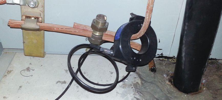
50 • FALL 2020
PARTIAL DISCHARGE SECRETS, TIPS, AND TRICKS FEATURE
Figure 3: Defective Cable Termination
Figure 4: Properly Placed RFCT

A related discharge — floating metal discharge — is an electrical discharge that takes place due to floating metal in the electric field. The floating metal typically acquires an electric charge from the field and then discharges to ground, the conductor, or via corona through the air. Common examples include tools or hardware left in a cabinet after work is performed.
Contact discharge and floating metal discharge have characteristic phase resolved partial discharge (PRPD) plots where the level of discharge is consistent as the voltage increases (Figure 5). These two types of discharge emit similar patterns, so it can be difficult to differentiate between the two.
The phase resolved pattern indicates that PD magnitude does not change despite the change in voltage. This is because the distance from the gap at the poor HV connection or the floating metal to the live conductor is constant; therefore, the flashover voltage remains the same. The discharge phase angle actually moves with each succeeding discharge due to the physics of this type of discharge. The variance in phase and consistency in discharge amplitude produces these characteristic flat, broad lines in the PRPD. This characteristic can be used to identify this type of discharge and make it easier to find the offending component.
Contact discharge can cause failure due to the poor HV connection, whereas floating metal discharge tends not to lead to catastrophic failure. Both discharge types create a strong signal that often masks more damaging types of discharge. Ensure you eliminate this so you can see other discharge sources.
IS IT BETTER TO GROUND THE CABLE AT ONE END OR BOTH?
When you design a cable system, you have an option of grounding the shield at one end or both ends. If one end is ungrounded, a sheath voltage limiter (SVL) is typically placed on that
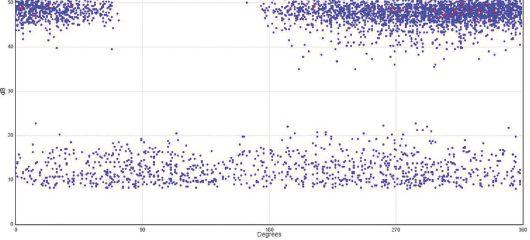
end. The shield of a cable capacitively and inductively couples to the conductor, thereby acquiring potentially dangerous voltage. If both ends are grounded, the sheath voltage will be lower than if one end is an open circuit, especially during a fault. The downside of grounding both ends is that circulating currents can heat the cable and reduce its ampacity.
If a cable grounded at one end shows PD, the current has nowhere to go except the ground strap where the RFCT is located. This allows you to measure the total PD current. If the cable is grounded at both ends, the PD current will divide according to the ratio of impedances in either direction. This gives a lower reading. However, there is a bright side: Testing both ends of the cable allows better sensitivity overall. A small discharge on one end might not be detectable at the other end.
IS THERE A STANDARD FOR ACCEPTABLE PD LEVELS IN CABLES?
The world of electrical testing is largely predicated on the fact that we can assign a threshold. Above the threshold is considered bad, and below the threshold is considered good, or vice versa. As an example of the latter, in an insulation resistance test at 1 KV, above 100 Megaohms is generally considered good for many equipment types while below 100 Megaohms is suspect or bad. These test methods and thresholds are codified in international, peer reviewed, and balloted standards to ensure they are accurate.
NETAWORLD • 51
PARTIAL DISCHARGE SECRETS, TIPS, AND TRICKS FEATURE
Figure 5: Phase Resolved Partial Discharge Plot

The world of partial discharge testing has very few approved standards, and most of them contain vague words like “should” and “may” instead of “shall” and “must.” Cable PD testing is especially void of standards that include hard and fast thresholds. ANSI/NETA MTS 2019 is the first United States standard to include online PD testing, but it doesn’t cover cables. IEEE 400.3 is specifically for field PD testing of cables, but it has no thresholds.
This lack of standardized acceptance levels can be traced back to the very nature of PD. It is an unfortunate fact that the absolute PD level is not directly relatable to the likelihood of failure or the time to failure. PD levels go up and down with a variety of influencing factors: Voltage, current, ambient temperature, relative humidity, time since inception, defect carbonization, and other factors. With all these variables unrelated to the test method, it is difficult to arrive at threshold levels. Trending over time or comparison to similar assets remains the best way to gauge the severity of PD. You may not be able to predict when something will fail, but you can identify bad actors for further study.
WHICH IS BETTER — ONLINE OR OFFLINE PD TESTING?
This is a bit of a trick question. The tests are quite different, and they tell us different things. Both have their place in any maintenance and reliability program. It is important to understand their different strengths.
• Online PD Testing is usually the first step. You can test all your assets quickly and efficiently to see what is good and what needs further study. You are testing under real-world conditions of voltage, current, frequency, and load. If PD does not exist in the real-world conditions, there is no need to be too concerned. You can test all your assets without taking anything out of service or opening any panels to do the tests. Typically, a very small percentage of assets record any PD. The downside is that online PD testing will tell you less about PD than an offline test.
• Offline PD Testing is as close as you can get to factory testing in the field. You can vary voltage and see noise-free PD patterns. You can see exactly at what voltage PD begins and ceases. Unfortunately, it’s not all good news. You must take the equipment out of service and bring in large, heavy, expensive test equipment. You are also not working in a real-world condition, so results may not be fully representative of normal conditions. An offline test takes 10 to 20 times longer than an online test. The frequency is typically not power system frequency, and there is no load current, so the temperature profile is also different.
The global best practice is to do online testing or monitoring on all assets and do offline tests on the small population of assets that give indications of PD online.
CAN YOU FIND PD INSIDE SWITCHGEAR BY TESTING THE CABLE?
Transient earth voltage (TEV) is a standard technique for finding partial discharge inside medium-voltage metal-clad switchgear. The TEV effect, discovered in the late 1970s by Dr. John Reeves of EA Technology, has become the basis for non-invasive testing for internal discharge. Voltage is induced on the outside surface of metal-clad gear as a result of discharge inside the gear. This voltage is a narrow pulse of a few microseconds and amplitude in millivolts. Measuring TEV can be very difficult because the signals of interest are hidden in noise.
One trick we have learned is that performing a TEV test on the outside of a cable exiting the cubicle is an excellent way to find PD inside the cubicle. A TEV probe on the outside of the sheath will couple to the shield and often provide a higher signal than the outside of the switchgear. The PD pulse in the switchgear will travel down the conductor and radiate to the shield. However, gaining access to the cables within a meter of the switchgear is not always possible. With IEC-type gear, the cables are exposed. In most cases with ANSI gear, you will
52 • FALL 2020
PARTIAL DISCHARGE SECRETS, TIPS, AND TRICKS
FEATURE


need access below the cabinet. Many industrial substations are raised or have a basement that allows access. If at all possible, try it out.
HOW SOON AFTER ENERGIZING CAN YOU SEE PD?
Traditional knowledge held that partial discharge took years or decades to develop. The standard response was “all my equipment is new! I don’t need to do PD testing.” In some instances, PD takes a long time to start. The thermal cycling that occurs throughout device operation can cause voids over time, and internal discharge can take decades to cause failure. However, as we have learned recently, early-life PD and failures are quite common. The oil sands region of Alberta, Canada, has seen explosive growth in the past 25 years, and the demand for jointers outstripped the qualified supply. Cable failures within the first 12 to 18 months were common. Data centers and windfarms have similarly driven cable installation rates to rise, and early failure rates in those applications are well above acceptable levels.
If the conditions are right for PD, there is no physical reason for it not to start immediately. It may be so low as to be undetectable at first, but it can be present. PD is more likely to be caused by workmanship than by aging, and bad workmanship is there from day one. In Figure 6, a monitoring system was installed on a cable with new splices; PD was detectable by day 10. By day 14, it was 300 pC — not quite ready

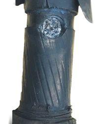
to fail, but clearly a rapid increase immediately after energizing.
Figure 7 is an EHV termination that failed within days of energization. PD would have been detectable immediately.
CONCLUSION
I hope these few examples have been interesting and enlightening. While partial discharge is still a developing topic in our industry and we continue to find new things every day, the information we can learn about our assets is worth the learning curve.

William G. Higinbotham has been president of EA Technology LLC since 2013. His responsibilities involve general management of the company, including EA Technology activities in North and South America. William is also responsible for sales, service, support, and training on partial discharge instruments and condition-based asset management. He is the author or co-author of several industry papers. Previously, William was Vice President of RFL Electronics Inc.’s Research and Development Engineering Group, where his responsibilities included new product development, manufacturing engineering, and technical support. He is an IEEE Senior Member and is active in the IEEE Power Systems Relaying Committee. He has co-authored a number of IEEE standards in the field of power system protection and communications, and holds one patent in this area. William received a BS in computer/electrical engineering from Rutgers, the State University of New Jersey’s School of Engineering, and worked in the biomedical engineering field for five years prior to joining RFL.</pubtitle>
NETAWORLD • 53 PARTIAL DISCHARGE SECRETS, TIPS, AND TRICKS FEATURE
Figure 6: Partial Discharge over Time
Figure 7: Failed EHV Termination

Superior Service for Optimal Performance
Whether you need startup services, ongoing maintenance, or emergency response you need a partner you can trust.
Rely on Vertiv’s Electrical Reliability Services’ team for expertise, responsiveness, and safety.
• Consistent quality, service-delivery process
• Proactive customer communication and project management
• National, regional, and local service center availability
To learn more, visit ERS.Vertiv.com or call 877-468-6384
Experts Available Across Six Centers of Excellence: Commissioning | Electrical Engineering | DC Power Testing and Maintenance | Protection and Controls | Compliance




the Vertiv logo are trademarks or registered trademarks of Vertiv Group Corp. All other names and logos referred to are trade names,
or registered trademarks
their
Vertiv™
and
trademarks
of
respective owners.



ACCEPTANCE AND MAINTENANCE TESTING MEDIUM-VOLTAGE ELECTRICAL POWER CABLES


 BY THOMAS D. SANDRI, Shermco Industries
As time progresses and a cable system ages, the system’s bulk dielectric strength degrades. During this aging process, artifacts such as water trees, delamination, voids, and shield corrosion raise the local stress placed on the cable during normal operation. The exact way in which the strength of a device degrades depends upon many factors including voltage, thermal stresses, maintenance practices, system age, cable system technology and materials, and environment.


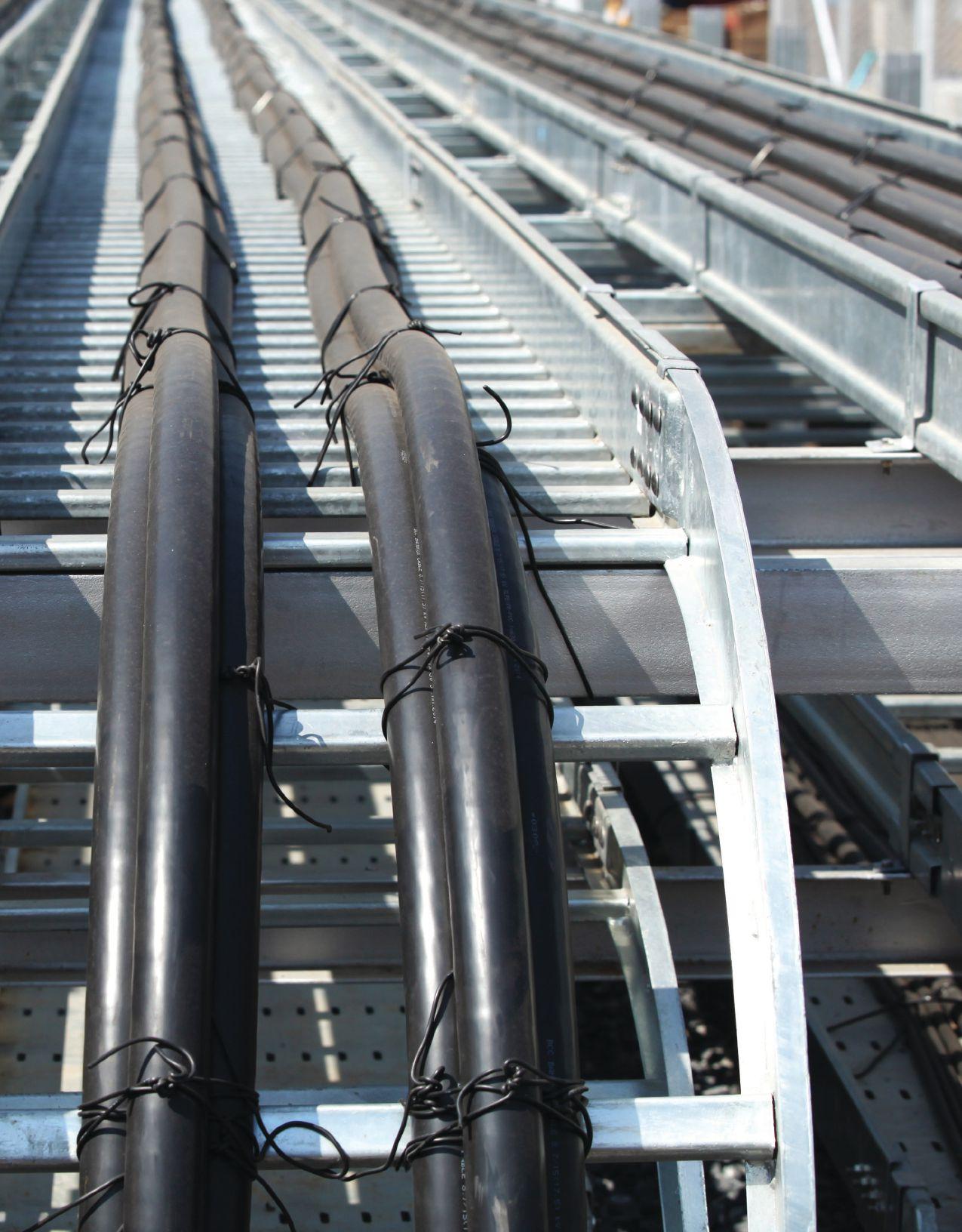
56 • FALL 2020 ACCEPTANCE AND MAINTENANCE TESTING MEDIUM-VOLTAGE ELECTRICAL POWER CABLES
FEATURE
As reliability demands grow, testing methods have been developed that can provide a better indication of the integrity of cables, splices, and terminations. To use these methods effectively, the operator must understand the mechanisms of aging and failure in cable systems.
CABLE TESTING OPTIONS
Over the years, several methods and/or philosophies regarding testing underground electrical power cable in the field have evolved. The Insulated Conductor Committee of the IEEE Power & Energy Society has divided these methods or philosophies into two fundamental categories: Type 1 Field Tests and Type 2 Field Tests.
Type 1 tests are intended to detect defects in a cable system’s insulation in order to improve service reliability after the defective part is removed and appropriate repairs are performed. These tests are usually achieved by applying moderately increased voltages across the insulation for a prescribed duration of time. Such tests are categorized as pass/fail. Type 1 tests include:
• Direct Current Withstand: IEEE 400.1, Guide for Field Testing of Laminated Dielectric, Shielded Power Cable Systems Rated 5 kV and Above with High Direct Current Voltage
• VLF Withstand: IEEE 400.2, Guide for Field Testing of Shielded Power Cable Systems Using Very Low Frequency (VLF)
• High Potential Power Frequency: This is typically considered a factory test, not a field test.
Type 2 tests are intended to provide indications that the insulation system has deteriorated; hence, they are termed diagnostic tests. Type 2 tests include:
• Dissipation Factor (Tan Delta) Testing: IEEE 400.2, Guide for Field Testing of Shielded Power Cable Systems Using Very Low Frequency (VLF)
• Partial Discharge: IEEE 400.3, Guide for Partial Discharge Testing of Shielded Power Cable Systems in a Field Environment
• Damped Alternating Current: IEEE 400.4, Guide for Field Testing of Shielded Power Cable Systems Rated 5 kV and Above with Damped Alternating Current (DAC) Voltage
HIGH POTENTIAL TESTING WITH DIRECT CURRENT (DC)
For years, high-voltage DC testing has been the traditionally accepted method for judging the serviceability of medium-voltage cables. Direct current tests have worked well for conducting high potential and condition assessment tests on paper-insulated lead-covered (PILC) cable. When plastic-insulated cables were first introduced in the 1960s, DC continued to be the preferred method.
As time moved on, plastic-insulated cables became more abundant and began showing effects of service age. Direct current continued to be the dominant test, but concerns began to grow over this test’s effectiveness. In the early 1990s, reports began to surface indicating that DC high potential testing could be to blame for latent damage experienced by extruded medium-voltage cable insulation (cross-linked polyethylene and ethylene propylene rubber). After receiving these reports, the Electrical Power Research Institute (EPRI) funded a study (EPRI Report TR-101245) related to cross-linked polyethylene (XLPE) and ethylene propylene rubber (EPR) cables that yielded three conclusions regarding XLPE cable:
1. DC high potential testing of field-aged cable reduces its life.
2. DC high potential testing of field-aged cable generally increases water tree growth.
3. DC high potential testing before energizing new medium-voltage cable does not cause any reduction in cable life.
NETAWORLD • 57 ACCEPTANCE AND MAINTENANCE TESTING MEDIUM-VOLTAGE ELECTRICAL POWER CABLES
FEATURE PHOTO: © ISTOCKPHOTO.COM/PORTFOLIO/SERGEY PAKULIN

Current versions of most industry recommendations no longer include DC high potential testing of extruded cables (XLPE and EPR) as a maintenance test. Of those that still do, all have reduced the recommended test duration from 15 minutes to only 5 minutes. None endorses DC high potential testing as a factory test for extruded cables, but most documents continue to include DC high potential testing as an acceptance test on newly installed extruded cable. These industry recommendations and guides also no longer endorse DC high potential testing as a maintenance test for extruded cables that have been in service for more than five years.
HIGH POTENTIAL TESTING PERFORMED AT POWER FREQUENCY
As a field test, power frequency testing suffers a serious disadvantage: At increased voltage levels, the test sets require heavy, bulky, and expensive transformers. Field-portable AC high potential test sets of the power frequency variety are used worldwide for field testing vacuum bottles, switchgear, reclosers, circuit breakers, etc. These units typically offer ratings of 3 to 7 kVA and are portable and cost effective for these applications.
The reason large transformers are required for cable testing has to do with the capacitance of the load being tested. Capacitive reactance (Xc) changes as a function of frequency as seen in the following formula:

Therefore, if we test a 15 kV-rated cable of approximately 10,000 feet, the capacitance would be around 1uF. Based on the formula, the capacitive reactance at 60 Hz would be 2,654 ohms:

To apply the IEEE-recommended 22 kV test voltage would require a power supply rated for 8.3 amps or 183 kVA:


The physical size and weight of a transformer capable of this rating is obviously not practical as a portable field unit.
HIGH POTENTIAL TESTING PERFORMED AT VERY-LOW FREQUENCY (VLF)
The main advantage of testing at very-low frequency is that it significantly reduces the size, weight, and cost of the power supply required and thus offers greater attraction for field testing medium-voltage cables. If the test frequency were dropped to 0.1 Hz, the capacitive reactance, as calculated earlier, becomes 1.6 megohms. The same 22 kV would now only draw 14 mA or 0.303 kVA. Therefore, the size, weight, and portability of the power supply become very convenient for field use. VLF power supplies can be constructed as either a cosine-pulse (rectangular) waveform or sinusoidal waveform output.
Cosine-Pulse Waveform VLF
The cosine-pulse waveform version is constructed using a DC test set that acts as the high-voltage source. A DC-to-AC converter then changes the DC voltage to the VLF AC test signal. The converter consists of a highvoltage inductor (choke) and a rotating rectifier that changes the polarity of the cable system being tested every 5 seconds. This generates a 0.1-Hz bipolar wave. A resonance circuit, consisting of a high-voltage inductor and a capacitor in parallel with the cable capacitance, assures sinusoidal polarity changes in the power frequency range. The use of a resonance circuit to change cable voltage polarity preserves the energy stored in the cable system. Only leakage losses have to be supplied to the cable system during the negative half of the cycle.
58 • FALL 2020
ACCEPTANCE AND MAINTENANCE TESTING MEDIUM-VOLTAGE ELECTRICAL POWER CABLES
FEATURE

The intent of the VLF cosine-pulse waveform test is to generate a 0.1-Hz bipolar pulse wave that changes polarity sinusoidally. Sinusoidal transitions in the power frequency range will then initiate a partial discharge at an insulation defect, which the 0.1-Hz pulse wave develops into a breakdown channel. During the test period, typically within minutes, a defect can be detected and forced to break through. After the defect breaks through and faults, it can then be located with standard, readily available cable fault-locating equipment. Identified faults can then be repaired during the scheduled outage. When a cable system passes the VLF test, it can be returned to service.
Sinusoidal Waveform VLF
The VLF test set generates sinusoidally changing waves that are less than 1 Hz (0.1 Hz, 0.05 Hz, or 0.02 Hz). When the local field strength at a cable defect exceeds the dielectric strength of the insulation, partial discharge starts. The local field strength is a function of applied test voltage, defect geometry, and space charge. After partial discharge is initiated, the partial discharge channels develop into breakthrough channels within the applied test period. When a defect is forced to break through, it can then be located with standard, fault-locating equipment during the scheduled outage.
DISSIPATION FACTOR (TAN δ ) TESTING
Dissipation factor testing, also called tan δ or loss angle testing, is a diagnostic method of testing cables to determine the quality of the cable insulation. This is done to try to predict remaining life expectancy and to prioritize cable replacement and/or injection. Injection technology, also known as cable insulation rejuvenation, is an option to cable replacement. Cable injection technology involves the injection of a diffusive, water-reactive material into the conductor core of a buried power cable insulated with solid dielectric materials. Once inside the cable, the fluid diffuses into the cable’s insulation and chemically combines with the water content


contained within. This process retards the growth of water trees, a cause of cable failure in aged solid dielectric cable.
Tan δ is also useful for determining which other tests, such as VLF withstand or partial discharge, might be worthwhile.
If the insulation of a cable is free from defects like water trees, electrical trees, moisture, and air pockets, the cable approaches the properties of a perfect capacitor. It is very similar to a parallel plate capacitor with the conductor and the neutral being the two plates separated by the insulation material. In a perfect capacitor, the voltage and current are phase-shifted 90 degrees, and the current through the insulation is capacitive (Figure 1).
If there are impurities in the insulation, the resistance of the insulation decreases, resulting in an increase in resistive current through the insulation. It is no longer a perfect capacitor. The current and voltage will no longer be shifted 90 degrees but will be shifted something less than 90 degrees. The extent to which the phase shift is less than 90 degrees is indicative of the level of insulation contamination, hence quality/reliability. This loss angle is measured and analyzed (Figure 2).
The tangent of the angle delta is measured. This indicates the level of resistance in the insulation. By measuring IRp/ICp, we can determine the quality of the cable insulation. In perfect cable insulation, the angle would be nearly zero. An
NETAWORLD • 59
FEATURE
ACCEPTANCE AND MAINTENANCE TESTING MEDIUM-VOLTAGE ELECTRICAL POWER CABLES p Cp 90° I I V V
Figure 1: Ideal Model for Insulation


increasing angle generally indicates an increase in the resistive current through the insulation, meaning contamination. Keep in mind, however, that different insulation materials have higher or lower dielectric losses; therefore, the angle or tan δ value may be higher for some insulating materials due to their associated dielectric losses.
A voltage supply is required to energize the cable under test to the desired test voltage(s). Although power frequency can be used, and is used in factory testing, VLF is typically chosen as the power supply for field application. As mentioned earlier, to test a cable with 60 Hz power requires a very-high power supply. When testing in the field, it is not practical — or possible in many locations — to test several thousand feet of cable with a 60 Hz supply. A typical VLF frequency of 0.1 Hz takes less than 0.2 percent of the power to test the same cable compared to 60 Hz and therefore provides a significant size, weight, and cost advantage in field testing. Secondly, the magnitude of the tan delta numbers increases as the frequency decreases, making measurement easier. As shown in the following equation, the lower the frequency (f), the higher the tan δ number.
PARTIAL DISCHARGE TESTING
The obvious advantage of online PD testing is that it does not require disconnection or an outage. The main disadvantage when testing cables under operation is that the test is only performed at the operating voltage level and cannot be adjusted. In comparison to offline testing, where voltages can
be adjusted to simulate transients or other overvoltage conditions, online methods detect a lower percentage of defects in the cable’s insulation system.

Partial Discharge Inception and Extinction Voltage
For partial discharge to occur, sufficient voltage must be applied to the system to meet the minimum voltage required to start partial discharge activity. This is known as the partial discharge inception voltage (PDIV). Once the PDIV has been reached, voltage may be lowered, and PD will remain present at the lower voltages until it finally extinguishes at what is referred to as the partial discharge extinction voltage (PDEV). The PDEV is therefore less than the PDIV. If the PDEV voltage level is lower than the system operating voltage (phase-to-ground), this implies that an over-voltage surge on the insulating system could initiate PD. The PD activity might then continue even when the system voltage returns to normal. Partial discharge activity that can continue at operating voltage is therefore more likely to result in insulation failure than PD that extinguishes above normal operating voltage.
Power Frequency and Alternative Test Voltage Sources
As stated, for partial discharge to occur, sufficient voltage must be applied to the system to meet the minimum voltage required to start partial discharge activity. When testing cables, the online testing approach uses the system voltage of a constant fixed magnitude. In an offline approach, a temporary voltage source will be required.
Voltage sources that are used for commercially available field partial discharge measurement systems will fall into the general categories of power frequency and alternative voltage sources such as very-low frequency (VLF).
VLF Test Voltage
Depending on the type of defect, sinusoidal VLF voltage sources (usually 0.1 Hz) for extruded
60 • FALL 2020
ACCEPTANCE AND MAINTENANCE TESTING MEDIUM-VOLTAGE ELECTRICAL POWER CABLES
Cp Rp tanδ = –I I Rp I Rp I Rp I Cp I I Cp V V δ
FEATURE
Figure 2: Typical Insulation Model

dielectric systems may require a higher test voltage to generate the same partial discharge level compared with tests performed with power frequency voltages. For example, the conductivity of the surface of a cavity that has been exposed to PD increases, which allows any charges deposited on the surface by PD to leak away; this lowers the electric field in the cavity. As more charge can leak away between polarity reversals at VLF than at power frequency, the PDIV at sinusoidal VLF will be larger than that at power frequency. If there has been no previous PD activity to increase the conductivity of the cavity surface, the PDIV at sinusoidal VLF and power frequency will be similar (IEEE 400.3).
A VLF cosine-pulse waveform generates a 0.1 Hz bipolar pulse wave that changes polarity sinusoidally. Since the sinusoidal transitions are in the power frequency range, the PDIV measurement will be comparable to power frequency. The VLF cosine-pulse voltage works according to the principle of 50/60 Hz slope technology. This is particularly important for PD diagnosis, since reliably evaluating the measured results requires direct comparability with the power frequency. Partial discharge characteristics change in the case of large frequency differences, making reliable evaluation to power frequency impossible. The 50/60 Hz slope technology ensures comparability for both voltage wave shapes.
Figure 3 shows a typical example of how PD measurement is carried out during the slope of the applied voltage. The steepness of the VLF cosine-pulse slopes in comparison to the 0.1 Hz sine wave can be clearly seen. It is precisely this rise in voltage that is so important for the PD inception voltage. Therefore, the 0.1 Hz sine wave test voltage cannot be directly compared to the 50/60 Hz power frequency, and critical partial discharge defects are therefore not always reliably detected.
Damped Ac Voltage (DAC)
Another approach to reduce the size and weight of the test voltage supply from that of a conventional power frequency supply is the
damped AC voltage (DAC) technique. For the purpose of partial discharge analysis, the cable under test is charged to the pre-selected peak value by a direct-current high-voltage source within a couple of seconds and then shorted with an electronic switch via a resonance coil. This creates a sinusoidal oscillating AC voltage with low damping (Figure 4). The frequency is fixed in a range from 50 Hz to several 100 Hz, depending on the capacitance of the test object. Since the frequency of the test voltage is close

NETAWORLD • 61 ACCEPTANCE AND MAINTENANCE TESTING MEDIUM-VOLTAGE ELECTRICAL POWER CABLES
FEATURE
VLF cosine-pulse
ΔT
VLF sine wave
Time
ΔT cosine shape transition approx. 2 to 6 ms
Exponential decay curve
Figure 3: VLF Sine Wave vs. VLF Cosine-Pulse
Figure 4: Damped AC Voltage

to nominal service conditions, all measured PD activities can be effectively evaluated and compared to that of power frequency.
Due to the decaying amplitude of the test voltage, the partial discharge extinction voltage can easily be determined.
CONCLUSION
Numerous insulation tests can assist in assessing the quality and condition of a cable’s insulation. Pass/fail tests provide the means to identify gross defects, while diagnostic tests provide us with an understanding of the severity of degradation or the extent of contamination in the insulation.
Technology and philosophies toward testing have advanced and pushed toward predictive maintenance solutions. A key element in predictive maintenance is monitoring the

trend of diagnostic test results. Not all tests are appropriate to all circumstances nor can any single test give you the complete answer. Each type of test serves as a window into the condition of the cable, and you build a more complete picture by putting together a number of different tests.


Thomas D. Sandri is the Training Development Manager at Shermco Industries. He has been active in the field of electrical power and telecommunications for over 30 years. During his career, he has developed numerous training aids and training guides and has conducted domestic and international seminars. Tom supports a wide range of electrical and telecommunication maintenance application disciplines. He has been directly involved in supporting test and measurement equipment for over 20 years and is considered an industry expert in application disciplines, including battery and dc systems testing and maintenance, medium- and highvoltage cables, ground testing, and partial discharge analysis. Tom holds a BSEE from Thomas Edison University in Trenton, New Jersey.

FEATURE www.BurlingtonSafety.com info@BurlingtonSafety.com Browse and Buy Online Now! Metro NY/NJ/PA 800-220-2120 Calif (SF) 888-817-1412 Calif (LA) 800-296-2803 Your Source for NFPA 70E Compliant Protective Gear Accredited Proof Testing Laboratory Services Rubber Gloves Sleeves Blankets Line Hose Footwear Jumpers Hotsticks


800.331.2002 | PotomacTesting.com POWER THROUGH WITH CONFIDENCE MAKE A REAL POWER MOVE... PARTNER WITH MID-ATLANTIC’S PREMIER PROVIDER OF ELECTRICAL TESTING, ENGINEERING AND FIELD SERVICES. Since 1985

USING VLF AND PD TESTING TO IMPROVE COMMISSIONING RELIABILITY
 BY JAVIER RUIZ, Megger
Methods to check medium voltage cable integrity have evolved drastically in the last 30 to 40 years. The DC hipot test has largely been replaced by the 0.1 Hz very-low-frequency (VLF) test, and North American (IEEE) and European (IEC, CE, CIGRE) standards specify the VLF test method for solid dielectric medium-voltage cables.
Throughout these years, the 0.1 Hz VLF test has proven to be a reliable test method to perform acceptance and preventive maintenance testing of medium-voltage cables. Like any proof test method, it is a go/no-go test and has limited diagnostic capabilities. However, the scope of the 0.1 Hz VLF proof test method can be greatly expanded into a predictive/diagnostic field test method.
This expansion can be accomplished in one of two ways:
• Combine the 0.1 Hz VLF proof test method with a trending indicator such as tan delta, partial discharge level, or leakage current during the withstand test. In IEEE 400.2, this is called a monitored withstand test.
• Use 0.1 Hz VLF technology as a voltage source for either tan delta or PD testing.
These are predictive and diagnostic methods to assess the insulation of medium-voltage power cable systems as well as cable accessories like terminations and splices.
64 • FALL 2020 USING VLF AND PD TESTING TO IMPROVE COMMISSIONING RELIABILITY
FEATURE
© ISTOCKPHOTO.COM/PORTFOLIO/NIPLOT
PHOTO:

This article reviews the important aspects of the VLF and PD tests. The PD test can identify not only incipient discharge defects (primarily workmanship issues) but can also provide the location of the defects within the cable system. The straight 0.1 Hz VLF withstand test as a pure proof test cannot provide either of these important pieces of information.
VLF TEST
The VLF test is a go/no-go AC overvoltage test at 0.1 Hz. The test voltage levels are between 2 Uo and 3 Uo, where Uo is the rated phaseto-ground voltage (RMS) and the test time varies between 15 and 60 minutes.
IEEE 400.2 is the North American Guide for the VLF field test on medium-voltage, shielded power cables. The two approved VLF technologies are based on the 0.1 Hz sine and 0.1 Hz cosine rectangular wave shapes.
VLF TECHNOLOGIES
The difference in the available technologies is reflected in the wave shape (sine and cosine rectangular) of the 0.1 Hz AC voltage. Aside from this difference, the technologies share common aspects. Both show significant variations in growth rate for electrical trees when compared to that at power frequency. Figure 1 shows that at test voltage of 3 Uo RMS, the growth rate is 10 mm/hour for both wave shapes at 0.1 Hz frequency. However, if the sine wave frequency is decreased to 0.01 Hz, the growth rate also decreases by ten times to 1mm/hr.
VLF testers using any 0.1 Hz AC frequency are substantially smaller in weight and size when compared to 60 Hz equipment. The ratio for the required input power for a given test voltage and cable capacitance between the 60 Hz and the 0.1 Hz cosine rectangular is 20 to 1 and still 5 to 1 between the 0.1 Hz sinusoidal and the 0.1 Hz cosine rectangular wave shapes.
1: Electrical-Tree Growth Rate (mm/hr) as Function of Test Voltage for Four Testing Frequencies
This difference is directly related to the fact that the full charging energy for each half wave must be provided and dissipated twice within each cycle. The 0.1 Hz cosine rectangular technology utilizes a patented energy-recovery system (LC resonance circuit) that recovers approximately 90% of the required charging energy between half waves. Energy recovery is essential to accomplish polarity reversal within the same time period as under 60 Hz.
The difference in wave shape has a significant effect on the rate of change of the potential (dV/dt) during the transition from one polarity to another. For 60 Hz power frequency, this transition happens within 8 milliseconds. The sinusoidal 0.1 Hz wave takes 5 seconds or approximately 1,000 times longer to change the polarity, which translates into significantly lower electrical stress potential. In comparison, the cosine rectangular 0.1 Hz wave accomplishes the same transition in only 5 milliseconds on average, thus matching the 8 milliseconds of the 60 Hz power frequency very closely.

NETAWORLD • 65 USING VLF AND PD TESTING TO IMPROVE COMMISSIONING RELIABILITY
FEATURE 1000 mm/hr Test voltage V/Vo [RMS] 0.1 Hz sin 0.1 Hz cos 50 Hz sin 0.01 Hz sin 100 10 1 1234 0,1
Figure

Figure 2: Needle-Fault and Water-Tree Damage vs. Inception Voltage
When a test voltage of 3 Uo RMS is applied, the sinusoidal 0.1 Hz wave compensates for the lower electrical stress (dV/dt) with a higher peak test voltage with respect to the cosine rectangular wave. This creates a similar growth rate of electrical trees for both wave shapes (Figure 1). The 0.1 Hz cosine rectangular technology exhibits lower electrical tree inception voltage because it replicates the electrical stress at operating frequency compared to 0.1 Hz sinusoidal (Figure 2) while at the same time providing accelerated growth of electrical trees at 0.1 Hz (Figure 1).
Because sinusoidal technology cannot recover the charging energy, sinusoidal test sets are offered with lower test frequencies in addition to 0.1 Hz, including .02 Hz, .05 Hz, and even .01 Hz to be able to test cables with large
capacitance. When this solution is applied, the duration of the test must be increased inversely proportional to the reduction in frequency to at least match the number of total cycles to that at 0.1 Hz. Published test results show a significantly slower (10 times, see Figure 1) growth rate for 0.01 Hz compared to 0.1 Hz. The fact that the electrical stress dV/dt for lower frequencies is substantially less than at 0.1 Hz makes it difficult to compare test results between 0.1 Hz and .05 Hz or .02 Hz or .01 Hz even when increasing the test duration. No statistical field test data have been published to validate the equivalence of these lower frequencies in terms of meaningful test results when compared to 0.1 Hz. IEC 60060-3 provides only 0.1 Hz frequency; the IEEE 400.2 Guide mentions lower frequencies for withstand testing but provides no related test parameters in conjunction with them.
Another difference must be taken into account when comparing the test voltages for both technologies, which are specified as RMS value in the European Standard CENELEC 620/621 (typical for all AC testing). In IEEE 400.22013, however, the test voltages are specified as peak-based for sinusoidal technology and as RMS-based for cosine rectangular technology. Because peak and RMS value are the same for the cosine rectangular wave shape, the peak values for both technologies are the same per IEEE 400.2. However, compared on an RMS basis (typical for AC testing), the sinusoidal 0.1 Hz technology has approximately 30% lower RMS value (see also Figures 1 and Figure 3).
TEST PARAMETERS
Figure 3: Excerpt from Table 3, IEEE 400.2-2013, Page 11
It is important to recognize that the test parameters for duration and voltage are not arbitrary. They are based on the existing AC test standards at power frequency, which call for 2 x Vo RMS, as well as on the results from experience with a large field database in combination with a number of laboratory tests. Due to the nature of the failure mechanism in XLPE cables, voltage of a specific level (2 to 3 Uo ) should be applied for a test time of 60
66 • FALL 2020
USING VLF AND PD TESTING TO IMPROVE COMMISSIONING RELIABILITY FEATURE PD inception voltage 50-Hz WS 0.1 Hz cosine rectangular wave 0.1 Hz sinusoidal wave Oscillating voltages 00,51,01,52,02,53,0 Needle fault Water-tree damage
Waveform Cable system rating (phase to phase) [kV] Acceptance (phase to ground) [kV rms][kV peak] Sinusoidal 51014 81318 152130 CosineRectangular 51414 81818 153030

minutes to convert critical-size water trees into electrical trees (voltage dependent) and cause them to grow and fail during the test time (energy = power x time shows the importance of time). By maintaining a 60-minute test time on service-aged cables, future in-service failures can be statistically avoided. Many times, the cosine rectangular technology permits all three phases of a cable to be tested simultaneously, which compares very favorably with a typical old-school 15-minute DC high potential test for each phase. However, this does not allow the conclusion that a 15-minute DC test is equivalent to a 60-minute (AC) VLF test. On the contrary, DC tests have proven ineffective and damaging when used on XLPE cables due to the different mechanisms of the methods.
TEST PARAMETERS VERSUS MEANING OF TEST RESULTS
Since the late 1980s when the 0.1 Hz cosine rectangular technology was first introduced, thousands of XLPE cables have been tested by applying a 60-minute test duration and a test voltage of 2 to 3 Uo. A cable that passes this test protocol will statistically not fail within the next 2–3 years (assuming criticalsize water trees are not present). Generally, a change in test parameters (voltage and/or time) will produce test results that require a new interpretation, which itself requires a substantial and new database with field test results. The results between sinusoidal 0.1 Hz and cosine rectangular 0.1 Hz are comparable provided the test voltage is based on the RMS value and test times are identical.
LIMITATIONS OF THE 0.1 HZ VLF TEST
The 0.1 Hz AC VLF test will detect severe problems related to manufacturing defects and/ or workmanship issues during a commissioning test provided the test voltage and test time have been set up according to the standards. However, it cannot convert incipient problems into a test failure, for instance, a too-small bending radius or a small cut in the insulation. The partial discharge diagnostic method is an
SOURCE: NETA POWERTEST CONFERENCE 2018
excellent tool to uncover small and incipient workmanship problems or manufacturing defects, provided they are accompanied by a gas (partial) discharge. It complements the 0.1 Hz VLF withstand test and significantly increases the value and meaning of the test results.
OFFLINE PARTIAL DISCHARGE TEST SOURCES
The increasingly complex installation of medium-voltage accessories has resulted in many cable failures due to poor workmanship in splices and terminations, for example, in windfarm installations. Figure 4 shows that 68% of failures occur in locations where technicians perform work; 25% of failures occur mid-cable, where technicians typically do not work directly on the cable. These are mostly related to laying or trenching or point to manufacturing issues.
The offline partial discharge test has proven its efficiency in detecting poor workmanship, installation problems, and manufacturing defects. Therefore, it is recommended to perform a PD test to detect these problems before the commissioning VLF withstand test or as part of a monitored withstand test. This article constrains the discussion of the offline PD test to the two technologies more widely used in medium-voltage cables: the VLF-PD test and the damped alternating current (DAC) voltage test (Figure 5).
NETAWORLD • 67
USING VLF AND PD TESTING TO IMPROVE COMMISSIONING RELIABILITY FEATURE
Termination 23% Connector 7% Mid-Cable 25% Splice 45%
Figure 4: Location of Final Cable Fault
FEATURE

[kVpeak]
Charging phase Time scale in [s]
Switching phase Time scale in [μs] LC oscillating phase Time scale in [ms]
Figure 5: Schematic Overview of the Three Stages of a Single DAC Excitation
For both technologies, 0.1 Hz AC VLF equipment is used as the HV source. In the VLF-PD test, the sinusoidal 0.1 Hz wave is used, while the damped AC-PD test uses a cosine rectangular 0.1 Hz wave to generate the damped AC voltage to excite the cable and measure the PD activity.
A power frequency range of 20–300 Hz has proven very reliable in AC hipot and PD testing on high-voltage transmission cables for decades. The damped AC voltage creates similar PD behavior when compared to AC voltage in the power frequency range. The DAC characteristic wave shape is generated by applying very-
short, non-continuous voltage from a negative or positive maximum voltage level and exhibits a damped sinusoidal oscillation around the zero level (Figure 5), which is caused by losses in the cable insulation.
The similarities between the damped AC and the AC power frequency voltages have proven to produce similar characteristics for PD test results.
To perform an offline PD test with either of these two technologies, the cable is disconnected from the network. To avoid PD activity during the test from external sources, both ends must be isolated from any device (e.g. lightning arrestors). A separate power source and a coupling capacitor or sensor are connected to the near end of cable under test as shown in Figure 6, and the voltage is increased from 0.5 times rated voltage to 2 times rated voltage for new cables, or up to 1.7 times rated voltage for aged cables. The PD activity in the cable under test is detected, and the spot or spots causing the PD are localized and mapped.
OFFLINE PD TECHNOLOGIES
The IEEE 400.3 Guide for Partial Discharge Testing in Power Shielded Cables in a Field Environment and IEEE 400.2 IEEE Guide for Field Testing of Shielded Power Cable Systems Using Very Low Frequency (VLF)(less than 1 Hz) provide guidance for offline PD tests using VLF-PD (sinusoidal

6: Connection of PD Test Equipment
68 • FALL 2020
USING VLF AND PD TESTING TO IMPROVE COMMISSIONING RELIABILITY
t[s]t[ms]
VT
00102030405060708090100110120130140150
Figure

wave shape at 0.1 Hz) and DAC PD (sinusoidal wave shape at power frequency) technologies. Both methods are typically compliant with IEC 60270. IEEE 400.4 provides additional guidance for application of the damped AC (DAC) wave shape.
The inception voltage and extinction voltage of a PD defect are two very important parameters to characterize the severity of a PD defect. The inception voltage for certain types of defects depends on the frequency of the applied test voltage of the selected PD test method. PD defects in devices like splices and terminations, which employ stress cones to change the characteristics of the electrical field (voltage gradient), will show lower PD inception voltages for PD test methods operating in the power frequency range compared to the sine 0.1 Hz AC (VLF) values. This can be problematic when inception voltages measured using 0.1 Hz VLF equipment are well above the operating voltage levels of a cable. This suggests safe operation of the cable under operating conditions when — in reality — PD is already present at or below operating voltage levels. In this situation, PD equipment that operates within the power frequency range will detect the correct inception voltage and identify the circuit as potentially compromised depending on level of PD level detected.
Figure 7a shows very strong PD activity in a cable at operating voltage Uo when using DAC technology; however, when applying 0.1 Hz Sine wave technology (Figure 7b), no PD could be identified at operating voltage Uo.
PD FIELD TEST IN A WIND FARM
The next field measurement example provides a good example of how the PD test can help detect incipient problems with the DAC technology (power frequency range) that are not apparent with either of the 0.1 Hz AC VLF technologies.
The test was performed at a wind farm that experienced splice failures. The previously performed VLF withstand test had not been able to detect the problematic splices by
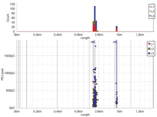

SOURCE: NETA POWERTEST CONFERENCE 2019
failing them during a commissioning test. Therefore, the wind farm operator performed a DAC PD test of the cables. Figure 8 shows a PD test performed on a 6.5-km-long XLPE cable. The graph shows PD activity in all three phases. In phase A (red dots), the PD activity was due a non-PD free connection between the equipment and phase A and was therefore
NETAWORLD • 69 USING VLF AND PD TESTING TO IMPROVE COMMISSIONING RELIABILITY FEATURE
Figure 7a: Strong PD Activity with DAC Technology @Uo
Figure 7b: No PD Activity with 0.1 Hz sine Technology @Uo

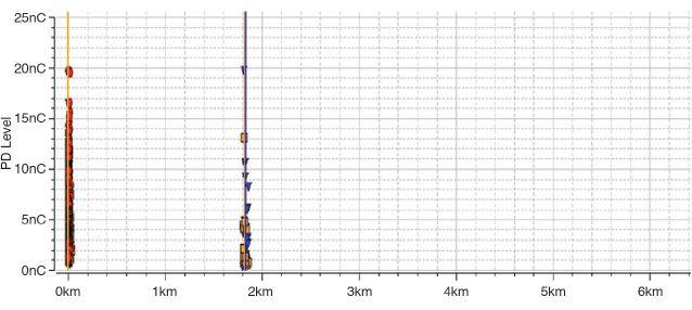
REFERENCES
IEEE 400.2, Guide for Field Testing of Shielded Power Cables Systems Using Very Low Frequency (VLF) (less than 1Hz).
IEEE 400.3, Guide for Partial Discharge Testing of Shielded Power Cable Systems in a Field Environment.
IEEE 400.4, Guide for Field Testing of Shielded Power Cables Systems Rated 5kV and Above with Damped Alternating Current (DAC) Voltage.
discarded. In phases B (blue triangles) and C (orange squares), PD activity was observed at 1.8 km with levels around 20 nC.
The cable had a joint in all three phases at 1.8 km. The splice was opened in phase B and later in phase C, and visual inspection revealed that no sealing mastic had been used in the mechanical connector screw housings in phase B, with the same result in phase C.
CONCLUSION
Over the last 40 years, the VLF withstand test has proven its effectiveness and value to detect defects and severe workmanship problems by failing them during the test. Although workmanship issues in new cables can be detected (failed) by a VLF withstand test if they are very severe, lesser problems will not fail under withstand test conditions. However, the PD test, especially when performed within the power frequency range like the DAC PD, is an excellent method to detect and localize even very small workmanship issues (incipient defects) in new cables during the commissioning test.
Today, the monitored withstand test as suggested in IEEE 400.2 may represent the best available test method for commissioning new cables. The withstand test component stresses the cable for mechanical damage like cuts, nicks, and kinks that occurred during laying and/or trenching, and the PD component checks for workmanship issues in accessories.
Oetjen, Henning. “Principals and field experience with the 0.1 Hz VLF method regarding the test of medium-voltage distribution cables,” Conference Record of the 2004 IEEE International Symposium on Electrical Insulation, Indianapolis, IN, USA, 2004, pp. 376-379, doi:10.1109/ ELINSL.2004.1380602.
Jäverberg, Nadejda and Hans Edin. “Applied voltage frequency dependence of partial discharges in electrical trees,” Proceedings of the 21st Nordic Insulation Symposium 2009.
Yan, Biao, Li Zhou, Jie Chen, Feng Bo Tao, and Jian Zhang. “Testing and Diagnosis of Extra High Voltage Power Cables Using Damped AC Voltages Combined with Distributed Partial Discharge Measurement.” Advanced Materials Research 1070–1072 (December 2014): pp. 1039–1043. https://doi.org/10.4028/www. scientific.net/amr.1070-1072.1039
IEC 62067-2011, Power Cables with Extruded Insulation and their accessories for rated voltages above 150 kV (Um=170kV) up to 500 kV (Um=550kV) – Test methods and requirements.

Javier Ruiz is Megger’s fault location, test, and diagnostics sales manager for Mexico and East Canada. His focus is training end-users on the theory and correct use of cable infrastructure equipment. Javier initially worked as a field support engineer for the former HDW Electronics, a power cable fault location and testing company, before joining Megger in 2012. He earned a BS in engineering at Autonomous University San Luis Potosi in Mexico specializing in instrumentation and control.
70 • FALL 2020 USING VLF AND PD TESTING TO IMPROVE COMMISSIONING RELIABILITY FEATURE
Figure 8: PD Activity Detected at 0≤ U ≤1.7 in Phases B and C


THE PREMIER ELECTRICAL MAINTENANCE AND SAFETY CONFERENCE
Promote your products and services to a valuable audience of key industry decision makers while increasing brand visibility.
MARCH 8 – 12, 2021
CREEK
View available sponsorship items at powertest.org

Take advantage of print and media exposure to your target market before, during, and after the conference by customizing your sponsorship package to suit your needs.

POWERTEST.ORG
BY
ROSEN SHINGLE
ORLANDO, FLORIDA
888.300.6382 HOSTED
➤ 5 models available ➤ 10 to 200 Amp AC Vacuum Interrupter Tester, 60 kV
➤ Bluetooth connection to Android devices
➤ Bluetooth to battery print
➤ Android App included
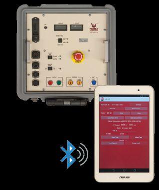
40+ Years Experience
Micro-Ohm Meters
➤ Accurately measure very low contact resistances

High Current Circuit Breaker Test Sets
➤ 9 models available
➤ 1,000 to 75,000 Amp Outputs
➤ Updated control system, automated testing, data acquisition
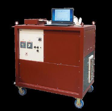


Ground Resistance Testers
The Highest Safety Rated Ground Resistance Testers — CAT IV 600V!
• Two instruments in one; test Ground and Bonds
• Low cost, great performance and feature rich
• One button connect — press — read operation; eliminates testing errors
• Storage of 3 measurements along with average and % deviation; easily determine proper test results (Model 6424)
• Automatic frequency adjustments; improves accuracy
• Automatic continuity and resistance check of the injector electrode
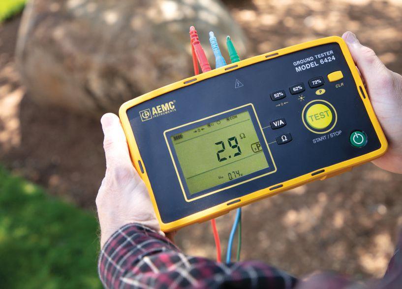
• Measure voltage and current (Model 6424)
• Dust proof, weather-resistant and flame retardant; works in all environments
1-301-746-8118 • www.PhenixTech.com
info@phenixtech.com • 75 Speicher Drive, Accident, MD 21520 USA A Wide Range of Test Systems Available High Voltage - High Current - High Power Test Systems and Components TECHNOLOGIES PHENIX R
IP 65
www.aemc.com sales@aemc.com
NEW
Models 6422 & 6424



When equipment fails, every minute spent searching for what you need is bad for the bottom line. Our massive inventory of millions of new, surplus and repurposed circuit breakers, switchgear and related products is here for you. We have the expertise to see the big picture, understand your problem and recommend the best solution. Already know exactly what you need? Our website is constantly being updated with products and the online buying process is easy.
Tap into the power of National Switchgear at nationalswitchgear.com or call us today at (800) 322-0149.
CAN’T AFFORD TO WAIT FOR
ELECTRICAL EQUIPMENT?
performance by design sm
PROTECTION CONSIDERATIONS FOR AN IMPROPERLY INSTALLED ON-LOAD TAP CHANGER

 BY ALEX RANGEL, Saber Power Services, LLC
Large power transformers are widely used in the electrical grid, and interconnecting solar farms to the utility is one of their many applications. To control voltage variations throughout the day, an on-load tap changer (OLTC) is used to adjust the number of effective windings to match the utility’s voltage. Proper functionality of the OLTC requires a specific sequence of operations, and this component must be recommissioned if it is replaced.
Improper replacement of an OLTC can cause severe transformer damage, and traditional protection methods, such as differential protection (ANSI 87), might not detect this condition. Therefore, enhanced protection techniques might be necessary. This article analyzes the improper installation of an OLTC and suggests a protection method to detect this condition.
ON-LOAD TAP CHANGER THEORY
The purpose of a tap changer is to add or remove turns to the windings on either side of a power transformer to increase or decrease the voltage on the coupled side. A no-load tap changer (NLTC) requires the system to be deenergized due to a temporary load loss during
74 • FALL 2020 PROTECTION CONSIDERATIONS FOR AN IMPROPERLY INSTALLED ON-LOAD TAP-CHANGER
INDUSTRY TOPICS

the tap change. An OLTC allows a tap change to be performed with the system energized using a make-before-break contact concept.
A live tap change is possible using:
• Resistors and/or reactors that allow current transfer between the taps and limit circulating currents when in parallel
• Bypass switches that allow isolation of the reactors
• Selector switches that perform the actual tap change
• A vacuum interrupter that makes and breaks the current.
Because the make-before-break operation happens at the vacuum interrupter, the oil is not
affected by the arc produced during the operation; therefore, contamination is prevented.
The OLTC described in this article is a 32step, 26.4 kV rated tap changer. A simplified schematic of its winding arrangement is shown in Figure 1. Whenever a tap change is required, the OLTC works in the following manner:
• Switch P3 opens to allow current to flow through the vacuum interrupter.
• The vacuum interrupter opens, and current stops flowing through the rightside reactor (P3–P4).
• As no current is flowing, the selector switch (P4) moves to the adjacent tap.
• The vacuum interrupter closes, and current flows again through the right-side reactor.
• Bypass switch P3 closes, and the tapchanging operation is complete.
A similar operation occurs with the P1 and P2 switches to move the left-side reactor to an adjacent tap.
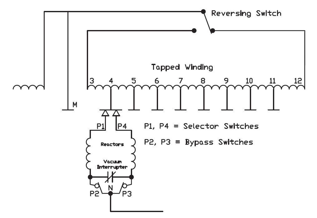
NETAWORLD • 75 PROTECTION CONSIDERATIONS FOR AN IMPROPERLY INSTALLED ON-LOAD TAP-CHANGER
TOPICS
© ISTOCKPHOTO.COM/PORTFOLIO/ZHENGZAISHURU
INDUSTRY
PHOTO:
SOURCE: REINHAUSEN GROUP
Figure 1: Simplified On-Load Tap-Changer Schematic
EXISTING SYSTEM
The system discussed consists of a 40 MVA, 138 kV / 34.5 kV transformer, which is wyegrounded connected on both primary and secondary sides, and a delta tertiary. It is connected to utility on the high-voltage side and to a 35 kV bus on the low-voltage side. Contrary to the norm, power flows from the low-voltage side to the high-voltage side via solar inverters connected to two feeders (F1 and F2) at the 35 kV bus. A capacitor bank is also connected to a third feeder at the bus (C). Figure 2 shows a simplified one-line diagram of the system (only the primary relay is shown).
The transformer is protected by primary and backup digital relays. The primary relay’s differential zone of protection includes the transformer, the 35 kV bus, and the breakers connected to this bus. It also senses voltage on both sides of the transformer. The secondary relay’s differential zone of protection includes only the transformer, and the relay only senses voltage on the high-voltage side of the transformer. Because of its more limited capabilities, the backup relay has been omitted from this analysis.
OLTC INSTALLATION AND RESULTING ISSUES
Due to several leaks and damaged components, site personnel determined that the existing OLTC was defective and needed to be replaced. A new OLTC was installed during a maintenance outage, and the system was re-energized. Shortly after energization, site personnel mentioned that solar inverters began to “trip offline randomly” several times throughout the day. After a few days of continued unexpected outages, an investigation was initiated, and oil samples were obtained from the main transformer and from the OLTC.
The transformer sample did not yield any major issues; however, the OLTC sample yielded an extremely high concentration of several gases, including hydrogen (H₂), nitrogen (N₂), and acetylene (C₂H₂). According to Gill, high concentration of these gases is indicative of
76 • FALL 2020
PROTECTION CONSIDERATIONS FOR AN IMPROPERLY INSTALLED ON-LOAD TAP-CHANGER INDUSTRY TOPICS YΔY Y Y Y Y
Figure 2: Simplified One-Line Diagram of Existing System
Sample Date 06/07/2019 04/29/2019 Top Oil Temp °C 22 Hydrogen (H2) 9,000 0 Oxygen (O2) 8,760 2,070 Nitrogen (N2) 50,100 13,100 Methane (CH4) 2,990 0.8 Carbon Monoxide (CO) 69 15 Ethane (C2H6) 206 0 Carbon Dioxide (CO2) 297 248 Ethylene (C2H4) 6,240 0 Acetylene (C2H2) 23,800 0 Total Gas 101,462 15,434 COMB GAS 42,305 16 EST TCG % 26.12 0.08 C2H4/C2H2 0.26 0.00 Comb Gas Rate ppm/day 1,084.33 -1.30
Table 1: OLTC Gas Concentration
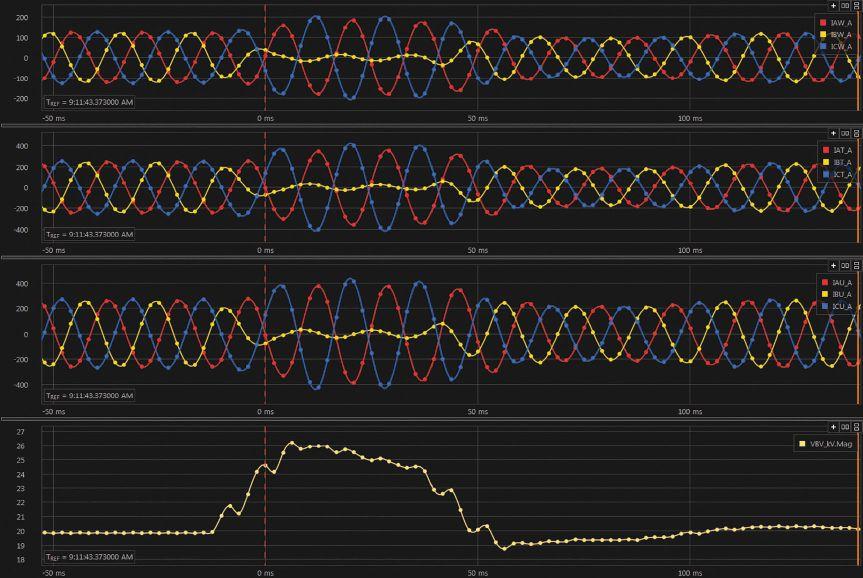
high-energy arcing, with the key component being acetylene. Due to the high-energy arcing condition, the transformer was taken out of service immediately and the OLTC installation was investigated. Table 1 shows the gas concentration indicating problems at the OLTC, along with previous values shown for comparison.
As part of the investigation, relay event data was collected and analyzed. A negativesequence overvoltage event trigger was enabled (V2 > 700 V), and several events were captured. Figure 3a and Figure 3b show the currents observed on 06/06/2019 at 9:11 am on the high-voltage side (channels W and Z) as well as the low-voltage side (channels T, U, and V). At the moment the event was triggered:
• B-phase current collapsed almost to 0.
• The angles of A- and C-phase currents drifted to almost 180 degrees with a slight increase in magnitude.
• B-phase voltage on the 19.9 kV (LN) side increased to 26.1 kV, a 31% increase.
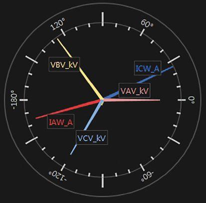
There was no change in voltage at the high-voltage side of the transformer.
The voltage and current symmetrical components also experienced changes during the event (Figure 4):
NETAWORLD • 77
PROTECTION CONSIDERATIONS FOR AN IMPROPERLY INSTALLED ON-LOAD TAP-CHANGER INDUSTRY TOPICS
Figure 3a: Phase Currents and B-Phase Voltage
Figure 3b: Phasor Diagram
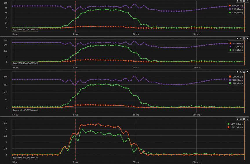
• An increase of negative-sequence current (I2) in each set of currents (approximately 80% of nominal)
• An increase in zero- and negativesequence voltage higher than 5%
Because symmetrical components are present during traditional (short-circuit) faults, these

should not be used solely to detect OLTC problems. Instead, they can be used as an alarm to indicate a problem is present in the system.
Harmonic content was also analyzed. The third harmonic (180 Hz) content registered during the event in Figures 3 and 4 exceeded 10% on B-phase voltage. Figure 5 shows the harmonic analysis in the COMTRADE event.
Table 2 summarizes the values collected on several events between 6/5/2019 and 6/7/2019:
• B-phase voltage
• Negative-sequence voltage
• Positive- and negative-sequence currents for channels W, T, and U
• 3rd harmonic content
The three most extreme cases show:
• Phase overvoltage was higher than 30% nominal.
• Negative-sequence voltage was higher than 5%.
78 • FALL 2020
PROTECTION CONSIDERATIONS FOR AN IMPROPERLY INSTALLED ON-LOAD TAP-CHANGER
Figure 4: Voltage and Current Symmetrical Components
INDUSTRY TOPICS
Figure 5: Harmonic Content for VB, COMTRADE Event
Table 2: Voltages and Currents Observed Using Relay Event Data
• The I2/I1 ratios are higher than 50% in each set of currents.
• 3rd harmonic content is higher than 5%.
Based on the above observations, a phase overvoltage element on the low-voltage side of the transformer will protect the transformer. An element set at 20% higher than nominal would have tripped the relay in three of the events, while setting it at 10% would have operated in six of the eight events.
The following procedure is recommended:
• Enable an instantaneous phase overvoltage element trip at 20% higher than nominal and a time-delayed overvoltage element trip at 10% higher than nominal (1–2 cycle delay).
• Enable an alarm when the ratio of I2 to I1 is greater than 50%.
• Enable an alarm when V2 is greater than 5%.
• Enable an alarm when the 3rd harmonic content is greater than 5%.
The alarm triggers, as well as the 10% overvoltage delay, are dependent on the relay’s
capabilities due to the short duration of these faults and the fast processing interval required.
The new protection elements were tested using the COMTRADE report from the event shown in Figures 3 and 4. Figure 6 shows the oscillography obtained by the newly generated event report, as well as both overvoltage elements (59P1 and 59P2) asserting at 20% and 10%, respectively. The element set at 10% lasted in the asserted condition for 49.95 ms.
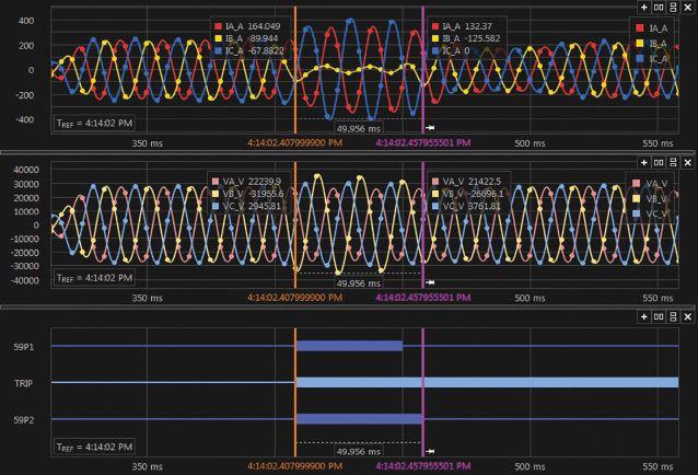
NETAWORLD • 79 PROTECTION CONSIDERATIONS FOR AN IMPROPERLY INSTALLED ON-LOAD TAP-CHANGER
Time
PM9:11 AM9:11 AM9:08 PM1:21 AM3:34 AM9:27 AM VB RMS (kV) 21.821.926.125.821.952221.4726.5 %VNOM 109.5110.1131.2129.6110.3110.6107.9133.2 V2 RMS (kV) 0.70.71.71.860.70.70.72.1 %VNOM 3.53.58.59.33.53.53.510.6 I2W (A) 0.870.8973550.730.91.360.4 I1W (A) 3.93.9287703.533.783.4780.7 W - %I2/I1 22.322.783.978.620.723.837.574.8 I2T (A) 1.641.71471091.341.871.7116.9 I1T (A) 8.118.651721388.328.138.65162.8 T - %I2/I1 20.219.785.57916.12319.771.8 I2U (A) 1.891.61531161.842.11.76123.79 I1U (A) 4.935.211861585.045.25.26173.51 U - %I2/I1 38.330.782.373.436.540.433.571.3 3rd Harmonic 2.372.1911.286.073.753.952.8510
Date6/5/196/5/196/6/196/6/196/6/196/7/196/7/196/7/19
9:40 PM9:40
INDUSTRY TOPICS
Figure 6: COMTRADE Event Showing Overvoltage Elements
INDUSTRY TOPICS
FIELD OBSERVATIONS
The oil sample results showed a problem in the OLTC, while the relay event data showed the problem was related to B-phase. The OLTC manufacturer provided a procedure to perform raise and lower tests to verify crossed leads. The procedure consists of:
Raise:
• Operate the OLTC in the raise direction from neutral to open P3 and P4.
• Use a continuity tester to verify that P3–P4 is a closed circuit.
• Use a continuity tester to verify that P3–P2, P3–P1, P4–P2, and P4–P1 are open circuits.
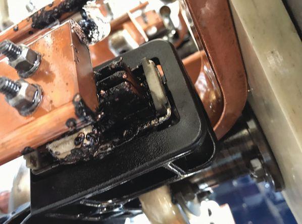
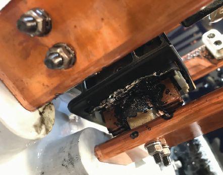
Lower:
• Operate the OLTC in the lower direction from neutral to open P1 and P2.
• Use a continuity tester to verify that P1–P2 is a closed circuit.
• Use a continuity tester to verify that P3–P2, P3–P1, P4–P2, and P4–P1 are open circuits.
These tests were passed on A- and C-phases. However, these tests failed on B-phase — there was no continuity between P3–P4 and P1–P2. A visual inspection showed severe damage at the selector and bypass switches due to arcing during load tap operations (Figure 7a, Figure 7b, and Figure 7c).

Figures 7a, 7b, 7c: Damage at the Selector and Bypass Switches Due to Arcing
80 • FALL 2020 PROTECTION CONSIDERATIONS FOR AN IMPROPERLY INSTALLED ON-LOAD TAP-CHANGER
CONCLUSION
An OLTC is an essential transformer component whenever voltage regulation is required while the transformer is energized. The installation of an OLTC requires a test to ensure the leads for the selector and bypass switches have not been crossed. If such leads were accidentally crossed, overvoltage protection elements are needed to send a trip signal to take the transformer out of service before further damage is created. Several alarms using symmetrical components and harmonic content are also recommended to advise site personnel of abnormal conditions.
REFERENCES
Dohnal, D. On-Load Tap-Changers for Power
Reinhausen Group. On-Load Tap-Changer VacuTAP RMV-II Instruction Manual. Available at www.reinhausen.com/ desktopdefault.aspx/tabid-310/94_read-65/.
Gill, Paul. Electrical Power Equipment Maintenance and Testing, Marcel Dekker, 1997. Available at https://neta.netaworld.org/ netassa/ecssashop.show_home_category.
Reinhausen Standards. Testing for Crossed Preventative Autotransformer Connections.

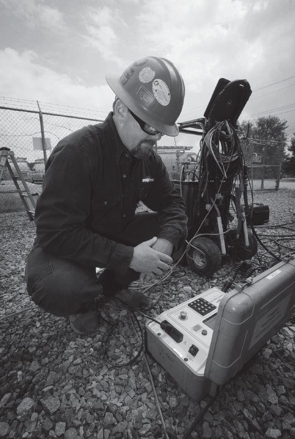

Alex Rangel is a Protection and Controls Engineer for Saber Power Services, LLC. Alex is NETA Level 4 Certified, has been an IEEE member for 11 years, and has been a registered professional engineer (PE) in the state of Texas since 2014. He holds a BS in electrical engineering and an MS in engineering from the University of Texas at Austin.

INDUSTRY TOPICS
Accredited Company 204 Gale Lane Kennett Square, PA 19348 484.731.0200 enerGtest.com Serving clients in Pennsylvania, Delaware, New Jersey, Maryland, Washington, DC and New England. We deliver optimum system reliability and performance while reducing the chances of costly unplanned power outages. Whether you need acceptance ener es ™ testing or preventive maintenance, depend on EnerGTest to keep the power on. Reliable Power System Solutions
•
•
•
•


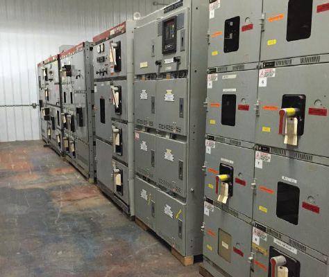

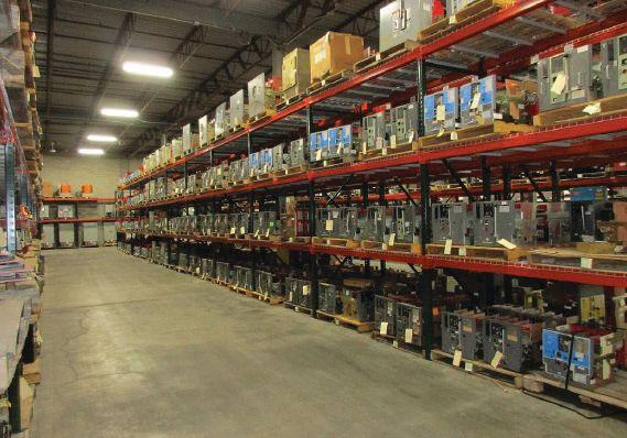

Independent Electrical Testing and Preventive Maintenance PROFESSIONAL SERVICES
Acceptance Testing • Planned Electrical Testing and Preventive Maintenance Programs
Power Factor Testing
Cable Testing
Relay & Meter Calibration
Ground Resistance Testing
Transformer Oil Analysis, Vacuum Degassing and Repair
Circuit Breaker Retrofit and Repair
•
•
•
•
•
•
•
Power Generation Systems Testing
Load and Power Quality Recording/Analysis
Chiller Systems Testing
Infrared Inspections 609-890-8300 www.easternhighvoltage.com 11-A S. Gold Drive • Robbinsville, NJ 08691 BULLOCK BREAKERS B B 475 Annandale Blvd • Annandale • Minnesota 55302 www.bullockbreakers.com • Email: jason@bullockbreakers.com • Thousands of Air Circuit Breakers in Stock! • Switchgear Line-ups you can’t find anywhere else! • Now Available as Reconditioned with AC-Pro Trip Units! 1-763-269-2832

Arizona (480)967-7765 linc.mcnitt@hamptontedder.com Nevada (702)452-9200 roger.cates@hamptontedder.com California (909)628-1256 ken.peterson@hamptontedder.com jim.andersen@hamptontedder.com FamilyOwnedandOperatedSince1958

IMPROVED SAFETY METHOD FOR MEASURING DEAD TANK CIRCUIT BREAKER OPERATION TIME

 BY RADENKO OSTOJIC and ADNAN ŠECIC, DV Power — Sweden

Safety in high-voltage substations is the highest priority for all personnel involved, and regulations and laws require all objects to be grounded on both sides before any maintenance work is performed. Failure to ground the circuit breaker (CB) on both sides creates risk of induced high voltages and currents at the ungrounded terminal. Eliminating this risk improves the safety of the test personnel and the test instrument itself.
If both sides are grounded, applying conventional main contact state detection methods is not possible because there is a parallel circuit through grounding cables and the grounding network, and the device would always detect a closed circuit. To overcome this obstacle, modern test methods applicable for testing a dead tank CB in these conditions are based on dynamic resistance measurement (DRM) or current injection through the grounding cables
and simultaneous measurement of the current changes during CB operations.
However, these methods are not accurate or applicable for dead tank circuit breakers with a pole-pole-pole-neutral (P-P-P-N) grounding system. This paper presents a novel method for testing a dead tank CB with both sides grounded that would be applicable for all types of grounding systems. The method is based on DC current injection (about 20–30 A per phase)
84 • FALL 2020 IMPROVED SAFETY METHOD FOR MEASURING DEAD TANK CIRCUIT BREAKER OPERATION TIME
INDUSTRY TOPICS PHOTO: © ISTOCKPHOTO.COM/PORTFOLIO/VICTOR YEE
through the main circuit and measurement of the response signals on the secondary terminals of breaker-mounted current transformers (CT).
INTRODUCTION
Regulations and laws related to maintenance and testing in high-voltage substations require all objects to be grounded on both sides during work. To measure operating times (O, C, O-C, CO, etc.) on the dead tank CB’s main circuit with the conventional testing method, grounding cables must be removed from one side of the circuit breaker. However, the procedure to remove cables is unsafe and time-consuming and often not practical — and is therefore considered undesirable by test personnel in utilities. There is also a risk of inducing high voltages at the ungrounded side of the circuit breaker when the circuit breaker is in the open position during testing.
If the grounding cables are not removed or disconnected, a conducting circuit parallel to the tested main circuit path is formed (Figure 1). Therefore, when the circuit breaker is in an open position, there is a closed circuit through the grounding cables and grounding network. The resistance of this circuit usually varies from a few mΩ to tens of mΩ. The main arcing contacts are first to close and last to open the main circuit, so they define the initial closing and opening operations of the circuit breaker. The resistance of arcing contacts ranges from a couple of hundreds μΩ to a couple of mΩ, so it is still possible to distinguish this resistance from grounding resistance and use it to determine the state of the main circuit.
One existing method in the market that uses this approach to measure timing in dead tank circuit breakers with improved safety is based on dynamic resistance measurement (DRM). The other method is based on inducing voltages across grounding cables and measuring the current change through the grounding cables during circuit breaker operation. These two methods are applicable for testing a dead tank circuit breaker with a pole-neutral
(P-N) grounding system (Figure 1), where each single pole of the circuit breaker is separately grounded on both sides.
However, these test methods are not fully applicable or reliable for measuring operating time on a dead tank CB with a P-P-P-N grounding system (Figure 2), which is very


NETAWORLD • 85 IMPROVED SAFETY METHOD FOR MEASURING DEAD TANK CIRCUIT BREAKER OPERATION TIME
INDUSTRY TOPICS
Figure 1: Dead Tank Circuit Breaker with P-N Grounding System on Both Sides
Figure 2: Three-Pole Controlled Dead Tank Circuit Breaker with P-P-P-N Grounding System on Both Sides


popular in the United States. If the DRM method is used in this situation, the same result would be obtained for the main contacts of all three poles, even if the real operating time of the main contacts is different. The method based on voltage generation and current measurement through the grounding cables is not applicable since the unique pair of grounding cables required to measure current changes in each pole of the circuit breaker does not exist.
AN INNOVATIVE SOLUTION
It would be desirable to develop a universal test method that would be applicable for both P-N and P-P-P-N grounding systems in dead tank CBs. Such a method is proposed as a solution for testing gas-insulated substation (GIS) circuit breakers with both sides grounded as described by Ostojic and Secic in “Improving Safety in Operation Time Measurement.” This method combines the resources of two existing CB test methods: a) dynamic resistance measurement (DRM) as described by Secic and Milovic, and b) the first-trip test proposed by Obarcanin and Secic.
The DRM test consists of injecting high DC current, usually 100A or even up to 500A, through the breaker contacts and simultaneously recording the voltage drop across the main circuit during CB operation. The proposed new method is also based on the injection of the DC current but requires only about 20–30 A per phase. We suggest using the same power source used for the DRM test method, which in this case is a voltage-controlled DC current source with high output current based on state-of-the-art power electronic converters. It should be noted that a high-power battery, such as Li-Po or similar, can also be used as a current generator in this case. For this test method, one power source is enough. A connection from a power source to the circuit breaker terminals must be performed with two current cables that each branch into three cables, thus providing even current distribution through all three main contacts (Figure 3).
In the first-trip test, contact timing is calculated by measuring the AC waveform (voltage or current) on the secondary of the current transformer while the CB is still in service. In
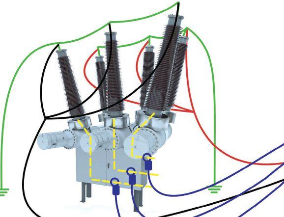

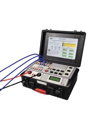
86 • FALL 2020
TOPICS IMPROVED SAFETY METHOD FOR MEASURING DEAD TANK CIRCUIT BREAKER OPERATION TIME
INDUSTRY
Figure 3: Proposed Method for Dead Tank Circuit Breaker with P-P-P-N Grounding System on Both Sides
the proposed method, the CB is disconnected from the grid. However, the same approach for contact timing is used as for the first-trip test.
Current transformers (CTs) are an integral part of a dead tank CB. The primary terminal of these elements is located at the bushings, while the secondary terminal is in the auxiliary circuit (see Figure 3). These accessible CT secondary terminals can be used to measure operation time in dead tank circuit breakers. While DC current is generated through the main circuit during CB operation, the measuring instrument should record either the current or voltage response on the CT secondary based on which instant of the CB contacts can be detected. Currents at a CT’s secondary can be recorded using current probes based on the Hall effect or using a transformer.
CASE STUDY
To prove the applicability of the proposed novel method, an experiment was conducted on an improvised test station. An air-type circuit breaker, model AT-16 manufactured by Terasaki, was used in the experiment. These types of modular switchgear are equipped with current transformers. A test of a dead tank CB with a P-P-P-N grounding system on both sides was simulated using grounding system cables of 4 mΩ resistance.
The required value of the current was generated by the built-in power source in the test

instrument. The connection from power source terminals to circuit breaker terminals was performed with current cables that branch into three cables, similar to the test setup shown in Figure 3. All three CT secondary currents were measured by transformer-based current probes where the outputs were connected to the analog voltage channels of the test instrument.
DC source current generation and secondary CT current measurements were synchronized during circuit breaker operation. The results of close and open tests are shown in Figure 4. For the close operation, the instant of contact touching represents the measured CB closing time, which can be determined by the moment when CT secondary currents start to appear (around 38 ms). For the open operation, the instant of contact separation represents the measured CB opening time, which can be determined by the moment CT secondary currents reach the latest turning point (around 21 ms).
Following these measurements, the grounding cables were removed from the breaker, and the measurements were repeated with a conventional CB analyzer with only one side of the CB grounded. Results for close and open operations are shown in Figure 5. The experiment was repeated until a considerable amount of data was gathered. Data analysis led to the conclusion that the measured operation
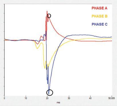


NETAWORLD
INDUSTRY TOPICS
IMPROVED SAFETY METHOD FOR MEASURING DEAD TANK CIRCUIT BREAKER OPERATION TIME
WOORLD 8 87 7 Y T O P I C S CLOSE OPERATION OPEN OPERATION Instant of contact touching Instant of contact separation Instant of contact separation
Figure 4: CT Secondary Current Responses


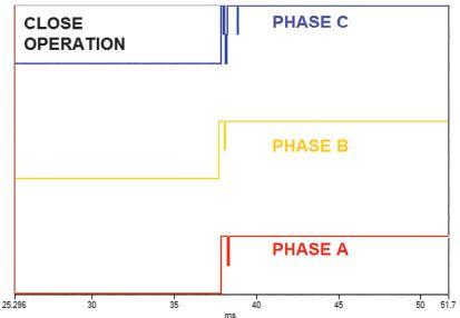
Figure 5: Results with conventional timing
time of the breaker matches with moments that can be extracted from the waveform obtained from the current signal recorded on the CT secondary wires.
CONCLUSION
P-N and P-P-P-N are the two most common systems used to ground dead tank circuit breaker terminals during maintenance and testing. Currently, two methods exist to measure operation time of a dead tank CB with both sides grounded. However, these methods are applicable and reliable only for the P-N grounding system. By combining the resources of two already known test methods — dynamic resistance measurement and the first-trip test — it is possible to measure the operation time of a dead tank CB with improved safety conditions for P-N and P-P-P-N grounding systems. This proposed method does not require changing or adjusting the grounding system when using the test method. Thus, safety risks to test personnel are avoided, and the testing procedure is accelerated.
REFERENCES
IEEE Std. 510-1983, IEEE Recommended Practices for Safety in High-Voltage and HighPower Testing.
R. Ostojić, A. Šečić. “Improving Safety in Operation Time Measurement Procedure for Circuit Breakers in Gas Insulated Substation,” Research Disclosure, 2019.
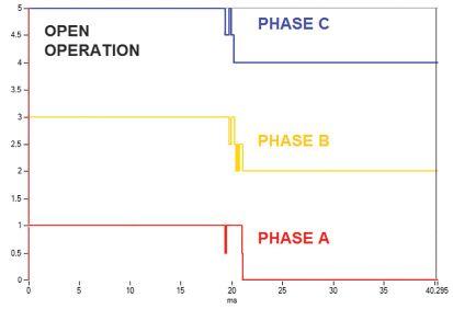
A. Šečić, B. Milovic. “Dynamic Resistance Measurement Method Applying High DC current,” at CEATI Circuit Breaker Test & Maintenance Workshop, 2014, Palm Desert, CA.
K. Obarcanin, A. Šečić. “The Embedded Handheld System for Contact Timing Parameter Extraction in Online Mode for the High Voltage Circuit Breaker Condition Assessment,” 2018 International Symposium on Industrial Electronics (INDEL) 2018, DOI: 10.1109/INDEL.2018.8637631.

Radenko Ostojić is a test and diagnosis engineer at DV Power — Sweden in the field of circuit breaker testing and maintenance. He has been employed at DV Power since 2010 and works on the improvement of circuit breaker testing equipment and development of new methods for circuit breaker testing. Radenko’s area of special interest is testing of circuit breakers in enhanced safety conditions, which implies testing of circuit breakers with both terminals grounded. He earned his BS in electrical engineering at the University of East Sarajevo.

Adnan Šečić is an R&D Engineer at DV Power — Sweden. As a project leader, he is responsible for development of the circuit breaker analyzer and timer (CAT) device series. Adnan received his BS in electrical engineering and MS in electronics, electrotechnics, and automation (EAA) from the University of Sarajevo, Bosnia and Herzegovina, and is in the final stage of PhD studies at the Faculty of Electrical Engineering and Computing in Zagreb, Croatia.
88 • FALL 2020
INDUSTRY TOPICS
IMPROVED SAFETY METHOD FOR MEASURING DEAD TANK CIRCUIT BREAKER OPERATION TIME
Absolute con dence. Every time.
You can count on us for specialized experience in healthcare, data center, o ce complex, and commercial acceptance and maintenance testing. Absolutely Power generation, petrochemical, oil & gas, and heavy industries also look to us for high demand services such as start-up commissioning, maintenance testing, shut-down and turnarounds, and breaker shop repair. Get started today.


Toll Free 1+ (855)767-4446 8100 West Little York | Houston, Texas 77040 Email: Alan Postiglione | apost@absolutetesting.com | www.absolutetesting.com Like us on:


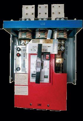

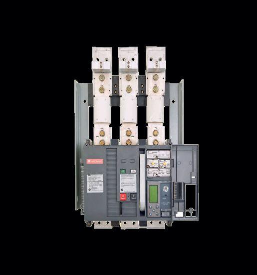

1315 Columbine, Gainesville, Texas 76241 | 800-232-5809 INFO @ CBSALES.COM | CircuitBreaker.com CBS Florida | Lakeland, Florida | 863-646-5099 | CBS-Florida.com CBS Midwest | Crown Point, Indiana | 219-575-5420 | CBSMidwest.com new service locations CBS stocks every low- and mediumvoltage circuit breaker made in America since 1945. With more than 5 million breakers and parts in our 200,000-square-foot warehouse — including switchgear, transformers, substations, protective relays, loadbreak switches, electrical contacts, motor controls and centers, vacuum interrupters, and more — Circuit Breaker Sales has you covered. √ Replacement parts and equipment √ Remanufacturing, retrofits, and upgrades √ Reverse engineering, 3-D printing of obsolete parts For more information about Group CBS and its affiliate companies, visit GroupCBS.com. CircuitBreaker.com (800) 232-5809 TOLLFREE Your TRUSTED online resource for authentic circuit breaker and electrical distribution equipment CBStore.com HPC Switches? We’ve got you covered. • In Stock • New and Obsolete • 800A—4000A • Retrofit kits • 24/7 Emergency Service We stock new General Electric HPCII drop in replacements for the THPC 3000 & 4000 amp GFI models for same day shipping. Call anytime for immediate service. 800-421-5082 www.qualityswitchgear.com HPC New Generation HPC




For 25 years we have been committed to designing, engineering, manufacturing, and supporting industry-leading solutions from our home base in Ohio. By supporting local economies and keeping supply chains short, we are able to provide our customers with unmatched availability, security, and reliability. We are proud to be a part of what makes “Made in America” truly exceptional, and we look forward to the next 25 years and beyond together.

UTILITYRELAY.COM | 888.289.2864 | URCSALES@UTILITYRELAY.COM Home of AC-PRO-II® and AC-PRO-MP-II® BUILDING THE BEST HERE AT HOME
25
FOR
YEARS



POWER QUALITY, RELIABILITY, AND SOPHISTICATED AUTOMATED SYSTEMS
 BY ALAN ROSS, Electric Power Reliability Alliance
What do robotics, artificial intelligence (AI), automation, synaptic performance indicators (SPI), and machine learning (ML) have in common? In addition to being buzzwords for the reliability professional to throw around, the reliability world uses these terms to get practitioners to spend a lot of money on the shiny new thing. Sadly, too much of that money will be wasted by well-meaning managers trying to impress their C-level bosses as we all adapt to the rapid move into the digital age.
Sophisticated systems all require quality power — not just bulk power, but quality power. Without clean, quality power, complex automated operations are meaningless and potentially even harmful.
While poor power quality can create a myriad of problems, this article focuses on the issue of power quality as it affects sophisticated automated systems from a reliability professional’s perspective. The more we rely on automation to
operate plants, the greater the impact of poor power quality, and in turn, the greater the impact on the reliability of those plants.
In the world of the NETA professional, constantly increasing change affects the manufacturing world as we fully embrace digitization and automated control systems. Globalization, hyper-competition, advanced automation design, and the ever-present pressure to produce more at lower cost and
92 • FALL 2020 POWER QUALITY, RELIABILITY, AND SOPHISTICATED AUTOMATED SYSTEMS
INDUSTRY TOPICS

© ISTOCKPHOTO.COM/PORTFOLIO/WANGANQI
higher quality means plant design, operations, maintenance, and reliability professionals cannot rest on yesterday’s advancements. The pressure is even greater on reliability, electrical and instrumentation (E&I), and electrical engineering departments, as the need for quality power challenges them the most.
POWER QUALITY DEFINED
Poor power quality is defined by IEEE as “any power problem manifested in voltage, current, or frequency deviations that results in failure or mis-operation of customer equipment.” Thus, good power quality is best described as voltage that adequately feeds its load within proscribed parameters. For the most part, changing proscribed parameters creates the problem as the requirements of automated systems in industry decrease the margin of error for power quality. Adding uninterruptible power supply (UPS) equipment and back-up generation can also add fluctuations in power quality, so as
these back-up systems for power availability become more important, they might not solve a power quality problem; in some cases, they could increase or create a problem.
Asset Reliability: When an asset performs its required designed function, without failure, over the course of its design life.
Let’s look at this definition in more detail given that most electrical systems, unless we are dealing with totally new installations, are full of assets that are well beyond their designed life. Power transformers, for instance, average over 38 years of life in the United States. The same is true of assets from cables to switchgear in a substation. To make this aging system more functional, we add relays, capacitance, and back-up systems that have been built within different design parameters. Assets designed using microtechnology and electro-mechanical technology can and do work well together, but their reliance on quality power varies.
When a steady supply of voltage within the proscribed parameters of the load is maintained such that the equipment using the load can operate effectively under normal conditions, we have power quality. Consider the premise that asset reliability is defined as an asset that performs its required design function over the course of its design life, and it is clear that one important factor for asset reliability is the power required to ensure the asset performs to its design standard. As design parameters for equipment power requirements get tighter — with little or no room for disruptions of any kind — making sure we maintain power quality requires greater emphasis on system design, not just the design of individual productive assets in that system. System design is paramount when changing assets within that system.
One important change taking place in the reliability world is the emphasis on system reliability. Consider that any production facility is made up of a series of assets, operated by people, within a designed set of operating parameters, and you can see how the reliability of the system is more than the sum of the parts. A disruption at
NETAWORLD • 93 POWER QUALITY, RELIABILITY, AND SOPHISTICATED AUTOMATED SYSTEMS
INDUSTRY TOPICS
PHOTO:

any point in a complex manufacturing or process system affects the entire system.
Any variation that causes voltage to drop below the requirements of the system or causes voltage to spike severely is a disruption due to lack of power quality. Harmonics and waveform fluctuations create their own distinct set of problems different from sags or spikes. The devices or equipment being powered will fail, malfunction, or operate inefficiently.
Imagine the tighter parameters required as we add more robotics, automation, and sophisticated processes into the production system. Surges, sags, transients, and momentary disruptions interrupt or distort the ideal 60-hertz wave form. And while it may cause a slight flickering of lights in the office, it can severely damage a plasma TV production line or an automated chip manufacturing process. These types of production systems require more stringent power quality.

WHEN VOLUME MATTERS
Let’s step back and look at what has happened to the power supply side — the generating utility world. Most industrial countries developed a step-down system where power was generated from large generation facilities such as hydro, coal, nuclear, and gas. It was stepped up in voltage to large transmission lines crisscrossing the country and then stepped down to cities, towns, communities, and ultimately to the industrial and residential marketplaces. Getting the right volume of power to the end user was the requirement.
In the industrial world, large mechanical machinery powered assembly lines or processing systems. Paper, steel, and chemical facilities needed a lot of power to heat their raw materials as they were processed into finished goods. Quantity and continuity of power was what mattered most. In the generation world, life was simple. Make more. Get it to the end user as safely and cost effectively as possible.
But today, things like distributed energy resources, microgrids, and renewables are
changing us from a step-down system to a stepeverywhere system. Consider what happens when a solar array that powers part of a plant begins sending power back into a grid that was designed to step down power, but now it must also step up that power. The entire grid is negatively impacted because of the way it was designed, which causes utilities to put their primary focus onto their side of the fence, not on the industrial customers’ side of the fence.
“In essence, everything on your side of the fence is your problem,” is how one transmission and distribution engineer described it to me.
Using micro-technology to measure and monitor systems as we automate production makes them more sophisticated and more reliant on the quality of the required power. But power suppliers are grappling with their own challenges of a similar nature, so for the most part, they leave the power quality issue up to others. Their job is to feed the main substation, and users are left to make sure the feed is adequate to meet the needs of the system.
POWER QUALITY PROBLEMS
The results of poor power quality include automatic resets, data errors, complete equipment failure, circuit board failure, memory loss, power supply problems, UPS alarms, software corruption, and overheating of electrical distribution systems. It’s enough to keep a reliability engineer up at night and give a plant manager nightmares.
Because of the sophistication of automated systems, any one of these problems can be catastrophic. As Schneider Electric has found:
“Several studies estimate that power quality issues cost the U.S. economy about $15 billion each year. Because approximately 80 percent of all powerquality problems originate from the customer’s side of the meter, facility owners, managers, designers, and other high-tech equipment users need to understand and manage and avoid power quality issues.”

94 • FALL 2020
POWER QUALITY, RELIABILITY, AND SOPHISTICATED AUTOMATED SYSTEMS
INDUSTRY TOPICS
Schneider estimates 80% of power quality problems are the customer’s problems, and those problems grow exponentially when we add more power quality parameters through automation, robotics, sensors, and microprocessing. Without proper conditioning, sags, momentary interruptions, or transients can adversely affect the performance of sensitive equipment.
POWER CONDITIONING RESEARCH AND STANDARDS
IEEE and IEC have conducted a great deal of research and developed standards in the area of power quality for industrial applications. The most applicable to industrial plants or commercial facilities include:
• IEEE Std. 1100-2005 , Recommended Practice for Powering and Grounding Electronic Equipment: “This document presents recommended design, installation, and maintenance practices for electrical power and grounding (including both safety and noise control) and protection of electronic loads such as industrial and controllers, computers, and other information technology equipment (ITE) used in commercial and industrial applications.”
• IEEE Std. 519-2014 , Recommended Practice and Requirements for Harmonic Control in Electric Power Systems: “This recommended practice is to be used for guidance in the design of power systems with nonlinear loads. The limits set are for steady-state operation and are recommended for worse case conditions.”
• IEC 62586-1 Edition 2.0 b:2017, Power quality measurement in power supply systems – Part 1: Power quality instruments (PQI): “Specifies product and performance requirements for instruments whose functions include measuring, recording and possibly monitoring power quality parameters in power supply systems, and whose measuring methods (class A or class S) are defined in IEC 61000-4-30.”
• IEC 62586-2 Edition 2.0 b:2017: Power quality measurement in power supply systems – Part 2: Functional tests and uncertainty requirements: “Specifies functional tests and uncertainty requirements for instruments whose functions include measuring, recording, and possibly monitoring power quality parameters in power supply systems, and whose measuring methods (class A or class S) are defined in IEC 61000-4-30.”
Additional guidelines and standards for specific applications such as medical or specific industrial applications are available through IEEE, IEC, and NEC.
POWER QUALITY IMPACT ON A RELIABLE SYSTEM
The critical nature of power quality as it relates to the reliability of a production system has been established, and now we are left with what to do about it. Individual problems abound, and there seems to be one common thread. Let’s consider a few cases where the problem was created when newer, more sophisticated equipment was added to an existing system.
• An ice cream storage facility added a series of new freezers with energy-efficient motors and compressors to save electricity, keep the temperature more constant, and create alarms that directly alerted the control system of any anomalies. The problem was that individual freezers continuously shut down randomly. The freezer company checked them out, and they were all functioning properly and according to their operating parameters. An electrical contractor traced the feed and noticed sags in the power supply to these freezers that shut them down due to the sensitive parameters of the new equipment. Old freezers did not care that there was a sag in power, but the newer ones reacted as they were designed. The solution to the problem was to add a small control transformer to even out the load.


NETAWORLD • 95
POWER QUALITY, RELIABILITY, AND SOPHISTICATED AUTOMATED SYSTEMS
INDUSTRY TOPICS

INDUSTRY TOPICS
• A more complicated but insightful IEEE case study involved monitoring power quality disturbances at a plant and identifying the disturbances that disrupt production.

“The sensitivities of representative electronic control equipment to the identified disturbances were measured and then projected to form a plant disturbance threshold. For the monitoring effort, six disturbance analyzers were installed at four voltage levels extending from the utility 40 kV station to 120 V control power in an individual machine tool. Voltage sags were the only disturbance to directly cause lost production and were the most common disturbance at 68% of the total number of events recorded. Two programmable logic controller (PLC) transfer lines and a computerized numerically controlled (CNC) lathe were tested with a sag generator to determine the sensitivities of the equipment. The most sensitive components required the voltage during a sag to drop to less than 80–86% of rated to malfunction, whereas the least sensitive required the voltage to drop below 30% of rated. From the test results, the calculated sag threshold at the utility feed to the plant to disrupt production was 87% of the nominal voltage for more than 8.3 ms.”
CONCLUSION
The common element to these cases — and to most others we have researched — is increased sensitivity to power quality from new equipment installed in an existing system. The proscribed parameters have changed, and what was once adequate power quality is no longer adequate. Mitigating the problem is often not all that difficult once you determine the cause of the problem.
Power quality testing has become much more cost-effective and common. When adequate and appropriate power conditioning equipment is installed between the main feed and the load requirements, results show automation and digitization of production and processing systems can continue to take advantage of new technologies and developments.
The first step is to understand that it is not the supplier of power or the new equipment manufacturer that is responsible for power quality; it is the responsibility of the power user. The best time to address potential power quality problems is during the design phase of a line or system configuration where newer automated equipment is being deployed — not after a failure causes a catastrophic loss of the new equipment. Testing for power quality in alignment with the parameters required by the automated system, conditioning the power feed to meet the new parameters, and maintaining a vigilant monitoring program for power quality are the hallmarks of a good power quality program.
REFERENCES
Ignatova, Venya. “Why Poor Power Quality Costs Billions Annually and What Can Be Done About It,” Schneider Electric Blog, https://blog. se.com/power-management-meteringmonitoring-power-quality/2015/10/16/whypoor-power-quality-costs-billions-annuallyand-what-can-be-done-about-it/
Wagner, VE; Andreshak, AA; and Staniak, JP. “Power Quality and Factory Automation,” IEEE Transactions on Industry Applications, Vol. 26, No. 4, pp. 620-626, July-Aug 1990. Access at: https://ieeexplore.ieee.org/abstract/ document/55984.

Alan Ross is President of the Electric Power Reliability Alliance (EPRA) and is responsible for leading the alliance to build electric system reliability in the industrial and commercial marketplace. He often presents at industry conferences and has authored several trade publication articles on electric power reliability, including articles featured in Solutions and Uptime magazines and has written two books: Unconditional Excellence and Beyond World Class, and is currently Editor in Chief of Transformer Technology magazine. Alan earned a BS in mechanical engineering at Georgia Institute of Technology and an MBA in marketing from Georgia State University, graduating Magna Cum Laude. He is a Certified Reliability Leader (CRL), a Certified Maintenance and Reliability Professional (CMRP), a member of the IEEE Reliability and Power Energy Societies, and chairs the Smart Grid Reliability Alliance.

96 • FALL 2020
POWER QUALITY, RELIABILITY, AND SOPHISTICATED AUTOMATED SYSTEMS
Huge Selection of In-Stock Electrical Equipment
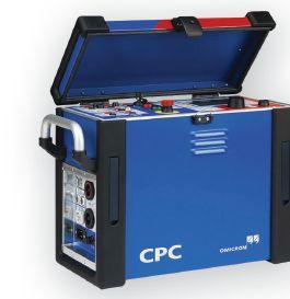


• Protective Relays
• Transformers & Motor Analysis
• Partial Discharge/Corona
• Current Injection
• Cable Fault Location
OF RENTING
• Cost-Savings Versus Buying
• Available for Immediate Delivery

SPECIAL TEST EQUIPMENT FOR
• Always Calibrated Equipment
ISO 17025 / NIST Cal / ANSI Z540
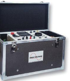






• Switchgear/Circuit Breakers
• Insulation Resistance
• Tan Delta/Power Factor
• Current Transformers
• Ground Grid
• Choose From a Variety of Manufacturer’s Top-of-the-Line Products
• Short-term Solutions for One-Off Tests


Start Saving Today! www.atecorp.com 800-404-ATEC (2832)
ADVANTAGES


ONSITE PD MEASUREMENT DURING COMMISSIONING: SAFE…RIGHT FROM THE START
 BY MATHIEU LACHANCE, OMICRON electronics Canada, and TIM GANNON, Advanced Electrical Services
Partial discharge (PD) measurement has been used for several decades to assess the condition of high-voltage (HV) and medium-voltage (MV) electrical apparatus. In the past, PD measurements were largely limited to the production stages of various assets (e.g., during R&D, factorytype tests, and factory acceptance tests). However, the advantages of such testing have resulted in it being used more often during onsite commissioning, periodic maintenance, and monitoring.
Partial discharge is defined as a localized dielectric breakdown of a small portion of an insulating material. PD events occur when the local electric field exceeds the local dielectric strength of the
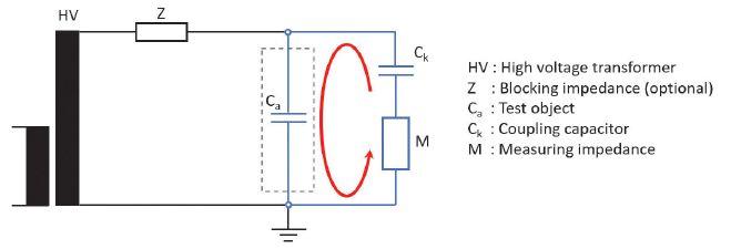
Figure 1: PD Measurement Setup According to IEC60270
insulation. When a PD event occurs, a shortduration current pulse (in the nanoseconds range) is generated. This current pulse can be measured using various types of sensors.
In many cases, PD events are detectable at the early stage of insulation deterioration. Therefore, PD measurements can provide early warning to operators and allow time to plan corrective actions when needed. For this reason, PD measurements are commonly performed on apparatus such as rotating machines, transformers, cables, instrument transformers, and switchgear. Figure 1 is a schematic of a
98 • FALL 2020 ONSITE PD MEASUREMENT DURING COMMISSIONING: SAFE…RIGHT FROM THE START
ADVANCEMENTS IN INDUSTRY


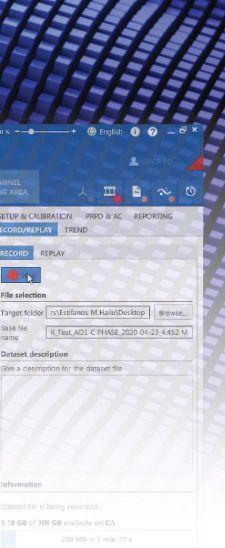

t typical PD measurement setup according to IEC C 602700.
This article shares a recent case study of onsite commissioning of a medium-voltage airinsulated switchgear. It exposes the benefits of PD measurement as an onsite diagnostic test and highlights the advantages of using an advanced partial discharge measuring system to enhance, facilitate, and accelerate PD data analysis.
CASE STUDY
In April 2020, Advanced Electrical Services (AES) was contracted to perform commissioning of a newly installed 27.5 kV air-insulated switchgear (Figure 2) located in Nisku, Alberta. The commissioning was to include offline partial discharge measurements and would be performed according to ANSI/NETA standards.
To take full advantage of the advanced functions of a newly released PD measurement and analysis system, onsite support from the PD equipment manufacturer was requested. However, the

NETAWORLD • 99 ONSITE PD MEASUREMENT DURING COMMISSIONING: SAFE…RIGHT FROM THE START
ADVANCEMENTS IN INDUSTRY
Figure 2: Air-Insulated Switchgear
ADVANCEMENTS IN INDUSTRY


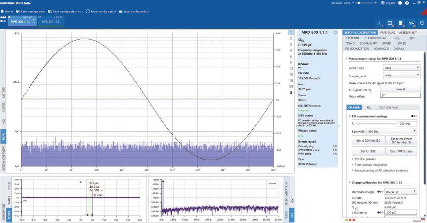
COVID-19 travel and safety restrictions implemented across many Canadian provinces and regions made onsite support impossible. Therefore, after consideration, the PD measurements would take place with remote virtual support from the PD equipment manufacturer. This solution allowed the test to take place without increasing the risk of transmitting the novel virus.
A safety hazard always exists when a highvoltage source is used to energize the test object. In this case, the maximum test voltage was
30 kV AC. Since the company had experience testing medium- and high-voltage air-insulated, vacuum, and GIS switchgear, all parties felt comfortable to go ahead with remote PD measurement testing. The PD measurement and analysis system would be shipped to the site, and the test would be conducted by onsite personnel with live virtual support from the manufacturer’s application engineers.
It was important for onsite personnel to feel comfortable with the new PD equipment.
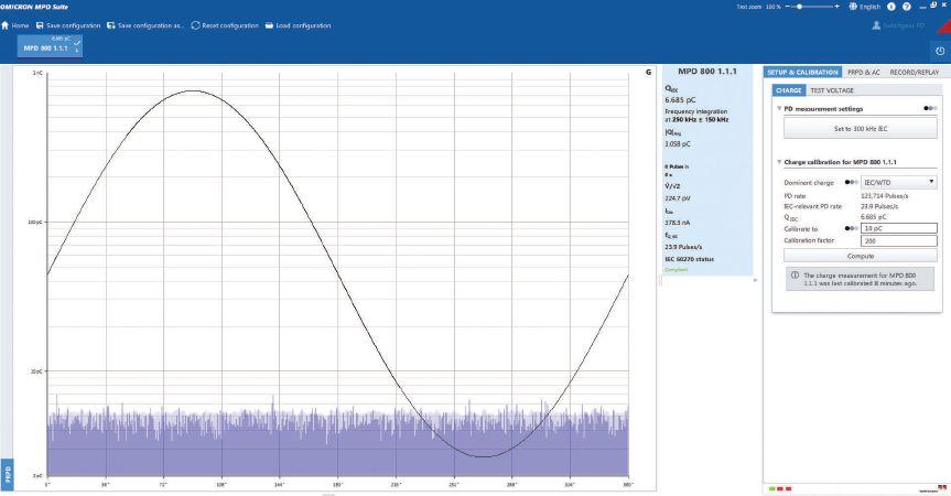
100 • FALL 2020
ONSITE PD MEASUREMENT DURING COMMISSIONING: SAFE…RIGHT FROM THE START
Figure 3: Default View of MPD Software
Figure 4: Customized View Used for PD Test

Therefore, the equipment was received approximately one week prior to the scheduled testing date. This allowed the manufacturer’s application engineers to provide initial training on the new PD measurement system. In addition, a customized profile was created for that specific application, enabling the operator to visualize only the functions he would require during the test (Figure 3 and Figure 4).
On the first day of onsite testing, performance and safety checks determined that partial discharges were present on one of the cables from the high-voltage source, and the cable would need to be replaced for the measurement. Once completed, the actual testing of the switchgear could begin.
Prior to the PD measurements, the switchgear had successfully passed an AC dielectric withstand test, commonly referred to as a Hipot test. However, during initial PD measurements, high PD levels were measured on all three phases at a voltage of approximately 5 kV. The remote connection to the manufacturer’s engineers allowed fast response, and analysis of the phase-resolved partial discharge (PRPD) diagram (Figure 5) determined that conductive parts were left at floating potential inside the switchgear. This meant those conductive objects were neither insulated nor grounded properly.
To locate the source of the partial discharges, various areas of the switchgear were isolated and tested by opening and closing some of the breakers. This process of elimination helped narrow down the search area to the main bus compartment. Visual inspection to verify the findings of the PD measurements was initiated, and after opening and inspecting the switchgear, the team found several anomalies inside the main bus compartment. Numerous pieces of hardware used for assembly had been left uninstalled inside the switchgear along with a pair of electrical pliers. In addition, critical errors in switchgear assembly, such as unconnected corona rings (Figure 6), were discovered. These findings confirmed the initial diagnosis from the PRPD analysis.
ADVANCEMENTS IN INDUSTRY

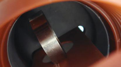
The pieces of hardware were removed, and the corona rings were connected according to the manufacturer’s specifications. PD measurements were then repeated, and all PD apparent charge levels were below 100 pC, which was the passing criteria at a voltage of 19 kV (Figure 7).
These types of anomalies are commonly found in air-insulated switchgear after onsite assembly. Unfortunately, they are too often only detected by visual inspection several years after the original commissioning because of obvious signs of deterioration, or in the worst case, after a failure.
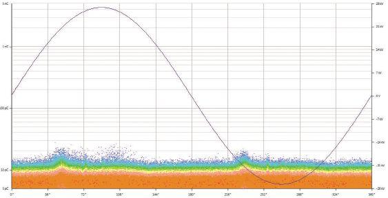

NETAWORLD • 101
ONSITE PD MEASUREMENT DURING COMMISSIONING: SAFE…RIGHT FROM THE START
Figure 6: Corona Ring Improperly Connected
Figure 5: PRPD Patterns Indicating Objects at Floating Potential
Figure 7: PRPD Pattern at 19 kV after Corrective Actions

ADVANCEMENTS IN INDUSTRY
CONCLUSION
The AC dielectric withstand test is typically the only onsite insulation test performed on these assets, and it only detects major defects. Objects left behind can cause partial discharges that deteriorate the insulation over time and create an abnormal amount of ozone. This can eventually damage the equipment, lead to inservice failure with significant economic losses, or more important, pose considerable risk to the health and safety of onsite personnel.
Partial discharge measurements can be used to assess the insulation of various mediumand high-voltage apparatus. Technology advancements in recent years have made PD measurement systems more attractive for onsite testing. They provide users with a high-end and robust system, and customizable profiles allow users to optimize their testing experience based on the specific application.
ACKNOWLEDGMENTS

The authors thank Joshua Blanchette, Stive Hailu, and Zak Houk for their on-site support during the measurements.

Mathieu Lachance joined Omicron electronics Canada Corp. in 2019 and presently holds the position of Regional Application Specialist for rotating machines and partial discharges. Mathieu previously worked as a test engineer in the fields of partial discharges and high voltage. He received a BS in electrical engineering from Université Laval in 2014.

Tim Gannon, a Red Seal Journeyman Electrician, is currently the Field Service Manager for Advanced Electrical Services (AES) in Edmonton, Alberta, Canada. His career spans 20 years in the electrical industry in roles relating to construction, manufacturing, and more recently, testing and commissioning.






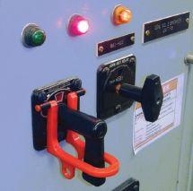
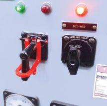




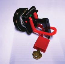
® THE DIFFERENCE... ® I DIF IF .. L .LIMIT DOWNTIME; ; CHOOSE ® FFERFEEREN REN CONSERVATORBLADDERS TRANSFORMER AIR-CELL 800-526-5330 +1-201-825-1400 www.atlinc.com ABB Inc. - G.E. / Alstom Grid - Atlantic Transformer CG Power USA - Calpine - Duke Energy - First Energy Gexpro - Jacksonville Electric Authority - NASS - PSE&G Siemens - SPX Transformer Solutions &ManyMore! BLADDER R DESIGN GUIDE AVAILABLE ON N OUR R WEBSITE ULTRA-STRONG “OVER-LAP” STYLE SEAMS MADE IN THE U.S.A. FOR OVER 45 YEARS! STANDARD TEMPLATES DIGITAL LIBRARY OF POPULAR SIZES/STYLES! REVERSE ENGINEERING ATL CAN PRECISELY DUPLICATE ANY BLADDER! STANDARD & CUSTOM HARDWARE METALLICFLANGES,HANGERLOOPS&MORE! EXPEDITED DELIVERY ULTRA-FAST TURNAROUND - 2 TO 3 DAY AVERAGE! CUSTOMERS INCLUDE: ® ! R! ! ARE AR

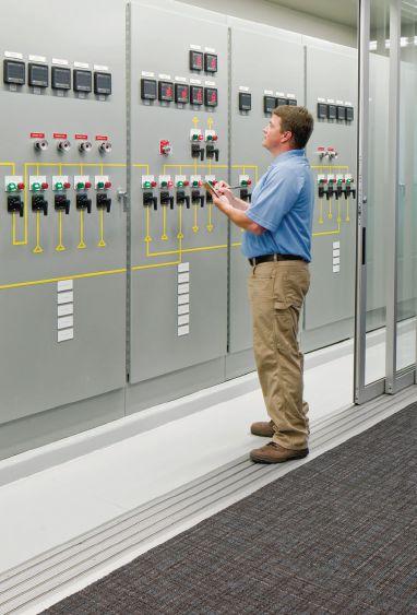


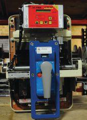

6605 W. WT Harris Blvd. Suite F • Charlotte NC 28269 | 13 Jenkins Court • Mauldin, SC 29662 | 9481 Industrial Center Drive, Suite 5 • Ladson, SC 29456 704.573.0420 • 844-383-8617 • 704.573.3693 (fax) • www.powerproducts.biz Acceptance and Maintenance Testing Commissioning Circuit Breaker Repair and Retrofit Infrared Scanning MV Cable Terminations and Testing Commissioning and Load Bank Testing of UPS, Generators, and ATS RETROFITTED BREAKER
WEIDMANN: 143 YEARS OF GLOBAL IMPACT
NETA Corporate Alliance Partners (CAPs) are a group of industry-leading companies that have joined forces with NETA to work together toward a common aim: improving quality, safety, and electrical system reliability.

In our CAP Spotlight series, we look at what makes CAPs special and highlight some of their individual successes. In this issue, NETA World interviews Francis Fisher, head of global marketing for Weidmann Electrical Technology.
NW: Who is Weidmann?
Fisher: The Weidmann Group, founded in 1877, is headquartered in Rapperswil, Switzerland, on the shores of Lake Zurich. Recognized throughout the world as a leading supplier of products and services to the transformer industry, Weidmann employs more than 3,000 people in over 30 locations worldwide. Weidmann Electrical Technology, one of the Group’s key business areas, may have started out producing cardboard products, but over 80 years ago, they also invented a product named Transformerboard. Now a well-known name throughout the electrical industry, this product had a significant impact on the global transformer insulation market. Today, more than 90 per cent of the world’s delivered power is insulated at some point along its journey by a Weidmann product.
As part of Weidmann’s growth and expansion strategy, today, the North American market is served by two production facilities, a state-of-
the-art, high-voltage R&D test center, and nine regional testing laboratories to support transformer operators across each region. Initially a provider of insulation products, Weidmann’s current product portfolio offers a complete range of products and services that allow us to support the full transformer lifecycle. From initial design through to providing transformer operators with services and testing over the course of the life of the asset, Weidmann is a trusted partner of transformer manufacturers and operators worldwide.
NW: Tell us something we don’t know about Weidmann?
Fisher: Weidmann Electrical Technology may be well-regarded around the world as a leading supplier of electrical products and services, but the Weidmann Group also has a medical division. Weidmann Medical Technology is a leading producer of innovative, technically advanced, injection-molded components supplied to pharmaceutical companies around the world.
104 • FALL 2020 WEIDMANN: 143 YEARS OF GLOBAL IMPACT
INSIGHTS & OBSERVATIONS — NETA CAP SPOTLIGHT
FRANCIS FISHER
Weidmann Medical recently made the headlines as a key supplier of blood sampling cassettes used in the most accurate COVID-19 test available in the world today. Driven by the global pandemic, the Weidmann Group invested in increased production capacity that allowed us to produce enough cassettes for more than 2.4 million patients to be tested for COVID-19 each week.
NW: How is Weidmann addressing future industry challenges?
Fisher: Fundamental to the future of our industry is the reliability and security of energy networks. Understanding the reasons why power transformers and other energy infrastructure assets fail is critical in the development of industry standards, products, and practices that can limit risk and improve the overall reliability of energy networks. Capturing critical asset data enables all stakeholders to determine areas for improvement and predict future behavior when managing electric power system assets.
Our deep-rooted knowledge of the transformer industry led Weidmann Electrical to develop a range of on-line monitoring devices that enables transformer operators to manage critical assets more effectively. Our experience researching and developing transformer insulation, a key component when determining the life of a transformer, along with knowledge from many years operating diagnostic testing laboratories, has put us in a strong position in the on-line monitoring market to face future industry challenges.
NW: Why is monitoring important, and specifically, why on-line monitoring?
Fisher: Deterioration in the condition of insulation over time can lead to the failure of a transformer. The objective of a monitor is to detect a change in the transformer and avoid this risk of failure. Historically, manual processes and testing procedures have been used to detect transformer issues and
supplement scheduled maintenance. But these manual processes only provide a snapshot of the transformer’s condition at a moment in time and cannot be fully relied upon to predict impending issues or failures.
On-line monitoring continually checks the status of the transformer, providing actionable data that can be used to schedule essential maintenance or ultimately, in the event of a pending catastrophic failure, shut down the asset.
By using the failure data Weidmann has available, transformer operators and manufacturers can determine which on-line monitoring solution can provide the highest return on investment based on budget and infrastructure in place.

Headquarters - Rapperswil, Switzerland
NW: Will on-line monitoring solutions disrupt your existing diagnostic lab business?
Fisher: For Weidmann, having operated off-line diagnostic testing labs for many years, developing on-line monitors was a natural progression. We believe providing customers with both off-line and on-line services is complementary. On-line monitors typically provide data about the current state of the transformer or asset, identifying any change in its condition and alerting the operator to this.
However, the level of detail and advanced diagnostics that can be performed on a transformer off-line can provide important additional visibility to determine the true condition and status of the transformer prior to taking action.
As one of the only companies in the world that can offer such a wide range of services, we believe this brings great value to our customers and keeps them coming back!
NETAWORLD • 105 WEIDMANN: 143 YEARS OF GLOBAL IMPACT
— NETA CAP SPOTLIGHT
INSIGHTS & OBSERVATIONS
TRAIN WITH THE EXPERTS
LIVE VIRTUAL ONLINE ELECTRICAL SAFETY TRAINING
Experience the same quality and engagement as our in-person, training courses while saving big on enrollment and travel costs. Our virtual training courses allow students to log-in remotely and fully participate in a live, instructor-led, online classroom setting.
Enroll in one of our pre-scheduled open enrollment virtual courses or if you have a group of employees that need training, ask about our virtual on-site training.
NFPA 70E® 2018 ELECTRICAL SAFETY (2-DAY)
NATIONAL ELECTRICAL CODE CHANGES 2020 (2-DAY)
NATIONAL ELECTRICAL CODE 2020 (4-DAY)
ELECTRICAL SAFETY FOR INDUSTRIAL FACILITIES (4-DAY)
ELECTRICAL SAFETY FOR UTILITIES (4-DAY)
NEW VIRTUAL COURSES COMING SOON
• SUBSTATION MAINTENANCE
• RELAY MAINTENANCE
• LOW-VOLTAGE CIRCUIT BREAKER

avotraining.com/virtual 877-594-3156 TRAINING INSTITUTE

STANDARDFOR NElltf EDITION ELECTRICAL COMMISSIONINGSPfCfflCATIONS FORELECTRICALPOWEREQUIPMENT & SYSTEMS NETA . ORDERNOW VisitNETAW0RLD.0RG orcall888.300.6382 NETA® STANDARDS -w-
ANSI/NETA STANDARDS UPDATE






ANSI/NETA ATS–2017 REVISION UNDERWAY


ANSI/NETA ATS–2017, Standard for Acceptance Testing Specifications for Electrical Power Equipment & Systems continues an American National Standard revision process that is scheduled to be completed by the end of 2020. The new edition will be released in March 2021.
A project intent notification published in ANSI’s Standards Action on January 3, 2020, announced the opening of a 45day public comment period. The initial ballot was issued on January 17, 2020, and closed on February 18, 2020. A second ballot was scheduled for issue in summer 2020. The revised edition of ANSI/NETA ATS is scheduled to debut at PowerTest 2021 in Orlando.
ANSI/NETA ATS covers suggested field tests and inspections for assessing the suitability for initial energization of electrical power equipment and systems. The purpose of these specifications is to assure that tested
108 • FALL 2020 SPECIFICATIONS AND STANDARDS ACTIVITY ANSI/NETA STANDARDS UPDATE
FOR ELECTRICAL POWER EQUIPMENT & SYSTEMS STANDARD FOR ACCEPTANCE TESTING SPECIFICATIONS ANSI/NETA ATS-2017 ANSI/NETA STANDARD FOR ELECTRICAL COMMISSIONING SPECIFICATIONS ANSI/NETA ECS-2020 STANDARDS 20 2020 STANDARD FOR ELECTRICAL COMMISSIONING SPECIFICATIONS FOR ELECTRICAL POWER EQUIPMENT & SYSTEMS REVISION UNDERWAY REVISION SCHEDULED
electrical equipment and systems are operational, are within applicable standards and manufacturers’ tolerances, and are installed in accordance with design specifications.
ANSI/NETA ETT–2018 REVISION SCHEDULED FOR 2021
A project intent notification is anticipated to be published in ANSI’s Standards Action in fall 2020, announcing the opening of a 45-day public comment period. The initial ballot is expected in summer 2021. A second ballot is scheduled for issue in fall 2021. The revised edition of ANSI/NETA ATS is scheduled to debut at PowerTest 2022.
ANSI/NETA ETT establishes minimum requirements for qualifications, certification, training, and experience for the electrical testing technician. It provides criteria for documenting qualifications for certification and details the minimum qualifications for an independent and impartial certifying body to certify electrical testing technicians.
ANSI/NETA ECS–2020 LATEST EDITION
ANSI/NETA ECS, Standard for Electrical Commissioning of Electrical Power Equipment & Systems, 2020 Edition, completed the American National Standard revision process. ANSI administrative approval was received on September 9, 2019. ANSI/NETA ECS–2020 supersedes the 2015 Edition.
ANSI/NETA ECS describes the systematic process of documenting and placing into service newly installed or retrofitted electrical power equipment and systems. This document shall be used in conjunction with the most recent edition of ANSI/NETA ATS, Standard for Acceptance Testing Specifications for Electrical Power Equipment & Systems . The individual electrical components shall be subjected to factory and field tests, as required, to validate the individual components. It is not the intent of these specifications to provide comprehensive details on the commissioning of mechanical equipment, mechanical instrumentation systems, and related components.
The ANSI/NETA ECS–2020 Edition includes updates to the commissioning process, as well as inspection and commissioning procedures as it relates to low- and mediumvoltage systems.
Voltage classes addressed include:
• Low-voltage systems (less than 1,000 volts)
• Medium-voltage systems (greater than 1,000 volts and less than 100,000 volts)
• High-voltage and extra-high-voltage systems (greater than 100 kV and less than 1,000 kV)
References:
• ASHRAE, ANSI/NETA ATS, NECA, NFPA 70E, OSHA, GSA Building Commissioning Guide
ANSI/NETA MTS–2019 LATEST EDITION
ANSI/NETA MTS, Standard for Maintenance Testing Specifications for Electrical Power Equipment & Systems, 2019 Edition, completed an American National Standard revision process and received ANSI approval on February 4, 2019. The revised edition of ANSI/NETA MTS was released in March 2019 and supersedes the 2015 Edition.
ANSI/NETA MTS contains specifications for suggested field tests and inspections to assess the suitability for continued service and reliability of electrical power equipment and systems. The purpose of these specifications is to assure that tested electrical equipment and systems are operational and within applicable standards and manufacturers’ tolerances, and that the equipment and systems are suitable for continued service. ANSI/NETA MTS–2019 revisions include online partial discharge survey for switchgear, frequency of power systems studies, frequency of maintenance matrix, and more. ANSI/NETA MTS–2019 is available for purchase at the NETA Bookstore at www.netaworld.org.
PARTICIPATION
Comments and suggestions on any of the standards are always welcome and should be directed to NETA. To learn more about the NETA standards review and revision process, to purchase these standards, or to get involved, please visit www.netaworld.org or contact the NETA office at 888-300-6382.
NETAWORLD • 109
AND STANDARDS ACTIVITY ANSI/NETA STANDARDS UPDATE
SPECIFICATIONS
ASTM F18 COMMITTEE REPORT
BY JAMES R. WHITE, Shermco Industries
The semi-annual ASTM-F18 Committee Meeting on May 28, 2020, was hosted on the WebEx app. This takes the place of the April meeting that was scheduled in Boston and cancelled due to the COVID-19 crisis. There were 74 participants.
F1506
Antitrust laws were read first. The first and only subject was F1506 arc-rated face masks, which are similar to a surgical mask. The proposal was to allow a smaller F1506 label. This was disputed.
As usual, things were somewhat difficult. Mikhail Golokov submitted three negatives, some of which actually violated OSHA standards. Mikhail was given 15 minutes to justify his negatives. Subsequently, David Wallis stated that Mikhail misquoted the OSHA regulation. Hugh Hoagland contested the statements that the arc temperature was only 70 °C. His tests showed the quoted arc temperature is illogical and can be 20,000 °C.
Mikhail also misquoted Exception No. 2 from NFPA 70E 130.7(C)11. The author spoke up to correct the misquote. Other 70E committee members supported this correction.
This discussion revolved around COVID-19 arc-rated face masks that are currently being produced. Mikhail declined to withdraw his negative, which is typical for Mikhail. By not
withdrawing the negative, it will go to ballot. This means FR face masks could possibly be produced without an F1506-approved label.
The next meeting is scheduled October 26–27, 2020, in Orlando, Florida.
MAIN COMMITTEE
The main committee meeting followed the F1506 meeting. Sam Stonerock called the meeting to order. General information that has no relevance NETA member companies was provided in the general session. The meeting adjourned at 11:20 AM.

James (Jim) R. White, Vice President of Training Services, has worked for Shermco Industries since 2001. He is a NFPA Certified Electrical Safety Compliance Professional and a NETA Level 4 Senior Technician. Jim is NETA’s principal member on NFPA Technical Committee NFPA 70E®, Electrical Safety in the Workplace; NETA’s principal representative on National Electrical Code® Code-Making Panel (CMP) 13; and represents NETA on ASTM International Technical Committee F18, Electrical Protective Equipment for Workers. Jim is Shermco Industries’ principal member on NFPA Technical Committee for NFPA 70B, Recommended Practice for Electrical Equipment Maintenance and represents AWEA on the ANSI/ISEA Standard 203, Secondary Single-Use Flame Resistant Protective Clothing for Use Over Primary Flame Resistant Protective Clothing. An IEEE Senior Member, Jim was Chairman of the IEEE Electrical Safety Workshop in 2008 and is currently Vice Chair for the IEEE IAS/PCIC Safety Subcommittee.
110 • FALL 2020 SPECIFICATIONS AND STANDARDS ACTIVITY ASTM F18 COMMITTEE REPORT
NFPA 70B COMMITTEE REPORT
BY DAVID HUFFMAN, Power Systems Testing Company
The NFPA 70B committee has continued to meet every two weeks via conference and video calls. We are working on revamping chapters to make it into a standard, and while progress is sometimes slow, we appear to be on track for a First Draft for public comment sooner rather than later.
With the continued issue of COVID-19, our tentative in-person meeting scheduled for August 10–13, 2020, has been canceled. In fact, NFPA has canceled all in-person meetings
for 2020. We remain hopeful to have an inperson meeting after the first of the year.

David Huffman has been with Power Systems Testing, a NETA Accredited Company, since January 1988 and is currently CEO. He graduated from California State University, Fresno, and is a licensed Professional Electrical Engineer in the state of California as well as a NETA Level IV Certified Technician. David is a NETA board member, NETA’s Principal Representative to the NFPA 70B Committee, and serves as a member of various NETA committees.

SPECIFICATIONS AND STANDARDS ACTIVITY
Thomas D. Sandri is Training Development Manager at Shermco Industries. He has been active in the field of electrical power and telecommunications for over 30 years. During his career, he has developed numerous training aids and training guides and has conducted domestic and international seminars. Tom supports a wide range of electrical and telecommunication maintenance application disciplines. He has been directly involved in supporting test and measurement equipment for over 20 years and is considered an industry expert in application disciplines, including battery and dc systems testing and maintenance, medium- and high-voltage cables, ground testing, and partial discharge analysis. Tom holds a BSEE from Thomas Edison University in Trenton, New Jersey.

ANSWERS
ANSWERS

1. b and c are correct. Ethylene-propylene rubber (EPR) is still used for some applications, such as industrial and underwater uses. Paper-insulated lead-covered (PILC) cable was used for many years for government and federal buildings but is no longer used because of its high cost. When the weaknesses of cross-link polyethylene became apparent, some facilities (military bases and other secure facilities) began using it again in limited quantities.
2. The following AC test sources are listed in MTS 2019:
a. Very-low frequency (VLF)
b. Power frequency (50/60 Hz)
c. Damped alternating current (20 to 50 Hz)
3. c. Based on the Electrical Power Research Institute (EPRI) report TR-101245, DC high potential testing of field-aged cable reduces the life of the cable.
4. a. True
NFPA Disclaimer: Although Jim White is a member of the NFPA Technical Committee for both NFPA 70E, Standard for Electrical Safety in the Workplace, and NFPA 70B, Recommended Practice for Electrical Equipment Maintenance, the views and opinions expressed in this column are purely the author’s and shall not be considered an official position of the NFPA or any of its technical committees and shall not be considered, nor be relied upon, as a formal interpretation or promotion of the NFPA. Readers are encouraged to refer to the entire text of all referenced documents.

TECH QUIZ
No. 131
112 • FALL 2020
TECH QUIZ ANSWERS
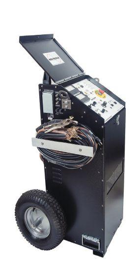

•



ELECTRICAL TESTING LEADING EDGE on the ELECTRICAL TESTING LEADING EDGE on the ELEMCO SERVICES offers a comprehensive array of state-of-the-art electrical testing services and expertise. HIGH, MEDIUM AND LOW VOLTAGE REPAIR AND MAINTENANCE OF: Switchgear / Circuit Breakers / Transformers / ATS Switches / Cables TESTING, CALIBRATION AND REPAIR OF METERS AND RELAYS FIELD SERVICES: Acceptance Testing and Commissioning / Infrared Surveys Motor and Cable Testing Load and Power Quality Recording and Analysis Nu Heat Certified Repair Specialists CONTACT US TODAY • 24 HOUR SERVICE 228 Merrick Road, Lynbrook, NY 11563 (631) 589-6343 601 Union Street, Brooklyn, NY 11215 (718) 786-4900 WWW.ELEMCO.COM Licenced in New York and New Jersey HIGH VOLTAGE, INC. 31 County Rt. 7A • Copake, NY 12516 • Tel: (518) 329-3275 • Fax: (518) 329-3271 • sales@hvinc.com • www.hvinc.com HIGH VOLTAGE, INC. ISO 9001 2015 HVI - The World’s Source for High Voltage Test Equipment VLF hipot: 0 - 33 kVac @ 1 μF @ 0.1 Hz Fault locate: 0 - 13 kV @ 760 J VLF Fault Burner Radar/TDR ready Other Thumper models: 5/10/20 kV @ 1000 J 9/18/36 kV @ 3200 J • Very Low Frequency AC Technology
Cable Diagnostic TD & PD Testing
Cable Fault Locating with Controlled Energy
AC & DC Hipots, Aerial Lift
Oil
•
•
•
Testers,
Testers
Ω-CHECK®
Neutral Testing
Concentric
VLF/Thumper Combination All That You Need 50 kVac @ 3 kVA Hipot 1 piece & w/cable output VLF 0.1 Hz @ 34 kVac Comp. control - wireless 80 kVdc Hipot/Megohmmeter 1 instrument - 2 tests All HVI Products are Made in the USA You Can Rely on HVI! HVI Makes it Easy and Efficient
&
• Custom Engineered & Fabricated Van Pkgs.
Cable Fault Locating
VLF Testing
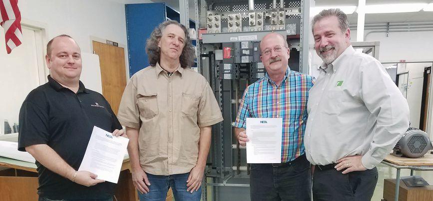
MOU Signing (left to right): Nenad Pasic, NETA Accredited Representative for Tony Demaria Electric and NETA Training Committee Member; John Hauck, LBCC Electrical Technology Instructor; Scott Fraser, LBCC Trades and Industry Department Chair and Electrical Technology Professor; and Bob Sheppard, NETA Training Committee Member
IN MEMORIAM: JOHN HAUCK — “STUDENTS FIRST”
John Hauck, 67, recently retired Electrical Technology Instructor at Long Beach City College (LBCC) and dear friend of NETA and Tony Demaria Electric, Inc. (TDE), passed away on May 31, 2020.
John was actively involved in successfully implementing the NETA Electrical Power Testing Technician (EPTT) Curriculum into LBCC’s existing Electrical Technology Program. He worked diligently with NETA and TDE to overcome numerous hurdles toward securing approval for the program from the State of California.
It all started in 2014 when TDE invited John to the NETA PowerTest Conference in Denver, Colorado. John spoke at the annual NETA Member Meeting about the proposed program and the efforts to implement it.
As a first step, NETA and LBCC participated in a series of successful discussions and site visits to decide how best to adopt NETA’s Electrical Power Testing Technician (EPTT) Curriculum, which includes a series of courses and labs designed to provide the education and knowledge required for a Level II NETA Test Technician as specified per ANSI/NETA ETT, Standard for Certification of the Electrical Testing Technician.
On November 15, 2016, LBCC and NETA signed a Memo of Understanding (MOU). This accomplishment was the culmination of John’s tireless efforts, professional dedication, and passion.
114 • FALL 2020 IN MEMORIAM: JOHN HAUCK — “STUDENTS 1ST”
“John often said this was going to be his last project before he retired, as well as his legacy to the industry he loved,” says Neno Pasic. “And he kept his promise and retired shortly after the MOU was signed and LBCC adopted the NETA Curriculum.”
Nearly a year later, on October 4, 2017, John attended the ribbon-cutting ceremony at the Grand Opening of the two buildings that now serve as the home of the LBCC Electrical Technology Program where the NETA curriculum is being taught.
John was again on hand on May 17, 2019, as LBCC held its first-ever Career Technical Education (CTE) Night to promote the NETA Curriculum to prospective students and introduce it to other LBCC staff.
John is survived by his wife Gail, daughters Erica and Erin, son-in-law Brian, and grandchildren Leah and Jacob. “John would be (and is) over the moon to have this written although he would be the last to say that out loud,” Gail says. “He was the absolute last person to toot his own horn. ‘Students first’ was his motto.”
“John will always remain in our hearts and minds,” adds Pasic. “It was a privilege to know him.”
John’s celebration of life date will be announced when circumstances allow it.

Ribbon Cutting Ceremony (left to right): Nenad Pasic; Scott Fraser; Bob Sheppard; Anthony Demaria, Owner and Chairman, Tony Demaria Electric; Rick Reyes, President, Tony Demaria Electric; Katie Scarlett Reyes, Director of Operations Excellence and Safety & Quality Director, Tony Demaria Electric; Joe Barrios, Operations Manager, Tony Demaria Electric; and John Hauck

NETAWORLD • 115 IN MEMORIAM: JOHN HAUCK — “STUDENTS 1ST”
NETA Booth (left to right): John Hauck; Scott Fraser; Ken Peterson, NETA Training Committee Member; Bob Sheppard; Nenad Pasic; and Erfan Bamdad, LBCC Electrical Technology NETA Curriculum Instructor of Tony Demaria Electric
Introducing NETA Series III Handbooks


We’ve got answers. Discover page after page of comprehensive, component-specific, technical resources for training and reference purposes. Over 200 of the very best articles from NETA World Journal and technical presentations from NETA’s PowerTest conferences. To order, please visit netaworld.org or call 888.300.6382
WORLD
AT YOUR FINGERTIPS.
REAL
LEARNING
A&F Electrical Testing, Inc.
80 Lake Ave S Ste 10 Nesconset, NY 11767-1017 (631) 584-5625
http://www.afelectricaltesting.com
A&F Electrical Testing, Inc.
80 Broad St Fl 5 New York, NY 10004-2257 (631) 584-5625
ABM Electrical Power Services, LLC
720 S Rochester Ste A Ontario, CA 91761-8177 (301) 397-3500
abm.com/Electrical
ABM Electrical Power Services, LLC 6541 Meridien Dr Suite 113 Raleigh, NC 27616 (919) 877-1008
ABM Electrical Power Services, LLC
2631 S. Roosevelt St Tempe, AZ 85282 (602) 722-2423
ABM Electrical Power Services, LLC
3600 Woodpark Blvd Ste G Charlotte, NC 28206-4210 (704) 273-6257
ABM Electrical Power Services, LLC
6940 Koll Center Pkwy Suite# 100 Pleasanton, CA 94566 (408) 466-6920
ABM Electrical Power Services, LLC
9800 E Geddes Ave Unit A-150 Englewood, CO 80112-9306 (303) 524-6560
ABM Electrical Power Services, LLC
3585 Corporate Court San Diego, CA 92123-1844 (858) 754-7963
ABM Electrical Power Services, LLC 1005 Windward Ridge Pkwy Alpharetta, GA 30005 (770) 521-7550
ABM Electrical Power Services, LLC 4221 Freidrich Lane Suite 170 Austin, TX 78744 (210) 347-9481
ABM Electrical Power Services, LLC 11719 NE 95th St. Ste H Vancouver, WA 98682 (360) 713-9513
ABM Electrical Power Solutions
4390 Parliament Place Suite S Lanham, MD 20706 (301) 967-3500
ABM Electrical Power Solutions
3700 Commerce Dr # 901-903 Baltimore, MD 21227-1642 (410) 247-3300
ABM Electrical Power Solutions
NETA ACCREDITED COMPANIES
317 Commerce Park Drive Cranberry Township, PA 16066-6407 (724) 772-4638
ABM Electrical Power Solutions
814 Greenbrier Cir Ste E Chesapeake, VA 23320-2643 (757) 364-6145
ABM Electrical Power Solutions 1817 O’Brien Road Columbus, OH 43228 (724) 772-4638
Absolute Testing Services, Inc. 8100 West Little York Houston, TX 77040 (832) 467-4446 http://www.absolutetesting.com
Accessible Consulting Engineers, Inc. 1269 Pomona Rd Ste 111 Corona, CA 92882-7158 (951) 808-1040 www.acetesting.com
Advanced Electrical Services 4999 - 43rd St. NE Unit 143 Calgary, AB T2B 3N4 (403) 697-3747
Advanced Testing Systems 15 Trowbridge Dr Bethel, CT 06801-2858 (203) 743-2001
http://www.advtest.com
American Electrical Testing Co., LLC 25 Forbes Boulevard Suite 1 Foxboro, MA 02035 (781) 821-0121 http://www.aetco.us
American Electrical Testing Co., LLC Green Hills Commerce Center 5925 Tilghman St Ste 200 Allentown, PA 18104-9158 (484) 538-2272
American Electrical Testing Co., LLC 34 Clover Dr South Windsor, CT 06074-2931 (860) 648-1013
American Electrical Testing Co., LLC 76 Cain Dr Brentwood, NY 11717-1265 (631) 617-5330
American Electrical Testing Co., LLC 91 Fulton St., Unit 4 Boonton, NJ 07005-1060 (973) 316-1180
AMP Quality Energy Services, LLC 352 Turney Ridge Rd Somerville, AL 35670 (256) 513-8255
AMP Quality Energy Services, LLC
41 Peabody Street Nashville, TN 37210 (629) 213-4855
Apparatus Testing and Engineering
11300 Sanders Dr Ste 29 Rancho Cordova, CA 95742-6822 (916) 853-6280
http://www.apparatustesting.com
Apparatus Testing and Engineering 7083 Commerce Cir Ste H Pleasanton, CA 94588-8017 (916) 853-6280
Applied Engineering Concepts 894 N Fair Oaks Ave. Pasadena, CA 91103 (626) 389-2108
http://www.aec-us.com
Applied Engineering Concepts 8160 Miramar Road San Diego, CA 92126 (619) 822-1106
BEC Testing 50 Gazza Blvd Farmingdale, NY 11735-1402 (631) 393-6800 www.bectesting.com
Burlington Electrical Testing Co., LLC
300 Cedar Ave Croydon, PA 19021-6051 (215) 826-9400 http://www.betest.com
Burlington Electrical Testing Co., LLC 846 Waterford Drive Delran, NJ 08075 (609) 267-4126
C.E. Testing, Inc.
6148 Tim Crews Rd Macclenny, FL 32063-4036 (904) 653-1900 http://www.cetestinginc.com/
Capitol Area Testing, Inc. P.O. Box 259 Suite 614 Crownsville, MD 21032 (757) 650-0740 http://www.capitolareatesting.com
CE Power Engineered Services, LLC 4040 Rev Drive Cincinnati, OH 45232 (800) 434-0415
CE Power Engineered Services, LLC 480 Cave Rd Nashville, TN 37210-2302 (615) 882-9455
CE Power Engineered Services, LLC 40 Washington St Westborough, MA 01581-1088 (508) 881-3911
CE Power Engineered Services, LLC 9200 75th Avenue N Brooklyn Park, MN 55428 (877) 968-0281
CE Power Engineered Services, LLC 72 Sanford Drive Gorham, ME 04038 (800) 649-6314
CE Power Engineered Services, LLC 8490 Seward Rd. Fairfield, OH 45011 (800) 434-0415
CE Power Engineered Services, LLC 1803 Taylor Ave. Louisville, KY 40213 (800) 434-0415
CE Power Engineered Services, LLC 10338 Citation Drive Suite 300 Brighton, MI 48116 (810) 229-6628
CE Power Engineered Services, LLC 10840 Murdock Drive Knoxville, TN 37932 (800) 434-0415
CE Power Engineered Services, LLC 3496 E. 83rd Place Merrillville, IN 46410 (219) 942-2346
CE Power Engineered Services, LLC 1260 Industrial Park Eveleth, MN 55734 (218) 744-4200
CE Power Solutions of Florida, LLC 3502 Riga Blvd., Suite C Tampa, FL 33619 (866) 439-2992 www.cepowersol.com
CE Power Solutions of Florida, LLC 3801 SW 47th Avenue Suite 505 Davie, FL 33314 (866) 439-2992
Control Power Concepts 3750 Las Vegas Blvd S. Unit 3303 Las Vegas, NV 89158 (702) 448-7833 www.controlpowerconcepts.com
Dude Electrical Testing, LLC 145 Tower Drive, Unit 9 Burr Ridge, IL 60527-7840 (815) 293-3388
http://www.dudetesting.com
Eastern High Voltage, Inc. 11A S Gold Dr Robbinsville, NJ 08691-1685 (609) 890-8300 http://www.easternhighvoltage.com
NETAWORLD • 117 NETA ACCREDITED COMPANIES
Setting the Standard
NETA ACCREDITED COMPANIES Setting the Standard
ELECT, P.C.
375 E. Third Street Wendell, NC 27591 (919) 365-9775
http://www.elect-pc.com
Electek Power Services, Inc.
870 Confederation Street Sarnia, ON N7T2E5 (519) 383-0333
Electric Power Systems, Inc.
21 Millpark Ct Maryland Heights, MO 63043-3536 (314) 890-9999
http://www.epsii.com
Electric Power Systems, Inc.
11211 E. Arapahoe Rd Ste 108 Centennial, CO 80112 (720) 857-7273
Electric Power Systems, Inc. 120 Turner Road Salem, VA 24153-5120 (540) 375-0084
Electric Power Systems, Inc.
1090 Montour West Ind Park Coraopolis, PA 15108-9307 (412) 276-4559
Electric Power Systems, Inc.
6141 E Connecticut Ave Kansas City, MO 64120-1346 (816) 241-9990
Electric Power Systems, Inc.
1230 N Hobson St. Suite 101 Gilbert, AZ 85233 (480) 633-1490
Electric Power Systems, Inc. 915 Holt Ave Unit 9 Manchester, NH 03109-5606 (603) 657-7371
Electric Power Systems, Inc.
3806 Caboose Place Sanford, FL 32771 (407) 578-6424
Electric Power Systems, Inc. 1129 E Highway 30 Gonzales, LA 70737-4759 (225) 644-0150
Electric Power Systems, Inc. 684 Melrose Avenue Nashville, TN 37211-3121 (615) 834-0999
Electric Power Systems, Inc.
2888 Nationwide Parkway 2nd Floor Brunswick, OH 44212 (330) 460-3706
Electric Power Systems, Inc.
54 Eisenhower Lane North Lombard, IL 60148 (815) 577-9515
Electric Power Systems, Inc.
1330 Industrial Blvd. Suite 300 Sugar Land, TX 77478 (713) 644-5400
Electric Power Systems, Inc.
56 Bibber Pkwy # 1 Brunswick, ME 04011-7357 (207) 837-6527
Electric Power Systems, Inc. 11861 Longsdorf St Riverview, MI 48193-4250 (734) 282-3311
Electric Power Systems, Inc. 8515 Calle Alameda NE Ste A Albuquerque, NM 87113 (505) 792-7761
Electric Power Systems, Inc.
3209 Gresham Lake Rd. Suite 155 Raleigh, NC 27615 (919) 210-5405
Electric Power Systems, Inc.
5850 Polaris Ave., Suite 1600
Las Vegas, NV 89118 (702) 815-1342
Electric Power Systems, Inc.
7925 Dunbrook Rd. Suite G San Diego, CA 92126 (858) 566-6317
Electric Power Systems, Inc. 6679 Peachtree Industrial Dr. Suite H Norcross, GA 30092 (770) 416-0684
Electric Power Systems, Inc.
306 Ashcake Road suite A Ashland, VA 23005 (804) 526-6794
Electric Power Systems, Inc. 7169 East 87th St. Indianapolis, IN 46256 (317) 941-7502
Electric Power Systems, Inc.
7308 Aspen Lane North Suite 160 Brooklyn Park, MN 55428 (763) 315-3520
Electric Power Systems, Inc. 140 Lakefront Drive Cockeysville, MD 21030 (443) 689-2220
Electric Power Systems, Inc. 783 N. Grove Rd Suite 101 Richardson, TX 75081 (214) 821-3311
Electric Power Systems, Inc.
11912 NE 95th St. Suite 306 Vancouver, WA 98682 (855) 459-4377
Electrical & Electronic Controls 6149 Hunter Rd Ooltewah, TN 37363-8762 (423) 344-7666
Electrical Energy Experts, LLC W129N10818 Washington Dr Germantown, WI 53022-4446 (262) 255-5222
http://www.electricalenergyexperts.com
Electrical Engineering & Service Co., Inc. 289 Centre St. Holbrook, MA 02343 (781) 767-9988
www.eescousa.com
Electrical Equipment Upgrading, Inc. 21 Telfair Pl Savannah, GA 31415-9518 (912) 232-7402 http://www.eeu-inc.com
Electrical Maintenance & Testing, Inc. 12342 Hancock St Carmel, IN 46032-5807 (317) 853-6795 http://www.emtesting.com
Electrical Maintenance & Testing, Inc. 1130 MacArthur Rd. Jeffersonville, OH 43128 (740) 426-9104
Electrical Reliability Services 610 Executive Campus Dr Westerville, OH 43082-8870 (877) 468-6384 http://www.electricalreliability.com
Electrical Reliability Services 5909 Sea Lion Pl Ste C Carlsbad, CA 92010-6634 (858) 695-9551
Electrical Reliability Services 1057 Doniphan Park Cir Ste A El Paso, TX 79922-1329 (915) 587-9440
Electrical Reliability Services
6900 Koll Center Pkwy Ste 415 Pleasanton, CA 94566-3119 (925) 485-3400
Electrical Reliability Services
8500 Washington St NE Ste A6 Albuquerque, NM 87113-1861 (505) 822-0237
Electrical Reliability Services 2275 Northwest Pkwy SE Ste 180 Marietta, GA 30067-9319 (770) 541-6600
Electrical Reliability Services 10606 Bloomfield Ave Santa Fe Springs, CA 90670-3912 (562) 236-9555
Electrical Reliability Services 400 NW Capital Dr Lees Summit, MO 64086-4723 (816) 525-7156
Electrical Reliability Services
7100 Broadway Ste 7E Denver, CO 80221-2900 (303) 427-8809
Electrical Reliability Services
2222 W Valley Hwy N Ste 160 Auburn, WA 98001-1655 (253) 736-6010
Electrical Reliability Services
221 E. Willis Road, Suite 3 Chandler, AZ 85286 (480) 966-4568
Electrical Reliability Services
1380 Greg St. Ste. 216 Sparks, NV 89431-6070 (775) 746-4466
Electrical Reliability Services 11000 Metro Pkwy Ste 30 Fort Myers, FL 33966-1244 (239) 693-7100
Electrical Reliability Services 245 Hood Road Sulphur, LA 70665-8747 (337) 583-2411
Electrical Reliability Services
9736 South Sandy Pkwy 500 West Sandy, UT 84070 (801) 561-0987
Electrical Reliability Services
6351 Hinson Street, Suite A Las Vegas, NV 89118-6851 (702) 597-0020
Electrical Reliability Services
36572 Luke Drive Geismar, LA 70734 (225) 647-0732
Electrical Reliability Services
9636 Saint Vincent Ave Unit A Shreveport, LA 71106-7127 (318) 869-4244
Electrical Reliability Services 1426 Sens Rd. Ste. #5 La Porte, TX 77571-9656 (281) 241-2800
Electrical Reliability Services 9753 S. 140th Street, Suite 109 Omaha, NE 68138 (402) 861-9168
Electrical Reliability Services
4099 SE International Way Ste 201 Milwaukie, OR 97222-8853 (503) 653-6781
Electrical Testing and Maintenance Corp. 3673 Cherry Rd Ste 101 Memphis, TN 38118-6313 (901) 566-5557 www.etmcorp.net
Electrical Testing Solutions
2909 Greenhill Ct Oshkosh, WI 54904-9769 (920) 420-2986 www.electricaltestingsolutions.com/
118 • FALL 2020 NETA ACCREDITED COMPANIES
NETA ACCREDITED COMPANIES Setting the
Electrical Testing, Inc.
2671 Cedartown Hwy SE Rome, GA 30161-3894 (706) 234-7623
http://www.electricaltestinginc.com
Elemco Services, Inc. 228 Merrick Rd Lynbrook, NY 11563-2622 (631) 589-6343 http://www.elemco.com
EnerG Test, LLC
206 Gale Lane Kennett Square, PA 19348 (484) 731-0200 http://www.energtest.com
Energis High Voltage Resources 1361 Glory Rd Green Bay, WI 54304-5640 (920) 632-7929 http://www.energisinc.com
EPS Technology
37 Ozick Dr. Durham, CT 06422 (203) 679-0145 http://www.eps-technology.com
Giga Electrical & Technical Services, Inc.
2743A N. San Fernando Road Los Angeles, CA 90065 (323) 255-5894 http://www.gigaelectrical-ca.com/
Grubb Engineering, Inc.
2727 North Saint Mary’s St. San Antonio, TX 78212 (210) 658-7250 http://www.grubbengineering.com
Halco Testing Services 5773 Venice Boulevard Los Angeles, CA 90019 (323) 933-9431 www.halcotestingservices.com
Hampton Tedder Technical Services 4563 State St Montclair, CA 91763-6129 (909) 628-1256 http://www.hamptontedder.com
Hampton Tedder Technical Services 3747 W Roanoke Ave Phoenix, AZ 85009-1359 (480) 967-7765
Hampton Tedder Technical Services 4113 Wagon Trail Ave. Las Vegas, NV 89118 (702) 452-9200
Harford Electrical Testing Co., Inc. 1108 Clayton Rd Joppa, MD 21085-3409 (410) 679-4477 www.harfordtesting.com
High Energy Electrical Testing, Inc. 5042 Industrial Road, Unit D Farmingdale, NJ 07727 (732) 938-2275 http://www.highenergyelectric.com
High Voltage Maintenance Corp. 5100 Energy Dr Dayton, OH 45414-3525 (937) 278-0811
http://www.hvmcorp.com
High Voltage Maintenance Corp. 24 Walpole Park S Walpole, MA 02081-2541 (508) 668-9205
High Voltage Maintenance Corp. 1052 Greenwood Springs Rd. Suite E Greenwood, IN 46143
High Voltage Maintenance Corp. 355 Vista Park Dr Pittsburgh, PA 15205-1206 (412) 747-0550
High Voltage Maintenance Corp. 8787 Tyler Blvd. Mentor, OH 44061 (440) 951-2706
High Voltage Maintenance Corp. 24371 Catherine Industrial Dr Ste 207 Novi, MI 48375-2422 (248) 305-5596
High Voltage Maintenance Corp. 3000 S Calhoun Rd New Berlin, WI 53151-3549 (262) 784-3660
High Voltage Maintenance Corp.
1 Penn Plaza Suite 500 New York, NY 10119 (718) 239-0359
High Voltage Maintenance Corp. 29 Diana Court Cheshire, CT 06410 (203) 949-2650
High Voltage Maintenance Corp. 941 Busse Rd Elk Grove Village, IL 60007-2400 (847) 640-0005
High Voltage Maintenance Corp. 14300 Cherry Lane Court Suite 115 Laurel, MD 20707 (410) 279-0798
High Voltage Maintenance Corp. 10704 Electron Drive Louisville, KY 40299 (859) 371-5355
Hood Patterson & Dewar, Inc. 850 Center Way Norcross, GA 30071 (770) 453-1415 https://hoodpd.com/
Hood Patterson & Dewar, Inc. 15924 Midway Road Addison, TX 75001 (214) 461-0760
Hood Patterson & Dewar, Inc. 4511 Daly Dr. Suite 1 Chantilly, VA 20151 (571) 299-6773
Hood Patterson & Dewar, Inc. 1531 Hunt Club Blvd Ste 200 Gallatin, TN 37066 (615) 527-7084
Industrial Electric Testing, Inc. 11321 Distribution Ave W Jacksonville, FL 32256-2746 (904) 260-8378 http://www.industrialelectrictesting.com
Industrial Electric Testing, Inc. 201 NW 1st Ave Hallandale Beach, FL 33009-4029 (954) 456-7020
Industrial Tests, Inc. 4021 Alvis Ct Ste 1 Rocklin, CA 95677-4031 (916) 296-1200 http://www.industrialtests.com
Infra-Red Building and Power Service, Inc. 152 Centre St Holbrook, MA 02343-1011 (781) 767-0888 http://www.infraredbps.com
J.G. Electrical Testing Corporation 3092 Shafto Road Suite 13 Tinton Falls, NJ 07753 (732) 217-1908 www.jgelectricaltesting.com
M&L Power Systems, Inc. 109 White Oak Ln Ste 82 Old Bridge, NJ 08857-1980 (732) 679-1800 http://www.mlpower.com
Magna IV Engineering 1103 Parsons Rd. SW Edmonton, AB T6X 0X2 (780) 462-3111 http://www.magnaiv.com
Magna IV Engineering 141 Fox Cresent Fort McMurray, AB T9K 0C1 (780) 791-3122
Magna IV Engineering 3124 Millar Ave. Saskatoon, SK S7K 5Y2 (306) 713-2167
Magna IV Engineering
96 Inverness Dr E Ste R Englewood, CO 80112-5311 (303) 799-1273
Magna IV Engineering
Avenida del Condor sur #590 Oficina 601 Huechuraba 8580676 +(56) -2-26552600
Magna IV Engineering Unit 110, 19188 94th Avenue Surrey, BC V4N 4X8 (604) 421-8020
Magna IV Engineering Suite 200, 688 Heritage Dr. SE Calgary, AB T2H 1M6 (403) 723-0575
Magna IV Engineering 4407 Halik Street Building E Suite 300 Pearland, TX 77581 (346) 221-2165
Magna IV Engineering 10947 92 Ave Grande Prairie, AB T8V 3J3 1.800.462.3157
Midwest Engineering Consultants, Ltd. 2500 36th Ave Moline, IL 61265-6954 (309) 764-1561 www.Midwestengr.com
MTA Electrical Engineers 350 Pauma Place Escondido, CA 92029 (760) 658-6098
National Field Services 651 Franklin Lewisville, TX 75057-2301 (972) 420-0157 http://www.natlfield.com
National Field Services 1890 A South Hwy 35 Alvin, TX 77511 (800) 420-0157
National Field Services 1405 United Drive Suite 113-115 San Marcos, TX 78666 (800) 420-0157
National Field Services 3711 Regulus Ave. Las Vegas, NV 89102 (888) 296-0625
National Field Services 2900 Vassar St. #114 Reno, NV 89502 (775) 410-0430
Nationwide Electrical Testing, Inc. 6515 Bentley Ridge Drive Cumming, GA 30040 (770) 667-1875 http://www.n-e-t-inc.com
North Central Electric, Inc. 69 Midway Ave Hulmeville, PA 19047-5827 (215) 945-7632 www.ncetest.com
Northern Electrical Testing, Inc. 1991 Woodslee Dr Troy, MI 48083-2236 (248) 689-8980 http://www.northerntesting.com
NETAWORLD • 119 NETA ACCREDITED COMPANIES
Standard
NETA ACCREDITED COMPANIES Setting the Standard
Orbis Engineering Field Services Ltd.
#300, 9404 - 41st Ave.
Edmonton, AB T6E 6G8 (780) 988-1455
http://www.orbisengineering.net
Orbis Engineering Field Services Ltd.
#228 - 18 Royal Vista Link NW Calgary, AB T3R 0K4 (403) 374-0051
Orbis Engineering Field Services Ltd.
Badajoz #45, Piso 17 Las Condes, Santiago +56 2 29402343
Pace Technologies, Inc.
9604 - 41 Avenue NW Edmonton, AB T6E 6G9 (780) 450-0404 www.pacetechnologies.com
Pace Technologies, Inc. #10, 883 McCurdy Place Kelowna, BC V1X 8C8 (250) 712-0091
Pacific Power Testing, Inc.
14280 Doolittle Dr San Leandro, CA 94577-5542 (510) 351-8811
http://www.pacificpowertesting.com
Pacific Powertech Inc.
#110, 2071 Kingsway Ave. Port Coquitlam, BC V3C 6N2 (604) 944-6697
http://www.pacificpowertech.ca
Phasor Engineering
Sabaneta Industrial Park #216 Mercedita, PR 00715 (787) 844-9366 http://www.phasorinc.com
Potomac Testing, Inc. 1610 Professional Blvd Ste A Crofton, MD 21114-2051 (301) 352-1930 http://www.potomactesting.com
Power Engineering Services, Inc. 9179 Shadow Creek Ln Converse, TX 78109-2041 (210) 590-4936 http://www.pe-svcs.com
Power Engineering Services, Inc. 1 Ellis Road, Suite 100 Friendswood, TX 77546 (210) 590-4936
Power Engineering Services, Inc.
124 S West St. Suite 200 Alexandria, VA 22314 (703) 299-3430
Power Products & Solutions, LLC
6605 W WT Harris Blvd Suite F Charlotte, NC 28269 (704) 573-0420 x12
http://www.powerproducts.biz
Power Products & Solutions, LLC
13 Jenkins Ct Mauldin, SC 29662-2414 (800) 328-7382
Power Products & Solutions, LLC
9481 Industrial Center Dr. Unit 5 Ladson, SC 29456 (844) 383-8617
Power Solutions Group, Ltd.
425 W Kerr Rd Tipp City, OH 45371-2843 (937) 506-8444
http://www.powersolutionsgroup.com
Power Solutions Group, Ltd. 251 Outerbelt St. Columbus, OH 43213 (614) 310-8018
Power Solutions Group, Ltd. 5115 Old Greenville Highway Liberty, SC 29657 (864) 540-8434
Power Solutions Group, Ltd. 172 B-Industrial Dr. Clarksville, TN 37040 (931) 572-8591
Power System Professionals, Inc.
429 Clinton Ave Roseville, CA 95661 (866) 642-3129
Power Systems Testing Co.
4688 W Jennifer Ave Ste 108 Fresno, CA 93722-6418 (559) 275-2171 ext 15 http://www.powersystemstesting.com
Power Systems Testing Co.
600 S Grand Ave Ste 113 Santa Ana, CA 92705-4152 (714) 542-6089
Power Systems Testing Co. 6736 Preston Ave Ste E Livermore, CA 94551-8521 (510) 783-5096
Power Test, Inc. 2200 Highway 49 S Harrisburg, NC 28075-7506 (704) 200-8311 http://www.powertestinc.com
PowerSouth Testing, LLC 240 Pine Pitch Road Cedartown, GA 30125 (678) 901-0205 www.powersouthtesting.com
Powertech Services, Inc. 4095 Dye Rd Swartz Creek, MI 48473-1570 (810) 720-2280
Precision Testing Group 5475 Highway 86 Unit 1 Elizabeth, CO 80107-7451 (303) 621-2776 www.precisiontestinggroup.com
Premier Power Maintenance Corporation 4035 Championship Drive Indianapolis, IN 46268 (317) 879-0660
Premier Power Maintenance Corporation 2725 Jason Rd Ashland, KY 41102-7756 (606) 929-5969
Premier Power Maintenance Corporation 3066 Finley Island Cir NW Decatur, AL 35601-8800 (256) 355-1444
Premier Power Maintenance Corporation 4301 Iverson Blvd Ste H Trinity, AL 35673-6641 (256) 355-3006
Premier Power Maintenance Corporation 7301 E County Road 142 Blytheville, AR 72315-6917 (870) 762-2100
Premier Power Maintenance Corporation 7262 Kensington Rd. Brighton, MI 48116 (517) 715-9997
Premier Power Maintenance Corporation 4537 S Nucor Rd. Crawfordsville, IN 47933 (317) 879-0660
Premier Power Maintenance Corporation 1901 Oakcrest Ave., Suite 6 Saint Paul, MN 55113 (612) 616-4236
Premier Power Maintenance Corporation 119 Rochester Dr. Louisville, KY 40214 (256) 200-6833
RESA Power Service 46918 Liberty Dr Wixom, MI 48393-3600 (248) 313-6868 www.resapower.com
RESA Power Service 3890 Pheasant Ridge Dr. NE Suite 170 Blaine, MN 55449 (763) 784-4040
RESA Power Service 4540 Boyce Parkway Cleveland, OH 44224 (800) 264-1549
RESA Power Service 47119 Cartier Court Wixom, MI 48393-2872 (248) 896-0200
RESA Power Service 19621 Solar Circle, 101 Parker, CO 80134 (303) 781-2560
RESA Power Service 40 Oliver Terrace Shelton, CT 06484-5336 (800) 272-7711
RESA Power Service 13837 Bettencourt Street Cerritos, CA 90703 (800) 996-9975
RESA Power Service 2390 Zanker Road San Jose, CA 95131 (800) 576-7372
RESA Power Service 1401 Mercantile Court Plant City, FL 33563 (813) 752-6550
RESA Power Service 6268 Route 31 Cicero, NY 13039 (315) 699-5563
RESA Power Service #181-1999 Savage Road, Richmond, BC V6V OA5 (604) 303-9770
Reuter & Hanney, Inc., a CE Power Company
Northampton Industrial Park 149 Railroad Dr Ivyland, PA 18974-1448 (215) 364-5333 http://www.reuterhanney.com
Reuter & Hanney, Inc., a CE Power Company
11620 Crossroads Cir Middle River, MD 21220-2874 (410) 344-0300
REV Engineering Ltd. 3236 - 50 Avenue SE Calgary, AB T2B 3A3 (403) 287-0156 http://www.reveng.ca
Rondar Inc.
333 Centennial Parkway North Hamilton, ON L8E2X6 (905) 561-2808 www.rondar.com
Rondar Inc. 9-160 Konrad Crescent Markham, ON L3R9T9 (905) 943-7640
Saber Power Services, LLC 9841 Saber Power Ln Rosharon, TX 77583-5188 (713) 222-9102 http://www.saberpower.com
Saber Power Services, LLC 14617 Perkins Road Baton Rouge, LA 70810 (225) 726-7793
Saber Power Services, LLC
9006 Western View Helotes, TX 78023 (210) 267-7282
120 • FALL 2020 NETA ACCREDITED COMPANIES
Saber Power Services, LLC
1908 Lone Star Rd. Mansfield, TX 76063 (210) 296-9970
Saber Power Services, LLC
433 Sun Belt Dr. Suite C Corpus Christi, TX 78408 (210) 267-7282
Saber Power Services, LLC
6097 Old Jefferson Hwy Geismar, LA 70734 (713) 222-9102
Scott Testing, Inc.
245 Whitehead Rd Hamilton, NJ 08619 (609) 689-3400 http://www.scotttesting.com
Sentinel Field Services, LLC
7517 E Pine St Tulsa, OK 74115-5729 (918) 359-0350 www.sentinelpowerservices.com
Shermco Industries 2425 E Pioneer Dr Irving, TX 75061-8919 (972) 793-5523 http://www.shermco.com
Shermco Industries 112 Industrial Drive Minooka, IL 60447-9557 (815) 467-5577
Shermco Industries
233 Faithfull Cr. Saskatoon, SK S7K 8H7 (306) 955-8131
Shermco Industries 2231 E Jones Ave Ste A Phoenix, AZ 85040-1475 (602) 438-7500
Shermco Industries 1711 Hawkeye Dr. Hiawatha, IA 52233 (319) 377-3377
Shermco Industries 1705 Hur Industrial Blvd Cedar Park TX 78613-7229 (512) 267-4800
Shermco Industries Boulevard Saint-Michel 47 1040 Brussels Brussels +32 (0)2 400 00 54
Shermco Industries 3434 25th Street NE Calgary, AB T1Y 6C1 (403) 769-9300
Shermco Industries 2100 Dixon Street Suite C Des Moines, IA 50316-2174 (515) 263-8482
Shermco Industries 4510 South 86th East Ave. Tulsa, OK 74145 (918) 234-2300
Shermco Industries 1375 Church Avenue Winnipeg, MB R2X 2T7 (204) 925-4022
Shermco Industries 1033 Kearns Crescent RM of Sherwood, SK S4K 0A2 (306) 949-8131
Shermco Industries 33002 FM 2004
Angleton, TX 77515-8157 (979) 848-1406
Shermco Industries 12000 Network Blvd Buidling D, Suite 410 San Antonio, TX 78249-3354 (210) 877-9090
Shermco Industries
3731 - 98 Street Edmonton, AB T6E 5N2 (780) 436-8831
Shermco Industries 417 Commerce Street Tallmadge, OH, 44278 (614) 836-8556
Shermco Industries
3807 S Sam Houston Pkwy W Houston, TX 77056 (281) 835-3633
Shermco Industries 4670 G. Street Omaha, NE 68117 (402) 933-8988
Shermco Industries 1301 Hailey St. Sweetwater, TX 79556 (325) 236-9900
Shermco Industries 2901 Turtle Creek Dr. Port Arthur, TX 77642 (409) 853-4316
Shermco Industries 5145 NW Beaver Dr. Johnston, IA 50131 (515) 265-3377
Shermco Industries 998 E. Berwood Ave. Saint Paul, MN 55110 (651) 484-5533
Shermco Industries 12796 Currie Court Livonia, MI 48150 (734) 469-4050
Shermco Industries 1720 S. Sonny Ave. Gonzales, LA 70737 (225) 647-9301
NETA ACCREDITED COMPANIES
Shermco Industries 501 Union West Blvd. Matthews, NC 28104 (910) 568-1053
Shermco Industries 5805 Hwy 43 Satsuma, AL 36507 (251) 679-3224
Shermco Industries 5211 Linbar Dr. Suite 507 Nashville, TN 37211 (615) 928-1182
Shermco Industries #307-2999 Underhill Ave Burnaby, BC V5A 3C2 (972) 793-5523
Sigma Six Solutions, Inc. 2200 W Valley Hwy N Ste 100 Auburn, WA 98001-1654 (253) 333-9730
http://www.sigmasix.com
Sigma Six Solutions, Inc. www.sigmasix.com Quincy, WA 98848 (253) 333-9730
Southern New England Electrical Testing, LLC
3 Buel St Ste 4 Wallingford, CT 06492-2395 (203) 269-8778
http://www.sneet.org
Star Electrical Services & General Supplies, Inc. PO Box 814 Las Piedras, PR 00771 (787) 716-0925
www.starelectricalpr.com
Taurus Power & Controls, Inc. 9999 SW Avery St Tualatin, OR 97062-9517 (503) 692-9004
http://www.tauruspower.com
Taurus Power & Controls, Inc. 19226 66th Ave S. #L102 Kent, WA 98032-2197 (425) 656-4170
Tidal Power Services, LLC 4211 Chance Ln Rosharon, TX 77583-4384 (281) 710-9150
http://www.tidalpowerservices.com
Tidal Power Services, LLC 8184 Highway 44 Ste 105 Gonzales, LA 70737-8183 (225) 644-8170
Tidal Power Services, LLC 1056 Mosswood Dr Sulphur, LA 70665-9508 (337) 558-5457
Tidal Power Services, LLC 1806 Delmar Drive Victoria, TX 77901 (281) 710-9150
Titan Quality Power Services, LLC 1501 S Dobson Street Burleson, TX 76028 (866) 918-4826
www.titanqps.com
Titan Quality Power Services, LLC 7630 Ikes Tree Drive Spring, TX 77389 (281) 826-3781
Titan Quality Power Services, LLC 7000 Meany Ave. Bakersfield, CA 93308 (661) 589-0400
Tony Demaria Electric, Inc. 131 W F St Wilmington, CA 90744-5533 (310) 816-3130 http://www.tdeinc.com
Utilities Instrumentation Service - Ohio, LLC 998 Dimco Way Centerville, OH 45458 (937) 439-9660 www.uiscorp.com
Utilities Instrumentation Service, Inc. 2290 Bishop Cir E Dexter, MI 48130-1564 (734) 424-1200 http://www.uiscorp.com
Utility Service Corporation PO Box 1471 Huntsville, AL 35807 (256) 837-8400
http://www.utilserv.com
Western Electrical Services, Inc. 14311 29th St E Sumner, WA 98390-9690 (253) 891-1995 www.westernelectricalservices.com
Western Electrical Services, Inc. 5680 S 32nd St Phoenix, AZ 85040-3832 (602) 426-1667
Western Electrical Services, Inc. 3676 W California Ave Ste C106 Salt Lake City, UT 84104-6533 (888) 395-2021
Western Electrical Services, Inc. 4510 NE 68th Dr Unit 122 Vancouver, WA 98661-1261 (888) 395-2021
Western Electrical Services, Inc. 5505 Daniels St. Chino, CA 91710 (602) 426-1667
Western Electrical Services, Inc. 620 Meadow Ln. Los Alamos, NM 87547 (505) 469-1661
Western Electrical Services, Inc. 8985 Double Diamond Pkwy, #10B Reno, NV 98521 (602) 426-1667
NETAWORLD • 121 NETA ACCREDITED COMPANIES
Setting the Standard
This issue’s advertisers are identified below. Please thank these advertisers by telling them you saw

122 • FALL 2020 ADVERTISERS INDEPENDENT NETA ACCREDITED COMPANIES Absolute Testing Services, Inc. ...................... 89 American Electrical Testing Co., LLC ............... 27 Apparatus Testing and Engineering 62 Eastern High Voltage............................... 82 Electrical Energy Experts, Inc. ....................... 26 Electrical Reliability Services (Vertiv) 54 Elemco Testing Co., Inc. 113 EnerG Test ........................................ 81 Hampton Tedder 83 Harford Electrical Testing Co. 113 High Voltage Maintenance Corp. ................... 29 Industrial Electric Testing, Inc. 8 Infra-Red Building and Power Service, Inc. 81 North Central Electric, Inc. .......................... 6 Orbis Engineering Field Services LTD 29 Potomac Testing, Inc. 63 Power Products & Solutions, Inc. ................... 103 Power Systems Testing Co. 111 Scott Testing, Inc. 29 Shermco Industries................................. 55 Sigma Six Solutions, Inc. ............................ 26 Taurus Power & Controls, Inc. 54 Tony Demaria Electric, Inc. ......................... 35 Utilities Instrumentation Service ..................... 6
MANUFACTURERS AND OTHER SERVICE PROVIDERS Advanced Test Equipment Rentals (ATE Corp) 97 AEAMC .................................................. 22 AEMC 72 Aero Tech Laboratories 102 AVO Training Institute .................................... 106 BCS Switchgear 46 Belyea Company 103 Bullock Breakers ........................................... 82 Burlington Safety Laboratory, Inc. 62 Doble Engineering 47 ECP Solutions ............................................. 21 Circuit Breaker Sales Co., Inc................................ 90 High Voltage Inc. 113 High Voltage Electric Service, Inc. .......................... 102 HV Diagnostics, Inc. ....................................... 34 Intellirent 13 Megger .................................... Inside Front Cover National Switchgear ........................................ 73 NETA ANSI/NETA ECS 107 NETA Handbook Series III 116 NETA PowerTest 2021 Call for Exhibitors ................... 30 NETA PowerTest 2021 Call for Sponsors 71 NETA PowerTest 2021 Save the Date 17 OMICRON electronics Corp. USA................. Back Cover Phenix Technologies, Inc. 72 Protec Equipment Resources 5 Quality Switchgear......................................... 90 Raytech Inside Back Cover Sertec 54 Solid State Exchange ........................................ 9 Southland Electrical 16 Technitrol, Inc. 8 Thyritronics, Inc............................................ 34 Utility Relay Company ..................................... 91 Vacuum Interrupters, Inc. 22
ADVERTISERS
their advertisement in NETA World.


Reliability You Need Support You Deserve


With a standard 5-YEAR warrant y, you can trust that Raytech equipment is built for the harsh environments of our testing industr y.

Free ser vice evaluations and lifetime product suppor t guarantees qualit y ser vice that is fast and easy.
O ffering the following easy to set up, and easy to use produc t lines:
• Transformer R atiometers

• Winding Resistance
• Contac t Resistance
• Current Transformer Test Sets
• Power Fac tor Test Sets


Toll Free: 888 484 3779 | Phone 267 404 2676 118 South 2nd Street, Perkasie, PA 18944
RaytechUSA.com


Get your hands on the new MPD 800 –our cutting-edge PD acquisition unit
The new MPD 800 Universal Partial Discharge (PD) measurement and analysis system represents the next generation of our innovative and widely-used PD testing equipment. Simultaneous RIV/PD testing, powerful noise/signal suppression technology, Live PD dataset recording enables you to detect PD activities and asses the risk of insulation failure in a wide variety of power assets. The multi-language and user-configurable software is also fully compatible with existing MPD 600 devices.
www.omicronenergy.com/mpd800


 Scott A. Blizard, President International Electrical Testing Association


 BY DON GENUTIS, Halco Testing Services


 BY PAUL CHAMBERLAIN, American Electrical Testing Co. LLC


 BY JIM GUO, PHD, and ZHONG ZHENG, PHD, TechImp US Corp.


 BY THOMAS D. SANDRI, Shermco Industries


 BY JAVIER RUIZ, Megger


 BY ALEX RANGEL, Saber Power Services, LLC


 BY RADENKO OSTOJIC and ADNAN ŠECIC, DV Power — Sweden


 BY ALAN ROSS, Electric Power Reliability Alliance


 BY MATHIEU LACHANCE, OMICRON electronics Canada, and TIM GANNON, Advanced Electrical Services


