






END-TO-END TESTING FOR LINE DIFFERENTIAL PROTECTION PAGE 44
R-GOOSE APPLICATIONS IN A SMART GRID PAGE 62
ISSN 2167-3594 NETA WORLD JOURNAL PRINT ISSN 2167-3586 NETA WORLD JOURNAL ONLINE SPRING 2013 WINTER 2019
USING COMMUNICATIONS TO MONITOR POWER DISTRIBUTION SYSTEMS


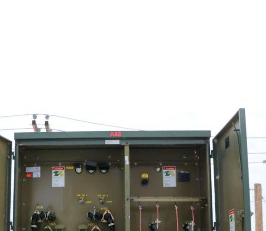



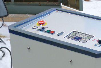


Multifunctional test and diagnostics system for medium voltage cables up to 35 kV Drop by BOOTH #219 on the exhibit floor to see the VLF Sinus 62 kV in action at NETA POWERTEST 2020! Dealing with cable just got easier. 1-800-723-2861 us.megger.com/powertest The
testing,
computer,
power
ease. VLF Sinus 62 kV
Megger VLF Sinus 62 kV is the smallest and lightest testing unit in its class. Not only can it perform VLF and DC
but it can also perform sheath testing and sheath fault pinpointing. All of this is achieved with no need for an external
allowing you to
on with
FEBRUARY 24 - 28, 2020

ENERGIZE
FUTURE
YOUR
Hosted by PowerTest.org | 888.300.6382 PREVIEW GUIDE THE PREMIER ELECTRICAL MAINTENANCE AND SAFETY CONFERENCE
Hyatt Regency Chicago l Chicago, Illinois
PowerTest 2020 boasts five different paper tracks, 40+ sessions, and a full week of conference activities.
NETWORK
Build relationships and establish valuable contacts with 500+ leaders in the electrical testing industry when you attend engaging events at PowerTest.
Expand your brand power and attract the attention of industry decision-makers by sponsoring and exhibiting at PowerTest 2020.
LEARN
PROMOTE
Join leading electrical professionals at PowerTest, the premier electrical maintenance and safety conference. Register before December 31, 2019 and save $100 PREVIEW GUIDE


Welcome to Chicago
Discover a full week of technical sessions, networking events, and more – all designed to showcase the latest industry developments and foster relationship building. Build downtime into your PowerTest itinerary and indulge in a Chicago style hotdog or deep dish pizza, and explore the rich history and local attractions the windy city has to offer. PowerTest 2020: Learning, energizing, renewing. Focused on learning, connecting, updating, and advancing, PowerTest 2020 will be held in one of the world’s most dynamic cities: Chicago.

THE PREMIER ELECTRICAL MAINTENANCE AND SAFETY CONFERENCE

Enjoy pre-conference mischief with us at Tommy Gun’s Garage.
In addition to serving up amazing entrees, Tommy Gun's puts on a prohibition-themed, audience-interactive, musical comedy show that you'll never forget. You'll be transported to the 1920s with memorabilia, songs by composers like Cole Porter and George Gershwin, and the performers dancing the Charleston.
Sunday, February 23 | 5:00 PM
PREVIEW GUIDE


PowerTest 2020 Mobile App available soon
Don’t miss a single moment of PowerTest 2020. Download the PowerTest Mobile App and get instant access to the full schedule - right at your fingertips!
Mobilize yourself
• View session abstracts and speaker bios.
• Customize your schedule for the events and sessions you plan to attend.
• Set reminders and manage alerts.
• View Trade Show floor plan map and booth information.
• Message other conference attendees.
• View sponsor information.
• Complete evaluations to earn CTDs/ CEUs as well as provide feedback, vote for your favorite sessions, booths, and hospitality suites.
THE PREMIER ELECTRICAL MAINTENANCE AND SAFETY CONFERENCE
Advance your knowledge
Learn from industry leaders about the latest developments in the electrical testing industry. The educational opportunities at PowerTest are detailed and engaging.
47 CTD credits* 4.7 CEU credits* AVAILABLE AVAILABLE
*when attending Megger Best Practices Seminar.

Choosing among 27 sessions across 5 learning tracks allows you to focus on your expertise and interests.
1. Electrical Safety
2. Equipment
3. Relays
4. Transformers
5. Reliability
NETA CTD Credits and CEUs are available for all educational sessions throughout the week.
- Voltage current and power monitoring
- Harmonic detection analysis
- Inrush current analysis
- Energy cost analysis and management
- Power factor analysis and correction
- Power demand and consumption monitoring
- Transient detection and analysis
- Data logging


LEARN
www.aemc.com
Rely on AEMC® for Your Power Quality & Energy Measurement Instruments Our products are backed by over 125 years of experience in test and measurement equipment. PREVIEW GUIDE
sales@aemc.com
Emerging Technology Symposium
Monday, February 24
Learn about the newest technology, techniques, and the evolution of the electrical testing industry from a panel of selected experts from the industry.
New Product Forum
Monday, February 24
In sixty minutes, attendees will preview the newest products and services shaping the power systems industry from 30 of the leading equipment manufacturers and service providers.
Panel Sessions
Tuesday, February 25
In panel sessions attendees can learn about electrical safety, emerging technologies, relays, or transformers. Two sessions are available for each panel topic, but could completely differ in content as much of the discussion is driven through audience participation. Please come prepared with some thoughts and questions to engage with the panel experts.
Seminars
Wednesday & Thursday, February 26-27
Two days of in-depth, four hour, interactive seminar presentations offer an opportunity to learn about Relay Troubleshooting, Arc-Flash Workshop, Full Time Partial Discharge Monitoring, Changes to the 2021 NFPA 70E, and much more.
Doble Laboratory Seminar
Friday, February 28
Doble's laboratory expert will present a full day, interactive session that combines theoretical background with practical experience. We will share case studies illustrating common problems found in the field.

THE PREMIER ELECTRICAL MAINTENANCE AND SAFETY CONFERENCE
Connect with industry peers
From a 1920’s-themed speakeasy to hospitality suites and an awards reception, PowerTest offers a multitude of opportunities to socialize and network with colleagues and industry leaders.


NETWORK YOUR TRUSTED SOURCE OF HV TESTING EQUIPMENT FOR OVER 20 YEARS HV TECHNOLOGIES, Inc. provides the most comprehensive range of high voltage test equipment and services available.
insulating properties of oil, cables,
accessories,
brings together the design, engineering, technology,
support for easy to use
accurate high voltage testing. T: (703) 365-2330 | F: (703) 365-2331 | hvsales@hvtechnologies.com Request a quote online at hvtechnologies.com HV TECHNOLOGIES, Inc. is now the exclusive distributor and service center for all HAEFELY High Voltage Test Equipment Products in USA! stating to PREVIEW GUIDE
Whether you’re testing the
or HV transformers and
HVT
and
and

Pre-Conference Event*
Sunday, February 23 | 5:00 PM
Go back in time to the 1920’s with the best and longest running show in Chicago, Tommy Gun’s Garage. This interactive speakeasy features gangsters, flappers, comedy, and dangerous fun. Be ready to hide your hooch for this is prohibitionera party.
Cost is $155 per person.

Hospitality Suites
Monday, February 24 | 6:00 PM
Mingle with fellow guests and a host of leaders at a variety of uniquely themed suites complete with food, drinks, and entertainment.
PowerBash Reception*
Tuesday, February 25 | 7:00 PM
Enjoy an evening of awards and entertainment in the company of hundreds of like-minded industry professionals at the PowerBash Reception.
Cost is $35 per person.
*Please note that pre-registration is required to attend the Preconference Event and PowerBash.
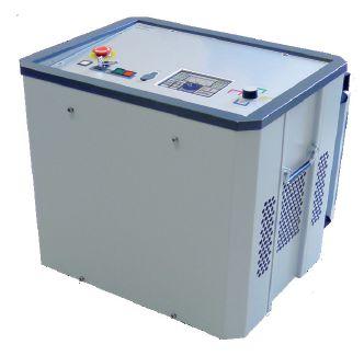
We’ll See You in The Windy City at NETA PowerTEST 2020! Drop by BOOTH 219 or our HOSPITALITY SUITE for a breezy look at our newest products. 1-800-723-2861 us.megger.com/powertest See the new VLF Sinus 62 kV Multifunctional test and diagnostics system for medium voltage cables up to 35 kV THE PREMIER ELECTRICAL MAINTENANCE AND SAFETY CONFERENCE
Enhance your exposure
Power up your brand. Attract the attention of high-profile industry decision-makers by sponsoring and exhibiting at PowerTest 2020.

2020 TRADE SHOW
Tuesday, February 25 | 12:00 PM
Create new leads and strengthen existing relationships when you present your products and services at the PowerTest Trade Show, a standalone event, that does not compete with any other sessions. By popular demand, PowerTest 2020 is offering lead capture technology to exhibitors, making lead generation more seamless than ever.
PowerTest Sponsorship
Gain industry exposure when you put your brand in front of hundreds of electrical professionals. PowerTest offers a wide array of sponsorship levels to fit every budget.


PROMOTE
PREVIEW GUIDE

Products
Quality products from industry-leading manufacturers.


Calibration Services
Two in-house labs provide NIST Traceable calibration.
Asset Management
We manage all of your equipment, including analytic reports on asset fleet, cleaning, repair & calibration.
Protec Connect & Customer Web Portal
Renting & managing electrical test equipment just got a whole lot easier.
Sales & Service
Application support & customer service available 24/7.


Nobody Works Harder For You Than Protec
We understand that you need experienced people to align you with the proper equipment, in the right place at the right time.
To better serve our customers, we offer a large, nationwide rental fleet of electrical test and measurement equipment, with all Protec locations stocked with inventory.
The number one choice for mission critical equipment where time, quality and service are vital.

Electrical Test Equipment Rental Experts t 866-352-5550 Dallas | Atlanta | Chicago Houston | New Jersey | Reno
The
Large enough to serve your needs small enough to care
THE PREMIER ELECTRICAL MAINTENANCE AND SAFETY CONFERENCE
TRADE
FLOOR
ENTRANCE TRUCK DOCK EXHIBITOR SERVICES EE PARKING GARAGE RAMP FHC EE EE LOWER E. SOUTH WATER STREET E1 E1 E1 E1 E1 E1 E1 E1 E1 E1 E1 E2 E2 E3 TV C C C C E1 E1 E1 E1 E1 E1 E1 E1 E1 E1 E1 E1 E1 E1 E1 E3 E2 E2 TV AWD,E1 E1 E1 E1 E1 E1 E2 E2,MIC E1 E1 E1 E1 E1 E1 E1 E1 E1 E1 E1 E1 E1 E1 C E1 E1 E1 E1 E1 E1 E1 E1 E1 E1 E1,TV E1,MIC AWD,MIC E2,TV C C C C C E1 E1 E1 E1 E1 E1 E1 E1 E1 E1 E1 E1 E1 E1 E1 E1 E1 E1 E1 E1 E1 E1 E1 E1 E1 E1 E1 E3 E1,MIC E1 E1 E1 E1 FHC FX A-1 A-2 A-3 B-1 B-2 B-3 B-4 C-1 C-2 C-3 C-4 C-5 B-5 D-1 D-2 D-3 D-4 D-5 E-1 E-2 E-3 E-4 E-5 PJ-1 F-1 F-2 F-3 F-4 F-5 G-1 G-2 G-3 G-4 G-5 L-5 H-2 H-3 H-4 I-4 I-3 I-2 I-1 J-1 J-2 J-3 J-4 J-5 K-5 K-4 K-3 K-2 FHC West / North West / South 101 200 201 224 226 240 242 300 313 333 335 340 342 405 409 411 412 413 415 419 425 427 429 431 432 433 435 441 443 445 447 104 417 331 20' 301 20' 311 20' 421 20' 125 20' 106 20' 241 20' 437 20' 449 451 319 321 418 420 BAR BAR FOOD FOOD STATION BAR DESSERT 6' 6' 6' 6' 6' 6' 6' 6' 6' 6' 6' 6' 8' 8' 8' 21'-10" 15'-6" 13'-7" 341 20' 42' Spotlight Lounge 8' 147 20' 50' 302 304 305 404 303 402 325 20' 30' 141 20' 346 20' STATION 111 20' 20' 211 20' 310 312 13120' 20' 13720' 20' 219 20' 53'-7" 229 231 233 237 239 328 330 332 336 338 202 20' 20' 119 20' 20' Inventory Dimension 10'x10' 10'x20' 20'x20' 20'x30' 20'x42' 20'x50' 20'x53'-7" February Conference Hyatt PREVIEW GUIDE
2020
SHOW
PLAN
February 25th Exhibits Conference
Hyatt
2020 TRADE SHOW EXHIBITORS
2020 IEEE PES Transmission & Distribution Conference & Exposition .................................. 330 A-Rent Test Equipment 233 ABB 429 AEMC Instruments ........................................... 229 Amblyonix Industrial Instrument Company ....... 301 Basler Electric Company 321 BCS Switchgear, Inc. .......................................... 111 Belyea Company Inc. ....................................... 231 BRAH Electric Mfg. 242 CE Power Engineered Services, LLC ................... 404 CHK Power Quality Pty Ltd ............................... 425 Dexotech Inc. 312 Doble Engineering Company 119 EA Technology ................................................. 340 EasyPower LLC ................................................ 435 Electrical Builders, Inc. (EBI) 449 Electrical Reliability Services - Vertiv ................ 333 Electrical Test Instruments ................................ 313 Electroswitch 319 Exiscan IR Windows ......................................... 447 GCBS New Products ......................................... 437 Group CBS, Inc. 341 High Voltage Maintenance 335 High Voltage, Inc. ............................................ 451 HV Diagnostics, Inc. .......................................... 211 HV TECHNOLOGIES, Inc. 332 I-Gard Corporation .......................................... 432 Intellirent ......................................................... 147 Interstates 336 KoCos America LLC. ......................................... 240 Maddox Industrial Transformer ......................... 418 Megger ............................................................ 219 National Switchgear ......................................... 131 ndb Technologies 409 NETA ............................................................... 106 North American Switchgear, Inc. ...................... 420 Ofil Ltd. 305 OMICRON electronics 202 Parts Super Center .......................................... 331 Phenix Technologies, Inc. ................................. 342 Power Grid Engineering 402 Power Substation Services ............................... 427 ProgUSA - Dv Power ......................................... 433 Protec Equipment Resources 137 R.N.T. Supply ................................................... 417 RB Sales .......................................................... 303 Safearth 338 Schweitzer Engineering Laboratories 415 Sertec Relay Services ....................................... 445 Shermco Industries .......................................... 346 SMC 224 Solid State Exchange & Repair ......................... 441 Southland Electrical Supply .............................. 241 Staubli Electrical Connectors, Inc. 237 Technical Diagnostic Services ............................125 Technitrol, Inc. ................................................. 328 TJH2b Analytical Services 310 Tyndale Company, Inc. 412 Utilities Instrumentation Service ...................... 239 Utility Relay Company ...................................... 141 Warren Steel Specialties 413 Weidmann Electrical Technology ...................... 226 Western Electrical Services ............................... 443
STREET Inventory as of 07/30/2019 Dimension 10'x10' 10'x20' 20'x20' 20'x30' 20'x42' 20'x50' 20'x53'-7" Size 100 200 400 600 840 1,000 1,071 Totals: Qty 57 11 5 1 1 1 1 77 SqFt 5,700 2,200 2,000 600 840 1,000 1,071 13,411
PowerTest
24
2020
- 28th,
Regency Chicago Riverside Center THE PREMIER ELECTRICAL MAINTENANCE AND SAFETY CONFERENCE





Register online at powertest.org or give us a call us at 888.300.6382 Hotel Reservations Upon registering for PowerTest 2020, you will receive a link via email to secure your hotel reservations at: Hyatt Regency Chicago 151 E Wacker Dr. Chicago, IL 60601 312.565.1234 RESERVATION DEADLINE January 30, 2020 GROUP CODE G-BIET GROUP RATE $175 REGISTER TODAY Register before December 31, 2019 and save $100. Want to learn more? You can also find a complete schedule
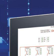
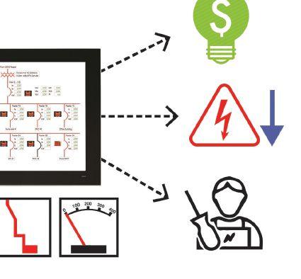
We’ll see you in Chicago Join us at Booth 141 and celebrate with us as we toast to 25 Years! Interactive & Customizable One-Line Diagrams Display Waveforms, Alarms, Current, Power, Breaker Status and More Increase Productivity Improve Safety February 24-28 at NETA POWERTEST 2020 +1.888.289.2864 www.UtilityRelay.com Utility Relay Company The Modern Solution for Monitoring Your Networks Ask about our... PREVIEW GUIDE
at powertest.org

Monday–Thursday Non-Members $1,895 NAC/Alliance $1,695 Any Single Day Non-Members $580 NAC/Alliance $550 Monday & Tuesday Non-Members $995 NAC/Alliance $895 Doble Seminar Non-Members $445 NAC/Alliance $445 PowerTest 2020 Prohibition Party at Tommy Gun’s Garage Sunday, February 23 $155 PowerBash Reception Tuesday, February 25 $35 Social/Guest Pass Includes Breakfast Monday/ Tuesday, Hospitality Suites, Trade Show, and PowerBash Reception $75 Nike PowerTest Polo Shirt $60 PRICING Extra Perks MARCH 8 – 12, 2021 ROSEN SHINGLE CREEK ORLANDO, FLORIDA POWERTEST.ORG 888.300.6382 SAVE THE DATE THE PREMIER ELECTRICAL MAINTENANCE AND SAFETY CONFERENCE HOSTED BY
THE PREMIER ELECTRICAL MAINTENANCE AND SAFETY CONFERENCE
Photo Credit: Rosen Shingle Creek
To

Megger Best Practices
Sunday, February 23
9:00 AM - 4:00 PM
Megger’s Best Practices Seminars are designed to bring you up to speed on new testing techniques and technology as well as offer the opportunity to engage in technical discussions with our expert engineers. Megger’s world-class Applications Engineers utilize their vast industry knowledge and experience to craft an in-depth program backed by Megger’s expertise in the market. This full-day of quality education includes training related to key industry topics as well as some of the best practices to follow when performing offline electrical testing. Pre-registration is required to attend.
For more information or to register, please visit powertest.org/2020-highlights/educational
PowerDB Users Group
Monday, February 24
12:15 PM - 2:00 PM
Annual User’s Group Meeting open to licensed users of PowerDB Pro Software. Agenda will include presentations by the PowerDB Pro development team as well as utility, industrial and contractor groups discussing how this product is an integral part of their business operations.
Pre-registration is required by contacting PowerDB at (979) 690-7925 ext. 702 or by registering at powerdb.com

GROUP CBS, Inc. Providing Electrical Solutions Worldwide protecequip.com PREMIUM SPONSORS HIGH VOLTAGE LOW VOLTAGE MEDIUM VOLTAGE GENERAL
thank you.
our invaluable PowerTest 2020 sponsors,
SPECIAL SESSIONS PREVIEW GUIDE
COVER STORY
FEATURES
7 President’s Desk


Using Communications to Monitor Power Distribution Systems


An increasing number of facilities are exploring and appreciating the communications capabilities of electrical power equipment. Modern electrical system protection and metering devices measure and calculate a significant amount of digital data, and most of this data can be retrieved via communications, enabling systems to monitor multiple devices in a system-wide manner from a central and/ or remote location. Due to the increased availability of communicating devices and equipment, integrating a basic power monitoring system can be simple and can be accomplished without significant effort or significant additional equipment.
By Ryan McClarnon, Utility Relay Company
44
Scott Blizard, American Electrical Testing Co., LLC NETA President
End-to-End Testing for Line Differential Protection
Sughosh Kuber, Megger
52 Fiber Optic Network Operation, Maintenance, and Restoration
Jim Hayes, Fiber Optic Association
62
R-GOOSE Applications in a Smart Grid
Alex Apostolov, OMICRON electronics Corp. USA

TABLE OF CONTENTS TABLE OF CONTENTS NETAWORLD • 3
34 72
WINTER 2019 · VOLUME 41, NO. 4 COVER IMAGES COURTESY OF UTILITY RELAY COMPANY; COVER BACKGROUND PHOTO: © ISTOCKPHOTO.COM/ PORTFOLIO/METAMORWORKS
10 The NFPA 70E and NETA
Small Things Mean a Lot
Ron Widup and James R. White, Shermco Industries
15 Relay Column
Functional Testing for Sudden Pressure Relay
Steve Turner, Arizona Public Service Company
20 In the Field
Communications Kicks Off New Column
Don Genutis, Halco Testing Services
26 Tech Quiz
Communications
James R. White, Shermco Industries
28 Safety Corner
Communicating Hazards during the Pre-Job Briefing
Paul Chamberlain, American Electrical Testing Co., LLC INDUSTRY TOPICS
72 Medium-Voltage Asset Failure Investigations
Kelly Higinbotham, University of Connecticut, and William G. Higinbotham, EA Technology LLC
84 A New Way to Test Distribution Automation Schemes
Robert Wang, OMICRON electronics Corp. USA
92
Ensure Effective Acceptance and Maintenance Testing with Quality Reporting and Analysis
Steve Park, Electrical Reliability Services — a Vertiv Company
ADVANCEMENTS IN INDUSTRY
101 Communications Security for Field Testing Organizations
Gowri Rajappan, Doble Engineering Company
SPECIFICATIONS AND STANDARDS 106 ANSI/NETA Standards Update 110 Electrical Maintenance: Canada Update
Kerry Heid, Shermco Industries Canada
NETA Accredited Companies
Advertiser List
4 • WINTER 2019 TABLE OF CONTENTS TABLE OF CONTENTS IN EVERY ISSUE
NETA NEWS 117
IMPORTANT LISTS 120
NETA Activities Update
128

Nobody Works Harder For You Than Protec
We understand that you need experienced people to align you with the proper equipment, in the right place at the right time.
To better serve our customers, we offer a large, nationwide rental fleet of electrical test and measurement equipment, with all Protec locations stocked with inventory.
Products
Quality products from industry-leading manufacturers.
Calibration Services
Two in-house labs provide NIST Traceable calibration.
Asset Management
We manage all of your equipment, including analytic reports on asset fleet, cleaning, repair & calibration.
Protec Connect & Customer Web Portal
Renting & managing electrical test equipment just got a whole lot easier.
Sales & Service
Application support & customer service available 24/7.

The number one choice for mission critical equipment where time, quality and service are vital.



t 866-352-5550 Dallas | Atlanta | Chicago Houston | New Jersey | Reno
The Electrical Test Equipment Rental Experts
Large enough to serve your needs small enough to care

#1 Great Lakes Electrical Testing Firm
• Full Member of the InterNational Electrical Testing Association (NETA)
• Licensed Electricians (IBEW-JIW)
• Member of the National Electrical Contractors Association (NECA) • ISO/IEC 17025 Accredited
Electrical Testing & Commissioning
•Acceptance Testing •Preventative and Predictive Maintenance •Technical Support•Protective Relays • Transformers• Switchgear • Breakers • Infrared & Ultrasonic Survey • Cable Locating • VLF & Tan Delta Testing• Partial Discharge• Meters• Grounding• Generator Controls• ATS• UPS• Battery Systems • Motor Control Centers • Switches• Capacitor Banks
Electrical Studies
• Short Circuit/Device Coordination Studies • Arc Flash/Shock Hazard Studies • Harmonic/Power Factor/Transient Studies & Corrections Training
• Electrical Safety & Troubleshooting • NFPA 70E

3050 Old Centre Road, Suite 101
Portage, MI 49024
Toll free: 888.300.NETA (6382)
Phone: 269.488.NETA (6382)
Fax : 269.488.6383
neta@netaworld.org
www.netaworld.org
EXECUTIVE DIRECTOR: Missy Richard
NETA Officers
PRESIDENT: Scott Blizard, American Electrical Testing Co., Inc.
FIRST VICE PRESIDENT: Lorne Gara, Orbis Engineering Services, Ltd.
SECOND VICE PRESIDENT: Eric Beckman, National Field Services
SECRETARY: Scott Dude, Dude Electrical Testing, LLC
TREASURER: John White, Sigma Six Solutions, Inc.
NETA Board of Directors
Ken Bassett (Potomac Testing, Inc.)
Eric Beckman (National Field Services)
Scott Blizard (American Electrical Testing Co., Inc.)
Jim Cialdea (CE Power Engineered Services, LLC)
Scott Dude (Dude Electrical Testing LLC)
Lorne Gara (Orbis Engineering Field Services, Ltd.)
Dan Hook (Western Electrical Services, Inc.)
David Huffman (Power Systems Testing)
Alan Peterson (Utility Service Corporation)
Chasen Tedder, Hampton Tedder Technical Services
John White (Sigma Six Solutions)
Ron Widup (Shermco Industries)
NETA World Staff
TECHNICAL EDITORS: Roderic L. Hageman, Tim Cotter
ASSISTANT TECHNICAL EDITORS: Jim Cialdea, Dan Hook, Dave Huffman, Bob Sheppard
ASSOCIATE EDITOR: Resa Pickel
MANAGING EDITOR: Carla Kalogeridis
COPY EDITOR: Beverly Sturtevant
ADVERTISING MANAGER: Laura McDonald
DESIGN AND PRODUCTION: Moon Design
NETA Committee Chairs
CONFERENCE: Ron Widup; MEMBERSHIP: Ken Bassett; PROMOTIONS/MARKETING: Scott Blizard; SAFETY: Scott Blizard and Jim White; TECHNICAL: Alan Peterson; TECHNICAL EXAM: Dan Hook; CONTINUING TECHNICAL DEVELOPMENT: David Huffman; TRAINING: Bob Sheppard; FINANCE: John White; NOMINATIONS: Alan Peterson; ALLIANCE PROGRAM: Jim Cialdea; ASSOCIATION DEVELOPMENT: Ken Bassett and John White
© Copyright 2019, NETA
NOTICE AND DISCLAIMER
NETA World is published quarterly by the InterNational Electrical Testing Association. Opinions, views and conclusions expressed in articles herein are those of the authors and not necessarily those of NETA. Publication herein does not constitute or imply endorsement of any opinion, product, or service by NETA, its directors, officers, members, employees or agents (herein “NETA”).
All technical data in this publication reflects the experience of individuals using specific tools, products, equipment and components under specific conditions and circumstances which may or may not be fully reported and over which NETA has neither exercised nor reserved control. Such data has not been independently tested or otherwise verified by NETA.
NETA MAKES NO ENDORSEMENT, REPRESENTATION OR WARRANTY AS TO ANY OPINION, PRODUCT OR SERVICE REFERENCED OR ADVERTISED IN THIS PUBLICATION. NETA EXPRESSLY DISCLAIMS ANY AND ALL LIABILITY TO ANY CONSUMER, PURCHASER OR ANY OTHER PERSON USING ANY PRODUCT OR SERVICE REFERENCED OR ADVERTISED HEREIN FOR ANY INJURIES OR DAMAGES OF ANY KIND WHATSOEVER, INCLUDING, BUT NOT LIMITED TO ANY CONSEQUENTIAL, PUNITIVE, SPECIAL, INCIDENTAL, DIRECT OR INDIRECT DAMAGES. NETA FURTHER DISCLAIMS ANY AND ALL WARRANTIES, EXPRESS OF IMPLIED, INCLUDING, BUT NOT LIMITED TO, ANY IMPLIED WARRANTY OF FITNESS FOR A PARTICULAR PURPOSE.
ELECTRICAL TESTING SHALL BE PERFORMED ONLY BY TRAINED ELECTRICAL PERSONNEL AND SHALL BE SUPERVISED BY NETA CERTIFIED TECHNICIANS/ LEVEL III OR IV OR BY NICET CERTIFIED TECHNICIANS IN ELECTRICAL TESTING TECHNOLOGY/LEVEL III OR IV. FAILURE TO ADHERE TO ADEQUATE TRAINING, SAFETY REQUIREMENTS, AND APPLICABLE PROCEDURES MAY RESULT IN LOSS OF PRODUCTION, CATASTROPHIC EQUIPMENT FAILURE, SERIOUS INJURY OR DEATH.
When downtime is not an option
The
Since 1976
734-216-7229
UNION Solution
TM Stop by and see us at PowerTest 2020 Booth #239


WELCOME TO THE 2019 WINTER EDITION OF NETA WORLD
As humans, we are drawn to one another and communicate with each other using a variety of methods. Good and effective communication is an essential tool to achieve productivity and maintain strong and lasting working relationships at all levels of an organization. What every interaction has in common is the need for clear and effective communication.
In this issue of NETA World, we look at the way electrical systems communicate internally with controls, devices, and applications to improve the functionality of the protection, automation, and control systems. Articles in this issue range from R-GOOSE technology on the smart grid to new communication devices for monitoring electrical power distribution systems.
Mark your calendar — PowerTest 2020 is February 24–28, 2020! PowerTest 2020 will take place in one of the world’s most dynamic and popular cities: Chicago, at the Hyatt Regency. The PowerTest Conference will feature a symposium and a separate panel session on emerging technologies. Be sure to check it out. I can tell you the venue and programs for PowerTest 2020 are sure to be outstanding. Register today to assure your spot among the leaders in the electrical testing industry.
Here in the Northeast, winter brings some interesting weather. Be aware of ice, snow, sleet, and rain when traveling the roadways. Leave a little extra room between you and the vehicle in front of you. Be aware of walkways, driveways, and parking lots for black ice. It is the season for trips, slips, and falls.
Coach safe behavior … Living injury free every day!

Scott A. Blizard, President
NETA — InterNational Electrical Testing Association Safety First…No One Gets Hurt!

PRESIDENT’S DESK PRESIDENT’S DESK


the industry, that never compromises


As North America’s largest independent electrical testing company, our most important Company core value should come as no surprise: assuring the safety of our people and our customer’s people. First and foremost.
Our service technicians are NETA-certified and trained to comply and understand electrical safety standards and regulations such as OSHA, NFPA 70E, CSA Z462, and other international guidelines. Our entire staff including technicians, engineers, administrators and management is involved and responsible for the safety of our co-workers, our customers, our contractors as well as our friends and families.
Our expertise goes well beyond that of most service companies. From new construction to maintenance services, acceptance testing and commissioning to power studies and rotating machinery service and repair, if it’s in the electrical power system, up and down the line, Shermco does it.
www.shermco.com l 888-SHERMCO
One
The largest NETA Accredited technical group in
safety.
Line. One Company.
SMALL THINGS MEAN A LOT
RON WIDUP and JAMES R. WHITE, Shermco Industries
One of the most important details in NFPA 70E is its definitions. Many people automatically believe they already know the definition of a word or phrase. This is a mistake that can have negative consequences. The place to start is to read Chapter 1, Article 100 Definitions. Once you have a better understanding of the definitions, the rest of the standard becomes much easier to read and comprehend the intent.
For example, the definition of Electrically Safe Work Condition has seen a lot of attention over the last two revisions. Some additional controversy was created when the definition was [essentially] challenged to mean that the only way to assure compliance was that the equipment had to be replaced, rather than maintained. This caused quite a stir, so the definition was expanded and an information note was added, all intended to make the definition clearer.
In the current 2018 edition, the definition of Electrically Safe Work Condition reads:
Electrically Safe Work Condition. A state in which an electrical conductor or circuit part has been disconnected from energized parts, locked/ tagged in accordance with established standards, tested to verify the absence of voltage, and, if necessary, temporarily grounded for personnel protection.
The proposed revised definition of Electrically Safe Work Condition now reads:
A state in which an electrical conductor or circuit part has been disconnected from energized parts, locked/tagged in accordance with established standards, tested to verify the absence of voltage, and if necessary, temporarily grounded for personnel protection.
Informational Note: An electrically safe work condition is not a procedure; it is a state wherein all hazardous electrical conductors or circuit parts to which a worker might be exposed are maintained in a zero energy state for the purpose of temporarily eliminating electrical hazards for the period of temporary time for which the state is maintained.
The accompanying Informational Note points out that an electrically safe work condition is not a procedure, but a state. Once it becomes
10 • WINTER 2019 SMALL THINGS MEAN A LOT
THE NFPA 70E AND NETA

an electrically safe work condition, all hazardous energy is no longer available to cause injury or death. The condition is temporary, which means it is intended to be re-energized (maybe not right away), but for a period of time for which the state is maintained. This should make the meaning of the definition clear to everyone.
Only minor editorial changes were made to a few additional definitions to ensure each definition provided in the standard is as understandable as possible. A good example is the definition of Working On (energized electrical conductors and circuit parts), which now has the proposed added text (shown as underlined) and reads:
Working On (energized electrical conductors and circuit part). Intentionally coming in contact with energized electrical conductors or circuit parts with the hands, feet, or other body parts, with tools, probes, or with test equipment, regardless of the personal protective equipment (PPE) a person is wearing. There are two categories of working on : Diagnostic (testing) is taking readings or measurements of electrical equipment, conductors, or circuit parts with approved test equipment that does not require making any physical change to the electrical equipment, conductors, or circuit parts; repair is any physical alteration of electrical equipment, conductors, or circuit parts (such as making or tightening connections, removing or replacing components, etc.).
NETAWORLD • 11 SMALL THINGS MEAN A LOT
NFPA
NETA
© ISTOCKPHOTO.COM/PORTFOLIO/SHINYFAMILY
THE
70E AND
PHOTO:
THE NFPA 70E AND NETA
Users of 70E are familiar with the concept of two working on conditions:
1. Diagnostic testing using approved test equipment, which includes taking voltage readings or tasks that do not make changes to the electrical equipment, conductors, or circuit parts, and
2. Repairs that involve making physical changes to the equipment, conductors, or circuit parts to get it to work again. The idea is to avoid intentionally coming in contact with the equipment, conductors, or circuit parts.
But remember this: Best practices teach us that if the person doing the repair task has first placed the equipment, conductors, or circuit parts in an electrically safe condition using PPE, they have removed the hazard, so there is no need to mitigate the hazard, since it isn’t there. It’s the best way to go!
The 70E standard required this in Article 110.1, which addresses general requirements for electrical safety-related work practices. There is a new first clause in 110.1 (electrical safety program) identified as Priority, which was previously located in Article 105.4 and is proposed as:
110.1 Electrical Safety Program
(A) Priority. Hazard elimination shall be the first priority in the implementation of safetyrelated work practices.
Informational Note No. 1: Elimination is the risk control method listed first in the hierarchy of risk control identified in 100.5(H)(3). See Annex F for examples of hazard elimination.
Informational Note No. 2: An electrically safe work condition is a state wherein all hazardous electrical conductors or circuit parts to which a worker might be exposed are placed and maintained in a de-energized state, for the purpose of temporarily eliminating electrical hazards. See Article 120 for requirements to establish an electrically safe work
condition for the period of time for which the state is maintained. See Informative Annex F for information regarding the hierarchy of risk control and hazard elimination.
This is another example where small things can make a big difference. In this section, hazard elimination is the first priority of safety-related work practices. We should always keep this in mind, as quitting time, personal issues, overtime, fatigue, and countless other items could distract us from keeping elimination as the first priority.
The second informational note also speaks to an electrically safe work condition and refers the 70E user to Informative Annex F. Informative annexes are not mandatory requirements, but contain related and very useful information that should be reviewed and incorporated into work plans and safe work practices. If you haven’t been carefully studying the informative annex material in the 70E, you really should — it’s a great resource for additional knowledge and best practices.
CONCLUSION
The upcoming new (2021) edition of NFPA 70E will have many changes — some very important and some just editorial.
The structure of the document, with shading that highlights any new or revised text, makes it simple to see what has changed, how it has changed, and what has been added. We recommend studying the definitions, Section 130, as well as all of Chapter 1 and Chapter 2. Add in the informative annexes, and there is quite a bit to digest. But this is not like eating distasteful food; it is more like dessert. It should be taken in, reviewed, and taken in again. Every time you do, you will likely find something new that helps us all in our quest for electrical safety perfection.
Be careful out there, and always test before touch!
12 • WINTER 2019
SMALL THINGS MEAN A LOT
Ron Widup and Jim White are NETA’s representatives to NFPA Technical Committee 70E, Electrical Safety Requirements for Employee Workplaces. Both gentlemen are employed by Shermco Industries in Dallas, Texas, a NETA Accredited Company.

Ron Widup, Shermco Industries Vice Chairman and Senior Advisor, Technical Services, has been with Shermco since 1983, and currently serves on the company’s board of directors. He is a member of Technical Committee on NFPA 70E, Electrical Safety in the Workplace; a Principal Member of National Electrical Code (NFPA 70) Code Panel 11; a Principal Member of the Technical Committee on NFPA 790, Standard for Competency of Third-Party Evaluation Bodies; a Principal Member of the Technical Committee on NFPA 791, Recommended Practice and Procedures for Unlabeled Electrical Equipment Evaluation; a member of the Technical Committee on NFPA 70B, Recommended Practice for Electrical Equipment Maintenance, and Vice Chair for IEEE Std. 3007.3, Recommended Practice for Electrical Safety in Industrial and Commercial Power Systems. Ron also serves on NETA’s board of directors and Standards Review Council. He is a NETA Certified Level 4 Senior Test Technician, a State of Texas Journeyman Electrician, an IEEE Standards Association member, an Inspector Member of the International Association of Electrical Inspectors, and an NFPA Certified Electrical Safety Compliance Professional (CESCP).

James (Jim) R. White, Vice President of Training Services, has worked for Shermco Industries since 2001. He is a NFPA Certified Electrical Safety Compliance Professional and a NETA Level 4 Senior Technician. Jim is NETA’s principal member on NFPA Technical Committee NFPA 70E®, Electrical Safety in the Workplace; NETA’s principal representative on National Electrical Code® Code-Making Panel (CMP) 13; and represents NETA on ASTM International Technical Committee F18, Electrical Protective Equipment for Workers. Jim is Shermco Industries’ principal member on NFPA Technical Committee for NFPA 70B, Recommended Practice for Electrical Equipment Maintenance and represents AWEA on the ANSI/ISEA Standard 203, Secondary Single-Use Flame Resistant Protective Clothing for Use Over Primary Flame Resistant Protective Clothing. An IEEE Senior Member, Jim was Chairman of the IEEE Electrical Safety Workshop in 2008 and is currently Vice Chair for the IEEE IAS/PCIC Safety Subcommittee.


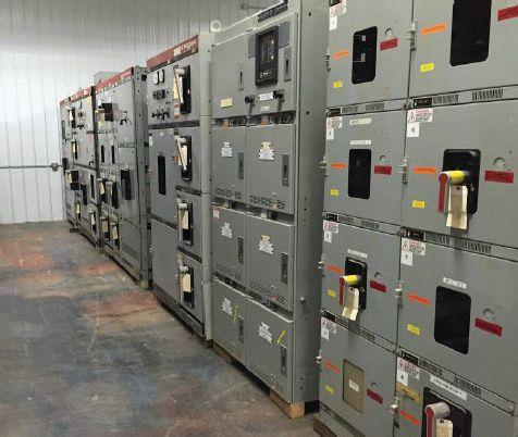


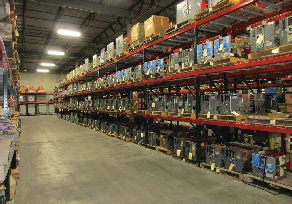


THE NFPA 70E AND NETA BULLOCK BREAKERS B B 475 Annandale Blvd • Annandale • Minnesota 55302 www.bullockbreakers.com • Email: jason@bullockbreakers.com • Thousands of Air Circuit Breakers in Stock! • Switchgear Line-ups you can’t find anywhere else! • Now Available as Reconditioned with AC-Pro Trip Units! 1-763-269-2832

FUNCTIONAL TESTING FOR A SUDDEN PRESSURE RELAY
BY STEVE TURNER, Arizona Public Service Company
This article presents a functional test procedure for a sudden pressure relay. The sudden pressure relay trips when it detects a sudden increase in gas pressure due to a fault internal to the transformer tank. Recommendations for mounting the relay and a procedure for post-analysis following field trips are also provided.
The sudden pressure relay (Figure 1) offers three main functions:
• Pressure sensing bellows
• Pressure equalizing orifice
• Microswitch
The bellows expands when an internal fault causes arcing, which operates the microswitch. The orifice is a plug with a very small hole that equalizes pressure inside the relay during slow changes due to transformer loading and ambient temperature changes.
Note: The sudden pressure relay can only be applied to transformers with a gas space above the windings inside the tank.

NETAWORLD • 15 FUNCTIONAL TESTING FOR A SUDDEN PRESSURE RELAY
RELAY COLUMN
Microswitch Test Plug Pressure Tight Connector 3 4 5 0123456789 Time to Operate – Cycles Rise –PSI / SEC Bellows Equalizer Mounting Boss (PART OF TANK) Cycles
Figure 1: Sudden Pressure Relay
RELAY COLUMN

SUDDEN PRESSURE RELAY PROTECTION CHARACTERISTICS
Figure 2A and Figure 2B illustrate the operating time to trip as a function of rate of pressure rise (psi/sec) and the time required to equalize the pressures between the transformer and sudden pressure relay respectively.
SUDDEN PRESSURE RELAY SCHEMATIC
Typically, the relay includes a seal-in relay and a reset switch. The seal-in relay has alarm and trip contacts and is energized by the microswitch. It closes an alarm contact output and trips. It then seals itself closed until manually reset via the reset switch.
MOUNTING RECOMMENDATIONS
Mount the relay above the maximum oil level in the gas space above the windings inside the tank. The relay mounting should be rigid and well-braced to prevent false operation due to any vibration, which can occur during close-in, high-magnitude through faults.
Figure 4 shows a sudden pressure relay mounted to a transformer tank.
16 • WINTER 2019 FUNCTIONAL TESTING FOR A SUDDEN PRESSURE RELAY
Figure 4: Sudden Pressure Relay Mounting Recovery Time in Seconds 010 1 2 3 4 5 6 7 8 2030 63 GREEN 63 X 63 X 63 X 63 MICROSWITCH 63X SEAL - IN RELAY 63RS RESET SWITCH 63V VOLTRAP RI RESISTOR 63 X 6 7 8 9 SPR PANEL ALARM TRIP CUSTOMER SUPPLY 10 11 12 63 X 63X 63V 63 RS RI WHITE BLACK CAB 4050607080 Transformer Gas Space Pressure in psig Test Plug Pressure Tight Connector Time to Operate – Seconds Recovery Time in Seconds 0 010 1 2 3 4 5 6 7 8 2030 4050607080 0 1 2 3 4 5 123456789 0123456789 Time to Operate – Cycles Rate of Pressure Rise –PSI / SEC Transformer Gas Space Pressure in psig Cycles Time to Operate – Seconds Recovery Time in Seconds 0 010 1 2 3 4 5 6 7 8 2030 63 GREEN 63 X 63 X 63 X 63 MICROSWITCH 63X SEAL - IN RELAY 63RS RESET SWITCH 63V VOLTRAP RI RESISTOR 63 X 6 7 8 9 SPR PANEL ALARM TRIP CUSTOMER SUPPLY 10 11 12 63 X 63X 63V 63 RS RI WHITE BLACK CAB 4050607080 0 123456789 Transformer Gas Space Pressure in psig
Figure 2A: Operating Characteristic
Figure 2B: Recovery Time
Figure 3: Schematic Diagram
RELAY COLUMN
FUNCTIONAL TEST PROCEDURE
1. Disconnect the sudden pressure relay supply voltage.
2. Record the transformer operating pressure. The pressure must be greater than 3/4 psi for the following tests.
3. Connect a circuit tester across terminals 1 and 2 on the terminal strip (B and C on Figure 3).
4. Remove the test plug from the relay case. The relay microswitch will operate and the circuit tester will indicate a closed contact output.
5. Close the test plug and record the time in seconds required for these same contacts to open.
6. Using the recovery time recorded in #5 and the pressure recorded in #2 as coordinates on Figure 2B: Recovery Time, verify that the point is within the allowed operating area.
7. Disconnect any external trip or alarm circuit.
8. Check that the reset switch is closed.
9. Reconnect the sudden pressure relay supply voltage.
10. Connect the circuit tester across terminals 7 and 8.
11. Remove the test plug. The relay will operate and the circuit tester will indicate an open circuit.
12. Replace the test plug and allow sufficient time (see #5) for the sudden pressure relay to equalize.
13. Operate the reset switch. The contact output across terminals 7 and 8 should fall closed. This check should be performed for each of the alarm and trip circuits.
14. Reconnect the trip or alarm circuits following the correct operation of the relay.
Note: This test procedure is for a specific type of sudden pressure relay, so some steps may vary or not be necessary depending upon the actual type of relay that is being tested.
TESTING AFTER FIELD OPERATION
After a breaker trip resulting from operation of the sudden pressure relay, the transformer and the relay panel must be tested before it is re-energized to prevent possible damage to the coils and insulation.
Three checks are recommended prior to reenergizing the transformer:
1. Functionally test the sudden pressure relay to determine if it is in proper operating condition.
2. Conduct suitable tests and observations to verify that the transformer is undamaged and suitable for re-energization. Contact the transformer manufacturer if in doubt.
3. Contact the transformer manufacturer for any additional instructions concerning maintenance and inspection procedures.
REFERENCE
ABB. “Sudden Pressure Relay Technical Guide.” 1ZUA566ref-210–rev.2 September 8, 2009. Available at www.library.e.abb.com/ public/7ecd37d3c79ef688c1256fa2007003cc/ 1ZUA5663-210_r2_Sudden%20Pressure% 20Relay.pdf.

Steve Turner is in charge of system protection for the fossil generation department at Arizona Public Service Company in Phoenix. After working with Beckwith Electric Company, Inc. for 10 years, Steve spent two years as a consultant in San Diego. His previous experience includes positions as an Application Engineer at GEC Alstom and in the international market for SEL focusing on transmission line protection applications. Steve also worked for Duke Energy (formerly Progress Energy), where he developed the first patent for double-ended fault location on overhead high-voltage transmission lines and was in charge of all maintenance standards in the transmission department for protective relaying. Steve has BSEE and MSEE degrees from Virginia Tech University. He has presented at numerous conferences including Georgia Tech Protective Relay Conference, Western Protective Relay Conference, ECNE, and Doble User Groups, as well as various international conferences. Steve is a senior member of IEEE and a member of the IEEE PSRC.
NETAWORLD • 17 FUNCTIONAL TESTING FOR A SUDDEN PRESSURE RELAY


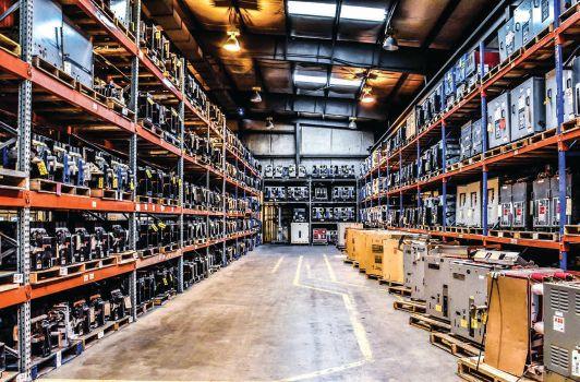


An extensive inventory of over 200,000 sq. ft. across the southeast means the Southland Group has the products you need most in stock and ready to ship! Our team of experienced technicians provide on-site field service support and engineering services to ensure that your products are safe, reliable and service ready. Contact us today and let us create the solutions you need most!





6605 W. WT Harris Blvd. Suite F • Charlotte NC 28269 | 13 Jenkins Court • Mauldin, SC 29662 | 9481 Industrial Center Drive, Suite 5 • Ladson, SC 29456 704.573.0420 • 844-383-8617 • 704.573.3693 (fax) • www.powerproducts.biz Acceptance and Maintenance Testing Commissioning Circuit Breaker Repair and Retrofit Infrared Scanning MV Cable Terminations and Testing Commissioning and Load Bank Testing of UPS, Generators, and ATS RETROFITTED BREAKER


THE PREMIER ELECTRICAL MAINTENANCE AND SAFETY CONFERENCE FOR MORE INFORMATION OR TO REGISTER visit www.powertest.org or call (888)300-6382 (NETA) PowerTest.org l 888.300.6382 Hosted by REGISTER AND SAVE Early Bird Registration Opens September 1, 2019
COMMUNICATIONS KICKS OFF NEW COLUMN
BY DON GENUTIS, Halco Testing Services
It’s very exciting to kick off the first “In the Field” column. Consistent with this NETA World edition’s theme, an article on communications seemed fitting. As I write this, I realize I assumed the “communications” theme was related to interpersonal communications, but I didn’t communicate well enough to clarify that the theme is probably related to equipment communications such as electronic communication protocols using for metering networks or SCADA. Oh well, I’m just going to push forward and keep writing. Plus technician communications skills have been ignored for much too long.
I used the term interpersonal communication as I understood it, but a quick internet search to ensure I’m not way off provided a very good definition that ties in perfectly to my intended article discussion points. See the following from www.skillsyouneed.com
“Interpersonal communication is the process by which people exchange information, feelings, and meaning through verbal and non-verbal messages: It is face-to-face communication. Interpersonal communication is not just about what is actually said — the language used — but how it is said and the non-verbal messages sent through tone of voice, facial expressions, gestures, and body language.”
“THE MORE YOU SAY THE LESS PEOPLE REMEMBER.”
François Fénelon
TYPES OF COMMUNICATIONS
How do we communicate? Most ways I can think of are listed below.
Verbal: Face-to-Face, Phone, Video
Face-to-face is the most effective method. I think that’s because we can look at others, have their full attention (unless they have a cell phone in their hands), and see their facial expressions and body language. Video might then be second, but this platform’s potential hasn’t been realized.
20 • WINTER 2019 COMMUNICATIONS KICKS OFF NEW COLUMN
IN THE FIELD

Phone communications are common and can explain a more complex issue easier than its sometimes-laborious written counterpart. Phone communications can also open the door to getting both parties on the same page toward finding common ground, such as in negotiations, and it often is easier than email negotiations that can quickly become confrontational with finger-pointing.
Written: Letter, Email, Text, Fax, Sign, Label
Letters only contain bad news — bills and lawsuits — but can make an impact on the recipient. The fax is now almost extinct with the advent of email. Everyone seems to love
email, and it has made communication much easier, plus we can now mostly ignore these communications if we want to. We can respond when time allows based on urgency, which in some cases is not at all. Email communications are so effective that advertising campaigns cannot exist without them. However, this mode of communications can be abused as in the case of spam, and email wording can be misconstrued and result in unnecessary hard feelings.
One of the best written communication tools for the technician, next to the test data sheet, is the job hazard assessment (JHA) form, as it makes us carefully think about what we are doing and how to do it safely. It also requires us
NETAWORLD • 21 COMMUNICATIONS KICKS OFF NEW COLUMN
IN THE FIELD
to sign the document, which adds an additional element of importance and thought to ensuring the task we are about to embark upon is performed safely.
Body Language, Sign Language
The study and interpretation of body language is a fascinating subject. It has been said these observations can provide insight into what a person is really thinking. Instead of studying this technique, most of us can just get a feel about how someone’s body language provides clues to their actual inner thoughts.
Sign language, which is primarily a means of communications for the hearing impaired, has evolved to help many people communicate. For example, the signals communicated among crane operating crews are another form of effective sign language communications, but we may also have witnessed a less-effective use of sign language by a traffic cop thrusting his arms in various directions. Their efforts sometimes seem to create more congestion and confusion than would otherwise be expected.
COMMUNICATIONS FOR TECHNICIANS
Communication is extremely important for the test technician. Our lives are on the line, and miscommunication can lead to an extremely dangerous situation. Communications must be clear and concise. We must be quick to state the answer and only provide brief clarification — not tell a story.
We must also realize that communications are a two-way street. If not precisely sure what you are being told, just ask (verify). The cartoon displays — in a humorous way — how a simple verbal miscommunication could result in a mishap.
MINI CASE STUDIES
• A utility outage occurred at a major downtown building. Communication with the utility was made between our foreman
through the building engineer. We disliked this situation because the utility was remote, and they did not allow us to apply our lock to their equipment. Near the end of the outage, a miscommunication between the foreman and the utility caused the line side of the main to be energized. Although an incident did not occur, this miscommunication could have easily resulted in injury or death. It was a surprise we won’t forget.
• A similar incident occurred while performing an acceptance ground fault interrupter (GFI) test on a switchboard at a large retail store. While setting up for the test, the foreman went outside to the utility personnel who were working on the pad-mount transformer feeding the store’s service entrance. Although communication seemed to be clear, the utility surprisingly energized the circuit moments after clearing the safety grounds. Did we tell the wrong man? He didn’t indicate he wasn’t the correct person to inform. Did he simply forget?
• I witnessed two instances where people were accidently locked in an elevator for hours due to miscommunication. A technician was locked in an elevator after the utility performed a maintenance disconnect, even though the foreman told the utility to tell us when they were ready BEFORE shutting down, not after. In a second event, a building engineer was locked in an elevator under similar circumstances. He was confident the elevator circuit would be on the automation transfer switch and it should have been.
• Troubleshooting activities can often lead to confusion and miscommunication. In many cases, one must be a detective and keep prying to understand the critical events related to the failure to piece together the puzzle.
• A similar “trust but verify” troubleshooting situation occurred where two competent independent testing teams were thumping the wrong faulted medium-voltage circuit for a couple of days before dismissing the site contact’s incorrect recollection and the incorrect single line drawings and starting the troubleshooting process all over from the beginning.
22 • WINTER 2019
COMMUNICATIONS KICKS OFF NEW COLUMN IN THE FIELD
• Another similar situation occurred — not once but twice — when the responsible cable splicing team conducting the circuit continuity, phase identification, and labeling tasks made labeling errors that caused the testing firm to VLF the wrong circuit. Did they just skip this task because they didn’t understand the importance of the task? Were they untrained to perform the task? Did they merely get confused when applying the label?
• I once texted our project manager, “do you read?” to ensure he got my message. The next day, he seemed upset until I learned he thought I meant “can’t you read” when I actually meant “do you read me?” to have him verify he got my message. We both got a laugh out of it in the end.
• Project specification wording can often lead to controversy. Words with similar meanings can be misinterpreted. “Test” vs. “Set.” “Set” vs. “Calibrate.” “Verify settings” vs. “Set.” Has anyone ever got been caught up in SEL programming vs. setting? That could be an article in itself.
• Even written communication can be difficult in an examination setting. Anyone taking the NETA exam or any other exam can be faced with determining exactly what the question writer is trying to convey. This question seems too easy. Is this a trick question? Should I read this question over again?
• Finally, just today, we sent a colleague to the store to pick up some simple breakfast items for a small office celebration. The list included juices, breakfast sandwiches, pastries, and muffins. The person providing the instructions envisioned breakfast muffins such as blueberry or banana. He was surprised to be handed a bag of English muffins. The end result of this miscommunication was a laugh or two and another trip to the store.
FINAL WORDS
Although we can thankfully be amused by some of these events, we cannot discount the
possibility that disaster could easily have been the outcome of these “In the Field” situations, except for the muffins, of course! I actually like English muffins.
The majority of these events occurred because of miscommunications, assumptions, failure to verify, and even forgetfulness. The challenge facing the technician is to avoid these events. Safety procedures such as lock out/tag out (LOTO) and JHA are extremely important and can help prevent major events from occurring. Understanding the entire task process and the various interfaces with other equipment and other personnel along with concise communications will also help greatly.
So long for now. I really hope we get some good war-story articles from our technicians out there.
REFERENCES
Don A. Genutis. “No Outage Corner: First Rule of Troubleshooting: Trust but Verify.” NETA World, Winter 2016.
Don A. Genutis. “No Outage Corner: What’s in a Sign?” NETA World, Winter 2017.

Don A. Genutis presently serves as President of Halco Testing Services, Inc., a NETA Accredited Company with offices in Los Angeles and Houston. He has held various principal positions during his 35plus year career in the electrical testing field, primarily focused on advancing no-outage testing techniques for the last 20 years, with emphasis on cable and switchgear on-line partial discharge testing techniques. Early in his career, Don acquired and operated the former Westinghouse East Pittsburgh Insulation Research Laboratory, where he gained valuable experience in the understanding of insulation material performance. Don holds a BS in electrical engineering from Carnegie Mellon University and is a NETA Certified Technician. Don has authored 50 technical articles for NETA World and has been featured in EC&M and Uptime magazines. Don’s work is summarized in his book, Partial Discharge & Other NoOutage Testing Methods, published in 2019.
NETAWORLD • 23
COMMUNICATIONS KICKS OFF NEW COLUMN IN THE FIELD


Superior Service for Optimal Performance




To learn more, visit HVMCorp.com or call 1-866-HVM-TEAM Experts Available Across Six Centers of Excellence: Commissioning | Electrical Engineering | DC Power Testing and Maintenance | Protection and Controls | Compliance © 2019 HVM CORP. All rights reserved. HVM and the HVM logo are trademarks or registered trademarks of HVM Corp. All other names and logos referred to are trade names, trademarks or registered trademarks of their respective owners. While every precaution has been taken to ensure accuracy and completeness herein, HVM Corp. assumes no responsibility, and disclaims all liability, for damages resulting from use of this information or for any errors or omissions. Specifications are subject to change without notice. Whether you need startup services, ongoing maintenance, or emergency response you need a partner you can trust. Rely on your High Voltage Maintenance team for expertise, responsiveness, and safety. • Consistent quality, service-delivery process • Proactive customer communication and project management • National, regional, and local service center availability HVM-COE-AD-2-EN-NA-8x5.25.indd 1 12/07/2019 8:54:28 PM


EXCLUSIVE INVITATION TO NETA EVENTS
Annual Member/Alliance Meeting
Annual Member/Alliance Luncheon
Meeting of the Minds

EXCLUSIVE DISCOUNTS
Discounted PowerTest Registration
50% o one ANSI/NETA Standard ($138 value)
20% o NETA Bookstore Purchases


20% o NETA Training and SPTS Courses STAY INFORMED

NETA World Journal ($40 value) SHARE INFORMATION


Post Press Releases Participate in Technical Working Committee Activities


ATTENTION NETA ALLIANCE PARTNERS.
The
Alliance Program is designed for individuals working in and connected to the electrical power systems industry. Partners enjoy many benefits:
www.netaworld.org
NETA
ALLIANCE PARTNERSHIP $150 ($285 Value) Take advantage of YOUR benefits today. Ask about joining the NETA Alliance Partnership Program & attending PowerTest 2020! February 24-28, 2020 • Go to powertest.org or give us a call at 888-300-6382 (NETA). CONFERENCE


James (Jim) R. White, Vice President of Training Services, has worked for Shermco Industries Inc. since 2001. He is a NFPA Certified Electrical Safety Compliance Professional and a NETA Level 4 Senior Technician. Jim is NETA’s principal member on NFPA Technical Committee NFPA 70E®, Electrical Safety in the Workplace®, NETA’s principal representative on National Electrical Code® Code-Making Panel (CMP) 13, and represents NETA on ASTM International Technical Committee F18, Electrical Protective Equipment for Workers. Jim is Shermco Industries’ principal member on NFPA Technical Committee for NFPA 70B, Recommended Practice for Electrical Equipment Maintenance and represents AWEA on the ANSI/ISEA Standard 203 Secondary Single-Use Flame Resistant Protective Clothing for Use Over Primary Flame Resistant Protective Clothing. An IEEE Senior Member, Jim received the IEEE/IAS/PCIC Electrical Safety Excellence Award in 2011 and NETA’s Outstanding Achievement Award in 2013. Jim was Chairman of the IEEE Electrical Safety Workshop in 2008 and is currently Vice-Chair for the IEEE IAS/ PCIC Safety Subcommittee.


COMMUNICATIONS
BY JAMES R. WHITE, Shermco Industries


This edition of the NETA World is on communications — a very broad, but necessary subject. This Tech Quiz looks at three types of communication: digital substations, three-way communication, and hand signals for heavy lifting and cranes. Every NETA technician should have knowledge of these.
1. Digital substations are based on which IEC standard?
a. IEC 61800
b. IEC 47855
c. IEC 60947
d. IEC 61850
2. Digital substations eliminate:
a. Copper wire connections
b. Personal interaction with the equipment
c. Copper bus between breakers and other devices
d. CTs and PTs to save space and increase signals
See answers on page 114.

3. Three-way communication first originated in:
a. Nuclear industry
b. Military
c. Airline industry
d. NETA
4. Hand signals are important every time we use a machine to lift or move an object. Which hand signal should be obeyed by a crane operator regardless of who gives it?
a. Hoist
b. Lower
c. Stop
d. Time for a break
26 • WINTER 2019 TECH QUIZ
TECH QUIZ
No. 128


800.331.2002 | PotomacTesting.com POWER THROUGH WITH CONFIDENCE MAKE A REAL POWER MOVE... PARTNER WITH MID-ATLANTIC’S PREMIER PROVIDER OF ELECTRICAL TESTING, ENGINEERING AND FIELD SERVICES. Since 1985


COMMUNICATING HAZARDS DURING THE PRE-JOB BRIEFING
BY PAUL CHAMBERLAIN, American Electrical Testing Co., LLC
Protection from hazards always begins with proper prior planning. An important aid to correctly and thoroughly planning a job includes using a tool known throughout the industry as a pre-job briefing, commonly called a PJB. This tool is called a tailboard or tailboard meeting in construction parlance, but no matter what it is called, PJBs are all designed to do the same thing: Identify relevant hazards on the job site or while performing a task and communicate those hazards to all persons on the job who might be affected by those hazards.
Communication is key. PJBs should be a give-and-take discussion. All members of the workgroup should participate, whether they are fellow employees or not. If they are affected by your work, or their work affects yours, they should participate.
The updated requirement in NFPA 70E-2018, Standard for Electrical Safety in the Workplace, Article 110.1(I) states the following regarding a pre-job briefing:
Before starting each job that involves exposure to electrical hazards, the employee in charge shall complete a job safety plan and conduct a job briefing with the employees involved.
(1) Job Safety Planning. The job safety plan shall be in accordance with the following:
(1) Be completed by a qualified person
(2) Be documented
(3) Include the following information:
a. A description of the job and the individual tasks
b. Identification of the electrical hazards associated with each task
c. A shock risk assessment in accordance with 130.4 for tasks involving a shock hazard
d. An arc flash risk assessment in accordance with 130.5 for tasks involving an arc flash hazard
e. Work procedures involved, special precautions, and energy source controls
(2) Job Briefing. The job briefing shall cover the job safety plan and the information on the energized electrical work permit, if a permit is required.
(3) Change in Scope. Additional job safety planning and job briefings shall be held if changes occur during the course of the work that might affect the safety of employees.
28 • WINTER 2019 COMMUNICATING HAZARDS DURING THE PRE-JOB BRIEFING
SAFETY CORNER
NFPA goes so far as to include a sample Job Briefing and Planning Checklist under Informative Annex I (Figure 1). This specific form is not required, but a similar form should be created to aid employees in the identification and mitigation of potential hazards.
The Occupational Safety and Health Administration (OSHA) also requires a PJB under 29 CFR 1910.269, Electric Power Generation, Transmission, and Distribution:
• 269(c)(1)(i): In assigning an employee or a group of employees to perform a job, the employer shall provide the employee in charge of the job with all available information that relates to the determination of existing characteristics and conditions.
• 1910.269(c)(1)(ii): The employer shall ensure that the employee in charge conducts a job briefing that meets paragraphs (c)(2), (c)(3), and (c)(4) of this section with the employees involved before they start each job.
• OSHA also requires the PJB to cover “hazards associated with the job, work procedures involved, special precautions, energy-source controls, and personal protective equipment requirements.”
Additional PJBs may be required during the day if the task or workplace location change significantly enough to change the hazards involved in performing the work. The more hazards present to the task performers, the more detailed the PJB must be. More extensive PJBs may need to be conducted for inexperienced employees. The only time a PJB is NOT required is if that employee will be working alone:
OSHA 1910.269(C)(5): However, the employer shall ensure that the tasks to be performed are planned as if a briefing were required.
OSHA’s website, under eTools, suggests using a checklist to facilitate the PJB:
Keeping a written record of job briefings is not specifically covered by the standard, but it is
Identify
The hazards
The voltage levels involved
Skills Required
Any “foreign” (secondar y source) voltage source
Any unusual work conditions
Ask
Can the equipment be deenergized?
Are backfeeds of the circuits to be worked on possible?
Check
Job plans
Single-line diagrams and vendor prints
Status board
Information on plant and vendor resources is up to date.
Know
What is the job?
Who else needs to know — Communicate!
Think
About the unexpected event… What if?
Lock — Tag — Test — Try Test for voltage — FIRST. Use the right tools and equipment, including PPE.
Prepare for an emergency
Is the standby person CPR/AED trained?
Is the required emergency equipment available? Where is it?
Where is the nearest telephone?
Where is the fire alarm? Is confined space rescue available?
What is the exact work location?
SAFETY CORNER
Number of people needed to do the job
Shock protection boundaries
Available incident energy
Potential for arc flash (conduct an arc flash risk assessment)
Arc flash protection boundar y
Is an energized electrical work permit required?
Is a standby person required?
Is the equipment properly installed and maintained?
Safety procedures
Vendor information
Individuals are familiar with the facility.
Who is in charge?
Install and remove temporar y protective grounding equipment. Install barriers and barricades. What else…?
How is the equipment shut of f in an emergency?
Are the emergency telephone numbers known?
Where is the fire extinguisher? Are radio communications available?
Is an AED available?
a best practice to do so. A written checklist can include the hazards, procedures, precautions, and PPE requirements associated with a job, as well as a column for employee signatures indicating they are knowledgeable about job hazards and safety procedures. Such documentation can help ensure that proper briefings are held at the right
NETAWORLD • 29 COMMUNICATING HAZARDS DURING THE PRE-JOB BRIEFING
Figure 1: Sample Job Briefing and Planning Checklist
SAFETY CORNER


times (for example, beginning of a shift) and that everyone has been informed. For an example checklist, see the “Job Briefing and Planning Checklist” in Annex I of the National Fire Protection Association’s NFPA 70E, Standard for Electrical Safety in the Workplace.
As can be seen in this quote, even OSHA refers back to the sample PJB in NFPA 70E.
Many different versions and styles of PJBs are used by utilities, large manufacturers, and individual testing companies. All of them are designed to do one thing, and they do it fairly well: PJBs aid task performer(s) in identifying and minimizing risks associated with the hazards of doing the task. Some PJBs focus strongly on physical hazards, others focus on task specific procedures, and some help identify human error traps. Since a PJB is designed to be a quick, simple-to-use tool for the task performer, it is difficult to develop a form that encapsulates all of those needs. An employer should be able to identify which hazards within the work are greatest or are a more pressing need to address with the workforce and develop a PJB adequate to identify those hazards.
Every PJB should identify the means to prevent the inadvertent or unexpected release of electrical energy. Since that is one of the greater and most prevalent hazards that exist within the testing industry, the PFJ should identify how it will controlled via means including individual lock out/tag out, switching and tagging, liveline clearances, and/or the use of grounding. It is also wise to allow space on the form for the performer to indicate lock or tag or ground locations to ensure proper removal when the work is completed.
Address and indicate the limited, restricted, and arc flash boundaries on the form. This makes it easier for performers to advise visitors to the work location of the various approach distances. Additionally, the hazard/risk category level or PPE category level and any additional PPE required to complete the task should be indicated on the form.
Th e person-in-charge (PIC) who fi lls out a PJB form should review all hazards with the task performer(s) and give them ample opportunity to ask questions. A PJB should be a give-and-take discussion, not a dictation. Th e PJB review should be conducted with ALL personnel who could be aff ected by task performance or by anyone else whose work could impact the task. Th is includes contractors, subcontractors, and peripheral workers on the jobsite. Once the review is complete, all persons attending the PJB review should indicate as such in some way. It may be as simple as printing their name on the PJB itself, or the PJB may have a separate sign-in sheet. If the task or the job location changes signifi cantly, a new PJB or review and amendment of the original PJB form may be necessary. Should a visitor arrive on-site, they should immediately be prevented from encroaching upon the work area, and the PJB should be reviewed to apprise them of the potential hazards on the jobsite.
CONCLUSION
Identifying and mitigating potential job hazards is important to prevent possible injuries or accidents. It is up to the employer to provide an adequate means to identify and address those hazards. A PJB form is required in most cases, and it is an easy and effective means to identify hazards. Th e employer should ensure the PJB is adequate for the tasks employees will perform, and employees should USE the form to aid in preventing potential injuries. An employee who has suggestions on improving the form should voice those suggestions to the employer. After all, it is the employee’s form to use.

Paul Chamberlain has been the Safety Manager for American Electrical Testing Co., LLC since 2009. He has been in the safety field for the past 21 years, working for various companies and in various industries. He received a Bachelor of Science in safety and environmental protection from Massachusetts Maritime Academy.
30 • WINTER 2019
COMMUNICATING HAZARDS DURING THE PRE-JOB BRIEFING





ATL


ULTRA-FAsT TURNARoUND - 2 To 3 DAY AVERAGE!


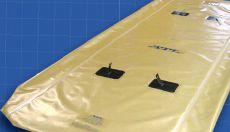


® THE DIFFERENCE... ® ...LImIT DowNTImE; CHoosE CoNsERVAToRBLADDERs TRANsFoRmER AIR-CELL 800-526-5330 +1-201-825-1400 www.atlinc.com ABB Inc. - G.E. / Alstom Grid - Atlantic Transformer CG Power USA - Calpine - Duke Energy - First Energy Gexpro - Jacksonville Electric Authority - NASS - PSE&G Siemens - SPX Transformer Solutions &ManyMore! BLADDER DEsIGN GUIDE AVAILABLE oN oUR wEBsITE ULTRA-sTRoNG “oVER-LAP” sTYLE sEAms MADE IN THE U.S.A. FOR OVER 45 YEARS! sTANDARD
LIBRARY oF PoPULARsIzEs/sTYLEs!
TEmPLATEs DIGITAL
REVERsE ENGINEERING
CAN
ExPEDITED
PRECIsELY DUPLICATE ANY BLADDER sTANDARD & CUsTom HARDwARE mETALLICFLANGEs,HANGERLooPs & moRE!
DELIVERY
CUsTomERs INCLUDE: ® s! LADDER ARE ENGINEERING SERVICES • TECHNICAL SERVICES • COMMISSIONING
(310) 816-3130 www.tdeinc.com 131 W F Street Wilmington, CA 90744 Los Angeles Area | | CA LICENSE #315448
Demaria Fami
QUALITY SERVICE! Safety / Technical / Custom Training Available MANY COURSES ARE ELIGIBLE TO EARN NETA CONTINUING TECHNICAL DEVELOPMENT CREDITS (CTDC’S) “Safety is 99.9% common sense...” Anthony F. Demaria Sr. “...when you are qualified.” Anthony F. Demaria Jr.
Protection Systems Design, Electro-Mechanical & Microprocessor Relay Testing NCSCB Certified Cable Splicing, Cable Testing & Analysis using VLF, VLF-TAN Delta, and Partial Discharge Motor, Generator & Transformer Maintenance, Life Extension, Testing, Oil Handling & Leak Repairs Power Systems Repairs & Troubleshooting and Power Quality Audits
CELEBRATINGOVER
y


228 Merrick Road Lynbrook, NY 11563 (631) 589-6343/Fax (516) 596-3680 601 Union Street Brooklyn, NY 11215 (718) 786-4900 PowerSystemsTesting.1-2_NETA.WI15.indd 1 10/21/15 9:16 AM


Finding more ways to serve you 3.0


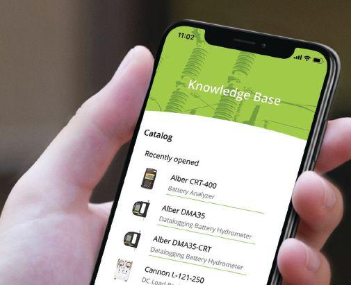
Sometimes it’s not only about the equipment you’re using on the job but the information you need to support the equipment and the job. my intellirent is a free app. You can view or save manuals on your phone, search the equipment catalog, have access to the knowledge base and even request rental pricing or support. It’s powered by intellirent so you can track what equipment you have on rent or your rental history.
my intellirent 3.0 new features:
Enhanced order history with shipment notifications
Calibration sheets on your rentals with the ability to share/email/print
Shipped accessories list with each unit
Identify Me allows scanning of equipment for quick reference of the intellirent asset tag for links to history, manuals and calibration information
Now with dark mode
Powered by ■ ■ ■ ■ ■


USING COMMUNICATIONS TO MONITOR POWER DISTRIBUTION SYSTEMS
BY RYAN M c CLARNON, Utility Relay Company
An increasing number of facilities are exploring and appreciating the communications capabilities of electrical power equipment. Modern electrical system protection and metering devices measure and calculate a signi cant amount of digital data, and most of this data can be retrieved via communications. Due to the availability of these devices and data, systems can monitor multiple devices in a system-wide manner from a central and/or remote location. For the purpose of this article, these systems are referred to as power monitoring systems. Power monitoring systems are becoming easier to establish, including integration into existing equipment not originally equipped with communications.
is article provides a basic overview of power monitoring systems and outline one example solution. e reference point is a basic monitoring
system for a low-voltage (e.g., 480V) system. However, many of the concepts and principles are applicable regardless of system voltage.
34 • WINTER 2019 USING COMMUNICATIONS TO MONITOR POWER DISTRIBUTION SYSTEMS
COVER STORY

POWER MONITORING SYSTEM BASICS

A power monitoring system usually o ers one or more of the following features:
• Monitor multiple devices or entire systems from one location
• Monitor metered or calculated data (e.g., current, voltage, power, energy)
• Monitor events and alarms
• View system con guration or status
• Control system devices, con gurations, and equipment
Power and Energy Monitoring
Power monitoring systems often provide power and energy information, hence the name. is information can be used to monitor and analyze use, e ciency, historical trends, peak usage, energy/cost allocation, cost control, performance, etc. For example, a facility may have a utility billing structure that incentivizes maintaining power factor above or peak demand below certain thresholds. ese metrics can be monitored, and in some scenarios, the system could even provide alarms or noti cations to pre-warn that values are approaching the threshold.
Overall System Monitoring
A typical power monitoring system can centrally monitor many devices or the entire system from one location. is allows systemwide monitoring of the following:
• Events and Alarms. Remotely monitoring multiple devices or an entire system from one location often translates to faster response time.
• Electrical Service Reliability and Continuity (Uptime). Operations sta can view information such as breaker positions and system voltages in a single snapshot and assess overall status. Figure 1 shows low-voltage circuit breaker data

displayed in a power monitoring system human machine interface (HMI). In this example, current, voltage, power, energy, and breaker position (red = closed) information are all based on communications data obtained from the low-voltage circuit breaker trip unit. e HMI also displays breaker and load identi cation.

Figure 1: Low-Voltage Circuit Breaker Data in a Power Monitoring System HMI
• Power Quality. Power factor and system voltages can be monitored. Advanced systems can also monitor items such as harmonics.
• Verification of Protective Device Settings. Equipment, devices, and settings can be frequently changed and interchanged. Device settings can be veri ed to ensure proper protection and to avoid accidental nuisance trips.
Safety
It is di cult to put a price tag on this simple bene t. Having the capability to monitor and/ or operate devices without exposing personnel to equipment hazards such as shock or arc ash is signi cant.
NETAWORLD • 35 USING COMMUNICATIONS TO MONITOR POWER DISTRIBUTION SYSTEMS
COVER STORY

Asset Management and Maintenance

Power distribution equipment communications can offer valuable information about the equipment itself and/or the load or process equipment that it feeds. is information can be used to track asset performance, loading, operating conditions, predictive maintenance, etc.
Control
Some equipment can be controlled or operated via communications. At a basic level, this capability o ers safety and operational bene ts. Some more advanced systems utilize this for control schemes or protection schemes.
Troubleshoot and Diagnose
Valuable information such as protection target information, date/time, currents, voltages, and waveforms can play a key role in root-cause analysis of power system events and disturbances. Figure 2 shows current waveforms displayed on a remote HMI using communications data from a low-voltage circuit breaker trip unit. is example shows two waveform captures. e top waveform capture shows three-phase currents from a breaker in which the Phase B (red waveform) current transformer wires were discovered to be mistakenly reversed during installation. e

reversed wires would result in incorrect ground fault current calculations — and a possible trip depending on settings and phase current magnitude — and incorrect power calculations. e bottom waveform capture shows the same breaker after the Phase B current transformer wiring mistake was corrected.
WHAT IS A COMMUNICATION PROTOCOL?
A communication protocol is a system of rules that allow two or more devices to transmit and receive information with each other. Modern-day low-voltage circuit breaker trip units commonly utilize the MODBUS communications protocol, which has become an industry standard protocol for connecting industrial electronic devices.
Legacy Protocols
When considering existing systems, it is important to understand that multiple communications protocols cannot successfully coexist on the same local RS-485 network. Legacy OEM trip unit proprietary protocols include Commnet and INCOM. ese trip units typically cannot be placed on the same local RS-485 network as MODBUS RTU devices. However, converters are available in some applications.

Figure 2: Waveforms on a Remote HMI Using Communications Data from a 480V Trip Unit
36 • WINTER 2019
USING COMMUNICATIONS TO MONITOR POWER DISTRIBUTION SYSTEMS COVER STORY

HOW DOES IT WORK?
A power monitoring system is made up of master equipment, devices, software and drivers, monitoring devices, and network equipment. The following explanation generally applies to most communication systems, but includes some references to RS-485 modbus serial communications, since it is common in low-voltage switchgear communications.

2. A gateway including pre-loaded software and drivers is directly connected to the devices. The gateway can be accessed by computers over Ethernet to display the system information.

Software, Firmware, Drivers
Typically, master equipment requests and obtains communications data from multiple devices. The data is interpreted and can be displayed on HMIs. Low-voltage circuit breaker trip units typically utilize RS-485 (serial) communications networks (twisted shielded pair, daisy-chained).
Products such as trip units and power meters are the devices, and the network is wired to a master device that interprets the data. Each device must be programmed with a unique address to allow the master to identify each device correctly.
Master equipment must be capable of the same communications protocol (language) as the devices.
Master Equipment
Master equipment collects and/or displays the system information on some form of human machine (HMI) or graphical user interface (GUI). This equipment exists in many forms.
Typical master equipment examples include computers, servers, displays, gateways, etc. More complex and elaborate systems may utilize server equipment, gateways, and computers with customized software. However, some turnkey solutions are available, which are more straightforward to install and set up. Two turnkey solution examples are as follows:
1. An HMI computer including preloaded software and drivers is directly connected to the devices. The same computer is used to display the system information.
Master equipment must have software or firmware and drivers, which allow it to interpret the communications information it receives back from devices such as trip units.
Master equipment must have a driver for each device type it is connected to. This driver allows the master to know how to request and interpret specific data from each particular device type. Unfortunately, each device type organizes the communications data differently. Each device type has a published register map that documents each communication register number and the corresponding name for the data in that register. For example, a trip unit manufactured by Brand XYZ utilizes Register 7042 for current Phase A, whereas a power meter manufactured by Brand ABC utilizes Register 188. In this scenario, the master equipment needs a driver for both of these device types to allow it to properly request current Phase A.
In addition, master equipment often includes software or firmware that allows display of the communications information. This interface is often designed to allow the user or operator to view information from multiple devices, ideally in a meaningful, graphical representation. Some interfaces allow viewing multiple devices simultaneously; others only allow viewing information from one device at a time. Many present-day systems utilize Windows PCs with custom software.
Monitoring Devices
Monitoring devices are typically the equipment that measures and/or calculates the data. In the case of power distribution, these devices are often trip units, power meters, or protective relays.
NETAWORLD • 37
USING COMMUNICATIONS TO MONITOR POWER DISTRIBUTION SYSTEMS COVER STORY

When equipped with communications capabilities, most or all of the metered and calculated data available in the device can be retrieved via communications. In most applications, each device must be configured or programmed with its own unique address, which allows for device identification. This is true for RS-485 MODBUS communications. Each device typically has configuration settings, for example:

to device). Since low-voltage power circuit breakers utilize draw-out construction, RS-485 wires must be routed through a connector that is either automatically or manually connected/ disconnected when the breaker is racked in/ out.

INTEGRATING A POWER MONITORING SYSTEM INTO EXISTING EQUIPMENT
• Baud Rate: Speed
• Parity and Stop Bits: Standard configuration settings to facilitate error detection that must match master equipment settings.
• Reply Delay: Setting to allow devices to process the current request before the master sends a new request
Network Wiring, Cabling, Equipment
Presently, most power monitoring systems utilize wired networks. Low-voltage trip units commonly use RS-485 networks (twistedshielded pair cable daisy-chained from device
Constructing a power monitoring system can be involved and can require specialty staff or communications experts. As devices become more technically advanced, power monitoring systems are also becoming more advanced and complex. However, due to the increased availability of communicating devices, integrating a basic power monitoring system can be simple, and can be accomplished without significant effort or significant additional equipment.
Figure 3 depicts an example of establishing a basic 480V monitoring system using thirdparty retrofit trip units and an industrial HMI computer. The original switchgear and breakers were not equipped with communications

Figure 3: Adding Communications and Monitoring to Existing 480V System
38 • WINTER 2019
USING COMMUNICATIONS TO MONITOR POWER DISTRIBUTION SYSTEMS
COVER STORY

capabilities. Note that this system architecture leverages modern circuit breaker trip units, which can be installed on almost any existing power circuit breaker. This allows the addition of communications to occur in conjunction with breaker maintenance or upgrades. Other than the industrial HMI, no additional dedicated communications products are needed.

• Industrial HMI computer with no moving parts

• Metering, waveforms, graphics
• Pre-installed software and drivers
• Wall-mount in electrical room or control room
Example System-View Screens, Information, and Functionality:
Example System Components and Devices
• Trip units capable of MODBUS communications
• Industrial HMI computer with serial port capable of RS-485 connection
Example System Requirements and Installation Items
• Trip units on low-voltage circuit breakers must have communications capability if voltage, power, and energy features are desired.
• Install RS-485 network (twisted-shielded pair cable, daisy-chained from trip unit to trip unit) in switchgear and on breakers.
• Set each trip unit with a unique address.
• Configure one-line diagram view and HMI settings.
• Install HMI computer in electrical room or control room.
• In this example, software and drivers were included and pre-installed in the manufacturer’s turnkey product. In some scenarios, PC equipment, software selection, and installation may be separate.
Example System Features and Capabilities
• Field-configurable electronic one-line diagram
• Designed specifically to communicate with low-voltage trip units
• System overview of information from multiple devices at a time
• Breaker positions
• Metered values
• Alarms and status
Example Breaker-View Screens, Information, and Actions:
• View waveforms
• View breaker trip history including waveforms
• View breaker settings
• View real-time breaker readings
• View time-current curves
• Execute remote breaker trip (requires enabled security code and local permissive setting)
• View breaker test data
• Acknowledge and reset alarms
ADVANCED FEATURES AND POSSIBILITIES
In addition to the features discussed in this article, power distribution communications systems can off er many advanced features. Some examples are listed below:
• Protection Schemes. High-speed communications between devices allows for many possibilities, including simple and complex protection schemes.
NETAWORLD • 39 USING COMMUNICATIONS TO MONITOR POWER DISTRIBUTION SYSTEMS
COVER STORY

• Smart Predictive Maintenance. With the increase in available data, additional analysis is possible. For some equipment and systems, even a slight increase in electrical loading or energy consumption can be used to identify whether service or maintenance is necessary.


• Wireless. Wireless communications is becoming a more practical and acceptable option. Improvements in capabilities, reliability, and security will continue to make wireless communications an increasingly attractive method.
TESTING AND TROUBLESHOOTING
Although testing and troubleshooting is not the focus of this article, additional information and terminology is provided for reference.
• Confirm Network Wiring Integrity. This can be as simple as verifying continuity throughout an RS-485 network (twisted shielded pair).
• Confirm Device and Master Settings. Ensure configuration settings (baud rate, parity, addresses, etc.) are correct.
• Device Unit Test. Performing a simple is-it-communicating test on individual devices is often a good place to start when troubleshooting a suspected device failure.
• Network or System Tests. If the final HMI master equipment is not available, a basic software tool could be used to communicate with individual network devices one at a time over the network connection.
• Device Manufacturer Tools. Some manufacturers offer a simple test device or a simple software tool to allow testing a single unit.
• Software Tools. Several companies offer software to execute simple communications actions such as requesting MODBUS register data.
• Confirm Network Termination Circuitry Recommendations. Many manufacturers of serial communications devices require or recommend some sort of termination circuitry at the end of the line to prevent reflections. Some devices include internal circuitry that can be switched in or out with dip switches, jumpers, or software settings. Others require externally wired termination components. Others do not recommend and sometimes prohibit external termination circuitry. The bottom line is to consult device manufacturers for recommendations or requirements related to termination circuitry.
• Protocol Analyzers. These tools are available as hardware and/or software tools that capture and analyze communications data. They are typically used as an advanced troubleshooting tool.
• ANSI/NETA ECS-2015. ANSI/NETA ECS-2015, Standard for Electrical Commissioning Specifications for Electrical Power Equipment and Systems identifies general communications requirements in the Inspection and Commissioning/ Testing Procedures sections.
SUMMARY
Installing a power monitoring system offers many benefits. Establishing these systems often requires special equipment and specialty staff. However, due to the increasing availability of communicating devices and equipment, incorporating a power monitoring system might not be as challenging or expensive as you think.

Ryan McClarnon is Engineering Manager at Utility Relay Company, a manufacturer of digital trip units and conversion kits for power circuit breakers, located in Chagrin Falls, Ohio. He is an IEEE member and a Registered Professional Engineer. Ryan has been in the power distribution/systems field for over 17 years, participates in IEEE standards, and represents URC in NETA and PEARL technical activities. He received a BSEE from Cleveland State University.
40 • WINTER 2019 USING COMMUNICATIONS TO MONITOR POWER DISTRIBUTION SYSTEMS
COVER STORY
Arc Flash Reduction and Remote Display


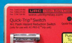


Arc Flash Mitigation & Remote Display available for AC-PRO ® and AC-PRO-II ®

• Manually Controlled Arc Flash Reduction System
• Pad-Lockable QUICK-TRIP® Switch
• Remote (Door) Display for AC-PRO-II® * or AC-PRO®
• Display Voltage, Power, and Energy Information When Connected to AC-PRO-II® with VDM

(*via interface module) UTILITYRELAY.COM | +1.888.289.2864 | URCSALES@UTILITYRELAY.COM
Transformer Turns Ratio Meter
Model PATTR-01D
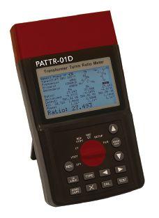
Measurements of 1-Phase and 3-Phase
Transformer/VT/CT Turns Ratio
• VT/PT ratio 0.8-10000, CT ratio 0.8-2000
• High accuracy
• Bluetooth PC communication for CSV file extraction and remote operation
• Stores up to 4096 files internally
• Single Phase and 3 Phase operation at the push of a button
• 10 test frequencies (50-400 Hz)
• Displays Turns Ratio, Deviation, Secondary Output, Excitation Voltage and Current and Phase Angle
• Choose from 9 types of 3 Phase winding connections

Contact & Winding Resistance Micro-Ohm Meter MR
Model MRM-10P
• Manual or Auto Range
• Measurement of resistive and inductive
• Programmable Hi-Lo alarm with memory
• Readings Hold function
• Communication with PC
Voltage - High Current - High Power Test Systems and Components


1-301-746-8118 • www.PhenixTech.com 40+ Years Experience info@phenixtech.com • 75 Speicher Drive, Accident, MD 21520 USA Small, Handheld, Portable Transformer Turns Ratio and Micro- Ohm Meters
TECHNOLOGIES PHENIX R
High
NEW!
Absolute con dence. Every time.
You can count on us for specialized experience in healthcare, data center, o ce complex, and commercial acceptance and maintenance testing. Absolutely Power generation, petrochemical, oil & gas, and heavy industries also look to us for high demand services such as start-up commissioning, maintenance testing, shut-down and turnarounds, and breaker shop repair. Get started today.


Toll Free 1+ (855)767-4446 8100 West Little York | Houston, Texas 77040 Email: Alan Postiglione | apost@absolutetesting.com | www.absolutetesting.com Like us on:
END-TO-END TESTING FOR LINE DIFFERENTIAL PROTECTION
 BY SUGHOSH KUBER, Megger
Line differential protection is one of the most popular applications used for transmission line protection. Line differential protection works on the theory of Kirchhoff’s current law, where the magnitude of the current flowing into the line should be equal to the current flowing out of the line. For line differential protection, the zone of protection is defined by the location of current transformers (CTs) monitoring the currents on either end of the transmission line. It is crucial for the protective relays on both ends of the line to communicate with each other when a fault condition is established and issue a trip signal for the in-zone fault.
44 • WINTER 2019 END-TO-END TESTING FOR LINE DIFFERENTIAL PROTECTION
FEATURE
In Figure 1, a single-line diagram shows the set-up of line current differential relays (87L) installed on either end of the transmission line. The relays monitor current from the CTs they are connected to on the either end of the transmission line. These relays, which are referred to as local relay and remote relay, are connected to each other by means of optical fiber cables for the purpose of communication. When a fault occurs on the line, the relays see the fault at the same time. Based on the information received from the other end, the relays decide what needs to be done: trip or restrain.

Relay manufacturers use different methods to measure and compare currents in differential protection relays, including magnitude comparison, phasor comparison, phase comparison, charge comparison, or various combinations of these options. One popular method is to use the alpha plane characteristic to determine line differential condition. This article discusses line differential protection, the importance of end-to-end testing, and the procedure to test alpha plane characteristics using an end-to-end test method. Specifically, the 87L element is discussed with respect to pick-up accuracy, time of operation, dependability by simulating internal faults, and security by simulating external faults.
UNDERSTANDING ALPHA PLANE CHARACTERISTICS
The ratio of phase currents (or sequence currents) entering or leaving a transmission line is geometrically represented on a complex plane, which constitutes the alpha plane characteristics. Currents considered for the ratio calculation can be either monitored values of phase currents at remote and local relays or derived currents from calculations involving equations that use real and imaginary parts of differential and restrain currents obtained from monitored phase currents. Usage of these algorithms varies by relay models. In Figure 2, k represents the ratio of the currents.
NETAWORLD • 45 END-TO-END TESTING FOR LINE DIFFERENTIAL PROTECTION
FEATURE
Figure 1: Line Differential Protection Implementation
PHOTO: © ISTOCKPHOTO.COM/PORTFOLIO/MYCTERIA

SIGNIFICANCE OF END-TO-END TESTING
The area of stability and trip can be determined by the characteristic parameters due to which any percentage differential characteristics can be mapped onto the alpha plane. The restrain region is defined by parameters such as the radius of the greater arc (R), radius of the inner arc (1/R), and the angle (α). The radius of the greater arc and inner arc determines the radius of the restrain region (stability area), and the angle (α) represents the angular extent of the restrain region. Each phase has its own alpha plane characteristics. In the example, if the A phase current monitored by the local relay is 3∠0°, then the remote relay will record 3∠180°. The ratio of the remote current to local current would be:

On the alpha plane, this ratio will plot on the real axis to the left of the imaginary axis. As could be seen in Figure 2, this falls in the restrain region, which is also the stability area. This case can be related to nominal load condition or an external fault depending on the current levels. In the case of an internal fault, the currents read by both the relays for their respective phases tend to be in phase with each other as they monitor the currents feeding the internal fault. This will plot the resultant of the ratio to be 0°, which falls in the trip region of the alpha plane characteristics shown above.
End-to-end testing is the evaluation of a relay protection scheme by simulating fault conditions simultaneously at each end of the transmission line. The ability to synchronize the test systems on each end is paramount. This means that test quantities should be injected to all the relay terminals simultaneously. Line differential relays receive a set of currents from their own terminals and data of currents from the remote relay by means of various communication modes. Since the relays send time-stamped information packets to each other, even a slight slip-up of the time during injection can incorrectly stamp the packets reaching the local and remote relays, which can cause incorrect or unintended operation. Hence, a time signal from a global positioning system (GPS) clock is used to synchronize multiple test systems. Time signals are available in various standards such as IRIG-B, pulse per second (1 PPS), precision time protocol (PTP), etc. In this article, the IRIG-B time sync standard is considered for testing.
The end-to-end testing method requires multiple relay test equipment with the ability to decode the IRIG-B signal to trigger injection of analog signals simultaneously (Figure 3). The IRIG-B signal that is obtained by a GPS receiver via antenna is also provided to the relays under test. This kind of testing is used to evaluate a new protection scheme during commissioning of a substation, troubleshoot malfunction of relays, verify the relay setting changes, and other functions. Equipment (hardware/software/accessories) required to perform an end-to-end test includes:
• Two sets of relay test equipment with ability to decode IRIG-B signal and generate currents with magnitude and phase angle as specified in the test plan
• GPS receivers
• Co-axial cables (to connect GPS receiver and relay test sets and relays)
• Two computers (to drive the relay test sets at respective substations)
46 • WINTER 2019
END-TO-END TESTING FOR LINE DIFFERENTIAL PROTECTION FEATURE
Figure 2: Alpha Plane Characteristics
• Communication medium between the test technicians, i.e., cell phones or other voice communication equipment
• Test software with pre-built test plans to simulate faults in the protected zone and out of the zone (through faults) for singlephase, phase-to-phase, and three-phase faults, as well as positive-, negative-, and zero-sequence currents.
When implemented correctly, communicationbased protection schemes result in efficient and reliable protection of transmission lines as compared to numerous relays that cannot communicate with each other. It is simpler to test individual relays in a scheme; however, it’s more effective to test an entire scheme as a whole, which validates not only the components, but also the communication aspect of the scheme. Issues that occur with communication-based schemes can be detected by end-to-end testing.
TEST PROCEDURE
A test set-up can be arranged to simulate a system similar to the one shown in Figure 3. IRIG-B signals must be provided to the appropriate inputs of the relay test equipment as well as the relays under test. Necessary test connections to inject analog signals to the relays must be made on both ends. Spare output contacts on both the relays should be programmed for the 87L element. A phase differential pick-up test, radius check tests, angular extent boundary tests, and timing test for an internal fault are performed. In this article, the algorithm in the relay used for testing considers derived currents from calculations involving equations that use real and imaginary parts of differential and restrain currents obtained from monitored phase currents.
Relay Settings
• Phase differential element pick-up — 0.72 pu
• Phase differential element radius (R) — 6
• Phase differential element block angle (α) — 195°

Phase Differential Pick-Up Test
The phase differential pick-up test validates the 87L logic and pick-up setting when the injected current is above the pick-up setting. This test can be performed on each phase at each end separately and does not need time synchronization. Based on the relay setting of 0.72 pu and the nominal current of 5A, the calculated pick-up value in amps is 3.6A. Therefore, the 87L element should pick up at 3.6A.
Radius Check Test
The radius check test is performed to validate the boundary of the restrain region in the alpha plane with respect to the radius from origin. Initially, the test should be conducted to verify the radius setting pick-up of inner arc of the restrain region. The distance from the origin to the inner arc of the restrain region is defined by 1/R as was depicted in Figure 2. Based on the relay settings, 1/R = 1/6 = 0.16. Once the test sets are synched during pre-fault, the test values should be varied during the fault state. The end test value at which the 87L element trips should be 0.80∠0° amps. This result value translates to 0.16 pu distance from the origin to the inner arc.
NETAWORLD • 47
END-TO-END TESTING FOR LINE DIFFERENTIAL PROTECTION FEATURE
Figure 3: End-to-End Testing: The Whole Picture
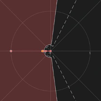
In Figure 4, the alpha plane characteristic shows changes in complex ratio plot based on the varied test value of currents to validate the 1/R setting. Table 1 lists the phase A currents to be injected to local and remote relays during pre-fault and fault states. Based on the currents injected to relays, the relays perform mathematical calculations using differential and restrained equations to calculate derived currents, and the ratio of those derived currents are plotted on alpha plane to define the 87L element operation.
Table 1: Inner Arc Radius Test
After validating the 1/R setting, the next test will verify the radius setting of the outer arc of the restrain region. This radius setting was depicted in Figure 2 as R. To test the R setting, same pre-fault values should be injected as before. However, the fault state currents on the local relay should be varied up to 30 amps, which translates to 6 pu. This is the radius of the restrain region. As soon as the current is increased more than 30A, the complex ratio on alpha plane crosses the restrain region and trips the relay. The test procedure described above is for A phase. The same procedure can be followed to perform tests for B and C phases.
Table 2: Outer Arc Radius Test
Angular Extent Boundary Check Test
This test is performed to validate the angular extent of the restrain region on the alpha plane. The angular extent setting α was depicted in Figure 2. The α setting of the relay is 195°. Therefore, a pre-fault current injection with phase angles ∠0° on local relay and ∠ 180° on remote relay should be done. In the fault state, the angle of the analog currents to the local relay should be varied up in the counterclockwise direction. The relay should trip for a 98° phase angle value.
Table 3: Angular Extent Boundary Check Test 1
Pre-FaultFault
In Figure 5, the alpha plane characteristics show changes in complex ratio plot based on the phase angle variation to validate the angular extent of restrain region. Similarly, the next test should be performed to validate the

5:
48 • WINTER 2019
Pre-FaultFault Local Relay 1∠0°0.80∠0° Remote Relay 5∠180°5∠180°
END-TO-END TESTING FOR LINE DIFFERENTIAL PROTECTION
Pre-FaultFault Local Relay 1∠0°30∠0° Remote Relay 5∠180°5∠180°
Relay 5∠0°5∠98° Remote Relay 5∠180°5∠180°
Local
FEATURE
Figure 4: Alpha Plane Characteristic Plot — Inner Arc Radius Test
Figure
Alpha Plane Characteristic Plot — Angular Extent Boundary Check Test
angular extent in the opposite direction from origin. The phase angle in fault state should be varied in clockwise direction for the local relay. The relays should trip at a value of –98°. The difference of angular extents between the first and second test is 98° – (–98°) = 196°. This result translates close to the angular extent setting of the relay (195°). The test procedure described above is for A phase. Th e same procedure can be followed to perform tests for B and C phases.

Local Relay 5∠0°5∠ – 98° Remote Relay 5∠180°5∠180°
Timing Test for Internal Fault
An internal fault can be simulated to perform the timing test of the 87L element. Pre-fault and fault states should be set up with the values shown in the test table below. Ideally, the local relay and remote relays should trip close to a cycle as soon as the relays see an internal fault. In Figure 6, the alpha plane characteristic shows the path of complex ratio plot transitioning from restrain region to operate region based on current injection switch from pre-fault to fault state.
A similar set-up of pre-fault and fault states can be set up to simulate external fault currents. Th e relays should restrain from tripping, as the complex ratio of currents plots on to the restrain region on the alpha plane.
Relays may also have settings enabled for 87L negative sequence and 87L zero sequence elements to provide protection for
Table 5: Timing Test — Internal Fault
Figure 6: Alpha Plane Characteristic Plot — Internal Fault Timing Test
single line to ground faults and unbalanced fault conditions. The tests discussed for phase element in this article should also be performed to validate negative sequence and zero sequence elements.
CONCLUSION
Line differential protection has been implemented all over the world by the vast majority of utilities. It is signifi cant to validate the protection scheme for its accurate operation for faults. End-to-end testing validates the entire communication-based protection scheme including the operation of the relays as well as the communication between the relays. Knowledge of endto-end test methods and fi eld experience helps technicians perform the testing more effi ciently. Th is article provides insight on testing line diff erential protection using the end-to-end test method and its importance, as
NETAWORLD • 49 END-TO-END TESTING FOR LINE DIFFERENTIAL PROTECTION
Pre-FaultFault
Table 4: Angular Extent Boundary Check Test 2
FEATURE
Pre-Fault Fault Local RelayRemote RelayLocal RelayRemote Relay Phase A 1∠0° 1∠180° 5∠0° 5∠0° Phase B 1∠ – 120° 1∠60° 5∠ – 120° 5∠ – 120° Phase C 1∠120° 1∠ – 60° 5∠120° 5∠120°
well as testing of alpha plane characteristics to validate the line differential element through the pick-up test, radius check test, and angular extent check test.
REFERENCES
James Ariza, G Ibarra. “Application Case of the End-to-End Relay Testing using GPS-Synchronized Secondary Injection in Communication Based Protection Schemes.” Available at: http://www.netaworld. org/sites/default/files/public/neta-journals/ NWwtr06Megger.pdf.
Schweitzer Engineering Laboratories. “SEL 411L Advanced Line Differential Protection, Automation, and Control System instruction Manual,” May 10, 2019. Available at www.selinc.com.
G. Benmouyal. “The Trajectories of Line Current Differential Faults in the Alpha Plane.” Line Current Differential Protection: A Collection of Technical Papers Representing Modern Solutions, 2014
Chris Werstiuk. “End-to-End Testing,” Valence Electrical Training Services, 2010.
Abel Gonzalez. “Advanced End-toEnd Testing Webinar.” Available at https://register.gotowebinar.com/ recording/3052100615461400833

Sughosh Kuber is a Relay and Protection Applications Engineer at Megger North America, where he provides technical support to service companies and utilities responsible for reliable operation of electrical networks. Sughosh brings over 9 years of field experience and academic research in power systems from protection schemes and testing to data analysis for energy efficiency and sustainability. Sughosh received his MS in electrical engineering from New Mexico State University.

FEATURE


When equipment fails, every minute spent searching for what you need is bad for the bottom line. With a constantly updated inventory of new, surplus and repurposed electrical equipment, you can get what you need 24/7. Use our easy checkout process, or if you need help our experts are standing by. Visit nationalswitchgear.com or call us today at (800) 322-0149.





Where Technology and Innovation Meet
Enhance Your Professional Development
Presented by
TO WAIT FOR ELECTRICAL EQUIPMENT? performance
design
CAN’T AFFORD
by
sm
2 020 FEB 18-20 Orlando, Florida HYATT REGENCY GRAND CYPRESS RESORT SCHEDULE MONDAY • February 17 5:30-7pm Badges & Beer Regi-ception TUESDAY • February 18 8-8:30 am Keynote Address 8:30-Noon General Session & Panel 12:30-5:30 pm Golf Noon-1 pm Lunch Noon-5 pm Two User Groups 1-4 pm Facility Tour 5:30-8:30 pm Welcome Reception WEDNESDAY
February 19 8 am-3 pm General Session 3:15-5:30 pm Training Tracks Noon-1:30 pm Lunch/EXPO 5:30-7 pm EXPO & Reception 7-9:30 pm Gala Dinner THURSDAY • February 20 8-10 am General Session 10 am -12:30 pm Training Tracks 12:30-2 pm Lunch/EXPO 2-3 pm Interactive Roundtables & Beer Tasting Join us for the next generation of Power Discussions! Expert White Papers, Panelists and Training Tracks! Register to attend at www.TechCon.info
•
utility industry professionals, corporate suppliers and decision-makers ready to network
share their expertise and experience. Gain knowledge about the latest industry technology developments
successes.
Attend TechCon® and learn from
and
and
generation, transmission
distribution executives and personnel; electrical engineers; maintenance and asset managers; consultants; service providers; manufacturers; insurance companies; utility maintenance specialists and technician and substation superintendents.
Who should attend:
and
SEE YOUIN ORLANDO!
FIBER OPTIC NETWORK OPERATION, MAINTENANCE, AND RESTORATION

© ISTOCKPHOTO.COM/PORTFOLIO/SHULZ
BY JIM HAYES, Fiber Optic Association
All networks are susceptible to problems that affect communications. One consequence of a fiber optic system’s high bandwidth, long distance capability, and security is the extreme dependence of users on the non-stop operation of these systems. Because they can transmit large amounts of data long distances with immunity from signal degradation and extremely high reliability, these systems usually carry the most critical data.
52 • WINTER 2019 FIBER OPTIC NETWORK OPERATION, MAINTENANCE, AND RESTORATION
FEATURE
PHOTO:


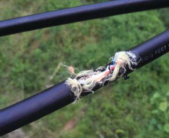


Fortunately, fiber optic cable plants are very reliable and need no routine maintenance. We tell network owners that once the network is installed and tested, lock it up and keep all unauthorized personnel away from it.
Network operation does not require periodic testing because most equipment has builtin self-testing that monitors link errors and informs you of problems before they become serious. If your cable plant has spare fibers — it
should — they can be used to periodically test the cable plant without disturbing the network.
WHAT GOES WRONG?
It’s a fact of life: When fiber optic systems fail, it’s mostly due to accidental damage. I remember telling a group of network managers that in the fiber optic industry, we say the most common cause of failure is backhoe fade. A member of the group replied, “I’m from
NETAWORLD • 53 FIBER OPTIC NETWORK OPERATION, MAINTENANCE, AND RESTORATION
FEATURE
Damage from Gunshots
Damage from Gunshots Squirrel Attack
Damage from a Backhoe
SOURCE: MISSISSAUGA TRAINING (AUGER, BACKHOE); CITY OF ALBANY, GEORGIA (GUNSHOTS, SQUIRREL); ISTOCK (BACKGROUND)
Damage from an Auger


Bonneville Power, and our most common problem is target practice.” There are, in fact, many potential problems.


• Underground cable damage from construction dig-ups or directional boring

• Flooding during storms or ice in winter in manholes, hand-holes, or poorly sealed splice closures
• Aerial cable damage from vehicle accidents, shootings, animals, ice or storms, and vandalism
• Cutting the wrong cable when removing older cables indoors or out
• Breaking patchcords or connectors during moves, adds, or changes
• Getting connectors dirty or not cleaning dirty connectors properly before use
• Misconnections or polarity mismatches when connecting transmitters
• Breaking fibers in splice trays or kinking cable tubes in splice closures when building or upgrading networks
Sadly, there are even instances where disgruntled company employees sabotage links. Even personnel taking visitors on tours have unplugged a connector on an operating link.
Most of these problems affect outside plant cables, but premises cables are still susceptible to damage. With the current push by landlords to remove abandoned cables to comply with the NEC, the likelihood of damage is much higher as workers cut out the old cables.
DESIGN FOR RELIABILITY, PREPARE FOR RESTORATION
We always tell network owners and operators that preparing for restoration starts at the design phase of the project. Communications system reliability depends on a design that has lots of margin, spare fibers in the cable plant, and diverse routing for traffic in case something does happen on a link.


Moving cables in a typical patch panel without damage can be a challenge.
Telecommunications companies usually build route diversity into their network so a problem on one route will allow simply switching to another. Many systems also run backup links on spare fibers ready to switch over if one link fails. Critical systems in utility substations or control rooms should also have redundant connections on diverse routes to ensure connectivity in case of accidental damage. In 1975, the Browns Ferry Nuclear Plant nearly melted down because there was a fire in a conduit that held all three cables designed to provide redundancy.
Of course, communications equipment requires an electric power supply. AC power should be properly conditioned and backup power provided. Backups often have two stages: a) battery backup to make sure the equipment continues running during brief power outages and b) generator power for outages longer than the batteries can last.


54 • WINTER 2019
FIBER OPTIC NETWORK OPERATION, MAINTENANCE, AND RESTORATION FEATURE
SOURCE: JIM HAYES, FOA


When designing a network, plan to order extra components that can be kept after installation is complete to be used when repair is needed. Nothing can be more frustrating than having to wait for components necessary for repairs. When building a network, order extra cables and hardware for installation as insurance.


Leftover components should be stored in a box along with a restoration plan that includes documentation such as cable route diagrams, test results — especially OTDR traces — and any other information that could help locate and fix a problem in the cable plant.
For underground networks, it’s important to provide above-ground markers to indicate the route of the cable plant. The design should also include burying marker tape that can be found with cable-location equipment about a foot underground above the cable. That provides two layers of protection.
Restoration planning should be part of the design. If it was not done originally, now is the time to do it before something happens.
NETWORK FAILURE
If something happens to your network, it’s important to not panic. Quickly fi nd the problem and mobilize the personnel to fix it. Start with some quick checks.
Do not jump to the conclusion that the problem is the cable plant. First, determine that the communications equipment on both ends of the link work properly. Start with a simple check of system power. Some equipment will tell you the problem is with the equipment or the cable plant by something as simple as a green light on the receiver if it’s got power and a connection. If multiple links operate over the same cable plant, diagnosis is easier. If only one link is down, it’s likely the electronics. If all links are down, it’s likely the cable plant.
If the electronics are the problem or are suspected, swap modules for spares. If that


A cleaning kit will quickly remove dirt and contamination, and a video microscope can inspect connectors for dirt or damage.
solves the problem, make sure to send that bad module out for repair ASAP.
If it’s not the electronics, start looking at the cable plant, beginning with the patchcords. They can be tested with an inexpensive visual fault locator (VFL) to confirm they have not been broken or connected wrong. A connector inspection microscope and cleaning kit are a good investment too, since the majority of fiber optic problems are due to dirty connectors. That’s another reason not to let unqualified personnel touch the fibers.
Diagnosing cable problems is a matter of shooting several spare fibers in the cable with an optical time-domain reflectometer (OTDR) and analyzing the traces. Is the cable the expected length? If it’s shorter or it has a high loss event at an unexpected point, it may indicate a damaged cable. Don’t trust the results of just one fiber. Test a few and see what they all look like. If they are all the same, you may have a cable break. If only some fibers show the problem, you may have cable damage in only a few fibers, indicating a problem with a kinked but not totally broken cable or problems at a splice point.
Remember, the OTDR is not 100% accurate. It measures fiber length, not cable length, and


NETAWORLD • 55
FIBER OPTIC NETWORK OPERATION, MAINTENANCE, AND RESTORATION FEATURE
SOURCE: JIM HAYES, FOA


the cable length is approximately 1–2% shorter. Compare the length on the OTDR with data from installation testing and correlate with splice points to reduce location uncertainty. Alternatively, shoot from both ends to locate a break and average distances.


Make certain you are testing the correct cable. Using OTDR testing, one crew thought they had a break in a 6 km underground cable at 4 km. But physical inspection, including digging at the location indicated by the OTDR, showed no problem. In fact, they were testing the wrong cable. They were testing a cable 4km long running in the opposite direction from the patch panel, not the cable they thought they were testing. Their patch panel marking and documentation didn’t match.
This is where documentation helps. Having information on the length of the cable and the location of splice points — especially geographic information system (GIS) data — makes pinpointing problems easier. Comparing traces of problem fibers allows correlation of the problem location to the location of a splice closure or a service loop in a vault.
Splice closures can be the problem. Fibers can get cracked or broken in splice trays, yet not fail for a long time, perhaps after seasons of temperature changes. Splice closures can be improperly sealed, and moisture — or ice in winter — will cause damage. There are even tales of animals such as squirrels or woodpeckers attacking splice closures or cables and causing damage.
Finding a fiber break in a splice tray can be difficult. If you are close enough to use a visual fault locator (VFL), it will pinpoint the break. If the distance to the nearest fiber end is more than 4-5km, a gadget called a fiber identifier may be used.
Sometimes a visual inspection of a cable route will find the cause of the break faster than testing fibers. One tech remembers that a construction team was installing road signs
56 • WINTER 2019 FIBER OPTIC NETWORK OPERATION, MAINTENANCE, AND RESTORATION
FEATURE
An OTDR with long launch and receive cables will help diagnose problems in the cable plant.
SOURCE: JIM HAYES, FOA
A visual fault locator (VLF) is extremely useful at finding breaks in splice trays, couplers, etc.
SOURCE:
ALAN KOJIMA





Restoration can be in a muddy field along a rural road or in the middle of a busy street in downtown Los Angeles.
nearby when their network went down, so he hopped in his truck and drove to the job site. There he found the construction crew stuffing the broken fiber optic cable back into the hole they had dug with an auger.
Another network went down when a helicopter flew into an optical power ground wire (OPGW) on a tower. That one was easy to find, but hard to fix, but one of our FOA instructors spliced it from a precarious perch in a bucket truck.
And always remember to ask around the offices to see if someone has been working on the network.
REPAIR STRATEGY
Okay, there is a break. How do you fix it? You should have a restoration plan and a restoration kit complete with up-to-date documentation, a list of test and repair equipment — including where to find them — and components set aside for repair. A contact list of knowledgeable people on staff or a contractor on call is also necessary.
Many companies use contractors to install fiber optic cabling because they do not have qualified employees to do the work, or at least not enough with the experience and equipment to do the job. Lacking staff capable of diagnosing problems and making temporary repairs can be problematic, since even a contractor on call 24/7 will take time to respond.
It’s much better to have several employees trained in basic fiber optics who can maintain the network and do basic repairs. For the cost of a few minutes of downtime on a typical communications link, send a couple of techs to an FOA-approved training course and equip them with a basic OTDR, an inexpensive portable fusion splicer, and some basic tools that will allow them to at least patch up the network and get it running before the final repairs are completed.
Everyone knows techs need training, but FOA also recommends that a couple of supervisors attend a training course in person or online. Our experience is that managers who understand basic fiber optics are better equipped to oversee construction, operation, and restoration.
NETAWORLD • 57
FIBER OPTIC NETWORK OPERATION, MAINTENANCE, AND RESTORATION FEATURE
SOURCE: JIM HAYES, FOA


Once the trouble spot has been located, you will want to get the network back up as fast as possible. If it’s a break, you probably will not be able to pull the cable ends out and splice them together again unless you are near some service loops. If you can’t get enough cable to splice (you need a minimum of ~10 m or 30 feet on both ends being spliced), you will have to bring out that extra cable you saved from the installation and splice a length of that to the two broken ends.
Yes, that means you need two splices to make the repair. And you will need two splice closures and about 100 m of cable just to have enough working length. Temporary fixes are OK. Splice together enough fibers to get the network back operational, even forgoing fitting splices into closures, and come back later and carefully splice all the fibers, neatly place the splices in a closure, and replace the cable in its original location.
If you read older documents on restoration, they may suggest temporary repairs using mechanical splices instead of fusion splices. That can work, but was advice from an era when fusion splicers were rare and expensive machines. Today, a simple portable fusion splicer can be purchased for little more than the kit to make a mechanical splice. In our experience teaching techs, a fusion splicer is easier to learn how to use properly.
OTDRs are also now aff ordable, so there is little excuse for a network operator not to have one. However, they do need some training to operate properly. Most are touted as having automatic testing modes that do the work for the tech operating them. Th at may work well on testing dozens of identical

fibers during installation, but doesn’t hold for troubleshooting. For that, training is required.
POST-RESTORATION


Once the restoration is complete, it is important to prepare for the next time a problem arises, including updating documentation and replenishing supplies. The documentation should be updated to reflect changes in the cable plant after repair. This includes any new components, new splices or splice closures, or especially any fibers that are no longer serviceable. New test data (loss measurements and OTDR traces) should be recorded and preferably compared to pre-restoration data.
Leftover Inventories of restoration supplies that are reusable should be updated. Required supplies should be noted and ordered promptly. Remember to update inventories when supplies are received. You never know when you’ll need them.
(Editor’s note: FOA’s Fiber U offers free online courses for technicians and managers.)
REFERENCES
Lochbaum, Dave. “Nuclear Plant Accidents: Browns Ferry Fire,” Disaster by Design/ Safety by Intent #41, July 19, 2016. Available at https://allthingsnuclear.org/dlochbaum/ nuclear-plant-accidents-browns-ferry-fire

Jim Hayes is an author and trainer and President of the Fiber Optic Association. Find him at www.jimhayes.com.
58 • WINTER 2019
FIBER OPTIC NETWORK OPERATION, MAINTENANCE, AND RESTORATION FEATURE


The Power of Positive Results


AET
Value to Electrical Testing,
Engineering…
Positive Results to Our
WWW.AETCO.US • 800.992.3826
Brings Precision and
Commissioning and
and
Customers. AET delivers the best value in the marketplace by offering the highest quality service at competitive prices. With a workforce and offices located throughout the country, AET is an industry leader and one of the largest independent electrical testing companies in the U.S. To learn more about AET’s full range of testing and engineering services, visit www.aetco.us
An Company A Subsidiary of






www.BurlingtonSafety.com info@BurlingtonSafety.com Browse and Buy Online Now! Metro NY/NJ/PA 800-220-2120 Calif (SF) 888-817-1412 Calif (LA) 800-296-2803 Your Source for NFPA 70E Compliant Protective Gear Accredited Proof Testing Laboratory Services Rubber Gloves ◆ Sleeves ◆ Blankets ◆ Line Hose Footwear ◆ Jumpers ◆ Hotsticks


THE PREMIER ELECTRICAL MAINTENANCE AND SAFETY CONFERENCE PowerTest.org l 888.300.6382 Hosted by •Join 500+ electrical testing professionals •Leading decision-makers looking for new products and services •For attendee profile and additional information, visit www.powertest.org CALL FOR EXHIBITORS Hyatt Regency Chicago • Chicago, Illinois •


R-GOOSE APPLICATIONS IN A SMART GRID
BY ALEX APOSTOLOV, OMICRON electronics Corp. USA
The high level of penetration of distributed energy resources (DERs) is one of the main characteristics of the smart grid, and it requires a different approach to the protection of the grid. IEC 61850 is widely accepted around the world due to the significant benefits it provides compared with conventional hardwired solutions. However, many specialists in the industry still hesitate to start using Generic Object Oriented Substation Event (GOOSE) messages for all protection and protection-related functions. This is due mainly to lack of understanding of the differences between hardwired and GOOSE-based solutions. Taking advantage of the benefits is possible only when the fundamentals and applications are well understood.
This article first introduces the concepts of the IEC 61850 GOOSE (generic object oriented substation event).
• Publisher and subscriber functionality
• Multicasting
• Event reporting versus commands
• Repetition mechanism
• Data sets
• Simulation bit
Routable GOOSE (R-GOOSE) is presented later, followed by discussion of several use
cases describing application of R-GOOSE technology for reducing fault clearing time.
GOOSE COMMUNICATIONS
Peer-to-peer is the characteristic communications type for IEC 61850-based systems. It is one of the distinguishing features of the standard that makes it attractive to protection and control specialists. It describes the ability of arbitrary pairs of intelligent electronic devices (IEDs) connected to the substation network to manage the exchange
62 • WINTER 2019 R-GOOSE APPLICATIONS IN A SMART GRID
FEATURE PHOTO: © ISTOCKPHOTO.COM/PORTFOLIO/AF-STUDIO


of information as necessary with all devices having equal rights, in contrast to master/ slave communication. High-speed, peer-topeer communications in IEC 61850-based protection and control systems use a specific method designed to meet a variety of requirements. It is very important that the concept of the generic substation event (GSE) model is not based on commands, but on the sending indication by a function that a specific substation event has occurred. It is designed to support reliable high-speed communications between different devices or applications and allows the replacement of hardwired signals between devices with communication message exchange while improving the functionality of the protection, automation, and control system. It uses a connectionless publisher–subscriber communications mechanism shown in Figure 1.
The model includes several features that can be used to improve the reliability and availability of the system. At the same time, the proper use of these features in a vendor’s implementation will reduce maintenance and increase the flexibility of the system. GOOSE was initially developed for substation communications, but due to the benefits it provides, there is a need
to define how it can be used for substation-tosubstation or wide-area communications.
To understand the differences between substation GOOSE and wide-area GOOSE, we need to look into some of the details of the generic substation event (GSE) model. The GSE method is considered a mechanism for reporting by a logical device. The achievement of speed, performance, availability, and reliability depends on the implementation in any specific device.

The GSE model is used to exchange the values of a collection of data attributes defined as a data set (Figure 2). GOOSE supports the exchange of a wide range of data types organized in a data set.
The publisher writes the values in a transmission buffer at the sending side and multicasts them over the substation local area network to the various subscribers — clients or servers.
The data in the published GOOSE messages is a collection of values of data attributes defined
NETAWORLD • 63 R-GOOSE APPLICATIONS IN A SMART GRID
FEATURE Figure 1: Publisher/Subscriber Mechanism Physical Device Publisher ACSI Server Data Data Application Physical Device Subscriber ACSI Server Data Data Application Physical Device Subsciber ACSI Client Data Data Application GSE message Publisher mx-attr mx-attr mx-attr st-attr dc-attr cf-attr DATA Member #1 Member #2 Transmission Buffer Communication mapping specific Publish Req. FCD FCD FCDA Control Buffer GOOSE control Member #3 DATA-SET
Figure 2: Publisher Functionality


as members of a data set. The receiver reads the values from a local buffer at the receiving side. A GSE control class in the publisher is used to control the process. If the value of at least one of the data attributes has changed, the publisher’s transmission buffer is updated with the local service publish, and the values are transmitted with a GOOSE message.
The publisher/subscriber mechanism allows the source IED to reach multiple receiving IEDs, thus significantly improving the efficiency of the communications interface. In substation communication networks, this is based on the use of a media access control (MAC) multicast destination address in the Ethernet frame shown in Table 1.

As shown in Figure 3, the interval immediately after a change is very short — a few milliseconds — which later increases until it reaches a value of a few seconds. This method achieves several important tasks:
• Ensures that loss of a single message will not affect the functionality of the system.
• Allows any new device to inform all subscribing devices about its state.
• Allows any new device to learn the state of all publishing devices it subscribes to.
Event: Data Change fast Repetitions
Where:
• Destination address (6 bytes) identifies which station(s) should receive the frame.
• Source address (6 bytes) identifies the sending station.
• Length is 6 octets and contains the value of the destination MAC address to which the GOOSE message is to be sent. The address must be an Ethernet address that has the multicast bit set TRUE.
• If a port has an 802.1Q-compliant device such as another switch attached (such as another switch), these tagged frames can carry virtual local area network (VLAN) membership information between switches, thus letting a VLAN span multiple switches.
• Specific communication services in the subscribers update the content of their reception buffers, and new values received are indicated to the related applications.
Since the GOOSE messages replace hardwired signals used for protection and control applications, IEC 61850 introduces mechanisms that ensure delivery of the required information.
Once a new value of a data attribute has resulted in the multicasting of a new GOOSE message, the repetition mechanism ensures that the message is sent with a changing time interval between the repeated messages until a new change event occurs.
The GOOSE messages contain information that allows the receiving devices to know not only that a status has changed, but also the time of the last status change. This allows a receiving device to set local timers relating to a given event.
At the same time, the repetition mechanism can be used as a heartbeat that allows the continuous monitoring of the communications interface — something that is not possible in conventional hardwired systems.
The state number and the sequence number can be used to detect intrusion, thus allowing significant improvement in the cyber security of the system without the need for encryption or other cyber security methods.
The GOOSE control block class defined in Edition 1 of IEC 61850 (Figure 4) includes the attributes that define the behavior of peer-topeer communications and is related to a logical device — and more specifically, to its Logical Node Zero (LLN0).
• GoCBName (GOOSE control name) identifies a GoCB within the scope of a
64 • WINTER 2019
R-GOOSE APPLICATIONS IN A SMART GRID FEATURE Destination MAC Address 6 bytes Source MAC Address 6 bytes MAC Header Ethernet Type II Frame 64 – 1518 bytes Ethertype 2 bytes Payload 46-1500 bytes CRC 4 bytes
Table 1: Ethernet Type II Frame
max. Repetition Interval max. Repetition Interval Time new
Figure 3: GOOSE Repetition Mechanism

GoCBRef (GOOSE control reference) — a unique path name of a GoCB within LLN0: LDName/LLN0.GoCBName.

• GoEna (GOOSE enable) indicates that the GoCB is enabled (if set to TRUE) to send GOOSE messages. If set to FALSE, it will stop sending GOOSE messages.
• AppID is an application identification represented by a visible string that represents a logical device in which the GoCB is located.
• DatSet is the reference of the data set whose values of members shall be transmitted.
• ConfRev is the configuration revision indicating the number of times the configuration of the data set referenced by DatSet has been changed. The counter is incremented every time the configuration changes.
• NdsCom (needs commissioning) is TRUE if the attribute DatSet has a value of NULL and is used to indicate that the GoCB requires configuration.
As already mentioned, the content of the GOOSE message (Figure 5) allows receiving
GOOSE message
Parameter name
Parameter type
GoCB class
Attribute nameValve/value range/explanation
GoCBName Instance name of an instance of GoCB
GoCBRef
GoEna
App ID
DatSet
ConfRev
NdsCom Services
SendGOOSEMessage
GetGoReference

Path-name of an instance of GoCB
Enabled (TRUE) | dsabled (FALSE)
Attribute that allows a user to assign a system unique identification for the application that is issuing the GOOSE. DEFAULT GoCBRef
GETGOOSEElementNumber
GetGoCBValues
SetGoCBValues
Figure 4: GOOSE Control Block Class
devices to process the data in order to execute required actions. Some of the attributes in the GOOSE message that help perform the functions described earlier are:
• T is the time stamp representing the time at which the attribute StNum was incremented.
Value/value range/explanation
DatSet ObjectReference Value from instance of GoCB
GoID VISIBLE STRING 129Value from instance of GoCB
GoCBRef ObjectReference Value from instance of GoCB
T TimeStamp
StNum INT32U
SqNum INT32U
Simulation BOOLEAN (TRUE) simulation | (FALSE) real values
ConfRev INT32U Value from instance of GoCB
NdsCom BOOLEAN Value from instance of GoCB
GooseData [1..n]
Value (*) (*) type depends on the appropriate common data classes (CDC).
Figure 5: GOOSE Message
NETAWORLD • 65
R-GOOSE APPLICATIONS IN A SMART GRID FEATURE


• StNum indicates the current state number — a counter that increments each time a GOOSE message (including a changed value) is sent for the first time. The initial value is 1.
• SqNum is the sequence number — the value of a counter that increments each time a GOOSE message with the same values has been sent. The initial value is 1.
• Simulation is a parameter that indicates that the GOOSE message is used for test purposes (if the value is TRUE) and that the values of the message have been issued by a simulation unit and shall not be used for operational purposes.
• The GOOSE subscriber reports the value of the simulated message to its application instead of the real message depending on the setting of the receiving IED.
This basic concept also applies to the GSSE model, which is similar to the GOOSE model. However, there are two major differences:
• GOOSE provides flexibility in the definition of a data set with different data types, while GSSE provides only a simple list of status information.
• GOOSE mapping to IEC 61850 8-1 supports VLAN and priority tagging.
R-GOOSE
The GOOSE message was designed for peer-topeer substation communications and therefore uses a three-layer stack and MAC multicast. This is not suitable for messages that need to be sent over a wide-area network. For that reason, Technical Report IEC 61850 90-5, Use of IEC 61850 to transmit synchrophasor information according to IEEE C37.118 selected UDP/IP as the option to transmit data over arbitrary large distances.
Internet Protocol (IP) is a Layer 3 protocol. The network layer adds the concept of routing above the data link layer. When data arrives at the network layer, the source and destination addresses contained inside each frame are

examined to determine if the data has reached its final destination. If that is true, Layer 3 formats the data into packets delivered up to the transport layer. IP allows the routing of data packets (IP packets) between different networks over any distance.
User Datagram Protocol (UDP) is a transport Layer 4 network protocol. While Transmission Control Protocol (TCP) is a connection oriented protocol that requires communications between a client and a server to first be established, UDP is connectionless, which makes it more suitable for GOOSE communications.
UDP network traffic is organized in the form of datagrams. A datagram comprises one message unit. The first eight bytes of a datagram contain header information; the remaining bytes contain message data.
A UDP datagram header consists of four fields of two bytes each:
• Source port number
• Destination port number
• Datagram size
• Checksum
UDP checksum protects the message data from tampering. The checksum value represents an encoding of the datagram data calculated first by the sender and later by the receiver. If the checksum does not match, indicating tampered or corrupted data during transmission, the UDP protocol detects it. In UDP, the checksum is optional as opposed to TCP, where it is mandatory.
Many working applications of the IEEE C37.118 protocol confirm that the use of UDP for streaming of the synchrophasor data is a proven method that can also be used for the routable GOOSE.
Considering the importance of the checksum as a cyber security tool, IEC 61850 8-1 Edition 2.1 defines it as mandatory for IEC 61850 implementations. Table 2 shows the UDP field implementation requirements defined in the standard.
66 • WINTER 2019
R-GOOSE APPLICATIONS IN A SMART GRID
FEATURE

Table 2: UDP Field Implementation Requirements


R-GOOSE APPLICATIONS IN SMART GRID
R-GOOSE may have many different applications. It can be used for complex hierarchical system integrity protection schemes (SIPS) at the system’s transmission level in order to communicate the change of state of system components that impact the stability of the system. It also can be used by the SIPS to send GOOSE messages to the system components that are used to execute the required actions.
At the system’s distribution level, the R-GOOSE can be used very successfully for distribution automation applications. It can also play a critical role in smart grids with high penetration of distributed energy resources (DERs).
Distributed generators are typically connected to sub-transmission or distribution systems. e de nition of such systems varies between utilities, and in some cases, systems with voltages as high as 138 kV may be considered as distribution. e addition of distributed generators has a signi cant e ect on the system (Figure 6). It a ects the levels of short-circuit currents, the dynamic behavior of the system following such faults, and the coordination of protective relays and must be considered when selecting the protection system. Line protection settings and criteria should take into account in-feed e ect, possible power swings, and generator out-of-step conditions.
e increased fault clearing times caused by the in-feed e ect of a distributed generator may not be acceptable to customers with sensitive loads. e voltage sag is experienced
not only by users on the faulted feeder, but also on adjacent feeders connected to the same distribution system.
Figure 7 shows the areas impacted by voltage sags or swells on sensitive equipment and demonstrates that the impact depends on
NETAWORLD • 67 R-GOOSE APPLICATIONS IN A SMART GRID FEATURE
UDP Mandatory/Optional/ eXcluded Source Port M Destination Port M Length M Checksum M
R F2 F1 ITOC Protection DTOC Protection IOC Protection DG Y Δ
0 100 200 300 400 500 1 Duration in Cycles (c) and Seconds (s) Percent of Nominal Voltage (RMS or Peak Equivalent) 20 ms 3 ms 1ms 0.5 s 10 s 1.0 cSteady state 10 c 100 c 0.01 c 1 us 0.001 c 120 140 110 90 80 70 40 Prohibited Region No Damage Region No
Region Voltage
Applicable
Single-Phase 120-Volt Equipment
Figure 6: Distribution Feeder with DG
Interruption in Function
Tolerance Envelope
to
Figure 7: ITIC (formerly CBEMA) Curve
FEATURE


two characteristics. e rst characteristic of a voltage sag — the depth — is a function of the type of fault, fault location, and system con guration. It will also be a ected by the state of the distributed generator — whether it is in service or not. Single phase-to-ground faults lead to voltage sag in the faulted phase and to voltage swell in the healthy phases. e level of voltage increase is also a ected by the grounding of the interface transformer and must be taken into consideration.
e same two fault characteristics also have an impact on the ride-through capability of the DER. Figure 8 shows an example of a ridethrough characteristic. is is something we can’t control, but we must study it in order to be able to predict or estimate the e ects of di erent faults on sensitive equipment.
e second characteristic of the voltage sag — duration — is the parameter we can control by properly applying the advanced features of multifunctional protection relays.

Distributed generator interconnection protection has been the subject of many papers, as well as standardization work such as IEEE P-1547 (Figure 9). It is clear that the location of the fault and the in-feed from the generator will lead to increased fault clearing time and coordination problems. is depends more speci cally on the type of distributed generator and its interconnection with the electric power system.
However, it is not only distribution feeder protection that needs to be accelerated. When a short-circuit fault occurs on a transmission line connected to a substation with DERs connected at the distribution level, the voltage drop caused by the fault must be considered in analyzing the performance of the DER and its ability to ride through the fault.
When the fault is in Zone 2 of the protected transmission line (especially on shorter lines), the time delayed trip will depend on the time delay setting, which may be in the range of 300–400 msec. Such a delayed trip will impact the duration of the voltage sag experienced by a DER in the tripping area of the ride-through characteristic. An accelerated protection scheme can signi cantly reduce fault clearing time and bring it within the stay-connected area of the characteristic.
ACCELERATED LINE PROTECTION SCHEMES
Conventional distance protection does not provide instantaneous tripping for all faults on a protected transmission line. Communicationsbased accelerated schemes allow considerable improvement in overall fault clearing time for any fault within the zone of protection. At the same time, they do not have the high-speed communication requirements line di erential protection has. is is due to the fact that these
68 • WINTER 2019 R-GOOSE APPLICATIONS IN A SMART GRID
Beginning of Voltage sag Wind turbines should connectedstay to grid Wind turbines can trip 1.2 1.0 0.9 0.8 0.6 0.4 0.2 0 -1 0 0.625 t [s] Grid V oltage [pu] 2
F1 F2 Distance Protection t AB Distance Protection F3
Figure 8: Ride- rough Characteristic
Figure 9: Distance Protection of Transmission Line


schemes use a signaling channel to transmit simple ON/OFF data from a local protection device. This provides additional information to the remote-end protection device that can be used to accelerate in-zone fault clearance or prevent operation for external faults. These teleprotection schemes can be grouped into three main operation modes.
In each mode, the decision to send a command is made by a local protective relay operation:
• In intertripping, (direct or transfer tripping) applications, the command is not supervised at the receiving end by any protection function and simply causes a breaker trip operation. Since no checking of the received signal is performed, it is absolutely essential that any noise on the signaling channel isn’t seen as being a valid signal. In other words, an intertripping channel must be very secure.
• In permissive applications, tripping is only permitted when the command coincides with a protection operation at the receiving end. Since this applies a second, independent check before tripping, the signaling channel for permissive schemes does not have to be as secure as for intertripping channels.
In blocking applications, tripping is only permitted when no signal is received, but a protection operation has occurred. In other words, when a command is transmitted, the receiving end device is blocked from operating even if a protection operation occurs. Since the signal is used to prevent tripping, it is clear that a signal must be received whenever possible and as quickly as possible. In other words, a blocking channel must be fast and dependable.
The protection function that sends the permissive or blocking signal to the remote end determines the type of scheme used. If this is a distance element, we usually talk about permissive underreaching or overreaching schemes or blocking schemes. If a directional element is used to initiate the transmission

of a signal to the remote end of the protected line, we have directional comparison schemes. A directional comparison scheme can be permissive or blocking, with directional elements initiating signal transmission and providing supervision at the receiving end.
As an example of an accelerated transmission line protection scheme, consider a permissive directional comparison scheme commonly used to accelerate the clearing of all kinds of faults, including high-resistance faults that are not seen by the distance elements of the transmission line protection relays or line differential relays (Figure 10).
Th e channel for a directional comparison permissive scheme is keyed by operation of the forward-looking elements of the relay. If the remote relay has also detected a forward fault upon receipt of this signal, the relay will operate. Such schemes offer significant advantages, especially when high-speed directional detection methods based on superimposed current and voltage components are used.
Permissive schemes tend to be more secure than blocking schemes because forward directional decisions must be made at both ends of the line before tripping is allowed. Failure of the
NETAWORLD • 69 R-GOOSE APPLICATIONS IN A SMART GRID FEATURE
DIR
Z Z END G TZ(T) TZ(T) t 0 t 0 END H Trip GTrip H DIR FWD DIR FWD 1 1 11 && & & CTX CRX Signalling Equipment CTX CRX Signalling Equipment CB Open CB Open
DIR FWD
FWD
Figure 10: Permissive Directional Comparison Scheme

signaling channel will not result in unwanted tripping because no signal is going to be received, and the relay does not trip based on a forward directional detection only.

CONCLUSION

If the source at either end of the line is weak, the directional comparison permissive scheme uses weak infeed logic.
Current reversal guard logic is used to prevent healthy line protection maloperation for the high-speed current reversals experienced in double circuit lines caused by sequential opening of circuit breakers.
If the signaling channel fails, basic distance scheme tripping will usually be available.
The challenge for the implementation of accelerated transmission line protection schemes is that they require a communications channel which, if it is dedicated, will require additional costs. IEC 61850 R-GOOSE messages are a technology that can help us achieve these goals without the need for additional investments.
R-GOOSE is a version of the popular IEC 61850 peer-to-peer communications method that can be used for wide-area protection and control applications. While the principles remain the same, R-GOOSE uses UDP multicast as the transport mechanism. R-GOOSE offers significant benefits for many diff erent electric power system protection, automation, and control applications, including:
• System integrity protection schemes at the transmission level
• Distribution automation systems
• Accelerated transmission line protection schemes
• Accelerated distribution protection schemes
Such applications will have a positive impact on the efficiency of the protection and control systems in smart grids.

Dr. Alexander Apostolov is presently Principal Engineer for OMICRON electronics Corp. USA in Los Angeles. He has 42 years of experience in power systems protection, automation, control and communications. Alex holds four patents, has authored and presented more than 500 technical papers, is editor-in-chief of PAC World, and is an IEEE distinguished lecturer and adjunct professor at the Department of Electrical Engineering, Cape Peninsula University of Technology, Cape Town, South Africa. He is an IEEE Fellow and a member of the Power Systems Relaying Committee and Substations C0 Subcommittee; is past chair of the Relay Communications Subcommittee; serves on many IEEE PES working groups; and chairs WG C2 Role of Protective Relaying in Smart Grid. He is a member of IEC TC57 Working Groups 10, 17, 18, and 19, and leads the Task Force for Functional Testing of IEC 61850 Based Devices and Systems. He is a Distinguished Member of CIGRE; Convenor of CIGRE WG B5.53, Test Strategy for Protection, Automation and Control (PAC) functions in a full digital substation based on IEC 61850 applications; and a member of several other CIGRE B5 working groups. Alex received his MS in electrical engineering, MS in applied mathematics, and PhD from the Technical University in Sofia, Bulgaria.
70 • WINTER 2019
APPLICATIONS
A SMART GRID
R-GOOSE
IN
FEATURE
Figure 11: Accelerated Protection with R-GOOSE
A Distance Protection 1 AB B Distance Protection 1 A Distance Protection 2 B Distance Protection 2 R-GOOSE IP network F3
F1F2
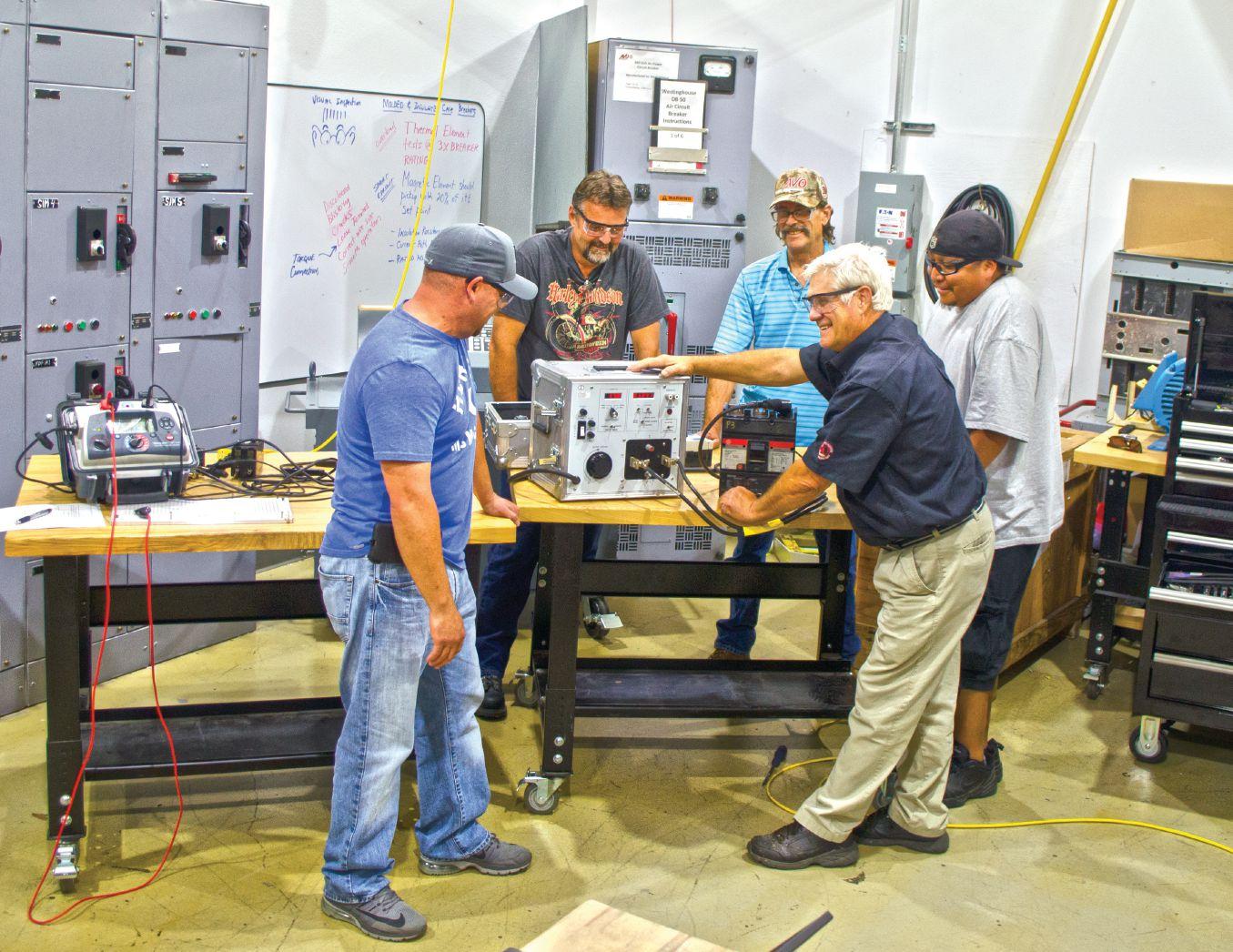


Many avo training courses are eligible for neta ctd’s t By offering the broadest selection of electrical training in the industry, we have a training course for all things electrical. We train to NETA and other industry recognized standards to take your knowledge to the next level. A training course is only as good as the instructor teaching it. That’s why our instructors are some of the most qualified in the industry. To be the best, train with the best. Offering over 57 electrical safety & electrical maintenance training courses and certifications. WWW.AVOTRAINING.COM 877-594-3156 Let us bring the training to your location, call today for an on-site quote Images depict a de-energized controlled environment with no chance for arc flash Hands-on training and NETA standards, together get you the most accurate field results. In order to provide a broad range of training and real world experiences, AVO Training Institute, Inc., courses are non-product specific. No AVO Training instructor nor contract instructor has any proprietary interest in any products, instruments, devices, services, or materials discussed.
MEDIUM-VOLTAGE ASSET FAILURE INVESTIGATIONS
BY KELLY HIGINBOTHAM, University of Connecticut, and WILLIAM G. HIGINBOTHAM, EA Technology LLC
Medium-voltage cables are an integral part of modern power systems and have existed for over 100 years in various forms. Over the past 50 years, extruded cables have largely displaced paper insulated cables. Extruded cables offer many advantages over older designs, but are similarly prone to failure. Such failures are a significant impediment to improving overall power system reliability.
Since cables are often sealed systems, continual assessment is difficult, and failures often occur without warning or preparation. Figure 1, provided by the National Electric Energy Testing Research, and Applications Center (NEETRAC), compares the costs of testing equipment, replacing all equipment regularly, and running equipment to failure. Each cost is shown as a standard distribution to represent the uncertainty associated with failure costs. It is evident that the costs of testing are significantly lower and have less uncertainty than the costs associated with running equipment to failure or wholesale replacement prior to failure.
This article sets out to sample the results of multiple forensic analyses, determine the common causes of cable failures, and identify how users can acquire accurate information

Figure 1: Cost Option Comparison
on the status of their cables. For the sake of this analysis, cable failures include failures in terminations, splices, connectors, and midcable failures. By being able to accurately determine potential cable issues before the failure occurs, we can plan better outages, improve system reliability, and prevent
72 • WINTER 2019 MEDIUM-VOLTAGE ASSET FAILURE INVESTIGATIONS
INDUSTRY TOPICS
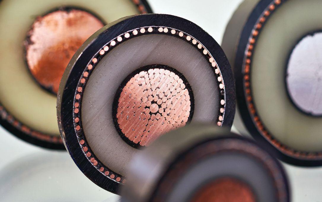
collateral damage caused by faults. Asset management and a proper testing schedule have been proven to lower costs associated with unplanned outages due to cable failures.
STUDY BACKGROUND
This article analyzes a subset of the forensic investigations performed by EA Technology on failed cables and components to determine failure mechanisms and set recommendations for similar system components. This analysis can provide insight into fault mechanisms, highlight other at-risk assets, and recommend asset management strategies to reduce future risk of failure. In addition, these reports provide insight into manufacturer quality and jointer workmanship. From these reports, we try to determine proximate cause and ultimate cause.
• A proximate cause is the obvious, direct cause of the failure. Examples include moisture ingress and mechanical damage.
• The ultimate cause is the deeper, systematic reason for a failure, such as poor workmanship, lack of training, or application errors. Other potential actions leading to a systemic cause include seeking the lowest installed cost, which includes decreasing the money spent on training, buying lower grade materials, or increasing the workload on individual jointers. Another explanation can be the current labor market and how difficult it is to find and retain highly skilled jointers.
To get from the proximate cause to the ultimate cause, the authors employed a commonly used management practice called the 5 Whys. By asking “Why?” and then challenging the answer with “Why?” in a serial fashion, the ultimate cause of an event can often be found.
For example, the proximate cause of the Titanic sinking is that it hit an iceberg. While addressing that, one could overlook the
NETAWORLD • 73 MEDIUM-VOLTAGE ASSET FAILURE INVESTIGATIONS
INDUSTRY TOPICS PHOTO: © ISTOCKPHOTO.COM/PORTFOLIO/SERGEYRYZHOV


ultimate cause: White Star Line had systematic issues that devalued passenger safety. The hope is that by addressing the ultimate causes of a failure, a wider range of proximate causes can be prevented. Over the course of this article, major trends are developed across both proximate and ultimate causes, and actions are recommended.
It should be noted that this study involved a small number of samples over a short period of time. While the authors believe the results to be representative of actual field conditions, this cannot be guaranteed. Sample size, time period, motivations for investigations, etc., could contribute to variations from a more detailed study. The reader should keep this possibility in mind when considering the findings presented.
FORENSIC FAILURE INVESTIGATION PROCESS
EA Technology’s investigations begin with visual investigation of the samples and analysis of the fault timeline if provided. Th is is followed by review of application parameters and instructions, then mechanical disassembly. Once disassembled, analytic investigation and specialized mechanical testing is completed and a report is provided to the client detailing the fi ndings and recommendations of the investigation.
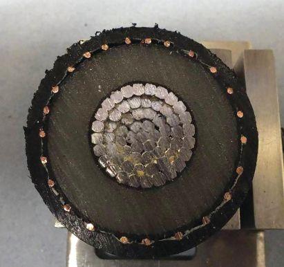
First, a visual investigation can provide vital details on workmanship and manufacturing errors, evidence of partial discharge, and moisture ingress into the cables. This step often includes documentation of the site and failure conditions. If possible, a representative should be present for removal of the failed component to ensure no information is lost during the process. Being present also provides a better understanding of the factors leading up to the fault.
Next, the team will review the application parameters and instructions provided by the manufacturer at the time of installation. Th ese will be used as a reference for the visual inspection and will be verified to be both accurate and clear. The visual inspection concludes with mechanical disassembly of the failed element. The cable is deconstructed layer by layer and extensively documented with pictures and measurements. This often speaks volumes about workmanship and cable age/ condition.
The next step is the analytical investigation. The details vary based on insulation type, but in general the analytical investigation dives deeply into suspected issues and determines the severity of underlying issues. For XLPE (Figure 2), the sample is boiled in oil of cloves

74 • WINTER 2019
MEDIUM-VOLTAGE ASSET FAILURE INVESTIGATIONS
INDUSTRY TOPICS
Figure 2: XLPE Insulation
Figure 3: XLPE Insulation Made Transparent

to make it transparent (Figure 3). This allows the researchers to microscopically examine thin sections of insulation to visualize any inclusion and ambers from the manufacturing process. Inclusions come from foreign matter lodged in the insulation during the extrusion process. Ambers are bits of insulation that weren’t fully converted to the final material. Both can affect the dielectric constant of the insulation, but foreign materials have a more negative effect on insulation quality. Having the insulation transparent also makes it possible to see developing water trees in the insulation. Th ese could have contributed to the fault or could indicate underlying issues based on size and location. For paper oilinsulated cables, the analytical investigation looks into the many mechanical factors that can lead to cable failure. Th is is done by unraveling the paper and looking for two major things:
• First, the overlapping of the strands is checked. Uneven overlapping can cause concentration of the electric fields and in turn lead to partial discharge.
• Second, the strands are checked for waxy patterns located at interstitials of the papers. These waxy residues can indicate partial discharge occurring in the cable and strongly indicate voids or moisture affecting the reliability of the cable.
When necessary, three major specialized material tests are conducted to gather more information on the samples.
• Scanning electron microscopy (Figure 4) performs elemental analysis on inclusions to identify foreign compounds. This can be used to compare the materials in the inclusion to the bulk insulation and possibly determine the impacts the inclusion would have on dielectric constants.
• Scanning differential calorimetry can determine the maximum temperature reached by the component prior to failure. This is important information to determine whether the component was used in the wrong application and whether overheating contributed to fault.
• Mechanical tests of cable components can determine material characteristics that indicate whether a component was appropriate for the application it was used in. This is commonly done for components expected to perform
The findings of all the tests are compiled into a report, and recommendations are drafted based on the findings. Client reports include detailed documentation of the investigation process, conclusions, and recommendations. Conclusions are structured to highlight


NETAWORLD • 75
MEDIUM-VOLTAGE ASSET FAILURE INVESTIGATIONS INDUSTRY TOPICS
Figure 4: Scanning Electron Microscope-Based Elemental Spectroscopy
INDUSTRY TOPICS
proximal and ultimate causes of failure based on the data gathered in the report, and recommendations are provided to address the proximal and ultimate causes of the failure. Th e report often includes several types of recommendations.
• First, suggestions address current at-risk assets to lower the risk of failure. Cable updates are often part of a large program update, so a failed cable could indicate larger system concerns.
• Second, suggestions are aimed at internal modifications that can prevent these issues in the future. These can include a new training program for jointers or an asset management program aimed at preventing end of life failures.
• Finally, recommendations may be aimed at external factors that contributed to the fault. Examples of these are informing a manufacturer of a defect or poor design or changing suppliers to use higher-quality materials.
All recommendations build the foundation for a more reliable system with the aim of reducing failures.
This study compiles the data drawn from a set of reports to analyze the greater trends indicated by their results and recommendations. We
pulled 100 reports generated in 2011–2015 from EA Technology’s forensic analysis report database. After the initial review, 27 of the reports were deemed irrelevant and discarded. Many of these were from lower voltage classes, were mechanical failures, or were a condition assessment report, not a failure analysis report. The remaining 73 reports were sorted and analyzed based on cable age, insulation type, voltage class, installation conditions, failure location, failure causes, and recommendations. These characteristics were graphed and analyzed for evident trends.
FINDINGS
The first metric analyzed was the age of the cable when the failure occurred. It was found that failure occurrence matched the Weibull distribution — the bathtub curve pattern shown in Figure 5. Failures can be classified into three main categories:
• Infant mortality failures make up the largest segment of the graph and last for approximately 10 years after installation.
• Random failures occur for the next 30 years or so. These are intermittent and generally uncorrelated.
• At around 40 years after installation, end of life failures begin to occur.



End of life failures are generally only prevented by replacement, while infant mortality and random failures can be prevented by looking deeply into the causes and responding appropriately.
Next, the report samplings were analyzed across insulation type and fault type (Figure 6). Based on “Historical Overview of Mediumand High-Voltage Cables,” written by the Georgia Tech NEETRAC group, XLPE and PILC cables show a similar ratio of failures per mile of installed cable. The ratio of failures per mile was developed using the data about EPR usage compared to XLPE usage provided by NEETRAC. Comparing NEETRAC’s
76 • WINTER 2019
MEDIUM-VOLTAGE ASSET FAILURE INVESTIGATIONS
Figure 5: Time to Failure
average percentages per insulation type versus this study’s average percentages of failures per insulation type takes into account that EPR is less commonly used than XLPE. This factor may have swayed the data to make EPR look dramatically more reliable than XLPE. While the numbers presented are backed by the various reports referenced, the difference in field failure rates for insulation types is unlikely to be as great as this specific study implies due to external factors not accounted for in this analysis.
Next, we analyzed where the failures occurred (Figure 7). Based on the fault locations seen in the report sampling, 68% of failures occur in places where technicians are working on cables in the fi eld versus 25% of failures mid-cable where technicians likely have had little interaction with the cable. Clearly, the act of working on the cable in the field can introduce failures. Explanations for the midspan failures include mechanical damage before or during installation, incorrect application, manufacturing defects, or simply random failures without a clear reason.
We next characterized and plotted the proximate causes of failure (Figure 8). Reviewing the proximate causes of failure revealed several interesting trends. Assembly mistakes cause 43% of failures commonly found. This indicates a lack of effective communication between manufacturers and
installers or in training of jointers. Another 40 percent is due to preventable damage to the cable, either from moisture or mechanical damage. Small percentages can be attributed to contaminants, circulating currents, and overheating.
What is missing from this picture is the detail of what is causing these failures. Proximate cause provides insight into what happened, but often lacks the complexity of the full reasoning behind a fault. Looking at the ultimate causes of the sampling (Figure 9), we see that the vast majority of faults can be attributed to workmanship errors. Th ese include errors in jointing due to negligence or inexperience, as well as sloppy work and lack of care. Six percent of failures were due


NETAWORLD • 77 MEDIUM-VOLTAGE ASSET FAILURE INVESTIGATIONS INDUSTRY TOPICS
Figure 6: Failure Rate by Insulation Type
Figure 7: Fault Location
Not Specified 18% Termination 23% Connector 7% Mid-Cable 25% Splice 45% Overheating 1% Age 6% Circulating Currents 1% Application error 4% Externally caused damage 4% Manufacturing defect in accessory 11% Manufacturing defect in cable 5% Contaminants 1% None Found 3% None found 4% Workmanship 66% Moisture 22% Mechanical Damage 18% Cutback Errors 11% Insulation Failure 10% Assembly Mistake 32% Partial Discharge 1% EPR 1% PILC 22% XLPE 59% Review Equipment Selection Discuss with Manufacturer Assess for Mechanical Damage Review Instructions/Procedures Retrain Jointer Not Specified 18% Termination 23% Connector Splice 45% Overheating 1% Age 6% Circulating Currents 1% Application error 4% Contaminants 1% None Found 3% Workmanship 66% Moisture 22% Mechanical Damage 18% Cutback Errors 11% Insulation Failure 10% Assembly Mistake 32% Partial Discharge 1% EPR 1% PILC 22% XLPE 59%
Figure 8: Proximate Causes of Failure


Review Equipment Selection
Discuss with Manufacturer
Assess for Mechanical Damage
Review Instructions/Procedures
Retrain Jointer
Perform Visual Inspection
Condition Assessment, Similar Comp.
Consider Replacement
to age, which is lower than expected based on the correlation to the Weibull distribution discussed earlier. Manufacturing defects presented about 11% of all ultimate causes, which is higher than expected. Th ese range from contaminants in the insulation to violation of conductor spacing requirements in the brand new cables. In just 4% of cases, no ultimate cause was found, which suggests steps can be taken to address the vast majority of cable failures.
Perform PD Mapping
Based on the ultimate and proximal causes of failure, several standard recommendations would help prevent future failures (Figure 10). The most commonly recommended
Retrain Jointer
Review Instructions/Procedures
Discuss with Manufacturer
Review Equipment Selection
Discuss with Manufacturer
Assess for Mechanical Damage
Review Instructions/Procedures
Retrain Jointer
Perform Visual Inspection
Condition Assessment, Similar Comp.
Consider Replacement
Perform PD Mapping Retrain Jointer
Manufacturing defect in cable 5% Contaminants 1%
action was to perform partial discharge mapping regularly. Partial discharge is cyclic breakdown of part of the insulation system due to a localized electric field greater than the dielectric withstand capability of that part, while the overall insulation system remains capable of withstanding the applied electric fi elds. Partial discharge, commonly found surrounding voids in the insulation, produces a variety of detectable byproducts such as heat, light, sound, scent, electromagnetic waves, and a high frequency electric current. Since the prevalence of partial discharge can indicate issues with insulation quality, routine partial discharge mapping can help clients plan for outages to address issues before they escalate. Cable partial discharge testing can provide data about how aging and conditions have affected installed cable and help prioritize replacement and repair.
Replacement is a commonly recommended action, yet it is regarded as only one of many options. The prevalence of partial discharge mapping and condition assessment recommendations suggests that proper asset management techniques can help prevent untimely replacement of working equipment by providing additional information about its operating condition. Discussing the fault with the manufacturer was also commonly recommended. By having clear and open
78 • WINTER 2019 MEDIUM-VOLTAGE ASSET FAILURE INVESTIGATIONS
INDUSTRY TOPICS
Figure 9: Ultimate Causes of Failure
Age 6% Application error 4% Externally caused damage 4% Manufacturing defect in accessory 11% Manufacturing defect in cable 5% None found 4% Workmanship 66% Moisture 22% Assembly Mistake 32%
Figure 10: Recommended Actions for Existing Equipment
Number of times recommended 0 05 1015 20 1020304050 Number of times recommended Splice 45% Overheating 1% Age 6% Circulating Currents 1% Application error 4%
damage
Review Equipment Selection
Externally caused
4% Manufacturing defect in accessory 11%
None
Workmanship 66% Moisture 22% Mechanical Damage 18% Cutback Errors 11% Insulation Failure 10% Assembly Mistake 32% Partial Discharge 1% XLPE 59%
None Found 3%
found 4%
Number of times recommended 0 05 1015 20 1020304050
communication with the manufacturer, installation errors or application errors are less likely. Similarly, since 11% of faults occur because of manufacturing defects, it is important to have clear quality expectations for the manufacturer. Providing feedback on failed components can prevent future quality issues from costing the user so much long term. Visual inspection is relevant for some faults, but it is considered to be of a limited value since most problems are hidden. This reinforces the value of partial discharge mapping, which provides data about cable condition and longevity that cannot be gathered from visual inspection alone.
Recommendations aimed at preventing failures in future installations (Figure 11) center around providing high-quality training for jointers and ensuring that instructions and procedures are clear and set the technician up for success. Well-trained jointers are key to having a reliable system because such a high percentage of faults can be traced to jointing issues. Talking to manufacturers throughout the process of a program upgrade can ensure instructions are being accurately followed. Finally, choosing the correct equipment for the application is frequently recommended since application errors caused about 4% of the failures from this sampling.
EXAMPLES
The first example is an 11 KV PICAS to XLPE branch adapter that failed one hour after installation (Figure 12). The proximate cause was determined to be incorrect positioning of the adapter tubes. Therefore, workmanship errors were determined to be the ultimate cause of failure. Investigation found many quality issues: Shear bolts were misaligned, there was no putty in the shear bolts, the tubing was poorly cut, and there were gaps in the insulation throughout the sample. Common recommendations for these conclusions include retraining the jointers and assessing the components as a part of the project. This example highlights that finding and fixing the
Number of times recommended
Review Instructions/Procedures
Discuss with Manufacturer
Review Equipment Selection
Number of times recommended


NETAWORLD • 79 MEDIUM-VOLTAGE ASSET FAILURE INVESTIGATIONS INDUSTRY TOPICS
Figure 11: Recommended Actions for New Installations
Figure 12: XLPE-PICAS Joint
Perform PD Mapping
Figure 13: Failure Location on 33KV XLPE Joint
Retrain Jointer
0 05 1015 20 1020304050


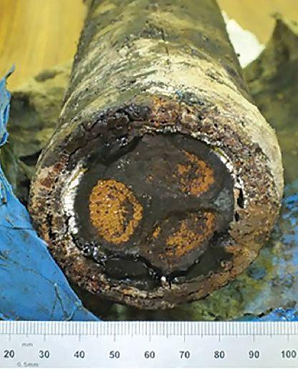
proximate cause of the failure is not adequate. Several mistakes all could have led to failure had the first cause not been present. By addressing the ultimate cause of jointer training, all of the workmanship issues and potential failure points would be addressed.
The next example explored a 33KV XLPE joint that failed after 18 months in service. The fault hole is visible through the insulation in Figure 13. The failure occurred because the jointer did not properly deburr a connector. The sharp edge caused mechanical damage and created a concentration of electric fields in the damaged insulation. The takeaway: Poor understanding of instructions, lack of attention to detail, and lack of training all contributed to the failure of this joint.
The final example explored an 11 KV PILC cable that experienced a mid-cable failure after 47 years of service (Figure 14). This failure is a result of age-related partial discharge. Although this cable was in service for an appropriate life span, it is an example of how partial discharge mapping could have prevented an unplanned failure. Catching the partial discharge earlier
would have allowed the client to plan an outage to address the issues.
CONCLUSIONS
With cable failures costing clients significantly every year, identifying trends in occurrences can help reduce future failure-related costs. Forensic analysis allows the community to learn from past failures to promote a more reliable and robust system. Th e following conclusions were drawn from the investigation of 73 forensic analysis reports:
• Cable faults follow a predictable reliability curve and generally can be expected to fail within the first 10 years or after 40 years in service. With about 35% of failures occurring in the first ten years, it is vital to install cables carefully to prevent the majority of infant mortality-related faults.
• Ensuring installations are done following clear and accurate manufacturer’s instructions can prevent ⅔ of faults.
• Since human error is inevitable in every field, a proper asset management program founded on partial discharge testing can help identify and prioritize issues as they develop.
Furthermore, since faults are inevitable, performing a forensic analysis post-mortem can help diagnose the causes of failure and identify trends in the failures associated with a company and suppliers. Although universal trends were shown through these reports, these do not necessarily indicate that every company should prioritize the recommendations in the same manner. For example, Company A may have excellent jointers but poor quality cables; Company B may have the highest quality components, but a few subpar practices are affecting their installations.
A custom assessment and recommendations may expose problems specific to your company or installations. Forensic analysis provides a much more detailed analysis than field review and can even help prevent future failures by looking
80 • WINTER 2019
MEDIUM-VOLTAGE ASSET FAILURE INVESTIGATIONS INDUSTRY TOPICS
Figure 14: Failed PILC Cable
deeper than proximal causes. Even in cases where there is no evident root cause, every investigation adds to our knowledge base and helps us create more reliable systems in the future.

Kelly Higinbotham started her career at Burns & McDonnell as a Substation Engineer in 2018 following graduation from the University of Connecticut with a BS in electrical engineering and a minor in mathematics. She is an Engineer in Training (EIT) in the state of Connecticut and looks forward to pursuing her Professional Engineer license in the next several years. Outside of her professional commitments, Kelly serves as an Alumni Advisor for the University of Connecticut chapter of Phi Sigma Rho, a national sorority for women in engineering.

William G. Higinbotham has been President of EA Technology LLC since 2013. His responsibilities involve general management of the company, including EA Technology activities in North and South America. William is also responsible for sales, service, support, and training on partial discharge instruments and condition-based asset management. He is the author or co-author of several industry papers. Previously, William was Vice President of RFL Electronics Inc.’s Research and Development Engineering Group, where his responsibilities included new product development, manufacturing engineering, and technical support. He is a senior member of IEEE and is active in the IEEE Power Systems Relaying Committee. He has co-authored a number of IEEE standards in the field of power system protection and communications, and holds one patent in this area. William received his BS degree from Rutgers, the State University of New Jersey’s School of Engineering, and worked in the biomedical engineering field for five years prior to joining RFL.


Far From Work, But Close to Data


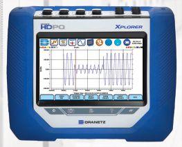
INDUSTRY TOPICS
PQ Analyzers with Remote Wireless Communications 732.287.3680 1000 New Durham Road Edison, New Jersey 08817 Control your Dranetz HDPQ from your smartphone, tablet, or computer! sales@dranetz.com www.dranetz.com ® ® Dranetz HDPQ Xplorer SP Dranetz HDPQ Xplorer


CALL FOR SPONSORS
Hyatt Regency Chicago
• Chicago, Illinois
•

Sponsorships are now available
•Promote your products and services to a valuable audience of key industry decision makers
•Increased brand visibility - print and media exposure to your target market before, during, and after the conference
•Customize your sponsorship package to suit your needs


THE PREMIER
MAINTENANCE
CONFERENCE PowerTest.org l 888.300.6382
by
ELECTRICAL
AND SAFETY
Hosted


A NEW WAY TO TEST DISTRIBUTION AUTOMATION SCHEMES
 BY ROBERT WANG, OMICRON electronics Corp. USA
With an ever-growing demand for a more reliable distribution grid, utilities are constantly looking for possibilities to optimize their distribution networks by implementing distribution automation. One method to improve the network and reduce permanent outages is using pole-mounted reclosers, due to their wide range of functionality. By introducing built-in voltage sensing on both source and load sides, automation can easily be achieved by using local, built-in logic to isolate a faulted section and closing in a tie recloser to supply power to customers from an alternate source.
Automation schemes utilizing coordinated protection functions provide an easy and lowcost solution to improve reliability. However, the process of isolation and service restoration can take up to several minutes. For critical feeder lines where long, temporary outages are unacceptable, reclosers equipped with highspeed peer-to-peer communication provide
possibilities to locate, isolate, and restore power to unfaulted sections within seconds or faster. With the American Recover and Reinvestment Act of 2009 providing $4.5 billion to the U.S. Department of Energy to modernize the electric power grid, most of the funded SmartGrid projects include communicationassisted distribution automation.
84 • WINTER 2019 A NEW WAY TO TEST DISTRIBUTION AUTOMATION SCHEMES
INDUSTRY TOPICS


To put such projects into operation, utilities often rely on manufacturers to design and implement the automation scheme. Thorough testing of the entire scheme prior to installation is critical to ensure that the switching logic works as desired for the multitude of fault scenarios that may affect the network and verify that the communication equipment can support the resulting network traffic. The testing process is integral for the verification of the system, but can also be extremely complex, labor intensive, and time-consuming. Th is article suggests an easy-to-apply method to test any distribution automation network that can significantly reduce testing time. At the same time, it covers parameters that can verify correct operation of distributed automation schemes, which are typically not included in routine conventional testing.
FEEDER AUTOMATION CONFIGURATION EXAMPLE
There are many ways to automate feeders using reclosers. One commonly used method is to
connect two feeders at an interconnection point (R5) using a normally open recloser (Figure 1). While the number of reclosers used in the scheme may vary, this example provides a general idea of the concept.
If a fault occurs (Figure 2), R3 must trip first to interrupt current flowing into the fault. To isolate the faulted section, R4 should open next. The feeder supplied by Sub 2 should then be checked to verify that it can supply the additional load between R4 and R5. If the load can be supplied, the normally open R5 will close, restoring power to customers who would otherwise be left out of service.

NETAWORLD • 85 A NEW WAY TO TEST DISTRIBUTION AUTOMATION SCHEMES
PHOTO: © ISTOCKPHOTO.COM/PORTFOLIO/METAMORWORKS
INDUSTRY TOPICS
Figure 1: Typical Feeder Automation Example with a Tie Recloser


Now that power is restored to customers between R4 and R5, R3 will try to reclose to verify whether the fault was only of a temporary nature.
Achieving this type of functionality can be done in a variety of ways. The simplest method is to rely only on local logic in each recloser; this logic is based on a voltage function. In case of a permanent fault, recloser R3 will typically try to reclose until lockout. Meanwhile, a timer in R4 will initiate after it detects a permanent loss of voltage and eventually open after a set amount of time based on protection settings. Since R5 has lost voltage on one side, an undervoltage timer will start to count and will close after a defined time.
Purely based on voltage logic, this scheme will typically take a minute or more to restore power to non-faulted sections, which may not be acceptable for critical feeder lines. Th is isolation and reconfi guration process can be significantly improved by using communication to or between the reclosers in the field. In case of a fault, the recloser could then quickly send an open or closing signal to downstream and tie reclosers.
COMMUNICATION PLATFORMS AND PERFORMANCE
The automation scheme’s performance greatly depends on the communication platform. A wired network using fiber-optic cables is one of the fastest solutions available, since it offers high bandwidth and low latency. However, implementing schemes with new fiberoptic networks can be very expensive, and
considerations must be made for the number of protection devices and the distances between protection devices. An alternative solution is to use wireless networks, which can be easily established and expanded and can fulfill both bandwidth and latency requirements. Utilities often have a choice to use public or private wireless networks. When deciding whether to implement a public or a private network for communication, a number of factors must be considered. Cost certainly is one factor, but service availability and coverage are also very important. Aside from the communication platform, the performance of the scheme also depends on the number of connected devices, the communication distance, and certainly the communication technology.
TESTING PROTECTION FUNCTIONS
If the scheme’s protection is not based on communication or distributed logic, testing the protective functions of the recloser control can be performed with minimal eff ort via secondary injection testing for individual recloser controls. Some test sets can be universally connected to the control cable interface of any recloser control with short recloser-specific adapters. Some simulate the recloser with up to six voltages and enable three-phase testing of the controller in both lab and field environments.
TESTING DISTRIBUTION AUTOMATION SCHEMES
Testing a distribution scheme with communication and distributed logic verifies the correct functionality of all protection devices in the scheme. A distribution automation scheme can be implemented with hundreds of lines of custom logic code in the recloser control and/or a programmable automation controller. Before a scheme is deployed in the field, it should be thoroughly tested to ensure that the scheme operates as expected, especially once it is put into operation. When a fault occurs, the distribution
86 • WINTER 2019
A NEW WAY TO TEST DISTRIBUTION AUTOMATION SCHEMES
INDUSTRY TOPICS
Figure 2: Fault Location, Isolation, and Service Restoration in Case of a Fault

automation scheme must identify the location of the fault, determine the best way to clear the fault, and restore the unfaulted line segments through various switching sequences. These switching sequences must also be tested to fully verify the functionality of the scheme.
TYPICAL SCHEME TESTS IN A LAB
To test a distribution automation scheme in a lab, all devices are set up in a test environment. These tests are typically performed as a proof of concept for new projects or for acceptance testing a scheme prior to installation in the field. Using secondary injection test devices connected to each recloser control, various preprogrammed test sequences can be executed to test the logic and the communication, which are essential to the scheme (Figure 3).

Scheme testing can be complex (Figure 4), and may require weeks to complete. To simulate realistic faults in every fault scenario, load and fault values for each operating state must be calculated for every recloser in the scheme. To execute each test case, vocal coordination to turn injection from each test device on and off at designated times to simulate each step of
the test case is required. Any mistakes or miscoordination among test personnel would result in an inaccurate test. After execution, results from each location must be collected, merged, and assessed. If any issues are discovered, the automation logic must be adapted to address the problems.
To synchronously test a scheme involving several reclosers, a single test device can be assigned for each recloser location, which then requires synchronization (e.g., via a GPS or IRIG-B signal).
SHORTCOMINGS OF A TYPICAL LAB TEST
Th is method has proven to work well for lab testing. However, it comes with several disadvantages: The expected test values have to be calculated and programmed into a sequence for every single test device — a very time-consuming process. After running the test, additional time must be spent comparing the time stamps of each test result from each diff erent testing device. All this eff ort can represent additional complications.
Two factors that can influence the performance or even the basic function of the scheme must also be considered. When distribution automation schemes are installed in the field,
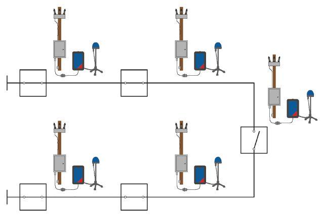
NETAWORLD • 87
A NEW WAY TO TEST DISTRIBUTION AUTOMATION SCHEMES INDUSTRY TOPICS
Figure 3: Secondary Injection Test Device Connected to Recloser Control
Figure 4: Typical Lab Setup

distances between the individual reclosers can be much farther than when testing in a lab environment. Longer communication distances with possibly weak communication links and waveforms of faults that are different from static fault values can drastically affect the operation and testing of the scheme.
INFLUENCE OF COMMUNICATION EQUIPMENT
Communication equipment used in automated high-speed distribution automation schemes is a critical component. The performance of the scheme greatly depends on the selected communication media, which defines how fast and how much information can be transmitted from one device to another. Only certain technologies provide enough bandwidth, security, and reliability to transmit wirelessly (e.g., an IEC 61850 GOOSE message). Other commonly used wireless transmitting technologies include WiMAX, LTE or 4G.
Transmitting and receiving functions can be affected by greater distances in field installations. In the case of a weak link or overflow on the communication channels, the automated scheme might fail. For this reason, synchronized injection testing into all devices

in the field is recommended to test the scheme under real-life conditions.
TRANSIENT WAVEFORMS
A test under real-life conditions requires the test values to match those of a real fault as closely as possible. With conventional testing methods, static fault values are typically applied, and the resulting reaction from the recloser control is measured. Under realistic fault conditions, a dc offset is present, and depending on the algorithms of the recloser control, one device in the scheme might detect the fault faster than another. To determine the real performance of the scheme, it is beneficial to test with transient signals.
NEW APPROACH FOR SCHEME TESTING IN THE FIELD
Using new software solutions, distribution automation schemes can be tested in the lab or the field while remotely controlled from a single PC. In addition to addressing the issues described previously, this greatly reduces the testing time while providing comprehensive reporting and troubleshooting options.
A power system under test can be modeled in a single-line diagram editor (Figure 5), and devices such as reclosers and circuit breakers can be placed in the network. Infeeds are defi ned by entering the source-impedanceratio (SIR), the line data calculated by using line length and impedance, and loads in the network specified using active and reactive power data. Using this information, the software can calculate the resulting load and fault values for any user defined test case.
The behavior of circuit breakers and/ or reclosers should be defi ned within the simulation software. If the circuit breaker and/or recloser opening and closing times are known or have been previously measured using a breaker timing test device, the software allows the input of those times, which are taken into consideration to ensure a more realistic test. Secondary injection test devices have a built-
88 • WINTER 2019
A NEW WAY TO TEST DISTRIBUTION AUTOMATION SCHEMES INDUSTRY TOPICS
Figure 5: Power System Model Using Software

in circuit breaker simulator, which can be extremely beneficial for testing purposes. Using the binary outputs of the test device, the 52a and 52b contacts can be simulated without requiring the circuit breaker or recloser to be connected during the test.
For a lab or field test, a single test set must be connected to each recloser control or relay to inject the appropriate current and voltage inputs and binary inputs (52a/b), as well as receive the resulting binary outputs (trip/close commands). However, when performing a field test, protection points can be located several miles from each other. The system must use either an existing communication network or an external cloud service with remote connection. In this case, all testing devices must be synchronized to GPS for time-synchronized injection (Figure 6).
Once GPS synchronization is established, test devices in the scheme can communicate with each other, as well as with the associated PC running the simulation software over the network. The PC must have access to the network to establish communication with all the test devices. Individual GPS antennas are used to synchronize all test devices at each protection point.
For each test case, a fault can be defi ned within the single-line diagram of the scheme; the software then calculates the resulting fault values for each device at each location. When the test is executed, the software sends the calculated test values into all test sets. Once all the test values at the test devices have been received, the injection begins synchronously.
A closed-loop test would be ideal; after a device issues a close or open command, the software would calculate new values taking into account the changed values after, for example, a breaker opening. This is not possible with a distributed test. When this mode is enabled, the software runs the first test; once a device under test in the scheme reacts, the software recalculates the test values taking this operation into account. It is assumed that a device under test will always react in the same time if the same test values are applied.
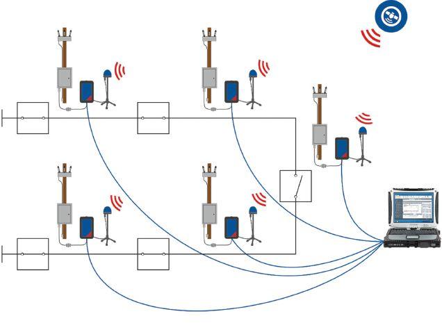
Figure 6: Typical Setup for GPS Time-Synchronized Transient Simulation Test of Recloser Controllers Using a Test Device at Each Protection Point
After resetting the scheme, the test is then repeated as the second iteration. The software automatically repeats the calculations after each iteration, taking all breaker and recloser operations into account. This iterative process will continue to reset and run until the system under test no longer reacts. This is typically the case once the fault is isolated and power is restored to segments of the network that are not affected by the fault.
Using this test method, the correct switching behavior of the scheme can be assessed, and it is immediately clear whether the communication equipment can handle the amount of data once the equipment is installed in the field. Thanks to transient test signals, the overall performance of the automation sequence can be measured and assessed. Furthermore, it can be determined whether corrective measures to improve the performance of the system need to be implemented.
CONCLUSION
Th e method and testing process described in this paper are easily applied and allow communication-based automated distribution schemes to be performed in a lab or field
NETAWORLD • 89 A NEW WAY TO TEST DISTRIBUTION AUTOMATION SCHEMES
INDUSTRY TOPICS

environment to verify the switching logic, the communication equipment, and the communication network’s ability to handle the data traffic. By also using transient test values, the actual performance of the scheme can be evaluated. Results could also be used to compare diff erent communication technologies. By using the iterative closed-loop approach, switching operations don’t need to be defined prior to the test. The software will learn the behavior of the scheme for a certain fault, and the engineer is only required to assess whether the switching operations were performed correctly by the devices under test.
REFERENCES
U.S. Department of Energy, “Recovery Act: SmartGrid Programs,” www.smartgrid.gov/ recovery_act/.
Newton-Evans Research Company, “Distribution Automation: Communications for Feeder Automation Survey,” www. newton-evans.com/distribution-automationcommunications-for-feeder-automation/
OMICRON Energy, “ARCO 400 – The Future of Recloser Testing,” 2016 www.youtube.com/watch?v=9h2yQ2sJeUo.

Robert Wang is a Training and Application Engineer at OMICRON electronics Corp. USA, where he functions as a Regional Application Specialist and Application Engineer with particular interest and focus on distribution automation and power system reliability. He is a member of IEEE PES. Robert received a BS in electrical engineering from the University of Massachusetts Amherst and completed his MEng in power systems engineering from Worcester Polytechnic Institute.

Industrial Electric Testing, Inc.
Cables
LV/MV Circuit Breakers • Rotating Machinery
• Meters
• Automatic Transfer Switches
• Switchgear and Switchboard Assemblies
Load Studies
LV/MV Switches
Relays - All Types
Motor Control Centers
Grounding Systems
Transformers • Insulating Fluids • Thermographic Surveys
Reclosers
Surge Arresters
Capacitors
Batteries • Ground Fault Systems
Equipotential Ground Testing
CoNSulTING AND ENGINEERING SERvICES
Transient Voltage Recording and Analysis
Electromagnetic Field (EMF) Testing
Harmonic Investigation
Replacement of Insulating Fluids
Power Factor Studies

INDUSTRY TOPICS
EC13004105 • 24 Hour Emergency Service ACCEPTANCE AND MAINTENANCE TESTING AND REPAIR
•
•
•
•
•
•
•
•
•
•
•
•
•
•
11321 West Distribution Avenue • Jacksonville, Florida 32256 • (904) 260-8378 201 NW 1st Avenue • Hallandale, Florida 33009 • (954) 456-7020
•
•
•
•
•
•
•


Independent Electrical Testing and Preventive Maintenance PROFESSIONAL SERVICES
Acceptance Testing • Planned Electrical Testing and Preventive Maintenance Programs
Power Factor Testing
Cable Testing
Relay & Meter Calibration
Ground Resistance Testing
Transformer Oil Analysis, Vacuum Degassing and Repair
Circuit Breaker Retrofit and Repair
Power Generation Systems Testing
•
•
•
•
•
•
•
•
Load and Power Quality Recording/Analysis
Chiller Systems Testing
Infrared Inspections 609-890-8300 www.easternhighvoltage.com 11-A S. Gold Drive • Robbinsville, NJ 08691


ENSURE EFFECTIVE ACCEPTANCE
AND MAINTENANCE TESTING WITH QUALITY REPORTING AND ANALYSIS
BY STEVE PARK, Electrical Reliability Services — a Vertiv Company
Coming up through the ranks in the power industry, I quickly realized I didn’t know what I didn’t know! There are so many facets of the power industry: generation, protection and controls, distribution and delivery, reliability, drives, uninterruptable power supplies, system studies, safety, maintenance, testing, as well as other areas that are vital for the safe and reliable delivery and utilization of electric power. How power is used also varies greatly. The power system in a steel mill is different than one in an automotive assembly plant or a data center or a wind or solar farm. They all may use similar components (cables, circuit breakers, fuses, disconnects, transformers, etc.), but the size and complexity of the systems can be very different. As such, acceptance and maintenance testing requirements and complexity will also vary. This paper focuses on how to ensure electrical maintenance and testing projects are effective and provide the information needed to assess the condition of power system assets.
ESTABLISH A TESTING AND MAINTENANCE PLAN
Before discussing project documentation such as test data and reports, an adequate testing and maintenance scope must be established. Many resources can help identify and define which electrical maintenance tasks and testing should
be performed on electrical assets. The most frequently referenced sources are the ANSI/ NETA ATS-2017, ANSI/NETA MTS-2019, and the National Fire Protection Association’s NFPA 70B, Recommended Practice for Electrical Equipment Maintenance. Another source for testing and maintenance recommendations is the equipment manufacturer’s literature.
92 • WINTER 2019 ENSURE EFFECTIVE ACCEPTANCE AND MAINTENANCE TESTING WITH QUALITY REPORTING AND ANALYSIS
INDUSTRY TOPICS
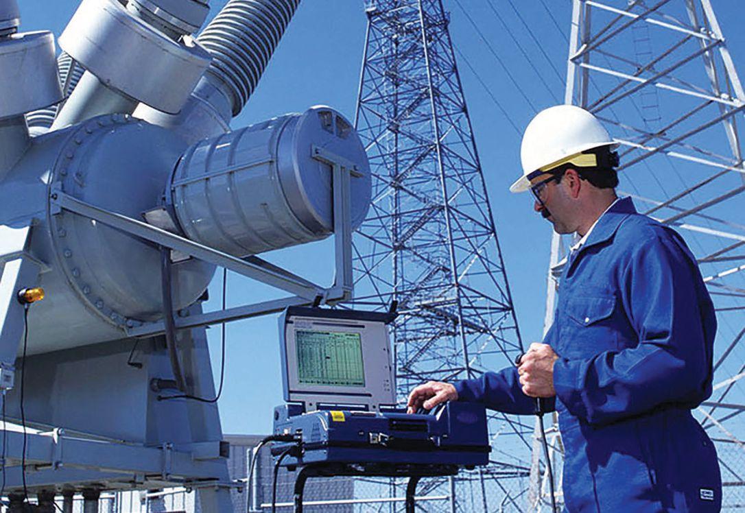
With all this information at your fingertips, determining which tests to perform, on what equipment, how often, and how to interpret results might be easy — but not necessarily. Those who have reviewed those documents know it is not that clear and concise. The manufacturer’s literature — while the best and most specific source of recommended maintenance and testing for a given asset — is not always readily available and does not always provide specific recommended practices. NFPA 70B and the ANSI/NETA testing specifications, while based on common practices in the industry and available manufacturer recommendations, do not always agree 100%.
Additionally, while these documents provide a good basis for which maintenance and tests should be performed, they do not cover the details of proper test techniques.
They also do not consider the type of power distribution system or the criticality of the equipment. Some systems may include redundant feeds and transformers to increase their reliability and decrease the impact should equipment fail. Equipment supplying power to critical infrastructure may require more maintenance and testing than equipment feeding administrative offices. To ensure an effective testing and maintenance program, the following factors should be considered as you assemble the list and frequency of tests and maintenance tasks to be performed.
1. Criticalness of equipment served
2. Age of equipment
3. Condition of equipment
4. Operating environment of equipment
5. History of equipment
6. System configuration


NETAWORLD • 93 ENSURE EFFECTIVE ACCEPTANCE AND MAINTENANCE TESTING WITH QUALITY REPORTING AND ANALYSIS
INDUSTRY TOPICS
IMAGE COURTESY OF VERTIV
Substation Maintenance Services

INDUSTRY TOPICS


Businesses operate within a limited budget and can typically only support equipment outages for limited time periods. Therefore, budget and time constraints must be considered when determining which equipment should be tested and what tests and maintenance tasks should be performed.


Testing and maintenance is about risk aversion. The expected level of reliability (or failure) must be established to determine the testing and maintenance scope. When high reliability is required, the system must be designed with adequate redundancy, and certain testing and maintenance tasks must be performed to ensure the proper operation of the primary and redundant system components. If a high level of reliability is required from a system design that lacks sufficient redundancy, additional or more detailed testing and maintenance (time and money) will be required. When considering these important factors and decisions, it is often advantageous for the owner to work with a testing and maintenance service provider to establish a customized scope of work for a testing and maintenance program.
EXECUTE THE PROJECT
Once a testing and maintenance program including scope, test specifi cations, time, and duration has been developed, it is time to release the project for bid, evaluate proposals, and select the best candidate to execute the work. Once a testing fi rm is selected, the owner must ensure all key requirements of the project specifi cations are understood to avoid issues during the execution of the project. Any deviations or alterations should be discussed and agreed to before project execution begins. Th is is the ideal time to ensure all inspection, testing, and maintenance actions are documented and included in the fi nal test report.
Once a larger project begins, times must be established for the owner and the service provider to discuss activities, schedules, and findings. These discussions may not be necessary on smaller projects unless something is discovered that aff ects the ability to reenergize the system or places the system at risk as a result of deterioration or equipment otherwise not suitable for return to service.
Reliable and accurate documentation of test procedures and test data is vital to an effective testing and maintenance project. Depending on the apparatus and tests being performed, variations of a given test or test procedure may be applied. Some tests or procedures will yield similar and accurate results, while others may not provide the expected results or may include or exclude components that affect the results. The person witnessing the testing should be familiar with the test methods outlined in the project specifications. There are times when shortcuts are permitted due to outage window or other site-specific conditions, but the impact and ramifications of these shortcuts must be understood and approved.
To ensure tests are performed correctly and the test results are accurate, the owner should assign a project manager with a strong background in testing and maintenance to all testing and maintenance projects. If the owner’s project
94 • WINTER 2019
ENSURE EFFECTIVE ACCEPTANCE AND MAINTENANCE TESTING WITH QUALITY REPORTING AND ANALYSIS
IMAGE COURTESY OF VERTIV
UPS Maintenance and Data Collection
manager does not have a strong background in this field, it may be in the owner’s best interest to hire a third-party project manager.
DOCUMENT THE PROJECT
Reporting and documenting a testing and maintenance project is critical. The test report, which summarizes project activities, test data, analysis, and recommendations, communicates the test results. Other than test stickers, the report is the only evidence that electrical testing was performed.
Th e test data documentation process must be accurate and reliable. Testers must record values accurately and with minimal errors. Measurement values and units, as well as any observations, must be recorded. The tester’s experience level can make a significant difference in the quality of the project’s documentation. In addition to performing the electrical tests, an experienced tester will carefully examine the apparatus and note any signs of damage, deterioration, excessive wear, excessive heating, etc. These inspections should be clearly documented on the test data sheet. The equipment owner should assume that if the inspections and tests are not documented, they likely did not occur.
During the project, test data must be constantly reviewed by the technician to ensure all test parameters are met and any equipment with concerning test data is immediately identified and brought to the attention of the owner. This is where the guidance of a Level III or Level IV certifi ed technician is required. Senior testers can ensure the data is accurate and make sound recommendations based on their years of experience. When less than acceptable test data is discovered, an immediate retest is often warranted to verify the data and ensure the test data has not been affected by a test method, a test equipment defect, or other external influence. Once the test data is verified, the project lead and owner representative must communicate to determine the best course of action. This frequently does not happen.
Topics discussed in these conversations and any recommendations should be included in the project’s formal test report.
The documentation process must involve minimal transcription of information from one source to another to avoid introducing additional errors. If documentation is performed using pencil and paper forms, the report should contain a copy of those same paper forms. Errors are often introduced by transcribing paper forms onto an electronic data form or database. While some testing companies continue to use paper test forms on the project and then input the data into a computer system at a later time, the most accurate and efficient process involves direct input of test data into a reliable database during testing. The key to success in using a data management system is to use standardized forms and a common database where all data can be stored, backed up, mined, and retrieved. This database should not reside solely on a local laptop or office computer; it must be synchronized to a commercial data architecture system with redundancy and regular backup processes to avoid losing the data or placing the data at unnecessary risk of corruption.
STANDARDIZED REPORTING
While the general format of test reports varies from vendor to vendor, basic sections and content should be included. At a minimum, the report should contain:
1. Project summary
2. Description of equipment tested
3. Description of tests performed
4. Protective device settings
5. Test data
6. Test data analysis, evaluation, and recommendations
Within the test data sheets, additional information such as testing organization; clear identification of tested equipment using client names and facility references; pertinent equipment nameplate data; ambient humidity and temperature at time of test


NETAWORLD • 95
INDUSTRY TOPICS
ENSURE EFFECTIVE ACCEPTANCE AND MAINTENANCE TESTING WITH QUALITY REPORTING AND ANALYSIS


at the test location; project date(s); test equipment calibration information and/or dates (if required); person performing the tests; documentation of inspections, test, maintenance, and calibration performed; documentation of as-found and asleft settings and test results; and observations and comments should be included.
QUALIFICATIONS
Adequate experience and qualifi cations of the testing firm and testing technicians are of paramount importance. Two U.S. qualification agencies are widely accepted: the InterNational Electrical Testing Association (NETA) and the National Institute for Certifi cation in Engineering Technologies (NICET). NICET and ANSI/NETA have established four test
technician certification levels. While large or complex projects may require one or more Level 4 technicians to lead and manage the project, most testing projects can be successfully managed by one or more Level 3 technicians. NETA Level 2 technicians are often capable of performing most testing independently and with little supervision. A Level 1 technician can work as an assistant under the direct guidance and supervision of a more experienced tester.
Qualifications and experience can make a signifi cant diff erence in the quality and success of an acceptance or maintenance testing project. If the owner wants to know everything possible was done to ensure the reliable operation of their electrical equipment, confi rming that the testing company and technicians have adequate qualifications and experience is vital to the accuracy of the results and owner’s peace of mind.
Test technician qualifications are important, but the testing firm must also provide oversight and a thorough review and analysis of the test data. This review typically involves a team of the firm’s subject matter experts not engaged in the testing procedures. The team not directly involved in the testing project usually includes experienced testers, technical writers, and engineers who examine the test data, identify documentation errors, and ensure that any test data not meeting the established project standards is identified. Data not meeting the project standards must be clearly called out in the report, and recommendations for corrective actions should be included.
The test report should provide vital information about the continued reliable operation of the tested electrical equipment. However, it does take time to assemble a comprehensive and accurate report. The delay between performing the testing and issuing the report can be critical if defects or deficiencies are discovered during testing. The owner must ensure that any issues discovered during testing are brought to their attention immediately during the testing phase of the project. This allows the owner time to address any issues while the test team is on site
96 • WINTER 2019
INDUSTRY TOPICS
ENSURE EFFECTIVE ACCEPTANCE AND MAINTENANCE TESTING WITH QUALITY REPORTING AND ANALYSIS
IMAGE COURTESY OF VERTIV
Circuit Breaker Maintenance Testing
and the equipment is de-energized. If good communication is established during a project testing phase, the test report should not contain any surprises.
Report turnaround time can vary from project to project depending on complexity and size. For large, ongoing projects, periodic reports can be provided on an established schedule (weekly, bi-weekly, monthly) or by progress (completed substation). For smaller projects, reports should be available in a matter of days unless additional test information such as laboratory liquid analysis or other specimen tests must be performed. For medium to larger projects, a turnaround of two weeks is considered reasonable.
Smaller projects may not contain large amounts of complex data or recommendations, but larger projects can contain a mountain of data and recommendations. This amount of data can be overwhelming to review, understand, and digest. For larger projects containing complex testing, the test provider should arrange a follow-up meeting to review the report and outline any critical recommendations or corrective actions. Interpretation and explanation of the data to provide a better understanding is often included during this meeting.
CONCLUSION
Effective acceptance and maintenance testing of electrical equipment and systems starts by using experienced and qualifi ed testing technicians and testing companies that have established reporting systems and procedures. These procedures dictate:
• Identify data to be evaluated during the testing process.
• Immediately identify assets that are defective or produce concerning test results and bring them to the attention of the owner throughout the project.
• Conduct an internal review process using a knowledgeable and competent team — independent of the test technicians — to
ensure all data and recommendations are accurate. This is extremely important to ensure substandard equipment is not unknowingly returned to service.
• Hold a final project review meeting with the owner to present the final report and analysis.
Th e owner is assured the highest level of confidence if they know that the test data has been accurately recorded, managed, and stored in a database that permits quick recall, trending, and data mining. This data is a key asset for owners as they plan for the most effective condition-based maintenance cycle. It can help them identify equipment reaching end-of-life and plan for system upgrades.
Choosing a service provider with the experience, qualifications, test data management, and established internal review systems outlined in this article has an impact on the cost of the project, but a higher level of system reliability and operational assurance is gained. The old adage, “You get what you pay for,” comes to mind.

Steve Park, PE, is Director, Engineering and Technical Services at Electrical Reliability Services, a Vertiv company, where he provides expertise and leadership for sales, marketing, training, and operations, serves as the lead technical writer, and conducts technical and commercial seminars for internal and external customers. Steve has over 40 years in management, leadership, and operational experience in the design, maintenance, testing, and engineering of low-, medium-, and high- voltage power systems and apparatus. He is an SME in power system maintenance, management, equipment testing and evaluation, system studies, electrical safe work practices, and medium-voltage cable testing. Steve led two major operational and organizational changes involving extensive change management of operational systems and processes including establishing a unified data collection and management system for over 40 geographically dispersed offices and creating a centralized engineering and technical support department. He is a former Service Center Manager responsible for sales and operations. Steve is a Professional Engineer, a Level 2 Test Technician, and is OSHA 30 qualified. He received his BS and MS in electrical and electronics engineering from Purdue University and an MBA from Indiana Wesleyan University.


NETAWORLD • 97
ENSURE EFFECTIVE ACCEPTANCE AND MAINTENANCE TESTING WITH QUALITY REPORTING AND ANALYSIS
TOPICS
INDUSTRY
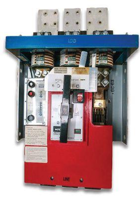

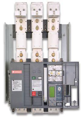


HPC Switches? We’ve got you covered. • In Stock • New and Obsolete • 800A—4000A • Retrofit kits • 24/7 Emergency Service We stock new General Electric HPCII drop in replacements for the THPC 3000 & 4000 amp GFI models for same day shipping. Call anytime for immediate service. 800-421-5082 www.qualityswitchgear.com HPC New Generation HPC Superior Service for Optimal Performance To learn more, visit ERS.Vertiv.com or call 877-468-6384 Experts Available Across Six Centers of Excellence: Commissioning | Electrical Engineering | DC Power Testing and Maintenance | Protection and Controls | Compliance Vertiv™ and the Vertiv logo are trademarks or registered trademarks of Vertiv Group Corp. All other names and logos referred to are trade names, trademarks or registered trademarks of their respective owners. Whether you need startup services, ongoing maintenance, or emergency response you need a partner you can trust. Rely on Vertiv’s Electrical Reliability Services’ team for expertise, responsiveness, and safety. • Consistent quality, service-delivery process • Proactive customer communication and project management • National, regional, and local service center availability Vertiv-ERS-COE-AD-2-EN-NA-8x5.25.indd 1 12/07/2019 4:01:37 PM




We’ve got answers.
Discover page after page of comprehensive, component-specific, technical resources for training and reference purposes. Over 200 of the very best articles from NETA World Journal and technical presentations from NETA’s PowerTest conferences. To order, please visit netaworld.org or call 888.300.6382
AT YOUR FINGERTIPS. Introducing
REAL WORLD LEARNING
NETA Series III Handbooks
LEARN WHAT YOUR OIL RESULTS REALLY MEAN.

DOBLE LABORATORY DIAGNOSTICS SEMINAR AT POWERTEST 2020 | FEBRUARY28, 2020
Join us for a one day laboratory seminar on Friday, February28 at PowerTest 2020. Doble’s laboratory expert will present an interactive session that combines theoretical background with practical experience. We will share case studies illustrating common problems found in the field.
• Understand how to determine the condition of electrical apparatus using laboratory tests
• Discover how knowing about aging characteristics of insulating materials can help you extend asset life
• Learn how to take oil samples, avoid common pitfalls, save time and save money by sampling only once
•Detect the presence of incipient-fault conditions and categorize them
• Find out how to assess the condition of the paper insulation
• Establish the correct method of analyzing moisture-in-oil results
• Study the significance of dissolved metals, particulate metals and other particle contamination
• Learn about the quality of new and service aged oils
• Learn how to identify and mitigate issues with corrosive oils
REGISTER TODAY www.powertest.org 888-300-NETA Laboratory Seminar Fee is $445
www.doble.com
PAR TI CIPANT S W IL L


COMMUNICATIONS SECURITY FOR FIELD TESTING ORGANIZATIONS


 BY GOWRI RAJAPPAN, Doble Engineering Company
Cybersecurity is one of the greatest challenges to grid reliability. As more facilities and devices become IP-routable communications-enabled, the threats multiply along with the incredible productivity gains. This additional complexity impacts the work of field testing organizations in the form of a bewildering milieu of new technologies, processes, and regulations. Without awareness of the threats and security best practices, it is easy to feel lost in this complex new reality. This article attempts to fill the knowledge gap by describing real-world cyber threats and how they can impact communication-enabled grid assets. This article discusses best practice countermeasures and what field testing organizations can do to improve security while ensuring that work still gets done.
NETAWORLD • 101
ADVANCEMENTS IN INDUSTRY COMMUNICATIONS SECURITY FOR FIELD TESTING ORGANIZATIONS PHOTO: © ISTOCKPHOTO.COM/PORTFOLIO/BLACKJACK3D

ADVANCEMENTS IN INDUSTRY

CYBERTHREAT LANDSCAPE
The energy sector is among the most frequently targeted critical infrastructure sectors. Advanced persistent threats (APTs) — defined as targeted attacks by technologically sophisticated, well-funded, and motivated groups, often with the backing of a state actor — have multiplied in recent years, and now constitute the greatest challenge to grid cyber security. In the early years of this decade, only one or two such successful attacks were detected, most notably the Stuxnet attack in 2010 that took out up to a fifth of Iranian nuclear centrifuges. But over the course of this decade, such attacks have multiplied manifold.
One well-studied APT is the 2014 attack by the group variously known as Energetic Bear (because it was thought to target energy sector entities), Crouching Yeti, and Dragonfly. The purpose of the attack was cyber espionage (i.e., data theft),
Energetic Bear group


and so its visible impact wasn’t nearly as severe as the better-known cyberattacks against the Ukraine power grid, but the details of the attack are instructive and resemble other APTs.
Figure 1 shows the various elements of this attack. In general, the various stages of an APT are reconnaissance, social engineering/ phishing, lateral movement, data destruction, and ultimately, an industrial control system (ICS) impact. Reconnaissance may involve identifying approved vendors from websites (company website, vendor news releases, etc.); company assets, locations, and power system information determined from regulatory fi lings and other such public information; and employee information from the company website and social networks such as LinkedIn. Th e objective of the reconnaissance is to identify employees who may get the attacker closer to target assets and systems.
Software update compromised with Trojan
Malware installed on industry website using exploit kit
Industry website
Malware modules and updates made available via command and control server
Compromised web server used for command and control
Spear-phishing email with malicious PDF attachment
Victim visits website and downloads malware
Target
Software update server
Information sent to command and control server for retrieval
Industrial control system (ICS)
Malware performs ICS device discovery
Victim downloads software with Trojan Malware installs and runs downloader to obtain further modules
OPC (open platform communications) server
102 • WINTER 2019 COMMUNICATIONS SECURITY FOR FIELD TESTING ORGANIZATIONS
Figure 1: Dragonfly / Energetic Bear / Crouching Yeti Attack
SOURCE: DR. RICHARD PIGGIN


Th e next step is to target these identifi ed employees through social engineering. This may be in the form of spear phishing, where employees receive a legitimate-looking email — for instance, one that looks to the undiscerning eye to be from a trusted vendor announcing their user conference with a PDF attachment of the conference program. The PDF attachment in this case could be the actual conference program so that it doesn’t cause any suspicion, but it would be altered (weaponized) to include a malware that would infect the computer of any email recipient who opens the weaponized PDF.
The infected employee computers then serve as the staging for further reconnaissance from within the network. This next recon phase may involve techniques such as network scanning to identify assets and keystroke loggers to record user keystrokes and harvest sensitive information such as login credentials. Th e attackers use these launch points to move through the network and possibly erase or alter log files to avoid detection. Once they are able to identify a trusted link to the ICS network, such as the one between the corporate and control center historians, they may be able to exploit any available application vulnerability to enter the ICS network and compromise the control systems. With a higher degree of penetration of IP-based communication all the way down to the substations, such attacks now have the ability to propagate deep into the control and process zones of the utility organizations.
CYBERSECURITY COUNTERMEASURE
Defense in Depth is a key countermeasure strategy to secure communication-enabled systems. According to the NSA (National Security Agency), this is a practical strategy for achieving information assurance in today’s highly networked environment. As shown in Figure 2, Defense in Depth requires balanced focus on People, Technology, and Operations to ensure that defenses exist in all three dimensions. Th is is akin to castle defense,
ADVANCEMENTS

Information Assurance
Defense In Depth Strategy
People

Technology Operations
Robust and Integrated Set of Information Assurance Measures and Actions
where multiple layers of defense such as walls, watchtowers, and moats prevent unauthorized ingress. Examining how Defense in Depth strategies might apply to communicationenabled systems demonstrates that two aspects need to be secured: the communication itself and access to the device.
Data communication should be secured at multiple levels, in keeping with the Defense in Depth strategy. For instance, security measures should be in place for communication links as well as application traffic. Table 1 shows some of the controls that could be used to secure
Table 1: Security Controls in the 4G LTE Communication Network
Security Measure Description
Mutual AuthenticationThe network authenticates the device, and the device authenticates the network. This protects against attacks such as rogue devices or access points.
Enhanced Root Key The root key used to derive the various security keys should be at least 128 bits in length. The cellular and core network keys are cryptographically separated, thereby providing two independent layers of security.
Security ContextNew keys are derived from the master key for each data session. Separate keys are derived and used for signaling and user traffic.
Integrity ProtectionThis mechanism protects signaling. Each message is appended with an integrity tag and is accepted at the receiving end only upon its verification with algorithms such as the 128-bit Advanced Encryption Standard (AES) and SNOW3G cipher used for integrity protection.
Encryption All communications on the air interface are encrypted. The default encryption is at least a 128-bit AES algorithm.
NETAWORLD • 103
COMMUNICATIONS SECURITY FOR FIELD TESTING ORGANIZATIONS
IN INDUSTRY
SOURCE: NATIONAL SECURITY AGENCY
Figure 2: The Defense in Depth strategy includes multiple layers of defense along the three dimensions of People, Technology, and Operations.

ADVANCEMENTS IN INDUSTRY

Table 2: Security Controls for the On-Demand Support
Security Measure Description
Authentication Strong user-credential management controls and policies
AuthorizationRole-based and/or attribute-based granular authorization scheme, whereby access to various modules can be controlled, and the type of access, such as read-only, can be specified
EncryptionStrong end-to-end TLS encryption
Supervised SessionAbility to supervise the session by an administrator
Session LoggingDetailed logging of all the events of a session
Session RecordingRecording capability for the remote session to show live action by the user — should contain metadata to identify the events
Audit
Auditing capabilities provided via the session logs and session recordings
the communication link. The application traffic occurs over this secure communication network and should be further secured at the application layer. This additional security consists of authentication using encrypted credentials and encrypted application payload using transport layer security (TLS). In addition, there could be an end-to-end tunnel between the endpoints.
When facilities and devices are communicationenabled, remote access is technically feasible. If an organization decides to provide remote access to certain facilities or devices, strong measures must be put in place to ensure security. Table 2 shows some of the controls that could be used.
IMPLICATIONS FOR TESTING ORGANIZATIONS
Within a typical utility, groups other than the testing organization control technology and compliance aspects of cyber security. IT may be responsible for the technology aspects, such as firewalls, anti-malware, and access control. The compliance group is responsible for determining policies other groups must adhere to. But ultimately, the testing organization works directly with these assets and must have a good understanding of the reasons for the controls and the policies.

CONCLUSION

Cybersecurity is a discipline that is here to stay and grow in importance with developments such as the adoption of IEC 61850-based digital substations and the deployment of networked sensors such as phasor measurement units (PMUs). It is important for testing organizations to recognize this and become more aware of security threats and countermeasures as it applies to their job function. As more grid assets become communication-enabled and IP-connected, testing organizations must become comfortable working within the layered defenses put in place for them and be able to identify issues that invariably arise with any such complex, multi-layered system.
REFERENCES
SANS Institute. “Anatomy of an ICS Attack.” Available at https://securingthehuman.sans.org/ cyberattackdemo.
Dr. Richard Piggin. “Industrial Control Systems and SCADA Cyber-Security,” IET Engineering and Technology Magazine, Volume 9, Issue 8, 11 August 2014. Available at https://eandt.theiet.org/content/ articles/2014/08/industrial-control-systemsand-scada-cyber-security/.
National Security Agency (NSA). Defense in Depth: A Practical Strategy for Achieving Information Assurance in Today’s Highly Networked Environments. Available at https://www.nsa.gov/ia/_files/support/ defenseindepth.pdf.

Dr. Gowri Rajappan is Director of Technology and Cybersecurity at Doble Engineering. As an expert in cybersecurity and enterprise data technologies, he leads the cybersecurity activities at Doble and chairs the IEC TC57 task group for developing a common information model standard for asset management. Prior to Doble, he worked on cybersecurity and data technologies in support of the United States Department of Defense.
104 • WINTER 2019 COMMUNICATIONS SECURITY FOR FIELD TESTING ORGANIZATIONS
NEW EDITION ANSI/NETA MTS-2019 Please visit www.netaworld.org or call 888-300-NETA (6382). ORDER NOW! • FEATURING NEW CONTENT • -Online Partial Discharge Survey for Switchgear -Frequency of Power System Studies
ANSI/NETA STANDARDS UPDATE
ANSI/NETA ECS-2020 REVISION COMPLETED
ANSI/NETA ECS, Standard for Electrical Commissioning of Electrical Power Equipment & Systems, 2020 Edition, completed the American National Standard revision process. ANSI administrative approval was received on September 9, 2019. ANSI/NETA ECS-2020 supersedes the 2015 Edition.
ANSI/NETA ECS describes the systematic process of documenting and placing into service newly installed or retrofitted electrical power equipment and systems. This document shall be used in conjunction with the most recent edition of ANSI/NETA ATS, Standard for Acceptance Testing Specifications for Electrical Power Equipment & Systems . The individual electrical components shall be subjected to factory and field tests, as required, to validate the individual components. It is not the intent of these specifications to provide comprehensive details on the commissioning of mechanical equipment, mechanical instrumentation systems, and related components.
Th e ANSI/NETA ECS-2020 Edition includes updates to the commissioning process, as well as inspection and commissioning procedures as it relates to low- and mediumvoltage systems.
A project intent notification published in ANSI’s Standards Action on May 18, 2018, announced the intent to revise the standard. A 30-day initial ballot period and a 45-day public comment period began on April 26, 2019. A second ballot was issued July 5, 2019, and closed on August 5, 2019. The 45-day second ballot public comment period was scheduled to close on August 20, 2019. The revised edition of ANSI/ NETA ECS will be released in February 2020 at PowerTest in Chicago.
Voltage classes addressed include:
• Low-voltage systems (less than 1,000 volts)
• Medium-voltage systems (greater than 1,000 volts and less than 100,000 volts)
• High-voltage and extra-high-voltage systems (greater than 100 kV and less than 1,000 kV)


REVISION UNDERWAY

FORELECTRICALPOWEREQUIPMENT&SYSTEMS
References:

• ASHRAE, ANSI/NETA ATS, NECA, NFPA 70E, OSHA, GSA Building Commissioning Guide
ANSI/NETA ATS-2017 REVISION UNDERWAY
ANSI/NETA ATS-2017, Standard for Acceptance Testing Specifications for Electrical Power Equipment & Systems is scheduled to complete an American National Standard revision
106 • WINTER 2019 SPECIFICATIONS AND STANDARDS ACTIVITY ANSI/NETA STANDARDS UPDATE
WWW.NETAWORLD.ORG ANSI/NETA STANDARD FOR ELECTRICAL COMMISSIONING SPECIFICATIONS ANSI/NETA ECS-2020 STANDARDS 2020 2020 STANDARD FOR ELECTRICAL COMMISSIONING SPECIFICATIONS FOR ELECTRICAL POWER EQUIPMENT & SYSTEMS REVISION COMPLETE
STANDARDFOR
ANSI/NETA ATS-2017
ACCEPTANCE TESTINGSPECIFICATIONS


SPECIFICATIONS AND STANDARDS
ANSI/NETA MTS-2019 LATEST EDITION
ANSI/NETA MTS, Standard for Maintenance Testing Specifications for Electrical Power Equipment & Systems, 2019 Edition, completed an American National Standard revision process having received ANSI approval on February 4, 2019. The revised edition of ANSI/NETA MTS was released in March 2019 and supersedes the 2015 Edition.




process in fall 2020. A project intent notification was published in ANSI’s Standards Action on November 30, 2018. The revised standard is targeted for release in first quarter 2021.
ANSI/NETA ATS covers suggested field tests and inspections for assessing the suitability for initial energization of electrical power equipment and systems. The purpose of these specifications is to assure that tested electrical equipment and systems are operational, are within applicable standards and manufacturers’ tolerances, and are installed in accordance with design specifications.
ANSI/NETA MTS contains specifications for suggested fi eld tests and inspections to assess the suitability for continued service and reliability of electrical power equipment and systems. The purpose of these specifications is to assure that tested electrical equipment and systems are operational and within applicable standards and manufacturers’ tolerances, and that the equipment and systems are suitable for continued service. ANSI/NETA MTS-2019 revisions include online partial discharge survey for switchgear, frequency of power systems studies, frequency of maintenance matrix, and more. ANSI/NETA MTS-2019 is available for purchase at the NETA Bookstore at www.netaworld.org
ANSI/NETA ETT-2018 LATEST EDITION
ANSI/NETA ETT, Standard for Certification of Electrical Testing Technicians, 2018 Edition, was approved by ANSI as an American National Standard on February 22, 2018. It is available now in the NETA Bookstore at www.netaworld.org, where a complimentary PDF copy can be downloaded or a printed copy ordered.
ANSI/NETA ETT establishes minimum requirements for qualifications, certification, training, and experience for the electrical testing technician. It provides criteria for documenting qualifications for certification and details the minimum qualifications for an independent and impartial certifying body to certify electrical testing technicians.
PARTICIPATION
Comments and suggestions on any of the standards are always welcome and should be directed to NETA. To learn more about the NETA standards review and revision process, to purchase these standards, or to get involved, please visit www.netaworld.org or contact the NETA office at 888-300-6382.
NETAWORLD • 107
ACTIVITY ANSI/NETA STANDARDS UPDATE


Acceptance Testing Services
Low, Medium, and High Voltage
Substations • Distribution switchgear • Transformers • Cables • Relays
Preventative Maintenance & Testing
Switchgear
Infra-red surveys • Circuit breakers • Relay testing and calibration
Transfer switches • Complete maintenance of ACB’s-OCB’s-SF6 CB’s
UPS & station battery maintenance • Gen. load tests
Transformers
TTR • Power factor testing • Oil testing and field analysis
Oil reconditioning & reclaiming • field replacements
Engineering Services
Arc-flash, short circuit, and coordination studies
Power factor correction • Power quality and harmonic studies
Load surveys • Grounding system design
Trust us to keep your business up and running. Call for a free consultation


Street
Over 25 Years of Experience & Reliability Full Service Independent Electrical Testing Accredited Company 204 Gale Lane Kennett Square, PA 19348 484.731.0200 enerGtest.com Serving clients in Pennsylvania, Delaware, New Jersey, Maryland, Washington, DC and New England. We deliver optimum system reliability and performance while reducing the chances of costly unplanned power outages. Whether you need acceptance ener es testing or preventive maintenance, depend on EnerGTest to keep the power on.
Power
Solutions
today. P: 781-767-0888 Email: infrared.ma@verizon.net 152 Centre
Holbrook, MA 02343 www.infraredbps.com
Reliable
System


We Buy, Sell, Trade, Calibrate, Repair
Featuring quality, reliable, on-time service and support for all brands and types of solid state power electronics.
Power electronics are our business
Let us suppoort you with our quality repair, calibration and servicing of your solid state equipment. We also buy, sell and trade:
•Communications devices for power equipment
•Protective relays
•Circuit breaker trip devices
•Motor overload relays
•Rating plugs
4701 Spartan Drive • Denton, TX 76207 (877-874-7349) • Phone: 940-243-3731 • Fax: 940-387-8277 Email: info@solidstaterepair.com • Web: www.solidstaterepair.com
“SOLID STATE” INDUSTRIAL ELECTRONICS “SOLID STATE” INDUSTRIAL ELECTRONICS Toll Free 877-TRIP-FIX NOWRENTING TESTEQUIPMENT


ELECTRICAL MAINTENANCE: CANADA UPDATE

 BY KERRY HEID, Shermco Industries Canada
There has been much emphasis in Canada recently on looking at electrical maintenance from two perspectives: safety and production. Many times, these go hand in hand. Th e standards committees in Canada are paying specific attention to devices that — when not maintained properly — can have an adverse effect on the electrical safety of workers. These include the most commonly used devices for switching the power system and protection devices that need to operate quickly during faults.


To illustrate what the industry is contemplating, let’s look at two examples of apparatus in a power system: buried underground cable and a low-voltage removable power circuit breaker. The safety and production considerations are quite contrasting.
• A buried underground cable failure would have low probability of creating a dangerous situation for a worker but could have severe ramifications to production or extended downtime. There is always a slim chance the worker is in close proximity to the failure point at one of the exposed ends; if the protection does not operate, the worker could be exposed to some energy. This would be more of a protection failure, and the probability of the worker being in close proximity at the exact time of failure is very low. However, failure of an underground cable could result in lengthy

outage time and a very adverse effect on production, particularly if the fault must be located, exposed, and repaired. Days or even weeks of lost production could result depending on how the system is designed.


• In contrast, a low-voltage circuit breaker failure due to lack of maintenance has numerous safety ramifications to the worker directly. A trip unit malfunction could produce larger than expected arc flash values due to extended trip times, could allow ground fault currents to flow, and could leave extended short-circuit currents without instantaneous tripping. A low-voltage breaker mechanical failure can be hazardous to the worker during racking or operating tasks when the worker is directly engaging with the unit. Many times, these mechanical failures go unnoticed on breakers that do not get exercised regularly, and the worker is at risk unknowingly. From a production perspective, most facilities would have a spare low-voltage breaker and would rack it in with limited interruption to production.

Clearly, there are very different maintenance objectives.
Therefore, it is critical to identify equipment within a maintenance program from a mindset of the different objectives for safety and production.

SPECIFICATIONS AND STANDARDS ACTIVITY 110 • WINTER 2019 ELECTRICAL MAINTENANCE: CANADA UPDATE

SPECIFICATIONS AND STANDARDS
The standards committees in Canada are particularly stressing the safety perspective.

CSA Z463, Maintenance of Electrical Systems and CSA Z462, Workplace Electrical Safety both address electrical maintenance. CSA Z462 places maintenance as a critical part of any risk assessment and provides safety-related maintenance requirements in Clause 5. CSA Z463 requires equipment that has adverse effects on workers’ safety when not maintained to be identified and a maintenance program to be built around that.
CSA Z463


CSA Z463 is mid-cycle, and the technical committee is just reorganizing to get ready for the next update in 2023. Since its release in 2018, the standard has been a popular seller for CSA, as many companies are using it as the backbone of their electrical maintenance program. This document requires identification of equipment that, when unmaintained, could have safety ramifications to workers. These identified devices are then required to be part of the electrical maintenance program. CSA Z463 asks users to pay particular attention to the items in the power system that can adversely affect personnel safety and ensure that a maintenance program is in place for those items. The standard indicates which tests and inspections must be performed, but it does not mandate the particular maintenance strategy, as each power system has different operating characteristics. The standard does mandate that equipment that is critical to worker safety must be part of the electrical maintenance program and not “run to fail.”
CSA Z462

not be reflected in 70E. These copyright issues are a challenge for companies working on both sides of the Canada–US border. However, the goal moving forward is to remain technically harmonized as much as possible.
Of specific note in the Z462 safety standard is that Clause 5, safety related maintenance requirements, will be revamped as follows:
1. Consolidate items that are repeated in various clauses.
2. Remove some irrelevant material.
3. Add more about maintenance of equipment that directly affects worker safety.
4. Reorganize the section.


5. Align with CSA Standard Z463, Maintenance of Electrical Systems.
The objective for this revamp is to focus on maintenance program requirements that directly support worker safety.
CONCLUSION
We continue to work in Canada to build on the understanding that electrical maintenance has objectives for safety and production. The Canadian safety standards are committed to ensuring workers can better understand the condition of equipment and how that can determine work tasks, risk mitigation, and selection of PPE.


CSA Z462 is in a revision cycle in line with NFPA 70E. Meetings will be held November 19–20, 2019, in Toronto to review changes to NFPA 70E and to update the Canadian standard. It should be noted that the copyright agreement between NFPA and CSA is not in place at this time, so future revisions to 70E will not be input word for word directly into Z462. In the same manner, changes to the new edition of Z462 will


Kerry Heid is an Executive Consultant with Shermco Industries Canada Inc. After beginning his career with Westinghouse Service, Kerry started the Magna Electric Corporation (MEC) office in Regina in 1996 and became President of the company in 2001. The company grew to over 1,000 employees and earned many prestigious awards as one of Canada’s 50 Best Managed Companies and Canada’s Top 100 Employers. MEC was acquired by Shermco Industries in December 2013. Kerry is a NETA past-President, served on NETA’s Board of Directors for over 10 years, won NETA’s Outstanding Achievement Award in 2010, and is a NETA Certified Level 4 Test Technician. He chairs the CSA Z463 Maintenance of Electrical Systems Technical Committee and has been on the CSA Z462 Workplace Electrical Safety Technical Committee since its inception in 2006. Kerry received CSA’s Award of Merit in 2019.


NETAWORLD • 111 ELECTRICAL MAINTENANCE: CANADA UPDATE
ACTIVITY


Reversed Delivering Powerful Reliability Solutions Power System Acceptance Testing Commissioning and Start-up Maintenance Coordination and Arc Flash Studies Troubleshoot and Repair Training and Engineering Services Planning and Operations Support Project Management ✔ ✔ ✔ ✔ ✔ ✔ ✔ ✔ Sigma Six Solutions, Inc. 2200 West Valley Hwy North, Suite 100 | Auburn, WA 98001 | Sales: 425-293-1239 www.sigmasix.com CIRCUIT BREAKER TESTING l SERVICE l REPAIR info@ampteks.com PATENT PENDING CIRCUIT BREAKER TESTING ELECTRODES info@electrolinkusa.com





EVERYTHING You Need for Ground
We offer the most complete line of Ground Resistance Testers — including the most advanced Clamp-On Ground Resistance Testers. Our products are backed by over 125 years of experience in test and measurement equipment and encompass the latest international standards for quality and safety. www.aemc.com sales@aemc.com 31 County Rt. 7A • Copake, NY 12516 • Tel: (518) 329-3275 • Fax: (518) 329-3271 • sales@hvinc.com • www.hvinc.com ® HIGH VOLTAGE, INC. ISO 9001 2015 The Best Method for Measuring Concentric Neutral Integrity vital to maintaining system stability, reliability, and safety ® HVI Introduces the NEW OHM-CHECK Concentric Neutral Resistance Tester HOW ARE YOUR NEUTRALS? The Ω-CHECK® Tester is a unique and very useful product. It injects an AC current through a live cable neutral and measures the voltage drop to calculate the resistance of the neutral to determine the level of deterioration: how many strands have opened due to corrosion. It is a vital tool for URD systems and to measure the resistance of substation ground cables. For more information about the design and use of this product please visit our website or contact us by telephone or email: (518) 329-3275 or sales@hvinc.com All HVI Products are Made in the USA Concentric Neutral Resistance Tester 4313_HVI_NETA_OHM-CHECK_Ad_PRINT.pdf 1 9/12/19 4:24 PM
Resistance Testing


ANSWERS


ANSWERS


NFPA Disclaimer:
Although Jim White is a member of the NFPA Technical Committee for both NFPA 70E, Standard for Electrical Safety in the Workplace, and NFPA 70B, Recommended Practice for Electrical Equipment
Maintenance, the views and opinions expressed in this column are purely the author’s and shall not be considered an official position of the NFPA or any of its technical committees and shall not be considered, nor be relied upon, as a formal interpretation or promotion of the NFPA. Readers are encouraged to refer to the entire text of all referenced documents.
1. d. IEC 61850 is the standard. IEC standards are moving into the United States, and it is important for us to be familiar with many of them. Digital substations definitely will impact the design, construction, and operation of substations in the near future.


2. a. Digital substations use fiber optic connections to eliminate copper wire. Devices can communicate more quickly and operate more quickly. Current transformers (CTs) and potential transformers (PTs) can be replaced by electronic fiber optic CTs and PTs — although they may not save space or increase signals — or traditional CTS and PTs can be used. Using fiber optics and generic objectoriented substation event (GOOSE) allows events to be transmitted more quickly (4ms) when compared with standard construction.
3. b. Military. Three-way communication has been used by many industries, but the military has required its use since before I enlisted (1971). Three-way communication starts with the person doing or supervising the task (sender) stating what the task is. The second person (receiver) may be an observer or the person performing the task; they will repeat the task. If there is misunderstanding between the two, this must be addressed at this point. The sender then repeats the task so both know they are correct. An example would be:
SenderPlace green wire on terminal 3
ReceiverPlace (or placing) green wire on terminal 3
SenderPlacing green wire on terminal 3
Task to be done
Verification
Final verification
Common behaviors that impede the process of three-way communications include:
• Using slang instead of appropriate work environmental-related terms
• Sender not taking responsibility to validate whether what was said was correctly received
• Engaging in cross-talk; communicating when the receiver is engaged in another conversation
• Message not clearly stated due to environmental noise, not speaking loudly enough, or not enunciating clearly
• Receiver not verifying understanding of the speaker or not asking questions
4. c. Regardless of who gives it, the stop signal should be immediately obeyed. It’s a safety thing.
TECH QUIZ
No. 128
TECH QUIZ ANSWERS
114 • WINTER 2019



CAN’T AFFORD TO SKIMP ON SAFETY TRAINING? Keeping your employees safe is critical, and the best way to do that is to give them the most effective training. The National Training Center has the unique ability to provide a number of innovative training solutions specific to your needs. We’re also qualified to create training programs. We can even design and build training simulators to match your existing switchgear line up. When you can’t afford to skimp on electrical safety training that meets your needs, tap into the power of the National Training Center. Learn more at natltraining.com or call us at (800) 300-0157.
NETA ACTIVITIES UPDATE JUNE THROUGH DECEMBER 2019
NETA BOARD MEETING
June 20–21, 2019
Girdwood, Alaska
NETA’s June Board of Directors meeting took place in “The Last Frontier,” Girdwood, Alaska. The meeting focused on budget and program initiatives proposed for the new fiscal year.
NAMO/MUSE MEETING
June 22–24, 2019
Port Hueneme, California
NETA representatives conducted an informational session on the NETA Training and Certifi cation Exam with members of NETA Approved Military Organizations (NAMOs) and the U.S. Navy Seabees Mobile Utilities Support Equipment (MUSE) unit.
NETA BOARD AND MEMBER MEETING
September 19–20, 2019
San Diego, California
NETA’s fall Board and Member meetings held in the Gaslamp Quarter of San Diego focused on association development, membership, PowerTest updates, certification, and standards development. Two of NETA’s Corporate Alliance Partners, Protec Equipment Resources and Circuit Breaker Sales Co., Inc., gave emerging technologies presentations during the membership meeting.
NETA STANDARDS REVIEW COUNCIL MEETING
October 18–20, 2019
Dallas, Texas
The NETA Standards Review Council met to conduct regular business, including

concentration on the upcoming revision of ANSI/NETA ATS, Standard for Acceptance Testing Specifications for Electrical Power Equipment and Systems.
NETA ASSOCIATION STRATEGY MEETING
October 21–22, 2019
Dallas, Texas
NETA EXAM COMMITTEE MEETING
November 15–17, 2019
Dunedin, Florida
The NETA Exam Committee oversaw continuing maintenance of the NETA Certification Exams.
NETAWORLD • 117 NETA ACTIVITIES UPDATE — JUNE THROUGH DECEMBER 2019
Bob Sheppard, Premier Power Maintenance Corporation; Neno Pasic,Tony Demaria Electric, Inc.; and Adis Talovic, Power Products & Solutions, LLC enjoy the rooftop reception following the September Member Meeting.


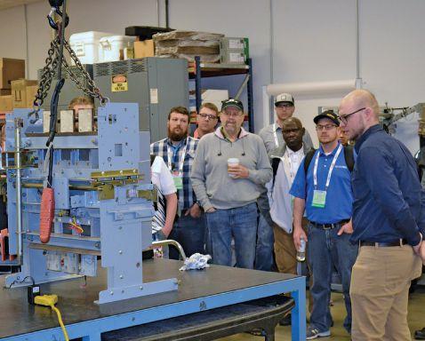




Search. Click. Ship. Purchase AEAMC equipment online, anytime! Emergency support 24/7 800-289-2757 Advanced Electrical & Motor Controls 1801 HURD DR. | IRVING, TX 75038 | 972-253-7783 | Sales@AEAMC.com | AEAMC .com 455-B SHEPARD DRIVE | ELGIN, IL 60123 | 224-856-5036 CHICAGO SERVICE CENTER NOW OPEN!
Insulated Case Circuit Breakers
Molded Case Circuit Breakers
Motor Controls & Centers Bolted Pressure Switches Panelboard Switches & Bus Plugs 480 V Distribution Transformers Replacement Parts New Replacement Motor Control Buckets We can provide and repair the following: From a single part to a switchboard lineup, Advanced Electrical & Motor Controls’ inventory of low-voltage insulated case circuit breakers, molded case circuit breakers, motor controls, and custom switchboards are second to none in the U.S. No matter what you need — new, surplus, used, or reconditioned power distribution equipment, testing and repair, or an engineered solution — AEAMC will keep you up and running. In Stock for Emergency Delivery: New Switchboards up to 4000 amps; New Motor Controls No One Knows Low-Voltage Circuit Breakers & Motor Controls Like Advanced Electrical & Motor Controls visitusatpowertest 2020, booth 341 Chicago, IL 2616 Sirius Road | Denton, TX 76208 | Ph: 877-4-SAFETY | Fx: 940-382-9435 info@CBSArcSafe.com | CBSArcsafe.com From the electrical industry’s most rugged line of ArcSafe universal racking and switching solutions to our ultra-lightweight Chicken Switch product line, we’re here to prove that Distance Is Safety. I use remote racking and switching devices because it means I’ll make it home safe today. Call me chicken. I dare you. RSA-12 RSA-53A CS-01 RRS-3 VB


NEWLY ADDED
EARN CREDITS
LEARN AT YOUR OWN PACE. ADVANCE YOUR KNOWLEDGE. NETA Self-Paced Technical Seminars (SPTS)
All NETA SPTS are eligible for CEUs (Continuing Education Units) and NETA CTD (Continuing Technical Development) credits.
Take advantage of the latest additions to NETA’s learning resources with seminars from PowerTest 2019. www.netaworld.org | 888-300-6382 (NETA)
NETA ACCREDITED COMPANIES Setting the Standard
A&F Electrical Testing, Inc.
80 Lake Ave S Ste 10 Nesconset, NY 11767-1017 (631) 584-5625
kchilton@afelectricaltesting.com www.afelectricaltesting.com
Kevin Chilton
A&F Electrical Testing, Inc.
80 Broad St Fl 5 New York, NY 10004-2257 (631) 584-5625 afelectricaltesting@afelectricaltesting.com Florence Chilton
ABM Electrical Power Services, LLC
720 S Rochester Ste A Ontario, CA 91761-8177 (301) 397-3500 rob.parton@abm.com www.abm.com/electrical Robert Parton
ABM Electrical Power Services, LLC
2631 S. Roosevelt St Tempe, AZ 85282 (602) 722-2423
ABM Electrical Power Services, LLC
3600 Woodpark Blvd Ste G Charlotte, NC 28206-4210 (704) 273-6257
ABM Electrical Power Services, LLC
6940 Koll Center Pkwy Suite# 100 Pleasanton, CA 94566 (408) 466-6920
ABM Electrical Power Services, LLC 9800 E Geddes Ave Unit A-150 Englewood, CO 80112-9306 (303) 524-6560
ABM Electrical Power Services, LLC
3585 Corporate Court San Diego, CA 92123-1844 (858) 754-7963
ABM Electrical Power Services, LLC 1005 Windward Ridge Pkwy Alpharetta, GA 30005 (770) 521-7550
ABM Electrical Power Services, LLC
4221 Freidrich Lane Suite 170 Austin, TX 78744 (210) 347-9481
ABM Electrical Power Services, LLC 6541 Meridien Dr Suite 113 Raleigh, NC 27616 (919) 877-1008 rob.parton@abm.com Robert Parton
ABM Electrical Power Solutions 4390 Parliament Place Suite S Lanham, MD 20706 (301) 967-3500
ABM Electrical Power Solutions 3700 Commerce Dr # 901-903 Baltimore, MD 21227-1642 (410) 247-3300
ABM Electrical Power Solutions
317 Commerce Park Drive Cranberry Township, PA 16066-6407 (724) 772-4638
ABM Electrical Power Solutions 814 Greenbrier Cir Ste E Chesapeake, VA 23320-2643 (757) 364-6145
ABM Electrical Power Solutions
1817 O’Brien Road Columbus, OH 43228 (724) 772-4638 www.abm.com
Absolute Testing Services, Inc. 8100 West Little York Houston, TX 77040 (832) 467-4446 www.absolutetesting.com
Accessible Consulting Engineers, Inc. 1269 Pomona Rd Ste 111 Corona, CA 92882-7158 (951) 808-1040 info@acetesting.com www.acetesting.com
Advanced Electrical Services 4999 - 43rd St. NE Unit 143 Calgary, AB T2B 3N4 (403) 697-3747
Advanced Testing Systems 15 Trowbridge Dr Bethel, CT 06801-2858 (203) 743-2001 pmaccarthy@advtest.com www.advtest.com Pat McCarthy
American Electrical Testing Co., LLC 25 Forbes Boulevard Suite 1 Foxboro, MA 02035 (781) 821-0121 sblizard@aetco.us www.aetco.us
Scott Blizard
American Electrical Testing Co., LLC
Green Hills Commerce Center 5925 Tilghman St Ste 200 Allentown, PA 18104-9158 (484) 538-2272 jmunley@aetco.us
Jonathan Munley
American Electrical Testing Co., LLC
34 Clover Dr South Windsor, CT 06074-2931 (860) 648-1013 jpoulin@aetco.us
Gerald Poulin
American Electrical Testing Co., LLC 76 Cain Dr Brentwood, NY 11717-1265 (631) 617-5330 bfernandez@aetco.us
Billy Fernandez
American Electrical Testing Co., LLC
91 Fulton St., Unit 4 Boonton, NJ 07005-1060 (973) 316-1180 jsomol@aetco.us
Jeff Somol
AMP Quality Energy Services, LLC 352 Turney Ridge Rd Somerville, AL 35670 (256) 513-8255
brian@ampqes.com
Brian Rodgers
Apparatus Testing and Engineering 11300 Sanders Dr Ste 29 Rancho Cordova, CA 95742-6822 (916) 853-6280
jcarr@apparatustesting.com www.apparatustesting.com
Jerry Carr
Apparatus Testing and Engineering
7083 Commerce Cir Ste H Pleasanton, CA 94588-8017 (916) 853-6280 jcarr@apparatustesting.com
Jerry Carr
Applied Engineering Concepts 894 N Fair Oaks Ave. Pasadena, CA 91103 (626) 389-2108 michel.c@aec-us.com www.aec-us.com
Michel Castonguay
Applied Engineering Concepts 8160 Miramar Road San Diego, CA 92126 (619) 822-1106 michel.c@aec-us.com www.aec-us.com
Michel Castonguay
BEC Testing 50 Gazza Blvd Farmingdale, NY 11735-1402 (631) 393-6800
ddevlin@banaelectric.com www.bectesting.com
Daniel Devlin
Burlington Electrical Testing Co., Inc. 300 Cedar Ave Croydon, PA 19021-6051 (215) 826-9400 waltc@betest.com www.betest.com
Walter P. Cleary
Burlington Electrical Testing Co., Inc. 846 Waterford Drive Delran, NJ 08075 (609) 267-4126
C.E. Testing, Inc. 6148 Tim Crews Rd Macclenny, FL 32063-4036 (904) 653-1900 cetesting@hotmail.com www.cetestinginc.com
Mark Chapman
CE Power Engineered Services, LLC 4040 Rev Drive Cincinnati, OH 45232 (800) 434-0415 info@cepower.net
Jerry Daugherty
CE Power Engineered Services, LLC 480 Cave Rd Nashville, TN 37210-2302 (615) 882-9455 dave.mitchell@cepower.net
Dave Mitchell
CE Power Engineered Services, LLC 40 Washington St Westborough, MA 01581-1088 (508) 881-3911 jim.cialdea@cepower.net
Jim Cialdea
CE Power Engineered Services, LLC 9200 75th Avenue N Brooklyn Park, MN 55428 (877) 968-0281 jason.thompson@cepower.net
Jason Thompson
CE Power Engineered Services, LLC 72 Sanford Drive Gorham, ME 04038 (800) 649-6314 mike.roach@cepower.net
Michael Roach
120 • WINTER 2019 NETA ACCREDITED COMPANIES
NETA
CE Power Engineered Services, LLC
8490 Seward Rd. Fairfield, OH 45011 (800) 434-0415
info@cepower.net
Jerry Daugherty
CE Power Engineered Services, LLC
1803 Taylor Ave. Louisville, KY 40213 (800) 434-0415
joe.psillos@cepower.net
Joe Psillos
CE Power Engineered Services, LLC 10338 Citation Drive Suite 300 Brighton, MI 48116 (810) 229-6628
ken.lesperance@cepower.net
Ken L’Esperance
CE Power Engineered Services, LLC 10840 Murdock Drive Knoxville, TN 37932 (800) 434-0415
don.williams@cepower.net
Don Williams
CE Power Engineered Services, LLC
3496 E. 83rd Place Merrillville, IN 46410 (219) 942-2346
lucas.gallagher@cepower.net
Lucas Gallagher
CE Power Engineered Services, LLC
1260 Industrial Park Eveleth, MN 55734 (218) 744-4200
Joseph Peterson
CE Power Solutions of Florida, LLC 3502 Riga Blvd., Suite C Tampa, FL 33619 (866) 439-2992
robert.bordas@cepowersol.com www.cepowersol.com
Robert Bordas
CE Power Solutions of Florida, LLC 3801 SW 47th Avenue Suite 505 Davie, FL 33314 (866) 439-2992
robert.bordas@cepowersol.com
Robert Bordas
Control Power Concepts
3750 Las Vegas Blvd S. Unit 3303 Las Vegas, NV 89158 (702) 448-7833 jtravis@ctrlpwr.com www.controlpowerconcepts.com
John Travis
Dude Electrical Testing, LLC
145 Tower Drive, Unit 9 Burr Ridge, IL 60527-7840 (815) 293-3388
scott.dude@dudetesting.com www.dudetesting.com
Scott Dude
Eastern High Voltage, Inc. 11A S Gold Dr
Robbinsville, NJ 08691-1685 (609) 890-8300
bobwilson@easternhighvoltage.com www.easternhighvoltage.com
Robert Wilson
ELECT, P.C.
375 E. Third Street Wendell, NC 27591 (919) 365-9775
btyndall@elect-pc.com www.elect-pc.com
Barry W. Tyndall
Electek Power Services, Inc. 870 Confederation Street Sarnia, ON N7T2E5 (519) 383-0333
tvanderheide@electek.ca
Tim Vanderheide
Electric Power Systems, Inc. 21 Millpark Ct Maryland Heights, MO 63043-3536 (314) 890-9999 s.reed@epsii.com www.epsii.com
Steve Reed
Electric Power Systems, Inc. 11211 E. Arapahoe Rd Ste 108 Centennial, CO 80112 (720) 857-7273
Thomas Reed
Electric Power Systems, Inc. 120 Turner Road Salem, VA 24153-5120 (540) 375-0084
Virginia@EPS-International.com
Bruce Eppers
Electric Power Systems, Inc. 1090 Montour West Ind Park Coraopolis, PA 15108-9307 (412) 276-4559
Ed Nahm
Electric Power Systems, Inc. 6141 E Connecticut Ave Kansas City, MO 64120-1346 (816) 241-9990
Joe Dillon
Electric Power Systems, Inc. 1230 N Hobson St. Suite 101 Gilbert, AZ 85233 (480) 633-1490
Louis Gilbert
Electric Power Systems, Inc. 915 Holt Ave Unit 9 Manchester, NH 03109-5606 (603) 657-7371
Cindy Taylor
Electric Power Systems, Inc. 3806 Caboose Place Sanford, FL 32771 (407) 578-6424
Doug Pacey
Electric Power Systems, Inc. 1129 E Highway 30 Gonzales, LA 70737-4759 (225) 644-0150
Electric Power Systems, Inc. 684 Melrose Avenue Nashville, TN 37211-3121 (615) 834-0999
Larry Christodoulou
Electric Power Systems, Inc. 2888 Nationwide Parkway 2nd Floor Brunswick, OH 44212 (330) 460-3706
Garth Paul
Electric Power Systems, Inc. 54 Eisenhower Lane North Lombard, IL 60148 (815) 577-9515
George Bratkiv
Electric Power Systems, Inc. 1330 Industrial Blvd. Suite 300 Sugar Land, TX 77478 (713) 644-5400
Houston@eps-international.com
Electric Power Systems, Inc. 56 Bibber Pkwy # 1 Brunswick, ME 04011-7357 (207) 837-6527
Garth Paul
Electric Power Systems, Inc. 11861 Longsdorf St Riverview, MI 48193-4250 (734) 282-3311
t.lindemann@eps-international.com
Teresa Lindemann
Electric Power Systems, Inc. 8515 Calle Alameda NE Ste A Albuquerque, NM 87113 (505) 792-7761
Bill Lewis
Electric Power Systems, Inc. 3209 Gresham Lake Rd. Suite 155 Raleigh, NC 27615 (919) 210-5405
Ray Livingston
Electric Power Systems, Inc. 5850 Polaris Ave., Suite 1600 Las Vegas, NV 89118 (702) 815-1342
Devin Hopkins
Electric Power Systems, Inc. 7925 Dunbrook Rd. Suite G San Diego, CA 92126 (858) 566-6317
Devin Hopkins
Electric Power Systems, Inc. 6679 Peachtree Industrial Dr. Suite H Norcross, GA 30092 (770) 416-0684
Jeremy Russell
Electric Power Systems, Inc. 306 Ashcake Road suite A Ashland, VA 23005 (804) 526-6794
Chris Price
Electric Power Systems, Inc. 7169 East 87th St. Indianapolis, IN 46256 (317) 941-7502
Daniel Douglas
Electric Power Systems, Inc. 7308 Aspen Lane North Suite 160 Brooklyn Park, MN 55428 (763) 315-3520
Paul Cervantez
Electric Power Systems, Inc. 140 Lakefront Drive Cockeysville, MD 21030 (443) 689-2220
Chris Myers
Electric Power Systems, Inc. 783 N. Grove Rd Suite 101 Richardson, TX 75081 (214) 821-3311
Thomas Coon
Electrical & Electronic Controls 6149 Hunter Rd Ooltewah, TN 37363-8762 (423) 344-7666
eecontrols@comcast.net
Michael Hughes
NETAWORLD • 121 NETA ACCREDITED COMPANIES
the Standard
ACCREDITED COMPANIES Setting
NETA ACCREDITED COMPANIES Setting the Standard
Electrical Energy Experts, LLC
W129N10818 Washington Dr Germantown, WI 53022-4446 (262) 255-5222
tim@electricalenergyexperts.com www.electricalenergyexperts.com
Tim Casey
Electrical Engineering & Service Co., Inc.
289 Centre St. Holbrook, MA 02343 (781) 767-9988 jcipolla@eescousa.com www.eescousa.com
Joe Cipolla
Electrical Equipment Upgrading, Inc. 21 Telfair Pl Savannah, GA 31415-9518 (912) 232-7402 kmiller@eeu-inc.com www.eeu-inc.com
Kevin Miller
Electrical Maintenance & Testing, Inc. 12342 Hancock St Carmel, IN 46032-5807 (317) 853-6795
brian.borst@emtesting.com www.emtesting.com
Brian Borst
Electrical Reliability Services
610 Executive Campus Dr Westerville, OH 43082-8870 (877) 468-6384 info@electricalreliability.com www.electricalreliability.com
Electrical Reliability Services
5909 Sea Lion Pl Ste C Carlsbad, CA 92010-6634 (858) 695-9551
Electrical Reliability Services
1057 Doniphan Park Cir Ste A El Paso, TX 79922-1329 (915) 587-9440
Electrical Reliability Services
6900 Koll Center Pkwy Ste 415 Pleasanton, CA 94566-3119 (925) 485-3400
Electrical Reliability Services
8500 Washington St NE Ste A6 Albuquerque, NM 87113-1861 (505) 822-0237
Electrical Reliability Services
2275 Northwest Pkwy SE Ste 180 Marietta, GA 30067-9319 (770) 541-6600
Electrical Reliability Services
10606 Bloomfield Ave Santa Fe Springs, CA 90670-3912 (562) 236-9555
Electrical Reliability Services
400 NW Capital Dr Lees Summit, MO 64086-4723 (816) 525-7156
Electrical Reliability Services
7100 Broadway Ste 7E Denver, CO 80221-2900 (303) 427-8809
Electrical Reliability Services
2222 W Valley Hwy N Ste 160 Auburn, WA 98001-1655 (253) 736-6010
Electrical Reliability Services
221 E. Willis Road, Suite 3 Chandler, AZ 85286 (480) 966-4568
Electrical Reliability Services
1380 Greg St. Ste. 216 Sparks, NV 89431-6070 (775) 746-8484
Electrical Reliability Services 11000 Metro Pkwy Ste 30 Fort Myers, FL 33966-1244 (239) 693-7100
Electrical Reliability Services
245 Hood Road Sulphur, LA 70665-8747 (337) 583-2411
Electrical Reliability Services
9736 South Sandy Pkwy 500 West Sandy, UT 84070 (801) 975-6461
Electrical Reliability Services
6351 Hinson Street, Suite A Las Vegas, NV 89118-6851 (702) 597-0020
Electrical Reliability Services
3535 Emerson Pkwy Suite A Gonzales, LA 70737 (225) 755-0530
Electrical Reliability Services
9636 Saint Vincent Ave Unit A Shreveport, LA 71106-7127 (318) 869-4244
Electrical Reliability Services
1426 Sens Rd. Ste. #5 La Porte, TX 77571-9656 (281) 241-2800
Electrical Reliability Services
4099 SE International Way Ste 201 Milwaukie, OR 97222-8853 (503) 653-6781
Electrical Testing and Maintenance Corp.
3673 Cherry Rd Ste 101 Memphis, TN 38118-6313 (901) 566-5557
r.gregory@etmcorp.net www.etmcorp.net
Ron Gregory
Electrical Testing Solutions
2909 Greenhill Ct Oshkosh, WI 54904-9769 (920) 420-2986
tmachado@electricaltestingsolutions.com www.electricaltestingsolutions.com
Tito Machado
Electrical Testing, Inc. 2671 Cedartown Hwy SE Rome, GA 30161-3894 (706) 234-7623 www.electricaltestinginc.com
Jamie Dempsey
Elemco Services, Inc. 228 Merrick Rd Lynbrook, NY 11563-2622 (631) 589-6343 courtney@elemco.com www.elemco.com
Courtney Gallo
EnerG Test, LLC
206 Gale Lane Kennett Square, PA 19348 (484) 731-0200 KMatthews@energtest.com www.energtest.com
Kevin Matthews
Energis High Voltage Resources 1361 Glory Rd Green Bay, WI 54304-5640 (920) 632-7929 info@energis.com www.energisinc.com
EPS Technology 37 Ozick Dr. Durham, CT 06422 (203) 679-0145 www.eps-technology.com
Sean Miller
Giga Electrical & Technical Services, Inc.
2743A N. San Fernando Road Los Angeles, CA 90065 (323) 255-5894 gigaelectrical@att.net www.gigaelectrical-ca.com
Hermin Machacon
Grubb Engineering, Inc.
2727 North Saint Mary’s St. San Antonio, TX 78212 (210) 658-7250 rgrubb@grubbengineering.com www.grubbengineering.com
Robert Grubb
Halco Testing Services 5773 Venice Boulevard Los Angeles, CA 90019 (323) 933-9431 www.halcotestingservices.com Don Genutis
Hampton Tedder Technical Services 4563 State St Montclair, CA 91763-6129 (909) 628-1256 x271 chasen.tedder@hamptontedder.com www.hamptontedder.com
Chasen Tedder
Hampton Tedder Technical Services 3747 W Roanoke Ave Phoenix, AZ 85009-1359 (480) 967-7765
Linc McNitt
Hampton Tedder Technical Services 4113 Wagon Trail Ave. Las Vegas, NV 89118 (702) 452-9200
Roger Cates
Harford Electrical Testing Co., Inc. 1108 Clayton Rd Joppa, MD 21085-3409 (410) 679-4477 testing@harfordtesting.com www.harfordtesting.com Vincent Biondino
High Energy Electrical Testing, Inc. 515 S Ocean Ave Seaside Park, NJ 08752-1843 (732) 938-2275 judylee@highenergyelectric.com www.highenergyelectric.com
High Voltage Maintenance Corp. 5100 Energy Dr Dayton, OH 45414-3525 (937) 278-0811 www.hvmcorp.com
High Voltage Maintenance Corp. 24 Walpole Park S Walpole, MA 02081-2541 (508) 668-9205
High Voltage Maintenance Corp. 1052 Greenwood Springs Rd. Suite E Greenwood, IN 46143 (317) 322-2055
High Voltage Maintenance Corp. 355 Vista Park Dr Pittsburgh, PA 15205-1206 (412) 747-0550
High Voltage Maintenance Corp. 8787 Tyler Blvd. Mentor, IN 44061 (440) 951-2706
122 • WINTER 2019 NETA ACCREDITED COMPANIES
High Voltage Maintenance Corp.
24371 Catherine Industrial Dr Ste 207 Novi, MI 48375-2422 (248) 305-5596
High Voltage Maintenance Corp.
3000 S Calhoun Rd New Berlin, WI 53151-3549 (262) 784-3660
High Voltage Maintenance Corp.
1 Penn Plaza Suite 500 New York, NY 10119 (718) 239-0359
High Voltage Maintenance Corp.
29 Diana Court Cheshire, CT 06410 (203) 949-2650
High Voltage Maintenance Corp. 941 Busse Rd Elk Grove Village, IL 60007-2400 (847) 640-0005
High Voltage Maintenance Corp. 14300 Cherry Lane Court Suite 115 Laurel, MD 20707 (410) 279-0798
High Voltage Maintenance Corp. 10704 Electron Drive Louisville, KY 40299 (859) 371-5355
HMT, Inc.
6268 State Route 31 Cicero, NY 13039-9217 (315) 699-5563
jack.mcdonnell@resapower.com www.hmt-electric.com
Jack McDonnell
Industrial Electric Testing, Inc. 11321 Distribution Ave W Jacksonville, FL 32256-2746 (904) 260-8378 gbenzenberg@bellsouth.net www.industrialelectrictesting.com Gary Benzenberg
Industrial Electric Testing, Inc. 201 NW 1st Ave Hallandale Beach, FL 33009-4029 (954) 456-7020
Industrial Tests, Inc. 4021 Alvis Ct Ste 1 Rocklin, CA 95677-4031 (916) 296-1200 greg@indtest.com www.industrialtests.com
Greg Poole
NETA ACCREDITED COMPANIES Setting
Infra-Red Building and Power Service, Inc. 152 Centre St Holbrook, MA 02343-1011 (781) 767-0888
Tom.McDonald@infraredbps.com www.infraredbps.com
Thomas McDonald Sr.
J.G. Electrical Testing Corporation 3092 Shafto Road Suite 13 Tinton Falls, NJ 07753 (732) 217-1908 www.jgelectricaltesting.com
M&L Power Systems, Inc.
109 White Oak Ln Ste 82 Old Bridge, NJ 08857-1980 (732) 679-1800 milind@mlpower.com www.mlpower.com
Milind Bagle
Magna IV Engineering 1103 Parsons Rd. SW Edmonton, AB T6X 0X2 (780) 462-3111 info@magnaiv.com www.magnaiv.com
Virginia Balitski
Magna IV Engineering 141 Fox Cresent Fort McMurray, AB T9K 0C1 (780) 791-3122
Ryan Morgan
Magna IV Engineering 3124 Millar Ave. Saskatoon, SK S7K 5Y2 (306) 713-2167 info.saskatoon@magnaiv.com
Adam Jaques
Magna IV Engineering 96 Inverness Dr E Ste R Englewood, CO 80112-5311 (303) 799-1273 info.denver@magnaiv.com Kevin Halma
Magna IV Engineering Avenida del Condor sur #590 Oficina 601 Huechuraba, 8580676 +(56) -2-26552600 info.chile@magnaiv.com Harvey Mendoza
Magna IV Engineering 106, 4268 Lozells Ave Burnaby, BC VSA 0C6 (604) 421-8020 info.vancouver@magnaiv.com
Scott Nixon
Magna IV Engineering Suite 200, 688 Heritage Dr. SE Calgary, AB T2H 1M6 (403) 723-0575
Magna IV Engineering 4407 Halik Street Building E Suite 300 Pearland, TX 77581 (346) 221-2165 info.houston@magnaiv.com Aric Proskurniak
Midwest Engineering Consultants, Ltd. 2500 36th Ave Moline, IL 61265-6954 (309) 764-1561 m-moorehead@midwestengr.com www.Midwestengr.com
Monte Moorehead
MTA Electrical Engineers 350 Pauma Place Escondido, CA 92029 (760) 658-6098 tim@mtaee.com
Timothy G. Shaw
National Field Services 651 Franklin Lewisville, TX 75057-2301 (972) 420-0157
eric.beckman@natlfield.com www.natlfield.com
Eric Beckman
National Field Services 1890 A South Hwy 35 Alvin, TX 77511 (800) 420-0157
Jonathan.wakeland@natlfield.com
Jonathan Wakeland
National Field Services 1405 United Drive Suite 113-115 San Marcos, TX 78666 (800) 420-0157 matt.lacoss@natlfield.com
Matthew LaCoss
National Field Services 3711 Regulus Ave. Las Vegas, NV 89102 (888) 296-0625
tylor.pereza@natlfield.com
Tylor Pereza
National Field Services 2900 Vassar St. #114 Reno, NV 89502 (775) 410-0430 tylor.pereza@natlfield.com
Tylor Pereza
Nationwide Electrical Testing, Inc. 6050 Southard Trce Cumming, GA 30040-6343 (770) 667-1875
Shashi@N-E-T-Inc.com www.n-e-t-inc.com
Shashikant B. Bagle
North Central Electric, Inc. 69 Midway Ave
Hulmeville, PA 19047-5827 (215) 945-7632 ncetest@aol.com www.ncetest.com
Robert Messina
Northern Electrical Testing, Inc. 1991 Woodslee Dr Troy, MI 48083-2236 (248) 689-8980 ldetterman@northerntesting.com www.northerntesting.com
Lyle Detterman
Orbis Engineering Field Services Ltd. #300, 9404 - 41st Ave. Edmonton, AB T6E 6G8 (780) 988-1455 accountspayable@orbisengineering.net www.orbisengineering.net
Orbis Engineering Field Services Ltd. #228 - 18 Royal Vista Link NW Calgary, AB T3R 0K4 (403) 374-0051
Amin Kassam
Orbis Engineering Field Services Ltd. Badajoz #45, Piso 17 Las Condes Santiago, +56 2 29402343 framos@orbisengineering.net
Felipe Ramos
Pace Technologies, Inc. 9604 - 41 Avenue NW Edmonton, AB T6E 6G9 (780) 450-0404 www.pacetechnologies.com
Craig Leavitt
Pace Technologies, Inc. #10, 883 McCurdy Place Kelowna, BC V1X 8C8 (250) 712-0091
Pacific Power Testing, Inc. 14280 Doolittle Dr San Leandro, CA 94577-5542 (510) 351-8811 steve@pacificpowertesting.com www.pacificpowertesting.com
Steve Emmert
NETAWORLD • 123 NETA ACCREDITED COMPANIES
the Standard
NETA ACCREDITED COMPANIES Setting the Standard
Pacific Powertech Inc. #110, 2071 Kingsway Ave. Port Coquitlam, BC V3C 6N2 (604) 944-6697
www.pacificpowertech.ca
jkonklin@pacificpowertech.ca
Josh Konklin
Phasor Engineering
Sabaneta Industrial Park #216
Mercedita, PR 00715 (787) 844-9366 rcastro@phasorinc.com www.phasorinc.com
Rafael Castro
Potomac Testing, Inc.
1610 Professional Blvd Ste A Crofton, MD 21114-2051 (301) 352-1930
kbassett@potomactesting.com www.potomactesting.com
Ken Bassett
Power Engineering Services, Inc. 9179 Shadow Creek Ln Converse, TX 78109-2041 (210) 590-4936
dstaudt@pe-svcs.com www.pe-svcs.com
Daniel Staudt
POWER PLUS Engineering, Inc.
47119 Cartier Court Wixom, MI 48393-2872 (248) 896-0200
sam.mancuso@resapower.com www.epowerplus.com
Power Products & Solutions, LLC 6605 W WT Harris Blvd Suite F Charlotte, NC 28269 (704) 573-0420 x12 adis.talovic@powerproducts.biz www.powerproducts.biz
Adis Talovic
Power Products & Solutions, LLC 13 Jenkins Ct Mauldin, SC 29662-2414 (800) 328-7382
raymond.pesaturo@powerproducts.biz
Raymond Pesaturo
Power Products & Solutions, LLC 9481 Industrial Center Dr. Unit 5 Ladson, SC 29456 (844) 383-8617
Power Solutions Group, Ltd. 425 W Kerr Rd Tipp City, OH 45371-2843 (937) 506-8444
bwilloughby@powersolutionsgroup.com www.powersolutionsgroup.com
Barry Willoughby
Power Solutions Group, Ltd.
2739 Sawbury Blvd. Columbus, OH 43235 (614) 310-8018
sspohn@powersolutionsgroup.com
Stuart Spohn
Power Solutions Group, Ltd.
5115 Old Greenville Highway Liberty, SC 29657 (864) 540-8434
fcrawford@powersolutionsgroup.com
Anthony Crawford
Power Solutions Group, Ltd.
172 B-Industrial Dr. Clarksville, TN 37040 (931) 572-8591
Chris Brown
Power Systems Testing Co.
4688 W Jennifer Ave Ste 108 Fresno, CA 93722-6418 (559) 275-2171 ext 15
dave@pstcpower.com
www.powersystemstesting.com
David Huffman
Power Systems Testing Co.
600 S Grand Ave Ste 113 Santa Ana, CA 92705-4152 (714) 542-6089
Power Systems Testing Co. 6736 Preston Ave Ste E Livermore, CA 94551-8521 (510) 783-5096
Power Test, Inc. 2200 Highway 49 S Harrisburg, NC 28075-7506 (704) 200-8311 rich@powertestinc.com www.powertestinc.com
Rich Walker
POWER Testing and Energization, Inc. 14006 NW 3rd Ct Ste 101 Vancouver, WA 98685-5793 (360) 597-2800 www.powerte.com
POWER Testing and Energization, Inc. 303 US Route One Freeport, ME 04032 (207) 869-1200
POWER Testing and Energization, Inc. 4100 International Plaza, Suite 320 Fort Worth, TX 76109 (817) 882-1900
POWER Testing and Energization, Inc. 12755 Olive Blvd., Suite 100 Saint Louis, MO 63141 (314) 851-4065 www.powerte.com
POWER Testing and Energization, Inc. 1041 Red Ventures Dr. Suite 105 Fort Mill, SC 29707 (803) 835-5900 www.powerte.com
Powertech Services, Inc. 4095 Dye Rd Swartz Creek, MI 48473-1570 (810) 720-2280 www.powertechservices.com
Precision Testing Group 5475 Highway 86 Unit 1 Elizabeth, CO 80107-7451 (303) 621-2776 www.precisiontestinggroup.com
Premier Power Maintenance Corporation 4035 Championship Drive Indianapolis, IN 46268 (317) 879-0660
kevin.templeman@premierpower.us www.premierpowermaintenance.com Kevin Templeman
Premier Power Maintenance Corporation 2725 Jason Rd Ashland, KY 41102-7756 (606) 929-5969
jay.milstead@premierpower.us Jason Milstead
Premier Power Maintenance Corporation 3066 Finley Island Cir NW Decatur, AL 35601-8800 (256) 355-1444
johnnie.mcclung@premierpower.us Johnnie McClung
Premier Power Maintenance Corporation 4301 Iverson Blvd Ste H Trinity, AL 35673-6641 (256) 355-3006
Kevin.Templeman@premierpower.us Kevin Templeman
Premier Power Maintenance Corporation 7301 E County Road 142 Blytheville, AR 72315-6917 (870) 762-2100
Kevin.Templeman@premierpower.us
Kevin Templeman
Premier Power Maintenance Corporation 7262 Kensington Rd. Brighton, MI 48116 (517) 230-6620
Brian.Ellegiers@premierpower.us
Brian Ellegiers
Premier Power Maintenance Corporation 4537 S Nucor Rd. Crawfordsville, IN 47933 (317) 879-0660
kevin.templeman@premierpower.us
Kevin Templeman
Premier Power Maintenance Corporation
1901 Oakcrest Ave., Suite 6 Saint Paul, MN 55113 (612) 616-4236
Josh.vareberg@premierpower.us
Josh Vareberg
RESA Power Service
46918 Liberty Dr Wixom, MI 48393-3600 (248) 313-6868
bruce.robinson@resapower.com www.resapower.com
Bruce Robinson
RESA Power Service
3890 Pheasant Ridge Dr. NE Suite 170 Blaine, MN 55449 (763) 784-4040
Michael.mavetz@resapower.com
Mike Mavetz
RESA Power Service 4540 Boyce Parkway Stow, OH 44224 (800) 264-1549
RESA Power Service 19621 Solar Circle, 101 Parker, CO 80134 (303) 781-2560
jodymedina@groundedtech.com
Jody Medina
RESA Power Service 40 Oliver Terrace Shelton, CT 06484-5336 (800) 272-7711
Bill Hartman
RESA Power Service
13837 Bettencourt Street Cerritos, CA 90703 (800) 996-9975 roger.torrices@resapower.com
Roger Torrices
124 • WINTER 2019 NETA ACCREDITED COMPANIES
RESA Power Service
2390 Zanker Road
San Jose, CA 95131 (800) 576-7372
roger.torrices@resapower.com
Roger Torrices
RESA Power Service
1401 Mercantile Court Plant City, FL 33563 (813) 752-6550
Reuter & Hanney, Inc., a CE Power Company
Northampton Industrial Park 149 Railroad Dr Ivyland, PA 18974-1448 (215) 364-5333 www.reuterhanney.com
Reuter & Hanney, Inc., a CE Power Company
11620 Crossroads Cir Middle River, MD 21220-2874 (410) 344-0300 mjester@reuterhanney.com
Michael Jester
REV Engineering Ltd.
3236 - 50 Avenue SE Calgary, AB T2B 3A3 (403) 287-0156 rdavidson@reveng.ca www.reveng.ca
Roland Nicholas Davidson, IV
Rondar Inc.
333 Centennial Parkway North Hamilton, ON L8E2X6 (905) 561-2808
rshaikh@rondar.com www.rondar.com
Rajeel Shaikh
Rondar Inc. 9-160 Konrad Crescent Markham, ON L3R9T9 (905) 943-7640
Saber Power Services, LLC
9841 Saber Power Ln Rosharon, TX 77583-5188 (713) 222-9102 wharrison@saberpower.com www.saberpower.com
Saber Power Services, LLC 14617 Perkins Road Baton Rouge, LA 70810 (225) 726-7793
Saber Power Services, LLC
9006 Western View Helotes, TX 78023 (210) 267-7282
Saber Power Services, LLC 1908 Lone Star Rd. Mansfield, TX 76063 (210) 296-9970
Scott Testing, Inc. 245 Whitehead Rd Hamilton, NJ 08619 (609) 689-3400 rsorbello@scotttesting.com www.scotttesting.com Russ Sorbello
Sentinel Field Services, LLC 7517 E Pine St Tulsa, OK 74115-5729 (918) 359-0350 gellis@spstulsa.com www.sentinelpowerservices.com Greg Ellis
Shermco Industries 2425 E Pioneer Dr Irving, TX 75061-8919 (972) 793-5523 info@shermco.com www.shermco.com
Shermco Industries 112 Industrial Drive Minooka, IL 60447-9557 (815) 467-5577 info@shermco.com
Shermco Industries 2231 E Jones Ave Ste A Phoenix, AZ 85040-1475 (602) 438-7500 info@shermco.com
Shermco Industries 1711 Hawkeye Dr. Hiawatha, IA 52233 (319) 377-3377 info@shermco.com
Shermco Industries 1705 Hur Industrial Blvd Cedar Park, TX 78613-7229 (512) 267-4800 info@shermco.com
Shermco Industries Boulevard Saint-Michel 47 1040 Brussels Brussels, +32 (0)2 400 00 54
Shermco Industries 2100 Dixon Street Suite C Des Moines, IA 50316-2174 (515) 263-8482 info@shermco.com
NETA ACCREDITED COMPANIES
Shermco Industries 4510 South 86th East Ave. Tulsa, OK 74145 (918) 234-2300 info@shermco.com
Shermco Industries 33002 FM 2004 Angleton, TX 77515-8157 (979) 848-1406 info@shermco.com
Shermco Industries 12000 Network Blvd Buidling D, Suite 410 San Antonio, TX 78249-3354 (210) 877-9090 info@shermco.com
Shermco Industries 4383 Professional Parkway Groveport, OH 43125 (614) 836-8556 info@shermco.com
Shermco Industries 3807 S Sam Houston Pkwy W Houston, TX 77056 (281) 835-3633 info@shermco.com
Shermco Industries 4670 G. Street Omaha, NE 68117 (402) 933-8988 info@shermco.com
Shermco Industries 1301 Hailey St. Sweetwater, TX 79556 (325) 236-9900 info@shermco.com
Shermco Industries 2901 Turtle Creek Dr. Port Arthur, TX 77642 (409) 853-4316 info@shermco.com
Shermco Industries 5145 NW Beaver Dr. Johnston, IA 50131 (515) 265-3377 info@shermco.com
Shermco Industries 998 E. Berwood Ave. Saint Paul, MN 55110 (651) 484-5533 info@shermco.com
Shermco Industries 12796 Currie Court Livonia, MI 48150 (734) 469-4050 info@shermco.com
Shermco Industries 1720 S. Sonny Ave. Gonzales, LA 70737 (225) 647-9301 info@shermco.com
Shermco Industries 501 Union West Blvd. Matthews, NC 28104 (910) 568-1053 info@shermco.com
Shermco Industries 5805 Hwy 43 Satsuma, AL 36507 (251) 679-3224
James Irby info@shermco.com
Shermco Industries 5805 Hwy 43 Satsuma, AL 36507 (251) 679-3224 info@shermco.com
Shermco Industries 5211 Linbar Dr. Suite 507 Nashville, TN 37211 (615) 928-1182 info@shermco.com
Shermco Industries Canada 1033 Kearns Crescent RM of Sherwood, SK S4K 0A2 (306) 949-8131 info@shermco.com
Shermco Industries Canada 233 Faithfull Cr. Saskatoon, SK S7K 8H7 (306) 955-8131 info@shermco.com
Shermco Industries Canada 3434 25th Street NE Calgary, AB T1Y 6C1 (403) 769-9300 info@shermco.com
Shermco Industries Canada 1375 Church Avenue Winnipeg, MB R2X 2T7 (204) 925-4022 info@shermco.com
Shermco Industries Canada 3731 - 98 Street Edmonton, AB T6E 5N2 (780) 436-8831 info@shermco.com
NETAWORLD • 125 NETA ACCREDITED COMPANIES
the Standard
Setting
NETA ACCREDITED COMPANIES Setting the Standard
Sigma Six Solutions, Inc.
2200 W Valley Hwy N Ste 100 Auburn, WA 98001-1654 (253) 333-9730
jwhite@sigmasix.com www.sigmasix.com
John White
Sigma Six Solutions, Inc. www.sigmasix.com Quincy, WA 98848 (253) 333-9730
Chris Morgan
Southern New England Electrical Testing, LLC
3 Buel St Ste 4 Wallingford, CT 06492-2395 (203) 269-8778
dave.asplund@sneet.org www.sneet.org
Dave Asplund
Star Electrical Services & General Supplies, Inc. PO Box 814 Las Piedras, PR 00771 (787) 716-0925
ahernandez@starelectricalpr.com www.starelectricalpr.com
Abelardo Hernandez
Taurus Power & Controls, Inc.
9999 SW Avery St Tualatin, OR 97062-9517 (503) 692-9004 robtaurus@tauruspower.com www.tauruspower.com
Rob Taurus
Taurus Power & Controls, Inc. 19226 66th Ave S. #L102 Kent, WA 98032-2197 (425) 656-4170
Tidal Power Services, LLC 4211 Chance Ln Rosharon, TX 77583-4384 (281) 710-9150
monty.janak@tidalpowerservices.com www.tidalpowerservices.com
Monty Janak
Tidal Power Services, LLC 8184 Highway 44 Ste 105 Gonzales, LA 70737-8183 (225) 644-8170
Tidal Power Services, LLC 1056 Mosswood Dr Sulphur, LA 70665-9508 (337) 558-5457
Titan Quality Power Services, LLC 1501 S Dobson Street Burleson, TX 76028 (866) 918-4826
Titan Quality Power Services, LLC 7630 Ikes Tree Drive Spring, TX 77389 (281) 826-3781
Titan Quality Power Services, LLC 7000 Meany Ave. Bakersfield, CA 93308 (661) 589-0400
Tony Demaria Electric, Inc. 131 W F St Wilmington, CA 90744-5533 (310) 816-3130
neno@tdeinc.com www.tdeinc.com Neno Pasic
Utilities Instrumentation Service - Ohio, LLC 998 Dimco Way Centerville, OH 45458 (937) 439-9660 www.uiscorp.com
Utilities Instrumentation Service, Inc. 2290 Bishop Cir E Dexter, MI 48130-1564 (734) 424-1200
gary.walls@UIScorp.com www.uiscorp.com
Gary Wells
Utility Service Corporation PO Box 1471 Huntsville, AL 35807 (256) 837-8400
apeterson@utilserv.com www.utilserv.com
Alan D. Peterson
Western Electrical Services, Inc. 14311 29th St E Sumner, WA 98390-9690 (253) 891-1995
dhook@westernelectricalservices.com www.westernelectricalservices.com
Dan Hook
Western Electrical Services, Inc. 5680 S 32nd St Phoenix, AZ 85040-3832 (602) 426-1667
carcher@westernelectricalservices.com
Craig Archer
Western Electrical Services, Inc. 3676 W California Ave Ste C106 Salt Lake City, UT 84104-6533 (888) 395-2021
tking@westernelectricalservices.com
Toby King
Western Electrical Services, Inc. 4510 NE 68th Dr Unit 122 Vancouver, WA 98661-1261 (888) 395-2021
Jason Carlson
Western Electrical Services, Inc. 5505 Daniels St. Chino, CA 91710 (619) 672-5217
mwallace@westernelectricalservices.com
Matt Wallace
Western Electrical Services, Inc. 620 Meadow Ln. Los Alamos, NM 87547 (505) 469-1661
tking@westernelectricalservices.com
Toby King
126 • WINTER 2019 NETA ACCREDITED COMPANIES
RENT ELECTRICAL TEST EQUIPMENT




Providing Testing Solutions for:


• Protective Relays
• Transformers & Motor Analysis
• Partial Discharge/Corona
• Current Injection
• Cable Fault Location


• Switchgear/Circuit Breakers
• Insulation Resistance
• Tan Delta/Power Factor
• Current Transformers
• Ground Grid
Advanced Test Equipment Rentals


The Knowledge. The Equipment. The Solution.
800-404-ATEC (2832) • rentals@atecorp.com • www.atecorp.com
Please
in


128 • WINTER 2019 ADVERTISERS
below.
thank
you
advertisement
NETA
. INDEPENDENT NETA ACCREDITED COMPANIES Absolute Testing Services, Inc. 43 American Electrical Testing Co., LLC 59 Apparatus Testing and Engineering 115 Burlington Electrical Testing Co. .................... 32 Eastern High Voltage............................... 91 Electrical Energy Experts, Inc. ....................... 42 Electrical Reliability Services (Vertiv) 98 Elemco Testing Co., Inc. 32 EnerG Test 108 Harford Electrical Testing Co. 112 High Voltage Maintenance Corp. ................... 24 Industrial Electric Testing, Inc. ...................... 90 Infra-Red Building and Power Service, Inc. .......... 108 Nationwide Electrical Testing, Inc. 108 North Central Electric, Inc. 6 Orbis Engineering Field Services LTD 42 Potomac Testing, Inc. .............................. 27 Power Products & Solutions, Inc. .................... 18 Power Systems Testing Co. .......................... 32 Power Testing and Energization, Inc. 115 Resa Power, LLC 60 Scott Testing Inc. 31 Shermco Industries 9 Sigma Six Solutions, Inc. ........................... 112 Taurus Power & Controls, Inc. ...................... 60 Tony Demaria Electric, Inc. ......................... 31 Utilities Instrumentation Service 6 MANUFACTURERS AND OTHER SERVICE PROVIDERS Advanced Test Equipment Rentals (ATE Corp) ............. 127 AEAMC ................................................. 118 AEMC .................................................. 113 Aero Tech Laboratories 31 Ampteks 112 AVO Training 71 B CS Switchgear 83 Belyea Company .......................................... 116 Bullock Breakers ........................................... 13 Burlington Safety Laboratory, Inc. ........................... 60 CBS ArcSafe 118 Circuit Breaker Sales Co., Inc. 14 Doble Engineering 100 Dranetz ................................................... 81 ECP Solutions .............................................. 8 High Voltage Inc. ......................................... 113 High Voltage Electric Service, Inc. 24 HV Diagnostics, Inc. 50 Intellirent 33 Megger Inside Front Cover Monster Electrical ......................................... 24 National Switchgear ........................................ 51 National Training Center .................................. 116 NETA ANSI/NETA MTS 105 NETA Handbook Series III. . . . . . . . . . . . . . . . . . . . . . . . . . . . . . . . . 99 NETA New SPTS 119 NETA PowerTest 2020 Alliance ............................. 25 NETA PowerTest 2020 Call for Exhibitors ................... 61 NETA PowerTest 2020 Call for Sponsors .................... 82 NETA PowerTest 2020 Early Bird Registration 19 OMICRON electronics Corp. USA Back Cover Phenix Technologies, Inc. 42 Protec Equipment Resources 5 Quality Switchgear......................................... 98 R aytech ..................................... Inside Back Cover Solid State Exchange ...................................... 109 Southland Electrical Supply 18 Tech Con/TJH2b 51 Technitrol, Inc. 91 Thyritronics, Inc. 115 Utility Relay Company ..................................... 41 Vacuum Interrupters, Inc. .................................. 14
This issue’s advertisers are identified
these advertisers by telling them
saw their
World
ADVERTISERS





Raytech’s CAPO 12 offers features that allow you to take advantage of the current and future testing methods.
• Test Voltage up to 12kV | Built in Standard Capacitor
• Test Frequency – 10 Hz to 400 Hz
• Easy to Operate, Accurate & Reliable
• Internal Thermal Printer for Printing Test Results
• Internal Storage for Over 10,000 Test Results
• 5 Year Warranty

For more information regarding the newest test methods and standards for Insulation Power Factor testing, email: Info@RaytechUSA.com


Toll Free: 888 484 3779 | Phone 267 404 2676 118 South 2nd Street, Perkasie, PA 18944 www.RaytechUSA.com Phone +41 56 648 60 10 Oberebenestrasse 11, 5620 Bremgarten, Switzerland www.raytech.ch CAPO 12 Portable - Accurate - Reliable 12 kV Insulation Power Factor Test Set


Test partial discharge in less than 10 clicks with MONTESTO 200
Up to now, many of our customers have considered on-line partial discharge (PD) measurement and monitoring to be time-consuming and complicated. This inspired us to develop the portable, user-friendly and versatile MONTESTO 200.
It is designed for both on-line PD measurement and monitoring, indoors or outdoors, on various electrical assets. Plug-and-play connections reduce setup time. Automated software features help to quickly identify insulation defects.
www.omicronenergy.com/montesto200


 Matthew Sze Regional Application Specialist


 BY SUGHOSH KUBER, Megger


 BY ROBERT WANG, OMICRON electronics Corp. USA


 BY GOWRI RAJAPPAN, Doble Engineering Company


 BY KERRY HEID, Shermco Industries Canada


 Matthew Sze Regional Application Specialist