






TRANSDUCER: WHERE DO I CONNECT? SF6—THE ALTERNATIVE GAS PAGE 58 ISSN 2167-3594 NETA WORLD JOURNAL PRINT ISSN 2167-3586 NETA WORLD JOURNAL ONLINE S P RIN G 2013 SPRING 2019 NEW PRODUCT FORUM PAGE 114
CIRCUIT BREAKER AND

True 3 Phase Transformer Turns Ratiometer Ask why stepping up delivers more accuracy than stepping down when you see the new TTRU3 at NETA POWERTEST 2019! TTRU3 us.megger.com/powertest The new Megger TTRU3 transformer turns ratiometer steps up the voltage during ratio measurements to give you the most accurate readings possible, so you and your equipment can Power on. Visit Megger at Booth 303 to see all of our newest test solutions built to help you Power on. STEP UP to Accuracy
COVER STORY

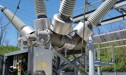
Circuit Breaker and Transducer: Where Do I Connect?
Medium- and high-voltage circuit breakers, a critical component of the electrical grid, are designed to protect both assets and personnel in the substation. CIGRE Working Group
A3.06’s study on the reliability of high-voltage equipment revealed that the majority of circuit breaker faults were related to problems with the mechanism. To verify that the mechanism is functioning correctly, a time and travel test needs to be performed. Due to the perceived complexity involved or the occasional lack of information from the manufacturer, travel measurements are often neglected. This article examines several transducers that can be used for travel measurement and what is required to use them. A case study investigates different types of transducers attached at various points of the circuit breaker; all reveal the same information. Additionally, the article presents recommendations on how and where to attach a transducer when little or no information is provided.
By Robert Foster, Megger
FEATURES
7 President’s Desk
Jim Cialdea, CE Power Engineered Services, LLC
NETA President
58 SF6 — The Alternative Gas
Danielle White and Lina Encinias, DILO Company, Inc.
Reconditioning the existing stockpile of SF6 gas offers several benefits over importing virgin gas. But what measures must be taken so that the industry can continue to use this insulating medium safely and in compliance with best practices and standards?
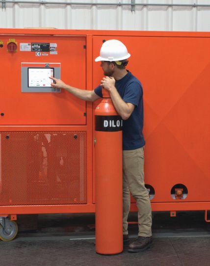

TABLE OF CONTENTS TABLE OF CONTENTS NETAWorld • 3
42 58
10 NFPA 70E and NETA
Testing Battery Banks
Ron Widup and James R. White, Shermco Industries
16 Tech Tips
Computer-Based Technology for Ground Testing
Jeff Jowett, Megger
23 Tech Quiz
Sulphur Hexafluoride Circuit Breakers
James R. White, Shermco Industries
26 Safety Corner
Sulphur Hexafluoride Gas Hazards
Paul Chamberlain, American Electrical Testing Co., LLC
32 Relay Column
Dynamic Testing of Numerical Protection Relays
Steve Turner, Electrical Consultants, Inc.
INDUSTRY
64 The Value of Performing Power Factor
Sweep Measurements on Bushings
Brandon Dupuis, OMICRON
74 High-Power Batteries as Power Source with Dynamic Resistance Measurement and Both Sides Grounded
Adnan Šečić, Radenko Ostojić, and Nijaz Hadžimejlić, DV Power–Sweden
82 Measuring Humidity: Why It’s Important
John Olobri, AEMC Instruments
ADVANCEMENTS IN INDUSTRY
88 Practice and Theory: High-Voltage Laboratory Testing of New Electrical Products
Jerod Day, Vacuum Interrupters, Inc., and Finley Ledbetter, Group CBS, Inc.
INSIGHTS & OBSERVATIONS — NETA CAP SPOTLIGHT 96 Group CBS: Evolve and Change — or Decay
AND STANDARDS
ANSI/NETA Standards Update
ASTM F18 Committee Report
James R. White, Shermco
108 Insulated Conductor Committee News
Ralph Patterson, Carolina Electrical 111 IEEE Transformers Committee Report
Scott Reed, MVA Diagnostics
Product Forum
4 • SPRING 2019 TABLE OF CONTENTS TABLE OF CONTENTS IN EVERY ISSUE
TOPICS
100
105
SPECIFICATIONS
NETA NEWS 114 New
IMPORTANT LISTS 125 NETA
132
Accredited Companies
Advertiser List

3050 Old Centre Road, Suite 101
Portage, MI 49024
Toll free: 888.300.NETA (6382)
Phone: 269.488.NETA (6382)
Fax : 269.488.6383
neta@netaworld.org
www.netaworld.org
executive director: Missy Richard
NETA Officers
president: Jim Cialdea, CE Power Engineered Services, LLC
first vice president: Scott Blizard, American Electrical Testing Co., Inc.
second vice president: Lorne Gara, Orbis Engineering Field Services, Ltd.
secretary: Eric Beckman, National Field Services
treasurer: John White, Sigma Six Solutions
NETA Board of Directors
Ken Bassett (Potomac Testing, Inc.)
Eric Beckman (National Field Services)
Scott Blizard (American Electrical Testing Co., Inc.)
Jim Cialdea (CE Power Engineered Services, LLC)
Scott Dude (Dude Electrical Testing LLC)
Lorne Gara (Orbis Engineering Field Services, Ltd.)
Dan Hook (Western Electrical Services, Inc.)
David Huffman (Power Systems Testing)
Alan Peterson (Utility Service Corporation)
John White (Sigma Six Solutions)
Ron Widup (Shermco Industries)
NETA World Staff
technical editors: Roderic L. Hageman, Tim Cotter
assistant technical editors: Jim Cialdea, Dan Hook, Dave Huffman, Bob Sheppard
associate editor: Resa Pickel
managing editor: Carla Kalogeridis
copy editor: Beverly Sturtevant
advertising manager: Laura McDonald
design and production: Moon Design
NETA Committee Chairs
conference: Ron Widup; membership: Ken Bassett; promotions/marketing: Scott Blizard; safety: Scott Blizard and Jim White; technical: Alan Peterson; technical exam: Dan Hook; continuing technical development: David Huffman; training: Bob Sheppard; finance: John White; nominations: Alan Peterson; alliance program: Jim Cialdea; association development: Ken Bassett and John White
© Copyright 2019, NETA
NOTICE AND DISCLAIMER
NETA World is published quarterly by the InterNational Electrical Testing Association. Opinions, views and conclusions expressed in articles herein are those of the authors and not necessarily those of NETA. Publication herein does not constitute or imply endorsement of any opinion, product, or service by NETA, its directors, officers, members, employees or agents (herein “NETA”).
All technical data in this publication reflects the experience of individuals using specific tools, products, equipment and components under specific conditions and circumstances which may or may not be fully reported and over which NETA has neither exercised nor reserved control. Such data has not been independently tested or otherwise verified by NETA.
NETA MAKES NO ENDORSEMENT, REPRESENTATION OR WARRANTY AS TO ANY OPINION, PRODUCT OR SERVICE REFERENCED OR ADVERTISED IN THIS PUBLICATION. NETA EXPRESSLY DISCLAIMS ANY AND ALL LIABILITY TO ANY CONSUMER, PURCHASER OR ANY OTHER PERSON USING ANY PRODUCT OR SERVICE REFERENCED OR ADVERTISED HEREIN FOR ANY INJURIES OR DAMAGES OF ANY KIND WHATSOEVER, INCLUDING, BUT NOT LIMITED TO ANY CONSEQUENTIAL, PUNITIVE, SPECIAL, INCIDENTAL, DIRECT OR INDIRECT DAMAGES. NETA FURTHER DISCLAIMS ANY AND ALL WARRANTIES, EXPRESS OF IMPLIED, INCLUDING, BUT NOT LIMITED TO, ANY IMPLIED WARRANTY OF FITNESS FOR A PARTICULAR PURPOSE.
ELECTRICAL TESTING SHALL BE PERFORMED ONLY BY TRAINED ELECTRICAL PERSONNEL AND SHALL BE SUPERVISED BY NETA CERTIFIED TECHNICIANS/ LEVEL III OR IV OR BY NICET CERTIFIED TECHNICIANS IN ELECTRICAL TESTING TECHNOLOGY/LEVEL III OR IV. FAILURE TO ADHERE TO ADEQUATE TRAINING, SAFETY REQUIREMENTS, AND APPLICABLE PROCEDURES MAY RESULT IN LOSS OF PRODUCTION, CATASTROPHIC EQUIPMENT FAILURE, SERIOUS INJURY OR DEATH.









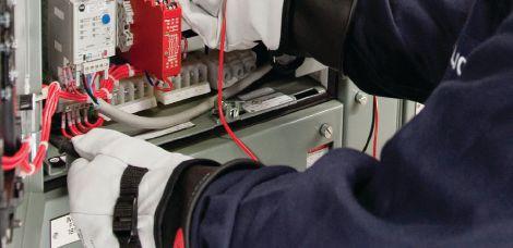

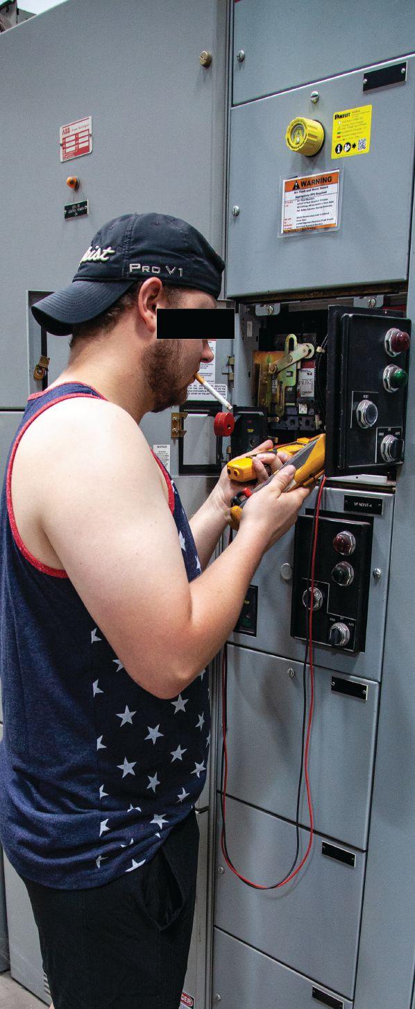


(be_this_guy!) (be_this_guy!) Train with the Experts. Train with Shermco. www.shermco.com 888-SHERMCO WHY Endanger yourself and others?







TESTING BATTERY BANKS


BANKS
BY RON WIDUP and JIM WHITE, Shermco Industries
The 2021 NFPA 70E cycle started last year, and the Second Draft Meeting will convene July 14–19, 2019. One interesting benefit of being on the committee is the information that is shared with us. Some of it is obviously presented to serve one purpose or another, but some of it is put forward by well-known, independent laboratories that have no reason to slant things.
One such piece of information was presented by Bonneville Power Administration (BPA) in their Engineering and Technical Services Report, BPA F5450.05. This report covers incident energy tests done on a 125V, 1,300-ampere-hour battery bank. BPA is part of the United States Department of Energy and is well-respected for their studies on testing and maintenance of field equipment, as well as other subjects. The 90-page report is too long to publish in this column, but anyone can request a copy from Jim White at jwhite@shermco.com
This column shares the conclusions they reached by testing the subject battery bank and tries to clear the air a bit, as a number of
NETA-member technicians have concerns about working on battery systems. The report is dated May 2017, so it is fairly recent.
IN THE BEGINNING
The report was initiated by BPA’s Protection Engineering Group (TECC) to validate the models they were using for dc incident energy calculations and to provide guidance for reducing the exposure of its technicians. Previously, they had performed some testing at 48Vdc and 125Vdc using small (nine-ampere-hour) batteries. These earlier tests indicated that many of their dc panels had high estimated incident energy and required restrictive personal protective gear to
10 • SPRING 2019 TESTING BATTERY BANKS
THE NFPA 70E AND NETA
work on or near. In these earlier tests, an arc could be sustained at 125V, but not at 48V. Incident energy at 48V was negligible due to the small capacity of the battery.
The tests provided some information, but BPA wanted to perform tests closer to the actual conditions its technicians would face in the field. Therefore, this new series of tests was conducted.
HERE AND NOW
The tests were performed using a 125V, 1,300-ampere-hour battery bank with a bolted fault current of 11,000A. The tests were performed at 3,900A and 7,850A of fault current. Sixty tests were run, and the arc duration, peak current, mean arc current, and incident energy at 18 inches were all recorded, including the waveforms.
According to the report, changing to the fullsize battery bank actually made the arc more difficult to sustain due to magnetic forces that caused the arc to move and expand rapidly. The difficulty in sustaining the arc was also caused by erosion of the metal, which widened the arc gap and extinguished the arc. Between the two factors, arc duration and incident energy were reduced.
The highest fault current was measured at 7,850A, and the greatest arc duration was 0.715 seconds. The highest incident energy (at 18 inches) measured 0.9 Cal/cm2. To us, this is surprisingly low. BPA notes that their previous estimates on incident energy were 10 times what these tests indicated. With that much difference in estimated incident energy, technicians would surely wear much more arcrated PPE, maybe unnecessarily. The testing to investigate reducing incident energy exposure to their workers was not followed through, as the tests did not provide justification.
BPA REPORT SUMMARY
The dc arc flash test results using the 125V 1,300-ampere-hour battery are summarized here.
THE NFPA 70E AND NETA
• Bolted fault currents of 3,900A and 7,850A were achieved.
• An arc can be reliably initiated with bus bar spacing of .025 inch and 0.5 inch. Gap spacing larger than 0.5 inch results in a very short arc duration.
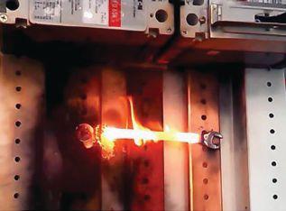
• It is difficult to sustain an arc with this source. Once established, the arc rapidly moves to a place where it can expand and extinguish itself. When forced into a confined area, it erodes the copper (or steel) electrodes until there is sufficient gap to extinguish the arc.
• The longest arc time observed was 0.715 seconds. This is significantly shorter than the standard two-second arc duration used in arc flash calculations.
• The measured incident energy at 18 inches was modest. The maximum measured incident energy was 0.9 Cal/cm2. This is considerably less than models would predict (10.3 Cal/cm2).
• Molten metal is ejected from the arc and presents a hazard to personnel in close proximity to the fault.
• Tests with a tool in the gap did not produce significant incident energy levels. Loose tools were quickly ejected from the test bus without excessive force. When the tool was fixed into place, the resulting arc eroded the tool and bus bar until the gap was wide enough to extinguish the arc.
• Test results with battery chargers are consistent with standard assumptions that they contribute up to 150 percent of their maximum current rating.
• Adding inductance to the circuit did not result in a significant increase in arc duration.

NETAWorld • 11 TESTING BATTERY BANKS
Results with a Tool in the Gap
THE NFPA 70E AND NETA
• In most cases, combustible materials in the gap extend the arc duration and thereby the incident energy.
• Arc detection and mitigation schemes are not worth pursuing due to the low incident energy levels observed.
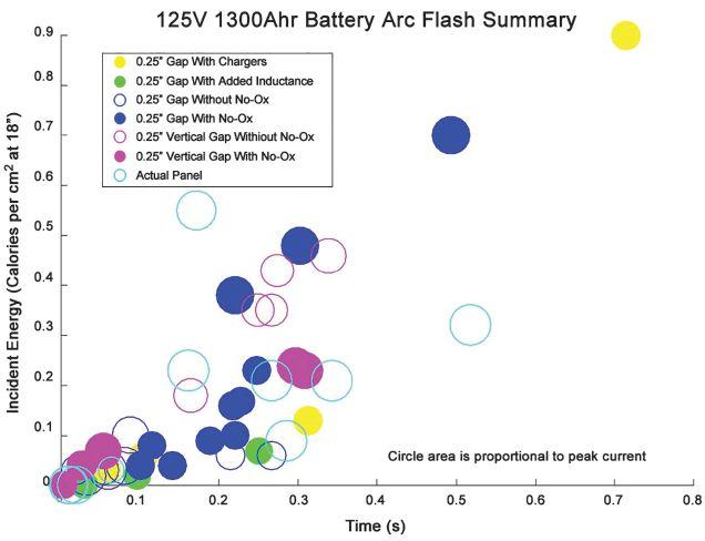
Figure 1: Incident energy was measured at 0.25-inch gap, with and without No-Oxide® used to prevent corrosion of the terminals.
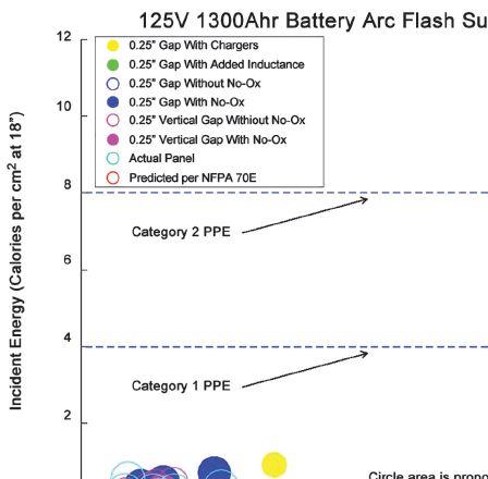


Figure 2: Measured vs. Calculated Values and Category 1 PPE
When BPA used a tool to bridge the two bus bars, it was ejected immediately without excessive force. I guess that means it didn’t become a weapon. A maximum of 0.8 Cal/cm2 was measured during these tests. When the tool was fixed to one bus and touching the other, it burned away the end of the tool and the bus until there was adequate gap to extinguish the arc. The maximum incident energy measured was 0.32 Cal/cm2.
THE BOTTOM LINE
BPA provides all the test results in the report. However, more important for most NETA members are the graphs included in the report.
In Figure 1, the highest incident energy recorded (18 inches from the arc source) was 0.9 Cal/cm2; other tests were measured at almost 0.8 Cal/cm2 and 0.6 Cal/cm2. The rest of the results were less than 0.6 Cal/cm2.
In Figure 2, these measured values are compared to the calculated values plus Category 1 (4 Cal/cm2) and Category 2 (8 Cal/ cm2) arc-rated clothing. Note the calculated value is a bit above 10 Cal/cm2.
CONCLUSION
The test results provided by BPA’s testing are interesting and raise questions about dc arc fl ash calculations provided by NFPA 70E. Although ac arcs are fairly well researched, dc arcs are not. More clarity should be brought to light when the IEEE/NFPA Joint Work Group publishes its results, but who knows how long that will take.
In the meantime, you have to make your own decisions about how to treat dc arc flash. You can use the results of BPA’s report, or you can be more conservative (much more conservative according to BPA) and use the calculations in NFPA 70E. Or you could use something between the two. In the end, we’re discussing personnel safety, and your company would be responsible.
12 • SPRING 2019
TESTING BATTERY BANKS
THE NFPA 70E AND NETA
Ron Widup and Jim White are NETA’s representatives to NFPA Technical Committee 70E, Electrical Safety Requirements for Employee Workplaces. Both gentlemen are employed by Shermco Industries in Dallas, Texas, a NETA Accredited Company.

Ron Widup is CEO of Shermco Industries and has been with the company since 1983. He is a member of the Technical Committee on NFPA 70E, Standard for Electrical Safety in the Workplace; a Principal Member of the National Electrical Code (NFPA 70) Code Panel 11; a Principal Member of the Technical Committee on NFPA 790, Standard for Competency of Third-Party Evaluation Bodies; and a Principal Member of the Technical Committee on NFPA 791, Recommended Practice and Procedures for Unlabeled Electrical Equipment Evaluation. Ron is also a member of the Technical Committee on NFPA 70B, Recommended Practice for Electrical Equipment Maintenance, and a member of the NETA Board of Directors and Standards Review Council. He is Vice Chair for IEEE Std. 3007.3, Recommended Practice for Electrical Safety in Industrial and Commercial Power Systems. Ron is a Journeyman Electrician in Texas, a NETA Level 4 Senior Technician, and an NFPA Certified Electrical Safety Compliance Professional.

James (Jim) R. White, Vice President of Training Services, has worked for Shermco Industries since 2001. He is a NFPA Certified Electrical Safety Compliance Professional and a NETA Level 4 Senior Technician. Jim is NETA’s principal member on NFPA Technical Committee NFPA 70E®, Standard for Electrical Safety in the Workplace; NETA’s principal representative on National Electrical Code® Code-Making Panel (CMP) 13; and represents NETA on ASTM International Technical Committee F18, Electrical Protective Equipment for Workers. Jim is Shermco Industries’ principal member on NFPA Technical Committee for NFPA 70B, Recommended Practice for Electrical Equipment Maintenance and represents AWEA on the ANSI/ ISEA Standard 203, Secondary Single-Use Flame Resistant Protective Clothing for Use Over Primary Flame Resistant Protective Clothing. An IEEE Senior Member, Jim was Chairman of the IEEE Electrical Safety Workshop in 2008 and is currently Vice Chair for the IEEE IAS/PCIC Safety Subcommittee.









6605 W. WT Harris Blvd. Suite F • Charlotte NC 28269 | 13 Jenkins Court • Mauldin, SC 29662 | 9481 Industrial Center Drive, Suite 5 • Ladson, SC 29456 704.573.0420 • 844-383-8617 • 704.573.3693 (fax) • www.powerproducts.biz Acceptance and Maintenance Testing Commissioning Circuit Breaker Repair and Retrofit Infrared Scanning MV Cable Terminations and Testing Commissioning and Load Bank Testing of UPS, Generators, and ATS RETROFITTED BREAKER HIGH VOLTAGE, INC. 31 County Rt. 7A • Copake, NY 12516 • Tel: (518) 329-3275 • Fax: (518) 329-3271 • sales@hvinc.com • www.hvinc.com HIGH VOLTAGE, INC. ISO 9001 2008 HVI - The World’s Source for High Voltage Test Equipment HVI Makes it Easy and Efficient Cable Fault Locating & VLF Testing VLF hipot: 0 - 33 kVac @ 1 μF @ 0.1 Hz Fault locate: 0 - 13 kV @ 760 J VLF Fault Burner Radar/TDR ready Other Thumper models: 5/10/20 kV @ 1000 J 9/18/36 kV @ 3200 J • Very Low Frequency AC Technology • Cable Diagnostic TD & PD Testing • Cable Fault Locating with Controlled Energy • AC & DC Hipots, Aerial Lift Testers, Oil Testers • Ω-CHECK® Concentric Neutral Testing • Custom Engineered & Fabricated Van Pkgs. All That You Need VLF/Thumper Combination 50 kVac @ 3 kVA Hipot 1 piece & w/cable output VLF 0.1 Hz @ 34 kVac Comp. control - wireless 80 kVdc Hipot/Megohmmeter 1 instrument - 2 tests All HVI Products are Made in the USA 4244_HV_NETA_Winter_2018_Ad.pdf 1 9/10/18 9:17 AM


COMPUTER-BASED TECHNOLOGY FOR GROUND TESTING
 BY JEFF JOWETT, Megger
Since its inception in the early 20th century, testing grounded electrodes has been grounded on one technique and technology only: Fall of Potential. The test instrument made contact with the earth through long leads and driven probes, injected a current between the electrode being tested and a remote probe, and measured the voltage drop caused by earth resistance to another driven probe. Since the earth is not a discrete object, but rather the vastness of the planet, ground testing required a great deal of operator training, knowledge, involvement, and technique to obtain a reliable measurement and confirm it was correct.
Over the years, improvements accrued with three goals: Make the tests less time consuming, more accurate, and more reliable. In the late 20th century, a second technology — the clamp-on ground tester — emerged. However, the clamp-on aims only at the first of the three goals: make testing quicker and easier. It eliminates long leads and a lot of walking to move probes. However, it is somewhat less accurate, less reliable, and includes significant limitations, specifically shorts and opens — the
two fundamental faults in electrical operations of all sorts. A clamp-on can’t test an isolated electrode not connected to a system (open) or to a multiply-connected electrode (short).
About the same time, the computer-based grounding multimeter was developed. This is not actually a new technology, but rather a significant enhancement of the tried-andtrue Fall of Potential and its derivatives. Developed by A. P. (Sakis) Meliopoulos in
16 • SPRING 2019 COMPUTER-BASED TECHNOLOGY FOR GROUND TESTING
TECH TIPS

association with George Cokkinides at Georgia Tech and then commercially marketed, the grounding multimeter combines standard testing techniques with computer-controlled interaction that vastly enhances data analysis. Operation is back to square one in terms of time and involvement, but built-in computer analysis adds another layer of confidence in accuracy and reliability. The original ground testers were null balance instruments that worked by balancing a series of built-in decade resistors against the load, which was the critical expanse of earth judiciously selected by the operator for probe placement. The reading was attained when the null meter balanced. Instrument technology at the time was concerned with getting an accurate measurement; it left a lot for the operator to figure out when a stable reading was not forthcoming, and a lot of trial and error was routine. Later, built-in indicators detected issues such as noise interference and insufficient probe

contact and notified the operator. Additional test methods dealt with common problems like working distance and used mathematics to flag insufficient tests and give the operator the chance to try again after some correction.
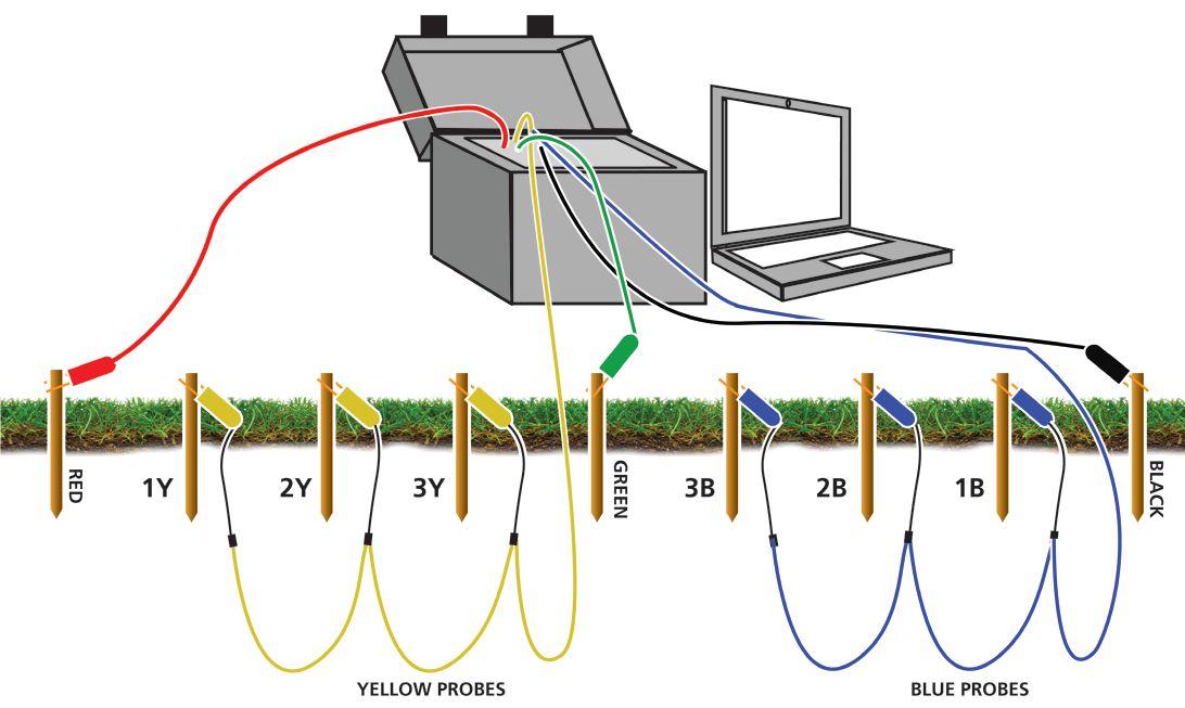
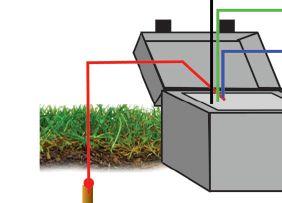
The computer-based multimeter still relies on the traditional knowledge and parameters of ground testing, so the operator’s experience is not supplanted. Rather, it is supplemented by software that adds an extra layer of accuracy and confidence in the results. The multimeter works in tandem with a computer to perform ground impedance, soil resistivity, step and touch potentials, continuity, ground mat impedance, and tower ground resistance measurements — all within an operator’s basic understanding of these tests. Using leads and probes in the soil, the multimeter injects a square wave current signal and measures the voltage drop according to established ground testing principles (Figure 1). But the resulting

1: A computer-based test system uses standard test technology coupled with computer control and data analysis.
NETAWorld • 17 COMPUTER-BASED TECHNOLOGY FOR GROUND TESTING
TECH TIPS
Figure

data doesn’t end at the display. The software analyzes it for coherence and agreement and provides the operator with a confidence factor.
One significant improvement over standard earth testers is that the multimeter employs six potential parallel and stationary probes instead of the traditional single probe that must be repeatedly moved by the operator. The software analyses the soil environment around the probes and averages out the most reliable reading while storing the information for operator review. The operator is not held hostage by the software, but rather is

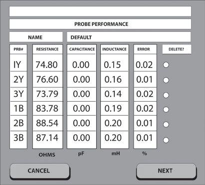
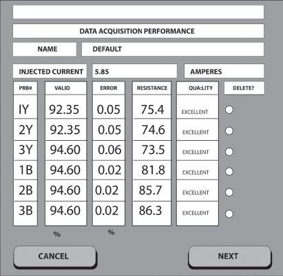
constantly updated on the screen and afforded a high degree of flexibility in modifying the parameters. The software first collects data to calibrate the potential probe. A second phase collects ground potential data to compute the ground system impedance. Th e probe calibration phase eliminates any undue infl uence probe resistance might otherwise exert on the measurement. The data is retained internally, but is also posted on the screen. It includes the resistance, inductance, and percent error of each of the six probes (Figure 2). The operator can make a decision, adjust probes, and restart the test until satisfied.
Testing proceeds and displays another report on data quality. To calculate this report, the software considers corrupted data where harmonics or other noise sources have contributed excessively and assigns a percentage error. Rather than relying on a single noise indicator, as in less detailed testing methods, the operator has a clear picture of noise influence and can decide whether it is acceptable or not. A quality column provides endorsement: excellent, good, marginal, or unacceptable (Figure 3).
Unacceptable data is automatically removed from the calculation process. The operator may also remove data, and the tester offers a warning if too much is deleted. A warning
18 • SPRING 2019
COMPUTER-BASED TECHNOLOGY FOR GROUND TESTING TECH TIPS
Figure 2: Test Results Display
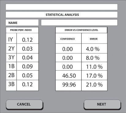
Figure 4: Probe Performance Index
Figure 3: Data Quality Report

is also automatically issued when probe placement is not acceptable, such as too close to another element in the system. This gives the operator an extra layer of confidence in the result. A final report calculates a probe performance index (PPI), which the operator uses to decide whether the test results are acceptable. The PPI ranges from 0 to 1, with anything below 0.5 considered good. Above 0.5, the recommendation is to reposition the probes and repeat the test (Figure 4).
How does this compare to more familiar ground testing methods with core instrumentation?
Other methods sometimes result in a Fall of Potential graph that is dead flat through the middle of the range. But it is often not truly flat — the graph line wavers. Is it significant to the interpretation or just an artifact of graded landscape? And just where on the slightly wavering graph line is the actual measurement?

Is it at the 62-percent point, or could that be over a water main? Typically, the resolution to this conundrum lies in the operator’s judgment. The computer-based multimeter adds a new dimension of confidence. As in traditional testing, moving the probes is the solution. But now, the software provides an objective standard, and there is less guesswork. Based on the dimensional parameters the operator enters prior to initiating the test, the software can use this ideal-case scenario to calculate results and to recognize deviations that may impinge on the accuracy of the measurements.
As with standard testing methods and equipment, soil resistivity is measured by a specific arrangement of probes. In this method, nine probes are uniformly spaced along a line on the soil surface (Figure 5). The tester collects measurements that are processed by error-correction and estimation algorithms
NETAWorld • 19
COMPUTER-BASED TECHNOLOGY FOR GROUND TESTING TECH TIPS
Figure 5: Soil Resistivity Setup







to construct a two-layer soil model and reports the resistivities of the layers and upper layer thickness, along with an error-versusconfidence level.
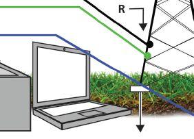
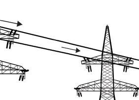
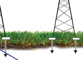
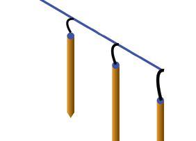
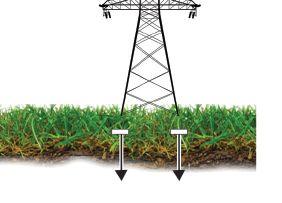
Transmission towers can also be tested with shield wires in place. A current is injected into the tower ground and measurements are taken to six voltage probes around the tower (Figure 6). The parallel ground resistance and the impedance looking into the shield wires are computed, and an identification algorithm determines the contribution of the shield wires and eliminates it from the total measured impedance. The algorithm separates the predominantly reactive shield impedance from the resistive ground impedance. No knowledge of shield wire parameters is necessary. The
results plot tower ground impedance as a function of frequency and measure the errorversus-confidence level.
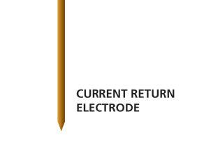
Step and touch potentials, transfer voltage, and ground mat impedance are also measured. Each is defined by the probe connections and data input. Step and touch potentials require knowledge of available fault current, as do other test instruments. The computer-based multimeter also requires the operator to input the voltage, the current probe coordinates, and the size and shape of the grounding system. Transfer voltage is calculated to a user-selected point, and the coordinates are entered into the software along with the coordinates of the current return electrode, the size and location of the system, and the available fault current.
20 • SPRING 2019 TECH TIPS
COMPUTER-BASED TECHNOLOGY FOR GROUND TESTING
Figure 6: Tower Ground Test


James (Jim) R. White, Vice President of Training Services, has worked for Shermco Industries Inc. since 2001. He is a NFPA Certified Electrical Safety Compliance Professional and a NETA Level 4 Senior Technician. Jim is NETA’s principal member on NFPA Technical Committee NFPA 70E®, Standard for Electrical Safety in the Workplace®, NETA’s principal representative on National Electrical Code® Code-Making Panel (CMP) 13, and represents NETA on ASTM International Technical Committee F18, Electrical Protective Equipment for Workers. Jim is Shermco Industries’ principal member on NFPA Technical Committee for NFPA 70B, Recommended Practice for Electrical Equipment Maintenance and represents AWEA on the ANSI/ISEA Standard 203 Secondary Single-Use Flame Resistant Protective Clothing for Use Over Primary Flame Resistant Protective Clothing. An IEEE Senior Member, Jim received the IEEE/IAS/PCIC Electrical Safety Excellence Award in 2011 and NETA’s Outstanding Achievement Award in 2013. Jim was Chairman of the IEEE Electrical Safety Workshop in 2008 and is currently Vice-Chair for the IEEE IAS/ PCIC Safety Subcommittee.


No. 125
SULPHUR HEXAFLUORIDE CIRCUIT BREAKERS
 BY JAMES E. WHITE, Shermco Industries


Sulphur hexafluoride circuit breakers used to be the domain of utilities, but they are liable to be used now by any large- or medium-size industrial. This Tech Quiz will review some of the NETA standard requirements for these circuit breakers.
1. In ANSI/NETA ATS, which ANSI/IEEE standard is referred to if manufacturer’s data is not available?
a. C57.04
b. C57.11
c. C37.04
d. C37.11
2. What is considered an acceptable value for air in the gas?
a. 0.03 percent (300 ppmw)
b. 0.05 percent (500 ppmw)
c. 0.07 percent (700 ppmw)
d. 0.09 percent (900 ppmw)
3. Which method is used to test for air in the gas?
a. ASTM D2029
b. ASTM D2284
c. ASTM D2685
d. ASTM D2681
4. How much leakage is allowed per the ATS test values?
a. 0
b. 0.5ppm over 3 months
c. 0.5ppm over 6 months
d. 0.05 percent over 6 months
5. The power factor of bushings is to be within ____________ percent of nameplate.
a. 3 percent
b. 5 percent
c. 7 percent
d. 10 percent
6. What are the two types of SF6 circuit breakers?
a. Bused and un-bused
b. Extended tank and compact tank
c. Spring and pneudraulic
d. Dead tank and live tank See answers on page 122.
TECH QUIZ
22 • SPRING 2019 TECH QUIZ


Many avo training courses are eligible for neta ctd’s t By offering the broadest selection of electrical training in the industry, we have a training course for all things electrical. We train to NETA and other industry recognized standards to take your knowledge to the next level. A training course is only as good as the instructor teaching it. That’s why our instructors are some of the most qualified in the industry. To be the best, train with the best. Offering over 57 electrical safety & electrical maintenance training courses and certifications. WWW.AVOTRAINING.COM 877-594-3156 Let us bring the training to your location, call today for an on-site quote Images depict a de-energized controlled environment with no chance for arc flash Hands-on training and NETA standards, together get you the most accurate field results. In order to provide a broad range of training and real world experiences, AVO Training Institute, Inc., courses are non-product specific. No AVO Training instructor nor contract instructor has any proprietary interest in any products, instruments, devices, services, or materials discussed.


We Buy, Sell, Trade, Calibrate, Repair
Featuring quality, reliable, on-time service and support for all brands and types of solid state power electronics.
Power electronics are our business
Let us suppoort you with our quality repair, calibration and servicing of your solid state equipment. We also buy, sell and trade:
•Communications devices for power equipment
•Protective relays
•Circuit breaker trip devices
•Motor overload relays
•Rating plugs
4701 Spartan Drive • Denton, TX 76207 (877-874-7349) • Phone: 940-243-3731 • Fax: 940-387-8277 Email: info@solidstaterepair.com • Web: www.solidstaterepair.com
“SOLID STATE” INDUSTRIAL ELECTRONICS “SOLID STATE” INDUSTRIAL ELECTRONICS Toll Free 877-TRIP-FIX NOWRENTING TESTEQUIPMENT





Sign up for social networking events when you register for PowerTest online at powertest.org/registration or by calling the NETA office: 888.300.6382 BCS Switchgear, Inc. ECP Solutions Group CBS, Inc. Megger National Switchgear Protec Equipment Resources RESA Power Services Shermco Industries THE PREMIER ELECTRICAL MAINTENANCE AND SAFETY CONFERENCE PREMIUM SPONSORS PowerTest.org l 888.300.6382 Hosted by High Voltage Sponsors Medium Voltage Sponsors Low Voltage Sponsors General Sponsors Hospitality Suite Sponsors We would like to acknowledge and thank our sponsors for helping make PowerTest 2019 possible. OUR SPONSORS ARE INVALUABLE – THANK YOU!



SULFUR HEXAFLUORIDE GAS HAZARDS
BY PAUL CHAMBERLAIN, American Electrical Testing Co., LLC
Sulfur hexafluoride, also known as SF6 gas, is a commonly used and excellent insulator found in many medium to large circuit breakers protecting transmission and distribution equipment. It has been argued that gas-filled breakers are superior to those filled with oil, air, or a vacuum. They operate cooler and with no noise or gas emissions and are considered relatively low maintenance compared to other types. However, as is the case with many chemicals used in the workplace, the use of sulfur hexafluoride carries inherent dangers.
26 • SPRING 2019 SULFUR HEXAFLUORIDE GAS HAZARDS
SAFETY CORNER
In its normal state, sulfur hexafluoride gas is:
• Colorless
• Odorless
• Non-flammable
• Non-toxic to humans
Under high temperature conditions (greater than 350 degrees F), sulfur hexafluoride decomposes into toxic and corrosive by-products. Decomposition can occur when sulfur hexafluoride is exposed to spark discharges, partial discharges, switching arcs, and failure arcing. While pure sulfur hexafluoride is odorless, contaminated sulfur hexafluoride has an unpleasant, pungent odor.
Exposure to these by-products, typically found in the form of gases or powders, can cause several health conditions:
• Irritation to the eyes, nose, and throat
• Pulmonary edema
• Other lung damage, skin and eye burns, nasal congestion, bronchitis
• Dermatitis (skin rash or inflammation)
In addition to hazards associated with decomposition by-products, the hazards typically involved with the analysis, testing, and maintenance of any electrical equipment also apply to medium- and high-voltage sulfur hexafluoride breakers.
CHEMICAL HAZARDS
Sulfur hexafluoride is denser than air. This means any released gases may settle into lower areas such as trenches, displacing the oxygen. This is a potentially hazardous situation for any employee entering the trench. Humans require an oxygen level between 19.5 percent and 21 percent. The minimum allowable oxygen level — called the permissible oxygen level by the Occupational Safety and Health Administration (OSHA) — is 19.5 percent. If a gas leak is suspected, an oxygen meter that has been recently calibrated and bump tested must be used to detect whether the oxygen is depleted to ensure there is no hazard to an employee.


Lower-order gases formed when sulfur hexafluoride is subjected to an arc are a potential toxicity hazard that may cause an employee to suffer from irritation to the eyes and respiratory system. Additionally, the sulfur hexafluoride gas will decompose into highly hazardous metal fluorides. If metal fluorides are subjected to moisture, such as that on an average humid day, decomposition by-products will include sulfur oxyfluoride as well as hydrofluoric and sulfuric acids. These by-products, which appear as a white or grayish powdery substance, are easy to detect because they smell of rotten eggs. Respiratory protective equipment must be worn if these decomposition by-products are suspected. Face shields, nitrile gloves, and Tyvek splash suits are also required to minimize potential exposure when handling contaminated equipment.
Sulfur hexafluoride is designated a greenhouse gas by the U.S. Environmental Protection Agency (EPA), and many utilities are required to report known leakages. Please contact your EPA representative to determine whether this is the case.
PHYSICAL HAZARDS
Cylinders that store virgin sulfur hexafluoride gas are heavy and cumbersome. It is a gas under pressure, so special precautions must be used when handling the containers:
• Cylinders must be secured to prevent tipping.
• Protective caps must be in place over the valve when the cylinder is not in use.
• Transport of quantities over a certain limit requires U.S. Department of Transportation placarding and a bill of lading. Please see Department of Transportation regulations if you will be hauling bottles of sulfur hexafluoride.
Due to the weight of the bottles, a group lift is suggested, and specialized tools such as


NETAWorld • 27 SULFUR HEXAFLUORIDE GAS HAZARDS
CORNER
SAFETY
SAFETY CORNER
bottle grabs or carts can assist. Working smart, not hard, helps prevent injuries; if a tool is available to ease movement of the cylinder, use it. Employees have strained muscles, tripped and fallen, and even chipped teeth carrying cylinders by hand. Do not become a statistic by trying to be a hero. Get help or use tools to prevent the possibility of physical injury.
Additional personal protective equipment may be necessary depending on the task and workplace requirements. Wear all applicable personal protective equipment when handling anything heavy.
• Durable work gloves can help protect your hands if pinched between bottles.
• Safety-toed, appropriately rated work boots are required. In many work environments using sulfur hexafluoride gas, boots must be electrical-hazard rated.
• While a bottle is in use, rapid and longduration venting can cause freezing on the surface of the bottle due to condensation in the air. It is cold enough to cause frostbite if in contact with human skin for an extended time. Gloves can minimize the potential of contact with the cold surface of the bottle.
Sulfur hexafluoride gas recycling and reclaiming equipment is also heavy. It is usually wheeled, but a group effort is still required to minimize the potential for injury, especially if taking it out of or off a vehicle. Always read the instruction manual prior to use of unfamiliar equipment and have an experienced coworker train you in its use. Many hoses and components are under pressure, so caution must be used when using tools around the equipment.

CONCLUSION
Sulfur hexafluoride breakers are one of the most effective inventions for protecting electrical equipment, but their use can become a disadvantage. Caution above and beyond the usual electrical hazards must be used when working with any chemical, pressurized gas, or heavy object. No matter the job, use these rules to help ensure the work is carried out safely:
1. Establish and barricade a safe work area.
2. Perform a pre-job brief with all employees on the site.
3. Wear proper PPE for each task.
4. De-energize and perform lock out/tag out.
5. Verify zero energy (test, check, test) and discharge all stored energy, including pressurized gases.
6. Connect grounds where and if applicable.
7. Use the available tools to make the job easier to perform.
8. Identify, visually mark, and/or flag equipment being worked on.
Following these steps can lead to a safer work environment while on and around SF6 gas and the electrical equipment that uses it.

Paul Chamberlain has been the Safety Manager for American Electrical Testing Co., LLC since 2009. He has been in the safety field for the past 20 years, working for various companies and in various industries. Paul holds a BS in environmental health and safety from Massachusetts Maritime Academy.


28 • SPRING 2019
SULFUR HEXAFLUORIDE GAS HAZARDS


The Power of Positive Results


AET Brings Precision and Value to Electrical Testing, Commissioning and Engineering… and Positive Results to Our Customers.
AET delivers the best value in the marketplace by offering the highest quality service at competitive prices. With a workforce and offices located throughout the country, AET is an industry leader and one of the largest independent electrical testing companies in the U.S.
To learn more about AET’s full range of testing and engineering services, visit www.aetco.us
• 800.992.3826

WWW.AETCO.US
An Company A Subsidiary of

Arizona (480) 967-7765 linc.mcnitt@hamptontedder.com Nevada (702) 452-9200 roger.cates@hamptontedder.com California (909) 628-1256 ken peterson@hamptontedder com jim.andersen@hamptontedder.com Family O wned and O perated S ince 1958


Expertise to Ensure Power Reliability
Whether you need a testing and maintenance partner, assistance with upgrades or modernization, or help meeting regulatory requirements, High Voltage Maintenance’s team of experts will ensure your electrical infrastructure is performing at the highest level of reliability and safety.











Rely
Testing
Maintenance
Electrical Engineering • Protection and Controls
DC Power
Compliance • Commissioning
1-866-HVM-TEAM
Critical Assets: Chemical | Data Centers | Education | Government | Healthcare |
and Mining | Oil & Gas Manufacturing | Telecommunications | Utilities and Renewables.
on Our Expertise Across Six Centers of Excellence •
and
•
•
•
To learn more, visit HVMCorp.com or call
We Protect Your Most
Metals
HVM-COE-AD-EN-NA-8x5.25.indd 2 1/29/2019 4:04:47 PM


DYNAMIC TESTING OF NUMERICAL PROTECTION RELAYS
BY STEVE TURNER, Electrical Consultants, Inc.
A numerical protection relay provides multiple functions and typically uses algorithms that do not work on the same principles as older electromechanical relays. Numerical relays are often still tested using old techniques developed long ago for electromechanical relays. One such common technique is referred to as a “static test.” Fault voltage and/or fault current are injected to see whether the selected protection function operates at the setpoint and is in tolerance. Some protection functions have dynamic characteristics, and if a static test is applied, then the true performance of the selected function may not be properly tested.
A good example is a mho distance element that is polarized using memorized positive-sequence voltage. The mho circle actually expands during
an actual fault and has more resistive coverage, which is dependent on the apparent source strength. Static testing is only useful to measure the reach point setting along the line angle and the line angle setting itself. A dynamic test usually consists of a pre-fault condition and a fault condition. Table 1 illustrates a simple two-stage dynamic test for a three-phase fault on a distribution feeder.
This article demonstrates the benefits of dynamic testing and provides some examples of how to apply them. Assume that all values shown are secondary unless otherwise noted.
32 • SPRING 2019 DYNAMIC TESTING OF NUMERICAL PROTECTION RELAYS
RELAY COLUMN
Test Signal Pre Fault Fault VA 67 ∠0° volts 53.6 ∠0° volts VB 67 ∠240° volts 53.6 ∠240° volts VC 67 ∠120° volts 53.6 ∠120° volts IA 1 ∠-3° amps 13.4 ∠-80° amps IB 1 ∠237° amps 13.4 ∠160° amps IC 1 ∠117° amps 13.4 ∠40° amps
Table 1: Dynamic Three-Phase Feeder Fault
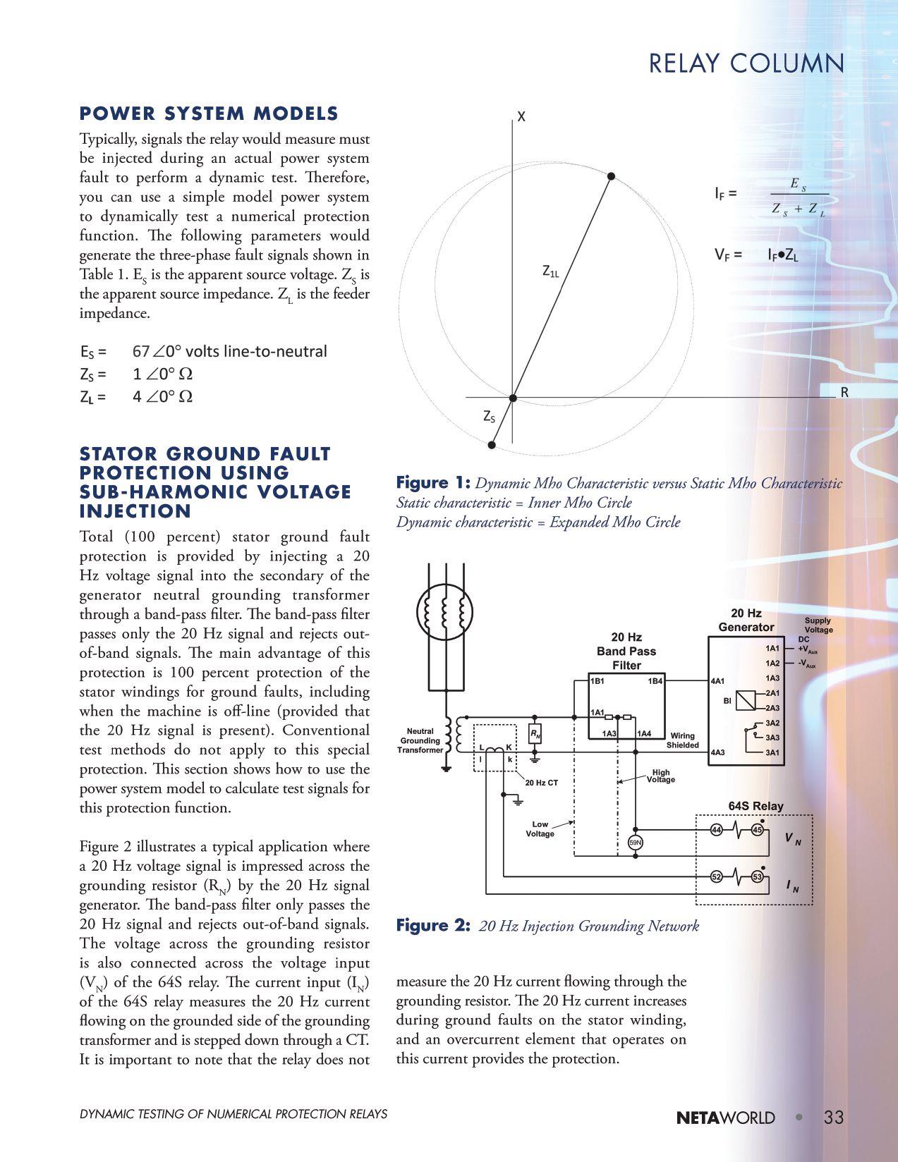


The following series of equations shows how to model and calculate the 20 Hz voltage and current measured by the 64S relay.
Grounding Transformer Turns Ratio (N)
Assume that the turns ratio of the grounding transformer is equal to:

Capacitive Reactance
The total capacitance to ground of the generator stator windings, bus work, and delta connected transformer windings of the unit transformer is expressed as C0. Generator step up transformers have delta connected windings facing the generator, so capacitance on the high side is ignored. The corresponding capacitive reactance is calculated as follows:

The capacitive reactance for 1 micro-Farad is equal to:

Reflect the capacitive reactance to the secondary of the grounding transformer:
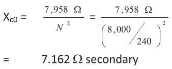
Grounding Resistor (RN)
The ohmic value of the grounding resistor can be sized as follows so as to avoid high transient over-voltage due to ferroresonance:


A value of 2.5 ohms secondary is used for this example.
20 Hz Signal Generator and Band-Pass Filter Characteristics
Assume that the 20 Hz signal generator outputs 25 volts. The band-pass filter has a resistance equal to 8 ohms.

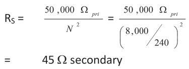
Stator Insulation Resistance (RS)
RS is the insulation resistance from the stator windings to ground. A typical value for nonfault conditions is 50,000 ohms primary.
Current Transformer
The current input (I N) of the 64S relay measures the 20 Hz current flowing on the grounded side of the grounding transformer and is stepped down through a CT.

GROUNDING NETWORK
All of the elements needed to mathematically represent the grounding network and determine the 20 Hz signals measured by the 64S relay are now available. Figure 3A shows the insulation resistance and the stator windings referred to
Figure 3A: 20 Hz Grounding Network Referred to Primary of Grounding Transformer
34 • SPRING 2019
(1)
(2)
(4) (5)
(6)
DYNAMIC TESTING OF NUMERICAL PROTECTION RELAYS RELAY COLUMN
V XCP RStator RFilter = 8 Ohms RN CT = 400:5 25 V 20 Hz N
Figure 3B: 20 Hz Grounding Network
Referred to Secondary of Grounding Transformer
the primary of the grounding transformer.
Figure 3B shows the insulation resistance and the stator windings referred to the secondary of the grounding transformer.
20 Hz Current (IN) Measured by 64S Relay
The current input (I N) of the 64S relay measures the 20 Hz current flowing on the grounded side of the grounding transformer and is stepped down through a CT. As noted previously, the relay does not measure the 20 Hz current flowing through the grounding resistor.
Total 20 Hz Current Supplied by Signal Generator
The 20 Hz signal generator looks into the band-pass filter resistance (R BPF), which is in series with the parallel combination of the following:
• Zc0
• RS
• RN
Therefore, the total loop impedance of the 20 Hz grounding network can be expressed as:
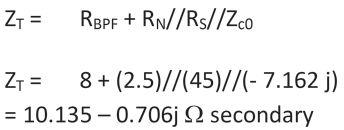
The total 20 Hz current supplied by the signal generator is determined as follows:
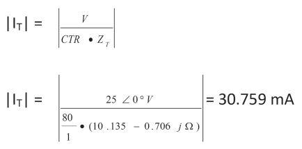
20 Hz Current Measured by 64S Relay (IN) during NonFaulted Conditions
The 20 Hz current measured by the 64S relay is the ratio of the total current that flows into the primary side of the grounding network (Zc0//RS):
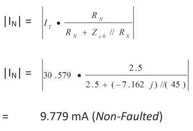
20 Hz Current Measured by 64S Relay (IN) during Ground Fault on Stator Windings
A typical value to represent the insulation resistance of the stator windings breaking down during a ground fault is 5,000 ohms primary. If the calculations for equations (7) through (9) are repeated for a fault resistance equal to 5,000 ohms primary (4.5 ohms secondary), then the 20 Hz current measured by the relay is as follows:

|IN| = 13.486 mA (5,000 ohm primary ground fault)
If the calculations for (7) through (9) are repeated for a fault resistance equal to 1,000 ohms primary (0.9 ohms secondary), then the 20 Hz current measured by the relay is as follows:
=

)
NETAWorld • 35
(7) DYNAMIC TESTING OF NUMERICAL PROTECTION RELAYS RELAY COLUMN
(8)
(9)
V XCS RS 8 Ohms RN CT = 80:1 25 V 20 Hz I t
|IN|
26.640 mA (1,000 ohm primary ground fault

RELAY COLUMN
Table 2 summarizes the 20 Hz current measured by the relay for non-faulted and faulted conditions. Use these values to test the function.
Table 2: 20 Hz Current Measurements
relay misoperated during a black start. The primary numerical generator protection relay properly restrained due to having a CT saturation detector built in. The current waveforms captured by the numerical relays can be played back to test that the backup relay works properly after modifying the protection settings. This playback can also be used for generator relays at other locations that also have black start capability.
HIDDEN FEATURES AND COMTRADE PLAYBACK
Numerical protection functions often have hidden features the user may not be aware of when testing the relay. A good example is how a generator differential protection function provides proper restraint to prevent a misoperation during a black start.
Black Start and Generator Differential Protection
This section provides such an example where a backup numerical generator protection

What is Black Start?
A black start is the process of restoring a power station to operation without relying on external power sources. An off-site power source is not available during a wide-area outage. Therefore, a black start is required in the absence of grid power. Generator relay current inputs are subjected to high levels of dc offset and harmonic current due to energizing the step-up transformer during a black start. If the system side and neutral side sets of current transformers do not have the same saturation voltage characteristics and there is a large dc offset present in the inrush current, then the current transformers can saturate with restraint current significantly less than two times the nominal relay current.
Generator differential protection must have special built-in measures to account for CT saturation, thus preventing unwanted tripping. An easy method to test CT saturation detectors is via COMTRADE playback. COMTRADE playback is a form of dynamic testing, since you are injecting actual fault signals recorded during a system event. This is a very practical method to check that any protection function potentially affected by transformer inrush is properly set.
Figure 4 shows the switching configuration for an actual black start. The step-up transformer is normally energized from the 230 kV transmission grid. This particular test was performed to prove that the generating company can pick up the station service transformer for essential loads, such as the
36 • SPRING 2019
RS (primary) |IN| (secondary) 50,000 Ω 09.779 mA 5,000 Ω 13.486 mA 1,000 Ω 26.640 mA
DYNAMIC TESTING OF NUMERICAL PROTECTION RELAYS
52 52 TransmissionCo. 230kVGrid Generation Co. Open 114MVA G1 G2 27 MVA27MVA 52 *87G Trip 13.8 kV
Figure 4: Black Start at Hydroelectric Plant
sluice gate spillway supply, should a system blackout occur. This is considered to be a dead bus operation. Th e transmission company opened the step-up transformer high-side breaker and the generators continued to turn at speed with no load. The plant was attempting to only pick up station service; however, the step-up bank had to be picked up as well, since the plant cannot remotely isolate the step-up transformer.
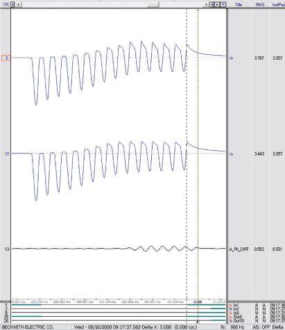
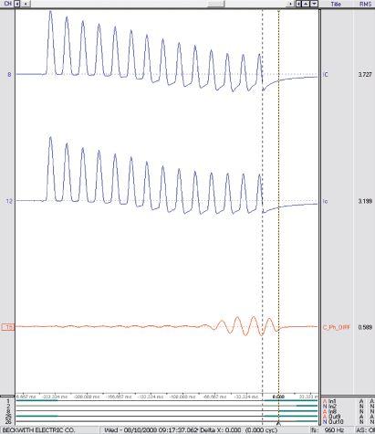
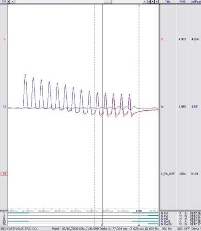
Review of the oscillography captured by the relay that misoperated revealed that there was significant mismatch present in A-phase and C-phase CT secondary currents from both the neutral (Iabc) and system (IABC) sides of the generator windings. The mismatch was due to the different voltage class ratings for the neutral and system side CTs. Figure 5A and Figure 5B show the individual differential currents for A-phase and C-phase. It can be seen that Ia is more saturated in comparison to IA if the 9th positive peak in Figure 3A is examined. Figure 5C is the same as Figure 5B, but all three signals (IC, Ic, C_Ph_DIFF) are superimposed onto the same channel.
The primary numerical generator protection relay phase differential protection used for

this particular application has a CT saturation detection algorithm to improve security. If there is dc offset present, CTs can saturate with restraint current significantly less than two times nominal. The primary numerical generator differential protection automatically multiples the slope by four times (see Figure 6) if the total RMS differential current is greater

NETAWorld • 37 DYNAMIC TESTING OF NUMERICAL PROTECTION RELAYS
RELAY COLUMN
Figure 5A: A-Phase Differential Current
Figure 5B: C-Phase Differential Current
Figure 5C: C-Phase Differential Current (Superimposed)

RELAY COLUMN

than the fundamental differential current. The total RMS differential current calculated by the relay contains dc and the 1st through 5th harmonic components.
Arc Fault Protection
It is extremely difficult to model an arcing fault even with the use of advanced transient simulation tools such as the Alternate Transients Program (ATP). COMTRADE playback is an extremely valuable tool for testing arc fault protection. One customer captured a long event where an undetected intermittent arcing fault eventually evolved into a three-phase fault and completely destroyed the machine.
Arcing faults can occur due to dirty insulators or broken strands in the generator stator windings. If undetected, such faults can lead to overheating along with catastrophic electrical failure. These events typically require extensive re p a i r s w i t h a n e x t e n d ed s h u t dow n o f t h e machine. It is highly desirable to detect such faults at an early or incipient stage so that remedial action can be taken before a complete failure occurs. A common practice for large synchronous machines is to limit the ground fault current through the generator stator windings by grounding the neutral through a grounding transformer with a resistor connected across the secondar y winding. The neutral resistor is reflected to the primary and provides high-resistance grounding during single phase-to-ground faults and is typically sized to limit the ground fault current from 3 to 25 amps primary. The ohmic value of
the grounding resistor is selected to avoid high transient voltage due to ferro-resonance. Figure 7 illustrates how the stator windings are grounded through high impedance using the grounding transformer and grounding resistor across the secondary.
An arcing fault is intermittent, and if the duration of each arc is shorter than the conventional 100 percent stator ground fault protection time delay on pickup, then no trip occurs. Figure 8 illustrates the logic for a new method of arc protection, where 59N is the neutral overvoltage protection.
Figure 9 shows a typical timing sequence for a trip during an intermittent arcing ground fault
The reset timer (TR) has memory and stalls the delay on pickup timer (tp) when the initiating
38 • SPRING 2019 DYNAMIC TESTING OF NUMERICAL PROTECTION RELAYS
0.5 Minimum Pickup 1.0 1.5 Differential (PerUnit) 1.02.0 3.04.0 Bias (Per Unit) APhase CPhase Slope=40% Slope = 10%
Figure 6: Generator Differential Protection Characteristics
Generator
Figure 7: High-Impedance Grounded Stator Windings R
59N tP TR TRIP
Figure 8: Arc Detector Logic
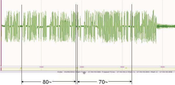
function pickup drops out intermittently as is always the case for an arcing fault. The initiating function that drives this logic is 59N. For the purpose of this test, the time delay on pickup was set equal to 18 cycles and the reset timer was equal to 30 cycles. Set the reset timer greater than the period when the arcing fault is off; otherwise, the pickup timer will reset prior to a trip. Figure 10 shows the arcing fault captured by the customer. The relay operated twice, and you can see the variable operating time, which is a function of both the arc and reset timer.
CONCLUSION
A numerical protection relay provides multiple functions and typically uses algorithms that do not work on the same principles as older electromechanical relays. Relay test personnel often still want to use old test methods developed long ago for electromechanical relays. Test results obtained from these old test methods may not be a good indication of whether or not the numerical relay functions properly. One such obsolete technique is referred to as a static test. Fault voltage and/or fault current are injected to see if the selected protection function operates at the setpoint and is in tolerance. Many protection functions have dynamic characteristics and/or hidden features that cannot be properly tested using

a static test. This paper demonstrates how to test numerical protection relays using dynamic tests, model power systems, and COMTRADE playback.

Steve Turner is a Senior Engineer II at Electrical Consultants, Inc., working in their San Diego office. Steve worked at Beckwith Electric Company, Inc. for 10 years, first as the Engineering Laboratory Director and then as Senior Applications Engineer. His previous experience includes working as an Application Engineer with GEC Alstom and as an Application Engineer in the international market for SEL focusing on transmission line protection applications. While at Duke Energy (formerly Progress Energy), Steve developed the first patent for double-ended fault location on overhead high-voltage transmission lines and was in charge of all maintenance standards in the transmission department for protective relaying. Steve has a BSEE and MSEE from Virginia Tech University.

NETAWorld • 39 DYNAMIC TESTING OF NUMERICAL PROTECTION RELAYS
RELAY COLUMN
5 Cycles 10 Cycles 15 Cycles 18 Cycles OFF ON 5 Cycles 10 Cycles 5 Cycles 10 Cycles 5 Cycles 10 Cycles 5 Cycles 59N Picked Up 59N PickupTime Delay Setting 59N PickupTime Delay Timing Trip Output PickupTimer Stalled PickupTimer Stalled PickupTimer Stalled Arcing Fault
Figure 9: Timing Sequence to Trip During Arcing Fault
Figure 10: Arcing Fault Simulation with Variable Trip Time
Expertise to Ensure Power Reliability
Whether you need a testing and maintenance partner, assistance with upgrades or modernization, or help meeting regulatory requirements, Vertiv’s Electrical Reliability Services team of experts will ensure your electrical infrastructure is performing at the highest level of reliability and safety. Rely on Our
Across Six Centers of Excellence
• Commissioning
• Testing and Maintenance
• Electrical Engineering
• Protection and Controls
• DC Power
• Compliance



Expertise
To learn more, visit ERS.VertivCo.com or call 877-468-6384 We Protect Your Most Critical Assets: Data Centers | Metals and Mining | Utilities and Renewables | Chemical | Oil & Gas Manufacturing | Healthcare | Education | Telecommunications | Government. Electrical Reliability Services, Inc. A Vertiv Company Vertiv-ERS-COE-AD-EN-NA-8x5.25.indd 1 1/30/2019 11:43:15 AM

Absolute con dence. Every time.
You can count on us for specialized experience in healthcare, data center, o ce complex, and commercial acceptance and maintenance testing. Absolutely Power generation, petrochemical, oil & gas, and heavy industries also look to us for high demand services such as start-up commissioning, maintenance testing, shut-down and turnarounds, and breaker shop repair. Get started today.


Toll Free 1+ (855)767-4446 8100 West Little York | Houston, Texas 77040 Email: Alan Postiglione | apost@absolutetesting.com | www.absolutetesting.com Like us on:

CIRCUIT BREAKER AND TRANSDUCER: WHERE DO I CONNECT?
BY ROBERT FOSTER, Megger
Many types of equipment in the electrical transmission and distribution network perform a specific and necessary operation, and the circuit breaker is no exception, as it serves to protect the substation’s valuable assets. The circuit breaker — defined as a mechanical switching device — is unique: At one time, it must function as a nearly perfect conductor; at another time, it must function as a nearly perfect insulator, transitioning from one state to the other in a matter of milliseconds and occasionally dispersing enormous amounts of energy during the transition. To determine whether the mechanical switching function is working correctly, a time and travel analyzer is used to evaluate the operating characteristics of the circuit breaker.


When bulk oil circuit breakers were the prevalent technology in substations, travel measurements were performed without question. Over the years, due to lack of maintenance personnel and time for planned outages, as well as the complexity of hooking up a transducer to the circuit breaker, travel measurements have been performed less
frequently. Time and travel measurements have been replaced with contact timing or reduced to first-trip testing. A 2012 study by CIGRE Working Group A3.06 found that 50 percent of major failures in a circuit were due to the operating mechanism; 30 percent were due to electrical control and auxiliary circuits. While contact timing and first trip are important
42 • SPRING 2019 CIRCUIT BREAKER AND TRANSDUCER: WHERE DO I CONNECT?
COVER STORY
tests and should be performed, they will not fully test the operating characteristics of the mechanism; travel measurements should be standard practice to determine the true health of the circuit breaker.
BASIC MEASUREMENTS WITH A TRANSDUCER
Although the transducer can be attached to the circuit breaker to determine the travel of different parts of its components such as the dashpot, the primary application of a motion transducer is to measure the motion of the main/arcing contacts in the circuit breaker. The transducer can be hooked to various parts of the circuit breaker: directly to the pull rod of the main contacts, directly to the mechanism, somewhere on the linkage, or even to an auxiliary switch.
Although the transducer provides many parameters, the most important measurement is the stroke of the circuit breaker. In fact, all other parameters are derived from the stroke of the circuit breaker, which is defined as the total travel distance of the contacts from resting position in one state (e.g., closed) to the resting position in the other state (open), or vice versa. It is imperative to be diligent in connecting the transducer to the manufacturer’s recommended attachment point on the circuit breaker and in correcting for any multiplication factors if a direct connection to the contacts cannot be made. At the very least, the technician must be consistent in measuring the stroke through periodic maintenance to trend the results. If the circuit breaker is gang operated, i.e., one mechanism operates all three phases, only one transducer is needed. If the circuit breaker has separate operating mechanisms for each phase, an individual transducer should be used for each mechanism.
Once the stroke of the circuit breaker is determined, the velocity of the contacts in different regions of the travel can be derived. The most common place to measure velocity is during the arcing zone of the circuit breaker,
where it is actually interrupting or clearing the fault. Occasionally, damping is measured on the travel curve by calculating the velocity in the damping zone or the time between two predefined points on the travel curve in the damping zone.
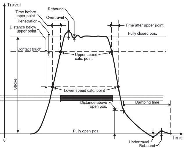
By observing the closing time along with the travel measurement, the penetration or contact wipe can be determined. Penetration is the length measured from initial contact touch to the final resting position after the operation; contact wipe measures how far the contacts are engaged. Overtravel, which is measured directly from the travel curve, is the maximum displacement past the resting position that the contacts reach during the operation. After overtravel is measured, rebound is measured from minimum displacement to the final resting position of the contacts. Other parameters can also be determined, but they are all derivatives of the actual stroke measurement of the contacts, so it is important to connect the transducer correctly and to accurately measure the stroke of the circuit breaker. Figure 1 shows the various parameters that can be measured with a travel transducer.
NETAWorld • 43 CIRCUIT BREAKER AND TRANSDUCER: WHERE DO I CONNECT?
COVER STORY
Figure 1: Typical Motion Trace

TRANSDUCER TYPES AND PARAMETERS NEEDED FOR PROPER MEASUREMENTS
Two types of transducers can be used to measure circuit breaker contacts: linear and rotary. A linear transducer measures a value of length typically in either inches or millimeters; a rotary transducer measures angle, typically in degrees, which must be converted to inches or millimeters. Various transducer designs — resistive, optical, magnetic, etc. — generally provide analog or digital output. The type of transducer to be used, rotary or linear, must be selected when setting up for motion measurements. Although either type of transducer works on many breakers, the manufacturer generally specifies a preference, and the manufacturer’s specified attachment point, transducer type, and conversion factor (if needed) should always be used.


Caution: Before connecting the transducer, always ensure the circuit breaker is in the open position and that no energy is stored in the mechanism. If it is impractical to discharge all the energy, as in the case of some pneumatic or hydraulic mechanisms, ensure the maintenance pin that blocks operation is set. Finally, de-energize the power going to
the control circuitry. No matter where the transducer is placed, no part of the transducer, mounting bracket, or travel rod (if used) can be in the direct path of any moving parts of the circuit breaker. That will cause damage to the transducer or its accessories.
Linear Transducer
If a linear transducer is used, it must be of suitable length to cover the total travel distance the transducer will encounter, including overtravel, on both close and open operations. Linear transducers are available in a wide variety of lengths ranging from 25 mm or less, commonly used for vacuum circuit breakers, all the way up to 1,000 mm or more. Typical lengths are from 225–300 mm for SF6 dead tank circuit breakers and 500–600 mm for bulk oil circuit breakers. If the transducer is of questionable length, it is common practice to attach the transducer in one positon (e.g., closed), and then detach the transducer and operate the circuit breaker so it changes state. Now that the circuit breaker is in the opposite position (open), re-attach the circuit breaker to see if it is of suitable length. Once a transducer of adequate length is selected, determine whether the transducer will fit in the space provided.




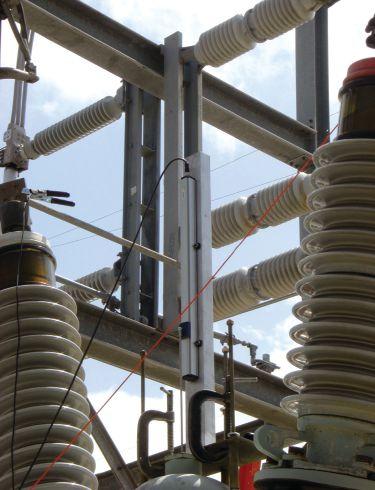
44 • SPRING 2019
BREAKER AND TRANSDUCER: WHERE DO I CONNECT? COVER STORY
CIRCUIT
Figure 2: ITE Bulk Oil CB with Direct Linear Connection
Two types of measurements can be made with a linear transducer.
1. In direct measurement (Figure 2), the transducer or linkage rod is connected directly to the moving contacts. Direct measurements are common in bulk oil circuit breakers, minimum oil breakers, most vacuum CBs, and some dead tank SF6 circuit breakers.
Although finding a suitable mounting bracket and correctly mounting the transducer can be difficult, this method is beneficial because the actual stroke of the transducer is equal to the actual stroke of the contacts. Therefore, no conversion factor is needed, and all parameters measured with the transducer are direct representatives of the motion of the contacts in the circuit breaker. The motion isn’t distorted by gears, linkages, or any mechanical play of the interconnections.
2. In indirect measurement using a linear transducer (Figure 3), the transducer is connected not directly to the moving contacts, but to another part of the circuit breaker that is connected to the moving contacts, such as the mechanism or
interconnecting linkage. When this type of connection is used, the travel of the transducer may or may not be equal to the travel of the main contacts. If the travel of the transducer is different, a conversion factor or ratio should be used to obtain the correct stroke length and travel parameters of the circuit breaker. For example, 80 mm of transducer stroke can be equivalent to 120 mm of contact stroke, so a multiplication factor of 1.5 should be used.
Rotary Transducer
When a rotary transducer is used, the measured quantity is in degrees, or occasionally radians, and is then converted to a unit of length using one of two types of conversions:
1. In a constant conversion, one degree is equal to a certain value of length throughout the entire travel of the contacts. This is common where the mechanical linkage is simple with few interconnecting parts.
2. When the linkage is more complicated, the ratio of the angle to length may not be constant throughout the total travel of the contacts; for example, 1 degree might equal

NETAWorld • 45
CIRCUIT BREAKER AND TRANSDUCER: WHERE DO I CONNECT? COVER STORY
Figure 3: SF6 Dead Tank CB with Indirect Linear Connection


1.5 millimeters for the first 10 degrees; then for the next 10 degrees of travel, 1 degree might equal 2.5 millimeters. In these cases, a conversion table must be used to account for the varying values.
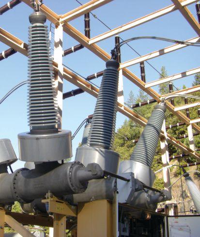
Rotary transducers have the advantage of being relatively small, and one kit with a few accessories can hook up to many different styles or types of circuit breakers. The disadvantage of the rotary transducer is that you must know
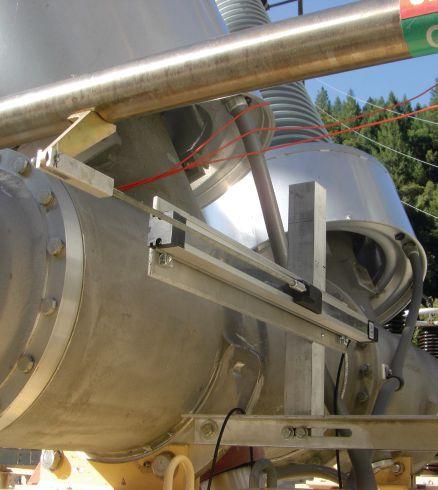
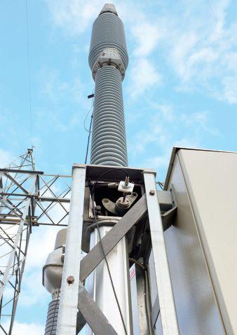
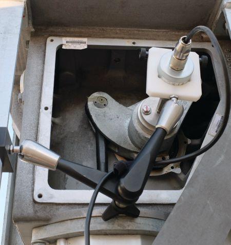
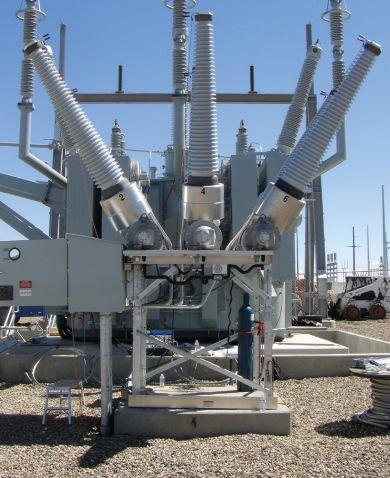
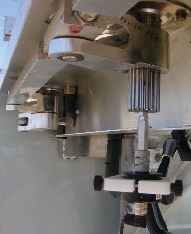
the conversion factor or table to calculate the correct parameters of the circuit breaker. If the conversion factor or table is not provided in the manual, the breaker manufacturer should be contacted. Rotary transducers are most common on live tank SF6 circuit breakers, but are also used on certain types of dead tank SF6 breakers, bulk oil circuit breakers, and generator circuit breakers. Figure 4 and Figure 5 show examples of rotary transducer connections.






46 • SPRING 2019
CIRCUIT BREAKER AND TRANSDUCER: WHERE DO I CONNECT?
COVER STORY
Figure 4: Rotary Transducer on SF6 Live Tank CB
Figure 5: Rotary Transducer on SF6 Dead Tank CB
VELOCITY
Once the proper transducer and conversion factor are selected, most parameters, including stroke, overtravel, rebound, penetration, etc., will come out of the measurements automatically. One exception is the velocity measurement. To calculate velocity, the analyzer must be told where on the curve velocity should be measured. Two points on the travel curve are selected, and the average velocity between these two points is calculated. These points can reference various points on the curve such as distance below close, distance above open, percentage of stroke, distance below upper point, etc. Another common reference point is an event during the timing such as contact touch or contact separation. The two most important factors that influence the selection of the speed calculation points are (a) that the velocity is measured on a linear portion of the travel curve and (b) that it is measured during the arcing zone. Therefore, the calculation points are generally near contact touch on the close and contact separation on the open.
A common misconception when calculating velocity is to take the total travel distance (stroke) and divide it by the total time it takes for the contacts to reach the fully closed positon. This will not determine the velocity
during the arcing zone; it will provide the average velocity for the total travel. In this case, the acceleration at the beginning of travel and the deceleration at the end will mask the instantaneous velocity around the arcing zone.
The speed calculation points can vary by manufacturer, type of circuit breaker, type of mechanism, etc., so the manufacturer should be consulted to select the proper speed calculation points. This information is generally available in the manual or in the original test report provided with the circuit breaker. If no information is given, it is recommended to use contact touch and 10 ms before for the close calculation points and contact separation and 10 ms after for the open calculation points. Table 1 provides a list of common transducer types and speed calculation points used by different manufacturers. The manufacturer or manual should always be consulted for proper transducer and speed calculation points.
CASE STUDY: SIEMENS SPS2-38-40-2 CIRCUIT BREAKER
To investigate how transducer placement affects travel measurements, several transducers — rotary and linear — were attached to a Siemens SPS2-
NETAWorld • 47 CIRCUIT BREAKER AND TRANSDUCER: WHERE DO I CONNECT?
COVER STORY
and Speed
Circuit Breaker Type Manufacturer Transducer Type Conversion Factor Open Speed Points Close Speed Points Bulk Oil ITE Linear None See commissioning test See commissioning test Bulk Oil Pacific Electric Rotary Constant: See Manual See commissioning test See commissioning test Bulk Oil Westinghouse Rotary Constant: See Manual See commissioning test See commissioning test SF6 Dead Tank ABB Linear None See manual: Typically Below Closed and a Differential in length is referenced SF6 Dead Tank Alstom Rotary Constant: See Manual Constant Separation, 10 ms after Contact Touch, 10 ms before SF6 Dead Tank Mitsubishi Linear None Contact Separation to 90% of travel 10% of travel to Contact Touch SF6 Dead Tank Siemens Linear Constant: See Manual Contact Separation, 10 ms after Contact Touch, 10 ms before SF6 Live Tank ABB Rotary Table: Consult Manufacturer Consult Manufacturer: Typically Below Closed and a Differential in Time SF6 Live Tank Various Rotary Table: Consult Manufacturer Consult Manufacturer Consult Manufacturer Vacuum Various Linear None Consult Manufacturer Consult Manufacturer
Table 1: Typical Transducer Types
Calculation Points


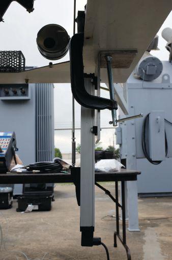


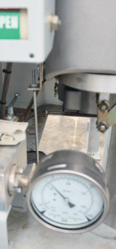
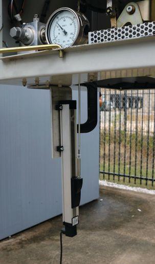
38-40-2 SF6 dead tank circuit breaker fitted with an FA2.20 mechanism. The breaker is rated at 38kV, is capable of interrupting 40k, has one break per phase, and is gang-operated (Figure 6).
Siemens recommends measuring motion with a linear transducer attached to an actuating arm on the mechanism (Figure 7). They state that
80 mm of travel at the mechanism is equal to 120 mm of travel at the contacts, i.e., there is a 1.5 multiplication factor used to determine the true contact motion. They also state that the speed calculation points of contact touch and 10 ms before for the close operation and contact separation and 10 ms after for the open operation must be used.
48 • SPRING 2019 CIRCUIT BREAKER AND TRANSDUCER: WHERE DO I CONNECT?
COVER STORY
Figure 6: Siemens SPS2-38-40-2 CB with FA2.20 Mechanism
Figure 7: Transducer Connection Linear Mechanism
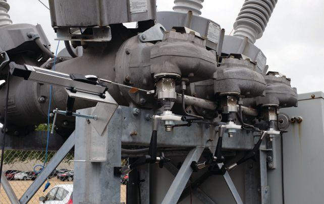
In addition to the standard transducer connection, four more transducer connections were made (Figure 8):
1. One linear transducer was connected to the end linkage arm on the third phase.
2. Three rotary transducers were attached to the rotating splines that drive the interrupter.
The same speed calculation points were used for all connections.
To compare the different transducer measurements, no conversion factors were initially used on the two linear transducer connections; a factor of 1 degree equals 1 millimeter was used for the rotary transducer. Figure 9 shows the motion traces from the three connections for a close operation; all three are scaled at 10 mm per division.
• M A (red), the linear transducer connected directly to the mechanism per Siemens recommendations, is referred to as Linear Mech.
• M B (black), the rotary transducer connected to the rotating spline on B phase is called Rotary B.
• M C (blue), the linear transducer connected to the end of the interconnect linkage near the rotating spline on C phase is referred to as Linear Linkage.
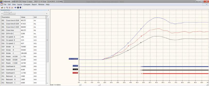
For all graphs, the bottom of the curve is the fully open position, and the top of the curve is the fully closed position. The timing for each phase where a thin line is open and a thick line is closed is also included. From the timing results, all three phases are relatively in sync with 0.3 ms difference between the slowest and the fastest phase with a close time of about 48 ms. As expected, the travel measurements vary widely across the connection points. The stroke for Linear Mech is 78.9 mm, Rotary B is 59.0 mm (degrees), and Linear Linkage is 106.5 mm. From these stroke measurements, the travel dependent parameters, i.e., velocity, overtravel, penetration, rebound, etc., will all vary by transducer placement.
NETAWorld • 49 CIRCUIT BREAKER AND TRANSDUCER: WHERE DO I CONNECT?
COVER STORY
Figure 8: Transducer Connections (left to right) Linear Linkage, Rotary C, Rotary B, Rotary A
Figure 9: Close Operation, No Conversion: Linear Mech in Red (center), Rotary B in Black (bottom), Linear Linkage in Blue (top)


An examination of the open operation shows similar variance in stroke values for the different connections (Figure 10).
The circuit breaker manual states that 80 mm of motion at the mechanism is equivalent to 120 mm of contact movement; therefore, with a transducer stroke of 78.9 mm, the contact stroke is determined to be 118.35 mm.

Since the other transducers measured motion on the same operation, the ratios of the alternate linear transducer and rotary transducer can be calculated. Using simple algebra, the ratios of 59.0 degrees = 118.35 mm (Rotary B); 106.5 mm = 118.35 mm (Linear Linkage) are used to determine the conversion
factors of 2.003 mm/degrees and 1.1099 mm/ mm, respectively. With this information, the circuit breaker was measured again with the appropriate conversion factor applied to each transducer. The results are shown in Figure 11 and Figure 12 (close), as well as in Figure 13 and Figure 14 (open).
These results show that, even with three different transducer attachment points and two different types of transducers, very similar results are produced as long as the correct conversion factor is applied. The maximum difference between stroke values is 0.2 mm on the close operation and 0.5 mm upon opening. Penetration, overtravel, and rebound are also very close for the three measurements. One


50 • SPRING 2019 CIRCUIT BREAKER AND TRANSDUCER: WHERE DO I CONNECT?
STORY
COVER
Figure 10: Open Operation, No Conversion: Linear Mech in Red (center), Rotary B in Black (bottom), and Linear Linkage in Blue (top)
Figure 11: Close Operation, Conversion Factors Applied: Linear Mech (red), Rotary B (black), Linear Linkage (blue)
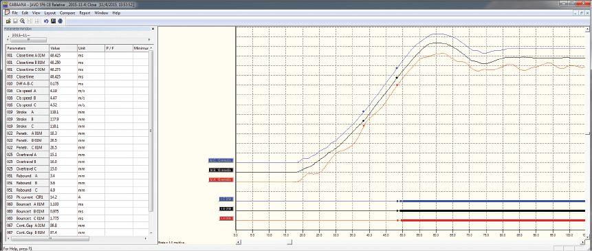
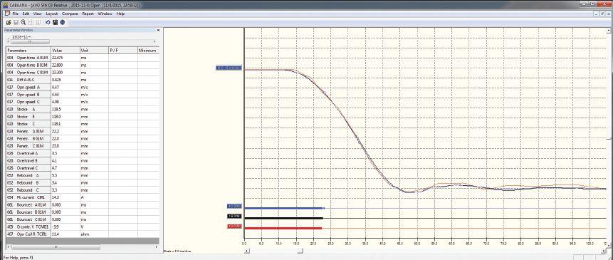

NETAWorld • 51 CIRCUIT BREAKER AND TRANSDUCER: WHERE DO I CONNECT? COVER STORY
Figure 12: Close Operation, Conversion Factors Applied, Horizontal Axes Shifted to Show Detail: Linear Mech (red), Rotary B (black), Linear Linkage (blue)
Figure 13: Open Operation, Conversion Factors Applied: Linear Mech (red), Rotary B (black), Linear Linkage (blue)
Figure 14: Open Operation, Conversion Factors Applied, Horizontal Axes Shifted to Show Detail: Linear Mech (red), Rotary B (black), Linear Linkage (blue)


interesting observation is that the travel trace of Linear Mech, the linear transducer connected directly to the mechanism, shows oscillation throughout the entire movement, and Linear Linkage, the linear transducer connected to the end of the linkage, shows slight oscillatory movement at the beginning and the end of travel. Flex in the travel rod and the connection of the rod to the transducer is most likely causing some of this movement. Additionally since Linear Mech is connected directly to the mechanism, the mechanism’s vibrations affect the motion throughout the entire travel. Since the close operation — closing the breaker and charging the opening spring — requires more energy, the effect is more apparent on the close operation.
Note that the velocity is different for each connection; this is partially due to the calculation points being based on contact touch and separation, so the variance in the timing affects where on the curve the velocity is calculated. On Linear Mech, the vibrations also affect the velocity calculations. If one of the speed calculation points rests on the crest of an oscillation and the other speed calculation point rests on the trough of an oscillation, the speed can vary dramatically compared to points taken on a neutral part of the oscillation. This effect can be seen by examining several operations in a row and observing that the velocity of Linear Mech can vary by 0.16 m/s or 3 percent, whereas the other two connections vary by a magnitude less. Play in the linkages will have some effect on the velocity calculations.
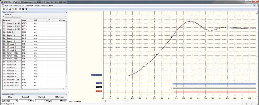


52 • SPRING 2019
CIRCUIT BREAKER AND TRANSDUCER: WHERE DO I CONNECT?
COVER STORY
Figure 15: Close Operation with Conversion Factors Applied (bottom to top): Rotary A (red), Rotary B (black), Rotary C (blue)
Figure 16: Close Operation, Conversion Factors Applied, Horizontal Axes Shifted to Show Detail: Rotary A (red), Rotary B (black), Rotary C (blue)
One last consideration is that a linear conversion factor was assumed, i.e., a conversion constant was used. Comparing Rotary B to Linear Linkage shows that they align better at the beginning and at the end of travel; in the middle of the movement, they diverge slightly, since this is the portion of the curve where velocity is calculated. It follows that the speeds would diverge slightly as well. If the geometries were analyzed and a conversion table was built for both connections, they would most likely overlap throughout most of the travel, and the velocities would align more closely.
The motion traces of the three rotary transducers can be examined to see how the same connection can be placed at different distances from the mechanism — at different parts along the interconnecting linkages — and yield similar results.
• M A on the graph (red), the rotary transducer connected directly to the rotating spline that drives the interrupter in A phase, is referred to as A phase.
• M B (black), the rotary transducer connected to phase B, is referred to as B phase.
• M C (blue), the rotary transducer connected to phase C, is referred to as C phase.
Figure 15 and Figure 16 show the results from a close operation.
All three traces are similar with a variance in stroke of only 1.2 mm between the shortest and the longest phase. Note that phase A begins to move approximately 0.5 ms before phases B and C, which can be expected since it is the closest connection to the mechanism. Both A and C phases produce very smooth traces throughout the motion, but B phase shows some oscillations in the first 20 ms of travel. These oscillations are most likely due to a mechanical delay, as B phase is pushed by the linkage from A phase and then has to push the linkage to phase C. Any mechanical play within the connections between B and the other two phases results in small perturbations. The velocities of A and C are fairly close, but B phase is 0.2 m/s slower. This is most likely caused by two factors: First, the oscillations in the trace can cause different speed points to be taken; second, the timing of the three phases is slightly different and the speed calculation point is based on contact touch. Careful observation of the speed calculation points reveals that they do not line up in time.
The open operation in Figure 17 and Figure 18 shows even more consistency between the different phases.
All three traces lay almost on top of each other with no deviation until the contacts reach the
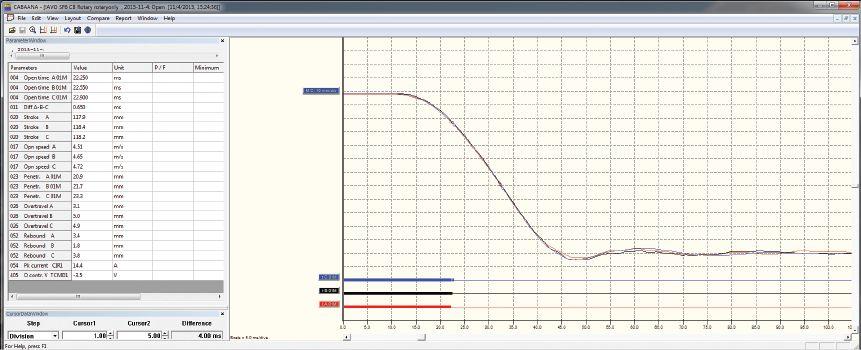
NETAWorld • 53 COVER STORY CIRCUIT BREAKER AND TRANSDUCER: WHERE DO I CONNECT?
Figure 17: Open Operation, Conversion Factors Applied (bottom to top): Rotary A (red), Rotary B (black), Rotary C (blue)


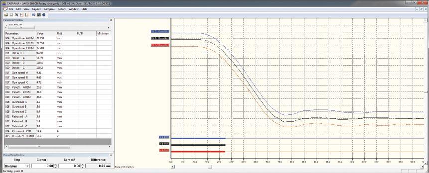
closed position. The stroke of the different phases is closer, with only a 0.5 mm difference between the shortest and the longest phase. The velocities of the three phases are different, but observing the contact times and speed calculation points shows that the velocity is calculated at slightly different points on each curve, thus changing the values slightly. If the speed calculation points are changed to reference below closed and a differential, then B and C phases travel at the same velocity, while A phase travels slightly slower because it has to push the other two phases.

WHAT TO DO IF VERY LITTLE OR NO INFORMATION IS PROVIDED BY THE MANUFACTURER
Occasionally, the manufacturer may not provide appropriate information for travel measurements, and it is left to the technician to decide which type of transducer to use and where to connect, what conversion factor/table to use (if any), and the proper speed calculation points for determining the velocity of the contacts. Careful consideration should be given before attaching a transducer and, once a method is determined, the same attachment and measurement parameters should be used in the future for trending purposes. Although these travel recordings provide valuable data

and can be used for future reference, it should be noted that the values obtained may not necessarily be comparable to the factory test reports or parameter limits. No matter where the transducer is placed, no part of the transducer, mounting bracket, or travel rod (if used) must be in the direct path of any moving parts of the circuit breaker to avoid damage to the transducer and its accessories.
To decide where to connect the transducer, first determine whether connection directly to the contacts or actuating arm of the contacts is possible. If so, a linear transducer can be connected and the correct stroke, velocities, and other parameters will be measured without the need for a conversion table. If direct connection to the contacts is not possible, which is often the case, select a spot very close to the contacts with the minimal number of linkages between the connection point and the contacts. Either a linear or a rotary transducer can be used. Per IEC 62271-100, the mechanical characteristics can be recorded with a travel transducer at “convenient locations on the drive to the contact system where there is a direct connection, and a representative image of the contact stroke can be achieved.” Connecting directly to the mechanism can cause unwanted vibrations and influence the results; this should be avoided if possible. If an indirect connection is used, there are two options: Create a conversion table/factor or measure the absolute value of
54 • SPRING 2019 COVER STORY CIRCUIT BREAKER AND TRANSDUCER: WHERE DO I CONNECT?
Figure 18: Open Operation, Conversion Factors Applied, Horizontal Axes Shifted to Show Detail: Rotary A (red), Rotary B (black), Rotary C (blue)
the motion, in either length or angle, and trend the results with the transducer connected in the same spot during future testing. If a conversion factor or table is used, the connection points and linkages can be examined and measured to develop a trigonometric function that relates the transducer movement to the contact motion. The function can also be determined from the circuit breaker’s mechanical drawings.
If the strokes of the contacts are known, another less accurate method of creating a conversion factor is to assume a linear relationship between the connection point and the contacts. The known stroke of the contacts can be divided by the measured stroke of the transducer to create the conversion factor. This value can then be used to measure the travel characteristics for initial fingerprint measurements and future testing. Note that if the relationship between the connection point and the contacts is not linear, the other stroke-dependent parameters such as velocity, overtravel, rebound, etc., may not be correct. Additionally, if this measurement is made when there are issues with the circuit breaker, i.e., the stroke is not correct, the subsequent measurements will also be incorrect. If other circuit breakers of the same type are available, it is beneficial to compare measurements to verify the correction factor.
If no speed calculation points are provided by the manufacturer, use contact touch and 10 ms before for close and contact separation and 10 ms after for the open. This assures that the velocity is measured in the critical arcing zone of the interrupter. Remember that once a method of transducer connection, conversion factor, and speed calculation points is used, the same method should continuously be employed through the life of the circuit breaker to trend the results.
CONCLUSION
Circuit breakers are a key element in the electrical transmission and distribution network throughout the world. IEEE Std. C37.09
states: “Travel-time curves shall be obtained for all outdoor circuit breakers with an interrupting time of three cycles or less,” and NETA requires time and travel analysis on medium- and highvoltage SF6 and oil circuit breakers. To verify that the circuit breaker will operate effectively when called upon to protect various assets in the network, time and travel analysis must be performed.
REFERENCES
IEEE Std. C37.100-1992 (R 2001), IEEE Standard Definitions for Power Switchgear.
CIGRE TB 510, “Reliability of High Voltage Equipment – Part 2: SF6 Circuit Breakers.” Working Group A3.06, 2012.
Siemens, Type SPS2-38-40-2 “Circuit Breaker Manual.”
IEC 62271-100, International Standard Highvoltage Switchgear and Controlgear – Part 100: Alternating-current circuit-breakers.
CB Testing Guide AG en V02, “Megger Circuit Breaker Testing Guide,” 2012.
IEEE Std. C37.09-1999 (R2007), IEEE Standard Test Procedure for AC High-Voltage Circuit Breakers Rated on a Symmetrical Current Basis.
ANSINETA ATS, Standard for Acceptance Testing Specifications for Electrical Power Equipment and Systems - 2013 Edition.

Robert Foster, an Applications Engineer with Megger, specializes in high-voltage circuit breaker and transformer testing. In his current role with Megger, he is involved with customers and product development, supporting products and applications throughout North America. He previously was a Field Service Engineer for ABB in the high-voltage deadtank circuit breaker division. Robert graduated from California State University, Chico, with a BS in physics and mechatronic engineering.
NETAWorld • 55 COVER STORY CIRCUIT BREAKER AND TRANSDUCER: WHERE DO I CONNECT?

In August 2018 intellirent joined the Electro Rent Corp family and together the two organizations have united to bring you more. We’ve carefully selected critical practices from each organization to best serve you and your customers.


The merging of Electro Rent’s electrical testing segment with intellirent builds on the customer centric focus with the same culture, the same support and above all the same commitment to you

rental l support l logistics

United in finding more ways to serve the Electrical Testing Community.

more resources
more capability
more inventory





S


T E R N ATI

 BY DANIELLE WHITE and LINA ENCINIAS, DILO Company, Inc.

With the ever-growing challenges of federal and local reporting and SF6 emission reduction, several alternatives have been presented to the industry as replacements for SF6 gas. As the industry continues to review and consider alternatives, we should not limit our solutions, and the alternative of turning to the existing stockpile of SF6 gas offers several benefits. However, what preventative measures must be taken so that the industry can continue using this insulating medium safely and in compliance with best practices and standards?
Discovered in 1901 by French Chemists Henri Moissan and Paul Lebeau, sulfur hexafluoride is a man-made gas that has a greater dielectric strength and density than air (Figure 1). In pure form, SF6 is inert, non-flammable, non-toxic, and thermally stable, and has unmatched arc-quenching

capabilities. Most interesting are the molecule’s self-healing abilities. The gas only begins to break down at a temperature of 380 degrees F; once the heat source is removed, the atoms regenerate like new. The chemical properties of SF6 make it ideal for use within circuit breakers and switchgear.
58 • SPRING 2019 SF6 — THE ALTERNATIVE GAS
T H E A L
V E G A

Figure 1: Comparison of Dielectric Breakdown
of SF6 Gas versus Air and Oil
The use of SF6 within circuit breakers has offered the electrical industry several benefits. Oil circuit breakers (OCBs), which were popular in the early 1900s, required frequent upkeep as the medium became easily polluted following arcing events and posed a potential fire hazard. Oil is also difficult to recondition. The introduction of sulfur hexafluoride offered a non-flammable resolution for the insulation of switches. In addition, the shift toward SF6 changed the design of circuit breakers by allowing a more compact infrastructure due to the dielectric strength of the gas. About 80 percent of manufactured SF6 is used in high-voltage equipment like switchgears and circuit breakers.
Unfortunately, the same properties that make SF6 such a great insulating gas also make SF6 the most potent of all greenhouse gases. One molecule of SF6 can trap 23,900 times more heat than carbon dioxide over a 100-year period, and it remains in the atmosphere for thousands of years.
ALTERNATIVES
Some proposed alternatives fall short of SF6 and would create an enormous economic burden
on utilities because it would require a complete overhaul of their gas insulated switchgear (GIS) equipment. We make the case that the industry has an SF6 handling problem, not an SF6 problem.
Th e industry could make two changes to drastically decrease SF6 emissions:
• Use reconditioned SF6 instead of importing virgin gas.
• Ensure that trained and certified personnel are using best management and safety practices when handling SF6.
The United States has a large stockpile of SF6 gas. From an environmental perspective, reconditioning gas could lower the carbon footprint by removing the need to manufacture new product. Sulfur hexafluoride is 100 percent recyclable, and there is no chemical difference between virgin SF6 gas and certified reconditioned SF6 gas. Any contaminants that occur due to the intrusion of air, moisture, or generation of arc by-products can be removed with the proper process.
RECONDITIONING
The SF6 reconditioning process ensures readily available supply and eliminates the need for

NETAWorld • 59 SF6 — THE ALTERNATIVE GAS
FEATURE
Strength
200 1 23456 150 Air Oil p (bar) U (kV) SF6 100 50 0
with Reconditioned SF6 Gas
Cylinders Filled
importing virgin product (the manufacturing process for SF6 is a known source of emissions). A limited number of North American suppliers can recondition SF6 gas to meet the standards set by CIGRE, IEEE, ASTM, and IEC while ensuring zero emissions of SF 6. The process requires specific handling procedures to ensure zero emissions of SF6 gas, and the overall properties of the gas must be respected. When the process is followed correctly, CIGRE, IEEE, ASTME, and IEC standards can easily be exceeded. An SF6 gas separator, which uses a three-stage cryogenic process to remove nonreactive gases, can recondition SF6 gas to a guaranteed 99.99 percent purity and less than 40 ppm moisture.
The reconditioning process includes increasing the storage pressure of the gas to allow the start of SF6 gas liquefaction followed by lowering the temperature by using two to three temperature changes below -40 degrees C. This further helps the liquefaction of SF 6 gas, thus separating other vapors such as N2, O2, and CF4. Upon the start of the reconditioning process, the contaminated SF 6 gas must be processed through a pre-filter system ensuring oil, moisture, and SF6 gas by-products are captured and scrubbed from the gas. This process is similar to the final process in the production of virgin SF6 gas.
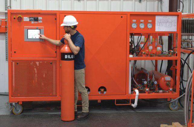
TRAINING
While the capability of recycling stockpiles of SF6 for utility and industrial users is beneficial to the environment, the composition of the gas remains the same. Handlers are still required to use SF6 in a closed cycle to prevent emissions while performing maintenance on circuit breakers and switchgear. Even after recycling, the global warming potential and the lengthy atmospheric lifespan (3,200 years) SF6 remains the same. However, the dielectric strength, thermal stability, and self-healing capabilities of the gas also remain. Choosing to reuse is just a step in the right direction. Ultimately, the only way companies can ensure that their choice is beneficial to the environment is to guarantee field staff are properly versed in SF6 handling methods.
Proper field training is essential to safeguarding an organization from unintentionally leaking SF6 into the atmosphere. According to the Environmental Protection Agency, “training raises awareness of emissions, environmental and health impacts of SF6 and by-products, and potential reduction options, but training also enables employees to follow procedures and protocols properly.”
Basic methods on preventing emissions during the circuit breaker maintenance process include:
• Recovery. When recovering SF6 using a gas cart, it is imperative to reach the lowest level of vacuum or blank-off
60 • SPRING 2019
SF6 — THE ALTERNATIVE GAS
FEATURE
An SF6 gas separator uses a cryogenic process to recondition contaminated SF6 gas to >99.99 percent purity.
SF6 Safety and Handling Training
pressure possible. Generally, reducing the amount of gas in a breaker to atmospheric pressure alone leaves a startling 20 percent of residual gas within the gas insulated enclosure. Starting additional maintenance while residual gas is still present can cause an emission.
• Filling. Check the OEM’s manual or nameplate for accurate SF 6 capacity information. Accidently overfilling GIE could result in an SF6 emission by engaging a pressure relief valve. Tracking gas weights by documenting SF 6 movements and using a cylinder weight scale can aid in preventing both positive and negative emissions. The Mass Balance Equation is used to determine leakage rates:
User Emissions = (Decrease in Storage Inventory) + (Acquisitions) –(Disbursements) – (Net increase in Total Nameplate Capacity of Equipment Operated)
Using the above equation, it can easily be determined that underestimating the capacity of the retiring equipment (for example, if the true value is 300 lbs., but the nameplate label reads 280 lbs.) will lead to showing a negative SF6 emission, and the emission rate will subsequently be underestimated.
• Testing. SF6 analysis to determine gas quality prior to performing maintenance is standard practice. It is important to use a collection bag when taking gas samples if your test equipment is not equipped with a self-recovery feature.
• Fittings and adaptors. Ensure fittings used for connection to GIE and other accessories (manifolds, analyzers, cylinders, etc.) are leak tested. Refrain from using threaded connections, which are prone to leak over time.
CONCLUSION
Turning to the existing stockpile of SF 6 gas offers an environmentally friendly alternative
solution to importing virgin SF 6 gas from overseas. The implementation of reconditioned SF6 that has been properly treated to meet or surpass IEEE/CIGRE standards helps reduce the carbon footprint and eliminates SF6 emissions that are the direct result of the manufacturing process. Awareness and preventative measures will allow the industry to continue using this insulating medium safely, provided the benefits of reuse are shared and understood.
REFERENCES
Lukas Rothlisberger. “SF6 Nameplate Inaccuracies and their Impact on Greenhouse Gas Reporting,” May 2014. Available at: www.epa.gov/sites/production/files/2016-02/ documents/nameplate_issues_final.pdf.
United States Environmental Protection Agency. “Overview of SF6 Emissions Sources and Reduction Options in Electric Power Systems,” August 2018. Available at: www.epa.gov/sites/production/files/2018-08/ documents/12183_sf6_partnership_overview_ v20_release_508.pdf.

Danielle White is a Marketing Representative and DILO’s Account Manager for the Canadian Region. She is committed to DILO’s Zero SF6 Emissions philosophy. Danielle is responsible for assisting customers in establishing comprehensive SF6 maintenance and management plans through on-site trainings, articles in DILO’s newsletter and other publications, as well as co-coordinating DILO’s annual SF6 Gas Management Seminar.

Lina Encinias, a Marketing Specialist for DILO Company, Inc., has a passion for sustainability. She helps spread awareness on SF6 emissions, regulations, and handling issues through DILO newsletters, the annual SF6 Gas Management Seminar, and industry trainings. Lina graduated from the University of South Florida with a BS in environmental science and a minor in mass communications.
NETAWorld • 61
SF6 — THE ALTERNATIVE GAS FEATURE






THE VALUE OF PERFORMING POWER FACTOR SWEEP MEASUREMENTS ON BUSHINGS
BY BRANDON DUPUIS, OMICRON
Power factor measurement has long been accepted as an invaluable tool for identifying insulation defects such as aging, deterioration, moisture ingress, and localized failures involving the winding and bushing insulation of a power transformer. Historically, power factor measurements have been performed at a single test frequency (typically 60Hz) and at a single test voltage (typically 10kV). However, modern test instruments can perform power factor measurements at several different test frequencies and at several different test voltages with minimal additional time and effort.
Based on experience, performing power factor frequency sweep and voltage sweep measurements can help identify and confirm:
• Compromised insulation
• User error
• Influence of the test environment
Power factor sweep measurements help the industry:
• Better assess the condition of an insulation system
• Determine whether a given power factor measurement is even valid
Power factor measurement is highly sensitive to the test environment — for example, it is sensitive to moisture on the surfaces of the bushings during the time of the test, to the test connections, and to the test specimen’s earth-
64 • SPRING 2019
THE VALUE OF PERFORMING POWER FACTOR SWEEP MEASUREMENTS ON BUSHINGS INDUSTRY TOPICS
ground connection — so a simple tool that allows a user to better detect a bad power factor measurement is useful.
Although power factor sweep measurements can be performed on the overall winding insulation of a power transformer, this paper focuses on the benefits of applying sweep measurements to the C1 insulation of bushings. While power factor sweep measurements are not the silver bullet of power factor testing, they can be beneficial for the maintenance testing industry.
WHO CAN BENEFIT FROM PERFORMING POWER FACTOR SWEEP MEASUREMENTS?
Power factor measurement is highly sensitive. Therefore, obtaining correct (i.e., valid) power factor measurements in the field is challenging. In many cases, a questionable power factor measurement is not caused by compromised insulation, but is due to either user error or the influence of the test environment.
Unfortunately, an invalid measurement is often not identified until the user leaves the job site, places the transformer back into service, and returns to the office. The user often has only a short window of time to test a power transformer — only one shot to obtain the correct measurements.
The Test Equipment Operator
Invalid power factor measurements that go undetected are a significant waste of a company’s resources. Although it is difficult for the user to determine whether a power factor measurement at one test voltage and one test frequency is valid, invalid measurements often become obvious when the power factor sweep measurements are performed and analyzed. Therefore, the test equipment operator should use power factor sweep measurements as a tool to quickly identify and correct invalid or questionable measurements before they leave the job site with incorrect test results.
The Engineer
In most cases, a test equipment operator performs power factor measurements in the field and distributes a test report to an engineer, who assesses the test results in the office. Based on the results, the engineer is responsible for assessing the condition of the insulation system to determine the appropriate course of action.
A disconnect often exists between the test equipment operator and the engineer. In most cases, the engineer is not on site when the measurements are performed, making it difficult to be confident that the measurements are valid. However, an engineer who has the power factor sweep results in hand can better identify invalid measurements, which helps prevent an incorrect condition assessment.
It is widely known that the best way to assess a power factor measurement is to compare the most recent measurement to a series of previous baseline measurements that were obtained at consistent test intervals. However, many asset owners do not have a collection of reliable baseline test results for their transformer fleet, which makes assessing the condition of an insulation system and determining the appropriate course of action a challenge. Fortunately, power factor sweep measurements can be used to better assess the condition of an insulation system at a given point in time, especially when there are no historical test results for comparison.
POWER FACTOR SWEEP TEST ANALYSIS
Analysis of voltage sweep and frequency sweep measurements is performed visually. The power factor measurements are plotted versus the applied test voltage and versus the applied test frequency, and the condition of the insulation is assessed based on the shape of the plots (aka, the traces). Although this paper focuses on applying power factor sweep measurements to the C1 insulation system of bushings, the same analysis strategies are valid for assessing power factor sweep measurements performed on the overall winding insulation of a power
NETAWorld • 65 THE VALUE OF PERFORMING POWER FACTOR SWEEP MEASUREMENTS ON BUSHINGS INDUSTRY TOPICS
transformer. In general, the analysis involves determining whether the shape of a trace is normal or abnormal. If either of the sweep measurements produces an abnormal trace, the insulation system should be investigated and/or tested more frequently in the future.
Power Factor Voltage Sweep Test (aka Voltage Tip-Up Test)
Performing a power factor measurement at multiple test voltages helps identify compromised insulation as well as invalid power factor measurements. At a minimum, an oil-and-paper insulation system should be tested at two test voltages (e.g., 2kV and 10kV). In most cases, a power factor measurement performed on bushing insulation should not be voltage sensitive. Therefore, regardless of the applied test voltage, the measured power factor value should be the same.
If the measured power factor value is not reasonably similar compared to the same power factor measurement at a different voltage, the measurement is questionable and should be investigated. To investigate further, the power factor measurement can be repeated at four or five different test voltages (e.g., 2kV, 4kV, 6kV, 8kV, and 10kV) to establish a definitive pattern.
When a power factor measurement is invalid, it often becomes voltage sensitive. Therefore, a power factor measurement at two different test voltages — first at a relatively low test voltage
(e.g., 1kV or 2kV) and then at a relatively high test voltage (e.g., 10kV) — can detect invalid measurements better than a single power factor measurement at one test voltage.
When the insulation of a bushing begins to deteriorate, the C1 power factor measurement for that bushing often becomes voltage sensitive. Therefore, at a minimum, a bushing C1 power factor measurement should be performed at two different test voltages (e.g., 2kV and 10kV). If the power factor value obtained at the two test voltages is not reasonably similar, then the C1 insulation of the bushing is typically deemed questionable. Remember, however, that a few bushing types may produce C1 power factor measurements that are slightly voltage sensitive even when the C1 insulation system of the bushing is healthy.
The Power Factor Frequency Sweep Test
Performing a power factor measurement at multiple test frequencies helps to identify compromised insulation and invalid measurements. The power factor frequency sweep test involves performing power factor measurements at a series of various test frequencies (e.g., 15Hz, 30Hz, 45Hz, 60Hz, 150Hz, 200Hz, 300Hz, and 400Hz).
The general guidelines used to assess a frequency sweep trace (Figure 1) are as follows:
• In general, if an oil-and-paper insulation system is healthy, the measured power factor value increases versus frequency. In other words, the frequency sweep trace climbs uphill versus frequency.
Figure 1: Acceptable C1 Power Factor Frequency Sweep Traces
• As an oil-and-paper insulation system deteriorates, the frequency sweep trace typically becomes flat, or worse, decreases versus frequency. If the trace decreases versus frequency throughout all or most of the frequency sweep, then the insulation system is typically considered questionable and is either investigated further and/or tested more frequently in the future.
66 • SPRING 2019
THE VALUE OF PERFORMING POWER FACTOR SWEEP MEASUREMENTS ON BUSHINGS
0.6 PF fequency sweep 480 460 440 420 400 380 360 340 0 50 100 Cap. pF 0.35 0.4 0.45 0.50 0.55 0.6 0.65 0.7 0 50 100 150 200 250 Hz PF fequency sweep 300 350 400 % H1 H2 H3
INDUSTRY TOPICS
• Another characteristic of compromised insulation is a distinct fishhook shape in the lower frequency range of the sweep (i.e., at frequencies below 60Hz). If this occurs, the insulation system is typically considered questionable and is investigated further and/or tested more frequently in the future.
• One advantage of performing power factor frequency sweep measurements on the C1 insulation system of a bushing is that, in most cases, a bushing mounted on a power transformer has two or three similar-unit bushings that can be tested and compared to each other. In general, power factor sweep measurements should behave similarly when comparing similar-unit bushings. Ideally, the traces for similar-unit bushings overlay or overlap when plotted against each other. Most important, the shape of the frequency sweep traces should be reasonably similar when comparing similar-unit bushings. If the shape of the trace of one bushing is dissimilar relative to the shape of the traces of the other similar-unit bushings, then the dissimilar bushing should be investigated further and/or tested more frequently in the future.
The C1 power factor frequency sweep measurements for three sister-unit bushings are provided in Figure 1. Notice that the shape of the traces is similar when comparing the similarunit bushings, and in all the traces in Figure 1, the measured power factor increases versus frequency (from left-to-right). This is typically indicative of healthy insulation.
CASE STUDIES
Several case studies involving power factor sweep measurements helped identify both compromised insulation and invalid measurements and demonstrated the value of performing power factor sweep tests on the C1 insulation of a bushing.
Case Study #1: Haefely 115kV Bushings
The first case involves power factor measurements that were performed on three Haefely 115kV bushings (Figure 2).
Based on the results in Figure 2, the 10kV power factor for H3 is higher than its nameplate value, whereas the 10kV power factor for the other two bushings is below their respective nameplate values. Notice that the 2kV and 10kV power factor measurements for the H3 bushing are dissimilar. In contrast, the 2kV and 10kV power factor measurements for the H1 and H2 bushings are reasonably similar, which further suggests that the H3 measurements are abnormal.
When comparing the power factor frequency sweep traces among similar-unit bushings, the shape of the traces should be reasonably similar. Clearly, the shape of the H3 trace is dissimilar relative to the traces of the other two bushings. Moreover, the H3 trace decreases versus
*Note: the measured capacitance for each bushing compared well to its respective nameplate value.
NETAWorld • 67 THE VALUE OF PERFORMING POWER FACTOR SWEEP MEASUREMENTS ON BUSHINGS INDUSTRY TOPICS
Figure 2: C1 Power Factor Results for Three Haefely 115kV Bushings
2kV Power Factor 10kV Power Factor 10kV PF –2kV PF Nameplate Power Factor H1 0.34% 0.34% 0.00% 0.38% H2 0.32% 0.32% 0.00% 0.37% H3 0.38% 0.41% 0.03% 0.35%
HAEFELY 115kV BUSHINGS (2000)
0.55 0.6 0.45 0.5 0.35 0.4 0.25 0 50 100 150 200 250 Hz PF fequency sweep 300 350 400 0.3 % 480 460 440 420 400 380 360 340 0 50 pF 0.38 PF fequency sweep 0.35 0.4 0.45 0.50 0.55 0.6 0.65 0.7 0 50 100 150 200 250 Hz
300 350 400 % H1 H2 H3 H1 H2 H3
PF fequency sweep
frequency and has the distinctive fish-hook in the lower frequency range; this is typically indicative of compromised insulation.
Interestingly, the 10kV power factor for H3 is below 1.5 to 2 times its nameplate value, which the industry generally considers to be acceptable. However, the H3 bushing is clearly behaving differently than the other two similar bushings, which is cause for concern. This case demonstrates that power factor sweep measurements are more sensitive to compromised insulation than conventional 10kV power factor measurements. The H3 bushing should be flagged as the weak link among the three bushings, and if returned to service, should be tested more frequently to gauge the severity of the situation.
Case Study #2: Lapp POC Series 2 115kV Bushings
The second case involves power factor measurements performed on three Lapp POC Series 2 115kV bushings (Figure 3).
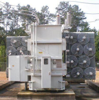
Bushings are a necessary component of a power transformer, but they are one of the transformer’s main weaknesses.
The power factor frequency sweep trace for the H3 bushing is not plotted because its 10kV power factor value is three times its nameplate value, which is already enough to condemn the H3 bushing. In other words, the power factor frequency sweep trace for the H3 bushing only confirms what we already know. Additionally, the 2kV and 10kV power factor values for the H3 bushing differ significantly — further evidence to condemn the H3 bushing.
Based on the results in Figure 3, the 10kV power factor value for H1 is higher than its nameplate value, whereas the 10kV power factor value for the H2 bushing is the same as its nameplate value. Additionally, the frequency sweep trace for the H1 bushing is clearly dissimilar relative to the frequency sweep trace for the H2 bushing. The H1 trace decreases versus frequency and has developed the distinctive fish-hook in the low-frequency range — typically indicative of compromised insulation. Although the 10kV power factor for H1 is well below 1.5 to 2 times its nameplate value, the H1 bushing is clearly behaving differently than the H2 bushing. As a result, the H1 bushing should be tested more frequently to gauge the severity of the situation.
68 • SPRING 2019
THE VALUE OF PERFORMING POWER FACTOR SWEEP MEASUREMENTS ON BUSHINGS
Figure 3: C1 Power Factor Results for Lapp POC Series 2 115kV Bushings
INDUSTRY TOPICS
LAPP POC SERIES 2 115kV BUSHINGS 2kV Power Factor 10kV Power Factor 10kV PF –2kV PF Nameplate Power Factor H1 0.27% 0.28% 0.01% 0.25% H2 0.25% 0.25% 0.00% 0.25% H3 0.66% 0.76% 0.10% 0.24%
0.55 0.6 0.45 0.5 0.35 0.4 0.25 0 50 100 150 200 250 Hz PF fequency sweep 300 350 400 0.3 % 480 460 440 420 400 380 360 340 0 50 100 150 200 250 Hz Cap. fequency sweep 300 350 400 pF % 0.34 0.36 0.38 0.30 0.32 0.26 0.28 0.22 0 50 100 150 200 250 Hz PF fequency sweep 300 350 400 0.24 1.6 PF fequency sweep Cap. at 60.00 Hz 200 0.35 0.4 0.45 0.50 0.55 0.6 0.65 0.7 0 50 100 150 200 250 Hz PF fequency sweep 300 350 400 % H1 H2 H3 H1 H2 H3 H1 H2 H3 H1 H2
Case Study #3: Westinghouse Electric Type S 37kV Bushings
The third case involves power factor measurements performed on three Westinghouse Electric Type-S 37kV bushings. The power factor measurements are summarized in Figure 4.
This case provides an example of three sisterunit bushings that produced three completely different power factor frequency sweep traces. The power factor frequency sweep trace for the H1 bushing is a typical example of a trace produced by a healthy bushing, whereas the power factor frequency sweep trace for the H2 bushing is a typical example of a trace produced by a questionable bushing. However, the power factor frequency sweep trace for the H3 bushing is an example of an abnormal or non-typical frequency sweep trace, which warrants concern.
Based on experience, there appears to be a bushing insulation failure mode where the measured capacitance (pF) value of the bushing is dissimilar relative to its nameplate value and
to the other sister-unit bushings. For this type of insulation failure, in addition to the measured capacitance (pF) value being different than expected, the power factor frequency sweep trace becomes more-or-less linear and exhibits a steep incline from left-to-right (as demonstrated by the H3 bushing in Figure 4).
Interestingly, the H1 and H2 bushings tested with capacitance (PF) values well below their respective nameplate values; the capacitance value of the H3 bushing is above its nameplate value. If the measurements provided in Figure 4 can be verified, the insulation system of the H3 bushing is suspect, and if returned to service, should be tested more frequently to gauge the severity of the situation.
Case Study #4: Lapp POC 138kV Bushings
This case involves power factor measurements performed on three Lapp POC 138kV bushings (Figure 5).
Based on the results in Figure 5, the power factor values for all three bushings are higher
NETAWorld • 69
THE VALUE OF PERFORMING POWER FACTOR SWEEP MEASUREMENTS ON BUSHINGS INDUSTRY TOPICS
Figure 4: C1 Power Factor Results for Three Westinghouse Type-S 37kV Bushings
WESTINGHOUSE ELECTRIC TYPE S 37kV BUSHINGS 2kV Power Factor 10kV Power Factor 10kV PF –2kV PF Nameplate Power Factor Measured Capacitance Nameplate Capacitance H1 0.60% 0.58% -0.02% 0.65% 169pF 182pF H2 0.79% 0.78% -0.01% 0.72% 184pF 197pF H3 0.69% 0.69% 0.00% 0.66% 203pF 198pF 0.55 0.6 0.45 0.5 0.35 0.4 0.25 0 50 100 150 200 250 Hz PF fequency sweep 300 350 400 0.3 % 0 50 100 150 200 250 Hz 300 350 400 % 0.34 0.36 0.38 0.30 0.32 0.26 0.28 0.22 0 50 100 150 200 250 Hz PF fequency sweep 300 350 400 0.24 0.38 PF fequency sweep % 1.4 1.6 1.0 1.2 0.8 0.6 0 50 100 150 200 250 Hz PF fequency sweep Cap. at 60.00 Hz 300 350 400 pF 200 100 150 50 0 H1 Measured values Nameplate values H2 H3 0 50 100 150 200 250 Hz 300 350 400 H1 H2 H3 H1 H2 H3 H1 H2
INDUSTRY TOPICS
than their respective nameplate values. Notice that the power factor measurement for the H2 bushing is clearly voltage sensitive. Furthermore, the power factor frequency sweep traces for the three bushings are erratic and jagged. In general, jagged power factor frequency sweep traces are indicative of invalid power factor measurements. Regardless of whether an insulation system is healthy or compromised, its power factor frequency sweep trace should be smooth.
By analyzing only the 10kV power factor measurements, it is not obvious that the power factor measurements for the three bushings are invalid; however, the voltage and frequency sweep test results make it obvious that the
power factor measurements are invalid. In this case, the customer determined that the primary-side bushing terminals were not shortcircuited together when the C1 power factor measurements were performed; this identified the cause of the abnormal power factor measurements.
CONCLUSION
With both the voltage and frequency sweep measurements on hand, invalid measurements are easier to identify. The equipment operator can use the sweep measurements to quickly identify and correct invalid measurements in the field before the transformer is placed back into service. The engineer can use the sweep measurements to identify invalid power factor measurements, especially when they must rely on the data provided within a test report.
Finally, power factor sweep measurements help to accurately assess the condition of a bushing’s insulation system. This helps the engineer choose the best course of action.
REFERENCES
IEEE Std. C57.152-2013, IEEE Guide for Diagnostic Field Testing of Fluid-Filled Power Transformers, Regulators, and Reactors.

Brandon Dupuis joined OMICRON in 2013 and presently holds the position of Regional Application Specialist for transformer testing. Brandon’s focus is currently on standard and advanced electrical diagnostics for power transformers and circuit breakers.He is a well-known OMICRON instructor teaching electrical transformer diagnostic testing theory, application, and test result analysis. Brandon received a BSEE from the University of Maine.
70 • SPRING 2019
THE VALUE OF PERFORMING POWER FACTOR SWEEP MEASUREMENTS ON BUSHINGS
Figure 5: C1 Power Factor Results for Three Lapp POC 138kV Bushings
2kV Power Factor 10kV Power Factor 10kV PF –2kV PF Nameplate Power Factor H1 0.34% 0.36% 0.02% 0.29% H2 0.52% 0.24% -0.28% 0.23% H3 0.34% 0.35% 0.01% 0.23% % 0.34 0.36 0.30 0.32 0.26 0.28 0.22 0 50 100 150 200 250 Hz 300 350 400 0.24 % 0.34 0.36 0.38 0.30 0.32 0.26 0.28 0.22 0 50 100 150 200 250 Hz PF fequency sweep 300 350 400 0.24 % 1.4 1.6 1.0 1.2 0.8 0.6 0 50 100 150 200 250 Hz PF fequency sweep Cap. at 60.00 Hz 300 350 400 pF 200 100 150 50 0 H1 Measured values Nameplate values H2 H3 H1 H2 H3 H1 H2 H3 H1 H2
LAPP POC 138kV BUSHINGS



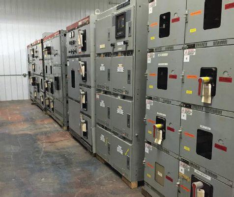


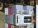
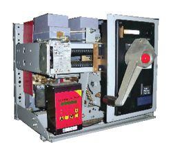
BULLOCK BREAKERS B B 475 Annandale Blvd • Annandale • Minnesota 55302 www.bullockbreakers.com • Email: jason@bullockbreakers.com • Thousands of Air Circuit Breakers in Stock! • Switchgear Line-ups you can’t find anywhere else! • Now Available as Reconditioned with AC-Pro Trip Units! 1-763-269-2832

FREE

Quotation ON-SITE ELECTRICAL TRAINING



Live instruction:
Online Courses and Videos are a great resource - but nothing can replace having an expert sit down with your team, learn more about the team environment, and deliver a training course that is relevant to your team’s experience, current projects, and future learning goals.
Hands-on skiLLs training:
All of our instructors are personable and friendly, and they can do more than provide lecture instruction. They can also get busy with your team, putting their experience into action and help solve your most critical problems.

Focused training:
Our Experts are focused on delivering training that is strictly dedicated to your specific equipment and practices, is the most effective training solution.




at Your Location:
When we deliver on-site training, your team can still address critical plant questions and issues that arise.
economicaL:
Training budgets are shrinking and travel costs are rising. Our on-site training is much less expensive than sending your staff to a training course in another city. We offer a flat rate training fee with instructor travel costs built in, so you pay for just one flight and one hotel expense. The more students you have, the more you save!

www.electricityforum.com/catalog Downloa D 2019 o n-Site t raining Catalog www.ele C tri C ityforum. C om /on S ite-training-quote top 5 advantages o f instruc tor-led on-Site training:


HIGH-POWER BATTERIES AS POWER SOURCE WITH DYNAMIC RESISTANCE
MEASUREMENT AND BOTH SIDES GROUNDED
BY ADNAN ŠECIC, RADENKO OSTOJIC, and NIJAZ HADŽIMEJLIC, DV Power–Sweden
Electrical arc phenomena have been studied for a long time. It is an inevitable process that occurs during interruption of high electrical currents (e.g., during a short circuit current interruption). The effects of the electrical arc on the circuit breaker contacts are known, and great attention has been paid to developing methods to analyze arc behavior and minimize damage to the breaker contacts.
One mitigating solution is the separation of main and arcing contacts. Arcing contacts are responsible for carrying the arc inside the breaker chamber during the breaker operation, and those contacts must be designed to withstand high currents and high temperatures with minimal deformation and erosion. The real challenge is to learn about the state of these contacts during regular maintenance procedures. The goal is to reduce time spent on testing to bring down maintenance costs and keep equipment out of operation as briefly as possible. The arcing contacts are active (carrying current) only a few milliseconds. Thus, the test and the collection of useful data set must be adjusted to this very limited time frame.
Dynamic resistance measurement (DRM), already adopted and approved as the standard testing procedure by many maintenance companies, is usually based on recording a resistance and a motion curve during the opening operation of the high-voltage circuit breaker. However, by recording a dynamic resistance curve during the closing operation of the breaker, the useful data set can be extended; consequently, the diagnostic process is more reliable. The circuit breaker arcing contact is the first to make contact during a closing operation and the last to break contact during the opening. Therefore, arcing contact wear occurs during normal operation as well as when interrupting fault currents. If the arcing
74 • SPRING 2019 HIGH-POWER BATTERIES AS POWER SOURCE WITH DYNAMIC RESISTANCE MEASUREMENT AND BOTH SIDES GROUNDED
INDUSTRY TOPICS

contacts are damaged, the breaker becomes unreliable very quickly.
An important diagnostic parameter is the main circuit resistance of the circuit breaker. Th is parameter is measured while breaker main contacts are in a closed position. For that reason, measurements can be recorded just before or after the DRM procedure, which reduces testing time since both measurements can be performed in one test sequence.
SAFE AND FAST TESTING OF CIRCUIT BREAKERS WITH BOTH SIDES GROUNDED
Safety in high-voltage substations is the highest priority for all personnel involved. Recent regulations and laws require all objects to be grounded on both sides before any maintenance work is performed. Eliminating the risk of induced high voltages improves the safety of test personnel and the instrument itself. This leads to a requirement for the modern circuit breaker analyzer to detect a main arcing contact’s state and to measure the operation time of the contacts when both circuit breaker terminals are grounded (Figure 1).
If both sides are grounded, applying conventional main arcing contact state detection methods is not possible because there is a parallel circuit through ground
cables and the ground network. When both sides of the circuit breaker are grounded, modern test methods use a main circuit resistance measurement for the main arcing contact state detection during a circuit breaker operation. Th is procedure is similar to the DRM method.

When a circuit breaker is open, there is a closed circuit through the grounding cables and grounding system. Commonly, the resistance of this circuit ranges from a few mΩ to tens of mΩ. Arcing contacts are first to close and last to open the main circuit, so they define the closing and opening time of the circuit breaker. The resistance of arcing contacts ranges from a couple of hundred µΩ to a couple of mΩ. Thus, it is possible to detect changes in the recorded resistance curve at the instances of arcing contact separation. Based on this, breaker timing can be measured in BSG conditions. Unlike conventional methods using only low power dc voltage sources, the BSG method requires additional dc voltage with ampacity of a few tens to a few hundred amperes.
POWER SOURCE FOR DRM AND BSG METHODS
Portable equipment for measuring resistance using the DRM and BSG methods must have an integrated power source that will provide high current for testing purposes.
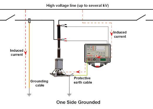
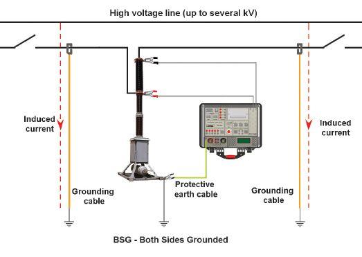
1: Circuit Breaker Test with One Side Grounded (left) and Both Sides Grounded (right)
NETAWorld • 75 HIGH-POWER BATTERIES AS POWER SOURCE WITH DYNAMIC RESISTANCE MEASUREMENT AND BOTH SIDES GROUNDED
INDUSTRY TOPICS
Figure
INDUSTRY TOPICS

A high dc current power source can be realized in various ways. Lead-acid batteries were used as a power source for this method, but transportation cost, difficult installation in a portable instrument, and other technical reasons prevented wide use of lead and similar rechargeable batteries. Another way is to use energy directly from an ac mains supply using high-frequency dc/dc power converters. This solution provides continuous high dc current,

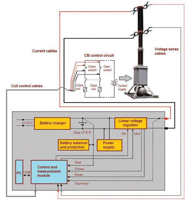
but is dependent on the availability of the ac source on the mains supply; furthermore, power converters require more space in the instrument than some non-dispersible energy storages.

One such energy storage device is a supercapacitor (ultracapacitor or EDLC-electric double-layer capacitor). A supercapacitor has capacitance from a few hundred or thousands of Farads and voltage of a single cell from 2.3 to 3.0 V. Most of these components have very low internal resistance — in the order of milliohms — so it is possible to generate currents in the order of hundreds to thousands of amperes.
A supercapacitor can be charged from a lowpower electronic source or from batteries (leadacid, NiMH, Li-ion, and similar) with lower current (around 1 ampere), which requires longer charging time (up to one minute). Capacitor discharging can be performed with currents of up to hundreds of amperes in intervals up to one second.
High-power batteries such as lithium polymer (Li-Po) or similar also provide high-impulse dc current, which overcomes these shortcomings.
HIGH-POWER BATTERY VERSUS SUPERCAPACITOR
Solutions applying standard batteries and supercapacitors (Figure 2) have a few shortcomings:
• Long charging or recharging time, ranging from 10–130 seconds depending on the current level and duration of the test
• Significantly reduced supercapacitor dc voltage when the capacitor discharges, requiring constant recharging to provide the voltage level necessary for the desired current (e.g. >100 A)
High-power batteries have higher capacity and lower demand for recharging and are suitable for installation in a portable test instrument.
76 • SPRING 2019
Figure 2: Supercapacitor 3400 F (top), Supercapacitor 310 F (bottom left), 3600 mAh High Power Battery (bottom right)
Figure 3: Block Structure of Proposed System

Once charged, a high-power battery with the capacity of 3,600 mAh is capable of generating around 300 to 400 100A current pulses for 100 ms and uses lightweight current cables 10–20 meters long. The voltage level of the 100 percent charged battery is 4.2 V (singlecell 4.2 V; two serial connected cells 8.4 V, etc.), while a 30–35 percent charged battery cell has a voltage level of 3.7 V (7.4V for serial connected cells). That means voltage is reduced only 0.5 V when the battery is about 70 percent discharged. When connected in a series, these battery cells can be charged from a universal 100–250 V, 50–60 Hz ac mains supply adapter, but also from a standard car supply outlet (12 V).
A current regulator can be used to set the desired test current during the resistance measurement of the main circuit. It is also possible to use a voltage regulator to provide constant voltage on the output terminals of the device and to use the current measurement as a feedback value to set the desired current by controlling the output voltage.
Figure 3 shows the block structure of the proposed measurement and control system.
METHOD VERIFICATION ON THE TEST OBJECT
To verify the efficacy of this battery as a power source for DRM and BSG methods, a control and measurement module was constructed. Tests have been carried out on actual test objects (Figure 4).
The test was conducted on a three-pole air circuit breaker, model AT-16, manufactured by Terasaki Electric Co. LTD, Japan. Simultaneous measurements recorded the test current and the voltage drop across the breaker’s main circuit. Current was recorded by measuring the voltage drop across a shunt resistor.
Breaker timing was measured from the instance of energizing the coil. For that reason, a coil control module was also constructed and connected to the main processing unit.

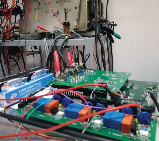
The test procedure can be described as follows:
1. Test preparation
• Set the circuit breaker in the closed position.
• Start regulating the current by increasing the output voltage of the voltage regulator.
• When the current reaches the desired value, store the current settings.
• Stop regulation.
2. Test
• Set the coil control and the measuring module to trigger waiting mode.
• Enable voltage regulation and set the output voltage to the previously stored value.
• Simultaneously start the measurement and issue the command to open or close the breaker coil (depending on the current breaker state).
• Record the data and disable voltage regulation.
NETAWorld • 77
INDUSTRY TOPICS
Figure 4: Constructed Control and Measurement Module
INDUSTRY TOPICS

Simple software for data acquisition (Figure 5) also had to be developed. Data acquisition was performed through the PC’s USB port.
For easier data manipulation, the software incorporates an export option that supports several data formats (Excel™, .csv, etc.). The results were first exported in .csv; the data was then imported into MATLAB for further analysis.
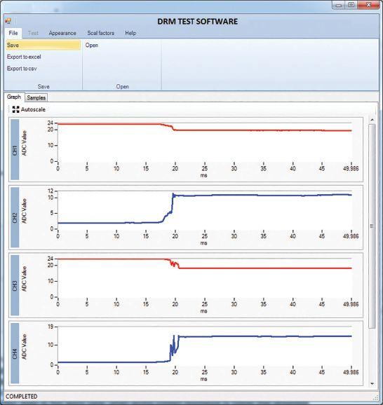
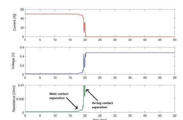

The first tests were performed on the circuit breaker grounded only on one side. The DRM results, including current, voltage drop, and resistance for phase A are shown in Figure 6. It is not difficult to determine the moments of separation of the breaker’s main and the arcing contacts. Based on these points, parameter overlapping time can be determined and used to assess the arcing contact condition. The peak on the voltage drop graph during arcing contact engagement indicates high-resistance changes during the open operation, which further indicates a rough arcing contact surface, usually due to wear of arcing contacts. The test current was around 50A.
The breaker was then grounded on both sides, and the DRM test repeated. The measured grounding resistance was around 12–13 mΩ. Figure 7 shows the results for the same phase (A).
The moments of separation of the arcing and main contact are identical on Figure 6 and Figure 7, which means that the described method can be successfully used with one side grounded and with both sides grounded.
Next, several DRM tests were conducted on all three phases of the tested circuit breaker. To examine repeatability, the dynamic resistance graphics were overlapped for each phase separately. Figure 8 shows three of the graphs for each phase. The breaker was grounded on both sides.
The results show increased bouncing in phase C, where grounding resistance had the highest value. However, repeat tests led to almost identical results for all three phases.
The proposed method can also be used to conduct a DRM test during close operation. Figure 9 shows the results. Arcing contacts touch around t=38 ms, while the main contacts close in t=40 ms after some bouncing. The initial current is around 42A, which corresponds to the ratio of the regulated voltage at the output terminals and the resistance of the serial connection of the
78 • SPRING 2019
HIGH-POWER BATTERIES AS POWER SOURCE WITH DYNAMIC RESISTANCE MEASUREMENT AND BOTH SIDES GROUNDED
Figure 6: Current, Voltage Drop, and Calculated Resistance during Opening Operation — One Side Grounded
Figure 5: Data Acquisition Software

current cables and the grounding resistance. As seen in the diagram, the current value goes up to 50A, representing the set current value for the breaker in the closed position.
In total, approximately 100 tests were performed on the test object without recharging the single battery. This proves the benefits of using high-power batteries during condition assessment of high-voltage circuit breaker main and arcing contacts.
CONCLUSION
High-power batteries (Li-Po or similar) are a good solution for generating dc current pulses for Dynamic Resistance Measurement and timing tests with a circuit breaker grounded at both terminals. The experiments show that these batteries can hold a steady voltage regardless of high discharging test currents.
These batteries are superior to similar solutions, as they now can be used as a building block of a handheld device capable of performing a large number of operations without single battery recharging. This reduces testing time and contributes to savings in test personnel work hours.
REFERENCES
A. Secic and B. Milovic, DV Power–Sweden. “Dynamic Resistance Measurement Method Applying High DC Current,” CEATI Circuit Breaker Circuit Breaker Test & Maintenance WS, 2014, Palm Desert, CA, USA.
V. Mrdic, R. Levi. “Advanced Dynamic Testing of Substation Apparatus,” TechCon USA 2016, Albuquerque, NM, USA.
J. Levi. “A Simplified Method for Determining HV Circuit Breaker Contact Condition – Dynamic Resistance Measurement,” Doble Client Conference, Boston, MA, 2005.


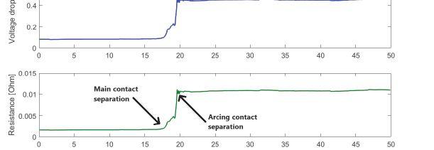
Figure 7: Current, Voltage Drop, and Calculated Resistance During Opening Operation — Both Sides Grounded
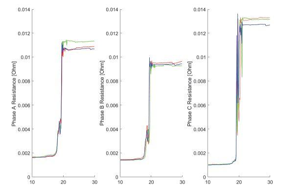
Figure 8: Overlapped DRM Results for Opening Operation on Phase A, Phase B, and Phase C
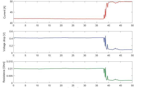
Figure 9: Current, Voltage Drop, and Calculated Resistance During Closing Operation Under BSG Conditions
NETAWorld • 79 HIGH-POWER BATTERIES AS POWER SOURCE WITH DYNAMIC RESISTANCE MEASUREMENT AND BOTH SIDES GROUNDED
INDUSTRY TOPICS
INDUSTRY TOPICS

IEEE Std. P510, Guide for Electrical Safety in High-Voltage Testing.
OSHA 29 CFR 1910.331 – 1910.335, Electrical Safe Work Practices.
R. Ostojic and B. Milovic. DV Power–Sweden, “New Requirements in Circuit Breaker Diagnostics,” NETA World — Spring 2014.
Maxwell Technologies, BOOSTCAP® Ultracapacitors, Product Guide.

Adnan Šečić is an R&D Engineer at DV Power–Sweden. As a project leader, he is responsible for development of the circuit breaker analyzer and timer (CAT) device series. Adnan received his BS in electrical engineering and MS in electronics, electrotechnics, and automation (EAA) from the University of Sarajevo, Bosnia and Herzegovina, and is in the final stage of PhD studies at the Faculty of Electrical Engineering and Computing in Zagreb, Croatia.



Radenko Ostojić is a test and diagnosis engineer at DV Power–Sweden in the field of circuit breaker testing and maintenance. He has been employed at DV Power since 2010 and works on the improvement of circuit breaker testing equipment and development of new methods for circuit breaker testing. Radenko’s area of special interest is testing of circuit breakers in enhanced safety conditions, which implies testing of circuit breakers with both terminals grounded. He earned his BS in electrical engineering at the University of East Sarajevo.

Nijaz Hadžimejlić has been with DV Power since 2015. From 1977–1998, he was with the Department of Power Electronics and Motor Control, Institute for Computer Science and Control-IRCA, Energoinvest, Sarajevo. Nijaz was a part-time Teaching Assistant and Senior Teaching Assistant in the Department of Electrical Engineering, University of Sarajevo from 1984–1997 and was an Associate Professor from 1998-2015. He received his BS, MS, and PhD degrees, all in electrical engineering, from the University of Sarajevo. Nijaz’s research interests include power electronics converters, motor drive control for electric cars, and robotics. He is the author or co-author of over fifty technical papers.




MEASURING HUMIDITY: WHY IT’S IMPORTANT


 BY JOHN OLOBRI, AEMC Instruments
Most people are all too aware of the effects humidity can have on human comfort and health, especially when combined with high temperatures. Perhaps less well known is how humidity can impact electrical systems. For example, high humidity can cause droplets of water to condense on circuits, producing problems such as shorting and corrosion.
Many geographic regions are prone to humid conditions, particularly the tropics. But even in relatively temperate climates, high humidity can occur depending on altitude, proximity to bodies of water, and seasonal effects. In addition, the microclimate inside and immediately around an electrical cabinet can result in condensation issues. As a result, organizations that set industry standards often require that humidity data be included in test reports.
ABSOLUTE vs. RELATIVE HUMIDITY
Simply stated, humidity is the amount of water vapor in the air. Two ways are commonly used to measure humidity:
• Absolute humidity (AH) is the mass of water vapor present in a given volume of air. This is usually expressed in grams per cubic meter (g/m³) and changes as the volume of air changes.
• Relative humidity (RH) is the ratio of water vapor density (mass per unit volume) to the water vapor density at the saturation vapor pressure (the point at which the air can hold no more water vapor and liquid droplets begin to precipitate out). This is also known as the dew point. RH is typically expressed as a percentage and changes with air pressure and temperature.
In this article, humidity is expressed as RH.
HUMIDITY AND PEOPLE
Maintaining an appropriate level of humidity is important for ensuring a comfortable and healthy indoor environment. Excessive humidity can make working difficult, especially if physical activity is involved. Less directly (but equally important), high humidity promotes the growth of mold that can cause respiratory issues. It can also cause peeling paint, rust on iron objects, and surfaces slick with condensation. These and other factors can significantly affect health and safety.
82 • SPRING 2019 MEASURING HUMIDITY: WHY IT’S IMPORTANT
INDUSTRY TOPICS

In general, a humidity level between 30 and 40 percent is considered ideal for maximum comfort. To ensure humidity remains within this range, facilities employ a variety of HVAC systems, including air conditioning, controlled mechanical ventilation, and dehumidifiers. To test their efficiency, it is important to periodically check the humidity level with hygrometers and other moisture-measuring instruments. In many cases, it can also be useful to monitor humidity continuously over an extended interval to identify potential trends and spikes.
temperature in the enclosure, creating a condition where the heatsink temperature falls below the dew point. Therefore, it is critical to be aware of any changes in operation from full to reduced power, such as equipment entering standby mode or experiencing unexpected downtime.

ELECTRICAL EQUIPMENT
Humidity can have a detrimental effect on electrical systems and components. The most obvious issue is condensation, which results when RH reaches 100 percent. For example, droplets of water forming on a heatsink can wick into power module housings. In live conductors, liquid can compromise insulation. The damage may remain even after the RH falls and the droplets evaporate, making it very difficult to troubleshoot and identify the cause of the problem.
A number of factors can cause RH to reach the saturation point. One of the more common is temperature disparity. As air cools, the amount of water vapor it can hold decreases. Thus, sudden cooling causes RH to rise rapidly.
For instance, an electrical system can be warmed by dissipation of heat from its components. A sudden change in operating state — for example, a power failure — can cause the system to cool. Components such as the heatsink may cool far more rapidly than the air
Changes in air temperature can also cause internal condensation in electrical systems. Many heatsinks are cooled by outside ambient air. As the inlet air temperature drops in the evening, the heatsink may be cooled to below the dew point. Both the interior and exterior RH should be monitored over a period of days or weeks to understand how weather and system operation interact.
In addition to electrical conductance, humidity can have a corrosive effect on many materials. Corrosion progresses rapidly when humidity exceeds 60 percent. Since corrosion also progresses as temperature increases, facilities in high-humidity locations must carefully monitor — and prepare countermeasures for — the amount of water vapor in the air.
ORGANIC COMPONENTS
A recent trend is to fabricate electronic components from organic materials due to their reduced cost and ease of manufacture. Unfortunately, these materials present special humidity-related issues. This is due to the fact that they tend to be water-permeable, slowly absorbing moisture until the internal water concentration matches the ambient air.

Excessive levels of moisture in organic materials can severely impact performance and reliability. One obvious example is so-called popcorn cracking, caused when saturated
NETAWorld • 83
MEASURING HUMIDITY: WHY IT’S IMPORTANT
INDUSTRY TOPICS
Mold
Condensation

organic materials are suddenly heated to a high temperature. Other longer-term effects include swelling of components, which can compromise electrical connections.
MEASURING HUMIDITY
Many instruments on the market measure and, where necessary, record temperature, humidity, and dew point. On the low-cost end, a number of choices measure and display either humidity only or both temperature and humidity.
For more demanding applications that require documented results, a data logging thermo-hygrometer is a better choice. These instruments are portable, compact digital meters designed for simplicity of operation. Most enable you to perform a variety of recording tasks with easy and intuitive setup from a computer or smart device app. These meters use a semiconductor as the temperature sensor, which provides excellent response time to changes in temperature, as well as good repeatability and accurate readings. Relative humidity is typically measured by a thin, polymer film capacitive sensor, offering excellent recovery from 100 percent moisture and fast response time and durability.
A variety of common features includes:
• Ability to monitor and record temperature, humidity, and dew point
• User-selectable temperature units (Fahrenheit and Centigrade)
• Plug-in sensors with easy replacement capability
• The capability to store minimum, maximum, and average measurements time stamped for ease of analysis
• Spot or continuous recording of measurements
• Backlit display
• Programmable alarms for temperature, dew point, and humidity through software
• USB and Bluetooth communication
• Battery or USB power capability
• Graphing and analysis software to program the instrument, analyze the results, and print or transmit reports
CONCLUSION

Relative humidity is a common term most people can relate to. We know that when the humidity is high, the environment can be uncomfortable. When it is too low, static electric shocks are common when we touch something. As human beings, we like the relative humidity to be between 30 and 40 percent.
Electrical equipment is also affected by humidity. Condensation caused by high humidity can damage the operation and functionality of sensitive equipment that is not treated for humid conditions. Newer components made from organic materials are even more sensitive to high humidity, and corrosion progresses rapidly when humidity exceeds 60 percent with many materials.
It is a good practice to monitor the humidity in the work environment and in control rooms where critical electrical equipment resides to prevent costly down time or failure. Many good choices of instruments are available to monitor, control, and report temperature, humidity and dew point. It is an investment worth making to protect your assets.

John Olobri has been Director of Sales and Marketing at AEMC Instruments for 20 years. He has been actively involved in the areas of insulation resistance, ground resistance testing, power quality testing, data logging, and environmental testing. John previously worked in instrumentation design and marketing for over 35 years, holding positions as Service Manager, Product Marketing Manager, and Sales Manager for several instrument manufacturers. He holds degrees in both electrical and industrial engineering and conducts accredited seminars on ground resistance testing across the country.
84 • SPRING 2019
MEASURING HUMIDITY: WHY IT’S IMPORTANT
INDUSTRY TOPICS





THEORY: AND PRACTICE
HIGH-VOLTAGE LABORATORY TESTING OF NEW ELECTRICAL PRODUCTS
BY JEROD DAY, Vacuum Interrupters, Inc. and FINLEY LEDBETTER, Group CBS, Inc.
High voltage is defined by the National Electrical Code (NEC) as any voltage over 600V and by the International Electrotechnical Commission (IEC) as any voltage greater than or equal to 1,000V. NETA uses the IEEE definition: any voltage greater than or equal to 100kV and less than or equal to 230kV. Other standards and industries define high voltage at different levels. This can lead to confusion with regard to nomenclature, but in this case, it is relative to the application. For every normal operating voltage level used by electrical equipment, there is a corresponding test voltage and a method of applying that voltage for a particular type of equipment according to the tests and standards being applied.
Photos courtesy
Group CBS
High-Voltage Laboratory, Farmers Branch, Texas
From low- to ultra-high voltages, all electrical equipment requires some type of electrical insulation to separate circuits from each other and/or from grounded connections. Insulation materials include solid insulation and/or air, vacuum, liquid, or gas mediums. Most standards outline basic conductor clearances and phase spacing, but many details that affect the highvoltage characteristics of equipment are the responsibility of the manufacturer.
Vacuum interrupter manufacturers perform special operations to smooth the contacts and other internal conducting surfaces on the finished units to enhance their dielectric performance, which is gauged through high-voltage testing. More often, highvoltage equipment manufacturers combine technologies to increase the overall performance of the equipment; this includes the use of dry insulating gases with vacuum interrupters for use in applications well over 100kV. Design
88 • SPRING 2019 PRACTICE AND THEORY: HIGH-VOLTAGE LABORATORY TESTING OF NEW ELECTRICAL PRODUCTS
ADVANCEMENTS IN INDUSTRY
Table 1: ANSI and IEC Voltage Rating Chart


ADVANCEMENTS IN INDUSTRY
and production tests may include basic insulation level, chopped wave insulation level, dielectric withstand, critical flashover voltage, as well as many other application-specific tests.
Over time, insulation systems begin to deteriorate due a number of operational and environmental factors, including contamination, mechanical eff ects, thermal aging, partial discharge, and over-voltage spikes; these eventually lead to failure of the system. Degradation of insulation can lead to equipment failure and loss of assets as well as injury or death to personnel. Numerous
types of high-voltage tests require a laboratory environment due to environmental factors, test levels, and equipment requirements. For example, partial discharge tests require an environment with low electrical noise for sensitive measurements of voltage fluctuations. Contamination tests for some products require the test sample to be mounted on a rotating wheel that intermittently submerges the product in a temperature-controlled bath of a preselected contaminant — often while under test — to simulate worst-case environments and accelerate aging. Some test labs are capable of performing high-voltage tests while
NETAWorld • 89
PRACTICE AND THEORY: HIGH-VOLTAGE LABORATORY TESTING OF NEW ELECTRICAL PRODUCTS
Application Standards Line-to-Line Voltage, kV (rms) 1-Min AC Withstand Voltage, kV (rms) Basic Impulse Voltage, kV (peak) 3-Sec, ChoppedWave Impulse Voltage, kV (peak) 2-Sec, ChoppedWave Impulse Voltage, kV (peak) IEC 3.6 10 20 IEC 3.3 10 40 ANSI Indoor 4.76 19 60 IEC 7.2 20 40 IEC 7.2 20 60 ANSI Indoor 8.25 36 95 IEC 12 28 60 IEC 12 28 75 ANSI Indoor 15 36 95 ANSI Outdoor 15.5 50 110 126 142 IEC 17.5 38 75 IEC 17.5 38 95 IEC 24 50 95 IEC 24 50 125 ANSI Indoor 27 60 125 ANSI Outdoor 25.8 60 150 172 194 IEC 36 70 145 IEC 36 70 170 ANSI Indoor 38 80 150 ANSI Outdoor 38 80 200 230 258 ANSI Outdoor 48.3 105 250 288 322 IEC 52 95 250 IEC 72.5 140 325 ANSI Outdoor 72.5 160 350 402 452
ADVANCEMENTS IN INDUSTRY

simulating atmospheric pollution, rain, fog, snow, or ice via spray nozzles or misters.
EVOLUTION OF HV LAB
The need for high-voltage testing was established with the advent of high-voltage power generation and transmission in the late 1800s. The individual components that made up high-voltage systems needed to be tested to ensure they could reliably operate at the required voltage level and withstand surges in voltage generated from events such as lightning strikes or short circuits.

with multiple test standards to ensure their equipment fits the requirements of the region where it is being sold. High-voltage labs provide independent, third-party performance of these tests to provide customers with reliable, unbiased results. The theory of highvoltage testing has not changed tremendously since the early days of electricity. However, there have been substantial improvements in the technology required to perform testing and to measure the results accurately and precisely.
In the early days of electricity, there were no industry design or testing standards, so equipment manufacturers were responsible for selecting their own test procedures and levels. Manufacturers often had inadequate laboratory facilities, so tests were performed in cooperation with a local utility at a highvoltage substation. Varying test procedures and levels inevitably led to compatibility issues between different types of equipment and those manufactured by different companies such as the burning of wooden insulator pins on highvoltage transmission lines.
The first attempt at standardization in the United States came with the creation of the American Institute of Electrical Engineers (AIEE) in 1884. However, the first standard was not adopted until 1893, and that standard was related to the use of units and symbols. It wasn’t until 1903 that the first technical committee — the High-Voltage Transmission Committee — was formed. By this time, transmission systems as high as 60kV were operated in some parts of the world, and the industry was growing rapidly. At present, numerous electrical standards are used across the world, including IEEE, ANSI, ASTM, UL, CSA, IEC, ICEA, and AEIC, as well as utility-specifi c standards, and high-voltage transmission lines are now operated at voltages in excess of 1MV.
Manufacturers of electrical equipment often certify their products in accordance
From measuring high voltages based on the breakdown distance of an air gap, to Fleming’s oscillation valve, to vacuum tubes, to the analog-to-digital converters used today, the accuracy and precision of high-voltage measurement has improved by magnitudes. Access to the high-voltage equipment necessary to perform the same tests offered at world-renowned testing labs has also become more widespread. Once, just a handful of high-voltage test labs were available; due to the proliferation of higher-voltage products and the availability of test equipment, hundreds of labs are now capable of performing many of the design and production tests manufacturers require.
A modern high-voltage laboratory can evaluate the design, configuration, and materials of many types of high-voltage equipment — including circuit breakers, transformers, insulators, cables, and motors — for suitability, reliability, performance, and safety. New products can be tested to ensure they conform to design specifications as well as national and international standards, existing equipment conditions can be reevaluated after modifications, and failed equipment can be analyzed to find a root cause.
HIGH-VOLTAGE LAB UTILITY
Examples of high-voltage testing include:
• Basic insulation level (BIL) test of a new primary disconnect design. Even though switchgear may have been tested and certified
90 • SPRING 2019
PRACTICE AND THEORY: HIGH-VOLTAGE LABORATORY TESTING OF NEW ELECTRICAL PRODUCTS

previously, any change to the system, such as a primary disconnect design using new methods or materials, warrants additional testing and possible recertification of the switchgear. Any change to the system, including changes in design, insulation distance, materials, insulating medium, etc., could affect overall performance. BIL testing generally takes place inside a high-voltage lab due to the size of the test system — which consists of a capacitor bank, charging circuit, voltage divider, and high-speed analog-todigital measurement equipment — and environmental factors such as temperature and humidity.
• Partial discharge test of a molded insulator design. The process of manufacturing a molded insulator can leave small voids inside the finished insulator. These voids act as capacitors inside the solid insulation and produce reoccurring discharges that do not fully bridge the space between the two
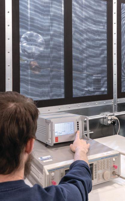

ADVANCEMENTS IN INDUSTRY

conductors — hence, partial discharge. This will lead to erosion of the solid insulation and eventual insulation breakdown. To obtain an accurate measurement of partial discharges, sensitive voltage measurement equipment must be used, usually in the form of a coupling capacitor and partial discharge detection circuit. Measurements must often be taken inside an environment with low electrical noise such as a Faraday cage.
• Dielectric breakdown test on a new insulator design. The dielectric breakdown test is a common design test performed on insulators before entering production to determine the voltage at which an insulator can no longer withstand the voltage being applied, which leads to internal or external
NETAWorld • 91
PRACTICE AND THEORY: HIGH-VOLTAGE LABORATORY TESTING OF NEW ELECTRICAL PRODUCTS
BIL Test
Partial Discharge Test
ADVANCEMENTS IN INDUSTRY


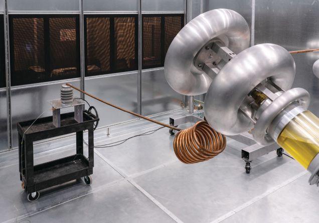
flashover. This helps manufacturers refine their designs to enhance performance and reliability.
HV LAB BENEFITS
High-voltage test labs provide an indispensable source of information that ultimately improves the overall reliability, performance, and safety of electrical products and systems. Independent, third-party testing of electrical products helps prevent bias and improves the accuracy of a
Standard High-Voltage Lab Tests
• Partial Discharge
• Radio Interference Voltage - RIV
• Visual Corona
• Temperature Rise
• Chopped Wave Impulse
• Dielectric Breakdown / Dielectric Withstand
• AC Short-Term and Long-Term Withstand
• Dry Lightning Impulse Critical Flashover and Withstand
• Vibration
• Accelerated Life
• Environmental
• Mechanical Endurance
• Speed, Velocity, and Motion
• Seismic
product’s electrical specifications. Accrediting bodies such as ISO help identify high-quality testing laboratories. Information gathered at a high-voltage lab can help companies further advance electrical technologies, improve the reliability of existing electrical systems, and keep users and operators safe from harm.
REFERENCES
National Fire Protection Association. NFPA 70, National Electrical Code, 2008 Edition.
International Electrotechnical Commission. IEC 62271-1, High-voltage switchgear and controlgear - Part 1: Common specifications, 2007 Edition.
ANSI/NETA ATS, Standard for Acceptance Testing Specifications for Electrical Power Equipment and Systems, 2017 Edition.
American Institute of Electrical Engineers (AIEE). “High-Tension Power Transmission,” McGraw Publishing Company, New York, 1905.
Koepfinger, J. “History of Institute of Electrical and Electronic Engineers (IEEE) Standards.” Engineering and Technology History Wiki (ETHW), Available online: www.ethw.org/History_of_Institute_of_ Electrical_and_Electronic_Engineers_(IEEE) Standards, accessed November 21, 2018.

Jerod Day is Vice President of Vacuum Interrupters, Inc., which specializes in vacuum interrupter design and testing. He has five years of field experience with medium-voltage circuit breakers and switchgear. Jerod has coauthored articles in publications including the Journal of Heat Transfer. He received his MS degrees in mechanical and energy engineering from the University of North Texas, Denton, Texas.

Finley Ledbetter is the Chief Scientist for Group CBS, Inc. He has more than 40 years of power systems engineering experience. Finley is a member of the IEEE, past president of PEARL, and a frequent contributor to NETA World Journal. He received NETA’s Alliance Recognition Award in 2016.
92 • SPRING 2019
PRACTICE AND THEORY: HIGH-VOLTAGE LABORATORY TESTING OF NEW ELECTRICAL PRODUCTS
Dielectric Breakdown Test



GROUP CBS: EVOLVE AND CHANGE — OR DECAY
NETA Corporate Alliance Partners (CAPs) are industry-leading companies that have joined forces with NETA to work together toward a common goal: improving quality, safety, and electrical system reliability. The new NETA World spotlight series looks at what makes CAPs special and highlights some of their successes.

This issue features an interview with Bill Schofield, President of Advanced Electrical and Motor Controls, Inc. and Vice President of Group CBS. Group CBS provides electrical solutions to industrial, utility, electrical distribution, and repair markets worldwide.
NWJ: What is something we don’t know about Group CBS?
Schofield: Today, people may assume we only sell circuit breakers, but we do a whole lot more. People might not know we’re as technology driven as we are. Part of that might be because we are a little bit of a confusing group. We’re really five or six different corporations owned by a core group of business people. The beauty of Group CBS — because we are these five or six different entities all with different strengths — is that we can offer more effective equipment, service, or testing solutions than our competitors because they don’t have our full range of electrical equipment and engineering capabilities.
NWJ: What recent company achievement or milestone are you particularly proud of?
Schofield: One recent development is our new high-voltage laboratory for the purpose of evaluating the design, configuration, and materials of an electrical system for suitability, reliability, performance, and safety. We realized that electrical companies, such as Group CBS, that develop innovative electrical solutions, service electrical gear, and/or regularly extend the life of switchgear through retrofit, retrofil, and similar modifications needed a cost-effective way to test their designs without waiting weeks or months and paying a hefty price. As a result, smaller electrical design houses have been at a significant disadvantage to their larger
96 • SPRING 2019 GROUP CBS: EVOLVE AND CHANGE – OR DECAY
INSIGHTS & OBSERVATIONS — NETA CAP SPOTLIGHT
BILL SCHOFIELD

competitors, utilities, and similar operations with big testing budgets. Now, thanks to Group CBS’s new HVLAB, the industry can benefit from our engineering experience when it comes to high-voltage testing. Our engineers have tested many different types of high-voltage equipment developed both in-house and by our HVLAB customers, including circuit breakers, transformers, insulators, cables, and motors. We regularly test our newest products to ensure they conform to design specifications as well as national and international standards; existing equipment conditions can be re-evaluated after modifications; and failed equipment can be analyzed to find a root cause. We strongly recommend that other electrical service companies and product engineers do the same to make our industry stronger and safer.
Another interesting development is in response to the active hurricane seasons we’ve seen in recent years. During natural disasters, we can respond to NETA members like no other supplier. For example, due to our size and the number of nationwide service locations, we can mobilize as a group to provide equipment services and remote support for NETA field service companies where they put boots on the ground. Because we have offices across the country, we’re able to focus our services where they are most needed. For example, our Houston office wasn’t a big help during Hurricane Harvey because our own homes and facilities were flooded, but we were able to deploy from Dallas and solve that manpower problem ourselves. We worked three shifts for two or three months to get people back online — and we were proud to do it.
NETAWorld • 97 GROUP CBS: EVOLVE AND CHANGE – OR DECAY INSIGHTS & OBSERVATIONS — NETA CAP SPOTLIGHT
INSIGHTS & OBSERVATIONS — NETA CAP SPOTLIGHT
The peril in emergency response lies in this question: Do we replace with new or used? After a catastrophic event, companies in the area are fully funded, but face the difficult question of what equipment to install. Companies sometimes don’t want to replace old equipment with new equipment; they still have other plants with the same electrical distribution technology, and their maintenance personnel know how to operate and maintain that equipment. Plus there are all the upstream and downstream electrical considerations that can add additional costs if replacing damaged gear with an incompatible replacement. In these cases, there is often more utility value in providing equipment similar to what was damaged instead of new equipment.
NWJ: What evolution do you see on the horizon that will have a positive impact on your work?
Schofield: As a group, we are heavy into research and development — innovative solutions that will reshape how the United States maintains its electrical grid. For example, we are working on a process to recondition vacuum interrupters. The procedure and technology would mean that instead of immediately replacing it, you could recondition it and get another five to 10 years of life. That’s big savings.
NWJ: What challenges do you see going forward for the industry?
Schofield: Finding quality people is a challenge. Everyone wants to be a derivatives trader or a doctor. There aren’t many people studying to go into a technical field like ours, so workforce is a major issue. As an employer, if you hire someone today, you usually will not see return on your investment for a couple of years, when they have learned to think and be safe on their own. From an investment standpoint, keeping people is a necessity, but it is also a challenge.
As we push forward in technology, we need to be smarter about the technology we use in our power distribution systems. People want apps for things and buzz-whizzers that really don’t tell us anything. For example, everyone wants an amp meter on their breaker. And then they shut it behind a gray door so you can’t read it. If you can’t read it, it doesn’t do you any good. And you don’t want to have to open the door to read it — that’s dangerous. However, technological advances related to asset management are useful. When equipment tells us, “Hey. I’m moving slow now,” or “I’ve got corona discharge,” that will make our electrical industry safer and more reliable for everyone. I tell my people all the time, “You either evolve or you decay. If you’re standing still, not changing, that’s decay.”
98 • SPRING 2019
GROUP CBS: EVOLVE AND CHANGE – OR DECAY





ENGINEERING SERVICES • TECHNICAL SERVICES • COMMISSIONING Protection Systems Design, Electro-Mechanical & Microprocessor Relay Testing NCSCB Certified Cable Splicing, Cable Testing & Analysis using VLF, VLF-TAN Delta, and Partial Discharge Motor, Generator & Transformer Maintenance, Life Extension, Testing, Oil Handling & Leak Repairs Power Systems Repairs & Troubleshooting and Power Quality Audits (310) 816-3130 www.tdeinc.com 131 W F Street Wilmington, CA 90744 Los Angeles Area | | www.youtube.com/tdeinc2 www.twitter.com/tdeinc www.facebook.com/tdeinc www.linkedin.com/company/tony-demaria-electric Safety / Technical / Custom Training Available MANY COURSES ARE ELIGIBLE TO EARN NETA CONTINUING TECHNICAL DEVELOPMENT CREDITS (CTDC’S) CA LICENSE #315448 “Safety is 99.9% common sense...” Anthony F. Demaria Sr. “...when you are qualified.” Anthony F. Demaria Jr. COMPLETE HANDS-ON TRAINING SUBSTATION CELEBRATINGOVER Demaria
QUALITY SERVICE!
Family
ANSI/NETA STANDARDS UPDATE




ANSI/NETA MTS-2019 NEW EDITION
ANSI/NETA MTS, Standard for Maintenance Testing Specifications for Electrical Power Equipment and Systems, 2015 Edition, has been revised. ANSI/NETA MTS-2019 was approved by ANSI as an American National Standard on February 7, 2019. The revised edition of ANSI/NETA MTS, scheduled for release in March 2019, features new content including Online Partial Discharge Survey for Switchgear and Frequency of Power System Studies. The revised edition will be available in the NETA Bookstore at www.netaworld.org, where a complimentary PDF copy can be downloaded or a printed copy ordered.
ANSI/NETA MTS contains specifications for suggested field tests and inspections to assess the suitability for continued service and reliability of electrical power equipment and systems. The purpose of these specifications is to assure that tested electrical equipment and systems are operational and




within applicable standards and manufacturers’ tolerances, and that the equipment and systems are suitable for continued service.
100 • SPRING 2019 SPECIFICATIONS AND STANDARDS ACTIVITY ANSI/NETA STANDARDS UPDATE
FOR ELECTRICAL POWER EQUIPMENT & SYSTEMS STANDARD FOR ACCEPTANCE TESTING SPECIFICATIONS ANSI/NETA ATS-2017 ANS 015 S T A N D ARD FO R EL E C T RI C A L SCOMMISSIONING P EC IFI C A T IO N S F O R E L ECTR I CAL POWE R EQUIPMENT AND SYSTEMS
NEW EDITION
SPECIFICATIONS AND STANDARDS
ANSI/NETA ECS-2015
ANSI/NETA ECS, Standard for Electrical Commissioning of Electrical Power Equipment and Systems, 2015 Edition, was approved as an American National Standard on December 3, 2014. This standard is available for purchase in the NETA Bookstore at www.netaworld.org. A project intent notification was published in ANSI’s Standards Action on May 18, 2018, with a 30-day public review period that closed June 18, 2018. An initial ballot and 45-day public comment period is scheduled to begin in April 2019.
ANSI/NETA ECS describes the systematic process of documenting and placing into service newly installed or retrofitted electrical power equipment and systems. This document shall be used in conjunction with the most recent edition of ANSI/NETA ATS, Standard for Acceptance Testing Specifications for Electrical Power Equipment and Systems The individual electrical components shall be subjected to factory and field tests, as required, to validate the individual components. It is not the intent of these specifications to provide comprehensive details on the commissioning of mechanical equipment, mechanical instrumentation systems, and related components.
Voltage classes addressed include:
• Low-voltage systems (less than 1,000 volts)
• Medium-voltage systems (greater than 1,000 volts and less than 100,000 volts)
• High-voltage and extra-high-voltage systems (greater than 100 kV and less than 1,000 kV)
References:
• ASHRAE, ANSI/NETA ATS, NECA, NFPA 70E, OSHA, GSA Building Commissioning Guide
This document is scheduled for release as a reaffirmed or revised standard in spring 2020. Those interested in participating in the revision process should contact the NETA office for more information. Initial review work began in the spring of 2018.
ANSI/NETA ETT-2018
ANSI/NETA ETT, Standard for Certification of Electrical Testing Technicians, 2015 Edition, has been revised as an American National Standard. ANSI/NETA ETT-2018 was approved by ANSI as an American National Standard on February 22, 2018. The revised edition was released in March 2018. It is available now in the NETA Bookstore at www.netaworld.org, where a complimentary PDF copy can be downloaded or a printed copy ordered.
ANSI/NETA ETT establishes minimum requirements for qualifications, certification, training, and experience for the electrical testing technician. It provides criteria for documenting qualifications for certification and details the minimum qualifications for an independent and impartial certifying body to certify electrical testing technicians.
ANSI/NETA ATS-2017
ANSI/NETA ATS covers suggested field tests and inspections for assessing the suitability for initial energization of electrical power equipment and systems. The purpose of these specifications is to assure that tested electrical equipment and systems are operational, are within applicable standards and manufacturers’ tolerances, and are installed in accordance with design specifications.
This document is scheduled for release as a revised standard in the spring of 2021. Those interested in participating in the revision process should contact the NETA office for more information, or see www.netaworld.org.
PARTICIPATION
Comments and suggestions on any of the standards are always welcome and should be directed to NETA. To learn more about the NETA standards review and revision process, to purchase these standards, or to get involved, please visit www.netaworld.org or contact the NETA office at 888-300-6382.
NETAWorld • 101
ACTIVITY ANSI/NETA STANDARDS UPDATE
NEW EDITION ANSI/NETA MTS-2019 Receive additional discounts at PowerTest 2019 on all NETA publications. Please visit www.netaworld.org or call 888-300-NETA (6382). ORDER NOW! • FEATURING NEW CONTENT • -Online Partial Discharge Survey for Switchgear -Frequency of Power System Studies


HOME SAFE GET THEM
The only way to avoid arc flash is to stay outside the danger zone by operating electrical equipment with remote racking and switching solutions from CBS ArcSafe.


Remote racking and switching solutions from CBS ArcSafe allow technicians to operate electrical equipment from up to 300 feet away. Our best-in-class solutions reduce fatigue from manual racking, reduce the need for hot PPE gear, and give you the data you need for preventive and predictive maintenance operations. And thanks to our proprietary magnetic latching, our solutions protect the integrity of your equipment. Call us to set up a demo at your facility to keep your technicians safe from arc-flash incidents.
No One Knows Low-Voltage Circuit Breakers
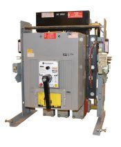

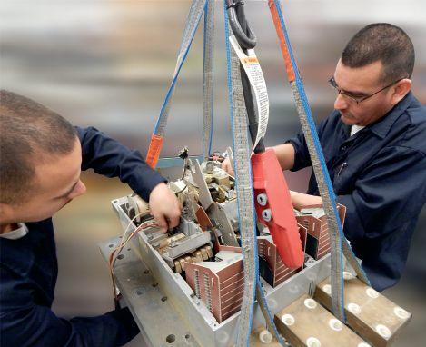


www.CBSArcSafe.com Distance is Safety (877)-4-SAFETY RRS-2 RRS-3 AKD-6 RRS-3 DHP/DVP (S) RRS-1 cbs_arc_safe_neta_horizontal_half_page_ad_final.indd 1 6/29/18 3:46 PM From a single part to a switchgear lineup, Advanced Electrical & Motor Controls’ inventory of low-voltage insulated case circuit breakers, molded case circuit breakers, motor controls, and custom switchgear is second to none in the U.S. No matter what you need — new, surplus, used, or reconditioned power distribution equipment, testing and repair,
an engineered solution — AEAMC will keep you up and running. Insulated Case Circuit Breakers Molded Case Circuit Breakers Motor Controls & Centers Bolted Pressure Switches Panelboard Switches & Bus Plugs 480 V Distribution Transformers Replacement Parts UL-Listed Motor Control Center Replacements Let us test, repair, and extend the life of your: Search. Click. Ship. Purchase AEAMC equipment online, anytime! Emergency support 24/7 800-289-2757
or
Like Advanced Electrical & Motor Controls Advanced Electrical & Motor Controls Inc. 1801 HURD DR. | IRVING, TX 75038 | 972-253-7783 | Sales@AEAMC.com | AEAMC .com
& Motor Controls


2200 West Valley Hwy North, Suite 100 l Auburn, WA 98001 l Office: 253-333-9730 ✔ Power System Acceptance Testing ✔ Commissioning and Start-up ✔ Maintenance ✔ Life-Cycle Extension ✔ Troubleshooting ✔ Training and Engineering Services ✔ Planning and Operations Support ✔ Project Management HAVE AN ELECTRICAL POWER SYSTEM PROBLEM? WE HAVE THE SOLUTION! TESTING
& MANAGING ELECTRICAL POWER SYSTEMS Check us out at www.sigmasix.com CAN’T AFFORD TO GAMBLE ON YOUR ELECTRICAL RELIABILITY? We have you covered. We understand that the most important electrical testing takes place before your system is powered on. And now that National Field Services has acquired two new locations in Las Vegas and Reno, we have the ability to offer even more customers start-up and maintenance services throughout the lifecycle of their switchgear. Tap into the power of National Field Services at natlfield.com or call us today at (800) 300-0157. performance by design sm
MAINTAINING
SPECIFICATIONS
ASTM F18 COMMITTEE REPORT
BY JAMES R. WHITE, Shermco Industries
The ASTM Committee has purview over all protective electrical equipment, including arc flash suits, arc-rated clothing, rubber insulated gloves, insulated tools, and grounds. They do not specify how they are to be used, but specify how they are to be designed, tested, cleaned, and cared for. The meeting was held in Orlando, Florida, on October 8–9, 2018, which sounds nice, but not when Hurricane Michael is bearing down on you. The meeting was called after two days due to members trying to reserve seats on available planes, which became increasingly difficult. In spite of the shortened time, some interesting items did come up.
F1506
ASTM WG1506 is trying to update the F1506 standard, but hit the wall and made little or no progress, even though Chair Marcia Eblens held conference calls every two weeks or so. At this time, F1506 will not change for at least six months.
F18.15
• F18.15.07 Personal Climbing Equipment had three negatives. The author agreed to withdraw the negatives if they would be addressed after the changes were made to the standard.
• F18.15.10 Non-Leather Protectors appears to have finally been accepted. Negatives on this new standard were almost all editorial.
Congratulations to Hugh Hoagland for getting this through.
• F18.15.11 Dielectric Footwear did not make it for a vote, as there was concern it was being confused with another standard. F117 covers dielectric footwear that covers the shoe, while F116 covers dielectric footwear that only covers the sock. There was some discussion about combining the two.
F855
In the F855 meeting, removing columns H and I from Table 7 was discussed, but there was no vote. It seems these two categories of cable are not used for ground cables, but for power cables. Removing the word “minimum” from the specification stating ground cables should be 10 feet long was also discussed, and more discussion will be needed; the longer the cable, of course, the higher its impedance. It was also noted that the worst case for clamping ground cable is onto flat bus, as the magnetic fields can cause it to turn and blow off.
The subject of mixing cables, ferrules, and clamps from different companies came up again. No manufacturer will warrant an assembly that is constructed from different manufacturers’ components. Mixing components from different manufacturers may give a rating different than that from a single manufacturer. A new specification is being considered for a preassembled clamp, cable, and ferrule assembly that can be configured different ways.
NETAWorld • 105
ACTIVITY ASTM F18 COMMITTEE REPORT
AND STANDARDS

INSULATED CONDUCTOR COMMITTEE NEWS
BY RALPH PATTERSON, Carolina Electrical
The Insulated Conductor Committee’s groups, which include engineers and scientists, met in Orlando, Florida, for the fall 2018 IEEE/ ICC meeting from October 29–31, 2018. The Insulated Conductors Committee (ICC) is a professional organization within the Power Engineering Society (PES) of the Institute of Electrical and Electronics Engineers (IEEE).
This is an ongoing opportunity for the InterNational Electrical Testing Association to be recognized and to offer a field-testing perspective to the working groups as documents are developed. The working groups are made up of cable manufacturers, utilities, test equipment manufacturers, and end users.
DISCUSSION
Several presentations followed the working group meetings.
Diagnostics to Manage Water-Treeing in MV Cables
Dr. Nigel Hampton, Josh Perkel, Thomas Parker, NEETRAC, USA
The underground distribution system makes up approximately 18 percent of the distribution infrastructure (EEI). This system is comprised of terminations/elbows, cable, and joints, which all contribute to the reported SAIDI and SAIFI data (see sidebar). Most of the reported failures are associated with the accessories, which can be addressed easily (relative to the whole system) through replacement and diagnosis because they are discrete devices. However, the system continues to age while being required to deliver increased reliability (lower CAIDI). Thus, the longevity and degradation rate of the backbone cables remains of paramount importance.
1: Fall 2018 Working Groups/Discussion Groups Meetings for Subcommittee F
F02W Field Testing of Laminated Dielectric Shielded Power Cable Systems Rated 5 KV and Above (400.1)
Discussion of balloting comments
Larzelere/Rickman
F04W Partial Discharge Testing in the Field (P400.3) Preparation of latest draft for ballot Levine/Walton
F06W Field Testing of Shielded D Power Cable Systems Using High-Voltage Direct Current (IEEE 400.5)
F07W Guide on Neutral Corrosion in MV Underground Cables (1617)
Discussion of current draft
Larzelere/Rickman
Review of proposed revisions by writing group Von Herrmann/Giotis
F11W Constant Voltage AC Field Testing of Cable Systems Further discussion on content of first draft Fenger/Denmon
F12W Guide for Fault Locating on Shielded Power Cables
Resolution of remaining ballot comments/issues
Moiser/Von Herman
108 • SPRING 2019 SPECIFICATIONS AND STANDARDS ACTIVITY INSULATED CONDUCTOR COMMITTEE NEWS
GROUP NO. GROUP NAME ACTIVITY CHAIRS
Table
MEASURING RELIABILITY
SAIFI and SAIDI are commonly used indices used by electric power utilities to measure reliability as defined in IEEE Std. 1366.
• System Average Interruption Duration Index (SAIDI) is the average duration of interruptions per consumers during the year. It is the ratio of the annual duration of interruptions (sustained) to the number of consumers: total duration of sustained interruptions in a year / total number of consumers. If duration is specified in minutes, SAIDI is given as consumer minutes.
• System Average Interruption Frequency Index (SAIFI) is the average number of sustained interruptions per consumer during the year. It is the ratio of the annual number of interruptions to the number of consumers: total number of sustained interruptions in a year / total number of consumers.
• Consumer Average Interruption Duration Index (CAIDI) is the average duration of an interruption, calculated based on the total number of sustained interruptions in a year. It is the ratio of the total duration of interruptions to the total number of interruptions during the year: total duration of sustained interruptions in a year / total number of interruptions. It can be seen that CAIDI equals SAIDI / SAIFI.
Partial Discharge Monitored Voltage Testing by Damped AC Voltages of Power Cables up to 220 kV
Edward Gulski and Rogier Jongen, onsite HV solutions ag, Switzerland; Jaroslaw Parciak, onsite HV solutions Central Europe, Poland
Abstract: For transmission grid operators, important questions about reliable network operation include:
1. How do you perform the detection of poor workmanship defects of newly installed cable circuits in a sensitive and non-destructive way?
2. How do you perform non-destructive diagnostics of in-service cable circuits to determine the actual condition?
Condition
Assessment of
Aged
SCFF & HPFF Cables via On-Line and Off-Line PD Measurements
Mark Fenger, Prysmian Cable and Systems
Abstract: Over the past number of years, a larger portion of SCFF and HPFF cable circuits have been subjected primarily to on-line partial
discharge measurements as complementary to or instead of traditional dissolved gas analysis (DGA). The presentation discusses how on-line and off-line PD measurements can be performed in a meaningful way on fluid-filled cable systems. Multiple case studies are presented and discussed.
The 2018 fall meeting in Orlando, Florida, was a great success. The discussion that followed these presentations will allow the working groups to better understand the ongoing research that can be incorporated into the revision of the guidelines and allow us to prepare for the 2019 spring meeting in Savannah, Georgia.

Ralph Patterson is the owner and President of Carolina Electrical and former owner of Power Products and Solutions. His professional background includes working as a design engineer of transformers and as a specifying engineer of insulated conductors. He has more than 25 years in power engineering, particularly in insulation diagnosis and evaluation of electrical distribution equipment. He serves on the NETA Standards Review Council, is the NETA liaison for the IEEE Insulated Conductor Committee’s working groups, and received NETA’s 2001 Outstanding Achievement Award.
NETAWorld • 109
AND STANDARDS ACTIVITY INSULATED CONDUCTOR COMMITTEE NEWS
SPECIFICATIONS


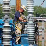





800.331.2002 | PotomacTesting.com POWER THROUGH WITH CONFIDENCE MAKE A REAL POWER MOVE... PARTNER WITH MID-ATLANTIC’S PREMIER PROVIDER OF ELECTRICAL TESTING, ENGINEERING AND FIELD SERVICES. Since 1985
IEEE TRANSFORMERS COMMITTEE REPORT
BY SCOTT REED, MVA Diagnostics
Several of the subcommittees under the IEEE Transformers Committee are doing significant work. This report covers work in the last two quarters of 2018.
INSULATING FLUIDS SUBCOMMITTEE
C57.104, IEEE Guide for the Interpretation of Gases Generated in Oil-Immersed Transformers (DGA) is being revised and will change how DGA results will be interpreted. It went out to the working group for ballot in summer 2018 and passed; however, a significant number of comments were submitted. As a result, the committee is reviewing all of the comments and will prepare a new draft of the guide for the members to review in 2019. This guide is only for mineral-oil filled transformers. It’s important to recognize that different fluids have different gassing characteristics. As such, this guide is not applicable to the gassing of other fluids such as natural esters.
C57.147, IEEE Guide for Acceptance and Maintenance of Natural Ester Insulating Liquid in Transformers was updated and published in July, 2018. This guide is only for the fluid qualities of natural esters and does not include DGA limits. Dissolved gas thresholds can be found in C57.155, IEEE Guide for Interpretation of Gases Generated in Natural Ester and Synthetic Ester-Immersed Transformers.
A new Working Group was established in 2018 for C57.166, IEEE Guide for Acceptance and Maintenance of Insulating Liquids in Transformers and Related Equipment. Work is just beginning,
but the goal is to combine the various fluid guides into a single guide. As a result, the user will be able to reference one IEEE guide to research the limit values of a specific fluid quality test, such as the minimum acceptable dielectric value, regardless of the fluid type (mineral oil, silicone, natural ester, etc.).
POWER TRANSFORMER SUBCOMMITTEE
Within the Power Transformer Subcommittee, C57.93, IEEE Guide for Installation and Maintenance of Liquid-Immersed Power Transformers , was revised and went out to ballot to the working group in 2018. The revision passed and has gone through a second recirculation to resolve questions raised during the review. This updated guide, which is applicable to transformers 501 kVA and larger, with a secondary voltage of 1,000 Volts or higher, is expected to be published in 2019.
Separately, a task force within the Power Transformer Subcommittee studied the level of interest in developing a new guide for the industry to use in performing a condition assessment on a transformer and concluded there is sufficient value in creating a new guide. The next step will be to develop a title, scope, and purpose for this guide so it can be submitted for review and approval. If approved, work can begin on developing this new guide.
In other areas of the Power Transformer Subcommittee, work continues toward updating C57.143, IEEE Guide for Application for Monitoring Equipment to Liquid-Immersed
NETAWorld • 111
AND STANDARDS ACTIVITY IEEE TRANSFORMERS COMMITTEE REPORT
SPECIFICATIONS
SPECIFICATIONS AND STANDARDS ACTIVITY
Transformers and Components; C57.150, IEEE Guide for the Transportation of Transformers and Reactors Rated 10,000 kVA or Larger; and C57.148, IEEE Standard for Control Cabinets for Power Transformers.
BUSHING SUBCOMMITTEE
Within the Bushing Subcommittee, C57.19.01, IEEE Standard for Performance Characteristics and Dimensions for Power Transformer and Reactor Bushings was revised and published in July, 2018. This guide covers electrical, dimensional, and related requirements for power transformer and reactor bushings that have basic impulse insulation levels (BILs) of 150 kV and above.

Procedure for Power Apparatus Bushings. This guide was last updated and published in 2004.

Finally, work continues on updating C57.19.00, IEEE Standard General Requirements and Test
Scott Reed is President of MVA Diagnostics, which specializes in the diagnostic analysis of oil in substation transformers throughout the United States. He received a BS in electrical engineering from North Carolina State University with a concentration in power and joined Baltimore Gas & Electric performing relay system protection design work. Scott serviced transformers, including vacuum filling, oil processing, repairing, electrical testing, and oil testing for 25 years before founding MVA Diagnostics. He has written and published various papers for the industry and is very active with the IEEE Transformer Committee, where he serves as the Secretary for the IEEE Insulating Fluids Subcommittee; Vice Chairman of IEEE Std. C57.166, Acceptance and Maintenance of Insulating Liquids in Transformers; and Secretary of IEEE Std. C57.93, Installation and Maintenance of Liquid Immersed Power Transformers.

Reliable Power System Solutions
We deliver optimum system reliability and performance while reducing the chances of costly

TTR
Power factor testing • Oil testing and field analysis Oil reconditioning & reclaiming • field replacements
Engineering Services
Arc-flash, short circuit, and coordination studies
Power factor correction • Power quality and harmonic studies
Load surveys • Grounding system design

112 • SPRING 2019 XXXXXXXXX
XXX
Accredited Company 204 Gale Lane Kennett Square, PA 19348 484.731.0200 enerGtest.com Serving
in Pennsylvania, Delaware, New Jersey, Maryland, Washington, DC and New England.
clients
unplanned power outages. Whether you need acceptance ener es testing or preventive maintenance, depend on EnerGTest to keep the power on.
Acceptance Testing Services Low, Medium, and High Voltage Substations • Distribution switchgear • Transformers • Cables • Relays Preventative Maintenance & Testing Switchgear
surveys • Circuit breakers •
testing
calibration
switches • Complete maintenance of ACB’s-OCB’s-SF6 CB’s UPS
station battery maintenance
Gen.
tests Transformers
Infra-red
Relay
and
Transfer
&
•
load
•
Trust us
keep
up
running.
consultation today. P: 781-767-0888 Email: infrared.ma@verizon.net 152 Centre Street Holbrook, MA 02343 www.infraredbps.com Over 25 Years of Experience & Reliability Full Service Independent Electrical Testing
to
your business
and
Call for a free

2019 – NEW PRODUCT FORUM
AEMC INSTRUMENTS
www.aemc.com
AEMC’s New Line of Simple-to-Use Data Loggers
AEMC Instruments has just introduced a new, low-cost line of simple-to-use data loggers. These small, compact data loggers measure just 3 inches by 3/4 inches. The 10 models in the family measure dc volts, ac volts, dc current, pulse, event, and temperature (model dependent). Inputs to each unit are facilitated through a two-pin screw terminal. For simplicity, sample rate and storage interval are predetermined and do not require user input. Scaling, units of measure, time and date, and recording length are user-configurable through the provided software. Data analysis and report generation are also available through the software.
AVO TRAINING INSTITUTE, INC.
www.avotraining.com
Microprocessor-Based Relay Testing, Feeder Protection Course
AVO Training Institute introduces its new MicroprocessorBased Relay Testing, Feeder Protection Course. The first course is scheduled March 25, 2019. This course is a natural progression for technicians who have received their Protective Relay Maintenance basic certification.
The course will expand past the basics of mechanical relays, explaining how to establish communication with the relay to 1) download event recorder data, and 2) read and save relay settings. ANSI/NETA and NFPA 70B maintenance and testing standards recommend testing relays either every two years or at other regular intervals based on equipment condition and reliability requirements. The relays used in the course lab exercises are SEL-751A, GE SR750, and ABB REF615.
BRAH ELECTRIC MANUFACTURING
www.brahelectric.com
Plug-and-Play
Relay Product Line
BRAH Electric Mfg. is thrilled to announce its new direct replacement line of bus plugs. The line currently includes replacement bus plugs that fit the General Electric OEM Spectra, Spectra Low-Amp, Armor Clad, and Flex-A-Plug Series busway systems, as well as a replacement line that fits the Bulldog/Siemens BD Series OEM busway.
BRAH mastermind engineer and co-owner Garrett Garcia has designed a universal bus plug that includes BRAH’s USpatented and UL-listed FCS-100 inner switch. This inner switch features a floating contact design unlike anything else on the market and offers superior longevity, endurance, and reliability. These families of bus plugs, coupled with the new BRAH Logic Wireless Power Metering, have the market buzzing and BRAH’s customers raving!
CE POWER ENGINEERED SERVICES
www.cepower.net
NERC MOD Testing and Model Validation
CE Power is excited to provide NERC MOD testing/model validation to generation plants. These NERC standards address how generators and associated systems behave dynamically to changes in voltage and frequency. CE Power can identify the correct IEEE models and perform staged testing where we collect output data from the associated generator systems. By utilizing the latest modeling software, we can validate models by applying data gathered from this testing. From there, comprehensive reports are sent to NERC for compliance acceptance. CE Power can assist your clients by providing NERC testing on generators or plants ranging in size from 50MW and up.
ELECTROSWITCH
www.electroswitch-psr.com
Electroswitch Arga 25-1000 Substation Battery Monitor
Electroswitch introduces its new Arga 25-1000 substation battery monitor. Standard features include:
• Battery voltage monitoring and ground fault detection
• Predictive corrosion/open-strap and open-cell detection with hardwired, digital (DNP 3.0/Modbus), and analog (I420) output alarms
• Loss of ac-to-battery charger and ground fault location detection
• A new dual-display identifying alarm conditions
• New accessible front panel setup menu
• Simplified calibration, setup, and alarm set-point change functionality
Stop in to Booth 611 to see the new Arga 25-1000.
114 • SPRING 2019 NEW PRODUCT FORUM
2019 – NEW PRODUCT
GROUP CBS, INC.
www.groupcbs.com
RSA-224
CBS ArcSafe presents a remote switch actuator (RSA) to safely operate the Eaton/Cutler Hammer Pow-R-Way Busway System Plug 100-200A. The RSA-224 is one of the newest actuators CBS ArcSafe has brought to market. While using the RSA224, the user can remotely switch the bus plug from a safe distance outside the arc-flash boundary. The RSA-224 requires no modifications to the gear and is held in place by switchable magnets. Safety features such as built-in microswitches ensure over-travelling or excessive stress to the gear does not occur during operation.
GROUP CBS NEW PRODUCTS
www.groupcbs.com
CTVT-45
The CTVT-45 is a one-of-a-kind, two-in-one tester designed for testing both current and voltage transformers in the field or at the lab. Technicians can now use this user-friendly and lightweight test set to perform basic and routine maintenance testing to ensure the safety and continuous operation of instrument transformers to avoid costly and unexpected shutdowns.
Capable of testing knee voltages up to 45 kV and testing up to five taps on multi-tap CTs, the CTVT-45 can test a wide range of instrument transformers in protection and metering applications. It combines all-in-one testing with high accuracy and resolution to provide reliable and efficient equipment maintenance.
HAEFELY HIPOTRONICS
www.haefely-hipotronics.com
OC60-DI Liquid Dielectric Tester
The Haefely Hipotronics OC60-DI Liquid Dielectric Tester accurately and reliably tests the dielectric strength of insulating liquids used in a wide variety of electrical apparatus. The rugged, lightweight, and portable design ensures years of safe and trouble-free operation both in the field and in the laboratory. This model is designed to meet testing specifications from all parts of the world with test cells available for ASTM and IEC standards. The OC60-DI offers the ability to use one of the preprogrammed rates of voltage rise or allows the operator to create their own tests using manual mode. The breakdown voltage is automatically stored and saved into internal memory or can be exported to a USB drive.
HIOKI USA
www.hiokiusa.com
Hioki PQ3100
The PQ3100 is a comprehensive but easy-to-use power quality analyzer for monitoring and recording power supply anomalies, allowing their causes to be quickly investigated, and also for assessing power supply problems such as swells, sags, voltage drops, inrush current, harmonics, and other electrical issues. It provides an intuitive Quick Set navigation system to simplify the wiring and configuration procedures for measuring a threephase system. Connection mistakes are automatically detected along with suggestions on how to correct the setup. PQ One application software lets you analyze captured data in fine detail and create regular power quality management reports with ease and flexibility. Investigate the cause of power anomalies in the comfort of your office using your PC.
HV TECHNOLOGIES, INC.
www.hvtechnologies.com
Protrac®
The new, multi-functional Protrac® allows precise pinpointing of cable and cable sheath faults. One particularly innovative Protrac® feature is its rapid and simple commissioning because the control unit, ground microphone, and headphones are wirelessly connected by Bluetooth®. An adaptive, ambientnoise suppression system filters ambient noise and provides a clear signal from the fault breakdown to the headphones or loudspeaker of the control unit. The capacitive color display with touch function guides the operator rapidly and efficiently to the fault with the aid of a 3D display of the cable position.
IRISS
www.iriss.com
Scan Your Low-Voltage Busway Joints with Custom Solutions from IRISS
Working with one of our OEM partners, IRISS recently launched a series of busway joint covers that incorporate an IR viewing window and latching cover that allow for safe and easy thermal imaging. Specifically developed for the Eaton Pow-R-Way III® low-voltage busway system, these joint covers can be easily added to existing joints. Busway operation can be critical to your facility, and there is usually no redundant backup system in place. Performing regular IR inspections on the primary potential point of failure — the joint splice — can ensure you will detect and have the opportunity to correct deficiencies.
NETAWorld • 115 NEW PRODUCT FORUM
FORUM
2019 – NEW PRODUCT FORUM
KOCOS AMERICA
www.kocos.com
PROMET L100
PROMET L100 is a compact, battery operated, high-precision measuring device for determining resistances in the µΩ to Ω range. With 20 VDC of compliance voltage, the PROMET L100 is able to meet the most stringent accuracy requirements. In addition to measuring contact and dynamic resistance in circuit breakers, the PROMET L100 can also measure inductive loads, and therefore can be used to determine the winding resistances of transformers, motors, and instrument transformers.
High functionality, rechargeable batteries, and a light weight of just 9.3 kg built into a hard shell case make the PROMET L100 ideal for field service use.
MEGGER
www.megger.com
TTRU3
The Megger TTRU3 performs ratio tests on power, voltage, or current transformers. It uses the patent-pending step-up ratio test method, exciting all three phases at once. It is designed to be used in severe field conditions, guaranteeing ±0.05 percent turns ratio accuracy. Tests performed with the TTRU3 include true three-phase turns ratio, single-phase turns ratio, excitation current, polarity, phase angle deviation, magnetic balance, vector recognition, and phase shift.
Two interface options are included: a 7-inch onboard display (standard on all models) or USB for PC control. Vector configurations are displayed during test setup, providing assurance that correct setup has been selected before the test begins. PowerDB Lite software comes with the TTRU3.
MEISTER INTERNATIONAL LLC
www.meisterintl.com
Cycloaliphatic A20 Bus Insulators
Meister International LLC, a member of the National Association of Electrical Distributors (NAED), is pleased to introduce its complete line of cycloaliphatic A20 bus insulators for the switchgear industry. The cycloaliphatic A20 bus insulators are available for 5kv, 7.2kv, and 15kv applications and are in stock. Meister International will also feature a new line of cycloaliphatic feed-through bus supports used throughout the switchgear industry. Learn more at www.meisterintl.com or give us a call at (513) 923-2712.
MONSTER ELECTRICAL
www.monsterelectrical.com
New Look and Updated Product Line
What’s new at Monster? A lot! We haven’t just updated our look — we are making things easier and offering more products in 2019. What you’ve known us for before is likely not the only thing you’ll use us for in the future. Join us for a quick overview of our new and future offerings that will help you be the hero to your customers and make doing business with us effortless and even faster.
NATIONAL SWITCHGEAR
www.nationalswitchgear.com
TrainSafe
Mini
At last year’s New Product Forum, National Switchgear presented its TrainSafe training simulators, developed by our PEARL-accredited breaker shop exclusively to match existing customer switchgear. This year, we’re presenting our latest development in that line: the TrainSafe Mini. The Mini features a compact design consisting of the breaker and cradle on a height-adjustable, weight-stabilized cart. Like the original TrainSafe, the Mini allows personnel to become familiar with the racking procedure in a safe, controlled environment and provides a functional spare. It’s a more portable and less expensive training option that is the perfect companion piece to a retrofit project. Come by the National Switchgear booth for a live demo.
NDB TECHNOLOGIES
www.ndbtech.com
SPI-III
Our vision has always been to create a phase identification system that exceeds any of today’s industry quality, safety, and efficiency requirements. SPI-III’s unique design consists of a wireless bi-module combo that is stunningly easy to configure and operate. With many advancements and innovations, SPI-III will be more helpful than ever before, enabling field applications such as identification of A-B-C electrical phases from all 50- and 60-Hz networks, switchgear phase concordance (matching), phase rotation, system paralleling, underground phasing applications, and more.
116 • SPRING 2019 NEW PRODUCT FORUM
2019 – NEW PRODUCT FORUM
OFIL LTD.
www.ofilsystems.com
HD Corona Camera for UAV
DayCor® micROMHD is an innovative HD corona camera for sUAS, featuring ultralight weight, low power consumption, and interfaces to most common communication protocols. With its dual solar blind UV and visible light sensors, micROMHD is capable of detecting, imaging, recording, and storing corona events during daytime. The micROMHD provides an efficient means to pinpoint faults and investigate corona PD, in particular because it filters out noise and focuses on corona. With interfaces to GPS and temperature and humidity sensors, micROMHD is easy to integrate and comes with a set of commands that control all camera functions.
OMICRON ELECTRONICS CORP. USA
www.omicronenergy.com
MONTESTO 200
A portable, on-line, partial discharge measurement and temporary monitoring system, the MONTESTO 200 combines on-line partial discharge (PD) measurement and temporary monitoring functions into one portable solution. It can be used indoors and outdoors for insulation condition assessment on various medium- and high-voltage electrical assets under load. MONTESTO 200 can be quickly and safely connected to a variety of permanently installed PD sensors via a terminal box while the asset is online to avoid unnecessary downtime. The user-friendly MONTESTO 200 software simplifies setup, data analysis, and reporting. Data from thirdparty sensors can be easily integrated for correlation with the PD data.
PHENIX TECHNOLOGIES, INC.
www.phenixtech.com
Model 660–10PA AC Hipot with Bluetooth
Connectivity
Phenix Technologies’ new Model 660-10PA AC Hipot with Bluetooth connectivity allows the operator to remotely set up and execute a test via the available tablet and software. The center-tapped, high-voltage transformer develops 0–60 kV ac (0–30kV ac with respect to ground potential). The control section features a digital LCD display and offers manual control of high voltage, rate of rise, and fault reset. The twopiece unit is housed in a wheeled case and includes a safety foot switch with 10-foot cable.
POWER DIAGNOSTIC SERVICE
www.pdservice.com
TR 300
The TR 300 is a true, three-phase transformer turns ratio tester designed to test all transformer types, including CTs, PTs, power transformers, and phase-shifting transformers. It performs turns ratio tests per the IEEE C57.12.90 measurement standard and has a measuring range of 0.8–50,000 to 1. It also measures the excitation current and phase angle. Selectable test voltages of 5, 50, 100, and 250 V are available for testing in electrically noisy environments. It features a full-sized QWERTY keypad, color display, built-in printer, and a battery that can provide 3 hours of operation.
POWER GRID ENGINEERING
www.powergridengineering.com
Power Grid Engineering Webinar Series
Power Grid Engineering, LLC (PGE) is excited to offer a series of webinars with content that parallels our Power Systems seminar series. Each one-hour webinar provides attendees with a sneak peek into the content covered in our training seminars. Instructors showcase content from the full training that allows attendees to gather information and experience the instructional style of each presenter before attending the seminar. These online sessions offer an efficient way for attendees to learn from the convenience of their desks. 2019 webinars will be offered in February, March, May, June, July, and August.
PROGUSA – DV POWER
www.progusa.net
CT/PT Test Set by Lithonix Power Inc.
ProgUSA will showcase the latest technology in the CT/PT test set by Lithonix Power Inc. of Florida. Performs ratio and polarity tests of current, potential, and power transformers.
• High accuracy of 0.1 percent or better
• Saturation test of current transformers
• X1-X5 tap connections with fully automatic multi-tap test mode
• AC phase angle and amplitude metering for load tests
• Secondary injection test
• Modern data interface and control over web or use with USB or just front panel control
NETAWorld • 117 NEW PRODUCT FORUM
2019 – NEW PRODUCT FORUM
PROTEC EQUIPMENT RESOURCES
www.protecequip.com
Protec Connect
Renting electrical test and measurement equipment just got a whole lot easier. With the Protec Connect mobile app from Protec Equipment Resources, the largest independent equipment rental fleet is at your fingertips. Protec Connect features a link to knowledgeable experts ready to help with your equipment needs. Easily find locations near you or contact us. Our 24/7 customer support is waiting for you. You’ll also find the latest news on the equipment you use every day and a hassle-free way to manage your Protec account anywhere, anytime.
SCHWEITZER ENGINEERING LABORATORIES, INC.
www.selinc.com
SEL-FT50 and SEL-FR12 Fault Transmitter and Receiver System
Visit with SEL professionals in Booth 817 to learn about the SEL-FT50 and SEL-FR12 Fault Transmitter and Receiver System, which provides an innovative approach for speeding up distribution protection and improving selectivity. You will also hear about the latest developments from SEL that are making power systems all over the world safer, more reliable, and more economical. We look forward to seeing you at our booth!
SMC
www.smcint.com
Raptor Breaker Stabs
Reduce your breaker testing time by as much as 80 percent by not having to remove the molded case breakers from the panel. With the new Raptor breaker stabs, you can quickly and easily test molded case breakers in place without having to disassemble, test, and then reassemble. Comes in various sizes to fit almost any molded case breaker in the field. Available in standard copper or beryllium copper for long sustainability. See them and pick up a set at Booth 814
THE COLT GROUP
www.coltpowerservices.com
Drill and Tap Seal Technique
The flapper flange is a common leak. These flanges typically have a grooved area for a gasket or O-ring to lie in. Colt’s repair procedure is to drill and tap several 1/16-inch NPT injection ports into the failed gasket/O-ring. S-22 sealant is then injected into the gasket area, the groove acts as a mold, and a new gasket is formed during the injection process. After injecting, the material is allowed to cure (1-2 hours) and the injectors are removed and Teflon-coated pipe plugs installed. Another common leak is the packing. Colt uses its drill-and-tap technique to gain access into the packing-gland area for injection of our S-22 sealant.
UTILITY RELAY COMPANY
www.utilityrelay.com
InfoPro-AC™ Software — New Features Available!
A new version of InfoPro-AC software for AC-PRO-II trip units is now available. This version adds time current curves, test result plotting, and more. This provides a means to document all breaker and test data by using one convenient software application. Test Reports can be saved electronically and printed. InfoPro-AC is free software for Windows PCs, specifically designed to simplify using AC-PRO-II trip units. In addition to its new features, InfoPro-AC offers the full capability to configure and access all AC-PRO-II information (settings, metering, waveforms, trip data, etc.) via the AC-PRO-II mini-USB port.
• Download: www.utilityrelay.com/Side_Bar/Downloads.html
• Additional info: www.utilityrelay.com/products/InfoPro.html
WEIDMANN ELECTRICAL TECHNOLOGY
www.weidmann-electrical.com
Methanol in Oil Testing
The mechanical and insulating capabilities of solid and liquid materials are significant factors in determining the remaining operating life of a transformer. Maintaining electrical equipment using dissolved gas analysis (DGA), furanic compound testing (furans), and a combination of general liquid-quality tests provides valuable insight into its condition. To advance this assessment, new test methods have been developed and are in the process of receiving ASTM approval. This presentation introduces the new methanol and ethanol test and its use within a comprehensive insulation system assessment.
118 • SPRING 2019 NEW PRODUCT FORUM

Industrial Electric Testing, Inc.
• Cables
• LV/MV Circuit Breakers
• Rotating Machinery
• Meters
• Automatic Transfer Switches
• Switchgear and Switchboard Assemblies
• Load Studies
• LV/MV Switches
• Relays - All Types
• Motor Control Centers
• Grounding Systems
• Transformers
• Insulating Fluids
• Thermographic Surveys
• Reclosers
• Surge Arresters
• Capacitors
• Batteries
• Ground Fault Systems
• Equipotential Ground Testing
CoNSulTING AND ENGINEERING SERvICES
• Transient Voltage Recording and Analysis
• Electromagnetic Field (EMF) Testing
• Harmonic Investigation
• Replacement of Insulating Fluids
• Power Factor Studies
11321 West Distribution Avenue • Jacksonville, Florida 32256 • (904) 260-8378 201 NW 1st Avenue • Hallandale, Florida 33009 • (954) 456-7020


•
Emergency
EC13004105
24 Hour
Service ACCEPTANCE AND MAINTENANCE TESTING AND REPAIR
PowerSystemsTesting.1-2_NETA.WI15.indd 1 10/21/15 9:16 AM
•
•

•
•
•
• Cable Testing
• Relay & Meter Calibration
• Ground Resistance Testing
•




228 Merrick Road Lynbrook, NY 11563 (631) 589-6343/Fax (516) 596-3680 601 Union Street Brooklyn, NY 11215 (718) 786-4900 NETA ACCREDITED ELECTRICAL TESTING COMPANY. Serving the Sacramento and San Francisco Bay Area 916-853-6280 www.apparatustesting.com • Acceptance Testing • Commissioning • Maintenance Testing • High Voltage Substations • Short Circuit and Coordination Studies • Data Centers and UPS Systems Independent Electrical Testing and Preventive Maintenance PROFESSIONAL SERVICES
Acceptance
Testing
Planned
Preventive Maintenance Programs
Electrical Testing and
• Power Factor Testing
Transformer Oil Analysis, Vacuum Degassing and Repair
Circuit Breaker Retrofit and Repair
Power Generation Systems Testing
• Load and Power Quality Recording/Analysis
Systems Testing
• Chiller
Infrared Inspections 609-890-8300 www.easternhighvoltage.com 11-A S. Gold Drive • Robbinsville, NJ 08691 EasternHighVoltage_1-2_NETA_F14.indd 1 7/31/14 2:26 PM


EXCLUSIVE INVITATION TO NETA EVENTS
Annual Member/Alliance Meeting
Annual Member/Alliance Luncheon
Meeting of the Minds

EXCLUSIVE DISCOUNTS
Discounted PowerTest Registration
50% o one ANSI/NETA Standard ($138 value)
20% o NETA Bookstore Purchases

20% o NETA Training and SPTS Courses

STAY INFORMED
NETA World Journal ($40 value)

SHARE INFORMATION

Post Press Releases

Participate in Technical Working Committee Activities


ATTENTION NETA ALLIANCE PARTNERS. www.netaworld.org The
Program is designed for individuals working in and connected to the electrical power systems industry.
enjoy
benefits:
NETA Alliance
Partners
many
ALLIANCE PARTNERSHIP $150
Take advantage of YOUR benefits today. Ask about joining the NETA Alliance Partnership Program & attending PowerTest 2020! February 24-28, 2020 • Go to powertest.org or give us a call at 888-300-6382 (NETA). CONFERENCE
($285 Value)


ANSWERS


ANSWERS

1. c. C37.04. The IEEE C37 standards cover different types of circuit breakers. C37.04 covers SF6. C57 covers transformers.
2. b. 0.05 percent (500 ppmw) for new SF6 circuit breakers. In-service circuit breakers call for less than 5,000 ppm.
3. c. ASTM 2685 is used for air in SF6
4. a. Since SF6 is considered a greenhouse gas, 0 would be correct.
5. d. 10 percent. If you do power factor testing, this should have been easy for you. All bushings are created equal, regardless of what they are used on.
6. d. Dead tank and live tank. On a dead tank circuit breaker, the contacts are inside a metallic container that is kept at earth potential (top). Live tank circuit breaker contacts are inside the bushings, so they are live at all times (bottom).


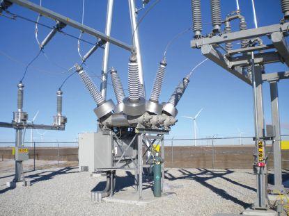
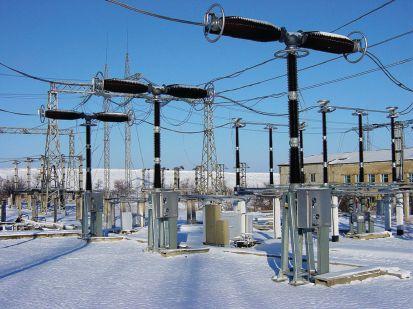
NFPA Disclaimer: Although Jim White is a member of the NFPA Technical Committee for both NFPA 70E, Standard for Electrical Safety in the Workplace, and NFPA 70B, Recommended Practice for Electrical Equipment Maintenance, the views and opinions expressed in this column are purely the author’s and shall not be considered an official position of the NFPA or any of its technical committees and shall not be considered, nor be relied upon, as a formal interpretation or promotion of the NFPA. Readers are encouraged to refer to the entire text of all referenced documents.
TECH QUIZ
No.
125
TECH QUIZ
ANSWERS
122 • SPRING 2019
Live Tank Circuit Breaker
Dead Tank Circuit Breaker


CIRCUIT BREAKER TESTING l SERVICE l REPAIR info@ampteks.com PATENT PENDING CIRCUIT BREAKER TESTING ELECTRODES info@electrolinkusa.com

A&F Electrical Testing, Inc.
80 Lake Ave. S Ste. 10 Nesconset, NY 11767-1017 (631) 584-5625 kchilton@afelectricaltesting.com www.afelectricaltesting.com
Kevin Chilton
A&F Electrical Testing, Inc.
80 Broad St. Fl. 5 New York, NY 10004-2257 (631) 584-5625 afelectricaltesting@afelectricaltesting.com
Florence Chilton
ABM Electrical Power Services, LLC
720 S Rochester Ste. A Ontario, CA 91761-8177 (301) 397-3500 rob.parton@abm.com www.abm.com
Rob Parton
ABM Electrical Power Services, LLC
6541 Meridien Dr. Ste. 113 Raleigh, NC 27616 (919) 877-1008
ABM Electrical Power Services, LLC
2631 S. Roosevelt St. Tempe, AZ 85282 (602) 722-2423
ABM Electrical Power Services, LLC
3600 Woodpark Blvd. Ste. G Charlotte, NC 28206-4210 (704) 273-6257
ABM Electrical Power Services, LLC
6940 Koll Center Pkwy. Ste. 100 Pleasanton, CA 94566 (408) 466-6920
ABM Electrical Power Services, LLC
3585 Corporate Court San Diego, CA 92123-1844 (858) 754-7963
ABM Electrical Power Services, LLC
1005 Windward Ridge Pkwy Alpharetta, GA 30005 (770) 521-7550
ABM Electrical Power Services, LLC
9800 E Geddes Ave. Unit A-150 Englewood, CO 80112-9306 (303) 524-6560
ABM Electrical Power Solutions
4390 Parliament Pl. Ste. S Lanham, MD 20706 (301) 967-3500 christopher.smith@abm.com www.abm.com
Christopher Smith
ABM Electrical Power Solutions
3700 Commerce Dr. # 901-903 Baltimore, MD 21227-1642 (410) 247-3300
ABM Electrical Power Solutions
NETA ACCREDITED COMPANIES
317 Commerce Park Dr. Cranberry Township, PA 16066-6407 (724) 772-4638
ABM Electrical Power Solutions 814 Greenbrier Cir. Ste. E Chesapeake, VA 23320-2643 (757) 364-6145
ABM Electrical Power Solutions 1817 O'Brien Rd. Columbus, OH 43228 (724) 772-4638
Absolute Testing Services, Inc. 8100 West Little York Houston, TX 77040 (832) 467-4446 www.absolutetesting.com
Accessible Consulting Engineers, Inc.
1269 Pomona Rd. Ste. 111 Corona, CA 92882-7158 (951) 808-1040 info@acetesting.com www.acetesting.com
Iraj Nasrolahi
Advanced Electrical Services 4999 - 43rd St. NE Unit 143 Calgary, AB T2B 3N4 Canada (403) 697-3747
zakhouk@aes-ab.com www.aes-ab.com
Zachary Houk
Advanced Testing Systems 15 Trowbridge Dr. Bethel, CT 06801-2858 (203) 743-2001 pmaccarthy@advtest.com www.advtest.com
Pat MacCarthy
American Electrical Testing Co., LLC 25 Forbes Blvd. Ste. 1 Foxboro, MA 02035 (781) 821-0121 sblizard@aetco.us www.aetco.us
Scott A. Blizard
American Electrical Testing Co., LLC
Green Hills Commerce Center 5925 Tilghman St. Ste. 200 Allentown, PA 18104-9158 (215) 219-6800 jmunley@aetco.us
Jonathan Munley
American Electrical Testing Co., LLC
34 Clover Dr. South Windsor, CT 06074-2931 (860) 648-1013
jpoulin@aetco.us
Gerald Poulin
American Electrical Testing Co., LLC 76 Cain Dr. Brentwood, NY 11717-1265 (631) 617-5330 bfernandez@aetco.us
Billy Fernandez
American Electrical Testing Co., LLC
91 Fulton St. Boonton, NJ 07005-1060 (973) 316-1180 jsomol@aetco.us
Jeff Somol
Apparatus Testing and Engineering
11300 Sanders Dr. Ste. 29 Rancho Cordova, CA 95742-6822 (916) 853-6280 info@apparatustesting.com www.apparatustesting.com
Harold (Jerry) Carr
Apparatus Testing and Engineering
7083 Commerce Cir. Ste. H Pleasanton, CA 94588-8017 (925) 454-1363
Applied Engineering Concepts
894 N. Fair Oaks Ave. Pasadena, CA 91103 (626) 389-2108
Michel.c@aec-us.com www.aec-us.com
Michel Castonguay
Applied Engineering Concepts 8160 Miramar Rd. San Diego, CA 92126 (619) 822-1106 Michel.c@aec-us.com www.aec-us.com
Michel Castonguay
BEC Testing 50 Gazza Blvd. Farmingdale, NY 11735-1402 (631) 393-6800 ddevlin@banaelectric.com www.bectesting.com Daniel Devlin
Burlington Electrical Testing Co., Inc. 300 Cedar Ave. Croydon, PA 19021-6051 (215) 826-9400
Burlington Electrical Testing Co., Inc.
198 Burrs Rd. Westampton, NJ 08060 (609) 267-4126
waltc@betest.com www.betest.com
Walter P. Cleary
C.E. Testing, Inc. 6148 Tim Crews Rd. Macclenny, FL 32063-4036 (904) 653-1900 cetesting@aol.com www.cetestinginc.com
Mark Chapman
CE Power Engineered Services, LLC 40 Washington St. Westborough, MA 01581-1088 (508) 881-3911
jim.cialdea@cepower.net www.cepower.net
Jim Cialdea
CE Power Engineered Services, LLC 480 Cave Rd. Nashville, TN 37210-2302 (615) 882-9455
bryant.phillips@cepower.net www.cepower.net
Bryant Phillips
CE Power Engineered Services, LLC 72 Sanford Dr. Gorham, ME 04038 (800) 649-6314 jim.cialdea@cepower.net www.cepower.net
Jim Cialdea
CE Power Engineered Services, LLC 4040 Rev Dr. Cincinnati, OH 45232 (800) 434-0415 info@cepower.net www.cepower.net
Brent McAlister
CE Power Engineered Services, LLC 7674 Washington Ave. S Eden Prairie, MN 55344 (877) 968-0281
Jason.thompson@cepower.net
Jason Thompson
CE Power Engineered Services, LLC 8490 Seward Rd. Fairfield, OH 45011 (800) 434-0415
Tim.lana@cepower.net
Tim Lana
CE Power Engineered Services, LLC 1803 Taylor Ave. Louisville, KY 40213 (800) 434-0415
bob.sheppard@cepower.net
Bob Sheppard
NETAWorld • 125 NETA ACCREDITED COMPANIES
Setting the Standard
NETA ACCREDITED COMPANIES Setting the Standard
CE Power Engineered Services, LLC
10338 Citation Dr. Ste. 300 Brighton, MI 48116 (810) 229-6628
Ken.lesperance@cepower.net
Ken L’Esperance
CE Power Engineered Services, LLC
10840 Murdock Dr. Knoxville, TN 37932 (800) 434-0415
Don.williams@cepower.net
Don Williams
CE Power Engineered Services, LLC
3496 E. 83rd Pl. Merrillville, IN 46410 (219) 942-2346
CE Power Solutions of Florida, LLC
3502 Riga Blvd. Ste. C Tampa, FL 33619 (866) 439-2992
CE Power Solutions of Florida, LLC 3801 SW 47th Ave. Ste. 505 Davie, FL 33314 (866) 439-2992
Control Power Concepts
353 Pilot Rd. Ste. B Las Vegas, NV 89119-3520 (702) 448-7833
jtravis@ctrlpwr.com www.controlpowerconcepts.com
John Travis
Dude Electrical Testing LLC
145 Tower Dr. Ste. 9 Burr Ridge, IL 60527-7840 (815) 293-3388
scott.dude@dudetesting.com www.dudetesting.com
Scott Dude
Eastern High Voltage, Inc.
11A S Gold Dr. Robbinsville, NJ 08691-1685 (609) 890-8300
bobwilson@easternhighvoltage.com www.easternhighvoltage.com
Robert Wilson
ELECT, P.C.
375 E. Third St. Wendell, NC 27591 (919) 365-9775
btyndall@elect-pc.com www.elect-pc.com
Barry W. Tyndall
Electric Power Systems
6679 Peachtree Industrial Dr. Ste. H Norcross, GA 30092 (770) 416-0684
Electric Power Systems, Inc.
21 Millpark Ct. Maryland Heights, MO 63043-3536 (314) 890-9999
s.reed@epsii.com www.epsii.com
Steve Reed
Electric Power Systems, Inc.
11211 E. Arapahoe Rd. Ste. 108 Centennial, CO 80112 (720) 857-7273
Electric Power Systems, Inc. 120 Turner Rd. Salem, VA 24153-5120 (540) 375-0084
Electric Power Systems, Inc. 1090 Montour West Industrial Pk. Coraopolis, PA 15108-9307 (412) 276-4559
Electric Power Systems, Inc. 6141 E Connecticut Ave. Kansas City, MO 64120-1346 (816) 241-9990
Electric Power Systems, Inc. 1230 N Hobson St. Ste. 101 Gilbert, AZ 85233 (480) 633-1490
Electric Power Systems, Inc. 915 Holt Ave. Unit 9 Manchester, NH 03109-5606 (603) 657-7371
Electric Power Systems, Inc.
4436 Parkway Commerce Blvd. Orlando, FL 32808-1008 (407) 578-6424
Electric Power Systems, Inc. 1129 E Highway 30 Gonzales, LA 70737-4759 (225) 644-0150
Electric Power Systems, Inc. 684 Melrose Ave. Nashville, TN 37211-3121 (615) 834-0999
Electric Power Systems, Inc.
2888 Nationwide Pkwy. 2nd Floor Brunswick, OH 44212 (330) 460-3706
Electric Power Systems, Inc. 54 Eisenhower Ln. North Lombard, IL 60148 (815) 577-9515
Electric Power Systems, Inc.
1330 Industrial Blvd. Ste. 300 Sugar Land, TX 77478 (713) 644-5400
Electric Power Systems, Inc. 56 Bibber Pkwy. # 1 Brunswick, ME 04011-7357 (207) 837-6527
Electric Power Systems, Inc. 11861 Longsdorf St. Riverview, MI 48193-4250 (734) 282-3311
Electric Power Systems, Inc. 8515 Calle Alameda NE Ste. A Albuquerque, NM 87113 (505) 792-7761
Electric Power Systems, Inc. 319 US 70 Hwy. E Ste. E Garner, NC 27529-4054 (919) 210-5405
Electric Power Systems, Inc. 5850 Polaris Ave. Ste. 1600 Las Vegas, NV 89118 (702) 815-1342
Electric Power Systems, Inc. 7925 Dunbrook Rd. Ste. G San Diego, CA 92126 (858) 566-6317
Electric Power Systems, Inc. 306 Ashcake Rd. Ste. A Ashland, VA 23005 (804) 526-6794
Electric Power Systems, Inc. 7169 E. 87th St. Indianapolis, IN 46256 (317) 941-7502
Daniel Douglas
Electrical & Electronic Controls 6149 Hunter Rd. Ooltewah, TN 37363-8762 (423) 344-7666 eecontrols@comcast.net
Michael Hughes
Electrical Energy Experts, Inc. W129N10818 Washington Dr. Germantown, WI 53022-4446 (262) 255-5222 tim@electricalenergyexperts.com www.electricalenergyexperts.com
Tim Casey
Electrical Engineering & Service Co. Inc. 289 Centre St. Holbrook, MA 02343 (781) 767-9988 jcipolla@eescousa.com www.eescousa.com
Joe Cipolla
Electrical Equipment Upgrading, Inc. 21 Telfair Pl. Savannah, GA 31415-9518 (912) 232-7402 kmiller@eeu-inc.com www.eeu-inc.com
Kevin Miller
Electrical Maintenance & Testing, Inc. 12342 Hancock St. Carmel, IN 46032-5807 (317) 853-6795 info@emtesting.com www.emtesting.com
Brian K. Borst
Electrical Reliability Services
610 Executive Campus Dr. Westerville, OH 43082-8870 (877) 468-6384 info@electricalreliability.com
Electrical Reliability Services
5909 Sea Lion Pl. Ste. C Carlsbad, CA 92010-6634 (858) 695-9551
Electrical Reliability Services
1057 Doniphan Park Cir. Ste. A El Paso, TX 79922-1329 (915) 587-9440
Electrical Reliability Services
6900 Koll Center Pkwy. Ste. 415 Pleasanton, CA 94566-3119 (925) 485-3400
Electrical Reliability Services
8500 Washington St. NE Ste. A6 Albuquerque, NM 87113-1861 (505) 822-0237
Electrical Reliability Services
2275 Northwest Pkwy. SE Ste. 180 Marietta, GA 30067-9319 (770) 541-6600
Electrical Reliability Services
10606 Bloomfield Ave. Santa Fe Springs, CA 90670-3912 (562) 236-9555
Electrical Reliability Services
400 NW Capital Dr. Lees Summit, MO 64086-4723 (816) 525-7156
Electrical Reliability Services
7100 Broadway Ste. 7E Denver, CO 80221-2900 (303) 427-8809
Electrical Reliability Services
2222 W Valley Hwy. N Ste. 160 Auburn, WA 98001-1655 (253) 736-6010
126 • SPRING 2019 NETA ACCREDITED COMPANIES
NETA ACCREDITED COMPANIES
Electrical Reliability Services
221 E. Willis Road Chandler, AZ 85286 (480) 966-4568
Electrical Reliability Services
1380 Greg St. Ste. 217 Sparks, NV 89431-6070 (775) 746-8484
Electrical Reliability Services
11000 Metro Pkwy. Ste. 30 Fort Myers, FL 33966-1244 (239) 693-7100
Electrical Reliability Services
245 Hood Rd. Sulphur, LA 70665-8747 (337) 583-2411
Electrical Reliability Services
9736 South 500 West Sandy, UT 84070 (801) 975-6461
Electrical Reliability Services
6351 Hinson St. Ste. A Las Vegas, NV 89118-6851 (702) 597-0020
Electrical Reliability Services
3535 Emerson Pkwy. Ste. A Gonzales, LA 70737 (225) 755-0530
Electrical Reliability Services
9636 Saint Vincent Ave. Unit A Shreveport, LA 71106-7127 (318) 869-4244
Electrical Reliability Services
1426 Sens Rd. Ste. 5 La Porte, TX 77571-9656 (281) 241-2800
Electrical Reliability Services 6135 Lakeview Rd. Ste. 500 Charlotte, NC 28269-2630 (704) 441-1497
Electrical Reliability Services
4099 SE International Way Ste. 201 Milwaukie, OR 97222-8853 (503) 653-6781
Electrical Testing and Maintenance Corp.
3673 Cherry Rd. Ste. 101 Memphis, TN 38118-6313 (901) 566-5557
r.gregory@etmcorp.com www.etmcorp.net
Ron Gregory
Electrical Testing Solutions
2909 Greenhill Ct. Oshkosh, WI 54904-9769 (920) 420-2986
tmachado@electricaltestingsolutions.com
Tito Machado
Electrical Testing, Inc.
2671 Cedartown Hwy. SE Rome, GA 30161-3894 (706) 234-7623
jamie@electricaltestinginc.com www.electricaltestinginc.com
Jamie Dempsey
Elemco Services, Inc.
228 Merrick Rd. Lynbrook, NY 11563-2622 (631) 589-6343
Courtney@elemco.com www.elemco.com
Courtney Gallo
EnerG Test, LLC
206 Gale Ln. Kennett Square, PA 19348 (484) 731-0200
dbuehler@energtest.com www.energtest.com
Dennis Buehler
Energis High Voltage Resources 1361 Glory Rd. Green Bay, WI 54304-5640 (920) 632-7929
info@energisinc.com www.energisinc.com
Mick Petzold
EPS Technology
29 N Plains Hwy. Ste. 12 Wallingford, CT 06492-5838 (203) 679-0145
s.miller@eps-technology.com www.eps-technology.com
Sean Miller
Giga Electrical & Technical Services, Inc.
2743A N. San Fernando Rd. Los Angeles, CA 90065 (323) 255-5894
gigaelectrical@att.net www.gigaelectrical-ca.com
Hermin Machacon
Grubb Engineering, Inc. 2727 North Saint Mary’s St. San Antonio, TX 78212 (210) 658-7250 joy@grubbengineering.com www.grubbengineering.com
Robert D. Grubb Jr.
Halco Testing Services 5773 Venice Blvd. Los Angeles, CA 90019 (323) 933-9431
d.genutis@halco.net www.halcotestingservices.com
Don Genutis
Hampton Tedder Technical Services 4563 State St. Montclair, CA 91763-6129 (909) 628-1256 x214
Chasen.tedder@hamptontedder.com www.hamptontedder.com
Chasen Tedder
Hampton Tedder Technical Services 3747 W Roanoke Ave. Phoenix, AZ 85009-1359 (480) 967-7765
Linc McNitt
Hampton Tedder Technical Services 4113 Wagon Trail Ave. Las Vegas, NV 89118 (702) 452-9200 Roger Cates
Harford Electrical Testing Co., Inc. 1108 Clayton Rd. Joppa, MD 21085-3409 (410) 679-4477 testing@harfordtesting.com www.harfordtesting.com
Vincent Biondino
High Voltage Maintenance Corp. 10704 Electron Dr. Louisville, KY 40299 (859) 371-5355
High Voltage Maintenance Corp. 5100 Energy Dr. Dayton, OH 45414-3525 (937) 278-0811
High Voltage Maintenance Corp. 24 Walpole Park S Walpole, MA 02081-2541 (508) 668-9205 www.hvmcorp.com
High Voltage Maintenance Corp. 8320 Brookville Rd. Ste. E Indianapolis, IN 46239-8914 (317) 322-2055
High Voltage Maintenance Corp. 355 Vista Park Dr. Pittsburgh, PA 15205-1206 (412) 747-0550
High Voltage Maintenance Corp. 7200 Industrial Park Blvd. Mentor, OH 44060-5316 (440) 951-2706
High Voltage Maintenance Corp. 24371 Catherine Industrial Dr. Ste. 207 Novi, MI 48375-2422 (248) 305-5596
High Voltage Maintenance Corp. 3000 S Calhoun Rd. New Berlin, WI 53151-3549 (262) 784-3660
High Voltage Maintenance Corp. 1250 Broadway Ste. 2300 New York, NY 10001-3726 (718) 239-0359
High Voltage Maintenance Corp. 150 N Plains Industrial Rd. Wallingford, CT 06492-2353 (203) 949-2650
High Voltage Maintenance Corp. 9305 Gerwig Ln. Ste. B Columbia, MD 21046-2903 (410) 309-5970
High Voltage Maintenance Corp. 941 Busse Rd. Elk Grove Village, IL 60007-2400 (847) 640-0005
High Voltage Maintenance Corp. 14300 Cherry Lane Ct. Ste. 115 Laurel, MD 20707 (410) 279-0798
Industrial Tests, Inc. 4021 Alvis Ct. Ste. 1 Rocklin, CA 95677-4031 (916) 296-1200 greg@indtest.com www.industrialtests.com Greg Poole
Infra-Red Building and Power Service, Inc. 152 Centre St. Holbrook, MA 02343-1011 (781) 767-0888 tom.mcdonald@infraredbps.com www.infraredbps.com Thomas McDonald Sr.
J.G. Electrical Testing Corporation 3092 Shafto Rd. Ste. 13 Tinton Falls, NJ 07753 (732) 217-1908 www.jgelectricaltesting.com h.trinkowsky@jgelectricaltesting.com Howard Trinkowsky
M&L Power Systems, Inc. 109 White Oak Ln. Ste. 82 Old Bridge, NJ 08857-1980 (732) 679-1800 milind@mlpower.com www.mlpower.com Milind Bagle
Magna IV Engineering 1103 Parsons Rd. SW Edmonton, AB T6X 0X2 Canada (780) 462-3111 info@magnaiv.com www.magnaiv.com
Virgina Balitski
NETAWorld • 127 NETA ACCREDITED COMPANIES
Setting the Standard
NETA ACCREDITED COMPANIES Setting the Standard
Magna IV Engineering
141 Fox Cresent Fort McMurray, AB T9K 0C1 (780) 791-3122
Info.fmcmurray@magnaiv.com
Ryan Morgan
Magna IV Engineering
7, 3040 Miners Ave. Saskatoon, SK S7K 5V1 Canada (306) 713-2167 Info.regina@magnaiv.com
Adam Jaques
Magna IV Engineering
96 Inverness Dr. E Ste. R Englewood, CO 80112-5311 (303) 799-1273 Info.denver@magnaiv.com
Aric Proskurniak
Magna IV Engineering
Avenida del Condor sur #590 Oficina 601 Huechuraba, 8580676 Chile +(56) -2-26552600 chile@magnaiv.com Harvey Mendoza
Magna IV Engineering
106, 4268 Lozells Ave. Burnaby, BC VSA 0C6 Canada (604) 421-8020
Scott Nixon
Magna IV Engineering
688 Heritage Dr. SE Ste. 200 Calgary, AB T2H 1M6 Canada (403) 723-0575
Magna IV Engineering
4407 Halik St. Building E Ste. 300 Pearland, TX 77581 (306) 221-2165 aproskurniak@magnaiv.com www.magnaiv.com Aric Proskurniak
Midwest Engineering Consultants, Ltd. 2500 36th Ave. Moline, IL 61265-6954 (309) 764-1561 m-moorehead@midwestengr.com www.midwestengr.com
Monte Moorehead
National Field Services 651 Franklin Lewisville, TX 75057-2301 (972) 420-0157 www.natlfield.com
Eric Beckman
National Field Services 1890 A South Hwy. 35 Alvin, TX 77511 (800) 420-0157
Jonathan.wakeland@natlfield.com www.natlfield.com
Jonathan Wakeland
National Field Services 1405 United Dr. Ste. 113-115 San Marcos, TX 78666 (800) 420-0157 info@natlfield.com www.natlfield.com
Matt LaCoss
National Field Services 3711 Regulus Ave. Las Vegas, NV 89102 (888) 296-0625 www.natlfield.com howard.herndon@natlfield.com
Howard Herndon
National Field Services 2900 Vassar St. #114 Reno, NV 89502 (775) 410-0430 www.natlfield.com howard.herndon@natlfield.com
Howard Herndon
Nationwide Electrical Testing, Inc. 6050 Southard Trce. Cumming, GA 30040-6343 (770) 667-1875
Shashi@N-E-T-Inc.com www.n-e-t-inc.com
Shashikant B. Bagle
North Central Electric, Inc. 69 Midway Ave. Hulmeville, PA 19047-5827 (215) 945-7632 ncetest@aol.com www.ncetest.com
Robert Messina
Northern Electrical Testing, Inc. 1991 Woodslee Dr. Troy, MI 48083-2236 (248) 689-8980
ldetterman@northerntesting.com www.northerntesting.com
Lyle Detterman
Pace Technologies, Inc. 9604 - 41 Ave. NW Edmonton, AB T6E 6G9 Canada (780) 450-0404 cleavitt@pacetechnologies.com www.pacetechnologies.com
Craig Leavitt
Pace Technologies, Inc. #10, 883 McCurdy Pl. Kelowna, BC V1X 8C8 (250) 712-0091
Pacific Power Testing, Inc. 14280 Doolittle Dr. San Leandro, CA 94577-5542 (510) 351-8811
steve@pacificpowertesting.com www.pacificpowertesting.com
Steve Emmert
Pacific Powertech Inc. #110, 2071 Kingsway Ave. Port Coquitlam, BC V3C 6N2 Canada (604) 944-6697 jkonkin@pacificpowertech.ca www.pacificpowertech.ca
Josh Konkin
Phasor Engineering Sabaneta Industrial Park #216 Mercedita, PR 00715 (787) 844-9366 rcastro@phasorinc.com www.phasorinc.com
Rafael Castro
Potomac Testing, Inc. 1610 Professional Blvd. Ste. A Crofton, MD 21114-2051 (301) 352-1930 kbassett@potomactesting.com www.potomactesting.com
Ken Bassett
Power Engineering Services, Inc. 9179 Shadow Creek Ln. Converse, TX 78109-2041 (210) 590-4936 dstaudt@pe-svcs.com www.pe-svcs.com
Daniel Staudt
POWER PLUS Engineering, Inc. 47119 Cartier Ct. Wixom, MI 48393-2872 (248) 896-0200
Power Products & Solutions, LLC 6605 W WT Harris Blvd. Ste. F Charlotte, NC 28269 (704) 573-0420 x12 Adis.talovic@powerproducts.biz www.powerproducts.biz
Adis Talovic
Power Products & Solutions, LLC 13 Jenkins Ct. Mauldin, SC 29662-2414 (800) 328-7382
Raymond.pesaturo@powerproducts.biz www.powerproducts.biz
Raymond Pesaturo
Power Products & Solutions, LLC 9481 Industrial Center Dr. Unit 5 Ladson, SC 29456 (844) 383-8617 www.powerproducts.biz
Power Solutions Group, Ltd. 425 W Kerr Rd. Tipp City, OH 45371-2843 (937) 506-8444
bwilloughby@powersolutionsgroup.com www.powersolutionsgroup.com
Barry Willoughby
Power Solutions Group, Ltd. 2739 Sawbury Blvd. Columbus, OH 43235 (614) 310-8018
sspohn@powersolutionsgroup.com www.powersolutionsgroup.com
Stuart Spohn
Power Solutions Group, Ltd. 5115 Old Greenville Hwy. Liberty, SC 29657 (864) 540-8434 fcrawford@powersolutionsgroup.com www.powersolutionsgroup.com
Anthony Crawford
Power Solutions Group, Ltd. 172-B Industrial Dr. Clarksville, TN 37040 (931) 572-8591
Chris Brown
Power Systems Testing Co. 4688 W Jennifer Ave. Ste. 108 Fresno, CA 93722-6418 (559) 275-2171 ext 15
dave@pstcpower.com www.powersystemstesting.com
David Huffman
Power Systems Testing Co. 600 S Grand Ave. Ste. 113 Santa Ana, CA 92705-4152 (714) 542-6089
Power Systems Testing Co. 6736 Preston Ave. Ste. E Livermore, CA 94551-8521 (510) 783-5096
Power Test, Inc. 2200 Highway 49 S Harrisburg, NC 28075 (704) 200-8311
rich@powertestinc.com
Rich Walker
POWER Testing and Energization, Inc. 14006 NW 3rd Ct. Ste. 101 Vancouver, WA 98685-5793 (360) 597-2800
Chris.zavadlov@powerte.com www.powerte.com
Chris Zavadlov
POWER Testing and Energization, Inc. 12755 Olive Blvd. Ste. 100 St. Louis, MO 63141 (314) 851-4065
128 • SPRING 2019 NETA ACCREDITED COMPANIES
POWER Testing and Energization, Inc.
303 US Route One Freeport, ME 04032 (207) 869-1200
POWER Testing and Energization, Inc.
16825 Northchase Dr. Houston, TX 77060 (281) 765-5536
POWER Testing and Energization, Inc.
1041 Red Ventures Dr. Ste. 105 Fort Mill, SC 29707 (803) 835-5900
Powertech Services, Inc.
4095 Dye Rd. Swartz Creek, MI 48473-1570 (810) 720-2280
kirkd@powertechservices.com www.powertechservices.com
Kirk Dyszlewski
Precision Testing Group 5475 Hwy. 86 Unit 1 Elizabeth, CO 80107-7451 (303) 621-2776
Premier Power Maintenance Corporation
4035 Championship Dr. Indianapolis, IN 46268 (317) 879-0660
kevin.templeman@premierpower.us
Kevin Templeman
Premier Power Maintenance Corporation
2725 Jason Rd. Ashland, KY 41102-7756 (606) 929-5969
Jay.milstead@premierpower.us www.premierpowermaintenance.com
Jay Milstead
Premier Power Maintenance Corporation 3066 Finley Island Cir. NW Decatur, AL 35601-8800 (256) 355-1444
Johnnie.mcclung@premierpower.us
Johnnie McClung
Premier Power Maintenance Corporation 4301 Iverson Blvd. Ste. H Trinity, AL 35673-6641 (256) 355-3006
Kevin.templeman@premierpower.us Kevin Templeman
Premier Power Maintenance Corporation 7301 E County Rd. 142 Blytheville, AR 72315-6917 (870) 762-2100
Kevin.templeman@premierpower.us Kevin Templeman
NETA ACCREDITED COMPANIES Setting
Premier Power Maintenance Corporation 7262 Kensington Rd. Brighton, MI 48116 (517) 230-6620
Brian.ellegiers@premierpower.us
Brian Ellegiers
Premier Power Maintenance Corporation 4537 S Nucor Rd. Crawfordsville, IN 47933 (317) 879-0660
Kevin.templeman@premierpower.us Kevin Templeman
REV Engineering Ltd.
3236 - 50 Ave. SE Calgary, AB T2B 3A3 Canada (403) 287-0156 rdavidson@reveng.ca www.reveng.ca
Roland Nicholas Davidson, IV
Rondar Inc.
333 Centennial Pkwy. North Hamilton, ON L8E2X6 Canada (905) 561-2808 www.rondar.com ghysop@rondar.com
Gary Hysop
Rondar Inc. 9-160 Konrad Crescent Markham, ON L3R9T9 Canada (905) 943-7640 www.rondar.com
Saber Power Services, LLC 9841 Saber Power Ln. Rosharon, TX 77583-5188 (713) 222-9102 info@saberpower.com www.saberpower.com
Saber Power Services, LLC 1315 FM 1187, Ste. 105 Mansfield, TX 76063 (682) 518-3676
Saber Power Services, LLC 14617 Perkins Rd. Baton Rouge, LA 70810 (225) 726-7793
Saber Power Services, LLC 4703 Shavano Oak Ste. 104 San Antonio, TX 78249 (210) 267-7282
Scott Testing, Inc. 245 Whitehead Rd. Hamilton, NJ 08619 (609) 689-3400
rsorbello@scotttesting.com www.scotttesting.com Russ Sorbello
Shermco Industries 2425 E Pioneer Dr. Irving, TX 75061-8919 (972) 793-5523 info@shermco.com www.shermco.com
Shermco Industries 112 Industrial Dr. Minooka, IL 60447-9557 (815) 467-5577 info@shermco.com
Shermco Industries 1711 Hawkeye Dr. Hiawatha, IA 52233 (319) 377-3377 info@shermco.com
Shermco Industries 1705 Hur Industrial Blvd. Cedar Park, TX 78613-7229 (512) 267-4800 info@shermco.com
Shermco Industries Boulevard Saint-Michel 47 1040 Brussels Brussels, Belgium +32 (0)2 400 00 54 info@shermco.com
Shermco Industries 2100 Dixon St. Ste. C Des Moines, IA 50316-2174 (515) 263-8482 info@shermco.com
Shermco Industries 4510 South 86th East Ave. Tulsa, OK 74145 (918) 234-2300 info@shermco.com
Shermco Industries 33002 FM 2004 Angleton, TX 77515-8157 (979) 848-1406 info@shermco.com
Shermco Industries 12000 Network Blvd. Buidling D Ste. 410 San Antonio, TX 78249-3354 (210) 877-9090 info@shermco.com
Shermco Industries 4383 Professional Pkwy. Groveport, OH 43125 (614) 836-8556 info@shermco.com
Shermco Industries 12796 Currie Ct. Livonia, MI 48150 (734) 469-4050 info@shermco.com
Shermco Industries 3807 S Sam Houston Pkwy. W Houston, TX 77056 (281) 835-3633 info@shermco.com
Shermco Industries 4670 G St. Omaha, NE 68117 (402) 933-8988 info@shermco.com
Shermco Industries 1301 Hailey St. Sweetwater, TX 79556 (325) 236-9900 infor@shermco.com
Shermco Industries 2901 Turtle Creek Dr. Port Arthur, TX 77642 (409) 853-4316 info@shermco.com
Shermco Industries 5145 NW Beaver Dr. Johnston, IA 50131 (515) 265-3377 info@shermco.com
Shermco Industries 998 E. Berwood Ave. Saint Paul, MN 55110 (651) 484-5533 info@shermco.com
Shermco Industries Canada 1033 Kearns Crescent RM of Sherwood, SK S4K 0A2 Canada (306) 949-8131 info@shermco.com
Shermco Industries Canada 233 Faithfull Cir. Saskatoon, SK S7K 8H7 Canada (306) 955-8131 info@shermco.com
NETAWorld • 129 NETA ACCREDITED COMPANIES
the Standard
NETA ACCREDITED COMPANIES Setting the Standard
Shermco Industries Canada 3434 25th St. NE Calgary, AB T1Y 6C1 Canada (403) 769-9300 info@shermco.com
Shermco Industries Canada 1375 Church Ave. Winnipeg, MB R2X 2T7 Canada (204) 925-4022 info@shermco.com
Shermco Industries Canada 3731 - 98 St. Edmonton, AB T6E 5N2 Canada (780) 436-8831 info@shermco.com
Sigma Six Solutions, Inc.
2200 W Valley Hwy. N Ste. 100 Auburn, WA 98001-1654 (253) 333-9730 jwhite@sigmasix.com www.sigmasix.com
John White
Southern New England Electrical Testing, LLC
3 Buel St. Ste. 4 Wallingford, CT 06492-2395 (203) 269-8778
dave.asplund@sneet.org www.sneet.org
David Asplund, Sr.
Southwest Energy Systems, LLC
2231 E Jones Ave. Ste. A Phoenix, AZ 85040-1475 (602) 438-7500
dave.hoffman@sesphx.com www.southwestenergysystems.com
Dave Hoffman
Taurus Power & Controls, Inc. 9999 SW Avery St. Tualatin, OR 97062-9517 (503) 692-9004 robtaurus@tauruspower.com www.tauruspower.com
Rob Bulfinch
Taurus Power & Controls, Inc. 19226 66th Ave. S #L102 Kent, WA 98032-2197 (425) 656-4170
Tidal Power Services, LLC 4211 Chance Ln. Rosharon, TX 77583-4384 (281) 710-9150 monty.janak@tidalpowerservices.com www.tidalpowerservices.com
Monty C. Janak
Tidal Power Services, LLC 8184 Hwy. 44 Ste. 105 Gonzales, LA 70737-8183 (225) 644-8170
Darryn Kimbrough
Tidal Power Services, LLC 1056 Mosswood Dr. Sulphur, LA 70665-9508 (337) 558-5457
Steve Drake
Titan Quality Power Services, LLC 1501 S. Dobson St. Burleson, TX 76028 (866) 918-4826 www.titanqps.com
Titan Quality Power Services, LLC 7630 Ikes Tree Dr. Spring, TX 77389 (281) 826-3781
Tony Demaria Electric, Inc. 131 W F St. Wilmington, CA 90744-5533 (310) 816-3130 neno@tdeinc.com www.tdeinc.com
Neno Pasic
Utilities Instrumentation Service, Inc. 2290 Bishop Cir. E Dexter, MI 48130-1564 (734) 424-1200 GE.walls@UIScorp.com www.uiscorp.com
Gary E. Walls
Utilities Instrumentation ServiceOhio, LLC PO Box 750066 998 Dimco Way Dayton, OH 45475-0066 (937) 439-9660
Utility Service Corporation PO Box 1471 Huntsville, AL 35807 (256) 837-8400 apeterson@utilserv.com www.utilserv.com
Alan D. Peterson
Western Electrical Services, Inc. 14311 29th St. E Sumner, WA 98390-9690 (253) 891-1995
dhook@westernelectricalservices.com www.westernelectricalservices.com
Dan Hook
Western Electrical Services, Inc. 5680 S 32nd St. Phoenix, AZ 85040-3832 (602) 426-1667
carcher@westernelectricalservices.com
Craig Archer
Western Electrical Services, Inc. 3676 W California Ave. Ste. C106 Salt Lake City, UT 84104-6533 (888) 395-2021
rcoomes@westernelectricalservices.com
Rob Coomes
Western Electrical Services, Inc. 4510 NE 68th Dr. Unit 122 Vancouver, WA 98661-1261 (888) 395-2021
tasciutto@westernelectricalservices.com
Tony Asciutto
Western Electrical Services, Inc. 5505 Daniels St. Chino, CA 91710 (619) 672-5217
mawallace@westernelectricalservices.com
Matt Wallace
Western Electrical Services, Inc. 620 Meadow Ln. Los Alamos, NM 87547 (505) 469-1661
tking@westernelectricalservices.com
Toby King
130 • SPRING 2019 NETA ACCREDITED COMPANIES


132 • SPRING 2019 ADVERTISERS This issue’s
identified below.
thank these advertisers
them you
their advertisement
NETA World Journal. INDEPENDENT NETA ACCREDITED COMPANIES Absolute Testing Services, Inc. 41 American Electrical Testing Co., LLC 29 Apparatus Testing and Engineering 120 Burlington Electrical Testing Co. .................... 80 CE Power ........................................ 131 Eastern High Voltage.............................. 120 Electrical Energy Experts, Inc. 6 Electrical Reliability Services (Vertiv) 40 Elemco Testing Co., Inc. 120 EnerG Test 112 Hampton Tedder .................................. 30 Harford Electrical Testing Co. ...................... 80 High Voltage Maintenance Corp. ................... 31 Industrial Electric Testing, Inc. 119 Infra-Red Building and Power Service, Inc. 112 National Field Services 104 Nationwide Electrical Testing, Inc. ................. 123 North Central Electric, Inc. .......................... 6 Potomac Testing, Inc. ............................. 110 Power Products & Solutions, Inc. 14 Power Systems Testing Co. 119 Power Testing and Energization, Inc. 106 Scott Testing Inc 40 Shermco Industries.................................. 9 Sigma Six Solutions, Inc. ........................... 104 Taurus Power & Controls, Inc. ...................... 21 Tony Demaria Electric, Inc. 99 Utilities Instrumentation Service 21 MANUFACTURERS AND OTHER SERVICE PROVIDERS Advanced Test Equipment Rentals (ATE Corp) .............. 81 AEAMC ................................................. 103 AEMC ................................................... 85 Aero Tech Laboratories 94 Ampteks 123 Arbiter Systems 62 AVO Training Institute, Inc. 23 BCS Switchgear ........................................... 15 Belyea Company .......................................... 124 Bullock Breakers ........................................... 71 Burlington Safety Laboratory, Inc. 106 CBS ArcSafe 103 Dranetz 94 ECP Solutions ............................................ 113 Electricity Today ........................................... 73 Group CBS, Inc. ........................................... 93 High Voltage Inc. 14 High Voltage Electric Service, Inc. 40 Hioki USA 87 HV Diagnostics, Inc. 71 Intellirent .............................................. 56, 57 Jud Walker ................................................ 98 Megger .................................... Inside Front Cover Monster Electrical 72 National Switchgear 85 NETA ANSI/NETA MTS 102 NETA PowerTest 2019 Thank You Sponsors ................. 25 NETA PowerTest 2020 Alliance ............................ 121 NETA PowerTest 2020 Call for Exhibitors ................... 95 NETA PowerTest 2020 Call for Speakers 63 NETA PowerTest 2020 Save the Date 8 OMICRON Electronics Corp. USA Back Cover Orbis Engineering Field Services LTD 94 Phenix Technologies, Inc. .................................. 124 Protec Equipment Resources ................................. 5 Quality Switchgear......................................... 86 Raytech Inside Back Cover Solid State Exchange 24 Southland Electrical Supply 31 Technitrol, Inc. 86 Thyritronics, Inc............................................ 62 Trace Electrical Services & Testing ........................... 13 Utility Relay Company 107 Vacuum Interrupters, Inc. 93
advertisers are
Please
by telling
saw
in
ADVERTISERS





















TESTRANO 600:


Power transformer testing made faster and easier than ever before …
Due to its one-time test connection and 3-phase concept, TESTRANO 600 minimizes the number of test connections and lead changes required to perform conventional transformer diagnostic tests.
TESTRANO 600 significantly reduces test time, improves ease-of-use, and improves user safety – you can now make fewer trips up and down the transformer. TESTRANO 600 can be controlled using either the Primary Test Manager (PTM) software or the touch display.
www.omicronenergy.com/newTESTRANO600







 Brandon Dupuis Regional Application Engineer


 BY JEFF JOWETT, Megger


 BY JAMES E. WHITE, Shermco Industries


 BY DANIELLE WHITE and LINA ENCINIAS, DILO Company, Inc.


 BY JOHN OLOBRI, AEMC Instruments


