
Recover up to $20,000 on your old assets! Trade-IN your current working or non-working equipment, Trade-UP to a NEW Megger Relay, Current Transformer, or Power Factor Test Set. Contact us today before the Trade-IN season ends on October 31, 2018. Visit us.megger.com/tradein for accepted Trade-IN models and program details. 1-800-723-2861, ext. 6000 salescampaigns@megger.com us.megger.com/tradein
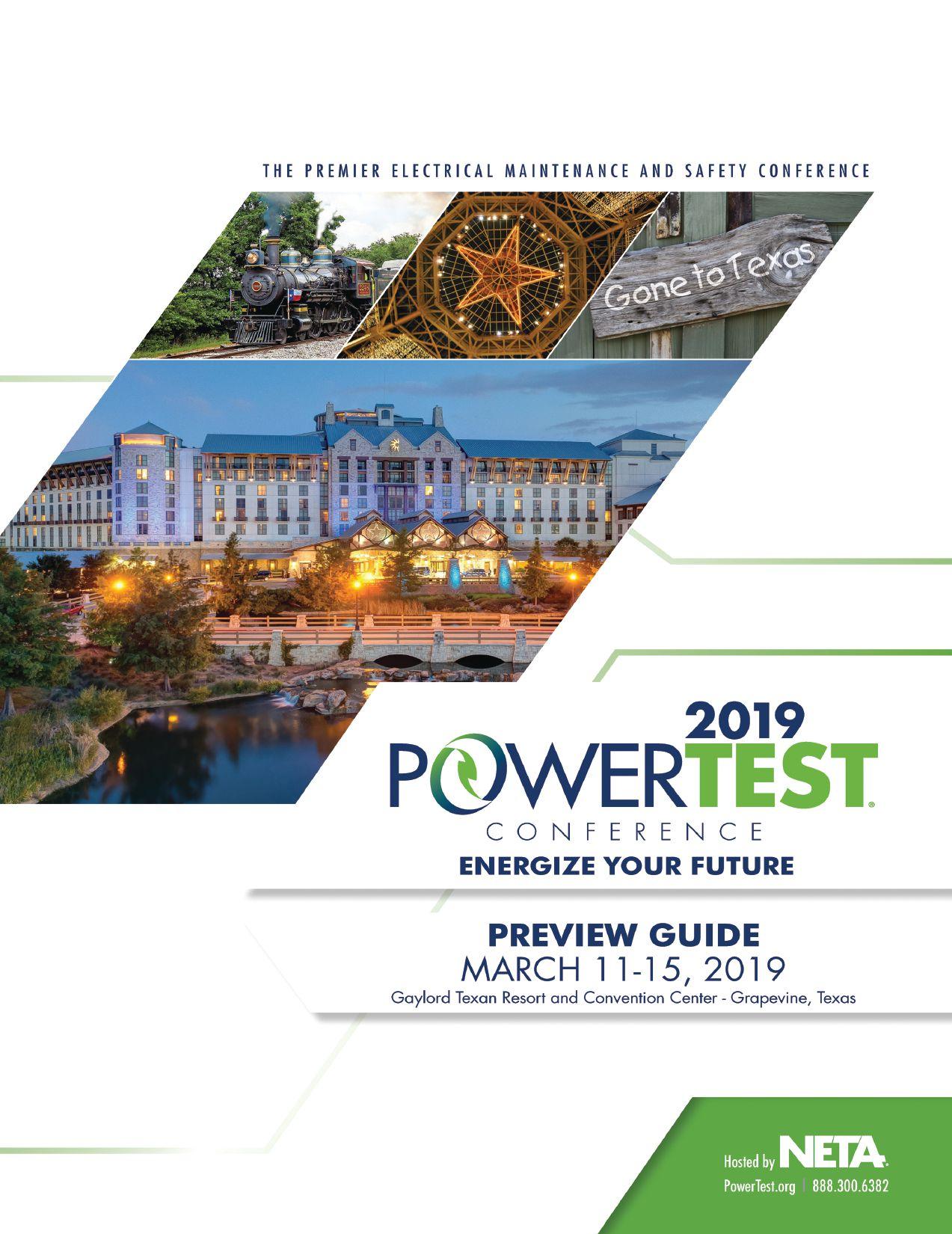
MARCH 11-15, 2019
Gaylord Texan Resort and Convention Center - Grapevine, Texas

The home of PowerTest 2019 is Grapevine, Texas, a city founded on the ideals of peace and friendship. Grapevine’s story began in1843 when General Sam Houston and other prominent Texans met with10 American Indian nations to negotiate a peace treaty, opening the area to homesteaders. Named for the wild mustang grapes that covered the area, today Grapevine is a thriving center of culture and commerce known for its restored19thand 20th-century buildings along Main Street and a unique collection of restaurants, fine art galleries, and shops. The Cotton Belt Railroad District is home to an array of fascinating artisan workshops and is the starting point of the Grapevine Vintage Railroad, which follows a scenic route between Grapevine and the Fort Worth Stockyards.
The quaintness of Grapevine’s walk-friendly historic district, art, and wineries is complemented by its

proximity to the downtowns of both Dallas and Fort Worth and the convenience of nearby Dallas/ Fort Worth International Airport. In recent years, Grapevine has become a sought-after location for major meetings and conventions. PowerTest 2019 will be held at the area’s largest site, the Gaylord Texan Resort, which offers views of beautiful Lake Grapevine, nearly five acres of lush indoor gardens and a river walk, a waterpark, a spa, and more than10 restaurants, bars, and nightclubs.
In welcoming the leading event for electrical power systems professionals, Grapevine will provide a fresh backdrop for PowerTest’s focus on connections, learning, and updating your knowledge of the latest advancements in the electrical maintenance and safety field. Building on Grapevine’s history of friendly collaboration, PowerTest 2019 is designed to make business a pleasure.
Keynote Speaker Stacey Hanke, Stacey Hanke Inc.
Stacey Hanke is the author of Influence Redefined…Be the Leader You Were Meant to Be, Monday to Monday. She is also the co-author of Yes You Can! Everything You Need From A To Z To Influence Others To Take Action. Stacey is the founder of Stacey Hanke, Inc. She has trained and presented to thousands to help business leaders improve body language habits and learn how to choose words wisely in industries from financial to healthcare to government, and everyone in between. Her vast client list includes Coca-Cola, FedEx, Kohl’s, U.S. Army, U.S. Navy, U.S. Air Force, McDonald’s, Publicis Media, Nationwide, US Cellular, Pfizer, GE, General Mills, and Abbvie. Her team works with Directors up to the C-suite. She has been the Emcee for Tedx and has inspired thousands as a featured guest on media outlets including The New York Times, Forbes, Entrepreneur, Thrive, SmartMoney, The Economist, and Business Week Certified Speaking Professional — a valuable accreditation earned by less than 10 percent of speakers worldwide.

YOU’RE INVITED
WHAT:
Pre-Conference Event PowerTest 2019
WHERE:
Topgolf at the Colony
WHEN:
Sunday, March 10, 2019
5:00 PM – 9:00 PM
THE SKINNY:
Cost: $155.00 per person
To register: Call the NETA office 888-300-6382 (NETA)
Buses leave at 5:00 PM
YOUR HOSTS:

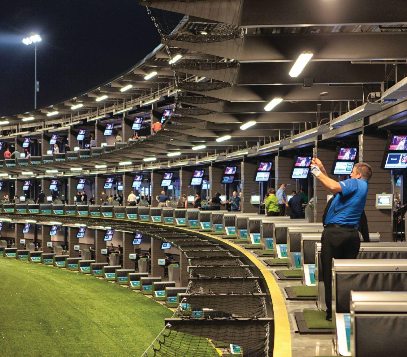
Whether you’re an aspiring golf pro or picking up a club for the first time, Topgolf is everyone’s game!
Join us for some Texas backyard BBQ, cold beverages, a KissFM DJ spinning your favorite music, golf pros to assist you with your game, and additional yard games such as bag toss, giant Jenga, and Connect 4!
We’ve gathered leaders in the industry and will stage a full day of engaging, 45-minute presentations sure to expand your thinking and generate new ideas. Choose from 27 detailed presentation track topics.
MONDAY: DAY 1
TECHNICAL PRESENTATIONS
ELECTRICAL SAFETY
• 10 Most Important Changes to the 2018 NFPA 70E
Jim White, Shermco Industries.
• A Reliable Plant is a Safe Plant
Alan Ross, SD Myers
• Electrical Safety Program Principles: Do You Have Them in Your ESP?
Terry Becker, Danatec Educational Services Ltd.
• Changing the Electrical Safety Culture
Daryld Ray Crow, DRC Consulting Ltd.
• 10 Most Common Errors in Arc Flash Analysis
Jim Chastain, EasyPower LLC
• Importance of Risk Assessment and Risk Control Hierarchy in Electrical Safety Programs: NFPA 70E Topic
Bhanu Srilla, Grace Engineered Products
EQUIPMENT
• Recommended Practices for Applying an Effective Test Protocol to Power Transformers
Charles Sweetser, OMICRON electronics Corp. USA
• Transformer Turns Ratio Test: Some Unknown Facts
Dinesh Chhajer and Daniel Carreno Perez, Megger
• Utilizing Primary Injection for Transformer Differential
Protection Commissioning
Alan Andrew Holt, Premier Power Maintenance Corporation
• Relay Testing for Real World Conditions
John Lane, Doble Engineering Company
• Beyond the Knee Point: A Practical Guide to CT Saturation
Brad Heilman, Schweitzer Engineering Laboratories, Inc.
• Travel Measurement and Analysis of Medium-Voltage Vacuum Circuit Breakers
Volney Naranjo and Robert Foster, Megger
Albert Livshitz, CE Power Engineered Services, LLC RELIABILITY
• PRC-005: Can You Pass an Audit?
Bruce Horowitz, American Electrical Testing Co., LLC
• Applications in Power & Power Quality Monitoring
Ross Ignall, Dranetz Technologies
• Calibration: Levels of Service and Understanding the Differences
John E. Couturier, Energy Northwest
• Substation Acceptance and Pre-Operational Testing Plan
Kenneth George Peterson, Hampton Tedder Technical Services
• We Need You and You Need Us!
Scott James, Tate and Lyle Inc.
• Validation Testing of Variable Speed AC and DC Drive
Semiconductors, DC Filter Capacitors, and Related Devices
Thomas Engel, Al Corcoran, and Kent Wegley, QP Testing, LLC
EMERGING TECHNOLOGIES
• The Use and Condition Assessment of Esters in Electrical Equipment
Nick Perjanik, WEIDMANN Electrical Technology Inc.
• MV Cable Termination Failure Prevention
William Higinbotham, EA Technology
• There is a You in Analytics
Noah Bethel, PdMA Corporation
• Challenges in Offshore Wind Energy Maintenance
Kevin Alewine, Shermco Industries
• The Reconditioning of Vacuum Interrupters is Nearer Than You May Think Finley Ledbetter, Group CBS, Inc.
• Addressing Noise Sources During Online PD Testing
Timothy Erwin, EA Technology CASE STUDIES
• A Customer’s Perspective: Implementing Commissioning Plans
Randall Sagan, MBUSI
• VCB and GCB Power Factor Tests: Data Analysis and Troubleshooting
Michael Wolf, Doble Engineering Company
• Tips to Avoid Failure: System Critical Bus Duct Systems: Inspection and Maintenance Best Practices for Isophase and Non-Seg Bus Systems Mohsen Tarassoly and Mitch Pallansch, Electrical Builders, Inc.
PowerTest 2018 Welcome and Keynote Address

THE PREMIER ELECTRICAL MAINTENANCE AND SAFETY CONFERENCE
MONDAY (continued)
PROJECT MANAGEMENT FOR ELECTRICAL OUTAGES SYMPOSIUM
Moderator: Ron Widup, Shermco
Industries
Owners of electrical systems and contractors who perform electrical services: You have a large outage coming up and need to perform the work safely, effectively, and on budget. How do you manage a large electrical outage and hit all of these goals? This symposium will provide insight and expertise on this very topic, and will provide information from both the owner’s and the contractor’s perspective. A must-attend event for those responsible for electrical systems.
New Product Forum
In sixty minutes, preview the newest products and services shaping the power systems industry from the PowerTest 2019 exhibitors. All conference registrants are invited to attend, and you just might be a door-prize winner.
Hospitality Suites
Mingle with colleagues and a host of leaders at Monday night’s hospitality suites. Hosts will offer their own brand of hospitality with uniquely themed suites with the best of food, drinks, and entertainment.

TRADE SHOW HIGHLIGHT
THE PREMIER ELECTRICAL MAINTENANCE AND SAFETY CONFERENCE
TUESDAY: DAY 2
TUESDAY MORNING
Join in the discussion during the Tuesday morning Panel Sessions. Select two of the four panel topics and get ready to learn from experts and peers alike.
Panels:
Electrical Safety
Jim White, Shermco Industries
Emerging Technologies
Eric Beckman, National Field Services Circuit Breakers
Finley Ledbetter, Group CBS, Inc.
Project Management
Pat Beisert, Shermco Industries

TRADE SHOW HIGHLIGHT


Tuesday
( continued )
PowerTest 2019 Trade Show
The PowerTest 2019 Trade Show promises more than 100 top-tier electrical power vendors whose mission is electrical safety and reliability. Enjoy a complimentary lunch and beverages as you tour the show and make connections.The PowerTest 2019 Trade Show will take place from 12:00 PM – 5:30 PM.
PowerTest 2019 – PowerBash Reception!
A gathering you don’t want to miss. Enjoy an evening of entertainment, awards, and recognitions while mixing and mingling. Tuesday evening from 7:00 PM – 10:00 PM.


 TRADE SHOW HIGHLIGHT
THE PREMIER ELECTRICAL MAINTENANCE AND SAFETY CONFERENCE
PowerTest Trade Show and Luncheon
POWERTEST 2019 TRADE SHOW FLOOR PLAN


HALL C ENTRANCE HALL D ENTRANCE HALL D 100 aisle 200 aisle 300 aisle 400 aisle 500 aisle 600 aisle 700 aisle 800 aisle 25' 25' 10' 10' 10' 10' 10' 10' 10' 10' 819 817 813 811 809 818 816 810 808 719 717 711 709 704 702 611 609 605 618 519 506 407 405 418 319 318 316 304 302 219 217 211 209 205 118 120 122 124 225324 323 325 422 424 523 525 623 625 722 724725824 823 825 821 Media Food Dessert / Food Food Bar 715 20' 115 20' 30' 109 20' 20' 102 20' 129228229 328329428429 728729828 ENTRANCE 308 20' CAP VIP 123 125 222 224 223 20' 317 20' 303 20' 50' 708 20' 805 20' 723 20' 617 20' 20' Bar Bar 502 20' 703 20' 20' 409 20' 20' 517 20' 423 20' 20' 106 20' 103 20' 202 20' 622 20' 628 20' 503 20' 60' Resort & Convention Texas THROUGHOUT = 24'-0" OUTLETS DATA VOICE BOX 10'-11" Clearance Height from the ground Electrical box Clearance Height 10"-0 Concrete box Flush to the ground columns additional charge 350lbs per sq ft 10/26/2018 Qty 69 15 5 1 1 1 92 SqFt 6,900 3,000 2,000 600 1,000 1,200 14,700 02/26/2019 02/27/2019 03/02/2019 *This floor plan is subject to fire marshal approval. Disclaimer 10-26-2018 NETA - Powertest 2019 February 27, 2019 Gaylord Texan Exhibit Halls C & D Lounge 115 CAP Lounge
THE PREMIER ELECTRICAL MAINTENANCE AND SAFETY CONFERENCE
COMPANY BOOTH # COMPANY BOOTH #
ABB - GE 103 AEMC INSTRUMENTS .......................................................... 222 AMBLYONIX INDUSTRIAL INSTRUMENT COMPANY 805 AVO TRAINING INSTITUTE 407 BCS SWITCHGEAR, INC. ..................................................... 703 BELYEA COMPANY INC.. 211 CE POWER ENGINEERED SERVICES 118 CORPORATE ALLIANCE PARTNERS VIP LOUNGE ................. 115 DOBLE ENGINEERING COMPANY 808 EA TECHNOLOGY LLC 506 EASYPOWER LLC ................................................................. 605 ELECTRICAL BUILDERS, INC. 304 ELECTROSWITCH. 611 GROUP CBS NEW PRODUCTS..............................................517 GROUP CBS, INC. 109 HAEFELY HIPOTRONICS 106 HIGH VOLTAGE MAINTENANCE ......................................... 525 HIGH VOLTAGE, INC. 318 HIOKI USA. 702 HV DIAGNOSTICS, INC. 628 HV TECHNOLOGIES, INC. 519 INTELLIRENT ........................................................................ 503 IRISS 219 KOCOS AMERICA LLC 704 MADDOX INDUSTRIAL TRANSFORMER ............................... 325 MEGGER 303 MEISTER INTERNATIONAL LLC 209 MONSTER ELECTRICAL ........................................................ 223 MVA DIAGNOSTICS 316 NATIONAL FIELD SERVICES 429 NATIONAL SWITCHGEAR .................................................. 423 NATIONAL TRAINING CENTER 428 NETA 102 OFIL LTD. 711 OMICRON ELECTRONICS CORP. USA................................... 617 OPAL-RT TECHNOLOGIES 324 PARTS SUPER CENTER. 622 PHENIX TECHNOLOGIES INC. ..............................................418 POWER ASSET RECOVERY CORP 123 POWER DIAGNOSTIC SERVICE 205 POWER GRID ENGINEERING, LLC ....................................... 709 POWER MONITORING & DIAGNOSTIC TECHNOLOGY 810 POWER SUBSTATION SERVICES 625 PROGUSA - DV POWER ...................................................... 202 PROTEC EQUIPMENT RESOURCES 409 QUALITY SWITCHGEAR INC. 708 RAYTECH USA..................................................................... 715 REMOTE SOLUTIONS, LLC 623 RICHARDS MANUFACTURING 319 SENTINEL CONTROL PRODUCTS ......................................... 424 SHERMCO INDUSTRIES 308 SMC 813 SOUTHLAND ELECTRICAL SUPPLY 323 STÄUBLI ELECTRICAL CONNECTORS 328 SUNBELT TRANSFORMER ..................................................... 618 SWITCHGEAR PRO 120 TECHNICAL DIAGNOSTIC SERVICES 302 THE COLT GROUP, POWER SERVICES DIVISION ....................217 TITAN QUALITY POWER SERVICES 719 TRS-RENTELCO 717 TYNDALE COMPANY, INC. .................................................. 405 UE SYSTEMS INC. 422 UTILITY RELAY COMPANY 502 VERTIV - ELECTRICAL RELIABILITY SERVICES .......................... 523 WEIDMANN ELECTRICAL TECHNOLOGY 609 WIDESPREAD ELECTRICAL SALES / BRAH ELECTRIC 317
POWERTEST 2019 EXHIBITORS
Wednesday - Thursday Seminars
Two days are dedicated to high-power learning.
On Wednesday, choose from eight in-depth, four-hour seminar presentations.
WEDNESDAY: DAY 3
WEDNESDAY
SEMINAR TITLES
• Overall Transformer Insulation Diagnostics: Field and Laboratory Approach
Diego Robalino, Megger
Nick Perjanik, WEIDMANN Electrical Technology Inc.
• Understanding Line Protection Relays
J. Scott Cooper, OMICRON electronics Corp. USA
• Leading Generational Engagement: Learning to Flex in a Culture of Resistance
Stacey Hefner, Practicing Perfection Institute
• Cable Testing and Diagnostics with a Focus on Practical Testing
Jason Souchak and Robert Probst, Megger
• Understanding Partial Discharge Workshop
Tom Sandri, Shermco Industries
• Interpretation of Power Factor and Excitation Current Test Data
Keith Hill and Mike Anderson, Doble Engineering Company
• Battery Testing and Maintenance
Volney Naranjo and Dinesh Chhajer, Megger
• Electrical Safety for the Technician
Jim White, Shermco Industries
Daryld Ray Crow, DRC Consulting Ltd.
Daleep Mohla, DCM Electrical Consulting Services
TRADE SHOW HIGHLIGHT
TEXAS at NETA POWERTEST

WED/THU: DAY 3 & 4

n Accurate ratio ±0.05% from -20 °C to +50°C n Three-phase step up ratio (patent pending)
n Smallest/lightest three-phase test set on the market n Fast true three-phase tests—less than 8 seconds
SEE THE NEW TTRU3
TTR
3-PHASE
We’ll See You In GRAPEVINE
2019! MARCH 11-15 J oin us
Booth
us.megger.com/powertest
at
303 to see our newest products and the broadest selection of testing solutions in the industry.
THE PREMIER ELECTRICAL MAINTENANCE AND SAFETY CONFERENCE
THURSDAY: DAY 4
THURSDAY
OFFSITE
SEMINARS
Attendees can choose one of the following topics for a full-day, off-site, hands-on seminar presented by three leaders in the industry: Switchgear:
Advanced Electrical & Motor Controls, AVO Training Institute, and Megger Medium-Voltage: Doble Engineering Company, Shermco Industries, and Vacuum Interrupters
Circuit Breakers: National Switchgear, BCS Switchgear, and Circuit Breaker Sales Breakfast and lunch will be provided.

TRADE SHOW HIGHLIGHT
Standard
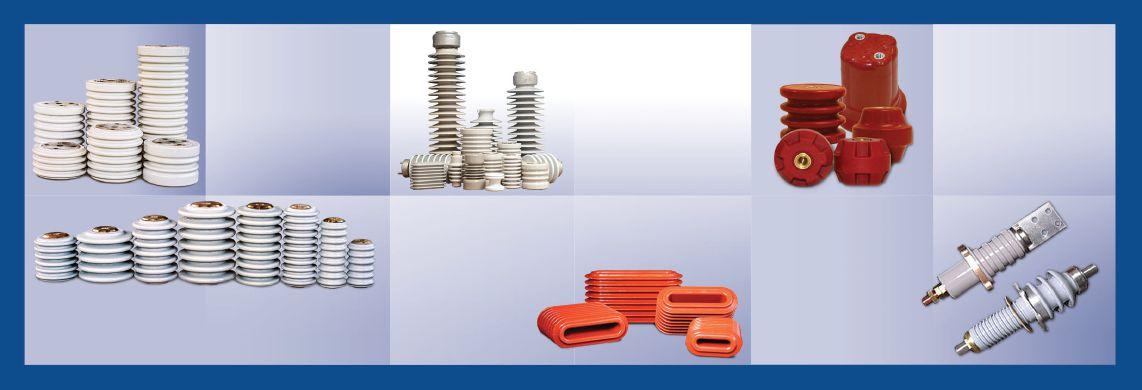
are in stock and used to support copper and/or aluminum bus bar in switchboards, motor control centers and panel boards.
CYCLOALIPHATIC BUS BAR FEED-THROUGH INSULATORS
Feed-through type cycloaliphatic bus bar support insulators for bus bars in air insulated metal-clad and metal enclosed switchgear. High compression strength and other qualities of cycloaliphatic epoxy. In stock for 1/4” x 2”, 3/8”x 4”, ½” x 4” & ¼” x 6” copper bus bars.
PORCELAIN BUSHINGS
Porcelain bushings for transformer, switchgear and bus duct applications. Bushings from 1.2kV to 46kV for air to oil and air to air applications. Current ratings up to 8000 amps available.
IN STOCK, FOR IMMEDIATE SHIPMENT Email: sales@meisterintl.com • Phone: (513) 923-2712 • www.meisterintl.com Meister International, a member of the National Association of Electrical Distributors, and founded in 2003, distributes the nest quality insulators and bushings to OEMs and users of switchgear, transformers and bus-duct around the world. A20 & A30 PORCELAIN BUS INSULATORS A20 (5kV–18kV) & A30 (5kV-34.5kV) bus insulators used by switchgear, power transformer and bus duct manufacturers where reliability and ‘uptime’ is paramount. Manufactured and tested to ANSI C29.9. PORCELAIN STATION POST INSULATORS
strength,
1800kV
POLYESTER INSULATORS
high-strength, and extra high-strength station post insulators are available from stock. Voltage ratings from 95kV BIL to
BIL.
the world
bus bars
electrical components.
berglass reinforced,
resistant polyester.
PORCELAIN STANDOFF INSULATORS
to 15kV porcelain stando insulators
Used around
to support
and other live
Manufactured from UL recognized
ame
Strong mechanical and electrical insulating properties.
2.5kV
FRIDAY
The Doble Laboratory Seminar is designed for engineers, chemists, and others responsible for reviewing data to interpret laboratory results to detect and identify problems within electric apparatus. The seminar will be interactive, combining theoretical background with practical experience and hands-on examples including case studies illustrating common problems found in the field.
FRIDAY: DAY 5
• Learn about the quality of oils on the market today.
• Discover how knowing about the aging characteristics of insulating materials can help you extend the life of your transformer.
• Learn how to take oil samples, avoid common pitfalls and save time and money by sampling only once.
• Diagnose apparatus problems with dissolved gas-in-oil analysis.
• Find out how to assess the condition of paper insulation.
• Detect the presence of incipient-fault conditions and categorize them.
• Establish the correct method of analyzing moisture-in-oil results.
• Study the significance of dissolved and particulate metals and other particle contamination found in electrical apparatus.
• Understand how to determine the condition of electric apparatus using laboratory tests.
• Diagnostics and condition assessment for LTCs and bulk oil breakers based on oil test.

Disasters happen. And no matter how well recovery plans are created and executed, there are often big problems. Sometimes too big. Shermco has the resources and expertise to lead or support a safe, ef cient and well managed recovery plan. As the largest independent electrical equipment testing, maintenance and repair organization in North America, we have both the manpower and the experience to get factories, commercial buildings and utilities back on line as soon as possible. And the engineering expertise to make sure they stay on line.
So, when the disaster is too big to manage on your own, Shermco is your best call.

Emergency power
On-site circuit breaker repair
Motor and generator eld repair services
Transformer testing and repair • Cable cleaning, drying, testing and repair • Replacement equipment when required
• Motor and generator reconditioning and remanufacturing
• Removal and reinstallation of motors, transformers, switchgear
• Engineering studies and design updates
• Testing and commissioning
• Future disaster recovery planning
If only
as simple as pushing a button. •
•
it were
Recovery project management and support
•
•
•
888-SHERMCO www.shermco.com TRADE SHOW HIGHLIGHT
THE PREMIER ELECTRICAL MAINTENANCE AND SAFETY CONFERENCE
The Gaylord National Resort Alamo Replica
SPECIAL SESSIONS AND MORE
Megger Best Practices
Sunday, March 10 9:00 AM - 4:00 PM
Megger’s Best Practices Seminars are designed to bring you up to speed on new testing techniques and technology as well as offer the opportunity to engage in technical discussions with our expert engineers. Megger’s world-class Applications Engineers utilize their vast industry knowledge and experience to craft an in-depth program backed by Megger’s expertise in the market. This full day of quality education includes training related to key industry topics as well as some of the best practices to follow when performing offline electrical testing.
PowerDB User Group
Monday, March 11 12:15 PM – 2:15 PM
Annual User’s Group Meeting open to licensed users of PowerDB Pro Software. Agenda will include presentations by the PowerDB Pro development team as well as utility, industrial, and contractor groups discussing how this product is an integral part of their business operations. Preregistration is required by contacting PowerDB at 979.690.7925, ext. 702 or by registering at www.powerdb.com.

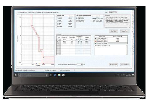


InfoPro-AC® Software
Designed to simplify use of AC-PRO-II® trip units
o View Currents, Voltages, Power, Status, and Alarms
o Download Settings from/to AC-PRO-II®
o Waveforms (on-demand)
o Trip History including Waveforms
o Time Current Curves (NEW!)
o Test RS-485 Modbus port (NEW!)
o Document breaker data and test results (NEW!)
o Save and print files for documentation & records www.utilityrelay.com

TRADE SHOW HIGHLIGHT



Don’t miss a single moment of PowerTest 2019. Download the PowerTest Mobile App and get instant access to the full schedule - right at your fingertips!
H View session abstracts and speaker bios.
H Customize your schedule for the events and sessions you plan to attend.
H Set reminders and manage alerts.
H View Trade Show floor plan map and booth information.
H Message other conference attendees.
H View sponsor information.
H Complete evaluations to earn CTDs/CEUs as well as provide feedback, vote for your favorite sessions, booths, and hospitality suites.

To download the NETA/PowerTest app, scan the QR code or visit https://engagefully.info/ef/international-electrical-testing-association/218
MOBILIZE YOURSELF WITH THE
POWERTEST 2019 MOBILE APP Download the PowerTest 2019 Mobile App
The Premier Electrical Maintenance and Safety Event
11 -
2019 Gaylord Texan Resort and Convention Center Grapevine, Texas www.powertest.org
March
15,
EARLY BIRD REGISTRATION IS NOW OPEN!
Register on-line at www.powertest.org or call 888.300.6382 (NETA)
PowerTest 2019 Early Bird Pricing
Monday & Tuesday $ 995 $ 895
Monday - Thursday $1895 $1695
Single Day $ 580 $ 550
Doble Seminar $ 445 $ 445
Register Online: To register for PowerTest 2019, save time by registering online. You’ll find a complete brochure and registration form available at www.powertest.org.
Hotel Reservations*
Gaylord Texan Resort Reservation By: & Convention Center February 18, 2019
817.778.2000
Group Name: 1501 Gaylord Trail PowerTest/NETA Grapevine, TX 76051 Group Rate: $219
*Once you register for PowerTest 2019, you will receive a link via email to secure your hotel reservations at the Gaylord Texan Resort & Convention Center.
Payment: NETA accepts all major credit cards. Save time and register online at www.powertest.org 888.300.6382 (NETA)
Extras: PowerTest 2019 Technical Papers
Registered conference attendees will receive all PowerTest technical presentations on a USB drive in their registration bag.
Guest Pass: Includes admission to the Hospitality Suites, Trade Show, breakfast, and the PowerBash reception. $75 per person. Attendees registered for Mon-Thurs technical sessions do not need to purchase a guest pass, as it is included with registration (with exception of the PowerBash — this is an additional $35).
Easy Steps for Registration
1. Go to www.powertest.org and review the complete PowerTest 2019 online brochure.
2. Decide the number of days you will attend the conference.
3. Tuesday attendees select up to two panels. (Cost of panels included in the registration fees.)
4. Wednesday attendees register for up to two seminars. (Cost of seminars included if registered for Monday – Thursday.)
5. Thursday attendees register for one full-day tour. (Cost of seminars included if registered for Monday – Thursday.)
6. Register for Doble Lab Seminar. (Cost of seminar is in addition to the registration fees.)
7. Sign up for Guest Passes. Guest Pass only needed for guests of attendees who wish to attend the Hospitality Suites, the Trade Show, and the PowerBash Reception (Cost of passes is in addition to the registration fees.)
8. Sign up for PowerTest 2019 conference polo shirts and select size. (Cost of polo shirts is in addition to the registration fees.)

Non Members NAC/Alliance
SPONSORS

PREMIUM SPONSORS


HIGH-VOLTAGE SPONSORS MEDIUM-VOLTAGE SPONSORS


LOW-VOLTAGE SPONSORS GENERAL SPONSORS


DayCor® Corona Cameras Assist Adaptation to Global Climate Change
Climate changes pose fundamental concerns to electrical utilities. Longer droughts affect levels of pollution on overhead transmission lines. Unexpected outages are reported due to buildup of contaminants on insulators.
Ispections with Ofil DayCor® corona cameras solved flashover problems in contaminated areas. Cameras provided crucial immediate information about the criticality of the contamination.
The proliferated use of polymeric insulators demands inspection with corona cameras due to their vulnerability to the by-products of corona.
Ofil DayCor® UV cameras were tested on HV apparatuses and transmission lines. DayCor® Cameras proved their usefulness to detect corona and show the intensity and location of discharge activities along insulators. The information provided information about the insulator performance while operating the lines at the regular applied voltage.


“Maintenance crew adopted UV inspections with Ofil DayCor® Cameras in order to properly check what was happening…”

 Failure at the tower 284 insulator’s string occurred in 2015 due to pollution
Critical corona activity on V String-Power
TAESA Brazil 2015
THE PREMIER ELECTRICAL MAINTENANCE AND SAFETY CONFERENCE
Ofil Solution for Inspection with UAV
COVER STORY


The Electrical Code Is Not Just for Electrical Contractors
Testing companies do not typically think to use the National Electrical Code NFPA 70 (NEC) in the execution of their activities, as it is a minimum standard for electrical installations. However, the NEC has included testing activities since 1971, with new requirements added over the years primarily due to failures that caused equipment damage and injuries to personnel. All of these are important for an electrical testing technician to be aware of both before arriving onsite and during the testing session. Although projects with complete design documentation often cover these requirements, they may be overlooked on small projects or turn-key projects accomplished under a maintenance and repair program budget. This article provides an indepth look at where NEC requirements apply to acceptance testing, commissioning, and maintenance. Testing companies, technicians, ECs, engineers, AHJs, and end users must be aware of and understand these requirements.
By James G. Cialdea, CE Power Engineered Services, LLC and Daniel Hook, Western Electrical Services
FEATURES
7 President’s Desk
Jim Cialdea, CE Power Engineered Services, LLC
NETA President
42 Testing and Maintenance of Critical Electrical Systems
William Otterson, Shermco Industries
48 NETA’s Voice in the National Electrical Code
James R. White, Shermco Industries


TABLE OF CONTENTS TABLE OF CONTENTS NETAWorld • 3
34 42
10 NFPA 70E and NETA
NETA and the NFPA 70E
Ron Widup and James R. White, Shermco Industries
14 Tech Tips
Ground Testing Instrumentation Undergoes
Rapid Development
Jeff Jowett, Megger
20 Tech Quiz
National Electrical Code
James R. White, Shermco Industries
22 Safety Corner
PPE Requirements for Installation of Temporary Protective Grounds
Paul Chamberlain and Scott Blizard,
American Electrical Testing Co., LLC
28 Relay Column
Setting Overcurrent Protection for Collection
Feeders at Wind Farms
Steve Turner, Electrical Consultants, Inc.
INDUSTRY TOPICS
54 Testing, Operating, and Maintaining Fiber Optic Networks
Jim Hayes, Fiber Optic Association
62 Safety Improvements When Testing
High- and Medium-Voltage Circuit
Breakers with Both Sides Grounded
Adnan Šečić and Nijaz Hadžimejlić, DV Power — Sweden
72 Understanding Current Transformers
Thomas D. Sandri, Shermco Industries
& OBSERVATIONS —
78 Megger: A History of Innovation and Advancement
SPECIFICATIONS AND STANDARDS
95 ANSI/NETA Standards Update
98 ASTM F18 Committee Report
James R. White, Shermco
103 CSA Update
Kerry Heid, Shermco Industries
106 NFPA 70E Committee Report
James R. White, Shermco
109 NFPA CMP-13 Committee Report
James R. White, Shermco
NETA NEWS — SETTING THE STANDARD
91 NETA University Curriculum Update
Nenad Pasic, Tony Demaria Electric, Inc.
NETA
NEWS
82 PT19 Keynote Speaker Stacey Hanke Redefines Influence
85 PowerTest 19 Offers New Learning Seminars
87 CAPS Share Insights on Emerging Technologies
88 NETA Activities Update — July through October 2018
IMPORTANT LISTS
113 NETA Accredited Companies
120 Advertiser List
4 • WINTER 2018 TABLE OF CONTENTS TABLE OF CONTENTS IN EVERY ISSUE
SPOTLIGHT
INSIGHTS
NETA CAP

Where technicians, equipment and jobs intersect Available at 888.902.6111 | assist@intellirentco.com | assist.intellirentco.com
app-based platform, built for testing organizations
uses the people and normal processes of a testing organization to manage and track test equipment. It’s built for barcoding, tracking and scheduling test equipment that your company owns or rents.
An
assist
Reliable Power System Solutions


3050 Old Centre Road, Suite 101
Portage, MI 49024
Toll free: 888.300.NETA (6382)
Phone: 269.488.NETA (6382)
Fax : 269.488.6383
neta@netaworld.org
www.netaworld.org
executive director: Missy Richard
NETA Officers
president: Jim Cialdea, CE Power Engineered Services, LLC
first vice president: Scott Blizard, American Electrical Testing Co., Inc.
second vice president: Lorne Gara, Orbis Engineering Field Services, Ltd.
secretary: Eric Beckman, National Field Services
treasurer: John White, Sigma Six Solutions
NETA Board of Directors
Ken Bassett (Potomac Testing, Inc.)
Eric Beckman (National Field Services)
Scott Blizard (American Electrical Testing Co., Inc.)
Jim Cialdea (CE Power Engineered Services, LLC)
Scott Dude (Dude Electrical Testing LLC)
Lorne Gara (Orbis Engineering Field Services, Ltd.)
Dan Hook (Western Electrical Services, Inc.)
David Huffman (Power Systems Testing)
Alan Peterson (Utility Service Corporation)
John White (Sigma Six Solutions)
Ron Widup (Shermco Industries)
NETA World Staff
technical editors: Roderic L. Hageman, Tim Cotter
assistant technical editors: Jim Cialdea, Dan Hook, Dave Huffman, Bob Sheppard
associate editor: Resa Pickel
managing editor: Carla Kalogeridis
copy editor: Beverly Sturtevant
advertising manager: Laura McDonald
design and production: Moon Design
NETA Committee Chairs
conference: Ron Widup; membership: Ken Bassett; promotions/marketing: Scott Blizard; safety: Scott Blizard and Jim White; technical: Alan Peterson; technical exam: Dan Hook; continuing technical development: David Huffman; training: Bob Sheppard; finance: John White; nominations: Alan Peterson; alliance program: Jim Cialdea; association development: Ken Bassett and John White
© Copyright 2018, NETA
NOTICE AND DISCLAIMER
NETA World is published quarterly by the InterNational Electrical Testing Association. Opinions, views and conclusions expressed in articles herein are those of the authors and not necessarily those of NETA. Publication herein does not constitute or imply endorsement of any opinion, product, or service by NETA, its directors, officers, members, employees or agents (herein “NETA”).
All technical data in this publication reflects the experience of individuals using specific tools, products, equipment and components under specific conditions and circumstances which may or may not be fully reported and over which NETA has neither exercised nor reserved control. Such data has not been independently tested or otherwise verified by NETA.
NETA MAKES NO ENDORSEMENT, REPRESENTATION OR WARRANTY AS TO ANY OPINION, PRODUCT OR SERVICE REFERENCED OR ADVERTISED IN THIS PUBLICATION. NETA EXPRESSLY DISCLAIMS ANY AND ALL LIABILITY TO ANY CONSUMER, PURCHASER OR ANY OTHER PERSON USING ANY PRODUCT OR SERVICE REFERENCED OR ADVERTISED HEREIN FOR ANY INJURIES OR DAMAGES OF ANY KIND WHATSOEVER, INCLUDING, BUT NOT LIMITED TO ANY CONSEQUENTIAL, PUNITIVE, SPECIAL, INCIDENTAL, DIRECT OR INDIRECT DAMAGES. NETA FURTHER DISCLAIMS ANY AND ALL WARRANTIES, EXPRESS OF IMPLIED, INCLUDING, BUT NOT LIMITED TO, ANY IMPLIED WARRANTY OF FITNESS FOR A PARTICULAR PURPOSE.
ELECTRICAL TESTING SHALL BE PERFORMED ONLY BY TRAINED ELECTRICAL PERSONNEL AND SHALL BE SUPERVISED BY NETA CERTIFIED TECHNICIANS/ LEVEL III OR IV OR BY NICET CERTIFIED TECHNICIANS IN ELECTRICAL TESTING TECHNOLOGY/LEVEL III OR IV. FAILURE TO ADHERE TO ADEQUATE TRAINING, SAFETY REQUIREMENTS, AND APPLICABLE PROCEDURES MAY RESULT IN LOSS OF PRODUCTION, CATASTROPHIC EQUIPMENT FAILURE, SERIOUS INJURY OR DEATH.
Accredited Company 204 Gale Lane Kennett Square, PA 19348 484.731.0200 enerGtest.com Serving clients
Pennsylvania, Delaware,
Jersey, Maryland, Washington, DC and New England.
of costly
power
you need
ener es ™
preventive maintenance, depend on
to keep the power on.
in
New
We deliver optimum system reliability and performance while reducing the chances
unplanned
outages. Whether
acceptance
testing or
EnerGTest




NETA AND THE NEC
As technicians, electricians, and engineers, we all use codes and standards.

e minimum standard for electrical installations is the National Electrical Code (NEC), which has been the guide for electricians since 1897. e National Fire Protection Association (NFPA) has published the NEC since 1911. Also known as NFPA 70, the NEC is revised every three years.
e NEC continues to add requirements for the electrical testing — and more recently, requirements for maintenance — of systems that we as test technicians and engineers need to be aware of and make sure our customers meet. Electricity has become so critical for some applications that major hazards — even death — can occur if systems do not operate correctly.


e NEC recognizes this fact and has added many requirements to ensure that not only are installations safe, but also that they operate correctly when things go wrong, such as a ground fault or loss of power to a critical system.


take
e 2019 PowerTest Conference will be in Grapevine, Texas, on March 11–15. e conferences are getting bigger every year, and this year is no di erent. We are expecting record attendance. I hope you are planning to attend!
Let’s all remember to be safe — every day, all day.
 James Cialdea, President NETA — InterNational Electrical Testing Association


In this edition of NETA World Journal, we take a look at some of these NEC requirements.





NETA • PRESIDENT’S DESK PRESIDENT’S DESK
WORLD 7

The most trusted brands trust Electro Rent. A global test and technology solution provider, Electro Rent delivers over 50 years of experience in advising customers on electrical testing products and the best acquisition approach. RENT / LEASE / PURCHASE • Largest Test Inventory • Immediate Availability • Local Service Centers • ISO & ANSI Accredited Labs electrorent.com 1.800.553.2255


Sonel’s Graphic Insulation Testers expose flaws that numerical testers simply can’t see.


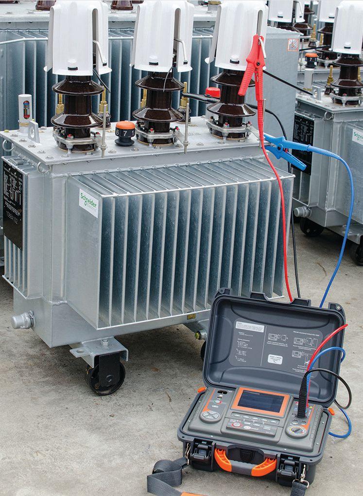
Transformer windings, motor windings, cable spools
User-selectable test voltages from 50 V to 5/10 KV
All ratios and parameters calculated – absorption, PI, DAR, capacitance, length
You run an insulation resistance test and get a number. Everything is fine. Right? Well...maybe not. This graphic display plots the results of a test where the final number appears to be OK, but the graph indicates a latent flaw that will likely result in an avoidable breakdown.
Sonel MIC Graphic Insulation Testers are the only instruments that display this valuable information on


the tester screen. Without this graph you’d wind up with a false sense of insulation integrity.
Sonel Graphic Insulation Testers have all the features you’d expect from high performance instruments including stepped or continuous voltage, selectable test voltages and currents, three test times plus CAT IV safety rating, auto-discharge, high-noise immunity and live object protection.
Get more information on these powerful instruments and the complete line of Sonel testers at www.soneltest.com

Better yet, call us today. 408.988.1346


Get the complete picture.
3350 Scott Blvd., Bldg 55, unit 1 Santa Clara, CA 95054 office@soneltest.com www.soneltest.com
NETA AND THE NFPA 70E
BY RON WIDUP and JIM WHITE, Shermco Industries
This edition of NETA World Journal focuses on the testing requirements of the National Electrical Code (NEC). Why would the NEC have testing requirements? It’s primarily because of the safety hazards untested and unproven installations may present and the reluctance of some builders or companies to spend the money to perform the necessary tests.
The NEC is considered a safety document because its purpose is to protect personnel and property from the hazards of electricity due to faulty design or construction. It contains requirements that can be similar to requirements in NFPA 70E. Here is an example from Article 110.16(B):
(B) Service Equipment. In other than dwelling units, in addition to the requirements in (A), a permanent label shall be field or factory applied to service equipment rated 1200 amps or more. The label shall meet the requirements of 110.21(B) and contain the following information:

(1) Nominal system voltage
(2) Available fault current at the service overcurrent protective devices
(3) The clearing time of service overcurrent protective devices based on the available fault current at the service equipment
(4) The date the label was applied
Exception: Service equipment labeling shall not be required if an arc flash label is applied in accordance with acceptable industry practice.
Informational Note No. 1: NFPA 70E – 2015, Standard for Electrical Safety in the Workplace provides guidance, such as determining severity of
10 • WINTER 2018 NETA AND THE NFPA 70E
THE NFPA 70E AND NETA
National Electrical Code, 2017 Edition
potential exposure, planning safe work practices, arc flash labeling, and selecting personal protective equipment.
As with many things, change takes time, but several 70E committee members are also on various NEC Code Panels. We are able to voice our concerns, and they are being heard by other panel members. The intent is not to make the NEC a copy of 70E. The 70E has purview over safe work practices; the NEC has purview over installation and construction requirements. We work together to make a safer workplace. Note that the 70E standard is also mentioned in the Informational Note shown. It is also mentioned in Informational Note No. 3 in this section, along with ANSI Z535, Safety Alerting Standards on label design.
Article 701.1 Legally Required Standby Systems states that this article pertains to the safe installation, operation, and maintenance of circuits and equipment supplying, distributing, and controlling electricity required for all emergency systems. What good is a generator that is needed for emergency power if it does not run after a period of time due to lack of maintenance? To ensure public safety, an operational emergency standby system is necessary, not optional.
In NFPA 70, 2017 Edition, 701.3(C) was added. It states:
(C) Maintenance. Legally required standby system equipment shall be maintained in accordance with manufacturer instructions and industry standards.
(D) Written Record. A written record shall be kept on such tests and maintenance.
Maintenance shall be performed in accordance with the manufacturer’s instructions (which many people never see) or industry standards. Which industry standards? ANSI/NETA MTS, Standard for Maintenance Testing Specifications for Electrical Power Equipment and Systems is one of them. The other would be NFPA 70B, but it is not a standard — it is a recommended
practice. So NETA member companies have a large stake in the NEC, and that will probably grow in the future.
Maintenance is also mentioned in Article 706.30 Energy Storage Systems (such as batteries). Battery circuits exceeding 240 V require a disconnect for series-connected strings that prevent the battery string being maintained to have a voltage no higher than 240 V. Of course, batteries require maintenance, and we don’t want people exposed to excessive voltages. Why would that be a requirement in the NEC? It is because that is when such a means to disconnect must be installed. So it is with many NEC maintenance requirements: The equipment or circuitry has to be installed, and it is a small step to recognize that maintenance is also necessary for safe operation.
Article 230 states in 230.95(C), Performance Testing:
(C) Performance Testing. The ground-fault protection system shall be performance tested when first installed on site. This testing shall be conducted by a qualified person(s) using a test process of primary current injection, in accordance with instructions that shall be provided with the equipment. A written record of this testing shall be made and shall be available to the authority having jurisdiction.
This section applies to industrial and commercial locations where the system is rated above 1,200 A, not homes or other dwellings.
If the code numbers are getting too high for you, look at Article 240 Overcurrent Protection. In 240.2 Definitions, supervised industrial installations are defined as:
(1) Conditions of maintenance and engineering supervision ensure that only qualified persons monitor and service the system.
(2) The premises wiring system has 2500 kVA or greater of load used in industrial process(es), manufacturing activities, or both, as calculated in accordance with Article 220.
NETAWorld • 11 NETA AND THE NFPA 70E
NFPA 70E AND NETA
THE
THE NFPA 70E AND NETA
(3) The premises have at least one service or feeder that is more than 150 volts to ground and more than 300 volts phase-to-phase.
The definition of supervised industrial installations excludes warehouses, offices, and similar facilities not integral to the industrial plant itself. As we know, industrial conditions can impose much more severe conditions on equipment than low-energy facilities. Maintenance is again part of the safety process.
CONCLUSION
This article contains only a small portion of the maintenance and testing required by the National Electrical Code. Along with NFPA 70E, ANSI/NETA MTS, Standard for Maintenance Testing Specifications for Electrical Power Equipment and Systems , and other standards, maintenance is becoming a higher priority for business owners and managers of industrial facilities.
Ron Widup and Jim White are NETA’s representatives to NFPA Technical Committee 70E, Electrical Safety Requirements for Employee Workplaces. Both gentlemen are employed by Shermco Industries in Dallas, Texas, a NETA Accredited Company.

Ron Widup is CEO of Shermco Industries and has been with the company since 1983. He is a member of the Technical Committee on NFPA 70E, Standard for Electrical Safety in the Workplace; a Principal Member of the National Electrical Code (NFPA 70) Code Panel 11; a Principal Member of the Technical Committee on NFPA 790, Standard for Competency of Third-Party Evaluation Bodies; and a Principal Member of the Technical Committee on NFPA 791, Recommended Practice and Procedures for Unlabeled Electrical Equipment Evaluation. Ron is also a member of the Technical Committee on NFPA 70B, Recommended Practice for Electrical Equipment Maintenance, and a member of the NETA Board of Directors and Standards Review Council. He is Vice Chair for IEEE Std. 3007.3, Recommended Practice for Electrical Safety in Industrial and Commercial Power Systems. Ron is a Journeyman Electrician in Texas, a NETA Level 4 Senior Technician, and an NFPA Certified Electrical Safety Compliance Professional.

James (Jim) R. White, Vice President of Training Services, has worked for Shermco Industries since 2001. He is a NFPA Certified Electrical Safety Compliance Professional and a NETA Level 4 Senior Technician. Jim is NETA’s principal member on NFPA Technical Committee NFPA 70E®, Standard for Electrical Safety in the Workplace; NETA’s principal representative on National Electrical Code® Code-Making Panel (CMP) 13; and represents NETA on ASTM International Technical Committee F18, Electrical Protective Equipment for Workers. Jim is Shermco Industries’ principal member on NFPA Technical Committee for NFPA 70B, Recommended Practice for Electrical Equipment Maintenance and represents AWEA on the ANSI/ ISEA Standard 203, Secondary Single-Use Flame Resistant Protective Clothing for Use Over Primary Flame Resistant Protective Clothing. An IEEE Senior Member, Jim was Chairman of the IEEE Electrical Safety Workshop in 2008 and is currently Vice Chair for the IEEE IAS/PCIC Safety Subcommittee.
12 • WINTER 2018
NETA AND THE NFPA 70E


THE PREMIER ELECTRICAL MAINTENANCE AND SAFETY CONFERENCE EARLY BIRD REGISTRATION September 1 – December 31, 2018 Register Early and Save PowerTest.org l 888.300.6382
Hosted by
Gaylord Texan Resort and Convention Center - Grapevine, Texas


GROUND TESTING INSTRUMENTATION


UNDERGOES RAPID DEVELOPMENT


 BY JEFF JOWETT, Megger

New technologies and innovations are being developed at jet speed, and it can be a challenge just to keep up. At the same time, veteran field operators often develop a comfort zone for particular instruments or technologies. A prime example is that of digital versus analog display. There’s nothing wrong with this; it can even keep specific models on the market and thriving for years or even decades after their purely objective obsolescence. But innovations in technology can make electrical testing quicker, more efficient, more accurate and reliable, less laborious, safer, and more.
One of the most conservative tried-and-true forms of electrical testing is that of grounding electrodes: ground rods, grids, and other buried objects that fix the electrical system to a ground reference and provide a safe parallel path for fault currents. Th e electrode must provide minimal resistance to the flow of current into the surrounding soil. But how do we test this?

The major challenge is to define what is being tested. It is not like testing a motor or wiring circuit — a discrete object. In the case of grounding electrodes, the entire Planet Earth is involved. Fortunately, it is enough to be able to test a critical portion of the earth within a reasonable vicinity to the electrode. Fault current dissipates radially in every direction, so
14 • WINTER 2018 GROUND TESTING INSTRUMENTATION UNDERGOES RAPID DEVELOPMENT
TECH TIPS

it encounters diminishing additional resistance with distance from the point of injection. If this weren’t so, the electrode would be ineffective.
FALL OF POTENTIAL METHOD
Over a century ago, the development of the Fall of Potential (FOP) test method and the requisite instrumentation overcame this challenge. The test current and potential functions had to be separate, each with their own lead and probe contacting the earth. By moving the potential probe in regular intervals against an independently established test current, the change in resistance with increasing distance could be plotted. Accordingly, the point at which the earth was no longer adding resistance could be recognized, and the fault current would encounter the resistance at this point — the lower, the better (Figure 1). In the literature, this critical distance at which there is no additional resistance is called “remote earth.” Today, test instrumentation and procedure are still locked into this testing basis.
Testing presents two issues: (1) the amount of time and effort required and (2) the inherent possibility of obtaining confusing or misinterpreted results. Recent advances reduce test time and help assure results. Pioneer testers performed just the basic test requirements and relied heavily on the operator doing everything right; but even the most competent personnel can be prone to error when under time pressure.
MODERN GROUND TESTERS
Ground testers are available in three- and four-terminal models, and the number of terminals in use varies with the test being performed. Old-timers had to do this manually by installing shunts, which was error-prone, especially when hurried or at the end of a long day. For a time, membrane keys were the rage, but these can force the operator to remember which function has been selected. The best option is a selector switch that internally switches the tester between various functions like two-pole, three-pole, four-pole, and other tests while reminding the operator of the test mode at a glance.
NETAWorld • 15 GROUND TESTING INSTRUMENTATION UNDERGOES RAPID DEVELOPMENT
TECH TIPS
Figure 1: Ideal Fall of Potential Graph


Noise suppression capabilities have recently been developed to new levels. Yes, there is electrical interference (noise) traveling through the earth, especially in the vicinity of substations where it is returning to source. In converting ac to dc, modern microelectronic equipment contributes to substantial increases in noise levels that go to ground. But the operator of a ground test no longer has to guess at the middle of a swinging pointer or mentally average dancing digits. Enhanced noise suppression now not only accurately measures, but also freezes the reading even in the presence of substation noise levels (Figure 2).
Filters plus voltage and frequency adjustments are effective tools for noise suppression. Filters slow the measurement process by averaging over an interval and can be disengaged when not needed to improve testing speed. Th e option of higher test voltages improves the signal-to-noise ratio and can be disengaged to conserve battery life. Finally — and most important — the operator can select the test frequency in half-Hertz intervals over ranges to 200 Hz. Earth testers operate with a squarewave signal to recognize their own test current against background noise. A sophisticated model can even automatically search out the best frequency at which to test.


Original earth testers — many from quality manufacturers still in operation — relied heavily on operator influence and experience. There is nothing wrong with this and, like drivers of stick-shift cars, many skilled workers like the engagement. But modern testers come equipped with an array of indicators that can be effectively used with no more than basic familiarization. Indicators include the presence of noise and its elimination when accomplished, potentially dangerous voltage on the tested electrode, and various instructions for missed steps such as insufficient contact with test probes or the presence of faulted leads. In the old days, these problems had to be recognized and then eliminated by trial and error. They can now be corrected in a fraction of the time.
Measurement range, accuracy, and resolution can now be realized to new limits and specifications. Of course, when testing a grounding electrode, it’s the low end that counts. Any resistance measurement above 25Ω (NEC®) indicates a need for more electrodes. Another tenth of an ohm doesn’t matter much. But in soil resistivity testing, numbers can run quite high, so a broad range of measurement is necessary. Furthermore, the extra resolution (down to 1 mΩ) is vital to achieve the most precise volumetric calculation, as required for soil resistivity. Full-featured testers, such as Wenner (Figure 3a) or Schlumberger (Figure 3b), can now perform the entire resistivity calculation and display the result. Once again, this saves time and possible error.
The LCD now provides the operator with a treasure trove of additional information and assistance. FOP tests no longer have to be graphed by hand. The display can graph an FOP test while still in progress, permitting the operator to spot problems and take corrective action instead of waiting possibly days until hand-collected data is graphed. Secondary
16 • WINTER 2018
GROUND TESTING INSTRUMENTATION UNDERGOES RAPID DEVELOPMENT TECH TIPS
Figure 2: Noise Level Graphed Against Test Results

graphics, conveniently distinguished by color, can track noise infl uence, telling the operator when they are getting a reliable, uninfluenced result. Other potential mistakes are avoided by indicators of probe spacing and adequate connections. All these capabilities can be augmented by storing and downloading data and graphics, even colorcoded and date- and time-stamped. Testing services in particular are often required to submit a test report including data and a full FOP graph. In situations where FOP cannot be run — usually for lack of space — popular alternatives like Slope Method and Intersecting Curves can also be found in automated form complete with details of the layout and calculation of the result. All of this can be kept in stored records for conformance compliance and safety audits, free of the thirdparty challenges that are a potential headache with handwritten records.
The biggest challenge in ground testing is the placement of long leads that must extend out to distant probes in the soil, with the monotonous pacing back and forth. Fully enhanced testers can now seriously reduce this onerous task with remote activation. A signal can be sent to the tester to activate the TEST function. The operator can then proceed forward according to the test method — FOP, Slope, or any other — placing probes and taking readings without having to retrace steps. Th is represents an enormous saving in time.
CLAMP-ON GROUND TESTING
No listing of modern developments would be complete without accounting for the widespread use of the clamp-on tester. Tracing back to the 1990s, clamp-on ground testing is the only major departure from the original format. The clamp-on (Figure 4) is a selfcontained unit that simply clamps over the





NETAWorld • 17
GROUND TESTING INSTRUMENTATION UNDERGOES RAPID DEVELOPMENT TECH TIPS
Figure 3a: Automatic Calculation Using Wenner Method
Figure 3b: Automatic Calculation Using Schlumberger Method
Figure 4: Clamp-On Ground Tester


ground rod, like an ammeter, and produces a resistance reading.
This reading is a series loop resistance, but it relies on a current return through the multigrounded utility, which can reasonably be presumed to contribute only a negligible amount to the reading. Therefore, it won’t work if there is no return path, such as an isolated ground being commissioned. It also won’t work if the electrode has multiple connections to the ground bus, thereby creating a shortcircuit path entirely through metal. An initial problem was erratic and unreliable readings due to cross-talk between the voltage and current windings in each jaw. This problem was solved two decades ago through the development of effective shielding, but the reputation hasn’t completely faded.
In an additional step, the modern full-featured tester now employs clamps in a way that expands on the original self-contained unit. In a full-featured tester, the windings are separated into two distinct clamps: voltage and ground. They can be used together to facilitate the wellknown ground resistance test by clamping the two of them onto appropriately grounded circuits. In addition, the ammeter function can be used separately: first to detect current on the grounding system, second to enable FOP testing on systems that are connected at the service entrance to the utility ground (ground and neutral buses jumpered) without having to lift this bond.

In the first test, the selector is moved to broadband frequency, and the tester indicates any current of any source that is traveling on the system. Typically, if in milli-ohms, it’s noise; if in ohms, there’s unbalance in the load. These tests warn the operator of possible danger from a live system and also serve as a valuable diagnostic tool. In the second instance, the selector is moved to the frequency at which the tester itself is operating. Clamped downstream of the alligator clip to the tested electrode, the ammeter tells the measurement module how much of the total test current is traveling on the local ground while ignoring that which travels to the paralleled utility ground. This eliminates that connection from the measurement. The tester measures the on-site ground only, another saving in man-hours.
CONCLUSION
Old null balance earth testers can still give a perfectly good test as long as they are in calibration. But a modern, full-featured model offers a quantum leap in convenience, timesaving, accuracy, reliability, and safety.

Jeffrey R. Jowett is a Senior Applications Engineer for Megger in Valley Forge, Pennsylvania, serving the manufacturing lines of Biddle, Megger, and MultiAmp for electrical test and measurement instrumentation. He holds a BS in biology and chemistry from Ursinus College. He was employed for 22 years with James G. Biddle Co., which became Biddle Instruments and is now Megger.
18 • WINTER 2018
GROUND TESTING INSTRUMENTATION UNDERGOES RAPID DEVELOPMENT
TECH TIPS


HOME SAFE GET THEM
The only way to avoid arc flash is to stay outside the danger zone by operating electrical equipment with remote racking and switching solutions from CBS ArcSafe.


Remote racking and switching solutions from CBS ArcSafe allow technicians to operate electrical equipment from up to 300 feet away. Our best-in-class solutions reduce fatigue from manual racking, reduce the need for hot PPE gear, and give you the data you need for preventive and predictive maintenance operations. And thanks to our proprietary magnetic latching, our solutions protect the integrity of your equipment. Call us to set up a demo at your facility to keep your technicians safe from arc-flash incidents. www.CBSArcSafe.com
cbs_arc_safe_neta_horizontal_half_page_ad_final.indd 1
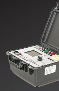
GET 3 TEST SETS FOR THE PRICE OF 1 WITH THE NEW VITS6 0 M
THE VITS6 0 M PERFORMS HIGH-POTENTIAL (HIPOT) TESTS FOR VACUUM INTERRUPTER TESTING UP TO 6 0 KV, AS WELL AS RESISTANCE, POLARITY INDEX, AND ABSORPTION RATIO TESTS.
Unlike other DC HiPot test sets on the market, the VITS60M not only performs specialized go/no-go tests on vacuum interrupters at up to 60 kV DC but also includes a 2.5/5/10 kV megohmmeter for Resistance, Polarity Index, and Absorption Ratio testing. Get 3 test sets for the price of 1 with the VITS60M.
This simple-to-operate set walks technicians through setup, generating a visual go/no-go result for testing the dielectric strength of various vacuum breaker components during regular maintenance, while offering fully programmable leakage current thresholds and test durations.
FEATURES AND BENEFITS
• Safety features with auto discharging, interlock, and safety control button
• Integrity test, Insulation Resistance test, Absorption test, and Polarity test all in one — lower price, more functions
INTERESTED IN A DEMO?
• Operates in 1 kV DC increments instead of 5 kV DC
• Easy-to-use, programmable set walks technicians through setup, tests, and results
• Failure indicator LED makes it easy to interpret results (green light: pass; red light: fail)
Let us bring our equipment to your facility for an on-site demonstration. Contact us at info@vacuuminterruptersinc.com or (214) 442-5877.


Distance is Safety (877)-4-SAFETY RRS-2 RRS-3 AKD-6 RRS-3 DHP/DVP (S) RRS-1
6/29/18
3:46 PM
vacuuminterruptertesting.com | info@vacuuminterruptersinc.com
VI_Ad_NETA_HP_June2018_6_20_final.indd 1 6/20/18 11:51 AM


James (Jim) R. White, Vice President of Training Services, has worked for Shermco Industries Inc. since 2001. He is a NFPA Certified Electrical Safety Compliance Professional and a NETA Level 4 Senior Technician. Jim is NETA’s principal member on NFPA Technical Committee NFPA 70E®, Standard for Electrical Safety in the Workplace®, NETA’s principal representative on National Electrical Code® Code-Making Panel (CMP) 13, and represents NETA on ASTM International Technical Committee F18, Electrical Protective Equipment for Workers Jim is Shermco Industries’ principal member on NFPA Technical Committee for NFPA 70B, Recommended Practice for Electrical Equipment Maintenance and represents AWEA on the ANSI/ISEA Standard 203 Secondary Single-Use Flame Resistant Protective Clothing for Use Over Primary Flame Resistant Protective Clothing. An IEEE Senior Member, Jim received the IEEE/IAS/PCIC Electrical Safety Excellence Award in 2011 and NETA’s Outstanding Achievement Award in 2013. Jim was Chairman of the IEEE Electrical Safety Workshop in 2008 and is currently Vice-Chair for the IEEE IAS/ PCIC Safety Subcommittee.


124
NATIONAL ELECTRICAL CODE
BY JAMES R. WHITE, Shermco Industries


This issue of NETA World Journal highlights testing required by the National Electrical Code. Even though the NEC is an installation standard, safety would be an issue if various types of equipment were not tested to ensure they are functional and within the manufacturer’s specifications when installed. Therefore, the NEC is also considered a safety standard: It considers what makes equipment safe, not only at installation, but also during maintenance. If equipment doesn’t work for some period of time after installation, it isn’t safe.
1. When was the NEC first written?
a. 1910
b. 1897
c. 1886
d. 1922
2. Where was the first NEC published?
a. Washington, DC
b. Philadelphia, Pennsylvania
c. Atlanta, Georgia
d. New York, New York
3. Legally required standby systems (typically generators) require maintenance testing.
Which article covers that topic?
a. Article 240.1
b. Article 520.4
c. Article 695.1
d. Article 701.3
4. Article 695 also contains requirements for testing and maintenance. Which equipment does Article 695 cover?
a. Photovoltaic electric power systems
b. Wind energy systems
c. Fuel cell systems
d. Fire pumps
5. Another article requiring testing and maintenance is Article 700. What does Article 700 cover?
a. Optional standby systems
b. Energy storage Systems
c. Emergency systems
d. Stand-alone systems
20 • WINTER 2018 TECH QUIZ
TECH QUIZ
No.
See
111.
answers on page

Absolute con dence. Every time.
You can count on us for specialized experience in healthcare, data center, o ce complex, and commercial acceptance and maintenance testing. Absolutely Power generation, petrochemical, oil & gas, and heavy industries also look to us for high demand services such as start-up commissioning, maintenance testing, shut-down and turnarounds, and breaker shop repair. Get started today.


Toll Free 1+ (855)767-4446 8100 West Little York | Houston, Texas 77040 Email: Alan Postiglione | apost@absolutetesting.com | www.absolutetesting.com Like us on:



PPE REQUIREMENTS FOR INSTALLATION OF TEMPORARY PROTECTIVE GROUNDS



 BY PAUL CHAMBERLAIN and SCOTT BLIZARD, American Electrical Testing Co., LLC
The purpose of temporary protective grounds is to protect personnel servicing the equipment and to create a safe work environment. Prior to servicing a piece of electrical equipment, it is important to ensure the equipment is in a safe state and to verify zero voltage before applying temporary protective grounds. In many situations, more than one set of grounds or grounding apparatus must be applied. When identifying the placement of temporary protective grounds, ensure all work will be performed within the zone of protection.
For proper placement and sizing of temporary protective grounds and grounding apparatus, refer to OSHA 29 CFR 1910.269, Electric Power Generation, Transmission, and Distribution, which states under paragraph (n):
Grounding for the protection of employees: Grounding must be utilized as a means of protecting employees on deenergized lines.
The standard also states:
For any employee to work transmission and distribution lines or equipment as deenergized, the
employer shall ensure that the lines or equipment are deenergized under the provisions of paragraph (m) of this section and shall ensure proper grounding of the lines or equipment as specified in paragraphs (n)(3) through (n)(8) of this section. However, if the employer can demonstrate that installation of a ground is impracticable or that the conditions resulting from the installation of a ground would present greater hazards to employees than working without grounds, the lines and equipment may be treated as deenergized provided that the employer establishes that all of the following conditions apply:
22 • WINTER 2018 PPE REQUIREMENTS FOR INSTALLATION OF TEMPORARY PROTECTIVE GROUNDS
SAFETY CORNER

1. The employer ensures that the lines and equipment are deenergized under the provisions of paragraph (m) of this section.
2. There is no possibility of contact with another energized source.
3. The hazard of induced voltage is not present.
1910.269 then states under (n)(4):
Protective grounding equipment shall be capable of conducting the maximum fault current that could flow at the point of grounding for the time necessary to clear the fault.
Protective grounding equipment shall have an ampacity greater than or equal to that of No. 2 AWG copper.
Protective grounds shall have an impedance low enough so that they do not delay the operation of protective devices in case of accidental energizing of the lines or equipment.
PPE REQUIREMENTS
Which PPE level is required when installing temporary protective grounds? Any work on or near exposed energized equipment that encroaches within the restricted approach boundary or the arc protection boundary requires some form of additional personal protection. The level of protection required depends upon the incident energy level and proximity to the circuit. NFPA 70E, Standard for Electrical Safety in the Workplace should be referenced prior to beginning the grounding operation at any commercial location. Additionally, if supplied, reference the arc flash analysis of the equipment to be grounded. In power generation, transmission, and distribution facilities, reference CFR 1910.269.
For example, assume the facility is a commercial operation that does not have an analysis or that we are double-checking the analysis provided.
The first step is to determine the required PPE by using Table 130.5(C) Estimate of the

Likelihood of Occurrence of an Arc Flash Incident for ac and dc Systems. Next, refer to Table 130.7(C)(15)(a), Table 130.7(C)(15) (b), and Table 130.7(C)(15)(c), which describe equipment voltage classes. Notice the notes at the end of the tables, as they may affect the PPE required to perform the task.
Reference the same tables before applying protective grounds onto a circuit comprised of the same equipment and within the same voltage range.
It is important to note that the table terminology in NFPA 70E has coincided with OSHA 1910.269 since the .269 rewrite in 2009. The table states that the grounds are “temporary protective grounds” and that they are applied “after voltage test.” This means that even in the presence of zero voltage, the application of grounds must be done when wearing arc flash PPE at the appropriate level for the hazard and incident energy level, with rubber insulating gloves as a means of protecting personnel. Table 1 shows the PPE required for Hazard Risk Category 4.
Table 1: Arc Flash PPE Category 4
Arc-rated clothing selected so that the system arc rating meets the required minimum arc rating of 40cal/cm2 (167.5 J/cm2)a
AN: As needed (optional)
AR: As required
SR: Selection required
· Arc-rated long-sleeve shirt (AR)
· Arc-rated pants (AR)
· Arc-rated coverall (AR)
· Arc-rated arc flash suit jacket (AR)
· Arc-rated arc flash suit pants (AR)
· Arc-rated arc flash suit hood
· Arc-rated gloves
· Arc-rated jacket, parka, rainwear, or hardhat liner (AN)
Protective Equipment
· Hard hat
· Safety glasses or safety goggles (SR)
· Hearing protection (ear canal inserts)
· Leather footwear
Application of the clamp to the grounded side can be achieved without using the full level of PPE unless work will encroach within the approach distance of some piece of equipment. Clamping the ground to equipment that has
NETAWorld • 23 PPE REQUIREMENTS FOR INSTALLATION OF TEMPORARY PROTECTIVE GROUNDS
SAFETY CORNER
SAFETY CORNER

been removed from service and de-energized should be accomplished using a shotgun stick while wearing the required and indicated PPE for the task and incident energy level. The notes in the PPE table indicate:

If rubber insulating gloves with leather protectors are used, additional leather or arc-rated gloves are not required. The combination of rubber insulating gloves with leather protectors satisfies the arc flash protection requirement.
Because of this, it is advisable to wear rubber insulating gloves and protectors.
RECOMMENDED PRACTICES
The following valuable steps should be taken prior to commencing work:
1. Get familiar with the equipment being serviced.
2. Check drawings and one-lines.
3. Walk the site to identify any physical hazards.
4. Check the equipment for a recent arc flash hazard analysis.
5. Write a switching and tagging order or use the lock out/tag out procedure specific to the equipment.
6. Write a job hazard analysis and/or prejob briefing, identifying all site- and task-specific hazards.
7. Discuss the pre-job brief with coworkers to see if they have any insight into past successes or failures in completing similar tasks.
8. Put on the required level of PPE after verifying that the task has a known or calculated hazard/risk category. Ensure that no additional PPE is necessary when applying protective grounds.
9. De-energize equipment.
10. Verify that the voltage testing device is functional against a known source.
11. Verify zero voltage and have someone double-check it.
12. Re-verify that the test device is functional against a known source.
13. Apply the grounding side of the clamp and ensure that it is No. 2 AWG or larger ground cable.
14. Apply grounds to the equipment using a reach or remote method such as a shotgun.
15. Remove the PPE when the task is complete.
CONCLUSION
Refer to industry standards such as NFPA or OSHA as necessary and wear the required PPE when installing temporary protective grounds. Be safe — and when in doubt, always err on the side of caution.
REFERENCES
OSHA Standards for General Industry, 29 CFR Part 1910.269, Electric Power Generation, Transmission, and Distribution.
NFPA 70E, Standard for Electrical Safety in the Workplace, 2018 Edition.
Paul Chamberlain has been the Safety Manager for American Electrical Testing Co., LLC since 2009. He has been in the safety field for the past 20 years, working for various companies and in various industries. Paul holds a BS in environmental health and safety from Massachusetts Maritime Academy.

Scott Blizard is the current Vice President — Chief Operations Officer and former head of safety for American Electrical Testing Co., LLC. Scott is a Master Electrician and a NETA Level 4 Test Technician with over 30 years of experience in the electrical industry.
24 • WINTER 2018
PPE REQUIREMENTS FOR INSTALLATION OF TEMPORARY PROTECTIVE GROUNDS


The Power of Positive Results


AET delivers the best value in the marketplace by offering the highest quality service at competitive prices. With a workforce and offices located throughout the country, AET is an industry leader and one of the largest independent electrical testing companies in the U.S.
To learn more about AET’s full range of testing and engineering services, visit www.aetco.us

AET Brings Precision and Value to Electrical Testing, Commissioning and Engineering… and Positive Results to Our Customers.
WWW.AETCO.US •
800.992.3826
An Company A Subsidiary of


When equipment fails, every minute spent searching for what you need is bad for the bottom line. With a constantly updated inventory of new, surplus and repurposed electrical equipment, you can get what you need 24/7. Use our easy checkout process, or if you need help our experts are standing by.
Visit nationalswitchgear.com or call us today at (800) 322-0149.



Legendary Customer Service
We are there when and where you need us
Multiple Offices


Located throughout the country yields dramatically lower shipping costs
Local Inventory
Better shipping rates and great application support from the Protec team


National Headquarters 1517 West Carrier Pkwy Suite 116 Grand Prairie, TX 75050 (866) 352-5550

Protec West 924 Greg St Sparks, NV 89431 (775) 984-5223
Protec South 7102 Brookside Rd Suite 102 Pearland, TX 77581 (832) 251-7047


Protec Midwest 1501 Wright Blvd Schaumburg, IL 60193 (847) 434-5808
Protec East 200 Gates Rd Suite E Little Ferry, NJ 07643 (201) 450-9743

Protec Southeast 105 Village Walk Suite 185 Dallas, GA 30132 (972) 352-5550


CAN’T AFFORD TO WAIT FOR ELECTRICAL EQUIPMENT? performance by design sm
Visit us at PowerTest Booth 133 protecequip.com The Electrical Test Equipment Rental Experts






800.331.2002 | PotomacTesting.com POWER THROUGH WITH CONFIDENCE MAKE A REAL POWER MOVE... PARTNER WITH MID-ATLANTIC’S PREMIER PROVIDER OF ELECTRICAL TESTING, ENGINEERING AND FIELD SERVICES. Since 1985


SETTING OVERCURRENT PROTECTION FOR COLLECTION FEEDERS AT
 BY STEVE TURNER, Electrical Consultants, Inc.
This article provides practical advice for setting phase overcurrent elements that protect collection feeders at a wind farm. The first example demonstrates how to use directionality for phase overcurrent elements to make them more secure and reliable. The second example shows how to enable special phase overcurrent elements when conducting maintenance to better protect for arc flash.
PHASE DIRECTIONAL OVERCURRENT PROTECTION
Figure 1 illustrates a single-line diagram for a collector feeder at a typical wind farm.
Th e power generated by the wind turbine fl ows through the collector circuit to the transmission system on the high side of the step-up transformer. Therefore, the phase time overcurrent element 51P sees the power as import (i.e., reverse flow); however, it should only trip for faults in the forward direction
anywhere along the collector circuit. 51P provides protection for three-phase faults on the collection circuit up to the bushings on the high side of the WTG step-up transformer and is typically set below maximum power flow from the wind turbine generator.
Figure 2 illustrates the impedance measured by the feeder relay when the wind turbine generator is exporting power. Note that the origin is located with respect to the collector breaker where 51P resides. For example, export is power flowing to the wind turbine
28 • WINTER 2018 SETTING OVERCURRENT PROTECTION FOR COLLECTION FEEDERS AT WIND FARMS
RELAY COLUMN
RELAY COLUMN
Turbine Generator (WTG) Power Flow Direction (Import wrt 51P)
generator with respect to 51P, which is typically not the case.
A common feature for numerical feeder relays is a load encroachment function that calculates the positive-sequence impedance measured by the relay. Load is typically quite symmetrical, so apparent positive-sequence impedance is a good measure of the load. Use the load encroachment function to detect when power is normally flowing from the wind turbine generator to the transmission system to block 51P. The load encroachment function allows the phase overcurrent elements to be set securely beneath maximum power flow for greater sensitivity. The hatched region in Figure 2 represents the measured positive-sequence impedance when power is flowing from the wind turbine generator to the transmission system. Block 51P whenever the measured positive-sequence impedance resides within the hatched area.
The maximum torque angle (MTA) shown in Figure 2 is for the positive-sequence voltage polarized directional element. 51P should only operate and trip when the fault is in the forward direction on the collector circuit.
Figure 3 illustrates simplified logic to directionally supervise 51P. Note that the overcurrent element should be torque controlled, i.e., the overcurrent element does not start timing unless the fault is in the
(Import)
Forward-Trip (Operating
Reverse (Blocking Region) X (Export) (Import) X
forward region and the measured positivesequence impedance is not in the hatched area (Zload) shown in Figure 2. The forward decision from the positive-sequence voltage polarized directional element is 32F.
Maximum Torque Angle (MTA)

(Export)

NETAWorld • 29 SETTING OVERCURRENT PROTECTION FOR COLLECTION FEEDERS AT WIND FARMS
51P Step-Up Transformer Collector Circuit WTG
Wind
34.5 kV 230 kV
Figure 1: Collector Circuit Single-Line Diagram
Step-Up Transformer
Point of Interconnect (PoI)
Figure 2: 51P Directional Characteristic
Region)
R
32F 32R
R
Z
Figure 3: 51P Directional Supervision
51P 32F & &
load

RELAY COLUMN
FEEDER 5
0.00638 + 0.01027i 3303 feet
0.01274 + 0.02049i 6593 feet := Z11
0.05718 + 0.01782i 4419 feet := Z21

0.00988 + 0.0159i 5114 feet := Z31
0.00469 + 0.0066i 2068 feet := Z41
0.02596 + 0.02966i 8827 feet := Z51
0.02402 + 0.02017i 5717 feet := Z61
0.00589 + 0.00495i 1403 feet := Z71
0.01248 + 0.00515i 1303 feet := Z81
0.05327 + 0.01186i 2664 feet := Z91
Figure 5: Collection Feeder Impedance Calculations
Figure 4 shows a collection feeder modeled in a commercial short circuit program.
Figure 5 shows the calculations to determine the total positive-sequence feeder impedance. Z01 is the impedance from the bus to the first node (JB5-1), Z11 is the impedance from the first node to the second node (JB5-3), and so on to the end of the feeder at node C17.
The angle of the feeder impedance is approximately 34 degrees. A setting of 45 degrees for the positive-sequence voltage polarized directional element MTA provides excellent sensitivity for three-phase faults located in the trip region shown in Figure 2 and is also secure in regards to wind turbine reactive power consumption.
MAINTENANCE MODE OVERCURRENT PROTECTION
An arc flash is a type of electrical explosion that results from a low impedance connection to ground and/or between phases. It can expel large amounts of deadly energy. The arc causes air to ionize and arc flash temperatures can reach as high as 35,000 degrees Fahrenheit. Enabling an instantaneous phase overcurrent element 50P whenever maintenance is being performed helps protect against any arc flash. The pickup setting must be determined by performing an arc flash study.
30 • WINTER 2018
SETTING OVERCURRENT PROTECTION FOR COLLECTION FEEDERS AT WIND FARMS
Figure 4: Collection Feeder Short Circuit Model
JB5-1 34.5kV JB5-2 34.5kV JB5-3 34.5kV SC3-3 34.5kV D10 34.5kV C12 34.5kV C14 34.5kV C15 34.5kV C16 34.5kV C17 34.5kV D09 34.5kV D09 0.69kV D10 0.69kV C12 0.69kV C14 0.69kV C15 0.69kV C16 0.69kV C17 0.69kV
100MW 11.902Ω
Zbase_35kV (34.5kV)2
VTR 300 := := Zbase Z01
:= Z1 Z01 Z11 Z21 + + + + + + + + + Z31 Z41 Z51 Z61 Z71 Z81 Z91 _35kV = := CTR 240 := ·Zbase ·Re = 2.023Ω ( )Z1 _35kV CTR VTR ·Zbase ·Im = 1.36Ω = 33.915 degrees ( )Z1 ·arg( )Z1 _35kV CTR VTR 180 3.1416
You can enable 50P via torque control, such as asserting a relay opto-isolated input via a control switch mounted on the same panel, or remotely send a control bit via SCADA. If 50P is sensitive enough to operate for a reverse fault, then use the load encroachment function to block it as well.
CONCLUSION
This article provides practical advice for setting phase overcurrent elements that protect collection feeders at a wind farm. The first example demonstrates how to use directionality for phase overcurrent elements to make them more secure and reliable. The second example shows how to enable special phase overcurrent elements when maintenance is being conducted to better protect for arc flash.
REFERENCES
McDaniel, Ryan. “Phase Directional Overcurrent Settings Recommendations for Wind Farm Applications Using the SEL351S,” Application Guide, Volume III, 2015.

Steve Turner is a Senior Engineer II at Electrical Consultants, Inc., working in their San Diego office. Steve worked at Beckwith Electric Company, Inc. for 10 years, first as the Engineering Laboratory Director and then as Senior Applications Engineer. His previous experience includes working as an Application Engineer with GEC Alstom and as an Application Engineer in the international market for SEL focusing on transmission line protection applications. While at Duke Energy (formerly Progress Energy), Steve developed the first patent for double-ended fault location on overhead high-voltage transmission lines and was in charge of all maintenance standards in the transmission department for protective relaying. Steve has a BSEE and MSEE from Virginia Tech University.


RELAY COLUMN ers.VertivCo.com • 877-468-6384 Plug Into Our Expertise
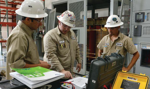


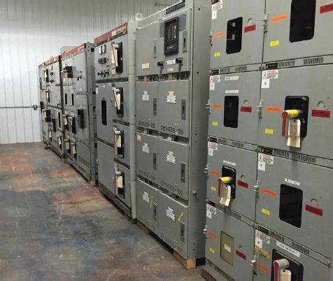


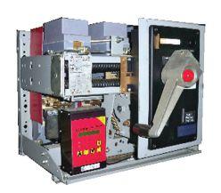
CAN’T AFFORD TO GAMBLE ON YOUR ELECTRICAL RELIABILITY? We
we have
Tap into the power of National Field Services at natlfield.com or call us today at (800) 300-0157. performance by design sm BULLOCK BREAKERS B B 475 Annandale Blvd • Annandale • Minnesota 55302 www.bullockbreakers.com • Email: jason@bullockbreakers.com • Thousands of Air Circuit Breakers in Stock! • Switchgear Line-ups you can’t find anywhere else! • Now Available as Reconditioned with AC-Pro Trip Units! 1-763-269-2832 C M Y CM MY CY CMY K
have you covered. We understand that the most important electrical testing takes place before your system is powered on. And now that National Field Services has acquired two new locations in Las Vegas and Reno,
the ability to offer even more customers start-up and maintenance services throughout the lifecycle of their switchgear.

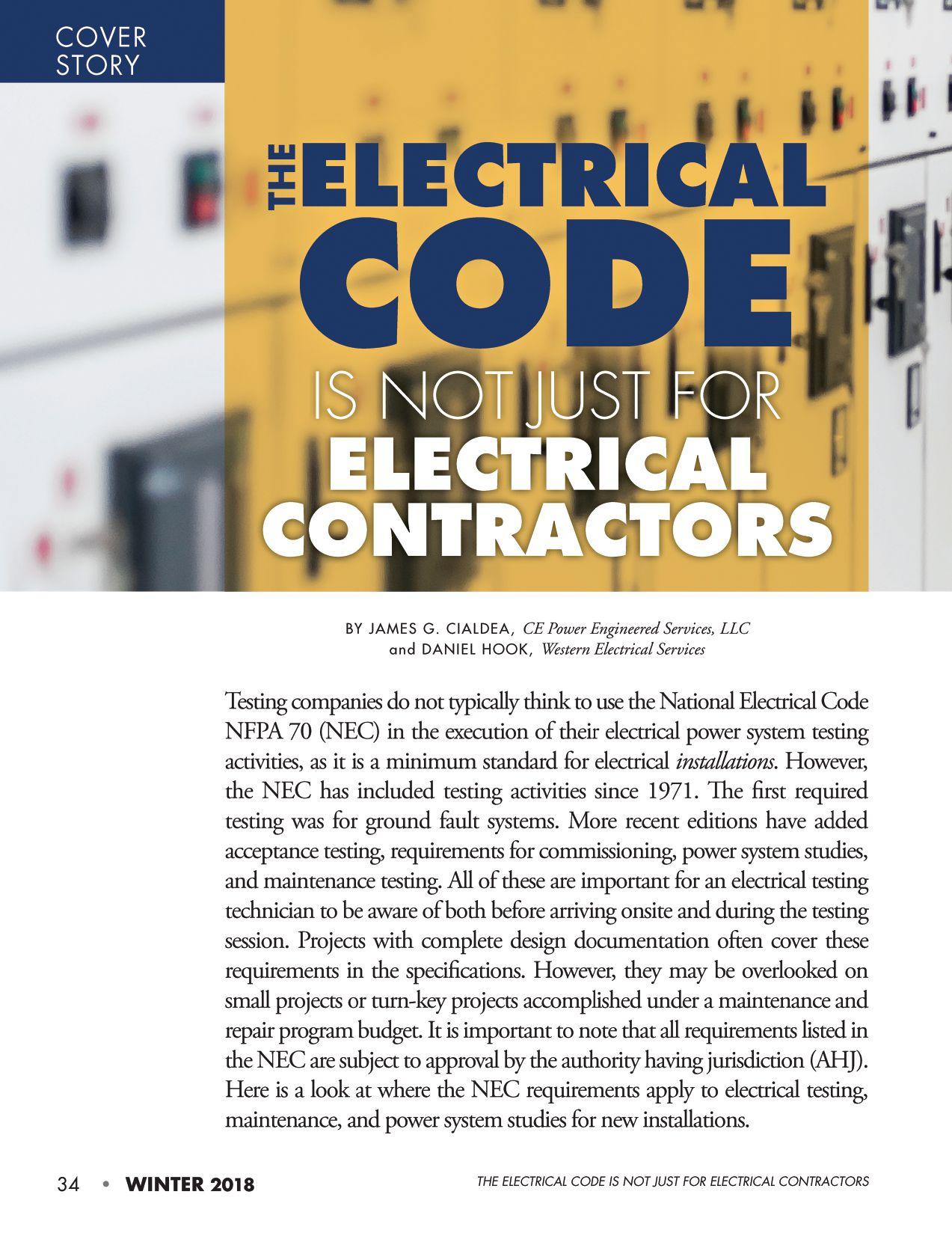

100.16 Arc Flash Hazard Warning . This article states that warning labels must be applied to electrical equipment that is likely to be worked on while energized to warn workers of the potential arc flash hazard. If this required labeling is not present, that needs to be noted during acceptance testing of equipment.
110.21(A)(2) Reconditioned Equipment.
This new sub-article in the 2017 edition under 110.21 Equipment Markings will prove useful to technicians in the field. Technicians often encounter service-aged equipment that is no longer supported by the manufacturer. Until the 2017 edition of the NEC, reconditioned equipment was a gray area and was not dealt with consistently throughout the industry. The NEC now officially recognizes reconditioned equipment and outlines requirements for labeling such equipment. Reconditioned equipment must be marked with the name, trademark, or other descriptive marking identifying the organization responsible for reconditioning the electrical equipment, along with the date of the reconditioning. The
equipment must be identified as reconditioned, and the approval of the equipment cannot be based solely on the equipment’s original listing. This new article can provide a recognized solution to equipment shortages encountered in the field. The Professional Electrical Apparatus Reconditioning League (PEARL) publishes an industry standard covering the reconditioning of electrical equipment, and this standard was recently approved by the American National Standards Institute (ANSI).
110.41 Inspections and Tests. This is a new section in the 2017 edition that requires Preenergization and Operating Tests and a Test Report. It requires acceptance testing and a report “where required elsewhere in this Code…” This section is a general requirement that applies to all references to testing throughout the NEC and states that, when specifically required in the code, the complete electrical system design, including settings for protective, switching, and control circuits, shall be prepared in advance and made available on request to the AHJ, and shall be tested when
NETAWorld • 35 THE ELECTRICAL CODE IS NOT JUST FOR ELECTRICAL CONTRACTORS
COVER STORY
first installed on-site. It also requires that the test report covering the results be available to the AHJ prior to energization and be made available to those authorized to install, operate, test, and maintain the system.

225.56 Inspections and Tests. 225.56 is in Part III Over 1000 Volts under Article 225 Outside Branch Circuits and Feeders. Th is section specifi es Pre-energization and Operating Tests for Instrument Transformers, Protective Relays, Switching Circuits, Control and Signal Circuits, Metering Circuits, Acceptance Tests, and a Test Report. Th e section includes an Informational Note (IN) that references ANSI/NETA ATS. The requirements here are for complete acceptance testing of equipment over 1000V including in-service checks. NETA’s Standards Review Council Chairman Al Peterson was instrumental in getting this requirement into the 2011 NEC. This article specifi cally requires comprehensive testing. Th ese installations must meet the requirements of Article 110.41 and shall therefore be performance tested when fi rst installed on-site. Each protective, switching, and control circuit shall be adjusted in accordance with the system design and tested by actual operation using current injection or equivalent methods to ensure that each and every such circuit operates correctly to the satisfaction of the AHJ. The timing of testing and documentation is clearly stated in this article’s requirements. Complete acceptance tests shall be performed, after the substation installation is completed, on all assemblies, equipment, conductors, and control and protective systems to verify the integrity of all the systems. All relays and metering that use phase diff erences for operation shall be verified by measuring phase angles at the relay under actual load conditions after operation commences. A test report covering the results of the required tests shall be delivered to the AHJ prior to energization.
230.95 Ground-Fault Protection of Equipment. Article 230.95(C) Performance Testing. Th e fi rst required testing added

to the NEC in the 1971 edition, this is the most widely known article to electrical testing technicians. Th e requirement was added to ensure that ground fault protection (GFP) systems are correctly installed and operate as intended. Th e section specifi ed that testing be conducted “in accordance with instructions that shall be provided with the equipment. ” Unfortunately, most people do not read the instructions and think that pushing the Test button meets this requirement. Instructions require primary injection of current at the CT(s) for correct testing of the GFP system. Th is has not consistently been done nor universally understood. Recognizing this industry problem, Rod Hageman and Ron Widup, both members of NETA’s Standards Review Council, submitted a proposal for the 2014 NEC to modify the language to include “by primary injection” in the section. This change was accepted for the 2017 NEC. In addition, the term “ …by a qualified person(s)… ” was added by Code Making Panel (CMP) 4. These changes make it clear that pushing the Test button does not meet the intended requirements of testing a GFP system. In order for the GFP system to operate properly, the entire grounding system has to be installed correctly — not just the GFP relay. To meet the intent of the Code involves testing the entire GFP system: neutral/ground current transformer wiring, reduced control voltage tests, zone interlock components, proper installation, polarity of sensing CTs, etc. See NETA ATS-2017 7.14. The written test record must be made available to the AHJ.
240.67 Arc Energy Reduction. 240.67 states that fuses rated 1200A or greater must have a clearing time of 0.07 seconds or less at the available arcing current or one of the following alternative arc energy reduction methods must be employed:
• Differential relaying
• Energy-reducing maintenance switch with local status indicator
• Energy-reducing active arc-flash mitigation system
36 • WINTER 2018
THE ELECTRICAL CODE IS NOT JUST FOR ELECTRICAL CONTRACTORS COVER STORY
This requirement is not effective until 2020. Scott Blizard, a member of the NETA Board of Directors, has put in a proposal to require performance testing of the alternative methods for the 2020 edition.
240.87 Arc Energy Reduction. This article is similar to 240.67 except it applies to circuit breakers 1200A and larger and states that one of the following means shall be provided to reduce arc energy:
• Zone-selective interlocking
• Differential relaying
• Energy-reducing maintenance switching with local status indicator
• Energy-reducing active arc-flash mitigation system
• An instantaneous trip setting that is less than the available arcing current
• An instantaneous override that is less than the available arcing current
• An approved equivalent means
Informational Notes reference NFPA 70E and IEEE Std. 1584, Guide for Performing Arc Flash Calculations. Scott has also put forth a proposal to require performance testing of these methods.
328.14 Installation. This section covers another common testing routine that technicians are often called upon to perform. It requires Type MV cable to be “…tested by qualified persons .” Th e IN references IEEE St.d 576-2000, which describes dc testing and references the IEEE 400 series of standards for cable testing that are in development. The IEEE 576 reference is from 2000; the IEEE 400 series is now mostly complete. The IEEE 400 series covers Very-Low-Frequency (VLF) Withstand, VLF Tan Delta, Partial Discharge (PD), and other testing and methods for Shielded Power Cable Systems.
517.17 Ground-Fault Protection. This section of the Health Care Facilities article covers one aspect of ground fault protection system testing that may not be well known.

When there are multiple levels of protection in a health care facility, each level of ground fault protection must be tested. Multi-level ground fault protection systems could consist of simple, separate ground fault protection systems or more complex schemes. Zone selective interlocking can be employed, which will require testing of each level of protection separately, as well as proving how the system reacts in situations this protection scheme is designed for. This requirement extends the requirement of testing the GFP on the main breaker in 230.95(C) to every level in the system.
700 Emergency Systems, 701 Legally Required Standby Systems, and 708 Critical Operations Power Systems. These articles all require Tests (or Testing) and Maintenance.
• 700.3 Tests and Maintenance, 701.3 Tests and Maintenance, and 708.6 Testing and Maintenance. These sections require Witness Test, Tests Periodically, Maintenance, Written Record, and Testing Under Load. An IN in each of these articles references NFPA 110, Standard for Emergency and Standby Power Systems. The maintenance requirement was added to 700.3 and 701.3 in the 2017 edition, copied from 708.6. An additional IN in 708.6 references NFPA 70B, Recommended Practice for Electrical Equipment Maintenance.
• 701.3 covers legally required standby systems and goes a bit further in its requirements. Not only does this article require that the AHJ conduct or witness a test of the complete system after installation, but periodically as well. This is to ensure the systems are maintained in proper operating condition. A maintenance program must be implemented, including documentation of testing and maintenance results, in accordance with manufacturer’s instructions and industry standards. Finally, this article requires that a means for testing the system under load be provided.
NETAWorld • 37 THE ELECTRICAL CODE IS NOT JUST FOR ELECTRICAL CONTRACTORS
COVER STORY
Now we know why there are load banks installed on these systems in some cases, or at least provisions for connecting a temporary one.

• 708.6 covers critical operations power systems (COPS). Critical operations power systems, as defined by the NEC, are those systems classified as such by the AHJ or by facility engineering documentation establishing the necessity for such a system. These systems include, but are not limited to: power systems, HVAC, fire alarm, security, communications, and signaling for designated critical operations areas. This classification is often given to power systems when, if they were to become incapacitated for any reason, would threaten the economy, public health and safety, or national security. The requirements for these designated systems are very similar to the legally required standby systems above, with a little different language as it applies to testing under load and a clear requirement for system commissioning. Testing for all critical power systems is required during maximum anticipated load conditions.
• 708.8 Commissioning. This section in the Critical Operations Power Systems (COPS) article is a requirement for complete commissioning to include development and documentation of a Commissioning Plan, Component and System Tests, Baseline Test Results, and Functional Performance Tests. The NEC defines Commissioning in 708.2 as “… acceptance testing, integrated system tests, operational tune-up, and start-up testing…” It differentiates between component testing and system testing — while requiring both — to ensure the system will function properly. The baseline component test results and functional performance test program must be obtained and are required to be documented, so comparison with maintenance and functional performance

testing in the future can be performed. The IN directs you to Informative Annex F Availability and Reliability for Critical Operations Power Systems and Development and Implementation of Functional Performance Tests (FPTs) for Critical Operations Power Systems. For additional information, see ANSI/ NETA ECS-2015, Standard for Electrical Commissioning Specifications for Electrical Power Equipment and Systems, which is a great reference.
• 708.52 Ground-Fault Protection of Equipment. This section is the same as 517.17 as it requires GFP testing at “ each level…,” not just at the main breaker for COPS.
CONCLUSION
Any jurisdiction that has adopted the NEC (some states are on different editions — not necessarily the latest — so check your local jurisdiction) has requirements for the installing electrical contractor (EC). NETA Accredited Companies need to understand these requirements and work with ECs to make sure they understand the requirements, too. A NETA Certified Technician certainly meets the requirements of a “qualified person” to perform these tests.
The requirements in the NEC have been added over the years primarily due to failures that have caused equipment damage and injuries to personnel. There are many opportunities for acceptance testing, commissioning, and even maintenance on systems. Awareness and understanding of the NEC requirements by testing companies, electrical test technicians, ECs, engineers, the authority having jurisdiction (AHJ), and end users are the only way these requirements will be properly met. NETA continues to work to provide information and education to its members and the industry on these important requirements in the NEC.
38 • WINTER 2018 THE ELECTRICAL CODE IS NOT JUST FOR ELECTRICAL CONTRACTORS
COVER STORY


James G. Cialdea, PE, is the Chief Technical Officer for CE Power Engineered Services, LLC. He has served on the Massachusetts Electrical Code Advisor y Committee since 1999, has represented NETA as a member of NFPA Code Making Panel 4 since 2011, was appointed to NETA’s Standards Review Council in 2015, is active in the IEEE Power and Energy Society, and is currently NETA’s President. He is a licensed Master Electrician, a registered Professional Engineer, and a NETA Certified Senior Technician. Jim has worked in the electrical testing industry for over 35 years as test technician, engineer, and President of 3C Electrical Co., Inc. (a CE Power company since 2016). Jim holds a BS in electric power engineering from Worcester Polytechnic Institute.

Dan Hook, PE, is the President of Western Electrical Services, where he previously held Field Service Engineer, Sales Engineer, COO, and Vice President positions. Dan focuses on the strategic growth of each production division, as well as trade association affiliations, and corporate-level sales efforts. He is a Level IV NETA and NICET Technician and serves on the board of directors for both NETA and PEARL. Dan holds an MS in electric power engineering from Rensselaer Polytechnic Institute and an MBA from Pacific Lutheran University with a concentration in entrepreneurship and closely held businesses. He maintains his Professional Engineer’s license in Washington, Oregon, Utah, and Arizona.


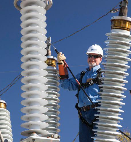


COVER STORY


onster Electrical is introducing a new look for our company, but we're still the Monster you depend on. When you need new and surplus fuses and 5kV starter control parts, whether it's a middle-of-the-night emergency or in the regular course of business, we're right here to get it to you—tested and ready to install.

NEW LOOK, SAME MONSTER
YOU KNOW OUR FUSES, GET TO KNOW OUR 5KV CONTROLS. M monsterelectrical.com Far From Work, But Close to Data PQ Analyzers with Remote Wireless Communications 732.287.3680 1000 New Durham Road Edison, New Jersey 08817 Control your Dranetz HDPQ from your smartphone, tablet, or computer! sales@dranetz.com www.dranetz.com ® ® Dranetz HDPQ Xplorer SP Dranetz HDPQ Xplorer


THE PREMIER ELECTRICAL MAINTENANCE AND SAFETY CONFERENCE SAVE THE DATE FEBRUARY 24 - 28, 2020 Hyatt Regency Chicago • Chicago, Illinois • PowerTest.org l 888.300.6382 Hosted by


TESTING AND MAINTENANCE OF CRITICAL ELECTRICAL SYSTEMS
 BY WILLIAM OTTERSON, Shermco Industries


The National Electrical Code (NEC) requires systems that supply emergency, critical operations, and legally required standby power to be maintained in accordance with manufacturer’s instructions or industry consensus standards. A written record documenting these activities is also required. While the NEC requires these maintenance and record-keeping activities, it is silent as to how the equipment owner should accomplish them. Instead, the Code points the user to other NFPA standards for information on how to properly maintain these systems and for examples of how to document that the required testing has been completed. While the equipment owner may use any maintenance and testing regimen to satisfy NEC requirements, a best practice is to always follow a recognized consensus standard.


42 • WINTER 2018 TESTING AND MAINTENANCE OF CRITICAL ELECTRICAL SYSTEMS
FEATURE


The NEC mostly references other NFPA standards, except that in Article 225 Part III Over 1,000 Volts, the NEC references ANSI/NETA ATS-2013 as an example of acceptance testing specifications. NETA companies use the NETA maintenance or acceptance testing standards in conjunction with or as an alternative to the manufacturer’s recommended practices. Careful maintenance and complete testing of systems that provide emergency power ensure that the equipment will respond when called upon.
This article explores NEC requirements for each of these emergency systems, as well as direction to other standards to find recommended practices for maintenance, testing, and documentation of these activities. It also looks at facilities that use dc battery systems to operate critical loads. The NEC is silent on testing and maintaining these systems, which are commonly found in generation, distribution, and transmission facilities not covered by the NEC. Owners of these sites may fall under North American Electric Reliability Corporation (NERC) regulations that require maintenance and testing.
EMERGENCY SYSTEMS
Article 700 Emergency Systems defines systems legally classified as emergency by municipal, state, federal, or other codes, or by any governmental agency having jurisdiction. These systems automatically supply illumination, power, or both to designated areas and equipment in the event of failure of the normal supply. These systems are generally installed in places where artificial illumination is required for safe exiting by large numbers of people, such as hotels, arenas, and health care facilities. These systems may also provide power for functions like ventilation, fire detection, alarm systems, elevators, and fire pumps where interruption of the normal source would produce serious life-safety or health hazards.
The user will find the requirements for tests and maintenance requirements in Article
700.3, which requires witness testing, periodic testing, maintenance, and finally load testing. The authority having jurisdiction (AHJ) must conduct a witness test upon completion of the emergency-system installation and periodically afterward. NEC 700.3(C) requires maintenance of the system:
Emergency system equipment shall be maintained in accordance with the manufacturer’s instructions and industry standards.
Finally, 700.3 requires a written record of maintenance and testing, as well as a means for testing all emergency lighting and power systems under maximum anticipated load conditions.
That is all the NEC says regarding testing and maintenance of emergency system equipment. An informational note refers the user to NFPA 110-2013, Standard for Emergency and Standby Power Systems. In NFPA 110, emergency systems are further classified as either Level 1 or Level 2 systems. Level 1 systems are installed where failure of the equipment to perform could result in loss of human life or serious injuries. Level 2 systems are used where failure of the emergency system is less critical to human life and safety. This NFPA standard covers all requirements for these systems, but our discussion of the requirements is confined to Chapter 8, Routine Maintenance and Operational Testing.
Chapter 8, General, states:
The routine maintenance and operational testing shall be based on manufacturer’s recommendations, instruction manuals, minimum requirements of Chapter 8, and the AHJ.
Section 8.2.3 requires the owner to establish a routine maintenance and testing program that includes documentation of inspections, tests, exercising, and repairs. NFPA 70B , Recommended Practice for Electrical Equipment Maintenance, Annex H, provides many examples of typical testing and periodicmaintenance forms.

NETAWorld • 43 TESTING AND MAINTENANCE OF CRITICAL ELECTRICAL SYSTEMS
FEATURE


Section 8.4.1 requires all Level 1 and Level 2 systems to be inspected weekly and exercised under load monthly. Compliance to the inspections is easy for most emergency power supply system (EPSS) owners. However, exercising these units under load is exceedingly difficult unless a permanently installed load bank is present. The standard does allow an alternative for diesel-powered systems: They can be exercised for 30 minutes monthly with the available load and then load-banked annually with a supplemental load with increasing loading over a two-hour period. This type of load-bank testing is particularly good for dieselengine generators (Figure 1).
When run for extended periods without load (without reaching peak operating temperatures), engines can load up with unburned fuel and oil. Testing them with an adjustable load bank allows technicians to increase load and temperatures over the twohour period and run the unit at full load for the last portion of the test. By slowly increasing the load over the test period, unburned materials can be burned off by raising the temperature of the unit and sustaining it for an extended period. This extended runtime at peak load will also find any weak parts of the generator, which can then be repaired and returned to peak reliability.

Transfer switches, according to NFPA 110, shall also be tested monthly by electrically initiating a transfer of load. Storage batteries for starting the diesel generator must be visually inspected weekly for electrolyte levels and tested for specific gravity monthly. For medium- and high-voltage systems, circuit breakers must be exercised every six months and electrically tested under simulated overload conditions every two years. For information on the type of testing MV and HV circuit breakers require, owners should consult manufacturer’s recommendations and a consensus standard. ANSI/NETA MTS-2015 is an excellent reference for guidance on how to test these breakers to ensure their proper operation. ( Editor’s note: ANSI/NETA MTS-2019 is scheduled for release in March 2019.)

CRITICAL ASSETS
Article 708 deals with critical operations power systems (COPS). COPS systems require continuous operation for public safety, emergency management, national security, or business continuity. They are classified as COPS by local, state, or federal government agencies or by facility engineering documentation that establishes the necessity for such a system. These systems typically supply power for HVAC, fire alarm, security, communications, and signaling for areas designated as critical.
These systems are meant to provide critical power during natural disasters or humancaused events, both accidental and intentional, and they require a higher level of reliability than the other two types of emergency systems. These systems require the owner to perform and document a risk assessment and develop a mitigation strategy. Part of protecting these systems is a testing and maintenance regimen. The Code requires witness and periodic testing along with a maintenance program with documentation and testing under load conditions. As discussed earlier, the references are the same: Refer to NFPA 70B for recommended maintenance practices and NFPA 110 for testing.
44 • WINTER 2018
TESTING AND MAINTENANCE OF CRITICAL ELECTRICAL SYSTEMS
FEATURE
Figure 1: Emergency System Diesel Generators

Many customers also use dc storage batteries to supply critical emergency power. These systems are commonly found in substations and transmission facilities. They supply emergency power for protection system relays, tripping or reclosing equipment, and supervisory control and data acquisition (SCADA) systems. Because most of these installations are part of the bulk electric system (BES), NERC requires a comprehensive testing and maintenance plan. The maintenance can be either time-based, performance-based, or a combination of the two.
NERC requires asset owners under their purview to perform certain maintenance tasks on the equipment, document the plan, and prove that the required maintenance has been completed. A time-based plan of routine maintenance completed by in-house employees or contractors works well.
• At four months, verify supply voltage, visually inspect electrolyte levels, and check for unintentional grounds.
• At 18-month intervals, test the float voltage and connection resistance, and visually inspect each cell or measure internal resistance values (Figure 2). Verify the physical condition of the battery supporting rack.
• At six-year intervals, perform a load test of the entire battery bank.
Keep in mind that these are the maximum intervals. Many asset owners perform these tasks on a much shorter interval to ensure that the dc system performs as required. ANSI/ NETA-MTS is a guide for performing these required tasks and provides the user with a step-by-step approach to performing the required maintenance.
LEGALLY REQUIRED STANDBY SYSTEMS
NEC Article 701 covers legally required standby systems. Government agencies require these systems to automatically supply power when interruption of the normal source


could create a hazard or hamper fire-fighting operations. The requirements for testing and maintenance in Section 701.3 are the same as previously discussed. The NEC also references the NFPA 110 standard.
CONCLUSION
Owners of critical power supply equipment are required to perform testing and maintenance to ensure the proper operation of the equipment. Where the NEC specifies that these activities are required, it is short on details for the asset owner on how to accomplish this. Learning where to find the information is part of the battle. In the case of BES equipment, NERC is specific about the testing and maintenance plans and required tasks, but the owner must still train its employees or hire qualified contractors to perform the maintenance and testing.

William “Bill” Otterson is a Senior Training Instructor at Shermco Industries. Bill has worked in the electrical industry for more than 30 yeaaurs as a Journeyman Lineman, Journeyman Electrician, Field Engineer, Safety and Training Manager, and in generator sales and service. He is certified by the NFPA as a CESCP and is currently an alternate on NFPA 70 CMP 13.
NETAWorld • 45
TESTING AND MAINTENANCE OF CRITICAL ELECTRICAL SYSTEMS FEATURE
Figure 2: Cell Voltage and Internal Resistance Testing
RENT ELECTRICAL TEST EQUIPMENT



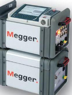


Providing Testing Solutions for:


• Protective Relays
• Transformers & Motor Analysis
• Partial Discharge/Corona
• Current Injection
• Cable Fault Location


• Switchgear/Circuit Breakers
• Insulation Resistance
• Tan Delta/Power Factor
• Current Transformers
• Ground Grid
Advanced Test Equipment Rentals


The Knowledge. The Equipment. The Solution.
800-404-ATEC (2832) • rentals@atecorp.com • www.atecorp.com



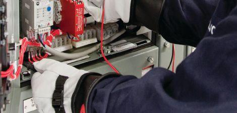



(be_this_guy!) (be_this_guy!) Train with the Experts. Train with Shermco. www.shermco.com 888-SHERMCO WHY Endanger yourself and others?


NETA’S VOICE IN THE NATIONAL ELECTRICAL CODE

 BY JAMES R. WHITE, Shermco Industries
The National Electrical Code (NEC®), first published in 1897, is sponsored by the National Fire Protection Association (NFPA®). The code is developed by NFPA’s Committee on the National Electrical Code, which consists of 19 code-making panels (CMPs) and a technical correlating committee.
Each article and annex in the NEC is designated to one of the 19 technical committees. Each panel consists of a consensus body comprised of committee members who represent diff erent industries aff ected by the code: manufacturers, users, installers/ maintainers, labor, applied research/testing laboratories, enforcing authorities, insurance, consumers, special experts, and others. This balance ensures that modifi cations are not made to benefit just one faction of the industry.
THE CODE-MAKING PROCESS
The NEC is revised every three years using a four-step process.
“Input stage. The first step involves issuing a public notice that the NEC revision process has begun and asking for interested parties to submit proposals for revising the document. The notice is placed in appropriate publications such as the NFPA News, the U.S. Federal Register, and the American National Standards Institute’s Standards Action. This step allows 23 weeks for respondents to submit their proposals. Anyone can submit a proposal to change the NEC provided it contains the required information. After the last date to receive proposals, code panels meet to discuss and vote on each of the proposed changes. All technical committee reports are posted on the NFPA website for public review. Everyone has the opportunity to submit a comment on each of the proposed changes.
48 • WINTER 2018 NETA’S VOICE IN THE NATIONAL ELECTRICAL CODE
FEATURE

“Comment stage. The second step in the process is the comment stage. Public comments are accepted on the first draft for 10 weeks. The appropriate technical committee or code-making panel reviews all comments and formulates the second draft committee report. Any proposal or comment that is not accepted by the committee must contain a written reason for the rejection. New proposals cannot be submitted during this stage of the cycle. The CMP can only take action on proposals that have received adequate public review during the proposal stage.
“NFPA annual meeting. A notice of intent to make a motion (NITNAM) is accepted for five weeks following the posting of the second draft report. After review, validated motions become certified amending motions (CAMs). Certified amending motions are considered and acted on during the annual meeting. The chairman of each code-making panel provides a report on the actions of the committee for approval. Floor actions on certified motions occur during this meeting.
“Appeals and issuance. Any appeal to the Standards Council will be considered, and final rulings will be posted on the NFPA website. The Standards Council has the responsibility for overseeing and issuing all of the codes and standards developed for the NFPA. The NEC Correlating Committee, which works directly under the Standards Council, steers the panels through the process, ensuring that each proposal and comment is processed according to an established operating procedure. Once the process is complete, the Standards Council issues the document for publication.”
CODE MAKING PANEL REPORTS
Some readers might be surprised to learn that NETA is represented on a number of NEC committees:
• CMP 4 James Cialdea, CE Power Engineered Services, LLC
• CMP 10 Scott Blizard, American Electrical Testing Co., LLC
• CMP 11 Ron Widup, Shermco Industries
• CMP 13 James White, Shermco Industries

NETA has selected these code making panels because actions by those committees could have a negative impact on NETA member companies and their technicians if they were not represented when changes are considered.
Th e second draft meetings for the 2020 National Electrical Code Cycle were held October 22–November 3, 2018. Th is issue of NETA World Journal features a report on CMP 13. Additional reports will be published in upcoming issues.
CMP 13
Code Making Panel 13 has purview over emergency equipment and systems, such as fire pumps, legally required generators, optional generators, and emergency standby systems (ESS). This covers Articles 445, 480, 695, 700, 701, 702, and 706.
One of the more interesting public comments came from the National Electrical Manufacturer’s Association (NEMA) to include a definition for “reconditioned.” However, their original definition would have prohibited maintenance of many types of electrical equipment. Their concern was that unscrupulous rebuilders would take flood-damaged equipment (e.g., automatic transfer switches) and clean them up and resell them without properly testing them. This issue hit a number of the CMPs, so the Correlating Committee will ultimately have to sort out a definition that will work. CMP 13 recommended wording the definition to allow “rebuilding” or “maintenance” at the site. Used automatic transfer switches cannot be sold if they are removed from the site for reconditioning.
Generators will be required to have an additional emergency stop switch located outside the enclosure. Generators larger than 15kW will be required to shut down the
NETAWorld • 49 NETA’S VOICE IN THE NATIONAL ELECTRICAL CODE
FEATURE

prime mover. Each disconnecting means shall be lockable. Trailer-mounted generators with a bonded neutral will be required to have a GFCI. Battery systems that are subject to field servicing must have a means of disconnecting the series-connected string so it does not exceed 240 Vdc. Use of a non-load-break or plug-in disconnect is not permitted. If the controls for the disconnecting means are not line-ofsight, they must be capable of being locked open. Labeling must include the fault current from the battery system, an arc flash label, and the date the calculation was performed. If the building is supplied by a stand-alone system, there must be a directory at an entrance or an approved visible location.
Raceways or cable fittings terminating at the fire pump controller must be listed and identified for use in wet locations, and their rating must be equal or greater than the fire pump controller. Installation instructions must be followed, and the authority having jurisdiction (AHJ) must approve any modifications. Fire pump controllers or transfer switches shall not be permitted to be reconditioned.
Emergency systems must have adequate capacity to operate all loads simultaneously. Circuits for legally required optional standby and life safety circuits must be kept separate from each other. Control devices for use in emergency lighting systems must be listed for emergency service. Adjustable trip settings on emergency systems with overcurrent devices must be selectively coordinated. This is explained in a new Informational Note and figure added to 700.32. The overcurrent protective device is to be set by a qualified person.
Batteries are not necessarily energy storage systems (ESS). New Informational Note No. 2 added to 706.1 points out the differences between an ESS and a battery storing energy, which can be subtle. Batteries should comply with Article 480 and ESS Article 706, so the difference can be important. The requirement for maintenance on energy storage systems

was modified from compliance with the manufacturer’s requirements to NFPA 855 requirements. A public comment to delete maintenance requirements was modified to require maintenance to keep it in “proper and safe operating condition.” Maintenance records must be kept.
CONCLUSION
I hope this article provides some idea of the scope of what is covered in these separate CMPs. A good portion of the committee action is to address rewording of existing sections, but a certain number of new requirements are also addressed. Speaking for CMP 13, this was the smoothest, least stress-filled committee meeting we have had since I’ve been a member. Having representation on committees such as the NEC provides NETA with the voice it needs to help it be the voice of the electrical testing and maintenance industry.
REFERENCE
NEC® is a registered trademark of the National Fire Protection Association (NFPA®), Quincy, MA.

James (Jim) R. White, CESCP, Vice President of Training Services, has worked for Shermco Industries since 2001. He is a NFPA Certified Electrical Safety Compliance Professional and a NETA Level 4 Senior Technician. Jim is NETA’s principal member on NFPA Technical Committee NFPA 70E®, Standard for Electrical Safety in the Workplace; NETA’s principal representative on National Electrical Code® Code-Making Panel (CMP) 13; and represents NETA on ASTM International Technical Committee F18, Electrical Protective Equipment for Workers. Jim is Shermco Industries’ principal member on NFPA Technical Committee for NFPA 70B, Recommended Practice for Electrical Equipment Maintenance and represents AWEA on the ANSI/ ISEA Standard 203, Secondary Single-Use Flame Resistant Protective Clothing for Use Over Primary Flame Resistant Protective Clothing. An IEEE Senior Member, Jim was Chairman of the IEEE Electrical Safety Workshop in 2008 and is currently Vice Chair for the IEEE IAS/PCIC Safety Subcommittee.
50 • WINTER 2018
NETA’S VOICE IN THE NATIONAL ELECTRICAL CODE FEATURE


Our retrofit kits for GE High Pressure Contact Switches come complete with a ‘Ground Fault Only’ version of the AC-PRO-II and everything else needed for the retrofit.

Dedicated Customer Service & Technical Support 24/7 - 365 Days a Year Same-Day Shipping on Small Orders


UTILITYRELAY.COM | 888.289.2864 | URCSALES@UTILITYRELAY.COM
NEW! Accessories & more Available from URC
Replace Ground Fault Protection on GE HPC Switches
Independent Electrical Testing and Preventive Maintenance PROFESSIONAL SERVICES
• Acceptance Testing
• Planned Electrical Testing and Preventive Maintenance Programs
• Power Factor Testing
• Cable Testing
• Relay & Meter Calibration
• Ground Resistance Testing


• Transformer Oil Analysis, Vacuum Degassing and Repair
• Circuit Breaker Retrofit and Repair
• Power Generation Systems Testing
• Load and Power Quality Recording/Analysis
• Chiller Systems Testing
• Infrared Inspections


Acceptance Testing Services
Low, Medium, and High Voltage
Substations • Distribution switchgear • Transformers • Cables • Relays
Preventative Maintenance & Testing
Switchgear
Infra-red surveys • Circuit breakers • Relay testing and calibration
Transfer switches • Complete maintenance of ACB’s-OCB’s-SF6 CB’s
UPS & station battery maintenance • Gen. load tests
Transformers
TTR • Power factor testing • Oil testing and field analysis
Oil reconditioning & reclaiming • field replacements
Engineering Services
Arc-flash, short circuit, and coordination studies
Power factor correction • Power quality and harmonic studies
Load surveys • Grounding system design
Trust us to keep your business up and running. Call for a free consultation today.
P: 781-767-0888 Email: infrared.ma@verizon.net 152 Centre Street Holbrook, MA 02343 www.infraredbps.com

Over 25 Years of Experience & Reliability Full Service Independent Electrical Testing
609-890-8300 www.easternhighvoltage.com 11-A S. Gold Drive • Robbinsville, NJ 08691 EasternHighVoltage_1-2_NETA_F14.indd 1 7/31/14 2:26 PM


TESTING, OPERATING, AND MAINTAINING FIBER OPTIC NETWORKS
 BY JIM HAYES, Fiber Optic Association
Fiber optics is the backbone of all communications today. The Internet, landline and cellular phones, even cable TV all depend on fiber optic backbones. Like any communications medium, fiber requires users to understand how to test new and old cable plants and how to operate and maintain fiber networks. (Editor’s note: Cable plant is the term used for telecommunications cabling networks both historically and in this article.) One reason fiber is so widely used is that these topics are straightforward and easy to understand. Fiber additionally — and not inconsequentially — requires little oversight and maintenance.
This article discusses how to test newly installed fiber optic networks and older networks when considering a communications upgrade, as well as operations and maintenance and how these often depend on the installation and testing documentation.
WHY TEST?
Testing is used to verify performance, whether it’s the fuel economy of a vehicle, the speed of
a computer processor, or the attenuation of a fiber optic cable plant. In all cases, test results are dependent on test conditions, and those conditions should reflect the real world so results are relevant to the use of the product.
Fiber optics testing must be done in several stages:
• Manufacturers test fiber as it is made and again as it is cabled.
54 • WINTER 2018 TESTING, OPERATING, AND MAINTAINING FIBER OPTIC NETWORKS — PART 2
INDUSTRY TOPICS

• A spool of cable is tested when it is delivered to a job site. If the cable reel doesn’t appear damaged, a simple continuity test may suffice. Apparent damage requires verification of the cable with more comprehensive testing before installation.
• Following installation, additional comprehensive testing verifies the end-toend optical loss of the cable plant and the loss of individual splices and connectors. A snapshot of the fibers checks whether the installation was done properly. Sometimes, the cable plant is checked for high-speed network upgrades.
• Finally, the communications equipment that operates over the fiber optic cable plant network may be tested.
If you think this is a lot of testing, you are correct, but a fiber optic cable plant is a big investment and testing confirms you get what you pay for. Testing documentation should be archived for future use when restoration is necessary or upgrades are desired.
Fiber optic component and equipment manufacturers say testing by installers is the biggest problem with installations of their products. Contractors and installers are often unclear about how to test fiber optics or how to interpret the data from fi ber optic test equipment. Further, network owners often are given data they do not understand regarding an installation. About 90 percent of technical questions the Fiber Optic Association receives are related to testing.
Testing is generally defined in six categories:
1. Visual inspection and cleaning of connectors
2. Visual continuity, tracing, and fault location
3. Optical power measurement
4. Optical loss measurement
5. Optical time domain reflectometry
6. Fiber characterization
Visual Inspection and Cleaning of Connectors
Connectors cause most problems with fiber optics, so they must be checked first. Most connector problems are caused by dirt on the end of the connector or poor connector installation. Dirty connectors cause high loss and reflectance and, if mated to a clean connector, can also make it dirty or even cause damage.

Cleaning connectors is a complex topic related to all kinds of testing because you simply cannot effectively test a cable with dirty or damaged connectors. Never connect to another connector or to communications equipment until you inspect and clean the connectors.
The first and most important step in testing connectors is to inspect them visually using a fiber optic inspection microscope that allows you to look for dirt or other contamination, as well as scratches or cracks that can affect light transmission. Modern video microscopes also can analyze connector defects and identify problems (Figure 1).

NETAWorld • 55 TESTING, OPERATING, AND MAINTAINING FIBER OPTIC NETWORKS — PART 2
INDUSTRY TOPICS
Figure 1: Microscopic View of Connector Showing Dirt, Oil, and Scratches


Of course, if the connector is dirty, you must clean it. You can’t just wipe a connector off with a tissue or your shirt and plug it back in. To really clean a connector, you need a special product made for cleaning (Figure 2). After cleaning, visually inspect again to ensure the connector was cleaned properly.
Visual Continuity, Tracing, and Fault Location
When a connected fiber optic link doesn’t work, the connections between transmitter and

receiver are often incorrect. If there are just two fibers, it’s easy to switch them and try again. If you are trying to find the two correct fibers in a multifiber cable, documentation should refer to the cable color codes. A visual fault locator (VFL, Figure 3) uses visible red laser light to trace fibers for many kilometers. These visual tracers are necessary for work on a large-fibercount cable, as is often the case.
These inexpensive instruments are called visual fault locators because they can find high-loss splices and connectors and even damage to fibers. If light loss is in the open, a VFL will show the location of the loss with a bright red glow.
Optical Power Measurement
The most basic fiber optic measurement is optical power from the end of a fiber, and this measurement is the basis for all fiber optic measurements. Measuring optical loss, as well as the power from a source or at a receiver, is necessary to test communications equipment. An optical time domain reflectometer (OTDR) measures power to measure loss.
56 • WINTER 2018
TESTING, OPERATING, AND MAINTAINING FIBER OPTIC NETWORKS — PART 2 INDUSTRY TOPICS
Figure 2: Cleaning a Connector with a Professional Cleaning Kit
Figure 3: Tracing Fibers with a Visual Fault Locator

Fiber optic power meters (Figure 4) are essentially light meters set up to measure the output of an optical fiber and calibrate it to the wavelengths of light emitted by typical fiber optic systems. The detector adapter mates to the connector on a fiber optic cable to allow light to shine on the detector for measurement. The reading is in decibels of optical power (dBs).
Optical Loss Measurement
Add a test source to the optical power meter, and you have an optical loss test set (OLTS).
An OLTS test, formally known as an insertion loss test, is required in all industry standards because it tests the fibers in the same way as a communications system uses the fiber. The test source is like the transmitter of the communications system, and the meter is like the receiver. The loss is given in dB. The measured loss is compared to the loss calculated during the design phase to create a loss budget, which is used to determine whether the installation was done properly and the cabling will work with the planned transmission system.
The OLTS mimics the transmitter and receiver of the transmission system to measure optical loss in the same way the system transmits data. The test source must have the same wavelengths as the fiber optic cable plant — generally lasers at 1,310 nm and 1,550 nm for outside plant single-mode fiber and 850 and 1300 nm LEDs for multi-mode fiber.
The test source is connected to a reference test cable, and the output is calibrated with the power meter to define zero dB loss (Figure 5).
The source and launch cables are then connected to a fiber in the cable plant. At the far end, the meter is mated to the same fiber in the cable under test with another reference test cable. The source output is known, so the loss at the meter includes the loss of the cable plant including the connectors on each end. Repeat for every fiber in the cable.


Optical Time Domain
Reflectometry
The OTDR test, named for the testing instrument — an optical time domain reflectometer — uses scattering from the fiber to provide a snapshot of the fiber along its length. The OTDR shows the position of fiber,
NETAWorld • 57
TESTING, OPERATING, AND MAINTAINING FIBER OPTIC NETWORKS — PART 2 INDUSTRY TOPICS
Figure 4: Fiber Optic Power Meter (right) and Test Source (left)
Figure 5: Test Setup for Insertion Loss Testing


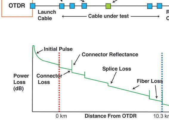

splice, and individual connector losses along the length of fiber (Figure 6).
OTDRs are very effective for troubleshooting problems. Th ey can detect bad splices or connectors and even the location of stress causing loss in the fiber. Because they use a different test method than an optical loss test set and not in the same way a communication system uses the fiber, the test results may not agree with the insertion loss tests. Therefore, most standards call for insertion loss tests first.
OTDR data is the best documentation for troubleshooting future problems. Testing each fiber when it is installed to verify proper
installation and saving the data electronically provides baseline data to compare against test data when problems arise. OTDRs can compare old and new traces to help pinpoint problems.
When buying an OTDR, it’s important to consider the application. If you are testing long-distance networks, choose an OTDR based on its distance capability. If you will use it to test short cables indoors or in a substation, buy an OTDR with the shortest range and highest resolution to see faults in those short cables.
Fiber Characterization
Long cables outside a plant require testing for dispersion, a process called fiber characterization. Shorter cables intended for use in a high-speed network (>10Gb/s) should also be tested for dispersion. Dispersion limits the bandwidth of signals that can be transmitted over long distances. Several types of dispersion must be tested, and the extremely high bandwidth of fiber means these tests are complicated and expensive.
New cable plants are generally tested for chromatic dispersion (CD) and polarization mode dispersion (PMD) as they are installed. Older cable plants — especially those installed before 2,000 — should be tested to determine their capability for network upgrades. Generally, these tests are subcontracted to specialized companies that have the equipment, training, and experience to perform all these tests.
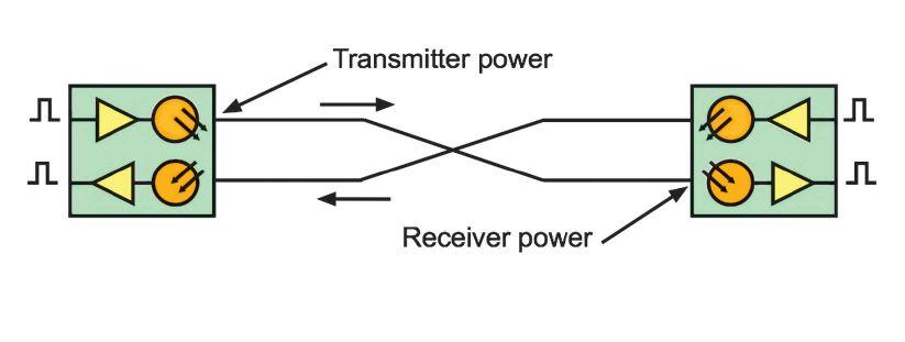
58 • WINTER 2018
TESTING, OPERATING, AND MAINTAINING FIBER OPTIC NETWORKS — PART 2 INDUSTRY TOPICS
Figure 6: OTDR Trace with Marker Set to Measure Distance
Figure 7: Duplex Fiber Optic Link Testing

Testing Communications Networks
Fiber optic communications networks communicate over fiber optic links. A link consists of a transmitter coupled into a cable plant that connects to a receiver on the far end. Full duplex links (Figure 7) usually consist of two fibers transmitting in opposite directions, although some networks, such as fiber to the home, use bidirectional transmission over a single fiber.
The first requirement for proper transmission is the proper amount of power at the receiver: not too little power, which causes poor signal to noise, nor too much power, which overloads the receiver (Figure 8). Measuring optical power allows the transmission system to be tested for proper optical connections.
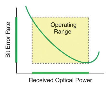
Figure 8: Bit error rate is a function of receiver optical power.
The amount of power at the receiver is determined by the amount of power coupled by the transmitter into the fiber optic cable plant, which is then reduced by the attenuation of the cable plant. During the design stage, the link power budget and fiber optic cable loss budget are calculated to ensure the design can accommodate the chosen fiber optic links.
To test a fiber optic link, first turn on the transmitter, then test the power at the receiver end of the cable plant. Compare that power measurement to the manufacturer’s specification for the receiver. The power level should be in the correct range for that receiver.
If the receiver power is too high, add a fiber optic attenuator at the receiver to reduce the power to the proper level. If the power is too low, measure the power at the transmitter to verify it is within the manufacturer’s specification.

The power at the transmitter may be correct, but if the cable plant loss is too high, the power at the receiver will be too low. Reduce the loss in the cable plant or fi nd a higher power transmitter. If the cable plant loss is proper, but the transmitter power is too high or too low, find a transmitter with the correct power level.
THE FIBER TECH’S TOOLBOX
A fiber technician testing cable plants and networks will have a full toolbox:
• Fiber optic inspection microscope, video preferred
• Fiber optic cleaning kit
• Visual fault locator
• OLTS light source, power meter, and reference test cables
• OTDR and reference cables
Due to the cost, one OTDR is often shared among techs or even several offices.
OPERATING AND MAINTAINING FIBER OPTIC NETWORKS
Once a fiber optic network is installed, tested, connected to communications equipment, and operates properly, lock it up and leave it alone. Most problems with operational fiber optic networks are caused by untrained workers breaking patchcords or connectors or getting them dirty or connecting them to the wrong fiber or equipment.
Some sources advise periodic maintenance on fi ber optic networks like oil changes on vehicles, but that is nonsensical. Telcos and utilities install fiber optic networks and run them for decades without touching the fibers.
NETAWorld • 59 TESTING, OPERATING, AND MAINTAINING FIBER OPTIC NETWORKS — PART 2 INDUSTRY TOPICS

or changes are needed, give the keys only to trained and certified techs.
UNDERSTANDING TESTING REQUIRES TRAINING
Remember, manufacturers say the biggest problem they have with installations of their products is testing by installers. The problem is simply a matter of training. You can’t learn fiber optic testing by playing with the instruments, following the salesman’s advice to push the automatic test button, or taking a two-hour class. The tech must understand the reasons for and the processes of testing to be able to perform tests and evaluate test results.
We recommend managers also get training on testing. I’ve often had to convince managers
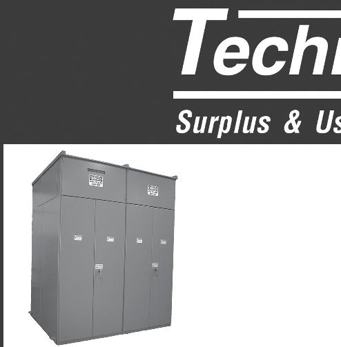

that the tests they specified or the data they have been given is problematic because someone did not understand what or how to test fiber properly in their application. If you are confused about how to specify testing or interpret test results, email me at FOA (jim@foa.org). A free online course on fiber optic testing is provided by the FOA at Fiber U (www.fiberu.org).

Jim Hayes is President and a Co-Founder of the Fiber Optic Association (FOA). He was educated as a physicist and astronomer and has been in high tech for his entire career. Since he was introduced to fiber optics by Bell Labs staff in 1978, he has been involved in the industry as an entrepreneur, writer, and educator. He is the author of nine books and hundreds of magazine articles on fiber optics and communications cabling and is a frequent speaker on the topic. One of his latest projects was working with the Electric Power Research Institute (EPRI) on their upcoming Guidebook for Strategic Fiber.

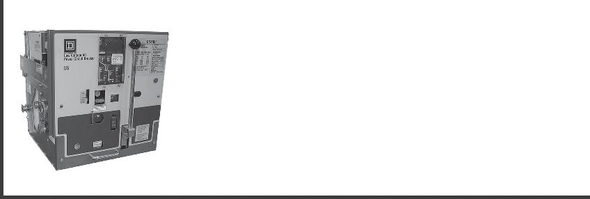


or


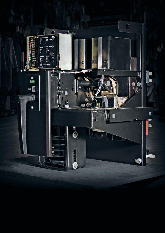


1315 Columbine, Gainesville, Texas 76241 | 800-232-5809 INFO @ CBSALES.COM | CircuitBreaker.com CBS Florida | Lakeland, Florida | 863-646-5099 | CBS-Florida.com CBS Midwest | Crown Point, Indiana | 219-575-5420 | CBSMidwest.com new service locations CBS stocks every low- and mediumvoltage circuit breaker made in America since 1945. With more than 5 million breakers and parts in our 200,000-square-foot warehouse — including switchgear, transformers, substations, protective relays, loadbreak switches, electrical contacts, motor controls and centers, vacuum interrupters, and more — Circuit Breaker Sales has you covered. √ Replacement parts and equipment √ Remanufacturing, retrofits, and upgrades √ Reverse engineering, 3-D printing of obsolete parts For more information about Group CBS and its affiliate companies, visit GroupCBS.com. CircuitBreaker.com (800) 232-5809 TOLLFREE Your TRUSTED online resource for authentic circuit breaker and electrical distribution equipment C B Store.com From a single part to a switchgear lineup, Advanced Electrical & Motor Controls’ inventory of low-voltage insulated case circuit breakers, molded case circuit breakers, motor controls, and custom switchgear is second to none in the U.S. No matter what you need — new, surplus, used, or reconditioned power distribution equipment, testing and repair, or an engineered solution — AEAMC will keep you up and running. Insulated Case Circuit Breakers Molded Case Circuit Breakers Motor Controls & Centers Bolted Pressure Switches Panelboard Switches & Bus Plugs 480 V Distribution Transformers Replacement Parts UL-Listed Motor Control Center Replacements Let us test, repair, and extend the life of your: Search. Click. Ship. Purchase AEAMC equipment online, anytime! Emergency support 24/7 800-289-2757 No One Knows Low-Voltage Circuit Breakers & Motor Controls Like Advanced Electrical & Motor Controls Advanced Electrical & Motor Controls Inc. 1801 HURD DR. | IRVING, TX 75038 | 972-253-7783 | Sales@AEAMC.com | AEAMC .com


SAFETY IMPROVEMENTS WHEN TESTING

HIGH- AND MEDIUM-VOLTAGE CIRCUIT BREAKERS WITH BOTH SIDES GROUNDED
 BY ADNAN ŠECIC and NIJAZ HADŽIMEJLIC, DV Power — Sweden


Testing circuit breaker main contacts is an important phase in production, commissioning, and maintenance. During the test, simultaneous timing measurements are performed on the circuit breaker main contacts to determine displacements of the circuit breaker’s moving parts. These measurements can also provide information on synchronization between the circuit breaker poles. Time differences between phases with a common operating mechanism could indicate internal faults on the main contacts on a particular phase.
On the other hand, increased static resistance causes heating of circuit breaker contacts during operation, which can lead to melting of the main contacts or, in the worst case, explosion of the breaker chamber. Dynamic resistance measurement (DRM), although not described in standards, is one of the relatively new methods for testing the SF 6 circuit breaker with separated main and arcing contacts. Many regulations and laws require all objects to be grounded before any maintenance work is performed. Testing
a high-voltage circuit breaker that is not grounded on both sides can be hazardous due to the high electric potential.
This article presents the principles of performing timing tests as well as static and dynamic resistance measurements on circuit breakers with both sides grounded. The specifics of testing circuit breakers in this way and a comparison of the results with those obtained on circuit breakers that are not grounded on both sides are discussed.
62 • WINTER 2018 SAFETY IMPROVEMENTS WHEN TESTING HIGH- AND MEDIUM-VOLTAGE CIRCUIT BREAKERS WITH BOTH SIDES GROUNDED
INDUSTRY TOPICS

BACKGROUND


In recent years, considerable research has been done toward development of on-line monitoring systems for continuous monitoring of the components of the power system, including transformers, circuit breakers, disconnectors, etc. Despite the obvious advantages of such solutions (for example, their ability to follow sequences of events and the online decision-making process), these methods have not yet become common practice. The reasons vary from economic constraints to reasons of a technical nature and, above all, the satisfactory efficiency level in the maintenance process achieved by the conventional testing methods.
In most cases, power system component diagnostics are still done through regular maintenance procedures performed onsite by trained personnel. The diagnostic processes on these elements are performed by implementing various types of tests (usually defi ned by standards such as IEC 62271100; IEC 56; ANSI C37.09, etc.). Data is collected on different parameters of the tested object, arranging them in a mosaic to arrive at certain conclusions about the state of the equipment and its reliability. Although such tests are performed on test objects that have been taken out of service, they are carried out directly in the field where the testing itself can be potentially life threatening. There are many laws and regulations requiring all test objects to be properly grounded before any testing is done to minimize the number of unwanted incidents and to increase the safety and protection of personnel. Testing itself must be done in the shortest possible time which, besides the obvious economic reasons (excluding the test object from the power grid), is also dictated by the safety of personnel, since reducing the time spent in a dangerous environment also reduces the risk of the unwanted incidents.
For high- and medium-voltage circuit breakers, a basic rule required by the laws and the regulations is to ground the test object on both sides before performing any tests. There are
some exceptions, however, when this has not been possible. For example, when conducting timing tests in the past, there was no alternative for using the safest approach, and the tests were conducted on the breaker grounded only on one side. Further development of the test method enabled performing this test with both sides grounded (BSG). In practice, proper grounding of the power circuit breaker refers to the grounding of its main contacts on both sides (Figure 1).


In this way, potentially dangerous situations are avoided. Such situations can be caused by various factors, including:
• A fault occurs and unwanted electrical potential reaches this object.
• Lightning strikes somewhere on deenergized lines connected to the object.
• A capacitive coupling from a nearby HV conductor causes a dangerous potential.
• High voltages are induced on the apparatus under test from adjacent energized objects.
Common practice when conducting conventional resistance measurement on a circuit breaker implies that one side of the circuit breaker is grounded. Since resistance measurement does not require opening of the circuit breaker and the main contact has low
NETAWorld • 63 SAFETY IMPROVEMENTS WHEN TESTING HIGH- AND MEDIUM-VOLTAGE CIRCUIT BREAKERS WITH BOTH SIDES GROUNDED
TOPICS
INDUSTRY
Figure 1: Circuit Breaker Grounded on Both Sides
INDUSTRY TOPICS

electrical resistance, one could argue that this procedure should be completely safe. Although this is not totally incorrect, failure on the main contact could cause its resistance to increase substantially. In this case, one side of the closed circuit breaker would not be properly grounded, and an unwanted incident could result.
RESISTANCE MEASUREMENT WITH BOTH SIDES GROUNDED
Standards require measurement of the circuit breaker main contacts to be conducted with dc currents of at least 50A (IEC 60694) or even 100A (ANSI C37.09), even though resistance measurement could be conducted with lower currents. Experience has shown that real resistance values are obtained at high test currents, while low test currents might yield false results such as resistance values slightly higher than actual in some cases. For example, an insulating layer on the surface of some contact fingers can result from the buildup of decomposition products or dry lubricant. Thus, the contact resistance can be measured at a level higher than its real in-service value.
Precision micro-ohmmeters capable of generating high dc currents are therefore used to perform field measurements of the circuit breaker main contacts resistance. Today, commercially available micro-ohmmeters are capable of generating up to 800A dc ripple-free current and measuring the resistance with very high precision (resolution up to 0.1 uΩA). The method is based on the Kelvin measurement principle, so the device generates dc current and simultaneously measures the voltage drop across the circuit breaker main contact as well as the current value through the precision shunt resistor (or some other current measurement principle) to calculate the corresponding resistance value.
Measuring the resistance of the main contact is usually done along with other tests, such as the timing measurement. Because of this, very popular devices currently on the market combine all of these features. Such devices, called circuit breaker analyzers and timers, have built-in micro-

ohmmeters. Cables for connecting the high current dc source to the test object are required to perform the measurement. Due to the different structure of high- and medium-voltage circuit breakers, cable length can be quite long (up to 20m). This means that even cables with a very high cross-section (tens of mm2) can still have high resistance. Thus, voltage drop on current cables plays an important role in the design of high current dc sources. That is the reason this current source should be very powerful.
There are two basic methods for generating high dc current to perform resistance measurement:
1. The first requires an energy storage element, such as a super-capacitor. Based on double-layer technology, these high energy capacitors can have capacitance up to a few hundred Farads. Due to very low internal resistance, this type of capacitor appears to be the best choice for situations where it is necessary to frequently perform charging and discharging at high currents and in short periods of time.
2. The second method utilizes rectification of the service ac voltage using a highfrequency switching dc/dc converter to achieve the desired current.
Measurement of the resistance of the circuit breaker that is grounded on both sides requires some modifications of the normal method. In this case, the generated current has two paths: one consisting of the circuit breaker main contact and the other one consisting of the resistance of the grounding cables and the ground resistance. Two test methods allow resistance measurement of the circuit breaker main contact in this case.
Using External Current Clamps
This method enables additional measurement of the current that flows through the grounding cables. It requires external current clamps and enables generating adjusted current by
64 • WINTER 2018
SAFETY IMPROVEMENTS WHEN TESTING HIGH- AND MEDIUM-VOLTAGE CIRCUIT BREAKERS WITH BOTH SIDES GROUNDED

considering the measured current value from the current clamps (Figure 2). An obvious advantage is that the given current will flow through the main contact since a feedback controller can now use the Ir = It - Ig signal, where It represents total current, Ig represents the current that flows through the ground wire, and I r represents the current that goes through the resistor. The result will be obtained immediately after one measurement. A disadvantage is that the precision of the measurement is influenced by the accuracy of the current clamps that are used.
Table 1 represents the measured values on three different sizes of shunt resistors (which simulate the breaker main contacts) with different test currents. The results show that if the measuring current is increased, the measured values get closer to the real value (shunt resistance).
Using Consecutive Measurements
The second method consists of two consecutive measurements and tripping off the circuit breaker. In the first measurement, the circuit breaker is in a closed position and parallel resistance of both main contacts and grounding cables (Rp) is measured. The device then issues a command to the trip coil of the circuit breaker and another measurement is obtained after the breaker is opened. The resistance of the main contact of the circuit breaker can be calculated based on these
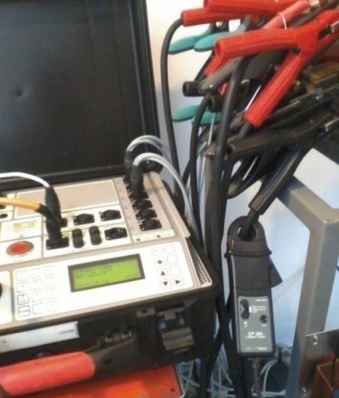

two results. Measurement is more precise, since there is no need to use external current clamps. The disadvantage of this method is that two measurements are performed, and the circuit breaker is opened. The entire test current will not flow through the main contact because some of the current will flow through the grounding cables. The percentage of the current that flows through the grounding cable is very low because of its much higher resistance (Table 1).
NETAWorld • 65
INDUSTRY TOPICS
SAFETY IMPROVEMENTS WHEN TESTING HIGH- AND MEDIUM-VOLTAGE CIRCUIT BREAKERS WITH BOTH SIDES GROUNDED
Measurement Current 100 uΩ 300 uΩ 1 mΩ 1 100A 97.5 uΩ 297.4 uΩ 978.0 uΩ 2 150A 97.8 uΩ 297.5 uΩ 1.02 mΩ 3 200A 101.5 uΩ 302.5 uΩ 1.01 mΩ
Table 1: Shunt Resistance Measurements Results Using Current Clamps
Figure 2: Measuring Circuit Breaker Resistance with BSG Using Test Device with External Current Clamps
Phase Current Grounding Resistance (Rg) Parallel Resistance (RP) Calculated Resistance (Rc) Measured Resistance (Rm) A 200A 12.677 m 352.8 u 362.9 u 367.4 u B 200A 12.364 m 338.9 u 348.5 u 349.4 u C 200A 13.356 m 485.2 u 503.5 u 504.0 u
Table 2: CB Resistance Measurement Results Using Consecutive Measurements
INDUSTRY TOPICS

CIRCUIT BREAKER TIMING WITH BSG
The main features desired for a power circuit breaker are:
• To act as close as possible to a perfect conductor in a closed position
• To act as close as possible to a perfect insulator in open position
• To have adequate transition speed between these two stages
By definition, a circuit breaker timing test is the process of measuring mechanical operating times. These tests are also used to determine synchronization either between phases or within one phase for circuit breakers having more than one break unit per phase. Timing measurement is triggered by the instant of energizing the opening release or closing circuit of the circuit breaker. Several methods can be used to determine timing on the main contacts. These methods are based on tracking changes either in resistance or capacitance of main contacts during operation.
• The first method consists of using a voltage source with a current limiter to measure voltage drop across the contacts. Based on the measurement and predefined thresholds, the circuit breaker state can

now be easily determined in any position (closed, pre-insertion-resistor, open).

• The second method is based on the variable capacitance in the circuit breaker chamber formed by the two separated connectors. The capacitance is used as a part of a resonant circuit. This method uses a high-frequency generator to detect impedance changes of the circuit on resonant frequency during operation.
Either way, a timing test requires the opening or closing of the main contacts. Conventional testing methods cannot be used to perform timing measurements on a circuit breaker grounded on both sides. That’s because grounding is usually achieved through low-resistance cables (in most cases, over 70mm sq), and earth resistance is also very low. Field experiments have shown that grounding resistance can go below 10 mΩ in some extreme cases.
In that case, the overall change of the resistance during closing or opening of the main contacts is too low for conventional test methods to determine the comparator threshold in the time measurement process. Modification of the conventional resistance testing method by increasing current — paying particular attention to signal filtration — and developing special state detection algorithms will define a test method that can be used to perform timing measurement on a breaker grounded on both sides. This is BSG measurement.
To demonstrate the efficiency of this method, tests were performed on the same circuit breaker — both with and without grounding on both sides (Figure 3).
For this purpose, low-resistance cables were used to simulate grounding. A circuit breaker analyzer and timer with built in microohmmeter was used to determine the resistance of the cables. The obtained values are: Phase A: 12.68 mΩ; Phase B: 12.36 mΩ; Phase C: 12.36 mΩ. An O-0.3s-C timing test was then performed on a circuit breaker with and without grounding. The O-0.3s-C test is a
66 • WINTER 2018
SAFETY IMPROVEMENTS WHEN TESTING HIGH- AND MEDIUM-VOLTAGE CIRCUIT BREAKERS WITH BOTH SIDES GROUNDED
Figure 3: Timing Tests on a Circuit Breaker

standard timing test for the circuit breaker. It means open-0.3s delay-close operation. The obtained results are nearly identical.
Figure 4 and Figure 5 compare graphical and numerical results in both cases.
DYNAMIC RESISTANCE MEASUREMENT AND BSG
The design of modern high-voltage puffertype SF6 gas circuit breakers is based on the switching of two parallel contact sets. First, the low-resistance silver-plated contacts or the main contacts are specifically designed to carry the load current without excessive temperature rise. Second, tungsten-copper arcing contacts operate at breaker opening following the main contact part. The test device is used to inject a high dc current through the breaker contact and simultaneously monitor the voltage drop across the main contact during the trip operation.
An analog or digital (linear or rotary) transducer records the motion of the main contacts. DRM measurement can also be performed on a circuit breaker grounded on both sides. The main goal of this test is to determine the overlapping time and overlapping length of a main and arcing contact. The same circuit breaker as in the previous tests was used for DRM measurements with and without the BSG option. Grounding resistance is measured after opening the main contact; the obtained value was around 12 mΩ. Figure 6 and Figure 7 show DRM results with an injected constant current of 200A.
If a circuit breaker is grounded on both sides, the voltage drop across the arcing contacts will be lower due to the presence of parallel resistance from the grounding cables and the ground resistance. Even with decreased total resistance when both sides of the circuit breaker are grounded, the overlapping time does not change. Considering the overlapping length is determined by the motion diagram based on overlapping time, one can conclude that grounding does not affect DRM results.


5: O-0.3s-C Test with Both Sides Grounded (Grounding Resistance 12m)
CONCLUSION
In most cases, diagnostics of power system components are still done through regular maintenance procedures performed onsite by trained personnel. These conventional testing methods are also commonly applied as part of testing procedures in the regular maintenance processes of medium- and highvoltage circuit breakers in the field. However, conventional tests are performed on a circuit breaker that is grounded only on one side. Testing a high-voltage circuit breaker that is not grounded on both sides can be hazardous
NETAWorld • 67 INDUSTRY TOPICS
SAFETY IMPROVEMENTS WHEN TESTING HIGH- AND MEDIUM-VOLTAGE CIRCUIT BREAKERS WITH BOTH SIDES GROUNDED
Figure 4: O-0.3s-C Test without Both Sides Grounded
Figure


due to the high electric potential. Development of new technologies has made it possible to modify conventional methods to perform measurements with both sides grounded. Using these methods achieves a higher level of personal safety and protection.
REFERENCES
M. Kezunovic, M. Knezev, Z. Djekic. “Automated Circuit Breaker Monitoring,” Project Report for the U.S. Department of Energy’s Consortium for Electric Reliability Technology Solutions (CERTS), Power Systems Engineering Research Center, PSERC Publication 07,38, November 2007.

“Main Contact Resistance Measurement of a Circuit Breaker with Both Sides Grounded (BSG),” DV-Power, 2011, IBEKO Power AB, Lidingö, Sweden.
“Guide for circuit breaker testing,” DV-Power, 2012, IBEKO Power AB, Lidingö, Sweden.
L. Claesson, Z. Stanisic, H. Wernli, K. Pettersson. “Safe Circuit Breaker Timing with New Technology,” CMD2006, International Conference on Condition Monitoring and Diagnosis, Changwon, Korea, April 4, 2006.
A. Secic, B. Milovic. “Dynamic Resistance Measurement Method with High DC Currents,” AMforum Technical Journal No.3, September 2013.
R. Ostojic, J. Levi. “Use of MICRO OHM METER as Power Source for DRM Testing on Dead Tank Circuit Breakers,” 80th Annual International Doble Client Conference, 2013 Doble Engineering Company.

Adnan Šečić is an R&D Engineer at DV Power — Sweden. As a project leader, he is responsible for development of the circuit breaker analyzer and timer (CAT) device series. Adnan received his BS in electrical engineering and MS in electronics, electrotechnics, and automation (EAA) from the University of Sarajevo, Bosnia and Herzegovina, and is in the final stage of PhD studies at the Faculty of Electrical Engineering and Computing in Zagreb, Croatia.

Nijaz Hadžimejlić has been with DV Power since 2015. From 1977–1998, he was with the Department of Power Electronics and Motor Control, Institute for Computer Science and Control-IRCA, Energoinvest, Sarajevo. Nijaz was a part-time Teaching Assistant and Senior Teaching Assistant in the Department of Electrical Engineering, University of Sarajevo from 1984–1997 and was an Associate Professor from 1998-2015. He received his BS, MS, and PhD degrees, all in electrical engineering, from the University of Sarajevo. Nijaz’s research interests include power electronics converters, motor drive control for electric cars, and robotics. He is the author or co-author of over fifty technical papers.
68 • WINTER 2018 INDUSTRY TOPICS
SAFETY IMPROVEMENTS WHEN TESTING HIGH- AND MEDIUM-VOLTAGE CIRCUIT BREAKERS WITH BOTH SIDES GROUNDED
Figure 6: DRM Results without BSG
Figure 7: DRM Results with BSG


THE PREMIER ELECTRICAL MAINTENANCE AND SAFETY CONFERENCE CALL FOR EXHIBITORS Gaylord Texan Resort and Convention Center - Grapevine, Texas
500+ electrical testing professionals
decision-makers looking for new products and ser vices
attendee profile and additional information, visit www.powertest.org PowerTest.org l 888.300.6382 Hosted by
•Join
•Leading
•For
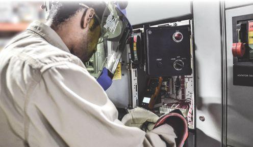












√ QUICK Setup
√ FREE PC Software
√ 200 kHz RMS sampling
√ CT’s powered by main unit
√ 8 hours of battery operation





√ AC/DC power measurements PQ3100 Power Quality Analyzer


√ Flicker √ Demand Graphs √ Harmonics Trend
√ Rapid Voltage Change (RVC)
√ Remote control via Ethernet with FTP & Emails


6 C o r p o r a t e D r i v e • C r a n b u r y , N J P H O N E : 6 0 9 . 4 0 9 - 9 1 0 9 • F A X : 6 0 9 . 4 0 9 - 9 1 0 8 w w w . h i o k i u s a . c o m Over 80 Years of Meeting Your Needs! ISO9001 ISO14001 A c h i e v e N e w L e v e l o f P o w e r A n a l y s i s ...with Hioki’s New PQ3100 Visit our New & Improved Website
CAT III CAT IV Record and analyze data with a single instrument FIELD-PROVEN
STRENGTH
UNDERSTANDING CURRENT TRANSFORMERS
BY THOMAS D. SANDRI, Shermco Industries
Current transformers are a commonly used device found in metering and protective relay applications for the electrical power industry. The purpose of these devices is to scale large primary currents to a smaller, easy to measure, secondary current. The device also isolates measuring and recording instruments. Current transformers (CT) together with voltage transformers (VT) or potential transformers (PT) are known as instrument transformers.
Like any other transformer, a CT has a primary winding, a magnetic core, and a secondary winding. Alternating current (ac) flowing in the primary winding produces a magnetic field in the core, which in turn induces a current in the secondary winding circuit.
The objective of the CT design is to ensure that the primary and secondary circuits are efficiently coupled so that the secondary current reflects an accurate relationship to that of the primary current. The most basic design of a CT consists of a length of wire wrapped many times around a silicon steel ring passed over the circuit being measured.
The CT’s primary circuit usually consists of a single turn of conductor with a secondary consisting of as many as hundreds of turns (Figure 1).

Figure 1: Basic CT Design where I = Primary Current and N = Number of Turns
The primary winding may be a permanent part of the CT consisting of a heavy copper bar to carry current through the magnetic core (Figure 2).
72 • WINTER 2018 UNDERSTANDING CURRENT TRANSFORMERS
INDUSTRY TOPICS
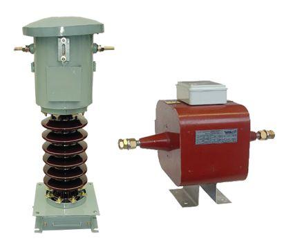
WINDOW CT s
Window-type CTs are also very common. In window CTs, circuit cables run through the middle of an opening in the core to provide the single-turn primary winding (Figure 3).

The primary circuit is largely unaffected by the insertion of the CT. The secondary current rating is typically standardized at either 1 ampere or 5 amperes. Therefore, if a CT is rated at 4,000:5, the CT would provide an output current of 5 amperes when the primary is passing 4,000 amperes.
A number of factors must be taken into consideration when looking at the accuracy of a CT:
• Burden
• Burden class/saturation class
• Rating factor
• Load
• External electromagnetic fields
• Temperature and physical conditions
• The selected tap


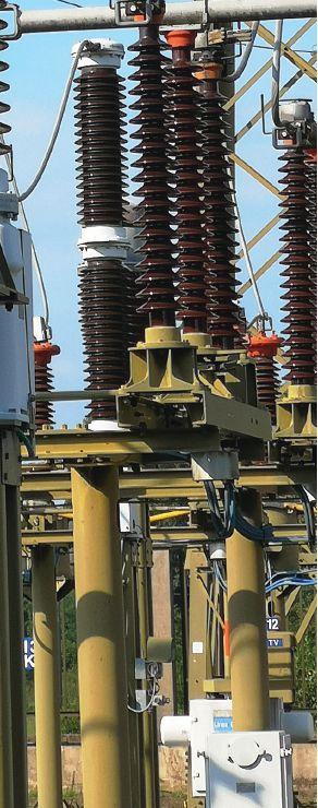

NETAWorld • 73 UNDERSTANDING CURRENT TRANSFORMERS
INDUSTRY TOPICS
Figure 3: Window-Type CT
Figure 2: CT with Permanent Primary
The IEC 60044-1 standard sets out various accuracy classes: 0.1; 0.2s; 0.2; 0.5; 05.s; 1; and 3. The class designation is an approximate measure of the CT’s accuracy. For example, the ratio error of a Class 1 CT is 1 percent at rated current. The ratio error of a Class 0.5 CT is 0.5 percent or less. Each class also has an allowable maximum phase error for specified load impedance. Current transformers used for protective relays have accuracy requirements at overload currents in excess of the normal rating to ensure accurate performance of relays during system faults.
The load, or burden, in a CT metering circuit is the impedance presented to its secondary winding. This impedance is largely resistive. Typical burden ratings for IEC CTs are:
• 1.5 VA
• 3 VA
• 5 VA
• 10 VA
• 15 VA
• 20 VA
• 30 VA
• 45 VA
• 60 VA
ANSI/IEEE burden ratings are:
• B-0.1
• B-0.2
• B-0.5
• B-1.0
• B-2.0
• B-4.0
Looking at these ratings, you can see that a CT with a burden rating of B-0.2 can tolerate up to 0.2 ohms of impedance in the metering circuit before its output current is no longer a fixed ratio of the primary current. Switch blocks, meters, and intermediate conductors all contribute to the burden of a current measurement circuit. The conductor between the meter and the CT can also be the source of excess burden.
CT KNEE POINT
The knee point of a CT is the magnitude of the secondary voltage after which the output

current ceases to linearly follow the input current. In other words, the one-to-one relationship between input and output is no longer within the declared accuracy. When a voltage is applied across the secondary terminals during testing, the magnetizing current increases in proportion to the applied voltage up until the knee point, which is defined as the point at which an increase in applied voltage of 10 percent results in an increase in magnetizing current of 50 percent (Figure 4).
The knee-point voltage is less applicable for metering CTs because their accuracy is generally much tighter and is constrained within a very small bandwidth of the current transformer rating. Knee point, however, is very important to protection CTs because they are exposed to currents of 20 to 30 times the rated current during faults.

Thomas D. Sandri is a Senior Technical Instructor at Shermco Industries. He has been active in the field of electrical power and telecommunications for over 30 years. During his career, he has developed numerous training aid and training guides and has conducted domestic and international seminars. Thomas supports a wide range of electrical and telecommunication maintenance application disciplines. He has been directly involved in supporting test and measurement equipment for over 20 years and is considered an industry expert in application disciplines, including battery and dc systems testing and maintenance, medium- and high-voltage cables, ground testing, and partial discharge analysis. He holds a BSEE from Thomas Edison University in Trenton, New Jersey.
74 • WINTER 2018
UNDERSTANDING CURRENT TRANSFORMERS INDUSTRY TOPICS
Figure 4: CT Knee Point


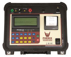
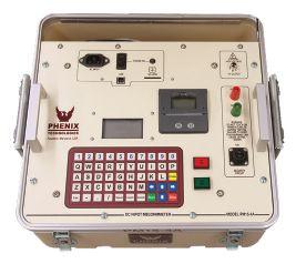

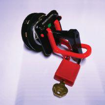


Reversed Delivering Powerful Reliability Solutions
System Acceptance Testing Commissioning and Start-up Maintenance Life-Cycle Extension Troubleshoot and Repair Training and Engineering Services Planning and Operations Support Project Management ✔ ✔ ✔ ✔ ✔ ✔ ✔ ✔ Sigma Six Solutions, Inc. 2200 West Valley Hwy North, Suite 100 | Auburn, WA 98001 Office: 253-333-9730 | Sales: 425-293-1239 www.sigmasix.com Reversed 1-301-746-8118 • www.PhenixTech.com 40+ Years Experience info@phenixtech.com • 75 Speicher Drive, Accident, MD 21520 USA Insulation Analyzers High Voltage - High Current - High Power Test Systems and Components TECHNOLOGIES PHENIX R ➤ Perform multiple testing functions • Insulation Resistance • Dielectric Absorption Ratio • Polarization Index • Capacitance • Leakage Current • Guarded Current • Step Voltage • Pass / Fail Test • Low Resistance and Continuity 4 models available, 1 kV DC to 15 kV DC ➤ Automated testing with microprocessor controller ➤ Auto-range ➤ External noise rejection ➤ Rechargeable battery ➤ IEC compliant
Power


MEGGER: A HISTORY OF INNOVATION AND ADVANCEMENT
NETA Corporate Alliance Partners (CAPs) are a group of industry-leading companies that have joined forces with NETA to work together toward a common aim: improving quality, safety, and electrical system reliability.

In this new NETA World article series, we will look at what makes CAPs special and highlight some of their successes. To kick off this issue’s spotlight, NETA World interviewed Dinesh Chhajer, Technical Services Group Manager.
Megger designs and manufactures portable electrical testing equipment with a focus on efficiency, reduced cost, and extended life of electrical assets.
NWJ: When people think Megger, what do they think?
Chhajer: Megger is one of the world’s leading providers of portable electrical testing and measuring instruments. Power industry professionals think of Megger when they need reliable equipment to get the job done.
We have a rich history. Over the past 100 years, we have grown from a small company
to an international organization through technological advancements as well as a series of mergers and acquisitions with companies of similar vision and objectives.
We are a technology-driven company with a focus on supporting and helping our customers across the globe improve efficiency, reduce cost, and extend the life of electrical assets. Our goal is to anticipate, meet, and exceed the industry’s testing needs through innovative research
78 • WINTER 2018 MEGGER: A HISTORY OF INNOVATION AND ADVANCEMENT
INSIGHTS & OBSERVATIONS - NETA CAP SPOTLIGHT
DINESH CHHAJER
and development, design engineering, and manufacturing techniques, and to provide the best solutions and services to our clients.
NWJ: What is something that people don’t know about Megger?
Chhajer: People may not be familiar with our diverse culture. Megger is a prime example of harmonization between different cultures, people, and thinking. We manufacture quality products at seven manufacturing sites in many countries to obtain a unique perspective
Over the years, more than 10 companies have come under the brand name of Megger; each one was able to address specific needs of our clients in performing electrical measurements for preventive maintenance, troubleshooting, and commissioning of highvalue assets. Our diversity allows us to work and provide advanced technical solutions in the environment where our customers work with a focus on developing products that are easy to use.
NWJ: What makes Megger stand out in its field?
Chhajer: We are best known for dc insulation testers. With a 100-year history, Megger is now synonymous with dc insulation testing in the industry and with various international standards.
However, that is only one part of our offerings and products for electrical testing and assessing the health condition of assets such as transformers, circuit breakers, relays, motors, generators, cables, switchgears, and more. Through continuous investment in technology, listening to client needs, and working with industry specialists, we are always at the leading edge of launching new products to meet the challenging testing requirements of utilities and other power industry users.

NWJ: How does Megger provide solutions to the testing industry?
Chhajer: The power and energy industry is constantly challenged to optimize the life of assets, develop proactive methods to identify problems, and exchange ideas and processes to address similar concerns. Being at the heart of providing testing solutions to the power industry, Megger recognizes these challenges, and we are involved in the research and development of new testing technologies,
NETAWorld • 79 MEGGER: A HISTORY OF INNOVATION AND ADVANCEMENT
contribute to various industry events, participate in the development of new and revised IEEE and other international standards, and publish white papers and technical articles.
Additionally, we conduct best-practices seminars in partnership with utilities and OEMs to share the best testing methods to obtain reliable and accurate results for trending, analysis, and diagnosis.
NWJ: What are some of the latest technologies or solutions Megger is developing?
Chhajer: Megger is always working on either refining existing testing practices or coming up with new and innovative techniques to improve safety, increase efficiency, and determine asset condition more effectively.
Some of the latest testing solutions from Megger include high-voltage dielectric frequency response for bushing insulation condition assessment, a
dual-ground measurement technique for highvoltage circuit breakers, patented concurrent testing for current transformers, and a patented individual temperature correction method for power factor results correction.
NWJ: What has working with NETA meant for Megger?
Chhajer: Megger has had a strong relationship with NETA for a number of years, and it has proven beneficial for both organizations. NETA offers a direct pipeline to one of our larger customer markets and gives us the opportunity to be front and center with them in showcasing our products and services.
NETA is always open to ideas and suggestions when it comes to giving more to their membership, allowing Megger to offer more to its customers through NETA programs. It’s this open communication and mutual support that Megger values most, and it has fostered the strong bonds we have to this day.
BE AN EARLY BIRD
Don’t miss your chance to SAVE $100 on registration for PowerTest 2019, the leading event for electrical power systems professionals. Early-bird registration closes December 31, 2018. PowerTest offers everything you need to stay updated on the latest advancements in the electrical maintenance and safety field. You will have access to knowledge, tools, and resources that will directly impact your profession, as well as training and opportunities to build relationships with leading industry professionals.

MEGGER: A HISTORY OF INNOVATION AND ADVANCEMENT INSIGHTS & OBSERVATIONS - NETA CAP SPOTLIGHT
For more information visit www. powertest.org 80 • WINTER 2018

PT19 KEYNOTE SPEAKER STACEY HANKE REDEFINES INFLUENCE

What we say and what others hear is not always the same. While frustrating in personal communications, it can be counterproductive and even dangerous on the job.
Stacey Hanke, founder and owner of Stacey Hanke, Inc., and author of Influence Redefined: Be the Leader You Were Meant to Be, Monday to Monday, has made it her mission to help people overcome these communication difficulties by focusing on their influence. Hanke will be the keynote speaker at PowerTest 2019 at the Gaylord Texan Resort and Convention Center in Grapevine, Texas, on March 11–15, 2019.

“If you’re not aware and actively building your influence every day, you’re losing it,” Hanke says. “That’s what I mean in my book when I say ‘Monday to Monday.’ It has to be every day, not just sometimes. It is harder to get people to follow you if you don’t have the reputation of influence.”
NETA World Journal sat down with Hanke to learn more about building influence.
NWJ: Your book is titled Influence Redefined; what does that mean?
Hanke: I help individuals realize how much influence they have. People often mistake their comfort discussing a topic with the reputation they are building. It’s not just what you’re
82 • WINTER 2018 PT19 KEYNOTE SPEAKER STACEY HANKE REDEFINES INFLUENCE
saying, it’s how you’re saying it — your body language, consistency, so many things.
Effective communication is so important to getting just about anything done. It also makes a big difference in the amount of work people can do. It is amazing how much more people can get done when an email is clear the first time and doesn’t have to go back and forth or when meetings that used to take an hour now get the same information out in half an hour.
You might be getting results, and you might be happy with them, but people often think they are getting better results than they are. Even those who are getting results can still grow. We can always do better. This is all about life-long learning.

NWJ: Why is this topic so important to you?
Hanke: My father always said, “Just be kind to everyone. It doesn’t matter who they are, where they come from. Just make someone happy.” Doing that is not just about what you are saying. They have to believe you. They have to trust you. That’s body language.

JUST BECAUSE YOU COMMUNICATE ALL THE TIME DOESN’T MEAN YOU HAVE THE INFLUENCE YOU THINK YOU DO. WE DON’T KNOW WHAT WE DON’T KNOW. WE ARE BASING OUR DECISIONS ON OUR OWN EXPERIENCES

NWJ: What will you share that people don’t already know?
Hanke: Common sense does not mean common process. Most people have heard about effective communication practices. Just because they know about it, just because they’ve heard of it, doesn’t mean they do it.
I coach executives who have years, if not decades, of experience in their position. They know about effective communication. When I sit them down and show them a video of themselves, show them how their communication comes across, they are shocked. CEOs of massive companies will look at me and say, “I had no idea how much training I need.”
Just because you communicate all the time doesn’t mean you have the infl uence you think you do. We don’t know what we don’t know. We are basing our decisions on our own experiences. How you experience your communication and how others experience it can be totally different if you are not actively aware of how you are communicating.
I am so intrigued by body language — how we can behave the way we do and not know about it. I’m blown away by the things people do when they talk and how often the person listening takes something away that totally undermines the person who is talking.
I’ve worked with many well-known CEOs who are not as good at communicating as they thought. Your job title doesn’t determine how influential you are. It doesn’t matter if you are technically accurate if people can’t understand you or don’t care. You build your reputation with how you communicate, not with your title.
NWJ: Are there other misconceptions people have about communicating?
Hanke: In my experience, people often mistake their time with an organization for influence. “I’ve been here so long. I’m comfortable. I’m infl uential.” All the experience in the world doesn’t matter if
NETAWorld • 83 PT19 KEYNOTE SPEAKER STACEY HANKE REDEFINES INFLUENCE
PREVIEW

people don’t trust you, if they don’t believe in you, if they have to struggle to figure out what you’re trying to say.
The amount of awareness and practice it takes to be truly influential is significant. It’s a lot like golf. From a distance, it looks easy. Just hit the ball. Then you are the one swinging, and you realize why even professionals spend thousands of hours practicing something that looks so simple.
Practice is the key. Another misconception people have is that someone who is a good communicator is that someone is “born with it” or “it comes naturally to them.” In reality, it’s a learned skill. It’s the result of practice.
NWJ: What can attendees expect to take away from your address?
Hanke: Awareness. By the time we’re done, they will be so self aware — in a good way. I’m not talking about changing them. I’m giving them tools to do their own work. However they define influence, they have to be able to figure out what is working and what is not.
If people don’t really listen, they aren’t going to understand. If they don’t understand, how can they do what you need them to do?
This is not going to just be them listening to me preach what I believe in. I’m going to give them tools to implement — right away — to start improving their influence. Going back to golf, it’s the difference between a coach telling you how to swing better without a club in sight and a coach who can show what to do while you actually swing.

PREVIEW
NEW LEARNING SEMINARS OFFERS
PowerTest 19 dedicates two full days to highpowered learning. Choose from eight sessions on Wednesday plus an action-packed tour schedule on Thursday.
WEDNESDAY
IN-DEPTH SESSIONS
Don’t miss out on Wednesday’s selection of four-hour, in-depth seminars.
Morning 8:00 AM–11:45 AM
• Overall Transformer Insulation Diagnostics: Field and Laboratory Approach. Presenters: Diego Robalino, Megger, and Nick Perjanik, WEIDMANN Electrical Technology Inc.
• Understanding Line Protection Relays. Presenter: J. Scott Cooper, OMICRON electronics Corp. USA
• Leading Generational Engagement: Learning to Flex in a Culture of Resistance. Presenter: Stacey Hefner, Practicing Perfection Institute
• Cable Testing and Diagnostics with a Focus on Practical Testing. Presenters: Jason Souchak and Robert Probst, Megger
Afternoon 1:15 PM–5:00 PM
• Understanding Partial Discharge Workshop. Presenter: Tom Sandri, Shermco Industries
• Interpretation of Power Factor and Excitation Current Test Data. Presenters: Keith Hill and Mike Anderson, Doble Engineering Company
• Battery Testing and Maintenance. Presenters: Volney Naranjo and Dinesh Chhajer, Megger
• Electrical Safety for the Technician. Presenters: Jim White, Shermco Industries; Daryld Ray Crow, DRC Consulting Ltd.; Daleep Mohla, DCM Electrical Consulting Services
THURSDAY
OFF-SITE SEMINARS
PowerTest 2019 attendees can take part in a brand-new educational opportunity — off-site seminars. Hands-on sessions hosted by three leaders in the industry across three tracks are part of an action-packed, all-day seminar schedule.
Choose from tracks focused on switchgear, medium-voltage, or breaker equipment.
• Switchgear sessions are hosted by Advanced Electrical & Motor Controls; AVO Training Institute, Inc.; and Megger.
• Medium-voltage sessions include Doble Engineering Company, Shermco Industries, and Vacuum Interrupters.
• Breaker sessions showcase National Switchgear; BCS Switchgear; and Circuit Breaker Sales, Inc.
Breakfast and lunch are included. To register for your choice of seminars, please visit www.powertest.org or call the NETA office at 888.300.6382.
SAVE $100 WITH EARLY BIRD REGISTRATION
Don’t miss your chance to save $100 on registration for PowerTest 2019, the leading event for electrical power systems professionals. PowerTest offers everything you need to stay updated on the latest advancements in the electrical maintenance and safety field. You will have access to knowledge, tools, and resources that will directly impact your profession, as well as training and opportunities to build relationships with leading industry professionals.

NETAWorld • 85 POWERTEST 19 OFFERS NEW LEARNING SEMINARS


CAPS SHARE INSIGHTS ON EMERGING TECHNOLOGIES
At NETA’s recent Board and Member Meeting, two Corporate Alliance Partners shared their insights into emerging electrical testing technology you should know about.
Electro Rent’s Tim Bealby and Group CBS’s Finley Ledbetter presented on September 21 in Providence, Rhode Island.
ADVANCES IN ASSET MANAGEMENT
Chief Technical Officer Tim Bealby shared a new, more effective way to achieve real-time asset management of high-value testing equipment. Using the latest low-energy Bluetooth exchanges, beacons with a battery life of four to five years can be affixed to assets just about anywhere.
Engineers, product managers, and fi nance teams can use smartphones, tablets, static readers, and desktop computers to get a real-time view of all test and measurement equipment in one place. Knowing they have the newest, most accurate data, companies can more efficiently view assets, approve requests, estimate cost and delivery times, allocate costs, and make informed rent versus buy decisions.
While modern test and measurement equipment enables projects to be completed in an efficient and timely manner, these Bluetooth-enabled asset management devices help companies reduce costs, increase visibility and accountability, eliminate redundant assets, and improve equipment use.
RECONDITION NEARFAILURE VACUUM INTERRUPTERS
CEO and Chief Scientist Finley Ledbetter shared a new process from Group CBS that will allow certain vacuum interrupters (VIs) to go back into service for an additional 20 years after they have reached their original life limits.
As long as the VI has not out-lived its wear limits and its contact structure has not seen too much damage, it will be suitable for this type of reconditioning. Most VIs have seen little operation or use and only need to be reconditioned to go right back into service; the real market disruption starts with the price and the reuse of the original type of certified vacuum interrupter design.
The reconditioning is a three-day process done at a Group CBS facility in Denton, Texas. Ledbetter says this type of reconditioning will be the norm in 50 years. However, by that time, it will likely be possible to keep vacuum breakers in service for more than 100 years after their original install.
NETAWorld • 87 CAPS UPDATE NETA MEMBERS AND BOARD ON EMERGING TECHNOLOGY
NETA ACTIVITIES UPDATE — JULY THROUGH OCTOBER 2018

NETA Board and Member Meeting in Rhode Island.
NTI TRADE SHOW
July
28, 2018
Ann Arbor, Michigan
In July, NETA attended the annual National Training Institute (NTI) trade show. Th e one-day trade show offers an extensive variety of educational and training opportunities available within the electrical industry.
EXAM COMMITTEE STANDARD SETTING MEETING
August 10–12, 2018
Clearwater, Florida
This summer, the NETA Exam Committee, led by Chair Dan Hook, successfully completed another NETA Certification Exam development goal by debuting new exam forms for Levels 2, 3, and 4. Development professionals and subject matter experts navigated a three-day workshop and finished the final tasks involved in standard setting and vetting the new forms.
NETA BOARD AND MEMBER MEETING
September 20–21, 2018
Providence, Rhode Island
NETA’s fall Board and Member meetings held in the heart of southern New England focused on association development, certification, technical standards, and training.
NETA STANDARDS REVIEW COUNCIL MEETING
October 5–7, 2018
Portland, Oregon
In October, the NETA Standards Review Council, led by Co-Chairs Alan Peterson and Lorne Gara, gathered for its bi-annual meeting. The SRC advanced several agenda items, including the latest revision of ANSI/ NETA MTS coming available in March 2019, as well as upcoming revisions to ANSI/NETA ECS (2020) and ANSI/NETA ATS (2021).
NETA ACTIVITIES UPDATE — JULY THROUGH OCTOBER 2018 88 • WINTER 2018

CALL FOR SPEAKERS


Hyatt Regency Chicago • Chicago, Illinois

•Communicate Your Knowledge
•Assist the Industry
•Gain Visibility
•Presentations Sought –Electrical Safety –Reliability –Equipment –Case Studies –Transformers

Submit abstracts on powertest.org by May 1, 2019
Call for Speakers opens January 3, 2019.

PREMIER
MAINTENANCE
CONFERENCE PowerTest.org l 888.300.6382
THE
ELECTRICAL
AND SAFETY
Hosted by
•




PowerSystemsTesting.1-2_NETA.WI15.indd 1 10/21/15 9:16 AM ENGINEERING SERVICES • TECHNICAL SERVICES • COMMISSIONING Protection Systems Design, Electro-Mechanical & Microprocessor Relay Testing NCSCB Certified Cable Splicing, Cable Testing & Analysis using VLF, VLF-TAN Delta, and Partial Discharge Motor, Generator & Transformer Maintenance, Life Extension, Testing, Oil Handling & Leak Repairs Power Systems Repairs & Troubleshooting and Power Quality Audits (310) 816-3130 www.tdeinc.com 131 W F Street Wilmington, CA 90744 Los Angeles Area | | CA LICENSE #315448 CELEBRATINGOVER Demaria Fami y QUALITY SERVICE! Safety / Technical / Custom Training Available MANY COURSES ARE ELIGIBLE TO EARN NETA CONTINUING TECHNICAL DEVELOPMENT CREDITS (CTDC’S) “Safety is 99.9% common sense...” Anthony F. Demaria Sr. “...when you are qualified.” Anthony F. Demaria Jr.
SETTING THE STANDARD
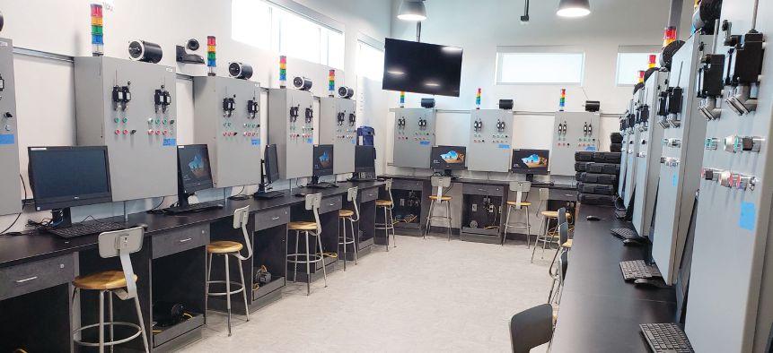


NETA UNIVERSITY CURRICULUM UPDATE
BY NENAD PASIC, Tony Demaria Electric, Inc.
In November 2016, the InterNational Electrical Testing Association (NETA) and Long Beach City College (LBCC) signed a Memorandum of Understanding (MoU) regarding the adoption of the NETA-developed Electrical Power Testing Technician (EPTT) curriculum.
Clockwise from top left: High-Tech QQ 206 Classroom Ready for Students; New LBCC PCC QQ Building — Home of NETA EPTT Program and Lifetime Learning Center; LBCC Pacific Coast Campus
NETAWorld • 91 NETA UNIVERSITY CURRICULUM UPDATE
PHOTOS COURTESY TONY DEMARIA ELECTRIC, INC.
The MoU was preceded by several meetings between NETA, represented by Bob Sheppard, NETA Training Committee Chair at that time; Nenad Pasic, NETA Training Committee Member and NETA Accredited Representative for Tony Demaria Electric, Inc. (TDE); and LBCC, represented by now retired John Hauck, LBCC Electrical Technology Instructor, and Scott Fraser, LBCC Trades and Industry Department Chair and Electrical Technology Professor.
Since the MoU signing, LBCC has worked hard to get EPTT courses approved by the State of California and the LBCC Trades and Industry Department, and the courses were successfully approved and integrated into LBCC’s Electrical Program in December 2016. On October 4, 2017, a ribbon-cutting ceremony was held at LBCC Pacific Coast Campus (PCC) to inaugurate a new QQ
building and the renovated RR building, which will house the EPPT program as well as the new High Voltage Technician Program based on the NETA EPTT curriculum at LBCC.
The EPTT curriculum includes a series of courses designed to provide graduates with a strong grasp of the educational requirements specified for a Level 2 NETA Test Technician per ANSI/NETA ETT, Standard for Certification of Electrical Testing Technicians
The new program, which will be offered as a California community college program, is designed for individuals interested in a career in the power systems industry or for electrical testing technicians seeking advancement.
Successful participants will graduate with a certificate of achievement or continue with additional credits to earn an associate degree. By the end of the program, graduates will have
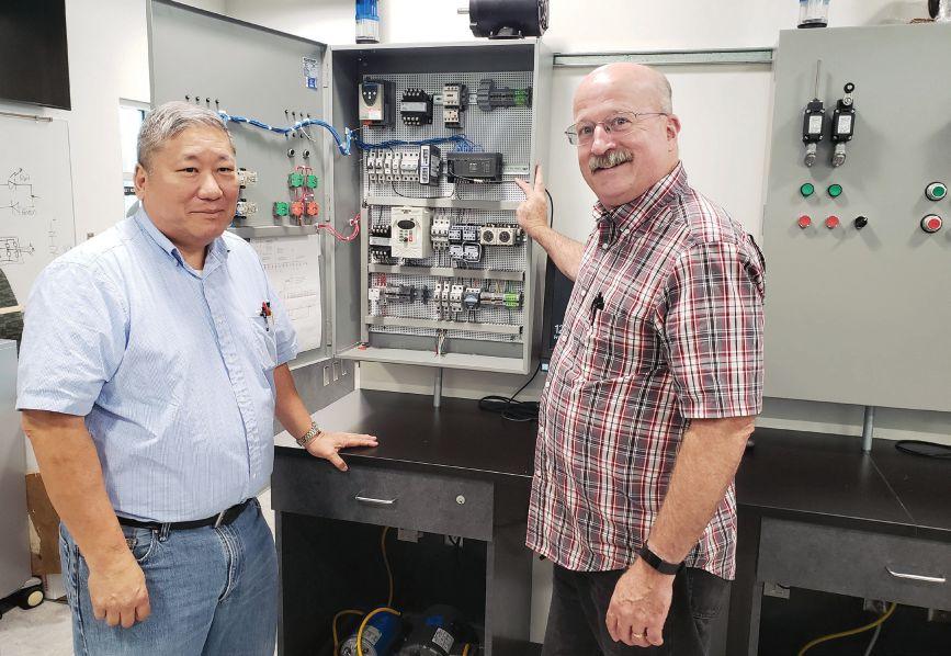
92 • WINTER 2018 NETA UNIVERSITY CURRICULUM UPDATE
PHOTO COURTESY TONY DEMARIA ELECTRIC, INC.
Mike Paik, PE, Tony Demaria Electric and LBCC instructor (left), with Scott Fraser, LBCC professor and LBCC Trades & Industry Department Chair (right), in front of one of the teaching/training modules that will be used in the NETA EPTT classes.
completed OSHA 30 training and numerous hours of electrical safety training and achieved first aid and CPR certifications.
To implement this curriculum, LBCC relies on instructors who will teach courses per NETA’s developed EPTT curriculum. Courses will be listed in LBCC’s class schedule once instructors are hired for each course. Meanwhile, to allow enough time for instructor search, LBCC off ers a ELECT 256 High Voltage Safety Awareness course during Fall 2018 and Spring 2019 semesters. This single-unit, 18-hour class focuses on safety procedures, PPE, NFPA 70E, and similar topics. It will be used to properly prepare students for the follow-on NETA classes and to build a significant number of adequately prepared students for the remainder of the classes.
The remainder of the classes will be modified to use ELECT 256 as a prerequisite class for entry. This path should ensure a better student success rate and give LBCC time to gather up the necessary hardware from the industry and properly build up the lab rather than rushing to put something together.
HIGH-VOLTAGE SAFETY AWARENESS COURSE
Mike Paik, PE, CESCP, was hired as the instructor for a High Voltage Safety Awareness course in August 2018. The class, which includes eight session sstarted on October 24, 2018. Currently, 16 students are registered for the class; the outline, agenda, test equipment, and instrument needs are planned for a class of 20. A second ELECT 256 High Voltage Safety Awareness course is slated for the Spring 2019 semester.
NETA EPTT COURSE
Hiring instructors to teach the NETA EPTT courses remains a challenge. Instructor requirements are as follows:
• Associate degree in any discipline
• Completion of an electrical training program
• Minimum six years journeyman experience (typically 20 years are required)
• Teaching credentials are not required, but a person who has them receives increased pay.
• Pay is $65-$72 per hour, typically 3-4 hours per week per class, 16 weeks per semester (with an optional third summer semester)
• Benefits such as an option to pay into retirement and pay for health benefits at a group rate are included.
Assuming instructors are hired, LBCC will off er four EPTT courses in the Fall 2019 semester:
1. ELECT 265 – Conductors, 2 units
2. ELECT 266 – Circuit Breakers, 2 units
3. ELECT 267 – Switchgear and Switchboards, 2 units
4. ELECT 268 – Transformers, 2 units
Each course is four hours per week (one hour lecture and three hours lab), 16 weeks per semester. The total cost of the program to the student is approximately $4,000.
If you are interested in teaching any of the NETA EPTT courses at LBCC, please contact Nenad (Neno) Pasic at (310) 872-6865 or email neno@tdeinc.com or Eric Beckman, eric.beckman@natlfield.com, (469) 312-1235, for more information and to start the process.

Nenad Pasic (Neno) is a NETA Accredited Representative and IT Manager for Tony Demaria Electric (TDE), where he has worked for over 15 years. He serves on the NETA Training Committee and the NETA Promotions and Marketing Committee. Neno earned his BS in computer information systems, business administration from California State University Dominguez Hills, as well as project management and information technology management certificates from the University of California Los Angeles (UCLA).
NETAWorld • 93 NETA UNIVERSITY CURRICULUM UPDATE
Cables
Rotating Machinery
Meters
Automatic Transfer Switches
Switchgear and Switchboard Assemblies
Insulating Fluids
Thermographic Surveys
Load Studies • Transient Voltage Recording and Analysis
Electromagnetic Field (EMF) Testing

Capacitors
Batteries
Ground Fault Systems • Equipotential Ground Testing
Harmonic Investigation
Replacement of Insulating Fluids
Power Factor Studies








® THE DIFFERENCE... ® ...LImIT DowNTImE; CHoosE ® CoNsERVAToRBLADDERs TRANsFoRmER AIR-CELL 800-526-5330 +1-201-825-1400 www.atlinc.com ABB Inc. - G.E. / Alstom Grid - Atlantic Transformer CG Power USA - Calpine - Duke Energy - First Energy Gexpro - Jacksonville Electric Authority - NASS - PSE&G Siemens - SPX Transformer Solutions &ManyMore! BLADDER DEsIGN GUIDE AVAILABLE oN oUR wEBsITE ULTRA-sTRoNG “oVER-LAP” sTYLE sEAms MADE IN THE U.S.A. FOR OVER 45 YEARS! sTANDARD TEmPLATEs DIGITAL LIBRARY oF PoPULAR sIzEs/sTYLEs! REVERsE ENGINEERING ATL CAN PRECIsELY DUPLICATE ANY BLADDER sTANDARD & CUsTom HARDwARE mETALLIC FLANGEs,HANGERLooPs & moRE! ExPEDITED DELIVERY ULTRA-FAsT TURNARoUND - 2 To 3 DAY AVERAGE! CUsTomERs INCLUDE: s! LADDER! ARE A FULL SERVICE NETA ACCREDITED ELECTRICAL TESTING COMPANY. Serving the Sacramento and San Francisco Bay Area 916-853-6280 www.apparatustesting.com • Acceptance Testing • Commissioning • Maintenance Testing • High Voltage
•
•
UPS
Industrial Electric Testing, Inc. EC13004105 • 24 Hour Emergency Service ACCEPTANCE AND MAINTENANCE TESTING AND REPAIR CoNSulTING AND ENGINEERING SERvICES •
•
•
•
• LV/MV Switches •
-
•
Control Centers •
•
•
•
•
•
•
•
11321
Distribution Avenue • Jacksonville, Florida 32256 • (904) 260-8378 201 NW 1st Avenue • Hallandale, Florida 33009 • (954) 456-7020
Substations
Short Circuit and Coordination Studies
Data Centers and
Systems
LV/MV Circuit Breakers
•
•
Relays
All Types
Motor
Grounding Systems
Transformers
Reclosers
Surge Arresters
•
•
•
•
•
•
West


REVISION IN PROCESS


ANSI/NETA STANDARDS UPDATE


ANSI/NETA MTS-2015 2019 REVISION IN PROCESS
ANSI/NETA MTS, Standard for Maintenance Testing Specifications for Electrical Power Equipment and Systems, 2015 Edition, continues an American National Standard revision process. A project intent notification was published in ANSI’s Standards Action on October 6, 2017, with a 45day public review period that closed November 11, 2017. The initial ballot was issued on March 8, 2018, and closed on April 8, 2018. A 30-day second ballot period and a 30day public comment period began on August 10, 2018. The intent is to release the revised edition of ANSI/NETA MTS in March 2019.
ANSI/NETA MTS contains specifications for suggested field tests and inspections to assess the suitability for continued service and reliability of electrical power equipment and systems. The purpose of these specifications is to assure that tested electrical equipment and systems are operational and within applicable standards and manufacturers’ tolerances, and that the equipment and systems are suitable for continued service.


Single copy of draft document: $459
Order from: Richard Piet 888.300.6382 rpiet@netaworld.org

Send comments to Richard Piet, rpiet@netaworld.org, with copy to psa@ansi.org.

NETAWorld • 95 ANSI/NETA STANDARDS UPDATE
SPECIFICATIONS AND STANDARDS ACTIVITY
FOR ELECTRICAL POWER EQUIPMENT & SYSTEMS STANDARD FOR ACCEPTANCE TESTING SPECIFICATIONS ANSI/NETA ATS-2017 NEW EDITION
S T A N D ARD FO R EL E C T RI C A L SCOMMISSIONING P EC IFI C A T IO N S F O R E L ECTR I CAL POWE R EQUIPMENT AND SYSTEMS
ANSI/NETA ECS-2015
SPECIFICATIONS

ANSI/NETA ECS-2015
ANSI/NETA ECS, Standard for Electrical Commissioning of Electrical Power Equipment and Systems, 2015 Edition, was approved as an American National Standard on December 3, 2014. This standard is available for purchase in the NETA Bookstore at www.netaworld.org. A project intent notification was published in ANSI’s Standards Action on May 18, 2018, with a 30-day public review period that closed June 18, 2018. An initial ballot and 45-day public comment period is scheduled to begin in January 2019.


ANSI/NETA ECS describes the systematic process of documenting and placing into service newly installed or retrofitted electrical power equipment and systems. This document shall be used in conjunction with the most recent edition of ANSI/NETA ATS, Standard for Acceptance Testing Specifications for Electrical Power Equipment and Systems. The individual electrical components shall be subjected to factory and field tests, as required, to validate the individual components. It is not the intent of these specifications to provide comprehensive details on the commissioning of mechanical equipment, mechanical instrumentation systems, and related components.
Voltage classes addressed include:
ANSI/NETA ETT-2018 NEW EDITION


ANSI/NETA ETT, Standard for Certification of Electrical Testing Technicians, 2015 Edition, has been revised as an American National Standard. ANSI/NETA ETT-2018 was approved by ANSI as an American National Standard on February 22, 2018. The revised edition was released in March 2018. It is available now in the NETA Bookstore at www.netaworld.org, where a complimentary PDF copy can be downloaded or a printed copy ordered.
ANSI/NETA ETT establishes minimum requirements for qualifications, certification, training, and experience for the electrical testing technician. It provides criteria for documenting qualifications for certification and details the minimum qualifications for an independent and impartial certifying body to certify electrical testing technicians.

• Low-voltage systems (less than 1,000 volts)
• Medium-voltage systems (greater than 1,000 volts and less than 100,000 volts)


• High-voltage and extra-high-voltage systems (greater than 100 kV and less than 1,000 kV)
References:
• ASHRAE, ANSI/NETA ATS, NECA, NFPA 70E, OSHA, GSA Building Commissioning Guide
This document is scheduled for release as a reaffirmed or revised standard in spring 2020. Those interested in participating in the revision process should contact the NETA office for more information. Initial review work began in the spring of 2018, with the initial ballot issued in late 2018/early 2019.

ANSI/NETA ATS-2017
ANSI/NETA ATS covers suggested field tests and inspections for assessing the suitability for initial energization of electrical power equipment and systems. The purpose of these specifications is to assure that tested electrical equipment and systems are operational, are within applicable standards and manufacturers’ tolerances, and are installed in accordance with design specifications.
This document is scheduled for release as a revised standard in the spring of 2021. Those interested in participating in the revision process should contact the NETA office for more information.


PARTICIPATION
Comments and suggestions on any of the standards are always welcome and should be directed to NETA. To learn more about the NETA standards review and revision process, to purchase these standards, or to get involved, please visit www.netaworld.org or contact the NETA office at 888-300-6382.


ANSI/NETA STANDARDS UPDATE 96 • WINTER 2018
AND STANDARDS ACTIVITY


ORDER TODAY! ANSI/NETA ETT-2018 STANDARD FOR CERTIFICATION OF ELECTRICAL TESTING TECHNICIANS FOR ELECTRICAL POWER EQUIPMENT & SYSTEMS To order: visit www.netaworld.org, call 888.300.6382, or email neta@netaworld.org


ASTM F18 COMMITTEE REPORT

 BY JAMES WHITE, Shermco Industries
Th e F18 committee has purview over all worker protective clothing, live-line tools, and temporary protective grounds. Unlike NFPA, ASTM meets every April to discuss what changes they want to make, then meets every October to try to correct any negatives. Changes can sometimes take years to resolve. The meeting on April 4–9, 2018, had a larger than usual attendance — about 110 people. (Editor’s note: A brief summary of this committee report was published in the Fall 2018 issue of NETA World. This article contains additional detail on the proceedings.)


F18.35.45 STANDARD TEST METHOD FOR HOOK LADDERS
The standard was balloted about a year ago. The purpose of this meeting was to resolve comments received from voters.

F1506
I am part of a working group that has been trying to revise that standard. Revisions include reflective trim and logo (no more than 16 square inches or 40 inches total). ASTM has decided to follow NFPA 70E by requiring the fabric producer to identify proof of conformity, but is also developing its own guideline. A new section 6 on visibility enhancements (high visibility) is being added and should be balloted in October.


F1506 also discussed the effects of ejected arc (arc from horizontal bus); the group believes 1584 does not accurately predict incident energy. Th e IEEE National Electric Safety Code (NESC) requires two ratings. It was agreed there needs to be more study. The tear strength and fabric weight of arc-rated clothing is currently being discussed.
• There was a lengthy discussion about whether a ladder can be used as a fall arrestor for the worker. It was decided that the ladder is a positioning device, not a fall prevention device. There was also a discussion on how to overvoltage test the ladder rungs. It was decided that additional investigation was needed on this subject before it could be resolved.
• All additional comments from the ballots were very quickly discussed and then resolved with minimal comment from the audience.
F18.25.22 D 1048 INSULATING BLANKET TEST CURRENT TASK GROUP


• Insulating blankets must be completely clean and dry before testing, or they will fail the test. If the blanket is very dirty, do not clean it by soaking it in water for several days before testing because this will ruin the blanket.
• The committee decided a maximum leakage current for blanket testing is necessary. A

SPECIFICATIONS AND STANDARDS ACTIVITY 98 • WINTER 2018 ASTM F18 COMMITTEE REPORT

SPECIFICATIONS AND STANDARDS ACTIVITY
lengthy and very lively discussion on this subject took place. There were many points of view on what the test current should be. A motion was made to limit the test to 80 percent of the test set trip current; this is said to be the unofficial default the testing industry has been using, and it appears to provide reasonable results. Many objections to this motion were raised because the suggestion was based on testing equipment capability, not safety. The committee decided much more information was needed on the subject before a decision could be made.


• Data on testing of hot gloves was presented. Several lower voltage hot gloves were punctured in a uniform way so they all had the same size hole in them. The gloves were than tested in the normal way. The gloves passed the ac test but failed the dc test. A group member suggested that the tested values in the standard should be adjusted to reflect his findings. His comments were taken under advisement, and the committee decided it needed additional information before they could move forward on this subject.

problem must be addressed in the near future.


• There are many cable types that do not work. This problem must be addressed in the near future.
• There are many problems with the tables that must be addressed in the near future.
It was decided that the only way to make progress was to break all future ballots up into small subject groups so that the issues could be appropriately addressed. The main areas to be balloted next will probably be:

F18.45.21 TEMPORARY PROTECTIVE GROUNDS, F 855 TASK GROUP
The purpose of this meeting was to resolve comments from the negative ballots on the standard:
• One negative voter wanted to add grounded mats to the standard. More discussion off-line will be necessary to resolve this issue.
• One negative voter wanted the test cables to be 10 feet long to ensure uniformity of testing. This negative voter said he would remove his negative vote if his concerns would be addressed in the future.


1. Cable test samples will be 10 feet long.
2. All tests must be done with rigid bus.
3. Rope-lay cables will not be allowed.
4. Lack of interchangeability of the products that are currently available must be addressed.
5. The number of samples that must be tested must be specified.
6. A pullout test to ensure correct crimping of the ferrules must be included.
7. A method to validate alternative testing methods must be included.


F18.15 WORKERS PERSONAL EQUIPMENT
The minutes of the last meeting held in Las Vegas were approved.
• One negative voter wanted a statement in the standard stating it is imperative to remove the rubber hot glove from the leather glove before storage, particularly if the rubber glove is wet.

• The standard implies that there is interchangeability between manufacturer’s products, which is not correct. This

• There were many comments about personal climbing equipment. The committee is collecting comments about climbing equipment. This subject should be ready for re-balloting soon.
• Another voter did not want to use ANSI as the requirement for testing because

NETAWorld • 99 ASTM F18 COMMITTEE REPORT


ANSI changes more often than the ASTM standard. It was decided to work with Hugh Hoagland to develop a testing standard for this type of equipment.

• It was agreed that the standard should be harmonized with other standards.
• It was decided that the ac test for hot gloves is not as good as the dc test because the dc test always found holes where the ac test may not. The test tables in the standard must be changed to reflect this new finding.
F18.25 INSULATED COVER-UP EQUIPMENT


The minutes from the last meeting were reviewed and approved. Two negative ballots were reviewed:
• Blanket classes 2, 3, and 4 were removed from the standard because they are no longer made. It was agreed to change the tables to represent this.
• A negative voter identified an issue with Table 1 that will be corrected. He was also concerned that the safety factor in the dc testing may be too low when testing sheet goods. The committee disagreed and voted down his proposal.

F18.35 TOOLS AND EQUIPMENT
The standard was successfully balloted.
Problems with proximity arms were discussed. A task group was working on resolving three negative votes for proximity arms. It was decided that the negative votes were not valid because they did not cover manufacturing tests, but were concerned with in-use tests.

• There was a concern that the ASTM pulltest method was not appropriate and should be replaced with the federal test method. A task group will be formed to look at the issue.
• There was concern that covers are not tested by manufacturers. The negative vote was withdrawn; a task force will investigate and make recommendations.


This meeting was attended by Tony Demaria and Gary Donner. Watch for a report on the October 7-9 meeting in the Spring 2019 NETA World Journal.

James (Jim) R. White, CESCP, Vice President of Training Services, has worked for Shermco Industries since 2001. He is a NFPA Certified Electrical Safety Compliance Professional and a NETA Level 4 Senior Technician. Jim is NETA’s principal member on NFPA Technical Committee NFPA 70E®, Standard for Electrical Safety in the Workplace; NETA’s principal representative on National Electrical Code® Code-Making Panel (CMP) 13; and represents NETA on ASTM International Technical Committee F18, Electrical Protective Equipment for Workers. Jim is Shermco Industries’ principal member on NFPA Technical Committee for NFPA 70B, Recommended Practice for Electrical Equipment Maintenance and represents AWEA on the ANSI/ ISEA Standard 203, Secondary Single-Use Flame Resistant Protective Clothing for Use Over Primary Flame Resistant Protective Clothing. An IEEE Senior Member, Jim was Chairman of the IEEE Electrical Safety Workshop in 2008 and is currently Vice Chair for the IEEE IAS/PCIC Safety Subcommittee.


SPECIFICATIONS AND STANDARDS ACTIVITY 100 • WINTER 2018 ASTM F18 COMMITTEE REPORT


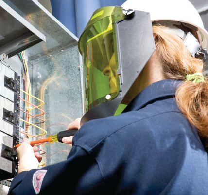


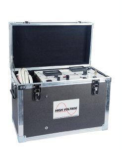

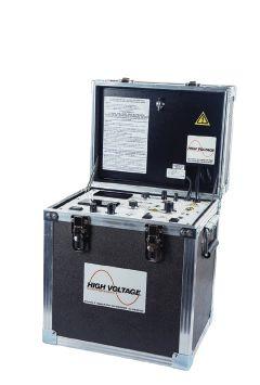

6605 W. WT Harris Blvd. Suite F • Charlotte NC 28269 | 13 Jenkins Court • Mauldin, SC 29662 | 9481 Industrial Center Drive, Suite 5 • Ladson, SC 29456 704.573.0420 • 844-383-8617 • 704.573.3693 (fax) • www.powerproducts.biz Acceptance and Maintenance Testing Commissioning Circuit Breaker Repair and Retrofit Infrared Scanning MV Cable Terminations and Testing Commissioning and Load Bank Testing of UPS, Generators, and ATS RETROFITTED BREAKER HIGH VOLTAGE, INC. 31 County Rt. 7A • Copake, NY 12516 • Tel: (518) 329-3275 • Fax: (518) 329-3271 • sales@hvinc.com • www.hvinc.com HIGH VOLTAGE, INC. ISO 9001 2008 HVI - The World’s Source for High Voltage Test Equipment HVI Makes it Easy and Efficient Cable Fault Locating & VLF Testing VLF hipot: 0 - 33 kVac @ 1 μF @ 0.1 Hz Fault locate: 0 - 13 kV @ 760 J VLF Fault Burner Radar/TDR ready Other Thumper models: 5/10/20 kV @ 1000 J 9/18/36 kV @ 3200 J • Very Low Frequency AC Technology • Cable Diagnostic TD & PD Testing • Cable Fault Locating with Controlled Energy • AC & DC Hipots, Aerial Lift Testers, Oil Testers • Ω-CHECK® Concentric Neutral Testing • Custom Engineered & Fabricated Van Pkgs. All That You Need VLF/Thumper Combination 50 kVac @ 3 kVA Hipot 1 piece & w/cable output VLF 0.1 Hz @ 34 kVac Comp. control - wireless 80 kVdc Hipot/Megohmmeter 1 instrument - 2 tests All HVI Products are Made in the USA CMY 4244_HV_NETA_Winter_2018_Ad.pdf 1 9/10/18 9:17 AM




• Digital or hand-crank models
• Analog, digital, or graphical displays
• 10V, 50V, 100V, 250V, 500V, 1000V, 2500V, 5000V, 10kV, and 15kV models
• Perform insulation resistance test into the G Ω and T Ω ranges
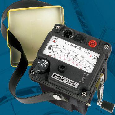

• Data analysis and reporting software included with some models
www.aemc.com

(800) 343-1391
sales@aemc.com
Megohmmeters exceed insulation testing expectations!
Our family of


CSA UPDATE
BY KERRY HEID, Shermco Industries


CSA Group is a global provider of testing, inspection, and certification services for products from a wide range of market sectors and a leader in safety and environmental certification for Canada and the United States. As one of the largest standards development organizations in North America, CSA understands the recognized benchmark that a standard sets.
Standards set benchmarks for quality, safety, sustainability, and consistency. CSA creates standards that document best practices and make the world a safer and more sustainable place. The CSA certification mark appears on billions of products worldwide.
CSA has worked closely with NETA representatives during the development of the Canadian standards.

CSA Z463 MAINTENANCE OF ELECTRICAL SYSTEMS
On August 30, 2018, the new CSA Z46318, National Standard on Maintenance of Electrical Systems, was officially published. It is now available on CSA’s on-line store at https:// store.csagroup.org/. The French edition is also available now.


CSA Z462 WORKPLACE ELECTRICAL SAFETY
CSA Z462, Standard for Workplace electrical safety has now been approved as a National Standard of Canada. You may notice that the cover page now includes the National Standard of Canada stamp (upper left) and the Standards Council of Canada logo (bottom right).


While Z462’s status as a National Standard makes little difference in how it is used in Canada, recognition as a Canadian National Standard makes a significant difference in how it is viewed outside of Canada. It also ensures that no other competing standards can replace Z462 as the National Standard.
As chair of the technical committee, I want to thank everyone across the country for all your hard work in bringing this important new standard to workplaces across Canada. Electrical maintenance programs are now a requirement in Canada, and safety risk assessments must include condition of maintenance, particularly when dealing with power systems equipment involved with switching, isolation, and protection.


The maintenance necessary for electrical equipment and systems that are critical to electrical safety for workers can be different than the maintenance required for uptime production or other business objectives. Maintenance of the electrical equipment has a direct effect on the safety of the workers using this equipment. Therefore, it is critical that electrical maintenance is an integral part of overall workplace safety and risk reduction. This standard helps organizations develop their electrical maintenance strategy that suits their needs based on:
• The principles of electrical risk management and hazard mitigation
• The size of the organization (in terms of electrical system components)

SPECIFICATIONS AND STANDARDS ACTIVITY NETAWorld • 103 CSA UPDATE
SPECIFICATIONS AND STANDARDS ACTIVITY

The standard includes the basic requirements and elements to develop an effective electrical maintenance program:
• Risk management
• Electrical maintenance program
• Factors to consider
• Planning and development of a maintenance program
• Asset maintenance strategy assessment
• Criticality of assets


• Selecting a maintenance strategy
• Equipment-specific maintenance practices
• Specialized equipment maintenance
CSA Z463’s purpose is to facilitate safe, reliable, and cost-effective operation of electrical equipment and systems through the application of consistent maintenance practices. A recent survey of electrical incidents identified lack of electrical maintenance as a major contributing factor in 14 percent of cases. Careful analysis by industry experts
confirmed a clear gap in electrical maintenance practices.
Please submit any comments or questions about CSA Z462-18 or Z463-18 to Canadian NETA Representative, Kerry Heid kheid@shermco.com, or to the CSA Group Standards Project Manager, Dave Shanahan, at dave.shanahan@csagroup.org.


Kerry Heid is President and CEO of Shermco Industries Canada Inc. After beginning his career with Westinghouse Service, Kerry started the Magna Electric Corporation (MEC) office in Regina in 1996 and became President of the company in 2001. The company grew to over 1,000 employees. MEC was acquired by Shermco Industries in December 2013. Kerry is a NETA past-President, served on NETA’s Board of Directors for over 10 years, won NETA’s Outstanding Achievement Award in 2010, and is a NETA Certified Level 4 Test Technician. He chairs the CSA Z463 Maintenance of Electrical Systems Technical Committee and has been on the CSA Z462 Workplace Electrical Safety


228 Merrick Road Lynbrook, NY 11563 (631) 589-6343/Fax (516) 596-3680 601 Union Street Brooklyn, NY 11215 (718) 786-4900
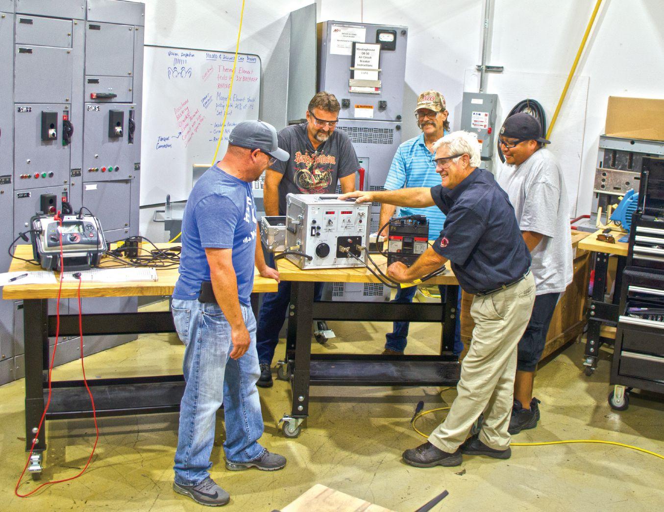


Many avo training courses are eligible for neta ctd’s t By offering the broadest selection of electrical training in the industry, we have a training course for all things electrical. We train to NETA and other industry recognized standards to take your knowledge to the next level. A training course is only as good as the instructor teaching it. That’s why our instructors are some of the most qualified in the industry. To be the best, train with the best. Offering over 57 electrical safety & electrical maintenance training courses and certifications. WWW.AVOTRAINING.COM 877-594-3156 Let us bring the training to your location, call today for an on-site quote Images depict a de-energized controlled environment with no chance for arc flash Hands-on training and NETA standards, together get you the most accurate field results. In order to provide a broad range of training and real world experiences, AVO Training Institute, Inc., courses are non-product specific. No AVO Training instructor nor contract instructor has any proprietary interest in any products, instruments, devices, services, or materials discussed.

NFPA 70E COMMITTEE REPORT


 BY JAMES WHITE, Shermco Industries
The first-draft meeting of the NFPA 70E Committee was held July 12–17, 2018, in St. Louis, Missouri. The 26 principle members represent various industry associations and companies including IEEE, ASTM, General Motors, Electrical Training Alliance (NJATC), Eaton, Sandia National Labs, Department of the Army, National Contractor’s Association, and NETA. Each of these organizations has their own agenda.
As a member of Tables Task Group and Article 130.1–4 Task Group, I arrived on Sunday to participate. There were 344 public inputs (PIs) and 12 committee first revisions (FRs). Fortytwo percent (138) of the PIs were resolved (rejected); 67 percent (206) were made into FRs.
The committee desires to make 70E simpler and easier to use. All three chapters were reorganized somewhat to move content where it should be.

not constitute elimination. The Handbook is not an official interpretation of the 70E.
A large number of other articles were moved to Article 110 because it covers safety program requirements. The committee believed that parts of Articles 120 and 130 should be moved into Article 110 for clarity. This includes Electrically Safe Work Condition, Energized Work, Equipment Less than 50 V, and Normal Operating Condition.


• In Article 110.2(4) Type of Training, an added IN allows interactive video or webbased interactive training: Informational Note: Classroom training can include interactive electronic or interactive webbased training components.
• Article 110.11 Equipment Use states: Equipment shall be used in accordance with the manufacturer’s instructions.
CHAPTER 1 OVERVIEW
Informational Note No. 2 was added to Article 110.1:
Informational Note 2: An electrically safe work condition is a state wherein all hazardous electrical conductors or circuit parts to which a worker might be exposed are placed and maintained in a zero-energy state, eliminating electrical hazards. See Article 120 for requirements to establish an electrically safe work condition. See Informative Annex F for information regarding the hierarchy of risk control and hazard elimination.


This was necessary because the NFPA 70E Handbook erroneously stated that placing equipment in an electrically safe condition did

• Article 130.2 Electrically Safe Work Conditions was moved to Article 110.1.
• Article 130.3 Working While Exposed to Electrical Hazards was moved to Article 110.1.
• Article 130.4 added a requirement to consider the condition of equipment and its maintenance when estimating the likelihood of occurrence and severity.
• Article 130.4(F)(3) Entering the Limited Approach Boundary now states: The qualified person escorting the unqualified person(s) shall have no unrelated duties.


• Changes to Table 130.5(C) Estimate of the Likelihood of Occurrence of an Arc Flash Incident for ac and dc Systems added a task: Operation of a CB or switch the first time after installation or completion of work or maintenance in the equipment (Likelihood of Occurrence is YES).

SPECIFICATIONS AND STANDARDS ACTIVITY 106 • WINTER 2018 NFPA 70E COMMITTEE REPORT

• Table 130.7(C)(70(a) was revised and corrected:


Table 130.7(C)(7)(a) Maximum Use Voltage for Rubber Insulating Gloves

• In Article 130.7(C)(9) Factors in Selection of Protective Clothing, high-visibility safety apparel was added to the list of outerwear that must be arc-rated.

• A new requirement was added to Article 130.7(C)(10)(E) Foot Protection: Footwear other than leather or dielectric shall be permitted to be used provided it has been tested to demonstrate no ignition, melting or dripping at the estimated incident energy. exposure or the minimum arc rating for the respective Arc Flash PPE Category.
• Article 130.7(C)(15)(c) was amended: PPE listed in Table 130.7(C)(15)(c) is a minimum requirement. Use of PPE in addition to that listed shall be permitted provided it meets the requirements of 130.7(C)(7).

CHAPTER 3 — ARTICLE 130


Various other changes were made to Article 130, to Chapter 3, and to the Informative Annexes, but space here is limited to discuss.
The second-draft 70E Committee meeting is scheduled July 14–17, 2019. The location has not been determined.

CHAPTER 2 SAFETYRELATED MAINTENANCE REQUIREMENTS
New text was added to Article 250.3 Safety Grounding Equipment:
(B) Testing. Prior to being returned to service, temporary protective grounding equipment that has been repaired or modified shall be tested. Temporary protective grounding equipment shall be tested as service conditions require, but in no case shall the interval exceed 3 years.


James (Jim) R. White, CESCP, Vice President of Training Services, has worked for Shermco Industries since 2001. He is a NFPA Certified Electrical Safety Compliance Professional and a NETA Level 4 Senior Technician. Jim is NETA’s principal member on NFPA Technical Committee NFPA 70E®, Standard for Electrical Safety in the Workplace; NETA’s principal representative on National Electrical Code® Code-Making Panel (CMP) 13; and represents NETA on ASTM International Technical Committee F18, Electrical Protective Equipment for Workers. Jim is Shermco Industries’ principal member on NFPA Technical Committee for NFPA 70B, Recommended Practice for Electrical Equipment Maintenance and represents AWEA on the ANSI/ISEA Standard 203, Secondary Single-Use Flame Resistant Protective Clothing for Use Over Primary Flame Resistant Protective Clothing. An IEEE Senior Member, Jim was Chairman of the IEEE Electrical Safety Workshop in 2008 and is currently Vice Chair for the IEEE IAS/PCIC Safety Subcommittee.


NETAWorld • 107 NFPA 70E COMMITTEE REPORT
Class Designation of Glove or Sleeve Maximum AC Use Voltage rms, V Maximum DC Use Voltage avg, V Distances Between Gauntlet and Cuff, min 00 500 750 13 mm (0.5 in) 0 1000 1500 13 mm (0.5 in) 1 7500 11250 25 mm (1 in) 2 17000 25500 51 mm (2 in) 3 26500 39750 76 mm (3 in) 4 36000 54000 102 mm (4 in) SPECIFICATIONS AND STANDARDS ACTIVITY


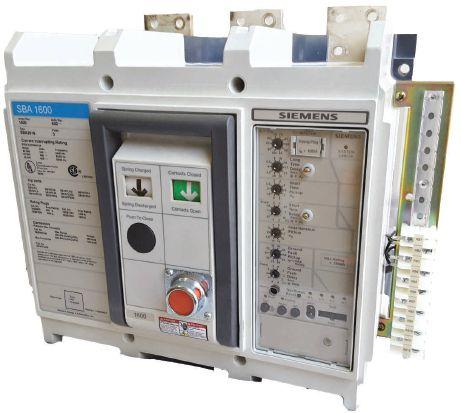


Phone: 800-421-5082 email: Sales@qualityswitchgear.com Something you don’t see everyday... SB Breakers But we do! Complete Breakers Trip Units Electric Operators Shunt trips/UVRs All Factory New


NFPA CMP 13 COMMITTEE REPORT
BY JAMES WHITE, Shermco Industries
The first draft meeting of the NFPA CMP 13 Committee was held January 8–13 in Hilton Head, South Carolina. CMP 13 is composed of 33 members from various organizations including IBEW, the National Electrical Contractors Association, Portable Generator Manufacturers, NEMA, the International Association of Electrical Inspectors, CSA, the American Chemistry Council, Cummins Power Generation, and NETA.


by a qualified person(s) in accordance with manufacturer’s instructions.

CMP 13 covers legally required generators, standby generators, micro-grids, fire pumps, emergency systems, energy storage systems, and critical operations power systems, specifically Articles 480, 700, 701, 702, 708712, 695, 750, 100, and 706. The closing date for the second draft was August 30, 2018. There were 280 public inputs (PIs).
In the articles under the purview of CMP 13, particularly those dealing with emergency systems, the .3 sections address testing and maintenance. Various inputs to these sections would require maintenance testing and designate which standards should be referenced. Several inputs suggest referencing manufacturer’s recommendations or industry consensus standards. The first draft will likely include several references to ANSI/NETA MTS-2015.


When performance testing an instantaneous trip setting specified in 240.87(B)(5) or instantaneous override specified in 240.87(B) (6), this testing shall be conducted by a qualified person(s) using a test process of primary injection and manufacturer’s recommended testing procedures. A written record of this testing shall be made and shall be available to the authority having jurisdiction.
The January meeting was attended by alternate representative Bill Otterson. The second draft meeting is October 22–November 3, 2018, in San Diego.

Several PIs requiring performance testing of the arc reduction system after installation were submitted:
The arc energy reduction protection system shall be performance tested when first installed on site. This test shall be conducted


James (Jim) R. White, CESCP, Vice President of Training Services, has worked for Shermco Industries since 2001. He is a NFPA Certified Electrical Safety Compliance Professional and a NETA Level 4 Senior Technician. Jim is NETA’s principal member on NFPA Technical Committee NFPA 70E®, Standard for Electrical Safety in the Workplace; NETA’s principal representative on National Electrical Code® Code-Making Panel (CMP) 13; and represents NETA on ASTM International Technical Committee F18, Electrical Protective Equipment for Workers. Jim is Shermco Industries’ principal member on NFPA Technical Committee for NFPA 70B, Recommended Practice for Electrical Equipment Maintenance and represents AWEA on the ANSI/ ISEA Standard 203, Secondary Single-Use Flame Resistant Protective Clothing for Use Over Primary Flame Resistant Protective Clothing. An IEEE Senior Member, Jim was Chairman of the IEEE Electrical Safety Workshop in 2008 and is currently Vice Chair for the IEEE IAS/PCIC Safety Subcommittee.

NETAWorld • 109 NFPA CMP-13 COMMITTEE REPORT
SPECIFICATIONS AND STANDARDS ACTIVITY


Ensure YOUR Safety and Reliability.

NETA has been connecting designers, specifiers, architects and users of electrical power equipment and systems with independent, third-party electrical testing companies since 1972.


NETA Accredited Companies test the complete system in accordance with industry codes and standards to provide accurate test reports you can count on every time.


HIRE A NETA ACCREDITED COMPANY. For more information on NETA or our ANSI/NETA Standards give us a call at 888-300-NETA (6382) or a complete listing of NETA Accredited Companies visit www.netaworld.org.


ANSWERS




ANSWERS


1. b. The National Electrical Code was first published as a national standard in 1897. The first committee began working on it in 1895 because the 1888 World’s Fair had a number of electrical problems and experts were brought in to make corrections. That caused people to start thinking about the consequences of poor wiring.
2. d. The NEC was first published in New York.
3. d. Article 701.3 covers legally required standby systems.
4. d. Article 695 covers fire pumps.
5. c. Article 700 covers emergency systems.
NFPA Disclaimer: Although Jim White is a member of the NFPA Technical Committee for both NFPA 70E, Standard for Electrical Safety in the Workplace, and NFPA 70B, Recommended Practice for Electrical Equipment Maintenance, the views and opinions expressed in this column are purely the author’s and shall not be considered an official position of the NFPA or any of its technical committees and shall not be considered, nor be relied upon, as a formal interpretation or promotion of the NFPA. Readers are encouraged to refer to the entire text of all referenced documents.
NETAWorld • 111 TECH QUIZ
No. 124
TECH QUIZ ANSWERS




24 Hour Emergency Services (937) 439-9660 Electrical Distribution System Testing, Repair, and Maintenance www.BurlingtonSafety.com info@BurlingtonSafety.com Browse and Buy Online Now! Metro NY/NJ/PA 800-220-2120 Calif (SF) 888-817-1412 Calif (LA) 800-296-2803 Your Source for NFPA 70E Compliant Protective Gear Accredited Proof Testing Laboratory Services Rubber Gloves ◆ Sleeves ◆ Blankets ◆ Line Hose Footwear ◆ Jumpers ◆ Hotsticks
A&F Electrical Testing, Inc.
80 Lake Ave. S Ste. 10 Nesconset, NY 11767-1017 (631) 584-5625 kchilton@afelectricaltesting.com www.afelectricaltesting.com
Kevin Chilton
A&F Electrical Testing, Inc.
80 Broad St. Fl. 5 New York, NY 10004-2257 (631) 584-5625 afelectricaltesting@afelectricaltesting.com
Florence Chilton
ABM Electrical Power Services, LLC
720 S Rochester Ste. A Ontario, CA 91761-8177 (301) 397-3500 rob.parton@abm.com www.abm.com
Rob Parton
ABM Electrical Power Services, LLC 6541 Meridien Dr. Ste. 113 Raleigh, NC 27616 (919) 877-1008
ABM Electrical Power Services, LLC
2631 S. Roosevelt St. Tempe, AZ 85282 (602) 722-2423
ABM Electrical Power Services, LLC
3600 Woodpark Blvd. Ste. G Charlotte, NC 28206-4210 (704) 273-6257
ABM Electrical Power Services, LLC
6940 Koll Center Pkwy. Ste. 100 Pleasanton, CA 94566 (408) 466-6920
ABM Electrical Power Services, LLC
3585 Corporate Court San Diego, CA 92123-1844 (858) 754-7963
ABM Electrical Power Services, LLC
1005 Windward Ridge Pkwy Alpharetta, GA 30005 (770) 521-7550
ABM Electrical Power Solutions
4390 Parliament Pl. Ste. S Lanham, MD 20706 (301) 967-3500 christopher.smith@abm.com www.abm.com
Christopher Smith
ABM Electrical Power Solutions
3700 Commerce Dr. # 901-903 Baltimore, MD 21227-1642 (410) 247-3300
ABM Electrical Power Solutions
317 Commerce Park Dr. Cranberry Township, PA 16066-6407 (724) 772-4638
ABM Electrical Power Solutions 814 Greenbrier Cir. Ste. E Chesapeake, VA 23320-2643 (757) 364-6145
ABM Electrical Power Solutions 9800 E Geddes Ave. Unit A-150 Englewood, CO 80112-9306 (303) 524-6560
ABM Electrical Power Solutions 1817 O'Brien Rd. Columbus, OH 43228 (724) 772-4638
Absolute Testing Services, Inc. 8100 West Little York Houston, TX 77040 (832) 467-4446 www.absolutetesting.com
Accessible Consulting Engineers, Inc. 1269 Pomona Rd. Ste. 111 Corona, CA 92882-7158 (951) 808-1040 info@acetesting.com www.acetesting.com
Iraj Nasrolahi
Advanced Electrical Services 4999 - 43rd St. NE Unit 143 Calgary, AB T2B 3N4 Canada (403) 697-3747
zakhouk@aes-ab.com www.aes-ab.com
Zachary Houk
Advanced Testing Systems 15 Trowbridge Dr. Bethel, CT 06801-2858 (203) 743-2001
pmaccarthy@advtest.com www.advtest.com
Pat MacCarthy
American Electrical Testing Co., LLC 25 Forbes Blvd. Ste. 1 Foxboro, MA 02035 (781) 821-0121 sblizard@aetco.us www.aetco.us
Scott A. Blizard
American Electrical Testing Co., LLC
Green Hills Commerce Center 5925 Tilghman St. Ste. 200 Allentown, PA 18104-9158 (215) 219-6800
jmunley@aetco.us
Jonathan Munley
American Electrical Testing Co., LLC 34 Clover Dr. South Windsor, CT 06074-2931 (860) 648-1013 jpoulin@aetco.us
Gerald Poulin
NETA ACCREDITED COMPANIES
American Electrical Testing Co., LLC
76 Cain Dr. Brentwood, NY 11717-1265 (631) 617-5330
bfernandez@aetco.us
Billy Fernandez
American Electrical Testing Co., LLC
91 Fulton St. Boonton, NJ 07005-1060 (973) 316-1180
jsomol@aetco.us
Jeff Somol
American Electrical Testing Co., LLC 12566 W Indianola Ave. Avondale, AZ 85392-6322 (480) 383-9242 dmadaglia@aetco.us
Donald Madaglia
Apparatus Testing and Engineering
11300 Sanders Dr. Ste. 29 Rancho Cordova, CA 95742-6822 (916) 853-6280 info@apparatustesting.com www.apparatustesting.com
Harold (Jerry) Carr
Apparatus Testing and Engineering 7083 Commerce Cir. Ste. H Pleasanton, CA 94588-8017 (925) 454-1363
Applied Engineering Concepts 894 N. Fair Oaks Ave. Pasadena, CA 91103 (626) 389-2108
Michel.c@aec-us.com www.aec-us.com
Michel Castonguay
Applied Engineering Concepts 8160 Miramar Rd. San Diego, CA 92126 (619) 822-1106 Michel.c@aec-us.com www.aec-us.com
Michel Castonguay
BEC Testing 50 Gazza Blvd. Farmingdale, NY 11735-1402 (631) 393-6800
ddevlin@banaelectric.com www.bectesting.com
Daniel Devlin
Burlington Electrical Testing Co., Inc. 300 Cedar Ave. Croydon, PA 19021-6051 (215) 826-9400
Burlington Electrical Testing Co., Inc. 198 Burrs Rd. Westampton, NJ 08060 (609) 267-4126
waltc@betest.com www.betest.com
Walter P. Cleary
C.E. Testing, Inc. 6148 Tim Crews Rd. Macclenny, FL 32063-4036 (904) 653-1900
cetesting@aol.com www.cetestinginc.com
Mark Chapman
CE Power Engineered Services, LLC
40 Washington St. Westborough, MA 01581-1088 (508) 881-3911
jim.cialdea@cepower.net www.cepower.net
Jim Cialdea
CE Power Engineered Services, LLC 480 Cave Rd. Nashville, TN 37210-2302 (615) 892-9455
bryant.phillips@cepower.net www.cepower.net
Bryant Phillips
CE Power Engineered Services, LLC 72 Sanford Dr. Gorham, ME 04038 (800) 649-6314
jim.cialdea@cepower.net www.cepower.net
Jim Cialdea
CE Power Engineered Services, LLC 4040 Rev Dr. Cincinnati, OH 45232 (800) 434-0415
info@cepower.net
www.cepower.net
Brent McAlister
CE Power Engineered Services, LLC 7674 Washington Ave. S Eden Prairie, MN 55344 (877) 968-0281
Jason.thompson@cepower.net
Jason Thompson
CE Power Engineered Services, LLC 8490 Seward Rd. Fairfield, OH 45011 (800) 434-0415
Tim.lana@cepower.net
Tim Lana
CE Power Engineered Services, LLC 1803 Taylor Ave. Louisville, KY 40213 (800) 434-0415
bob.sheppard@cepower.net
Bob Sheppard
CE Power Engineered Services, LLC 10338 Citation Dr. Ste. 300 Brighton, MI 48116 (810) 229-6628
Ken.lesperance@cepower.net
Ken L’Esperance
NETAWorld • 113 NETA ACCREDITED COMPANIES
Setting the Standard
NETA ACCREDITED COMPANIES Setting the
CE Power Engineered Services, LLC
10840 Murdock Dr. Knoxville, TN 37932 (800) 434-0415
Don.williams@cepower.net
Don Williams
CE Power Engineered Services, LLC
3496 E. 83rd Pl. Merrillville, IN 46410 (219) 942-2346
CE Power Solutions of Florida, LLC
3502 Riga Blvd. Ste. C Tampa, FL 33619
CE Power Solutions of Florida, LLC
3801 SW 47th Ave. Ste. 505 Davie, FL 33314 (866) 439-2992
Control Power Concepts
353 Pilot Rd. Ste. B
Las Vegas, NV 89119-3520 (702) 448-7833
jtravis@ctrlpwr.com www.controlpowerconcepts.com
John Travis
Dude Electrical Testing LLC
145 Tower Dr. Ste. 9 Burr Ridge, IL 60527-7840 (815) 293-3388
scott.dude@dudetesting.com www.dudetesting.com
Scott Dude
Eastern High Voltage, Inc.
11A S Gold Dr. Robbinsville, NJ 08691-1685 (609) 890-8300
bobwilson@easternhighvoltage.com www.easternhighvoltage.com
Robert Wilson
ELECT, P.C.
375 E. Third St. Wendell, NC 27591 (919) 365-9775
btyndall@elect-pc.com www.elect-pc.com
Barry W. Tyndall
Electric Power Systems
6679 Peachtree Industrial Dr. Ste. H Norcross, GA 30092 (770) 416-0684
Electric Power Systems, Inc. 21 Millpark Ct. Maryland Heights, MO 63043-3536 (314) 890-9999
s.reed@epsii.com www.epsii.com
Steve Reed
Electric Power Systems, Inc. 11211 E. Arapahoe Rd. Ste. 108 Centennial, CO 80112 (720) 857-7273
Electric Power Systems, Inc. 120 Turner Rd. Salem, VA 24153-5120 (540) 375-0084
Electric Power Systems, Inc. 1090 Montour West Industrial Pk. Coraopolis, PA 15108-9307 (412) 276-4559
Electric Power Systems, Inc. 6141 E Connecticut Ave. Kansas City, MO 64120-1346 (816) 241-9990
Electric Power Systems, Inc.
1230 N Hobson St. Ste. 101 Gilbert, AZ 85233 (480) 633-1490
Electric Power Systems, Inc. 915 Holt Ave. Unit 9 Manchester, NH 03109-5606 (603) 657-7371
Electric Power Systems, Inc. 4436 Parkway Commerce Blvd. Orlando, FL 32808-1008 (407) 578-6424
Electric Power Systems, Inc. 1129 E Highway 30 Gonzales, LA 70737-4759 (225) 644-0150
Electric Power Systems, Inc. 684 Melrose Ave. Nashville, TN 37211-3121 (615) 834-0999
Electric Power Systems, Inc.
2888 Nationwide Pkwy. 2nd Floor Brunswick, OH 44212 (330) 460-3706
Electric Power Systems, Inc. 54 Eisenhower Ln. North Lombard, IL 60148 (815) 577-9515
Electric Power Systems, Inc. 1330 Industrial Blvd. Ste. 300 Sugar Land, TX 77478 (713) 644-5400
Electric Power Systems, Inc. 56 Bibber Pkwy. # 1 Brunswick, ME 04011-7357 (207) 837-6527
Electric Power Systems, Inc. 11861 Longsdorf St. Riverview, MI 48193-4250 (734) 282-3311
Electric Power Systems, Inc. 8515 Calle Alameda NE Ste. A Albuquerque, NM 87113 (505) 792-7761
Electric Power Systems, Inc. 319 US 70 Hwy. E Ste. E Garner, NC 27529-4054 (919) 210-5405
Electric Power Systems, Inc. 5850 Polaris Ave. Ste. 1600 Las Vegas, NV 89118 (702) 815-1342
Electric Power Systems, Inc. 7925 Dunbrook Rd. Ste. G San Diego, CA 92126 (858) 566-6317
Electric Power Systems, Inc. 306 Ashcake Rd. Ste. A Ashland, VA 23005 (804) 526-6794
Electric Power Systems, Inc. 7169 E. 87th St. Indianapolis, IN 46256 (317) 941-7502
Daniel Douglas
Electrical & Electronic Controls 6149 Hunter Rd. Ooltewah, TN 37363-8762 (423) 344-7666 eecontrols@comcast.net
Michael Hughes
Electrical Energy Experts, Inc. W129N10818 Washington Dr. Germantown, WI 53022-4446 (262) 255-5222 tim@electricalenergyexperts.com www.electricalenergyexperts.com
Tim Casey
Electrical Engineering & Service Co. Inc. 289 Centre St. Holbrook, MA 02343 (781) 767-9988 jcipolla@eescousa.com www.eescousa.com
Joe Cipolla
Electrical Equipment Upgrading, Inc. 21 Telfair Pl. Savannah, GA 31415-9518 (912) 232-7402 kmiller@eeu-inc.com www.eeu-inc.com
Kevin Miller
Electrical Maintenance & Testing, Inc. 12342 Hancock St. Carmel, IN 46032-5807 (317) 853-6795 info@emtesting.com www.emtesting.com
Brian K. Borst
Electrical Reliability Services 610 Executive Campus Dr. Westerville, OH 43082-8870 (877) 468-6384 info@electricalreliability.com
Electrical Reliability Services
5909 Sea Lion Pl. Ste. C Carlsbad, CA 92010-6634 (858) 695-9551
Electrical Reliability Services
1057 Doniphan Park Cir. Ste. A El Paso, TX 79922-1329 (915) 587-9440
Electrical Reliability Services
6900 Koll Center Pkwy. Ste. 415 Pleasanton, CA 94566-3119 (925) 485-3400
Electrical Reliability Services
8500 Washington St. NE Ste. A6 Albuquerque, NM 87113-1861 (505) 822-0237
Electrical Reliability Services 2275 Northwest Pkwy. SE Ste. 180 Marietta, GA 30067-9319 (770) 541-6600
Electrical Reliability Services 10606 Bloomfield Ave. Santa Fe Springs, CA 90670-3912 (562) 236-9555
Electrical Reliability Services
400 NW Capital Dr. Lees Summit, MO 64086-4723 (816) 525-7156
Electrical Reliability Services 7100 Broadway Ste. 7E Denver, CO 80221-2900 (303) 427-8809
Electrical Reliability Services 2222 W Valley Hwy. N Ste. 160 Auburn, WA 98001-1655 (253) 736-6010
Electrical Reliability Services 221 E. Willis Road Chandler, AZ 85286 (480) 966-4568
Electrical Reliability Services 1380 Greg St. Ste. 217 Sparks, NV 89431-6070 (775) 746-8484
Electrical Reliability Services 11000 Metro Pkwy. Ste. 30 Fort Myers, FL 33966-1244 (239) 693-7100
Electrical Reliability Services 245 Hood Rd. Sulphur, LA 70665-8747 (337) 583-2411
Electrical Reliability Services 9736 South 500 West Sandy, UT 84070 (801) 975-6461
Electrical Reliability Services
6351 Hinson St. Ste. A Las Vegas, NV 89118-6851 (702) 597-0020
114 • WINTER 2018 NETA ACCREDITED COMPANIES
Standard
Electrical Reliability Services
3535 Emerson Pkwy. Ste. A Gonzales, LA 70737 (225) 755-0530
Electrical Reliability Services
9636 Saint Vincent Ave. Unit A Shreveport, LA 71106-7127 (318) 869-4244
Electrical Reliability Services
1426 Sens Rd. Ste. 5 La Porte, TX 77571-9656 (281) 241-2800
Electrical Reliability Services
6135 Lakeview Rd. Ste. 500 Charlotte, NC 28269-2630 (704) 441-1497
Electrical Reliability Services
4099 SE International Way Ste. 201 Milwaukie, OR 97222-8853 (503) 653-6781
Electrical Testing and Maintenance Corp.
3673 Cherry Rd. Ste. 101 Memphis, TN 38118-6313 (901) 566-5557
r.gregory@etmcorp.com www.etmcorp.net
Ron Gregory
Electrical Testing Solutions
2909 Greenhill Ct. Oshkosh, WI 54904-9769 (920) 420-2986
tmachado@electricaltestingsolutions.com
Tito Machado
Electrical Testing, Inc. 2671 Cedartown Hwy. SE Rome, GA 30161-3894 (706) 234-7623
jamie@electricaltestinginc.com www.electricaltestinginc.com
Jamie Dempsey
Elemco Services, Inc. 228 Merrick Rd. Lynbrook, NY 11563-2622 (631) 589-6343 Courtney@elemco.com www.elemco.com
Courtney Gallo
EnerG Test, LLC
206 Gale Ln. Kennett Square, PA 19348 (484) 731-0200 dbuehler@energtest.com www.energtest.com
Dennis Buehler
Energis High Voltage Resources 1361 Glory Rd. Green Bay, WI 54304-5640 (920) 632-7929 info@energisinc.com www.energisinc.com
Mick Petzold
EPS Technology 29 N Plains Hwy. Ste. 12 Wallingford, CT 06492-5838 (203) 679-0145
s.miller@eps-technology.com www.eps-technology.com
Sean Miller
Giga Electrical & Technical Services, Inc.
2743A N. San Fernando Rd. Los Angeles, CA 90065 (323) 255-5894
gigaelectrical@att.net www.gigaelectrical-ca.com
Hermin Machacon
Grubb Engineering, Inc. 2727 North Saint Mary’s St. San Antonio, TX 78212 (210) 658-7250 joy@grubbengineering.com www.grubbengineering.com
Robert D. Grubb Jr.
Halco Testing Services 5773 Venice Blvd. Los Angeles, CA 90019 (323) 933-9431
d.genutis@halco.net www.halcotestingservices.com
Don Genutis
Hampton Tedder Technical Services 4563 State St. Montclair, CA 91763-6129 (909) 628-1256 x214
Chasen.tedder@hamptontedder.com www.hamptontedder.com
Chasen Tedder
Hampton Tedder Technical Services 3747 W Roanoke Ave. Phoenix, AZ 85009-1359 (480) 967-7765
Linc McNitt
Hampton Tedder Technical Services 4113 Wagon Trail Ave. Las Vegas, NV 89118 (702) 452-9200
Roger Cates
Harford Electrical Testing Co., Inc. 1108 Clayton Rd. Joppa, MD 21085-3409 (410) 679-4477 testing@harfordtesting.com www.harfordtesting.com
Vincent Biondino
High Energy Electrical Testing, Inc. 515 S Ocean Ave. Seaside Park, NJ 08752-1843 (732) 938-2275 hinrg@comcast.net www.highenergyelectric.com
Charles Blanchard
High Voltage Maintenance Corp. 10704 Electron Dr. Louisville, KY 40299 (859) 371-5355
High Voltage Maintenance Corp. 5100 Energy Dr. Dayton, OH 45414-3525 (937) 278-0811
High Voltage Maintenance Corp. 24 Walpole Park S Walpole, MA 02081-2541 (508) 668-9205 www.hvmcorp.com
High Voltage Maintenance Corp. 8320 Brookville Rd. Ste. E Indianapolis, IN 46239-8914 (317) 322-2055
High Voltage Maintenance Corp. 355 Vista Park Dr. Pittsburgh, PA 15205-1206 (412) 747-0550
High Voltage Maintenance Corp. 7200 Industrial Park Blvd. Mentor, OH 44060-5316 (440) 951-2706
High Voltage Maintenance Corp. 24371 Catherine Industrial Dr. Ste. 207 Novi, MI 48375-2422 (248) 305-5596
High Voltage Maintenance Corp. 3000 S Calhoun Rd. New Berlin, WI 53151-3549 (262) 784-3660
High Voltage Maintenance Corp. 1250 Broadway Ste. 2300 New York, NY 10001-3726 (718) 239-0359
High Voltage Maintenance Corp. 150 N Plains Industrial Rd. Wallingford, CT 06492-2353 (203) 949-2650
High Voltage Maintenance Corp. 9305 Gerwig Ln. Ste. B Columbia, MD 21046-2903 (410) 309-5970
High Voltage Maintenance Corp. 941 Busse Rd. Elk Grove Village, IL 60007-2400 (847) 640-0005
High Voltage Maintenance Corp. 14300 Cherry Lane Ct. Ste. 115 Laurel, MD 20707 (410) 279-0798
HMT, Inc.
6268 State Route 31 Cicero, NY 13039-9217 (315) 699-5563 jpertgen@hmt-electric.com www.hmt-electric.com John Pertgen
Industrial Tests, Inc. 4021 Alvis Ct. Ste. 1 Rocklin, CA 95677-4031 (916) 296-1200
greg@indtest.com www.industrialtests.com
Greg Poole
Infra-Red Building and Power Service, Inc. 152 Centre St. Holbrook, MA 02343-1011 (781) 767-0888
tom.mcdonald@infraredbps.com www.infraredbps.com
Thomas McDonald Sr.
J.G. Electrical Testing Corporation 3092 Shafto Rd. Ste. 13 Tinton Falls, NJ 07753 (732) 217-1908 www.jgelectricaltesting.com h.trinkowsky@jgelectricaltesting.com
Howard Trinkowsky
M&L Power Systems, Inc. 109 White Oak Ln. Ste. 82 Old Bridge, NJ 08857-1980 (732) 679-1800 milind@mlpower.com www.mlpower.com
Milind Bagle
Magna IV Engineering 1103 Parsons Rd. SW Edmonton, AB T6X 0X2 Canada (780) 462-3111 info@magnaiv.com www.magnaiv.com
Virgina Balitski
Magna IV Engineering 141 Fox Cresent Fort McMurray, AB T9K 0C1 (780) 791-3122 Info.fmcmurray@magnaiv.com
Ryan Morgan
Magna IV Engineering 7, 3040 Miners Ave. Saskatoon, SK S7K 5V1 Canada (306) 585-2100 Info.regina@magnaiv.com
Adam Jaques
Magna IV Engineering 96 Inverness Dr. E Ste. R Englewood, CO 80112-5311 (303) 799-1273
Info.denver@magnaiv.com
Aric Proskurniak
Magna IV Engineering Avenida del Condor sur #590 Oficina 601 Huechuraba, 8580676
Chile +(56) -2-26552600 chile@magnaiv.com Harvey Mendoza
NETAWorld • 115 NETA ACCREDITED COMPANIES
COMPANIES Setting the Standard
NETA ACCREDITED
NETA ACCREDITED COMPANIES Setting the Standard
Magna IV Engineering
106, 4268 Lozells Ave. Burnaby, BC VSA 0C6 Canada (604) 421-8020
Scott Nixon
Magna IV Engineering
688 Heritage Dr. SE Ste. 200 Calgary, AB T2H 1M6 Canada (403) 723-0575
Magna IV Engineering
4407 Halik St. Building E Ste. 300 Pearland, TX 77581 (720) 480-9680
aproskurniak@magnaiv.com www.magnaiv.com Aric Proskurniak
Midwest Engineering Consultants, Ltd. 2500 36th Ave.
Moline, IL 61265-6954 (309) 764-1561 m-moorehead@midwestengr.com www.midwestengr.com
Monte Moorehead
National Field Services 651 Franklin Lewisville, TX 75057-2301 (972) 420-0157
www.natlfield.com Eric Beckman
National Field Services
1890 A South Hwy. 35 Alvin, TX 77511 (800) 420-0157
Jonathan.wakeland@natlfield.com www.natlfield.com
Jonathan Wakeland
National Field Services
1405 United Dr. Ste. 113-115 San Marcos, TX 78666 (800) 420-0157 info@natlfield.com www.natlfield.com
Matt LaCoss
National Field Services 3711 Regulus Ave. Las Vegas, NV 89102 (888) 296-0625 www.natlfield.com howard.herndon@natlfield.com Howard Herndon
National Field Services
2900 Vassar St. #114 Reno, NV 89502 (775) 410-0430 www.natlfield.com howard.herndon@natlfield.com
Howard Herndon
Nationwide Electrical Testing, Inc.
6050 Southard Trce. Cumming, GA 30040-6343 (770) 667-1875
Shashi@N-E-T-Inc.com www.n-e-t-inc.com
Shashikant B. Bagle
North Central Electric, Inc.
69 Midway Ave. Hulmeville, PA 19047-5827 (15) 945-7632 ncetest@aol.com www.ncetest.com
Robert Messina
Northern Electrical Testing, Inc. 1991 Woodslee Dr. Troy, MI 48083-2236 (248) 689-8980 ldetterman@northerntesting.com www.northerntesting.com
Lyle Detterman
Oris Engineering Field Services Ltd. #300, 9404 - 41st Ave. Edmonton, AB T6E 6G8 Canada (780) 988-1455 lorne@orbisengineering.net www.orbisengineering.net
Lorne Gara
Orbis Engineering Field Services Ltd. #228 - 18 Royal Vista Link NW Calgary, AB T3R 0K4
Canada (403) 374-0051
Orbis Engineering Field Services Ltd.
Badajoz #45, Piso 17 Las Condes
Santiago, Chile +56 2 29402343
Pace Technologies, Inc. 9604 - 41 Ave. NW Edmonton, AB T6E 6G9 Canada (780) 450-0404 cleavitt@pacetechnologies.com www.pacetechnologies.com
Craig Leavitt
Pace Technologies, Inc. #10, 883 McCurdy Pl. Kelowna, BC V1X 8C8 (250) 712-0091
Pacific Power Testing, Inc. 14280 Doolittle Dr. San Leandro, CA 94577-5542 (510) 351-8811
steve@pacificpowertesting.com www.pacificpowertesting.com
Steve Emmert
Pacific Powertech Inc. #110, 2071 Kingsway Ave. Port Coquitlam, BC V3C 6N2
Canada (604) 944-6697
jkonkin@pacificpowertech.ca www.pacificpowertech.ca
Josh Konkin
Phasor Engineering
Sabaneta Industrial Park #216 Mercedita, PR 00715 (787) 844-9366 rcastro@phasorinc.com www.phasorinc.com
Rafael Castro
Potomac Testing, Inc. 1610 Professional Blvd. Ste. A Crofton, MD 21114-2051 (301) 352-1930 kbassett@potomactesting.com www.potomactesting.com
Ken Bassett
Power Engineering Services, Inc. 9179 Shadow Creek Ln. Converse, TX 78109-2041 (210) 590-4936
dstaudt@pe-svcs.com www.pe-svcs.com
Daniel Staudt
POWER PLUS Engineering, Inc. 47119 Cartier Ct. Wixom, MI 48393-2872 (248) 896-0200
Power Products & Solutions, LLC 6605 W WT Harris Blvd. Ste. F Charlotte, NC 28269 (704) 573-0420 x12 Adis.talovic@powerproducts.biz www.powerproducts.biz
Adis Talovic
Power Products & Solutions, LLC 13 Jenkins Ct. Mauldin, SC 29662-2414 (800) 328-7382
Raymond.pesaturo@powerproducts.biz www.powerproducts.biz
Raymond Pesaturo
Power Products & Solutions, LLC 9481 Industrial Center Dr. Unit 5 Ladson, SC 29456 (844) 383-8617 www.powerproducts.biz
Power Solutions Group, Ltd. 425 W Kerr Rd. Tipp City, OH 45371-2843 (937) 506-8444
bwilloughby@powersolutionsgroup.com www.powersolutionsgroup.com
Barry Willoughby
Power Solutions Group, Ltd. 2739 Sawbury Blvd. Columbus, OH 43235 (614) 310-8018
sspohn@powersolutionsgroup.com www.powersolutionsgroup.com
Stuart Spohn
Power Solutions Group, Ltd. 5115 Old Greenville Hwy. Liberty, SC 29657 (864) 540-8434
fcrawford@powersolutionsgroup.com www.powersolutionsgroup.com
Anthony Crawford
Power Solutions Group, Ltd. 172-B Industrial Dr. Clarksville, TN 37040 (931) 572-8591
Chris Brown
Power Systems Testing Co. 4688 W Jennifer Ave. Ste. 108 Fresno, CA 93722-6418 (559) 275-2171 ext 15 dave@pstcpower.com www.powersystemstesting.com
David Huffman
Power Systems Testing Co. 600 S Grand Ave. Ste. 113 Santa Ana, CA 92705-4152 (714) 542-6089
Power Systems Testing Co. 6736 Preston Ave. Ste. E Livermore, CA 94551-8521 (510) 783-5096
Power Test, Inc. 2200 Highway 49 S Harrisburg, NC 28075 (704) 200-8311 rich@powertestinc.com
Rich Walker
POWER Testing and Energization, Inc. 14006 NW 3rd Ct. Ste. 101 Vancouver, WA 98685-5793 (360) 597-2800
Chris.zavadlov@powerte.com www.powerte.com
Chris Zavadlov
POWER Testing and Energization, Inc. 12755 Olive Blvd. Ste. 100 St. Louis, MO 63141 (314) 851-4065
POWER Testing and Energization, Inc. 303 US Route One Freeport, ME 04032 (207) 869-1200
POWER Testing and Energization, Inc. 16825 Northchase Dr. Houston, TX 77060 (281) 765-5536
116 • WINTER 2018 NETA ACCREDITED COMPANIES
POWER Testing and Energization, Inc.
1041 Red Ventures Dr. Ste. 105 Fort Mill, SC 29707 (803) 835-5900
Powertech Services, Inc.
4095 Dye Rd. Swartz Creek, MI 48473-1570 (810) 720-2280 kirkd@powertechservices.com www.powertechservices.com
Kirk Dyszlewski
Precision Testing Group 5475 Hwy. 86 Unit 1 Elizabeth, CO 80107-7451 (303) 621-2776
Premier Power Maintenance Corporation 4035 Championship Dr. Indianapolis, IN 46268 (317) 879-0660
kevin.templeman@premierpower.us
Kevin Templeman
Premier Power Maintenance Corporation 2725 Jason Rd. Ashland, KY 41102-7756 (606) 929-5969
Jay.milstead@premierpower.us www.premierpowermaintenance.com
Jay Milstead
Premier Power Maintenance Corporation
3066 Finley Island Cir. NW Decatur, AL 35601-8800 (256) 355-1444
Johnnie.mcclung@premierpower.us
Johnnie McClung
Premier Power Maintenance Corporation 4301 Iverson Blvd. Ste. H Trinity, AL 35673-6641 (256) 355-3006
Kevin.templeman@premierpower.us
Kevin Templeman
Premier Power Maintenance Corporation 7301 E County Rd. 142 Blytheville, AR 72315-6917 (870) 762-2100
Kevin.templeman@premierpower.us
Kevin Templeman
Premier Power Maintenance Corporation 7262 Kensington Rd. Brighton, MI 48116 (517) 230-6620
Brian.ellegiers@premierpower.us
Brian Ellegiers
Premier Power Maintenance Corporation 4537 S Nucor Rd. Crawfordsville, IN 47933 (317) 879-0660
Kevin.templeman@premierpower.us
Kevin Templeman
RESA Power Service
46918 Liberty Dr. Wixom, MI 48393-3600 (248) 313-6868
Bruce.robinson@resapower.com
www.resapower.com
Bruce Robinson
RESA Power Service
19621 Solar Cir. Ste. 101 Parker, CO 80134 (303) 781-2560
jody.medina@resapower.com
Jody Medina
RESA Power Service
4540 Boyce Pkwy. Stow, OH 44224 (800) 264-1549
RESA Power Service
13837 Bettencourt St. Cerritos, CA 90703 (800) 996-9975
Many.sanchez@resapower.com
Manny Sanchez
RESA Power Service
311 Bay Ave. A Highlands, NJ 07732 (888) 996-9975
Trent.robbins@resapower.com
Trent Robbins
RESA Power Service 2390 Zanker Rd. San Jose, CA 95131 (800) 576-7372
Toby.ramsey@resapower.com
Toby Ramsey
RESA Power Service 1401 Mercantile Ct. Plant City, FL 33563 (813) 752-6550
RESA Power Service
3890 Pheasant Ridge Dr. NE Ste. 170 Blaine, MN 55449 (763) 784-4040
Michael.mavetz@resapower.com
Mike Mavetz
Reuter & Hanney, Inc., a CE Power Company
Northampton Industrial Park 149 Railroad Dr. Ivyland, PA 18974-1448 (215) 364-5333
mjester@reuterhanney.com www.reuterhanney.com
Michael Jester
Reuter & Hanney, Inc., a CE Power Company
11620 Crossroads Cir. Middle River, MD 21220-2874 (410) 344-0300 mjester@reuterhanney.com
Michael Jester
Reuter & Hanney, Inc., a CE Power Company 4270 Henninger Ct. # I Chantilly, VA 20151-2931 (703) 263-7163
REV Engineering Ltd. 3236 - 50 Ave. SE Calgary, AB T2B 3A3 Canada (403) 287-0156 rdavidson@reveng.ca www.reveng.ca
Roland Nicholas Davidson, IV
Rondar Inc.
333 Centennial Pkwy. North Hamilton, ON L8E2X6 Canada (905) 561-2808 www.rondar.com ghysop@rondar.com
Gary Hysop
Rondar Inc. 9-160 Konrad Crescent Markham, ON L3R9T9 Canada (905) 943-7640 www.rondar.com
Saber Power Services, LLC 9841 Saber Power Ln. Rosharon, TX 77583-5188 (713) 222-9102 info@saberpower.com www.saberpower.com
Saber Power Services, LLC 1315 FM 1187, Ste. 105 Mansfield, TX 76063 (682) 518-3676
Saber Power Services, LLC 14617 Perkins Rd. Baton Rouge, LA 70810 (225) 726-7793
Saber Power Services, LLC 4703 Shavano Oak Ste. 104 San Antonio, TX 78249 (210) 267-7282
Scott Testing, Inc. 245 Whitehead Rd. Hamilton, NJ 08619 (609) 689-3400 rsorbello@scotttesting.com www.scotttesting.com Russ Sorbello
Sentinel Power Services, Inc. 7517 E Pine St. Tulsa, OK 74115-5729 (918) 359-0350 gellis@spstulsa.com www.sentinelpowerservices.com
Greg Ellis
Sentinel Power Services, Inc. 1110 West B St. Ste. H Russellville, AR 72801 (918) 359-0350
Shermco Industries 2425 E Pioneer Dr. Irving, TX 75061-8919 (972) 793-5523 info@shermco.com www.shermco.com
Shermco Industries 112 Industrial Dr. Minooka, IL 60447-9557 (815) 467-5577 info@shermco.com
Shermco Industries 1711 Hawkeye Dr. Hiawatha, IA 52233 (319) 377-3377 info@shermco.com
Shermco Industries 1705 Hur Industrial Blvd. Cedar Park, TX 78613-7229 (512) 267-4800 info@shermco.com
Shermco Industries Boulevard Saint-Michel 47 1040 Brussels Brussels, Belgium +32 (0)2 400 00 54 info@shermco.com
Shermco Industries 2100 Dixon St. Ste. C Des Moines, IA 50316-2174 (515) 263-8482 info@shermco.com
Shermco Industries 4510 South 86th East Ave. Tulsa, OK 74145 (918) 234-2300 info@shermco.com
Shermco Industries 33002 FM 2004 Angleton, TX 77515-8157 (979) 848-1406 info@shermco.com
Shermco Industries 12000 Network Blvd. Buidling D Ste. 410 San Antonio, TX 78249-3354 (210) 877-9090 info@shermco.com
Shermco Industries 4383 Professional Pkwy. Groveport, OH 43125 (614) 836-8556 info@shermco.com
NETAWorld • 117 NETA ACCREDITED COMPANIES
Setting the Standard
NETA ACCREDITED COMPANIES
NETA ACCREDITED COMPANIES
Shermco Industries
3807 S Sam Houston Pkwy. W Houston, TX 77056 (281) 835-3633 info@shermco.com
Shermco Industries 4670 G St. Omaha, NE 68117 (402) 933-8988 info@shermco.com
Shermco Industries 1301 Hailey St. Sweetwater, TX 79556 (325) 236-9900 infor@shermco.com
Shermco Industries 2901 Turtle Creek Dr. Port Arthur, TX 77642 (409) 853-4316 info@shermco.com
Shermco Industries 5145 NW Beaver Dr. Johnston, IA 50131 (515) 265-3377 info@shermco.com
Shermco Industries 998 E. Berwood Ave. Saint Paul, MN 55110 (651) 484-5533 info@shermco.com
Shermco Industries Canada 1033 Kearns Crescent RM of Sherwood, SK S4K 0A2 Canada (306) 949-8131 info@shermco.com
Shermco Industries Canada 233 Faithfull Cir. Saskatoon, SK S7K 8H7 Canada (306) 955-8131 info@shermco.com
Shermco Industries Canada 3434 25th St. NE Calgary, AB T1Y 6C1 Canada (403) 769-9300 info@shermco.com
Shermco Industries Canada 1375 Church Ave. Winnipeg, MB R2X 2T7 Canada (204) 925-4022 info@shermco.com
Shermco Industries Canada 3731 - 98 St. Edmonton, AB T6E 5N2 Canada (780) 436-8831 info@shermco.com
Sigma Six Solutions, Inc. 2200 W Valley Hwy. N Ste. 100 Auburn, WA 98001-1654 (253) 333-9730 jwhite@sigmasix.com www.sigmasix.com
John White
Southern New England
Electrical Testing, LLC 3 Buel St. Ste. 4 Wallingford, CT 06492-2395 (203) 269-8778
dave.asplund@sneet.org www.sneet.org
David Asplund, Sr.
Southwest Energy Systems, LLC 2231 E Jones Ave. Ste. A Phoenix, AZ 85040-1475 (602) 438-7500
dave.hoffman@sesphx.com www.southwestenergysystems.com
Dave Hoffman
Taurus Power & Controls, Inc. 9999 SW Avery St. Tualatin, OR 97062-9517 (503) 692-9004 robtaurus@tauruspower.com www.tauruspower.com
Rob Bulfinch
Taurus Power & Controls, Inc. 19226 66th Ave. S #L102 Kent, WA 98032-2197 (425) 656-4170
Tidal Power Services, LLC 4211 Chance Ln. Rosharon, TX 77583-4384 (281) 710-9150 monty.janak@tidalpowerservices.com www.tidalpowerservices.com
Monty C. Janak
Tidal Power Services, LLC 8184 Hwy. 44 Ste. 105 Gonzales, LA 70737-8183 (225) 644-8170
Darryn Kimbrough
Tidal Power Services, LLC 1056 Mosswood Dr. Sulphur, LA 70665-9508 (337) 558-5457
Steve Drake
Titan Quality Power Services, LLC 1501 S. Dobson St. Burleson, TX 76028 (866) 918-4826 www.titanqps.com
Titan Quality Power Services, LLC 7630 Ikes Tree Dr. Spring, TX 77389 (281) 826-3781
Tony Demaria Electric, Inc. 131 W F St. Wilmington, CA 90744-5533 (310) 816-3130 neno@tdeinc.com www.tdeinc.com
Neno Pasic
Trace Electrical Services & Testing, LLC 293 Whitehead Rd. Hamilton, NJ 08619-3250 (609) 588-8666
jvasta@tracetesting.com www.tracetesting.com
Joseph Vasta
Utilities Instrumentation Service, Inc. 2290 Bishop Cir. E Dexter, MI 48130-1564 (734) 424-1200
GE.walls@UIScorp.com www.uiscorp.com
Gary E. Walls
Utilities Instrumentation ServiceOhio, LLC PO Box 750066 998 Dimco Way Dayton, OH 45475-0066 (937) 439-9660
Utility Service Corporation PO Box 1471 Huntsville, AL 35807 (256) 837-8400
apeterson@utilserv.com www.utilserv.com
Alan D. Peterson
Western Electrical Services, Inc. 14311 29th St. E Sumner, WA 98390-9690 (253) 891-1995
dhook@westernelectricalservices.com www.westernelectricalservices.com
Dan Hook
Western Electrical Services, Inc. 5680 S 32nd St. Phoenix, AZ 85040-3832 (602) 426-1667
carcher@westernelectricalservices.com
Craig Archer
Western Electrical Services, Inc. 3676 W California Ave. Ste. C106 Salt Lake City, UT 84104-6533 (888) 395-2021
rcoomes@westernelectricalservices.com
Rob Coomes
Western Electrical Services, Inc. 4510 NE 68th Dr. Unit 122 Vancouver, WA 98661-1261 (888) 395-2021
tasciutto@westernelectricalservices.com
Tony Asciutto
Western Electrical Services, Inc. 5505 Daniels St. Chino, CA 91710 (619) 672-5217
mawallace@westernelectricalservices.com
Matt Wallace
Western Electrical Services, Inc. 620 Meadow Ln. Los Alamos, NM 87547 (505) 469-1661
tking@westernelectricalservices.com
Toby King
118 • WINTER 2018 NETA ACCREDITED COMPANIES
the Standard
Setting


We Buy, Sell, Trade, Calibrate, Repair
Featuring quality, reliable, on-time service and support for all brands and types of solid state power electronics.
Power electronics are our business
Let us suppoort you with our quality repair, calibration and servicing of your solid state equipment. We also buy, sell and trade:
•Communications devices for power equipment
•Protective relays
•Circuit breaker trip devices
•Motor overload relays
•Rating plugs
4701 Spartan Drive • Denton, TX 76207 (877-874-7349) • Phone: 940-243-3731 • Fax: 940-387-8277 Email: info@solidstaterepair.com • Web: www.solidstaterepair.com
“SOLID STATE” INDUSTRIAL ELECTRONICS “SOLID STATE” INDUSTRIAL ELECTRONICS Toll Free 877-TRIP-FIX NOWRENTING TESTEQUIPMENT


120 • WINTER 2018 ADVERTISERS
issue’s
identified below.
thank these advertisers
them you
their advertisement
NETA World Journal. INDEPENDENT NETA ACCREDITED COMPANIES Absolute Testing Services, Inc. ...................... 21 American Electrical Testing Co. LLC ................ 25 Apparatus Testing and Engineering .................. 94 Burlington Electrical Testing Co. 52 CE Power 33 Eastern High Voltage 52 Electrical Energy Experts, Inc. 108 Electrical Reliability Services (Vertiv) ................ 31 Elemco Testing Co., Inc. ........................... 104 EnerG Test ......................................... 6 Harford Electrical Testing Co. 108 High Voltage Maintenance Corp. 39 Industrial Electric Testing, Inc. 94 Infra-Red Building and Power Service, Inc. ........... 52 National Field Services ............................. 32 Nationwide Electrical Testing, Inc. .................. 86 North Central Electric, Inc. 104 Orbis Engineering Field Services LTD 86 Potomac Testing, Inc. 27 Power Products & Solutions, Inc. 101 Power Services .................................... 112 Power Systems Testing Co. .......................... 90 Power Testing and Energization, Inc. ................ 40 Scott Testing Inc. 86 Shermco Industries 47 Sigma Six Solutions, Inc. 76 Taurus Power & Controls, Inc. 6 Tony Demaria Electric, Inc. ......................... 90 Trace Electrical Services & Testing ................... 77 MANUFACTURERS AND OTHER SERVICE PROVIDERS Advanced Test Equipment Rentals (ATE Corp) 46 AEAMC 61 AEMC 102 Aero Tech Laboratories 94 Ampteks .................................................. 84 Arbiter Systems ........................................... 102 AVO Training Institute, Inc. ............................... 105 BCS Switchgear 81 Belyea Company 77 Bullock Breakers 32 Burlington Safety Laboratory, Inc. .......................... 112 CBS ArcSafe .............................................. 19 Dranetz ................................................... 40 ECP Solutions 53 Electro Rent 8 Group CBS, Inc. 61 High Voltage Inc. 101 High Voltage Electric Service, Inc. ........................... 76 Hioki USA ................................................ 71 HV Diagnostics, Inc. ....................................... 70 IEEE/ESW 75 Intellirent 5 Megger Inside Front Cover Monster Electrical 40 National Switchgear ........................................ 26 NETA ANSI/NETA ETT. . . . . . . . . . . . . . . . . . . . . . . . . . . . . . . . . . 97 NETA Hire a NAC ....................................... 110 NETA PowerTest 2019 Call for Exhibitors 69 NETA PowerTest 2019 Early Bird Registration 13 NETA PowerTest 2020 Call for Speakers 89 NETA PowerTest 2020 Save the Date ........................ 41 OMICRON Electronics Corp. USA ................ Back Cover Phenix Technologies, Inc. ................................... 76 Protec Equipment Resources 26 Quality Switchgear, Inc. 108 Raytech Inside Back Cover Solid State Exchange 119 Sonel Test .................................................. 9 Southland Electrical Supply ................................. 70 Technitrol, Inc. ............................................ 60 Thyritronics, Inc. 112 Utility Relay Company 51 Vacuum Interrupters, Inc. 19
This
advertisers are
Please
by telling
saw
in
ADVERTISERS
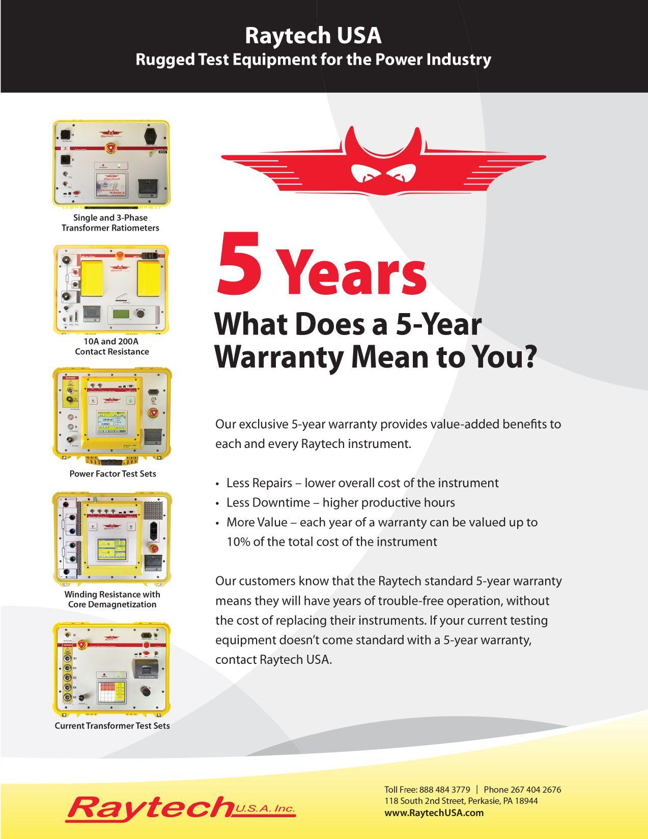


Step & Touch Potential - Are you safe?


In the event of a ground fault in a substation or at a pole several kilo-amps of fault current must be safely diverted to ground. Safe means, that resulting step & touch potentials must not exceed permissible limits as per IEEE 80. Make sure that your facilities are safe by verifying step & touch potentials according to the standard – with OMICRON’s CPC 100 and HGT1!
www.omicronenergy.com/grounding
Regional Application Specialist


 TRADE SHOW HIGHLIGHT


 Failure at the tower 284 insulator’s string occurred in 2015 due to pollution
Critical corona activity on V String-Power
TAESA Brazil 2015


 James Cialdea, President NETA — InterNational Electrical Testing Association


 BY JEFF JOWETT, Megger


 BY PAUL CHAMBERLAIN and SCOTT BLIZARD, American Electrical Testing Co., LLC


 BY STEVE TURNER, Electrical Consultants, Inc.


 BY WILLIAM OTTERSON, Shermco Industries


 BY JAMES R. WHITE, Shermco Industries


 BY JIM HAYES, Fiber Optic Association


 BY ADNAN ŠECIC and NIJAZ HADŽIMEJLIC, DV Power — Sweden


 BY JAMES WHITE, Shermco Industries


