













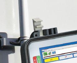
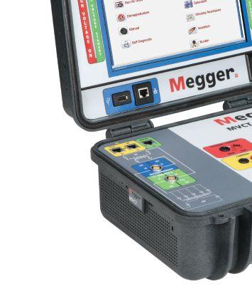
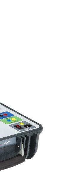
With a simplified connection process, the MVCT performs ratio, winding resistance, saturation, demagnetization, and insulation testing on multi-tap CTs using a single connection of leads. That means fewer trips up and down a ladder, for a safer and more productive work environment.
The MVCT also performs demagnetization, ratio, winding resistance, polarity and insulation testing on voltage transformers, making it an incredibly versatile tool at only 20 lbs., so you can Power on.











National
Infrared
Substation
Electrical
Power
Protective
Circuit
Transformer

■ Continuity test instrument
■ Insulation resistance test instrument
All test instruments include specific manufacturer’s operational instructions, and must be certified and display a label of an independent verification lab (UL, CSA, CE, ETL, or TUV). Sometimes, the only thing standing between an electrical worker and an unexpected spike is their meter and test leads. Meters, test leads, and probes must have an adequate category (CAT) safety rating. If the wrong equipment is used with the wrong voltage, workers and others are at risk. Before conducting any test, choose the correct instrument.
Electrical standards, such as UL, ANSI, IEC, and CAN, specify protection from currents at levels well above a system’s rated capacity. Without this additional protection, transient overvoltages, which are becoming increasingly common, can lead to equipment failure and serious injury or death.
Minimizing such risks requires everyone working in electrical environments to use the required safety equipment:properly rated gloves, eye protection, and electrical measurement test instruments that provide appropriate protection. The correct electrical testing and measurement instruments and using the correct procedures can improve job safety.
Category I typically covers electronic equipment, signal level for telecommunications, electronic equipment, and low-energy equipment with transient-limiting protection. The peak impulse transient range is from 600 to 4,000 volts with a 30-ohm source and includes:
■ Protected electronic equipment
■ Equipment connected to (source) circuits in which measures are taken to limit transient overvoltages to an appropriately low level
■ Any high-voltage-low-energy source derived from a high-winding resistance transformer, such as the high-voltage section of a copier
Category II covers single-phase receptacle connected loads; local level for fixed or non-fixed powered devices — everything from lighting to appliances to
office equipment; all outlets at more than 10 meters (30 feet) from Category III sources; and all outlets at more than 20 meters (60 feet) from Category IV sources. The peak impulse transient range is from 600 to 6,000 volts with a 12-ohm source and includes:
■ Appliances, portable tools, and other household and similar loads
■ Outlets and long branch circuits
■ Outlets at more than 10 meters from CAT III source
■ Outlets at more than 20 meters from CAT IV source

If the wrong equipment is used with the wrong voltage, workers and others are at risk.


Category III covers three-phase distribution, including single-phase commercial lighting, distribution-level fixed primary feeders, or branch circuits. These circuits are usually separated from Category IV (whether utility service or other high-voltage source) by a minimum of one level of transformer isolation — for example, feeders and short branch circuits, distribution branch panels, and heavy appliance outlets with short connections to the service entrance. The peak impulse transient range is from 600 to 8,000 volts with a 2-ohm source and includes:
■ Equipment in fixed installations, such as switchgear and polyphase motors
■ Bus and feeders in industrial plants
■ Feeders, short branch circuits, and distribution panel devices
■ Lighting systems in larger buildings
■ Appliance outlets with short connections to the service entrance
Category IV covers three-phase at utility connection, any outdoor conductors, or primary supply level. It
is the highest and most dangerous level of transient overvoltage you are likely to encounter in utility service to a facility both outside and at the service entrance, as well as the service drop from the pole to the building, the overhead line to a detached building, and the underground line to a well pump. The peak impulse transient range is from 600 to 12,000 volts with a less than 1-ohm source and includes:
■ Origin of installations, such as where low-voltage connection is made to utility power
■ Electricity meters and primary overcurrent protection equipment
■ Outside and service entrance, service drop from pole to building, and run between meter and panel
■ Overhead line to detached building and underground line to well pump
The following additional requirements apply to test instruments, equipment, and all associated test leads, cables, power cords, probes, and connectors:
■ Must be rated for circuits and equipment where they are used
■ Must be designed for the environment in which they will be exposed and used
■ Must be visually inspected for external defects and damage before each use, and if a defect or evidence of damage exists that might expose an employee to injury, the defective or damaged item shall be removed from service
When test instruments are used for testing the absence of voltage on conductors or circuit parts

operating at 50 volts or more, the operation of the test instrument must be:
■ Verified on a known voltage source before an absence-of-voltage test is performed
■ Tested for the absence of voltage on the deenergized conductor or circuit part, noting that a zero reading might mean no voltage is present during the testing or that the instrument has failed
■ Verified on a known voltage source after an absence-of-voltage test is performed
This verification primarily applies to conductors or circuit parts operating at 50 volts or more. However, under certain conditions (such as wet contact or immersion), even circuits operating under 50 volts can pose a shock hazard.
Only qualified persons are permitted to perform tasks such as testing, troubleshooting, and voltage measuring, due to the electrical hazards associated with energized work. All required PPE for the associated hazards must be used when performing these tasks. Test instruments must be rated for the conditions under which testing is performed. When selecting voltage testing instruments, an assessment must be performed to determine the proper CAT rating required based on the highest hazard exposure, and the operation of the test instrument must be verified on a known voltage source before and after an absence-of-voltage test is performed on conductors or circuit parts operating above 50 volts.
DENNIS K. NEITZEL, CPE, CESCP, Director Emeritus of AVO Training Institute, Inc., Dallas, Texas, has over 50 years in the electrical industry in various capacities, specializing in electrical equipment and systems maintenance, testing, engineering, inspection, and safety. Dennis is an active Senior Member of IEEE, ASSE, NFPA, AFE, IAEI, and SNAME. He is a past Chair of the IEEE-IAS Electrical Safety Workshop (2012); a Certified Plant Engineer (CPE), a Certified Electrical Safety Compliance Professional (CESCP), and a Certified Electrical Inspector-General. Dennis is a Principle Committee Member and Special Expert for NFPA 70E, Standard for Electrical Safety in the Workplace; the Working Group Chairman for IEEE standards 3007.1-2010, 3007.2-2010, 3007.3-2012, and 45.5-2014; and is co-author of the Electrical Safety Handbook, McGraw-Hill Publishers. He earned his BS in electrical engineering management and his MS in electrical engineering applied sciences. He has authored, published, and presented numerous technical papers and magazine articles on electrical safety, maintenance, and technical training.
Electrical insulating liquids are used in transformers and other electrical apparatus to provide efficient cooling and sufficient dielectric strength to prevent electrical breakdown. These insulating fluids are tested to determine their ability to perform these essential functions. Examples of problems from excessive deterioration include becoming too acidic, forming sludge deposits, or having low dielectric breakdown voltage. The properties of the dielectric liquid are important, but more value is derived from the diagnostic oil tests that provide key information on the condition of the apparatus.
Some of these insulating liquids have significantly different chemical compositions in comparison to the mineral oils widely used in the industry. There can be significant differences in the analysis of the data based on these different chemical compositions. Comprehensive knowledge is needed to effectively interpret oil test results and ultimately assess the condition of electrical equipment. Comprehensive laboratory diagnostic oil seminars aid in expanding the knowledge of those in attendance, while minimizing the ever-increasing knowledge gaps within the power industry.
There are two main groups of tests routinely performed on in-service insulating liquids.
■ Dielectric liquid condition tests. This group of tests allows for determination of the physical, chemical, and electrical properties of the insulating liquid. A typical group of tests to evaluate the condition of the insulating liquid includes water content, interfacial tension, neutralization/ acid number, dielectric breakdown voltage, power factor/dissipation factor, color, visual examination, and relative density/specific gravity.
■ Diagnostic tests. This group of tests includes dissolved gas-in-oil analysis (DGA), water content (dryness of the insulation system), furans, methanol, ethanol, and other tests. DGA testing is the most important test offered in our industry worldwide because the test results provide indication of a developing thermal and/ or electrical problem, as well as an assessment of the condition of the solid insulation. In addition, the DGA test is important as an indicator of deterioration of the apparatus, the materials involved, and the urgency of response required.
The testing of oil from electrical equipment is typically performed by following established test methods. These test methods are established from standard organizations such as ASTM, IEC, ISO, or other independent companies. Depending on the type of insulating liquid being used, different test methods may need to be followed. For example, a common test in our industry is ASTM D971, which is the test method to perform interfacial tension testing on the insulating liquid against water via the ring method. This test method is not suitable for silicone oil, as the interfacial tension of silicone oil does not change much with aging and is not a good indicator of its condition.
Various guides from IEEE, IEC, and other vendors are available to interpret oil test results. These guides are provided to give users a basic level of how to interpret test results. However, it is important to have a good understanding of the subject matter to make sure expensive and important decisions are made on a sound basis. Many of the guidelines give
users the ability to make an initial assessment, but a more detailed analysis should always follow.
Utilities and service companies are under increasing pressure to provide safe and reliable power to customers. The power and energy industry continues to experience a large knowledge gap due to the retirement of seasoned staff replaced by employees who are new to the power industry or have little experience. To address the knowledge gap, organizations should provide training internally and externally using experienced companies and events.
For example, at NETA’s annual PowerTest Conference, the Doble Oil Seminar helps address this knowledge gap. This unique course expands the knowledge of engineers, technicians, and project managers responsible for the quality of electrical power systems. The course content covers DGA, condition of the solid insulation, assessment of the wetness of the insulation system, condition of the insulating liquid and solid insulation, significance of metals in oil, flammability characteristics of gases in oil, diagnostics for energized tap changers and oil circuit breakers, and sampling. After completing the course, attendees take a quiz to make sure that their

learning objectives were met and to earn continuing education credits.
Some of the benefits companies can realize by providing regular technical training to staff include:
■ Stay up to date with technology changes within the power and energy industry
■ Remain competitive within the power and energy industry
■ Increase employee morale and performance
■ Attract new talent
■ Reduce employee turnover
■ Provide job growth opportunities for staff
An often overlooked benefit of attending industry conferences is networking with colleagues to share common challenges and best practices.
With constantly evolving technology in the power and energy industry, effective training courses ensure that attendees stay current with not only the various insulating liquids available for use, but also learn how to interpret oil test results so that an informed decision can be made regarding the condition of the electrical equipment and the associated insulating liquid.
DAVID KOEHLER is the New Business Development and Technical Manager for Doble Engineering Company Insulating Materials Laboratories. He has 20 years of experience in the testing of insulating liquids and the management of analytical laboratories. He has provided numerous technical presentations and published technical articles within the power industry. David is a member of the ASTM D-27 Technical Committee on Electrical Insulating Liquids and Gases. In 2016, David was elected by the IEEE Region 4 voting members to the position of Region 4 Director-Elect. In 2017–2018, David serves as the Region 4 Director-Elect, chairing the IEEE Region 4 Strategic Planning Committee. In 2019–2020 David will serve as the IEEE Region 4 Director, while also serving on the Board of Directors for IEEE.
The last thing anyone wants to read about is how we are losing legacy knowledge as the Boomers retire and Millennials take over. Please bear with me a bit as I address it in a different, and I believe, unique way.
What if much of that legacy knowledge isn’t worth passing on? What if things are changing so rapidly in our field of electrical system reliability that much of that legacy knowledge is outdated? Or, worse: What if it is flat out wrong? Would we want to make sure the next generation learned it?
Consider a case in point. A well-known bathtub curve has been the norm for decades. Transformer failures in the first year of life are at pretty significant risk. Once they get beyond year one, they are pretty much good to go for another 20 to 50 years. That end-of-life figure averages around 38 years for power transformers according to the largest insurers of power transformers in the world.
But recently, the early failure rate of transformers has been increasing so much that the bathtub curve is no longer the same curve. We aren’t sure what the early failure rate is, but several major carriers
have reported an early failure rate of 10 years. That is significant. If we taught the next generation what we thought was the norm, the risk associated with transformer failures could be overlooked, and testing, maintenance, and life-cycle management would be completely awry.
And it’s not just transformers. Breakers, motors, and even cabling are all undergoing similar life-cycle changes. What we have always accepted as legacy knowledge may be wrong. We have to consider what knowledge is timeless and enduring. That is the knowledge we should pass on. If you are a Boomer, look at your own area of expertise and ask yourself: “What changes have I seen to previously believed timeless truths since I began my career? Are they still true?” There may not be many, but you will be hard pressed to have none. If you are that next generation professional, ask yourself a similar question: “What have I learned that is different from what my predecessor considered the norm?”
My generation was a challenge-everything generation. We challenged institutions. We challenged norms. We challenged leadership. It was often a challenge based on ignorance and youth. A sense of betrayal during the Vietnam War carried over into society — especially younger society — in a sometimes unhealthy way. We were willing to throw out the baby with the bathwater because we were so ticked off at the bathwater. Fortunately, most of us settled down.
Millennials and Generation Xs and Generation Ys seem to have a similar sense of challenging the status quo, and we should consider many of their challenges healthy. Rethinking what we took for granted allows us to engage the next generation of electrical system professionals, making sure we don’t throw truth out because we want to see change.
Some of the most beneficial changes are taking place around careers and career development. It is no longer accepted that a four-year college degree is the only way to career fulfillment and success. Technical degrees, apprenticeship training, and careers that emphasize technical proficiency are becoming priority in education and in government.
I recently accompanied a team from the Society of Maintenance and Reliability Professionals to
Washington, DC, to meet with members of Congress and the White House in support of Career Technical Education (CTE) programs. The Perkins Act — named after Carl Perkins, a longtime advocate of technical education — passed unanimously in the House of Representatives to fund CTE programs. Unanimously! That speaks volumes about our commitment to technical education. It has great support in the Senate, and President Trump said he will sign it as soon as it reaches his desk.
Another major change that will affect how we pass on legacy knowledge is the phenomenon of “Siri, what time is it?” or “Alexa, turn on the alarm” or “Google, what is the meaning of life?” (OK, maybe that last one is farfetched.) The next generation, and especially the ones after that, will all be what I call “Google brains.” Why learn everything if Google or Wikipedia knows it all? It’s a scary development and it will change learning in a major way.
What does it mean for the NETA or electrical system reliability professional when access to a massive amount of information is available on demand? The internet has changed everything about the way we access knowledge and not always for the better. It means we had better rethink training and training programs. Searchable, videocentric training platforms will be the norm in the future. These are expensive and time consuming to produce. The old standard of training programs is changing and changing fast.
We are currently in the transition period where providers are making online or on-demand

tools available because we still rely on classroom knowledge. One of the reasons is that live, classroom situations allow for more interaction and engagement between trainers and participants. Distance-learning college programs have begun to address that need, but one is still the loneliest number when you are sitting behind a computer and your professor and classmates are a thousand miles away.
The important takeaway from these changes taking place in the knowledge revolution is that learning is changing, therefore teaching and training must change too. A good Training & Educational Development (TED) program must take into account the need for experiential learning and various learning styles to be successful at passing on the most valuable legacy knowledge.
The value of technical career development is on the rise, and we must meet the need with a different solution. We must change the notion that only a four-year college education is valuable and remove the stigma that technical schools are second choices for those not capable. Enticing younger men and women into technical careers means preparing the way for them to succeed and prosper while adding value to the nation’s workforce in meaningful ways.
Finally, let’s not wonder how we are going to survive the great Boomer retirement. Let’s focus on the opportunity to impact the future by changing the way we prepare the next generation. Let’s embrace the knowledge revolution and train for success. A successful future demands it.
ALAN ROSS is Vice President of Reliability at SD Myers, Inc, in Tallmadge, Ohio. He is responsible for developing and executing long-term reliability strategies and next-generation leadership for all operating units, domestically and internationally. He often presents at industry conferences and has authored several trade publication articles on transformer maintenance and reliability, and has written two books: Unconditional Excellence and Beyond World Class. He earned a BS in mechanical engineering at Georgia Institute of Technology and an MBA in marketing from Georgia State University, graduating Magna Cum Laude. Alan is a Certified Reliability Leader and a member of the IEEE Reliability Society.
Having trained thousands of technicians over the last 37 years, I tend to think training is a cure for many things. Hands-on training can be especially effective because field people learn by doing, much more so than they do sitting in a classroom. They are smart people, but the way they learn is different from someone who does well in a college curriculum-type situation.
When I first started training back in 1981, most of the attendees were out of the military, which meant they had basic skills training, had a good measure of self-discipline (just to survive boot camp), and were focused and motivated. It was rare to find someone who was not interested or did not want to be in the class. And to be sure, training was reserved for only the best of a company’s technicians.
In the late 1980s, attendees to the classes came more out of general industry instead of the military. The attitudes displayed started to be more about what to do after the class than what was going on in the class. A majority of attendees were still motivated and wanted to be there, but I began to
hear more and more, “I’m here because I was told to be.” That’s not what an instructor wants to hear at the beginning of a course. I continued to have top performers in my classes, just not as many.
Fast forward to today’s work environment: Workers expect more from their companies. Their attention spans are not as focused, and they tend to get bored easily. This is not putting younger workers down; it’s their environment and how they are raised. Younger workers also want to move up. They expect more from the company they work for, and being promoted/making better money is part of that.
Because of the military draft, most people entering the workforce had their military experience to fall back on. Yes, being chewed up like bubble gum was not my idea of a great time, but it did teach me selfdiscipline. Many of the workers we see now do not have the benefit of that background, so they don’t have that basic skills training that nearly everyone who served in the military received. They are sent to a training program to increase their effectiveness at work. It is difficult to grasp concepts when you hear them for the first time, so a good part of what is covered in the class is not retained.
One method that can help is to have them go through some basic technical skills training, such as basic electrical fundamentals, electrical print reading, and the like. One issue I have seen my entire career is that many senior technicians won’t admit they can’t effectively read an electrical drawing. If you ask them, they will answer, “Of course, I know how to read a print!” Technically, that would be correct, but they lose a lot of time fumbling their way through it.
If you are hiring younger workers and it’s known they are deficient in technical skills and knowledge, spend some money on the basics so when they are training — either on the job or in a formal classroom setting — they can understand what is being said. Many vendors offer these basic skills courses, as do local community colleges. Community colleges are less expensive, but it can take a couple of semesters to complete the program. Most of the vendor courses will be a week or less.


Every field service or facility technician will have holes in his or her knowledge. It’s inevitable, because much of what the typical worker learns is by on-the-job training (OJT). It stands to reason that a worker can only learn as much as the person teaching him knows, minus some. I often refer to this as tribal knowledge — knowledge that is passed down from worker to worker. Sometimes it’s good, and sometimes bad habits are passed along. The problem with men, in particular, is that once we do something the wrong way, if we are not immediately killed or injured, it now becomes “our way.” We are reluctant to change, even if we know it’s not the best or safest way to do it, because we discovered this and it works. And it does work — as long as nothing changes. If some new issue pops up and we don’t account for it, an incident could be just a step away. We’ll never see it coming.


If you’re going to pay to have your people out of work for the training, the instructor cost is not the bulk of the program expense. Hire people with experience and a good reputation. It will pay off.
You just paid a large sum of money for safety training, and the training instructor shows up and reads the NFPA 70E from cover to cover for eight hours. We hear this story more frequently than you would think. Often, in these cases, the worker must repeat the training because just hearing the standard read aloud is not an effective method of learning. Then the new instructor steps into a class full of workers who have previously been bored to tears and are now sitting through the same training.
The price difference between an inexpensive trainer and a professional is not that great in the grand budget scheme of things. If you’re going to pay to have your people out of work for the training, the instructor cost is not the bulk of the program expense. Hire people with experience and a good reputation. It will pay off.
If a technician hears something from the company’s safety people or in training — and then is told “don’t worry about that” by a senior technician — trust me, he won’t worry about anything the safety guy said. This is probably the worst-case scenario, because the company’s efforts are undercut by the very people they rely on to mentor new workers and get the job done. Smaller companies probably see this less than larger companies, but it can happen within any company.
This is a hard nut to crack, as they say. Training may help if the worker understands the shortcomings of his way, or he may just decide to ride out the class and do what he wants to do. NFPA 70E requires that supervisors audit their workers once a year to ensure they are following safe work practices. If we observe this worker performing a task unsafely, steps can be taken to correct him. An effective trainer can usually convince people of the errors of their ways, but not always.
This is really a double sucker-punch because the senior people doing this are breaking trust. They don’t want to see anyone hurt; it’s just that their experience has gotten them through, and they rely on it more than on what they are being taught. I’ve thought about this a lot. I go to customer sites and can see it in their body language and in their eyes.
In some cases, a good instructor can help reverse this, but not always. As painful as it may be, that A-player may not be worth the risk of exposing other employees to bad habits if he is spreading unsafe information. The fact that someone has not been injured is not evidence of competency, and it may be just a matter of time before that worker or someone working with him is seriously injured
or killed. Oh, yes — people sit up and take notice once the old dooky hits the spinning blades, but by then the damage is done. If you have someone in this category, carefully assess the employee and determine whether they can be brought back to the light… or if it is better just to part ways.
Training is good. Effective training is better. Effective, hands-on training combined with focused classroom time is probably best. It takes time and money to develop someone into an effective and knowledgeable worker, properly trained in the essential duties of their job. Many people entering the workforce do not have adequate technical skills or knowledge to be cost effective, but companies will try to force-fit them into a work situation they cannot handle.
Remember this key point: Provide newer workers with basic technical skills training before trying to provide more advanced training. Some of this training can be taken online, but people are often

reluctant to give up their free time to do company work, so you may have to carve out some time during the day. After the basics are done, give them time working in the field with a mentor who will teach them some of the more basic hands-on tasks. After they have successfully completed that portion, then send them to the more advanced technical skills training. Basic technical skills training would be helpful even before sending them to safety training. If they only have a vague concept of electricity, how much will they learn and retain in an electrical safety training program?
Be honest with the goals for your training. Trying to fit 20 hours of training knowledge into 8 hours is not going to turn out well. Making people suffer through 10-hour days is also not a great plan. After about 6 or 7 hours, the lights are on, but nobody’s home. A choice has to be made as to whether the training is important, or if cutting costs is important. Some compromises can be made, but paying for ineffective training is throwing good money after bad.
JAMES (JIM) R. WHITE, Vice President of Training Services, has worked for Shermco Industries Inc. since 2001. He is a NFPA Certified Electrical Safety Compliance Professional and a NETA Level IV Senior Technician. Jim is NETA’s principle member on NFPA Technical Committee NFPA 70E®, Standard for Electrical Safety in the Workplace; NETA’s principle representative on National Electrical Code® Code-Making Panel (CMP) 13; and represents NETA on ASTM International Technical Committee F18 Electrical Protective Equipment for Workers. Jim is Shermco Industries’ principal member on NFPA Technical Committee for NFPA 70B, Recommended Practice for Electrical Equipment Maintenance, and represents AWEA on the ANSI/ISEA Standard 203 Secondary Single-Use Flame Resistant Protective Clothing for Use Over Primary Flame Resistant Protective Clothing. An IEEE Senior Member, Jim received the IEEE/IAS/ PCIC Electrical Safety Excellence Award in 2011 and NETA’s Outstanding Achievement Award in 2013. Jim was Chairman of the IEEE Electrical Safety Workshop in 2008 and is currently Vice-Chair for the IEEE IAS/PCIC Safety Subcommittee.
One of the most significant changes in CSA Z462–2018 is the arc flash risk assessment requirement for energized electrical work task execution as a component of the work task’s overall risk assessment procedure. In the 2015 edition, the arc flash risk assessment process was not a complete risk assessment process. The 2018 edition provides the following general and specific arc flash risk assessment requirements:
1. Appropriate safety-related work practices shall be determined before any person is exposed to the electrical hazards involved in executing an energized electrical work task by using both shock risk assessment and arc flash risk assessment.
2. Only qualified electrical workers (QEWs) shall work on electrical conductors or circuit parts that are not in an electrically safe work condition.
3. An arc flash risk assessment performed on a specific energized electrical work task includes the following requirements:
■ General
■ Estimate of Likelihood and Severity
■ Additional Protective Measures
■ Documentation (the arc flash risk assessment for an energized electrical work task shall be documented)
■ Arc Flash Boundary
■ Arc Flash PPE
■ Equipment Labeling
There is more to it than you may have been trained on in the past for the 2015 edition. The requirements are not complex to know and perform, but without a documented electrical safety program and compliant electrical safety training, you will have difficulty getting the QEW to apply the electrical safety training they received. You need management system documentation, as well as field-based hazard identification and application of risk control methods documents, for a QEW to use in the field to document that an acceptable residual risk level is achieved.
Let’s review the specific requirements of completing a documented arc flash risk assessment process in more detail, with some more specific information on items 3(a) through 3(g) above.
This is where key changes were made. For a justified energized electrical work task, the QEW must identify whether an arc flash hazard exists. Before executing the energized electrical work task, an estimate of the likelihood of occurrence of injury or damage to health and the potential severity of injury or damage to health must be completed. The QEW must then determine whether additional protective measures are required, including the use of PPE.
When completing an arc flash risk assessment for a specific energized electrical work task, it is a mandatory requirement with respect to likelihood of occurrence and the potential severity of injury or damage to health that the following items are considered when evaluating the work task’s risk level:
■ The design of the electrical equipment, including its overcurrent protective device and its operating time
■ The electrical equipment operating condition and condition of maintenance
If the inherent risk level for the energized electrical work task is not acceptable, additional protective measures will be required. Additional protective measures must be selected and implemented in accordance with the hierarchy of risk control methods. When additional protective measures include the use of PPE, the QEW shall determine them and apply them to the energized electrical work task to reduce risk, including applying appropriate safety-related work practices such as arc flash boundary and the PPE that the QEW will be required to wear when exposed to the arc flash hazard.
A key change not required previously is the assessment of likelihood of occurrence of an arcing fault and arc flash occurring. A new table has been provided (Table 2); it used to be Table 4A. However, the context and use of the new Table 2 is a significant change.
The arc flash risk assessment must be documented. Your company must provide a method of documenting a specific work task’s arc flash risk assessment as part of the company’s electrical safety program. This field-based document would be used by a QEW to identify whether they are exposed to arc flash and/or shock, and to document the hierarchy of risk control methods applied to the work task so that an acceptable residual risk level is achieved.
When an arcing fault and arc flash are probable, the distance at which incident energy is 1.2 cal/ cm2 is the arc flash boundary. When you stand outside of the arc flash boundary, no arc flash PPE is required to be worn. This distance can be calculated using formulas identified in CSA Z462 Annex D. If calculations have not been performed, then application of the arc flash PPE category method can be used to determine the arc flash boundary.
Two methods can be used to determine arc flash PPE: (1) The incident energy analysis method or (2) the arc flash PPE category method. Either method (but not both) may be used on the same
piece of equipment. When the incident energy analysis method is used, arc flash PPE SHALL NOT be identified with an arc flash PPE category number, but SHALL be determined with an arc thermal performance value (ATPV) for the arc flash PPE being equal to or greater than the calculated incident energy.
CSA Z462–2018 provides a new Table 3 for reference when incident energy analysis is completed. It identifies two choices for arc flash PPE: (1) task wear ATPV 1.2-12 cal/cm2 or (2) an arc flash suit with ATPV >12 cal/cm2. Note that arc flash suits are available up to a 140 cal/cm2 ATPV.
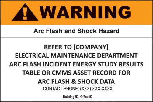
Electrical equipment that will have energized electrical work performed on it shall be labeled with an arc flash and shock warning equipment label (based on ANSI Z535). Specific information must be included on the equipment label (Figure 1). The incident energy analysis must be reviewed for accuracy at intervals not to exceed five years.
By using the CSA Z462–2018 in supervised industrial installations, arc flash data can be documented in a manner readily available to persons likely to perform examination, servicing, maintenance, or operation of the equipment while energized. The arc flash data (Figure 2) could be provided in a results table format directly from the professional engineer’s incident energy analysis report.
SS06-A-E05004
SS06-B-E05004 (Line
Figure 2: Incident Energy Analysis Results Table Example
As a component of the overall work task’s risk assessment procedure, an arc flash risk assessment must be completed. The arc flash risk assessment requirements in CSA Z462–2018 edition are significantly different than the 2015 edition. Please make sure your company documents the specific requirements in its electrical safety program. A qualified electrical worker also must document their
 TERRY BECKER, P.ENG.,
specific work task’s arc flash risk assessment before executing the work task.
CSA Z462–2018 was published January 8, 2018. Please purchase a copy for your reference and use at www.shop.csa.ca/en/canada/c221-canadian-electricalcode/z462-18/invt/27029372018. Please submit any questions or comments to tbecker@danatec.com.
CESCP, is the first past Vice Chair of the CSA Z462 Workplace Electrical Safety Standard and is currently a Voting Member and Working Group 8 Leader, Annexes. Terry is also a Voting Member on the IEEE 1584 Technical Committee and an Associate Member of the CSA Z463 Guideline on maintenance of electrical systems. Terry is a Professional Engineer in the Provinces of British Columbia, Alberta, Saskatchewan, and Ontario. Terry is Senior Vice President, Electrical Safety, at Danatec Educational Services Ltd., providing electrical
consulting, licensed products, and training solutions.
Many AVO courses are eligible for NETA CTDs.*
If it’s electrical, AVO Training is focused on it. Electrical safety training, electrical maintenance training, and electrical consulting is not just a part of our offering, it’s our total focus. That’s why we offer more electrical safety and electrical maintenance training courses than any other training facility. With over 52 different courses, we offer the widest selection of courses available. To complement our training courses, we have a stand-alone Engineering Division that offers Arc Flash Studies, Risk Assessment Analysis, and a full menu of electrical engineering services.
Available Courses:
Protective Relay
• Protective Relay Maintenance - Basic
• Protective Relay Maintenance - Advanced
• Protective Relay Maintenance - Generation
• Protective Relay Maintenance - Solid State
• Microprocessor Based Relay Testing - Generation
• Microprocessor Based Relay Testing - Distribution/ Industrial
• Advanced Visual Testing Software
Circuit Breaker
• Circuit Breaker Maintenance, SF6
• Circuit Breaker Maintenance, Molded- and Insulated-Case
• Circuit Breaker Maintenance, Medium-Voltage
• Circuit Breaker Maintenance, Low-Voltage
Cable U
• Cable Splicing and Terminating, Medium-Voltage
• Cable Fault Location and Tracing, Medium-Voltage
• Cable Testing and Diagnostics, Medium-Voltage
Substation
• Battery Maintenance and Testing
• Transformer Maintenance and Testing
• Advanced Transformer Maintenance and Testing
• Substation Maintenance I
• Substation Maintenance II
• Power Factor Testing
Safety
• NFPA 70E 2015 Electrical Safety
• Electrical Safety for Utilities
• Electrical Safety for Mining
• Electrical Safety for Industrial Facilities
• Electrical Safety for Inspectors
• Electrical Safety for Overhead Contact Systems
• 2017 National Electrical Code
• OSHA Electrical Safety Related Work Practices
• Maritime Electrical Safety
Basics
• Basic Electricity
• Basic Electrical Troubleshooting
• Electronics Troubleshooting
• Electronics for Electricians
• Electrical Print Reading
• Grounding & Bonding
Engineering
• Short Circuit Analysis
• Protective Device Coordination Utilities
• Protective Device Coordination Industry
• Power Quality & Harmonics
Motors/Controls
• Programmable Logic Controllers
• Maintenance & Trouble Shooting
• Motor Maintenance and Testing
• Motor Controls and Starters, Low-Voltage
Throughout the year, Doble hosts accredited technical trainings on a variety of topics to help engineers and technicians of all levels be more efficient, effective, and safe in the field. Learn from the industry’s top experts, receive real-world training that you can immediately apply, and build your professional network.
• Circuit Breaker Seminar
October 1-5, 2018 | Jackson, MS
Brush up on circuit breaker fundamentals, get practical hands-on training, and learn from the experts at the industry’s best circuit breaker educational seminar.
• Life of a Transformer Seminar
February 11-15, 2019 | Red Rock, NV
Practical training on all aspects of transformers, including sessions focused on transformer differential protection, transformer maintenance, and asset and maintenance strategies.
• Rotating Machinery & Electrical Plant Reliability
Tutorial
April 10-11, 2019 | Boston, MA
Learn everything you need to know to reliably maintain the electrical side of a generation or industrial plant.
• Laboratory Seminars
Offered throughout the year
Learn how to review data to assess transformer condition from instructors presenting theory and practical examples that illustrate common problems found in the field.
• Protection Training Courses
Offered throughout the year
Choose from a range of protection courses that will prepare you for testing a modern grid, power plant, and industrial facility.
• Free Webinar Series
Offered throughout the year
Join us for our free webinars. Each topic is discussed for approximately one hour. Doble experts cover testing techniques, safety, theory, and industry trends.
Companies with Doble Services Agreements can also join us for these client events:
• Doble Client Committee Meetings & Conference September 30-October 4, 2018 | Nashville, TN
• International Conference of Doble Clients April 7-12, 2019 | Boston, MA
Many Doble training courses are eligible for NETA Continuing Technical Development Credits (CTDs) as well as IACET certified Continuing Education Units (CEUs). Visit: www.doble.com/earning-ceus
Learn valuable testing tips and tricks from Megger application engineers and product managers. In this webinar series, our experienced staff will show you how to make your testing more efficient by sharing their lessons learned in the field. You will find answers to frequently asked questions, learn how to avoid the most common mistakes and accelerate your testing.
• Test Data Management for NERC Compliance Reporting
Jun 15 | Presenter: Mark Meyer
• Battery Impedance Test: Analysis and Trending
Jul 20 | Presenter: Volney Naranjo
• Variable Frequency Power Factor Testing for Advanced Insulation Diagnosis
Aug 17 | Presenter: Jill Duplessis
• Understanding the Time Domain Reflectometer (TDR) Traces for Cable Fault Location
Sep 21 | Presenter: Jason Souchak
• High-Voltage Dielectric Frequency Response for Bushing and Instrument Transformer Diagnosis
Oct 19 | Presenter: Diego Robalino
• Basics of Recloser Testing
Nov 16 | Presenter: David Beard
• Cable Testing 101: Introduction to VLF
Dec 14 | Presenter: Robert Probst
Previous Webinars
• Field Testing of Transformers for Winding Condition Assessment
May 18 | Presenter: Dinesh Chhajer
• Power Quality: A Detailed Understanding of Harmonics
Apr 20 | Presenter: Sanket Bolar
• Fault Location on Oil Filled Cables
Mar 16 | Presenter: Robert Probst
• Introduction to Sweep Frequency Response Analysis
Feb 16 | Presenter: Robert Foster
• Transformer Differential Protection: Challenges and Solutions
Jan 22 | Mohit Sharma
• Megger Webinars are held on the 3rd Friday of every month
• Time: 10:00 AM Central Time.
• Sessions are FREE
• Earn 1 NETA CTD and 1 PDH or 0.1 CEU
• us.megger.com/webinars
Webinar Registration: http://us.megger.com/webinars
Megger designs and manufactures portable electrical test equipment. Megger products help you install, improve efficiency, reduce cost, and extend the life of your or your customers’ electrical assets or your own. For more information, visit http://us.megger.com/.
Protection Testing
Pow er System Protection Testing with the OM ICRON Test Universe
This course wi ll focus on testing the most commonly used protection schemes in the transmission and distribution systems. Learn how to efficiently test overcurrent, distance, and transformer differ ential rel ays with the OMICRON Test Univers e Other topics include manual testing, creation of automated test plans, elem ent testing (pick-up and delay tim e of relay el em ents), and test of relay logics. Hands-on tests will be perform ed on electromechanical and digital relays.
Recloser Control T esting with ARCO 400
Learn the theory of reclosers and their application in the distributions system Learn how to test all kinds of reclos er controls quickly and reliably with ARCO 400 Get familiar with the softwar e guided workfl ow of ARCO Control and learn how to prepare test plans for standardized testing Hands-on practice including m eter checks, protective function operating characteristics, reclosing sequences, and restoration schemes.
Introduction to Protection Testing
This course wi ll focus on the basic skills needed by Protection and Control Technicians/Field Engineers to perform their jobs. Topics of the course include: technical math, fault types, CT/PT introduction, and basic relay concepts. Students will also learn the basic schem es associated with protection and control systems and techniques on how to test them
Pow er T ransform er T esting & M onitoring
Electrical Diagnostic Testing of Pow er T ransformers
Learn how to perform and assess m any of the conventional electrical diagnostic tests recommended for power transform ers, including power factor, exciting current, TTR, leakage reactance, and DC winding resistance. Other topics include DGA/Oil Screen, life expectancy, SFRA, DFR, bushings, LTCs, surge arresters, and demagnetization techniques. Hands-on measurements will be performed using the OMICRON CPC100, CP TD1, FRANEO, and TESTRANO test instrum ents.
Basics of Conducting Partial Discharge M easurements Using the M PD 600
Learn the basics of partial discharge measurement applications, including transform ers, rotating m achines, and cables. Additional topics include: operating the OMICRON MPD 600 Partial Discharge detector and soft ware; gating and noise m itigation; using 3PARD and 3FREQ PD separation techniques; and interpreting typical partial discharge patterns.
Introduction to the CIBAN O 500 and T esting Circuit Breakers
This course wi ll focus on timing, travel, and contact resistance measurements of circuit breakers using the OMICRON CIBANO 500, including test plan creation and test result analysis. Hands-on m easurem ents including main contact tim ing, pole spread, dwell/dead timing, travel/stroke, contact wipe, m inimum pick-up, and static/dynamic resistance with be perform ed on SF6 Dead Tank and Vacuum type circuit breakers.
Current T ransform er T esting and Analysis
This course wi ll also provide you with an understanding of the IEEE and IEC assessment standards that apply to Protection and Metering CTs. The OMICRON CT Analyzer wil l be used in the assessment of accuracy and serviceabilit y of vari ous CT classes (C, K, T, and B) by hands-on measurements of ratio, burden, winding resistance, and knee-point excitation curves.
For dates and locations please visit: www.omicronenergy.com /na-training
Effective transformer management requires special skills acquired from years of hands-on experience. The diminishing number of experts is causing a growing need for specialized training to ensure these skills are not lost. SDMyers offers your team the opportunity to benefit from our 50 years of transformer maintenance expertise. We offer a variety of training options including enhanced e-learning courses; seminars; and onsite, online, and customized courses.
• Principles of Transformer Maintenance
Basics of transformers: electric concepts, solid and liquid insulation, oil testing and analysis, basic electrical testing, and maintenance.
• Principios de Mantenimiento de Transformadores
Este curso introduce al alumno en una serie de temas que resumen los fundamentos básicos de los transformadores y de mantenimiento del transformador.
• In-Service Inspection & Sampling of Fluid-Filled Transformers
Learn safe procedures needed to obtain a representative sample of dielectric fluid. Features a sampling demonstration and practical exercises to obtain accurate oil samples for use in lab analysis.
• Half-Century Transformer
Foundational understanding of transformers: operation, maintenance implementation, and related industry standards.
• Half-Century Transformer - Applied Maintenance
Foundational understanding of transformers: operation, maintenance implementation, and related industry standards. Includes lab and equipment tours, rewind facility tour, case studies, and expert panel discussion.
• Advanced DGA Diagnostics
Learn to identify fault gases and what causes their formation, evaluate the condition of cellulose insulation, examine the role DGA plays in new oil testing, and discuss obtaining samples from transformers.
• Load Tap Changer Principles & Maintenance
Load tap changing, styles of tap changers and their operation, and how to develop a preventative load tap changer (LTC) maintenance program.
• Electrical Testing - Power Factor Testing for Transformers, Bushings, and Breakers
The Power Factor is a measurement of the efficiency of the transformer’s insulation system and a reliable electrical test to detect deterioration.
• Transformer 360 Course is 3 days — take any or all. Day 1: Re-energized Half-Century course as part of a transformer reliability program. Day 2: Risk & Reliability and DGA. Day 3: LTC Testing & Maintenance and Electrical Testing.
• Transformer Lifecycle Management
Manage the lifecycle of the transformer including specification and purchasing, transportation, assembly and start-up, field and shop repair, overall risk and asset management, and end-of-life options. Learn to develop and manage a reliability-based maintenance program.
• Advanced Transformer Maintenance and Planning
Reactive, predictive, and preventative maintenance of transformers, and building a cost-effective testing and maintenance plan to prolong the reliable life of transformers. Includes substation equipment, transformer design and construction, and how to make critical maintenance and planning decisions.
SD Myers courses are eligible for NETA CTDs.*
*NETA continuing technical development (CTDs) units are required of NETA Certified Technicians
Shermco is a leader in electrical power systems maintenance, repair, and testing, and for years, we have trained others in those skills. Offering onsite, classroom, and hands-on training, Shermco conducts a wide variety of courses covering Electrical Systems Maintenance, Electrical Safety, and Electrical Technical Skills. Some of the most influential leaders in electrical safety work at Shermco Industries, and now you have direct access to that experience and expertise! Shermco offers technical and electrical safety programs year-round and at multiple locations in the U.S. and Canada. NETA CTDs and CEUs through IEEE are available for most courses where applicable. Train with the experts. Train with Shermco.
• Understanding the NFPA 70E
Austin, TX
2018 4/5 • 8/13
2019 4/5 • 8/12
Dallas, TX
2018 4/12 • 7/20
2019 2/22 • 7/19
Cedar Rapids, IA
2018 5/24 • 11/2
2019 5/24 • 11/1
Houston, TX
2018 9/17
2019 3/22 • 9/20
St. Paul, MN
2018 9/17
2019 3/29 • 9/27
Tulsa, OK
2018 7/20 • 11/29
2019 7/19 • 11/22
• Electrical Safety for Qualified Electrical Workers
Austin, TX
2018 5/15 • 8/14 • 11/13
2019 2/12 • 5/14 • 8/13 • 11/12
Dallas, TX
2018 5/8 • 6/5 • 7/10 • 8/7 9/11 • 10/9 • 11/6 • 12/11
2019 1/8 • 2/5 • 3/5 • 4/2 • 5/7 • 6/4 • 7/8 • 8/6 • 9/10 • 10/8 • 11/5 • 12/10
Cedar Rapids, IA
2018 6/19 • 11/6
2019 2/12 • 6/11 • 10/1
Houston, TX
2018 7/24
2019 3/12 • 9/17 • 12/3
New Orleans, LA
2018 6/19 • 8/28 • 11/13
2019 3/26 • 6/18 • 8/27 • 11/12
St. Paul, MN
2018 8/21 • 12/11
2019 4/16 • 8/20 • 12/10
Tulsa, OK
2018 7/17 • 10/16
2019 1/22 • 4/9 • 7/16 • 10/15
Wilmington, CA
2018 7/17 • 10/16
2019 3/26 • 6/11 • 8/6 • 10/22
• Lab Session - Electrical Safety for Qualified Electrical Workers
Dallas, TX
2018 5/11 • 6/8 • 7/13 • 8/10 • 9/14 • 10/12 • 11/9•12/14
2019 1/11 • 2/8 • 3/8 • 4/5 • 5/10 • 6/7 • 7/12 • 8/9 • 9/13 • 10/11 • 11/8 • 12/13
Cedar Rapids, IA
2018 6/22 • 11/9
2019 2/15 • 6/14 • 10/4
Houston, TX
2018 7/27
2019 3/15 • 9/20 • 12/6
Wilmington, CA
2018 6/15 • 9/14 • 12/21
2019 3/29 • 6/14 • 8/9 • 10/25
• Electrical Safety Refresher
Austin, TX
2018 8/17
2019 2/15 • 8/16
Dallas, TX
2018 6/4 • 10/8
2019 2/4 • 6/3 • 10/7
Cedar Rapids, IA
2018 6/15 • 10/5
2019 2/18 • 6/17 • 10/7
Houston, TX
2019 3/15 • 9/25
New Orleans, LA
2018 8/31
2019 3/29 • 8/30
St. Paul, MN
2019 4/19 • 8/23 • 12/13
Tulsa, OK
2019 4/12 • 10/18
• Low to Medium Circuit Breaker Maintenance and Testing
Dallas, TX
2018 6/18 • 10/1
2019 2/11 • 6/17 • 9/30
Wilmington, CA
2018 11/12
2019 4/8 • 11/11
• Basic Electrical Fundamentals
Dallas, TX
2018 5/15 • 9/5
2019 1/8 • 5/14 • 9/17
Enroll today by visiting www.shermco.com/training or call 888-Shermco and mention your promotional code.
For more information, to download our current course catalog, or to register online, go to www.shermco.com/training or email training@shermco.com Shermco.com • 888-shermco







NERC PRC 005-6 Standards and Testing Program Options


7 President’s Desk
Jim Cialdea, CE Power Engineered Services, LLC
NETA President
48 Latest NERC Requirements: Getting on the Path to Compliance
Doda Dedijer, Vertiv’s Electrical Reliability Services
56 Cybersecurity and Compliance for Testing Professionals
Gowri Rajappan, Doble Engineering Company
62 An Overview of NERC Protection and Control Standards
Jim Huddleston, Shermco Industries
As demand increases for more reliable and safer electrical systems, the inspection and maintenance of these systems has increased in importance. Regulatory requirements are becoming more stringent and demand documentation to verify that acceptance, commissioning, and maintenance activities meet minimum requirements and demonstrate compliance. e North American Electric Reliability Corporation (NERC) provides mandatory and enforceable standards for power system operation in the United States and parts of Canada. NERC requires each transmission owner, generator owner, and applicable distribution provider to have a Protection System Maintenance Program for protection systems that a ect reliability of the bulk electric system. is article provides an update on required maintenance and monitoring activities to meet and exceed NERC requirements.
Scott Blizard and Bruce Horowitz, American Electrical Testing Co. LLC


10 NFPA 70E and NETA
Rubber Insulating Gloves — I’ve Got a Question
Ron Widup and Jim White, Shermco Industries
16 Tech Tips
Another Type of Grounding
Jeff Jowett, Megger
22 Tech Quiz
NERC Compliance
Jim White, Shermco Industries
29 Safety Corner
Maintenance and Safety
Scott Blizard and Paul Chamberlain, American Electrical Testing Co. LLC
34 Relay Column
Distribution Protection — Optimizing the Fast Bus Trip Scheme
Steve Turner, Electrical Consultants, Inc.
INDUSTRY TOPICS
75 Transformer Winding Resistance
Measurement: Challenges and Solutions
Dinesh Chhajer, Megger
83 What is So Negative About Negative Sequence? Part 2
Alex Rangel, Saber Power Services, LLC ADVANCEMENTS IN THE INDUSTRY
104 Medium-Voltage Vacuum Circuit Breaker Extension: A New Approach Part 1
Finley Ledbetter and David Walterscheid, Group CBS, Inc.
113 ANSI/NETA ETT-2018: A Significant Update to NETA’s Flagship Standard
AND STANDARDS
115 NFPA 70 Code Making Panel 10 Committee Report
Scott Blizard, American Electrical Testing Co. LLC
118 ANSI/NETA Standards Update
120 NEC CMP-13 First Draft Meeting for 2020 National Electric Code
Jim White, Shermco Industries
122 2018: A Big Year for CSA Standards
Kerry Heid, Shermco Industries Canada
125 NFPA 70B Committee Report
David Huffman, Power Systems Testing Company
24 In Memoriam — Anthony Demaria, Sr. Anthony Demaria, Jr. and Nenad Pasic, Tony Demaria Electric, Inc.
92 NETA’s PowerTest 2018 Sparks Innovation and Achievement
96 Outstanding Achievement Award — Dan Hook
100 Alliance Recognition Award — Bob Sheppard
128 NETA Accredited Companies
134 Advertiser List
to the next level. A
course is


as
as the instructor teaching it. That’s why our instructors are some of the most
in the industry. To be the best, you need to train with the best.

3050 Old Centre Road, Suite 101
Portage, MI 49024
Toll free: 888.300.NETA (6382)
Phone: 269.488.NETA (6382)
Fax : 269.488.6383
neta@netaworld.org
www.netaworld.org
executive director: Missy Richard
NETA Officers
president: Jim Cialdea, CE Power Engineered Services, LLC
first vice president: Scott Blizard, American Electrical Testing Co., Inc.
second vice president: Lorne Gara, Orbis Engineering Field Services, Ltd.
secretary: Eric Beckman, National Field Services
treasurer: John White, Sigma Six Solutions
NETA Board of Directors
Ken Bassett (Potomac Testing, Inc.)
Eric Beckman (National Field Services)
Scott Blizard (American Electrical Testing Co., Inc.)
Jim Cialdea (CE Power Engineered Services, LLC)
Scott Dude (Dude Electrical Testing LLC)
Lorne Gara (Orbis Engineering Field Services, Ltd.)
Dan Hook (Western Electrical Services, Inc.)
David Huffman (Power Systems Testing)
Alan Peterson (Utility Service Corporation)
John White (Sigma Six Solutions)
Ron Widup (Shermco Industries)
NETA World Staff
technical editors: Roderic L. Hageman, Tim Cotter
assistant technical editors: Jim Cialdea, Dan Hook, Dave Huffman, Bob Sheppard
associate editor: Resa Pickel
managing editor: Carla Kalogeridis
copy editor: Beverly Sturtevant
advertising manager: Laura McDonald
design and production: Moon Design
NETA Committee Chairs
conference: Ron Widup; membership: Ken Bassett; promotions/marketing: Scott Blizard; safety: Scott Blizard and Jim White; technical: Alan Peterson; technical exam: Dan Hook; continuing technical development: David Huffman; training: Bob Sheppard; finance: John White; nominations: Alan Peterson; alliance program: Jim Cialdea; association development: Ken Bassett and John White
© Copyright 2018, NETA
NOTICE AND DISCLAIMER
NETA World is published quarterly by the InterNational Electrical Testing Association. Opinions, views and conclusions expressed in articles herein are those of the authors and not necessarily those of NETA. Publication herein does not constitute or imply endorsement of any opinion, product, or service by NETA, its directors, officers, members, employees or agents (herein “NETA”).
All technical data in this publication reflects the experience of individuals using specific tools, products, equipment and components under specific conditions and circumstances which may or may not be fully reported and over which NETA has neither exercised nor reserved control. Such data has not been independently tested or otherwise verified by NETA.
NETA MAKES NO ENDORSEMENT, REPRESENTATION OR WARRANTY AS TO ANY OPINION, PRODUCT OR SERVICE REFERENCED OR ADVERTISED IN THIS PUBLICATION. NETA EXPRESSLY DISCLAIMS ANY AND ALL LIABILITY TO ANY CONSUMER, PURCHASER OR ANY OTHER PERSON USING ANY PRODUCT OR SERVICE REFERENCED OR ADVERTISED HEREIN FOR ANY INJURIES OR DAMAGES OF ANY KIND WHATSOEVER, INCLUDING, BUT NOT LIMITED TO ANY CONSEQUENTIAL, PUNITIVE, SPECIAL, INCIDENTAL, DIRECT OR INDIRECT DAMAGES. NETA FURTHER DISCLAIMS ANY AND ALL WARRANTIES, EXPRESS OF IMPLIED, INCLUDING, BUT NOT LIMITED TO, ANY IMPLIED WARRANTY OF FITNESS FOR A PARTICULAR PURPOSE.
ELECTRICAL TESTING SHALL BE PERFORMED ONLY BY TRAINED ELECTRICAL PERSONNEL AND SHALL BE SUPERVISED BY NETA CERTIFIED TECHNICIANS/ LEVEL III OR IV OR BY NICET CERTIFIED TECHNICIANS IN ELECTRICAL TESTING TECHNOLOGY/LEVEL III OR IV. FAILURE TO ADHERE TO ADEQUATE TRAINING, SAFETY REQUIREMENTS, AND APPLICABLE PROCEDURES MAY RESULT IN LOSS OF PRODUCTION, CATASTROPHIC EQUIPMENT FAILURE, SERIOUS INJURY OR DEATH.
















A NETA member we see fairly often asked a good question: “The revised 2018 NFPA 70E allows insulating gloves without protectors to be used when reduced to 50 percent of class 00 and one whole class for 0 through 4. The question then becomes: Must rubber insulating gloves be electrically retested before reuse? Since NFPA 70E – 2018, Article 130.7(C)(2) states an electrical test is required, is it necessary to recertify by lab test, or is there an electrical test that can be performed by the technician? Would the technician be allowed to continue use at a reduced value, or can he perform a roll-up test, replace protectors, and continue use at the rated class?”
First, let’s see what OSHA says in 29 CFR 1910.137:
1910.137(c)(2)(vii)(A)
Protector gloves need not be used with Class 0 gloves, under limited-use conditions, when small equipment and parts manipulation necessitate unusually high finger dexterity.
Note to paragraph (c)(2)(vii)(A): Persons inspecting rubber insulating gloves used under these conditions need to take extra care in visually examining them. Employees using rubber insulating gloves under these conditions need to take extra care to avoid handling sharp objects.
1910.137(c)(2)(vii)(C)
Any other class of glove may be used without protector gloves, under limited-use conditions, when small equipment and parts manipulation necessitate unusually high finger dexterity, but only if the employer can demonstrate that the possibility of physical damage to the gloves is small and if the class of glove is one class higher than that required for the voltage involved.
1910.137(c)(2)(vii)(D)
Insulating gloves that have been used without protector gloves may not be reused until they have been tested under the provisions of paragraphs (c) (2)(viii) and (c)(2)(ix) of this section.
OSHA states that rubber insulating gloves may be used without leather protector gloves if “unusually
high finger dexterity” is needed. But take caution; this statement should throw up some warning signs. To put it another way: Leather protector gloves are always required, unless unusually high finger dexterity is needed. How is “unusually high finger dexterity” defined? That is a choice the worker must make when performing the task.
The hitch is that if something goes wrong and he is injured, the company is responsible. No doubt, OSHA would write willful citations for lack of training, improper or no PPE, and unqualified persons working on energized conductors and circuit parts. The rationale is that a qualified worker with the proper training would assess the risk involved and wear the correct PPE. The cost of defending the company in court would range around $100,000.
Th e 2018 edition of NFPA 70E includes additional information to assist workers in making this type of choice. Being hung up on the term “lab test” is missing the point. When OSHA or 70E state that the gloves are to be tested before use, only a lab test would fulfill that requirement. The only other test mentioned in the ASTM standards for rubber insulating gloves is an “air test,” which is really an inspection requirement, not a true test.
Another question is whether the technician can perform all the field inspections, replace the leather protectors, and use the rubber insulating gloves at full-rated voltage. The short answer is no. Performing a field inspection does not verify the integrity of the rubber insulating glove; only an electrical test can provide that verification. The electrical test (the “lab” test) can be performed internally if the company has the required equipment and fully follows the ASTM test procedures.
Besides the electrical retest statement, note what the 2018 edition of 70E, Article 130.7(C) (2) states about the use of rubber insulating glove s without leather protectors:
Rubber insulating gloves shall be permitted to be used without leather protectors, under the
following conditions:
(1) There shall be no activity performed that risks cutting or damaging the glove.
(2) The rubber insulating gloves shall be electrically retested before reuse.
(3) The voltage rating of the rubber insulating gloves shall be reduced by 50 percent for class 00 and by one whole class for classes 0 through 4.
NFPA 70E is very clear on the requirements for using rubber insulating gloves without the leather protectors, and item (1) should be as far as anyone would need to go. Cutting stranded wire is like a dozen Ginsu knives waiting to puncture or cut the rubber glove. Ask yourself this: What task is so important that it has to be completed in an energized state? The risk is simply too high. The best answer is always to wear leather protector gloves over the rubber insulation gloves.
As a side note, arc-rated gloves provide no shock protection and should never be worn where possibility exists of making contact with an energized conductor or circuit part. Rubber insulating gloves and leather protector gloves provide high resistance to heat when worn together.
A second question posed by a NETA member: “Can natural fiber undergarments be worn under arc flash category 3 or 4 PPE?”
Th e answer is yes. Undergarments of 100 percent cotton or wool are allowed under all categories of PPE. Wearing arc-rated daily workwear provides additional protection from incident energy if something goes wrong. NFPA 70E provides the following on this subject in 130.7(C)(9)(a):
(a) Layering. Nonmelting, flammable fiber garments shall be permitted to be used as underlayers in conjunction with arc-rated garments in a layered system. If nonmelting, flammable fiber garments are used as underlayers, the system arc


rating shall be sufficient to prevent breakopen of the innermost arc-rated layer at the expected arc exposure incident energy level to prevent ignition of flammable underlayers. Garments that are not arc rated shall not be permitted to be used to increase the arc rating of a garment or of a clothing system.
Also take note of 130.7(C)(9)(c), Underlayers:
(c) Underlayers. Meltable fibers such as acetate, nylon, polyester, polypropylene, and spandex shall not be permitted in fabric underlayers.
Exception: An incidental amount of elastic used on nonmelting fabric underwear or socks shall be permitted.
The 70E Committee strives to make the 70E as clear as possible, but people will read its text based on their experience, cultural background, previous training, etc. As 70E matures, it will become a better standard and provide clearer direction — that is, if the users of 70E send in proposals and comments when the 70E is in cycle.
And speaking of changes or modifications to 70E, note that you have until June 27, 2018, to

submit proposals for the 2021 edition. If you see something you want changed or improved, submit a proposal.
When in doubt, be conservative in your choices. When it comes down to the outcome of the actions, it is the field service technician who suffers the consequences of a bad work decision. Those consequences may be minor, but we cannot rely on luck to get us through. Slow down and take the time to adequately assess the work site. Perform an honest JSA/ JHA, and communicate its findings with all other workers who may be placed at risk.
Think about it: If the work is so complex or the parts so small that leather protector gloves cannot be worn, the best choice may be to de-energize and place the equipment into an electrically safe work condition. If you remove the hazard, the hazard doesn’t exist.
If you have questions on NFPA 70E or have other electrical safety questions, forward them to us, and we’ll see if we can answer them for you.
Ron Widup and Jim White are NETA’s representatives to NFPA Technical Committee 70E Electrical Safety Requirements for Employee Workplaces. Both gentlemen are employed by Shermco Industries in Dallas, Texas, a NETA Accredited Company.

Ron Widup is CEO of Shermco Industries and has been with the company since 1983. He is a member of the Technical Committee on NFPA 70E, Standard for Electrical Safety in the Workplace; a Principal Member of the National Electrical Code (NFPA 70) Code Panel 11; a Principal Member of the Technical Committee on NFPA 790, Standard for Competency of Third-Party Evaluation Bodies; and a Principal Member of the Technical Committee on NFPA 791, Recommended Practice and Procedures for Unlabeled Electrical Equipment Evaluation. Ron is also a member of the Technical Committee on Recommended Practice for Electrical Equipment Maintenance (NFPA 70B), and a member of the NETA Board of Directors and Standards Review Council. He is Vice Chair for IEEE Std. 3007.3, Recommended Practice for Electrical Safety in Industrial and Commercial Power Systems. Ron is a Journeyman Electrician in Texas, a NETA Level 4 Senior Technician, and an NFPA Certified Electrical Safety Compliance Professional.

James (Jim) R. White, Vice President of Training Services, has worked for Shermco Industries since 2001. He is a NFPA Certified Electrical Safety Compliance Professional and a NETA Level 4 Senior Technician. Jim is NETA’s principle member on NFPA Technical Committee NFPA 70E®, Standard for Electrical Safety in the Workplace; NETA’s principle representative on National Electrical Code® Code-Making Panel (CMP) 13; and represents NETA on ASTM International Technical Committee F18 Electrical Protective Equipment for Workers. Jim is Shermco Industries’ principal member on NFPA Technical Committee for NFPA 70B, Recommended Practice for Electrical Equipment Maintenance and represents AWEA on the ANSI/ ISEA Standard 203, Secondary Single-Use Flame Resistant Protective Clothing for Use Over Primary Flame Resistant Protective Clothing. An IEEE Senior Member, Jim was Chairman of the IEEE Electrical Safety Workshop in 2008 and is currently Vice Chair for the IEEE IAS/PCIC Safety Subcommittee.


We have you covered. We understand that the most important electrical testing takes place before your system is powered on. And now that National Field Services has acquired two new locations in Las Vegas and Reno, we have the ability to offer even more customers start-up and maintenance services throughout the lifecycle of their switchgear. Tap into the power of National Field Services at natlfield.com or call us today at (800) 300-0157.






“Ground” is one of the most prevalent terms in the electrical industry. Its use has carried over into colloquial language, and it is familiar to many people outside of the electrical industry. Not surprising, the term has a number of uses in varying degrees of accuracy. A short circuit or electrical fault in wiring or equipment is often called a ground, meaning a short to ground. The third conductor in building wiring and line cords is called a ground; it’s actually a grounding conductor, but people tend to lean toward brevity. And of course, there’s the familiar ground rod in the dirt outside the building, which is shortened to ground; it’s actually a grounding electrode. As clarifying terminology is critical to error-free analysis, this article focuses on the grounding conductor.
Most people operate electrical equipment and circuitry every day without any thought that they are only millimeters away from possible injury and even death. What keeps them safe is a combination of insulation and grounding, specifically via the grounding conductor (Figure 1). Most electrical equipment, including many common household items, is protected by double layers of insulation. The protection relies on the remote chance of two or more layers of insulating material breaking down to a dangerous level simultaneously.
With heavier-duty equipment, which includes electrical hand tools, kitchen appliances, air conditioners, and other semi-permanent installed equipment like vending machines and food cases, a grounding conductor keeps
the operator safe (Figure 2). This is a metallic conductor — usually copper, in the line cord — which is internally soldered, welded, or in some way electrically connected to the dead metal frame of the electrical item.
Plastic housing is not infallibly safe, as cracks or pinholes barely observable to the naked eye can still pass lethal levels of current to, a perspiring hand of an operator stepping in water. Socalled freak accidents happen in just this way. In turn, plastic items may have an internal metal cage around the electrical circuitry to which the grounding conductor is attached.
Th e protective circuit is completed when the line cord is plugged in. The ground pin on the plug mates with the receptacle to



firmly establish a continuous, uninterrupted low-impedance (typically less than an ohm) contact between the equipment and the utility ground, as described by the National Electric Code® (NEC). Th e safety function operates effectively to protect the human by offering a parallel, low-impedance path to ground — around rather than through the operator’s body. In the event of an electrical fault, current must and will fi nd its way back to the source: the grounded utility transformer that feeds the site. Current will divide, according to the Law of Parallel Resistances, through any and all paths. The human body typically has around 1,000 Ω resistance and, in the absence of any better path, the human will become the conductor. Remember, it is current — not voltage — that kills. And it will! An added complication is that these accidents disproportionately aff ect children because their smaller body mass makes them more vulnerable.
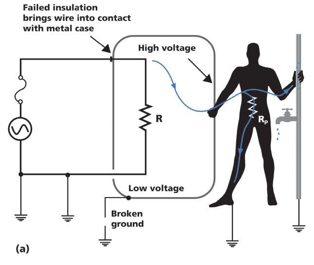

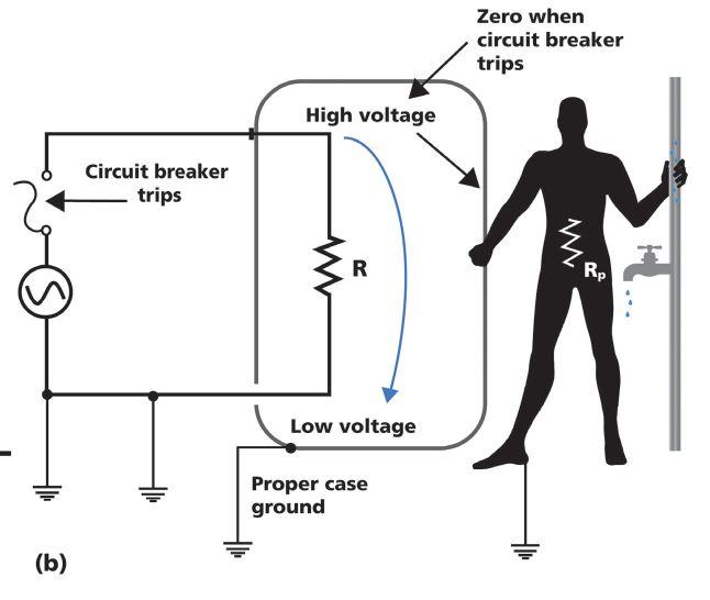
But with a parallel path of less than an ohm in place via the grounding conductor and utility ground, all but a miniscule amount of fault current will pass harmlessly around, not through, the operator (Figure 3).
With this function so vital, should it be taken for granted? Or should it be maintained, as are other and often not even potentially lethal, elements of the electrical program? Line cords take a severe beating, being dragged, yanked, stepped on, driven over, rolled, and unrolled. A serious limitation to regular maintenance, however, is the enormity of the task, and therefore, it is often just not done.
An ordinary multimeter (also known as a voltohm-milliammeter or VOM) could be used to make a resistance measurement from the ground pin on the plug to the metal frame of the item. But such a test is made with only a few milliamps of test current and is far from rigorous. It proves there is basic continuity, but little else.
Grounding conductors in line cords are often stranded for flexibility and could be hanging by

a few strands. That would pass an ordinary test with a VOM, but one good tug and the cord is out of service — and possibly dangerous. At the other extreme are low-resistance ohmmeters, but this is like using a limousine for a golf cart. Low-resistance ohmmeters employ large currents, often approximating operating current, and measure to a precision far greater than required to qualify a line cord. They are expensive and involved to operate — in short, massive overkill.
Convenient test instrumentation with a portable appliance tester (PAT) is available, just not widely known in the United States. In Europe, they are ahead of the curve, including legislation requiring assurance of worker safety, and PAT testing has been implemented for years. There are no direct mandates in the United States, but many American companies have implemented the process for the sake of European customers, clients, and intracompany facilities. Others are simply ahead of the curve and perform PAT testing for the security of their own employees and customers.
So how does a PAT work? The device to be tested (IUT) is plugged into the socket on the panel of the tester. If it is an extension cord, the circuit is completed by looping the cord back to a receptacle also conveniently located on the tester panel. If the IUT is a complete piece of equipment (e.g., electric saw, hair dryer, portable heater), the circuit is completed with a handheld probe applied to metallic surfaces. Various test currents can be applied depending on the nature of the IUT, with typical values like 10 and 25 amps circulated through the grounding conductor. The test current on a quality tester is selectable. Other parameters may also be adjustable, like pass/ fail value down to fractions of ohms and time in seconds that the test is applied. The tester indicates pass (Figure 4) or fail (Figure 5), after which adjustments are made and a retest run. A critical adjustment may include an allowance for the copper’s resistance in long leads and cords. Quality testers have built-in functions where the operator can enter such data and

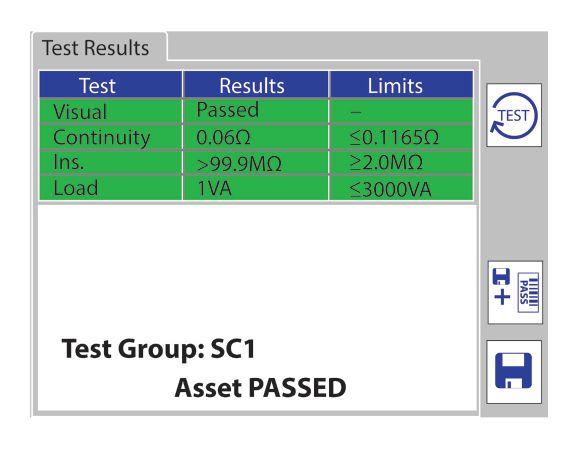
the test will then automatically allow for it, eliminating a potential source of erroneous conclusions.
Some available simplified testers perform only one or two safety tests. But quality testers are full-featured to include a battery of such tests including insulation resistance, polarity, leakage currents at operating voltage that include hot-neutral balance and potential operator exposure, and possibly a hipot (dielectric strength) test. Note that on a well-designed PAT, all these tests are run automatically in sequence as part of a test group, but the earth bond (grounding conductor) test is always first. This emphasizes its fundamental importance in safety protection. No other test is conducted unless the grounding conductor has passed.
Tests can also be performed individually, so if only the ground bond was of concern, a large number of line cords or extension cords could be tested quickly with minimal hookup time. Just plug in the IUT, connect the earth bond probe (which can be done by clipping or simply holding the tip against the IUT), and press the test button. A pass or fail is displayed following the pre-set test interval. When a test group is being run instead of an individual test, the tester will automatically sequence them in proper safety order, with ground bond first, even if the operator had set up the group in some other order. The PAT will

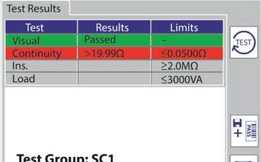

then perform each test in sequence, followed by a color-coded pass indication, until the regimen is completed or a test has failed. In the latter case, testing ceases and will not proceed until the defect has been repaired or otherwise corrected, so that electrically dangerous equipment is no longer being subjected to applied voltage.
Once testing has been completed — whether passed or failed — it is of paramount importance to keep a record. PATs include the ability to store enormous amounts of data in dynamically organized electronic files. This capability enables an electrical maintenance supervisor to readily keep track of an entire facility’s electrical equipment in up-to-date safety conformance. It not only prolongs the life of equipment and keeps the workforce safe, but also regular electrical safety audits are more easily defended in the case of legal action.

Je rey R. Jowett is a Senior Applications Engineer for Megger in Valley Forge, Pennsylvania, serving the manufacturing lines of Biddle, Megger, and MultiAmp for electrical test and measurement instrumentation. He holds a BS in biology and chemistry from Ursinus College. He was employed for 22 years with James G. Biddle Co., which became Biddle Instruments and is now Megger.

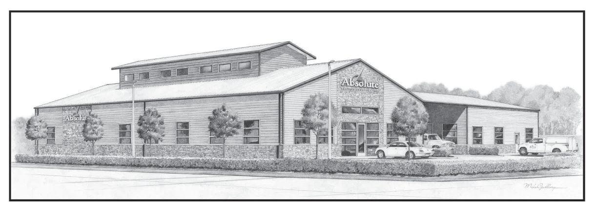
You can count on us for specialized experience in healthcare, data center, o ce complex, and commercial acceptance and maintenance testing. Absolutely Power generation, petrochemical, oil & gas, and heavy industries also look to us for high demand services such as start-up commissioning, maintenance testing, shut-down and turnarounds, and breaker shop repair. Get started today.


James (Jim) R. White, Vice President of Training Services, has worked for Shermco Industries Inc. since 2001. He is a NFPA Certified Electrical Safety Compliance Professional and a NETA Level 4 Senior Technician. Jim is NETA’s principle member on NFPA Technical Committee NFPA 70E®, Standard for Electrical Safety in the Workplace®, NETA’s principle representative on National Electrical Code® Code-Making Panel (CMP) 13, and represents NETA on ASTM International Technical Committee F18, Electrical Protective Equipment for Workers Jim is Shermco Industries’ principal member on NFPA Technical Committee for NFPA 70B Recommended Practice for Electrical Equipment Maintenance and represents AWEA on the ANSI/ISEA Standard 203 Secondary Single-Use Flame Resistant Protective Clothing for Use Over Primary Flame Resistant Protective Clothing. An IEEE Senior Member, Jim received the IEEE/IAS/PCIC Electrical Safety Excellence Award in 2011 and NETA’s Outstanding Achievement Award in 2013. Jim was Chairman of the IEEE Electrical Safety Workshop in 2008 and is currently Vice-Chair for the IEEE IAS/ PCIC Safety Subcommittee.


No. 122


This month’s Tech Quiz is on NERC. Many technicians may not have heard of NERC since it is only for generation, transmission, and distribution facilities and sites, but it is important to understand at least some of the basics.
1. What does NERC stand for?
a. National Electrical Regional Committee
b. Natural Environment Research Council
c. Nigerian Electricity Regulatory Commission
d. North American Electric Reliability Corporation
2. NERC can only enforce its regulations and requirements within the United States.
a. True
b. False
3. What is NERC’s purpose?
a. It oversees the reliability of North American power grids.
b. It has the authority to enforce its standards on all users, owners, and operators of bulk power systems.
c. Both a and b
d. As a self-regulated government agency, it is used to generate cash flow for the federal general fund, much like Social Security.
4. Looking at unmonitored vented, leadacid battery systems that fall under NERC PRC-005-2(i), what are the two maintenance intervals given in Table 1-4(a)?
a. 4 months and 18 months
b. 6 months and 12 months
c. 12 months and 18 months
d. 18 months and 24 months


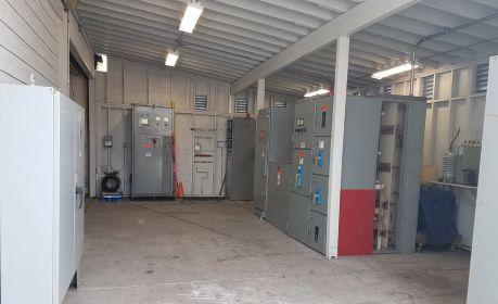


Anthony F. Demaria, Sr. — affectionately called Mr. D by those closest to him — passed away December 31, 2017. He was surrounded by family and exactly where he wanted to be: the Demaria family home in San Pedro, California.
“I was born in San Pedro, and I’m going to die in San Pedro,” he said on more than one occasion. Mr. D was born there in 1925. His father, Nick, came to San Pedro in 1900, and Mr. D was proud that Demarias have lived in the town for 117 years.

Among those in electrical testing and maintenance, Mr. D was most well known for his work in the maritime and fishing industries. His career started in the Navy. He would go on to work with the U.S. Merchant Marine, the U.S. Coast Guard, aboard commercial fishing boats, as a marine engineer for a State of California research vessel, as an electrician and supervisor at Seaboard Electric, and finally as the founder of Demaria Electric.
Anthony F. Demaria, Sr.
Mr. D led the modernization and reliability of electrical systems on board ships in two very important ways: retrofitting the old electromechanical voltage regulators on shipboard generators with new solid-state regulators and adding refrigeration circuitry to provide additional capacity to cool produce and freeze ice cream. Skilled Demaria Electric electricians were the go-to crew for companies like Matson, American President Lines, Keystone Shipping, Texaco Tankers, and others.
Th ose who spent any time with Mr. D remember him better for his genuine interest and care about other people’s lives. He was truly a people person. He would talk to anyone —
ANTHONY FRANCIS DEMARIA, SR.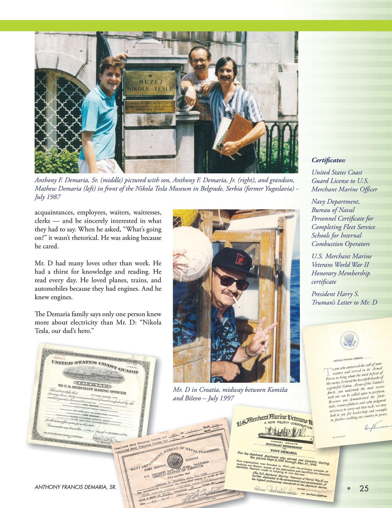

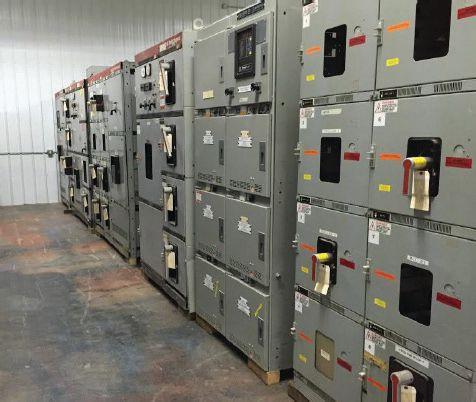
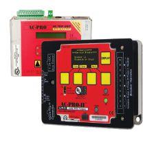
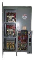
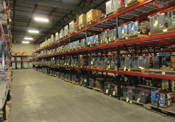
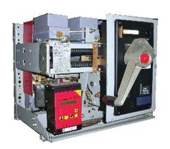


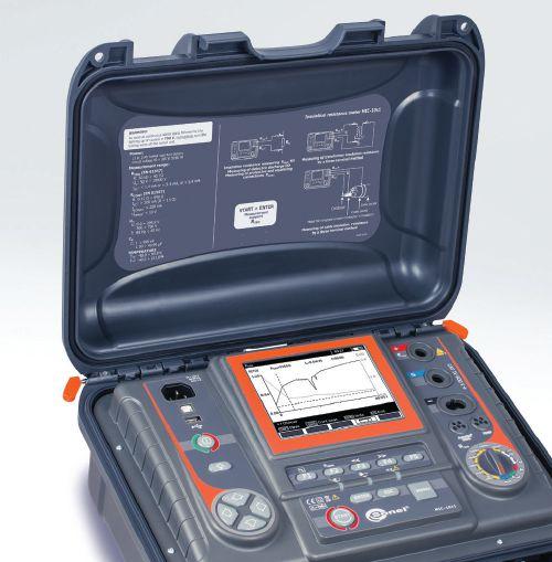


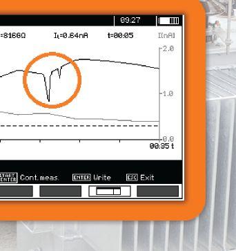
Sonel’s Graphic Insulation Testers expose flaws that numerical testers simply can’t see.


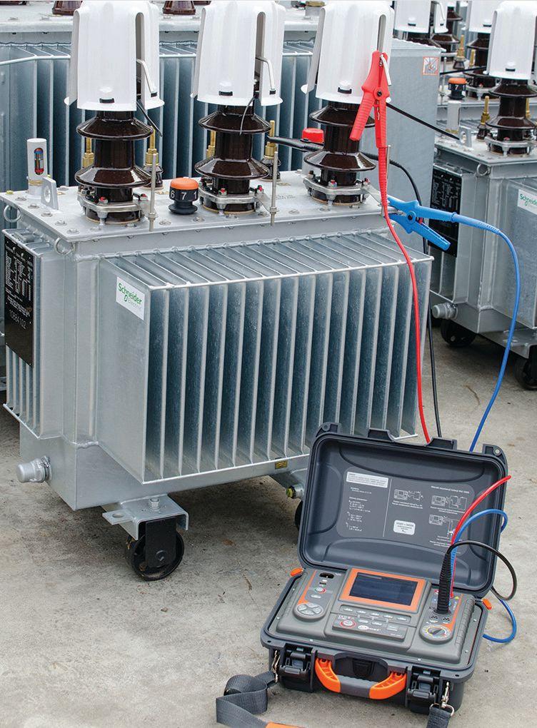
Transformer windings, motor windings, cable spools
User-selectable test voltages from 50 V to 5/10 KV
All ratios and parameters calculated – absorption, PI, DAR, capacitance, length
You run an insulation resistance test and get a number. Everything is fine. Right? Well...maybe not. This graphic display plots the results of a test where the final number appears to be OK, but the graph indicates a latent flaw that will likely result in an avoidable breakdown.
Sonel MIC Graphic Insulation Testers are the only instruments that display this valuable information on


the tester screen. Without this graph you’d wind up with a false sense of insulation integrity.
Sonel Graphic Insulation Testers have all the features you’d expect from high performance instruments including stepped or continuous voltage, selectable test voltages and currents, three test times plus CAT IV safety rating, auto-discharge, high-noise immunity and live object protection.
Get more information on these powerful instruments and the complete line of Sonel testers at www.soneltest.com
Better yet, call us today. 408.988.1346


• Cables
• LV/MV Circuit Breakers
• Rotating Machinery
• Meters
• Automatic Transfer Switches
• Switchgear and Switchboard Assemblies
• Load Studies
• LV/MV Switches
• Relays - All Types
• Motor Control Centers
• Grounding Systems
• Transformers
• Insulating Fluids
• Thermographic Surveys
AND
• Reclosers
• Surge Arresters
• Capacitors
• Batteries
• Ground Fault Systems
• Equipotential Ground Testing
• Transient Voltage Recording and Analysis
• Electromagnetic Field (EMF) Testing
• Harmonic Investigation
• Replacement of Insulating Fluids
• Power Factor Studies


 BY SCOTT BLIZARD and PAUL CHAMBERLAIN, American Electrical Testing Co. LLC
Equipment maintenance and safety go hand in hand. Improperly maintained electrical equipment can contribute to or cause injuries. “Maintenance, condition of” is a very important definition given by NFPA 70E. It defines the state of electrical equipment such as a protective device that a worker may come in contact with.
What is the equipment’s functioning condition; has it been maintained? Is everything working as it is designed? Most equipment in the industry is likely very old and reaching the end of its life. This could mean that it may not operate as the manufacturer intended. This could be very dangerous for someone working on it without knowing whether the device will function correctly.
NFPA 70E defines “Maintenance, condition of” in Article 100 as:
Maintenance, Condition of — The state of the electrical equipment considering the manufacturer’s instructions, manufacturer’s recommendations, and applicable industry codes, standards, and recommended practices.
Both the NFPA and OSHA recognize that improper maintenance can contribute to arc fl ash duration and exacerbate injuries and equipment damage. OSHA states that electrical accidents, when initially studied, often appear to be caused by circumstances that are varied and peculiar to the particular incidents involved. Further consideration usually reveals the underlying cause to be a combination of three possible factors:
• Work involving unsafe equipment and installations
• Workplaces made unsafe by the environment
• Unsafe work practices
The first two factors are sometimes considered together and simply referred to as unsafe conditions. Thus, electrical accidents are generally considered as caused by unsafe conditions, unsafe work performance, or as is usually the case, combinations of the two. It should also be noted that inadequate maintenance can cause equipment or installations that were originally considered safe to deteriorate, resulting in an unsafe condition. In Article 110, NFPA requires the electrical safety program to address the condition of maintenance as part of the plan.
From Article 110.1 of NFPA 70E — 2018:
(C) Condition of Maintenance — The electrical safety program shall include elements that consider condition of maintenance of electrical equipment and systems.

Chapter 2 in NFPA 70E, Standard for Electrical Safety in the Workplace, is dedicated solely to safety-related maintenance requirements. It is written to identify only maintenance that is directly associated with employee safety. Generally, OSHA and NFPA lean heavily on the requirement that the equipment be maintained in accordance with the manufacturer’s recommendations or industry consensus standards. They clarify that, first and foremost, only authorized and qualified individuals may perform maintenance on the equipment, because those individuals can more effectively identify potential hazards when working with and around the equipment. It also states that it is the equipment owner’s responsibility to ensure that appropriate maintenance is conducted.
At this point, the separate articles within Chapter 2 of NFPA 70E go on to differentiate equipment classes and the types of equipment generally worked on within the electrical industry and further refines the typical maintenance requirements or items inspected. Again, this is not meant to supersede the manufacturer’s requirements, only to supplement them. Th e informational note contained in Article 200.1 provides the tools

to accomplish the safety-related maintenance requirements.
Article 200.1 Informational Note: Refer to NFPA 70B, Recommended Practice for Electrical Equipment Maintenance ; ANSI/ NETA MTS, Standard for Maintenance Testing Specifications for Electrical Power Distribution Equipment and Systems ; and IEEE Std. 3007.2, IEEE Recommended Practice for the Maintenance of Industrial and Commercial Power Systems, for guidance on maintenance frequency, methods, and tests.
Language about properly maintained electrical equipment can be found in NFPA 70E 2018, 130.2(A)(4) Normal Operating Conditions:
Normal operation of electric equipment shall be permitted where a normal operating condition exists. A normal operating condition exists when all of the following conditions are satisfied:
1. The equipment is properly installed.
2. The equipment is properly maintained.
3. The equipment is used in accordance with instructions included in the listing and labeling and in accordance with manufacturer’s instructions.
4. The equipment doors are closed and secured.
5. All equipment covers are in place and secured.
6. There is no evidence of impending failure.
Informational Note: The phrase properly installed means that the equipment is installed in accordance with applicable industry codes and standards and the manufacturer’s recommendations. The phrase properly maintained means that the equipment has been maintained in accordance with the manufacturer’s recommendations and applicable industry codes and standards. The phrase evidence of impending failure means that there is evidence such as arcing, overheating, loose or bound equipment parts, visible damage, or deterioration.
When it comes to the personal protective equipment required by NFPA for working on or around energized equipment, the question
of equipment condition is addressed within Table 130.5(C) — Estimate of the Likelihood of Occurrence of an Arc Flash Incident for ac and dc Systems. Th is table helps determine the likelihood that an arc flash incident could occur based upon the equipment type and its condition. This likelihood aids in determining the relevant arc fl ash category of protective equipment required while performing a task related to that equipment. Th e equipment condition can be listed as any of the following:
• Any
• Normal
• Abnormal
It is obvious that any abnormal equipment condition increases the likelihood of an incident, but it is sometimes hard to determine whether the equipment could be considered normal versus abnormal. What if a breaker hasn’t been exercised in the 20 years since it was installed? It may look normal, but is it going to operate as intended? Without proper regular maintenance of the equipment, in this case, regular operation of the breaker, can it be a guarantee that the equipment will operate?
Based upon this assumption, when working with the unknown, you must protect yourself with the highest level of personal protective equipment indicated for the potential fault current of that equipment — provided that it can operate within the indicated fault-clearing time. The employer and the worker must always be aware that NFPA states that for the PPE to perform as intended, it needs to be “maintained in a safe, clean, and reliable condition and in accordance with manufacturers’ instructions. The protective equipment shall be visually inspected before each use. Protective equipment shall be stored in a manner to prevent damage from physically damaging conditions and from moisture, dust, or other deteriorating agents.”
Failure to do this can exacerbate injuries should an event occur. Improperly maintained PPE can be as dangerous as improperly maintained equipment.
NFPA 70-2018 requires equipment to meet a standard from installation to end of life. To help end users meet the standard set by NFPA 70E, ANSI/NETA standards already exist to meet the intent of NFPA 70E: ANSI/NETA ECS, Standard for Electrical Commissioning Specifications for Electrical Power Equipment and Systems; ANSI/ NETA ATS, Standard for Acceptance Testing Specifications for Electrical Power Equipment and Systems; and ANSI/NETA MTS, Standard for Maintenance Testing Specifications for Electrical Power Equipment and Systems
Remember: If the owner of an electrical installation, no matter how big or small, has not acceptance tested or maintained that equipment, the worker cannot be sure the equipment will operate as designed. When in doubt, be sure to wear the proper PPE for the task.

As mentioned previously, all of Chapter 2 is devoted to electrical equipment maintenance. For this reason, forethought must be taken by engineers and designers during the planning phase to ensure they meet the requirements set forth by OSHA and NFPA, as well as the NEC. A strong correlation exists between proper maintenance of equipment, design of equipment, and safety. The concepts of safety and maintenance lean on each of these to enable better production and equipment design, as well as reduction of potential injuries or equipment damage.
Paul Chamberlain has been the Safety Manager for American Electrical Testing Co. LLC since 2009. He has been in the safety field for the past 18 years, working for various companies and in various industries. He holds a BS in marine safety and environmental protection from Massachusetts Maritime Academy.

Scott Blizard has been the Vice President and Chief Operating Officer of American Electrical Testing Co. LLC since 2000. During his tenure, Scott has acted as the Corporate Safety Officer for nine years. He has over 25 years of experience in the field as a Master Electrician, Journeyman, Wireman, and NETA Level IV Senior Technician.


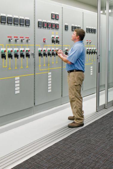

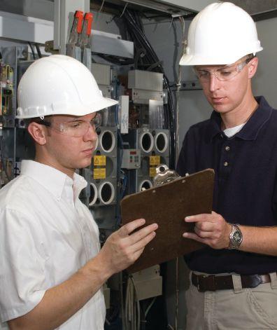






 BY STEVE TURNER, Electrical Consultants, Inc.


The fast bus trip (FBT) scheme provides bus protection for radial systems. This protection has a short time delay on pickup in the order of three cycles and does not require extra current transformers (CTs) needed for a differential scheme. FBT also reduces the required number of relays and the amount of wiring and testing. Take the extra steps to make this protection scheme reliable and secure.
Figure 1 is a one-line diagram for a distribution bus with one main (source) and two feeders. Each breaker has a non-directional definite time overcurrent relay (i.e., 50M, 50F2, and 50F3). These are the relays used for the traditional scheme. The feeder relays (50F1 and 50F2) send a blocking signal to the bus relay (50M) when they detect a feeder fault to prevent it from tripping.



Figure 2 illustrates the traditional logic used for this protection scheme.
If a fault is located at F 1 (bus), there is no blocking signal from either feeder relay, and the bus relay 50M trips after a short time delay (tp) typically set at three cycles. If a fault is on a feeder such as F2, then the feeder relay blocks the bus relay and prevents tripping the bus. Typically, an output contact from each feeder relay is wired to an input of the bus relay to transmit the blocking signal during feeder faults. Use phase overcurrent elements for this scheme and set the pickup for the overcurrent elements to operate for faults close in to the bus.
Figure 3 illustrates a ground fault on the bus (for example, a bushing fl ashes over). A transformer connected to Feeder 2 has a winding connected grounded wye facing the distribution system. Ground fault current (IG) comes up the neutral of the wye-connected winding from ground flowing through the feeder back into the bus fault; as a result, 50F2 incorrectly blocks fast bus tripping.
The solution is to use forward-looking directional overcurrent elements (67F1 and 67F2) to block the bus relay (Figure 4). Using directional overcurrent to block properly

Figure 4: FBT Logic Diagram with Directional Blocking


discriminates between bus and feeder faults, which in turn prevents delayed tripping for cases such as shown in Figure 3.


Figure 5 illustrates a three-phase overhead feeder. A fault occurs that is first A-Phase-to-ground. The fault then evolves into A-Phase-to-B-Phaseto-ground and finally into a three-phase fault. This could be due to a broken tree limb as it falls across each phase. Therefore, the fault type is initially single phase-to-ground, then phaseto-phase-to-ground, and finally three-phase. Positive-sequence current, negative-sequence current, and zero-sequence current are present during the initial fault (A-G) and subsequent fault (A-B-G), but there is only positive-sequence current during the final fault (A-B-C-G).
It is a common design for numerical feeder relays to use steering logic that determines which polarizing quantity to use for the ground overcurrent directional elements based upon prevailing fault conditions. For example, a popular choice is to fi rst use negativesequence voltage polarization followed by zero-sequence voltage polarization if there is little or no negative-sequence voltage present at the relay voltage terminals. Both of these directional elements drop out when the fault evolves into all three phases, since there is no longer any unbalance. Therefore, there is no blocking signal for at least one relay processing interval until the steering logic switches over to positive-sequence voltage polarization. As a result, an unwanted bus trip can occur when the blocking signal drops out.
Figure 6: FBT Logic Diagram with Time Delay on Dropout for Directional Blocking
The solution is to use time delay on dropout for blocking overcurrent elements as illustrated in Figure 6 so the blocking signal will ride through the final stage of evolving faults.
Figure 7 below illustrates an inter-circuit fault between two distribution feeders. This could be due to a tree branch falling across two feeders running along the same set of overhead poles.
The bus relay 50M sees the total fault current IF while each feeder relay (50F1 and 50F2) only sees half that magnitude. Therefore, if the overcurrent elements on these relays are set with the same pickup setting, then the feeder relays will not detect the inter-circuit fault, and an


Figure 5: Evolving Fault on Overhead Distribution Feeder
Figure 7: Inter-Circuit Fault Involving Two Overhead Distribution Feeders
unwanted bus trip occurs. Use the following criteria when setting the pickup:
50F#P < 50MP/2
Where:
50F#P = Feeder Relay Overcurrent Pickup
Setting
50MP = Bus Relay Overcurrent Pickup
Settings
The following steps make fast bus trip more secure:
• Use forward-looking directional overcurrent elements to block so that the fast bus trip occurs during back feed from any feeders.
• Time delay on dropout for the blocking elements prevents unwanted bus trips if the signal momentarily drops out during an external fault.
• Set the overcurrent pickup for the blocking elements more than twice as sensitive as the bus tripping element.
Remember: Fast bus trip protection is simple to implement and provides economical bus protection for radial distribution systems. Traditional scheme logic is reliable, but not secure due to the simplicity.

Steve Turner is a Senior Engineer II at Electrical Consultants, Inc., working in their San Diego office. Steve worked at Beckwith Electric Company, Inc. for 10 years, first as the Engineering Laboratory Director and then as Senior Applications Engineer. His previous experience includes working as an Application Engineer with GEC Alstom and as an Application Engineer in the international market for SEL focusing on transmission line protection applications. While at Duke Energy (formerly Progress Energy), Steve developed the first patent for double-ended fault location on overhead high-voltage transmission lines and was in charge of all maintenance standards in the transmission department for protective relaying. Steve has a BSEE and MSEE from Virginia Tech University.








 BY SCOTT BLIZARD and BRUCE HOROWITZ, American Electrical Testing Co. LLC


The largest blackout in history occurred on November 9, 1965. About 30 million people lost power in the northeastern United States and southeastern Ontario, Canada. In response to this incident, the electricity industry established the National Electric Reliability Council (NERC) in 1968. Nine regional reliability organizations were formalized under NERC. This original council maintained and practiced voluntary operating criteria and guides.
During the period between 1968 and 2005, NERC underwent numerous transformations, including a 1981 change to the North American Electric Reliability Council. A subsequent change in 2007 replaced Council with Corporation. Several substantial power interruptions during this timeframe encouraged more stringent guidelines and began to compel better compliance with those guidelines. NERC’s guidelines for power system operation and accreditation were referred to as policies; compliance was strongly encouraged, yet ultimately voluntary. During this period, NERC worked closely with all stakeholders to revise its policies into standards.
On August 14, 2003, 50 million people lost power in the Northeast and Midwest as well as Ontario, Canada. This was the second major blackout affecting the whole Northeast. As a result, Congress passed the U.S. Energy Act, better known as the Electric Modernization Act of 2005. This act authorized the Federal Electric Reliability Commission (FERC) to designate an Electric Reliability Organization (ERO) to oversee and regulate the reliability of the North American electrical grids.
In 2006, NERC was named the designated ERO and was authorized by FERC to create and enforce standards upon suppliers to the

bulk power system (BPS). FERC granted NERC the legal authority to enforce reliability standards with all users, owners, and operators of the BPS in the United States. Compliance with those standards is mandatory and enforceable in the United States, Ontario, and New Brunswick.
As the federally recognized ERO, NERC is responsible for developing and enforcing reliability standards; creating annual and 10-year assessments for winter and summer forecasts; monitoring the bulk power system; and educating, training, and certifying industry personnel. FERC approved 83 NERC reliability standards in March 2007, making them the first set of legally enforceable standards for the U.S. BPS effective June 2007.
NERC PRC-005 was first approved April 1, 2005. Since its inception, it has undergone several revisions and modifications. In November 2012, Revision 2 (PRC-005-2) was completed. This was a comprehensive update, absorbing maintenance requirements from PRC-005-1.1b, Transmission and Generation Protection System Maintenance and Testing ; PRC-008-0, Implementation and Documentation of Underfrequency Load Shedding Equipment Maintenance Program ; PRC-011-0, Underfrequency Load Shedding System Maintenance and Testing; and PRC-0170, Special Protection System Maintenance and Testing. Revision 3 added automatic reclosers, and Revision 4 added sudden pressure relays. Other changes have been made over time to the current enforceable standard, PRC-0056, Protection System, Automatic Reclosing, and Sudden Pressure Relaying
NERC states that the purpose of PRC-005 is:
To document and implement programs for the maintenance of all Protective Systems, Automatic Reclosing, and Sudden Pressure Relaying affecting the reliability of the Bulk Electric System (BES) so that they are kept in working order.
The standard requires:
R1 Each Transmission Owner, Generator Owner, and Distribution Provider shall establish a Protection System Maintenance Program (PSMP) for its Protection Systems, Automatic Reclosing, and Sudden Pressure Relaying identifi ed in Section 4.2, Facilities. The PSMP shall:

1.1. Identify which maintenance method (time-based, performance-based per PRC-005 Attachment A, or a combination) is used to address each Protection System, Automatic Reclosing, and Sudden Pressure Relaying Component Type. All batteries associated with the station dc supply Component Type of a Protection System shall be included in a timebased program as described in Table 1-4 and Table 3.
1.2. Include the applicable monitored Component attributes applied to each Protection System, Automatic Reclosing, and Sudden Pressure Relaying Component Type consistent with the maintenance intervals specified in Tables 1-1 through 1-5, Table 2, Table 3, Table 4-1 through 4-3, and Table 5, where monitoring is used to extend the maintenance intervals beyond those specified for unmonitored Protection System, Automatic Reclosing, and Sudden Pressure Relaying Components.
Two types of enforceable Protection System Maintenance Programs (PSMP) have been adapted into today’s industrial compliance requisite: time-based and performance-based. However, no matter which maintenance program is selected, the station dc supply components must follow the time-based program as delineated in Tables 1-4 and Table 3.
The following section is an interpretation of the standard for each type of maintenance program listed previously.
Time-based maintenance (TBM) is described as a routine maintenance activity or periodic testing interval applicable to all electrical components. These intervals are determined by prior trending history, user experience, and/or manufacturers’ recommendations.
NERC PRC-005-6 specifies testing and maintenance intervals according to component type: protection system (relaying and communication), voltage and current sources from instrument transformers, trip and control

circuits, wiring, batteries, and chargers. The present standard is being revised to accommodate certain critical reclosing relays and mechanical transformer fault sensing relays.
As a practical matter, it is advisable that critical equipment be identified and prescribed at a more frequent testing interval than the tables suggest. Th is will maximize the reliability and safety of the equipment and allow for maintenance emergencies, personnel errors, and usual work without inadvertently slipping into non-compliance and suffering penalty for a maintenance-related catastrophic event.
An electromechanical or analog solid-state distance relay must be tested within six calendar years. Thus, a relay tested any time in 2018 must be tested by the end 2024 at the latest to be in compliance. The owner may schedule the next maintenance session for 2023, five years after the 2018 test, to stay well within the limit and to have margin for personnel, work rescheduling, or storm-induced delays.
A zero-tolerance standard of performance is upheld at 100 percent. The requirements of PRC-005-6 call for regimented documentation and archiving of the Protection System Maintenance Program (PSMP) records, right down to the specifications of every test of every relay. Every attempt must be made to correct device failures and maintain thorough records of these issues. Auditors will cautiously review all maintenance records to find specific evidence that the PSMP is carried out. Failing to perform and/or document testing in accordance with the PSMP at its time limits is an act of non-compliance.
A performance-based maintenance (PBM) program is a regimen of established intervals based on the analysis of historical results of time-based maintenance (TBM) failure rates on statistically similar protection systems and components. If a particular group of

components has a proven low failure rate in TBM testing records, the maintenance interval is extended for as long as reasonable while maintaining a low failure rate. Even after an extended time interval has been justified for components with low risk of failure, some infrequent TBM must be carried out to further justify the continued use of extended intervals and to reveal any increase in failure rates requiring remediation of potential failures.
NERC PRC-005-6 has a specific PBM program that describes how the owner documents these PBM populations and conducts the ongoing management process for PBM.
NERC PRC-005-6 Attachment A describes a structured methodology in developing and managing a PBM maintenance program. Attachment A can be found at www.nerc.com/pa/ Stand/Reliability%20Standards/PRC-005-6.pdf
PRC-005-6 is very specific on the periodicity on the testing intervals for a TBM program. Tables 1-1, 1-2, 1-3, 1-4 (a – f), 1-5, 2, 3, 4-1, 4-2 (a – b), 4-3, and 4 delineate the TBM testing requirements. Testing intervals range from 4 months to 12 years. Remember, these are maximum times and are dependent on the history of your devices. These tables can be found at www.nerc.com/pa/Stand/ Reliability%20Standards/PRC-005-6.pdf.
Electrical maintenance is a necessity for all electrical power equipment and systems. This maintenance is often performed by a combination of the owner, operator, and contractor. Th ere are several diff erent maintenance programs, and frequency depends on the age of the equipment and the required system reliability. Today, there is a very high demand to find qualified and competent electrical workers to complete the inspection, testing, and maintenance of

electrical equipment and systems. This demand for qualified electrical test technicians is high due to the aging infrastructure and the new, complex systems we are installing. The systems range from generating plants to transmission systems, distribution systems, and the larger end-user’s systems. All of these systems require qualified technicians to maintain and assess the equipment to assure the safe and reliable operation of the electrical system.
Every maintenance program should start with proper acceptance testing and commissioning of the components and the system. This will assure the proper design, installation, and operation of the electrical system to the owner’s requirements, manufacturer’s specifi cations, applicable standards, and regulatory requirements. Acceptance and commissioning will also provide benchmark values for the maintenance testing of the equipment. The online monitoring system and components should include the applicable attributes applied to each protection system component type, consistent with NERC requirements, to extend the maintenance intervals beyond those specified for unmonitored protection system components. Monitors and components should be properly set up during the commissioning to provide accurate results and reliable operation. Online monitors are a valuable tool to assist with your maintenance plan and possibly extend your maintenance intervals, but will not replace the offline maintenance of the system and components.
As demand for more reliable and safer electrical systems grows, inspection and maintenance of these systems will increase in importance. Regulatory requirements are becoming more stringent and demand documentation to verify that acceptance, commissioning, and maintenance activities meet or exceed the minimum requirements and demonstrate compliance. Documentation of the maintenance program, maintenance activities, and system events must be readily available for safety officers, insurance companies, and regulatory auditors.
Whichever methodology is selected as the PSMP, ANSI/NETA standards can provide the backbone of your program when installing a new protection system or developing a maintenance plan for an existing system. ANSI/NETA ATS, Standard for Acceptance Testing Specifications for Electrical Power Equipment and Systems ; ANSI/NETA ECS, Standard for Electrical Commissioning Specifi cations for Electrical Power Equipment and Systems; ANSI/NETA ETT, Standard for Certifi cation of Electrical Testing Technicians ; and ANSI/NETA MTS, Standard for Maintenance Testing Specifications for Electrical Power Equipment and Systems are helpful tools in the development of a comprehensive testing program that meets the requirements of PRC005-6.

After all testing has been completed and verified as in compliance with PRC-005-6, it must be documented with either test data sheets or reports. BES owners are required to demonstrate compliance to PRC-005-6. The following evidence retention periods identify the period of time an entity is required to retain specific evidence to demonstrate compliance. For instances where the evidence retention period specified is shorter than the time since the last audit, the compliance enforcement authority may ask an entity to provide other evidence to show that it was compliant for the full time period since the last audit. The transmission owner, generator owner, and distribution provider shall each keep data or evidence to show compliance as identified in the following, unless directed by its compliance enforcement authority to retain specific evidence for a longer period of time as part of an investigation.
• For Requirement R1: The transmission owner, generator owner, and distribution provider shall each keep its current dated Protection System Maintenance Program, as well as any superseded versions since

the preceding compliance audit, including the documentation that specifies the type of maintenance program applied for each protection system component type.
• For Requirement R2, Requirement R3, Requirement R4, and Requirement R5: The transmission owner, generator owner, and distribution provider shall each keep documentation of the two most recent performances of each distinct maintenance activity for the protection system component or all performances of each distinct maintenance activity for the protection system component since the previous scheduled audit date, whichever is longer. The compliance enforcement authority shall keep the last audit records and all requested and submitted subsequent audit records.
NERC requires each transmission owner, generator owner, and applicable distribution provider to have a Protection System Maintenance Program (PSMP) for protection systems that affect the reliability of the bulk electric system (BES). Th e program can be time based, performance based, or a combination of both. The PSMP shall identify which maintenance method is used to address each type of protection system component. All batteries associated with the station dc supply component-type protection system shall be included in a time-based program. The program shall also include the applicable monitored component attributes applied to each protection system component type consistent with the specifi ed maintenance intervals in PRC-005-6 Tables where monitoring is used to extend the maintenance intervals beyond those specified for unmonitored protection system components. Each entity shall document its compliance with that program and shall be responsible for maintaining each of its protection system components according to its maintenance program, which must meet or exceed the NERC requirements.

The required maintenance activities and maximum intervals in PRC-005-6 range from 4 months to 12 years. The maintenance activities and intervals depend on the type of protection system, applicable monitoring components installed, and the type of maintenance program implemented: time-based maintenance or performance-based maintenance.
Each transmission owner, generator owner, and distribution provider shall have a documented PSMP and keep evidence that it has maintained its protection system components in accordance with the NERC requirements for that type of maintenance program. Th e evidence may include, but is not limited to, component lists, dated maintenance records, dated maintenance summaries, dated inspection records, and dated analysis records and results. Each entity shall provide evidence that it has undertaken efforts to correct identified, unresolved maintenance issues in accordance with NERC requirements.
When dealing with service-aged equipment, many criteria are used to determine which maintenance program to use, which equipment is to be tested, at what intervals, and to what extent. Ambient conditions, availability of downtime, and maintenance budgets are a few considerations that go into the planning of a maintenance schedule. The owner must make many decisions each time that maintenance is considered, and the owner shall always meet or exceed NERC requirements. As the demand for more reliable and safer electrical systems increases, the inspection and maintenance of these systems increases in importance. Regulatory requirements are becoming more stringent and demand documentation to verify that acceptance, commissioning, and maintenance activities meet or exceed the minimum requirements and demonstrate compliance. Documentation of the maintenance program, maintenance activities, and system events must be readily available for safety officers, insurance companies, and regulatory auditors. The ANSI/NETA standards are valuable tools for

any maintenance program, bid document, field checklist, or testing specification. The documents provide the inspections and tests for assessing the suitability for service and reliability of the power system and individual components.
NORTH AMERICAN ELECTRIC RELIABILITY CORPORATION, PRC-005-6
NORTH AMERICAN ELECTRIC RELIABILITY CORPORATION, PRC-005-6 Implementation Plan
Supplementary Reference and FAQ - PRC005-6 Protection System Maintenance, Protection System Maintenance and Testing Standard Drafting Team (July 2015)

Scott Blizard has been Vice President and Chief Operating Officer of American Electrical Testing Co. LLC since 2000. During his tenure, Scott acted as Corporate Safety Officer for nine years. In addition, he has over 30 years of experience in the field as a Master Electrician, Journeyman, Wireman, and NETA Level IV Senior Technician.


Bruce Horowitz spent 30 years with Consolidated Edison of New York. He was General Supervisor of Maintenance in the Borough of Brooklyn for the Central Substation Department. He held various levels of positions in engineering, up to and including Section Manager. Bruce spent most of his career at Con Edison working in the Fossil and Nuclear Generation Departments and represented Con Edison for 10 years on the IEEE Battery Working Group. He joined American Electrical Testing Co. LLC in 2011 as a Senior Engineering Manager and was promoted to Director of Engineering in 2016. Bruce has been involved in numerous projects for the transit, power generation, electric utility, industrial, and commercial market segments.


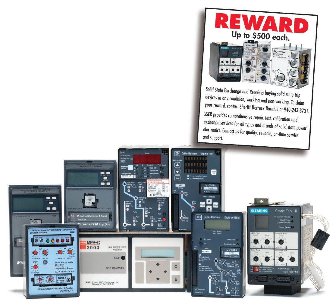
Featuring quality, reliable, on-time service and support for all brands and types of solid state power electronics.
Power electronics are our business
Let us suppoort you with our quality repair, calibration and servicing of your solid state equipment. We also buy, sell and trade:
•Communications devices for power equipment
•Protective relays
•Circuit breaker trip devices
•Motor overload relays
•Rating plugs
Measure turns ratios, phase displacements, excitation currents
➤ Real 3-phase test voltage output
➤ Up to 275 V output for high accuracy
➤ Tertiary winding channel
➤ Fully automatic tap changer test mode
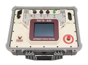
the Current Transformer Ratio, Phase Shift, Polarity, Excitation, Saturation, Winding Resistance and Insulation Resistance
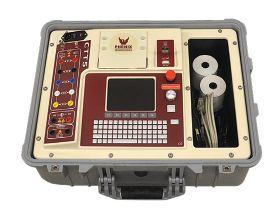
➤ “Hear” Corona / Partial Discharge
➤ Countless number of possible applications
➤ Battery operated for maximum flexibility
➤ Parabolic sensor with laser for optimal pinpoint location
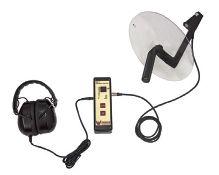
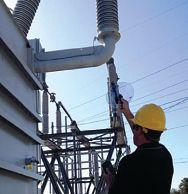



One need only recall the 2003 electric power blackout across the Northeast United States and Ontario, Canada, to understand the importance of grid stability. Ensuring the reliability of the bulk electric system (BES) has been a national priority for many decades. To that end, the North American Electric Reliability Corporation (NERC) was established in the 1960s to develop and enforce mandatory standards for the maintenance and testing of all transmission and generation protection systems a ecting the reliability and operation of the BES.
Recently, NERC handed down several new power system protection standards, including PRC-019, PRC-024, and PRC-025, each with impending compliance deadlines for generator owners and generator operators. Navigating these standards can be more time consuming than a facility’s management might realize.
e NERC compliance process starts with understanding the requirements, developing and implementing a compliance plan, and ultimately, reporting actions and e orts to NERC. When generator owners or operators comply with NERC, they are not only doing their part to improve grid reliability, but simultaneously, they are improving their own generator stability and infrastructure performance while avoiding costly nes.
In 2015, NERC published PRC-019 and PRC-024 to help ensure reliable protection schemes for generating unit facilities. NERC quickly followed up with PRC-025, which included additional requirements for various components of protection schemes. Facilities must demonstrate full compliance with all three standards over the next 12 to 18 months.
NERC PRC-019
Coordination of Generating Unit or Plant Capabilities, Voltage Regulating Controls, and Protection
Compliance Due Dates:
40% complete – March 2016
60% complete – March 2017
80% complete – March 2018
100% complete – March 2019
NERC PRC-024
Generator Frequency and Voltage Protective Relay Settings
Compliance Due Dates:
40% complete – March 2016
60% complete – March 2017
80% complete – March 2018
100% complete – March 2019
NERC PRC-025
Generator Relay Loadability
Compliance Due Dates:
100% complete – October 2019
100% complete if a retrofit is required to comply – October 2021
Figure 1: NERC Compliance Deadlines


The purpose of the PRC-019 standard is to verify coordination of a generating unit and protective relays. It applies to all controls and relays that impact the voltage regulation of the generator. Essentially, this standard ensures coordination between the generator’s automatic voltage regulator (AVR) and the exciter controls and protective relay systems to ensure safety and reliability. This coordination allows the generator to function appropriately under various conditions, but without causing damage to the generator equipment.
Per the standard, at least every fi ve years, generator owners must verify coordination of the voltage regulating system controls (including in-service limiters and protection functions) with the applicable equipment capabilities and with the settings and functions of applicable protection system devices. Owners may be required to change voltage regulating settings or equipment, protection system settings or components, and generating or synchronous condenser equipment capabilities to ensure compliance with the standard. In other words, owners must adjust device settings to comply with the standard, and if those devices cannot accept the required settings, then the devices must be replaced.
The purpose of the PRC-024 standard is to ensure generating units remain connected during defined frequency and voltage excursions. Th e standard ensures that the generator meets voltage and frequency ridethrough requirements during switching
transients, and that it will remain online for an event that it is intended to support. The standard requires generator owners to either:
1. Set its installed generator frequency protective relaying so as not to trip during defined frequency-related operating conditions and to set its installed generator over- and undervoltage protective relays (including volts per hertz relays evaluated at nominal frequency) so as not to trip during defined steady-state and voltage-related operating conditions.
2. Document and report the unit’s limitations if the required settings cannot be accommodated.
The purpose of the PRC-025 standard is to ensure that load-responsive protective relays associated with generation facilities are set at a level to prevent unnecessary tripping of generators during a system disturbance that does not pose a risk of damage to associated equipment. Studies show that generators have tripped for conditions that did not apparently pose a direct risk to those generators and associated equipment within the time period when the tripping occurred. This tripping can expand the scope and/or extend the duration of a disturbance unnecessarily. In fact, this very scenario contributed to the August 2003 blackout.
PRC-025 establishes criteria for setting loadresponsive protective relays that handle load transfer from one generation site to the next, such that individual generators may provide reactive power within their dynamic capability during transient time periods to help the system recover from the voltage disturbance. Generator owners must apply the settings and provide evidence that the settings have been applied. Such evidence may include summaries of calculations, spreadsheets, simulation reports, or setting sheets.
By now, most generator operators and owners are aware of NERC and have a general understanding of the consequences for noncompliance, which can include stiff penalties. Companies have already been assessed fines as much as $500,000, depending on the violation. Yet, many facilities fail to demonstrate compliance with the enforceable standards. Why? Often, it’s because they lack awareness of a specific standard and its enforcement date. Perhaps the person responsible for compliance is no longer with the company. In some cases, the facility engineer in charge of understanding and applying NERC standards misinterprets the standard and believes it is not applicable to his or her facility.
The point is that someone needs to be responsible for paying attention to NERC standards and changes by making a list of standards applicable to their facility. Sometimes, owners and operators become aware of the need to comply with a specific standard because they receive a notification from a transmission owner or operator or because a maintenance professional points it out. Relying on these sources of information can be risky, yet experience shows that most facilities lack the internal resources or focus to dedicate someone to the task of staying on top of the latest NERC requirements. It’s simply too much work for in-house teams to take on. Sometimes, partnering with compliance experts who take a proactive approach to understanding NERC standards can help.
It’s important and beneficial to address NERC compliance right now. While it can be tempting to delay addressing these technically challenging issues until the deadline gets closer, planning ahead is the best way to ensure any required changes have the least impact on a business. For example, some changes can be scheduled during a regularly planned maintenance shutdown when they will have
virtually no cost impact. It’s important to get a solid grasp on how NERC will affect the facility so that you can plan ahead.
Once generator operators or owners understand which standards apply to their facility, it’s their job to determine the facility’s current level of compliance as quickly as possible. They should assess the frequency and voltage protection relays and load-responsive protective relay settings to determine whether their facility is falling short of requirements and by what margin, and ascertain the level of effort needed to meet and demonstrate requirements.
If you discover non-compliance, the next step is further evaluation and analysis. While there are helpful tools to reveal non-compliance for a particular relay setting, understanding the process of achieving compliance can be technically demanding. For example, if the deviation from the required setting is not significant, it may be possible to use computer modeling and analysis to demonstrate compliance. But if the deviation is large, the relay setting change should be coordinated with transmission operators and other entities that can be affected by this change.
You might need expert help to know how to interpret the results of the go/no-go tools and use them to define the right road to compliance. For example, a Fortune 500 integrated power company pursued PRC-019 compliance at its Los Angeles-area plant. The company found expert help for gathering data and applicable documentation for the existing protective relay system, generator unit, and generator excitation system to support analysis and demonstration of compliance. Protection engineers also helped determine which protection relays were subject to complying with the standard.
The team analyzed the settings of the in-service limiters to verify that they were set to avoid disconnecting the generator unnecessarily. It


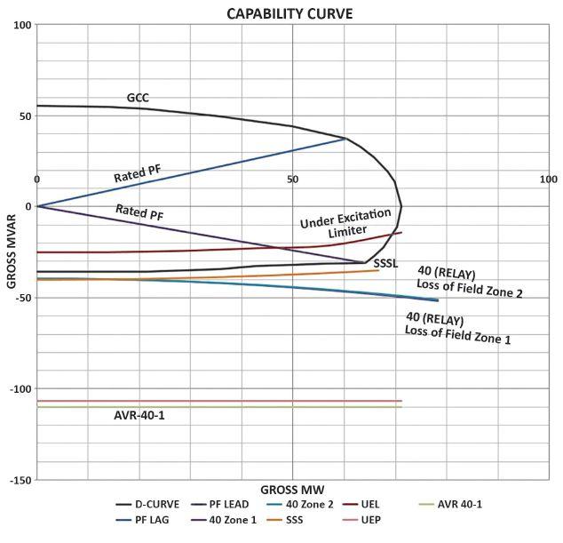
with standards. A complete NERC-approved mathematical proof was created for each load-sensitive relay studied, along with a comprehensive report including detailed recommendations and corrective actions required for ensuring compliance. In the end, the power company had a solid plan for compliance that could be cost-effectively and efficiently implemented prior to the deadline, allowing the business to avoid significant fines.
Taking the necessary steps to address protective relay settings and conform with NERC standards is a process that requires coordinated activities, potentially a planned outage, testing activities, and budgeting. And of course, it all must be documented and accomplished within the compliance deadlines set by NERC.


also analyzed in-service protection system devices, verifying that they were set to operate, isolate, or de-energize equipment to limit the extent of damage when operating conditions exceed equipment capabilities or stability limits. To demonstrate compliance, protection engineers provided P-Q diagrams to illustrate the generator’s capabilities, operating limits, and protective functions. R-X diagrams as well as time current curves explained rotor thermal limits. The engineers also plotted permissible volts per hertz limits for the generator and generator step-up (GSU) transformer with the protection and limiting functions to ensure proper coordination.
Per NERC standards, a generation unit can be evaluated under field-forcing simulations using power system modeling software or by conservative loadability evaluation criteria. If the relay setting fails the conservative evaluation by a margin of 30 percent or less, there is a good possibility that the computer modeling option sets accurate limitation for modeled equipment and shows compliance
Generator operators and owners must select, schedule, and implement the most costeffective and appropriate compliance solutions, including testing, commissioning, and reporting. Generally, if the system is not in compliance with NERC standards, compliance solutions include either changing the settings of some protective relays, or upgrading or replacing some of the relays protecting a facility’s generation plant. In both cases, after changes are made, testing, commissioning, and coordination studies/verification for all affected devices are needed to ensure the system functions correctly.
In the Los Angeles-area plant example, an engineering analysis revealed the need for several changes to the ANSI 40 loss-ofexcitation function of two different relays. During a short, planned outage, the protective relays were set to comply with the standard, new settings were tested, and documentation was updated within the outage window. System compliance was achieved by modifying the protective relay settings, completing necessary testing, and compiling all data, calculations,
and analysis in an easy-to-search electronic report that fully demonstrates compliance.
In some cases, a generator’s existing protective devices may not be capable of accepting the settings required to comply with NERC requirements. For example, in one generating facility, an engineering analysis revealed that a field overcurrent relay was not compliant with PRC-019 at its present setting. Specifically, the report stated, “At the lower end of its range, the relay does not coordinate with the excitation limiter, and at the upper end of its range, it does not act quickly enough to protect the rotor against thermal damage.” In fact, this relay was not capable of both protection and coordination for the installed generator.
In this instance, the AVR manufacturer developed a new relay that was capable of providing adequate protection as well as the coordination required by the NERC standards. The new relay was designed, tested, and installed, bringing the facility into compliance and also improving grid stability for the transmission owner.
Whether a generating facility needs to adjust protective relay settings or upgrade or replace protective relays, the facility must demonstrate to NERC that its solutions meet the requirements laid out in the standard. Facilities will need to create a well-structured report that clearly presents the data and the sources of data used during the studies. The report should make the information easily assessable to auditors. If the facility needs to make any setting adjustments or relay changes based on the assessments, the report should outline the recommended solutions and plan of action.
NERC conformance reports and compliance documentation should be designed with the
auditor’s needs in mind. Use standardized terminology and equations from the NERC standards to ensure clear interpretation of the results. Include comprehensive engineering analysis that is searchable and linked for ease of navigation and full demonstration of compliance. Reports should allow for the easy addition of updated or cyclic information, such as relay maintenance test data, which must be added every five years. Learn how to complete these updates for long-term compliance.
NERC developed its standards to ensure generation plants can manage disturbances in the best way possible to balance protection with reliability. Complying with NERC’s latest regulatory standards is essential to the protection of the nation’s grid and the safe and efficient operation of power generation equipment.
With deadlines approaching for compliance with several critical standards, now is the time for generator operators and owners to assess their protective relay settings and make a plan for compliance. It is important to conduct a reliable power system analysis and perhaps obtain expert recommendations while streamlining the process of changing relay settings and/or replacing protective relays. The key is for facilities to make the right choices for their operations and the BES.

Doda Dedijer is a Senior Integration Engineer for Vertiv’s Electrical Reliability Services, where he provides technical support to the protection and control group. He joined the company in 2002 and has 20 years of experience performing and managing electrical testing, maintenance, and engineering. Several of those years have been specifically focused on helping power generators improve the safety and reliability of their infrastructure. Dedijer holds an MS in electrical engineering from the University of Belgrade and is a Professional Engineer in the state of Washington. He achieved NETA Level IV certification in 2017.







 BY GOWRI RAJAPPAN, Doble Engineering Company

Cybersecurity is fast becoming a leading challenge to grid reliability. Recent power grid cyber attacks have demonstrated the dangers posed by cyber threats, especially nation-state-backed advanced persistent threats (APTs). On March 15, 2018, the United States Computer Emergency Readiness Team (US-CERT), a division of the United States Department of Homeland Security (DHS), issued Alert TA18-074A on Russian government cyber activity targeting the U.S. energy sector. This extraordinary direct attribution to the Russian government reflects the perilous times we live in.
In response to such advanced cyber threats, FERC and NERC have spearheaded stringent cybersecurity requirements in the form of critical infrastructure protection (CIP) standards. These standards have improved the security of critical bulk electric system (BES) facilities such as control centers and highvoltage substations.
Increasingly, asset management professionals are in the vanguard of the defense against such threats. In addition to their regular testing duties, they are asked to perform information technology tasks such as updating software and
firmware on relays and other microprocessorbased devices. Due to their regular contact with relays and other bulk electric system cyber assets (BCAs), they are targets of APTs as well. In particular, the laptops and tablets they use to work with BCAs are a means for malicious software (malware) transmission to the BCAs.
In response to the cyber threat landscape, NERC has led the development of critical

infrastructure protection cybersecurity standards. The first version of this standard was released in 2008, and the standards have rapidly evolved since then. CIP Version 5 and Version 6 went into effect July 2016. This new version is a significant expansion of the requirements and the entities affected. Fewer than 100 entities were subject to CIP V3; in CIP V5/6, CIP requirements apply to more than 1,000 entities, affecting nearly every grid asset owner and operator.


most vulnerable links: the laptop computers and tablets brought into sensitive environments such as substations. As FERC noted in Order 791, such transient devices can move between electronic security perimeters and could spread malware across BES cyber systems. The TCA requirement primarily affects asset management professionals because they rely on devices such as laptops and tablets to perform their test and maintenance functions.


In CIP V5/6, the criteria for what constitutes a Bulk Electric System (BES) Asset are broader than the criteria for Critical Assets in V3. Groupings of such BES Assets, called BES Cyber Systems, are categorized into high, medium, and low impact. Many new control centers are identified as high impact under the new classification and more substations identified as medium impact. A large number of small distribution providers are now newly classified as having low-impact assets.
The experience of Sacramento Municipal Utility District (SMUD) is illustrative of the NERC CIP impact. SMUD’s Distribution Control Center (DCC) was newly classified as a high-impact facility because it had possible connectivity to the transmission operations computers when performing certain distribution functions (via SCADA). NERC determined that, while actual connectivity is not apparent, if there is the capability of any potential connectivity to equipment or software that involves control of the BES, then the utility’s distribution control center can have a high impact on the BES, and it must be identified as such. Altogether, the DCC and four newly identifi ed medium-impact substations cost SMUD 10,000 person hours and $5 million in cyber security upgrades.
Among the newest NERC CIP requirements are the transient cyber asset (TCA) requirements, which went into effect in April 2017. The TCA requirements secure one of the
A notable aspect of CIP V5/6 is that the TCA requirements apply even to laptops that are used to connect to a BCA exclusively via a serial port. While serial communications were excluded from CIP V3 due to the protocol being non-routable, the BES cyber asset definition of CIP V5/6 is more general and includes any programmable electronic device, immaterial of the means of communication.
The current TCA requirements, effective since April 2017, apply only to high- and mediumimpact BCS. However, NERC has also developed TCA requirements for low-impact systems, which are expected to go into effect in the near future. These requirements would apply at the facility level. This is so that utilities don’t have to inventory and keep track of what low-impact systems are out there; instead, they just need to know which facilities have lowimpact systems.
One implication is that, in the case of systemlevel requirements (as with medium and high impact), the requirements only apply when an asset tester connects to the system (e.g., a test laptop connecting to a protection relay). In contrast, for low-impact systems, the requirements need to be met while in the facility. For example, to work in a substation that has low-impact systems (which is the majority of substations with 100 kV or above transformers), the requirements need to be met. This facility-level approach means that the requirements apply to anyone who is in a facility that has low-impact systems: transformer and circuit breaker test technicians, maintenance and commissioning personnel, etc. Ultimately, any laptop or tablet taken into


a substation will have to meet the NERC CIP TCA requirements.

Now, nearly a year since TCA requirements went into effect, are utilities compliant? Our experience is that initial attempts by many in using IT-hardening techniques are impacting work. Two common examples:
• Due to the age of some BCAs, the software applications used to test them are also very old and, in many cases, no longer supported by the vendor. IT hardening typically disallows such software applications.
• Unforeseen circumstances that come up in the field, such as the need to connect to serial ports through a locked-down USB port, cannot be easily solved in remote facilities where testing occurs without providing administrative rights to the tester.
So what is the right approach? Start with the work processes that need to be protected and tailor IT security controls to them. The following are some of the elements of the test and maintenance work process:
• The correct test plans and configurations are needed for the task at hand.
• The test results must be provided to the appropriate storage systems.
• The facilities may be remote without easy access to technical support for issues that arise.
• Various ports such as Ethernet, USB, and serial are needed to connect to the BCA and the test instrument.
• Some of the BCAs are old and can only be tested using old, unsupported software.
To facilitate these features, the following elements are needed in a TCA program:
• Transparent communication that automatically syncs test plans and results

on the device with the relevant servers and does it securely

• Communication management that disables external communication while connected to a BCA

• Secure remote support that meets the NERC CIP requirements
• Port management that enables the ports appropriate for the testing task at hand, while keeping unnecessary ports disabled
• Secure environment for executing old, unsupported software needed to test the aged BCAs
This work-process-centric approach to security provides NERC CIP compliance while improving work effi ciency. Exclusive use of TCAs for fieldwork tasks and curtailing capability, such as email and web browsing, helps ensure that TCAs don’t get infected with malware.
United States Computer Emergency Readiness Team (US-CERT), Alert TA18-074A, “Russian Government Cyber Activity Targeting Energy and Other Critical Infrastructure Sectors,” 15 March 2018, www.us-cert.gov/ncas/alerts/TA18-074A.
Michael Gianunzio and James Leigh-Kendall, “Critical Infrastructure Protection: Lessons Learned from a Unique NERC Pilot Project,” Western Energy Magazine, 17 February 2016, www.westernenergy.org/news-resources/uniquenerc-pilot-project/.

Dr. Gowri Rajappan is Director of Technology and Cybersecurity at Doble Engineering Company. He is an expert in cybersecurity and enterprise data technologies. He leads the cybersecurity activities at Doble and is the chair of the IEC TC57 task group for developing a common information model standard for asset management. Prior to Doble, he worked on cybersecurity and data technologies in support of the United States Department of Defense.

Supporting you with advanced diagnostics and engineering expertise
Doble is here to support you with the tools, training, and information you need to perform effective diagnostic testing and asset management.
From application specific test equipment through advanced consulting, we are here to answer your questions and help make testing simple, safe, and efficient.
Did you know?
Manta Test Systems, Morgan Schaffer and Vanguard Instruments are now part of Doble.
With an expanded portfolio, our wide range of hardware, software, and services include:
• Off-line Testing
• In-Service Testing
• On-line Monitoring
• Protection Testing
• Consulting Services
• Enterprise Asset Management
Learn more about how our team can support you with your testing needs. www.doble.com



NETA technicians and engineers perform maintenance and testing on many different types of electrical equipment to demonstrate compliance with the reliability standards of the North American Electric Reliability Corporation (NERC).

While all NERC standards are important, the protection and control (PRC) standards are of critical importance for ensuring the reliable operation of the bulk electric system (BES) in North America, because all blackouts ultimately result in the operation (correct or incorrect) of protection and control equipment in response to some BES disturbance.
NETA technicians and engineers are experts in the maintenance and testing of the electrical equipment connected to the BES. However, they may not be as familiar with the NERC standards that form the basis of why we do all of this maintenance and testing in the first place.
There are 30 PRC standards in the most recently released update to the NERC Reliability Standards. This article provides an overview of the requirements of the 12 PRC standards most applicable to the work of NETA technicians and engineers.
In November 1965, a blackout affected 30 million customers in the northeastern United States and southeastern Ontario, Canada. New York City and Toronto were among the hardest hit, with some losing power for 13 hours.
In response to the 1965 blackout, the National Electric Reliability Council (NERC, as it was originally called) was established in June 1968 by the electric industry as a voluntary reliability organization. In the early years, NERC focused on development of operating policies and planning standards. In 1981, NERC changed its name to the North American Electric Reliability Council in recognition of Canada’s increased participation and membership.
New York City during the blackout of November 1965
In July and August 1996, two major blackouts in the western United States led to the creation of an Independent Electric Reliability Panel, which was established in 1997 by the Department of Energy’s Electric System Reliability Task Force. The Independent Electric Reliability Panel and NERC determined that reliability rules must be mandatory and enforceable. NERC began converting its

planning policies, criteria, and guidelines into reliability standards.
In May 2001, NERC operating policies and planning standards became mandatory and enforceable in Ontario — the first province in Canada to adopt NERC’s reliability standards.
On August 14, 2003, the worst blackout to date resulted in lost power for 50 million in the northeastern and midwestern United States and Ontario, Canada. Power was restored for some within 7 hours. However, the majority were without power for 48 hours, and some were without power for 2 weeks. In response to the August 2003 blackout, the U.S.Canada Power System Outage Task Force was formed to investigate the cause and to make recommendations to prevent future blackouts.

In April 2004, the final report of the U.S.-Canada Power System Outage Task
Force concluded that the most important recommendation for preventing future blackouts was for the U.S. government to make reliability standards mandatory and enforceable.
In September 2004, NERC translated its operating policies, planning standards, and compliance requirements into an integrated and comprehensive set of 90 measurable standards called Version 0 Reliability Standards, which became effective April 1, 2005. At that time, these standards were still voluntary and not mandatory or enforceable.
On August 8, 2005, the Energy Policy Act of 2005 authorized the creation of an Electric Reliability Organization (ERO) for North America with Federal Energy Regulatory Commission (FERC) oversight in the United States. The law stated that compliance with reliability standards would be mandatory and enforceable.
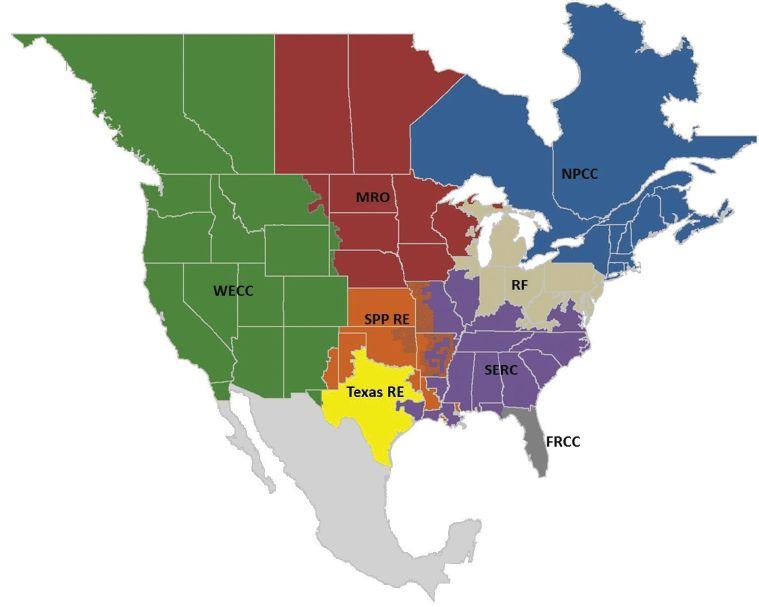

• Florida Reliability Coordinating Council (FRCC)
• Midwest Reliability Organization (MRO)
• Northeast Power Coordinating Council (NPCC)
• Reliability First (RF)
Figure 1: The Eight NERC Regional Entities
• Southeast Reliability Corporation (SERC)
• Southwest Power Pool, RE (SPP RE)
• Texas Reliability Entity (Texas RE)
• Western Electricity Coordinating Council (WECC)
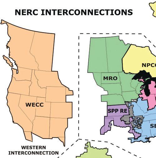

On April 4, 2006, NERC filed an application with FERC to become the Electric Reliability Organization (ERO) in the United States. NERC also filed an application with Canadian provincial authorities and the National Energy Board to be recognized as the ERO in Canada. All NERC filings on this date included 102 reliability standards for approval.
On July 20, 2006, FERC certified NERC, which formed eight regional entities, as the ERO in the United States.
On January 1, 2007, the North American Electric Reliability Council (NERC) became the North American Electric Reliability Corporation (NERC), as we know it today. On March 15, 2007, FERC approved 83 NERC reliability standards — the first set of legally enforceable standards for the U.S. bulk power system. On April 19, 2007, FERC approved agreements by which NERC delegated its authority to monitor and enforce compliance with NERC reliability standards in the United States to eight regional entities, with NERC
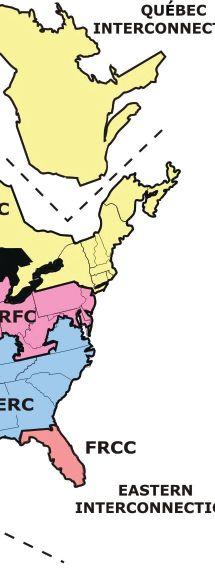

continuing in an oversight role. The eight NERC regional entities and four NERC interconnections are shown in Figure 1 and Figure 2, respectively.
On June 18, 2007, compliance with approved NERC Reliability Standards became mandatory and enforceable in the United States, and the world as we know it was changed forever for the better.

There are 30 NERC PRC standards in the most recently released update to the NERC reliability standards. The NERC PRC standards ensure that good engineering, design, maintenance, and testing practices are being utilized across North America to achieve maximum reliability (security and dependability) of BES protection and control systems and the BES. As there is not enough space to discuss all 30 of the active NERC PRC standards, this article provides an


overview of the requirements of 12 of the PRC standards believed to be the most relevant to NETA technicians and engineers.
(Editor’s note: The NERC PRC standards contain legal language, which is to be expected in any standard used for monitoring and enforcement. To use language more appropriate for a journal article, the author has chosen less rigid language than that which appears in the published standards. The author has made every attempt not to change the intent of any requirement in the 12 standards that will be discussed.)

Th e purpose of this standard is to ensure that system protection is coordinated among operating entities. This standard applies to generator operators, transmission operators, and balancing authorities. Key requirements include:
• Generator operators, transmission operators, and balancing authorities must know the purpose and limitations of the protection schemes in their areas.
• Generator and transmission operators must notify the appropriate reliability entities, reliability coordinators, and balancing authorities of all relaying and equipment failures that reduce BES reliability. Corrective actions must be prompt.
• Generator and transmission operators must coordinate protective system changes with their balancing authority and neighboring transmission operators.

• Generator and transmission operators must provide advanced notice to other affected transmission operators to coordinate changes in generation, transmission, loading, or operating conditions that could require protection system changes.
• Transmission operators and balancing authorities must monitor the status of all special protection systems (SPS) in their area and provide prompt notification of any SPS status changes to other affected
transmission operators and balancing authorities.
Th e purpose of this standard is to ensure that adequate data is available to facilitate analysis of BES Disturbances. This standard applies to generator owners, transmission owners, reliability coordinators, and planning coordinators. Key requirements include:
• Transmission owners must identify all BES buses for which sequence-of-events recording (SER) and fault recording (FR) data is required using Attachment 1. All BES buses must be re-evaluated once every 5 years against Attachment 1.
• Generator and transmission owners must have SER data indicating the position (open/close) for each circuit breaker it owns connected to the BES buses identified by using Attachment 1.
• Generator and transmission owners must have FR data for each required BES element they own, including:
a. Phase-to-neutral voltages for each phase
b. Phase currents for each phase
c. Residual /neutral current for transformers having a low-side operating voltage of 100kV or above
d. Residual /neutral current for transmission lines connected to BES buses requiring FR
• Generator and transmission owners must have FR data that meets the record length, sampling rate, and triggering requirements specified in Requirement R4.
• Regional entities must identify BES elements requiring dynamic-disturbance recording (DDR) data and minimum DDR coverage against Requirement R5. All BES elements must be re-evaluated once every 5 years against Requirement R5.
• Generator owners must have DDR data for each of the required BES elements they own, including:
a. One phase-to-neutral, phase-tophase, or positive-sequence voltage on either the high side or low side of the generator step-up transformer
b. The phase current for the voltage selected in “a” above
c. Real and reactive power flows for all BES elements where current measurements are required
d. Frequency of the voltage in “a” above
• Transmission owners must have DDR data for each of the required BES elements they own, including:
a. One phase-to-neutral or positivesequence voltage
b. The phase current for the voltage selected in “a” above
c. Real and reactive power flows for all BES elements where current measurements are required
d. Frequency of the voltage in “a” above
• Generator and transmission owners responsible for DDR data must have continuous data recording and storage that meets the record length, trigger settings, sampling rates, and recording rates specified in Requirements R8 and R9.
• Generator and transmission owners must time-synchronize all SER, FR, and DDR data to Coordinated Universal Time (UTC) as specified in Requirement R10.
• Generator and transmission owners must provide, upon request, all required SER, FR, and DDR data to the regional entity or NERC with retrieval periods, time requirements, data formats, and file naming as specified in Requirement R11.
• Upon discovery of a SER, FR, or DDR data recording failure, generator and transmission owners must:
a. Restore recording capability, or
b. Submit and implement a corrective action plan (CAP) to the regional entity
The purpose of this standard is to identify and correct the causes of misoperations of protection
systems for BES elements. This standard applies to generator owners, transmission owners, and distribution providers. Key requirements include:
• Generator owners, transmission owners, and distribution providers that own a BES interrupting device that operated under the circumstances listed in Requirement R1 must identify whether that operation was the result of a protection system component(s) misoperation, and if so, must provide prompt notification to other affected owners in accordance with Requirement R2.
• Generator owners, transmission owners, and distribution providers that receive notification of a BES interrupting device operation from another owner must identify whether that operation was the result of a protection system component(s) misoperation of equipment under their ownership.

• Generator owners, transmission owners, and distribution providers that have not determined the cause(s) of a misoperation must investigate the cause(s) of the misoperation until either: (1) the cause(s) of the misoperation is identified or (2) a declaration is made that no cause could be identified.
• Generator owners, transmission owners, and distribution providers that own the protection system component(s) that caused the misoperation must either: (1) develop and implement a CAP for the failed protection system component(s) or (2) provide a declaration stating why no further corrective action will be taken.

The purpose of this standard is to ensure that all generation and transmission protection systems affecting BES reliability are maintained and tested. This standard applies to generator owners, transmission owners, and distribution providers that own a transmission protection system(s). Key requirements include:


• Generator owners, transmission owners, and distribution providers that own a protection system(s) that affects BES reliability must:
a. Have a maintenance and testing program for these protection systems that includes (1) maintenance and testing intervals and basis and (2) summary of maintenance and testing procedures.
b. Provide documentation of their protection system maintenance and testing program to the regional entity, on request, including (1) evidence protection system devices were maintained and tested within the required intervals and (2) the date each protection system device was last tested and/or maintained.

The purpose of this standard is to ensure the documentation and implementation of maintenance programs for all protection systems, automatic reclosing, and sudden pressure relaying affecting BES reliability so they are kept in working order. This standard applies to generator owners, transmission owners, and distribution providers. Key requirements include:
• Generator owners, transmission owners, and distribution providers must establish a protection system maintenance program (PSMP) for all protection systems specified in Section 4.2, Facilities, which includes:

a. Identification as to whether time-based or performance-based maintenance will be used for each protection system, automatic reclosing, and sudden pressure relaying system component(s). All batteries must be included in a time-based maintenance program as described in Tables 1-4 and 3.
b. Applicable monitored component attributes for each protection system,
automatic reclosing, and sudden pressure relaying system component(s) where monitoring is used to extend maintenance intervals for these component(s) beyond those specified in Tables 1-1, 1-2, 1-3, 1-4, 1-5, 2, 3, 4-1, 4-2, 4-3, and 5.
• Generator owners, transmission owners, and distribution providers that use performance-based maintenance intervals in their PSMP must use Attachment A to establish performance-based maintenance intervals and must implement and fully comply with their PSMP.
• Generator owners, transmission owners, and distribution providers that use timebased maintenance intervals in their PSMP must maintain equipment in accordance with the maintenance activities and maximum maintenance intervals specified in Tables 1-1, 1-2, 1-3, 1-4, 1-5, 2, 3, 4-1, 4-2, 4-3, and 5.
• Generator owners, transmission owners, and distribution providers must demonstrate reasonable efforts to correct identified, unresolved maintenance issues.
The purpose of this standard is to provide last resort system preservation measures by implementing an underfrequency load shedding (UFLS) program. This standard applies to transmission owners and distribution providers required by their regional reliability organization to have a UFLS program. Key requirements include:
• Transmission owners and distribution providers with a UFLS program required by their regional reliability organization must have a UFLS equipment maintenance and testing program including:
a. UFLS equipment identification
b. UFLS equipment testing schedule
c. UFLS equipment maintenance schedule
• Transmission owners and distribution providers with a UFLS program required by their regional reliability organization must:
a. Implement their UFLS equipment maintenance and testing program
b. Provide documentation of UFLS equipment maintenance and testing results to their regional reliability organization and NERC, on request, within a specified time period
The purpose of this standard is to provide system preservation measures to prevent system voltage collapse or voltage instability by implementing an undervoltage load shedding (UVLS) program. This standard applies to transmission owners and distribution providers that own a UVLS system. Key requirements include:
• Transmission owners and distribution providers that own a UVLS system must have a UVLS equipment maintenance and testing program including:
a. UVLS equipment identification
b. UVLS equipment testing schedule
c. UVLS equipment maintenance schedule
d. Documentation of UVLS maintenance and testing intervals and their basis
e. Summary of UVLS testing procedure(s)
f. Date of last testing and/or maintenance
• Transmission owners and distribution providers that own a UVLS system must:
a. Implement their UVLS equipment maintenance and testing program
b. Provide documentation of UVLS equipment maintenance and testing results to their regional reliability organization and NERC, on request, within a specified time period
The purpose of this standard is to ensure that all Special Protection Systems (SPSs) are properly designed, meet performance requirements, and
are coordinated with other protection systems. This standard applies to regional reliability organizations. Key requirements include:
• Regional reliability organizations that have generator owners, transmission owners, or distribution providers with an SPS installed must maintain an SPS database that includes:
a. Design objectives including the contingencies and system conditions for which the SPS was designed
b. Operations including the actions taken by the SPS in response to disturbance conditions
c. Modeling information including detection logic and/or relay settings that control the operation of the SPS

• Regional reliability organizations must provide documentation of their SPS database and/or specific SPS database information to other affected regional reliability organizations and NERC, on request, within a specified time period.
The purpose of this standard is to ensure that all remedial action schemes (RAS) are properly designed, meet performance requirements, and are coordinated with other protection systems, in addition to ensuring that maintenance and testing programs are developed and misoperations are analyzed and corrected. Th is standard applies to generator owners, transmission owners, and distribution providers that own a RAS. Key requirements include:

• Generator owners, transmission owners, and distribution providers that own a RAS must have a RAS system maintenance and testing program including:
a. RAS system identification
b. RAS system testing schedule
c. RAS system maintenance schedule
d. Documentation of RAS system maintenance and testing intervals and their basis


e. Summary of RAS system testing procedure(s)
f. Date of last testing and/or maintenance
• Generator owners, transmission owners, and distribution providers that own a RAS must:
a. Implement their RAS system maintenance and testing program
b. Provide documentation of RAS system maintenance and testing results to the appropriate regional reliability organization(s) and NERC, on request, within a specified time period.

Th e purpose of this standard is to verify coordination of generating unit facility or synchronous condenser voltage regulating controls, limit functions, equipment capabilities, and protection system settings. This standard applies to generator owners and transmission owners that own synchronous condensers. Key requirements include:
• Generator and transmission owners must coordinate voltage regulating system controls, including in-service limiters and protection functions, with applicable equipment capabilities and protection system devices within a maximum of every 5 years. In-service limiters must be set to operate before the protection system to avoid unnecessary generator disconnection. The protection system must be set to operate to isolate or deenergize equipment to limit the extent of damage when operating conditions exceed equipment capabilities and/or stability limits.

• Within 90 days of the identification or implementation of systems, equipment, or settings that will affect the coordination of in-service limiters, protection functions, the protection system, and/or equipment capability, generator and transmission
owners must ensure proper coordination. Systems, equipment, and settings of interest include:
a. Voltage-regulating settings or equipment changes
b. Protection system settings or component changes
c. Generator or synchronous condenser capability changes
d. Generator or synchronous condenser step-up transformer changes
Th e purpose of this standard is to ensure generator owners set their generator protective relays such that generating units remain connected during defined frequency and voltage excursions. This standard applies to generator owners. Key requirements include:
• Generator owners that have generator frequency protective relaying that can trip their generating units must set their generator frequency protective relays such that they do not trip the generating unit(s) within the no-trip zone of the off nominal frequency capability curve provided in Attachment 1 (Figure 3).
• Generator owners that have generator voltage protective relaying that can trip their generating units must set their generator voltage protective relays such that they do not trip the generating units within the no-trip zone of the voltage ridethrough time duration curve provided in Attachment 2 (Figure 4).
• Generator owners must document each known regulatory or equipment limitation that prevents their generating units with frequency and/or voltage protective relaying from meeting the no-trip zone operating restriction and must communicate this to their planning coordinator and transmission planner.
• Generator owners must provide their generator’s frequency and voltage protection trip settings, and any future
changes, to the planning coordinator or transmission planner for modeling purposes.
The purpose of this standard is to ensure that load-responsive protective relays associated with generation facilities are set to prevent unnecessary tripping of generators during a system disturbance for conditions that do not pose a risk of damage to the associated equipment. This standard applies to generator owners, transmission owners, and distribution providers that apply load-responsive protective relays at the terminals of BES elements that affect BES reliability. Key requirements include:
• Generator owners, transmission owners, and distribution providers must apply settings that are in accordance with Attachment 1: Relay Settings on each load-responsive protective relay while maintaining reliable fault protection.
• The following relays and relay elements are considered to be load-responsive relays:
a. 21 — phase distance relay (trip direction toward transmission system)
b. 50 — instantaneous overcurrent relay
c. 51 — ac inverse time overcurrent relay
d. 67 — ac directional overcurrent relay (trip direction toward transmission system)
This standard is about the best when it comes to providing criteria, guidelines, and setting examples for calculating relay settings for loadresponsive protective relays that are compliant with this standard. The committee that wrote this standard deserves recognition for a job very well done.
NERC requires that evidence be provided upon request proving that protection and control systems were in compliance with NERC reliability standards during the period of time
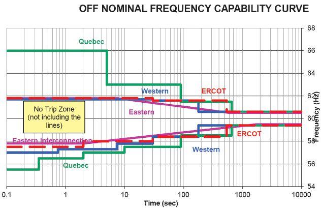

4: PRC-024-2 Attachment 2 — Voltage Ride-Through Time Duration Curve
between the current and last NERC compliance audits. Therefore, it is vital that NETA technicians and engineers provide accurate and detailed documentation to the customer for all maintenance and testing that was performed. It is also vital that NETA technicians and engineers promptly notify their customers of any issues they identify during maintenance and testing, because customers have reporting requirements enforced by NERC.

NERC protection and control (PRC) standards are critical for ensuring the reliable and secure operation of the BES in North America. The NERC PRC standards ensure that good engineering, design, maintenance, and testing practices are being utilized across North America to achieve maximum reliability and security of BES protection and control systems and the BES. The 12 NERC PRC standards discussed here are only the tip of the iceberg; there are 18 other NERC PRC standards not discussed due to space limitations. Be on the lookout for future articles that will discuss the NERC PRC standards in more depth and detail.

North American Electric Reliability Corporation (NERC), www.nerc.com.
NERC Reliability Standards for the Bulk Electric Systems of North America, updated February 15, 2018.
North American Electric Reliability Corporation, History of NERC, January 2018.

Jim Huddleston is a Senior Power Systems Engineer with Shermco Industries in Chicago. He has 30 years experience working in a variety of roles in electric utilities, nuclear power plants, and chemical/petrochemical processing plants and has spent the last 10 years as a consultant. Jim’s primary areas of expertise are power systems analysis and modeling, as well as protective relay settings, coordination, and testing for electric power generation, transmission, and distribution systems. He holds a BS in electrical engineering from the University of Illinois at Urbana Champaign, an MS in electrical engineering from the Illinois Institute of Technology in Chicago, and is a licensed Professional Engineer in the State of Illinois.


OSHA 29CFR1910.399 definition of a qualified person:
“Qualified person. One who has received training in and has demonstrated skills and knowledge in the construction and operation of electric equipment and installations and the hazards involved.”
Shermco’s Electrical Safety for Qualified Workers course meets the minimum mandated requirements of both OSHA and NFPA 70E.
Shermco’s field service technicians are required to complete this course. Shouldn’t you be training with the people who are in the field every day?
Don’t risk fines and events due to “check-the-box” training. Train with the experts. Train with Shermco
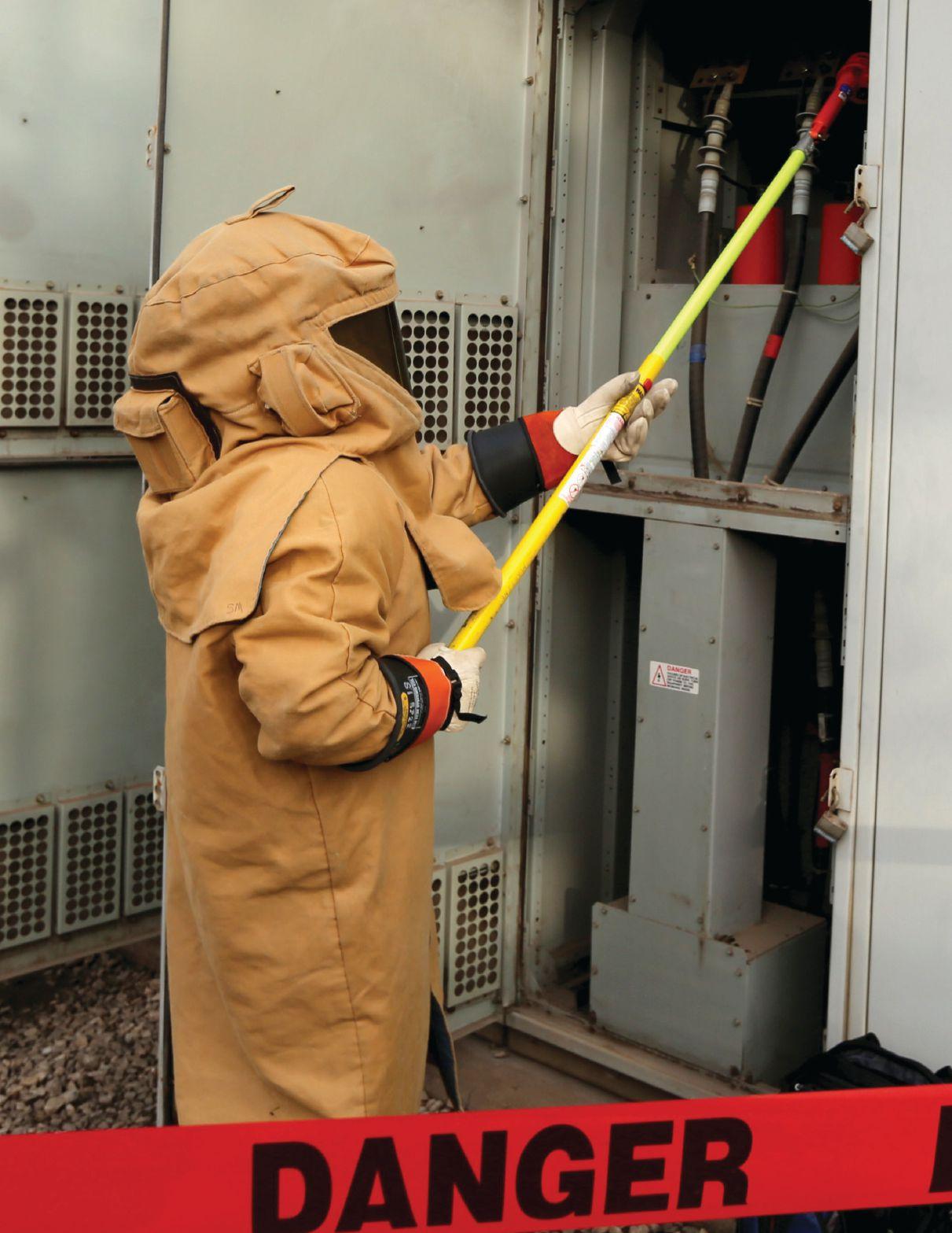


Power
Commissioning


 BY DINESH CHHAJER, Megger
A winding resistance test assesses the condition of the current-carrying path between transformer bushing terminals. Problems such as loose, defective, or incorrect connections; open, partially open (i.e., broken strands), short-circuited turns in windings; or high contact resistance in tap changers will result in a change in resistance, and therefore be indicated by an unexpectedly high, low (for short-circuits), or unstable resistance measurement in this test.
A number of international standards and guides describe the winding resistance test method, including ANSI/NETA ATS 2017, ANSI/NETA MTS 2015, IEEE C57.152-2013, IEC 600761, and CIGRE TB445. Safety, effectiveness, and efficiency are important aspects of a winding resistance test that are dramatically influenced by the test equipment and methods used.
Safety of the operator, the asset (transformer), and the test instrument is paramount in all testing but warrants special mention with winding resistance tests. A tester needs to be mindful that a transformer winding is an inductor. If an inductor is suddenly opencircuited while dc current is flowing through


it, the inductor will oppose the initial change in current by building a high voltage across it in an attempt to sustain the current. The voltage across the winding is given by:
where:
L represents the inductance of winding
I is the dc test current
R is the resistance of the winding di/dt is the rate of change of current
If a test lead should get disconnected accidentally (falls off or is pulled off of a bushing terminal) during the test, a dangerously high voltage will develop. As an example, assuming a sample inductance of 100 H, a test current of 25 A, and di/dt = 25/0.1 (100 ms = time for lead to disconnect and current to change from 25 A to 0 A), the voltage developed would be greater than 25,000 volts!
The tester must also stay aware that a great deal of energy can be stored in a transformer’s magnetic field, as is the case when dc test current is injected into a winding for the duration of a winding resistance test. That energy has to be dissipated before leads can be disconnected, which can take some time for a large transformer.
To safeguard (1) personnel standing in close proximity to the transformer bushing; (2) the transformer under test, which could potentially be damaged because of an unplanned high voltage; and (3) the test instrument that must survive under a high-voltage fault condition (else testing will be interrupted and repair of instruments will be on-going and expensive), a test instrument should be equipped with a safety circuit that provides an escape path for energy dissipation. This is typically done using current leads, and potential leads provide an alternate path for discharge if leads are accidently disconnected. Additional features recommended in a winding resistance test instrument include automatic discharge when test is completed, protection/automatic discharge when input
power is lost, an emergency off switch, a test current indicator that is maintained even when instrument power is lost, and protection/ automatic discharge when test current level is accidentally changed before discharging the present test current. Do not disconnect the leads until the discharge light and current-on light indicators go completely off.
An imperative but potentially time-consuming first step to obtain stable and accurate winding resistance test results is to saturate the transformer core. To do this efficiently, the correct test current and compliance voltage must be selected. Alternative test hook-up configurations, such as dual injection methods, may be useful to reduce total test time, and the direction of the injected test current is important for three-phase transformers.
While it is commonly thought that higher test current speeds up the saturation of large transformers, this is not true in the majority of cases. Voltage determines the saturation rate of the test, as given by:
When selecting a test instrument, compliance voltages above 40V dc are preferred. A higher test current will speed up a test only when the rated current of the winding is high. As a general rule, the test current should be greater than 1 percent of the current rating of the winding under test (Figure 1). However, to avoid heating of the winding, the maximum recommended test current is 15 percent of rated winding current, as given in IEEE Std. C57.152. Otherwise, the test current may cause unquantifiable error in the results, as resistance is a temperature-dependent characteristic. Also, a higher current creates higher energy stored in the winding and a higher state of magnetization (and a requirement to demagnetize).
As an example, given a 20 MVA transformer rated 120 kV to 4.8 kV, the HV current rating is 96 A and the LV rating is 2400 A. Test current less than 1 percent of 2400 A, or 24 A, is likely to take a longer duration for stable measurements of the low-voltage winding. It is important to keep in mind that higher current only provides the added benefit of getting stable readings faster; it provides no additional accuracy in the measurements. For the HV winding, a recommended test current should be at least 1 A but no more than 14.4 A. One note on current limit relates to an alternate test hook-up described below, where both primary and secondary windings are energized at the same time. The extra primary-side winding turns and series test current through primary and secondary windings helps saturate the core faster (than if only injecting test current through the secondary winding alone) and helps keep the core saturated while secondary results are obtained. Under this condition, lower secondary test current is required than would typically be needed (see the following method).
To improve saturation on transformer windings when charging time is slow, connecting the primary and secondary windings in series is recommended. This speeds up the test by providing more volt-turns of charge (Figure 2). This method is particularly useful when testing large, three-phase transformers (>100 MVA) where testing low-side delta windings requires long times to reach stability (without very high test current). It is important to note how the windings are connected. Connect the nonpolarity terminal of the primary winding to the polarity terminal of the secondary winding to ensure that flux setup by both windings in the core is in the same direction.
The dual-injection method has some limitations, as the amount of test current that can be applied is limited by the max allowed current (15 percent) for the high-voltage winding. For example, a two-winding delta-delta transformer
rated with 1100 kVA and 13.8 kV primary to 480 V secondary won’t get much benefit from the dual-injection method. The rated current of the primary winding is 46 A and the secondary is 1323 A. If the dual-injection method is applied for this transformer, only 6.9 A (15 percent of 46 A) can be applied, which would be only 0.5 percent of the rated secondary winding current. One would get faster results by testing windings individually and injecting 50 A when testing secondary winding. The high turns ratio of some transformers doesn’t provide the benefit of the dual-injection method. For all practical purposes, transformers with turns ratios less than


15 are good candidates for the dual-injection method. Most of the large power transformers have ratios below 15; for those applications, the dual-injection method is recommended.
Proper direction of the test current through thoughtful placement of test connections may aid in minimizing test time by as much as 30 to 50 percent. Conversely, reflexively following the winding nomenclature order to connect test leads — i.e., H1 to H0, H2 to H0, and then H3 to H0 — creates longer test times, because these connections require re-magnetization of core legs in opposite directions for each phase measurement (Figure 3), hence twice the energy and time. When testing H1-H0, a magnetic field is created in the H0-H2 and H0-H3 direction. Therefore, to maintain the same direction of flux in the core and lower charging time, H0-H2 or H0-H3 should be tested next, not H2-H0. Most of the advanced three-phase winding resistance test instruments follow this logic to speed up the testing time duration.
Demagnetization is recommended after a winding resistance measurement. While putting the transformer in service effectively returns it to a normal state (unsaturated core), large in-rush currents can be drawn in the process of energizing the transformer if the
transformer core has residual flux. These inrush currents have multiple implications. For the power system, protective relays cannot distinguish between the causes of high current (e.g., a transformer fault or a magnetized core) and will trip until this condition is corrected. Additionally, if the core is not demagnetized properly and contains residual flux, it can affect other tests such as excitation current and sweep frequency response analysis.
Demagnetization is typically performed by injecting dc current with positive and negative polarity cycles alternatively with progressively reducing magnitude each cycle. Note that the best results are obtained by performing the demagnetization on the B phase of the high-side winding. Th is provides an even distribution of alternating flux through the core with less rated current requirements. Use the same amount of current for demagnetization as for winding resistance measurements.
Typical transformer winding resistance values range from a few milliohms to several Ohms. For a three-phase transformer, test results from dc winding resistance tests are most frequently evaluated based on how well they compare across phases. Differences between phase values are expected to be less than 2 percent. (Note: For a delta-connected winding, it is not practical to isolate and test a single-phase winding of a three-phase transformer; rather, the comparison is made between pairs of terminals.) Although dc winding resistance measurements are temperature dependent, temperature corrections are not generally necessary when comparing individual phase results, as it is presumed that the temperature is essentially the same for each of the three measurements.
Figure 3: Direction of the Flux during a Winding Resistance Test in a Three-Legged, Core-Type Transformer for a Wye-Connected Winding

In addition, dc winding resistance test results may be compared to a factory reference measurement or other previous test results or with those from a similar transformer. In these cases, temperature must be considered. Once test temperature is compensated, test results
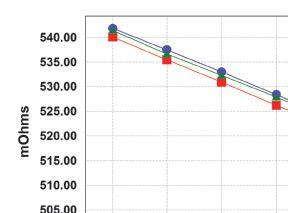
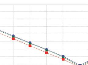
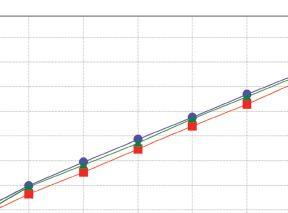

Figure 4: Acceptable OLTC Results, Resistance vs. Tap Position
should not diff er by more than 5 percent compared to the reference measurement. It is imperative to note the winding temperature when documenting and storing the test results for later review and analysis.
IEEE Std. C57.12.00 – 2006 provides the following conversion formula to calculate Rs, the “factory temperature equivalent” resistance result given the dc winding resistance measured in the field, Rm. This temperaturecompensated version of the field measured test result, Rs, may then be compared to the original factory reference measurement.
Rs = Rm [(Ts + Tk)/(Tm + Tk)]
where:
Rs is the temperature-compensated dc winding resistance test result
Rm is the measured dc winding resistance test result
Ts is the factory, or desired, reference temperature (degrees C)
Tm is the winding temperature during dc winding resistance test (degrees C)
Tk is the constant for the winding material (234.5° C for copper; 225° C for aluminum)
For transformers with on-load tap changers (OLTC), winding resistance testing is an exceptional diagnostic tool to assess the mechanical health of the OLTC — a component susceptible to mechanical problems as one of the transformer’s few moving parts. Winding resistance measurements are performed on each tap position, and a resistance-versus-tap graph (Figure 4) enables validation of proper contact resistance at each OLTC tap position. The resistance readings are even sensitive enough to confirm that the OLTC compartment is positioned closer to A phase on the transformer. This proximity is noted by the lower resistance tap values on the A phase.
Confirming that the OLTC is making before breaking during an operation sequence is important as well. Test current is maintained while transitioning between OLTC tap positions; with highly sensitive circuits, test current is monitored for unexpected drops during each tap transition and any deviations from expected time for transition (Figure 5).

Figure 5: Example of Make/Break Pass and Fail Criteria for OLTC Transition between Taps


A related but far more insightful diagnostic method that assesses the OLTC transition — and is of particular value for resistive-type OLTCs — is the dynamic resistance measurement. In this test, current, voltage, and calculated resistance are plotted as functions of time during the switching operation. Resistance (e.g., of the winding + diverter resistors) is calculated with the measured parameters. This method can show misalignment of contacts and misoperation and/or absence of critical components, such as transition resistors. Other parameters, such as the tap changer motor current characteristics, can be recorded to pick up problems during transitions.
The winding resistance test is a very important diagnostic test to assess the condition of windings and overall conducting paths of transformers. While performing the test, the technician should be particularly careful about some of the safety aspects, requirements to use appropriate test
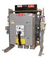
part to a switchgear lineup, Advanced Electrical & Motor Controls’ inventory of low-voltage insulated case circuit breakers, molded case circuit breakers, motor controls, and custom switchgear is second to none in the U.S. No matter what you need — new, surplus, used, or reconditioned power distribution equipment, testing and repair, or an engineered solution — AEAMC will keep you up and running. Insulated Case Circuit Breakers Molded Case Circuit Breakers Motor Controls & Centers Bolted Pressure Switches Panelboard Switches & Bus Plugs 480 V Distribution Transformers
Replacement Parts
UL-Listed Motor Control Center Replacements Let us test, repair, and extend the life of your: Search. Click. Ship. Purchase AEAMC equipment online, anytime! Emergency support 24/7 800-289-2757

current, and techniques to speed up the test and make it more efficient. At the completion of the test, energy stored in the windings should be dissipated safely, and core should be demagnetized effectively to remove any residual flux stored in the core because of injection of dc current. OLTC make-before-break operation should always be checked for any misalignment, coking, or any transition problem for all the taps of the OLTC.

Dinesh Chhajer received his MS in electrical engineering from the University of Texas at Arlington. He is the Manager of the Technical Support Group at Megger USA. His responsibilities include providing engineering consultation and recommendations in relation to testing of transformers, batteries, circuit breakers, and other substation assets. Dinesh has presented a number of white papers related to asset maintenance and testing at various conferences within power industry. Dinesh previously worked as an applications engineer at Megger and a substation and design engineer at Power Engineers Inc. He is an IEEE member and a licensed Professional Engineer in Texas.

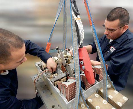


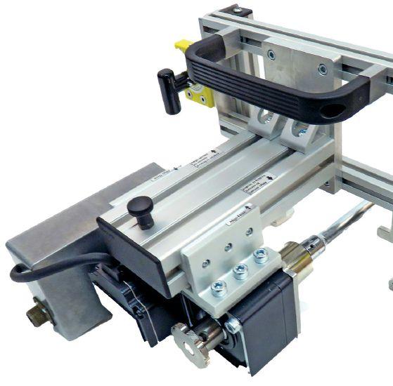
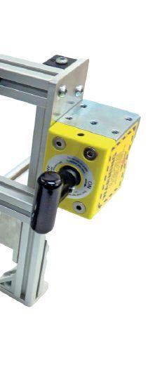


The VITS60M performs high potential (HiPot) tests for vacuum interrupter testing up to 60 kV, as well as Resistance, Polarity Index, and Absorption Ratio tests.
Unlike other DC HiPot test sets on the market today, the VITS60M not only performs specialized go/no-go tests on vacuum interrupters at up to 60 kV DC, but also includes a 2.5/5/10 kV megohmmeter for Resistance, Polarity Index, and Absorption Ratio testing. Get 3 test sets for the price of 1 with the VITS60M.
This simple-to-operate set walks technicians through setup, generating a visual go/no-go result for testing the dielectric strength of various vacuum breaker components during regular maintenance, while offering fully programmable leakage current thresholds and test durations. To learn more about the VITS60M, contact us at Info@VacuumInterruptersInc.com for a demo at your location or call us at (214) 442-5877.
FEATURES AND BENEFITS
• Safety features with auto discharging, interlock, and safety control button
• Integrity test, Insulation Resistance test, Absorption test, and Polarity test all in one — lower price, more functions
• Tough dual-case design
Interested in a demo?
• Operates in 1 kV DC increments instead of 5 kV DC
• CE certified
• Lightweight
• Failure indicator LED makes it easy to interpret results (green light: pass; red light: fail)
Let us bring our equipment to your facility for an on-site demonstration. Contact us at Info@VacuumInterruptersInc.com, or call us at (214) 442-5877.
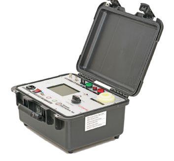
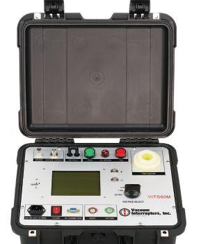


 BY ALEX RANGEL, Saber Power Services, LLC
Part 1 of this article, published in the Spring 2018 edition of NETA World Journal, discussed symmetrical components, why it is important for protection and control (P&C) engineers and technicians to understand the theory, and how to apply this topic to simulate several faults and test relay protection elements.
In Part 2, we discuss one of the most complicated elements in distribution protection: the directional overcurrent element. To have a thorough understanding of the directional overcurrent element, it is necessary to have a good understanding of symmetrical components, which is beyond the scope of this article; for a detailed explanation, refer to Amberg and Rangel.
Power system protection evolves as power systems grow in complexity. Protection systems require reliability, speed, dependability, security, and selectivity. Typical radial
systems (one source) require non-directional overcurrent protection (Figure 1 50/51), since the direction of the fault is always from the source to the load. However, on non-radial or loop systems (two or more sources), a basic overcurrent element would detect the fault (it provides sensitivity), but would not know the fault location, and therefore, would not provide security and selectivity.
Figure 1 shows a radial system protected by 50/51 elements and a loop system protected by a 67 element. The directional overcurrent element (67) helps identify the direction of the fault by using information provided by voltage and current transformers (PTs and CTs, respectively).


How do directional overcurrent elements determine the direction of the fault? It is important to note that for a relay to determine the direction of current ow, it must measure currents and voltages. e voltages are used as a reference (i.e., A-phase voltage is assumed to have a phase angle of 0 degrees); depending on the characteristics of the system, the current might lag (inductive), be in phase (resistive), or lead (capacitive) its corresponding voltage.
Current transformers have an H1 side on one opening and an H2 side on the opposite opening, as well as X1 and X2 connections on the secondary side. If the primary current travels from H1 to H2, then the secondary current traveling from X1 to X2 will be in phase (0 degrees); if the primary current travels from H2 to H1, then the secondary current traveling from X1 to X2 will be out of phase (180 degrees).
Schematics typically denote H1 and X1 with polarity marks or polarity dots. e polarity dot for H1 is typically drawn on the line, while the polarity dot for X1 is typically drawn on the CT. Figure 2 shows a current transformer on the H1 side; X1 and X2 connections are shown as well. Figure 3 shows the primary currents owing in both directions through a CT.



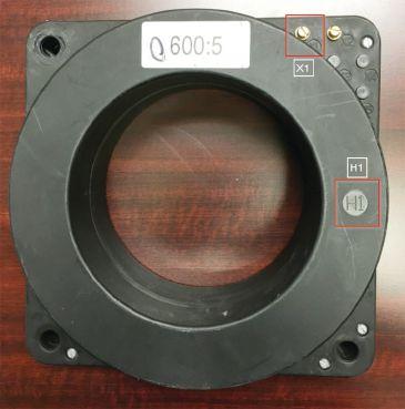
3: Primary and Secondary Current Phase Angle with Current Flow in Forward and Reverse Directions


A typical distribution system is slightly inductive, since distribution lines and the load being served normally have a combination of resistive and inductive elements. Capacitor banks might be added to the system to bring the power factor closer to unity (i.e., to reduce the phase angle between the voltages and their respective currents). Assuming a lagging power factor of 0.9 per unit (90 percent) and an ABC phase rotation (Va = 0 degrees, Vb = 240 degrees, and Vc = 120 degrees), the phase di erence between voltages and currents is approximately 26 degrees. If power ows in the forward direction, then currents would lag voltages by 26 degrees (Ia = 334 degrees, Ib = 214 degrees, and Ic = 94 degrees), but if power ows in the reverse direction, currents would then ip 180 degrees from the original 26 degrees (Ia = 154 degrees, Ib = 34 degrees, and Ic = 274 degrees). Figure 4 shows the voltage and current phasors for power ow in both directions.
In Part 1, we learned that di erent types of faults generate a di erent combination of symmetrical components. For example, a phase-to-ground fault generates all three symmetrical component currents (I1, I2, and I0) with the same magnitude and phase angle, while a phase-to-phase fault only generates positive- and negative-sequence currents (I 1 and I 2 , respectively) with the same


magnitude, but opposite in phase angle. When testing directional elements, it is important to simulate faults as close to reality as possible, including magnitudes and phase angles.
Another factor that might in uence testing of directional elements is the loss of potential (LOP) element. Given that voltages are necessary to serve as a reference for the current angles, if one or more voltages are lost by the relay (blown fuses, bad relay connections, etc.), then the reference is lost, and the directional element is typically disabled to prevent an undesired operation. erefore, it is important to simulate healthy voltages prior to the fault, which is done by adding a pre-fault state with healthy voltages and currents, as shown in Figure 4.
Finally, di erent manufacturers have built different methods to enable and disable directional elements; in general, they allow the user to specify in which order and direction (forward or reverse) the relay will operate. e order and direction speci cations (settings) will determine which symmetrical components are required, as well as the direction of the fault.
The following sections present a basic explanation of how to test zero-, negative-, and positive-voltage polarized directional elements. For a detailed procedure for analyzing directional elements using event data, refer to Hargrave, Heilman, and Watkins.


The zero-sequence voltage-polarized element uses the zero-sequence voltage and ground current (3V0 and I0, respectively) to identify the direction of the fault by comparing the equivalent zero-sequence impedance (Z0) to a forward and a reverse threshold: If Z0 is lower than the forward threshold, then the direction is forward (F32V = 1); if Z0 is larger than the reverse threshold, then the direction is reverse (R32V = 1). In addition, this element is enabled by the following factors (see SEL-3515, -6, -7 Protection System Instruction Manual):
• The magnitude of the ground current is larger than a specified threshold.
• The LOP element is not active (voltages are healthy).
• The magnitude of the zero-sequence current is larger than a percentage of the magnitude of the positive-sequence current.
• The zero-sequence voltage-polarized element is enabled per setting E32IV.


To test this element, a phase-to-ground (AG) fault has been simulated. Table 1 shows the relay settings values used for CT and PT ratios, as well as the line-impedance settings. Table 2 shows the test values used for pre-fault, forward fault, and reverse fault. Note that the phase angle of IA lags VA by approximately the line-impedance angle, since we are considering a situation with very little or no load on the system.
Note: The direction of a phase-to-ground fault can also be determined by a current-polarized directional element; however, simulation of this element is beyond the scope of this article. For more information, refer to the SEL-351-5, -6, -7 Protection System Instruction Manual
Figure 5 and Figure 6 show the voltage and current waveforms and phasors during the AG fault simulation, as well as the element that picks up during each event. Figure 5 is a simulation of a forward fault (F32V = 1).
Figure 6 is a simulation of a reverse fault (R32V = 1).
Note that this element is only enabled if it has been turned on in the ground directional priority setting, and it is the highest priority by not being blocked by the negative-sequence voltage-polarized or the current-polarized elements.


The negative-sequence voltage-polarized element for negative-sequence and phase OC elements is very similar to the zero-sequence voltage-polarized element discussed previously. However, this element uses negative-sequence voltage and current (V2 and I2, respectively) instead of ground/zero-sequence voltage and current. Also, the forward and reverse thresholds are compared to negative-sequence impedance (Z2) instead of Z0. This element is enabled by the following factors (see SEL-3515, -6, -7 Instruction Manual):
• The magnitude of the negative-sequence current is larger than a specified threshold.
• The LOP element is not active (voltages are healthy).
• The magnitude of the negative-sequence current is larger than a percentage of the magnitude of the positive- and/or zerosequence currents.
• The negative-sequence element has been specified in the order setting.
To test this element, a phase-to-phase (BC) fault has been simulated. Table 3 shows the test values used for pre-fault, forward fault, and reverse fault. Note that the phase angle for B and C voltages has been modified to eliminate the zerosequence voltage; similarly, the load on A-phase has been removed to eliminate the zero-sequence current. The phase angle for B-phase lags the


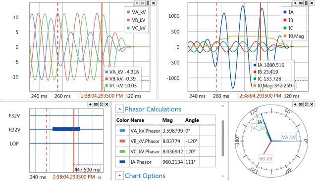
phase angle of VBC (270 degrees) by roughly the line impedance angle, while the phase angle for C-phase is 180 degrees out of phase. During the reverse fault scenario, the phase angles for B- and C-phase are swapped.


Figure 7 and Figure 8 show the voltage and current waveforms and phasors during the BC fault simulation, as well as the element that picked up during each event: Figure 7 is a simulation of a forward fault (F32Q = 1).


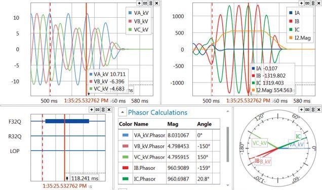
Figure 7: AB — Forward Direction Event Report
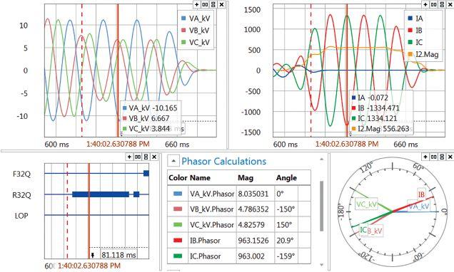
8: AB — Reverse Direction Event Report
Table 4: Testing Values for A-B-C Fault

Figure 8 is a simulation of a reverse fault (R32Q = 1).


Note that in Figure 8, the relay declares a forward direction prior to the current being removed; however, this does not represent a concern in a real situation, given that the reverse fault will be declared for as long as the fault current is steady, and a trip should have been declared at this point.
The positive-sequence voltage-polarized element for phase OC elements is similar to the two elements mentioned previously. However, this element uses positive-sequence voltage and current (V1 and I1, respectively) instead of negative- or ground/zero-sequence voltage and current. In this case, the angle of the positive-sequence impedance (Z1) is compared to an angle offset by the line impedance angle to determine the direction. This element is enabled by the following factors (see SEL-3515, -6, -7 Instruction Manual):
• The magnitude of the three phase-to-phase currents is larger than a specified threshold.
• The LOP element is not active (voltages are healthy).
• Positive-sequence polarizing voltage must be present.
Because this element uses positive-sequence voltage and current, it works better with a fault


that has large positive-sequence values, such as three-phase faults. To test this element, a three-phase fault was simulated. Table 4 shows the test values used for pre-fault, forward fault, and reverse fault. Note that similar to the zero-sequence element, the phase angle of IA is lagging VA by approximately the lineimpedance angle. However, B- and C-phase currents are also present with the same magnitude and 120 degrees apart.

Figure 9 and Figure 10 show the voltage and current waveforms and phasors during the ABC fault simulation, as well as the element that picked up during each event: Figure 9 is a simulation of a forward fault (F32P = 1). Figure 10 is a simulation of a reverse fault (R32P = 1).
A thorough understanding of symmetrical components, as well as an understanding of the pre- and post-fault requirements, such as defeating loss of potential and providing the necessary sequence component, is fundamental for proper directional element testing.
Amberg, A. and Rangel, A. (2012). Tutorial on Symmetrical Components. 1st ed. [e-book] Schweitzer Engineering Laboratories, Inc, p. All. Available at: www.cdn.selinc.com/ assets/Literature/Publications/White%20 Papers/LWP0010-01_TutorialSymmetricalPt1_AR_20130422.pdf
Hargrave, A., Heilman, B., and Watkins, A. (2016). Using Custom Calculations in SynchroWAVe Event 2015 to Analyze Directional Elements. 1st ed. [e-book] Schweitzer Engineering Laboratories, Inc, p. All. Available at: www.selinc.com/ literature/application-guides/?title=using%20 custom%20calculations%20in%20 synchrowave%20event%202015%20to%20 analyze%20directional%20elements


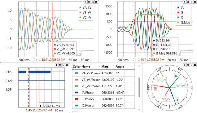


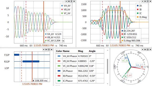
Schweitzer Engineering Laboratories (2017). SEL-351-5, -6, -7 Protection System Instruction Manual. Available at: www.selinc.com/literature/instructionmanuals/?title=sel-351

Alex Rangel is a Protection and Controls Engineer for Saber Power Services, LLC. He holds a BS in electrical engineering and an MS in engineering from The University of Texas at Austin. Alex is NETA Level 4 Certified, has been an IEEE member for nine years, and has been a registered Professional Engineer in the state of Texas since 2014.


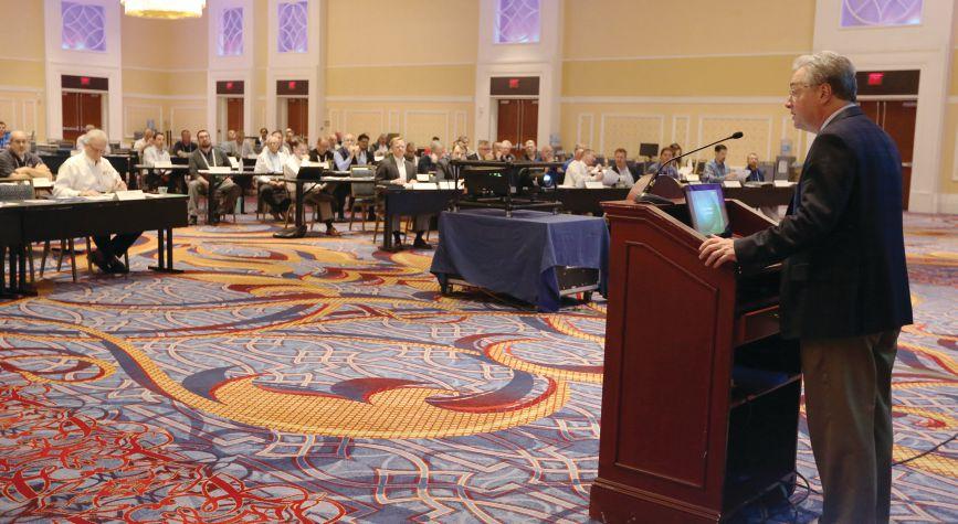
Five days of high-powered education, training, and networking drew a record-breaking 500-plus industry professionals from around the nation as the best and brightest in electrical testing and maintenance lit up PowerTest 2018, the premier electrical power systems event. The annual five-day conference hosted 513 attendees at the Gaylord National Resort & Convention Center in Washington, DC from February 26–March 2, 2018.
PowerTest, the largest gathering of NETA Accredited Company representatives and industry professionals each year, is attended by those aligned in their commitment to continually improve safety, reliability, and quality across the electrical power systems industry.
“It is the highlight of our year to host the gathering of so many of the industry’s leading electrical power system professionals,” says NETA Executive Director Missy Richard. “Part of what makes PowerTest the industry’s top event is the collaboration, networking,
and open sharing of ideas among leaders and experts in the field. We are so pleased to see the conference continue its upward growth trend over the last couple of years, which allows us increased opportunities to promote technical excellence and deliver world-class programs.”
Th e PowerTest technical agenda off ers fi ve days of educational and interactive sessions that facilitate the exchange of ideas, helping to shape the future of the electrical power systems industry by involving electrical testing technicians, engineers, and managers from a cross-section of all industries reliant
upon large power generation and distribution facilities. Highlights of the 2018 conference included:
• 27 technical presentations by industry leaders
• 16 in-depth seminars covering current topics and industry issues
• 30 exhibitors presenting the latest products and services at the New Product Forum
• All-day seminars such as Megger Best Practices and Doble Laboratory Seminar
• Keynote speaker Robert McCall, author of Zero Accidents and Injuries: Are You Willing to Pay the Price?
• Opportunities to earn CEUs and receive exam preparation
In addition, attendees and local electrical power systems professionals took advantage of the PowerTest Trade Show on Tuesday afternoon, featuring 82 top-tier vendors that provided PowerTest attendees with real-world solutions to their everyday challenges.
More than 150 NETA Accredited Company representatives, Alliance Partners, and Corporate Alliance participants gathered February 25, 2018, at Gaylord National Harbor in Washington, DC, for NETA’s 2018 Annual Member and Alliance Meetings.
e annual meetings are held on the Sunday before PowerTest and serve as the kicko to the conference each year.
e NETA Member Meeting, a gathering open only to representative and technicians from NETA Accredited Companies, provides an update of NETA business. e agenda included membership updates, recognition of volunteers and committee chairs, association news, and a review of program plans for the year.
Updates to NETA training opportunities were discussed, including new features for Self-Paced Technical Seminars. ere is now a single sign-on interface that allows access to videos, presentations, and pro ciency tests all in one location. e system also automatically updates to the technician’s record.
Updates coming soon to NETA training include Grounding Systems Acceptance Testing, Cable Systems Acceptance Testing, Instrument Transformer Acceptance Testing, and web-based training for Electrical Safety Training System. Al Peterson, Technical Committee Chairman and a member of the NETA Board of Directors, provided highlights of the updates to the ANSI/NETA ETT-2018, ANSI/NETA MTS-2019, and ANSI/NETA ECS-2020 standards.
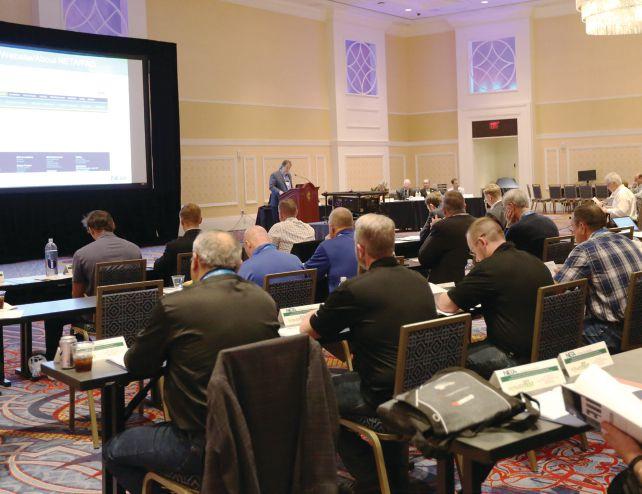
e NETA Alliance and Member Meeting takes place during the second half of the NETA Member Meeting. Corporate Alliance and Alliance Partners are invited to join NETA Accredited Companies in the afternoon for roundtable discussions, technical reporting, and NETA updates.


Join NETA and leading electrical power systems professionals at the premier industry conference March 11–15, 2019, at the Gaylord Texan Resort and Convention Center in Grapevine, Texas. Sponsorship and exhibitor opportunities are available for companies seeking leadership visibility at the event. NETA’s industry partners are encouraged to reserve exhibit space and confirm sponsorships as soon as possible. Direct inquiries to Laura McDonald at 269-488-6382 or lmcdonald@netaworld.org
Roundtable discussions were hosted by 10 of NETA’s Corporate Alliance Partners to provide an exchange of information and ideas. Roundtable topics included:
• Ground Resistance Testing, Power Quality Testing, and Insulation Testing — AEMC Instruments
• NFPA 70E-2018 Revisions that have an Impact on Maintenance — AVO Training Institute
• A Comparison of ANSI and UL Standards: How are they Alike and What Makes Them Different — BCS Switchgear
• The Importance of Vacuum Circuit Breaker Contact Pressure — Circuit Breaker Sales Co., Inc.
• Relay Testing in a Cyber Insecure World — Doble Engineering Company
• The Art of Winding Resistance Measurement — Electro Rent Corporation
• Insulation Diagnosis using Variable Frequency Power Factor Testing, Test Data Reporting: The Necessary Evil — Megger
• The Mystery of Partial Discharge Testing Explained — OMICRON electronics Corp.
• Low-Voltage Breaker Trip System Testing: Did You Consider These Items? — Utility Relay Company
• Assessing Solid Insulation Aging: A New Diagnostic Test For Methanol — WIEDMANN Diagnostic Solutions
Throughout the week of PowerTest, special events are designed to promote the exchange of ideas and information sharing. For upcoming Alliance Partner events, watch your inbox for emails from NETA, and look for notices in NETA World Journal.
For additional information about the NETA Alliance Program or to enroll, visit www. netaworld.org/allianceprogram.
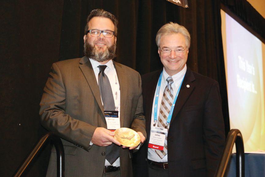
After many years of hearing the accolades of Outstanding Achievement Award honorees at PowerTest, Dan Hook says he was floored to be named among their number.
“It was a little surreal. As you might imagine, the background Jim Cialdea gave as he was leading up to the announcement started out applying to many of NETA members. But as he continued about my service in the submarine force and my college, it all started to point to me,” Hook says. “I remember listening to these announcements for about 12 years and being in awe of the impact individuals had on NETA. Many of them were the early pioneers
in NETA and helped shape what we are today. It is a great honor to be recognized as part of that group.”
Hook is known as a leader who guides by example. Those who work with him have seen him demonstrate the importance of knowing when to be captain and when to be crew — two jobs he is equally comfortable with and skilled at doing.
Cialdea, NETA President and President of 3C Electrical Company, says Hook is a selfless proponent of the industry and all those who are a part of it. “He is always helping others and contributing. He is not out for glory, but he is always where the action is. He’s the guy who steps up, dives in, and gets things done to improve the industry for everyone.”
These qualities are evident when speaking with Hook. He speaks with kindness and conviction, and gives careful consideration to all people and angles when faced with a challenge.
Hook readily admits his success also comes from the many important people in the industry he has worked alongside and learned from. “In my mind, a mentor is someone who is actively involved in your progression in your career, whereas a role model is someone you may not interact with often or at all, but you strive to emulate them because of your image of them.”
“My partner, Craig Archer, is one of my mentors. He hired me after I graduated college and left the Navy. He gave me an opportunity and supported me in every aspect along the way,” Hook says. “He has a tremendous knowledge of electrical equipment, and he showed me that equipment knowledge and mechanical skills are an invaluable asset in an electrical technician’s toolbox. He taught me so much about business, it’s unreal.”
“As a role model, I have to mention Ron Widup. I first met Ron at a PowerTest conference, back in the day when your name tag had different ribbons based on what activities you were involved with. Ron’s reached below the belt. He was active in so many parts of NETA — it was amazing. Later, I learned he also participates in other associations and activities in our industry, all the while being a key man at Shermco,” Hook says. “Ron is so dedicated, but even more important, he is a great guy to be around. Ron is always appreciative, and he actively shows it often. He has unparalleled people skills. Business is
all about relationships, and Ron is the best example I have of that.”
Widup, a Board member and CEO of Shermco Industries, says Hook’s contributions to NETA cannot be overstated. “NETA is a notable force in the industry, and when you consider the influence we have (the numerator) compared to the volunteers who do the work (the denominator), the math is simple: Dan has an exponentially dominant impact. He’s a math nerd, so you have to explain it to him this way.”
Hook acknowledges that many of those relationships and much of what he has learned along the way has come from his involvement with NETA. “I have learned so much from other volunteers working on behalf of NETA,” Hook says. “I am a better technician, engineer, business person, and human because of my relationships with everyone at NETA.”
Hook’s impact comes from his desire to repay some of what he has gained through NETA. “On more than one occasion, I approached members of the Board and NETA staff asking how I could help. Craig understood the importance and encouraged me to participate,” Hook says. “WES was not a NETA Accredited Company when I first joined the company, but it was something Craig understood. Before I knew what NETA was, he knew the prestige associated with being a member company. This was one of the first things I tackled after coming onboard.”
Widup says Hook’s contributions have been remarkable. Perhaps most important is his work to rebuild NETA’s certification exam. “We were at a crossroads with the exam and needed a leader, and Dan did a fantastic job. We could not have completed the exam project without him.”
Involvement and dedication are clear in everything Hook does, and it is these qualities that are his greatest assets to the electrical testing industry and NETA’s future. “NETA must continue to be involved in the electrical
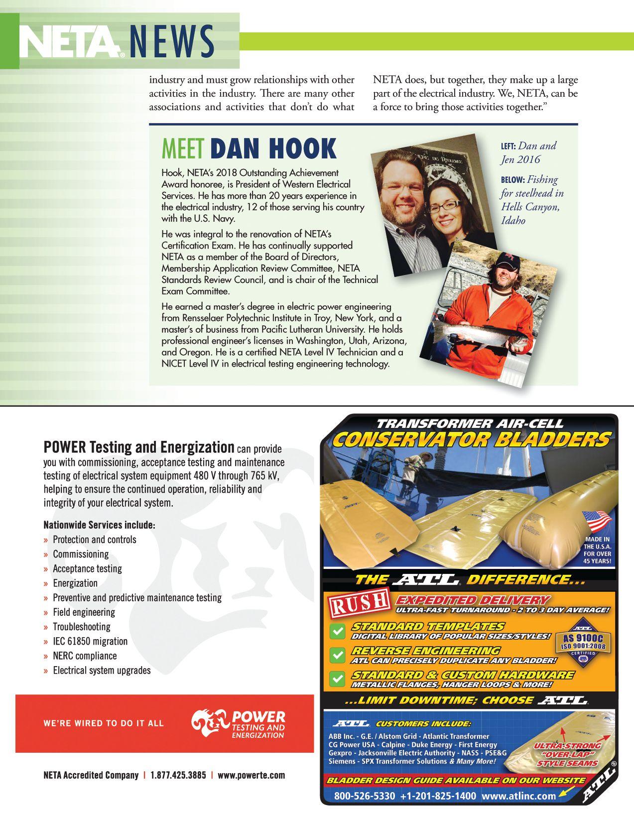
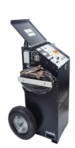
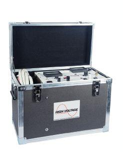
•
•
•
• Ω-CHECK® Concentric Neutral Testing
• Custom Engineered & Fabricated Van Pkgs.
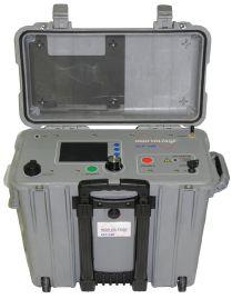
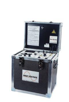

NETA President Jim Cialdea (right) presents the 2018 NETA Alliance Recognition Award to Bob Sheppard
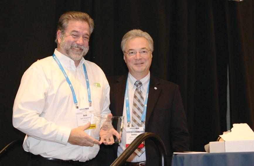
The 2018 NETA Alliance Recognition Award recipient is the true definition of a “renaissance man.” While in high school, he was part of the local sheriff’s department search and rescue team. Some days, Bob Sheppard might have helped with a search and rescue, and then rushed off to dance class. “Bob’s mother enrolled him in ballroom and disco dancing, so he danced early in his high school years,” Bob’s wife Erin recalls, “strutting his stuff like John Travolta. He used to ride his 10-speed to the dance studio, and I’m sure he met a lot of girls that way.”
Bob’s high school sweetheart, Erin says a love of music brought them together. Music took him in some other directions, too. At the dance studio, Bob learned how to cue up music, which led him to try his hand as a radio DJ in his sophomore year. “He was a program director and
DJ for many years,” Erin says. “That’s how we met…I fell in love with his voice on the radio, and a co-worker knew him and introduced us.
Then there was that dream of becoming the next Sir George Martin or Quincy Jones. After high
school graduation, Bob went to Chillicothe, Ohio, to summer school to be a record producer — an idea, she says, that eventually fizzled. From there, he served as a restaurant manager for many years, provided transportation to forests for Idaho firefighters, was a stockbroker, and then director of finance at a marine speedboat dealership. Working his way through Idaho State University, his wife says Bob attended the American Bartending School and has a certificate as a qualified mixologist — and still is an “awesome bartender” to this day.
Luckily for the electrical testing industry and for NETA, none of that panned out. Erin Sheppard says her husband eventually discovered his right place in the electrical testing field. “He was in the top of his class to become an electrical engineer, which he loves dearly. He is so passionate about this field. It makes me smile that he has come a long way to finally find the career he loves.” Before joining Intellirent in August 2016, Bob served as Principal and General Manager of Southwest Energy Systems for nine years and was Area Manager at both Electro-Test, Inc. (six years) and Emerson (five years).
But even though he found his career in electrical engineering, his life learning did not stop. His wife says that in addition to the many other hats he wears, Bob is a private pilot and an outstanding cook. “I can’t think of a single thing that Bob hasn’t been able to do,” she says. “Whether it’s mixing cement for backyard pads or fixing just about anything around the house, he is amazing. He just makes things happen.”
Today, Bob Sheppard is Vice President of Business Development at Intellirent. During Powertest 2018, he received NETA’s 2018 Alliance Recognition Award, which honors an individual who has not only been a dedicated supporter of NETA and the work of the association, but has also furthered the industry and inspired others to do the same. Presented


annually at PowerTest, Bob received this year’s honor in recognition of his commitment to the industry and NETA, having served on the Board of Directors and as a leader on the NETA Training Committee.
Dave Gibson, Principal at Intellirent, has been a friend, customer, peer, and now a colleague of Bob Sheppard’s for over 20 years. He notes that long ago, Bob identified the big issue all NETA members face — the lack of capable and qualified field technicians. “Many, if not most, of the challenges we encounter would be mitigated if we had a consistent and wellrounded manpower pool,” says Gibson. “The benefits would be vast, but without a practical education path that leads to our industry, this problem isn’t going away.”
Gibson says this challenge had a significant impact on Bob when he led testing service organizations. “He engaged with NETA so he could do something about it,” he says.
What Bob did about it was a volunteer project about six years in the making, according to
NETA President Jim Cialdea of CE Power’s 3C Electrical. Bob put together the curriculum for the new NETA Electrical Power Testing Technician (EPTT) program now offered to students at Long Beach City College in California through a partnership with NETA. The EPTT curriculum includes courses that provide graduates with a strong grasp of the educational requirements specified for a Level 2 NETA Test Technician per the ANSI/NETA ETT, Standard for Certification of Electrical Testing Technicians. Cialdea says the plan is to move the curriculum to other schools across the country. “This program is unique in the world of electrical test technician education,” Bob says about his pet project. “It provides individuals with the knowledge and skills to succeed in the electrical testing industry.”
“The greatest challenge we have in our space is a lack of qualified and experienced people,” Gibson sums up. “Sincere compliments and appreciation to Bob for doing something
about it. He embraces the true spirit and purpose of the NETA organization.” As Cialdea put it when presenting the prestigious Alliance Recognition Award to Sheppard, “Bob Sheppard is a modern-day Renaissance man.” Gibson agrees, “He really does have an incredibly diverse background. At the award ceremony, as Jim Cialdea listed the experience Bob has accumulated over his career, I could see his face and could hear him thinking, ‘Wait — is he talking about me?’”
But Bob doesn’t do it all for the recognition. He does it because he’s passionate. Th at’s why his background is so diverse. He brings that passion to whatever he does. NETA, our industry, and my organization are fortunate to be associated with him,” Gibson says.
“NETA and our industry have greatly benefitted from Bob’s devoted volunteer work in electrical testing technician safety, training, and education. This award is well deserved.”
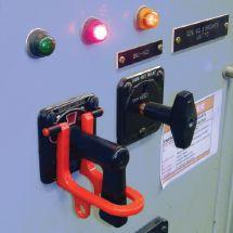
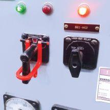
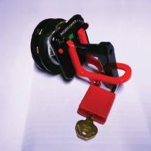


Vacuum circuit breakers are the dominant switchgear technology used in medium-voltage (1kV-38kV) power system applications due to their smaller size, increased service life, and ease of maintenance when compared to other alternatives. However, many of the medium-voltage vacuum circuit breakers (MVVCBs) in service today are nearing or exceeding their expected lifespan. This two-part article provides evidence that simply using a breaker’s age or number of operations to quantify mechanism health and schedule maintenance is ill advised due to the effects of outside variables.
Part one discusses the properties and data that can offer a more accurate service-life projection for breakers and describes a three-tiered approach that utilizes industry-standardized maintenance intervals and philosophies during the life of the equipment. Part two will detail newly available testing techniques and technologies as well as component upgrades with modern replacements to modernize the aging population and keep these valuable assets in service for many years to come.
Life extension and modernization of MVVCBs and the electrical equipment they protect is a critical need for the aging power system infrastructure in the United States. Recommended intervals between maintenance can differ based on many variables, including:
• Original equipment manufacturer (OEM) guidelines
• Environmental and operating conditions

• Age and condition of the MVVCB
• Number of operations on key components
• The criticality of the circuit
• Maintenance philosophy adopted
Industry standards dictate how each of these criteria should be considered when dealing with service-aged MVVCBs to determine the ideal service intervals to maximize safety, reliability, and cost effectiveness.
In addition to recommended maintenance, MVVCBs must also be regularly tested to ensure proper operation during normal operating conditions, and accelerated testing must be performed on equipment subjected to extreme conditions such as high duty-cycle applications or interrupting faults. Generally, VCBs will require more maintenance as they age, and new replacement parts from the OEM are not always available in a timely manner, at the right price, or at all. Downtime is very costly, and access to high-quality replacement components is essential to getting the equipment repaired quickly and back online.
A previous study conducted by the authors focused on determining whether any correlation exists between vacuum interrupter (VI) age, internal pressure, contact resistance, and AC HiPot leakage current. The results showed a strong correlation between VI age and internal pressure, a minimal correlation between VI age and contact resistance, and no correlation between VI age and AC HiPot leakage current. This article investigates the MVVCB’s operating mechanism first-trip timing versus age and number of operations using the data gathered from the initial all-inclusive study of as-found, service-aged equipment.
During the testing, alternating open and close operations were performed three times on each MVVCB, and the timing was recorded for each phase individually. In the re-evaluation of the data for this article, the timing test results
for the first open operation are examined. This first-trip data is important because, when a fault occurs, the MVVCB is expected to operate within its specified time-current characteristics. Unfortunately, due to environmental contaminants, hardened grease, vibration, and other factors, it’s not unusual for the operating time of a circuit breaker’s first opening to exceed the OEM-specified operating time.
Additionally, the problem(s) that cause a circuit breaker to operate slowly are frequently cleared during the fi rst operation of the breaker, meaning that the cause cannot be detected in subsequent testing. The act of operating the breaker will loosen hardened grease and exercise springs and other mechanisms so that, when the breaker is tested again, the test will not represent a true as-found opening time.
An arc flash analysis assumes that the overcurrent protective device (OCPD) will clear a fault within the OEM’s specified time-current characteristics. Since the energy released during an arc flash is proportional to fault clearing time, operating at rated speed is critical for calculations and protective schemes to be correct. A failed MVVCB, or even a slowly operating one, will result in higher incident energies — resulting in larger boundaries than specified or a higher level of required PPE than what is detailed on placards.
Traditional maintenance testing of MVVCBs requires them to be opened and removed from the cell prior to conducting timing tests; therefore, conducting a test will not yield a true first-trip operating time. First-trip testing methods can provide a real-life operating time that can be compared to the assumed opening times used in an arc flash analysis. It’s not unusual for the first-trip time of a breaker with 5–10 years of inactivity to be greater than 100 milliseconds, and after the first trip, it will typically fall within the safe limits of 30–50 milliseconds. If the first parting time of a MVVCB is greater than 60 milliseconds, it is not operating properly and should be pulled aside for further investigation and maintenance.

The data set was analyzed, yielding the results in Table 1, Figure 1, and Figure 2. Based on the data, there is little to no correlation between the age or number of operations and the mechanism first-trip timing as shown by the correlation coefficient (r) values of 0.0261 and 0.0298, respectively. These r values near zero signify a very weak relationship between the
variables. Similarly, the r2 value, which is the percentage of the y values whose variance can be explained by a change in x, is equally low.
Given the fact that no meaningful relationship exists, simply using mechanism age or number of operations alone is not enough to determine mechanism health and maintenance needs. Industry standards point to a maximum allowable time or number of operations between maintenance; other factors must be taken into consideration as dictated by the maintenance philosophy set out within these same standards.

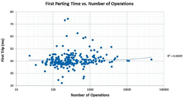
2: Mechanism First Parting Time vs. Number of Operations
It is important to note that there are variables which affect mechanism timing that cannot be accounted for in this data. First, there is no way to qualitatively or quantitatively include variations of ambient conditions while in service. Temperature extremes and humidity will adversely affect mechanism timing. Second, no data was available for individual mechanisms with respect to time since last operation or prior mechanism timing test results for comparison. Research has shown that inclusion of individual time-based data greatly improves the quality of the statistical analysis, so 10 MVVCBs have been isolated from the present study to be fully re-evaluated in a 5-year period. This will help to establish important mechanism timing information and provide a means for projecting future timing test results.
Many papers, articles, and standards have been written on the topic of recommended maintenance intervals. While they all vary in scope and findings, none of the sources suggests exceeding a maintenance interval of five years for electrical equipment.
The majority of all circuit breaker operational

failures below 38kV can be attributed to lubrication failure as a result of degradation due to age, temperature, contaminants, or combinations of incompatible lubricants. Fortunately, these mechanical failures can be avoided with correct lubrication practices at properly scheduled maintenance intervals.
Suitable lubricants for circuit breakers must meet distinct requirements for these applications, including:
• Long periods of inactivity
• Large temperature variations
• Exposure to harsh environments
• Lengthy time between services
Eff ective lubrication will positively impact circuit breaker performance and extend maintenance interval periods.
Grease is the predominant lubrication choice for various parts of a MVVCB mechanism due to its ability to stay in position and seal the underlying material from corrosive or foreign contaminants. The most unavoidable cause of grease degradation is age: As grease ages, the ratio of lubricant to thickener changes as shown in Figure 3. The oil-based lubricant portion of the grease evaporates over time, leaving an abundance of thickener in the mixture and causing the grease to change viscosity and stiffen.
Temperature extremes can also wreak havoc on a lubricant’s ability to perform correctly. Localized heating can result in grease oxidation, forming a film that can spread throughout the grease and completely coat parts with a varnishlike substance. If the environment’s ambient temperature is lower than the threshold of the lubricant’s working temperature, the lubricants may stiffen to a point that may actually prevent circuit breaker operation.
Grease or oil applied to parts within a circuit breaker will attract and capture dust, dirt, and other environmental contaminants. Over time, the concentration of these contaminants will increase and inhibit the lubricant’s ability to do its job correctly. Depending on their size and
composition, contamination particles may even become trapped between moving parts and act as an abrasive.
Another factor contributing to degradation is when a combination of two or more lubricants causes their collective properties to fall outside of the original specifications, rendering them incompatible. Examples of incompatible lubricants are shown in Figure 4. If a new type of lubricant must be introduced, the component should be disassembled and

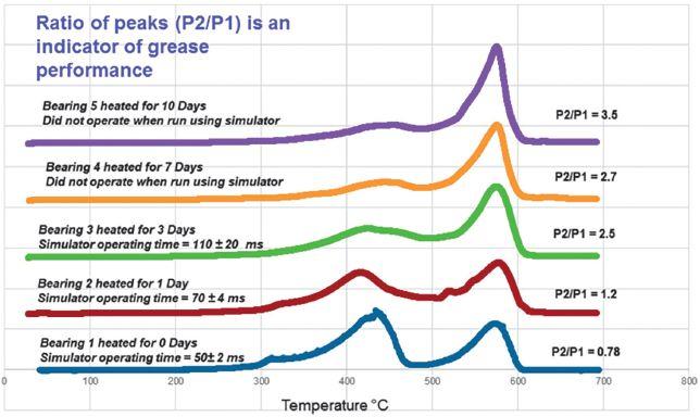

thoroughly cleaned to remove any trace of the previous lubricant prior to application.
Use of penetrating oils and sprays can dissolve and flush out previously installed lubricants and accelerate equipment failure. These sprays have a much lower viscosity than grease and quickly leak from their applied locations. Furthermore, the little penetrating oil that does remain will evaporate quicker than grease, leaving behind a viscous coating that actually inhibits mechanism operation. The use of spray penetrating oil is not advised for long-term circuit breaker health.
It is estimated that one in every four breakers in service has some type of lubrication issue. To minimize impact on personnel safety, equipment reliability, and maintenance costs, regularly scheduled maintenance should monitor the lubricant characteristics and properties. Lubricant data is valuable when scheduling maintenance intervals.
While cleaning the mechanism and removing all traces of the old lubricant is not required at every maintenance cycle, once the lubricant has degraded to the point where it affects the operation of the circuit breaker, application of new lubricant is required. Proper lubricating practices and appropriate maintenance intervals are essential for selecting and establishing a maintenance philosophy that coincides with the facility’s long-term objectives.
Under a reactive — or run-to-failure (RTF) — philosophy, electrical equipment is deliberately allowed to operate until failure. This philosophy is not prudent due to personnel safety concerns and the potential impact failure would have on the greater electrical system. Only in rare circumstances where no consequences of failure exist in terms of safety, mission, environment, or security can equipment be allowed to run until failure.
An interval-based maintenance philosophy, more often referred to as preventive

maintenance (PM), involves scheduled maintenance at preset intervals to reduce the likelihood of operational failures and to obtain as much useful life as possible out of the equipment before failure. Studies have shown that many types of failures cannot be prevented no matter how comprehensive maintenance activities are. Additionally, for many items, the probability of failure does not increase with age; therefore, a maintenance program based strictly on the age of the equipment will have little, if any, effect on the failure rate.
Advances in monitoring wear and electrical equipment failure analysis in real-time have made it possible to schedule appropriate repairs with a higher degree of confidence. Using this data to predict the probability of failure is a philosophy known as condition-based maintenance (CBM).
Reliability-centered maintenance (RCM) is a logical, structured framework for determining the optimum mix of reactive, interval-based, and condition-based maintenance practices. Since being introduced in the 1960s in aviation, RCM has continued to spread as the most prominent maintenance philosophy.
Most MVVCB service manuals contain some type of information concerning usage- or timebased intervals for preventative maintenance. This one-size-fits-all may not be effective. RCM will reduce operating costs, unplanned outages, and increase production. However, RCM can be costly up front, as a baseline requiring breakers to be removed from service, tested, cleaned, inspected, lubricated, and reassembled must be developed.
More information can be found in the most recent editions of applicable industry standards. For example, standards maintained by NETA and NFPA are helping steer the industry from outdated maintenance philosophies to RCMbased philosophies; they provide detailed information on how to apply RCM as well as reliability data for many types of electrical equipment.

Th ere are two main sources for MVVCB maintenance:
• ANSI/NETA MTS, Standard for Maintenance Testing Specifications for Electrical Power Distribution Equipment and Systems
• NFPA 70B, Recommended Practice for Electrical Equipment Maintenance
ANSI/NETA MTS does an excellent job of covering electrical testing, maintenance requirements, and visual and mechanical inspections for virtually every piece of electrical equipment in an electrical power system. In response to requests for a maintenance interval timetable, ANSI/NETA MTS provides information in Appendix B that outlines a matrix-based multiplier approach to maintenance intervals for facilities that have not yet adopted RCM practices (Table 2). Equipment that has a low reliability requirement and is in good condition would have a multiplier of 2.5. Multiplying 2.5 by the number of months for MVVCBs in Table 3, the maximum allowable interval for maintenance is 5 years (2.5 x 24 months = 60 months or 5 years).
In addition to the reliability requirement and equipment condition, application of the matrix when determining maintenance frequency should take into consideration the results of historical test data, as well as other criteria such as OEM guidelines, environmental and operating conditions, age and number of operations, loading, how the circuit breaker is being used, etc. An effective RCM program
will identify these factors and provide measures to address them at the proper intervals.
ANSI/NETA MTS diff ers from NFPA 70B in that it doesn’t cover anything beyond which tests to perform and what the results should be. It is a what-to-do specifi cation, whereas NFPA 70B helps to bridge the gap on electrical maintenance requirements in a how-to-do-it format.

Table 4 from NFPA 70B Annex I provides an initial guideline for the maintenance intervals of MVVCBs; service is to be performed annually and testing completed every 3 years.
Both ANSI/NETA MTS and NFPA 70B stress that other factors such as environmental or operating conditions may dictate a different frequency of maintenance than what is suggested in Annex I.

Additionally, NFPA 70B notes that maintenance, inspection, and test methods are essentially the same regardless of whether the electrical equipment is shut down frequently or operated for long periods of time uninterrupted.
Based on the original criteria OEM marketing and sales departments gave product development and engineering teams, MVVCBs were only designed to have a 20-year service life. However, this does not mean that these MVVCBs will only last for 20 years — in fact, many are now approaching 40 years of reliable service. But what will it take to continue this trend and extend the useful life of the MVVCB fleet in the United States even further beyond their original life expectancy — say another 20, 30, or even 50 years? As this article discussed, one of the most important parts of a properly structured life extension plan for MVVCBs is adhering to an industry recognized maintenance philosophy. Part two of this paper will continue with tests and upgrades to extend MVVCB life expectancy.
F. Ledbetter, J. Cadick, J. Day, F. Ledbetter, III, J. Toney, and G. Garonzik, “Vacuum Interrupters: Pressure Versus Age, A Study of Vacuum Levels in 322 Service-Age Vacuum Breakers,” 2016.
T. Demaria, “Circuit Breaker Lubrication in the Field,” NETA World, pp. 7-10, 2007.
A. R. Salinas, B. Desai, J. Harley, B. Kinner, and M. Lebow, “Circuit Breaker Mechanism Lubricant Performance Assessment: Investigation and Field Experience,” 82nd International Conference of Doble Clients, Boston, 2015.
B. H. Chudnovsky, “Lubrication of Electrical Distribution Equipment,” NETA World, pp. 24-31, 2012.
J. White, “Crital Maintenance for Circuit Breakers,” NETA World, pp. 1-8, 2007.
F. S. N. a. H. Heap, Reliability-Centered Maintenance, San Francisco: Dolby Access Press, 1978.
J. Cadick, M. Capelli-Schellpfeffer and D. Neitzel, Electrical Safety Handbook, New York: McGraw-Hill, 2006.
ANSI/NETA MTS, Standard For Maintenance Testing Specifications for Electrical Power Equipment and Systems, Portage: InterNational Electrical Testing Association, 2011.
NFPA (National Fire Protection Agency), 70B, Recommended Practice For Electrical Equipment Maintenance, Quincy, 2016.


Finley Ledbetter is the Chief Scientist for Group CBS, Inc., with over 40 years of power systems engineering experience. He is a member of the IEEE and was a past president of PEARL. Finley was awarded NETA’s Alliance Recognition Award at PowerTest 2016.
David Walterscheid is currently a Senior Engineer at Group CBS, Inc. He started with Group CBS, Inc. in 2009 at CBS ArcSafe developing electrical safety equipment and served as Vice President of the company for over four years. David’s patents in the field of remote operation for electrical equipment and the products he has developed have won awards from industry publications and organizations.
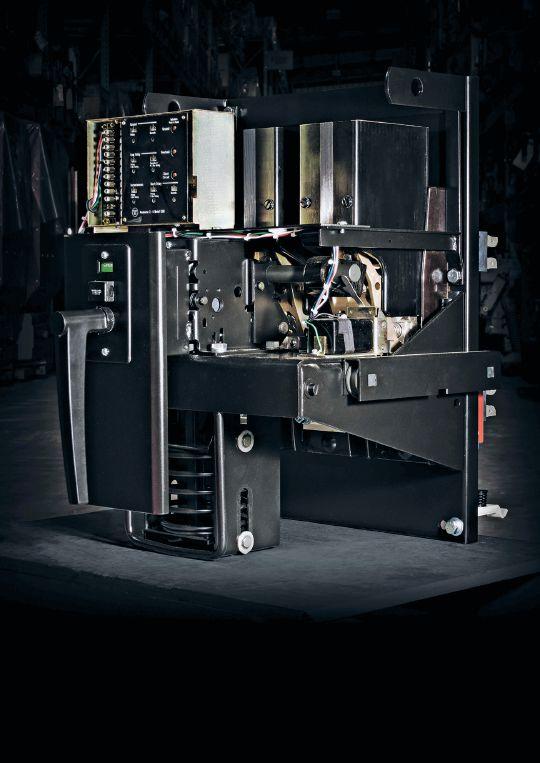



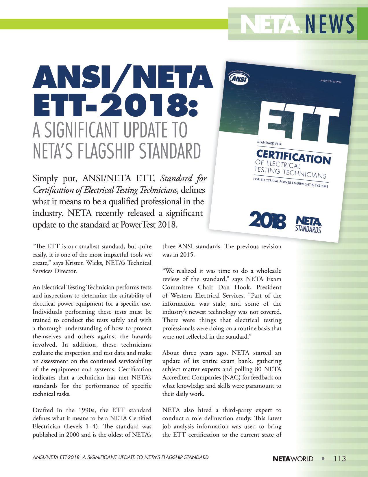
the electrical testing industry. The new ANSI/ NETA ETT-2018 is still the same scope, but Hook describes it as “a very significant update,” including:
• Knowledge, skills, and abilities are updated.
• Level 1 Technician is now required to have electrical safety training.
• The continuing education requirement is set for Level 2 Technicians.
• The Level 2 Technician is now a Certified Technician and no longer called an Assistant.
“It is important to understand that the ETT standard and certification go hand-in-hand to qualify individuals,” Hook adds. “Certification is one of the pillars of NETA. The goal is established standards and a qualified person to perform that specification.”
Accreditation, he says, takes this one step further. “Accreditation is for the company. It includes things like safety, calibration, and quality control. A lot of higherlevel requirements are needed to reach accreditation.”
The ETT defines the experience, education, and training requirements necessary for an individual to obtain a level of competency as an Electrical Testing Technician. In addition to certifying the individual technician, NETA carefully examines the qualifications of each NAC. Because of this requirement, the ETT review team made sure that the NETA requirements for certifi cation were aligned
with the certification path for qualified individuals.
ANSI/NETA ETT-2018 establishes minimum requirements for qualification and certification of the Electrical Testing Technician by detailing the minimum training and experience requirements and providing criteria for documenting qualifications and certification. The standard details the requirements for an independent and impartial certification system of Electrical Testing Technicians.
As Hook explains it, the NETA Certifi ed Technician is a very broad, knowledge-based certifi cation. “If you’re an expert on one or two things and that’s all you do, you’re a specialist,” he says. “A NETA Certifi ed Technician, on the other hand, has to be knowledgeable on many voltage levels and different kinds of equipment.
“If you can know a little bit about everything, it puts you in a better position for management, customer service, and problem solving,” he continues, “as opposed to a specialist, who is helpful only if the problem happens to fall into their area of expertise.”
Current NETA Certifi ed Technicians will certify to the 2018 revision. “The new standard does not take away a technician’s past certifi cation, but the requirement for CEUs and recertifi cation every three years will be covered under this standard,” Hook explains.
Summing up the signifi cance of the ANSI/ NETA ETT-2018 update, Hook says, “A customer should be asking who is best qualified to perform the work needed to meet this standard, and the answer points in the direction of a NETA Certified Technician.”


Description of Panel

 BY SCOTT BLIZARD, American Electrical Testing Co. LLC
CMP-10 Articles: 215 Feeders, 225 Outside Branch Circuits and Feeders, 230 Services, 240 Overcurrent Protection, and 242 Overvoltage Protection New Article
Number of Public Inputs 213
Resolve 114
First Revisions 99
Definitions


First Revision A Revision developed by a Technical Committee contained in Public Input of the First Draft. A First Revision must be accompanied by a panel statement supporting the reasoning for the First Revision.


Resolve Negative vote cast by a member of the consensus body or a comment submitted as a result of public review where the negative voter agrees to change his/her vote or the negative commenter accepts the proposed resolution of his/her comment. A Resolve must be accompanied by a panel statement supporting the reasoning for the Resolve.
Code-Making Panel 10 (CMP 10) is a wellorganized and knowledgeable panel, with representation from many organizations including IAIE, IEC, IEEE, IBEW, EEI, ACC, NETA, UL, NEMA, and NECA. This diverse group brings various points of view to the code-making process.

For the 2020 cycle, Julian Burns has been appointed Chair of CMP 10. Julian is a member of the Independent Electrical Contractors, Inc., and was Chair of Code Panel 10 during the last code-making cycle.

Due to significant effort by members of the panel in preparing suggested panel statements and Julian’s work in organizing the comments in a logical order to be addressed by the panel, the panel worked through the 213 public inputs in four days.

The first daft meeting took place in Hilton Head, South Carolina, on January 15–18,


2018. NETA was represented by Scott Blizard, Principle, and David Morrissey, Alternate. There were a few public inputs that would be of particular interest to NETA members. Some of these were rejected unanimously by the panel, and therefore, will have no impact on NETA at this stage of the code-making process. Public inputs of interest are noted in the following Committee Update.

Public Input 1247 and Public Input 1248 were submitted by the Fault Current Working Group, which was formed to support the Correlating Committee’s Usability Task Group. Members of the Fault Current Working Group included Scott Blizard, Jim Dollard, Carl Fredericks, Jeff Hidaka, Chris Jensen, Alan Manche, and Vince Saporita. The goal of the Fault Current Working Group was to analyze the usage of the terms “short circuit” and “fault” throughout the NEC and submit Public Inputs, as appropriate, to improve clarity, consistency, and usability.

The Usability Task Group has identified a new definition in the 2018 edition of NFPA 70E to be considered for insertion into the NEC. This task group (CMP 10) will review the work of the 70E Committee and consider the addition of the term “fault current” in the 2020 edition of the NEC. The two proposed new definitions for Article 100 are:
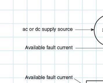


• Fault Current: An objectionable current that flows due to an abnormal circuit condition
• Fault Current, Available (Available Fault Current): The largest amount of current capable of being delivered at a point on the system during a short-circuit condition

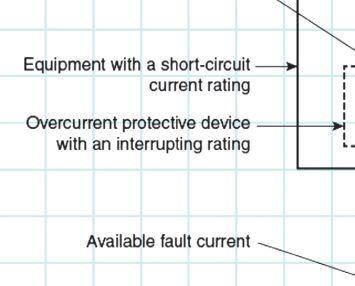

1


Informational Note: A short circuit can occur during abnormal conditions such as a fault between circuit conductors or a ground fault (Figure 1).
Public Input 3554 and Public Input 1852 proposed to change 230-95(C) Performance Testing on ground fault protection. The manufacturers tried to redefine primary injection testing through an information note; this was a Resolve by the committee in the first draft.
Public Input 8641 First Revision submitted by CMP 10. The change is to 240.67(B) Method to Reduce Clearing Time, adding four current limiting, electronically actuated fuses. Th e panel statement supporting the change is as follows:
Current limiting, electronically actuated fuses are an acceptable method of arc energy reduction. While this method is currently permitted as an ‘approved equivalent,’ clarity and usability are added with a specific reference.


Public Input 3144 proposed change to 240.67 (Switch) Arc Energy Reduction submitted by


NETA, which goes into e ect in 2020, deals with a proposal to require performance testing on arc energy reduction systems. is proposal was a Resolve in the rst draft.

Public Input 8671 First Revision was submitted by CMP 10. e change is to 240.87(B) Method to Reduce Clearing Time:
(5) An instantaneous trip setting that is less than the available arcing current. Temporary adjustment of the instantaneous trip setting to achieve arc energy reduction shall not be permitted.


is change clari es that it is the nal setting of the instantaneous trip that determines whether or not additional arc energy reduction techniques are required. It is not intended that the minimum setting of the instantaneous trip — as is typically shipped from the factory — be the determining factor of whether additional arc energy reduction is necessary. Rather, the nal setting is determined by the electrical system requirements such as inrush characteristics or selective coordination. Nor is it the intent that the instantaneous trip be adjusted to a lower setting while a worker is working on the equipment and then adjusted back to the desired setting after work is complete.

Public Input 3151 proposed a change to 240.87 (Breaker) Arc Energy Reduction submitted by NETA, and deals with a proposal to require performance testing on arc energy reduction systems. is proposal was a Resolve in the rst draft.
Note: Proposals on both Public Input 3144 and Public Input 3151 proposed by NETA drew a lot of attention and took the better part of a day of debate. Public Input 3151 had some support among the committee. We will continue to work to add clarity and performance testing to both sections in Article 240.

Public Input 1898 First Revision creates new Article 242 Overvoltage Protection. The Correlating Committee reviewed the NEC® for gaps and issues where clarity and usability could be improved. e Correlating Committee agreed that combining Article 280 and Article 285 in a style similar to that of Article 240 would signi cantly improve clarity and usability. e Correlating Committee then formed a task group, consisting of Larry Ayer (Co-Chair), Joseph DeGregoria, James Dollard, Carl Fredericks, Alan Manche, Michael O’Meara, Daleep Mohla, and Vince Saporita (Co-Chair), to: (1) con rm whether there was merit in developing a more comprehensive article on surge protection similar to Article 240, and (2) if appropriate, submit public inputs for such an article. is public input has been generated by the task group to address the gap identi ed by the Correlating Committee.


Overvoltage protection and surge protection are presently addressed in two short articles, one for 1,000 volts and below (Article 285) and one for above 1,000 volts (Article 280). Combining the two articles improves clarity and usability. For clarity, a new table similar to Table 240.3 is added. is public input simply combines the two articles without changes to existing requirements. e new article will increase usability for the code user.
e second draft meeting is scheduled for December 2018 in San Diego, California.

Scott A. Blizard is Vice President and COO at American Electrical Testing Company Co. LLC and is NETA’s Principal representative to the NFPA 70 Code-Making Panel 10 Committee.


ANSI/NETA ETT, Standard for Certification of Electrical Testing Technicians, 2015 Edition, has been revised. ANSI/ NETT ETT-2018 was approved by ANSI as an American National Standard on February 22, 2017. The revised edition was released in March 2018. It is available now in the NETA Bookstore at www.netaworld.org, where a complimentary PDF copy can be downloaded, or a printed copy can be ordered.


ANSI/NETA ETT establishes minimum requirements for qualifications, certification, training, and experience for the electrical testing technician. It provides criteria for documenting qualifications for certification and details the minimum qualifications for an independent and impartial certifying body to certify electrical testing technicians.
ANSI/NETA MTS, Standard for Maintenance Testing Specifications for Electrical Power Equipment and Systems, 2015 Edition, is being revised as an American National Standard. A project intent notification was published in ANSI’s Standards Action on October 6, 2017, with a 45-day public review period that closed November 11, 2017. The initial ballot was issued on March 8, 2018, and closed on April 8, 2018. A 30-day second ballot period and a 45-day public comment period were scheduled to begin on June 29, 2018. The intent is to release the revised edition of ANSI/NETA MTS in March 2019.


ANSI/NETA MTS contains specifications for suggested field tests and inspections to assess the suitability for continued service and reliability of electrical power equipment and systems. The purpose of these specifications is to assure that tested electrical equipment and systems are operational and within applicable standards and manufacturers’ tolerances, and that the equipment and systems are suitable for continued service.
Single copy of draft document: $459
Order from: Richard Piet (888) 300-6382 rpiet@netaworld.org
Send comments to Richard Piet, rpiet@netaworld.org, with copy to psa@ansi.org






REVISION IN PROCESS




ANSI/NETA ECS, Standard for Electrical Commissioning Specifications for Electrical Power Equipment and Systems, 2015 Edition, was approved as an American National Standard on December 3, 2014. This standard is available for purchase in the NETA Bookstore at www.netaworld.org
ANSI/NETA ECS describes the systematic process of documenting and placing into service newly installed or retrofitted electrical power equipment and systems. This document shall be used in conjunction with the most recent edition of ANSI/NETA ATS, Standard for Acceptance Testing Specifications for Electrical Power Equipment and Systems. The individual electrical components shall be subjected to factory and field tests, as required, to validate the individual components. It is not the intent of these specifications to provide comprehensive details on the commissioning of mechanical equipment, mechanical instrumentation systems, and related components.


Voltage classes addressed include:

• Low-voltage systems (less than 1,000 volts)
• Medium-voltage systems (greater than 1,000 volts and less than 100,000 volts)
• High-voltage and extra-high-voltage systems (greater than 100 kV and less than 1,000 kV)
References:
• ASHRAE, ANSI/NETA ATS, NECA, NFPA 70E, OSHA, GSA Building Commissioning Guide

suggested field tests and inspections for assessing the suitability for initial energization of electrical power equipment and systems. The purpose of these specifications is to assure that tested electrical equipment and systems are operational, are within applicable standards and manufacturers’ tolerances, and are installed in accordance with design specifications.
This document is scheduled for release as a revised standard in the spring of 2021. Those interested in participating in the revision process should contact the NETA office for more information.


This document is scheduled for release as a reaffirmed or revised standard in Spring 2020. Those interested in participating in the revision process should contact the NETA office for more information. Initial review work will begin in the spring of 2018, with the initial ballot issued in late 2018/early 2019.
ANSI/NETA ATS, Standard for Acceptance Testing Specifications for Electrical Power Equipment and Systems, 2017 Edition, covers


Acceptance Testing Services
Low, Medium, and High Voltage
Substations • Distribution switchgear • Transformers • Cables • Relays
Preventative Maintenance & Testing
Switchgear
Infra-red surveys • Circuit breakers • Relay testing and calibration
Transfer switches • Complete maintenance of ACB’s-OCB’s-SF6 CB’s
UPS & station battery maintenance • Gen. load tests
Transformers
TTR • Power factor testing
• Oil testing and field analysis
Oil reconditioning & reclaiming • field replacements
Engineering Services
Arc-flash, short circuit, and coordination studies
Power factor correction
• Power quality and harmonic studies
Comments and suggestions on any of the standards are always welcome and should be directed to the NETA office. To learn more about the NETA standards review and revision process, to purchase these standards, or to get involved, please visit www.netaworld.org or contact the NETA office at 888-300-6382.

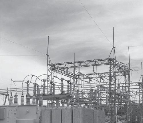
Load surveys
• Grounding system design
Trust us to keep your business up and running. Call for a free consultation today.
P: 781-767-0888 Email: infrared.ma@verizon.net
152 Centre Street Holbrook, MA 02343 www.infraredbps.com

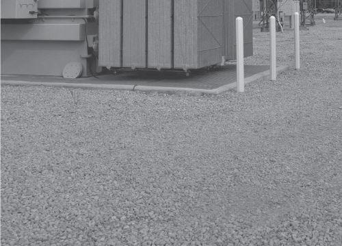


 BY JAMES R. WHITE, Shermco Industries
Code-Making Panel 13 covers legally required and optional standby systems, including microgrids and emergency storage systems (ESS). Microgrids may be ac or dc, but are often dc. ESS can include capacitors and flywheel systems, as well as batteries. CMP13 has purview over Articles 445, 455, 480, 695; 700, 701, 702, 706, 708, 710, 712; and Annex F.
The first draft meeting took place on January 7–12, 2018 in Hilton Head, South Carolina.
On Monday, January 8, the CMP-13 panel began addressing the 267 public inputs for the first draft of the 2020 NEC. The public inputs were divided into four groups; each group of PIs was assigned to a task work group. The task groups had met several times via teleconference over several months preceding the first draft meeting. At this meeting, each task group was to review their assigned public inputs and make recommendations to the full panel. Each task group leader then addressed the panel with the recommendations from their group.


Seven global inputs needed to be addressed by multiple panels. These global inputs were mostly grammatical in nature. They address terms such as “list” and “identified” and “satisfactory” that are considered subjective. The new suggested changes should simplify the language in the code for usability.


Several PIs may be of interest to NETA. Throughout the articles under the purview of CMP13, particularly those dealing with emergency systems, there were public inputs on the (.3) sections of these articles. The .3 sections address testing and maintenance of these systems.


PIs were submitted referencing NFPA 70B, Recommended Practice for Electrical Equipment Maintenance , but not ANSI/NETA MTS.
NETA representatives James R. White, Principle, and William Otterson, Alternate, convinced the majority of the panel to include the ANSI/NETA standard as well. Some committee members objected to placing maintenance requirements into the NEC, as that is the purpose of NFPA 70B, so there was some question as to purview, especially to optional standby systems. The answer to that objection was that even though standby systems are optional, they are typically connected and operating during emergencies. This gives other organizations that use the NEC a basis for ensuring that required maintenance is performed.


The final first draft report is scheduled for posting in July.

James (Jim) R. White, Vice President of Training Services, has worked for Shermco Industries Inc. since 2001. He is a NFPA Certified Electrical Safety Compliance Professional and a NETA Level IV Senior Technician. Jim is NETA’s principle member on NFPA Technical Committee NFPA 70E® Standard for Electrical Safety in the Workplace®, NETA’s principle representative on National Electrical Code® Code-Making Panel (CMP) 13, and represents NETA on ASTM International Technical Committee F18 Electrical Protective Equipment for Workers. Jim is Shermco Industries’ principal member on NFPA Technical Committee for NFPA 70B Recommended Practice for Electrical Equipment Maintenance and represents AWEA on the ANSI/ISEA Standard 203 Secondary Single-Use Flame Resistant Protective Clothing for Use Over Primary Flame Resistant Protective Clothing. An IEEE Senior Member, Jim received the IEEE/ IAS/PCIC Electrical Safety Excellence Award in 2011 and NETA’s Outstanding Achievement Award in 2013. Jim was Chairman of the IEEE Electrical Safety Workshop in 2008 and is currently Vice-Chair for the IEEE IAS/PCIC Safety Subcommittee.






 BY KERRY HEID, Shermco Industries Canada
Each year, electric shock results in 25 fatalities and more than 800 injuries in Canadian workplaces. Arc fl ash events (high-voltage discharges and explosions) result in many more injuries and property damage.
We are therefore pleased to announce that the fourth edition of CSA Z462 was released in January in conjunction with the 2018 edition of Part I of the Canadian Electrical Code. In addition to a number of technical updates reflecting the latest research in electrical safety, the standard has been reoriented to focus on hazard elimination and risk control.


Note: CSA Z462 is designed to be a Canadianized version of NFPA 70E. As such, it has been technically harmonized with the NFPA Standard while referencing the CE Code and other Canadian standards.


• The requirement to inspect newlyinstalled or modified equipment
• The requirement to include human error as a factor in risk assessment
• The requirement to consider a specified hierarchy of risk control
• The requirement to perform and document job safety planning
• The requirement to investigate electrical incidents

Major revisions to the 2018 edition include:
1. A general requirement that hazard elimination is the first priority in the implementation of safety-related work practices
2. The addition of several new electrical safety program requirements:

3. Reduction of the minimum threshold for potentially hazardous energy from 50 V to 30 V
4. Reorganization of Clause 4.2, including relocating all training and auditing requirements to Clause 4.1
5. Alignment of shock risk assessment with the arc flash risk assessment
6. Inclusion of Table 2 on the likelihood of arc flash incidents as part of the requirements for arc flash risk assessment


7. Integration of Table 3 on the selection of arc-rated clothing and PPE (previously in Annex H) into the requirements for arc flash risk assessment
8. Revision of Annex F on risk assessment and risk control
9. Update of Annex K on the categories of electrical hazards


CSA Z462 is now recognized by industry, contractors, and regulatory authorities as the primary standard on electrical safety used throughout Canada. With research assistance from NFPA, IEEE, NEMA, and ASTM International, this standard is kept up to date with the latest information on integrated safety systems and risk control procedures.

Scheduled for release mid-2018, this new standard has been recently converted from the 2013 guideline. Th is new standard is loaded with strategies, test procedures, and qualifications all required to properly build an electrical maintenance program to drive the safety and reliability of any organization.


different than uptime, productivity, and other business objectives. The safety risk factors are also expanded into an annex where the user can review examples of 10 different asset classes and how the likelihood and impact of each (when not maintained properly) can affect the worker safety and the electrical safety program.
The CSA Group would like to thank the many expert volunteer members of the Technical Committee for all of their hard work in creating the expanded new editions of CSA Z462 and Z463. These experts represent a broad stakeholder base that includes electrical equipment manufacturers, equipment designers and installers, safety groups, researchers, consultants, and regulatory authorities from across Canada.

One of the key features administered by the new standard is the requirement to have a written electrical maintenance program. A variety of maintenance strategies can be employed by users based on but not limited to the criticality, condition, and age of the equipment, as well as the environment, operating duty, and budget.


CSA Z463-18 will require that electrical maintenance programs specifically address the safety-specific items in an electrical power system. This equipment is normally associated with switching devices operated to establish an electrically safe working condition as well as overcurrent, short circuit, arcing current, and ground fault protection. These devices can have an extremely adverse effect on electrical safety when they do not operate as originally designed and installed. The key requirement is to have safety risk factors for this equipment that must function properly in the interest of worker safety. This safety objective is much
Please submit any comments or questions about CSA Z462-18 or Z463-18 to Canadian NETA Representative, Kerry Heid kheid@shermco.com , or to the CSA Group Standards Project Manager, Dave Shanahan, at dave.shanahan@csagroup.org


Kerry Heid is the President and CEO of Shermco Industries Canada Inc. After beginning his career with Westinghouse Service, Kerry started the Magna Electric Corporation (MEC) office in Regina in 1996 and became President of the company in 2001. The company grew to over 1,000 employees and earned many prestigious awards as one of Canada’s 50 Best Managed Companies and Canada’s Top 100 Employers. MEC was acquired by Shermco Industries in December 2013. Kerry is a NETA past president, served on NETA’s Board of Directors for over 10 years, won NETA’s Outstanding Achievement Award in 2010, and is a NETA Certified Level 4 Test Technician. He chairs the CSA Z463 Maintenance of Electrical Systems Technical Committee and has been on the CSA Z462 Workplace Electrical Safety Technical Committee since its inception in 2006.




The NFPA 70B Committee held the 2019 edition second draft and 2022 edition planning meeting in San Antonio, Texas, in January 2018. After the public comments were reviewed and addressed, the committee moved into planning for the 2022 edition. Modification of the document to move it to a standard is being considered.


Th e committee broke into task groups to see how the editing of each chapter might be accomplished and what it would look like. Th ese task groups will communicate throughout the year to continue work on the modifications. As the edits come together, it is anticipated that another face-to-face meeting will be planned to bring the task groups together.


Deadlines for the 2022 edition are being considered for such a potentially large task.


As the committee moves forward, the impact on the publication date will be reviewed.


David Hu man has been with Power Systems Testing, a NETA Accredited Company, since January 1988 and is currently the CEO. He graduated from California State University, Fresno, and is a licensed Professional Electrical Engineer in the state of California as well as a NETA Certified Technician Level IV. David is a NETA Board member, NETA’s Principal Representative to the NFPA 70B Committee, and serves as a member of various NETA committees.


1. d: All of the answers are actual organizations, and several others use the same acronym. NERC is the North American Electric Reliability Corporation. Don’t ask me what happened to the “A” in their name. I guess it just did not fit.


2. b-False: NERC has authority over all of the United States; the Canadian provinces of Ontario, Alberta, Manitoba, Nova Scotia, Quebec, Saskatchewan, and New Brunswick; and Baja California Norte in Mexico.
3. a and b: NERC is self-regulated, but so are other government agencies. Don’t get your conspiracy theories on overdrive.
4. a: This could be pushed to 6 years if load (capacity) testing is performed and the batteries pass.
NFPA Disclaimer: Although Jim White is a member of the NFPA Technical Committee for both NFPA 70E, Standard for Electrical Safety in the Workplace, and NFPA 70B, Recommended Practice for Electrical Equipment Maintenance, the views and opinions expressed in this column are purely the author’s and shall not be considered an official position of the NFPA or any of its technical committees and shall not be considered, nor be relied upon, as a formal interpretation or promotion of the NFPA. Readers are encouraged to refer to the entire text of all referenced documents.

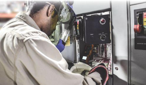




3C Electrical Co. - A CE Power Company
40 Washington St. Westborough, MA 01581-1088 (508) 881-3911
jim@three-c.com www.three-c.com
Jim Cialdea
3C Electrical Co. - A CE Power Company
72 Sanford Dr. Gorham, ME 04038 (800) 649-6314
jim@three-c.com www.three-c.com
Jim Cialdea
A&F Electrical Testing, Inc.
80 Lake Ave. S Ste. 10 Nesconset, NY 11767-1017 (631) 584-5625
kchilton@afelectricaltesting.com www.afelectricaltesting.com
Kevin Chilton
A&F Electrical Testing, Inc.
80 Broad St. Fl. 5 New York, NY 10004-2257 (631) 584-5625 afelectricaltesting@afelectricaltesting.com
Florence Chilton
ABM Electrical Power Services, LLC
720 S Rochester Ste. A Ontario, CA 91761-8177 (301) 397-3500
rob.parton@abm.com www.abm.com
Rob Parton
ABM Electrical Power Services, LLC 6541 Meridien Dr. Ste. 113 Raleigh, NC 27616 (919) 877-1008
ABM Electrical Power Services, LLC 2631 S. Roosevelt St. Tempe, AZ 85282 (602) 722-2423
ABM Electrical Power Services, LLC 3600 Woodpark Blvd. Ste. G Charlotte, NC 28206-4210 (704) 273-6257
ABM Electrical Power Services, LLC 6940 Koll Center Pkwy. Ste. 100 Pleasanton, CA 94566 (408) 466-6920
ABM Electrical Power Services, LLC 3585 Corporate Court San Diego, CA 92123-1844 (858) 754-7963
ABM Electrical Power Services, LLC 1005 Windward Ridge Pkwy Alpharetta, GA 30005 (770) 521-7550
ABM Electrical Power Solutions
4390 Parliament Pl. Ste. S Lanham, MD 20706 (301) 967-3500
christopher.smith@abm.com www.abm.com
Christopher Smith
ABM Electrical Power Solutions 3700 Commerce Dr. # 901-903 Baltimore, MD 21227-1642 (410) 247-3300
ABM Electrical Power Solutions 317 Commerce Park Dr. Cranberry Township, PA 16066-6407 (724) 772-4638
ABM Electrical Power Solutions 814 Greenbrier Cir. Ste. E Chesapeake, VA 23320-2643 (757) 364-6145
ABM Electrical Power Solutions 9800 E Geddes Ave. Unit A-150 Englewood, CO 80112-9306 (303) 524-6560
Accessible Consulting Engineers, Inc. 1269 Pomona Rd. Ste. 111 Corona, CA 92882-7158 (951) 808-1040 info@acetesting.com www.acetesting.com
Iraj Nasrolahi
Advanced Electrical Services 4999 - 43rd St. NE Unit 143 Calgary, AB T2B 3N4 Canada (403) 697-3747
zakhouk@aes-ab.com www.aes-ab.com
Zachary Houk
Advanced Testing Systems 15 Trowbridge Dr. Bethel, CT 06801-2858 (203) 743-2001 pmaccarthy@advtest.com www.advtest.com
Pat MacCarthy
American Electrical Testing Co., LLC
25 Forbes Blvd. Ste. 1 Foxboro, MA 02035 (781) 821-0121 sblizard@aetco.us www.aetco.us
Scott A. Blizard
American Electrical Testing Co., LLC
Green Hills Commerce Center 5925 Tilghman St. Ste. 200 Allentown, PA 18104-9158 (215) 219-6800 jmunley@aetco.us
Jonathan Munley
American Electrical Testing Co., LLC
34 Clover Dr. South Windsor, CT 06074-2931 (860) 648-1013
jpoulin@aetco.us
Gerald Poulin
American Electrical Testing Co., LLC
76 Cain Dr. Brentwood, NY 11717-1265 (631) 617-5330
bfernandez@aetco.us
Billy Fernandez
American Electrical Testing Co., LLC 50 Intervale Rd. Ste. 1 Boonton, NJ 07005-1060 (973) 316-1180 jsomol@aetco.us
Jeff Somol
American Electrical Testing Co., LLC 12566 W Indianola Ave. Avondale, AZ 85392-6322 (480) 383-9242 dmadaglia@aetco.us
Donald Madaglia
Apparatus Testing and Engineering
11300 Sanders Dr. Ste. 29 Rancho Cordova, CA 95742-6822 (916) 853-6280
info@apparatustesting.com www.apparatustesting.com
Harold (Jerry) Carr
Apparatus Testing and Engineering
7083 Commerce Cir. Ste. H Pleasanton, CA 94588-8017 (925) 454-1363
Applied Engineering Concepts 1105 N Allen Ave. Pasadena, CA 91104-3207 (626) 398-3052
Michel.c@aec-us.com www.aec-us.com
Michel Castonguay
Applied Engineering Concepts 8160 Miramar Rd. San Diego, CA 92126 (619) 822-1106
Michel.c@aec-us.com www.aec-us.com
Michel Castonguay
BEC Testing
50 Gazza Blvd. Farmingdale, NY 11735-1402 (631) 393-6800
ddevlin@banaelectric.com www.bectesting.com
Daniel Devlin
Burlington Electrical Testing Co., Inc.
300 Cedar Ave. Croydon, PA 19021-6051 (215) 826-9400
Burlington Electrical Testing Co., Inc.
198 Burrs Rd. Westampton, NJ 08060 (609) 267-4126
waltc@betest.com www.betest.com
Walter P. Cleary
C.E. Testing, Inc. 6148 Tim Crews Rd. Macclenny, FL 32063-4036 (904) 653-1900
cetesting@aol.com www.cetestinginc.com
Mark Chapman
Capitol Area Testing, Inc. 703 E. Ordnance Rd. Ste. 614 Baltimore, MD (443) 370-8583
CE Power Engineered Services, LLC 4040 Rev Dr. Cincinnati, OH 45232 (800) 434-0415 info@cepowersol.net www.cepower.net
Brent McAlister
CE Power Engineered Services, LLC 7674 Washington Ave. S Eden Prairie, MN 55344 (877) 968-0281
Jason.thompson@cepower.net
Jason Thompson
CE Power Engineered Services, LLC 8490 Seward Rd. Fairfield, OH 45011 (800) 434-0415
Tim.lana@cepower.net
Tim Lana
CE Power Engineered Services, LLC 1803 Taylor Ave. Louisville, KY 40213 (800) 434-0415
Tom.hutchinson@cepower.net
Tom Hutchinson
CE Power Engineered Services, LLC 10338 Citation Dr. Ste. 300 Brighton, MI 48116 (810) 229-6628
Ken.lesperance@cepower.net
Ken L’Esperance
CE Power Engineered Services, LLC 10840 Murdock Dr. Knoxville, TN 37932 (800) 434-0415
Don.williams@cepower.net
Don Williams
CE Power Engineered Services, LLC 3496 E. 83rd Pl. Merrillville, IN 46410 (219) 942-2346
Control Power Concepts
353 Pilot Rd. Ste. B
Las Vegas, NV 89119-3520 (702) 448-7833
jtravis@ctrlpwr.com www.controlpowerconcepts.com
John Travis
Dude Electrical Testing LLC
145 Tower Dr. Ste. 9 Burr Ridge, IL 60527-7840 (815) 293-3388
scott.dude@dudetesting.com www.dudetesting.com
Scott Dude
Eastern High Voltage, Inc.
11A S Gold Dr. Robbinsville, NJ 08691-1685 (609) 890-8300
bobwilson@easternhighvoltage.com www.easternhighvoltage.com
Robert Wilson
ELECT, P.C.
375 E. Third St. Wendell, NC 27591 (919) 365-9775
btyndall@elect-pc.com www.elect-pc.com
Barry W. Tyndall
Electric Power Systems
6679 Peachtree Industrial Dr. Ste. H Norcross, GA 30092 (770) 416-0684
Electric Power Systems, Inc. 21 Millpark Ct. Maryland Heights, MO 63043-3536 (314) 890-9999
s.reed@epsii.com www.epsii.com
Steve Reed
Electric Power Systems, Inc. 11211 E. Arapahoe Rd. Ste. 108 Centennial, CO 80112 (720) 857-7273
Electric Power Systems, Inc. 120 Turner Rd. Salem, VA 24153-5120 (540) 375-0084
Electric Power Systems, Inc. 1090 Montour West Industrial Pk. Coraopolis, PA 15108-9307 (412) 276-4559
Electric Power Systems, Inc. 6141 E Connecticut Ave. Kansas City, MO 64120-1346 (816) 241-9990
Electric Power Systems, Inc. 1230 N Hobson St. Ste. 101 Gilbert, AZ 85233 (480) 633-1490
Electric Power Systems, Inc. 915 Holt Ave. Unit 9 Manchester, NH 03109-5606 (603) 657-7371
Electric Power Systems, Inc.
4436 Parkway Commerce Blvd. Orlando, FL 32808-1008 (407) 578-6424
Electric Power Systems, Inc. 1129 E Highway 30 Gonzales, LA 70737-4759 (225) 644-0150
Electric Power Systems, Inc. 684 Melrose Ave. Nashville, TN 37211-3121 (615) 834-0999
Electric Power Systems, Inc.
2888 Nationwide Pkwy. 2nd Floor Brunswick, OH 44212 (330) 460-3706
Electric Power Systems, Inc.
54 Eisenhower Ln. North Lombard, IL 60148 (815) 577-9515
Electric Power Systems, Inc.
4100 Greenbriar Dr. Ste. 160 Stafford, TX 77477-3965 (713) 644-5400
Electric Power Systems, Inc.
56 Bibber Pkwy. # 1 Brunswick, ME 04011-7357 (207) 837-6527
Electric Power Systems, Inc. 11861 Longsdorf St. Riverview, MI 48193-4250 (734) 282-3311
Electric Power Systems, Inc. 8515 Calle Alameda NE Ste. A Albuquerque, NM 87113 (505) 792-7761
Electric Power Systems, Inc. 319 US 70 Hwy. E Ste. E Garner, NC 27529-4054 (919) 210-5405
Electric Power Systems, Inc. 5850 Polaris Ave. Ste. 1600 Las Vegas, NV 89118 (702) 815-1342
Electric Power Systems, Inc.
7925 Dunbrook Rd. Ste. G San Diego, CA 92126 (858) 566-6317
Electric Power Systems, Inc.
306 Ashcake Rd. Ste. A Ashland, VA 23005 (804) 526-6794
Electrical & Electronic Controls 6149 Hunter Rd. Ooltewah, TN 37363-8762 (423) 344-7666
eecontrols@comcast.net
Michael Hughes
Electrical Energy Experts, Inc. W129N10818 Washington Dr. Germantown, WI 53022-4446 (262) 255-5222 tim@electricalenergyexperts.com www.electricalenergyexperts.com
Tim Casey
Electrical Engineering & Service Co. Inc. 289 Centre St. Holbrook, MA 02343 (781) 767-9988 jcipolla@eescousa.com www.eescousa.com Joe Cipolla
Electrical Equipment Upgrading, Inc. 21 Telfair Pl. Savannah, GA 31415-9518 (912) 232-7402 kmiller@eeu-inc.com www.eeu-inc.com
Kevin Miller
Electrical Maintenance & Testing, Inc. 12342 Hancock St. Carmel, IN 46032-5807 (317) 853-6795 info@emtesting.com www.emtesting.com
Brian K. Borst
Electrical Reliability Services 610 Executive Campus Dr. Westerville, OH 43082-8870 (877) 468-6384 info@electricalreliability.com
Electrical Reliability Services 5909 Sea Lion Pl. Ste. C Carlsbad, CA 92010-6634 (858) 695-9551
Electrical Reliability Services 1057 Doniphan Park Cir. Ste. A El Paso, TX 79922-1329 (915) 587-9440
Electrical Reliability Services 6900 Koll Center Pkwy. Ste. 415 Pleasanton, CA 94566-3119 (925) 485-3400
Electrical Reliability Services
8500 Washington St. NE Ste. A6 Albuquerque, NM 87113-1861 (505) 822-0237
Electrical Reliability Services 2275 Northwest Pkwy. SE Ste. 180 Marietta, GA 30067-9319 (770) 541-6600
Electrical Reliability Services 10606 Bloomfield Ave. Santa Fe Springs, CA 90670-3912 (562) 236-9555
Electrical Reliability Services 400 NW Capital Dr. Lees Summit, MO 64086-4723 (816) 525-7156
Electrical Reliability Services 7100 Broadway Ste. 7E Denver, CO 80221-2900 (303) 427-8809
Electrical Reliability Services 2222 W Valley Hwy. N Ste. 160 Auburn, WA 98001-1655 (253) 736-6010
Electrical Reliability Services 1775 W University Dr. Ste. 128 Tempe, AZ 85281-3254 (480) 966-4568
Electrical Reliability Services 1380 Greg St. Ste. 217 Sparks, NV 89431-6070 (775) 746-8484
Electrical Reliability Services 11000 Metro Pkwy. Ste. 30 Fort Myers, FL 33966-1244 (239) 693-7100
Electrical Reliability Services 245 Hood Rd. Sulphur, LA 70665-8747 (337) 583-2411
Electrical Reliability Services 9736 South 500 West Sandy, UT 84070 (801) 975-6461
Electrical Reliability Services 6351 Hinson St. Ste. A Las Vegas, NV 89118-6851 (702) 597-0020
Electrical Reliability Services 3535 Emerson Pkwy. Ste. A Gonzales, LA 70737 (225) 755-0530
Electrical Reliability Services 9636 Saint Vincent Ave. Unit A Shreveport, LA 71106-7127 (318) 869-4244
Electrical Reliability Services 1426 Sens Rd. Ste. 5 La Porte, TX 77571-9656 (281) 241-2800
Electrical Reliability Services 6135 Lakeview Rd. Ste. 500 Charlotte, NC 28269-2630 (704) 441-1497
Electrical Reliability Services 4099 SE International Way Ste. 201 Milwaukie, OR 97222-8853 (503) 653-6781
Electrical Testing and Maintenance Corp.
3673 Cherry Rd. Ste. 101 Memphis, TN 38118-6313 (901) 566-5557
r.gregory@etmcorp.com
www.etmcorp.net
Ron Gregory
Electrical Testing Solutions
2909 Greenhill Ct. Oshkosh, WI 54904-9769 (920) 420-2986
tmachado@electricaltestingsolutions.com
Tito Machado
Electrical Testing, Inc.
2671 Cedartown Hwy. SE Rome, GA 30161-3894 (706) 234-7623
jamie@electricaltestinginc.com www.electricaltestinginc.com
Jamie Dempsey
Elemco Services, Inc.
228 Merrick Rd. Lynbrook, NY 11563-2622 (631) 589-6343
Courtney@elemco.com www.elemco.com
Courtney Gallo
EnerG Test, LLC
206 Gale Ln. Kennett Square, PA 19348 (484) 731-0200
dbuehler@energtest.com www.energtest.com
Dennis Buehler
Energis High Voltage Resources, Inc. 1361 Glory Rd. Green Bay, WI 54304-5640 (920) 632-7929
info@energisinc.com www.energisinc.com
Mick Petzold
EPS Technology 29 N Plains Hwy. Ste. 12 Wallingford, CT 06492-5838 (203) 679-0145
s.miller@eps-technology.com www.eps-technology.com
Sean Miller
Giga Electrical & Technical Services, Inc.
2743A N. San Fernando Rd. Los Angeles, CA 90065 (323) 255-5894
gigaelectrical@att.net
www.gigaelectrical-ca.com
Hermin Machacon
Grounded Technologies, Inc. 19621 Solar Cir., 101 Parker, CO 80134 (303) 781-2560
jodymedina@groundedtech.com www.groundedtech.com
Jody Medina
Grubb Engineering, Inc. 2727 North Saint Mary’s St. San Antonio, TX 78212 (210) 658-7250
joy@grubbengineering.com www.grubbengineering.com
Robert D. Grubb Jr.
Halco Testing Services 5773 Venice Blvd. Los Angeles, CA 90019 (323) 933-9431
d.genutis@halco.net www.halcotestingservices.com
Don Genutis
Hampton Tedder Technical Services 4563 State St. Montclair, CA 91763-6129 (909) 628-1256 x214
Chasen.tedder@hamptontedder.com www.hamptontedder.com
Chasen Tedder
Hampton Tedder Technical Services 3747 W Roanoke Ave. Phoenix, AZ 85009-1359 (480) 967-7765
Linc McNitt
Hampton Tedder Technical Services 4113 Wagon Trail Ave. Las Vegas, NV 89118 (702) 452-9200
Roger Cates
Harford Electrical Testing Co., Inc. 1108 Clayton Rd. Joppa, MD 21085-3409 (410) 679-4477 testing@harfordtesting.com www.harfordtesting.com
Vincent Biondino
High Energy Electrical Testing, Inc. 515 S Ocean Ave. Seaside Park, NJ 08752-1843 (732) 938-2275 hinrg@comcast.net www.highenergyelectric.com
Charles Blanchard
High Voltage Maintenance 10704 Electron Dr. Louisville, KY 40299 (859) 371-5355
High Voltage Maintenance Corp. 5100 Energy Dr. Dayton, OH 45414-3525 (937) 278-0811
High Voltage Maintenance Corp. 24 Walpole Park S Walpole, MA 02081-2541 (508) 668-9205 www.hvmcorp.com
High Voltage Maintenance Corp. 8320 Brookville Rd. Ste. E Indianapolis, IN 46239-8914 (317) 322-2055
High Voltage Maintenance Corp. 355 Vista Park Dr. Pittsburgh, PA 15205-1206 (412) 747-0550
High Voltage Maintenance Corp. 7200 Industrial Park Blvd. Mentor, OH 44060-5316 (440) 951-2706
High Voltage Maintenance Corp. 24371 Catherine Industrial Dr. Ste. 207 Novi, MI 48375-2422 (248) 305-5596
High Voltage Maintenance Corp. 3000 S Calhoun Rd. New Berlin, WI 53151-3549 (262) 784-3660
High Voltage Maintenance Corp. 1250 Broadway Ste. 2300 New York, NY 10001-3726 (718) 239-0359
High Voltage Maintenance Corp. 150 N Plains Industrial Rd. Wallingford, CT 06492-2353 (203) 949-2650
High Voltage Maintenance Corp. 9305 Gerwig Ln. Ste. B Columbia, MD 21046-2903 (410) 309-5970
High Voltage Maintenance Corp. 941 Busse Rd. Elk Grove Village, IL 60007-2400 (847) 640-0005
High Voltage Maintenance Corp. 14300 Cherry Lane Ct. Ste. 115 Laurel, MD 20707 (410) 279-0798
HMT, Inc. 6268 State Route 31 Cicero, NY 13039-9217 (315) 699-5563 jpertgen@hmt-electric.com www.hmt-electric.com
John Pertgen
Industrial Electric Testing, Inc. 201 NW 1st Ave. Hallandale Beach, FL 33009-4029 (954) 456-7020
Industrial Tests, Inc. 4021 Alvis Ct. Ste. 1 Rocklin, CA 95677-4031 (916) 296-1200 greg@indtest.com www.industrialtests.com
Greg Poole
Infra-Red Building and Power Service, Inc. 152 Centre St. Holbrook, MA 02343-1011 (781) 767-0888
tom.mcdonald@infraredbps.com www.infraredbps.com
Thomas McDonald Sr.
J.G. Electrical Testing Corporation 3092 Shafto Rd. Ste. 13 Tinton Falls, NJ 07753 (732) 217-1908 www.jgelectricaltesting.com h.trinkowsky@jgelectricaltesting.com
Howard Trinkowsky
M&L Power Systems, Inc. 109 White Oak Ln. Ste. 82 Old Bridge, NJ 08857-1980 (732) 679-1800 milind@mlpower.com www.mlpower.com
Milind Bagle
Magna IV Engineering 1103 Parsons Rd. SW Edmonton, AB T6X 0X2 Canada (780) 462-3111 info@magnaiv.com www.magnaiv.com
Virgina Balitski
Magna IV Engineering 141 Fox Cresent Fort McMurray, AB T9K 0C1 (780) 791-3122
Info.fmcmurray@magnaiv.com
Ryan Morgan
Magna IV Engineering 7, 3040 Miners Ave. Saskatoon, SK S7K 5V1 Canada (306) 585-2100 Info.regina@magnaiv.com
Adam Jaques
Magna IV Engineering 96 Inverness Dr. E Ste. R Englewood, CO 80112-5311 (303) 799-1273 Info.denver@magnaiv.com Aric Proskurniak
Magna IV Engineering Avenida del Condor sur #590 Oficina 601 Huechuraba, 8580676 Chile +(56) -2-26552600 chile@magnaiv.com
Harvey Mendoza
Magna IV Engineering 106, 4268 Lozells Ave. Burnaby, BC VSA 0C6 Canada (604) 421-8020
Scott Nixon
Magna IV Engineering 688 Heritage Dr. SE Ste. 200 Calgary, AB T2H 1M6 Canada (403) 723-0575
Magna IV Engineering
4407 Halik St. Building E Ste. 300 Pearland, TX 77581 (720) 480-9680
aproskurniak@magnaiv.com www.magnaiv.com
Aric Proskurniak
Midwest Engineering Consultants, Ltd.
2500 36th Ave. Moline, IL 61265-6954 (309) 764-1561
m-moorehead@midwestengr.com www.midwestengr.com
Monte Moorehead
National Field Services 651 Franklin Lewisville, TX 75057-2301 (972) 420-0157 www.natlfield.com
Eric Beckman
National Field Services
1890 A South Hwy. 35 Alvin, TX 77511 (800) 420-0157
Jonathan.wakeland@natlfield.com www.natlfield.com
Jonathan Wakeland
National Field Services
1405 United Dr. Ste. 113-115 San Marcos, TX 78666 (800) 420-0157 info@natlfield.com www.natlfield.com
Matt LaCoss
National Field Services 3711 Regulus Ave. Las Vegas, NV 89102 (888) 296-0625 www.natlfield.com howard.herndon@natlfield.com
Howard Herndon
National Field Services 2900 Vassar St. #114 Reno, NV 89502 (775) 410-0430 www.natlfield.com howard.herndon@natlfield.com
Howard Herndon
Nationwide Electrical Testing, Inc. 6050 Southard Tr. Cumming, GA 30040-6343 (770) 667-1875
Shashi@N-E-T-Inc.com www.n-e-t-inc.com
Shashikant B. Bagle
North Central Electric, Inc. 69 Midway Ave. Hulmeville, PA 19047-5827 (15) 945-7632
ncetest@aol.com www.ncetest.com
Robert Messina
Northern Electrical Testing, Inc. 1991 Woodslee Dr. Troy, MI 48083-2236 (248) 689-8980
ldetterman@northerntesting.com www.northerntesting.com
Lyle Detterman
Oris Engineering Field Services Ltd. #300, 9404 - 41st Ave. Edmonton, AB T6E 6G8 Canada (780) 988-1455
lorne@orbisengineering.net www.orbisengineering.net
Lorne Gara
Orbis Engineering Field Services Ltd. #228 - 18 Royal Vista Link NW Calgary, AB T3R 0K4 Canada (403) 374-0051
Orbis Engineering Field Services Ltd. Badajoz #45, Piso 17 Las Condes Santiago, Chile +56 2 29402343
Pace Technologies, Inc. 9604 - 41 Ave. NW Edmonton, AB T6E 6G9 Canada (780) 450-0404
cleavitt@pacetechnologies.com www.pacetechnologies.com
Craig Leavitt
Pace Technologies, Inc. #10, 883 McCurdy Pl. Kelowna, BC V1X 8C8 (250) 712-0091
Pacific Power Testing, Inc. 14280 Doolittle Dr. San Leandro, CA 94577-5542 (510) 351-8811
steve@pacificpowertesting.com www.pacificpowertesting.com
Steve Emmert
Pacific Powertech Inc. #110, 2071 Kingsway Ave. Port Coquitlam, BC V3C 6N2 Canada (604) 944-6697
jkonkin@pacificpowertech.ca www.pacificpowertech.ca
Josh Konkin
Phasor Engineering Sabaneta Industrial Park #216 Mercedita, PR 00715 (787) 844-9366
rcastro@phasorinc.com www.phasorinc.com
Rafael Castro
Potomac Testing, Inc. 1610 Professional Blvd. Ste. A Crofton, MD 21114-2051 (301) 352-1930 kbassett@potomactesting.com www.potomactesting.com
Ken Bassett
Power & Generation Testing, Inc. - A CE Power Company 480 Cave Rd. Nashville, TN 37210-2302 (615) 882-9455 mose@pgti.net www.pgti.net
Mose Ramieh
Power Engineering Services, Inc. 9179 Shadow Creek Ln. Converse, TX 78109-2041 (210) 590-4936
dstaudt@pe-svcs.com www.pe-svcs.com
Daniel Staudt
POWER PLUS Engineering, Inc. 47119 Cartier Ct. Wixom, MI 48393-2872 (248) 896-0200
Power Products & Solutions, LLC 6605 W WT Harris Blvd. Ste. F Charlotte, NC 28269 (704) 573-0420 x12 Adis.talovic@powerproducts.biz www.powerproducts.biz
Adis Talovic
Power Products & Solutions, LLC 13 Jenkins Ct. Mauldin, SC 29662-2414 (800) 328-7382 Raymond.pesaturo@powerproducts.biz www.powerproducts.biz
Raymond Pesturo
Power Services, LLC PO Box 750066 998 Dimco Way Dayton, OH 45475-0066 (937) 439-9660 mkbeucler@aol.com
Mark Beucler
Power Solutions Group, Ltd. 425 W Kerr Rd. Tipp City, OH 45371-2843 (937) 506-8444 bwilloughby@powersolutionsgroup.com www.powersolutionsgroup.com
Barry Willoughby
Power Solutions Group, Ltd. 2739 Sawbury Blvd. Columbus, OH 43235 (614) 310-8018
sspohn@powersolutionsgroup.com www.powersolutionsgroup.com
Stuart Spohn
Power Solutions Group, Ltd. 5115 Old Greenville Hwy. Liberty, SC 29657 (864) 540-8434
fcrawford@powersolutionsgroup.com www.powersolutionsgroup.com
Anthony Crawford
Power Solutions Group, Ltd. 1760 Husky Dr. Clarksville, TN 37040 (931) 572-8591
Chris Brown
Power Systems Testing Co. 4688 W Jennifer Ave. Ste. 108 Fresno, CA 93722-6418 (559) 275-2171 ext 15 dave@pstcpower.com www.powersystemstesting.com
David Huffman
Power Systems Testing Co. 600 S Grand Ave. Ste. 113 Santa Ana, CA 92705-4152 (714) 542-6089
Power Systems Testing Co. 6736 Preston Ave. Ste. E Livermore, CA 94551-8521 (510) 783-5096
Power Test, Inc. PO Box 888 Wake Forest, NC 27588 (704) 200-8311 rich@powertestinc.com
Rich Walker
POWER Testing and Energization, Inc. 14006 NW 3rd Ct. Ste. 101 Vancouver, WA 98685-5793 (360) 597-2800
Chris.zavadlov@powerte.com www.powerte.com
Chris Zavadlov
POWER Testing and Energization, Inc. 22035 70th Ave. S Kent, WA 98032-1911 (253) 437-3100
POWER Testing and Energization, Inc. 731 E Ball Rd. Ste. 100 Anaheim, CA 92805-5951 (714) 507-2702
POWER Testing and Energization, Inc. 303 US Route One Freeport, ME 04032 (207) 869-1200
POWER Testing and Energization, Inc.
16825 Northchase Dr. Houston, TX 77060 (281) 765-5536
Powertech Services, Inc.
4095 Dye Rd. Swartz Creek, MI 48473-1570 (810) 720-2280
kirkd@powertechservices.com www.powertechservices.com
Kirk Dyszlewski
Precision Testing Group 5475 Hwy. 86 Unit 1 Elizabeth, CO 80107-7451 (303) 621-2776
Premier Power Maintenance Corporation 4035 Championship Dr. Indianapolis, IN 46268 (317) 879-0660
Kvin.templeman@premierpower.us
Kevin Templeman
Premier Power Maintenance Corporation 2725 Jason Rd. Ashland, KY 41102-7756 (606) 929-5969
Jay.milstead@premierpower.us www.premierpowermaintenance.com
Jay Milstead
Premier Power Maintenance Corporation
3066 Finley Island Cir. NW Decatur, AL 35601-8800 (256) 355-1444
Johnnie.mcclung@premierpower.us
Johnnie McClung
Premier Power Maintenance Corporation 4301 Iverson Blvd. Ste. H Trinity, AL 35673-6641 (256) 355-3006
Kevin.templeman@premierpower.us
Kevin Templeman
Premier Power Maintenance Corporation 7301 E County Rd. 142 Blytheville, AR 72315-6917 (870) 762-2100
Kevin.templeman@premierpower.us
Kevin Templeman
Premier Power Maintenance Corporation 7262 Kensington Rd. Brighton, MI 48116 (517) 230-6620
Brian.ellegiers@premierpower.us
Brian Ellegiers
Premier Power Maintenance Corporation 4537 S Nucor Rd. Crawfordsville, IN 47933 (317) 879-0660
Kevin.templeman@premierpower.us
Kevin Templeman
RESA Power Service (DYMAX) 46918 Liberty Dr. Wixom, MI 48393-3600 (248) 313-6868
Bruce.robinson@resapower.com
www.resapower.com
Bruce Robinson
RESA Power Service (DYMAX) 4213 Kropf Ave. SW Canton, OH 44706-3648 (800) 264-1549
Ron.ford@resapower.com
Ron Ford
RESA Power Service (DYMAX) 13837 Bettencourt St. Cerritos, CA 90703 (800) 996-9975
Many.sanchez@resapower.com
Manny Sanchez
RESA Power Service (DYMAX) 311 Bay Ave. A Highlands, NJ 07732 (888) 996-9975
Trent.robbins@resapower.com
Trent Robbins
RESA Power Service (DYMAX) 2390 Zanker Rd. San Jose, CA 95131 (800) 576-7372
Toby.ramsey@resapower.com
Toby Ramsey
RESA Power Service (DYMAX) 1401 Mercantile Ct. Plant City, FL 33563 (813) 752-6550
Joel.mcdaniel@resapower.com
Joel McDaniel
RESA Power Service (High Voltage Service) 3890 Pheasant Ridge Dr. NE Ste. 170 Blaine, MN 55449 (763) 784-4040
Michael.mavetz@resapower.com
Mike Mavetz
Reuter & Hanney, Inc. Northampton Industrial Park 149 Railroad Dr. Ivyland, PA 18974-1448 (215) 364-5333 mikereuter@reuterhanney.com www.reuterhanney.com
Michael Reuter
Reuter & Hanney, Inc. 11620 Crossroads Cir. Middle River, MD 21220-2874 (410) 344-0300
Reuter & Hanney, Inc. 4270 Henninger Ct. # I Chantilly, VA 20151-2931 (703) 263-7163
REV Engineering Ltd. 3236 - 50 Ave. SE Calgary, AB T2B 3A3 Canada (403) 287-0156 rdavidson@reveng.ca www.reveng.ca
Roland Nicholas Davidson, IV
Rondar Inc.
333 Centennial Pkwy. North Hamilton, ON L8E2X6 Canada (905) 561-2808 www.rondar.com ghysop@rondar.com
Gary Hysop
Rondar Inc. 9-160 Konrad Crescent Markham, ON L3R9T9 Canada (905) 943-7640 www.rondar.com
Saber Power Services, LLC 9841 Saber Power Ln. Rosharon, TX 77583-5188 (713) 222-9102 info@saberpower.com www.saberpower.com
William Dunn
Saber Power Services, LLC 14617 Perkins Rd. Baton Rouge, LA 70810 (225) 726-7793
Saber Power Services, LLC 4703 Shavano Oak Ste. 104 San Antonio, TX 78249 (210) 267-7282
Scott Testing, Inc. 245 Whitehead Rd. Hamilton, NJ 08619 (609) 689-3400 rsorbello@scotttesting.com www.scotttesting.com
Russ Sorbello
Sentinel Power Services, Inc. 7517 E Pine St. Tulsa, OK 74115-5729 (918) 359-0350 gellis@spstulsa.com www.sentinelpowerservices.com
Greg Ellis
Sentinel Power Services, Inc. 1110 West B St. Ste. H Russellville, AR 72801 (918) 359-0350
Shermco Industries 2425 E Pioneer Dr. Irving, TX 75061-8919 (972) 793-5523 info@shermco.com www.shermco.com
Shermco Industries 112 Industrial Dr. Minooka, IL 60447-9557 (815) 467-5577 info@shermco.com
Shermco Industries 1711 Hawkeye Dr. Hiawatha, IA 52233 (319) 377-3377 info@shermco.com
Shermco Industries 1705 Hur Industrial Blvd. Cedar Park, TX 78613-7229 (512) 267-4800 info@shermco.com
Shermco Industries Boulevard Saint-Michel 47 1040 Brussels Brussels, Belgium +32 (0)2 400 00 54 info@shermco.com
Shermco Industries 2100 Dixon St. Ste. C Des Moines, IA 50316-2174 (515) 263-8482 info@shermco.com
Shermco Industries 4510 South 86th East Ave. Tulsa, OK 74145 (918) 234-2300 info@shermco.com
Shermco Industries 33002 FM 2004 Angleton, TX 77515-8157 (979) 848-1406 info@shermco.com
Shermco Industries 12000 Network Blvd. Buidling D Ste. 410 San Antonio, TX 78249-3354 (210) 877-9090 info@shermco.com
Shermco Industries 4383 Professional Pkwy. Groveport, OH 43125 (614) 836-8556 info@shermco.com
Shermco Industries 3807 S Sam Houston Pkwy. W Houston, TX 77056 (281) 835-3633 info@shermco.com
Shermco Industries 4670 G St. Omaha, NE 68117 (402) 933-8988 info@shermco.com
Shermco Industries 1301 Hailey St. Sweetwater, TX 79556 (325) 236-9900 infor@shermco.com
Shermco Industries 2901 Turtle Creek Dr. Port Arthur, TX 77642 (409) 853-4316 info@shermco.com
Shermco Industries 5145 NW Beaver Dr. Johnston, IA 50131 (515) 265-3377 info@shermco.com
Shermco Industries 998 E. Berwood Ave. Saint Paul, MN 55110 (651) 484-5533 info@shermco.com
Shermco Industries Canada 1033 Kearns Crescent RM of Sherwood, SK S4K 0A2 Canada (306) 949-8131 info@shermco.com
Shermco Industries Canada 233 Faithfull Cir. Saskatoon, SK S7K 8H7 Canada (306) 955-8131 info@shermco.com
Shermco Industries Canada 3434 25th St. NE Calgary, AB T1Y 6C1 Canada (403) 769-9300 info@shermco.com
Shermco Industries Canada 1375 Church Ave. Winnipeg, MB R2X 2T7 Canada (204) 925-4022 info@shermco.com
Shermco Industries Canada 3731 - 98 St. Edmonton, AB T6E 5N2 Canada (780) 436-8831 info@shermco.com
Sigma Six Solutions, Inc. 2200 W Valley Hwy. N Ste. 100 Auburn, WA 98001-1654 (253) 333-9730 jwhite@sigmasix.com www.sigmasix.com
John White
Southern New England Electrical Testing, LLC 3 Buel St. Ste. 4 Wallingford, CT 06492-2395 (203) 269-8778 dave.asplund@sneet.org www.sneet.org
David Asplund, Sr.
Southwest Energy Systems, LLC 2231 E Jones Ave. Ste. A Phoenix, AZ 85040-1475 (602) 438-7500 dave.hoffman@sesphx.com www.southwestenergysystems.com
Dave Hoffman
Taurus Power & Controls, Inc. 9999 SW Avery St. Tualatin, OR 97062-9517 (503) 692-9004 robtaurus@tauruspower.com www.tauruspower.com
Rob Bulfinch
Taurus Power & Controls, Inc. 19226 66th Ave. S #L102 Kent, WA 98032-2197 (425) 656-4170
Tidal Power Services, LLC 4211 Chance Ln. Rosharon, TX 77583-4384 (281) 710-9150
monty.janak@tidalpowerservices.com www.tidalpowerservices.com
Monty C. Janak
Tidal Power Services, LLC 8184 Hwy. 44 Ste. 105 Gonzales, LA 70737-8183 (225) 644-8170
Darryn Kimbrough
Tidal Power Services, LLC 1056 Mosswood Dr. Sulphur, LA 70665-9508 (337) 558-5457
Steve Drake
Tony Demaria Electric, Inc. 131 W F St. Wilmington, CA 90744-5533 (310) 816-3130 neon@tdeinc.com www.tdeinc.com
Nenad Pasic
Trace Electrical Services & Testing, LLC
293 Whitehead Rd. Hamilton, NJ 08619-3250 (609) 588-8666
jvasta@tracetesting.com www.tracetesting.com
Joseph Vasta
Utilities Instrumentation Service, Inc. 2290 Bishop Cir. E Dexter, MI 48130-1564 (734) 424-1200
GE.walls@UIScorp.com www.uiscorp.com
Gary E. Walls
Utility Service Corporation PO Box 1471
Huntsville, AL 35807 (256) 837-8400
apeterson@utilserv.com www.utilserv.com
Alan D. Peterson
Western Electrical Services, Inc. 14311 29th St. E Sumner, WA 98390-9690 (253) 891-1995
dhook@westernelectricalservices.com www.westernelectricalservices.com
Dan Hook
Western Electrical Services, Inc. 5680 S 32nd St. Phoenix, AZ 85040-3832 (602) 426-1667
carcher@westernelectricalservices.com
Craig Archer
Western Electrical Services, Inc. 3676 W California Ave. Ste. C106 Salt Lake City, UT 84104-6533 (888) 395-2021
rcoomes@westernelectricalservices.com
Rob Coomes
Western Electrical Services, Inc. 4510 NE 68th Dr. Unit 122 Vancouver, WA 98661-1261 (888) 395-2021
tasciutto@westernelectricalservices.com
Tony Asciutto
Western Electrical Services, Inc. 5505 Daniels St. Chino, CA 91710 (619) 672-5217
mawallace@westernelectricalservices.com
Matt Wallace
Western Electrical Services, Inc. 620 Meadow Ln. Los Alamos, NM 87547 (505) 469-1661
tking@westernelectricalservices.com
Toby King







Power transformer testing made faster and easier than ever before …
Due to its one-time test connection and 3-phase concept, TESTRANO 600 minimizes the number of test connections and lead changes required to perform conventional transformer diagnostic tests.
TESTRANO 600 significantly reduces test time, improves ease-of-use, and improves user safety – you can now make fewer trips up and down the transformer. TESTRANO 600 can be controlled using either the Primary Test Manager (PTM) software or the touch display.
www.omicronenergy.com/newTESTRANO600


