
Recover up to $20,000 on your old assets! Trade-IN your current working or non-working equipment, Trade-UP to a NEW Megger Relay, Current Transformer, or Power Factor Test Set. Contact us today before the Trade-IN season ends on October 31, 2018. Visit us.megger.com/tradein for accepted Trade-IN models and program details. 1-800-723-2861, ext. 6000 salescampaigns@megger.com us.megger.com/tradein


THE PREMIER ELECTRICAL MAINTENANCE AND SAFETY CONFERENCE ENERGIZE YOUR FUTURE MARCH 11-15, 2019 Gaylord Texan Resort and Convention Center - Grapevine, Texas PowerTest.org l 888.300.6382 Hosted by
MARCH

11-15, 2019
Gaylord Texan Resort and Convention Center - Grapevine, Texas


The home of PowerTest 2019 is Grapevine, Texas, a city founded on the ideals of peace and friendship. Grapevine’s story began in1843 when General Sam Houston and other prominent Texans met with10 American Indian nations to negotiate a peace treaty, opening the area to homesteaders. Named for the wild mustang grapes that covered the area, today Grapevine is a thriving center of culture and commerce known for its restored19th- and 20th-century buildings along Main Street and a unique collection of restaurants, fine art galleries, and shops. The Cotton Belt Railroad District is home to an array of fascinating artisan workshops and is the starting point of the Grapevine Vintage Railroad, which follows a scenic route between Grapevine and the Fort Worth Stockyards.

The quaintness of Grapevine’s walk-friendly historic district, art, and wineries is complemented by its proximity to the downtowns of both Dallas and Fort Worth and the convenience of nearby Dallas/Fort Worth International Airport. In recent years, Grapevine has become a sought-after location for major meetings and conventions. PowerTest 2019 will be held at the area’s largest site, the Gaylord Texan Resort, which offers views of beautiful Lake Grapevine, nearly five acres of lush indoor gardens and riverwalk, a waterpark, a spa, and more than10 restaurants, bars, and nightclubs.
In welcoming the leading event for electrical power systems professionals, Grapevine will provide a fresh backdrop for PowerTest’s focus on connections, learning, and updating your knowledge of the latest advancements in the electrical maintenance and safety field. Building on Grapevine’s history of friendly collaboration, PowerTest 2019 is designed to make business a pleasure.


REGISTER ONLINE OR CALL
888.300.6832 (NETA)
EARLY BIRD REGISTRATION
OPENS SEPTEMBER 1, 2018
Non-Members NAC/Alliance
Monday & Tuesday $ 995 $ 895
Monday - Thursday $1895 $1695
Single Day $ 580 $ 550
Doble Seminar $ 445 $ 445
Register Online: To register for PowerTest 2019, save time by registering online. You’ll find a complete brochure and registration form available at www.powertest.org
* Hotel Reservations
Gaylord Texan Resort Reservation Deadline: & Convention Center February 8, 2019
817.778.2000
Group Name: 1501 Gaylord Trail PowerTest/NETA Grapevine, TX
Group Rate: $219 76051
* Once you register for PowerTest 2019, you will receive a link via email to secure your hotel reservations at the Gaylord Texan Resort & Convention Center.
Payment: NETA accepts all major credit cards. Save time and register on-line at www.powertest.org or call 888-300-6382 (NETA)
Extras: PowerTest 2019 Technical Papers – Registered conference attendees will receive all PowerTest technical presentations on a USB drive on site in their registration bag.
Easy Steps for Registration
1. Go to www.powertest.org and review the complete PowerTest 2019 on-line brochure.
2. Decide the number of days you will attend the conference.
3. Tuesday attendees select up to two panels. (Cost of panels included in the registration fees.)
4. Wednesday attendees register for up to two seminars. (Cost of seminars included if registered for Monday –Thursday.)
5. Thursday attendees register for up to two seminars. (Cost of seminars included if registered for Monday –Thursday.)
6. Register for Doble Lab Seminar. (Cost of seminar is in addition to the registration fees.)
7. Sign up for Social Passes. Social pass only needed for guests of attendees who wish to attend the hospitality suites, the Trade Show, and the PowerBash Reception. (Cost of passes is in addition to the registration fees.)
8. Sign up for PowerTest 2019 conference polo shirts and select size. (Cost of polo shirts is in addition to the registration fees.)

powertest.org
View from the Cigar Terrace at the Gaylord Texan Resort & Convention Center

PREMIUM SPONSORS


VOLTAGE SPONSORS



SPONSORS


Sunday, March 10 9:00 AM – 4:00 PM
Megger Best Practices
Megger’s Best Practices Seminars are designed to bring you up to speed on new testing techniques and technology as well as offer the opportunity to engage in technical discussions with our expert engineers. Megger’s world-class Applications Engineers utilize their vast industry knowledge and experience to craft an in-depth program backed by Megger’s expertise in the market. This full-day of quality education includes training related to key industry topics as well as some of the best practices to follow when performing offline electrical testing.
Social Pass
The Social Pass includes admission to the Hospitality Suites, Trade Show, Breakfast and the PowerBash reception. $75 per person. This pass is intended for guests of attendees who are not interested in attending technical presentations. Those attending Mon-Thurs sessions do not need to purchase a social pass, as it is included in full conference registration (with exception to the PowerBash reception – this is an additional $35).
Monday, March 11 12:00 PM – 2:00 PM
Annual User’s Group Meeting open to licensed users of PowerDB Pro Software. Agenda will include presentations by the PowerDB Pro development team as well as utility, industrial and contractor groups discussing how this product is an integral part of their business operations. Pre-registration is required by contacting PowerDB at (979) 690-7925 ext. 702 or by registering at www.powerdb.com
5:00 PM – 6:00 PM
New Product Forum
Attendees will have the opportunity to learn about dozens of the latest products and innovations, major expansions, and significant improvements by the leading industry-specific manufacturers and suppliers at the Tuesday Trade Show. Stay until the end for the chance to win an exclusive prize! Must be present to win.
MEDIUM
LOW VOLTAGE
GENERAL
CONFERENCE
HIGH VOLTAGE SPONSORS
SPONSORS
SPONSORS





Electrical Power Systems Industry Resource on Technical and Professional Training FALL 2018: VOL. 3. NO. 2

National
Infrared
Substation
Electrical
Power
Protective
Circuit
Transformer


• Circuit Breaker Seminar: October 1-5, 2018 | Jackson, MS • Life of a Transformer Seminar: February 11-15, 2019 | Summerlin, NV • Rotating Machinery & Electrical Plant Reliability Tutorial: April 10-11, 2019 | Boston, MA • Laboratory Seminars: offered throughout the year • Protection Training Courses: various topics offered throughout the year • Free Webinars: 30+ topics throughout the year covering testing, safety and more TRAINING OPPORTUNITIES www.doble.com/training Learn from the industry’s top experts, receive real-world training you can immediately apply, and build your professional network with various educational programs offered throughout the year. Make training a priority for you & your team LEARN MORE take the best hands-on electrical training back to the field with you. www.avotraining.com Over 57 courses including:
Safety for Industrial Facilities
Relay Maintenance
Electrical
Microprocessor
Electrical Code 2017
70E® 2018 Electrical Safety
NFPA
Thermography Level I & 2
Maintenance
Certification Programs
Quality & Harmonics
Relay Maintenance
Breaker Maintenance
Maintenance u u u u u u u u u u u Many AVO Training courses are eligible for NETA ctd’s.


A NETA World Journal
Special Publication
FALL 2018 04 08 11 14
A publication dedicated to disseminating information on technical and professional training for the advancement of the electrical power systems industry
ELECTRICAL SAFETY TRAINING: WHO NEEDS IT?
Dennis K. Neitzel, AVO Training Institute, Inc.
CHANGING OBJECTIVES FOR RELAY PROTECTION TESTING
Ed Khan, Doble Engineering Company
THE TRAINING DYNAMICS OF TECHNOLOGY CHANGE: HOW TO KEEP UP WITH THE TIMES
Alan Ross, SD Myers
RISK ASSESSMENT SAVES LIVES ON THE JOB SITE
Thomas Sandri, Shermco Industries





ELECTRICAL SAFETY TRAINING: WHO NEEDS IT?
BY DENNIS K. NEITZEL , AVO Training Institute, Inc.
When it comes to workplace safety, federal, state, and local standards, regulations, and programs must be put in place to protect businesses, workers, and the public from a wide variety of electrical hazards. Who is required to take electrical safety training? What constitutes a qualified person, an unqualified person, and a competent person? This article identifies the minimum required training pertaining to the skills, knowledge, and safety that must be considered for a worker to be qualified.
QUALIFIED, UNQUALIFIED, AND COMPETENT PERSONS
When considering the type of required training, the job classifications for qualified, unqualified, and competent workers must first be defined. The definition of a qualified person in OSHA 29 CFR 1910.399, Definitions, is provided here so there will be no misunderstanding of what constitutes a qualified person in industry. Unqualified and competent persons are also defined.
Qualified Person
One who has received training in and has demonstrated skills and knowledge in the construction and operation of electric equipment and installations and the hazards involved.
Note 1 to the definition of ‘‘qualified person”: Whether an employee is considered to be a “qualified person” will depend upon various circumstances in the workplace. For example, it is possible and, in fact, likely for an individual to be considered “qualified” with regard to certain equipment in the workplace, but “unqualified” as to other equipment.
Note 2 to the definition of ‘‘qualified person”: An employee who is undergoing on-the-job training and who, in the course of such training, has demonstrated an ability to perform duties safely at his or her level of training and who is under the direct supervision of a qualified person is considered to be a qualified person for the performance of those duties.
NFPA 70E provides a similar definition of a qualified person; however, it expands on the training requirements by adding “and has received safety training to identify the hazards and reduce the associated risk.”
Unqualified Worker
NFPA 70E defines an unqualified person as “a person who is not a qualified person.” The following are additional definitions of an unqualified worker:
a. A worker who is lacking the skills and experience needed for a particular job.
b. A worker who is not officially recognized as a practitioner of a particular profession or activity by satisfying the relevant requirements or conditions.
c. A worker who is not competent or sufficiently knowledgeable to do something.
d. A worker who is lacking the proper qualification requirements for the particular job or task.
Competent Worker
According to OSHA, a competent person or worker is “one who is capable of identifying existing and predictable hazards in the surroundings or working conditions which are unsanitary, hazardous, or dangerous to employees, and
4 | TRAINING TALK | A NETA WORLD JOURNAL SPECIAL PUBLICATION
who has authorization to take prompt corrective measures to eliminate them.”
It is important to understand the difference between these classifications. It is particularly valuable when identifying the training requirements and job functions addressed in this article.
TRAINING PROGRAMS
This article presents some of the basic concepts for developing an effective training program and provides a good starting point. A great deal of information and material is available on how to develop an effective training program. This article addresses some of this information, including the most basic concepts, but will not attempt to address all of the ideals and philosophies dealing with curriculum development.
One typical method used in industry for developing effective training programs is the Systematic Approach to Training (SAT), which utilizes the Instructional Systems Design (ISD) methodology for performing the analysis, design, development, implementation, and evaluation of training programs to meet the specific needs of an employer. SAT is a methodology for managing training programs that provides a logical and orderly approach to evaluating employees and determining what they need to know when working in a particular job classification or profession.
Needs Assessment
A needs assessment is a systematic process for determining and addressing the needs and any gaps between current conditions and the desired conditions or outcomes. Any discrepancies between the current conditions and desired conditions must be measured to appropriately identify the needs for training.
Therefore, the needs assessment would be the first step or element of the analysis phase of the ISD and must be conducted to determine what is needed before any significant training can be developed and implemented. The needs assessment is used to gather the data necessary to determine what training is required to be developed to assist individuals and organizations in accomplishing their goals and objectives. This assessment looks at employee and organizational knowledge, skills, and abilities to identify any gaps or areas of need.
Job/Task and Hazard Analysis
Now that the needs assessment phase is completed, the final two steps or elements of the ISD analysis phase must be evaluated. Identifying and establishing the necessary job procedures and training programs are the main benefits of conducting the job/task analysis (JTA) and the job hazard analysis (JHA).
A careful study and recording of each step of a job must be done. The tasks and elements that make up the job must be identified, existing or potential hazards associated with the job must be identified, and the safest and most efficient way to perform the job must be determined, along with the elimination or reduction of any hazards.

Performing a needs assessment along with the job/task and job hazard analyses will clarify the elements of an e ective training program.




Performing a needs assessment along with the job/ task and job hazard analyses will clarify the elements of an effective training program. These analyses may indicate the need for a training program that is as simple as computer-based or online training or a training program as complex as a combination of classroom and hands-on or on-the-job instruction. As a general rule, the more extensive the training program, the better qualified the employee. It has been proven that the most effective training programs available include a combination of lecture and hands-on instruction because the employee has actually performed the task as part of the training.
TRAINING REQUIREMENTS FOR EMPLOYEES
With the needs assessment, job/task, and job hazard analyses completed, the next step is to provide the required training to all potentially affected employees. This would include qualified, unqualified, and competent workers, as well as
A NETA WORLD JOURNAL SPECIAL PUBLICATION | TRAINING TALK | 5
supervisors, managers, and safety personnel. The required training is needed to help ensure these employees understand the electrical hazards, the hierarchy of risk control, applicable standards and regulations, the control of electrical hazards, the electrical safety program and procedures, and the use of proper PPE. The information and data obtained through these assessments and analyses are necessary for the development of training programs.
In addition to the requirements stated in the definitions, NFPA 70E, Section 110.2, Training Requirements, states that employees must be “trained to understand the specific hazards associated with electrical energy,” and “the safety-related work practices.” The training must help protect employees from the “electrical hazards associated with their respective job or task assignments,” as well as “identify and understand the relationship between electrical hazards and possible injury.” OSHA also requires training in emergency procedures when employees are working “on or near exposed energized electrical conductors or circuit parts.”
Qualified Person
OSHA requires qualified persons to be trained in and familiar with “the skills and techniques necessary to distinguish exposed live parts from other parts of electric equipment, the skills and techniques necessary to determine the nominal voltage of exposed live parts, the clearance distances specified in 1910.333(c), and the corresponding voltages to which the qualified person will be exposed.”
Note 1: … a person must have the training required … in order to be considered a qualified person.
Note 2: Qualified persons whose work on energized equipment involves either direct contact or contact by means of tools or materials must also have the training needed … ” for energized work.
NFPA 70E goes on to state that qualified persons must be familiar with:
■ Special precautionary techniques
■ Personal protective equipment, including arcflash
■ Insulating and shielding materials
■ Insulated tools and test equipment
The employer is required to determine through regular supervision and through inspections conducted on at least an annual basis that each employee is complying with the safety-related work practices. Retraining is required if the annual inspection indicates the employee is not complying; if there is new technology, new types of equipment, or changes in procedures; or if the employee must employ safety-related work practices that are not normally used. Tasks that are performed less often than once per year require retraining before the performance of the work practice involved.
Unqualified Person
An unqualified worker is one who does not meet the training, skills, and knowledge requirements of a qualified person. However, there are a large number of unqualified or nonelectrical workers who may be exposed to electrical hazards, including the use of cord- and plug-connected portable equipment and extension cords, which would require a level of electrical safety training. Electrical safety training is not restricted to only qualified electrical workers. Statistics show that more nonelectrical people are electrocuted every year than electrical people. The OSHA Directive STD 01-16-07, Electrical SafetyRelated Work Practices – Inspection Procedures and Interpretation Guidelines, states:
“In addition to being trained in and familiar with safety-related work practices, unqualified employees must be trained in the inherent hazards of electricity, such as high voltages, electric current, arcing, grounding, and lack of guarding. Any electrically related safety practices not specifically addressed by Sections 1910.331 through 1910.335 but necessary for safety in specific workplace conditions shall be included.”
This requirement should alert the employer to evaluate all workplace hazards that may affect every employee to determine whether there are any other hazards that were not addressed in this standard.
Competent Person
In further addressing training and/or experience requirements, a competent worker is one who is knowledgeable of applicable standards, is capable of identifying workplace hazards relating to the specific operation, and has the authority to correct
6 | TRAINING TALK | A NETA WORLD JOURNAL SPECIAL PUBLICATION
them. Some standards provide additional specific requirements that must be met by the competent person. Competency is demonstrated, not certified.
■ A competent worker must be able to recognize hazards and also be in a position to mitigate them.
■ A worksite may have multiple competent workers or one worker who is competent in multiple areas.
■ A competent worker is not required to have a recognized degree, certificate, or extensive experience and ability to solve the identified problem — this would include technical or engineering knowledge.
Two additional specific job functions should also be addressed due to the potential exposure to electrical hazards or supervising or overseeing electrical tasks that are being performed. According to OSHA 29 CFR 1910.332, note to Table S-4, anyone who supervises employees who are exposed to 50 volts to ground or more are also required to receive electrical safety training. These job functions include:
Management and Supervision Management and supervision must also receive electrical safety training. One thing to keep in mind is that management (including supervision) has the responsibility to effectively administer the electrical safety program as outlined in NFPA 70E, Section 110.1. Management and supervision involvement in the development and implementation of an electrical safety program and the technician training programs is vital to the success of those programs.
Safety Officers
Safety officers, which include safety managers and inspectors, would require the same training

as managers and supervisors. They are essentially supervising or managing the overall safety program of a facility and are involved in overseeing the safety of particular jobs or tasks to ensure that employees are following safe work practices.
SUMMARY
This article addressed the reasons why there must be a thorough understanding of what constitutes a Qualified Person, an Unqualified Person, and a Competent Person, along with the training requirements for each. A job/task analysis and hazard analysis must be performed and the data used to identify training requirements for all personnel who are, or may be, exposed to electrical hazards or employees who may work on, near, or interact with the electrical equipment and systems.
Training requirements for unqualified or nonelectrical workers, competent personnel, supervisors, managers, and safety personnel who may be exposed to electrical hazards were also addressed. Properly trained and qualified workers are required for performing maintenance on electrical equipment and can reduce the risk of employee injuries and fatalities.
Organizations with industry-specific rules or guidance for safe work practices should ensure that all aspects of electrical safety are adequately covered and kept up to date according to OSHA and NFPA 70E requirements. Organizations that do not have this guidance will need to apply the principles contained in the standards and regulations noted in this article and develop training programs and safe work practices relating to their specific circumstances and activities.
DENNIS K. NEITZEL, CPE, CESCP, Director Emeritus of AVO Training Institute, Inc., Dallas, Texas, has over 50 years in the electrical industry in various capacities, specializing in electrical equipment and systems maintenance, testing, engineering, inspection, and safety. Dennis is an active Senior Member of IEEE and a member of ASSE, NFPA, AFE, IAEI, and SNAME. He is a past Chair of the IEEE-IAS Electrical Safety Workshop (2012); a Certified Plant Engineer (CPE), a Certified Electrical Safety Compliance Professional (CESCP), and a Certified Electrical Inspector-General. Dennis is a Principle Committee Member and Special Expert for NFPA 70E, Standard for Electrical Safety in the Workplace; the Working Group Chairman for IEEE standards 3007.1-2010, 3007.2-2010, 3007.3-2012, and 45.5-2014; and is co-author of the Electrical Safety Handbook, McGraw-Hill Publishers. He earned his BS in electrical engineering management and his MS in electrical engineering applied sciences. He has authored, published, and presented numerous technical papers and magazine articles on electrical safety, maintenance, and technical training.
A NETA WORLD JOURNAL SPECIAL PUBLICATION | TRAINING TALK | 7
CHANGING OBJECTIVES FOR RELAY PROTECTION TESTING
BY ED KHAN , Doble Engineering Company
Training is an activity that goes on in various forms in all organizations. The need for company training is always there and includes these two types:
1. General-purpose training
2. Technical training
General-purpose training ensures that employees understand diversity, ethics, and use of certain tools such as time entries and expense reporting. These are not very complex and do not include much technical content. They are intended to train all employees and are not directly related to revenuegenerating expertise and tools.
On the other hand, technical training in the area of protection and substation engineering goes much deeper and is used to train individuals to use tools for performing technical tasks such as relay testing, circuit breaker testing, etc. These are focused tasks and require more planning, since training program deficiencies will be reflected directly in the financial performance of the corporation. While the financial aspect is also true for generalpurpose training since corporations must protect themselves from lawsuits stemming from ethics
and diversity violations, a lack of technical training can bring the operations of a utility, industrial plant, power plant, or testing company to a halt if trained staff are not present.
Technical training — especially in relay protection — has assumed significant importance due to:
■ Relay protection technology has made dramatic progress.
■ Government regulations, especially in protection testing, have become very stringent.
■ Experienced engineers and relay technicians are retiring at a fast pace, and there is a shortage of new workforce.
■ There is a shortage of universities offering power system courses.
■ There is a shortage of community colleges offering courses in relay testing.
PRESENT LANDSCAPE OF TECHNOLOGY USE
In the United States, three types of relays are applied: electromechanical, solid-state, and microprocessor. The percentage of electromechanical relays present is still around 60 percent; 10 – 15 percent of the 60 percent are solid-state relays. Each passing day, the percentage of electromechanical relays is reduced as a result of on-going replacement programs.
The diverse population of relay technology makes it imperative to have a training program covering old and new technology. Even though relay protection technology has advanced significantly, the basic philosophy of protective relaying has not changed. Concepts developed during the early days of relay protection are very much alive, but the implementation of these concepts is being done using microprocessor relays instead of electromechanical relays. Furthermore, microprocessor relays by design can implement basic relay protection concepts as well as advanced concepts that electromechanical relays cannot provide.
Hence, any relay protection testing training must incorporate an element of basic protection philosophy, an understanding of electromechanical relays, and an understanding of microprocessor relays. It is not enough to simply train testers to use protection software to test relays.
8 | TRAINING TALK | A NETA WORLD JOURNAL SPECIAL PUBLICATION
ADVANCED ALGORITHMS IN RELAY PROTECTION
The advancement of protection technology is at a stage where many dynamic and adaptive elements are introduced within microprocessor relays. Examples of these dynamic elements include adaptive slopes used for transformer restraints. Testing these requires dynamic testing tools. Similarly, current transformer saturation algorithms are now available in microprocessor relays. When such relays expect current transformer saturation, they change operating characteristics within a relay to take the expected saturation into account.
These algorithms are implemented within the relays in various ways. Testing these features requires good understanding of the relay algorithm, and therefore, the appropriate method of testing must be developed. Conventional methods of steadystate testing are no longer applicable in all cases. These new testing methods require dynamic testing using tools such as COMTRADE replays or state simulations, which are also called state sequencers.
Implementations of dynamic features in a relay are expected to become rampant. This means that individuals testing these new dynamic and adaptive functions must have very good familiarity with relay algorithms as well as knowledge of COMTRADE files and how these can be replayed. Instead of COMTRADE replays, use of state simulations may suffice. In either case, a clear understanding of dynamic and adaptive operations within a relay is required to prepare a test using these tools.
This advanced testing method requires highly trained testing staff familiar with basic electricity theory as well as advanced knowledge of electrical engineering. In some instances, engineers responsible for recommending relay settings can help testing staff, but testing staff must still be knowledgeable about advanced theories implemented in the relays. This requires training in this specific area of advanced testing.
At some utilities, engineers prepare test plans since they are more familiar with relay algorithms. They hand these test plans to relay technicians, who in turn push the right buttons on the test set to perform
the tests. This is not a good approach; technicians may be turned into robots. They must be taught more about relay theory and the algorithm within the relays because they cannot rely on engineers all the time, especially if they have to perform troubleshooting.
Other utilities are purchasing automated testing programs where the user just has to know which buttons to push. If the test runs, that is great. However, if the test does not run, the vendor must be contacted for a solution. This approach will result in total loss of protection knowledge, and when these technicians are called to perform troubleshooting tasks, they will be at a loss.
CORRECT APPROACH TO TRAINING
The following approach is needed to conduct productive training:
1. Testing staff must be provided with a decent level of basic electrical theory.
2. Training must involve teaching about the relay design and its functioning principles. Students must be taught the working principles of electromechanical relays and microprocessor relays. Differences between the two must also be highlighted.
3. Training must be graded to cater to students with basic, intermediate, and advanced levels of experience.
4. In the United States, engineers have traditionally stayed away from tasks involving relay testing. Their task has been to select relays, design relaying systems, perform coordination studies, and recommend relay settings. However, as applications using microprocessor relays have become more involved, engineers are asked to support testing of relays and protection systems. Therefore, it will also be beneficial for engineers to take relay testing courses. This will help them interact effectively with technicians involved with testing.
5. Training programs should be developed at utilities, power plants, and industrial facilities. This is possible at larger companies, but for smaller companies, outsourced training is a good option. Larger companies can benefit from outsourced training, as well. In some instances, in-house and outsourced training can be combined.
A NETA WORLD JOURNAL SPECIAL PUBLICATION | TRAINING TALK | 9
6. There are no dedicated relay protection technicians in some smaller utilities such as cooperatives. These technicians perform all kinds of testing tasks, including transformer testing, circuit breaker testing, relay testing, etc. Therefore, these technicians may be in a tough spot when performing relay testing that requires them to move from one type of testing to another because they may not have done this task recently. Training in such situations is critical, and special attention must be paid to providing adequate digital or clearly written documentation to refresh a technician’s memory when they are called to perform tasks they have not done for the past six or seven months.

CONCLUSION
Training has assumed a very critical role. It must create an effective workforce for testing to move smoothly and keep up with government regulations. There is a shortage of experienced staff, and the newcomers have to be trained quickly and appropriately. Relay protection training must be multidimensional: theory and hands-on. Training materials must be simple, easy, and clear to enable self-study. This will allow technicians to refer back to testing techniques and will enable them to keep learning even after course completion. The same holds true for engineers. Newly graduated engineers can benefit by attending courses designed to provide basic theory and also get more involved with testing. This will be a win-win for everybody.
ED KHAN has been with Doble Engineering Company for 10 years working in various capacities including Product Manager for protection test related instruments. Currently, he is the Director of Protection R&D and Training. Prior to Doble, Ed worked for GE, ABB, SEL, KEMA, and others in various capacities. He has 36 years of experience in system studies, protection applications, relay design, power plant design, teaching, and product management. He has a thorough knowledge of product development, protection, harmonic analysis, harmonic filter design, stability studies, real-time digital simulations, generator protection, and more. He has presented courses on behalf of GE and Doble in the United States, Southeast Asia, the Middle East, Mexico, India, and China, and has taught the GE protection course on a few occasions. As a CIGRE member, Ed is currently a member of Working Group B5.56, Optimization of Protection, Automation and Controls, and has written articles and presented papers on protection and testing related topics. He holds an MS in Electrical Engineering from Texas A&M University.
10 | TRAINING TALK | A NETA WORLD JOURNAL SPECIAL PUBLICATION
THE TRAINING DYNAMICS OF TECHNOLOGY CHANGE:
HOW TO KEEP UP WITH THE TIMES
BY ALAN ROSS , SD Myers
Technology in the electrical services field changes so quickly that it is often difficult for training, education, and development (TED) to keep up. There are three examples of where technology advances affect the scope of TED requirements:
■ Dielectric natural ester fluids in oil-filled transformers
■ SF6 gas in breakers
■ DGA monitoring equipment
But first, let’s look at the direction and velocity of technology change. Wayne Gretsky, the prolific NHL goal scorer, was once asked how he was so good at what he did. He was the overall scoring leader for years on end, he was fast, and his stick handling was more advanced than the league had ever seen. But those were not the reasons he gave for his success. He simply said that most players skated to where the puck was, but he skated to where the puck was going to be.
It’s much like that when it comes to adjusting to change — any type of change for that matter. Technology has been changing rapidly since the advent of the steam engine, picking up speed with the development of electrical power as the industrial
revolution took place. Imagine the change in TED that happened when that one technological advance occurred. How many technicians were electrocuted as a result of not understanding the new technology and not preparing for it?
Change is coming more rapidly and from more directions than ever before. A whole new generation — or should we say generations — will have to be prepared for the old order as well as the new. In a previous article, “Gray Beards to Gray Matter” (Training Talk, Summer 2018), I addressed that one aspect of change. A more pressing and more urgent aspect of change is keeping up with TED in terms of content and delivery methods.
We have a fast-moving train on a track that hasn’t even been finished yet. We need to get busy.
CONTENT IS KING
For most training organizations, content is the primary initial focus. While it is easy to take industry standards as the basis for content, what do we do when that content is new and technologically still gaining traction? While organizations like IEEE do a great job of getting standards agreed to and adopted, the process is normally longer and more deliberate than that which is required when the technological change is rapid and requires a large leap from what we are currently used to. How do we adjust to the need for content development when that content has not been widely validated? We are likely to see more of this type of change when it comes to solid-state advancements and the rebuilding of our electrical infrastructure.
The increase in the size and potential function of dry-type transformers with unique new designs and the ongoing changes in breaker, cable, relay, and protective equipment technology will make it more difficult to apply TED content across a broad industry spectrum. OEM training for new technologies is great, but we cannot afford to have one set of content rules based on the unique application of a narrowly defined technology. As the volume of content changes, the need for more time spent training increases at a time when people are being asked to do more with less, more than ever.
A NETA WORLD JOURNAL SPECIAL PUBLICATION | TRAINING TALK | 11
While TED is critical, it is often the first thing cut when there is a downturn or a financial issue. It’s sad but true. So, how do we make content more broadly applied to get the most out of TED dollars?
A NEW DELIVERY SYSTEM
Old-style classroom training works. We know that. But it is also expensive and time consuming at a time when training dollars are more scrutinized than ever. So, how can we adjust to this rapid pace of change and the potential for more narrow-range TED needs based on OEM technology disruption?
A distance-learning, mobile-centric curriculum that is searchable and accessible in the field long after the training class is over, coupled with visual learning techniques, will revolutionize TED in our field. And it cannot come fast enough. The good news is that this next generation of professionals we keep hearing about is predisposed to this kind of learning.




We normally think of technological change as advances in electronics or equipment, but chemical advances a ect our world, too.
With m-learning, the subset of e-learning that makes rich training experiences available on mobile devices, training can be delivered directly to learners on the same mobile devices and tablets they use in the field. For example, tablet-based inspections are rapidly gaining adoption as the industry tries to better equip technicians with readily changeable content.
THE PUCK IS ALREADY HERE
Consider the move from petroleum-based oil to plant-based oils, like natural ester fluids. Every year, we have seen the increased usage of these fluids,
a 1 percent to 2 percent increase annually. While that seems easy enough to adjust to, the cumulative effect over the past decade is that more than 12 percent of installed transformers are now filled with natural ester fluids. Even more important is that nearly 50 percent of new transformers we test are natural-ester-filled units. At some point, that 12 percent will approach the 50 percent range.
Is this technological change or simply a new formulation? Actually, it is a chemical technological change. We normally think of technological change as advances in electronics or equipment, but chemical advances affect our world, too. How?
A panel at the last NETA PowerTest Conference launched a conversation about how natural ester fluids affect electrical testing; the conclusion was that it was creating difficulty in standardized test results. While the industry will figure out the nuances of electrical test results from natural-esterfilled transformers, how do we prepare technicians who must test a growing number of those units today? At this point, the technology is ahead of the training.
Next, let’s consider SF6 breakers and the changes they require. First and foremost is the fact that SF6 has much stricter guidelines for losses and for the reporting of those losses. At the recent Electrical Power Reliability Summit in Houston, Texas, one presentation clearly outlined the methodology for testing and the requirements for reporting test results on SF6 breakers. Given the potential for stiff fines, the utility industry must make sure that its testing technicians are prepared for the change, including how to remove the gas for testing and reporting on that removal.
Finally, there is likely no greater change coming than in the world of DGA monitoring. Many of these sensors are also coupled with communication hardware and software that make the data far more accessible. Sadly, they also lead to more nuisance alarms, which have become a major frustration for those who rely on these monitors. This technology is in its early adoption stage and is already moving rapidly beyond DGA monitors into partial discharge, moisture level, infrared, bushing, and advanced gage monitors. Some are also coupled to site security.
12 | TRAINING TALK | A NETA WORLD JOURNAL SPECIAL PUBLICATION
Who will test and maintain these new monitors? While the gold standard has been the lab analysis of dissolved gases, the advent of the online monitor is here to stay. Monitors must be tested and calibrated to continue delivering the right readings as opposed to false positives. What does that mean for field-technician training? Will there be specially trained groups of men and women who only deal with online monitors? Or will the NETA-trained technician become certified to test and calibrate?

As we align the advances in technology with advances in TED, these changes make our future brighter than ever. Every high-voltage electrical system training provider must adjust to the speed of technological change and to the direction of that change. Further, we must adjust our content and delivery methodology to keep up with it as well. We will have to be a bit like Wayne Gretsky, skating to where the puck is going to be instead of believing that we are already there.
ALAN ROSS is Vice President of Reliability at SD Myers, LLC in Tallmadge, Ohio. He is responsible for developing and executing long-term reliability strategies and next-generation leadership for all operating units, domestically and internationally. Alan often presents at industry conferences and has authored several trade publication articles on transformer maintenance and reliability, including articles featured in Solutions and Uptime magazines, and has written two books: Unconditional Excellence and Beyond World Class. He earned a BS in mechanical engineering at Georgia Institute of Technology and an MBA in marketing from Georgia State University, graduating Magna cum Laude. Alan is a Certified Reliability Leader (CRL), a member of the IEEE Reliability Society, and a Certified Maintenance & Reliability Professional (CMRP).
A NETA WORLD JOURNAL SPECIAL PUBLICATION | TRAINING TALK | 13
RISK ASSESSMENT SAVES LIVES ON THE JOB SITE
BY THOMAS SANDRI, Shermco Industries
Arisk assessment is a standard part of completing any activity hazard analysis (AHA) that identifies hazards, evaluates the risk of harm from those hazards, implements measures to eliminate or control those hazards, and prioritizes occupations that require a job hazard analysis. When performing a risk assessment, start by asking three key questions:
1. How bad?
2. How often?
3. How likely?
The answers to these three questions are combined to give a rating of where safety issues stand in relationship to each other.
The AHA is a tool for listing steps associated with a job and identifying hazards related to each component of work. Five steps are required to complete an AHA:
Step 1. Break down the job scope into the steps to perform.
Step 2. Identify the hazards associated with the tasks.
Step 3. Perform a risk assessment that includes an impact estimation (the worst-case impact that could go wrong) and a probability estimation (the likelihood of it going wrong).
Step 4. Identify safety procedures to mitigate the risks identified.
Step 5. Revise the JHA accordingly to remove risk.
IMPACT ESTIMATION
When performing the impact estimation of the risk assessment, it is important to not only look at how tasks could affect the people performing the work, but also how it could affect the environment and the client’s property or assets. Consider the worst-case scenario for all the elements involved. Ask yourself:
■ What is the worst-case scenario for the people?
■ What is the worst-case scenario for the environment?
■ What is the worst-case scenario for the property?
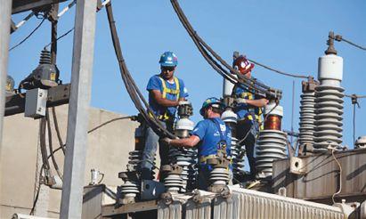
For example, when workers break cables free of the transformer, there is a risk of the workers falling off the transformer.
Even with proper personal protective equipment (PPE) and fall protection, the fall could result in a serious injury. Because of this, the risk to people involved is listed as critical
There is very little risk to the environment in this instance, so that risk would be negligible. Risk to the assets can be categorized as marginal.
The impact estimation ranking is reflective of the highest level of risk. So even though the risks to
14 | TRAINING TALK | A NETA WORLD JOURNAL SPECIAL PUBLICATION
Workers Freeing Cables from Transformer
Table 1: Risk Assessment Code Matrix
E = Extremely High Risk
H = High Risk M = Moderate Risk
L = Low Risk
environment and property did not exceed marginal, the risk to the people is critical; therefore, the impact estimation for the task is critical.
It is necessary to have a good understanding of the tasks performed and the area where they are being performed when considering the impact estimation.
PROBABILITY ESTIMATION
After determining the worst-case impact scenario, the next step is to determine how likely these scenarios are to occur. Jobsite conditions need to be evaluated at this point. The likelihood or probability estimation may consider:
■ History of incidents and events
■ Skills and knowledge of the workers assigned to the task (qualifications)
■ Human performance factors (stress, fatigue, mind-set, etc.)
■ Worksite conditions
■ Current practices and procedures
For example, if an unqualified person is working on a scissor or aerial lift, he/she is much more likely to make mistakes; this raises the probability of an incident to likely. If the unqualified person is replaced with someone who is experienced with aerial lifts and has undergone aerial lift training, the probability of incident will go down to occasional or seldom. Provide the experienced person with a spotter, and the probability of an incident occurring drops to unlikely. The task remains the same in these scenarios, but the conditions are what affect the probability estimation.
RISK LEVEL AND ACTION
When the risk severity and probability are determined, the findings are entered in the risk assessment code matrix (Table 1) to determine the risk potential associated with the work. The levels of risk potential and their meanings are as follows:
■ Extreme. Stop activities. Work cannot proceed until risk is reduced to a lower level.
■ High. Extensive risk controls/mitigation measures must be implemented to reduce the risk to a medium or low level.
■ Moderate. Risk controls/mitigation measures must be implemented to allow work to proceed. Efforts to reduce risk to a low level should be undertaken.
■ Low. Some risk controls/mitigation measures may be justified. Represents an acceptable level of risk.

When the risk severity and probability are determined, the ndings are entered in the risk assessment code matrix to determine the risk potential associated with the work.




A NETA WORLD JOURNAL SPECIAL PUBLICATION | TRAINING TALK | 15
Frequent Likely Occasional Seldom Unlikely S E V E R I T Y Catastrophic E E H H M Critical E H H M L Marginal H M M L L Negligible M L L L L
PROBABILITY
At this point, the purpose of the risk assessment is to take the information and find ways to manage the conditions of the work area to lower the risk potential to its lowest conceivable point.
In the example of workers breaking cables free of the transformer, we’ve determined the risk severity to be critical. Now, let’s look at the probability of something going wrong. As seen in the photo, the presence of multiple people on the transformer limits the amount of space each person can use. The presence of tools further limits mobility. These factors make the probability occasional because of the work conditions. Therefore, the risk potential would be high
At this point, it is necessary to implement safety procedures to alter the environment to lower the risk level. If we reduce the number of workers on the transformer and designate an area for tools, the risk probability drops to unlikely because we are managing the work space, allowing for better movement.
RISK REPORTING
When performing a risk assessment, the goal is to find ways to minimize the overall risk factor to a low or negligible risk level. In addition to a specific behavior associated with each individual risk level, a hierarchy of reporting relates to the severity of the risk:

■ Moderate. If risks cannot be reduced to low, then risks must typically be approved by a qualified crew leader (NETA Level III or IV).
■ High. High risks identified during operations should be approved by the host employer and the qualified crew leader.
■ Extreme. Extreme risks identified during operations must be communicated to the host employer and all affected employees. Work should only continue after developing a written mitigation plan, implementing satisfactory control measures, and selecting proper PPE.
Keep in mind that the risk assessment does not end after the morning job briefing. Assessments can change from day to day or even during the day. When changes occur, the risk assessment must be reviewed, and the activity hazard analysis must be updated.
CONCLUSION
Remember, a risk assessment is meant to bring attention to what could go wrong on a job site — not just the severity of the event, but also the likelihood of the worst-case scenario for:
■ The people
■ The environment
■ The property
Being aware of risk assessment practices can save lives on the jobsite, so it is important to consult your activity hazard analysis when assessing risk.
THOMAS D. SANDRI is a Senior Technical Instructor at Shermco Industries. He has been active in the field of electrical power and telecommunications for over 30 years. During his career, Tom has developed numerous training aids and training guides and has conducted seminars domestically and internationally. He supports a wide range of electrical and telecommunication maintenance application disciplines. He has been directly involved with and supported test and measurement equipment for over twenty years and is considered an industry expert in application disciplines including battery and dc systems testing and maintenance, mediumand high-voltage cable, ground testing, and partial discharge analysis. Tom earned a BSEE from Thomas Edison University.
16 | TRAINING TALK | A NETA WORLD JOURNAL SPECIAL PUBLICATION
AVO Training Institute: The One Stop for Electrical Safety
Training, Electrical Maintenance Training, and Electrical Technicial Certifications
Many AVO courses are eligible for NETA CTDs.*
If it’s electrical, AVO Training is focused on it. Electrical safety training, electrical maintenance training, and electrical consulting is not just a part of our offering, it’s our total focus. That’s why we offer more electrical safety and electrical maintenance training courses than any other training facility. With over 52 different courses, we offer the widest selection of courses available. To complement our training courses, we have a stand-alone Engineering Division that offers Arc Flash Studies, Risk Assessment Analysis, and a full menu of electrical engineering services.
Available Courses:
Protective Relay
• Protective Relay Maintenance - Basic
• Protective Relay Maintenance - Advanced
• Protective Relay Maintenance - Generation
• Protective Relay Maintenance - Solid State
• Microprocessor Based Relay Testing - Generation
• Microprocessor Based Relay Testing - Distribution/ Industrial
• Advanced Visual Testing Software
Circuit Breaker
• Circuit Breaker Maintenance, SF6
• Circuit Breaker Maintenance, Molded- and Insulated-Case
• Circuit Breaker Maintenance, Medium-Voltage
• Circuit Breaker Maintenance, Low-Voltage
Cable U
• Cable Splicing and Terminating, Medium-Voltage
• Cable Fault Location and Tracing, Medium-Voltage
• Cable Testing and Diagnostics, Medium-Voltage
Substation
• Battery Maintenance and Testing
• Transformer Maintenance and Testing
• Advanced Transformer Maintenance and Testing
• Substation Maintenance I
• Substation Maintenance II
• Power Factor Testing
Safety
• NFPA 70E 2015 Electrical Safety
• Electrical Safety for Utilities
• Electrical Safety for Mining
• Electrical Safety for Industrial Facilities
• Electrical Safety for Inspectors
• Electrical Safety for Overhead Contact Systems
• 2017 National Electrical Code
• OSHA Electrical Safety Related Work Practices
• Maritime Electrical Safety
Basics
• Basic Electricity
• Basic Electrical Troubleshooting
• Electronics Troubleshooting
• Electronics for Electricians
• Electrical Print Reading
• Grounding & Bonding
Engineering
• Short Circuit Analysis
• Protective Device Coordination Utilities
• Protective Device Coordination Industry
• Power Quality & Harmonics
Motors/Controls
• Programmable Logic Controllers
• Maintenance & Trouble Shooting
• Motor Maintenance and Testing
• Motor Controls and Starters, Low-Voltage
WWW.AVOTRAINING.COM • 877-594-3156 *NETA continuing technical development (CTDs) units are required of NETA Certified Technicians.
DIRECTORY OF TECHNICAL AND PROFESSIONAL TRAINING
Doble Engineering Company: Learn from the Industry’s Top Experts
Throughout the year, Doble hosts accredited technical trainings on a variety of topics to help engineers and technicians of all levels be more efficient, effective, and safe in the field. Learn from the industry’s top experts, receive real-world training that you can immediately apply, and build your professional network.
2018-2019 Course Listings
• Circuit Breaker Seminar
October 1-5, 2018 | Jackson, MS
Brush up on circuit breaker fundamentals, get practical hands-on training, and learn from the experts at the industry’s best circuit breaker educational seminar.
• Life of a Transformer Seminar
February 11-15, 2019 | Summerlin, NV
Practical training on all aspects of transformers, including sessions focused on transformer differential protection, transformer maintenance, and asset and maintenance strategies.
• Rotating Machinery & Electrical Plant Reliability
Tutorial
April 10-11, 2019 | Boston, MA
Learn everything you need to know to reliably maintain the electrical side of a generation or industrial plant.
• Laboratory Seminars
Offered throughout the year
Learn how to review data to assess transformer condition from instructors presenting theory and practical examples that illustrate common problems found in the field.
• Protection Training Courses
Offered throughout the year
Choose from a range of protection courses that will prepare you for testing a modern grid, power plant, and industrial facility.
• Free Webinar Series
Offered throughout the year
Join us for our free webinars. Each topic is discussed for approximately one hour. Doble experts cover testing techniques, safety, theory, and industry trends.
Save The Date
Companies with Doble Services Agreements can also join us for these client events:
• Doble Client Committee Meetings & Conference September 30-October 4, 2018 | Nashville, TN
• International Conference of Doble Clients April 7-12, 2019 | Boston, MA
Earn Credits
Many Doble training courses are eligible for NETA Continuing Technical Development Credits (CTDs) as well as IACET certified Continuing Education Units (CEUs). Visit: www.doble.com/earning-ceus
www.doble.com/training events@doble.com 617.926.4900 DIRECTORY OF TECHNICAL AND PROFESSIONAL TRAINING
Megger’s Testing Tactics Webinar Series 2018
Learn valuable testing tips and tricks from Megger application engineers and product managers. In this webinar series, our experienced staff will show you how to make your testing more efficient by sharing their lessons learned in the field. You will find answers to frequently asked questions, learn how to avoid the most common mistakes and accelerate your testing.
Upcoming Webinars
• Battery Impedance Test: Analysis and Trending
Sep 21 | Presenter: Volney Naranjo
• High-Voltage Dielectric Frequency Response for Bushing and Instrument Transformer Diagnosis
Oct 19 | Presenter: Diego Robalino
• Basics of Recloser Testing
Nov 16 | Presenter: David Beard
• Cable Testing 101: Introduction to VLF
Dec 14 | Presenter: Robert Probst
Previous Webinars
• Variable Frequency Power Factor Testing for Advanced Insulation Diagnosis
Aug 17 | Presenter: Jill Duplessis
• Understanding the Time Domain Reflectometer (TDR) Traces for Cable Fault Location
Jul 20 | Presenter: Jason Souchak
• Field Testing of Transformers for Winding Condition Assessment
Jun 15 | Presenter: Dinesh Chhajer
• Test Data Management for NERC Compliance Reporting
May 18 | Presenter: Mark Meyer
• Power Quality: A Detailed Understanding of Harmonics
Apr 20 | Presenter: Sanket Bolar
• Fault Location on Oil Filled Cables
Mar 16 | Presenter: Robert Probst
• Introduction to Sweep Frequency Response Analysis
Feb 16 | Presenter: Robert Foster
• Transformer Differential Protection: Challenges and Solutions
Jan 19 | Presenter: Mohit Sharma
How to Join Megger Webinar Series
• Megger Webinars are held on the 3rd Friday of every month
• Time: 10:00 AM Central Time
• Sessions are FREE
• Earn 1 NETA CTD and 1 PDH or 0.1 CEU
• us.megger.com/webinars
Webinar Registration: http://us.megger.com/webinars
Megger designs and manufactures portable electrical test equipment. Megger products help you install, improve efficiency, reduce cost, and extend the life of your or your customers’ electrical assets or your own. For more information, visit http://us.megger.com/.
DIRECTORY OF TECHNICAL AND PROFESSIONAL TRAINING
2018 – 2019 OMICRON Academy Courses
MICRON offers a wide variety of training courses in Houston, Texas; Waltham, Massachusetts; and Hamilton, Ontario, Canada. Courses include both classroom and hands-on instruction. For pricing, training location, and additional course information, visit www.omicronenergy.com/na-training or call 1-800-OMICRON.
Protection Testing
• Power System Protection Testing with the Test Universe
This course will focus on testing the most commonly used protection schemes in the transmission and distribution systems. Learn how to efficiently test overcurrent, distance, and transformer differential relays with the Test Universe. Other topics include manual testing, creation of automated test plans, element testing (pick-up and delay time of relay elements), and test of relay logics. Hands-on tests will be performed on electromechanical and digital relays.
• Recloser Control Testing with ARCO 400
Learn the theory of reclosers and their application in the distributions system. Learn how to test all kinds of recloser controls quickly and reliably with ARCO 400. Get familiar with the software guided workflow of ARCO Control and learn how to prepare test plans for standardized testing. Hands-on practice including meter checks, protective function operating characteristics, reclosing sequences, and restoration schemes.
• Introduction to Protection Testing
This course will focus on the basic skills needed by Protection and Control Technicians/Field Engineers to perform their jobs. Topics of the course include: technical math, fault types, CT/PT introduction, and basic relay concepts. Students will also learn the basic schemes associated with protection and control systems and techniques on how to test them.
Power Transformer Testing & Monitoring
• Electrical Diagnostic Testing of Power Transformers
Learn how to perform and assess many of the conventional electrical diagnostic tests recommended for power transformers, including power factor, exciting current, TTR, leakage reactance, and DC winding resistance. Other topics include DGA/Oil Screen, life expectancy, SFRA, DFR, bushings, LTCs, surge arresters, and demagnetization techniques. Hands-on measurements will be performed using the CPC 100, CP TD1, FRANEO 800, and TESTRANO 600 test instruments.
• Basics of Conducting Partial Discharge Measurements Using the MPD 600
Learn the basics of partial discharge measurement applications, including transformers, rotating machines, and cables. Additional topics include: operating the MPD 600 Partial Discharge detector and software; gating and noise mitigation; using 3PARD and 3FREQ PD separation techniques; and interpreting typical partial discharge patterns.
Circuit Breaker/Switchgear Testing
• Introduction to the CIBANO 500 and Testing Circuit Breakers
This course will focus on timing, travel, and contact resistance measurements of circuit breakers using the CIBANO 500, including test plan creation and test result analysis. Hands-on measurements including main contact timing, pole spread, dwell/dead timing, travel/stroke, contact wipe, minimum pick-up, and static/dynamic resistance with be performed on SF6 Dead Tank and Vacuum type circuit breakers.
Instrument Transformer Testing
• Current Transformer Testing and Analysis
This course will provide you with an understanding of the IEEE and IEC assessment standards that apply to Protection and Metering CTs. The CT Analyzer will be used in the assessment of accuracy and serviceability of various CT classes (C, K, T, and B) by hands-on measurements of ratio, burden, winding resistance, and knee-point excitation curves.
For dates and locations, please visit www.omicronenergy.com/na-training
DIRECTORY OF TECHNICAL AND PROFESSIONAL TRAINING
SDMyers: In Electrical System Maintenance and Management, Knowledge Means Power
Effective transformer management requires special skills acquired from years of hands-on experience. The diminishing number of experts is causing a growing need for specialized training to ensure these skills are not lost. SDMyers offers your team the opportunity to benefit from our 50 years of transformer maintenance expertise. We offer a variety of training options including enhanced e-learning courses; seminars; and onsite, online, and customized courses.
INTRODUCTORY
• Principles of Transformer Maintenance
Basics of transformers: electric concepts, solid and liquid insulation, oil testing and analysis, basic electrical testing, and maintenance.
• Principios de Mantenimiento de Transformadores
Este curso introduce al alumno en una serie de temas que resumen los fundamentos básicos de los transformadores y de mantenimiento del transformador.
• In-Service Inspection & Sampling of Fluid-Filled Transformers
Learn safe procedures needed to obtain a representative sample of dielectric fluid. Features a sampling demonstration and practical exercises to obtain accurate oil samples for use in lab analysis.
INTERMEDIATE
• Half-Century Transformer
Foundational understanding of transformers: operation, maintenance implementation, and related industry standards.
• Half-Century Transformer - Applied Maintenance
Foundational understanding of transformers: operation, maintenance implementation, and related industry standards. Includes lab and equipment tours, rewind facility tour, case studies, and expert panel discussion.
• Advanced DGA Diagnostics
Learn to identify fault gases and what causes their formation, evaluate the condition of cellulose insulation, examine the role DGA plays in new oil testing, and discuss obtaining samples from transformers.
• Load Tap Changer Principles & Maintenance
Load tap changing, styles of tap changers and their operation, and how to develop a preventative load tap changer (LTC) maintenance program.
• Electrical Testing - Power Factor Testing for Transformers, Bushings, and Breakers
The Power Factor is a measurement of the efficiency of the transformer’s insulation system and a reliable electrical test to detect deterioration.
• Transformer 360 Course is 3 days — take any or all. Day 1: Re-energized Half-Century course as part of a transformer reliability program. Day 2: Risk & Reliability and DGA. Day 3: LTC Testing & Maintenance and Electrical Testing.
ADVANCED
• Transformer Lifecycle Management
Manage the lifecycle of the transformer including specification and purchasing, transportation, assembly and start-up, field and shop repair, overall risk and asset management, and end-of-life options. Learn to develop and manage a reliability-based maintenance program.
• Advanced Transformer Maintenance and Planning
Reactive, predictive, and preventative maintenance of transformers, and building a cost-effective testing and maintenance plan to prolong the reliable life of transformers. Includes substation equipment, transformer design and construction, and how to make critical maintenance and planning decisions.
SD Myers courses are eligible for NETA CTDs.*
*NETA continuing technical development (CTDs) units are required of NETA Certified Technicians
DIRECTORY OF TECHNICAL AND PROFESSIONAL TRAINING
Register by phone: 330.630.7000 x.4018 Register online: sdmyers.com/training For class dates and locations, visit sdmyers.com/training/calendar 180 South Avenue, Tallmadge, Ohio 44278, USA
Shermco Industries: Your Electrical Safety Experts
Shermco is a leader in electrical power systems maintenance, repair, and testing, and for years, we have trained others in those skills. Offering onsite, classroom, and hands-on training, Shermco conducts a wide variety of courses covering Electrical Systems Maintenance, Electrical Safety, and Electrical Technical Skills. Some of the most influential leaders in electrical safety work at Shermco Industries, and now you have direct access to that experience and expertise! Shermco offers technical and electrical safety programs year-round and at multiple locations in the U.S. and Canada. NETA CTDs and CEUs through IEEE are available for most courses where applicable. Train with the experts. Train with Shermco.
Safety Training Course Schedule 2018/2019
• Understanding the NFPA 70E
Austin, TX
2019 4/5 • 8/12
Dallas, TX
2019 2/22 • 7/19
Cedar Rapids, IA
2018 11/2
2019 5/24 • 11/1
Houston, TX
2018 9/17
2019 3/22 • 9/20
St. Paul, MN
2018 9/17
2019 3/29 • 9/27
Tulsa, OK
2018 11/29
2019 7/19 • 11/22
• Electrical Safety for Qualified Electrical Workers
Austin, TX
2018 11/13
2019 2/12 • 5/14 • 8/13 • 11/12
Dallas, TX
2018 9/11 • 10/9 • 11/6 • 12/11
2019 1/8 • 2/5 • 3/5 • 4/2 • 5/7 •
6/4 • 7/8 • 8/6 • 9/10 • 10/8 • 11/5 • 12/10
Cedar Rapids, IA
2018 9/11 • 11/6
2019 2/12 • 6/11 • 10/1
Houston, TX
2018 9/11 • 11/6
2019 3/12 • 9/17 • 12/3
New Orleans, LA
2018 8/28 • 11/13
2019 3/26 • 6/18 • 8/27 • 11/12
St. Paul, MN
2018 8/21 • 12/11
2019 4/16 • 8/20 • 12/10
Tulsa, OK
2018 10/16
2019 1/22 • 4/9 • 7/16 • 10/15
Wilmington, CA
2018 9/25 • 10/9 • 12/3
2019 3/26 • 6/11 • 8/6 • 10/22
• Lab Session - Electrical Safety for Qualified Electrical Workers
Dallas, TX
2018 9/14 • 10/12 • 11/9 • 12/14
2019 1/11 • 2/8 • 3/8 • 4/5 • 5/10 • 6/7 • 7/12 • 8/9 • 9/13 •
10/11 • 11/8 • 12/13
Cedar Rapids, IA
2018 9/14 • 11/9
2019 2/15 • 6/14 • 10/4
Houston, TX
2018 9/17
2019 3/15 • 9/20 • 12/6
Wilmington, CA
2018 9/28 • 10/12 • 12/6
2019 3/29 • 6/14 • 8/9 • 10/25
• Electrical Safety Refresher
Austin, TX
2018 8/17
2019 2/15 • 8/16
Dallas, TX
2018 10/8
2019 2/4 • 6/3 • 10/7
Cedar Rapids, IA
2018 10/5
2019 2/18 • 6/17 • 10/7
Houston, TX
2018 9/21
2019 3/15 • 9/25
New Orleans, LA
2018 8/31
2019 3/29 • 8/30
St. Paul, MN
2019 4/19 • 8/23 • 12/13
Tulsa, OK
2019 4/12 • 10/18
• Low to Medium Circuit Breaker Maintenance and Testing
Dallas, TX
2018 10/1
2019 2/11 • 6/17 • 9/30
Cedar Rapids, IA
2018 10/22
Houston, TX
2018 10/1
Wilmington, CA
2018 11/12
2019 4/8 • 11/11
• Basic Electrical Fundamentals
Dallas, TX
2018 9/5
2019 1/8 • 5/14 • 9/17
Enroll today by visiting www.shermco.com/training or call 888-Shermco.
For more information, to download our current course catalog, or to register online, go to www.shermco.com/training or email traininginfo@shermco.com SHERMCO.COM • 888-SHERMCO

DIRECTORY OF TECHNICAL AND PROFESSIONAL TRAINING
CEUs available from







(be_this_guy!) (be_this_guy!) Train with the Experts. Train with Shermco. www.shermco.com 888-SHERMCO WHY Endanger yourself and others? INTELLIGENT TRANSFORMER MANAGEMENT® SDMyers.com | 800.444.9580 ext. 3485 180 South Avenue, Tallmadge, Ohio 44278, USA Increase Your Transformer IQ SDMyers Training Courses will increase transformer knowledge & earn NETA CTDs
COVER STORY
FEATURES
7 President’s Desk
Jim Cialdea, CE Power Engineered Services, LLC
NETA President
48 Continuous Monitoring Is on the Rise: Can You Adapt?
William Higinbotham, EA Technology LLC
56 Understanding the Past and Future of Fiber Optics in Utilities
Jim Hayes, Fiber Optic Association
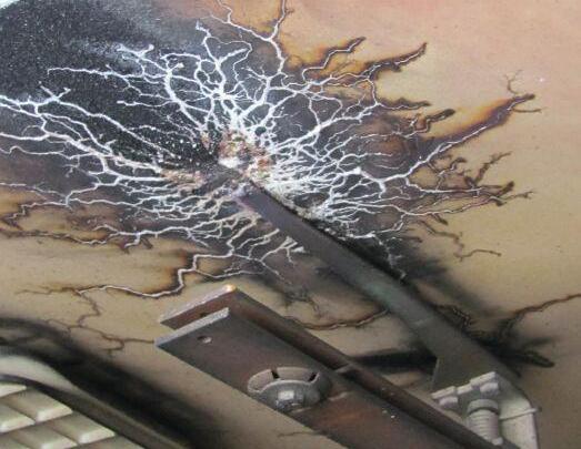
On-line partial discharge (PD) testing is an effective diagnostic approach to evaluate insulation condition in multiple power system assets. PD is the symptom of insulation aging/ degradation, and PD can also cause insulation deterioration. As a symptom of early-stage aging, PD further accelerates degradation until insulation breakdown occurs. PD testing can discriminate defect types, locate defect sites, and recognize defect severity. This article provides a brief overview of on-line PD testing technology, including the mechanism of using PD testing in the transmission and distribution (T&D) system, as well as expectations, challenges, and solutions to performing on-line T&D system diagnosis.
Jim Guo, PhD, Techimp US Corp., and Wen Shu, PhD, NEETRAC, Georgia Institute of Technology


TABLE OF CONTENTS TABLE OF CONTENTS NETAWorld • 3
34 56
10 NFPA 70E and NETA
Long-Sleeved Shirts and Electrical Equipment — What Should You Wear?
Ron Widup and Jim White, Shermco Industries
14 Tech Tips
Battery Grounds: A Hidden Danger
Jeff Jowett, Megger
20 Tech Quiz Emerging Technologies
Jim White, Shermco Industries
22 Safety Corner Hand Protection
Paul Chamberlain, American Electrical Testing Co., LLC
28 Relay Column
Using Numerical Relay Logic to Automatically Switch Capacitor Banks
Steve Turner, Electrical Consultants, Inc.
INDUSTRY TOPICS
64 NFPA 70B and CSA Z463 Standards: Where Does Airborne Ultrasound Fit In?
Adrian Messer, UE Systems, Inc.
70 Non-Conventional Instrument Transformer Designs for Air Insulated Substations
Steven A Kunsman, Nicholas Powers, and Bharadwaj Vasudevan, ABB Inc. USA
80 Splicing and Terminating…Defects
Don’t Hide
Scott Saniti, Shermco Industries
ADVANCEMENTS IN THE INDUSTRY
94 Medium-Voltage Vacuum Circuit Breaker Extension: A New Approach — Part 2 Finley Ledbetter and David Walterscheid, Group CBS, Inc.
ASTM Meeting Report Jim White, Shermco
NETA Activities Update
NETA Welcomes Newest Accredited Company — J.G. Electrical Testing Corporation
4 • FALL 2018 TABLE OF CONTENTS TABLE OF CONTENTS
ISSUE
IN EVERY
SPECIFICATIONS
STANDARDS 105 ANSI/NETA Standards Update 109
NETA NEWS 86
91
IMPORTANT
114 NETA Accredited Companies 122
List
AND
LISTS
Advertiser

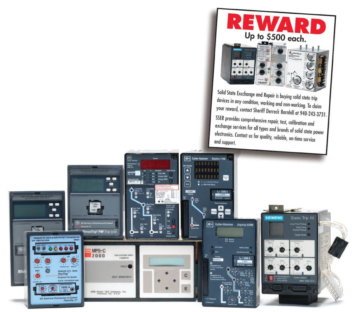
We Buy, Sell, Trade, Calibrate, Repair
Featuring quality, reliable, on-time service and support for all brands and types of solid state power electronics.
Power electronics are our business
Let us suppoort you with our quality repair, calibration and servicing of your solid state equipment. We also buy, sell and trade:
•Communications devices for power equipment
•Protective relays
•Circuit breaker trip devices
•Motor overload relays
•Rating plugs
4701 Spartan Drive • Denton, TX 76207 (877-874-7349) • Phone: 940-243-3731 • Fax: 940-387-8277 Email: info@solidstaterepair.com • Web: www.solidstaterepair.com
“SOLID STATE” INDUSTRIAL ELECTRONICS “SOLID STATE” INDUSTRIAL ELECTRONICS Toll Free 877-TRIP-FIX NOWRENTING TESTEQUIPMENT
Electrical Distribution System Testing, Repair, and Maintenance




3050 Old Centre Road, Suite 101
Portage, MI 49024
Toll free: 888.300.NETA (6382)
Phone: 269.488.NETA (6382)
Fax : 269.488.6383
neta@netaworld.org
www.netaworld.org
executive director: Missy Richard
NETA Officers
president: Jim Cialdea, CE Power Engineered Services, LLC
first vice president: Scott Blizard, American Electrical Testing Co., Inc.
second vice president: Lorne Gara, Orbis Engineering Field Services, Ltd.
secretary: Eric Beckman, National Field Services
treasurer: John White, Sigma Six Solutions
NETA Board of Directors
Ken Bassett (Potomac Testing, Inc.)
Eric Beckman (National Field Services)
Scott Blizard (American Electrical Testing Co., Inc.)
Jim Cialdea (CE Power Engineered Services, LLC)
Scott Dude (Dude Electrical Testing LLC)
Lorne Gara (Orbis Engineering Field Services, Ltd.)
Dan Hook (Western Electrical Services, Inc.)
David Huffman (Power Systems Testing)
Alan Peterson (Utility Service Corporation)
John White (Sigma Six Solutions)
Ron Widup (Shermco Industries)
NETA World Staff
technical editors: Roderic L. Hageman, Tim Cotter
assistant technical editors: Jim Cialdea, Dan Hook, Dave Huffman, Bob Sheppard
associate editor: Resa Pickel
managing editor: Carla Kalogeridis
copy editor: Beverly Sturtevant
advertising manager: Laura McDonald
design and production: Moon Design
NETA Committee Chairs
conference: Ron Widup; membership: Ken Bassett; promotions/marketing: Scott Blizard; safety: Scott Blizard and Jim White; technical: Alan Peterson; technical exam: Dan Hook; continuing technical development: David Huffman; training: Bob Sheppard; finance: John White; nominations: Alan Peterson; alliance program: Jim Cialdea; association development: Ken Bassett and John White
© Copyright 2018, NETA
NOTICE AND DISCLAIMER
NETA World is published quarterly by the InterNational Electrical Testing Association. Opinions, views and conclusions expressed in articles herein are those of the authors and not necessarily those of NETA. Publication herein does not constitute or imply endorsement of any opinion, product, or service by NETA, its directors, officers, members, employees or agents (herein “NETA”).
All technical data in this publication reflects the experience of individuals using specific tools, products, equipment and components under specific conditions and circumstances which may or may not be fully reported and over which NETA has neither exercised nor reserved control. Such data has not been independently tested or otherwise verified by NETA.
NETA MAKES NO ENDORSEMENT, REPRESENTATION OR WARRANTY AS TO ANY OPINION, PRODUCT OR SERVICE REFERENCED OR ADVERTISED IN THIS PUBLICATION. NETA EXPRESSLY DISCLAIMS ANY AND ALL LIABILITY TO ANY CONSUMER, PURCHASER OR ANY OTHER PERSON USING ANY PRODUCT OR SERVICE REFERENCED OR ADVERTISED HEREIN FOR ANY INJURIES OR DAMAGES OF ANY KIND WHATSOEVER, INCLUDING, BUT NOT LIMITED TO ANY CONSEQUENTIAL, PUNITIVE, SPECIAL, INCIDENTAL, DIRECT OR INDIRECT DAMAGES. NETA FURTHER DISCLAIMS ANY AND ALL WARRANTIES, EXPRESS OF IMPLIED, INCLUDING, BUT NOT LIMITED TO, ANY IMPLIED WARRANTY OF FITNESS FOR A PARTICULAR PURPOSE.
ELECTRICAL TESTING SHALL BE PERFORMED ONLY BY TRAINED ELECTRICAL PERSONNEL AND SHALL BE SUPERVISED BY NETA CERTIFIED TECHNICIANS/ LEVEL III OR IV OR BY NICET CERTIFIED TECHNICIANS IN ELECTRICAL TESTING TECHNOLOGY/LEVEL III OR IV. FAILURE TO ADHERE TO ADEQUATE TRAINING, SAFETY REQUIREMENTS, AND APPLICABLE PROCEDURES MAY RESULT IN LOSS OF PRODUCTION, CATASTROPHIC EQUIPMENT FAILURE, SERIOUS INJURY OR DEATH.
24 Hour Emergency Services (937) 439-9660










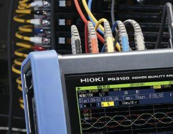





√ QUICK Setup
√ FREE PC Software
√ 200 kHz RMS sampling
√ CT’s powered by main unit
√ 8 hours of battery operation
√ AC/DC power measurements









Flicker

Demand Graphs

Harmonics Trend √ Rapid Voltage Change (RVC)
√ Remote control via Ethernet with FTP & Emails


6 Corporate Drive • Cranbury, NJ PHONE: 609.409-9109 • FAX: 609.409-9108 www.hiokiusa.com Over 80 Years of Meeting Your Needs! ISO9001 ISO14001 Achieve New Level of Power Analysis ...with Hioki’s New PQ3100 Visit our New & WebsiteImproved √
√
√
PQ3100 Power Quality Analyzer CAT III CAT IV Record and analyze data with a single instrument FIELD-PROVEN STRENGTH

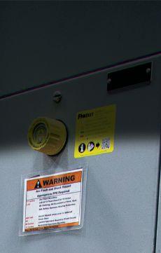



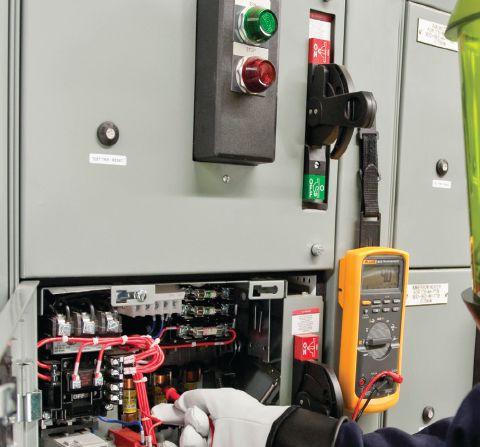
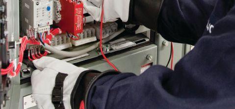

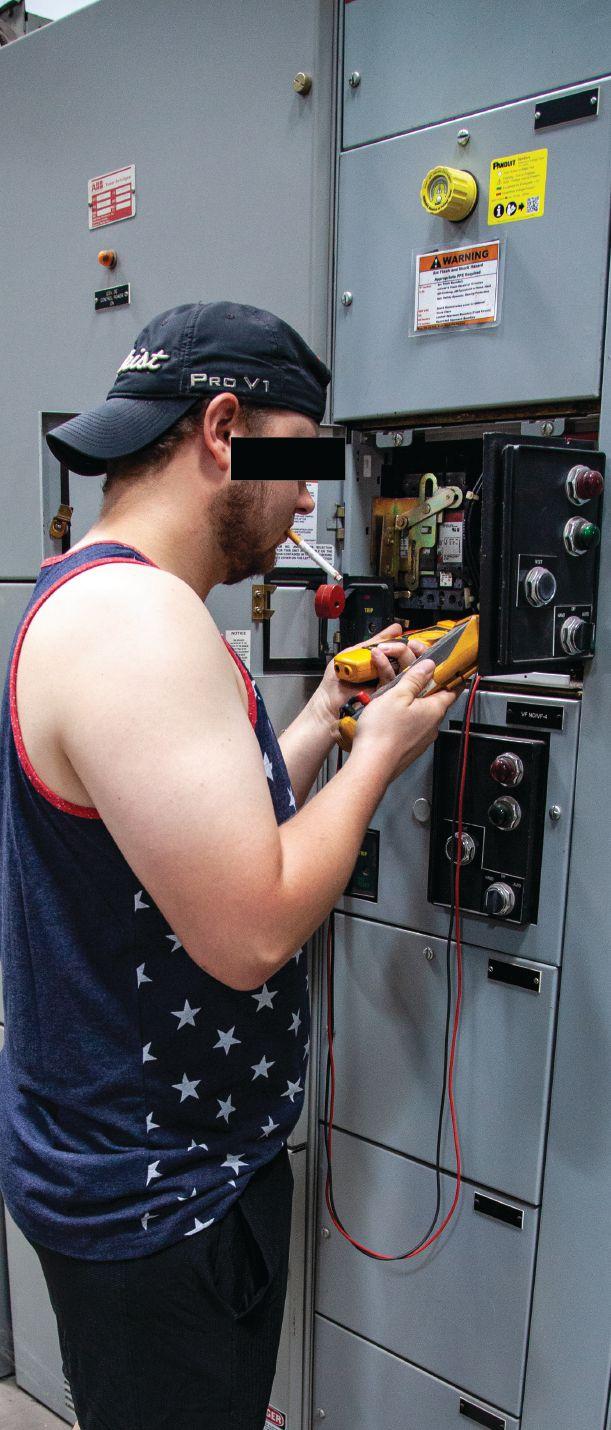


(be_this_guy!) (be_this_guy!) Train with the Experts. Train with Shermco. www.shermco.com 888-SHERMCO WHY Endanger yourself and others?
LONG-SLEEVED SHIRTS AND ELECTRICAL EQUIPMENT — WHAT SHOULD YOU WEAR?
BY RON WIDUP and JIM WHITE, Shermco Industries
Recently, a NETA member asked us when long-sleeved shirts are required while working on the job around energized electrical equipment…but the question was not about the wearing of arc-rated shirts and when they were needed. This question highlights a common misconception about arc-rated clothing and working around electrical equipment, and when the 70E committee did away with the HRC 0 class of PPE, a lot of people thought it also did away with non-arc-rated clothing. This is not the case.
The first place to look is 130.7(C)(9)(c):
• Underlayers. Meltable fibers such as acetate, nylon, polyester, polypropylene, and spandex shall not be permitted in fabric underlayers.
• Exception: An incidental amount of elastic used on nonmelting fabric underwear or socks shall be permitted.
The exception is in place so people’s pants don’t fall down when they’re working. We know from this section that whatever we wear cannot be meltable. The second part comes as part of the risk assessment. How much risk are we willing to handle? It’s good to remember that the 70E provides minimum requirements,
not best practices. We must meet or exceed those requirements. This question crops up often when companies require more than the minimum, so remember this: You can require more than the 70E minimum requirements, but you can’t require less than the minimum requirements.
That’s good information to know, but the original question was, “When are long-sleeve shirts required?” The answer comes down to this: It is part of the risk assessment process.
Long sleeves are not for shock protection, but for protection against burns associated with arc flash. That means voltage is not a big player — it is a part of an arc flash evaluation, but
10 • FALL 2018 LONG-SLEEVED SHIRTS AND ELECTRICAL EQUIPMENT — WHAT SHOULD YOU WEAR?
THE NFPA 70E AND NETA

not huge, like many people think. Ask yourself this: When are qualified people most at risk?
Answer: When they are inside the restricted approach boundary…because that’s when they are more exposed to live parts, which could create an arc flash. There is no restricted approach boundary if all parts are guarded or if the equipment has been placed into an electrically safe work condition. So if you guard the parts or turn it off, long-sleeves would not be needed.
When a qualified person is inside the restricted approach boundary, they are at increased risk of being subjected to electrical arc flash, and accordingly, they may need more protection. Non-flammable and non-meltable underlayers can provide additional arc flash protection, but do not increase the arc rating, as detailed in 130.7()(9)(a) of 70E. So cotton underwear, which is flammable, can be worn, but not polyester, which is meltable.
(a) Layering. Nonmelting, flammable fiber garments shall be permitted to be used as underlayers in conjunction with arcrated garments in a layered system. If nonmelting, flammable fiber garments are used as underlayers, the system arc rating shall be sufficient to prevent breakopen of the innermost arc-rated layer at the expected arc exposure
incident energy level to prevent ignition of flammable underlayers. Garments that are not arc rated shall not be permitted to be used to increase the arc rating of a garment or of a clothing system.
There is another place to look within130.7(C) (7)(b), although it is not as pertinent:
(b) Arc Flash Protection. Hand and arm protection shall be worn where there is possible exposure to arc flash burn. The apparel described in 130.7(C)(10)(d) shall be required for protection of hands from burns. Arm protection shall be accomplished by the apparel described in 130.7(C)(6).
So, 70E requirements provide guidance on protection from an arc flash burn, but does not try to protect us from all arc flash heat. That gives employees and employers a little flexibility. The last thing anyone wants is to have a third party dictate every single thing we do. A little flexibility will help safety, not hinder it.
Going back to the original question of whether you should wear long-sleeved and arcrated shirts when working around electrical equipment, if you want to protect the worker and be most prepared for ever-changing field conditions….the answer is, “Yes.”
NETAWorld • 11 LONG-SLEEVED SHIRTS AND ELECTRICAL EQUIPMENT — WHAT SHOULD YOU WEAR?
THE NFPA 70E AND NETA
THE NFPA 70E AND NETA
Ron Widup and Jim White are NETA’s representatives to NFPA Technical Committee 70E, Electrical Safety Requirements for Employee Workplaces. Both gentlemen are employed by Shermco Industries in Dallas, Texas, a NETA Accredited Company.

Ron Widup is CEO of Shermco Industries and has been with the company since 1983. He is a member of the Technical Committee on NFPA 70E, Standard for Electrical Safety in the Workplace; a Principal Member of the National Electrical Code (NFPA 70) Code Panel 11; a Principal Member of the Technical Committee on NFPA 790, Standard for Competency of Third-Party Evaluation Bodies; and a Principal Member of the Technical Committee on NFPA 791, Recommended Practice and Procedures for Unlabeled Electrical Equipment Evaluation. Ron is also a member of the Technical Committee on NFPA 70B, Recommended Practice for Electrical Equipment Maintenance, and a member of the NETA Board of Directors and Standards Review Council. He is Vice Chair for IEEE Std. 3007.3, Recommended Practice for Electrical Safety in Industrial and Commercial Power Systems. Ron is a Journeyman Electrician in Texas, a NETA Level 4 Senior Technician, and an NFPA Certified Electrical Safety Compliance Professional.

James (Jim) R. White, Vice President of Training Services, has worked for Shermco Industries since 2001. He is a NFPA Certified Electrical Safety Compliance Professional and a NETA Level 4 Senior Technician. Jim is NETA’s principle member on NFPA Technical Committee NFPA 70E®, Standard for Electrical Safety in the Workplace; NETA’s principle representative on National Electrical Code® Code-Making Panel (CMP) 13; and represents NETA on ASTM International Technical Committee F18, Electrical Protective Equipment for Workers. Jim is Shermco Industries’ principal member on NFPA Technical Committee for NFPA 70B, Recommended Practice for Electrical Equipment Maintenance and represents AWEA on the ANSI/ ISEA Standard 203, Secondary Single-Use Flame Resistant Protective Clothing for Use Over Primary Flame Resistant Protective Clothing. An IEEE Senior Member, Jim was Chairman of the IEEE Electrical Safety Workshop in 2008 and is currently Vice Chair for the IEEE IAS/PCIC Safety Subcommittee.

• Acceptance Testing
• Planned Electrical Testing and Preventive Maintenance Programs
• Power Factor Testing
• Cable Testing
• Relay & Meter Calibration
• Ground Resistance Testing
• Transformer Oil Analysis, Vacuum Degassing and Repair
• Circuit Breaker Retrofit and Repair
• Power Generation Systems Testing
• Load and Power Quality Recording/Analysis
Chiller Systems Testing
Infrared Inspections


Independent Electrical Testing and Preventive Maintenance PROFESSIONAL SERVICES
609-890-8300 www.easternhighvoltage.com 11-A S. Gold Drive • Robbinsville, NJ 08691
•
•

BATTERY GROUNDS: A HIDDEN DANGER








 BY JEFF JOWETT, Megger








The term “ground” is used — and sometimes misused — in various contexts throughout the electrical industry. Its most fundamental use is in reference to a grounding electrode, a buried metal structure that protects the electrical system by establishing a parallel path for unwanted currents. But ground is also commonly used to refer to a short-to-ground or earth, i.e., a path to ground established inadvertently or extraneously, often by some flaw or fault. This generally represents a reduction in performance or even a danger. Among these is the battery ground, which can develop on standby protective battery banks.
Unwanted earth grounds can occur through equipment wear, deterioration of or damage to insulation, miswiring, and various other sources. If the system is a grounded system, then grounds are often quickly and harmlessly detected through tripping of protective devices or malfunction of equipment and can be corrected in time. But a particularly insidious type of spontaneous ground occurs in battery rooms, where isolated standby battery banks can wait for months and years to be suddenly called on line in the event of a power outage
14 • FALL 2018 BATTERY GROUNDS: A HIDDEN DANGER
TECH TIPS
or other emergency. These battery banks bridge an enormous gap between virtually seamless continued electrical operation and a prolonged outage.
Standby battery systems are generally designed to float without an earth connection. A control panel issues an alarm if a fault is detected. These alarms may have a high-resistance ground for safety purposes. It can be disconnected during ground fault tracing to eliminate this competing ground path from the measurement. Ground faults are common and develop as a result of spilled electrolytes, dirt, and moisture accumulating down the sides of batteries and eventually completing an unwanted path to ground. Failing cable insulation due to water ingress is another common cause of battery ground faults. A short circuit is formed across the battery, and the system may fail prematurely and not operate when needed. These battery systems are often quite large, especially in power stations and substations. Knowing that a fault exists and locating it are two different propositions, and the latter can be difficult.
Maintenance begins with checking for any existing ground faults. If there is no ground fault monitor, this can still be easily accomplished with a digital multi-meter (DMM). Measure the voltage from the positive terminal to earth and then from the negative terminal to earth. They should measure the same. When this measurement is made, one will be positive and the other negative. In a system with no ground fault, the difference of potential from one side to the other will be equal. If they are not equal, this indicates a ground fault on the side with the lower voltage. Another indicator is float current. A quickly rising float current can be a sign of either a short circuit or a ground fault, so long as the batteries are not charging at the moment.
If a ground fault is indicated, then what? The next step is to locate and correct the fault. Sectionalizing the system by opening the breakers is an obvious answer and was the
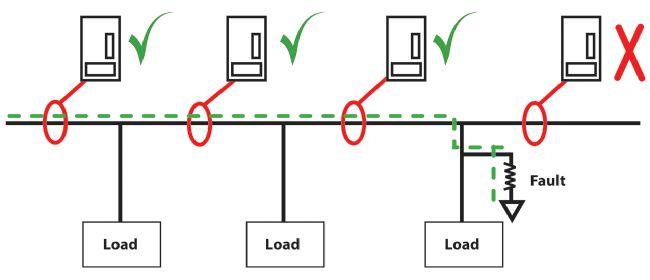
original method. But, it is inconvenient and requires the system to go off line. A battery ground fault locator is a better choice. This technology enables rapid and efficient location of faults, saving considerable time over trialand-error methods. With this instrumentation, a transmitter injects a low-frequency trace current through the battery string, and a handheld receiver traces the path (Figure 1).
Typical frequencies are around 20 – 25 Hz, providing a clear trace signal below the normal noise level generated by the ac-to-dc conversion of the battery string charger. Fault tracing can thereby be accomplished not just on off-line systems, but also on live systems with typical values of 20 amps dc current and 0.5 amps of ac ripple.
Signal frequency is critical to successful operation. Low-frequency square waves around 5 Hz allow testing without disconnecting system elements, but can cause nuisance tripping of protective relays. Going to the other extreme and tracing with high frequencies — for example, in the 5 kHz range — avoids one problem while introducing another. These systems can have long cable runs. Cables have a capacitive property. This presents low impedance, and therefore, may appear as a phantom ground fault, seriously obscuring detection of the real faults. The perfect compromise is to employ an ac test signal in the range of 20 – 30 Hz, high enough to avoid interaction with protective relays while minimizing the effect of capacitance.
NETAWorld • 15 BATTERY GROUNDS: A HIDDEN DANGER
TECH TIPS
Figure 1: Tracing-01 A ground fault diverts current from its prescribed path.



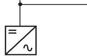


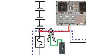
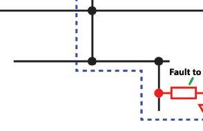
Ground fault locators are typically two-piece instruments. Once the transmitter has applied the test current at the proper frequency through the battery string, a handheld probe traces the signal (Figure 2).
This probe is essentially a clamp-on ammeter tuned to look for the applied test frequency


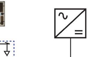
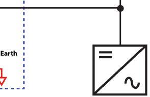
only. The transmitter will either directly measure or indirectly tune out the capacitive leakage in the system to identify phantom faults. The transmitter displays the resistance of all parallel circuits to ground from the point where it is clamped. Th e tuning function provides additional discrimination against phantom faults.
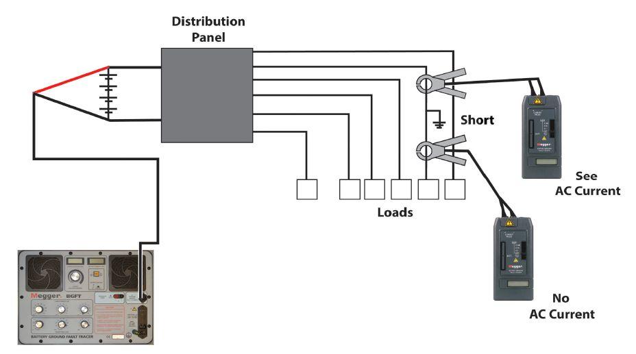
16 • FALL 2018
BATTERY GROUNDS: A HIDDEN DANGER TECH TIPS
Figure 2: Battery Ground Fault Tracer — Current Follows Path to Ground
Figure 3: Fundamental Schematic of Battery Ground Locator


The signal transmitter is connected between earth and either the positive or negative pole of the battery string. The correct pole to connect is the one with the ground fault, which should have been identified by the DMM procedure previously described. The probe then tracks the signal from the source, always following the circuit branches that show the lowest resistance (highest current flow). If the signal is injected at the battery terminal and the clamp-on CT connected to the outgoing lead, the battery ground locator (BGL) will measure the total ground resistance of the system (Figure 3).






If the CT is clamped on a feeder, the instrument will measure ground resistance on that feeder. Faults can be easily traced, regardless of the complexity of the system, because the tracer is merely following the strength of the ac signal. If, for instance, the total resistance of the string is shown to be 10 kΩ (a comparatively low value), then by testing each individual circuit, the faulted one will be revealed by a 10 kΩ reading. Similarly, multiple faults can be tracked. If total resistance was 1 kΩ but an individual branch measures 10 kΩ, the imbalance indicates the presence of a second fault. Applied systematically, the procedure reliably leads to the fault. It can be performed on in-service and isolated batteries.
Sounds easy — and fundamentally, it is — especially when compared to the pioneer method of sectionalizing. But there are still potential pitfalls, including systems with long cable runs, which can present high capacitance paths. This creates phantom faults that the fault current will follow. Having the ability to determine which current paths are due to capacitive phantom faults and which are due to real ground faults is crucial.
Another problem is the presence of highresistance faults that can develop on cables supporting the load (Figure 4). These are faults caused by the ingress of water. They can harbor faults with resistances approaching 400 kΩ, whereas common dirt and electrolyte faults tend to be under 100 kΩ. The transmitter


requires enough power to push current through these faults to locate them. The solution to these potential problems is a tester with a built-in Wheatstone bridge adjusted to tune out capacitance and a higher-voltage option to draw enough current to meet the instrument’s measurement parameters.
Typical test values are 50 V for location of high-resistance faults and 15 V for routine testing. However, care must be taken because the more current used, the more heat is generated. This can prematurely dry out the fault before it is located. It is always best to use the minimum amount of current that achieves stable measurement.
Any electrical maintenance program can gain value by conformance to established industry standards backed up by recognized nonprofit organizations, and this applies to battery fault maintenance. For nickel-cadmium (Ni-Cd) batteries, the standard is IEEE 1106. For valveregulated lead acid (VRLA) batteries, it is IEEE 1188. And for vented lead acid or flooded (VLA) batteries, the standard is IEEE 450. All are in agreement with North American Electric Reliability Council (NERC) regulations.
For Ni-Cds, check batteries for ground faults quarterly, with every four months a
NETAWorld • 17 BATTERY GROUNDS: A HIDDEN DANGER
Figure 4: Phantom faults from cable capacitance can be tuned out.


minimum requirement. Monthly checks are recommended for VRLA and VLA, with quarterly again the bare minimum. Tracing and removing battery ground faults is now a NERC requirement for substations. With the introduction of BGL technology, a recent development in electrical instrumentation, most utilities have banned the previous practice of sectionalizing, as it is wasteful of time and precision and poses the added risk of taking the battery systems off line.


performance have once again been significantly enhanced. Battery ground fault tracing allows backup battery systems to be kept ready to go on line, yet without the man hours and risks that accompanied earlier procedures.


CONCLUSION
By the development of a specifically dedicated technology, electrical safety, maintenance, and
Jeffrey R. Jowett is a Senior Applications Engineer for Megger in Valley Forge, Pennsylvania, serving the manufacturing lines of Biddle, Megger, and MultiAmp for electrical test and measurement instrumentation. He holds a BS in biology and chemistry from Ursinus College. He was employed for 22 years with James G. Biddle Co., which became Biddle Instruments and is now Megger.
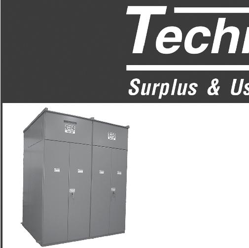



TECH TIPS




James (Jim) R. White, Vice President of Training Services, has worked for Shermco Industries Inc. since 2001. He is a NFPA Certified Electrical Safety Compliance Professional and a NETA Level 4 Senior Technician. Jim is NETA’s principle member on NFPA Technical Committee NFPA 70E®, Standard for Electrical Safety in the Workplace®, NETA’s principle representative on National Electrical Code® Code-Making Panel (CMP) 13, and represents NETA on ASTM International Technical Committee F18, Electrical Protective Equipment for Workers Jim is Shermco Industries’ principal member on NFPA Technical Committee for NFPA 70B, Recommended Practice for Electrical Equipment Maintenance and represents AWEA on the ANSI/ISEA Standard 203 Secondary Single-Use Flame Resistant Protective Clothing for Use Over Primary Flame Resistant Protective Clothing. An IEEE Senior Member, Jim received the IEEE/IAS/PCIC Electrical Safety Excellence Award in 2011 and NETA’s Outstanding Achievement Award in 2013. Jim was Chairman of the IEEE Electrical Safety Workshop in 2008 and is currently Vice-Chair for the IEEE IAS/ PCIC Safety Subcommittee.


EMERGING TECHNOLOGIES
BY JIM WHITE, Shermco Industries


Sometimes, to understand the future, you must have knowledge of the past. In this Tech Quiz, all the answers are available on the internet — if you know where to look. This one is supposed to be a little fun and educational at the same time.
1. Who invented the first insulation resistance test set?
a. Megger
b. Sydney Evershed
c. Thomas Edison
d. Jerry Jodice
e. Nicola Tesla
2. Who invented the first digital relay test set?
a. Megger
b. George Westinghouse
c. Thomas Edison
d. Jerry Jodice
e. Nicola Tesla
3. Who invented the transformer?
a. Megger
b. George Westinghouse
c. Thomas Edison
d. Jerry Jodice
e. Nicola Tesla

4. Who invented the incandescent light bulb?
a. Humphry Davy
b. George Westinghouse
c. Thomas Edison
d. Jerry Jodice
e. Nicola Tesla
See answers on page 112.
20 • FALL 2018 TECH QUIZ
TECH QUIZ
No. 123


The Power of Positive Results


AET Brings Precision and Value to Electrical Testing, Commissioning and Engineering… and Positive Results to Our Customers.
AET delivers the best value in the marketplace by offering the highest quality service at competitive prices. With a workforce and offices located throughout the country, AET is an industry leader and one of the largest independent electrical testing companies in the U.S.
To learn more about AET’s full range of testing and engineering services, visit www.aetco.us
• 800.992.3826

WWW.AETCO.US
An Company A Subsidiary of


HAND PROTECTION


 BY PAUL CHAMBERLAIN, American Electrical Testing Co., LLC


Hand injuries are the most common injury in the workplace. Whether the source of the hazard comes from spinning blades, pinches between two materials, heat, chemicals, or electricity, working hands are under constant attack. Therefore, hands require a high level of protection in the electrical testing work environment. This article identifies some common hazards and risks to a worker’s hands and the means to mitigate injury and promote safety.
CHEMICALS
Many commonly used workplace chemicals can cause chronic illness by absorption through the skin and may go undetected by the worker; therefore, direct contact must be avoided. Other chemicals can cause painful and debilitating burns on the skin that may take a long time to heal. Burns and dermal absorption can potentially result in serious, if not fatal,
injuries. Employers and employees must ensure the proper use of gloves specific to the chemical in use.
Many materials are available for glove construction; some are better suited than others for resistance to breakthrough or permeation. Figure 1 shows the resistance to certain families of chemicals for a Nitrile line of gloves manufactured by North.
22 • FALL 2018 HAND PROTECTION
SAFETY CORNER

= Degradation
= Breakthrough
= Permeation Rate
The breakthrough time (BT) shown in Figure 1 is determined using an ASTM standardized test for the elapsed time between initial contact of the chemical on one side of the glove material and the analytical detection of the chemical on the other side of the glove material. If there is no breakthrough, this test is marked as N/D (for none detected) or I/D (for insufficient data). These times generally reflect how long a glove can provide resistance when totally submerged in the chemical.
The permeability of the material, or permeation rate (PR), measures how long it takes for a chemical to pass through the glove on a molecular level. Glove thickness can affect the material’s permeability. There is an ASTM test for permeation rate, and a
glove manufacturer must disclose the permeability rate of the glove on its fact sheet.
Figure 1 also indicates the rate of degradation (D), which is defined by North as “a deleterious change in one or more of the glove’s physical properties.” The most obvious forms of degradation are loss of the glove’s strength and excessive swelling. Always refer to the manufacturer’s fact sheet when determining the correct glove for handling a chemical.
LACERATION/ABRASION/ CRUSHING
Cutting a finger while removing insulation, scraping a hand on a sharp panel door edge,
NETAWORLD • 23 Butyl Nitrile Natural Rubber Silver Shield Chemical Name CAS No. D BT PR Viton Chemsoft D BT PR D BT PR D BT PR D BT PR D PR D
BT
PR
Good for total immersion Good for accidental splash protection and intermittent contact Only use with extreme caution. Glove will fail with only short exposure E = Excellent G = Good F = Fair P = Poor N/D = None Detected I/D = Insufficient Data BT p-Dioxane 123-91-1 I/D I/D I/D P 23 min 26.8 E >20 hrs N/D I/D I/D I/D P 28 min 77.1 I/D I/D I/D Perchloric Acid (70%) 7601-90-3 I/D I/D I/D I/D I/D I/D I/D I/D I/D E >8 hrs N/D E >8 hrs N/D I/D I/D I/D Perchloroethylene 127-18-4 E >8 hrs N/D E >17 hrs N/D P I/D I/D F 1 hr 3.8 F 1.3 hrs 5.5 I/D I/D I/D Perchloromethane 56-23-5 E >8 hrs N/D E >13 hrs N/D I/D I/D I/D F 1.3 hrs 3.45 F 3.4 hrs 5 I/D I/D I/D Phenol (85% in water) 108-95-2 E >8 hrs N/D E >15 hrs N/D E >20 hrs N/D I/D I/D I/D P 39 min >1500 F 2.2 hrs 4.64 Phenylamine 62-53-3 E >8 hrs N/D P 6 min 18.7 E >8 hrs N/D I/D I/D I/D F 1.1 hrs 45 I/D I/D I/D Phosphoric
7664-38-2 I/D I/D I/D I/D I/D I/D I/D I/D I/D E >8 hrs N/D E >8 hrs N/D E >8 hrs N/D Pimelic Ketone 108-94-1 E >8 hrs N/D P 29 min 86.3 E >16 hrs N/D I/D I/D I/D I/D I/D I/D F 2.1 hrs 0.07 2-Propanone 67-64-1 E >8 hrs N/D P 2 min 383 E >8 hrs N/D P 1 min 42.3 P 3 min 291 P 10 min 12.2 Propyl Acetate 109-60-4 E >8 hrs N/D P I/D I/D G 2.7 hrs 2.86 I/D I/D I/D P 17 min 72.5 I/D I/D I/D Propyl Alcohol 71-23-8 I/D I/D I/D I/D I/D I/D I/D I/D I/D G 3.8 hrs 0.35 E 4.4 hrs 1.1 I/D I/D I/D Propylene Oxide 75-56-9 I/D I/D I/D P 1 min 1790 F 2.2 hrs 7 I/D I/D I/D P <6 min >3.9 I/D I/D I/D p-ter t-Butyltoluene 98-51-1 E >8 hrs N/D E >8 hrs N/D F 1.78 hrs 8 I/D I/D I/D P I/D I/D I/D I/D I/D Pyridine 110-86-1 I/D I/D I/D P 38 min 74 E >8 hrs N/D I/D I/D I/D P I/D I/D I/D I/D I/D Sodium Hydroxide 50% 1310-73-2 E >8 hrs N/D E >8 hrs N/D E >8 hrs N/D E >8 hrs N/D E >8 hrs N/D E >8 hrs N/D Stoddard Solvent 8052-41-3 E >8 hrs N/D I/D I/D I/D I/D I/D I/D E >8 hrs N/D E >6 hrs N/D I/D I/D I/D Styrene 100-42-5 E >6 hrs N/D E >6 hrs N/D F 35 Mins 0.19 P 16 min 39 P 11 min >3.35 I/D I/D I/D Sulfuric Acid (50%) 7664-93-9 E >6 hrs N/D E I/D I/D E I/D I/D G >8 hrs N/D G >6 hrs N/D G >6 hrs N/D Sulfuric Acid (93%) 7664-93-9 E >8 hrs N/D E >8 hrs N/D E >8 hrs N/D P 2 min N/D F 1.9 hrs 11.4 G 5.1 hrs N/D Tetrachloroethylene 127-18-4 E >8 hrs N/D E >17 hrs N/D P I/D I/D F 1 hr 3.8 F 1.3 hrs 5.5 I/D I/D I/D Tetrachloromethane 56-23-5 E >8 hrs N/D E >13 hrs N/D I/D I/D I/D F 1.3 hrs 3.45 F 3.4 hrs 5 I/D I/D I/D Tetrahydrofuran 109-99-9 E >8 hrs N/D P 0 min 327 F 27 min 112 P I/D I/D P 0 min 167 P 5 min 360 Thioglycolic Acid 68-11-1 I/D I/D I/D E >8 hrs N/D E >8 hrs N/D I/D I/D I/D I/D I/D I/D I/D I/D I/D Toluene 108-88-3 E >8 hrs N/D E >16 hrs N/D P 6 min 511 P I/D I/D P 11 min 68.1 P 3 min 82.2 Toluene Diisocyanate 584-84-9 E >8 hrs N/D I/D I/D I/D E I/D I/D F 1 hr 2.52 G I/D I/D I/D I/D I/D 1,1,1-Trichloroethane 71-55-6 E >8 hrs N/D E >15 hrs N/D P I/D I/D I/D I/D I/D F 37 min 76.4 I/D I/D I/D Trichloroethylene 79-01-6 E >8 hrs N/D E 7.4 hrs 0.24 P 14 min 550 I/D I/D I/D P 4 min 283 P <5 min 894 Trichloromethane 67-66-3 E >8 hrs N/D E 9.5 hrs 0.46 I/D I/D I/D I/D I/D I/D P 4 min 352 I/D I/D I/D Triethanolamine 102-71-6 I/D I/D I/D I/D I/D I/D E >8 hrs N/D E >8 hrs N/D I/D I/D I/D E >8 hrs N/D Triethylamine 121-44-8 I/D I/D I/D E >8 hrs N/D P I/D I/D E 5.8 hrs 0.18 E >8 hrs N/D I/D I/D I/D
141-78-6 E >8 hrs N/D P I/D I/D E 7.6 hrs 3.4 I/D I/D I/D P 8 min 145 I/D I/D I/D Vinylstyrene 1321-74-0 E >8 hrs N/D E >17 hrs N/D F 2.2 hrs 238 I/D I/D I/D P I/D I/D I/D I/D I/D Xylene 1330-20-7 E >8 hrs N/D E >8 hrs N/D P I/D I/D P I/D I/D P 21 min 18.5 I/D I/D I/D HAND PROTECTION
Time
Acid (85%)
Vinegar Naphtha
SAFETY CORNER
Figure 1: Resistance to Chemicals (SOURCE: NORTH)
SAFETY CORNER


or slamming a finger with a tool can be hard to avoid. Human beings are fallible; however, we can minimize the impact of these injuries by a means of protection like leather, cotton, or rubberized gloves. Leather gloves are usually the preferred means of protection from all of these injuries; they are relatively inexpensive and easily replaced when worn out. In circumstances with a high likelihood of laceration or puncture, Kevlar® or metal gloves may be necessary.
A good rule of thumb: If a tool is necessary as part of the job, it is likely that gloves are also needed. A job hazard analysis — along with good, old-fashioned, common sense — will help determine if an employee could be lacerated, crushed, or otherwise injured performing a task. Much like other forms of personal protective equipment, gloves must be inspected for wear and tear and replaced as necessary.
Different work methods and alternative, safer tool use can also go a long way toward reduction of preventable hand injuries. Instead of using a knife to strip insulation, use a wirestripping tool, and use safety knives to open letters and boxes instead of a razor blade or scissors. Ensuring that tools like rotating carpenter’s saws or right-angle grinders have adequate guarding installed will also reduce injury potential. Managers and supervisors should inspect workers’ tools regularly to ensure that the guarding has not been removed or compromised. Removing the guard may aid in getting a job done quicker or easier, but it could cost a finger or worse.
ERGONOMICS/REPETITIVE MOTION
Carpal tunnel syndrome is one of the most common hand injuries in the United States. It is even harder to prevent when activites outside of the workplace contribute to these
injuries. Carpal tunnel syndrome is not an occupational hazard exclusive to those who type all day on a computer. It is also a hazard to anyone who performs repetitive hand motions, mechanical gripping, and small-part assembly, or those who encounter vibration in fields such as mechanics, factory work, or an electrical trade. Other common types of repetitive motion injuries are tendonitis and bursitis, which are injuries to tendons and bursae, respectively.
Education is the best method of prevention for repetitive motion injuries. To avoid these injuries, perform frequent range-of-motion exercises to warm up and alleviate injury. Many tools are available to promote proper ergonomics and posture, including a wavestyle keyboard or a track-ball mouse. Hand tools such as right-angle power drills and t-handle drivers help prevent hand and wrist strain by supporting proper hand positioning. Padded palms and fi ngers can help prevent repetitive motion injury while using vibrating tools such as a hammer drill or jig saw or while using impact tools such as a hammer.
Additionally, for every hour sitting and/ or working on a keyboard, take a minute or two to get up and move around and stretch. Several manufacturers of ergonomic mice and keyboards have companion software to remind the worker to stretch and even show the worker the most effective stretching exercises.
ELECTRICAL SHOCK
Electrical shock injuries to the hands are common in the electrical testing industry. The best prevention is to wear the correct voltagerated gloves. The gloves must be tested using an ASTM standard to ensure they can properly protect the worker (Figure 2). The cuff length must also be adequate to protect the forearm from electric arc. Gloves must be retested regularly to the ASTM specification.
24 • FALL 2018
HAND PROTECTION
Protective Rubber Equipment Labeling Chart
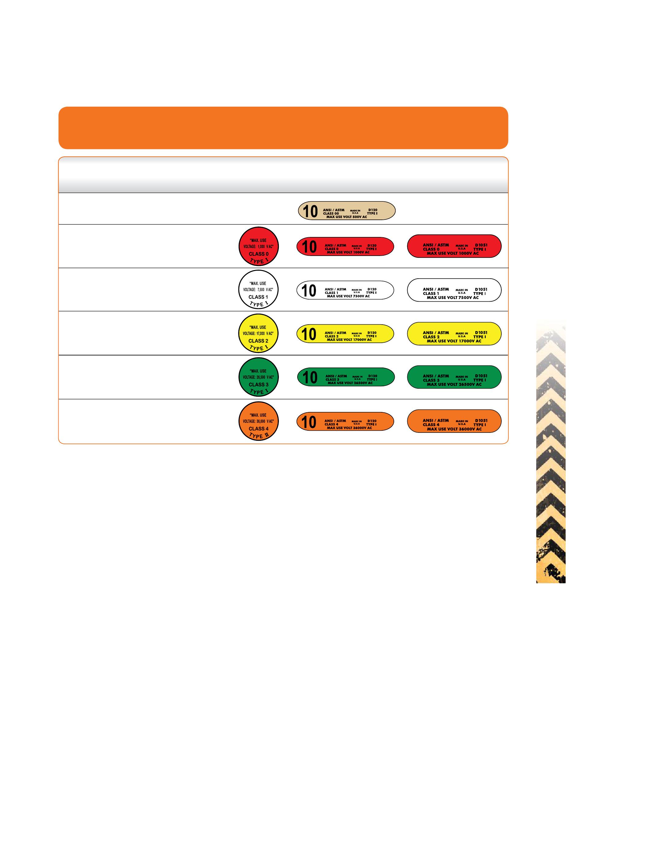
Two OSHA standards indicate the appropriate test intervals:
• OSHA 1910.137, Personal Protective Equipment — Electrical Protective Devices. This regulation states that gloves must be electrically tested before first issue and every six months thereafter. OSHA regulation 1910.137(c)(2)(xii) states that the employer shall certify that equipment has been tested in accordance with the requirements of paragraphs (c)(2)(iv), (c)(2)(vii)(D), (c)(2) (viii), (c)(2)(ix), and (c)(2)(xi) of this same section. The certification shall identify the equipment that passed the test and the date it was tested. Individual marking of the glove (i.e., equipment identification numbers) and entering the results of the tests and the dates of testing onto a tracking log is an accepted means of meeting this regulatory requirement.
• OSHA 1910.268, Special Industries — Telecommunications. This regulation states that natural rubber insulating gloves must be electrically tested before first issue, 12 months after first issue, and every 9 months thereafter. Any unissued glove that has not been tested within 12 months must be retested before issue to an employee.
The user of any protective equipment must also inspect it before each use and after any action that may cause damage. The user must visually inspect the gloves for any physical damage like punctures, cuts, nicks, cracks, scratches, or abrasions. The user must also inspect the glove for any chemical deterioration of the material by looking for swelling, softness, stickiness, or hardness. Ozone, a form of oxygen that is found in the air surrounding a conductor in high voltages, can also cause rapid deterioration of rubber goods.
NETAWorld • 25
HAND PROTECTION SAFETY CORNER
Figure 2: Voltage Ratings for Gloves
Proof Test Max. Use Rubber Molded Insulating Insulating Class Voltage Voltage* Products Rubber Rubber Dipped Color AC / DC AC / DC Label Glove Label Sleeve Label 00 2,500 / 10,000 500 / 750 Beige 0 5,000 / 20,000 1,000 / 1,500 Red 1 10,000 / 40,000 7,500 / 11,250 White 2 20,000 / 50,00017,000 / 25,500 Yellow 3 30,000 / 60,00026,500 / 39,750 Green 4 40,000 / 70,000 36,000 / 54,000 Orange
SAFETY CORNER


Th e glove must be infl ated to no more than twice its normal size to ensure that the rubber stretches and must be inspected for breaks in the material by listening and looking for the defect. If a portable infl ator is not available, the glove can be manually infl ated by rolling the cuff toward the fi ngers, then spreading the fi ngers to look and listen for escaping air from holes. Th is inspection should also be repeated with the glove turned inside out to ensure a thorough inspection. Inspection results do not need to be tracked, but do need to be conducted by the user to ensure their safety. More detailed inspection guidelines and procedures can be found under ASTM F1236.
CONCLUSION
With so many bones, ligaments, tendons, and joints keeping hands and wrists working, there is ample opportunity for injury in the workplace and during everyday activities. Proper protection, training, equipment, and techniques go a long way to protect these important assets.

Paul Chamberlain has been the Safety Manager for American Electrical Testing Co., LLC since 2009. He has been in the safety field for the past 18 years, working for various companies and in various industries. He holds a BS in marine safety and environmental protection from Massachusetts Maritime Academy.
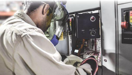


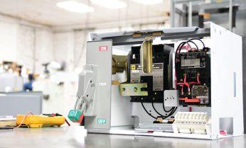




USING NUMERICAL RELAY LOGIC TO AUTOMATICALLY SWITCH CAPACITOR BANKS
 BY STEVE TURNER, Electrical Consultants, Inc.
Modern numerical protection relays often have built-in automation as well as protection logic. This article demonstrates how to use a numerical relay located at a renewable energy source (RES) to automate switching a capacitor bank in and out. This example is only intended as a tutorial.
AUTOMATION LOGIC SWITCHING GUIDELINES
The purpose of the automation logic is to switch the capacitor bank automatically based on the MW output from the RES. If the MW output is 85 percent of the rated output power (Prated equals 79.75 MW) or above for five minutes, then switch in the capacitor bank. If the MW output drops below 70 percent of Prated for 30 seconds, then switch out the cap bank.
MANUAL VERSUS AUTOMATIC CONTROL
LT01 is a latch that toggles control between automatic and manual switching. If the latch is equal to logical 1, automatically switch the capacitor bank. If the latch is equal to logical 0, manually switch the capacitor bank. You can locally toggle this latch via a front panel relay pushbutton (PB01) or remotely via SCADA (RB01).
Latch 1
LT01S = (TRIGGER RB01 OR TRIGGER PB01) AND NOT LT01 # Set Latch
LT01R = ((TRIGGER RB01 OR TRIGGER PB01) AND LT01) OR LT02 # Reset Latch
28 • FALL 2018 USING NUMERICAL RELAY LOGIC TO AUTOMATICALLY SWITCH CAPACITOR BANKS
RELAY COLUMN

LT02 is a latch that blocks automatic control if either the main breaker or capacitor bank is open.
Latch 2
LT02S = (NOT IN101 OR NOT IN102) AND NOT LT02 # Set Latch
LT02R = IN101 AND IN102 AND LT02 # Reset Latch
IN101 is a relay input that monitors the main breaker 52a contact; IN102 is another relay input that monitors capacitor bank breaker 52a contact.
SWITCHING IN THE CAPACITOR BANK
The numerical relay measures the main bus voltage and line current; therefore, the output power is measured per phase. If the RES power output (Pout) is greater than or equal to 85 percent of Prated for at least five minutes, switch in the capacitor bank.
PSW_IN = (79.75 MW/3)×0.85 = 22.6 MW
Use math variables MV01, MV02, and MV03 to determine if Pout is equal to or greater than PIN per phase. PA, PB, and PC are the measured output power measured by the relay per phase.
MV01 = PA1 >= 22.6
MV02 = PB1 >= 22.6
MV03 = PC1 >= 22.6
Program the switch-in timer T01 as follows:
T01IN = (MV01 AND MV02 AND MV03) AND NOT IN103 AND LT01 # Start Timer 1
Only initiate the timer if the relay is in automatic mode.
T01R = NOT (MV01 OR MV02 OR MV03) OR NOT IN101 OR RB05 #Reset Timer 1
T01PU = 300.00 # Timer 1 Pickup Time (sec)
IN103 is a blocking input that inhibits switching in the capacitor bank if the bus voltage is greater than 105 percent nominal voltage and is asserted by an external relay.
RB05 is a remote bit sent to the relay via SCADA to reset the timer.
Use math variable MV07 to switch in the capacitor bank:
MV07 = T01Q AND NOT IN102
T01Q is the output from Timer 1 and is programmed to an appropriate relay output contact.
SWITCHING OUT THE CAPACITOR BANK
If Pout is equal to or less than 70 percent Prated for at least 30 seconds, then switch out the capacitor bank.
PSW_OUT = (79.75 MW/3)×0.70 = 18.61 MW

NETAWorld • 29 USING NUMERICAL RELAY LOGIC TO AUTOMATICALLY SWITCH CAPACITOR BANKS
RELAY COLUMN

Use math variables MV04, MV05, and MV06 to determine if Pout is equal to or less than PIN per phase.
MV04 = PA1 <= 18.61
MV05 = PB1 <= 18.61
MV06 = PC1 <= 18.61
Program the switch-out timer T02 as follows:

T02IN = (MV04 AND MV05 AND MV06) AND (IN102 AND LT01) # Start Timer 2
T02R = NOT (MV04 AND MV05 AND MV06) OR NOT IN102 OR NOT LT01 # Reset Timer 2
T02PU = 30.00 # Timer 2 Pickup Time (sec)
T02Q (not shown) is the output from Timer 2 and is programmed to an appropriate relay output contact.
Figure 1 is the single line diagram depicting this application.
Pout Cap Bank
Figure 1: Single Line Diagram
CONCLUSION
Automation is the act of automatically controlling the power system via instrumentation and control devices. Substation automation uses data from numerical devices such as modern protective relays, control and automation capabilities within the substation, and control commands from remote users to control power-system devices. Using an existing relay eliminates the need for other equipment.

Steve Turner is a Senior Engineer II at Electrical Consultants, Inc., working in their San Diego office. Steve worked at Beckwith Electric Company, Inc. for 10 years, first as the Engineering Laboratory Director and then as Senior Applications Engineer. His previous experience includes working as an Application Engineer with GEC Alstom and as an Application Engineer in the international market for SEL focusing on transmission line protection applications. While at Duke Energy (formerly Progress Energy), Steve developed the first patent for double-ended fault location on overhead high-voltage transmission lines and was in charge of all maintenance standards in the transmission department for protective relaying. Steve has a BSEE and MSEE from Virginia Tech University.
30 • FALL 2018
RELAY COLUMN USING NUMERICAL RELAY LOGIC TO AUTOMATICALLY SWITCH CAPACITOR BANKS
Point of Interconnec on Relay CT Relay VT

LIS T ED ® US C I1 117.5 A I2 126.9 A I3 99.7 A V23 V31 I3 V12 I1 I2 3-Phase 3-Wire Δ U12 442.0 V U23 435.7 V U31 382.2 V 60.00 PT 4.194 kW Load QT 0.256 kvar Inductive ST 4.202 kVA PEL 1:56 (800) 343-1391 www.aemc.com sales@aemc.com Power & Energy Logger PEL 103 Android™ App • Display data in real-time • Configure measurements and recordings • Includes DataView® software and can be used with an Android™ device • Monitor and record energy and cost of energy • Complies with the requirements of NEC 220.87 Monitor Your Power & Energy Usage and Costs Locally or from Anywhere in the World!


ON-LINE PARTIAL DISCHARGE DIAGNOSIS FOR


 BY JIM GUO, PhD, Techimp US Corp. and WEN SHU, PhD, NEETRAC, Georgia Institute of Technology
On-line partial discharge (PD) testing is an effective diagnostic approach to evaluate insulation condition in multiple power system assets. Benefits include no power outage, nondestructive, and high accuracy in defect recognition and fault localization. On-line PD testing as a diagnostic tool to improve reliability of power distribution and transmission (T&D) systems has been gradually adopted by many equipment owners. This article provides a brief overview of on-line PD testing technology, including the mechanism of using PD testing in the T&D system, as well as the expectations, challenges, and solutions to performing on-line T&D system diagnosis.
Although various T&D system failures can lead to power outages, most are related to insulation issues. Over 60 percent of major failures in gasinsulated switchgear (GIS) are due to insulation breakdown. The majority of underground cable failures are caused by insulation degradation and aging. About 50–70 percent of transformer failures result from insulation defects in the winding, oil, or accessories. Insulation condition assessment proactively reduces the failure rate of power apparatus, which improves reliability of the entire T&D system.
34 • FALL 2018 ON-LINE PARTIAL DISCHARGE DIAGNOSIS FOR POWER DISTRIBUTION AND TRANSMISSION SYSTEMS
COVER STORY

By definition, PD is an electric discharge that does not bridge two electrodes. Almost all insulation failures exhibit PD activity prior to the fault. In some cases, PD is the symptom of insulation aging/degradation; PD can also cause insulation deterioration. PD as a symptom of early-stage aging further accelerates degradation until insulation breakdown occurs.
PD testing can discriminate defect types, locate defect sites, and recognize defect severity. Therefore, PD testing is an effective and economical diagnostic technology for evaluating insulation condition for power T&D system apparatus. PD diagnosis has been adopted by utilities and industries over the last 20 years.
PD testing can be performed when the equipment under test (EUT) is removed from service, i.e., an offline test. An external power supply energizes the EUT. The offline testing voltage is normally higher than the operating voltage to reach the PD inception voltage (PDIV). The level of over-voltage is determined by the EUT. For example, the PD testing voltage for medium-voltage solid dielectric cables should reach 2.5U₀ or until PD is initiated; testing voltage for high-voltage cables normally should not exceed 1.7U₀. The advantage of applying the over-voltage to the EUT is to find dormant defects, which serves as a factory acceptance test or commissioning test when the insulation is brand new. However, the over-voltage test for an aged insulation system must be examined carefully, as aged insulation can be fragile, and over-voltage could reduce the remaining life signifi cantly. Some aged cables fail during the offline test, while others could fail at a higher rate within the first year after the test.
On-line PD testing is truly a non-destructive test, as the PD measurement is performed when the EUT is under normal operating condition. Although performing on-line PD diagnosis has many benefits, its challenges determine the diagnostic effectiveness and accuracy.
ADVANTAGES OF ON-LINE PARTIAL DISCHARGE DIAGNOSIS
PD diagnosis has two major advantages over other testing technologies: defect localization and categorization.
Defect Localization

Defect site localization with PD measurement varies for different types of apparatus, but most technologies use PD pulse propagation in the EUT. Once PD occurs, the PD-induced pulse (electrical pulse, acoustic pulse, electromagnetic pulse, etc.) propagates in the EUT in all directions. Common PD source localization methods include:
• Time-of-arrival analysis. Several PD sensors are deployed at separate locations on the EUT to capture PD pulses. The PD source location is calculated by the difference of the PD pulse arrival times at the sensors. This method is popular in PD source locating for power transformers. Several acoustic sensors are placed either in the transformer tank or on the surface of the tank for PD data acquisition. With the known acoustic sensor locations and the model of the transformer, the time difference of the PD pulse arriving at the sensors gives an accurate discharge source location in the transformer.
In power cables, the time-of-arrival analysis is simpler, as the PD pulse can only propagate in two directions. The PD pulse reflects at the cable joints and terminations during the propagation. One PD sensor is enough to capture the original PD pulse and the reflected pulses. With prior knowledge of the PD pulse propagating velocity in the tested cable, the cable length, and/or the position of the splices, the PD source location can be calculated by the time difference between the original pulse and the reflected pulse.
• Frequency spectrum analysis. The original PD pulse has a very sharp rise time in the range of a few nanoseconds (ns), which corresponds to ultra-wide bandwidth (UWB) up to GHz
NETAWorld • 35 ON-LINE PARTIAL DISCHARGE DIAGNOSIS FOR POWER DISTRIBUTION AND TRANSMISSION SYSTEMS
COVER STORY

range. The measured PD pulse could have much lower bandwidth, which is determined by the signal propagation path. The PD source location can be estimated with the measured PD bandwidth if the relation between the attenuation and the signal propagation path is known. This method is particularly helpful in PD tests for power cables, where knowledge of the measured PD signal bandwidth as a function of the pulse propagation distance has been established. This method is not as accurate as the time-of-arrival analysis, but has the advantage of simplicity, as the localization only requires one PD sensor and does not rely on the detection of reflections. Using this method, discharges occurring at the sensor placement location can be easily distinguished from discharges propagated from a remote location.
• Magnitude comparison. This method is similar to using a stethoscope. The PD sensor(s) are placed at various locations in the EUT, and the measured PD magnitude is strongest when the sensor is closest to the defect. This method is usually employed in testing a pile of switchgear cabinets or testing large, gas-insulated switchgear.
Other non-electrical PD source localization technologies include ultrasonic sniffer, infrared imaging, ultra-violet imaging, etc. Most of these technologies require a clear path between
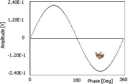

the PD source and the detection equipment, which may not be available in field conditions. Thus, these non-electrical PD testing methods are normally used as additional tools during on-line diagnosis.
Defect Categorization
Categorizing defects is one of the greatest benefits of PD diagnosis, as severity to the insulation system varies among distinct types of defects. Defect categorization is performed with the phase-resolved PD (PRPD) pattern. PD activities can be quantified by magnitude (q, in the unit of pC or mV) and repetition rate (n, number of discharges per a certain time frame, i.e., per cycle or per second). These values can be plotted in one voltage cycle with the phase reference at which the PD pulse occurs, which is the phase resolved PD pattern. The PRPD pattern varies by the nature of defects. Figure 1a, Figure 1b, and Figure 1c show PRPD patterns for three typical defects.
These advantages are generic for all on-line and offline PD diagnosis. On-line PD diagnosis has several unique advantages, as removing the EUT from service is not required. The first benefit is cost savings. Since the EUT remains in service during the test, on-line PD testing does not require switching operations, which saves labor and system downtime. The on-line test is also more economical, as it does not require an
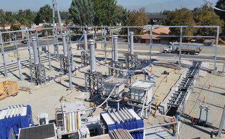
Figure 1a: Corona discharges are normally caused by a sharp metal edge with high potential. Corona discharge is very common in outdoor substations. The photo on the right shows two 500kV XLPE circuits going through a commissioning test. Strong corona discharge was observed during the PD measurement, but did not raise concern.
36 • FALL 2018
COVER STORY ON-LINE PARTIAL DISCHARGE DIAGNOSIS FOR POWER DISTRIBUTION AND TRANSMISSION SYSTEMS


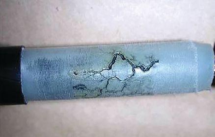
Figure 1b: Surface discharges could be on the external surface of a component, such as the surface of an insulator, busbar, or arrester. They could also be on the internal surface (interface) of a device, e.g., interfaces within a separable connector, cable termination, cable joint, etc. The photo on the right is the interface in a 15kV splice that showed surface discharges.
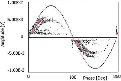

Figure 1c: These internal discharges were caused by voids or cavities in an insulation system. Internal discharge is the most dangerous defect in the organic insulation system, as the discharge activities further deteriorate the polymer chains and accelerate the aging process. The photo on the right shows electrical tree (black traces) going into the water-tree region (blue traces) in a medium-voltage XLPE-insulated cable.
expensive external power supply and testing productivity is much higher than an offline test.
On-line PD testing can reveal all active defects in an operating condition, including load- and temperature-dependent defects. IEEE 400.32006 standard describes load- and temperaturedependent defects as:
In a complex cable system…the voltage built up in the ground system is induced by the current being conducted and is therefore a strong function of the cable loading… For this type of discharge, testing under heavily loaded conditions is essential.”
[In] an XLPE insulated cable…the size of some defects varies with cable loading so that the PD magnitude varies with the cable loading. PD in some cases might disappear (extinguish) as load conditions change. For a laminated cable, longterm operation at high temperatures may cause the insulating fluid to migrate. The extent of this depends on the viscosity of the impregnating fluid. This can affect the PD producing defect.
Since the EUT is connected to other components in the T&D system, an on-line PD test also assesses insulation condition for all connected components. At the same time, the interconnection poses a challenge for on-line

NETAWorld • 37
COVER STORY
ON-LINE PARTIAL DISCHARGE DIAGNOSIS FOR POWER DISTRIBUTION AND TRANSMISSION SYSTEMS

PD diagnosis, as the measured signals could come from any of the connected components or even be cross-talked from nearby devices, creating difficulties in PD data interpretation.
CHALLENGES IN ON-LINE PD DIAGNOSIS — DATA INTERPRETATION
Commercially available equipment can be used for on-line PD measurement. However, PD diagnosis is difficult: How can we derive insulation condition from the measured data, and what action shall we take after PD measurement? Unlike other testing technologies, PD diagnosis does not have standard numerical values to categorize the condition of the EUTs. Questions arise, such as “Why did Device A work properly with 100mV measured PD, but Device B failed with only 2mV of measured PD?” or “The measured PD value for Device C is 12 mV; what should I do?” The objective of PD data interpretation is to answer those questions, which is considered the most challenging process in the on-line PD diagnosis.
To properly evaluate insulation condition with on-line PD diagnosis, assess the following:
• Noise separation. The first question when analyzing measured PD data is whether the data contains PD signals from the EUT.
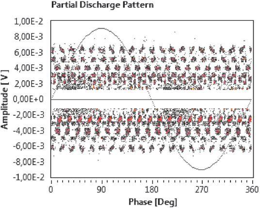

Noise separation is the first step for PD data interpretation, and it is a critical step in on-line diagnosis. Various interferences could occur during on-line PD measurement, including switching noise, interference from stationary broadcasting, communication noise, and irrelevant PD signals such as coronas from overhead lines. All noises must be identified and removed before further analysis.
• PD source classification. PRPD pattern is the most common tool employed in defect categorization. However, discharge signals from various sources and interferences are always mixed together in on-line PD testing. To accurately recognize the type of defect, the acquired PD data must be categorized by the discharge sources. The five illustrations in Figure 2 show the signal categorization method based on T-F Map analysis. The entire acquired data (Figure 2a) contains strong interferences from variable speed drives, and the possible PD signals are all overwhelmed by the noise. To separate the PD signals from the noise as well as categorize PD signals from various sources, each acquired pulse in Figure 2a is plotted in the T-F Map (Figure 2b) by its equivalent pulse width (T) and pulse bandwidth (F). Signals from the same sources tend to cluster in the T-F map, as they have similar waveform features.
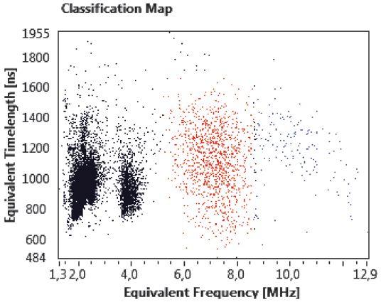
38 • FALL 2018
STORY ON-LINE PARTIAL DISCHARGE DIAGNOSIS FOR POWER DISTRIBUTION AND TRANSMISSION SYSTEMS
COVER
Figure 2a: PRPD Pattern for Entire Acquired Data Figure 2b: PD Data Plotted in T-F Map


Each cluster in the T-F Map can be separated for further analysis, as shown in Figure 2c, Figure 2d, and Figure 2e. Weak PD signals can be extracted from strong interferences with T-F Map analysis, and each type of discharge signal can be categorized for further evaluation.
• Condition assessment. When noise signals are removed from the PD signals and the PD signals are separated by discharge sources, the PD activity for each defect type can be quantified by PD features such as discharge magnitude and repetition rate. Most on-line PD tests stop at this step. However, those PD values cannot answer the initial questions: What is the status of the tested apparatus, and what should we do with it?
There are no easy answers. Condition assessment depends on many factors, and damage to the insulation system varies from different types of PD activities. Corona discharge normally does not cause much damage to the insulation system; therefore, corona discharge might be considered acceptable in many applications. Internal discharge occurs within the dielectric and accelerates insulation aging significantly; this is considered the most dangerous defect in a dielectric. The severity of surface discharge falls between the corona discharge and internal discharge. Moreover, different insulation materials have diff erent tolerances on PD activities. Oil-paper insulation can survive with PD for a long time, so even if oil-paper


insulation has intensive PD activities, the insulation system may hold for years. However, once PD starts in a medium-voltage XLPE cable, organic insulation would quickly degrade and electrical treeing could be initiated, quickly leading to failure.
To properly assess insulation condition, consider the following factors:
• Type of insulation materials
• Knowledge of the aging and failure mechanism for the tested insulation system
• Operating condition of the apparatus
• Type of defects from PD measurement
• Measured PD magnitude
• Measured PD repetition rate
• Comparison of historical PD data for trending analysis
Note that the absolute value of PD magnitude does not carry much weight in condition assessment, which is quite different from other diagnostic technologies that have defined threshold values for good or bad. First, damage to insulation varies by defect type. Comparing PD magnitude without mentioning defect type does not make sense. Second, the measured PD magnitude is not the defect’s real discharge. Measured PD magnitude is strongly affected by the propagating path and position of the defect in the insulation. Therefore, the measured PD magnitude has no direct relation to the size or severity of the defect.
NETAWorld • 39 COVER STORY ON-LINE PARTIAL DISCHARGE DIAGNOSIS FOR POWER DISTRIBUTION AND TRANSMISSION SYSTEMS
Figure 2c: Black Cluster, Noise From VFD
Figure 2d: Red Cluster, Surface Discharges
Figure 2e: Blue Cluster, Internal Discharges

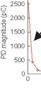
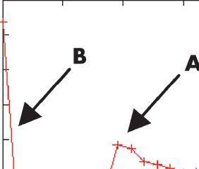


Moreover, PD magnitude may fluctuate during the insulation aging process. PD magnitude increases with the aging process until a certain point prior to breakdown. PD magnitude may drop for a while and then surge until breakdown occurs, as shown in Figure 3. Hence, one cannot determine the aging stage with only the PD magnitude from a spot measurement. Instead, trending analysis of PD magnitude and repetition rate gives a more precise indication of the aging process. Trending data can be obtained by comparing a series of historical spot measurements or from the PD monitoring system.
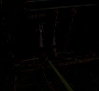
ON-LINE PD DIAGNOSIS FOR T&D SYSTEMS – APPLICATION AND CASE STUDY
Since di erent devices under test are energized, non-galvanic sensors are required for PD detection. Figure 4 shows possible sensor placement in a medium-voltage distribution system. Using a hot-stick, a capacitive sensor was connected to the shielded part of the cable close to the termination or the joint. e PD sensor is connected to the data acquisition system via coaxial cable. A laptop controller connects to the acquisition system through ber optic cable or Wi-Fi to isolate the operator

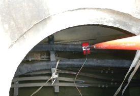





40 • FALL 2018 COVER STORY ON-LINE PARTIAL DISCHARGE DIAGNOSIS FOR POWER DISTRIBUTION AND TRANSMISSION SYSTEMS
Figure 3: PD magnitude varies prior to breakdown. Discharge magntiude decreases from Point A and surges in Stage B until fault. (SOURCE: LAI, LOHRASBY, PHUNG, AND BLACKBURN)
Figure 4: Non-galvanic capacitive sensor is placed on the shielded part of medium-voltage cables for PD measurment.
Table 1: Five-Level Condition Assessment for Apparatus in a T&D System
Level 1The insulation in the EUT is not degraded. No action needed.

Level 2EUT is aged but not in danger. The probability of failure within 2 years is negligible.
Level 3EUT has low to moderate deterioration and low probability of failure within the next 2 years.
Level 4EUT has medium probability of failure within the next 2 years.
Level 5EUT is at the end of economic life and has a high probability of failure within 1 year.
and the energized testing equipment. During the data acquisition, the technician determines the type of apparatus, vintage, installation, operating and environmental condition, etc. The controller stores the acquired PD data for further analysis.
After onsite data acquisition, stored PD data is transferred to a PD expert for interpretation. The assessment is presented by levels to indicate the insulation condition or the probability of failure, with recommended actions. Table 1

Retest is recommended within 2 years for trending analysis.
Retest is recommended within 1 year.
Further discussion is required to determine repair or replacement.
Recommend immediate attention.
shows a five-level condition assessment that categorizes EUTs by the probability of failure in a certain timeframe. Th e probability of failure is analyzed by an independent research institute, as shown in Figure 5. The five-level result helps equipment owners prioritize the maintenance plan.
Figure 6 summarizes testing performed for a utility in the northwestern United States. A total of 97 circuit segments were diagnosed in a five-day on-line PD test. The testing was
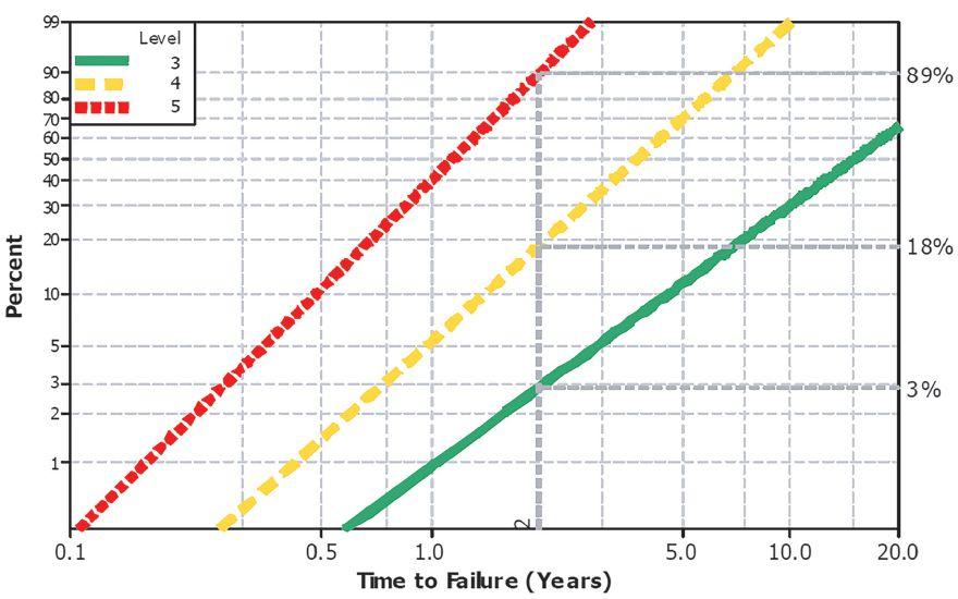
NETAWorld • 41 COVER STORY ON-LINE PARTIAL DISCHARGE DIAGNOSIS FOR POWER DISTRIBUTION AND TRANSMISSION SYSTEMS
LEVELS INSULATION CONDITION RECOMMENDATIONS
Figure 5: Diagnostic Performance Curve for an On-Line PD Test Technology (SOURCE: NEETRAC CDFI REPORT)

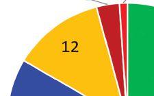


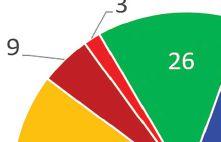


Figure 6: Pie graphs summarize assessment levels for tested cables, cable termanations, and splices, as well as connected apparatus such as switchgears, riser pole components, transformers, etc.
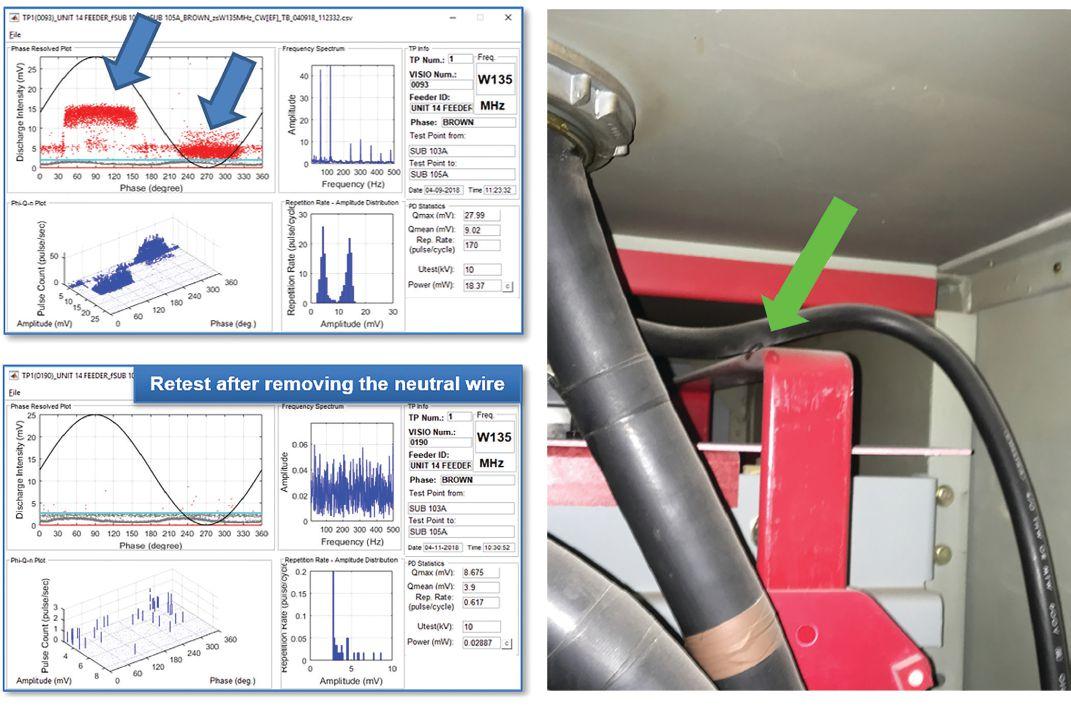
Figure 7: A Level 4 defect was pinpointed during the on-line testing. The neutral wire was touching the energized bus-bar in a switchgear cabinet and created intensive tracking discharges. Discharge was eliminated once the wire was repositioned.
42 • FALL 2018 COVER STORY ON-LINE PARTIAL DISCHARGE DIAGNOSIS FOR POWER DISTRIBUTION AND TRANSMISSION SYSTEMS

performed for the medium-voltage distribution network in a metropolitan downtown area. Th e PD data were acquired at each cable termination and splice if accessible.
The data pinpointed one Level 4 defect that was repaired immediately (Figure 7). Such discharges erode the insulation and eventually lead to a flashover. This defect was pinpointed during the test, and the neutral wire was repositioned immediately. Th e retest of the circuit confirmed the correction.
The final assessment results helped the circuit owner prioritize the maintenance schedule. In general, the Level 5 cables and accessories needed immediate replacement. Th e Level 4 circuits could wait 6–12 months for repair or replacement. Normally, Level 3 circuits do not require immediate action, although some circuit owners replace Level 3 cables in 2–5 years depending on budget. Retesting for the Level 3 component in 1–2 years is recommended to monitor the degradation process and to determine the best actions based on economy and reliability. The acquired PD data was safely saved in cloud storage for future trending analysis.
CONCLUSION
It is not difficult to perform PD testing and generate good data with the available technology. However, the data needs to be analyzed by experts to assess the health of an individual EUT and to help in prioritizing asset management decisions.
In the modern T&D system, an aging North American infrastructure is a key concern. The investment to address aging infrastructures is significant. Often, an asset manager is not only deciding whether to replace equipment or cables, but also prioritizing among aging system components.
On-line PD measurement is a widely accepted diagnostic tool for T&D systems and is an economic, eff ective, and fl exible diagnostic
technology for evaluating power apparatus insulation condition. Th ose benefi ts make on-line PD diagnosis a good choice for asset managers in prioritizing their T&D system maintenance plans.

REFERENCES
CIGRE A3.06. “Final Report of the 2004–2007 International Enquiry on Reliability of High Voltage Equipment.”
Cable Diagnostic Focused Initiative, National Electric Energy Testing, Research and Application Center (NEETRAC), 2016.
Victor Sokolov. “Understanding Failure modes of transformers,” Euro TechCon 2005.
B. H. Finke. “Changes in factory and field high voltage dc testing of shielded medium voltage cable insulation,” Conference Record of 1996 Annual Pulp and Paper Industry Technical Conference, Birmingham, AL, 1996, pp. 137–139.
D. A. P. Ferreira; R. A. C. Altafim; F. S. I. de Sousa; T. T. C. Palitó; Y. A. O. Assagra; and R. A. P. Altafim. “Detection of acoustic emissions from partial discharges in distribution transformers with piezoelectret transducers,” 2017 IEEE Conference on Electrical Insulation and Dielectric Phenomenon (CEIDP), Fort Worth, TX, 2017, pp. 381–384.
IEEE 400.3-2006. “IEEE Guide for Partial Discharge Testing of Shielded Power Cable Systems in a Field Environment.”
J. J. Guo; L. Zhang; C. Xu; and S. A. Boggs. “High Frequency Attenuation in Transmission Class Solid Dielectric Cable,” IEEE Transactions on Power Delivery, Vol. 23, no. 4, October 2008, pp. 1713–1719.
A. Cavallini; A. Contin; G. C. Montanari; and F. Puletti. “Advanced PD inference in onfield measurements. I. Noise rejection,” in IEEE Transactions on Dielectrics and Electrical Insulation, vol. 10, no. 2, April 2003, pp. 216–224.
NETAWorld • 43 COVER STORY ON-LINE PARTIAL DISCHARGE DIAGNOSIS FOR POWER DISTRIBUTION AND TRANSMISSION SYSTEMS

K. X. Lai, A. Lohrasby, B. T. Phung and T. R. Blackburn, “Partial discharge characteristics of electrical trees prior to breakdown,” 2008 International Symposium on Electrical Insulating Materials (ISEIM 2008), Mie, 2008, pp. 649–652.

Dr. Jim (Jun) Guo has over 10 years experience working in diagnostic testing for high-voltage apparatus. He received his PhD in material science at the Electrical Insulation Research Center, Institute of Material Science, University of Connecticut, in 2010. He was an Engineering Systems Analyst and Project Manager with CableWISE from 2010 to 2015, focusing on on-line diagnosis for power transmission and distribution systems. In 2015, Jim joined Techimp US Corp as Vice President of Technology. His research interests focus on high-voltage dielectric aging and breakdown theories, partial discharge measurement and analysis, and high-voltage equipment diagnostic testing and

monitoring. Jim has over 30 publications in peer-reviewed journals and international conferences, and holds four U.S. and international patents. He is the member of IEEE PES, DEIS, senior member of IEEE Insulated Conductor Committee, and a frequent reviewer for several academic journals such as IEEE Electrical Insulation Magazine, IEEE Transactions of Dielectric and Electrical Insulation, and IET Science Measurement & Technology. Jim also serves as associate editor for IET Science Measurement & Technology

Dr. Wen Shu received BS and MS degrees in electrical engineering from the School of Electrical Engineering of Southwest Jiaotong University, Sichuan, China, in 2003 and 2006, respectively. She received her PhD. in materials science from the University of Connecticut, Storrs, in 2010. She spent seven years with UtilX Corp with research focused on partial discharge measurement and analysis, water treeing phenomena, and dielectric property of water treed cables. In 2016, Wen joined the National Electric Energy Testing, Research, & Applications Center, Georgia Institute of Technology, with research focused on finite element analysis, population forensic analysis, electric tests, wood pole asset management, and power system reliability analysis.

Acceptance Testing Services
Low, Medium, and High Voltage
Substations • Distribution switchgear • Transformers • Cables • Relays
Preventative Maintenance & Testing
Switchgear
Infra-red surveys • Circuit breakers • Relay testing and calibration
Transfer switches • Complete maintenance of ACB’s-OCB’s-SF6 CB’s
UPS & station battery maintenance • Gen. load tests
Transformers
TTR • Power factor testing • Oil testing and field analysis
Oil reconditioning & reclaiming • field replacements
Engineering Services
Arc-flash, short circuit, and coordination studies
Power factor correction • Power quality and harmonic studies
Load surveys • Grounding system design
Trust us to keep your business up and running. Call for a free consultation today.
P: 781-767-0888 Email: infrared.ma@verizon.net 152 Centre Street Holbrook, MA 02343 www.infraredbps.com


COVER STORY
Reliability Full Service Independent Electrical Testing
Over 25 Years of Experience &




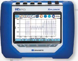
Up Your Production And Stay In The Game! PQ Monitors with Remote Wireless Communications 732.287.3680 1000 New Durham Road Edison, New Jersey 08817 Dranetz HDPQ Xplorer SP Control your Dranetz HDPQ from your smartphone, tablet, or computer! www.dranetz.com ® Dranetz HDPQ Xplorer Portable




When equipment fails, every minute spent searching for what you need is bad for the bottom line. With a constantly updated inventory of new, surplus and repurposed electrical equipment, you can get what you need 24/7. Use our easy checkout process, or if you need help our experts are standing by.


CAN’T
TO WAIT FOR ELECTRICAL EQUIPMENT? performance by design sm
AFFORD
today
322-0149. Visit us at PowerTest Booth 133 OPPORTUNITIES Electrical Power Systems Industry Learn at Your Own Pace • Online Courses • Self-Paced Technical Seminars (SPTS) • Electrical Safety Training Systems (ESTS) Ask About Continuing Education and NETA CTD Credits. Learn More at: netaworld.org/training or Call 888-300-6382 (NETA)
Visit nationalswitchgear.com or call us
at (800)


The obvious analogy is the increasing use of 24/7 wearable EKG monitors for heart patients. Having an EKG at your annual physical is great, but you can still have an issue between visits. For most people, the inconvenience and cost of such a device makes it not worth the benefit, but as cost goes down and convenience goes up, who knows? For high-risk patients, it can be a lifesaver.
On assets above 2.5 kV, partial discharge testing is typically done annually or biannually because the general belief is that PD takes at least that long to lead to failure. That is sometimes — or even often — true, but it is not always the case. Take the following incidents as examples.
Example 1: Distribution Utility
In November 2014, a UK utility installed a fulltime-only partial discharge monitor at one of their high-risk substations. The site was judged high risk due to its location near a river’s edge combined with the type of switchgear operated at the location. Tragically, there was no remote communication channel available, and the system data was not reviewed during the testing period. On July 28, 2015, the switchgear failed catastrophically (Figure 1).
Experts reviewed the recorded data and found that the substation had read little to no activity from installation in November 2014 until March 2015. However, from March 2015 on, there was a marked increase in PD activity. Over a week-long period, PD rose to a level that — had the alarm system been installed — would have triggered an alarm

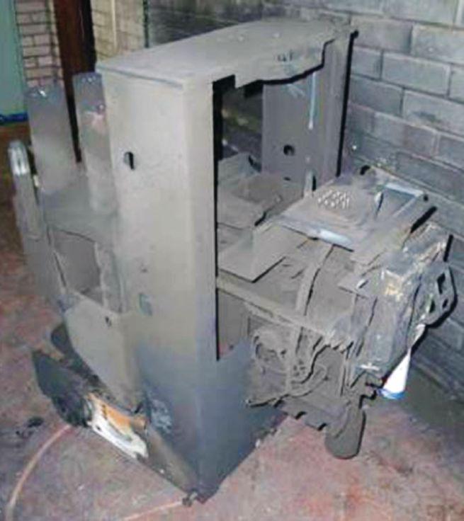
(Figure 2). This spike continued to exist until July 28, 2015, when the switchgear suffered a catastrophic failure. Although a periodic survey in early March would have found no issues, a catastrophic failure still occurred four months later. Th is would have been easily detected with continuous monitoring. As a direct result of downtime, the utility received Customer Minutes Lost (CML) and Customer Interruption (CI) fines totaling $700,000.

NETAWorld • 49 CONTINUOUS MONITORING IS ON THE RISE: CAN YOU ADAPT?
FEATURE
Figure 1: Result of Inaction — Catastrophic Failure
Figure 2: Dramatic Rise in PD Reading

Example 2: Petro-Chemical Plant
A large manufacturing site that is home to an olefin and polymers business and a crude oil refi nery operates a combined heat and power plant that supplies electricity to the site through two separate 1km-long, XLPE cable circuits known as CHP1 and CHP2. Following the detection of partial discharge in three relatively new joint pairs during routine conventional offline very-low-frequency (VLF) testing, an on-line permanent cable monitoring system was installed.

to determine the severity of the problem. Avoiding just a single CHP outage in this way saved more money in terms of lost production than the entire cost of installation.
The onset of PD can be seen in Figure 3 for cable CHP2-R2 over a one-month period when levels rose from 100 pC to 1,000 pC. Figure 4 shows the very clean PD pulse that enabled location of the PD. This highlights the benefit of continuous monitoring whereby trends in activity can be seen that would have been missed with spot measurements alone.
Following installation, the PD activity identified during the VLF testing was confirmed in all three cables and located to the vicinity of the suspect joint pairs. This removed the need to take the CHP plant off line again to perform further periodic VLF testing
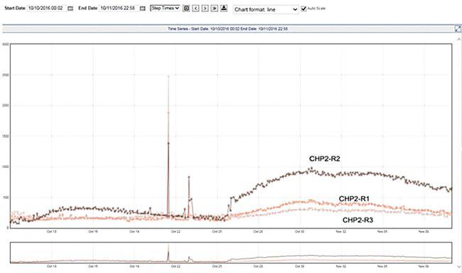
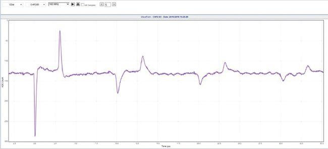
All three cables where PD was identified were successfully managed until their joint pairs were replaced during the planned outage 10 months later. The suspect joint pairs were sent for forensic examination.
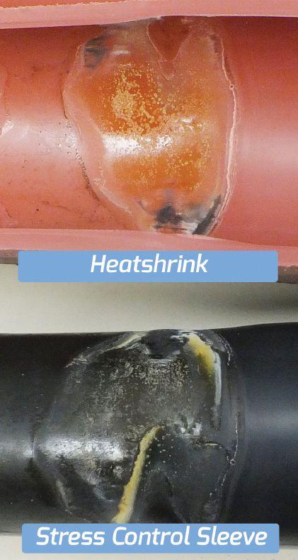
50 • FALL 2018
CONTINUOUS MONITORING IS ON THE RISE: CAN YOU ADAPT?
FEATURE
Figure 3: Rapid Increase in PD in CHP2-R2
Figure 4: PD Current Pulse Recorded on CHP-R2
Heatshrink Stress Control
Sleeve
Figure 5: Partial Discharge Location

During the forensic investigation, evidence of PD was found in one joint of the joint pairs when the outer heatshrink cover was removed from the cable stress control sleeve (Figure 5). The root cause was identified as an incorrect gap — only 1 mm instead of the recommended 5 mm — between the XLPE insulation and the connector. This prevented the yellow mastic from filling the gap properly, leaving a void that led to the elevated electrical stress responsible for the detected PD.
Example 3: Critical Infrastructure Building in Virginia
A large office building had full-time partial discharge monitoring installed due to the critical nature of its operations. Ultrasonic and TEV detection were provided for all cable termination compartments. An installation mistake common to all the potential transformer cables (Figure 6) caused partial discharge to be present almost immediately upon energization.
As seen in Figure 7, the cable was energized in early March 2017, and within a month, the ultrasonic level was already four times higher than other identical cabinets where the problem was previously corrected. During the next three months, the level increased to over 100 times that of the good cabinets.

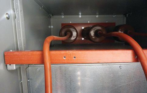
The cable was denergized after a few months, and the damage was similar to that shown in Figure 8. This image is from another cable that was previously damaged and replaced.
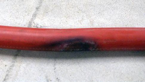
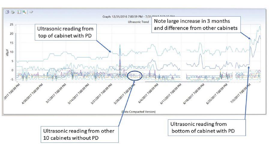
NETAWorld • 51
FEATURE
CONTINUOUS MONITORING IS ON THE RISE: CAN YOU ADAPT?
Figure 6: Improperly Installed PT Cables
Figure 7: Graph Showing Marked Increase in PD Signature
Figure 8: PD Damage to PT Cable

DOES THIS MEAN PERIODIC SURVEYING IS DEAD?
Periodic testing is powerful and inexpensive, so it will take a lot to kill it. For assets below 2.5KV, periodic testing will always be more cost effective. Even for medium-voltage systems, it is the cheapest way to go.

Because of its ease of installation, non-invasive monitors can be removed and relocated periodically.
When asset owners look seriously at the cost of outages and aging infrastructure, lowest testing cost shouldn’t be the only consideration. Each asset failure has an impact, and the owner should do a risk and impact analysis before deciding what to do. For most applications, a mix of full-time monitoring on critical assets and periodic surveying on less critical systems will be the ideal route going forward.
WHAT’S INVOLVED IN FULL-TIME MONITORING?
Full-time monitoring systems roughly fall into one of two categories: invasive and noninvasive. Invasive systems require full shutdown and internal access to the cubicles. They are typically hardwired with sensors like coupling capacitors. These are capacitor dividers that are connected between the conductors and ground and have a test cable connection port. High-voltage (HV) wiring is required between the sensor and HV conductors. Low-voltage (LV) wiring is required between the sensor port and the electronics portion. A Hipot test is required after installation and before energization. Invasive systems are almost always permanently installed at the same time as the original system due to the work required to remove and relocate them.
Non-invasive monitor systems use the same technologies as handheld non-invasive test devices. Th ese include ultrasonic detection and Transient Earth Voltage (TEV). The main advantage of these systems is that they can be installed on the outside of switchgear and do not require outages. Cable monitoring can be added to either system, but it does require access to the ground straps of the cables.
Either type of system can provide local or remote access. Local access is easier to install but does not provide instant response to emerging faults. Remote access with continual monitoring provides the additional advantage of allowing experts to analyze the data. The end customer (or the service company) does not need partial discharge expertise.
Going back to the wearable EKG monitor, would you rather try to interpret the charts yourself or have the data continuously streamed to the hospital where a doctor can analyze it?
WHERE DO TESTING COMPANIES FIT IN?
As MV asset owners make the inevitable move to more continuous testing, less periodic testing will be required. Additionally, if issues are caught before failure, fewer large repairs will be required. Testing companies that rely solely on testing and repairing failed equipment will suffer from reduced opportunities.
However, a testing company that evolves can still fi nd plenty of opportunity. Designing, installing, and maintaining monitoring systems will be required. Responding to early indications of problems and making repairs in a timely fashion will increase as well. Testing companies would be well served to become familiar with monitoring systems and their installation and maintenance requirements.
A popular use for monitors is employing portable systems for several months and then removing or moving to another set of assets. This is a viable intermediate step to permanently putting monitors on all assets. Testing companies may want to purchase portable monitor systems and provide the install, remove, and relocate services as well as leasing the equipment to the asset owners.
52 • FALL 2018
FEATURE
CONTINUOUS MONITORING IS ON THE RISE: CAN YOU ADAPT?

One last gratuitous parallel reference to the 24/7 wearable EKG monitor: If they become inexpensive enough for everyone to have one implanted, and you are a medical technician who performs routine EKGs in a doctor’s office, you might want to consider a new career. I hear jobs are opening in 24/7 PD monitoring.

William G. Higinbotham has been President of EA Technology LLC since 2013. His responsibilities involve general management of the company, which includes EA Technology activities in North and South America. William is also responsible for sales, service, support,

and training on partial discharge instruments and conditionbased asset management. He is the author or co-author of several industry papers. Previously, William was Vice President of RFL Electronics Inc.’s Research and Development Engineering Group, where his responsibilities included new product development, manufacturing engineering, and technical support. He is a senior member of IEEE and is active in the IEEE Power Systems Relaying Committee. He has co-authored a number of IEEE standards in the field of power system protection and communications, and holds one patent in this area. William received his BS degree from Rutgers, the State University of New Jersey’s School of Engineering, and worked in the biomedical engineering field for five years prior to joining RFL.


Prevent Equipment Failures
To prevent partial discharge related failures, Astute Monitoring Services, from EA Technology offers the combined benefits of permanent and regular monitoring of assets, along with expert analysis and reporting in one simple commercial arrangement.
• Switchgear
• Cables
• 24 x 7 Monitoring
• Online
• No upfront costs
• Expert analysis
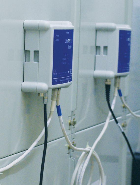
EA Technology LLC www.eatechnology.com 862.261.2759 | sales@eatechnologyusa.com

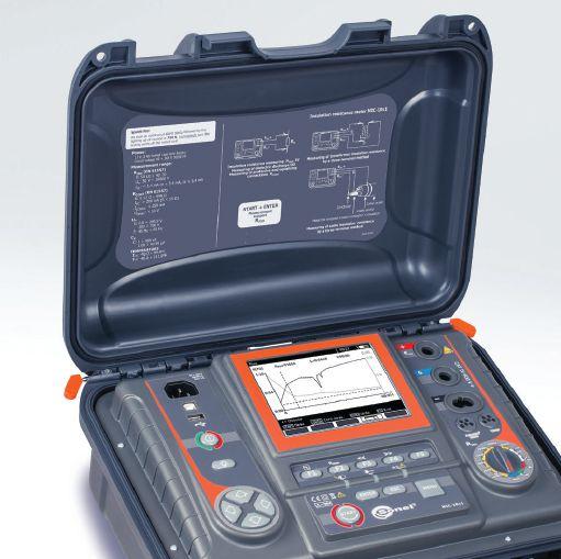




Sonel’s Graphic Insulation Testers expose flaws that numerical testers simply can’t see.


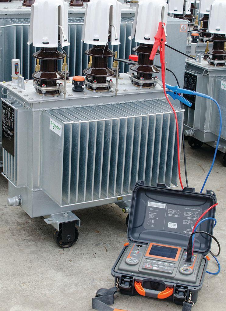
Transformer windings, motor windings, cable spools
User-selectable test voltages from 50 V to 5/10 KV
All ratios and parameters calculated – absorption, PI, DAR, capacitance, length
You run an insulation resistance test and get a number. Everything is fine. Right? Well...maybe not. This graphic display plots the results of a test where the final number appears to be OK, but the graph indicates a latent flaw that will likely result in an avoidable breakdown.
Sonel MIC Graphic Insulation Testers are the only instruments that display this valuable information on


the tester screen. Without this graph you’d wind up with a false sense of insulation integrity.
Sonel Graphic Insulation Testers have all the features you’d expect from high performance instruments including stepped or continuous voltage, selectable test voltages and currents, three test times plus CAT IV safety rating, auto-discharge, high-noise immunity and live object protection.


Get more information on these powerful instruments and the complete line of Sonel testers at www.soneltest.com
Better yet, call us today. 408.988.1346


complete picture.
Get the
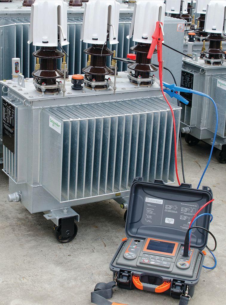


THE PREMIER ELECTRICAL MAINTENANCE AND SAFETY CONFERENCE SAVE THE DATE MARCH 11-15, 2019 Gaylord Texan Resort and Convention Center - Grapevine, Texas PowerTest.org l 888.300.6382 Hosted by
UNDERSTANDING THE PAST AND FUTURE OF
FIBER OPTICS IN UTILITIES
 BY JIM HAYES, Fiber Optic Association
Fiber optics is the ideal communication medium for electrical utilities. It is the cheapest, fastest, and longest-distance medium for communications, plus it’s immune to electromagnetic interference. All those reasons prompted utilities to adopt fiber optics over 30 years ago, but fiber, like all technologies, is constantly changing. Some fiber networks installed 20 or 30 years ago may not be capable of upgrades to meet today’s communications needs.
56 • FALL 2018 UNDERSTANDING THE PAST AND FUTURE OF FIBER OPTICS IN UTILITIES
FEATURE
This article discusses the historical uses of fiber in utilities and how these have evolved into today’s world of Smart Grid, microgrids, alternative energy, energy storage, 5G, and more. The information will be useful for engineers, managers, and planners in understanding fiber, how it impacts the utility business, and how to implement fiber networks.
BACKGROUND/HISTORY
In 1976, AT&T and Bell Labs personnel installed the first trial of a new communications medium in the coal tunnels under Chicago’s Loop. The link sent telephone signals created by semiconductor lasers over hair-thin strands of glass called optical fiber. About the same time, British Telecom conducted a similar trial in Milton Keynes, England. The trials were successful, and telecommunications would never be the same again.
By the mid 1980s, the technology of fiber optics had developed to a high level, close to what we use today. Telecom companies, especially new competitive carriers like MCI, switched their focus from digital microwave radio to fiber optics. In 1988, TAT-8, the first
transatlantic fiber optic cable, was completed and sounded the death knell for telecom satellites.
Why did fiber optic technology gain acceptance so fast? Simple: economics. When fiber was first introduced, a copper telephone cable could transmit 1.5 megabits/second over about 1.5 miles before needing regeneration. Fiber could transmit 145 megabits/second about 15 miles before needing regeneration. The cost per voice channel over fiber was approximately 5 percent of the cost of a copper channel overall because, when you converted to fiber, you ended up with about 100 times the capacity for communications with only a somewhat higher capital expense. While a fiber network’s total cost to build was higher than copper, you got much more communications capacity. The end result was that the cost of a single connection was much less over fiber.
The appeal of fiber technology to electrical utilities also came from another advantage of fiber optics: Fiber is pure glass, a dielectric, so fiber is immune to electromagnetic interference. Fiber could be used in substations for controls where copper wires could not. Fibers could even be embedded in electrical conductors used in ground wires on transmission lines.

NETAWorld • 57 UNDERSTANDING THE PAST AND FUTURE OF FIBER OPTICS IN UTILITIES
FEATURE

Fiber optic cables including optical power ground wire with fibers embedded in a ground cable (OPGW) became an immediate hit with utilities. These fibers provided the communications needed for the utility’s grid management systems, and spare fibers could be leased to telecom companies to generate revenue. Utilities created partnerships with many telecom companies to create long distance networks.
As fiber use facilitated the expansion of the Internet and cellular communications, utilities expanded their use of fiber to more metropolitan and suburban networks. Others continued developing partnerships with telecom service providers, which must have been successful, since incumbent service providers lobbied to create legal barriers in many states.
In more recent times, utilities like the Electric Power Board (EPB) in Chattanooga, Tennessee, have realized a similar dual use for fiber. They built a fiber network right to the home. It was used for grid management and meter reading and also became the first gigabit fiber to the home (FTTH) network. Today, the Gig City® of Chattanooga has perhaps the most successful FTTH network of all time, especially in terms of providing economic stimulus to the surrounding area. It was another one of those successful networks that precipitated legal barriers, which put a damper on similar projects.

In addition to fiber from the utility point of view, fiber is now ubiquitous. It is the backbone of the Internet and data centers, the backhaul of the cellular phone system, enables CATV broadband, and is the necessary backbone of 5G (cellular), the Internet of Things (IoT), smart cities, intelligent transportation systems including electric and/or autonomous vehicles, and alternative energy (solar and wind). Fiber also holds much more promise for the future from the tech community, and many of these promises involve utilities.
For utilities today, fiber is a strategic asset. It is a necessity for managing grids, especially in a time
of smart grids, micro-grids, energy storage, and alternative energy. It will facilitate the future of electrical power. It is the backbone of intelligent traffic systems based around electric cars. Where allowed, it offers utilities an opportunity to enter new markets or partner with cities, communications service providers, and data center operators. Planning for the future requires understanding how fiber is integral to the system.
WHAT YOU SHOULD KNOW ABOUT FIBER
If you are a manager responsible for communications, it’s important to understand how utilities use fiber. If you are a design engineer or field engineer, you should advance your technical background. For both managers and engineers, free on-line courses are available from the Fiber Optic Association (FOA) website at Fiber U ( fiberu.org ), FOA’s free on-line training site, or classes are available from FOA-approved training organizations.
First of all, fiber is a mature technology. It has been around for 35-plus years. You can ignore all the old wives’ tales that still crop up about fiber. Yes, fiber is glass, but it is stronger and more flexible than steel. It is not expensive; in fact, it has replaced copper wiring and radio because it is much less expensive.
Many people are already trained and certified to install fiber. The FOA alone has certified over 70,000. Fiber is supported by every company in the communications business and has more than 100,000 technicians trained in its use. Even the International Brotherhood of Electrical Workers’ (IBEW) apprenticeship program includes training in fiber optics based on the FOA program.
Any communications equipment needed as part of the grid management of a communications network is available to operate on fiber. Suppliers generally offer several versions of their equipment depending on the length of the span to be covered, from a few meters to hundreds of kilometers.
58 • FALL 2018
UNDERSTANDING THE PAST AND FUTURE OF FIBER OPTICS IN UTILITIES FEATURE
If you want to build a system to read subscriber meters or offer fiber to the home, incorporate a passive optical network (PON) that uses optical splitters instead of switches to share electronics and fiber, greatly reducing costs. The number of units built for PON systems is in the hundreds of millions, ensuring volume pricing. Gigabit PON (GPON), the most-used standard for fiber to the home, connects all users at gigabit speeds.
Fiber optic components are inexpensive. An industry friend likes to say, “Fiber is cheaper than kite string and fishing line.” Typical fiber costs about a penny per foot. Cable will cost more depending on the type of cable you buy. Fiber is so cheap that most outside plant cables start at 144 fibers. In metro areas, we see cables with 288, 432, or 864 fibers. While that may sound incredible, cities considering their future as smart cities and offering fiber to the home networks need lots of fibers.
INSTALLING FIBER
There are many options on how to install fiber. Fiber optic cables can be installed on poles or towers, underground in conduit, directly buried underground if the local soil permits, or even installed underwater. New types of processes and components have simplifi ed installation to reduce costs and disruption due to construction.
Aerial cables are often the least expensive way to install fiber. Regular, outside-plant fiberoptic cable can be lashed to a messenger wire or other cables. You can buy fiber optic cable in a figure-eight configuration with steel messenger wire already attached. One of the most popular ways to install aerial cable is to use all-dielectric self-supporting (ADSS) cable. It requires no messenger wire and can span long distances, and being all dielectric, it can be installed on transmission towers near power conductors.
Electrical utilities have several specialty cables available for use on transmission towers and poles. Besides cables lashed to messengers, figure-eight cables, or ADSS cables, utilities
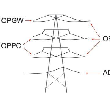
Figure 1: Application of OPGW, OPAC, OPPC, and ADSS Cables

can construct transmission links using optical ground wire (OPGW) or optical power phase conductor (OPPC) cables that include fiber and metallic conductors, or optical power attached cable (OPAC), which is wrapped around power or ground conductors. The application of these cables in a tower is shown in Figure 1.
ELECTRICAL CONDUCTORS WITH FIBERS
OPGW and OPPC cables are not new concepts. The first patents on such cables date to 1977, and they have been in regular use since the mid 1980s. The optical fibers are usually in the middle of the cable in a sealed metal tube, surrounded by steel strength members and aluminum conductors.

OPAC cables are newer technology and are mainly used in remote areas. OPAC cable wraps a small fiber optic cable tightly around a ground wire or power phase conductor. Since it is tightly wound around the electrical cable, the fiber cable has to be small and flexible. It also has to withstand the operational environment, moving with the power cable, withstanding wind, rain, ice, and any other environmental stress. Early installations had some problems with jacket abrasion, especially if not tightly wound, and coronal discharge and lightning can be issues.
Since the fi bers are glass and immune to electrical interference, fiber is not affected by

NETAWorld • 59
UNDERSTANDING THE PAST AND FUTURE OF FIBER OPTICS IN UTILITIES FEATURE

the electrical power being transmitted nor does it disturb the functions of the conductors. However, cable manufacturers should be consulted on specific applications, including proximity to power conductors, to ensure cable reliability.
On poles, the fiber optic cables are placed below the power conductors. In suburban and urban areas, older poles may have installed legacy copper phone cables and multiple fiber optic cables, sometimes bundled together. Working on these poles can be tricky, since damage to other cables is possible.
In areas where cables must be placed underground, there are many installation options. If conduit space is available, new fibers can be pulled into existing conduits. Sometimes special plastic tubes and fabric ducts can be pulled into existing ducts.
If construction is required for underground cables, traditional trenching, directional boring, or microtrenching can be used. Traditional trenching is expensive and disruptive to the area, but once a trench is opened, multiple ducts can be installed for future expansion. This is called Dig Once and is now a U.S. DOT policy. Directional boring is less disruptive, but it is slow and limits the size of ducts. Boring also requires extreme care to prevent damage to current infrastructure. One contractor using boring on a FTTH project punctured six water mains in six months.

Microtrenching is a new process based on using a large saw to cut a groove about a foot deep in a road or sidewalk and laying in small cables or microducts. During the sawing process, the dust is vacuumed up, then mixed with a mastic to fill the groove over the cable or ducts. Using a new type of cable called a microcable, the groove needs to be only about a half-inch wide to accommodate ducts for 288 fiber cables. Some contractors have laid two to three miles of cable in one day, and another is installing six microducts in the groove for future expansion to 1,728 fibers.
There are also other options for installing fiber. Techniques exist for placing cables in storm sewers, gas pipes, and even old coax cable. With unused coax, the technique involves blowing out the insides and blowing the fiber cable into the coax cable jacket.
These cables use standard, single-mode fibers for long links. Since there is a practical limit to how long a cable can be made, splicing is required periodically, and that is done on the ground, usually in a splice trailer. Splices are protected in enclosures attached to the towers or cables or placed inside buildings required for the communications equipment. At the ends, connectors are required for patch-panel connections or connecting communications equipment. Special splices on connectors or fiber pigtails are generally attached with fusion splicing.
FIBER PROJECT PLANNING AND MANAGEMENT
Fiber projects begin with establishing a need for communications defined by the type of communications (voice, data, and/or video). The location of the ends of the links determines the routes of the fiber optic cable plant. The routes then determine the types of installation, which determines the types of fiber optic cables needed as well as other hardware to complete the cable plant.
Personnel designing and managing the project must have a thorough understanding of fiber optic network design, installation, testing, and operation. Th ey must create a scope of work (SOW) that details the specifications for the network, project timing, and acceptance criteria. Contractors and suppliers are good sources of information on the project, but your own personnel must be able to set the standards for the project and evaluate recommendations to ensure proper choices are made.
FOA’s experience is that two important aspects of the project are often shortchanged: testing and documentation. Documentation needs to
60 • FALL 2018
UNDERSTANDING THE PAST AND FUTURE OF FIBER OPTICS IN UTILITIES FEATURE
show every detail of the installation including fiber and cable types, plus where every fiber — not every cable, but every fiber — goes, and test data for every fiber. Associated hardware must also be listed.
Testing is important to judge the quality of the installation and should be specified in detail in the SOW. A large fiber optic network will have tons of testing data, and someone who knows what the test data shows about the installation must review all the data before accepting the project.
The test data needs to be archived for future use. Since fi ber networks last for decades, upgrades to higher speeds and adding services are common. Test data is needed to show whether the fiber performance meets the needs of future upgrades. If a problem occurs that requires restoring a link, test data and
documentation are the best tools for a rapid restoration of service.
A future article in NETA World will cover testing fiber optic networks, including what needs testing and how to judge test results, as well as testing results as an important part of the network documentation package.

Jim Hayes is President and co-founder of the Fiber Optic Association (FOA). He was educated as a physicist and astronomer and has been in high tech for his entire career. Since he was introduced to fiber optics by Bell Labs staff in 1978, he has been involved in the industry as an entrepreneur, writer, and educator. He is the author of nine books on fiber optics and communications cabling, as well as hundreds of magazine articles and a frequent speaker on the topic. One of his latest projects was working with the Electric Power Research Institute (EPRI) on their upcoming Guidebook for Strategic Fiber.

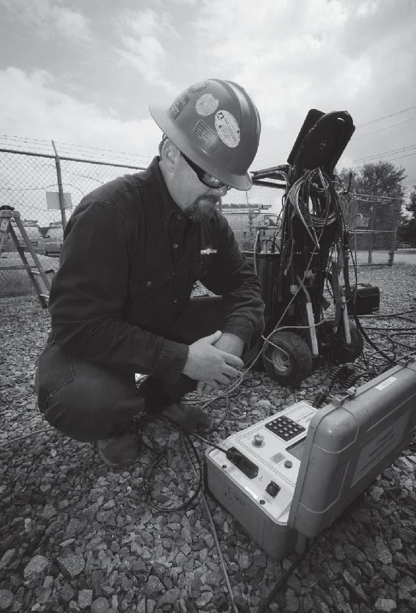

FEATURE
Accredited Company 204 Gale Lane Kennett Square, PA 19348 484.731.0200 enerGtest.com Serving clients in Pennsylvania, Delaware, New Jersey, Maryland, Washington, DC and New England. We deliver optimum system reliability and performance while reducing the chances of costly unplanned power outages. Whether you need acceptance ener es ™ testing or preventive maintenance, depend on EnerGTest to keep the power on. Reliable Power System Solutions







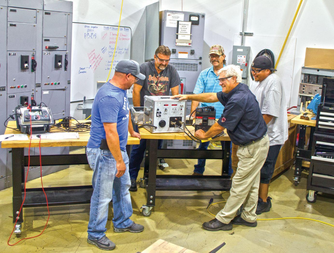


800.331.2002 | PotomacTesting.com POWER THROUGH WITH PARTNER WITH MID-ATLANTIC’S PREMIER PROVIDER OF ELECTRICAL TESTING, Since 1985


Many avo training courses are eligible for neta ctd’s t By offering the broadest selection of electrical training in the industry, we have a training course for all things electrical. We train to NETA and other industry recognized standards to take your knowledge to the next level. A training course is only as good as the instructor teaching it. That’s why our instructors are some of the most qualified in the industry. To be the best, train with the best. Offering over 57 electrical safety & electrical maintenance training courses and certifications. WWW.AVOTRAINING.COM 877-594-3156 Let us bring the training to your location, call today for an on-site quote Images depict a de-energized controlled environment with no chance for arc flash Hands-on training and NETA standards, together get you the most accurate field results. In order to provide a broad range of training and real world experiences, AVO Training Institute, Inc., courses are non-product specific. No AVO Training instructor nor contract instructor has any proprietary interest in any products, instruments, devices, services, or materials discussed.



NFPA 70B AND CSA Z463 STANDARDS: WHERE DOES FIT
IN?
BY ADRIAN MESSER , UE Systems, Inc.
When it comes to establishing an electrical maintenance program for your facility, many resources are at your disposal. An infrared camera is probably the first tool that comes to mind for inspecting energized electrical equipment. If you said an airborne ultrasound instrument, you are among a growing number of maintenance and reliability professionals who realize that airborne ultrasound is a viable tool that can effectively inspect and diagnose conditions such as corona, tracking, arcing, and partial discharge in energized electrical equipment.
Maintenance and reliability professionals responsible for establishing procedures and best practices for inspecting and maintaining electrical equipment in facilities are guided by standards such as the National Fire Protection Association (NFPA) 70B and the Canadian Standards Association (CSA) Z463. Both of these documents create recommended practices for inspecting and maintaining electrical assets to prevent accidents and reduce downtime.
NFPA 70B AND CSA Z463
According to NFPA 70B, Recommended Practice for Electrical Equipment Maintenance, an Electrical Preventive Maintenance program
is “a managed program of inspecting, testing, analyzing, and servicing electrical systems and equipment with the purpose of maintaining safe operations and production by reducing or eliminating system interruptions and equipment breakdowns.”
When it comes to the inspection tools that NFPA 70B recommends for inspecting energized electrical equipment, the document only mentions ultrasound in two sections. The first mention is in Section 11.21.3.3.2.2 discussing partial discharge. The other mention is in Section 15.1.2.2, which addresses corona in substations and switchgear.
64 • FALL 2018 NFPA 70B AND CSA Z463 STANDARDS: WHERE DOES AIRBORNE ULTRASOUND FIT IN?
INDUSTRY TOPICS
CSA Z463, the Canadian equivalent to NFPA 70B, goes into more detail regarding ultrasound technology. CSA Z463 Section 7.10.2 states, “Ultrasound inspections use collectors that detect the high frequency produced by the emissions caused by electrical arcing, tracking, and corona.” This section goes on to mention that the sound heard by the inspector can be recorded and further analyzed in spectrum analysis software for an accurate diagnosis of what was detected by the ultrasound instrument.
Users of airborne ultrasound, a technology that was once considered just a leak detector, quickly began to realize that the instruments could be used for other applications, such as condition monitoring of rotating equipment and electrical inspection. To many, airborne ultrasound has become a necessity when inspecting energized electrical equipment. The primary driver of this application is safety. In most cases, airborne ultrasound inspection can be performed without opening energized electrical cabinets. This helps reduce the risk the inspector faces from potential exposure to arc flash hazards.
WHAT IS ULTRASOUND?
Ultrasonic equipment detects airborne and structure-borne ultrasounds normally inaudible to the human ear and electronically transposes them into audible signals that a technician can hear through headphones and view on a display panel as a decibel (dB) level. On some instruments, incoming sound can also be viewed on a spectral analysis screen that displays either the fast Fourier transform (FFT) or time wave form (TWF). With this information, a trained technician can interpret condition to determine what, if any, corrective action is needed, and the current data can be compared to the baseline data on the spot.
Ultrasound technology has many advantages:
• Using ultrasound to listen prior to opening a panel or cabinet for further inspection can help reduce the risk or chance of an arc flash incident.
• Ultrasound can be used in virtually any environment.
• Learning to use ultrasound technology is relatively easy.
• The technology is relatively inexpensive.
• Modern ultrasonic equipment makes it easy to track trends and store historical data.
• Ultrasonic technology has proven itself to be extremely reliable in predictive maintenance, saving thousands of dollars and hours of lost productivity.

• There are remote monitoring options for both mechanical and electrical applications.
Airborne and structure-borne ultrasound instruments are an extension of the user’s sense of hearing. Just as accelerometers sense vibrations you can’t feel and infrared cameras see what you can’t see, ultrasound hears what you can’t hear. Sounds take place in a typical plant and manufacturing environment (machines running, production equipment running, etc.) that prevent us from hearing other sounds such as compressed air leaks or electrical discharges like corona, tracking, or arcing. Ultrasound instruments listen for sounds that are not present in our normal audible range.
Typically, the sounds outside normal human hearing are high-frequency sounds. These high-frequency sounds are detected by the instrument and translated through a process called heterodyning into an audible sound in the inspector’s headset. The dB level is indicated on the display of the ultrasound instrument.
Ultrasound inspection can be done by scanning any openings on the cabinet itself, such as vent openings, seals around doors and louvers, etc. Therefore, before any energized electrical cabinet is opened for maintenance or further inspection, a pre-inspection can be done with ultrasound to detect any anomaly. If there is a condition like corona, tracking, or arcing inside the electrical equipment, the ultrasound produced by those anomalies will be heard by the inspector via those openings. The source of the ultrasound produced is ionization.
NETAWorld • 65 NFPA 70B AND CSA Z463 STANDARDS: WHERE DOES AIRBORNE ULTRASOUND FIT IN?
INDUSTRY TOPICS

ELECTRICAL INSPECTION WITH ULTRASOUND
Ultrasound can be used to inspect almost any energized electrical equipment, including metal-clad switchgear, transformers, substations, relays, motor control centers, and many others (Figure 1). Ultrasound can be used to measure equipment voltages from the low end (110 volts) to well over 12,000 volts (12kV).
Corona refers to the ionization of air surrounding an electrical connection above 1,000 volts. By nature, corona does not produce significant heat that would be detected by an infrared camera. However, it does produce high-frequency sound that can be detected by the ultrasound instrument. If corona discharge continues to occur, it can lead to a more severe problem such as tracking or arcing. Byproducts of the ionization process are ozone, electromagnetic emissions, ultraviolet light, and nitric acid. Nitric acid is corrosive and can deteriorate the insulators and connectors and lead to tracking and arcing (Figure 2).
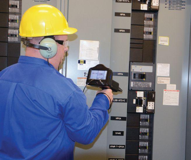
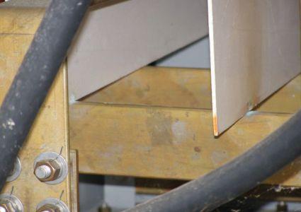
Figure 2: Corona activity has advanced to the tracking stage on insulation board resting on a 13kV bus. Notice the carbon deposits and light-brown discoloration of the insulation board on the right.
When the sound file of corona is recorded, signature characteristics are visible in the FFT and TWF that will help diagnose the condition. For corona, the discharge points only occur at the highest voltage point on the sine wave (Figure 3). This means that the amplitude peaks in the TWF are somewhat equally spaced, as the discharges are only at the positive peak of the sine wave. The result will be well-defined 60Hz or 50Hz harmonics (Figure 4).
Look for certain characteristics of tracking (low current pathway to ground across an insulator) and arcing (electrical discharge to ground across an insulator). With tracking, the discharge does not have to take place at the peak of the waveform; instead, it can happen anywhere on the positive portion of the cycle. The spacing of the peaks in the TWF would be similar, but not uniform. As tracking becomes more severe, more discharge events as well as more nonuniformly spaced narrow peaks occur. Arcing has the most non-uniform look in the FFT and TWF. Only the bursts of the discharge can be heard, and these will be seen as wide peaks in the TWF view (Figure 5).
CONCLUSION
NFPA 70B is in the middle of a revision period for the standard. The next revision is
66 • FALL 2018
NFPA 70B AND CSA Z463 STANDARDS: WHERE DOES AIRBORNE ULTRASOUND FIT IN?
INDUSTRY TOPICS
Figure 1: Traditional Ultrasound Inspection of Enclosed Energized Electrical Equipment
scheduled for release in 2019. I hope that the 2019 revision of NFPA 70B will add additional information regarding how ultrasound can be used for electrical inspections. CSA Z463 and NFPA 70B go into great detail regarding the inspection and maintenance of any electrical asset in a facility. Recommended procedures regarding asset criticality and establishing an electrical maintenance program are discussed. The current version of NFPA 70B now includes torque requirements because loose connections are a significant contributor to maintenance issues.
If you were on the NFPA 70B Technical Committee, I welcome any comments and discussion regarding airborne ultrasound technology and its use for inspecting energized electrical equipment. Interest in airborne ultrasound for electrical inspection is increasing, not only from maintenance and reliability professionals in plants and facilities, but also from insurance companies that inspect a facility’s electrical infrastructure.
REFERENCES
NFPA 70B. www.nfpa.org CSA Z7463. www.csa.ca

Adrian Messer, CMRP, is the Manager of U.S. Operations for UE Systems, Inc. For more than a decade, Adrian has helped facilities around the country transform their reliability programs by successfully implementing ultrasound technology for condition monitoring and energy conservation applications. As a subject matter expert on ultrasound technology and implementation best practices, Adrian has been a featured speaker at numerous industry events. He is a graduate of Clemson University and maintains close ties to the university, assisting current students in a mentorship program through the College of Business & Behavioral Science. Adrian is a Certified Maintenance & Reliability Professional through the Society of Maintenance & Reliability Professionals (SMRP), a charter member of the Carolinas Chapter of SMRP, and is currently the chapter Chairman.


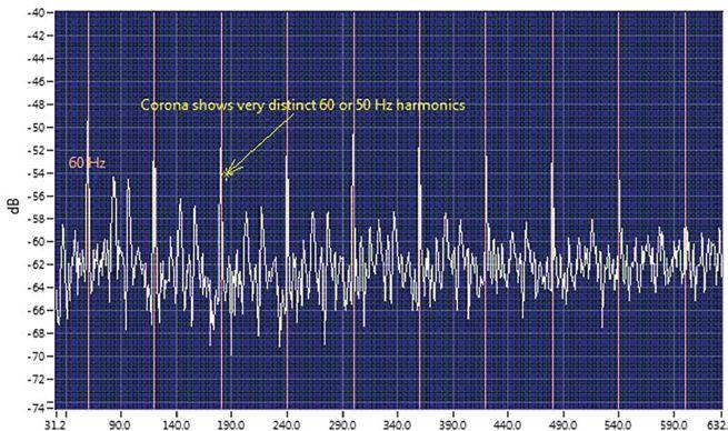
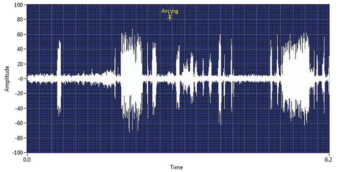
NETAWorld • 67
INDUSTRY TOPICS NFPA 70B AND CSA Z463 STANDARDS: WHERE DOES AIRBORNE ULTRASOUND FIT IN?
Figure 3: Example Discharge Points for Corona
Figure 4: FFT View of Recorded Sound File of Corona Showing 60Hz Harmonics
Figure 5: Arcing in the Time Wave Form View


NON-CONVENTIONAL
INSTRUMENT TRANSFORMER DESIGNS FOR AIR-INSULATED SUBSTATIONS
BY STEVEN A. KUNSMAN, NICHOLAS POWERS, and BHARADWAJ VASUDEVAN, ABB Inc., USA
In today’s electrical systems, currents in high-voltage equipment are measured using bulky and heavy current transformers in oil- or SF6-insulated designs. These use the principle of electromagnetic induction to generate a small secondary current, typically 5A or 1A nominal at rated current, from a primary current, which then serves as an input for protection relays or energy meters. Such transformers have represented the state of the art for many decades, and they operate reliably under the harsh conditions found in an outdoor substation.
However, besides their size and weight, these transformers have a number of additional shortcomings, the most important of which is that, as a result of magnetic saturation and limited bandwidth, the waveform of the secondary current is often not a true image of the primary current. Over 40 years ago, it was recognized that the Faraday Effect could be the basis of a new and better, technology for current measurement. But it is only in
the last 20 years that appropriate technology has become sufficiently mature to allow it to be used as a commercially attractive basis for fiber optic current sensor (FOCS) applications. The remarkable progress made by the optical communications business has provided many components that can be re-used for the FOCS, including light sources, fiber-optics, modulators, and photodetectors.
70 • FALL 2018 NON-CONVENTIONAL INSTRUMENT TRANSFORMER DESIGNS FOR AIR-INSULATED SUBSTATIONS
INDUSTRY TOPICS
Optical current and voltage sensors have found significant interest in recent years for use in electric power transmission. In particular, fiber-optic current sensors have become rather mature and are finding commercial applications not only in high-voltage systems, but also in industry, e.g., in the measurement of high direct currents (dc) in the electrowinning of metals (aluminum, copper, etc.). Optical sensors offer considerable benefits over conventional instrument transformers. They are inherently free of magnetic saturation and typically have a measurement bandwidth in the range of kilohertz (determined by the data rate). Bandwidths in the range of tens or hundreds of kHz are also feasible. As a result, fiber-optic current transformers deliver a true image of the primary current within their measurement range, and can also be used for fast-transient currents, short-circuit currents, and alternating current (ac) with dc offset. Furthermore, optical CTs are lightweight and small. It is possible to operate them as freestanding devices or integrate them easily into other power products. Substation footprint and installation costs are reduced. Other advantages include enhanced safety (no risk from open secondary CT circuits or catastrophic failure) and environmental friendliness (no oil). Optical current sensors are immediately compatible with modern digital substation communication, which helps to eliminate large amounts of copper cabling.
Modern fiber-optic current sensors have been developed for use in electric power transmission as well as for the measurement of high dc in industrial applications. Fiber optic current sensors use light to deduce the precise magnitude of current that is creating the magnetic field. FOCS designs for high-voltage substations include FOCS integrated with DCB disconnecting circuit breakers (DCBs), FOCS kits for integrating with other high-voltage equipment such as gas-insulated switchgear and generator circuit breakers, and free-standing fiber optic current sensors (FOCS-FS). The major difference is that these modern sensors now provide direct-to-digital outputs, not the analog outputs offered by earlier designs.
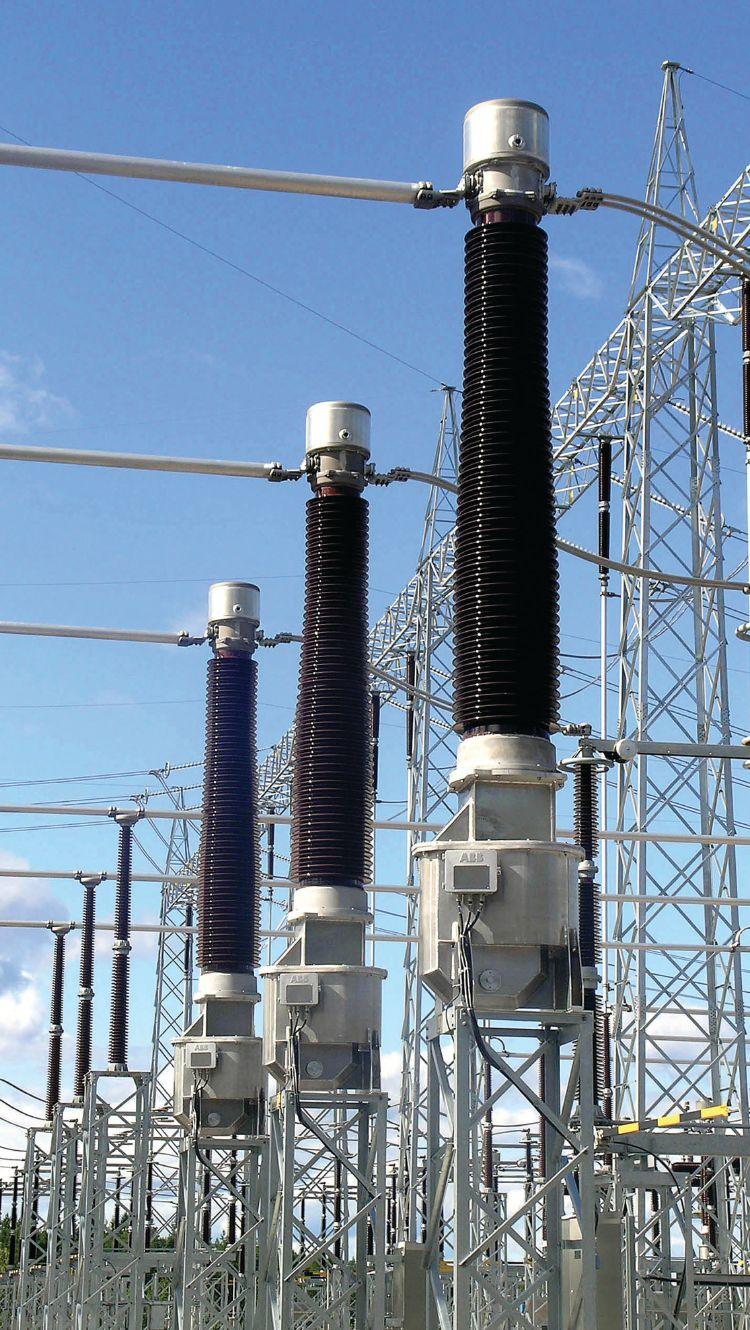
NETAWorld • 71 NON-CONVENTIONAL INSTRUMENT TRANSFORMER DESIGNS FOR AIR-INSULATED SUBSTATIONS
INDUSTRY TOPICS
420kV Oil-Filled Current Transformers


Sensor Electronics Module
Light source
Signal processor Controller Interfaces
Orthogonal
Sensing fiber
FOCS DESIGN AND HOW IT WORKS
FOCS designs exploit the Faraday Effect, which defines that left and right circularly polarized waves propagate at slightly different speeds when they travel in a medium that is subject to a magnetic field. The main components of the FOCS are an optoelectronics (OE) module or sensor electronics module at ground potential and a coil of sensing fiber, which is wound around the current conductor (Figure 1).
The OE module includes a semiconductor light source and a closed-loop detection circuit with a fiber-optic polarizer, an optical phase modulator, and a digital signal processor. The module sends two light waves with orthogonal linear polarization to the sensing fiber coil. At the coil entrance, a fiber-optic polarization converter transforms the linear waves into left and right circularly polarized light waves. These waves travel at different speeds through the sensing fiber in the magnetic field (caused by the current) as a result of the Faraday Effect, and this in turn creates an optical phase difference. The waves are reflected at the end of the fiber and they retrace their optical path back to the optoelectronics module, where they interfere at the polarizer.
The signal that results from the interference depends on the phase difference and is measured by a photodiode. The closed-loop
control circuit reverses the current-induced phase shift by means of a phase modulator so that the phase difference of the waves when they interfere at the polarizer is always kept at zero. The feedback signal to the modulator is then essentially an image of the primary current and the digital sensor output is derived from this signal. A particular advantage of this closed-loop detection scheme is that the signal is perfectly in proportion to the primary current over the entire measurement range. The roundtrip phase difference of the two light waves is proportional to the number of fiber loops and the line integral of the magnetic field along the closed path described by the sensing fiber. Geometrical parameters such as the coil diameter or the position of the conductor inside the fiber coil do not affect the signal. Currents outside the coil also have no influence.
Operation of the sensing fiber in reflection mode has the advantage that the sensor becomes immune to mechanical disturbances. The mirrored coil end swaps the polarization states of the light waves. As a result, vibrationinduced phase shifts cancel each other out over one roundtrip of the waves while the nonreciprocal magneto-optic phase shifts double.
By appropriately selecting the number of fiber loops, the measurement range can be optimized for specific applications. The typical sensor as
72 • FALL 2018
INDUSTRY TOPICS NON-CONVENTIONAL INSTRUMENT TRANSFORMER DESIGNS FOR AIR-INSULATED SUBSTATIONS
Current Conductor
linear light waves Left and right circular light waves
Detector
Optical fiber Retarder Mirror
Figure 1: FOCS Configuration
made for power transmission applications has a range of ±180kA. e operating temperature range of the sensor head is from below -40 degrees C to 105 degrees C. e OE module is designed for operation in a heated outdoor cubicle. It can be operated with three ber coils in parallel to cover all three phases normally found in a high-voltage installation.
ASCERTAINING ACCURACY AND STABILITY
e FOCS system is designed to meet the requirements for metering and protection in electric power transmission systems according to IEEE Class 0.15s, IEC Class 0.2s, Class 5P, and Class 5TPE. To achieve such performance, it is essential that the circular polarization states of the light waves in the ber coil are well maintained under all conditions of operation and not disturbed, e.g., by mechanical stress acting on the ber. Furthermore, the temperature dependence of the Faraday E ect (0.7 percent per 100 degrees C) must be taken into account. Techniques have been developed to package the sensing ber in a stress-free manner and to inherently compensate for the variation of the Faraday E ect from temperature by means of the ber retarder, which generates the circular light waves. Figure 2 and Figure 3 graphically represent the method of the temperature compensation.
e polarization converter ( ber retarder) at the entrance to the ber coil converts the two linearly polarized light waves coming from the opto-electronics module into left and right circularly polarized waves before the light enters the ber coil. e scale factor (sensitivity to current) of the sensor varies with the phase retardation ρ introduced by the polarization converter in a parabolic manner illustrated in Figure 2.
e heavy red curve segment indicates the scale factor decreasing at increasing retarder temperature, which balances the opposite change of the Faraday E ect with temperature.
If the room temperature retardation of the polarization converter is set to about 100 degrees instead of 90 degrees, the scale factor decreases at rising temperature stemming from the retarder (along the red heavy curve segment shown in Figure 2) and just balances the increase in the Faraday E ect as shown in Figure 3.
e theoretical scale factor versus temperature curve is calculated neglecting bend-induced birefringence in the fiber coil. Some modi cations apply in case of non-negligible birefringence.
With these measures, the sensor output becomes independent of temperature well

NETAWORLD 73
INDUSTRY TOPICS
NON-CONVENTIONAL INSTRUMENT TRANSFORMER DESIGNS FOR AIR-INSULATED SUBSTATIONS Normalized Scale Factor 1.04 1.03 1.02 1.01 80 80 100 90°C –40°C 1.00 Retardation ρ (deg) Normalized Scale Factor 1.02 –40 –20 020406080 Retarder contribution Combined contributions Faraday effect (Verdet constant) (1/V) δV/δT = 0.7x10⁻⁴ °C–1 1.01 1.00 Temperature (°C)
Figure 2: Sensitivity to Current
Figure 3: Scale Factor Balanced by Temperature

INDUSTRY TOPICS

less than ±0.1 percent over a range of at least from -40 to 85 degrees C without the need of an extra temperature compensation using additional T-measurement (Figure 4). Even at 105 degrees C, the sensor coil is still within the
requirements of IEEE metering class 0.15 and IEC metering class 0.2.
The physical principle and the proper choice of materials, coupled with absence of any nonlinear effects, defines excellent predictability and the perfectly linear relationship of the FOCS signal to the applied current, as shown in Figure 5.
FOCS overall system accuracy is independent on the measurement current range, so the same sensor can be designed and used for protection and measuring in the whole dynamic range of common power devices. Further on, the system measures only the instantaneous values of a current; more precisely, it is measured average current during 700-800 nanoseconds without any effects of the current history curve. Therefore, the same system can be used for measurement of ac and dc currents, as well as for ac with dc offset.
MEASURING DIRECT CURRENT FROM GEOMAGENTIC DISTURBANCES
The fiber optic current sensor was originally designed to measure direct current. Applications included current measurement for process control and protection in the electrowinning industry, for example at
74 • FALL 2018
NON-CONVENTIONAL INSTRUMENT TRANSFORMER DESIGNS FOR AIR-INSULATED SUBSTATIONS
Normalized signal 1.006 1.004 1.002 1.000 0.998 0.996 0.994 –40–20 020406080 100
Figure 4: Sensor Output
Signal to Applied Current Sensor signal (A) Current (A) 100000 10000 1000 100 10 100000 10000 1000 100 10 Deviation from linearrity Current (A) 100000 10000 1000 100 10 0.40% 0.20% 0.00% –0.20% –0.40%
Figure 5: Linear Relationship of FOCS

aluminum smelters. The ability to measure direct current (dc) is very important for transmission utility alternating current (ac) application. The North American Reliability Corporation (NERC) has introduced TPL007, which requires bulk power transmission and generation owners to monitor the effects of geomagnetic disturbances (GMDs). Th e disturbances, a result of our sun’s solar flare activity, produce geomagnetic induced currents (GICs) coupling to utility transmission lines.
During a GMD event, the GIC into the transmission line could impact the large power transformer because the dc coupled with the GIC causes the transformer to have hot-spot heating that leads to damage. These loose, reactive power sources increase the reactive power demand, which may lead to system voltage collapse and potential blackouts.
NERC TPL-007 requires asset owners to perform vulnerability assessments of their system to be able to a benchmark a “1-in-100year” GMD event. One common solution to address this measurement is to apply Halleffect sensors to the neutral on large power transformers at risk. However, the neutral dc measurement does not represent the actual transmission line direct current and is inadequate for autotransformers.
Deployment of the FOCS will allow a precise measurement of both the ac and dc measurements on the transmission line per-
phase currents. The extraction of the per-phase dc line current can be used to not only measure the amount of line current, but also drive an automated mitigation scheme that assesses transformer impact and identifies the required reactive power to stabilize the impacted large power transformer. The combination of the FOCS and a modern substation protection and control device measures and extracts the dc value that is delivered to the utility operation center via a SCADA protocol or pay loaded into the synchrophasor measurement unit (PMU) data for proactive mitigation or longterm profiling.

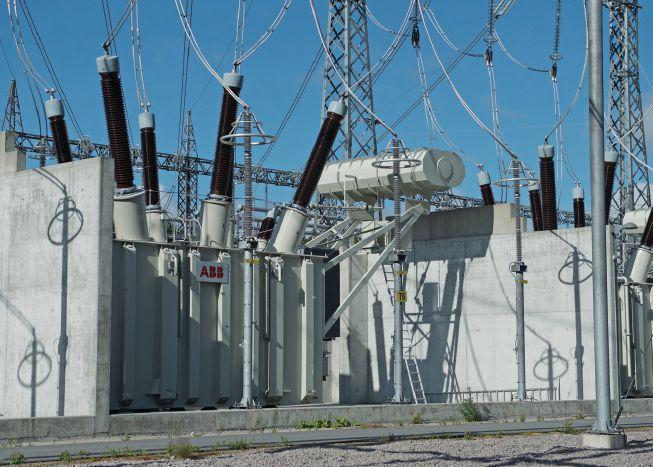
NETAWorld • 75 NON-CONVENTIONAL INSTRUMENT TRANSFORMER DESIGNS FOR AIR-INSULATED SUBSTATIONS INDUSTRY TOPICS
Figure 6: GMD Produced from Solar Flares
Figure 7: This large power transformer could be impacted by GMDs produced from solar flares.


LOOKING AHEAD
FOCS technology will serve as a platform for other high-voltage applications. The variable diameter of the sensing head allows the sensor to be easily adapted to high-voltage equipment such as gas-insulated switchgear (GIS) or generator circuit breakers. By choosing the fi ber loop number appropriately, high accuracy can also be achieved at low currents, e.g., in zero sequence current measurements. New or improved substation protection and monitoring functions may follow from the fast response of the FOCS and its precise measurement of both ac and transient dc.
Using FOCS in high-voltage substations means the measurement is digitized right at the source and transmitted as a digital signal, via the process bus, to the protection and control IEDs, as well as the revenue meters. This eliminates copper runs from the substation back to the control room. Coupling the benefits of fiberoptic current sensor solution with direct-todigital capability will facilitate the development of digital substations and enable the grid to get smarter. New FOCS designs address demanding performance requirements for accuracy across a wide temperature range. It is inherently free of magnetic saturation, making it ideal for capturing fast-transient currents and short-circuit currents. The compact design helps achieve reduced substation footprint, as it requires much smaller space compared to conventional instrument transformers. It is also an eco-efficient solution that uses no oil or gas, eliminating the risk of explosion.
CONCLUSION
FOCS is one of a range of non-conventional instrument transformers (NCITs) that can make substations entirely digital. These NCITs have to be every bit as reliable as the equipment being replaced — and they are. Over the past 30 years of real work experience, companies making optical sensors have gained a unique perspective of how to make these systems more reliable. Extensive use of NCITs makes a substation simpler, cheaper, smaller, and more efficient.
Improvement in fiber-optic current sensors and integration of standalone merging units also provides utilities and engineering firms with a great tool box for the future deployment of this maturing technology. For retrofit applications, the possibility of installing the new process bus system in parallel with the existing system will allow the substation to remain in service during the main part of the work. This will be a big advantage, reducing outages to a minimum during the retrofit.
REFERENCES
K. Bohnert, P. Gabus, H. Brändle, and A. Khan. “Fiber-optic current and voltage sensors for high-voltage substations,” 16th International Conference on Optical Fiber Sensors, Nara, Japan, October 13-17, 2003, Technical Digest, pp 752-755.
Rahmatian, G. Polovick, B. Hughes, and V. Aresteanu. “Field experience with high voltage combined optical voltage and current transducer,” Cigre (Paris), Session 2004, paper A3-111.
J. Wang, Z. Guo, G. Zhang. “Study on long-term stability of 110 kV power optical sensor solution - optical current transducer,” in Proceedings APPEEC 2010 (Asia-Pacific Power & Energy Engineering Conference 2010), Chengdu, China, 28-31 March 2010, pp 1178-1179.
K. Bohnert, P. Gabus, J. Nehring, H. Brändle, M. Brunzel. “Fiber-optic high current sensor for electrowinning of metals,” Journal of Lightwave Technology, 25(11), 3602 (2007). 5. German patent E4224190B4, 22.7.1992.
Frosio and R. Dändliker. “Reciprocal reflection interferometer for a fiber-optic Faraday current sensor,” Appl. Opt., vol. 33, no. 25, pp. 6111-6122, 1994.
J. Blake, P. Tantaswadi, and R.T. de Carvalho. “In-line Sagnac interferometer current sensor,” IEEE Trans. Power Delivery, vol. 11, no. 1, pp. 116-121 (1996).
K. Bohnert, P. Gabus, J. Nehring, and H. Brändle. “Temperature and vibration insensitive fiber-optic current sensor,” Journal of Lightwave Technology, 20, 267-276 (2002).
76 • FALL 2018
NON-CONVENTIONAL INSTRUMENT TRANSFORMER DESIGNS FOR AIR-INSULATED SUBSTATIONS
INDUSTRY TOPICS
H-E Olovsson, T. Werner, P Rietmann. “Next generation substations,” ABB Review Special Report on IEC 61850, pp. 33-37.

Steven A. Kunsman is Director Product Management and Applications, ABB Power Grids - Grid Automation North America. Steve joined ABB Inc. in 1984 and has over 34 years of experience in substation automation, protection, and control. He graduated from Lafayette College with a BS in Electrical Engineering and from Lehigh University with an MBA concentrated in management of technology. Today, Steve is responsible for ABB North American Substation Automation business’ technical team. He is an active member of the IEEE Power Engineering Society PSRC and PSCC Committees, PSCC Cyber Security Subcommittee chair, and has held multiple working group chairs, an IEC TC57 US delegate in the development of the IEC61850 communication standard, and UCA International Users Group Executive Committee Co-Chair..
Nicholas Powers is NAM Marketing Manager, ABB Power Products — High Voltage Instrument Transformers. Nick joined ABB in 2008 with the acquisition of Kuhlman Electric and is ABB’s NAM HVIT Marketing Manager and Global Product Marketing Manager for Station Service Voltage Transformers. He


has 37 years of experience in the instrument transformer eld for electrical systems from 600 V up to 800 kV. Nick has a B.S. in electrical engineering from the University of Kentucky and completed courses of study in marketing and business development at the University of Wisconsin School of Business. He has helped develop advanced HVIT designs targeted for the rapidly changing electric utility in measurement, protection, and control instrument transformer needs.

Bharadwaj Vasudevan is an Application Engineer at ABB Power Systems — Substation Automation North America. He graduated from North Carolina State University with an M.S. in electrical engineering and started his career with Areva T&D Ltd in New Delhi, India, as a Power Systems Engineer. Bharadwaj worked on various EHV substation design projects throughout India before joining ABB as a consulting engineer for the Power Systems group. With a strong background in real-time power system modeling, he develops transient system models for transmission planning projects. In his current role with the Power Systems Automation group for the North America market, he supports all transmission-level Relion relay products from Raleigh, North Carolina. He is a member of the IEEE Power System Relay Committee and contributes to various working groups in the Relay Communications subcommittees.

Industrial Electric Testing, Inc.
• Cables
• LV/MV Circuit Breakers
• Rotating Machinery
• Meters
• Automatic Transfer Switches
• Switchgear and Switchboard
Assemblies • LV/MV Switches
• Relays - All Types
• Motor Control Centers
• Grounding Systems
• Transformers
• Insulating Fluids
• Thermographic Surveys
Reclosers
Surge Arresters
Capacitors
Batteries • Ground Fault Systems • Equipotential Ground Testing
CoNSulTING AND ENGINEERING SERvICES
Load Studies
Transient Voltage Recording and Analysis
Electromagnetic Field (EMF) Testing
Harmonic Investigation
Replacement of Insulating Fluids
Power Factor Studies

EC13004105 • 24 Hour Emergency Service ACCEPTANCE AND MAINTENANCE TESTING AND REPAIR
•
•
•
•
•
•
•
11321 West Distribution Avenue • Jacksonville, Florida 32256 • (904) 260-8378 201 NW 1st Avenue • Hallandale, Florida 33009 • (954) 456-7020 INDUSTRY TOPICS
•
•
•


THE PREMIER ELECTRICAL MAINTENANCE AND SAFETY CONFERENCE CALL FOR EXHIBITORS Gaylord Texan Resort and Convention Center - Grapevine, Texas • Join 500+ electrical testing professionals • Leading decision-makers looking for new products and services • For attendee profile and additional information, visit www.powertest.org PowerTest.org l 888.300.6382 Hosted by

We have you covered. We understand that the most important electrical testing takes place before your system is powered on. And now that National Field Services has acquired two new locations in Las Vegas and Reno, we have the ability to offer even more customers start-up and maintenance services throughout the lifecycle of their switchgear.
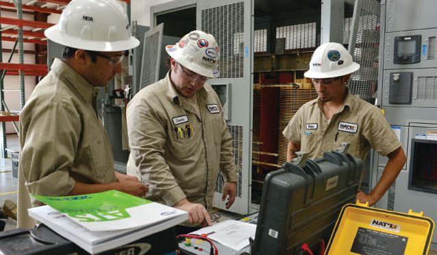
Tap into the power of National Field Services at natlfield.com or call us today at (800) 300-0157.
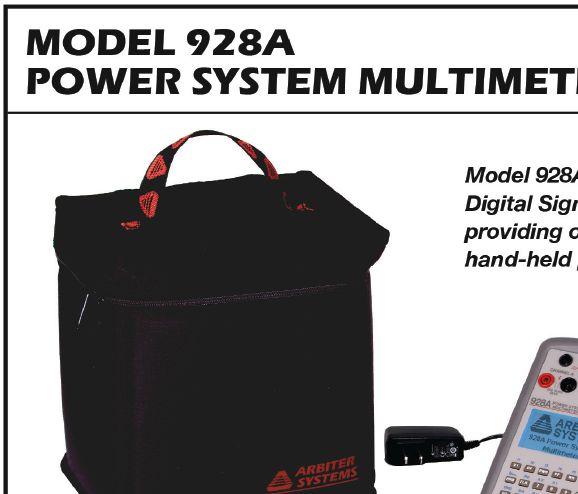
performance by design sm

CAN’T AFFORD TO GAMBLE ON YOUR ELECTRICAL RELIABILITY?


SPLICING AND TERMINATING... DEFECTS DON’T HIDE
BY SCOTT SANITI, Shermco Industries
Developments in the field of splicing and terminating — from the earliest tape splices to the current pre-molded ones — have taken a task that required lengthy proficiency training and reduced it to one that can be more readily accomplished. Care must be taken, however, to avoid errors during installation that can lead to premature failure.
Cable splicing and terminating have evolved a great deal over the last 50 years. Highly skilled craftsmen constructed the first splices with tape. The process took years of training to master.
As time progressed, fewer and fewer highly skilled craftsmen existed.
Premolded splices began to appear in the early 1960s. From that point forward, the skill level to splice a high-voltage cable was reduced, and it no longer took a skilled craftsman to install a splice. Premolded splices typically
consist of a one-piece molded body, insulation, and an insulation shield all molded into one body. The electrode covers the connector and extends onto the cable insulation, creating a Faraday cage, which puts everything at the same potential and reduces electrical stress to a minimum.
Heat-shrink and cold-shrink accessories were not far behind. Although cable splicing became easier and more forgiving with the premolded splices, certain errors made during cable preparation (e.g., surface defects), still required training.

80 • FALL 2018 SPLICING AND TERMINATING...DEFECTS DON’T HIDE!
INDUSTRY TOPICS
Premolded Cable Splice

Figure 1: Stress Lines Caused by Sharp Points on Semi-Con
Manufacturers of cable accessories offer training on their products to ensure they are properly installed. The National Joint Apprenticeship and Training Committee (NJATC) — now called the Electrical Training Alliance (ETA) — was formed by the IBEW and NEMA 60plus years ago. ETA provides adequate training for electricians on all aspects of the electrical industry, up to and including cable splicing.
COMMON ERRORS
A properly installed splice or termination can have a life expectancy of 25 years or more, while a poorly installed device may fail in years, months, or even as soon as it is energized. Some common mistakes made when terminating a cable include:
• Knife cuts in the cable insulation
• Semi-con not removed
• Using the wrong cutbacks
• Misalignment
• Jagged semi-con step
• Not following installation instructions
• Not using grease or using the wrong grease
Premolded splices use a conductive electrode and a geometric design to manage the electric field and act to control stress on the cable. Common errors in splicing include:
• Positioning off center
• Incorrect size splice
• Improper connector crimping
• Improper connector
These mistakes can and will affect the overall performance of the accessory, but some may not show up for a quite some time. Depending on the severity of the mistake, it may or may not show up initially during the acceptance testing or later when maintenance testing.
For example, jagged edges on the semi-con will cause more electrical stress at those edges (Figure 1), which in turn will cause a faster dielectric breakdown of the cable insulation. When making the semi-con cutback, take care not to cut into the cable insulation (Figure 2), as the stress will be more concentrated in this area (Figure 3) and, along with reduced insulation thickness, will cause premature failure.

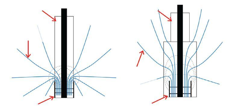
Equipotential Lines

2: Cut into Insulation
Equipotential Lines
3: Expected Stress Lines

NETAWorld • 81 SPLICING AND TERMINATING...DEFECTS DON’T HIDE!
TOPICS
INDUSTRY
Insulation Insulation
Shield
Insulation
Insulation
Shield
Figure
Figure

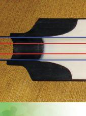
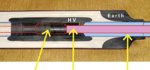
TESTING: HIDING THE FACTS
Over-crimping of the connector or using the incorrect die when crimping can cause several issues:
• Over-crimping (more than recommended by the manufacturer) affects the overall integrity of the connector and can lead to overheating or thermal runaway of the connector.
• Failure to remove sharp edges from the crimp can damage the interior of the splice by penetrating into the splice cavity.
A splice is designed to essentially rebuild the cable (Figure 4). It is also designed so that a failure that occurs under normal operating conditions would usually be off the end of the connector and out through the transition portion of the splice. Generally, any other failure mode can be attributed to installer errors, such as mispositioning of the splice or poor workmanship preparing the cable for installation, or to a defective product.
Important precautions to remember when prepping cable include:
• Proper cutbacks
• Clean surfaces
• Smooth, even edge of semi-con (no fragments or sharp points)
• Insulation imperfections removed
• Proper die used for crimping and not over-crimped
• Do not apply or make contact with semicon region with cable cleaner as it will separate from the cable insulation and cause a defect within the cable.
• Do not sand the semi-con region.
Studies have shown that testing with dc will miss the vast majority of these errors and can cause more damage on service-aged cables. Testing with ac (power frequency or VLF) will uncover more of the errors and defects associated with the splice, termination, or cable. The recommended acceptance testing for new installations on new cable using ac VLF is 60 minutes (Figure 5). Studies have shown that testing for a 60-minute time interval reduces the likelihood that any defects will be missed. Defects can be detected most effectively with partial discharge testing, either on-line or offline, which will pick up the voids within the insulation of the splice or termination missed by a dc withstand hi-potential test.
One misconception is that tan delta testing will detect bad terminations. Remember that tan delta testing measures the health of the cable insulation — not necessarily the condition of the termination. You can rule out the terminations by simply guarding them out during the test.

SHIELDING/GROUNDING
It is very important to take care with the shielding of the cable, as it is the path the fault current utilizes. When dealing with tape shield (which is very common in most of our applications in the industrial sector), it is
82 • FALL 2018
SPLICING AND TERMINATING...DEFECTS DON’T HIDE! INDUSTRY TOPICS
Figure 5: Sixty-Minute Test Time on New Cable
Figure 4: Splice Placement on Cable
important not to directly use the tape shield to attach to the ground or ground bus. The appropriate gauge wire should be attached to the shield first, then attached to the ground bus.
When splicing a shielded cable, be sure to ask the customer if they use a cross-bonding method, as this differs greatly from the common configuration.
CONCLUSION
Following these simple steps will result in a reliable product that will last a long time.
• Follow the manufacturer’s instructions.
• Be cognizant of how you are preparing the cable.
• Remove any sharp edges on the connector.
• Remove any defects in the insulation that may appear from prepping the cable.
• Clean the insulation thoroughly, being careful not to get any cable cleaner on or near the semi-con region (this will lift the bond between the semi-con and insulation).
• Do not sand the semi-con region.
• Use the proper crimp die for aluminum or copper conductors when crimping the connector. Shear bolt connectors (Figure 6) do not require a crimp tool for installation and can be used on copper as well as aluminum.
• Apply only the recommended number of crimps as stated by the manufacturer.
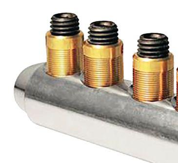



Scott Saniti is the Reliability Manager at Shermco Industries. Scott joined Shermco Industries in 2014 as a cable specialist focusing on cable reliability testing and primary cable fault locating before moving to the position of Reliability Manager, where he focuses on managing reliability maintenance and condition-based maintenance schedules and procedures. Scott began his career at 3M’s Electrical Markets Division as a High-Voltage Technologist in the product development group, then moved through positions at Megger, Emerson ERS, and Director of Operations and Application Support at Protec Equipment Resources. While at 3M, he authored a paper titled “High-Voltage Cable Splicing and Terminating.”


NETAWorld • 83
SPLICING AND TERMINATING...DEFECTS DON’T HIDE! INDUSTRY TOPICS
Figure 6: Shearbolt Connector


Where technicians, equipment and jobs intersect Available at 888.902.6111 | assist@intellirentco.com | assist.intellirentco.com An app-based platform, built for testing organizations assist uses the people and normal processes of a testing organization to manage and track test equipment. It’s built for barcoding, tracking and scheduling test equipment that your company owns or rents


The most trusted brands trust Electro Rent. A global test and technology solution provider, Electro Rent delivers over 50 years of experience in advising customers on electrical testing products and the best acquisition approach. RENT / LEASE / PURCHASE • Largest Test Inventory • Immediate Availability • Local Service Centers • ISO & ANSI Accredited Labs electrorent.com 1.800.553.2255
NETA ACTIVITIES UPDATE — JANUARY THROUGH JUNE 2018
POWERTEST 2018 — ELECTRICAL MAINTENANCE AND SAFETY CONFERENCE
February 26 – March 2, 2018
NETA hosted PowerTest 2018 in Washington, DC, drawing record attendance. With more than 47 unique training sessions, the conference provided a broad agenda of technical training opportunities for technicians, engineers, project managers, and professionals involved in the testing and maintenance of electrical power systems.
IEEE IAS ESW CONFERENCE
March 19 – 23, 2018
In March, NETA again maintained a presence at the Electrical Safety Workshop (ESW) tradeshow at the Omni Hotel in Fort Worth, Texas. Sponsored by the IEEE IAS Electrical Safety Committee, ESW is a must-attend event for electrical safety professionals. It’s a great opportunity for NETA to engage them about the ANSI/NETA standards, NETA Training, NETA Accredited Companies, and the NETA Certification Exam.
INTERNATIONAL CONFERENCE OF DOBLE CLIENTS
April 8 – 13, 2018
Held annually in Boston, Massachusetts, the International Conference of Doble Clients brings together professionals from all
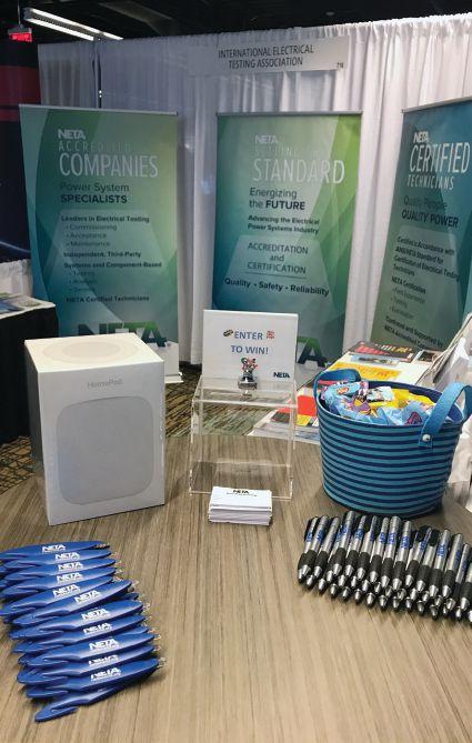
NETA Booth at International Conference of
business sectors serving the power industry and addresses pressing topics affecting power generation, transmission, and distribution. NETA joined more than 100 industry suppliers at the Doble Expo and offered technical training courses, ANSI/NETA standards, and technical resources.
NETA ACTIVITIES UPDATE — JANUARY THROUGH JUNE 2018 86 • FALL 2018
Doble Clients
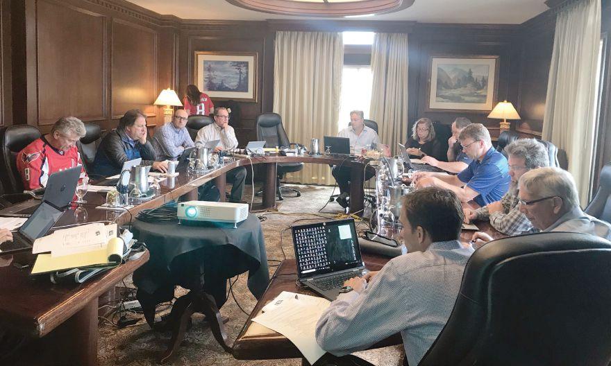
EXAM COMMITTEE MEETING
May 17 – 19, 2018
This spring and summer, the NETA Exam Committee, led by Chair Dan Hook, achieved further NETA Certification Exam development goals at a collaborative meeting in Tampa/St. Petersburg, Florida. Development professionals and NETA subject matter experts navigated a three-day workshop focused on maintaining and advancing the relevance and integrity of the NETA Certification Exam.
GSA PRESENTATION
May 22 – 23, 2018
In May, NETA presented to the General Services Administration (GSA) in Washington, DC. NETA answered a call for input on how ANSI/NETA MTS, Standard for Maintenance Testing Specifications for Electrical Power Equipment and Systems can support the agency in its strategic goals, including saving taxpayer money through better management of federal properties.

ANNUAL PLANNING AND BOARD OF DIRECTORS MEETING
June 14 – 15, 2018
NETA held its Annual Planning and Board of Directors meetings in Victoria, British Columbia, Canada. Planning discussions centered on association development, membership services, technician certification, NETA training resources, and updates to the ANSI/NETA standards. Committee Chairs reported on accomplishments in 2018, and the Board of Directors approved plans for fiscal 2019 to keep NETA on track with longterm goals.
NETAWorld • 87 NETA ACTIVITIES UPDATE — JANUARY THROUGH JUNE 2018
The NETA June Board Meeting was held in Victoria, British Columbia, Canada.











ers.VertivCo.com • 877-468-6384 Plug Into Our Expertise


HOME SAFE GET THEM
The only way to avoid arc flash is to stay outside the danger zone by operating electrical equipment with remote racking and switching solutions from CBS ArcSafe.


Remote racking and switching solutions from CBS ArcSafe allow technicians to operate electrical equipment from up to 300 feet away. Our best-in-class solutions reduce fatigue from manual racking, reduce the need for hot PPE gear, and give you the data you need for preventive and predictive maintenance operations. And thanks to our proprietary magnetic latching, our solutions protect the integrity of your equipment. Call us to set up a demo at your facility to keep your technicians safe from arc-flash incidents.
GET 3 TEST SETS FOR THE PRICE OF 1 WITH THE NEW VITS6 0 M
THE VITS6 0 M PERFORMS HIGH-POTENTIAL (HIPOT) TESTS FOR VACUUM INTERRUPTER TESTING UP TO 6 0 KV, AS WELL AS RESISTANCE, POLARITY INDEX, AND ABSORPTION RATIO TESTS.
Unlike other DC HiPot test sets on the market, the VITS60M not only performs specialized go/no-go tests on vacuum interrupters at up to 60 kV DC but also includes a 2.5/5/10 kV megohmmeter for Resistance, Polarity Index, and Absorption Ratio testing. Get 3 test sets for the price of 1 with the VITS60M.
This simple-to-operate set walks technicians through setup, generating a visual go/no-go result for testing the dielectric strength of various vacuum breaker components during regular maintenance, while offering fully programmable leakage current thresholds and test durations.

FEATURES AND BENEFITS
• Safety features with auto discharging, interlock, and safety control button
• Integrity test, Insulation Resistance test, Absorption test, and Polarity test all in one — lower price, more functions
INTERESTED IN A DEMO?
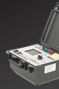
• Operates in 1 kV DC increments instead of 5 kV DC
• Easy-to-use, programmable set walks technicians through setup, tests, and results
• Failure indicator LED makes it easy to interpret results (green light: pass; red light: fail)
Let us bring our equipment to your facility for an on-site demonstration. Contact us at info@vacuuminterruptersinc.com or (214) 442-5877.


www.CBSArcSafe.com Distance is Safety (877)-4-SAFETY RRS-2 RRS-3 AKD-6 RRS-3 DHP/DVP (S) RRS-1
vacuuminterruptertesting.com | info@vacuuminterruptersinc.com

NETA WELCOMES NEWEST ACCREDITED COMPANY — J.G. ELECTRICAL TESTING CORPORATION
J.G. Electrical Testing Corporation was established in 2010 to provide the highest level of service to its clients, servicing low- and medium-voltage electrical equipment in the New York/New Jersey tri-state area. President George Stopera is a licensed electrician in the state of New Jersey and has extensive experience in electrical contracting, building management, and electrical testing. Howard Trinkowsky, Vice President and NETA Accredited Representative, has specialized in all aspects of electrical testing, is a Level III Certified NETA Technician, a Level III NICET Certified Technician, and a Level III Certified Thermographer.
The company’s mission is to provide the highest level of maintenance and testing through state-ofthe-art equipment and techniques. J.G. Electrical Testing’s pledge is to establish lasting relationships with customers by exceeding their expectations and gaining their trust through exceptional performance by every member of its team. In fact, the company’s team members are available 24 hours a day to meet the customer needs.
President George Stopera says, “We are proud to become fully accredited with NETA. Our
association with NETA provides tremendous value to our firm and to the customers we serve. Certifying the company and our field service technicians through the demanding accreditation process helps assure quality, experience, and training in the eyes of our clients. We also acknowledge all of our employees. Without their dedication, we would not have achieved this level of expertise.”
“NETA extends a warm welcome to J.G. Electrical Testing Corporation as its newest NETA Accredited Company,” says Jim Cialdea, Chief Technical Officer of CE Power and current president of NETA. “NETA Accredited Companies are such an important part of our work to advance the electrical power systems industry and assure electrical power system safety and reliability. It is not easy to achieve NETA accreditation, and this should be recognized as a well-deserved milestone for J.G. Electrical Testing.”
J.G. Electrical Testing
3092 Shafto Road, Suite 13
Tinton Falls, NJ 07753
Tel. (732) 217-1908 Fax (732) 791-1441 www.jgelectricaltesting.com
NETAWorld • 91 NETA WELCOMES NEWEST ACCREDITED COMPANY — J.G. ELECTRICAL TESTING CORPORATION
(Left to Right) Paul Jackson, George Stopera, Dean DiSanzo, Patrick Smith, Ryan Strafer, Howard Trinkowsky

Arizona (480) 967-7765 linc.mcnitt@hamptontedder.com Nevada (702) 452-9200 roger.cates@hamptontedder.com California (909) 628-1256 ken.peterson@hamptontedder.com jim.andersen@hamptontedder.com Family Owned and Operated Since 1958

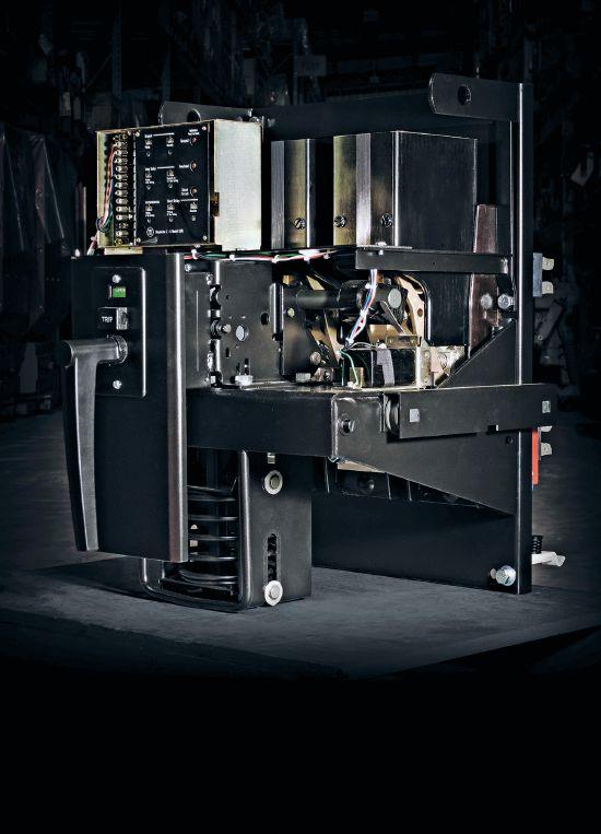


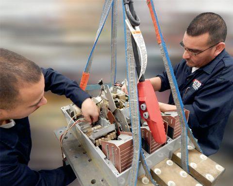


1315 Columbine, Gainesville, Texas 76241 | 800-232-5809 INFO @ CBSALES.COM | CircuitBreaker.com CBS Florida | Lakeland, Florida | 863-646-5099 | CBS-Florida.com CBS Midwest | Crown Point, Indiana | 219-575-5420 | CBSMidwest.com new service locations CBS stocks every low- and mediumvoltage circuit breaker made in America since 1945. With more than 5 million breakers and parts in our 200,000-square-foot warehouse — including switchgear, transformers, substations, protective relays, loadbreak switches, electrical contacts, motor controls and centers, vacuum interrupters, and more — Circuit Breaker Sales has you covered. √ Replacement parts and equipment √ Remanufacturing, retrofits, and upgrades √ Reverse engineering, 3-D printing of obsolete parts For more information about Group CBS and its affiliate companies, visit GroupCBS.com. CircuitBreaker.com (800) 232-5809 TOLLFREE Your TRUSTED online resource for authentic circuit breaker and electrical distribution equipment CB Store.com From a single part to a switchgear lineup, Advanced Electrical & Motor Controls’ inventory of low-voltage insulated case circuit breakers, molded case circuit breakers, motor controls, and custom switchgear is second to none in the U.S. No matter what you need — new, surplus, used, or reconditioned power distribution equipment, testing and repair, or an engineered solution — AEAMC will keep you up and running. Insulated Case Circuit Breakers Molded Case Circuit Breakers Motor Controls & Centers Bolted Pressure Switches Panelboard Switches & Bus Plugs 480 V Distribution Transformers Replacement Parts UL-Listed Motor Control Center Replacements Let us test, repair, and extend the life of your: Search. Click. Ship. Purchase AEAMC equipment online, anytime! Emergency support 24/7 800-289-2757 No One Knows Low-Voltage Circuit Breakers & Motor Controls Like Advanced Electrical & Motor Controls Advanced Electrical & Motor Controls Inc. 1801 HURD DR. | IRVING, TX 75038 | 972-253-7783 | Sales@AEAMC.com | AEAMC .com


MEDIUM-VOLTAGE VACUUM CIRCUIT BREAKER LIFE EXTENSION: A NEW APPROACH — PART 2


 BY FINLEY LEDBETTER and DAVID WALTERSCHEID, Group CBS, Inc.
Vacuum circuit breakers are the dominant switchgear technology used in medium-voltage (1kV-38kV) power system applications due to their smaller size, increased service life, and ease of maintenance. However, many of the medium-voltage vacuum circuit breakers (MVVCBs) in service today are nearing or exceeding their expected lifespan. This twopart paper provides evidence that simply using a breaker’s age or number of operations to quantify mechanism health and schedule maintenance is ill advised due to the effects of outside variables.
Part one, which appeared in the Summer 2018 issue of NETA World , discussed the properties and data that can off er a more accurate service life projection for breakers and described a three-tiered approach using industry standardized maintenance intervals and philosophies during the life of the equipment. This final section of the article describes newly available testing techniques and technologies to collect the data needed for an accurate service life projection for breakers, as well as component upgrades with replacements that can modernize the aging population of
MVVCBs and keep these valuable assets in service for many years to come.
NEW TESTING TECHNIQUES
New developments in reliable, efficient test instruments and testing methods have made it possible to improve and re-evaluate historical methodologies. To minimize personnel injury, failures, and equipment damage, MVVCBs must be routinely tested and maintained to ensure proper function when called to action even after months or years of inactivity.
94 • FALL 2018 MEDIUM-VOLTAGE VACUUM CIRCUIT BREAKER LIFE EXTENSION: A NEW APPROACH — PART 2
ADVANCEM ENTS IN INDUSTRY

Wipe Spring Force
The energy stored in the closing springs of the circuit breaker mechanism provides a set amount of motion. The first portion of this motion is used to rapidly close the VI contacts. The remaining travel, known as wipe, is used to compress a preloaded spring (shown in yellow in Figure 1) to apply and maintain a constant force on the VI contacts while the breaker is closed.
Wipe has three main purposes:
• Compensate for contact erosion over time
• Maintain a low contact resistance
• Counteract the popping or blow-off force
As the contacts inside the VI erode over time, the additional stroke in the mechanism ensures that the contacts are able to fully close, which in turn decreases the amount of wipe. Most technicians and service shops are aware of the effects of poor wipe due to contact erosion and resistance and know how to test for them. However, many are unfamiliar with arguably the most important purpose of wipe: counteracting popping force. The area actually touching between the VI contacts is quite small. As electric current flows through pinch points, an electromagnetic force, called a popping force, attempts to spread apart the VI contacts. This force can occur during highcurrent conditions, such as during faults.
Testing standards require VCBs to withstand full fault current for up to three seconds while the VIs remain closed. The strength of the popping force is proportional to the current passing through the contacts. Contact area will decrease as these points begin to separate, leading to high resistance and formation of a metal vapor bridge between the contacts. This arc melts regions of the contacts and its effects add to the opening force, separating the contacts further. Wipe spring force on the VI contacts can also cause problems, such as cracks in the contact faces, excessive bellows wear, and even bent poles.

ADVANCEMENTS IN INDUSTRY


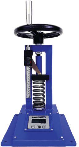
The wipe force acting on a VI is a critical design specification that does not receive enough attention during routine maintenance, repair, or the remanufacturing process. To get the poles of a breaker in sync, technicians often make adjustments to the wipe spring without regard to the effect these maladjustments may have on the VI’s ability to withstand a fault. Additionally, it is recommended that MVVCBs subjected to high temperatures for prolonged periods or high duty cycles have each spring removed and checked (similar to the test setup shown in Figure 2) to ensure the spring rate is within OEM specifications before returning to service.
NETAWorld • 95 MEDIUM-VOLTAGE VACUUM CIRCUIT BREAKER LIFE EXTENSION: A NEW APPROACH — PART 2
Figure 1: Wipe Spring Placement on a Medium-Voltage Vacuum Circuit Breaker
Figure 2: Wipe Spring Rate Test Setup

ADVANCEMENTS IN INDUSTRY
Parting Time vs. Clearing Time: Effects on Arc Flash Calculations and How to Measure in the Field
MVVCBs and other electrical distribution switchgear all have an interrupting rating, defi ned as the RMS value of symmetrical current that the circuit breaker can interrupt without being destroyed or causing an electric arc with unacceptable duration. It is impossible for a circuit breaker to instantaneously interrupt a circuit at the exact start of a fault. Instead, an overcurrent protection device (OCPD) uses a time-current curve in a band bound by minimum and maximum values of total clearing time, indicating how long it will take to clear a fault for a given magnitude of current. The rated clearing time of a circuit breaker is the maximum allowable length of time between energizing the trip circuit and the interruption of the main circuit in all poles and is computed as the sum of the circuit breaker’s sensing time, unlatching time, and arcing time as demonstrated in Figure 3.
Arguably, the most important variable when performing incident energy calculations for an arc flash hazard analysis is the arcing time. It defines the duration of the arc flash. Using the equations provided either by IEEE 1584
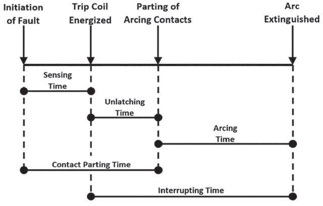
or NFPA 70E, the incident energy value is calculated in cal/cm2 at a specific working distance and used to select appropriate protective equipment and clothing for each piece of electrical equipment. The arcing time used in these equations is typically chosen as the total clearing time of the protective device located upstream from the equipment being analyzed. Newer MVVCBs will clear a fault in three to five cycles, but if this changes or is inaccurate, the results of the arc flash study may put personnel in danger.
Performing a timing test is the best option if the breaker can only be out of service for a limited amount of time. Parting time gives a clear metric for the mechanical reaction to a trip command and generally has a relationship to the total clearing time. The time correlates with the MVVCB’s operating mechanism health and lubrication state.
Incorporating the timer and power supply into one unit can perform a circuit breaker timetravel analysis in a few minutes. Additionally, compatible secondary disconnect plugs are available to ensure users connect the device correctly to prevent damage to the breaker and/or tester. If a breaker cannot be removed, a vibration analysis will off er a chance to determine the overall mechanical condition and timing to ensure the equipment performs in accordance with the values used for the arc flash study. This has to be done during an actual switching event, but the data can be extracted while the MVVCB is still fully installed.
Maintenance and testing must be performed routinely to minimize risk of having an unintentional time delay in MVVCB operation. Otherwise, extended clearing times could occur, and the time delay will adversely affect the results of flash hazard analyses. To meet growing demand, shorter breaker clearing times will be required to address higher fault currents and minimize damage due to breaker failures.
A number of factors affect overall breaker fault clearing time, but the most impactful is the
96 • FALL 2018
MEDIUM-VOLTAGE VACUUM CIRCUIT BREAKER LIFE EXTENSION: A NEW APPROACH — PART 2
Figure 3: Phases of Total Clearing Time in a Medium-Voltage Vacuum Circuit Breaker

operating time of the circuit breaker, which includes the operating time of the primary protective relays. With only parting time, what is really known about total clearing time, and what has to be assumed? Technicians must be aware of the limitations of the tests they are performing and how to properly read the results. Otherwise, data may be misinterpreted, potentially endangering service personnel.
Vacuum Interrupters: Predicting Their Remaining Life in the Field
A means of circuit protection is necessary to safeguard service personnel, electrical equipment, and productivity against the effects of shorts, faults, and dangerous arcing conditions. For MV applications, the means of circuit protection has, in the last half century, been dominated by VCBs. The preference of vacuum over other alternatives such as air, oil, or SF6 gas is due to vacuum’s ability to interrupt high-energy faults quicker than the alternatives, thus improving personnel safety and equipment reliability. For all the time spent perfecting their design, VIs are still susceptible to failure due to contact erosion, loss of insulating ability, and loss of vacuum due to damage or age.
When VIs are manufactured, three tests are used to validate their function prior to factory release:
• Contact resistance
• High potential withstand
• Leak rate
Only two of these have seen widespread use in the field: the contact resistance test and the high potential withstand test — neither of which can determine the level of vacuum pressure inside the VI. Only leak rate testing provides results beyond pass/fail, thereby offering quantifiable data about the integrity of the VI’s vacuum pressure. Possessing data about the internal pressure would allow the use of reliability centered maintenance (RCM) procedures and programs, resulting in higher
ADVANCEMENTS IN INDUSTRY
equipment uptime, longer lifecycles, and lower operating costs.
Until recently, leak rate testing has not been feasible for field applications due to equipment size, cost, and complexity. However, recent advances have enabled manufacturers to build portable leak rate test equipment.
Leak rate testing is based on the Penning Discharge Principle. Figure 4 shows the basic test setup for a VI leak rate test. The VI is placed in a portable fixed magnetic coil or a flexible cable is wrapped around the test specimen a prescribed number of times. When the test is started, high-voltage dc is applied to the VI, and the baseline leakage current is measured. Next, a dc voltage pulse is applied to the magnetic field coil, and the total current is measured during the pulse. The ion current is calculated as the total current minus the leakage current. Since the magnetic field and the applied voltage are known, the only variable remaining is the gas pressure. If the relationship between the gas pressure and the current flow is known, the internal pressure can be calculated based on the amount of current.
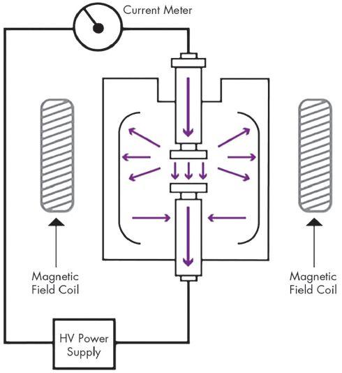
NETAWorld • 97
MEDIUM-VOLTAGE VACUUM CIRCUIT BREAKER LIFE EXTENSION: A NEW APPROACH — PART 2
Figure 4: Vacuum Interrupter Leak Rate Test Setup

ADVANCEMENTS IN INDUSTRY
There will always be some leakage in even the best VIs, and leakage may be slow enough that the VI will meet or exceed manufacturer’s predicted service life. To work efficiently, an RCM program depends on data gathered during testing. With continued adoption of leak rate testing, the electrical industry can see improvement in maintenance efficiency and a reduction in unexpected failures.
Continuous Partial Discharge Monitoring
Partial discharge (PD) is a localized dielectric breakdown within insulators due to voids, cracks, air bubbles, or foreign inclusions; it appears when the irregularity leads to a nonuniform electrical fi eld in systems running under high-voltage stresses. Irregularities could be caused by internal, external, or outside infl uences such as system voltage, load, temperature, humidity, vibration, and atmospheric pressure.
Some PD events are invisible to the naked eye and can be diffi cult to detect and monitor, while some will occur as corona discharges, which are usually visible via a steady glow or arcing. Unmonitored PD events can become dangerous and will not cease without corrective actions. Over time, these effects will damage the insulation’s integrity, as shown in Figure 5.
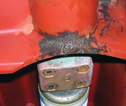

Today’s insulating systems have evolved. Advanced materials such as plastics, fiberglass, or epoxies will not be as sensitive to the environment and will last longer than previous materials, such as organic insulation, which was susceptible to moisture. Modern insulation materials can last 20 years and will far exceed this if kept clean and dry.
Many possibilities to detect and measure PD are available on the market and are widely used. Each is very site specific, as the switchgear environment and age of the equipment all dictate which method is applied. Continuously monitoring switchgear is possible by using electromagnetic field detection, which picks up the radio waves generated by PD events in insulation. This newly adapted technology is ideally suited for the most demanding applications, as when switchgear access is limited or maintenance is diffi cult and dangerous.
A real-time algorithm analyzes the received signal patterns to monitor for PD signatures within each cycle. These systems may be connected to existing SCADA or local alarm systems to provide real-time feedback about PD, which is necessary for an RCM program. These radio frequency systems accurately assess the actual health of an insulation system, and the antenna and data acquisition instruments can also be used for interrogating surface acoustic wave-based, wireless, passive temperature sensors, thereby increasing value to the monitoring system.
Testing, for the sake of brevity, will be narrowed to the focus on ANSI/NETA MTS. Any reasonable attempt by maintenance personnel to meet this standard will put them well ahead of the rest of the world. The following tests should be done when performing maintenance on a MVVCB:
• Visual inspection
• Mechanical tests
• Electrical tests
• Mechanical/electrical test value comparison and analysis
98 • FALL 2018
MEDIUM-VOLTAGE VACUUM CIRCUIT BREAKER LIFE EXTENSION: A NEW APPROACH — PART 2
Figure 5: Effects of Unmitigated Partial Discharge in Insulation

Some of these tests were not available, nor were they accounted for when OEMs were designing these breakers to a specific service life. Today, the ability to perform these tests in the field has increased service life.
MODERN REPLACEMENT PARTS
In addition to regularly scheduled routine maintenance, MVVCBs may also require component upgrades to extend their service life. Facility managers must consider the initial capital cost, along with downtime during integration. The more cost-effective and environmentally friendly alternative is usually to leave the switchgear housing in place and upgrade all other parts of the existing VCBs and controls with the latest state-of-the-art replacement components.
Recent advances have given rise to a market of circuit breaker replacement parts and upgrades that can increase reliability, decrease maintenance costs, and even improve the switchgear’s ratings. For the foreseeable future, non-OEM vendors will have the necessary parts available to support legacy platforms.
Today’s Vacuum Interrupters: Higher Ratings and Better Reliability in Smaller Packages
With aging MVVCBs, VI failures are estimated to occur every few hours in the United States. New technologies and advances in material science, arc control, construction, and assembly have increased reliability and ratings, while decreasing the size and costs of VIs over the last half century (Figure 6).
One of the most signifi cant improvements in VIs since their first use in VCBs has been contact materials. In a VI, contact material determines the properties of arc, current chop, its tendency to weld, and more. The development and application of advanced copper-chrome alloys over other materials has been so successful that they are now almost universally used in VIs worldwide.
ADVANCEMENTS IN INDUSTRY



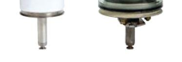
Figure 6: Current Vacuum Interrupter with Improved Ratings vs. OEM Vacuum Interrupter
An additional advancement is arc control contact geometry. Engineers had to address difficulties associated with interrupting high currents. When interrupting high currents, the arc is concentrated with all energy to a few spots on the contact surface, resulting in localized overheating, contact melting, and failure to interrupt. To solve this issue, engineers developed contacts that caused a self-induced magnetic field generated by the arc to help distribute the current more evenly; this aided in extinguishing the arc. These novel designs used a radial magnetic fi eld; more recently, the technology evolved to feature an axial magnetic field to do so more efficiently. Better arc control geometries allowed the contacts to become smaller (Figure 7), which reduced the size and cost of VIs.
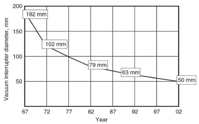
Figure 7: 15kV, 12.5kA Vacuum Interrupter Size
Reduction over a 40-Year Timespan
NETAWorld • 99 MEDIUM-VOLTAGE VACUUM CIRCUIT BREAKER LIFE EXTENSION: A NEW APPROACH — PART 2

ADVANCEMENTS IN INDUSTRY
To take full advantage of the smaller VI contact, VI manufacturing methods needed to change. The pinch tube sealing method has now been replaced by a one-shot seal-off operation within a vacuum furnace. However, design options were still limited due to the need for a floating shield to prevent metal vapor produced during arcing. Adding complexity and cost, a shieldless VI was developed that used only one ceramic insulator with no metal vapor shield. This design drastically reduced the number of required components and simplified the assembly process.
These new manufacturing and assembly techniques have increased the shelf life for newly designed VIs. In addition, suppliers are providing upgraded components that off er these benefits, but may no longer be available from OEMs. When VI failure occurs, make sure to choose a modern VI to gain the benefits of almost a century’s worth of research and development.
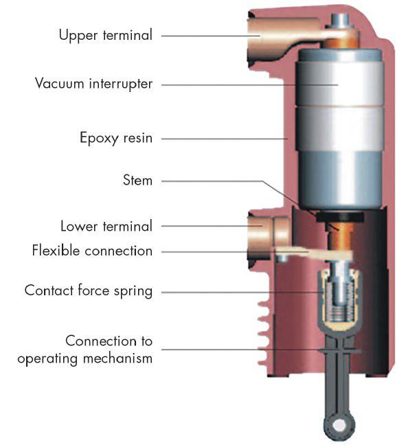
Embedded Poles: Next Step in the Evolution of the Vacuum Interrupter
The purpose of embedded poles was to simplify the VCB’s pole assemblies by enclosing the VIs in a silicone or epoxy resin insulating material using specialized molding processes. Embedded pole advantages include.

• High dielectric strength in air
• Suitability in a wide range of environmental conditions
• Increased structural rigidity
• Ability to seal and protect the VI from dust, moisture, and impact
A VI’s internal dielectric strength from the contact gap within the sealed vacuum atmosphere is greater than its external dielectric strength, which is limited by the insulation properties of air and is subject to environmental conditions such as condensation or contaminant buildup. Dielectric strength can be improved by embedding the VI in a solid silicone or epoxy resin (Figure 8), since the VI is protected from external contaminants and has an increased creepage distance. Recently, new epoxy formulations for outdoor applications boast qualities including:
• Lower moisture absorption
• UV resistance
• Improved thermal conductivity
• Higher impact strength
• Lower temperature limits down to -75 degrees F
This solution has been widely adopted for use in new IEC-rated MVVCBs and has been approved in ANSI-rated MVVCBs.
Because of their minimal maintenance requirements and compact robust designs, they are a promising solution for legacy VI pole assembly upgrades similar to those shown in Figure 9. Replacement assemblies must be ANSI/IEEE C37 tested and certified. When combined with proper mechanical maintenance of the breaker, these hardened and superior
100 • FALL 2018
MEDIUM-VOLTAGE VACUUM CIRCUIT BREAKER LIFE EXTENSION: A NEW APPROACH — PART 2
Figure 8: Embedded Pole Construction

assemblies will extend the life of the equipment another 20-plus years. Embedded poles are close to the cost of a VI replacement with core exchange.
A Brand New Start
Breaker remanufacturing has traditionally been performed by OEMs, but today, customers have their choice between OEMs or other service companies. Some even have in-house overhaul programs. At a minimum, the remanufacture should include:
• Complete disassembly
• Cleaning
• Lubrication of the operating mechanism and contact pivots
During this remanufacturing process, the evaluation of individual parts should consider the availability of new industry-recommended alternative replacements. This evaluation and the upgrades that go along with it have become so popular that some OEMs and service companies are offering these hardened or tough-duty products to replace or exchange legacy MVVCBs. These offerings usually boast more advanced plating to guard equipment for environmental issues, better insulating systems with modern materials, and modern lubrication systems designed and tested for use on circuit breakers in the harshest environments. These modern, tough-duty direct replacement designs (Figure 10) have longer warranties and essentially restart the VCB’s service life.
CONCLUSION
OEMs gave MVVCBs a 20-year service life. However, many are now approaching 40 years of reliable service. The infrastructure in the United States is heavily dependent on MVVCBs. The MVVCBs in these applications will not simply be replaced — they will be coaxed to reach 100 years of service life. It may seem crazy to think about this now, as we are only nearing the 50-year mark. However, it is achievable if we continue to properly implement and improve

ADVANCEMENTS IN INDUSTRY


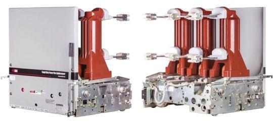
existing life-extension programs that prioritize safety, reliability, and value.
For MVVCB life extension, adhering to an industry-recognized maintenance philosophy is imperative; RCM is the preferred. Specific maintenance intervals for MVVCBs should not exceed five years, due largely to the limits of lubrication life. The maintenance testing should consist of accurately determining the interrupter’s remaining lifetime and also verifying the breaker trip time. Continuous switchgear monitoring of insulation integrity and bus temperature is also beneficial to not only ensure breaker integrity, but also to ensure overall switchgear health.
Asset owners should always be thinking, “What can I do to extend the usable life of my electrical system?” Adopting these principles will go a long way toward meeting operational integrity goals. A more reliable system is a safer system, and that is really what this is all about — a protective system that will stand vigilant for many years, yet react quickly and do its job when needed.
NETAWorld • 101 MEDIUM-VOLTAGE VACUUM CIRCUIT BREAKER LIFE EXTENSION: A NEW APPROACH — PART 2
Figure 9: OEM Pole Assembly (left) vs. New Encapsulated Pole with Embedded Vacuum Interrupter
Figure 10: Remanufactured Replacement Vacuum Circuit Breaker

ADVANCEMENTS IN INDUSTRY
REFERENCES
H. Khan, A. Tjandra, H. Iu and V. Sreeram, “A Novel Island Detection Methodology for the Realization of Smart Grid,” Smart Grid and Renewable Energy, pp. 330-337, 2011.
J. Cadick, F. Ledbetter and A. Seidel, “Predicting the Remaining Life of Vacuum Interrupters in the Field,” 81st International Conference of Doble Clients, Boston, 2014.
P. G. Slade, The Vacuum Interrupter: Theory, Design, and Application, Boca Raton: CRC Press, 2008.
L. T. Falkingham and G. Montillet, “A History of Fifty Years of Vacuum Interrupter Development (The English Connection),” IEEE Power Engineering Society General Meeting, 2004.
B. Fenski, H. Fink, T. Fugel, D. Gentsch and T. Rumenapp, “Vacuum interrupters and embedded poles for medium voltage,” ETZ Elektrotechnik & Automation, 2007.


Legendary Customer Service
We are there when and where you need us
Multiple Offices


Located throughout the country yields dramatically lower shipping costs
Local Inventory
Better shipping rates and great application support from the Protec team


J. White, “Determining Maintenance Intervals for Safe Operation of Circuit Breakers,” NETA PowerTest 2014, Denver
A. Greenwood, Vacuum Switchgear, London: The Institution of Engineering and Technology, 2007.


Finley Ledbetter, Chief Scientist for Group CBS, Inc., has over 40 years of power systems engineering experience. He is a member of IEEE and was a past president of PEARL. Finley was awarded NETA’s Alliance Recognition Award at PowerTest 2016.
David Walterscheid is currently a Senior Engineer at Group CBS, Inc. He started with Group CBS, Inc. in 2009 at CBS ArcSafe developing electrical safety equipment and served as Vice President of the company for over five years. David’s patents in the field of remote operation for electrical equipment and the products he has developed have won awards from industry publications and organizations.


National Headquarters 1517 West Carrier Pkwy Suite 116 Grand Prairie, TX 75050 (866) 352-5550

Protec West 924 Greg St Sparks, NV 89431 (775) 984-5223
Protec South 7102 Brookside Rd Suite 102 Pearland, TX 77581 (832) 251-7047


Protec Midwest 1501 Wright Blvd Schaumburg, IL 60193 (847) 434-5808
Protec East 200 Gates Rd Suite E Little Ferry, NJ 07643 (201) 450-9743

Protec Southeast 105 Village Walk Suite 185 Dallas, GA 30132 (972) 352-5550


protecequip.com The Electrical Test Equipment Rental Experts


ORDER TODAY! ANSI/NETA ETT-2018 STANDARD FOR CERTIFICATION OF ELECTRICAL TESTING TECHNICIANS FOR ELECTRICAL POWER EQUIPMENT & SYSTEMS To order: visit www.netaworld.org, call 888.300.6382, or email neta@netaworld.org


ANSI/NETA STANDARDS UPDATE


ANSI/NETA MTS-2015 2019 REVISION IN PROCESS
ANSI/NETA MTS, Standard for Maintenance Testing Specifications for Electrical Power Equipment and Systems, 2015 Edition, continues an American National Standard revision process. A project intent notification was published in ANSI’s Standards Action on October 6, 2017, with a 45-day public review period that closed November 11, 2017. The initial ballot was issued on March 8, 2018, and closed on April 8, 2018. A 30-day second ballot period and a 45-day public comment period began in early July 2018. The intent is to release the revised edition of ANSI/NETA MTS in March 2019.


ANSI/NETA MTS contains specifications for suggested field tests and inspections to assess the suitability for continued service and reliability of electrical power equipment and systems. The purpose of these specifications is to assure that tested electrical equipment and systems are operational and within applicable standards and manufacturers’ tolerances, and that the equipment and systems are suitable for continued service.
Single copy of draft document: $459

Order from: Richard Piet (888) 300-6382 rpiet@netaworld.org
Send comments to Richard Piet, rpiet@netaworld.org, with copy to psa@ansi.org
ANSI/NETA ECS-2015
ANSI/NETA ECS, Standard for Electrical Commissioning of Electrical Power Equipment and Systems, 2015 Edition, was



approved as an American National Standard on December 3, 2014. This standard is available for purchase in the NETA Bookstore at www.netaworld.org. A project intent notification was published in ANSI’s Standards Action on May 18, 2018, with a 30-day public review period that closed June 18, 2018. An initial ballot and 45-day public comment period is scheduled to begin in January 2019.
ANSI/NETA ECS describes the systematic process of documenting and placing into service newly installed or retrofitted electrical power equipment and systems. This document shall be used in conjunction with the most recent edition of ANSI/NETA ATS, Standard for Acceptance Testing Specifications for Electrical Power Equipment and Systems. The individual electrical components shall be subjected to factory and field tests, as required, to validate the individual components. It is not the intent of these specifications to provide comprehensive details on the commissioning of mechanical equipment, mechanical instrumentation systems, and related components.


Voltage classes addressed include:
• Low-voltage systems (less than 1,000 volts)


• Medium-voltage systems (greater than 1,000 volts and less than 100,000 volts)
• High-voltage and extra-high-voltage systems (greater than 100 kV and less than 1,000 kV)
References:
• ASHRAE, ANSI/NETA ATS, NECA, NFPA 70E, OSHA, GSA Building Commissioning Guide

NETAWorld • 105 ANSI/NETA STANDARDS UPDATE
.
SPECIFICATIONS AND STANDARDS ACTIVITY
STAND ARD FO R EL ECT RI CAL COMMISSIONING SP EC IFI CAT IO NS FO R E L ECTR I CAL POWE R EQUIPMENT AND SYSTEMS FOR ELECTRICAL POWER EQUIPMENT & SYSTEMS STANDARD FOR ACCEPTANCE TESTING SPECIFICATIONS ANSI/NETA ATS-2017 NEW EDITION REVISION IN PROCESS
ANSI/NETAECS-2015


This document is scheduled for release as a reaffirmed or revised standard in spring 2020. Those interested in participating in the revision process should contact the NETA office for more information. Initial review work will begin in the spring of 2018, with the initial ballot issued in late 2018/early 2019.
ANSI/NETA ETT-2018 NEW EDITION
ANSI/NETA ETT, Standard for Certification of Electrical Testing Technicians, 2015 Edition, has been revised as an American National Standard. ANSI/NETA ETT-2018 was approved by ANSI as an American National Standard on February 22, 2018. The revised edition was released in March 2018. It is available now in the NETA Bookstore at www.netaworld.org, where a complimentary PDF copy can be downloaded or a printed copy ordered.


ANSI/NETA ETT establishes minimum requirements for qualifications, certification, training, and experience for the electrical testing technician. It provides criteria for documenting qualifications for certification and details the minimum qualifications for an independent and impartial certifying body to certify electrical testing technicians.
ANSI/NETA ATS-2017
ANSI/NETA ATS covers suggested field tests and inspections for assessing the suitability for initial energization of electrical power equipment and systems. The purpose of these specifications is to assure that tested electrical equipment and systems are operational, are within applicable standards and manufacturers’ tolerances, and are installed in accordance with design specifications.
This document is scheduled for release as a revised standard in the spring of 2021. Those interested in participating in the revision process should contact the NETA office for more information.


PARTICIPATION
Comments and suggestions on any of the standards are always welcome and should be directed to NETA. To learn more about the NETA standards review and revision process, to purchase these standards, or to get involved, please visit www.netaworld.org or contact the NETA office at 888-300-6382.




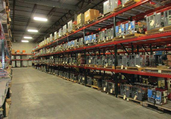

BULLOCK BREAKERS B B 475 Annandale Blvd • Annandale • Minnesota 55302 www.bullockbreakers.com • Email: jason@bullockbreakers.com • Thousands of Air Circuit Breakers in Stock! • Switchgear Line-ups you can’t find anywhere else! • Now Available as Reconditioned with AC-Pro Trip Units! 1-763-269-2832
AND STANDARDS ACTIVITY
SPECIFICATIONS

Absolute con dence. Every time.
You can count on us for specialized experience in healthcare, data center, o ce complex, and commercial acceptance and maintenance testing. Absolutely Power generation, petrochemical, oil & gas, and heavy industries also look to us for high demand services such as start-up commissioning, maintenance testing, shut-down and turnarounds, and breaker shop repair. Get started today.


Toll Free 1+ (855)767-4446 8100 West Little York | Houston, Texas 77040 Email: Alan Postiglione | apost@absolutetesting.com | www.absolutetesting.com Like us on:


ASTM MEETING REPORT
 BY JIM WHITE, Shermco Industries


The April 8–11, 2018, ASTM meeting in San Diego was attended by Tony Demaria, as Jim White was indisposed. Many thanks to Tony for his support in attending and taking notes on this important committee.


The F18 Committee has responsibility for a wide range of electrical protective devices and clothing associated with electrical workers. Some examples are insulated and insulating gloves and hand tools, arc-rated clothing and PPE, personal protective grounds, eyewear, footwear, live-line tools, and even insulating links for cranes. Because of its scope, NETA represents the interests of its member companies on F18. The next meeting will be held in Orlando, Florida, on October 7–10, 2018.
Approximately 110 people were in attendance. By far, the largest block of members represents manufacturers. The second largest block represents utilities. There are few industrial users at these meetings.
F1506
F1506, which covers arc-rated clothing, is undergoing a complete rewrite. The revisions to F1506 are handled by small working groups that vote on specific sections instead of the entire standard. This tactic should allow the standard to move more quickly through the process. That said, there were a lot of negatives during this meeting, and all negatives must be resolved by the full committee before the proposed revisions can be adopted.


F855
F855 covers temporary protective grounds. As with all April meetings, this meeting was conducted to resolve negatives received from the last ballot. One negative was to add ground mats to the standard. This issue will be discussed in more detail at a later date.
Another negative was to specify cable length at 10 feet, with an intention to make test results more consistent. As discussed in a previous ASTM report, ground clamps and ferrules are not interchangeable between manufacturers. They almost always fail at a short-circuit current that is lower than their rating. ASTM F855 implies that components can be mixed, but that is not the case. The negative is intended to revise the standard to reflect this. Note to NETA members: If purchasing components to assemble grounds, use one manufacturer’s components only. There are also issues with the current tables in F855, and there was a negative to address these issues.


F18.15
F18.15 covers worker personal equipment, including rubber insulating gloves. One negative wants to insert that gloves should be removed from the protectors when stored. This is particularly important if the glove is wet.

SPECIFICATIONS AND STANDARDS ACTIVITY NETAWorld • 109 ASTM MEETING REPORT


The committee has determined that ac testing of rubber insulating gloves is not as effective as testing with dc voltages. When gloves were tested using ac, defects were not uncovered, whereas dc testing always found the defect.
One manufacturer conducted a test where rubber insulating gloves were given pin-sized holes and then tested using ac and dc. The ac test did not fail the gloves, but the dc test did. This has broad implications for anyone who tests gloves. One method to resolve this is to increase the ac test voltage so ac testing has the same reliability as the dc test. The tables will require revision to reflect this new test voltage.


CONCLUSION
F18.25
F18.25 covers insulated cover-up equipment, such as blankets. Blanket classes 2, 3, and 4 will be removed from the standard, as they are no longer manufactured. The tables will be revised to reflect the change.
F18.65

1. Open-air arc
2. Arc-in-a-box
3. Moving arc
4. Ejected arc
5. Tracking arc

Once again, the ASTM F18 Committee meeting provided much of interest to NETA member companies. How these standards are revised can greatly affect how our employees are protected.



James (Jim) R. White, Vice President of Training Services, has worked for Shermco Industries Inc. since 2001. He is a National Fire Protection Association (NFPA) Certified Electrical Safety Compliance Professional (CESCP) and a NETA Level IV Senior Technician. Jim is NETA’s principle member on NFPA Technical Committee NFPA 70E®, Standard for Electrical Safety in the Workplace®, NETA’s principle representative on National Electrical Code® (NEC®) Code-Making Panel (CMP) 13, and represents NETA on ASTM International Technical Committee F18 Electrical Protective Equipment for Workers. Jim is Shermco Industries’ principal member on NFPA Technical Committee for NFPA 70B, Recommended Practice for Electrical Equipment Maintenance and represents AWEA (American Wind Energy Association) on ANSI/ISEA Standard 203, Secondary Single-Use Flame Resistant Protective Clothing for Use Over Primary Flame Resistant Protective Clothing. An IEEE Senior Member, Jim is currently Vice-Chair for the IEEE IAS/PCIC Safety Subcommittee.


F18.65 discusses ejected arcs. These are arcs created when a horizontal bus is faulted. This would include all equipment installed on a bus using stab-type connections. There are five possible types of arcs:

The equations on IEEE 1584 do not apply to ejected arcs. They were tested for arc-in-a-box faults only. Some of the conclusions reached during this task group meeting were that ejected arcs potentially affect incident energy received by a worker. This affects whether the PPE selected will provide adequate protection. There needs to be more testing to determine the difference in ejected arcs to arc-in-a-box incident energy.


SPECIFICATIONS AND STANDARDS ACTIVITY 110 • FALL 2018
www.BurlingtonSafety.com info@BurlingtonSafety.com Browse and Buy Online Now! Metro NY/NJ/PA 800-220-2120 Calif (SF) 888-817-1412 Calif (LA) 800-296-2803 Your Source for NFPA 70E Compliant Protective Gear Accredited Proof Testing Laboratory Services Rubber Gloves ◆ Sleeves ◆ Blankets ◆ Line Hose Footwear ◆ Jumpers ◆ Hotsticks


ANSWERS


ANSWERS

1. b. Sydney Evershed of Britain. He and Ernest Vignoles bought the instrument section of Goolden and Trotter, where they were employed. The name of the instrument was shortened to Megger and it was registered in 1903. After a number of changes, the company became Megger Instruments in 1987.
2. d. Jerry Jodice with Doble Engineering, invented the first digital relay test set. He was honored in 2015 by the Institute of Electrical and Electronic Engineers (IEEE) as a Fellow, a very high honor for his contributions.
3. e. Nicola Tesla. Tesla, born and raised in the Austrian Empire (modern-day Croatia), originally worked for Thomas Edison, but had a falling out as to which was better: ac or dc. Of course, Edison thought dc was better and safer; Tesla sold Westinghouse on the benefits of an ac power system, which eventually became the standard. So much for sticking to your guns.


4. a. Humphry Davy of Britain. You might be asking why not Edison, but Edison invented the first commercial light bulb. That is why he gets the credit. Davy actually had a light bulb in 1802, but the light bulb did not have much life. Edison had better vacuum and better filament (bamboo and carbon and the Edison screw) in 1878.
NFPA Disclaimer: Although Jim White is a member of the NFPA Technical Committee for both NFPA 70E, Standard for Electrical Safety in the Workplace, and NFPA 70B, Recommended Practice for Electrical Equipment Maintenance, the views and opinions expressed in this column are purely the author’s and shall not be considered an official position of the NFPA or any of its technical committees and shall not be considered, nor be relied upon, as a formal interpretation or promotion of the NFPA. Readers are encouraged to refer to the entire text of all referenced documents.
TECH QUIZ
No. 123
TECH QUIZ ANSWERS
112 • FALL 2018



2200 West Valley Hwy North, Suite 100 l Auburn, WA 98001 l Office: 253-333-9730 ✔ Power System Acceptance Testing ✔ Commissioning and Start-up ✔ Maintenance ✔ Life-Cycle Extension ✔ Troubleshooting ✔ Training and Engineering Services ✔ Planning and Operations Support ✔ Project Management HAVE AN ELECTRICAL POWER SYSTEM PROBLEM? WE HAVE THE SOLUTION! TESTING MAINTAINING & MANAGING ELECTRICAL POWER SYSTEMS Check us out at www.sigmasix.com
NETA ACCREDITED COMPANIES Setting the Standard
A&F Electrical Testing, Inc.
80 Lake Ave. S Ste. 10 Nesconset, NY 11767-1017 (631) 584-5625
kchilton@afelectricaltesting.com www.afelectricaltesting.com
Kevin Chilton
A&F Electrical Testing, Inc.
80 Broad St. Fl. 5 New York, NY 10004-2257 (631) 584-5625 afelectricaltesting@afelectricaltesting.com
Florence Chilton
ABM Electrical Power Services, LLC
720 S Rochester Ste. A Ontario, CA 91761-8177 (301) 397-3500 rob.parton@abm.com www.abm.com
Rob Parton
ABM Electrical Power Services, LLC 6541 Meridien Dr. Ste. 113 Raleigh, NC 27616 (919) 877-1008
ABM Electrical Power Services, LLC
2631 S. Roosevelt St. Tempe, AZ 85282 (602) 722-2423
ABM Electrical Power Services, LLC
3600 Woodpark Blvd. Ste. G Charlotte, NC 28206-4210 (704) 273-6257
ABM Electrical Power Services, LLC
6940 Koll Center Pkwy. Ste. 100 Pleasanton, CA 94566 (408) 466-6920
ABM Electrical Power Services, LLC
3585 Corporate Court San Diego, CA 92123-1844 (858) 754-7963
ABM Electrical Power Services, LLC 1005 Windward Ridge Pkwy Alpharetta, GA 30005 (770) 521-7550
ABM Electrical Power Solutions
4390 Parliament Pl. Ste. S Lanham, MD 20706 (301) 967-3500 christopher.smith@abm.com www.abm.com
Christopher Smith
ABM Electrical Power Solutions
3700 Commerce Dr. # 901-903 Baltimore, MD 21227-1642 (410) 247-3300
ABM Electrical Power Solutions
317 Commerce Park Dr. Cranberry Township, PA 16066-6407 (724) 772-4638
ABM Electrical Power Solutions 814 Greenbrier Cir. Ste. E Chesapeake, VA 23320-2643 (757) 364-6145
ABM Electrical Power Solutions
9800 E Geddes Ave. Unit A-150 Englewood, CO 80112-9306 (303) 524-6560
ABM Electrical Power Solutions 1817 O'Brien Rd. Columbus, OH 43228 (724) 772-4638
Absolute Testing Services, Inc. 8100 West Little York Houston, TX 77040 www.absolutetesting.com
Accessible Consulting Engineers, Inc. 1269 Pomona Rd. Ste. 111 Corona, CA 92882-7158 (951) 808-1040 info@acetesting.com www.acetesting.com Iraj Nasrolahi
Advanced Electrical Services 4999 - 43rd St. NE Unit 143 Calgary, AB T2B 3N4 Canada (403) 697-3747 zakhouk@aes-ab.com www.aes-ab.com
Zachary Houk
Advanced Testing Systems 15 Trowbridge Dr. Bethel, CT 06801-2858 (203) 743-2001
pmaccarthy@advtest.com www.advtest.com
Pat MacCarthy
American Electrical Testing Co., LLC
25 Forbes Blvd. Ste. 1 Foxboro, MA 02035 (781) 821-0121 sblizard@aetco.us www.aetco.us Scott A. Blizard
American Electrical Testing Co., LLC Green Hills Commerce Center 5925 Tilghman St. Ste. 200 Allentown, PA 18104-9158 (215) 219-6800
jmunley@aetco.us
Jonathan Munley
American Electrical Testing Co., LLC
34 Clover Dr. South Windsor, CT 06074-2931 (860) 648-1013
jpoulin@aetco.us Gerald Poulin
American Electrical Testing Co., LLC
76 Cain Dr. Brentwood, NY 11717-1265 (631) 617-5330
bfernandez@aetco.us
Billy Fernandez
American Electrical Testing Co., LLC
50 Intervale Rd. Ste. 1 Boonton, NJ 07005-1060 (973) 316-1180
jsomol@aetco.us
Jeff Somol
American Electrical Testing Co., LLC
12566 W Indianola Ave. Avondale, AZ 85392-6322 (480) 383-9242
dmadaglia@aetco.us
Donald Madaglia
Apparatus Testing and Engineering 11300 Sanders Dr. Ste. 29 Rancho Cordova, CA 95742-6822 (916) 853-6280
info@apparatustesting.com www.apparatustesting.com
Harold (Jerry) Carr
Apparatus Testing and Engineering
7083 Commerce Cir. Ste. H Pleasanton, CA 94588-8017 (925) 454-1363
Applied Engineering Concepts 1105 N Allen Ave. Pasadena, CA 91104-3207 (626) 398-3052
Michel.c@aec-us.com www.aec-us.com
Michel Castonguay
Applied Engineering Concepts 8160 Miramar Rd. San Diego, CA 92126 (619) 822-1106
Michel.c@aec-us.com www.aec-us.com
Michel Castonguay
BEC Testing
50 Gazza Blvd. Farmingdale, NY 11735-1402 (631) 393-6800
ddevlin@banaelectric.com www.bectesting.com
Daniel Devlin
Burlington Electrical Testing Co., Inc.
300 Cedar Ave. Croydon, PA 19021-6051 (215) 826-9400
Burlington Electrical Testing Co., Inc. 198 Burrs Rd. Westampton, NJ 08060 (609) 267-4126
waltc@betest.com www.betest.com
Walter P. Cleary
C.E. Testing, Inc. 6148 Tim Crews Rd. Macclenny, FL 32063-4036 (904) 653-1900
cetesting@aol.com www.cetestinginc.com
Mark Chapman
CE Power Engineered Services, LLC 40 Washington St. Westborough, MA 01581-1088 (508) 881-3911
jim@three-c.com www.three-c.com
Jim Cialdea
CE Power Engineered Services, LLC 72 Sanford Dr. Gorham, ME 04038 (800) 649-6314
jim@three-c.com www.three-c.com
Jim Cialdea
CE Power Engineered Services, LLC 4040 Rev Dr. Cincinnati, OH 45232 (800) 434-0415
info@cepowersol.net www.cepower.net
Brent McAlister
CE Power Engineered Services, LLC 7674 Washington Ave. S Eden Prairie, MN 55344 (877) 968-0281
Jason.thompson@cepower.net
Jason Thompson
CE Power Engineered Services, LLC 8490 Seward Rd. Fairfield, OH 45011 (800) 434-0415
Tim.lana@cepower.net
Tim Lana
CE Power Engineered Services, LLC 1803 Taylor Ave. Louisville, KY 40213 (800) 434-0415
Tom.hutchinson@cepower.net
Tom Hutchinson
CE Power Engineered Services, LLC 10338 Citation Dr. Ste. 300 Brighton, MI 48116 (810) 229-6628
Ken.lesperance@cepower.net
Ken L’Esperance
CE Power Engineered Services, LLC 10840 Murdock Dr. Knoxville, TN 37932 (800) 434-0415
Don.williams@cepower.net
Don Williams
CE Power Engineered Services, LLC 3496 E. 83rd Pl. Merrillville, IN 46410 (219) 942-2346
114 • FALL 2018 NETA ACCREDITED COMPANIES
Control Power Concepts
353 Pilot Rd. Ste. B
Las Vegas, NV 89119-3520 (702) 448-7833
jtravis@ctrlpwr.com www.controlpowerconcepts.com
John Travis
Dude Electrical Testing LLC
145 Tower Dr. Ste. 9 Burr Ridge, IL 60527-7840 (815) 293-3388
scott.dude@dudetesting.com www.dudetesting.com
Scott Dude
Eastern High Voltage, Inc.
11A S Gold Dr. Robbinsville, NJ 08691-1685 (609) 890-8300
bobwilson@easternhighvoltage.com www.easternhighvoltage.com
Robert Wilson
ELECT, P.C.
375 E. Third St. Wendell, NC 27591 (919) 365-9775
btyndall@elect-pc.com www.elect-pc.com
Barry W. Tyndall
Electric Power Systems
6679 Peachtree Industrial Dr. Ste. H Norcross, GA 30092 (770) 416-0684
Electric Power Systems, Inc. 21 Millpark Ct. Maryland Heights, MO 63043-3536 (314) 890-9999
s.reed@epsii.com www.epsii.com
Steve Reed
Electric Power Systems, Inc. 11211 E. Arapahoe Rd. Ste. 108 Centennial, CO 80112 (720) 857-7273
Electric Power Systems, Inc. 120 Turner Rd. Salem, VA 24153-5120 (540) 375-0084
Electric Power Systems, Inc. 1090 Montour West Industrial Pk. Coraopolis, PA 15108-9307 (412) 276-4559
Electric Power Systems, Inc. 6141 E Connecticut Ave. Kansas City, MO 64120-1346 (816) 241-9990
Electric Power Systems, Inc. 1230 N Hobson St. Ste. 101 Gilbert, AZ 85233 (480) 633-1490
Electric Power Systems, Inc. 915 Holt Ave. Unit 9 Manchester, NH 03109-5606 (603) 657-7371
Electric Power Systems, Inc.
4436 Parkway Commerce Blvd. Orlando, FL 32808-1008 (407) 578-6424
Electric Power Systems, Inc. 1129 E Highway 30 Gonzales, LA 70737-4759 (225) 644-0150
Electric Power Systems, Inc. 684 Melrose Ave. Nashville, TN 37211-3121 (615) 834-0999
Electric Power Systems, Inc.
2888 Nationwide Pkwy. 2nd Floor Brunswick, OH 44212 (330) 460-3706
Electric Power Systems, Inc.
54 Eisenhower Ln. North Lombard, IL 60148 (815) 577-9515
Electric Power Systems, Inc.
4100 Greenbriar Dr. Ste. 160 Stafford, TX 77477-3965 (713) 644-5400
Electric Power Systems, Inc.
56 Bibber Pkwy. # 1 Brunswick, ME 04011-7357 (207) 837-6527
Electric Power Systems, Inc. 11861 Longsdorf St. Riverview, MI 48193-4250 (734) 282-3311
Electric Power Systems, Inc. 8515 Calle Alameda NE Ste. A Albuquerque, NM 87113 (505) 792-7761
Electric Power Systems, Inc. 319 US 70 Hwy. E Ste. E Garner, NC 27529-4054 (919) 210-5405
Electric Power Systems, Inc. 5850 Polaris Ave. Ste. 1600 Las Vegas, NV 89118 (702) 815-1342
Electric Power Systems, Inc.
7925 Dunbrook Rd. Ste. G San Diego, CA 92126 (858) 566-6317
Electric Power Systems, Inc.
306 Ashcake Rd. Ste. A Ashland, VA 23005 (804) 526-6794
NETA
Electrical & Electronic Controls 6149 Hunter Rd. Ooltewah, TN 37363-8762 (423) 344-7666
eecontrols@comcast.net
Michael Hughes
Electrical Energy Experts, Inc. W129N10818 Washington Dr. Germantown, WI 53022-4446 (262) 255-5222 tim@electricalenergyexperts.com www.electricalenergyexperts.com
Tim Casey
Electrical Engineering & Service Co. Inc. 289 Centre St. Holbrook, MA 02343 (781) 767-9988 jcipolla@eescousa.com www.eescousa.com Joe Cipolla
Electrical Equipment Upgrading, Inc. 21 Telfair Pl. Savannah, GA 31415-9518 (912) 232-7402 kmiller@eeu-inc.com www.eeu-inc.com
Kevin Miller
Electrical Maintenance & Testing, Inc. 12342 Hancock St. Carmel, IN 46032-5807 (317) 853-6795 info@emtesting.com www.emtesting.com
Brian K. Borst
Electrical Reliability Services 610 Executive Campus Dr. Westerville, OH 43082-8870 (877) 468-6384 info@electricalreliability.com
Electrical Reliability Services 5909 Sea Lion Pl. Ste. C Carlsbad, CA 92010-6634 (858) 695-9551
Electrical Reliability Services 1057 Doniphan Park Cir. Ste. A El Paso, TX 79922-1329 (915) 587-9440
Electrical Reliability Services 6900 Koll Center Pkwy. Ste. 415 Pleasanton, CA 94566-3119 (925) 485-3400
Electrical Reliability Services
8500 Washington St. NE Ste. A6 Albuquerque, NM 87113-1861 (505) 822-0237
Electrical Reliability Services 2275 Northwest Pkwy. SE Ste. 180 Marietta, GA 30067-9319 (770) 541-6600
Electrical Reliability Services 10606 Bloomfield Ave. Santa Fe Springs, CA 90670-3912 (562) 236-9555
Electrical Reliability Services 400 NW Capital Dr. Lees Summit, MO 64086-4723 (816) 525-7156
Electrical Reliability Services 7100 Broadway Ste. 7E Denver, CO 80221-2900 (303) 427-8809
Electrical Reliability Services 2222 W Valley Hwy. N Ste. 160 Auburn, WA 98001-1655 (253) 736-6010
Electrical Reliability Services 221 E. Willis Road Chandler, AZ 85286 (480) 966-4568
Electrical Reliability Services 1380 Greg St. Ste. 217 Sparks, NV 89431-6070 (775) 746-8484
Electrical Reliability Services 11000 Metro Pkwy. Ste. 30 Fort Myers, FL 33966-1244 (239) 693-7100
Electrical Reliability Services 245 Hood Rd. Sulphur, LA 70665-8747 (337) 583-2411
Electrical Reliability Services 9736 South 500 West Sandy, UT 84070 (801) 975-6461
Electrical Reliability Services 6351 Hinson St. Ste. A Las Vegas, NV 89118-6851 (702) 597-0020
Electrical Reliability Services 3535 Emerson Pkwy. Ste. A Gonzales, LA 70737 (225) 755-0530
Electrical Reliability Services 9636 Saint Vincent Ave. Unit A Shreveport, LA 71106-7127 (318) 869-4244
Electrical Reliability Services 1426 Sens Rd. Ste. 5 La Porte, TX 77571-9656 (281) 241-2800
Electrical Reliability Services 6135 Lakeview Rd. Ste. 500 Charlotte, NC 28269-2630 (704) 441-1497
Electrical Reliability Services 4099 SE International Way Ste. 201 Milwaukie, OR 97222-8853 (503) 653-6781
NETAWorld • 115 NETA ACCREDITED COMPANIES
the Standard
ACCREDITED COMPANIES Setting
NETA ACCREDITED COMPANIES Setting the Standard
Electrical Testing and Maintenance Corp.
3673 Cherry Rd. Ste. 101 Memphis, TN 38118-6313 (901) 566-5557
r.gregory@etmcorp.com
www.etmcorp.net
Ron Gregory
Electrical Testing Solutions
2909 Greenhill Ct. Oshkosh, WI 54904-9769 (920) 420-2986
tmachado@electricaltestingsolutions.com
Tito Machado
Electrical Testing, Inc.
2671 Cedartown Hwy. SE Rome, GA 30161-3894 (706) 234-7623
jamie@electricaltestinginc.com www.electricaltestinginc.com
Jamie Dempsey
Elemco Services, Inc.
228 Merrick Rd. Lynbrook, NY 11563-2622 (631) 589-6343
Courtney@elemco.com www.elemco.com
Courtney Gallo
EnerG Test, LLC
206 Gale Ln. Kennett Square, PA 19348 (484) 731-0200
dbuehler@energtest.com www.energtest.com
Dennis Buehler
Energis High Voltage Resources, Inc. 1361 Glory Rd. Green Bay, WI 54304-5640 (920) 632-7929
info@energisinc.com www.energisinc.com
Mick Petzold
EPS Technology 29 N Plains Hwy. Ste. 12 Wallingford, CT 06492-5838 (203) 679-0145
s.miller@eps-technology.com www.eps-technology.com
Sean Miller
Giga Electrical & Technical Services, Inc.
2743A N. San Fernando Rd. Los Angeles, CA 90065 (323) 255-5894
gigaelectrical@att.net
www.gigaelectrical-ca.com
Hermin Machacon
Grounded Technologies, Inc. 19621 Solar Cir., 101 Parker, CO 80134 (303) 781-2560
jodymedina@groundedtech.com www.groundedtech.com
Jody Medina
Grubb Engineering, Inc. 2727 North Saint Mary’s St. San Antonio, TX 78212 (210) 658-7250
joy@grubbengineering.com www.grubbengineering.com
Robert D. Grubb Jr.
Halco Testing Services 5773 Venice Blvd. Los Angeles, CA 90019 (323) 933-9431
d.genutis@halco.net www.halcotestingservices.com
Don Genutis
Hampton Tedder Technical Services 4563 State St. Montclair, CA 91763-6129 (909) 628-1256 x214
Chasen.tedder@hamptontedder.com www.hamptontedder.com
Chasen Tedder
Hampton Tedder Technical Services 3747 W Roanoke Ave. Phoenix, AZ 85009-1359 (480) 967-7765
Linc McNitt
Hampton Tedder Technical Services 4113 Wagon Trail Ave. Las Vegas, NV 89118 (702) 452-9200
Roger Cates
Harford Electrical Testing Co., Inc. 1108 Clayton Rd. Joppa, MD 21085-3409 (410) 679-4477 testing@harfordtesting.com www.harfordtesting.com
Vincent Biondino
High Energy Electrical Testing, Inc. 515 S Ocean Ave. Seaside Park, NJ 08752-1843 (732) 938-2275 hinrg@comcast.net www.highenergyelectric.com
Charles Blanchard
High Voltage Maintenance 10704 Electron Dr. Louisville, KY 40299 (859) 371-5355
High Voltage Maintenance Corp. 5100 Energy Dr. Dayton, OH 45414-3525 (937) 278-0811
High Voltage Maintenance Corp. 24 Walpole Park S Walpole, MA 02081-2541 (508) 668-9205 www.hvmcorp.com
High Voltage Maintenance Corp. 8320 Brookville Rd. Ste. E Indianapolis, IN 46239-8914 (317) 322-2055
High Voltage Maintenance Corp. 355 Vista Park Dr. Pittsburgh, PA 15205-1206 (412) 747-0550
High Voltage Maintenance Corp. 7200 Industrial Park Blvd. Mentor, OH 44060-5316 (440) 951-2706
High Voltage Maintenance Corp. 24371 Catherine Industrial Dr. Ste. 207 Novi, MI 48375-2422 (248) 305-5596
High Voltage Maintenance Corp. 3000 S Calhoun Rd. New Berlin, WI 53151-3549 (262) 784-3660
High Voltage Maintenance Corp. 1250 Broadway Ste. 2300 New York, NY 10001-3726 (718) 239-0359
High Voltage Maintenance Corp. 150 N Plains Industrial Rd. Wallingford, CT 06492-2353 (203) 949-2650
High Voltage Maintenance Corp. 9305 Gerwig Ln. Ste. B Columbia, MD 21046-2903 (410) 309-5970
High Voltage Maintenance Corp. 941 Busse Rd. Elk Grove Village, IL 60007-2400 (847) 640-0005
High Voltage Maintenance Corp. 14300 Cherry Lane Ct. Ste. 115 Laurel, MD 20707 (410) 279-0798
HMT, Inc.
6268 State Route 31 Cicero, NY 13039-9217 (315) 699-5563
jpertgen@hmt-electric.com www.hmt-electric.com
John Pertgen
Industrial Tests, Inc. 4021 Alvis Ct. Ste. 1 Rocklin, CA 95677-4031 (916) 296-1200 greg@indtest.com www.industrialtests.com
Greg Poole
Infra-Red Building and Power Service, Inc. 152 Centre St. Holbrook, MA 02343-1011 (781) 767-0888 tom.mcdonald@infraredbps.com www.infraredbps.com
Thomas McDonald Sr.
J.G. Electrical Testing Corporation 3092 Shafto Rd. Ste. 13 Tinton Falls, NJ 07753 (732) 217-1908
www.jgelectricaltesting.com h.trinkowsky@jgelectricaltesting.com
Howard Trinkowsky
M&L Power Systems, Inc. 109 White Oak Ln. Ste. 82 Old Bridge, NJ 08857-1980 (732) 679-1800 milind@mlpower.com www.mlpower.com
Milind Bagle
Magna IV Engineering 1103 Parsons Rd. SW Edmonton, AB T6X 0X2 Canada (780) 462-3111 info@magnaiv.com www.magnaiv.com
Virgina Balitski
Magna IV Engineering 141 Fox Cresent Fort McMurray, AB T9K 0C1 (780) 791-3122 Info.fmcmurray@magnaiv.com
Ryan Morgan
Magna IV Engineering 7, 3040 Miners Ave. Saskatoon, SK S7K 5V1 Canada (306) 585-2100 Info.regina@magnaiv.com
Adam Jaques
Magna IV Engineering 96 Inverness Dr. E Ste. R Englewood, CO 80112-5311 (303) 799-1273 Info.denver@magnaiv.com Aric Proskurniak
Magna IV Engineering Avenida del Condor sur #590 Oficina 601 Huechuraba, 8580676 Chile +(56) -2-26552600 chile@magnaiv.com
Harvey Mendoza
Magna IV Engineering 106, 4268 Lozells Ave. Burnaby, BC VSA 0C6 Canada (604) 421-8020
Scott Nixon
Magna IV Engineering 688 Heritage Dr. SE Ste. 200 Calgary, AB T2H 1M6 Canada (403) 723-0575
116 • FALL 2018 NETA ACCREDITED COMPANIES
Magna IV Engineering
4407 Halik St. Building E Ste. 300 Pearland, TX 77581 (720) 480-9680
aproskurniak@magnaiv.com www.magnaiv.com
Aric Proskurniak
Midwest Engineering Consultants, Ltd.
2500 36th Ave. Moline, IL 61265-6954 (309) 764-1561
m-moorehead@midwestengr.com www.midwestengr.com
Monte Moorehead
National Field Services 651 Franklin Lewisville, TX 75057-2301 (972) 420-0157 www.natlfield.com
Eric Beckman
National Field Services
1890 A South Hwy. 35 Alvin, TX 77511 (800) 420-0157
Jonathan.wakeland@natlfield.com www.natlfield.com
Jonathan Wakeland
National Field Services
1405 United Dr. Ste. 113-115 San Marcos, TX 78666 (800) 420-0157 info@natlfield.com www.natlfield.com
Matt LaCoss
National Field Services 3711 Regulus Ave. Las Vegas, NV 89102 (888) 296-0625 www.natlfield.com howard.herndon@natlfield.com
Howard Herndon
National Field Services 2900 Vassar St. #114 Reno, NV 89502 (775) 410-0430 www.natlfield.com howard.herndon@natlfield.com
Howard Herndon
Nationwide Electrical Testing, Inc. 6050 Southard Tr. Cumming, GA 30040-6343 (770) 667-1875
Shashi@N-E-T-Inc.com www.n-e-t-inc.com
Shashikant B. Bagle
North Central Electric, Inc. 69 Midway Ave. Hulmeville, PA 19047-5827 (15) 945-7632
ncetest@aol.com www.ncetest.com
Robert Messina
Northern Electrical Testing, Inc. 1991 Woodslee Dr. Troy, MI 48083-2236 (248) 689-8980
ldetterman@northerntesting.com www.northerntesting.com
Lyle Detterman
Oris Engineering Field Services Ltd. #300, 9404 - 41st Ave. Edmonton, AB T6E 6G8 Canada (780) 988-1455
lorne@orbisengineering.net www.orbisengineering.net
Lorne Gara
Orbis Engineering Field Services Ltd. #228 - 18 Royal Vista Link NW Calgary, AB T3R 0K4 Canada (403) 374-0051
Orbis Engineering Field Services Ltd. Badajoz #45, Piso 17 Las Condes Santiago, Chile +56 2 29402343
Pace Technologies, Inc. 9604 - 41 Ave. NW Edmonton, AB T6E 6G9 Canada (780) 450-0404
cleavitt@pacetechnologies.com www.pacetechnologies.com
Craig Leavitt
Pace Technologies, Inc. #10, 883 McCurdy Pl. Kelowna, BC V1X 8C8 (250) 712-0091
Pacific Power Testing, Inc. 14280 Doolittle Dr. San Leandro, CA 94577-5542 (510) 351-8811
steve@pacificpowertesting.com www.pacificpowertesting.com
Steve Emmert
Pacific Powertech Inc. #110, 2071 Kingsway Ave. Port Coquitlam, BC V3C 6N2 Canada (604) 944-6697
jkonkin@pacificpowertech.ca www.pacificpowertech.ca
Josh Konkin
NETA ACCREDITED COMPANIES
Phasor Engineering Sabaneta Industrial Park #216 Mercedita, PR 00715 (787) 844-9366
rcastro@phasorinc.com www.phasorinc.com
Rafael Castro
Potomac Testing, Inc. 1610 Professional Blvd. Ste. A Crofton, MD 21114-2051 (301) 352-1930 kbassett@potomactesting.com www.potomactesting.com
Ken Bassett
Power & Generation Testing, Inc. - A CE Power Company 480 Cave Rd. Nashville, TN 37210-2302 (615) 882-9455 mose@pgti.net www.pgti.net
Mose Ramieh
Power Engineering Services, Inc. 9179 Shadow Creek Ln. Converse, TX 78109-2041 (210) 590-4936
dstaudt@pe-svcs.com www.pe-svcs.com
Daniel Staudt
POWER PLUS Engineering, Inc. 47119 Cartier Ct. Wixom, MI 48393-2872 (248) 896-0200
Power Products & Solutions, LLC 6605 W WT Harris Blvd. Ste. F Charlotte, NC 28269 (704) 573-0420 x12 Adis.talovic@powerproducts.biz www.powerproducts.biz
Adis Talovic
Power Products & Solutions, LLC 13 Jenkins Ct. Mauldin, SC 29662-2414 (800) 328-7382
Raymond.pesaturo@powerproducts.biz www.powerproducts.biz
Raymond Pesturo
Power Products & Solutions, LLC 9481 Industrial Center Dr. Unit 5 Ladson, SC 29456 (844) 383-8617 www.powerproducts.biz
Power Services, LLC PO Box 750066 998 Dimco Way Dayton, OH 45475-0066 (937) 439-9660
mkbeucler@aol.com
Mark Beucler
Power Solutions Group, Ltd.
425 W Kerr Rd. Tipp City, OH 45371-2843 (937) 506-8444
bwilloughby@powersolutionsgroup.com www.powersolutionsgroup.com
Barry Willoughby
Power Solutions Group, Ltd. 2739 Sawbury Blvd. Columbus, OH 43235 (614) 310-8018
sspohn@powersolutionsgroup.com www.powersolutionsgroup.com
Stuart Spohn
Power Solutions Group, Ltd. 5115 Old Greenville Hwy. Liberty, SC 29657 (864) 540-8434
fcrawford@powersolutionsgroup.com www.powersolutionsgroup.com
Anthony Crawford
Power Solutions Group, Ltd. 1760 Husky Dr. Clarksville, TN 37040 (931) 572-8591
Chris Brown
Power Systems Testing Co. 4688 W Jennifer Ave. Ste. 108 Fresno, CA 93722-6418 (559) 275-2171 ext 15 dave@pstcpower.com www.powersystemstesting.com
David Huffman
Power Systems Testing Co. 600 S Grand Ave. Ste. 113 Santa Ana, CA 92705-4152 (714) 542-6089
Power Systems Testing Co. 6736 Preston Ave. Ste. E Livermore, CA 94551-8521 (510) 783-5096
Power Test, Inc. 2200 Highway 49 S Harrisburg, NC 28075 (704) 200-8311 rich@powertestinc.com
Rich Walker
POWER Testing and Energization, Inc. 14006 NW 3rd Ct. Ste. 101 Vancouver, WA 98685-5793 (360) 597-2800
Chris.zavadlov@powerte.com www.powerte.com
Chris Zavadlov
POWER Testing and Energization, Inc. 731 E Ball Rd. Ste. 100 Anaheim, CA 92805-5951 (714) 507-2702
POWER Testing and Energization, Inc.
303 US Route One Freeport, ME 04032 (207) 869-1200
NETAWorld • 117 NETA ACCREDITED COMPANIES
the Standard
Setting
NETA ACCREDITED COMPANIES
POWER Testing and Energization, Inc.
16825 Northchase Dr. Houston, TX 77060 (281) 765-5536
Powertech Services, Inc.
4095 Dye Rd. Swartz Creek, MI 48473-1570 (810) 720-2280
kirkd@powertechservices.com www.powertechservices.com
Kirk Dyszlewski
Precision Testing Group
5475 Hwy. 86 Unit 1 Elizabeth, CO 80107-7451 (303) 621-2776
Premier Power Maintenance Corporation
4035 Championship Dr. Indianapolis, IN 46268 (317) 879-0660
Kvin.templeman@premierpower.us
Kevin Templeman
Premier Power Maintenance Corporation 2725 Jason Rd. Ashland, KY 41102-7756 (606) 929-5969
Jay.milstead@premierpower.us www.premierpowermaintenance.com
Jay Milstead
Premier Power Maintenance Corporation
3066 Finley Island Cir. NW Decatur, AL 35601-8800 (256) 355-1444
Johnnie.mcclung@premierpower.us
Johnnie McClung
Premier Power Maintenance Corporation 4301 Iverson Blvd. Ste. H Trinity, AL 35673-6641 (256) 355-3006
Kevin.templeman@premierpower.us
Kevin Templeman
Premier Power Maintenance Corporation 7301 E County Rd. 142 Blytheville, AR 72315-6917 (870) 762-2100
Kevin.templeman@premierpower.us
Kevin Templeman
Premier Power Maintenance Corporation 7262 Kensington Rd. Brighton, MI 48116 (517) 230-6620
Brian.ellegiers@premierpower.us
Brian Ellegiers
Premier Power Maintenance Corporation 4537 S Nucor Rd. Crawfordsville, IN 47933 (317) 879-0660
Kevin.templeman@premierpower.us
Kevin Templeman
RESA Power Service
46918 Liberty Dr. Wixom, MI 48393-3600 (248) 313-6868
Bruce.robinson@resapower.com
www.resapower.com
Bruce Robinson
RESA Power Service
4213 Kropf Ave. SW Canton, OH 44706-3648 (800) 264-1549
Ron.ford@resapower.com
Ron Ford
RESA Power Service
13837 Bettencourt St. Cerritos, CA 90703 (800) 996-9975
Many.sanchez@resapower.com
Manny Sanchez
RESA Power Service
311 Bay Ave. A Highlands, NJ 07732 (888) 996-9975
Trent.robbins@resapower.com
Trent Robbins
RESA Power Service
2390 Zanker Rd. San Jose, CA 95131 (800) 576-7372
Toby.ramsey@resapower.com
Toby Ramsey
RESA Power Service 1401 Mercantile Ct. Plant City, FL 33563 (813) 752-6550
Joel.mcdaniel@resapower.com
Joel McDaniel
RESA Power Service
3890 Pheasant Ridge Dr. NE Ste. 170 Blaine, MN 55449 (763) 784-4040
Michael.mavetz@resapower.com
Mike Mavetz
Reuter & Hanney, Inc.
Northampton Industrial Park 149 Railroad Dr. Ivyland, PA 18974-1448 (215) 364-5333 mikereuter@reuterhanney.com www.reuterhanney.com
Michael Reuter
Reuter & Hanney, Inc. 11620 Crossroads Cir. Middle River, MD 21220-2874 (410) 344-0300
Reuter & Hanney, Inc. 4270 Henninger Ct. # I Chantilly, VA 20151-2931 (703) 263-7163
REV Engineering Ltd. 3236 - 50 Ave. SE Calgary, AB T2B 3A3 Canada (403) 287-0156 rdavidson@reveng.ca www.reveng.ca
Roland Nicholas Davidson, IV Rondar Inc.
333 Centennial Pkwy. North Hamilton, ON L8E2X6 Canada (905) 561-2808 www.rondar.com ghysop@rondar.com
Gary Hysop
Rondar Inc. 9-160 Konrad Crescent Markham, ON L3R9T9 Canada (905) 943-7640 www.rondar.com
Saber Power Services, LLC 9841 Saber Power Ln. Rosharon, TX 77583-5188 (713) 222-9102 info@saberpower.com www.saberpower.com
William Dunn
Saber Power Services, LLC 1315 FM 1187, Ste. 105 Mansfield, TX 76063 (682) 518-3676
Saber Power Services, LLC 14617 Perkins Rd. Baton Rouge, LA 70810 (225) 726-7793
Saber Power Services, LLC 4703 Shavano Oak Ste. 104 San Antonio, TX 78249 (210) 267-7282
Scott Testing, Inc. 245 Whitehead Rd. Hamilton, NJ 08619 (609) 689-3400 rsorbello@scotttesting.com www.scotttesting.com Russ Sorbello
Sentinel Power Services, Inc. 7517 E Pine St. Tulsa, OK 74115-5729 (918) 359-0350 gellis@spstulsa.com www.sentinelpowerservices.com Greg Ellis
Sentinel Power Services, Inc. 1110 West B St. Ste. H Russellville, AR 72801 (918) 359-0350
Shermco Industries 2425 E Pioneer Dr. Irving, TX 75061-8919 (972) 793-5523 info@shermco.com www.shermco.com
Shermco Industries 112 Industrial Dr. Minooka, IL 60447-9557 (815) 467-5577 info@shermco.com
Shermco Industries 1711 Hawkeye Dr. Hiawatha, IA 52233 (319) 377-3377 info@shermco.com
Shermco Industries 1705 Hur Industrial Blvd. Cedar Park, TX 78613-7229 (512) 267-4800 info@shermco.com
Shermco Industries Boulevard Saint-Michel 47 1040 Brussels Brussels, Belgium +32 (0)2 400 00 54 info@shermco.com
Shermco Industries 2100 Dixon St. Ste. C Des Moines, IA 50316-2174 (515) 263-8482 info@shermco.com
Shermco Industries 4510 South 86th East Ave. Tulsa, OK 74145 (918) 234-2300 info@shermco.com
Shermco Industries 33002 FM 2004 Angleton, TX 77515-8157 (979) 848-1406 info@shermco.com
Shermco Industries 12000 Network Blvd. Buidling D Ste. 410 San Antonio, TX 78249-3354 (210) 877-9090 info@shermco.com
Shermco Industries 4383 Professional Pkwy. Groveport, OH 43125 (614) 836-8556 info@shermco.com
Shermco Industries 3807 S Sam Houston Pkwy. W Houston, TX 77056 (281) 835-3633 info@shermco.com
118 • FALL 2018 NETA ACCREDITED COMPANIES
Setting the Standard
Shermco Industries 4670 G St. Omaha, NE 68117 (402) 933-8988 info@shermco.com
Shermco Industries 1301 Hailey St. Sweetwater, TX 79556 (325) 236-9900 infor@shermco.com
Shermco Industries
2901 Turtle Creek Dr. Port Arthur, TX 77642 (409) 853-4316 info@shermco.com
Shermco Industries 5145 NW Beaver Dr. Johnston, IA 50131 (515) 265-3377 info@shermco.com
Shermco Industries 998 E. Berwood Ave. Saint Paul, MN 55110 (651) 484-5533 info@shermco.com
Shermco Industries Canada 1033 Kearns Crescent RM of Sherwood, SK S4K 0A2 Canada (306) 949-8131 info@shermco.com
Shermco Industries Canada 233 Faithfull Cir. Saskatoon, SK S7K 8H7 Canada (306) 955-8131 info@shermco.com
Shermco Industries Canada 3434 25th St. NE Calgary, AB T1Y 6C1 Canada (403) 769-9300 info@shermco.com
Shermco Industries Canada 1375 Church Ave. Winnipeg, MB R2X 2T7 Canada (204) 925-4022 info@shermco.com
NETA ACCREDITED COMPANIES Setting
Shermco Industries Canada 3731 - 98 St. Edmonton, AB T6E 5N2 Canada (780) 436-8831 info@shermco.com
Sigma Six Solutions, Inc. 2200 W Valley Hwy. N Ste. 100 Auburn, WA 98001-1654 (253) 333-9730 jwhite@sigmasix.com www.sigmasix.com
John White
Southern New England Electrical Testing, LLC 3 Buel St. Ste. 4 Wallingford, CT 06492-2395 (203) 269-8778 dave.asplund@sneet.org www.sneet.org
David Asplund, Sr.
Southwest Energy Systems, LLC 2231 E Jones Ave. Ste. A Phoenix, AZ 85040-1475 (602) 438-7500 dave.hoffman@sesphx.com www.southwestenergysystems.com
Dave Hoffman
Taurus Power & Controls, Inc. 9999 SW Avery St. Tualatin, OR 97062-9517 (503) 692-9004 robtaurus@tauruspower.com www.tauruspower.com
Rob Bulfinch
Taurus Power & Controls, Inc. 19226 66th Ave. S #L102 Kent, WA 98032-2197 (425) 656-4170
Tidal Power Services, LLC 4211 Chance Ln. Rosharon, TX 77583-4384 (281) 710-9150 monty.janak@tidalpowerservices.com www.tidalpowerservices.com
Monty C. Janak
Tidal Power Services, LLC 8184 Hwy. 44 Ste. 105 Gonzales, LA 70737-8183 (225) 644-8170
Darryn Kimbrough
Tidal Power Services, LLC 1056 Mosswood Dr. Sulphur, LA 70665-9508 (337) 558-5457
Steve Drake
Titan Quality Power Services, LLC 1501 S. Dobson St. Burleson, TX 76028 (866) 918-4826 www.titanqps.com
Titan Quality Power Services, LLC 7630 Ikes Tree Dr. Spring, TX 77389 (281) 826-3781
Tony Demaria Electric, Inc. 131 W F St. Wilmington, CA 90744-5533 (310) 816-3130 neon@tdeinc.com www.tdeinc.com
Nenad Pasic
Trace Electrical Services & Testing, LLC 293 Whitehead Rd. Hamilton, NJ 08619-3250 (609) 588-8666
jvasta@tracetesting.com www.tracetesting.com
Joseph Vasta
Utilities Instrumentation Service, Inc. 2290 Bishop Cir. E Dexter, MI 48130-1564 (734) 424-1200
GE.walls@UIScorp.com www.uiscorp.com
Gary E. Walls
Utility Service Corporation PO Box 1471 Huntsville, AL 35807 (256) 837-8400
apeterson@utilserv.com www.utilserv.com
Alan D. Peterson
Western Electrical Services, Inc. 14311 29th St. E Sumner, WA 98390-9690 (253) 891-1995
dhook@westernelectricalservices.com www.westernelectricalservices.com
Dan Hook
Western Electrical Services, Inc. 5680 S 32nd St. Phoenix, AZ 85040-3832 (602) 426-1667
carcher@westernelectricalservices.com
Craig Archer
Western Electrical Services, Inc. 3676 W California Ave. Ste. C106 Salt Lake City, UT 84104-6533 (888) 395-2021
rcoomes@westernelectricalservices.com
Rob Coomes
Western Electrical Services, Inc. 4510 NE 68th Dr. Unit 122 Vancouver, WA 98661-1261 (888) 395-2021
tasciutto@westernelectricalservices.com
Tony Asciutto
Western Electrical Services, Inc. 5505 Daniels St. Chino, CA 91710 (619) 672-5217
mawallace@westernelectricalservices.com
Matt Wallace
Western Electrical Services, Inc. 620 Meadow Ln. Los Alamos, NM 87547 (505) 469-1661
tking@westernelectricalservices.com
Toby King
NETAWorld • 119 NETA ACCREDITED COMPANIES
the Standard


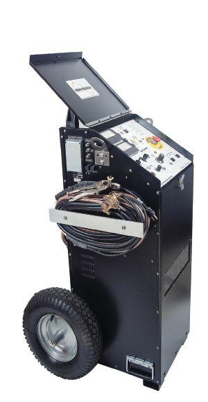

Radar/TDR ready
Other Thumper models: 5/10/20 kV @
• Very Low Frequency AC Technology
• Cable Diagnostic TD & PD Testing
• Cable Fault Locating with Controlled Energy
• AC & DC Hipots, Aerial Lift Testers, Oil Testers
• Ω-CHECK® Concentric Neutral Testing
• Custom Engineered & Fabricated Van Pkgs.

sales@hvinc.com

HIGH VOLTAGE, INC.
www.hvinc.com HIGH VOLTAGE, INC. HVI - The World’s Source for High Voltage Test Equipment HVI Makes it Easy and Efficient
hipot: 0 - 33 kVac @ 1 μF @ 0.1 Hz Fault locate: 0 - 13 kV @ 760 J VLF Fault Burner
Cable Fault Locating & VLF Testing VLF
1000 J 9/18/36 kV @ 3200 J
All That You Need VLF/Thumper Combination 50 kVac @ 3 kVA Hipot 1 piece & w/cable output VLF 0.1 Hz @ 34 kVac Comp. control - wireless 80 kVdc Hipot/Megohmmeter 1 instrument - 2 tests All HVI Products are Made in the USA



More than ever, you need a resource you can count on. That’s why we’ve significantly expanded our capabilities, along with our geographic reach, to help ensure your success When you need us, we’re there.
cepower.net cepjobs.com

800.434.0415
© 2018 CE Power Engineered Services, LLC COMPREHENSIVE SOLUTIONS FOR POWER RELIABILITY


122 • FALL 2018 ADVERTISERS This issue’s advertisers are identified below.
thank these advertisers by telling them you
their advertisement in NETA World Journal. INDEPENDENT NETA ACCREDITED COMPANIES Absolute Testing Services, Inc. 107 American Electrical Testing Co. LLC 21 Apparatus Testing and Engineering 111 Burlington Electrical Testing Co. ..................... 6 CE Power ........................................ 121 Eastern High Voltage............................... 12 Electrical Energy Experts, Inc. 44 Electrical Reliability Services (Vertiv) 89 Elemco Testing Co., Inc. 111 EnerG Test ........................................ 61 Hampton Tedder .................................. 92 Harford Electrical Testing Co. ...................... 61 High Voltage Maintenance Corp. 89 Industrial Electric Testing, Inc. 77 Infra-Red Building and Power Service, Inc. 44 National Field Services 79 Nationwide Electrical Testing, Inc. ................. 113 North Central Electric, Inc. ......................... 88 Orbis Engineering Field Services LTD ............... 46 Potomac Testing, Inc. 62 Power Products & Solutions, Inc. 103 Power Services 6 Power Systems Testing Co. 111 Power Testing and Energization, Inc. ............... 120 Scott Testing Inc. ................................. 120 Shermco Industries.................................. 9 Sigma Six Solutions, Inc. 113 Taurus Power & Controls, Inc. 46 Tony Demaria Electric, Inc. 46 Trace Electrical Services & Testing ................... 32 MANUFACTURERS AND OTHER SERVICE PROVIDERS Advanced Test Equipment Rentals (ATE Corp) .............. 68 AEAMC .................................................. 93 AEMC ................................................... 32 Aero Tech Laboratories 108 Ampteks 69 Arbiter Systems 79 AVO Training Institute, Inc. 63 B CS Switchgear ........................................... 19 Belyea Company ........................................... 45 Bullock Breakers 106 Burlington Safety Laboratory, Inc. 110 CBS ArcSafe 90 Dranetz 45 E A Technology ............................................ 53 ECP Solutions ............................................. 33 Electro Rent ............................................... 85 Group CBS, Inc. 93 High Voltage Inc. 120 High Voltage Electric Service, Inc. 108 Hioki USA 8 HV Diagnostics, Inc. ...................................... 108 Intellirent ................................................. 84 Megger .................................... Inside Front Cover Monster Fuses 88 National Switchgear 47 NETA ANSI/NETA ETT. . . . . . . . . . . . . . . . . . . . . . . . . . . . . . . . . 104 NETA Hire a NAC ........................................ 31 NETA PowerTest 2019 Call for Exhibitors ................... 78 NETA PowerTest 2019 Call for Sponsors .................... 13 NETA PowerTest 2019 Save the Date 55 NETA Training 47 OMICRON Electronics Corp. USA Back Cover Phenix Technologies, Inc. 103 Protec Equipment Resources ............................... 102 Quality Switchgear, Inc. .................................... 69 R aytech ..................................... Inside Back Cover Solid State Exchange 5 Sonel Test 54 Southland Electrical Supply 26 Technitrol, Inc. 18 Thyritronics, Inc............................................ 88 Utility Relay Company ..................................... 27 Vacuum Interrupters, Inc. 90
Please
saw
ADVERTISERS



www.omicronenergy.com/protection


Tomorrow’s protection testing, today!
As a power systems engineer it’s essential that I keep up to date with what’s going on in the market and what our customers need. Based on this, I am constantly looking for better ways of doing things. Take our simulation-based protection testing solution; now even complex networks can be tested automatically from a single point of control. This allows a comprehensive assessment of the entire protection scheme, taking into account the settings and functionality of the individual relays.


 Scott Cooper Application Engineer


 BY JEFF JOWETT, Megger


 BY PAUL CHAMBERLAIN, American Electrical Testing Co., LLC


 BY STEVE TURNER, Electrical Consultants, Inc.


 BY JIM GUO, PhD, Techimp US Corp. and WEN SHU, PhD, NEETRAC, Georgia Institute of Technology


 BY JIM HAYES, Fiber Optic Association


 BY FINLEY LEDBETTER and DAVID WALTERSCHEID, Group CBS, Inc.


 BY JIM WHITE, Shermco Industries


 Scott Cooper Application Engineer