




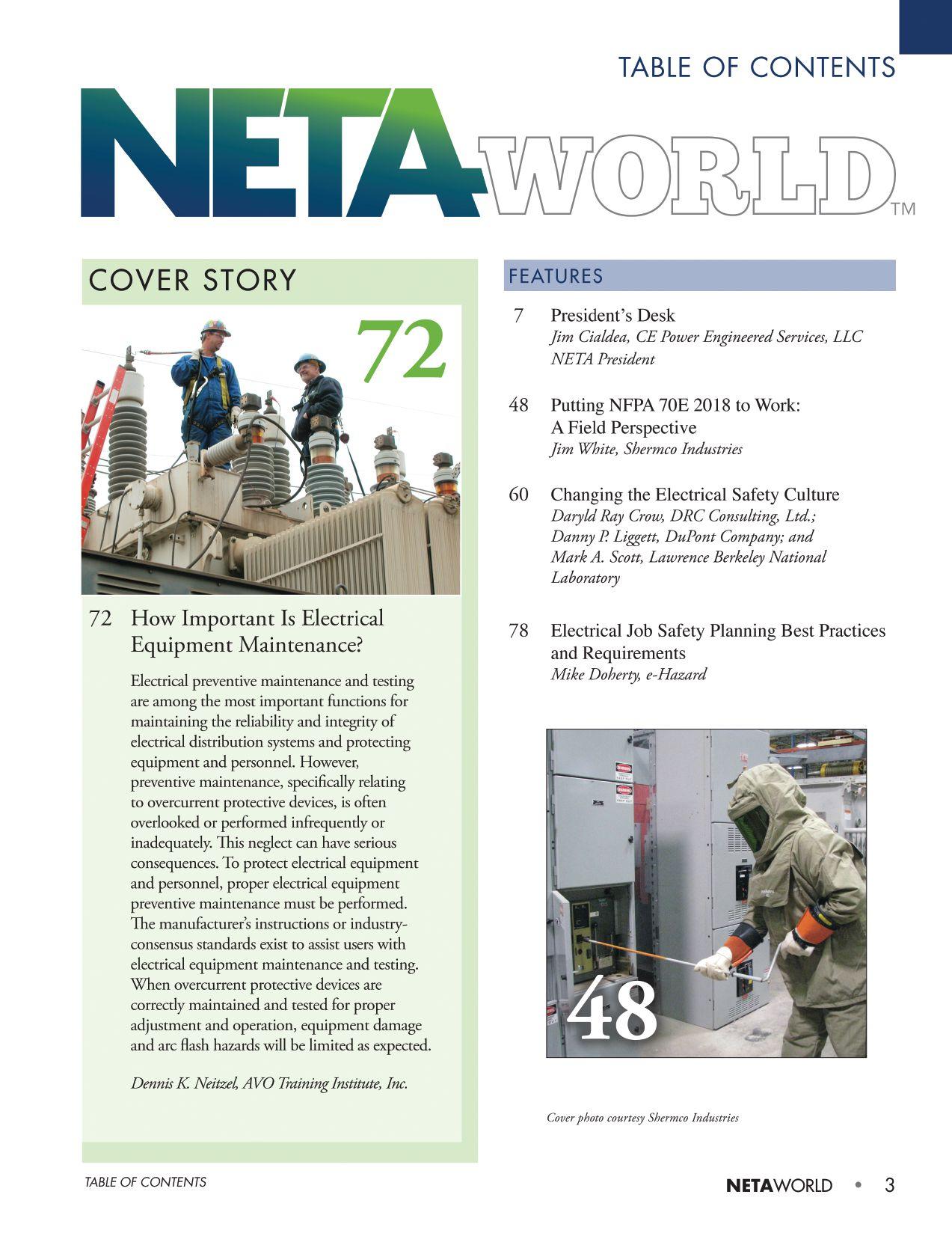
11 NFPA 70E and NETA
Using NFPA 70E 2018 in the Field
Ron Widup and Jim White, Shermco Industries
18 No-Outage Corner
What’s in a Sign?
Don A. Genutis, Halco Testing Services, Inc.
22 Tech Quiz
Focus on Safety
Jim White, Shermco Industries
28 Tech Tips
Balance Aids Noise Mitigation
Jeff Jowett, Megger
34 Safety Corner
The Dos and Don’ts of Electrical Equipment Lubrication
Scott Blizard, American Electrical Testing Co., Inc.
40 Relay Column
Measuring Zero-Sequence Quantities and Single Line-to-Ground Fault Calculations
Steve Turner, Electrical Consultants, Inc.
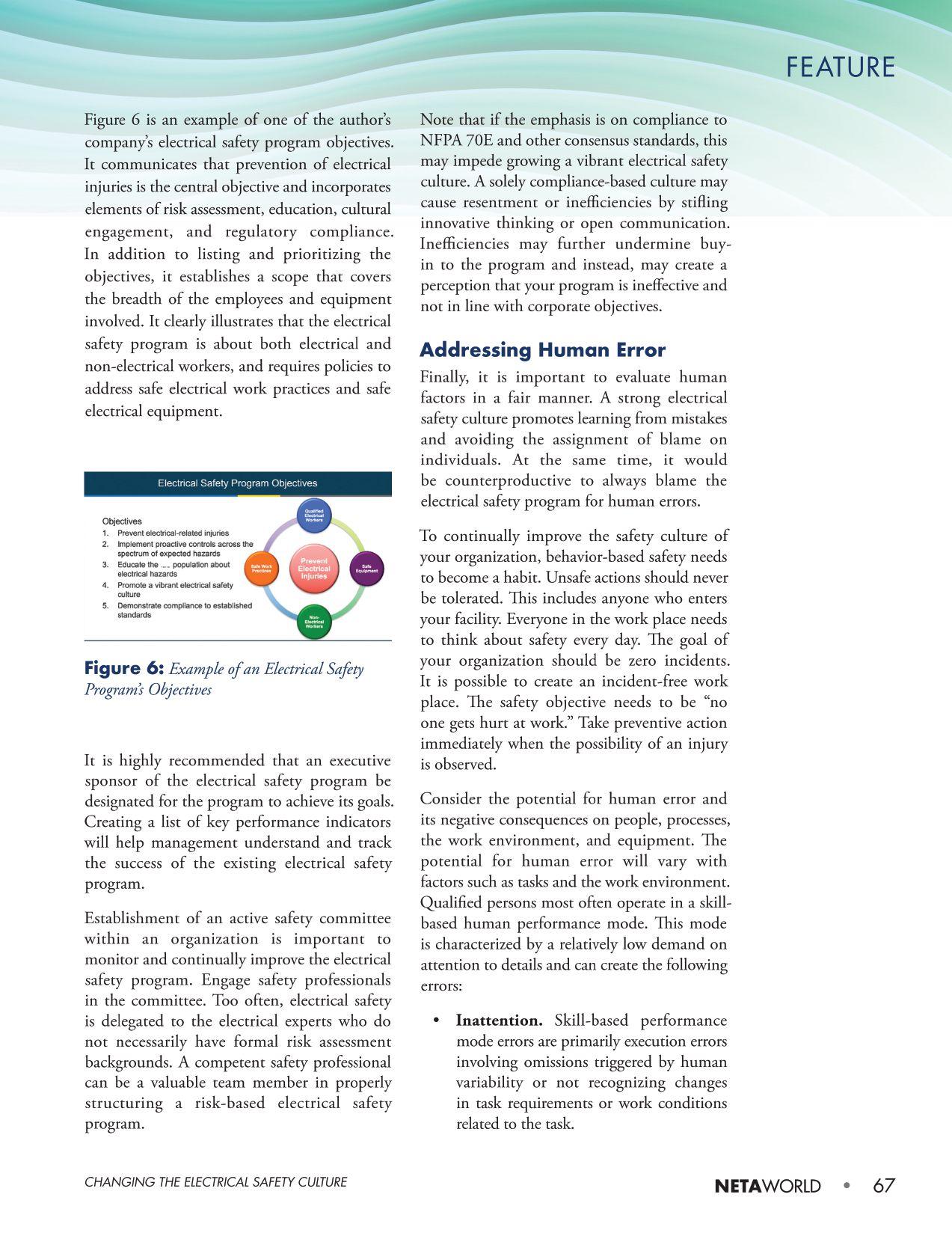
INDUSTRY TOPICS
86 Demagnetizing Power Transformers
Raka Levi, PhD., DV-Power Sweden
92 Electrical Equipment Reliability with Ultrasound and Infrared
Adrian Messer, UE Systems, Inc.
ADVANCEMENTS IN THE INDUSTRY
116 Assessing Solid Insulation Aging Through Oil Testing
Nick Perjanik, PhD, Weidmann Electrical Technology Inc.
SPECIFICATIONS AND
STANDARDS
108 ANSI/NETA Standards Update
110 Insulated Conductor Committee News
Ralph Patterson, Consultant
113 CSA Committee Reports
Kerry Heid, Shermco Industries Canada
NETA NEWS
24 Emerging Technologies and Web-Based Learning Debut at NETA Member Meeting
POWERTEST 2018 PREVIEW
100 PowerTest Expands Hands-On Seminar Offerings for 2018
102 Electrical Power Systems Industry Leaders Gather to Share Intelligence at PowerTest 2018
106 Industry Leader Robert McCall to Give PowerTest 2018 Keynote Address
IMPORTANT LISTS
124 NETA Accredited Companies
130 Advertiser List
4 • WINTER 2017 TABLE OF CONTENTS
OF CONTENTS
TABLE
ISSUE
IN EVERY

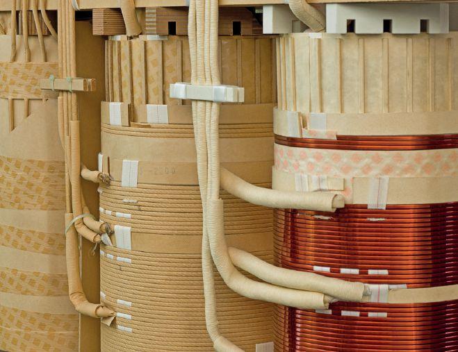
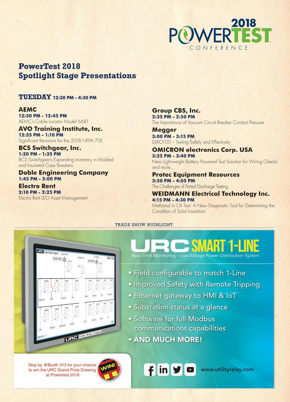
WEIDMANN INTRODUCES METHANOL IN OIL TESTING
STARTING JANUARY 2018, WEIDMANN WILL OFFER METHANOL TESTING
Check out our Spotlight Presentation at the NETA Powertest 2018 conference by Dr. Nick Perjanik, Knowledge Services Manager at Weidmann Electrical Technology Inc.
Weidmann laboratories provide professional diagnostic services, producing actionable data that help lower risk and improve your electrical system‘s reliability. Following recent developments in the ASTM Standard Test Method for the Determination of Methanol and Ethanol in Electrical Insulating Liquids (currently under development), Weidmann Laboratories will introduce the latest in Methanol testing in January 2018.
By accurately testing and detecting Methanol and Ethanol (by-products of cellulosic degradation) at a parts per billion level in oil, Weidmann can assist transformer operators and owners to better predict the breakdown and aging of their transformer insulation system. Research shows that Methanol has a near linear correlation to mechanical strength (DPv) of the solid insulation, resulting in accurate test results that are not affected by the moisture content in insulation, and can provide added benefits over simply testing for furans.
To learn more, please join our presentation or alternatively visit us at the Weidmann booth #412
Weidmann Electrical Technology Inc. One Gordon Mills Way St. Johnsbury, VT 05819, USA
www.weidmann-electrical.com
A Member of the Wicor Group
3050 Old Centre Road, Suite 101
Portage, MI 49024
Toll free: 888.300.NETA (6382)
Phone: 269.488.NETA (6382)
Fax : 269.488.6383
neta@netaworld.org
www.netaworld.org
executive DiRectOR: Missy Richard
NETA Officers
pResiDent: Jim Cialdea, CE Power Engineered Services, LLC
fiRst vice pResiDent: Scott Blizard, American Electrical Testing Co., Inc.
secOnD vice pResiDent: Lorne Gara, Orbis Engineering Field Services, Ltd.
secRetaRy: Eric Beckman, National Field Services
tReasuReR: John White, Sigma Six Solutions
NETA Board of Directors
Ken Bassett (Potomac Testing, Inc.)
Eric Beckman (National Field Services)
Scott Blizard (American Electrical Testing Co., Inc.)
Jim Cialdea (CE Power Engineered Services, LLC)
Scott Dude (Dude Electrical Testing LLC)
Lorne Gara (Orbis Engineering Field Services, Ltd.)
Dan Hook (Western Electrical Services, Inc.)
David Huffman (Power Systems Testing)
Alan Peterson (Utility Service Corporation)
John White (Sigma Six Solutions)
Ron Widup (Shermco Industries)
NETA World Staff
technicaL eDitORs: Roderic L. Hageman, Tim Cotter
assistant technicaL eDitORs: Jim Cialdea, Dan Hook, Dave Huffman, Bob Sheppard
assOciate eDitOR: Resa Pickel
managing eDitOR: Carla Kalogeridis
cOpy eDitOR: Beverly Sturtevant
aDveRtising manageR: Laura McDonald
Design anD pRODuctiOn: Moon Design
NETA Committee Chairs
cOnfeRence: Ron Widup; membeRship: Ken Bassett; pROmOtiOns/maRketing: Scott Blizard; safety: Scott Blizard and Jim White; technicaL: Alan Peterson; technicaL exam: Dan Hook; cOntinuing technicaL DeveLOpment: David Huffman; tRaining: Bob Sheppard; finance: John White; nOminatiOns: Alan Peterson; aLLiance pROgRam: Jim Cialdea; assOciatiOn DeveLOpment: Ken Bassett and John White
© Copyright 2017, NETA
NOTICE AND DISCLAIMER
NETA World is published quarterly by the InterNational Electrical Testing Association. Opinions, views and conclusions expressed in articles herein are those of the authors and not necessarily those of NETA. Publication herein does not constitute or imply endorsement of any opinion, product, or service by NETA, its directors, officers, members, employees or agents (herein “NETA”).
All technical data in this publication reflects the experience of individuals using specific tools, products, equipment and components under specific conditions and circumstances which may or may not be fully reported and over which NETA has neither exercised nor reserved control. Such data has not been independently tested or otherwise verified by NETA.
NETA MAKES NO ENDORSEMENT, REPRESENTATION OR WARRANTY AS TO ANY OPINION, PRODUCT OR SERVICE REFERENCED OR ADVERTISED IN THIS PUBLICATION. NETA EXPRESSLY DISCLAIMS ANY AND ALL LIABILITY TO ANY CONSUMER, PURCHASER OR ANY OTHER PERSON USING ANY PRODUCT OR SERVICE REFERENCED OR ADVERTISED HEREIN FOR ANY INJURIES OR DAMAGES OF ANY KIND WHATSOEVER, INCLUDING, BUT NOT LIMITED TO ANY CONSEQUENTIAL, PUNITIVE, SPECIAL, INCIDENTAL, DIRECT OR INDIRECT DAMAGES. NETA FURTHER DISCLAIMS ANY AND ALL WARRANTIES, EXPRESS OF IMPLIED, INCLUDING, BUT NOT LIMITED TO, ANY IMPLIED WARRANTY OF FITNESS FOR A PARTICULAR PURPOSE.
ELECTRICAL TESTING SHALL BE PERFORMED ONLY BY TRAINED ELECTRICAL PERSONNEL AND SHALL BE SUPERVISED BY NETA CERTIFIED TECHNICIANS/ LEVEL III OR IV OR BY NICET CERTIFIED TECHNICIANS IN ELECTRICAL TESTING TECHNOLOGY/LEVEL III OR IV. FAILURE TO ADHERE TO ADEQUATE TRAINING, SAFETY REQUIREMENTS, AND APPLICABLE PROCEDURES MAY RESULT IN LOSS OF PRODUCTION, CATASTROPHIC EQUIPMENT FAILURE, SERIOUS INJURY OR DEATH.

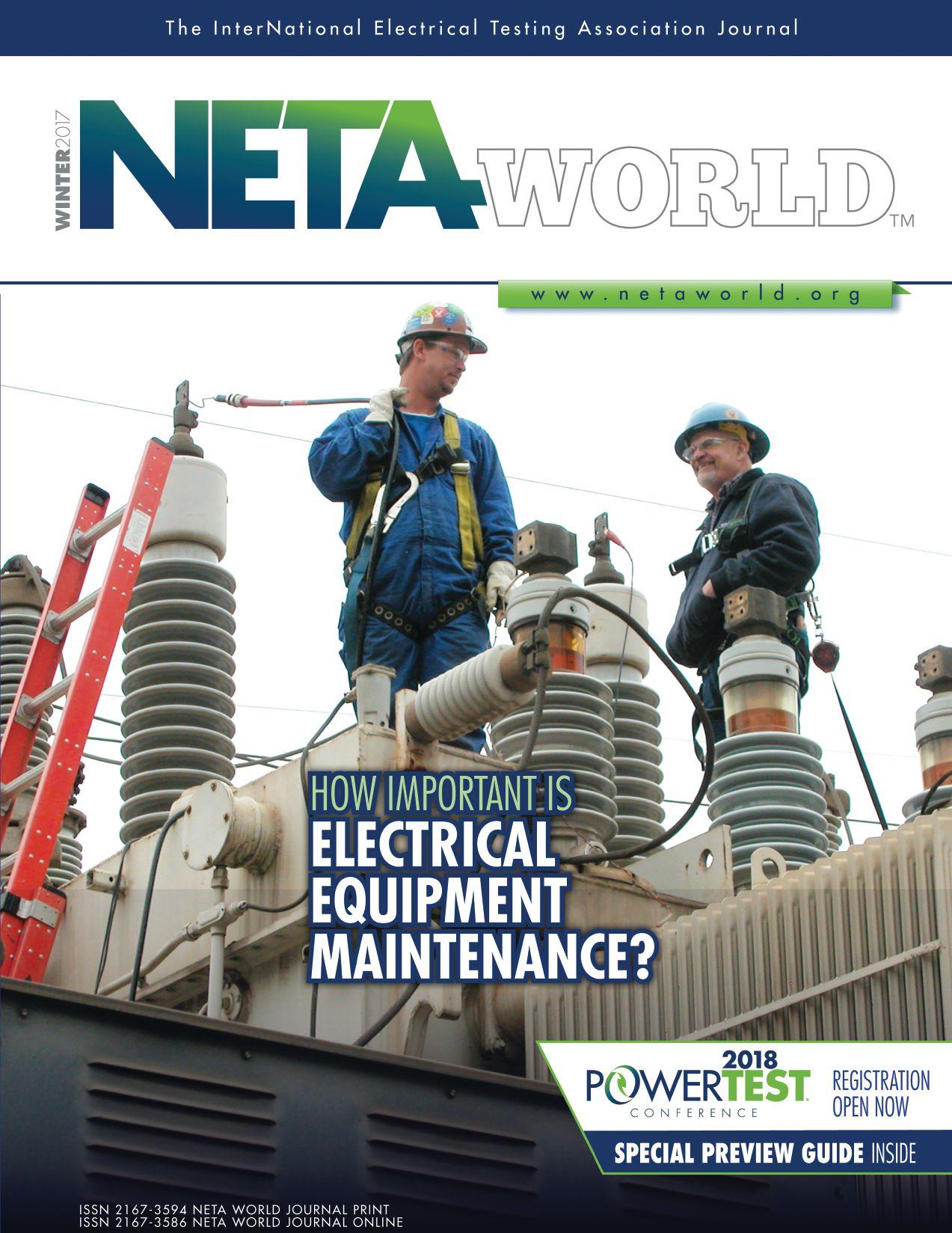
IMPORTANT LINK BETWEEN MAINTENANCE AND SAFETY
This month’s NETA World theme is Safety. It’s our most important topic, and I hope you get a lot from the outstanding articles presented this month.
An important link between electrical equipment maintenance and safety is sometimes overlooked: A much higher risk of an equipment failure exists when the equipment is not maintained properly. There is also a potential for higher energy release should a fault occur when protective devices are not maintained in proper working condition.
When we work on equipment, we need to be aware of its condition. Is it dirty? Are there test stickers on the equipment? What is the date of the last maintenance? All of these factors impact the risk of working on the equipment. The risk is what we are trained to assess before we start work.
There is a lot of information to help us. NFPA 70E is a good source, and the 2018 issue is now available. One very important point: PPE only works when you wear it.
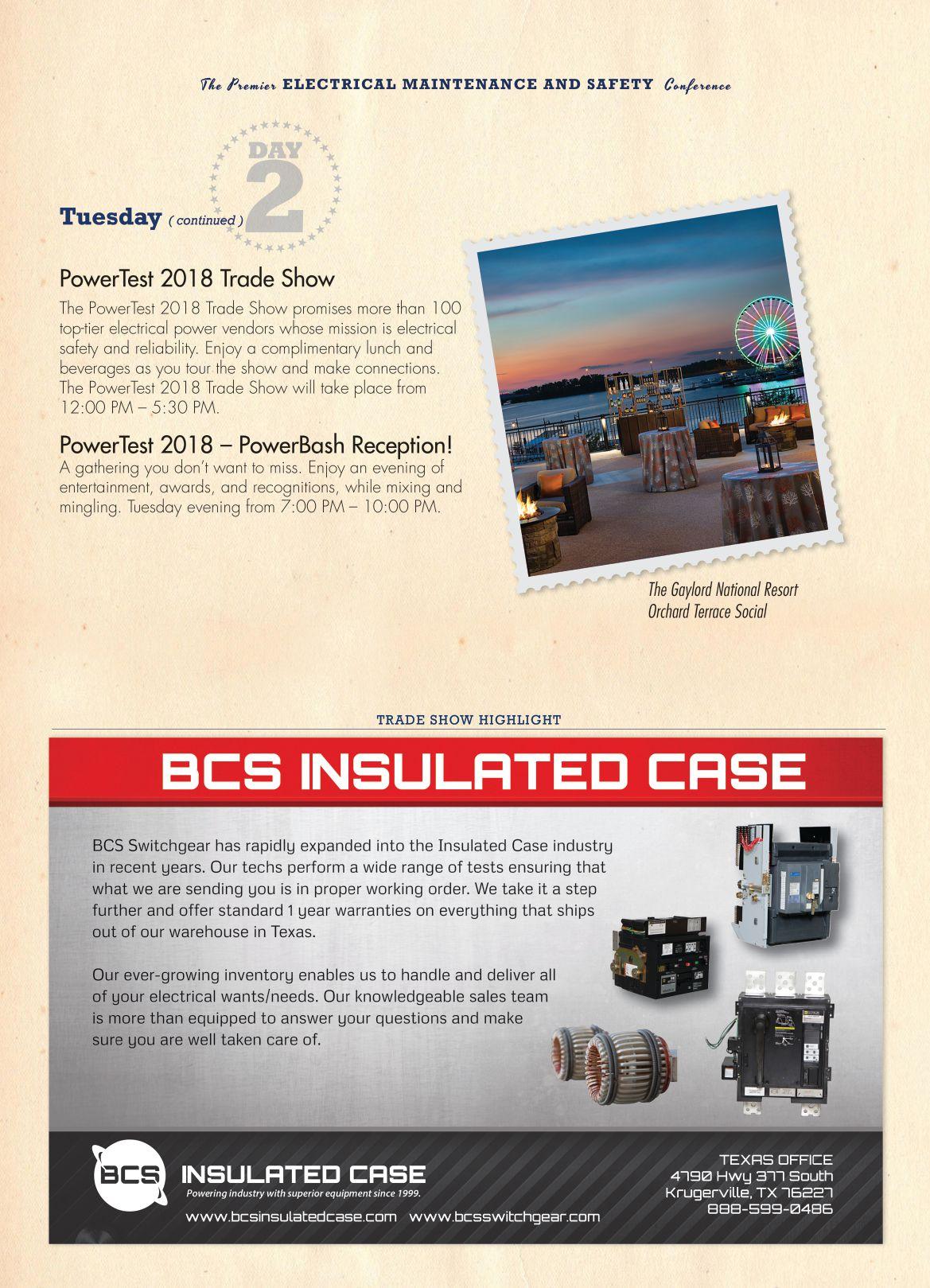
I hope to see you all at PowerTest 2018, February 26 –March 2, at the Gaylord National Resort & Convention Center in Washington, DC.
Be safe!
 James Cialdea, President NETA — InterNational Electrical Testing Association

PRESIDENT’S DESK PRESIDENT’S DESK

Absolute con dence. Every time.
You can count on us for specialized experience in healthcare, data center, o ce complex, and commercial acceptance and maintenance testing. Absolutely Power generation, petrochemical, oil & gas, and heavy industries also look to us for high demand services such as start-up commissioning, maintenance testing, shut-down and turnarounds, and breaker shop repair. Get started today.


Toll Free 1+ (855)767-4446 8100 West Little York | Houston, Texas 77040 Email: Alan Postiglione | apost@absolutetesting.com | www.absolutetesting.com Like us on:


• Largest Inventory • Consistent Delivery Service • Immediate Availability • ISO and ANSI Accredited Labs Vanguard Instruments Company, Inc www.vanguard-instruments.com ELECTRO RENT ANSWERS YOUR EVERY TEST NEED 888.739.1095 www.electrorent.com/electrical-power sales@electrorent.com Electro Rent works to make your job easier! Count on Electro Rent to get the latest test equipment you need rapidly and with experienced customer support you can rely on. From Insulation and Power Quality to Motor Test Equipment, if it tests, we’ve got it and we’re ready to meet your needs.


The New NFPA 70E 2018 Edition is coming and you need to be ready. Look to Shermco for your required Electrical Safety for Electrical Workers training, or just a refresher course to get you up to date on the revisions.
Of course, all of your electrical technician and manager training needs are available as well, so take advantage of the expert’s experts here at Shermco.
Shermco’s field service technicians are required to complete this course. Shouldn’t you be training with the people who are in the field every day?
www.shermco.com
888-SHERMCO
All Shermco safety courses include the changes to the 2018 NFPA 70E, including our popular Electrical Safety for Qualified Electrical Workers, which provides the electrical safety training and the documented hands-on practical exercises and lab sessions mandated by OSHA 29CFR2910.132 and NFPA 110.2. Other electrical safety courses include Electrical Safety for Managers, Electrical Safety for Non-Electrical Personnel and Electrical Safety for Utilities.
Don’t risk fines and events due to “check-the-box” training. Train with the experts. Train with Shermco.
2018 is right around the corner. 2018 is right around the corner. Questions? training@shermco.com
USING NFPA 70E 2018 IN THE FIELD
BY RON WIDUP and JIM WHITE, Shermco Industries
Many eld technicians have issues when it comes to using NFPA 70E in practical eld applications. is NETA World Journal 70E and NETA column provides some introductory information needed to fully apply and understand the accompanying feature article on the steps required to insert or remove (rack) a circuit breaker. Read this column rst, then turn to the feature article (page 48).
FIRST THINGS FIRST
e company’s electrical safety program (ESP) must be updated to be in compliance with NFPA 70E. Just recently, we reviewed a major corporation’s ESP that had last been updated to the 2012 edition of NFPA 70E. When our recommended changes were sent to their safety committee for review, they were met with resistance. Some members of that company’s safety committee thought accepting the latest changes might make them responsible if an accident occurred. We responded that basing their ESP on the 2012 edition of NFPA 70E put them in a vulnerable position because workers would not have the latest consensus standard on safety-related work practices. Not updating their ESP to the latest 2018 edition could create legal challenges, as well. At least, they needed an updated ESP to show good-
faith e ort. Continuing to use an outdated version of the 70E because it might make you responsible is just not smart.
e following statement precedes the foreword in every edition of NFPA 70E. is wording is from the 2018 edition.

This edition of NFPA 70E®, S tandard for Electrical Safety in the Workplace® , was prepared by the Technical Committee on Electrical Safety in the Workplace and released by the Correlating Committee on National Electrical Code®. It was issued by the Standards Council on August 1, 2017, with an e ective date of August 21, 2017, and supersedes all previous editions.
It seems pretty clear: Use an out-of-date 70E as the basis for your company’s ESP, and it is out of compliance. How is that defensible in court if there is an injury or fatality?
NETAWORLD • 11 USING NFPA 70E 2018 IN THE FIELD
THE NFPA 70E AND NETA
THE NFPA 70E AND NETA
APPLYING NFPA 70E
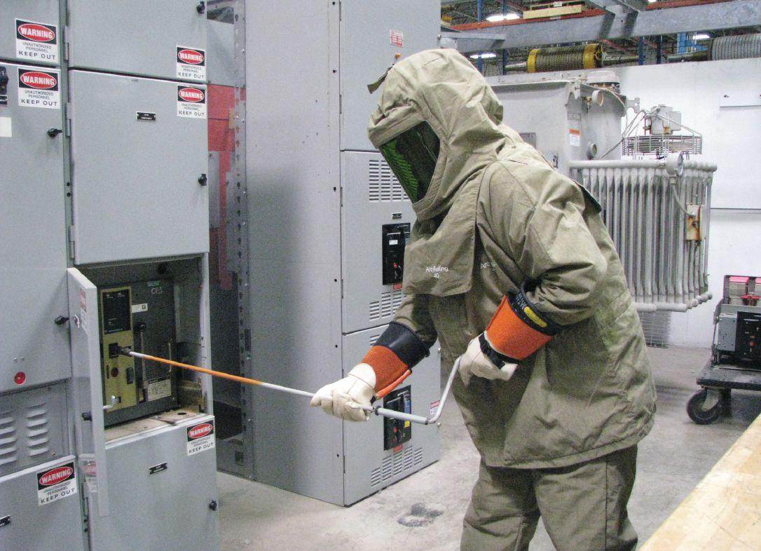
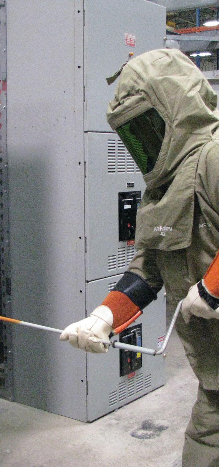
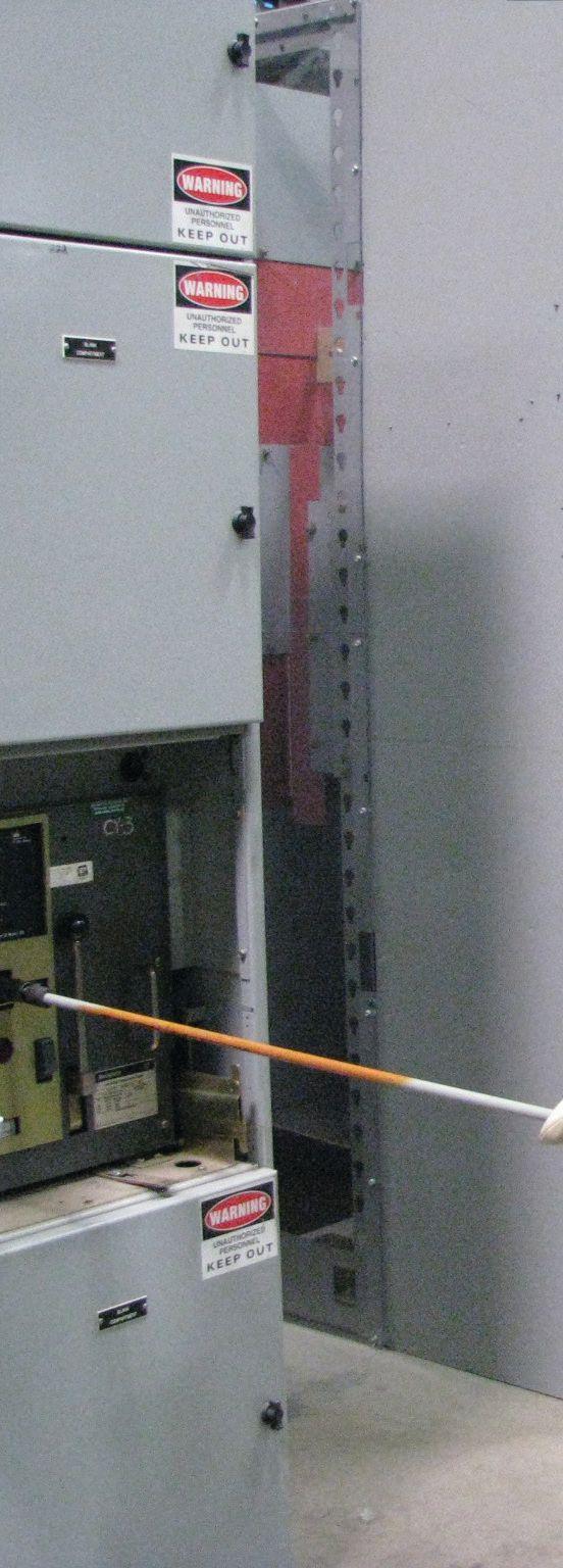
Racking a circuit breaker is a fairly common task that probably occurs a few thousand times a week at industrial facilities all over the United States. However, it is a task that presents many hazards as well as an increased risk of equipment failure.
How can NFPA 70E be applied to this task? A good place to begin is at the beginning: Article 100 — Definitions. Informational Note No. 1 for the definition of an arc flash hazard states:
An arc flash hazard may exist when energized electrical conductors or circuit parts are exposed or when they are within equipment in a guarded or enclosed condition, provided a person is interacting
with the equipment in such a manner that could cause an electric arc. Under normal operating conditions, enclosed energized equipment that has been properly installed and maintained is not likely to pose an arc flash hazard.
This definition contains a number of important points for the worker.
• An arc flash hazard might exist when energized conductors or circuit parts are exposed. We normally would consider a hazard to exist “when energized electrical conductors or circuit parts are exposed or when they are within equipment in a guarded or enclosed condition.” How could that be? When equipment is in a guarded condition, energized components cannot
12 • WINTER 2017 USING NFPA 70E 2018 IN THE FIELD
Racking a Circuit Breaker (Photo courtesy Shermco Industries)
be contacted. The definition of “guarded” in 70E states: ….to remove the likelihood of approach or contact by persons or objects to a point of danger.
Whenever a bus connection is made or broken while the bus is energized, the probability of an arc flash event increases. The actual number of such events is small — probably less than one per month. That is a small percentage of the many thousands of times this task is performed. When an arc flash does occur, however, the consequences can be devastating, especially if the worker is unprotected or underprotected. An arc flash at the bus means the next overcurrent protective device upstream must operate to clear the fault. That device might have a short time delay (STD) function to properly coordinate with other overcurrent protective devices upstream. That could delay opening of the upstream circuit breaker by as much as a half second or more. The incident energy from such a fault could potentially be beyond what is normally worn as a PPE Category 4 arcrated flash suit.
NFPA 70E does not consider equipment doors to provide adequate protection, as noted in 130.7(C)(15)(b) Informational Note No. 2, which states:
In most cases, closed doors do not provide enough protection to eliminate the need for PPE in situations where the state of equipment is known to readily change (e.g., doors open or closed, rack in or rack out).
Racking a circuit breaker is one of the specific instances where the state of the equipment is known to change rapidly (arc flash). Therefore, racking circuit breakers constitutes an increased probability of an arc flash, even though the conductors and circuit parts are enclosed.
• Informational Note No. 1 continues: “Under normal operating conditions, enclosed
THE NFPA 70E AND NETA
energized equipment that has been properly installed and maintained is not likely to pose an arc flash hazard.” The conditions for normal operation are set forth in 130.2(4) Normal Operating Condition. Normal operation exists when all of the following conditions are satisfied:
1. The equipment is properly installed.
2. The equipment is properly maintained.
3. The equipment is used in accordance with instructions included in the listing and labeling and in accordance with manufacturer’s instructions. (Note: Added for NFPA 70E 2018)
4. The equipment doors are closed and secured.
5. All equipment covers are in place and secured.
6. There is no evidence of impending failure.
All six conditions must be met or the equipment cannot be considered normally operating. If the equipment is no longer normally operating, fully arcrated clothing and PPE must be worn for any task, including opening and closing. Additionally, if the task is troubleshooting (that’s not the example task, but…) the equipment is in distress and cannot be considered normally operating.
• “… not likely to pose an arc flash hazard.” When 70E states something is not likely, it is not saying it won’t happen; it means the probability is reduced, but not eliminated. If a 60 A circuit breaker is about to be operated (opened or closed), the consequences of a failure would be pretty small. A pair of leather work gloves, UV-rated safety glasses or goggles, hearing protection, and cotton clothing would provide adequate protection (what we would call Category 0 PPE in previous editions of NFPA 70E).
If a 600 A circuit breaker is about to be operated, the consequences of a failure
NETAWORLD • 13 USING NFPA 70E 2018 IN THE FIELD
THE NFPA 70E AND NETA
would be much greater. Now, some level of arc-rated clothing and PPE would be needed, probably a PPE Category 2 or 3, depending on the operating speed of the overcurrent protective device. Bump that up to a 3,000 A circuit breaker, and the consequences of a failure could be severe. PPE Category 4 arc-rated clothing and PPE would probably be needed.
Th is is why many companies require the use of arc-rated clothing and PPE for their employees to operate a circuit breaker or a switch. It needs to be stated that NFPA 70E is a standard. Standards only provide minimum requirements — not the best requirements —and so it is with 70E. It is expected that employers and employees using 70E will meet or exceed the requirements when it is necessary.
CONCLUSION
A company’s electrical safety program must be updated to comply with NFPA 70E requirements. Using an out-of-date edition automatically renders the ESP as non-compliant. Since the 70E is a safe work practices standard, only the current edition will have the latest thinking on those safe work practices.
Understanding what is considered an arc flash hazard is important to being a qualified person. It is human nature to want to get right into the meat of 70E, but Article 100 is important to using 70E properly. By breaking the definition for an arc flash hazard into its separate pieces, its true meaning can be clearly seen.
Did you read the feature article on the steps required for racking a circuit breaker first? That’s okay. What is important is to read both of these pieces and put them together.
Ron Widup and Jim White are NETA’s representatives to NFPA Technical Committee 70E Electrical Safety Requirements for Employee Workplaces. Both gentlemen are employed by Shermco Industries in Dallas, Texas, a NETA Accredited Company.

Ron Widup is CEO of Shermco Industries and has been with the company since 1983. He is a member of the Technical Committee on Standard for Electrical Safety in the Workplace (NFPA 70E), a principal member of the National Electrical Code (NFPA 70) Code Panel 11, a principal member of the Technical Committee on Standard for Competency of Third-Party Evaluation Bodies (NFPA 790), and a principal member of the Technical Committee on Recommended Practice and Procedures for Unlabeled Electrical Equipment Evaluation (NFPA 791). He is also a member of the Technical Committee Recommended Practice for Electrical Equipment Maintenance (NFPA 70B), and a member of the NETA Board of Directors and Standards Review Council. He is Vice Chair for IEEE Std. 3007.3, Recommended Practice for Electrical Safety in Industrial and Commercial Power Systems. Ron is a State of Texas journeyman electrician, a NETA Level 4 Senior Technician, and an NFPA Certified Electrical Safety Compliance Professional (CESCP).

James (Jim) R. White has been the Training Director for Shermco Industries since 2001. He is a NFPA Certified Electrical Safety Compliance Professional (CESCP) and a NETA Level 4 Senior Technician. Jim is a principal member on NFPA Technical Committee NFPA 70E Standard for Electrical Safety in the Workplace; a principal member on NFPA Technical Committee NFPA 70B Recommended Practice for Electrical Equipment Maintenance; a principal representative on NEC Code-Making Panel (CMP) 13; a member of ASTM International Technical Committee F18 Electrical Protective Equipment for Workers; and represents AWEA on ISEA ANSI/ISEA Standard 203, Secondary SingleUse Flame Resistant Protective Clothing for Use Over Primary Flame Resistant Protective Clothing. An IEEE Senior Member, he received the IEEE/IAS/PCIC Electrical Safety Excellence Award in 2011 and NETA’s Outstanding Achievement Award in 2013. Jim was Chair of the IEEE Electrical Safety Workshop in 2008 and is currently the Vice-Chair for the IEEE IAS/ PCIC Safety Subcommittee.
14 • WINTER 2017 USING NFPA 70E 2018 IN THE FIELD

• Selectable test voltages from 10 to 1000V*
• Insulation resistance measurement up to 200GΩ*
• Active voltmeter detects live voltage prior to starting a test
• Automatic test inhibition if live voltage above 25V detected
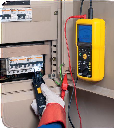
• Measures V (AC & DC), Hz, Ω, kΩ, capacitance and cable length*
• Computer report generation of test results
• Data storage of test results* * Model dependent

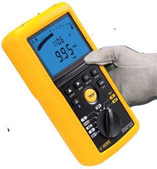
AEMC® has NEW Expert Tools for Testing Insulation Safely & Accurately! Chauvin Arnoux®, Inc. d.b.a. AEMC® Instruments 200 Foxborough Blvd., Foxborough, MA 02035 USA Phone: (800) 343-1391 • Fax: (508) 698-2118 www.aemc.com
6500 Series Handheld Megohmmeters Including Multimeter Functions IP Rated 54


THE EXPERTS IN ELECTRICAL RELIABILITY
Comprehensive Electrical Testing and Maintenance
Commissioning and Startup Services
Engineering Services Power System and Coordination Studies
FAILURE IS NOT AN OPTION.
Predictive and Preventive Maintenance
Partial Discharge Testing and Monitoring
24/7 Emergency Service
Ensuring the reliability of your electrical distribution system.
As the leading independent electrical testing, maintenance, and engineering service company, you can rely on High Voltage Maintenance to exceed your electrical equipment performance goals. From testing for problems that could disable your system, to complete turnaround execution, you’ll quickly understand how we are your single source solution for all of your electrical reliability needs. With a service geography across the Midwest and Eastern Seaboards, our service team puts experienced professionals where and when you need them.


For more information: High Voltage Maintenance (866) HVM-TEAM
A great deal of our work today involves performing an incident energy or arc ash study. is also involves performing a shortcircuit study that might reveal underrated switchboards or breakers. Figure 4 shows a breaker underrated for the 64kA available fault current present in an existing 480 volt switchboard; therefore, it was removed from service and replaced with a higher rated breaker.
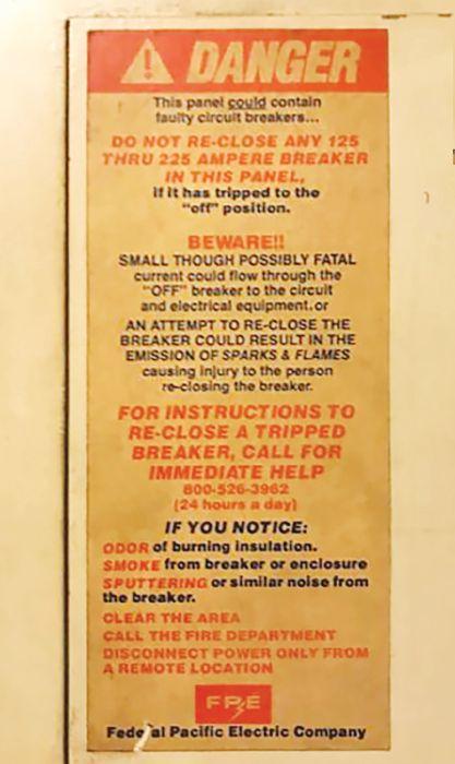
Figure 5 came from the eld. We are all happy that the breakers hadn’t tripped, as we apparently
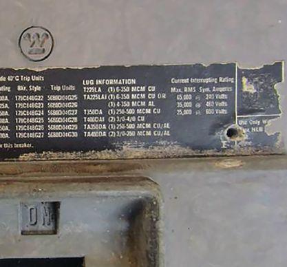
Figure 4: Although di cult to read in this photo, this breaker is underrated for its application and has been replaced in the switchboard.
can’t reset them! Perhaps the warning is intended to make sure the circuit is cleared of faults before attempting to close after a trip. Any way you look at it, this one looks dangerous.
Figure 6 is typically found inside the padmount transformer enclosure near the tap changer operator. e types of tap changers found in these transformers are also known as

TRANSFORMER BEFORE OPERATING TAP-CHANGER. FAILURE TO COMPLY MAY RESULT IN PERSONAL INJURY OR PROPERTY DAMAGE
Figure 6: Caution Sign Inside Padmount Transformer
NETAWORLD • 19
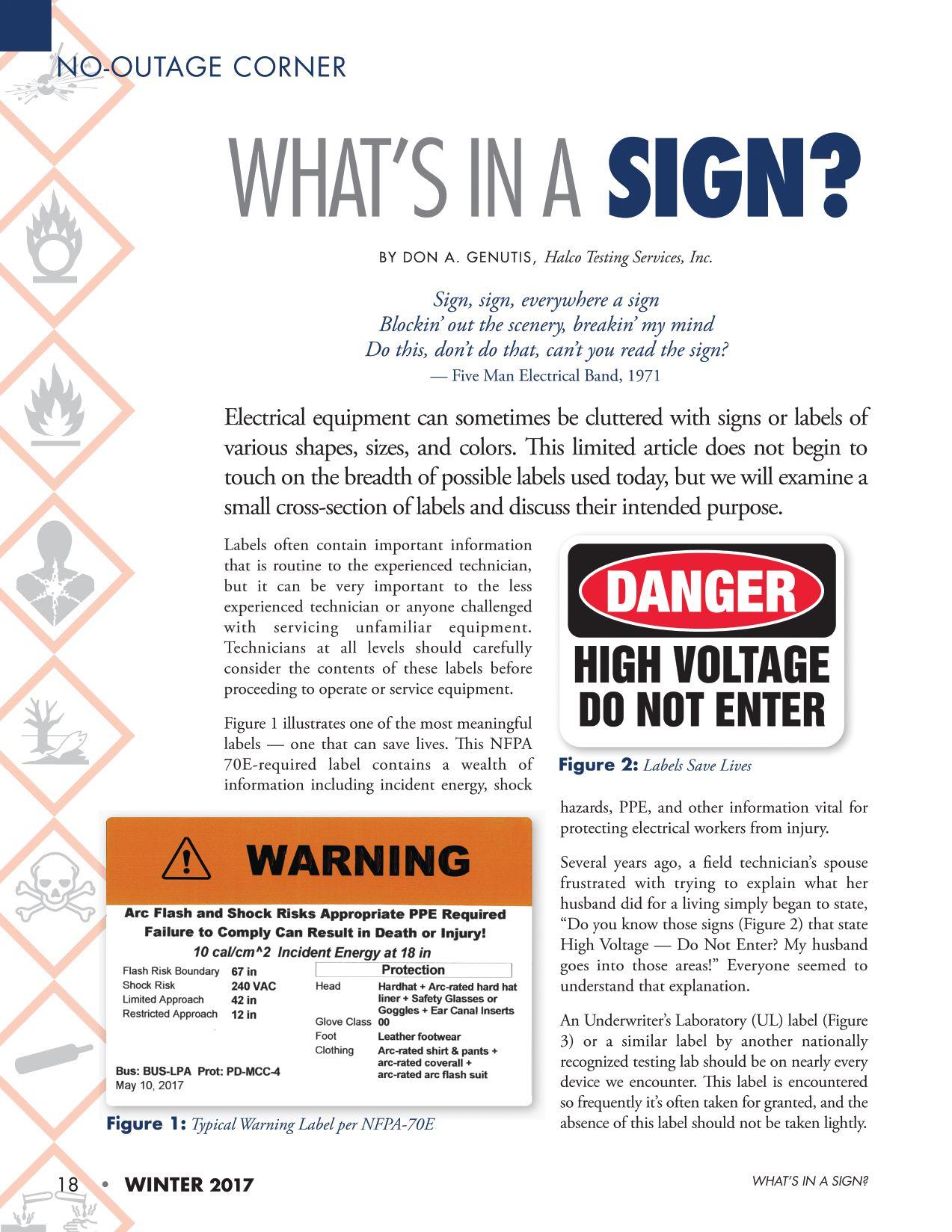
WHAT’S IN A SIGN?
Figure 5: Confusing Danger Label
NO-OUTAGE CORNER
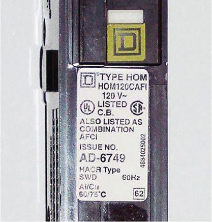
Figure 3: Breaker with UL Label
CA UTI O N DE-ENERGIZE

Power Monitors: Rugged Power Analyzers and Loggers for tough environments. Ground Resistance Meters, with built-in GPS and PC connection. High-performance IR Imaging cameras. UV Corona Camera. www.soneltest.com | Buy. Or Rent from us at a great rate! | Call: 408 898 2215 The New World of Electrical Test Tools
James (Jim) R. White has been the Training Director for Shermco Industries since 2001. He is a NFPA Certified Electrical Safety Compliance Professional and a NETA Level IV Senior Technician. Jim is NETA’s principal member on NFPA Technical Committee NFPA 70E® Standard for Electrical Safety in the Workplace®; is Shermco Industries’ principal member on NFPA Technical Committee NFPA 70B Recommended Practice for Electrical Equipment Maintenance; is NETA’s principal representative on NEC® Code-Making Panel (CMP) 13; represents NETA on ASTM International Technical Committee F18 Electrical Protective Equipment for Workers; and represents AWEA on ISEA ANSI/ISEA Standard 203, Secondary Single-Use Flame Resistant Protective Clothing for Use Over Primary Flame Resistant Protective Clothing Jim is an IEEE Senior Member, was Chair of the IEEE Electrical Safety Workshop in 2008, and is currently the Vice-Chair for the IEEE IAS/PCIC Safety Subcommittee.
FOCUS ON SAFETY
JIM WHITE, Shermco Industries

NETA technicians receive safety training to the point where it becomes routine — even forgettable. That’s unfortunate, because we come into close proximity nearly every day to electrical hazards and the risk associated with those hazards. The Tech Quiz for this issue ventures into the weeds to emphasize the importance of human performance.
1. Familiarity breeds ______.
A. A warm feeling, much like romance
B. Alcohol poisoning
C. Contempt
D. Rabbits
2. How would you react to the following scenario? You are asked to troubleshoot a motor control center. There’s a guard on the line-side of the incoming circuit breaker. After checking for the absence of voltage (wearing your arc-rated PPE, of course) you:
A. Mark the MCC bucket with red safety barrier tape
B. Remove your PPE, since it is proven dead
C. Continue to wear your arc-rated PPE
D. Decide it’s a good time for a break
3. When does NFPA 70E state a safety backup is needed?
A. Never
B. When we are exposed to shock hazard
C. When our risk assessment indicates one is needed
D. Any time our company’s policies and SOPs require it
4. One aspect of human performance is that of __________.
A. Attention
B. Rejection
C. Multitasking
D. Rule-making
5. NETA’s minimum safety guidelines state three behaviors that could result in disciplinary action (reference Section 4, Personal Responsibilities). What are they?
A. Alcohol/drug use, sleeping on the job, fighting
B. Alcohol/drug use, showing up late, horseplay
C. Alcohol/drug use, playing cards, practical jokes
D. Alcohol/drug use, fighting, horseplay
See answers on page 123.
22 • WINTER 2017 TECH QUIZ
TECH QUIZ
No. 120

EMERGING TECHNOLOGIES AND WEB-BASED LEARNING DEBUT AT NETA MEMBER MEETING

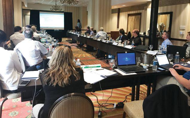
NETA’s Board of Directors and Membership met at the Brown Palace Hotel & Spa in Denver, Colorado, for regularly scheduled meetings on September 21–22, 2017. NETA Accredited Company Representatives and other members received updates on the association’s initiatives and activities, as well as general information about NETA’s business health.
24 • WINTER 2017 EMERGING TECHNOLOGIES AND WEB-BASED LEARNING DEBUT AT NETA MEMBER MEETING

MEMBERSHIP MEETING
Following the business segment of the Membership Meeting, participants experienced the first annual Emerging Technologies presentations that provided opportunities to hear about new technologies impacting their work now and in the future, and to follow up with questions. Presenters included Megger’s Robert Foster on “Dynamic Contact Resistance Testing for Load-Tap Changers and Circuit Breakers,” and Western Electrical Services’ Dan Hook on “Online Partial-Discharge Testing.” Emerging Technologies will be part of the fall Member Meeting each year as a means to provide additional technical education and network opportunities to participants.
NETA also rolled out its new online training platforms, which allow for single signon access to NETA’s Self-Paced Technical Seminars (SPTS). The hard-copy SPTS course books have been replaced by a webbased platform that provides access to course materials anytime, anywhere. With this latest advancement, all NETA training is now available online. Additional benefits of the new training platforms include:
1. Single Sign-on Interface
• Users log in to the NETA website
• Purchase courses in the NETA Bookstore
• Receive instructions on how to access purchased courses via email
• No more hard copies to keep track of
• No more video file issues
2. Videos, Presentations, and Proficiency Tests
• All in one location
• Results automatically recorded to technician’s record
Two new SPTS courses also debuted to the membership: “Understanding Generator Protection” by Scott Cooper, OMICRON electronics Corp. USA, and “What Does a Partial Discharge Tell Me and How Do I Perform the Test?” by Tom Sandri, Shermco Industries.
BOARD MEETING
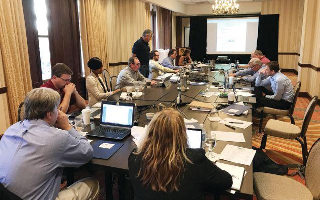
The NETA Board spent time on succession planning to ensure that the association’s progress will continue seamlessly as volunteer and committee membership grows and evolves. Succession planning assures that NETA committees and programs continue to be supported by NETA’s most precious assets: its volunteers. Additional details will be reported to the membership during PowerTest 2018 in Washington, DC, February 26 – March 2, 2018.
Additional discussions covered marketing and promotions activities and a detailed overview of the PowerTest conference and trade show. The next NETA Membership Meeting will be held in January 2018.
NETAWORLD • 25 EMERGING TECHNOLOGIES AND WEB-BASED LEARNING DEBUT AT NETA MEMBER MEETING
NETA Membership Meeting
NETA Board Meeting

Industrial Electric Testing, Inc.
• Cables
• LV/MV Circuit Breakers
• Rotating Machinery
• Meters
• Automatic Transfer Switches
• Switchgear and Switchboard Assemblies
• Load Studies
• LV/MV Switches
• Relays - All Types
• Motor Control Centers
• Grounding Systems
• Transformers
• Insulating Fluids
• Thermographic Surveys
• Reclosers
• Surge Arresters
• Capacitors
• Batteries
• Ground Fault Systems
• Equipotential Ground Testing
CoNSulTING AND ENGINEERING SERvICES
• Transient Voltage Recording and Analysis
• Electromagnetic Field (EMF) Testing
• Harmonic Investigation
• Replacement of Insulating Fluids
• Power Factor Studies 11321 West Distribution Avenue • Jacksonville, Florida 32256 • (904) 260-8378 201 NW 1st Avenue • Hallandale, Florida 33009 • (954) 456-7020

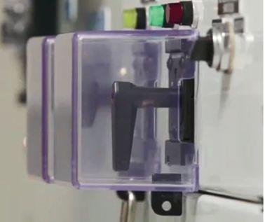


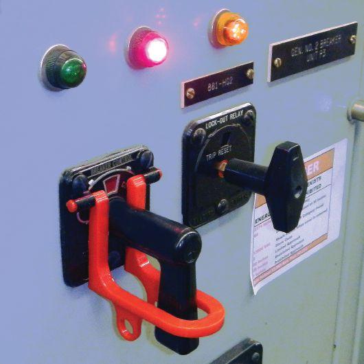
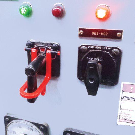
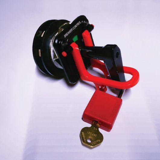
GOT PROTECTION? Add physical security to your controls switches. SENTINEL CONTROL PRODUCTS, LLC Sentinel CS-1 Conrtol Switch Safety Cover INSTALL IN MINUTES • NO DRILLING • LOCKABLE For complete details, visit: sentinelcontrolproducts.com US Patent 9,756,754 B2 Compatible with: Electroswitch • ITI • GE • Shallco
EC13004105 • 24 Hour Emergency Service ACCEPTANCE AND MAINTENANCE TESTING AND REPAIR


BALANCE AIDS MITIGATION
BY JEFF JOWETT, Megger
Grounding and ground testing are topics and practices most widely recognized by familiar terms and organizations like Fall of Potential Method, 62 Percent Rule, IEEE and NETA standards and practices, and the National Electric Code® (NEC®). These and other significant contributions to the body of knowledge form the foundation of the subject and its implementation in practice.
But ground testing, the instrumentation associated with it, and the requirements for electrode and system installation, testing, and maintenance are evolving right along with electrical systems and applications in general. One of the most sensitive, progressive, and demanding areas is that of telecommunications.
Almost everyone uses cell phones, and many have had the regrettable experience of trying to carry on a conversation through what sounds like trench warfare in WWI — crackling, banging, whistling, whooshing — and sounds that can’t even be described in onomatopoeia. There are numerous possible causes for this unwelcome phenomenon, generally tracing back to electrical noise from a variety of possible sources. That small extraneous disturbance riding on top of the main signal, which would mean nothing to a lamp or a motor, becomes
larger by comparison as powered equipment becomes more sensitive, and it can reach its apotheosis on a phone connection. There are numerous causes and no single miracle cure, but this article will examine one very subtle and easily overlooked issue.
The basic lightning grounds of POTS systems (Plain Old Telephone Service) generally could be relied upon to protect these more robust, less-demanding systems. That was before voice, data, and video were included. Now, voltage disturbances that would mean little or nothing to a typical power system load loom large in the communication system (Figure 1). Grounding and bonding must now meet more stringent requirements.
Let’s focus more closely on the concept of noise. There are numerous possible sources,
28 • WINTER 2017 BALANCE AIDS NOISE MITIGATION
TECH TIPS

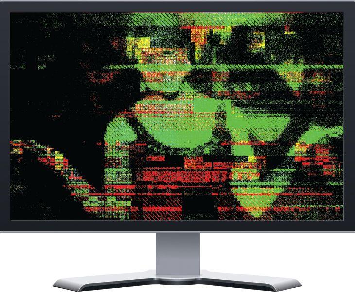
but in particular, there is the problem of random spikes of impulse noise. Common grounding systems protect against steadystate noise, but the narrow plus/minus voltage windows that support data transmission can experience loss of data bits from impulse noise. Such loss is always a sign of inadequate grounding and/or bonding. If cables were bonded and grounded, impulse noise would go to ground and not interfere with the transmitted signal.
And the problem is getting progressively more acute. As data rates increase, the same length of impulse noise spike knocks out more data bits. Moreover, compression protocols now allow each bit to carry more information; hence, the same length of noise spike is progressively knocking out more and more data. For this problem to be effectively and thoroughly mitigated, the grounding requirements had to include a new concept: balance. International telecommunications standard Data Over Cable
Service Interface Specification (DOCSIS) 3.1 now includes not only the traditional and familiar aspects of grounding and bonding for hubs and headends, but also new parameters for establishing adequate balance.
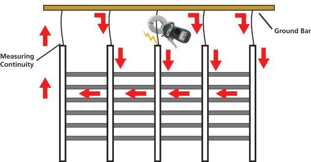
Let’s examine the elements of hub and headend grounds. The ground bus bar, shelves, racks, and aisles all must be considered. The shelves are bonded to racks with screws and wire. The racks are bonded together into aisles, and the aisles are bonded to bus bars. Wires, bars, screws, posts, and bolts — sometimes of different materials — are all part of this system and bonded together by various methods. Collectively, these runs must meet the familiar, low-resistance safety spec and have the same resistance to establish balance. Each place these elements are bonded is a potential ingress point where moisture, rust, corrosion, loosening, installation damage, and the like can compromise the connection — and there are thousands of them.
NETAWORLD • 29 BALANCE AIDS NOISE MITIGATION
TECH TIPS
Figure 1: Steady-State Noise Caused by Inadequate Grounding and/or Bonding
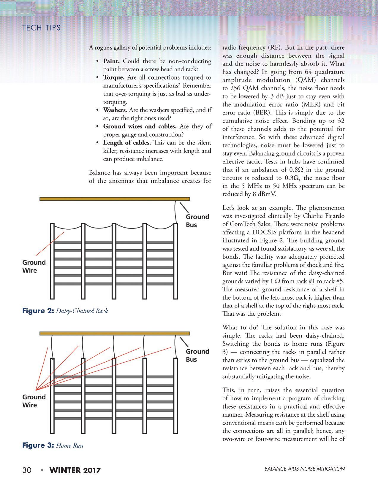

the structure, not the bond. However, a fully e ective comparative test can be accomplished by measuring continuity. is can be readily and reliably performed with a clamp-on ground tester.

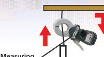
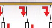

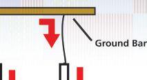

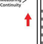
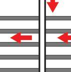
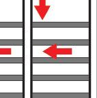
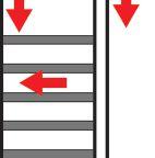
e clamp-on tester’s jaws are comprised of two windings; one induces a test current and the other measures the voltage drop caused by the resistance around the current circuit. Note a critical di erence from conventional multimeter and ohmmeter tests. With the clamp-on, the tester automatically establishes its own test circuit by following paths of low resistance rather than a xed circuit between alligator clips set by the operator. In Figure 4, the test current would travel through all the same paths from any point; the only di erence is that it must enter the circuit from the point immediately below the clamped position. erefore, the reading should be essentially the same from any clamped point in this system.
at’s balance. If there was a bad connection, as in Figure 5, that would limit the current entering via the clamped position and it would show up as a higher reading. Note that it isn’t so much the absolute measurement as the comparative reading that is critical here. If they’re all the same, the system is balanced. If not, there can be cross-talk.
Referring to the list of possible problems, if the clamp-on is positioned just upstream of such localized problems as a painted joint, a bad washer, or an over-torqued connection, the current will be reduced through that aw as compared to the parallel paths and will appear as a tell-tale higher reading. Similarly, when clamped around a mismatched gauge or section of cable, the test current will be out of sync with parallel connections, and the operator will be able to recognize and correct the problem.
CONCLUSION
Mismatched parallel circuits in a headend or hub can be a devilish source of noise and loss



of data, but one that can be relatively easily ferreted out and corrected. Ahhh…beautiful background silence. No more air raid!

Je rey R. Jowett is a Senior Applications Engineer for Megger in Valley Forge, Pennsylvania, serving the manufacturing lines of Biddle, Megger, and MultiAmp for electrical test and measurement instrumentation. He holds a BS in biology and chemistry from Ursinus College. He was employed for 22 years with James G. Biddle Co., which became Biddle Instruments and is now Megger.
NETAWORLD • 31 TECH TIPS BALANCE AIDS NOISE MITIGATION
Figure 4: With all connections good, the rack tests the same from every point.
Figure 5: Poor connection limits test current and increases resistance.

PowerSystemsTesting.1-2_NETA.WI15.indd 1 10/21/15 9:16 AM
sitting on the shelf for an extended period of time. Alternatively, if the service is performed frequently or on many pieces of equipment, it doesn’t make sense to store hundreds of small aerosol spray cans that may require special storage and disposal considerations, such as in a flammable-materials cabinet. This may be due to the aerosol can using a propane propellant, causing the material to be listed as flammable. In this situation, it may be better to purchase the material in bulk, such as a 55-gallon container, and apply it with another means such as a small pump sprayer. This eliminates the propane propellant. Depending on the chemical’s properties, it may or may not be considered a hazardous or flammable material requiring special storage containment and notification to the local emergency planning commission.
If either the propellant or the material itself is flammable, it cannot be used in an area where heat or a potential arc could ignite it. Look at the SDS for the lubricant and determine its flash point. Avoid material that contains the words “flammable” or “keep away from heat or flame,” or displays the Globally Harmonized Standard (GHS) pictogram (Figure 1) on its label, or that contains a propane propellant. These materials typically have a very low lower explosive limit (LEL) indicating that they will readily ignite in the presence of heat or spark.
Health considerations are also a factor when considering an appropriate lubricant. What personal protective equipment (PPE) does the employee need to wear when applying the lubricant? The technician or electrician may need to wear nitrile gloves and safety glasses or goggles to handle the chemical safely. To determine this, refer to Section 2 — Hazard(s) Identification; Section 8 — Exposure Controls/ Personal Protection, and Section 11 — Toxicological Information on the SDS that follow the standard set forth in the current OSHA 29 CFR 1910.1200.
Often, the equipment to be serviced is enclosed within a cabinet with limited ventilation.
This means fumes and vapors can accumulate and possibly overwhelm an employee. In cases where the lubricant has this potential, additional ventilation or respiratory protection may be required. Determine whether the fumes generated from the chemical are denser than air; if they are, fumes can collect in low-lying areas, causing a flammable or health-hazardous atmosphere. To find additional information, refer to the SDS for the lubricant being researched.
The environmental impact of storing and disposing of the chemical should also be considered. Refer to the SDS to determine any environmental impacts the chemical will have if there is an accidental release. If release could pose an environmental hazard, employees should be trained on spill-response procedures. Disposal of lubricant waste can also pose an environmental risk. State and federal agencies (e.g., Departments of Environmental Protection in many states (DEP), the U.S. Environmental Protection Agency (EPA), various state Departments of Environmental Management (DEM), and
NETAWORLD • 35 THE DOS AND DON’TS OF ELECTRICAL EQUIPMENT LUBRICATION
SAFETY
CORNER
Figure 1: GHS Label Indicating Flammable Material
SAFETY CORNER
the U.S. Department of Energy Office of Environmental Management) may require notification when disposing of certain quantities of chemical wastes. There are also time limitations on the storage of regulated waste chemicals based on certain quantities. Waste generators, shippers, and disposers are required to obtain certifications and track the shipment of the chemical from cradle to grave.
Before using any lubricant, determine its health effects, flammability, and reactivity. Sometimes this can be done by simply referencing the
16. Other information, including date of preparation or last revision
Issue date 01-16-2015
Revision date 06-12-2017
Prepared by Allison Yoon
Version # 02
Further information CRC # 568F/G
HMIS® ratings Health: 2*
Flammability: 4
Physical hazard: 0
Personal protection: B
NFPA ratings Health: 2
Flammability: 4
Instability: 0
label; other times, more information may need to be obtained from the SDS. Figure 2 shows the SDS of a common white lithium aerosol spray lubricant that provides the HMIS and NFPA label data.
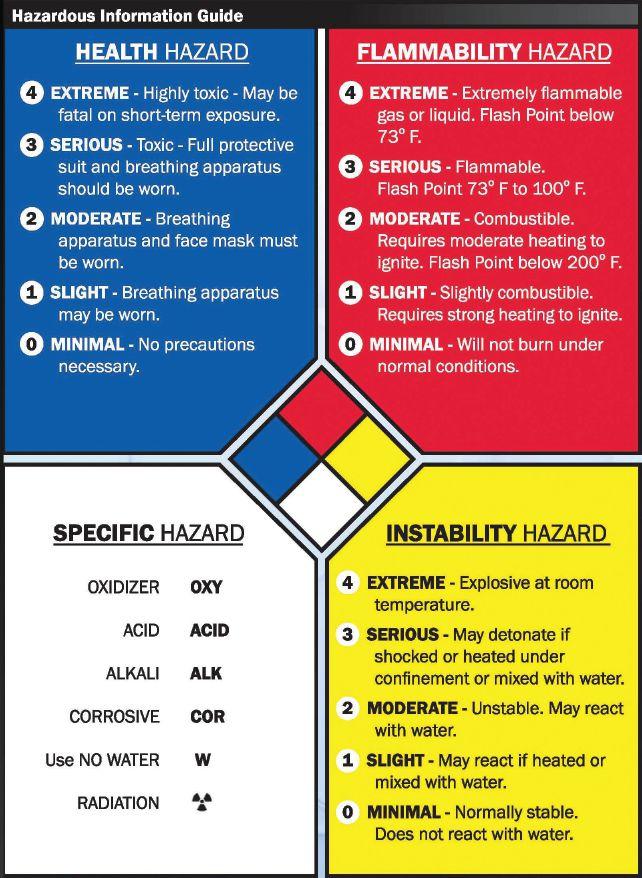
The label shows that this lubricant has very similar ratings under NFPA and HMIS. However, it is necessary to know what those ratings mean. To do this, reference the ratings straight from the NFPA and HMIS. Figure 3 shows a blank NFPA label; data from each legend for the lubricant in question would be added to the center section.
Cross-referencing the SDS, the label for the white lithium grease, and the NFPA label shows that the grease has a flash point of <73 degrees Fahrenheit and is considered “moderately hazardous” on the flammability scale. This material should not be exposed to an open flame or spark. Additionally, the health rating of this material is high enough to warrant concern. However, by taking proper precautions while using the grease, such as wearing protective gloves (i.e., nitrile), not concentrating and breathing the fumes, and ensuring that it is not exposed directly to open
36 • WINTER 2017
THE DOS AND DON’TS OF ELECTRICAL EQUIPMENT LUBRICATION
Figure 2: SDS for a Common White Lithium Aerosol Spray Lubricant
Figure 3: Blank NFPA Label
flame, the material is safe enough to use in most cases. The reality is that this spray has a propane propellant, and if the material is non-aerosol, the flammability of the material is most likely significantly decreased. If it is necessary to use this material in an area where the possibility of flames or sparks exists, then a non-aerosol version would be recommended.
CONCLUSION
Many factors must be considered when determining which type of lubricant to use. Most of this information can easily be obtained from the SDS or the label on the chemical container. The SDS for any chemical used by your company must be available to all employees and must be kept updated per OSHA 29 CFR 1910.1200, Hazard
Communication . Before using a lubricant, review the SDS and label to determine whether the product will satisfy the criteria for the intended use, what safety precautions may be needed, and which PPE may be required. Review this information with all employees using the chemical to ensure they understand the hazards of its use and how to properly interpret the label and SDS.

Paul Chamberlain has been Safety Manager at American Electrical Testing Company, Inc. since 2009. He has been in the safety field for 12 years, working for various companies and in various industries. Paul holds a BS in marine safety and environmental protection from Massachusetts Maritime Academy.

SAFETY CORNER
Why my intellirent? Convenience in the palm of your hand. Search for equipment, view and save manuals, access tips and how-to’s, or get quick rental pricing and tech support. It’s connected to intellirent, so you can see what equipment you have on rent, track shipments and see account details.
Available at Powered by


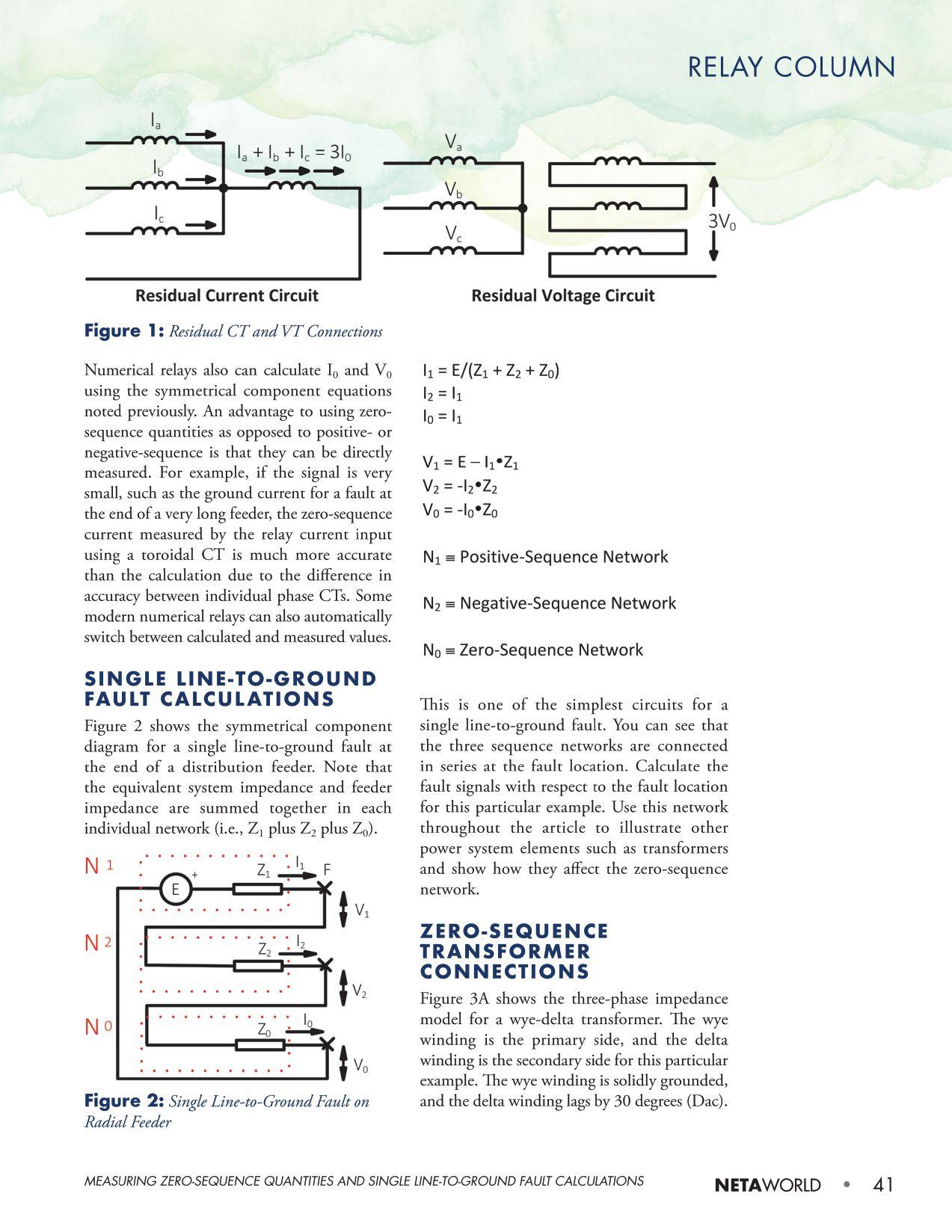
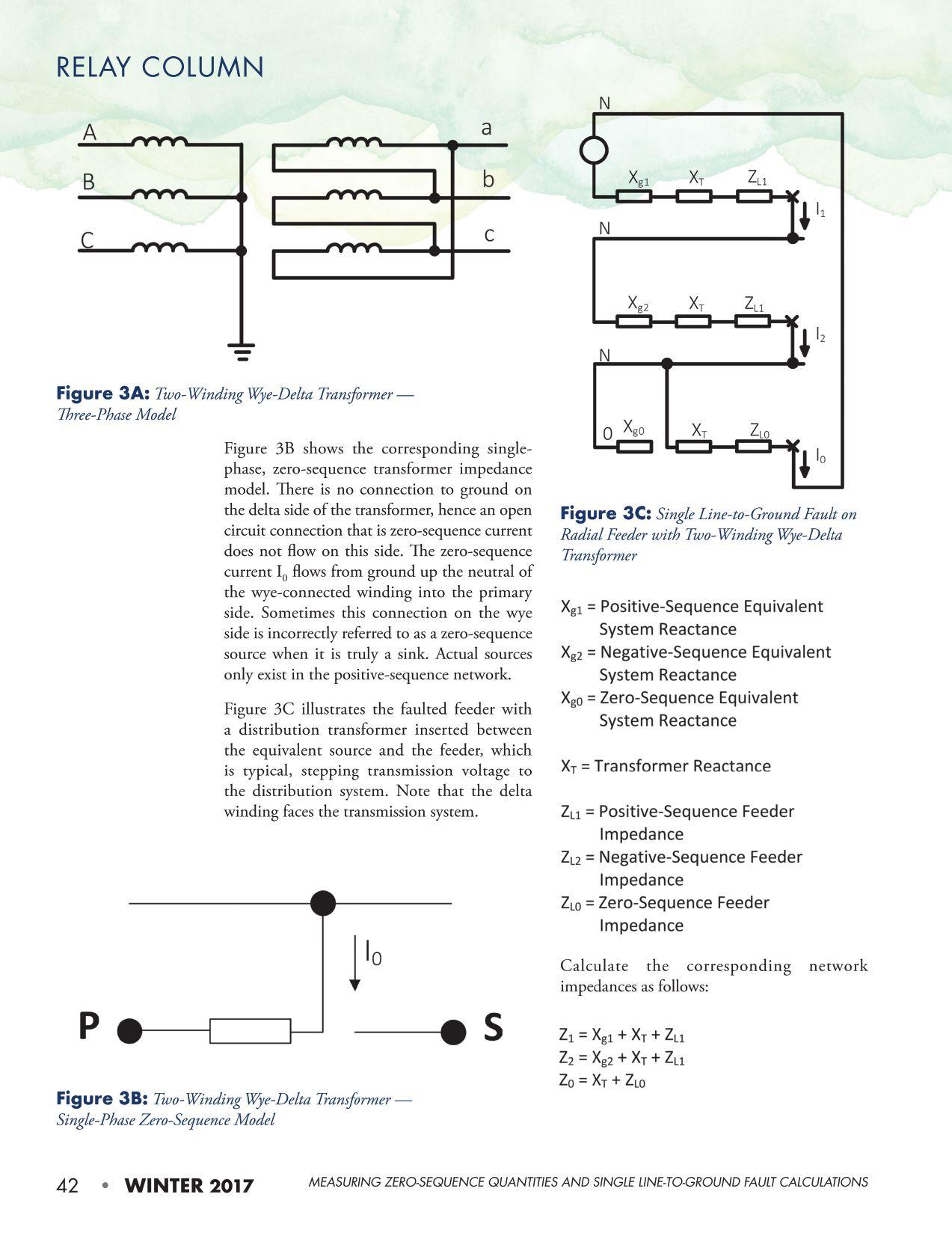
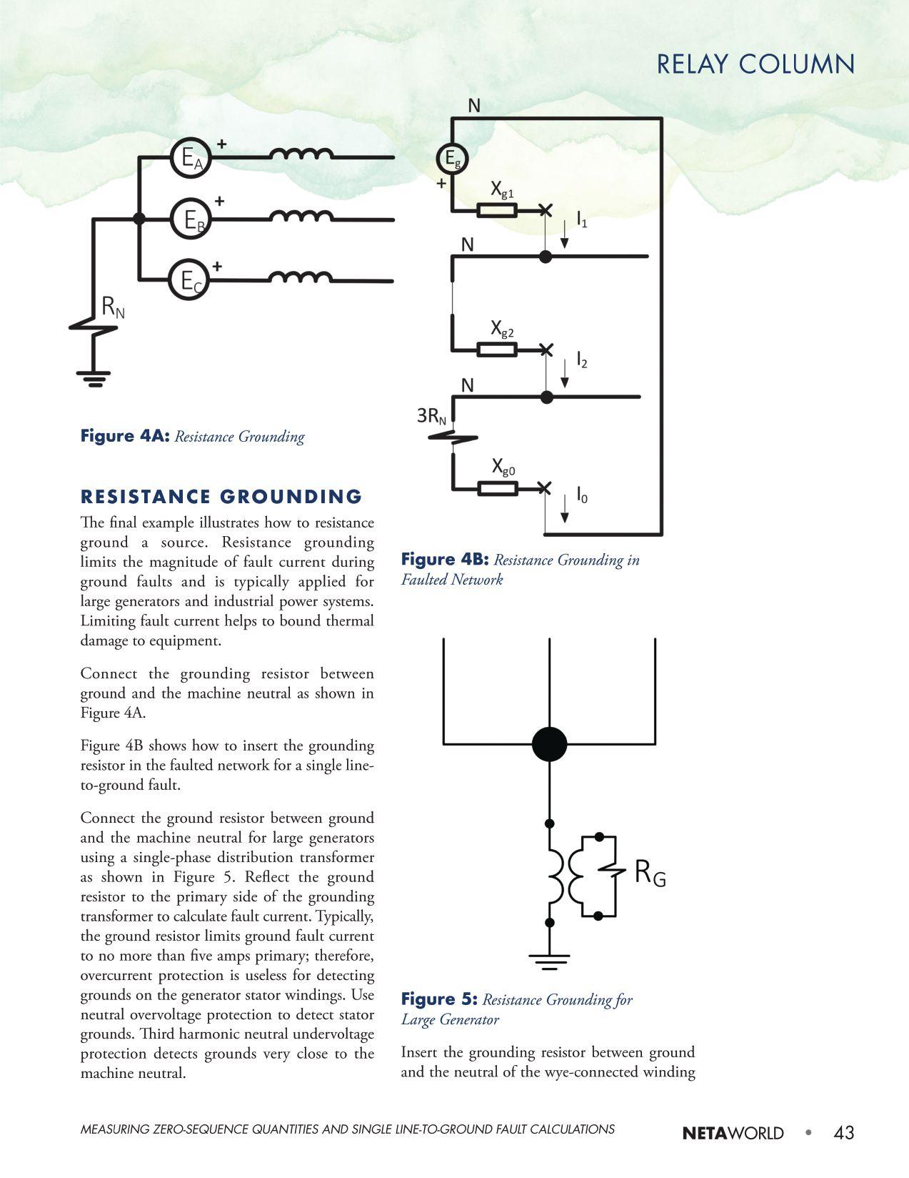
RELAY COLUMN

of distribution transformers at industrial sites to limit ground fault current.
CONCLUSION
This article demonstrated how to calculate and physically measure zero-sequence voltage and current using the proper VT and CT connections. Many simple examples are provided to show how to calculate zerosequence current and voltage for single line-to-ground faults. These examples cover transmission and distribution systems, as well as generators. Ground protection can be set very sensitive since it only operates during the presence of unbalance such as a single line-toground fault. Stator ground fault protection operates on the zero-sequence voltage drop across the grounding resistor RG, and grounds
up to 95 percent can typically be seen along the winding.

Steve Turner is a Senior Engineer II at Electrical Consultants, Inc., working in their San Diego office. Steve worked at Beckwith Electric Company, Inc. for 10 years, first as the Engineering Laboratory Director and then as Senior Applications Engineer. His previous experience includes working as an Application Engineer with GEC Alstom and as an Application Engineer in the international market for SEL focusing on transmission line protection applications. While at Duke Energy (formerly Progress Energy), Steve developed the first patent for double-ended fault location on overhead highvoltage transmission lines and was in charge of all maintenance standards in the transmission department for protective relaying. Steve has both a BSEE and MSEE from Virginia Tech University.


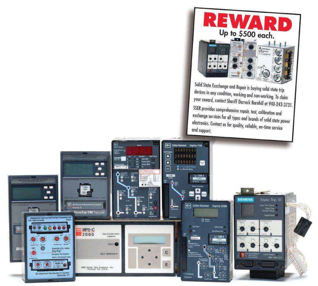
We Buy, Sell, Trade, Calibrate, Repair
Featuring quality, reliable, on-time service and support for all brands and types of solid state power electronics.
Power electronics are our business
Let us suppoort you with our quality repair, calibration and servicing of your solid state equipment. We also buy, sell and trade:
•Communications devices for power equipment
•Protective relays
•Circuit breaker trip devices
•Motor overload relays
•Rating plugs

4701 Spartan Drive • Denton, TX 76207 (877-874-7349) • Phone: 940-243-3731 • Fax: 940-387-8277 Email: info@solidstaterepair.com • Web: www.solidstaterepair.com
“SOLID STATE” INDUSTRIAL ELECTRONICS “SOLID STATE” INDUSTRIAL ELECTRONICS Toll Free 877-TRIP-FIX NOWRENTING TESTEQUIPMENT

PUTTING NFPA 70E 2018 TO WORK: A FIELD PERSPECTIVE
BY JIM WHITE, Shermco Industries
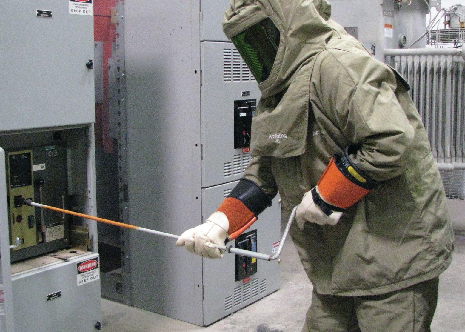
This article will go through the required steps for the task of inserting or removing (racking) a circuit breaker, including some guidance on assessing risk. Before reading this feature article, read the NFPA 70E and NETA column on page 11. That column provides introductory information needed to fully understand and apply the steps in this article.
STEP ONE: ASSESS THE RISK
The first step in the process is a risk assessment. But even before the risk assessment is performed, the qualifications of the worker must be assessed. NFPA 70E 110.2 contains a list of requirements to be a qualified person. This is a hefty requirement consisting of technical expertise (what most field service technicians have) and safety expertise (which many do not have). Unfortunately, many field people discover they are not really qualified persons until they make an error that results in injury or worse. Spending time in a burn unit
is not a good way to use vacation time, nor is it a pleasant experience.
If the employees are qualified persons, then the assessment process can begin. Some questions to consider when evaluating how to perform a task safely include:
• Is the equipment in normal operating condition?
• Is the probability of an arc flash acceptable to the employee operating the circuit breaker?
• What are the consequences of a failure?
• Is the residual risk acceptable?
48 • WINTER 2017 PUTTING NFPA 70E 2018 TO WORK: A FIELD PERSPECTIVE FEATURE

A small burn injury is one that happens to someone else. (Source: “I Thought it was De-energized,” 2002 IEEE Electrical Safety Workshop presentation by Daryld Ray Crow)
• Does the employer have work rules requiring the use of arc-rated clothing and PPE to operate a circuit breaker?
• What steps need to be taken to ensure the safety of unqualified persons?
• What tools, equipment, and PPE will be required?
Asking these questions is the start of a risk assessment, which was referred to as a Hazard/ Risk Analysis in earlier editions of NFPA 70E. This is the part many field workers have problems with.
Conduct a Risk Assessment
A good starting place is in 110.1(H), Risk Assessment Procedures. This subsection requires an electrical safety program to contain a risk assessment procedure that complies with all of the following requirements.
The risk assessment must address the employee exposure to electrical hazards and identify the process used by the employee before work is started. The fact that the risk assessment is to be completed before work is started seems to be news to some people. The purpose of the risk assessment is to identify the hazards and assess the risks involved with a task and “implement
risk control procedures according to the hierarchy of risk control methods.”
This is new wording for the 2018 edition of NFPA 70E. The hierarchy of risk control methods is taken from ANSI/AIHA Z10, American National Standard for Occupational Health and Safety Management Systems. The intent is that PPE is not the first option to consider when additional protective measures are needed. The hierarchy of risk control methods is:
• Elimination: putting equipment or systems into an electrically safe work condition

• Substitution: reducing the hazard, such as using current-limiting fuses when possible
• Engineering controls: guarding of energized electrical conductors and circuit parts to prevent contact
• Awareness: installing signs, safety barrier tape, or other means of alerting other workers of hazards
• Administrative controls: procedures and job planning tools, such as lock out/tag out (LOTO), SOPs, and forms
• PPE: shock and arc-rated clothing and PPE
NETAWORLD • 49 PUTTING NFPA 70E 2018 TO WORK: A FIELD PERSPECTIVE
FEATURE

Informational Note No. 1 notes that the first three methods are the most effective, while the last three are the least effective. Elimination — putting the equipment into an electrically safe work condition — must be considered first. If the equipment cannot be placed into an electrically safe work condition (refer to 130.2), substitution must be considered. If substitution is not possible, engineering controls must be considered, and so on down through the list. If none of the first five risk-control methods resolve the conditions or situation, PPE can be considered. Even after applying the hierarchy of risk control methods, there will be residual risk. Residual risk is risk that cannot be eliminated or abated. It is what it is. The technician and employer must consider whether the residual risk is acceptable or is not acceptable. Informative Annex F was revised and provides clear direction (for a change) on risk assessments. It is worthwhile reading.
The risk assessment must account for human error. This is also new for the 2018 edition of NFPA 70E. Most experts state that human error accounts for approximately 80 percent of all incidents. It only makes sense that NFPA 70E would want this to be part of the risk assessment. How could human error affect the task(s)? What would happen if a wrench were dropped on the bus? What could be done to prevent it (tying off hand tools, placement of rubber insulating blankets on nearby exposed energized conductors and circuit parts, etc.)? Make a list on the risk assessment form and check each item off as it is considered and the remedy is documented.
The risk assessment procedure must include the completion of a job safety plan. It must be documented, and then a job briefing must be conducted. This is a new subsection in NFPA 70E, but is not new territory for most companies. Instead of referring to it as a job safety plan, it is probably called a job safety assessment (JSA) or job hazard assessment (JHA). In 70E 2015, the job safety plan and job briefing were crammed into one section. The job safety plan was broken out as a separate part to give it more prominence for
2018. Job planning is core to working safely. Communicating that job plan is also core. Both are needed to ensure everyone on the job understands what is going to happen and when. The job safety plan includes a description of the task(s), identification of the hazards associated with each task, a shock risk assessment, an arc flash risk assessment, as well as any work procedures needed, special precautions, and lockout/tagout procedures. The job briefing covers all that information, plus the energized electrical work permit, if one is needed.
The specific task(s) performed and the hazards associated with each task must be listed. Here is a list for our example task, racking a circuit breaker. Note: There are many more, but this short list will get things started.
• Set up a safe work zone to exclude unqualified persons and police the area. Be aware of anything that might cause slips, trips, and falls.
• Inspect all PPE for defects that could cause a safety issue. Defective PPE must be tagged as defective and out-of-service. Secure new PPE to replace it if it is defective. Do not proceed with PPE that is defective.
• Don company-mandated arc-rated clothing and PPE (Category 4). If a safety backup is used, have him/her verify the PPE is properly in place.
• Have the safety backup stand at the edge of the safe work zone. The safety backup will also wear Category 4 PPE and possibly hold a rescue hook at the ready.
• Operate the circuit breaker controls to open the circuit breaker. If remotely operated, PPE may be reduced. Arc-rated clothing and PPE may still need to be worn, even if using a remote operator. If manually operating the circuit breaker, stand to one side. I prefer the hinge side, but others will say to stand on the latch side, as the arc-rated clothing and PPE will protect you in case of an arc flash. I’d rather get beat on by the door than risk being burned because of a slow overcurrent protective device. It’s a personal choice.
50 • WINTER 2017 FEATURE
PUTTING NFPA 70E 2018 TO WORK: A FIELD PERSPECTIVE
• If using a remote racking device (recommended), set it up according to the manufacturer’s recommendations and instructions. It may be possible to wear a lower category of arc-rated clothing and PPE due to the reduced exposure if there is an arc flash.
• If manually racking the circuit breaker, use an extension on the racking handle, if possible. If all else fails, have your apprentice do the racking (just kidding on that one). Advise any workers nearby to stand clear, and make sure the safety backup is ready before proceeding.
• R ack the circuit breaker from the CONNECTED position through the TEST position. The circuit breaker can be test operated if it is an electrically operated circuit breaker. If possible, rack the circuit breaker with the door closed and latched. Even though the door will not reduce the PPE required, it may divert some of the heat and blast from an arc.
• O nce the circuit breaker is in DISCONNECTED position, it is safe to move it into the WITHDRAWN position. It may be necessary to install extension arms or to extend them from the cubicle. Verify the requirements by reviewing the manufacturer’s instructions.
• If the circuit breaker is removed by using extension arms, be certain the rollers are squarely on the extension arms. If they are not, the circuit breaker can pivot and fall from the extension arms. Ask me how I know.
• Check to make sure the shutter mechanism is closed on medium-voltage equipment or on newer LVPCB. This is still an arc flash hazard. Wear Category 4 arcrated clothing and PPE, and keep bystanders or others in the area clear of the work area.
• If the shutter mechanism closes, close the cubicle door. This reduces the arc flash hazard. Wear the same PPE while closing the door and secure the fasteners.
• If the shutter mechanism does not cover the bus stabs completely, this creates an increased arc flash hazard. Secure the
cubicle door, wear the same PPE while closing the door, secure all the fasteners, place a warning sign on the cubicle door to prevent it from being opened, notify management or other appropriate authority to institute shutdown of switchgear, and schedule repairs as needed.
• Remove the safe work zone barriers/ tape. Police the area for slips, trips, and falls.
• I f the circuit breaker is being removed from its cubicle, follow the manufacturer’s recommendations. If using a winch-type device and spreaders, be certain the spreader is fully connected to the circuit breaker. Also, make certain the cable on the winch reel does not overlap. If they overlap, they will slide off the cable underneath and cause the circuit breaker to overstress the cable.
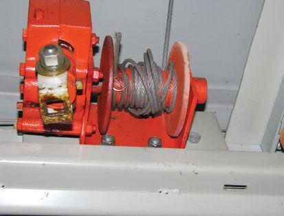
Note how the cable is wound haphazardly. When uncoiling, the cable will have slack and cause the circuit breaker to bounce. This can overload the cable and cause it to fail.

• If the cable is miswound (see photo) unwind it completely. Then, rewind it so it is straight on the reel.
• NFPA 70E 2018 requires that human error be addressed in the risk assessment. What actions or missteps could cause safety issues and how would they be prevented?
– Not setting up a safe work zone because it’s too much effort. The corrective action includes setting the safe work zone up to either the
NETAWORLD • 51 FEATURE
PUTTING NFPA 70E 2018 TO WORK: A FIELD PERSPECTIVE

limited approach boundary or the arc flash boundary, whichever is farthest from the equipment. Safety barrier tape is usually used, placed about waist high.
– Not setting up the remote racking device properly. This could result in over-torquing the racking screw. The corrective action would be to follow the manufacturer’s instructions.
– Not visually verifying the circuit breaker is open. This happens every now and then; sometimes, it is due to equipment malfunction, but more often it is carelessness. The corrective action is to visually verify the circuit breaker is open by pressing the TRIP button and crosschecking that with the operation flag on the circuit breaker. Some of the operation indicators are connected to the circuit breaker’s operating mechanism by a very light linkage. Physically pressing the TRIP button ensures the circuit breaker is open.
Review the Information on the JSA/JHA
For our task of racking a circuit breaker in or out of its cubicle, an energized electrical work permit is needed because the probability of an arc flash is increased, and the consequences could be severe. If there is a change in the scope of work that creates additional or increased
risk to the employees performing the task(s), a new job plan and job briefing need to be implemented. To recap the requirements so far:
• The employees performing the task must be qualified.
• A risk assessment must be performed; this includes a job safety plan and then a job briefing.
• If an energized electrical work permit is needed (which it is for our example task), that information must be covered in the risk assessment and job briefing.
• If the scope of work changes and creates additional or increased risk for the employees performing the task, a new job plan and job briefing are required. An example of a scope change would be a shutter that does not close on a mediumvoltage drawout circuit breaker.
STEP TWO: SELECT SHOCK AND ARC-RATED CLOTHING AND OTHER PPE
If arc-rated clothing and PPE are required, a new table in Article 130 can be used to assess the likelihood of occurrence of an arc flash: Table 130.5(C), Estimate of the Likelihood of Occurrence of an Arc Flash Incident for ac or dc. This table was taken from the 2015 70E Table 130.7(C)(15)(A)(a), Arc Flash Hazard Identification for Alternating Current (ac) and Direct Current (dc) Systems. Table 130.7(C) (15)(A)(a) was taken from Table 2 in OSHA 29CFR1910.269 Annex E (Table 1).
or
Normal operation of enclosed equipment, such as closing or opening a switch
The employer properly installs and maintains enclosed equipment, and there is no evidence of impending failure.
There is evidence of arcing or overheating.
Parts of the equipment are loose or sticking, or the equipment otherwise exhibits signs of lack of maintenance.
Servicing electric equipment, such as racking in a circuit breaker or replacing a switch Yes
52 • WINTER 2017
PUTTING NFPA 70E 2018 TO WORK: A FIELD PERSPECTIVE
FEATURE
Task Is Employee
Table 1: Table 1, Annex E, Partial from 29CFR1910.269
Exposed to Flame
Electric-Arc Hazard?
No
Yes
Yes
In Table 130.5(C), the different task categories have been broadened to make the table applicable to more equipment and, instead of the third column being titled Arc Flash PPE Required, it now is titled Likelihood of Occurrence These two changes simplify the use of this table. By moving the table out of the table method for selecting arc-rated clothing and PPE into the main text, Table 130.5(C) can be used for the table method as well as the incident energy analysis method for determining the likelihood of occurrence of an arc flash.
Note that Table 130.5(C) is very general, and the technician must perform a risk assessment for the equipment at the time work is to begin. No table such as this can anticipate all circumstances or all variations that the technician may be faced with in field conditions.
There are several notes and Informational Notes that must be reviewed prior to using this table. One table note states in part: “The estimate of likelihood of occurrence contained in this table does not cover every possible situation, nor does it address severity of injury or damage to health.” However likelihood is addressed by the risk assessment, it needs to be realistic and account for conditions at the time of work.
The next steps in selecting the appropriate PPE are:
• Select shock-protective PPE using Table 130.4(D)(a) for ac systems and equipment or 130.4(D)(b) for dc systems and equipment.
• If arc flash hazard labels are present, use Table 130.5(G) to select arc-rated clothing and PPE.
• If no arc flash hazard warning label is present, use the table method.
– D etermine whether the table method can be used. The equipment about to be worked on cannot exceed the limits given in Table 130.7(C)(15)(a).
– Table 130.7(C)(15)(a) is also used to determine which PPE category is recommended.
– Refer to Table 130.7(C)(15)(c) to select the actual PPE recommended.
As stated earlier, either Table 130.4(D) (a) or 130.4(D)(b) is used to select shock protective equipment. These tables are fairly straightforward. The nominal voltage is used to determine the class of rubber insulating gloves and leather protectors. The nominal voltage can be determined by referring to the equipment’s data plate, single-line diagrams, or schematics, depending on the equipment. Caution: Arcrated gloves do not provide shock protection and should not be worn where the possibility of electric shock exists.
Use of a new table, Table 130.5(G) Selection of Arc-Rated Clothing and Other PPE When Using the Incident Energy Category Method (Table 2), is permitted to select arc-rated equipment when arc flash hazard warning labels are in place. Table 130.5(G) is taken from Table H.3(b) in Annex H and clothing under 1.2 cal/cm2 has been removed, so it only applies to arc-rated clothing and PPE. By stating its use is permitted, the use of this table is optional, not mandatory. If arc-rated clothing and PPE are
Incident energy exposures equal to 1.2 cal/cm2 (5
Arc-rated clothing with an arc rating equal to or greater than the estimated incident energy a
• Long-sleeve shirt and pants or coverall or arc flash suit (SR)
• Arc-rated face shield and arc-rated balaclava or arc-rated flash suit hood (SR) b
• Arc-rated outer wear (e.g. jacket, parka, rainwear, hard hat liner) (AN)

• Heavy-duty leather gloves, arc-rated gloves, or rubber insulating gloves with leather protectors (SR) c
• Hard hat
• Safety glasses or safety goggles (SR)
• Hearing protection
• Leather footwear
Incident energy exposures greater than 12 cal/cm2 (50.2 J/cm2)
Arc-rated clothing with an arc rating equal to or greater than the estimated incident energy a
• Long-sleeve shirt and pants or coverall or arc flash suit (SR)
• Arc-rated flash suit hood
• Arc-rated outer wear (e.g. Jacket, parka, rainwear, hard hat liner) (AN)
• Arc-rated gloves or rubber insulating gloves with leather protectors (SR) c
• Hard hat
• Safety glasses or safety goggles (SR)
NETAWORLD • 53
FEATURE PUTTING NFPA 70E 2018 TO WORK: A FIELD PERSPECTIVE
Table 2: Table 130.5(G) from NFPA 70 E 2018
J/cm2) up to 12 cal/cm2
(50.2 J/cm2)

specified by the company’s procedures or ESP, use that information, not 70E.
If using the table method in NFPA 70E, begin with Table 130.7(C)(15)(a) Arc Flash PPE Categories for Alternating Current (ac) Systems or 130.7(C)(15)(b) Arc Flash PPE Categories for Direct Current (dc) Systems, depending on the equipment. These tables are used to select the arc flash PPE category. The limits contained in the tables and the different PPE categories are unchanged from the 2015 edition of NFPA 70E, with one exception in the dc table. Under the Equipment Type — Storage batteries, dc switchboards, and other dc supply sources where the available fault current is less than 4 kA — the PPE category has changed from Category 1 to Category 2. It was discovered during the committee meetings that this was transcribed incorrectly in the 2015 edition, so it was corrected for the 2018 edition.
Since the example task is racking a circuit breaker, it will no doubt put the employee
performing the task into a PPE Category 4 arc flash suit. The safety backup, if there is one, would wear the same PPE as the employee performing the task. It should be noted that the tables cannot be used when the incident energy is outside of the limits given in Table 130.7(C) (15)(a). If none of the limits are exceeded, Table 130.7(C)(15)(c) is used to select the actual arcrated clothing and other PPE required for the task. In the 2015 edition of NFPA 70E, this was Table 130.7(C)(16). If any of the limits in Table 130.7(C)(15)(a) are exceeded, an incident energy analysis must be performed and the table method cannot be used.
STEP THREE: OPERATE THE CIRCUIT BREAKER
Wearing the appropriate PPE, operate the circuit breaker control switch to open the circuit breaker. Once the circuit breaker is opened (listen for the sound of the circuit breaker opening), open the door and visually
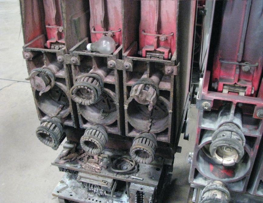
Dirt and other contaminants caused a fault in this circuit breaker. Note the light bulb left on the stabs.
54 • WINTER 2017
PUTTING NFPA 70E 2018 TO WORK: A FIELD PERSPECTIVE
FEATURE
verify that the circuit breaker opened. Medium-voltage circuit breakers will usually have indicator lights on the door, but still verify the indicator is in the open position. Low-voltage power circuit breakers usually do not have indicator lights, although some do. There has been at least one incident reported where the circuit breaker control switch was operated to the open position and the circuit breaker reclosed instead of opening. The circuit breaker manufacturer stated this could happen in 1 out of every 10,000 operations. Russian roulette, anyone? Take the few extra seconds to verify opening. Pull the control fuses, if accessible, and place them inside the cabinet in a safe location. This will prevent unauthorized or unintended operation.
STEP FOUR: RACK THE CIRCUIT BREAKER
Circuit breakers don’t often fail when they are racked in or out, but when they do fail, they make a really big mess. During a forensic investigation of a circuit breaker that had a three-phase failure, it was determined that dirt or other contaminants caused a fault at the primary stab connections. Note the light bulb found on the stabs.
Make sure the safety backup is prepared. This may seem like a no-brainer, but people get distracted. This task calls for focus. If at all possible, rack the circuit breaker remotely. Distance is your friend, as the saying goes. Don’t be fooled by the nice long cord. Thirty or 50 feet may seem like a lot of distance, but many switchgear rooms are configured so the equipment forms a corridor, or as I like to call it, a blow torch. If an arc flash occurs, it is going to shoot out of the front of the enclosure and hit the opposite switchgear. Depending on how far away that switchgear is, it may dissipate quickly or it may travel down both sides of the walkway.
The same is true for the pressure wave. It’s probably not going to hit the other switchgear and stop. Some level of PPE is needed, even when remote racking. The other potential issue with remote racking devices is that of
over-torquing the racking screw. This can happen for a number of reasons, such as not paying attention, incorrect transcribing of the torque values when setting up, or a circuit breaker that just racks easier than the others. Don’t assume all circuit breakers will require the same torque, even of the same type and manufacturer.
If racking manually, try to fit an extension onto the racking handle. Many factory racking handles don’t allow this to be done, but they can be field modified to accept an extension. Our machine shop reconfigures racking handles so we can use extenders when needed. Incident energy decreases by the inverse square of the distance, so as the distance increases, the incident energy decreases rapidly. When racking, rack slowly. Listen for any odd noises or sounds (tough to do in a flash suit hood, but try). If racked slowly, it can be felt when the circuit breaker drops off the bus stab. Use extra caution at this point. If the circuit breaker did not open (due to mechanical failure, this can happen even if the indicator says it is open), an arcing noise can be heard. This will be pretty loud, so odds are the person racking can hear it. If that occurs, immediately rack the circuit breaker back onto the bus stab. It cannot be removed. The switchgear will need to be shut down and repairs made to the circuit breaker.
The same is true if the shutter mechanism does not close or closes incompletely. Game over — leave it in the disconnected position and notify the authority having jurisdiction (usually a supervisor or manager) so the switchgear can be safely shut down and repairs made. The equipment should be tagged as out of service or, if it is defective, tagged stating that it cannot be placed into service and the reason why.

STEP FIVE: POLICE THE AREA
Remove all barriers, barricades, signs, safety barrier tape, or other means of restricting access. If any materials were left on the floor, pick them up and dispose of or restock. Inspect the used PPE and store it in a manner
NETAWORLD • 55
FEATURE PUTTING NFPA 70E 2018 TO WORK: A FIELD PERSPECTIVE
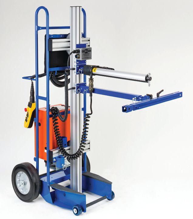
Remote racking devices can be pricy, but they pay for themselves when the first equipment failure occurs. (Photo courtesy CBS ArcSafe)
and location where it won’t be damaged or deteriorate. If any PPE is found to be defective, tag it as defective and out of service. Secure replacement PPE.
CONCLUSION
What can be done to make this very common task event safer? The use of remote racking devices is certainly one method used by many companies. The cost is not insignificant, but a single unit can be used to remotely rack several different types of circuit breakers. Don’t like the idea of having more equipment sitting around? If you only use a remote racking device infrequently, rent it when needed. Other options include engineering solutions, such as arc-
detection systems, arc-suppression systems, zone interlocking, or possibly differential relaying.
Qualified persons need to be responsible for their personal safety. Yes, the employer is ultimately responsible for worker safety, but it is not the employer who will be injured — possibly severely — in the case of an arc flash incident. The money you receive (minus the 50 percent or so the attorneys get) will not ease the pain of left-over injuries, nor will it make it easier to do simple day-to-day tasks that can no longer be done. The frustration can make life much less than ideal, regardless of the size of the settlement.
This article may not cover all aspects of racking the particular circuit breaker you may be faced with, but it should get the brain cells lubricated. Do the smart thing: Work safely every day on every task. Let someone else have the honor of being the example.

James (Jim) R. White has been Training Director for Shermco Industries Inc. in Irving, Texas, since 2001. He is certified by the National Fire Protection Association (NFPA) as a Certified Electrical Safety Compliance Professional and by the interNational Electrical Testing Association (NETA) as a Level IV Senior Technician. Jim represents NETA as the principal member on NFPA Technical Committee NFPA 70E®, Standard for Electrical Safety in the Workplace; is the principal member for Shermco Industries on the NFPA Technical Committee for NFPA 70B, Recommended Practice for Electrical Equipment Maintenance; is NETA’s principal representative on the National Electrical Code (NEC®) Code-Making Panel (CMP) 13; represents NETA on ASTM International Technical Committee F18 on Electrical Protective Equipment for Workers; and represents the American Wind Energy Association (AWEA) on the International Safety Equipment Association (ISEA) ANSI/ISEA Standard 203, Secondary Single-Use Flame Resistant Protective Clothing for Use Over Primary Flame Resistant Protective Clothing. An IEEE Senior Member, he received the IEEE/IAS/PCIC Electrical Safety Excellence Award in 2011 and NETA’s Outstanding Achievement Award in 2013. Jim was the Chairman of the IEEE Electrical Safety Workshop in 2008 and is currently the Vice-Chair for the IEEE IAS/PCIC Safety Subcommittee.
56 • WINTER 2017
FEATURE PUTTING NFPA 70E 2018 TO WORK: A FIELD PERSPECTIVE




A FULL SERVICE NETA ACCREDITED ELECTRICAL TESTING COMPANY. Serving the Sacramento and San Francisco Bay Area 916-853-6280 www.apparatustesting.com • Acceptance Testing • Commissioning • Maintenance Testing • High Voltage Substations • Short Circuit and Coordination Studies • Data Centers and UPS Systems 24 Hour Emergency Services (937) 439-9660 Electrical Distribution System Testing, Repair, and Maintenance


HIGH VOLTAGE, INC. 31 County Rt. 7A • Copake, NY 12516 • Tel: (518) 329-3275 • Fax: (518) 329-3271 • sales@hvinc.com • www.hvinc.com HIGH VOLTAGE, INC. ISO 9001 2008 HVI - The World’s Source for High Voltage Test Equipment HVI Makes it Easy and Efficient
VLF hipot: 0 - 33 kVac @ 1 μF @ 0.1 Hz Fault locate: 0 - 13 kV @ 760 J VLF Fault Burner Radar/TDR ready Other Thumper models: 5/10/20 kV @ 1000 J 9/18/36 kV @ 3200 J • Very Low Frequency AC Technology • Cable Diagnostic TD & PD Testing • Cable Fault Locating with Controlled Energy • AC & DC Hipots, Aerial Lift Testers, Oil Testers
Ω-CHECK® Concentric Neutral Testing
Custom Engineered & Fabricated Van Pkgs. All That You Need
50 kVac @ 3 kVA Hipot 1 piece & w/cable output VLF 0.1 Hz @ 34 kVac Comp. control - wireless 80 kVdc Hipot/Megohmmeter 1 instrument - 2 tests All HVI Products are Made in the USA Visit us at POWERTEST 2018 Booth 422
Cable Fault Locating & VLF Testing
•
•
VLF/Thumper Combination



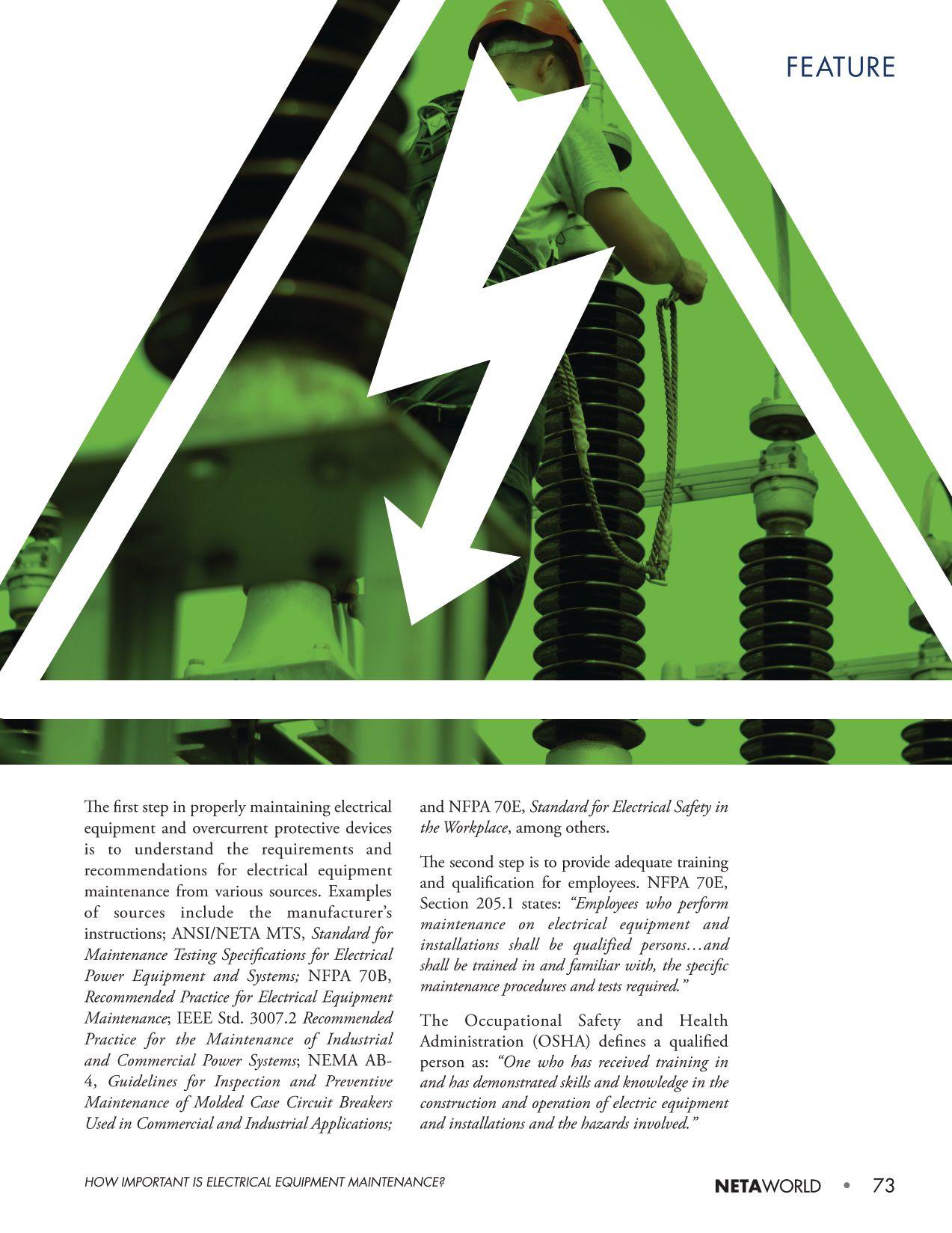
It is important that employees are properly trained and qualified to maintain electrical equipment to increase equipment and system reliability, as well as to enhance employee safety for all who work on, near, or interact with the equipment.
NFPA 70E provides guidance on electrical equipment maintenance:
• Section 90.2(A): “This standard addresses electrical safety-related work practices, safety-related maintenance requirements, and other administrative controls for employee workplaces.” An informational note to paragraph 110.1(A) explains that “administrative controls” include “verification of proper maintenance and installation, alerting techniques, auditing requirements, and training requirements provided in the standard.”
• Section 110.1(B), Maintenance, was added to the 2015 edition of NFPA 70E to require the condition of maintenance as a part of the overall electrical safety program.
• Section 130.5, Arc Flash Risk Assessment: “…take into consideration the design of the overcurrent protective device and its opening time, including its condition of maintenance.”
• S ection 205.3: “Electrical equipment shall be maintained in accordance with manufacturers’ instructions or industry consensus standards to reduce the risk of failure and the subsequent exposure of employees to electrical hazards.”
• Section 205.4: “Overcurrent protective devices shall be maintained in accordance with the manufacturers’ instructions or industry consensus standards. Maintenance, tests, and inspections shall be documented.”
• Section 225.3: “Circuit breakers that interrupt faults approaching their ratings shall be inspected and tested in accordance with the manufacturers’ instructions.”
The third step is to have an effective written Electrical Preventive Maintenance (EPM) program. NFPA 70B makes several very clear statements about an effective EPM program as follows:
• “Electrical equipment deterioration is normal, but equipment failure is not inevitable. As soon as new equipment is installed, a process of normal deterioration begins. Unchecked, the deterioration process can cause malfunction or an electrical failure. An effective EPM program identifies and recognizes these factors and provides measures for coping with them.”
• “In addition to normal deterioration, there are other potential causes of equipment failure that can be detected and corrected through EPM. Among these are load changes or additions, circuit alterations, improperly set or improperly selected protective devices, and changing voltage conditions.”
• “A well-administered EPM program will reduce accidents, save lives, and minimize costly breakdowns and unplanned shutdowns of production equipment.”
• NFPA 70E, Chapter 2, Safety-Related Maintenance Requirements: “...these requirements identify only maintenance that is directly associated with employee safety… it does not prescribe specific maintenance methods or testing procedures. It is left to the employer to choose from the various maintenance methods available to satisfy the requirements.”
As noted in NFPA 70E, Chapter 2, the maintenance requirements are necessary for employee safety, but this chapter does not specify reliability issues, although properly maintaining equipment will have an impact on the reliability of the electrical equipment and systems.
IEEE Std. 3007.2 states: “In planning an electrical preventive maintenance (EPM) program, consideration must be given to the costs of safety, the costs associated with direct losses
74 • WINTER 2017 HOW IMPORTANT IS ELECTRICAL EQUIPMENT MAINTENANCE? FEATURE
due to equipment damage, and the indirect costs associated with downtime or lost or inefficient production.”
All maintenance and testing of electrical protective devices must be carried out in accordance with the manufacturer’s instructions. In the absence of the manufacturer’s instructions, the latest edition of ANSI/NETA MTS is an excellent source of information for performing the required maintenance and testing of these devices. However, the manufacturer’s time-current curves would be valuable information for properly testing each overcurrent protective device.
ARC FLASH HAZARD CONSIDERATIONS
Maintenance and testing are essential to ensure proper protection of equipment and the safety of personnel. Regarding personnel protection, NFPA 70E requires an arc flash risk assessment before anyone approaches exposed energized electrical conductors or circuit parts not placed in an electrically safe work condition. NFPA 70E, Section 130.5, states that the arc flash risk assessment must consider the design of the overcurrent protective device and its opening time, including its condition of maintenance.
All calculations for determining the incident energy of an arc flash require the arc clearing time of the overcurrent protective device. This clearing time is derived from settings on the device, along with the time-current curves. This information can also be obtained from a current engineering protective-device coordination study, which is based on what the protective devices are supposed to do. If, for example, a low-voltage power circuit breaker has not been operated or maintained for several years and the lubrication has become sticky or hardened, the circuit breaker could take several additional cycles, seconds, minutes, or longer to clear a fault condition. Due to the increase in incident energy, this unintentional time
delay could have catastrophic consequences should an arc flash occur.
If a worker is protected based on what the circuit breaker is supposed to do and an unintentional time delay occurs, the worker could be seriously injured or killed because he/she was underprotected. Maintenance is extremely important to an electrical safety program. Maintenance must be performed according to the manufacturer’s instructions or industry-consensus standards to minimize the risk of unintentional time delay in the operation of the circuit protective devices.
CONCLUSION
To protect electrical equipment and personnel, proper electrical equipment preventive maintenance must be performed. The manufacturer’s instructions or industryconsensus standards exist to assist users with electrical equipment maintenance and testing. When overcurrent protective devices are correctly maintained and tested for proper adjustment and operation, equipment damage and arc flash hazards will be limited as expected.

Dennis K. Neitzel, CPE, CESCP, Director Emeritus of AVO Training Institute, Inc. in Dallas, has over 50 years in the electrical industry in various capacities, specializing in electrical equipment and systems maintenance, testing, engineering, inspection, and safety. Dennis is an active member of IEEE (Senior Member), ASSE, NFPA, AFE, IAEI, and SNAME. He is a past Chair of the IEEE-IAS Electrical Safety Workshop (2012), a Certified Plant Engineer (CPE), a Certified Electrical Safety Compliance Professional (CESCP), and a Certified Electrical Inspector-General. He is a Principal Committee Member and Special Expert for NFPA 70E, Standard for Electrical Safety in the Workplace; the Working Group Chairman for IEEE Stds. 3007.1-2010, 3007.2-2010, 3007.3-2012 and IEEE Std. 45.5-2014; and is co-author of the Electrical Safety Handbook, McGraw-Hill Publishers. Dennis earned his BS in electrical engineering management and his MS in electrical engineering applied sciences. He has authored, published, and presented numerous technical papers and magazine articles on electrical safety, maintenance, and technical training.
NETAWORLD • 75 HOW IMPORTANT IS ELECTRICAL EQUIPMENT MAINTENANCE?
FEATURE
➤
➤
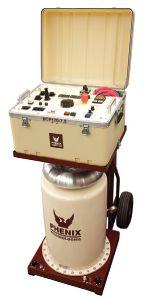
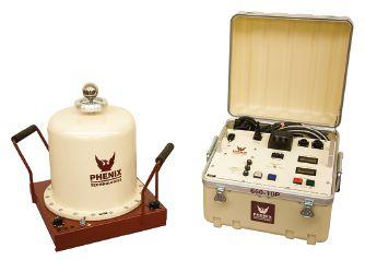
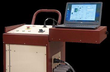


7102 Brookside Rd Suite 102 Pearland, TX 77581 (832) 251-7047
Midwest 1501 Wright Blvd Schaumburg, IL 60193 (847) 434-5808
East 200 Gates Rd Suite E Little Ferry, NJ 07643 (201) 450-9743
Southeast 105 Village Walk Suite 185 Dallas, GA 30132 (972) 352-5550

1-301-746-8118 • www.PhenixTech.com 40+ Years Experience info@phenixtech.com • 75 Speicher Drive, Accident, MD 21520 USA A Wide Range of Test Systems Available PROVEN TO BE THE SUPERIOR TEST EQUIPMENT SUPPLIER! TECHNOLOGIES PHENIX R Unmatched Reliability and Per for mance! Model HC-8, 2-piece design 8,000 A Output, fully automated testing High Current Circuit Breaker Test Sets NEW!
Simple set-up and operation
➤
Ruggedly constructed for years of use
Low partial discharge output A premier line of AC DIELECTRIC TEST SETS with ratings from 15 to 200 kV AC ➤ 40 kV and 60 kV models ➤ Digital instrumentation ➤ Lightweight and rugged ➤ 9 models available ➤ 1,000 to 75,000 A Outputs Vacuum Bottle Testers protecequip.com The Electrical Test Equipment Rental Experts Legendary Customer Service We are there when and where you need us Multiple Offices Located throughout the country yields dramatically lower shipping costs Local Inventory Better shipping rates and great application support from the Protec team National Headquarters 1517 West Carrier Pkwy Suite 116 Grand Prairie,
352-5550 Protec West
Protec
Protec
TX 75050 (866)
924 Greg St Sparks, NV 89431 (775) 984-5223
South
Protec
Protec
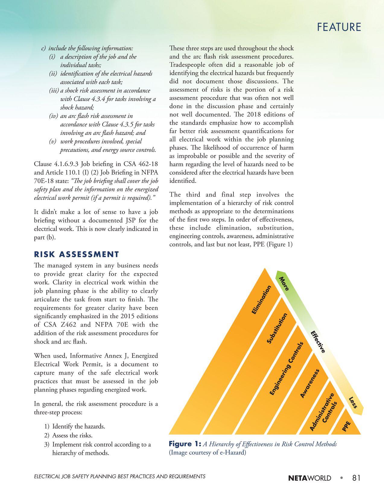
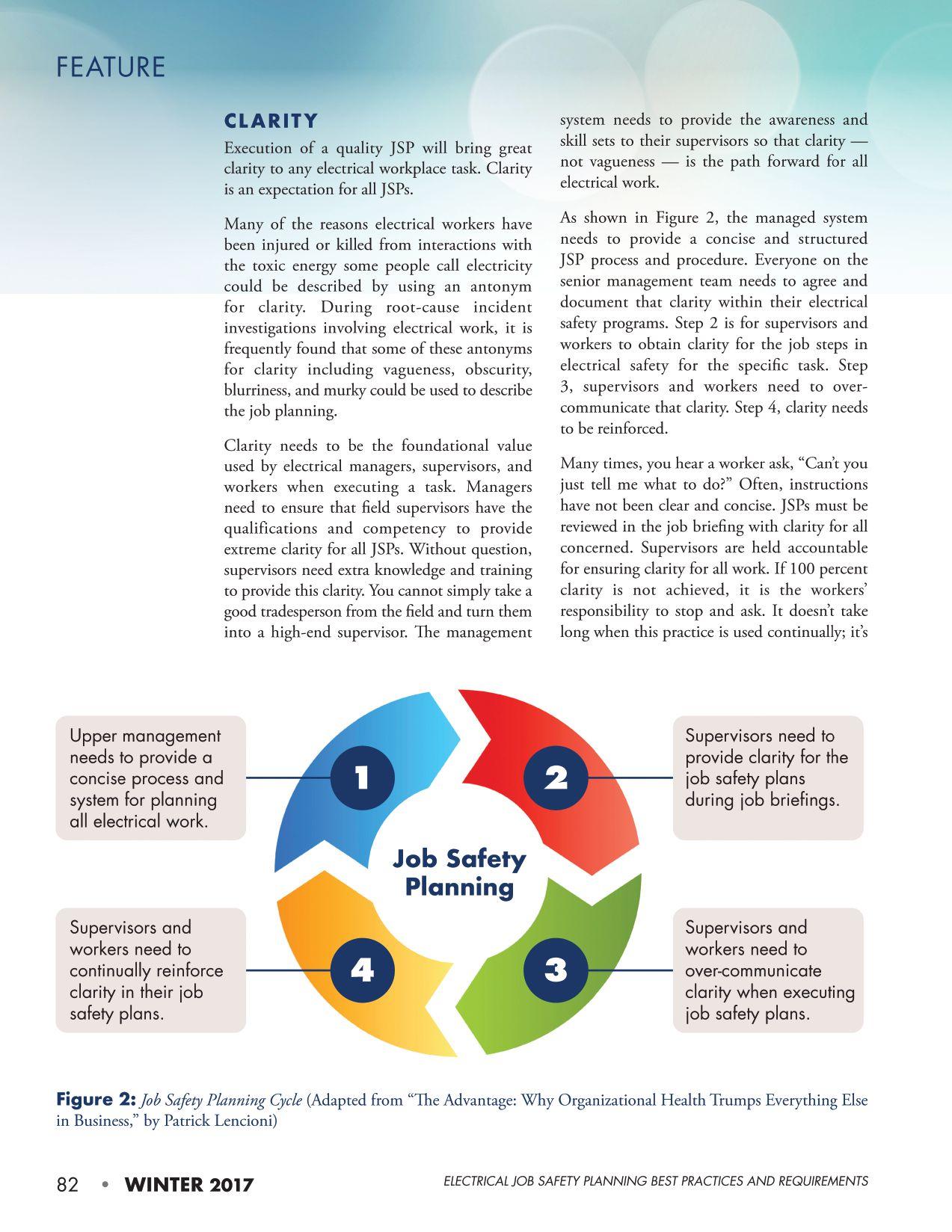
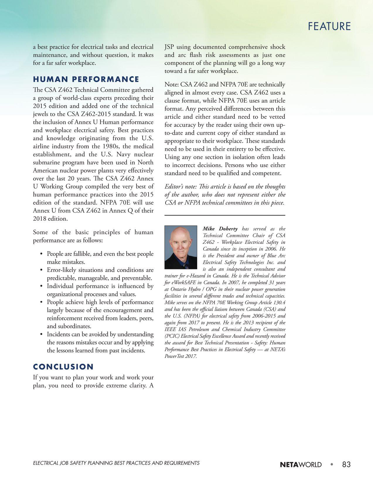
TWO NEW SELF-PACED TECHNICAL SEMINARS (SPTS)
Understanding Generator Protection
What Does Partial Discharge Tell Me and How Do I Perform the Test?
Learn at your own pace. Advance your knowledge. Ask about continuing education. Earn CTD*Credits for NETA Level III and IV Technicians. Order online at: www.netaworld.org or call 888-300-6382 (NETA)
*CTDs awarded when participant receives a passing score on the proficiency exam.

ADDITIONAL COURSES AVAILABLE



ENGINEERING SERVICES • TECHNICAL SERVICES • COMMISSIONING Protection Systems Design, Commissioning, Relay Testing Certified Cable Splicing, Cable Testing & Analysis using VLF, VLF-TAN Delta, and Partial Discharge Motor, Generator & Transformer Maintenance, Testing, Oil Handling & Leak Repairs Troubleshooting Power Systems and Power Quality Audits (310) 816-3130 www.tdeinc.com 131 W F Street Wilmington, CA 90744 Los Angeles Area | | www.youtube.com/tdeinc2 www.twitter.com/tdeinc www.facebook.com/tdeinc www.linkedin.com/company/tony-demaria-electric CA LICENSE #315448 Also Provides Technical & Safety Training
seconds; how much depends on the voltage rating of the transformer and the voltage of the dc source used to charge it. For example, a 400 kV transformer designed for 60 Hz will require about 1,500 volt-seconds to reach saturation flux. Using a 60 V source will decrease it to 25 seconds. It could take 250 seconds using a 6 V source. This process is exponential and starts slowly to gain the maximum speed at the end of the process. This information will be useful later when we discuss the disadvantage of manual demagnetization.
DEMAGNETIZATION
Remanent magnetism in magnetic materials is dissipated naturally through the thermal demagnetization process over a very long period of time or at very high temperatures (on the order of 550 degrees C for magnetite or hematite). This is not practical for electrical power systems; thus, an artificial demagnetization is performed for power transformers.
Let us review four methods for removal of remanent magnetism from power transformers:
1. Variable voltage constant frequency source (VVCFS)
2. Constant voltage variable frequency source (CVVFS)
3. Constant alternating polarity voltage (dc) with decreasing time (CAVDT)
4. Decreasing amplitude of an alternating polarity dc current (DAAPC)
Variable Voltage Constant Frequency Source
Performed in the factory, VVCFS is the best method, but it requires a very large energy source. Impractical for field operation, VVCFS requires an industrial frequency (50 or 60 Hz) source powerful enough to demagnetize the magnetic core. Another requirement is the ability to control and slowly reduce this voltage. By reducing the voltage and current from nominal to zero, the core is demagnetized. This is impossible to do in the field, even on a medium-size power transformer.
Constant Voltage Variable Frequency Source
A paper published in IEEE Transactions on Power Delivery , Volume 30, by researchers at New York University explains a simple and quick method to demagnetize the iron core of a power transformer by measuring and calculating coercive force applied in a single application. This is a variation of the CVVFS. The experiment in that publication shows results for single-phase and threephase units. The method has been verified on Y-Y connections for three- and five-limb transformers as well. It requires very exact calculation of the current and time required for achieving the required coercive force as well as precise execution. Some commercially available instruments already use this procedure; however, results reported from the field are not always positive.
Constant Alternating Polarity Voltage (dc) with Decreasing Time
IEEE Std. 62-1995 (Section 6.1.3.5) directs one to alternate the polarity of a fixed voltage with decreasing application time per alternation of polarity. This is the CAVDT method. With each alternation, the voltage is applied until the current flow has reversed and is slightly lower in absolute magnitude than the current in the previous application. The explanation is clear following our explanation of volt-seconds required: With decreasing time, you should obtain slightly lower magnitude of the current/flux. However, this is easier said than done, and this is one of the big disadvantages of manual demagnetization.
Once the current reaches the knee-point of the saturation curve with applied fixed voltage, it changes too fast for precise manual control. Experience has shown that improper procedure often caused other core legs to get magnetized while one was being demagnetized. Thus, no successful demagnetization could be reported in most cases.
NETAWORLD • 87 DEMAGNETIZING POWER TRANSFORMERS INDUSTRY TOPICS
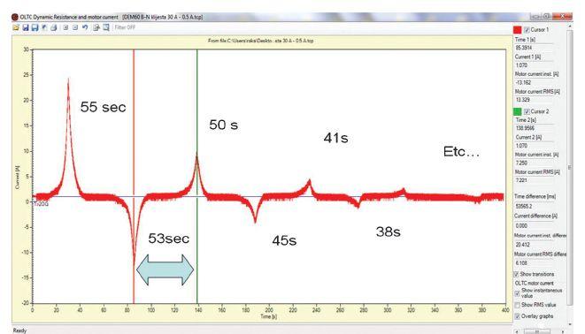
Figure 1: Demagnetization Process and Timing of Each Sequence
Figure 1 shows the proper time sequence for diminishing current magnitude after the first sequence reaches the amplitude of 25A at: 55, 53, 50, 45, 41, 38… seconds — not to mention that at lower current levels, you may be talking fractions of a second. If the time is not right, the current will again reach the previous value and thus cancel the effectiveness of the process.
Decreasing Amplitude of an Alternating Polarity DC Current
With the DAAPC method, modern electronically controlled, high-power dc test instruments can control the amplitude of the applied current with high precision, and they can be programmed to perform polarity reversal and automatic demagnetization of the power transformer magnetic core. As shown in Figure 1, current is interrupted at a pre-selected value; following a discharge process, the opposing polarity current is applied. In this subsequent step, the amplitude at which the supply is interrupted is lower by 40 percent of the previous cycle. The process is repeated down to the lowest practically controllable current amplitude. A successful demagnetization was obtained on various sizes of power transformers up to 1,100 MVA in both configurations — star or delta.
SAFETY
When a dc current is applied to a power transformer winding, energy is stored in the
magnetic core. This energy is equal to the product of inductance and a square of the current and must be discharged safely. Manual demagnetization using a car battery and swapping cables to produce an alternating effect is dangerous. All the stored energy is dissipated through the arc, which may be as much as a few feet long as the cable is disconnected — no need to talk about possible hazards from the arc, heat, shock, etc. Winding resistance instruments are equipped with discharging circuits that gradually and safely discharge this energy after the winding resistance tests, as well as the demagnetization procedure.
CONCLUSION
Various methods for core demagnetization are available. Theoretically, all of them will produce good demagnetization results if performed precisely and correctly. However, this is not always possible or practical and may present dangerous situations. Winding resistance instruments or demagnetizing instruments offer this procedure automatically and safely.
REFERENCE
de Leon, F.; Farazmand, A.; Jazebi, S.; Deswal, D.; Levi, R. “Elimination of Residual Flux in Transformers by the Application of an Alternating Polarity DC Voltage Source,” IEEE Transactions on Power Delivery, Volume 30, Issue 4, 2015, Page(s):1727–1734

Raka Levi, PhD., is an Application Expert at DV-Power Sweden and convener of the AMforum association. He has over 30 years of asset performance and condition assessment experience, specializing in apparatus testing, monitoring, and diagnostics. Seven years ago, he started a working group on DRM test methodology for tap changers within the AMforum organization. For 20 years, he has led committees that assemble asset managers, organizing AMforum conferences in Europe, LTC Universities in the U.S., and LTC Colleges in Asia. His education includes a PhD in HV diagnostics for circuit breakers from University of Belgrade and an ME in electric power engineering from Rensselaer Polytechnic Institute.
88 • WINTER 2017 DEMAGNETIZING POWER TRANSFORMERS INDUSTRY TOPICS
PRECISION + SIMPLICITY
without compromise
When it comes to substation testing, you shouldn’t have to compromise simplicity for precision and accuracy. That’s why, for over 25 years, we have designed our precision instruments to be intuitive and easy to use so that you can focus on testing instead of wasting time in training.
Our versatile instruments offer a built-in thermal printer and on-board test record storage so that tests can be conducted in stand-alone mode in the field. A computer interface is also offered so that tests can be easily conducted from a PC.
And all of our instruments are competitively priced to provide cost-effective accuracy. Visit us at www.vanguard-instruments.com today to find out why Vanguard Instruments is the right choice for your testing needs.


current transformer
circuitbreakeranalyzers vacuum bottle testers winding resistance
circuit breaker contact resistance meters current transformer turns
relaytestequipment Vanguard Instruments Company, Inc. www.vanguard-instruments.com | PH 909.923.9390 Ontario, California PROUDLY MADE IN THE U.S.A.
testers
meters
ratio testers
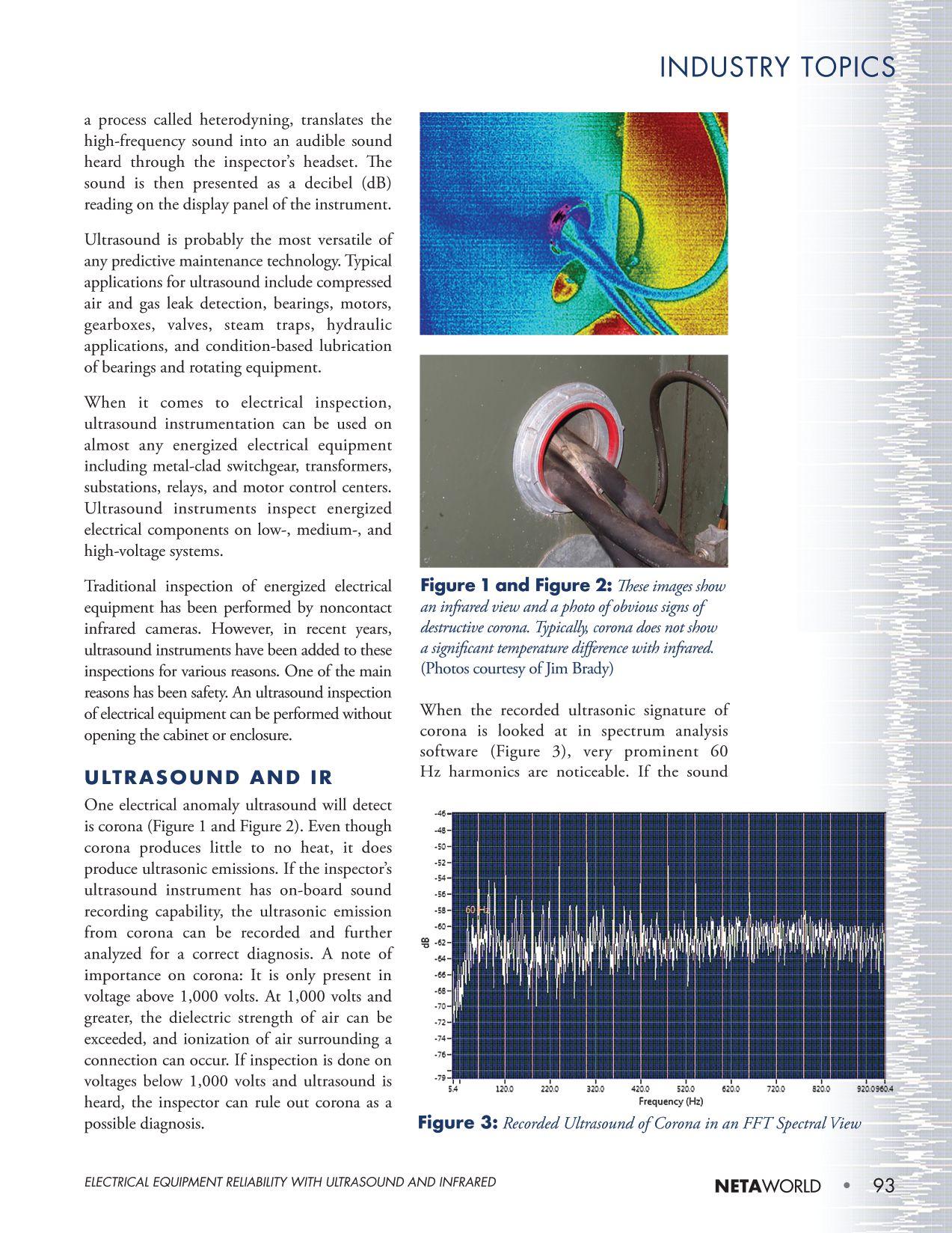
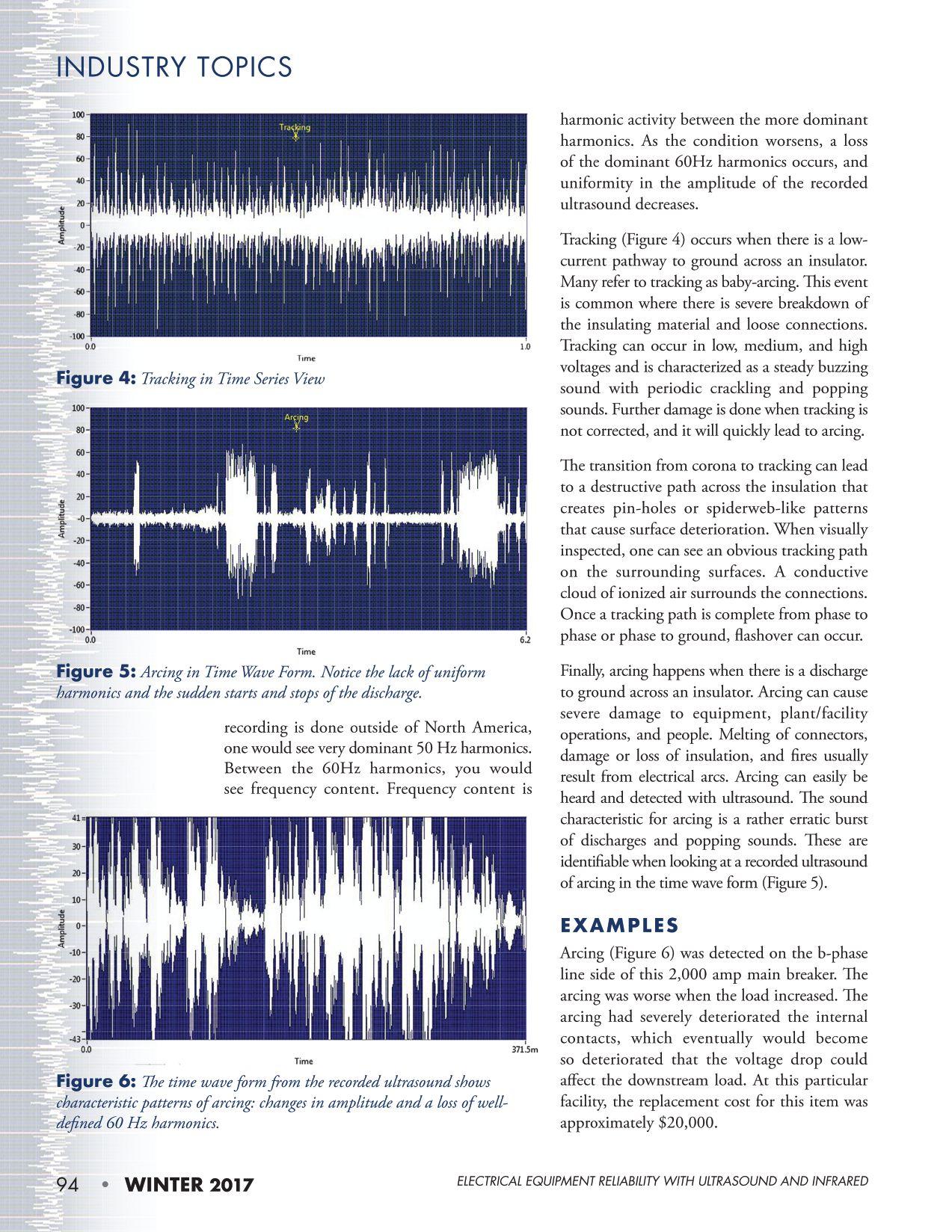
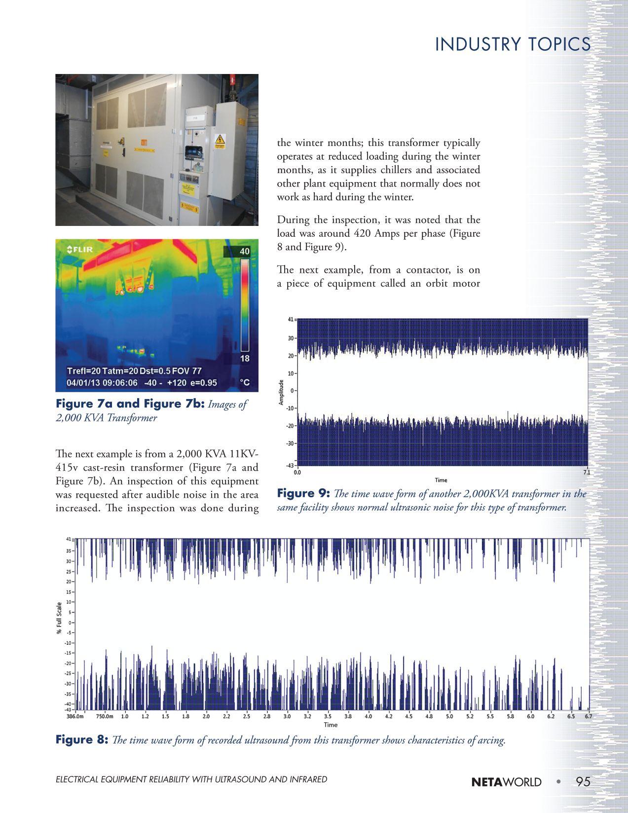
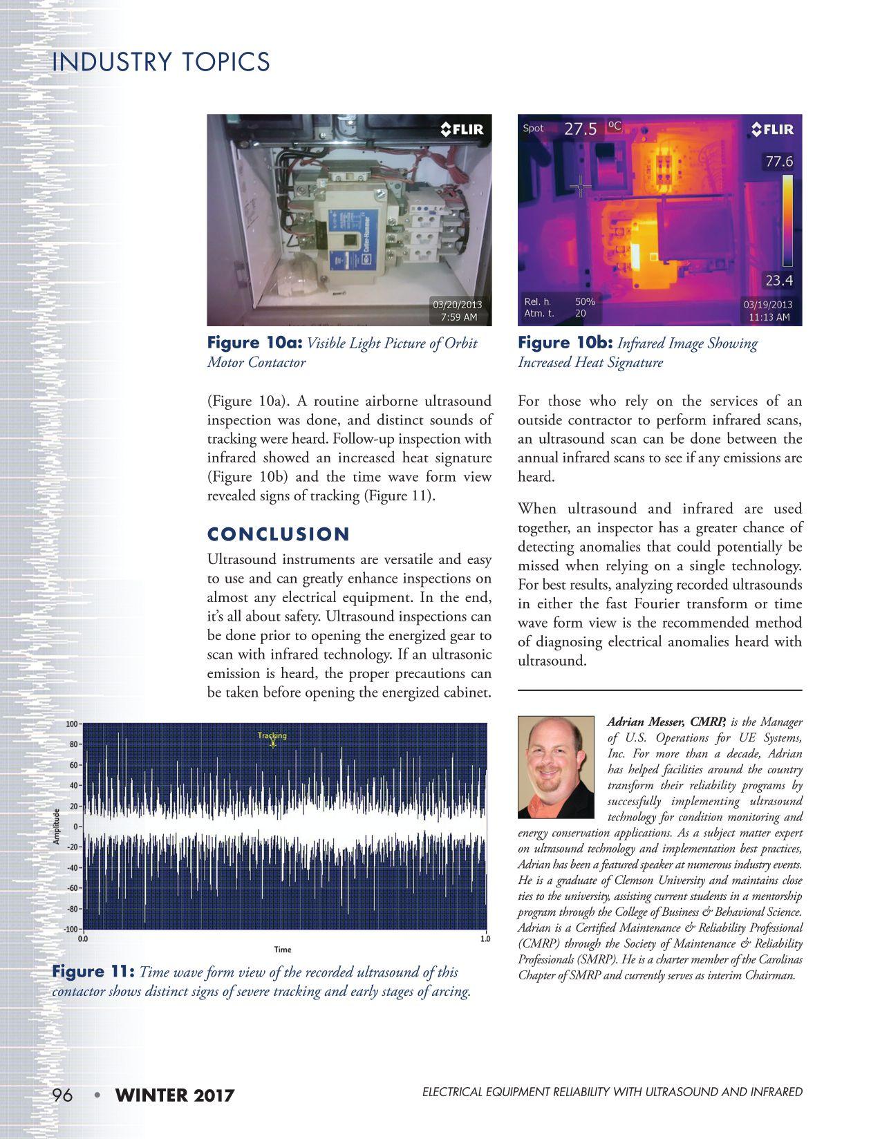


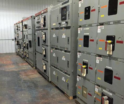
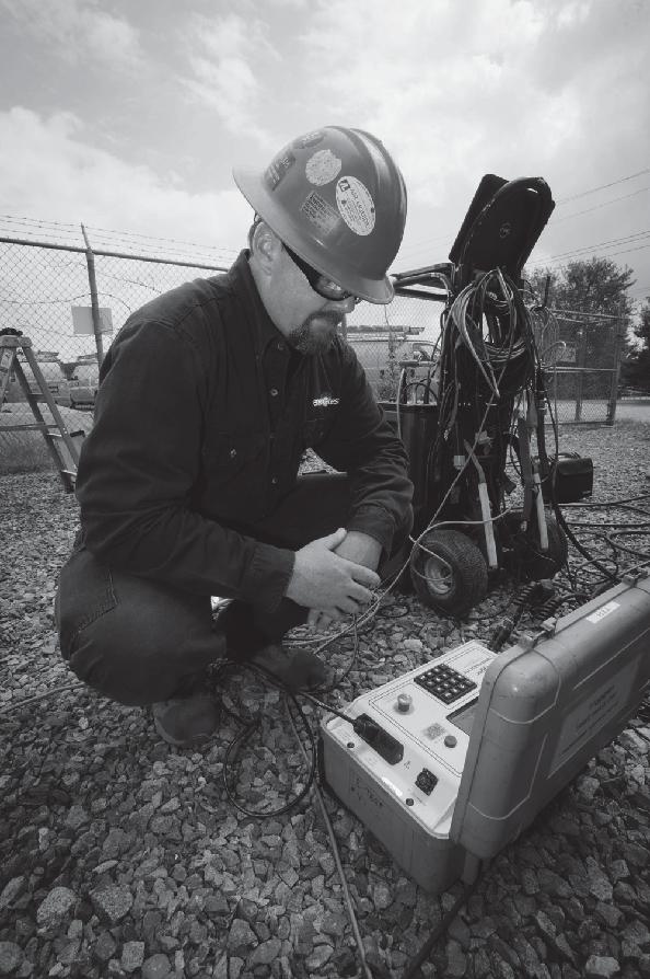

Accredited Company 204 Gale Lane Kennett Square, PA 19348 484.731.0200 enerGtest.com Serving clients in Pennsylvania, Delaware, New Jersey, Maryland, Washington, DC and New England. We deliver optimum system reliability and performance while reducing the chances of costly unplanned power outages. Whether you need acceptance ener es ™ testing or preventive maintenance, depend on EnerGTest to keep the power on. Reliable Power System Solutions 228 Merrick Road Lynbrook, NY 11563 (631) 589-6343/Fax (516) 596-3680 601 Union Street Brooklyn, NY 11215 (718) 786-4900 BULLOCK BREAKERS B B 475 Annandale Blvd • Annandale • Minnesota 55302 www.bullockbreakers.com • Email: jason@bullockbreakers.com • Thousands of Air Circuit Breakers in Stock! • Switchgear Line-ups you can’t find anywhere else! • Now Available as Reconditioned with AC-Pro Trip Units! 1-763-269-2832
POWERTEST EXPANDS HANDS-ON SEMINAR OFFERING FOR 2018
Due to growth in attendees and an increase in highquality presentations submitted, NETA is expanding its PowerTest 2018 seminar offering from 12 to 16 sessions. “We had such an impressive number of abstracts submitted this year that we decided to expand the schedule and give PowerTest attendees as many educational opportunities as possible,” says Missy Richard, executive director.
Scheduled for February 26–March 2, 2018, at the Gaylord National Resort & Convention Center in the Washington, DC, metro area, PowerTest features five days of high-powered learning and interactive sessions that focus on electrical power systems commissioning, acceptance and maintenance testing, and safety. The conference features more than 40 education sessions overall.
The four-hour seminars round out the conference, providing equipment on which attendees can advance their testing and troubleshooting skills.
WEDNESDAY, FEBRUARY 28, 2018
Relay Troubleshooting — Ryan McDaniel, Schweitzer Engineering Laboratories, Inc. (two sessions: morning and afternoon)
Want to learn more about the basics of troubleshooting application problems with protective relays? This half-day session guides you through troubleshooting techniques with common distribution and transformer protection relays. Topics include:
• Troubleshooting problems with a distribution feeder relay, such as reclosing and logic setting issues
• Troubleshooting problems with a transformer protection relay, such as current differential winding compensation setting issues
• Troubleshooting problems with a motor protection relay, such as thermal element and motor lockout issues
Requirements: For full participation, participants should bring a laptop with acSELerator QuickSet and Synchrowave 2015 software pre-installed and a calculator. Attendees must be familiar with how to connect to relays, send and receive settings, and download event reports. It is recommended that attendees have experience applying relays for transformers and distribution lines.
Medium-Voltage Circuit Breaker Maintenance: A Hands-On Seminar with GE PowerVac Breaker — Finley Ledbetter, Group CBS, Inc.
This workshop on General Electric’s legacy PowerVac circuit breakers covers the strength of the platform, the excellent service life, and ways to extend the usable life beyond planned obsolescence. This workshop covers lubrication adjustments, parts availability, testing, and upgrades required to keep this important, medium-voltage power circuit breaker in service for many years.
In addition to remarkable similarities between different types of circuit breakers and the PowerVac, other medium-voltage vacuum circuit breakers manufactured in the United States between 1975 and 2000 will be discussed, and major action items will be explained. This is a team-led, hands-on workshop with audiovisual highlights. Attendees will watch several key maintenance items performed firsthand and learn the best practices based on Group CBS’s 40 years of experience.
100 • WINTER 2017 POWERTEST EXPANDS HANDS-ON SEMINAR OFFERING FOR 2018
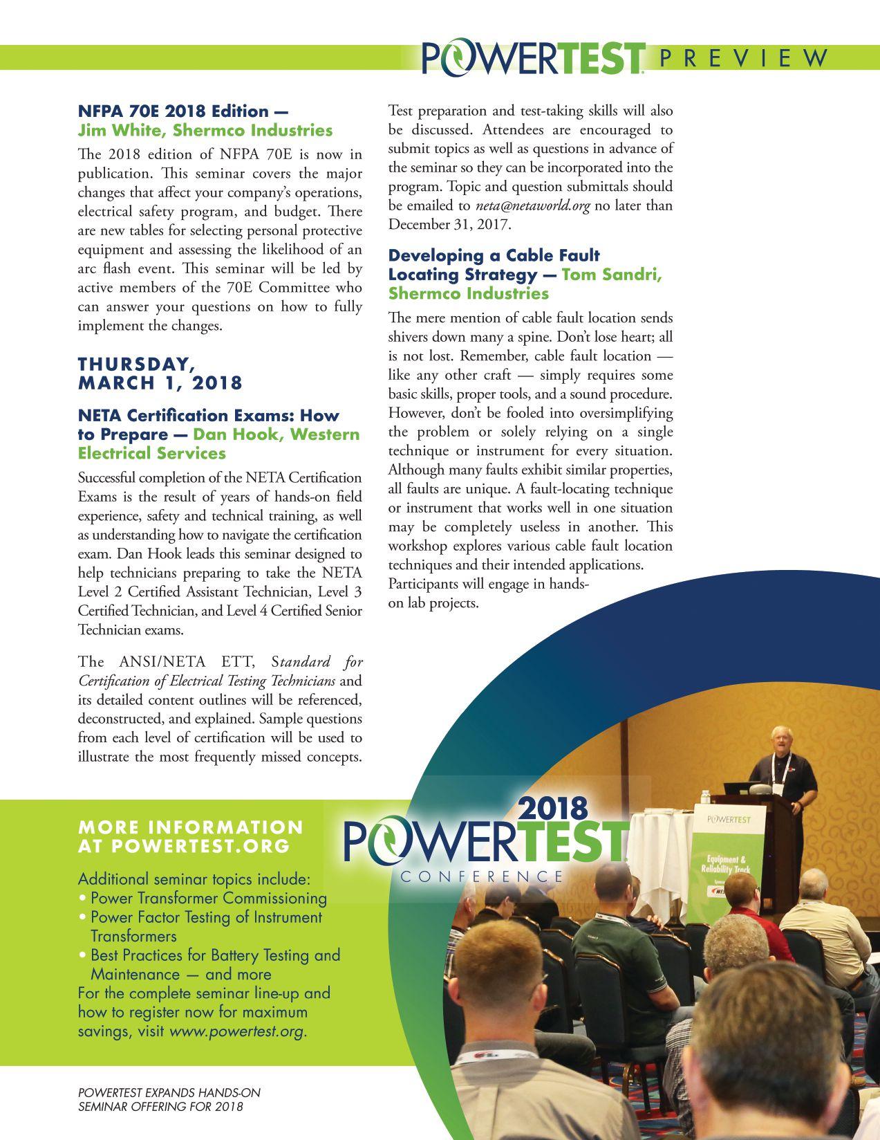
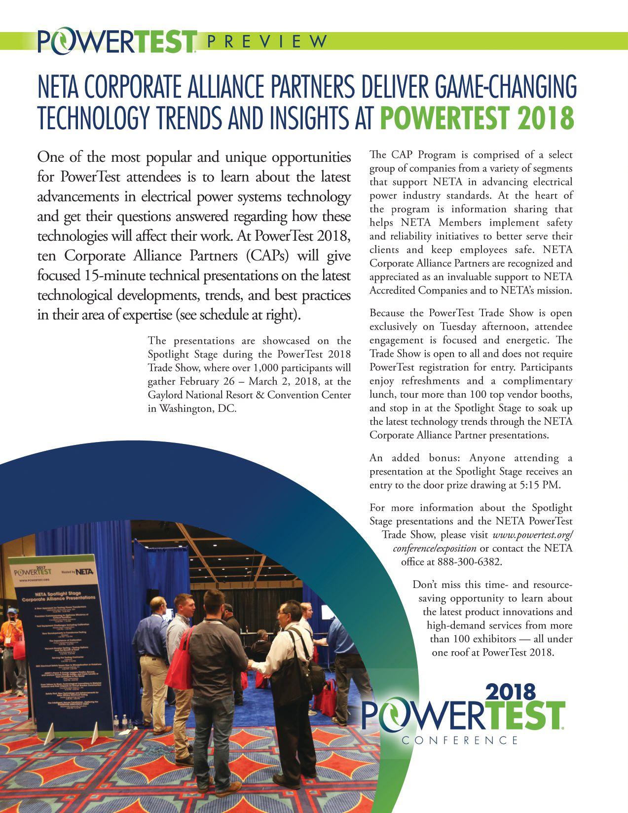



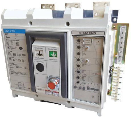



Phone: 800-421-5082 email: Sales@qualityswitchgear.com Something you don’t see everyday... SB Breakers But we do! Complete Breakers Trip Units Electric Operators Shunt trips/UVRs All Factory New
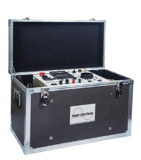
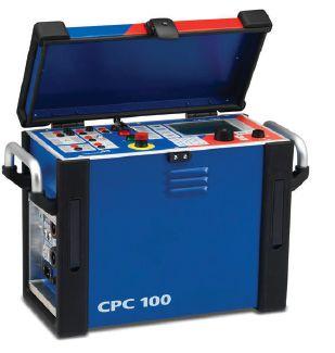
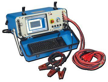
Providing Testing Solutions for:
• Protective Relays
• Transformers & Motor Analysis
• Partial Discharge/Corona
• Current Injection
• Cable Fault Location
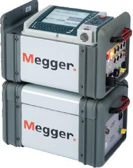
• Switchgear/Circuit Breakers
• Insulation Resistance
• Tan Delta/Power Factor
• Current Transformers
• Ground Grid
San Diego Test Equipment Symposium Oct. 24th, 2017 • San Diego Register now! www.atecorp.com/sdtes Register now!

RENT ELECTRICAL TEST EQUIPMENT
800-404-ATEC (2832) • rentals@atecorp.com • www.atecorp.com

SPECIFICATIONS AND STANDARDS ACTIVITY

ANSI/NETA STANDARDS UPDATE
2018 REVISION IN PROCESS
Standard for Certification of Electrical Testing , is being revised as an American National Standard. A project intent notification was published in ANSI Standards Action on October 6, 2017, with a 45-day public review period that closed November 11, 2017.
ANSI/NETA ETT establishes minimum requirements for qualifications, certification, training, and experience for the electrical testing technician. It also provides criteria for documenting qualifications for certification and details the minimum qualifications for an independent and impartial certifying body to certify electrical testing technicians.
Single copy of draft document: $459.00
Order from: Kristen Wicks, (888) 300-6382, kwicks@netaworld.org
Send comments (with copy to psa@ansi.org) to: Kristen Wicks, kwicks@netaworld.org
ANSI/NETA MTS-2015 2019 REVISION IN PROCESS
ANSI/NETA MTS, Standard for Maintenance Testing Specifications for Electrical Power Equipment and Systems, 2015 Edition , is being revised as an American National Standard. A project intent notification was published in ANSI

Standards Action on October 6, 2017, with a 45-day public review period that closed November 11, 2017.
ANSI/NETA MTS contains specifications for suggested field tests and inspections to assess the suitability for continued service and reliability of electrical power equipment and systems. The purpose of these specifications is to assure that tested electrical equipment and systems are operational and within applicable standards and manufacturers’ tolerances, and that the equipment and systems are suitable for continued service.
Single copy of draft document: $459.00
Order from: Kristen Wicks, (888) 300-6382, kwicks@netaworld.org. Send comments (with copy to psa@ansi.org) to: Kristen Wicks, kwicks@netaworld.org.
ANSI/NETA ECS-2015
ANSI/NETA ECS, Standard for Electrical Commissioning of Electrical Power Equipment and Systems, 2015 Edition , was approved as an American National Standard on December 3, 2014. This standard is available for purchase in the NETA Bookstore at www.netaworld.org.
ANSI/NETA ECS describes the systematic process of documenting and placing into service newly installed or retrofitted electrical power equipment and systems. This document shall be used in conjunction with the most recent edition of the
ANSI/NETA STANDARDS UPDATE 108 • WINTER 2017
ANSI/NETAETT-2015 ST AN D ARD F OR OCERTIFICATION F ELECTRICALTESTING T EC HN ICI ANS
ANSI/NETA ECS-2015 STAND ARD FO R ECT RI CAL MMISSIONING EC IFI CAT IO NS R E L ECTR I CAL POWE R UIPMENT AND SYSTEMS ING SPECIFICATIONS ANSI/NETA ATS-2017
ANSI/NETA, Standard for Acceptance Testing Specifications for Electrical Power Equipment and Systems. The individual electrical components shall be subjected to factory and field tests, as required, to validate the individual components. It is not the intent of these specifications to provide comprehensive details on the commissioning of mechanical equipment, mechanical instrumentation systems, and related components.
Voltage classes addressed include:
• Low-voltage systems (less than 1,000 volts)
• Medium-voltage systems (greater than 1,000 volts and less than 100,000 volts)
• High-voltage and extra-high voltage systems (greater than 100 kV and less than 1,000 kV)
References:
• ASHRAE, ANSI/NETA ATS, NECA, NFPA 70E, OSHA, GSA Building Commissioning Guide
This document is scheduled for release as a reaffirmed or revised standard in Spring 2020. Those interested in

participating in the revision process should contact the NETA office for more information.
ANSI/NETA ATS-2017
ANSI/NETA ATS covers suggested field tests and inspections for assessing the suitability for initial energization of electrical power equipment and systems. The purpose of these specifications is to assure that tested electrical equipment and systems are operational, are within applicable standards and manufacturers’ tolerances, and are installed in accordance with design specifications.
This document is scheduled for release as a revised standard in the spring of 2021. Those interested in participating in the revision process should contact the NETA office for more information.
PARTICIPATION
Comments and suggestions on any of the standards are always welcome and should be directed to the NETA office. To learn more about the NETA standards review and revision process, to purchase these standards, or to get involved, visit www.netaworld.org, email neta@netaworld.org, or call 888-300-6382.
INSULATED CONDUCTOR COMMITTEE NEWS
BY RALPH PATTERSON
The working groups, including engineers and scientists, met in San Diego, California, for the Spring 2017 IEEE/ ICC meeting from May 6 – May 10, 2017. The Insulated Conductors Committee (ICC) is a professional organization within the Power Engineering Society (PES) of IEEE.
This is an ongoing opportunity for NETA to be recognized and offer a field-testing perspective to the working groups as documents are
developed. The working groups are made up of cable manufacturers, utilities, test equipment manufacturers, and end users.
Table 1: Fall 2016 Working Groups/Discussion Groups Meetings for Subcommittee F
F02WField Testing of Laminated Dielectric Shielded Power Cable Systems Rated 5 KV and above (400.1)
F04WPartial Discharge Testing in the Field (P400.3)
F06DField Testing of DC Extruded Cable Systems
F07DGuide on Neutral Corrosion in MV Underground Cables (1617)
F11WConstant Voltage AC Field Testing of Cable Systems
F12WGuide for Fault Locating on Shielded Power Cables
Reviewed first draft and assignment of sections for revision

Larzelere/ Rickman
Prepared final draft for ballot Levine/ Walton
Continued discussion of the process forward and identification of discrepancies
Continued review of proposed revisions by writing group
Larzelere/ Rickman
Buchholz/ Von Herrmann
Discussed content of first draftFenger/ Denmon
Continued review of flowchart for fault locating and discussed new CIGRE guidelines Moiser/ Vacant
110 • WINTER 2017 INSULATED CONDUCTOR COMMITTEE NEWS SPECIFICATIONS AND STANDARDS ACTIVITY
GROUP NO.GROUP NAME ACTIVITY CHAIRS

CSA COMMITTEE REPORTS
BY KERRY HEID, Shermco Industries Canada
Two major documents currently in the review cycle directly apply to the electrical testing industry in Canada. These documents cover policies and procedures for safety and maintenance when dealing with electrical power distribution equipment and systems.
CSA Z462 WORKPLACE ELECTRICAL SAFETY
CSA Z462, Workplace Electrical Safety is currently under revision and works in unison with the NFPA 70E document, as both standards remain technically harmonized. Some of the most significant changes to Z462 will be in clause 4.1.6 in the area of electrical safety program requirements.
The next technical committee meeting is scheduled for September 28, 2017, at the CSA head office in Toronto. This will be a closed meeting; only voting members of the technical committee will be allowed to attend as the final document gets technically approved.
CSA Z463 MAINTENANCE OF ELECTRICAL SYSTEMS
This document is currently being converted from a guideline to a standard with a prospective release date in 2018. The conversion requires adoption of a more prescriptive tone, because the word “shall” is used frequently in the language of a standard. As a guideline, there are currently no mandatory requirements for electrical maintenance, only suggested practices. The technical committee is working diligently to convert the guideline to a standard.

The scope and ability to cover underground and overhead utility power systems has been discussed and is something the technical committee is considering very carefully. CSA Z463 uses ANSI/NETA MTS, Standard for Maintenance Testing Specifications for Electrical Power Equipment and Systems as its outline for Clause 8 in equipment-specific maintenance practices.
The next technical committee meeting is scheduled for October 3-4, 2017, in Calgary, Alberta. Additional meetings will take place later in the calendar year with the goal to release the document as a standard in 2018.

Kerry Heid is the President and CEO of Shermco Industries Canada Inc. After beginning his career with Westinghouse Service, Kerry started the Magna Electric Corporation (MEC) office in Regina in 1996 and became President of the company in 2001. The company grew to over 1,000 employees and earned many prestigious awards as one of Canada’s 50 Best Managed Companies and Canada’s Top 100 Employers. MEC was acquired by Shermco Industries in December 2013. Kerry is a NETA Past President, served on NETA’s Board of Directors for over 10 years, won NETA’s Outstanding Achievement Award in 2010, and is a NETA Certified Level 4 Test Technician. He chairs the CSA Z463 Maintenance of Electrical Systems Technical Committee and has been on the CSA Z462 Workplace Electrical Safety Technical Committee since its inception in 2006.
NETAWORLD • 113
SPECIFICATIONS AND STANDARDS ACTIVITY
CSA COMMITTEE REPORTS


www.BurlingtonSafety.com info@BurlingtonSafety.com Browse and Buy Online Now! Metro NY/NJ/PA 800-220-2120 Calif (SF) 888-817-1412 Calif (LA) 800-296-2803 Your Source for NFPA 70E Compliant Protective Gear Accredited Proof Testing Laboratory Services Rubber Gloves ◆ Sleeves ◆ Blankets ◆ Line Hose Footwear ◆ Jumpers ◆ Hotsticks


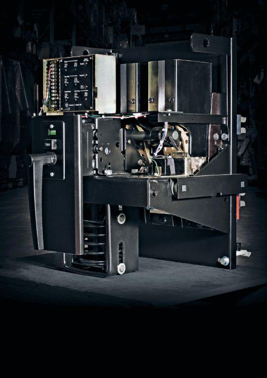


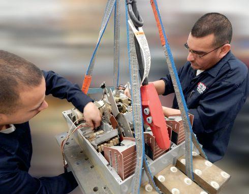


1315 Columbine, Gainesville, Texas 76241 | 800-232-5809 INFO @ CBSALE S.COM | CircuitBreaker.com CBS Florida | Lakeland, Florida | 863-646-5099 | CBS-Florida.com CBS Midwest | Crown Point, Indiana | 219-575-5420 | CBSMidwest.com new service locations CBS stocks every low- and mediumvoltage circuit breaker made in America since 1945. Wit h more t h an 5 million breakers and parts in our 200,000-square-foot warehouse — including switchgear, transformers, substations, protective relays, load break switches, electr ical contacts, motor contr ols and centers, vacuum interrupters, and more — Circuit Breaker Sales has you covered. √ Replacement parts and equipment √ Remanufacturing, retrofits, and upgrades √ Reverse engineering, 3-D printing of obsolete parts For more information about Group CBS and its affiliate companies, visit GroupCBS.com. Circ uitBreaker.com (800) 232-5809 TOLLFREE Your TRUSTED online resource for authentic circuit breaker and electrical distribution equipment CB Store.com From a single part to a switchgear lineup, Advanced Electrical & Motor Controls’ inventory of low-voltage insulated-case circuit breakers, molded-case circuit breakers, motor controls, and custom switchgear is second to none in the U.S. No matter what you need — new, surplus, used, or reconditioned power distribution equipment, testing and repair, or an engineered solution — AEAMC will keep you up and running. Insulated-Case Circuit Breakers Molded-Case Circuit Breakers Motor Controls & Centers Bolted Pressure Switches Panelboard Switches & Bus Plugs 480 V Distribution Transformers Replacement Parts UL-Listed Motor Control Center Replacements Let us test, repair, and extend the life of your: ADVANCED ELECTR I CAL & MOTOR CONTROLS | 1801 Hurd Drive, Irving, Texas 7503 8 | 972-253-7783 | AEAMC.COM Search. Click. Ship. Purchase AEAMC equipment online, anytime! Emergency support 24/7 800-289-2757 No One Knows Low-Voltage Circuit Breakers & Motor Controls Like Advanced Electrical & Motor Controls Like Advanced Electrical & Motor Controls


wood, enameled wire, epoxy coatings, paper phenolic, and the dielectric fluid. Although electrical tests are available to measure the quality of the major insulation (the insulation between phases, between windings, and windings to ground), the average moisture content of the insulation, and insulation contamination, there are limited tests that directly measure the mechanical strength of the solid insulation. Directly measuring the insulation requires the unit to be de-energized, oil drained, opened, and a physical sample of the paper taken — a challenging and economically prohibitive task given accessing a transformer and the physical impracticality of locating the most representative conductor paper. What is needed is a specific test or group of tests that assess the quality of the insulation through comprehensive indirect testing of the fluid.
ADVANCEMENTS IN THE INDUSTRY
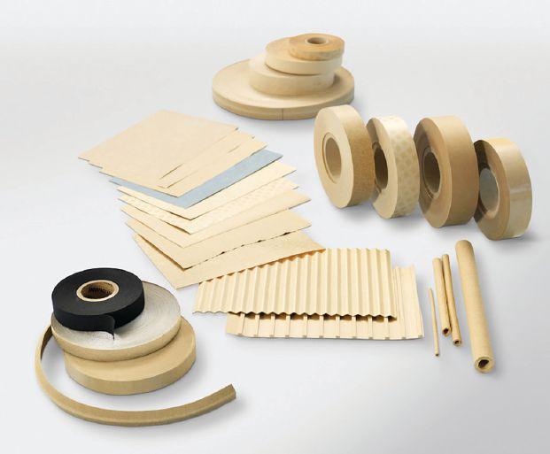

NETAWORLD • 117 ASSESSING SOLID INSULATION AGING THROUGH OIL TESTING
Figure 1: Cellulose Insulation


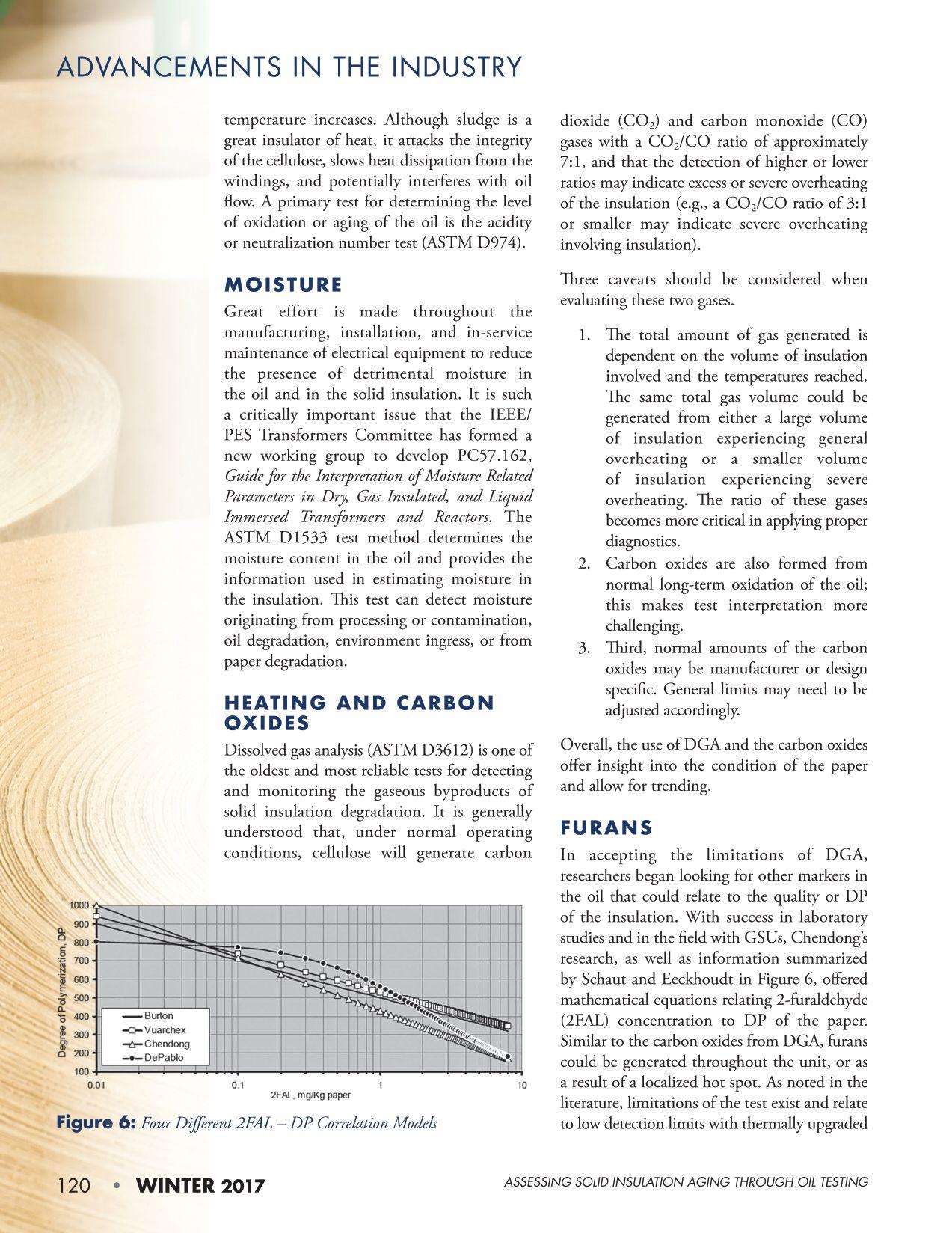
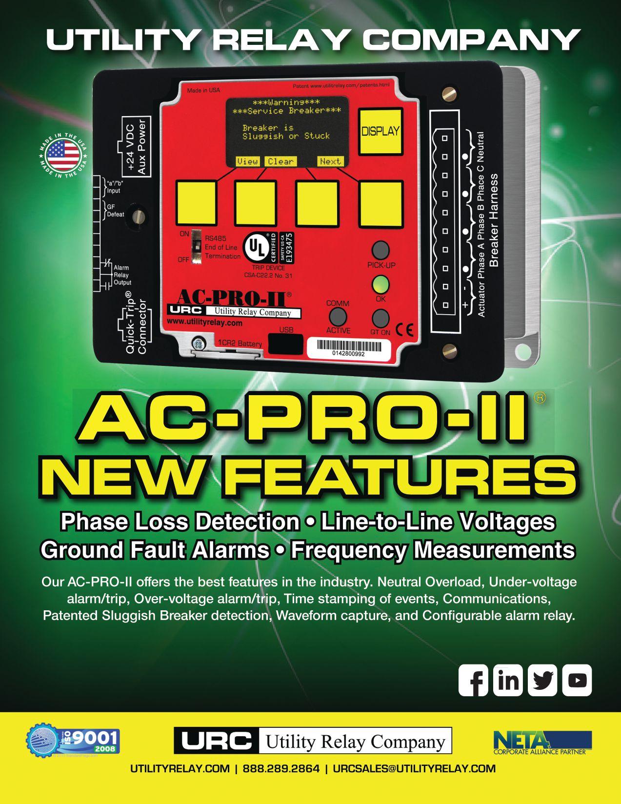

ANSWERS
ANSWERS
1. C. Everyone has heard this saying, but few think about its meaning. We receive a lot of safety training from customers, our home companies, every time we open a new product (really, don’t use a lawn mower to trim hedges?), so we become a bit numb to it all. Important pieces of information are tucked away in the tsunami of mundane blap. It is our job to pull them out. It’s part of being a professional.
2. C. Not a trick question. You were troubleshooting, so the equipment is in distress. If electrical equipment is in distress, you are required to wear arc-rated PPE any time you are exposed to electrical hazards. Answer A is not entirely wrong, but I didn’t state you were leaving the area, so it is a step that may or may not be needed. For those of you who chose answer D: good luck.
3. Trick question! Actually, it’s a trick answer. Both C and D would be correct, depending on your company’s safe work practices and electrical safety program. NFPA 70E does not state when a safety backup is needed — only that, if one is required, it needs to be documented on the risk assessment. Many companies require a safety backup whenever a qualified person would be exposed to electrical hazards, but it is not mandated.
NFPA Disclaimer: Although Jim White is a member of the NFPA Technical Committee for both NFPA 70E, Standard for Electrical Safety in the Workplace, and NFPA 70B, Recommended Practice for Electrical Equipment Maintenance, the views and opinions expressed in this column are purely the author’s and shall not be considered an official position of the NFPA or any of its technical committees and shall not be considered, nor be relied upon, as a formal interpretation or promotion of the NFPA. Readers are encouraged to refer to the entire text of all referenced documents.
4. A. Attention. When we first perform a task, we are focused. Our complete attention is given to performing that task. Once we have completed the task successfully a number of times, we tend to lose focus. It’s human nature. That is why SOPs, safe work practices, and electrical safety programs are so important. They help us maintain our focus when performing hazardous tasks.
5. D. Alcohol or drug use is an automatic disciplinary situation. The purpose of this question is to get NETA Technicians to read the Minimum Safety Guidelines NETA has developed. Also mentioned along with alcohol, drug use, fighting, and horseplay is practical jokes. Any of these are inappropriate on the job site, whether it is at a customer’s site or at your home office. Horseplay and practical jokes indicate a lack of maturity, especially in our occupations. Fighting should never be tolerated at any company, and alcohol and drug use (or any combination thereof) gets you a quick exit. Again, it comes down to professionalism.
NETAWORLD • 123 TECH QUIZ TECH QUIZ ANSWERS
No. 120
NETA ACCREDITED COMPANIES Setting the Standard
A&F Electrical Testing, Inc.
80 Lake Ave. South, Ste. 10 Nesconset, NY 11767 (631) 584-5625 Fax: (631) 584-5720 kchilton@afelectricaltesting.com www.afelectricaltesting.com
Kevin Chilton
A&F Electrical Testing, Inc.
80 Broad St. 5th Floor
New York, NY 10004 (631) 584-5625 Fax: (631) 584-5720 afelectricaltesting@afelectricaltesting.com
Florence Chilton
ABM Electrical Power Solutions
3602 East Southern Ave., Ste. 1 Phoenix, AZ 85040 (602) 722-2423 www.ABM.com
Doug Bukowski
ABM Electrical Power Solutions
9800 E. Geddes Avenue, Unit A-150 Englewood, CO 80112 (303) 524-6560 Fax: (303) 524-6581
Brian Smith
ABM Electrical Power Solutions
2142 Rheem Drive Pleasanton, CA 94588 (408) 466-6920
John Marvulli
ABM Electrical Power Solutions
3940 Ruffin Rd., Ste. C San Diego, CA 92123 (858) 754-7963
william.mckenzie@abm.com
William McKenzie
ABM Electrical Power Solutions
6280 South Valley View Blvd., Ste. 618 Las Vegas, NV 89118 (602) 300-2188 Fax: (602) 437-3894
Jason Black
ABM Electrical Power Solutions
814 Greenbrier Circle, Ste. E Chesapeake, VA 23320 (757) 548-5690 Fax: (757) 548-5417
Mark Anthony Gaughan, III
ABM Electrical Power Solutions
3700 Commerce Dr. #901-903 Baltimore, MD 21227 (410) 247-3300 Fax: (410) 247-0900
Bill Hartman
ABM Electrical Power Solutions
5809 Departure Dr., Ste. 104 Raleigh, NC 27616 (919) 877-1008 Fax: (919) 501-7492
Rob Parton
ABM Electrical Power Solutions
317 Commerce Park Dr. Cranberry Township, PA 16066-6427 (724) 772-4638 Fax: (724) 772-6003
christopher.smith@abm.com
Christopher Smith
ABM Electrical Power Solutions
4390 Parliament Place, Ste. S Lanham, MD 20706 (301) 967-3500 Fax: (301) 735-8953
Frank Ceci
ABM Electrical Power Solutions
3600 Woodpark Blvd., Suite G Charlotte, NC 28206 (704) 273-6257 Fax: (704) 598-9812 ernest.goins@abm.com
Ernest Goins
ABM Electrical Power Solutions
720 S. Rochester Ave., Suite A Ontario, CA 91761 (800) 597-1225 Fax: (909) 937-6798
Mike Bivens
Absolute Testing Services 6829 Guhn Rd. Houston, TX 77040 (832) 467-4446 Fax: (713) 849-3885 rgamble@absolutetesting.com www.absolutetesting.com
Richard Gamble
Accessible Consulting Engineers, Inc. 1269 Pomona Rd., Ste. 111 Corona, CA 92882 (951) 808-1040 info@acetesting.com www.acetesting.com Iraj Nasrolahi
Advanced Electrical Services 4999 43rd St. SE, Unit 143 Calgary, AB T2B 3N4 Canada (403) 697-3747 www.aes-ab.com
Advanced Testing Systems 15 Trowbridge Dr. Bethel, CT 06801 (203) 743-2001 Fax: (203) 743-2325 pmaccarthy@advtest.com www.advtest.com
Pat MacCarthy
American Electrical Testing Co., Inc. 25 Forbes Blvd., Ste. 1 Foxboro, MA 02035 (781) 821-0121 Fax: (781) 821-0771 sblizard@aetco.us www.aetco.us
Scott A. Blizard
American Electrical Testing Co., Inc. 34 Clover Dr. South Windsor, CT 06074 (860) 648-1013 Fax: (781) 821-0771
jpoulin@aetco.us
Gerald Poulin
American Electrical Testing Co., Inc. 76 Cain Dr. Brentwood, NY 11717 (631) 617-5330 Fax: (631) 630-2292 bfernandez@aetco.us
Billy Fernandez
American Electrical Testing Co., Inc. 50 Intervale Rd., Ste. 1 Boonton, NJ 07005 (973) 316-1180 Fax: (781) 316-1181 jsomol@aetco.us
Jeff Somol
American Electrical Testing Co., Inc. Green Hills Commerce Center 5925 Tilghman St., Ste. 200 Allentown, PA 18104 (215) 219-6800 jmunley@aetco.us
Jonathan Munley
American Electrical Testing Co., Inc. 12566 W. Indianola Ave. Avondale, AZ 85392 (480) 383-9242 dmadaglia@aetco.us
Donald Madaglia
AMP Quality Energy Services, LLC 4220 West Schrimsher SW Site W1 P.O. Box 526, Huntsville, AL 35804 (256) 513-8255
Brian Rodgers
Apparatus Testing and Engineering 11300 Sanders Dr., Ste. 29 Rancho Cordova, CA 95742 (916) 853-6280 Fax: (916) 853-6258 info@apparatustesting.com www.apparatustesting.com
Harold (Jerry) Carr
Apparatus Testing and Engineering 7083 Commerce Circle, Ste. H Pleasanton, CA 94588 (925) 454-1363 Fax: (925) 454-1499
Applied Engineering Concepts 1105 N. Allen Ave. Pasadena, CA 91104 (626) 398-3052 Fax: (626) 398-3053 michel.c@aec-us.com www.aec-us.com
Michel Castonguay
BEC Testing 50 Gazza Blvd. Farmingdale, NY 11735 (516) 531-9136 Fax: (631) 249-6115 ddevlin@banaelectric.com www.bectesting.com
Daniel Devlin
Burlington Electrical Testing Co., Inc.
300 Cedar Ave. Croydon, PA 19021-6051 (215) 826-9400 (221) Fax: (215) 826-0964 waltc@betest.com www.betest.com
Walter P. Cleary
C.E. Testing, Inc. 6148 Tim Crews Rd. Macclenny, FL 32063 (904) 653-1900 Fax: (904) 653-1911 cetesting@aol.com
Mark Chapman
CE Power Engineered Services, LLC 4040 Rev Dr. Cincinnati, OH 45232 (513) 563-6150 Fax: (513) 563-6120 info@cepowersol.net www.cepower.net
Brent McAlisar
CE Power Engineered Services, LLC 8490 Seward Road Fairfield, OH 45011 (513) 563-6150 tim.lana@cepower.net
Tim Lana
CE Power Engineered Services, LLC 10338 Citation Drive, Suite 300 Brighton, MI 48166 (810) 229-6628
Ken L'Esperance
CE Power Engineered Services, LLC 1803 Taylor Avenue Louisville, KY 40213 (502) 479-0612
tom.hutchinson@cepower.net
Tom Hutchinson
CE Power Engineered Services, LLC 10840 Murdock Drive Knoxville, TN 37932 (865) 310-2522
don.williams@cepower.net
Don Williams
CE Power Engineered Services, LLC 7674 Washington Ave. S Eden Prairie, MN 55344 (877) 968-0281 jason.thompson@cepower.net
Jason Thomps
NETA ACCREDITED COMPANIES
124 • WINTER 2017
Control Power Concepts
353 Pilot Rd; Ste. B Las Vegas, NV 89119 (702) 448-7833 Fax: (702) 448-7835 www.controlpowerconcepts.com
John Travis
Dude Electrical Testing LLC
145 Tower Dr., Unit# 9 Burr Ridge, IL 60527 (815) 293-3388 Fax: (815) 293-3386 scott.dude@dudetesting.com www.dudetesting.com
Scott Dude
DYMAX Service, LLC
46918 Liberty Dr. Wixom, MI 48393 (248) 313-6868 Fax: (248) 313-6869 www.dymaxservice.com
Bruce Robinson
DYMAX Service, LLC
4213 Kropf Ave. Canton, OH 44706 (330) 484-6801 Fax: (740) 333-1271
Chuck Baker
Eastern High Voltage, Inc.
11A South Gold Dr. Robbinsville, NJ 08691-1606 (609) 890-8300 Fax: (609) 588-8090 bobwilson@easternhighvoltage.com www.easternhighvoltage.com
Robert Wilson
ELECT, P.C.
7400-G Siemens Rd., P.O. Box 2080 Wendell, NC 27591 (919) 365-9775 Fax: (919) 365-9789 btyndall@elect-pc.com www.elect-pc.com
Barry W. Tyndall
Electric Power Systems, Inc. 21 Millpark Ct. Maryland Heights, MO 63043 (314) 890-9999 Fax: (314) 890-9998 www.epsii.com
Electric Power Systems, Inc.
557 E. Juanita Ave., #4 Mesa, AZ 85204 (480) 633-1490 Fax: (480) 633-7092
Electric Power Systems, Inc. 4436 Parkway Commerce Blvd. Orlando, FL 32808 (407) 578-6424 Fax: 407-578-6408
Electric Power Systems, Inc.
7000 E. 47th Avenue Drive, Suite 100 Denver, CO 80216 (720) 857-7273 Fax: 303-928-8020
NETA ACCREDITED COMPANIES Setting the
NETA ACCREDITED COMPANIES
Electric Power Systems, Inc.
23823 Andrew Rd. Plainfield, IL 60585 (815) 577-9515 Fax: (815) 577-9516
Electric Power Systems, Inc.
2601 Center Rd., # 101 Hinckley, OH 44233 (330) 460-3706 Fax: (330) 460-3708
Electric Power Systems, Inc.
56 Bibber Pkwy #1 Brunswick, ME 04011 (207) 837-6527
Electric Power Systems, Inc.
4100 Greenbriar Dr., Ste. 160 Stafford, TX 77477 (713) 644-5400
Electric Power Systems, Inc. 11861 Longsdorf St. Riverview, MI 48193 (734) 282-3311
Electric Power Systems, Inc.
827 Union St., Salem, VA 24153 (540) 375-0084 Fax: (540) 375-0094
Electric Power Systems, Inc.
915 Holt Ave., Unit 9 Manchester, NH 03109 (603) 657-7371 Fax: 603-657-7370
Electric Power Systems, Inc.
146 Space Park Dr. Nashville, TN 37211 (615) 834-0999 Fax: (615) 834-0129
Electric Power Systems, Inc.
8515 Cella Alameda NE, Ste. A Albuquerque, NM 87113 (505) 792-7761
Electric Power Systems, Inc.
7140 Dean Martin Drive, Suite 900 Las Vegas, NV 89118 (702) 815-1342
Electric Power Systems, Inc.
319 US Hwy. 70 E, Unit E Garner, NC 27529 (919) 322-2670 www.epsii.com
Electric Power Systems, Inc.
1090 Montour West Industrial Blvd. Coraopolis, PA 15108 (412) 276-4559
Electric Power Systems, Inc. 6141 Connecticut Ave. Kansas City, MO 64120 (816) 241-9990 Fax: (816) 241-9992
Electric Power Systems, Inc. 2495 Boulevard of the Generals Norristown, PA 19403 (610) 630-0286
Electric Power Systems, Inc. 1129 East Hwy. 30 Gonzalez, LA 70817 (225) 644-0150 Fax: (225) 644-6249
Electric Power Systems, Inc. 7925 Dunbrook Rd., Ste. G San Diego, CA 92126 (858) 566-6317
Electric Power Systems, Inc. 6679 Peachtree Industrial Dr. Ste. H Norcross, GA 30092 (770) 416-0684 j.cash@epsii.com
Jeff Cash
Electrical & Electronic Controls 6149 Hunter Rd. Ooltewah, TN 37363 (423) 344-7666 (23) Fax: (423) 344-4494 eecontrols@comcast.net
Michael Hughes
Electrical Energy Experts, Inc. W129N10818, Washington Dr. Germantown, WI 53022 (262) 255-5222 Fax: (262) 242-2360 bill@electricalenergyexperts.com www.electricalenergyexperts.com
William Styer
Electrical Engineering & Service Co., Inc. 289 Centre St. Holbrook, MA 02343-1075 (781) 767-9988 jcipolla@eescousa.com www.eescousa.com
Joe Cipolla
Electrical Equipment Upgrading, Inc. 21 Telfair Place, Savannah, GA 31415 (912) 232-7402 Fax: (912) 233-4355 kmiller@eeu-inc.com www.eeu-inc.com
Kevin Miller
Electrical Maintenance & Testing Inc. 12342 Hancock St., Carmel, IN 46032 (317) 853-6795 Fax: (317) 853-6799 info@emtesting.com www.emtesting.com
Brian K. Borst
Electrical Reliability Services 1057 Doniphan Park Circle, Ste. A El Paso, TX 79922 (915) 587-9440 Fax: (915) 587-9010
Electrical Reliability Services 1775 W. University Dr., Ste. 128 Tempe, AZ 85281 (480) 966-4568 Fax: (480) 966-4569
Electrical Reliability Services 1426 Sens Rd. Ste. 5 Houston, TX 77571 (281) 241-2800 Fax: (281) 241-2801
Electrical Reliability Services 4099 SE International Way, Ste. 201 Milwaukie, OR 97222-8853 (503) 653-6781 Fax: (503) 659-9733
Electrical Reliability Services 5909 Sea Lion Place, Ste. C Carlsbad, CA 92010 (858) 695-9551
Electrical Reliability Services 8500 Washington Pl. NE, Ste. A-6 Albuquerque, NM 87113 (505) 822-0237 Fax: (505) 822-0217
Electrical Reliability Services 1380 Greg Street, Ste. 216 Sparks, NV 89431 (775) 746-8484 Fax: (775) 356-5488
Electrical Reliability Services 2275 Northwest Pkwy SE, Ste. 180 Marietta, GA 30067 (770) 541-6600 Fax: (770) 541-6501
Electrical Reliability Services 7100 Broadway, Ste. 7E Denver, CO 80221-2915 (303) 427-8809 Fax: (303) 427-4080
Electrical Reliability Services 400 N.W. Capital Dr. Lee's Summit, MO 64086 (816) 525-7156 Fax: (816) 524-3274
Electrical Reliability Services 6900 Koll Center Parkway, Ste. 415 Pleasanton, CA 94566 (925) 485-3400 Fax: (925) 485-3436
Electrical Reliability Services 10606 Bloomfield Ave. Santa Fe Springs, CA 90670 (562) 236-9555 Fax: (562) 777-8914
Electrical Reliability Services 3535 Emerson Parkway, Ste. A Gonzales, LA 70737 (225) 755-0530 Fax: (225) 751-5055
Electrical Reliability Services 245 Hood Rd. Sulphur, LA 70665 (337) 583-2411 Fax: (337) 583-2410
NETAWORLD • 125
Standard
NETA ACCREDITED COMPANIES Setting the Standard
Electrical Reliability Services
11000 Metro Pkwy., Ste. 30 Ft. Myers, FL 33966 (239) 693-7100 Fax: (239) 693-7772
Electrical Reliability Services
2222 West Valley Hwy. N., Ste 160 Auburn, WA 98001 (253) 736-6010 Fax: (253) 736-6015
Electrical Reliability Services
9736 South 500 West Sandy, UT 84070 (801) 975-6461
Electrical Reliability Services
6351 Hinson St., Ste. B Las Vegas, NV 89118 (702) 597-0020 Fax: (702) 597-0095
Electrical Reliability Services
9636 St. Vincent, Unit A Shreveport, LA 71106 (318) 869-4244
Electrical Reliability Services
610 Executive Campus Dr. Westerville, OH 43082 (877) 468-6384 Fax: (614) 410-8420 info@electricalreliability.com
Electrical Testing and Maintenance Corp.
3673 Cherry Rd., Ste. 101 Memphis, TN 38118 (901) 566-5557 r.gregory@etmcorp.com www.etmcorp.net
Ron Gregory
Electrical Testing, Inc.
2671 Cedartown Hwy. Rome, GA 30161-6791 (706) 234-7623 Fax: (706) 236-9028 steve@electricaltestinginc.com www.electricaltestinginc.com
Electrical Testing Solutions
2909 Green Hill Ct. Oshkosh, WI 54904 (920) 420-2986 Fax: (920) 235-7136 tmachado@electricaltestingsolutions.com www.electricaltestingsolutions.com
Tito Machado
Elemco Services, Inc.
228 Merrick Rd. , Lynbrook, NY 11563 (631) 589-6343 Fax: (631) 589-6670 courtney@elemco.com www.elemco.com
Courtney Gallo
EnerG Test
206 Gale Lane Kennett Square, PA 19348 (484) 731-0200 Fax: (484) 713-0209
dbuehler@energtest.com www.energtest.com
Dennis Buehler
Energis High Voltage Resources, Inc. 1361 Glory Rd. Green Bay, WI 54304 (920) 632-7929 Fax: (920) 632-7928 info@energisinc.com www.energisinc.com
Mick Petzold
EPS Technology
29 N. Plains Hwy., Ste. 12 Wallingford, CT 06492 (203) 679-0145 www.eps-technology.com
Grounded Technologies, Inc.
10505 S. Progress Way, Ste. 105 Parker, CO 80134 P-(303) 781-2560 F- (303) 781-5240
jodymedina@groundedtech.com www.groundedtech.com
Jody Medina
Grubb Engineering, Inc.
3128 Sidney Brooks San Antonio, Tx 78235 (210) 658-7250 Fax: (210) 658-9805 joy@grubbengineering.com www.grubbengineering.com
Robert D. Grubb Jr.
Hampton Tedder Technical Services
4563 State St. Montclair, CA 91763 (909) 628-1256 Fax: (909) 628-6375 chasen.tedder@hamptontedder.com www.hamptontedder.com
Chasen Tedder
Hampton Tedder Technical Services
4113 Wagon Trail Ave. Las Vegas, NV 89118 (702) 452-9200 Fax: (702) 632-0079
Roger Cates
Hampton Tedder Technical Services 3747 West Roanoke Ave. Phoenix, AZ 85009 (480) 967-7765 Fax: (480) 967-7762
Linc McNitt
Harford Electrical Testing Co., Inc. 1108 Clayton Rd. Joppa, MD 21085 (410) 679-4477 Fax: (410) 679-0800 testing@harfordtesting.com www.harfordtesting.com
Vincent Biondino
High Energy Electrical Testing, Inc. 515 S. Ocean Ave. Seaside Park, NJ 08752 (732) 938-2275 Fax: (732) 938-2277 hinrg@comcast.net www.highenergyelectric.com
Charles Blanchard
High Voltage Maintenance Corp. 24 Walpole Park South Dr. Walpole, MA 02081 (508) 668-9205 www.hvmcorp.com
High Voltage Maintenance Corp. 941 Busse Rd. Elk Grove Village, Il 60007 (847) 640-0005
High Voltage Maintenance Corp. 7200 Industrial Park Blvd. Mentor, OH 44060 (440) 951-2706 Fax: (440) 951-6798
High Voltage Maintenance Corp. 3000 S. Calhoun Rd. New Berlin, WI 53151 (262) 784-3660 Fax: (262) 784-5124
High Voltage Maintenance Corp. 8320 Brookville Rd. #E Indianapolis, IN 46239 (317) 322-2055 Fax: (317) 322-2056
High Voltage Maintenance Corp. 1250 Broadway, Ste. 2300 New York, NY 10001 (718) 239-0359
High Voltage Maintenance Corp. 355 Vista Park Dr. Pittsburgh, PA 15205-1206 (412) 747-0550 Fax: (412) 747-0554
High Voltage Maintenance Corp. 150 North Plains Industrial Rd. Wallingford, CT 06492 (203) 949-2650 Fax: (203) 949-2646
High Voltage Maintenance Corp. 9305 Gerwig Ln., Ste. B Columbia, MD 21046 (410) 309-5970 Fax: (410) 309-0220
High Voltage Maintenance Corp. 24371 Catherine Industrial Dr, Ste. 207 Novi, MI 48375 (248) 305-5596 Fax: (248) 305-5579
High Voltage Maintenance Corp. 5100 Energy Dr. Dayton, OH 45414 (937) 278-0811 Fax: (937) 278-7791
High Voltage Service, LLC 3890 Pheasant Ridge Dr. NE, Ste. 170 Blaine, MN 55449 (763) 784-4040 Fax: (763) 784-5397 www.hvserviceinc.com
Mike Mavetz
HMT, Inc. 6268 Route 31 Cicero, NY 13039 (315) 699-5563 Fax: (315) 699-5911 jpertgen@hmt-electric.com www.hmt-electric.com
John Pertgen
Industrial Electric Testing, Inc. 11321 West Distribution Ave. Jacksonville, FL 32256 (904) 260-8378 Fax: (904) 260-0737 gbenzenberg@bellsouth.net www.industrialelectrictesting.com
Gary Benzenberg
Industrial Electric Testing, Inc. 201 NW 1st Ave. Hallandale, FL 33009-4029 (954) 456-7020
Industrial Electronics Group 850369 Highway 17 South P.O. Box 1870 Yulee, FL 32041 (904) 225-9529 Fax: (904) 225-0834 butch@industrialgroups.com www.industrialgroups.com
Butch E. Teal
Industrial Tests, Inc. 4021 Alvis Ct., Ste. 1 Rocklin, CA 95677 (916) 296-1200 Fax: (916) 632-0300 greg@indtest.com www.industrialtests.com
Greg Poole
Infra-Red Building and Power Service 152 Centre St. Holbrook, MA 02343-1011 (781) 767-0888 Fax: (781) 767-3462 tom.mcdonald@infraredbps.com www.infraredbps.com
Thomas McDonald Sr.
NETA ACCREDITED COMPANIES
126 • WINTER 2017
NETA ACCREDITED COMPANIES Setting
M&L Power Systems, Inc.
109 White Oak Ln., Ste. 82 Old Bridge, NJ 08857 (732) 679-1800 Fax: (732) 679-9326 milind@mlpower.com www.mlpower.com
Milind Bagle
Magna IV Engineering
1103 Parsons Rd. SW Edmonton, AB T6X 0X2 Canada (780) 462-3111 Fax: (780) 450-2994 info@magnaiv.com www.magnaiv.com
Virgina Balitski
Magna IV Engineering 200, 688 Heritage Dr. Calgary, AB T2H 1M6 Canada (403) 723-0575 Fax: (403) 723-0580 info.calgary@magnaiv.com
Dave Emerson
Magna IV Engineering 141 Fox Cresent Fort McMurray, AB T9K 0C1 Canada (780) 791-3122 Fax: (780) 791-3159 info.fmcmurray@magnaiv.com
Ryan Morgan
Magna IV Engineering
96 Inverness Dr. East, Unit R Englewood, CO 80112 (303) 799-1273 Fax: (303) 790-4816 info.denver@magnaiv.com
Aric Proskurniak
Magna IV Engineering Avenida del Condor sur #590 Oficina 601 Huechuraba, Santiago 8580676 Chile +(56) 9-9-517-4642 info.chile@magnaiv.com
Harvey Mendoza
Magna IV Engineering 7,3040 Miners Ave. Saskatoon, SK S7K 5V1 Canada (306) 585-2100 Fax: (306) 585-2191 info.regina@magnaiv.com
Adam Jaques
Magna IV Engineering 106, 4268 Lozells Ave. Burnaby, BC VSA 0C6 Canada (604) 421-8020
Scott Nixon
Magna IV Engineering 4407 Halik St., Bldg. 3, Ste. 300 Pearland, TX 77581 (720) 480-9680 aproskurniak@magnaiv.com www.magnaiv.com
Aric Proskurniak
National Field Services 1890 A South Hwy 35 Alvin, TX 77511 (800) 420-0157 jonathan.wakeland@natlfield.com www.natlfield.com
Jonathan Wakeland
National Field Services 649 Franklin St. Lewisville, TX 75057 (972) 420-0157 www.natlfield.com
Eric Beckman
National Field Services 1405 United Drive, Ste. 113-115 San Marcos, TX 78666 (800) 420-0157 Fax: (972) 420-0552 info@natlfield.com www.natlfield.com
Matt LaCoss
Nationwide Electrical Testing, Inc. 6050 Southard Trace Cumming, GA 30040 (770) 667-1875 Fax: (770) 667-6578 Shashi@N-E-T-Inc.com www.n-e-t-inc.com
Shashikant B. Bagle
North Central Electric, Inc. 69 Midway Ave. Hulmeville, PA 19047-5827 (215) 945-7632 Fax: (215) 945-6362 ncetest@aol.com www.ncetest.com
Robert Messina
Northern Electrical Testing, Inc. 1991 Woodslee Dr. Troy, MI 48083-2236 (248) 689-8980 Fax: (248) 689-3418 ldetterman@northerntesting.com www.northerntesting.com
Lyle Detterman
Orbis Engineering Field Services Ltd. #300, 9404 - 41st Ave. Edmonton, AB T6E 6G8 Canada (780) 988-1455 Fax: (780) 988-0191 lorne@orbisengineering.net www.orbisengineering.net
Lorne Gara
Pace Technologies, Inc. 9604-31 Avenue NW Edmonton, AB T6E 6G9 Canada (780) 450-0404 cleavitt@pacetechnologies.com www.pacetechnologies.com
Craig Leavitt
Pacific Power Testing, Inc. 14280 Doolittle Dr. San Leandro, CA 94577 (510) 351-8811 Fax: (510) 351-6655 steve@pacificpowertesting.com www.pacificpowertesting.com
Steve Emmert
Pacific Powertech, Inc. #110, 2071 Kingsway Ave. Port Coquitlam, BC V3C 6N2 Canada (604) 944-6697 Fax: (604) 944-1271 jkonkin@pacificpowertech.ca www.pacificpowertech.ca
Josh Konkin
Phasor Engineering
Sabaneta Industrial Park #216 Mercedita, PR 00715 Puerto Rico (787) 844-9366 Fax: (787) 841-6385 rcastro@phasorinc.com
Rafael Castro
Potomac Testing, Inc. 1610 Professional Blvd., Ste. A Crofton, MD 21114 (301) 352-1930 Fax: (301) 352-1936 kbassett@potomactesting.com www.potomactesting.com
Ken Bassett
Power & Generation Testing, a CE Power Company 480 Cave Rd. Nashville, TN 37210 (615) 882-9455 Fax: (615) 882-9591 mose@pgti.net www.pgti.net
Mose Ramieh
Power Engineering Services, Inc. 9179 Shadow Creek Lane Converse, TX 78109 (210) 590-4936 Fax: (210) 590-6214 engelke@pe-svcs.com www.pe-svcs.com
Miles R. Engelke
POWER PLUS Engineering, Inc. 46575 Magellan Novi, MI 48377 (248) 344-0200 Fax: (248) 305-9105 smancuso@epowerplus.com www.epowerplus.com Salvatore Mancuso
Power Products & Solutions, LLC 9604 W. WT Harris Blvd., Ste F Charlotte, NC 28269 (704) 573-0420 x12 Fax: (704) 573-3693 adis.talovic@powerproducts.biz www.powerproducts.biz
Adis Talovic
Power Products & Solutions, LLC 13 Jenkins Ct. Mauldin, SC 29662 (800) 328-7382 raymond.pesaturo@powerproducts.biz www.powerproducts.biz
Raymond Pesaturo
Power Services, LLC 998 Dimco Way, P.O. Box 750066 Centerville, OH 45475 (937) 439-9660 Fax: (937) 439-9611 mkbeucler@aol.com
Mark Beucler
Power Solutions Group, Ltd. 425 W. Kerr Rd. Tipp City, OH 45371 (937) 506-8444 Fax: (937) 506-8434
bwilloughby@powersolutionsgroup.com www.powersolutionsgroup.com
Barry Willoughby
Power Solutions Group, Ltd. 135 Old School House Rd. Piedmont, SC 29673 (864) 845-1084 Fax:: (864) 845-1085 fcrawford@powersolutionsgroup.com www.powersolutionsgroup.com
Anthony Crawford
Power Solutions Group, Ltd. 670 Lakeview Plaza Blvd. Columbus, OH 43085 (614) 310-8018 sspohn@powersolutionsgroup.com www.powersolutionsgroup.com
Stuart Spohn
Power Systems Testing Co. 4688 W. Jennifer Ave., Ste. 108 Fresno, CA 93722 (559) 275-2171 ext 15 Fax: (559) 275-6556 dave@pstcpower.com www.powersystemstesting.com
David Huffman
Power Systems Testing Co. 600 S. Grand Ave., Ste. 113 Santa Ana, CA 92705-4152 (714) 542-6089 Fax: (714) 542-0737 www.powersystemstesting.com
NETA ACCREDITED COMPANIES
Standard NETAWORLD • 127
the
NETA ACCREDITED COMPANIES Setting the Standard
Power Systems Testing Co.
6736 Preston Ave, Ste. E Livermore, CA 94551 (510) 783-5096 Fax: (510) 732-9287 www.powersystemstesting.com
Power Test, Inc.
2200 Highway 49 Harrisburg, NC 28075 (704) 200-8311 Fax: (704) 455-7909 rich@powertestinc.com
Richard Walker
POWER Testing and Energization, Inc. 14006 NW 3rd Ct., Ste. 101 Vancouver, WA 98685 (360) 597-2800 Fax: (360) 576-7182 chris.zavadlov@powerte.com www.powerte.com
Chris Zavadlov
POWER Testing and Energization, Inc.
731 E. Ball Rd., Ste. 100 Anaheim, CA 92805 (714) 507-2702
POWER Testing and Energization, Inc. 16825 Northchase Dr. Houston, TX 77056
POWER Testing and Energization, Inc.
22035 70th Ave. South Kent, WA 98032 (253) 437-3100
Powertech Services, Inc.
4095 South Dye Rd. Swartz Creek, MI 48473-1570 (810) 720-2280 Fax: (810) 720-2283 kirkd@powertechservices.com www.powertechservices.com
Kirk Dyszlewski
Precision Testing Group 5475 Highway 86, Unit 1 Elizabeth, CO 80107 (303) 621-2776 Fax: (303) 621-2573 glenn@precisiontestinggroup.com Glenn Stuckey
Premier Power Maintenance Corporation 6525 Guion Rd. Indianapolis, IN 46268 (317) 879-0660
kevin.templeman@premierpower.us
Kevin Templeman
Premier Power Maintenance Corporation 2725 Jason Rd. Ashland, KY 41102 (606) 929-5969
jay.milstead@premierpower.us www.premierpowermaintenance.com Jay Milstead
Premier Power Maintenance Corporation 3066 Finley Island Cir NW Decatur, AL 35601 (256) 355-1444
johnnie.mcclung@premierpower.us
Johnnie McClung
Premier Power Maintenance Corporation 4301 Iverson Blvd., Ste. H Trinity, AL 35673 (256) 355-3006
kevin.templeman@premierpower.us
Kevin Templeman
Premier Power Maintenance Corporation 7301 E County Road 142 Blytheville, AR 72315 (870) 762-2100
kevin.templeman@premierpower.us
Kevin Templeman
Premier Power Maintenance Corporation 7262 Kensington Rd. Brighton, MI 48116 (517) 230-6620
brian.ellegiers@premierpower.us
Brian Ellegiers
Premier Power Maintenance Corporation 4035 Championship Dr. Indianapolis, IN 46268 (317) 879-0660
kevin.templeman@premierpower.us
Kevin Templeman
Reuter & Hanney, Inc. 149 Railroad Dr. Northampton Industrial Park Ivyland, PA 18974 (215) 364-5333 Fax: (215) 364-5365 mikereuter@reuterhanney.com www.reuterhanney.com
Michael Reuter
Reuter & Hanney, Inc. 4270-I Henninger Ct. Chantilly, VA 20151 (703) 263-7163 Fax: 703-263-1478
Reuter & Hanney, Inc. 11620 Crossroads Circle, Suites D-E Middle River, MD 21220 (410) 344-0300 Fax: (410) 335-4389
Michael Jester
REV Engineering, LTD
3236 - 50 Ave. SE Calgary, AB T2B 3A3 Canada (403) 287-0156 Fax: (403) 287-0198 rdavidson@reveng.ca www.reveng.ca
Roland Nicholas Davidson, IV
Saber Power Services, LLC
9841 Saber Power Lane Rosheron, TX 77583-5188 (713) 222-9102 info@saberpower.com www.saberpower.com
Mike McDaniel
Saber Power Power Services LLC 14617 Perkins Road Baton Rouge, LA 70810 (225) 726-7793 info@saberpower.com www.saberpower.com
Joey Nelson
Saber Power Power Services LLC 4703 Shavano Oak San Antonio, TX 78249 (210) 267-7282 info@saberpower.com www.saberpower.com
Brad Bodine
Scott Testing Inc. 1698 5th St. Ewing, NJ 08638 (609) 882-2400 Fax: (609) 882-5660 rsorbello@scotttesting.com www.scotttesting.com
Russ Sorbello
Sentinel Power Services, Inc. 7517 E. Pine St. Tulsa, OK 74115 (918) 359-0350 gellis@spstulsa.com www.sentinelpowerservices.com
Greg Ellis
Sentinel Power Services, Inc. 1110 West B St., Ste. H Russellville, AR 72801 (918) 359-0350
Shermco Industries 2425 E. Pioneer Dr. Irving, TX 75061 (972) 793-5523 info@shermco.com www.shermco.com
Shermco Industries 112 Industrial Dr., PO Box 606 Minooka, IL 60447 (815) 467-5577 info@shermco.com
Shermco Industries 1705 Hur Industrial Blvd. Cedar Park, TX 78613 (512) 267-4800 info@shermco.com
Shermco Industries 33002 FM 2004 Angleton, TX 77515 (979)848-1406 info@shermco.com
Shermco Industries 4510 South 86th East Ave. Tulsa, OK 74145 (918) 234-2300 info@shermco.com
Shermco Industries 1711 Hawkeye Dr. Hiawatha, IA 52233 info@shermco.com
Shermco Industries 2100 Dixon St., Ste. C Des Moines, IA 50316 (515) 263-8482 info@shermco.com
Shermco Industries 4383 Professional Parkway Groveport, OH 43125 (614) 836-8556 info@shermco.com
Shermco Industries 998 East Berwood Ave. Saint Paul, MN 55110 (651) 484-5533 info@shermco.com
Shermco Industries
12000 Network Blvd., Bldg D, Ste. 410 San Antonio, TX 78249 (512) 267-4800 info@shermco.com
Shermco Industries
3807 S. Sam Houston Pkwy. W Houston, TX 77056 (281) 835-3633 info@shermco.com
Shermco Industries 4670 G Street Omaha, NE 68117 (402) 933-8988 info@shermco.com
Shermco Industries 1301 Hailey St. Sweetwater, TX 79556 (325) 236-9900 info@shermco.com
Shermco Industries
2901 Turtle Creek Dr. Port Arthur, TX 77642 (409) 853-4316 info@shermco.com
NETA ACCREDITED COMPANIES
128 • WINTER 2017
Shermco Industries 5145 NW Beaver Dr. Johnston, IA 50131 (512) 265-3377 info@shermco.com
Shermco Industries Canada Inc. 1033 Kearns Crescent RM of Sherwood, SK S4K 0A2 Canada (306) 949-8131 info@shermco.com
Shermco Industries Canada Inc. 233 Faithfull Cr. Saskatoon, SK S7K 8H7 Canada (306) 955-8131 info@shermco.com
Shermco Industries Canada Inc. 3731-98 St. Edmonton, AB T6E 5N2 Canada (780) 436-8831 info@shermco.com
Shermco Industries Canada Inc. 3434 25th St. NE Calgary, AB T1Y 6C1 Canada (403) 769-9300 info@shermco.com
Shermco Industries Canada Inc. 1375 Church Ave. Winnipeg, MB R2X 2T7 Canada (204) 925-4022 info@shermco.com
Sigma Six Solutions, Inc. 2200 West Valley Hwy., Ste. 100 Auburn, WA 98001 (253) 333-9730 Fax: (253) 859-5382 jwhite@sigmasix.com www.sigmasix.com
John White
Southern New England Electrical Testing, LLC 3 Buel St., Ste. 4 Wallingford, CT 06492 (203) 269-8778 Fax: (203) 269-8775 dave.asplund@sneet.org www.sneet.org
David Asplund, Sr.
Southwest Energy Systems, LLC 2231 East Jones Ave., Ste. A Phoenix, AZ 85040 (602) 438-7500 Fax: (602) 438-7501 dave.hoffman@sesphx.com www.southwestenergysystems.com
Dave Hoffman
Taurus Power & Controls, Inc. 9999 SW Avery St. Tualatin, OR 97062-9517 (503) 692-9004 Fax: (503) 692-9273 robtaurus@tauruspower.com www.tauruspower.com
Rob Bulfinch
=Taurus Power & Controls, Inc. 19226 66th Ave. S, Ste. L102 Kent, WA 98032 (425) 656-4170 Fax: (425) 656-4172 servicereq@tauruspower.com www.tauruspower.com
David Koons
3C Electrical Co., A CE Power Company 40 Washington St. Westborough, MA 01581 (508) 881-3911 Fax: (508) 881-4814 jim@three-c.com www.three-c.com
Jim Cialdea
3C Electrical Co., A CE Power Company 72 Sanford Dr. Gorham, ME 04038 (800) 649-6314 Fax: (207) 782-0162 jim@three-c.com www.three-c.com
Jim Cialdea
Tidal Power Services, LLC 4202 Chance Lane Rosharon, TX 77583 (281) 710-9150 Fax: (713) 583-1216 monty.janak@tidalpowerservices.com www.tidalpowerservices.com
Monty C. Janak
Tidal Power Services, LLC 8184 Highway 44, Ste. 105 Gonzales, LA 70737 (225) 644-8170 Fax: (225) 644-8215
Darryn Kimbrough
Tidal Power Services, LLC 1056 Mosswood Dr. Sulphur, LA 70663 (337) 558-5457 Fax: (337) 558-5305
Steve Drake
Tony Demaria Electric, Inc. 131 West F St. Wilmington, CA 90744 (310) 816-3130 (310) 549-9747 neno@tdeinc.com www.tdeinc.com
Nenad Pasic
Trace Electrical Services & Testing, LLC 293 Whitehead Rd. Hamilton, NJ 08619 (609) 588-8666 Fax: (609) 588-8667 jvasta@tracetesting.com www.tracetesting.com
Joseph Vasta
Utilities Instrumentation Service, Inc. 2290 Bishop Circle East Dexter, MI 48130 (734) 424-1200 Fax: (734) 424-0031 GEWalls@UISCorp.com www.uiscorp.com
Gary E. Walls
Utility Service Corporation 4614 Commercial Dr. NW Huntsville, AL 35816-2201 (256) 837-8400 Fax: (256) 837-8403 apeterson@utilserv.com www.utilserv.com
Alan D. Peterson
Western Electrical Services, Inc. 14311 29th St. East Sumner , WA 98390 (253) 891-1995 Fax: (253) 891-1511 dhook@westernelectricalservices.com www.westernelectricalservices.com
Dan Hook
Western Electrical Services, Inc. 3676 W. California Ave., #C, 106 Salt Lake City, UT 84104 (888) 395-2021 Fax: (253) 891-1511 rcoomes@westernelectricalservices.com
Rob Coomes
Western Electrical Services, Inc. 5680 South 32nd St. Phoenix, AZ 85040 (602) 426-1667 Fax: (253) 891-1511 carcher@westernelectricalservices.com
Craig Archer
Western Electrical Services, Inc. 4510 NE 68th Dr., Ste. 122 Vancouver, WA 98661 (888) 395-2021 Fax: (253) 891-1511 Tasciutto@westernelectricalservices.com
Tony Asciutto
Western Electrical Services, Inc. 5505 Daniels St. Chino, CA 91710 (619) 672-5217 Fax (253) 891-1995 mawallace@westernelectricalservices.com
Matt Wallace
Western Electrical Services, Inc. 620 Meadow Ln. Los Alamos, NM 87547 (505) 469-1661 (253) 891-1995 tking@westernelectricalservices.com
Toby King
Setting the Standard NETA ACCREDITED COMPANIES NETAWORLD • 129
NETA ACCREDITED COMPANIES
ADVERTISERS


130 • WINTER 2017 ADVERTISERS This issue’s
are identified below.
thank these advertisers by telling them you
their advertisement
NETA World Journal. INDEPENDENT NETA ACCREDITED COMPANIES Absolute Testing Services, Inc. ....................... 8 American Electrical Testing Co. ..................... 23 Apparatus Testing and Engineering .................. 57 Burlington Electrical Testing Co., Inc 104 Eastern High Voltage 45 Electrical Energy Experts, Inc. 6 Elemco Testing Co., Inc. ............................ 99 EnerG Test ........................................ 99 Harford Electrical Testing Co. ..................... 104 High Voltage Maintenance Corp. 17 Industrial Electric Testing, Inc. 26 Infra-Red Building and Power Service, Inc. 97 Nationwide Electrical Testing, Inc. 85 North Central Electric, Inc. .......................... 6 Orbis Engineering Field Services LTD ............... 26 Potomac Testing, Inc. .............................. 16 Power Products & Solutions, Inc. 17 Power Services 57 Power Systems Testing Co. 32 P OWER Testing and Energization, Inc. 114 Scott Testing, Inc. .................................. 45 Shermco Industries................................. 10 Sigma Six Solutions, Inc. ........................... 107 Taurus Power & Controls, Inc. 107 Tony Demaria Electric, Inc. 85 Trace Electrical Services & Testing 32 Vertiv - Electrical Reliability Services ................ 20 MANUFACTURERS AND OTHER SERVICE PROVIDERS Advanced Test Equipment Rentals (ATE Corp) 105 AEAMC 115 AEMC Instruments 15 Aero Tech Laboratories ..................................... 45 Ampteks ................................................. 109 Arbiter Systems ........................................... 114 AVO Training Institute, Inc. 71 B CS Switchgear 33 Belyea Company 57 Bullock Breakers 99 Burlington Safety Laboratory, Inc. .......................... 114 CBS ArcSafe ............................................. 112 Doble Engineering Company 58 Dranetz 70 e-Hazard 77 EL SCO 15, 111 Electro Rent Corporation ................................... 9 Group CBS, Inc. .......................................... 115 High Voltage, Inc........................................... 59 High Voltage Electric Service, Inc. 47 HV Diagnostics, Inc. 59 Intellirent 38 Megger Inside Front Cover Monster Fuses ............................................. 97 National Switchgear ........................................ 90 NETA PowerTest 2018 Call for Exhibitors ................... 39 NETA PowerTest 2018 Early Bird Registration 27 NETA PowerTest 2018 Spotlight Stage 103 NETA PowerTest 2019 Call for Speakers 98 NETA PowerTest 2019 Save the Date ........................ 91 NETA Self-Paced Technical Seminars ....................... 84 NETA Training ............................................ 44 OMICRON Electronics Corp. USA Back Cover Phenix Technologies, Inc. 76 Protec Equipment Resources 76 Quality Switchgear, Inc. 104 R aytech ..................................... Inside Back Cover Sentinel Control Products .................................. 26 Solid State Exchange & Repair Co. .......................... 46 Sonel Test 21 Southland Electrical Supply 90 Technitrol, Inc. 37 Thyritronics, Inc. 97 Utility Relay Company .................................... 122 Vacuum Interrupters, Inc. ................................. 112 Vanguard Instruments 89 Weidmann Electrical Technology Inc. 5
advertisers
Please
saw
in
Perfect for ALL of your power factor measuring needs
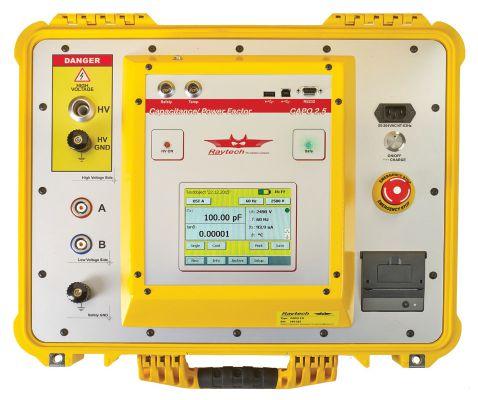
Designed for fast, easy field measurements with Raytech precision and accuracy
• Battery-operated, light weight and portable
• Built-in standard capacitor
• Test frequency 10 Hz – 400 Hz
• Test results easily displayed at 10kV for direct comparison to historical results
• External safety switch for safe operation
• Easy export of results using USB interface
• Built-in printer


BATTERY-OPERATED 2.5kV VARIABLE FREQUENCY POWER
FACTOR TEST SET
CAPO 2.5 TROUBLE-FREE AND BACKED BY OUR 5 YEAR WARRANTY! Toll free 888 484 3779 | Phone 267 404 2676 | Fax 267 404 2685 118 South 2nd St., Perkasie, PA 18944 www.RaytechUSA.com
COMPANO 100 new
Our new COMPANO 100 is a unique, battery operated testing tool for all types of basic testing tasks in electrical energy systems. It’s lighter and easier to use than all of the comparable test sets on the market today.
Numerous applications such as quick wiring, polarity and CT/VT ratio checks, as well as single-phase protection relay testing, are possible with this cost-effective device.
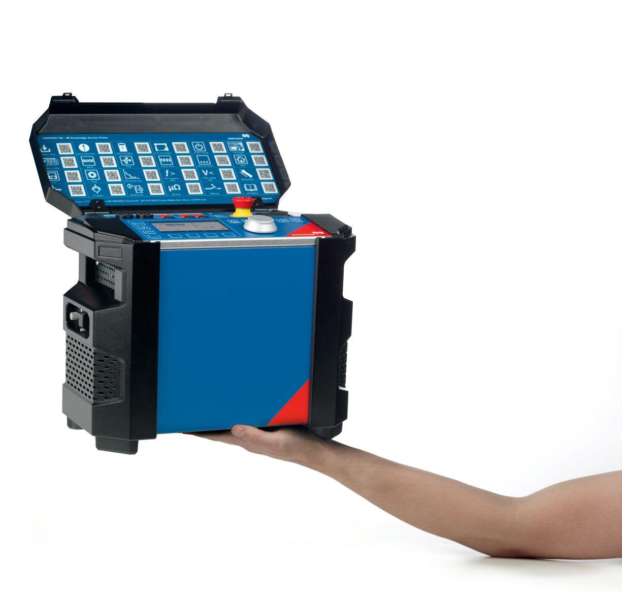
battery operated
www.omicronenergy.com/newCOMPANO100


 James Cialdea, President NETA — InterNational Electrical Testing Association


