



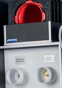








Cable testing and diagnostics are key to maintaining power line reliability and longevity.
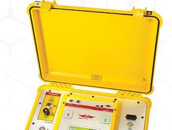
Megger’s industry leading cable test and diagnostic solutions are built to quickly and accurately locate cable issues that others cannot, so you can Power on.

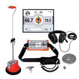
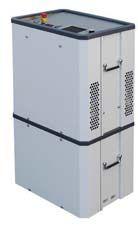
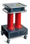


Partial discharge (PD) testing, a new generation of diagnostic testing for medium- and highvoltage underground power cable systems, offers a powerful diagnostic technique capable of identifying problem spots in cables long before they cause an in-service outage or, if used during commissioning testing, detecting problems before the cable is placed into service. This knowledge can then be used to improve system reliability, reduce unplanned outages, reduce emergency call-outs, and help target the most vulnerable cables for replacement while allowing good cables to remain in service.
Jason Souchak, Megger
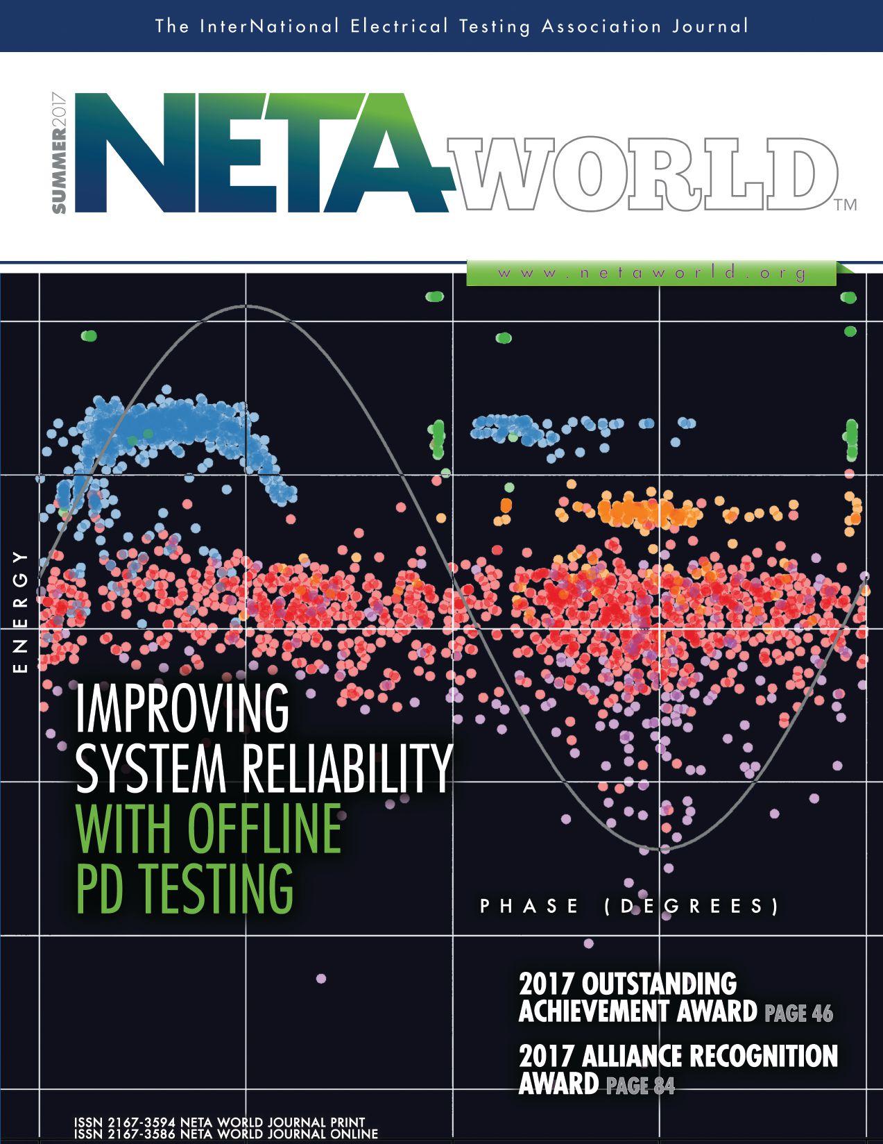
Cover image provided courtesy of O. Perpiñán, M.A. Sánchez-Urán, F. Álvarez, J. Ortego, F. Garnacho, authors of Signal analysis and feature generation for pattern identification of partial discharges in high-voltage equipment, Electric Power Systems Research, Volume 95, February 2013, Pages 56-65, ISSN 0378-7796, https://doi.org/10.1016/j.epsr.2012.08.016.
7 President’s Desk
Ron Widup, Shermco Industries
NETA President
68 Cable Insulation Assessment of a Small M-V Distribution System Using Online Partial Discharge Techniques
Don Genutis, Halco Testing Services, Inc.
76 Non-Invasive PD Testing of Switchgear: Does It Really Work?
William G. Higinbotham, EA Technology, LLC
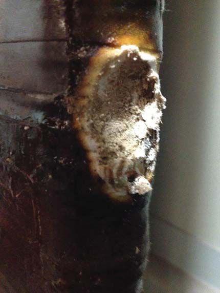
11 NFPA 70E and NETA
Big Changes to 2018 70E Tables
Ron Widup and Jim White, Shermco Industries
18 No-Outage Corner
Using Ultrasonic Instruments in Outdoor Substations
Don A. Genutis, Halco Testing Services, Inc.
22 Tech Quiz
Partial Discharge
Jim White, Shermco Industries
28 Tech Tips
Ground Testing FAQs
Jeff Jowett, Megger
34 Safety Corner
Drug and Alcohol Policy: Is It Up to Date?
Paul Chamberlain, American Electrical Testing Co., Inc.
40 Relay Column
Safety and Its Importance in Protective Relaying
Steve Turner, Electrical Consultants, Inc.
89 On Load Tap Changer Testing —
Dynamic Recording
Raka Levi, Ph.D., AMforum
99 Requirements for Testing Switchgear
Quickly and Economically
Christian Studen, KoCoS Messtechnik AG
116 Fundamental Changes to the Electric Power System Post-2018
Mark Siira, ComRent International
96 ASTM F18, NEC CMP-13, and NFPA 70E Committee Report
Jim White, Shermco Industries
106 ANSI/NETA Standards Update
110 NFPA 70 Code-Making Panel 10 Committee Report
Scott Blizard, American Electrical Testing Company, Inc.
111 NFPA 70B – 2019 Committee Report
David Huffman, Power Systems Testing Company
24 NETA and LBCC Launch New Education Program for Electrical Testing Technicians
26 NETA Welcomes Newest Accredited Company — Electrical Engineering & Service Co., Inc.
46Outstanding Achievement Award – John White
51 PowerTest 2017 Attracts Record Attendance as Industry Gathers for Premier Electrical Maintenance and Safety Conference
84 Alliance Recognition Award – Will Knapek
112 NETA Members and Alliance Partners
Enjoy Peer Discussion and NETA Updates
124 NETA Accredited Companies
130 Advertiser List

Your source for high voltage and electrical
| CALIBRATION | RENTALS


Working with the biggest names in the industry:









A NETA World Journal
Special Publication
SUMMER 2017 04 07 15 17 20 22
A publication dedicated to disseminating information on technical and professional training for the advancement of the electrical power systems industry.
NETA CERTIFICATION: IN PURSUIT OF EXCELLENCE IN ELECTRICAL TESTING
By Dan Hook, Western Electrical Services, and Kristen Wicks, NETAPOWER CABLE OUTAGES AND THE TRAINING CONNECTION
By Alan Mark Franks, AVO TrainingCOUNT THE NUMBER OF Fs
By David Sowers, Knowledge Vine
SAFETY TRAINING IN COMPLIANCE WITH OSHA AND NFPA 70E
By Jim White, Shermco Industries
DON’T FILL IN THE BLANKS
By David Sowers, Knowledge Vine
DIRECTORY OF TECHNICAL AND PROFESSIONAL TRAINING


NETA was established by a group of individuals who collaborated because they realized that quality assurance requires a team of people working toward the same goal, with a shared vision, and a well-defined outcome. These people believed that the best way to provide safe, reliable power was to bring a third-party, independent perspective to the table along with the architects, engineers, manufacturers, installers, and facility management to help assure that all facets of the system work together as designed. The individuals responsible for providing that perspective must be fluent in all these spheres of responsibility, but also must be knowledgeable in very specific technical areas across all manner of equipment and systems, individually and as a whole. This realization was eventually quantified in the ANSI/NETA ETT, Standard for Certification of Electrical Testing Technicians

Diversity in collaboration helps assure that stakeholder voices are heard and represented in the final product.
While the role of these uniquely qualified individuals was not officially codified by NETA until 2000 when the ANSI/NETA ETT Standard for Electrical Testing Technicians was first published as an American National Standard, NETA had been certifying electrical testing technicians for many years prior. The most current edition of the ANSI/NETA ETT is the 2015 edition, slated to be released as a revised American National Standard in 2018. It will consider the work achieved over the past two years during the certification exam restructuring, but will stay true to the core tenants of the document. To learn more about the specific requirements for NETA Certification and to download a complimentary copy of the current ANSI/NETA ETT, please visit NETA’s website at www.netaworld.org

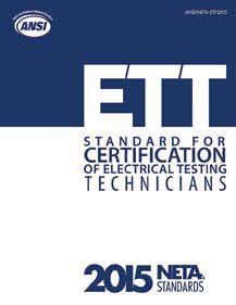
standard to which all NETA Certified Technicians are held.
Like most things, NETA’s certification program has evolved and expanded as certification-industry best practices were established and revised. One thing that has remained constant throughout the history of the program is a commitment to safety, public protection, and assuring that the content is technically relevant. Each Technical Exam Committee Chair and the Exam Committee they lead has raised the bar in pursuit of that moving target: excellence.
The road to excellence never truly ends. Loftier heights are achieved, new goals are set, but the path to each is paved with routine. Routine preventive maintenance and improvement is critical to the health and safety of every system, whether it is an electrical power

Excellence is a moving target; never stop climbing.
system or a certification exam designed to establish minimum competency requirements for electrical testing technicians. NETA has established an ongoing maintenance program for certification exams to assure that resources are allocated to this program on an ongoing basis in support of the growing population of individuals seeking certification.
The most recent round of maintenance to NETA’s certification program began in 2015, with the launch of a project aimed at elevating the quality of NETA’s certification exams for Level 2, Level 3, and Level 4 Certified Electrical Testing Technicians. NETA contracted with a third-party exam development and administration company, Schroeder Measurement Technologies, Inc., to provide an assessment of the existing certification program and make recommendations for improving it through a job analysis survey, exam item (question) writing, form development, and standard setting. This project marked the largest initiative in the history of the association in terms of fiscal and human resources.

Proactive planning assures a solid certification program now, and into the future.
The result of this collaboration is a psychometrically sound set of certification exams that are in alignment with current industry standards and practices. Psychometrics is the field of science associated with the development of instruments (such as examinations) that measure knowledge, skills, and attributes (KSAs) — essentially measuring what is in someone’s mind. This measurement is a critical component of a strong
certification program, which also includes components like relevant pre-requisites for training, education, and experience, as well a recertification mechanism to assure that certified individuals are keeping pace with emerging technologies and revised or new industry standards and best practices.
NETA Accredited Companies are tasked with helping their technicians prepare for these certification exams over the course of their careers. Many NETA Accredited Companies have internal training programs designed to assure that their technicians meet the prerequisites and have the necessary field experience to succeed on the exams. Industry partners offering training are also heavily relied upon to provide the technical expertise in certain subject areas where practical and book-based knowledge is required. One of the most important tools for preparation is the detailed content outline that functions as the blueprint for the certification exams. This document is available on NETA’s website and should be used in conjunction with ANSI/NETA ETT when designing an exam preparation program.


Overall, what NETA’s Certification Program means for NETA, NETA’s Accredited Companies, and the industry at large is that now, more than ever, specifying NETA means specifying quality, safety, and reliability. When electrical components and systems are tested as specified in the ANSI/NETA standards by a Certified Electrical Testing Technician, that work is being performed by a specialist who has demonstrated that they have the knowledge, skills, and attributes needed to perform that work accurately, safely, and in accordance with industry standards.
No matter who you are, or what your responsibility is in the electrical testing industry, remember this helpful hint: If you are pursuing excellence, keep NETA in the equation.

DAN HOOK is the Executive Vice President in charge of Business Development at Western Electrical Services, where he previously held Field Service Engineer, Sales Engineer, and Chief Operating Officer positions. He has been in the industrial electrical industry for over 20 years and has U.S. Navy and civilian experience. Currently, he focuses on strategies to grow three company divisions and manages employee development, trade association affiliations, and corporate-level sales efforts. Dan holds a Master’s degree in Electric Power Engineering from Rensselaer Polytechnic Institute and maintains his professional engineer’s license in Washington, Utah, Arizona, and Oregon. He earned an MBA in 2012 from Pacific Lutheran University with a concentration in Entrepreneurship and Closely Held Businesses. Dan is a certified NETA Level IV Technician as well as a NICET Level IV in Electrical Testing Engineering Technology. He is also a member of the NETA Board of Directors, a member of the NETA Standards Review Council, and is the NETA Certification Exam Committee Chair.
KRISTEN K. WICKS is the Technical Services Director for NETA, the InterNational Electrical Testing Association, and has been supporting NETA’s technical efforts since 2006. A summa cum laude graduate of the Honors College at Florida State University, Kristen serves as the liaison to NETA’s Standards Review Council and collaborates with NETA’s Board of Directors, committees, and subject matter experts to assure that NETA’s programs, products, and services are aligned with its mission and vision, are technically substantiated, are in accordance with other industry standards, and are stylistically and grammatically correct. Kristen manages the association’s technical portfolio, which encompasses programs and projects such as the Technical Certification Examination program, Continuing Technical Development program, NETA Approved Military Organization (NAMO) program, and NETA’s American National Standards. Kristen also contributes to NETA’s marketing and outreach initiatives, training program development, NETA World Journal, and supports NETA Accredited Companies in leveraging and implementing the ANSI/NETA standards in service to their electrical power systems clients.

Much has been said about the aging condition of power cable installations in the United States. Cables can be categorized as service-aged solid dielectric, service-aged laminated (PILC), or cables of more recent design and installation. Much has been learned about the causes of cable outages, and recent studies indicate that even with design issues in early cables, the major cause of these outages can be related to poor quality during the installation process, either in cable installation, termination, or splicing.
The National Electric Energy Testing Research & Applications Center (NEETRAC) documents that approximately 50 percent of cable outages can be directly attributed to poor workmanship during cable installation, splicing, and terminating. As a result of the failure analysis studies conducted by NEETRAC, it can be concluded that there is a significant connection between cable outages and a lack of training in cable installation, splicing, and terminating of medium-voltage cables. As well-stated in “Cable Accessory Failure Analysis,” presented at the NEETRAC Fall 2010 ICC Educational Session: “All evidence points to improved training
as the single most cost-effective means of improving system reliability.” Figure 1 represents the process of improving system reliability through failure analysis, training, and skill certification.

First, consider the issue of failure analysis. A process of root cause should be employed to all cable outages to determine the primary cause of failure. If the failure is due to a product quality issue, the manufacturer is likely involved, and these types of issues normally include a significant timeline. Redirection in purchasing and product approvals may be necessary to offset any further outages due to the use of the product.
More often, the root cause can be identified as a workmanship issue, either in cable installation, splicing, or termination. Often, imminent cable failure is due to tracking caused by inadequate preparation and cleaning during the splicing process. This is one of the many common modes of failure experienced by utilities today.

Tracking leads to imminent cable failure and is caused by inadequate preparation and cleaning during the splicing process.
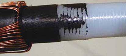
Improper cable preparation leaves semi-conductive insulation shield material that will result in cable failure.
Another example of improper cable preparation is where tool settings are not adequate for the semicon stripping process, which will certainly result in failure.
In many cases, the results of improper cable installation make it somewhat difficult to get to the bottom of what actually caused the initial failure. With these issues in mind, it is imperative that a comprehensive cable failure analysis program be in place to determine root cause, thus ensuring that costly failures can be eliminated.
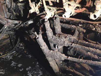
Improper cable installation caused cable failure in a manhole installation.
Failure analysis certainly will identify poor workmanship that leads to failure. Identifying these types of issues can provide invaluable insight concerning the training of workers involved in installation, splicing, and termination of cable systems.
Training certainly will have an impact on system reliability, provided that the proper skills in cable
handling, preparation, splicing, and terminating are imparted to the worker. This is a craftsmanship issue that requires a detailed understanding of medium-voltage cable construction as well as the use of proper procedures and tools. Historically, these craft skills were taught in an on-the-job (OJT) fashion with apprentices working under the watchful eyes of skilled craftsmen who had years of cable experience. These mentors grew up in the early stages of the cable industry and acquired their skills over a significant timeline that coincided with the boom of the power cable industry. As Baby Boomers are leaving the workplace, so are most of these mentors and, along with them, many years of cable splicing and terminating craft skills.
OJT training philosophies need to be supplemented with more formal training with finite objectives and proctored labs where workers not only learn the technologies, but also the craft skills necessary to perform medium-voltage cable work. The implementation of formal cable training greatly reduces the time it would take to gain this experience on the job. By implementing formal training, the quality of instruction can be monitored to ensure that all trainees get the same information and apply the knowledge in controlled lab exercises proctored by experienced instructors; this ensures that the mentorship is complete. The impact of high-quality training where workers demonstrate the learned skills has a definite impact on the future quality of maintenance and new installation work.
Training can be outlined in four basic areas of craftsmanship:
■ Cable installation and handling
■ Cable preparation and tools
■ Cable splicing
■ Cable termination
Many cable failures occur because of mishandling the cable during installation. Issues such as exceeding the bending radius, excessive tension, excessive side-wall pressure, cuts, abrasion, and damage to the jacket can lead to cable failure. Much of this damage goes unrecognized, as many current acceptance testing methods will not identify the damage unless it is catastrophic in nature. In short,

It often takes a significant amount of equipment and rigging to install power cables.
these damages go unnoticed — sometimes for years — and ultimately lead to failure and a premature shortening of cable life.
Cable handling, specifications, rigging, application of lubricants, conduit fill, etc., are necessary components of training that installers need to ensure proper installation of medium-voltage cables. It often takes a significant amount of equipment and rigging to install power cables.
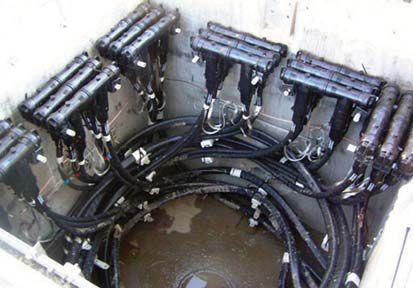
A cable failure in a medium-voltage cable installation like this one could potentially cause catastrophic damage to other feeders in the same vault.
Cable handling and installation take on significant meaning when considering an installation that requires a high level of craftsmanship. A cable failure in this type of installation could potentially cause catastrophic damage to other feeders in the same vault. Every aspect of the need for a quality cable installation is apparent.
A large number of cable outages can readily be attributed to how the cables were prepared for splicing or terminating. Most cable manufacturers
do not provide explicit instructions on how to prepare the cable; rather, the instructions specify the dimensions required in the preparation. Most manufacturers have a disclaimer that reads as follows: “Prepare cables according to acceptable industry practices.” Therein lies the ambiguity, as no specific guidelines are provided as to methods or tooling other than tool manufacturers’ instructions on how to use their specific tools.
Procedures vary widely in the U.S. and, in many cases, there are no specific requirements. Most splices and terminations come in kit form today, and the assumption is that all the instructions needed are in the kit. This is a fallacy, as there are no specific instructions on cable prepping procedures and techniques, not to mention appropriate tools. Everyone would agree that the tool illustrated on the left in Figure 2 would not be appropriate for cable preparation. On the other hand, some may believe that the tool on the right in Figure 2 would be an appropriate tool for preparing a cable. Box cutters and other razor-blade knives have contributed significantly to cable failures in the U.S. One could argue that in the hands of a well-trained splicer, the box cutter would work. The better argument is that the appropriate tool is one manufactured for cable prepping, and that is the tool that should be in the hands of a welltrained splicer.

There are many tools available for any cable splicing or terminating project. Cable tool selection is a responsibility of the end user and should be based on reliability, ease of use, and repeatability of the task being performed. Adjustment and maintenance of the tool is as important as the tool itself. Keep in mind that improper use of the tool or a maladjusted tool could prove detrimental.


The use of appropriate tools alone does not ensure quality. Training in cable construction, dimensions, materials, care, and use of appropriate tools, along with environmental controls, are needed to equip the worker with the the skills to complete a quality splice or termination.
Let’s consider the technologies available today to splice medium-voltage cables. The major technologies employ products of tape, heat-shrink, molded, cold-shrink, resin, and a specialized group of products for paper-insulated lead cable splicing. Technologies are also available where the outside diameter of cable is a significant issue or where flexibility is needed, such as cables for dredge or mining operations. All of these products require special skills for the splice to meet the quality standards required for the installation.
There are literally hundreds of individual products and kits that cover the scope of medium-voltage cable splicing. Mastering the technologies required to move efficiently within the medium-voltage cable field requires a solid base of cable understanding. The use of specialized tools, attention to detail, preciseness, and other skills are required to perform quality splicing with the array of cable and ancillary products available today. The following introduces examples of several technologies used in industrial and utility cable systems with comments identifying certain skills needed to perform quality work.
Tape splices can be completed in various levels of voltage and configurations. Instructions are normally very detailed, and several different types of tapes are used to complete the splice. Tapes can be ordered in kit or bulk quanities depending on the end user’s needs. These types of splices define the craft skills needed to perform medium-voltage cable splicing. Properly completed, this type of splicing will perform well for many years.

Some of the critical points that must be employed by the splicer include:
■ Cable prepping dimensions are critical.
■ Cable must be kept extremely clean and splicer cannot handle insulation surfaces.
■ Proper tape must be used to replace cable construction.
■ Thickness of materials is critical, especially the insulation layers.
■ All tapes are assembled in a half-lapping process that has to be learned.
■ Tension and tape elongation is critical for proper performance of the splice.
■ Moisture proofing, grounding, shielding, rejacketing are all part of the technology.
■ The variables in maintaining tension, precise intepretation of instructions, and the time it takes to assemble this type of splice make this technology somewhat difficult to master.
Modern material science should be credited for the development of various types of heat-shrink materials. These products are available in multiple voltage levels and numerous cable configurations. Since these products use heat from a torch for assembly, a multitude of precautions and safety procedures must be implemented by the splicer. Work in confined spaces, flames, hazardous location work, and the general requirements for using flames are skills required of the splicer.
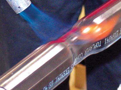
Since heat-shrink splice products use heat from a torch for assembly, a multitude of precautions and safety procedures must be implemented by the splicer.
Cold-shrink splice products have entered the product market and are being extensively used in the wind power sector. These splices are normally used on large conductor, jacketed concentric cables and can present some difficulty in installation in direct-bury trench installations due to the environment. As mentioned previously, prepping, dimensions, assembly, and clean insulation surfaces are critical to the reliability of all splices. Since many of these splices are at the 35 kV level, environmental issues during construction are main contributors to failure.

Molded products have increased in use due to the ease in assembly these products provide; they are the product of choice for underground residential cable installation. These products come in all mediumvoltage ranges and can be slip on, bolt on, or a combination of technologies to accommodate the splicing configuration desired. The cable prepping and adherence to specific dimensions are critical for this type of product. The tracking surfaces provided by these splices are usually short, requiring the surface to be extremely clean during installation.
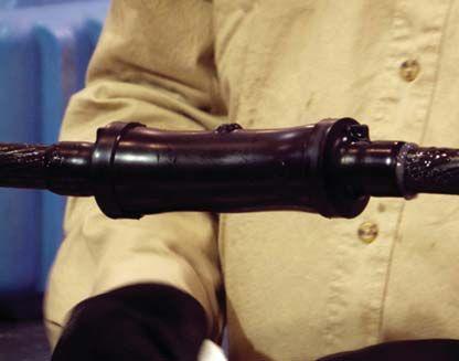
Resin splices are not the most common type of splice used in the U.S., but do have an application. Assembly, prepping, sealing, and mixing the compounds become critical issues for the assembly of this type of splice. Many failures occur when voids are left in the filling process, producing partial discharges that ultimately lead to failure.


Splicing PILC cable should only be undertaken by techs with significant training and experience with this technology, which is cable splicing in a totally different dimension. Probably the oldest splicing technology in the U.S., it is considered a craft of its own. The largest myth today is that lead cable is gone; there are many miles of lead cable in large metro installations. The main issue today is finding techs who have the experience to splice the cable in the numerous configurations required. With companies transitioning from lead to other cable insulations such as poly or EPR, additional technical issues present themselves. All manner of mistakes can be made that would affect the integrity of the splice, not to mention the safety issues with handling molten lead. Significant tooling and knowledge are required.
Terminating medium-voltage cables presents similar technical issues as performing cable splicing. The same cable prepping, cleaning, assembly, and
connecting technologies are present and require a skilled tech. As can be expected, there are fewer cable termination failures in the U.S. than failures in cable splices. This is due to the environmental issues, difficulty in assembly, and numerous opportunities for error that present themselves during the splicing operation. With that said, a termination being installed outdoors in inclement weather may also present the same difficulties.
What follows are examples of similar products for terminating medium-voltage cables. The most common failure point in cable terminations is the failure to control the electrical stresses created by terminating the insulation shielding. Moisture seals are necessary for terminations installed in outdoor applications or in environments where contaminants might enter the termination.
Taped terminations require a significant amount of time like hand-taped splices. A taped termination, thought of as half of a splice, requires specific dimensions for tape thicknesses to form a stressrelief cone. The electrical stress must be controlled to ensure there is no excessive electrical stress on the insulation at the point of termination of the insulation shielding. This construction results in the creation of a geometric stress cone as illustrated in Figure 3.

Terminations made of high-performance heatshrink materials (Figure 4) are currently available for all medium-voltage cables. As in heat-shrink splices, care in the use of torches must be exercised. One of the significant issues using a torch is that the

technician must ensure the entire termination body has been sufficiently shrunk, and there are no voids in the termination.
The advent of cold-shrink products that can withstand severe environmental and electrical conditions along with ease of construction have enhanced their use in the utility market. As with all previously described methods, the cold-shrink terminations must be installed with precision and adherence to approved cable preparation techniques.
Molded and modular terminations are used in a variety of applications including utility, industrial, and commercial. The terminations are designed to address a host of installation configurations
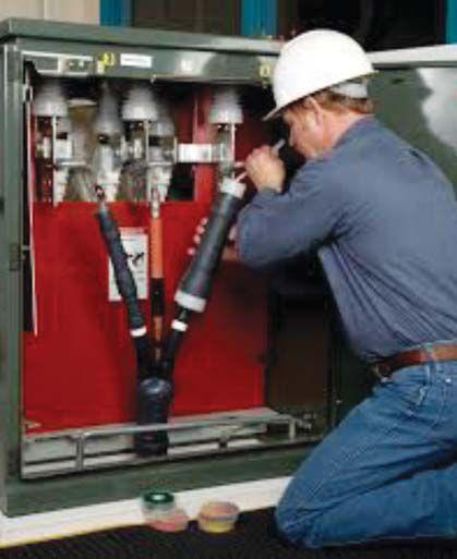
A three-phase cable installation using cold-shrink terminations requires great precision in installation.
and equipment specific termination requirements. Most of the failure issues with molded products are a result of prepping mistakes and a lack of clean assembly coupled with issues in torque and connector crimping. Cable alignment and external physical stress also contribute to failure.
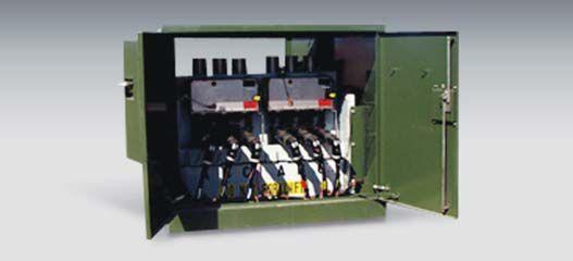
Molded and modular terminations are used in a variety of applications including utility, industrial, and commercial.
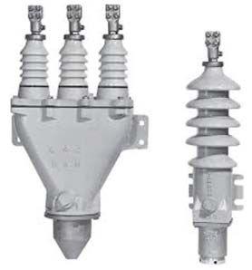
Figure 5: Paper-insulated lead cable terminations can use heat-shrink or cold-shrink technology.
Previous methods of terminating PILC cables consisted primarily of the porcelain-insulated type (Figure 5). Today, PILC cables can be terminated by using modern technologies of heat-shrink or cold-shrink technology. Only well-experienced technicians should undertake the termination of PILC type cables.
There are literally hundreds of examples of mediumvoltage cable splicing and terminating that could illustrate different challenges to the cable splicer. The examples in this article promote the understanding of
the different skills a technician must have to perform reliable cable splices and terminations using an array of technologies. Key to the current status of cable splicing in the U.S. is the migration of experienced technicians away from the workforce, either by retirement or being promoted to supervisory-level positions of leadership that take them away from the everyday, on-the-job mentoring necessary to transfer the splicing and terminating skills needed in today’s cable environment.
Employers must consider either more formal apprentice programs with documented mentorship or formal training with clear objectives and proctored activities ensuring trainees demonstrate their skill. Either of these methods should lead to certifying of the employee’s skills and should include documented demonstration of successful splicing and terminating craftsmanship.
Further certifications or re-certification may be necessary based on evidence obtained through failure analysis as indicated in the model in Figure 1. Remember, you can only expect what you inspect. Many of the cable outages today could have been averted by simply having a quality inspection program in place to ensure installations were being completed within guidelines.
Project manning and time constraints on many installations create the “get in, get it done, and get out” philosophy, and cable terminations and splices are usually the last part of the installation. The sense of urgency of project completion can easily be directed

at the cable splicer. A skilled, certified cable splicer understands that the quality of the cable installation is in his/her hands and will take all necessary steps to provide reliable terminations and splices that will last the duration of the cable’s life span.
To ensure a reliable cable installation, have competent personnel who are trained, have demonstrated splicing skills, and have attained a level of certification that will ensure a quality installation is achieved.
Cable prepping is the basis for all medium-voltage cable terminations and splices. Significant training in the use of special tools and materials with emphasis on following instructions is necessary.
Unlike the assembly of various products that require a more specialized understanding of the process, splices and terminations require the same basic skill in prepping medium-voltage cables. Failures in cable splices contribute to a large portion of cable outages in the U.S.
Validation of a cable splicer’s skill is necessary to ensure quality installations and a reliable cable future. Certification and recertification ensure that the splicer has demonstrated the requisite skills and is maintaining that skill level.
With the high-quality cable products on the market today, we must conclude that the future of cable reliability is in the hands of the cable splicer.
ALAN MARK FRANKS is a Senior Safety Specialist at AVO Training Institute. He has over 48 years in the electrical utility industry with an extensive background in electrical safety and power distribution. Mark was instrumental in developing the pre-OSHA Electrical Safety Audit for the industry and the conducting of on-site audits of facilities, installation of electrical equipment and systems, safety procedures, and training records and programs, all based on OSHA and NFPA regulations and other industry consensus standards. He has been an authorized OSHA Instructor for all general industry and construction regulations. Mark is a certified fiber optic technician, certified fiber optic instructor (#839), and a member-in-good-standing of the Fiber Optic Association. He participates in numerous associations including NFPA 70E 2000 alternate committee member, International Association of Electrical Inspectors, American Society of Safety Engineers, National Cable Splicer Certification Board, and American Society for Testing and Materials. Mark has provided electrical safety training and performed electrical safety audits for general industry, utilities, and mines both underground and surface. He has instructed all aspects of power cable splicing, termination, testing, and fault location for 25 years and has been instrumental in developing the AVO Training Institute Cable Technician Certification Program.
Self-checking test: Quick! Count the number of times the letter “F” appears in the following sentence. Take your time but only count once.
“Finished files are the result of years of scientific study combined with the experience of years.”
What answer did you get? The most common responses are 3 or 6. If you answered 3, you have probably re-read the sentence looking for those three missing letters. If you answered 6, you may be feeling a little self-satisfied, but you are also wrong. Technically, the answer is zero. Don’t worry, I’ll explain.
Did you answer three? Here’s why you got it wrong. Your brain typically does not recognize the letter F in the word “of”. This could be for one of two reasons. First, the letter F generally sounds as you would expect, like in the words “fox” or “fast” or “finished files.” However, in the word “of,” it has a “v” sound as in “ov”. This pronunciation causes the brain to fail to immediately recognize the
letter because it doesn’t correspond with the sound we are accustomed to hearing form the letter F.
Second, since “of” is a common preposition and not a lexical word, we may just skip right over the word as we read in our heads. For years we have seen prepositions, conjunctions, and other grammatical words and have conditioned ourselves to give them little thought as we move quickly to the lexical words, which reveal meaning or intent. We tend to read in shorthand to get straight to the point, having little time for bothersome little words like “of”.
So, even though you assumed there was some sort of gimmick, and you were asked to self-check, you still probably missed three of the letter Fs in that sentence. Don’t feel bad. The high and mighty folks that answered six are about to get their comeuppance.
Did you answer six? OK, let’s assume for the sake of argument that you read the sentence only one time and came up with six for an answer. There are also several explanations as to how you came to that answer, ranked in order of least to most plausible.
■ You are a super genius who should rightly direct your scorn toward the masses of disappointing wastes of perfectly good oxygen — everyone else.
■ You read the sentence twice and really slowed down the second time because three seemed like too easy of an answer.
■ You have seen this little mental gymnastic exercise before, so you were keyed in to the potential trap already.
■ You slowed down and focused on reading each word.
■ You’re lying.
So, if you answered six, you are probably feeling superior to the people who answered three while simultaneously wondering what I meant earlier when I stated that technically the answer is zero. Here are the directions again:
Self-checking test: Quick! Count the number of times the letter “F” appears in the following sentence. Take your time but only count once.


When it’s time to selfcheck, take the time to do it right. When you’re given vague or interpretive guidance, ask for clarification.
Be focused and methodical. Second, look at the structure of the directions. The structure led you to think, “He’s talking about the sentence which is in bold or standing alone.” The structure encourages you to move past the instructions to the bold face type and thereby fail to read the instructions critically. My vague or interpretive guidance set you up for error.
Here’s the takeaway. When it’s time to self-check, take the time to do it right. When you’re given vague or interpretive guidance, ask for clarification. When you recognize an error trap, get it fixed. Now that we are growing as an organization, here are your instructions for the next self-checking test:
Technically, the “following sentence” referred to by the directions is “Take your time but only count once.”— not the sentence that begins with “Finished files…”. As you can see, the “Take your time…” sentence has zero Fs in it. If you caught that one, then try this out on your friends at your next Mensa meeting. Don’t feel bad if you didn’t catch the nuance because you were set up to make that mistake by vague guidance.
Look at the directions again. First, I frame it as a self-checking exercise, then I immediately put time pressure on you by saying “Quick!” and then I tell you to “Take your time.” So which is it? Are you supposed to hurry or be more methodical? Just to clarify, we are a human performance company. Always take a moment to self-check.

■ Step 1: Count the number of times the letter F appears in the sentence in Step 2. Caution: Operating experience has revealed that the letter F is often overlooked in the word “of”. Be aware of each occurrence of the word “of” and the potential to miss the letter “f” in it.
■ Step 2: “Finished files are the result of years of scientific study combined with the experience of years.”
■ Step 3: Record your answer with a newfound sense of confidence achieved by only those who have been given clear, understandable guidance.
How many of you could come up with the intended correct answer of six? We can all apply for Mensa membership now.
DAVE SOWERS is Director of Performance Improvement at Knowledge Vine LLC, a human performance training and consulting organization. A veteran of the U.S. Navy’s nuclear power program, he has more than 25 years of industrial experience gained through his work in the military, semiconductor manufacturing, commercial nuclear power, and hydro-electric generation. Dave holds both B.S. and M.S. degrees in Management from Troy University and a M.S. in Emergency Management and Homeland Security from George Washington University.
Providing employee training can be a very expensive proposition. It includes cost of the service, travel expenses, and shipping course materials, as well as employee time, benefits, and possibly overtime — all of which add up quickly. However, training must be provided, as both OSHA and NFPA 70E mandate demonstration of certain skills and knowledge. As an example, the definition of a qualified person in 29CFR1910.399 states:
“Qualified Person. One who has demonstrated skills and knowledge related to the construction and operation of electrical equipment and installations and has received safety training to identify and avoid the hazards involved.”
With the costs so great and the scheduling of employee time often complex, it is not difficult to understand why some companies take a check-the-box approach to training. These are the companies that will conduct training just to show that it was done, the old “looks good on paper” thing…or does it?
To understand the requirements for training and auditing, responsible training managers and
company leaders who have the authority to enforce training policies should read and understand 29CFR1910.332 and .333, as well as NFPA 70E Sections 110.1, 110.2, and 120.2. The requirements of training qualified persons are substantial. My experience is that most workers who initially attend safety programs are not qualified persons. They have the technical expertise (technicians, Master Electricians, electrical engineers) but lack the skills and knowledge to properly conduct a risk assessment, select the correct PPE, or interpret arc-flash hazard warning labels. Meeting the mandated training requirements requires a multistep process; it is not a one-and-done thing.
To be a qualified person, that person must have the technical skills and knowledge related to their job. Journeyman, Master Electrician, and NETA Certified Technician all demonstrate technical skills and knowledge, and many people consider them to be qualified because of those skills and knowledge. However, OSHA and the 70E require more. There must also be demonstrated safety skills and knowledge.
A qualified person must be trained on how to apply the OSHA and NFPA 70E requirements in their job on a practical level. That means being able to accurately perform a shock and arc-flash risk assessment; select, inspect, wear, and care for arc-rated clothing and PPE; and understand the limitations and indications of the test instruments being used, as well as how to inspect them before use to determine if they are safe to use. This is by no means a complete list. The requirements are lengthy. Read NFPA 70E Section 110.2 to get a better grasp of why qualified electrical worker training is not a one-day or even a one-time training proposition.
Qualified person training also requires learning while on the job (OJT). This training is essential because it covers safe operation and any changes in the equipment, procedures, or safe work practices related to their job-specific work environment. When performing OJT, be as straightforward as possible so there are no misunderstandings.
If you’re a box-checker, stop reading; your feelings are going to be hurt. A Louisiana facility hired a contract instructor for NFPA 70E training. For eight hours, the NFPA 70E contract instructor read the 70E to the attendees, straight out of the book, word for word. Box checked! Maybe not. As a follow-up to the training, the facility safety manager had conversations with the attendees; when he realized the recent NFPA 70E training was inadequate, Shermco Training was called in to do proper 70E-mandated training. It took more than two days, but the facility attendees gained the safety skills and knowledge to perform their work tasks safely. Neither OSHA nor the 70E require a contractor to be hired to conduct training, nor is classroom training alone always effective. The combination of classroom and field training is often the best option.
Initial safety training for qualified persons also requires a demonstration of skills. This means documented, hands-on lab sessions that specifically target mandated safety-training skills. NFPA 70E and OSHA call for these three lab sessions:
1. Determining Nominal Voltage
2. Selection of Appropriate PPE
3. Determining the Absence of Voltage
However, there’s more to it than that. To determine nominal voltage, that person must first understand how to select and use each type of test instrument; know how to inspect it for safe use (including how it might provide false indications); understand the limitations and specific risks that type of instrument might pose, and know how to use it in a safe manner; and be able to accurately interpret nameplate information or single-line diagrams to determine the nominal voltage.
The other two labs include more extensive training requirements beyond the obvious. A quick look at the 29CFR1910.399 definition of a qualified person states this clearly. It is also required in 1910.332 and 1910.333. Bringing in a well-qualified instructor to conduct the training can provide insights that someone in-house may not have.
Providing “blah-blah” training — especially as initial training to qualified persons — is almost worse than no training at all. It conveys a message that employees have no real value, that no one really expects them to follow the training given, and that it is a waste of time. They are absolutely correct. Save your time and money because, if an incident occurs and OSHA investigates, check-the-box training won’t help your case at all. Review OSHA’s Letter of Interpretation dated November 24, 1994 (see http://bit.ly/2paotF1). In this letter, OSHA clearly states that computer-based training is valuable — but not sufficient — to meet OSHA’s training requirements. The letter adds, “Equally important is the use of hands-on training and exercises to provide trainees with an opportunity to become familiar with equipment and safe practices in a nonhazardous setting.”
Companies with a good safety culture look for effective safety training. This safety culture is generated from the top down with real commitments to safe work practices and a desire to protect their workers.
NFPA 70E does not mention refresher training, but it requires retraining every three years. That retraining should cover any changes in the company’s electrical safety program, work procedures, work practices, policies, NFPA 70E requirements, and any OSHA regulatory requirements that pertain to their jobs. It does not require a repeat of the initial training that they should have received. There is a lot of misunderstanding in the industry about this. The duration of the retraining is determined by the amount of information that employees need to receive. In most cases, a one-day training program is sufficient, but it may take longer, especially if there are new work practices or procedures to cover. Retraining is also required when new equipment with different operating procedures is installed, when audits disclose that employees are not following procedures or policies, and if the employee must perform an unfamiliar task.
For initial training of qualified persons, OSHA and NFPA 70E both require a demonstration of skills and knowledge. The knowledge component can be partially satisfied by a test at the completion of
the training program. Demonstrating skills requires a hands-on lab session. Some training companies advocate that their customers can confirm the required skills on a job or at a later date. Don’t drink that Kool-Aid. In 99 percent of the cases, that never happens. It sounds good and people may have the best intentions, but do the hands-on demonstration of skills when the instructor is at the worksite. The lab sessions must be documented. Joe Pipkin, OSHA’s former representative to the NFPA 70E Committee, once stated, “If you don’t document it, you can’t prove you did it.”
Lab sessions must be documented and must be pertinent to the demonstration of skills required. Looking at NFPA 70E 110.2:
(D) Employee Training.
(1) Qualified Person. A qualified person shall be trained and knowledgeable in the construction and operation of equipment or a specific work method and be trained to identify and avoid the electrical hazards that might be present with respect to that equipment or work method.
(a) Such persons shall also be familiar with the proper use of the special precautionary techniques, applicable electrical policies and procedures, PPE, insulating and shielding materials, and insulated tools and test equipment. A person can be considered qualified with respect to certain equipment and methods but still be unqualified for others.
(b) Such persons permitted to work within the limited approach boundary shall, at a minimum, be additionally trained in all of the following:
(1) Skills and techniques necessary to distinguish exposed energized electrical conductors and circuit parts from other parts of electrical equipment

(2) Skills and techniques necessary to determine the nominal voltage of exposed energized electrical conductors and circuit parts
(3) Approach distances specified in Table 130.4(D)(a) and Table 130.4(D)(b) and the corresponding voltages to which the qualified person will be exposed
(4) Decision-making process necessary to be able to do the following:
a. Perform the job safety planning
b. Identify electrical hazards
c. Assess the associated risk
d. Select the appropriate risk control methods from the hierarchy of controls identified in 110.1(G), including personal protective equipment.
And yes, all this is needed to be a qualified person. OSHA refers to single-point responsibility — that is, the employer will be at fault, period. If the employer can show that the injured person was properly trained, was provided with the proper PPE, and demonstrated the skills and knowledge to be considered qualified, OSHA may determine the employer did all it could do. However, that’s a high bar to leap over.
If OSHA cites companies when an employee is injured regardless, then what good is it to provide the training and PPE? The short answer is that it could be the difference between a willful citation and a serious citation. A willful citation is evidence of negligent behavior, which leaves the company open to legal action and could void their Workman’s Compensation protection. This is never a good situation. It is always best to show good-faith effort, reduce the potential consequences of an incident and, most important, assure that your employees and co-workers are as safe as possible while performing potentially dangerous tasks.
JIM WHITE is the Training Director for Shermco Industries. He is the Principal Member of the ASTM F18 Electrical Protective Equipment for Workers Committee and the NFPA Recommended Practice for Electrical Equipment Maintenance Committee (NFPA 70B). He represents NETA as the Principal member of NFPA 70E and is NETA’s Principal member on NEC CMP13. Jim is an IEEE Senior Member and was Chairman of the IEEE Electrical Safety Workshop in 2008.
As a supervisor, do you send messages that are open to interpretation? Do you allow others to fill in the blanks with their definition of what good looks like? Can you be upset when someone fails to read your mind and performs a task differently than you imagined? You have a wealth of experience, much of it paid for in bumps, bruises, and blood. You’ve learned lessons the hard way. Your workers don’t have the benefit of that experience and aren’t likely to make the same choices without specific guidance.
Early in our marriage, my wife gave me the vague guidance to “pick up some groceries” on my way home. This seemed like an easy enough task; after all, I had been feeding myself for years. We need food, and the grocery store has food for sale. The path for success seemed pretty well laid out.
I put great thought into what made its way into the cart. I got the basics such as bread, milk, and eggs, and rounded out the cart with other reasonable options. Oreos? I’ve seen her eat Oreos before — but wait! Generic Oreos are half as much; grab two bags. I am crushing this grocery shopping thing. When we unloaded bags of bachelor staples like chicken wings, nachos, and Capt’n Crunch, my wife realized further trips to the grocery store required specific guidance or supervisor engagement. Her idea of “mission accomplished” was vastly different from mine.
How did a task that seemed so simple go so wrong? Why didn’t her expectations align with my understanding? Was this a failing on my part or was poor communication to blame? Could she really be mad when I filled in the blanks with my best guesses?
There’s a reason you’re in charge. You have the experience and subsequent judgment to choose the safest, most efficient option for getting a job done. It’s your job to narrow the number of options for your team so they can avoid the hard lessons you had to learn. In all likelihood, you also had a supervisor who at one time or another muttered “What were you thinking?” How great would it have been if they had been specific in their expectations and saved you from having to fill in the blanks with your best judgment?
Nobody comes to work thinking, “I’m gonna mess stuff up today.” Workers try their best to perform the tasks given to them by drawing from the information provided and then filling in the gaps with their best judgment, which does not include the supervisor’s experience. Don’t leave blanks for your workers to fill in. It bears repeating, your workers are not you. They are well-intentioned, independent-thinking people, but without your specific guidance, they are going to look at all the options and choose the one that makes the most sense to them. If you can eliminate most of these options, the chances of them doing the task as you anticipated increases greatly. Be complete and specific on how to do the job successfully and safely. It’s not micro-managing — it’s establishing standards and expectations to set them up for success.
A supervisor told me about instructing a new loading dock worker to clean up an outside dolly so it could be used to move office furniture. He wanted it to have a fresh coat of paint but didn’t want the wheels or plastic handles to get paint on them. He told the worker, “Tape up the dolly and spray paint it red for use in the office building.” When the supervisor returned, the dolly was completely wrapped in tape and the tape was painted red. To this supervisor’s credit, he recognized his role in this
faulty execution. He said, “I couldn’t even be mad. He did exactly what I said. I realized that this guy had spent very little time in the office area of the facility. He had no idea what they did or why they would need a completely taped up and spray painted dolly, but he gave them what they requested.” He filled in the blanks his supervisor left. Of course, workers have a responsibility to ask questions if they are unsure, but recognizing and admitting a lack of understanding is often difficult.
As a worker, do you find yourself trying to fill in the blanks? Are you faced with multiple options on how to complete a task? Do you find yourself using your best judgment to meet your supervisor’s expectations but aren’t 100 percent sure what that is? Effective communication is a two-way street. Your supervisor may assume you know the best course of action, but if you don’t take a moment to question your actions or to fully understand your role, you are setting yourself up for failure. You have to be your own advocate. Speak up and ask for specific guidance or solicit operating experience from your supervisor. Understand that most supervisors would rather answer 100 dumb questions from you than answer one hard question from leadership: “Why did that accident happen?”
When you are given guidance, make sure you completely understand the expectations. It’s not enough to know what to do; you also need to know how to do it. If you find yourself with several options to complete a task, stop and get clarification. Don’t try to fill in the blanks.
If workers are going to do as we ask and seek out further guidance, supervisors have to ensure they create an environment where questions are
welcomed. Workers, especially inexperienced ones, are in a tough position. We are asking them to recognize what they don’t know, and then admit their ignorance. They don’t want to disappoint their supervisor, and they certainly don’t want to seem incompetent. They are motivated to seem capable and effective for the sake of job security and the esteem of their co-workers.
Effective supervisors are easily approached with even the simplest of questions. They recognize that it takes less time to get a worker lined up than it does to do rework or fill out an accident form. Supervisors should be open to dumb questions, and should thank workers for asking them. They may have just saved you time and effort or may have just protected equipment, themselves, or their coworkers.
Think about how you communicate. Ensure you are giving direction that is specific and not open to interpretation. Make sure your people understand what good looks like. Simply saying “be safe” is not enough; give them actionable guidance. “On this job, you need to keep your hands out of the line of fire by…” or “Make sure you use the following PPE for this task…” or “Here are the human performance tools we are going to use on this job…” Be complete and be specific, and don’t leave blanks for your workers to fill in.
My wife and I learned this lesson with my ill-fated “get some groceries” outing. Trips to the grocery store these days involve a detailed list and, generally, some direct supervisor engagement. Her next move may be to require procedure usage and place-keeping with circle/slash, since there is still the occasional box of Capt’n Crunch that finds its way into the cart (a clear Foreign Material Exclusion violation).

DAVE SOWERS is Director of Performance Improvement at Knowledge Vine LLC, a human performance training and consulting organization. A veteran of the U.S. Navy’s nuclear power program, he has more than 25 years of industrial experience gained through his work in the military, semiconductor manufacturing, commercial nuclear power, and hydro-electric generation. Dave holds both B.S. and M.S. degrees in Management from Troy University and a M.S. in Emergency Management and Homeland Security from George Washington University.
Many AVO courses are eligible for NETA CTDs.*
If it’s electrical, AVO Training is focused on it. Electrical safety training, electrical maintenance training, and electrical consulting is not just a part of our offering, it’s our total focus. That’s why we offer more electrical safety and electrical maintenance training courses than any other training facility. With over 52 different courses, we offer the widest selection of courses available. To complement our training courses, we have a stand-alone Engineering Division that offers Arc Flash Studies, Risk Assessment Analysis, and a full menu of electrical engineering services.
Available Courses:
Protective Relay
• Protective Relay Maintenance - Basic
• Protective Relay Maintenance - Advanced
• Protective Relay Maintenance - Generation
• Protective Relay Maintenance - Solid State
• Microprocessor Based Relay Testing - Generation
• Microprocessor Based Relay Testing - Distribution/ Industrial
• Advanced Visual Testing Software
Circuit Breaker
• Circuit Breaker Maintenance, SF6
• Circuit Breaker Maintenance, Molded- and Insulated-Case
• Circuit Breaker Maintenance, Medium-Voltage
• Circuit Breaker Maintenance, Low-Voltage
Cable U
• Cable Splicing and Terminating, Medium-Voltage
• Cable Fault Location and Tracing, Medium-Voltage
• Cable Testing and Diagnostics, Medium-Voltage
Substation
• Battery Maintenance and Testing
• Transformer Maintenance and Testing
• Advanced Transformer Maintenance and Testing
• Substation Maintenance I
• Substation Maintenance II
• Power Factor Testing
Safety
• NFPA 70E 2015 Electrical Safety
• Electrical Safety for Utilities
• Electrical Safety for Mining
• Electrical Safety for Industrial Facilities
• Electrical Safety for Inspectors
• Electrical Safety for Overhead Contact Systems
• 2017 National Electrical Code
• OSHA Electrical Safety Related Work Practices
• Maritime Electrical Safety
Basics
• Basic Electricity
• Basic Electrical Troubleshooting
• Electronics Troubleshooting
• Electronics for Electricians
• Electrical Print Reading
• Grounding & Bonding
Engineering
• Short Circuit Analysis
• Protective Device Coordination Utilities
• Protective Device Coordination Industry
• Power Quality & Harmonics
Motors/Controls
• Programmable Logic Controllers
• Maintenance & Trouble Shooting
• Motor Maintenance and Testing
• Motor Controls and Starters, Low-Voltage
Throughout the year, Doble hosts accredited technical trainings on a variety of topics to help engineers and technicians of all levels be more efficient, effective, and safe in the field. Learn from the industry’s top experts, receive real-world training that you can immediately apply, and build your professional network.
• Protection Engineers & Technicians Summit
June 12-15, 2017 | Fort Worth, TX
Training on test plan/routine building for generator protection, transformer protection, and more featuring live demonstrations and protection asset management plus case studies, conference papers, and software training.
• Circuit Breaker Seminar
October 2-6, 2017 | Pittsburgh, PA
Brush up on fundamentals, get practical hands-on training, and learn from the experts at the industry’s best circuit breaker educational seminar.
• Life of a Transformer Seminar
February 19-23, 2018 | National Harbor, MD
Practical training on all aspects of transformers, including sessions focused on transformer differential protection, transformer maintenance, and asset and maintenance strategies.
• Rotating Machinery & Electrical Plant
Reliability Tutorial
April 11-12, 2018 | Boston, MA
Learn everything you need to know to reliably maintain the electrical side of a generation or industrial plant.
• Laboratory Seminars
Offered throughout the year
Learn how to review data to assess transformer condition from instructors presenting theory and practical examples that illustrate common problems found in the field.
• Protection Training Courses
Offered throughout the year
Choose from a range of protection courses that will prepare you for testing a modern grid, power plant, and industrial facility.
Many Doble training courses are eligible for NETA Continuing Technical Development Credits (CTDs) as well as IACET certified Continuing Education Units (CEUs). Visit: www.doble.com/earning-ceus
For more information, Visit: www.doble.com/training Email: events@doble.com Call: 617.926.4900
Effective transformer management requires special skills acquired from years of hands-on experience. The diminishing number of experts is causing a growing need for specialized training to ensure these skills are not lost. SDMyers offers your team the opportunity to benefit from our 50 years of transformer maintenance expertise. We offer a variety of training options including enhanced e-learning courses; seminars; and onsite, online, and customized courses.
• Principles of Transformer Maintenance
Basics of transformers: electric concepts, solid and liquid insulation, oil testing and analysis, basic electrical testing, and maintenance.
• Principios de Mantenimiento de Transformadores
Este curso introduce al alumno en una serie de temas que resumen los fundamentos básicos de los transformadores y de mantenimiento del transformador.
• In-Service Inspection & Sampling of Fluid-Filled Transformers
Learn safe procedures needed to obtain a representative sample of dielectric fluid. Features a sampling demonstration and practical exercises to obtain accurate oil samples for use in lab analysis.
• Half-Century Transformer
Foundational understanding of transformers: operation, maintenance implementation, and related industry standards.
• Half-Century Transformer - Applied Maintenance
Foundational understanding of transformers: operation, maintenance implementation, and related industry standards. Includes lab and equipment tours, rewind facility tour, case studies, and expert panel discussion.
• Advanced DGA Diagnostics
Learn to identify fault gases and what causes their formation, evaluate the condition of cellulose insulation, examine the role DGA plays in new oil testing, and discuss obtaining samples from transformers.
• Load Tap Changer Principles & Maintenance
Load tap changing, styles of tap changers and their operation, and how to develop a preventative load tap changer (LTC) maintenance program.
• Electrical Testing - Power Factor Testing for Transformers, Bushings, and Breakers
The Power Factor is a measurement of the efficiency of the transformer’s insulation system and a reliable electrical test to detect deterioration.
• Transformer 360 Course is 3 days — take any or all. Day 1: Re-energized Half-Century course as part of a transformer reliability program. Day 2: Risk & Reliability and DGA. Day 3: LTC Testing & Maintenance and Electrical Testing.
• Transformer Lifecycle Management
Manage the lifecycle of the transformer including specification and purchasing, transportation, assembly and start-up, field and shop repair, overall risk and asset management, and end-of-life options. Learn to develop and manage a reliability-based maintenance program.
• Advanced Transformer Maintenance and Planning
Reactive, predictive, and preventative maintenance of transformers, and building a cost-effective testing and maintenance plan to prolong the reliable life of transformers. Includes substation equipment, transformer design and construction, and how to make critical maintenance and planning decisions.
SD Myers courses are eligible for NETA CTDs.*
*NETA continuing technical development (CTDs) units are required of NETA Certified Technicians
Shermco is a leader in electrical power systems maintenance, repair, and testing and, for years, we have trained others in those skills. Offering onsite, classroom and hands-on training, Shermco conducts a wide variety of courses covering Electrical Systems Maintenance, Electrical Safety, and Electrical Technical Skills. Some of the most influential leaders in electrical safety work at Shermco Industries and now you have direct access to that experience and expertise! Shermco offers technical and electrical safety programs year-round and at multiple locations in the U.S. and Canada. NETA CTDs and CEUs through IEEE are available for most courses where applicable. Train with the experts. Train with Shermco.
• Workers
Irving, TX
Jun 6-8, Jul 11-13, Aug 8-10, Sep 12-14, Oct 10-12, Nov 7-9, Dec 12-14
Austin, TX
Aug 15-17, Nov 14-16
Houston, TX
Sep 19-21, Dec 5-7
Tulsa, OK
Jul 18-20, Oct 17-19
Des Moines, IA
Jun 13-15, Oct 3-5
St. Paul, MN
Aug 22-24, Dec 12-14
New Orleans, LA
Jun 20-22, Aug 29-31, Nov 14-16
Sewell, NJ
Jun 6-8, Aug 1-3, Nov 7-9
• Electrical Workers
Irving, TX
Jun 9, Jul 14, Aug 11, Sep 15, Oct 13, Nov 10, Dec 15
• Electrical Safety Refresher
Irving, TX
Jun 5, Oct 9
Austin, TX
Aug 18
Houston, TX
Sep 22
Tulsa, OK
Oct 20
Des Moines, IA
Jun 16, Oct 6
St. Paul, MN
Aug 25, Dec 15
New Orleans, LA
Sep 1
Sewell, NJ
Aug 4
• Understanding the NFPA 70E & 2018 Changes
Irving, TX
Jul 21
Austin, TX
Aug 14
Des Moines, IA
Nov 3
St. Paul, MN
Sep 18
Tulsa, OK
Jul 21, Nov 30
• Low-Medium Voltage Circuit Breaker Maintenance & Testing
Irving, TX
Jun 19, Oct 2
• Circuit Breaker Maintenance Operations & Controls
Irving, TX
Jul 10, Oct 23
Enroll today by visiting www.shermco.com/training or call 888-Shermco and mention your promotional code.
For more information, to download our current course catalog, or to register online go to www.shermco.com/training or email training@shermco.com Shermco.com • 888-shermco

Learn valuable testing tips and tricks from Megger application engineers and product managers. In this webinar series, our experienced staff will show you how to make your testing more efficient by sharing their lessons learned in the field. You will find answers to frequently asked questions, learn how to avoid the most common mistakes and accelerate your testing.
• Best Practices for Performing Dielectric Breakdown Test on Insulating Liquids
May 19, 2017 | Presenter: Daniel Carreno
• A Step by Step Process to Troubleshoot Power Quality Problems
Jun 16, 2017 | Presenter: Andy Sagl/Sanket Bolar
• Do’s and Don’ts of Insulation Power Factor Testing
Jul 21, 2017 | Presenter: Jill Duplessis
• Practical Applications of Cable Testing & Diagnostics Techniques
Aug 18, 2017 | Presenter: Jason Souchak
• The Evolution of Insulation Resistance Testing
Sep 15, 2017 | Presenter: Jeff Jowett
•
Oct 20, 2017 | Presenter: Vijay Sundaram
• Alternate Testing Techniques for Instrument Transformers
Nov 17, 2017 | Presenter: Diego Robalino
• Discharge Results on Medium Voltage Cables
Dec 15, 2017 | Presenter: Jason Souchak
• Best Practices for Performing Travel Measurements on HV Circuit Breakers
Feb 17, 2017 | Presenter: Robert Foster
• Battery Testing and Maintenance as per NERC PRC005 Guidelines
Mar 17, 2017 | Presenter: Volney Naranjo
• Cable Fault Location 202: Advanced Techniques
Apr 21, 2017 | Presenter: Robert Probst
• Megger Webinars are held on the 3rd or 4th Friday every month
• Time: 10:00 AM Central Time.
• Sessions are FREE
Webinar Registration: http://us.megger.com/webinars
Megger designs and manufactures portable electrical test equipment. Megger products help you install, improve efficiency, reduce cost, and extend the life of your or your customers’ electrical assets or your own. For more information, visit http://us.megger.com/.
NETA Self-Paced Technical Seminars (SPTS) are training materials created for distance learning. Every year, PowerTest offers in-depth seminars covering a wide variety of topics. Two seminars are selected by the Conference Committee each year to be recorded and produced into an SPTS.
NETA’s online training courses cover specific sections of the ANSI/NETA, Standard for Acceptance Testing Specifications for Electrical Power Equipment and Systems (ANSI/NETA ATS-2013). This training material assists the field service technician in understanding and acquiring the knowledge to properly test, assess, and validate various systems and electrical power equipment as required by the ANSI/NETA ATS.
SPTS HIGHLIGHTS:
• Four-hour run time
• DVD or USB of the recorded technical seminar and printed hard copy of the presentation
• One access to the proficiency exam
• Earn four NETA CTD Credits (NETA Certified Technicians) or submit for CEUs
AVAILABLE COURSES:
• Power Transformer Testing and Maintenance
Jim White, Shermco Industries
• Critical Maintenance for Circuit Breakers
Jim White, Shermco Industries
• Electrical Testing Basics: What You Need to Know to Succeed — Part 1
Jim White, Shermco Industries
• Electrical Testing Basics: What You Need to Know to Succeed — Part 2
Jim White, Shermco Industries
• A Primer on MCC Maintenance and Testing
Malcom Frederick, Shermco Industries
• Primer on Transformer Diagnostics
Charles Sweetser, OMICRON electronics Corp. USA
• Transformer Dielectric Fluids: Use of DGA and Furans
Melvin Wright, LICA Consulting, LLC
• Using Partial Discharge Detection
Don Genutis and Neil Davies, No-Outage Electrical Testing, Inc.
• Hazards of Electricity, Shock, Arc, and Blast: An Educational Journey Through Case Studies
Jim White, Shermco Industries
• Electrical Testing Medium-Voltage Stator Windings
Tom Sandri, Shermco Industries, and Vicki Warren, Iris Power – A Qualitrol Company
• How Do They Do It? Electrical Power Measurement Methods, Practices, and Standards
Ross Ignall, Dranetz Technologies
• The Practical Application of NFPA 70E in Routine Work Tasks
Jim White, Shermco Industries
• Condition of Maintenance: A Practical Approach to Compliance within the Industry
Jim White, Shermco Industries
• Acceptance and Maintenance Testing for Medium-Voltage Electrical Power
Cables: Exploring Technology Developments Over the Past 20 Years
Tom Sandri, Shermco Industries
• Risk Assessment Techniques Using NFPA 70E: A Primer
Jim White, Shermco Industries
• Maintenance and Testing of Battery Systems
Tom Sandri, Shermco Industries
• Understanding Generator Protection
Scott Cooper, OMICRON electronics Corp. USA
• What Does a Partial Discharge Tell Me and How Do I Perform the Test?
Tom Sandri, Shermco Industries
Developed by the NETA Training Committee Approved by the NETA Standards Review Council
EACH PURCHASE INCLUDES:
• An individual account with access to NETA’s Online Training Center
• One access to the proficiency exam (additional attempts may be purchased separately)
• Earn NETA CTD Credits (NETA Certified Technicians) or submit for CEUs
AVAILABLE COURSES:
• Grounding Systems Acceptance Testing
• Cable Systems Acceptance Testing
• Instrument Transformer Acceptance Testing
Electrical Safety Training Systems










3050 Old Centre Avenue, Suite 102
Portage, MI 49024
Toll free: 888.300.NETA (6382)
Phone: 269.488.NETA (6382)
Fax: 269.488.6383
neta@netaworld.org
www.netaworld.org
EXECUTIVEDIRECTOR: Missy Richard
PRESIDENT: Ron Widup, Shermco Industries
FIRSTVICEPRESIDENT: Jim Cialdea, Three-C Electrical Co., Inc.
SECONDVICEPRESIDENT: Scott Blizard, American Electrical Testing Co., Inc.
SECRETARY: Eric Beckman, National Field Services
TREASURER: John White, Sigma Six Solutions
Ken Bassett (Potomac Testing, Inc.)
Eric Beckman (National Field Services)
Scott Blizard (American Electrical Testing Co., Inc.)
Jim Cialdea (Three-C Electrical Co., Inc.)
Lorne Gara (Orbis Engineering Field Services, Ltd.)
Dan Hook (Western Electrical Services, Inc.)
David Huffman (Power Systems Testing)
Alan Peterson (Utility Service Corporation)
John White (Sigma Six Solutions)
Ron Widup (Shermco Industries)
TECHNICALEDITORS: Roderic L. Hageman, Tim Cotter
ASSISTANTTECHNICALEDITORS: Jim Caldea, Dan Hook, Dave Huffman, Bob Sheppard
ASSOCIATEEDITOR: Resa Pickel
MANAGINGEDITOR: Carla Kalogeridis
COPYEDITOR: Beverly Sturtevant
ADVERTISINGMANAGER: Laura McDonald
DESIGNANDPRODUCTION: Moon Design
CONFERENCE: Ron Widup; MEMBERSHIP: Ken Bassett; PROMOTIONS/MARKETING: Scott Blizard; SAFETY: Scott Blizard and Jim White; TECHNICAL: Alan Peterson; TECHNICALEXAM: Ron Widup; CONTINUINGTECHNICALDEVELOPMENT: David Huffman; TRAINING: Bob Sheppard; FINANCE: John White; NOMINATIONS: Alan Peterson; ALLIANCEPROGRAM: Jim Cialdea; ASSOCIATIONDEVELOPMENT: Ken Bassett and John White
© Copyright 2017, NETA
NOTICE AND DISCLAIMER
NETA World is published quarterly by the InterNational Electrical Testing Association. Opinions, views and conclusions expressed in articles herein are those of the authors and not necessarily those of NETA. Publication herein does not constitute or imply endorsement of any opinion, product, or service by NETA, its directors, officers, members, employees or agents (herein “NETA”).
All technical data in this publication reflects the experience of individuals using specific tools, products, equipment and components under specific conditions and circumstances which may or may not be fully reported and over which NETA has neither exercised nor reserved control. Such data has not been independently tested or otherwise verified by NETA.
NETA MAKES NO ENDORSEMENT, REPRESENTATION OR WARRANTY AS TO ANY OPINION, PRODUCT OR SERVICE REFERENCED OR ADVERTISED IN THIS PUBLICATION. NETA EXPRESSLY DISCLAIMS ANY AND ALL LIABILITY TO ANY CONSUMER, PURCHASER OR ANY OTHER PERSON USING ANY PRODUCT OR SERVICE REFERENCED OR ADVERTISED HEREIN FOR ANY INJURIES OR DAMAGES OF ANY KIND WHATSOEVER, INCLUDING, BUT NOT LIMITED TO ANY CONSEQUENTIAL, PUNITIVE, SPECIAL, INCIDENTAL, DIRECT OR INDIRECT DAMAGES. NETA FURTHER DISCLAIMS ANY AND ALL WARRANTIES, EXPRESS OF IMPLIED, INCLUDING, BUT NOT LIMITED TO, ANY IMPLIED WARRANTY OF FITNESS FOR A PARTICULAR PURPOSE.
ELECTRICAL TESTING SHALL BE PERFORMED ONLY BY TRAINED ELECTRICAL PERSONNEL AND SHALL BE SUPERVISED BY NETA CERTIFIED TECHNICIANS/ LEVEL III OR IV OR BY NICET CERTIFIED TECHNICIANS IN ELECTRICAL TESTING TECHNOLOGY/LEVEL III OR IV. FAILURE TO ADHERE TO ADEQUATE TRAINING, SAFETY
AND
OR


We have to do something about this. Please keep reading.
This is my last President’s Message as my term as NETA President comes to an end and Jim Cialdea of CE Power takes over. Jim is a great contributor to the Association and we look forward to his continued contributions!
The adage, “The harder you work, the luckier you are,” holds true when it comes to involvement in trade and technical associations. I encourage you to get involved with NETA at any level you can. You will find that the more you put in, the more you get out — and the luckier you will be because of it.
At PowerTest this year, I asked the NETA Board members if they would allow me 10 minutes to get on a soapbox, and they graciously agreed. The reason for the soapbox was to speak about something that kills at least eight people every day, is on the rise, and affects people in the workplace, at home, on vacation, in just about any place and at any time. The issue?
Distracted driving.
We focus and train our people on the hazards of electricity and how to be a qualified electrical worker, as we should. This is very important to anyone who has a career involving something as toxic as electricity.
But what about that other guy driving down the road who places more importance on checking his email or texting his buddy than keeping his eye on the road? The Centers for Disease Control and Prevention (CDC) reports that more than eight people die every day due to distracted driving.
So, since there isn’t enough space in the President’s Message to go through all the statistics and reasons why we need to work on the distracted-driving issue, I’ll step down from the soapbox, give Jim the nod, and ask that each of you help in our quest to reduce the number of distracted drivers on the road. It’s important stuff.
Thank you for allowing me to be a part of NETA — and I hope you get involved!
 Ron Widup President NETA — InterNational Electrical Testing Association


Offering over 52 electrical safety and electrical maintenance training courses. Many
Be prepared for exams and take your knowledge to the next level with a comprehensive hands-on “real world” training experience. A training course is only as good as the instructor teaching it. That’s why AVO’s instructors are some of the most qualified in the industry.
Be the best, train with the best.






my intellirent is a free app for access and support in your hand. You can view and save manuals to your phone, have access to the knowledge base which is a collection of tips and how-to’s, even request rental pricing or support. It’s connected with intellirent’s system, so you can see what equipment you have on rent, your previous, current or future rental orders.

search equipment, view specifications, manuals or accessories plus share details with colleagues
view, search or download equipment manuals
search test equipment technical details and FAQs
submit request, view past requests and responses
browse past, current and pending order details
view equipment presently on rent receive intellirent news
contact intellirent


 BY RON WIDUP AND JIM WHITE, ShermcoIndustries Shermco Industries


As the 2018 edition of NFPA 70E prepares to roll out in September, many changes will directly affect the way energized work is conducted.
Since NETA Accredited Companies are frequently involved in work performed at sites where the customer has not conducted an incident energy analysis, the arc-flash tables in NFPA 70E are often relied on to select arc-rated clothing and PPE.
Each cycle, or at least for the last three cycles, some substantial changes to the way the tables are used have been made by the NFPA 70E Committee. One of the biggest changes came in the 2015 edition, where the tables were no longer based on risk, but on the estimated incident energy at a working distance. This change was the result of several factors that came together at one time:
• Several members of the NFPA 70E Committee wanted to eliminate the table
method completely, arguing that if the tables were not in the NFPA 70E, companies would be forced to perform an incident energy analysis. This was dismissed by the general committee as essentially unrealistic.
• Although the committee did not buy into the argument that eliminating the tables would automatically make companies perform arc -flash studies, the argument that the tables were potentially under-protecting workers was taken seriously, as the tables



Normal operation of enclosed equipment, such as closing or opening a switch
Task
The employer properly installs and maintains enclosed equipment, and there is no evidence of impending failure
Is Employee Exposed to Flame or Electric-Arc Hazard?
No
There is evidence of arcing or overheatingYes
Parts of the equipment are loose or sticking, or the equipment otherwise exhibits signs of lack of maintenance.
Servicing electric equipment, such as racking in a circuit breaker or replacing a switch
The employee is not holding conductive objects and remains outside the minimum approach distance established by the employer.
Inspection of electric equipment with exposed energized parts.
The employee is holding a conductive object, such as a flashlight, that could fall or otherwise contact energized parts (irrespective of whether the employee maintains the minimum approach distance).
The employee is closer than the minimum approach distance established by the employer (for example, when wearing rubber insulating gloves for rubber insulating gloves and sleeves).
Yes
Yes
Yes
Yes
Yes
Using open flames, for example, in wiping cable splice sleevesYes
Table 1: Example Assessment for Various Tasks from 29CFR1910.269 Appendix E
from the 2000 edition through the 2012 edition could reduce the arc-rating of the clothing and PPE by one, two, or even three categories, based on perceived risk. The problem was we didn’t have a solution to this issue.
• OSHA, led by David Wallis, who was the Director of the Office of Engineering Safety (and OSHA’s representative to the NFPA 70E Committee) revised 1910.269 in April 2014. This revision included a new Table 1 in Appendix E, shown as Figure 1.
• During the 2015 cycle, David Wallis proposed changing Table 130.7(C)(15)(a) from being based on perceived risk to being based on the estimated incident energy (using the limits included in the table). The committee was unwilling to state that an employee would not be exposed to the risk of an electric arc, as in 1910.269 Table 1, but did agree to state that arc-rated clothing and PPE are required or not required.
This was no easy decision. There were strong opinions on both sides, although Jim Dollard, representing the IBEW, and Daniel Roberts, representing CSA Z462, convinced the bulk of the committee that the new table method would be safer than the existing method. The deciding factor for arc-rated PPE not to be required was that all conditions set forth in the tables must be met (properly installed, properly maintained, etc.). If any doubt remained as to whether any of the conditions were met, arcrated clothing and PPE were required. The other deciding factor was that the new method would finally eliminate using risk to determine the level of PPE. The new table method requires the selection be based on the estimated incident energy at working distance. Figure 2 shows a partial example of Table 130.7(C)(15) (a) as a comparison to Table 1 from OSHA’s 1910.269 Appendix E.
To fully appreciate the effort and thought that went into this decision, one would have had to be present at the task group meetings and the
Reading a panel meter while operating a meter switch
Normal operation of a circuit breaker (CB), switch, contactor, or starter
All of the following:
The equipment is properly installed
The equipment is properly maintained
All equipment doors are closed and secured
All equipment covers are in place and secured
There is no evidence of impending failure
One or more of the following:
The equipment is not properly installed
The equipment is not properly maintained
Equipment doors are open or not secured
Equipment covers are off or not secured
There is evidence of impending failure
Table 130.7(C)(15)(a) — Partial from 2015 edition of NFPA 70E
full committee meetings. The 2015 cycle was especially difficult, due to major changes made to the flow and organization of the standard, plus considerations made for the risk assessment and tables. In addition to teleconferences prior to the First and Second Draft meetings, task groups met all day on the Saturday and Sunday prior to the meeting, then worked 10 to 12 hours each day with some committee members working on task groups afterwards.
By comparing Figures 1 and 2, one can see that their basic concepts are similar. The changes made to Table 130.7(C)(15)(a) also aligned it more closely with OSHA’s direction on assessing the risk of an arc flash. With low probability of an arc flash, arc-rated clothing and PPE would not be mandated by the 70E. If an arc flash is more likely, full arcrated clothing and PPE is required. The hook in this method is the word “unlikely.” The 70E Committee was unwilling to state that unlikely means no risk if the table indicated no arc-rated clothing and PPE is required. As a compromise, a note was added to the bottom of Table 130.7(C)(15)(a):
“Note: Hazard identification is one component of risk assessment. Risk assessment involves a determination of the likelihood of occurrence of an
No

Yes
incident, resulting from a hazard that could cause injury or damage to health. The assessment of the likelihood of occurrence contained in this table does not cover every possible condition or situation. Where this table indicates that arc-flash PPE is not required, an arc flash is not likely to occur.”
This note would make a Philadelphia lawyer proud. The committee is saying that since we cannot possibly predict every condition or circumstance at a specific worksite, unlikely may not mean unlikely, but could mean likely. The person standing in front of the equipment performing the risk assessment is the only one who can determine the likelihood of an arc flash. When asked a question, committee member Daleep Mohla, representing IEEE, likes to say, “It depends.” And so it is when implementing the table method in field conditions: It depends. This is why a thorough risk assessment is so important — it depends.


To assist workers in determining the risks associated with performing work on or near exposed energized conductors or circuit parts, the NFPA 70E Committee is moving Table 130.7(C)(15)(a) into the main body of the text as Table 130.5(C), shown as Figure 3.

Table 130.5 Estimate of the Likelihood of Occurrence of an Arc Flash Incident for ac and dc Systems
Task
Reading a panel meter while operating a meter switch
Performing infrared thermography and other non-contact inspections outside the restricted approach boundary. This activity does not include opening of doors or covers.
Working on control circuits with exposed energized electrical conductors and circuit parts, nominal 125 volts ac or dc, or below without any other exposed energized equipment over nominal 125 volt ac or dc, including opening of hinged covers to gain access.
Examination of insulated cable with no manipulation of cable

For dc systems, insertion or removal of individual cells or multi-cell units of a battery system in an open rack
For dc systems, maintenance on a single cell of a battery system or multi-cell units in an open rack
Table 130.5(C) — Partial from 2018 Edition of NFPA 70E
AnyNo


Table 130.5(C) can be used as a guide for assessing risk when using the incident energy analysis method or the table method, since it is no longer part of the table method. This should help everyone using the 70E, but should also be viewed in light of a full risk assessment. No autopilot risk assessments are allowed. The task categories listed in new Table 130.5(C) have been broadened, so it should be even more useful than previously.
Another change in Section 130.5 is the addition of Table 130.5(G), Selection of Arc-Rated Clothing and Other PPE When the Incident Energy Analysis Method is Used. Figure 4 shows a partial table and is taken from Table H.3(b) in Annex H. Any reference to incident energy below 1.2 cal/cm2 was removed, as Table 130.5(G) only applies to arc-rated clothing and
PPE. By placing it into the main body of the text, this table is much more visible to those performing an incident energy analysis. Note that NFPA 70E states its use is “permitted,” not mandatory.
By moving Table 130.7(C)(15)(a) to 130.5 (C), the numbering of the remaining tables is simplified. Once it is determined that arc-rated clothing and PPE is needed, the user of NFPA 70E would go to Table 130.7(C)(15)(a), Arc Flash PPE Categories for Alternating Current (ac) Systems or Table 130.7(C)(15)(b), Arc Flash PPE Categories for Direct Current (dc) Systems. Using the type of equipment about to be worked on and the limits for fault current and clearing
Incident energy exposures equal to 1.2 cal/cm2 up to 12 cal/cm2
Arc-rated clothing with an arc rating equal to or greater than the estimated incident energya
Long-sleeve shirt and pants or coverall or arc flash suit (SR)
Arc-rated face shield and arc-rated balaclava or arc flash suit hood (SR)b
Leather gloves or rubber insulating gloves with leather protectors (SR)c
Hard hat
Safety glasses or safety goggles (SR)
Hearing protection
Leather footwear
New Table 130.5(G) from 2018 Edition NFPA 70E
Panelboards or other equipment rated 240 volts and below
Parameters: Maximum of 25 kA available fault current, maximum of 0.03 s (2 cycles) fault clearing time; minimum working distance 455 mm (18 in.)
Panelboards or other equipment rated greater than 240 volts and up to 600 volts
Parameters: Maximum of 25 kA available fault current; maximum of 0.03 s (2 cycles) fault clearing time; minimum working distance 455 mm (18 in.)
600-volt class motor control centers (MCCs)
Parameters: Maximum of 65 kA available fault current; maximum of 0.03 s (2 cycles) fault clearing time; minimum working distance 455 mm (18 in.)
Table 130.7(C)(15)(a) — Partial from 2018 Edition NFPA 70E
time given in the tables, the arc-flash PPE category is selected (Figure 5). A new table note (2) was added, based on IEEE 1584 and other sources, that provides typical operating times for common overcurrent protective devices. This information is of great assistance to workers who don’t have the information available to them. It needs to be emphasized that, when information such as the fault current and operating time is estimated, the opportunity for error increases. Use this information with care.
Using the PPE category number, the required PPE is chosen from Table 130.7(C)(15)(c), Personal Protective Equipment. The contents of this table (Figure 6) are virtually unchanged from previous cycles, although hearing protection can now include over-the-ear muffs if they are protected by arc-rated hoods, and leather gloves was changed to heavy-duty leather gloves.
Numerous other changes could affect the use of the tables in NFPA 70E. The committee believes the changes made for 2018 will greatly simplify the use of the tables, while also providing more information not only for users of the tables, but also for those relying on an incident energy analysis. Looking into our crystal ball, many committee members think the 2018 cycle might be the last cycle where wholesale changes are made. The information in the 70E is wellorganized, the language is simplified, and the information given should allow it to be used effectively.
That is not to say that the next cycle won’t bring changes because, as our understanding of the risks involved in the electrical industry changes, the standard will continue to evolve. Hopefully,
Arc-Rated Clothing, Minimum Arc Rating of 4 cal/cm2 (16.75 J/cm2)a
Arc-rated long-sleeve shirt and pants or arc-rated coverall
Arc-rated face shieldb (see Note 2) or arc flash suit hood
Arc-rated jacket, parka, rainwear, or hard hat liner (AN)
Protective Equipment
1
Hard hat
Safety glasses or safety goggles (SR)
Hearing protection
Heavy-duty leather glovesc
Leather footwear (AN)
Table 130.7(C)(15)(c) — Partial from 2018 Edition NFPA 70E


changes in future editions will be more of a maintenance level as opposed to these recent major overhauls.
Get a copy of the new 2018 edition of NFPA 70E when it comes out this fall. Read it, understand it — and please, be careful out there.
Ron Widup and Jim White are NETA’s representatives to NFPA Technical Committee 70E (Electrical Safety Requirements for Employee Workplaces).Both gentlemen are employees of Shermco Industries in Dallas, Texas, a NETA Accredited Company.

Ron Widup is CEO of Shermco and has been with the company since 1983. He is a Principal member of the Technical Committee on Electrical Safety in the Workplace (NFPA 70E) and a Principal member of the National Electrical Code (NFPA 70) Code Panel 11. He is also a member of the Technical Committee Recommended Practice for Electrical Equipment Maintenance (NFPA 70B), and a member of the NETA Board of Directors and Standards Review Council.

Jim White is nationally recognized for technical skills and safety training in the electrical power systems industry. He is the Training Director for Shermco Industries, and has spent the last twenty years directly involved in technical skills and safety training for electrical power system technicians. Jim is a Principal member of NFPA 70B representing Shermco Industries, NETA’s alternate member of NFPA 70E, NETA’s Principal representative to NEC CMP13, and NETA’s Principal representative to the ASTM F18 Committee Electrical Protective Equipment for Workers.



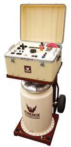

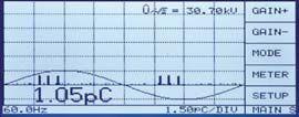
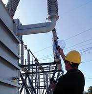
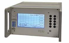


 BY DON GENUTIS, Halco Testing Services, Inc.
Ultrasonic instruments and surveys are widely used for the inspection of mechanical equipment, and are gaining popularity for detecting surface-related defects in medium-voltage switchgear. This article will discuss the application and some of the merits of using ultrasound as a tool for potential detection of outdoor substation problems.
A wide variety of handheld ultrasonic inspection instruments are available for the technician use as part of a comprehensive, medium-voltage switchgear inspection. Selecting an instrument for this purpose can be challenging; however, it is usually best to choose a solution optimized for electrical applications. Look for an easy-to-use instrument that emphasizes electrical inspections as your best bet.
Surface defects inside medium-voltage switchgear can lead to partial discharge activity. Partial discharge can produce a spark that may create a small pressure wave, which may be detected through vents and openings from outside the switchgear. Test instruments equipped with piezo sensors tuned in the 40-kHz range, along with transient earth voltage (TEV) sensors, are often available in the same instrument (Figure 1). TEV
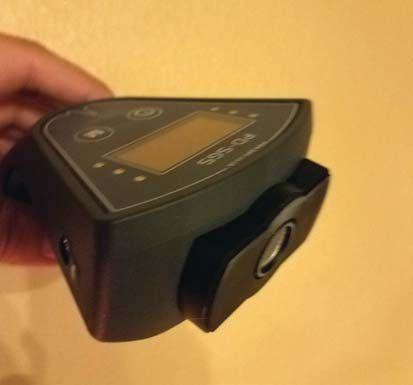
Dual-Sensor Handheld PD Instrument
sensors have the additional benefit of detecting electromagnetic signals created by internal component defects. By using both sensor types, surface and internal switchgear insulation condition can be evaluated.
Outdoor substations are often composed of robust ceramic insulators that can be extremely resilient to partial discharge damage, but can still fail over time. Figure 2 shows a damaged 15kV insulator that was subjected to contamination for over 20 years.
Substations also may use non-ceramic insulators and other components such as bushings, instrument transformers, and lightning arrestors. These components are generally much more vulnerable to PD damage and may warrant more attention.

Ultrasonics can be a valuable tool for detecting outdoor insulation problems; however, a majority of components could be located a great distance away from the technician. Therefore, a signal concentrator, such as the one shown in Figure 3, can be very useful to increase the range of the ultrasound instrument.
Signal concentrators, sometimes referred to as dishes, are offered as a relatively inexpensive attachment to the ultrasonic or dual ultrasonic/ TEV instrument.
Failing components, such as the deeply eroded non-ceramic insulation shown in Figure 4 or the current transformer shown in Figure 5, were detected up to 100 feet away with the help of a signal concentrator.


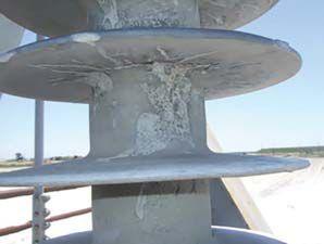


If distant insulation problems are detected using ultrasound instruments, it becomes necessary to identify whether the signals are dangerous surface activity or being caused by benign corona emanating from a sharp conductor point. Equipment used for this investigation can
include a good pair of binoculars or a daylight corona camera for pinpointing the activity. Corona cameras can view ultraviolet light associated with corona or surface insulation breakdown during daylight or night. Daylight corona cameras use special filters that allow only the UV signals associated with potential electrical problems to be visible through the camera. Figure 6 shows a corona camera image of a failing outdoor medium-voltage ceramic insulator.

Daylight Corona Camera Image of Active Ceramic Insulator Defect
much better accuracy. Pay close attention to the signal source location when determining the potential for insulation damage. A good pair of binoculars— or better yet, a daylight corona camera — will help
This article briefly identified the use of TEV sensors in detecting internal switchgear component failures. Detection of internal defects in outdoor substation equipment will be the subject of a future No-Outage Corner.
Ultrasonic instruments can be a useful tool to detect surface insulation problems in outdoor substations. Using a signal concentrator allows detection at much greater distance and with

Don A. Genutis presently serves as President of Halco Testing Services, Inc., a NETA Accredited Company, in Los Angeles, California. He has held various principal positions during his 30-year career in the electrical testing field and has primarily focused on advancing no-outage testing techniques for the last 15 years. Don holds a BS in electrical engineering from Carnegie Mellon University and is a NETA Certified Technician.


Jim White is nationally recognized for technical skills and safety training in the electrical power systems industry. He is the Training Director for Shermco Industries, and has spent the last 36 years directly involved in technical skills and safety training for electrical power system technicians.
Jim is a Principal member of NFPA 70B representing Shermco Industries, NETA’s Principal member of NFPA 70E, NETA's Principal member of NEC CMP-13, and NETA’s Principal representative to the ASTM F18 Committee Electrical Protective Equipment for Workers.

Partial discharge (PD) testing has become one if the primary cable testing methods, as the dc overpotential testing we used to do on power cables was found to cause premature failure. As the use of PD testing has increased, some of the basics involved should be reviewed by those performing the tests.
Partial Discharge (PD) of insulation occurs:
a. When a dry cable allows an increase in leakage current
b. When a shielded cable drain wire becomes overloaded and discharges are created
c. When a spark or discharge bridges two conducting electrodes within a small portion of the insulation
d. When a termination is made using handtaped materials that allows excess leakage current
When present, how often does partial discharge occur within insulation?
a. It’s constant
b. Once every cycle
c. Twice a cycle
d. Every quarter cycle
For a partial discharge to occur, a minimum voltage level must be reached. What is this minimum voltage called?
a. Partial discharge inception voltage (PDIV)
b. Partial discharge minimum voltage (PDMV)
c. Partial discharge start voltage (PDSV)
d. Partial discharge ramp voltage (PDRV)
What does PDEV refer to?
a. Partial discharge extinction voltage
b. Partial discharge exciting voltage
c. Partial discharge execution voltage
d. Partial discharge excess voltage
What effect does sustained voltage above the voltage where PD begins have on XLPE cable?
a. None, unless it exceeds the rated voltage of the cable
b. Possible damage only if the cable is very old
c. Possible color change to the cable insulation
d. Possible further deterioration


NETA — InterNational Electrical Testing Association (NETA) and Long Beach City College (LBCC) signed a Memorandum of Understanding on November 15, 2016, regarding the adoption of the NETA-developed Electrical Power Testing Technician (EPTT) Curriculum. EPTT includes a series of courses designed to provide graduates with a strong grasp of the educational requirements specified for a Level II NETA Test Technician per the ANSI/NETA ETT, Standard for Certification of Electrical Testing Technicians.* NETA will continue to work with LBCC to integrate the NETA EPTT Curriculum with the LBCC Power Technician Program.
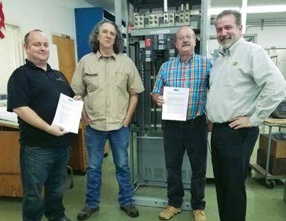
The NETA-LBCC MOU was signed at LBCC’s Liberal Arts Campus in Long Beach, California, in the presence of (left to right) Nenad Pasic, NETA Training Committee Member and NETA Accredited Representative for Tony Demaria Electric, Inc.; John Hauck, LBCC Electrical Technology Instructor; Scott Fraser, LBCC Trades and Industry Department Chair and Electrical Technology Professor; and Bob Sheppard, NETA Training Committee Chair and Vice President of Intellirent.
LBCC has agreed to integrate the NETA EPTT Curriculum into its current program offerings. LBCC offers a series of core courses with the opportunity to specialize in Communications, Automation, Industrial Management, Solar, and Power. The EPTT curriculum will provide the Power area of specialization.
The New LBCC Power Technician program will be offered as a post-secondary adult education program, designed for individuals interested in a career in the power systems industry or for electrical testing technicians seeking advancement. Participants should be able to complete the coursework and graduate with a certificate of
* The ANSI/NETA ETT, Standard for Certification of Electrical Testing Technicians was created to codify the experience, education, and training requirements necessary for an individual to obtain a level of competency as an electrical test technician. A complimentary copy of the ANSI/NETA ETT is available for download at: www.netaworld.org.
completion or continue with additional credits to earn an Associate Degree. At program completion, graduates will have completed OSHA 30 training, numerous hours of electrical safety training, and achieved first aid and CPR certifications.
In addition to the new course offering, construction is under way at LBCC’s Pacific Coast Campus (PCC) where the new Electrical Department is scheduled to move in 2017. This nearly $12 million California state-sponsored program will add over 32,000 square feet of space that will primarily be used by LBCC’s Electrical Department.
The Building QQ New Construction and Building RR Renovation project’s main programmaticfunction is to provide updated spaces for the Electrical Department and some larger general-use classroom spaces. The renovation of existing Building RR will create new lab and instructional space for the Electrical Department. The existing Building QQ will be

LBCC Pacific-Coast Campus Building QQ New Construction and Building RR Renovation
replaced with a new 24,000-square-foot, twostory building. The building will encompass a new Dyer Hall, Lifetime Learning Center (formerly the Senior Center), large multi-purpose classrooms, faculty offices, additional classrooms, and electrical labs.
NETA looks forward to this new joint venture and is excited to welcome the first graduates of the program in 2019.




NETA — the InterNational Electrical Testing Association is proud to add Electrical Engineering & Service Co., Inc., to the community of electrical testing companies committed to meeting the ever-increasing demand for qualified testing firms and personnel.
Electrical Engineering & Service Co., Inc. was founded by Stephen Isaac and Joseph Cipolla in 1989 as a power systems testing, maintenance, and services firm. The goal has always been to provide prompt and honest technical and professional service to help clients keep their electrical distributions systems safe and reliable. The company’s staff of experienced technicians and engineers serves clients within Boston and the surrounding New England area. Known as EESCO, the company prides itself on delivering first-class customer service.
EESCO’s clients include industrial facilities, commercial facilities, data centers, waste water treatment, government installations, contractors, power plants, hospitals, engineering firms, and more. The company provides commissioning and acceptance testing services, routine preventive maintenance, modifications and repairs, infrared thermography, power quality services, and power system studies.
EESCO Vice President Joseph A. Cipolla says, “We are extremely proud to become fully accredited with NETA. Our association with NETA provides tremendousvaluetobothourfirmandtothe tremendous value to both our firm and to the customers we serve. Certifying the company and our field service technicians through the demanding certification process helps assure quality, experience, and training in the eyes of our clients. Since our inception, we have seen an ever increasing demand for high quality power systems services, and we plan on meeting those demands.”
“NETAwelcomesEESCOasitsnewestNETA “NETA welcomes EESCO as its newest NETA Accredited Company,” says Ron Widup, CEO of Shermco Industries and current president of NETA. “NETA Accredited Companies help advance the electrical power systems industry, in part by increasing electrical power system safety and reliability. Achieving NETA accreditation is a significant accomplishment, and we congratulate EESCO on this impressive achievement.”


The Doble M7100 High Voltage Asset Analyzer is a revolutionary solution for high voltage testing. And it is built to reduce the various safety risks a field crew is exposed to per job.
Patented dual high-voltage leads allow you to perform multiple tests with one cable hook up. This means a reduction in ladder trips per job – cutting the number by one third.
Eye hooks on the high-voltage leads let you use hotstick tools to place HV cables on the apparatus under test.
Emergency stop button initiates a controlled shutdown with one motion, and once pressed, will lock until it is twisted and released.
Two test enable/safety switches must be pressed at the same time by the test set operator and the operator’s assistant – otherwise the M7100 will not operate.
Discharge complete will appear on the LED display once a test completes and the M7100 has entered a discharge mode that releases energy from the test specimen.


Learn more about how the M7100 is making testing simple, safe & efficient. ww w.doble.com/ M710 0


 BY JEFF JOWETT, Megger

It’s a common expression that “the devil is in the details,” and electrical testing is hardly an exception. A technician or operator familiarizes with a new field of testing, learns all the theory, and masters the fundamentals. anewfieldoftestinglearnsallthetheoryandmastersthefundamentals He or she well understands why and how the testing is done and has learned the accepted procedures. An instrument and accessories are obtained and the instruction manual read. The operator heads out into the field, sets up a test, and oops! Something unanticipated and unexplained stops the testing or creates an ambiguity that leaves the results less than confident.
For ground testing, this article reviews some common field questions.

Yes and no. That would be convenient, but it doesn’t always work. It might give you the correct reading, but you don’t know. Ground testing is more procedure-dependent than many other types of electrical testing. That’s because the test item isn’t a discrete object; you’re making
a connection to the planet. Indeed, you may run the provided lead set out full length, make a test, and get the right answer. But that is purely a matter of luck. Test leads often conform to the 62 percent rule: a pretty good chance, but not a sure thing. You don’t know, and a client would never accept it. You could still be within the electrical field of the ground you’re trying to test, a water main or live buried cable could be right underneath the test probe, or numerous other deviations from ideality could exist. The standard test procedures devised for the industry can sort out a bad test from a good one.

There’s no simple answer to this. It depends on the variables of the test site and can only be effectively determined by trial and error. Some standard procedures — not all of them — have a built-in proof, and your chances of clearing the proof on the first test are enhanced by following a standardtablethatrelatesthesizeoftheelectrode standard table that relates the size of the electrode under test (diagonal of a ground grid, length of a deep-driven rod, etc.) to lead length. These tables (see Table 1) are commonly found in the literature, and their recommendations may differ. This is because they are practical, not scientific.
Reference Table for Probe
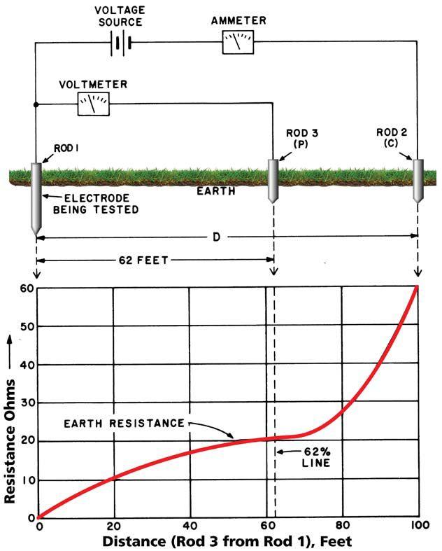
of
within the available space, and if the results square with a rigorous procedure, you’re good.


Note 1: Based upon data in Reference 2. Note 2: For example, the diagonal across and area surrounded by an earthed fence.
Source: Earth Resistances, G.F. Tagg
If you don’t have the working space (remember, this can easily be hundreds of yards for large grids), it doesn’t mean you can’t test. Work
Over the years, numerous test procedures have been devised by field operators to meet different demands. Some are meant to overcome difficult physical conditions, some to save time, and some to be assured of the accuracy and reliability of the measurement. Be sure to understand the purpose of the procedure and which of these contingencies it is meant to address. The most basic, accepted, and reliable of all


procedures, Fall of Potential, provides a graph of measurements versus distance (Figure 1). This graph will clearly distinguish between a poorly conceived or executed test and a well-spaced and well-performed test.
Other procedures use mathematics to weed out bad results. The math exercise gives the operator guidance about the accuracy of the reading and, therefore, its reliability. In worst-case instances, the math may not calculate at all.
Quality testers can tolerate thousands of ohms in the test circuit. If the resistance between the probe and surrounding soil does go over limit, just reduce it by pounding the probes in deeper, tamping the soil, or possibly adding water.
Remember, you are not phonying the test by adding water to the probes. The test does not measure the resistance of the probes; it measures the test ground. If you were to water the ground rod that you’re trying to measure, then you would be influencing the result.
Like an alligator clip on more common test procedures, metal spikes provide the necessary contact with the earth to execute the test. It is generally not necessary to pound these in as far as they will go. Exceptions do exist, mainly in poor grounding soil, but in most instances, probes can be hand-pushed in. Modern testers require only minimal amounts of current and voltage to make highly accurate measurements. What’s more, a quality tester will have indicators that tell the operator of any problem with the probes. Pounding them all the way in is extra work and can also be a hazard to back and knees when getting them out.
In the old days, operators had to rely much more on experience and intuition in diagnosing problems where test results were incoherent, which included a lot of educated guesswork. As explained earlier, modern testers tell you what’s wrong, but it’s easy to focus on those big digits — or on where they should be — and overlook the small details around the edge of the display. Always scan the whole display for potential issues. Indicators will typically tell you if the test probes aren’t making sufficient contact with the soil. This is more likely to be an issue with the current probe, as it must inject the test current, but could be either one or both. Probe resistance should never defeat your test.
In the old days, when you couldn’t get the pointer to stop swinging, you averaged the swings. It’s better now. Modern testers have several weapons against noise, including filtering, higher test currents, and frequency adjustment. Quality testers will tell you when there is noise, so you know what the issue is and are therefore better at addressing it. Some testers automatically initiate corrective measures, some leave it to the operator, and some do both. Note that there are noise threats both above and below, in other words, air and ground. Testers are better equipped against ground noise, which is mostly composed of wandering currents trying to get back to the utility source. But don’t forget that noise sources can be overhead, such as from power lines, and these can be more difficult to suppress. Don’t run test leads parallel to them by any means, and try to run at a right angle if possible. Snaking leads instead of having them running parallel to each other helps, and there are also shielded leads.
No. You don’t have to shut down a whole switchyard to test. Modern testers use so little current (a couple of milli-amps) and such low voltage (less than 50V) that they do not trip protective devices or damage loads.
No and yes. There is nothing about ground testing itself that is inherently dangerous, nor are the testers. In the old days, yes; higher voltages and currents were used in bygone generations. Modern quality testers with microprocessor calculation do not require so much power, and so it is not used. Be aware, though, that equipment for a specialty application such as deep prospecting for oil, minerals, geologic layers, and so forth, does call for higher power, and such specialty instrumentation may require an extra level of awareness and caution.
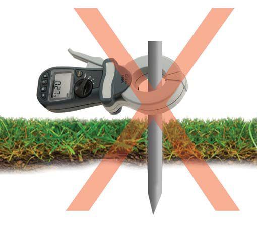


Aha! As in much of electrical testing, that’s another story. We can make testers and procedures infinitely safe, but they still get connected to potentially faulty equipment and circuitry. For ground testing, the risk is that of an event occurring in the utility or on the premises while the test is in progress. The chances of this are rather remote, but still, play it safe and follow industry-standard safe working practices and employ personal protective equipment like gloves, boots, and mats. In addition, note that substantial current may be flowing on the grounding conductor even when an event is not occurring. This originates from unbalanced loads and other wiring shortfalls. There usually isn’t enough voltage to be a risk, but exceptions occur. It is a good idea to always have a clamp-on ammeter and check the ground current first.
leaves the facility unprotected, however briefly. A temporary ground can be installed, but that still leaves the physical hassle of breaking the connection, which is often a welded jumper. If the equipment is energized, as is often the case, usually no safe method is available to accomplish the separation. Some specialty testers include a current clamp that can separate test current going to ground on site from that going back to the utility, and the tester make its calculation only on the on-site current. This solution doesn’t always work, as the utility ground resistance may be so low that it hogs nearly all the test current. But this solution does provide a viable option in many cases.
Yes. Usually, the on-site ground is paralleled with the utility ground feeding the site by a jumper from ground bus to neutral bus at the service. A perfectly good test can be run, and you’ll get a perfectly good measurement, but it is of the entire system, not just the on-site. You can lift the jumper long enough to run the test, but this
Probably not. When a clamp-on ground tester reads open circuit, you are probably trying to measure an open circuit (Figure 2). For the clamp-on technique to work, there must be a path that the test current induced by the clamp onto the rod can find to complete a circuit. If

you’re clamping over an isolated ground, such as one just installed on a site not yet connected to the utility, the tester cannot be used.
Probably not with the tester. Unlike a traditional lead-and-probe tester, where the operator is in complete control by probe placement, the clamp-on controls the test. It induces a current onto the clamped rod, and that current finds its own way back. The operator has nothing to do with it. If the readings are suspiciously low — a tenth or two of an Ohm — the current has probably found an alternate path through metal, not the earth. Examine the circuit. It’s reading continuity, not earth resistance.
Don’t let lack of knowledge make you a victim of sloppy work. Ground testing requires more technique and operator involvement than many more familiar types of electrical test. Make sure you can dot the Is and cross the Ts.

Jeffrey R. Jowett is a Senior Applications Engineer for Megger in Valley Forge, Pennsylvania, serving the manufacturing lines of Biddle, Megger, and MultiAmp for electrical test and measurement instrumentation. He holds a BS in Biology and Chemistry from Ursinus College. He was employed for 22 years with James G. Biddle Co. which became Biddle Instruments and is now Megger.
Tagg, G.F. “Earth Resistances,” George Newnes Limited, London (1964)


With recreational or medical marijuana use legalized in many states across the U.S., workplaces should review their health and safety or human resources policies regarding alcohol and drug use — and if your workplace does not have a policy, it’s time to create one.
What if your job is considered safety sensitive, such as working with live-line voltages, and a coworker shows up for their shift smelling like a distillery? Or, you’re a supervisor and an employee calls to tell you their driving license was suspended, and they will be unable to show up for work without a ride? What exactly are employers, supervisors, and co-workers supposed to do when someone they depend on is clearly under the influence of alcohol or drugs? It’s a sensitive subject that affects many U.S. citizens.
According to the Substance Abuse and Mental Health Services Administration (SAMHSA), illegal and illicit drug use is a growing workplace hazard affecting worker safety. SAMHSA’s annual survey, the National Survey on Drug
Use and Health (NSDUH), is a major source of information on substance use, abuse, and dependence among Americans 12 years and older. Survey respondents report whether they have used specific substances ever in their lives, over the past year, and over the past month (indicating current use). Most analyses focus on current use.
The following are facts and statistics on substance use in the United States in 2013, according to the most recent NSDUH survey. Approximately 67,800 people responded to the survey in 2013.
• Illicit drug use is increasing. In 2013, an estimated 24.6 million Americans age 12 or older — 9.4 percent of the population — had used an illicit drug in the past month. This number is up from 8.3 percent in 2002. The

declined from 19.3 to 14.2 percent, and the rate of heavy drinking went from 6.2 to 3.7 percent.
• Binge and heavy drinking are more widespread among men than women. In 2013, 30.2 percent of men and 16.0 percent of women age 12 and older reported binge drinking in the past month. Heavy alcohol use was reported by 9.5 percent of men and 3.3 percent of women.
• Driving under the influence of alcohol has also declined slightly. In 2013, an estimated 28.7 million people, or 10.9 percent of persons age 12 or older, had driven under the influence of alcohol at least once in the past year, down from 14.2 percent in 2002. Although this decline is encouraging, any driving under the influence remains a cause for concern.
Resources such as SAMHSA or www. drugfreeworkplace.org can help the workplace’s policy makers develop a program. Once a program is developed, notification and training of all employees is essential. Contracting with a thirdparty company to aid in random selections as well as testing and analysis can buffer a workplace from potential lawsuits that could occur should an employee be terminated based on a positive drug or alcohol test.
Managers responsible for administering any program should receive additional training on how to handle reasonable-suspicion or postaccident drug and alcohol testing as well as how to give proper notice to an employee who has been selected for a random test.
• Rates of alcohol dependence/abuse declined from 2002 to 2013. In 2013, 17.3 million Americans (6.6 percent of the population) were dependent on alcohol or had problems related to their alcohol use or abuse. This is a decline from 18.1 million (or 7.7 percent) in 2002.
• A large treatment gap exists. In 2013, an estimated 22.7 million Americans (8.6 percent) needed treatment for a problem related to drugs or alcohol, but only about 2.5 million people (0.9 percent) received treatment at a specialty facility.
Employees should be reminded regularly that some prescription or even over-the-counter drugs may affect their performance. Certain cough medicines, pain medications, and others may have detrimental effects. The company should appoint a Designated Employee Representative (DER) to maintain confidential records of drug testing and serve as a resource for questions regarding these drugs.
Impaired workers can cause serious injury or damage to themselves, fellow employees, and to expensive components or equipment. Developing a comprehensive workplace drug and alcohol policy and a testing procedure is essential for any workplace that exposes employees to hazards or equipment that make them considered “safety sensitive.”
Statistics show that we cannot underestimate the influence of our off-the-job behavior when it comes to alcohol and other drugs. Many incidents occur the next day when blood alcohol levels may still be high. The prime time for workplace incidents to occur is when a worker is hung over and the senses are dulled from the ill effects of too much alcohol or drugs — especially if that worker operates machinery or equipment in a safety-sensitive industry.
Research has found a correlation between the frequency of being hung over at work and workplace events such as feeling sick, sleeping on the job, and having problems with tasks or co-workers. An employee with substance-abuse issues may be frequently tardy or miss more days of work (sick, vacation, or just never clocked in). It is an operational issue for management to
continue backfilling positions to ensure work is completed in the time allotted.
In one study, the hangover effect was demonstrated by pilots tested in flight simulators. There was still evidence of impairment 14 hours after pilots reached blood alcohol concentrations (BACs) of between 0.10 per cent and 0.12 percent, and pilots were still significantly impaired eight hours after reaching a BAC of 0.10 percent. This study effectively illustrates that performance is decreased long after use has concluded, and alcohol use contributes to an employee’s potential missed work.
Every worker has a personal responsibility to ensure their safety and the safety of others. Part of that responsibility is to encourage someone with an alcohol or drug problem to seek assistance through an employee assistance service or a supervisor. If the individual is putting themselves or others in danger, you have a responsibility to report that individual to a supervisor or leader. The adage “you
are your brother’s keeper” is accurate in this case. The employee may prevent injury to their brother worker, as well as to themselves and others.
Based on usage statistics and constantly evolving legislation, the guiding principles of alcohol and drug policies include sharing responsibility for safety, understanding how behavior on and off the job affects safety, and balancing safety and privacy interests.

Paul Chamberlain has served as Safety Manager for American Electrical Testing Co., Inc., since 2009. He has been in the safety field for the past 17 years, working for various companies and industries. He holds a B.S. degree in marine safety and environmental protection from Massachusetts Maritime Academy.




You can count on us for specialized experience in healthcare, data center, office complex, and commercial acceptance and maintenance testing. Absolutely. Power generation, petrochemical, oil & gas, and heavy industries also look to us for high demand services such as start-up commissioning, maintenance testing, shut-down and turnarounds, and breaker shop repair. Get started today.


An old saying in the industry goes like this: “There are bold protection engineers, and there are old ones, too, but there are no old bold ones.” Emphasis is often placed first on economics, but in truth, safety is always of the utmost importance. We are working in an energized high-voltage power system, which is a hazardous environment. Being safe is a state of mind and closely following a good set of well-established practices is necessary to maintain this state of mind. You must fully understand these practices and be extremely well versed in them.
Unsafe practices can result in the loss of revenue, and more important, human life. The lack of good, safe practices invariably leads to relay misoperations or the lack of a critical relay operation when required.
Much of the advice presented here is based upon real-life experience, such as working at nuclear power plants, which follow a highly regimented set of practices that are periodically reviewed and constantly improved over time. The purpose of this article is to demonstrate:
•Good practices for safety as related to protective relaying
•Bad practices or, at best, a lack of good ones.
This section provides tips on good practices for any work related to protective relaying. These suggested practices cover field work and an office environment where the protection and control systems are designed.

• Proper Training and Practical Understanding. Field personnel should have a practical understanding of workrelated tasks and be properly trained prior to beginning any field tasks. A practical understanding means that the field personnel can troubleshoot during a task and not strictly be dependent on automated test equipment and software.
• Direct Access to Supervision. Field personnel should always have direct access to their supervisor(s) should they have any questions related to successfully performing a work task. Supervisors should either be able to answer these questions directly or have immediate access to resources that can.
• Work Plan. Any time work such as testing is conducted in the field, a detailed step-bystep work plan must be in place. Workers sign off on the procedure as each step is completed. Some companies require two individual signatures from independent personnel per step for additional verification.
• Error Checking. Field personnel should identify any errors present in the design of new projects and properly communicate these findings to the engineer(s) responsible for the original design for correction. This is an extremely important skill because this is the last point in the overall process that any possible errors can be caught and corrected prior to a misoperation.
• Human Performance. Protection and control apparatus and schemes should be designed with field personnel in mind since they are responsible for installing, operating, and maintaining it. Therefore, all schemes should be designed first and foremost with safety in mind. For example, test switches must isolate every relay voltage and current input from the electrical power system with test connections available for the relay test sets to inject the corresponding test signals. The same holds true for relay digital inputs and outputs.
• Do the Job Right the First Time. Sometimes management pushes the protection engineer to complete the project as quickly as possible. A work backlog often acts as an impetus to rush. This scenario invariably leads to safety-related issues. It is the protection engineer’s responsibility to firmly identify the amount of time required to properly complete each project. There is no place for an 80/20 mentality in the design or testing of protection and control (80/20 refers to only completing the first 80 percent of the job as a means to save time). Often, the final 20 percent can take longer to complete than the first 80 percent of the job. This philosophy amounts to willful negligence.

• System Projects. A good practice is to develop system projects so that corrections for an inherent design flaw, such as a relay misoperation, can quickly be implemented throughout the rest of the system once it has been identified at one location. A system project could be as simple as disabling a protection function or as elaborate as replacing an existing relay or entire panel.
Note: This category addresses when field personnel and designers work directly together side by side.
• End-to-End Transmission Line Communication-Assisted Tripping Scheme Testing. A good example is the end-to-end field testing of a high-voltage transmission line communication-assisted protection scheme. The design engineer is often called upon to run short circuit studies for internal and external faults to the protected transmission line. These test signals are simultaneously injected at each line terminal via GPS synchronization. It has often been reported that this type of testing leads to relay setting changes that improve the overall reliability and security

of the protection scheme. Field personnel and relay designers working directly together is the best-case scenario to ensure protection is fully optimized and properly commissioned.
• Off-Site Testing. Perform off-site testing in a laboratory or similar type of environment. All protection and ancillary equipment (e.g., modem, communication processors, etc.) is brought to one location, connected, and thoroughly tested to make sure the design is proper and to catch any errors prior to installation and on-site commissioning.
• Third-Party Check. A third-party check is performed by an independent body outside of the owning electric utility such as a consulting engineer(s). This is an excellent method to procure a fresh set of eyes as a final check. If the third party is procured on a regular basis, they can develop an intimate understanding of the end user’s standards and operating procedures.
•Programmable Relay Logic (PRL) Implementation. Modernnumerical protection relays have PRL that can be used to augment existing protection functions to achieve any standard. While relay manufacturers are responsible to ensure the protection functions meet their stated accuracy and tolerance, they are not responsible for the PRL schemes implemented by end users. It should be noted that NERC stated in its 2012 State of Reliability report that more misoperations were occurring in the United States at that time due to relay complexity such as PRL. If PRL is implemented, it should be fully tested in a laboratory environment by the designers before it is sent to the field. Some design groups rely on the field to correct errors in the implementation, which is a bad practice.
This section demonstrates bad practices for any work related to protective relaying. These practices cover field work and an office environment. Note that a third category classified as Enterprise pertains to managementlevel decisions or actions.
•Run to Fail (RTF) Maintenance. The simplest maintenance strategy is known as run-to-failure maintenance. Assets are deliberately allowed to operate until they break down, at which point reactive maintenance is performed. No maintenance, including preventative maintenance, is performed on the asset until the failure occurs. Spare parts must be available to replace the failed part and to maintain equipment availability.
•Unreported Design Changes. Abad practice regarding any change made to an existing design in the field is failure to report these back to the design team or update relevant system drawings. If field personnel make any changes to an existing design for any reason, this should first be communicated to the responsible designer(s) for approval, and then the changes should be noted on any relevant drawings (i.e., as-builts). The wiring in the control room should always exactly match the drawings.
This strategy is useful for assets that pose no safety risks on breakdown and have minimal effect on production. While okay for a light bulb, this strategy does not translate well to electric power systems since, for example, if a large transformer should fail, the inevitable outage and the time and labor necessary for a replacement are major expenses.
The main advantage is minimal planning; since maintenance does not need to be scheduled in advance, the requirements are very low. This strategy is also easy to understand. One disadvantage is that


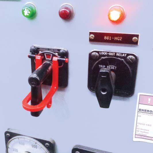

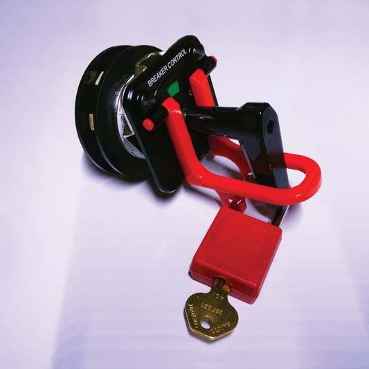
John White received the 2017 Outstanding Achievement Award for his dedication and service to NETA; presented by Ron Widup, NETA President.

John White is hard-working, dedicated, brilliant, and a joy to know. As Ron Widup puts it, NETA’s 2017 Outstanding Achievement Award honoree is “an all-around good dude.”
“John knows what it is to be the scrappy testing guy or to work for the multimillion-dollar publicly traded company. In either instance, he is the same quality person making a difference,” says Widup, CEO and PresidentofShermcoIndustriesandPresidentofthe President of Shermco Industries and President of the NETA Board of Directors. “John is the type of person we should all try to be.”
NETA’s Outstanding Achievement Award is given in recognition of an individual’s commitment to NETA and leadership through service to the asso-
ciation. White, who serves as President of Sigma Six Solutions, has seen many iterations of NETA since joining the organization in 1975.
“I considered retiring 10 years ago, but I kept postponing it until five years ago because of the NETA people. I really enjoy working with them,” White says. “NETA is made up of hardworking individuals who are totally dedicated to the association and to the cause. They don’t stop trying, and they don’t give up.”
In fact, his work is one of the great joys in his life. “He doesn’t have hobbies. Really, it’s just work, family, and football — and not necessarily in that order,” says his wife, Bev, with a laugh. “He loves his work, and he’s really good at it. John is my hero.”
Widup presented White with the Outstanding Achievement Award at this year’s PowerTest 2017 conference, which ran February 26 to March 3, 2017, at the Disneyland Hotel in Anaheim, California. PowerTest represents the largest gathering of electrical power systems professionals in the industry and is the only conference and trade show specifically designed for the electrical testing industry. Every year, the Outstanding Achievement Award is presented by NETA’s President at the Member and Alliance Luncheon during PowerTest. It is a special presentation where the honoree is unaware of his or her selection until the announcement is made from the podium.
White says receiving the award was a touching moment that he will remember fondly. He says he was “completely caught off guard” when he heard Widup announce his name. Even better was watching Widup welcome several special guests who had secretly arrived in White’s honor.

“Ron and my wife had worked in secret to arrange to have all these people I worked with in the past come and surprise me. It was so nice to see so many old friends and former colleagues,” White says. “That they would go to such lengths was really touching.”

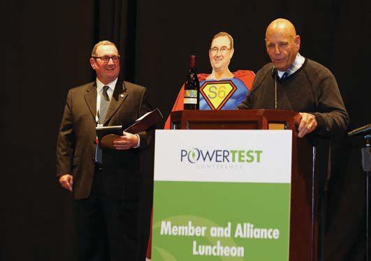
John White’s family shares in the celebration.John Moore (right), past NETA President and close colleague, was on hand to poke some fun and offer kind words about his good friend, John White.
White’s sense of humor, coupled with his business sense, has given him the reputation as a calming person who provides great knowledge to the group. He is known not only for his wealth of knowledge, but also for how free he is in sharing it. From the earliest stages of his career, White has always taken the opportunity to help others and provide his insight — especially whenitbenefitsNETA. when it benefits NETA.
“Whenever I have the opportunity to interact with John White, I’m smarter after having had that opportunity,” says Ken Bassett, President of Potomac Testing.
Over the years, NETA and its members have benefited greatly from White’s passion for helping others grow, learn, and improve. “Understanding how people think is something I really enjoy,” White says. “I love listening to everybody’s perspectives.”
When new people join the board, White is usually one of the first people to step up, welcome them, and begin making them feel at home.
White, NETA’s 2017 Outstanding Achievement Award honoree, joined the organization in1975. in 1975.
“Or what was NETA at the time,” says White, President of Sigma Six Solutions. “I joined NETA in its infancy. So I’ve seen it go from brand new and struggling to where it is now — a premier professional technical organization.”
In fact, he says NETA has grown and prospered to be of higher quality than any other electrical organization. “Some industry associations cover a much wider array of electrical areas, but if you break it down and look at the areas they cover that correspond to areas NETA covers, NETA has grown over the years to far surpass all other organizations in those areas.”
“A lot of times, they are shy or kind of holding back. I like to bring them into the conversation, help them open up and get excited about sharing within the NETA community,” he says. “It is neat to see them grow.”
White has always approached his work with aplomb and with a joy that makes him a positive force in any situation. It’s an attitude that comes naturally to him. “People strive to find balance in life. John just lives it,” says Jayne Tanz, Deputy Director of NETA.
“Work doesn’t feel like work with him, because he thoroughly enjoys and brings passion to everything he does. He likes to contribute,” she says. “He likes to create new ideas. NETA has been an enormous beneficiary of his dedication.”
White credits much of his personal and industry success to NETA and its people. “In other organizations, you feel like a number. But in NETA, you feel like you belong, like you have a real voice,” he says. “It’s full of people dedicated to seeing NETA and our industry succeed.”

White serves as NETA Treasurer, Chair of the Finance Committee, and sits on the MARCOM, Membership Application Review, and Nominationscommittees.HeearnedaB.S. Nominations committees. He earned a B.S. in Electrical Engineering from Washington State University.

sales@vacuumreplacementinterrupters.com

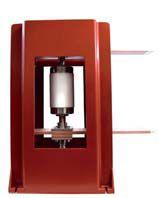
VRI is proud to announce our new VR Interrupters for the GE line of Vacuum Breakers. Products include; Outdoor PVDB1 15 kv, Indoor VVC, PVVL, VB and VB1 Vacuum Circuit Breakers, ranging from 5-15kv, 1200-2000 amp. These interrupters are ANSI C.37 rated and are drop in replacements vacuum interrupters.
VRI also has the newest Vacuum Interrupter Pressure Test Set (VIP-TS-1) that uses the Paschen’s Law and Paschen’s curve to determine the life of your vacuum interrupters. This VIP-TS-1 also makes it possible to test VI’s in-house and will test most 5-15kv vacuum circuit breakers in the market with VI’s still installed on breaker.
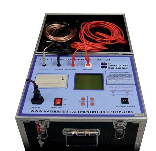


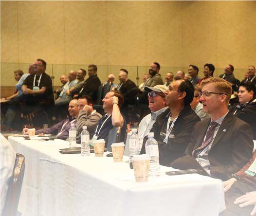



Five days of high-powered education, training, and networking drew over 500 industry professionals from around the nation to the Golden Land of Promise, the site of NETA’s PowerTest 2017 conference at the Disneyland Hotel in Anaheim, California. The industry’s premier electrical power systems event, held February 27 – March 3, 2017, continued its upward growth curve with record attendance numbers in 2016 and again this year in 2017.
About 510 power systems professionals attended the conference technical and training sessions, and over 1,200 attended the PowerTest Trade Show. The event also featured a New Product Forum, eight hospitality suites, Spotlight Stage
presentations by NETA’s Corporate Alliance Partners, raffles, award presentations, and more. Vision, ingenuity, resourcefulness, and purpose are qualities of Southern California that inspired attendees to PowerTest 2017, who came together to strengthen the industry, expand their knowledge, and improve the quality, safety, and reliability of electrical power systems.
“We were honored to host so many of the industry’s leading electrical power systems professionals,” says NETA Executive Director Missy Richard. “NETA’s role in facilitating our industry’s open sharing of ideas, collaboration, and networking is one that we prepare for all year. We are excited to see the conference continue its
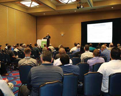

Intellirent, voted Best in Show at the PowerTest
brought a new and innovative design to their
upward growth trend, which allows us to offer even more opportunities to promote technical excellence, world-class programs, and consensus standards.”
Richard says PowerTest attendees often serve as messengers who take information, technology, and solutions gathered at PowerTest back to their companies. PowerTest is consistently recognized as one of the best educational and networking events in the electrical power testing industry.
Many PowerTest attendees kicked off their week at Megger’s Best Practices seminar, a free session that brought them up to speed on new testing techniques and technology and provided the opportunity to engage with expert engineers. Megger’s application engineers shared their industry knowledge and experience through an in-depth, full day of quality education that included training related to key industry topics
Keynote Speaker Todd Conklin, Ph.D., Senior Advisor to the Associate Director at Los Alamos National Laboratory, kicked off PowerTest 2017 with a humorous but meaningful presentation that was well-received by attendees. With playful advice such as “Never take a laxative and a sleeping pill at the same time,” Conklin loosened up the audience and prepared them to receive a more serious message.
“Safety is not the absence of accidents,” he reminded PowerTest attendees. “Safety is the presence of defenses.”
At Los Alamos National Laboratory, Dr. Conklin has served for the last 15 years in the Human Resource and Reliability Management and Training arena with an emphasis in Organizational Development and Human Reliability. His book, Simple Revolutionary Acts: Ways to Revitalize Yourself and Your Workplace, helps readers become a positive deviant in the workplace in a fun way. He was a guest host on National Public Radio’s “All Things Considered” and “Morning Edition.” His session was a perfect launching point for the week ahead.
After the keynote, attendees enjoyed Monday’s technical presentations, a full day of engaging, 45-minute presentations designed to expand thinking and generate new ideas. Attendees chose from 27 detailed presentation track topics under the main headings of Electrical Safety, Protective Relays, Equipment & Reliability, Power Transformers, Battery Systems, and a symposium on Medium-Voltage Vacuum Circuit Breakers.
At the end of the afternoon, the New Product Forum provided attendees with dozens of the latest products and innovations, as well as information on major expansions by leading industry-specific manufacturers and suppliers. Monday concluded with attendees enjoying a host of hospitality suites sponsored by BCS



Switchgear, Inc.; Doble Engineering Company; Electro Rent Corporation; Group CBS, Inc.; Hampton Tedder Technical Services; Megger/ AVO Training Institute, Inc.; Protec Equipment Resources; and Shermco Industries.
Tuesday began with engaging Panel Sessions where attendees selected two panel topics among
Electrical Safety, Relays, Circuit Breakers, and Power Transformers. It was a great opportunity to learn from experts and peers. Panelists worked in tandem with attendees during these sessions, inspiring lively conversation addressing real-world problems faced in the field and providing realistic solutions to take home and apply. Rooms were filled with people engaging in Q&A and learning from each other.
The NETA community put forth an impressive joint effort to celebrate its 45th anniversary with a fascinating on-site museum for PowerTest attendees. A special thank-you to the companies that loaned items for the museum — everything from a 1930s Wattmeter, vintage brochures, and 1950s synchronous and dc motors to a 1970s hand-crank transformer and a display of old photos such as a 1940 loading rail car, a 1907 steam turbine generating plant, and utility workers from the 1900s.
Companies and organizations contributing items to the museum include:
• 3-C Electrical Co., Inc.
• AEMCInstruments AEMC Instruments
• Basler Electric Company
• BCS Switchgear, Inc.
• Belyea Company, Inc.
• Group CBS, Inc.
• HAEFELY Hipotronics
• Halco Testing Services
• High Voltage Inc.
• NETA
• NFPA
• ShermcoIndustries Shermco Industries
• Tony DeMaria Electric, Inc.
• Utility Relay Company
• WilliamStockhouse William Stockhouse
TheNETA45 The NETA 45th Anniversary Museum inspired incredible support from the industry’s leading electrical testing equipment manufacturers, testing companies, and product suppliers. The shared effort underscores the respect those in our industry have for the old, the new... and a pride in the continual evolution of quality across the electrical power industry. NETA greatly appreciates everyone who took the time to seek out items of interest for the museum and make it a great exhibition.
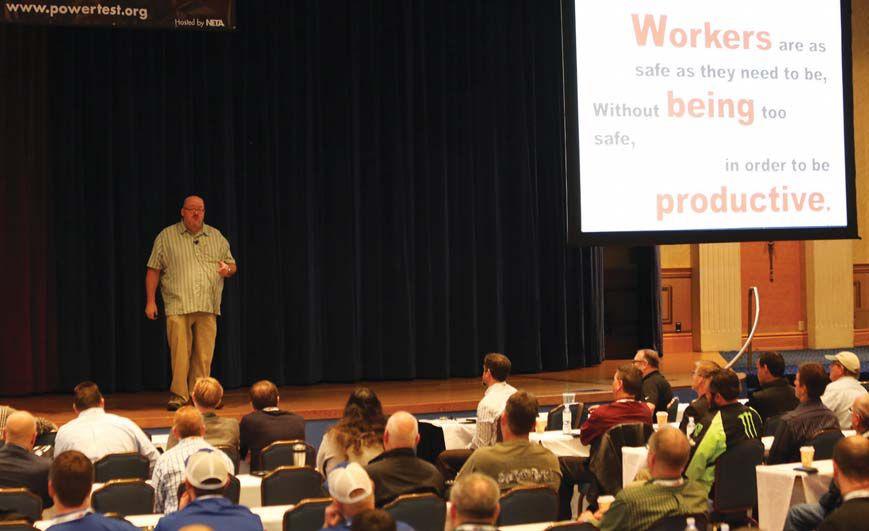
Tuesday afternoon was dedicated to the everpopular PowerTest Trade Show, featuring more than 85 top-tier electrical power vendors whose mission is electrical safety and reliability. A hearty complimentary lunch and beverages were provided to attendees as they walked the floor, gathered information, and made connections. As the biggest single event at PowerTest, the Trade Show is where most business is conducted among attendees and vendors. Each year, this event also features industry leaders at the Spotlight Stage. Presentations were given by NETA’s Corporate Alliance Partners including OMICRON electronics Corp. USA; ComRent Load Bank Solutions; Electro Rent Corporation; Megger; Protec Equipment Resources; BCS Switchgear, Inc.; Intellirent; AVO Training Institute, Inc.; AEMC Instruments; Doble Engineering Company; and WEIDMANN Electrical Technology, Inc..
Another highlight of the Trade Show is the doorprize raffle that takes place at the end of the show. This year’s winners were not disappointed with the excellent offerings from exhibitors as well as from NETA, including a $500 cash prize and a YETI cooler.
Following the PowerTest Trade Show, attendees met up at the PowerBash Awards Reception and Dinner, which this year also celebrated NETA’s 45th Anniversary. During PowerBash, NETA presented awards for the best Technical Presentations, Trade Show Exhibitors, and Hospitality Suites (see sidebar).
PowerBash was a particularly special event this year because NETA celebrated its 45th Anniversary (see sidebar) with a historical exhibit, trivia contest, timeline, and photo-bomb challenge. The PowerBash reception marks the end of the first two full-packed days of technical and social events and the beginning of three more days of technical seminars. Regular attendees consider PowerBash the seventh-inning stretch of PowerTest, the pause before the more intense educational innings to come.
More than 500 guests were mesmerized by a special performance by James Kellogg, Jr., a comedic hypnotist. Six brave attendees agreed to be hypnotized in front of their PowerTest colleagues. Kellogg, who won “The Gong Show”
at age 17, has been delighting audiences with his magic since he was a young boy. His stage credits include TV, film, radio, and thousands of casino, festival, and corporate event performances.
PowerBash was not only a great opportunity to relax and connect with old and new colleagues, but was also full of entertainment and inspiration sparked by celebrating 45 years of NETA’s service to the industry alongside the industry’s many accomplishments.
Wednesday and Thursday have always featured four-hour technical seminars that offer attendees a more thorough exploration of various subject matters. Attendees gained hands-on experience by applying what they learned to troubleshooting transformers and distribution lines.
On Friday, Doble Engineering Company added one more day of learning with its Laboratory Seminar. The seminar — designed for engineers, chemists, and others responsible for reviewing data to interpret laboratory results to detect and identify problems within electric apparatus — offered attendees an interactive experience. The session combined theoretical background with practical experience and hands-on examples, including case studies illustrating common problems found in the field.
PowerTest 2017 was the best yet! PowerTest attendees, speakers, sponsors, and exhibitors all contributed to making the event a tremendous success. NETA thanks each individual and company who contributed to this success by participating, speaking, exhibiting, and energizing their future at PowerTest 2017.
NETA looks forward to welcoming electrical power system industry leaders to PowerTest 2018 “On the Potomac,” February 26 – March 2, 2018, at the Gaylord National Resort & Convention Center near Washington, D.C. Mark your calendars, and make plans to join us next year!
TRADE SHOW EXHIBITION WINNERS
MostInnovative Most Innovative — Tony Demaria Electric, Inc.
MostVisited Most Visited — Megger
BestinShow Best in Show —Intellirent — Intellirent
TECHNICAL PRESENTATION WINNERS
Safety —HumanPerformanceBestPracticesinElectrical — Human Performance Best Practices in Electrical Safety
Presenter: Mike Doherty, eHazard
Equipment & Reliability — How Vacuum Interrupters Work and How They Fail
Presenter: Finley Ledbetter, Group CBS, Inc.
Battery Systems — NERC Requirements for Battery Acceptance and Maintenance Testing
Presenter: Bruce Horowitz, American Electrical Testing Co., Inc.
Protective Relays —Man-MadeFaults–LineProtection — Man-Made Faults – Line Protection
Operation for an Unintended Phase Cross-Connect Condition
Presenter: Ryan McDaniel, Schweitzer Engineering Laboratories, Inc.
PowerTransformers Power Transformers — Understanding the Value of Electrical Testing for Power Transformers
Presenter: Charles Sweetser, OMICRON electronics Corp. USA
BestOverall Best Overall — Keynote Address
Presenter: Todd Conklin, Los Alamos National Laboratory
HOSPITALITY SUITE WINNERS
MostCreative Most Creative — Doble Engineering Company
Most Appetizing — BCS Switchgear, Inc.
MostTechnical Most Technical — Megger Most Entertaining — Megger Most Hospitable —ShermcoIndustries — Shermco Industries
(names given are user names within the Mobile App)
GrandPrizeWinner: Grand Prize Winner: Lucero10
Runners Up: NSF-Matt, iesussotus, and SD Jaxon




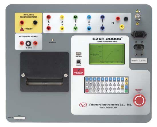
When it comes to substation testing, you shouldn’t have to compromise simplicity for precision and accuracy. That’s why, for over 25 years, we have designed our precision instruments to be intuitive and easy to use so that you can focus on testing instead of wasting time in training.
Our versatile instruments offer a built-in thermal printer and on-board test record storage so that tests can be conducted in interface is also offered so that tests can be easily conducted from a PC. And all of our instruments are competitively priced to provide cost-effective accuracy. Visit us at www.vanguard-instruments.com is the right choice for your testing needs.









Partial discharge (PD) testing is a new generation of diagnostic testing for medium- and high-voltage underground power cable systems, offering a very powerful diagnostic technique. Partial discharge testing can identify problem spots in cables long before they cause an in-service outage or, if used during commissioning testing, can detect problems before the cable is even placed into service.
Ideally, the cable should be tested as if it were in service, at 50 or 60 Hz. However, the power requirements to charge a cable at this frequency make this kind of field testing equipment large, expensive, and impractical. Because of this, cable testing is usually done at very low frequency (VLF). VLF tests are most commonly performed at 0.1 Hz — but this 0.1 Hz voltage source is not
in the same frequency range as 50 or 60 Hz, so will the results of PD testing be the same, or what kind of differences can be expected?
Online PD can be an effective tool as well. If used properly, it can give advance warning prior to a cable failing in service. However, it has the limitation

that it can only be used at operating voltage. Many times an outage is still required to install the highfrequency current transformer (HFCT) sensors before the system can be monitored online. To get accuratelocationinformationonwherethePD accurate location information on where the PD is occurring, additional sensors will need to be installed and their measurements synched so that recorded pulses can be accurately compared from multiple locations. This contributes to the cost and complexity of an online PD measurement system.


Online PD can either be continuously monitored or intermittently scanned. In the case of an installation that is intermittently scanned, think of scan results as a photograph: The results capture an instant in time and, in this instant, the cable can be either PD free or show signs of PD. No further analysis is possible.
In the case of an installation that is continuously monitored with online PD measurements, the amount of useful information also increases, but so does the cost and complexity. This method retains the “photograph” quality of intermittent scans — in other words, the results can indicate if the cable has PD or if it is currently PD free — but it also gains the ability to provide an alert if the cable develops PD at any time at operating voltage.
As an example, think of online PD as an alarm. Imagine a house, built near a river. When heavy rains come, the house could flood, so the occupants must leave for their own safety. The continuously monitoring PD method is like installing a flood alarm. This alarm goes off once the water reaches a certain height and, if the occupants were unaware of the approaching rains, they would have enough time after that alarm goes off to safely evacuate the house. The intermittent scan method of PD would be like polling this alarm only once a day. If the water is already at a dangerous level, it will provide an alert, but it has no way of indicating how fast the water would rise if it wasn’t already a problem. This flood alarm for both the intermittent scan and continuous scan examples provides no advanced warning — the occupants or the cable owners must react immediately.
Offline PD solves many of online PD’s shortcomings, but requires the cable to be removed from service during a planned outage. With offline PD testing, a separate power source is connected to the cable. This allows the PD test to be performed at any desired voltage, allowing for diagnostic test results that indicate the quality of the cable before it fails. By varying the voltage from about 0.5 times rated voltage to 1.7 times rated voltage for aged cables or up to 2 times rated voltage for new cables, it is possible to find out at what voltage PD begins. If PD events don’t occur until well above operating voltage (say 1.5 or 1.7 times operating voltage), the cable should be monitored, but it is not necessarily an immediate concern. However, if PD events begin much closer to operating voltage (say 1.1 or 1.2 times operating voltage), then that cable is of greater concern and should be monitored more frequently. Cables with a partial discharge inception voltage (PDIV) below operating voltage would be of immediate concern and repaired or replaced as necessary. Conversely, cables that do not exhibit PD up to maximum voltage can have a much longer testing interval.
In the case of partial discharge starting at 1.1 or 1.2 times rated voltage, which is not uncommon, none of the online PD measurements would give an alert to the critical state of this cable. The cable would remain in service without any indication of the PD occurring in it until the PD became severe enough to occur at operating voltage. Once PD begins, it is a continuously degrading process; if the PD is occurring at operating voltage, that cable may only have a short time until failure.
Imagine that same house on the same river. It may still have the flood alarm installed, but now the occupants watch the weather report. The report says that a hurricane is going to reach the area in three days. The occupants know that amount of rain will force them to evacuate, so they can be prepared when it becomes necessary to leave. In this case, the weather report is like an offline PD diagnostic test. The occupants (cable owners) received notice of incoming danger before it was critical and took planned action instead of taking unplanned emergency action.


Ideally, cables would be tested at 50/60 Hz to simulate what occurs in service. However, to do this as an offline test would require very large power sources. For example, a 1,000-foot 15 kV class cable tested per IEEE 400.2 - Table 3 specified maintenance test value of 16 kV would require 9,650 VA, nearly 10 kW capacitive charging power. And a 10,000-foot 15 kV class cable tested at the acceptance test value of 21 kV would require 166,250 VA, over 166 kW capacitive charging power:
Power = 2 * π * Frequency * Cable Capacitance * Voltage 2, assuming nominal value of 100 pF/ft for capacitance.
Since the power requirements are too large for practical field portable test equipment, what are the other options?
DC testing used to be the go-to standard for cable testing. However, it has long since fallen out of favor for extruded cables. Based on the EPRI report 101245-V2, published in December 1995, and many others, it was found that dc testing can induce faults onto cables that they would not have otherwise seen due to trapped space charges. Additionally, studies have shown that dc is blind to gross defects in the cable insulation. As a result,

no IEEE standard exists for dc testing extruded power cables.
So, if dc isn’t a good choice and power frequency testing takes too much power, what other options are available? The problem with power frequency is that it takes too much power. If it was possible to lower the power requirements, then ac would be the best choice. The formula for calculating the power requirements is shown in the equation.

In the equation, the numeral 2 and π are constants and cannot be changed. The cable capacitance is a function of the cable construction and length and cannot be changed at will. The voltage is dictated by the specific testing standard. This leaves only frequency available to be changed. If the frequency is lowered from 60 Hz to 0.1 Hz, there is a huge power savings. In fact, 0.1 Hz testing uses 600 times less power than the equivalent power frequency test. Those same cables that used 10 kW and 166 kW at power frequency would only need 16 W and 277 W, respectively, when tested at 0.1 Hz (very low frequency or VLF). A field test set using 300 W is a reasonable amount of power and is state of the art in cable testing today.
The term VLF covers several waveforms. In cable testing, these are most often one or more of the following: VLF sinusoidal, VLF cosine rectangular (CR), or damped ac (DAC). VLF sinusoidal and VLF cosine rectangular are continuous waves, while damped ac consists of discreet pulses that may have significant time between pulses. Figure 1 shows a visual comparison of these wave shapes.
VLF sinusoidal is the easiest to understand. It is simply the same wave shape as power frequency, but it is slowed down to 0.1z. This wave is recognized by IEEE for VLF withstand testing, and test values are conveniently given in RMS voltage and peak voltage in standard 400.2 - Table 3. VLF sine is a very slow-changing wave, having a polarity crossover (from positive to negative, or vice versa) of 5,000 ms or 5 seconds. When zoomed in close to the zero crossing, as shown in Figure 2, the VLF sine wave looks almost flat with a very slow rate of voltage change.


VLF cosine rectangular is more difficult to describe. It looks similar to a square wave, but when zoomed in close (Figure 2), it clearly is not a simple square wave. It has a 5-second dc hold period, followed by a sinusoidal transition, followed by a 5-second dc hold in the opposite polarity, and a sinusoidal transition back to the original polarity. These very short dc hold periods do not damage the cable as continuous dc testing does, since the duration in each polarity is kept short.


The transition period is what makes this wave special regarding PD testing. Using the capacitance in the cable and a fixed inductor in the equipment, a resonance circuit is set up. When it is time to switch polarities, the circuit resonates one-half cycle, stopped by a diode. This results in a polarity reversal in the range of 16 ms to 1.6 ms (corresponding to a frequency range or 30 to 300 Hz, respectively). This is very similar to the polarity crossover of 60 Hz at 8.3 ms, or 50 Hz at 10 ms, and much closer to power frequency than VLF sine at 5,000 ms, which is approximately 1,000 times slower.
Similar to cosine rectangular, DAC sets up a resonance circuit between the capacitance of the cable and a fixed inductor in the test equipment (see circuit diagram, Figure 3). However, instead of limiting the resonance to a single half cycle, DAC allows the voltage to exponentially decay through the resistive losses in the circuit. This means that DAC has a frequency in the power frequency range of 30 to 300 Hz, and voltage is only on the cable for a very short period of time, oscillating for only a few hundred milliseconds. This makes DAC an ideal voltage for PD diagnostics. Because voltage is on the cable for such a short period, this waveform is very gentle on the cable and is very unlikely (although not impossible) to cause a weak spot in the cable to fail during testing.
IEEE has recognized this waveform as viable for PD testing in standard 400.3, specifically clause 6.2.2. Damped ac is also recognized by IEEE 400.4 as appropriate for withstand testing, and commericaly available options up to 300 kV exist.
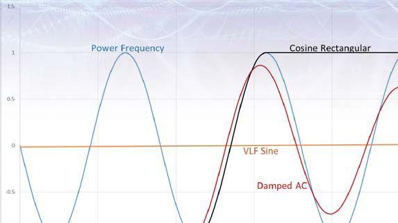


Zoomed-in View of Figure 1 Showing Three Cycles of Power Frequency and the Different Polarity Reversal Times of Various VLF Waveforms
(Note: DAC and CR have approximately the same polarity crossover speed as power frequency.)


Diagram of Circuit Used to Create DAC Waveform
(Note: Cosine rectangular circuit is similar, but includes a blocking diode to allow only a half cycle of resonance.)
Why is all this important? The initiation and the amount of PD measured in a cable are related to the dV/dt or the rate of change in voltage over time. The faster the voltage changes (the higher the frequency), the more PD will be measured and the lower the PD inception voltage will be. Power frequency changes from one peak of voltage to the other peak of voltage in 8.3 ms or 10 ms (60 or 50 Hz), so the testing should be done to mimic this rate of voltage change. Both cosine rectangular and damped ac change polarity in this same few millisecond range, from 5 times faster to 2 times slower than power frequency, on the extreme ends of the scale, for very short or very long cables. However, VLF sinusoidal changes polarity 600

times slower than 60 Hz power frequency does. Due to this much slower polarity change, PD test results collected with a VLF sinusoidal wave may not represent what is occurring in the cable under operating conditions. As seen in the following case study, VLF sinusoidal did not detect the presence of PD on the splice at 750 meters at all, but DAC and cosine rectangular were both able to easily identify it.

According to IEEE 400.3, clause 7.4:
“In summary, it is not possible to standardize a specific test protocol at the current time for either online or off-line tests. This may become possible as more data are collected.”
This standard is unable to provide limits to what would be considered good or bad cables, due to the wide variety of cables and defects encountered in PD testing. However, through experience, certain parameters are clear indicators of problems on the cable system. These parameters include intensity, position, and PD inception voltage. It is obvious that when numerous events occur at a specific location, that location is weaker than the surrounding material. The intensity is a measure of the strength of the discharge. Again, it is obvious that a stronger discharge indicates a more severe condition.
Finally, the PD inception voltage (PDIV) is the minimum voltage needed to trigger partial discharge events. This is a critical measurement, as a cable that exhibits PD at or below operating voltage is much more critical than one that only exhibits PD at 1.5 or 1.7 times operating voltage. In the first case, the cable will experience PD continuously until finally failing in service or during a testing period. In the second case, the cable will operate without PD during day-to-day
operation and only experience PD events when exposed to a high voltage, such as a switching transient or a lightning strike.
This all may sound intimidating, but cables in very good condition are easy to identify, as are cables in very bad condition. It is the cables in between that require additional analysis, and experience quickly makes this simple as well. Some PD threshold levels exist from research and field use to help guide users of PD equipment, even though no standard has been adopted.

In the following example, a single section of cable was tested with each of the three voltage waveforms discussed previously. The tests were performed in this order: DAC, VLF sine, and VLF CR. All three tests were performed within about an hour. The cable sample as shown in Figure 4 was a service-aged mix of XLPE and oil impregnated paper insulation rated at 12/20 kV, and had a total length of 1,335 meters. It had 10 splices, including four transition splices between XLPE and PILC cable. The results are presented in the order the tests were performed. For simplicity, only the results from phase L1 are shown, but the tests were performed on all three phases with similar results across all phases. A summary of all three phases is in Figure 8.
The DAC results show two clear weak points in the cable. The splices at 750 m and at 1,000 m both display large amounts of PD activity. These also correspond to transition splices in the cable system, from XLPE to PILC cable. The DAC results show up to 1,500 picocoulombs (pC) of PD activity on the splice at 750 m and up to 2,000 pC of PD activity on the splice at 1,000 m. The PD activity shown in Figure 5 is up to
(Note: Cable is a total of 1,335 meters and contains 10 splices in 11 sections. Green sections are XLPE cable, and blue sections are PILC cable. Splices are represented by small black segments.)


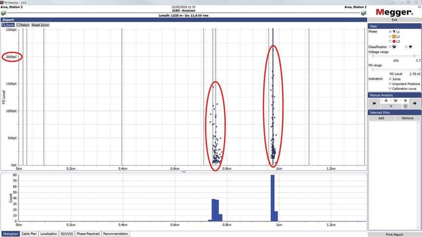
Case Study DAC Results Showing PD Measurements Up to 1.7 Times Rated Voltage
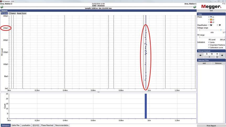
Case Study Sinusoidal Results Showing PD Measurements Up to 1.7 Times Rated Voltage
a voltage of 1.7 times operating voltage, but the PD activity started at a much lower voltage. In this case (Figure 5), the PDIV was 0.4 times operating voltage for the weak spot at 750 m and 0.6 times operating voltage for the weak spot at 1,000 m. Both are well below operating voltage and are cause for significant concern.
VLF sinusoidal results as shown in Figure 6 indicated only one of the weak points detected by DAC. The splice at 1,000 m is identified again
as a site of potential weakness, but it was unable to detect the weak spot at 750 m. Additionally, the weak spot identified at 1,000 m shows a PD activity of only 250 pC at 1.7 times rated voltage. This is a significantly different result from the DAC test. Although 250 pC in a splice may not be critical, it should be monitored, while the 2,000 pC detected during the DAC test is a critical level. Furthermore, the PDIV in this sample was 1.3 times operating voltage, meaning that this result is far less critical than the 0.6 times operating voltage result observed in the DAC test.


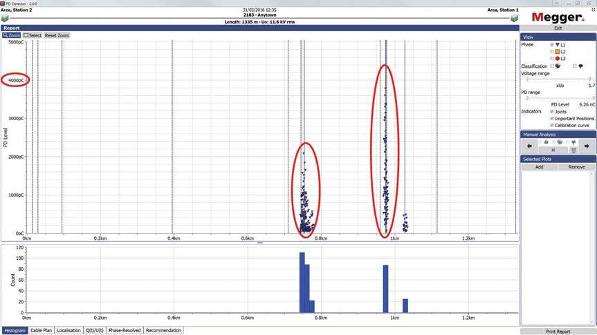
The cosine rectangular results were very similar to the DAC results. This test (Figure 7) located the weak spots at 750 m and at 1,000 m, and identified a PD activity of about 2,000 pC at the 750 m point and about 4,000 pC at the 1,000 m point. While these are higher than the PD activity recorded by the DAC wave — typically due to the continuing voltage application during the voltage hold phase — the ultimate course of action for both tests would be the same. This cable shows a critical amount of PD in both these points for the CR and the DAC tests. The PDIV values for the CR test were approximately 0.5 times operating voltage for both weak spots detected. This test also revealed an additional weak spot. At approximately 1,050 meters, another PD weak spot emerges. This is different from the other points observed, as it is in the cable insulation itself and not in a splice. This is not unusual to see in an oil-impregnated insulation system and could indicate that the oil has leaked out at that point creating a dry spot, or possibly that a small rise in cable elevation resulted in a similar dry spot. At about 500 pC, this would not be an immediate concern for laminated insulation, but should be monitored closely.
The results from this case study demonstrate the frequency-dependent nature of PD testing. In this example, the cable tested with VLF sine would be considered acceptable since the PDIV was above operating voltage, and the level of PD recorded was low. This cable would be placed back into service and would likely soon suffer an unplanned outage. However, by using waveforms that more closely simulate power frequency, the true health of the cable could be assessed. Both damped ac and cosine rectangular identified a weak spot at 750 m that VLF sine was not able to detect, and they detected higher levels of PD activity. The result for both VLF CR and DAC would mean that the cable would not be placed back into service until the splices were repaired or replaced. VLF CR was also able to identify a weak spot in the laminated insulation. At the time of the test, this weak spot did not exhibit enough PD to be of immediate concern, but it should be monitored closely.
The summary in Figure 8 shows a side-by side comparison of the voltage waveforms. The results for DAC and CR are similar, easily locating the weak spots at 750 m and at 1,000 m at both operating voltage and at 1.7 times operating voltage. Both the DAC and CR waveforms had a resonant frequency of 280 Hz, similar in dV/

dtto50/60Hzandmuchfasterthanthe0.1Hz

dt to 50/60 Hz and much faster than the 0.1 Hz fromtheVLFsinewave.TheVLFsinusoidal from the VLF sine wave. The VLF sinusoidal waveform was just able to detect the weak spot at 750 m, with an intensity of less than 80 pC, compared to greater than 1,000 pC for DAC and 1,500 pC for CR. It is entirely possible that in an electromagnetically noisy environment, this amount of partial discharge may not be detectable because it is obscured by background noise. But the 1,000 pC level from DAC would be enough to detect above the background noise. Typical field background noise levels fall in the 20 to 150 pC range.
Looking at Figure 8, it is obvious that DAC and CR have similar results, including a much more detectable PD compared to sinusoidal voltage. Even though DAC and CR detected more PD, it does not mean they were any more stressful to the cable. These tests were performed in the order DAC, VLF sinusoidal, and cosine rectangular. The sine wave was in between the other two wave forms, but did not produce the same results.
It is difficult to overstate the potential power of offline partial discharge diagnostic testing. From IEEE 400.3, clause 1.3:
“The PD measurement can, at times, predict with a high level of confidence that a given cable is in very poor condition and is likely to fail in the near future.”
This knowledge can then be used to improve system reliability, reduce unplanned outages, reduce emergency call-outs, and help target the most vulnerable cables for replacement while allowing good cables to remain in service. However, for accurate results, it is necessary to use a voltage source with characteristics similar to those experienced by the cable in operation, particularly the voltage rate of change from one polarity to the other. Practical, field-portable test sets are available that achieve results comparable to in-service conditions, allowing for the best and most accurate cable maintenance strategy.
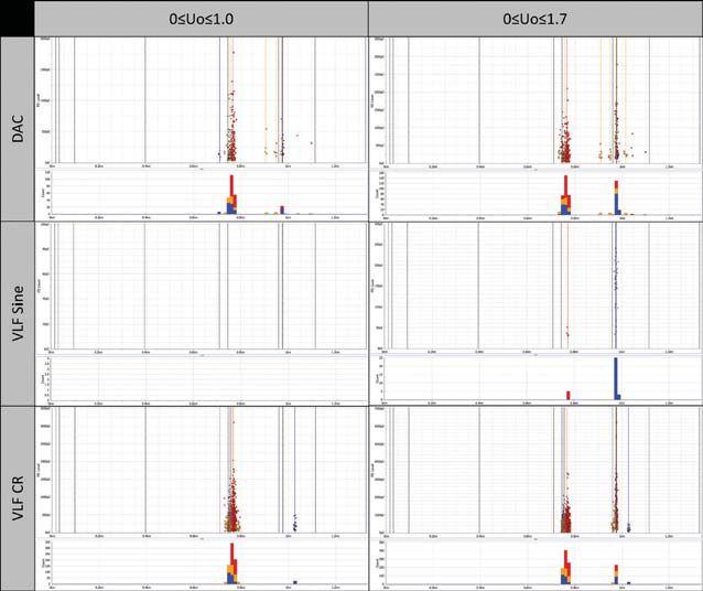

Summary of Test Results — DAC (Top), VLF Sine (Middle), and CR (Bottom) Waveforms at Operating Voltage (Left Column) and 1.7 Times Operating Voltage (Right Column)

Jason Souchak is an Application Engineer for Megger, specializing in cable testing and diagnostic and fault location techniques. He trains end users on the theory and proper use of various pieces of high-voltage testing equipment. Jason is an active member of the IEEE Insulated Conductors Committee (ICC), helping to develop the latest cable testing standards. He graduated from Drexel University in Philadelphia with a B.S. in Electrical Engineering (BSEE), specializing in the power track. He has worked with protective relay manufacturers, utilities, and development and certification testing labs in the United States and in Europe.
R. Bach, P. Craatz, W.Kalkner, K. Hrefter, H. Oldenhoff, G. Ritter. “Voltage tests to assess medium voltage cable systems,” Elektrizitaetswirtschaft 92.17/18 (1993): 1076-1080

Power System Acceptance Testing
Commissioning and Start-up
Maintenance
Life-Cycle Extension
Troubleshoot and Repair
Training and Engineering Services
Planning and Operations Support
Project Management


FOR ACCEPTANCE TESTING SPECIFICATIONS FOR ELECTRICAL POWER EQUIPMENT & SYSTEMS
• Specifies field tests and inspections used to assess the suitability for initial energization of electrical power equipment and systems.
• References include: ASTM, EASA, ICEA, IEEE, NEMA, NFPA, UL, and others.


 BYDONGENUTIS BY DON GENUTIS , Halco Testing Services, Inc.
Once a method used only for laboratory testing purposes, partial discharge (PD) testing has evolved into an effective field testing technique. The high background noise environment typically present in most locations throughout the U.S. initially presented challenges to obtaining trustworthy test results, especially for cable systems. However, the very good noise removal capability of today’s instruments, coupled with greater field application experience gathered over the last 20 years, have greatly enhanced test result reliability.
This article describes the real-life, step-by-step approach of an online insulation condition assessment survey at a facility with a small distribution system.
Our team responded to an emergency for a customer operating a 4,160-volt distribution
system on the coast near Los Angeles. Initial examination determined that the failure occurred in the cable termination area of the main oil fuse cutout (Figure 1). A high-voltage contractor bypassed the damage by taking the switch out of the circuit and splicing the undamaged portions of the line conductors to the load conductors. Energization was successful.


A couple of weeks later, the customer called and explained that the general contractor on site for an unrelated chiller upgrade project stated that the fault would have certainly damaged the customer-owned line-side cables connecting to the utility and recommended replacing the entire MV cable system. It was agreed that a better plan was to first evaluate the cable condition before spending $500,000 on a system replacement.
Recommendations included online and offline cable assessment tests to best evaluate the cable system (see sidebar, “Primary Advantages of OnLine Cable Partial Discharge Testing”). These methods identify different cable system failure mechanisms; however, conducting both types of tests would yield the best data for a proper evaluation.
The customer agreed to proceed with online PD testing and would follow up with off-line testing at a later date if no PD was detected.
We were all holding back our grins when we merged onto Pacific Coast Highway. PCH runs tight along the California coast for over

Job sites like this one on the Pacific Ocean help make up for long, difficult hours often endured by field technicians.
600 miles from the Oregon border to Mexico and is perhaps the most beautiful coastal route in the U.S. Field technicians appreciate these experiences because they help make up for the difficult hours and circumstances that are too often a mainstay in our line of work. After taking in the breathtaking scene at the job site, we got to work setting up our equipment at the bypassed OFC.


Thedevicesusedconsistedofanadvanced The devices used consisted of an advanced dual-sensor (ultrasonic and TEV) handheld PD instrument (Figure 2) for equipment condition assessment and a computer-controlled cable PD assessment instrument equipped with advanced noise removal algorithms (Figure 3) and highfrequency current transformers (HFCT).

Anyone experienced in our industry understands the importance of safety, but it’s important to re-emphasize it — especially in the context of on-line testing — as these tests are performed in
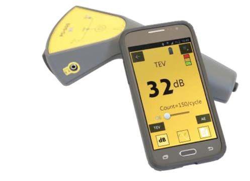

a different manner and not as frequently as offline tests. All of the general safety practices apply to on-line testing, but additional rules must be followed. Detailed safety procedures will be presented in a future NETAWorld NETA World article, but are briefly summarized below:
1. Complete a Job Hazard Analysis (JHA) with careful thought.
2. When performing on-line testing, the first rule is always: “If it’s not safe, don’t perform thetest.” the test.”
3. Observe and strictly abide by the incident energy labels; if labels are not apparent, other NFPA-70E guidelines must be followed. Also, always consider that the label on the equipment could be incorrect for many reasons. Is the label data logical?

Before thinking about testing cables, consider if it’s electrically safe enough to remove the cover and begin the testing sequence. First, perform partial discharge detection of the bypassed OFC using the handheld dual-sensor instrument. If partial discharge activity is present, it’s best to not open the enclosure at all. Alternatively, we may choose to very carefully remove the cover and perform visual inspections. However, it is very unlikely that we would proceed with performing cable PD testing if the handheld instrument detected a problem.
In this case, the handheld instrument test did not detect any PD activity, so the OFC cover was carefully removed and the internal components were visually inspected. We determined that the split-core high-frequency sensors could be safely installed at the new splices (Figure 4).
We then recorded the signals using the computer-based system. We monitored all three cable phases simultaneously and used a magnetic TEV sensor on the enclosure to monitor local discharge activity. A standard 120v outlet was readily available to obtain our synch signal, which is critical for determining precise phaseresolved patterns. PD occurs as the voltage increases near maximum positive and negative

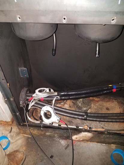
Attached to the Cable Splice
levels of the sine wave, and the synch signal allows confirmation that true PD is present and producing a strong, repeatable pattern across a full cycle.
After the recording was complete, we analyzed the test results. C-phase displayed the nearly synchronous pattern shown in Figure 5, indicating possible PD. Next, we analyzed the waveforms to see if they also displayed PD characteristics. It was first noted that the waveforms had fairly long pulse widths, which could be indicative of distant PD or noise.
Further waveform analysis (Figure 6) determined that the signals were noise. The instrument’s automatic noise-removal algorithms are excellent, but it is still necessary to manually analyze the waveforms further to confirm PD. The OFC cover was reinstalled, and we went on to the next location.
The distribution system consisted of several OFCs throughout the facility connected in series (line-side daisy-chained) with the load side feeding dry-type transformers, so we set up at the next OFC. None of the downstream

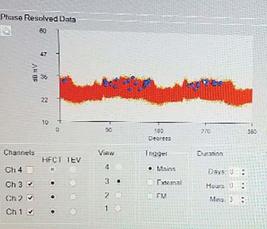

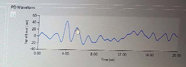
• Does not require an outage
• Very cost effective
• Detects ancillary equipment problems
OFCs would permit safe access for HFCT installation. With three sets of cables in the small enclosure, years of dust buildup, and several oil leaks apparent, testing was unnecessary — the terminations would all need repair, and the aged OFCs presented a major hazard themselves.


Weusedthehandheldinstrumenttodetermine We used the handheld instrument to determine if any OFC or dry-type transformer failures were impending. All dry-type transformers were discharge-free, and one major problem was pinpointed with the ultrasonic sensor (Figure 7) in a short, unshielded jumper cable segment connecting two OFCs (Figure 8).
Thefinalassessmentdeterminedthatthe The final assessment determined that the incoming circuit was free of PD activity and a short OFC-to-OFC jumper circuit needed immediate replacement. Additionally, it was recommended that all OFCs be replaced with air- or gasinsulated switches, and repairs to all associated terminations conducted simultaneously.

Following a major termination failure, the client was uncertain of the incoming cable integrity as well as the condition of their other mediumvoltage equipment. Although upcoming results of off-line cable tests may prove otherwise, it is expected that this cable segment is good and replacement can be deferred. This case study is an excellent example of how on-line PD testing helped a customer determine the best use of their funds, resulting in a much wiser replacement of the failing jumper segment and dangerous OFCs instead of the previously recommended replacement of the entire MV cable system.

Don A. Genutis presently serves as President of Halco Testing Services, Inc., a NETA Accredited Company in Los Angeles. He has held various principal positions during his 30-plus year career in the electrical testing field and has primarily focused on advancing no-outage testing techniques for the last 15 years, with emphasis on cable and switchgear on-line partial discharge testing techniques. Early in his career, Don acquired and operated the former Westinghouse East Pittsburgh Insulation Research laboratory, where he gained valuable experience in the understanding of insulation material performance. Don holds a BS in Electrical Engineering from Carnegie Mellon University and is a NETA Certified Technician. Don has authored dozens of technical articles for NETA World and has been featured in EC&M and Uptime magazines.

You’ve known Electrical Reliability Services as part of Emerson Network Power. Although we’re now part of Vertiv, our commitment to you remains the same. You can still look to us for the same non-biased independent third-party electrical testing, maintenance, and engineering services. But now, we’re more than that. We’re an agile operation with a laser focus on delivering vital, innovative and intelligent applications for high-tech environments.




 BY WILLIAM G. HIGINBOTHAM, EA Technology, LLC

Condition assessment of electrical assets is often compared to going to the doctor: It’s best to find out about minor issues before they become major problems. Another analogy: You ask your doctor, “What’s the best exercise I can do to get in shape?” His response: “The one you can actually do!” The most effective exercise might be spending three hours in the gym every day and training for a marathon on the side. However, the one you might actually do is walk a mile each day and add some light calisthenics. The point is, while different levels of exercise might have different benefits, don’t attempt something so difficult that you just won’t do it.
The same thought process applies to mediumvoltage maintenance. If you had no other considerations, you might disassemble everything every year and do offline VLF PD tests, visual inspections, etc. However, just because that’s not practical doesn’t mean you
should do nothing. Online, non-invasive tests are practical and cost effective, and doing them is a much better alternative to doing nothing. This article will explain the technology behind the main non-invasive techniques used for switchgear, ultrasonic, and transient earth
voltage (TEV) detection, and show how they can provide much of the value commonly associated with off-line testing. Field results from around the world are included.
Two forms of partial discharge — surface discharge and corona — emit high levels of sound waves. Most of that energy is above the frequency range of human hearing, so it is called ultrasonic. By measuring and analyzing the ultrasonic spectrum, we can detect this energy and, more important, discriminate it from other sources of ultrasonic noise.
Sound can be measured on the Sound Pressure Level (SPL) scale, which is a logarithmic scale where 0 SPL is approximately the threshold of human hearing and 100 SPL is the sound of a pneumatic jackhammer. Ultrasonic energy can be measured on the same scale using equivalent electrical output levels from a sensor even though you cannot hear this energy.
If you measure the sound energy in a narrow frequency band around 40 KHz, you get some surprising results. The air coming out of an HVAC vent may contain 40 SPL of ultrasonic energy and virtually nothing in the audio band. Conversely, the ultrasonic energy given off by a freight train 50 feet away may be 0 SPL. Ultrasonic energy given off by surface discharge at close range is typically -10 to 60 SPL. PD instruments tend to display levels in dBuV where 18 dB SPL = 0 dBuV. This will vary with sensor sensitivity and manufacturer.
More important than the sound level are its characteristics. Ultrasonic energy from PD will have four characteristics that make it straightforward to detect.
1. When super-heterodyned down into the range of human hearing (2 KHz center frequency), it has a distinctive sound much like bacon frying or fizzing.
2. The sound will be concentrated in 120Hz bursts related to the positive and negative
rising edges in the power system sine wave.
3. The sound will have a repetition rate in the range of 6 to 50 pulses per cycle.
4. The sound will not be perfectly repetitive in phase angle, amplitude, or energy level gy from pulse to pulse.
These characteristics make it possible to design an instrument that can pick out PD from the cacophony of ultrasonic energy present in some locations. When trying to detect sound pressure waves, an air path is needed from the source to the sensor. Fortunately, an air path is almost always present in metal-clad switchgear. Switchgear has louvers, vents, loosely fitting panels, and doors. Moving a sensor along these openings allows the user to pick up PD from outside a closed cabinet. In the event no air path (well-sealed compartments) exists, contact sensors can pick up the very slight vibrations on the panel due to ultrasonic energy inside. Such sensors must be incredibly sensitive.

Once you’ve heard the sound and recognized it, make sure the other characteristics are present. Modern instruments provide phaseresolved and pulses-per-cycle (PPC) displays that confirm presence of the second and third characteristics.Thelatestinstrumentsalso characteristics. The latest instruments also include advanced algorithms that look for all four potential characteristics and automatically classify detected energy as PD or noise.

In 1979, Dr. John Reeves of EA Technology nology discovered the Transient Earth Voltage (TEV) phenomenon and developed it to measure internal partial discharge inside metal-clad switchgear. Figure 1 shows how the partialdischarge-induced current pulse travels along theinternalandthenexternalsurfaceofthe the internal and then external surface of the switchgear. The pulse travels through the impedance of the ground connection. Because the typical grounding of metal-clad switchgear tchgear


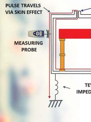
Current Flow Resulting in Transient Earth Voltage present curren surface With capacit switchg measur signific presenc meter. will va the hig system or over of PD Doing involve the me few sec
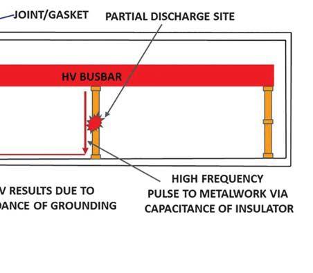
presents high impedance to high-frequency currents, a voltage is developed on the gear’s surface.
One challenge is ensuring that the values obtained are repeatable and useful. Obviously, if you get a different answer every time you do the test, the test is useless. This has been a concern connected with PD testing for a long time, and past methods suffer from poor repeatability. Most likely, Dr. Reeves’ first TEV test instrument took a fair amount of expertise to generate repeatable results. One advantage of modern instruments is that their use is more straightforward. A good PD test instrument will have minimal manual settings available so that results are consistent, regardless of who conducts the test.
Another advantage of modern equipment is multiple testing modalities. For example, an ultrasonic test by listening for the sound is good, but seeing phase-resolved plots, PPC counts, and algorithmic results gives users more confidence in what they are hearing. Of course, the ability to record the results for discussion with support staff and comparison to past results improves results even further. Instruments with built-in humidity recording make tests more repeatable, as ultrasonic readings are highly variable with changes in humidity.
With a highly selective, very sensitive meter capacitively coupled to the outside of the switchgear, this voltage can be discriminated and measured. Levels as low as 10 mV can indicate significant PD, and measuring this in the presence of tens of kV requires a very selective meter. The absolute level of the TEV reading will vary significantly due to the variability of the high-frequency impedance of the grounding system, but comparing measurements over time or over similar devices provides a good indication of PD severity.
Doing an on-line, non-invasive TEV test involves pressing the capacitive sensor plate to the metal cladding of each compartment for a few seconds and taking a reading.

If the repeatability is good, then the next question is how to relate the levels to asset condition. Measured levels will vary with grounding, air path attenuation, humidity, etc. Even if all variables are controlled, it is difficult to relate the measurement results to the time to failure. There is no magic solution for that problem, but some methods can help.
Offline and vis So, can quanti won’t r provid not oth testing
Offline VLF testing has recognized thresholds, and visual inspection produces obvious results. So, can on-line, non-invasive PD testing provide quantitative results? While this type of testing won’t reveal as much as other methods, it will provide a wealth of information you might not otherwise have if practical realities prevent testing every piece of gear. It is “the one you can actually do.”

• Trend the levels over time to give an indication of the rate of change. Because the effects of the process influence the process, the levels are exponential. As the rate of change begins increasing, the asset approaches failure.
• Compare similar pieces of gear. Among 10 identical cabinets, if one is putting out significantly more TEV, it’s time for further investigation.
• Compare large bodies of data to obtain guidelines. If the test equipment manufacturer has a large user’s group and a database of thousands of results from similar assets, they can establish guidelines for when action is required.
• Narrow down TEV to a specific cabinet. It’s an unfortunate fact that PD in one cabinet can produce TEV of equal or higher levels in adjacent cabinets. Using a time-precedence-based location system can pinpoint the TEV source to a single cabinet for further investigation. Such devices use the time of flight of PD currents to determine where it occurred first.
Finally, it’s important to understand the limitations of non-invasive testing and its place in the world. Non-invasive testing allows a user to quickly scan all gear and trend it over time until a more invasive test is warranted. Because an enormous population of gear is significantly aged and has never been scanned, the first pass often dictates immediate action. Upon initial scan, it is typical to find 5 to 10 percent of gear with a major issue. Performing more invasive testing on assets flagged in the initial scan is often a viable and cost-effective method for improving reliability and reducing unplanned outages.
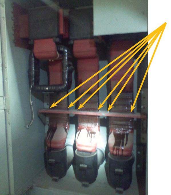

The user acquired a combined ultrasonic and TEV test instrument and, without any training, donned the headphones and started taking ultrasonic measurements. At first, much of it sounded unremarkable; then they came upon one cabinet where the classic ultrasonic sound of bacon frying was present. When the cabinet was opened, six partial discharge sites (one on each edge of each busbar) were found (Figure 2) where contamination along a horizontal brace was causing severe discharge (Figure 3). This equipment was on the verge of failure


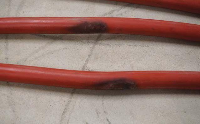
and, without remedial action, would have soon caused significant damage and potential risk to personnel.
A large office building had full-time partial discharge monitoring installed due to the critical nature of its operations. The monitor found a workmanship issue in a termination (Figure 4) that was approaching catastrophic failure. In addition, an installation mistake common to all the installed potential transformer cables (Figure 5) was discovered. The improper installation was causing degradation to dozens of cables throughout the installation (Figure 6). These were all corrected with a planned, orderly shutdown and returned to service.
Matthew Vaughan, AECOM, who maintains the site, said, “The advance notice that the PD monitoring system gave us enabled us to plan an outage to resolve the problem and significantly increased the client’s confidence in our highvoltage maintenance program.”
An ultrasonic and TEV survey was performed on the assets of a petrochemical plant. During the initial survey, ultrasonic energy in one cabinet was significantly higher than all others. The distinctive sound of PD was heard. The phaseresolved plots were distinctive (Figure 7) and the algorithm indicated PD with 100 percent certainty (Figure 8). Because all three modalities agreed, PD was conclusively identified. The cabinet was de-energized, and a visual inspection showed a significant PD site due to improper clearances with obvious tracking and nitric oxide buildup. The damage would have led to a failure had it not been caught.
In summary, on-line, non-invasive partial discharge testing of metal-clad switchgear provides repeatable, actionable information

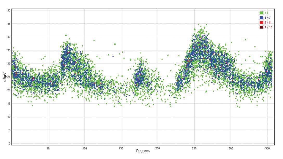
that is impractical to take any other way. Test hundreds of assets per day without taking an outage or subjecting employees to risk. Do “the one you can actually do.”
After all this talk about exercise, I think I’ll go take a nap.

William G. Higinbotham has been president of EA Technology LLC since 2013. His responsibilities involve general management of the company, including EA Technology activities in North and South America. William is also responsible for sales, service, support, and training on partial discharge instruments and condition-based asset management. He is the author or co-author of several industry papers. Previously, William was vice president of RFL Electronics Inc.’s Research and Development Engineering Group, where his responsibilities included new product development, manufacturing engineering, and technical support. He is a senior member of IEEE and is active in the IEEE Power Systems Relaying Committee. He has co-authored a number of IEEE standards in the field of power system protection and communications, and holds one patent in this area. William received his B.S. degree from Rutgers, the State University of New Jersey’s School of Engineering in 1984, and worked in the biomedical engineering field for five years prior to joining RFL.







With an average 20 years of experience, our technicians and engineers can quickly assess equipment and implement repairs or upgrades—with licensed PEs reviewing your test results. We’ll meet budgets while surpassing expectations
• Upgrades, including testing and repairs for 480V to 765kV systems
• Circuit breakers, transformers, relays, and other electrical apparatuses
• On-staff NETA® A -certified engineers and technicians
• Direct relationships with all major OEMs
• Switchgear upgrade services with on-site capabilities
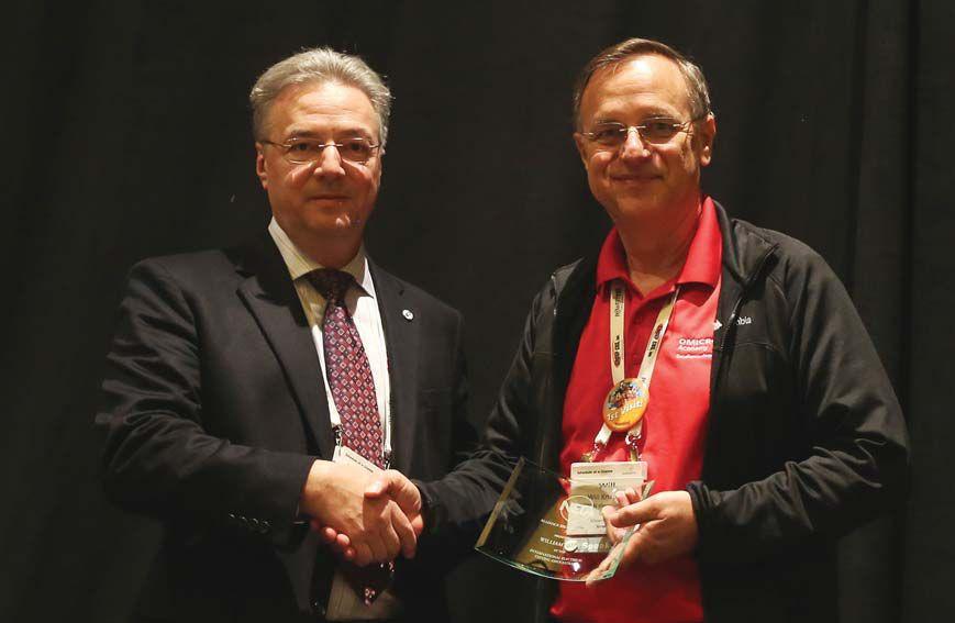
After the shock of being presented the 2017 Alliance Recognition Award settled in, Will Knapek had only one thing to say to his NETA colleagues: “What can I do next to support you?”
This likely did not come as a surprise for those who know Knapek. Many of the reasons he was chosen for the award have to do with his dedication to the power systems industry and his reputation as a person who will always get the job done.
“Will is incredibly knowledgeable about the industry,” says Jim Cialdea, President of 3C Electrical Company and First Vice President of NETA’s Board of Directors. “But even more impressive is his willingness — in fact, his drive — to share that knowledge with others. NETA is
certainly better for having Will as a part of us.”
The Alliance Recognition Award is NETA’s way of honoring worthy contributors to the electrical testing industry, people like Knapek who have not only been a dedicated supporter of NETA and the work of the association, but also have furthered the industry and inspired others to do the same.
“Will has contributed to NETA since the beginning of his career when he worked for one of our NETA Accredited Companies and was an advocate for membership,” says NETA Executive Director Missy Richard. “He is always ready and willing to assist in the educational process and share information with the goal of advancing the work of NETA.”
Considered an expert in protective relay and substation maintenance testing, Knapek is often described as eager to share his knowledge and experience. Knapek says he remembers as a young man that it was difficult to find training in electrical systems. It’s now important to him to have a role in creating those opportunities for today’s young people.
“NETA’s standardization and the process to become a member requires an education level that is important for the industry,” says Knapek, Sales Manager for the Southeast Area of North America for OMICRON electronics Corp. “This business has a lot of on-the-fly learning. It’s important to get quality training whenever you can — so you can keep up. NETA provides that.”
Knapek helped provide numerous training opportunities himself. He served on NETA’s Training Committee for many years. More recently, he orchestrated the creation of two major training programs with OMICRON. The Road Show Bus is a customized tour bus that not only allows Knapek to bring the full range of OMICRON products with him wherever he travels, but there is also a classroom on the bus, allowing him to bring training opportunities just about anywhere.

Will shares his knowledge while presenting at PowerTest 2017
“I have a passion for training,” says Knapek, who was also instrumental in the creation of OMICRON’s Houston training center. He says he saw the opportunity when one of the company’s leases in Houston was coming close to expiring, and they had a transformer in Nashville. “I said, ‘Why don’t we just look for some property and put together a training center and move the transformer down there?’” So OMICRON built a brand-new facility with a training area.
Will Knapek is Sales Manager for the Southeast Area of North America for OMICRON electronics Corp, USA. He is certified as a Senior NICET Technician and is a member of IEEE and Vice Chair of WG I23 of the PSRC.
Knapek earned a bachelor’s degree in industrial technology from East Carolina University and an associate’s degree in industrial technology from Western Kentucky University. After college, he served in the U.S. Army for 20 years. During his time with the Army Corps of Engineers, he held positions as a Power Plant Instrumentation Specialist, a WriterInstructor for the Army Engineer School, and a Facility Engineer for a Special Operations compound. He retired in 1995 as a Chief Warrant Officer.
After retiring from the Army, he entered the electrical testing industry in the Nashville area until he joined OMICRON electronics as an application engineer in April 2008.
Knapek has been a speaker at PowerTest every year since 2008, including this year when he presented on Protective Relays - Equipment and Reliability. At Member Alliance Meetings, he has been a Roundtable discussion leader. He is the OMICRON representative to the Corporate Alliance Partnership Program and is a former NETA Level IV Technician: Electrical Reliability Services – Power and Generation Testing.

Now technicians benefit from ideal training conditions and special equipment, including a wide range of test sets and assets, such as the transformer, circuit breakers, a partial-discharge testing area, and a hands-on protective relay lab and distribution automation area.
Knapek got his start in the industry while serving in the Army Corps of Engineers. After 20 years of service, he retired as a Chief Warrant Officer in 1995 and went to work for NETA member companies in Nashville, Tennessee. He joined
OMICRON electronics in 2008, where he continues to serve to this day.
His passion for the industry must have rubbed off on his family as well. His sons are following in his footsteps: Richard works for Power Solutions Group Inc., and his youngest son, JW, works for Sweitzer Electric, LLC, and is preparing to become a NETA Certified Technician.
“I guess I pounded the electrical stuff into their heads when they were young,” he says.







OSHA 29CFR1910.399 definition of a qualified person:
“Qualified person. One who has received training in and has demonstrated skills and knowledge in the construction and operation of electric equipment and installations and the hazards involved.”
Shermco’s Electrical Safety for Qualified Workers course meets the minimum mandated requirements of both OSHA and NFPA 70E.
Shouldn’t you be training with the people who are in the field every day?


In the past, on load tap changer (OLTC) testing and diagnostics were based on simple resistance measurements at each static tap position to establish whether the tap changer contacts were in good condition. The dynamic recording measurement (DRM) is a new offline test technique showing its diagnostic power in detecting OLTC operational problems. Sometimes, this test method is incorrectly called a dynamic resistance measurement (same acronym — DRM), but it is not a resistance graph. The product is a current graph versus time, and its analysis is explained in this article.
The AMforum (a European association of asset managers in electric utilities) created a working group to investigate and standardize the methodology, and some of the cases collected are presented here. The IEEE Transformer Committee, through the Power Transformer Subcommittee, is looking into standardizing this method. The IEC and IEEE are coming out with a joint OLTC user guide that includes this test.
The on load tap changer principle was patented in 1927 by Dr. Bernhard Jansen, and its premise


is very simple: “Make before break,” meaning connect with the next tap before breaking with the previous one. This is still true today, and tap changers are designed following this approach. As this is a tap changer that operates under transformer full-load condition, as opposed to de-energized tap changer (DETC), the circuit should never be broken. Thus, opening the circuit is one of the biggest OLTC problems. It creates gases and can cause transformer tripping or even failure. Detecting this was impossible using old-fashioned static measurement techniques.

Tap changers can be visually observed or scanned using thermography. Dissolved gas can be used as a tool to find a problem with excessive heating or arcing. These tests can indicate the existence of a problem. Turns ratio can be measured on each tap, and winding resistance test results for all taps should be consistent. Vibration methods look into signatures collected using vibroacoustic sensors or accelerometers. Monitoring various on-line parameters can indicate torque, mechanical issues, overcurrent, overheating, etc.


In the past, the possibility for a test crew to see the problem off-line with OLTC operation was based on flicker in the test voltage or induced voltage when performing some ac tests such as turns ratio while operating the tap changer. Many times, OLTC was open on these indications, and nothing unusual could be observed.
With modern electronics, recording of a test current at high frequency allows observing the performance of an OLTC at high speed, providing important information on its mechanical motion as well as contact bouncing, opening, coking, etc. The DRM methodology is only 10 to 15 years old, but it has shown great potential in detecting problems otherwise invisible to repair technicians. Fortunately, this method of analysis does not require great experience when viewing the graph. When the current is stable, it creates a straight horizontal line. Any increase in resistance or reactance makes the current drop, visible as a dip on the graph. Any resistance drop makes the current jump, as with lowering the number of turns the current will go up. A good tap changer makes the graph very smooth, and any discrepancy indicates a problem (Figure 1).
Figure 2 is a graph of a brand new reactor tap changer at plus-minus regulation. These good graphs or benchmarks when the tap changer is new should serve as a base for comparison during maintenance periods.
There are many different designs and principles of OLTC operation. They can be in the tank or in a separate compartment attached to the tank. They can use reactors (preventive autotransformers) or resistors to lower the circulating current. The switching can be in oil or contained in the vacuum bottles. For high currents, a booster or a series transformer may be added to lower the current while increasing the voltage dealt with by the OLTC. The current switching and selection of taps can be performed using the same pair of contacts (arcing tap switch) or using two sets of contacts (a selector
and a separate transfer or diverter switch). Then, two or three tap changers can operate on the same mechanism in one transformer, and their synchronization needs to be verified. Many variations require the knowledge of exact tap changer type to analyze the result.
Reactor-type tap changers are predominant in U.S. networks, while European tap changers use resistors for circulating current limitation during the tap transition. These reactor OLTC constructions rely on preventive autotransformers (PA) to limit this current, and provide double the number of tap positions compared with resistor types for the same number of taps brought out from the regulating winding. The PA is a gapped core reactor with dual windings wound in opposite directions; in fact, there is an additional small transformer inside the main transformer tank. As the PA does not permit the current to circulate, a bridging position is allowed with reactor OLTC indefinitely. For resistor types, the bridging position lasts only 10 to 20 msec. It is not really a position, just a quick transition.
With the DRM, our dynamic test applies to all types of tap changers. Of course, there are certain modifications to the procedure when testing a series transformer, as the OLTC circuit is electrically isolated from the test circuit. However, the analysis of results and evaluation of the graphs are somewhat different depending on the construction principles.
Each tap changer transition during this DRM test creates a dip in the current graph. These dips are called ripples, and values and shapes of the ripple are analyzed for each transition. The ripple value is expressed in percents, and they all should be consistent. A ripple value of 100 percent (or close to that) indicates the circuit opening, and this is not acceptable for normal OLTC operation. For resistor-type tap changers, ripples are very consistent, while ripples for reactor types alternate — longer and shorter, for bridging and non-bridging position transitions.

Following the idea of dynamic resistance measurement in circuit breakers, the identical procedure is applied to transformers (the reason this method is incorrectly named). However, transformer inductance does not allow calculation of resistance during the transition from tap to tap; thus, only the test current is recorded with high resolution at a frequency of 10 kHz. The connection of the test leads is identical to winding resistance measurement, and the instrument is usually the same. In fact, both can be obtained in the same process; the first one is sometimes called static resistance, as opposed to this dynamic resistance graph. A recommended test current for the measurement is 10A or even 15 to 20A, although there is no special requirement for higher current. The only requisite is that the current is stable, and that is achieved faster if the magnetic core is saturated by applying higher current.
The current trace in Figure 3 shows the key points of a good GE-type LRT200 tap changer operation. Events are identified by these sudden current changes. Six key feature points
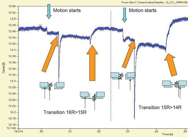

representing two transitions of OLTC are visible in this graph: from non-bridging to bridging, and then from bridging to non-bridging positions (in this example, from 16R to 15R, then 15R to 14R).
The first point in Figure 3 is a small drop pointing to a contact motion start, which creates a small variation in the test current. It points to an increased resistance as the contacts are now sliding over its surface. The next big ripple corresponds to the first contact parting from the initial tap, in this case, the vacuum switch operation. The second ripple, which is somewhat smaller, is where the contact touches the next tap. This is now the bridging position, as two contacts are at two taps — practically bridging them. The bridging positions are oddnumbered positions, while the non-bridging positions are even-numbered positions; a typical U.S. tap changer normally has 33 positions for an eight-tap regulating winding. The reversal switch doubles the eight taps into 16, and the reactor tap changer operating at bridging position makes this double again, creating 32 positions plus the neutral.
The next transition record in Figure 3 shows identical motion and switching points of the tap changer as it moves from the bridging position to the next one, the non-bridging position 14R, where both moving contacts are on the same tap. The difference is in the ripple length, so in a complete graph, ripples alternate long-short to various degrees (where for a resistor OLTC they are almost identical).
When located in the delta winding, tap changers at higher voltages need to be isolated from each other, so two or even three separate tap changers are operated from the same motor and mechanical drive. Their operation coordination needs to be checked, and the synchronization mode is used, where all three phases are tested together. The connection for Wye configuration is with three parallel phases, where for Delta winding, the test is two by two. For a test current of 10A per phase, that would require an instrument with 30A capacity. Figure 4 shows a synchronization graph of a Wye configuration, where one phase is leading the other two by a significant 100 msec difference.
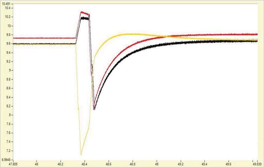
AMforum has looked into this test method at previous meetings and decided to form a working group to define a procedure and standard method of evaluating test results. The group collected a large number of test graphs from all over the world; some interesting cases are shown here. These are simple cases that saved a number of problems and money to the operator by finding the defect early and requiring an easy fix to rectify it.
On load tap changer model 546, manufactured by Federal Pacific Electric, exhibited a significant difference in the ripple value for the phases X2 compared to X1 and X3. Figure 5 shows an overlay of two graphs with phase X2 in red and X1 in blue. This difference was significant enough to prompt a corrective action, including draining the oil and opening the OLTC tank.
Upon investigation, it was found that the bolt for the feed on phase X2 from the transformer to the collector ring had vibrated loose. The maintenance personnel cleaned and retightened the bolt. Once the transformer was repaired and ready for service, a retest verified that corrective action was successful. Ripple values were normal and compared favorably with the other two phases. This simple and timely correction saved a major problem that could have developed if the bolt was left loose, creating overheating and arcing.
Another example of the problem pinpointed following high DGA results is a VRC-type tap changer, where a reversal switch connection was found loose. Figure 6 shows a correlation of two phases, the good one in blue and bad one in red. It is clearly visible that the red current trace is not a straight line during the stable period of tap changer idling at the neutral position.
The wiggly trace is pointing to a bad contact or connection, in this case the K (+/-) contact. Figure 7 shows the exact position of the loose bolt, which was tightened very easily using the manhole at the selector.
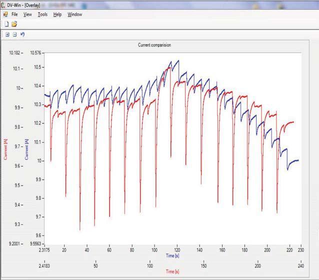

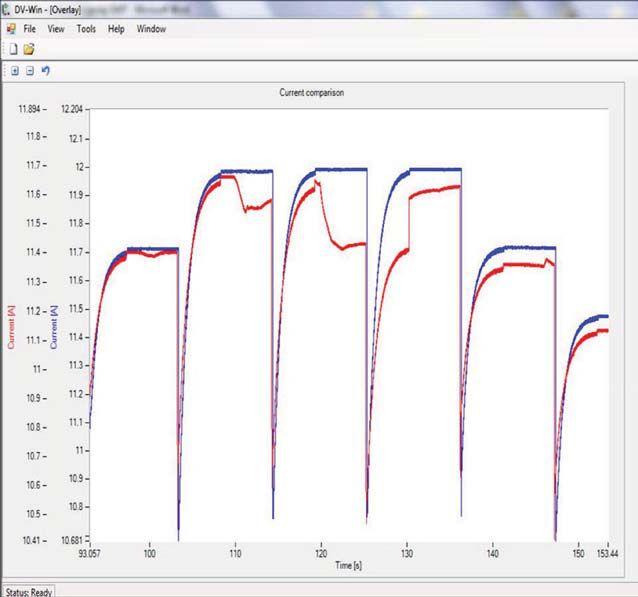
Correlation of Two Phases in a VRC-Type Tap Changer, Where a Reversal


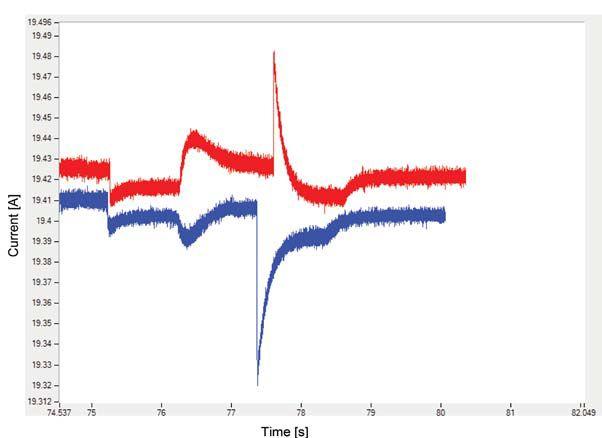
Two Traces Recorded When a Reactor-Type Tap Changer
Switched from One Position to the Next in One Direction and Then in the f OtherDirection Other Direction
The graph in Figure 8 is a good example that proves an important point and makes the necessary procedure very exact. The two traces were recorded when a reactor-type tap changer was switching from one position to the next in one direction and then in the other direction. It is almost a mirror image of the transitions. For that reason, always perform the test in the same direction — either from 16L to 16R or opposite. It would be even better if the tests
were performed in both directions so that various switches are investigated in their action regardless of the tap changer direction.
Whenever a dc current is applied to a transformer winding, the core gets magnetized. Remanent magnetism can affect the in-rush current and some other diagnostic test procedures. To eliminate remanent magnetism, an automatic demagnetization process is required from all instruments supplying a dc current for winding resistance tests, no matter whether it is static or dynamic.
Service organizations have a new tool in their toolbox with potential to detect and eliminate problems and save big transformers. The DRM is a new method for OLTC condition assessment that has shown great diagnostic power in defining exactly which component is defective, so an early spare part request can be made before the repair. Mechanism defects or maladjustments were detected, and contact bouncing and coking were found. Spring breaking, transfer switch loosening, loose bolts, and circuit opening are some of the problems detected. More important, result analysis defines which phase and which switches were defective. The beauty of the method is the ease with which analysis is visually performed, and no great expertise is required to observe a problem when evaluating the DRM graphs.

Raka Levi, Ph.D., is an Application Expert at DV-Power Sweden and convener of the AMforum association. He has over 30 years of asset performance and condition assessment experience, specializing in apparatus testing, monitoring, and diagnostics. Seven years ago, he started a working group on DRM test methodology for tap changers within the AMforum organization. For 20 years, he has led committees that assemble asset managers, organizing AMforum conferences in Europe, LTC universities in the U.S., and LTC colleges in Asia. His education includes a Ph.D. in HV diagnostics for circuit breakers from University of Belgrade and an M.E. in Electric Power Engineering from Rensselaer Polytechnic Institute.


Simultaneous three-phase tap changer analysis and six-winding resistance measurements
One-of-a-kind diagnostic solution for power transformer testing
Testing is safer, significantly faster, and more convenient
Automatic demagnetization process
Checking synchronization of multiple tap changers
Once all 6-8 bushings are connected the test procedure runs automatically
Quick tests by saturating the magnetic core on the HV and LV winding at the same time
Interchangeable test leads with TRT series of true 3-phase turns ratio testers


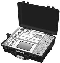

We deliver optimum system reliability and performance while reducing the chances of costly unplanned power outages. Whether you need acceptance


The ASTM F18 committee is responsible for all rubberinsulating PPE, as well as arc-flash PPE, live-line tools, insulated tools, and insulated bucket trucks. The F18 committee met in Orlando, Florida, from October 22–25, 2016. The next meeting is scheduled April 23–27, 2017, in Las Vegas, Nevada, and in October 2017 in New Orleans, Louisiana.
NETA has supported removing mandatory references from NFPA 70E so it can be used in other countries. Mandatory references to U.S. standards, although acceptable in the U.S., prevent the use of 70E elsewhere. The proposed change would move all requirements to adhere to specific standards to Informational Notes.
NETA’s participation on ASTM F18 is necessary to provide a different voice from the majority now on the committee, which is primarily comprised of manufacturers and utilities. There is very little opinion from the industrial sector of the industry. Much useful information comes out during the committee meetings, as has been related in previous columns in NETA World.

was successful. The final vote by the NFPA will occur during its National Conference and Expo scheduled for June 4–7, 2017, in Boston, Massachusetts.


The removal of mandatory references was mentioned in the ASTM report. Other changes include a significant reorganization to Article 120 to make it easier to use:
• Moving all requirements for training into 110.2
• Moving all auditing requirements into 110.1
• Changing Table 130.7(C)(15)(A)(a) to Table 130.5, which allows it to assess the likelihood of an arc flash for all methods (table method or incident energy analysis method)

NETA is also on the ASTM F1506 work group, which is reviewing that standard and making changes. These changes will have a significant impact on NETA member companies and their employees in the future.


The NEC is out of cycle, so there is no new business to report. Jim White is NETA’s primary representative on NEC CMP13.
The 70E had its Second Draft meeting July 16–22, 2016, in Salt lake City, Utah. The 70E is nearly finished; only one outstanding TIA (Tentative Interim Amendment) remains, and it is mostly editorial in nature. The balloting indicated it
• Moving Table H.3(b) to Table 130.5(G) to allow for selecting arc-rated PPE and other PPE when using the incident energy analysis method, and the new requirement for conformity assessments for arc-rated PPE
The need for representation on the 70E is clear, as this is the industry’s primary electrical safety standard.
Jim White (Shermco Industries) is NETA’s primary representative on NFPA 70E; Ron Widup is the alternate representative.


Jim White is the Training Director for Shermco Industries. He is the Principal Member of the ASTM F18 Electrical Protective Equipment for Workers Committee and the NFPA Recommended Practice for Electrical Equipment Maintenance Committee (NFPA 70B). He represents NETA as the Principal member of NFPA 70E and is NETA’s Principal member on NEC CMP-13. Jim is an IEEE Senior Member and was Chairman of the IEEE Electrical Safety Workshop in 2008.






Switchgear devices are situated at key points of electrical energy transmission and distribution systems. Their reliability has a decisive influence on the availability, safety, and economic efficiency of electricity supply systems. Switchgear devices are constantly exposed to the elements, such as dirt, moisture, and temperature fluctuations, which can have negative effects. They are often not operated for years at a time and then have to operate reliably up to 20 times within a very short period under fault conditions, like a thunderstorm. The demands placed on their operational reliability are extremely high.
It is essential to take preventive measures at an early stage in reaction to changes in breaker performance and to regularly acquire and verify all relevant device parameters. This should not be limited to the maintenance cycles in a revision plan. Various mechanical and electrical parameters can be instrumental in making a full assessment of the reliability of a switchgear device, including the main contact velocity, its stroke, and the operating time of the breaker. Deviations from the rated values can point to defects in the drive or in the main contact chamber.



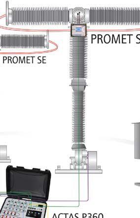

Electrical as well as mechanical parameters are important indicators for detecting impending faults. The amplitudes and time-dependent characteristics of the operating currents of release coils, for instance, can give a good indication of what state they are in, as changes in the operating forces can occur as a result of mechanical wear and tear and usually show up directly in the amplitude and curve shape. For this reason, in addition to measuring main and auxiliary contact status, modern test systems are capable of measuring resistive contacts, coil operating currents, the operating currents of spring-charging or pump motors, valve pressures, and travel and mechanical main contact travel. Only then is it possible to investigate all the parameters that determine the reliability of a switchgear device and to assess the conditions inside the switchgear device without opening the drive or even the main contact chambers.
ohm meter, and a motor-and-coil test system has a number of significant differences over all-in-one systems, including:
• Price advantage compared to all-in-one systems
• Stand-alone operation of each individual system for maximum flexibility
• Simple, joint operation of all devices plus central data management with the same testing software
• Common test plan for controlling the individual devices
Networking and flexible deployment of individual test devices allow conventional measurements to be carried out with one test setup when a system solution is used. Figure 1 shows the setup for testing an outdoor breaker. The ohm meters are put into position on the main contact chambers and are connected to the switchgear test system via only a data line.
While demands placed on switchgear testing are increasing all the time, fewer personnel are available to carry out the tests, and the person carrying out the test may not have time to assess the recorded measurement data and results adequately. Modern test technology can provide tools for the automatic execution and evaluation of some test routines. A system solution with a switchgear test system, an
Combining a switchgear test system with three ohm meters makes it possible to carry out dynamic and static resistance determinations on six interrupter units. In addition, the operating times of the main and resistive contacts of six interrupter units can be determined with a dynamic timing method. This is also possible when the switchgear device is earthed on both sides,
ensuring that the most stringent safety criteria are fulfilled while considerably reducing the time and effort involved in cabling. With conventional measurement methods, resistance measurement may only be possible on one interrupter unit; for the outdoor breaker mentioned previously, this meansthatatleastsixmeasurementshavetobe means that at least six measurements have to be made, taking up more time. me.

Unlike evaluation based on a simple binary signal, as used in high-frequency test methods, the use of switchgear test systems in combination with ohm meters enables a sound diagnosis of interrupter units throughout the whole switching operation. The measurement result is displayed in a curve that visualizes in detail all the events of a switching operation. This allows an accurate assessment of the start of travel and the final position of the contacts; it even reveals time differences between the movements of the main and resistive contacts.

connections can be identified by measuring static contact resistance. Dynamic contact resistance measurementscandeterminetheresistance measurements can determine the resistance characteristic during a freely definable switching operation. These measurements, for example, give an indication of the length and state of the arcing contacts of high-voltage breakers (Figure 2).
Regular measurements of the static and dynamic contact resistance allow an accurate assessment of the condition of the entire contact system. This ensures that maintenance requirements can be identified at an early stage and downtimes kept to a minimum. With an ohm meter, contact resistance measurements can be carried out on up to six main contact chambers and can be incorporated directly in the test procedure. Using a state-of-the-art ohm meter, the test current can be set to a maximum of 200 A. Even very low resistance values in the single-digit micro-ohm range can be measured extremely accurately. The measured values can be used in the evaluation of tests and included in the test report.
A high-contact resistance within a switchgear device leads to high power loss coupled with thermal stress, which can cause serious damage to the switchgear device. Problems such as high transfer resistance resulting from poor

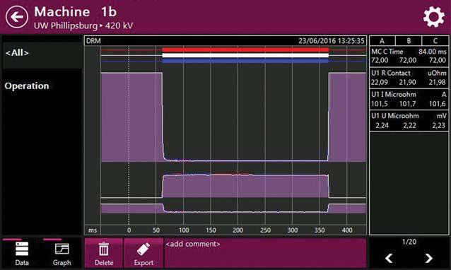
The ability to connect a powerful ac/dc voltage source makes it possible to test the correct functioning of the additional components of switchgear devices directly and independently of the station voltage. To perform an undervoltage release, as well as minimum reading test on coils, disconnection from the station supply and a connection to an adjustable power source is necessary.
In addition to carrying out the previous measurements, modern test systems also need to score high on functionality, ergonomics, and performance. An integrated control panel with touch screen, a streamlined operating concept, and powerful hardware guarantee simple operation with optimum display of all information. The user interface should be clear, well structured, selfexplanatory, and user-intuitive. All test parameters


need to be displayed clearly, and it should be possible to set them directly. The measurement results should be shown on the display together with the associated signatures, enabling conclusions to be drawn directly as to the state of the switchgear device. The ability to control the test system using a smartphone, tablet, etc. can be an advantage, as this allows a test instrument to be remotely controlled, making it possible to carry out measurements at the prescribed safety distance.
The number of analog and binary signals measured differs depending on the type and design of the specific switchgear device. The requirements for a test on a medium-voltage breaker with only one interrupter assembly per pole and a three-pole spring energy drive are much less exacting than for a test on a highvoltage breaker with four interrupter assemblies and a single-pole hydraulic drive. Switchgear test systems need versatility to fulfill these different requirements.
Time is often the limiting factor when preparing tests, connecting cables, and carrying out tests on site. With some software, tests can be tests on site. With som prepared in full with all the necessary switchgear and test parameters. No further settings need to be made on-site, and the desired test can be carried out without delay. Once the device under test has been connected to the test system, the test prepared in advance can be started and run immediately.
Configuration and analysis of tests can then be carried out with the aid of testing software and the carried out with the aid o control panel located on the test system itself or a PC. Test data and parameters can be imported or exported as required using a USB flash drive or network connection. Another useful feature is a graph of all measured signal characteristics, featuring zoom functions and measurement cursors and offering additional options for detailed analysis. This makes it easy for tests to be called up, edited, or used as templates. Some systems can compress switchgear data and measurement results and send them by email. Archiving the data in databases can also be an important feature.
Following fast test execution, modern devices should help evaluate the measured results. It should be possible to set limits as well as options for subsequent calculations or recalculations with the raw data from the test systems. At the end of a test, a modern test system can often directly provide a test report.

Direct integration in a rugged, hard-top case makes a test system able to withstand dust and water. Low weight and compact dimensions are ideal for on-site use (Figure 3). The weight of cables and accessories should also be taken into account, as many technicians travel all over the world with their portable test systems.
Christian Studen is Product Manager for Circuit Breaker Test Systems at KoCoS Messtechnik AG in Korbach, Germany. He provides product and application support to distributors and customers throughout the world. Christian joined KoCoS in May 2013 and spent the first two years on the Service & Support team acquiring knowledge and practical experience in electrical power engineering. After completing an apprenticeship as a power electronics installer with Viessmann in Allendorf, Germany, Christian earned a B.S. in Electrical Engineering at the University of Applied Sciences in Lemgo, Germany. While working towards his M.S. in Mechatronic Systems, he was employed as a research assistant in the power electronics laboratory.













VLF
locate:
VLF Fault Burner
Radar/TDR ready
Other Thumper models: 5/10/20 kV @ 1000 J 9/18/36 kV @ 3200 J
• Very Low Frequency AC Technology
• Cable Diagnostic TD & PD Testing
• Cable Fault Locating with Controlled Energy
• AC & DC Hipots, Aerial Lift Testers, Oil Testers
• ® Concentric Neutral Testing
• Custom Engineered & Fabricated Van Pkgs.




The ANSI/NETA ATS, Standard for Acceptance Testing Specifications for Electrical Power Equipment and Systems, covers suggested field tests and inspections for assessing the suitability for initial energization of electrical power equipment and systems. The purpose of these specifications is to assure that tested electrical equipment and systems are operational, are within applicable standards and manufacturers’ tolerances, and are installed in accordance with design specifications.

The ANSI/NETA ETT, Standard for Certification of Electrical Testing Technicians, 2015 edition, was approved asanAmericanNationalStandardon as an American National Standard on December 3, 2014, and supersedes the ANSI/NETAETT-2010.Thisstandard ANSI/NETA ETT-2010. This standard is available for purchase in the NETA Bookstore online at www.netaworld.org. This document will undergo revision and balloting for release in the spring of 2018.

TheANSI/NETAETTestablishes The ANSI/NETA ETT establishes minimum requirements for qualifications, certification, training, and experience for the electrical testing technician. It also provides criteria for documenting qualifications for certification and details the minimum qualifications for an independent and impartial certifying body to certify electrical testing technicians.

The ANSI/NETA ECS, Standard for Electrical Commissioning of Electrical Power Equipment and Systems, 2015 edition, was approved as an American National Standard on December 3, 2014. This standard is available for purchase


STANDARD FOR CERTIFICATION OF ELECTRICALTESTING TECHNICIANS

STANDARD FO ELECTRICAL COMMISSIONING SPECIFICATIONS FOR ELECTRICALPOWER EQUIPMENT ANDSYSTEMS


intheNETABookstoreonlineatwww. in the NETA Bookstore online at www. netaworld.org.
The ANSI/NETA ECS describes the systematic process of documenting and placing into service newly installed or retrofitted electrical power equipment and systems. This document shall be used in conjunction with the most recent edition of the ANSI/NETA, Standard for Acceptance Testing Specifications for Electrical Power Equipment and Systems.Theindividual . The individual electrical components shall be subjected to factory and field tests, as required, to validate the individual components. It
is not the intent of these specifications to provide comprehensive details on the commissioning of mechanical equipment, mechanical instrumentation systems, and related components.
Voltage classes addressed include:

• Low-Voltage Systems (less than 1,000 volts)
• Medium-Voltage Systems (greater than 1,000 volts and less than 100,000 volts)
• High-Voltage and Extra-HighVoltage Systems (greater than 100 kV and less than 1,000 kV)


The ANSI/NETA MTS, Standard for Maintenance Testing Specifications for Electrical Power Equipment and Systems, 2015 edition, was approved as an American National Standard on December 3, 2014, and supersedes the ANSI/ NETAMTS-2011.Thisstandardisavailablefor NETA MTS-2011. This standard is available for purchase in the NETA Bookstore online at www. netaworld.org.


The ANSI/NETA MTS contains specifications for suggested field tests and inspections available to assess the suitability for continued service and reliability of electrical power equipment and systems. The purpose of these specifications is to assure that tested electrical equipment and systems are operational and within applicable standards and manufacturers’ tolerances, and that the equipment and systems are suitable for continued service.
Revisionsinclude: Revisions include:
• New numbering system for more accurate referencing
• Protective relays
• Instrumenttransformers Instrument transformers
• Rotating machinery
• RevisedTable100.1 Revised Table 100.1
• NewTable100.11 New Table 100.11
• Updated references to industry standards
• Many more revisions, all marked in the margins for ease of use


Comments and suggestions on any of the standards are always welcome and should be directed to the NETAoffice.TolearnmoreabouttheNETA NETA office. To learn more about the NETA standards review and revision process, to purchase these standards, or to get involved, please visit www.netaworld.org or contact the NETA office at 888-300-6382.


If you need electrical equipment, tap into the power of National Switchgear’s massive inventory. With millions of products,weoffera huge selection of new, surplus and repurposed circuit breakers, switchgear and related equipment. And it’s all easy to order on our website. Go


 BYSCOTTBLIZARD BY SCOTT BLIZARD , American Electrical Testing Company, Inc.
Code-Making Panel 10 (CMP 10) is a well-organized and knowledgeable panel, with representation from many organizations including IAIE, IEC, IEEE, IBEW, EEI, ACC, NETA, UL, NEMA, and NECA. This diverse group brings various points of view to the code-making process.


For the 2017 cycle, Julian Burns has been appointed Chair of CMP 10. Julian is a member of the Independent Electrical Contractors, Inc., and was Chair of Code Panel 10 during the last code-making cycle. No Chairman for CMP 10 has been appointed for the 2020 cycle as of this report.
In January 2017, NFPA sent an email regarding CMP 10 with notification of an expansion of committee responsibilities. In addition to Article 240, the committee will also manage Articles 215, 225, 230, and 240. Articles 215 and 225 deal with feeders.TheemailfromNFPAreads: feeders. The email from NFPA reads:
The NFPA is taking the following action:

The following action of the NFPA Standards Council (November 30 – December 1, 2016):
CMP 10: Would consist of the following Articles: 215, 225, 230, and 240. Articles 215 and 225 both deal with feeders.
CMP 19: Change designation to CMP 7.
NOTE: Existing CMP 4, 6, 7, and 10 members will be asked to reapply for panel membership.

The Council approved the request of the NEC Correlating Committee to reorganize Code Making Panels 6 and 7 into a single Code Making Panel and also approved the reorganization of Articles. The Council directed that a call for individuals interested in serving on the reorganized Code Making Panel be published. All existing members of the Panel, as well as other interested individuals, are encouraged to apply. NFPA Staff will return to the Council with a proposed start-up roster and a recommendation for a panel chair. On approval of the new Code Making Panel’s roster, the current Code Making Panels 6 and 7 will be disbanded.
CMP 2: Reassign Article 215-Feeders to CMP 10


The change of panel number designation would not affect anyone onCMP19. on CMP 19.
NETA has submitted the application to retain its seat on CMP 10.
The Usability Task Group has identified a new definition in the2018editionofNFPA70Etobeconsideredforinsertion the 2018 edition of NFPA 70E to be considered for insertion into the NEC. This task group (CMP 10) will review the work ofthe70Ecommitteeandconsidertheadditionoftheterm of the 70E committee and consider the addition of the term “FaultCurrent”inthe2020editionoftheNEC. “Fault Current” in the 2020 edition of the NEC.

CMP 4: Reassign Articles 225 and 230 to CMP 10
Combine existing CMPs 6 and 7: The resulting panel would become CMP 6. Its article assignments would be: Articles 310, 320, 322, 324, 326, 328, 330, 332, 334, 336, 338, 340, 382, 394, 396, 398, 399, 400, 402, Chapter 9, Tables 5 through 9 and AnnexB. Annex B.

In addition to reviewing the 70E definition, the Task Group will review the following affirmative comment by 70E member Ernie Gallo: “In Informational Note No. 2, the text ‘...refers to the prospective short-circuit current‘ implies an ‘expected’ short-circuit current. Where batteries are concerned, it is not the ‘expected’ short-circuit current, but the calculated or measured short circuit current capable of being supplied by the battery.”
A committee conference call on January 27, 2017, assigned research tasks, and we reported back our findings by February 17, 2017. A conference call will be scheduled to discuss findings.


ScottA.Blizard Scott A. Blizard is Vice President and COO of American Electrical Testing Company, Inc., and is NETA’s Principle representative to the NFPA 70 Code-Making Panel 10 Committee.


The NFPA 70B Committee held its first draft meeting of the 2019 edition on February 22 via teleconference and webcast. Thirteen public input comments were addressed. The majority of comments accepted pertained to updating references or updating language to be consistent with other standards.
Public comments on the second draft closed on November 16, 2016, and a Second Draft report should be posted by August 2, 2018.



David Huffman has been with Power Systems Testing, a NETA Accredited Company, since January 1988 and is currently the CEO. He graduated from California State University, Fresno, and is a licensed Professional Electrical Engineer in California as well as a NETA Certified Technician Level IV. David is also a NETA Board member, NETA’s Principal Representative to the NFPA 70B Committee, and serves as a member of various NETA committees.



More than 200 NETA Accredited Company representatives, Alliance Partners, and Corporate Alliance participants gathered February 26, 2017, in Anaheim, California, for NETA’s 2017 Annual Member and Alliance Meetings. The annual meetings — the kickoff to PowerTest each year — were held in the Disneyland Hotel on the Sunday before PowerTest 2017’s five days of high-powered technical sessions, professional exchange, and networking opportunities. The meetings are the largest gathering of NETA Accredited Company representatives and industry professionals who are aligned in their commitment to continually work to improve safety, reliability, and quality across the electrical power systems industry.
The NETA Member Meeting, open only to NETA Accredited Companies, brings together representatives and technicians from the many NETA Accredited Companies that attend PowerTest to provide an update of NETA business. The agenda included membership updates, nominations and elections of officers, recognition of volunteers and committee chairs, association news, and a review of program plans for the year.
Updates to NETA training opportunities were discussed, including NETA EPTT (Electrical Power Testing Technical), a seven-course electrical

Dan Hook, Western Electrical Services, provides an update on program development to NETA Members.
power curriculum. NETA is working with Long Beach Community College to integrate the curriculum into their Power Technician Program. Enrollments are planned for fall 2018. Looking forward, NETA is also considering other partner institutions with the goal of increasing the number of power system graduates in the coming years.
NETA staff presented statistics from PowerTest 2016 that show the reach of the event. With 472 attendees and record sponsorships and exhibitors, PowerTest draws representatives from important target groups in the industry such as government and military, A&E firms, insurance, education, and facility maintenance.
• DC Winding Resistance Tests On Power Transformers, led by OMICRON electronics Corp. USA
•Directional Harmonics/Tower Ground Resistance/Test Ground Grid Integrity, led by AEMC Instruments
• Electrical Power Cable — The Training Connection, led by AVO Training Institute, Inc.
• Vacuum Breaker Testing: Testing Options and the Benefit of Each, led by BCS Switchgear, Inc.
• Fundamental Changes to the Electric Power Systems, led by ComRent Load Bank Solutions
The NETA Member and Alliance Meeting takes place during the second half of the NETA Member Meeting. Corporate Alliance and Alliance Partners were invited to join the NETA Accredited Companies in the afternoon for roundtable discussions, technical reporting, and NETA updates. Roundtable discussions were hosted by 11 NETA Corporate Alliance Partners with the goal of providing an exchange of information and ideas. Discussions included:
• Safety First: New Technology And Advancements For Safe Off-Line Electrical Testing, led by Doble Engineering Company
• Complexity of Instrument Transformer Testing Simplified In Fast And Efficient MultiFunctional Algorithms, led by Electro Rent Corporation
• DGA and Recent Fault Field Sampling Approaches, led by WEIDMANN Electrical Technology Inc.

•Identifying the Right Tool For the Job and Job Preparation, led by Intellirent
•Safe Practices for Testing of Medium and High Voltage Circuit Breakers with Dual Ground Technique, led by Megger
• Common Ground Fault Misunderstanding In Low Voltage Systems, led by Utility Relay Company
Throughout the week of PowerTest 17, many special events are designed to promote the exchange of ideas and information sharing. For upcoming Alliance Partner events, watch your inbox for emails from NETA, and look for notices in NETA World Journal
For additional information about the NETA Alliance Program or if you would like to enroll, visit www.netaworld.org/allianceprogram.
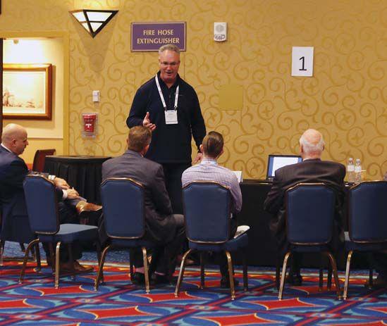


 Charles Sweetser, OMICRON electronics Corp. USA, speaks with technicians and other electrical power industry professionals during a roundtable discussion at the NETA Member and Alliance Meeting.


 BY MARK SIIRA, ComRentInternational ComRent International
This article gives a glimpse of some significant changes that will occur in electric power system testing and commissioning after 2018. We will review the drivers of the oncoming change, some common themes emerging in standards and requirements, and some key topics such as interoperability, interconnection, and commissioning.
The first changes toward the smart grid occurred in the 2000s when the Energy Independence and Security Act of 2007 (EISA) made it the policy of the United States to modernize the nation’s electricity transmission and distribution system to create a smart electric grid. IEEE was cited as a standards development organization partner to the National Institute of Standards and Technology (NIST) as the lead to coordinate a framework and roadmap for Smart Grid Interoperability standards and protocols, specifically expanding the IEEE 1547 and 2030 series.
The publication in January 2010 of the “NIST Framework and Roadmap for Smart Grid Interoperability Standards” documented progress made up to that time and laid out a conceptual framework of domains describing the electric power system (Figure 1).
Since that time, extensive efforts to revise and amend standards in multiple domains have occurred, most notably transmission, distribution, and non-bulk generation. Commissioning process and interoperability are the most significant existing gaps.
Proper commissioning uncovers quality problems with critical primary or backup systems. Once placed under expected power and load conditions, these systems can fail because the equipment was defective, damaged in transit, or not installed properly. You may be unaware of an issue until the equipment is tested under a load.
Commissioning provides a systematic way to confirm proper performance levels and identify any problems before the facility is brought on-line. In general, commissioning should be viewed as a process and should accompany all project phases. The expected requirements for equipment service are driven by the authorities having jurisdiction over a project (regulations), the electric power system operator, and the equipment manufacturers. More specificity on verification requirements for compliance may not always be a component-level test, and there is a renewed emphasis on comprehensive system testing for final verification. Commissioning may also include other verification methods such as power systems simulation and modeling, the design review (paper study), and a field evaluation that verifies critical component settings and electrical configuration. Most problems are caught during commissioning, not during subsystem or component tests.
Smart Grid has been defined as the integration of power, communications, and information technologies for an improved electric power infrastructure serving loads while providing for an ongoing evolution of end-use applications. An important element of the smart grid is interoperability or the capability of two or more networks, systems, devices, applications, or components to externally exchange and readily use information securely and effectively (Std 2030-2011). Interoperability requires the coordination of three different perspectives: power, communication, and information (Figure 2).
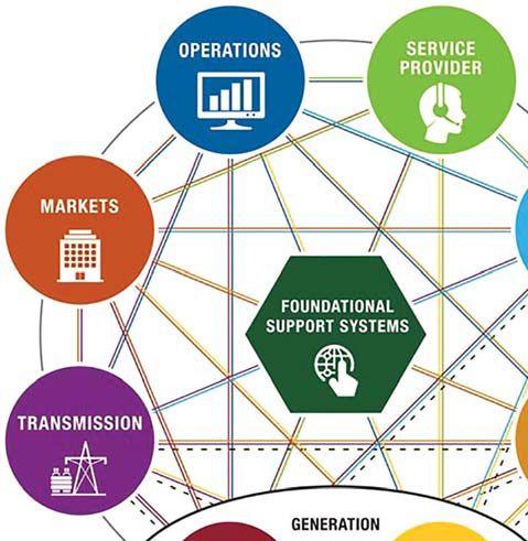


Embedding interoperability requirements into standards will occur at an increased rate as working groups comprehend future markets, as well as communication and control needs.
Interconnection requirements have added specific interoperability capabilities in addition to several new technical requirements. These changes create a uniform standard for the interconnection and interoperability of distributed energy resources (DER) with electric power systems (EPS). It provides requirements relevant to interconnection and interoperability performance, operation, testing, safety, maintenance, and security considerations.
These requirements apply to interconnection systems, which are the collection of all interconnection equipment and functions, taken as a group, used to interconnect DER to an area Electric Power System (electric utility distribution) (Figure 3).
The following standards have been developed to embed commissioning and interoperability into utility-scale systems:
• EPRI Guide for Energy Storage System Commissioning and Testing
• IEEE PSRC I25, Draft Best Practices in (Substation) Commissioning Report - 2016
• IEEE C37.233, Substation Protection Testing Reaffirmation - 2017


The following standards have been developed to improve the interoperability of the critical interconnection process:
• Interconnection: IEEE 1547 Standard, IEEE 1547.1 Test Requirements, and UL 1741 Inverters
• Smart Grid Standards: IEEE 2030 Series for Interoperability and Cybersecurity
• Energy Storage/Renewable Integration
Most likely, the commissioning guides mentioned earlier will result in endorsement of best practices to ensure commissioning is contemplated at all phases of a protection system project. Comprehensive commissioning is an emerging best practice and should be considered when evaluating project risk. Once this becomes a best practice, commissioning without comprehending minimum thresholds for all sensor inputs can be viewed as increasing the risk or increasing liability for the project owner.
Generally, the best practices for commissioning across multiple electric power industries include:
•Elements of the commissioning process take place in all phases of project execution. The commissioning guidelines reference best practices from relevant equipment or industries.
•Set clearly defined roles and responsibilities before the project starts and reaffirm at each project phase.
•Require a clearly defined and effective comprehensive commissioning test for the overall commissioning process.
•Plan the commissioning verification method and test early in a project’s planning phase, and execute it successfully prior to system turn-over.
•Subsystems type, factory acceptance test (FAT), and/or field testing are on the critical path to successful commissioning. These additional tests should also be identified, planned for, and incorporated in overall system commissioning planning and execution.
•Contingency plans should be included for special project circumstances that could affect timing of the commissioning. This could include alternative methods for verifying performance in the event critical resources are not available during the originally scheduled time frame, weather delays, or inadequate consistency in the load profile used during commissioning.
This area is becoming pervasive as a requirement to most domains in the electric power system. The importance of interoperability is driven by the eventual need for modular plug-and-play solutions.
The specific communication requirements are determined by the area EPS operator, subject to regulatory or contractual arrangements. The information to be exchanged falls into four categories:
1. Nameplate data describes the as-built characteristics of the DER.
2. Basic settings describe the present capacity and ability of the DER to perform functions.
3. Monitoring describes the present operating conditions of the DER.
4. Management is used to update functional and mode settings for the DER.
The DER should verify an interface capable of communicating to support the information exchange requirements specified in this standard for all applicable functions supported in the DER. Even though these may not be used in a specific application, the system capability needs to be available.
The revised interconnection standard anticipated for approval in 2017 includes many new technical requirements. These requirements will apply to all distributed energy resources, both inverter-based and synchronous generator-based. No upper size limit is stated in the requirements. Any system that can parallel with the electric power system for greater than 100 milliseconds may have to verify performance to these two technical requirements. Although they appear more complex, when viewed, the new requirements should simplify the execution of distributed energy resources when connecting to the electric power system.
When a DER request is received, first determine the reference point for technical requirements. Most large and complex systems must meet the requirements at the point of common coupling (PCC), which is the physical interface between the utility electric power system and the local (or customer’s) electric power system. If the generation is small (or small and embedded in a customer’s facility), the requirements must be met at the point of connection, which generally means that type-tested components and a field inspection may be all that’s required.
The next requirements will have to be answered by the electric power system operator (electric utility) and are unique to that location or circuit. The determination on the required DER capabilities for using reactive power to regulate the voltage will be made. Additionally, the electric utility will determine the category of requirements for the DER response to abnormal conditions in the electric power system it connects to.
Some of the new requirements likely to be in the final document include:
• Verification requirements may be specifically called out for each scenario described previously. This means less ambiguity on how to verify the system’s performance and which tests to complete.
• An installation evaluation clause may include inspection for proper installation


1. c. Whenever there is a void in the insulation, some level of partial discharge occurs. This void can be caused by moisture intrusion, overstressing the cable, or manufacturing defects, to name a few.
2. c. Partial discharge occurs during the peak of every half cycle, see Figure 1.

Figure 1: Partial Discharge Characteristics in Power Cable
IEEE from
Applications
3. a. It is the partial discharge inception voltage (PDIV). Partial discharge just begins at this voltage.
4. a. Partial discharge extinction voltage (PDEV). Once the PDIV is determined, the voltage is decreased to determine the PDEV during testing.
5. d. Even at the PDIV, the cable will begin to deteriorate. Since partial discharges are occurring within the insulation, those discharges attack the insulation, although at a lower rate than would happen during normal operation.

NFPA Disclaimer: Although Jim White is a member of the NFPA Technical Committee for both NFPA 70E, Standard for Electrical Safety in the Workplace, and NFPA 70B, Recommended Practice for Electrical Equipment Maintenance, the views and opinions expressed in this column are purely the author’s and shall not be considered an official position of the NFPA or any of its technical committees and shall not be considered, nor be relied upon, as a formal interpretation or promotion of the NFPA. Readers are encouraged to refer to the entire text of all referenced documents.


Featuring quality, reliable, on-time service and support for all brands and types of solid state power electronics.
Power electronics are our business
Let us suppoort you with our quality repair, calibration and servicing of your solid state equipment. We also buy, sell and trade:
•Communications devices for power equipment
•Protective relays
•Circuit breaker trip devices
•Motor overload relays
•Rating plugs

A&F Electrical Testing, Inc.
80 Lake Ave. South, Ste. 10 Nesconset, NY 11767 (631) 584-5625 Fax: (631) 584-5720 kchilton@afelectricaltesting.com www.afelectricaltesting.com
Kevin Chilton
A&F Electrical Testing, Inc.
80 Broad St. 5th Floor
New York, NY 10004 (631) 584-5625 Fax: (631) 584-5720 afelectricaltesting@afelectricaltesting.com
Florence Chilton
ABM Electrical Power Solutions
3602 East Southern Ave., Ste. 1 Phoenix, AZ 85040 (602) 722-2423 www.ABM.com
Doug Bukowski
ABM Electrical Power Solutions
9800 E. Geddes Avenue, Unit A-150 Englewood, CO 80112 (303) 524-6560 Fax: (303) 524-6581
Brian Smith
ABM Electrical Power Solutions
2142 Rheem Drive Pleasanton, CA 94588 (408) 466-6920
John Marvulli
ABM Electrical Power Solutions
3940 Ruffin Rd., Ste. C San Diego, CA 92123 (858) 754-7963
william.mckenzie@abm.com
William McKenzie
ABM Electrical Power Solutions
6280 South Valley View Blvd., Ste. 618 Las Vegas, NV 89118 (602) 300-2188 Fax: (602) 437-3894
Jason Black
ABM Electrical Power Solutions
814 Greenbrier Circle, Ste. E Chesapeake, VA 23320 (757) 548-5690 Fax: (757) 548-5417
Mark Anthony Gaughan, III
ABM Electrical Power Solutions
3700 Commerce Dr. #901-903 Baltimore, MD 21227 (410) 247-3300 Fax: (410) 247-0900
Bill Hartman
ABM Electrical Power Solutions
5809 Departure Dr., Ste. 104 Raleigh, NC 27616 (919) 877-1008 Fax: (919) 501-7492
Rob Parton
ABM Electrical Power Solutions
317 Commerce Park Dr. Cranberry Township, PA 16066-6427 (724) 772-4638 Fax: (724) 772-6003
christopher.smith@abm.com
Christopher Smith
ABM Electrical Power Solutions
4390 Parliament Place, Ste. S Lanham, MD 20706 (301) 967-3500 Fax: (301) 735-8953
Frank Ceci
ABM Electrical Power Solutions
3600 Woodpark Blvd., Suite G Charlotte, NC 28206 (704) 273-6257 Fax: (704) 598-9812 ernest.goins@abm.com
Ernest Goins
ABM Electrical Power Solutions
720 S. Rochester Ave., Suite A Ontario, CA 91761 (800) 597-1225 Fax: (909) 937-6798
Mike Bivens
Absolute Testing Services 6829 Guhn Rd. Houston, TX 77040 (832) 467-4446 Fax: (713) 849-3885 rgamble@absolutetesting.com www.absolutetesting.com
Richard Gamble
Accessible Consulting Engineers, Inc. 1269 Pomona Rd., Ste. 111 Corona, CA 92882 (951) 808-1040 info@acetesting.com www.acetesting.com Iraj Nasrolahi
Advanced Testing Systems 15 Trowbridge Dr. Bethel, CT 06801 (203) 743-2001 Fax: (203) 743-2325 pmaccarthy@advtest.com www.advtest.com Pat MacCarthy
American Electrical Testing Co., Inc. 25 Forbes Blvd., Ste. 1 Foxboro, MA 02035 (781) 821-0121 Fax: (781) 821-0771 sblizard@aetco.us www.aetco.us
Scott A. Blizard
American Electrical Testing Co., Inc. 34 Clover Dr. South Windsor, CT 06074 (860) 648-1013 Fax: (781) 821-0771 jpoulin@aetco.us
Gerald Poulin
American Electrical Testing Co., Inc. 76 Cain Dr. Brentwood, NY 11717 (631) 617-5330 Fax: (631) 630-2292 bfernandez@aetco.us
Billy Fernandez
American Electrical Testing Co., Inc. 50 Intervale Rd., Ste. 1 Boonton, NJ 07005 (973) 316-1180 Fax: (781) 316-1181 jsomol@aetco.us
Jeff Somol
American Electrical Testing Co., Inc. Green Hills Commerce Center 5925 Tilghman St., Ste. 200 Allentown, PA 18104 (215) 219-6800 jmunley@aetco.us
Jonathan Munley
American Electrical Testing Co., Inc. 12566 W. Indianola Ave. Avondale, AZ 85392 (480) 383-9242 dmadaglia@aetco.us
Donald Madaglia
AMP Quality Energy Services, LLC 4220 West Schrimsher SW Site W1 P.O. Box 526, Huntsville, AL 35804 (256) 513-8255
Brian Rodgers
Apparatus Testing and Engineering 11300 Sanders Dr., Ste. 29 Rancho Cordova, CA 95742 (916) 853-6280 Fax: (916) 853-6258 info@apparatustesting.com www.apparatustesting.com
Harold (Jerry) Carr
Apparatus Testing and Engineering 7083 Commerce Circle, Ste. H Pleasanton, CA 94588 (925) 454-1363 Fax: (925) 454-1499
Applied Engineering Concepts 1105 N. Allen Ave. Pasadena, CA 91104 (626) 398-3052 Fax: (626) 398-3053 michel.c@aec-us.com www.aec-us.com
Michel Castonguay
BEC Testing
50 Gazza Blvd. Farmingdale, NY 11735 (516) 531-9136 Fax: (631) 249-6115 wfernandez@banaelectric.com www.bectesting.com
William Fernandez
Burlington Electrical Testing Co., Inc.
300 Cedar Ave. Croydon, PA 19021-6051 (215) 826-9400 (221) Fax: (215) 826-0964 waltc@betest.com www.betest.com
Walter P. Cleary
C.E. Testing, Inc. 6148 Tim Crews Rd. Macclenny, FL 32063 (904) 653-1900 Fax: (904) 653-1911 cetesting@aol.com
Mark Chapman
CE Power Engineered Services, LLC 4040 Rev Dr. Cincinnati, OH 45232 (513) 563-6150 Fax: (513) 563-6120 info@cepowersol.net www.cepower.net
Brent McAlisar
CE Power Engineered Services, LLC 8490 Seward Road Fairfield, OH 45011 (513) 563-6150 tim.lana@cepower.net
Tim Lana
CE Power Engineered Services, LLC 10338 Citation Drive, Suite 300 Brighton, MI 48166 (810) 229-6628
Ken L'Esperance
CE Power Engineered Services, LLC 1803 Taylor Avenue Louisville, KY 40213 (502) 479-0612 tom.hutchinson@cepower.net
Tom Hutchinson
CE Power Engineered Services, LLC 10840 Murdock Drive Knoxville, TN 37932 (865) 310-2522 don.williams@cepower.net
Don Williams
CE Power Engineered Services, LLC 7674 Washington Ave. S Eden Prairie, MN 55344 (877) 968-0281
jason.thompson@cepower.net
Jason Thomps
Control Power Concepts
353 Pilot Rd; Ste. B Las Vegas, NV 89119 (702) 448-7833 Fax: (702) 448-7835 www.controlpowerconcepts.com
John Travis
Dude Electrical Testing LLC
145 Tower Dr., Unit# 9 Burr Ridge, IL 60527 (815) 293-3388 Fax: (815) 293-3386
scott.dude@dudetesting.com www.dudetesting.com
Scott Dude
DYMAX Service, LLC
46918 Liberty Dr. Wixom, MI 48393 (248) 313-6868 Fax: (248) 313-6869 www.dymaxservice.com
Bruce Robinson
DYMAX Service, LLC
4213 Kropf Ave. Canton, OH 44706 (330) 484-6801 Fax: (740) 333-1271
Chuck Baker
Eastern High Voltage, Inc.
11A South Gold Dr. Robbinsville, NJ 08691-1606 (609) 890-8300 Fax: (609) 588-8090 bobwilson@easternhighvoltage.com www.easternhighvoltage.com
Robert Wilson
ELECT, P.C.
7400-G Siemens Rd., P.O. Box 2080 Wendell, NC 27591 (919) 365-9775 Fax: (919) 365-9789 btyndall@elect-pc.com www.elect-pc.com
Barry W. Tyndall
Electric Power Systems, Inc. 21 Millpark Ct. Maryland Heights, MO 63043 (314) 890-9999 Fax: (314) 890-9998 www.epsii.com
Electric Power Systems, Inc. 557 E. Juanita Ave., #4 Mesa, AZ 85204 (480) 633-1490 Fax: (480) 633-7092
Electric Power Systems, Inc. 4436 Parkway Commerce Blvd. Orlando, FL 32808 (407) 578-6424 Fax: 407-578-6408
Electric Power Systems, Inc.
7000 E. 47th Avenue Drive, Suite 100 Denver, CO 80216 (720) 857-7273 Fax: 303-928-8020
Electric Power Systems, Inc. 23823 Andrew Rd. Plainfield, IL 60585 (815) 577-9515 Fax: (815) 577-9516
Electric Power Systems, Inc.
2601 Center Rd., # 101 Hinckley, OH 44233 (330) 460-3706 Fax: (330) 460-3708
Electric Power Systems, Inc.
56 Bibber Pkwy #1 Brunswick, ME 04011 (207) 837-6527
Electric Power Systems, Inc.
4100 Greenbriar Dr., Ste. 160 Stafford, TX 77477 (713) 644-5400
Electric Power Systems, Inc. 11861 Longsdorf St. Riverview, MI 48193 (734) 282-3311
Electric Power Systems, Inc.
827 Union St., Salem, VA 24153 (540) 375-0084 Fax: (540) 375-0094
Electric Power Systems, Inc. 915 Holt Ave., Unit 9 Manchester, NH 03109 (603) 657-7371 Fax: 603-657-7370
Electric Power Systems, Inc.
146 Space Park Dr. Nashville, TN 37211 (615) 834-0999 Fax: (615) 834-0129
Electric Power Systems, Inc. 8515 Cella Alameda NE, Ste. A Albuquerque, NM 87113 (505) 792-7761
Electric Power Systems, Inc. 7140 Dean Martin Drive, Suite 900 Las Vegas, NV 89118 (702) 815-1342
Electric Power Systems, Inc. 319 US Hwy. 70 E, Unit E Garner, NC 27529 (919) 322-2670 www.epsii.com
Electric Power Systems, Inc. 1090 Montour West Industrial Blvd. Coraopolis, PA 15108 (412) 276-4559
Electric Power Systems, Inc. 6141 Connecticut Ave. Kansas City, MO 64120 (816) 241-9990 Fax: (816) 241-9992
Electric Power Systems, Inc. 2495 Boulevard of the Generals Norristown, PA 19403 (610) 630-0286
Electric Power Systems, Inc. 1129 East Hwy. 30 Gonzalez, LA 70817 (225) 644-0150 Fax: (225) 644-6249
Electric Power Systems, Inc. 7925 Dunbrook Rd., Ste. G San Diego, CA 92126 (858) 566-6317
Electric Power Systems, Inc. 6679 Peachtree Industrial Dr. Ste. H Norcross, GA 30092 (770) 416-0684 j.cash@epsii.com
Jeff Cash
Electrical & Electronic Controls 6149 Hunter Rd. Ooltewah, TN 37363 (423) 344-7666 (23) Fax: (423) 344-4494 eecontrols@comcast.net
Michael Hughes
Electrical Energy Experts, Inc. W129N10818, Washington Dr. Germantown, WI 53022 (262) 255-5222 Fax: (262) 242-2360 bill@electricalenergyexperts.com www.electricalenergyexperts.com
William Styer
Electrical Equipment Upgrading, Inc. 21 Telfair Place, Savannah, GA 31415 (912) 232-7402 Fax: (912) 233-4355 kmiller@eeu-inc.com www.eeu-inc.com
Kevin Miller
Electrical Maintenance & Testing Inc. 12342 Hancock St., Carmel, IN 46032 (317) 853-6795 Fax: (317) 853-6799 info@emtesting.com www.emtesting.com
Brian K. Borst
Electrical Reliability Services 1057 Doniphan Park Circle, Ste. A El Paso, TX 79922 (915) 587-9440 Fax: (915) 587-9010 www.electricalreliability.com
Electrical Reliability Services 1775 W. University Dr., Ste. 128 Tempe, AZ 85281 (480) 966-4568 Fax: (480) 966-4569
Electrical Reliability Services 1426 Sens Rd. Ste. 5 Houston, TX 77571 (281) 241-2800 Fax: (281) 241-2801
Electrical Reliability Services 4099 SE International Way, Ste. 201 Milwaukie, OR 97222-8853 (503) 653-6781 Fax: (503) 659-9733
Electrical Reliability Services 5909 Sea Lion Place, Ste. C Carlsbad, CA 92010 (858) 695-9551
Electrical Reliability Services 8500 Washington Pl. NE, Ste. A-6 Albuquerque, NM 87113 (505) 822-0237 Fax: (505) 822-0217
Electrical Reliability Services 1380 Greg Street, Ste. 216 Sparks, NV 89431 (775) 746-8484 Fax: (775) 356-5488
Electrical Reliability Services 2275 Northwest Pkwy SE, Ste. 180 Marietta, GA 30067 (770) 541-6600 Fax: (770) 541-6501
Electrical Reliability Services 7100 Broadway, Ste. 7E Denver, CO 80221-2915 (303) 427-8809 Fax: (303) 427-4080
Electrical Reliability Services 400 N.W. Capital Dr. Lee's Summit, MO 64086 (816) 525-7156 Fax: (816) 524-3274
Electrical Reliability Services 6900 Koll Center Parkway, Ste. 415 Pleasanton, CA 94566 (925) 485-3400 Fax: (925) 485-3436
Electrical Reliability Services 10606 Bloomfield Ave. Santa Fe Springs, CA 90670 (562) 236-9555 Fax: (562) 777-8914
Electrical Reliability Services 3535 Emerson Parkway, Ste. A Gonzales, LA 70737 (225) 755-0530 Fax: (225) 751-5055
Electrical Reliability Services 245 Hood Rd. Sulphur, LA 70665 (337) 583-2411 Fax: (337) 583-2410
Electrical Reliability Services 11000 Metro Pkwy., Ste. 30 Ft. Myers, FL 33966 (239) 693-7100 Fax: (239) 693-7772
Electrical Reliability Services 2222 West Valley Hwy. N., Ste 160 Auburn, WA 98001 (253) 736-6010 Fax: (253) 736-6015
Electrical Reliability Services
9736 South Sandy Pkwy 500 West Sandy, UT 84070 (801) 975-6461
Electrical Reliability Services
6351 Hinson St., Ste. B Las Vegas, NV 89118 (702) 597-0020 Fax: (702) 597-0095
Electrical Reliability Services
9636 St. Vincent, Unit A Shreveport, LA 71106 (318) 869-4244
Electrical Reliability Services
610 Executive Campus Dr. Westerville, OH 43082 (877) 468-6384 Fax: (614) 410-8420 info@electricalreliability.com
Electrical Testing and Maintenance Corp.
3673 Cherry Rd., Ste. 101 Memphis, TN 38118 (901) 566-5557 r.gregory@etmcorp.com www.etmcorp.net
Ron Gregory
Electrical Testing, Inc.
2671 Cedartown Hwy. Rome, GA 30161-6791 (706) 234-7623 Fax: (706) 236-9028 steve@electricaltestinginc.com www.electricaltestinginc.com
Electrical Testing Solutions
2909 Green Hill Ct. Oshkosh, WI 54904 (920) 420-2986 Fax: (920) 235-7136 tmachado@electricaltestingsolutions.com www.electricaltestingsolutions.com Tito Machado
Elemco Services, Inc. 228 Merrick Rd. , Lynbrook, NY 11563 (631) 589-6343 Fax: (631) 589-6670 courtney@elemco.com www.elemco.com
Courtney Gallo
EnerG Test
204 Gale Lane Bldg. 2 - 2nd Floor Kennett Square, PA 19348 (484) 731-0200 Fax: (484) 713-0209 kbleiler@energtest.com www.energtest.com
Katie Bleiler
Energis High Voltage Resources, Inc. 1361 Glory Rd. Green Bay, WI 54304 (920) 632-7929 Fax: (920) 632-7928
info@energisinc.com www.energisinc.com
Mick Petzold
EPS Technology
29 N. Plains Hwy., Ste. 12 Wallingford, CT 06492 (203) 679-0145 www.eps-technology.com
Grounded Technologies, Inc.
10505 S. Progress Way, Ste. 105 Parker, CO 80134 P-(303) 781-2560 F- (303) 781-5240 jodymedina@groundedtech.com www.groundedtech.com
Jody Medina
Grubb Engineering, Inc. 3128 Sidney Brooks San Antonio, Tx 78235 (210) 658-7250 Fax: (210) 658-9805 joy@grubbengineering.com www.grubbengineering.com
Robert D. Grubb Jr.
Hampton Tedder Technical Services 4571 State St. Montclair, CA 91763 (909) 628-1256 x214 Fax: (909) 628-6375 matt.tedder@hamptontedder.com www.hamptontedder.com
Matt Tedder
Hampton Tedder Technical Services 4920 Alto Ave. Las Vegas, NV 89115 (702) 452-9200 Fax: (702) 453-5412
Roger Cates
Hampton Tedder Technical Services 3747 West Roanoke Ave. Phoenix, AZ 85009 (480) 967-7765 Fax: (480) 967-7762
Harford Electrical Testing Co., Inc. 1108 Clayton Rd. Joppa, MD 21085 (410) 679-4477 Fax: (410) 679-0800 testing@harfordtesting.com www.harfordtesting.com
Vincent Biondino
High Energy Electrical Testing, Inc. 515 S. Ocean Ave. Seaside Park, NJ 08752 (732) 938-2275 Fax: (732) 938-2277 hinrg@comcast.net www.highenergyelectric.com
Charles Blanchard
High Voltage Maintenance Corp. 24 Walpole Park South Dr. Walpole, MA 02081 (508) 668-9205 www.hvmcorp.com
High Voltage Maintenance Corp. 941 Busse Rd. Elk Grove Village, Il 60007 (847) 640-0005
High Voltage Maintenance Corp. 7200 Industrial Park Blvd. Mentor, OH 44060 (440) 951-2706 Fax: (440) 951-6798
High Voltage Maintenance Corp. 3000 S. Calhoun Rd. New Berlin, WI 53151 (262) 784-3660 Fax: (262) 784-5124
High Voltage Maintenance Corp. 8320 Brookville Rd. #E Indianapolis, IN 46239 (317) 322-2055 Fax: (317) 322-2056
High Voltage Maintenance Corp. 1250 Broadway, Ste. 2300 New York, NY 10001 (718) 239-0359
High Voltage Maintenance Corp. 355 Vista Park Dr. Pittsburgh, PA 15205-1206 (412) 747-0550 Fax: (412) 747-0554
High Voltage Maintenance Corp. 150 North Plains Industrial Rd. Wallingford, CT 06492 (203) 949-2650 Fax: (203) 949-2646
High Voltage Maintenance Corp. 9305 Gerwig Ln., Ste. B Columbia, MD 21046 (410) 309-5970 Fax: (410) 309-0220
High Voltage Maintenance Corp. 24371 Catherine Industrial Dr, Ste. 207 Novi, MI 48375 (248) 305-5596 Fax: (248) 305-5579
High Voltage Maintenance Corp. 5100 Energy Dr. Dayton, OH 45414 (937) 278-0811 Fax: (937) 278-7791
High Voltage Service, LLC 3890 Pheasant Ridge Dr. NE, Ste. 170 Blaine, MN 55449 (763) 784-4040 Fax: (763) 784-5397 www.hvserviceinc.com
Mike Mavetz
HMT, Inc. 6268 Route 31 Cicero, NY 13039 (315) 699-5563 Fax: (315) 699-5911 jpertgen@hmt-electric.com www.hmt-electric.com
John Pertgen
Industrial Electric Testing, Inc. 11321 West Distribution Ave. Jacksonville, FL 32256 (904) 260-8378 Fax: (904) 260-0737 gbenzenberg@bellsouth.net www.industrialelectrictesting.com
Gary Benzenberg
Industrial Electric Testing, Inc. 201 NW 1st Ave. Hallandale, FL 33009-4029 (954) 456-7020
Industrial Electronics Group 850369 Highway 17 South P.O. Box 1870 Yulee, FL 32041 (904) 225-9529 Fax: (904) 225-0834 butch@industrialgroups.com www.industrialgroups.com
Butch E. Teal
Industrial Tests, Inc. 4021 Alvis Ct., Ste. 1 Rocklin, CA 95677 (916) 296-1200 Fax: (916) 632-0300 greg@indtest.com www.industrialtests.com
Greg Poole
Infra-Red Building and Power Service 152 Centre St. Holbrook, MA 02343-1011 (781) 767-0888 Fax: (781) 767-3462 tom.mcdonald@infraredbps.com www.infraredbps.com
Thomas McDonald Sr.
M&L Power Systems, Inc. 109 White Oak Ln., Ste. 82 Old Bridge, NJ 08857 (732) 679-1800 Fax: (732) 679-9326 milind@mlpower.com www.mlpower.com
Milind Bagle
Magna IV Engineering 1103 Parsons Rd. SW Edmonton, AB T6X 0X2 Canada (780) 462-3111 Fax: (780) 450-2994 info@magnaiv.com www.magnaiv.com
Virgina Balitski
Magna IV Engineering 200, 688 Heritage Dr. Calgary, AB T2H 1M6 Canada (403) 723-0575 Fax: (403) 723-0580 info.calgary@magnaiv.com
Dave Emerson
Magna IV Engineering 141 Fox Cresent Fort McMurray, AB T9K 0C1 Canada (780) 791-3122 Fax: (780) 791-3159 info.fmcmurray@magnaiv.com
Ryan Morgan
Magna IV Engineering
96 Inverness Dr. East, Unit R Englewood, CO 80112 (303) 799-1273 Fax: (303) 790-4816 info.denver@magnaiv.com
Aric Proskurniak
Magna IV Engineering Avenida del Condor #590 Oficina 601 Huechuraba, Santiago 8580676
Chile
+(56) 9-9-517-4642 info.chile@magnaiv.com
Harvey Mendoza
Magna IV Engineering 1040 Winnipeg St. Regina , SK S4R 8P8 Canada (306) 585-2100 Fax: (306) 585-2191 info.regina@magnaiv.com
Adam Jaques
Magna IV Engineering 106, 4268 Lozells Ave. Burnaby, BC VSA 0C6 Canada (604) 421-8020
Scott Nixon
Magna IV Engineering 10325 Landsbury, Ste. 404 Houston, TX 77099 (720) 480-9680 aproskurniak@magnaiv.com www.magnaiv.com Aric Proskurniak
National Field Services
1890 A South Hwy 35 Alvin, TX 77511 (800) 420-0157 jonathan.wakeland@natlfield.com www.natlfield.com
Jonathan Wakeland
National Field Services 649 Franklin St. Lewisville, TX 75057 (972) 420-0157 www.natlfield.com
Eric Beckman
National Field Services 1405 United Drive, Ste. 113-115 San Marcos, TX 78666 (800) 420-0157 Fax: (972) 420-0552 info@natlfield.com www.natlfield.com
Matt LaCoss
Nationwide Electrical Testing, Inc. 6050 Southard Trace Cumming, GA 30040 (770) 667-1875 Fax: (770) 667-6578
Shashi@N-E-T-Inc.com www.n-e-t-inc.com
Shashikant B. Bagle
North Central Electric, Inc. 69 Midway Ave. Hulmeville, PA 19047-5827 (215) 945-7632 Fax: (215) 945-6362 ncetest@aol.com www.ncetest.com
Robert Messina
Northern Electrical Testing, Inc. 1991 Woodslee Dr. Troy, MI 48083-2236 (248) 689-8980 Fax: (248) 689-3418 ldetterman@northerntesting.com www.northerntesting.com
Lyle Detterman
Orbis Engineering Field Services Ltd. #300, 9404 - 41st Ave. Edmonton, AB T6E 6G8 Canada (780) 988-1455 Fax: (780) 988-0191 lorne@orbisengineering.net www.orbisengineering.net
Lorne Gara
Pacific Power Testing, Inc. 14280 Doolittle Dr. San Leandro, CA 94577 (510) 351-8811 Fax: (510) 351-6655 steve@pacificpowertesting.com www.pacificpowertesting.com
Steve Emmert
Pacific Powertech, Inc. #110, 2071 Kingsway Ave. Port Coquitlam, BC V3C 6N2 Canada (604) 944-6697 Fax: (604) 944-1271 jkonkin@pacificpowertech.ca www.pacificpowertech.ca
Josh Konkin
Phasor Engineering Sabaneta Industrial Park #216 Mercedita, PR 00715 Puerto Rico (787) 844-9366 Fax: (787) 841-6385 rcastro@phasorinc.com
Rafael Castro
Potomac Testing, Inc. 1610 Professional Blvd., Ste. A Crofton, MD 21114 (301) 352-1930 Fax: (301) 352-1936 kbassett@potomactesting.com www.potomactesting.com
Ken Bassett
Power & Generation Testing, a CE Power Company 480 Cave Rd. Nashville, TN 37210 (615) 882-9455 Fax: (615) 882-9591 mose@pgti.net www.pgti.net
Mose Ramieh
Power Engineering Services, Inc. 9179 Shadow Creek Lane Converse, TX 78109 (210) 590-4936 Fax: (210) 590-6214 engelke@pe-svcs.com www.pe-svcs.com
Miles R. Engelke
POWER PLUS Engineering, Inc. 46575 Magellan Novi, MI 48377 (248) 344-0200 Fax: (248) 305-9105 smancuso@epowerplus.com www.epowerplus.com
Salvatore Mancuso
Power Products & Solutions, LLC 12465 Grey Commercial Rd. Midland, NC 28107 (704) 573-0420 x12 Fax: (704) 573-3693 adis.talovic@powerproducts.biz www.powerproducts.biz
Adis Talovic
Power Products & Solutions, LLC 13 Jenkins Ct. Mauldin, SC 29662 (800) 328-7382 raymond.pesaturo@powerproducts.biz www.powerproducts.biz
Raymond Pesaturo
Power Services, LLC 998 Dimco Way, P.O. Box 750066 Centerville, OH 45475 (937) 439-9660 Fax: (937) 439-9611 mkbeucler@aol.com
Mark Beucler
Power Solutions Group, Ltd. 425 W. Kerr Rd. Tipp City, OH 45371 (937) 506-8444 Fax: (937) 506-8434 bwilloughby@powersolutionsgroup.com www.powersolutionsgroup.com
Barry Willoughby
Power Solutions Group, Ltd. 135 Old School House Rd. Piedmont, SC 29673 (864) 845-1084 Fax:: (864) 845-1085 fcrawford@powersolutionsgroup.com www.powersolutionsgroup.com
Anthony Crawford
Power Solutions Group, Ltd. 670 Lakeview Plaza Blvd. Columbus, OH 43085 (614) 310-8018
sspohn@powersolutionsgroup.com www.powersolutionsgroup.com
Stuart Spohn
Power Systems Testing Co. 4688 W. Jennifer Ave., Ste. 108 Fresno, CA 93722 (559) 275-2171 ext 15 Fax: (559) 275-6556 dave@pstcpower.com www.powersystemstesting.com
David Huffman
Power Systems Testing Co. 600 S. Grand Ave., Ste. 113 Santa Ana, CA 92705-4152 (714) 542-6089 Fax: (714) 542-0737 www.powersystemstesting.com
Power Systems Testing Co. 6736 Preston Ave, Ste. E Livermore, CA 94551 (510) 783-5096 Fax: (510) 732-9287 www.powersystemstesting.com
Power Test, Inc. 2200 Highway 49 Harrisburg, NC 28075 (704) 200-8311 Fax: (704) 455-7909 rich@powertestinc.com
Richard Walker
POWER Testing and Energization, Inc. 14006 NW 3rd Ct., Ste. 101 Vancouver, WA 98685 (360) 597-2800 Fax: (360) 576-7182 chris.zavadlov@powerte.com www.powerte.com
Chris Zavadlov
POWER Testing and Energization, Inc. 731 E. Ball Rd., Ste. 100 Anaheim, CA 92805 (714) 507-2702
POWER Testing and Energization, Inc.
22035 70th Ave. South Kent, WA 98032 (253) 437-3100
Powertech Services, Inc.
4095 South Dye Rd. Swartz Creek, MI 48473-1570 (810) 720-2280 Fax: (810) 720-2283
kirkd@powertechservices.com www.powertechservices.com
Kirk Dyszlewski
Precision Testing Group
5475 Highway 86, Unit 1 Elizabeth, CO 80107 (303) 621-2776 Fax: (303) 621-2573 glenn@precisiontestinggroup.com
Glenn Stuckey
Premier Power Maintenance Corporation 6525 Guion Rd. Indianapolis, IN 46268 (317) 879-0660
kevin.templeman@premierpower.us
Kevin Templeman
Premier Power Maintenance Corporation 2725 Jason Rd. Ashland, KY 41102 (606) 929-5969
jay.milstead@premierpower.us www.premierpowermaintenance.com
Jay Milstead
Premier Power Maintenance Corporation
3066 Finley Island Cir NW Decatur, AL 35601 (256) 355-1444
johnnie.mcclung@premierpower.us
Johnnie McClung
Premier Power Maintenance Corporation 4301 Iverson Blvd., Ste. H Trinity, AL 35673 (256) 355-3006
kevin.templeman@premierpower.us
Kevin Templeman
Premier Power Maintenance Corporation 7301 E County Road 142 Blytheville, AR 72315 (870) 762-2100
kevin.templeman@premierpower.us
Kevin Templeman
Premier Power Maintenance Corporation 7262 Kensington Rd. Brighton, MI 48116 (517) 230-6620
brian.ellegiers@premierpower.us
Brian Ellegiers
Premier Power Maintenance Corporation 4537 S. Nucor Rd. Crawfordsville, IN 47933 (317) 879-0660
kevin.templeman@premierpower.us
Kevin Templeman
Reuter & Hanney, Inc. 149 Railroad Dr. Northampton Industrial Park Ivyland, PA 18974 (215) 364-5333 Fax: (215) 364-5365 mikereuter@reuterhanney.com www.reuterhanney.com
Michael Reuter
Reuter & Hanney, Inc. 4270-I Henninger Ct. Chantilly, VA 20151 (703) 263-7163 Fax: 703-263-1478
Reuter & Hanney, Inc. 11620 Crossroads Circle, Suites D-E Middle River, MD 21220 (410) 344-0300 Fax: (410) 335-4389
Michael Jester
REV Engineering, LTD 3236 - 50 Ave. SE Calgary, AB T2B 3A3 Canada (403) 287-0156 Fax: (403) 287-0198 rdavidson@reveng.ca www.reveng.ca
Roland Nicholas Davidson, IV
Scott Testing Inc. 1698 5th St. Ewing, NJ 08638 (609) 882-2400 Fax: (609) 882-5660 rsorbello@scotttesting.com www.scotttesting.com
Russ Sorbello
Sentinel Power Services, Inc. 7517 E. Pine St. Tulsa, OK 74115 (918) 359-0350 gellis@spstulsa.com www.sentinelpowerservices.com Greg Ellis
Sentinel Power Services, Inc. 1110 West B St., Ste. H Russellville, AR 72801 (918) 359-0350
Shermco Industries 2425 E. Pioneer Dr. Irving, TX 75061 (972) 793-5523 info@shermco.com www.shermco.com
Shermco Industries 112 Industrial Dr., PO Box 606 Minooka, IL 60447 (815) 467-5577 info@shermco.com
Shermco Industries 1705 Hur Industrial Blvd. Cedar Park, TX 78613 (512) 267-4800 info@shermco.com
Shermco Industries 33002 FM 2004 Angleton, TX 77515 (979)848-1406 info@shermco.com
Shermco Industries 1357 N. 108th E. Ave. Tulsa, OK 74116 (918) 234-2300 info@shermco.com
Shermco Industries 796 11th St. Marion, IA 52302 (319) 377-3377 info@shermco.com
Shermco Industries 2100 Dixon St., Ste. C Des Moines, IA 50316 (515) 263-8482 info@shermco.com
Shermco Industries 4383 Professional Parkway Groveport, OH 43125 (614) 836-8556 info@shermco.com
Shermco Industries 998 East Berwood Ave. Saint Paul, MN 55110 (651) 484-5533 info@shermco.com
Shermco Industries 12000 Network Blvd., Bldg D, Ste. 410 San Antonio, TX 78249 (512) 267-4800 info@shermco.com
Shermco Industries 4240 South Drive Houston, TX 77053 (281) 835-3633 info@shermco.com
Shermco Industries 4670 G Street Omaha, NE 68117 (402) 933-8988 info@shermco.com
Shermco Industries 1301 Hailey St. Sweetwater, TX 79556 (325) 236-9900 info@shermco.com
Shermco Industries 2901 Turtle Creek Dr. Port Arthur, TX 77642 (409) 853-4316 info@shermco.com
Shermco Industries 5145 NW Beaver Dr. Johnston, IA 50131 (512) 265-3377 info@shermco.com
Shermco Industries Canada Inc. 1033 Kearns Crescent, Box 995 Regina, SK S4P 3B2 Canada (306) 949-8131 info@shermco.com
Shermco Industries Canada Inc. 851-58th St. East Saskatoon, SK S7K 6X5 Canada (306) 955-8131 info@shermco.com
Shermco Industries Canada Inc. 3731-98 St. Edmonton, AB T6E 5N2 Canada (780) 436-8831 info@shermco.com
Shermco Industries Canada Inc. 3430 25th St. NE Calgary, AB T1Y 6C1 Canada (403) 769-9300 info@shermco.com
Shermco Industries Canada Inc. 1375 Church Ave. Winnipeg, MB R2X 2T7 Canada (204) 925-4022 info@shermco.com
Sigma Six Solutions, Inc. 2200 West Valley Hwy., Ste. 100 Auburn, WA 98001 (253) 333-9730 Fax: (253) 859-5382 jwhite@sigmasix.com www.sigmasix.com John White
Southern New England Electrical Testing, LLC
3 Buel St., Ste. 4 Wallingford, CT 06492 (203) 269-8778 Fax: (203) 269-8775
dave.asplund@sneet.org www.sneet.org
David Asplund, Sr.
Southwest Energy Systems, LLC
2231 East Jones Ave., Ste. A Phoenix, AZ 85040 (602) 438-7500 Fax: (602) 438-7501 dave.hoffman@sesphx.com www.southwestenergysystems.com
Dave Hoffman
Taurus Power & Controls, Inc.
9999 SW Avery St. Tualatin, OR 97062-9517 (503) 692-9004 Fax: (503) 692-9273 robtaurus@tauruspower.com www.tauruspower.com
Rob Bulfinch
=Taurus Power & Controls, Inc. 19226 66th Ave. S, Ste. L102 Kent, WA 98032 (425) 656-4170 Fax: (425) 656-4172 servicereq@tauruspower.com www.tauruspower.com
David Koons
3C Electrical Co., A CE Power Company 40 Washington St. Westborough, MA 01581 (508) 881-3911 Fax: (508) 881-4814 jim@three-c.com www.three-c.com
Jim Cialdea
3C Electrical Co., A CE Power Company 72 Sanford Dr. Gorham, ME 04038 (800) 649-6314 Fax: (207) 782-0162 jim@three-c.com www.three-c.com
Jim Cialdea
Tidal Power Services, LLC 4202 Chance Lane Rosharon, TX 77583 (281) 710-9150 Fax: (713) 583-1216 monty.janak@tidalpowerservices.com www.tidalpowerservices.com
Monty C. Janak
Tidal Power Services, LLC 8184 Highway 44, Ste. 105 Gonzales, LA 70737 (225) 644-8170 Fax: (225) 644-8215
Darryn Kimbrough
Tidal Power Services, LLC 1056 Mosswood Dr. Sulphur, LA 70663 (337) 558-5457 Fax: (337) 558-5305
Steve Drake
Tony Demaria Electric, Inc. 131 West F St. Wilmington, CA 90744 (310) 816-3130 (310) 549-9747 neno@tdeinc.com www.tdeinc.com Nenad Pasic
Trace Electrical Services & Testing, LLC
293 Whitehead Rd. Hamilton, NJ 08619 (609) 588-8666 Fax: (609) 588-8667 jvasta@tracetesting.com www.tracetesting.com
Joseph Vasta
Utilities Instrumentation Service, Inc. 2290 Bishop Circle East Dexter, MI 48130 (734) 424-1200 Fax: (734) 424-0031 GEWalls@UISCorp.com www.uiscorp.com
Gary E. Walls
Utility Service Corporation 4614 Commercial Dr. NW Huntsville, AL 35816-2201 (256) 837-8400 Fax: (256) 837-8403 apeterson@utilserv.com www.utilserv.com
Alan D. Peterson
Western Electrical Services, Inc. 14311 29th St. East Sumner , WA 98390 (253) 891-1995 Fax: (253) 891-1511 dhook@westernelectricalservices.com www.westernelectricalservices.com
Dan Hook
Western Electrical Services, Inc. 3676 W. California Ave., #C, 106 Salt Lake City, UT 84104 (888) 395-2021 Fax: (253) 891-1511 rcoomes@westernelectricalservices.com
Rob Coomes
Western Electrical Services, Inc. 5680 South 32nd St. Phoenix, AZ 85040 (602) 426-1667 Fax: (253) 891-1511 carcher@westernelectricalservices.com
Craig Archer
Western Electrical Services, Inc. 4510 NE 68th Dr., Ste. 122 Vancouver, WA 98661 (888) 395-2021 Fax: (253) 891-1511 Tasciutto@westernelectricalservices.com
Tony Asciutto
Western Electrical Services, Inc. 5505 Daniels St. Chino, CA 91710 (619) 672-5217 Fax (253) 891-1995 mawallace@westernelectricalservices. com
Matt Wallace
Western Electrical Services, Inc. 620 Meadow Ln. Los Alamos, NM 87547 (505) 469-1661 (253) 891-1995 tking@westernelectricalservices.com
Toby King
This issue’s advertisers are identified below. Please thank these advertisers by telling them you saw their advertisement in YOUR magazine –NETA World.


Absolute Testing Services, Inc. ...................... 39
American Electrical Testing Co., Inc. ................ 33
Apparatus Testing and Engineering ...................6
Burlington Electrical Testing Co., Inc. ...............17
CE Power .........................................83
Eastern High Voltage...............................56
Electrical Energy Experts, Inc. .......................37
Elemco Testing Co., Inc. ............................66
EnerG Test ........................................95
Harford Electrical Testing Co., Inc. ..................17
High Voltage Maintenance Corp. ...................82
Industrial Electric Testing, Inc. ......................56
Infra-Red Building and Power Service, Inc. ...........37
Nationwide Electrical Testing, Inc. ..................50
North Central Electric, Inc. ..........................6
Orbis Engineering Field Services, Ltd. ...............86
Potomac Testing, Inc. ..............................87
Power Products & Solutions, Inc. ....................20
Power Services .....................................97
Power Systems Testing Co. ..........................66 POWER Testing and Energization, Inc. ..............86
Scott Testing, Inc. ..................................43
Shermco Industries .................................88
Sigma Six Solutions, Inc. ............................66
Taurus Power & Controls, Inc. ......................95 Tony Demaria Electric, Inc. ........................105
Trace Electrical Services & Testing ...................73
Vertiv - Electrical Reliability Services ................73


