CABLE TESTING STANDARDS:

OVERVIEW


OF THE IEEE 400 BUNDLE PAGE 56 ISSN 2167-3594 NETA WORLD JOURNAL PRINT ISSN2167-3586NETAWORLDJOURNALONLINE ISSN 2167-3586 NETA WORLD JOURNAL ONLINE SPRING 2017 NETA CELEBRATES 45TH ANNIVERSARY PAGE 50

















Electronic Recloser Test Simulator
Megger’s NEW ERTS Electronic Recloser Test Simulator allows you to perform trip and reclose tests on both the electronic controller and recloser simultaneously, simplifying your testing process so you can Power on.





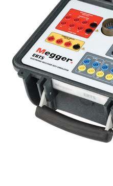





SEE THE NEW ERTS AT NETA POWERTEST 2017! Visit Megger at Booth 401 to see all of our newest test solutions built to help you Power on. Simultaneous electronic controller and recloser testing. ERTS us.megger.com/ERTS

56 Cable Testing Standards: Overview of the IEEE 400 Bundle
New studies have indicated a significant reason for concern regarding the integrity of U.S. power cable installations. Service-aged and new cable installations are subject to the same workmanship issuesthatcausemorethanhalfoftheU.S.cable issues that cause more than half of the U.S. cable outages. A new age of testing is now providing solutions to complex cable problems and establishing baseline data for condition-based maintenance programs. The current IEEE 400 Series of standards includes five major standards known as the IEEE 400 Bundle. These comprehensive standards provide the guidance the industry needs to address testing and evaluating of cableinstallationsoldandnew. cable installations old and new.
Alan Mark Franks, AVO Training
FEATURES
7 President’s Desk
Ron Widup, Shermco Industries
NETA President
64
William Higinbotham, EA Technology, LLC
Thomas Sandri, Shermco Industries

TABLE OF CONTENTS TABLE OF CONTENTS NETAWORLD • 3
STORY
COVER
72
TABLE OF CONTENTS
IN EVERY ISSUE
Mandatory and Informational References within NFPA 70E
Ron Widup and Jim White, Shermco Industries
Enhancing Medium-Voltage Cable Reliability
Don A. Genutis, Halco Testing Services
Medium-Voltage Cable Assessments
Jim White, Shermco Industries
Ground Faults and Inadequate Bonding
Jeff Jowett, Megger
Understanding the Difference Between Programs, Policies, Manuals, Procedures, and Training
Paul Chamberlain, American Electrical Testing Co., Inc.
Overall Differential Relay Operation at a Hydro Power Plant
Steve Turner, Beckwith Electric Company, Inc.
INDUSTRY TOPICS
Steven A. Kunsman, Nicholas Powers, and Bharadwaj Vasudevan, ABB Inc., USA
Dave Sowers, Knowledge Vine
ADVANCEMENTS IN TECHNOLOGY
Matthew Lawrence and Elizabeth Aragao, Doble Engineering Company
John Olobri, AEMC Instruments
SPECIFICATIONS AND STANDARDS
Jim White, Shermco Industries
Ralph Patterson, Consultant
Vijay Shanmugasundaram, Dinesh Chhajer, Dhanabal Mani, and Daniel Carreño, Megger
NETA NEWS – IMPORTANT LISTS
4 • SPRING 2017 TABLE OF CONTENTS
NETA NEWS POWERTEST

HARNESS THE POWER OF GROUP CBS










Providing Electrical Solutions Worldwide POWERTEST, BOOTH 225 | HOSPITALITY SUITE: THE ADVENTURE ROOM Since 1981 EQUIPMENT & RELIABILITY TRACK How Vacuum Interrupters Work and How They Fail Monday 9:30–10:15 a.m. Presented by: Finley Ledbetter, Group CBS, Inc. CIRCUIT BREAKERS PANEL Tuesday 8–9:45 a.m. & 10:15 a.m.–noon Moderated by: Dan Hook, Western Electrical Services, Inc. POWERTEST 2017 SPOTLIGHT STAGE Tuesday 4:10–4:25 p.m. From Edison to Musk: Technological Innovations in Material Science and Their Impact on Circuit Breaker Construction Circuit Breaker Sales Co., Inc DON’T MISS THESE TECHNICAL PRESENTATIONS FROM THE BREAKER PROS AT GROUP CBS:
GROUP CBS: EMPOWERING
FIELD SERVICE
When an emergency strikes, our dedicated engineers and technicians — along with our unparalleled inventory of all manufacturers’ obsolete, surplus, and new electrical equipment and replacement parts — enable us to restore your power quickly and safely, 24/7.
LIFE EXTENSION
We can extend the life of your obsolete, hard-to-maintain switchgear, motor controls, and circuit breakers by raising interrupting capacity, increasing equipment reliability, matching your existing switchgear lineup, providing solid-state trip units, and offering retrofit and retrofill solutions.
PARTS
Our stock includes a wide variety of new, surplus, and reconditioned industrial molded-case circuit breakers and insulated-case breakers rated up to 5000 amperes from virtually all manufacturers, including ABB, Cutler-Hammer, FPE, General Electric, ITE, Siemens, Square D, Westinghouse, and Zinsco.
POWER EQUIPMENT
Contact us for ready access to virtually any low- or medium-voltage electrical power apparatus ranging from a single replacement part to a complete substation. Our vast inventory includes new, surplus and reconditioned circuit breakers, switchgear, transformers, motor control, load break switches, protective relays, replacement parts, and much more.
THE ELECTRICAL INDUSTRY
ENERGY
Supply Chain

REMOTE RACKING & SWITCHING
To provide enhanced arc-flash protection for your personnel, we offer circuit breaker remote racking systems and remote switch operators, reducing the need for full-ready arc-flash hazard suits by taking technicians outside the arcflash boundary.
SHOP REPAIRS
Our trained technical and engineering staff is on hand to test and inspect your electrical equipment and then professionally repair, remanufacture, or recondition it to original equipment manufacturer and industry standards. We follow up with full documentation of test results and equipment performance.
TESTING
We go well beyond the pass/fail HiPot test for your vacuum interrupters. Our technicians can predict the remaining life of your vacuum interrupters through Magnetron Atmospheric Condition (MAC) field and shop testing.
CUSTOM-ENGINEERED PRODUCTS
With our experienced in-house engineering, metal working capabilities, and skilled technicians, we can custom design and build or modify an existing panelboard or switchboard to fit your lighting or power distribution application.
C B Store.com
Group CBS, Inc.
GroupCBS.com
Headquarters for affiliated electrical equipment, service, and engineering companies throughout the U.S., UK, Middle East, and Pacific Rim, providing premier products and services to the industrial, utility, electrical distribution, and repair markets worldwide. Addison, TX – 972-250-2500
Advanced Electrical & Motor Controls, Inc.
AEAMC.com
Certified UL 508A industrial control panel builder specializing in the sales and service of insulated-case circuit breakers, molded-case circuit breakers, bolted pressure switches, panelboards, switchboards, motor controls, bus plugs, bus ducts, and renewal and replacement parts. Irving, TX – Ph: 800-289-2757
CBS ArcSafe, Inc.
CBSArcSafe.com
The arc-flash protection experts, offering remote racking systems, remote switch actuators, and handheld motorized racking tools for low- and medium-voltage switchgear.
Denton, TX – Ph: 877-4-SAFETY
CBS Nuclear Services, Inc.
CBSNuclear.com
In-shop and on-site field servicer of Class 1E safety-related low- and medium-voltage switchgear and circuit breakers. Also services industrial and non-nuclear-related circuit breakers and related switchgear and substations.
Matthews, NC – Ph: 704-882-1875
Circuit Breaker Analyzer, Inc.
CBAnalyzer.com
Producer of new circuit breaker testing methods that use vibration analysis combined with Internet data transfer and sophisticated condition-based analysis to determine the condition of all types of circuit breakers. Addison, TX – Ph: 972-290-0074
Circuit Breaker Sales & Repair, Inc.
CBSalesAndRepair.com
Servicing the Gulf Coast with shop or field service, repair, upgrade, or replacement of power system apparatus. La Porte, TX – Ph: 281-479-4555

GROUP CBS AFFILIATES
Circuit Breaker Sales Co., Inc.
CircuitBreaker.com
World’s largest inventory of low- and medium-voltage circuit breakers and parts. Complete service, remanufacture, upgrade, and life-extension services. Also offers CBS MagVac magnetic latching medium-voltage breakers and Tough Duty™ Power/Vac® roll-in replacement breakers.
Gainesville, TX – Ph: 800-232-5809
Circuit Breaker Sales Florida, Inc.
CBS-Florida.com
One-stop service for circuit breakers, switchgear, transformers, protective relays, loadbreak switches, motor controls, unit substations, and renewal parts, as well as repair, upgrade, life extension, and maintenance services.
Lakeland, FL – Ph: 863-646-5099
Circuit Breaker Sales NE, Inc.
CircuitBreakerSalesNE.com
A leader in providing power distribution products and services, specializing in life-extension services and offering an expansive inventory of new, surplus, and reconditioned circuit breakers, switchgear, motor controls, transformers, and other power apparatus.
Seymour, CT – Ph: 203-888-7500
Circuit Breaker Sales Southeast, Inc.
CBSSoutheast.com
Sales and repair, upgrade, reconditioning, and lifeextension services of utility-industrial circuit breakers, motor controls, switchgear, substations, transformers, and other electrical equipment.
Gonzales, LA – Ph: 225-673-2278
Circuit Breaker Store, Inc.
CBStore.com
Your online source for all Group CBS products. A powerful solutions provider with a specialty vendor network that can supply factory new, surplus new, and reconditioned circuit breakers, electrical distribution equipment, control equipment, parts, and remote racking equipment.
Gainesville, TX – Ph: 855-227-8673

Sertec Relay Services
A Division of CBS NE, Inc.
ProtectiveRelaySpecialists.com
Specialists in extending the life of obsolete electromechanical protective relays by providing quality repair, remanufacture, and retrofit services for relays of all types and from all manufacturers.
Seymour, CT – 203-888-7500
Solid State Exchange & Repair, Inc.
SolidStateRepair.com
Quality, reliable, on-time service and support for all brands and types of solid state power electronics, including circuit breaker trip devices, protective relays, motor overload relays, and rating plugs.
Denton, TX – Ph: 877-TRIP-FIX
Vacuum Interrupters, Inc.
VacuumInterruptersInc.com
Your source for replacement vacuum interrupters, MAC-TSx series of vacuum interrupter test units, CBT1201 timer, and new replacement encapsulated poles for Power/Vac® circuit breakers.
Farmers Branch, TX – Ph: 214-442-5877
Western Electrical Services, Inc.
WesternElectricalServices.com
One-stop shop for all electrical equipment sales, testing, and engineering needs in a utility-class service provider. Superior quality on-site electrical testing, maintenance, and repair services as well as rebuild, upgrade, and life-extension services for switchgear, circuit breakers, motor controls, and transformers. Also offering electrical engineering studies and custom manufacturing of engineered and reverse-engineered parts.
Phoenix, AZ • Chino, CA • Salt Lake City, UT • Sumner, WA • Vancouver, WA – Ph: 888-395-2021

Group CBS, Inc. | 4800 Broadway, Ste. B | Addison, TX 75001 | 972-250-2500 | Info @ GroupCBS.com | GroupCBS.com





On the Potomac CALL FOR EXHIBITORS The premier ELECTRICAL MAINTENANCE AND SAFETY Conference Join 400+ electrical testing professionals Leading decision makers looking for new products and services For attendee profile and additional information, visit www.powertest.org PowerTest.org 888.300.6382 Hosted by

Electrical Distribution System



3050 Old Centre Avenue, Suite 102
Portage, MI 49024
Toll free: 888.300.NETA (6382)
Phone: 269.488.NETA (6382)
Fax: 269.488.6383 neta@netaworld.org
www.netaworld.org
EXECUTIVEDIRECTOR: Missy Richard
PRESIDENT: Ron Widup, Shermco Industries
FIRSTVICEPRESIDENT: Jim Cialdea, Three-C Electrical Co., Inc.
SECONDVICEPRESIDENT: Scott Blizard, American Electrical Testing Co., Inc.
SECRETARY: Eric Beckman, National Field Services
TREASURER: John White, Sigma Six Solutions
Ken Bassett (Potomac Testing, Inc.)
Eric Beckman (National Field Services)
Scott Blizard (American Electrical Testing Co., Inc.)
Jim Cialdea (Three-C Electrical Co., Inc.)
Lorne Gara (Orbis Engineering Field Services, Ltd.)
Dan Hook (Western Electrical Services, Inc.)
David Huffman (Power Systems Testing)
Alan Peterson (Utility Service Corporation)
John White (Sigma Six Solutions)
Ron Widup (Shermco Industries)
TECHNICALEDITORS: Roderic L. Hageman, Tim Cotter
ASSISTANTTECHNICALEDITORS: Jim Caldea, Dan Hook, Dave Huffman, Bob Sheppard
ASSOCIATEEDITOR: Resa Pickel
MANAGINGEDITOR: Carla Kalogeridis
COPYEDITOR: Beverly Sturtevant
ADVERTISINGMANAGER: Laura McDonald
DESIGNANDPRODUCTION: Moon Design
CONFERENCE: Ron Widup; MEMBERSHIP: Ken Bassett; PROMOTIONS/MARKETING: Scott Blizard; SAFETY: Scott Blizard and Jim White; TECHNICAL: Alan Peterson; TECHNICALEXAM: Ron Widup; CONTINUINGTECHNICALDEVELOPMENT: David Huffman; TRAINING: Bob Sheppard; FINANCE: John White; NOMINATIONS: Alan Peterson; ALLIANCEPROGRAM: Jim Cialdea; ASSOCIATIONDEVELOPMENT: Ken Bassett and John White
© Copyright 2017, NETA
NOTICE AND DISCLAIMER
NETA World is published quarterly by the InterNational Electrical Testing Association. Opinions, views and conclusions expressed in articles herein are those of the authors and not necessarily those of NETA. Publication herein does not constitute or imply endorsement of any opinion, product, or service by NETA, its directors, officers, members, employees or agents (herein “NETA”).
All technical data in this publication reflects the experience of individuals using specific tools, products, equipment and components under specific conditions and circumstances which may or may not be fully reported and over which NETA has neither exercised nor reserved control. Such data has not been independently tested or otherwise verified by NETA.
NETA MAKES NO ENDORSEMENT, REPRESENTATION OR WARRANTY AS TO ANY OPINION, PRODUCT OR SERVICE REFERENCED OR ADVERTISED IN THIS PUBLICATION. NETA EXPRESSLY DISCLAIMS ANY AND ALL LIABILITY TO ANY CONSUMER, PURCHASER OR ANY OTHER PERSON USING ANY PRODUCT OR SERVICE REFERENCED OR ADVERTISED HEREIN FOR ANY INJURIES OR DAMAGES OF ANY KIND WHATSOEVER, INCLUDING, BUT NOT LIMITED TO ANY CONSEQUENTIAL, PUNITIVE, SPECIAL, INCIDENTAL, DIRECT OR INDIRECT DAMAGES. NETA FURTHER DISCLAIMS ANY AND ALL WARRANTIES, EXPRESS OF IMPLIED, INCLUDING, BUT NOT LIMITED TO, ANY IMPLIED WARRANTY OF FITNESS FOR A PARTICULAR PURPOSE.
ELECTRICAL TESTING SHALL BE PERFORMED ONLY BY TRAINED ELECTRICAL PERSONNEL AND SHALL BE SUPERVISED BY NETA CERTIFIED TECHNICIANS/ LEVEL III OR IV OR BY NICET CERTIFIED TECHNICIANS IN ELECTRICAL TESTING TECHNOLOGY/LEVEL III OR IV. FAILURE TO ADHERE TO ADEQUATE TRAINING, SAFETY REQUIREMENTS, AND APPLICABLE PROCEDURES MAY RESULT IN LOSS OF PRODUCTION, CATASTROPHIC EQUIPMENT FAILURE, SERIOUS INJURY OR DEATH.


24 Hour Emergency Services (937) 439-9660

NETA: YOUR KNOWLEDGE HUB
If you are reading this in Anaheim — welcome to PowerTest!
And if you weren’t able to join us at PowerTest 2017 — while you’re missing a great event — be sure to check the NETA website for conference materials and information on PowerTest 2018 at Gaylord National Harbor in Washington, DC. Additional information on both NETA and PowerTest can be found at www.netaworld.org and www.powertest.org
For all of us in the electrical power industry, it’s a good time to be in this market. Advances in safety — with a broader understanding of safe work practices — coupled with improvements in equipment technology, all make it better for our employees and our clients. Plus, the current economic climate around what we do is robust and exciting.
To keep up with the advancements and changes, you’ve come to the right spot — PowerTest and NETA World journal. So take time to mingle with your colleagues or spend some quiet time within the pages of NETA World. It’s sure to benefit your knowledge and your career.
Finally, thank you for taking time to participate in the success of our association — be it active participation in NETA committees, the conference, or endorsement of the association’s goals and aspirations. The more we can involve all of us, the more influence we have on the industry. And for that, we are extremely grateful.
Have a great and safe spring.
 Ron Widup President NETA — InterNational Electrical Testing Association

PRESIDENT’SDESK PRESIDENT’S DESK PRESIDENT’S DESK


On the Potomac SAVE THE DATE Join us at the Gaylord National Resort and Convention Center on the banks of the Potomac River, a stone’s throw from Washington, D.C., Georgetown, Arlington, and Alexandria, Virginia. PowerTest.org 888.300.6382 Hosted by The premier ELECTRICAL MAINTENANCE AND SAFETY Conference


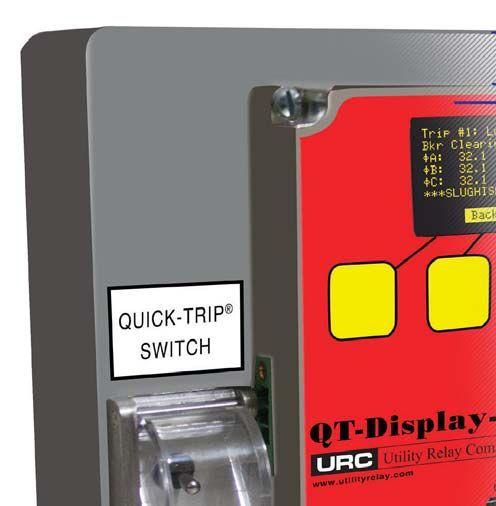


This new addition to the AC-PRO-II ® product line provides:
•An extension of all the AC-PRO-II ® information to the cubicle door
•OLED display for easy viewing
•Integral Quick-Trip ® switch & LED for arc flash hazard reduction

•Additional communication options:
• Ethernet port
• RS485 port
•2 Alarm Relays
•USB port for:
• InfoPro-AC™ software
• SAFE-T-TRIP ®
About URC:
Utility Relay Company was started in 1995 and after 21 years of developing and manufacturing we are now one of the industry leaders. Our focus is providing high units for low voltage circuit breakers. kits that are designed with ease of installation and reliability in mind. The end result is an extensive line and work when needed.
UtilityRelay.com 888.289.2864 URCSales@UtilityRelay.com
AC-PRO-II
A CUBICLE DOOR MOUNTED DISPLAY FOR THE
®

OSHA 29CFR1910.399 definition of a qualified person:
“Qualified person. One who has received training in and has demonstrated skills and knowledge in the construction and operation of electric equipment and installations and the hazards involved.”
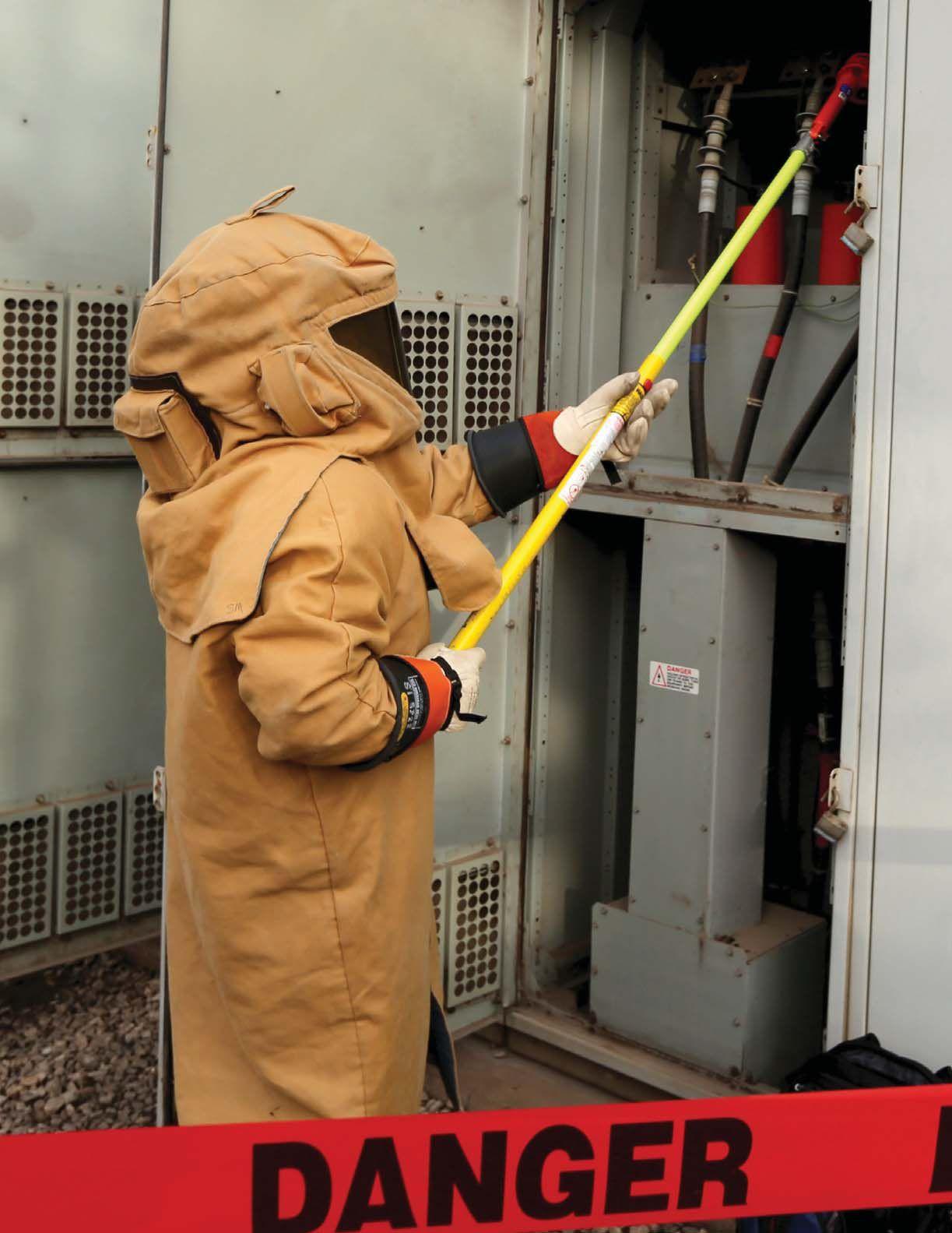
Shermco’s Electrical Safety for Qualified Workers course meets the minimum mandated requirements of both OSHA and NFPA 70E.
Shouldn’t you be training with the people who are in the field every day?

www.shermco.com 888-SHERMCO training makes all the difference. When the job calls for the best, Questions? training@shermco.com
INFORMAT INFORMA NFORMA NFORMAT NFOR N NF I IN
R AND


REFERENCES WITHIN NFPA 70E MANDATORY MANDATO MANDAT INFOR O F O
BY RON WIDUP AND JIM WHITE, Shermco Industries


Are you familiar with the structure of NFPA documents and references within the documents? Or, more specifically, when a reference is made to another document or action, when is it mandatory in complying with the intent of the document, or when is it simply there to provide additional information for clarity?
This article addresses some of the ins and outs of mandatory and informational references within NFPA 70E. These are the references seen either within Informational Notes or the body of the text.
Section 130.5. Arc Flash Risk Assessment
Informational Note No. 5: See IEEE 1584, Guide for Performing Arc Flash Calculations, for more information regarding arc flash hazards for threephase systems.
Section 130.7(C)(14). Standards for Personal Protective Equipment (PPE) PPE shall conform to the standards listed in Table 130.7(C)(14). Informational Note: Non–arc-rated or flammable fabrics are not covered by any of the standards in Table 130.7(C)(14). See 130.7(C) (11) and 130.7(C)(12).


The first example illustrates how a standard is referenced in an Informational Note. The second example shows how a standard is referenced within the body of the text. Informational Notes are not mandatory to the 70E, while anything within the body of the text would be mandatory. In the second example, a host of ASTM and ANSI standards regarding PPE construction, care, and storage are considered mandatory. Table 130.7(C)(14) lists 18 standards that relate to different aspects of PPE construction, care, and testing.
It is important that the referenced standards be read and understood by NFPA 70E users. It is not possible for the 70E to contain all the information required to assess risk, inspect PPE, or determine what size temporary personal protective grounds to use. Other industry

NETAWORLD • 11 MANDATORY AND INFORMATIONAL REFERENCES WITHIN NFPA 70E THE NFPA 70E AND NETA

THE NFPA 70E AND NETA
standards contain this information, which is why the 70E references them.

For example, consider ASTM F1506, Standard Performance Specification for Flame Resistant and Arc Rated Textile Materials for Wearing Apparel for Use by Electrical Workers Exposed to Momentary Electric Arc and Related Thermal Hazards. This standard contains six pages of detailed specifications for the construction and qualification testing of arc-rated fabrics and materials, including such topics as terminology, requirements, test methods, and more. Multiply this by the 18 additional standards referenced in Table 130.7(C)(14) and the size of NFPA 70E nearly doubles. And those are not the only standards referenced by the 70E. A quick look at Informative Annex A, Referenced Publications, reveals 50 mandatory references; Informative Annex B, Informational References includes 53 non-mandatory references. Some of these standards appear in both lists, so the actual number of standards is less than 100. Whenever information is transferred from one source to another, a chance of misinterpretation or transcribing errors exists. It is much better for the NFPA 70E user to go straight to the source.
Can anyone read and digest almost 100 different standards — or even 50? Perhaps you could, but it would not be practical to require this of the industry. However, it is important that we can pick through these standards and find specific information needed to perform the job safely.
ANSI/AIHA Z10, Occupational Health and Safety Management Systems, contains very useful information on risk assessments. The 70E committee relied heavily on this standard to develop its risk assessment requirements. The standard contains 72 pages; not all of that information is relevant to the 70E, but all of it has value to workers trying to understand the risk assessment process.
Everyone knows or at least has heard of IEEE 1584, IEEE Guide for Performing Arc-Flash Hazard Calculations. And while the 1584 guide has mounds of useful technical information, arguably most field service technicians would
have difficulty interpreting much of the data, and even more difficulty applying it to their everyday tasks. However, Table 1 provides useful guidance on typical maximum total trip times for various overcurrent protective devices, and it is pieces of information from standards like this that are most useful to the 70E document user.
In the definitions section, ASTM F1506 has this to say about arc ratings:
• 3.2.3 arc rating, n — value attributed to materials that describes their performance to exposure to an electrical arc discharge.
• 3.2.3.1 Discussion — The arc rating is expressed in cal/cm2 and is derived from the determined value of ATPV or EBT (should a material system exhibit a breakopen response below the ATPV value).
• 3.2.4 arc thermal performance value (ATPV), n — In arc testing, the incident energy on a material or a multilayer system of materials that results in a 50 percent probability that sufficient heat transfer through the tested specimen is predicted to cause the onset of a second-degree skin burn injury based on the Stoll curve, cal/cm2.
From these definitions, we know the arc rating (section 3.2.3), that it is derived from the Arc Thermal Performance Value (ATPV), that it is expressed in cal/cm2 (section 3.2.3.1), and that the ATPV represents the incident energy that would cause a 50 percent probability of a second-degree burn on bare, unprotected skin underneath it (section 3.2.4). In simple terms, the arc rating is the incident energy that would result in a 50 percent probability of the onset of a second-degree burn on bare skin under that garment. That’s pretty important information to those of us who use or specify arc-rated clothing to protect from the risk of arc-flash injuries.
NFPA 70E is a consensus standard, and, as such, it does not carry the force of law the way OSHA regulations do. Even though it is written in mandatory language, OSHA will only use it as a guide and cannot enforce the provisions of
MANDATORY AND INFORMATIONAL REFERENCES WITHIN NFPA 70E
12 • SPRING 2017
the 70E. Whether the references are used within the text or within Informational Notes is almost immaterial, as it is the responsibility of qualified persons to be aware of the information needed to perform their job safely. This opinion is at variance with OSHA’s single-responsibility viewpoint, where the employer is always fully responsible for every employee’s safety.
It’s not only ASTM or ANSI standards that appear in the 70E. IEEE, IEC, UL, CSA, ISA, ISEA, ISO, ICRP, NIOSH, NETA, NFPA, and OSHA standards are also referenced. Not all of them may have application to the task or job at hand, but researching these standards and determining which ones are pertinent to you and your employees is important.
Some standards have not been reviewed because the need has not existed — yet. A time may come when that ICRP standard could be the one needed to successfully complete a task safely, especially if you are working around medicalgrade radiological materials.

THE NFPA 70E AND NETA

Ron Widup and Jim White are NETA’s representatives to NFPA Technical Committee 70E (Electrical Safety Requirements for Employee Workplaces). Both gentlemen are employees of Shermco Industries in Dallas, Texas, a NETA Accredited Company. Ron Widup is CEO of Shermco and has been with the company since 1983. He is a Principal member of the Technical Committee on Electrical Safety in the Workplace (NFPA 70E) and a Principal member of the National Electrical Code (NFPA 70) Code Panel 11. He is also a member of the Technical Committee Recommended Practice for Electrical Equipment Maintenance (NFPA 70B), and a member of the NETA Board of Directors and Standards Review Council. Jim White is nationally recognized for technical skills and safety training in the electrical power systems industry. He is the Training Director for Shermco Industries, and has spent the last twenty years directly involved in technical skills and safety training for electrical power system technicians. Jim is a Principal member of NFPA 70B representing Shermco Industries, NETA’s alternate member of NFPA 70E, and NETA’s Principal representative to the ASTM F18 Committee Electrical Protective Equipment for Workers.






 Ron Widup
Jim White





ENHANCING


 BY DON GENUTIS, Halco Testing Services
Medium-voltage cable reliability philosophies and programs edium-voltageMe have changed dramatically over the years — all the way from “set it and forget it,” to performing dc hipot testing. On-line techniques have proven advantageous, and trends toward monitoring technology advancements show great promise.
The majority of medium-voltage cable system insulation failures are preceded by an increase of partial discharge activity, in a similar manner as other medium-voltage insulation failures. Partial discharge activity that precedes cable failure creates distinct electromagnetic signals that are detected using high-frequency current sensors coupled to the cable shield. PD signals that are distant from the sensor location attenuate in amplitude and frequency. Detection becomes much more difficult as the amplitude falls closer to the ambient noise floor, and frequency can fall into bandwidths occupied by typical industrial noise sources.
The majority of cable system failures occur at splices and terminations. Insulation defects in these components tend to take a longer period of time to fail. Because these components are more readily accessible, signal attenuation is reduced and noise concerns are negligible, making spot PD testing effective.
Detecting PD in cable insulation itself presents a unique difficulty. In addition to the potential
for noise-related obstacles discussed earlier, the cable insulation itself may fail rapidly after the onset of PD activity. Spot testing may not be a viable solution to provide cost-effective reliability for cable systems overall.
Therefore, to provide the highest level of reliability, the cable system should be monitored continuously, and effective noise-removal techniques should be employed. Fortunately, new advances in on-line cable PD monitoring could be a solution for these problems.
Several types of noise-removal techniques such as filtering and windowing have enjoyed some success. Advanced noise-removal algorithms and novel, computer-based waveform comparison and recognition software — developed from a database of millions of actual in-service cable signal waveforms — have proven much more effective in recognizing PD. (Editor’s note: Cable noise removal methods were described in greater detail in the No-Outage Corner article in the Fall 2015 issue of NETA World.) PD monitors that apply these sophisticated noise-removal
ENHANCING MEDIUM-VOLTAGE CABLE RELIABILITY 16 • SPRING 2017
NO-OUTAGECORNER NO-OUTAGE CORNER

algorithms to the cable signals are in service at many locations throughout the world. The benefit of this technology is described in the following case study provided courtesy of Independent Power Engineering Consultants.
A continuous cable PD monitor was installed at a steel manufacturing facility in Asia. After three years of normal operation, one of the cables indicated a rapid increase in the level of PD, which automatically triggered an alarm at the central monitoring data center facility 3,000 miles away. From the waveforms, the discharge site was accurately pinpointed to a splice in the 2,400-foot cable without needing to visit the site. Plant personnel replaced the splice during a planned routine maintenance outage three months later, and the suspect splice was sent to an independent laboratory for expert analysis, which confirmed the findings. If not for the online monitoring system, the splice would have failed without warning, creating an unplanned outage and expensive loss of production.

As technology continues to rapidly change our our daily lives, new technology in the power industry must also continue to advance and provide us with better methods for ensuring mediumvoltage cable reliability. Recent on-line cable cable waveform analysis and monitoring advancements promise to provide dependable solutions today and into the future.

Don A. Genutis presently serves as President of Halco Testing Services, a NETA Accredited Company, in Los Angeles, California. He has held various principal positions during his 30-year career in the electrical testing field and has primarily focused on advancing no-outage testing techniques for the last 15 years. Don holds a bachelor of science in electrical engineering from Carnegie Mellon University and is a NETA Certified Technician.
REFERENCES

Genutis, Don A. “How New PD Technology Can Make You Hero of the Day,” NETA World, Fall 2015, pp 40-42.

NO-OUTAGE CORNER

Absolute confidence. Every time.
You can count on us for specialized experience in healthcare, data center, office complex, and commercial acceptance and maintenance testing. Absolutely Power generation, petrochemical, oil & gas, and heavy industries also look to us for high demand services such as start-up commissioning, maintenance testing, shut-down and turnarounds, and breaker shop repair. Get started today.


Toll Free 1+ (855)767-4446 8100 West Little York | Houston, Texas 77040 Email: Alan Postiglione | apost@absolutetesting.com | www.absolutetesting.com Like us on:

We support testing
Relay and Protective Device Test Equipment
Battery Analysis and Battery Discharge Test Equipment
Low Voltage Circuit Breaker and Switchgear Test Equipment
Medium/High Voltage Circuit Breaker and Substation Test Equipment
SF6 Chemical Analysis Equipment
Transformer Testing and Diagnostic Equipment
DC, VLF, Online PD and Offline PD Test Equipment for Cables
Cable Fault Location Equipment
Power Quality and Load Analysis
Data Acquisition and Recorders
Meter Analysis Equipment
Online and Offline Partial Discharge for Apparatus and Substations
Low Resistance Ohmmeters
Insulation Resistance / Megohmmeters
Ground Test Equipment
Photovoltaic Test Equipment
Infrared Cameras
Ultrasound and TEV Analysis Equipment
Motor and Rotating Apparatus Test Equipment
Patient Care Area Test Equipment
AC and DC Load Banks
AC High Potential Test Sets to 200kV
DC High Potential Test Sets to 200kV
VLF and Tan Delta to 90kV
888.902.6111


rental support logistics
ir
info@intellirentco.com intellirentco.com
intellirent


Jim White is the Training Director for Shermco Industries, Inc., in Dallas, Texas. He is the Principal member on NFPA Technical Committee Recommended Practice for Electrical Equipment Maintenance (NFPA 70B). Jim represents NETA as an alternate member of NFPA Technical Committee Electrical Safety in the Workplace (NFPA 70E) and represents NETA on the ASTM F18 Committee Electrical Protective Equipment for Workers. He is an IEEE Senior Member and in 2011 received the IEEE/ PCIC Electrical Safety Excellence Award. Jim is a past Chairman (2008) of the IEEE Electrical Safety Workshop (ESW).


MEDIUM-VOLTAGE CABLE ASSESSMENTS
BY JIM WHITE, Shermco Industries


Medium-voltage power cables are critical to power systems operation. A cable failure can cause disruptions ranging from minor power outages to equipment destruction, loss of production, and expensive rehab of facilities. Whenever there is an in-service failure of electrical power equipment, safety risks increase. This month’s Tech Quiz is about assessing medium-voltage cables.
1. Which IEEE standard covers power cable testing and evaluation?
a. IEEE standard 400
b. IEEE standard 421
c. IEEE standard 446
d. IEEE standard 484
e. IEEE standard 850
2. Within the standard referenced in Question 1, what is the specific section that covers tan-delta testing of medium-voltage power cables?
a. IEEE standard 400.2
b. IEEE standard 421.2
c. IEEE standard 446.2
d. IEEE standard 484.2
e. IEEE standard 850.2
3. What does a withstand test determine?
a. The ability of the power cable under test to withstand three-times rated voltage
b. The amount of voltage versus time the cable can safely handle
c. Whether there are defects in the cable that will fail under test conditions
d. The health of the insulation under test
4. Over-potential dc testing:
a. Is highly recommended for diagnostic testing of medium-voltage, solid dielectric cable
b. Can only be performed once, either when the cable is new or within the first five years of service
c. Uses very heavy, bulky test equipment to perform the test
d. Is a go/no-go type of test
5. What are four diagnostic tests that can be performed using a tan-delta test set? (You can use just the initials instead of writing out the entire name.)
a. _________________________________
b. _________________________________
c. _________________________________
d. _________________________________
20 • SPRING 2017 TECHQUIZ TECH QUIZ See answers on page 126.
No.117 No. 117
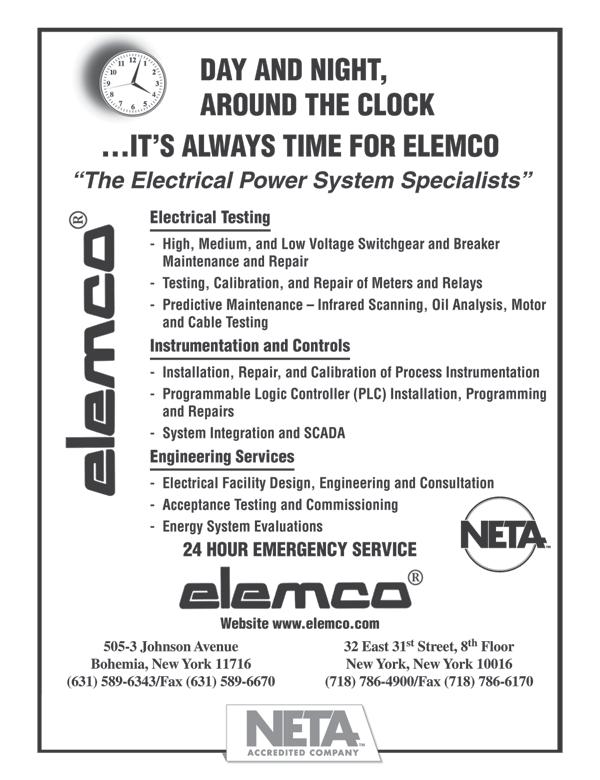
6. Label the components on the following diagram:


a. _________________________________ b. _________________________________ c. _________________________________ d. _________________________________ e. _________________________________ a c f e b d 228 Merrick Road Lynbrook, NY 11563 (631) 589-6343/Fax (516) 596-3680 601 Union Street Brooklyn, NY 11215 (718) 786-4900

Electric Testing, Inc.
Industrial
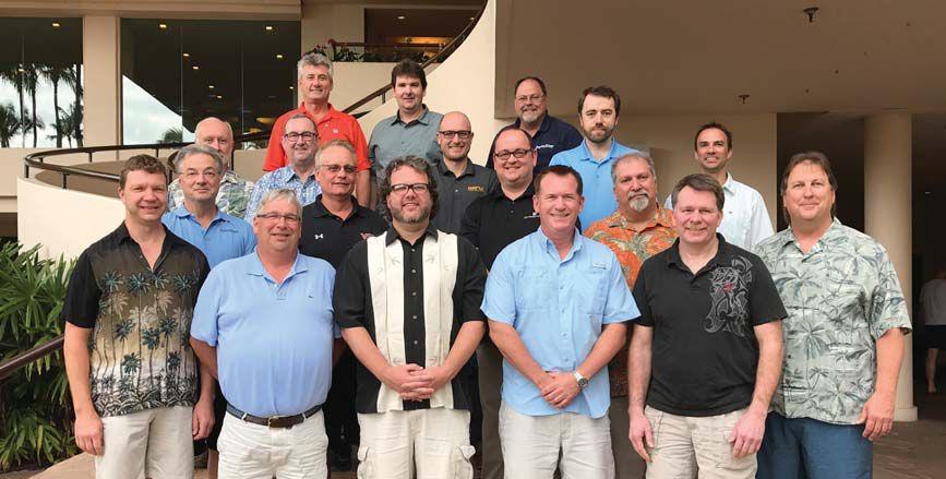

NETA members, Hawaiian-style (left to right, front to back):
Scott Dude, Scott Blizard, Dan Hook, Walt Cleary, Chris Zavadlov, Ron Widup
Jim Cialdea, Gary Walls, Nenad Pasic, Russ Sorbello, Lorne Gara
Dick Reese, John White, Eric Beckman, Adis Talovic
Ken Bassett, Michel Castonguay, Dave Huff man
NETA BOARD AND MEMBERSHIP MEETINGS SHOW ASSOCIATION PROGRESS TRACKING AS PLANNED
NETA’s Board of Directors and Membership met at the Westin Maui Resort & Spa for regularlyscheduled meetings on January 19 and 20, 2017. The unique beauty and warmth of Hawaii was the perfect backdrop for meaningful discussions about NETA’s progress and activities.
January marks the half-way point in the association’s fiscal year and has been the traditional time for NETA’s Board and Members to look back at the goals established at the beginning of the year and measure the progress of various programs and initiatives. The Board reported e
sound fiscal standings to the Membership and confirmed that programs are tracking as projected for the year.
Members were given progress updates on various NETA projects. Two focal points of the Member roundtable discussions were the NETA Certification Program and exams and the Association’s ongoing development.

Additional discussions covered marketing and promotion activities, a detailed overview of PowerTest 2017, and the upcoming 45th Anniversary celebration at PowerBash.

24










AND INADEQUATE BONDING — PART I

 BY JEFF JOWETT, Megger
The most dramatic and well-known effects of grounding — or rather, lack thereof — are fires and electrocutions. Fortunately, the examples to be discussed here did not result in fatalities but did cause substantial injury. Additionally, the examples illustrate that poor grounding isn’t just a potential cause of electrocution but also has many corollary risks.
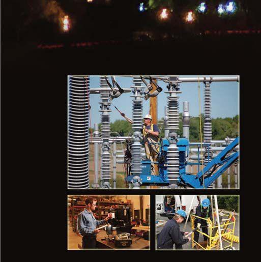
Utility poles commonly carry a mix of conductors, such as power and communication. The latter are typically installed lower than the power conductors. Workers from both sources commonly climb these poles to perform maintenance and installation functions, and their activities and work practices are strictly regulated by a variety of organizations, including their companies and independent agencies.


In one instance, a phone company worker investigating a customer complaint traced the issue to the pole servicing the premises. Preparation was conducted in accordance with safe work practices, including the donning of personal protective gear and a check of the base of the pole and immediate environment for any voltage sources. No grounding conductor was visible on the pole. Climbing the pole, the worker maintained safety protocols, always maintaining three points of contact so that the hands were never used for any task other than the
act of climbing. But when arriving at the work area and reaching around the pole to connect a safety belt that would free up his hands for work, the worker received a severe electric shock and fell to the ground.
Investigation uncovered three points of interruption to what should have been a safe grounding plan. First, the pole, which included a pole-mounted transformer, had been installed with a grounding conductor running down the pole to a ground rod at the base. This had not been observed by the worker upon initial evaluation of the site because its lower length had been cut and removed, almost certainly by copper thieves. When in place, there was no protective molding on the grounding conductor to impede the vandalism.
Furthermore, there had been an interconnect jumper from the power neutral to the pole ground. The operative term here is had been.
GROUND FAULTS AND INADEQUATE BONDING — PART I TECHTIPS TECH TIPS 28 SPRING 2017

The clamp to the power neutral had been disconnected for no known reason. Finally, there was evidence of a small fire having melted away the connection to the phone system ground. The only remaining connection from the transformer to ground was through the phone system messenger wire, which is not rated for power current and had most likely melted open. Unfortunately, when the victim accidentally contacted the open grounding conductor, he became the path to ground. The most critical of the failures was the loss of the connection to the power neutral. Had this been in place, the parallel pole grounds down the line, typically every third pole, would have cleared the worker.
This example illustrates many important points: the usefulness of redundant grounding protection, the dangers that can occur apart from electrocution itself, and perhaps most of all, the necessity for vigilant maintenance. It also illustrates how important proper bonding is in an electrical system. Bonding is the establishment of a continuous, low-impedance path from equipment to ground, that is, the grounding electrode buried under or beside the building and ultimately the earth itself. Without a properly connected bonding path, fault current will find its own — through equipment, building structures, and even people. As normally non-current-carrying conductors, bonding conductors are often easily ignored, left hanging, or randomly connected to any convenient metal. As this example shows, bonding paths are essential to the protection of buildings and life. The National Electric Code® (NEC) specifically defines and describes proper bonding. It’s not there to make life difficult; it’s there to save it.
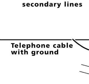


and easily overlooked is the effect of variable frequency drives (VFDs) as a source of shaft voltages. A VFD can induce stray currents that travel through a motor’s shaft. The high switching frequencies of modern VFDs can make unwanted use of the parasitic capacitance between stator and rotor.

But inadequate grounding isn’t just manifested in catastrophic incidents. Equipment can be slowly worn down by fault currents well below those injurious to humans. The performance and life cycle of electric motors is affected by grounding in numerous ways. One that is subtle
Seeking ground, these currents can cause arcing that slowly and steadily deteriorates a motor’s performance in at least two ways. The more obvious one is that arcs can blast bearing balls and races with fusion craters. As little as 5 volts may be enough to overcome the dielectric properties of the bearing grease and produce discharge along the path of least resistance, typically through the bearings. In turn, this arcing releases tiny metal particles that contaminate bearing grease, causing friction, added wear, and higher temperatures. The cumulative effect has shown that bearings
GROUND FAULTS AND INADEQUATE BONDING — PART I TECH TIPS
C H T I P S NETAWORLD 29
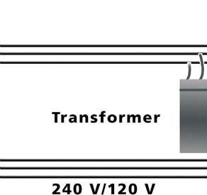
Utility Pole


Danger to Swimmers
can be seriously damaged in as little as two years. Repeated reconditioning has been the first line of defense and can become painfully expensive. Insulating and installing carbon-block grounding brushes only moves the problem. Rather than adding insulation on the bearings, a shaft grounding ring can channel harmful currents away from the bearings to ground.
The ring accomplishes this by encircling the shaft with conductive microfibers that do not rely on physical contact while increasing the electron transfer rate. A low-impedance path is thereby established from shaft to frame, bypassing the bearings. To maximize effectiveness, such protective devices must be sized as required for the magnitude of actual current flow. Periodic checks of shaft voltage are part of a subsequent maintenance program that would also include checking the shaft’s conductivity and possibly recoating with colloidal silver. This ensures that the potentially destructive currents are conducted safely to ground rather than arcing across narrow air gaps. VFDs can save considerable amounts in energy costs and are valuable assets for energy-efficient processes. But damage to motor bearings can offset any such gains. The preventive measures outlined here
preserve the advantages of VFDs without the offsetting costs of bearing repair. Again, good bonding and grounding is essential in providing a harmless path out of equipment that otherwise can be damaged by stray currents.
So far, this article has examined an obvious case of code violation with potentially catastrophic results and, at the opposite end of the recognition spectrum, an example of the consequences of a small, subtle, long-term fault. The next example describes a potential ground-fault condition that can be both subtle and catastrophic: fault current traveling through water.
Years ago, in the era of line-operated radios, deaths occurred when the radios would fall into bathtubs. Fortunately, the rise of batteryoperated appliances — along with the use of ground fault circuit interrupters (GFCIs) — has mitigated such catastrophes. But a clear and present aquatic danger exists from boats and marinas. Faulty wiring, coupled with improper or non-existent grounding at marinas, makes the surrounding water a ready and willing
30 SPRING 2017 TECH TIPS
GROUND FAULTS AND INADEQUATE BONDING — PART I TECHTIPS TECH TIPS

conductor. As fault current radiates out from the source, it establishes a voltage gradient from point to point, just as can happen in the earth in the more documented case of step potential. As a swimmer crosses this gradient, current travels through the body as well as through surrounding water. Normally, this is far less likely to cause electrocution than to cause drowning. Muscles tire quickly or the swimmer loses muscle control altogether, as in the more familiar let-go situation that occurs on land. Efforts at rescue typically only add to the tragic toll, as the would-be rescuer plunges unknowingly into the same environment. The victims lose control of the ability to keep themselves buoyant and drown. It has even been suggested that much lower amounts of current, which tend to travel at the surface and directly in line with a swimmer’s heart, can fatigue swimmers and cause drowning without even a suspicion of electrical involvement.
Missing and unconnected grounds are major causes of marina faults. The NEC provides the rules for installation of wiring and equipment in marinas and boatyards in Article 555.
“555.3 Ground Fault Protection. The main overcurrent protective device that feeds the marina shall have ground fault protection not exceeding 100mA. Ground fault protection of each individual branch or feeder circuit shall be permitted as a suitable alternative.”
explained previously, the current levels that can get a swimmer into trouble can be lower than the targeted Class A GFCI time-current thresholds. Much study and formulation remains to be done. This example illustrates how electrical dangers can exist seemingly remote from the normally recognized sources like circuitry and equipment. Persons who would be wary around electrical equipment might well be totally off guard in a lakeside environment. Indeed, some of the enacted legislation begins with the basic installation of warning signs.

The National Fire Protection Association (NFPA) outlines wiring requirements in Chapter 5 of NFPA 303, Fire Protection Standard for Marinas and Boatyards. A major complication, however, is that many such facilities have existed since before issues like grounding a marine facility and the associated codes were created. Legislation is being passed in various jurisdictions involving installation, periodic inspection, and enforcement, but the specific requirements have proven difficult to define. Accepted remedial measures include isolation transformers and GFCIs.
However, the specification of GFCIs in this application meets an additional challenge. As

The above examples represent just the tip of the iceberg regarding possible problems from lack of proper grounding and bonding. They range from the obvious to the unseen to the not-evenconsidered. But the unavoidable conclusion is that a grounding system must be properly installed, routinely inspected, and critically maintained just as the more obviously active elements of an electrical system. It can literally be a life-and-death issue.


Jeffrey R. Jowett is a Senior Applications Engineer for Megger in Valley Forge, Pennsylvania, serving the manufacturing lines of Biddle, Megger, and MultiAmp for electrical test and measurement instrumentation. He holds a BS in Biology and Chemistry from Ursinus College. He was employed for 22 years with James G. Biddle Co. which became Biddle Instruments and is now Megger.

Miller, Ben. “The Case of the Utility Pole Predicament.” EC&M, May 2016
Halverson, Matthew. “What Lies Beneath.” EC&M, August 2014


NETAWORLD 31 GROUND FAULTS AND INADEQUATE BONDING — PART I





AET Brings Precision and Value to Electrical Testing, Commissioning and Engineering… and Positive Results to Our Customers. located throughout the country, AET is an industry leader and one of the largest independent electrical testing companies in the U.S. To learn more about AET’s full range of testing and engineering services, visit www.aetco.us/NETA WWW.AETCO.US • 800.992.3826 The Power of Positive Results An Company A Subsidiary of

UNDERSTANDING THE DIFFERENCE BETWEEN
AND
BY PAUL CHAMBERLAIN, American Electrical Testing Co., Inc.


This article explores the typical safety documents needed to comply with federal OSHA standards. Each company should familiarize itself with what is required and comply with any other regulations that may apply to their business.
OSHA provides some guides in developing safety programs, and the need for compliance depends on whether the requirement is applicable to the work performed. These guides can be found
on the OSHA.gov website: www.osha.gov/dcsp/ compliance_assistance/sampleprograms.html
It is important for a company to know its scope of work and where the work is occurring prior to developing a program, policy, plan, or procedure, and associated training. Requirements change depending on where the work is conducted. For instance, work performed in a construction setting may have different requirements than work performed in a general industry setting.
Several different regulatory agencies specify which documents are needed to perform company tasks and services safely. In some cases, federal and state requirements must be adhered to for the same task or hazard. For example, the United States Environmental Protection Agency (US EPA), as well as state environmental agencies such as the Massachusetts Department of Environmental Protection (MA DEP), regulate environmental impacts that may occur during performance of a task. For workplace safety, there is the United States Department of Labor and its sub-department, the Occupational Safety and Health Administration (OSHA). Some states have their own state-approved occupational safety agency (see Figure 1). UNDERSTANDING THE DIFFERENCE BETWEEN PROGRAMS, POLICIES, MANUALS, PROCEDURES, AND TRAINING
34 • SPRING 2017
SAFETY CORNER
SAFETY CORNER

These 21 states and the territory of Puerto Rico have their own version of OSHA.
Additionally, not all OSHA requirements may be applicable. If the company performs entry into enclosed spaces only, and does not enter into confined spaces requiring permits, its program would indicate that and training must include that information. The program would not need to cover entry into permit-required confined spaces, even though enclosed and confined spaces are found in the same OSHA regulation.
A Job Hazard Analysis (JHA) is an important tool in analyzing the work to be performed and the hazards associated with each step in performing the work. Companies should take the time to create JHAs to better understand what hazards their employees will encounter. In some instances, such as in construction, a JHA will be required per OSHA. JHAs are known by many different names, but they all essentially have the same outcome: identification of known hazards, risk assessment, selection of appropriate PPEs if
applicable, and mitigation of the hazard through engineering controls or work practices associated with the completion of a task. They may be known as a Job Safety Analysis (JSA) or even just Hazard Analysis (HA). Some pre-job briefs, if detailed enough, can be considered a suitable substitute for a JHA.
Once a JHA is completed, the known hazards will be identified. The completed JHA should be reviewed with all personnel performing the work. Once a hazard is identified, the appropriate OSHA regulation can be located to aid in creation of a program, policy, procedure, or training.
Policies can be short and to the point. Think of these as a description sheet for a task or hazard. They are a position statement on how a company will address an issue, whether it is safety, environmental, procedural, or even humanresource related.
NETAWORLD • 35 • UNDERSTANDING THE DIFFERENCE BETWEEN PROGRAMS, POLICIES, MANUALS, PROCEDURES, AND TRAINING
AK AZ CA HI IN IA KY MD MI MN NV NM NC SC TN UT VT VA WA WY OR PR
SAFETY CORNER
Usually, a policy is not very detailed, especially if the topic can be covered succinctly and references other pertinent information. For example, a policy for respiratory protection may only state that the company provides the respirator and training, and indicates when wearing the respirator is necessary. If a topic requires greater detail, then it will usually be encased in a procedure or program. A policy may outline who and when, but is not detailed on how it will be accomplished. A policy may also speak to what can occur should a task not be completed as required.
respirator. The program will state that respirators will be cleaned daily, but the procedure will detail how the employee should clean the respirator.


Programs are designed for extensive detail. Think of these as detailed instruction sheets, including components necessary for construction that highlight the requirements as set forth by the regulatory agency and review the training. A program gets into the specifics of who, what, where, when, and why.
The program highlights the documents (i.e., inspection forms) required to comply with the regulations. Programs are fairly extensive and almost mimic a regulation line for line to ensure compliance. For example, programs go over what employees are required to do and where they can find information on performing the task and remaining in compliance with the requirement. They go over what is required to maintain compliance with the regulation. Each applicable hazard will usually have its own program. To continue the example, a respiratory protection program will detail the training provided, what areas require a respirator, types used, how it is determined that a respirator is required, and how an employee is issued a respirator.
Procedures are very task oriented. Think of these as the detailed steps in a set of instructions. They are very specific for each task performed. They will reference requirements as stated in programs, and will give physical direction line for line on how a task is performed. They will also generally discuss the hazards associated with each step in performing the task. Again, continuing the example, a procedure could be how to clean a
Think of a manual as a general overview. Manuals are usually designed as a reference for the programs. In this instance, they may only contain the information pertinent to the employee in how they comply with all of the company’s requirements. In some cases, a company may replace individual programs with a manual, essentially making the manual a collection of programs, each chapter becoming its own program.
Of course, this depends on how much information is relayed. If the chapter is extensive or the regulation contains requirements that do not apply to all of the company’s tasks, then it would make sense to summarize only the critical compliance information in the manual. Next, create a separate program that details specifically what is required for compliance, what is not, and why. Continuing the previous example, if the employee is required to use a new respirator, the manual may just indicate where to obtain one. Details such as types used or requirements for types used may be contained in the program.
Training must cover all the information that the employee will need to prevent the hazard while performing the task. It is not required that the employee reviews applicable programs, but some companies choose to perform training in this manner. Since programs are written similarly to the regulation needing compliance, they can be pretty boring. Therefore, some companies train using other methods such as a presentation, video, or even just on-the-job training (OJT).
First, however, the company must ensure that the employee is competent enough to perform the task. In some cases, competency must be refreshed on a regular basis, depending on the regulatory requirement. To document competency, a company can use quizzes, tests, or just simple signoff sheets indicating that the employee reviewed
36 • SPRING 2017 UNDERSTANDING THE DIFFERENCE BETWEEN PROGRAMS, POLICIES, MANUALS, PROCEDURES, AND TRAINING
and understood the information. No matter how training is conducted, this documentation must be performed. The documentation must be on file for as long as the employee works at that company.
Companies must comply with many regulatory requirements, and they can comply in several different ways. But no matter how a company chooses to comply, it cannot avoid the eventual paperwork and documents that must be created to reach compliance.
A JHA is a good starting point for determining which hazards are present in performing the job. Once the hazard is identified, it is easier to identify the regulation created to mitigate the hazard.
Further, once a company fully complies with the regulation and relays those requirements to the employee, it will go a long way toward preventing injuries. After all, knowledge is power. The more an employee knows about a hazard and how to mitigate it, the less likely it is that an employee will be injured.
Paul Chamberlain has served as Safety Manager for American Electrical Testing Co., Inc., since 2009. He has been in the safety field for the past 17 years, working for various companies and industries. He holds a B.S. degree in marine safety and environmental protection from Massachusetts Maritime Academy.

SAFETY CORNER







HYDRO POWER PLAN T
DURING EXTERNAL FAULT ON AN AUXILIARY TRANSFORMER LOW SIDE OVERALL DIFFERENTIAL RELAY OPERATION AT A

 BY STEVE TURNER, Beckwith Electric Company, Inc.
An undesired overall differential relay operation occurred at a hydro erential r power plant during an external fault on the low side of the auxiliary transformer. This was an extremely challenging case to analyze because there were no three-line diagrams, and it was eventually discovered that one set of current transformers (CTs) was located inside a delta winding of the generator step-up (GSU) transformer.




OVERALL DIFFERENTIAL RELAY OPERATION AT A HYDRO POWER PLANT DURING EXTERNAL FAULT ON AN AUXILIARY TRANSFORMER LOW SIDE RELAYCOLUMN RELAY COLUMN 40 • SPRING 2017


This article provides detailed technical analysis of a catastrophic relay misoperation, demonstrates how to prevent it from occurring, and provides a best-practice recommendation for this application. It also provides an example of using data recorded by a relay during onerous fault conditions to correct the overall protection scheme.
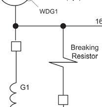
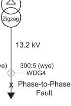
A phase-to-phase fault occurred within the 13.2 kV auxiliary system that was external to the overall differential scheme for generator #1 and resulted in a trip. Figure 1 shows the oneline diagram for this protection. Generator #1 is rated 200 MW. Note that the winding #1 CTs are internal to the delta-connected GSU transformer winding connected to the generator.




RELAY COLUMN
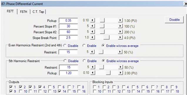
Figures 2a, 2b, and 2c show the original setup, differential, and taps settings, respectively.

Protection Settings — Setup



Protection Settings — Taps
OVERALL DIFFERENTIAL RELAY OPERATION AT A HYDRO POWER PLANT DURING EXTERNAL FAULT ON AN AUXILIARY TRANSFORMER LOW SIDE NETAWORLD • 41
Original
Original
Hydro-Electric Plant Single-Line Diagram (Generator #1)
Original
Protection Settings — Differential Settings
Figure 3A shows the oscillography captured by the relay at the time of the trip.
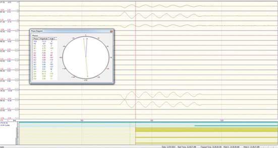
Event Oscillography
Figure 3B shows the current phasors measured by the protective relay.
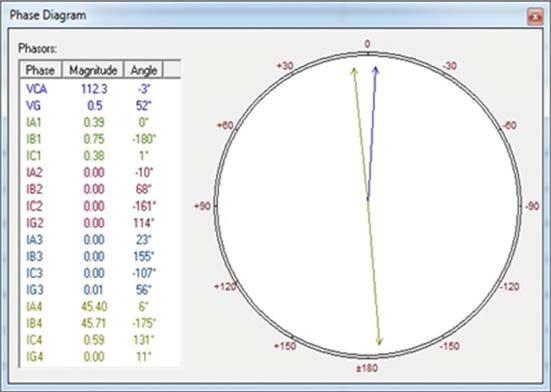
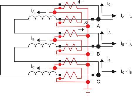
Figure 4 shows how it is believed the CTs are connected to the winding #1 current inputs for the differential relay. Zero-sequence current filtering is enabled to prevent unwanted operations since zero-sequence current circulates inside the delta winding during external ground faults within the transmission grid.
OVERALL DIFFERENTIAL RELAY OPERATION AT A HYDRO POWER PLANT DURING EXTERNAL FAULT ON AN AUXILIARY TRANSFORMER LOW SIDE 42 • SPRING 2017 RELAYCOLUMN RELAY COLUMN
Fault
Fault Current Phasors
Winding #1 Internal CT Connections
Figure 5A shows how the differential protection eliminates zero-sequence current from the winding #1 current inputs.
IAW1cAW1 IAW1 () IBW1 3 ICW1 + I I0W1 IBW1c IBW1 – I0W1 – := := 0W1 I:= 0W1 I= 0.01
Winding #1 Zero-Sequence Current Elimination
ICW1c ICW1 I0W1 – :=
Figure 5B shows how the differential protection compensates for the 30-degree phase shift across the GSU.
IAW1cc AW1c TAP1
TAP2· 3 I := AW2c I:= IBW1cc BW1c TAP1 I := ICW1cc CW1c TAP1 I :=
ICW2 IAW2 –TAP2· 3
BW2c I:= IAW2 IBW2 –
AW3c I:= ICW3 IAW3 –
TAP3· 3
BW3c I:= IAW3 IBW3 –
TAP3· 3
AW4c I:= IAW4 ICW4 –TAP4· 3 BW4c I:= IBW4 IAW4 –
TAP4· 3
Input Current Compensation
TAP2· 3 CW2c I:= IBW2 ICW2 –
TAP3· 3 CW3c I:= IBW3 ICW3 –
TAP4· 3 CW4c I:= ICW4 IBW4 –
Figure 5C shows how the differential protection calculates the differential and restraint current for each phase.
IAW1cc IAW2c + IAW3c + IAW4c + A DIFF:= IAW1cc IAW2c ++ AW3c 2 I+ IAW4c A BIAS:=
IBW1cc IBW2c + IBW3c + IBW4c + B DIFF:=
IBW1cc IBW2c ++ BW3c 2 I+ I B BIAS:=
ICW1cc ICW2c + ICW3c + ICW4c + C DIFF:=
ICW1cc ICW2c ++ CW3c 2 I+ ICW4c C BIAS:=
Differential and Restraint Current Calculations
NETAWORLD • 43 OVERALL DIFFERENTIAL RELAY OPERATION AT A HYDRO POWER PLANT DURING EXTERNAL FAULT ON AN AUXILIARY TRANSFORMER LOW SIDE RELAYCOLUMN RELAY COLUMN
RELAYCOLUMN RELAY COLUMN
Figure 6A shows balanced load current measured by the protective relay during a normal non-fault load condition.
TAP11.43:=TAP22.47:=TAP32.47:=TAP4100 :=
I1.51·ej·0·deg
AW1
j·28·deg :=
AW2 I2.67·e :=
AW3 I0 :=
AW4 I0.31·e :=
j·157·deg
I1.54·ej·– 122·deg := CW1 I1.51·ej·118·deg :=
j·148·deg CW2 I2.61·e := BW1
BW3 I0 := CW3 I0 := j·– 93·deg
BW2 I2.65·e :=
j·38·deg
BW4 I0.31·e :=
j·– 84·deg CW4 I0.31·e :=
Current Phasors During Normal Load Flow (Amps Secondary)
Figure 6B shows the resultant differential and restraint currents calculated by the relay.
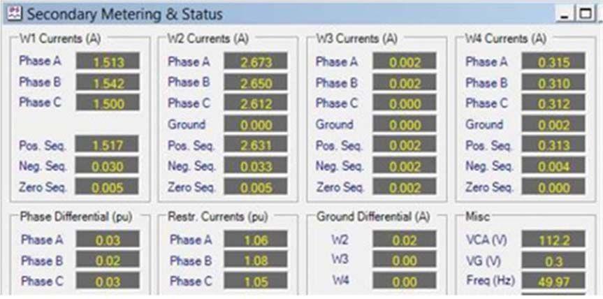
44 • SPRING 2017 OVERALL DIFFERENTIAL RELAY OPERATION AT A HYDRO POWER PLANT DURING EXTERNAL FAULT ON AN AUXILIARY TRANSFORMER LOW SIDE
Protective Relay Secondary Metering
Figure 6C shows the corresponding current phasors measured by the relay.
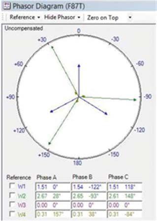
Figure 6C: Current Phasors Measured by Protective Relay (Amps Secondary)
FAULT CURRENT AND TRIP
Figure 6D shows the calculated differential and restraint currents, which match the values displayed in the relay secondary metering. Note that these values are per unit.
Figure 6D: Differential and Restraint Current Calculations (Per Unit)
Figure 7A shows the fault currents measured by the relay when the trip occurred due to the external phase-to-phase fault.
Figure 7A: Fault Current Phasors (Amps Secondary)
NETAWORLD • 45 OVERALL DIFFERENTIAL RELAY OPERATION AT A HYDRO POWER PLANT DURING EXTERNAL FAULT ON AN AUXILIARY TRANSFORMER LOW SIDE
RELAYCOLUMN RELAY COLUMN A DIFF0.029 = A BIAS1.066 = B DIFF0.021 = B BIAS1.083 = C DIFF0.021 = C BIAS1.056 =
AW1 I1.39·ej·0·deg j·0·deg := AW2 I0·e := j·– 174·deg AW4 I–45.4·e := j·6·deg BW4 I–45.71·e := j·– 49·deg CW4 I–0.59·e := AW3 I0 := BW3 I0 := CW3 I0 := j·0·deg BW2 I0·e := j·0·deg CW2 I0·e := BW1 I0.75·ej·– 179·deg := CW1 I0.38·ej·1·deg := TAP11.43:=TAP22.47:=TAP32.47:=TAP4100 :=
Figure 7B shows the calculated differential and restraint current when the trip occurred.
A DIFF0.532 = A BIAS0.266 =
B DIFF1.054 = B BIAS0.528 =
C DIFF0.523 = C BIAS0.262 =
Differential and Restraint
Current (Per Unit)
Figure 8 shows the operating points for each phase mapped onto the differential operating characteristic. All three phases are in the operate region.
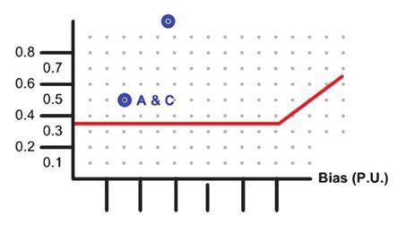
Differential Operating Characteristic
The solution is to roll the winding #4 current inputs as shown in Figure 9.

Correct Relay Setup
Figure 10 shows the new fault current measurements for winding #4 due to the correction.
j·– 174·deg
:= j·6·deg
Correct Winding #4 Current Measurements (amps secondary)
Figure 11 shows the corrected calculated differential and restraint current when the trip occurred. With minimal differential current, the relay does not trip.
A DIFF0.024 = A BIAS0.266 =
B DIFF0.048 = B BIAS0.528 =
C DIFF0.024 = C BIAS0.262 =
Differential and Restraint
Current (Per Unit)
j·– 49·deg
Figure 12 shows the corrected differential operating characteristic.
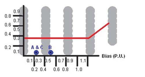
Corrected Differential Operating Characteristic
46 • SPRING 2017 OVERALL DIFFERENTIAL RELAY OPERATION AT A HYDRO POWER PLANT DURING EXTERNAL FAULT ON AN AUXILIARY TRANSFORMER LOW SIDE
RELAYCOLUMN RELAY COLUMN
AW4 I45.4·e
BW4 I45.71·e :=
CW4 I0.59·e :=
The differential protection tripped because of an incorrect CT phase compensation setting for winding #4 current inputs. The best practice is to not include the auxiliary transformer inside the zone of overall differential protection as shown in Figure 13.
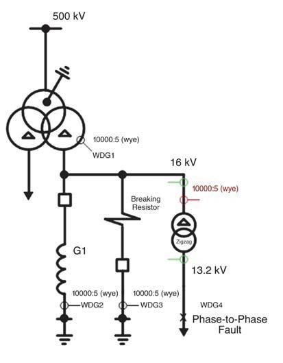
Hydro Electric Plant Single Line Diagram (Generator 1)
The auxiliary transformer should be protected by a separate differential relay, as denoted by the green CTs that overlap with the overall differential protection.

Steve Turner, an IEEE Senior Member, is a Senior Application Engineer at Beckwith Electric Company. His previous experience includes work as an Application Engineer with GEC Alsrom and as an Application Engineer in the international market for SEL, focusing on transmissionline protection applications. Steve worked for Duke Energy (formerly Progress Energy), where he developed a patent for double-ended fault location on overhead transmission lines. He has a BSEE and MSEE from Virginia Tech. Steve has presented at numerous conferences including Georgia Tech Protective Relay Conference, Western Protective Relay Conference, Energy Council of the Northeast, and Doble User Groups, as well as various international conferences.


OVERALL DIFFERENTIAL RELAY OPERATION AT A HYDRO POWER PLANT DURING EXTERNAL FAULT ON AN AUXILIARY TRANSFORMER LOW SIDE









MISSION AND MILESTONES
As NETA celebrates 45 years of service to the electrical power systems industry, we remember the events that shaped the association’s activities and initiatives over the last several decades.


The decade NETA was founded was a pivotal time. Automation, public lighting, electrical appliances, and the modernization of industrial production propelled the industry into a state of frenzied growth, fueling research into alternative power generation resources, electrical power infrastructure, and technological advancements — as well as a growing concern for safety and reliability.


For years, water, coal, and then oil were the main fuel sources to generate power. In the 1950s, n the 1950s, advancementsinnuclearscienceledtothefirst advancements in nuclear science led to the first reliable nuclear power plants. NETA was born at a time when government and industry were searching for safe, reliable, affordable ways to meet the rising demand. As maintenance and safety challenges were thrust into the limelight and the need for leadership in standards and guidelines grew apparent, NETA’s relevancy and importance took shape.


NFPA Publishes 70B
National Fire Protection Association creates NFPA 70B, Recommended Practice for Electrical Equipment Maintenance. The standard addresses maintenance testing and advises on equipment, test type, and frequency.







High-Voltage Transmission Lines Triple
Declining electricity prices make it cheaper to make electricity. The number of miles of high-voltage transmission lines triples from 10 years earlier to more than 60,000 circuit miles.





Utility Industry Forms NERC
The electric utility industry forms the North American Electric Reliability Corporation to promote the reliability and adequacy of bulk power transmission in North America.


President Richard Nixon Signs OSHA Act
The U.S. Department of Labor establishes the Occupational Safety and Health Administration as part of the OSHA Act.








MILESTONES AND MISSION 50 • SPRING 2017
1960s
1960 – 1969
1968 1970
1968


With an industry growing rapidly and facing challenges in reliability and safety, nine electrical testing company charter members form NETA — National Electrical Testing Association on April 14, 1972. Its mission is to clarify industry best practices and improve the quality of testing, safety, and system reliability. Together, they would write the first set of comprehensive standards for testing electrical power equipment and systems.
NETA establishes the NETA Electrical Testing Technician Certification program and publishes Maintenance Testing Specifications for Electrical Power Equipment and Systems


NETA releases its first standard, Acceptance Testing Specifications for Electrical Power Equipment and Systems.


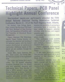

The NETA Technical Seminars and Trade Show is held at Dunfey’s Hotel in Dallas, Texas. NETA also launches NETA News, a newsletter that serves as the precursor to NETA World journal.




National Fire Protection Association publishes NFPA 70E, Standard for Electrical Safety in the Workplace.


Now called the Outstanding Achievement Award, the honor is given annually to one individual from a NETA Accredited Company who has volunteered above and beyond for NETA and the industry.

Environmental effects lead to lower-impact designs.


OPEC oil embargo focuses the nation’s attention on energy, increasing demand for coal.


The U.S. Department of Energy launches the Solar Energy Research Institute’s National Renewable Energy Laboratory. Total photovoltaic manufacturing production exceeds 500 kilowatts.

In response to increasing oil prices, the U.S. government explores natural gas and alternative energies. 1973


A partial nuclear meltdown at the Three Mile Island Nuclear Generating Station in Pennsylvania is the most significant accident in U.S. commercial nuclear power plant history, giving impetus to antinuclear safety concerns.


The act requires companies to buy electricity from renewable energy sources including wind, wood chip, trash, and hydroelectric. Many companies build small power plants to earn a 21 percent new-build tax credit.

NETAWORLD • 51 MILESTONES AND MISSION
1970s
1975
1975
1972
1980
1977 1979
1979 1978
1977


NETA Rebrands as International Organization
NETA changes its name to the InterNational Electrical Testing Association to better reflect an internationally active membership.


NETA Debuts NETA World Journal
The journal flourishes under the leadership of technical editors Rod and Diane Hageman, championed by Executive Director Mary Jordan, and later by Executive Director Jayne Tanz.


NETA Publishes First Safety Policy
NETA Accredited Companies will use Recommended Minimum Safety Guidelines as the basis for their safety procedures.


NETA
Launches NETA Accredited Company Program
NAC membership validates the need for third-party, independent testing firms involved in full-service testing, analysis, and maintenance of electrical power systems. A two-fold accreditation process certifies the company and its technicians.
Ocean
State Power Reaches Full Output
GE builds largest U.S. independent power plant to date with combined cycle, natural-gas-fired, 500-megawatt capacity.


1980s 1990s


Chernobyl Experiences Worst Nuclear Accident


This catastrophic nuclear accident at the Soviet Union’s Chernobyl Nuclear Power Plant is the most disastrous nuclear power plant accident in history. 1986


1986


U.S. Coal Production
Tops
1 Billion Tons/Year


Coal represents 53 percent of electricity in U.S. or 1,616 terawatt hours. 1990


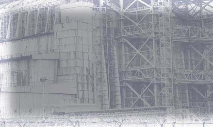
California Commissions Largest Solar Thermal Facility
The largest of nine such plants built in the 1980s, oil in the receiver tubes collects the concentrated solar energy as heat and pumps it to a power block located at the power plant for generating electricity.


NETA Launches
Now called the NETA Alliance Program, the association opens involvement to all electrical power professionals interested in advancing safety and reliability.



Congress Passes Energy Policy Act
In response to the crisis that led to the Gulf War, Congress enacts legislation to reduce U.S. dependence on foreign oil. This expands wholesale competition by broadening the rules about who can enter the power generation marketplace.


PG&E Installs First GridSupported Photovoltaic System


Pacific Gas & Electric completes California installation of a 500-kilowatt system representing the first successful distributedpower effort. 1993


52 MILESTONES AND MISSION
1983 1991 1990 1986
1992


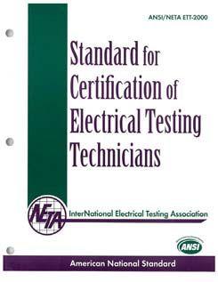
ANSI/NETA, Standard for Certification of Electrical Testing Technicians codifies the experience, education, and training requirements necessary for an individual to obtain competency as an electrical test technician.




IEEE 902, Guide for Maintenance, Operations and Safety of Industrial and Commercial Power Systems, is nicknamed the IEEE Yellow Book.


President George W. Bush signs new Energy Policy Act to combat growing energy problems, providing tax incentives and loan guarantees for energy production.
North American Electric Reliability Corporation is named the new, high-powered reliability watchdog with the ability to enforce rules and fine companies.

1990s


The Federal Energy Regulatory Commission implements new rules for the Energy Policy Act that, combined with a follow-up set in 1999, start opening access to the grid and countering utilities’ restrictive tactics.

National Electrical Manufacturers Association publishes AB 4, Guidelines for Inspection and Preventive Maintenance of Molded Case Circuit Breakers.


1990s
Many regions across the U.S. open the generation and distribution of electric power to provide a more competitive electricity market.


ANSI/NETA, Standard for Maintenance Testing Specifications for Electrical Power Equipment and Systems aids in assuring that tested electrical equipment and systems are operational, within applicable standards and manufacturer’s tolerances, and suitable for continued service.


2000s


The National Academy of Engineering describes the U.S. electric power grid as the greatest engineering achievement of the 20th century.

The largest blackout in North American history leaves nearly 50 million people without power in the Northeastern U.S. and Eastern Canada.

IEEE 1547, Standard for Interconnecting Distributed Resources with Electric Power Systems, establishes requirements for interconnection of distributed resources with electric power systems.

About 1.16 billion short tons of coal generates 50 percent of electricity (2,013 terawatt hours).


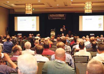
NETA’s annual Technical Seminars and Trade Show expands and is renamed PowerTest.

NETAWORLD • 53 MILESTONES AND MISSION
2000 1998 1996 2003 2005 2006

2007

Energy Act Boosts

President George W. Bush signs the Energy Independence and Security Act, providing funding to encourage smart grid development.



2012


ANSI/NETA, Standard for Acceptance Testing
Specifications for Electrical Power Equipment and Systems assists users of electrical equipment and systems in specifying required tests on newly installed power systems and apparatus to ensure compliance with specifications, intended use, and regulatory and safety requirements.
Canadian Standards Association publishes CSA Z463, Guideline on Maintenance of Electrical Systems.
President Barack Obama signs the Hydropower Regulatory Efficiency Act and the Bureau of Reclamation Small Conduit Hydropower Development and Rural Jobs Act to boost development of small U.S. hydropower projects.
NETA presents its first NETA Alliance Recognition Award to Dennis Neitzel of AVO Training Institute. The award is given annually to an outstanding Alliance Partner.


ANSI/NETA, Standard for Electrical Commissioning Specifications for Electrical Power Equipment and Systems coordinates with the ANSI/ NETA ATS. It aids in assuring that tested electrical equipment and systems are operational, within applicable standards and manufacturer’s tolerances, and installed to design specifications.
The U.S. generates about 4 trillion kw hours of electricity, with 33% from coal, 33% natural gas, 20% nuclear, 6% hydropower, 4.7% wind, 0.6% solar, 1% petroleum, and 1% biomass.


Wind power experiences largest growth in capacity, as 11,895 MW of wind power is installed, representing 26.5 percent of new power capacity.


2016


NETA Recognizes 45th Anniversary


With electricity-reliant technologies and the Information Age growing with no end in sight, demands for more electrical power capacity are predicted to continue into the foreseeable future.

NETA’S ROLE IN THE FUTURE OF ELECTRICAL POWER

NETA’s 45th Anniversary celebration culminates at PowerTest 2017 in Anaheim, California, with over 1,000 members and power systems professionals in attendance.


In a world heavily dependent on electric power and the stream of new electricity-exclusive technologies continuing indefinitely, electric power demand will surge. To balance supply and demand, analysts say the electric power industry may even double its rate of infrastructure investment (from 10 percent to 20 percent


of annual revenues). One thing is certain: Consumer demand will spark investment and innovation, leading to the creation of reliable and sustainable power sources and distribution systems. Whatever the future holds, NETA will continue championing safety and reliability, disseminating information, and fostering relationships that advance the quality of electrical power systems and the knowledge of industry professionals and their customers.
MILESTONES AND MISSION 2000s 2010s
2017
2013
2015

We rent and support electrical test equipment from AEMC, Doble, Dranetz, Fluke, High Voltage Inc., HV Diagnostics, Manta, Megger, Omicron, Phenix, Raytech, Vanguard and many more.
We carefully select the right equipment for your rental, prepare it in realworld conditions complete for the application. It’s field ready.
Testing needs support; the apparatus, the test equipment, the technician and the job. It’s all we do.
We make the connection between logistics and the job, wherever it is. Putting a label on a box isn’t enough. We proactively monitor the shipment, adapt, and ensure delivery commitment.
rental | support | logistics
Introducing

search equipment, view specifications, manuals or accessories plus share details with colleagues
view, search or download equipment manuals
search test equipment technical details and FAQs
submit request, view past requests and responses
browse past, current and pending order details
view equipment presently on rent
receive intellirent news contact intellirent
Available at
Acceptance Testing Services
Low, Medium, and High Voltage
Preventative Maintenance & Testing
Switchgear
Transformers
Engineering Services
781-767-0888
Email: infrared.ma@verizon.net
152 Centre Street Holbrook, MA 02343 www.Infraredbps.com

Power System Acceptance Testing
Commissioning and Start-up
Maintenance
Life-Cycle Extension
Troubleshoot and Repair
Training and Engineering Services
Planning and Operations Support
Project Management


FULL SERVICE INDEPENDENT ELECTRICAL TESTING
Years of Reliability 25 Delivering
Years of Experience
Powerful Reliability Solutions
|
Sigma Six Solutions, Inc. 2200 West Valley Hwy North, Suite 100 | Auburn, WA 98001





OVERVIEW OF THE

 BY ALAN MARK FRANKS, AVO Training



Since its inception, IEEE — the world’s largest technical professional association and a major U.S. and global standards organization — has been responsible for literally hundreds of standards and updates that include power cable. The need for testing has existed since the first cables were installed in the 1800s, back when electricity first began influencing American lives.
Studies completed and published by the National Electric Energy Testing Research and Applications Center (NEETRAC) at Georgia Institute of Technology have indicated a significant reason for concern involving the integrity of U.S. power cable installations. Research further indicates that service-aged and new cable installations are subject to the same workmanship issues that cause more than 50 percent of U.S. cable outages, as illustrated in Figure 1. This is not only costly but also negatively affects system reliability.
With the previously mentioned issues in workmanship and the need to identify the status of service-aged cable systems, a new age of cable


FEATURE CABLE TESTING STANDARDS: OVERVIEW OF THE IEEE 400 BUNDLE 56 • SPRING 2017
North American Cable Outages by Equipment Type Splices 37.1% Unknown 1.1% Terminations 5.6% Cable 56.2%

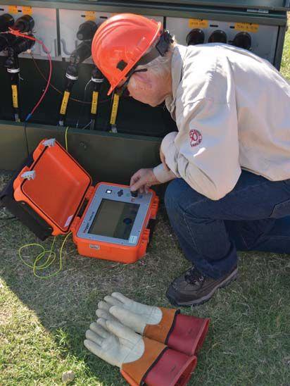
Time Domain Reflectometer (TDR)
testing is now providing solutions to complex cable problems and establishing baseline data for condition-based maintenance programs.
IEEE cable test standards have evolved with the science of cable and testing technologies that exist today. Tests are identified in major categories as either installation, acceptance, or maintenance in nature. Further, the tests can be withstand or diagnostic and used in combination depending on the user’s needs.
The current IEEE 400 Series of standards consists of five major standards known as the IEEE 400 Bundle. These comprehensive standards provide the guidance industry needs to address testing and evaluating of cable installations old and new. Much research has gone into the development of these standards.
What follows is an overview of the IEEE 400 Bundle of cable standards. A much more thorough examination is necessary specific to an organization’s needs for cable testing and evaluation of data derived from actual cable tests.
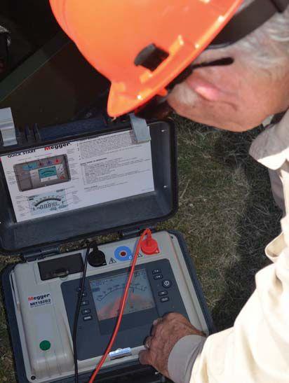
Resistance Test
The following IEEE standards (or their revisions) are included in the IEEE 400 Bundle. These standards outline current tests that are available and reported as in use in the cable industry.
IEEE 400™-2012,IEEE Guide for Field Testing
and Evaluation of the Insulation of Shielded Power Cable Systems Rated 5 kV and Above. This standard provides guidance on appropriate tests, including advantages and disadvantages. Field tests are identified as voltage withstand, dielectric response, partial discharge, timedomain reflectometry (Figure 2), and thermal infrared imaging.
For all types of tests, voltage levels and test duration should be consistent with the cable system characteristics. In shielded power cable system quality and reliability, these three aspects are important for field tests and results evaluation:
• A healthy (defect-free and/or non-aged) insulation can withstand a higher voltage stress level, whereas insulation that has aged and/or contains defects should have a lower withstand level (Figure 3).

NETAWORLD 57 CABLE TESTING STANDARDS: OVERVIEW OF THE IEEE 400 BUNDLE
FEATURE
Insulation


• A test shall be designed to prevent or minimize the shortening of service lifetime due to the field test. In the case of withstand tests, the impact on a defective insulation should be high enough to cause a breakdown or to exceed a critical level of a monitored property.
• Voltage level and duration are important, inseparable elements of the on-test and aftertest performance of the cable circuit. The recommended test voltages and durations for tests (given in IEEE 400 point documents) are based on extensive field testing and empirical data from experiments. Arbitrarily increasing voltage or extending the test duration from the recommended values can increase the probability of an early service failure.
IEEE 400.1™-2007, IEEE Guide for Field Testing of Laminated Dielectric, Shielded Power Cable Systems Rated 5 kV and Above with High Direct Current Voltage. This standard covers the application of high-voltage direct current (Hipot) as a means of acceptance and also as a diagnostic test. This type of test is recommended for laminated insulation. Cables in industry of this type are usually of the paper-insulated, lead-sheathed design. The dc high-potential (Hipot) test has long been an acceptable means of evaluating the condition of laminated insulation.
Note: IEEE 400 does not recommend the application of HVDC for evaluating extruded dielectric service-aged cable that has been in service for more than five years.
IEEE 400.2™-2013, IEEE Guide for Field Testing of Shielded Power Cable Systems Using Very Low Frequency (VLF) (Less Than 1 Hz). This standard presents the test methods and voltages applied when performing withstand tests using the very low frequency test (Figure 4). Also discussed is the rationale for performing the VLF withstand versus the dc dielectric withstand for solid dielectric extruded insulation cables. Test method and test parameters are also presented for the VLF tan delta test. The following four paragraphs are excerpts from IEEE 400™ 2013 Introduction.
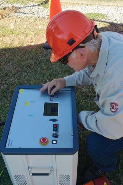
Performing VLF Withstand and Tan Delta Tests
“Ideally, field withstand testing of cable systems would be done using the same power frequency as would normally be applied to the cable under operating conditions, but at higher test voltage. However, because of the inherent capacitance of long runs of medium-/high-voltage concentric shielded cable, the excessive charging current is beyond the limits of normally available power sources and test equipment found in the field, except costly ac resonant test systems.
High-voltage dc testing would eliminate the charging current issue associated with ac tests, but would not subject the cable system to the voltage stress distribution that it is exposed to under normal operating conditions. Furthermore, there are significant negative issues affecting the integrity of aged cross-linked polyethylene (XLPE) cable after it is exposed to high-voltage dc tests and then placed back into service. There is also the unknown influence of elevated dc voltage on other extruded cables such as mineral-filled EPR. In addition, dc is not effective in detecting many
CABLE TESTING STANDARDS: OVERVIEW OF THE IEEE 400 BUNDLE 58 SPRING 2017
FEATURE

forms of gross defects that may be present in a cable system that will otherwise be detected by VLF or at operating frequency.
When required to perform field testing on long lengths of medium-/high-voltage cable with an alternating current source, an alternative to applying power frequency is very low frequency (VLF, 0.01 to 1 Hz). The charging current at a very low frequency of 0.1 Hz is only 1/500 or 1/600 of that at 50 Hz or 60 Hz respectively so that significantly smaller and more portable VLF power sources have the capability to test cable systems of relatively long lengths.
This guide provides a definition of VLF, a description of the wave-shapes and their magnitudes and frequencies that can be applied as a source for overvoltage field testing, the issues with different wave shapes, the duration of testing, and
what diagnostic information can be learned when these VLF voltages are applied.”
Applicable test procedures and test values for withstand and maintenance testing are contained in the ANSI/NETA MTS, Standard for Maintenance Testing Specifications, and ANSI/NETA ATS, Standard for Acceptance Testing Specifications
IEEE 400-3™-2006, IEEE Guide for Partial Discharge Testing of Shielded Power Cable Systems in a Field Environment. This standard provides background information on partial discharge detection and location (Figure 5). PD detection and location is applicable to laminated and solid dielectric cables. Guidance is provided involving interpretation of PD data. The following excerpts are taken from the IEEE 400.3™-2006 standard:

CABLE TESTING STANDARDS: OVERVIEW OF THE IEEE 400 BUNDLE
FEATURE
NETAWORLD 59
Partial Discharge Test Performed on 15 kV Cable


“PDs are small electric sparks or discharges that occur in defects in the insulation, or at interfaces or surfaces, or between a conductor and a floating metal component (not connected electrically to the high-voltage conductor nor to the ground conductor), or between floating metal components if the electric field is high enough to cause ionization of the gaseous medium in which the components are located. The discharges do not bridge the insulation between conductors, and the defects may be entirely within the insulation, along interfaces between insulating materials (e.g., at accessories), or along surfaces (terminations or potheads).
Partial discharge characteristics depend on the type, size, and location of the defects, insulating material, applied voltage, and cable temperature, and they vary with time. The damage caused by PD depends on several factors and can range from negligible to causing failure within days to years.
Advances in digital (electrical) measurement technology, both in the time and frequency domains, have improved the sensitivity of PD measurements. This has led to an increasing number of PD measurements on cable systems, particularly on medium-voltage systems. The purpose of such measurements is to assess the current condition of a cable circuit. At the current state-of-the-art, very good cables and very bad cables can generally be identified.
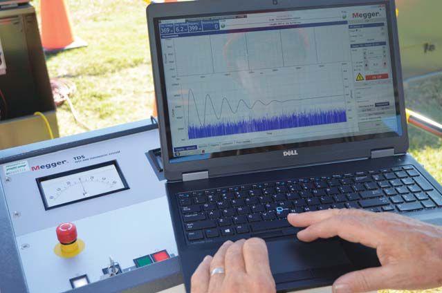
It is the remaining life of the cables between these two extremes that cannot be predicted with great accuracy. As well, this technology cannot determine with complete confidence that a specific cable is in very good condition with essentially no probability of failure in the near future, as failure can be caused by phenomena that do not generate PD. However, the PD measurement can, at times, predict with a high level of confidence that a given cable is in very poor condition and is likely to fail in the near future.”
IEEE 400-4™-2015, IEEE Guide for Field
Testing of Shielded Power Cable Systems Rated SKV and Above with Damped Alternating Current (DAC) Voltage. This latest IEEE standard provides a description of the methods and practices used in the application of damped alternating current voltages for field testing of shielded power-cable systems (Figure 6). DAC voltage testing is one of the alternative methods of ac voltage testing and is applicable for a broad range of medium-voltage, high-voltage, and extra-high-voltage cables. As the DAC test procedure has been used for several years for diagnostic, maintenance, and acceptance (commissioning) tests, it provides a method of evaluation of the insulation condition and helps fit the need for more complete information on the condition of cable systems. This guide addresses DAC voltage testing in the frequency range from 20 Hz to 500 Hz.
The guide presents the practices and procedures for testing and diagnosis of shielded powercable systems rated 5 kV and above using DAC voltages. It applies to all types of powercable systems intended for the transmission or distribution of electric power. The tabulated test levels assume that the cable systems have an effectively grounded neutral system or a grounded metallic shield.
The purpose of the guide is to provide uniform practices and procedures for performing DAC voltage off-line tests on installed shielded power-cable systems in the field and to provide guidelines for evaluation of test results. Certain test parameters and procedures require further study and clarification; this guide provides a starting point that can be grown and improved
60 SPRING 2017 CABLE TESTING STANDARDS: OVERVIEW OF THE IEEE 400 BUNDLE
FEATURE
Damped AC Used for Partial Discharge Test
with time as more experience is gathered from the field and analyzed.
Sinusoidal damped ac voltage testing, also known as oscillating wave testing, was introduced at the end of the 1980s as an alternative to dc test voltages. As a consequence of experiences in onsite ac testing on one hand and the technological progress in power electronics and advanced signal processing on the other hand, DAC testing has been used since the end of the 1990s. Some countries are currently using DAC for onsite testing with PD measurements and dissipation factor estimation for condition assessment of all types of power cable systems.
DAC voltages are generated by charging the test object to a predetermined voltage level and then discharging its capacitance through a suitable inductance. During the charging stage, the capacitance of the test object is subjected to a continuously increasing voltage at a rate dependent on the test-object capacitance and the current rating of the power supply. During the discharging stage, a DAC at a frequency dependent on the test-object capacitance and the inductance is present.
Most DAC applications are based on the combination of voltage withstand and advanced diagnostic measurements, i.e., partial discharges and dissipation factor.
The IEEE 400 Standards identify three major areas of field testing: installation, acceptance, and maintenance testing. Field tests are identified as either withstand or diagnostic in nature. Power cable testing technologies are not static. Enhancements in electronics and software will continue, thus improving capabilities in predicting cable maintenance needs and proving new installations to ensure conditions do not exist that lead to premature failure of the cable system.
As technologies are developed, standards organizations such as IEEE will continue to set new goals for testing and maintaining power cable systems.
Depending on the installation, cable age, and end-user service requirements, testing is sometimes complex. Many cable installations are critical components of electrical systems, and outages lead to costly downtime, lost production, and reliability. The type of tests used for a cable installation may vary depending on the objectives of the owner, e.g. type of data required and for what purpose.
Ultimately, what can be expected for the future of power cable in the U.S. is higher quality installations, improved reliability, and reductions in costly cable-related power outages.
IEEE 400 Bundle Series
Dean Williams. “Cable Accessory Failure Analysis.”
NEETRAC, ICC Education Session, October 6-20, 2010

Alan Mark Franks is a Senior Safety Specialist at AVO Training Institute. He has over 48 years in the electrical utility industry with an extensive background in electrical safety and power distribution. Mark was instrumental in developing the pre-OSHA Electrical Safety Audit for industry and the conducting of on-site audits of facilities, installation of electrical equipment and systems, safety procedures, and training records and programs, all based on OSHA and NFPA regulations and other industry consensus standards. He has been an authorized OSHA Instructor for all general industry and construction regulations
Mark is a certified fiber optic technician, certified fiber optic instructor (#839), and a member-in-good-standing of the Fiber Optic Association. He participates in numerous associations including NFPA 70E 2000 alternate committee member, International Association of Electrical Inspectors, American Society of Safety Engineers, National Cable Splicer Certification Board, and American Society for Testing and Materials. Mark has provided electrical safety training and performed electrical mine-safety audits for general industry, utilities, and mines both underground and surface. He has instructed all aspects of power cable splicing, termination, testing, and fault location for 25 years and has been instrumental in developing the AVO Training Institute Cable Technician Certification Program.


NETAWORLD 61 CABLE TESTING STANDARDS: OVERVIEW OF THE IEEE 400 BUNDLE


• Largest Inventory • Consistent Delivery Service • Immediate Availability • ISO and ANSI Accredited Labs Vanguard Instruments Company, Inc. www.vanguard-instruments.com ELECTRO RENT ANSWERS YOUR EVERY TEST NEED 888.739.1095 www.electrorent.com/electrical-power sales@electrorent.com Electro Rent works to make your job easier! Count on Electro Rent to get the latest test equipment you need rapidly and with experienced customer support you can rely on. From Insulation and Power Quality to Motor Test Equipment, if it tests, we’ve got it and we’re ready to meet your needs.


PARTIAL DISCHARGE TESTING FOR CABLE ASSESSMENT VERSUS


 BY WILLIAM HIGINBOTHAM, EA Technology, LLC

Medium voltage cables have three distinct phases to their lifecycle: (1) new — just manufactured, still in the factory; (2) installed — ready for commissioning but not yet energized; and (3) aged — in service for some period of time. These different periods of their life provide opportunities for condition assessment.
Tan delta and partial discharge testing are excellent indicators of insulation health and can be applied in all phases of a cable’s life. Tan delta provides an overall average condition assessment, whereas partial discharge testing can indicate weak spots that might not appear in tan delta results.
This article will explore the differences between tan delta and partial discharge testing as well as the differences between on-line and off-line testing. Advantages and disadvantages will be explored.
An ideal cable insulation system will be entirely capacitive in nature. The only current flowing through the insulation is a result of the reactive


impedance at the power line frequency. This current will be 90 degrees out of phase with the voltage and is given by the following formula:

In the real world, a resistive current results from impurities in the insulation and is increased by aging effects such as water trees. This current is in phase with the voltage and is given by the following formula:

Combining these two phasor currents, you can see the relationship and the resultant leakage current (Figure 1).
FEATURE ONLINE VERSUS OFFLINE PARTIAL DISCHARGE TESTING FOR CABLE ASSESSMENT 64 • SPRING 2017
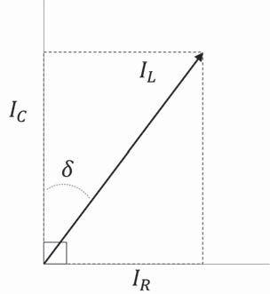
Figure 1: Relationship Between Capacitive and Resistive Currents
The ratio of the two currents (IR/IC) is the tangent of the angle δ (delta) or tan delta, for short. It is also known as dissipation factor or loss angle. As can be seen from the previous formulas, the capacitive current is a function of frequency, so the result is also a function of frequency. Therefore, not only do you need to know tan delta, you also need to know the frequency used for testing. Very low frequencies are typically used to limit the amount of power required to run the test.
For a given frequency and voltage, tan delta increases as the resistive current increases (as the resistance in the insulation decreases). This provides a measurable way to see how aging and impurities have affected a given cable. As this measure applies to the entire cable, it is a measure of the average condition over the length of the cable.
As a cable ages, its tan delta figure becomes more voltage dependent. Water trees exhibit a conductivity that increases with voltage, so the tan delta measurements taken at higher voltage increase. This plays an important part in analyzing cable condition.
PARTIAL DISCHARGE BASICS
Partial discharge is best described as a failure of part of an insulation system to withstand the electrical field applied to it. This can be a result of poor design, poor workmanship, defective materials, contamination, or aging. The result of this failure is a high-frequency, unipolar discharge and accompanying current that flows through and on the insulation from the conductor to ground. This current pulse is low energy due to its short (microsecond) duration, but it can negatively affect the insulation and eventually cause catastrophic failure.
The discharge spark erodes the insulation from within through its heat and ionization. If occurring on the surface, the discharge also causes the breakdown of air molecules into oxygen (ozone) and nitrogen (nitric oxide). The nitric oxide forms nitric acid, which erodes the insulation from the outside.
As any erosion of the insulation causes an increase in discharge — and therefore, more erosion — the effects are exponential until catastrophic failure occurs.
Partial discharge cable testing involves applying a voltage conducive to partial discharge and then directly or indirectly measuring the discharge current pulses.
OFFLINE TAN DELTA TESTING
Tan delta testing requires isolation from equipment not under test, and therefore, must be done offline. A high-quality, low-frequency voltage supply is typically used. The supply is attached to the cable under test and a tan delta analyzer is connected to measure the current and its phase angle relative to the voltage (Figure 2).

NETAWORLD • 65 ONLINE VERSUS OFFLINE PARTIAL DISCHARGE TESTING FOR CABLE ASSESSMENT
FEATURE
Figure 2: Typical Tan Delta Test Connections

The measurement is relatively quick and is taken e at several voltages. Getting the outage, switching the load, disconnecting attached equipment, setting up the test equipment, and taking highvoltage safety precautions take much longer than actually running the test.
When looking at the results of a tan delta test, two characteristics are significant. Whenever possible, comparing to a baseline measurement done at commissioning can show deterioration by a shift in the leakage current amplitude. If a baseline is not available, the value versus voltage is an excellent indicator of water intrusion. The more water tree damage present, the greater the
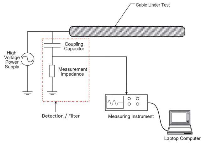

influence of voltage on tan delta amplitude. A uence rising trend as test voltage rises indicates damage or aging.

Offline partial discharge testing uses a similar setup to tan delta testing in that the cable should be disconnected from external equipment and connected to a high-quality, low-discharge voltage source. Additional precautions must be made because any discharge in the test equipment or setup will render the results meaningless.
Figure 3 (left) shows a typical offline PD test setup. While the goal is to measure the PD current pulse, it is not measured directly; rather, it is inferred from the voltage drop when the discharge occurs. For this reason, a known pulse generator is typically required to calibrate the system by relating a measured voltage drop to a Pico-Coulomb amount. Test procedures and general evaluation guidelines are given in the relevant IEEE 400 series standards.
Online partial discharge testing makes use of the power system voltage and only requires a monitoring circuit. While it is possible to attach a monitoring circuit to the conductor, it is also possible to connect to the ground strap of the conductor since the discharge must travel down it to ground. This ground connection is preferable due to its increased safety and the fact that the connection will not adversely affect the electric field at the conductor. By connecting via a radio-frequency current transformer (RFCT), a direct measurement can be made, eliminating the need for a calibrator (Figure 4). Tests can be done in a few minutes, as a periodic survey or as continuous monitoring.
Tan delta vs. online partial discharge. These two tests are similar in setup, invasiveness, test equipment, and time to test. They do,
FEATURE 66 • SPRING 2017 ONLINE VERSUS OFFLINE PARTIAL DISCHARGE TESTING FOR CABLE ASSESSMENT
Typical Offline PD Test Connections
Typical Online PD Test Connections
Comparison of Offline and Online PD Testing


Partial discharge presenceYesYes
Partial discharge severity Yes Yes
Partial discharge locationYesSometimes
Inception / extinction voltage
however, test two different aspects of the insulation system. Tan delta tests the health of the insulation as an average value of the length of the cable, and therefore, small sections with significant defects cannot be detected. Partial discharge detects these small defects but cannot detect aging effects (like water trees) until they result in discharge. Thus, these two tests are complementary, and it is advisable to do both at the commissioning of any cable.
Baseline tan delta and offline PD test results are useful in the future when a serious concern exists about the cable’s condition.
Online PD vs. offline PD. Both of these tests have advantages and disadvantages, and both should be applied in the right circumstance. Table 1 provides insight into these techniques.
Table 1 shows that offline testing provides more detailed results but is much more of a commitment to perform. Some of that commitment is lessened if done at commissioning. Online testing provides less detail but is economically feasible to perform on larger cable populations.
Online example #1. A major U.K. utility recently completed an evaluation of online
Yes No
partial discharge testing with positive results. As this was a technology assessment, no attempt to address suspect cables was made during the trial. Over an 18-month period, 188 33KV cables were tested with an online cable test device as described previously. The cable results were classified into green, amber, and red as shown in Table 2.
Within the 18-month test period and six months afterward, 13 cables failed. The results below showed that the red and amber categories had significantly higher failure rates. This proved to the utility that this type of online testing was effective for identifying at-risk cables.
Online example #2. An oil refinery operator hired a contractor to splice 80 – 100 feet of XLPE cable and new terminations onto existing PILC cable. Three splicing technicians performed the work. One of the technicians was not qualified to do the splice, and as a result, several of his
FEATURE NETAWORLD • 67 ONLINE VERSUS OFFLINE PARTIAL DISCHARGE TESTING FOR CABLE ASSESSMENT
Yes No HighMedium High Low Long (>2 hours)Short (<10 minutes)
Online PD Test Results 157< 2% 1421% 1741%


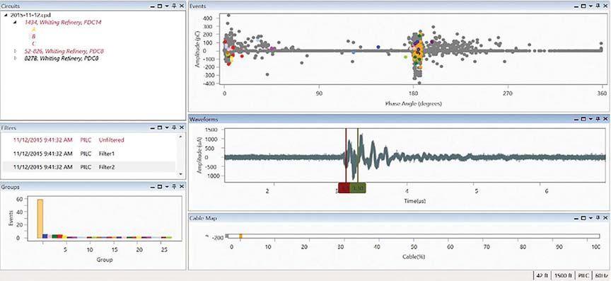


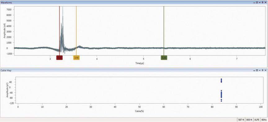
Phase Resolved, Waveform, and Location Mapping Plots for 34.5 KV Cable
68 • SPRING 2017 ONLINE VERSUS OFFLINE PARTIAL DISCHARGE TESTING FOR CABLE ASSESSMENT
FEATURE
Oil Refinery PD Test Results


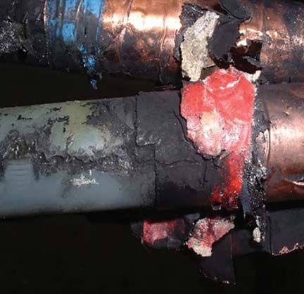
Partial Discharge Damage at Field Terminations as a Result of Poor Workmanship
splices were suspected as faulty. The customer wanted to know if an online cable tester could confirm the bad splices.
Online testing was performed on three cables where the known bad splicer did the joints and found that all three had excessive amounts of PD (Figure 5). A cable with known good splices was tested as a comparison and that cable was PD free. For the cables where PD was detected, the online test also discerned the location of the bad splices.
Online example #3. A municipal underground 34.5 kV XLPE cable was tested using online test technology (Figure 6). In this case, not only was the presence of PD detected, but also its location at 490 feet from the RFCT was mapped by looking at the primary and reflected pulse timing.
The leading cause of partial discharge in cable systems is field workmanship. As opposed to sterile factories with tight quality control measures, field installation of cables is difficult. Cables are spliced and terminated under adverse conditions, including weather, access, visibility, and cleanliness. Repairs are often made in the rain, in middle of the night, and in a hole with bad lighting and severe time pressures.

In summary, all three test methodologies are effective ways to determine cable insulation health. Tan delta and offline partial discharge are excellent commissioning tests, whereas online partial discharge testing is ideal for in-service screening of large populations of cables. Cables identified as suspect in the online tests can be addressed or selected for offline PD and tan delta testing before deciding on a remediation.

William G. Higinbotham has been president of EA Technology LLC since 2013. His responsibilities involve general management of the company, which include EA Technology activities in North and South America. William is also responsible for sales, service, support, and training on partial discharge instruments and condition-based asset management. He is the author or co-author of several industry papers. Previously, William was vice president of RFL Electronics Inc. Research and Development Engineering group, where his responsibilities included new product development, manufacturing engineering, and technical support. He is a senior member of IEEE and is active in the IEEE Power Systems Relaying Committee. He has co-authored a number of IEEE standards in the field of power system protection and communications, and holds one patent in this area. William received his B.S. degree from Rutgers, The State University of New Jersey’s School of Engineering in 1984 and worked in the biomedical engineering field for five years prior to joining RFL.
NETAWORLD • 69 ONLINE VERSUS OFFLINE PARTIAL DISCHARGE TESTING FOR CABLE ASSESSMENT FEATURE


You’ve known Electrical Reliability Services as part of Emerson Network Power. Although we’re now part of Vertiv, our commitment to you remains the same. You can still look to us for the same non-biased independent third-party electrical testing, maintenance, and engineering services. But now, we’re more than that. We’re an agile operation with a laser focus on delivering vital, innovative and intelligent applications for high-tech environments.
ELECTRICAL RELIABILITY SERVICES IS NOW PART OF VER VERTIV TIV ™ To learn more visit more ers.VertivC ers.VertivCo.com o.com YOUR VISION, OUR PASSION YOUR OUR PASSION Electrical Reliability Services is a NETA accredited company © 2017 Vertiv Co. All rights reserved. Vertiv and the Vertiv logo are trademarks or registered trademarks of Vertiv Co. All other names and logos referred to are trade names, trademarks or registered trademarks of their respective owners.





The premier ELECTRICAL MAINTENANCE AND SAFETY Conference A premier reservation. Sponsorships are now available. Reach hundreds of leading decision–makers at PowerTest Receive advertising and press reaching 24,000+ industry professionals before, during, and after the event Available in all price ranges On the Potomac PowerTest.org 888.300.6382 Hosted by CALL FOR SPONSORS





CABLE TESTING ? WHEN AND WHERE CAN IT BE USED

 BY THOMAS SANDRI, Shermco Industries

For years, high-voltage dc testing has been the traditionally accepted method for judging the serviceability of medium-voltage cables (Figure 1). High-potential dc tests have worked well for conducting withstand and condition assessment tests on paper-insulated, lead-covered (PILC) cable. When plastic-insulated cables were first introduced in the 1960s, dc continued to be the preferred method.

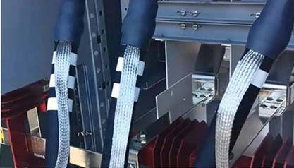

As time moved on, plastic-insulated cables were more abundant and began showing the effects of service age. The dominant test was still dc, but concerns grew over its effectiveness. In the early 1990s, reports surfaced indicating that dc highpotential testing could be to blame for latent damage experienced by extruded medium-voltage cable insulation (XLPE and EPR). After receiving

these reports, the Electrical Power Research Institute (EPRI) funded two studies relating to cross-linked polyethylene (XLPE) and ethylenepropylene rubber (EPR) cables. These studies (EPRI reports TR-101245 and EL- 6902) yielded the following conclusions regarding XLPE cable:
• High-potential dc testing of field-aged cable reduces its life.
• High-potential dc testing of field-aged cable generally increases water tree growth.

• High-potential dc testing before energizing new medium-voltage cable does not cause any reduction in cable life.
To better understand the conclusions of the EPRI studies, it’s beneficial to look at the aging
FEATURE CABLE TESTING WITH DC 72
Typical Single-Conductor, Three-Phase Cable Circuit

characteristics of extruded dielectric cables and the process of water treeing.
Under electrical stress, a series of tiny (typically less than 0.025mm – 0.001 inches in diameter) hollow channels can develop within an insulation exposed to water. Since the resulting pattern looks like a tree without leaves, the name water tree is used to identify the pattern.


The base of the tree is located at the point where the tree originated, and its extremities tend to grow parallel to the direction of the electrical field (Figure 2). Therefore, a tree originating at the stress-relieving layer at the conductor shield of a cable grows radially until the cable fails (Figure 3).
Water trees begin to form when a cable is exposed to water and normal operating voltage over an extended period of time. Electrical forces acting on water molecules (electrophoresis) at a microscopic point within the insulation increase the separation between polymer units. These water droplets become oriented into a conductive, chain-like channel. The result is a sharp electrode producing highly localized stresses. Once treeing is initiated, an electrical stress exists from the base of the tree channel to its extremity. Water treeing is one of the most important degradation mechanisms of XLPE cables.
When dc voltages are impressed on solid extruded-polymeric materials, their good electrical insulation properties become degraded. For example, trapped or low-mobility electrically charged particles within the bulk can give rise to space charge, resulting in localized electric stress enhancement. This can cause further concentration of charge and accelerate electrical aging; the water tree region contains more ionic impurities than the
sound region. Therefore, it is likely that in XLPE cable under dc voltage, the space charges are formed in the water tree region and its vicinity, promoting an increase in water-tree growth and reduced service life.


In 1996, a few years after the EPRI reports, the insulated conductor industry determined that dc withstand testing of plastic (XLPE) insulation systems — either in the cable factory as a routine production test or after installation as a high-voltage proof test — is detrimental to the life of the insulation; therefore, dc testing for plastic (XLPE) insulation systems was no longer recommended. In 2001, a new IEEE Guide for Field Testing and Evaluation of the Insulation of Shielded Power Cable Systems (IEEE Std 400™-2001) was released. The new standard includes statements such as:
Testing of cables that have been aged in a wet environment (specifically XLPE) with dc at the currently recommended dc voltages may cause the cables to fail after they are returned to service. These failures would not have occurred at that point in time if the cables had remained in service and had not been tested with dc.


This standard also indicates that other testing has shown “even massive insulation defects in extruded dielectric insulation cannot be detected with dc at the recommended voltage levels.”


Current versions of most industry standards no longer include dc high-potential testing of extruded cables (XLPE and EPR) as a maintenance test. Of those that still do, all have reduced the recommended test duration from 15 minutes to only five minutes. None endorse dc high-potential testing as a factory test for extruded cables, but most documents continue to include dc high-potential testing as an acceptance test on


WORLD 73 CABLE TESTING WITH DC WORLD
FEATURE
Water Tree
Formation in XLPE
Vented Water Tree at Fault Site


newly installed extruded cable. These industry standards and guides also no longer endorse dc high-potential testing as a maintenance test for extruded cables that have been in service for more than five years.


The new IEEE Guide for Field Testing and Evaluation of the Insulation of Shielded Power Cable Systems (IEEE Std 400™-2001 mentioned earlier) is structured as an omnibus guide that provides an overview of known techniques for performing electrical tests in the field on shielded power-cable systems. The guide discusses test techniques — both dc and alternatives to dc — and provides a summary of each technique’s advantages and limitations. Testing philosophies are broken down into two categories: Type 1 Field Tests and Type 2 Field Tests.

conditions very difficult. In practice, the shape of the leakage curve (assuming constant voltage) is more important than the absolute leakage current value of a pass/fail withstand test result.
After voltage has been applied and the test level reached, the leakage current may be recorded at one-minute intervals. As long as the leakage current decreases or stays steady after it has leveled off, the cable is considered satisfactory. If leakage current starts to increase — excluding momentary spurts due to supply circuit disturbances — trouble may be developing, and the test may be extended to see if the rising trend continues.


• Type 1 tests detect defects in the insulation of the cable system to improve service reliability after the defective part is removed and appropriate repairs are performed. These tests are usually achieved by application of moderately increased voltages across the insulation for a prescribed duration. Such tests are categorized as pass/fail. Tests include dc (recommended for laminated cable systems with cautions and warnings for extruded systems), very low frequency (VLF), and powerfrequency, high potential testing
• Type 2 tests provide indications that the insulation system has deteriorated — hence, termed diagnostic tests. These tests include dissipation factor/tan delta and partial discharge testing.
Laminated insulation systems are not subject to the same aging characteristics as XLPE and EPR. Therefore, dc testing is more accepted for acceptance and maintenance testing. Keep in mind, however, that the test has limitations. The dc leakage can be affected by external factors (such as heat, humidity, and water level) if unshielded and in ducts or conduits. It can also be affected by internal heating if the cable under test has recently been heavily loaded. These factors make comparisons of periodic data obtained under different test


Performing a dc high-potential test has not vanished from the industry, but now — armed with the knowledge of aging effects in extruded dielectric cables (particularly XPLE) and the effects of dc testing — cable installers and maintenance workers can proceed with caution and look to alternative tests to judge the condition of electric power cables. The IEEE standard for field testing and evaluating shielded power cables discusses six possible alternatives; each test provides certain benefits and limitations, and it is important to note that no one test provides the complete answer. A combination of Type 1 withstand tests combined with Type 2 diagnostic tests should be used for an overall, comprehensive cable management program.

Thomas D. Sandri is a Senior Technical Instructor at Shermco Industries. He has been active in the field of electrical power and telecommunications for over 30 years. During his career, he has developed numerous training aids and training guides, and has conducted domestic and international seminars. Thomas supports a wide range of electrical and telecommunication maintenance application disciplines. He has been directly involved in supporting test and measurement equipment for over 20 years and is an industry expert in application disciplines, including battery and dc systems testing and maintenance, medium- and high-voltage cables, ground testing, and partial discharge analysis. He holds a B.S. in electrical engineering (BSEE) from Thomas Edison University in Trenton, New Jersey.

FEATURE 74 CABLE TESTING WITH DC


FOR RESPONSIVE, 24/7 RELIABILITY CALL 800.434.0415 cepower.net cepjobs.com © 2017 CE Power Engineered Services, LLC. THE POWER OF PARTNERSHIP.
As a leading electrical-engineering service provider, we deliver reliability and peace of mind to a wide range of customers. With professional engineers on-staff, we can help you design, build, maintain, upgrade, repair any system. We’re your partner—today and tomorrow. PARTNER UP WITH CE POWER AT NETA booth 513.
FROM DESIGN AND BUILD TO REPAIR AND UPGRADE.



PROTECTION AND CONTROL SYSTEM USE OF NON-CONVENTIONAL
INSTRUMENT TRANSFORMERS AND PROCESS BUS
STEVEN A. KUNSMAN, NICHOLAS POWERS, AND BHARADWAJ VASUDEVAN, ABB Inc., USA
Digital substations are gaining traction, with real-world commercial installations now accepted among utilities. Main enablers for this technology are the non-conventional instrument transformers and standalone merging units using IEC 61850 process bus communication. IEC 61850 can improve the overall reliability and resiliency of the 21st century substation using digital communication. High-voltage measurement and control has recently improved to offer easily installed sensors with direct digital outputs offering excellent accuracy, stability, and faster frequency response. By going directly to digital, these state-of-the-art sensors preserve signal integrity and ease of connections through fiber communications. Unlike previous optical sensors that had some reliability concerns, the introduction of a new fiber optic current sensor (FOCS) design combines the inherent isolation of the optical current sensor with redundant systems to power, accurately process, and output signals capable of directly supporting
INDUSTRY TOPICS
PROTECTION AND CONTOL SYSTEM USE OF NON-CONVENTIONAL INSTRUMENT TRANSFORMERS AND PROCESS BUS NETAWORLD • 77


substation automation. These modern optical sensors embedded in free-standing form using modern polymer insulators free of oil or SF6 gas — or integrated into other power equipment such as live or dead tank breakers and gas insulated substations — can simplify the merging unit architecture and deliver the full promise of IEC 61850 to utilities and their customers.

The introduction of stand-alone merging units provides an equivalent approach to digitizing the secondary signals available in the switchyard. This approach also simplifies communication between the equipment in the switchyard and the relays in the control panel. In adherence to the IEC 61850 standard, the merging units easily virtualize any CT or PT signal available today from a conventional sensor. By implementing these merging units in the process bus, the complete potential of adhering to the IEC 61850 standard can be achieved.


microprocessor into substation automation, protection, and control has revolutionized the utility industry for the good and the bad. The push from a “dumb grid” to a “smart grid” has enabled the digital world to expand well beyond the traditional scope of protection, control, and supervisory control and data acquisition (SCADA). The ideal vision of knowing all aspects of every substation networked into an intelligent grid opens the opportunity to have information at our fingertips.

This article discusses basic application variants, results, and field experiences involving the nonconventional instrument transformer (NCIT), combined with the flexibility and modularity of the stand-alone merging units for process bus IO systems. In addition, the paper covers field installations of the GIS sensor technology and the availability of IEC 61850-9-2 implementation.
An overview will be provided to show the digital substation’s key benefits highlighting safety, reliability, functional consolidation, and cost drivers leading to customer savings. Utilities are facing an increased demand on substation information and the digital substation opens the door for real-time data exchange. The digital substation solution’s key technologies (relays, advanced substation automation, and modern instrument transformers) position IEC 61850/Ethernet as technology enablers and not obstacles.

One challenge continues to be the stranglehold from regulatory standards for reliability and security when, in fact, a smarter and highly intelligent automation system can make the grid much more reliable and dependable. The other challenge results as utility personnel struggle to find adequate time to research and explore new technologies that could change the landscape of the power system protection and control network. The upcoming generation of system and protection engineers has lived in the digital world their entire lives. As the aging infrastructure continues to feebly perform, the system has very little know-how on whether it is working or not, or the ability to make proactive decisions to limit outages or damage, restore consumers faster, and provide the post-mortem information to make necessary improvements.

Digital substations have evolved over the past two decades. The introduction of the
The last challenge is our aging and retiring workforce. The amount of knowledge leaving our industry each year is mind-blowing. Another challenge with the younger generation is a lack of company loyalty. Today’s younger employees have no concept of a lifetime at a single employer; this means that companies with increasing pressure on performance have lost the ability to retain their younger employees in dire times. With the younger workforce’s attachment to their digital devices, it is important to note that our society’s digital world has only been possible through the tight integration of information, resources on a common platform (open standards), and Moore’s Law continuing to prove that if it is not possible today, everadvancing technology will make it practical tomorrow.
INDUSTRYTOPICS INDUSTRY TOPICS
PROTECTION AND CONTOL SYSTEM USE OF NON-CONVENTIONAL INSTRUMENT TRANSFORMERS AND PROCESS BUS 78
The digital substation is no different. Open standards are now in place and have matured to the point of different manufacturers (some more than others) interoperating on a common platform. Technology for the complete digitization of the power system information, as well the speed and performance of the information exchange, allow real-time performance with better accuracy and open up possibilities for the digital substation. Who will be embracing this new technology? You do not have to look far, as our younger generation has the capability and is fearless to new technology advances. They are the key to pushing this new technology to advance protection, control, and automation into the modern era.
of substation devices should be described, how they should communicate with each other, what they should communicate, and how fast that communication should be. All of this is essential in achieving multi-vendor interoperability and realizing the benefits of a truly digital substation.

Without standards, we revert back to the 1990s when proprietary solutions resulted in one manufacturer’s system unable to communicate to another’s. Back then, products were installed with network interface modules (NIMs) in an attempt to make minimal information available to the network control centers. Today, the industry can appreciate the vision of John Burger from American Electric Power, who started the movement in the U.S. market to migrate the industry to a common standard. The history of the EPRI LAN Initiative to UCA to IEC 61850 is an entirely different article, but what has transitioned in the last 20 years has changed the landscape for modern and future control systems.
Wide-scale adoption of digital messaging for intra-substation communication is only possible if it is based on a common standard. Otherwise, we will revert back to the 1990s when information was piecemeal and fragmented, with mutually incompatible signaling creating an assortment of messaging within silos or islands of automation. IEC 61850, Communication Networks and Systems for Power Utility Automation, is not just a protocol, but rather a comprehensive standard defining a communication architecture and philosophies that specify how the functionality
IEC 61850 defines two main communication hierarchies inside the substation for information exchange between devices and from device to the sensing interface in the primary equipment (Figure 1). For inter-device communication, the IEC 61850-8-1 part of the standard, also known as the station-level bus, can be generalized as the necessary requirements for inter-bay and communications to the outside world. From the initial release of the IEC 61850 standard in 2004, the station bus brought the main benefit of the standard and was widely implemented by most vendors with a vested interest to support the changing world environment. The stationlevel bus provided a means for the common architecture targeting interoperability across vendors as well as significant reduction in copper wires through the introduction of unsolicited peer-to-peer device communication. Also known as Generic Object Oriented Substation Event (GOOSE) messaging, it is based on hardened Ethernet technology usable in the harsh substation environment.


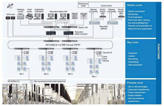


PROTECTION AND CONTOL SYSTEM USE OF NON-CONVENTIONAL INSTRUMENT TRANSFORMERS AND PROCESS BUS
INDUSTRYTOPICS INDUSTRY TOPICS NETAWORLD 79
Digital Substation Functional Levels

The second communication hierarchy introduced in the 2004 standard was the process bus as defined in IEC 61850-9-1 (point-to-point unidirectional) and IEC 61850-9-2 (multipoint bidirectional) for communication between the protection and control-bay-level devices and modern instrument transformers installed at the primary apparatus in the switch yard (Figure 2).


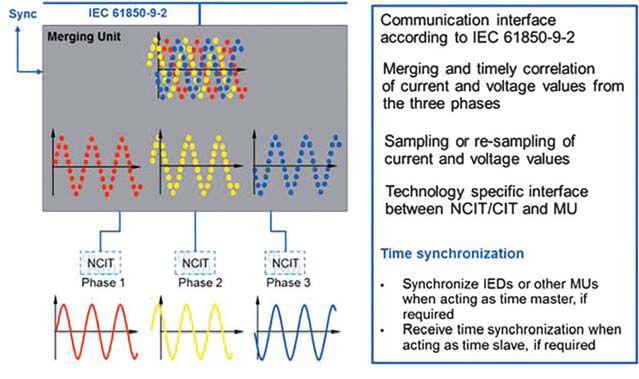
between the sensors and actuators, which are physically connected to the power system process, is why the term process bus is used as the interface to the protection and control systems. This enables the standard-compliant digitalization of the last mile in substation automation, and brings with it a wide range of benefits in the digital substation.
Communication Interface According to IEC 61850-9-2


In Edition 2 of IEC 61850, released in the past few years, IEC 61850-9-1 has been removed because its usefulness and application were limited. For process bus communications, IEC 61850-9-2’s main attributes are the streaming sampled measure values (SMV) where modern sensors digitalize the power system current and/or voltage measurements into a package of synchronized measurement values communicated to the protection and control devices. The standard does not define the type of sensor or the means for the digital transformation, but rather, defines a merging unit that collects the sensor information and prescribes a standard way to package and communicate the output.
The NCIT and process-bus technology has experience from a series of six outdoor gasinsulated substations (GIS) with process bus and NCIT technology installed and commissioned in 1999. As the IEC 618509 part of the standard was not released until 2004, these early installations were based on proprietary communication architectures. That notwithstanding, the sensor and digitalization technology experience was invaluable and is still used today with modern merging units supporting IEC 61850-9-2. The use of fiberoptic networks not only eliminates vast parts of the copper cabling, it also increases operational safety by isolating the primary from the secondary process.

The exchange of sampled values between these modern sensors or non-conventional instrument transformers (NCIT) and intelligent electronic devices (IEDs) for protection functions and other purposes allows for the real-time digital information exchange. The interconnection
The NCIT sensor families cited earlier are based on redundant sets of Rogowski coils for current measurement and two independent capacitive dividers for voltage measurement (Figure 3). The Rogowski coil is a device used to measure alternating current. It comprises a toroidal winding where the current-carrying conductor passes through the center of the toroid. The current output of the sensor is a voltage, which is proportional to the derivative of the current. The Rogowski coil has superb performance and improves linearity over a wide dynamic range, from metering to protection, and addresses the main issues of traditional CTs from the inductive open circuit as well saturation performance during fault conditions. The modern sensor also contains no oil, so this equipment is environmentally friendly and extremely safe.
INDUSTRYTOPICS INDUSTRY TOPICS
PROTECTION AND CONTOL SYSTEM USE OF NON-CONVENTIONAL INSTRUMENT TRANSFORMERS AND PROCESS BUS 80
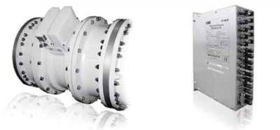
Gas-Insulated-Substation NCIT Use
Designed with fully redundant design of the sensors (including the associated electronics), this allows two completely independent and parallel protection systems, boosting the availability of the entire secondary protection system. As sensor electronics can be replaced independently and without shutting down the entire protection system, maintenance and repair activities require less time. Further, because there are no live parts to handle, maintenance activities are much safer. The GIS Sensor also saves significant space as it mounts on the gas insulated bus or on the hybrid breaker bushing (shown in photo below) — compared to requiring free-standing or integrated current and potential transformers, which are much larger in size — as well as additional space required in the substation switchyard layout.

NCITs installed on Hybrid Breaker Bushing
Since the first installation in 1999, more than 300 non-conventional instrument transformers and their electronics have been installed in Powerlink Australia’s substations. Notably, in more than 10 years of service, none of the primary converters has failed. Based on experience values, the mean time between failures (MTBF) of the sensor
electronics is over 300 years. This demonstrates the extreme reliability and high availability of the sensors, even in the very demanding environmental conditions of the Australian climate.

While NCITs are ideal solutions for new installations, it is also important to provide retrofit solutions for brownfield upgrades. A stand-alone merging unit (SAM) bridges traditional and digital technology. The SAM digitizes potential transformer and current transformer analog signals into digital communications (Figure 4).

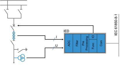
Stand-Alone Merging Unit for Conventional IT Connection to Process Bus
A SAM system combines voltage and current measurements, which are available on the SAM system bus, into an IEC 61850-9-2 compliant stream. This combined IEC 61850-9-2 stream is available on all IEC 61850 access points on SAM modules. The stream merging on the IEC 61850 access points is enabled by default and can be set via configuration parameters. Stream merging requires certain quality criteria of the streams available on the SAM system bus to be met. If those criteria are not met, then the stream merging is disabled. For maximum flexibility, the SAM is modular. Key components of the SAM include CT interface, VT interface, and a time-sync module.


SAM modules may be mounted using a DINrail and are typically placed in a station panel or marshalling kiosks near the primary equipment.


PROTECTION AND CONTOL SYSTEM USE OF NON-CONVENTIONAL INSTRUMENT TRANSFORMERS AND PROCESS BUS NETAWORLD 81


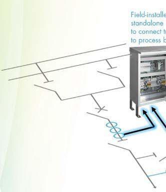


Retrofitting Conventional Substation for Digital Functionality
A marshalling kiosk with redundant SAMs is shown in Figure 5.
By adhering to the same IEC 61850 standard, these merging units can seamlessly integrate with any other non-conventional instrument transformer that is compatible with the same standard. This natural blend opens up the application possibilities of these devices.


A modular approach to integrating IEDs in the process bus provides the additional flexibility of routing the sensor signals to the protection IED in the most optimized way. It opens up various new engineering solutions to implement existing protection philosophies. An excellent example is the implementation of decentralized bus bar protection.
A quick thanks to Wikipedia: v(t) L di dt = The mathematics formula implicitly states that a voltage is induced across an inductor, equal to the product of the inductor’s inductance and current’s rate of change through the inductor. As the inductance does not change during the open circuit, the rate of change in current from 5 to 0 amps instantaneously has the derivative (di/dt) resultant go to infinity. Thus, the formula’s product voltage is dominated by the derivative blowing up to infinity and produces a very large voltage across the open circuited wires. Related to the substation application, an open CT secondary is equivalent to the inductive current going to zero; depending on the secondary load, arcing will occur as these dangerously high voltages build, putting field personnel at risk of serious injury or even fatality and equipment and the substation at risk from electrical fire. Minimizing copper leads to greatly improved safety.
The digital substation process bus for breaker status and control where copper control wires are replaced with digitized binary information can alone justify the switch to digital. Going digital can cut the quantity of copper wires in a substation by more than 80 percent, which is a substantial cost saving and, more importantly, a significant safety enhancement.


Every copper wire in a substation is a potential risk, whether it is from a CT or PT circuit or a 125V dc control wire. The highly inductive current transformer secondary circuit poses the largest safety concern. The hazard results when an energized current transformer wire is unknowingly disconnected. From inductive circuit theory, current flowing through an inductive circuit cannot be instantaneously changed from 5 amps to zero.
A fully digital substation is smaller, more reliable, has a reduced life-cycle cost, and is simpler to maintain and extend than an analog one. It offers increased safety and is more efficient than its analog equivalent. Not every substation needs to be catapulted into a wholesale digital world — it depends on the substation size and type, and whether it is a new station or a retrofit of the secondary system. Different approaches and solutions are required. Flexible solutions allow utilities to set their own pace on their way toward the digital substation:
• Increased system availability by replacing of electromechanical, static, or old-fashioned digital secondary equipment with modern
PROTECTION AND CONTOL SYSTEM USE OF NON-CONVENTIONAL INSTRUMENT TRANSFORMERS AND PROCESS BUS 82
numerical devices bundled to a real-time communication network and connected to a higher-level system such as a substation automation system or SCADA, allows continuous monitoring of all connected secondary equipment.
• Increased system and personnel safety, using remote control combined with authority and rule-based access and remote testing allows increased system safety and security. Personnel safety is increased since more tests can be done without putting test personnel close to primary equipment and without the risk of inadvertently opening CT circuits.
• Increased functionality with a fully distributed architecture, coupled with unrestricted communication and process capability, enables the system to add new functions easily with zero or minimal outage time, giving the user additional benefits in safety and security.
• Interoperability through deployment of IEC 61850 compliant solutions and interoperability regarding communications with other manufacturers’ equipment can be achieved. The benefit is that IEDs from different suppliers can be mixed on the same bus without concern for communication incompatibilities.
Also, improvement in fiber-optic current sensors and integration of the standalone merging units provides utilities and engineering firms with a great tool box for the future deployment of this maturing technology. For retrofit applications, the possibility of installing the new process bus system in parallel with the existing system will allow the substation to remain in service during the main part of the work. This will be a big advantage, reducing outages to a minimum during the retrofit process.


K. Bohnert, P. Gabus, H. Brändle, and A. Khan. “Fiberoptic current and voltage sensors for high-voltage substations,” 16th International Conference on Optical Fiber Sensors, Nara, Japan, October 13-17, 2003, Technical Digest, pp 752-755.
F. Rahmatian, G. Polovick, B. Hughes, and V. Aresteanu. “Field experience with high voltage combined optical voltage and current transducer,” Cigre (Paris), Session 2004, paper A3-111.
J. Wang, Z. Guo, G. Zhang. “Study on long-term stability of 110 kV power optical sensor solution - optical current transducer,” in Proceedings APPEEC 2010 (Asia-Pacific Power & Energy Engineering Conference 2010), Chengdu, China, 28-31 March 2010, pp 1178-1179.


K. Bohnert, P. Gabus, J. Nehring, H. Brändle, M. Brunzel. “Fiber-optic high current sensor for electrowinning of metals,” Journal of Lightwave Technology, 25(11), 3602 (2007). 5. German patent E4224190B4, 22.7.1992.
The introduction of the IEC 61850-9-2 process bus standard in substations has provided a platform that all manufacturers can develop to achieve the overall goal of interoperability. John Burger’s visionary ideas are being realized with the technology available today. In addition to interoperability benefits, the footprint of primary switchgear reduction using sensors (NCIT) instead of conventional measuring transformers allows a much safer work environment. On the secondary system, a massive reduction of cabling — by going from a lot of copper cables to a few fiber-optic communication cables — will mean reduced costs for cables and associated equipment such as cable trenches and installation material.
G. Frosio and R. Dändliker. “Reciprocal reflection interferometer for a fiber-optic Faraday current sensor,” Applied Optics, vol. 33, no. 25, pp. 6111-6122, 1994.
J. Blake, P. Tantaswadi, and R.T. de Carvalho. “In-line Sagnac interferometer current sensor,” IEEE Transactions on Power Delivery, vol. 11, no. 1, pp. 116-121 (1996).

K. Bohnert, P. Gabus, J. Nehring, and H. Brändle. “Temperature and vibration insensitive fiber-optic current sensor,” Journal of Lightwave Technology, 20, 267-276 (2002).
H-E Olovsson, T. Werner, P Rietmann. “Next generation substations,” ABB Review, Special Report on IEC 61850, pp. 33-37


PROTECTION AND CONTOL SYSTEM USE OF NON-CONVENTIONAL INSTRUMENT TRANSFORMERS AND PROCESS BUS NETAWORLD 83


W. Wimmer. “Systems’ Reliability and MaintainabilityThe Impact of Topology awareness,” PacWorld, pp. 54-59
March 2010
S. Meier. “Sharing Values,” ABB Review, Issue 1/11 pp.7377
M. Lenzin, S. Meier. “IEC 61850 at Work,” ABB Review, Special Report on IEC 61850, pp. 38-41
L. Andersson, K-P Brand, D. Fuechsle. “Optimized Arechitectures For Process Bus With IEC 61850-9-2,” B5101 CIGRE (2008)
IEC 61850-9-2 Communication networks and systems in substations – Part 9-2: Specific Communication Service Mapping (SCSM) – Sampled values over ISO/IEC 8802-3
IEC 61850-8-1 Communication networks and systems in substations – Part 8-1: Specific Communication Service Mapping (SCSM) – Mappings to MMS (ISO 9506-1 and ISO 9506-2) and to ISO/IEC 8802-3
IEEE 1588 Precision Clock Synchronization Protocol for Networked Measurement and Control Systems


Steven A. Kunsman is Vice President Business Development and Marketing at ABB Power Systems — Substation Automation North America. He joined ABB in 1984 and has 31 years of experience in substation automation, protection, and control. He graduated from Lafayette College with a B.S. in electrical engineering and Lehigh University with an MBA concentrated in management of technology. Today, Steve is responsible for ABB North American Power Systems Substation Automation business. He is an active member of the IEEE Power Engineering Society PSRC, including working group chairperson for H13, is an IEC TC57 U.S. delegate in the development of the IEC 61850 communication standard, and is UCA International Users Group Executive Committee cochairperson.

Nicholas Powers is NAM Marketing Manager, ABB Power Products — High Voltage Instrument Transformers. Nick joined ABB in 2008 with the acquisition of Kuhlman Electric and is ABB’s NAM HVIT Marketing Manager and Global Product Marketing Manager for Station Service Voltage Transformers. He has 37 years of experience in the instrument transformer field for electrical systems from 600 V up to 800 kV. Nick has a B.S. in electrical engineering from the University of Kentucky and completed courses of study in marketing and business development at the University of Wisconsin School of Business. He has helped develop advanced HVIT designs targeted for the rapidly changing electric utility in measurement, protection, and control instrument transformer needs.

Bharadwaj Vasudevan is an Application Engineer at ABB Power Systems — Substation Automation North America. He graduated from North Carolina State University with an M.S. in electrical engineering and started his career with Areva T&D Ltd in New Delhi, India, as a Power Systems Engineer. Bharadwaj worked on various EHV substation design projects throughout India before joining ABB as a consulting engineer for the Power Systems group. With a strong background in real-time power system modeling, he develops transient system models for transmission planning projects. In his current role with the Power Systems Automation group for the North America market, he supports all transmissionlevel Relion relay products from Raleigh, North Carolina. He is a member of the IEEE Power System Relay Committee and contributes to various working groups in the Relay Communications subcommittees.


PROTECTIONANDCONTOLSYSTEMUSEOFNON-CONVENTIONAL PROTECTION AND CONTOL SYSTEM USE OF NON-CONVENTIONAL INSTRUMENTTRANSFORMERSANDPROCESSBUS INSTRUMENT TRANSFORMERS AND PROCESS BUS 84

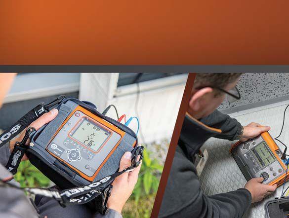






Now available for rent Contact info@progusa.net
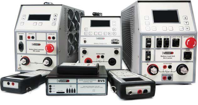
Features
Lightweight – starting from 32 Ibs (BLU200A) up to 45.4 Ibs (BLU360V)

Smart test devices for reliable electric power systems www.dv-power.com
Multiyear practice has proven the battery capacity test as being the most accurate battery-system health assessment method.
The DV Power Battery Load Unit (BLU) in a combination with Battery Voltage Supervisor (BVS - cell-by-cell scanner) gives you the powerful, yet handy, set of tools for the task.
– from 6 V up to 300V (BLU200A) and from 6 V up to 480V (BLU360V) – up to 19.7 kW (BLU200A ) and up to 28.4 kW (BLU360V)
test performed according to IEC 60896-21 standard ,increasing loading capability and reducing test time


The premier ELECTRICAL MAINTENANCE AND SAFETY Conference Lead the way. • Communicate Your Knowledge • Assist the Industry • Gain Visibility PRESENTATIONS SOUGHT Review of basics Industry-specific skills Insights into new methods, technologies, and advancements New testing procedures, safety procedures, and OSHA laws New types of electrical power equipment Uptime and reliability issues Submit abstracts on www.powertest.org
May 1, 2017 On the Potomac PowerTest.org 888.300.6382 Hosted by CALL FOR SPEAKERS
by
HUMAN PERFORMANCE AND A RAT TRAP

 BY DAVE SOWERS, Knowledge Vine
The rat trap is a fantastic combination of simplicity and efficiency. There isn’t much to it — just a wood pallet, a coiled spring, a latch, and a bar — but the results are impressive. The rat trap we know today was originally patented in 1897 and has remained largely unchanged for more than a century for one reason: It works.


However, the device comes with its own set of hazards for humans. The kinetic energy stored in the coiled spring is indiscriminate and comes at you in fewer than 0.004 seconds. Despite this fact, it’s easy to become complacent when handling a rat trap. The original patent called it the Little Nipper, which sounds almost harmless. In fact, the term rat trap is a little misleading, since the intent is not to trap rats but to kill them. (I guess the name Rat Spine Snapper didn’t poll well with focus groups in the 1890s). The rat trap has a job to do, and it does it well, but not without risks.

This is also true of many of the jobs utility safety professionals engage in every day; we do our best to execute them well, but they have their risks. Just like the rat trap, human performance is a fantastic combination of simplicity and efficiency. It’s all about recognizing the risks we face every day and taking
INDUSTRY TOPICS 88 • SPRING 2017
HUMAN PERFORMANCE AND A RAT TRAP
steps to mitigate them. Some risks are easy to identify, but others — like the rat trap — lie in wait, ready to cause harm.
Latent organizational weaknesses (LOWs) are those hazards we fail to recognize because we have walked by them a hundred times without consequence. A few examples include poorly written procedures, vague or interpretive guidance about how to perform a task, and the ever-present “you should just know how to do it.” These LOWs are similar to the rat trap in that if they are not understood and properly handled, they have the potential to ruin or degrade your performance.
Through human performance, techniques are available to help us recognize and mitigate the hazards associated with our jobs. Like the rat trap, human performance principles have stood the test of time for one reason: They work.
One such principle is the critical-step check, which involves recognizing the hazards inherent in a particular job and ensuring the steps we take will produce the results we desire. During many tasks, there are certain steps we must perform that are irreversible and can have devastating consequences if executed improperly. We can’t avoid these tasks, but we can work to ensure that everything leading up to our initiating action has been performed in a way that guarantees the outcome we want. A good analogy is the job of rat trap testing.
Our job today is ensuring that all of the rat traps work before sending them out to the public. What’s the critical step in testing the functionality of a rat trap? Some may argue it’s when you pull back the hammer and set it in the catch. These tasks are reversible. Activating the catch-release is not. If your fingers are in the way when the catch-release is touched, it’s too late. Irreversible harm has happened, and pain is setting in. If you’re the rat, well, you’re dead.
How can we ensure that we’re not going to suffer unwanted consequences when we perform
tasks? Simply performing a critical-step check as follows can help reduce painful mistakes:
1. Summarize the critical step. In this case, it’s activating the catch-release on a rat trap.
2. Anticipate error-likely situations. For instance, your fingers are near the hammer strike area; you’re not sure how the catchrelease works; there’s no procedure for the work; you’re facing time pressure; you’ve never performed this task before; you’re not trained.
3. Foresee consequences. If we don’t mitigate error-likely situations, what could happen or go wrong? There will be an action; will we get the reaction we want?
4. Evaluate defenses. Ask yourself, what do I have available to prevent an unwanted consequence? What else do I need to do to be successful? Am I using my hand and eye protection? Can I set the rat trap in a vise to get my fingers out of the way? What tool can I use to initiate the catch-release?
Additional human performance behaviors may also help, such as self-checking, peer checking, and demonstrating a questioning attitude. Once these behaviors become true standards, it’s easy to see how we can avoid the trap of initiating a critical step without first evaluating the irreversible results of our actions. Human performance methods, when used correctly, are simple and efficient and will help us all perform our jobs more safely.

Dave Sowers is the Director of Performance Improvement at Knowledge Vine LLC, a human performance training and consulting organization. A veteran of the U.S. Navy’s nuclear power program, he has more than 25 years of industrial experience gained through his work in the military, semiconductor manufacturing, commercial nuclear power, and hydro-electric generation. Dave holds a bachelor’s degree in resources management and a master’s degree in management as well as emergency management and homeland security.
NETAWORLD • 89 HUMAN PERFORMANCE AND A RAT TRAP
INDUSTRY TOPICS


“Working with SES was a huge success! We removed a safety issue at the same time decreasing our load on the compressors by 15% which has contributed to lower operating temperatures which will add longevity to the motors and a huge energy savings for the plant. Awesome job!” -Duane
Burgess, Ball Corp.

200K SQ. FT. OF INVENTORY
• All manufacturers from the 1920s to present
• Spares, replacement parts and rental options to keep you up and running
CERTIFIED TECHNICIANS
• Performance to a higher standard than the industry requires
• All product is guaranteed safe and reliable

CUSTOMER-FIRST FOCUS
• Expert staff willing to do whatever it takes to get you what you need when you need it
COMPETITIVE PRICING
• The most reasonable prices on electrical equipment and service
• Reconditioned items that provide the same or better quality than OEM items at more affordable prices

EMERGENCY SERVICE call us for

1.800.476.1486 SOUTHLANDELECTRICAL.COM


We Buy, Sell, Trade, Calibrate, Repair
Featuring quality, reliable, on-time service and support for all brands and types of solid state power electronics.
Power electronics are our business
Let us suppoort you with our quality repair, calibration and servicing of your solid state equipment. We also buy, sell and trade:
•Communications devices for power equipment
•Protective relays
•Circuit breaker trip devices
•Motor overload relays
•Rating plugs
4701 Spartan Drive • Denton, TX 76207 (877-874-7349) • Phone: 940-243-3731 • Fax: 940-387-8277 Email: info@solidstaterepair.com • Web: www.solidstaterepair.com
“SOLID STATE” INDUSTRIAL ELECTRONICS “SOLID STATE” INDUSTRIAL ELECTRONICS Toll Free 877-TRIP-FIX NOWRENTING TESTEQUIPMENT




INFLUENCE OF CIRCUIT BREAKER MAINTENANCE TESTS ON



BUSBAR DIFFERENTIAL



PROTECTION SCHEME
BY VIJAY SHANMUGASUNDARAM, DINESH CHHAJER, DHANABAL MANI, AND DANIEL CARREÑO, Megger



A busbar differential protection scheme identifies any in-zone faults on the busbar and immediately isolates the affected system from the sources. Any delay in the differential operation could potentially damage the substation equipment. Proper execution of a differential protection depends on the performances of all protection equipment in the scheme. Improper or accidental operation of the relay could lead to the loss of multiple feeders or transmission lines, thus reducing the system stability.
Low-resistance micro-ohm measurement is a routine diagnostic test performed on circuit breakers (CB) and busbars in medium- and highvoltage substations. A high-amplitude direct current (dc) is injected to check the integrity of breaker contacts. Although the test is very simple and easy to perform, it can prove problematic for protection schemes associated with the circuit under test.
The main buses in substations are designed to carry typical load currents and high-amplitude fault currents through individual feeders. Based on the flexibility of operation and the financial situation, there are several busbar arrangements. A differential function is implemented as the primary protection scheme to protect the busbars because it offers fast and sensitive protection. Although the busbar faults are relatively infrequent, an improper busbar protection


INDUSTRY TOPICS
NETAWORLD • 93 INFLUENCE OF CIRCUIT BREAKER MAINTENANCE TESTS ON BUSBAR DIFFERENTIAL PROTECTION SCHEME


scheme could cause severe disruption in the power system.
While performing periodic maintenance of dead-tank breakers with bushing current transformers (CT), the dc current used for measuring the low resistance can affect the differential scheme by causing an imbalance in the CT secondary circuit. Factors such as quality of the applied dc current, relay settings, CT accuracy class, and its magnetization can impact the selectivity and sensitivity of protection functions. This article focuses on the vulnerability of high-impedance bus differential protection due to low-resistance measurement tests. The root cause of relay misoperation is explained using lab simulations and a real-life case study where an external factor (periodic CB maintenance tests) affected the performance of a highly selective and sensitive protection function. We will also discuss recommended practices to prevent such scenarios using a proactive approach.
During normal operating conditions, the vectorial sum of all the CT secondary current is zero.
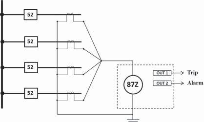
High-Impedance
Busbar Differential Scheme
A busbar fault typically results in high-amplitude fault current flowing through the feeders, circuit breakers, isolators, and associated CT circuits. During a high fault-current condition, any CTs connected to the differential relay could saturate, resulting in significant differential current. This could operate the differential relay even if the fault is external to the protected zone, thus reducing the stability of the function. Two major techniques can prevent the influence of unequal CT performance: (1) multi-restraint current differential, and (2) high-impedance voltage differential. Although multi-restraint current differential is the most flexible method, it is more complex to implement.
A typical arrangement of a high impedance busbar differential scheme is shown in Figure 1. The CT secondary from each phase is paralleled at the relay input, which offers very high impedance to the flow of current. When implementing this scheme, all the CTs must have the same ratio and accuracy to minimize the differential current due to CT mismatch.
A high-impedance bus differential relay employs a sensitive current element in series with high impedance, typically a resistive element as shown in Figure 2. The relay operates based on the voltage drop across the operating coil. To prevent damages to the element during high fault-current conditions, a varistor is connected in parallel. The voltage threshold for a highimpedance busbar differential function should be set balancing two considerations: (1) a low value setting for maximum sensitivity for inzone faults, and (2) a high-value setting to endure stability for a saturated CT due to a fault present outside the protected zone.
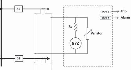
Internal Elements of High-Impedance
Busbar Differential Scheme
The basic function of a circuit breaker is to interrupt current flow in a circuit during a fault condition. However, under normal
INDUSTRY TOPICS 94 INFLUENCE OF CIRCUIT BREAKER MAINTENANCE TESTS ON BUSBAR DIFFERENTIAL PROTECTION SCHEME
operating conditions, the circuit breaker should be a good conductor offering the least resistive path. The contact resistance of the circuit breaker must remain under a certain value to ensure a good conductive path for the current circulating through it to avoid heating and hence, energy losses. Regular maintenance programs for circuit breakers include contact resistance testing in accordance with standards ANSI C37.09 and IEC 62271-100, which specify minimum current values to carry out the low resistance measurement. Special care should be taken when measuring contact resistance of circuit breakers with CTs that are still connected to a protection scheme.
A resistance measurement is considered to be of low resistance when the resulting value of the test is below 1.000 Ω. The lower ranges of many low-resistance ohmmeters measure down to 0.1 μΩ, which is required when conducting tests on breaker contacts and bus joints. At this level of resistance, it is important to use the correct test equipment and method that will minimize the introduction of errors due to test lead resistance, contact resistance between the probe and the specimen under test, as well as other phenomena like standing voltages across the item being measured (e.g. thermal EMFs at junctions between different metals). This is achieved by a four-terminal measurement (two current and two potential leads), ensuring that the potential leads are placed between the current leads, as illustrated in Figure 3.
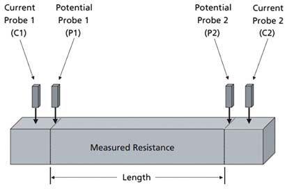
A low-resistance micro ohm measurement on each phase of medium- and high-voltage CBs is a routine maintenance test. The dc current applied for the test is passed through the breaker contacts, and the voltage drop is measured to determine the breaker contact resistance in micro ohms.
The majority of HV circuit breakers in North America are dead-tank-type breakers as shown in Figure 4. These breakers have CTs mounted on their bushings. The primary of the bushing CT is basically a center conductor passing through the CT that then gets connected to the breaker interrupting chamber, which encapsulates the fixed and moving contacts of the breaker.
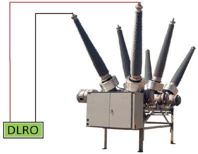
DLRO Test Connection to a Dead-Tank CB

Four-Wire Resistance Measurement
When performing a Digital Low Resistance Ohmic (DLRO) measurement, the applied dc current passes through the CT primary. In theory, it being a dc quantity, no current should be reflected on the secondary side of the CT. However, based upon the method used and quality of the applied dc current, in some cases, a reflection in the CT secondary circuit occurs. The duration and magnitude of the secondary current depends upon the following factors:
1. Rate of rise and fall of applied dc current
2. Method used to generate dc current:
• Half-wave rectified
• Full-wave rectified
• Generation using a regulated power supply

NETAWORLD 95 INFLUENCE OF CIRCUIT BREAKER MAINTENANCE TESTS ON BUSBAR DIFFERENTIAL PROTECTION SCHEME INDUSTRYTOPICS INDUSTRY TOPICS



A rapidly changing dc current output with ripple content or presence of harmonic components can be interpreted as a fault signal (ac quantity) by the relay. Additionally, when the bushing CT is part of a differential protection scheme, this secondary current could be interpreted by the protection scheme as an operating quantity. One other side effect of a DLRO measurement is that every time a dc quantity is passed through the CT primary, it magnetizes the CT and alters its performance. If the current is substantial enough, it could saturate the CT and introduce ratio errors during normal CT operation.
To avoid inadvertent relay tripping, the CT secondary is disconnected from the protection circuit and shorted. This must be performed on all CT secondaries whose primary is part of the low-resistance measurement circuit. One of the practical challenges at many utilities is that the substation crew is different than the protection and control crew and is not allowed to change any protection circuits. Additionally, there is always a precaution of not changing existing circuits as it might lead to incorrect rewiring, incorrect selection of CT tap, or accidentally leaving the CT secondary open. Because of these reasons, and although a recommended method, CT secondaries are typically not disconnected for low-resistance measurements.


After exposing the CTs to a dc current flowing through its primary circuit, the CTs might have residual magnetism. It is highly recommended to perform a demagnetization procedure on all the CTs involved to ensure proper performance after dc testing. Figure 5 (a) and (b) show the difference in excitation curve of a C200 multi tap CT with full ratio of 600:5, with and without a demagnetization procedure.
It is observed that the measured knee-point value changed from 210 V with demagnetization to 227 V without proper demagnetization. During routine CB testing, the dc current can magnetize the core of the CT and, if not addressed properly, can leave residual flux in the core. Under extreme cases, it can even saturate the CT. These measurements demonstrate the importance of demagnetization processes after performing dc testing on any circuit that has CTs, especially CTs connected to a protection scheme.
This incident occurred at one of the largest investor-owned utilities (IOU) with more than six million customers and operating in seven different states. The bus differential relay tripped while performing the micro ohmmeter testing Saturation

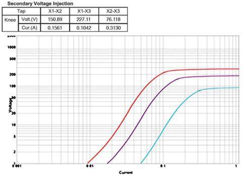
INDUSTRY TOPICS 96 • SPRING 2017 INFLUENCE OF CIRCUIT BREAKER MAINTENANCE TESTS ON BUSBAR DIFFERENTIAL PROTECTION SCHEME
C200
Demagnetization
Without Demagnetization a
Response Curve of
CT (a) With
and (b)
on a 138 kV circuit breaker. The technicians attempting the test had difficulty obtaining a good contact resistance measurement and made multiple test attempts prior to the one that caused the trip. The circuit breaker under test featured integrated CTs that were not isolated from the bus differential protective scheme. The dc current injected for the measurement was 100 A. The high-impedance relay used for differential protection was set at a pick-up voltage of 100 V with no intentional time delay.
During the trip event, it was reported that the relay registered a voltage of 132 V, prompting an investigation to determine the root cause of the incident to avoid future misoperation of the protection scheme. To observe how the relay responded to the application of dc current through CT primary, field conditions were simulated in a lab environment (Figure 6) using the same make and model of high-impedance relay along with the relay settings, CT of similar class and ratio, and same micro ohmmeter test instrument with different levels of current.
Different low-resistance ohmic test instruments may have different quality of dc output based on the method used to generate dc current from a connected ac source:
• Smooth dc output with no ripple current and ramp function at the start and end
• Decaying dc output without intentional time delay ramp
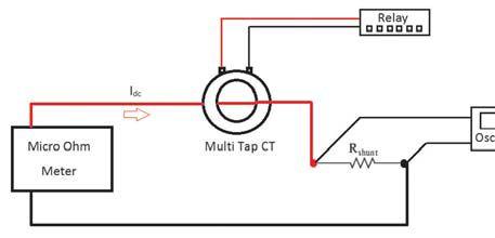
Overview of Lab Setup
• A dc output with spikes at start and end of current injection
The three commonly available dc outputs are shown in Figure 7.
The circuit breaker contact resistance was measured using a decaying dc output without intentional time delay ramp. The minimum primary current required to trip the relay is calculated as per the following equation:
Imin = (n * Ie + Ir + Im) * N
Where:
Imin = minimum primary current n = number of current transformers in parallel with the relay, per single phase Ie = current transformer exciting current at relay setting voltage, Vs Ir = current through the relay at relay setting voltage, Vs Im = current through the MOV at relay setting voltage, Vs N = CT ratio




DC Output Characteristics of Low-Resistance Ohmic Test Instruments


NETAWORLD 97 INFLUENCE OF CIRCUIT BREAKER MAINTENANCE TESTS ON BUSBAR DIFFERENTIAL PROTECTION SCHEME


CTs with higher knee-point voltage will have lower excitation current, making them more sensitive for the same relay-trip voltage settings as shown in Figure 8.
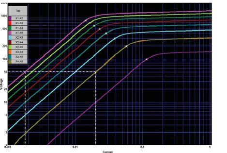
For any given relay voltage setting, the excitation current requirement is less for a higher tap CT. X1-X5 Ie is less than Ie for X1-X3. Additionally, for the same relay voltage settings, the number of CTs in the circuit would impact the sensitivity of the relay circuit. Protection schemes with fewer CTs per phase, connected in parallel to the differential relay, would be more sensitive when compared against a scheme that has more CTs in parallel.
For lab simulation purposes, the Vs was set to 50V with a CT class of C800 and 3000:5 tap ratio. The test was performed with a decaying dc output characteristic of 0.6 second and 3 second duration. The waveforms, as seen by the relay along with the elements picked for the previously mentioned conditions, are shown in Figure 9.


Waveforms Observed for 0.6-Second DC Current Injections


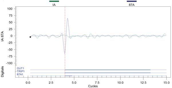

Waveforms Observed for 3-Second DC Current Injection

The voltage drop across the high-impedance circuit of the relay was around 65-75 V for repeated tests on the lab setup. The relay tripped on 87 element for A phase as the tests were performed on A phase. The same procedure was repeated with a dc pulse width of 3 seconds. The waveforms captured from the relay are shown in Figure 10.
In both cases, a steep increase in the differential current sufficient to operate the relay was observed for the initial rise of dc output current from the test instrument. Every time a dc current is injected to the CT primary, it magnetizes the core of the CT. This results in either increase or decrease of CT excitation current requirements when compared against a demagnetized CT. Multiple repeated low-resistance measurement tests in a short period of time could change the CT characteristics and make the relay operation unpredictable.
Analysis of the waveforms captured from the digital low-resistance testing instrument and high-impedance busbar differential relay indicated several factors that could contribute to the accidental relay trip. Some factors such as class of CT, CT ratio, and CT tap in operation cannot be altered during maintenance, but could be considered for proper system design.
98 • SPRING 2017
CT Saturation Curves for Multi-Tap CT
INFLUENCE OF CIRCUIT BREAKER MAINTENANCE TESTS ON BUSBAR DIFFERENTIAL PROTECTION SCHEME
On the other hand, factors such as CT residual magnetism, demagnetization, and unwanted repeated dc current injection could directly affect the outcome of the relay operation.
To avoid such scenarios, the low-resistance measurement tests could be performed using a filtered dc output to eliminate any change in frequency that may reflect on the secondary of the CT. A low-resistance micro ohmmeter with definable ramping rate at the start and end of a test will slowly vary the injected current. This prevents any sudden rise in dc quantity or spike that could possibly be interpreted by the relay as a fault current. Alternatively, a disconnectingtype terminal block in the CT marshaling box could safely short and isolate the CT secondary from the protection scheme.
Dinesh Chhajer and Daniel Carreño. “Effects of Low Resistance Measurement Instruments on Protection and Control Devices,” Power Test Conference, March 2016.
IEEE C37.09-1999, IEEE Standard Test Procedure for AC High-Voltage Circuit Breakers Rated on a Symmetrical Current Basis.
IEC 62271-100:2008, High-Voltage Switchgear and Controlgear - Part 100: Alternating Current Circuit-Breakers.

Vijay Shanmugasundaram is the lead Relay Applications Engineer at Megger focusing on protection and IEC 61850 applications. In 2008, Vijay received his Bachelor of Engineering degree with distinction from Amrita University, India. He joined Defense Research and Development Organization of India as a junior research fellow. In 2011, Vijay received his M.S. in ECE focusing on power systems from North Carolina State University. As a part of the master’s program, he worked on IEC 61850 substation development in Siemens's Energy and Automation department. He is an active member of IEEE and EPRI, participating in conferences and contributing to the working groups.
Low-resistance micro ohm measurement is an integral part of regular substation asset maintenance practices. Breaker contact resistance and bus work installation will continue to be checked using this test method. As simple as it is, the test comes with inherent critical issues that must be addressed to avoid any inadvertent trips.
This article described a real-life case study and the analysis made to discover the factors that can affect the protection scheme associated with the circuit under test. Understanding the CT performance and relay characteristics will prepare technicians to take a proactive approach and perform the test in a risk-free manner.

Dinesh Chhajer is the Manager of the Technical Support Group department at Megger. He received his M.S. in Electrical Engineering from the University of Texas in Arlington (UTA). In 2006, Dinesh joined Megger as an Applications Engineer, providing engineering consultation on testing of transformers, circuit breakers, and other substation assets. He previously worked as a Substation Design and Maintenance Engineer with POWER Engineers Inc. and focused on specializing in transformers, batteries, and power quality. He has presented a number of white papers related to substation asset maintenance at various international conferences. He is currently a licensed Professional Engineer in the state of Texas.

J. Lewis Blackburn and Thomas J. Domin. Protective Relaying: Principles and Applications, Third Edition, CRC Press, 2007.
Vijay Shanmugasundaram and Dhanabal Mani. “Importance of Harmonic Blocking in Generator Differential Protection,” 1st Annual conference of Protection, Automation and Contro, Americas Conference, September 2014.
Ken Behrendt, David Costello, and Stanley E. Zocholl. “Considerations for Using High-Impedance or LowImpedance Relays for Bus Differential Protection,” 63rd Annual Conference for Protective Relay Engineers, March 2010.

Dhanabal Mani received his Bachelor of Electrical and Electronics Engineering from Bharathiyar University, India, in 2001. As a lead commissioning engineer of Substation Automation Group at ABB India Ltd., he commissioned the first 400kV IEC61850 substation in India. He has also developed custom relay applications as a R&D engineer at ABB Ltd, Sweden. Dhanabal joined Megger India as an Application Manager in August 2009 and is presently based in Dallas. He has over 15 years of commissioning experience and has published numerous articles at various international conferences.

Daniel Carreño is an Applications Engineer with Megger, specializing in transformer testing and high voltage circuit breakers. He graduated from Instituto Politécnico Nacional in Mexico City, with a BS in Mechatronic Engineering. His experience involved working for power transformer manufacturers in Mexico and the USA. Daniel is an IEEE-PES member and actively participates in substation equipment condition assessment and applications development.

NETAWORLD 99 INFLUENCE OF CIRCUIT BREAKER MAINTENANCE TESTS ON BUSBAR DIFFERENTIAL PROTECTION SCHEME






SAFETY FIRST:



NEW TECHNOLOGY AND ADVANCEMENTS FOR SAFE, OFF-LINE ELECTRICAL TESTING
BY MATTHEW LAWRENCE AND ELIZABETH ARAGAO, Doble Engineering Company
As the power industry has evolved with an increased emphasis on speed and efficiency, we must always remember that safety is still the utmost priority. As any testing crew knows, off-line electrical testing can be a dangerous job. Power companies and government regulations have established precise rules and procedures for safe practices that need to be followed. New technology is available to help keep crews efficient and optimize outage time while also reducing safety risks.
Your company’s and your customers’ safety policies — and the approved test procedures for a specific apparatus — should always be your first line of defense when it comes to safety before, during, and after testing. Here are a few
safety tips to serve as a reminder of general safety practices:
• Hold a pretest tailgate meeting for crew members and all personnel who work close to the testing area. Review the tests
100 • SPRING 2017 ADVANCEMENTS IN THE INDUSTRY SAFETY FIRST: NEW TECHNOLOGY AND ADVANCEMENTS FOR SAFE, OFF-LINE ELECTRICAL TESTING
to be performed, apparatus, voltage test levels involved, potential hazards, and crew assignments.
• Emphasize to test personnel that induced voltages or trapped charges may be present on the equipment to be tested.
• Remember to perform only one job at a time on any apparatus. Performing different tasks on the same apparatus at the same time is an open invitation for confusion, trouble, and danger.
• Agree on a consistent and uniform set of signals — both visual and verbal — that all crew members must follow during testing.
• Remind the crew that all personnel must stand clear of an apparatus before any testing is performed.
When working with new equipment, it is important to be aware of how a device runs and how it must be operated. Detailed safety information should be available in equipment documentation. It should be covered during training sessions so that test crews are comfortable with how to perform the testing safely and accurately.
The benefit of working with new equipment is that advancements in technology can reduce some of the safety risks traditionally associated with off-line testing. Examples of new technologies and safety enhancements now available include:
• Dual high-voltage leads. New equipment with dual high-voltage leads allows you to perform multiple tests with one cable hook-up, which means a reduction in ladder trips per job. This can be achieved because the high-voltage and low-voltage leads can switch between source and measurement. In a real-world example, consider the highvoltage overall transformer test. Dual highvoltage leads are set up once, and all overall transformer tests can be run in one operation. This eliminates a ladder trip and lead swap.
• Safety switches. Equipment with two test enable/safety switches can be used by a test set operator and the operator’s assistant. Using two switches requires the crew to visually and verbally acknowledge that they are ready to test, when they are performing testing, and that testing is complete. Tests will not run unless both switches are held in the on position. And as an additional safety precaution, tests will stop if one of the operators lets go of the switch.
• Eye hooks. Look for eye hooks on highvoltage leads that let you use hot-stick tools to place HV cables on the apparatus under test.
• Emergency shutdown. Equipment with emergency stop buttons allows you to initiate a controlled shutdown with one motion.
• Clear notifications. Get visual confirmation on LED screens that energy is being released from the test specimen.
While many safety procedures seem like common sense, take the time to remind yourself of the tips, techniques, and technologies that keep you safe. Testing can be dangerous. It is never a wasted step or a wasted minute if it is being spent on the safety of you and your crew.


Elizabeth Aragao is Director, Marketing Communications, at Doble Engineering Company. She has worked with Doble for six years, with a focus on the customer experience, from websites through product usability.
Matthew Lawrence, Doble’s Senior Director, Solutions, oversees the development of Doble’s hardware and software solutions. Matthew has worked in the utility industry for over 30 years, with a focus on maintenance, construction, and operations.
NETAWORLD • 101
SAFETY FIRST: NEW TECHNOLOGY AND ADVANCEMENTS FOR SAFE, OFF-LINE ELECTRICAL TESTING
THE INDUSTRY
ADVANCEMENTS IN

Making testing simple, safe & efficient
M7100 High Voltage Asset Analyzer
REVOLUTIONIZING HIGH VOLTAGE TESTING


The Doble M7100 High Voltage Asset Analyzer is a revolutionary solution for high voltage testing. And it is built to reduce the various safety risks a field crew is exposed to per job.
Patented dual high-voltage leads allow you to perform multiple tests with one cable hook up. This means a reduction in ladder trips per job – cutting the number by one third.
Eye hooks on the high-voltage leads let you use hotstick tools to place HV cables on the apparatus under test.
Emergency stop button initiates a controlled shutdown with one motion, and once pressed, will lock until it is twisted and released.
Two test enable/safety switches must be pressed at the same time by the test set operator and the operator’s assistant – otherwise the M7100 will not operate.
Discharge complete will appear on the LED display once a test completes and the M7100 has entered a discharge mode that releases energy from the test specimen.


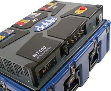

Learn more about how the M7100 is making testing simple, safe & efficient. ww w.doble.comm/ M710 0
RESISTANCE TESTER THE RIGHT GROUND
BY JOHN OLOBRI, AEMC® Instruments
A heightened focus on safety, combined with the increased application of highly sensitive, low-powered electronics susceptible to electrical noise issues, has made the need for an effective low-resistance grounding system more critical today. Additionally, grounding systems do degrade over time.
As a result, awareness of the importance of periodically testing installed grounding systems to ensure their integrity has also increased. Many organizations require annual testing with written reports filed. Today, the test engineer or technician has access to a wide variety of ground resistance test equipment to complete this task.
Test equipment varies in design, features, and complexity, including small, handheld models as well as larger field instruments with a full complement of user-selectable functions packaged as part of a complete kit. These products range in price from a few hundred dollars to several thousand dollars. Several critical questions are key when selecting a

ground resistance tester. This article is a guide to choosing the instrument best suited to your specific application and requirements.
The first question is whether your current or future needs require soil resistivity testing, because this will determine the type of ground resistance tester needed. For example, if the work involves the calculation and/or expanding/ upgrading existing systems, soil resistivity testing is necessary to determine design characteristics the system must have to achieve the desired resistance. The number and depth of ground rods
WORLD 103 ADVANCEMENTS IN THE INDUSTRY CHOOSING THE RIGHT GROUND RESISTANCE TESTER
ADVANCEMENTS IN THE INDUSTRY
and the interconnection of the ground grid are some of the parameters. An instrument designed for four-pole testing (also referred to as fourpoint testing) is required for this application. In addition to the instrument, four test electrodes and cables are needed. A basic four-pole tester provides measurement results in ohms. You can then use this reading to manually calculate soil resistivity known as Rho (ρ) by applying the result in a formula that also requires knowledge of the test rod spacing and depth. The result is usually expressed in ohm-centimeters (Ohmcm) or ohm-meters (Ohm-m).
More sophisticated instruments include builtin formulas for calculating soil resistivity using one of two methods: Wenner (Figure 1) or Schlumberger. If you regularly perform soil resistivity testing, consider purchasing an instrument that automatically calculates soil resistivity. This will save time and eliminate potential math errors.

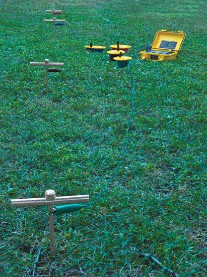
The obvious follow-up question involves which types of grounding systems will be tested. Will systems tested.
this include small systems such as residential, or larger and more complex systems such as commercial, industrial, telecommunication, or electric utility installations?

104
CHOOSING THE RIGHT GROUND RESISTANCE TESTER
Soil Resistivity Test Using the Wenner Method
Small Grounding System
To illustrate the importance of this question, consider a typical small site with a grounding system consisting of a ground rod or two, driven into the earth and connected to the service entrance.
In Figure 2, if the building has not yet been connected to the utility ground, a basic threepole ground resistance tester (or a four-pole instrument configured for three-pole testing) will suffice for measuring the resistance of the ground rod. In addition to the instrument, two auxiliary electrodes and spools of test cable are required.
If the building’s grounding system has been connected to the incoming power system through connection at the service entrance, a clampon ground resistance tester is a better choice, because it can measure the grounding resistance without the need to disconnect from the Utility neutral or to drive auxiliary test electrodes. If you choose a three- or four-pole instrument for this, bear in mind the distances required for auxiliary rod placement. For example, performing a fallof-potential test (Figure 3) on a single grounding electrode driven eight feet deep requires at least an 80- to 100-foot test lead to connect to the injecting test electrode and a 50- to 70-foot test lead to connect to the potential measuring electrode. If more ground rods are used, the distance requirement increases.
Ground resistance test kits are available that include the measurement instrument, the auxiliary electrodes (two are needed for fallof-potential testing, four are needed for soil resistance testing), and test leads to complete all the connections. Typical lead lengths provided in these kits range from 100 to 500 feet. It will be well worth your investment to select a ground resistance test kit with leads at least one size longer than your immediate need. So if 150 feet is required, a kit that includes 300-foot leads will provide for your current need and potential future needs. For larger sites with multiple rods or ground grids, consider kits that provide 500foot leads.
ADVANCEMENTS IN THE INDUSTRY
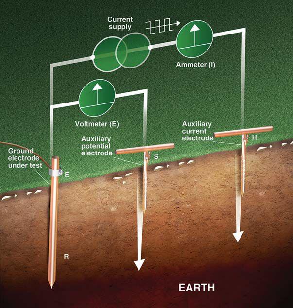

Another question is whether the soil resistivity in the testing area is high or whether the distance required for the auxiliary rods to perform fall-ofpotential testing is unusually long. If the answer to either of these questions is yes, and you intend to perform fall-of-potential and/or soil resistivity tests, you must consider the instrument’s injection current and test voltage. Typical voltage. injection currents range from a few milliamps up to several hundred mA. High soil resistivity usually produces high contact resistance for the auxiliary electrodes. This can be of concern when using lower-cost instruments that typically provide 10mA or less of test current. In this circumstance, an instrument capable of delivering higher test current is recommended. Note that clamp-on instruments do not require any auxiliary rods or leads. Another advantage is that you do not need to take the grounding system out of service to perform the test.
WORLD 105
CHOOSING THE RIGHT GROUND RESISTANCE TESTER
Typical Fall-of-Potential Test Setup
ADVANCEMENTS IN THE INDUSTRY

Another factor is whether electromagnetic interference is present at the test site. EMI can result in unstable or inaccurate readings, particularly at lower test frequencies.
The most common test frequency employed in ground test instruments is 128Hz. Newer instruments available today feature manual and/or automatic test frequency selection and and can scan through a range of frequencies to find frequencies to the cleanest available frequency. This provides an advantage in high-EMI environments, thus eliminating, or greatly reducing, the ill effects of the noise. Clamp-on ground resistance testers can also be effective in such locations, since they typically test at higher frequencies that are not multiples of the normal power frequency. Newer clamp-on ground resistance testers also offer test frequency selection. Note that in some highinductive environments, lower test frequencies can produce more reliable results.
data storage and report generation are important considerations. Newer and more advanced instruments — three- and four-pole testers as well as clamp-on ground resistance testers — can store test results in internal memory. This data can then be downloaded and analyzed using software supplied with the tester or via mobile apps for smartphones and tablets (Figure 4).
This can be a very powerful tool for contractors conducting tests for clients. The ability to easily compare the new measurement data with past data is a valuable tool in determining system degradation. An added advantage with a mobile app is the ability to immediately send test results as an email or text message right from the job site.
The choice of instrument depends on how you intend to use the data. For example, if you plan to save, analyze, and distribute the test results,

Finally, if you plan to test a complex grounding system consisting of many components including a ground mat or grid, the continuity of bonding between the various elements must be tested. This test is most often conducted using dc voltage and current. Several ground resistance testers provide this capability, with test currents up to a few hundred milliamps. In addition, a more complete test can be performed with a micro-ohmmeter. The advantage in using this instrument is its ability to test at high test currents, typically up to 10A or more. This can expose problem areas not always revealed when testing with milliamp-range currents.
Basic grounding electrode resistance testing requires a three-pole tester to conduct the common fall-of-potential test. To conduct this test adequately, the system under test must be isolated from other grounding systems. If it is not possible to disconnect or isolate the system under test, then a clamp-on ground resistance tester is a better option.
If you are conducting tests in electrically noisy environments, such as near transmission towers
106
CHOOSING THE RIGHT GROUND RESISTANCE TESTER
Application Software Fall-of-Potential Test Report (left) and Clamp-On Ground Tester Communicating with an Android™ App (right)
or power lines, a three- or four-pole tester with selectable frequencies may provide more accurate results.
If soil resistivity testing is needed, a four-pole tester is required. Consider one that will calculate the final result in ohm-centimeters (Ohm-cm) or ohm-meters (Ohm-m) and has minimal test current of 10 milliamps or more.
Bond resistance testing is best conducted with dc current. Consider a four-pole tester with higher test current capability typically in hundreds of milliamps. You could also move up to a more capable micro-ohmmeter capable of testing up to 10 Amps.
Finally, if you are conducting ground-resistance testing on a regular basis and are required to provide reports of the test results, consider an instrument that can store and output the measurements and includes application software to generate the fall-of-potential plots and
ADVANCEMENTS IN THE INDUSTRY
provides a professional report. It will pay for itself in a very short time.
There are specialty tests using fall-of-potential methods to effectively measure tower leg resistance and the effects of adjacent grounding systems on each other, which is a topic for a future article.

John Olobri, Director of Sales and Marketing at AEMC® Instruments, holds degrees in electrical and industrial engineering and has worked in the design and marketing of instrumentation for over 35 years. He began his career designing oscillographic chart recorders and subsequently held positions of Service Manager, Product Marketing Manager, and Sales Manager for several instrument manufacturers. For the past 20 years, John has been Director of Sales and Marketing for AEMC® Instruments, where he has been actively involved in insulation resistance, ground resistance testing, power quality testing, and data logging. He also conducts accredited seminars on ground resistance testing in various cities around the country.


ASTM F18 COMMITTEE REPORT
 BY JIM WHITE, Shermco Industries

The ASTM F18 Committee is responsible for all rubber-insulating PPE as well as arc-flash PPE, live-line tools, insulated tools, and insulated bucket trucks. The F18 Committee met in Orlando, Florida, from October 22-25, 2016. The next meetings are scheduled for April 23-27, 2017, in Las Vegas and October 2017 in New Orleans.


ASTM is represented on the NFPA 70E Committee by Marcia Eblen and Sam Stonerock. Marcia presented the 70E report to the ASTM members. Marcia and Sam were very much against the proposed elimination of mandatory references in the 70E. On the contrary, NETA has supported removing mandatory references. The proposed change would have taken all requirements to adhere to specific standards and moved them to Informational Notes, as in the example below from NFPA 70E 130.7(E)(1):


1) Safety Signs and Tags.
1)SftSiidT Safety signs, safety symbols, or accident prevention tags shall be used where necessary to warn employees about electrical hazards that might endanger them. Such signs and tags shall meet the requirements of ANSI Z535, Series of Standards for Safety Signs and Tags, given in Table 130.7(F).
The underlined text is the mandatory reference. This would have been placed into an Informational Note.
Putting these mandatory references into InformationalNoteswouldallowthe70Etobe Informational Notes would allow the 70E to be used in other countries, which is difficult now since other countries may not (and probably do not) use ANSI, ASTM, or UL standards. NETA believes this would have little or no impact on electrical safety equipment in the U.S. because OSHA already has requirements in place that supersede NFPA 70E requirements. Removal of


mandatory references would have made adoption of NFPA 70E easier for other countries and advanced their electrical safety culture. However, in the balloting for the second draft, the full NFPA Committee voted to retain the mandatory references for the 2018 cycle.
The F1506 Subcommittee had a lot of work for this standard. F1506 covers arc-rated clothing, so it is always of interest. Some of the more interesting actions included:
• Labels in arc-rated clothing can have only one arc rating, which would be the lowest arc rating. It was proposed to allow two arc ratings: one being used currently and a second for ejected arcs, such as what may be seen when vertical connections are used (circuit breaker stabs, MCC buckets, or bus duct plugs). Some testing indicates these ejected arcs can


108 • SPRING 2017 ASTM F18 COMMITTEE REPORT SPECIFICATIONS AND STANDARDS ACTIVITY


reduce the effectiveness of arc-rated clothing by as much as 50 percent. The subcommittee believed that having two arc ratings was not necessary, would complicate labeling, and would possibly confuse the end user.
• Only a 3 percent dimensional change is permitted for woven arc-rated clothing, but this may not be the best measure. The subcommittee will continue to work on this.
• The inclusion of conformity requirements similar to requirements in NFPA 70E is ready for balloting. This appears to have wide acceptance within the committee.


• YKK, a zipper manufacturer, made a presentation concerning arc testing of zippers that are exposed or covered. Plastic zippers in arc-rated clothing currently melt at about 20 cal/cm2 if exposed. Even though the zippers melted, they did not open during the arc testing, and YKK Zippers covered by arc-rated fabric suffered no damage. It was proposed that the zipper would have to be covered on clothing with an arc rating above 10 cal/cm2, or it would have to be arc tested to determine its capabilities.


• Discussions took place regarding inclusion of a new appendix to F1506 on test methods vs. arc ratings. This had general support, so the subcommittee will move forward on this.
• A test method is under development for reflective trim used on arc-rated clothing. Some companies require large amounts of reflective trim to improve worker visibility at night. Currently, there are no testing requirements.

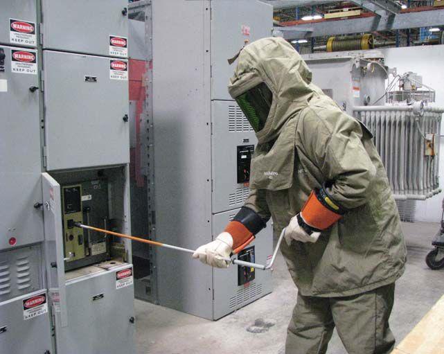

Arc-rated PPE is used to protect workers when exposed to the hazard of arc flash.
The subcommittee is investigating whether this should be a required test.
• Additionally, the arc rating for the hood should be based on the fabric, not the window. This is currently required. Arc-rated windows in hoods can and usually do have ratings well above the arc rating of the fabric portion of the hood.

• The testing of arc-rated hoods had a lot of discussion. Current requirements are for the arc-rated hood to be tested facing the arc. Some companies are also arc testing hoods for exposure to the side of the hood. This can move the fabric against the side of the head, greatly reducing the effectiveness of the hood.

There was also a presentation on different types of arc. Photos taken from videos demonstrated each of the four types:
• Open-air arcs. In-line electrodes produce open-air arcs. These are usually at high voltages.
• Arc-in-a-box. This is at lower voltages and is the basis for IEEE 1584.


• Running or moving arc. This runs down the electrode and is normally found at medium and high voltages.
• Ejected arc. This is an arc on vertical electrodes that jumps off the end, such as stab-connected equipment.

NETAWORLD • 109 ASTM F18 COMMITTEE REPORT
SPECIFICATIONS AND STANDARDS ACTIVITY

Because of the scope of the ASTM F18 Committee, it is important that NETA’s voice is heard. Virtually all electrical protective equipment and clothing is handled by this committee. Utilities and manufacturers make up the bulk of the committee, and sometimes their interests don’t align with NETA’s, so being there and getting firsthand information is especially important.


The information presented here does not represent fun facts. Much of it has importance to NETAmember companies and their workers. The details involved in the design and specifications of this life-critical equipment would not be
known without NETA’s participation on the F18 Committee.


James R. (Jim) White is the Training Director at Shermco Industries in Dallas, Texas. He is the principal member of NFPA Technical Committee Recommended Practice for Electrical Equipment Maintenance (NFPA 70B), represents NETA as an alternate member of NFPA Technical Committee Electrical Safety in the Workplace (NFPA 70E), represents NETA on the ASTM F18 Committee Electrical Protective Equipment for Workers, and is the past Chairman (2008) of the IEEE Electrical Safety Workshop (ESW). Jim is an IEEE Senior Member and in 2011 received the IEEE/PCIC Electrical Safety Excellence Award.



SYSTEMS
• Specifies field tests and inspections used to assess the suitability for initial energization of electrical power equipment and systems.
• References include: ASTM, EASA, ICEA, IEEE, NEMA, NFPA, UL, and others.

PREORDER TODAY! ANSI/NETA ATS-2017
STANDARD FOR ACCEPTANCE TESTING SPECIFICATIONS FOR ELECTRICAL POWER EQUIPMENT &
To order: visit www.netaworld.org, call 888.300.6382, or email neta@netaworld.org New Edition!


The ANSI/NETA ATS, Standard for Acceptance Testing Specifications for Electrical Power Equipment and Systems, 2017 edition, covers suggested field tests and inspections for assessing the suitability for initial energization of electrical power equipment and systems. The purpose of these specifications is to assure that tested electrical equipment and systems are operational, are within applicable standards and manufacturers’ tolerances, and are installed in accordance with design specifications.

The ANSI/NETA ECS, Standard for Electrical Commissioning of Electrical Power Equipment and Systems, 2015 edition, was approved as an American National Standard on December 3, 2014. This standard is available for purchase intheNETABookstoreonlineat in the NETA Bookstore online at www. netaworld.org.


ANSI/NETA STANDARDS UPDATE
The ANSI/NETA ECS describes the systematic process of documenting and placing into service newly installed or retrofitted electrical power equipment and systems. This document shall be used in conjunction with the most recent edition of the ANSI/NETA ATS. The individual electrical components shall be subjected to factory and field tests, as required, to validate the individual components. It is not the intent of these specifications to provide comprehensive details on the commissioning of mechanical equipment, mechanical instrumentation systems, and related components.
Voltage classes addressed include:
• Low-Voltage Systems (less than 1,000 volts)


• Medium-Voltage Systems (greater than 1,000 volts and less than 100,000 volts)


STANDARD

FOR
CERTIFICATION OF ELECTRICALTESTING TECHNICIANS


STANDARD FOR ELECTRICAL COMMISSIONING SPECIFICATIONS F OR ELECTRICALPOWER EQUIPMENT ANDSYSTEMS



• High-Voltage and Extra-High Voltage Systems (greater than 100 kV and less than 1,000 kV)


The ANSI/NETA MTS contains specifications for suggested field tests and inspections available to assess the suitability for continued service and reliability of electrical power equipment and systems. The purpose of these specifications is to assure that tested electrical equipment and systems are operational and within applicable standards and manufacturers’ tolerances, and that the equipment and systems are suitable for continued service.
The ANSI/NETA MTS, Standard for Maintenance Testing Specifications for Electrical Power Equipment and Systems, 2015 edition, was approved as an American National Standard on December 3, 2014, and supersedes the ANSI/NETA MTS-2011. This standard is available for purchase in the NETA Bookstore online at www.netaworld.org

112 • SPRING 2017 ANSI/NETA STANDARDS UPDATES SPECIFICATIONS AND STANDARDS ACTIVITY
GSP ECI F C A T I ONS ANSI/NETA ETT-2015
FORELECTRICALPOWEREQUIPMENT & SYSTEMS STANDARD FOR ACCEPTANCE TESTINGSPECIFICATIONS ANSI/NETA ATS-2017 NEW EDITION





Complete Breakers Trip Units


Electric Operators Shunt trips/UVRs


All Factory New







INSULATED CONDUCTOR COMMITTEE NEWS


 BY RALPH PATTERSON, Consultant
The Insulated Conductors Committee (ICC) is a professional organization within the Power Engineering Society (PES) of the Institute of Electrical and Electronics Engineers (IEEE). From October 30 through November 2, 2016, the working groups, including engineers and scientists, met in Scottsdale, Arizona, for the fall 2016 IEEE/ICC meeting.

This is an ongoing opportunity for NETA, the International Electrical Testing Association, to be recognized and to offer a fieldtesting perspective to the working groups as documents are developed. The working groups are comprised of cable manufacturers, utilities, test equipment manufacturers, and end-users.
Fall 2016 Working Groups/Discussion Groups Meetings for Subcommittee F


F02W Field Testing of Laminated DielectricShieldedPower Dielectric Shielded Power Cable Systems Rated 5 KV and Above (400.1)
F04WPartial Discharge Testing in the Field (P400.3)
F06D Field Testing of DC Extruded Cable Systems
F07DGuide on Neutral Corrosion in MV Underground Cables (1617)


F10D Diagnostic Testing for Cable Joints & Terminations
F11WConstant Voltage AC Field Testing of Cable Systems
F12W Guide for Fault Locating on ShieldedPowerCables Shielded Power Cables

Reviewed latest standard and started working onfirstdraftforrevision on first draft for revision
Larzelere/Rickman
Reviewed applied test voltages and revised latest draft Levine/Walton
Discussed the process forward and identified discrepancies
Larzelere/Rickman
Reviewed proposed revisions by writing groupBuchholz/ Von Herrmann


Viewed presentations and discussed diagnostic testing of cable accessories Jiang/Joy
Discussed content of first draftFenger/Denmon
Reviewed proposed flowchart for fault locating and discussed new CIGRE guidelines Moiser/Vacant

116 • SPRING 2017 INSULATED CONDUCTOR COMMITTEE NEWS SPECIFICATIONS AND STANDARDS ACTIVITY



Up Your Production And Stay In The Game! PQ Analyzers with Remote Wireless Communications 732.287.3680 1000 New Durham Road Edison, New Jersey 08817 Control your Dranetz HDPQ from your smartphone, tablet, or computer! sales@dranetz.com www.dranetz.com ® ® A Company



ENGINEERING SERVICES • TECHNICAL SERVICES • COMMISSIONING Protection Systems Design, Relay Testing (310) 816-3130 131 W F Street Wilmington, CA 90744 Los Angeles Area | | www.youtube.com/tdeinc2 www. twitter.com/tdeinc www.facebook.com/tdeinc www.linkedin.com/company/tony-demaria-electric CA LICENSE #315448 Please visit us at our Tuesday, February 28, 2017 12:00 PM – 6:00 PM
2017 – NEW PRODUCT FORUM
www.aemc.com
Thermal Imaging IR Camera Model 1950
AEMC’s Thermal Imaging IR Camera Model 1950 is equipped with infrared thermography detection technology that is used in sectors of industry as diverse as electrical maintenance, metallurgy and steel making, petroleum, automation, natural gas exploration, transportation, and in other professions such as fire-fighting and surveillance. Infrared thermal imaging provides a real-time non-contact inspection method that does not require you to shut off power, shut down the equipment, or interrupt production. It can diagnose latent malfunctions in advance and anticipate their occurrence and prevent production problems.
The Model1950 is a powerful cost-effective tool for analyzing electrical maintenance issues. It has features typically found in cameras two to three times its price.
www.avotraining.com
Cable U Training Courses
The Study of Electrical Cable Just Got a Lot Smarter
After careful planning, design, and construction, AVO’s Cable U is here. Located in Dallas, it’s designed to accommodate our updated Medium-Voltage Cable Fault Location & Tracing and new Cable Testing & Diagnostics courses. It allows cable technicians the most technologically advanced real-world place for every electrical cable testing and diagnostic application.
Proper training as well as test equipment technology is needed for future cable installations to ensure future-proofing for improved cable reliability. AVO Training continues to meet industry needs by providing comprehensive cable systems training.
www.basler.com
Distance Protection for BE1-11
Multifunction Protective Relaying System
Basler Electric is pleased to announce the latest addition to its BE1-11 Multifunction Protective Relaying system. Distance protection is now available in our BE1-11f and BE1-11t versions for feeder and transformer protection applications. The BE1-11f includes distance (21), volts/Hz (24), and directional power (32) protection; the BE1-11t includes distance (21), sync-check (25), and reclosing (79) functions. These optional features add to an already extensive number of protection functions and, as with all Basler products, use our BESTCOMSPlus® PC software for simple, easy, and trouble-free setup.
www.bcsswitchgear.com
Spring Charge Motors
BCS Switchgear now offers new replacement spring-charge motors for several different brands and types of low-voltage and medium-voltage circuit breakers. Some of the breakers include Westinghouse/Square D DS and DSII circuit breakers, Siemens GMI, Westinghouse/Cutler Hammer VCPW, GE Power Break, AKR, and Wave pro. These spring-charge motors are in stock and can be shipped same day of request. These competitively priced spring-charge motors will be backed by BCS Switchgear’s one-year full-replacement guarantee. Come see us at booth #427
www.doble.com
EMI Surveyor
Doble’s EMI Surveyor is a non-invasive, in-service survey solution that can identify more than 70 different electrical and mechanical defects in generators, motors, bus duct systems, transformers, switchgear, cable terminations, and other highvoltage equipment. This tool kit will detect problems such as partial discharge, corona, arcing, and sparking. The EMI Surveyor will help identify problem areas, giving you the information needed to conduct efficient off-line inspections and reduce the risk of system failures.
The EMI Surveyor kit comes with the spectrum analyzer, EMI sniffer, split-core high-frequency current transformer, wireless synchronization adapter, and the antennae and cables needed for a complete EMI assessment.
120 • SPRING 2017 NEW PRODUCT FORUM
www.electrorent.com
New Rental Inventory
Established in 1965, Electro Rent Corporation adds new products to its rental inventory every month. Recent additions include Vacuum Interrupters’ MAC-TS4 and RF System’s 3.9mm and 6.9mm borescope. Electro Rent has opened a stocking center in Houston, Texas. Electro Rent’s calibration lab is A2LA ISO/IEC 17025:2005 certified to ensure your equipment is calibrated correctly when you receive it. For daily and monthly test equipment rentals, please call our experienced staff at 800.688.1111 (USA) or 800.268.0216 (Canada). Email us at sales@electrorent.com.
www.geindustrial.com
GE IEEE Medium-Voltage SecoVac®Retrofill Vacuum Circuit Breaker
GE’s IEEE medium-voltage SecoVac®Retrofill vacuum circuit breaker is designed to easily replace vacuum circuit breakers in existing switchgear. It is a streamlined solution to update legacy circuit breakers with smart design features such as a simplified mechanism, which reduces maintenance times for customers. This advanced design demonstrates GE’s engineering strength in the latest circuit breaker and insulation technology. SecoVac®Retrofill vacuum circuit breakers are rated 5kV - 15kV; 1200A - 2000A; 31.5 - 40kA; 50Hz/60Hz.
www.groupcbs.com MAC-TS5+
Co-developed by Group CBS and Vacuum Interrupters, Inc., the magnetron atmospheric condition (MAC) family of predictive vacuum interrupter test sets has been warmly received by the electrical industry with 100-plus sets in service today. Group CBS is proud to announce the next-generation MAC test set: the MAC-TS5+. The MAC-TS5+ combines the functionality of a standalone 75 kV DC hipot test set with predictive MAC testing. Taken together, technicians can quickly perform a fiveyear vacuum integrity verification or a go/no-go test to confirm vacuum interrupter integrity today while ensuring the device’s remaining life is greater than five years with MAC testing.
www.halcotestingservices.com PD-SGS Blue
Halco Testing introduces the IPEC PD-SGS Blue, a dualtransducer partial discharge (PD) detector for switchgear, with mobile data synchronization. PD-SGS Blue will detect Transient Earth Voltage (TEV) signals as well as detect acoustic (AE) partial discharge on the surface of high-voltage insulators before failure occurs. Its Automatic Noise Rejection algorithm eliminates false positives and will send PD alerts live from the site. Data is stored remotely to a central server and can also be accessed from any mobile device for display, synchronization, and analysis.
www.hiokiusa.com
PQ3100
Power Quality Analyzer
The new Hioki PQ3100 power quality analyzer provides a costeffective yet full-featured approach to reliable power analysis. It provides single-phase two-wire to three-phase four-wire (including neutral phase) measurement for simultaneous AC/DC power parameter trending along with power anomaly capture capability. Voltage and current harmonics are also included as part of the parameter trending data. Quickset function walks the user through a four- step connection to recording process. The newly designed AC/DC auto zero current sensors are powered by the PQ3100, eliminating the need for external sensor power supplies. Remote control and FTP data transfer is accomplished through a LAN connection. To facilitate the use of the unit, specially configured kits provide a main unit with rechargeable battery, AC adapter, voltage test leads, 8GB SD memory card, four AC/DC current sensors, and PQ One power quality analysis software in a hard carrying case.
www.hvtechnologies.com
PD-TaD 60 BAUR Portable PD Diagnostics Systems
HV Technologies pioneers technology in the field of parallel diagnostics for medium-voltage cable systems. Together with a VLF generator, the PD-TaD 60 can be used to localize partial discharge sources along a cable. In combination with a VLF generator with integrated tan delta measurement function, the PD-TaD 60 can also be used to simultaneously measure PD and tan delta safely and efficiently. The advantages lie in maximizing the amount of diagnostics that can be conducted in the shortest amount of time. This helps to detect hidden faults and reduces the costs of testing your cable systems.
NETAWORLD • 121 NEW PRODUCT FORUM
NEW PRODUCT FORUM
2017 –
www.iriss.com
E-Sentry Connect
2017 – NEW PRODUCT FORUM
The E-Sentry Connect is our next generation intuitive asset information tagging system. The E-Sentry Connect system utilizes Near Field Communication Smart Card technology that allows smartphone devices with NFC to easily access critical data relating to the equipment being inspected and also save up-todate inspection data directly to the asset’s E Sentry Connect tag via a free IRISS App.
The E-Sentry Connect system has been designed to be operated on two platforms: a standalone system and a subscription-based cloud system allowing historical data back-up and complete access to the current status of all assets utilizing E-Sentry Connect tags.
www.morganschaffer.com
New Lab Services and Products – Lab Introduction Kit and New Oil Standards
Morgan Schaffer is pleased to offer several new and exciting lab services and products. Our lab introduction kit contains all you need to order a free oil analysis from Morgan Schaffer’s lab. Alternatively, you can request a free validation kit to compare your lab’s results with our lab’s analysis of your oil samples. Accuracy is everything.
Morgan Schaffer is also proud to offer two new oil standards: True North standards in silicone oil and True North standards in natural esters oil, which complete our range of True North DGA oil standards ensuring credibility, accuracy, efficiency, and cost savings backed by our superior technical support.
www.madisontesting.com
MadTest Instruments DMS4i1
The MadTest Instruments DSM4i1 is a multi-function adapter that addresses different families of trip units from Cutler Hammer in an all-in-one device. The adapter is designed be used in conjunction with the 140D481G03 Cutler Hammer or Westinghouse Amptector base unit. It performs four functions: it tests the Magnum trip units and the DS/DSII family of trip units, offers as a 32VDC power supply and a fused 120VAC outlet, and is sold with an 1150 Pelican case.
www.ofilsystems.com DayCor®LuminarHD
Ofil introduces DayCor® LuminarHD, the most enhanced corona camera that corresponds with an inspector’s need for ACCURACY, PERFORMANCE and SIMPLICITY. The outstanding features of the LuminarHD corona camera are
• Highest sensitivity to UV signals of corona due to the implemented proprietary DayCor® technology
• Highest resolution sun-readable WVGA LCD with 1000 cd/ m2
• Full high-definition video camera
• Comprehensive data collection of corona, position, and ambient conditions affixed to the recorded media
www.megger.com
MWA300
The Megger MWA300 delivers a powerful solution for measuring ratio + winding resistance safely and faster than traditional methods. It features a single control interface for both functions and a 12-inch color touch screen. Testing is made simpler through a combined test form as well as a single universal Kelvin clip lead set. It’s built-in thermal printer, USB port, and Ethernet ports allow you to get your data the way you want it. The new MWA300 gives you the tools you need to power on.
• Interface to coronaWise soft ware with automated data transfer and storage, supporting data management approach
• Extra-care ergonomic design
DayCor® LuminarHD guarantees an excellent user working experience
122 • SPRING 2017 NEW PRODUCT FORUM
www.phenixtech.com
Model MRM-200
PHENIX Technologies’ model MRM-200 is used to measure very low contact resistances of breakers, switches, busbars, motors, and generators, or it can be used for any application where low-resistance current is required. The model MRM-200 has five 200 A, true DC test current, is microprocessor controlled, has an easy-to-read digital display, and uses the 4-wire Kelvin measurement method. It includes a separate cable/accessory case and is IEC safety compliant.
Our top-of-the-line Micro-Ohm Meter, the model MRM-200, includes software, built-in memory, automatic report generator, and report print-out via external printer.
www.pdservice.com
New Online Monitoring Service
Based on the success model of PDCare, this On-line Monitoring Service is further extended to cover on-site measurement, meaning one system can now cover both time-based maintenance and condition-based monitoring in the most cost-effective way. The instrument is good for on-site measurement, and is able to transform into a permanent monitoring device at anytime and anywhere. This concept benefits customers who are seeking an economical solution and/or customers who request PD analysis service.
2017 – NEW PRODUCT FORUM
www.powermdt.com
PDiSmart Sensor Series
PMDT’s New PDiSmart Sensor Series is the latest cuttingedge, online PD testing technology developed by PMDT to autonomously sample PD signals wirelessly from MV and HV equipment. UHF, HFCT, TEV, AE, and ultrasonic extended-life battery-powered wireless sensors are utilized to autonomously record PRPD-2D & PRPS-3D spectrums every 24 hours. The data is periodically collected wirelessly and uploaded to our PCbased software or the Intelligent Cloud Server for diagnostics and analysis.
This PD testing system is truly OLPD made simple. It is designed to solve the Restricted Approach Boundary in NFPA 70E 2015. 130.8
www.powergridengineering.com
Relay Commissioning
103 Seminar
Power Grid Engineering’s Relay Commissioning 103 Seminar is geared toward answering fundamental questions about Field Commissioning of Protection and Control Equipment. This class is beneficial for hands-on field technicians, new protection and control engineers, and other utility company staff that want to know more about field testing. This class assumes knowledge of topics covered in Power Systems 101 and 102 Relay Philosophies.
www.protecequip.com
New Locations - Calibration Labs
Protec is an electrical test equipment rental company that primarily rents out electrical test equipment used in power generation. We have equipment locations in six different cities: Reno, Dallas, Houston, Chicago, Atlanta, and New York. We have a calibration lab in Dallas that services equipment for customers with a one-week turnaround time. We also now offer a calibration lab in the Midwest in our Chicago location.
If you would like more information on how we can be of service, visit us at booth # 201, and come listen to our spotlight presentation where you can get any questions answered.
www.smcint.com
Raptor 3 Phase
SMC is proud for PowerTest to be the first show to witness another innovation in the continuing evolution of the Raptor test system. Raptor 3 Phase is the first of its kind in the world market allowing new applications like BUS differential testing, substation commissioning, and breaker testing, all in a threephase fashion which drastically reduces test time and system errors while increasing safety.
All current Raptor owners will only need to download a new template and obtain the Raptor 3PH Controller to get going. RAPTOR SYSTEM is a must for the testing arena.
NETAWORLD • 123 NEW PRODUCT FORUM
www.soneltest.com
2017 – NEW PRODUCT FORUM
New Office Location and KT-series of Thermal Imaging Cameras
Sonel Test & Measurement, a manufacturer of electrical testing instruments, is pleased to announce its new office in Santa Clara, California. Sonel offers a range of test equipment for measuring ground resistance, insulation resistance, energy, power quality, thermal imaging, plus cable locators. Sonel will be showcasing the new KT-series of thermal imaging cameras with resolutions up to 640 x 480 pixels, articulating lenses, and wireless communications. Also on show will be the MIC range of insulation resistance meters for 1kV, 2.5 kV, 5kV, and 10kV testing. Sonel equipment is also available for rent.
www.vacuumreplacementinterrupters.org
New Vacuum Replacement Interrupters for the GE Line of Vacuum Breakers and Pressure Test Set
VRI is proud to announce its new Vacuum Replacement Interrupters for the GE line of vacuum breakers. Products include: Outdoor PVDB1 5-15 kv; Indoor VVC, PVVL, VB and VB1 Vacuum Circuit Breakers, ranging from 5-15kv, 12002000 amp. These interrupters are ANSI C.37 rated and are dropin replacement vacuum interrupters. VRI also has the newest Vacuum Interrupter Pressure Test Set (VIP-TS-1) that uses the Paschen’s Law and Paschen’s Curve to determine the life of your vacuum interrupters.
www.uesystems.com
Ultraprobe 15000
Your electrical equipment is speaking to you. Can you hear it? Ionization-based electrical faults such as corona, tracking, and arcing produce high frequency sound. The Ultraprobe 15000 from UE Systems allows you to hear any potential electrical fault prior to opening the energized electrical equipment. For further diagnostics, the sound can be recorded and analyzed in the included spectrum analysis software. Corona, tracking, and arcing have signature characteristics in both the spectrum and time series view, and therefore the fault can be diagnosed. Reduce the risk of arc flash by listening prior to opening.
www.utilityrelay.com
QT-Display-II
The QT-Display-II is an advanced door-mounted display for use with the AC-PRO-II trip unit. The QT-Display-II brings increased safety, convenience, and communications capabilities to a low-voltage circuit breaker. It includes an OLED display, a Quick-Trip switch and LED for arc-flash reduction, Ethernet & RS-485 communications, a USB port, alarm relays, and more.
In addition to including the Quick-Trip system, the QTDisplay-II extends all AC-PRO-II information to the cubicle door, eliminating the need to enter the breaker compartment to access the trip unit. The included Ethernet port allows for faster modbus communications, and the USB port can be used with our free InfoPro software, as well as our Safe-T-Trip device.
The VIP-TS-1 also makes it possible to test VIs in house and to test your vacuum interrupters in the field with the VIs still on the breaker. It will test almost all 5-15kv vacuum circuit breakers in the market with VIs still installed on the breaker. Come see us at booth #522.
www.weidmann-electrical.com InsuLogix® VAULT
WEIDMANN introduces the InsulLogix® VAULT – the most advanced and secure solution for your transformer against the threat of cyber attack. As the modern world becomes increasingly wired, more critical systems and infrastructure are linked via the internet. While that has given rise to incredible new technology efficiency and capability, it has also meant that more countries are vulnerable to hacking and cyber attack.
The InsuLogix® VAULT is a state-of-the-art transformer controller and monitoring integrator designed to meet the pending U.S. NERC CIP cyber security requirements for grid devices, providing a platform to monitor a utility’s entire fleet.
124 • SPRING 2017 NEW PRODUCT FORUM


No.117 No. 117

ANSWERS
1. a. IEEE Std. 400 covers a variety of cable tests and the interpretation of the test results.


2. a. IEEE Std. 400.2 specifically covers tangent delta testing.
3. c. A withstand test puts the power cable under stress over a specified time period. The purpose of the withstand test is to cause the cable to fail if it has defects. Th is may sound stupid, but it is much better for the cable to fail during a limited power test situation than to have it fail fully loaded. The damage caused by a test failure is significantly less than during normal operation.
4. b. Power cable dc testing was the way to go for laminated cable construction such as paper-insulated, lead-covered (PILC) cable. When cable construction moved to extruded dielectrics and polymers, the high-voltage dc testing had negative effects on service-aged polymers such as polyethylene (PE), cross-linke d polyethylene (XLPE), and ethylene propylene rubber (EPR) cable. EPRI research proved high-voltage dc testing causes deterioration of service-aged cables. That is why modern acceptance of highvoltage dc testing is only for initial (pre-energization) tests or maintenance tests up to the fifth year of a cable’s service life. Beyond the fifth year of service life, it is recommended to use very-low-frequency (VLF) or 0.1 Hz testing, which is an ac test and does not have the negative attributes of dc.

5. The four common diagnostic tests that can be performed using a tan-delta test set are:
a. VLF-TD (VLF tangent delta measurement)
b. VLF-DTD (VLF differential tangent delta measurement)

c. VLF-TDTS (VLF tangent delta temporal stability)
d. VLF-DS (VLF spectroscopy) — it is debatable whether this is a common test. It looks at tan-delta over a frequency spectrum from around 0.01 Hz up to 1 Hz. It is very rarely used, but in theory, is designed to uncover the degree of moisture in a dielectric.
6. The components shown are:
a. Capacitive current – IC
b. Loss (resistive) current – IR
c. Total current – IT
d. Applied test voltage
e. Cosine of the angle – Ɵ
f. Tangent of the angle – δ
Although Jim White is a member of the NFPA Technical Committee for both NFPA 70E, Standard for Electrical Safety in the Workplace, and NFPA 70B, Recommended Practice for Electrical Equipment Maintenance, the views and opinions expressed in this column are purely the author’s and shall not be considered an official position of the NFPA or any of its technical committees and shall not be considered, nor be relied upon, as a formal interpretation or promotion of the NFPA. Readers are encouraged to refer to the entire text of all referenced documents.
TECH QUIZ ANSWERS
TECHQUIZ
126 • SPRING 2017








A FULL SERVICE NETA ACCREDITED ELECTRICAL TESTING COMPANY. Serving the Sacramento and San Francisco Bay Area 916-853-6280 www.apparatustesting.com • Acceptance Testing • Commissioning • Maintenance Testing • High Voltage Substations • Short Circuit and Coordination Studies • Data Centers and UPS Systems
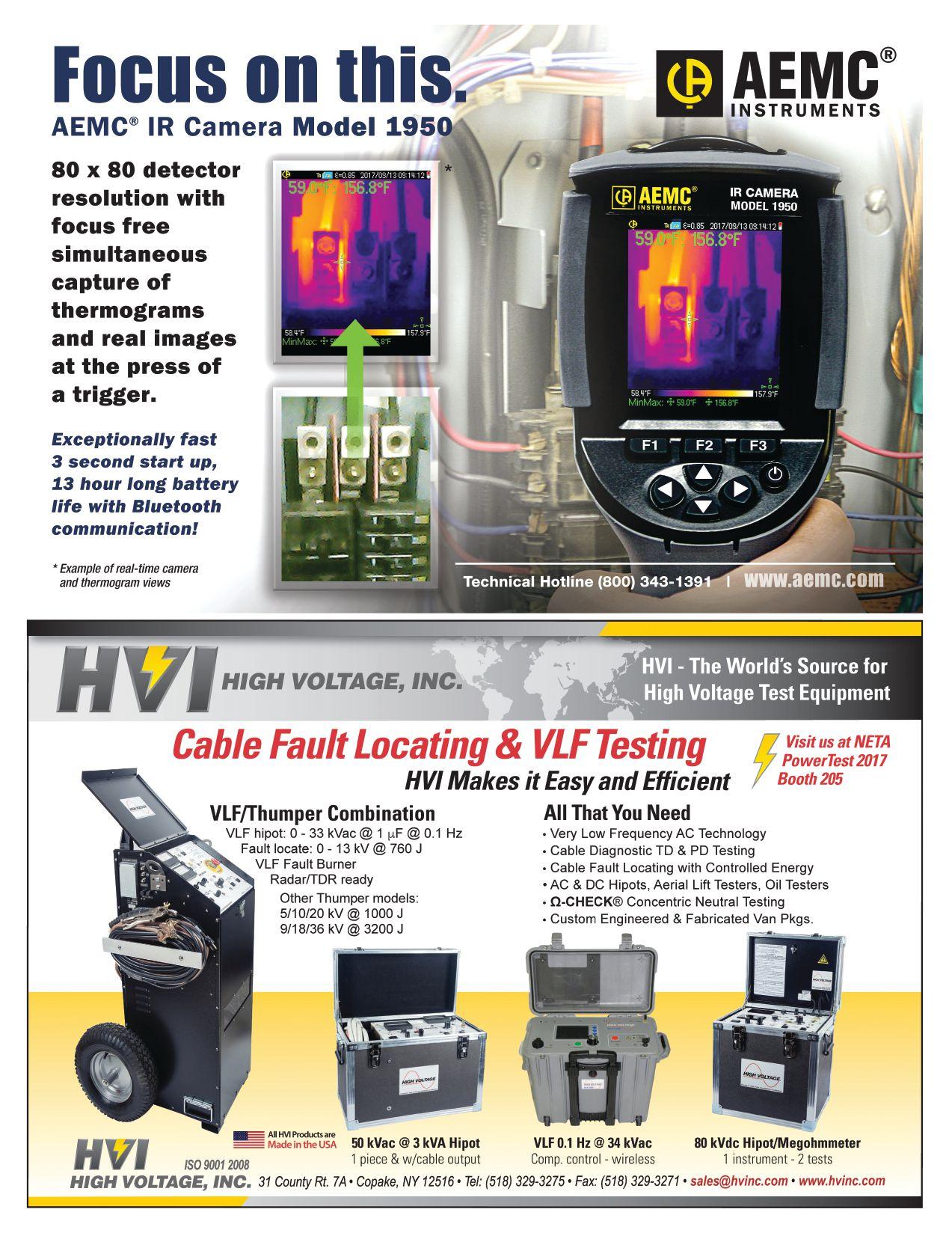


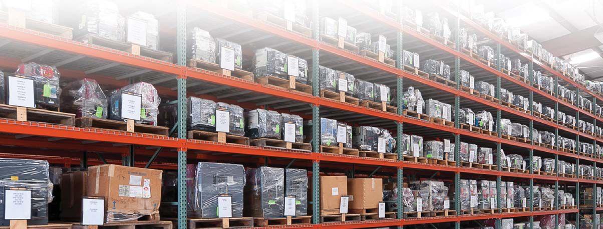
Independent Electrical Testing and Preventive Maintenance PROFESSIONAL SERVICES 609-890-8300 www.easternhighvoltage.com If you need electrical equipment, tap into the power of National Switchgear’s massive inventory. With millions of products, we offer a huge selection of new, surplus and repurposed circuit breakers, switchgear and related equipment. And it’s all easy to order on our website. Go to nationalswitchgear.com today to see our powerful array of solutions. 800-322-0149 THE POWER OF OUR INVENTORY. VISIT US AT POWERTEST BOOTH 231
NETA ACCREDITED COMPANIES Setting the
A&F Electrical Testing, Inc.
80 Lake Ave. South, Ste. 10 Nesconset, NY 11767 (631) 584-5625 Fax: (631) 584-5720 kchilton@afelectricaltesting.com www.afelectricaltesting.com
Kevin Chilton
A&F Electrical Testing, Inc.
80 Broad St. 5th Floor
New York, NY 10004 (631) 584-5625 Fax: (631) 584-5720 afelectricaltesting@afelectricaltesting.com
Florence Chilton
ABM Electrical Power Solutions
3602 East Southern Ave., Ste. 1 Phoenix, AZ 85040 (602) 722-2423 www.ABM.com
Doug Bukowski
ABM Electrical Power Solutions
9800 E. Geddes Avenue, Unit A-150 Englewood, CO 80112 (303) 524-6560 Fax: (303) 524-6581
Brian Smith
ABM Electrical Power Solutions
2142 Rheem Drive Pleasanton, CA 94588 (408) 466-6920
John Marvulli
ABM Electrical Power Solutions
3940 Ruffin Rd., Ste. C San Diego, CA 92123 (858) 754-7963
william.mckenzie@abm.com
William McKenzie
ABM Electrical Power Solutions
6280 South Valley View Blvd., Ste. 618 Las Vegas, NV 89118 (602) 300-2188 Fax: (602) 437-3894
Jason Black
ABM Electrical Power Solutions
814 Greenbrier Circle, Ste. E Chesapeake, VA 23320 (757) 548-5690 Fax: (757) 548-5417
Mark Anthony Gaughan, III
ABM Electrical Power Solutions
3700 Commerce Dr. #901-903 Baltimore, MD 21227 (410) 247-3300 Fax: (410) 247-0900
Bill Hartman
ABM Electrical Power Solutions
5809 Departure Dr., Ste. 104 Raleigh, NC 27616 (919) 877-1008 Fax: (919) 501-7492
Rob Parton
ABM Electrical Power Solutions
317 Commerce Park Dr. Cranberry Township, PA 16066-6427 (724) 772-4638 Fax: (724) 772-6003
christopher.smith@abm.com
Christopher Smith
ABM Electrical Power Solutions
4390 Parliament Place, Ste. S Lanham, MD 20706 (301) 967-3500 Fax: (301) 735-8953
Frank Ceci
ABM Electrical Power Solutions
3600 Woodpark Blvd., Suite G Charlotte, NC 28206 (704) 273-6257 Fax: (704) 598-9812 ernest.goins@abm.com
Ernest Goins
ABM Electrical Power Solutions
720 S. Rochester Ave., Suite A Ontario, CA 91761 (800) 597-1225 Fax: (909) 937-6798
Mike Bivens
Absolute Testing Services 6829 Guhn Rd. Houston, TX 77040 (832) 467-4446 Fax: (713) 849-3885 rgamble@absolutetesting.com www.absolutetesting.com
Richard Gamble
Accessible Consulting Engineers, Inc. 1269 Pomona Rd., Ste. 111 Corona, CA 92882 (951) 808-1040 info@acetesting.com www.acetesting.com Iraj Nasrolahi
Advanced Testing Systems 15 Trowbridge Dr. Bethel, CT 06801 (203) 743-2001 Fax: (203) 743-2325 pmaccarthy@advtest.com www.advtest.com Pat MacCarthy
American Electrical Testing Co., Inc. 25 Forbes Blvd., Ste. 1 Foxboro, MA 02035 (781) 821-0121 Fax: (781) 821-0771 sblizard@aetco.us www.aetco.us
Scott A. Blizard
American Electrical Testing Co., Inc. 34 Clover Dr. South Windsor, CT 06074 (860) 648-1013 Fax: (781) 821-0771 jpoulin@aetco.us
Gerald Poulin
American Electrical Testing Co., Inc. 76 Cain Dr. Brentwood, NY 11717 (631) 617-5330 Fax: (631) 630-2292 bfernandez@aetco.us
Billy Fernandez
American Electrical Testing Co., Inc. 50 Intervale Rd., Ste. 1 Boonton, NJ 07005 (973) 316-1180 Fax: (781) 316-1181 jsomol@aetco.us
Jeff Somol
American Electrical Testing Co., Inc. Green Hills Commerce Center 5925 Tilghman St., Ste. 200 Allentown, PA 18104 (215) 219-6800 jmunley@aetco.us
Jonathan Munley
American Electrical Testing Co., Inc. 12566 W. Indianola Ave. Avondale, AZ 85392 (480) 383-9242 dmadaglia@aetco.us
Donald Madaglia
AMP Quality Energy Services, LLC 4220 West Schrimsher SW Site W1 P.O. Box 526, Huntsville, AL 35804 (256) 513-8255
Brian Rodgers
Apparatus Testing and Engineering 11300 Sanders Dr., Ste. 29 Rancho Cordova, CA 95742 (916) 853-6280 Fax: (916) 853-6258 info@apparatustesting.com www.apparatustesting.com
Harold (Jerry) Carr
Apparatus Testing and Engineering 7083 Commerce Circle, Ste. H Pleasanton, CA 94588 (925) 454-1363 Fax: (925) 454-1499
Applied Engineering Concepts 1105 N. Allen Ave. Pasadena, CA 91104 (626) 398-3052 Fax: (626) 398-3053 michel.c@aec-us.com www.aec-us.com
Michel Castonguay
BEC Testing
50 Gazza Blvd. Farmingdale, NY 11735 (516) 531-9136 Fax: (631) 249-6115 wfernandez@banaelectric.com www.bectesting.com
William Fernandez
Burlington Electrical Testing Co., Inc.
300 Cedar Ave. Croydon, PA 19021-6051 (215) 826-9400 (221) Fax: (215) 826-0964 waltc@betest.com www.betest.com
Walter P. Cleary
C.E. Testing, Inc. 6148 Tim Crews Rd. Macclenny, FL 32063 (904) 653-1900 Fax: (904) 653-1911 cetesting@aol.com
Mark Chapman
CE Power Engineered Services, LLC 4040 Rev Dr. Cincinnati, OH 45232 (513) 563-6150 Fax: (513) 563-6120 info@cepowersol.net www.cepower.net
Brent McAlisar
CE Power Engineered Services, LLC 8490 Seward Road Fairfield, OH 45011 (513) 563-6150 tim.lana@cepower.net
Tim Lana
CE Power Engineered Services, LLC 10338 Citation Drive, Suite 300 Brighton, MI 48166 (810) 229-6628
Ken L'Esperance
CE Power Engineered Services, LLC 1803 Taylor Avenue Louisville, KY 40213 (502) 479-0612 tom.hutchinson@cepower.net
Tom Hutchinson
CE Power Engineered Services, LLC 10840 Murdock Drive Knoxville, TN 37932 (865) 310-2522 don.williams@cepower.net
Don Williams
CE Power Engineered Services, LLC 7674 Washington Ave. S Eden Prairie, MN 55344 (877) 968-0281
jason.thompson@cepower.net
Jason Thomps
Control Power Concepts
353 Pilot Rd; Ste. B Las Vegas, NV 89119 (702) 448-7833 Fax: (702) 448-7835 www.controlpowerconcepts.com
John Travis
NETA ACCREDITED COMPANIES
Standard
130 • SPRING 2017
Dude Electrical Testing LLC
145 Tower Dr., Unit# 9 Burr Ridge, IL 60527 (815) 293-3388 Fax: (815) 293-3386
scott.dude@dudetesting.com www.dudetesting.com
Scott Dude
DYMAX Service, LLC
46918 Liberty Dr. Wixom, MI 48393 (248) 313-6868 Fax: (248) 313-6869 www.dymaxservice.com
Bruce Robinson
DYMAX Service, LLC
4213 Kropf Ave. Canton, OH 44706 (330) 484-6801 Fax: (740) 333-1271
Chuck Baker
Eastern High Voltage, Inc.
11A South Gold Dr. Robbinsville, NJ 08691-1606 (609) 890-8300 Fax: (609) 588-8090 bobwilson@easternhighvoltage.com www.easternhighvoltage.com
Robert Wilson
ELECT, P.C.
7400-G Siemens Rd., P.O. Box 2080 Wendell, NC 27591 (919) 365-9775 Fax: (919) 365-9789 btyndall@elect-pc.com www.elect-pc.com
Barry W. Tyndall
Electric Power Systems, Inc. 21 Millpark Ct. Maryland Heights, MO 63043 (314) 890-9999 Fax: (314) 890-9998 www.epsii.com
Electric Power Systems, Inc. 557 E. Juanita Ave., #4 Mesa, AZ 85204 (480) 633-1490 Fax: (480) 633-7092
Electric Power Systems, Inc. 4436 Parkway Commerce Blvd. Orlando, FL 32808 (407) 578-6424 Fax: 407-578-6408
Electric Power Systems, Inc.
7000 E. 47th Avenue Drive, Suite 100 Denver, CO 80216 (720) 857-7273 Fax: 303-928-8020
Electric Power Systems, Inc. 23823 Andrew Rd. Plainfield, IL 60585 (815) 577-9515 Fax: (815) 577-9516
Electric Power Systems, Inc.
2601 Center Rd., # 101 Hinckley, OH 44233 (330) 460-3706 Fax: (330) 460-3708
Electric Power Systems, Inc.
56 Bibber Pkwy #1 Brunswick, ME 04011 (207) 837-6527
Electric Power Systems, Inc.
4100 Greenbriar Dr., Ste. 160 Stafford, TX 77477 (713) 644-5400
Electric Power Systems, Inc. 11861 Longsdorf St. Riverview, MI 48193 (734) 282-3311
Electric Power Systems, Inc.
827 Union St., Salem, VA 24153 (540) 375-0084 Fax: (540) 375-0094
Electric Power Systems, Inc. 915 Holt Ave., Unit 9 Manchester, NH 03109 (603) 657-7371 Fax: 603-657-7370
Electric Power Systems, Inc.
146 Space Park Dr. Nashville, TN 37211 (615) 834-0999 Fax: (615) 834-0129
Electric Power Systems, Inc. 8515 Cella Alameda NE, Ste. A Albuquerque, NM 87113 (505) 792-7761
Electric Power Systems, Inc. 7140 Dean Martin Drive, Suite 900 Las Vegas, NV 89118 (702) 815-1342
Electric Power Systems, Inc. 319 US Hwy. 70 E, Unit E Garner, NC 27529 (919) 322-2670 www.epsii.com
Electric Power Systems, Inc. 1090 Montour West Industrial Blvd. Coraopolis, PA 15108 (412) 276-4559
Electric Power Systems, Inc. 6141 Connecticut Ave. Kansas City, MO 64120 (816) 241-9990 Fax: (816) 241-9992
Electric Power Systems, Inc. 2495 Boulevard of the Generals Norristown, PA 19403 (610) 630-0286
NETA ACCREDITED COMPANIES
Electric Power Systems, Inc. 1129 East Hwy. 30 Gonzalez, LA 70817 (225) 644-0150 Fax: (225) 644-6249
Electric Power Systems, Inc. 7925 Dunbrook Rd., Ste. G San Diego, CA 92126 (858) 566-6317
Electric Power Systems, Inc. 6679 Peachtree Industrial Dr. Ste. H Norcross, GA 30092 (770) 416-0684 j.cash@epsii.com
Jeff Cash
Electrical & Electronic Controls 6149 Hunter Rd. Ooltewah, TN 37363 (423) 344-7666 (23) Fax: (423) 344-4494 eecontrols@comcast.net
Michael Hughes
Electrical Energy Experts, Inc. W129N10818, Washington Dr. Germantown, WI 53022 (262) 255-5222 Fax: (262) 242-2360 bill@electricalenergyexperts.com www.electricalenergyexperts.com
William Styer
Electrical Equipment Upgrading, Inc. 21 Telfair Place, Savannah, GA 31415 (912) 232-7402 Fax: (912) 233-4355 kmiller@eeu-inc.com www.eeu-inc.com
Kevin Miller
Electrical Maintenance & Testing Inc. 12342 Hancock St., Carmel, IN 46032 (317) 853-6795 Fax: (317) 853-6799 info@emtesting.com www.emtesting.com
Brian K. Borst
Electrical Reliability Services 1057 Doniphan Park Circle, Ste. A El Paso, TX 79922 (915) 587-9440 Fax: (915) 587-9010 www.electricalreliability.com
Electrical Reliability Services 1775 W. University Dr., Ste. 128 Tempe, AZ 85281 (480) 966-4568 Fax: (480) 966-4569
Electrical Reliability Services 1426 Sens Rd. Ste. 5 Houston, TX 77571 (281) 241-2800 Fax: (281) 241-2801
Electrical Reliability Services 4099 SE International Way, Ste. 201 Milwaukie, OR 97222-8853 (503) 653-6781 Fax: (503) 659-9733
Electrical Reliability Services 5909 Sea Lion Place, Ste. C Carlsbad, CA 92010 (858) 695-9551
Electrical Reliability Services 8500 Washington Pl. NE, Ste. A-6 Albuquerque, NM 87113 (505) 822-0237 Fax: (505) 822-0217
Electrical Reliability Services 1380 Greg Street, Ste. 216 Sparks, NV 89431 (775) 746-8484 Fax: (775) 356-5488
Electrical Reliability Services 2275 Northwest Pkwy SE, Ste. 180 Marietta, GA 30067 (770) 541-6600 Fax: (770) 541-6501
Electrical Reliability Services 7100 Broadway, Ste. 7E Denver, CO 80221-2915 (303) 427-8809 Fax: (303) 427-4080
Electrical Reliability Services 400 N.W. Capital Dr. Lee's Summit, MO 64086 (816) 525-7156 Fax: (816) 524-3274
Electrical Reliability Services 6900 Koll Center Parkway, Ste. 415 Pleasanton, CA 94566 (925) 485-3400 Fax: (925) 485-3436
Electrical Reliability Services 10606 Bloomfield Ave. Santa Fe Springs, CA 90670 (562) 236-9555 Fax: (562) 777-8914
Electrical Reliability Services 3535 Emerson Parkway, Ste. A Gonzales, LA 70737 (225) 755-0530 Fax: (225) 751-5055
Electrical Reliability Services 245 Hood Rd. Sulphur, LA 70665 (337) 583-2411 Fax: (337) 583-2410
Electrical Reliability Services 11000 Metro Pkwy., Ste. 30 Ft. Myers, FL 33966 (239) 693-7100 Fax: (239) 693-7772
Electrical Reliability Services 2222 West Valley Hwy. N., Ste 160 Auburn, WA 98001 (253) 736-6010 Fax: (253) 736-6015
NETA ACCREDITED COMPANIES
Setting the Standard NETAWORLD • 131
NETA ACCREDITED COMPANIES Setting the
Electrical Reliability Services
9736 South Sandy Pkwy 500 West Sandy, UT 84070 (801) 975-6461
Electrical Reliability Services
6351 Hinson St., Ste. B Las Vegas, NV 89118 (702) 597-0020 Fax: (702) 597-0095
Electrical Reliability Services
9636 St. Vincent, Unit A Shreveport, LA 71106 (318) 869-4244
Electrical Reliability Services
610 Executive Campus Dr. Westerville, OH 43082 (877) 468-6384 Fax: (614) 410-8420 info@electricalreliability.com
Electrical Testing and Maintenance Corp.
3673 Cherry Rd., Ste. 101 Memphis, TN 38118 (901) 566-5557 r.gregory@etmcorp.com www.etmcorp.net
Ron Gregory
Electrical Testing, Inc.
2671 Cedartown Hwy. Rome, GA 30161-6791 (706) 234-7623 Fax: (706) 236-9028 steve@electricaltestinginc.com www.electricaltestinginc.com
Electrical Testing Solutions
2909 Green Hill Ct. Oshkosh, WI 54904 (920) 420-2986 Fax: (920) 235-7136 tmachado@electricaltestingsolutions.com www.electricaltestingsolutions.com Tito Machado
Elemco Services, Inc. 228 Merrick Rd. , Lynbrook, NY 11563 (631) 589-6343 Fax: (631) 589-6670 courtney@elemco.com www.elemco.com
Courtney Gallo
EnerG Test
204 Gale Lane Bldg. 2 - 2nd Floor Kennett Square, PA 19348 (484) 731-0200 Fax: (484) 713-0209 kbleiler@energtest.com www.energtest.com
Katie Bleiler
Energis High Voltage Resources, Inc. 1361 Glory Rd. Green Bay, WI 54304 (920) 632-7929 Fax: (920) 632-7928
info@energisinc.com www.energisinc.com
Mick Petzold
EPS Technology
29 N. Plains Hwy., Ste. 12 Wallingford, CT 06492 (203) 679-0145 www.eps-technology.com
Grounded Technologies, Inc.
10505 S. Progress Way, Ste. 105 Parker, CO 80134 P-(303) 781-2560 F- (303) 781-5240 jodymedina@groundedtech.com www.groundedtech.com
Jody Medina
Grubb Engineering, Inc. 3128 Sidney Brooks San Antonio, Tx 78235 (210) 658-7250 Fax: (210) 658-9805 joy@grubbengineering.com www.grubbengineering.com
Robert D. Grubb Jr.
Hampton Tedder Technical Services 4571 State St. Montclair, CA 91763 (909) 628-1256 x214 Fax: (909) 628-6375 matt.tedder@hamptontedder.com www.hamptontedder.com
Matt Tedder
Hampton Tedder Technical Services 4920 Alto Ave. Las Vegas, NV 89115 (702) 452-9200 Fax: (702) 453-5412
Roger Cates
Hampton Tedder Technical Services 3747 West Roanoke Ave. Phoenix, AZ 85009 (480) 967-7765 Fax: (480) 967-7762
Harford Electrical Testing Co., Inc. 1108 Clayton Rd. Joppa, MD 21085 (410) 679-4477 Fax: (410) 679-0800 testing@harfordtesting.com www.harfordtesting.com
Vincent Biondino
High Energy Electrical Testing, Inc. 515 S. Ocean Ave. Seaside Park, NJ 08752 (732) 938-2275 Fax: (732) 938-2277 hinrg@comcast.net www.highenergyelectric.com
Charles Blanchard
High Voltage Maintenance Corp. 24 Walpole Park South Dr. Walpole, MA 02081 (508) 668-9205 www.hvmcorp.com
High Voltage Maintenance Corp. 941 Busse Rd. Elk Grove Village, Il 60007 (847) 640-0005
High Voltage Maintenance Corp. 7200 Industrial Park Blvd. Mentor, OH 44060 (440) 951-2706 Fax: (440) 951-6798
High Voltage Maintenance Corp. 3000 S. Calhoun Rd. New Berlin, WI 53151 (262) 784-3660 Fax: (262) 784-5124
High Voltage Maintenance Corp. 8320 Brookville Rd. #E Indianapolis, IN 46239 (317) 322-2055 Fax: (317) 322-2056
High Voltage Maintenance Corp. 1250 Broadway, Ste. 2300 New York, NY 10001 (718) 239-0359
High Voltage Maintenance Corp. 355 Vista Park Dr. Pittsburgh, PA 15205-1206 (412) 747-0550 Fax: (412) 747-0554
High Voltage Maintenance Corp. 150 North Plains Industrial Rd. Wallingford, CT 06492 (203) 949-2650 Fax: (203) 949-2646
High Voltage Maintenance Corp. 9305 Gerwig Ln., Ste. B Columbia, MD 21046 (410) 309-5970 Fax: (410) 309-0220
High Voltage Maintenance Corp. 24371 Catherine Industrial Dr, Ste. 207 Novi, MI 48375 (248) 305-5596 Fax: (248) 305-5579
High Voltage Maintenance Corp. 5100 Energy Dr. Dayton, OH 45414 (937) 278-0811 Fax: (937) 278-7791
High Voltage Service, LLC 3890 Pheasant Ridge Dr. NE, Ste. 170 Blaine, MN 55449 (763) 784-4040 Fax: (763) 784-5397 www.hvserviceinc.com
Mike Mavetz
HMT, Inc. 6268 Route 31 Cicero, NY 13039 (315) 699-5563 Fax: (315) 699-5911 jpertgen@hmt-electric.com www.hmt-electric.com
John Pertgen
Industrial Electric Testing, Inc. 11321 West Distribution Ave. Jacksonville, FL 32256 (904) 260-8378 Fax: (904) 260-0737 gbenzenberg@bellsouth.net www.industrialelectrictesting.com
Gary Benzenberg
Industrial Electric Testing, Inc. 201 NW 1st Ave. Hallandale, FL 33009-4029 (954) 456-7020
Industrial Electronics Group 850369 Highway 17 South P.O. Box 1870 Yulee, FL 32041 (904) 225-9529 Fax: (904) 225-0834 butch@industrialgroups.com www.industrialgroups.com
Butch E. Teal
Industrial Tests, Inc. 4021 Alvis Ct., Ste. 1 Rocklin, CA 95677 (916) 296-1200 Fax: (916) 632-0300 greg@indtest.com www.industrialtests.com
Greg Poole
Infra-Red Building and Power Service 152 Centre St. Holbrook, MA 02343-1011 (781) 767-0888 Fax: (781) 767-3462 tom.mcdonald@infraredbps.com www.infraredbps.com
Thomas McDonald Sr.
M&L Power Systems, Inc. 109 White Oak Ln., Ste. 82 Old Bridge, NJ 08857 (732) 679-1800 Fax: (732) 679-9326 milind@mlpower.com www.mlpower.com
Milind Bagle
Magna IV Engineering 1103 Parsons Rd. SW Edmonton, AB T6X 0X2 Canada (780) 462-3111 Fax: (780) 450-2994 info@magnaiv.com www.magnaiv.com
Virgina Balitski
NETA ACCREDITED COMPANIES
Standard
132 • SPRING 2017
Magna IV Engineering 200, 688 Heritage Dr. Calgary, AB T2H 1M6 Canada (403) 723-0575 Fax: (403) 723-0580 info.calgary@magnaiv.com
Dave Emerson
Magna IV Engineering 141 Fox Cresent Fort McMurray, AB T9K 0C1 Canada (780) 791-3122 Fax: (780) 791-3159 info.fmcmurray@magnaiv.com
Ryan Morgan
Magna IV Engineering
96 Inverness Dr. East, Unit R Englewood, CO 80112 (303) 799-1273 Fax: (303) 790-4816 info.denver@magnaiv.com
Aric Proskurniak
Magna IV Engineering Avenida del Condor #590 Oficina 601 Huechuraba, Santiago 8580676
Chile
+(56) 9-9-517-4642 info.chile@magnaiv.com
Harvey Mendoza
Magna IV Engineering 1040 Winnipeg St. Regina , SK S4R 8P8 Canada (306) 585-2100 Fax: (306) 585-2191 info.regina@magnaiv.com
Adam Jaques
Magna IV Engineering 106, 4268 Lozells Ave. Burnaby, BC VSA 0C6 Canada (604) 421-8020
Scott Nixon
Magna IV Engineering 11811 North Freeway, Ste. 500 Houston, TX 77060 (281) 436-7329 www.magnaiv.com
National Field Services 1890 A South Hwy 35 Alvin, TX 77511 (800) 420-0157 jonathan.wakeland@natlfield.com www.natlfield.com
Jonathan Wakeland
National Field Services 649 Franklin St. Lewisville, TX 75057 (972) 420-0157 www.natlfield.com Eric Beckman
Nationwide Electrical Testing, Inc. 6050 Southard Trace Cumming, GA 30040 (770) 667-1875 Fax: (770) 667-6578
Shashi@N-E-T-Inc.com www.n-e-t-inc.com
Shashikant B. Bagle
North Central Electric, Inc. 69 Midway Ave. Hulmeville, PA 19047-5827 (215) 945-7632 Fax: (215) 945-6362 ncetest@aol.com www.ncetest.com
Robert Messina
Northern Electrical Testing, Inc. 1991 Woodslee Dr. Troy, MI 48083-2236 (248) 689-8980 Fax: (248) 689-3418 ldetterman@northerntesting.com www.northerntesting.com
Lyle Detterman
Orbis Engineering Field Services Ltd. #300, 9404 - 41st Ave. Edmonton, AB T6E 6G8 Canada (780) 988-1455 Fax: (780) 988-0191 lorne@orbisengineering.net www.orbisengineering.net
Lorne Gara
Pacific Power Testing, Inc. 14280 Doolittle Dr. San Leandro, CA 94577 (510) 351-8811 Fax: (510) 351-6655 steve@pacificpowertesting.com www.pacificpowertesting.com
Steve Emmert
Pacific Powertech, Inc. #110, 2071 Kingsway Ave. Port Coquitlam, BC V3C 6N2 Canada (604) 944-6697 Fax: (604) 944-1271 jkonkin@pacificpowertech.ca www.pacificpowertech.ca
Josh Konkin
Phasor Engineering
Sabaneta Industrial Park #216 Mercedita, PR 00715 Puerto Rico (787) 844-9366 Fax: (787) 841-6385 rcastro@phasorinc.com
Rafael Castro
Potomac Testing, Inc. 1610 Professional Blvd., Ste. A Crofton, MD 21114 (301) 352-1930 Fax: (301) 352-1936 kbassett@potomactesting.com www.potomactesting.com
Ken Bassett
NETA ACCREDITED COMPANIES
Power & Generation Testing, a CE Power Company 480 Cave Rd. Nashville, TN 37210 (615) 882-9455 Fax: (615) 882-9591 mose@pgti.net www.pgti.net
Mose Ramieh
Power Engineering Services, Inc. 9179 Shadow Creek Lane Converse, TX 78109 (210) 590-4936 Fax: (210) 590-6214 engelke@pe-svcs.com www.pe-svcs.com
Miles R. Engelke
POWER PLUS Engineering, Inc. 46575 Magellan Novi, MI 48377 (248) 344-0200 Fax: (248) 305-9105 smancuso@epowerplus.com www.epowerplus.com
Salvatore Mancuso
Power Products & Solutions, LLC 12465 Grey Commercial Rd. Midland, NC 28107 (704) 573-0420 x12 Fax: (704) 573-3693 adis.talovic@powerproducts.biz www.powerproducts.biz
Adis Talovic
Power Products & Solutions, LLC 13 Jenkins Ct. Mauldin, SC 29662 (800) 328-7382 raymond.pesaturo@powerproducts.biz www.powerproducts.biz
Raymond Pesaturo
Power Services, LLC 998 Dimco Way, P.O. Box 750066 Centerville, OH 45475 (937) 439-9660 Fax: (937) 439-9611 mkbeucler@aol.com
Mark Beucler
Power Solutions Group, Ltd. 425 W. Kerr Rd. Tipp City, OH 45371 (937) 506-8444 Fax: (937) 506-8434 bwilloughby@powersolutionsgroup.com www.powersolutionsgroup.com
Barry Willoughby
Power Solutions Group, Ltd. 135 Old School House Rd. Piedmont, SC 29673 (864) 845-1084 Fax:: (864) 845-1085 fcrawford@powersolutionsgroup.com www.powersolutionsgroup.com Anthony Crawford
Power Solutions Group, Ltd. 670 Lakeview Plaza Blvd. Columbus, OH 43085 (614) 310-8018
sspohn@powersolutionsgroup.com www.powersolutionsgroup.com
Stuart Spohn
Power Systems Testing Co. 4688 W. Jennifer Ave., Ste. 108 Fresno, CA 93722 (559) 275-2171 ext 15 Fax: (559) 275-6556 dave@pstcpower.com www.powersystemstesting.com
David Huffman
Power Systems Testing Co. 600 S. Grand Ave., Ste. 113 Santa Ana, CA 92705-4152 (714) 542-6089 Fax: (714) 542-0737 www.powersystemstesting.com
Power Systems Testing Co. 6736 Preston Ave, Ste. E Livermore, CA 94551 (510) 783-5096 Fax: (510) 732-9287 www.powersystemstesting.com
Power Test, Inc. 2200 Highway 49 Harrisburg, NC 28075 (704) 200-8311 Fax: (704) 455-7909 rich@powertestinc.com
Richard Walker
POWER Testing and Energization, Inc. 14006 NW 3rd Ct., Ste. 101 Vancouver, WA 98685 (360) 597-2800 Fax: (360) 576-7182 chris.zavadlov@powerte.com www.powerte.com Chris Zavadlov
POWER Testing and Energization, Inc. 731 E. Ball Rd., Ste. 100 Anaheim, CA 92805 (714) 507-2702
POWER Testing and Energization, Inc. 22035 70th Ave. South Kent, WA 98032 (253) 437-3100
Powertech Services, Inc. 4095 South Dye Rd. Swartz Creek, MI 48473-1570 (810) 720-2280 Fax: (810) 720-2283 kirkd@powertechservices.com www.powertechservices.com
Kirk Dyszlewski
NETA ACCREDITED COMPANIES
Setting the Standard NETAWORLD • 133
NETA ACCREDITED COMPANIES
Precision Testing Group 5475 Highway 86, Unit 1 Elizabeth, CO 80107 (303) 621-2776 Fax: (303) 621-2573
glenn@precisiontestinggroup.com
Glenn Stuckey
Premier Power Maintenance Corporation 6525 Guion Rd. Indianapolis, IN 46268 (317) 879-0660
kevin.templeman@premierpower.us
Kevin Templeman
Premier Power Maintenance Corporation
2725 Jason Rd. Ashland, KY 41102 (606) 929-5969
jay.milstead@premierpower.us www.premierpowermaintenance.com
Jay Milstead
Premier Power Maintenance Corporation 3066 Finley Island Cir NW Decatur, AL 35601 (256) 355-1444
johnnie.mcclung@premierpower.us
Johnnie McClung
Premier Power Maintenance Corporation 4301 Iverson Blvd., Ste. H Trinity, AL 35673 (256) 355-3006
kevin.templeman@premierpower.us
Kevin Templeman
Premier Power Maintenance Corporation
7301 E County Road 142 Blytheville, AR 72315 (870) 762-2100
kevin.templeman@premierpower.us
Kevin Templeman
Premier Power Maintenance Corporation 7262 Kensington Rd. Brighton, MI 48116 (517) 230-6620
brian.ellegiers@premierpower.us
Brian Ellegiers
Premier Power Maintenance Corporation 4537 S. Nucor Rd. Crawfordsville, IN 47933 (317) 879-0660
kevin.templeman@premierpower.us
Kevin Templeman
Reuter & Hanney, Inc. 149 Railroad Dr. Northampton Industrial Park Ivyland, PA 18974 (215) 364-5333 Fax: (215) 364-5365 mikereuter@reuterhanney.com www.reuterhanney.com
Michael Reuter
Reuter & Hanney, Inc. 4270-I Henninger Ct. Chantilly, VA 20151 (703) 263-7163 Fax: 703-263-1478
Reuter & Hanney, Inc. 11620 Crossroads Circle, Suites D-E Middle River, MD 21220 (410) 344-0300 Fax: (410) 335-4389
Michael Jester
REV Engineering, LTD
3236 - 50 Ave. SE Calgary, AB T2B 3A3
Canada (403) 287-0156 Fax: (403) 287-0198 rdavidson@reveng.ca www.reveng.ca
Roland Nicholas Davidson, IV
Scott Testing Inc. 1698 5th St. Ewing, NJ 08638 (609) 882-2400 Fax: (609) 882-5660 rsorbello@scotttesting.com www.scotttesting.com Russ Sorbello
Sentinel Power Services, Inc. 7517 E. Pine St. Tulsa, OK 74115 (918) 359-0350 gellis@spstulsa.com www.sentinelpowerservices.com Greg Ellis
Sentinel Power Services, Inc. 1110 West B St., Ste. H Russellville, AR 72801 (918) 359-0350
Shermco Industries 2425 E. Pioneer Dr. Irving, TX 75061 (972) 793-5523 info@shermco.com www.shermco.com
Shermco Industries 112 Industrial Dr., PO Box 606 Minooka, IL 60447 (815) 467-5577 info@shermco.com
Shermco Industries 1705 Hur Industrial Blvd. Cedar Park, TX 78613 (512) 267-4800 info@shermco.com
Shermco Industries 33002 FM 2004 Angleton, TX 77515 (979)848-1406 info@shermco.com
Shermco Industries 1357 N. 108th E. Ave. Tulsa, OK 74116 (918) 234-2300 info@shermco.com
Shermco Industries 796 11th St. Marion, IA 52302 (319) 377-3377 info@shermco.com
Shermco Industries 2100 Dixon St., Ste. C Des Moines, IA 50316 (515) 263-8482 info@shermco.com
Shermco Industries 4383 Professional Parkway Groveport, OH 43125 (614) 836-8556 info@shermco.com
Shermco Industries 998 East Berwood Ave. Saint Paul, MN 55110 (651) 484-5533 info@shermco.com
Shermco Industries 12000 Network Blvd., Bldg D, Ste. 410 San Antonio, TX 78249 (512) 267-4800 info@shermco.com
Shermco Industries 4240 South Drive Houston, TX 77053 (281) 835-3633 info@shermco.com
Shermco Industries 4670 G Street Omaha, NE 68117 (402) 933-8988 info@shermco.com
Shermco Industries 1301 Hailey St. Sweetwater, TX 79556 (325) 236-9900 info@shermco.com
Shermco Industries 2901 Turtle Creek Dr. Port Arthur, TX 77642 (409) 853-4316 info@shermco.com
Shermco Industries 5145 NW Beaver Dr. Johnston, IA 50131 (512) 265-3377 info@shermco.com
Shermco Industries Canada Inc. 1033 Kearns Crescent, Box 995 Regina, SK S4P 3B2 Canada (306) 949-8131 info@shermco.com
Shermco Industries Canada Inc. 851-58th St. East Saskatoon, SK S7K 6X5 Canada (306) 955-8131 info@shermco.com
Shermco Industries Canada Inc. 3731-98 St. Edmonton, AB T6E 5N2 Canada (780) 436-8831 info@shermco.com
Shermco Industries Canada Inc. 3430 25th St. NE Calgary, AB T1Y 6C1 Canada (403) 769-9300 info@shermco.com
Shermco Industries Canada Inc. 1375 Church Ave. Winnipeg, MB R2X 2T7 Canada (204) 925-4022 info@shermco.com
Sigma Six Solutions, Inc. 2200 West Valley Hwy., Ste. 100 Auburn, WA 98001 (253) 333-9730 Fax: (253) 859-5382 jwhite@sigmasix.com www.sigmasix.com John White
Southern New England Electrical Testing, LLC 3 Buel St., Ste. 4 Wallingford, CT 06492 (203) 269-8778 Fax: (203) 269-8775 dave.asplund@sneet.org www.sneet.org David Asplund, Sr.
Southwest Energy Systems, LLC 2231 East Jones Ave., Ste. A Phoenix, AZ 85040 (602) 438-7500 Fax: (602) 438-7501 dave.hoffman@sesphx.com www.southwestenergysystems.com
Dave Hoffman
Taurus Power & Controls, Inc. 9999 SW Avery St. Tualatin, OR 97062-9517 (503) 692-9004 Fax: (503) 692-9273 robtaurus@tauruspower.com www.tauruspower.com
Rob Bulfinch
NETA ACCREDITED COMPANIES
Setting the Standard 134 • SPRING 2017
Taurus Power & Controls, Inc. 19226 66th Ave. S, Ste. L102 Kent, WA 98032 (425) 656-4170 Fax: (425) 656-4172 servicereq@tauruspower.com www.tauruspower.com
David Koons
3C Electrical Co., A CE Power Company
40 Washington St. Westborough, MA 01581 (508) 881-3911 Fax: (508) 881-4814 jim@three-c.com www.three-c.com
Jim Cialdea
3C Electrical Co., A CE Power Company
72 Sanford Dr. Gorham, ME 04038 (800) 649-6314 Fax: (207) 782-0162 jim@three-c.com www.three-c.com Jim Cialdea
Tidal Power Services, LLC
4202 Chance Lane Rosharon, TX 77583 (281) 710-9150 Fax: (713) 583-1216 monty.janak@tidalpowerservices.com www.tidalpowerservices.com
Monty C. Janak
Tidal Power Services, LLC 8184 Highway 44, Ste. 105 Gonzales, LA 70737 (225) 644-8170 Fax: (225) 644-8215
Darryn Kimbrough
Tidal Power Services, LLC 1056 Mosswood Dr. Sulphur, LA 70663 (337) 558-5457 Fax: (337) 558-5305
Steve Drake
Tony Demaria Electric, Inc. 131 West F St. Wilmington, CA 90744 (310) 816-3130 (310) 549-9747 neno@tdeinc.com www.tdeinc.com
Nenad Pasic
Trace Electrical Services & Testing, LLC
293 Whitehead Rd. Hamilton, NJ 08619 (609) 588-8666 Fax: (609) 588-8667 jvasta@tracetesting.com www.tracetesting.com
Joseph Vasta
NETA ACCREDITED COMPANIES
Utilities Instrumentation Service, Inc. 2290 Bishop Circle East Dexter, MI 48130 (734) 424-1200 Fax: (734) 424-0031
GEWalls@UISCorp.com www.uiscorp.com
Gary E. Walls
Utility Service Corporation 4614 Commercial Dr. NW Huntsville, AL 35816-2201 (256) 837-8400 Fax: (256) 837-8403 apeterson@utilserv.com www.utilserv.com
Alan D. Peterson
Western Electrical Services, Inc. 14311 29th St. East Sumner , WA 98390 (253) 891-1995 Fax: (253) 891-1511 dhook@westernelectricalservices.com www.westernelectricalservices.com
Dan Hook
Western Electrical Services, Inc. 3676 W. California Ave., #C, 106 Salt Lake City, UT 84104 (888) 395-2021 Fax: (253) 891-1511 rcoomes@westernelectricalservices.com
Rob Coomes
Western Electrical Services, Inc. 5680 South 32nd St. Phoenix, AZ 85040 (602) 426-1667 Fax: (253) 891-1511
carcher@westernelectricalservices.com
Craig Archer
Western Electrical Services, Inc. 4510 NE 68th Dr., Ste. 122 Vancouver, WA 98661 (888) 395-2021 Fax: (253) 891-1511
Tasciutto@westernelectricalservices.com
Tony Asciutto
Western Electrical Services, Inc. 5505 Daniels St. Chino, CA 91710 (619) 672-5217 Fax (253) 891-1995 mawallace@westernelectricalservices. com
Matt Wallace
Western Electrical Services, Inc. 620 Meadow Ln. Los Alamos, NM 87547 (505) 469-1661 (253) 891-1995
tking@westernelectricalservices.com
Toby King
Setting the Standard NETA ACCREDITED COMPANIES NETAWORLD • 135
This issue’s advertisers are identified below. Please thank these advertisers by telling them you saw their advertisement in YOUR magazine –NETA World.


INDEPENDENT NETA ACCREDITED COMPANIES
Absolute Testing Services, Inc.
American Electrical Testing Co., Inc. ................33
Apparatus Testing and Engineering .................127
Eastern
Electrical Energy Experts, Inc. ........................6
Elemco Services, Inc. ...............................21
EnerG
Potomac Testing, Inc. ..............................26
Taurus Power & Controls, Inc. ......................47
Tony Demaria Electric, Inc. ........................119
136 • SPRING 2017 ADVERTISERS
18
Burlington Electrical Testing Co., Inc. ...............86 CE Power .........................................75
High Voltage..............................129
Test ........................................25 Hampton Tedder ..................................39
Harford Electrical Testing Co., Inc. ..................47
High Voltage Maintenance Corp. ..................117 Industrial Electric Testing, Inc. .....................23
Infra-Red Building and Power Service ...............55 Nationwide Electrical Testing, Inc ...................55 North Central Electric, Inc. ........................127
Orbis Engineering Field Services, Ltd. ...............76
Power Products & Solutions, Inc. ....................25
Power Services .......................................6
Power Systems Testing Co. .........................118 POWER Testing and Energization, Inc. ..............90 Scott Testing, Inc. ..................................76
Shermco Industries. ................................10 Sigma Six Solutions ................................55
Electrical Services & Testing, LLC .............76
- Electrical Reliability Services ................70 MANUFACTURERS AND OTHER SERVICE PROVIDERS Advanced Test Equipment Rentals (ATE Corp) ..............38 AEAMC ..................................................14 AEMC .................................................. 128 Aero Tec Laboratories ......................................90 Ampteks ..................................................23 ANSI/NETA ATS 2017. . . . . . . . . . . . . . . . . . . . . . . . . . . . . . . . . . . 111 Arbiter Systems, Inc. ....................................... 48 AVO Training Institute, Inc. . ...............................62 BCS Switchgear, Inc. .......................................22 Belyea Company ...........................................48 Burlington Safety Laboratory, Inc. ...........................25 Caliber Test & Measurement................................21 CBS ArcSafe ..............................................49 Doble Engineering Company .............................. 102 Dranetz 118 Electro Rent ...............................................63 Elsco .................................................. 17, 127 Group CBS, Inc. ........................................... 14 High Voltage, Inc.......................................... 128 High Voltage Electric Service, Inc. ..........................115 HV Diagnostics, Inc. 110 Intellirent .................................................19 IRISS .....................................................15 Maintenance Technology ..................................125 Megger ....................................Inside Front Cover Monster Fuses .............................................86 National Switchgear ....................................... 129 NETA CAPS Spotlight Stage Schedule ......................27 NETA PowerTest Call for Exhibitors .........................5 NETA PowerTest Call for Speakers ..........................87 NETA PowerTest Call for Sponsors..........................71 NETA PowerTest Save the Date ..............................8 NETA PowerTest Thank You Sponsors.......................32 OMICRON electronics Corp. USA.................Back Cover Phenix Technologies, Inc. 113 PMDT ...................................................13 ProgUSA - DV Power ......................................86 Protec Equipment Resources ...............................90 Quality Switchgear, Inc. ................................... 114 Raytech .................................... Inside Back Cover Solid State Exchange & Repair Co...........................92 Sonel Test .................................................85 Southland Electrical Supply .................................91 Technitrol, Inc. ............................................37 Thyritronics, Inc...........................................107 Utility Relay Company ....................................9 Vacuum Interrupters, Inc. ...................................49 Vanguard Instrument Co., Inc. .......................... 70, 114
Trace
Vertiv
ADVERTISERS


LOOK WHO’S TURNING 20

2017 marks the 20 year anniversary of Raytech USA. We are proud to celebrate 20 years of providing precision measuring instruments to the electrical testing industry. We are excited to share this celebration with our loyal customers, without whom this would not be possible.
To show our appreciation, each month throughout 2017 we will offer a special promotion. Specials will be announced each month on our web site. We will also send the announcement to you if you are on our mailing list. Join the mailing list on our web site, or by scanning the QR code below.
With every new instrument sold in 2017, Raytech USA will also include one free annual every year.


thanks to you, our customers. Help us celebrate by visiting our website and participating in our 20th anniversary celebration, and thanks for 20 years of teamwork.




Toll free 888 484 3779 | Phone 267 404 2676 | Fax 267 404 2685 118 South 2nd St., Perkasie, PA 18944 www.RaytechUSA.com Join our mailing list See the active promo


Save time and increase safety when testing circuit breakers.

As an application engineer I know how time consuming it is to change the wiring setup several times between measurements. So I helped to develop a solution, which combines a timing and travel analyzer, a digital low-resistance ohmmeter and a coil and motor supply in one device. We’ve cut down the wiring effort to a minimum, which greatly reduces the testing time and probability of measuring errors. This pays off with every CB you test.


Charles Sweetser Regional Application Engineer


www.omicronenergy.com +1-800 OMICRON


 Ron Widup President NETA — InterNational Electrical Testing Association


 Ron Widup
Jim White


 BY DON GENUTIS, Halco Testing Services


 BY JEFF JOWETT, Megger


 BY STEVE TURNER, Beckwith Electric Company, Inc.


 BY ALAN MARK FRANKS, AVO Training


 BY WILLIAM HIGINBOTHAM, EA Technology, LLC


 BY THOMAS SANDRI, Shermco Industries


 BY DAVE SOWERS, Knowledge Vine


 BY JIM WHITE, Shermco Industries


