
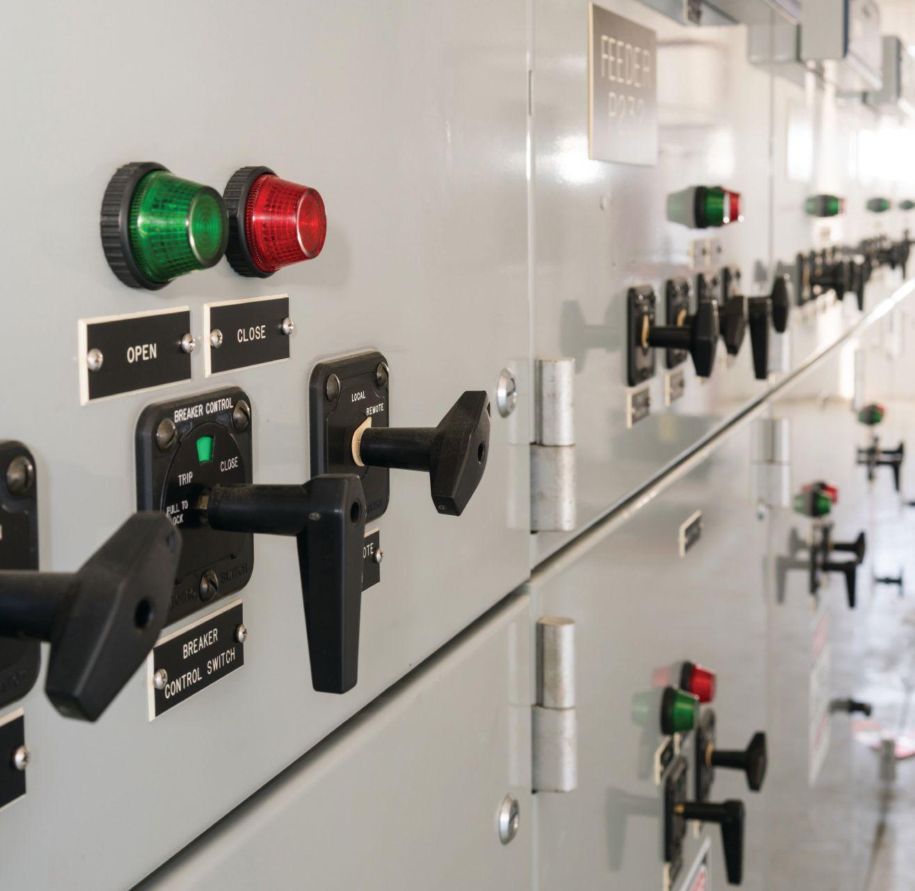
OLDER CBs: RETROFIT OR REPLACE? PAGE 52 KNOW WHEN CBs ARE FIT FOR DUTY OR NEED
ISSN 2167-3594 NETA WORLD JOURNAL PRINT ISSN 2167-3586 NETA WORLD JOURNAL ONLINE FALL 2017 MEDIUM-VOLTAGE
64
ATTENTION PAGE





Electrical Power Systems Industry Resource on Technical and Professional Training F A L L 2 0 1 7 : V O L . 2 . N O . 2 FALL 2017: VOL. 2. NO.

Electrical
Electrical
National
NFPA
Infrared
Substation
Electrical
Protective
Circuit
Transformer

• Circuit Breaker Seminar: October 2-6, 2017 | Pittsburgh, PA • Life of a Transformer Seminar: February 19-23, 2018 | National Harbor, MD • Rotating Machinery & Electrical Plant Reliability Workshop: April 11-12, 2018 | Boston, MA • Laboratory Seminars: offered throughout the year • Protection Training Courses: various topics offered throughout the year • Free Webinars: twice a month learn about testing, theory or industry trends TRAINING OPPORTUNITIES www.doble.com/training Learn from the industry’s top experts, receive real-world training you can immediately apply, and build your professional network with various educational programs offered throughout the year. Make training a priority for you & your team LEARN MORE Take the best hands-on electrical training back to the field with you. www.avotraining.com
Safety for Industrial Facilities
Safety for Utilities
Electrical Code 2017
70E Electrical Safety
Thermography Level I
Maintenance
Safety for Mining
Relay Maintenance
Breaker Maintenance
Maintenance Many AVO Training courses are eligible for NETA ctd’s.


TRAINING QUALIFIED PERSONS TO PERFORM ELECTRICAL WORK CAN REDUCE RISK
By Dennis K. Neitzel, CPE, CESCP, AVO Training Institute
PREVENT ELECTRICAL HAZARDS WITH CSA Z462-2015 CLAUSE 4.1.6 TRAINING
By Terry Becker, ESPS
MANAGING THE RISK OF TRANSFORMER FAILURES
By Alan M. Ross, SD Myers, Inc.
ELECTRICAL SAFETY PROGRAM: KEEPING US SAFE
By Anthony


Solutions,
Electrical Safety Program
Inc.
TECHNICAL
TRAINING FALL 2017 04 07 10 13 17 A NETA World Journal Special Publication A publication dedicated to disseminating information on technical
professional training for the advancement of the electrical power systems industry.
Demaria, Dennis Green, and Nenad Pasic, Tony Demaria Electric
DIRECTORY OF
AND PROFESSIONAL
and
TRAINING
TO PERFORM ELECTRICAL WORK CAN REDUCE RISK
BY DENNIS K. NEITZEL, CPE, CESCP, AVO Training Institute
The Occupational Safety and Health Administration (OSHA) and the National Fire Protection Association (NFPA) require employers to protect their employees from electrical hazards in the workplace. To accomplish this, there must be a strong emphasis on “qualified persons only” performing work on or near exposed energized and de-energized electrical systems and equipment. This article will define who a qualified person is and identify the training requirements for the required skills and knowledge.
Proper training and qualification of personnel is extremely important because maintenance of electrical protective devices, particularly circuit breakers and relays, is vital not only to the reliability of electrical systems and equipment, but also to the safety of employees working on, near, or interacting with these systems and equipment. What are the requirements for training qualified personnel?
QUALIFIED PERSON REQUIREMENTS
OSHA 29 CFR 1910.399 defines a qualified person as “one who has received training in and
has demonstrated skills and knowledge in the construction and operation of electric equipment and installations and the hazards involved.” OSHA provides additional information on what constitutes a qualified person in the following notes to this definition:
Note 1 to the definition of ‘‘qualified person”: Whether an employee is considered to be a ‘‘qualified person’’ will depend upon various circumstances in the workplace. For example, it is possible and, in fact, likely for an individual to be considered ‘‘qualified’’ with regard to certain equipment in the workplace, but ‘‘unqualified’’ as to other equipment. (See 1910.332(b) (3) for training requirements that specifically apply to qualified persons.)
Note 2 to the definition of ‘‘qualified person”: An employee who is undergoing on-the-job training and who, in the course of such training, has demonstrated an ability to perform duties safely at his or her level of training and who is under the direct supervision of a qualified person is considered to be a qualified person for the performance of those duties.
OSHA and NFPA 70E, Standard for Electrical Safety in the Workplace, provides strict requirements for safety training that go hand-in-hand with the qualification of an employee. The following information clarifies the mandates for training employees in the electrical field:
OSHA 1910.332, Training, requires a qualified person to be trained in “the safety-related work practices that are required by 1910.331 through 1910.335 that pertain to their respective job assignments.”
Qualified Persons (i.e. those permitted to work on or near exposed energized parts) shall, at a minimum, be trained in and familiar with the following:
■ The skills and techniques necessary to distinguish exposed live parts from other parts of electric equipment,
■ The skills and techniques necessary to determine the nominal voltage of exposed live parts, and
■ The clearance distances specified in 1910.333(c) and the corresponding voltages to which the qualified person will be exposed.
4 | TRAINING TALK | A NETA WORLD JOURNAL SPECIAL PUBLICATION
Note 1: For the purposes of 1910.331 through 1910.335, a person must have the training required by paragraph (b)(3) of this section in order to be considered a qualified person.
Note 2: Qualified persons whose work on energized equipment involves either direct contact or contact by means of tools or materials must also have the training needed to meet 1910.333(C)(2).
The training requirements contained in this section [1910.332] apply to employees who face a risk of electric shock…
Note: Employees in occupations listed in Table S-4 face such a risk and are required to be trained. Other employees who also may reasonably be expected to face comparable risk of injury due to electric shock or other electrical hazards must also be trained.
Table S-4 Typical Occupational Categories of Employees Facing a Higher than Normal Risk of Electrical Accident
Occupation
Blue collar supervisors.(1)
Electrical and electronic engineers.(1)
Electrical and electronic equipment assemblers.(1)
Electrical and electronic technicians.(1)
Electricians
Industrial machine operators.(1)
Material handling equipment operators.(1)
Mechanics and repairers.(1)
Painters.(1)
Riggers and roustabouts.(1)
Stationary engineers.(1)
Welders.
Footnote(1): Workers in these groups do not need to be trained if their work or the work of those they supervise does not bring them or the employees they supervise close enough to exposed parts of electric circuits operating at 50 volts or more to ground for a hazard to exist.
Employees are also required to be trained in and familiar with the safety-related work practices, safety procedures, and other safety requirements that pertain to their respective job assignments. This
training encompasses any other safety practices, including applicable emergency procedures that are related to their work and necessary for their safety.
NFPA 70E also requires qualified employees to be trained and competent in:
■ Skills and techniques necessary to distinguish live parts from other parts
■ Skills and techniques necessary to determine the nominal voltage
■ Minimum approach distances to live parts
■ The proper use of:
– Special precautionary techniques
– Insulating and shielding materials
– Insulated tools and test equipment
– Job planning
A person must have this training to be considered a qualified person. The employer, through regular supervision and annual inspections, must verify that employees are complying with the safety-related work practices. Additional training or retraining may be required if:
■ The supervision or annual inspection indicate non-compliance with work practices
■ New technology or new types of equipment are introduced
■ Changes in procedures become necessary
■ Employee is required to use abnormal work practices
OSHA and NFPA consider that tasks performed less than once per year require retraining before the performance of the work practices involved. This retraining may be as simple as a detailed job briefing prior to the commencement of the work, or it may require more in-depth classroom instruction along with on-the-job training. All training is required to establish employee proficiency in the work practices and procedures. Employees are required to demonstrate proficiency in the work practices involved before the employer can certify that the employee has been trained.
OSHA 1910.332 states:
The training required by this section shall be of the classroom or on-the-job type. The degree of training
A NETA WORLD JOURNAL SPECIAL PUBLICATION | TRAINING TALK | 5
provided shall be determined by the risk to the employee.” NFPA 70E goes on to state, “The training shall be classroom, on-the-job, or a combination of both, and that retraining shall be performed at intervals not to exceed three years.
Training and retraining are required to be documented.
In addition to these requirements from OSHA, the NFPA 70E states that employees are required to be trained to understand the specific hazards associated with electrical energy, safety-related work practices, and procedural requirements. These training requirements are necessary to help protect employees from the “electrical hazards associated with their respective job or task assignments” as well as to “identify and understand the relationship between electrical hazards and possible injury.” Training in emergency procedures is also required when employees are working “on or near exposed energized electrical conductors or circuit parts.”
OSHA and NFPA are consistent in their requirements for training and qualifying employees to perform work on electrical equipment and systems. Proper training is a vital part of the
worker’s safety and proficiency, as well as critical to the reduction of electrical hazards.
CONCLUSION
NFPA and OSHA state that to be considered a qualified person, an employee must receive extensive training. The goal of any training program is to develop and maintain an effective and safe workforce.
Electrical power systems today are often very complex. Protective devices, controls, instrumentation, and interlock systems demand that technicians be trained and qualified at a high technical skill level. Safety and operating procedures for working on these systems are equally complex, requiring technicians to be expertly trained in all maintenance and safety practices and procedures. OSHA regulations, as well as NFPA 70E, require employers to document that employees have demonstrated proficiency in electrical tasks and that they are qualified.
Properly training qualified persons to perform electrical work can greatly reduce the risk to employee safety, as well as increase reliability of the electrical system and equipment.
DENNIS K. NEITZEL, CPE, CESCP, is the Director Emeritus of AVO Training Institute, Inc. in Dallas, Texas. He is a Principle Committee Member for NFPA 70E, Standard for Electrical Safety in the Workplace. Dennis has 50 years in electrical power systems and is an active member of the Institute of Electrical and Electronics Engineers (IEEE), the American Society of Safety Engineers (ASSE), the Association for Facilities Engineering (AFE), the International Association of Electrical Inspectors (IAEI), and the National Fire Protection Association (NFPA), and is the co-author of the Electrical Safety Handbook, published by McGraw Hill. He earned his BS in Electrical Engineering Management and his MS in Electrical Engineering Applied Sciences.
6 | TRAINING TALK | A NETA WORLD JOURNAL SPECIAL PUBLICATION
PREVENT ELECTRICAL HAZARDS
training be designed by individuals with appropriate qualifications and subject matter expertise and that delivery of the training be done in a way that is conducive to learning.
Most importantly, CSA Z1001 dictates that the “development of competence through training is an integral part of OHS management,” and that the “goal of training is to help workers and other parties develop and achieve the knowledge, skills, and ability to perform their work in a manner that reduces risk of harm from work-related hazards.”
While the primary goal of regular, compliant training is to ensure workers are capable and knowledgeable in performing their work tasks and recognizing and mitigating hazards that may come with the risk of serious and potentially fatal injury, the possible liability to a company with an inadequate training program and a lack of effective documentation can lead to far-reaching legal and financial consequences.
BY TERRY BECKER, ESPS Electrical Safety Program Solutions INC.
All electrical incidents are preventable. Keep employees safe with an up-todate Electrical Safety Program and appropriate training.
CSA Z462-2015 CLAUSE 4.1.6 TRAINING
What is high-quality, compliant electrical safety, arc flash and shock training? Why and how often do your workers need it? Does your company have an electrical safety, arc flash and shock training specification that outlines corporate training requirements? Are worker training requirements (for example, an Electrical Safety Training Matrix) and other preventive and protective control measures documented in your company’s Electrical Safety Program?
The CSA Z1001 Occupational health and safety training Standard provides guidance in defining compliant, OHS-related training to ensure workers are “suitably trained to perform their work.” The Standard also notes:
Training should meet the needs of the organization as well as those being trained. It is important that
For this reason, the responsibility of reviewing, acquiring, tracking, and documenting ongoing effective and compliant worker training — combined with demonstrating worker competence — rests in the hands of the appropriate electrical safety leaders in the company, not in the hands of the workers, in a top-down collaborative approach that ensures overall success.
But what is high-quality, effective, and compliant electrical safety, arc flash and shock training? Not all training is created equal.
CHARACTERISTICS OF EFFECTIVE TRAINING
Effective training for qualified electrical workers is much more than just basic awareness training. Ask the following questions:
■ Who is providing the training? How long has the training company been in business? What is the education and experience level of the company’s subject matter expert on the CSA Z462 Workplace electrical safety Standard and the instructors delivering the training?
■ Is the training company insured? Does the training company have the appropriate liability insurance to back up its training?
A NETA WORLD JOURNAL SPECIAL PUBLICATION | TRAINING TALK | 7
W I T H C S A Z 4 6 2 - 2 0 1 5 WITH CSA Z462-2015 C L A U S E 4 . 1 . 6 T R A I N I N G CLAUSE 4.1.6 TRAINING


Once your company has selected high-quality, effective, and compliant electrical safety training, how often should you train your workers?
■ Does the training fully align with your company’s Electrical Safety Program? Does it cover all areas and consider your company’s unique situations and training needs?
■ Does the training meet the requirements outlined in both CSA Z462 and CSA Z1001? Are CSA Z462 clauses quoted and reviewed verbatim?
■ Does it clearly define “energized electrical work?”
■ Does the training include a comprehensive review of arc flash and shock hazards? Or does it primarily focus on arc flash?
■ Does the training include an analytical risk assessment procedure? And does the risk assessment procedure allow a qualified person to determine an energized electrical work task’s residual risk level?
■ Is measurement of learning included during the course? Does it specify a thorough evaluation of demonstrated knowledge, skills, and understanding?
■ How long is the training course? Appropriate training time must be considered for in-depth learning and review of the fundamentals, applying the concepts in hands-on exercises, and proper testing to ensure full understanding.
TRAINING PROVIDER RECOMMENDATIONS
When you specify the training developer and training provider, CSA Z1001 offers the following recommendations:
■ Subject matter expertise. Do the provider and instructor(s) have suitable CSA Z462 and
application knowledge, skills, and ability gained through training, education, and experience?
■ Training delivery skills. Are the instructors competent in delivery techniques and methods suitable for adult learners?
■ Continuing education. Have the provider and instructor(s) maintained their training skills by participating in continuing education or development programs?
■ Documentation of training course provider qualifications. Do the provider and instructor(s) have experience sheets and resumes, and are they accredited, or do they have continuing education course certificates or other certificates adhering to accredited standards, licensing, and registration?
Before you bid out the training to vendors, make sure your company has created an electrical safety, arc flash and shock training specification that outlines your corporate training requirements. Additional questions to consider:
■ Did you pre-qualify (by requesting defendable substantiation) that the training developer and training provider you identified could provide compliant arc flash and shock training?
■ Did your evaluation of the training proposal document find evidence that the training is compliant?
TRAINING SCHEDULE
Once your company has selected high-quality, effective, and compliant electrical safety training, how often should you train your workers?
CSA Z462 Clause 4.1.6 Training dictates “employers shall verify at least annually” that required worker training “is current,” and “shall document” that the training “has occurred.”
In terms of retraining, the Clause mandates “a worker shall receive periodic retraining in safety-related work practices and in the applicable changes to this Standard, at intervals not to exceed three years.” It is important to note here that the CSA Z462 Standard is updated every three years.
As an example, Alberta’s OH&S Act, Regulation and Code, Handi-Guide, Chapter 2: OH&S
8 | TRAINING TALK | A NETA WORLD JOURNAL SPECIAL PUBLICATION
Due Diligence, recommends “operators to be ‘recertified’ at periodic intervals, e.g., every three years,” and “when regulatory changes occur and re-training may be required.” It goes on to note that “ongoing or revised training related to PPE is important, particularly where advances in equipment or technologies result in changed practices or better equipment.”
CONCLUSION
For the best due diligence that is defendable to OH&S or OSHA requirements related to arc flash

and shock, ensure that the electrical safety training you procure for your workers is fully compliant training provided by a credible training developer and training provider. The CSA Z1001 Occupational health and training Standard can be used to develop a technical training program specification for your electrical safety, arc flash and shock training, which is only one element of the hierarchy of controls used to reduce risk as a component of a complete Electrical Safety Program.
TERRY BECKER is President and Principal of ESPS Electrical Safety Program Solutions INC., an electrical engineering consulting firm specializing in electrical safety consulting, licensed products, and training solutions. He is the first past Vice-Chair of the CSA Z462 Workplace electrical safety Standard Technical Committee and currently a Voting Member and Working Group 8 Leader, Annexes. Terry is also a Voting Member on the IEEE 1584 Technical Committee and an Associate Member of the CSA Z463 Guideline on maintenance of electrical systems. Terry is a Professional Engineer in the Provinces of British Columbia, Alberta, Saskatchewan, and Ontario.
A NETA WORLD JOURNAL SPECIAL PUBLICATION | TRAINING TALK | 9
MANAGING THE RISK OF TRANSFORMER FAILURES
BY ALAN M. ROSS, SD Myers, Inc.
Despite the fact that transformers have been around for nearly a century with varying opinions on transformer design and maintenance, most experts agree that not all transformer failures are alike. Most also agree that the life of the insulation or paper is the primary limiting factor in the life of the transformer.
Since most industrial companies use power to produce something, the risks associated with loss of that power have been misunderstood and all too often ignored. But risk comes in many different forms. Risk of failure is often quantified by the insurance industry as the cost to replace the transformer. But the loss of productive capacity — business interruption loss — is usually much higher than the cost of transformer replacement.
What is the risk of failure when the condition of the unit has deteriorated and routine preventative maintenance ignored? When asked, “Why do you test the oil in your transformers?” the most common response is, “Our insurance company requires it.” The need for a reliable system must become the reason we test transformers, since every reliable system starts with reliable, uninterrupted power.
CONDITION-BASED RISKS
Why do transformers fail in the first place? Many failures happen after an incident, such as lightening strike or a failure down line from the transformer. These anomalies can be characterized as electrical, mechanical, or thermal, but for the most part, they are separate from the condition of the unit. These may be root-cause failures, but they neglect a significant contributing factor: the condition of the unit. An overloaded transformer with well-maintained dielectric fluid that is not already weakened by poor maintenance is much less likely to fail than an overloaded transformer that has not been maintained.
Can transformer failures be avoided? Can life extension mitigate this risk? Experience proves that it is effective to develop standards, rigorously test and track the condition of the fleet of transformers, and maintain that fleet to those standards. Quite simply, the easiest risk to mitigate is the conditionbased risk.
We maintain productive assets with increasing rigor, yet too often, we confuse chemical or electrical testing of a transformer with the maintenance of a transformer. In one illustrative case, we were asked to develop a standard for testing and maintenance for a customer with multiple transformers and multiple sites. There was a great deal of commonality of the units, and we had done chemical testing for over seven years tracking the condition in the oil of the units. When we asked for the electrical test data to address the complete condition of each unit, we were told: “We only test with you.” That statement changed my perspective on the issue of risk and reliability of electrical systems, with particular emphasis on the heart of the system: the transformer.
And yet, there is so much more to a complete condition assessment than trended oil tests. While that is an important first step, the next steps are equally critical. Is recommended maintenance on oil processing standard throughout the company, or is it left up to each individual responsible for maintaining one plant? Not all oil processing is alike. While some contractors clean the oil, others may process on the unit until they address issues in the paper and the oil.
10 | TRAINING TALK | A NETA WORLD JOURNAL SPECIAL PUBLICATION
What criteria should be used for electrical testing to create a best-practices testing and maintenance protocol? What data is available from the manufacturer at assembly and installation to determine changes over time? A simple Sweep Frequency Response Analysis (SFRA) can serve as the baseline for future condition assessment, yet too often, we do not have that data. It is a matter of developing a reliable system that can address the condition of the unit — without a lot of added costs or downtime — during the life of that unit, not at the end of life. It is all about assessment, planning, and systems.
THE WEAKEST LINK: PAPER
While there are cases when transformers fail without warning, most failures are ones that we can see coming. Deteriorating paper and oil emit gases that can lead to a better diagnosis of the condition of the unit. Moisture content has become a tremendously valuable predictor of failure. Sadly, gassing and high moisture content is not perceived as critically important as it should be. Accelerated deterioration of the paper insulation comes about from moisture, acid, overheating, or oxidation, and it weakens the ability of the unit to perform.
Transformers today are built with much less margin for error than those of the past. If we take the same approach to reliability based on past experiences, we will likely see more unplanned outages and downtime from transformer failures than ever before.
DISSOLVED GAS ANALYSIS
Gases are dissolved in the transformer oil and are formed by both normal operation and aging and by anomalies or abnormal events. Because these gases can reveal the faults of a transformer, they are known as fault gases. Gases are produced by oxidation, vaporization, insulation decomposition, oil breakdown, and electrolytic action. By analyzing the volume, types, proportions, and rate of production of dissolved gases, we can get a very good picture of what has happened or what is happening inside the unit.
While it is becoming increasingly common for primary units within a substation — or, in the case of steel production, the furnace units — to have dissolved gas analysis (DGA) monitors installed on the units, the monitor will likely only detect
that a gas or gases are present. An oil sample with DGA analysis can determine the amount of gas and, in the case of frequent testing, the rate of change in that gas. From that data, knowledge is developed, meaning the cause of the increased gas is determined. In extreme cases, the analysis will indicate a potential catastrophic failure. In most cases, it will indicate a weakening of the overall condition of the unit and the need to avoid overheating and higher loading.

While there are cases when transformers fail without warning, most failures are ones that we can see coming. Deteriorating paper and oil emit gases that can lead to a better diagnosis of the condition of the unit.


DEVELOPING A RELIABLE SYSTEM
So where does that leave us? What should any company dependent on the safe, reliable, and uninterrupted use of electrical power do?
■ Understand the short- and long-term, direct and indirect impact and costs associated with unplanned power outages from the loss of a transformer.
■ Develop and implement a set of standards for determining the operating condition of transformer(s) through the use of intrusive and non-intrusive testing.
■ Develop a preventative maintenance plan to implement company wide, giving reliability professionals the tools they need to monitor and maintain this critical and often overlooked asset class.
■ Develop a reaction plan for every critical transformer in your area of responsibility and control.


A NETA WORLD JOURNAL SPECIAL PUBLICATION | TRAINING TALK | 11
BEST PRACTICES FOR ELIMINATING RISK OF FAILURE
It all boils down to prevention if you want to reduce or eliminate the risk of an unplanned outage of a transformer. Simple adherence to best practices for testing, maintenance, and monitoring will increase the life of the transformer, but will also create a more robust unit that can withstand most kinds of faults. These include:
■ Oil testing on a regular basis with corresponding maintenance assessment reporting. Remember, if we test because the insurance company requires it, we are missing the point of developing a reliable electrical system.
■ Electrical testing. For more critical units — and in the event of an oil testing result that indicates a need for additional testing — standardization is required.
■ Mechanical inspection. Check oil level; check proper functioning of gages, bushings, fans, and radiators; and check quality of connections.
■ Thermography (IR). While most companies provide an annual IR scan of their entire system, there is a great advantage to conducting an

annual routine IR at the time of the oil test. The combined information can lead to specifics about faults, loose connections, or potential bushing failure.
■ Monitoring for gases. Fault gases can lead to catastrophic failure that goes well beyond a simple unplanned outage. Monitoring for these gases creates an early warning system. Since hydrogen is usually present with gases, a costeffective monitoring solution may well be a single-gas monitor with a robust follow-up oil testing program.
■ Why do we test? The reason to test is to determine the condition of the unit and then perform preventive maintenance. A well-maintained and serviced transformer can last over half a century. Test to gain knowledge about the condition of your equipment, and recognize that knowledge leads to the wisdom to provide a low-cost, reliable electric system.
While we may not get every transformer expert to agree on everything, there is universal agreement that a healthy and robust electrical system starts with the heart of that system: the transformer.
ALAN ROSS is Vice President of Reliability at SD Myers, Inc. in Tallmadge, Ohio. He is responsible for developing and executing long-term reliability strategies and next-generation leadership for all operating units, both domestically and internationally. He often presents at industry conferences, has authored several articles on transformer maintenance and reliability, and has written two books: Unconditional Excellence and Beyond World Class. He earned a BS in Mechanical Engineering at Georgia Institute of Technology and an MBA in Marketing from Georgia State University, graduating Magna cum Laude. Alan is a Certified Reliability Leader and a member of the IEEE Reliability Society.
12 | TRAINING TALK | A NETA WORLD JOURNAL SPECIAL PUBLICATION
ELECTRIC AL ELECTRICAL SA F E T Y SAFETY KEEPING US SAFE
BY ANTHONY DEMARIA, DENNIS GREEN, AND NENAD PASIC, Tony Demaria Electric
Having a comprehensive Electrical Safety Program (ESP) and following it is a critical part of keeping electrical workers safe. The path to better safety requires very hard work and total commitment to the values involved. So, what is an ESP, and what are the major stumbling blocks to developing an organization where everyone goes home injury-free every day?
Figure 1 shows how an ESP could be structured. First, the safety policies describe the overall plan. Second, the safety procedures are created for the all-important tasks. A procedure consists of short sequential steps. Each step will have a check box to document that the task has been completed. Third, forms are created with spaces and boxes to fill in the information required.
The following list describes how to model an ESP. The list is not comprehensive; rather, it is meant to cover major points without being confusing.
1. The development and maintenance of an ESP require commitment from upper management to
provide the resources needed. This would include adequate time for the qualified persons responsible and the financial resources to fully develop it (refer to Annex E of NFPA 70E). Involve as many individuals as reasonable. Ownership and buy-in are vital to the program’s success.
2. Then create the policies. These describe what an ESP is and the safety issues covered. It is in text form and needs to be reviewed and accepted by all who are affected by it. As Shermco’s Jim White puts it: “If it isn’t simple, it won’t be used.”
3. Once you have the policies, develop clear, easy-tounderstand, specific safety procedures and forms. Test the procedure under actual field conditions. Any issues with the procedure should be resolved before it is implemented.
4. Perform thorough training for every person on the policies, procedures, and forms, with annual (or more frequent, if necessary) refresher training.
5. Require demonstration of trainee proficiency on the topics taught.
6. Conduct regular, knowledge-building auditing of each person to ensure they understand and follow the policies and procedures. Be certain to document the training and auditing of their proficiency as required by NFPA 70E.
7. Improve the policies and procedures when standards and best practices change or problems are revealed during auditing. Then, retrain to the new improvements. Again, the job is not finished until the paperwork is completed. Document everything.
A NETA WORLD JOURNAL SPECIAL PUBLICATION | TRAINING TALK | 13
POLICIES ELECTRICAL SAFETY PROGRAM (ESP) 3. FORMS 2. PROCEDURES
1.
Figure 1: Electrical Safety Program Components
8. Consider these items to be a continuing cycle of betterment. All of this is done with the spirit that every person is enabling everyone else to be successful at their job. Assume people want to be good at what they do.
9. The people performing the work are the ones who know how to improve what you do. Include your qualified persons at every step.
Do the preceding items sound familiar? There is nothing new in them, and they have been taught many times, in many ways, for the last 40-plus years.
The excellent news is that, as a result of all the ESPs we have and the safety training we perform, there has been a substantial reduction in incidents. In 1994, there was approximately one fatality per day from electrocution, about 365 total. In 2013, that number was down to 139. Considering how the American workforce has increased, this represents a huge drop in electrical shock fatalities.
The bad news is that too many injuries continue to happen. Our reaction is to take another class, create another policy or procedure, and train more. Even though we have achieved good results for our investments in the past, it seems a glass ceiling has been hit.
We reviewed seven serious shock/arc-flash injuries and found several examples of incidents that continue to occur. They happened in our geographical area in the past 10 years. Each incident had substantial similarities. The injuries happened to experienced electrical workers in the major industrial facilities. They all had a minimum of 5 to 10 years journeymen experience, and several of them had over 20 years of experience. All worked for companies with an ESP. All had received electrical safety training for the tasks they were performing when they got hurt. All were preventable.
This is not stated lightly. This is not utopia, and people are not perfect. We are not talking about utopia or perfection in this article. We are talking about people getting hurt, and nobody wants to be injured. So, what went wrong?
PROCEDURES AND FORMS
The ESP described in Figure 1 shows three parts. Large industry, in general, has done a good job
developing comprehensive policies. However, they have not performed well in using procedures and forms. Way too often, we observe no written procedures at job sites, and our peers often tell us they do not use written procedures. Following is an example of a procedure that makes an electrical working condition much safer for all of us.
Establishing an Electrically Safe Work Condition Procedure
NFPA 70E Article 120, if followed correctly, will help achieve an electrically safe work condition:
Determine all possible sources of electrical supply to the specific equipment. Check applicable up-to-date drawings, diagrams, and identification tags.
After properly interrupting the load current, open the disconnecting device(s) for each source.
Whenever possible, visually verify that all blades of the disconnecting devices are fully open or that the drawout-type circuit breakers are withdrawn to the fully disconnected position.
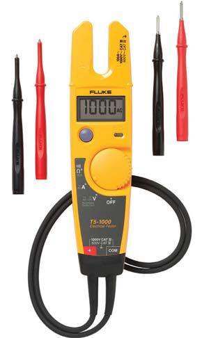
Figure 2: Notice the single voltage setting. It detects ac and dc voltages. This eliminates the possible error of having your voltmeter on the wrong setting.
14 | TRAINING TALK | A NETA WORLD JOURNAL SPECIAL PUBLICATION
Apply lockout/tagout devices in accordance with a documented and established policy.
Use an adequately rated voltage detector to test each phase conductor or circuit part to verify they are de-energized. For circuits less than 1,000 volts, use an instrument such as the Fluke T5-1000 (see Figure 2) and test each phase conductor or circuit part both phase-tophase and phase-to-ground. Before and after each test, determine that the voltage detector is operating satisfactorily.
Do not rely solely on proximity voltage detectors for the absence of voltage testing. If used, always follow that test with a directcontact test instrument to verify the absence of voltage.
Where the possibility of induced voltages or stored electrical energy exists, ground the phase conductor or circuit parts before touching them. Where it could be reasonably anticipated that the conductors or circuit parts being de-energized could contact other exposed electrical conductors or circuit parts, apply ground connecting devices rated for the available fault duty.
There is also a lack of forms, especially quality Job Hazard Analysis (JHA) forms. In 2015, NFPA 70E made a new requirement to include risk analysis to establish the risk of every task as a part of the condition for job safety; however, this has not been well implemented. Refer to Figure 3 for a sample of a JHA with the job hazards and risks considered. Having a procedure with written steps to follow and a form to fill out requires the person(s) performing the work to stop and think first.
THE HUMAN FACTOR
Some of the problems humans have include:
A. We rush people, and people allow themselves to be rushed.
B. Lack of crew harmony — some people just don’t get along. This can lead to poor communications that may result in injuries.
C. People forget, get distracted, get tired, and just make mistakes.
D. People like to take risks. High-voltage electrical workers accept high risk as a regular part of their work. Taking risks is genetic, and people drawn to electrical work tend to be wired for risk.
Items A through D present unique challenges to preventing injuries. By themselves, these behaviors are difficult, if not impossible, to control and eliminate. In the safety community, we now call such barriers human nature or the human factor.
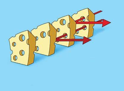
The traditional methods of solving these problems — creating another policy or having more training — will not work. Therefore, a new way of looking at this issue needs to be developed. A good solution to deal with this subject is demonstrated in the Swiss Cheese Model (Figure 4).
This model uses successive layers of defense. It acknowledges that humans get in a rush, may not


Figure 3: Sample JHA with Job Hazards and Risks Considered
A NETA WORLD JOURNAL SPECIAL PUBLICATION | TRAINING TALK | 15
get along, forget, make mistakes, and take too many risks. These are the holes in the Swiss cheese. The layers of cheese show that a mistake may get through on one layer but will be blocked by the next layer. Each layer may represent a written policy, a form to fill out, or a second person witnessing and verifying each step with a check sheet.
CONCLUSION
Companies should develop better procedures and forms, train personnel to understand them, and then audit the work to assure they are being utilized. Account for the human factor by implementing the policies, procedures, and forms in such a way that layers of safety are created, thereby significantly reducing the risk and the injuries.
What is agreed upon in the safety community is that we are on a journey. Knowledge of the ESP is one thing; changing people to follow it is another. The journey will take some time and require our very best efforts.



Hazards
SUCCESSIVE LAYERS OF DEFENSES
Figure 4: For a catastrophic error to occur, the holes need to align at each step in the process, allowing all defenses to be defeated and resulting in error. This would be unlikely.
REFERENCE
Duke University School of Medicine, www.patientsafetyed.duhs.duke.edu
ANTHONY DEMARIA (TONY) served an IBEW electrical apprenticeship while working in the marine electrical industry. He then worked for the Los Angeles Department of Water and Power in substation maintenance and power plant construction prior to starting his own company. He has owned and operated Tony Demaria Electric (TDE) for almost 40 years. TDE’s work includes engineering, technical services, electrical maintenance, troubleshooting, repairs, and testing for large industrials. TDE excels in providing electrical support in the oil industry. Tony served as the NETA Safety Committee Chair for several years.
DENNIS GREEN is a Safety Director, Safety Instructor, Safety Compliance Officer, and Project Manager at Tony Demaria Electric (TDE). He has worked with TDE for over 32 years. Dennis finished his I.B.E.W. Electrical Apprenticeship program in 1988 and since then has been actively involved in numerous electrical projects and training. He is a Member of NFPA 70B Technical Committee on Electrical Equipment Maintenance, an Electrical Section of the NFPA Member, and a Member of the NFPA Electrical Equipment Maintenance Committee. Dennis belongs to the American Association of Safety Engineers as well as IEEE and was a President of the Society of Port Engineers in the Port of Los Angeles/Long Beach.
NENAD PASIC (NENO) is a NETA Accredited Representative and IT Manager for Tony Demaria Electric (TDE). He has worked with TDE for over 15 years. Neno serves on the NETA Training Committee and the NETA Promotions and Marketing Committee. He is an IEEE Member, belonging to IEEE Computer Society, IEEE Communications Society, IEEE Information Theory Society, NFPA, and is an Electrical Section of the NFPA Member. Neno earned a BS in Computer Information Systems, Business Administration from California State University Dominguez Hills along with Project Management and Information Technology Management Certificates from the University of California Los Angeles.
16 | TRAINING TALK | A NETA WORLD JOURNAL SPECIAL PUBLICATION
DIRECTORY
AVO Training Institute: The One Stop for Electrical Safety Training, Electrical Maintenance
Many AVO courses are eligible for NETA CTDs.*
If it’s electrical, AVO Training is focused on it. Electrical safety training, electrical maintenance training, and electrical consulting is not just a part of our offering, it’s our total focus. That’s why we offer more electrical safety and electrical maintenance training courses than any other training facility. With over 52 different courses, we offer the widest selection of courses available. To complement our training courses, we have a stand-alone Engineering Division that offers Arc Flash Studies, Risk Assessment Analysis, and a full menu of electrical engineering services.
Available Courses:
Protective Relay
• Protective Relay Maintenance - Basic
• Protective Relay Maintenance - Advanced
• Protective Relay Maintenance - Generation
• Protective Relay Maintenance - Solid State
• Microprocessor Based Relay Testing - Generation
• Microprocessor Based Relay Testing - Distribution/ Industrial
• Advanced Visual Testing Software
Circuit Breaker
• Circuit Breaker Maintenance, SF6
• Circuit Breaker Maintenance, Molded- and Insulated-Case
• Circuit Breaker Maintenance, Medium-Voltage
• Circuit Breaker Maintenance, Low-Voltage
Cable U
• Cable Splicing and Terminating, Medium-Voltage
• Cable Fault Location and Tracing, Medium-Voltage
• Cable Testing and Diagnostics, Medium-Voltage
Substation
• Battery Maintenance and Testing
• Transformer Maintenance and Testing
• Advanced Transformer Maintenance and Testing
• Substation Maintenance I
• Substation Maintenance II
• Power Factor Testing
Safety
• NFPA 70E 2015 Electrical Safety
• Electrical Safety for Utilities
• Electrical Safety for Mining
• Electrical Safety for Industrial Facilities
• Electrical Safety for Inspectors
• Electrical Safety for Overhead Contact Systems
• 2017 National Electrical Code
• OSHA Electrical Safety Related Work Practices
• Maritime Electrical Safety
Basics
• Basic Electricity
• Basic Electrical Troubleshooting
• Electronics Troubleshooting
• Electronics for Electricians
• Electrical Print Reading
• Grounding & Bonding
Engineering
• Short Circuit Analysis
• Protective Device Coordination Utilities
• Protective Device Coordination Industry
• Power Quality & Harmonics
Motors/Controls
• Programmable Logic Controllers
• Maintenance & Trouble Shooting
• Motor Maintenance and Testing
• Motor Controls and Starters, Low-Voltage
WWW.AVOTRAINING.COM • 877-594-3156 *NETA continuing technical development (CTDs) units are required of NETA Certified Technicians.
OF TECHNICAL AND PROFESSIONAL TRAINING
Doble Engineering Company: Learn from the Industry’s Top Experts
Throughout the year, Doble hosts accredited technical trainings on a variety of topics to help engineers and technicians of all levels be more efficient, effective, and safe in the field. Learn from the industry’s top experts, receive real-world training that you can immediately apply, and build your professional network.
2017-2018 Course Listings
• Circuit Breaker Seminar
October 2-6, 2017 | Pittsburgh, PA
Brush up on fundamentals, get practical hands-on training, and learn from the experts at the industry’s best circuit breaker educational seminar.
• Life of a Transformer Seminar
February 19-23, 2018 | National Harbor, MD
Practical training on all aspects of transformers, including sessions focused on transformer differential protection, transformer maintenance, and asset and maintenance strategies.
• Rotating Machinery & Electrical Plant
Reliability Tutorial
April 11-12, 2018 | Boston, MA
Learn everything you need to know to reliably maintain the electrical side of a generation or industrial plant.
• Laboratory Seminars
Offered throughout the year
Learn how to review data to assess transformer condition from instructors presenting theory and practical examples that illustrate common problems found in the field.
• Protection Training Courses
Offered throughout the year
Choose from a range of protection courses that will prepare you for testing a modern grid, power plant, and industrial facility.
• Free Webinar Series
Stay current on testing techniques, theory, or power industry trends. Webinars are held twice a month and last approximately one hour.
Earn Credits
Many Doble training courses are eligible for NETA Continuing Technical Development Credits (CTDs) as well as IACET certified Continuing Education Units (CEUs). Visit: www.doble.com/earning-ceus
www.doble.com/training events@doble.com 617.926.4900 DIRECTORY OF TECHNICAL AND PROFESSIONAL TRAINING
Megger’s Testing Tactics Webinar Series 2017
Learn valuable testing tips and tricks from Megger application engineers and product managers. In this webinar series, our experienced staff will show you how to make your testing more efficient by sharing their lessons learned in the field. You will find answers to frequently asked questions, learn how to avoid the most common mistakes and accelerate your testing.
Upcoming Webinars
• Practical Applications of Cable Testing & Diagnostics Techniques
Aug 18, 2017 | Presenter: Jason Souchak
• The Evolution of Insulation Resistance Testing
Sep 15, 2017 | Presenter: Jeff Jowett
• Oct 20, 2017 | Presenter: Vijay Sundaram
• Alternate Testing Techniques for Instrument Transformers
Nov 17, 2017 | Presenter: Diego Robalino
• Discharge Results on Medium Voltage Cables
Dec 15, 2017 | Presenter: Jason Souchak
Previous Webinars
• Best Practices for Performing Dielectric Breakdown Test on Insulating Liquids
May 19, 2017 | Presenter: Daniel Carreno
• A Step by Step Process to Troubleshoot Power Quality Problems
Jun 16, 2017 | Presenter: Andy Sagl/Sanket Bolar
• Do’s and Don’ts of Insulation Power Factor Testing
Jul 21, 2017 | Presenter: Jill Duplessis
• Best Practices for Performing Travel Measurements on HV Circuit Breakers
Feb 17, 2017 | Presenter: Robert Foster
• Battery Testing and Maintenance as per NERC PRC005 Guidelines
Mar 17, 2017 | Presenter: Volney Naranjo
• Cable Fault Location 202: Advanced Techniques
Apr 21, 2017 | Presenter: Robert Probst
How to Join Megger Webinar Series
• Megger Webinars are held on the 3rd Friday of every month
• Time: 10:00 AM Central Time.
• Sessions are FREE
• us.megger.com/webinars
Webinar Registration: http://us.megger.com/webinars
Megger designs and manufactures portable electrical test equipment. Megger products help you install, improve efficiency, reduce cost, and extend the life of your or your customers’ electrical assets or your own. For more information, visit http://us.megger.com/.
DIRECTORY OF TECHNICAL AND PROFESSIONAL TRAINING
SDMyers: In Electrical System Maintenance and Management, Knowledge Means Power
Effective transformer management requires special skills acquired from years of hands-on experience. The diminishing number of experts is causing a growing need for specialized training to ensure these skills are not lost. SDMyers offers your team the opportunity to benefit from our 50 years of transformer maintenance expertise. We offer a variety of training options including enhanced e-learning courses; seminars; and onsite, online, and customized courses.
Introductory
• Principles of Transformer Maintenance
Basics of transformers: electric concepts, solid and liquid insulation, oil testing and analysis, basic electrical testing, and maintenance.
• Principios de Mantenimiento de Transformadores
Este curso introduce al alumno en una serie de temas que resumen los fundamentos básicos de los transformadores y de mantenimiento del transformador.
• In-Service Inspection & Sampling of Fluid-Filled Transformers
Learn safe procedures needed to obtain a representative sample of dielectric fluid. Features a sampling demonstration and practical exercises to obtain accurate oil samples for use in lab analysis.
Intermediate
• Half-Century Transformer
Foundational understanding of transformers: operation, maintenance implementation, and related industry standards.
• Half-Century Transformer - Applied Maintenance
Foundational understanding of transformers: operation, maintenance implementation, and related industry standards. Includes lab and equipment tours, rewind facility tour, case studies, and expert panel discussion.
• Advanced DGA Diagnostics
Learn to identify fault gases and what causes their formation, evaluate the condition of cellulose insulation, examine the role DGA plays in new oil testing, and discuss obtaining samples from transformers.
• Load Tap Changer Principles & Maintenance
Load tap changing, styles of tap changers and their operation, and how to develop a preventative load tap changer (LTC) maintenance program.
• Electrical Testing - Power Factor Testing for Transformers, Bushings, and Breakers
The Power Factor is a measurement of the efficiency of the transformer’s insulation system and a reliable electrical test to detect deterioration.
• Transformer 360 Course is 3 days — take any or all. Day 1: Re-energized Half-Century course as part of a transformer reliability program. Day 2: Risk & Reliability and DGA. Day 3: LTC Testing & Maintenance and Electrical Testing.
Advanced
• Transformer Lifecycle Management
Manage the lifecycle of the transformer including specification and purchasing, transportation, assembly and start-up, field and shop repair, overall risk and asset management, and end-of-life options. Learn to develop and manage a reliability-based maintenance program.
• Advanced Transformer Maintenance and Planning
Reactive, predictive, and preventative maintenance of transformers, and building a cost-effective testing and maintenance plan to prolong the reliable life of transformers. Includes substation equipment, transformer design and construction, and how to make critical maintenance and planning decisions.
SD Myers courses are eligible for NETA CTDs.*
*NETA continuing technical development (CTDs) units are required of NETA Certified Technicians
DIRECTORY OF TECHNICAL AND PROFESSIONAL TRAINING
Register by phone: 330.630.7000 x.4018 Register online: sdmyers.com/training For class dates and locations, visit sdmyers.com/training/calendar 180 South Avenue, Tallmadge, Ohio 44278, USA
Shermco Industries: Your Electrical Safety Experts
Shermco is a leader in electrical power systems maintenance, repair, and testing and, for years, we have trained others in those skills. Offering onsite, classroom and hands-on training, Shermco conducts a wide variety of courses covering Electrical Systems Maintenance, Electrical Safety, and Electrical Technical Skills. Some of the most influential leaders in electrical safety work at Shermco Industries and now you have direct access to that experience and expertise! Shermco offers technical and electrical safety programs year-round and at multiple locations in the U.S. and Canada. NETA CTDs and CEUs through IEEE are available for most courses where applicable. Train with the experts. Train with Shermco.
Safety Training Course Schedule 2017 / 2018
• Workers
Irving, TX
Sep 12-14, Oct 10-12, Nov 7-9, Dec 12-14, Jan 9-11,
Feb 6-8, Mar 6-8
Austin, TX
Aug 15-17, Nov 14-16, Feb 13-15
Houston, TX
Sep 19-21, Dec 5-7, Mar 13-15
Tulsa, OK
Oct 17-19, Jan 23-25
Des Moines, IA
Oct 3-5, Feb 13-15
St. Paul, MN
Aug 22-24, Dec 12-14
New Orleans, LA
Aug 29-31, Nov 14-16
Sewell, NJ
Nov 7-9
• Electrical Workers
Irving, TX
Sep 15, Oct 13, Nov 10, Dec 15
• Electrical Safety Refresher
Irving, TX
Oct 9, Feb 5
Austin, TX
Aug 18, Feb 16
Houston, TX
Sep 22, Mar 16
Tulsa, OK
Oct 20
Des Moines, IA
Oct 6, Feb 16
St. Paul, MN
Aug 25, Dec 15
New Orleans, LA
Sep 1, Mar 30
Sewell, NJ
Mar 23
• Understanding the NFPA 70E & Changes
Irving, TX
Feb 20
Austin, TX
Apr 5
Des Moines, IA
Nov 3
St. Paul, MN
Sep 18
Tulsa, OK
Nov 30
• Low-Medium Voltage Circuit Breaker Maintenance & Testing
Irving, TX
Oct 2, Feb 12
• Circuit Breaker Maintenance Operations & Controls
Irving, TX
Oct 23, Jan 22
Enroll today by visiting www.shermco.com/training or call 888-Shermco and mention your promotional code.
For more information, to download our current course catalog, or to register online go to www.shermco.com/training or email training@shermco.com Shermco.com • 888-shermco

DIRECTORY OF TECHNICAL AND PROFESSIONAL TRAINING
CEUs available from
Tony Demaria
Electric, Inc.: Our in-house training substation assures that all classes include hands-on training.
Tony Demaria Electric, Inc. (TDE) takes the lead in electrical industry improvements on safety and testing technology and adapts policies and procedures accordingly. TDE is one of the first electrical contractors adopting the use of Arc-Flash Personal Protection and Remote Racking and Switching. TDE is a NETA Accredited Company and participates actively in the NETA organization. TDE employees have published a number of safety and technical articles in NETA World Journal and other publications.
Training Courses Eligible To Earn NETA Continuing Technical Development Credits (CTDCs)
• AC Synchronous Motors – 9 CTDCs
• Batteries and DC Circuits – CTDCs pending
• Electrical Print Reading – 18 CTDCs
• Electrical Troubleshooting – 18 CTDCs
• Lockout / Tagout (LOTO) – 8 CTDCs
• Low Voltage, Air, Power Circuit Breakers Preventative Maintenance – 8 CTDCs
• Medium Voltage, Air, Circuit Breakers Preventative Maintenance – 36 CTDCs
• Motor Bearings and Lubrication – 9 CTDCs
• Motor Control Centers and Switchgear – 18 CTDCs
• Transformers Basics – CTDCs pending
• Transformers, Liquid Filled and Dry Type Preventative Maintenance – 36 CTDCs

Safety and Technical Training Courses
• AC Control Equipment
• AC Induction Motors, Basic
• Arc Flash Hazard Reduction Techniques
• Battery Safety and Maintenance
• Cable Terminating, Splicing, Grounding, and Bonding
• Electrical Inspection, Basic
• Electrical Print Reading
• Electrical Safety for Non-Qualified Workers
• Electrical Safety for Supervisors
• Electrical Skills, Basic
• Electrical Troubleshooting
• Grounding Systems
• Low Voltage Circuit Breaker Fundamentals
• Motor Bearings and Lubrication
• Motor Control Centers (MCC’s)
• NFPA 70E, 1-day
• NFPA 70E, 2-day
• NFPA 70E Refresher
• Synchronous Machines
• Test Meters and Test Equipment
• Transformers and AC Circuits
Custom Training Courses
TDE offers customized training courses that will meet your very specific needs. We will work with you to tailor a course based on your precise requirements to assure you are completely satisfied!
Prices and duration of courses varies. Please call 310.816.3130 or fill out form at http://www.tdeinc.com/contact-us/request-bid-or-information/ for more information.

DIRECTORY OF TECHNICAL AND PROFESSIONAL TRAINING


OPPORTUNITIES for the Electrical Power Systems Industry Learn at Your Own Pace • Online Courses • Self-Paced Technical Seminars (SPTS) • Electrical Safety Training Systems (ESTS) Ask About Continuing Education and NETA CTD Credits. Learn More at: netaworld.org/training or Call 888-300-6382 (NETA) INTELLIGENT TRANSFORMER MANAGEMENT®







(310) 816-3130 www.tdeinc.com 131 W F St Wilmington, CA 90744 Los Angeles Area Anthony F. Demaria, Sr. Anthony F. Demaria, Jr. MANY COURSES ARE ELIGIBLE TO EARN NETA CONTINUING TECHNICAL DEVELOPMENT CREDITS (CTDC’s) SAFETY | TECHNICAL | CUSTOM TRAINING AVAILABLE Why endanger yourself and others? Let Shermco’s experts teach you the whys and hows of electrical safety! (Meets requirements of OSHA and NFPA 70E) Train with the experts. Train with Shermco. www.shermco.com (Dont_be_this_guy!) (Dont_be_this_guy!)


On the Potomac


On the Potomac


Throughout history, Washington, D.C., has been a touchstone for leadership, initiative, and passion — a mecca for those dedicated to the highest ideals and aspirations of both leading and serving a nation. People come to D.C. to share ideas, to communicate, to engage. It’s a perfect environment to energize PowerTest 2018 — in fact, no city represents power more literally and figuratively than Washington, D.C.
With its broad avenues and majestic neoclassical architecture, Washington, D.C., is a city overflowing with history. Monuments and memorials engage you with our nation’s most influential leaders as well as its fallen heroes. The city is a tapestry of all the people and cultures and stories that make our country great.
Though deeply rooted in history, D.C. is always fertile ground for new restaurants, bars, and stores. From the hip neighborhoods of Capitol Hill to U Street to fascinating museums and tree-filled parks, the city has a retreat for everyone.


Washington, D.C., is a place where relationships are formed and plans are made. As the premier event for electrical power systems professionals, PowerTest 2018 will thrive in the highly charged rhythm of this city. Exploring D.C., you can feel the power, the leadership. It’s an electric environment sure to ignite PowerTest 2018 attendees’ desire to connect, learn, explore, and grow in their knowledge of electrical maintenance and safety.


Early Bird Registration is Now Open!
Register on-line at: www.powertest.org or call: 888-300-6382 (NETA)
Non-Members NAC/Alliance
Monday & Tuesday $ 995 $ 895
Monday - Thursday $1895 $1695
Single Day $ 580 $ 550
Doble Seminar $ 445 $ 445


Register Online: To register for PowerTest 2018, save time by registering online. You’ll find a complete brochure and registration form available at www.powertest.org
*Hotel Reservations
Gaylord National Resort Reservation Deadline: & Convention Center February 8, 2018 877–491–0468 Group Name: 201 Waterfront Street PowerTest/NETA
National Harbor, MD Group Rate: $219 20745
*Once you register for PowerTest 2018, you will receive a link via email to secure your hotel reservations at the Gaylord National Resort & Convention Center.
Payment: NETA accepts all major credit cards. Save time and register on-line at www.powertest.org or call 888-300-6382 (NETA)
Extras: PowerTest 2018 Technical Papers – Registered conference attendees will receive all PowerTest technical presentations on a USB drive on site in their registration bag.


Easy Steps for Registration
1. Go to www.powertest.org and review the complete PowerTest 2018 on-line brochure.
2. Decide the number of days you will attend the conference.
3. Tuesday attendees select up to two panels. (Cost of panels included in the registration fees.)

4. Wednesday attendees register for up to two seminars. (Cost of seminars included if registered for Monday –Thursday.)
5. Thursday attendees register for up to two seminars. (Cost of seminars included if registered for Monday –Thursday.)
6. Register for Doble Lab Seminar. (Cost of seminar is in addition to the registration fees.)
7. Sign up for Social Passes. Social pass only needed for guests of attendees who wish to attend the hospitality suites, the Trade Show, and the PowerBash Reception. (Cost of passes is in addition to the registration fees.)
8. Sign up for PowerTest 2018 conference polo shirts and select size. (Cost of polo shirts is in addition to the registration fees.)


F ORINFO RMATIO N visit: power test.org or call: 888-300-6382(NETA)


Monday daay DAY
We’ve gathered leaders in the industry and will stage a full day of engaging 45-minute presentations sure to expand your thinking and generate new ideas. Choose from 27 detailed presentation topics across six tracks.
TECHNICAL PRESENTATIONS
ELECTRICAL SAFETY
• Root Cause Analysis for Electrical Safety
Dennis Neitzel, AVO Training Institute, Inc.
• Identifying Residual Risk from Electrical Hazards: Avoiding Pitfalls to Achieve Risk ALARP
H. Landis Floyd, Electrical Safety Group, Inc.
• Safety Tips for Qualified Persons

Jim White, Shermco Industries
• Risk Assessment in the Design Phase
Mike Doherty, eHazard
• A Program Within a Program
Terry Becker, ESPS Electrical Safety Program Solutions INC.
• Implementation of Human Performance Initiative: A Lessons-Learned Case Study
Rorry Phillips, Shermco Industries
EQUIPMENT
• The Importance of Condenser Type Bushing
Keith Hill, Doble Engineering Company
• Review of Medium-Voltage Asset Failure Investigations
William Higinbotham, EA Technology LLC
• A Customer’s Perspective: Electrical Testing Agencies
Randall Sagan, MBUSI
• Don’t Let a Bad Leak Spoil Your Day – The Latest Solutions for Online Leak Repair of Transformers, Circuit Breakers, and GIS
Lissa Colby, The Colt Group
• Application of OLPD Sensor Technologies
Dustin Ashliegh, Power Monitoring and Diagnostic Technology LTD.
• Proper Grounding to Avoid Disasters
David Brender, Copper Development Association, Inc.
RELIABILITY
• Performing Cable Diagnostics on MV Cables with Special Emphasis on Offline Partial Discharge
TRANSFORMERS
• Transformer Oil Processing and Transformer Field Vacuum Dryout
Gregory Steeves, Baron USA
• A Review of Wye/Delta Transformer Connections and How It Affects Current and Voltage Measured on Both Sides of the Transformer
Todd Martin, Basler Electric
• Diagnostic Testing and Assessing Insulation System Life

Craig Goodwin, HV Diagnostics
• Timing and Travel Analysis of Medium-Voltage Vacuum Circuit Breakers

Albert Livshitz, CE Power Engineered Services, LLC
• The Importance of Power Factor Testing SF6 Gas Circuit Breakers
Jay Garnett, Doble Engineering Company
• The Art and Science of High-Voltage System Reliability in Industrial Applications
Alan Ross, SD Myers, Inc.
• The Differences Between Acceptance and Maintenance Testing of Medium-Voltage Distribution Power Circuits
Henning Oetjen, Megger
• How to Perform a Power Survey
Ross Ignall, Dranetz

Nicholas Perjanik, Weidmann Diagnostic Solutions, Inc.
• Applying Sweep Frequency Response Analysis and Leakage Reactance to Determine Mechanical Faults in a Power Transformer
Charles Sweetser, OMICRON electronics Corp. USA
• Transformer Insulation Field Diagnostics 1.0
Diego Robalino, Megger
• Narrow Band DFR Transformer Condition Assessment
Robert Breazeal, Southern California Edison Company
RELAYS
• Presentation of IEEE PSRC, WG I-25 Report
Will Knapek, OMICRON electronics Corp. USA
• Transformer Differential Testing & Commissioning John Lane, Doble Engineering Company
• Who Has the 32?
Benjamin Kazimier, Basler Electric SYMPOSIUM
Electrical Incident Reviews and Case Studies Symposium: What Can We Learn?
Moderator: Ron Widup, Shermco Industries
Remember the time you witnessed a 480-volt fault first hand? And if you heard it more than once that “shotgun blast” was likely the same sound each time. Have you seen the effects a medium-voltage electrical arc flash can have on the human body? What can we learn from these incidents?

There are many documented cases of electrical equipment failures or injury from electrical contact or burns. This symposium will present several case studies, provide opinions as to the cause, and more importantly, actions that could have been taken to prevent the incident from occurring in the first place. We can always learn from our life experiences and knowledge… this session will capitalize on this concept with experts in the industry providing insight and analysis to help us in our quest to live an incident-free existence in the world of electrical power. Don’t miss this very informative session!
A full moon over the Washington Memorial.


Tuesday
Join in the discussion during the Tuesday morning Panel Sessions. Select two of the four panel topics and get ready to learn from experts and peers alike.
Panels:
Electrical Safety
Moderator: Jim White, Shermco Industries
Relays
Moderator: Dave Huffman, Power Systems Testing Co.
Cables
Moderator: Tom Sandri, Shermco Industries
Transformers
Moderator: Rob Parton, ABM Electrical Power Services, LLC


Wednesday & Thursday


Two days are dedicated to high-power learning. Choose from 16 in-depth, four-hour seminar presentations. PowerTest 2018 Technical Seminars cover current topics and important industry issues that will broaden your horizons and expand your knowledge, preparing you for challenges ahead.
SEMINAR TITLES
• Reliability vs. Efficiency, Safety vs. Production: Creating Synergy in Quadrants of Dichotomy
Stacey Hefner, Practicing Perfection Institute
• Hands-On Relay Testing (Morning Session)
Tuesday Afternoon
PowerTest 2018 Trade Show
The PowerTest 2018 Trade Show promises more than 100 top-tier electrical power vendors whose mission is electrical safety and reliability. Enjoy a complimentary lunch and beverages as you tour the show and make connections. The PowerTest 2018 Trade Show will take place from 12:00 PM – 5:30 PM.
Tuesday Evening
Don’t miss the PowerTest 2018 PowerBash Reception!
A gathering you don’t want to miss. Enjoy an evening of entertainment, awards, and recognitions, while mixing and mingling. Tuesday evening from 7:00 PM – 10:00 PM.


Ryan McDaniel, Schweitzer Engineering Laboratories, Inc.
• Power Transformer Commissioning
Donald Platts and Brandon Dupuis, OMICRON electronics Corp. USA
• NFPA-70E 2018: Edition Changes, Overview, and Understanding the Impact of the New Standard
Jim White, Shermco Industries
• Medium-Voltage Circuit Breaker Maintenance: A Hands-On Seminar with GE PowerVac Breaker
Finley Ledbetter, Group CBS, Inc.
• Hands-On Relay Testing (Afternoon Session)
Ryan McDaniel, Schweitzer Engineering Laboratories, Inc.
• Power Factor Testing of Instrument Transformers
Keith Hill, Doble Engineering Company
• Best Practices for Battery Testing and Maintenance
Volney Naranjo, Megger

• Cable System Reliability, Testing, and Failure Analysis at Windfarms
Tom Sandri, Shermco Industries
• Grounding and Bonding to Avoid Disasters
David Brender, Copper Development Association, Inc.

• NETA Certification Exam: Useful Information on Preparation and Understanding of the Content
Dan Hook, Western Electrical Services, Inc.
• Transformer Protection and Testing
Vijay Sundaram, Megger
• Power Quality Seminar
Ross Ignall, Dranetz
• Power Factor Testing of Power Transformers
Keith Hill, Doble Engineering Company
• Developing a Cable Fault Locating Strategy – Hands-On Workshop
Tom Sandri, Shermco Industries
• Integration, Protection, and Maintenance of Renewable Power Plants
Ed Khan, Doble Engineering Company


Hospitality Suites


Mingle with colleagues and a host of leaders at Monday night’s hospitality suites. Nine companies will offer their own brand of hospitality with uniquely themed suites. 6:00 PM – 10:00 PM


Friday


The Doble Laboratory Seminar is designed for engineers, chemists, and others responsible for reviewing data to interpret laboratory results to detect and identify problems within electric apparatus. The seminar will be interactive, combining theoretical background with practical experience and hands-on examples including case studies illustrating common problems found in the field.
• Learn about the quality of oils on the market today

• Discover how knowing about the aging characteristics of insulating materials can help you extend the life of your transformer
• Learn how to take oil samples, avoid common pitfalls, and save time and money by sampling only once
• Diagnose apparatus problems with dissolved gas-in-oil analysis
• Find out how to assess the condition of paper insulation
• Detect the presence of incipient fault conditions and categorize them
• Establish the correct method of analyzing moisture-in-oil results
• Study the significance of dissolved and particulate metals and other particle contamination found in electrical apparatus
• Understand how to determine the condition of electric apparatus using laboratory tests

• Diagnostics and condition assessment for LTCs and bulk-oil breakers based on oil test

es e i n o S DAY T J Tr T an ans derra d ed d Two DAYS Mo M We e nee e g rptein to o dgnne DAY ed for r engin n


SPONSORS



Sunday, February 25 9:00 AM – 4:00 PM
Megger Best Practices


Social Pass
Monday, February 26 12:00 PM – 2:00 PM
PowerDB User’s Group

Megger’s Best Practices Seminars are designed to bring you up to speed on new testing techniques and technology as well as offer the opportunity to engage with our expert engineers in discussing best practices for field testing of transformers, circuit breakers, relays, cables, batteries and other substation assets. Megger’s world-class Applications Engineers utilize their vast industry knowledge and experience to craft an in-depth program backed by Megger’s expertise in the market. This full-day of quality education includes technical presentations covering latest update on standards, new developments in testing practices, field observations, analysis and case studies.
The Social Pass includes admission to the Hospitality Suites, Trade Show, Breakfast, and the PowerBash reception. $75 per person. This pass is intended for guests of attendees who are not interested in attending technical presentations. Those attending Mon-Thurs sessions do not need to purchase a social pass, as it is included in full conference registration (with the exception of the PowerBash reception – this is an addtional $25).
Annual User’s Group Meeting open to licensed users of PowerDB Pro Software. Agenda will include presentations by the PowerDB Pro development team as well as utility, industrial, and contractor groups discussing how this product is an integral part of their business operations. Preregistration is required by contacting PowerDB at 979-690-7925 ext. 702 or by registering at www.powerdb.com
5:00 PM – 6:00 PM
New Product Forum


Attendees will have the opportunity to learn about dozens of the latest products and innovations, major expansions, and significant improvements by the leading industry-specific manufacturers and suppliers at the Tuesday Trade Show. Stay until the end for the chance to win an exclusive prize! Must be present to win.


HIGH VOLTAGE SPONSORS MEDIUM VOLTAGE SPONSORS LOW VOLTAGE SPONSORS GENERAL SPONSORS
CONFERENCE View from the Cigar Terrace at the Gaylord National Resort & Convention Center
PREMIUM
Sponsors
FEATURES


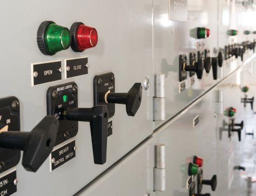
52 When to Consider a Retrofit Replacement Circuit Breaker
It is no secret that the majority of America’s infrastructure is old, with air-magnetic and even oil circuit breakers commonly in service decades beyond their 20-year design life. The longevity of air-magnetic medium-voltage circuit breakers is a testament to the reliability of the original designs, materials, and manufacturing methods, as well as the performance of those who maintain them today and over the last 30, 40, or even 50 years. But regardless of how well equipment is maintained, time takes its toll. Eventually, maintaining antiquated switchgear becomes impractical, and replacement options look appealing.
When that time comes, should a retrofit replacement breaker be considered against other options? The answer usually comes down to cost and how easily the end user can support the extended outage it will take to replace the gear. This article offers a look at the challenges to be considered when making that decision.
Paul H. Grein, Circuit Breaker Sales Co., Inc.
7 President’s Desk
Jim Cialdea, CE Power Engineered Services, LLC
NETA President
64 Medium-Voltage Circuit Breakers: Fit for Duty or in Need of Attention?
Bret Hammonds, Shermco Industries, and Robert Foster, Megger
73 Power Circuit Breaker Condition Assessment Based on Vibration Fingerprint Measurement: Why It Can Save Your Day
Adnan Secic and Kerim Obarcanin, DV Power
82 Testing Switchgear: Conventional vs. Both-Sides-Grounded Methods
Guy Wasfy, KoCoS America LLC, and Christian Studen, KoCoS Messtecknik AG
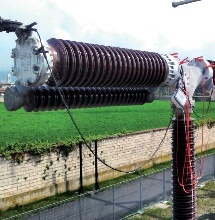

TABLE OF CONTENTS TABLE OF CONTENTS NETAWorld • 3
COVER STORY
52
82
Cover photo courtesy Brian Kaylor, Circuit Breaker Sales Co., Inc.
IN EVERY ISSUE
11 NFPA 70E and NETA
Overhead Power Lines + Unqualified Persons = Tragedy
Ron Widup and Jim White, Shermco Industries
18 No-Outage Corner
Overcoming Five Common Misconceptions About Online Switchgear PD Testing
Don A. Genutis, Halco Testing Services, Inc.
22 Tech Quiz
Medium-Voltage Circuit Breaker Safety
Jim White, Shermco Industries
34 Tech Tips
Ground Testing FAQs — Part II
Jeff Jowett, Megger
40 Safety Corner
Medium-Voltage Circuit Breaker Condition
Analysis and Hazard Awareness
Paul Chamberlain and Scott Blizard, American Electrical Testing Co., Inc.
46 Relay Column
Symmetrical Components Review: Base Quantities and Per-Unit
Steve Turner, Electrical Consultants, Inc.
INDUSTRY TOPICS
92 Passing the Torch
Dave Sowers, Knowledge Vine, LLC
ADVANCEMENTS IN TECHNOLOGY
112 Results are Only as Good as the Sample Taken
Nick Perjanik, PhD, Weidmann Electrical Technology Inc.
SPECIFICATIONS AND STANDARDS
106 ASTM F18 Committee Report
Jim White, Shermco Industries
108 ANSI/NETA Standards Update
NEWS NETA SETTING THE STANDARD
98 Changes in the Newly Published ANSI/ NETA ATS-2017, Standard for Acceptance Testing Specifications for Electrical Power Equipment and Systems
Jim Cialdea, CE Power Engineered Services, LLC, and Lorne Gara, Orbis Engineering Field Services, Ltd.
NETA NEWS
24 New NETA Board Member Scott Dude: ‘Impressed with the Integrity and Ethics of NETA’
26 Outgoing NETA President Ron Widup: ‘Drive the Discussion by Listening to Others’
30 Incoming NETA President Jim Cialdea: ‘We’ve Beaten a Lot of Our Challenges, but Need More People to Get Involved’
51 NETA Activities Update — January through June 2017
103 Notice of Errata for ANSI/NETA ATS-2017
IMPORTANT LISTS
120 NETA Accredited Companies
126 Advertiser List
4 • FALL 2017 TABLE OF CONTENTS
CONTENTS
TABLE OF


On the Potomac EARLY BIRD REGISTRATION SEPTEMBER 1 – DECEMBER 31, 2017 REGISTER EARLY & SAVE PowerTest.org 888.300.6382 Hosted by The Premier ● ● ● ● ● ● ● ● ● ● ELECTRICAL MAINTENANCE AND SAFETY Conference

3050 Old Centre Road, Suite 101
Portage, MI 49024
Toll free: 888.300.NETA (6382)
Phone: 269.488.NETA (6382)
Fax : 269.488.6383
neta@netaworld.org
www.netaworld.org
executive director: Missy Richard
NETA Officers
president: Jim Cialdea, CE Power Engineered Services, LLC
first vice president: Scott Blizard, American Electrical Testing Co., Inc.
second vice president: Lorne Gara, Orbis Engineering Field Services, Ltd.
secretary: Eric Beckman, National Field Services
treasurer: John White, Sigma Six Solutions
NETA Board of Directors
Ken Bassett (Potomac Testing, Inc.)
Eric Beckman (National Field Services)
Scott Blizard (American Electrical Testing Co., Inc.)
Jim Cialdea (CE Power Engineered Services, LLC)
Scott Dude (Dude Electrical Testing LLC)
Lorne Gara (Orbis Engineering Field Services, Ltd.)
Dan Hook (Western Electrical Services, Inc.)
David Huffman (Power Systems Testing)
Alan Peterson (Utility Service Corporation)
John White (Sigma Six Solutions)
Ron Widup (Shermco Industries)
NETA World Staff
technical editors: Roderic L. Hageman, Tim Cotter
assistant technical editors: Jim Caldea, Dan Hook, Dave Huffman, Bob Sheppard
associate editor: Resa Pickel
managing editor: Carla Kalogeridis
copy editor: Beverly Sturtevant
advertising manager: Laura McDonald
design and production: Moon Design
NETA Committee Chairs
conference: Ron Widup; membership: Ken Bassett; promotions/marketing: Scott Blizard; safety: Scott Blizard and Jim White; technical: Alan Peterson; technical exam: Dan Hook; continuing technical development: David Huffman; training: Bob Sheppard; finance: John White; nominations: Alan Peterson; alliance program: Jim Cialdea; association development: Ken Bassett and John White
© Copyright 2017, NETA
NOTICE AND DISCLAIMER
NETA World is published quarterly by the InterNational Electrical Testing Association. Opinions, views and conclusions expressed in articles herein are those of the authors and not necessarily those of NETA. Publication herein does not constitute or imply endorsement of any opinion, product, or service by NETA, its directors, officers, members, employees or agents (herein “NETA”).
All technical data in this publication reflects the experience of individuals using specific tools, products, equipment and components under specific conditions and circumstances which may or may not be fully reported and over which NETA has neither exercised nor reserved control. Such data has not been independently tested or otherwise verified by NETA.
NETA MAKES NO ENDORSEMENT, REPRESENTATION OR WARRANTY AS TO ANY OPINION, PRODUCT OR SERVICE REFERENCED OR ADVERTISED IN THIS PUBLICATION. NETA EXPRESSLY DISCLAIMS ANY AND ALL LIABILITY TO ANY CONSUMER, PURCHASER OR ANY OTHER PERSON USING ANY PRODUCT OR SERVICE REFERENCED OR ADVERTISED HEREIN FOR ANY INJURIES OR DAMAGES OF ANY KIND WHATSOEVER, INCLUDING, BUT NOT LIMITED TO ANY CONSEQUENTIAL, PUNITIVE, SPECIAL, INCIDENTAL, DIRECT OR INDIRECT DAMAGES. NETA FURTHER DISCLAIMS ANY AND ALL WARRANTIES, EXPRESS OF IMPLIED, INCLUDING, BUT NOT LIMITED TO, ANY IMPLIED WARRANTY OF FITNESS FOR A PARTICULAR PURPOSE.
ELECTRICAL TESTING SHALL BE PERFORMED ONLY BY TRAINED ELECTRICAL PERSONNEL AND SHALL BE SUPERVISED BY NETA CERTIFIED TECHNICIANS/ LEVEL III OR IV OR BY NICET CERTIFIED TECHNICIANS IN ELECTRICAL TESTING TECHNOLOGY/LEVEL III OR IV. FAILURE TO ADHERE TO ADEQUATE TRAINING, SAFETY REQUIREMENTS, AND APPLICABLE PROCEDURES MAY RESULT IN LOSS OF PRODUCTION, CATASTROPHIC EQUIPMENT FAILURE, SERIOUS INJURY OR DEATH.



LOOKING FORWARD, LOOKING BACK

It is an exciting time to be in the testing industry. New test equipment and techniques, new regulations, expansion of the transmission system, distributed generation, alternative energy, smart grid, and equipment upgrades all make for plenty of things for us to do – and to learn about.
NETA has released the update of ANSI/NETA ATS, Standard for Acceptance Testing Specifications for Electrical Power Equipment and Systems, 2017 edition, which contains many new tests to keep up with current industry trends. NETA also has a collection of courses to keep us and our technicians up to date. Both are excellent resources to help support current technicians and train new technicians to meet the increasing needs of our industry.
The last two years have gone well for NETA: new exam, new Executive Director, and successful growth in the industry. A lot of that has to do with the outstanding leadership demonstrated by Ron Widup, our past President. Thank you, Ron!
I look forward to being your President for the next two years and hope that I can at least come close to the great job Ron has done. Our dedicated staff, Board of Directors, volunteers, and Members all working together will certainly ensure that NETA continues to be the leader in the Electrical Testing Industry.
 James Cialdea, President NETA — InterNational Electrical Testing Association
PRESIDENT’S DESK PRESIDENT’S DESK
Jim Cialdea’s fi rst Board meeting as NETA President


We Buy, Sell, Trade, Calibrate, Repair
Featuring quality, reliable, on-time service and support for all brands and types of solid state power electronics.
Power electronics are our business
Let us suppoort you with our quality repair, calibration and servicing of your solid state equipment. We also buy, sell and trade:
•Communications devices for power equipment
•Protective relays
•Circuit breaker trip devices
•Motor overload relays
•Rating plugs
4701 Spartan Drive • Denton, TX 76207 (877-874-7349) • Phone: 940-243-3731 • Fax: 940-387-8277 Email: info@solidstaterepair.com • Web: www.solidstaterepair.com
“SOLID STATE” INDUSTRIAL ELECTRONICS “SOLID STATE” INDUSTRIAL ELECTRONICS Toll Free 877-TRIP-FIX NOWRENTING TESTEQUIPMENT


Circuit Breaker Seminar Test & Maintenance Training
October 2-6, 2017 | Pittsburgh, Pennsylvania USA
Brush up on fundamentals, get practical hands-on training, and learn from the experts at the industry’s best circuit breaker educational seminar.
• Learn the basics: history, application, lubrication techniques and apparatus controls
• Trends and regulations: stay current with sessions on SF6 management and challenges
• Hands-on learning: a full-day of specialized, small group sessions with circuit breaker manufacturers
• Earn credits: get professional development credits
• Industry expo: see the latest in circuit breaker products and services in one location

REGISTER TODAY events.doble.com/circuitbreakers

2017 See you at the best training on circuit breaker test & maintenance practices.
www.doble.com
2017

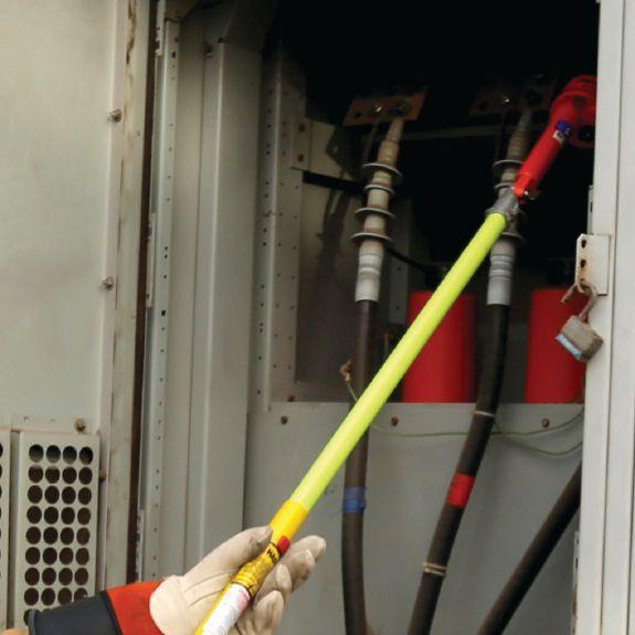



OSHA 29CFR1910.399 definition of a qualified person:
“Qualified person. One who has received training in and has demonstrated skills and knowledge in the construction and operation of electric equipment and installations and the hazards involved.”
Shermco’s Electrical Safety for Qualified Workers course meets the minimum mandated requirements of both OSHA and NFPA 70E.
Shermco’s field service technicians are required to complete this course. Shouldn’t you be training with the people who are in the field every day?
Don’t risk fines and events due to “check-the-box” training. Train with the experts. Train with Shermco


www.shermco.com 888-SHERMCO training makes all the difference. When the job calls for the best,
Questions? training@shermco.com




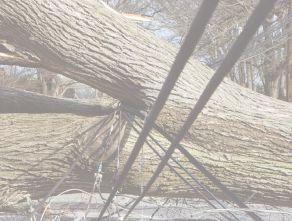


= TRAGEDY
BY RON WIDUP and JIM WHITE, Shermco Industries


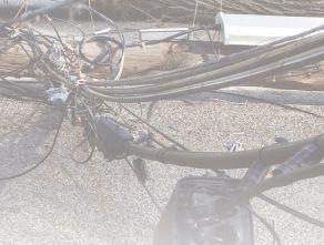


In January 2011, a tragic incident in San Bernadino, California, motivated us to write the Summer 2011 NETA World Journal column about the dangers of overhead lines. The incident in San Bernardino resulted in the electrocution of three family members: a father (44), a mother (43), and a son (21) who came in contact with a 12 kV overhead line that had fallen in their backyard during a windstorm. From news accounts, it appears that they went into the yard one by one — initially, to investigate the problem, and then, to help each other out — which resulted in three fatalities.
Unfortunately, things have not improved much since 2011. Statistically, contact with overhead lines still leads the pack for electrocution deaths. David Wallis, OSHA’s former representative on the 70E Technical Committee, made an impact statement years ago at one of the 70E Committee meetings that still resonates today. Paraphrasing, David said, “If someone in this room can come up with a way to reduce the number of overhead line contacts, we at OSHA will take it, because we can’t seem to effectively change the number
of incidents that occur each year, and something needs to be done.”
And so, we bring you another article to remind everyone, once again, how hazardous overhead lines can be — especially when the person near the lines is an unqualified person.
According to the Bureau of Labor Statistics, approximately 40 – 45 percent of electrocutions are the result of contact with overhead power lines. Many people assume the bulk of these


NETAWorld • 11 OVERHEAD POWER LINES + UNQUALIFIED PERSONS = TRAGEDY THE NFPA 70E AND NETA

THE NFPA 70E AND NETA
fatalities are caused by utility workers making contact. However, about 50 percent of the fatalities are from cranes, manlifts, and other types of mechanical equipment making contact, while the remaining 50 percent are from workers making contact through conduit, ladders, treetrimming equipment, etc.
THE DUMP TRUCK AND THE 69 kV LINE: A CASE HISTORY
A dump truck driver pulled his 40-foot box dump truck into a site where construction was taking place. He was to deliver a load of fill dirt being used for the construction. As he pulled his truck into position, he failed to notice the 69 kV power line directly over his truck bed. The driver did not have a spotter and did not check his clearances before he raised the box. Before the box of the truck made contact, the 69 kV overhead line arced over to the box of his truck, blowing out the truck’s tires and causing the protective relays to operate.

Photo 1 shows how the electrical current flowing through the tires to ground blew the front tires out. Photo 2 shows where the 69 kV arced over to the dump truck box trailer. The box did not make actual contact with the overhead power line, but came close enough to create a path to ground, initiating the fault.
What many unqualified people don’t realize is that higher-voltage overhead power lines are not

insulated to the operating voltage. If the line has a black covering on it, it is used primarily to protect the power cable from the effects of weathering. It provides no protection from the hazard of electrical shock.
In this instance, the box of the dump truck broke the cable’s plane of ionized gases surrounding the conductor, and a new path was created to ground. The stress from the higher voltage creates an area around power cables where the electrons of the air molecules are forced from their orbits. These loose or “free” electrons surround the power cable, looking for any path to ground. When a conductive object enters that area (breaks the plane), those free electrons will follow that conductive object to earth.
That is most likely what occurred with this dump truck box. Photo 3 shows the aftermath of the arcing and its effects on the overhead power line. Even though the power cable was suspended in air, it had to be replaced to prevent further deterioration.
Luckily, in this instance, the protective relays were sensitive enough to detect the fault, and the overcurrent protective system cleared the fault before causing significant damage. The truck driver did not have time to react to the incident and remained in the truck. Photo 4 and Photo 5 show where the electrical current flowed through the truck, through the tires and wheels, and into the earth.
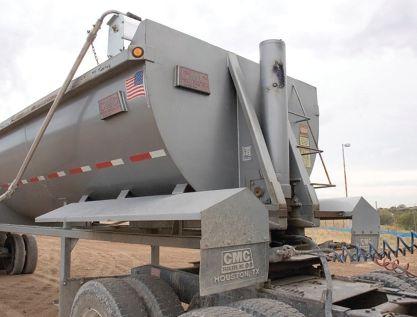
12 FALL 2017 OVERHEAD POWER LINES + UNQUALIFIED PERSONS = TRAGEDY
Photo 1: Tires — Conductors, Not Insulators
Photo 2: Scorch Marks on Dump Truck Box — Clear Evidence of Arcing Event

When electrical current flows through mechanical equipment into the earth, it sets up ground gradients of voltage (E). The electrical current (I) flows through the earth in these gradients, the earth has resistance (R), and Ohm’s Law (Figure 1) kicks in.
As a person moves closer to the electrical current point of entry, the voltage increases. This sets up a condition known as step potential. If that same person were to place one foot in front of the other (the normal way of walking), one foot will be at one potential and the other foot will be at a different potential. If the difference between the two potentials is great enough, current will be forced through that person’s

body, electrocuting them. This is a problem whenever mechanical equipment is used near energized overhead power lines. Workers near the mechanical equipment, who may not even be involved in the task being performed, are at risk of electrocution.
The driver of this dump truck insisted he did not make contact (true), but that his truck was struck by lightning (not so true). This is an example of an unqualified person placing himself and others at risk because he could not recognize the hazard and, therefore, did not avoid it.


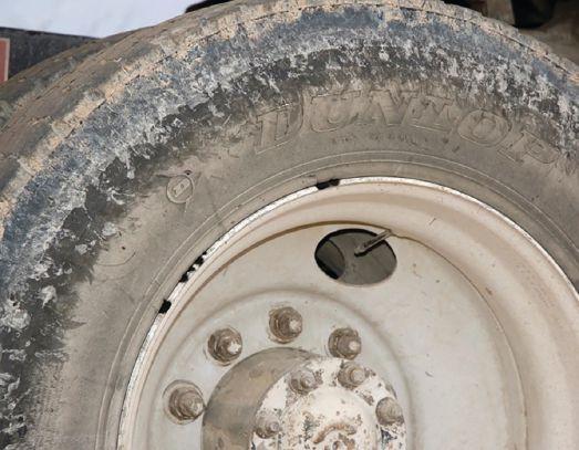

NETAWorld 13
THE NFPA 70E AND NETA
OVERHEAD POWER LINES + UNQUALIFIED PERSONS = TRAGEDY
Photo 4 and Photo 5: Flow of Current from Overhead Line to Ground
Photo 3: Damage to Overhead Power Line from Arcing (Replacement Needed)
Figure 1: Ohm’s Law

THE NFPA 70E AND NETA
Electrocutions by Year
STATISTICS FROM ELECTRICAL SAFETY FOUNDATION INTERNATIONAL
James Cawley, with Electrical Safety Foundation International (ESFI), was good enough to supply the most recent available information on electrical fatalities. Jim used to work for National Institute for Occupational Safety and Health (NIOSH). Figure 2 shows the number of electrocutions through 2015.
As you can see, the number of electrocutions has been dropping since about 1998. Even so, 134 fatalities directly related to contact with electrical current are still way too many.

Figure 3 shows electrocutions by occupation; construction always tops the list. Note, however, where Building and grounds maintenance and Farming, fishing and forestry occupations place in this graph. These are higher than would be expected. Many of these fatalities are caused
44% Contact with overhead power lines
27% Contact with wiring, transformers, or other electrical components
Construction and extraction occupations
Installation maintenance and repair occupations
Building and grounds cleaning and maintenance occupations
Farming, fishing and forestr y occupations
Production occupations
Transpor tation and material moving occupations
3: Electrocutions by Occupation
by tree trimming and similar tasks, where the perceived risk is low.
Figure 4 shows the percentage of electrical fatalities by event. At 44 percent, Contact with overhead power lines is by far the greatest cause of death from electrical hazards. This is from 1992 through 2010, but the ratio of fatalities between the different events changes very little from year to year.
Note that Contact with wiring, transformers and other electrical components is also a leading cause of electrocution. This is where most qualifiedperson fatalities would occur.
1% Contact with
5% Struck by
2% Contact with electric current, n.e.c.
4% Contact with electric current, unspecified
17% Contact with electric current of machine, tool, appliance or light fixture
Figure 4: 44 Percent of Electrocutions Due to Contact with Overhead Power Lines
14 FALL 2017 OVERHEAD POWER LINES + UNQUALIFIED PERSONS = TRAGEDY
0 50 100 150 200 Compiled by Electrical Safety Foundation International using data from U.S. Bureau of Labor Statistics, CFOI, 2011-2015 2011 2012 2013 2014 2015 174 156 141 154 134 400 300 200 100 0
by the Electrical Safety Foundation International using data from the U.S. Bureau of Labor Statistics, CFOI, 2011-2015
Compiled
Compiled by the Electrical Safety Foundation International using data from the U.S. Bureau of Labor Statistics, CFOI, 1992-2010
underground, buried power lines
lightning
Figure
THE NFPA 70E AND NETA
CONCLUSION
Remind your crews about the dangers of overhead lines and ask if anyone has an answer to David’s request to “come up with a way to reduce the number of overhead line contacts.”
Volunteer some of your time to educate unqualified workers and people in society about the hazards of overhead lines. Talk to
school kids, people in church, Boy Scouts, family, etc. Bring up step potential, shuffling your feet around downed lines, and overhead line avoidance, and highlight the hazards of overhead power lines.
Who knows, maybe collectively, we have David’s answer and can prevent another tragic event like the one in San Bernardino.
Ron Widup and Jim White are NETA’s representatives to NFPA Technical Committee 70E (Electrical Safety Requirements for Employee Workplaces). Both gentlemen are employed by Shermco Industries in Dallas, Texas, a NETA Accredited Company.

Ron Widup is CEO of Shermco Industries and has been with the company since 1983. He is a Principal member of the Technical Committee on Electrical Safety in the Workplace (NFPA 70E) and a Principal member of the National Electrical Code (NFPA 70) Code Panel 11. He is also a member of the Technical Committee Recommended Practice for Electrical Equipment Maintenance (NFPA 70B), and a member of the NETA Board of Directors and Standards Review Council.

Jim White is nationally recognized for technical skills and safety training in the electrical power systems industry. He is the Training Director for Shermco Industries, and has spent the last twenty years directly involved in technical skills and safety training for electrical power system technicians. Jim is a Principal member of NFPA 70B representing Shermco Industries, NETA’s alternate member of NFPA 70E, NETA’s Principal representative to NEC CMP13, and NETA’s Principal representative to the ASTM F18 Committee Electrical Protective Equipment for Workers.


PRECISION + SIMPLICITY
without compromise


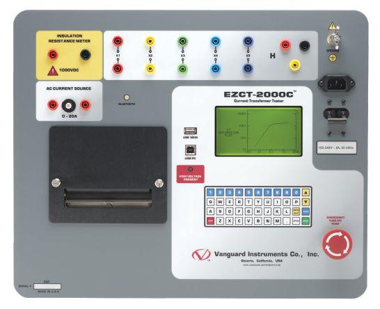
When it comes to substation testing, you shouldn’t have to compromise simplicity for precision and accuracy. That’s why, for over 25 years, we have designed our precision instruments to be intuitive and easy to use so that you can focus on testing instead of wasting time in training.
Our versatile instruments offer a built-in thermal printer and on-board test record storage so that tests can be conducted in stand-alone mode in the field. A computer interface is also offered so that tests can be easily conducted from a PC.
And all of our instruments are competitively priced to provide cost-effective accuracy. Visit us at www.vanguard-instruments.com today to find out why Vanguard Instruments is the right choice for your testing needs.



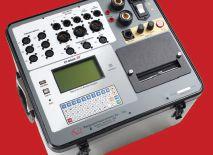

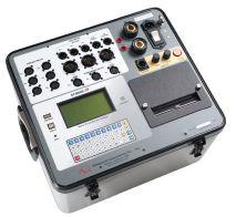

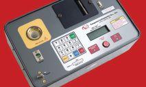

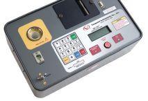


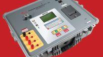




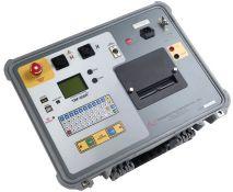
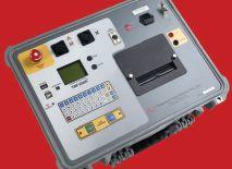

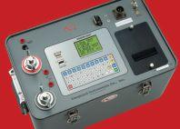



current transformer
circuitbreakeranalyzers vacuum bottle
winding resistance
circuit breaker contact resistance
current transformer
relaytestequipment Vanguard Instruments Company, Inc. www.vanguard-instruments.com | PH 909.923.9390 Ontario, California PROUDLY MADE IN THE U.S.A.
testers
testers
meters
meters
turns ratio testers



OVERCOMING

ABOUT ONLINE SWITCHGEAR PD TESTING
BY DON GENUTIS, Halco Testing Services, Inc.
Overcoming misunderstandings in the application of newer technologies can present unique challenges, but these challenges often create opportunities to educate skeptics and convince them that new technology can enhance reliability. Online switchgear partial-discharge testing is one technology that can help the customer realize their reliability goals, provided they are openedminded.

Here are five common misconceptions customers express and how to overcome them.
MISCONCEPTION #1 — “WE PERFORM ANNUAL INFRARED SURVEYS.”
This statement is usually made in conjunction with the customer puffing out their chest, leaving you with the challenge of further explaining the virtues of PD without excessively damaging their ego. Fortunately, the analogy of “infrared is to conductors as partial discharge is to insulation” helps a lot in this case. Once this is understood, it’s usually easy to make the advantages of PD testing apparent.
MISCONCEPTION #2 — “WE ALREADY PERFORM ULTRASONIC SURVEYS.”
This statement is often followed by, “Yeah, our infrared guy does it annually for no additional cost.” At this point, you can try to inspire a lengthy educational conversation or just show them Photo 1.
This photo was sent to us along with a thankyou note when our customer had an outage after we flagged high TEV signals. The problem was found behind the circuit breaker, which completely inhibited the ultrasonic pathway. Don’t get me wrong: Ultrasonics is a great tool, and infrared guys are good people. It’s just that ultrasonics can only detect surface defects and
OVERCOMING FIVE COMMON MISCONCEPTIONS ABOUT ONLINE SWITCHGEAR PD TESTING 18 • FALL 2017
NO-OUTAGE CORNER
relies on a pathway for the signals to escape to the outside of the switchgear enclosure. TEV signals from internal (switchgear or component) defects “ride” on outside switchgear surfaces. Ultrasonic and TEV technologies are complementary and work well together to provide greater overall flaw detection coverage.
MISCONCEPTION #3
— “WE’RE MOSTLY CONCERNED WITH THAT OLD SWITCHGEAR OVER THE HILL IN BACK.”

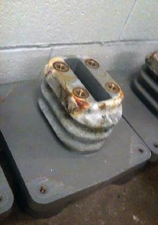
Photo 1: Severe tracking was detected deep within the switchgear assembly using TEV sensor technology.
Without the luxury of performing inexpensive, non-intrusive, condition-based insulation testing that doesn’t require an outage, many customers rely on age as the sole criteria for prioritizing equipment maintenance and replacement. There may very well be a logical explanation for why that old equipment is still in service, and that explanation could be related to the ceramic insulators more commonly employed with older switchgear construction. See the mini case study/war story at the end of this article.
MISCONCEPTION #4
— “WE’RE NOT GOING TO TEST THOSE TWO SUBS — THEY’RE NEW.”
This might be the most dangerous misconception of all, as it assumes an installation or workmanship problem can’t occur. Non-ceramic insulators, non-working space heaters, poorly made terminations, clearance problems, shipping and installation damage, etc., can all occur. You are more likely to find a problem with the new sub than you will with the old sub down over the hill. PD isn’t always where you think it
might be; that’s why it’s good to test for it in the first place.
WELL.”
This is sometimes, but not always, followed by “...so we put some tape on it.” Evidence of tracking can often be removed from the insulation surface, but that does not necessarily remove the reason the damage occurred in the first place, and it’s very likely that the problem will reoccur even though the insulation may look fine after cleaning. Sometimes the tape solution can help, but it can often make things worse (Photo 2). Is it possible that the tape altered the electrical field and contributed to the insulator tracking damage? I think so.
MINI CASE STUDY
Finding problems is probably the most rewarding part of being in the field. It allows you to display the value of performing your services to the client. The rewards of finding PD problems that were not detected by previous visual inspections or other test methods can be particularly profound.

Photo 2: Electrical tape applied at the top of the insulator altered the electrical field design, creating greater stress in the area where the tracking occurred.
When I flew across the country from Orlando to Seattle several years ago to perform an online switchgear and cable survey of a relatively small 15kV wastewater treatment plant on the Puget Sound, I fully expected to realize such a reward.
My assistant was a fine young technician who was naturally skeptical of new technologies but was reasonably opened-minded. I was sure I would be able to find
NETAWorld • 19 OVERCOMING FIVE COMMON MISCONCEPTIONS ABOUT ONLINE SWITCHGEAR PD TESTING
NO-OUTAGE CORNER

some problems and help launch this young man’s journey towards decades of PD detection rewards. Salt air and 15kV create the ideal recipe for PD, I thought. Yes, I can’t wait to see what we find.
However, as we went along through the survey, I wasn’t finding anything. That’s when I noted the equipment was completely constructed of ceramic insulators. When I explained this to the young technician, he became even more skeptical. My chance to make a positive impact on future generations was dissipating rapidly when, at the next-to-last enclosure, we found “near” cable PD. I initially suspected a termination problem. Then, at the final location just 25 feet away at the main, we detected strong ultrasonic and TEV signals. The diagnosis changed to local surface switchgear discharge with possible local termination discharge; unfortunately, we could not safely access the cable terminations for testing at this point. I left the project very pleased that fate had finally rewarded us with a significant detectable problem, but although my younger colleague was swaying a little, he remained unconvinced. I flew back home, hoping that the upcoming plant maintenance outage would reveal a good find for my new friend.
A few weeks later, my phone rang, and the breathless young technician could hardly control his excitement as he explained what he found: severe surface tracking on the glass epoxy interphase barriers in our suspect enclosure. He explained that plant personnel had installed permanent grounding provision hardware about six months ago to facilitate grounding out the bus.
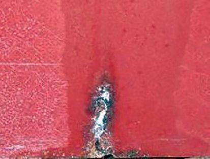
Photo 3: Bus grounding provision modifications created unintentional stress on the interphase barrier, leading to tracking.
The hardware was attached directly to the bus but positioned near the barriers with just a small air gap in between. This air gap allowed the electrical field to be compromised and led to the PD activity causing the tracking.
Sometimes, seeing is believing, and this experience will hopefully open the doors for my friend to find many more PD-inspired problems in the future. By the way, he sent me a photo (Photo 3) so I could see it, too.

Don A. Genutis is President of Halco Testing Services, Inc., a NETA Accredited Company, in Los Angeles, California. He has held various principal positions during his 30-year career in the electrical testing field and has primarily focused on advancing no-outage testing techniques for the last 15 years. Don holds a BS in Electrical Engineering from Carnegie Mellon University and is a NETA Certified Technician.
NO-OUTAGE CORNER
OVERCOMING FIVE COMMON MISCONCEPTIONS ABOUT ONLINE SWITCHGEAR PD TESTING 20 • FALL 2017

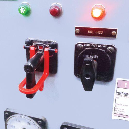

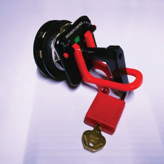


Jim White is nationally recognized for technical skills and safety training in the electrical power systems industry. He is the Training Director for Shermco Industries, and has spent the last 36 years directly involved in technical skills and safety training for electrical power system technicians.
Jim is a Principal Member of NFPA 70B representing Shermco Industries, NETA’s Principal Member of NFPA 70E, NETA's Principal Member of NEC CMP-13, and NETA’s Principal Representative to the ASTM F18 Committee Electrical Protective Equipment for Workers.


MEDIUM-VOLTAGE CIRCUIT BREAKER SAFETY
BY JIM R. WHITE, Shermco Industries


This Tech Quiz looks at various aspects of safety when working on or around medium-voltage circuit breakers. Certainly, one of the biggest areas of concern is the potential for an arc flash when installing or removing drawout circuit breakers.
1. Incident energy is directly proportional to
a. Short-circuit current
b. Distance
c. Voltage
d. Time
2. From a safety perspective, which of the following tests is most important?
a. First-trip testing
b. Time-travel analysis
c. Vacuum-bottle integrity
d. Insulation power factor
3. Which of the following tests provides the most accurate estimate of vacuum bottle life?
a. DC overpotential
b. Time-travel analysis
c. Insulation power factor
d. Magnetic atmospheric condition
4. Circuit breakers that stay in service for years without operating:
a. Are like brand new circuit breakers
b. Tend to have much lower insulation power factors
c. Are not likely to operate in accordance with manufacturer’s specifications
d. Will open much faster, since the lubricants are nice and fresh
22 • FALL 2017 TECH QUIZ TECH QUIZ See answers on page 119.
No. 119
_________.

In 1999, Dude moved back to Chicago and started an electrical testing division for Kelso-Burnett. In 2009, he set out on his own, founded Dude Electrical Testing, and the company earned NETA Accreditation in 2011.
No stranger to hard work, Dude says the spirit and ethics of current and former NETA Board Members inspire him. “I admire the hard work and dedication from current and former Board Members. It is what made me want to positively contribute to NETA to strengthen the association as a Member of the Board,” he says.
“I ADMIRE THE HARD WORK AND DEDICATION FROM CURRENT AND FORMER BOARD MEMBERS. IT IS WHAT MADE ME WANT TO POSITIVELY CONTRIBUTE TO NETA TO STRENGTHEN THE ASSOCIATION AS A MEMBER OF THE BOARD.”
“NETA is a collection of impact players who are really making a difference,” Hook says.
“What better job satisfaction could there be than to work with a great group of people who contribute at a very high level and achieve goals? The strategy and planning is backed up with a phenomenal work ethic.”
Among the many projects and initiatives he will be involved with during his term, Dude says one area is of particular interest to him. “Since I am former U.S. Navy, I would like to explore and expand NAMO — NETA Approved Military Organizations,” Dude says. “Training of field engineers has continued to be an obstacle for many NETA Accredited Companies, and the military could be a great help for our association.”

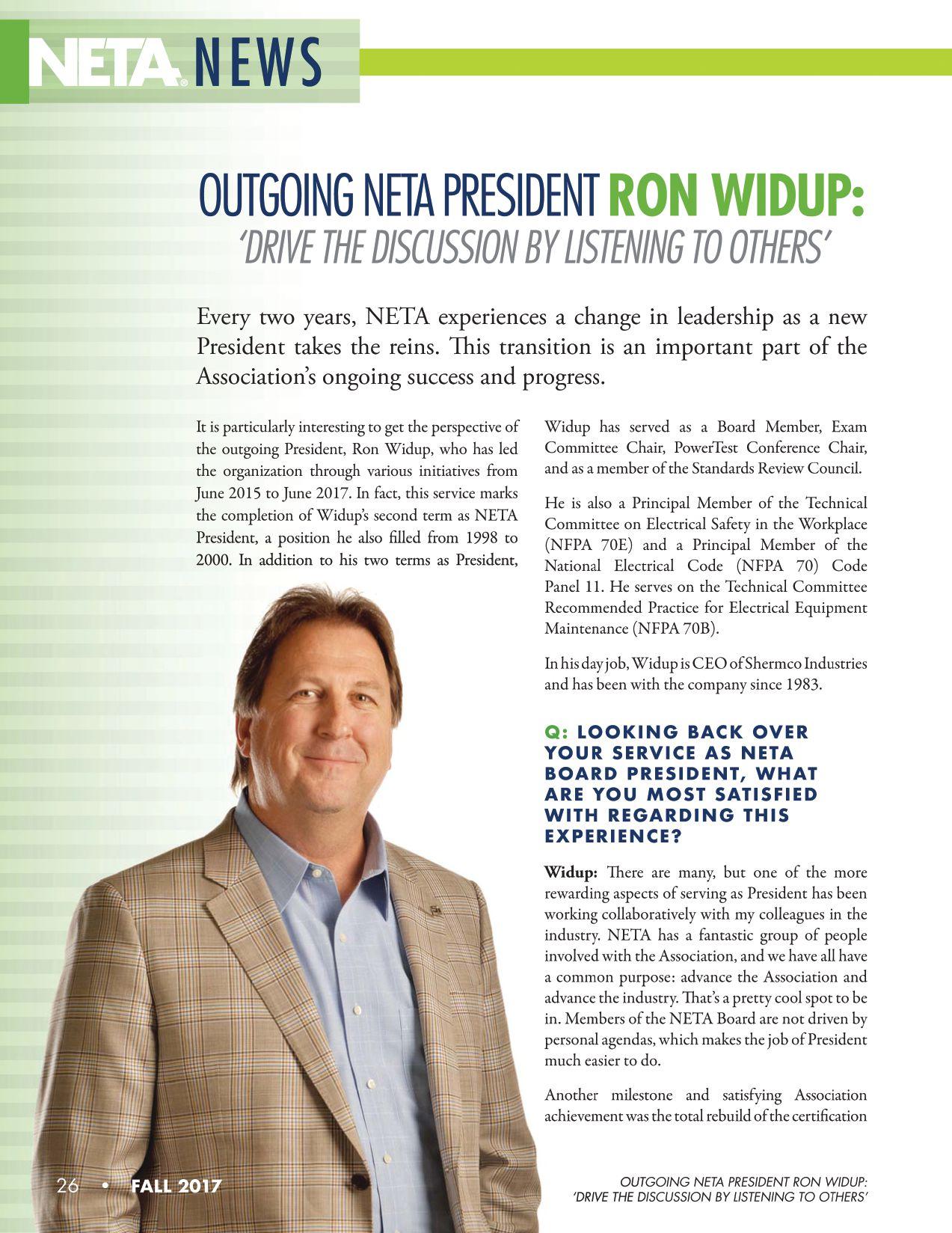
exam. It was the largest project NETA has taken on to date, and it greatly improved the quality and validity of certifying electrical power test technicians. Completed with many hours of dedication and passion from the Exam Committee, the NETA staff, and support from the NETA Board, we are in a much better place because of it.
Q: WHAT SURPRISED YOU THE MOST ABOUT SERVING AS NETA PRESIDENT?
Widup: This was my second time serving as President, so I basically knew what to expect. And while it wasn’t necessarily a surprise given who is doing the bulk of the work — the NETA staff — it was nice to see how they have continuously improved the processes that directly affect the running of the meetings and the Association. You always want to improve year-over-year, and it was evident to me that this has been the case through Jayne’s — and now Missy’s — leadership as Executive Director.
Q: WHAT WILL YOU MISS AND WHAT WILL YOU NOT MISS?
Widup: I will miss the road trips on the NETA Force One Learjet 45XR. It’s a nice perk to be able to have a quick dinner in the Bahamas or a sunrise breakfast in Alaska. And the trips to Camp David — wow!
But seriously, one aspect I won’t miss is the expected commitment to make every meeting and facilitate the flow and execution of the meeting. With two young boys still in school, there were times when schedules were a little complicated, but it all worked out and was definitely worth it.
Q: WHAT WILL KEEP NETA RELEVANT TO NEW YOUNG MEMBERS MOVING FORWARD?
Widup: One of the initiatives we drove was committee chair succession planning and getting more people involved. We worked on identifying
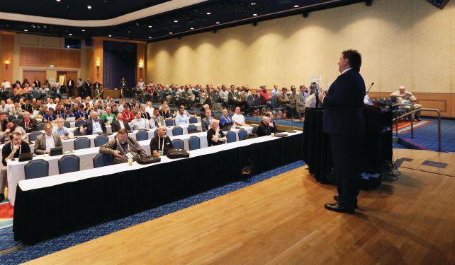
“RON
WIDUP HAS BEEN AN OUTSTANDING PRESIDENT. HE GOT NETA THROUGH THE CERTIFICATION EXAM PROCESS, WHICH WAS TOUGH. HE’S ALWAYS ON IT. RON HAS A GREAT SENSE OF HUMOR, BUT HE’S VERY SERIOUS ABOUT NETA.”
JIM
CIALDEA, Chief Technology Officer, CE Power Engineered Services, LLC, and incoming NETA Board President
areas of weakness for existing committee chairs who do not have a successor identified or do not have someone getting more involved.
You should always have your successor in mind and in training to take your job, and you do that by getting people involved in the Association. And if someone is interested in getting involved in NETA, they should let us know — as they say, you get out what you put in — and I can tell you from personal experience that this is a very accurate statement when you talk about getting involved with NETA.
Q: WHAT ADVICE DO YOU HAVE FOR INCOMING NETA PRESIDENT JIM CIALDEA?
Widup: Jim is a great guy, and I’m sure he will do a fantastic job in the NETA leadership position. I found that it is good practice to listen to others while discussing issues, step back a little, think about all of it in a holistic view, and drive the discussion from there. It took me a while to figure that out. Oh, yeah — and get a Twitter account.
NETAWorld • 27 OUTGOING NETA PRESIDENT RON WIDUP: ‘DRIVE THE DISCUSSION BY LISTENING TO OTHERS’


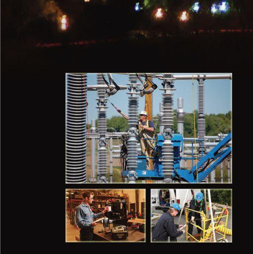







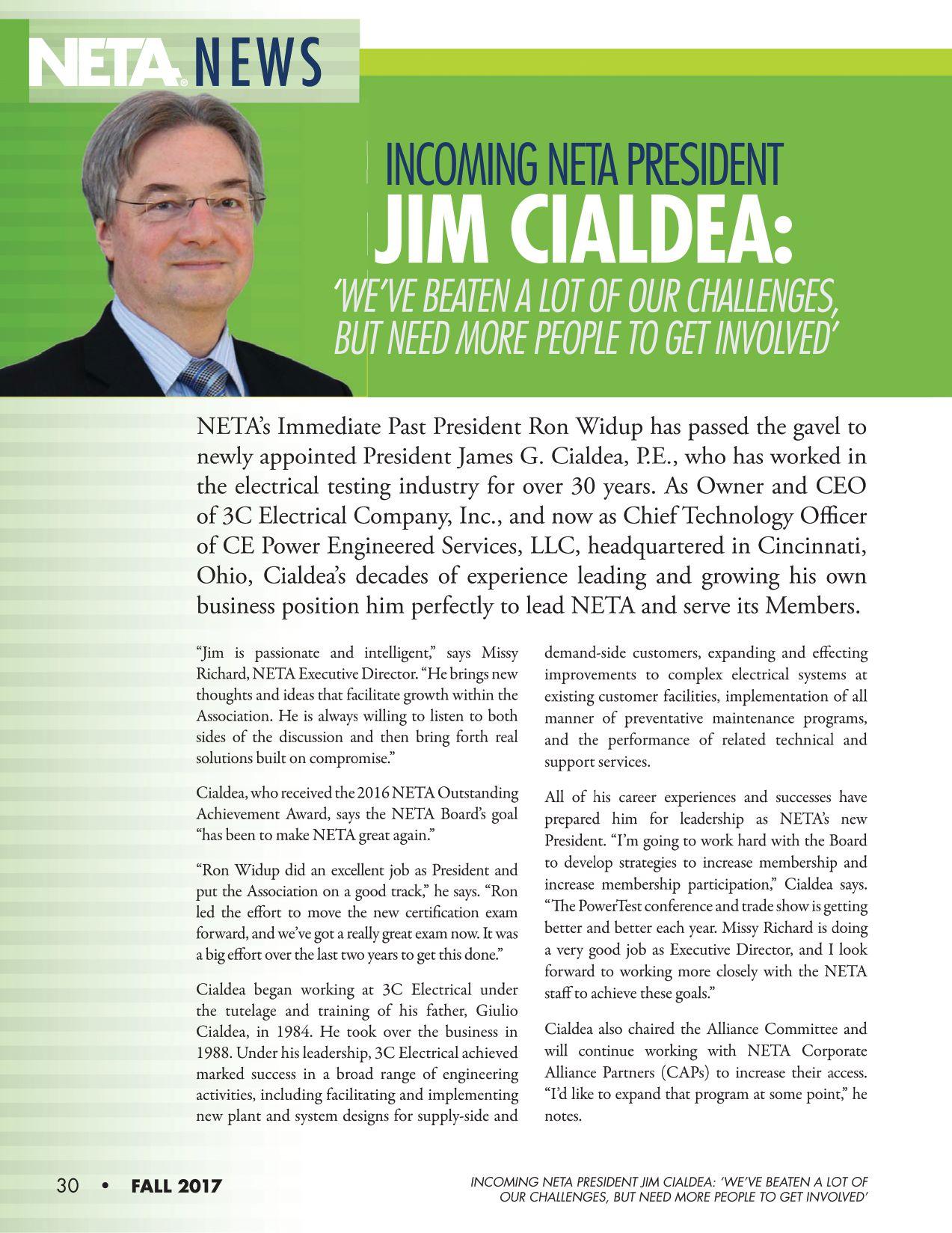
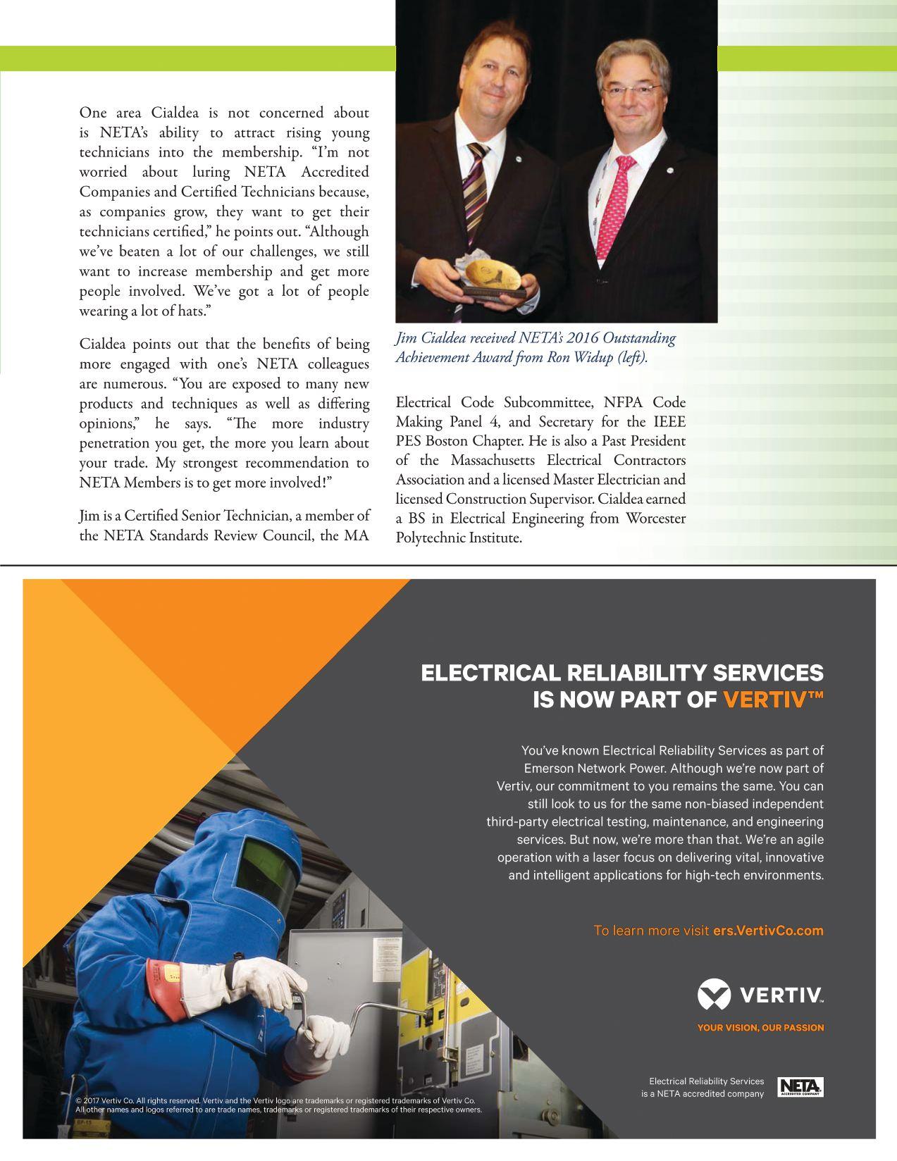



Q: WHY DON’T WE JUST PERFORM EVERY GROUND TEST AT 62 PERCENT AND BE DONE? WHY BOTHER WITH COMPLICATED AND TIMECONSUMING PROCEDURES LIKE FOP AND SLOPE?
The 62-percent rule is based on ideality, and the real world is anything but. Ideality includes, among other things, soil homogeneity (uniform type and composition) and adequate spacing of test probes. Actual test sites have often been graded, with different soil types brought in from varying sources. Under the potential probe, there might be a huge rock, a water main, a live electrical line, or numerous other inconsistencies. The current probe may not be out far enough for its resistance field to be effectively separated from the field being measured. Hence, a measurement taken at 62 percent could be too close to the IUT (too low) or too close to the current probe (too high), and it would be unknown. A fall-of-potential graph, as well as numerous other procedures, account for these possibilities and produce an accurate measurement.
The 62-percent rule is useful for repeat testing, such as annual maintenance, at a site that has been more rigorously proven by an FOP test. The distances and directions would then be known, and a 62-percent test could be performed quickly and reliably.
Q: MY TEST SHOWS THAT GROUND RESISTANCE IS MUCH TOO HIGH. WHAT CAN BE DONE?
There are three principle ways to improve the effectiveness of a grounding electrode and get it into spec: Add more rods, drive deeper, or use specialized electrodes. The most effective method is to drive deeper. As more contact is made with a longer rod, resistance goes down. If the water table is reached, that is ideal. A constant source of water will carry away unwanted fault currents and render the rod effective. In one case on record, a manufacturing plant used the water in
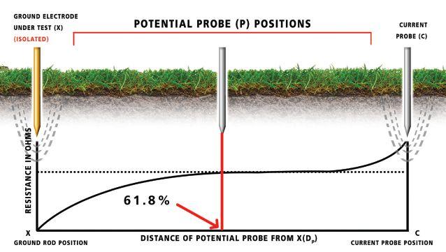

their process and thereby saved on the water bill while protecting the electrical system. However, even when the water table is reached, periodic testing should still be performed, as the water table can drop.
Driving deeper can be costly, especially where there is shallow bedrock, which requires expensive drilling. An easy alternative is to add more rods in parallel, connected in a network by a low-impedance conductor. The rule of thumb here is to space them farther apart horizontally than they are long; i.e., an 8-foot rod would be more than 8 feet away from the first rod. If closer, their electrical fields begin to coalesce into one, defeating the purpose. This method is comparatively easy and inexpensive, but the tradeoff is that the resultant array is relatively at the mercy of surface influences such as drying and freezing, which can be negative. Deeply driven rods are in a more stable environment well below surface. Substations get around any such problem by installing an enormous grid work underlying the entire facility.
A number of ground enhancement materials, treatments, and specialized electrodes are available. Some require regular maintenance while others are more static. At time of construction, a bore hole can be drilled and backfilled with bentonite, a naturally occurring mineral that holds moisture and promotes a constant, conductive environment around the


GROUND TESTING FAQS — PART II TECH TIPS
NETAWorld 35
Figure 1: Fall-of-Potential Test


rod. In addition, some synthetic alternatives claim to avoid the cracking and pulling away from the rod that may occur with bentonite. A less severe installation is to dig a trench around the rod and fill it with any of several conductive materials (Figure 2). These will leach away and so require regular attention. Some specialized rods can condense water from the atmosphere, while others can be filled with conductive liquids. These, of course, are only as good as the maintenance program supporting them.
Q: WHAT IS A DEAD-EARTH TEST?
Also called a two-point test, the name refers to using a convenient metal object that is not part of the electrical system, hence “dead.” This is traditionally the water-pipe system but can be anything convenient, such as a deep-driven

metal post. The idea is to shunt the terminals of the ground tester into just two, and then run one lead to the IUT and the other to the convenient return (Figure 3).
Running the test will then produce a series loop resistance of the entire circuit. It won’t give an actual measurement of the IUT, but if the loop resistance is sufficiently low, then the IUT’s resistance is lower still, and a “pass” can be reasonably assumed. The dead-earth test is a drop-dead test in the sense that it is really a last resort for areas like urban downtown, where congestion precludes virtually anything else. While it’s better than nothing, it is not accurate, rigorous, or all that reliable. At least it does enjoy inclusion in IEEE Std. 81-2012, Guide for Measuring Earth Resistivity, Ground Impedance, and Earth Surface Potentials of a Grounding System, with the relevant qualifications.
The dead-earth test has been performed since the beginning of ground testing, with all its limitations. But note that the popular clampon instrumentation that has appeared only in the last 25 years or so represents a significant improvement on this basic idea. Like the deadearth, the clamp-on provides the operator with a series loop resistance. But unlike the dead-earth test, where the operator designates the return path by alligator clip, the clamp-on finds its own return path primarily through the multi-
36 TECH TIPS
GROUND TESTING FAQS — PART II
Figure 2: Enhanced Ground Solutions
TECH TIPS
Figure 3: Dead-Earth or Two-Point Test
grounded utility neutral. The result is that the utility ground is expected to provide only a small amount of resistance and hence only a small error, whereas an element like the water pipe system or a post can easily contribute a significant error, which in turn can be mistaken for a bad ground.
Q: WHAT ELSE CAN BE DONE TO COPE WITH EXCEEDINGLY TIGHT QUARTERS FOR PERFORMING A TEST?
This is a serious and common problem when ground testing; there isn’t enough room to stretch out the leads and install the test probes sufficiently far from the IUT. If an FOP were performed, the graph would be unreadable. The line would just rise continuously from the resistance sphere of the IUT into that of the current probe. What to do?
Numerous specialized methods that rely on mathematics or some other clever adaptation are available in the ground-testing literature. Probably the most used is the slope method, common with utilities where large substation grids often translate into prohibitively long test leads. Also available is intersecting curves — a real challenge to the operator, but some people enjoy a challenge. Intersecting curves makes use of intricate graphing based on assumptions about the required spacing. Arbitrary graphs are drawn based on available spacing (Figure 4).
The distance from the start of these graphs (point of attachment of the tester) to the electrical center (which is unknown) is arbitrarily assigned and a second set of graphs drawn from the resistance at the 62-percent point from the arbitrary center. Only one value for the distance to the electrical center can be correct, and therefore only one 62-percent calculation can be correct. Plotting these resistance values against the arbitrary distances to the center will produce graphs that can intersect only at the correct resistance for the IUT. The four-potential method can be used where only one reasonable line of sight is available. Six measurements are taken at regular intervals and then processed through a series of
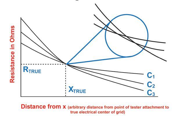

four equations that should substantially agree on the calculated resistance value (Figure 5).
The details of all these methods and others can readily be found in the literature.


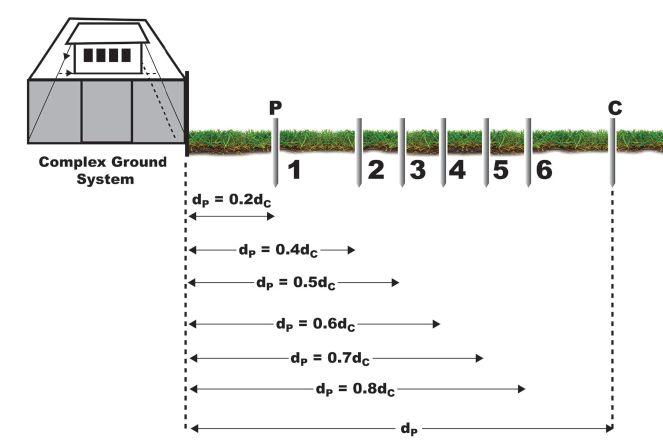
Q:
WHAT IF THERE IS NO SOIL IN WHICH TO DRIVE TEST PROBES?
This is a common problem in testing airport and parking lot lighting. Only macadam, tarmac, or asphalt is available for hundreds of feet. Modern testers are sufficiently sensitive so


NETAWorld 37 GROUND TESTING FAQS — PART II
Figure 4: Intersecting-Curves Method
TECH TIPS
Figure 5: Four-Potential Method


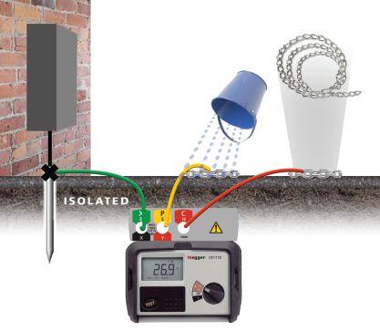
that only surface contact is required for a test. In place of pointed probes, use coiled metal chain or metalized grounding mats for the test probes, and pour water to make good electrical contact (Figure 6).
The fail-safe here is the indicator on the tester’s display. The tester will indicate if contact is not sufficient, and steps can be taken (more chain, ionized water) to improve contact. Once the indicators clear the test, the result is good.
Q: WHAT KIND OF WIRE SHOULD BE USED?
This parameter is very forgiving. There are few demands on ground-testing wire. There is a good chance that any spare wire lying around may suffice if you need to run longer leads. The tester’s specifications will tell you the limitations of various gauges, and it is typically longer than you’re likely to need. A 14-gauge rubber-insulated wire is fine. Smaller gauges can be used, down to 18-gauge. You’ll want stranded so that it can be easily rolled up and manipulated in the field.
Q: HOW DO I KNOW HOW MANY RODS TO PARALLEL OR HOW DEEP TO DRIVE?
There are two ways. One is to drive and test or add and test. This is common. A rod is driven and tested. If resistance is too high, a coupler and second rod are added and tested again, and
so on, until the requisite ground resistance is achieved. The same process applies to paralleling additional rods. This technique often works, but it can become tedious and counter-productive. Generally, a second rod will reduce resistance by about 40 percent. This looks great and gives the impression that another rod or two is all that is required. Not so! Each increment is smaller and smaller, so that you could end up chasing a chimera.
A more efficient method is to employ software, available from grounding materials suppliers, that allows you to enter relevant data and designs the system for you. A requirement will be a soilresistivity measurement taken at the site and entered into the software. A four-terminal ground tester will be necessary, but the measurement is readily taken. The desired ground resistance must also be entered, and the program may ask for some other details or preferences. Nomographs can be found in old literature that could be worked out to the same ends, but modern software is clearly the way to go.
CONCLUSION
It’s a common joke in the electrical industry — and just about everywhere else — that no one reads the instructions except as a last resort. However, reading the instruction manual first makes operation of test equipment more efficient and effective, cuts down significantly on errors, and above all, promotes safety. Note that instruction manuals tend to focus on ideal conditions and operation, while in the world of grounding and ground testing, there are many variables. Knowledge is as effective a tool as a piece of equipment, so it is useful to gain as much knowledge as possible outside the box.

Jeffrey R. Jowett is a Senior Applications Engineer for Megger in Valley Forge, Pennsylvania, serving the manufacturing lines of Biddle, Megger, and MultiAmp for electrical test and measurement instrumentation. He holds a BS in Biology and Chemistry from Ursinus College. He was employed for 22 years with James G. Biddle Co., which became Biddle Instruments and is now Megger.
TECH TIPS
38 GROUND TESTING FAQS — PART II
Figure 6: Ground Testing on Asphalt - Lazy Spike






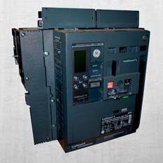
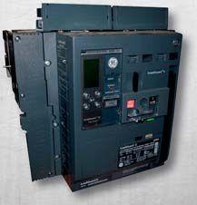


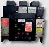


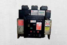

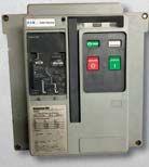
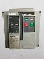
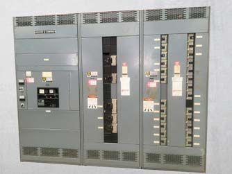
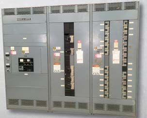


www.bcsswitchgear.com Are you having Power Equipment Problems? BCS HAS THE SOLUTION! new ∙ used ∙ obsolete ∙ reconditioned TEXAS OFFICE 4790 Hwy 377 South Krugerville, TX 76227 FAX 940-365-1808 ABB ∙ GENERAL ELECTRIC ∙ ITE GOULD ∙ WESTINGHOUSE ∙ SIEMENS SQUARE D · ALLIS CHALLMERS ∙ FEDERAL PACIFIC Call Toll Free: 888-599-0486 SWITCHGEAR, INC. Powering industry with superior equipment since 1999.
4790 US Hwy 377, Suite 100 Krugerville, TX 76227
940-440-0391
sales@vacuumreplacementinterrupters.com
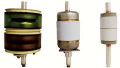
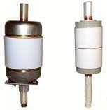
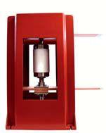
VRI is proud to announce our new VR Interrupters for the GE line of Vacuum Breakers. Products include; Outdoor PVDB1 15 kv, Indoor VVC, PVVL, VB and VB1 Vacuum Circuit Breakers, ranging from 5-15kv, 1200-2000 amp. These interrupters are ANSI C.37 rated and are drop in replacements vacuum interrupters.
VRI also has the newest Vacuum Interrupter Pressure Test Set (VIP-TS-1) that uses the Paschen’s Law and Paschen’s curve to determine the life of your vacuum interrupters. This VIP-TS-1 also makes it possible to test VI’s in-house and will test most 5-15kv vacuum circuit breakers in the market with VI’s still installed on breaker.
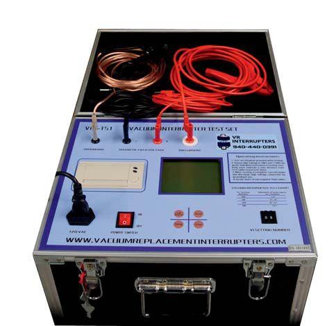
www.vacuumreplacementinterrupters.com
FOR G.E.
NEW
TEST SETS AVAILABLE


On the Potomac CALL FOR EXHIBITORS The premier ELECTRICAL MAINTENANCE AND SAFETY Conference ● ● ● ● ● ● ● ● ● ● H Join 400+ electrical testing professionals H Leading decision makers looking for new products and services H For attendee profile and additional information, visit www.powertest.org PowerTest.org 888.300.6382 Hosted by

MEDIUM-VOLTAGE AND HAZARD AWARENESS
BY PAUL CHAMBERLAIN and SCOTT BLIZARD, American Electrical Testing Co., Inc.
When performing a condition analysis on medium-voltage circuit breakers located in metal-clad switchgear, it is necessary to be aware of all potential hazards. The person performing the condition analysis must be qualified to perform the task and have a solid understanding of each possible hazard they may encounter and ways to minimize the risks.


To better understand the hazards involved with the analysis, testing, and maintenance of medium-voltage breakers, let’s look at the sources that contribute to each hazard.
LOCK OUT/TAG OUT OF ELECTRICAL AND MECHANICAL ENERGY
Improperly performed lock out/tag out is the primary cause of many injuries when performing maintenance on medium-voltage breakers. Electrical energy is the first and most obvious hazardous energy source that could cause injury while working on any electrical equipment.
Being aware of the breaker compartment layout is equally important. Many injuries and incidents occur while opening the breaker and then performing the visual verification that it is open. In many cases, the compartment
is isolated or physically a significant distance from the equipment being operated. Doublecheck the markings and nomenclature for each compartment to determine how it is arranged. A secondary method to verify no load is to use an ammeter within the switchgear, if one is associated with that equipment. During this step, electrical and mechanical energy become potential hazards depending upon the type of breaker. It is also necessary to isolate the electrical source and discharge any stored energy. Ensure that the breaker is not removed from service while in a closed position. Always check that the breaker is open prior to racking.
Electrically de-energize the breaker from its primary energy source and ensure that the breaker is disconnected from all sources of power, both ac and dc, if applicable. Once de-energized, verify that the breaker is at a zero energy state using the manufacturer’s approved method.
MEDIUM-VOLTAGE CIRCUIT BREAKER CONDITION ANALYSIS AND HAZARD AWARENESS
SAFETY CORNER 40 • FALL 2017
Verify the accuracy of the detection or voltage measuring device against a known source, check for zero energy on the de-energized equipment, and then re-test the detection equipment against another known source. This will verify that the detection equipment was functional during the check. Testing for voltage will require its own level of Personal Protective Equipment (PPE) depending upon the voltage and test procedure per NFPA 70E 2015 Table 130.7(C)(15)(A)(a) & (b) and 130.7(C)(15)(B). (Editor’s note: The 2018 edition of NFPA 70E is targeted for release in early August 2017.) If an arc-flash analysis has been performed on the equipment, use this information to determine your potential exposure and the PPE that will be necessary to mitigate it. It may also be necessary to lock out and tag out the actual compartment from which the breaker has been removed.
However, electrical energy isn’t the only energy that requires lock out/tag out; breakers also contain a large amount of mechanical energy. This energy must be removed prior to servicing or serious injury could occur. Once the breaker’s mechanical energy has been discharged, then lock out and tag out the charging mechanism, if feasible. Ensure that remote operating handles are tagged in a local or manual mode. This will prevent inadvertent operation of the breaker.
Gas and hydraulic operating mechanisms may be pressurized, if present. Ensure that the unit is depressurized and/or discharged and the source of the pressure is disabled. Once disabled, this source must also be locked out/tagged out prior to performing maintenance.
OTHER PHYSICAL HAZARDS
Gravity is an easily forgettable energy that must be controlled. The sheer size and weight of medium-voltage breakers makes them difficult to rack in and out or to maneuver around. When available, use remote racking equipment. Mechanical lifting devices should be used when available to move the breaker to an area where it can be serviced.
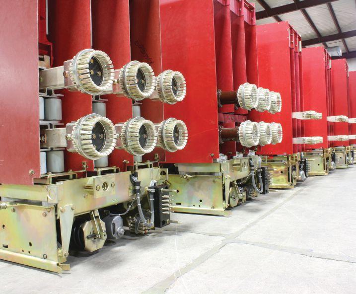
INSTALLATION OF TEMPORARY PROTECTIVE GROUNDS
Refer to manufacturers’ recommendations, OSHA 29 CFR 1910.269, and NFPA 70E for specific guidance on grounding locations and sizing of grounds required for the task. Grounds must always be applied upstream and downstream of the equipment and as close to the work as possible. Ensure that all work on electrical equipment is done between grounds, when possible, and that they are removed once the work is complete. The best means for accomplishing this is to use a tracking method for all grounds applied and removed. This can take the form of a handwritten log or a computer spreadsheet.
PROPER PERSONAL PROTECTIVE EQUIPMENT
After verification that the breaker is electrically de-energized, rack out the breaker. Use remote
NETAWORLD • 41 • MEDIUM-VOLTAGE CIRCUIT BREAKER CONDITION ANALYSIS AND HAZARD AWARENESS
SAFETY CORNER
Photo courtesy Brian Kaylor, Circuit Breaker Sales Co., Inc.
SAFETY CORNER
racking and un-racking equipment to minimize exposure if available. Ensure that proper personal protective equipment (PPE) is used for the class of breaker that will be serviced. Again refer to the Arc Flash Analysis, NFPA 70E, or 1910.269. These indicate the level of protection required for the class of breaker worked on; this will prevent electrical shock and protect personnel from arc flash. However, remember that the tables in OSHA and NFPA 70E provide information based upon known values of the short-circuit current available, the clearing time in cycles, and minimum working distance. If those factors are unknown, more information must be gathered prior to performing the work to ensure personnel safety.
CHEMICAL HAZARDS
Chemicals can be a hazard depending upon the type of breaker. Sulfur hexafluoride (SF6) gas is used as an insulating medium in some breakers. Caution must be taken with damaged breakers that exhibit arcing because this can form disulfur decafluoride, which is an extremely toxic gas. SF6 is denser than air, so it displaces oxygen in lower lying areas. Ventilation must be used to avoid gasses from being trapped.


Some lubricants and cleaners may pose a respiratory and skin irritant if used in enclosed areas or on bare skin. Knowledge of the material, reading its label, and checking the Safety Data Sheet (SDS) is advised to identify any potential health effects. Using the proper type of PPE is necessary for using some cleaners and lubricants. For example, nitrile gloves, safety glasses, face shield, and even respiratory protection may be needed in some cases.
CONCLUSION
There are many things to watch out for when we are performing maintenance and testing on a breaker.
• Obtain all service bulletins, maintenance documents, arc flash studies, and
manuals prior to beginning work for that specific device.
• Review relevant prints and one-lines associated with the equipment.
• Establish a safe work area and barricade off the work area.
• Perform a pre-job brief with all employees on-site performing the work, impacting the work, or being impacted by the work.
• Wear proper PPE for the task being performed.
• Disconnect the breaker control circuit and test equipment before performing visual or mechanical inspections and maintenance.
• Verify that there is zero energy (test, check, test) and discharge all stored energy, including pressurized gasses or mechanical energy.
• If possible, lock out and tag out all sources of energy.
• Connect grounds where and if applicable and track them.
• Identify, visually mark, and/or flag the equipment worked on.
Following these steps can led to a safer work environment while performing maintenance and testing of medium-voltage breakers.
Paul Chamberlain has been Safety Manager at American Electrical Testing Company Inc., since 2009. He has been in the safety field for the past 12 years, working for various companies and in various industries. Paul holds a BS in Marine Safety and Environmental Protection from Massachusetts Maritime Academy.

Scott Blizard has been Vice President and Chief Operating Officer at American Electrical Testing Co., Inc. since 2000. During his tenure, Scott acted as the Corporate Safety Officer for nine years. In addition, he has over 25 years of experience in the field as a Master Electrician, Journeyman, Wireman, and NETA Level IV Senior Technician.
42 • FALL 2017 MEDIUM-VOLTAGE CIRCUIT BREAKER CONDITION ANALYSIS AND HAZARD AWARENESS





AET Brings Precision and Value to Electrical Testing, Commissioning and Engineering… and Positive Results to Our Customers. AET delivers the best value in the marketplace by offering the highest quality service at competitive prices. With a workforce and offices located throughout the country, AET is an industry leader and one of the largest independent electrical testing companies in the U.S.
learn more about AET’s full range of testing and engineering services, visit www.aetco.us/NETA WWW.AETCO.US • 800.992.3826
An Company A Subsidiary of
To
The Power of Positive Results



A FULL SERVICE NETA ACCREDITED ELECTRICAL TESTING COMPANY. Serving the Sacramento and San Francisco Bay Area 916-853-6280 www.apparatustesting.com • Acceptance Testing • Commissioning • Maintenance Testing • High Voltage Substations • Short Circuit and Coordination Studies • Data Centers and UPS Systems




SYMMETRICAL COMPONENTS REVIEW: BASE QUANTITIES AND PER-UNIT
BY STEVE TURNER, Electrical Consultants, Inc.
Impedance is used to calculate fault current, so it is useful to understand how to calculate impedances in per-unit.
IMPEDANCE (Z)
Impedance is composed of resistance (R) and reactance (X), which are orthogonal to each other:
Z = R + X·j
|Z| = (R2 + X2 )½
R = resistance
X = reactance
The unit for impedance is ohms.
OHM’S LAW
Ohm’s Law states that the voltage drop (V) is the product of the current (I) and the impedance (Z) as illustrated in Figure 1. E is the ac source.
If the resistance is ignored or negligible, then the impedance is simply equal to the reactance, as is often the case when calculating fault current.
Reactance only (X):
I = V/X
V = I∙X
+ I
Figure 1: Ohm’s Law
POWER EQUATION
The power (P) equation is given below. Power is a necessary quantity to convert impedance from ohms to per-unit. P = E∙I E = I∙R
SYMMETRICAL COMPONENTS REVIEW: BASE QUANTITIES AND PER-UNIT RELAY COLUMN
∙
∙
46 • FALL 2017
P = I
I
R = I2∙R
E
Z ( = X) V
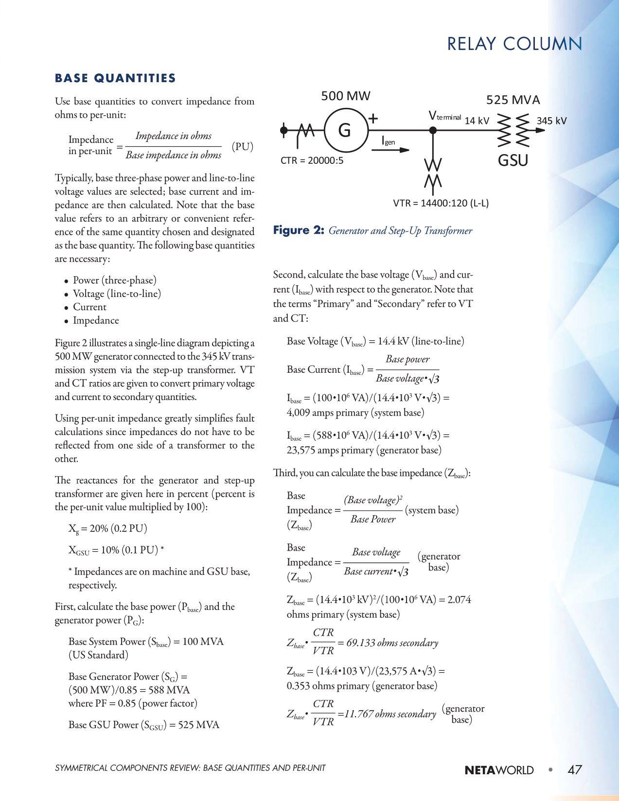

RELAY COLUMN
PER UNIT
Here is how to convert impedance to per-unit:
Per-Unit Value = Measured Value Base Value
Here is how to convert the impedance from one base power to another:
Znew = Zold∙ MVAnew MVAold
Convert the transformer impedance to the generator base:
XGSU = 10% (GSU base) = 0.1 per unit
XGSU = (0.1 PU) 588 MVA 525 MVA = 0.112 per unit (generator base)
Here is the generator impedance: Xg = 0.2 per unit (generator base)
THREE-PHASE FAULT CALCULATIONS
Calculate Generator Current and Voltage for a Three-Phase Fault at High Side of GSU
The final example illustrates the practicality of using per-unit to calculate fault current (Figure 3).

Calculate the generator current and voltage for a three-phase fault at high side of GSU.
Calculate the fault current IF as follows using Ohm’s Law:
= 1 Xg+ XGSU
= 1 0.2 + 0.112 = 3.205 PU
Convert per-unit fault current to primary amperes as follows:
IF∙Ibase (gen) = 3.205∙23,575 A = 75,560.9 amps primary
75,561∙ 5 20000 = 18.9 amps secondary
where 20,000:5 is the CT ratio (CTR)
Calculate the voltage drop (Vterminal) across the generator as follows:
Vterminal = Xg∙IF
Vterminal = 0.2·3.205 = 0.641 per unit
Vterminal = Vterminal (pu)∙Vbase (gen) = 0.641∙14,400 V = 9.23 kV (line-to-line)
9,230∙ 120 14400 = 76.92 volts secondary (line-to-line)
where 14,400:120 is the VT ratio (VTR)
CONCLUSION
This article demonstrates how to calculate base quantities that are then used to calculate the fault current. Using per-unit impedance greatly simplifies fault calculations since impedances do not have to be reflected from one side of a transformer to the other, as illustrated in the previous example. It is suggested as a final exercise to calculate the fault current measured by the generator CTs for a three-phase fault at the generator terminals.

Steve Turner is a Senior Engineer II at Electrical Consultants, Inc., working in their San Diego office. Steve worked at Beckwith Electric Company, Inc. for 10 years, first as the Engineering Laboratory Director and then as Senior Applications engineer. His previous experience includes working as an Application Engineer with GEC Alstom and as an Application Engineer in the international market for SEL focusing on transmission line protection applications. While at Duke Energy (formerly Progress Energy), Steve developed the first patent for double-ended fault location on overhead high-voltage transmission lines and was in charge of all maintenance standards in the transmission department for protective relaying. Steve has both a BSEE and MSEE from Virginia Tech University.
IF
IF
48 • FALL 2017 SYMMETRICAL COMPONENTS REVIEW: BASE QUANTITIES AND PER-UNIT Figure
X F + E g = 1 PU IF X g + X GSU
3: Fault Impedance Diagram (Three-Phase Fault)


NETA ACTIVITIES UPDATE — JANUARY THROUGH JUNE 2017
IEEE IAS ESW Conference
January 28 – February 3, 2017
IEEE International Applications Society (IAS) hosted its annual Electrical Safety Work Shop in Reno, Nevada. Key topics included Accelerate Application of Breakthrough Improvements in Human Factors; Technology and Managing Systems that Reduce Risk of Electrical Injuries; Stimulate Innovation in Overcoming Barriers; and Change and Advance the Electrical Safety Culture to Enable Sustainable Improvements in Prevention of Electrical Accidents and Injuries. NETA participates each year as an exhibitor and recognizes the IEEE ESW conferences as a must-attend event for electrical power industry professionals looking for the latest in electrical safety training.
training sessions, the conference provided a broad agenda of technical training opportunities for technicians, engineers, project managers, and professionals involved in the testing and maintenance of electrical power systems.
International Conference of Doble Clients
March 12 – 17, 2017

TechCon North America, 2017 Conference
February 14 – 16, 2017
TJ|H2b hosted TechCon North America in Houston, Texas, earlier this year o ering three days of advanced training. e event brings together utility industry experts, engineers, corporate suppliers, and decision-makers committed to advancing the industry. NETA participated in the Industry Expo in support of the power utility industry, providing access to training and the ANSI/NETA Standards for Electrical Commissioning, Acceptance Testing, Maintenance Testing, and Certi cation of Electrical Testing Technicians.
PowerTest 2017 – Electrical Maintenance and Safety Conference
February 26 – March 3, 2017
NETA hosted PowerTest 2017 in Anaheim, California, drawing record attendance of over 1,000 participants. With more than 47 unique
Held annually in Boston, Massachusetts, the International Conference of Doble Clients brings together professionals from all business sectors serving the power industry and addresses pressing topics a ecting power generation, transmission, and distribution. NETA contributed to the training sessions by presenting ANSI/NETA ATS2017, Standard for Acceptance Testing Speci cations for Electrical Power Equipment and Systems by Jim Cialdea, Chief Technology O cer at CE Power Engineered Services, LLC, and newly elected NETA President. NETA joined more than 100 industry suppliers at the Doble Expo and o ered technical training courses, ANSI/NETA standards, and technical resources.
Annual Planning and Board of Directors Meeting
June 15 – 16, 2017
NETA held its Annual Planning and Board of Directors meetings in Chicago, Illinois. Planning discussions centered on association development, membership services, technician certi cation, NETA training resources, and updates to the ANSI/NETA standards. Committee Chairs reported on accomplishments in 2017, and the Board of Directors approved plans for scal 2018 to keep NETA on track with longterm goals. e NETA Board of Directors also welcomed new Board Member Scott Dude of Dude Electrical Testing.
NETAWorld • 51 NETA ACTIVITIES UPDATE — JANUARY THROUGH JUNE 2017

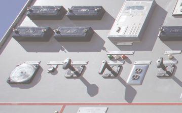





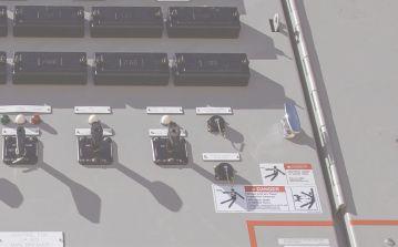


A RETROFIT REPLACEMENT

WHEN TO CONSIDER CIRCUIT BREAKER
 BY PAUL H. GREIN, Circuit Breaker Sales Co., Inc.

It is no secret that the majority of America’s infrastructure is old. Speak with any field service technician, and you will hear a story about some piece of gear they recently worked on that Edison or Westinghouse must have commissioned himself. While it may be an exaggeration, it is commonplace for air-magnetic and even oil circuit breakers to be in service decades beyond their 20-year design life.
The longevity of air-magnetic mediumvoltage circuit breakers — especially General Electric’s Magne-blast, Westinghouse’s DH and DHP, and ITE’s HK — is a testament to the reliability of the original designs, materials, and manufacturing methods, as well as the performance of those that maintain them today and over the last 40 years. However, regardless of how well equipment is maintained, time eventually takes its toll. Eventually, maintaining antiquated switchgear becomes impractical and
replacement options look appealing. This article discusses the options when that time comes, and specifically, when a retrofit replacement breaker should be considered versus the other options available.
WHAT IS A RETROFIT, ANYWAY?
The first logical step in discussing retrofit replacement circuit breakers is to define them.
COVER STORY WHEN TO CONSIDER A RETROFIT REPLACEMENT CIRCUIT BREAKER 52 • FALL 2017
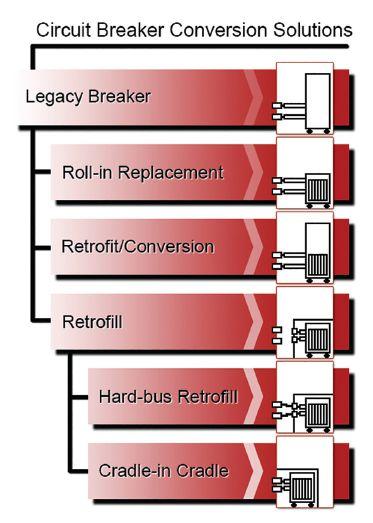
Defining and explaining the various methods of converting switchgear is a subject unto itself, but basically, a retrofit is the product/ process of altering an existing power switchgear equipment design from any qualified design. While “retrofit” is the commonly used term in the industry, the IEEE accepted terminology is “conversion,” as there are many ways to convert a qualified design, retrofit being one of them. The following list defines and summarizes the methods switchgear conversions are performed.
Roll-in/Direct Replacement
A roll-in or direct replacement is, arguably, not a conversion. A direct replacement is a new circuit breaker that installs directly into the existing cubicle with no (or very simple) modifications. The breaker racks into the switchgear line-up and correctly interfaces with the existing compartment cell. The original racking mechanism, safety interlocks, primary/ secondary/ground disconnects, and MOC/TOC switches inherent in the original equipment design are maintained. The switchgear structure is not modified.
While not always the case, it is common for the original equipment manufacturer
(OEM) to provide a roll-in replacement for its legacy equipment. The primary advantages of direct replacement circuit breakers include maintaining interchangeability with existing equipment, allowing one breaker to be replaced at a time, and minimal downtime required during installation. While a commissioning procedure is recommended, in most cases, the legacy breakers can be racked out and the new breaker in using standard operating and safety procedures.
The primary disadvantages root from the original switchgear. Since the original switchgear components are maintained, if existing issues are related to the cubicle — such as the unavailability of component’s or misalignment of the primary disconnect, accessories, or interlock systems — a direct replacement circuit breaker will not correct them, and in some circumstances, may amplify them.
Retrofit (Conversion)

A retrofit conversion, as it applies to mediumvoltage applications, is nearly identical to a rollin/direct replacement conversion — so much so that the terms are often used interchangeably. The primary difference between the two conversions is the methodology used to qualify the design. Though used in an existing switchgear design, a roll-in/direct replacement breaker is completely new, requiring a medium-voltage roll-in direct replacement design tested in accordance with C37.09, the IEEE Standard Test Procedure for AC High-Voltage Circuit Breakers

A retrofit (Figure 2), though similar in construction, may use components from the existing breaker, such as the frame, mechanism,
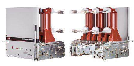
NETAWorld 53 WHEN TO CONSIDER A RETROFIT REPLACEMENT CIRCUIT BREAKER
COVER STORY
Figure 2: Retrofit Conversion Circuit Breaker
Figure 1: Circuit Breaker Conversion Solutions
or some portion of them. An original qualified design is converted, requiring a retrofit design to be tested in accordance with IEEE Std. C37.59, Standard Requirements for Conversion of Power Switchgear Equipment. C37.59 defines and specifies the qualification testing required depending on the nature of the conversion. For example, if the circuit interruption means is changed, the applicable design verification requirements of C37.09 are referenced. The certification testing is piece-wise, dependent on the nature of the conversion. The primary advantages and disadvantages of retrofits are very similar to those for roll-in/direct replacement conversions.
Retrofill
During a retrofill conversion (Figure 3), the existing switchgear structure and bus are modified to accept a new circuit breaker by installing a new cradle into the system. There are two primary retrofill methods. Commonly, a new cradle is hard-bussed into the system’s existing main bus. Alternatively, in a cradlein-cradle retrofill, the cradle is installed with connections interfacing with the existing primary disconnects, i.e., the new cradle is permanently racked in. In both retrofill methods, all new
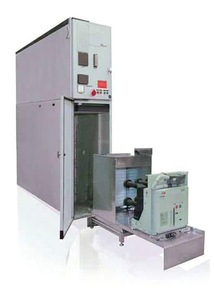
racking mechanisms, primary/secondary/ ground disconnect connections, and MOC/ TOC switches are installed in the existing cell.
The primary advantage of a retrofill conversion is utilizing the circuit breaker design of the OEM’s standard product offering, making replacement breakers, parts, and support readily available. The breaker is unmodified, and thus maintains the original design qualification. The primary disadvantages are that the end-user loses interchangeability with existing breakers (unless the entire lineup is upgraded). Further, it is generally the most expensive conversion option, as it requires complete de-energization of the switchgear during the lengthy conversion process. While employed in medium-voltage, retrofill conversions are more common in lowvoltage applications.
One of the challenges with discussing conversions is that different groups use varying terms to mean the same thing. Now that we are on the same page as far as terminology, take a look at the factors considered and the challenges faced during the conversion design process.
VACUUM RETROFIT DESIGN PROCESS AND CHALLENGES
There are many different types of conversions, but the majority of medium-voltage applications today consist of converting an air-magnetic circuit breaker to an equivalently rated vacuum circuit breaker, and that is the focus of this article. As discussed, the two primary means of medium-voltage conversion are retrofill and retrofit. This section presents a streamlined explanation of a complicated process. It can guide the recommendations you make to your customer and assist troubleshooting efforts if the reader can gain an understanding of the challenges faced during the conversion process.
The challenges associated with retrofills are generally not with the design; rather, they are presented during installation. In a retrofill, the switchgear is stripped, and the new cubicle is installed in the shell — in most cases, the new breaker cubicle is hard-bussed into the system.
54 WHEN TO CONSIDER A RETROFIT REPLACEMENT CIRCUIT BREAKER
COVER STORY
Figure 3: Retrofill Conversion
While retrofill kits that make the process a straight forward step-by-step procedure are available for low-voltage switchgear, they seldom exist in medium-voltage applications. Note that the custom nature of fitting the new cubicle into the existing cell, fitting the bus to it, and wiring the controls in a plant setting is challenging. Outages are short, making preplanning paramount to successful retrofill conversions. Coordinating multiple outages — one for assessment and at least one additional for installation — is a cumbersome process for most utilities and industrial users, especially in medium-voltage installations.
As the methodology varies between retrofill and retrofit conversions, so do the challenges associated with them. Perhaps the best way to introduce the design challenges is to give an overview of the retrofit process, from start to completion. What follows is a hypothetical but typical scenario.
Midwest Utility Co. calls its local field service company, ElectroServ Midwest, because it is experiencing issues with their medium-voltage equipment again. ElectroServ arrives on the scene and quickly identifies the challenge. The breakers were manufactured by Centralized Atlantic Equipment Co., an obscure manufacturer that was only around for a decade, 40 years ago, and thus had a very limited installed base. To make matters worse, the breaker has high interrupt and continuous current ratings. The combination of an obscure manufacturer and rare ratings will make sourcing a replacement on the surplus market nearly impossible.
Their spares (or the corpses of their spares) sit in the corner, having been robbed of parts over the last few decades to make the in-service breakers serviceable. Even if the utility could shut down long enough to replace the switchgear with new or to pursue retrofill options, the substation is on a mezzanine three floors up with plant expansions built around it. Keeping all of these factors in mind, ElectroServ makes the recommendation to install vacuum retrofits and starts gathering the necessary information for the converter to bid the project.
The majority of the information needed to evaluate a circuit breaker for conversion is listed on the circuit breaker nameplate:
• Manufacturer
• Type
• Rated Voltage (kV)
• Rated Maximum Voltage (kV)
• Rated Impulse Voltage (kV)
• Frequency (Hz)
• Rated Continuous Current (A)
• Rated MVA
• Rated Short-Circuit Current (kA)
• Asymmetrical Rating Factor (k-factor)
• Rated Interrupting Time (cycles)
• Control Voltage (VAC/VDC)
In most cases, the breaker nameplate data is sufficient information for a retrofit provider to quote a replacement breaker, assuming it is a model that they have provided in the past and are familiar with. However, it is always a good idea to send photos of the switchgear cubicle (with the breaker removed) along with orthogonal views (front, rear, sides) of the breaker. Even if a retrofit conversion has been developed — and in theory, the OEM designs are consistent — there are sometimes optional accessories and site-specific differences between installations that interfere with standard designs. Eventually, the circuit breaker control schematic will also be required.
The process of designing a retrofit replacement circuit breaker is simple in concept but challenging in execution. The stages of design include choosing a suitably rated replacement breaker, designing the interfaces between the original breaker and the new unit, and design verification testing.
The first stage, choosing a suitably rated replacement breaker, is a straightforward process. The ratings for the replacement breaker must meet or exceed the corresponding rating of the existing breaker. For example, if the original airmagnetic circuit breaker is rated at a maximum voltage of 5 kV and 1200A continuous current, the replacement vacuum circuit breaker must be rated at least 5 kV and 1200A; however, a
NETAWorld 55 WHEN TO CONSIDER A RETROFIT REPLACEMENT CIRCUIT BREAKER
COVER STORY

7.2 kV, 2000A-rated breaker could also be used. The MVA and short-circuit ratings are evaluated similarly, but two additional factors must be considered: the constant MVA to constant kA rating differences and the k-factor.
In 1999–2000, circuit breaker ratings changed from a constant MVA to a constant kA rating method. This is important to consider in retrofit applications, as some constant MVA-rated equipment did not give the short-circuit rating in kA; it requires calculation. For example, a 15 kV, 500-MVA circuit breaker has a rated interrupt current of 19 kA at the maximum 15 kV design voltage:


Note that this calculation is performed at the maximum design voltage. In the majority of constant MVA-rated circuit breakers, the physics of arc interruption are such that a given circuit breaker can interrupt a higher current at a lower voltage. However, there is a limit to how high the interrupt current can be increased, and that limit is defined by the k-factor. The k-factor is a dimensionless number that defines the range of voltage over which the interrupting current increases as the voltage decreases. In the 15kV, 500 MVA-rated circuit breaker example, if we include the k-factor rating of 1.3, the 19 kA interrupt current rating can be increased to 25 kA by lowering the maximum allowable voltage to 11.5 kV. When choosing a replacement circuit breaker for conversion applications, ensure that k-factor is considered and the maximum interrupt current is met or exceeded in the new design.

Once suitably rated replacement circuit breakers are identified, the next step in the conversion process is to evaluate the best option from a mechanical perspective and begin the conversion process. The most obvious consideration is that the replacement circuit breaker must fit on the existing frame (or the new frame, if it’s a direct replacement); in most cases, this is not an issue. The vast majority of medium-voltage conversions are air-magnetic to
vacuum interruption. Vacuum circuit breakers are compact compared to their air-magnetic counterparts of equivalent rating. However, the lower kV/MVA rating combinations can be a challenge, as the legacy frames are narrow (typically around 18 inches wide), and many modern vacuum circuit breaker designs have standardized across the 5–15 kV voltage ratings and are thus wider than necessary from a design limitation perspective.
When a breaker has been identified, the conversion process can begin. The breaker is first mounted to the rolling chassis; then the position interlock and racking mechanism, spring discharge, primary disconnect and insulation system, secondary disconnects/controls, blast shield, and MOC systems are all integrated into the conversion. All of the systems have unique design challenges and risks that a technician commissioning or working on the conversion should be aware of.
Position Interlock System
The purpose of the position interlock is to prevent the insertion or removal of a closed circuit breaker in and out of the connected position. The position interlock interfaces with the circuit breaker racking and operating mechanisms. Typically, in medium-voltage applications, the position interlock locks the racking mechanism when the breaker is closed and results in tripfree operation unless it is in the connected, test, or disconnect positions. The conversion must match the fit and function of the original design, preferably with minor modification and without adding additional mechanical load on the new mechanism.
Technicians should be familiar with the operation of the original position interlock system to ensure the conversion functions identically. The technician should also ensure that when the racking mechanism is locked, such as for a lock-out tag-out procedure, the breaker is held in the trip-free operating condition. The risks associated with improper conversions of the position interlock system are severe. Racking a closed circuit breaker into
56 WHEN TO CONSIDER A RETROFIT REPLACEMENT CIRCUIT BREAKER
COVER STORY
or out of the connected position can result in an arc-flash event causing equipment damage, injury, and death.
Spring Discharge System
The purpose of the spring discharge system is to ensure that all stored mechanical energy is absent when the circuit breaker is removed from the switchgear. Typically, this is accomplished by holding the breaker in a trip-free operating state by engaging the trip latch and operating the close latch, thus releasing the energy from the close and open springs. Similar to the position interlock, the conversion must match the fit and function of the original design, preferably with minor modification and without adding additional load on the new mechanism.
Technicians should be familiar with the operation of the original spring discharge and ensure the conversion functions identically. Technicians should pay particular attention to conversions that involve updating a solenoid-operated to a spring-charge mechanism, as there are no provisions in the legacy cubicle to trigger a spring discharge system. Converters will typically try to work around the issue by integrating the spring discharge with the racking mechanism, but this solution is not always feasible. In the cases where a workaround solution cannot be implemented, a label warning the operator of the risks is usually employed. The technician should be aware of the risks of a malfunctioning or absent spring discharge mechanism and ensure all mechanical energy is discharged prior to working on the circuit breaker.
Primary Disconnect and Insulation System
The purpose of the primary disconnect and insulation system is to make the high-voltage connections between the circuit breaker and the switchgear and isolate the primary voltage between phases and from phase to ground. The conversion process consists of aligning each of the line- and load-side connection locations of the legacy circuit breaker to the new breaker. The converter must ensure that when the
converted breaker is in the connected position, the primary disconnect alignment matches the legacy unit in all three axes: horizontal (x-axis), vertical (y-axis), and depth (z-axis). The insulation system must match the fit and function of the original design without creating interference with the cubicle.
The technician should be aware of the risks associated with converting the primary disconnect system. If the primary disconnects are not properly aligned in the x- and y-axes, it can introduce interference issues that prevent insertion of the breaker into the connected position. If the depth of the primary disconnects does not match the original, it can also cause interference or even prevent sufficient wipe across the stationary cubicle connections. If the primary disconnects are not correctly aligned and isolated from ground via the insulation system, a life-threatening arc flash from phaseto-phase or from phase-to-ground can occur. Insufficient wipe and/or inadequate contact pressure on the primary disconnects can also lead to catastrophic failures and should be verified during commissioning and periodically over its serviceable life.
Secondary Disconnect/ Controls


The purpose of the secondary disconnect is to make the control power connections between the circuit breaker and the switchgear. Similarly, the ground contact grounds the circuit breaker frame to the switchgear ground. The conversion process consists of ensuring the secondary disconnect matches the fit, form, and function of the original design. From the control standpoint, the breaker must function identically to the original breaker. The primary challenges are matching the original control schematic and ensuring the current draw of the new control components do not exceed those of the original (this is rarely an issue but is considered).
There is also a special consideration for converting a circuit breaker equipped with a solenoid-operated mechanism to a spring-charge design. Spring-charge operating mechanisms

NETAWorld 57 WHEN TO CONSIDER A RETROFIT REPLACEMENT CIRCUIT BREAKER
COVER STORY

require a constant supply of control power, whereas solenoid-operated do not. Though easily performed, the conversion will require modification to the existing switchgear control scheme to accommodate the charging circuit.
Though seemingly trivial, locating the original control schematic is often problematic. Over the course of 25 years or more, the original documentation is often lost or outdated. Reverse engineering the control schematic from the converted breaker is sometimes required.
The alignment of the ground contact is generally not a concern in retrofit applications, as it is mounted directly to the frame and is usually remanufactured and reapplied.

The risks associated with the secondary disconnect and controls are less serious than the other systems but are the most common. Issues converting the secondary disconnect are easily avoided by attentiveness during the informationgathering phase of the conversion process and electrically testing/cycling the converted breaker prior to installation.
MOC System
An MOC is a mechanism-operated cell switch located in the switchgear cell but operated by the circuit breaker mechanism. It provides extra or redundant contacts for breaker status indication and other control functions. When equipped, an MOC operator on the circuit breaker engages an MOC in the switchgear directly, or more commonly, via a mechanical assembly. Driving legacy MOC systems with modern mechanisms is one of the most challenging barriers to overcome during the conversion process.

Older switchgear MOCs were designed for the technology of the day. Air-magnetic circuit breaker mechanisms were massive with high forces and inertias, which resulted in slow travel times and velocities. Legacy MOC switches were designed to be robust. In a typical conversion process, the MOC actuator is the only factor that affects the dynamics of the new circuit breaker, as it alters the mechanical load the mechanism must drive.
Modern vacuum breakers are smaller, lighter, and compact. Vacuum contacts travel a much smaller distance than their air-magnetic counterparts and at a much faster speed — 10 times faster on average. These force, inertia, velocity, and travel-time mismatches between legacy and modern MOC systems present a number of challenges for converters. In addition to matching the fit, form, and function of the original MOC system, the conversion has the potential to change the operating speed of the new mechanism. The increased energy can cause MOC switch overtravel, bounce, wear, and damage. Since the MOC is installed in the switchgear and not the breaker, it presumably will not be replaced during the conversion process.
Poor MOC condition has the potential to be compounded by the converted circuit breaker. Some installations choose to replace aging MOC systems with relaying. The design and operation of legacy MOC switches varies considerably between OEMs, as do MOC conversion solutions. Of all the challenges associated with the conversion process, the risks associated with MOC systems are the most important for technicians to consider and mitigate. Worst case, a badly worn or broken MOC in the switchgear can stall the breaker, leading to a catastrophic failure. Technicians must ensure MOCs and their actuators are operating correctly and are in good condition, and must take them into account when recommending and working on converted equipment.
Design Testing
ANSI Standard C37.59, IEEE Standard Requirements for Conversion of Power Switchgear Equipment governs the requirements for conversions of previously qualified equipment. The standard was created in 1991 to address the lack of design verification of some conversions. Many forms of conversion exist; several have been discussed in this article. The standard provides the logic that should cover all forms of power switchgear conversion existing at the time of its publication. The latest version was published in 2007, but it is
WHEN TO CONSIDER A RETROFIT REPLACEMENT CIRCUIT BREAKER 58 2017
COVER STORY
currently undergoing revision by the IEEE PES Standards Committee and will be published within the next year. The latest revision adds conversions that were introduced since 2007, such as the addition of infrared inspection windows and remote racking devices.
The document is organized by the category of equipment, then by type of conversions. For each conversion method, the standard instructs which portions of the original design verification testing to perform. Here is an excerpt from the standard for the process described in this section:
Section 6.1.4.2 b) Conversions utilizing a modular assembly may require alterations to the original circuit breaker frame to mount the modular assembly as well as to provide connections to the existing or new primary bushings, and the conversions may require revisions to insulation structures or components. The modular assembly shall be subjected to the complete series of design tests in accordance with IEEE Std C37.09. The design test data from the modular assembly tests may be utilized for design verification if clearly applicable. Additional design tests shall be made on the complete conversion and shall include dielectric withstand, momentary current, shorttime current, continuous current, interlock, and other operational tests including tests to verify correct function with MOC switch assemblies, if applicable (see 6.1.7.2 and IEEE Std C37.20.2).
When a conversion is performed and design verified in accordance with the latest revision of C37.59, the risks discussed in this section have been mitigated but not eliminated. Conversions should only be performed by a qualified provider with the necessary knowledge, capability, and experience. With an understanding of the primary challenges encountered during the retrofit process, you should know when and which form of conversion is a suitable option. Conversion, however, is not the only option available. As equipment ages, you can remanufacture it, replace it, or convert it. The next section discusses when a conversion should be considered.
WHEN TO CONSIDER A MEDIUM-VOLTAGE CONVERSION
The previous section touched on when a medium-voltage conversion should be considered. To expand on and address this question, consider the product lifecycle of medium-voltage switchgear.
The first stage in the product life cycle is the commercialization period. The commercialization period is when the switchgear is launched onto the market and is offered for sale through the OEM’s approved sales channel. This discussion focuses on air-magnetic to vacuum conversions. The average commercialization period for air-magnetic switchgear was 20–25 years (modern equipment is much less, averaging 10–15 years). There are no mediumvoltage air-magnetic switchgear models still in the commercialization period (though airmagnetic switchgear may still be produced for special applications). For the sake of discussion, if the switchgear were still offered by the OEM, a conversion would not be a recommended solution except in rare circumstances where the switchgear is of poor design, was incorrectly applied, or the application requirements have changed.


The next stage in the product life cycle is the support period. Following the commercialization period, OEMs offer support through parts and service. The length of the support period varies between OEMs and models, but on average, medium-voltage equipment is supported for 10–15 years. Many models, however, are supported far beyond that — especially those with the highest market share (largest installed base), as well as those used in special applications like the nuclear industry.
Once the OEM withdraws full parts supply for its equipment, it is considered at the end of its lifecycle. However, a product at the end of its life cycle does not mean end of service. At the end of the product lifecycle or even during the support period, the OEM will often sell the intellectual property to what becomes the authorized aftermarket solutions provider that

WHEN TO CONSIDER A RETROFIT REPLACEMENT CIRCUIT BREAKER NETAWorld 59
COVER STORY

will continue to support the switchgear until it is no longer profitable to do so. The surplus switchgear market also supports the industry.
Only when support, replacement parts, and spares are no longer available should conversion solutions be presented as a viable option — the end-of-service point. The end-of-service point is not a fixed date; it comes gradually. Eventually, as discussed in the example in the previous section, supporting legacy equipment becomes cost prohibitive or outright impossible and must be remanufactured, converted, or replaced.
Remanufacturing power equipment is an extensive subject; this article focuses on when it should be considered versus conversion. Remanufacturing programs have increased over the last decade and for good reason. If the switchgear itself is in good, serviceable condition and parts/spares are readily available, a remanufacturing program should be considered over conversion and replacement. A properly performed remanufacturing process on an airmagnetic circuit breaker returns it to new, or better than new, condition. Organic insulation can be upgraded to modern materials. Modern, high-performance lubricants can be applied, and hazardous materials can be replaced with benign equivalents (technically, this is a conversion).


A remanufacturing program can solve most issues with aging equipment. Arguably, it can solve everything but obsolescence at a fraction of the material and outage cost and with less risk compared to replacing the switchgear or performing a conversion. When obsolescence is the primary issue and support no longer an option, consider the two remaining solutions: replacing the switchgear or converting it.
Choosing to replace the existing switchgear versus converting it usually comes down to cost and how easily the end user can support the extended outage it will take to replace the gear. In almost every facet, a conversion will be dramatically less expensive than replacing switchgear, especially since the breakers can be performed one or several at a time as budget factors allow. The choice between converting
switchgear and replacing it is a straightforward decision, as the two solutions are on the opposite ends of the spectrum in regards to time and cost.
CONCLUSION
When addressing needs that may include raising interrupt requirements, the limited availability of parts and support, or challenges with antiquated technology such as the insulation system, a medium-voltage vacuum conversion may be the answer. To simply modernize, you may better serve your customer by recommending remanufacturing the existing equipment and upgrading the switchgear controls and insulation.
However, we’ve seen generations of converted circuit breakers — good and bad — and it’s clear that not all converters are equal. Too many designs do not pass basic design and safety testing. Remember, no level of testing can compensate for poor design. When recommending a conversion option, take time to develop a detailed specification that references the required ANSI/IEEE design and testing requirements.
Finally, if you are ever in doubt whether to convert or maintain, remember this: The legacy equipment you are working on has been in service for 30, 40, or even 50 years. Don’t rush to replace it.

Paul Grein is Vice President of Circuit Breaker Sales and has been with GroupCBS since 2008, working primarily in the Dallas area. Paul’s primary responsibilities include business development, engineering design and management, technical expertise, standards, and project management. He has worked with industrial electrical equipment for over 20 years, beginning in the Navy as a Nuclear-Qualified Electrician on the submarine USS Topeka SSN 754 from 1996 through 2002, followed by positions in the steel industry through 2005. Paul has a BSEE from the University of Texas at Dallas (2007) and an MBA from the University of North Texas (2014). He participates in the IEEE/ANSI PES C37 Standards Committee, which publishes and maintains the design and testing standards that govern the industrial power equipment industry.
WHEN TO CONSIDER A RETROFIT REPLACEMENT CIRCUIT BREAKER 60 2017
STORY
COVER


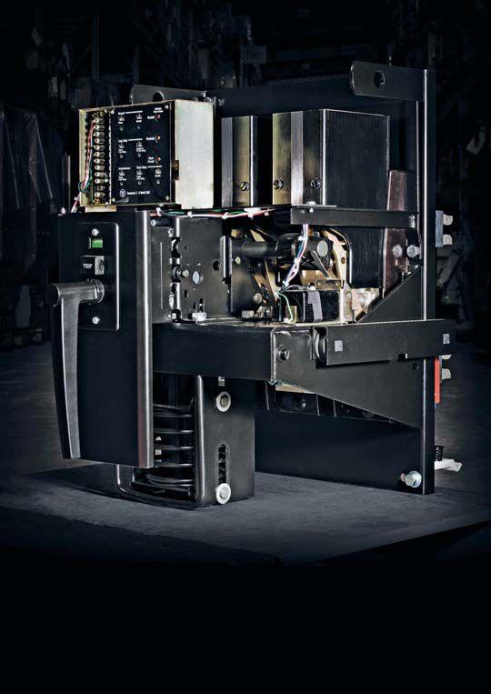


1315 Columbine, Gaine s v ille, Texa s 76241 1315 Columbine, Gainesville, Texas 76241 | 800-232-5809 INF O INFO @ CBSALE S COM CBSALES.COM | CircuitBreaker.com CBS Florida Florida | L akeland, Florida Lakeland, Florida | 863-646-5099 863-646-5099 | CBS-Florida .com CBS-Florida.com CBS Mid we s t CBS Midwest | Crow n Point, Indiana Crown Point, Indiana | 219-575-5420 | CBSMidwest.com N E W NEW S E R V I C E SERVICE L O C A T I O N S LOCATIONS CBS stocks every low- and mediumvoltage circuit breaker made in America since 1945. W i t h m o r e t h a n 5 m i l l i o n b r e a k e r s a n d p a r t s i n o u r 20 0,0 0 0 - s q u a r e -f o o t With more than 5 million breakers and parts in our 200,000-square-foot warehous e includin g s w itch ge ar, tran s for m er s , subs tation s , prote c ti ve relay s , warehouse — including switchgear, transformers, substations, protective relays, lo ad b r e a k s w i tc h e s , e le c tr i c al co n t ac t s , m o to r co n tr o l s a n d ce n te r s , v ac u u m loadbreak switches, electrical contacts, motor controls and centers, vacuum inter r upter s , an d m ore interrupters, and more — Circuit Breaker Sales Circuit Breaker Sales ha s you has you covere d. covered. √ Replacement par ts and equipment parts and equipment √ Remanufacturing , retrofits , and upgrades Remanufacturing, retrofits, and upgrades √ Reverse engineering , 3- D printing of obsolete Reverse engineering, 3-D of obsolete par ts parts Fo r m o re i n fo rm ati o n a b o u t G ro u p C B S a n d it s a ff i l i ate co m p a n i e s vi s it For more information about Group CBS and its affiliate companies, visit G ro u p C B S c o m GroupCBS.com. CircuitBreaker.com (800) 232-5809 TO L LTOLLF R E E FREE Your TRUSTED online resource for authentic circuit resource authentic breaker and electrical distribution equipment breaker and electrical distribution CBStore.com US PATENT NO. 9,031,795 B1 We have the world’s largest selection of replacement vacuum interrupters • Vacuum interrupter replacements rated up to 38 kV, 3000 A • Repair and replacement services for all major OEM interrupters, Eaton, CH, Westinghouse, ABB, Siemens, and many more • Pole assemblies, parts, and components • Custom design/manufacture services for obsolete interrupters, • Field and in-shop vacuum interrupter replacement services • Rental vacuum breakers available while yours are being serviced downloadourtechnicalpaper download our technical paper WATCH

VLF-34E 34 kV VLF Tester
VLF & DC Output | Sheath Testing | Cable Burning
The VLF-34E is a new generation VLF AC Hipot that uses a solid state design with microprocessor controls. It meets the requirements of applicable world standards regarding cable testing up to 25kV class maintenance testing. It is light, compact, rugged, and very portable. Its sine wave output is suitable for using external TD and PD detection equipment. Using a TD and PD option, the VLF-34E is all that is needed for nearly all cable testing up to 25kV class. Easy to use controls. Programmable test sequences & manual control, USB, XBEE® wireless, RS-232/422 port for downloading data and for unlimited test report capture, wireless computer interface to control and download Tan Delta diagnostics and for remote control operation via laptop.
Tan Delta TD-34E
VLF-TD Cable Diagnostic Testing


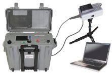

The TD-34E, along with the HVI VLF-34E AC hipot, is the latest in design using current electronic technology. Together they permit the user to perform all VLF and VLF-TD tests possible and offer the best wireless operation and data collection, aided by the HVI custom application software written solely for the two devices. There is no better alternative. HVI has been supplying the world with VLF and Tan Delta technology since 1998, with more models, greater voltage range, and higher power capability, all with the superior sales and service that HVI is well known for worldwide.


INC. HIGH VOLTAGE, INC. ISO 9001 2008 HVI - The World’s Source for High Voltage Test Equipment All HVI Products are Made in the USA 31 County Rt. 7A • Copake, NY 12516 • Tel: (518) 329-3275 • Fax: (518) 329-3271 • sales@hvinc.com • www.hvinc.com
HIGH VOLTAGE,
Ground To Test Cable For 5 – 25 kV cable: VLF-34E & TD-34E
NO BLUETOOTH
TD-34E Tan Delta Transducer


MEDIUM-VOLTAGE CIRCUIT BREAKERS:


FIT FOR DUTY OR IN NEED OF ATTENTION?
BY BRET HAMMONDS , Shermco Industries, and ROBERT FOSTER , Megger

Circuit breakers have historically functioned as the protective muscle of the electrical power system. Their effectiveness as the guardians of the grid is dependent on the unique application and design of each circuit breaker. Many original equipment designs can now be modified or updated to reflect the latest operating and arc-extinguishing techniques.
In medium-voltage applications, the most widely utilized design encases the main contacts of the CB in a sealed vacuum chamber. This design is preferable because of its size and proven reliability in comparison to other designs using air- and liquid-insulating mediums. While these CBs differ in construction, insulating materials, and arc-extinguishing techniques, vacuum circuit breakers share many of the same mechanical and environmental impacts that other medium-voltage circuit breakers (MVCB)
are subject to in terms of operating mechanisms and associated linkages. This article reviews various tests that evaluate the health of MVCBs. Time-travel analysis as a method of determining the overall operational characteristics of MVCBs will be discussed. Applicable testing guidelines are also considered in relation to ensuring the health of vacuum bottles as a critical component of an MVCB. Only then can one of these circuit breakers be proven as either fit for duty or in need of attention.
FEATURE MEDIUM-VOLTAGE CIRCUIT BREAKERS: FIT FOR DUTY OR IN NEED OF ATTENTION? 64 • FALL 2017

UNIQUE FEATURES OF MEDIUM-VOLTAGE CIRCUIT BREAKERS
Besides voltage class, MVCBs (Figure 1) and low-voltage circuit breakers (LVCB) differ mainly in design in that LVCBs have decisionmaking logic and controls that are integrated into the design of the CB itself. The decisionmaking logic and controls for MVCBs is not an integrated part of the design. They operate based on external signals from a remotely located protective device. In this sense, the MVCB becomes a simple mechanical switch that must be told what to do and when to do it.
Additionally, arc-extinguishing technologies have changed as it applies to MVCBs. For example, some of these breakers have utilized air as an insulating medium between the contacts. These type MVCBs also combine the use of arc chutes to divide the arc into smaller arcs that are more easily extinguished. This technique was an effective way of dealing with extinguishing arcs that occurred between the main contacts. However, this same technique suffered in comparison to more contemporary arcextinguishing methods because it left the main contacts exposed to the operating environment. Newer technologies also eliminate the need for arc chutes that are heavy and consume a great deal of space. MVCBs that use vacuum technologies for circuit interruption encase the main contacts
in a sealed vacuum bottle, therefore resolving both problems of having contacts exposed to the environment and the need for heavy and spaceconsuming arc chutes.
For this article, we’ll use the definition for mediumvoltage systems provided by IEEE 100: The Authoritative Dictionary of IEEE Standard Terms: “An electric system having a maximum rootmean-square alternating current voltage above 1,000 volts to 72,500 volts.”
CIRCUIT BREAKER COMPONENTS


Three major components make up an MVCB, and each of these components should be addressed in a periodic testing and maintenance program. Failure of any element will result in failure of the breaker. Component parts of an MVCB include:
• Conductive path — the path used to conduct current from the line side to the load side of the CB. This path consists of load- and line-side connections, a conducting medium, and stationary and moving contacts. The CB will have three conducting paths referred to as poles.
• Operating mechanism — the means by which a CB is closed and opened. The operating mechanism must be able to receive energy, store the energy, and then release it to close or open the breaker contacts.
• Insulation — forms the protective barrier between the conductors and ground and between the individual conductors. The insulation can vary based on the design of the CB but will consist of insulating arms between the mechanism and moving contacts, barriers between the phases, and insulated arc chutes. This insulation generally consists of solid materials, air, and in special


NETAWorld 65 MEDIUM-VOLTAGE CIRCUIT BREAKERS: FIT FOR DUTY OR IN NEED OF ATTENTION?
FEATURE
Figure 1: Medium-Voltage Vacuum Circuit Breaker


applications, SF6 gas. Additionally, several different mediums are used to insulate the conductors when they are open as well as assist in the interruption of the arc. The most common today are vacuum, air, and SF6.

e frequency of maintenance depends on the number of operations, the environment, and the manufacturer’s recommendations. Frequent and non-frequent operations can seriously affect a circuit breaker. Frequent operations may cause the contacts and the operating mechanism linkages to wear out. Non-frequent operations may cause the operating mechanism to become stiff and inoperable.
from these two values, resistance is calculated. Since the resistance value is generally in the micro-ohm range, a four-wire technique is used for accurate measurements. Make sure that the voltage-sensing leads are inside of the current leads. The measured value should be compared to the manufacturer’s specifications. If no manufacturer specifications are given, compare the three different poles to look for abnormalities or compare to similar CBs.

CBs that operate in wet or dusty environments will need frequent maintenance. Moisture may cause the operating mechanism to corrode and freeze linkages. Moisture can also result in insulation failure. Dust increases wear on the operating mechanism, hardens lubrication, and can cause insulation to fail. Manufacturers will normally recommend a maintenance schedule in the instruction manual for the CB.

e moving and stationary contacts are used for making and interrupting the circuit. The moving contact is the contact driven by the operating mechanism during close and open operations. e moving contact mates to the stationary contact to complete the conducting path. The condition of these contacts is important. Poor connections will result in the circuit breaker overheating, or in the worst case, contacts fusing together. If fusing occurs, the circuit breaker is unable to respond to an open operation. The condition of the contacts is determined mainly by resistance measurement.


A low-resistance ohmmeter is used to measure the resistance across the closed moving and stationary contacts. To test the conductive path of the CB, the breaker must be in the closed position. A dc current is injected through the interrupter, and a voltage drop is measured;
While CBs generally serve the function implied by their name, the way they perform this task can differ based on the application for which they are designed. MVCBs do not house the current-sensing and decisionmaking components within the breaker itself. In most cases, this makes it impractical to perform primary current operational tests as would potentially be done in lower-voltage applications. Therefore, operational tests related to MVCBs are performed through an analysis of operating signals and contact movement in relation to time. Manufacturers of MVCBs will supply specified tolerances for the operational performance of the equipment they provide. These equipment suppliers normally provide operational specifications in a format easily verified through time-travel analysis.
First-trip is a form of as-found test that can be performed using the same test equipment that would later be used for subsequent time-travel analysis. This test is performed prior to taking the breaker out of service to evaluate the CB’s performance when it is first opened after having been operationally stagnant for a length of time. As stated previously, one of the worst things that can happen to a CB is to sit for long periods of time without operation, as the mechanism and linkages can develop excessive friction in the moving parts or even be bound up completely.
Operating-coil currents recorded during a first-trip test can vary significantly from subsequent tests. If the breaker is taken out
MEDIUM-VOLTAGE CIRCUIT BREAKERS: FIT FOR DUTY OR IN NEED OF ATTENTION?
of service prior to first-trip testing, valuable information concerning the health of the CB as well as potential markers for condition-based maintenance could be lost. Certainly, this type of test would be extremely dangerous if it required contact with primary energized portions of the breaker. However, first-trip tests use current clamps and test clips to make connections to the control circuitry of the breaker only. When the CB is first operated to open the circuit, the primary parameter of interest is the operatingcoil current. The characteristic signature of the coil current can be used comparatively with previous and subsequent tests.
Variations in the coil-current signature could potentially indicate mechanical issues associated with lubrication and/or corrosion within operating linkages. As the CB operates to interrupt the primary circuit, operating times associated with the interruption of current through the contacts can also be recorded by monitoring the secondary currents of CTs that reflect the behavior of the primary circuit. Note that these are not the same contact times measured with a time-and-travel analyzer because some arcing will take place. These secondary currents are significantly reduced in magnitude from the primary currents and are normally rated at 5 amps. Even though first-trip testing can yield valuable information regarding CB health, or even provide information that can later be used in condition-based maintenance, it must be approached with the respect and caution appropriate for the conditions under which these tests are performed. First-trip testing is a supplement to traditional time-travel analysis, not a replacement.
Time-Travel Analysis
Testing the operational characteristics of MVCBs will normally provide valuable information in the evaluation of the operational health of a CB. However, the uniqueness of these CBs makes it necessary to consider an equally appropriate method of testing time and motion characteristics. The equipment required for this type of testing is generally referred to as a timetravel analyzer or circuit breaker analyzer.
When testing MVCBs, the capabilities of this type test equipment are often underused. Frequently, testing technicians will only connect that which is necessary to measure the time from the initiation of the control signal to the time when the contacts either make or break depending on the type of operation. Standard timing tests should include close, open, closeopen (also known as trip-free), open-close, and open-close-open operations. Each of these operations is designed to test a specific function of the CB under real-world conditions. Although all the standard tests should be performed, quite frequently, only the close, open, and trip-free times are measured.
To fully utilize time-travel recording test equipment and gain the greatest advantage of its testing capabilities requires installation of a transducer. The transducer extends the capabilities of the test equipment to include measurements of motion (stroke). Instead of limiting these tests to simply an operating time, the installation of a transducer provides additional information regarding the motion of the CB, including stroke, velocity, over-travel, and rebound. Although stroke may often be measured separately with a pair of calipers when the CB is resting, for numerous reasons, it is still of great benefit to measure this value during a mechanical operation. Measuring the velocity of the contacts verifies that the contacts are moving at a sufficient speed to extinguish the arc. Additionally, monitoring the rebound during an open operation verifies that the contacts are not bouncing back and coming too close to each other, causing a potential restrike. These parameters are illustrated in Figure 2.


One challenge to fully analyzing the operation of MVCBs is the ability to mount a transducer to the operating mechanism of the CB. This is not a unique issue, but it is one that sometimes requires a bit of ingenuity to overcome given the variety and construction of MVCBs. Either a linear or rotary transducer may be used, but most important is to represent the moving of the contacts as closely as possible. Occasionally, a conversion table or conversion factor may be needed to measure the correct stroke and

FEATURE NETAWorld 67 MEDIUM-VOLTAGE CIRCUIT BREAKERS: FIT FOR DUTY OR IN NEED OF ATTENTION?


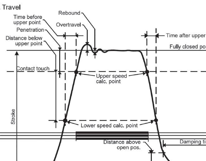

velocity. All values obtained should be compared to the manufacturer’s specified values or previous recordings.
INSULATION
Insulation failure is the most serious problem that can happen to a CB. This can result not only in a loss of the CB, but also possible major damage to the surrounding CBs and enclosures. It is very important that insulation be properly maintained and tested frequently.
One measure of insulation quality is the insulation resistance test. A fixed voltage, usually dc, is applied to the CB. The leakage current is measured and a resistance value is determined, once again, by Ohm’s Law. In contrast to the resistance of the conducting path, the insulation should be in the high mega ohms ranging upward to giga and tera ohms. An insulation tester will give a direct reading of the resistance


value. There are three types of insulation tests to perform:
1. From conductor to ground
2. From conductor to conductor
3. Across the open conductor
The voltage applied ranges from 1kV–15kV but depends on the rated voltage of the CB. For minimum/maximum test voltage recommendations, see the NETA acceptance testing guidelines. NETA also recommends that a power-factor test be performed. While insulation resistance is a dc test, power factor is an ac test. A fixed ac voltage is applied, and the leakage current measured. The ratio of the resistive component of the current to the total current gives a power-factor value. The three types of tests performed while measuring insulation resistance should also be measured while power factoring the breaker.
68 MEDIUM-VOLTAGE CIRCUIT BREAKERS: FIT FOR DUTY OR IN NEED OF ATTENTION? FEATURE
Figure 2: Typical Motion Trace
VACUUM BOTTLE INTERRUPTERS
As previously stated, many of today’s MVCBs use vacuum bottles to accomplish circuit operations. These devices appear very simple in their structure and operation; however, a great deal of science is associated with their purpose.
Theoretically, an arc cannot exist within a vacuum since requisite components for an arc do not exist. Realistically, there is no such thing as a perfect vacuum. Therefore, what actually happens when current-carrying components separate while in a vacuum? The only arcing that occurs is a result of ionized contact materials as the contacts separate. However, any arc generated is very quickly extinguished as current reaches a zero crossing, and the ionized materials are recombined into the contact surfaces or onto the metal vapor condensing shield as illustrated in Figure 3.
This evolving technology allows CBs to be smaller, lighter, and more easily serviceable. If a problem is discovered with a set of contacts, the simple solution is to replace the vacuum bottle, which is a much easier task than in alternative designs. Additionally, by sealing the main contacts in a vacuum bottle, the environmental influence of contaminants is no longer a factor regarding premature damage to the contacts. Note that you can still have environmental contaminants and leakage paths on the outside of the vacuum bottles.
Vacuum Integrity
While one might say there is reduced maintenance related to the main contacts of the breaker, an increased effort is associated with ensuring the integrity of the vacuum. This is commonly achieved by performing a vacuumbottle integrity (withstand voltage) test. High potential is applied across the vacuum bottle with the breaker in the open position. The purpose of this test is to verify that the bottle has remained sealed and therefore maintains all the beneficial electrical-insulating properties associated with an environment of negative pressure.
Take care to perform these tests in strict accordance with manufacturer’s published data.
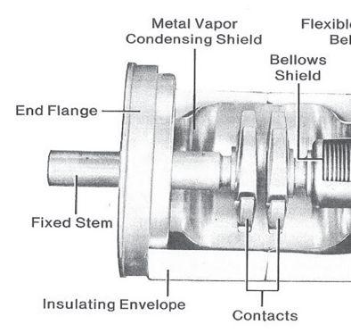


This will include the manufacturer’s specified test voltage. Additional information regarding test voltages at which to perform these tests can be found in IEEE/ANSI C37.06. Most manufacturers will specify that the equipment used in performing this test should have a sinusoidal waveform output. The reason is that some dc high-potential test equipment has half-wave rectified outputs. Test equipment of this sort could actually have much higher peak voltages than the dc value indicated on the equipment. In this case, vacuum bottles can fail based on leakage currents that reflect peak voltages much higher than specified. Therefore, if dc test equipment is used, it must be fullwave rectified, and the value applied should be adjusted to match the peak value of the recommended ac voltage.
CONCLUSION
A number of tests can and should be performed as part of a CB maintenance program. This article has focused on the three main components of a CB: the conducting path, the insulation, and the operating characteristics, with a focus on vacuum bottle technology. All of these tests, along with many others, are designed to confirm the health of the electric power systems muscle.
Time-travel analysis has become the method by which the operation of MVCBs can be verified and potential issues identified. This is achieved by performing initial first-trip tests as well as


NETAWorld 69 MEDIUM-VOLTAGE CIRCUIT BREAKERS: FIT FOR DUTY OR IN NEED OF ATTENTION? FEATURE
Figure 3: Typical Vacuum Interrupter
FEATURE

subsequent tests involving the parameters of time, motion, and velocity. Many original equipment designs are now modified to reflect the advantages of the latest arc-extinguishing techniques. Vacuum bottle interrupters have become the central part of many MVCBs. We know that the absence of components requisite to establishing an arc are absent in a vacuum. Verifying vacuum integrity of this critical component, along with other electrical operational observations, is paramount to proving that an MVCB is fit to be placed into service or needs maintenance prior to returning to service.


Bret Hammonds is a Senior Technical Instructor for Shermco Industries. He supports coworkers in a number of areas related to workforce development as well as the health and safety of Shermco employees. He holds a BSEET from Texas Tech University as well as an MBA from
the University of Phoenix. Bret spent close to 25 years working for an electrical test equipment manufacturer where he held various roles that included product management and technical support for a broad range of electrical test equipment. He has also directed operations for a test equipment rental company and managed an office for an electrical testing service company. Bret is a member of the IEEE Power Engineering Society and past member of ASTM D27 Committee for Insulating Liquids and Gases.

Robert Foster is an Applications Engineer with Megger, specializing in high-voltage circuit breaker and transformer testing. He graduated from California State University, Chico, with a BS in Physics and Mechatronic Engineering. After graduation, he worked as a Field Service Engineer for ABB in the high-voltage dead-tank circuit breaker division. In his current role with Megger, he is involved with customers and product development, supporting products and applications throughout North America.

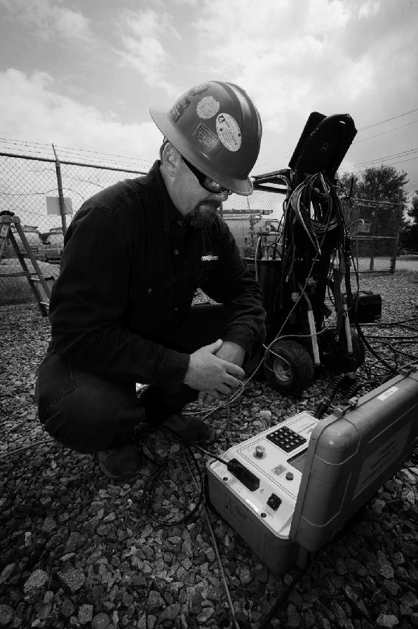

www.BurlingtonSafety.com info@BurlingtonSafety.com Browse and Buy Online Now! Metro NY/NJ/PA 800-220-2120 Calif (SF) 888-817-1412 Calif (LA) 800-296-2803 Your Source for NFPA 70E Compliant Protective Gear Accredited Proof Testing Laboratory Services Rubber Gloves ◆ Sleeves ◆ Blankets ◆ Line Hose Footwear ◆ Jumpers ◆ Hotsticks Accredited Company 204 Gale Lane Kennett Square, PA 19348 484.731.0200 enerGtest.com Serving clients in Pennsylvania, Delaware, New Jersey, Maryland, Washington, DC and New England. We deliver optimum system reliability and performance while reducing the chances of costly unplanned power outages. Whether you need acceptance ener es testing or preventive maintenance, depend on EnerGTest to keep the power on. Reliable Power System Solutions

Power Monitors: Rugged Power Analyzers and Loggers for tough environments. Ground Resistance Meters, with built-in GPS and PC connection. High-performance IR Imaging cameras. UV Corona Camera. www.soneltest.com | Buy. Or Rent from us at a great rate! | Call: 408 898 2215 The New World of Electrical Test Tools
TWO NEW SELF-PACED TECHNICAL SEMINARS (SPTS)

Understanding Generator Protection
What Does Partial Discharge Tell Me and How Do I Perform the Test?
Learn at your own pace. Advance your knowledge. Ask about continuing education. Earn CTD*Credits for NETA Level III and IV Technicians. Order online at: www.netaworld.org or call 888-300-6382 (NETA)
*CTDs awarded when participant receives a passing score on the proficiency exam.

ADDITIONAL COURSES AVAILABLE


POWER CIRCUIT BREAKER CONDITION ASSESSMENT BASED ON


VIBRATION FINGERPRINT MEASUREMENT:


WHY IT CAN SAVE YOUR DAY
BY ADNAN SECIC and KERIM OBARCANIN, DV Power

Noninvasive online monitoring methods in power systems and power engineering have become the hot topic over the last decade. Power circuit breakers are one of the most significant elements of power system protection. They protect customers as well as the entire electric power grid structure from damages caused by excessive current, which emphasizes the importance of their reliable and fast operating times. Use of timing tests in an off-the-grid mode has become the standard procedure for power circuit breaker condition assessment. However, a circuit breaker might spend months or even years in service before the next off-the-grid testing is performed, and during that period, we do not have insight into its condition — especially operating times. There are many benefits to a noninvasive measurement and condition assessment approach based on the measurement of the vibration fingerprint of power circuit breakers.


NETAWorld • 73 POWER CIRCUIT BREAKER CONDITION ASSESSMENT BASED ON VIBRATION FINGERPRINT MEASUREMENT: WHY IT CAN SAVE YOUR DAY FEATURE


The idea to assess the condition of power circuit breakers using measurement of vibrations reflecting the mechanical events within the object dates back to the late 1980s and early 1990s. The main idea has been the same for more than two decades, but the approach and technology have changed. Using the vibration fingerprint for this purpose has one crucial advantage: It is noninvasive.
Power circuit breakers are used as needed to configure a power system to control the load flow and disconnect any faulted parts of the system. Mechanical malfunctions are a major cause of failures during circuit breaker operations. Misoperation of circuit breakers can result in undesired changes in system function and may cause the system to go into an abnormal state. Therefore, circuit breakers need frequent maintenance and monitoring to ensure the stability of the power system. Every 6 to 12 months, circuit breakers have to be inspected — even if a fault has not occurred — and this generally introduces high cost. Maintenance might include internal inspection and disassembly of the circuit breaker. In addition, to inspect and assess the condition using conventional methods, the circuit breaker has to be removed from the grid; this usually implies an outage for a certain group of customers.
During circuit breaker operation, many interacting mechanical components are involved, resulting in numerous discrete sources of vibration excitation containing valuable and important information. Changes in the vibration signature of the circuit breaker, which signals mechanical malfunctions or abnormal behaviour, can be used to evaluate the mechanical state of the circuit breaker.
In addition, different mounting approaches include using high-intensity magnets for sensor mounting, sensor fixing using beeswax, and fixed connection using bolts and soldering. Each different mounting and installation method will yield different results regarding quality of the measurement, attenuation, or noise susceptibility, as will determining which vibration sensors to use in the application.

When it comes to the analysis and processing of the acquired vibration signals, a wide variety of algorithms, tools, and approaches exists in the marketplace as well as in the academic world, including:

• Analysis in the time domain, which in most cases uses a dynamic time-warp algorithm or short-time energy analysis
• Time-frequency analysis, which uses shorttime Fourier transform
• Wavelet analysis
• Hilbert-Huang transformation
• Approaches that combine these as well as some advanced techniques using artificial intelligence such as fuzzy logic or neural networks
The potential of this approach to circuit breaker condition assessment is clearly visible when the results of the standard offline timing test are compared with the vibration fingerprint for the same circuit breaker sequence. This paper presents the results obtained by comparing the timing results, along with a brief discussion regarding the installation and mounting approach of the vibration sensors.
MEASUREMENT AND DATA ACQUISITION SYSTEM REQUIREMENTS
The most important part of the machinery online monitoring approach is the usage of noninvasive measuring techniques that will not interfere with regular system operations. When high- and medium-voltage circuit breakers are under test, the measurement system should not interfere with the main functions, which are to carry high electric current in a closed position and to break or make contact when a command is issued by the operator or the protection system. The current-breaking process must be fast because of an inevitable process that occurs during interruption of the high electrical current (e.g., during a short-circuit current interruption), which is called the electrical arc. The high- and medium-voltage breakers are designed with a standard breaker opening time below two cycles (less than 35 ms for 60 Hz power grid). Using
FEATURE 74 • FALL 2017 POWER CIRCUIT BREAKER CONDITION ASSESSMENT BASED ON VIBRATION FINGERPRINT MEASUREMENT: WHY IT CAN SAVE YOUR DAY


a longer opening time means more stress on the arcing contacts and a longer arcing period.

To test and assess circuit breaker timings in the offline manner, the circuit breaker has to be opened and then disconnected from the power grid from both sides by the disconnector switch. The external power source can be used to inject current through the main contacts. In these conditions, the measurement system can be used to detect the moment when current starts or stops flowing through the circuit breaker main contacts. The moment the coil energizes is used as the starting point for measuring position in time. This is standard procedure in offline testing equipment. This measuring procedure is considered invasive, since it interferes with the system’s regular operation. However, such a procedure cannot be used by the online monitoring system, since the breaker needs to be connected to the electrical power grid, and an alternative way to measure breaker timing must be considered.
FIRST-TRIP TESTING
To meet noninvasive criteria, one test method is based on the measurement of the current that flows through the secondary or breaker current transformers. Such measurement can be performed with ac current clamps. This procedure is used by the well-known first-trip test. The reason for performing such a test comes from the fact that circuit breakers can spend months or even years in closed position without performing a single operation. During that period, lubrication problems may arise. Such problems can be caused by environmental influences including temperature or moisture variations. In that case, only one breaker operation could improve lubrication. For that reason, circuit breaker timing in the first-trip test will differ even from the next tripping operation.
The measured value is important, since it can be expected that, when the circuit breaker is returned to service after inactivity, it will again operate with similar timing to the one measured by the first-trip test. First-trip records are usually captured by portable equipment mounted on


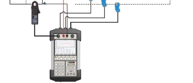
non-hazardous parts of the breaker just before testing is performed. The circuit breaker is tripped manually. However, the test is performed with the breaker connected to the power grid, justifying the term “online testing procedure.”
Figure 1 depicts the principal connection scheme of an instrument capable of performing the first-trip test. The current clamps measure the coil current and the instance of energizing coil (a moment when the current starts flowing through the circuit breaker coil) is again used as the reference time measuring point.
Another non-invasive technique with similar benefits to the online method for condition assessment of high- and medium-voltage circuit breaker main contacts is based on vibration measurements (Photo 1).
In this case, accelerometers are mounted on the circuit breaker contacts chamber or the linkage of the operating mechanism. It is desirable that the sensors are placed at the same mounting points for each new measuring interval when the testing is performed by portable equipment. This provides repeatability of the measuring conditions and makes obtained results comparable one to each other. Nevertheless, permanent installation of the vibration sensors is required for the online monitoring system. In that case, the vibration fingerprint is recorded
FEATURE NETAWorld • 75 POWER CIRCUIT BREAKER CONDITION ASSESSMENT BASED ON VIBRATION FINGERPRINT MEASUREMENT: WHY IT CAN SAVE YOUR DAY
Figure 1: First-Trip Breaker Online Test


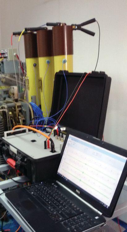
Photo 1: Vibration Measurement on a Minimum-Oil MV Circuit Breaker
during each circuit breaker operation, which can be the result of a command that originates from the protection system. Permanent installation of the vibration sensors also reduces possible errors, such as bad contact, which can be caused by the human factor.
The large number of installed measurement units in online monitoring requires a wireless network so the recorded data can be transferred to the central base station where data can be processed, analyzed, and presented. Internet connection enables data to be sent from the base station to the central database, which can be used for storing the data. The measurement is triggered by the current flow through the circuit breaker coil, and the recording time is limited to the interval of less than a second, so that the vibration fingerprint for the O-0.3s-

C-O breaker operation can be captured. Power consumption can be reduced by the system sleep mode when the circuit breaker transition process is completed.

Along with the vibration signals, binary signals that originate from the auxiliary contacts are recorded to confirm successful circuit breaker operation. There are two types of auxiliary contacts — dry and wet — and their timing must be calculated.
In summary, three parameters are recorded for the assessment of the circuit breaker main contacts using vibration-based analysis: close and trip coil currents, vibration fingerprints for all phases and/or operating mechanisms, and auxiliary contacts.
SENSOR PLACEMENT AND POTENTIAL ISSUES
A medium-voltage, minimum-oil circuit breaker has been used as a test object for the vibration measurement system in the laboratory environment. During the testing phase, the circuit breaker spring was charged manually to avoid the influence of the vibrations that originate from the motor operation after successful circuit breaker operation.
The circuit breaker used for testing in the test facility has not been bolted to the ground surface as it would be in the substation, and this fact will be reflected in the vibration fingerprint. Nevertheless, the whole test object is heavy, so vibrations resulting from not fixing it to the surface will be reflected in the lower frequency spectrum. For this reason, such influences are disregarded.
To analyze the best sensor placement position on the shell of the circuit breaker contact chamber, several tests have been conducted with the accelerometers mounted on the top (Photo 2), in the middle, and at the bottom of the breaker chambers. Beeswax was used to fix accelerometers in each position.
Comparing the vibration signals obtained using sensor mounting in these three positions
76 • FALL 2017 FEATURE
POWER CIRCUIT BREAKER CONDITION ASSESSMENT BASED ON VIBRATION FINGERPRINT MEASUREMENT: WHY IT CAN SAVE YOUR DAY


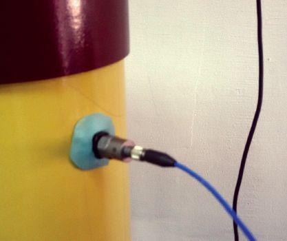



suggested that the best signal-to-noise ratio was achieved in the signals obtained with the sensor placement at the bottom of the circuit breaker chamber. This supports the theoretical assumption that has been formed based on the construction of the contacts.
To perform comparison and analysis of the vibration fingerprints and the graphical results obtained using the circuit breaker analyzer and timer, samples were exported into a CSV data format and imported in a MathWorks Matlab environment.
COMPARISON OF THE CLASSICAL TIMING TEST AND VIBRATION FINGERPRINT
Comparison of the classical timing test results with the corresponding numerical values extracted from the vibration fingerprints was conducted for the closing and opening breaker operations. First, the new signal, which is obtained as the absolute value of the vibration fingerprint, has been calculated. Then, a fixed threshold defined in the iterative experimental process was selected and applied to the signal, and samples with a value below the selected threshold were set to zero. As the outcome of this procedure, the first rising edge of the vibration signal can now be used for calculating the circuit breaker timing.
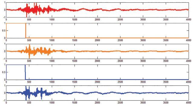
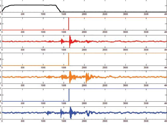
Figure 2 shows results for the open and close sequences of the circuit breaker, while Figure 3 shows the vibration timing extraction principle result on phase A of the close test.
For the close test, the fixed threshold value has been set to 70 percent of the signal maximum amplitude; the open test is set to 30 percent of the maximum signal amplitude. Table 1 shows the numerical results.
NETAWorld • 77 FEATURE
Photo 2: Accelerometer Placement on the Top of the Breaker Chamber
POWER CIRCUIT BREAKER CONDITION ASSESSMENT BASED ON VIBRATION FINGERPRINT MEASUREMENT: WHY IT CAN SAVE YOUR DAY
Figure 2: Results for the Close and Open Test Sequences


Table 1: Numerical Results
CLOSE TEST
CB Closing time calculated by circuit breaker analyzer and timer [ms]

CB
CB Opening time calculated by circuit breaker analyzer and timer [ms]
CB Opening time extracted from vibration fingerprint [ms]
Table 1 shows that the described method is more accurate for the breaker opening test. The reason is that the circuit breaker closing process is always followed by some bouncing period, which prevents selecting a lower signal threshold value in this particular case. The other reason arises from the fact that the tested circuit breaker has not been boltfixed to the ground surface as it would be in the substation, which generates additional vibrations during contact movement. However, presumably, a signal pre-processing strategy could help in further reducing imposed deviations and noise.
CONCLUSION
The circuit breaker vibration fingerprint carries valuable information about circuit breaker main contacts as well as the state of the operation
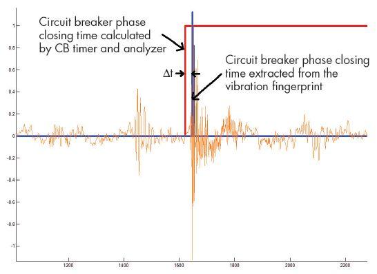


mechanism. This paper shows that the vibration signal can be used to extract the opening and closing time of the circuit breaker as defined by the standards.
For demonstration purposes, the simplistic approach was used to extract the interesting numerical values. The experimentally defined threshold levels provided impressive results. However, further improvements — and reducing the errors described in this paper — could be accomplished by developing more advanced generic algorithms.
On the other hand, the low timing detection error for opening operation indicates that even the suggested method (with small improvements in threshold setting) could be used as a reliable replacement of the standard first trip test in online monitoring solutions.
REFERENCES
S. Park, M. Lai, C. Lin, H. Naidu, A. Soom, A. Reinhorn, Y. Lee, V. Demjanenko, D. Benenson, T. Soong, S. Wright. “Measurement for Noninvasive Mechanical Diagnostics of Power Circuit Breakers,” Electric Power Systems Research, Volume 19, Number 1, pp. 1–10, 1990.
Hydroelectric Research and Technical Service Group, “Facilities Instructions, Standards and Technique 3-16T 3-16, Maintenance of Power Circuit Breaker,” U.S. Department of the Interior Bureau of Reclamation, Colorado, 1999.
78 • FALL 2017
FEATURE POWER CIRCUIT BREAKER CONDITION ASSESSMENT BASED ON VIBRATION FINGERPRINT MEASUREMENT: WHY IT CAN SAVE YOUR DAY
Figure 3: Phase Time Extraction Principle
vibration fingerprint [ms] Error [ms] 162,1 164,8 2,7 162,2 164,7 2,5 162,9 166,0 3,1 OPEN
Closing time extracted from
TEST
Error
43,0 43,1 0,1 43,0 43,9 0,9 42,1 43,2 1,1
[ms]


N. Charbkawe, T. Suwanasri, T. Bunyagul, A. Schnettler. “Vibration Signal Analysis for Condition Monitoring of Puffer-Type High-Voltage Circuit Breakers Using Wavelet Transform,” IEEE Transactions on Electrical and Electronic Engineering, Volume 7, Number 1, pp. 13-22, 2012.
L. Chao, H. Xiaoguang. “A New Method of Fault Diagnosis for High-Voltage Circuit Breakers Based on Hilbert-Huang Transform,” 2nd IEEE Conference on Industrial Electronics and Applications, ICIEA 2007, Harbin, China, 2007.
S. Laijun, L. Mingliang, Z. Jianju, Y. Guangzhoung. “A New Fault Diagnosis Method for HV Circuit Breakers Based on Wavelet Packet — Neural Network,” Industrial Electronics and Applications (ICIEA), 2011.
A. Akansu, W. Serdjin, I. Selesnick. “Emerging Application of Wavelets: A Review,” Physical Communication, Volume 3, Number 1, pp. 1–18, 2010.
M. Runde, G. Ottesen , B. Skyberg, M. Ohlen. “Vibration Analysis for Diagnostic Testing of Circuit Breakers,” IEEE Transaction on Power Delivery, Volume 11, Number 4, pp. 1816–1823, 1996.


Adnan Secic is an R&D Engineer at DV Power, Lidingö, Sweden. As a project leader, he is responsible for development of the Circuit Breaker Analyzer and Timer (CAT) device series. Adnan holds an MS in Electronics, Electrical Engineering, and Automation.
Kerim Obarcanin manages the Software Engineering Department for DV Power Sweden and is an Associate Lecturer for Sarajevo School of Science and Technology, which is a collaboration partner of Buckingham University UK. His primary research focus is in the domain of the data acquisition, conditioning, and algorithms for data processing. He is in the final stage of PhD studies at the Faculty of Electrical Engineering, Sarajevo.



FEATURE


If you need electrical equipment, tap into the power of National Switchgear’s massive inventory With millions of products, we offer a huge selection of new, surplus and repurposed circuit breakers, switchgear and related equipment. And it’s all easy to order on our website. Go to nationalswitchgear.com today to see our powerful array of solutions 800-322-0149 THE POWER OF OUR INVENTORY. ENGINEERING SERVICES • TECHNICAL SERVICES • COMMISSIONING Protection Systems Design, Commissioning, Relay Testing Certified Cable Splicing, Cable Testing & Analysis using VLF, VLF-TAN Delta, and Partial Discharge Motor, Generator & Transformer Maintenance, Testing, Oil Handling & Leak Repairs Troubleshooting Power Systems and Power Quality Audits (310) 816-3130 www.tdeinc.com 131 W F Street Wilmington, CA 90744 Los Angeles Area | | www.youtube.com/tdeinc2 www.twitter.com/tdeinc www.facebook.com/tdeinc www.linkedin.com/company/tony-demaria-electric CA LICENSE #315448 Also Provides Technical & Safety Training
ACTASBTT
• The smallest, fastest, lightest breaker test system on the market
• Testing of gang operated breakers
• Weight 3 pounds
ACTAS P260 I P360
• Extremely robust and compact
• Remote control function
• Full switchgear test in a single test procedure
• Stand-alone operation
• Operation and evaluation via 7" touch screen
• PIR and main contact measurement up to 12 main contact chambers
• Recording and analysis of Main Contact, Aux Contact, Travel, Velocity, Coil and Motor Circuit
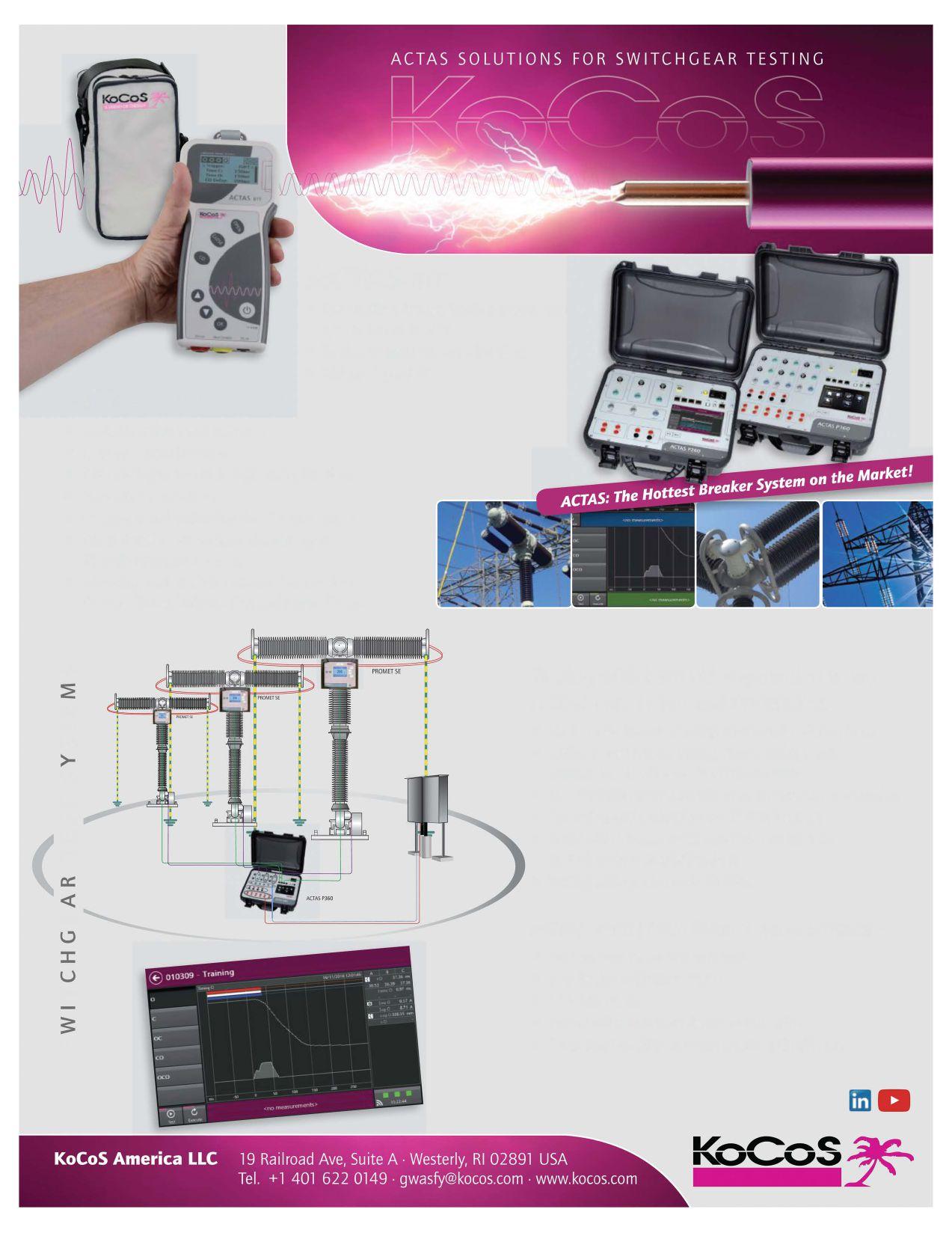
Testing with both sides grounded using ACTAS P260 I P360 and PROMET SE
• No need for time-consuming reconnection during tests
• Ability to test typical timing, static, and dynamic measurement with one set of connections
• Use PROMET SE with ACTAS or as a stand-alone operation
• Operation and evaluation via 7" touch screen
• Static and dynamic resistance determination on up to 6 main contact chambers
• Testing with ground on both sides
ACTAS P260 I P360 Front Screen Software
• On computer or on device results
• Live display of breaker status
• 7" touch screen
• Export pdf report from device to USB stick
• Zoom functionality on touch screen and software
V'I :E LU IV'I >V'I I- v V'I LU Ici::: <( LU Q :::c u I3: V'I
A FRIEND OF ENERGY


TESTING SWITCHGEAR:
CONVENTIONAL BOTH-SIDESGROUNDED METHODS
 BY GUY WASFY, KoCoS America LLC, and CHRISTIAN STUDEN, KoCoS Messtecknik AG
In the Summer 2017 NETA World Journal, “Requirements for Testing Switchgear Quickly and Economically” outlined some of the modern techniques and technologies now available for testing switchgear. The article showed how new technology drastically reduces testing time while increasing useable information for diagnosing the condition of switchgear. This article expands on that information and illustrates practical examples of how testing switchgear with both sides grounded yields the same results as the conventional method.
OVERVIEW
International Standard IEC EN 50110-1 states that any part of a high-voltage installation being tested shall be grounded. As such, it is highly recommended that users find equipment suitable to perform the test(s) in accordance with the standard.
Testing switchgear with grounding on both sides should be performed to decrease potential dangers caused by capacitively coupled voltages from neighboring components. When using the conventional method to test switchgear
equipment, a ground must be removed from at least one side. In contrast, the alternative method allows for the same tests to be conducted with grounding maintained on both sides. Not only does this make testing much safer, it makes it simpler and quicker as the steps to remove the ground lead are no longer required.
One of the main requirements of testing switchgear with a new methodology is that the results correlate to historical practices. The both-sides-grounded method and the
FEATURE TESTING SWITCHGEAR: CONVENTIONAL METHODS VS. BOTH-SIDES-GROUNDED 82 FALL 2017
VS.
conventional method yield the same results as long as they are performed in identical test conditions. Further, the both-sides-grounded method is faster, safer, and provides more diagnostic information.
CONVENTIONAL METHOD
When conducting a test on switchgear using the conventional method, the steps are as follows:
1. Open the switchgear.
2. Ground both sides of the switchgear.
3. Connect the coil operating currents in series with the test system.
4. Connect the transducer to measure motion.
5. Connect the main contact leads.
6. Remove ground from one side of the switchgear.
7. Test the switchgear.
8. Reattach ground on open side of the switchgear.
9. Remove all breaker timing cables.
10. Connect main contacts to microohmmeter for resistance measurements.
11. Perform resistance test on phase A, interrupter unit 1.
12. Perform resistance test on phase A, interrupter unit 2 (if applicable).
13. Perform resistance test on phase B, interrupter unit 1.
14. Perform resistance test on phase B, interrupter unit 2 (if applicable).
15. Perform resistance test on phase C, interrupter unit 1.
16. Perform resistance test on phase C, interrupter unit 2 (if applicable).
17. Perform procedure for safe breaker.
BOTH-SIDES-GROUNDED METHOD
When using the both-sides-grounded method, the procedure is more efficient in three major ways. In both methods, the controls for the coils and transducers are connected in the same manner, but instead of connecting the main contact leads in step 5, the connection for main
contacts uses the connections of a portable micro-ohmmeter. The main contact times are measured via the cables of the micro-ohmmeter.
Additionally, it is unnecessary to remove the ground on one side of the switchgear (step 6). The micro-ohmmeter is able to perform these measurements with both sides grounded; therefore, steps 8 – 16 are eliminated. The resistance measurements are included in the main test, and all three phases are measured at the same time.

Without the time-consuming connection and disconnection procedures, testing with both sides grounded turns a 17-step process into an eight-step process. The benefits of this method are as follows:
1. Safer environment for employees and contractors
2. Saves time as all tests can be completed with one cable configuration
3. Significantly more efficient, and with less connections, less probability of a mistake

Figure 1 illustrates the both-sides-grounded method connection on a live-tank breaker. The connection on a dead-tank breaker is the same but with one less main contact.









NETAWorld 83 TESTING SWITCHGEAR: CONVENTIONAL METHODS VS. BOTH-SIDES-GROUNDED
FEATURE
Figure 1: Measuring a Live-Tank Switchgear with Both Sides Grounded

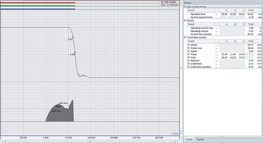

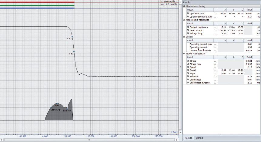
COMPARING TEST RESULTS — OPEN OPERATION
Figure 2 and Figure 3 show open operations. Figure 2 illustrates tests with the conventional method, and Figure 3 shows tests with the both-sides-grounded method. The results show that the main contact timing was approximately 64 ms for both methods. The parameters were set to be measured from the start of the coil current to the breaker opening. All other parameters were measured in the same manner.
The both-sides-grounded method measures and provides contact resistance results in the same test, measuring them before the breaker opens. This makes the additional test steps needed for measuring contact resistance in the conventional method unnecessary.
COMPARING TEST RESULTS — CLOSE OPERATION
Figure 4 and Figure 5 show close operations. Figure 4 illustrates tests with the conventional method, and Figure 5 shows tests with the both-
84 FALL 2017 TESTING SWITCHGEAR: CONVENTIONAL METHODS VS. BOTH-SIDES-GROUNDED
FEATURE
Figure 2: Open Operation, Conventional Method
Figure 3: Open Operation, Both-Sides-Grounded Method


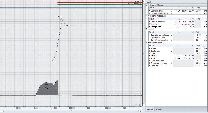
sides-grounded method. The results show that the main contact timing was approximately 60 ms for both methods. All other parameters were measured in the same manner. Again, when testing using the both-sides-grounded method, the main contact resistance can be measured within the test operation.
WORKINGS OF AN INTERRUPTER UNIT ON A LIVE-TANK CIRCUIT BREAKER
In electrical energy transmission and distribution systems, switchgear devices are the
connection to further parts of an installation. Throughout their operational lives, switchgear devices must constantly connect, interrupt, or disconnect operating parts. In the open status, they are a puncture-proof disconnection point; in the closed status, they carry and control short-circuit currents.

Switchgear devices must endure mechanical and thermal stresses during operation without damage; friction and abrasion influence the performance of the mechanical parts. The contact systems in the current-carrying circuits

FEATURE NETAWorld 85 TESTING SWITCHGEAR: CONVENTIONAL METHODS VS. BOTH-SIDES-GROUNDED
Figure 4: Close Operation, Conventional Method
Figure 5: Close Operation, Both-Sides-Grounded Method


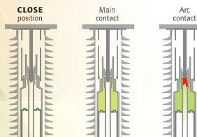



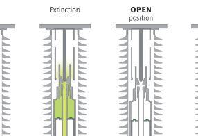

Workings of a Live-Tank Circuit Breaker

can deteriorate and thus increase development of excessive heat.
Figure 6 illustrates the workings of a live-tank circuit breaker.
1. Close position: Current flows via main contacts
2. Start of Open operation: Movement and disconnection of the main contacts; current is transferred to the arc contacts
3. Disconnection of the arc contacts; arc occurs between the contacts
4. Arc extinguished
5. Contacts opened
6. Close operation: Preparation for the next operation
These different positions can be seen in the results in Figure 7.
ASSESSING THE INTERRUPTER UNIT BY ANALYZING CONTACT RESISTANCE
Regular measurements of the static and dynamic contact resistance allow an accurate assessment of the condition of the entire contact system. This ensures that maintenance requirements can be identified at an early stage and downtimes kept to a minimum.
High contact resistance within a switchgear device leads to high power loss, and coupled with thermal stress, can potentially cause serious damage to the switchgear device. Problems such as high transfer resistance resulting from poor connections can be identified by measuring static contact resistance.
For the static resistance measurement, the contact resistance is determined when the interrupter
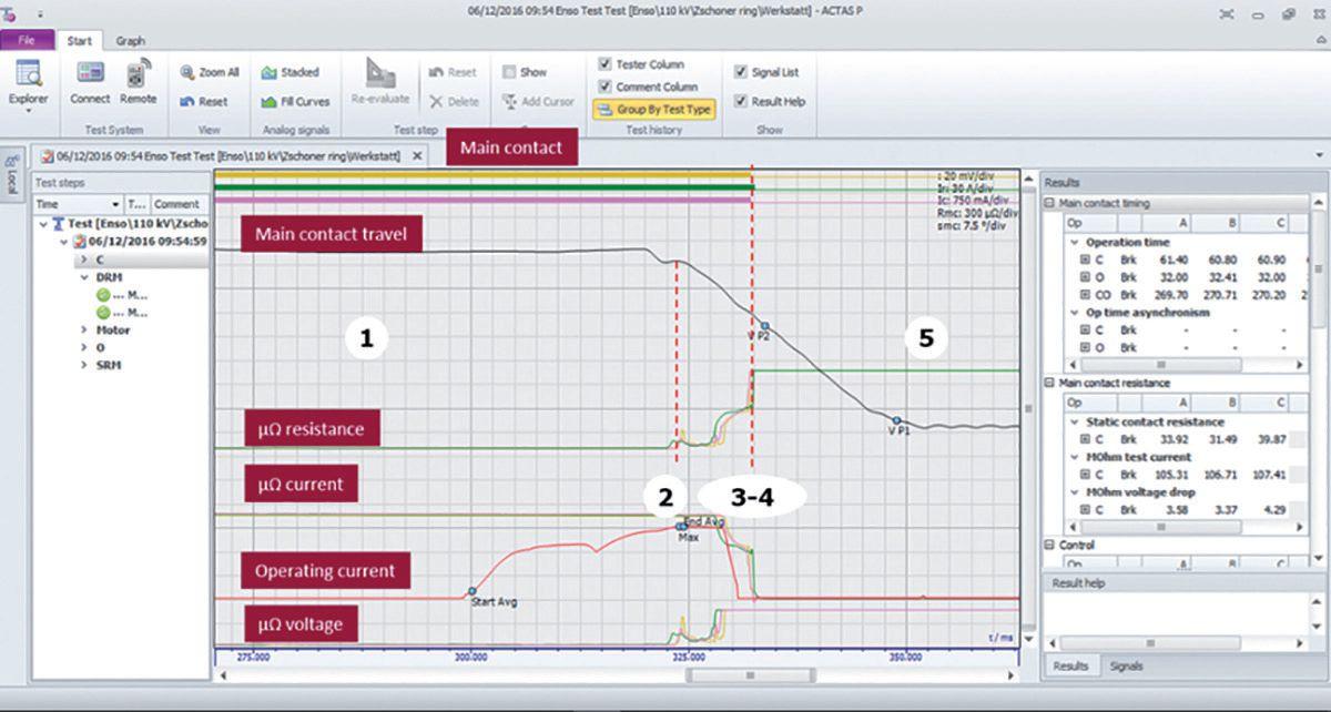
7: Measurement Curve for Live-Tank Circuit Breaker
86 FALL 2017 TESTING SWITCHGEAR: CONVENTIONAL METHODS VS. BOTH-SIDES-GROUNDED
FEATURE
Figure
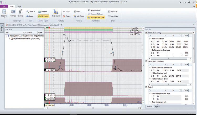
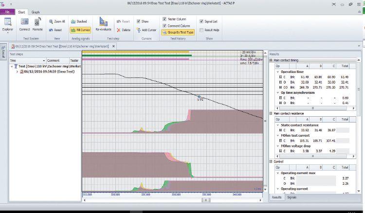
unit is closed. However, this measurement does not give an indication of the internal state, especially of the arc contacts. An assessment can be made by an internal inspection of the contact, but this is labor intensive and time consuming.
To simplify switchgear analysis, the dynamic resistance measurement was introduced. Dynamic contact resistance measurements can be used to determine the resistance characteristic during a freely definable switching operation. The contact resistance is dynamically measured via a close-open operation. The contact characteristic and the arc contact can be reliably determined via the


measurement results. During this switching operation, a high test current is applied and the voltage drop is measured. The measurement of the complete switching operation shows the resistance characteristic of the entire contact travel. The information given by the dynamic resistance measurement provides an overview of the entire contact status, particularly of the arc contact, and indicates any contact erosion. The condition of the arcing contacts cannot be determined by static resistance measurement.
Figure 8 and Figure 9 show the characteristics of the dynamic resistance measurement, illustrating the movement of the contacts.

NETAWorld 87 TESTING SWITCHGEAR: CONVENTIONAL METHODS VS. BOTH-SIDES-GROUNDED FEATURE
Figure 8: Close-Open DRM on a Live-Tank Circuit Breaker
Figure 9: Curve Used to Determine Health of Arcing Contacts
FEATURE


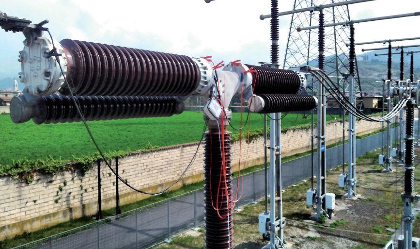
Th e transition to the arc contact is clearly visible. If the travel is measured, the length of the arc can also be determined. Th e display of the resistance characteristic and the length of the arc contact provide an insight into the internal status of the contact without opening it.
CONCLUSION
Testing switchgear with the both-sidesgrounded method saves a substantial amount of time, increases safety, and provides more diagnostic information than the conventional method. The effort involved in connecting and disconnecting cables on site is greatly reduced as all required tests are completed using one test setup. There is no need to change the cabling. Ensuring both sides of the switchgear are grounded significantly increases safety during tests. When using micro-ohmmeters for main contact cables, more information about the main and arcing contacts becomes available. The main contact diagnostics are measured by performing static resistance measurement, while arcing contact diagnostics are measured through performing
dynamic resistance measurement. With this method, tests can be performed according to standards.

Guy Wasfy is the Director of North American Operations at KoCoS America LLC in Westerly, Rhode Island. After graduating from the University of Rhode Island’s Electrical Engineering program in 1990, he went directly into the utility industry. After years of working around the world, Guy started KoCoS America in 2001, establishing and growing the sales, service, and application departments of KoCoS in North America.

Christian Studen is Product Manager for Circuit Breaker Test Systems at KoCoS Messtechnik AG in Korbach, Germany. He provides product and application support to distributors and customers throughout the world. Christian joined KoCoS in May 2013 and spent the first two years on the Service & Support team acquiring knowledge and practical experience in electrical power engineering. After completing an apprenticeship as a power electronics installer with Viessmann in Allendorf, Germany, Christian earned a BS in Electrical Engineering at the University of Applied Sciences in Lemgo, Germany. While working toward his MS in Mechatronic Systems, he was employed as a research assistant in the power electronics laboratory.
TESTING SWITCHGEAR: CONVENTIONAL METHODS VS. BOTH-SIDES-GROUNDED 88 FALL 2017
Measuring Setup in the Field
NETA Training: Learn to Test, Assess, and Validate
NETA Self-Paced Technical Seminars (SPTS) are training materials created for distance learning. Every year, PowerTest offers in-depth seminars covering a wide variety of topics. Two seminars are selected by the Conference Committee each year to be recorded and produced into an SPTS. NETA’s online training courses cover specific sections of the ANSI/NETA, Standard for Acceptance Testing Specifications for Electrical Power Equipment and Systems (ANSI/NETA ATS-2013). This training material assists the field service technician in understanding and acquiring the knowledge to properly test, assess, and validate various systems and electrical power equipment as required by the ANSI/NETA ATS.
Self-Paced Technical Seminars
SPTS HIGHLIGHTS:
• Four-hour run time
• DVD or USB of the recorded technical seminar and printed hard copy of the presentation
• One access to the proficiency exam
• Earn four NETA CTD Credits (NETA Certified Technicians) or submit for CEUs
AVAILABLE COURSES:
• Power Transformer Testing and Maintenance
Jim White, Shermco Industries
• Critical Maintenance for Circuit Breakers
Jim White, Shermco Industries
• Electrical Testing Basics: What You Need to Know to Succeed — Part 1
Jim White, Shermco Industries
• Electrical Testing Basics: What You Need to Know to Succeed — Part 2
Jim White, Shermco Industries
• A Primer on MCC Maintenance and Testing Malcom Frederick, Shermco Industries
• Primer on Transformer Diagnostics
Charles Sweetser, OMICRON electronics Corp. USA
• Transformer Dielectric Fluids: Use of DGA and Furans
Melvin Wright, LICA Consulting, LLC
• Using Partial Discharge Detection
Don Genutis and Neil Davies, No-Outage Electrical Testing, Inc.
• Hazards of Electricity, Shock, Arc, and Blast: An Educational Journey Through Case Studies
Jim White, Shermco Industries
• Electrical Testing Medium-Voltage Stator Windings
Tom Sandri, Shermco Industries, and Vicki Warren, Iris Power – A Qualitrol Company
• How Do They Do It? Electrical Power Measurement Methods, Practices, and Standards
Ross Ignall, Dranetz Technologies
• The Practical Application of NFPA 70E in Routine Work Tasks
Jim White, Shermco Industries
• Condition of Maintenance: A Practical Approach to Compliance within the Industry
Jim White, Shermco Industries
• Acceptance and Maintenance Testing for Medium-Voltage Electrical Power Cables: Exploring Technology
Developments Over the Past 20 Years
Tom Sandri, Shermco Industries
• Risk Assessment Techniques Using NFPA 70E: A Primer
Jim White, Shermco Industries
• Maintenance and Testing of Battery Systems
Tom Sandri, Shermco Industries
• Understanding Generator Protection
Scott Cooper, OMICRON electronics Corp. USA
• What Does a Partial Discharge Tell Me and How Do I Perform the Test?
Tom Sandri, Shermco Industries
Online Courses
Developed by the NETA Training Committee Approved by the NETA Standards Review Council
EACH PURCHASE INCLUDES:
• An individual account with access to NETA’s Online Training Center
• One access to the proficiency exam (additional attempts may be purchased separately)
• Earn NETA CTD Credits (NETA Certified Technicians) or submit for CEUs
AVAILABLE COURSES:
• Grounding Systems Acceptance Testing
• Cable Systems Acceptance Testing
• Instrument Transformer Acceptance Testing
Electrical Safety Training Systems
netaworld.org • 888-300-6382 (NETA) NETA Training Courses can be submitted for CTDs or CEUs
NETA
Electrical Testing Association
- InterNational





Offering over 52 electrical safety and electrical maintenance training courses. Many avo training courses are
Be prepared for exams and take your knowledge to the next level with a comprehensive hands-on “real world” training experience. A training course is only as good as the instructor teaching it. That’s why AVO’s instructors are some of the most qualified in the industry.
Be the best, train with the best.

WWW.AVOTRAINING.COM 877-594-3156 t If it’s electrical, we train it.
eligible
neta ctd’s
for


True TRMS measurement
Single & dual display models
Large jaw opening
Current measurements to 1000AAC/1400ADC (model dependent)
Voltage measurements to 1000VAC/DC
Resistance measurements to 9999Ω
Frequency measurement to 9999Hz
Temperature measurement to 999°C/2192°F
Over 20 models to choose from
RUGGED ACCURATE DEPENDABLE AFFORDABLE – AEMC® Meters – AFFORDABLE
www.aemc.com
PASSING THE TORCH
BY DAVE SOWERS, Knowledge Vine
The landscape of the U.S. labor force is changing fast. Millennials have been replacing Baby Boomers for years and recently reached a milestone: In 2015, for the first time, Millennials outnumbered Baby Boomers in the U.S. workforce. While they bring with them a new set of skills and perspectives, they don’t have the work experience or technical proficiency that is only acquired through time. When one of our more experienced workers leaves the team, it creates a brain drain as talent, experience, and knowledge head out the door. How do we ensure that this knowledge is not lost forever? How do we pass the torch to this younger generation of workers? Through effective coaching.
For more seasoned workers, the lessons learned and experience gained were often paid for with cuts, bumps, bruises, and heartache. We don’t want our new workers to learn the hard way, so current leaders must effectively impart their years of experience to the next generation.
Part of this transfer of knowledge can be accomplished with a robust training program, capturing best practices through accurate procedures, or the continued use of operating experience (OE) to see where the industry is getting it right or failing. These are good sources of information but typically only describe
the “what.” What are the specifications of this equipment? What is the process for operating it? What policies are in place to protect the worker and the system? It’s not the sharing of information, but the application of this information where most organizations struggle. Again, we are effective at telling our workers what we want, but miss the mark when it comes to how these expectations are accomplished.
Think of your organization like a football team. The organization has goals and can easily communicate the “what.” What the general manager/owner wants is to win Super Bowls.
INDUSTRY TOPICS 92 • FALL 2017
PASSING THE TORCH
What the head coach needs to do is win lots of games. What the offensive and defensive coordinators want is to score more points than their opponent to win those games. What the position coaches need from their players is flawless execution of the organization’s plan. What the players need to do is focus on the fundamentals of their job: blocking and tackling.
Here’s where we tend to get off the rails. We set the expectations for “what” we want from our people: “Your job is to block that person,” but fail to tell them “how” to do it. If we don’t continually coach and reinforce on “how” to properly block, we may have set the expectation, but we have not explained the execution. Then we become frustrated and ask, “Why didn’t you block? I told you to block! You’re a lineman; you should know how to block!”
a little direction. There are a number of tips and traits to employ before it all becomes habit. To make it a little easier, use the acronym COACH: Communicate, Observe, Acknowledge, Change, and Help.
COMMUNICATE
This may seem obvious; after all, isn’t communication one of those buckets you can put anything into? Can’t we all do better a job of communicating all the time? Of course, but as it relates to coaching, communication carries with it some very specific attributes.

Constant refinement of skills and continued reinforcement of expectations is what sustains high levels of performance. Baby Boomers have been in the trenches and may take for granted that the fundamentals of their work, the blocking and tackling, is understood by everyone in the organization. Younger workers may have had some education or work experience that implies a certain level of technical proficiency, but they still need coaching every day. Isn’t it interesting that the NFL still employs position coaches? You would think — after years dominating their position, being deemed the best of the best, and being handed millions of dollars — that teams would think these players would need very little oversight regarding the fundamentals. Yet, these professionals get coaching day in and day out. It’s time for us to take our All-Pro veterans and let them coach and groom our first-round picks.
AS A COACH, YOU NEED TO MAINTAIN THE BIG-PICTURE VIEW. ONCE YOU START TURNING WRENCHES, YOU ARE NO LONGER A COACH.
First, we must communicate the intent to engage in coaching. Nothing is more unsettling or distracting than a supervisor who lurks at the fringes of the jobsite with a notepad in hand and no explanation regarding intent or purpose. Coaching is not a game of “gotcha,” looking for compliance issues to write up; that’s an audit. It’s important to engage in conversation and let the person know you’re there to help. Communicate any changes that the worker may not have heard. Communicate the standards and expectations set by the organization for safe work. Communicate any lessons learned from previous jobs or industry events. Communicate that you won’t just passively observe but will be appropriately engaged, although not distracting. Ask if they have any questions for you.
OBSERVE
Coaching isn’t a natural ability. It’s a skill we can develop and hone, but it takes time, effort, and
As an observer, do you know what you are seeing? Are you prepared for the job? Do you understand the standards, expectations, and requirements of the work? Do you know the roles and responsibilities?
NETAWorld • 93 PASSING THE TORCH
TOPICS
INDUSTRY
One challenge for a Baby Boomer who came up through the ranks is the propensity to lose perspective. You know the work because you have performed it many times yourself. There is a tendency to jump in and lend a hand. But as a coach, you need to maintain the big-picture view. Once you start turning wrenches, you are no longer a coach; you are accomplice number two. During game action, football coaches are literally restricted to the sidelines; they have a great view but are not active participants. Stay in role and keep your perspective to help you in looking at the broader behaviors that drive success.
ACKNOWLEDGE
The quickest and most effective way to shape behaviors is through positive reinforcement. Oddly enough, the concept of positive reinforcement also seems to be the greatest divide between Baby Boomers and Millennials. Baby Boomers will wax nostalgic about the old days of a boot up your backside and the getit-done attitude that built America. The only positive reinforcement you needed was that paycheck every two weeks. Baby Boomers will point to participation trophies, trigger warnings, and safe spaces, and label this next generation as soft and needy.
These broad generalities tend to skew our perceptions. First, Baby Boomers received positive reinforcement and (gasp!) liked it. Sure, it was your old boss saying, “You messed up less today, good job,” but it was positive reinforcement all the same. Second, we don’t appreciate the positive qualities that most Millennials bring. Broadly speaking, they are more collaborative, they embrace change better, they have a greater sense of ownership over their work, and they thrive in jobs where they feel the work is important. Acknowledge the correct behaviors you see, help them understand the importance of their work, make them leaders in change, and solicit their input. If you don’t, you’re missing opportunities to really develop a younger worker who may otherwise become frustrated and leave — and then is immediately
replaced with another Millennial. Look for legitimate positive reinforcement opportunities (they are out there), and let your people know they are valued. It also makes it easier to engage in coaching when you need to address the wrong behaviors.
CHANGE
The reason you go into the field is to make a positive impact on the organization. You want to move the needle, create some change. If your engagement is focused on compliance issues and not behaviors, you are performing an audit and not coaching. It’s easy to slip into audit mode and miss the opportunity to create change. If you see a worker is missing some PPE and your coaching is “wear your gloves,” you are addressing the “what” but not the “how.” You can fix the glove issue, but you haven’t really coached the behavior. How did this happen? Are the requirements unclear or poorly communicated? Is there an extent of condition concern, are there other PPE requirements the worker is missing, and are there others with the same gap in knowledge? Why did the worker choose not to wear the gloves? Are gloves not available? Is the worker’s production bias encouraging shortcuts? Is the worker’s risk assessment not conservative enough? Ensure you are changing behaviors or processes rather than chasing compliance issues.
HELP
Give your people what they need to raise their performance. Establish communication early in the process, and continue this dialogue to find out how you can help increase their knowledge and skills. You are helping when you provide specific, actionable guidance. Vague platitudes like “Be safe” or “Stop when unsure” tell our people “what” but don’t communicate “how.” Specifically, how should they be safe today? Are there particular hazards associated with today’s work that need to be specifically addressed? How are they going to recognize that they are out of scope, procedure, or processes? What specific parameters will they look for to determine exactly when to stop work? When
PASSING THE TORCH 94 • FALL 2017
INDUSTRY TOPICS
they communicate their concerns to you, take action. Nothing shows your commitment to developing the next generation more than following through. Coaching is not a drive-by, one-time event.
When they take the time to look back on their careers, Baby Boomers recognize what influenced their evolution into the wily veterans they are today: coaching and mentoring. It took constant process improvements. It took time and effort. It took a refusal to accept errors and injuries as just the cost of doing business. We are better than we have ever been, but we are not as good as we can be. It is imperative that we coach the next generation so they can reach
even greater heights. Your legacy is not how you used to do it; it’s the people you leave behind to carry the torch.

Dave Sowers is Director of Performance Improvement at Knowledge Vine LLC, a human performance training and consulting organization. A veteran of the U.S. Navy’s nuclear power program, he has more than 25 years of industrial experience gained through his work in the military, semiconductor manufacturing, commercial nuclear power, and hydro-electric generation. Dave holds a BS and MS in Management from Troy University and an MS in Emergency Management and Homeland Security from George Washington University.
Power System Acceptance Testing
Commissioning and Start-up
Maintenance
Life-Cycle Extension
Troubleshoot and Repair
Training and Engineering Services
Planning and Operations Support
Project Management
2200 West Valley Hwy North, Suite 100 | Auburn, WA 98001 Office: 253-333-9730 | Sales: 425-293-1239 www.sigmasix.com


INDUSTRY TOPICS Delivering Powerful Reliability Solutions
✔ ✔ ✔ ✔ ✔ ✔ ✔ ✔
Six Solutions, Inc.
Sigma
• Specifies field tests and inspections used to assess the suitability for initial energization of electrical power equipment and systems.
• References include: ASTM, EASA, ICEA, IEEE, NEMA, NFPA, UL, and others.


ORDER NOW! ANSI/NETA ATS-2017 STANDARD
To order:
email
New Edition!
FOR ACCEPTANCE TESTING SPECIFICATIONS FOR ELECTRICAL POWER EQUIPMENT & SYSTEMS
visit www.netaworld.org, call 888.300.6382, or
neta@netaworld.org

Changes in the Newly Published ANSI/NETA ATS-2017 STANDARD FOR ACCEPTANCE TESTING SPECIFICATIONS (ATS) for Electrical
Power Equipment and Systems
BY JIM CIALDEA, CE Power Engineered Services, LLC, and LORNE GARA, Orbis Engineering Field Services, Ltd.
The newest edition of the ANSI/NETA ATS-2017, Standard for Acceptance Testing Specifications for Electrical Power Equipment and Systems was published in the first half of 2017. The NETA standards are currently in a four-year revision cycle with the latest in 2013 and 2017. The next edition is projected for release in 2021.


GENERAL SCOPE AND CHANGES
These specifications cover the suggested field tests and inspections available to assess the suitability for initial energization and final acceptance of electrical power equipment and systems. The purpose of these specifications is to assure that tested electrical equipment and systems are operational, within applicable standards and manufacturers’ tolerances, and installed in accordance with design specifications.
This revision of the ATS-2017 is published with marked changes or additions from the previous revision. Material included in this edition of the document, but not part of the 2013 edition, is marked with a black vertical line to the left of the text insertion, deletion, or alteration.
98
CHANGES IN THE NEWLY PUBLISHED ANSI/NETA ATS-2017 STANDARD FOR ACCEPTANCE TESTING SPECIFICATIONS (ATS) FOR ELECTRICAL POWER EQUIPMENT AND SYSTEMS
FOR ELECTRICAL POWER EQUIPMENT & SYSTEMS STANDARD FOR ACCEPTANCE TESTING SPECIFICATIONS ANSI/NETA ATS-2017
SEQUENCE OF TESTS AND INSPECTIONS
The tests and inspections specified in this ANSI/ NETA standard are not necessarily presented in chronological order and may be performed in a different sequence.
OPTIONAL TESTS
The NETA standards include a wide variety of visual, mechanical, and electrical tests; some of these are marked as optional.
Certain tests are assigned an optional classification. The following considerations are used in determining the use of the optional classification:
1. Does another listed test provide similar information?
2. How does the cost of the test compare to the cost of other tests providing similar information?
3. How commonplace is the test procedure?
4. Is it new technology?

4. Compare bolted connection resistance values to values of similar connections. Investigate values which deviate from those of similar bolted connections by more than 50 percent of the lowest value. (7.6.4.A.12.1)
5. Bolt-torque levels shallbe in accordance with manufacturer’s published data. In the absence of manufacturer’s published data, use Table 100.12. (7.6.4.A.12.2)
6. Results of the thermographic survey shall be in accordance with Section 9. (7.6.4.A.12.3)
7. Contact timingvaluesshall be in accordance with manufacturer’s published data. (7.6.4.A.14)
8. Trip/close coil current values shall be in accordance with manufacturer’s published data (7.6.4.A.15)
9. Travel and velocity values shall be in accordance with manufacturer’s published data. (7.6.4.A.16)
D.Test Values –Electrical
10. Operations counter shall advance one digit per close-open cycle. (7.6.4.A.17)
1. Compare bolted connection resistance values to values of similar connections. Investigate values which deviate from those of similar bolted connections by more than 50 percent of the lowest value.
2. Insulation-resistance values of circuit breakers shallbe in accordance with manufacturer’s published data. In the absence of manufacturer’s published data, use Table 100.1. Values of insulation resistance less than this table or manufacturer’s recommendations should be investigated.
3. Microhm or dc millivolt drop values shall not exceed the high levels of the normal range as indicated in the manufacturer’s published data. In the absence of manufacturer’s published data, investigate values that deviate from adjacent poles or similar breakers by more than 50 percent of the lowest value.
4. Insulation-resistance values of control wiring shall not be less than two megohms.
UPDATES FOR THE 2017 EDITION
The ATS-2017 Edition includes new test techniques, updated tables, and other minor revisions. Some of the more significant changes from the 2013 edition to the 2017 edition are as follows:
Section 7 — Inspection and Test Procedures
7.2.2
B.9 Perform leakage reactance three-phase equivalent and per-phase tests.
Modified - D.5 Investigate bushing pF that varies > 50% from nameplate. Investigate hot collar > 0.1 watt.
Modified - D.8 Winding resistance varies > 2% from factory or adjacent poles. Consult manufacturer.
7.3.3
Cables,
Medium- and High-Voltage
Mod. /
New Optional* B.4 Perform cable time domain reflectometer (TDR) measurements on each conductor.
* Items changed from original printing – see Errata for ATS-2017
World 99 CHANGES IN THE NEWLY PUBLISHED ANSI/NETA ATS-2017 STANDARD FOR ACCEPTANCE TESTING SPECIFICATIONS (ATS) FOR ELECTRICAL POWER EQUIPMENT AND SYSTEMS
Transformers, Liquid Filled Mod. / New Optional or Not Section New Text New Optional* B.7 Perform sweep frequency response analysis test. New Optional
New
Section New
Optional or Not
Text
7.INSPECTION AND TEST PROCEDURES 7.6.4 Circuit Breakers, SF6 (continued) * Optional Page 86 ANSI/NETA ATS-2017 C.Test Values – Visual and Mechanical 1. SF6 gas shall have values in accordance with Table 100.13. (7.6.4.A.6)
Results of the SF6 gas leak test shall confirm that no SF6 gas leak exists. (7.6.4.A.8)
Settings for alarm, pressure, and limit switches shallbe in accordance with manufacturer’s published data. (7.6.4.A.9)
2.
3.
In the 2013 edition, Perform time-travel analysis was listed for medium- and high-voltage breakers. This test was divided into three separate tests in the 2017 edition: Perform contact-timing test, Perform mechanism-motion analyses, and Perform trip/close coil current signature for the following sections in the standard:
• 7.6.1.3 Circuit Breakers, Air, Medium-Voltage
• 7.6.2 Circuit Breakers, Oil, Medium- and High-Voltage
• 7.6.3 Circuit Breakers, Vacuum, Medium-Voltage
• 7.6.4 Circuit Breakers, SF6
Under the 2017 edition, the contact timing test is now required, and the coil current signatures are optional in all of the previously referenced sections. Motion analysis is optional for all except 7.6.2 Circuit Breakers, Oil, Medium- and High-Voltage, and 7.6.4 Circuit Breakers, SF6.
Additional Changes for Circuit Breakers
7.6.2 — Circuit Breakers, Oil, Medium- and High-Voltage Mod. / New Optional or Not Section New Text New Optional B.4 Perform a dynamic contact/pole resistance test. Section 7.6.3 — Circuit Breakers, Vacuum, Medium-Voltage Mod. / New Optional or Not Section New Text New Optional B.11 Perform magnetron atmospheric condition (MAC) test on each vacuum interrupter. Section 7.6.4 — Circuit Breakers, SF6 Mod. / New Optional or Not Section New Text Modified - A.6 & C.1 SF6 test — Table 100.13 revised based on ASTM D2472-2015, Standard Specification for Sulphur Hexafluoride Table 1. 7.9.2 — Protective Relays, Microprocessor-Based Mod. / New Optional or Not Section New Text New Not optional A.11 Check with setting engineer for applicable firmware updates and product recalls. 7.12.3 — Regulating Apparatus, Load Tap-Changers Mod. / New Optional or Not Section New Text New Optional B.9 Perform magnetron atmospheric condition (MAC) test on each vacuum interrupter. 100 CHANGES IN THE NEWLY PUBLISHED ANSI/NETA ATS-2017 STANDARD FOR ACCEPTANCE TESTING SPECIFICATIONS (ATS) FOR ELECTRICAL POWER EQUIPMENT AND SYSTEMS
Section
7.16.1.2 — Motor Control, Motor Starters, Medium-Voltage
Mod. / New Optional or Not
Section New Text
New Optional B.4 Perform magnetron atmospheric condition (MAC) test on each vacuum interrupter.
Section
8:
System Functional Test and Commissioning
This was changed to “Perform system function test in accordance with ANSI/NETA ECS, Standard for Electrical Commissioning Specifications for Electrical Power Equipment.”
Table 100.1 Insulation Resistance Values includes an added note to clarify for use with cables.
ERRATA TO ANSI/NETA ATS-2017,
Corrections to ATS-2017 issued in May 2017
7.2.2 Transformers, Liquid-Filled
7.2.2.B.7
Perform sweep frequency response analysis tests should be marked as optional. Original text incorrectly had the SFRA test as mandatory.
7.2.2 Transformers, Liquid-Filled
7.2.2.D.5
Change text to read, “Investigate bushing power factor values that vary by more than 50%.” Original text is incorrectly shown as 150%.
Cables, Medium- and High-Voltage
7.3.3.B.4
TDR measurements should be marked as optional.
Original text incorrectly had the TDR test as mandatory.
Circuit Breakers, Vacuum, Medium-Voltage
7.6.3.B.5 (electrical test)
7.6.3.D.5 (test result)
Dynamic contact resistance test, delete the requirement and expected test results section. This test was not intended for medium-voltage vacuum breakers.
Please look for the errata included in both the electronic and hardcopy orders of the ATS2017. All persons who purchased a hardcopy or electronic copy of the ATS-2017 prior to June 2017 should have received an email or mailed copy of the errata. If you have not received a copy of the errata, please contact the NETA office 888-300-6382 (NETA).


ANSI/NETA ATS-2017 (Revision of ANSI/NETA ATS-2013) 21 May 2017 ANSI/NETA ATS-2017 Page 1 of 2 Errata to ANSI/NETA ATS-2017 Standard for Acceptance Testing Specifications for Electrical Power Equipment and Systems Issued by the NETA Standards Review Council Of the InterNational Electrical Testing Association Correction sheet Issued May 21, 2017 Copyright © 2017 by the InterNational Electrical Testing Association. All rights reserved. Published 2017. Printed in the United States of America. This correction sheetmay be freely reproduced and distributed in order to maintain the utility and currency of the underlying Standard. This correction sheet may not be sold, licensed or otherwise distributed for any commercial purposes whatsoever. The content of this correction sheet may not be modified. World 101 CHANGES IN THE NEWLY PUBLISHED ANSI/NETA ATS-2017 STANDARD FOR ACCEPTANCE TESTING SPECIFICATIONS (ATS) FOR ELECTRICAL POWER EQUIPMENT AND SYSTEMS STANDARD FOR ACCEPTANCE TESTING
FOR ELECTRICAL POWER
SPECIFICATIONS
EQUIPMENT AND SYSTEMS
DEVELOPMENT AND REVISIONS
The NETA standards are currently in a fouryear revision cycle, and NETA is continually working to revise and update all of the NETA standards with improvements, new tests, and new test procedures. Input to the standards is greatly appreciated and valued. All users of the documents are encouraged to provide input to all of the standards. NETA has a variety of events to educate, share, discuss, and socialize. The goal is to continue educating ourselves by evaluating new technology and improving standards for everyone.
James G. Cialdea, P.E., is currently President of NETA and has worked in the testing industry for over 30 years at 3C Electrical Company in Massachusetts. Now Chief Technology Officer of CE Power Engineered Services, LLC, in Cincinnati,

Ohio, he is a NETA Certified Senior Technician, a member of the NETA Standards Review Council, MA Electrical Code Subcommittee, NFPA Code Making Panel 4, and Secretary for the IEEE PES Boston Chapter. Jim is a past president of the MA Electrical Contractors Association and is a licensed Master Electrician and licensed Construction Supervisor. He earned a BS in Electrical Engineering from Worcester Polytechnic Institute in Worcester, Massachusetts.

Lorne Gara is a Technical Manager providing technical support for the engineering, field services, and automation departments within Orbis Engineering and many of its clients. Lorne has a wide range of experience in engineering, development, commissioning, maintenance, testing, fault analysis, and start-up of utility and industrial power systems across North America. He is a Red Seal Journeyman Electrician, a Journeyman Power Systems Electrician, a Level IV NETA Technician, and currently serves on NETA’s Standards Review Council. He earned an Electrical Engineering Technology diploma from the Northern Alberta Institute of Technology (NAIT).






You know how well we handle a transformer emergency. Imagine how well we do when it’s not. Electric Service Company 5331 Hetzel St Cincinnati, OH 45227
513-271-0543
www.electricservice.com Large selection of New Copper Wound Dry Types Units in Stock • 500 kVA thru 3000 kVA • Available with NEMA 2 Indoor and NEMA 3R Outdoor Enclosures • 3 Year Warranty Oil Filled Units in Stock • New Pad Mounts • 500 kVA to 3000 kVA Call 1-800-232-9002 or 513-271-1752 New copper wound round coil high efficiency dry types
Fax:
Email: elsco@fuse.net
Issued by NETA Standards Review Council on May 21, 2017
The following errata for the ANSI/NETA ATS, Standard for Acceptance Testing Specifications for Electrical Power Equipment and Systems, 2017 edition, were approved by the NETA Standards Review Council on May 21, 2017.
"Perform sweep frequency response analysis tests" should be marked (*) as optional. Original text incorrectly had the SFRA test as mandatory.
Change text to read, "Investigate bushing powerfactor values that vary by more than 50 percent." Original text is incorrectly shown as 150%.
TDR measurements should be marked (*) as optional.
Original text incorrectly had the TDR test as mandatory.
Dynamic contact resistance test
Delete requirement and expected test results section – this test was not intended for medium-voltage vacuum breakers
Errata notices are published on NETA’s website at www.netaworld.org/standards/errata
Why my intellirent? Convenience in the palm of your hand. Search for equipment, view and save manuals, access tips and how-to’s, or get quick rental pricing and tech support. It’s connected to intellirent, so you can see what equipment you have on rent, track shipments and see account details.
Available at Powered by
•
•
•
•


Independent Electrical Testing and Preventive Maintenance PROFESSIONAL SERVICES • Acceptance Testing
Planned Electrical Testing and Preventive Maintenance Programs
Power Factor Testing
Cable Testing
Relay & Meter Calibration
Ground Resistance Testing
Transformer Oil Analysis, Vacuum Degassing and Repair
Circuit Breaker Retrofit and Repair
•
•
•
•
•
•
•
Power Generation Systems Testing
Load and Power Quality Recording/Analysis
Chiller Systems Testing
Infrared Inspections 609-890-8300 www.easternhighvoltage.com 11-A S. Gold Drive • Robbinsville, NJ 08691


ASTM F18 COMMITTEE REPORT


 BY JAMES WHITE, Shermco Industries
The ASTM F18 Committee is responsible for all rubber insulating PPE, as well as arc-rated clothing and PPE, live-line tools, insulated tools, temporary personal grounds, and insulated bucket trucks. The F18 Committee met in Las Vegas on April 24 – 26, 2017. The next meeting is scheduled October 8 – 11, 2017, in New Orleans, then in April 2018 in San Diego.
Much of the F18 Committee is made up of manufacturers, which makes sense, as they are the ones tasked with designing and meeting the ASTM standards for their products. They seem


to be well-balanced in terms of bias toward their individual companies. Manufacturers often disagree as to the best way to approach a design requirement. This provides for a healthy exchange of ideas, and the committee works well as a whole.
As there are concurrent sessions, it is not possible to attend each work group, so I tend to stay toward the safety-related items in which NETA Member Companies are most interested. The April meetings are primarily for work groups to discuss their actions with members of the committee and to get direction. The October meeting focuses more on voting on the recommended changes.
F18.15
F18.15 covers non-leather protector gloves. This proposed standard would cover all protector gloves not covered by ASTM F696 that are designed to be worn over a rubber-insulating glove or mitten. There was a lot of discussion about after-flame on gloves that have non-FR components, such as the back of the hand area. The task group discussed what parameters such gloves should be held to. Suggested characteristics included:


• Cut resistance (report level of cut resistance)
• Arc rating (report arc rating in cal/cm2, with a minimum arc rating of 4 cal/cm2)


• Puncture resistance (minimum level ANSI Level 1)
• After flame (maximum of 15 seconds for any non-FR components)
• In addition, David Wallis stated that leather protector gloves would have to meet minimum OSHA requirements for glove thickness.

106 • FALL 2017 ASTM F18 COMMITTEE REPORT SPECIFICATIONS AND STANDARDS ACTIVITY


Question: What would NETA Member Companies want to see in such gloves: puncture resistance on the back of the hand, the same as on the palm? This would make the glove stiffer, but provide more protection. Or would NETA Members prefer a protector glove with thinner material on the back of the glove (ANSI Level 0)? This would enhance flexibility, but some protection would be lost in that area. If any NETA Member would like to research this and make recommendations on any glove characteristic for me to take to the next meeting, please feel free to email me at jwhite@shermco.com. Please provide a technical substantiation, also.
F1505


F1505 Standard Working Group (insulated and insulating hand tools) met, but this standard is up to date
F1506
The F1506 Working Group (arc-rated clothing and PPE) discussed how arc ratings should be addressed on clothing or equipment labels. This becomes especially important in clothing systems with multiple arc ratings. The current standard requires that each component or area that has a different arc rating be listed separately on the label. There has been balloting on whether to have a single arc rating that represents the lowest of the arc ratings or to allow the use of multiple arc ratings, as is currently done. This is being reballoted, as there was no consensus.

ASTM F2621 and must not melt or drip at a 20 cal/cm2 incident energy exposure. Non-arc-rated patches or logos shall be no more than 16 square inches and have a total area of no more than 40 square inches. Seam strength was also discussed, but no consensus was reached on requirements.
The F1506 and F1959 work groups meet every other Wednesday to discuss requirements for arcrated clothing. I signed up to be on these work groups, but unfortunately, cannot attend all of them. Much of the work groups’ assigned task is to harmonize ASTM and IEC standards.
F18.65


The F18.65 Working Group (wearing apparel) met and recommends that fabric layers on arcrated hoods be tested to ASTM F1506. The arc rating of the hood system (window and fabric) must be labeled with the lowest arc rating of any component.
F1236
Photos are being replaced in ASTM F1236, which is the guide for inspecting and caring for rubber insulating equipment. If you’re familiar with F1236, you may remember that Moses wore some of the gloves pictured in that standard. The new photos will be hi-res and full color.

The F1506 Working Group is developing a section on conformity, similar to what is being added to NFPA 70E 2018 edition. Some manufacturers voiced strong opposition due to the cost of auditing components used in the assembly of arcrated clothing (zippers, bindings, etc.), especially if Level 1 conformity is required by customers.


In other discussions, it was recommended that exposed zippers must remain functional after exposure to a 20 cal/cm2 arc flash. Any zipper in clothing above 12 cal/cm2 zippers must be covered by arc-rated material. Visibility enhancements such as reflective striping must be tested in accordance with ASTM F1959 or
If you have suggestions for changes to any of the ASTM standards, please feel free to pass them on to me. ASTM standards are reviewed and balloted every few years, so if the standard is not up for renewal, no action can be taken immediately. However, we could make a proposal when it does come up.

Jim White is nationally recognized for technical skills and safety training in the electrical power systems industry. He is the Training Director for Shermco Industries, and has spent the last 36 years directly involved in technical skills and safety training for electrical power system technicians. Jim is a Principal member of NFPA 70B representing Shermco Industries, NETA’s Principal member of NFPA 70E, NETA’s Principal member of NEC CMP-13, and NETA’s Principal representative to the ASTM F18 Committee Electrical Protective Equipment for Workers.


NETAWorld • 107 ASTM F18 COMMITTEE REPORT


ANSI/NETA STANDARDS UPDATE


ANSI/NETA ATS-2017 — NEW EDITION
The ANSI/NETA ATS covers suggested field tests and inspections for assessing the suitability for initial energization of electrical power equipment and systems. The purpose of these specifications is to assure that tested electrical equipment and systems are operational, are within applicable standards and manufacturers’ tolerances, and are installed in accordance with design specifications.


ANSI/NETA ECS-2015
The ANSI/NETA ECS, Standard for Electrical Commissioning of Electrical Power Equipment and Systems, 2015 edition, was approved as an American National Standard on December 3, 2014. This standard is available for purchase in the NETA Bookstore online at www. netaworld.org.


placing into service newly installed or retrofitted electrical power equipment and systems. This document shall be used in conjunction with the most recent edition of the ANSI/NETA ATS, Standard for Acceptance Testing Specifications for Electrical Power Equipment and Systems
The individual electrical components shall be subjected to factory and field tests, as required, to validate the individual components. It is not the intent of these specifications to provide comprehensive details on the commissioning of mechanical equipment, mechanical instrumentation systems, and related components.

The ANSI/NETA ECS describes the systematic process of documenting and


References: ASHRAE, ANSI/NETA ATS, NECA, NFPA 70E, OSHA, GSA Building Commissioning Guide

Voltage classes addressed include:
• Low-Voltage Systems (less than 1,000 V)
• Medium-Voltage Systems (greater than 1,000 V and less than 100,000 V)
• High-Voltage and Extra-High Voltage Systems (greater than 100 kV and less than 1,000 kV)
ANSI/NETA MTS-2015


The ANSI/NETA MTS, Standard for Maintenance Testing Specifications for Electrical Power Equipment and Systems, 2015 edition, was approved as an American National Standard on December 3, 2014, and supersedes the ANSI/NETA MTS-2011. This standard is available for purchase in the NETA Bookstore online at www.netaworld.org. Review of this document is in process for the next edition of this document, which is scheduled for publication in 2019.
The ANSI/NETA MTS contains specifications for suggested field tests and inspections available to assess the suitability for continued service and reliability of electrical power equipment and systems. The purpose of these specifications is to

ANSI/NETAETT-2015 S T AN D ARD F O ROCERTIFICATION F ELECTRICALTESTING T EC HN ICI A N S
108 • FALL 2017 ANSI/NETA STANDARDS UPDATES SPECIFICATIONS AND STANDARDS ACTIVITY
ANSI/NETA ECS-2015 S T A N D ARD FO R EL E C T RI C A L COMMISSIONING S P EC IFI C A T IO N S F O R E L ECTR I CAL POWE R EQUIPMENT AND SYSTEMS O N N G S P E C F C A T O N S FOR ELECTRICAL POWER EQUIPMENT & SYSTEMS STANDARD FOR ACCEPTANCE TESTING SPECIFICATIONS ANSI/NETA ATS-2017 NEW EDITION


assure that tested electrical equipment and systems are operational and within applicable standards and manufacturers’ tolerances, and that the equipment and systems are suitable for continued service.
Revisions include:
• New numbering system for more accurate referencing
• Protective relays
• Instrument transformers
• Rotating machinery
• Revised Table 100.1
• New Table 100.11
• Updated references to industry standards
ANSI/NETA ETT-2015


The ANSI/NETA ETT, Standard for Certification of Electrical Testing Technicians, 2015 edition, was approved as an American National Standard on December 3, 2014, and supersedes the ANSI/NETA ETT-2010. This standard is available for purchase in the NETA Bookstore online at www. netaworld.org. Review of this document is in process for the next edition of this document, which is scheduled for publication in 2018.
for the electrical testing technician. It also provides criteria for documenting qualifications for certification and details the minimum qualifications for an independent and impartial certifying body to certify electrical testing technicians.
PARTICIPATION

• Many more revisions, all marked in the margins for ease of use

The ANSI/NETA ETT establishes minimum requirements for qualifications, certification, training, and experience
Comments and suggestions on any of the standards are always welcome and should be directed to the NETA office. To learn more about the NETA standards review and revision process, to purchase these standards, or to get involved, please visit www.netaworld. org or contact the NETA office at 888300-6382.



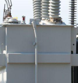
THE EXPERTS IN ELECTRICAL
RELIABILITY
Comprehensive Electrical Testing and Maintenance
Commissioning and Startup Services
Engineering Services
Power System and Coordination Studies
FAILURE IS NOT AN OPTION.
Predictive and Preventive Maintenance
Partial Discharge Testing and Monitoring
24/7 Emergency Service
Ensuring the reliability of your electrical distribution system.
As the leading independent electrical testing, maintenance, and engineering service company, you can rely on High Voltage Maintenance to exceed your electrical equipment performance goals. From testing for problems that could disable your system, to complete turnaround execution, you’ll quickly understand how we are your single source solution for all of your electrical reliability needs. With a service geography across the Midwest and Eastern Seaboards, our service team puts experienced professionals where and when you need them.




For more
High Voltage Maintenance (866) HVM-TEAM
information:


ELECTRO RENT ANSWERS YOUR EVERY TEST NEED 888.739.1095 www.electrorent.com/electrical-power sales@electrorent.com
ADVANCEMENTS IN THE INDUSTRY
BY NICK PERJANIK, PhD, Weidmann
With more than half the total cost of a high-voltage substation typically residing with one piece of equipment, the failure of a critical transformer could affect a vast number of customers and disrupt operational continuity. Although the industry has multiple strategies to maintaining equipment including runto-failure (RTF), reliability-centered maintenance (RCM), and condition-based maintenance (CBM), it is CBM that is founded on the tenet that maintenance should be based on electrical and diagnostic testing and only scheduled and performed as-needed. Proper and timely sampling and testing of insulation liquids is the accepted practice in the routine and emergency diagnostic testing of key electrical equipment.
With a properly implemented CBM program, actions to correct or address developing issues can be proactively taken during planned outages or prior to significant damage. When sampling insulation liquids, an increased topic ofdiscussion

is adhering to recognized standards that ensure the sample taken is representative of the liquid inside the equipment. The added costs, time required, and lack of confidence resulting from questionable sampling techniques continues to
 Electrical Technology Inc.
112 • FALL 2017
RESULTS ARE ONLY AS GOOD AS THE SAMPLE TAKEN
be an industry issue. ASTM International, the IEEE Transformers Committee, and CIGRE’s Working Group 47 are all working on this topic.
The purpose of this article is to provide a brief overview of advancements and the significant factors to consider in implementing proper sampling strategies of electrical insulating liquids. The ASTM International sampling method, the variables that can affect the quality of the sample and the results, and a case study of a faulted unit where normal oil sampling was insufficient to fully assess its condition are discussed.
STANDARD PRACTICES FOR SAMPLING
Organizations that sample electrical equipment are not always familiar with ASTM International’s D923-2015 standard method and the interpretive issues associated with improper sampling practices. As a result, multiple safety and application advancements are being identified, discussed, and added to existing sampling programs. With sound maintenance decisions relying on diagnostic test data, it is important that the sampling process and its limitations are fully understood.
The process for sampling of insulating liquids is provided in ASTM Method D923-2015, Standard Practices for Sampling Electrical Insulating Liquids available at www.astm.org. This standard provides a description of the sampling techniques for large and small energized equipment, cans, drums, and tank cars and addresses the suitability, advantages, and disadvantages of using various sampling containers. Although the majority of laboratory testing is completed using glass syringes and large volume containers, there are cases where other sampling equipment may be required.
At recent industry meetings and conferences, conversations have focused on the benefits and limitations of sampling from the bottom or top of the unit and in high-flow areas near the radiators. Considering the benefits and limitations of each, including those associated with safety and insulation liquid dynamics, the preference is to take samples from a location that provides the most valuable information on the condition of
ADVANCEMENTS IN THE INDUSTRY
the unit or contaminants within the liquid and in a safe manner. To date, this remains to be the bottom sampling drain valve.
In the updated ASTM standard, attention is placed on the use of clean and test-specific sampling containers, the importance of properly flushing the sampling valve and sample container, the steps to reduce air and moisture ingress, and the techniques to reduce potential loss of fault gases or other compounds of interest. As stated in the standard, properly addressing the hygroscopic tendency of insulating liquids and minimizing exposure to the atmosphere are critical to ensuring that the sample collected is representative of the liquid from within the unit. Remember: Results are only as good as the sample taken.
SAMPLING OF THE LIQUID AND HEADSPACE GASES
Given that gases, water, particles, and other contaminants are not always dispersed uniformly throughout the liquid, it is important to understand when, where, and how samples should be taken on normally operating and faulted equipment. Knowledge and proper documentation of the operating conditions including temperature, and in the case of a suspected fault, the timing and potential location of damage are critical factors in establishing a sampling strategy.
With incipient faults (i.e., those that occur over time and can be trended), testing for gases generated by partial discharge, overheating, or arcing aids in identifying internal fault activity. It should be noted that, when following the IEEE Guide C57.104 Guide for the Interpretation of Dissolved Gases (or additional IEEE Guides for LTCs, Natural Esters, etc.), the severity of a suspected fault is based on the gas generation rate. Here, it becomes more challenging. For example, it is common practice to consider that a transformer with an increase of 365 ppm of hydrogen (H2) over a one-year sampling interval was the result of H2 being generated at the constant rate of 1 ppm/day. In reality, the entire increase may have been generated over the entire year, over a period of several days, or possibly only hours prior to taking the sample. In the case of increased gases
NETAWorld • 113
RESULTS ARE ONLY AS GOOD AS THE SAMPLE TAKEN
ADVANCEMENTS IN THE INDUSTRY
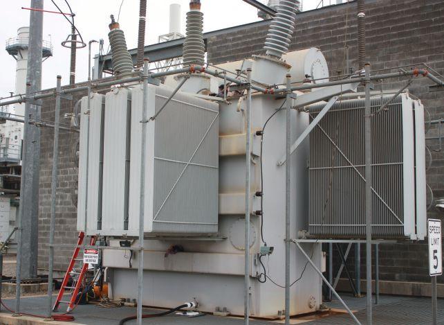
or moisture, a confirmational analysis is always recommended to fully evaluate the situation.
In cases of a recent fault and immediate liquid sampling, the generated gases may not be equally distributed throughout the unit. Several interpretive challenges could now exist. For instance, gas bubbles may rise and accumulate at the top of the unit or be trapped in the windings, which could result in inaccurate DGA interpretation. Cases have also illustrated that arcing gases generated near the bottom of the tank may be detected immediately following a fault, only to be followed by a lowered or undetectable level once the gases have been distributed and diluted throughout the tank. With this
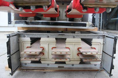
understood, a fault near the top or within the windings may not be immediately detected from sampling the bottom valve — especially in cases of cold temperatures, low oil flow, or no load. Taking liquid samples from the top, middle, or bottom of the unit necessitates an understanding of the flow of the liquid, the potential location of a fault, and an idea of where the specific contaminants of interest (i.e., gases, carbon, metals, etc.) are likely to be found.
For samples taken at the bottom valve, it is common to detect trace levels of particles, rust, carbon, or even free water — even after flushing the valve. The advantage of sampling from the bottom is that the liquid may contain oxidation, contamination, or degradation products not detected in liquids sampled from the top or highflow areas. Again, the liquid at the bottom may over-represent some contaminants and their effects on the properties of the liquid, but it may provide additional information worthy of further investigation. In contrast, sampling from the middle or top of the tank may provide a more representative view of the oil flowing throughout the unit, but a complete picture of the quality of the insulation system may not be presented. A proper sampling strategy can assist in providing the right information to diagnose the condition of the electrical equipment throughout the unit.
GSU CASE STUDY
A 13.8/230kV GSU transformer (Photo 1) experienced an external fault of one of its two bus feeds on December 10th (Photo 2a and Photo 2b).
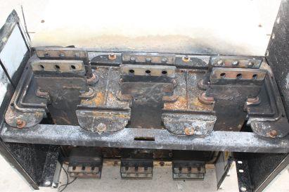
114 • FALL 2017 RESULTS ARE ONLY AS GOOD AS THE SAMPLE TAKEN
Photo 1: GSU Transformer
Photo 2a: External Bus
Photo 2b: External Bus Failure
ADVANCEMENTS IN THE
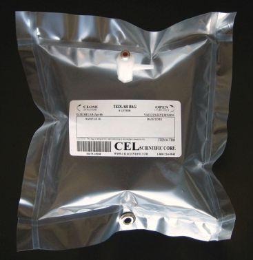
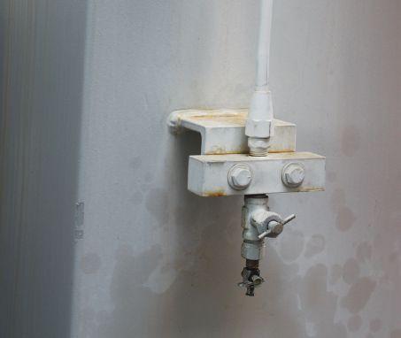
After an initial field inspection and laboratory testing, no indication of a major internal fault was detected and the unit was re-energized. Upon energizing on December 12, the gas pressure relief valve operated, and the transformer may have experienced a thru-fault of greater than 2,000 amps. The DGA following the trip on the same day still did not indicate an active internal fault. The accumulation indicator soon maxed-out, and additional liquid samples were taken from the bottom drain valve and the conservator, and a gas sample using a Tedlar® bag
(Photo 3) was taken from the gas accumulation indicator port (Photo 4).
The DGA results sampled from the bottom and conservator ports are provided in Table 1, and the gas results from the gas accumulation indicator port are provided in Table 2. The DGA results indicated that fault gases were not detected immediately following the operation of the gas pressure relay, but were detected at different levels at the bottom, conservator, and gas accumulation indicator within 24 hours.
NETAWorld • 115 RESULTS ARE ONLY AS GOOD AS THE SAMPLE TAKEN
INDUSTRY
Photo 3: Tedlar® Gas Sampling Bag
Note: “Tedlar” is a Registered trademark of Dupont
Dec13 Dec13 Dec12 Dec10 Compartment: Conserv Bottom Bottom Bottom Temp (°C) 20 20 15 30 Hydrogen (H2) (µL/L) 78 29 <2 <2 Methane (CH4) (µL/L) 62 47 32 32 Ethane (C2H6) (µL/L) 9 7 5 5 Ethylene (C2H4) (µL/L) 57 31 10 9 Acetylene (C2H2) (µL/L) 102 44 <1 <1 Carbon Monoxide (CO) (µL/L) 1270 1321 1168 1204 Carbon Dioxide (CO2) (µL/L) 5634 5832 5160 5535 Nitrogen (N2) (µL/L) 61347 68769 60900 57590 Oxygen (O2)
1900 3515 2840 1839 Total Dissolved Gas (TDG) (µL/L) 70459 79595 70116 66214 Total Dissolved Combustible Gas (TDCG) (µL/L) 1578 1479 1216 1250 Equivalent TCG (%) 1.6958 1.4223 1.3476 1.4737
Table 1: Dissolved Gas Analysis (DGA)
Date Sampled:
(µL/L)
Photo 4: Gas Accumulation Port
ADVANCEMENTS IN THE INDUSTRY
Table 2: Head-Space Gas Analysis (GA) Using a Tedlar® Gas Sampling Bag
(H2) (µL/L)
(CH4) (µL/L)
Ethane (C2H6) (µL/L)
Ethylene (C2H4) (µL/L)
Acetylene (C2H2) (µL/L)
Carbon Monoxide (CO) (µL/L)
Carbon Dioxide (CO2) (µL/L)
Nitrogen (N2) (µL/L)
Oxygen (O2) (µL/L) 4440 4260
Total Dissolved Gas (TDG) (µL/L)
Total Dissolved Combustible Gas (TDCG) (µL/L)
With adequate time and conditions, the fault gases will distribute throughout the unit. Relying on only the testing of the bottom liquid would have provided insufficient diagnostic information on the condition of the unit. In this case, the results from the three sample sources offered critical information related to an internal bus failure.
CONCLUSION
Across the industry, utilities and industrials alike are relying on basic electrical field testing and their laboratory liquid testing programs to lead their CBM programs. With an improved understanding of those factors that can influence the quality of test data, normal and fault condition diagnostics can be improved. The assessment of faults and contamination, degradation, or oxidation products can be improved with properly applied sampling and interpretative practices. An understanding of the sampling process and an
awareness of the factors that can impact results help ensure that CBM programs are maximized for operational continuity.

Nick Perjanik, PhD, is the Knowledge Services Manager for Weidmann Electrical Technology Inc. Nick received a BS in Chemistry and an MBA from California State University in Sacramento and earned a PhD in Management from Walden University, where he specialized in knowledge management in the field of Applied Management and Decision Sciences, in 2016. He began testing electrical insulating liquids in 1987 and managing analytical laboratories in 1995. Nick’s primary responsibilities include technical training and diagnostic support to the electrical equipment testing industry. Nick’s technical experience includes membership in the ASTM D-27 Technical Committee and the IEEE PES Transformers Committee. He is an active member of CIGRE’s WG 47 on Dissolved Gas Analysis and has authored multiple papers on diagnostic testing, decision sciences, and the application of management practices at electrical utilities.
116 • FALL 2017 RESULTS ARE ONLY AS GOOD AS THE SAMPLE TAKEN
Sampled Dec13 Dec13 Temp N/A N/A Hydrogen
627000 617000 Methane
76300 75600
Date
1080 1200
303000 317000
95100 96700
1040 1030
2050 1960
45500 43700
1156000 1158000
1010000 1108000 Equivalent TCG (%) 95.9177 96.0191

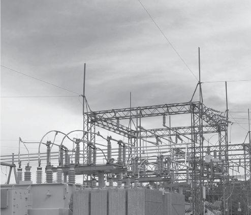


228 Merrick Road Lynbrook, NY 11563 (631) 589-6343/Fax (516) 596-3680 601 Union Street Brooklyn, NY 11215 (718) 786-4900 24 Hour Emergency Services (937) 439-9660 Electrical Distribution System Testing, Repair, and Maintenance







WE SAVE YOU TIME & MONEY WITH SPARES YOU NEED FOR EMERGENCY REPLACEMENTS ON YOUR NEXT TESTING JOB • Starters & Contactors • Motor Control Centers • Motor Control Buckets NEW, SURPLUS & RECONDITIONED ELECTRICAL EQUIPMENT southlandelectrical.com 1.800.476.1486 WHEN AND WHERE YOU NEED IT • Breakers • Contact Kits • Disconnects • PLCs & VFDs • Busway & Bus Plugs • Transformers and MORE! We’re on-call 24/7 CALL TODAY FOR PRICING AND QUOTES ON REPAIR SERVICES 1year warranty Backed by our 24/ 7 emergency service


ANSWERS


ANSWERS

1. d. Incident energy is directly proportional to time. If the operation time of an overcurrent protection device (OCPD) doubles, the incident energy received by a person would also double. Incident energy, by the way, increases by the square of the distance as the distance decreases.
2. a. No knock on the other tests, as they are important, but knowing the circuit breaker will open properly after it has been in service is most important safety-wise. As circuit breakers sit in service, lubricants tend to dry out, slowing the circuit breaker down. When they are operated the very first time after a long period of service, they may or may not operate in the manner specified by the manufacturer. The first-trip time test verifies whether circuit breakers will open within manufacturer’s specifications when needed that first critical time.
3. d. For years, the only field test available for vacuum bottles was the vacuum-bottle Integrity test, which applied ac voltage (sometimes dc) across the contacts inside the bottle. This test only gave a go/ no-go indication of the bottle’s ability to function at that moment in time. The magnetic atmospheric condition (MAC) test can provide a realistic estimate of a vacuum bottle’s life expectancy based on air leakage into the bottle.
4. c. If you answered question #2 correctly, you probably sorted this one out as well. Circuit breakers that sit for years without operating are most likely not to open within the manufacturer’s specifications. Jim Miller, who manages Shermco’s circuit breaker rebuild facilities, says that 40 percent of the circuit breakers Shermco receives have issues caused by lack of lubrication.


NFPA Disclaimer: Although Jim White is a member of the NFPA Technical Committee for both NFPA 70E, Standard for Electrical Safety in the Workplace, and NFPA 70B, Recommended Practice for Electrical Equipment Maintenance, the views and opinions expressed in this column are purely the author’s and shall not be considered an official position of the NFPA or any of its technical committees and shall not be considered, nor be relied upon, as a formal interpretation or promotion of the NFPA. Readers are encouraged to refer to the entire text of all referenced documents.

TECH QUIZ TECH QUIZ ANSWERS
No. 119
NETA ACCREDITED COMPANIES Setting the Standard
A&F Electrical Testing, Inc.
80 Lake Ave. South, Ste. 10 Nesconset, NY 11767 (631) 584-5625 Fax: (631) 584-5720 kchilton@afelectricaltesting.com www.afelectricaltesting.com
Kevin Chilton
A&F Electrical Testing, Inc.
80 Broad St. 5th Floor
New York, NY 10004 (631) 584-5625 Fax: (631) 584-5720 afelectricaltesting@afelectricaltesting.com
Florence Chilton
ABM Electrical Power Solutions
3602 East Southern Ave., Ste. 1 Phoenix, AZ 85040 (602) 722-2423 www.ABM.com
Doug Bukowski
ABM Electrical Power Solutions
9800 E. Geddes Avenue, Unit A-150 Englewood, CO 80112 (303) 524-6560 Fax: (303) 524-6581
Brian Smith
ABM Electrical Power Solutions
2142 Rheem Drive Pleasanton, CA 94588 (408) 466-6920
John Marvulli
ABM Electrical Power Solutions
3940 Ruffin Rd., Ste. C San Diego, CA 92123 (858) 754-7963
william.mckenzie@abm.com
William McKenzie
ABM Electrical Power Solutions
6280 South Valley View Blvd., Ste. 618 Las Vegas, NV 89118 (602) 300-2188 Fax: (602) 437-3894
Jason Black
ABM Electrical Power Solutions
814 Greenbrier Circle, Ste. E Chesapeake, VA 23320 (757) 548-5690 Fax: (757) 548-5417
Mark Anthony Gaughan, III
ABM Electrical Power Solutions
3700 Commerce Dr. #901-903 Baltimore, MD 21227 (410) 247-3300 Fax: (410) 247-0900
Bill Hartman
ABM Electrical Power Solutions
5809 Departure Dr., Ste. 104 Raleigh, NC 27616 (919) 877-1008 Fax: (919) 501-7492
Rob Parton
ABM Electrical Power Solutions
317 Commerce Park Dr. Cranberry Township, PA 16066-6427 (724) 772-4638 Fax: (724) 772-6003
christopher.smith@abm.com
Christopher Smith
ABM Electrical Power Solutions
4390 Parliament Place, Ste. S Lanham, MD 20706 (301) 967-3500 Fax: (301) 735-8953
Frank Ceci
ABM Electrical Power Solutions
3600 Woodpark Blvd., Suite G Charlotte, NC 28206 (704) 273-6257 Fax: (704) 598-9812 ernest.goins@abm.com
Ernest Goins
ABM Electrical Power Solutions
720 S. Rochester Ave., Suite A Ontario, CA 91761 (800) 597-1225 Fax: (909) 937-6798
Mike Bivens
Absolute Testing Services 6829 Guhn Rd. Houston, TX 77040 (832) 467-4446 Fax: (713) 849-3885 rgamble@absolutetesting.com www.absolutetesting.com
Richard Gamble
Accessible Consulting Engineers, Inc. 1269 Pomona Rd., Ste. 111 Corona, CA 92882 (951) 808-1040 info@acetesting.com www.acetesting.com Iraj Nasrolahi
Advanced Testing Systems 15 Trowbridge Dr. Bethel, CT 06801 (203) 743-2001 Fax: (203) 743-2325 pmaccarthy@advtest.com www.advtest.com Pat MacCarthy
American Electrical Testing Co., Inc. 25 Forbes Blvd., Ste. 1 Foxboro, MA 02035 (781) 821-0121 Fax: (781) 821-0771 sblizard@aetco.us www.aetco.us
Scott A. Blizard
American Electrical Testing Co., Inc. 34 Clover Dr. South Windsor, CT 06074 (860) 648-1013 Fax: (781) 821-0771 jpoulin@aetco.us
Gerald Poulin
American Electrical Testing Co., Inc. 76 Cain Dr. Brentwood, NY 11717 (631) 617-5330 Fax: (631) 630-2292 bfernandez@aetco.us
Billy Fernandez
American Electrical Testing Co., Inc. 50 Intervale Rd., Ste. 1 Boonton, NJ 07005 (973) 316-1180 Fax: (781) 316-1181 jsomol@aetco.us
Jeff Somol
American Electrical Testing Co., Inc. Green Hills Commerce Center 5925 Tilghman St., Ste. 200 Allentown, PA 18104 (215) 219-6800 jmunley@aetco.us
Jonathan Munley
American Electrical Testing Co., Inc. 12566 W. Indianola Ave. Avondale, AZ 85392 (480) 383-9242 dmadaglia@aetco.us
Donald Madaglia
AMP Quality Energy Services, LLC 4220 West Schrimsher SW Site W1 P.O. Box 526, Huntsville, AL 35804 (256) 513-8255
Brian Rodgers
Apparatus Testing and Engineering 11300 Sanders Dr., Ste. 29 Rancho Cordova, CA 95742 (916) 853-6280 Fax: (916) 853-6258 info@apparatustesting.com www.apparatustesting.com
Harold (Jerry) Carr
Apparatus Testing and Engineering 7083 Commerce Circle, Ste. H Pleasanton, CA 94588 (925) 454-1363 Fax: (925) 454-1499
Applied Engineering Concepts 1105 N. Allen Ave. Pasadena, CA 91104 (626) 398-3052 Fax: (626) 398-3053 michel.c@aec-us.com www.aec-us.com
Michel Castonguay
BEC Testing
50 Gazza Blvd. Farmingdale, NY 11735 (516) 531-9136 Fax: (631) 249-6115 ddevlin@banaelectric.com www.bectesting.com
Daniel Devlin
Burlington Electrical Testing Co., Inc.
300 Cedar Ave. Croydon, PA 19021-6051 (215) 826-9400 (221) Fax: (215) 826-0964 waltc@betest.com www.betest.com
Walter P. Cleary
C.E. Testing, Inc. 6148 Tim Crews Rd. Macclenny, FL 32063 (904) 653-1900 Fax: (904) 653-1911 cetesting@aol.com
Mark Chapman
CE Power Engineered Services, LLC 4040 Rev Dr. Cincinnati, OH 45232 (513) 563-6150 Fax: (513) 563-6120 info@cepowersol.net www.cepower.net
Brent McAlisar
CE Power Engineered Services, LLC 8490 Seward Road Fairfield, OH 45011 (513) 563-6150 tim.lana@cepower.net
Tim Lana
CE Power Engineered Services, LLC 10338 Citation Drive, Suite 300 Brighton, MI 48166 (810) 229-6628
Ken L'Esperance
CE Power Engineered Services, LLC 1803 Taylor Avenue Louisville, KY 40213 (502) 479-0612 tom.hutchinson@cepower.net
Tom Hutchinson
CE Power Engineered Services, LLC 10840 Murdock Drive Knoxville, TN 37932 (865) 310-2522 don.williams@cepower.net
Don Williams
CE Power Engineered Services, LLC 7674 Washington Ave. S Eden Prairie, MN 55344 (877) 968-0281
jason.thompson@cepower.net
Jason Thomps
Control Power Concepts
353 Pilot Rd; Ste. B Las Vegas, NV 89119 (702) 448-7833 Fax: (702) 448-7835 www.controlpowerconcepts.com
John Travis
NETA ACCREDITED COMPANIES
120 • FALL 2017
Dude Electrical Testing LLC
145 Tower Dr., Unit# 9 Burr Ridge, IL 60527 (815) 293-3388 Fax: (815) 293-3386 scott.dude@dudetesting.com www.dudetesting.com
Scott Dude
DYMAX Service, LLC
46918 Liberty Dr. Wixom, MI 48393 (248) 313-6868 Fax: (248) 313-6869 www.dymaxservice.com
Bruce Robinson
DYMAX Service, LLC
4213 Kropf Ave. Canton, OH 44706 (330) 484-6801 Fax: (740) 333-1271
Chuck Baker
Eastern High Voltage, Inc.
11A South Gold Dr. Robbinsville, NJ 08691-1606 (609) 890-8300 Fax: (609) 588-8090 bobwilson@easternhighvoltage.com www.easternhighvoltage.com
Robert Wilson
ELECT, P.C.
7400-G Siemens Rd., P.O. Box 2080 Wendell, NC 27591 (919) 365-9775 Fax: (919) 365-9789 btyndall@elect-pc.com www.elect-pc.com
Barry W. Tyndall
Electric Power Systems, Inc. 21 Millpark Ct. Maryland Heights, MO 63043 (314) 890-9999 Fax: (314) 890-9998 www.epsii.com
Electric Power Systems, Inc. 557 E. Juanita Ave., #4 Mesa, AZ 85204 (480) 633-1490 Fax: (480) 633-7092
Electric Power Systems, Inc. 4436 Parkway Commerce Blvd. Orlando, FL 32808 (407) 578-6424 Fax: 407-578-6408
Electric Power Systems, Inc.
7000 E. 47th Avenue Drive, Suite 100 Denver, CO 80216 (720) 857-7273 Fax: 303-928-8020
Electric Power Systems, Inc. 23823 Andrew Rd. Plainfield, IL 60585 (815) 577-9515 Fax: (815) 577-9516
Electric Power Systems, Inc.
NETA ACCREDITED COMPANIES Setting the
2601 Center Rd., # 101 Hinckley, OH 44233 (330) 460-3706 Fax: (330) 460-3708
Electric Power Systems, Inc.
56 Bibber Pkwy #1 Brunswick, ME 04011 (207) 837-6527
Electric Power Systems, Inc.
4100 Greenbriar Dr., Ste. 160 Stafford, TX 77477 (713) 644-5400
Electric Power Systems, Inc. 11861 Longsdorf St. Riverview, MI 48193 (734) 282-3311
Electric Power Systems, Inc.
827 Union St., Salem, VA 24153 (540) 375-0084 Fax: (540) 375-0094
Electric Power Systems, Inc.
915 Holt Ave., Unit 9 Manchester, NH 03109 (603) 657-7371 Fax: 603-657-7370
Electric Power Systems, Inc.
146 Space Park Dr. Nashville, TN 37211 (615) 834-0999 Fax: (615) 834-0129
Electric Power Systems, Inc.
8515 Cella Alameda NE, Ste. A Albuquerque, NM 87113 (505) 792-7761
Electric Power Systems, Inc. 7140 Dean Martin Drive, Suite 900 Las Vegas, NV 89118 (702) 815-1342
Electric Power Systems, Inc. 319 US Hwy. 70 E, Unit E Garner, NC 27529 (919) 322-2670 www.epsii.com
Electric Power Systems, Inc. 1090 Montour West Industrial Blvd. Coraopolis, PA 15108 (412) 276-4559
Electric Power Systems, Inc. 6141 Connecticut Ave. Kansas City, MO 64120 (816) 241-9990 Fax: (816) 241-9992
Electric Power Systems, Inc. 2495 Boulevard of the Generals Norristown, PA 19403 (610) 630-0286
Electric Power Systems, Inc. 1129 East Hwy. 30 Gonzalez, LA 70817 (225) 644-0150 Fax: (225) 644-6249
Electric Power Systems, Inc. 7925 Dunbrook Rd., Ste. G San Diego, CA 92126 (858) 566-6317
Electric Power Systems, Inc. 6679 Peachtree Industrial Dr. Ste. H Norcross, GA 30092 (770) 416-0684 j.cash@epsii.com
Jeff Cash
Electrical & Electronic Controls 6149 Hunter Rd. Ooltewah, TN 37363 (423) 344-7666 (23) Fax: (423) 344-4494 eecontrols@comcast.net
Michael Hughes
Electrical Energy Experts, Inc. W129N10818, Washington Dr. Germantown, WI 53022 (262) 255-5222 Fax: (262) 242-2360 bill@electricalenergyexperts.com www.electricalenergyexperts.com
William Styer
Electrical Engineering & Service Co., Inc. 289 Centre St. Holbrook, MA 02343-1075 (781) 767-9988 jcipolla@eescousa.com www.eescousa.com Joe Cipolla
Electrical Equipment Upgrading, Inc. 21 Telfair Place, Savannah, GA 31415 (912) 232-7402 Fax: (912) 233-4355 kmiller@eeu-inc.com www.eeu-inc.com
Kevin Miller
Electrical Maintenance & Testing Inc. 12342 Hancock St., Carmel, IN 46032 (317) 853-6795 Fax: (317) 853-6799 info@emtesting.com www.emtesting.com
Brian K. Borst
Electrical Reliability Services 1057 Doniphan Park Circle, Ste. A El Paso, TX 79922 (915) 587-9440 Fax: (915) 587-9010
Electrical Reliability Services
1775 W. University Dr., Ste. 128 Tempe, AZ 85281 (480) 966-4568 Fax: (480) 966-4569
Electrical Reliability Services 1426 Sens Rd. Ste. 5 Houston, TX 77571 (281) 241-2800 Fax: (281) 241-2801
Electrical Reliability Services 4099 SE International Way, Ste. 201 Milwaukie, OR 97222-8853 (503) 653-6781 Fax: (503) 659-9733
Electrical Reliability Services 5909 Sea Lion Place, Ste. C Carlsbad, CA 92010 (858) 695-9551
Electrical Reliability Services 8500 Washington Pl. NE, Ste. A-6 Albuquerque, NM 87113 (505) 822-0237 Fax: (505) 822-0217
Electrical Reliability Services 1380 Greg Street, Ste. 216 Sparks, NV 89431 (775) 746-8484 Fax: (775) 356-5488
Electrical Reliability Services 2275 Northwest Pkwy SE, Ste. 180 Marietta, GA 30067 (770) 541-6600 Fax: (770) 541-6501
Electrical Reliability Services 7100 Broadway, Ste. 7E Denver, CO 80221-2915 (303) 427-8809 Fax: (303) 427-4080
Electrical Reliability Services 400 N.W. Capital Dr. Lee's Summit, MO 64086 (816) 525-7156 Fax: (816) 524-3274
Electrical Reliability Services 6900 Koll Center Parkway, Ste. 415 Pleasanton, CA 94566 (925) 485-3400 Fax: (925) 485-3436
Electrical Reliability Services 10606 Bloomfield Ave. Santa Fe Springs, CA 90670 (562) 236-9555 Fax: (562) 777-8914
Electrical Reliability Services 3535 Emerson Parkway, Ste. A Gonzales, LA 70737 (225) 755-0530 Fax: (225) 751-5055
Electrical Reliability Services 245 Hood Rd. Sulphur, LA 70665 (337) 583-2411 Fax: (337) 583-2410
Electrical Reliability Services 11000 Metro Pkwy., Ste. 30 Ft. Myers, FL 33966 (239) 693-7100 Fax: (239) 693-7772
NETA ACCREDITED COMPANIES
NETAWorld • 121
Standard
NETA ACCREDITED COMPANIES Setting the Standard
Electrical Reliability Services
2222 West Valley Hwy. N., Ste 160 Auburn, WA 98001 (253) 736-6010 Fax: (253) 736-6015
Electrical Reliability Services
9736 South 500 West Sandy, UT 84070 (801) 975-6461
Electrical Reliability Services
6351 Hinson St., Ste. B Las Vegas, NV 89118 (702) 597-0020 Fax: (702) 597-0095
Electrical Reliability Services
9636 St. Vincent, Unit A Shreveport, LA 71106 (318) 869-4244
Electrical Reliability Services
610 Executive Campus Dr. Westerville, OH 43082 (877) 468-6384 Fax: (614) 410-8420 info@electricalreliability.com
Electrical Testing and Maintenance Corp.
3673 Cherry Rd., Ste. 101 Memphis, TN 38118 (901) 566-5557 r.gregory@etmcorp.com www.etmcorp.net
Ron Gregory
Electrical Testing, Inc. 2671 Cedartown Hwy. Rome, GA 30161-6791 (706) 234-7623 Fax: (706) 236-9028
steve@electricaltestinginc.com www.electricaltestinginc.com
Electrical Testing Solutions
2909 Green Hill Ct. Oshkosh, WI 54904 (920) 420-2986 Fax: (920) 235-7136 tmachado@electricaltestingsolutions.com www.electricaltestingsolutions.com
Tito Machado
Elemco Services, Inc. 228 Merrick Rd. , Lynbrook, NY 11563 (631) 589-6343 Fax: (631) 589-6670 courtney@elemco.com www.elemco.com
Courtney Gallo
EnerG Test
204 Gale Lane
Bldg. 2 - 2nd Floor Kennett Square, PA 19348 (484) 731-0200 Fax: (484) 713-0209 kbleiler@energtest.com www.energtest.com
Katie Bleiler
Energis High Voltage Resources, Inc.
1361 Glory Rd. Green Bay, WI 54304 (920) 632-7929 Fax: (920) 632-7928 info@energisinc.com www.energisinc.com
Mick Petzold
EPS Technology
29 N. Plains Hwy., Ste. 12 Wallingford, CT 06492 (203) 679-0145 www.eps-technology.com
Grounded Technologies, Inc. 10505 S. Progress Way, Ste. 105 Parker, CO 80134
P-(303) 781-2560 F- (303) 781-5240 jodymedina@groundedtech.com www.groundedtech.com
Jody Medina
Grubb Engineering, Inc. 3128 Sidney Brooks San Antonio, Tx 78235 (210) 658-7250 Fax: (210) 658-9805 joy@grubbengineering.com www.grubbengineering.com
Robert D. Grubb Jr.
Hampton Tedder Technical Services 4563 State St. Montclair, CA 91763 (909) 628-1256 Fax: (909) 628-6375
chasen.tedder@hamptontedder.com www.hamptontedder.com
Chasen Tedder
Hampton Tedder Technical Services 4113 Wagon Trail Ave. Las Vegas, NV 89118 (702) 452-9200 Fax: (702) 632-0079
Roger Cates
Hampton Tedder Technical Services 3747 West Roanoke Ave. Phoenix, AZ 85009 (480) 967-7765 Fax: (480) 967-7762
Linc McNitt
Harford Electrical Testing Co., Inc. 1108 Clayton Rd. Joppa, MD 21085 (410) 679-4477 Fax: (410) 679-0800 testing@harfordtesting.com www.harfordtesting.com
Vincent Biondino
High Energy Electrical Testing, Inc. 515 S. Ocean Ave. Seaside Park, NJ 08752 (732) 938-2275 Fax: (732) 938-2277 hinrg@comcast.net www.highenergyelectric.com
Charles Blanchard
High Voltage Maintenance Corp. 24 Walpole Park South Dr. Walpole, MA 02081 (508) 668-9205 www.hvmcorp.com
High Voltage Maintenance Corp. 941 Busse Rd. Elk Grove Village, Il 60007 (847) 640-0005
High Voltage Maintenance Corp. 7200 Industrial Park Blvd. Mentor, OH 44060 (440) 951-2706 Fax: (440) 951-6798
High Voltage Maintenance Corp. 3000 S. Calhoun Rd. New Berlin, WI 53151 (262) 784-3660 Fax: (262) 784-5124
High Voltage Maintenance Corp. 8320 Brookville Rd. #E Indianapolis, IN 46239 (317) 322-2055 Fax: (317) 322-2056
High Voltage Maintenance Corp. 1250 Broadway, Ste. 2300 New York, NY 10001 (718) 239-0359
High Voltage Maintenance Corp. 355 Vista Park Dr. Pittsburgh, PA 15205-1206 (412) 747-0550 Fax: (412) 747-0554
High Voltage Maintenance Corp. 150 North Plains Industrial Rd. Wallingford, CT 06492 (203) 949-2650 Fax: (203) 949-2646
High Voltage Maintenance Corp. 9305 Gerwig Ln., Ste. B Columbia, MD 21046 (410) 309-5970 Fax: (410) 309-0220
High Voltage Maintenance Corp. 24371 Catherine Industrial Dr, Ste. 207 Novi, MI 48375 (248) 305-5596 Fax: (248) 305-5579
High Voltage Maintenance Corp. 5100 Energy Dr. Dayton, OH 45414 (937) 278-0811 Fax: (937) 278-7791
High Voltage Service, LLC 3890 Pheasant Ridge Dr. NE, Ste. 170 Blaine, MN 55449 (763) 784-4040 Fax: (763) 784-5397 www.hvserviceinc.com
Mike Mavetz
HMT, Inc. 6268 Route 31 Cicero, NY 13039 (315) 699-5563 Fax: (315) 699-5911 jpertgen@hmt-electric.com www.hmt-electric.com
John Pertgen
Industrial Electric Testing, Inc. 11321 West Distribution Ave. Jacksonville, FL 32256 (904) 260-8378 Fax: (904) 260-0737 gbenzenberg@bellsouth.net www.industrialelectrictesting.com
Gary Benzenberg
Industrial Electric Testing, Inc. 201 NW 1st Ave. Hallandale, FL 33009-4029 (954) 456-7020
Industrial Electronics Group 850369 Highway 17 South P.O. Box 1870 Yulee, FL 32041 (904) 225-9529 Fax: (904) 225-0834 butch@industrialgroups.com www.industrialgroups.com
Butch E. Teal
Industrial Tests, Inc. 4021 Alvis Ct., Ste. 1 Rocklin, CA 95677 (916) 296-1200 Fax: (916) 632-0300 greg@indtest.com www.industrialtests.com
Greg Poole
Infra-Red Building and Power Service
152 Centre St. Holbrook, MA 02343-1011 (781) 767-0888 Fax: (781) 767-3462 tom.mcdonald@infraredbps.com www.infraredbps.com
Thomas McDonald Sr.
M&L Power Systems, Inc.
109 White Oak Ln., Ste. 82 Old Bridge, NJ 08857 (732) 679-1800 Fax: (732) 679-9326 milind@mlpower.com www.mlpower.com
Milind Bagle
NETA ACCREDITED COMPANIES
122 • FALL 2017
NETA ACCREDITED COMPANIES Setting the Standard
Magna IV Engineering 1103 Parsons Rd. SW Edmonton, AB T6X 0X2 Canada (780) 462-3111 Fax: (780) 450-2994 info@magnaiv.com www.magnaiv.com
Virgina Balitski
Magna IV Engineering 200, 688 Heritage Dr. Calgary, AB T2H 1M6 Canada (403) 723-0575 Fax: (403) 723-0580 info.calgary@magnaiv.com
Dave Emerson
Magna IV Engineering 141 Fox Cresent Fort McMurray, AB T9K 0C1 Canada (780) 791-3122 Fax: (780) 791-3159 info.fmcmurray@magnaiv.com
Ryan Morgan
Magna IV Engineering
96 Inverness Dr. East, Unit R Englewood, CO 80112 (303) 799-1273 Fax: (303) 790-4816 info.denver@magnaiv.com
Aric Proskurniak
Magna IV Engineering Avenida del Condor #590 Oficina 601 Huechuraba, Santiago 8580676 Chile +(56) 9-9-517-4642 info.chile@magnaiv.com
Harvey Mendoza
Magna IV Engineering 1040 Winnipeg St. Regina , SK S4R 8P8 Canada (306) 585-2100 Fax: (306) 585-2191 info.regina@magnaiv.com
Adam Jaques
Magna IV Engineering 106, 4268 Lozells Ave. Burnaby, BC VSA 0C6 Canada (604) 421-8020
Scott Nixon
Magna IV Engineering 10325 Landsbury, Ste. 404 Houston, TX 77099 (720) 480-9680 aproskurniak@magnaiv.com www.magnaiv.com
Aric Proskurniak
National Field Services
1890 A South Hwy 35 Alvin, TX 77511 (800) 420-0157
jonathan.wakeland@natlfield.com www.natlfield.com
Jonathan Wakeland
National Field Services 649 Franklin St. Lewisville, TX 75057 (972) 420-0157 www.natlfield.com
Eric Beckman
National Field Services 1405 United Drive, Ste. 113-115 San Marcos, TX 78666 (800) 420-0157 Fax: (972) 420-0552 info@natlfield.com www.natlfield.com
Matt LaCoss
Nationwide Electrical Testing, Inc. 6050 Southard Trace Cumming, GA 30040 (770) 667-1875 Fax: (770) 667-6578
Shashi@N-E-T-Inc.com www.n-e-t-inc.com
Shashikant B. Bagle
North Central Electric, Inc. 69 Midway Ave. Hulmeville, PA 19047-5827 (215) 945-7632 Fax: (215) 945-6362 ncetest@aol.com www.ncetest.com
Robert Messina
Northern Electrical Testing, Inc. 1991 Woodslee Dr. Troy, MI 48083-2236 (248) 689-8980 Fax: (248) 689-3418 ldetterman@northerntesting.com www.northerntesting.com
Lyle Detterman
Orbis Engineering Field Services Ltd. #300, 9404 - 41st Ave. Edmonton, AB T6E 6G8 Canada (780) 988-1455 Fax: (780) 988-0191 lorne@orbisengineering.net www.orbisengineering.net
Lorne Gara
Pace Technologies, Inc. 9604 41 Avenue NW Edmonton, AB T6E 6G9 Canada (780) 450-0404 cleavitt@pacetechnologies.com www.pacetechnologies.com
Craig Leavitt
Pacific Power Testing, Inc. 14280 Doolittle Dr. San Leandro, CA 94577 (510) 351-8811 Fax: (510) 351-6655 steve@pacificpowertesting.com www.pacificpowertesting.com
Steve Emmert
Pacific Powertech, Inc. #110, 2071 Kingsway Ave. Port Coquitlam, BC V3C 6N2 Canada (604) 944-6697 Fax: (604) 944-1271 jkonkin@pacificpowertech.ca www.pacificpowertech.ca
Josh Konkin
Phasor Engineering
Sabaneta Industrial Park #216 Mercedita, PR 00715 Puerto Rico (787) 844-9366 Fax: (787) 841-6385 rcastro@phasorinc.com
Rafael Castro
Potomac Testing, Inc.
1610 Professional Blvd., Ste. A Crofton, MD 21114 (301) 352-1930 Fax: (301) 352-1936 kbassett@potomactesting.com www.potomactesting.com
Ken Bassett
Power & Generation Testing, a CE Power Company 480 Cave Rd. Nashville, TN 37210 (615) 882-9455 Fax: (615) 882-9591 mose@pgti.net www.pgti.net
Mose Ramieh
Power Engineering Services, Inc. 9179 Shadow Creek Lane Converse, TX 78109 (210) 590-4936 Fax: (210) 590-6214 engelke@pe-svcs.com www.pe-svcs.com
Miles R. Engelke
POWER PLUS Engineering, Inc. 46575 Magellan Novi, MI 48377 (248) 344-0200 Fax: (248) 305-9105 smancuso@epowerplus.com www.epowerplus.com
Salvatore Mancuso
Power Products & Solutions, LLC 12465 Grey Commercial Rd. Midland, NC 28107 (704) 573-0420 x12 Fax: (704) 573-3693 adis.talovic@powerproducts.biz www.powerproducts.biz
Adis Talovic
Power Products & Solutions, LLC 13 Jenkins Ct. Mauldin, SC 29662 (800) 328-7382 raymond.pesaturo@powerproducts.biz www.powerproducts.biz
Raymond Pesaturo
Power Services, LLC 998 Dimco Way, P.O. Box 750066 Centerville, OH 45475 (937) 439-9660 Fax: (937) 439-9611
mkbeucler@aol.com
Mark Beucler
Power Solutions Group, Ltd. 425 W. Kerr Rd. Tipp City, OH 45371 (937) 506-8444 Fax: (937) 506-8434 bwilloughby@powersolutionsgroup.com www.powersolutionsgroup.com
Barry Willoughby
Power Solutions Group, Ltd. 135 Old School House Rd. Piedmont, SC 29673 (864) 845-1084 Fax:: (864) 845-1085 fcrawford@powersolutionsgroup.com www.powersolutionsgroup.com
Anthony Crawford
Power Solutions Group, Ltd. 670 Lakeview Plaza Blvd. Columbus, OH 43085 (614) 310-8018 sspohn@powersolutionsgroup.com www.powersolutionsgroup.com
Stuart Spohn
Power Systems Testing Co.
4688 W. Jennifer Ave., Ste. 108 Fresno, CA 93722 (559) 275-2171 ext 15 Fax: (559) 275-6556 dave@pstcpower.com www.powersystemstesting.com
David Huffman
Power Systems Testing Co.
600 S. Grand Ave., Ste. 113 Santa Ana, CA 92705-4152 (714) 542-6089 Fax: (714) 542-0737 www.powersystemstesting.com
NETA ACCREDITED COMPANIES
NETAWorld • 123
NETA ACCREDITED COMPANIES Setting the Standard
Power Systems Testing Co.
6736 Preston Ave, Ste. E Livermore, CA 94551 (510) 783-5096 Fax: (510) 732-9287 www.powersystemstesting.com
Power Test, Inc.
2200 Highway 49 Harrisburg, NC 28075 (704) 200-8311 Fax: (704) 455-7909 rich@powertestinc.com
Richard Walker
POWER Testing and Energization, Inc. 14006 NW 3rd Ct., Ste. 101 Vancouver, WA 98685 (360) 597-2800 Fax: (360) 576-7182 chris.zavadlov@powerte.com www.powerte.com
Chris Zavadlov
POWER Testing and Energization, Inc.
731 E. Ball Rd., Ste. 100 Anaheim, CA 92805 (714) 507-2702
POWER Testing and Energization, Inc. 16825 Northchase Dr. Houston, TX 77056
POWER Testing and Energization, Inc.
22035 70th Ave. South Kent, WA 98032 (253) 437-3100
Powertech Services, Inc.
4095 South Dye Rd. Swartz Creek, MI 48473-1570 (810) 720-2280 Fax: (810) 720-2283 kirkd@powertechservices.com www.powertechservices.com
Kirk Dyszlewski
Precision Testing Group 5475 Highway 86, Unit 1 Elizabeth, CO 80107 (303) 621-2776 Fax: (303) 621-2573 glenn@precisiontestinggroup.com Glenn Stuckey
Premier Power Maintenance Corporation 6525 Guion Rd. Indianapolis, IN 46268 (317) 879-0660
kevin.templeman@premierpower.us
Kevin Templeman
Premier Power Maintenance Corporation 2725 Jason Rd. Ashland, KY 41102 (606) 929-5969
jay.milstead@premierpower.us www.premierpowermaintenance.com Jay Milstead
Premier Power Maintenance Corporation 3066 Finley Island Cir NW Decatur, AL 35601 (256) 355-1444
johnnie.mcclung@premierpower.us
Johnnie McClung
Premier Power Maintenance Corporation 4301 Iverson Blvd., Ste. H Trinity, AL 35673 (256) 355-3006
kevin.templeman@premierpower.us
Kevin Templeman
Premier Power Maintenance Corporation 7301 E County Road 142 Blytheville, AR 72315 (870) 762-2100
kevin.templeman@premierpower.us
Kevin Templeman
Premier Power Maintenance Corporation 7262 Kensington Rd. Brighton, MI 48116 (517) 230-6620
brian.ellegiers@premierpower.us
Brian Ellegiers
Premier Power Maintenance Corporation 4537 S. Nucor Rd. Crawfordsville, IN 47933 (317) 879-0660
kevin.templeman@premierpower.us
Kevin Templeman
Reuter & Hanney, Inc. 149 Railroad Dr. Northampton Industrial Park Ivyland, PA 18974 (215) 364-5333 Fax: (215) 364-5365 mikereuter@reuterhanney.com www.reuterhanney.com
Michael Reuter
Reuter & Hanney, Inc. 4270-I Henninger Ct. Chantilly, VA 20151 (703) 263-7163 Fax: 703-263-1478
Reuter & Hanney, Inc. 11620 Crossroads Circle, Suites D-E Middle River, MD 21220 (410) 344-0300 Fax: (410) 335-4389
Michael Jester
REV Engineering, LTD
3236 - 50 Ave. SE Calgary, AB T2B 3A3 Canada (403) 287-0156 Fax: (403) 287-0198
rdavidson@reveng.ca www.reveng.ca
Roland Nicholas Davidson, IV
Saber Power Services, LLC
9841 Saber Power Lane Rosheron, TX 77583-5188 (713) 222-9102
info@saberpower.com www.saberpower.com
Mike McDaniel
Saber Power Power Services LLC 14617 Perkins Road Baton Rouge, LA 70810 (225) 726-7793 info@saberpower.com www.saberpower.com
Joey Nelson
Saber Power Power Services LLC 4703 Shavano Oak San Antonio, TX 78249 (210) 267-7282 info@saberpower.com www.saberpower.com
Brad Bodine
Scott Testing Inc. 1698 5th St. Ewing, NJ 08638 (609) 882-2400 Fax: (609) 882-5660 rsorbello@scotttesting.com www.scotttesting.com
Russ Sorbello
Sentinel Power Services, Inc. 7517 E. Pine St. Tulsa, OK 74115 (918) 359-0350 gellis@spstulsa.com www.sentinelpowerservices.com
Greg Ellis
Sentinel Power Services, Inc. 1110 West B St., Ste. H Russellville, AR 72801 (918) 359-0350
Shermco Industries 2425 E. Pioneer Dr. Irving, TX 75061 (972) 793-5523 info@shermco.com www.shermco.com
Shermco Industries 112 Industrial Dr., PO Box 606 Minooka, IL 60447 (815) 467-5577 info@shermco.com
Shermco Industries 1705 Hur Industrial Blvd. Cedar Park, TX 78613 (512) 267-4800 info@shermco.com
Shermco Industries 33002 FM 2004 Angleton, TX 77515 (979)848-1406 info@shermco.com
Shermco Industries 4510 South 86th East Ave. Tulsa, OK 74145 (918) 234-2300 info@shermco.com
Shermco Industries 1711 Hawkeye Dr. Hiawatha, IA 52233 info@shermco.com
Shermco Industries 2100 Dixon St., Ste. C Des Moines, IA 50316 (515) 263-8482 info@shermco.com
Shermco Industries 4383 Professional Parkway Groveport, OH 43125 (614) 836-8556 info@shermco.com
Shermco Industries 998 East Berwood Ave. Saint Paul, MN 55110 (651) 484-5533 info@shermco.com
Shermco Industries 12000 Network Blvd., Bldg D, Ste. 410 San Antonio, TX 78249 (512) 267-4800 info@shermco.com
Shermco Industries
3807 S. Sam Houston Pkwy. W Houston, TX 77056 (281) 835-3633 info@shermco.com
Shermco Industries 4670 G Street Omaha, NE 68117 (402) 933-8988 info@shermco.com
Shermco Industries
1301 Hailey St. Sweetwater, TX 79556 (325) 236-9900 info@shermco.com
Shermco Industries
2901 Turtle Creek Dr. Port Arthur, TX 77642 (409) 853-4316 info@shermco.com
NETA ACCREDITED COMPANIES
124 • FALL 2017
Shermco Industries 5145 NW Beaver Dr. Johnston, IA 50131 (512) 265-3377 info@shermco.com
Shermco Industries Canada Inc. 1033 Kearns Crescent RM of Sherwood, SK S4K 0A2 Canada (306) 949-8131 info@shermco.com
Shermco Industries Canada Inc. 851-58th St. East Saskatoon, SK S7K 6X5 Canada (306) 955-8131 info@shermco.com
Shermco Industries Canada Inc. 3731-98 St. Edmonton, AB T6E 5N2 Canada (780) 436-8831 info@shermco.com
Shermco Industries Canada Inc. 3430 25th St. NE Calgary, AB T1Y 6C1 Canada (403) 769-9300 info@shermco.com
Shermco Industries Canada Inc. 1375 Church Ave. Winnipeg, MB R2X 2T7 Canada (204) 925-4022 info@shermco.com
Sigma Six Solutions, Inc. 2200 West Valley Hwy., Ste. 100 Auburn, WA 98001 (253) 333-9730 Fax: (253) 859-5382 jwhite@sigmasix.com www.sigmasix.com
John White
Southern New England Electrical Testing, LLC 3 Buel St., Ste. 4 Wallingford, CT 06492 (203) 269-8778 Fax: (203) 269-8775 dave.asplund@sneet.org www.sneet.org
David Asplund, Sr.
Southwest Energy Systems, LLC 2231 East Jones Ave., Ste. A Phoenix, AZ 85040 (602) 438-7500 Fax: (602) 438-7501 dave.hoffman@sesphx.com www.southwestenergysystems.com
Dave Hoffman
Taurus Power & Controls, Inc. 9999 SW Avery St. Tualatin, OR 97062-9517 (503) 692-9004 Fax: (503) 692-9273 robtaurus@tauruspower.com www.tauruspower.com
Rob Bulfinch
=Taurus Power & Controls, Inc. 19226 66th Ave. S, Ste. L102 Kent, WA 98032 (425) 656-4170 Fax: (425) 656-4172 servicereq@tauruspower.com www.tauruspower.com
David Koons
3C Electrical Co., A CE Power Company 40 Washington St. Westborough, MA 01581 (508) 881-3911 Fax: (508) 881-4814 jim@three-c.com www.three-c.com
Jim Cialdea
3C Electrical Co., A CE Power Company 72 Sanford Dr. Gorham, ME 04038 (800) 649-6314 Fax: (207) 782-0162 jim@three-c.com www.three-c.com
Jim Cialdea
Tidal Power Services, LLC 4202 Chance Lane Rosharon, TX 77583 (281) 710-9150 Fax: (713) 583-1216 monty.janak@tidalpowerservices.com www.tidalpowerservices.com
Monty C. Janak
Tidal Power Services, LLC 8184 Highway 44, Ste. 105 Gonzales, LA 70737 (225) 644-8170 Fax: (225) 644-8215
Darryn Kimbrough
Tidal Power Services, LLC 1056 Mosswood Dr. Sulphur, LA 70663 (337) 558-5457 Fax: (337) 558-5305
Steve Drake
Tony Demaria Electric, Inc. 131 West F St. Wilmington, CA 90744 (310) 816-3130 (310) 549-9747 neno@tdeinc.com www.tdeinc.com
Nenad Pasic
Trace Electrical Services & Testing, LLC 293 Whitehead Rd. Hamilton, NJ 08619 (609) 588-8666 Fax: (609) 588-8667 jvasta@tracetesting.com www.tracetesting.com
Joseph Vasta
Utilities Instrumentation Service, Inc. 2290 Bishop Circle East Dexter, MI 48130 (734) 424-1200 Fax: (734) 424-0031 GEWalls@UISCorp.com www.uiscorp.com
Gary E. Walls
Utility Service Corporation 4614 Commercial Dr. NW Huntsville, AL 35816-2201 (256) 837-8400 Fax: (256) 837-8403 apeterson@utilserv.com www.utilserv.com
Alan D. Peterson
Western Electrical Services, Inc. 14311 29th St. East Sumner , WA 98390 (253) 891-1995 Fax: (253) 891-1511 dhook@westernelectricalservices.com www.westernelectricalservices.com
Dan Hook
Western Electrical Services, Inc. 3676 W. California Ave., #C, 106 Salt Lake City, UT 84104 (888) 395-2021 Fax: (253) 891-1511 rcoomes@westernelectricalservices.com
Rob Coomes
Western Electrical Services, Inc. 5680 South 32nd St. Phoenix, AZ 85040 (602) 426-1667 Fax: (253) 891-1511 carcher@westernelectricalservices.com
Craig Archer
Western Electrical Services, Inc. 4510 NE 68th Dr., Ste. 122 Vancouver, WA 98661 (888) 395-2021 Fax: (253) 891-1511
Tasciutto@westernelectricalservices.com
Tony Asciutto
Western Electrical Services, Inc. 5505 Daniels St. Chino, CA 91710 (619) 672-5217 Fax (253) 891-1995 mawallace@westernelectricalservices.com
Matt Wallace
Western Electrical Services, Inc. 620 Meadow Ln. Los Alamos, NM 87547 (505) 469-1661 (253) 891-1995 tking@westernelectricalservices.com
Toby King
Setting the Standard NETA ACCREDITED COMPANIES NETAWorld • 125
NETA ACCREDITED COMPANIES
This issue’s advertisers are identified


126 • FALL 2017 ADVERTISERS
below.
thank these advertisers
them you
their advertisement
NETA
Journal. INDEPENDENT NETA ACCREDITED COMPANIES Absolute Testing Services, Inc. ...................... 45 American Electrical Testing Co. ..................... 43 Apparatus Testing and Engineering .................. 44 Burlington Electrical Testing Co., Inc. 6 CE Power 29 Eastern High Voltage 105 Electrical Energy Experts, Inc. ....................... 79 Elemco Testing Co., Inc. ........................... 117 EnerG Test ........................................ 70 Harford Electrical Testing Co. 79 High Voltage Maintenance Corp. 110 Industrial Electric Testing, Inc. 62 Infra-Red Building and Power Service, Inc. 50 Nationwide Electrical Testing, Inc. ................. 105 North Central Electric, Inc. ........................ 119 Orbis Engineering Field Services LTD ............... 44 Potomac Testing, Inc. 28 Power Products & Solutions, Inc. 103 Power Services 117 Power Systems Testing Co. 63 POWER Testing and Energization, Inc. .............. 95 Scott Testing, Inc. .................................. 50 Shermco Industries................................. 10 Sigma Six Solutions, Inc. 95 Taurus Power & Controls, Inc. 62 Tony Demaria Electric, Inc. 80 Trace Electrical Services & Testing ................... 91 Vertiv - Electrical Reliability Services ................ 31 MANUFACTURERS AND OTHER SERVICE PROVIDERS Advanced Test Equipment Rentals (ATE Corp) 23 AEAMC 16 AEMC Instruments 91 Aero Tech Laboratories ..................................... 62 Ampteks .................................................. 50 ANSI/NETA ATS 2017. . . . . . . . . . . . . . . . . . . . . . . . . . . . . . . . . . . . 96 Arbiter Systems 110 AVO Training Institute, Inc. 90 BCS Switchgear 49 Belyea Company 15 Burlington Safety Laboratory, Inc. ........................... 70 CBS ArcSafe .............................................. 16 Doble Engineering Company 9 Dranetz 32 ELSCO 25, 102 Electro Rent Corporation 111 Group CBS, Inc. ........................................... 61 High Voltage Inc. .......................................... 63 High Voltage Electric Service, Inc. ........................... 21 HV Diagnostics, Inc. 117 Intellirent 104 KoCoS America, LLC. . . . . . . . . . . . . . . . . . . . . . . . . . . . . . . . . . . . . . 81 Megger Inside Front Cover Monster Fuses .............................................. 6 National Switchgear ........................................ 80 NETA Self-Paced Technical Seminars ....................... 72 NETA PowerTest Call for Exhibitors 39 NETA PowerTest Early Bird Registration 5 NETA Training Directory 89 OMICRON Electronics Corp. USA ................ Back Cover Phenix Technologies, Inc. ................................... 32 Protec Equipment Resources ............................... 109 Quality Switchgear, Inc. 97 Raytech Inside Back Cover Solid State Exchange & Repair Co. 8 Sonel Test 71 Southland Electrical Supply ................................ 118 Technitrol, Inc. ............................................ 97 Thyritronics, Inc............................................ 44 Utility Relay Company 33 Vacuum Interrupters, Inc 61 Vanguard Instruments 17
Please
by telling
saw
in
World
ADVERTISERS
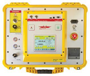
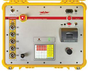
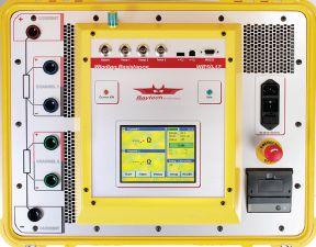
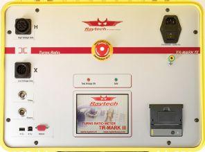


known for easy operation, precision,
accuracy.
Annual
for all equipment sold
2017.
reliable
rugged
market.
Year Warranty
instrument
no
charge. Free Annual Certifications and Year Warranty on all Product Lines by Raytech USA 5 Toll free 888 484 3779 | Phone 267 404 2676 | Fax 267 404 2685 118 South 2nd St., Perkasie, PA 18944 www.RaytechUSA.com Winding Resistance with Core Demagnetization 10A and 200A Contact Resistance Single and 3-Phase Ratiometers Power Factor Test Sets Current Transformer Test Sets
For 20 years, Raytech has built instruments
and
We focus our efforts on 5 product lines, ensuring expertise in each one. 5 Free
Certifications
during
5 Product Lines of the most
and
instruments on the
5
with every
at
additional


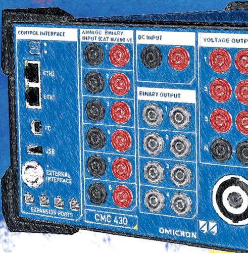
The lightest protection test set and calibrator
Discover our new CMC family member.
www.omicronenergy.com/newCMC430
Our 3-phase test set CMC 430 is the newest member of the CMC family and combines its outstanding performance as a relay tester and calibrator with hybrid measurement and recording facilities. Its lightweight and rugged design ensures excellent portability. Appropriate software tools also allow numerous applications from quick manual testing to distributed scheme tests which makes the CMC 430 a highly flexible solution.


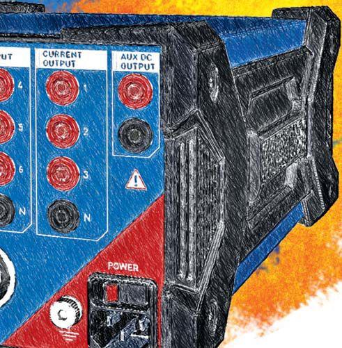


 James Cialdea, President NETA — InterNational Electrical Testing Association


 BY PAUL H. GREIN, Circuit Breaker Sales Co., Inc.


 BY GUY WASFY, KoCoS America LLC, and CHRISTIAN STUDEN, KoCoS Messtecknik AG


 BY JAMES WHITE, Shermco Industries


 Electrical Technology Inc.


