


ISSN 2167-3594 NETA WORLD JOURNAL PRINT ISSN 2167-3586 NETA WORLD JOURNAL ONLINE WINTER 2 0 16 PAGE 68 REGISTER TODAY INSIDE! PREVIEW GUIDE CELEBRATE NETA’S 45TH ANNIVERSARY THE FUTURE OF AND PROCESS AUTOMATION IN TEG R ATED PO WE R
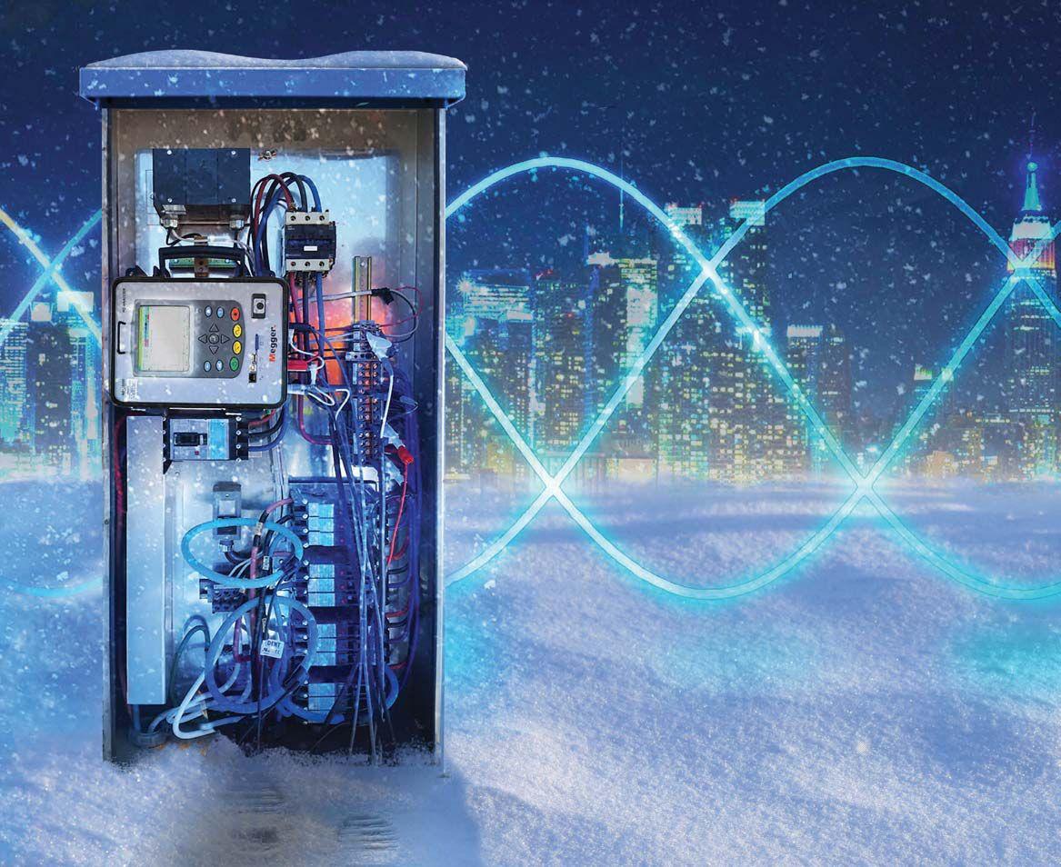

Take the trouble out of your power quality troubleshooting.
Power quality testing is less complex when you have the MPQ 2000 Power Quality Analyzer by your side. It’s intuitive for smart testing and analysis, yet resilient and weather-proof to work in any environment you need it to. No troubles, just power on.
us.megger.com/mpq
MPQ2000


•
•
•





2017 PREVIEW GUIDE ANAHEIM • CALIFORNIA February 27 - March 3 • 2017 DISNEYLAND HOTEL POWERTEST.ORG 888.300.6382 THE PREMIER ELECTRICAL MAINTENANCE & SAFETY EVENT
you in the Golden Land of Promise Plan your PowerTest 2017 schedule
See
Choose your sessions
See exhibitor previews
Make the most of PowerTest 2017

February
27 - March 3 • 2017
PowerTest heads to Anaheim, California in 2017


California became the 31st state of the Union in 1850; at the time, it was not the fertile and diverse land it is today. Cattle ranching and gold mining drove the economy and culture. It wasn’t until the turn of the century that Southern California’s destiny would be ignited by San Diego’s Panama-California Exposition of 1915, which promoted a vision of the American Southwest and Southern California as a region of Edenic abundance. San Diego would be only the first in a long series of cities building irrigation societies.
The California Aqueduct opened in 1913, bringing water from the Sierra Nevada Mountains over 230 miles to Los Angeles and the entire southland region. This, combined with the expansion of the Pacific Electric Railway, spurred Southern California toward becoming the Golden Land of Promise.
Vision, ingenuity, resourcefulness, and purpose are the qualities of Southern California that PowerTest 2017 draws on as we come together to strengthen our industry, expand our knowledge, and improve the quality, safety, and reliability of electrical power systems.


Keynote Speaker Todd Conklin, Ph.D., Los Alamos National Laboratory
Dr. Conklin is a Senior Advisor to the Associate Director at Los Alamos National Laboratory, where he has served for the last 15 years in the Human Resource and Reliability Management and Training arena with an emphasis in Organizational Development and Human Reliability. His book, Simple Revolutionary Acts: Ways to Revitalize Yourself and Your Workplace, helps readers become a positive deviant in the workplace in a fun way. He may be recognized as a guest host on National Public Radio’s All Things Considered and Morning Edition
Dr. Conklin has a B.A. in Communication from Southwestern College; an M.A. in Interpersonal Communication from Fort Hays State University; and a Ph.D. in Organizational Communication from the University of New Mexico.


ENERGIZE YOUR FUTURE THE PREMIER ELECTRICAL MAINTENANCE & SAFETY EVENT


DAY 1 Monday
We’ve gathered leaders in the industry and will stage a full day of engaging, 45-minute presentations sure to expand your thinking and generate new ideas. Choose from 27 detailed presentation track topics.
TECHNICAL PRESENTATIONS
ELECTRICAL SAFETY
• Improving Human Performance
D. Ray Crow, DRC Consulting Ltd.

• Electrical Safety for Contractors (Multi-Employer) Working in Industrial Facilities
Dennis Neitzel, AVO Training Institute, Inc.
• Guarded or Unguarded and Why It Makes a Safety Difference
Jim White, Shermco Industries
• Application of Work Flow Process in an Electrical Safety Program
Terry Becker, ESPS Electrical Safety Program Solutions Inc.
• Human Performance Best Practices in Electrical Safety
Mike Doherty, eHazard
• Design, Implementation, and Testing of Arc-Flash Mitigation on Low- and Medium-Voltage Systems
Christopher Inshaw, Southwest Energy Systems, LLC
PROTECTIVE RELAYS

• Testing High Magnitude Faults on a Transmission Line Using COMTRADE Records: A Case Study
Mohit Sharma and Vijay Sundaram, Megger
Chinmay Desai, National Field Services
• Testing Protective Relays – A Procedural Review
John Cadick and Jefferson Bronfeld, Cadick Corporation and Dennis Moon, AVO Training Institute, Inc.
• Influence of Non-Linear Loads on Generator Differential Protection
Vijay Sundaram and Dhanabal Mani, Megger

• Understanding Basic High Speed Tripping and Communications (Basics of Tone and Carrier Schemes)
Jay Garnett, Doble Engineering Company
• End-To-End Testing Methods Compared
Christopher Pritchard and Will Knapek, OMICRON electronics Corp. USA
• Man-Made Faults – Line Protection Operation for an Unintended Phase Cross-Connect Condition

Ryan McDaniel, Schweitzer Engineering Laboratories, Inc.


EQUIPMENT & RELIABILITY
&RELIABILITY
• How Vacuum Interrupters Work and How They Fail
Finley Ledbetter, Group CBS, Inc.
• Commissioning of Plant Electrical Systems Using Distributed Testing
Randall Sagan, MBUSI
Mose Ramieh III, PGTI, a CE Power Company
Will Knapek, OMICRON electronics Corp. USA
• Primary Current Injection Testing: Then and Now
Robert Probst, Megger
• How to Choose the Right Power Monitoring Tools
Ross Ignall, Dranetz Technologies
• Making Reliability Lean & Mean
Noah Bethel, PdMA
• Grounding Fundamentals That Help Avoid Electrical Disasters
David Brender, Copper Development Association
POWER TRANSFORMERS
• Why Get Excited about Excitation Current Tests
Keith Hill, Doble Engineering Company
• Understanding the Value of Electrical Testing for Power Transformers
Charles Sweetser, OMICRON electronics Corp. USA

• Sweep Frequency Response Analysis (SFRA) and the Best Practices for Reliable Results
Sanket Bolar and Robert Foster, Megger

• Emergency Transformer Bushing Replacement
Mark Haas, Power Asset Recovery Corporation
Randy Williams, ABB
• A Systematic Approach to Analyzing Exciting Current Measurements on Power Transformers
Brandon Dupuis, OMICRON electronics Corp. USA
• Cable Fault Location Techniques when Faced with Corroded Neutrals
Robert Probst and Jason Souchak, Megger


DAY 1 Monday (
TECHNICAL
PRESENTATIONS
continued )
( continued )

BATTERY SYSTEMS
• Battery Testing by the Standards and Field Experiences
Daniel Carreño-Perez and Volney Naranjo, Megger
• Station Battery Maintenance 101: What You Need to Know
Tom Sandri, Shermco Industries
• NERC Requirements for Battery Acceptance and Maintenance Testing
Steve Canale, American Electrical Testing Co., Inc.
SYMPOSIUM
Medium-Voltage Vacuum Circuit Breakers: An Industy Update
5:00 PM – 6:00 PM New Product Forum

Moderator: David Huffman, Power Systems Testing Co.
Medium-voltage circuit breakers are key and integral to system reliability and electrical power system performance, and have been a part of the electrical landscape for many years. This symposium will focus on medium-voltage circuit breaker technology, both new and old, and will provide insight and updates from medium-voltage circuit breaker subject matter experts.


Learn about dozens of the latest products and innovations, major expansions by leading industry-specific manufacturers and suppliers.
Hospitality Suites

Mingle with colleagues and a host of leaders at Monday night’s hospitality suites. Eight companies will offer their own brand of hospitality with uniquely themed suites. 6:00 PM – 10:00 PM


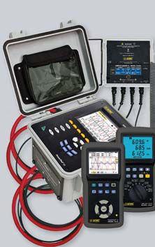
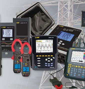
The Right Instruments For Your Power Quality & Energy Measurements Right Instruments
• Voltage current and power monitoring
• Harmonic detection analysis
• Inrush current analysis
• Energy cost analysis and management
• Power factor analysis and correction
• Power demand and consumption monitoring
• Transient detection and analysis
• Data logging



THE PREMIER ELECTRICAL MAINTENANCE & SAFETY EVENT
. .aemc.com ae co Chauvin Arnoux®, Inc. d.b.a. AEMC® Instruments 200 Foxborough Blvd. • Foxborough, MA 02035 USA PHONE: (800) 343-1391 • FAX: (508) 698-2118
TRADE SHOW HIGHLIGHT

DAY 2 Tuesday

Join in the discussion during the Tuesday morning Panel Sessions. Select two of the four panel topics and get ready to learn from experts and peers alike.
Panels:
Electrical Safety
Moderator: Jim White, Shermco Industries
Relays
Moderator: Rod Hageman, Shermco Industries
Circuit Breakers
Moderator: Dan Hook, Western Electrical Services, Inc.
Power Transformers

Moderator: Jean-Pierre Wolff, Applied Engineering Concepts



OSHA 29CFR1910.399 definition of a qualified person:


“Qualified person. One who has received training in and has demonstrated skills and knowledge in the construction and operation of electric equipment and installations and the hazards involved.”
Shermco’s Electrical Safety for Qualified Workers course meets the minimum mandated requirements of both OSHA and NFPA 70E.
you be training with the people who are in the field every day?


www.shermco.com 888-SHERMCO
difference.
the difference.
Training makes all the
Training makes all
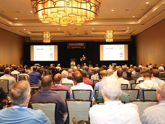
PowerTest Training Session TRADE SHOW HIGHLIGHT

PowerTest 2017 Trade Show
The PowerTest 2017 Trade Show promises more than 100 top-tier electrical power vendors whose mission is electrical safety and reliability. Enjoy a complimentary lunch and beverages as you tour the show and make connections. The PowerTest 2017 Trade Show will take place from 12:00 PM – 5:30 PM.
PowerTest 2017 – PowerBash Reception!

A gathering you don’t want to miss. Enjoy an evening of Southern California charm, awards, and recognitions, while mixing and mingling to musical entertainment. Tuesday evening from 7:00 PM – 10:00 PM.




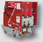


THE PREMIER ELECTRICAL MAINTENANCE & SAFETY EVENT BC BCS S Switctchhggea e r has ra r pi p dl d y expa p ndded into th t e Mol o ded d Ca C se e and Ins n ulated Cas a e inndudust s ry y in rec e en e t yeears. Ouur tecchs h perfororm a wi w de d ran a ge e of f test s s en ensuring thaat t whhat t we ar a e seend n in i g you is in propper r wor o ki k ng g orde d r. We take e it a ste t p fu f rtheer r an a d offfer sta t nd n ard 1 year r warra r nt ntiees s on eve v ryythhinng th t at ships ou o t of f our r warehhou o se s in Tex e as. Our r ev e err-ggrowing g inveentor o y ennable l s us u to handle e and delivver all of f yoour u electriicaal wa want n s/needs. s Our u knowledgeeable e is i morre e thhan equuippped to ans n we w r yoour u questtioonns s an sure e you are e we w ll taken care e of BC B S BOOTH #4227 at Power r Tesest 20 2017 1 Anaheieim, CA www.bcsswitchgear.com TEXAS OFFICE 4790 Hwy 377 South Krugerville, TX 76227 888-599-0486 e e ll salles e teaam nd d make e g BCS SWITCHGEAR
DAY 2 Tuesday ( continued )
TRADE SHOW HIGHLIGHT

Powertest 2017
Spotlight Stage Presentations
TUESDAY 12:30 PM - 5:15 PM
OMICRON electronics Corp. USA
12:30 PM - 12:45 PM
A New Approach for Testing Power Transformers ComRent Load Bank Solutions
12:55 PM - 1:10 PM
Precision Commissioning to Optimize Efficiency of Critical Facilities
Electro Rent
1:20 PM - 1:35 PM

Power Quality and Insulation Testing including a Special Conference Program
Megger
1:40 PM - 1:55 PM
New Developments in Transformer Testing
Protec Equipment Resources
2:05 PM - 2:20 PM
The Importance of Calibration
BCS Switchgear, Inc.
2:30 PM - 2:45 PM
Vacuum Breaker Testing – Testing Options and the Benefit of Each

Intellirent


2:55 PM - 3:10 PM
Serving the Testing Contractor
AVO Training Institute, Inc.
3:20 PM - 3:35 PM
NEC Electrical Safety Issues Due to Misapplication or Violations AEMC Instruments
3:45 PM - 4:00 PM
AEMC’s Power & Energy Loggers Monitor, Record, and Analyze Power, Energy Usage, and Costs Locally or from Anywhere in the World!
Circuit Breaker Sales Co., Inc
4:10 PM - 4:25 PM
From Edison to Musk, Technological Innovations in Material Science and their Impacts on Circuit Breaker Construction
Doble Engineering Company
4:35 PM - 4:50 PM
Safety First: New Technology and Advancements for Safer Off-line Electrical Testing WEIDMANN Electrical Technology, Inc.
4:55 PM - 5:10 PM
The Intelligent, Secure Transformer... Featuring the WEIDMANN INSULOGIX® VAULT





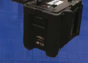
sales@hipotronics.com | www haefely-hipotronics.com | 845 230 9245
Hipot 800 SERIES Lightweight, rugged design forPR P EMIUM M SO S LUTIONS I IN N HIG I H VOLTAGGE. SINCE 1904. NEW W Vi Booth 121! 4. TRADE SHOW HIGHLIGHT
Digital DC

POWERTEST 2017 TRADE SHOW FLOOR PLAN


THE PREMIER ELECTRICAL MAINTENANCE & SAFETY EVENT AIRWALL FH FH FA FH FH FA FA FA FH FREIGHT DOOR STORAGE EXIT ENTRANCE Inventory as of 06/06/2016 Dimension 10'x10' 10'x20' 20'x20' 20'x50' Size 100 200 400 1,000 Totals: Qty 67 14 3 2 86 SqFt 6,700 2,800 1,200 2,000 12,700 FOOD & BEVERAGE 513 511 509 432 430 428 426 410 408 406 404 402 400 333 331 329 327 311 309 307 305 306 304 302 219 205 203 232 230 228 226 133 131 129 127 134 132 130 122 120 118 104 100 20' 201 20' 209 20' 308 20' 301 20' 505 20' 401 20' 50' 114 116 115 20' 121 20' 220 20' 231 20' 20' 225 20' 20' 318 20' 217 316 319 321 323 418 420 422 416 317 315 20' 421 423 429 431 433 520 522 528 530 532 417 20' 516 20' 427 20' 533 20' BAR / FOOD FOOD & BEVERAGE TEG Service Center 415514 101 20' 50' 8' 8'8'8' 8' 10' 10' 10' 8' *This floor plan is subject to fire marshal approval. 115 SPOTLIGHT STAGE


POWERTEST 2017 EXHIBITORS


AEMC INSTRUMENTS ...........................................................114 ARBITER SYSTEMS ................................................................415 AVO TRAINING INSTITUTE, INC ..........................................401 BASLER ELECTRIC.................................................................514 BCS SWITCHGEAR, INC. .....................................................427 BELYEA COMPANY ..............................................................422 CE POWER ..........................................................................513 CORPORATE ALLIANCE PARTNERS SPOTLIGHT STAGE PRESENTATIONS. .................................................................115 DOBLE ENGINEERING COMPANY.......................................400 ECP SOLUTIONS .................................................................232 ELECTRICAL RELIABILITY SERVICES, INC. ................................217 ELECTRO RENT CORPORATION ...........................................408 ELECTROSWITCH.................................................................406 GROUP CBS, INC. ...............................................................225 HAEFELY HIPOTRONICS........................................................121 HALCO TESTING SERVICES ...................................................410 HIGH VOLTAGE, INC. ..........................................................205 HV DIAGNOSTICS, INC. .......................................................516 HV TECHNOLOGIES, INC.. ...................................................219 INTELLIRENT .........................................................................101 IRISS ...................................................................................509 KOCOS AMERICA LLC .........................................................423 MEGGER ............................................................................401 MORGAN SCHAFFER INC. ...................................................316 NATIONAL SWITCHGEAR ...................................................231 NETA ..................................................................................100 OFIL LTD. .............................................................................323 OMICRON electronics ...........................................................318 POWER ASSET RECOVERY CORP. ........................................426 POWER DIAGNOSTIC SERVICE CO., LTD.. ............................327 PROG USA – DV POWER ....................................................104 PROTEC EQUIPMENT RESOURCES .......................................201 QUALITY SWITCHGEAR, INC. ..............................................305 RAYTECH USA.....................................................................308 REMOTE SOLUTIONS, LLC ...................................................520 SCHWEITZER ENGINEERING LABORATORIES, INC. ..............311 SHERMCO INDUSTRIES .......................................................302 SHERMCO INDUSTRIES .......................................................304 SONEL TEST & MEASUREMENT ...........................................309 SUMMIT TECHNOLOGY ......................................................226 SWITCHGEAR PRO (RB SALES) ..............................................511 TONY DEMARIA ELECTRIC, INC. ...........................................315 TRS-RENTELCO ....................................................................402 UE SYSTEMS INCORPORATED. ............................................404 UTILITY RELAY COMPANY ....................................................301 VACUUM REPLACEMENT INTERRUPTERS ..............................522 WEIDMANN ELECTRICAL TECHNOLOGY, INC. .....................416
COMPANY BOOTH #COMPANY BOOTH #

Wednesday - Thursday Seminars
Two days are dedicated to high-power learning. Choose from 12 in-depth, four-hour seminar presentations. PowerTest 2017 Technical Seminars cover current topics and important industry issues that will broaden your horizons and expand your knowledge, preparing you for challenges ahead.


DAY 3 Wednesday
SEMINAR TITLES
8:00 AM – 11:45 AM
• What Does a Partial Discharge Tell Me and How Do I Perform the Test?
Tom Sandri, Shermco Industries
• Relay Troubleshooting 2.0


Ryan McDaniel, Amanvir Sudan, and Anisha Gurumurthy, Schweitzer Engineering Laboratories, Inc.
• Power Transformer Commissioning
Donald Platts and Brandon Dupuis, OMICRON electronics Corp. USA
1:15 PM – 5:00 PM
• Understanding Generator Protection
J. Scott Cooper, OMICRON electronics Corp. USA
• 2018 Edition of NFPA 70E Changes
Jim White, Shermco Industries
D. Ray Crow, DRC Consulting Ltd.
Daleep Mohla, DCM Electrical Consulting Services
• Interpretation of Power Factor and Excitation Test Data
Keith Hill and Jay Garnett, Doble Engineering Company
TRADE SHOW HIGHLIGHT


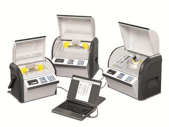

HV TECHNOLOGIES, Inc., partnered with BAUR, provides the most complete range of high voltage test equipment and service solutions available for the electrical power industries.
Cable Testing & Diagnostics
Portable VLF hipot testers with optionally integrated tan delta
Portable partial discharge diagnostic system
Cable Fault Location
Accurate location of low-resistive, high-resistive, and sheath faults
Efficient and precise pin-pointing
Insulating Oil Testing
Dielectric breakdown up to 100 kV
All-in-one tester for dissipation factor, specific resistance, and relative permittivity
Visit us at the 2017 Power Test Conference, Booth 219!
Ph: (703) 365-2330
hvsales@hvtechnologies.com www.hvtechnologies.com


THE PREMIER ELECTRICAL MAINTENANCE & SAFETY EVENT

DAY 4 Thursday
SEMINAR TITLES
8:00 AM – 11:45 AM
• Exploring the Techniques and Philosophies of Testing
Electrical Insulation
Tom Sandri, Shermco Industries
• Ground Fault Testing per ANSI/NETA ATS and MTS
Tim Reed, Electrical Reliability Services
• Mechanical Condition Assessment of Transformers

Using Sweep Frequency Analysis

Dinesh Chhajer and Robert Foster, Megger


1:15 PM – 5:00 PM
• Advanced Group Testing Concepts and Techniques


John Humphrey and Hilton Mills, Hood-Patterson and Dewar
• Advanced Test Techniques for Generator and Transformer Protection
Steve Turner, Beckwith Electric Co., Inc.
• Exploring Ohmic Trending of Battery Systems and Battery Capacity Testing – What Do These Tests Tell Me? Which One Should I Use?
Tom Sandri, Shermco Industries











New Developments in Transformer Testing
Transformers are a key asset in the transmission and distribution of power to the world. Join us at PowerTest 2017 in Anaheim, California as we discuss the ever changing landscape of transformer testing and the test equipment that will help you maintain these key assets.
Visit us at booth 410 for your transformer testing solutions and join us for our Spotlight Stage Presentation “New Developments in Transformer Testing”.
us.megger.com/applications/transformers
TRADE SHOW HIGHLIGHT

DAY 5 Friday
Doble Laboratory Seminar
8:00 AM - 5:00 PM
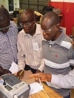
The Doble Laboratory Seminar is designed for engineers, chemists, and others responsible for reviewing data to interpret laboratory results to detect and identify problems within electric apparatus. The seminar will be interactive, combining theoretical background with practical experience and hands-on examples including case studies illustrating common problems found in the field.





THE PREMIER ELECTRICAL MAINTENANCE & SAFETY EVENT
www.avotraining.com or call 877-594-3156 The one-stop for electrical safety training, electrical maintenance training and electrical certifications. Many AVO training courses are eligible for NETA ctd’s.* DISNEYLAND HOTEL TRADE SHOW HIGHLIGHT


SPECIAL SESSIONS AND MORE
Megger Best Practices
Sunday, February 26 9:00 AM - 4:00 PM


Join us as Megger hosts a FREE Hands-On Best Practices Seminar at NETA’s PowerTest 2017! Megger’s Best Practices Seminars are designed to bring you up to speed on new testing techniques and technology as well as offer the opportunity to engage in hands-on learning with expert engineers. Megger’s world-class Applications Engineers utilize their vast industry knowledge and experience to craft an in-depth program backed by Megger’s expertise in the market. This full day of quality education includes training related to key industry topics as well as two hours of hands-on instruction. You must preregister for this event by contacting Megger. To register for Megger Best Practices and view the agenda, please visit https://goo.gl/forms/m6LjhgTZwvL9g4153

PowerTest 2017 Dinner & Dice Harbor Cruise
Sunday, February 26 5:30 PM – 9:30 PM
Join us Sunday evening for a dinner boat cruise along the western shores of southern California. Sit back and relax or trust your luck with a visit to the special themed casino night. What’s your pleasure? Music, comradery, roulette, black jack, poker, craps, and more. ($155 per person).
PowerDB User Group
Monday, February 27 12:15 PM – 2:15 PM
Annual User’s Group Meeting open to licensed users of PowerDB Pro Software. Agenda will include presentations by the PowerDB Pro development team as well as utility, industrial, and contractor groups discussing how this product is an integral part of their business operations. Pre-registration is required by contacting PowerDB at 979-690-7925 ext. 702 or by registering at www.powerdb.com


VACUUM REPLACEMENT INTERRUPTERS

VRI supplies Vacuum Replacement Interrupters for all types of Vacuum Circuit Breakers and Vacuum Contactors from 5-34kv. Manufactures include; GE, Cutler Hammer, Westinghouse, ABB, Siemens, etc.

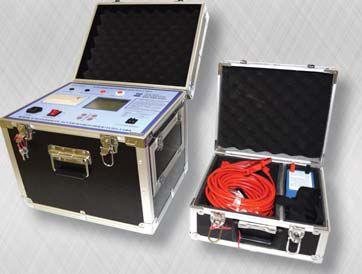
Along with the full line of vacuum replacement bottles we have our VRI exclusive test set that utilizes Paschen’s Law along with a High Current injection to test the vacuum integrity of your vacuum bottles. With this data you can prepare for the unexpected, as well as keep your vacuum breakers at their best.


VRI BOOTH #522 at Power Test 2017 Anaheim, CA




WWW.VACUUMREPLACEMENTINTERRUPTERS.COM TEXAS OFFICE 4790 HWY 377 SOUTH KRUGERVILLE, TX 76227 940-440-0391
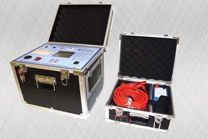
h s. s CA ACTUAL VRI TEST KIT
TRADE SHOW HIGHLIGHT




Download the PowerTest 2017 Mobile App
Don’t miss a single moment of PowerTest 2017. Download the PowerTest Mobile App and get instant access to the full schedule - right at your fingertips!
View session abstracts and speaker bios
Customize your schedule for the events and sessions you plan to attend
Set reminders and manage alerts
View facility maps including Trade Show floorplan and booth information
Rate speakers and submit feedback
View sponsor information
Play the NETA 45th Anniversary Photo Challenge within the mobile app. Visit powertest.org for more details.
Search PowerTest 2017 in the App Store or Google Play. Available January 1, 2017


14 2016 POWERTEST CONFERENCE | PREVIEW GUIDE THE PREMIER ELECTRICAL MAINTENANCE & SAFETY EVENT MOBILIZE YOURSELF WITH THE POWERTEST 2017 MOBILE APP
The Premier Electrical Maintenance and Safety Event
Disneyland Hotel Anaheim, California www.powertest.org TM App sponsored by: SWITCHGEAR, INC. Powering industry with superior equipment since 1999.
February 27 - March 3, 2017


Early Bird Registration is now Open!
Register on-line at: www.powertest.org or call: 888-300-6382 (NETA)
PowerTest 2017 Early Bird Pricing
Monday & Tuesday $ 995 $ 895
Monday - Thursday $1895 $1695
Single Day $ 580 $ 550
Doble Seminar $ 445 $ 445

Register On-line: To register for PowerTest 2017, save time by registering on-line. You’ll find a complete brochure and registration form available at www.powertest.org.
Hotel Reservations*
Disneyland Hotel Reservation Deadline: 714-520-5005 February 4, 2017
1150 Magic Way Group Name: Anaheim, CA 92802 PowerTest/NETA
Group Rate: $199

*Once you register for PowerTest 2017, you will receive a link via email to secure your hotel reservations at the Disneyland Hotel.

Payment: NETA accepts all major credit cards. Save time and register on-line at www.powertest.org or call 888-300-6382 (NETA)
Extras: PowerTest 2017 Technical Papers – Registered conference attendees will receive all PowerTest technical presentations on a USB drive in their registration bag.
Social/Guest Pass: Includes admission to the Hospitality Suites, Trade Show, and the PowerBash reception. $60 per person. Those registered for Mon-Thurs technical sessions do not need to purchase a social pass, as it is included with registration (with exception of the PowerBash - this is an additional $25).


Easy Steps for Registration
1. Go to www.powertest.org and review the complete PowerTest 2017 on-line brochure.
2. Decide the number of days you will attend the conference.
3. Tuesday attendees select up to two panels. (Cost of panels included in the registration fees.)
4. Wednesday attendees register for up to two seminars. (Cost of seminars included if registered for Monday – Thursday.)

5. Thursday attendees register for up to two seminars. (Cost of seminars included if registered for Monday – Thursday.)
6. Register for Doble Lab Seminar. (Cost of seminar is in addition to the registration fees.)

7. Sign up for Social Passes. Social pass only needed for guests of attendees wish to attend the hospitality suites, the Trade Show, and the PowerBash Reception (Cost of passes is in addition to the registration fees.)

8. Sign up for PowerTest 2017 conference polo shirts and select size. (Cost of polo shirts is in addition to the registration fees.)


Non Members NAC/Alliance


GENERAL SPONSORS PREMIUM SPONSORS HIGH-VOLTAGE SPONSORS MEDIUM-VOLTAGE SPONSORS LOW-VOLTAGE SPONSORS Sponsors CONFERENCE The premier ELECTRICAL MAINTENANCE AND SAFETY Conference A ND On the Potomac SAVE THE DATE Join us at the Gaylord National Resort and Convention Center on the banks of the Potomac River, a stone’s throw from Washington, D.C., Georgetown, Arlington, and Alexandria, Virginia. PowerTest.org 888.300.6382 Hosted by

HARNESS THE POWER OF GROUP CBS








Providing Electrical Solutions Worldwide POWERTEST, BOOTH 225 hospitality suite THE ADVENTURE ROOM Since 1981
THE EVOLUTION OF THE CIRCUIT BREAKER


After World War II ended


The
• 1945 1973 1972 1970 1945 1945–1975 1947 1945 1958 1963 1966 1970 1975 •
Oil-Breaker Years:



The Future of Circuit Breakers


The Air-Breaker Years: • • The Vacuum-Breaker Years: • • 1979 1981 1983 1989 1990 1994 2008 2016 1965–1995 1985–2016 • AEAMC.com CBSArcSafe.comVacuumInterruptersInc.com ANCED ELECTRICAL & MOTOR CONTROLS INC. ADV Providing Electrical Solutions Worldwide


Breaker Sales (CBS), Circuit Breaker Store, Advanced Electrical & Motor Controls (AEAMC), and Vacuum Interrupters. CBS also has a proven commitment to the environment as illustrated by our ISO 14001-compliant environment management system. | 4800 | , TX 75001 | | | Why You Can Trust Group CBS With Your Power Equipment ADVANCED ELECTRICAL & MOTOR CONTROLS INC. A Group CBS Company AEAMC.com | R CBSArcSafe.com | VacuumInterruptersInc.com | Providing Electrical Solutions Worldwide Group CBS’ new high-voltage, mechanical, and environmental test laboratory is located at Vacuum Interrupters’ new Farmers Branch, Texas, facility.
Group CBS companies across the U.S. specialize in the sale, low- and medium-voltage circuit breakers and other equipment. But what sepais the company we keep.-
COVER STORY

68 The Future of Integrated Power and Process Automation
David C. Mazur and John A. Kay, RockwellAutomation Rockwell Automation
As technology continues to drive innovations, industrial enterprises must continue to keep pace to remain competitive in an ever-changing marketplace. The technology trend is to replace yesterday’s systems with higher-performance, low-cost, option-rich devices that shorten the return on investment and offer more flexibility. As control system technology evolves, systems migrate to functions that are being increasingly distributed to smarter, more granular, controlsystem components capable of performing localized operations.
FEATURES
7 President’s Desk
Ron Widup, Shermco Industries
NETA President
52
Condition Monitoring: Automating Response
Tony McGrail, Doble Engineering Company
56 IEC 61850 — A Tale of Two Decades
Joseph Menezes, ABB Grid Automation Products
60 Acceptance, Commissioning, and Field Testing for Protection and Automation Systems
Michael Obrist, Stephan Gerspach, and Klaus-Peter Brand, ABB Switzerland


TABLE OF CONTENTS TABLE OF CONTENTS NETAWORLD • 3
68 60
IN EVERY ISSUE
11 NFPA 70E and NETA
NETA and the 70E
Ron Widup and Jim White, Shermco Industries
18No-Outage Corner
First Rule of Troubleshooting: Trust, But Verify
Don A. Genutis, Halco Testing Services
26Tech Quiz
Power System Automation Systems
Jim White, Shermco Industries
32Tech Tips
Dual Ground
Jeff Jowett, Megger
38Safety Corner
Distracted Driving
Paul Chamberlain, American Electrical Testing Co., Inc.
43Relay Column
Protective Relay Misoperations and Analysis
Steve Turner, Beckwith Electric Company, Inc.
INDUSTRY TOPICS
83 Cable Fault Properties and Troubleshooting Guide
Thomas Sandri, Shermco Industries
91 Transformer Liquid Sampling Dangers: Where Does the Air Go?
Don Platts, OMICRON electronics Corp. USA, and Dave Hanson, TJ|H2b Analytical Services, Inc.
97 Test Equipment: Managing the Hidden Defects
Ashley Harkness, Electrical Reliability Services
ADVANCEMENTS IN TECHNOLOGY
102 Innovations in Primary Current Injection Testing
Yier Toh, Megger
22 NETA Board and Members
Meet in the Mountains
28 NETA Welcomes Newest Accredited Company — Midwest Engineering Consultants, Ltd.
NEWS – POWERTEST 15 Early Bird Registration 25 Call for Exhibitors 50 Electrical Power Systems Industry Leaders Gather to Share Intelligence at PowerTest 2017
76 NETA Celebrates 45 Years of Volunteerism and Achievement in 2017
114 NETA Accredited Companies
120 Advertiser List
4 • WINTER 2016 TABLE OF CONTENTS
TABLE OF CONTENTS
SPECIFICATIONS AND STANDARDS 106 ANSI/NETA Standards Update NETA NEWS
NETA
NETA NEWS – IMPORTANT LISTS








3050 Old Centre Avenue, Suite 102
Portage, MI 49024
Toll free: 888.300.NETA (6382)
Phone: 269.488.NETA (6382)
Fax: 269.488.6383
neta@netaworld.org
www.netaworld.org
EXECUTIVEDIRECTOR: Missy Richard
NETA Officers
PRESIDENT: Ron Widup, Shermco Industries
FIRSTVICEPRESIDENT: Jim Cialdea, Three-C Electrical Co., Inc.
SECONDVICEPRESIDENT: Scott Blizard, American Electrical Testing Co., Inc.
SECRETARY: Eric Beckman, National Field Services
TREASURER: John White, Sigma Six Solutions
NETA Board of Directors
Ken Bassett (Potomac Testing, Inc.)
Eric Beckman (National Field Services)
Scott Blizard (American Electrical Testing Co., Inc.)
Jim Cialdea (Three-C Electrical Co., Inc.)
Lorne Gara (Orbis Engineering Field Services, Ltd.)
Dan Hook (Western Electrical Services, Inc.)
David Huffman (Power Systems Testing)
Alan Peterson (Utility Service Corporation)
John White (Sigma Six Solutions)
Ron Widup (Shermco Industries)
NETA World Staff
TECHNICALEDITORS: Roderic L. Hageman, Tim Cotter
ASSISTANTTECHNICALEDITORS: Jim Caldea, Dan Hook, Dave Huffman, Bob Sheppard
ASSOCIATEEDITOR: Resa Pickel
MANAGINGEDITOR: Jayne Tanz, CMP
ADVERTISINGMANAGER: Laura McDonald
DESIGNANDPRODUCTION: Hour Custom Publishing
NETA Committee Chairs
CONFERENCE: Ron Widup; MEMBERSHIP: Ken Bassett; PROMOTIONS/MARKETING: Scott Blizard; SAFETY: Scott Blizard and Jim White; TECHNICAL: Alan Peterson; TECHNICALEXAM: Ron Widup; CONTINUINGTECHNICALDEVELOPMENT: David Huffman; TRAINING: Bob Sheppard; FINANCE: John White; NOMINATIONS: Alan Peterson; STRATEGY: Ron Widup; ALLIANCEPROGRAM: Jim Cialdea
© Copyright 2016, NETA
NOTICE AND DISCLAIMER
NETA World is published quarterly by the InterNational Electrical Testing Association. Opinions, views and conclusions expressed in articles herein are those of the authors and not necessarily those of NETA. Publication herein does not constitute or imply endorsement of any opinion, product, or service by NETA, its directors, officers, members, employees or agents (herein “NETA”).
All technical data in this publication reflects the experience of individuals using specific tools, products, equipment and components under specific conditions and circumstances which may or may not be fully reported and over which NETA has neither exercised nor reserved control. Such data has not been independently tested or otherwise verified by NETA.
NETA MAKES NO ENDORSEMENT, REPRESENTATION OR WARRANTY AS TO ANY OPINION, PRODUCT OR SERVICE REFERENCED OR ADVERTISED IN THIS PUBLICATION. NETA EXPRESSLY DISCLAIMS ANY AND ALL LIABILITY TO ANY CONSUMER, PURCHASER OR ANY OTHER PERSON USING ANY PRODUCT OR SERVICE REFERENCED OR ADVERTISED HEREIN FOR ANY INJURIES OR DAMAGES OF ANY KIND WHATSOEVER, INCLUDING, BUT NOT LIMITED TO ANY CONSEQUENTIAL, PUNITIVE, SPECIAL, INCIDENTAL, DIRECT OR INDIRECT DAMAGES. NETA FURTHER DISCLAIMS ANY AND ALL WARRANTIES, EXPRESS OF IMPLIED, INCLUDING, BUT NOT LIMITED TO, ANY IMPLIED WARRANTY OF FITNESS FOR A PARTICULAR PURPOSE.
ELECTRICAL TESTING SHALL BE PERFORMED ONLY BY TRAINED ELECTRICAL PERSONNEL AND SHALL BE SUPERVISED BY NETA CERTIFIED TECHNICIANS/ LEVEL III OR IV OR BY NICET CERTIFIED TECHNICIANS IN ELECTRICAL TESTING TECHNOLOGY/LEVEL III OR IV. FAILURE TO ADHERE TO ADEQUATE TRAINING, SAFETY REQUIREMENTS, AND APPLICABLE PROCEDURES MAY RESULT IN LOSS OF PRODUCTION, CATASTROPHIC EQUIPMENT FAILURE, SERIOUS INJURY OR DEATH.
228 Merrick Road Lynbrook, NY 11563 (631) 589-6343/Fax (516) 596-3680 601 Union Street Brooklyn, NY 11215 (718) 786-4900


ENGAGING WITH THE ‘NETA MACHINE’

Thank you for taking the time to read the NETA World Journal.

Our guess is that by doing so, you have an affinity for learning more about the electrical testing industry, including expanding your knowledge and understanding of what can be a complicated industry. With a central theme in this issue of substation automation and IEC 61850, this is a great one to learn more about our ever-changing industry.
Engaging with NETA and the ‘NETA Machine’ is a great way to learn about and understand our industry, interact with your peers, infuse knowledge from subject matter experts, and become certified in a critical and important field of study as a NETA-certified Electrical Testing Technician. The ‘NETA Machine’ is made up of the many resources available to you through the Association, such as NETA World Journal, our annual PowerTest technical conference, ANSI/NETA electrical testing and commissioning standards, the technician certification standard, peer-to-peer interaction, and a host of other resources.
Speaking of technician certification, for those of you who are employed by a NETA Accredited Company and are pursuing certification, our Technician Certification Program has recently been completely revised with fresh content and comprehensive review. This makes it all that more valuable, respected, and defensible. A huge thank-you goes out to the members of the NETA Exam Committee and the many subject matter experts who participated in this 18-month-long project.
When you are studying for the exam, remember that it validates your understanding of electrical power system testing and is designed to test your knowledge, skills, and abilities for the field testing of electrical apparatus. Or to quote Albert Einstein: “Any fool can know. The point is to understand.”

So thank you for understanding more about our industry. Hey — we ain’t no fools!
Sincerely,
 Ron Widup President
NETA – InterNational Electrical
Testing Association

PRESIDENT’SDESK PRESIDENT’S DESK PRESIDENT’S DESK

Absolute confidence. Every time.
You can count on us for specialized experience in healthcare, data center, office complex, and commercial acceptance and maintenance testing. Absolutely. Power generation, petrochemical, oil & gas, and heavy industries also look to us for high demand services such as start-up commissioning, maintenance testing, shut-down and turnarounds, and breaker shop repair. Get started today.


Toll Free 1+ (855)767-4446 8100 West Little York | Houston, Texas 77040 Email: Alan Postiglione | apost@absolutetesting.com | www.absolutetesting.com Like us on:


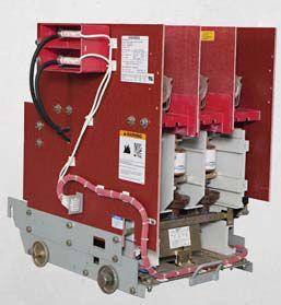
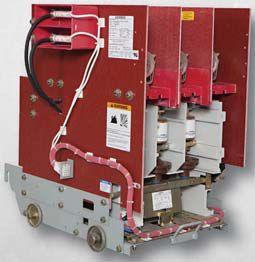


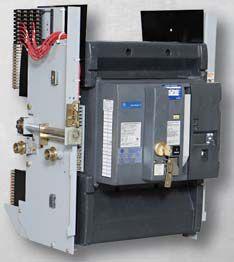
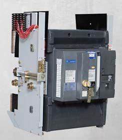



www.bcsswitchgear.com Are you having Power Equipment Problems? BCS HAS THE SOLUTION! new ∙ used ∙ obsolete ∙ reconditioned TEXAS OFFICE 4790 Hwy 377 South Krugerville, TX 76227 FAX 940-365-1808 ABB ∙ GENERAL ELECTRIC ∙ ITE GOULD ∙ WESTINGHOUSE ∙ SIEMENS SQUARE D · ALLIS CHALLMERS ∙ FEDERAL PACIFIC Call Toll Free: 888-599-0486 SWITCHGEAR, INC. Powering industry with superior equipment since 1999.
Training makes all the difference.


Training topics include:

Training includes proposed changes for NFPA 70E 2018
888.SHERMCO WWW.SHERMCO.COM


ANDTHE AND THE


 BY JAMES R. WHITE AND RON WIDUP, ShermcoIndustries Shermco Industries

This column focuses on NFPA 70E and highlights elements of the 70E that are impactful to NETA World readers, whether you are a NETA Accredited Company, a non-NETA testing company, or an owner/user of electrical power equipment testing and maintenance services.
The 2018 revision to the 70E has just completed the second draft meeting, which, as the name implies, is the second round of actions by the 70E Technical Committee surrounding public comments and submissions for change to the standard.
This second draft meeting of the 70E Committee was especially significant because Chairman David Dini will be retiring as committee chair (NFPA only allows a chair two cycles, and then a new chair is appointed) as well as from his position at Underwriter’s Laboratories (UL). While employed at UL, David was Senior Research Engineer, specializing in electrical safety. David is a Professional Engineer registered in the ofessional state of Illinois. Through UL, he participated in several NFPA research projects, including the Residential Electrical System Aging Research Project in July 2008, and co-authored the Firefighter Safety and Photovoltaic Installations Research Project in November 2011 with Robert Backstrom.
David was chairman during a difficult transition period when NFPA was incorporating its new software and committee process called Terraview. (Many 70E Committee members still refer to it as Terrorview for its many idiosyncrasies.) The 70E Committee was the first NFPA committee to use the new process for its entire cycle in 2015. All other NFPA committees are either using it now or will be during their next cycle.

David was able to assuage ruffled feathers and frustrated committee members with an insightful and dry sense of humor and an extraordinary amount of patience. David’s sense of humor was so dry that it took many committee members almost the entire 2015 First Draft meeting to catch on. David was always professional in his approach to chairing the 70E Committee, but he would surprise us from time to time with his humor. Whether it was opening the meeting with a snappy tune from Chicago, a story about how Canada got its name (eh?), or wearing a Test-Before-Touch t-shirt, Dave was always full of fun surprises.
NETAWORLD • 11 NETA AND THE 70E THENFPA70EANDNETA THE NFPA 70E AND NETA
THE NFPA 70E AND NETA


LOOKING TO THE 2018 EDITION
In the previous issue of NETA World Journal, we discussed some changes to the upcoming 2018 Edition of NFPA 70E. One change that caused much discussion among committee members was the edict from the NFPA Correlating Committee to remove all mandatory references to other standards from the primary text of the 70E in conformance with the NFPA Style Manual.Referencestootherstandardsinthe Manual. References to other standards in the annexes were fine, as they were not mandatory. Most 70E Committee members were not pleased with this change and requested a variance from NFPA to allow the 70E to continue including the mandatory references. The variance was denied, so there was only one way the committee could really vote at that point.


The other side of the equation is that NFPA realized that by allowing one standard to be used as a mandatory reference, it opened the door for other standards to demand the same treatment. In short order, the 70E could become a list of standards relating to a particular topic, such as PPE; this would degrade the standard’s benefits. Another factor driving the change is to make the 70E more readily applicable to international applications of the standard, which would allow it to be referenced in other standards in other countries. Removing mandatory references helps that process along.
As an example, the references to ASTM, ANSI, and UL standards will remain but will be placed into Informational Notes as below:
NETA AND THE 70E
12 • WINTER 2016
“Test before Touch!” reminds 70E Committee Chairman David Dini.
“120.3 (C) Equipment Approval. Temporary protective grounding equipment shall meet the requirements of nationally recognized industry standards.ASTM F855, Standard Specification for Temporary Protective Grounds to be Used on Deenergized Electric Power Lines and Equipment.
Informational Note: ASTM F855, Standard Specification for Temporary Protective Grounds to be Used on De-energized Electric Power Lines and Equipment contains requirements for temporary protective grounding equipment.”
The strike-through is the current text being deleted, while the underlined text is being added to the 2018 edition of NFPA 70E. It’s not a perfect resolution, but it’s the best that could be done. There may be some additional tweaking in the next edition of NFPA 70E.
Since we used Article 120 in the earlier example, one of the more significant changes made to Article 120 was the exception added to 120.5(7). The exception states:
“Exception: A permanentlymounted tester listed and labeled for the purpose of verifying the absence of voltage shall be permitted as the test instrument for the equipment being tested.”
”ONE
THE NFPA 70E AND NETA
permanently-mounted indicating devices have been marketed as substitutes for direct-contact test instruments. These earlier devices do not meet OSHA or NFPA 70E requirements and should not be used in place of an absence-ofvoltage test using a voltage-test instrument.
CHANGE
THAT CAUSED MUCH DISCUSSION AMONG COMMITTEE MEMBERS WAS THE EDICT FROM THE NFPA CORRELATING COMMITTEE TO REMOVE ALL MANDATORY
An example of how much things can change from the first draft meeting to the second draft meeting is Special Purpose Ground-Fault Circuit Interrupter (SPGFCI). During the first draft meeting, inclusion of these devices was accepted as an alternative to the assured equipment grounding conductor program. SPGFCIs or Type E GFCIs are used when the circuit voltage is more than a Type A GFCI (the one normally used for personnel protection) is rated for.
REFERENCES TO OTHER STANDARDS FROM THE PRIMARY TEXT OF THE 70E IN CONFORMANCE WITH THE NFPA STYLE MANUAL.”
This is the first time the committee has allowed such a device to be used. A Panduit representative presented information on a device they developed that meets the requirements of 120.5 and UL 1436, Outlet Circuit Testers and Similar Indicating Devices for Permanently-Mounted Absence of Voltage Testers. This is a brand-new UL standard that should be issued by the time this is published. Ordinarily, we would not state a company’s name associated with a product, but several
The 70E Committee found no fault with the SPGFCI itself, but was concerned that the end-user or worker in the field may not fully understand the differences between Type A GFCIs and Type E SPGFCIs. One member expressed the concerns of the Committee in his Public Comment:
“As both Type A and Type C, D, and E are termed GFCI for personnel protection, users may not realize the difference in protection provided by Type A (GFCI) and Type C, D, and E (SPGFCI). Type C, D, and E have special installation instructions that may not be clear to users. For example, the SPGFCI requires a larger equipment grounding conductor to provide protection.
“Recognizing the installation concerns, NEC CMP-2 created 2017-NEC second revisions that deleted the references to the Special Purpose GFCI in Art. 210. Their reasons had to do with special installation requirements for these GFCIs (Class C, D, and E) that may not be apparent to the installer or user.”
NETAWORLD • 13
NETA AND THE 70E


THENFPA70EANDNETA THE NFPA 70E AND NETA
In response, the 70E Committee went from approving the inclusion of SPGFCIs to taking out the sections that spoke to them. That is just the way things work out sometimes. When the Committee gets more information, it sometimes has to make a correction. This is a great example of how the first and second draft process works, as people weigh in with comments and suggestions. Ultimately, it makes for a better consensus-basedstandard. consensus-based standard.
SUMMARY
Several other changes are coming in the 2018 Editionandwillbediscussedinthenextcolumn. Edition and will be discussed in the next column. The 70E standard is approaching that maturity point where major changes are behind it and new additions will be more about maintaining the document.




We will miss David Dini as the 70E Committee Chairman. He did a fine job and showed great patience in dealing with a very diverse mix of personalities. Enjoy retirement, Dave!
WewillmissDavidDiniasthe70ECommittee
Ron Widup and Jim White are NETA’s representatives to NFPA Technical Committee 70E (Electrical Safety Requirements for Employee Workplaces). Both gentlemen are employees of Shermco Industries in Dallas, Texas, a NETA Accredited Company. Ron Widup is CEO of Shermco and has been with the company since 1983. He is a Principal member of the Technical Committee on Electrical Safety in the Workplace (NFPA 70E) and a Principal member of the National Electrical Code (NFPA 70) Code Panel 11. He is also a member of the Technical Committee Recommended Practice for Electrical Equipment Maintenance (NFPA 70B), and a member of the NETA Board of Directors and Standards Review Council. Jim White is nationally recognized for technical skills and safety training in the electrical power systems industry. He is the Training Director for Shermco Industries, and has spent the last twenty years directly involved in technical skills and safety training for electrical power system technicians. Jim is a Principal member of NFPA 70B representing Shermco Industries, NETA’s alternate member of NFPA 70E, and NETA’s Principal representative to the ASTM F18 Committee Electrical Protective Equipment for Workers.
 Ron Widup
Jim White


Save $100 September 1 through December 31, 2016
Electrical Safety, Protective Relays, Equipment & Reliability, Power Transformers, Battery Systems
Medium-Voltage Vacuum Circuit Breakers: An Industry Update Panels:
Electrical Safety, Relays, Circuit Breakers, Power Transformers


EARLY BIRD REGISTRATION ANAHEIM • CALIFORNIA February 27 - March 3 • 2017 DISNEYLAND HOTEL POWERTEST.ORG 888.300.6382 THE PREMIER ELECTRICAL MAINTENANCE & SAFETY EVENT
HIGH-POWER SEMINARS • NETWORKING WITH INDUSTRY LEADERS
Technical Presentations:
Symposium:
OPEN NOW! REGISTER
TODAY!





TROUBLESHOOTING: TRUST, BUT VERIFY FIRST RULE OF
It


 BY DON GENUTIS, Halco Testing Services
can be difficult to piece together a puzzle when troubleshooting — but when the information provided by the client is incomplete or just incorrect, the task is even more difficult.



As we began our ascent up the steep, winding, twolane mountain road, we were already 30 minutes late due to circumstances beyond our control. We were on our way to a remote, high-power radio broadcasting tower to troubleshoot a problem when our technician stated, “I probably should have gotten gas back there in that little town.” Our destination was another 25 miles away. Going back to the town would put us another 30 minutes behind schedule; however, based on the fuel-gauge level, it was a reasonable assumption that we would make it to the job site and back to town later, so we pushed on.


This adventure actually began the evening before when we received a call from a customer requesting help to troubleshoot his Automatic Voltage Regulator (AVR). Because we were unfamiliar with this apparatus, we did an Internet search and found some information about AVRs. Though there wasn’t much, at least we found enough to gain a better feel for the equipment.


One photo online showed three motor-operated variacs connected to a three-phase isolation transformer and three single-phase buck/boost transformers. An AVR’s job is to provide a stable output voltage. In this particular case, the load primarily consisted of the 30kv transmitter with a couple of additional minor loads. Considering that the customer is at the very end of a long, rural


overhead distribution line, voltage regulation along with emergency power is a necessity.
When we arrived at the customer’s site, we looked past the mammoth radio towers and had a tremendous view of the sprawling Los Angeles basin. After a deep breath, it was time to meet our customer.


Our new customer was a likable guy with a great deal of knowledge and experience with keeping the station operational. We quickly learned that much of the basic troubleshooting was complete, and there wasn't much information to go on regarding possible causes of the problem. Essentially, a utility event tripped a circuit breaker on the critical load panel, and now, the AVR did not function properly under load. The voltage was finewithoutload. fine without load.


Upon removing the apparatus covers, we were pleased to see that the basic component layout closely resembled the Internet photos. Almost immediately, we spotted six large fuses that seemedtobeassociatedwiththevariacs.Our seemed to be associated with the variacs. Our customer informed us that he had already checked all of the fuses. In most cases, checking the fuses and incoming power is the first rule of troubleshooting. We began operating the variacs manually, checking voltages, applying load, and then finally speaking to the manufacturer.



NO-OUTAGECORNER NO-OUTAGE CORNER FIRST RULE OF TROUBLESHOOTING: TRUST, BUT VERIFY 18 • WINTER 2016

The manufacturer provided great support, and after being brought up to speed, asked if we had checked the fuses. We replied that they were checked by the customer, and the manufacturer suggested other checks. We dug deeper, but no problems were uncovered. What initially may have been a microprocessor problem now began tolooklikeanisolationtransformerfailure.We to look like an isolation transformer failure. We determinedthatremovalofthesixvariacfuses determined that removal of the six variac fuses would provide good isolation for the connection of our test equipment. Our technician removed thefusesandfoundthatallsixfuseswereblown. the fuses and found that all six fuses were blown. Problem solved. We all had a good-hearted laugh with the customer, wrapped up, and proceeded down the mountain and off to the next adventure. By the way, we did make it back to town for gas.

of the problem usually provides valuable key facts that help point the troubleshooting technician in the right direction. Before going too far down the wrong path, it’s best for the technician to first verify everything, which is the basis for the first rule of troubleshooting. Always remember that the customer may not be 100 percent accurate with either recollection of the failure events or their initial troubleshooting results.
Oh, and the second rule of troubleshooting: Always remember to check the fuses twice.

Troubleshooting is often performed while the equipment remains energized. As always when troubleshooting, first adhere to proper safety procedures. The customer's explanation

Don A. Genutis holds a BSEE and was a NETA Certified Technician for more than 15 years. He has held various principal positions during his 30-year career in the electrical testing field. He primarily focused on advancing nooutage testing techniques for the last 15 years. Don presently serves as President of Halco Testing Services in Los Angeles, California.




NO-OUTAGE CORNER


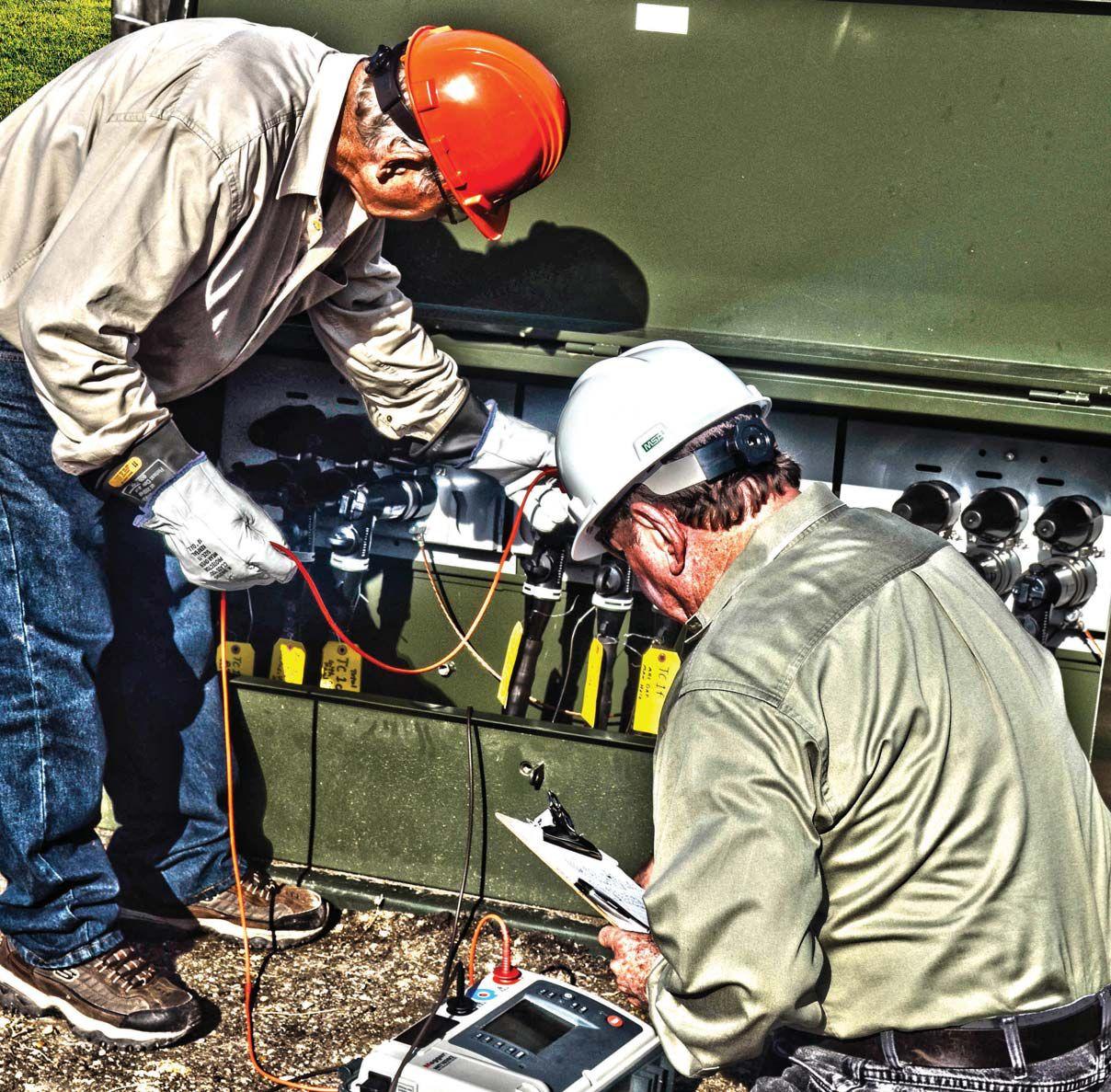
Introducing AVO Cable U
A one of a kind cable field for the most complete cable testing and diagnostic study found anywhere
After years of careful planning, design and construction, AVO’s Cable U is here. Designed to accommodate our new Medium-Voltage Cable Fault Location & Tracing and Cable Testing & Diagnostics courses, the cable field lab allows technicians the most technologically advanced “real world” place for electrical cable testing and diagnostic applications. The study of cable just got a lot smarter.

WWW.AVOTRAINING.COM 877-594-3156 Many AVO training courses are eligible for NETA ctd’s.*


NETA BOARD IN THE MOUNTAINS
BY KRISTEN WICKS, NETA
CoolerairandfallbreezesfoundNETA’sBoardof Cooler air and fall breezes found NETA’s Board of Directors and members traversing the Appalachian Mountains and settling in to the Renaissance Asheville Hotel in North Carolina to conduct their quarterly meetings on September 22–23, 2016.
One of the main topics of discussion both days was NETA’sCertificationExamandsomeofthenew NETA’s Certification Exam and some of the new processes and practices that have been introduced over the past six months. Many familiar faces — along with some who aren’t able to attend meetings as often — came

together to exchange ideas, hear about the latest technical involvement of NETA and its volunteer representatives, learn about the exciting things planned for PowerTest 2017, and enjoy some social time with their NETA colleagues.
The quarterly meetings continue to be an excellent venue for NETA Accredited Companies to get involved with their association and to have lasting impact and influence on NETA and the electrical testing industry at large. We look forward to the next meetings in January 2017!
NETA BOARD AND MEMBERS MEET IN THE MOUNTAINS
22 • WINTER 2016
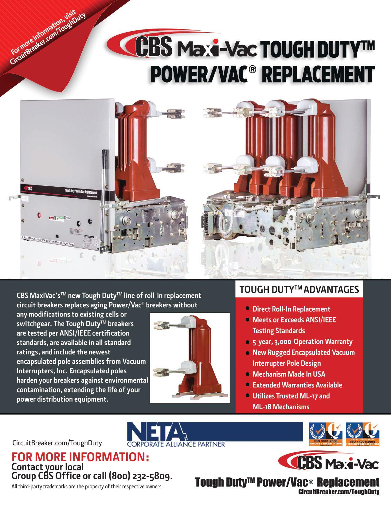
Extend their life, avoid downtime, and save $$$ with NEW Encapsulated Pole replacement assemblies
EXTEND THE LIFE OF YOUR POWER/VAC® CIRCUIT BREAKERS WITH NEWENCAPSULATED POLES
EPOXY-ENCASEDPOLESRESISTCONTAMINATION,MOISTURE, ANDOTHERADVERSE ENVIRONMENTALCONDITIONS
EXTENDSTHELIFEOFYOURBREAKER,ALLOWINGRE-USEOF TRUSTED USA-MADEMECHANISM
FUTUREMODELSWILLACCOMMODATEALL POWER/VAC® RATINGSUPTO27kV AND63kA




DON’T SAY GOODBYE TO YOUR OLD POWER/VAC®
BREAKERS
CIRCUIT
13765 BETA ROAD, FARMERS BRANCH, TEXAS 75244 | 214-442-5877 VACUUMINTERRUPTERSINC.COM | INFO@VACUUMINTERRUPTERSINC.COM One of these is abrand new vacuum interrupter. The other two are 30-year-old hand grenades. Which one is in your circuit breaker? MAC-TS4 The world’s first predictive test system for vacuum interrupters 13765 BETA ROAD, FARMERS BRANCH, TEXAS 75244 | 214-442-5877 VACUUMINTERRUPTERSINC.COM | INFO@VACUUMINTERRUPTERSINC.COM LEARN MORE AT VACUUMTESTING.COM Replacement vacuum interrupters | Vacuum interrupter test systems | Portable circuit breaker timer test systems US PATENTNO.9,031,795 B1 And replacements for every othervacuumbreaker other vacuum breaker evermadetoo! ever made too! Need a vacuum interrupter from We have it in stock.

If you need electrical equipment, tap into the power of National Switchgear’s massive inventory. With millions of products, we offer a huge selection of new, surplus and repurposed circuit breakers, switchgear and related equipment. And it’s all easy to order on our website, which includes calculated shipping costs, complementary items, instruction manuals, renewal parts books and wiring diagrams. If you need help, our experts are empowered to assist with customized equipment configuration, remanufacturing and reconditioning. Go to nationalswitchgear.com today to see our solutions.
800-322-0149 nationalswitchgear.com THE POWER OF OUR INVENTORY. VISIT US AT POWERTEST BOOTH 231





CALL FOR EXHIBITORS California is calling. Join 400+ electrical testing professionals Leading decision makers looking for new products and services For attendee profile and additional information, visit www.powertest.org ANAHEIM • CALIFORNIA February 27 - March 3 • 2017 DISNEYLAND HOTEL POWERTEST.ORG 888.300.6382 THE PREMIER ELECTRICAL MAINTENANCE & SAFETY EVENT


James R. (Jim) White is the Training Director of Shermco Industries, Inc., in Dallas, Texas. He is the principal member on the NFPA Technical Committee Recommended Practice for Electrical Equipment Maintenance (NFPA 70B). Jim represents NETA as an alternate member of the NFPA Technical Committee Electrical Safety in the Workplace (NFPA 70E) and represents NETA on the ASTM F18 Committee Electrical Protective Equipment For Workers. Jim is an IEEE Senior Member and in 2011 received the IEEE/PCIC Electrical Safety Excellence award. Jim is a past Chairman (2008) of the IEEE Electrical Safety Workshop (ESW).
BY JIM WHITE, ShermcoIndustries Shermco Industries

1. Two standards are typically used for the interconnectionofsmartdevicesinasubstation interconnection of smart devices in a substation environment. One is an IEC standard, the other is an IEEE standard. What are the two standards?
a. IEC 61850 and IEEE C37.94
b. IEC 81560 and IEEE C37.20.7
c. IEC 81650 and IEEE C57.60
d. IEC 68150 and IEEE C57.93
e. IEC 65180 and IEEE C37.95
2. When discussing power system automation, IED refers to:
a. Improvised Explosive Device
b. Integrated Electrical Data
c. International Electrotechnical Department
d. Intelligent Electronic Devices
e. Improved Electronic Data


POWER SYSTEM AUTOMATION SYSTEMS
3. In power generation plants, power management systems (PMS) are designed to:

a. Optimize the operation of protective relay systems and reduce trip time
b. Optimize generation with the most economical fuel consumption
c. Maximize control loops and provide efficient transfer functions
d. Reduce the effects of retro-encabulation during start up or shut down
e. Increase profitability by reducing offset periwinkling
4. List four primary functions of substation automation systems.
a. __________________________
b. __________________________
c. __________________________
d. __________________________
26 • WINTER 2016 TECHQUIZ TECH QUIZ See answers on page 110.
No.116 No. 116



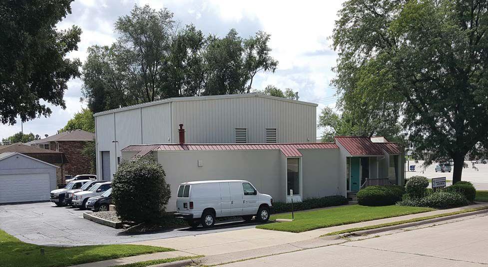
NETA, the InterNational Electrical Testing Association, is pleased to add Midwest Engineering Consultants, Ltd., to the community of electrical testing companies committed to meeting the ever-increasing demand for qualified testing firms and personnel.
Midwest Engineering Consultants was founded in 1991 and serves industrial, municipal, and utility customers inthecentralMidwestfromitslocationnearthe in the central Midwest from its location near the Mississippi River in Moline, Illinois. The MEC team has over 100 years of combined experience in the design, evaluation, testing, and maintenance of electrical power systems and apparatus.
MEC offers a wide range of technical services that include testing, maintenance, and repair of low-, medium-, and high-voltage equipment. The MEC engineering staff provides in-house technical support as well as power system studies, power monitoring, and
system evaluations. MEC’s mission is to improve the safety and reliability of its customers' power systems, thereby enhancing productivity and reducing business interruptions.
Monte Moorehead, MEC President and NETA Accredited Representative, is proud to be part of the NETA organization. “We strive to provide the best service possible, and becoming a NETA Accredited Company is certainly consistent with that goal. WelookforwardtothebenefitsthatNETA We look forward to the benefits that NETA accreditation will provide MEC, and ultimately, our customers.”
28 • WINTER 2016 NETAWELCOMESNEWESTACCREDITEDCOMPANY NETA WELCOMES NEWEST ACCREDITED COMPANY — MIDWEST ENGINEERING CONSULTANTS, LTD.


DUAL GROUND


BY JEFF JOWETT, Megger
Testing circuit breakers for contact resistance is a vital part of many electrical maintenance programs. It requires a high level of sophistication in the test equipment.
First, test currents, which are far more robust than those of ordinary multimeters, are necessary to ensure full working contact across the contact surface. Most utilities specify a 100 A test. Second, resistancemeasurementsmustbemadetoalevel resistance measurements must be made to a level of accuracy and precision far beyond that of many common applications. Utility standards generally require no more than 100 μΩ.
The formula:
W = I2R


are indispensable. Furthermore, where worker safety is concerned, redundancy is a valuable ally. When high-voltage circuit breakers are taken out of service for maintenance, safety and system protection rules make it very difficult to allow removal of the temporary ground leads from 20 feet in the air, with power lines nearby that are subject to dangerous events like lightning strokes. Maximum safety is achieved by grounding both sides of the breaker, but that introduces another problem: a parallel current path.
where watts equal current squared times resistance, indicates how even relatively small changes in resistance can have a profound effect upon energy, which, as heat, can be both wasteful and dangerous. It is obvious that effective testing requires a level of instrumentation above and beyond the familiar DMM.
To ensure the highest accuracy, safety — along with rigor in instrumentation and measurement — are top priorities. Industry standards, safe working practices, and the effective employment of personal protective clothing and equipment
LOW RESISTANCE TESTING VS. INSTALLED CIRCUIT BREAKER TESTING
A brief review of low-resistance testing is in order. To achieve the accuracy and precision necessary to test circuit-breaker contact resistance — where a single ohm is far too much and even a few micro ohms can represent an unacceptable deterioration in performance — the tester must not incorporate lead- and probe-contact resistance into the measurement. This is accomplished by fourwire (Kelvin bridge) measurement. The tester
DUAL GROUND TECHTIPS TECH TIPS 32 • WINTER 2016
injects a dc test current through the specimen being measured. It can accurately measure this current to provide a basis for calculating the resistance. The tester then measures the voltage drop between the two potential probes. It now has measured the test current and voltage drop. Ohm’s Law does the rest.
But in testing installed circuit breakers, physical and electrical impediments abound. The test connections may be 20 feet in the air and require a bucket truck or other means of ascension. Prohibitively long leads and grounding cables increase time and effort on the job. If dual grounds are in place on opposite sides of the

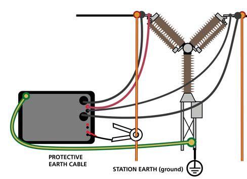
breaker, protection is at a peak. The line being tested is, of course, de-energized. But in power systems, live lines nearby can inductively apply thousands of volts to the adjacent line. Current may sometimes be minimal, but the voltage is still dangerous for its shock value, especially to anyone working at elevation. And this interference current, if directed through the tester, can seriously distort the measurement.
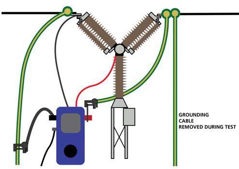
A standard test setup is illustrated in Figure 1. Current is injected by the tester on one side of the breaker and returns to the tester via the ground on the opposite side. Once the safety ground is lifted, all of the test current must pass through the breaker to complete a circuit. The two potential connections are made across the contacts and inside of the current clamps. The tester itself is grounded for safety but does not take part in the measurement circuit. Inductive interference can be picked up by the test circuit and influence the reading.


Applying a second ground (Figure 2) keeps the operator safe and effectively diverts interference currents, but at the cost of accuracy in the measurement. There is now a parallel current path through the earth from one ground to the other, bypassing the circuit breaker entirely.
Typically, ground resistance is at least 2 mΩ — about 20 times the maximum acceptable contact resistance — which introduces a serious error into the measurement. This error can be eliminated by use of a current clamp built into the tester. The current clamp measures the parallel current and subtracts it from the value used to calculate the contact resistance. Only the current passing through the circuit breaker contact is then part of the measurement calculation, and the parallel path is effectively eliminated as a source of error. Meanwhile, the parallel path keeps the operator safe and diverts the interference. Meeting the rigorous demands of a circuit-breaker contact test requires a current clamp of maximum quality, specially designed and interfaced with the tester. Do not try a jerryrigged test with an ordinary clamp-on ammeter used in building wiring applications.


DUAL GROUND TECH TIPS NETAWORLD • 33
Figure 1: Traditional Breaker Test Employing Single Ground
Figure 2: Typical Dual Ground Test

DUAL GROUNDING
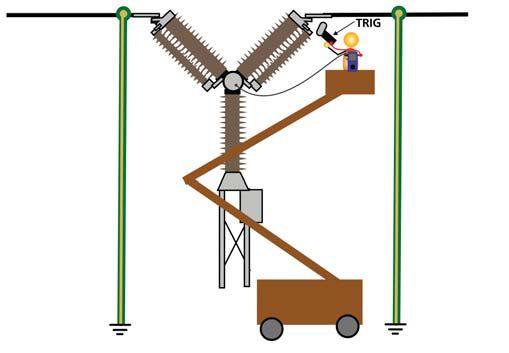
Dual grounding can also be applied successfully without the necessity of a specialized ohmmeter with built-in clamp. In situations where inductive interference is not ever-present, as in a de-energized substation shut down for maintenance, valuable time can be saved by testing with dual grounds in place that do not have to be lifted for the test. The operator is run up in a bucket truck, the tester connected across the test item, and the test conducted (Figure 3).


The earth is part of the circuit, but all test current passes through the breaker. There is no alternate path. As substations are typically shut down for a maximum four-hour period and must go back on line, the time saved in not having to lift the protective ground is significant. While the operator remains protected, this configuration would not do for an on-line substation as interference current would travel on the dual ground and degrade the measurement. For a deenergized station, it’s fine.
Contact resistance is a comparatively simple test in concept. Circuit breakers are also subjected to more sophisticated tests: timing, motion, and dynamic resistance measurement (DRM), and vibration. Timing is critical so that too much


voltage does not develop across the contacts as the breaker opens; it is generally limited to 2 ms. The speed of the breaker’s motion must be sufficient to break the arc and prevent it from restriking. It can be expressed in length, degrees, or percentage of movement, and generally takes from 10 to 20 ms (1 to 2 zero crossovers). DRM is also a measurement of contact resistance, but it is measured dynamically over an open or close operation. Vibration analysis can be made over one open-close operation. Corrosion and other metal-to-metal issues can affect the outcome of this test, so it is a good test to run after long standing in the same position. All of these tests can be performed with circuit-breaker analyzer systems available on the market, and with maximum operator safety and minimal test time using dual grounding.
CONCLUSION
An additional safety consideration is in order. Because safety is the prime parameter in all electrical testing, some substations have two separate grounding systems, and this must be taken into account when setting up a circuit breaker test. Either the two systems must be connected with a temporary bond or the test instrument must be powered from an isolating transformer. If neither of these protective steps is employed, the test instrument’s protective ground becomes a connection between the two grounding systems. This could provide a path for high current through the protective ground leads for which the system is not designed.


Jeffrey R. Jowett is a Senior Applications Engineer for Megger in Valley Forge, Pennsylvania, serving the manufacturing lines of Biddle, Megger, and multi-Amp for electrical test and measurement instrumentation. He holds a BS in Biology and Chemistry from Ursinus College. He was employed for 22 years with James G. Biddle Co. which became Biddle Instruments and is now Megger.
34 • WINTER 2016 TECH TIPS DUAL GROUND TECH TIPS
Figure 3: Aerial Test with Lightweight, Handheld Instrument Employing Duplex Leads
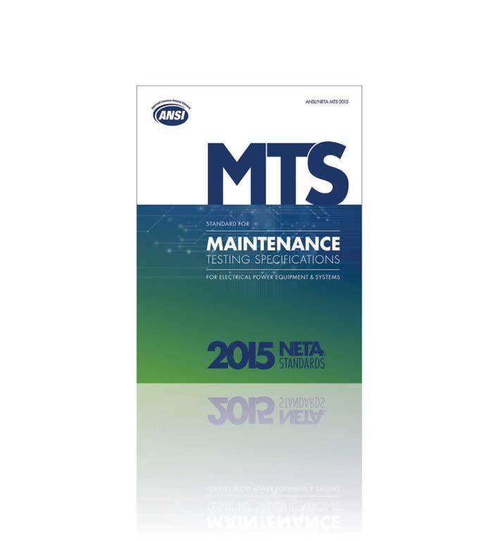

ANSI/NETA MTS - 2015 UPDATED EDITION To learn more about the newest edition of the ANSI/NETA MTS Standard for Maintenance Testing Specifications, visit netaworld.org/standards. ORDER NOW!





A FULL SERVICE NETA ACCREDITED ELECTRICAL TESTING COMPANY. Serving the Sacramento and San Francisco Bay Area 916-853-6280 www.apparatustesting.com • Acceptance Testing • Commissioning • Maintenance Testing • High Voltage Substations • Short Circuit and Coordination Studies • Data Centers and UPS Systems Delivering Powerful Reliability Solutions Power System Acceptance Testing Commissioning and Start-up Maintenance Life-Cycle Extension Troubleshoot and Repair Training and Engineering Services Planning and Operations Support Project Management Sigma Six Solutions, Inc. 2200 West Valley Hwy North, Suite 100 | Auburn, WA 98001 |





messages were sent in the U.S. (includes Puerto Rico, Guam, and the Philippines) every month.
• Ten percent of all drivers age 15 to 19 involved in fatal crashes were reported as distracted at the time of the crash. This age group has the largest proportion of drivers who were distracted at the time of the crash. Drivers in their 20s are 23 percent of drivers in all fatal crashes, but are 27 percent of the distracted drivers and 38 percent of the distracted drivers who were using cell phones in fatal crashes.
• The percentage of drivers text messaging or visibly manipulating handheld devices increased from 1.7 percent in 2013 to 2.2 percent in 2014. Since 2007, young drivers (age 16 to 24) have been observed manipulating electronic devices at higher rates than older drivers.
• A 2015 Erie Insurance distracted-driving survey reported that drivers do all sorts of dangerous things behind the wheel, including brushing teeth and changing clothes. The survey also found that onethird of drivers admitted to texting while driving, and three-quarters say they’ve seenothersdoit. seen others do it.

• Five seconds is the average time your eyes are off the road while texting. When traveling at 55 mph, that’s enough time to cover the length of a footballfieldblindfolded. football field blindfolded.
• Smartphone ownership is growing: In 2011, 52 percent of drivers reported owning a smartphone; by 2014, that number had grown to 80 percent. The greatest increases in smartphone ownership are among adults age 40 and older.
•At any given daylight moment across America, approximately 660,000 drivers are using cell phones or manipulating electronic devices while driving, a number that has held steady since 2010.


NETAWORLD • 39 • DISTRACTED DRIVING
SAFETYCORNER SAFETY CORNER
Figure 1: State laws govern cell-phone use and texting while driving.


HOW EMPLOYERS CAN REDUCE DISTRACTED DRIVING
Employers are certainly not powerless to prevent distracted driving by employees on company time or in a company vehicle. The U.S. DOT encourages employers to create a distracteddriving policy, and will provide videos, posters, and sample policies to encourage better driving habits. Hands-free technology can be provided for employees, or they can be encouraged to purchase it. First, however, be aware of which states allow the use of such devices. See Figure 1 for more information regarding hands-free device use and texting bans or allowances.




There are many things that can divert a person’s attention while driving, and in this digital age, the cell phone is probably the most prevalent. Communicate with employees about distracted driving and follow your state laws. Make it a point to be a better, more attentive driver, and you should realize improvements in your own driving ability and safety.
Paul Chamberlain has been the Safety Manager for American Electrical Testing Co., Inc. since 2009. He has been in the safety field for the past 17 years, working for various companies and industries. He holds a Bachelor of Science degree in Marine Safety and Environmental Protection from Massachusetts Maritime Academy.

SAFETYCORNER SAFETY CORNER AET delivers the best value in at competitive prices. With a an industry leader and one of the To learn more about AET’s full range of testing and engineering services, visit www.aetco.us • 800.992.3826 A Nationwide Service Provider The Power of Positive Results An Company Results to Our Customers.

“Working with SES was a huge success! We removed a safety issue at the same time decreasing our load on the compressors by 15% which has contributed to lower operating temperatures which will add longevity to the motors and a huge energy savings for the plant. Awesome job!” -Duane
Burgess, Ball Corp.

200K SQ. FT. OF INVENTORY
• All manufacturers from the 1920s to present
• Spares, replacement parts and rental options to keep you up and running
CERTIFIED TECHNICIANS
• Performance to a higher standard than the industry requires
• All product is guaranteed safe and reliable
CUSTOMER-FIRST FOCUS
• Expert staff willing to do whatever it takes to get you what you need when you need it
COMPETITIVE PRICING
• The most reasonable prices on electrical equipment and service
• Reconditioned items that provide the same or better quality than OEM items at more affordable prices


EMERGENCY SERVICE call us for
1.800.476.1486 SOUTHLANDELECTRICAL.COM
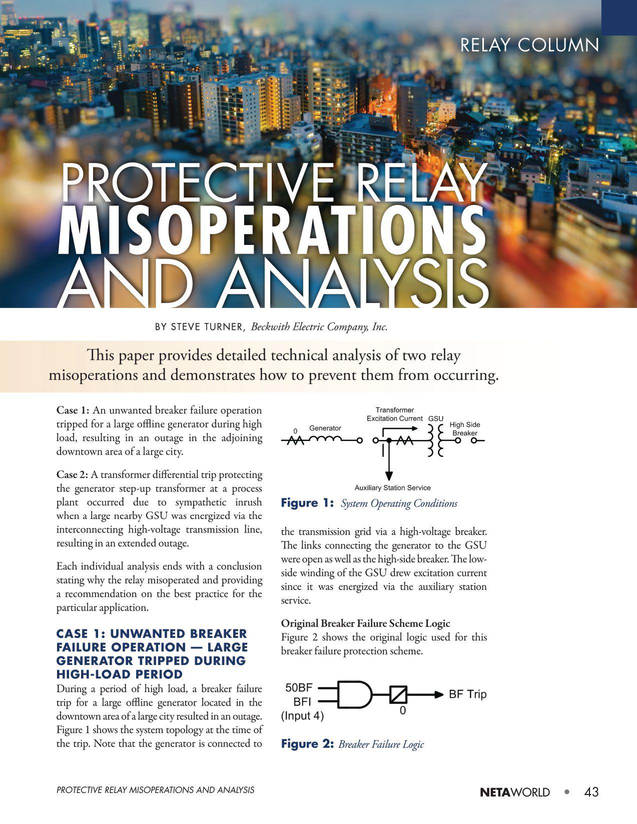
Original Protection Settings
Figure 3 shows the original relay settings for this breaker failure scheme.
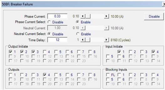
Fault Current Signals
Figure 4 shows the oscillography captured by the relay at the time of the trip.
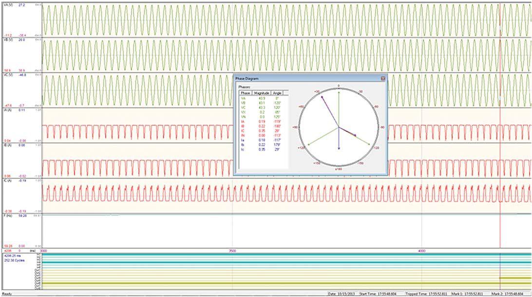
Figure 5 shows the current phasors measured by the protective relay when the breaker failure occurred.


PROTECTIVERELAYMISOPERATIONSANDANALYSIS PROTECTIVE RELAY MISOPERATIONS AND ANALYSIS RELAYCOLUMN RELAY COLUMN
Figure 4: Fault Event Oscillography
44 • WINTER 2016
Figure 3: Breaker Failure Settings
Figure 5: FaultCurrentPhasors Fault Current Phasors
Case1Conclusion Case 1 Conclusion
The breaker failure trip occurred because IC was above the current detector pickup setting and input 4 (BFI) was asserted.
The breaker failure function may be used for a unit breaker rather than a generator breaker. It is limited in that no fault detector is associated with the unit breaker. Output contact operation would occur if any of the initiate contacts close, and the 52b contact indicated a closed breaker after the set time delay. Thecorresponding logic is shown in Figure 6.

6: Fault Current Phasors
CASE 2: TRANSFORMER
DIFFERENTIAL TRIP DUE TO SYMPATHETIC INRUSH
The transformer differential relay protecting the step-up transformer at a processing plant tripped when a nearby large GSU at a power plant was energized from the high side. The trip was due to sympathetic inrush current flowing through the step-up transformer (Figure 7).
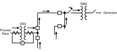
Figure 7: System Operating Conditions (Arrows Indicate Direction of Inrush Current)

Original Protection Settings
Figure 8 shows the original settings for the transformer differential protection.

8: 87T Settings
Fault Current Signals
Figure 9 shows the oscillography captured by the relay at the time of the trip. Note that current input IAW1 is almost completely offset, and there is some distortion in other current inputs as well.
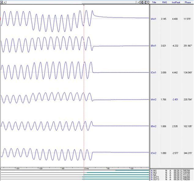

9: Fault Event Oscillography (Raw Waveforms)

PROTECTIVERELAYMISOPERATIONSANDANALYSIS PROTECTIVE RELAY MISOPERATIONS AND ANALYSIS RELAYCOLUMN RELAY COLUMN
Figure
Figure
NETAWORLD • 45
Figure


Harmonic Restraint Calculations
Figure 10 shows the second harmonic content of the current inputs at the time of the trip. The second harmonic differential current present when the trip occurred was as follows:
A-Phase = 17 percent
B-Phase = 13 percent
C-Phase = 13 percent
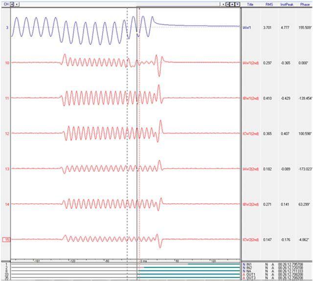
The ratio of harmonic to fundamental differential current used to restrain the transformer differential protection is calculated as follows (Figure 11):
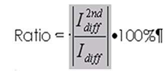
If the ratio is greater than the restraint setting, then the transformer differential protection is blocked (Figure 12).
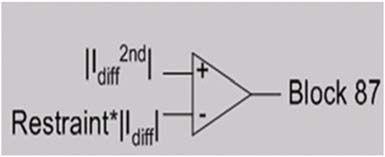
The original second harmonic restraint setting was 20 percent for the electro-mechanical transformer differential relay. The customer used the same setting for the multi-function numerical relay that replaced the original electro-mechanical relay. Figure 10 showed that a setting of 20 percent was not sensitive enough to detect the sympathetic inrush current flowing through the step-up transformer.
Case 2 Conclusion
For several decades, electro-mechanical relays had a fixed harmonic inhibit level of 20 percent. This worked well for a period of time until transformer manufacturers began making better transformers that used less material and were designed with smaller tolerances. Therefore, modern laminated-steel-core transformers will not reliably produce 20 percent second harmonic current during inrush.
Based upon this particular event, an 11 percent setting for the second harmonic restraint would be the most reliable. Note that the multi-function numerical relay in this application actually uses the root mean square (RMS) of the second and fourth harmonic differential current, but that still was not enough to restrain the protection.
PROTECTIVE RELAY MISOPERATIONS AND ANALYSIS 46 • WINTER 2016 RELAYCOLUMN RELAY COLUMN
Figure 10: Fault Event Oscillography (Second Harmonic Content)
Figure 11: Even Harmonic Restraint Equation
Figure 12: Even Harmonic Restraint Logic
FINAL CONCLUSION
The technical analysis of these two relay misoperations, along with examples of how to use the data recorded by a relay during these types of conditions, should help you understand why each misoperation occurred and how to implement best practices for each particular application. Knowing that the first misoperation was due to an incorrect relay setting, while the second was due to an incorrect application, should clarify the need for careful attention during the design and initial work stages.


Steve Turner, an IEEE Senior Member, is a Senior Applications Engineer at Beckwith Electric Company. His previous experience includes work as an application engineer with GEC Alstom and as an application engineer in the international market for SEL, focusing on transmission line protection applications. Steve worked for Duke Energy (formerly Progress Energy), where he developed a patent for double-ended fault location on overhead transmission lines. He has a BSEE and MSEE from Virginia Tech. Steve has presented at numerous conferences, including Georgia Tech Protective Relay Conference, Western Protective Relay Conference, Energy Council of the Northeast, and Doble User Groups, as well as various international conferences.


RELAY COLUMN


ELECTRICAL POWER SYSTEMS INDUSTRY LEADERS GATHER TO SHARE INTELLIGENCE AT POWERTEST 2017
Electrical power systems professionals have a unique opportunity to hear cutting-edge technical presentations at the PowerTest 2017 Spotlight Stage. Twelve Corporate Alliance Partners — each of them leaders in their field — will give 15-minute technical presentations to attendees on the latest technological developments, trends, and best practices.
The presentations will take place during the PowerTest 2017 Trade Show, when over 1,000 participants will gather February 27 - March 3, 2017, at the Disneyland Hotel in Anaheim, California, for the electrical power systems industry’s premier event.
The CAP Program recognizes a select group of industry-leading companies from a variety of segments that support NETA in advancing electrical power systems industry standards. The program helps all facets of the electrical power systems industry share information and align more efficiently around safety and reliability initiatives to better serve clients’ needs. NETA Corporate Alliance Partners are an invaluable support to NETA Accredited Companies and to NETA’s mission.
The PowerTest Trade Show is an open-to-all event and does not require registration for entry. Attendees will enjoy a complimentary lunch, tour 86 top vendor booths, and stop in to listen and engage with the NETA Corporate Alliance Partners that will present on the topics listed on the facing page. In addition, those attending a presentation at the Spotlight Stage receive an entry to the door prize drawing at 5:00 PM.
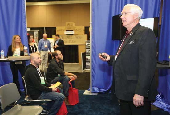
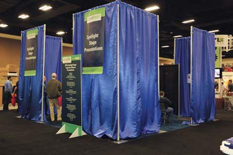
ELECTRICALPOWERSYSTEMSINDUSTRYLEADERSGATHER ELECTRICAL POWER SYSTEMS INDUSTRY LEADERS GATHER TOSHAREINTELLIGENCEATPOWERTEST2017 TO SHARE INTELLIGENCE AT POWERTEST 2017 50 • WINTER 2016
For more information about the Spotlight Stage presentations and the NETA PowerTest Trade Show, please visit www.powertest.org/conference/exposition or contact the NETA office at 888.300.6382.
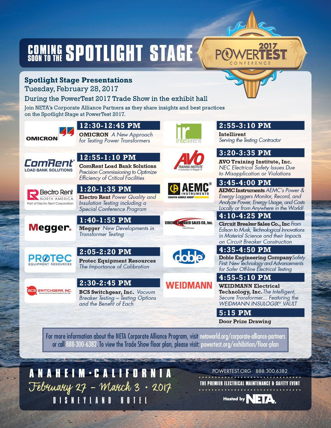


CONDITION MONITORING :

 BY TONY MCGRAIL, Doble Engineering Company


Condition monitoring can provide up-to-the-minute, real-time information about the status of key substation assets. It can be a great benefit to organizations — but only if we plan ahead and respond automatically to issues.
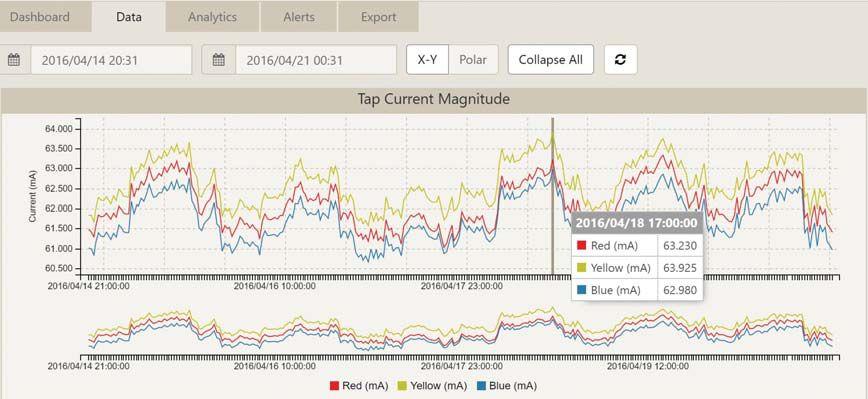

Figure 1 is an example of what useful conditionmonitoring data can look like. It shows the variation in online bushing leakage current magnitude readings for a generator step-up (GSU) transformer over the course of a week.
By itself, the data is quite revealing, showing the variation in applied voltage on the bushing as cycles appear and sudden changes reflect the altering tap positions. The data reflects not only the status of the bushing, but also the status of
the system, resulting in a daily variation of several percent in current magnitude.
How do we use this type of data to set an alert or alarm to indicate a possible problem? Usually, we look at thresholds, or limits, and see if the data has exceeded such a limit. Keep in mind that there may be several such limits.
A slightly more advanced approach is to look at trends to detect a continued rising trend. These approaches certainly allow for detection
FEATURE CONDITION MONITORING: AUTOMATING RESPONSE 52 • WINTER 2016
Figure 1: Variation in Bushing Leakage Current

of variation in the readings, but they will require interpretation: Is the cause of an alert the bushing or is it the system?


above nominal and higher level alerts for warning and action were also in place.

Analysis of data may require time, and we may be precious short of it after an alarm comes in. How much time we have depends on the failure mode encountered. Some bushings, for example, tend to fail gracefully over the course of several weeks to months, while others may fail with a rapid onset over a few hours, as in Figure 2. Our response has tobecommensuratewiththetimescaleofthe to be commensurate with the timescale of the failure mode, or we will miss an opportunity to act. We must understand the asset being monitored, the monitoring methodology, the resulting data, and the expected variation should a failure mode be in operation.
DEFINING THE RESPONSE PLAN
For each alert level, a response plan was put in place: at low level, a planned investigation in a timely manner; for a top level alert, the transformer wouldbeswitchedoutwithintwominutesanda would be switched out within two minutes and a test crew sent to perform offline tests to confirm condition.
The response to each alert was agreed, detailed, and approved as a written policy document within the company’s documentation system by operations, engineering, and management.

THE PLAN IN ACTION

When setting alarm limits, also consider the response and action plan: who must be notified, what steps need to be taken, and when. Two of the documented saves for rapid-onset failure of bushings occurred as the bushing owners had a systematic plan in place — and then followed the plan. Bushing monitors were applied to a large population of bushings with suspected failure modes involving the deterioration of insulation under voltage stress and subsequent degradation of dielectric performance. Limits were set based on the leakage current magnitude with an expectation that if the bushing failure mode were in operation, the leakage current would rise. Limits on information being a small percentage
When a bushing generated a high-level action alert, the action plan was followed, with offline testing confirming the condition of two suspect bushings on two separate occasions. The forensic teardown showed that deterioration was advanced; maybe a few hours separated the bushing from catastrophic failure and tens of millions of dollars in consequential losses.
The key was to have an automatic response: a failure mode identified, actions planned, actions followed, and saves made.
READING THE DATA
Condition monitoring can provide information related to many parameters: dissolved gases, moisture, operational data, or partial discharge. In many cases, a monitored parameter can show
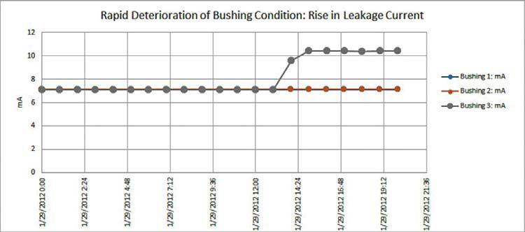


NETAWORLD CONDITION MONITORING: AUTOMATING RESPONSE
FEATURE
53 W WOORLLD
Figure 2: Rapid-Onset Failure Mode


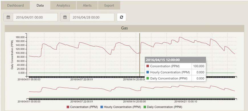


dramatic changes. Figure 3 shows a number of large changes in the single-value dissolved gas analysis (DGA) level associated with a unit transformer. The monitor type gives an aggregate representation of several of the key gases; variation in the response could be caused by variation in the level of any of the key gases. In the data shown, the variation may be greater than 50 percent in the courseofanhourortwo. course of an hour or two.
The changes are dramatic and by an amount that is a cause for concern. However, the variation is also cyclic, corresponding to load on the transformer, which was cyclic and reached different levels on different days. The generation of gas reflected the load on the transformer, with rapid gas generation and slower subsequent gas loss from the oil.

How would we plan for such variability? The DGA level by itself is a reflection of the transformer conditionaswellasthetransformerload.A condition as well as the transformer load. A response must take into account both factors: We must plan ahead and work out the expected response based on the level of load change and the level of DGA variation. This approach is much less common in substation monitoring where single-parameter analysis prevails. An automated response has to look at both factors, such as the setting of alerts based on a rise in DGA that does not correspond to a rise in load.
And a plan: What action will be taken when an
alert comes in? A low-level alert may trigger a review of available data; a high-level alert may trigger an oil sample and analysis if it can be done safely. In either case — with due reference to safety — a written procedure helps clarity of action when an alert comes in.
CONCLUSION
To gain benefit from condition monitoring, we should understand the monitoring system and the parameter being monitored, specifically in the context of operational variables such as load. Failure modes identified should be understood, and an automated response should be agreed and acted upon in a timely manner.
REFERENCES
“Condition Monitoring in the Real World,” Ken Wyper, Graeme MacKay, Tony McGrail, International Conference of Doble Clients, 2013.

Tony McGrail is Doble Engineering Company’s Solutions Director for Asset Management and Monitoring Technology, providing condition, criticality, and risk analysis for many organizations. Previously, Tony spent more than 10 years with National Grid in the U.K. and the U.S. In the U.K, he was a substation equipment specialist, with a focus on power transformers, circuit breakers, and integrated condition monitoring. In the U.S., he took on the role of substation and distribution asset manager, identifying risks and opportunities for investment in infrastructure.
FEATURE CONDITION MONITORING: AUTOMATING RESPONSE 54 • WINTER 2016
Figure 3: Cyclic Variation in DGA

Making testing simple, safe & efficient
High Voltage Asset Analyzer



The Doble M7100 High Voltage Asset Analyzer is a revolutionary solution for high voltage testing. And it is built to reduce the various safety risks a field crew is exposed to per job.
Patented dual high-voltage leads allow you to perform multiple tests with one cable hook up. This means a reduction in ladder trips per job – cutting the number by one third.
Eye hooks on the high-voltage leads let you use hotstick tools to place HV cables on the apparatus under test.
Emergency stop button initiates a controlled shutdown with one motion, and once pressed, will lock until it is twisted and released.
Two test enable/safety switches must be pressed at the same time by the test set operator and the operator’s assistant – otherwise the M7100 will not operate.
Dischargecomplete will appear on the LED display once a test completes and the M7100 has entered a discharge mode that releases energy from the test specimen.


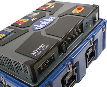

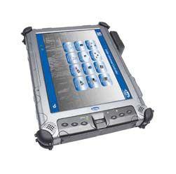
Learn more about how the M7100 is making testing simple, safe & efficient. w ww.doble.com /M710 0
REVOLUTIONIZINGHIGHVOLTAGETESTING
M7100


BY JOSEPH MENEZES, ABB Grid Automation Products
The first version of IEC 61850 was published in 2004, though it was three years later when the final part of the standard saw print.
Before the first document was approved, the Herculean work had already taken about 10 years. The final version consisted of 14 parts laying down the technical standards, and, perhaps more importantly, the semantic language for creating digital substations. The adoption of IEC 61850 has enabled a new generation of substations, more reliable and better managed, while driving suppliers to create compelling (but compatible) equipment to solve old problems in new ways.
Ten years from that original publication, IEC 61850 Edition 2 is now appearing in devices, bringing another decade of accumulated experience and knowledge to the standard and broadening the reach, refining the language, and extending the functionality to reflect an industry that has changed dramatically over the lasttwodecades. last two decades.

IEC 61850 was always a broad standard; it not only specified the logical architecture of a substation and the communication protocols to be used, but also the format of the messages and the functional capabilities. The standard even covers the naming conventions, the way that applications interact with devices, and how those devices are tested to ensure conformity. The major parts alone run more than a thousand pages.
Butthestandardabstractedthecontentofthe But the standard abstracted the content of the communications from the protocol used to convey it, allowing an evolution of networking technologies independent from the management systems. It created an object model describing
what information was available and from where, as well as how devices could be configured with a standard substation configuration description language (SCL). IEC 61850 kick-started the transition to digital substations, an ongoing process that would not have come nearly this far without an internationally recognized standard behind it.
Updating IEC 61850 is an epic task, but at least the standard is split into parts that can be addressed individually. Those parts are, therefore, updated separately (with one being added), and each has its own Edition 2 publication date. For basic enhancements like fixing the mistakes and ambiguities of the first version, that’s easy enough; but where new capabilities have been added, support was needed across the parts, and working groups had to cooperate to ensure interoperability was maintained.
The additional breadth of the standard is obvious from the title, which has changed from Power Utility Automation to Communication Networks and Systems for Power Utilities. This reflects the use of IEC 61850 with wind and hydro power as well as distributed energy resources, where the challenges are different but the solutions may be the same. Many companies have already deployed IEC 61850 in these environments with great success, but when a system manages non-electrical quantities, then proprietary formats and language have to be used — or had to be used until Edition 2 extended the options available.
FEATURE IEC 61850 — A TALE OF TWO DECADES 56 • WINTER 2016
Other than adding those options, the extension of the standard is just a matter of tightening up a few details and rubber-stamping the approvalfor-use in these new industries.
Even in traditional substations, the standard has become more broad, thanks to the increasingly complicated management systems being deployed. Modern IEDs now support several functions at once, meaning they can operate as multiple devices within a single physical enclosure. Such a device requires a hierarchical control structure, as the logical devices will share some configuration parameters and should thus be addressed as a group, while other parameters will need to be set individually and require individual referencing.
Communicating new properties means extending SCL, the XML-derived language used to describe delivered parameters and reported data, which (with Edition 2) can now better support engineering processes and retrofitting, as well as provide an exchange of mandatory and optional


featuresbetweenIEDsandthetoolsthatusethem. features between IEDs and the tools that use them.
IEC 61850 has become more literally broad, with the ability to communicate data between substationsaswellaswithinthem.Edition2 substations as well as within them. Edition 2 extendsSCLsoitcanbeusedbetweensubstations extends SCL so it can be used between substations creating a single management network. Initially, that will be over a low-bandwidth link; taking IEC 61850 beyond the switch yard to the point where the substation automation systems merge may take an addendum to Edition 2 — or even wait for a new edition before it is properly agreed — but Edition 2 has laid the groundwork for that to happen.




Joseph Menezes istheGlobalProduct is the Global Product Manager for ABB Grid Automation Products, responsible for the Relion® 670 series protection and control products. He has 25 years of experience in automation, control, and protection of power systems with a background in product development and product management.
NETAWORLD • 57 IEC 61850 — A TALE OF TWO DECADES
FEATURE




ENGINEERING SERVICES • TECHNICAL SERVICES • COMMISSIONING Protection Systems Design, Commissioning, Relays (310) 816-3130 131 W F Street Wilmington, CA 90744 Los Angeles Area | | www.youtube.com/tdeinc2www.twitter.com/tdeincwww.facebook.com/tdeinc www.linkedin.com/company/tony-demaria-electric CA LICENSE #315448 TRAINING

We support testing
Relay and Protective Device Test Equipment
Battery Analysis and Battery Discharge Test Equipment
Low Voltage Circuit Breaker and Switchgear Test Equipment
Medium/High Voltage Circuit Breaker and Substation Test Equipment
SF6 Chemical Analysis Equipment
Transformer Testing and Diagnostic Equipment
DC, VLF, Online PD and Offline PD Test Equipment for Cables
Cable Fault Location Equipment
Power Quality and Load Analysis
Data Acquisition and Recorders
Meter Analysis Equipment
Online and Offline Partial Discharge for Apparatus and Substations
Low Resistance Ohmmeters
Insulation Resistance / Megohmmeters
Ground Test Equipment
Photovoltaic Test Equipment
Infrared Cameras
Ultrasound and TEV Analysis Equipment
Motor and Rotating Apparatus Test Equipment
Patient Care Area Test Equipment
AC and DC Load Banks
AC High Potential Test Sets to 200kV
DC High Potential Test Sets to 200kV
VLF and Tan Delta to 90kV

888.902.6111


rental support logistics
ir
info@intellirentco.com intellirentco.com
intellirent

TESTING IN THE LIFE CYCLE OF SA SYSTEMS
The complete sequence of testing — from product development to installed, customized systems — is necessary to fulfill the general and dedicated user needs for SA systems. Behind the life cycle of any SA system are the life cycles of all integrated products and related tools. From the development and production of a device (IED) and the required software tools to the on-site system tests, a variety of test phases must be passed.
This Life Cycle Testing sequence was defined and described in a previous Cigre paper. Generally, all testing is intended to improve quality and reduce risks for supplier and users. This article summarizes the required testing sequence, starting with the development process of single products (IEDs and tools) through a commissioned system customized to the user’s needs as indicated by the project-specific requirements. The basis for reliable in-house testing is the quality system of the supplier and vendor, according to ISO 9001/9002 as far as applicable.
SA System Project Independent Testing Sequence Handled by the Vendor
The classic testing sequence starts with the Device Type Test and ends with the Integration Test to ensure proper functioning of the new product (IED and tool). The Conformance Test is part of the Device Type Test according to standards such as IEC 61850. Normally, the conformance of the IED or tool is confirmed by a certificate issued by a UCA International Users Group (UCAIug) qualified test center. The test requirements of IEC 61850-10 and the derived test procedures defined by the UCAIug are focused only on IED (single-product) testing. As a result, today’s conformance certificates are no guarantee of interoperability from a system perspective, but they are an important step to reaching interoperability.
The goal of IEC 61850 is interoperability of the IEDs and tools in SA systems. Therefore, a generic system test should also belong to the vendor’s testing sequence. In this step, the interoperability between the different system
components and tools is verified and validated. Part of this validation is the overall system performance of the provided services, tested in a reference system. This project-independent test substantially reduces the risks for all SA system projects to be executed. A second benefit is that the system configuration tool and its interfaces with the product tools are also tested. The system test described in “Exploiting the IEC 61850 Potential for New Testing and Maintenance Strategies” is not yet formally defined by IEC 61850 or by the UCAIug.
Routine tests or manufacturing tests in the production chain ensure a constant quality of delivered devices.
Testing Project Specific Configurations
The entire SA system project-testing sequence consists of project-related tests based on the user specification for the ordered SA system. They are performed by the system integrator (supplier, customer, third party, etc.) as directed by the user. These tests confirm that the delivered individual SA system is running as specified.
The testing sequence starts with the Factory Test. It is a project-related test to prepare the customized system for the Factory Acceptance Test (FAT). The FAT determines whether the equipment operates according to its specifications and covers all functional requirements. The FAT is witnessed and confirmed by the user and ends with a shipping release to site.
On site after the installation, the site tests are carried out. During these tests especially, the system interface to the real process will be verified and the SA system prepared for the Site Acceptance Test (SAT). The SAT witnessed and confirmed by the user is the final acceptance of the delivered system. Then the warranty and maintenance phase starts if applicable.
Maintenance Testing in Operation
Using the advantages of self-supervision provided in modern numerical system components, many of the tests described in the previous sections will not be repeated as part of periodical maintenance testing during the operational phase of the SA
NETAWORLD • 61 ACCEPTANCE, COMMISSIONING, AND FIELD TESTING FOR PROTECTION AND AUTOMATION SYSTEMS FEATURE


system. Vendor tests especially may be excluded. During the operational phase of the life cycle, the testing is focused on:
• Identifying faulty system components by periodic tests or self-supervision
• Exchanging and reconfiguring faulty system components
• Testing the repaired system
Periodic functional testing is especially related to the hardwired process interface due to its limited self-supervision capabilities. Maintenance activities like extensions of the substation or its functions need appropriate testing of the altered system. In any case, the traceability of configuration changes must be ensured.
CHANGES IN THE TESTING PROCESS INTRODUCED BY USING IEC 61850
Modern IEC 61850 SA systems are distributed software applications based on exchanging standardized information over the substation local area network. Instead of testing the functionality of single components as in the past, system tests performed today show more similarities with testing of software applications than traditional testing of individual devices in SA systems. Because the different SA system components share common system functionalities, the interoperability between those components is a prerequisite.
With the introduction of IEC 61850 Edition 2, online testing capabilities are enhanced.
Several additional features such as Identifier for Simulated Messages are introduced, and the definition of the Mode/Behavior introduced in IEC 61850 Edition 1 is clarified to be more usable.
Conformance versus Interoperability
Standard conforming products (IEDs and tools) from different suppliers, or products conforming to different standards from the same supplier, need not fulfill the same functional scope of supply. They may have different communication profiles.
A communication profile defines the mandatory subset of the standard with the selected options and vendor-specific extensions that are implemented. Different profiles provided by different products may conform to the standard but still not be 100 percent interoperable with each other. It is the responsibility of the system integrator to check the interoperability of two or more products based on the conformance statements of the different products and the required system functionality. Additionally, the performance of devices, including delays caused by communication equipment like switches, has to be verified. These tests, preferably done independently from SA system projects as a kind of generic system test, will greatly reduce the risks for all projects.
Re-Use of Formal System Description in the Testing Process
With the Substation Configuration Language (SCL), the IEC 61850 standard has introduced an interoperable and machine-readable description used for the standardized exchange of configuration data between engineering tools. Based on this configuration language, several file types have been defined in the standard. One of these files is the Substation/System Configuration Description (SCD) file providing the full documentation of the SA system as built. The typical content of the SCD file is:
• Description of complete topology of the primary equipment of the substation (single line diagram)
• Relationship between SA functionality defined by Logical Nodes (to be implemented in the selected IEDs) and the primary equipment
• All IEDs (servers) and station-level equipment (clients), including their data models
• Complete communication system with addressing and logical data flow
From the communication system point of view, the interfaces for each device, client, or server connected to the system are described in this
FEATURE ACCEPTANCE, COMMISSIONING, AND FIELD TESTING FOR PROTECTION AND AUTOMATION SYSTEMS 62 • WINTER 2016
file. This allows a comprehensive evaluation and documentation of the physical dataflow between all system components. These results stay valid if the configuration of related datasets and control blocks is only changed during engineering time and not created dynamically during runtime. Therefore, the static configuration is recommended.
As seen from the definition, the comprehensive SCD file is the central part of the system documentation and can be used as a standardized reference for all testing activities related to IEC 61850. This allows comparing data models, configuration version information, and the dataflow of the actual IEDs with the information as engineered in the SCD file. As a result, configuration mismatches can be easily detected in the entire SA system.
The message analysis of the communication between IEDs at the application level also requires the information about the content of the IEC 61850 datasets. Without this information, the transmitted values cannot be assigned to the related attributes of the data model, and an analysis at user level — i.e., a user-friendly analysis — is not possible.
To fully benefit from the version information contained in the SCD file, all engineering tools must follow the rules for handling configuration changes as defined in IEC 61850, i.e., to update all relevant configuration indices of the impacted IEDs. Keeping the SCD file up to date with the commissioned SA system also ensures one common reference for later extensions or maintenance tasks.
The information in the SCD file is also the basis for simulating physically nonexistent IEDs for communication (GOOSE, SV, and MMS services), for example, during factory testing where the complete SA system is not available.
TOOLS FOR ACCEPTANCE, COMMISSIONING, AND FIELD TESTING
A previous Cigre paper confirmed different tool requirements in the different phases of the life cycle of an SA system. Testing tools are generally
required during the entire life cycle for the related testing sequences.
Testing Tools
Testing tools are used in all phases and must support the testing process and automate testing activities as much as possible. The testing activities during acceptance, commissioning, and field testing can be divided into integration testing and functional testing. The SA system has to be tested for correct communication and configuration by an Integration Test tool. With the help of the Function Test tool, the SA system functions are tested according to user-dependent specifications. For both testing tasks, it is required to simulate missing components crucial for the correct behavior of the SA system. Therefore, it is most efficient when the testing tool provides simulation capabilities as well.
During testing activities in process-bus environments, a test engineer needs a way to measure the analog values sent from a merging unit (such as a current transformer) to the IEDs. In this case, the testing tool will act as an enhanced volt and ampere meter. In addition to these classic measured values, it shows useful information like phase angles and other quality attributes to the test engineer.
For SA functions with embedded GOOSE functionality like protection, the testing tool guides the test engineer to operate the IED under test while setting the impacted functions of all involved IEDs in the necessary modes (as defined in IEC 61850 Ed. 2). One example is the TestBlocked mode to avoid sending out unwanted trip signals to a circuit breaker in the process (switchyard). Additionally, under test conditions, it monitors the reaction of the complete involved IED chain to verify the expected result for the specific test case.
Diagnostic Tool
A diagnostic tool isolates the root cause of problems reported by the self-supervision of the SA system or detected during testing. To identify configuration issues, it is often enough to detect that different versions of the configuration files are used within the system. This information helps
NETAWORLD • 63 ACCEPTANCE, COMMISSIONING, AND FIELD TESTING FOR PROTECTION AND AUTOMATION SYSTEMS FEATURE


pinpoint the parts that need to be re-loaded with the latest version. Where the version information is consistent, an in-depth comparison of the data models may help identify further implementation problems with the functions.
Finally, the application-level protocol analysis makes it easy to detect whether the information sent from one IED to another is correct. This application-level information captured on top of the ethernet can even be enriched by adding information from the SCD file, such as links to the substation section or signal texts.
In the IEC 61850 world, switched ethernet is a communication backbone. Since managed switches are used, communication issues can also be related to the configuration of these active network components (e.g., wrongly defined multicast or VLAN filters). Here a diagnostic tool will help check whether the configuration of the ethernet equipment matches the logical and physical needs. These parameters can be retrieved online and later compared with the documented values in the project-specific SCD file.
For horizontal IED-IED communication services (GOOSE, SV), it is helpful if the tool also includes the graphical representation of message content at the application level. This helps the engineers focus on the application level, rather than counting bits and bytes.
Simulation Tool
When simulating a server IED, a client that acts toward a control center as an HMI or protocol converter, for example, could be tested. The simulation is restricted to the pure IEC 61850 data-model simulation. Any vendor-specific functional implementation cannot be provided by a generic tool. A simulation will also not replace the point-to-point test from the physical process to the HMI or gateway, but can be used to separate the testing processes to allow sequential tests with minimal effort. In this case, the HMI will be tested with signals from the process ensuring correct wiring up to the IED, and the gateway functionality can be tested
by generating artificial signals with an IED simulator.
Protection or control IEDs can be tested using a generic IEC 61850 client simulation. Such a client will browse the content of an IED and provide an intuitive interface based on the result — for example, to send commands to an IED and display the resulting feedback in the event list.
Another case for IED simulation is the usage of GOOSE and SV messages. In case a GOOSE or SV sender is not physically available, a simulation can produce the required messages on the bus for the IED under test.
The key to ensure consistency of simulation is the re-use of the SCD file for the simulation. All required information including configuration information is contained in the SCD file, making additional configuration of the tool superfluous.
The simulation tool should contain a way to block an unintended simulation of an IED. In case an IED with the same addressing information as the IED to be simulated is already available on the network, simulation must be blocked to avoid duplicated sending of potentially different values.
Documentation Tool
At the end of the commissioning, the Documentation Tool should gather all relevant maintenance information from the commissioned SA system, such as IED firmware and configuration versions, serial numbers, etc., and store them in a report. This information is implicitly contained in the final updated SCD file since it presents a kind of standardized project database. This may be a very large file, and linear searching can be time-consuming. Therefore, the equivalent project information is normally stored in a vendor-specific project database for fast access. A complementary documentation tool reading out the information of interest directly from the installed system is very convenient.
FEATURE ACCEPTANCE, COMMISSIONING, AND FIELD TESTING FOR PROTECTION AND AUTOMATION SYSTEMS 64 • WINTER 2016

REQUIRED SKILLS AND EXPERIENCE FOR TESTING IEC 61850 SYSTEMS
IEC 61850 systems demand additional skills for the operational and process know-how of an SA system. These skills are essential for project engineers as well as for maintenance personnel in the utility.
Withtheintroductionofcommunicationinan With the introduction of communication in an SA system, basic data communication know-how for a field user was required. With the introduction of IEC 61850, the major principles of IEC 61850suchasthedatamodelandfunctional 61850 such as the data model and functional representation in logical nodes (LN) must also be known. The same applies for using ethernet and switches. In any case, the maintenance engineer needs to be trained in relevant techniques to isolate and fix problems in a structured way.
Engineering and testing tools can help fulfill the related new requirements, but a tool does not replace the know-how of an engineer. The main objectives of the tool must be to facilitate the configuration process, address system complexity, and provide the required information at a practical level. An IT and communication (ITC) specialist is not needed for every project, but rather a substation engineer with all his skills. The ITC expertise is embedded in the tools.
CONCLUSION


On one hand, IEC 61850 allows the combination of system components from different vendors within one SA system with enhanced and distributed functionality and a complex interaction between these components. On the other hand, IEC 61850 supports the simplification of related configuration, testing, and maintenance activities by providing SCL used by tools in all phases of the testing life cycle. To ease the handling of software updates and licensing for testing tools, it is most
convenient if all tool types are combined in a single software package.
REFERENCES
IEC 61850, “Communication Networks and Systems in Substations.”
K.PBrand,V.Lohmann,W.Wimmer, K.P Brand, V.Lohmann, W.Wimmer, Substation Automation Handbook, ISBN 3-85759-951-5, 2003, www.uac.ch
UCA International Users Group, www.ucainternational.org
W. Baass, K.P. Brand, S. Gerspach, M. Herzig, A. Kreuzer, T. Maeda, “Exploiting the IEC 61850 Potential for New Testing and Maintenance Strategies,” Cigre B5-201, 2008
K.P. Brand, T. Maeda, P. Owen, W. Wimmer, “Requirements for Different Tools Over the Life Cycle of IEC 61850-Based Substation Automation Systems,” Cigre B5.PS119, 2011


MichaelObrist Michael Obrist istheGlobalProduct is the Global Product Manager for Software Tools within SubstationAutomationatABBSwitzerland Substation Automation at ABB Switzerland Ltd. Michael has spent nearly 20 years at ABB working across R&D and product management within substation automation. His work has focused on developing simpleto-understand software tools and technologies that help customers see the unseen from a new perspective.

Stephan Gerspach is the Systems Architect for Products and Tools at ABB Switzerland Ltd. He is responsible for the compliance of the substation automation product portfolio to the requirements from an SA System perspective. Stephan has more than 18 years of experience in the substation automation domain after working various positions in project execution, product verification and validation, and system architecture. He is an active member of the UCAIug IEC 61850 Testing Subcommittee.

Klaus-PeterBrand Klaus-Peter Brand is part of the small team introducing Substation Automation inBBC/ABBSwitzerland.Theco-author in BBC/ABB Switzerland. The co-author of “Substation Automation Handbook,” Klaus-Peter is a board member of the Cigre SC B5 and is an IEEE Fellow. With the beginning of the development of IEC 61850, he became a member, TF leader, andeditorintheIECTC57WG10.Heisalsoaconsultant and editor in the IEC TC57 WG10. He is also a consultant and teacher in the ABB University Switzerland.


NETAWORLD • 65 ACCEPTANCE, COMMISSIONING, AND FIELD TESTING FOR PROTECTION AND AUTOMATION SYSTEMS FEATURE



RESPONSIBLE FOR ELECTRICAL POWER SYSTEM COMMISSION? Get the ANSI/NETA Standard for Acceptance Testing and the ANSI/NETA Standard for Electrical Commissioning. Save 28% when you purchase the ANSI/NETA ATS 2013 and ANSI/NETA ECS 2015 together. To order: visit www.netaworld.org, call 888.300.6382, or email neta@netaworld.org New! BUNDLE YOUR ORDER AND SAVE! FULL S E RVIC E IND E P E ND E NT E L E CTRIC A L T E STING Acceptance Testing Services Low, Medium, and High Voltage Preventative Maintenance & Testing Switchgear Transformers Engineering Services
Years of Experience Years of Reliability 25
781-767-0888 Email: infrared.ma@verizon.net 152 Centre Street Holbrook, MA 02343 www.Infraredbps.com





THE FUTURE OF AND PROCESS AUTOMATION





 BY DAVID C. MAZUR AND JOHN A. KAY, RockwellAutomation Rockwell Automation


As technology continues to drive innovations, industrial enterprises must continue to keep pace to remain competitive in an ever-changing marketplace. The technology trend is to replace yesterday’s systems with higher-performance, low-cost, option-rich devices that shorten the return on investment and offer more flexibility. As control system technology evolves, systems migrate to functions that are being increasingly distributed to smarter, more granular, control-system components capable of performing localized operations.
Industrial facilities are under increasing pressure to reduce overall costs, boost productivity and quality, and improve personnel safety. One systematic approach for reaching these goals is automating and integrating facilities from the plant floor through the management of process information. Device-level integration through digital communication is the key to unlocking the full potential in the electronic controls being installed in industrial plants today. New advancements in device-level status monitoring and communications have boosted process throughput, system practicality, and affordability of complete plant-level integration.
was lack of proper and efficient flight controls. Without a review of the entire system, such as with the power and process systems of a modern facility, the overall system will lack high performance.
POWER AND PROCESS TRENDS TODAY
Furthermore, while the industrial automation space was being transformed by networks and communications, so, too, was the electrical infrastructure market. The challenge that remains is how to effectively integrate these two systems in an optimized, intuitive fashion. If one compares the evolution of heavier-than-air vehicles, adding more powerful engines was not a solution when there


Today, many industrial processes are controlled by a combination of systems working together (hopefully, in sync) to produce a target yield or product. Examples of these systems include continuous and discreet process control systems, electrical protection, SCADA, historian for archiving, and reporting tools for data trending. Traditionally, these subsystems have been logically separated as seen in Figure 1. The red boxes in Figure 1 depict the process automation system with intelligent motor control (IMC) devices — e.g., variable frequency drives, overloads, starters, etc. — feeding a process controller. This process controller feeds data to higher level systems to archive and report on the data. The blue boxes represent the power automation system where
FEATURE THEFUTUREOFINTEGRATEDPOWERANDPROCESSAUTOMATION THE FUTURE OF INTEGRATED POWER AND PROCESS AUTOMATION 68 • WINTER 2016
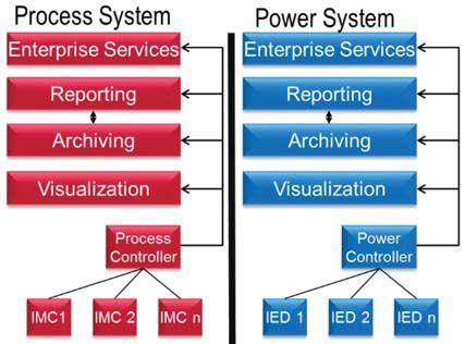
intelligent electrical devices (IEDs) feed a power automation controller. This controller, in turn, feeds similar higher-level systems to archive and report on the data. Although these two systems are within the same facility, they are logically isolated.
Figure 2 shows that, although the process and power automation systems have been logically isolated by industry, they are closely coupled to each other. It is very difficult to logically separate power from process, as they are intermingled within each other. The figure represents the power automation network in red and the process automation network in green. The red arrow suggests the linkage needed to realize the full potential of these industrial systems.
THE EVOLUTION OF POWER AND PROCESS AUTOMATION
Advancements in technology have created a society where companies want to collect a large amount of real-time data, sort this data — and
with the advent of the discrete event data — turn this into actionable information. Today, there is a push to archive this discrete data so that it can be trended at a later time, as well as used for modeling of the overall process. From an industrial manufacturing standpoint, electrical protection and SCADA data is crucial to identify operating points, create predictive maintenance models, identify load-shedding opportunities, and manage energy consumption and root-cause analysis.
As the information age has evolved, so has the technology used to transmit data from the electrical protection system to SCADA systems. Power system and industrial-based electrical protection devices have evolved over the past three decades from electromechanical to microprocessor-based relays. In parallel, the communication networks for electrical protection have also evolved. Electrical protection architectures have developed from hard-wired contacts to communication networks using serial protocols, such as Modbus. Serial communication has evolved to communication protocols over the TCP/IP stack, such as Modbus TCP and DNP3 LAN/WAN, which then allowed substation devices to communicate in a peer-to-peer manner to share data.
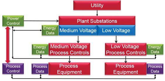
The IEC 61850 standard has become more prevalent in recent years. These examples and applications show that an Ethernet-based standard, such as IEC 61850, can be used for protection, command and control, and SCADA gathering of data over the same redundant wire pair. As this real-time data is provided to the central controller or SCADA master in the system, graphics can be populated to alert engineers and operations to system status in a time-synchronized fashion. Additionally, this data can be used to make commandand-control decisions in an industrial application. Furthermore, leveraging power and process in a unified solution provides users many benefits while reducing the overall total cost of ownership.
NETAWORLD • 69 THE FUTURE OF INTEGRATED POWER AND PROCESS AUTOMATION FEATURE
Figure 2: Power and Process Systems
Figure 1: Process and Power Models

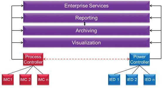
A UNIFIED SOLUTION FOR POWER AND PROCESS

By using data from process and power controllers, aniterativeevaluationofoverall an iterative evaluation of overall system efficiency, process-stage efficiency, and product quality can be performed. The result can help eliminate process bottlenecks and inefficient process steps, and reduce energy usage while maximizing overall system or plant output performance. Installing more efficient machines in one process step may actually be detrimental to the overall system performance without the review and collaborationofdatafrombothdatasources. collaboration of data from both data sources. Furthermore, harmonizing the upper layers of visualization, archiving, reporting, and enterprise services reduces cost and overhead for industrial process owners. The value of the unified system can be realized in the visualization, archiving, and reporting systems (Figure 3).
VISUALIZATION

Although automation control companies have developed solutions for process visualization, this solution takes process visualization one step further into the electrical distribution system. TheIEC61850standardallowsfor The IEC 61850 standard allows for the visual representation of reports and alarms at the process control level. With the development of more sophisticated humanmachine interface (HMI) screens,
global objects have been introduced into the automation graphics. The use of these global objects has allowed for the creation of faceplates, defined as reusable standard objects.
Examples of process faceplates can be seen in Figure 4. The left side of Figure 4 shows the representation of a low-voltage power circuitbreakerwithitscommand-and-control circuit breaker with its command-and-control functions. The right side of Figure 4 depicts a faceplate of a low-voltage, variable-frequency drive. Each faceplate was constructed with multiple tabs to change between home, engineering, and diagnostic screens. Graphics were designed to provide a user experience similar to interacting with the physical device. The advantage of the faceplate is that it is a familiar, standard, prebuilt object that can be implemented repeatedly for similar engineering designs.
The common naming convention and logical modelofIEC61850allowforavendormodel of IEC 61850 allow for a vendorindependent implementation of electrical distribution equipment, e.g., circuit breakers, relays, power monitors, etc. This information can be simultaneously displayed with process information provided by IMC devices, e.g., drives, overloads, starters, etc. Providing a unifiedvisualizationenvironmentallowsall unified visualization environment allows all pertinent information to be displayed in one place where data can be effectively acted on as actionableinformation. actionable information.
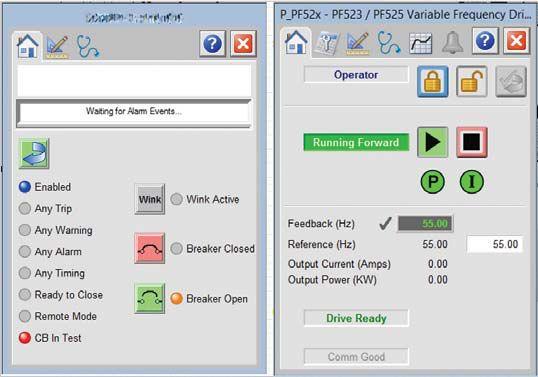
FEATURE THEFUTUREOFINTEGRATEDPOWERANDPROCESSAUTOMATION THE FUTURE OF INTEGRATED POWER AND PROCESS AUTOMATION 70 • WINTER 2016
Figure 3: Unified Visualization, Archiving, and Reporting
Figure 4: Graphical Faceplates
ARCHIVING
Time stamping of event data can be placed in a process historian, even if the act of event detection is a distributed system component. This enables reporting and key performance indicator (KPI) calculations based on energy data, as well as manufacturing processes variables. The impact of manufacturing intelligence with power systems data will yield relationships that, to date, have not been available in typical reporting environments. IEDs are critical to the management and control of industrial and commercial power systems, and can provide value in an environment with process historians.
Highly accurate and time-synchronized energy consumption and energy balance data can be used to determine overall process efficiencies for various production or process operations. Data from trip and alarm events can be deterministically used to establish maintenance schedules to prolong equipment life. Additionally, machine or production-flow characteristics can be refined and monitored to enhance production rates and maximize specific machine capabilities.
ASSET-BASED MODELING
The Industrial Internet of Things (IIoT) has created an environment where more data from assets is available than ever before. KPIs have traditionally been used to define metrics of industrial petrochemical facilities. The IIoT can present a number of KPIs for facility assets that are not uniform across similar types of equipment. Consequently, users have been seeking consistent application of KPI solutions across their enterprise assets. The definition of an asset template allows for consistent representation of a device across the industrial enterprise. Furthermore, this allows for comparison between assets or control processes in a standard fashion, thus optimizing reporting capabilities.
Asset models for equipment remove the concept of flat tags in a historian, replacing it with an object-oriented model. Tags that are monitored and archived are now associated with a physical piece of equipment or process, allowing context to be immediately applied (Figure 5). Furthermore,
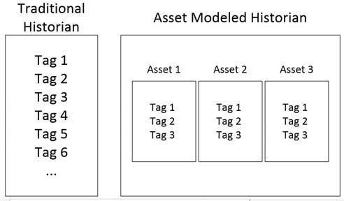
analytics can now be trended on each asset. Additionally, asset performance can now be compared at multiple levels: asset to asset, process line to process line, and facility to facility. The concept of asset modeling can be applied to power and process automation, thus providing standardization across the industrial enterprise.
REPORTING
The large quantity of data generated by modern automation systems makes it possible to apply a broad range of plant analytics to the automation systems and processes that make up an industrial enterprise or business. Reports, charts, and other human-readable formats are often available or may be created for plant personnel and others to monitor and review the generated data in either a real-time mode or at a later time after the data has been stored.
A report created to display the data of a given industrial automation system may find it difficult to find and display similar data of another industrial automation system. Objects and other components of the other system may be similar or even identical to the first system. However, due to even slight variations in component names (for example, during the system setup stage), a disconnect can exist between the data stored in the system and a pre-generated report designed to look for specifically named objects in the system. Thus, reports previously created may not display all the data they were designed to show.
Creating new reports or even fixing pre-generated reports to show the data generated by a particular system can be a laborious and tedious
NETAWORLD • 71 THE FUTURE OF INTEGRATED POWER AND PROCESS AUTOMATION FEATURE
Figure 5: Asset Model Example

manual process. This process can require setting up individual connections between system data points and the parameter value to be reported for hundreds of parameters or more.
ThebenefitoftheIEC61850standardisthatthe The benefit of the IEC 61850 standard is that the logical model allows for standard reporting across vendors in a specific format. This means that an IED of a specific type from Vendor A can be reported on the same way as an IED of the same type from Vendor B. IEC 61850 allows for assetbased reporting models and type-based reporting, where reporting systems have the context of devices on which they are reporting. By creating type-based reports, users can associate content in the form of trends, graphs, and analysis on a particular type of device. When it is instantiated within the enterprise system, the reports come pre-populated and wired to system tags due to the common naming convention of the standard. This provides a substantial design time savings for implementers of a unified system.

UNIFIED POWER AND PROCESS REPORTING
Even more powerful reports can now be created inaunifiedenvironment.These in a unified environment. These reports may provide additional insight into cause and effect of how changes in the power

automation system affect process automation and vice versa. These reports will allow process owners to provide better predictive and preventive maintenance, as well as optimize their overall process to new levels. The ability to obtain electrical information within the unified system allows for energy inputs into the facility optimization state space equation.
For example, in Figure 6, a unified system, a process owner can realize instantaneous profit, as they know all of the process yields (gross profit blue line), as well as the total costs to produce (red line). The area between these two curves provides the owner the instantaneous system profit in a timely fashion. This information can feed additional control loops to take corrective action and further optimize the process. Now, electrical distribution parameters can be effectively used in process optimization schemes. Furthermore, this electrical data can now be used in overall efficiency calculations and asset liability, and can be presented in dashboard format as seen in Figure 7. This data can be used to compare not only process line data, but also can be extrapolated in a facility-tofacility comparison providing a true enterprise comparison for process owners.

FEATURE THEFUTUREOFINTEGRATEDPOWERANDPROCESSAUTOMATION THE FUTURE OF INTEGRATED POWER AND PROCESS AUTOMATION 72 • WINTER 2016
Figure 6: Simulated Profit of an Oil Pumping Station
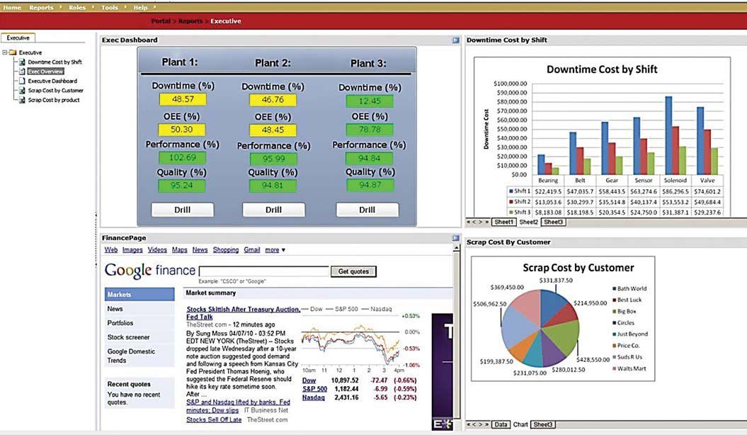
CONCLUSION
A common connected architecture across the process control and power control infrastructure creates a straightforward method for an organization to securely integrate and manage information flow across the entire connected enterprise.
Captured enterprise-wide data — starting from the most critical assets to the smallest shop-floor sensors — can provide the most relevant working data capital needed to deliver complete plant- and enterprise-wide automation and process efficiency. The true value of this enterprise-wide data lies not in the data itself, but in which analytics can be applied to the data. In this way, the raw information reveals areas where process and control transformation can be applied to identify points where power and process optimization can be employed.
This working data capital is easily displayed and
analyzed by those decision makers, at many levels of the enterprise, who can put it to best use. Using the most relevant interconnected technologies enables more efficient analysis, communication, and visualization of this valuable and scalable working data capital across the entire enterprise.
REFERENCES
D. C. Mazur, J. A. Kay, and K. D. Mazur, “Intelligent motor control, a definition and value add to process control,” in Industry Applications Society Annual Meeting, 2013 IEEE, 2013, pp. 1-7.
D. C. Mazur, “An Electrical Mine Monitoring System Utilizing the IEC 61850 Standard,” Doctor of Philosophy, Mining and Minerals, Virginia Polytechnic Institute and State University, 2013.
S. H. Horowitz and A. G. Phadke, Power System Relaying. John Wiley & Sons, 2008.
D. C. Mazur, R. D. Quint, and V. A. Centeno, “Time Synchronization of Automation Controllers for Power Applications,” IEEE Transactions on Industry Applications, vol. 50(1), January 2014, pp 25-32.
NETAWORLD • 73 THE FUTURE OF INTEGRATED POWER AND PROCESS AUTOMATION FEATURE
Figure 7: Process System Dashboard
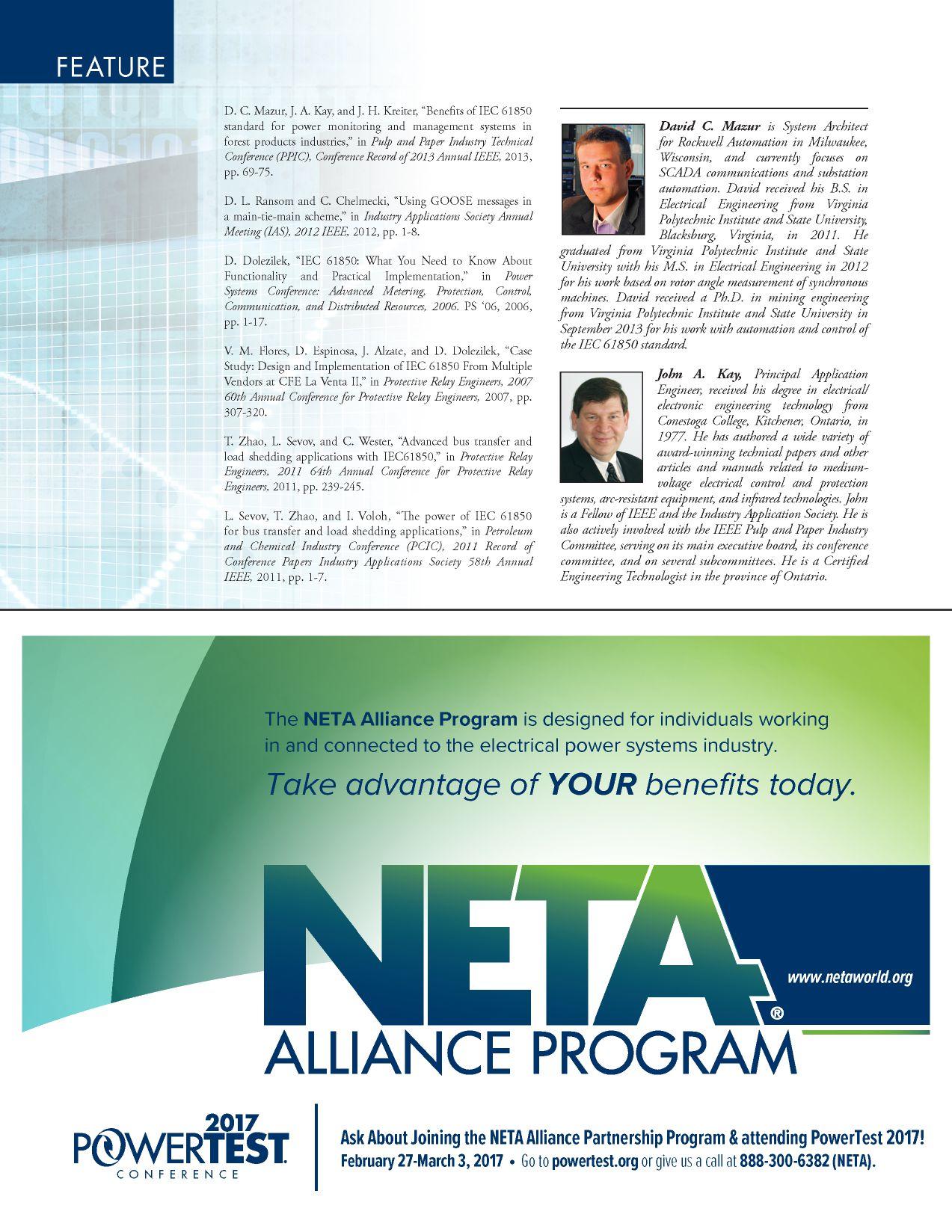
TWO NEW SELF-PACED TECHNICAL SEMINARS (SPTS)

*CTDs awarded when participant receives a passing score on the proficiency exam. Maintenance and Testing of Battery Systems Risk Assessment Techniques Using NFPA 70E: A Primer
Learn at your own pace. Advance your knowledge. Ask about continuing education. Earn CTD*Credits for NETA Level III and IV Technicians. Order online at: www.netaworld.org or call 888-300-6382 (NETA)

ADDITIONAL COURSES AVAILABLE

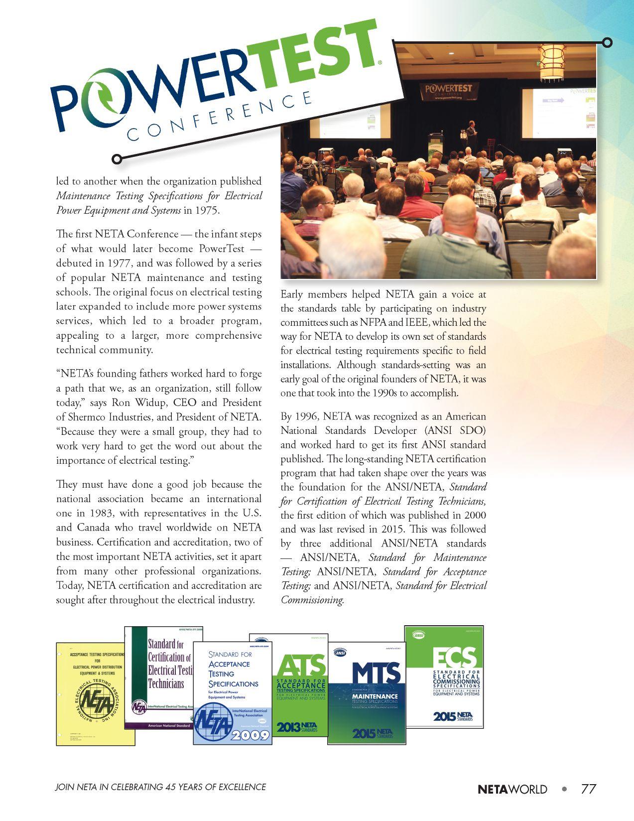
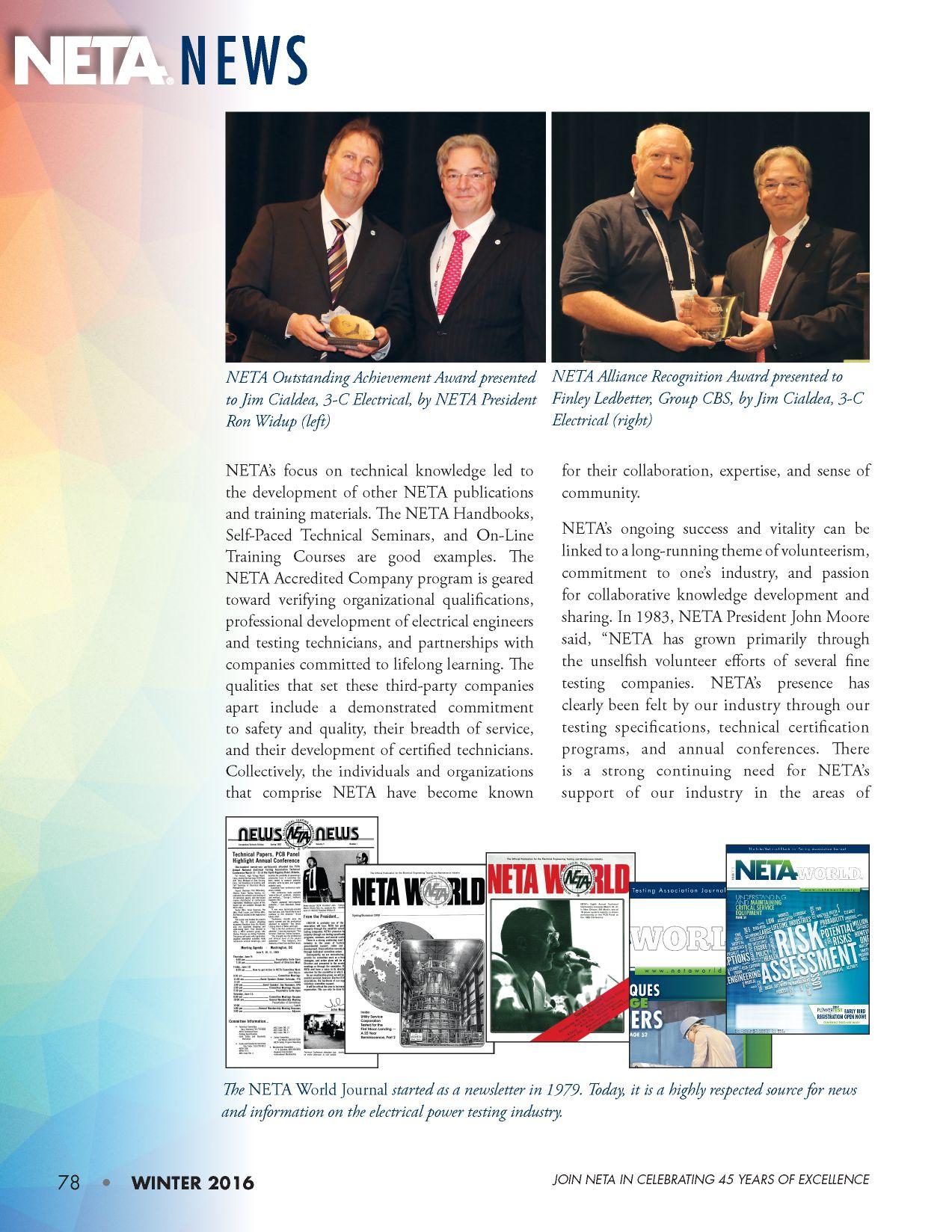
technical development, safety, governmental support, codes and standards, and market development. These activities can only be accomplished effectively through dedicated committee action. As our membership grows, we will be able to afford more outside services. However, the backbone of our organization will remain your voluntary committee support.”
Moore’s prediction rings true today. Commitment to safety and quality of life for its industry professionals led to the infrastructure that supports NETA’s global community today. Over the years, NETA volunteers have devoted themselves to a life of high achievement through serving others. In fact, this work-hard, play-hard group of professionals is known for traveling to help each other on the job site, jumping from the field to the committee table depending on the need.
“We are only where we are today because of the people who have remained the lifeblood of this association, people who wanted to be involved in something that would promote and strengthen their profession and keep its professionals safer,” says Missy Richard,




NETA’sExecutiveDirector.“Overthelast

NETA’s Executive Director. “Over the last 45 years, the early pioneers were followed by those who saw the importance of their work and dedicated themselves to continuing it. NETA is the pulse of this industry and thrives because of the many dedicated, busy volunteerswhotakethetimetobreathelife volunteers who take the time to breathe life into it every day.”
“The bond among NETA colleagues is very close,” says Mose Ramieh II, President of Power & Generation Testing, Inc., a CE Power Testing Company, who served as NETA President in 2011-2012. “The best thing about this organization is that there are so many people with mutual interests focused on the same goals. Even though we are competitors, we are friendly competitors who are happy to lend a hand if someone needs it.”
Perhaps Dave Huffman, President of Power Systems Testing, captures it best when he describes his peers as “heart-driven professionals aligned by the belief that good enough isn’t good enough.”

NETA’s 45th birthday belongs to them and to those who are following in their footsteps.
Please join your colleagues at NETA’s 45th Anniversary Celebration at PowerTest 2017, and watch for other exciting celebratory events leading up to and during PowerTest 2017.





JOIN NETA IN CELEBRATING 45 YEARS OF EXCELLENCE NETAWORLD • 79


TRIVIA CHALLENGE — SERIES 2
TEST YOUR INDUSTRY KNOWLEDGE
Note: Please submit answers by emailing neta@netaworld.org to be entered into the prize drawing at PowerTest 2017.
TRIVIA CHALLENGE #3
The Wright Meter
Do you know what this is? With a patent applied for on June 26, 1900, and patent approval on June 17, 1902, the patent application paperwork states: The liquid-indicator consists of a vessel of such form that liquid is put off from one part, hereinafter termed the reservoir, and is transferred by decantation to another part, hereinafter termed the receiver, in proportion to the angular movement or tilting of the said vessel.
Question:
The Wright Meter shown in the photo is a device used for:
1. Detecting pressure in inches of mercury, in Hg, within a building
2. Determining ambient temperature of a room
3. Determining maximum current attained on a load
4. Detecting psi limits of an industrial air supply
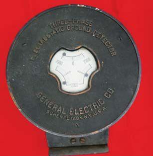
TRIVIACHALLENGE#4 TRIVIA CHALLENGE #4
AThree-PhaseElectrostaticGroundDetector A Three-Phase Electrostatic Ground Detector
The photo shows a three-phase electrostatic ground detector manufactured by General Electric.
Question:
What was the primary purpose of an electrostatic ground detector?
1. To trip primary circuit breakers in a ground fault
2. To measure dc ground currents from the main bus
3. To protect solid-state components from electrical static
4. To measure grounded conditions on polyphase lines
Photos and questions contributed by Shermco Industries
JOIN NETA IN CELEBRATING 45 YEARS OF EXCELLENCE 80 • WINTER 2016







Reflected
Shortedconductorsorboltedfaultsarelocalized Shorted conductors or bolted faults are localized by using Pulse Echo, also called Time Domain Reflectometry (TDR). The reflected pulse will be negative (Figure 6).

Since no gap value is associated with a shorted conductor, the fault will not arc or thump. Acoustic pinpointing will not be an option. A surge generator (thumper) can still be used for pinpointing if an electromagnetic impulse detector is used along with the surge generator.
Surge the cable with the surge generator. Track the surge pulse using an electromagnetic detector such as the Aquatronics SDAD. Strong signals will be detected up to the true fault location. Since the entire surge energy is lost at the fault, weak or no signal will be detected beyond the fault.
OPEN CONDUCTOR (BLOW-OUT)
Open conductor or blow-out (Figure 7 and Figure 8) occurs due to a high fault current, a dig-in, or a failed splice (Figure 9). An insulationresistance test may indicate a high resistance value if the fault and ground are dry. If the ground is moist, the resistance measurement may show a moderate to low resistance value at the fault. If the phase conductor or concentric burns back, the gap distance may be excessive and may not arc or thump; refer to fault position A. Testing from the other end of the cable may render better results, as shown in position B.
During a surge discharge (thump), the voltmeter will give a weak drop and will never approach zero


INDUSTRYTOPICS INDUSTRY TOPICS 84 •WINTER • WINTER 2016 CABLE FAULT PROFILES AND TROUBLESHOOTING GUIDE
Figure 5: Ammeter Reading — Shorted Fault
Figure 4: Voltmeter Reading — Shorted Fault
Figure 6: TDR Showing Negative
Pulse
Figure 7: Open Conductor (Blow-Out)
Figure 8: Open Conductor — Circuit Equivalent
Figure 9: Open Conductor — Cable

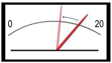
10:
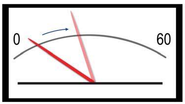
11:

12 represents the before-surge TDR signature; the dotted line represents the after-surge signature.
As stated previously, an open conductor or blow-out will appear as a positive reflection on a TDR. If the gap distance between the conductor and concentric has not burned back, the fault image will invert or reflect negative when the arc reflection test is performed, as seen in the dotted TDR trace (Figure 13). This also indicates good arc or thump condition.

SPLICE FAILURE
A failed cable splice (Figure 14 and Figure 16) can be a difficult fault to identify and locate. Since the physical distance between the phase conductor and concentric is increased, the gap distance is typically excessive (Figure 15). This creates a fault that may not arc or thump.
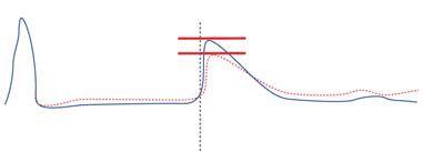
Figure 12: TDR - Open Conductor, Excessive Gap Value

13: TDR — Open Conductor Showing Good Thump Condition
volts (Fault A, Figure 10). Fault B will give a strong drop in the voltmeter, practically reaching zero; the ammeter will give a weak kick forward on Fault A (Figure 11). Fault B will give a strong kick forward.
An open conductor or blow-out will appear as a positive reflection on a Time Domain Reflectometer (TDR) as shown by the solid TDR signature in Figure 12. If the conductor or concentric is burned back and the gap value is excessive, the fault may not arc (thump). This will result in little or no change in the TDR signature when the arc reflection test, which uses both a surge generator and a TDR connected to the cable, is performed. The solid signature shown in Figure
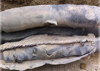


NETAWORLD • 85 CABLE FAULT PROFILES AND TROUBLESHOOTING GUIDE INDUSTRYTOPICS INDUSTRY TOPICS
Figure
Voltmeter Reading — Conductor (Fault A)
Figure
Ammeter Reading — Open Conductor (Fault A)
Figure
Figure 14: Splice Failure
Figure 15: Splice Failure — Circuit Equivalent
Figure 16: Splice Failure — Cable
INDUSTRY TOPICS

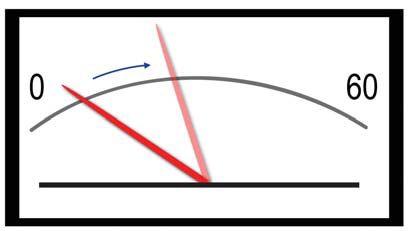
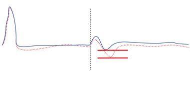
During a surge discharge (thump), the voltmeter will give a weak drop and will never approach zero volts (Figure 17). The fault may not arc or break down on every discharge cycle. During a proof test, the cable may hold voltage for a brief period before flashing over. During the thump, the ammeter will give a weak kick forward (Figure 18). Burn current may be necessary to reduce the fault resistance and gap distance.
A splice failure is very similar to an open conductor (blow-out) in that the resistance and gap value at the fault will typically be very high. The excessive gap value may make it difficult to arc or thump the cable. The fault may not arc on every discharge cycle. Applying burn-down current may be required to improve break-down performance.
The time domain reflectometer pattern for a splice is a small, positive reflection immediately followed by a small negative reflection (Figure 19). If water is present within the splice, the negative reflection will typically be more pronounced.
When the arc reflection test is performed, the signature of the splice may change slightly, becoming more pronounced on the negative as shown in the dotted signature above. This indicates that during the surge or thump, the resistance of the splice is becoming lower and a thump is occurring. If the gap between the conductor and concentric is too excessive, the arc reflection test will show no change in the TDR signature. This indicates that no thump is occurring and burn-down may be required.
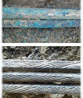


CORRODED OR OPEN CONCENTRIC
WARNING: Corroded or open concentric will present several issues during a fault locate. The concentric is designed to carry fault current. If the integrity of the concentric is jeopardized due to open strands or high levels of corrosion (Figure 20 and Figure 22), the concentric may no longer provide the lowest resistance path back to the surge generator (Figure 21).
CABLE FAULT PROFILES AND TROUBLESHOOTING GUIDE 86 • WINTER 2016
Figure 17: Voltmeter Reading — Splice Failure
Figure 18: Ammeter Reading — Splice Failure
Figure 19: TDR — Splice Failure
Figure 22: Corroded/Open Concentric — Cable
Figure 21: Corroded/Open Concentric — Circuit Equivalent
Figure 20: Corroded or Open Concentric
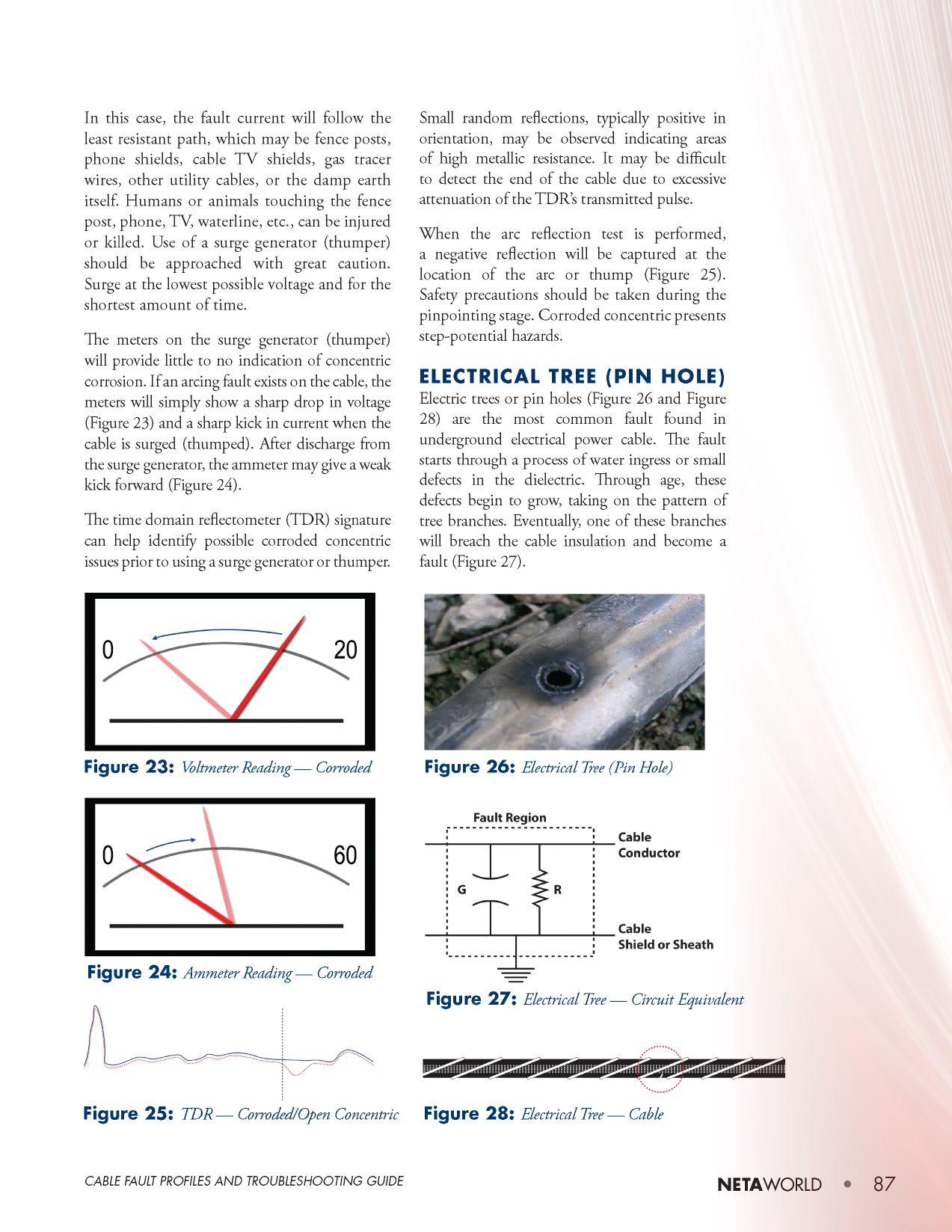

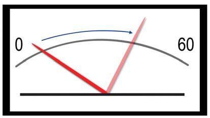
"THE DISCIPLINE TO FOLLOW STEP-BY-STEP PROCEDURES IS KEY TO SAVING TIME DURING FAULT LOCATION."
After discharge from the surge generator (thumper), the voltmeter will give a strong kick back, nearly reaching zero volts (Figure 29), while the ammeter will give a strong kick forward (Figure 30).
The time domain reflectometer signature will first show the end of the cable under test. The cable end will be seen as a positive reflection indicating an open. Refer to the signature shown with a solid line in Figure 31. After the arc reflection test, a negative reflection will be captured from the point of the fault. The fault will be shown as a negative reflection indicating the short circuit created by the arc (thump).
CONCLUSION
Although many faults exhibit similar properties, each one is unique. A cable fault-locating technique or instrument that works well in one situation may be completely useless in another. Understanding the general cable fault profiles and the intended design and function of the test equipment will serve well when the pressure is on.
A skilled golfer must analyze a situation before
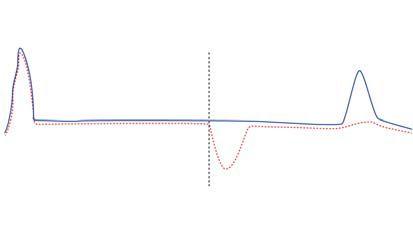
reaching into his or her bag and selecting a club. A variety of clubs — and knowledge of their performance — allows the golfer to select the most efficient tool for the job. The same is true for a skilled cable fault locator. As in diagnosing any complex problem, following a step-by-step procedure will help in arriving at the solution — or, in this case, locating the cable fault efficiently.

been active in the field of electrical power and telecommunications for over 30 years. During his career, he has developed numerous training aids and training guides, and has conducted domestic and international seminars. Thomas supports a wide range of electrical and telecommunication maintenance application disciplines. He has been directly involved in supporting test and measurement equipment for over 20 years and is considered an industry expert in application disciplines, including battery and dc systems testing and maintenance, medium- and high-voltage cables, ground testing, and partial discharge analysis. He holds a bachelor of science degree in electrical engineering (BSEE) from Thomas Edison University in Trenton, New Jersey.
INDUSTRY TOPICS CABLE FAULT PROFILES AND TROUBLESHOOTING GUIDE 88 • WINTER 2016
Thomas D. Sandri is a Senior Technical Instructor at Shermco Industries. He has
Figure 29: Voltmeter Reading — Electrical Tree
Figure 31: TDR — Electrical Tree
Figure 30: Ammeter Reading — Electrical Tree


Up Your Production And Stay In The Game! PQ Analyzers with Remote Wireless Communications 732.287.3680 1000 New Durham Road Edison, New Jersey 08817 Control your Dranetz HDPQ from your smartphone, tablet, or computer! sales@dranetz.com www.dranetz.com ® ® A Company Complete Breakers s Trip Units ts Electric Operators rs Shunt trips/UVRs Rs All Factory New w



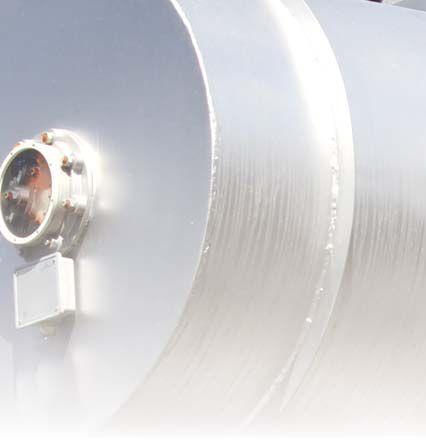

Gatevalve. Gate valve. The gate valve (Figure 2) can provide a full-bore opening through the valve to allow maximum oil surface exposure or insertion of a probe. A gate in the center of the valve body moves up and down on its vertical axis as the handle is rotated. As the gate lifts from its closed position, a small opening in the base of the valve cavity appears. It is oriented horizontally so that it allows the liquid to move, under pressure, and to compress the air in the valve cavity. When the valve outlet is blocked or connected to a closed sampling system, the pressurized air moves back through the valve into the transformer.
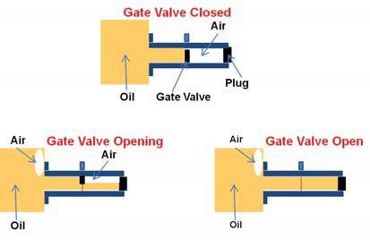
Figure 2: These sketches illustrate the danger of a gate valve when used as a transformer drain valve because when the valve outlet is blocked or connected to a closed sampling system, the trapped air moves back through the valve into the transformer.
Ball Valve. The ball valve (Figure 3) also provides a full-bore opening. It requires a 90-degree handle rotation between fully open and closed. A ball with a hole through it sits in the center of the valve body and rotates on its vertical axis as the handle is moved. When the ball starts to rotate from its closed position, a small opening in the shape of a football appears. It is oriented vertically, allowing the liquid to move under pressure, displacing the air in the valve cavity. When the output is blocked, the pressurized air in the valve moves back through the opening into the transformer.

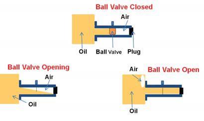
Figure 3: These sketches illustrate the danger of using a ball valve as a transformer drain valve because when the output is blocked, the pressurized air in the valve moves back through the opening into the transformer.
Globe Valve. The globe valve (Figure 4) provides a restricted flow path, resulting in turbulent flow. A valve disk sits in a valve seat in the center of the valve body and moves up and down on its vertical axis as the handle is rotated, regulating the liquid flow rate. As the valve disk lifts from its closed position, it allows the liquid to move vertically, under pressure, and to compress the air in the valve cavity. With an unrestricted opening, the air will be forced out of the valve along with the liquid. When the valve outlet is blocked (or restricted), the air is trapped in the valve cavity and cannot move back into the transformer.

Figure 4: There is minimal danger with a globe valve used as transformer drain valve because the trapped air floats above the liquid and remains in the valve.

INDUSTRYTOPICS INDUSTRY TOPICS 92 • WINTER 2016 TRANFORMER LIQUID SAMPLING DANGERS: WHERE DOES THE AIR GO?
TEST PLAN
TJ|H2b and OMICRON have both conducted tests using the various valves mounted on models of a transformer tank. Test protocols were developed to address:
• Will air enter the tank when the valve is opened and the valve outlet:
a. Is sealed by a pipe plug?
b. Has a sampling port with the connected tubing free of restrictions?
c. Is closed by a second valve in the sampling equipment?
• Can one safely test for transformer tank positive pressure using the documented procedures?
• Does pressure level inside the tank affect the results?
• Do procedures for installing monitoring products prevent air ingress?
SAMPLING EXPERIMENTAL SETUP
A pressure chamber was built to test a variety of sampling conditions. Gate valves, globe valves, and ball valves were connected to the chamber filled with water and air for these studies. Pressure in the chamber was varied using fittings on the top. The authors chose to use water rather than an insulating liquid primarily for the convenience and safety of the experiments. Each of the hundreds of trials required that the test assembly be disconnected and all of the liquid drained out before another trial could be started. Since water has a viscosity of 1 cSt and mineral (insulating) oil measures at 2.3 @100C, 9.6 @ 40C and 19 @15C, using water has no affect on the outcome of these experiments. (Note: SAE 10 motor oil has a viscosity of 85 – 140 cSt, and honey is 10,000 cSt.)
The different configurations of sampling equipment studied can be broadly categorized into restricted and unrestricted groups.
An oil sampling procedure may include a step to open a drain valve while there is a closed system component (or just a pipe plug) attached to the outlet side of the valve (restricted), or a different case where the sampling equipment does not close the outlet (unrestricted). Chamber air pressures used
for the trials in each study ranged from -100KPa to 175KPa. As each valve was opened, the entire assembly was observed for bubble ingress (Figure 5).

Figure 5: As the valve was opened during each of the test trials, the entire assembly was observed for bubble ingress.
The results of the trials are summarized in Table 1.
Table 1: Results for Cases Where Air Cannot Escape (Restricted) and Where Air Can Escape (Unrestricted).
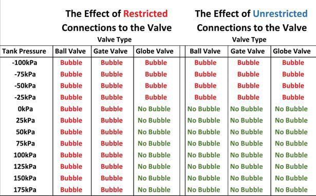
EVALUATION OF THE TEST RESULTS
A review of valve descriptions shows that each valve type presents a different degree of opportunity for air ingress under the tested scenarios. The ball valve loses all restraint at the valve face the moment it is opened. The gate valve loses restraint at the valve face by degree as the gate is raised. The globe valve uses buoyant forces provided by the liquid to maintain restraint as the valve is opened.
NETAWORLD • 93 INDUSTRY TOPICS TRANFORMER LIQUID SAMPLING DANGERS: WHERE DOES THE AIR GO?
• Sampling with an unrestricted valve outlet. With positive pressure inside the main tank, and with only unrestricted or open-vented components of sampling equipment on the drain valve, no bubbles will enter when the valve is opened.
• Sampling with a closed valve in the sampling fittings or tubing. Some sampling equipment components may completely close the airspace external to the valve. When sampled through a ball or gate valve, air is forced into the transformer tank, even against positive tank pressure. The procedure may need modification. As seen in Table 1, only the globe valve will allow this procedure without bubble ingress.
• Sampling with vacuum or negative gauge pressure in the transformer tank. There is no way to safely sample a transformer while it has negative gauge pressure. The tests demonstrated that with any sampling procedure, and with any valve type, for cases with negative gauge pressures, air will always enter the transformer when the drain valve is opened.
TESTING FOR VACUUM IN THE TRANSFORMER TANK
Most sampling procedures include a test to verify positive pressure in the tank before sampling, based on ASTM D923-07, Standard Practices for Sampling Electrical Insulating Liquids. The objective is to ensure that air will not enter the transformer during the sampling process. However, if a negative pressure is present in the tank at the valve, air bubbles will enter the tank, and the condition to be avoided is actually caused by following this testing procedure.
The authors recommend that the test for positive pressure (ASTM D923-07, Clause 7.2) be modified — or eliminated — to prevent air from entering the transformer with a negative pressure at the valve.
CONCERNS ABOUT VALVE TYPE
If someone attempts to take an oil sample from a ball or gate valve using standard techniques and equipment, air bubbles could very likely enter the transformer. If you must sample from one, carefully review the procedure to ensure there is a path for the air to escape when the drain valve is opened.
The globe drain valve was required by IEEE standards until the 1980s, when some customers started to require a full-bore-opening valve to accommodate monitoring devices. Since many manufacturers’ standard drain valve is still the globe valve, with a positive pressure inside the tank, most transformers will not have these issues of air ingress.
OIL PRESERVATION SYSTEM AND TANK PRESSURE
Test results show that we must address verification of the tank pressure. Therefore, let’s review the three oil preservation systems currently used to allow volume for the expansion and contraction of the transformer oil.
1. The sealed tank design has a blanket of nitrogen above the transformer oil. This design has a pressure/vacuum gauge and a pressure/vacuum bleeder to regulate the pressure inside the tank to a range of – 8 to +10 psi. To ensure safe sampling, rely on the pressure gauges.
2. The inert gas pressure system uses a nitrogen bottle to supply pressure to the nitrogen blanket. Through adjustable regulators, it maintains the pressure in a range of approximately 3-8 psi. Alarms alert to high and low tank pressure and for low nitrogen bottle pressure. If the system is functioning, there will be a pressure above the oil.
3. The conservator tank mounts above the main tank allowing expansion of the oil. Usually, a rubber bag separates the
94 • WINTER 2016 INDUSTRY TOPICS TRANFORMER LIQUID SAMPLING DANGERS: WHERE DOES THE AIR GO?


oil from the oxygen and moisture in the the atmosphere. With normal oil flow in and out of the conservator, static head pressure at the sampling valve is always present.
If you cannot rely on the readings of the rely the gauges and regulators, or a chance exists of a negative pressure in the main tank, the safest main recommendation is to not take a sample.

INSTALLATION OF MONITORING SYSTEM COMPONENTS


Similar tests confirm that installation procedures for some oil-contact monitoring products produce the same restricted case when the drain valve is opened, allowing ingress of air bubbles. Before installing a monitoring system on an energized transformer, investigate the possible results of the manufacturer’s installation procedures.
CONCLUSIONS
Sampling should not be attempted if there is a negative gauge pressure inside the tank. The authors recommend that organizations publishing a sampling procedure should study this article, conduct their own experiments, and revise their sampling procedures as necessary. Even with a valid sampling procedure, a simple error of opening the wrong valve first could introduceairbubblesintotheoilwithserious introduce air bubbles into the oil with serious consequences.

TheauthorsrecommendthatrelevantIEEE The authors recommend that relevant IEEE standards should again require globe valves for drain valves as well as for any other valve specified for sampling access.
The authors urge all transformer owners, operators, and service contractors to be cautious when performing oil sampling or installing monitoring devices on valves of energized transformers, and to review their existing procedures. Each worker should:
• Beawareoftheconditionsthatcanleadto Be aware of the conditions that can lead to air entering a transformer.


• Be able to identify the type of sampling valve.

• Know how to determine the pressure inside the main tank.

• Take all precautions to ensure that sampling can be done safely.
For many workers, this will require new training, using a modified training program and revised sampling procedures.


Donald W. Platts is a Senior Engineer with OMICRON Electronics Corp., providing technical support and training related to transformer applications and testing. He is the past Chair of the IEEE PES Transformers Committee.
Dave Hanson is the President and CEO of TJ|H2b Analytical Services, Inc. He has been active in the field of insulating materials testing since 1978 and has been involved with the development of test methods and diagnostic criteria for highvoltage electric equipment. Dave’s expertise extends to transformers, tap-changers, bushings, and gas- and oil-filled circuit breakers.



NETAWORLD • 95 TRANFORMERLIQUIDSAMPLINGDANGERS:WHEREDOESTHEAIRGO? TRANFORMER LIQUID SAMPLING DANGERS: WHERE DOES THE AIR GO? INDUSTRYTOPICS INDUSTRY TOPICS



TEST EQUIPMENT: MANAGING THE HIDDEN DEFECTS
BY ASHLEY HARKNESS, Electrical Reliability Services


You are testing a modern, digital protective relay. Your testing device is a modern, top-of-the-line, computer-driven, digital relay test set. The reliability of the protected power system is on the line. You think that your test equipment is at 100 percent. Then, in the middle of the job, it fails. Could this have been avoided? Perhaps it could. In this article, we will consider test equipment condition issues, steps to reduce their unplanned outage, and ways of managing test equipment’s hidden effects.
THE CHALLENGE OF REAL LIFE
In the real-life rush to get to the job, do we give our test equipment a good look over? NFPA70E requires handheld test equipment to be inspected before use. The reason is simple: If there are broken test leads, damaged probes, or cracked meters, you might have a serious safety issue on your hands. The same goes for more costly and important capital equipment.
Many of the newer test equipment devices are highly reliable, computer-driven instruments. They are designed to perform complex testing such as on protective relays. Left undisturbed on a lab bench in a clean, warm, safe environment, they are expected to perform well for many years. However, is that how a testing company actually
usesthem?Istheactualfieldenvironmentsafe uses them? Is the actual field environment safe and warm? Perhaps not.
A typical field scenario might go like this: Test equipment is manhandled into the back of a bouncing pickup truck; driven to the job site over rough construction roads; connected to a noisy, erratic generator; and carried from location-to-location or pushed on a stiffwheeled, jolting cart. This environment can really shake things up!

After over 40 years repairing test equipment, I have learned a few simple rules: Shake up the equipment and it will fall apart. Loose screws and hardware, disconnected cable assemblies, broken switches, jammed relays, and broken internal wires are very common; in fact, 95 percent of repairs are mechanical in nature.


• TEST EQUIPMENT: MANAGING THE HIDDEN DEFECTS NEETTA AWO W R RLD 9 97 7
INDUSTRYTOPICS INDUSTRY TOPICS

• Does the calibration service test each function of the test equipment? In some cases, the proper operation of mechanical switches and lamps is as important as the accuracy of the metering. This is especially true for test sets that test circuit breaker trip units.
Communication is the key. If they do not know your needs, will this service be provided? Probably not.
RECORD KEEPING
We know from wide experience in the electrical maintenance and testing industry that all systems, electronic and mechanical, will age and degrade over time. Similarly, we need to track changes in our test equipment.
• Do you keep the maintenance history of your test equipment? Repair orders and calibration certificates are critical. With them, the insight to the future serviceability of equipment can be revealed. When more repairs are needed or increasing close-to- or out-of-tolerance conditions are found, a replacement decision must be made. Review the records on a frequent basis.
• Too often, we continue to use obsolete test equipment long after its day is done. Yes, I have a beloved, old-friend analog meter, too. And, in some rare situations, it is the correct tool. However, we need to focus on technology changes. Sometimes, that means sending our old friends out to pasture. Records will give us the information we need to make even these tough decisions. Say goodbye, and purchase new equipment.
• If new technology requires more training, keep records. OSHA clearly
states that if there is no paperwork, i.e., records, it did not happen. No records may lead to increased liability.
Records can be easily kept electronically. They may also be required by clients as part of a bid package. Attention to test-equipment recordkeeping is an important part of the service that we, as testing companies, provide to our clients.
CONCLUSION
Our ability to continue providing successful service to our clients depends on how we maintain and service our tools. Improving testequipment reliability is a matter of observation and communication. Make sure to give your test equipment the inspections it needs. Make sure to communicate your expectations and needs to company users and service vendors. Keep good records. Take proactive steps. It is the best way to manage the hidden defects of your test equipment.

Ashley Harkness, Jr. is an Electrical System Specialist at Electrical Reliability Services. He joined the company (then known as Electro-Test, Inc.) in 1982. Until 2013, his duties included operation and management of the internal calibration laboratory program. During these years, he also managed the manufacturing department making specialized test equipment and led specialized electrical projects including European Community Machinery and EMC Electromagnetic Compatibility Directive testing, basic insulation level (BIL) impulse testing, process and control instrumentation acceptance and testing, electrical equipment forensic investigations, and electrical product safety testing. In 2005, Ashley became manager of the ERS medium-voltage systems (switchgear and cables) on/off line partial discharge/cable testing program. In 2014, his assignment changed to NFPA 70E trainer for ERS client organizations and internal training.
NETAWORLD • 99 TEST EQUIPMENT: MANAGING THE HIDDEN DEFECTS INDUSTRY TOPICS
THAT’S THE CRITICAL DIFFERENCE.
NETA certified experts at Electrical Reliability Services will keep you in perfect balance. To ensure the reliability of your electrical power, you have to balance the need to reduce maintenance costs with the need to perform regular maintenance. Only the team from Electrical Reliability Services delivers cost-effective services and system expertise to keep you up and running 24/7.





THE EXPERTS IN ELECTRICAL RELIABILITY
Comprehensive Electrical Testing and Maintenance

Commissioning and Startup Services
Engineering Services Power System and Coordination Studies
FAILURE IS NOT AN OPTION.
Predictive and Preventive Maintenance
Partial Discharge Testing and Monitoring 24/7 Emergency Service
Ensuring the reliability of your electrical distribution system.


As the leading independent electrical testing, maintenance, and engineering service company, you can rely on Emerson’s High Voltage Maintenance to exceed your electrical equipment performance goals. From testing for problems that could disable your system, to complete turnaround execution, you’ll quickly understand how we are your single source solution for all of your electrical reliability needs. With a service geography across the Midwest and Eastern Seaboards, our service team puts experienced professionals where and when you need them.


For more information: High Voltage Maintenance (866) HVM-TEAM CHOOSE BETWEEN KEEPING MAINTENANCE COSTS DOWN AND KEEPING UP WITH PRODUCTION DEMAND…OR DO BOTH.
Emerson, Business-Critical Continuity, Emerson Network Power and the Emerson and Double Helix Design are trademarks and service marks of Emerson Electric Co. ElectricalReliability.com



INJECTION TESTING INNOVATIONS IN
BY YIER TOH, Megger
The primary current injection test is the only comprehensive circuit breaker test that checks the correct operation of the whole protection system — including the current sensors, trip unit, tripping mechanism, and internal wiring and connections. In the U.S., the National Electrical Manufacturers Association (NEMA) and the Electric Power Research Institute’s (EPRI) Nuclear Maintenance Applications Center (NMAC) provide recommendations and guidelines on the use of primary current injection testing for the inspection and preventative maintenance of molded-case circuit breakers in their respective publications — NEMA AB 4 and NMAC Circuit Breaker Maintenance Volume 3.
However, primary current injection testing is often passed over in favor of secondary injection testing due to the practical difficulties of performing the test and the unwieldiness of the test equipment. Fortunately, modern primary current injection test systems have vastly improved, and it is time to take another look at the new generation of smaller and smarter instruments that make performing this essential test much easier.
REDUCED SIZE AND WEIGHT
Test sets for primary current injection are built to supply a lot of current, from 100 A up to 60,000 A. Equipment capable of delivering these currents has traditionally been massive, several-hundred-pound machines, but newer


test sets on the lower end of the spectrum have become increasingly smaller and lighter. Modern primary current injection systems have eliminated the large and heavy variable autotransformers and replaced them with synthetic chopping technology. Besides reducing the size and weight, this new technology also allows the voltage on the output transformer to be digitally controlled, conferring additional benefits during testing. A smaller unit that takes up less space can be placed closer to the test specimen, reducing the length of test leads and the power required and further reducing the overall footprint of the whole test setup. Multiple smaller units can often be connected together and synchronized to produce a higher output.
INNOVATIONS IN PRIMARY CURRENT INJECTION TESTING ADVANCEMENTS IN TECHNOLOGY
102 • WINTER 2016
ADVANCEMENTS
C CUUR

CURRENT DECAY CORRECTION
AUTOMATIC TEST REPORTS

W Whhen
teessting

h heat u will re


When performing primary current injection testing, the test leads and test specimen will heat up due to the high currents applied. This will result in current decay unless the operator manually intervenes. Manual intervention can cause inconsistent test results because even the same operator cannot perfectly replicate their every action and decision for every test they perform. Newer systems eliminate these problems by automatically regulating current output to compensate for test sample heating or changing loads. This ensures a constant current for the full duration of the test.
REDUCED PREHEATING
Due to the high currents used and the time it takes to manually set up and adjust test parameters, primary current injection tests tend to preheat the test specimen. This effect can trip breakers even before actual testing has commenced. Work-arounds are available — test engineers can perform the setup very quickly to minimize heating, or they can prevent tripping by isolating the trip circuits — but neither of these options is convenient. Newer test sets allow the operator to enter a predetermined current, and the system will automatically generate and regulate the requested current level.
AUTOMATED DC OFFSET ELIMINATION
A common problem when testing instantaneous trips on low-voltage circuit breakers is dc offset. A standard high-current test system will commonly cause dc offset in the initial two to four cycles of an output waveform. This dc offset will cause circuit breakers to trip at incorrect current amplitudes, providing incorrect results. A new feature available on the latest primary current injection test sets is zero-crossover synchronization. The system automatically adjusts the output firing angle so that the current is only turned on at a zero-crossing point. This eliminates dc offset effects and also ensures that the test is repeatable because the operator does not need to manually calculate and adjust the firing angle for different loads and circuit breakers.
An important but often overlooked feature when selecting a test set is the ease of generating and managing test reports. Modern primary current injection testing software includes automatic report generation and archiving. This not only saves time after testing, but also ensures that accurate records are maintained for compliance audits. Historical results stored in a database can be accessed at an instant and plotted to reveal trends that can be critical to decision making.
CONCLUSION
Primary current injection testing is one of the most valuable tests that can be performed on power systems because it takes into account the performance of every component in the protection circuit. The whole system is evaluated under conditions that most closely match the real-world operating environment, making the results more reliable than those obtained by secondary injection testing. In the past, primary current injection testing has been avoided due to the inconvenience caused by the size and weight of the equipment required and also because of the various limitations of previous generation test systems.
Fortunately, technological advancements over the last few years have made the latest primary current injection test equipment much more user friendly and much less back-breaking, so they are worth exploring.

Yier Toh received her bachelor’s Degree in Electrical & Electronic Engineering from the University of Western Australia. She started her career as a biomedical researcher and has coauthored several papers in neuroscience. Yier went on to become a Sales Engineer with a scientific imaging company, advising scientists on the best techniques for 3D and 4D image visualization and analysis. After completing her MBA, Yier joined Megger as a Marketing Engineer, creating technical content that helps customers understand the latest testing technology and industry best practices.


TECHNOLOGY NETAWORLD • 103 INNOVATIONS IN PRIMARY CURRENT INJECTION TESTING
IN
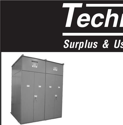







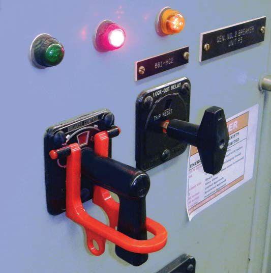
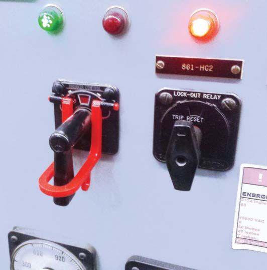

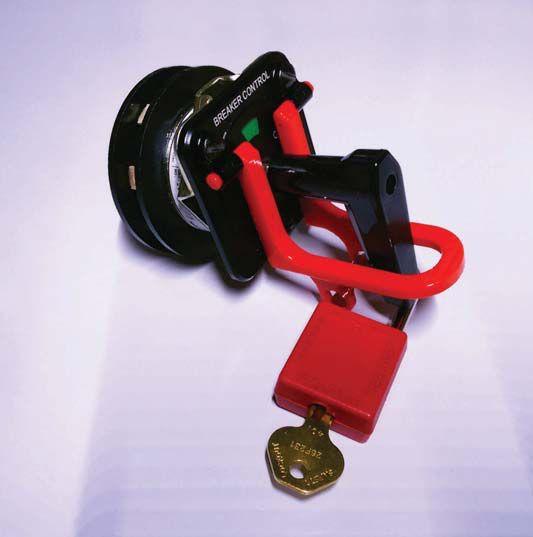
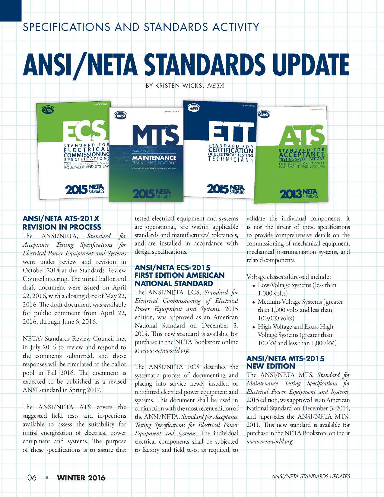





ANSWERS


No.116 No. 116

ANSWERS

1. a. The two standards that reference the interconnection of smart devices within substations are IEC 61850, Power Utility Automation and IEEE C37.94, IEEE Standard for N Times 64 Kilobit Per Second Optical Fiber Interfaces Between Teleprotection and Multiplexer Equipment.


4. There are five primary functions for a substation automation system:
a. Power flow measurement and analysis
b. Energy demand control
c. Transformer load management
d. Operational planning

2. d. The correct choice is Intelligent Electronic Devices. These devices communicate between each other. They are typically microprocessor-based and control other devices such as circuit breakers, transformers, and capacitor banks.
3. b. Optimize generation with the most economical fuel consumption. It’s all about the money. A bit off-topic, but still relevant, PMS ensures the greatest output for the least fuel used.
e. Energy scheduling
REFERENCES
Mukherjee, A. “Process Automation versus Power System Automation,” International Journal of Scientific & Engineering Research, Volume 4, Issue 10, October 2013.
NFPA Disclaimer: Although Jim White is a member of the NFPA Technical Committee for both NFPA 70E, Standard for Electrical Safety in the Workplace and NFPA 70B, Recommended Practice for Electrical Equipment Maintenance,”the views and opinions expressed in this message are purely the author’s and shall not be considered an official position of the NFPA or any of its technical committees and shall not be considered to be, nor be relied upon as, a formal interpretation or promotion of the NFPA. Readers are encouraged to refer to the entire text of all referenced documents.
TECH QUIZ ANSWERS
TECHQUIZ
110 • WINTER 2016


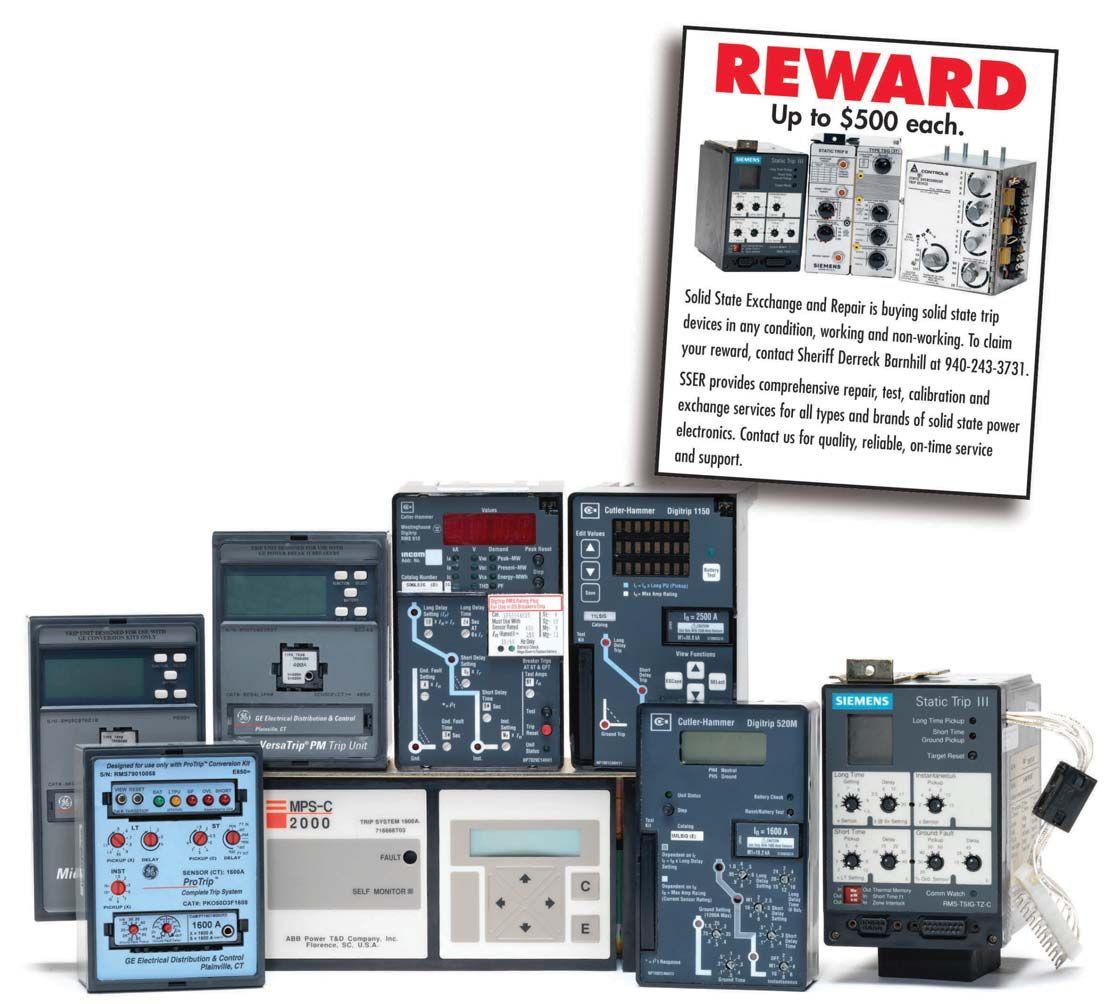
We Buy, Sell, Trade, Calibrate, Repair
Featuring quality, reliable, on-time service and support for all brands and types of solid state power electronics.
Power electronics are our business
Let us suppoort you with our quality repair, calibration and servicing of your solid state equipment. We also buy, sell and trade:
•Communications devices for power equipment
•Protective relays
•Circuit breaker trip devices
•Motor overload relays
•Rating plugs
4701 Spartan Drive • Denton, TX 76207 (877-874-7349) • Phone: 940-243-3731 • Fax: 940-387-8277 Email: info@solidstaterepair.com • Web: www.solidstaterepair.com
“SOLID STATE” INDUSTRIAL ELECTRONICS “SOLID STATE” INDUSTRIAL ELECTRONICS Toll Free 877-TRIP-FIX NOWRENTING TESTEQUIPMENT

NETA ACCREDITED COMPANIES Setting the
A&F Electrical Testing, Inc.
80 Lake Ave. South, Ste. 10 Nesconset, NY 11767 (631) 584-5625 Fax: (631) 584-5720 kchilton@afelectricaltesting.com www.afelectricaltesting.com
Kevin Chilton
A&F Electrical Testing, Inc.
80 Broad St. 5th Floor
New York, NY 10004 (631) 584-5625 Fax: (631) 584-5720 afelectricaltesting@afelectricaltesting.com
Florence Chilton
ABM Electrical Power Solutions
3602 East Southern Ave., Ste. 1 Phoenix, AZ 85040 (602) 722-2423 www.ABM.com
Doug Bukowski
ABM Electrical Power Solutions
9800 E. Geddes Avenue, Unit A-150 Englewood, CO 80112 (303) 524-6560 Fax: (303) 524-6581
Brian Smith
ABM Electrical Power Solutions
2142 Rheem Drive Pleasanton, CA 94588 (408) 466-6920
John Marvulli
ABM Electrical Power Solutions
3940 Ruffin Rd., Ste. C San Diego, CA 92123 (858) 754-7963
william.mckenzie@abm.com
William McKenzie
ABM Electrical Power Solutions
6280 South Valley View Blvd., Ste. 618 Las Vegas, NV 89118 (602) 300-2188 Fax: (602) 437-3894
Jason Black
ABM Electrical Power Solutions
814 Greenbrier Circle, Ste. E Chesapeake, VA 23320 (757) 548-5690 Fax: (757) 548-5417
Mark Anthony Gaughan, III
ABM Electrical Power Solutions
3700 Commerce Dr. #901-903 Baltimore, MD 21227 (410) 247-3300 Fax: (410) 247-0900
Bill Hartman
ABM Electrical Power Solutions
5809 Departure Dr., Ste. 104 Raleigh, NC 27616 (919) 877-1008 Fax: (919) 501-7492
Rob Parton
ABM Electrical Power Solutions
317 Commerce Park Dr. Cranberry Township, PA 16066-6427 (724) 772-4638 Fax: (724) 772-6003
christopher.smith@abm.com
Christopher Smith
ABM Electrical Power Solutions
4390 Parliament Place, Ste. S Lanham, MD 20706 (301) 967-3500 Fax: (301) 735-8953
Frank Ceci
ABM Electrical Power Solutions
3600 Woodpark Blvd., Suite G Charlotte, NC 28206 (704) 273-6257 Fax: (704) 598-9812 ernest.goins@abm.com
Ernest Goins
ABM Electrical Power Solutions
720 S. Rochester Ave., Suite A Ontario, CA 91761 (800) 597-1225 Fax: (909) 937-6798
Mike Bivens
Absolute Testing Services 6829 Guhn Rd. Houston, TX 77040 (832) 467-4446 Fax: (713) 849-3885 rgamble@absolutetesting.com www.absolutetesting.com
Richard Gamble
Accessible Consulting Engineers, Inc. 1269 Pomona Rd., Ste. 111 Corona, CA 92882 (951) 808-1040 info@acetesting.com www.acetesting.com Iraj Nasrolahi
Advanced Testing Systems 15 Trowbridge Dr. Bethel, CT 06801 (203) 743-2001 Fax: (203) 743-2325 pmaccarthy@advtest.com www.advtest.com Pat MacCarthy
American Electrical Testing Co., Inc. 25 Forbes Blvd., Ste. 1 Foxboro, MA 02035 (781) 821-0121 Fax: (781) 821-0771 sblizard@aetco.us www.99aetco.com
Scott A. Blizard
American Electrical Testing Co., Inc. 34 Clover Dr. South Windsor, CT 06074 (860) 648-1013 Fax: (781) 821-0771 jpoulin@aetco.us Gerald Poulin
American Electrical Testing Co., Inc. 76 Cain Dr. Brentwood, NY 11717 (631) 617-5330 Fax: (631) 630-2292 mschacker@aetco.us
Michael Schacker
American Electrical Testing Co., Inc. 50 Intervale Rd., Ste. 1 Boonton, NJ 07005 (973) 316-1180 Fax: (781) 316-1181 jsomol@aetco.us
Jeff Somol
American Electrical Testing Co., Inc. 4032 Park 65 Dr. Indianapolis, IN 46254 (317) 487-2111 Fax: (781) 821-0771 scanale@aetco.us
Stephen Canale
American Electrical Testing Co., Inc. Green Hills Commerce Center 5925 Tilghman St., Ste. 200 Allentown, PA 18104 (215) 219-6800 jmunley@aetco.us
Jonathan Munley
American Electrical Testing Co., Inc. 12566 W. Indianola Ave. Avondale, AZ 85392 (480) 383-9242 dmadaglia@aetco.us
Donald Madaglia
AMP Quality Energy Services, LLC 4220 West Schrimsher SW Site W1 P.O. Box 526, Huntsville, AL 35804 (256) 513-8255
Brian Rodgers
Apparatus Testing and Engineering 11300 Sanders Dr., Ste. 29 Rancho Cordova, CA 95742 (916) 853-6280 Fax: (916) 853-6258 info@apparatustesting.com www.apparatustesting.com
Harold (Jerry) Carr
Apparatus Testing and Engineering 7083 Commerce Circle, Ste. H Pleasanton, CA 94588 (925) 454-1363 Fax: (925) 454-1499
Applied Engineering Concepts 1105 N. Allen Ave. Pasadena, CA 91104 (626) 398-3052 Fax: (626) 398-3053 michel.c@aec-us.com www.aec-us.com
Michel Castonguay
BEC Testing 50 Gazza Blvd. Farmingdale, NY 11735 (516) 531-9136 Fax: (631) 249-6115 wfernandez@banaelectric.com www.bectesting.com
William Fernandez
Burlington Electrical Testing Co., Inc.
300 Cedar Ave. Croydon, PA 19021-6051 (215) 826-9400 (221) Fax: (215) 826-0964 waltc@betest.com www.betest.com
Walter P. Cleary
C.E. Testing, Inc. 6148 Tim Crews Rd. Macclenny, FL 32063 (904) 653-1900 Fax: (904) 653-1911 cetesting@aol.com
Mark Chapman
CE Power Engineered Services, LLC 4040 Rev Dr. Cincinnati, OH 45232 (513) 563-6150 Fax: (513) 563-6120 info@cepowersol.net www.cepower.net
Brent McAlisar
CE Power Engineered Services, LLC 8490 Seward Road Fairfield, OH 45011 (513) 563-6150 tim.lana@cepower.net
Tim Lana
CE Power Engineered Services, LLC 10338 Citation Drive, Suite 300 Brighton, MI 48166 (810) 229-6628
Ken L'Esperance
CE Power Engineered Services, LLC 1803 Taylor Avenue Louisville, KY 40213 (502) 479-0612
tom.hutchinson@cepower.net
Tom Hutchinson
CE Power Engineered Services, LLC 10840 Murdock Drive Knoxville, TN 37932 (865) 310-2522
don.williams@cepower.net
Don Williams
CE Power Engineered Services, LLC 7674 Washington Ave. S Eden Prairie, MN 55344 (877) 968-0281 jason.thompson@cepower.net
Jason Thomps
NETA ACCREDITED COMPANIES
Standard
114 • WINTER 2016
Control Power Concepts
353 Pilot Rd; Ste. B Las Vegas, NV 89119 (702) 448-7833 Fax: (702) 448-7835 www.controlpowerconcepts.com
John Travis
Dude Electrical Testing LLC
145 Tower Dr., Unit# 9 Burr Ridge, IL 60527 (815) 293-3388 Fax: (815) 293-3386 scott.dude@dudetesting.com www.dudetesting.com
Scott Dude
DYMAX Service, LLC
46918 Liberty Dr. Wixom, MI 48393 (248) 313-6868 Fax: (248) 313-6869 www.dymaxservice.com
Bruce Robinson
DYMAX Service, LLC
4213 Kropf Ave. Canton, OH 44706 (330) 484-6801 Fax: (740) 333-1271
Chuck Baker
Eastern High Voltage, Inc.
11A South Gold Dr. Robbinsville, NJ 08691-1606 (609) 890-8300 Fax: (609) 588-8090 bobwilson@easternhighvoltage.com www.easternhighvoltage.com
Robert Wilson
ELECT, P.C.
7400-G Siemens Rd., P.O. Box 2080 Wendell, NC 27591 (919) 365-9775 Fax: (919) 365-9789 btyndall@elect-pc.com www.elect-pc.com
Barry W. Tyndall
Electric Power Systems, Inc. 21 Millpark Ct. Maryland Heights, MO 63043 (314) 890-9999 Fax: (314) 890-9998 www.epsii.com
Electric Power Systems, Inc. 557 E. Juanita Ave., #4 Mesa, AZ 85204 (480) 633-1490 Fax: (480) 633-7092
Electric Power Systems, Inc. 4436 Parkway Commerce Blvd. Orlando, FL 32808 (407) 578-6424 Fax: 407-578-6408
Electric Power Systems, Inc.
7000 E. 47th Avenue Drive, Suite 100 Denver, CO 80216 (720) 857-7273 Fax: 303-928-8020
Electric Power Systems, Inc.
23823 Andrew Rd. Plainfield, IL 60585 (815) 577-9515 Fax: (815) 577-9516
Electric Power Systems, Inc. 2601 Center Rd., # 101 Hinckley, OH 44233 (330) 460-3706 Fax: (330) 460-3708
Electric Power Systems, Inc. 56 Bibber Pkwy #1 Brunswick, ME 04011 (207) 837-6527
Electric Power Systems, Inc.
4100 Greenbriar Dr., Ste. 160 Stafford, TX 77477 (713) 644-5400
Electric Power Systems, Inc. 11861 Longsdorf St. Riverview, MI 48193 (734) 282-3311
Electric Power Systems, Inc.
827 Union St., Salem, VA 24153 (540) 375-0084 Fax: (540) 375-0094
Electric Power Systems, Inc. 915 Holt Ave., Unit 9 Manchester, NH 03109 (603) 657-7371 Fax: 603-657-7370
Electric Power Systems, Inc.
146 Space Park Dr. Nashville, TN 37211 (615) 834-0999 Fax: (615) 834-0129
Electric Power Systems, Inc. 8515 Cella Alameda NE, Ste. A Albuquerque, NM 87113 (505) 792-7761
Electric Power Systems, Inc. 7140 Dean Martin Drive, Suite 900 Las Vegas, NV 89118 (702) 815-1342
Electric Power Systems, Inc. 319 US Hwy. 70 E, Unit E Garner, NC 27529 (919) 322-2670 www.epsii.com
Electric Power Systems, Inc. 1090 Montour West Industrial Blvd. Coraopolis, PA 15108 (412) 276-4559
Electric Power Systems, Inc. 6141 Connecticut Ave. Kansas City, MO 64120 (816) 241-9990 Fax: (816) 241-9992
NETA ACCREDITED COMPANIES
Electric Power Systems, Inc. 2495 Boulevard of the Generals Norristown, PA 19403 (610) 630-0286
Electric Power Systems, Inc. 1129 East Hwy. 30 Gonzalez, LA 70817 (225) 644-0150 Fax: (225) 644-6249
Electric Power Systems, Inc. 7925 Dunbrook Rd., Ste. G San Diego, CA 92126 (858) 566-6317
Electric Power Systems, Inc. 6679 Peachtree Industrial Dr. Ste. H Norcross, GA 30092 (770) 416-0684 j.cash@epsii.com
Jeff Cash
Electrical & Electronic Controls 6149 Hunter Rd. Ooltewah, TN 37363 (423) 344-7666 (23) Fax: (423) 344-4494 eecontrols@comcast.net
Michael Hughes
Electrical Energy Experts, Inc. W129N10818, Washington Dr. Germantown, WI 53022 (262) 255-5222 Fax: (262) 242-2360 bill@electricalenergyexperts.com www.electricalenergyexperts.com
William Styer
Electrical Equipment Upgrading, Inc. 21 Telfair Place, Savannah, GA 31415 (912) 232-7402 Fax: (912) 233-4355 kmiller@eeu-inc.com www.eeu-inc.com
Kevin Miller
Electrical Maintenance & Testing Inc. 12342 Hancock St., Carmel, IN 46032 (317) 853-6795 Fax: (317) 853-6799 info@emtesting.com www.emtesting.com
Brian K. Borst
Electrical Reliability Services 1057 Doniphan Park Circle, Ste. A El Paso, TX 79922 (915) 587-9440 Fax: (915) 587-9010 www.electricalreliability.com
Electrical Reliability Services 1775 W. University Dr., Ste. 128 Tempe, AZ 85281 (480) 966-4568 Fax: (480) 966-4569
Electrical Reliability Services 1426 Sens Rd. Ste. 5 Houston, TX 77571 (281) 241-2800 Fax: (281) 241-2801
Electrical Reliability Services 4099 SE International Way, Ste. 201 Milwaukie, OR 97222-8853 (503) 653-6781 Fax: (503) 659-9733
Electrical Reliability Services 5909 Sea Lion Place, Ste. C Carlsbad, CA 92010 (858) 695-9551
Electrical Reliability Services 8500 Washington Pl. NE, Ste. A-6 Albuquerque, NM 87113 (505) 822-0237 Fax: (505) 822-0217
Electrical Reliability Services 1380 Greg Street, Ste. 216 Sparks, NV 89431 (775) 746-8484 Fax: (775) 356-5488
Electrical Reliability Services 2275 Northwest Pkwy SE, Ste. 180 Marietta, GA 30067 (770) 541-6600 Fax: (770) 541-6501
Electrical Reliability Services 7100 Broadway, Ste. 7E Denver, CO 80221-2915 (303) 427-8809 Fax: (303) 427-4080
Electrical Reliability Services
400 N.W. Capital Dr. Lee's Summit, MO 64086 (816) 525-7156 Fax: (816) 524-3274
Electrical Reliability Services 6900 Koll Center Parkway, Ste. 415 Pleasanton, CA 94566 (925) 485-3400 Fax: (925) 485-3436
Electrical Reliability Services 10606 Bloomfield Ave. Santa Fe Springs, CA 90670 (562) 236-9555 Fax: (562) 777-8914
Electrical Reliability Services 3535 Emerson Parkway, Ste. A Gonzales, LA 70737 (225) 755-0530 Fax: (225) 751-5055
Electrical Reliability Services 245 Hood Rd. Sulphur, LA 70665 (337) 583-2411 Fax: (337) 583-2410
Electrical Reliability Services 11000 Metro Pkwy., Ste. 30 Ft. Myers, FL 33966 (239) 693-7100 Fax: (239) 693-7772
Electrical Reliability Services 2222 West Valley Hwy. N., Ste 160 Auburn, WA 98001 (253) 736-6010 Fax: (253) 736-6015
NETA ACCREDITED COMPANIES
Setting the Standard NETAWORLD • 115
NETA ACCREDITED COMPANIES Setting the
Electrical Reliability Services
9736 South Sandy Pkwy 500 West Sandy, UT 84070 (801) 975-6461
Electrical Reliability Services
6351 Hinson St., Ste. B Las Vegas, NV 89118 (702) 597-0020 Fax: (702) 597-0095
Electrical Reliability Services
9636 St. Vincent, Unit A Shreveport, LA 71106 (318) 869-4244
Electrical Reliability Services
610 Executive Campus Dr. Westerville, OH 43082 (877) 468-6384 Fax: (614) 410-8420 info@electricalreliability.com
Electrical Testing and Maintenance Corp.
3673 Cherry Rd., Ste. 101 Memphis, TN 38118 (901) 566-5557 r.gregory@etmcorp.com www.etmcorp.net
Ron Gregory
Electrical Testing, Inc.
2671 Cedartown Hwy. Rome, GA 30161-6791 (706) 234-7623 Fax: (706) 236-9028 steve@electricaltestinginc.com www.electricaltestinginc.com
Electrical Testing Solutions
2909 Green Hill Ct. Oshkosh, WI 54904 (920) 420-2986 Fax: (920) 235-7136 tmachado@electricaltestingsolutions.com www.electricaltestingsolutions.com Tito Machado
Elemco Services, Inc. 228 Merrick Rd. , Lynbrook, NY 11563 (631) 589-6343 Fax: (631) 589-6670 courtney@elemco.com www.elemco.com
Courtney Gallo
EnerG Test
204 Gale Lane Bldg. 2 - 2nd Floor Kennett Square, PA 19348 (484) 731-0200 Fax: (484) 713-0209 kbleiler@energtest.com www.energtest.com
Katie Bleiler
Energis High Voltage Resources, Inc. 1361 Glory Rd. Green Bay, WI 54304 (920) 632-7929 Fax: (920) 632-7928
info@energisinc.com www.energisinc.com
Mick Petzold
EPS Technology
29 N. Plains Hwy., Ste. 12 Wallingford, CT 06492 (203) 679-0145 www.eps-technology.com
Grounded Technologies, Inc.
10505 S. Progress Way, Ste. 105 Parker, CO 80134 P-(303) 781-2560 F- (303) 781-5240 jodymedina@groundedtech.com www.groundedtech.com
Jody Medina
Grubb Engineering, Inc. 3128 Sidney Brooks San Antonio, Tx 78235 (210) 658-7250 Fax: (210) 658-9805 joy@grubbengineering.com www.grubbengineering.com
Robert D. Grubb Jr.
Hampton Tedder Technical Services 4571 State St. Montclair, CA 91763 (909) 628-1256 x214 Fax: (909) 628-6375 matt.tedder@hamptontedder.com www.hamptontedder.com
Matt Tedder
Hampton Tedder Technical Services 4920 Alto Ave. Las Vegas, NV 89115 (702) 452-9200 Fax: (702) 453-5412
Roger Cates
Hampton Tedder Technical Services 3747 West Roanoke Ave. Phoenix, AZ 85009 (480) 967-7765 Fax: (480) 967-7762
Harford Electrical Testing Co., Inc. 1108 Clayton Rd. Joppa, MD 21085 (410) 679-4477 Fax: (410) 679-0800 testing@harfordtesting.com www.harfordtesting.com
Vincent Biondino
High Energy Electrical Testing, Inc. 515 S. Ocean Ave. Seaside Park, NJ 08752 (732) 938-2275 Fax: (732) 938-2277 hinrg@comcast.net www.highenergyelectric.com
Charles Blanchard
High Voltage Maintenance Corp. 24 Walpole Park South Dr. Walpole, MA 02081 (508) 668-9205 www.hvmcorp.com
High Voltage Maintenance Corp. 941 Busse Rd. Elk Grove Village, Il 60007 (847) 640-0005
High Voltage Maintenance Corp. 7200 Industrial Park Blvd. Mentor, OH 44060 (440) 951-2706 Fax: (440) 951-6798
High Voltage Maintenance Corp. 3000 S. Calhoun Rd. New Berlin, WI 53151 (262) 784-3660 Fax: (262) 784-5124
High Voltage Maintenance Corp. 8320 Brookville Rd. #E Indianapolis, IN 46239 (317) 322-2055 Fax: (317) 322-2056
High Voltage Maintenance Corp. 1250 Broadway, Ste. 2300 New York, NY 10001 (718) 239-0359
High Voltage Maintenance Corp. 355 Vista Park Dr. Pittsburgh, PA 15205-1206 (412) 747-0550 Fax: (412) 747-0554
High Voltage Maintenance Corp. 150 North Plains Industrial Rd. Wallingford, CT 06492 (203) 949-2650 Fax: (203) 949-2646
High Voltage Maintenance Corp. 9305 Gerwig Ln., Ste. B Columbia, MD 21046 (410) 309-5970 Fax: (410) 309-0220
High Voltage Maintenance Corp. 24371 Catherine Industrial Dr, Ste. 207 Novi, MI 48375 (248) 305-5596 Fax: (248) 305-5579
High Voltage Maintenance Corp. 5100 Energy Dr. Dayton, OH 45414 (937) 278-0811 Fax: (937) 278-7791
High Voltage Service, LLC 3890 Pheasant Ridge Dr. NE, Ste. 170 Blaine, MN 55449 (763) 784-4040 Fax: (763) 784-5397 www.hvserviceinc.com
Mike Mavetz
HMT, Inc. 6268 Route 31 Cicero, NY 13039 (315) 699-5563 Fax: (315) 699-5911 jpertgen@hmt-electric.com www.hmt-electric.com
John Pertgen
Industrial Electric Testing, Inc. 11321 West Distribution Ave. Jacksonville, FL 32256 (904) 260-8378 Fax: (904) 260-0737 gbenzenberg@bellsouth.net www.industrialelectrictesting.com
Gary Benzenberg
Industrial Electric Testing, Inc. 201 NW 1st Ave. Hallandale, FL 33009-4029 (954) 456-7020
Industrial Electronics Group 850369 Highway 17 South P.O. Box 1870 Yulee, FL 32041 (904) 225-9529 Fax: (904) 225-0834 butch@industrialgroups.com www.industrialgroups.com
Butch E. Teal
Industrial Tests, Inc. 4021 Alvis Ct., Ste. 1 Rocklin, CA 95677 (916) 296-1200 Fax: (916) 632-0300 greg@indtest.com www.industrialtests.com
Greg Poole
Infra-Red Building and Power Service 152 Centre St. Holbrook, MA 02343-1011 (781) 767-0888 Fax: (781) 767-3462 tom.mcdonald@infraredbps.com www.infraredbps.com
Thomas McDonald Sr.
M&L Power Systems, Inc. 109 White Oak Ln., Ste. 82 Old Bridge, NJ 08857 (732) 679-1800 Fax: (732) 679-9326 milind@mlpower.com www.mlpower.com
Milind Bagle
Magna IV Engineering 1103 Parsons Rd. SW Edmonton, AB T6X 0X2 Canada (780) 462-3111 Fax: (780) 450-2994 info@magnaiv.com www.magnaiv.com
Virgina Balitski
NETA ACCREDITED COMPANIES
Standard
116 • WINTER 2016
Magna IV Engineering 200, 688 Heritage Dr. Calgary, AB T2H 1M6 Canada (403) 723-0575 Fax: (403) 723-0580 info.calgary@magnaiv.com
Dave Emerson
Magna IV Engineering 141 Fox Cresent Fort McMurray, AB T9K 0C1 Canada (780) 791-3122 Fax: (780) 791-3159 info.fmcmurray@magnaiv.com
Ryan Morgan
Magna IV Engineering
96 Inverness Dr. East, Unit R Englewood, CO 80112 (303) 799-1273 Fax: (303) 790-4816 info.denver@magnaiv.com
Aric Proskurniak
Magna IV Engineering Avenida del Condor #590 Oficina 601 Huechuraba, Santiago 8580676 Chile +(56) 9-9-517-4642 info.chile@magnaiv.com
Harvey Mendoza
Magna IV Engineering 1040 Winnipeg St. Regina , SK S4R 8P8 Canada (306) 585-2100 Fax: (306) 585-2191 info.regina@magnaiv.com
Andrew Westerman
Magna IV Engineering 106, 4268 Lozells Ave. Burnaby, BC VSA 0C6 Canada (604) 421-8020
Scott Nixon
Magna IV Engineering 11811 North Freeway, Ste. 500 Houston, TX 77060 (281) 436-7329 www.magnaiv.com
National Field Services 649 Franklin St. Lewisville, TX 75057 (972) 420-0157 www.natlfield.com
Eric Beckman
Nationwide Electrical Testing, Inc. 6050 Southard Trace Cumming, GA 30040 (770) 667-1875 Fax: (770) 667-6578 Shashi@N-E-T-Inc.com www.n-e-t-inc.com Shashikant B. Bagle
North Central Electric, Inc. 69 Midway Ave. Hulmeville, PA 19047-5827 (215) 945-7632 Fax: (215) 945-6362 ncetest@aol.com www.ncetest.com
Robert Messina
Northern Electrical Testing, Inc. 1991 Woodslee Dr. Troy, MI 48083-2236 (248) 689-8980 Fax: (248) 689-3418 ldetterman@northerntesting.com www.northerntesting.com
Lyle Detterman
Orbis Engineering Field Services Ltd. #300, 9404 - 41st Ave. Edmonton, AB T6E 6G8 Canada (780) 988-1455 Fax: (780) 988-0191 lorne@orbisengineering.net www.orbisengineering.net
Lorne Gara
Pacific Power Testing, Inc. 14280 Doolittle Dr. San Leandro, CA 94577 (510) 351-8811 Fax: (510) 351-6655 steve@pacificpowertesting.com www.pacificpowertesting.com
Steve Emmert
Pacific Powertech, Inc. #110, 2071 Kingsway Ave. Port Coquitlam, BC V3C 6N2 Canada (604) 944-6697 Fax: (604) 944-1271 jkonkin@pacificpowertech.ca www.pacificpowertech.ca
Josh Konkin
Phasor Engineering
Sabaneta Industrial Park #216 Mercedita, PR 00715 Puerto Rico (787) 844-9366 Fax: (787) 841-6385 rcastro@phasorinc.com
Rafael Castro
Potomac Testing, Inc. 1610 Professional Blvd., Ste. A Crofton, MD 21114 (301) 352-1930 Fax: (301) 352-1936 kbassett@potomactesting.com www.potomactesting.com
Ken Bassett
Power & Generation Testing, a CE Power Company 480 Cave Rd. Nashville, TN 37210 (615) 882-9455 Fax: (615) 882-9591 mose@pgti.net www.pgti.net Mose Ramieh
NETA ACCREDITED COMPANIES
Power Engineering Services, Inc. 9179 Shadow Creek Lane Converse, TX 78109 (210) 590-4936 Fax: (210) 590-6214 engelke@pe-svcs.com www.pe-svcs.com
Miles R. Engelke
POWER PLUS Engineering, Inc. 46575 Magellan Novi, MI 48377 (248) 344-0200 Fax: (248) 305-9105 smancuso@epowerplus.com www.epowerplus.com Salvatore Mancuso
Power Products & Solutions, LLC 12465 Grey Commercial Rd. Midland, NC 28107 (704) 573-0420 x12 Fax: (704) 573-3693 ralph.patterson@powerproducts.biz www.powerproducts.biz
Ralph Patterson
Power Products & Solutions, LLC 13 Jenkins Ct. Mauldin, SC 29662 (800) 328-7382 ralph.patterson@powerproducts.biz www.powerproducts.biz
Raymond Pesaturo
Power Services, LLC 998 Dimco Way, P.O. Box 750066 Centerville, OH 45475 (937) 439-9660 Fax: (937) 439-9611 mkbeucler@aol.com
Mark Beucler
Power Solutions Group, Ltd. 425 W. Kerr Rd. Tipp City, OH 45371 (937) 506-8444 Fax: (937) 506-8434 bwilloughby@powersolutionsgroup.com www.powersolutionsgroup.com
Barry Willoughby
Power Solutions Group, Ltd. 135 Old School House Rd. Piedmont, SC 29673 (864) 845-1084 Fax:: (864) 845-1085 fcrawford@powersolutionsgroup.com www.powersolutionsgroup.com
Anthony Crawford
Power Solutions Group, Ltd. 670 Lakeview Plaza Blvd. Columbus, OH 43085 (614) 310-8018 sspohn@powersolutionsgroup.com www.powersolutionsgroup.com
Stuart Spohn
Power Systems Testing Co. 4688 W. Jennifer Ave., Ste. 108 Fresno, CA 93722 (559) 275-2171 ext 15 Fax: (559) 275-6556 dave@pstcpower.com www.powersystemstesting.com
David Huffman
Power Systems Testing Co. 600 S. Grand Ave., Ste. 113 Santa Ana, CA 92705-4152 (714) 542-6089 Fax: (714) 542-0737 www.powersystemstesting.com
Power Systems Testing Co. 6736 Preston Ave, Ste. E Livermore, CA 94551 (510) 783-5096 Fax: (510) 732-9287 www.powersystemstesting.com
Power Test, Inc. 2200 Highway 49 Harrisburg, NC 28075 (704) 200-8311 Fax: (704) 455-7909 rich@powertestinc.com
Richard Walker
POWER Testing and Energization, Inc. 14006 NW 3rd Ct., Ste. 101 Vancouver, WA 98685 (360) 597-2800 Fax: (360) 576-7182 chris.zavadlov@powerte.com www.powerte.com
Chris Zavadlov
POWER Testing and Energization, Inc. 731 E. Ball Rd., Ste. 100 Anaheim, CA 92805 (714) 507-2702
POWER Testing and Energization, Inc. 22035 70th Ave. South Kent, WA 98032 (253) 437-3100
Powertech Services, Inc. 4095 South Dye Rd. Swartz Creek, MI 48473-1570 (810) 720-2280 Fax: (810) 720-2283 kirkd@powertechservices.com www.powertechservices.com
Kirk Dyszlewski
Precision Testing Group 5475 Highway 86, Unit 1 Elizabeth, CO 80107 (303) 621-2776 Fax: (303) 621-2573 glenn@precisiontestinggroup.com
Glenn Stuckey
Premier Power Maintenance Corporation 6525 Guion Rd. Indianapolis, IN 46268 (317) 879-0660
kevin.templeman@premierpower.us
Kevin Templeman
NETA ACCREDITED COMPANIES
Setting the Standard NETAWORLD • 117
NETA ACCREDITED COMPANIES
Premier Power Maintenance Corporation 2725 Jason Rd. Ashland, KY 41102 (606) 929-5969
jay.milstead@premierpower.us www.premierpowermaintenance.com
Jay Milstead
Premier Power Maintenance Corporation
3066 Finley Island Cir NW Decatur, AL 35601 (256) 355-1444
johnnie.mcclung@premierpower.us
Johnnie McClung
Premier Power Maintenance Corporation
4301 Iverson Blvd., Ste. H Trinity, AL 35673 (256) 355-3006
kevin.templeman@premierpower.us
Kevin Templeman
Premier Power Maintenance Corporation 7301 E County Road 142 Blytheville, AR 72315 (870) 762-2100
kevin.templeman@premierpower.us
Kevin Templeman
Premier Power Maintenance Corporation 7262 Kensington Rd. Brighton, MI 48116 (517) 230-6620
brian.ellegiers@premierpower.us
Brian Ellegiers
Premier Power Maintenance Corporation
4537 S. Nucor Rd. Crawfordsville, IN 47933 (317) 879-0660
kevin.templeman@premierpower.us
Kevin Templeman
Reuter & Hanney, Inc. 149 Railroad Dr. Northampton Industrial Park Ivyland, PA 18974 (215) 364-5333 Fax: (215) 364-5365 mikereuter@reuterhanney.com www.reuterhanney.com
Michael Reuter
Reuter & Hanney, Inc. 4270-I Henninger Ct. Chantilly, VA 20151 (703) 263-7163 Fax: 703-263-1478
Reuter & Hanney, Inc. 11620 Crossroads Circle, Suites D-E Middle River, MD 21220 (410) 344-0300 Fax: (410) 335-4389
Michael Jester
REV Engineering, LTD 3236 - 50 Ave. SE Calgary, AB T2B 3A3 Canada (403) 287-0156 Fax: (403) 287-0198 rdavidson@reveng.ca www.reveng.ca
Roland Nicholas Davidson, IV
Scott Testing Inc. 1698 5th St. Ewing, NJ 08638 (609) 882-2400 Fax: (609) 882-5660 rsorbello@scotttesting.com www.scotttesting.com
Russ Sorbello
Sentinel Power Services, Inc. 7517 E. Pine St. Tulsa, OK 74115 (918) 359-0350 gellis@spstulsa.com www.sentinelpowerservices.com
Greg Ellis
Sentinel Power Services, Inc. 1110 West B St., Ste. H Russellville, AR 72801 (918) 359-0350
Shermco Industries 2425 E. Pioneer Dr. Irving, TX 75061 (972) 793-5523 Fax: (972) 793-5542 rwidup@shermco.com www.shermco.com
Ron Widup
Shermco Industries 112 Industrial Dr., PO Box 606 Minooka, IL 60447 (815) 467-5577 Fax: (815) 467-5883 rwidup@shermco.com
Ron Widup
Shermco Industries 1705 Hur Industrial Blvd. Cedar Park, TX 78613 (512) 267-4800 Fax: (512) 258-5571 cking@shermco.com
Chris King
Shermco Industries 33002 FM 2004 Angleton, TX 77515 (979)848-1406 Fax: (979) 848-0012 cking@shermco.com
Chris King
Shermco Industries 1357 N. 108th E. Ave. Tulsa, OK 74116 (918) 234-2300 jharrison@shermco.com
Jim Harrison
Shermco Industries 796 11th St. Marion, IA 52302 (319) 377-3377 Fax: (319) 377-3399 jedwards@shermco.com
Jason Edwards
Shermco Industries 2100 Dixon St., Ste. C Des Moines, IA 50316 (515) 263-8482 jedwards@shermco.com
Jason Edwards
Shermco Industries 4383 Professional Parkway Groveport, OH 43125 (614) 836-8556 Fax: (614) 836-8557 jharrison@shermco.com
Jim Harrison
Shermco Industries 998 East Berwood Ave. Saint Paul, MN 55110 (651) 484-5533 Fax: (651) 484-7686 jedwards@shermco.com
Jason Edwards
Shermco Industries 12000 Network Blvd., Bldg D,, Ste. 410 San Antonio, TX 78249 (512) 267-4800 Fax: (512) 267-4808 cking@shermco.com
Chris King
Shermco Industries Canada Inc. 1033 Kearns Crescent, Box 995 Regina, SK S4P 3B2 Canada (306) 949-8131 Fax: (306) 522-9181 kheid@magnaelectric.com
Kerry Heid
Shermco Industries Canada Inc. 851-58th St. East Saskatoon, SK S7K 6X5 Canada (306) 955-8131 Fax: (306) 955-9181 ajaques@magnaelectric.com www.shermco.com
Adam Jaques
Shermco Industries Canada Inc. 3731-98 St. Edmonton, AB T6E 5N2 Canada (780) 436-8831 Fax: (780) 468-9646 cgrant@magnaelectric.com Cal Grant
Shermco Industries Canada Inc. 3430 25th St. NE Calgary, AB T1Y 6C1 Canada (403) 769-9300 Fax: (403)769-9369 cgrant@magnaelectric.com
Cal Grant
Shermco Industries Canada Inc. 1375 Church Ave. Winnipeg, MB R2X 2T7 Canada (204) 925-4022 Fax: (204) 925-4021 cbrandt@magnaelectric.com
Curtis Brandt
Sigma Six Solutions, Inc. 2200 West Valley Hwy., Ste. 100 Auburn, WA 98001 (253) 333-9730 Fax: (253) 859-5382 jwhite@sigmasix.com www.sigmasix.com
John White
Southern New England Electrical Testing, LLC 3 Buel St., Ste. 4 Wallingford, CT 06492 (203) 269-8778 Fax: (203) 269-8775 dave.asplund@sneet.org www.sneet.org
David Asplund, Sr.
Southwest Energy Systems, LLC 2231 East Jones Ave., Ste. A Phoenix, AZ 85040 (602) 438-7500 Fax: (602) 438-7501 dave.hoffman@sesphx.com www.southwestenergysystems.com
Dave Hoffman
Taurus Power & Controls, Inc. 9999 SW Avery St. Tualatin, OR 97062-9517 (503) 692-9004 Fax: (503) 692-9273 robtaurus@tauruspower.com www.tauruspower.com
Rob Bulfinch
Taurus Power & Controls, Inc. 19226 66th Ave. S, Ste. L102 Kent, WA 98032 (425) 656-4170 Fax: (425) 656-4172 servicereq@tauruspower.com www.tauruspower.com
David Koons
3C Electrical Co., A CE Power Company 40 Washington St. Westborough, MA 01581 (508) 881-3911 Fax: (508) 881-4814 jim@three-c.com www.three-c.com
Jim Cialdea
NETA ACCREDITED COMPANIES
Setting the Standard 118 • WINTER 2016
3C Electrical Co., A CE Power Company
72 Sanford Dr. Gorham, ME 04038 (800) 649-6314 Fax: (207) 782-0162 jim@three-c.com www.three-c.com
Jim Cialdea
Tidal Power Services, LLC
4202 Chance Lane Rosharon, TX 77583 (281) 710-9150 Fax: (713) 583-1216 monty.janak@tidalpowerservices.com www.tidalpowerservices.com
Monty C. Janak
Tidal Power Services, LLC
8184 Highway 44, Ste. 105 Gonzales, LA 70737 (225) 644-8170 Fax: (225) 644-8215
Darryn Kimbrough
Tidal Power Services, LLC 1056 Mosswood Dr. Sulphur, LA 70663 (337) 558-5457 Fax: (337) 558-5305
Steve Drake
Tony Demaria Electric, Inc.
131 West F St. Wilmington, CA 90744 (310) 816-3130 (310) 549-9747 neno@tdeinc.com www.tdeinc.com Nenad Pasic
Trace Electrical Services & Testing, LLC
293 Whitehead Rd. Hamilton, NJ 08619 (609) 588-8666 Fax: (609) 588-8667 jvasta@tracetesting.com www.tracetesting.com
Joseph Vasta
Utilities Instrumentation Service, Inc. 2290 Bishop Circle East Dexter, MI 48130 (734) 424-1200 Fax: (734) 424-0031 GEWalls@UISCorp.com www.uiscorp.com
Gary E. Walls
Utility Service Corporation 4614 Commercial Dr. NW Huntsville, AL 35816-2201 (256) 837-8400 Fax: (256) 837-8403 apeterson@utilserv.com www.utilserv.com
Alan D. Peterson
Western Electrical Services, Inc.
14311 29th St. East Sumner , WA 98390 (253) 891-1995 Fax: (253) 891-1511
dhook@westernelectricalservices.com www.westernelectricalservices.com
Dan Hook
Western Electrical Services, Inc.
3676 W. California Ave., #C, 106 Salt Lake City, UT 84104 (888) 395-2021 Fax: (253) 891-1511 rcoomes@westernelectricalservices.com
Rob Coomes
Western Electrical Services, Inc. 5680 South 32nd St. Phoenix, AZ 85040 (602) 426-1667 Fax: (253) 891-1511 carcher@westernelectricalservices.com
Craig Archer
Western Electrical Services, Inc. 4510 NE 68th Dr., Ste. 122 Vancouver, WA 98661 (888) 395-2021 Fax: (253) 891-1511 Tasciutto@westernelectricalservices.com
Tony Asciutto
=Western Electrical Services, Inc. 5505 Daniels St. Chino, CA 91710 (619) 672-5217 Fax (253) 891-1995 mwallace@westernelectricalservices.com
Matt Wallace
Western Electrical Services, Inc.
620 Meadow Ln. Los Alamos, NM 87547 (505) 469-1661 (253) 891-1995 tking@westernelectricalservices.com
Toby King
Setting the Standard NETA ACCREDITED COMPANIES NETAWORLD • 119
NETA ACCREDITED COMPANIES
This issue’s advertisers are identified
Please thank these advertisers by telling them you saw their advertisement in YOUR magazine –NETA World.


120 • WINTER 2016 ADVERTISERS
ACCREDITED COMPANIES Absolute Testing Services, Inc. 8 American Electrical Testing Co., Inc. ................40 Apparatus Testing and Engineering ..................36 Burlington Electrical Testing Co., Inc. ...............67 Eastern High Voltage...............................17 Electrical Energy Experts, Inc. .......................29 Electrical Reliability Services .......................100 Elemco Services, Inc. ................................6 EnerG Test ........................................49 Harford Electrical Testing Co., Inc. ..................36 High Voltage Maintenance Corp. ..................100 Industrial Electric Testing, Inc. ....................111 Infra-Red Building and Power Service ...............67 Nationwide Electrical Testing, Inc ...................82 North Central Electric, Inc. .........................82 Orbis Engineering Field Services, Ltd. ................6 Potomac Testing, Inc. ...............................5 Power Products & Solutions, Inc. ....................35 Power Services .....................................31 Power Systems Testing Co. ..........................30 POWER Testing and Energization, Inc. ..............17 Scott Testing, Inc. ..................................31 Shermco Industries. ................................10 Sigma Six Solutions ................................36 Taurus Power & Controls, Inc. ......................82 3C Electrical Co. – a CE Power Company ...........58 Tony Demaria Electric, Inc. .........................58 Trace Electrical Services & Testing, LLC .............47 MANUFACTURERS AND OTHER SERVICE PROVIDERS Advanced Test Equipment Rentals (ATE Corp) .............108 AEMC ................................................... 29 Aero Tec Laboratories ...................................... 17 Ampteks .................................................. 14 ANSI/NETA ATS & ECS. . . . . . . . . . . . . . . . . . . . . . . . . . . . . . . . . . 67 ANSI/NETA MTS ........................................35 Arbiter Systems, Inc. ....................................... 30 AVO Training Institute, Inc. . ............................... 21 BCS Switchgear, Inc. ........................................ 9 Belyea Company ...........................................27 Burlington Safety Laboratory, Inc. ...........................29 CBS ArcSafe ..............................................16 Doble Engineering Company ............................... 55 Dranetz ................................................... 89 Electro Rent ...............................................81 Electricity Today ...........................................48 Elsco .................................................. 19, 107 Group CBS, Inc. ........................................... 41 High Voltage, Inc.......................................... 109 High Voltage Electric Service, Inc. ..........................105 HV Diagnostics, Inc. ....................................... 90 Instel Power Products . ..................................... 31 Intellirent .................................................59 IRISS .....................................................37 L.W. Brittain ..............................................49 Maintenance Technology ..................................101 Megger ....................................Inside Front Cover Monster Fuses ............................................. 36 National Switchgear ........................................ 24 NETA Alliance Program ...................................74 NETA PowerTest Call for Exhibitors ........................25 NETA PowerTest Early Bird Registration .................... 15 NETA Self-Paced Technical Seminars .......................75 NETA Training ............................................96 NETA Why Hire NAC? ...................................20 OMICRON electronics Corp. USA.................Back Cover Phenix Technologies, Inc. .................................. 16 Protec Equipment Resources ...............................27 Quality Switchgear, Inc. .................................... 89 Raytech .................................... Inside Back Cover Sertec Relay Services ......................................111 Solid State Exchange & Repair Co.......................... 112 Southland Electrical Supply .................................42 Technitrol, Inc. ...........................................104 TechCon .................................................113 Thyritronics, Inc............................................90 Utility Relay Company ...................................66 Vacuum Interrupters, Inc. ...................................23 Vanguard Instrument Co., Inc. ......................... 49, 104
below.
INDEPENDENT NETA
ADVERTISERS


C APO 2.5
2.5 kV Variable Frequency
Battery-Operated
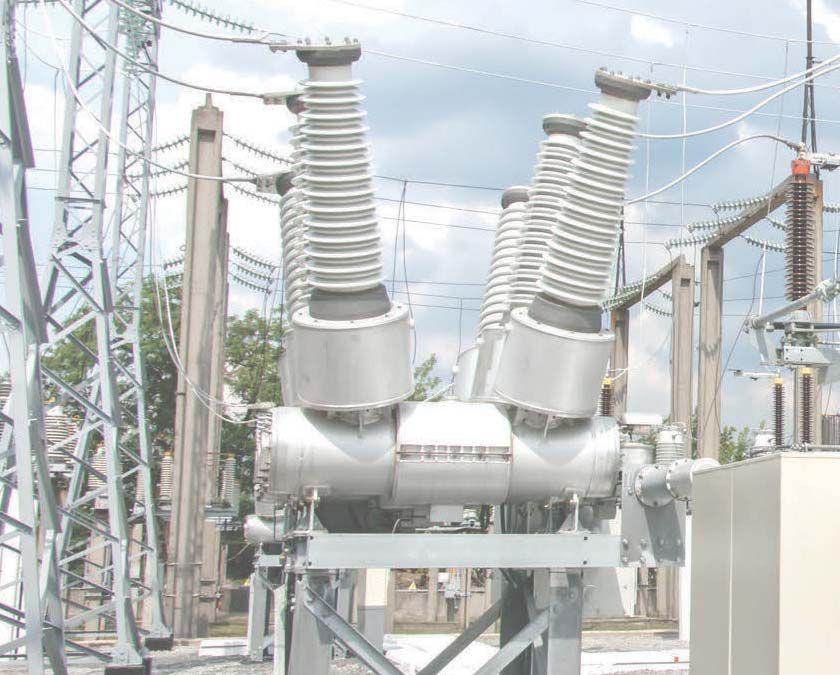
Portable Power Factor Test Set

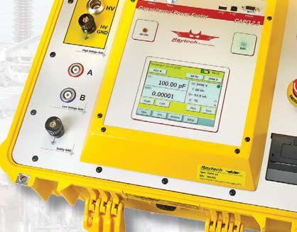


Designed for fast, easy field measurements with Raytech precision and accuracy.
•Battery operated instrument
•Portable and lightweight - only 22.2 kg (49 lbs.)
•Easy export of results with USB key
•Internal storage for over 10,000 test results
•External safety switch and safety ground detect for safe operation

•Temperature correction
•Color LCD touchscreen with LED backlight for easy-to-use operation
•Internal printer for printing results in the field
• 5 year standard warranty
BACKED BY OUR 5 YEAR WARRANTY! Toll Free 888 484 3779 | Phone 267 404 2676 118 South 2nd Street, Perkasie, PA 18944 www.RaytechUSA.com
Range Accuracy Resolution Dissipation Factor tan δ 0... 0.1 ±0.5% Rdg± 1x10⁻⁴ 1x10⁻⁵ 0.1...1 ±0.5% Rdg± 1x10⁻⁴ 1x10⁻⁴ >1±0.5% Rdg3 Digits Power Factor cos φ 0... 0.1 ±0.5% Rdg± 1x10⁻⁴ 1x10⁻⁵ 0.1...1 ±0.5% Rdg± 1x10⁻⁴ 1x10⁻⁴ Capacitance 60 Hz: 0.00pF to 1.1 μF±0.3% Rdg± 0.3pF0.01pF or 5 Digits 50 Hz: 0.00pF to 1.3 μF Test VoltageUp to 2500Vms (45... 400 Hz) ±0.5% Rdg± 1V 1V(<100V) 10V (>1000V)
Current Up to 200mAms ±0.3% Rdg±1μA 0.1μA or 4 Digits
Power 0... 500VA Output Frequency 10 Hz – 400 Hz (Step 0.5 Hz) ±0.01% 0.1 Hz
Test
Output


 Ron Widup President


 BY JAMES R. WHITE AND RON WIDUP, ShermcoIndustries Shermco Industries


 Ron Widup
Jim White


 BY DON GENUTIS, Halco Testing Services


 BY TONY MCGRAIL, Doble Engineering Company


 BY DAVID C. MAZUR AND JOHN A. KAY, RockwellAutomation Rockwell Automation


