
SPRING 2016 ADVERTISEMENT

SPRING 2 0 16 PAG E 110 P OW E RT E ST N EW P RO D U C T FO RU M MOVING
NEW YORK CITY 2003 BLACKOUT ISSN 2167-3594 NETA WORLD JOURNAL PRINT ISSN 2167-3586 NETA WORLD JOURNAL ONLINE
FROM ELEMENT TESTING TO PROTECTION SYSTEM TESTING
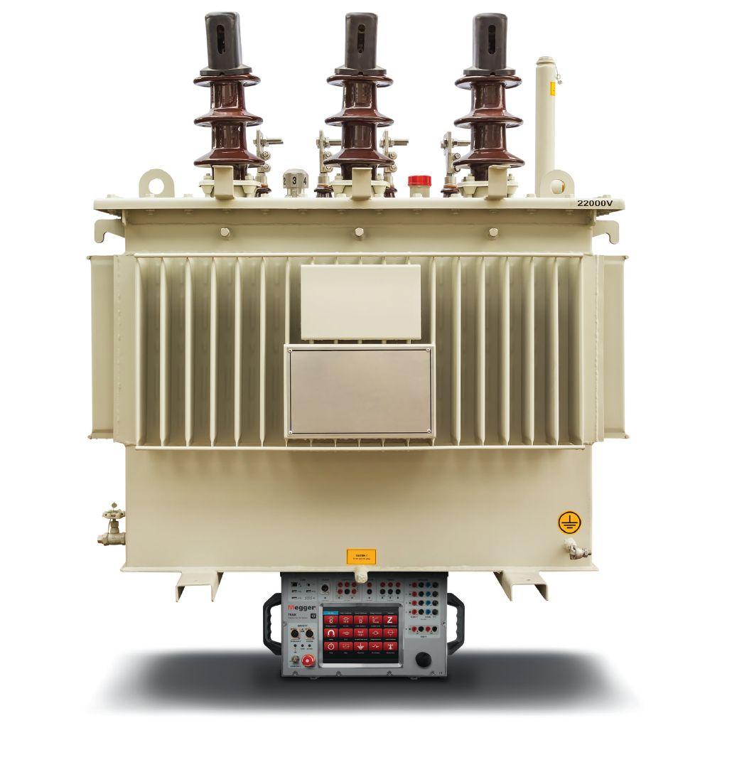
Megger’s new TRAX Transformer and Substation Test System is the multi-functional, app based testing solution that can carry the weight of all of your testing requirements.
This intelligently designed and simple to use test system replaces numerous individual transformer testing instruments to help save time and money while keeping the power on. From winding resistance and tap changer testing to high-voltage ratio measurement, the TRAX is the most versatile multi-tester on the market. Visit us.megger.com/TRAX for full specs and product details.
See the TRAX at the Megger NETA POWERTEST BOOTH #225 and at the TRAX Spotlight Stage Presentation!
The word “Megger” is a registered trademark WWW.MEGGER.COM/US HEAVY LIFTING.
Can Do The
TRAX


Technical
Training SPRING 2016: VOL. 1. NO. 1
Electrical Power Systems Industry Resource on
and Professional

In - depth Cour ses in These Applic ations > Protec tion Tes ting > Power Trans former Tes ting > Circuit Breaker Getcompletecourselistings omicronenergy.com/training-all Take a training center video tour omicronenergy.com/Houston-Video 1-800-OMICRON omicronenergy.com St ate of f the Ar t Facilities > Indoor Subs t ation > Hands- on Training > Receive Credit s (CEUs, PDHs, and C TDs) “BesttrainingI’veattendedinalongtime.” – Bill Carlson, PacifiCorp
A NETA World Journal Special Publication
A publication dedicated to disseminating information on technical and professional training for the advancement of the electrical power systems industry.
SPRING 2016 04 07 10 13 17 22 21
 By Don Brown, EASi
COMMITMENT: THE BRIDGE BETWEEN TRAINING AND RETENTION
By Chris Allaire, Shermco Industries
RELAY PROTECTION TESTING — NEED FOR TRAINING
By Ed Khan, Doble Engineering
TRANSFORMER TESTING TECHNIQUES AND STANDARD DEVELOPMENT
By
Diego
M.
Robalino,
PhD, PMP, MEGGER-AVO Training Institute
(Excerpt from NETA World Journal, Winter 2015)
THE TRAINING CHALLENGES OF CIRCUIT BREAKER MAINTENANCE AND TESTING
By Paul Grein, Assisted by Finley Ledbetter, Circuit Breaker Sales
TRAINING REQUIREMENTS OF A CERTIFIED ELECTRICAL TESTING TECHNICIAN: THE PERFECT BALANCE OF KNOWLEDGE AND EXPERIENCE
DIRECTORY OF TECHNICAL AND PROFESSIONAL TRAINING
Thank You to our Training Talk Sponsors: AVO Training Institute, ESPS, Electrical Safety Program Solutions Inc., OMICRON and SD. Myers.
NETA Training Opportunities for the Electrical Power Systems Industry TRAINING Online Training Courses Self-Paced Technical Seminars (SPTS) Electrical Safety Training System (ESTS) Ask about continuing education and NETA CTD credits. To learn more, visit www.netaworld.org/training or call 888-300-6382 (NETA)
at your own pace.
your knowledge. OSHA MULTI-EMPLOYER WORKSITE TRAINING AND SAFETY
STAFFING EMPLOYERS
Learn
Advance
FOR HOST AND
OSHA MULTI-EMPLOYER WORKSITE TRAINING AND SAFETY
FOR HOST AND STAFFING EMPLOYERS
BY DON BROWN , EASi
Employees have the right to a safe and healthy work environment, and that right is guaranteed by the Williams-Steiger Occupational Safety and Health Act of 1970 (the OSH Act). And, of course, no honest employee goes to work and intentionally tries to get hurt.
With today’s diverse workforce and with employers stretching for productivity increases and cost reductions, more companies are looking to personnel agencies to fill their staffing needs. Whether it is day labor, short-term employees, or long-term temporary staff, companies are required to provide the same level of safety that they would for full-time employees. In many cases, the perceived difference is that the staffing agency is providing skilled staff for a particular task and is required to provide all of the training, whether it is skill-set based or safety related. Often, host companies believe they are not responsible for the safety or training of those employees.
Those employers could not be further from the truth.
In April 2013, OSHA launched the Temporary Workers Initiative to help prevent work-related injuries to temporary workers. For the purposes of this article, temporary workers are those that are hired and paid through a staffing agency, but the daily work is directed by another employer known as the host employer. The initiative does not include day laborers or seasonal workers who have been hired directly by a single employer, nor does it include contractor/subcontractor relationships.
The initiative helps explain the responsibilities of the host employer and the temporary employer. Both employers are responsible for the safety of the worker. They should look at workplace hazards and identify how they can prevent and correct the hazard, as well as be in compliance with the OSHA regulations. Staffing agencies should provide general safety training for all their employees, but they are not required to become experts in the hazards of all workplaces that they staff. Some staffing companies supply workforce solutions for many different industries, including automotive, energy, and others. However, host employers are in a better position to provide worksite-specific safety training that is tailored to the daily hazards encountered.
One key to temporary worker safety is communication between the two employers. With open lines of communication, necessary protective measures can be ensured. It is the staffing agency’s responsibility to ask the host employer about specific conditions workers will be exposed to. They need to know they are sending their workers to a safe workplace. This can be accomplished by conducting on-location, site-safety assessments prior to and during the course of the work. The purpose of the site assessment is not to find fault; rather, it is to begin a working partnership between the parties to identify where safety measures can be implemented.
Another item that should be addressed at the beginning of any contractual relationship is defining the expectations and limitations of both employers’ safety programs, such as who will provide the PPE, who will provide specific training, who will be responsible for incident investigation, who will be responsible for reporting accidents and incidents to OSHA, and so on. These are only a few of the
4 | TRAINING TALK | A NETA WORLD JOURNAL SPECIAL PUBLICATION
questions that should be clarified at the beginning of a working relationship. Much of this information can be found in the OSHA regulations for reporting and recording injuries (29CFR1904 Recordkeeping).
Agencies need to train their staff to recognize and report safety and health hazards without fear of retribution. Most companies are happy to hear about hazards that they may not have considered. Call it a fresh set of eyes or a different perspective, getting input from someone who has not been exposed to a worksite’s hazards on a daily basis is necessary not only for temporary workers, but also for the fulltime employees. Temporary staff should report potential hazards to their host employer and to their agency as well. That way, the agency can follow up to ensure the hazards are abated before they cause worker injury or illness.
Comparing safety programs and injury and illness prevention programs is crucial to ensuring that workers are protected. Looking at the two programs side by side will help both employers determine the scope of the contracts that should be in place before work begins. While each employer will have specific items addressed in their respective programs, conducting this comparison will help ensure that all aspects of worker safety are covered.
CONCLUSION
When it comes to the temporary worker, training is a large point of discussion. While some may think it is the agency’s responsibility to provide all training for the employees they are supplying, that couldn’t be further from the truth. While some training may be provided by the agency, the task-specific training should be conducted by the host employer. Host employers should provide temporary workers the same safety training they provide their own full-time employees performing similar tasks. On the other hand, temporary employers should also provide general safety training such as HAZCOM, General Safety, and other company-specific safety-related topics.
Injury and Illness Prevention Programs (IIPP) are required of both host employers and staffing agencies. The IIPP for each company should address
things like OSHA recordkeeping and reporting, accident prevention, inspection processes and procedures, and how to recognize and avoid unsafe conditions. These two programs should be compared at the outset of each project. These programs also need to be communicated to workers at the beginning of the project as well as any time tasks are altered by the employer, a new employee comes to the site, or if the program itself changes. It is a good practice to hold annual refresher training on the IIPP for each job site.

While some may think it is the agency’s responsibility to provide all training for the employees they are supplying, that couldn’t be further from the truth.

One final note regarding multi-employer safety programs: The staffing agency cannot send workers out to a host site and forget about them. It is imperative that the agency keeps in contact with their employees to learn about changing conditions at the site or new policies and to show that they have not been forgotten. Too often, an employee is sent to a jobsite and never hears from the agency unless it involves problems with timesheets, vacation requests, or other administrative issues. Remember, these workers are employed by two different companies — one that pays them and one that directs their work. If they don’t hear from the agency, overlooked issues could lead to injuries, or worse.
Everyone has the right to a safe workplace. It does not matter if the employee is full-time or a temporary employee from a staffing agency. Host employers have the responsibility to provide all workers
A NETA WORLD JOURNAL SPECIAL PUBLICATION | TRAINING TALK | 5
with a safe place to work, earn a living, and provide for their families.
To quote Dr. David Michaels, Assistant Secretary of Labor for Occupational Safety and Health: “Host employers need to treat temporary workers as they treat existing employees. Temporary staffing agencies and host employers share control over the employee, and are therefore jointly responsible for temp employees’ safety and health. It is essen-

tial that both employers comply with all relevant OSHA requirements.”
Let’s be safe out there.
REFERENCES
OSHA Directorate of Enforcement Programs
OSHA Temporary Workers Initiative www.osha.gov/temp_workers
DON BROWN is the Regional Safety Manager for EASi LLC, an engineering and staffing agency and is based in Richardson, Texas. He has been in the electrical industry for over 40 years, implementing safety programs and training construction and general industry safety for the last 15+ years. Don is a Certified Electrical Safety Compliance Professional (CESCP) and provides safety programs for temporary staffing in various industries across the country. As the RSM, he is responsible for ensuring that host agreements include the required safety programs and safety training for staff placed in industries such as automotive, transportation, aerospace, construction, and energy. He has written many safety programs for large data centers, petrochemical facilities, and manufacturing facilities and is well-versed in OSHA’s Multi-Employer Worksite Policy.
6 | TRAINING TALK | A NETA WORLD JOURNAL SPECIAL PUBLICATION
COMMITMENT: THE BRIDGE BETWEEN TRAINING AND RETENTION
BY CHRIS ALLAIRE , Shermco Industries
The need for better trained and better educated technicians has greatly increased over the past several decades, as the electrical apparatus we work on and the test equipment we use each day becomes more complex. Trained and experienced technicians are needed in every facet of the organization, as technology changes at an ever-increasing rate. And don’t forget about the support staff — they are a vital part of a company’s success.
A major challenge facing many companies today is employee retention and employee turnover. Some managers argue that training leads to an increase in turnover, but most understand that training is a tool that can lead to higher levels of employee retention. In her article, “The Link between Recruitment, Training, and Retention,” published in 1998 in The Training Doctor, author Nanette Miner says studies confirm that when employees take advantage of training opportunities for skill development and career growth, they show an increased level of commitment to the organization. Miner confirms that employees who are more committed to the organization are less likely to jump ship. The bottom line is that committed individuals remain with the company.
SKILLS DEVELOPMENT EQUALS JOB COMMITMENT
According to a 2013 study conducted by Urm Ahmad and published for CASE Business School, among the top reasons an individual leaves a company for another company are job-specific training and career development opportunities. Ahmad also reports that an indirect relationship between quality training and increased retention can be bridged through increased employee commitment. Employees who value skills development for their career growth are more committed to an organization that constantly equips them with quality training and development opportunities.
Some companies shy away from training their technicians out of worry that they are making their workers more attractive on the job market — basically, that they are training their competitor’s future employees. In the article “Strategic Training Practices and Turnover Intention: The Mediating Role of Organizational Commitment,” published in the International Journal of Business and Management Studies in 2011, Roya Anvari argues that training and development are long-term investments in employee skills, a valuable tool to polish current skills, and an effective way to prepare employees for future impacts from competitive forces.
Employee training can be a win-win situation for the employee and the company. As individuals gain more knowledge and skills related to their job function, they become more valuable to the organization. Along with the added value gained through training comes more job security and increased wages. The company also wins by using training to develop a more engaged technician. Beverly Kaye and Patrick Smith make the point in their article, “Career Development: Shifting from Nicety to Necessity,” published in Training & Development in 2012, that engaged workers generate more profit, create stronger customer relationships, have fewer safety incidents, are less likely to quit, and are more productive than disengaged workers.
ADVANCEMENT VS. DEVELOPMENT
Many technicians and managers think of career advancement and career development as one and the same, but they are separate pieces of the professional puzzle. Employee training addresses the employee’s
A NETA WORLD JOURNAL SPECIAL PUBLICATION | TRAINING TALK | 7


current job duties, is present-orientated, and relates to the organization’s needs. The training an organization makes available to employees enhances specific skills and abilities needed to perform their current job. On the other hand, employee development is future-oriented training that focuses on the employee’s personal growth and future career opportunities.
Remember, individuals may leave their company when offered job-specific training and career development opportunities somewhere else. As published in ProQuest Education Journals, Tammy Galvin’s 2013 study of the top 100 U.S. companies in terms of the amount spent on training and development concluded that for the best people, employment is more about relationships and opportunities than it is about pay or security. Job security comes more from how employees feel about themselves and their ability to excel in the workplace.
ECONOMIC FACTORS
Economic conditions — more specifically, business downturns — can cause a company to curtail training activities and only offer what’s required such as safety training. While tight budgets may force a company to provide bare-minimum training, retaining the best employees requires providing the training they need to excel. The same employees who are with the company before the downturn are the ones who will be called upon to pull the company out of the slump. It may be the new hires or long-term employees, or both, who work to bring back the company; therefore, both must be trained and positioned for business recovery. Loyal employees will remain with a company through thick or thin when they feel the company is committed to their personal and professional development.

Most people will be loyal and thankful to the organization and remain with the company after completing their education.
The cheapest retention strategy is an investment in employee education and career development. Nanette Miner’s research confirms that when employees are asked what they seek from their employer, surveys continually show that acquiring new skills rates as high as getting more pay. When promising technicians are pursuing a degree or working toward a certificate program, they are almost guaranteed to remain with the company until they complete the program. In fact, most people will be loyal and thankful to the organization and remain with the company after completing their education. These individuals will not only be better educated but also better equipped to handle the future challenges of the job.
As discussed earlier, training is a major factor in employee retention. High performers and most motivated individuals don’t want to sit and mildew. Rather, they want to keep their skills and abilities current and useful. If they don’t have that, they go somewhere where they can find it. The truth of the matter is that high-performing employees desire more on-the-job learning and more career opportunities.
The training practices and programs offered to employees will have an effect — good or bad — on employee motivation and commitment. To equip a company’s employees with the skills necessary to do their jobs, focus training to optimize their potential. When planning for future opportunities, invest in the development of new skills that enable technicians to handle future situations. This kind of training can lead to high levels of employee motivation and commitment, at least among those who see the opportunity given. Employees will show their appreciation for the investment that is being made in them with hard work and contentment with the company. Training will have a positive impact on both motivation and commitment.
CONCLUSION
It is quite evident that employee training and development not only leads to better productivity, but organizations that focus on employee development create an enduring impression on their people and
8 | TRAINING TALK | A NETA WORLD JOURNAL SPECIAL PUBLICATION
earn their loyalty. The next article in this series explores ways to balance a busy production schedule with training activities, keep up with technology, motivate self-study, and meet other training challenges faced by most companies.
REFERENCES
Ahmad, U. 2013. “Impact of Training on Employee Retention,” Case Business School
Anvari, R. 2011. “Strategic Training Practices and Turnover Intention: The Mediating Role of Organizational Commitment,” International Journal of Business and Management Studies, 3 (2), 293-305

Galvin, T. 2003. “Training Top 100,” ProQuest Education Journals
Kaye, B., & Smith, C. P. 2012. “Career development: Shifting from Nicety to Necessity,” Training & Development, 52-55
Miner, N, 1998. “The Link Between Recruitment, Training, and Retention,” The Training Doctor
Walton, R.E. 1985. “From Control to Commitment in the Workplace,” Harvard Business Review, 77-84
CHRIS ALLAIRE is a Technical Instructor/Developer for Shermco Industries and an Adjunct Instructor for Texas State Technical College and North Lake College. Chris previously served as Lead Electrical Instructor at Everest College in Arlington, Texas. He earned a Bachelor of Science in Technical Management from DeVry University, majoring in Electronic Engineering Technology, and a Master’s of Education in Curriculum and Instruction from American College of Education. Chris spent nearly 30 years with General Electric, starting in the motor shop as a motor mechanic and test technician. The second half of his GE career was spent as a field service technician, performing start-up and commissioning at water treatment plants, data centers, and industrial facilities.
A NETA WORLD JOURNAL SPECIAL PUBLICATION | TRAINING TALK | 9
RELAY PROTECTION TESTING NEED FOR TRAINING
BY ED KHAN , Doble Engineering
The energy sector in the U.S., especially electric utilities, is facing tremendous strain and challenges due to a shrinking pool of skilled workers. According to an estimate published in “Gaps in the Energy Workforce Pipeline: A 2007 Workforce Survey Report from the Center for Energy Workforce Development,” at least 40 percent of the workforce in the energy sector is expected to either retire or leave by 2016. This will leave a large vacuum to be filled. Forty percent of an estimated 400,000 employees working in the generation and transmission and distribution (T&D) sectors is a very large number.
The problem of a shrinking availability of skilled workers is compounded by the fact that energy consumption in the U.S. is expected to grow significantly, demanding a much larger pool of engineers and technicians. According to the Energy Information Administration (EIA), national electricity consumption in the U.S. is expected to grow 40 percent by 2030. A 2007 survey conducted by National Electricity Reliability Corporation (NERC) concluded that an aging workforce and a lack of skilled workers rank first among all business issues that will have the highest impact on reliability.
The major issue of replacing skilled workers is concentrated around engineers and technicians. This problem of a shrinking workforce, although widespread across the energy sector, is specifically significant in technicians working in relay protection testing.
This issue of a shrinking workforce needs a complex array of solutions requiring implementations at various levels. One of the most important solutions is the implementation of robust and accelerated training programs at the utilities. However, since utilities are stretched in terms of resources and all-round talent, an attractive option is to hire companies specializing in protection testing/training.
TYPICAL TECHNOLOGY PROFILE OF RELAYS USED IN THE U.S.
Unlike Europe, relays present in U.S. utilities are comprised of different technologies. In Europe, almost all relays are microprocessor-based with some solid-state relays and very few electromechanical relays. In some eastern European countries, some electromechanical relays are in use. In the U.S. approximately 60 percent of relays are electromechanical, while the remainder are either microprocessor relays (35 percent) or solid-state relays (five percent). This spread in technology makes it difficult to tailor a uniform training program. A training program that addresses all three types needs to be implemented.
TYPICAL EXPERIENCE PROFILE OF U.S. RELAY TECHNICIANS
The experience profile of technicians in the U.S. is primarily based on age. Older technicians are typically very experienced with electromechanical relays and have a good knowledge of how those relays work. For electromechanical relays, the operation is very intuitive; microprocessor relays, on the other hand, act similar to a black box — unless one is very familiar with the built-in logic diagrams, etc. On the other end of the spectrum are the very young technicians who do not have much knowledge of electromechanical relays. However, they are very computer savvy and tend to pick up the working of microprocessor relays quickly — although they may lack the knowledge related to protection philosophy and related theory.
10 | TRAINING TALK | A NETA WORLD JOURNAL SPECIAL PUBLICATION
Depending on the age of the technician, a varying coverage of the three types of relay technologies exists. However, a training program must cater to all age groups of technicians. This clearly implies that training must be tailored to all classes of technicians as well. It is expected that this variance in training will have to be continued until microprocessor relays replace the existing population of electromechanical relays, which should take about 10 years.
This picture of evolving technologies and the changing profile of the work pool are two forces acting in conjunction to make matters worse. This situation is obviously more acute in the U.S. than in other countries, which have a lesser number of older technology relays.
METHODS OF TESTING RELAYS
In addition to a multi-tier training program — dictated by a varied pool of relay technologies — and a varying level of experience for each set of technology, other issues need attention.
The method of testing electromechanical relays started with steady state testing. In steady state testing, a relay is tested by application of sinusoidal currents and voltages of varying magnitudes and phase angles to test the operation or non-operation of a relay. This method is still very popular and is relevant to electromechanical and solid state relays. In steady state testing, the tester essentially tests the relay as an entity by itself. He checks the pickup, timing characteristics, etc. In an electromechanical relay, variables like pickup change over time, hence checking these at specific maintenance intervals is prudent. However, microprocessor relays do not change over time. Therefore, the way microprocessor relays should be tested is different than electromechanical relays. Steady state testing of microprocessor relays is limited to specific variables such as inputs/outputs, etc. The training program must address this new regimen of testing.
Also, testing of relays as a unit without any consideration of actual system conditions is adequate for relays such as over current, over/under voltage, and over/under frequency. However, distance relay performance, for example, is directly tied to voltage and current characteristics prior to and during the fault. Therefore, regardless of relay technology,
distance relays must be tested under actual system conditions, which are described by changing voltage and current profile. This type of testing should use dynamic testing tools. Relay test sets offered for this program are available under different names such as state simulation, state sequencer, etc. The training program needs to address this type of testing to ensure that students are capable of running such tests.
Finally, when testing protection, strive to test not just a relay as a box; instead, test the protection system as a whole. This requires COMTRADE files that are generated by transient analysis programs such as EMTP, DIGSILENT, ATP, etc. The result of these transient simulations is saved in a file in COMTRADE format. This is a standardized file format that protection relays, test sets, and digital fault recorders can read.
The file contains complete waveform data, so actual fault conditions can be simulated. Downloading these COMTRADE files to relay test sets and then replaying them into the relays is the most accurate method of testing an entire protection scheme. Such testing is far superior to the steady state testing mentioned earlier. The training program must ensure that students are familiar with these files and the procedure required to perform such testing. The students must also learn to analyze the test results in a meaningful way.
The event files in microprocessor relays are also stored in COMTRADE format. The technicians should be able to retrieve these files and analyze any operations that occur in the system. They can use these event files to test the performance of a specific relay that may have misoperated, and in this way, they can perform an effective root cause analysis.
CONCLUSIONS
Utilities are under pressure to perform relay testing at regular intervals with extensive record keeping to be in compliance with NERC/FERC regulations. This requires a large pool of trained technicians. However, a large workforce sector is ready to retire, leaving utilities scrambling to get trained replacements.
U.S. utilities have a population of relays that span over three technologies: electromechanical, solid
A NETA WORLD JOURNAL SPECIAL PUBLICATION | TRAINING TALK | 11
state, and microprocessor. This requires training that covers these three technologies.
Going forward, testing methods are going to change significantly. More emphasis will be on dynamic testing using transient data, which will require the

use of tools such as COMTRADE files and state simulations. This means training on running such tests is needed. Currently, these tests are not run frequently; therefore, a larger population of technicians must be trained to run them.
ED KHAN is Director of Protection R&D and Training at Doble Engineering. He has been with Doble Engineering Company for the last seven years, working in various capacities, including Product Manager for protection-tested related instruments. Prior to Doble, Ed worked for GE, ABB, SEL, KEMA, and others. He has 34 years of experience in system studies, protection applications, relay design, power plant design, presentation of courses and training, and product management. Ed has a thorough knowledge of product development, protection, harmonic analysis, harmonic filter design, system design, power system studies, and real-time digital simulations. His experience covers utilities, industrials, and power plants. Ed has presented courses on behalf of Doble Engineering and GE in the U.S. and overseas. He is a member of CIGRE WG 5.56 Optimization of Protection, Automation, and Control Systems.
12 | TRAINING TALK | A NETA WORLD JOURNAL SPECIAL PUBLICATION
TRANSFORMER TECHNIQUES AND STANDARD DEVELOPMENT
BY DIEGO M. ROBALINO, PhD, PMP, MEGGER-AVO Training Institute
Transformer manufacturers and field operators have always benefitted when new technologies are applied during design, manufacturing, commissioning, and operational processes that improve the quality and reliability of electrical apparatuses.
As technological advances and new testing methodologies become more readily available to transformer testing personnel, how can we keep up with this avalanche of new and promising alternatives, which at first glance seem to solve all our diagnostic problems? One way is by following the activities of national and international regulatory institutions. IEEE, NETA, CIGRE, and IEC are the best references in this area.
IEEE STANDARD C57.152-2013
IEEE is the world’s largest professional association dedicated to advancing technological innovation and excellence for the benefit of humanity. The IEEE Transformer Committee met in Dallas in 2007 to revise the existing guide for routine testing in the field, IEEE 62, Guide for Diagnostic Field Testing of Electric Power Apparatus — Oil-Filled Power Transformers, Regulators, and Reactors (R2005). At
the time, a vast number of old and new testing methodologies and practices were used in the field but were not covered by the IEEE 62 standard. It was logical to create a new or revised guide under the C57 standard series. The C57 standards already contained other transformer-related guidelines administered and supervised by the IEEE Transformer Committee.
The new guide for diagnostic field testing of fluid-filled power transformers, regulators, and reactors was balloted and approved by RevComm in 2013. The working group led by Jane Verner (Chair), and supported by many members of IEEE, dedicated long hours in revisions and contributions to the new guide.
The comparison between IEEE 62 and IEEE C57.152 brings something else to this discussion. The new Diagnostic Test Chart complements the old one, keeping the existing practices and adding those methods not considered previously. A comparative analysis shows the following methodologies were added to the new guide: Windings — Frequency Response Analysis (FRA); Insulating liquid — Furan Analysis and Corrosive Sulfur; and Current transformers — Ratio, Polarity, and Resistance.
IEEE C57.152 (Chapter 5) also considered the importance of providing a maintenance chart where the end user could select the testing practices recommended (REC), as-needed (AN), and optional (OPT) for different stages during the service life of the transformer: commissioning, in-service, after protection trip due to system fault, or after protection trip due to internal fault. In this chart, induced voltage and dielectric frequency response (DFR) are listed as optional techniques.
Not only are more testing methodologies listed in the new maintenance and diagnostics charts, but also included are new annexes developed to complement the guide:
■ Annex D (informative) Dew Point Test
■ Annex E (informative) Furan Testing
■ Annex F (informative) Frequency Response Analysis (published guide IEEE C57.149)
■ Annex G (informative) Dielectric Frequency Response (developing guide IEEE PC57.161)
■ Annex H (informative) Other methods to verify polarity from previous field test guide revisions
■ Annex I (informative) Particle Count
■ Annex J (informative) Bibliography
A NETA WORLD JOURNAL SPECIAL PUBLICATION | TRAINING TALK | 13
Only general information about FRA and DFR was included in annexes F and G because when C57.152 was close to being published, other working groups were developing specific guidelines for the advanced diagnostic techniques of SFRA and DFR. Frequency response techniques have been used in the field for over 20 years. Researchers worldwide have found SFRA and DFR useful not only in transformer diagnostics, but also in other electrical apparatuses in the field.
CIGRE
CIGRE 445, the guide for transformer maintenance, provides a diagnostics matrix where a line is drawn to differentiate basic electrical testing from advanced electrical testing. Frequency response techniques in time and frequency domains are grouped together with partial discharge (PD) testing as advanced electrical diagnostic techniques.
CIGRE pioneered publishing guidelines dedicated to the frequency response methods. In 2008, CIGRE published Technical Brochure 342 — Mechanical Condition Assessment of Transformer Windings Using Frequency Response Analysis (FRA). This is an excellent reference on the principles of FRA, suggested best practices for making repeatable measurements, and guidance for interpretation.
CIGRE also undertook a large project to investigate the frequency response of the dielectric components inside the transformer, publishing Technical Brochure 414 — Dielectric Response Diagnoses for Transformer Windings in 2010. CIGRE’s well-developed document describes the transformer dielectric response model, the best testing practices, and guidelines for the interpretation of results.
IEC
Prepared by Technical Committee 14, the IEC 60046 standards series covers technical areas related to transformers. Standard IEC 60046-1 (2011) is the latest revision available for power transformers and IEC 60046-18 Ed. 1 (2012) addresses the methodology, best practices, and minimum requirements for measuring equipment and formatting the data resulting from the SFRA test.
IEC 60046-18 also includes several annexes. Annex A covers the measurement lead connections. Annex B covers factors influencing FRA measurements, including residual magnetization, use of different liquids and the level of liquid
filled in the tank, temperature, and others. It also includes a few examples of confirmed damages in the windings detected by the FRA test. Annex C covers the applications of FRA, and Annex D provides examples of measurement configurations.
TRANSFORMER ADVANCED DIAGNOSTICS BY FREQUENCY RESPONSE TECHNIQUES
The objectives and scope of each frequency response method must be understood before it can be chosen for the appropriate application.
Frequency response analysis or sweep frequency response analysis (SFRA) is a comparative test to evaluate the electro-mechanical condition of the transformer. Deviations between frequency responses indicate mechanical and/or electrical changes in the active part of a transformer.
Dielectric frequency response (DFR) or frequency domain spectroscopy (FDS) tests the overall condition of the transformer’s insulation, identifying:
■ The percentage of moisture concentration in the solid insulation
■ The conductivity or the dissipation factor of the liquid insulation corrected to 25°C
■ The thermal behavior of dielectric parameters at specific frequencies, determining an accurate power factor / dissipation factor correction not based on table correction factors but on the individual dielectric response of the unit under test (UUT)
■ The presence of contaminants creating a distortion of the dielectric response (also called non-typical dielectric response)
A deeper look at each technique is helpful to understand their advantages.
Sweep Frequency Response Analysis
According to control theory, the behavior of a single input, single output (SISO) system can be described with an impulse response h(t) or its transfer function H(jw) (Figure 1).
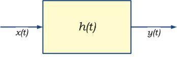
Figure 1: SISO — Representation of a Transfer Function in Time and Frequency Domains
14 | TRAINING TALK | A NETA WORLD JOURNAL SPECIAL PUBLICATION
In the case of power transformers, the physical structure of the winding can be represented in the electric language by an RLC complex circuit with multiple series and parallel combinations of these components (Figure 2).
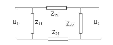
Figure 2: Simplified Diagram of the Winding Configuration
The ac input signal applied to one end of the winding at one specific frequency passes through the complex electric circuit of the winding, and the output voltage is measured in magnitude and phase at the other end.
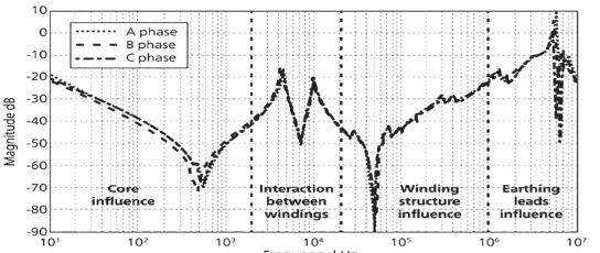
The frequency sweeps from 20Hz up to 2MHz. Typically, a 2MHz upper limit is sufficient for power transformers, and a clear and repeatable response of the magnetic circuit can be obtained from 20Hz up to approximately 2kHz, depending on transformer design. IEEE and IEC have set boundaries on the frequency response to identify different sections of the transformer (Figure 3).
SFRA measurement provides a very clear image of the electromechanical construction, but interpretation may always be validated with an additional testing technique. The chart at the right shows the correlation of SFRA with other testing practices.
Dielectric Frequency Response
This technique is already used by many utilities and transformer manufacturers, which have greatly benefited from the vast amount of information gathered from the unique and individual dielectric response of the transformer insulation.
The testing procedure is quite similar to that applied for power factor or dissipation factor testing. The main difference is the wide-frequency band used by DFR — typically from 1kHz down to 1mHz. The test is carried out at low voltage (200Vp) for transformer testing. For environments with high interference, a voltage amplifier increases the signal-to-noise ratio. The use of a voltage amplifier is fundamental for the analysis of bushings and instrument transformers.
In a two-winding transformer, DFR can analyze the following insulating areas:
■ CHL — capacitance between HV and LV windings (i.e. inter-winding capacitance)
■ CHG — capacitance between HV winding and ground
■ CLG — capacitance between LV and ground
■ Bushing C1 and C2 capacitances, but only if test tap is available in the bushing
■ Only oil sample DFR
Transformer Characteristic@ 60 Hz
Open CircuitLooks at winding and core characteristics
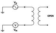
Similar to eExcitation current test
Short CircuitLooks at winding Similar to leakage reactance
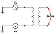
Capacitive Inter-windingLooks at capacitance between windings

Inductive Inter-windingLooks at inductance of both windings
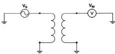
Similar to capacitance test
Similar to TTR
A NETA WORLD JOURNAL SPECIAL PUBLICATION | TRAINING TALK | 15
Figure 3: Frequency Response Analysis — IEEE C57.149
SFRA mode
Figure 4
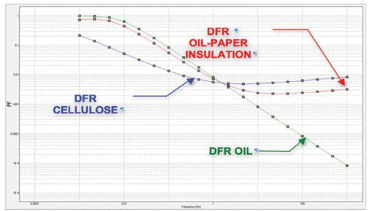
5: DFR of a Transformer’s Liquid-Paper Insulation (X=20, Y=20, %mc=1%, s=1E-13 pS/m, T=20°C)
The dielectric response provides an in-depth understanding of the insulation system and allows differentiation between the condition of the liquid insulation versus the condition of the solid insulation.
An example of a transformer in excellent condition is presented in Figure 5. Moisture in the solid insulation is only 1 percent, and the conductivity of the oil is 1x10-13 [S/m]. Temperature of the insulation system in this example is 20°C.
For interpreting DFR results, the XY model explains the relationship between the solid insulation, the liquid insulation, and the system geometry. The XY model is well described in CIGRE 414.
Following the XY model and using mathematics to match the readings to those in a well-developed database, users can determine the moisture concentration in the solid insulation and the conductivity (s) of the liquid insulation.
The DFR method continues to evolve. Part of this evolution is the implementation of a multi-frequency measurement system capable of reducing the testing time by almost 40 percent in the frequency

domain only. Testing time is critical for end users. Testing personnel should be aware of DFR best testing practices such as thermal stability of the specimen and preferably not-too-cold insulation temperatures where, inevitably, the prolongation of testing time runs to very low frequencies.
The thermal effect shifts the dielectric response to higher frequencies at higher temperatures and to lower frequencies at lower temperatures. This phenomenon led to another application: identification of the thermal behavior of dielectric parameters such as Power Factor and Dissipation Factor. In other words, DFR opened the door for transition from the frequency domain into the temperature domain of the insulation system, including using it for an accurate individual temperature correction of power factor values at line frequency or beyond it to reference values at 20°C, or any other temperatures from 5 to 60°C with very high accuracy.
CONCLUSIONS
As new testing techniques are developed, the international community must comprehend the benefits and limitations of these techniques.
The international committees go through a process that may take several years before a new guide is created and published. This is the only way to compile into one document the knowledge and experience of the entire technical community involved in this honorable activity.
SFRA is one of the most important tools for diagnosing potential mechanical problems in transformer windings. DFR is clearly gaining more importance within the utilities by providing a complete overview of the dielectric system inside the transformer, allowing end users to identify water contamination issues within the solid insulation or high conductivity in the liquid insulation.
DIEGO ROBALINO is a Senior Applications Engineer at Megger, specializing in the diagnosis of complex electrical testing procedures and supporting the AVO Training Institute in its evaluation and development of strategic academic material. Robalino received his electrical engineering PhD from Tennessee Technological University and has 20 years of experience in the electrical engineering profession, including management responsibilities in power systems, oil and gas, and research arenas as well as managing the design, construction, and commissioning of electrical and electro-mechanical projects. He is a senior member of IEEE and a member of the IEEE Transformer Committee.
16 | TRAINING TALK | A NETA WORLD JOURNAL SPECIAL PUBLICATION
Figure
EVOLUTION OF CIRCUIT BREAKER TESTING
BY PAUL GREIN, assisted by FINLEY LEDBETTER, Circuit Breaker Sales
Over the course of three generations and spanning 70 years, circuit breaker technology has advanced and safety practices have improved. This article provides a brief overview of three generations of circuit breaker technicians and how technological and safety advancements have led up to today’s testing requirements and the challenge of training the electrical testing technician to perform these tests.
THE OIL YEARS (1945 – 1975)
The Golden Years is the moniker often used to describe the period following World War II. Regulatory intervention from federal and local governments was minimal, and the power equipment industry benefited immensely from an era of rapid growth. Between the years 1946 and 1947 alone, power usage grew almost 15 percent, creating an avid demand for power equipment and technicians qualified to operate and maintain it.
The demand for electric power and advances in productivity created a need for circuit breakers with higher current ratings and interrupting capacities.
Growth continued for decades but at a diminishing rate, until it stagnated in the tumultuous 1970s to the average seven percent we see today. While The Golden Years may delineate the economic growth that drove the circuit breaker industry, The Oil Years better describes the breaker technology that ruled the era.
CIRCUIT BREAKERS IN THE OIL YEARS
Before and in the decades immediately following World War II, the most common medium-voltage circuit breaker technology utilized was the oil-tank type. Many of the switchgear manufacturers that served the American market during the war remain in business today, including General Electric, Westinghouse (now Eaton Cutler-Hammer), and ABB. I have chosen to use Westinghouse’s introduction of circuit breaker technology as the basis for this article, with the understanding that competing manufacturers may have innovated the technology earlier or later but all within the same general timeframe.
The 1940s saw the beginning of a major transition from oil-tank to air-magnetic circuit breakers, but oil remained the workhorse of American utilities and factories. Despite the introduction of air-magnetic technology, Westinghouse continued manufacturing its type B and F oil-tank circuit breakers into the early 1950s.
SAFETY IN THE OIL AGE
Safety was not a priority in industrial environments until the Occupational Safety and Health Administration (OSHA) was created in 1970 when the Williams-Steiger Act was signed into law. Electrical safety would not be emphasized until 1979 when the National Fire Protection Association (NFPA) published NFPA 70E, Standard for Electrical Safety in the Workplace, at OSHA’s request. Prior to OSHA and NFPA 70E, responsibility for maintaining safe work practices fell on the technician, and electrically “safe” work practices were anything but.
CIRCUIT BREAKER TESTING IN THE OIL AGE
The majority of circuit breaker testing performed in The Oil Age was a mechanical process analogous to performing maintenance on an automobile rath-
A NETA WORLD JOURNAL SPECIAL PUBLICATION | TRAINING TALK | 17
er than maintaining electrical equipment. Maintenance consisted of testing, cleaning, and changing the oil and then physically inspecting the operating mechanism, contact condition, connections, and looking for signs of carbonization. In-house technicians with limited specialized training or test equipment performed the maintenance.
If available, dedicated test equipment was limited to dielectric test sets that measured the insulating oil resistance and high-potential insulation test sets. Test equipment and practices did improve through the oil age but advancements were adopted slowly. It wasn’t until the next generation that circuit breaker testing would resemble what we see today.
THE AIR ERA (1965 – 1995)
The economic good times experienced during The Golden Years following World War II would not last forever, a combination of macroeconomic events including the oil embargo of 1973 stalled the economy, but growth in the power equipment industry crept along at seven percent. While the economic setting of the period may have been wanting, the technological advances and safety environment we experience today took root in The Air Era between 1965 and 1995.
FROM OIL TO AIR
The first generation of air circuit breakers was limited to light-duty applications with maximum ratings of 5kV, 50MVA, 1200A. However, customer interest in the new technology and technological limitations of oil-tank designs encouraged manufacturers to increase ratings quickly.
The first generation of Westinghouse type air-magnetic breakers reached their technological limit in1958 with the model 150-DH-1000, 3000A circuit breaker. To reach the extended 1000MVA interrupt and 3000A continuous current ratings, the breaker design had bloated to 3,908 pounds with arc chutes weighing in at over 600 pounds each!
The introduction of air-magnetic brought many advantages over the oil-tank breakers they replaced, including:
■ Removal of the oil and the associated chemical and fire hazards
■ Higher contact-breaking speeds and faster arc-quenching
■ Smaller arc duration allowed extended service life of contacts
■ Extended interrupt and continuous current ratings
■ Smaller size and weight at a given rating
■ Much less maintenance
The innovations introduced in second-generation air circuit breaker technology stemmed from advancements in design, materials, and manufacturing. Porcelain and similar advanced insulation material technologies offered a reduction of insulation tracking and non-hygroscopic properties, allowing circuit breakers to become more compact and lowering the risk of failure from flash-over, which increased reliability and safety. Technician safety was also improved by replacing antiquated materials that could be toxic when mishandled.
Early air circuit breaker designs were furnished with solenoid-operated mechanism with cast parts and monolithic pole assemblies. By the late 1960s, stored energy spring mechanisms had phased out the solenoid operator, markedly increasing operating speeds. By 1968, cast mechanisms were replaced with machined and modern fabricated mechanisms. Finally, after 1970, monolithic pole units were phased out by the post-insulator pole unit, which is the single/isolated pole design we see today. These and other advancements to circuit breaker design had an enormous impact on circuit breaker reliability — so much so that it is common to find equipment commissioned in the 1960s still in use over 50 years later.
THE SAFETY ERA
The safety environment that many of us take for granted today was pioneered a generation ago; workplace and electrical safety originated during The Air Era. As mentioned previously, the Williams-Steiger Act was signed into law in 1970, creating OSHA. In 1979 the NFPA published NFPA 70E, the first nationally accepted standard that addressed electrical safety requirements for employee workplaces.
THE AIR ERA CIRCUIT BREAKER TESTING
Circuit breaker testing requirements from generation to generation have expanded in both scope and scale. The introduction of new circuit breaker technology and the advancement of test equipment and safety practices introduced new types of tests and testing requirements.
18 | TRAINING TALK | A NETA WORLD JOURNAL SPECIAL PUBLICATION
The transition between circuit breaker technologies was a gradual process, requiring technicians to be capable of maintaining the equipment of current and previous generations. The growing knowledge and experience required to effectually test the rapidly expanding arena of circuit breaker technologies led to the increased use of specialized breaker technicians — often employed from outside testing companies versus in-house technicians. Outsourcing testing introduced new challenges, the largest of which was ensuring that testing was performed consistently and accurately by suitably experienced and trained technicians.
A group of electrical business owners recognized the need to standardize electrical testing to combat the inconsistent testing and safety practices that had become commonplace. In 1972, the National Electrical Testing Association (NETA) was formed with the goal of establishing uniform testing procedures for electrical equipment. In 1977, NETA published its ATS-1977, Acceptance Testing Specifications for Electrical Power Distribution Equipment and Systems. The ATS-1977 illustrates how circuit breaker testing expanded since the 1940s. Comparing the maintenance recommendations from circa 1940s and 1950s maintenance manuals to the ATS-1977 test recommendations for like equipment gives an indication of testing has and continues to grow.
THE VACUUM ERA (1985 – TODAY)
Vacuum Circuit Breakers
In 1978, Westinghouse introduced the DVP type, its first vacuum circuit breaker model, in 500 and 750 MVA. In 1981, Westinghouse introduced its VCP line of vacuum circuit breakers and associated VacClad switchgear in ratings up to 15kV and 1000 MVA. VCP was Westinghouse’s first generation of modern vacuum circuit breakers.
Vacuum interruption is, arguably, the most significant innovation in medium-voltage circuit breaker technology. Recent innovations have introduced magnetic-actuator operating mechanisms that have few moving parts and require no maintenance or adjustments over the products life — warranted to five years versus the industry standard of one year.
Modern Safety
During The Vacuum Era, the most significant contributor to safety was technological innovation. The
advantages of vacuum circuit breaker technology and modern manufacturing capabilities and materials dramatically increased reliability safety features.
Despite the progression, countless installations across the United States still utilize air-magnetic and even oil-tank circuit breaker technology, which have been in service for over 40 or 50 years. The continually expanding knowledge required to maintain three generations of power equipment spanning 60 years may be the greatest challenge to present day maintenance technicians.
Testing Today and Training
In this article, three generations of circuit breakers were discussed — the oil, air, and vacuum eras — as well as how technology and safety advancements have affected circuit breaker testing. Today’s technicians are required to have an overwhelming level of expertise to effectively and safely test the breadth of equipment they will encounter. Often, it is the seasoned old-timers who have the experience to get the job done; with many of these technicians retiring, it is important to have a plan to train younger technicians to service the new and the older equipment.
A good foundation of understanding can be easily and quickly gained by studying secondary resources and by enrolling in online or classroom-based training on circuit breaker maintenance. When considering a course, be sure to inquire about the scope of the instruction. Ultimately, be sure the course provides training on how to identify the type of circuit breaker and determine which tests and testing procedures should be performed on the different types of circuit breakers outlined in this article.
A good secondary resource is the NETA Self-Paced Technical Seminary: Critical Maintenance for Circuit Breakers, by Jim White of Shermco Industries, Inc.
REFERENCES
ABB. (2014). AMVAC. In ABB, Medium Voltage Indoor Circuit Breakers Descriptive Bulletin (pp. 6-7). Lake Mary: ABB.
Croft, T. (1942). American Electricians’ Handbook, 5th Edition. New York: McGraw-Hill Book Company.
A NETA WORLD JOURNAL SPECIAL PUBLICATION | TRAINING TALK | 19
Eaton. (2013). Medium Voltage Switchgear. In CA08100014E Aftermarket, Renewal Parts and Life Extension Solutions Catalog (pp. V12-T17-53 - 64). Eaton.
Howell, J. (2014). NETA — Setting the Standard. NETA World Journal, 1-4.
Jooma, Z. (2016, January 21). History of the NFPA 70E. Retrieved from Electricity and Control: http:// www.eandcspoton.co.za/resources/docs/Hazardous/History_of_the_NFPA.pdf
Littelfuse. (2005). Electrical Safety Hazards Handbook. Des Plaines: Littelfuse Inc.
NETA. (1977). Acceptance Testing Specifications for Electrical Power Distribution Equipment & Systems. Meriden: National Electrical Testing Association.
U.S. EIA. (2016, January 15). History of Energy Consumption in the United States, 1775-2009. Retrieved from U.S. Energy Information Administration — Today in Energy: https://www.eia.gov/ todayinenergy/detail.cfm?id=10#
Westinghouse. (1941). Type “DH” “De-ion” Air Circuit Breakers Instruction Book. Pittsburgh: Westinghouse.


Westinghouse. (1944). “Unitized” Heavy-Duty Metal-Clad Switchgear. Pittsburgh: Westinghouse Electric & Manufacturing Company.
Westinghouse. (1949). Instructions — High-Voltage Metal-Clad Switchgear with “F” and “B” Oil Circuit Breakers. Pittsburgh: Westinghouse Electric Corporation.
Westinghouse. (1949). Unitized Metal-Clad Switchgear Light-Duty DH Type - Descriptive Bulletin. East Pittsburgh: Westinghouse Electric Corporation.
Westinghouse. (1958). Descriptive Bulletin — Standardized Metal-Clad Switchgear. East Pittsburgh: Westinghouse Electric Corporation.
Westinghouse. (1959). Instructions - De-ion Air Circuit Breaker Type 150-DH-1000. East Pittsburgh: Westinghouse Electric Corporation.
Westinghouse. (1965). Porcel-line Metal-Clad Switchgear with Type DH-P Air Circuit Breakers — Descriptive Bulletin. East Pittsburgh: Westinghouse Electric Corporation, Switchgear Division.
PAUL GREIN, BSEE, MBA has been with GroupCBS since 2008, working primarily at Circuit Breaker Sales in Gainesville, Texas, in the Dallas area. He has worked with industrial electrical equipment for 20 years, starting in the Navy as an Electrician on the submarine USS Topeka SSN 754 from 1996 through 2002, followed by positions in the steel industry from 2002 to 2005. Paul has a BSEE from the University of Texas at Dallas (2007) and an MBA from the University of North Texas (2014). He participates in the IEEE/ANSI PES C37 Standards Committee, which writes and maintains the design/testing standards that govern the industry. His primary responsibilities at CBS and the Group include sales, engineering design, technical expertise, standards, project management, and engineering management .
FINLEY LEDBETTER has worked in power engineering for 35 years, including serving as an applications engineer and instructor for the Multi-Amp Institute. He was the founder of Shermco Engineering Services Division, a division of Shermco Industries — a NETA Accredited Company. Finley is also the founder of Group CBS, Inc., which owns 12 circuit breaker service shops in the United States. He is a member of IEEE, a NETA Corporate Alliance Partner, and a charter member and past president of Professional Electrical Apparatus Recycler’s League (PEARL).
20 | TRAINING TALK | A NETA WORLD JOURNAL SPECIAL PUBLICATION
TRAINING REQUIREMENTS OF A CERTIFIED ELECTRICAL TESTING TECHNICIAN:
THE PERFECT BALANCE OF KNOWLEDGE AND EXPERIENCE
ANSI/NETA ETT-2015 Standard for Certification of Electrical Testing Technicians was created to codify the experience, education, and training requirements found in a competent electrical test technician, as specified by the ANSI/NETA ETT. The candidate must also pass an Electrical Testing examination administered by a certifying body as defined in this standard.
TECHNICIAN LEVELS — A DETAILED OVERVIEW
The Standard sets four levels of expertise from entry level (ETT Trainee Level I) to an advanced senior level (ETT Senior Certified Level IV), which designs a career path for those desiring employment in this field. It establishes knowledge and skill requirements for each level and the testing requirements necessary for each certification.
ETT Trainee Level I
ETT Trainee Level I classification offers an entry-level gateway into electrical testing. Typical duties include:
■ Providing assistance to higher-level technicians
■ Pre- and post-test sequence assembly and disassembly
■ Performing simple measurements and/or tests under direct supervision
The candidate has a high school or general equivalency diploma (GED), and there are no requirements for related work experience in the electrical testing industry
ETT Assistant Level II
The ETT Assistant Level II performs limited testing and service work and generally requires direct supervision. The individual has sufficient experience to secure their own safety.
Safety knowledge includes an understanding of lockout/ tagout procedures and requirements, arc-flash and shock hazard analysis, and other facets of hazardous electrical energy control procedures. Other criteria for certification are:
■ Two years of related experience in the electrical testing industry
■ A minimum of 40 hours training in safety
■ A minimum of 160 hours of training related to the certification element categories
The candidate shall pass an electrical testing Level II examination administered by a certifying body as defined in this standard.
ETT Certified Level III
The ETT Certified Level III is capable of supervising ETT Trainee Level I and ETT Assistant Level II. Typical duties include performance and management of moderately complex tasks, record keeping, evaluation of test data, and responsibility for the safety of others. Additionally:
■ Individual is qualified to provide guidance and is capable of performing electrical power switching.
■ The candidate shall have a minimum of five years of fulltime experience in the electrical testing industry.
■ The candidate shall have a minimum of 24 hours of additional documented safety training.
■ The candidate shall have 240 hours of additional documented training related to the certification element categories for Level III.
The candidate shall pass an electrical testing Level III examination administered by a certifying body as defined in the ANSI/NETA ETT-2015 standard.
ETT Senior Certified Level IV
The ETT Senior Certified Level IV supervises large projects and multiple crews and can work independently. Individuals perform complex investigations, tests, and evaluations, and prepare written reports as needed. Additionally:
■ The candidate shall have a minimum of 10 years of experience in the electrical testing industry. The candidate shall have a minimum of 40 hours additional safety training.
■ The candidate shall have a minimum of 200 hours of additional training related to the certification element categories for Level IV.
The candidate shall pass an electrical testing Level IV examination administered by a certifying body as defined in this standard.
For a complete listing of Electrical Testing Technician Certification Elements — Categories and Levels, download a free PDF of the ANSI/NETA ETT 2015 standard at netaworld.org/standards/ANSI/NETA ETT.
A NETA WORLD JOURNAL SPECIAL PUBLICATION | TRAINING TALK | 21
PROTECTIVE RELAY
Protective Relay Maintenance
Protective Relay Maintenance - Advanced
Protective Relay Maintenance - Generation
Protective Relay Maintenance - Solid State
Microprocessor Based Relay TestingGeneration
Microprocessor Based Relay Testing -
Distribution/Industrial
Advanced Visual Testing Software
CIRCUIT BREAKER
Circuit Breaker Maintenance, SF6
Circuit Breaker Maintenance, Moldedand Insulated-Case
Circuit Breaker Maintenance, MediumVoltage
Circuit Breaker Maintenance, LowVoltage
NFPA
Electrical Safety for Utilities
Electrical Safety for Mining
Electrical Safety for Industrial Facilities
Electrical Safety for Inspectors
Systems National
The one-stop for electrical safety training, electrical maintenance training and electrical Technicial certifications. Many AVO courses are eligible for NETA CTDs.*
it’s electrical,
focused on it. Electrical safety training, electrical maintenance training and electrical consulting is not just a part of our offering, it’s our total focus. That’s why we offer more electrical safety and electrical maintenance training courses than any other training facility. With over 52 different courses, we offer the widest selection of courses available. To complement our training courses, we have a stand-alone Engineering Division that offers Arc Flash Studies, Risk Assessment Analysis and a full menu of electrical engineering services. WWW.AVOTRAINING.COM 877-594-3156 *NETA continuing technical development (CTDs) units are required of NETA certified technicians.
E
If
AVO Training is
- Basic
CORPORATE PARTNERS ALLIANCE
CABLE Cable Testing and Fault Location, Medium-Voltage Cable Splicing and Terminating, Medium-Voltage SUBSTATION
Maintenance and Testing
Maintenance and Testing
Transformer Maintenance
Testing
Battery
Transformer
Advanced
and
I
SAFETY
Substation Maintenance
Substation Maintenance II Power Factor Testing
70E 2015 Electrical Safety
Electrical
2014
BASICS Basic Electricity Electronics for Electricians Electrical Print Reading Grounding & Bonding ENGINEERING Protective Device Coordination Utilities Protective Device Coordination Industry MOTORS/CONTROLS Programmable Logic Controllers Motor Maintenance and Testing Motor Controls and Starters, LowVoltage INFRARED
OF TECHNICAL AND PROFESSIONAL
Code
Practices Maritime Electrical Safety
DIRECTORY
TRAINING
Electrical Safety Training System
ESPS Electrical Safety Program Solutions Inc. is an engineering consulting firm that provides electrical safety consulting services, licensed products, and training solutions to industry.ESPS’s Mission is to save lives, eliminate injuries, and save workers from the trauma related to electrical incidents. ESPS believes that the development and application of an Electrical Safety Program is the best solution to short- and long-term management of electrical hazards in the workplace.
What are the ESTS eLearning training courses?
The Electrical Safety Training System (ESTS) eLearning training courses are high-quality, comprehensive, interactive, adult oriented, Arc Flash & Shock training courses developed with content consistent with industry adopted electrical safety Standards, NFPA 70E for the USA, and CSA Z462 for Canada. The ESTS eLearning training courses for Electrical Workers apply to low- and high-voltage energized electrical work tasks. The ESTS eLearning training course for NonElectrical Workers provides for awareness level training.
ESTS eLearning training courses highlights:
● Electrical Worker, four-hour run time
● Non-Electrical Worker, one-hour run time
● 30-day time duration to complete
● Multiple Modules & Lessons
● Knowledge Checks & Final Assessments
Available Courses:
ESTS Electrical Worker USA 2012 — based on NFPA 70E, 2012. Available for companies that have not adopted the 2015 practices and requirements into their company Electrical Safety Program, but need to continue to provide arc flash & shock training to Electrical Workers and NonElectrical Workers as they transition.
ESTS Electrical Worker USA 2015 — based on NFPA 70E, 2015. Detailed training on the requirements of OSHA Regulations, Roles & Responsibilities, identifying Electrical Hazards, applying preventive and protective controls, detailed information on Electrical Specific PPE, Tools & Equipment, Emergency Response to an electrical incident, and the application of NFPA 70E’s requirements. Course includes a review of completing a Risk Assessment Procedure, including both Arc Flash & Shock Risk Assessments. A Final Assessment test is provided and 80% mark must be achieved to pass the training course. A Training Certificate is provided.
ESTS Electrical Worker Canada 2012 — based on CSA Z462, 2nd Edition, 2012. Available for companies that have not adopted the 2015 practices and requirements into their company Electrical Safety Program, but need to continue to provide arc flash & shock training to Electrical Workers and Non-Electrical Workers as they transition.
contact

ESTS
● Highly interactive, 2D, 3D, and video multi-media content
● Adult-oriented eLearning
● Cost effective
● Internet-based, flexible use, training anytime, anywhere
● Earn NETA Certified Technician CTD credits, contact NETA
ESTS Electrical Worker Canada 2015 — based on CSA Z462, 3rd Edition, 2015. Detailed training on the requirements of OH&S Regulations, Roles & Responsibilities, identifying Electrical Hazards, applying preventive and protective controls, detailed information on Electrical Specific PPE, Tools & Equipment, Emergency Response to an electrical incident, and the application of CSA Z462’s requirements. Course covers a review of completing a Risk Assessment Procedure, including both Arc Flash & Shock Risk Assessments. A Final Assessment test is provided and 80% mark must be achieved to pass the training course. A Training Certificate is provided.
ESTS Non-Electrical Worker Canada and USA — designed for Non-Electrical Workers as an awarenesslevel electrical safety training course. This training course identifies what electrical hazards are, as well as specific requirements depending on the Non-Electrical Workers role. Emphasis is placed on Non-Electrical Workers that are authorized to operate and isolate electrical equipment. Focuses on a Look, Listen & Smell philosophy to establish that energized electrical equipment is in a normal operating condition. Reviews portable cord-and-plug connected electrical equipment and the need for a GFCI. Overhead power line safety is reviewed. Reporting of electrical incidents and Emergency Response.
Be
info@esps.ca Calgary, AB | 403-532-9050
www.esps.ca
safe,
us today at
|
DIRECTORY OF TECHNICAL AND PROFESSIONAL TRAINING

2016OMICRON Academy Courses
ProtectionTesting
PowerSystem Protection Testing with the OMICRON Test Universe
Learn how to efficiently test overcurrent, distance and transformer differential relays with the OMICRON Test Universe. Getfamiliar with the test procedure in hands-on and theoretical sessions. Check back with the trainerontherelay model and profit from bringing your own protection relayto class.
Introduction toDifferentialProtectionTesting
Learn how to test differential relayswith the Differential modules in Test Universe. Become familiarwith testing differential relays in classroom and hands-on sessions.
Introduction toDistance ProtectionTesting
Learn how to test the impedance characteristic and tripping time ofdistance relayswith QuickCMC andtheDistance module.Become familiarwith testing distance relays in classroom and hands-on sessions.
TestingRecloser Controllers and Relays
Learn how to test recloser controllers and relayswith the StateSequencer modules in Test Universe. Become familiar with testing recloser controllers and relays in classroom and hands-on sessions.
IntroductiontoProtection Testing
Newto Protection Testing? This is the course for you. Students willapplytechnicalmath skills needed to perform their job as a Protection and Control Technician/Protection &Control Field Engineer. Students will learn to identify faulttypes and how totest protection and control systems according to the fault types and basic schemes associated with protection and control systems.
Power Transformer Testing & Monitoring
Measurements of Power Transformers with the CPC 100 and the CP TD1
After an introduction to maintenance ofpower transformers, developyour skills through theoretical and practical sessions measuring ratio, winding resistance and capacitance and power/dissipation factor with the CPC 100 and the CP TD1. OMICRON offers a realistic test environment by facilitatinga real power transformer or a model transformer respectively.
Sweep Frequency Response Analysis (SFRA)Diagnostic Tool forAssessing the MechanicalIntegrity of Transformers
Understandthe principles of Sweep Frequency Response(SFRA).Learn the test plan andprocedureofhowto perform SFRA tests. dentifythedifferent failure modes such as Hoop Buckling, Telescoping, Core Defects, Winding Turn to Turns Shorts and more.
MoistureDeterminationandDielectric Diagnostics of Power Transformers
Learn how to use OMICRON's testing device DIRANA and thecorresponding software to perform dielectric response measurements, analyze the measurement curves and determine the water contentof power transformers.
Advanced Transformer Diagnostics and Result Analysis
After the testsarecomplete, This course explains what the measurements mean. Participantslearn the meaning of power factor results and other transformer test results.
Basics of Conducting Partial Discharge Measurements Usingthe MPD 600
Learn the basics of partial discharge measurements and how the MPD 600 operates.
CircuitBreaker / Switchgear Testing
Introduction tothe CIBANO 500 and TestingCircuit Breakers
Getto know the CIBANO500 and the measurement principles for circuit breakers. Learn how to perform efficientcircuit breaker tests in hands-on and theoretical sessions. Simplify your tests with the PTM (Primary Test Manager).
Instrument TransformerTesting
Current Transformer Testing andAnalysis
Learn how to use the CTAnalyzer effectively to test and analyze current transformers.This course will also provideyou with an understanding of the standards that applyto CT and see how the test results relate to the CTclass and ratings.
DIRECTORY OF TECHNICAL AND PROFESSIONAL TRAINING
For complete course listings visitwww.omicronenergy.com/training-all
Introductory Advanced Intermediate
Principles of Transformer Maintenance
Basics of transformers: electric concepts, solid and liquid insulation, oil testing and analysis, basic electrical testing, and maintenance.
Available online at sdmyers.com/training.
Principios de Mantenimiento de Transformadores
Este curso introduce al alumno en una serie de temas queresumen los fundamentos básicosde los transformadores y de mantenimiento del transformador.
Available online at sdmyers.com/training.
In-Service Inspection& Sampling of Fluid-Filled
Transformers Learn safe procedures needed toobtain a representative sample ofdielectric fluid. Features a sampling demonstration and practical exercises to obtain accurate oil samples for use in lab analysis.
Half-CenturyTransformer
Foundational understanding of transformers: operation, maintenance implementation, and related industry standards.
Half-CenturyTransformer AppliedMaintenance
Same as above course but also includes lab and equipment tours, rewind facility tour, case studies, and expert panel discussion.
Advanced DGA Diagnostics
Learntoidentifyfaultgasesandwhat causestheirformation,learnhowto evaluatetheconditionofcellulose insulation,examinetheroleDGAplaysin newoiltesting,anddiscussobtaining samplesfromtransformers.
LoadTap Changer Principles &Maintenance
Loadtapchanging,stylesoftap changersandtheiroperation,andhow todevelopapreventativeloadtap changer(LTC)maintenanceprogram.
Electrical Testing Power Factor Testing for Transformers, Bushings, and Breakers
In-depth understanding of Power Factor Testingin the field. ThePower Factor is a measurement ofthe efficiency of the transformer’s insulation system and therefore a reliable electrical test to detect deterioration.
Advanced Transformer Maintenance and Planning
Reactive, predictive, and preventative maintenance of transformers, and building a cost-effective testingand maintenance plan to prolong the reliable life of transformers. Includes substation equipment, transformer design and construction, and how to make critical maintenance / planning decisions.
Transformer Lifecycle Management
Manage the lifecycle of the transformer including specification and purchasing, transportation, assembly and start-up, field and shop repair, overall risk and asset management, and endof-life options. Learn to developand manage a reliability-based maintenance program.
Reliability-Centered Maintenance for Transformers
SDMyers is taking a leading role in applying reliability principles and practices for electrical system critical assets. This class provides the foundation for evaluating and creating a Reliability Centered Maintenance (RCM) Plan for critical transformers. The class will lay out a framework for attendees to practically develop and applythe RCM tools as they return to their workplace.
DIRECTORY OF TECHNICAL AND PROFESSIONAL TRAINING
180 South Avenue Tallmadge, Ohio 44278USA Register by phone: 330.630.7000 x.4018 Register online: sdmyers.com/training
is power NETA and SDMyers power the world Take the next step in your career advancement
Knowledge
For class dates and locations visit sdmyers.com/ training/calendar All SDMyers coursesearn courses earn NETACTDcredits NETA CTD credits
What Are Self-Paced Technical Seminars?
NETA Self-Paced Technical Seminars (SPTS) are training materials created for distance learning. Every year, PowerTest offers in-depth seminars covering a wide variety of topics. Two seminars are selected by the Conference Committee each year to be recorded and produced into an SPTS.
SPTS HIGHLIGHTS:
• Four-hour run time
• DVD or USB of the recorded technical seminar and printed hard copy of the presentation
• One access to the proficiency exam
• Earn four NETA CTD Credits (NETA Certified Technicians) or submit for CEUs
AVAILABLE COURSES:
Power Transformer Testing and Maintenance
Jim White, Shermco Industries
Critical Maintenance for Circuit Breakers
Jim White, Shermco Industries
Electrical Testing Basics: What You Need to Know to Succeed — Part 1
Jim White, Shermco Industries
Electrical Testing Basics: What You Need to Know to Succeed — Part 2
Jim White, Shermco Industries

A Primer on MCC
Maintenance and Testing
Malcom Frederick, Coastal Switchgear and Controls
Primer on Transformer Diagnostics
Charles Sweetser, OMICRON electronics Corp. USA
Transformer Dielectric Fluids: Use of DGA and Furans
Melvin Wright, LICA Consulting, LLC
Using Partial Discharge Detection
Don Genutis and Neil Davies, No-Outage Electrical Testing, Inc.
Hazards of Electricity, Shock, Arc, and Blast: An Educational Journey Through Case Studies
Jim White, Shermco Industries
How Do They Do It? Electrical Power Measurement Methods, Practices, and Standards
Ross Ignall, Dranetz Technologies
The Practical Application of NFPA 70E in Routine Work Tasks
Jim White, Shermco Industries
Condition of Maintenance: A Practical Approach to Compliance within the Industry
Jim White, Shermco Industries
Electrical Testing MediumVoltage Stator Windings
Tom Sandri, Shermco Industries, and Vicki Warren, Iris Power –A Qualitrol Company
Acceptance and Maintenance
Testing for Medium-Voltage Electrical Power Cables: Exploring Technology Developments Over the Past 20 Years
Tom Sandri, Shermco Industries
Online Courses
Developed by the NETA Training Committee Approved by the NETA Standards Review Council
NETA’s online training courses cover specific sections of the ANSI/NETA Standard for Acceptance Testing Specifications for Electrical Power Equipment and Systems (ANSI/NETA ATS-2013).
It is the intent of this training material to assist the field service technician in understanding and acquiring the knowledge to properly test, assess, and validate various systems and electrical power equipment as required by the ANSI/NETA ATS.
EACH PURCHASE INCLUDES:
• An individual account with access to NETA’s Online Training Center
• One access to the proficiency exam (additional attempts may be purchased separately)
• Earn NETA CTD Credits (NETA Certified Technicians or submit for CEUs)
AVAILABLE COURSES:
Grounding Systems
Acceptance Testing
Cable Systems
Acceptance Testing
Instrument Transformer
Acceptance Testing
NETA Training Courses can be submitted for CTDs or CEUs
Learn at your own pace. Advance your knowledge.
NETA - InterNational Electrical Testing Association • netaworld.org • 888-300-6382 (NETA)
DIRECTORY OF TECHNICAL AND PROFESSIONAL TRAINING

ORDER TODAY! ANSI/NETA STANDARDS FOR ELECTRICAL POWER EQUIPMENT AND SYSTEMS To order: visit www.netaworld.org, call 888.300.6382, or email neta@netaworld.org New Edition! New Edition! New! Ask About Joining the NETA Alliance Partnership Program. Get Involved and Stay Connected! Go to www.powertest.org or give us a call at 888-300-6382 The NETA Alliance Program is designed for individuals working in and connected to the electrical power systems industry. Take advantage of YOUR benefits today. www.netaworld.org

www.avotraining.com or call 877-594-3156 The one-stop for electrical safety training, electrical maintenance training and electrical certifications. ESPS Electrical Safety Program Solutions Inc. offers comprehensive Arc Flash & Shock compliant solutions to fit the budget of any size company. Electrical Safety Consulting Services, Licenced Products and Training Solutions include: Calgary, AB | 403-532-9050 | www.esps.ca Be safe, contact us today at info@esps.ca
Electrical Safety Program
customizable Product in a BoxTM solution.
ConsultingServices - sustainable and measurable results.
Safety
based.
All electrical incidents are preventable... ...keep employees safe with an up-to-date Electrical Safety Program and relevant Arc Flash & Shock training.
*
-
* Safety Audit &
* ESTS - Electrical
Training System eLearning courses, visit www.arcflash-training.ca * Instructor-Led Training - CSA Z462 / NFPA 70E application
* Blended Training - integration of eLearning and practical application.
*Photo courtesy of Curtis Weber www.curtisweber.ca
COVER STORY

57 Moving From Element Testing to Protection System Testing
When it comes to commissioning and testing the protection system, many testing tools, methods, and approaches are available to meet every goal. To make an informed decision on the best testing strategy to apply, organizations must define and constantly review their goals. Inherently, every engineer and technician tries to do a good job. Therefore, the goal is to minimize misoperations of the protection system so that equipment is protected and power system stability is maintained.
Christopher Pritchard, OMICRON electronics Corp. USA
FEATURES
7
President’s Desk
Ron Widup, Shermco Industries
NETA President
50 How to Cook a Goose – Or Testing of IEC 61850 Protection Systems
Will Knapek, OMICRON electronics Corp. USA
64 Cable Testing for Wind Farms
Thomas Sandri, Shermco Industries


TABLE OF CONTENTS TABLE OF CONTENTS NETAWORLD • 3
57
IN EVERY ISSUE
11 NFPA 70E and NETA
Arc-Flash Tables and More – The 2018 Edition of NFPA 70E
Ron Widup and Jim White, Shermco Industries
18No-Outage Corner
Picnics and Partial Discharge
Don A. Genutis, Halco Testing Services
22Tech Quiz
General Testing and Maintenance
Jim White, Shermco Industries
28Tech Tips
Personal Protective Grounding
Jeff Jowett, Megger
34Safety Corner
Metal-Enclosed Medium-Voltage Air Switches –Condition Analysis and Hazard Awareness
Scott Blizard and Paul Chamberlain, American Electrical Testing Co., Inc.
41Relay Column
SEL Relay Commissioning for SCADA Points Using Test DB Command
Richard Furman, Southwest Energy Systems, LLC
INDUSTRY TOPICS
75 Vacuum Interrupters: Pressure Versus Age
Finley Ledbetter, Group CBS, Inc.
83 The Trillion-Dollar Cable Question
Alan Mark Franks, AVO Training Institute, Inc.
89 Electrical Commissioning of High-Voltage Electrical Systems
Ron Widup, Shermco Indutries
ADVANCEMENTS IN TECHNOLOGY
70 Field Force Automation: Optimize Workforce and Data Management With Cybersecurity
Renee Angell, Elizabeth Aragao, and Matthew Lawrence, Doble Engineering Company
SPECIFICATIONS AND STANDARDS
98 ANSI/NETA Standards Update
102 NEC CMP 13 Second Revision Meeting Report
Jim White, Shemco Industries
NETA NEWS
26 Life is Better at the Beach –January Board Meeting Kristen Wicks, NETA
46 Corporate Alliance Partners – Spotlight Stage Presentations at PowerTest 2016
106 Coming Together is a Beginning, Staying Together is Progress, and Working Together is Success - Upcoming Alliance Meetings
Jill Howell, NETA
110 PowerTest 2016 New Product Forum
NETA NEWS – IMPORTANT LISTS
122NETA Accredited Companies
128Advertiser List
4 • SPRING 2016 TABLE OF CONTENTS
TABLE OF CONTENTS
NETA NEWS - POWERTEST CONFERENCE
One of these is abrand new vacuum interrupter. The other two are 30-year-old hand grenades. Which one is in your circuit breaker? MAC-TS4 The world’s first predictive test system for vacuum interrupters 13765 BETA ROAD, FARMERS BRANCH, TEXAS 75244 214-442-5877 | INFO @VACUUMINTERRUPTERSINC.COM LEARN MORE AT VACUUMTESTING.COM Replacement vacuum interrupters | Vacuum interrupter test systems | Portable circuit breaker timer test systems US PATENT NO. 9,031,795 B1 Need a vacuum interrupter from We have it in stock. And replacements for every other vacuum breaker ever made too! 13765 BETA ROAD FARMERS BRANCH, TEXAS 75244 214-442-5877 INFO @VACUUMINTERRUPTERSINC.COM
3050 Old Centre Avenue, Suite 102
Portage, MI 49024
Toll free: 888.300.NETA (6382)
Phone: 269.488.NETA (6382)
Fax: 269.488.6383
neta@netaworld.org
www.netaworld.org
EXECUTIVEDIRECTOR: Jayne Tanz, CMP
NETA Officers
PRESIDENT: Ron Widup, Shermco Industries
FIRSTVICEPRESIDENT: Jim Cialdea, Three-C Electrical Co., Inc.
SECONDVICEPRESIDENT: Scott Blizard, American Electrical Testing Co., Inc.
SECRETARY: Mose Ramieh, Power & Generation Testing, Inc.
TREASURER: John White, Sigma Six Solutions
NETA Board of Directors
Ken Bassett (Potomac Testing, Inc.)
Scott Blizard (American Electrical Testing Co., Inc.)
Jim Cialdea (Three-C Electrical Co., Inc.)
Lorne Gara (Orbis Engineering Field Services, Ltd.)
David Huffman (Power Systems Testing)
Alan Peterson (Utility Service Corporation)
Mose Ramieh (Power & Generation Testing, Inc.)
Bob Sheppard (Southwest Energy Services, LLC)
John White (Sigma Six Solutions)
Ron Widup (Shermco Industries)
NETA World Staff
TECHNICALEDITORS: Roderic L. Hageman, Tim Cotter
ASSISTANT TECHNICAL EDITORS: Jim Caldea, Dan Hook, Dave Huffman, Bob Sheppart
ASSOCIATEEDITOR: Resa Pickel
MANAGINGEDITOR: Jayne Tanz, CMP
ADVERTISINGMANAGER: Laura McDonald
DESIGNANDPRODUCTION: Hour Custom Publishing
NETA Committee Chairs
CONFERENCE: Ron Widup; MEMBERSHIP: Ken Bassett; PROMOTIONS/MARKETING: Scott Blizard; SAFETY: Scott Blizard and Jim White; TECHNICAL: Alan Peterson; TECHNICALEXAM: Ron Widup; CONTINUINGTECHNICALDEVELOPMENT: David Huffman; TRAINING: Kerry Heid; FINANCE: John White; NOMINATIONS: Alan Peterson; STRATEGY: Mose Ramieh; ALLIANCEPROGRAM: Jim Cialdea
© Copyright 2016, NETA
NOTICE AND DISCLAIMER
NETA World is published quarterly by the InterNational Electrical Testing Association. Opinions, views and conclusions expressed in articles herein are those of the authors and not necessarily those of NETA. Publication herein does not constitute or imply endorsement of any opinion, product, or service by NETA, its directors, officers, members, employees or agents (herein “NETA”).
All technical data in this publication reflects the experience of individuals using specific tools, products, equipment and components under specific conditions and circumstances which may or may not be fully reported and over which NETA has neither exercised nor reserved control. Such data has not been independently tested or otherwise verified by NETA.
NETA MAKES NO ENDORSEMENT, REPRESENTATION OR WARRANTY AS TO ANY OPINION, PRODUCT OR SERVICE REFERENCED OR ADVERTISED IN THIS PUBLICATION. NETA EXPRESSLY DISCLAIMS ANY AND ALL LIABILITY TO ANY CONSUMER, PURCHASER OR ANY OTHER PERSON USING ANY PRODUCT OR SERVICE REFERENCED OR ADVERTISED HEREIN FOR ANY INJURIES OR DAMAGES OF ANY KIND WHATSOEVER, INCLUDING, BUT NOT LIMITED TO ANY CONSEQUENTIAL, PUNITIVE, SPECIAL, INCIDENTAL, DIRECT OR INDIRECT DAMAGES. NETA FURTHER DISCLAIMS ANY AND ALL WARRANTIES, EXPRESS OF IMPLIED, INCLUDING, BUT NOT LIMITED TO, ANY IMPLIED WARRANTY OF FITNESS FOR A PARTICULAR PURPOSE.
ELECTRICAL TESTING SHALL BE PERFORMED ONLY BY TRAINED ELECTRICAL PERSONNEL AND SHALL BE SUPERVISED BY NETA CERTIFIED TECHNICIANS/ LEVEL III OR IV OR BY NICET CERTIFIED TECHNICIANS IN ELECTRICAL TESTING TECHNOLOGY/LEVEL III OR IV. FAILURE TO ADHERE TO ADEQUATE TRAINING, SAFETY REQUIREMENTS, AND APPLICABLE PROCEDURES MAY RESULT IN LOSS OF PRODUCTION, CATASTROPHIC EQUIPMENT FAILURE, SERIOUS INJURY OR DEATH.

FULL SERVICE INDEPENDENT ELECTRICAL TESTING Acceptance Testing Services Low, Medium, and High Voltage Preventative Maintenance & Testing Switchgear Transformers Engineering Services 781-767-0888
152
Years of Experience Years of Reliability 25
Email: infrared.ma@verizon.net
Centre Street Holbrook, MA 02343 www.Infraredbps.com

SPRING IS IN THE AIR
As we exit the winter months and advance into spring, most of us start to get busier as we shake off that winter coat, and the spring outages begin. If you happen to be reading this message at PowerTest 2016 in Fort Worth — Welcome!
The theme for this issue of NETA World is Advancements in Electrical Power System Testing. We chose this theme in conjunction with PowerTest because the testing and commissioning of electrical power systems has evolved significantly over the last several decades. Advancements in testing methodology and diagnostic equipment will be on display at the conference and trade show, and as always, will be within the pages of NETA World.
As we all strive to better ourselves (that is why you read this stuff, right?), my guess is you want to provide the very best product and services to your customers. Your customer might be an inter-company person or entity, or it can be an external company paying you for your expertise. Either way, the more value you create for your customers, the more likely you are to advance in all areas of products and services.
So learn a little bit more at the conference, learn a little bit more in the pages of NETA World, and talk among your peers about the industry. The more we do this together, the better it all becomes — and we always want to do better today than we did yesterday.
If we do that, we can call it advancement. Have a great and safe spring.
Sincerely,
 Ron Widup President NETA – InterNational Electrical Testing Association

PRESIDENT’S DESK PRESIDENT’S DESK





ENGINEERING SERVICES • ELECTRICAL TESTING • COMMISSIONING Relay Services, Test Data Management, Safety & Technical Training (310)816-3130 131 W F Street Wilmington, CA 90744 Los Angeles Area TONY DEMARIA ELECTRIC SAFETY QUALITY SATISFACTION TDE www.youtube.com/tdeinc2 www. twitter.com/tdeinc www.facebook.com/tdeincwww.linkedin.com/company/tony-demaria-electric CA LICENSE #315448

So you thought school was out?
Training updated for lastest safety standards
does your training?
2425 E Pioneer Drive Irving, TX US 75061 +1.972.793.5523 WWW.SHERMCO.COM SAFETY TRAINING
Training topic examples: Who

ARC-FLASH TABLES AND MORE –THE 2018 EDITION OF NFPA 70E
BY RON WIDUP AND JIM WHITE, Shermco Industries
No one piece of information in NFPA 70E has caused more angst, confusion, debate, and even anger than the arc-flash tables. In 2000, when the tables were first introduced by Paul Hamer of Chevron Research and Technology, they were seen as a huge boon to electrical workers because no one had substantial guidance on which arc-flash protective equipment to use in the field.
The introduction of the tables had its share of controversy. As the 70E Technical Committee Chair at the time, Ray Jones stated, “It is more important for workers to wear some type of PPE, even if it is underrated, than to not wear any at all.” At the time, no consensus existed within the 70E committee on a method to test flame-resistant (FR) clothing and PPE, and what was available certainly did not have an arc rating.
Every cycle of NFPA 70E, we receive proposals to eliminate the table method — from comments like, “It’s not allowed by the 70E” (where did that come from?) to others who believe if the table method went away, everyone would miraculously perform incident energy analyses. Obviously, electrical workers in the field — such as NETA Accredited Companies — need the table method when they show up for an emergency service call at 2:00 a.m., and no study has been performed. While the new rules requiring field or factory labeling of arc-flash hazards help with new installations, thousands upon thousands of undocumented electrical systems have not had an incident energy analysis performed.
The tables remained mostly unchanged until the 2012 edition of NFPA 70E. The 70E Committee wanted to change the tables to reduce the user risk created by its hazard/risk category (HRC) system. The previous system allowed workers to reduce the category of their clothing by one, two, or even three categories, all based on presumed risk of the task; we just couldn’t agree on a methodology that worked better than what was in place. At the 2012 edition committee meetings, David Wallis,

NETAWORLD • 11
ARC-FLASH TABLES AND MORE – THE 2018 EDITION OF NFPA 70E
THE NFPA 70E AND NETA
THE NFPA 70E AND NETA
who was then OSHA’s representative to NFPA 70E, asked, “Why not just do it like OSHA does? There’s either an arc-flash hazard or there’s not. If there is, you have to wear full-rated protection. If not, you wear nothing.” Wallis submitted a partial table based on 29 CFR 1910.269 Annex E. After much debate, the full committee adapted the format, but we were unwilling to state there was no arc-flash hazard; instead, we would state that no PPE was required.
However, it’s a bit like Pandora’s Box. One definition of Pandora’s Box: a process that generates many complicated problems as the result of unwise interference. Or, stated another way, “Once you open it, it’s out.”
The good news is we continue to work toward
making the tables easier to use and less confusing. Most of the task categories have been combined and simplified, and we tried to lump tasks with the same risk in with each other, instead of having separate task categories for everything. This reduced the size of Task Table 130.7(C)(15)(a) in the 2012 edition to three pages in the 2015 edition, now identified as Table 130.7(C)(15)(A)(a).
The biggest change was the level of arc-rated protection required. In previous editions, a piece of equipment could have a requirement for HRC 1 (4 cal/cm2) clothing and PPE or a HRC 4 requirement (40 cal/cm2) based on the perceived risk of the task. The new tables require full arc-rated clothing and PPE with no de-rating based on risk.


12 • SPRING 2016 ARC-FLASH TABLES AND MORE – THE 2018 EDITION OF NFPA 70E
Table 1: NFPA 70E Table 130.5 (Partial) — Courtesy of the National Fire Protection Association
SOME PROBABLE CHANGES IN 2018
It’s too early to say with certainty whether the following changes will be adopted all the way through to the end of the process, but it looks strong. We are sometimes surprised at the turn some of the balloting takes, especially in the Second Draft meetings.
New Table 130.5
This is a revision of Table 130.7(C)(15)(A) (a) and is renamed Estimate of the Likelihood of Occurrence of an Arc-Flash Incident for ac and dc Systems. This particular table is being modified because several committee members wanted to clarify that we, as a committee, cannot predict all possible situations. Moving this table also helped alleviate the occurrence of ever-expanding numbering. (See Table 1 for a partial view of Table 130.5.)
The note for this table has also changed to include references to the manufacturer recommendations:
(1) Equipment condition is considered to be Normal if the following circumstances apply:
a) The equipment is properly installed in accordance with the manufacturer’s recommendations and applicable industry codes and standards;
THE NFPA 70E AND NETA
b) The equipment is properly maintained in accordance with the manufacturer’s recommendations and applicable industry codes and standards;
c) Equipment doors are closed and secured;
d) Equipment covers are in place and secured; and
e) There is no evidence of impending failure such as arcing, overheating, loose or bound equipment parts, visible damage, or deterioration.
The note now provides some additional information for evaluating the status of the equipment.
Table 130.5(D)
Table 2 below is Table H.3(b) with the less than 12 cal/cm2 information removed. The committee wanted to provide more access to the table, as opposed to it being in the back of the standard. The less than 1.2 cal/cm2 information was removed, as the 70E Committee did not want that part of the table to be mandatory information.
Equipment Labeling
In our quest for changing things each cycle, we successfully modified Section 130.5(D) again. This change was made to simplify the wording, as many people had questions over its interpretation.
Table 2: NFPA 70E Table 130.5(D) Selection of Arc-Rated Clothing and PPE Where the Incident Energy Analysis Method is Used (Partial) — Courtesy of the National Fire Protection Association
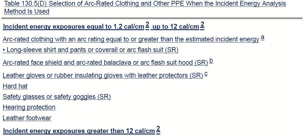

NETAWORLD • 13 ARC-FLASH TABLES AND MORE – THE 2018 EDITION OF NFPA 70E

Section (E) Equipment Labeling now reads: (E) Equipment Labeling.
Electrical equipment such as switchboards, panelboards, industrial control panels, meter socket enclosures, andmotorcontrolcentersthatarein and motor control centers that are in other than dwelling units and that are likely to require examination, adjustment, servicing, or maintenance while energized, shall be field-marked with a label containing all the following information:
(1) Nominal system voltage
(2) Arc-flash boundary
(3) At least one of the following:
a. Available incident energy and the corresponding working distance, or the arc-flash PPE category in Table 130.7(C) (15)(A)(b) or 130.7(C) (15)(B) for the equipment, but not both
b. Minimum arc rating of clothing
c. Site-specific level of PPE
Let us make clear that the 70E Committee does not require facilities to conduct a new incident energy analysis if the existing one is accurate — in fact, just the opposite. Several times, people have asked if they need to replace labels because they have HRC-0 information on them or if they need to replace labels because they contain incident energy at working distance and HRC information. The answer is no! The current exception was getting out of date, so it was revised to the following language:
Exception: Labels applied prior to the effective date of this edition of the standard shall be acceptable if they meet the requirements for equipment labeling in the standard in effect at the time when labels were applied.
This allows the exception to apply to later editions of NFPA 70E and maybe reduce some of the confusion being generated by companies pressuring their clients into replacing their labels just because there’s a new edition of 70E.
A new exception to 130.5(D) was also added. This recognizes that larger facilities may have multiple energy values, making the use of one
label unsuitable for all conditions. This also allows the information to be documented by barcode or other suitable means, as long as it is readily accessible.
Exception No. 2: In supervised industrial installations where conditions of maintenance and engineering supervision ensure that only qualified persons monitor and service the system, the information required in (E)(1) through (E)(3) shall be permitted to be documented in a manner that is readily available to persons likely to perform examination, servicing, maintenance, and operation of the equipment while energized.
Other Changes
Table 130.7(C)(15)(A)(b) now becomes Table 130.7(C)(15)(A) and has a new title: Arc-Flash Hazard PPE Categories for Alternating Current (ac) Systems. The table itself remains unchanged, but with Table 130.7(C)(15)(A)(a) moving to 130.5, reordering was necessary.
Table 130.7(C)(16) now becomes 130.7(C)(15) (C), Personal Protective Equipment (PPE). The table is changed somewhat to provide clarity. The requirement for ear canal inserts was deleted so other forms of hearing protection can be used. Most of the changes were made to correlate the table with other tables and language. One important change was a new note providing users with typical clearing times of common overcurrent protective devices. Operating time was often a stumbling block to users of the table method, and this addition will assist in its application.
A new note was added to Table 130.7(C)(15) (A) that states;
“Low Probability/High Consequence issues produce the same injuries as High Probability/ High Consequence issues if safe work practices and arc-rated clothing and PPE are not used and the event happens.”
This note is a caution for qualified persons to carefully evaluate the risks associated with the task they are about to perform. It is too easy (or lazy) to assume an arc flash won’t happen. If it
14 • SPRING 2016 ARC-FLASH TABLES AND MORE – THE 2018 EDITION OF NFPA 70E THENFPA70EANDNETA THE NFPA 70E
AND NETA
does occur, arc-rated clothing and PPE may be the only thing preventing a burn injury.
SUMMARY
This column is only the tip of the iceberg; about 430 public input submissions generated the first revisions of the document at the first draft meeting. The first revisions listed here are perhaps most interesting to the NETA community — but please, check it out for yourself because many more changes to the document are proposed.
Be sure to review the first revisions on www.nfpa. org/70e. Click the tab Next Edition, and take some time to review not only the committee actions, but also the committee statements. If you have any public comments to share with the committee, please complete the forms on the webpage. NFPA no longer accepts other forms of submittal.
And, stay tuned — it gets more exciting.


Ron Widup and Jim White are NETA’s representatives to NFPA Technical Committee 70E (Electrical Safety Requirements for Employee Workplaces). Both gentlemen are employees of Shermco Industries in Dallas, Texas, a NETA Accredited Company. Ron Widup is CEO of Shermco and has been with the company since 1983. He is a Principal member of the Technical Committee on “Electrical Safety in the Workplace” (NFPA 70E) and a Principal member of the National Electrical Code (NFPA 70) Code Panel 11. He is also a member of the technical committee “Recommended Practice for Electrical Equipment Maintenance” (NFPA 70B), and a member of the NETA Board of Directors and Standards Review Council. Jim White is nationally recognized for technical skills and safety training in the electrical power systems industry. He is the Training Director for Shermco Industries, and has spent the last twenty years directly involved in technical skills and safety training for electrical power system technicians. Jim is a Principal member of NFPA 70B representing Shermco Industries, NETA’s alternate member of NFPA 70E, and NETA’s Principal representative to the ASTM F18 Committee “Electrical Protective Equipment for Workers.”
Power System Acceptance Testing
Commissioning and Start-up
Maintenance
Life-Cycle Extension
Troubleshoot and Repair
Training and Engineering Services
Planning and Operations Support
Project Management
Six Solutions, Inc.
2200 West Valley Hwy North, Suite 100 | Auburn, WA 98001 |


ARC-FLASH TABLES AND MORE –THE 2018 EDITION OF NFPA 70E
Ron Widup
Jim White
Delivering Powerful Reliability Solutions
Sigma


Get Empowered with Doble.
Learn more about our in-service testing tools which help you to identify and locate electrical partial discharge, low-voltage arcing and mechanical system defects before they lead to asset failure.
www.doble.com/NETA
Empowering the industry with services, solutions and unmatched knowledge.
For nearly a century, Doble has been amassing an unprecedented amount of knowledge and practical experience in preventing asset failure. We share this knowledge through our products, services and training programs. We make sure you have the tools and information you need to perform your job and meet the needs of your customers.
We put the we in Empower
Far From Work, But Close To Data


Company A PQ Analyzers with Remote Wireless Communications ®

&
BY DON A. GENUTIS, Halco Testing Services
Partial discharge (PD) activity creates a sound often described as that of sizzling bacon. The sound is only applicable to surface PD activity, as sounds emitted from internal discharges are hopelessly trapped within the insulation. Other types of PD signals do escape, as we will discuss later. The sound produced by surface PD is not always similar to sizzling bacon, but the analogy is generally a good one for describing these surface PD events.
While barbecuing one recent weekend, steaks sizzling nicely on the grill, my thoughts randomly drifted to partial discharges. It occurred to me that the process of cooking meat over fire — at least when I am acting chef — shares some similarities to the stages of surface insulation damage that partial discharge causes. When meat is cooking, it exhibits physical, chemical, audible, and even aromatic changes. Similarly, when an insulation'slocalsurfaceelectricalfieldis insulation's local surface electrical field is compromised, partial discharge activity occurs and creates changes like that of cooking meat. The physical changes can include visible signs of surface tracking, chemical alteration of the insulation, and reaction with atmosphere. Audible sounds are more easily detected with ultrasonic detectorsthanwiththeunaidedhumanear. detectors than with the unaided human ear.
Aromatic changes, such as the generation of ozone and acidic byproducts which create a unique sharp smell, can also be detected.
As meat continues through the cooking process, the amplitude and frequency of the sizzling events increase — similar to partial discharge events during surface insulation breakdown. Typically, when surface PD is initiated, ultrasonic signals are all that can be detected. During the next stages of the cooking process, the meat could create a sudden fire, which is similar to a complete surface flashover of the electrical insulation. Fire or flashover can cause permanent damage to meat or insulation.
$25 SPACE HEATERS
High humidity has a drastic effect on increasing surface partial discharge activity. (I could go into the cold glass of lemonade condensation example from the same picnic, but I won't do that to you.) Outdoor medium voltage switchgear is always somewhat dusty. When atmospheric conditions are conducive to condensation, the moisture accumulation on the insulation
NO-OUTAGECORNER NO-OUTAGE CORNER PICNICS AND PARTIAL DISCHARGE 18 • SPRING 2016
surfaces, combined with other contaminants, can create partial discharge activity that leads to tracking and flashover of non-ceramic insulation. Thermostatically controlled space heaters can allow the internal switchgear elements to remain warm so that condensation and PD are prevented. Thus, the health of expensive outdoor switchgear can be dependent upon the health of a $25 space heater!
INTERNAL DISCHARGE
Electrical fields can also be compromised within electrical insulation. Just as a sharp conductor edge can initiate surface PD activity (see Figure 1), so can an internal sharp edge (in the right circumstances) coupled with an adjacent air void. In the case of cable terminations, poor preparation or lack of attention to cutback dimensions can create localized voltage stresses along the internal termination interface. These local stresses generate PD activity that can lead to failure, often in a similar manner to surface tracking.
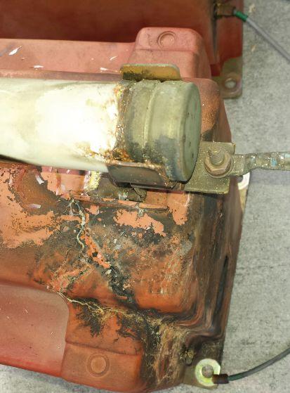
Many other types of internal insulation failures may occur due to PD activity. Because PD activity is internal, we seldom see the damage before it's too late. To prevent internal PD failure from occurring, it is necessary to detect the electrical pulses that are created from the sparking discharges, usually by using transient earth voltage (TEV) sensors. Don’t rely on ultrasonic technology alone, or you may miss the opportunity to prevent internal component failure.
Ultrasonic detectors require a pathway for the signal to reach sensors placed outside of switchgear. A vent or bolt-hole opening may be enough to allow an ultrasonic signal to escape, but not always. Figure 2 is an example of advanced surface PD tracking damage occurring king deep inside the switchgear at the back of the breaker receiver stabs. Ultrasonic signals could not escape from this location to a point where they couldbedetectedfromtheoutside.TEV could be detected from the outside. TEV sensors do a great job of detecting such potential eat disasters in time for performing necessary repairs.
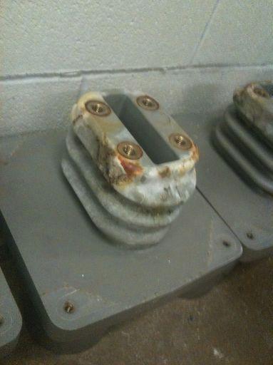
NO-OUTAGE CORNER PICNICS AND PARTIAL DISCHARGE NETAWORLD • 19
Figure 1: Surface PD Activity
Figure 2: Advanced Surface PD Tracking Damage
CONCLUSION
Many ever y-day experiences have parallel e scientific similarities — just like picnics and PD. Tr ying to understand a complex scientific phenomenon in simple terms allowsusto ws us to betterunderstandtheseev better understand these events.
Justasitisnecessar ust as it is necessar y to closely monitor the condition of your steaks while barbecuing, it is alsonecessar also necessar y to keep a close watch over your our medium-voltage insulation. Performing annual forming PDsur PD sur veys using handheld multi-sensor eys instruments or permanent monitors should be uments a part of that monitoring.
Hey, I just had a thought: WhatifImonitor What if I monitored ed my steaks using ultrasonic technology? Hmmm, maybe I'm on to something. I think I'm going tocall to call Webertomorr eber tomorrow.

DonA.G on A. Genutis enutis holds a BSEE from Carnegie-MellonU ellon University.H . Hehaso e has over 30 years of electrical testing experience. Don servesasP es as President of Halco alco Testing Services basedinLosA based in Los Angeles, California.

From Apollo 7 to Today’s Smart Grid



Utility Service Corporation has been providing electrical and technical services for government and industry since 1962.
Solving complex problems, testing under difficult and unusual circumstances and servicing the commissioning and maintenance needs of today’s electrical power systems both new and aged.
N O - O U TA G E C O R N E R
Preventative Maintenance Acceptance Testing High Potential Testing Commissioning Services System Studies Arc Flash Analysis Engineering & Consulting Construction Supervision System Trouble Shooting (256) 837-8400 Services:
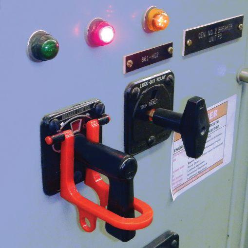
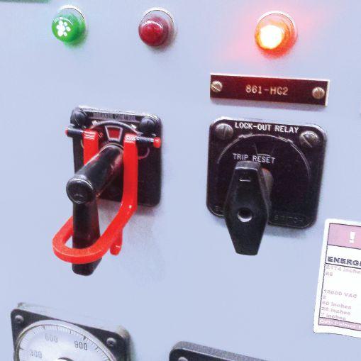

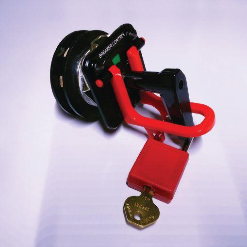


James R. (Jim) White is the Training Director of Shermco Industries, Inc., in Dallas, Texas. He is the principal member on the NFPA technical committee “Recommended Practice for Electrical Equipment Maintenance” (NFPA 70B). Jim represents NETA as an alternate member of the NFPA Technical Committee “Electrical Safety in the Workplace” (NFPA 70E) and represents NETA on the ASTM F18 Committee “Electrical Protective Equipment For Workers”. Jim is an IEEE Senior Member and in 2011 received the IEEE/PCIC Electrical Safety Excellence award. Jim is a past Chairman (2008) of the IEEE Electrical Safety Workshop (ESW).


No.113 No. 113
GENERAL TESTING AND MAINTENANCE
 BY JIM WHITE, Shermco Industries


This issue’s Tech Quiz will challenge your general testing and maintenance knowledge. NETA Technicians need a good understanding of testing and test results interpretation. Let’s see how you do.
1. First-out timing is performed to ensure:
a. All phases of the circuit breaker open within 25 milliseconds of each other.
b. The circuit breaker that should trip first will do so. This is also known as selective coordination.
c. The circuit breaker will rack out smoothly and without hesitation.
d. The circuit breaker will open within specifications after being closed for an extended period of time.
2. Partial discharges are created by:
a. Moisture that is trapped within the insulation
b. Ionization of air pockets within the insulation
c. Deep discounting at the Dollar General store
d. Carbon deposits vibrating within the insulation
3. What is considered a typical percent power factor for a new/in-service medium-voltage oil-filled power transformer?
a. 0.5%/1.0%
b. 1.0%/2.0%
c. 0.5%/2.0%
d. 1.0%/3.0%
4. When performing a VLF (very low frequency) test for in-service cable, what is the recommended test voltage for 15 kV-class power cable (per MTS-2015)?
a. 7 kV rms
b. 10 kV rms
c. 16 kV rms
d. 23 kV rms
5. What is the recommended minimum insulation resistance test value for a 2,300 V motor manufactured after 1970?
a. 50 MΩ
b. 75 MΩ
c. 100 MΩ
d. 200 MΩ
e. 500 MΩ
6. At what frequency is a VLF test performed?
a. 0.1 Hz
b. 0.2 Hz
c. 0.5 Hz
d. 1 kHz
7. What is the recommended moisture limit for in-service SF6 gas?
a. ≤ 500 ppm
b. ≤ 300 ppm
c. ≤ 200 ppm
d. ≤ 100 ppm
22 • SPRING 2016 TECHQUIZ TECH QUIZ See answers on page 118.


»


NOW IN HOUSTON


Electro Rent is proud to introduce its new Regional Service Center, serving your test needs better and faster than ever with experienced customer support 24x7. If it tests, we’ve got it— and we’re ready to deliver in Houston. »


CHOOSE BETWEEN KEEPING MAINTENANCE COSTS DOWN AND KEEPING UP WITH PRODUCTION DEMAND…OR DO BOTH. THAT’S THE CRITICAL DIFFERENCE. NETA certified experts at Electrical Reliability Services will keep you in perfect balance. To ensure the reliability of your electrical power, you have to balance the need to reduce maintenance costs with the need to perform regular maintenance. Only the team from Electrical Reliability Services delivers cost-effective services and system expertise to keep you up and running 24/7. Emerson, Business-Critical Continuity, Emerson Network Power and the Emerson and Double Helix Design are trademarks and service marks of Emerson Electric Co. ElectricalReliability.com
Largest inventory
Consistent, reliable delivery service
»
» Immediate availability
ISO
Vanguard Instruments Company, Inc. www.vanguard-instruments.com Y EAR S Electro Rent answers your every test need. Learn more at: www.electrorent.com/electr ica l-power 800.304.4744 | sales@electrorent.com E l e c t r Electro R e n t i s N o o Rent is Now a N E T w a NETA G o A Gol d ld C o r Cor p o r pora te A l l i a n c e e Alliance Pa r ar t n e r tner E l e c t r Electro R e n t o Rent Tu r ur n s 5 0 ns 50
and ANSI accredited labs


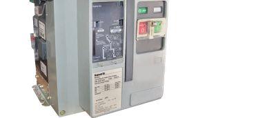


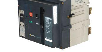


WE SAVE YOU TIME & MONEY BY PROVIDING THE SPARES YOU NEED FOR EMERGENCY REPLACEMENTS ON YOUR NEXT TESTING JOB We Stock All Manufacturers & Vintages of Breakers, Motor Control Centers, Starters & Contactors, Contact Kits, Disconnects, PLCs, VFDs, Busway & Bus Plugs, Transformers and MORE! New, Surplus & Reconditioned Electrical Equipment WE HAVE IT... THE INVENTORY, KNOWLEDGE AND EXPERTISE YOU NEED BUY, SELL RENT, REPAIR www.southlandelectrical.com 1.800.476.1486 SERVICE CALL US FOR *Some restrictions may apply Order by 4:00PM and we ship SAME DAY! * ALL PRODUCTS & SERVICES 123 E. MARKET ST. BURLINGTON, NC 27217 6 Locations in the Southeast to Serve You

LIFE IS BETTER
 BY KRISTEN WICKS, NETA
NETA's Board of Directors and Membership convened in Key West, Florida, for regularly scheduled meetings on January 21 and 22, 2016. Everyone enjoyed the warmer weather and laid-back culture of this island paradise, which was highlighted by a group dinner and then some timeoutonthetown. time out on the town.
January marks the half-way point in the association's fiscal year, so it is a good time to look back at the goals established at the beginning of the year and measure the progress of various programs and initiatives. The Board reported sound fiscal standings to the Membership and confirmed that programs are tracking as projected for the year.
Members were given progress updates on two projects related to the NETA Certification Program — the Exam Transition Project and the Exam Development and Project. The transition project has been in progress since May 2015 and involved an administrative change in the service provider for the NETA exams. The transition to the new provider was effective in November 2015, and any NETA Accredited Companies that sent technicians to test in January 2016 experienced the new testing platform and procedures. The development project has been in process since May 2015 as well and involved a complete review of the design of the certification exams for NETA Level II, III, and IV.
Additionaldiscussionscenteredaroundtherolloutof Additional discussions centered around the rollout of new communications protocols with the NETA office, the introduction of new NETA staff members, marketing and promotions activities, and a detailed overview of PowerTest2016. PowerTest 2016.
NETA Members gather over lunch following the meeting on Friday, January 21, 2016, for more casualconversation. casual conversation.

USED BY: WAUKESHA , CALPINE, TVA , FIRST ENERGY, PSE&G , L.A DEPT OF WATER & POWER, JACKSONVILLE ELEC. AUTHORITY & MANY MOREl Here's what you need to get it done . .. Burlington Safety Laboratory Inc. Accredited Proof Testing Laboratorv Services Rubber Gloves Sleeves, Blankets, line Hose, Footwear, Jumpers, and Hotsticks And Your Source for NFPA 70E Compliant Protective Gear Metro NY/NJ/PA 800-220-2120 Calif (Sfl 888-817-1412 Calif UAJ 800-296-2803 www.BurlingtonSaletv.com info@BurlingtonSafety.com 2AC Hipots 1 Field Portable AC Hi pot with higher kVA rating 1 DC Hipot w/Megohmmeter 0 - 30 kVac @ 1 kVA 0 - 50 kVac@ 3 kVA Shielded cable output & one piece 0-60 kVac@ 7 kVA or maybe 0-60/120 kVac@ 6 kVA 1 Oil Dielectric Tester 2 or 3 Very Low Frequency AC Hipots with Tan Delta 0-80 kVdc@ 10 mAwith HV Megohm meter HVI Products are ==== Made in the USA 0 - 30 kVac peak 0.4 1-'F@ 0 1 Hz ISO 9001 : 2008 Diagnostic Accessories 0 - 34 kVac peak wfTD 5-5 11 F@ 0 1 - 0 01 Hz VLFfThumper wNLF Burner 0 - 65 kVac peak w fTD 0 - 33 kVac peak , 0 1 Hz, 1 0 11 F 1 0- 10 11F@ 0 1 - 0 01 Hz 0- 13 kVdc@ 760 joules discharge 1!!9.!!..!. I.TAGE 31 County Rt. 7A • Copake, NY 12516 • Tel.: (518) 329-3275 • Fax: (518) 329-3271• sales@hvinc.com • www.hvinc.com

PERSONAL PROTECTIVE
BY JEFF JOWETT, Megger
This article series has reviewed worker safety during electrical equipment maintenance and repair, focusing on the necessity of proper installation and use of grounds. The previous article focused focused on the importance of establishing a continuous, low-impedance path importance establishing around the worker’s body so that he or she does not become a current she path if a fault occurs during contact with electrical equipment. This article examines how to avoid and deal with potential dangers.


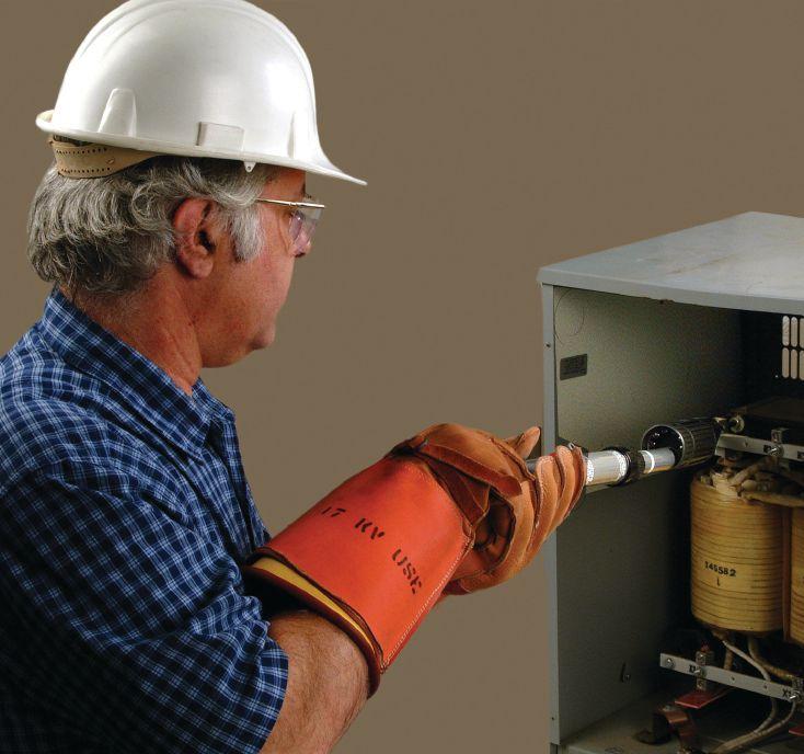
Many kinds of electrical tests and procedures require isolation from ground to eliminate parallel paths that can affect readings, while allowing the operator to focus on a specific part of the equipment being tested — stator to rotor, for example. OSHA permits this, e.g., OSHA29 CFR 1910.269(n)(8), as long as redundant safety measures are in place to protect the worker in case lines and equipment become energized. Protective grounds may be removed at such times, but only as a temporary measure during testing. It is the employer’s responsibility to assure that the employee has insulating equipment and is isolated from any possible hazards. Additional redundant protective measures may be in order. It is worth repeating that, from the standpoint of safety, by far the preferred equipment testing method is to leave grounds attached, disconnect conductor terminals, test, and then reinstall.
But it doesn’t stop there. Proper equipment and procedures are absolute necessities, but they are no substitute for operator awareness and education. Workers must be aware of all possible sources of danger and how to avoid
PERSONAL PROTECTIVE GROUNDING TECHTIPS TECH TIPS 28 • SPRING 2016
Operator Using Voltage Detector to Verify Equipment is De-Energized

or safely deal with them. Standard operating procedures for electrical repair and maintenance commonly refer to de-energized circuits and equipment, but this does not stop at pulling a plug or opening a switch. Nearby circuits that remain in service can be injurious or even lethal. OSHA has addressed this potential danger in OSHA 1910.333(b)(2)(iv)(B).
First, OSHA requires that a qualified person de-energize the equipment to be worked on by the normal procedures of opening switches and disconnects and so on. In addition, it must be verified that the equipment cannot be restarted, i.e. standard lock-out/tag-out procedures. Switches, panels, controls, and the like may be located at a considerable distance, where personnel unaware of work in progress could incept the circuit. Therefore, any such controls are not only locked but also tagged so that anyone knows when work is in progress.
However, it is not then assumed that the circuits to be tested are de-energized merely because a switch has been opened. The wrong circuit might have been engaged, the switch could be leaky or faulted, or some other compromise could exist. Accordingly, a qualified person must verify that all circuit elements and equipment parts are de-energized. Specialized indicators exist for this purpose. Voltage detectorsaremountedontheendsofhot-line detectors are mounted on the ends of hot-line poles and applied to circuits and equipment. Presence of voltage is indicated by both visible and audible warnings. The poles must be of suitable dielectric material and rated for the maximum voltage that could be encountered. But remember, where voltages higher than building-wiring voltages may be encountered (e.g., 120, 240, 480), the length of the pole is also critical. This prevents arcing to metallic objects on the worker’s body or in hand. Hot-line poles are marked accordingly to indicate a safe working distance up to the listed voltage. Collapsible poles must be set to the correct maximum.
For circuits over 600 V, standard procedure is to test the tester, test, and test the tester.
This routine is necessary because a broken indicatorthatshowsnoindicationcould indicator that shows no indication could be misinterpreted as an absence of voltage on the test item. Similarly, medium or high voltage applied during the test could damage the indicator and render it inoperative for the next test. Therefore, it is always retested at the conclusion by engaging a built-in test circuit or applying a verifier — a device that supplies sufficient voltage to incept the tester but not enough current to damage it. If several such devices may be in use at the same time, it is a useful redundant safety check to have voltage indicators that light a green LED when tested by a test circuit or verifier, and remain lit for some minutes. The purpose of this added protection is that the worker may set down the indicator to put on gloves or make some other preparatory adjustment, and then inadvertently pick up a different tester — one that may have just been damaged and rendered inoperative. Remember, redundant safety is the key to effective protection.
This redundancy is necessary and effective because hazardous voltages can also emanate from sources apart from the circuit under test. A false sense of security often comes whenacircuithasbeendisconnected.A when a circuit has been disconnected. A related problem is having a cavalier attitude to the dangers presented by lower voltages. Even though not lethal or even directly injurious, stray voltages produce annoying shocks that can cause involuntary reactions, thereby presenting a hazard of their own. The worker could be on a ladder, scaffold, or other tenuous footing, and pulling away or reacting spasmodically can cause a dangerous fall. Similarly, the worker may be in tight spaces close to moving parts and could pull away from a shock, only to become entangled with a belt, conveyor, or other physical hazard.
Accordingly, it is critical for all workers tounderstandandbeawareofadditional to understand and be aware of additional hazardoussourcesthatcanexistevenon hazardous sources that can exist even on electrical systems that are disconnected from all normal sources (switches open but no ground switches closed or grounding jumpers in place). The four possibilities include:
NETAWORLD • 29 PERSONAL PROTECTIVE GROUNDING TECH TIPS
1. Static charges
2. Capacitively coupled voltages
3. Electromagnetically coupled voltages
4. Lightning
Isolated circuits or equipment can build up a dc charge or voltage, often from unsuspected nonelectrical sources such as air flow, mechanical friction, and even dust. When done with a dc instrument, electrical testing can also leave static charge on equipment at the termination of the test. A prime example is insulation testing, where the voltage applied to perform the test can polarize the molecules of the insulating material, creating a separation of charge, and hence, a voltage. The direct-current voltage will add to any alternatingcurrent voltage that is present.

Static voltage can be in the tens of thousands of volts. Often, the discharge current is small and flows for only a fraction of a second. This can be a surprise shock that provokes a dangerous reaction, such as a fall or contact with nearby operating machinery. A single ground connection is sufficient to drain off this charge, usually in seconds; but if the circuit is again isolated, the charge can reappear. Static charges in insulation that result from testing can be lethal. The best protection is a quality instrument with a built-in discharge circuit, including warning indicators and a monitoring voltmeter so that the operator is aware of what is happening and will stand clear untilthetesterindicatesitissafe. until the tester indicates it is safe.
Capacitively coupled and static voltages can be immediately discharged by grounding one end. However, electromagnetically induced voltages cannot be completely discharged, even by grounding at both ends. Such a relationship constitutes a makeshift transformer, with the energized conductor acting as the primary and the isolated de-energized conductor the secondary. The accordant voltage is determined by the parallel length of the conductors, the separation distance, and the magnitude of fault current or load on the energized conductor.
The only total protection against lightning is to remain indoors. Substation and switchyard work should not be scheduled when such risk is at hand. Personal protective grounding may protect a worker on a lucky occasion but cannot be relied upon for complete protection. Multiple strokes can strike an overhead wire as many as 24 times in a fraction of a second. In extreme circumstances, the only way to be 100 percent protected is to be absent from the area.
Knowledge of potential dangers is an essential tool in worker protection, along with protective grounding, protective clothing, and safe practices. All substation and switchyard workers should be educated on potential sources of danger.
Whenevertwoormoreconductivesurfacesare Whenever two or more conductive surfaces are separated by insulation and one (or more) is energized, an ac voltage will be induced between the surfaces and steady-state charging current(s) will flow. This is capacitive coupling. These components can be substation bus conductors and the earth, and the insulation can be air. This is capacitively coupled voltage.
A conductor closely paralleling an energized conductor while isolated from its power source, if ungrounded, will develop all three voltages: static, capacitively coupled, and electromagnetically coupled. These will exist together in varying magnitudes on each phase conductor.


Jeffrey R. Jowett is a Senior Applications Engineer for Megger in Valley Forge, Pennsylvania, serving the manufacturing lines of Biddle, Megger, and multi-Amp for electrical test and measurement instrumentation. He holds a BS in Biology and Chemistry from Ursinus College. He was employed for 22 years with James G. Biddle Co. which became Biddle Instruments and is now Megger.
Reference: AVO Training Institute, Dallas, Texas
30 • SPRING 2016 TECH TIPS
PERSONAL PROTECTIVE GROUNDING
TECH TIPS





2016 P@WERTEST CO NFEREN C E M eggerm BCS SWITCHGEAR, INC. www.bcsswltchgeGr.com High Voltage POTOMAC TESTING CIRC ER SALES CO Inc. AGrlX!PCIS(Ciqlllll)' FORT WORTH, TEXAS OMNI FORT WORTH HOTEL MARCH 14-18, 2016 www powertest.org 888.300.6382 (NETA) Shermco Industries One Line. One Company NAT• SWITCHGEAR CBS tJD Safe· Distance Is SafetyMedium Volta e Low Volta e • - ;di- • • • Ravtech usAtn c • • • • • • • • • • • • • • • • • • BCS Switchgear, Inc . A ARBITER SYSTEMS EMERSON . Network Power Electrical Reliability Services Protec Equipment Resources Electric Power Systems RESA Power Solutions Electro Rent Shermco Industries Group CBS, Inc. SMC International IBEWLU 269 Doble Engineering Company Megger/AVO Training Institute, Inc THE PREMIER ELECTRICAL MAINTENANCE AND SAFETY EVENT * HOSTED BY NETA.



Independent Electrical Testing and Preventive Maintenance PROFESSIONAL SERVICES 609-890-8300 www.easternhighvoltage.com
MEDIUM-VOLTAGE AIR SWITCHES
–CONDITION ANALYSIS AND HAZARD AWARENESS
BY SCOTT BLIZARD and PAUL
When performing a condition analysis on medium-voltage air switches located in metal-enclosed switchgear, the person performing the task must be aware of all potential hazards. Furthermore, the individual must be qualified to perform the task and also have a solid understanding of each hazard and ways to mitigate those hazards.
To better understand the hazards involved with the analysis, testing, and maintenance of metalenclosed medium-voltage air switches, take a look at what sources contribute to each hazard.
LOCK OUT/TAG OUT OF ELECTRICAL AND MECHANICAL ENERGY
Prior to performing work on any electrical equipment, it must be de-energized and locked out to prevent inadvertent re-energization. Failure to properly perform lock out/tag out when performing maintenance on metal-enclosed medium-voltage air switches contributes to many injuries. Controlling the electrical energy of the air switch is the first and most obvious hazardous energy source that could cause injury. Prior to the start of a lock out/tag out procedure, review the electrical drawing and the arc-flash study to identify the personal protective equipment (PPE) required during isolation. Additionally, the task performer must identify the type of switch to be serviced and the electrical source(s) to be deenergized when isolating the switch.
Be aware of the air-switch compartment layout. Medium-voltage air switches come in several configurations, and the task performer must ensure that the line side of the switch is properly identified. Do not bypass interlocks or keyed systems. Secure the proper instruction manual for the make and model of the equipment prior to starting work. The air-switch operating compartment may be isolated, meaning that the operating devices may be located in one compartment while the air switch is located in a different compartment. During this step, electrical and mechanical energy are potential hazards, depending upon the type of air switch involved.
Electrically de-energize the air switch from its primary energy source, and ensure that the air switch is disconnected from all sources of power, including control voltage sources, if applicable. Once de-energized, verify that the air switch is at a zero energy state using the manufacturer’s approved method. Verify the accuracy of the detection or voltage measuring device against a
34 • SPRING 2016
CHAMBERLAIN, American Electrical Testing Co., Inc.
METAL-ENCLOSED MEDIUM-VOLTAGE AIR SWITCHES –CONDITION ANALYSIS AND HAZARD AWARENESS
SAFETYCORNER SAFETY CORNER
known source, then check for zero energy on the de-energized equipment, and test the detection equipment against a known source again. This will verify that the testing device was functional during the check for voltage.

manual mode. This will prevent someone from inadvertently operating the air switch.
For motor-driven operating systems, make sure the motor has been locked out or disengaged prior to starting work.
OTHER PHYSICAL HAZARDS
Gravity is also an energy that needs to be controlled. The size and weight of a medium-voltage air-switch panel cover can be heavy and awkward to remove prior to performing maintenance; therefore, take proper precautions. These may include getting another person to aid in removal of the panel or removing by mechanical means.

Testing for voltage requires its own level of PPE, depending on the voltage and equipment type per the tables in NFPA 70E 2015 or OSHA 1910.269 Appendix E. Determine which is applicable for the installation, whether commercial or utility, based on where the work is being performed. For example, in the NFPA 70E, use Table 130.7(C) (15)(A)(a) — Arc Flash Hazard Identification for Alternating (ac) and Direct Current (dc) Systems.Thistablewill . This table will tell you whether arc-flash protection is required based on the equipment condition and the task to be performed. If it is determined that arcflash protection is required for the task, then reference Table 130.7(C)(15)(A)(b) — ArcFlash Arc Flash PPE Categories for Alternating Current (ac) Systems or 130.7(C)(15)(B) — Arc Flash Hazard for Direct Current(dc) Systems, whichever is applicable. These tables will identify what level of arc-flash protection is required for the task as well as the arc-flash boundary. Performers can then reference Table 130.7(C)(16) — Personal Protective Equipment (PPE) toensure to ensure that they are performing the task using all the appropriate PPE. Additionally, rubber gloves, sleeves, insulated tools, and other rubber goods may be required during the isolation procedure. These specialized pieces of PPE and other equipment must be rated for the voltages worked with and tested per the applicable ASTMStandard. ASTM Standard.
However, electrical energy isn’t the only energy that requires lock out/tag out. The air switch may contain a large amount of mechanical energy. This energy must be dissipated prior to servicing or serious injury could occur. Once the air switch has been discharged, lock out and tag out the charging mechanism, if feasible. In the case of a motor-operated switch, ensure that remote operating handles are tagged in a local or

INSTALLATION OF TEMPORARY PROTECTIVE GROUNDS
Refer to OSHA (29 CFR 1910.269) and NFPA 70E for specific guidance on grounding locations and sizing of grounds required for the task. Grounds must always be applied upstream and downstream of the equipment and as close to the work as possible. Always ensure that work is done between the grounds and that you remove them once the work is complete.
PROPER PERSONAL PROTECTIVE EQUIPMENT

Prior to beginning any work, verify that the metal-enclosed medium-voltage air switches are electrically de-energized; in some cases, this may be accomplished through remote operation. Ensure that proper PPE is used for the class of air switch serviced or any adjacent energized equipment. Adjacent equipment may require different levels of PPE if the work is performed within its limited approach boundary.

Refer to the three applicable tables in the NFPA 70E 2015 or to OSHA 1910.169 Appendix E again. It will indicate the level of protection required and will aid in preventing


NETAWORLD • 35 METAL-ENCLOSED MEDIUM-VOLTAGE AIR SWITCHES –CONDITION ANALYSIS AND HAZARD AWARENESS
SAFETYCORNER SAFETY CORNER


electrical shock and protect personnel from arc flash. However, this table provides information based upon known values of the short-circuit current available, the clearing time in cycles, and minimum working distance. If those factors are unknown, more information must be gathered prior to performing the work to ensure personnel safety.
CHEMICALHAZARDS CHEMICAL HAZARDS
Some lubricants and cleaners may pose a respiratory and skin irritant if used in enclosed areas or on bare skin. Knowledge of the material, reading its label, and checking the Safety Data Sheet (SDS) is advised to identify any potential health effects from its use. Once again, use of proper PPE is necessary for using some cleaners and lubricants. For example, nitrile gloves, safety glasses, face shield, and even respiratory protection may be needed.
HUMAN ERROR MITIGATION
Simply put, human error is a person (or persons) making a mistake. To prevent an error, follow a procedure or checklist while performing the task. If one doesn’t exist, create one.
Nomenclature should be verified and reverified upon approaching a piece of equipment. Perform a self-check and a peer-check to ensure that the task is being performed on the correct component.
When working around similar-looking pieces of equipment, use markings such as flagging to identify the components that should not be touched. Flagging can take several forms, depending upon the company or client’s policy and procedures. Do not forget to identify, mark, then lock out/tag out all associated equipment (e.g. associated cables and compartments). Flagging could be used to indicate a component that is not operating normally.
Barricading off a safe work zone prevents other workers from inadvertently entering the work area. This will ensure that maintenance and testing is conducted in an area under your control. Use a test stand in this area, if applicable. Ensure
that any control voltage required to operate the switch during testing is within the secured area.
CONCLUSION
There are many potential hazards to watch out for when performing maintenance and testing on metal-enclosed medium-voltage air switches.
1. Obtain all service bulletins, maintenance documents, arc-flash studies, and manuals prior to beginning work for that specific device.
2. Review all prints and one-lines associated with the equipment.
3. Establish a safe work area, and barricade off the work area.
4.Perform a pre-job brief with all employees on site.
5. Wear proper PPE.
6. Disconnect any control circuits and test equipment before performing visual or mechanical inspections or during maintenance.
7. If applicable, verify zero energy (test, check, test) and discharge all stored energy.
8. If possible, lock out and tag out (mechanical and electrical energy sources).
9. Connect grounds where, and if, applicable;
10. Identify, visually mark, and/or flag the equipment worked on.
Following these steps will lead to a safer work environment while performing maintenance and testing of metal-enclosed medium-voltage air switches.

Scott Blizard has been the Vice President and Chief Operating Officer of American Electrical Testing Co., Inc. since 2000. During his tenure, Scott acted as the Corporate Safety Officer for nine years. He has over 25 years of experience in the field as a Master Electrician, Journeyman, Wireman, and NETA Level IV Senior Technician.
Paul Chamberlain has been the Safety Manager for American Electrical Testing Co., Inc. since 2009. He has been in the safety field for the past 17 years, working for various companies and in various industries. He received a Bachelor of Science degree from Massachusetts Maritime Academy.
36 • SPRING 2016 METAL-ENCLOSED MEDIUM-VOLTAGE AIR SWITCHES –CONDITION ANALYSIS AND HAZARD AWARENESS
SAFETYCORNER SAFETY CORNER

National Field Services has opened two new locations – in Central Texas and on the Gulf Coast, giving us the power to serve you better. So now we can provide our world-class expertise to even more local markets in Texas. Our 24/7 responsiveness will be at work from our two new offices. So we can keep our customers’ critical systems always on. And it will be easier than ever for our certified technicians and engineers to come to your facility to take care of your needs. National Field Services handles everything from commissioning and start-up to disaster recovery. Ready to connect? Visit natlfield.com today.
Gulf Coast Branch
Central Texas Branch
800-300-0157 natlfield.com THE POWER TO SERVE YOU BETTER.
POWERTEST BOOTH 129
VISIT US AT
Absolute confidence. Every time.
You can count on us for specialized experience in healthcare, data center, office complex, and commercial acceptance and maintenance testing. Absolutely Power generation, petrochemical, oil & gas, and heavy industries also look to us for high demand services such as start-up commissioning, maintenance testing, shut-down and turnarounds, and breaker shop repair. Get started today.


Email: Alan Postiglione apost@absolutetesting.com

Toll free: 832.467.4446 6829 Guhn Road, Houston, Texas 77040
absolutetesting.com Like us on:




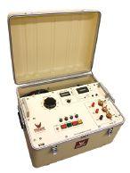
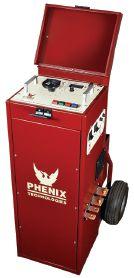
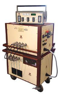
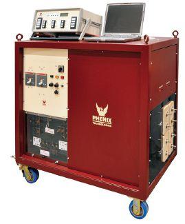
ISO 9001 C E R T I F I E D Taiwan +886.2.2835.9738 info@phenixasia.com Switzerland +41.61.383.2770 info@phenixsystems.com 35+ Years Experience HIGH VOLTAGE - HIGH CURRENT - HIGH POWER TEST SYSTEMS and COMPONENTS 1-301-746-8118 www.PhenixTech.com info@phenixtech.com • 75 Speicher Drive, Accident, MD 21520 USA High Current Circuit Breaker Test Sets Ideal for testing thermal, magnetic, and solid state relays, molded case circuit breakers and ground fault trip devices, plus other applications requiring a high current source. Made for field testing. Models up to 75,000 Amps. Features: Proven duty cycle Auto-jog and current-hold capabilities. Mobile units offer: Manual or computer operation with numerous automated modes. Precise, repeatable current pulses, minimal distortion. Current wave form display with WIN HC.


SEL RELAY COMMISSIONING FOR SCADA POINTS USING


 BY RICHARD FURMAN, Southwest Energy Systems, LLC
Southwest Energy Systems, LLC (SES) recently performed level four Supervisory, Control, and Data Acquisition (SCADA) testing for a building management system utilizing Schweitzer Engineering Laboratories (SEL) relays for the 13.8KV distribution system at a data center.


What is level four testing, and what does it take to test this type of system at level four?
The United States Army Corp of Engineers (USACE) refers to level four testing as proving the communication interfaces such as SEL fast message, Modbus, Distributed Network Protocol 3.0 (DNP3), and IEC 61850. Level three testing only proves the relays input/output, element, and functional testing. During the commissioning of this SCADA system, several problems were noted, including incorrect bit mapping, flipped bits, and wrong word bits. To perform level four testing, you need the joint effort of information technology (IT) personnel and a qualified relay technician.
SYSTEM DESCRIPTION
The electrical system under analysis here is a primary loop service using several 10 MVA, 69kV to 15kV transformers for the primary feeds, with back-up generation consisting of several 2 MW generators coupled with the use of several low-voltage uninterruptable power supplies (UPS), making this a robust system capable of supplying constant load. In this article, only one of the many substations used in
the distribution service loop will be examined. This SCADA installation uses a graphical user interface (GUI) and human machine interface (HMI) to monitor and control the system. Communications are via ethernet connection to the real-time automation controller (RTAC) system, which receives its signals from the many SEL relays installed on the system.
COMMUNICATION SYSTEM
The communication system is a cost-effective, third-generation or networked architecture. In this example, the main 15kV medium-voltage circuit breaker uses an SEL-351A relay for typical functions such as instantaneous and time overcurrent (50/51) phase and ground. Loop 1 and Loop 2 both use 15kV medium-voltage circuit breakers with SEL-751A relays for voltagerelated elements such as over/under voltage (27/59), negative sequence (47), and sync (25).
There are many types of RTAC system configurations (Figure 1). To maintain client confidentiality, the exact system details have been omitted from this discussion. This example merely shows all of the typical systems involved


RELAY COLUMN SEL RELAY COMMISSIONING FOR SCADA POINTS USING TEST DB COMMAND NETAWORLD • 41
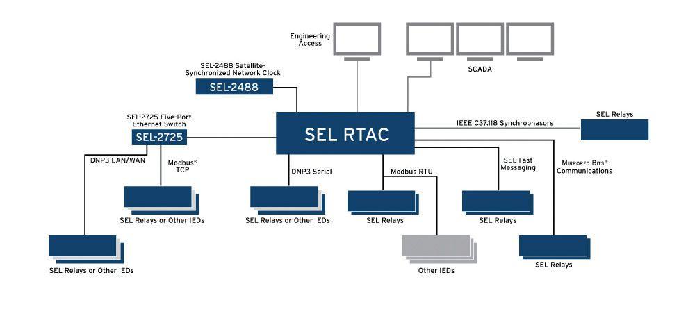
in a SCADA system and is sufficient to convey the complex schemes needed to provide adequate supervisory, control, and data acquisition of an elaborate electrical system.
WHERE IS SCADA USED?
SCADA is used to manage any kind of gear. Typically, SCADA systems automate complex processes where human control is impractical — systems where there are more control factors, and more fast-moving control factors, than human beings can comfortably manage (Figure 2).
Figure 2: Operations Controlled by SCADA Systems (Source: DPS Telecom www.dpstele. com/scada/where-is-used.php)
Around the world, SCADA systems control:
• Electric power generation, transmission, and distribution. Electric utilities use SCADA systems to detect current flow and line voltage, to monitor the operation of circuit breakers, and to take sections of the power grid on or offline.
• Water and sewage. State and municipal water utilities use SCADA to monitor and regulate water flow, reservoir levels, pipe pressure, and other factors.
• Buildings, facilities, and environments. Facility managers use SCADA to control HVAC, refrigeration units, lighting, and entry systems.
• Manufacturing. SCADA systems manage parts lists for just-in-time manufacturing, regulate industrial automation and robots, and monitor process and quality control.
• Mass transit. Transit authorities use SCADA to regulate electricity to subways, trams, and trolley buses; to automate traffic signals for rail systems; to track and locate trains and buses; and to control railroad-crossing gates.
• Traffic signals. SCADA regulates traffic lights, controls traffic flow, and detects outof-order signals.
RELAY COLUMN
SEL RELAY COMMISSIONING FOR SCADA POINTS USING TEST DB COMMAND 42 • SPRING 2016
Figure 1: Example of an RTAC System (Source: Schweitzer Engineering Laboratories, Inc.)
SECURITY ISSUES
It is almost impossible to talk about SCADA these days without mentioning its vulnerability. When you are talking about the United States transportation, water supply, or electrical grid, cyber security against terrorism is a must. Since SCADA sometimes uses Transmission Control Protocol and Internet protocol (TCP/ IP), the North American Electrical Reliability Corporation (NERC) and Critical Infrastructure Protection (CIP) have increased security demands on this type of system, resulting in the use of satellite-based communications. The main advantages of satellite-based communications are self-contained protocols, built-in encryption, and no public access to phone lines.
The HMI (Figure 3) controls the electrical system while the GUI, also known as a historian, serves as a graphical representation of the system in realtime, displaying events, conditions, and alarms. The HMI allows the user to drill down into the specific parts of the system and actually control that part of the system by opening/closing circuit breakers, resetting relays and alarms, etc.
TEST DB COMMAND
It may be required, as it was in our experience, that all SCADA points are tested and verified on the HMI and GUI. While some of these points are simple to test, others are not and require the use of the test db command, which is embedded within the SEL-351A relays. Below is a modified list of what was required to satisfy the requirements in this project:
1. Relay trip
2. 86 trip
3. 50 trip
4. 51 trip
5. Ground trip
6. A-phase trip
7. B-phase trip
8. C-phase trip
9. Relay-time sync — normal/fail
10. Relay status — normal/trouble
11. Relay Fail — normal/fail
12. Relay Enable — enabled/disabled
13. Voltage and current for analog metering
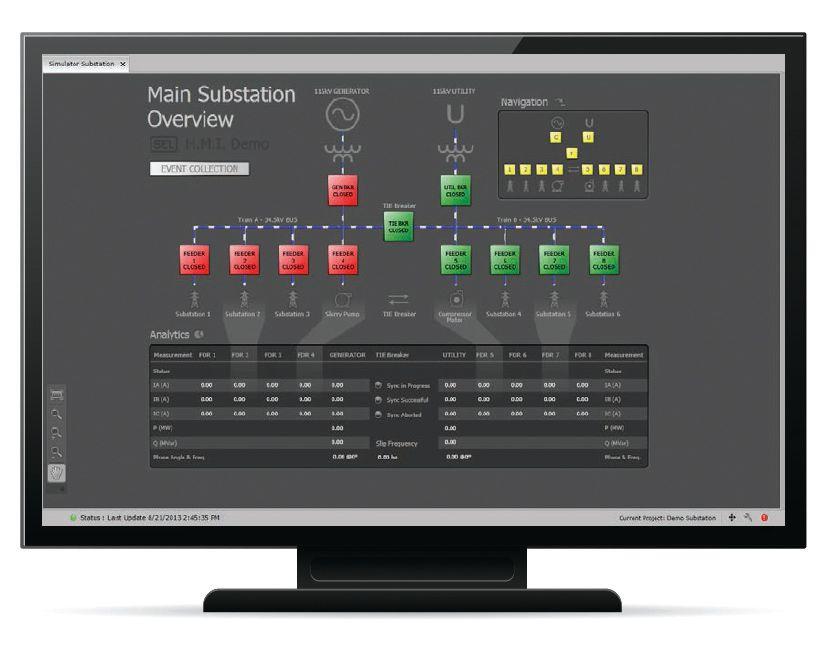
As evidenced, many of the functions were executed by injecting currents and voltages at appropriate levels with a relay test set. This would trigger the relay word bits to be sent via ethernet to the RTAC and distributed to the HMI and GUI. So, how is relay fail or relay disabled sent on an SEL-351A without tearing out the boards? The answer is the test command. This mode temporarily overrides relay word bits or analog values in the communication interfaces such as DNP. DNP is a set of communication protocols used between components in process automation systems. Its main use is in utilities such as electric and water companies. While not commonly used in other industries, it was used in this system. The actual values used by the relay for protection and control are not changed, but the data or analog value used in the communication interface allows verification of the remote devices to confirm that the proper information from the intelligent electronic devices is received. (IED)
To access the test db command, access the relay via hyper-terminal and access the relay at level two. Once granted access, type test dbon and press the {Enter} key to enter the test db command mode. From here, sending word bits via ethernet communication is easy; simply enter d for digital
NETAWORLD • 43 SEL RELAY COMMISSIONING FOR SCADA POINTS USING TEST DB COMMAND RELAY COLUMN
Figure 3: HMI Example (Source: Schweitzer Engineering Laboratories, Inc.)


or a for analog. The word bit mapped in the DNP can be toggled easily by entering 1 for on and 0 for off. The following is an example of the hyperterminal string used to toggle the relay-fail status using the word bit stfail:
1. Test db on and press the {Enter} key, which enters the db test mode
2. Test db d stfail 1 and press the {Enter} key, which overrides the word bit stfail on
3. Test db d stfail 0 and press the {Enter} key, whichoverridesthewordbit which overrides the word bit stfail off
4. Test db off and press the {Enter} key to exit the db test mode and return all overrides to normal
While the stfail word bit was set to 1, the HMIandGUIshouldseewhateverwordbitis HMI and GUI should see whatever word bit is associated with the stfail change state (normal/fail or normal/alarm, etc.) — simple as that.
Now, here is the string for analog signals:
a. Test db on and press the {Enter} key.
b. Test db a IA 100 and press the {Enter} key.
c. Test db a IB 150 and press the {Enter} key.
d. Test db a IC 200 and press the {Enter} key.
e. Test db off and press the {Enter} key.
Before turning the mode off in the last command string, the HMI and GUI should see 100 amperes (amps) on phase A, 150 amps on phase B, and 200 amps on Phase C. The same can be done for voltage using va, vb, vc, etc.
Other uses for the test db command include forcing elements such as 51PT active or toggling a set of bits defined in the relay’s word-bit mapping.
CONCLUSION
This test db command mode proved instrumental in satisfying our client's strict requirements. While not widely used, knowing about this mode can prove very helpful in certain situations. It is important to note that not all SEL relays have this mode available. Several other types of SEL relays were attached to this system, which had the same SCADA point requirements.
A liability waiver was requested for impending damages to the relays when respective relay boards were removed to activate the HMI and GUI relay disabled or relay fail signals. The client elected to omit these SCADA point verifications from the list. Unfortunately, the specific type of GUI and HMI software used with the specific modeling of the system cannot be disclosed. At any rate, it would just dilute the point of this article, which is to provide another tool in the toolbox — test db command mode — when it comes to commissioning relay SCADA points.

Richard Furman earned an Associates of Applied Science of Electronic Engineering Technology from ITT Technical Institute in 1996. Employed at Southwest Energy Systems, LLC since January 14, 2008, Richard is NETA Level 4 Certified. In his current position as Electrical Test Technician/Electrical Specialist, Richard’s responsibilities include the commissioning, acceptance, and maintenance testing of utility generation/distribution substations, data centers, mining sites, and industrial facilities electrical systems. His primary focus for the past five years has been in protective relaying, which includes microprocessor-based, solid-state, and electromechanical relays.
SEL RELAY COMMISSIONING FOR SCADA POINTS USING TEST DB COMMAND 44 • SPRING 2016 RELAY COLUMN







Reliability Solutions
Them Introducing the Maintenance Technology app for iPhone, iPad, iPod touch, Android and Kindle. Get each month's edition in a clear, readable format optimized for your tablets and phones — and browse the archives to catch up on what you may have missed. Discover the latest strategies, news format that works for you. PLANT PERFORMANCE ON THE GO For more information and to download, visit MaintenanceTechnology.com/Apps Apple, the Apple logo, iPhone, iPad and iPod touch are trademarks of Apple Inc., registered in the U.S. and other countries. App Store is a service mark of Apple Inc.
Wherever You Want
SPOTLIGHT STAGE PRESENTATIONS
SCHEDULE
StagePresentations
FORT WORTH, TEXAS OMNI FORT WORTH HOTEL MARCH 14-18, 2016 www.powertest.org 888.300.NETA(6382) THE PREMIER ELECTRICAL MAINTENANCE AND SAFETY EVENT HOSTED BY
12:30-12:45 PM For more information about the NETA Corporate Alliance Program visit netaworld.org/corporate-alliance-partners or call 888-300-6382 To view the Trade Show floor plan, please visit: powertest.org/exhibition/floor powertest.org/exhibition/floor-plan
OMICRON A Guided Workflow Approach to Transformer Diagnostic Testing AVO Training Institute, Inc. How Important is Electrical Equipment Maintenance? Electro Rent Test Equipment Acquisition Methods, Including a Financial Perspective ComRent Load Bank Solutions High-Definition Commissioning — Part 2 Doble Engineering Company Improving Electrical System Assessments through In-Service Surveying Solutions Utility Relay Company Advancing Low-Voltage Circuit Breaker Retrofit Protection Technology WEIDMANN Electrical Technology Moisture in Insulation and Transformer Dryout protecequip.com 12:50-1:10 PM 1:20-1:35 PM 1:45-2:00 PM 2:10-2:25 PM 2:35-2:50 PM 3:00-3:15 PM 3:25-3:40 PM Spotlight
Tuesday, March 15, 2016 During the PowerTest 2016 Trade Show in the exhibit hall. Join NETA’s Corporate A lliance Par tners as they share in sights and best practices on the Spotlight Stage at PowerTest 2016. Door prize drawing for Spotlight Stage attendance. Drawing at 5:45 PM. 3:50-4:05 PM 4:15-4:30 PM 4:40-4:55 PM Protec Equipment Resources Battery Testing Methodologies Megger TRAX — Transformer and Substation Test System Intellirent The Latest and Greatest in Electrical Testing SMC International Top Testing Product Insights and Updates BCS Switchgear, Inc. News on Molded Case and Insulated Case Switchgear Circuit Breaker Sales Co., Inc. TBD 5:05-5:20 PM 5:30-5:45 PM





SAVE THE DATE ANAHEIM • CALIFORNIA February 27 - March 3 • 2017 DISNEYLAND HOTEL POWERTEST.ORG 888.300.6382 THE PREMIER ELECTRICAL MAINTENANCE & SAFETY EVENT Join us in the land of golden promise. February 27 through March 3


National Field Services, a NETA-accredited electrical testing company, is now offering training courses on a range of safety and technical topics at our National Training Center in Lewisville, Texas. Our instructors can also conduct most courses at your facility, on your schedule. Find our Course Catalog and more information at natlfield.com/training or contact Training Program Manager Steve Newton at steve.newton@natfield.com or 469-312-1230. 800-300-0157 natlfield.com/training
GET CURRENT ON ELECTRICAL SAFETY AND STANDARDS. VISIT US AT POWERTEST BOOTH 228


NETA has been connecting designers, specifiers, architectsa s and users of electrical power equipmenta t and systemswit s with idependent, third-party electrical testing companies since1 ce 1972.


NETA Accredited Companiestestt ies test thec e complete system in accordancewit ce with industry codesa des andst d standardst ds to provide accurate test reports you can count t on every time


HIRE A NETA ACCREDITED COMPANY. Formore informationonNETA or our ANSI/NETA Standa Standards s give us a call at 888-300-NETA (6382) or a complete listing of NETA Accredited Companies visit www.netaworld.org.
Ensure YOUR Safety and Reliability.
TO COOK A GOOSE –

OF IEC 61850 PROTECTION SYSTEMS
BY WILL KNAPEK, OMICRONelectronics OMICRON electronics
With the advent of microprocessor relays, now known as intelligent electronic devices (IEDs), the power of the communications scheme implementation was sure to follow. As the IED evolved, several communication protocols were developed that had manufacturers and IED users in a constant battle to keep up with each system. In the mid 1990s, several forward-thinking engineers got together and took the best of some protocols and came up with the future-proof standard we have today: IEC 61850.
With this new standard came the possibility to have interoperability between manufacturers, reduced costs from less wiring, flexibility to support different protection philosophies, and the ability to follow the progress in communication technology.
When implementing this new way of wiring the substation control system, the old way of testing is no longer valid. With IEDs, it is not practical to focusonvalidationofcurvesandtimers.TheIED focus on validation of curves and timers. The IED has replaced the springs, magnets, and bearings found in electromechanical relays. Proving that the microprocessor can perform mathematics should not be the focus of substation testing. Now, the emphasis must be on the system as a whole and ensuring that the logic intended to protect the system is working properly.
Let’s look at the IEC 61850 device testing procedures and how we can be successful testing these systems.
IEC 61850 BACKGROUND
The IEC 61850 international standard for power utility communications defines not only protocols but also data models for substation equipment, abstract communication services, and a standard format to represent the system’s configuration called substation configuration language (SCL).
System Configuration Language
One of the fundamental aspects of the IEC 61850standardistodefineastandardized 61850 standard is to define a standardized configuration for the overall communication system. This is done in Part 6 of the standard with the definition of the substation (system) configuration description language. It specifies an XML file format for describing substation functional design and communication-related IED and system configuration. Its main purpose is to allow the exchange of communication configuration data between different engineering tools in a compatible way.
FEATURE HOWTOCOOKAGOOSE–ORTESTING HOW TO COOK A GOOSE – OR TESTING OFIEC61850PROTECTIONSYSTEMS OF IEC 61850 PROTECTION SYSTEMS 50 • SPRING 2016
Data Model
Data modeling is the first step of the communication method defined by the IEC 61850 series. IEC 61850 uses the concept of virtualizationinthecreationofthedatamodel.In virtualization in the creation of the data model. In other words, it models the common information found in real substation equipment. This data model provides an image of the physical world for the substation automation system. IEC 61850 makes use of a hierarchical organization of data that consists of five levels: server, logical device (LD), logical node (LN), data object (DO), and data attribute (DA).
Standardized logical nodes are used as building blocks for composing substation IEDs (Figure 1). Consider a certain transmission line that is protected with a time overcurrent function (LN PTOC) and a distance function (LN PDIS). A general trip (LN PTRC) should also be emitted to the circuit breaker (LN XCBR). The associated logical nodes defined in the standard are used for data modeling and can be distributed as desired through the available IEDs.
The client/server represents the services used by aclienttoretrieveinformationandsendcontrol a client to retrieve information and send control operations from/to IED servers, forming a typical SCADA system for supervising and controlling the substation. For implementation of these communication services, Part 8-1 of the standard defines the mapping and use of the manufacturing message specification (MMS) protocol.
Theothercommunicationmethoddefinedisthe The other communication method defined is the GOOSE message. It is used for the fast and reliable exchange of real-time information between IEDs in the bay and process levels. It is a multicast layer-two message published by an IED over the network that can be subscribed by any other IED connectedtothesamenetwork.Toincreaseits connected to the same network. To increase its reliability, the message is repeatedly published even if no changes occur. With the GOOSE message, any information (conventionally transmitted via binary outputs, copper cables, and binary inputs) can now be exchanged through the communication network (Figure 2). It replaces the point-to-point, hard-wired connections between devices for the exchange of IO binary data. Presumed advantages are:
• Saving significant copper and installation time
• Easier connection testing
• Changing the wiring as just a configuration issue
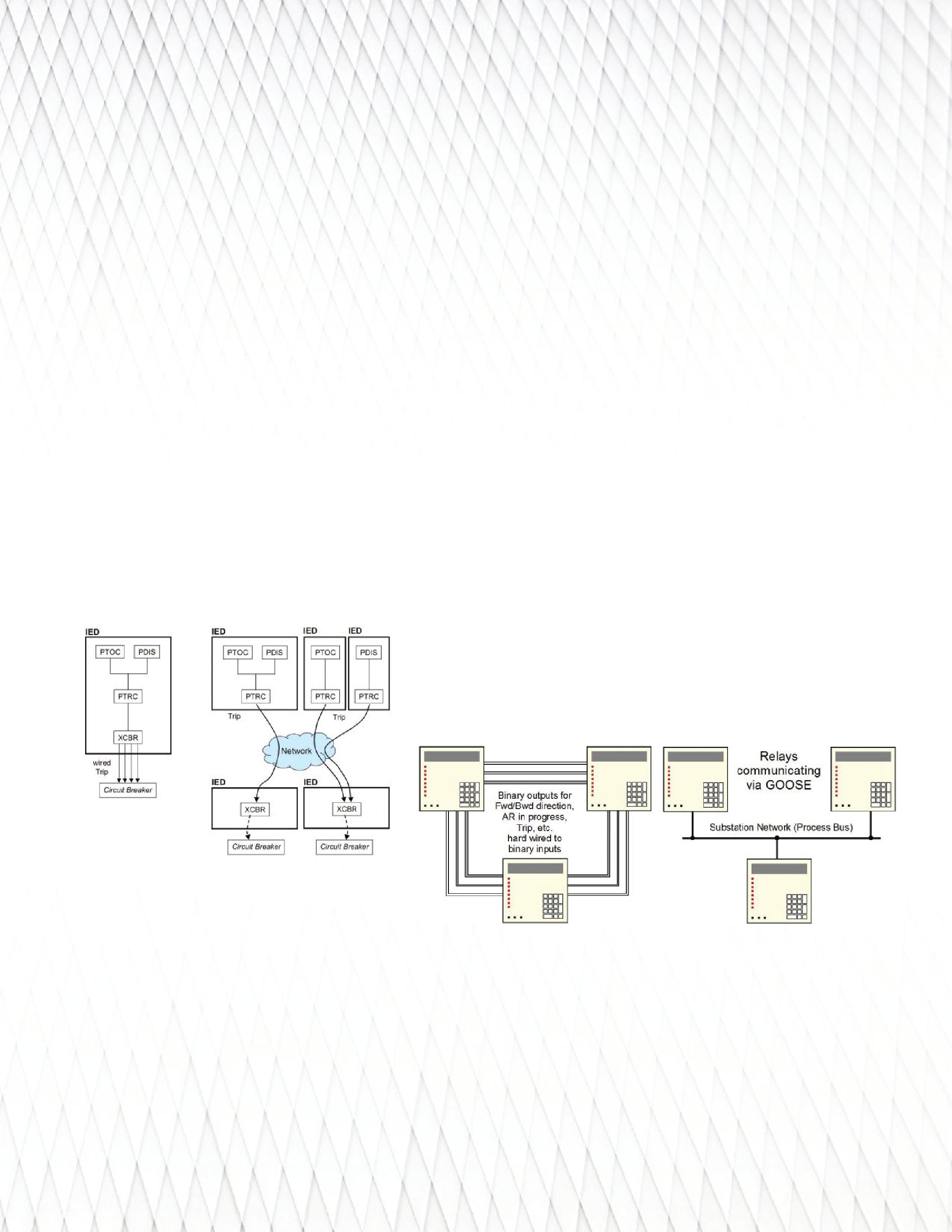
ServicesandProtocols
Services and Protocols
As communication services, the standard defines threeclassesofcommunicationtobeusedfor three classes of communication to be used for substation protection, control, and automation: client/server, GOOSE, and sampled values. Currently, the standard defines mappings of theseservicestoconcretecommunication these services to concrete communication protocols that use Ethernet as physical media for transporting information.
Thethirdservicedescribesamulticast The third service describes a multicast communicationmechanismforthetransmission communication mechanism for the transmission of current and voltage-sampled measured values through the substation network. It is called sampled values and replaces the classical secondary analog signals from CTs and VTs.
NETAWORLD • 51 HOWTOCOOKAGOOSE–ORTESTING HOW TO COOK A GOOSE – OR TESTING OFIEC61850PROTECTIONSYSTEMS OF IEC 61850 PROTECTION SYSTEMS
FEATURE
Figure 1: Example of Flexible IED Composition Using Logical Nodes
Figure 2: Hard-Wired Connections Replaced by GOOSE Messages
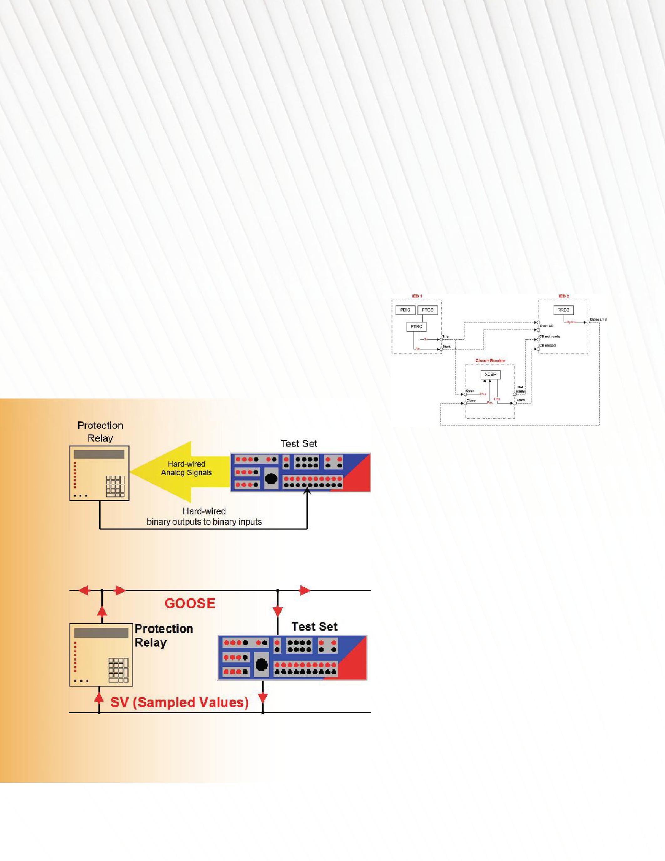
FUNCTIONAL TESTS
During a site or factory acceptance test, as well as for routine tests, a functional test of the IEDs and the overall system is required. Tests are performed to certify the correct functionality of the following applications, among others:
•Protection • Protection
• Control/interlocking
•SCADA • SCADA
• Monitoring
• Recording
• Metering
TheuseofIEC61850forthecommunication
The use of IEC 61850 for the communication has changed the way these tests are performed. Instead of hard-wired connections of pickup and trip signals between test set and relay, for example (Figure 3), the commissioning engineer has to configure virtual wiring with GOOSE messages. In a fully networked protection-testing scenario (Figure 4), the fault values are also sent by the test set over the network as sampled values.
As an example of an application using GOOSE, Figure 5 shows an overview of an autoreclosure function implemented in one bay of a substation. The autoreclosure function (RREC) is implemented in IED 2 (any protection relay or bay controller) and has to be started from the protection functions implemented in IED 1 (any protection relay with PDIS or PTOC, for example). Both IEDs interface with the circuit breaker to know its status and to send open and close commands. All signal exchanges are done via GOOSE. In this example, the IEDs measure voltages and currents through physical analog inputs and not via sampled values.
5: Overview of the Autoreclosure Function and GOOSE Exchange Between IEDs
TESTING PROTOCOL
Isolating
the IEDs Under Test
For commissioning de-energized substations, the test can be done without much worry. However, for maintenance tests in already energized substations, special precaution should be taken to isolate the IEDs under test. This will avoid any accidental breaker trip or undesired exchange of signaling between IEDs due to the test. One easy option is to disconnect the device under test from the network. However, it is not a recommended option — or even possible — depending on the networkarchitecture. network architecture.
The second edition of IEC 61850 provides some enhanced features to accomplish the test isolation. The main features include the ability to put an IED in test mode and simulation flag in GOOSE and sampled values. To isolate an IED under test, the first step is to set it to TEST Mode (MOD = test). In this case, all GOOSE messages sent by this IED
HOWTOCOOKAGOOSE–ORTESTING HOW TO COOK A GOOSE – OR TESTING OFIEC61850PROTECTIONSYSTEMS OF IEC 61850 PROTECTION SYSTEMS 52 • SPRING 2016
Figure 3: Conventional Hard-Wired Protection Testing
Figure 4: Fully Networked Protection Testing
FEATURE
Figure
are signaled for test purposes (q.test = true). Other IEDsconnectedtothenetwork thatareinnormal IEDs connected to the network that are in normal operation mode will ignore these messages. Secondly, set the IED to subscribe only to simulated messages, ignoring all messages coming from the process. This is accomplished by setting the IED into simulation mode (LPHD. Sim = true). Any message — either sampled values or GOOSE generated by a test set — must be flagged as simulated.
Testing IEDs Individually
The following provides guidance on how to test individual and system-wide IEDs:
1. IED1 — Figure 6
• Isolate IED1 by setting it to test and simulationmode. simulation mode.
• Connect test set to the network and inject afaultconditiontoIED1. a fault condition to IED 1.
• ObservethatthetestsetsubscribestoIED1 Observe that the test set subscribes to IED1 GOOSE to check that IED1 publishes it correctly and to measure the tripping time.
3. Testing the Whole System — Figure 8
• IsolateallIEDsundertestasdescribed Isolate all IEDs under test as described previously.
• Connectthetestsettothesubstationnetwork. Connect the test set to the substation network.
• Simulate a successful autoreclosure cycle by injecting currents and voltages to IED1.
• Observethatthetestsetsubscribestothe Observe that the test set subscribes to the GOOSE messages from IED1 and IED2 to verify trip and close times.
• Notethatifthecircuitbreakerisalso Note that if the circuit breaker is also involved in test, the test set can subscribe to the GOOSE containing the breaker position for assessing its operation.
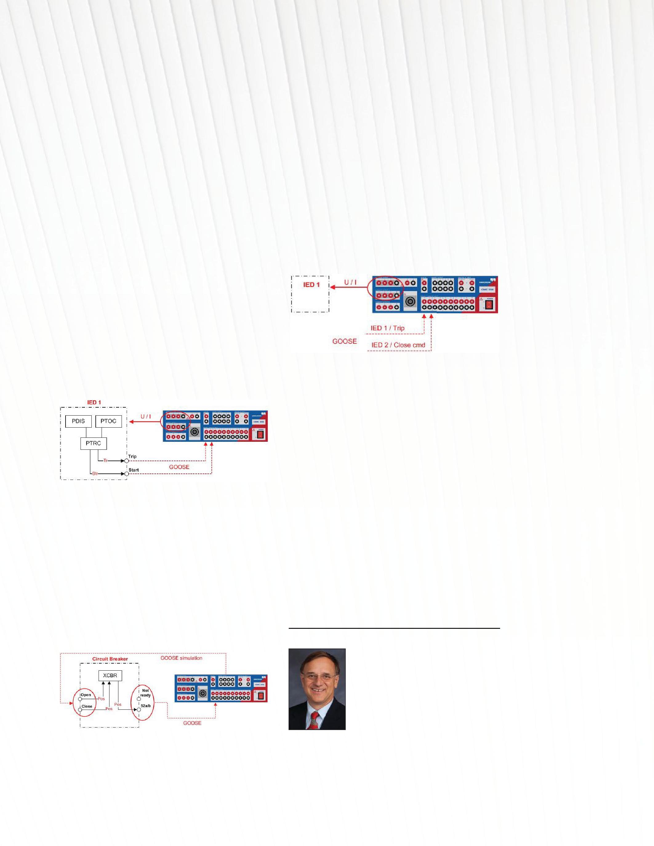
2. Circuit Breaker — Figure 7
• Isolate the circuit breaker by setting it to test andsimulationmode. and simulation mode.
• Connecttestsettothenetwork. Connect test set to the network.
• Observethatthetestsetsimulatesthe Observe that the test set simulates the GOOSE messages for opening and closing the breaker and subscribes to the breaker GOOSE message to measure the respective times.
CONCLUSION
It is clear that IED testing tools and methods are quite different from the traditional testing methods. It is imperative to have the proper documentation and testing tools when working with IEC 61850 schemes. There is more to the testing than showing up with themanufacturer’sliteratureandatestsetto the manufacturer’s literature and a test set to perform calibration of the relay. Using the proper tools will make the job of testing per IEC61850mucheasier. IEC 61850 much easier.
And that is how you cook a goose.
Will Knapek is an Application Engineer for OMICRON electronics Corp, USA. He holds a B.S. from East Carolina University and an A.S. from Western Kentucky University, both in Industrial Technology. He retired from the U.S. Army as a Chief Warrant Officer after 20 years of service, 15 of which were in the power field. Will has been active in the testing field since 1995 and is certified as a Senior NICET Technician and is a former NETA Level IV technician.
HOWTOCOOKAGOOSE–ORTESTING HOW TO COOK A GOOSE – OR TESTING OFIEC61850PROTECTIONSYSTEMS OF IEC 61850 PROTECTION SYSTEMS NETAWORLD • 53
Figure 6: Sample IED1 Test in Simulation Mode
Figure 7: Sample Circuit Breaker Test in SimulationMode Simulation Mode
FEATURE
Figure 8: Testing the Whole System in SimulationMode Simulation Mode




A FULL SERVICE NETA ACCREDITED ELECTRICAL TESTING COMPANY. Serving the Sacramento and San Francisco Bay Area 916-853-6280 www.apparatustesting.com • Acceptance Testing • Commissioning • Maintenance Testing • High Voltage Substations • Short Circuit and Coordination Studies • Data Centers and UPS Systems

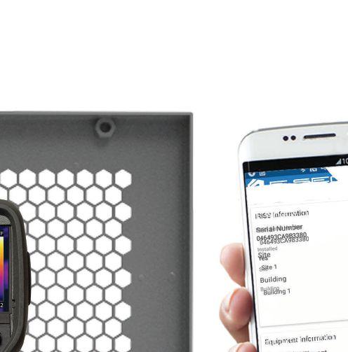


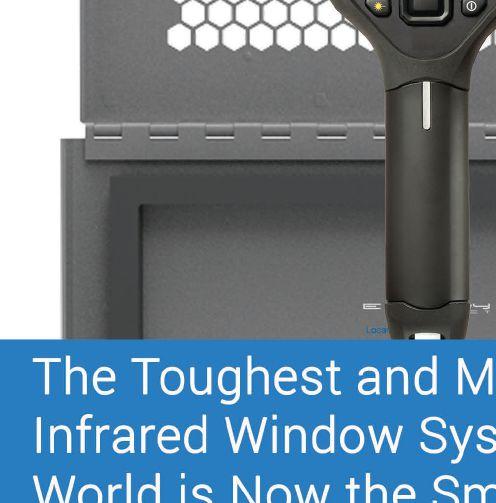

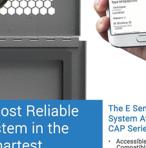



ELEMENT TE STING
MOVING FROM TO PROTECTION SYSTEM TESTING
BY CHRISTOPHER PRITCHARD, OMICRON Electronics Corp. USA


When it comes to commissioning and testing the protection system, many testing tools, methods, and approaches are available to meet every goal. To make an informed decision on the best testing strategy to apply, organizations must define and constantly review their goals. Inherently, every engineer and technician tries to do a good job. Therefore, the goal is to minimize misoperations of the protection system so that equipment is protected and power system stability is maintained.
To effectively minimize misoperations, recognize their causes. Why? Because when typical causes are identified, the testing effort can be efficiently focused. As with all complex systems, the cause of every misoperation cannot be predicted, but organizations should learn from detailed misoperation studies of the past.
The NERC Misoperations Report can serve as such a reference. This article will briefly discuss the misoperation causes identified by the report and discuss how different test approaches will uncover them. Also, a novel test approach is introduced to identify major misoperation causes.


New York City Blackout 2003 - The U.S.–CanadaPower U.S.–Canada Power System Outage Task Forceconcludedthata Force concluded that a combination of human error and equipment failures had caused theblackout. the blackout.
NETAWORLD • 57 MOVINGFROMELEMENTTESTINGTOPROTECTIONSYSTEMTESTING MOVING FROM ELEMENT TESTING TO PROTECTION SYSTEM TESTING FEATURE
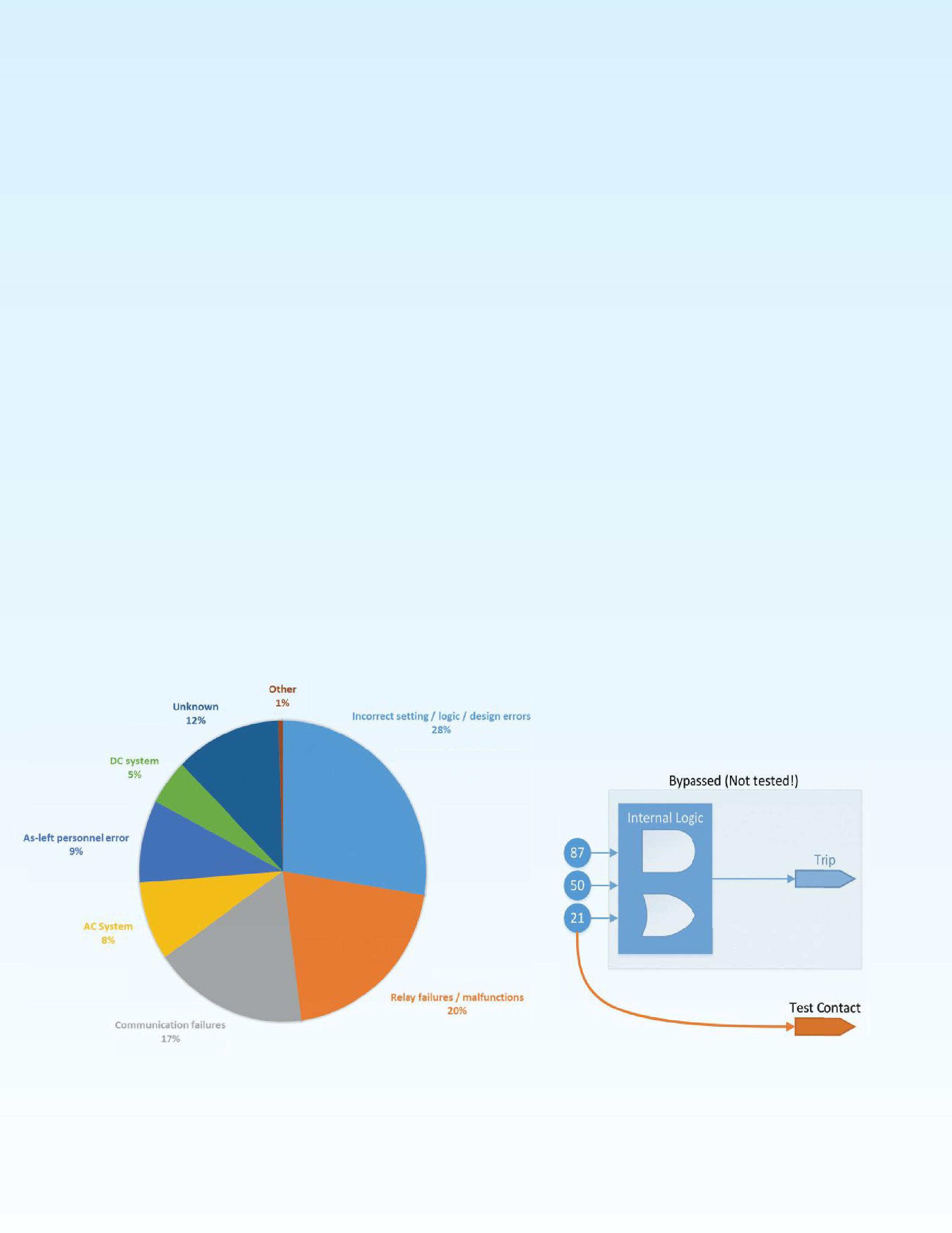
NERC REPORT OVERVIEW
The NERC report on misoperations gives an overview of misoperations by cause code (Figure 1) and holds two major findings:
• A misoperation can be caused by literally every component that is part of the protection system and is categorized by relays, communications, ac systems, and dc systems failure. While each component is often tested in isolation, it’s time to move forward toward a protection system testing approach.
• Incorrect settings and logic and design errors are the biggest causes for misoperations.
This is not likely to decrease by itself, as growing demands on cost and automation forces engineers to use more functions and logic inside modern microprocessor protection relays. The challenge liesinthefactthattechnicianshavenothad lies in the fact that technicians have not had sufficientinformationtouncovererrorsinthe sufficient information to uncover errors in the design, since it is part of a different process step. To move forward in protection testing system design — in addition to testing components — a holistic view of the process is needed. Here is a closer look at these findings.
MOVING FORWARD TO SYSTEM TESTING
Making sure the complete protection system is tested is not a new concept, and it has been highlighted in several papers and standards over the past years. NERC Standard PRC-0052 provides detailed tables for testing protection components. Other examples as described in K. Zimmerman’s “Advanced Event Analysis Tutorial Part 2: Answer Key” show that although components are tested individually, severe issues in the interfacing between components are not uncovered.
A simple example to illustrate: A current transformer (CT) has been tested, and its grounding has been verified according to the scheme drawing. Also, during commissioning, the relay has been tested with the CT polarity settings of the relay. Both components passed their test, but the CT polarity settings of the relay can still be wrong.
The scope of protection system testing includes testing interfaces of multiple components of the system, as shown in Figure 2. In this case, a primary injection of the CT with a primary test set — while simultaneously comparing the injected current to measured values of the relay — would have uncovered issues with polarity, ratio, and the CT wiring.
Figure 1: NERC Wide Misoperations by Cause Code from 2011-2013
FEATURE MOVINGFROMELEMENTTESTINGTOPROTECTIONSYSTEMTESTING MOVING FROM ELEMENT TESTING TO PROTECTION SYSTEM TESTING 58 • SPRING 2016
Figure 2: Different Tests Types of One or More Components
The same pattern applies to relay testing where pure element testing is still a common approach. As the name already suggests, the objective of element testing is to prove that an element inside the relay is working correctly. The origin of element testing comes from testing and calibrating electromechanical relays containing only one or two elements — still viable for these relay types. Presently, microprocessor relays contain multiple elements that are combined with logic and may reach up to 1,000 single settings or more. During an element test, each element of a relay is routed to a test contact to test for its threshold values and time delays. As shown in Figure 3, this bypasses the internal logic, ignoring the NERC misoperation study’s finding that logic errors are a major cause of misoperation.
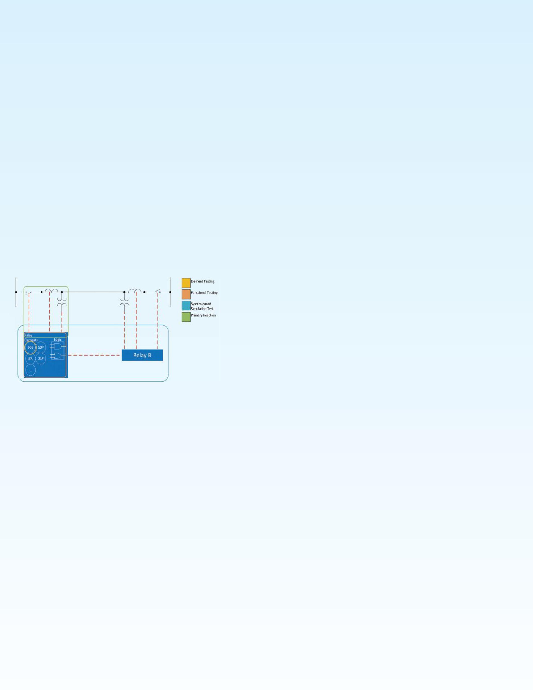
An element that is missing in the trip logic could still pass its test. Also, there is a risk of making setting changes to the relay under test, which can actually cause misoperations when they are not reverted. As electromechanical relays are steadily replaced by microprocessor relays, using testing methods designed for electromechanical relays to test their microprocessor replacements is rather questionable.
While relays contain multiple elements, modern protection systems contain multiple relays communicating with each other to build a larger, distributed logic scheme. Again, focusing just on the individual relays would not uncover any miscoordination of the bigger protection system. But testing a system of relays, like an end-
to-end test, can be a complex and time-consuming task. Therefore, here are some improvements that together build a novel testing tool.
Power System Simulation Instead of SteadyState Sequences
The most common method for testing a relay protection system is to create one steady-state sequence for each relay and test set, which are then synchronously executed. One sequence contains a minimum of two states — a pre-fault state and a fault state — but can also contain more steps such as when reclosing or restoration are tested. These states have to be calculated for each end, and most likely, for different fault positions and loops. This is a labor-intensive and error-prone task.
By using a power system simulation instead, this effortisreducedtoaminimum.Thesimulation effort is reduced to a minimum. The simulation takes care of the signal calculation, with the effort being independent from the number of relays or elements involved. Defining a test case is as easy as placing a fault in the model’s topology.
Another downside of steady-state signals is that the waveform detection in modern protection relays might drive a relay to lockout on signals that have unrealistic signal shapes. Because a transient power system model can simulate realistic signals, it does not have this issue.
Power System Simulation Onsite Instead of COMTRADE Replay
Another common approach for end-to-end tests is to hand over transient recordings (e.g. COMTRADE) to the technician for a synchronized injection. It is advisable to go a step further and provide the system parameters withfaultandnon-faulttestcasestorunthe with fault and non-fault test cases to run the simulation onsite for the following reasons:
• Afaultscenariocommunicatestheintention A fault scenario communicates the intention and empowers the technician to review the test cases beyond the thoughts of the protection design engineer. This follows the four-eye (peer review) principle.
• In case of failed tests, the technician can alter test settings to determine the sensitivity of the failed test. This is common when working close to the tolerance band.
FEATURE NETAWORLD • 59 MOVINGFROMELEMENTTESTINGTOPROTECTIONSYSTEMTESTING MOVING FROM ELEMENT TESTING TO PROTECTION SYSTEM TESTING
Figure 3: Element Testing Bypassing — Not Testing — the Relay Logic
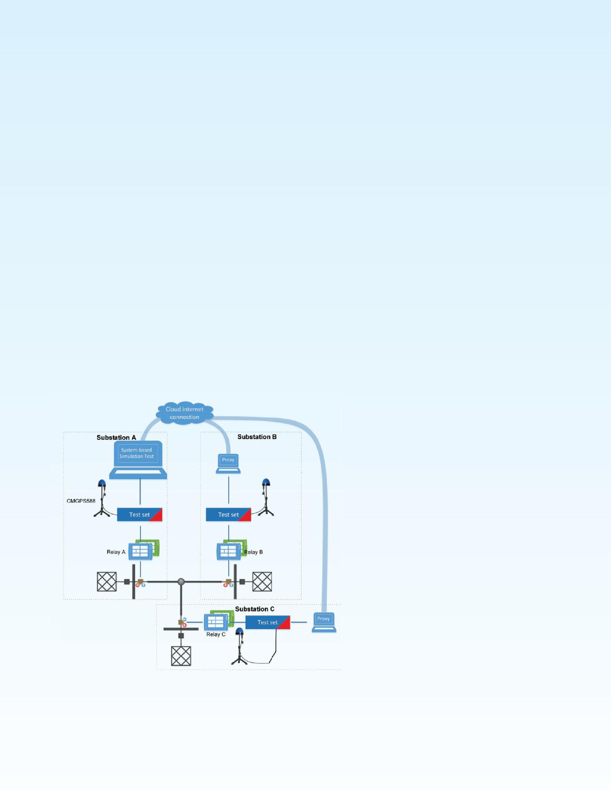
• It provides the ability to tune the test setup to the latest data on site with measured line impedances, measured CT parameters, transformer data from the nameplate, CT, and PT ratios as installed, etc.
CentralPointofControlInsteadofVerbal
Central Point of Control Instead of Verbal Coordination
Most end-to-end tests are executed by handing overtestfilesforeachlocationofatestsetor over test files for each location of a test set or relay to a technician. They start the execution by coordinating via phone and agree on the next possible timeslot to start. An overall assessment is only possible after the test results have been returned to the engineer.
An easier method is to control multiple test sets from software on one PC. Preferably, this masterPCcommunicatestothetestsetsviaa master PC communicates to the test sets via a direct network connection, e.g. a substation-tosubstation network. If this is not available, all testsetsstillcanbecontrolledfromonemaster test sets still can be controlled from one master PC while other PCs act as a proxy (Figure 4). The proxy PCs hand over control of their test setstothemasterPC. sets to the master PC.
In addition to not starting the test verbally, this has the added advantage of results presented immediately after execution. Paired with a power system simulation, the user can easily adapt the test cases at site for all locations with almost no effort. For troubleshooting reasons, making changes to a setup that is not centralized can be extremely difficult.
Relay in the Loop Instead of Predefined Event Sequence
Very often, misoperations can be found when testing beyond the first trip command of the protection system, e.g., unequally coordinated reclosing sequences or current reversal in parallel line circuits. Both cause unwanted trips or breaker failure trips. These issues are usually classified as settings, logic, and design errors, whichwillbediscussedinthenextsection. which will be discussed in the next section.
Creating a predefined sequence of states can again be very complex; therefore, use a testing tool that can react to each possible trip or close command by simulating the breaker inside the power system simulation, which adapts the current and voltage signals according to the new state. As a hard, real-time simulation cannot run on distributed test sets, a stepwise approach where the software learns the sequence from the relay’s reactions is a clever alternative.Thisiscalledaniterativeclosedalternative. This is called an iterative closedloop test, and its advantages include:
• Simple test definition by just placing a fault independent from the complexity of the protection system.
• False-coordination is visualized, which otherwisewouldbeoverlookedina otherwise would be overlooked in a predefined steady-state sequence. Also, one can assess the severity of an error as it displays the misbehavior from a power system point of view.
SETTINGS,LOGIC,AND DESIGN ERRORS
General protection element-setting errors, improper timing coordination, and zone overreaching are the main causes inside the
60 • SPRING 2016 MOVING FROM ELEMENT TESTING TO PROTECTION SYSTEM TESTING
LineProtection
FEATURE
Figure 4: Test Setup for a Three-Terminal
Line Protection
setting-error cause code. While improper coordination timing and zone overreaches can be reduced by thorough system studies, the vast number of relay functions and settings and their effect on the system protection is extremely challenging. Quality assurance often falls to the system design process, as an element test at best is able to test that a wrong setting is transferred to the relay.
To avoid the error propagation from the design step to the commissioning step, apply protection system testing. Extend the concept of covering multiple components, their interfaces, and interactions to covering multiple process steps and their data exchanges. This is extremely important, especially if one or more steps in the process are outsourced to a service company, as this makes a good data exchange between the steps more demanding. A protection system test should be an important step in a final field acceptance test by the operator. The same tool capabilities as described previously are key to this approach.
Protection system design is based on power system simulations of fault and non-fault scenarios. By using the same power system data for the model used inside the testing tool to calculate currents and voltages, protection of the power system is more easily assessed. Figure 5 shows how an application-oriented test spans across the process.
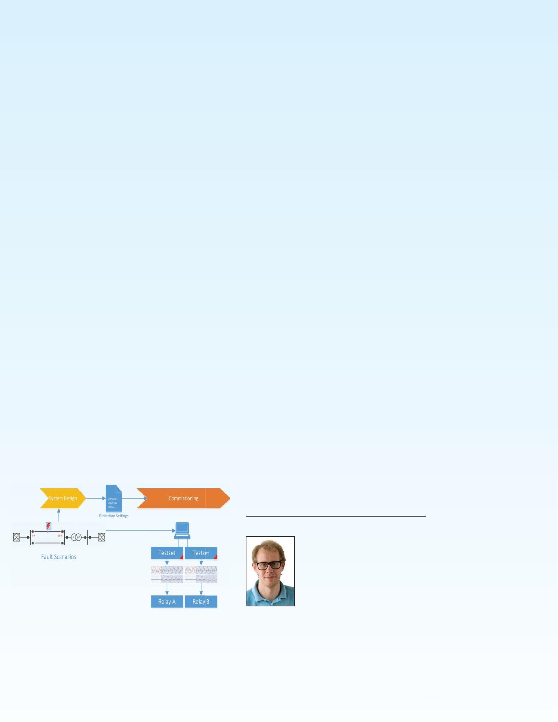
Figure 5: Uncovering Design Errors by Using Application-Oriented Testing
THE RIGHT TOOL AT THE RIGHT TIME
From a systematic point of view, it is still important to test each component before testing larger parts of the protection system. The more relays, custom logic, or complex coordination that are required, the more focus should be on application-oriented or protection system testing. The tools for application-oriented testing are already available and have shown their usefulness, e.g., for busbar, distribution scheme, and line protection testing.
REFERENCES
Protection System Misoperations Task Force, “Misoperations Report,” North American Electric Reliability Corporation (NERC), Atlanta, 2013.
N. S. PRC-005-2, “Protection System Maintenance,” NERC, 2012.
K. Zimmerman, “Advanced Event Analysis Tutorial Part 2: Answer Key,” www.selinc.com, 2013.
K. Zimmerman und D. Costello, “A Practical Approach to Line Current Differential Testing,” 66th Annual Conference for Protective Relay Engineers, 2013.
T. Hensler und C. Pritchard, “Test and Analysis of Protection Behavior on Parallel Lines with Mutual Coupling,” Australian Protection Symposium, Sydney, 2014.
OMICRONenergy, OMICRON electronics, April 1, 2015, www.youtube.com/watch?v=a_lRgJ9_Gcc
C.PritchardundT.Hensler,“TestandVerificationofaBusbar C. Pritchard und T. Hensler, “Test and Verification of a Busbar Protection Using a Simulation-Based Iterative Closed-Loop Approach in the Field,” Australian Protection Symposium, Sydney, 2014.
D. Bowman, B. Walker, C. Wright, A. Smit, A. Stinskiy, S. Chanda, T. Houseknecht, C. Pritchard, and S. Geiger, “Distributed Synchronous Coordination Field Testing of an Actual Automated Distribution Feeder System,” PAC World US, Raleigh, 2015.
Dipl-Ing. (FH) Christopher Pritchard was born in Dortmund, Germany. He started his career in power as an Electrical Energy Technician. Christopher received a diploma in Electrical Engineering at the University of Applied Science in Dortmund in 2006. He joined OMICRONelectronicsin2006where OMICRON electronics in 2006 where he worked in application software development in the field of testing solutions for protection and measurement systems and is now the responsible Product Manager for simulation-based testing solutions.
NETAWORLD • 61 MOVING FROM ELEMENT TESTING TO PROTECTION SYSTEM TESTING A
FEATURE




CALL FOR SPEAKERS

Lead the way.
• Communicate Your Knowledge
• Assist the Industry
• Gain Visibility
PRESENTATIONS SOUGHT
Review of basics
Industry-specific skills
Insights into new methods, technologies, and advancements
New testing procedures, safety procedures, and OSHA laws
New types of electrical power equipment
Uptime and reliability issues
• Submit abstracts on www.powertest.org by May 2, 2016




ANAHEIM • CALIFORNIA February
- March 3 • 2017 DISNEYLAND HOTEL POWERTEST.ORG 888.300.6382 THE PREMIER ELECTRICAL MAINTENANCE & SAFETY EVENT
27
FEATURE

Locating cable faults on wind farm collector systems often requires the use of several different techniquesand even then, because of the wide range of cabling structures used on wind farms, fault location is far from straightforward. The ideas and techniques described in this article will help clarifY some of the key issues involved.
Since underground cabling serves as the backbone of the wind farm collector system (commonly utilizing URD or concentric neutral type construction), testing the integrity and condition of the cabling is critical in ensuring reliability of the entire system. Over the years, several methods and philosophies for testing underground power cables have evolved
The Insulated Conductor Committee of the IEEE Power Society divided these methods and philosophies into two categories: Type 1 Field Tests and Type 2 Field Tests.
• Type 1 tests detect defects in the insulation of the cable system to improve the service reliability after the defective part is removed and appropriate repairs are performed These tests usually involve the application of moderately increased voltages across the insulation for a prescribed duration .
The tests are categorized as pass/fail. Tests include de (recommended for laminated cable systems; cautions and warnings apply to extruded systems); very low frequency (VLF) testing; power frequency testing; and sheath testing.
BY THOMAS SANDRI, Shermco Industries
• Type 2 tests provide indications that the insulation system has deteriorated and are termed diagnostic tests. These tests include tan delta or dissipation factor testing and partial discharge (PD) testing.
Many cable failures are the result of installation practices. Installation includes trenching, cable pulling, clamping of cable, and cable splicing as well as mounting accessories
High-quality installation work performed by qualified field personnel is essential for achieving the low failure rates and reliability needed in wind farm collector systems. Cable testing should be performed on new installations to identifY localized problems that may have occurred during installation. Testing should also be performed on existing cable systems, as cable can develop imperfections in the insulation over time. With a testing and preventative maintenance program, defects that were minor when the cable was installed but have become worse over time can be detected before a costly emergency outage occurs
UNDERSTANDING CABLE SYSTEM CONFIGURATIONS
The three cables that make up a three-phase circuit can be arranged in various formations, the most common being the trefoil (or triangular) and the flat formation (Figure 1). The choice of formation depends on several factors, including
=-
CABLE TESTING FOR WIND FARMS
the shield bonding method, the conductor area, and the space available for installation.

The power losses in a cabling circuit are partially dependent on the currents flowing in the metallic shields of the individual cables. Reducing or eliminating the shield currents through bonding practices will allow the current-carrying capacity of the cable circuit to be increased. Typical bonding methods are both-end bonding, singlepoint bonding, and cross-bonding.
A system is both-end bonded (Figure 2) if the cable shields provide a path for circulating currentsundernormalconditions.Thiswill currents under normal conditions. This will cause losses in the shield, which reduce the cable current-carrying capacity. These losses will be smallerforcablesintrefoilformationthanthose smaller for cables in trefoil formation than those in flat formation with separation.
In single-point bonding (Figure 3), the shields areconnectedandearthedatoneendoftherun. are connected and earthed at one end of the run. At all other points, the shield, as it is insulated from earth, will have a standing voltage proportional to the circuit length, conductor current, and cable spacing.
The voltage reaches maximum at the furthest point from the earth bond. Since there is no closed circuit, circulating currents in the shield are eliminated. Single-point bonding is normally used only for limited run lengths to minimize the standing voltage and render the cable installation safe against touch-voltage.
Cross-bonding (Figure 4) consists of sectionalizing thecablescreenintosectionscalledminor the cable screen into sections called minor sections and cross-connecting them to neutralize the total induced voltage in three consecutive sections. Three minor sections together make a major section. In a cross-bonding system, the run is split into groups of three drum lengths with the shields bonded and earthed together at both ends of a major section, but interrupted and connected in series at all other points.
The purpose is to allow a standing voltage between shield and earth in each major section, but eliminate circulating currents. With this arrangement, the current-carrying capacity of the cabling is considerably enhanced, particularly for large conductor sizes. This method is suitable for use on longer runs.
NETAWORLD • 65 CABLETESTINGFORWINDFARMS CABLE TESTING FOR WIND FARMS
FEATURE
Figure 1: CableFormations Cable Formations
p
Figure 2: Both-EndBonded Both-End Bonded
Figure 3: Single-Point Bonded

CABLE TESTING ON NEW INSTALLATIONS
Since the cable has been tested at the factory prior to delivery, new installations typically require only localized testing. The areas most prone to installation defects are the cable jacket/sheath, splices, and terminations.
After installation, the first test to perform is the sheath/jacket test, which will indicate whether there has been any mechanical damage to the outer cable sheath. If there has been damage of this type, degradation of the neutral/shield conductorsandthecableinsulationwillbe conductors and the cable insulation will be imminent, resulting in premature cable failure.
The sheath test is performed by applying a test voltage to the neutral/shield conductor of the cable. If the sheath is intact and undamaged, the neutral will hold the voltage and show no leakage current. If there is damage to the sheath, the voltage will drop and there will be current leakage toearth.Thelocationofthesheathfaultcanbe to earth. The location of the sheath fault can be determined by using an earth fault locator.
After the sheath integrity is validated, the integrity of the splices and terminations can be tested with a VLF hipot test. VLF (very low frequency) testing is done to prevent an in-service cable failure and serves as a pass/fail proof test.
Additional diagnostic value can be obtained by connecting a tan delta system to the VLF hipot. This allows the tan delta of the cable to be quickly measured and the results stored, thus providing a signature for the cable being tested.
CABLE TESTING FOR EXISTING OR SERVICE-AGED SYSTEMS
When testing involves existing systems, particularly service-aged systems, the condition of the cable itself along with the splices and terminations are of interest. By testing the collector cabling, it is possible to proactively manage the cabling system, thereby avoiding costly emergency outages.
A VLF hipot can be applied to a service-aged cable that may have developed water trees or electrical trees. The VLF hipot will test the entire cable and canbeusedtodrivetheweakestlocationonthe can be used to drive the weakest location on the cable to failure, thereby simplifying fault location. If the VLF hipot is connected to a tan delta system, the test can also offer diagnostic value and enable the test engineer to detect insulation defects or aging before the cable fails in service.
CHOOSING THE RIGHT TOOLS
Most cable fault-locating failures can be attributed to the improper interpretation of test results, selecting the wrong tools for the job, or taking short cuts. The first step in the fault location process is to determine the basics of the cabling system. This includes cable type, insulation type, overall circuit length, and bonding type.
The next step is to conduct a preliminary proof test. This can be done with a VLF hipot, and the test results will confirm if the cabling system has a failure. The test will also provide information about the fault profile such as the breakdown voltage. Once the breakdown characteristics are known, it is possible to start profiling the fault and selecting the most appropriate fault-locating equipment and techniques.
Since many modern fault-locating techniques use a pre-location method such as time domain reflectometry (TDR), arc reflection, or impulse current reflection, it is essential to know the bonding method before proceeding.
Many wind farm collector cabling systems span long distances, so they often use cross-bonding of the shields (Figure 5). For the application of cable fault-location methods, as well as for partial discharge diagnosis, the influences of crossbonding should be kept in mind. Cable fault pre-
CABLETESTINGFORWINDFARMS CABLE TESTING FOR WIND FARMS 66 • SPRING 2016
Figure 4: Cross-Bonded
location methods that are based on reflectometry techniques are influenced by the cross-bonding.
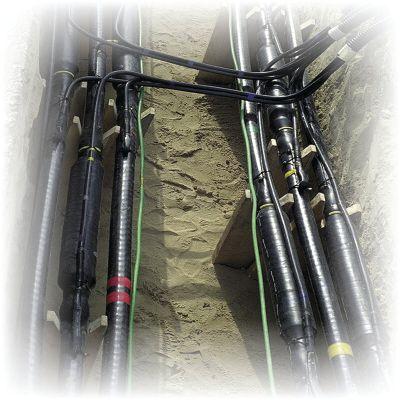
Every cross-bond creates a significant change in the characteristic impedance of the cable. With reflectometry techniques, this impedance change has similar characteristics to those of a cable end. Therefore, on such arrangements, the cable fault pre-location methods like TDR, arc reflection, and impulse current are greatly influenced. Ideally, to eliminate the effect of the impedance changes, all cross-bonding connections should be bridged with solid short-circuit jumpers that are fixed directly.
If bridging the cross-bonds with jumpers is not possible, a fault sectionalizing approach may be required before using reflectometry techniques. This can be achieved with a surge generator (thumper) (Figure 6) and an electromagnetic (ballistic) tracker (Figure 7).
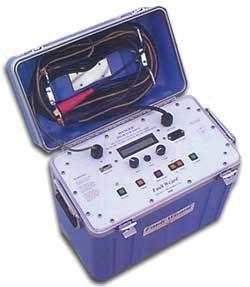
Another critical question in determining the best fault-locating tools is the overall capacitance of the cable being tested. The larger the capacitance (long cable runs), the more voltage and energy the thumper needs to supply.
It is dangerous to select a thumper that is too small. If the thumper is not powerful enough to break down or arc the fault, the voltage applied to the cable will be stored in the cable capacitance. When the cable finally reaches its breakdown point, the voltage/energy stored in the cable is reflected from the far end and fed back into the thumper, potentially causing the thumper to fail catastrophically.
Fault location on underground cables is never easy, and in wind farms, it is often especially challenging. Hopefully, this article has provided an insight into potential problems and the techniques that can be applied to solve them.


D. Sandri is a Senior Technical Instructor at Shermco Industries. He has been active in the field of electrical power and telecommunications for over 30 years. During his career, he has developed numerous training aids, training guides, and has conducted domestic and international seminars. Thomas supports a wide range of electrical and telecommunication maintenance application disciplines. He has been directly involved in supporting test and measurement equipment for over 20 years and is considered an industry expert in application disciplines, including battery and dc systems testing and maintenance, medium- and high-voltage cables, ground testing, and partial discharge analysis. He holds a Bachelor of Science degree in Electrical Engineering (BSEE) from Thomas Edison University in Trenton, New Jersey.
CABLE TESTING FOR WIND FARMS NETAWORLD • 67
Thomas
Figure 5: Typical Cross Bond
Figure 6: Small Thumper Example
Figure 7: Large Thumper Example
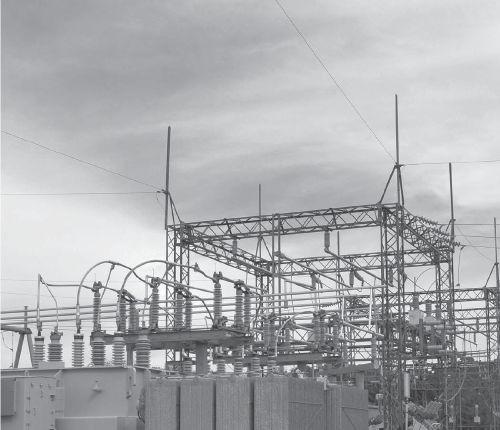
Electrical Distribution System




24 Hour Emergency Services (937) 439-9660


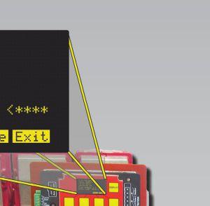
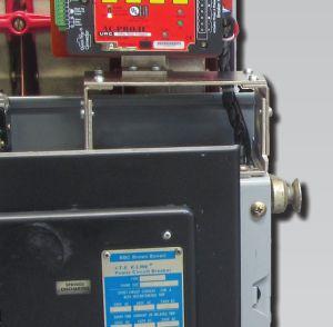
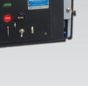
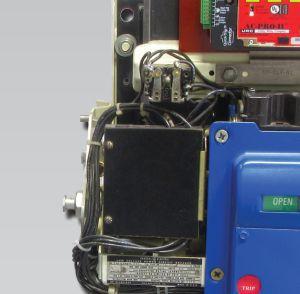
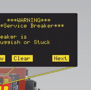




Can you tell at a glance which breaker mechanism needs service? Can you tell at a glance which breaker mechanism needs service? With the SAFE-T-TRIP® and the new AC-PRO-II®, you can trip a breaker from a safe distance and the Sluggish Breaker Detection® feature will record the mechanism operating time, on the first operation. Contact: 888-289-2864 www.UtilityRelay.com URC Utility Relay Company With the patented Sluggish Breaker Detection ® With hardened lubrication or bad bearings a “Warning Service Breaker” screen will be displayed on the AC-PRO-II® WiththeSAFE-T-TRIP®andthenewAC-PRO-II®, youcantripabreaker Breaker Detection in AC-PRO-II Now You Can! 20 Years of Exceptional Products & Exceptional Service
around specific business requirements and the necessary work practices, but whenever possible, it’s best to find ways to streamline. In many cases, seven manual steps in traditional testing workflows can be automated for teams.
WHERE IS MY DATA?
Imagine if all the information needed to run a test was already loaded on a device. And what if the test data from the field was automatically sent back to the office? Syncing technology now allows information to securely update behind the scenes. This means a USB drive is no longer needed to download test plans or save test files and drive them back to the office to upload later.
Seamless synching is proving to be one of the biggest factors in process and efficiency improvements. Now there is no question about where data is located, and teams can focus on testing, analyzing, and reporting forcustomers.WithUSBdrivesandother for customers. With USB drives and other removable media increasingly classified as security vulnerabilities, eliminating the need forthesedrivesiswise. for these drives is wise.
IS IT SECURE?
So the team loves the controllers and management loves the efficiency improvements — but is all of this secure? Over time, the industry’s definition of security has changed. In today’s world, it includes NERC CIP compliance, transient cyber assets, cyber threats, malicious code prevention, configuration management, and more. It’s easy to feel overwhelmed when trying to meet the requirements of this new and changing definition while still satisfying customers’ testing needs.
A field force automation program must adhere to strict security requirements to succeed. Cybersecurity best practices include:
• Remote wiping capability to clear a device that is stolen or compromised
As with any program, a field force automation solution needs to make sense for an organization. What are the goals? What are customers’ requirements now compared to what they will be next year? Is the organization meeting or exceeding cybersecurity standards? While it seems like the industry is getting more complex, it is reassuring to know that technology can help teams focus on the critical task at hand — testing.

Renee Angell is Doble’s Special Projects Manager for customized solutions. Renee has over 20 years of experience in the utility industry with a focus on operational field force optimization.
Elizabeth Aragao is Doble’s Director, Marketing Communications. Working with Doble for six years, Elizabeth’s focus is on the customer experience, from websites through product usability.
MatthewLawrence Matthew Lawrence isDoble’sSenior is Doble’s Senior Director, Solutions overseeing the development of Doble’s hardware and software solutions. Matthew has worked in the utility industry for over 30 years with a focus on maintenance, construction, and operations.
•CustomizedlockdownstorestrictInternet
• Customized lockdowns to restrict Internet access to prevent unauthorized downloads
• Disabling unneeded ports so no viruses or malwarecanbeintroducedtothedevice malware can be introduced to the device or the power system
IN TECHNOLOGY NETAWORLD • 71 FIELDFORCEAUTOMATION:OPTIMIZEWORKFORCEANDDATA FIELD FORCE AUTOMATION: OPTIMIZE WORKFORCE AND DATA MANAGEMENTWITHCYBERSECURITY MANAGEMENT WITH CYBERSECURITY
ADVANCEMENTS


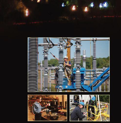





PRESSURE VERSUS AGE
BY FINLEY LEDBETTER, Group CBS
Vacuum technology is the most widely applied power interruption technique in the medium-voltage range (2.4kV38kV). This technology now dominates the interrupter market throughout the world with millions of vacuum circuit breakers installed and close to 10 million vacuum interrupters (VIs).
With the original introduction of vacuum breakers in the 1960s, manufacturers designed and tested vacuum interrupters to last 20 to 30 years. About 40 to 50 years later, hundreds of thousands of these breakers are still in their original installation — and operating under the same expectations as the 1960s. With few mechanical devices on the market today with such an extended working lifespan — and considering the inevitability of age rearing its ugly head — it’s time to wonder when and how age will affect the equipment we rely on. How long can we expect these interrupters to maintain the vacuum levels they require to effectively function?
Our team set out to study the effect of the vacuum interrupter age on its vacuum level by testing 815 VIs installed in over 320 vacuum circuit breakers. Our main objective was to determine the correlation between the following:
1. VI age and VI pressure
2. VI age and VI hipot leakage current
3. VI age and VI contact resistance
4. VI pressure and VI hipot leakage current
VACUUM INTERRUPTER PRESSURE LEVEL
All VIs increase in internal pressure over time. The pressure increase may be due to small, long-path leaks from outside to inside, diffusion through the container materials, and/or virtual leaks from materials within the internal volume. To help control the pressure increase from these leaks, a getter material is normally mounted inside the vacuum interrupter, which provides a continuous pumping for low levels of H 2, N 2, O 2, and other various residual gases. When , internal pressure rises above 10 -2 Pa, the VI dielectric strength will start to fall. The risk of interruption failure increases greatly for pressures higher than 10 -1 Pa.
As part of a vacuum breaker maintenance routine, manufacturers recommend a vacuum integrity test. This test consists of applying an ac power frequency-rated voltage across the terminals of a VI at its rated gap. If the VI is able to withstand the voltage for the manufacturer-specified length of time, the VI is deemed to have an adequate vacuum. Passing this test indicates that the VI vacuum is sufficient to successfully interrupt a fault, but gives no indication of how close the VI is to having a vacuum level that would cause it to lose capability for clearing a fault.
INDUSTRYTOPICS INDUSTRY TOPICS
NETAWORLD • 75 VACUUM INTERRUPTERS: PRESSURE VERSUS AGE


Until recently, no technology allowed field testing vacuum levels in VIs. Using a field portable magnetron, test technicians can nowtestvacuumlevelandevaluatetheVI now test vacuum level and evaluate the VI condition based on that parameter. The vacuum level test is called the magnetron atmospheric condition (MAC) test (see photo of test in progress). Note that this configuration does not require removal of the pole assembly or vacuum interrupter fromthebreaker. from the breaker.
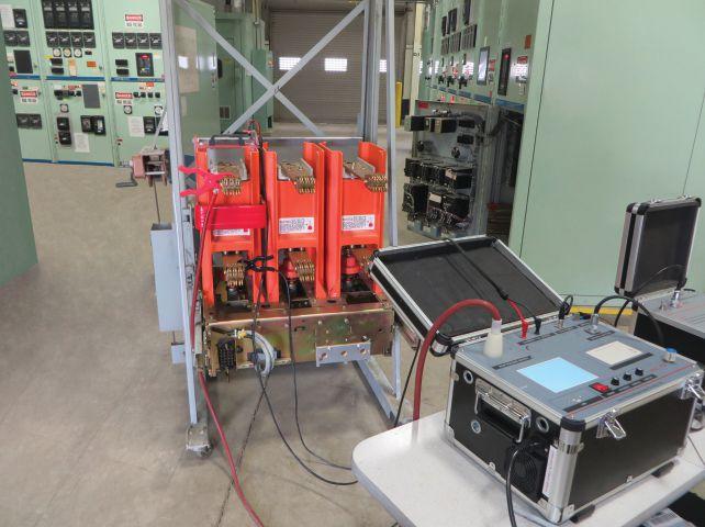


TEST POPULATION
Tominimizevariationduetodifferent To minimize variation due to different manufacturing methods, the 322 circuit breakerstestedwereallthesamemodeland breakers tested were all the same model and manufacturer; however, the breakers included a range of ratings and VI types. All of the breakers were in service at some point in their history, but none of the breakers or interrupters had been modified from the manufacturer’s original specifications — with the exception that some of the breakers had one or two VIs missing. The totalnumberofVIstestedwas815.Becausethe total number of VIs tested was 815. Because the serial numbers were sequential, it was assumed that the VI manufacturing dates were the same as the breakers in which they were installed.
The test procedure is as follows:
1. Document the condition of the breaker components and nameplate information photographically.
2. Thoroughly clean all dust and contaminants from the breaker.
3. Check primary contact erosion.
4. Perform contact resistance tests.
5. Perform VI pressure (MAC) test.
6. Perform ac high-potential test and measure and record leakage current at the recommended test voltage.
COLLECTED DATA
Standard nameplate data was collected for all circuit breakers. Inspection data collected includes the breaker mechanical operations before and after testing, ambient temperature, humidity, and the technician ID. Test data collected for each of the three phases includes the MAC ion current, contact gap, contact resistance, and the ac high-potential test (called hipot, a pass/not pass and the leakage current). The measured MAC ion current was converted to VI pressure in Pascals using calibration curves based on VI diameter provided by the MAC manufacturer.
Approximately 10 percent of the tested population (84 out of 815) exceeded the maximum pressure measurable with the MAC tester ( 5 x 10E-1 Pa – high pressure). These units were not included in the correlation analyses because the analysis method requires continuously variable data.
As shown in Table 1, the percentage of VIs with high pressure increases with age.
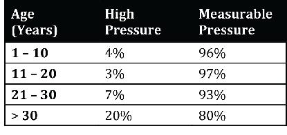
INDUSTRYTOPICS INDUSTRY TOPICS 76 • SPRING 2016
VACUUM INTERRUPTERS: PRESSURE VERSUS AGE
VI Vacuum Test (MAC Test)
Table 1: VI Percentage of High Pressure by Age
DATA ANALYSIS METHOD
Using standard statistical techniques, the correlation coefficient (r) and the square of the correlation coefficient were calculated for the four data relations given in Table 1.
Because of the population size, a standard adjustment was made on the correlation coefficient resulting in radj.
Grouping
The population was broken down into subgroups designated by VI type, the voltage rating for each piece of equipment (MVA), mechanism type, and pinch tube existence. Correlation coefficients were calculated for each of the data sets with the curve fits for relationships most commonly found in nature such as linear, logarithmic, exponential, square, and squareroot distributions. None of the subgroups had calculated correlation coefficients larger than the entire population. For this reason, the subgroups were dropped and data presented as a whole.
Results
Table 2 shows the best-fitting distributions, r (correlation coefficients), and r2 values. Note that the VI hipot leakage current shows minimal to no correlation between either the VI pressure or the VI age.
DATA DISTRIBUTIONS
Figures 1 and 2 are scatter plots of the VI age and VI contact resistance versus VI age, respectively. The best-fit exponential curve is shown on each graph. The strongest relationship was the age of the VI versus the VI pressure values, with an unbiased exponential correlation coefficient (radj) of 0.4107. Figure 4 shows the distribution of VI pressure ranges within four age groupings.
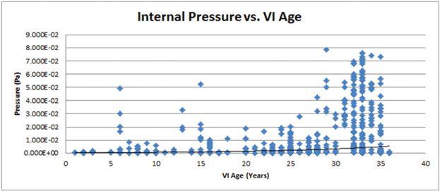
1: Exponential Distribution of Internal Pressure vs. VI Age, where radj = 0.4107 and r2 = 16.87%
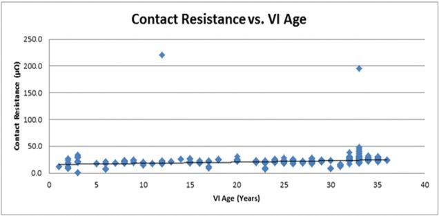
2: Exponential Distribution of Contact Resistance vs. VI Age, where radj = 0.3173 and r2 = 10.07%


NETAWORLD • 77 VACUUM INTERRUPTERS: PRESSURE VERSUS AGE
INDUSTRY TOPICS
Table 2: Correlation Results
Figure
Figure
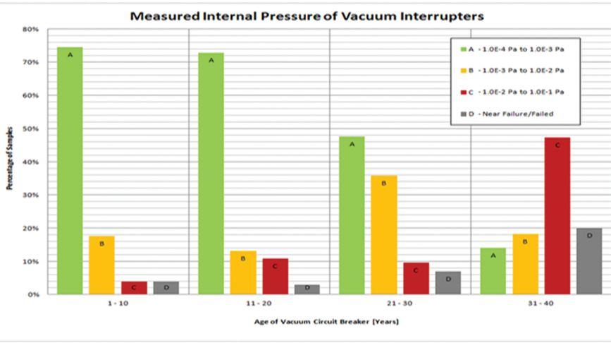
Explanation of Data
A distribution of the VI’s measured internal pressure ranges divided into four age groups is shown in Figure 3. Columns A, B, and C correspond to internal pressures measured by the MAC test set, while Column D (Near Failure/Failed) shows VIs that exceeded the maximum measureable pressure of the MAC test set.
The distribution shows that most VIs manufactured within 20 years of the present study had internal pressures in the lowest measured pressure range (Column A). The 2130 year age range shows a dramatic increase in VIs, with measured internal pressures in the 1E-3 Pa to 1E-2 Pa range (Column B). This could be explained by a large migration of VIs in the lowest range (Column A) to the next higher pressure range (Column B) due to increases in internal pressure.
The trend continues in the oldest age range with the percentage of VIs in the two lowest pressure ranges dropping and an increase of nearly 500 percent in the 1E-2 Pa to 1E-1 Pa pressure range (Column C) from the period before. Also in this period is a noticeable increase in VIs that exceeded the maximum
measureable pressure of the MAC test set (Near Failure/Failed). Overall, the data is in good agreement with the manufacturer’s stated design life of 20 to 30 years.
Test Summary
Tests were performed on 815 service-aged vacuum interrupters of similar design and type, from the same manufacturer, with a range of manufacture dates from 1978 to 2012. The tests performed included contact resistance, ac high-potential test, and MAC tests. After the data was compiled, correlation calculations were made for the following:
• VI pressure (Pa) versus VI age
• AC leakage (mA) (hipot) versus VI age
• Contact resistance (μΩ) versus VI age
• AC leakage (mA) (hipot) versus VI pressure (Pa)
Findings
Our research showed a relatively close, exponential correlation between VI age and internal pressure. We believe this correlation will be strengthened by an increase in the size of the database and inclusion of time-
78 • SPRING 2016
INDUSTRY TOPICS VACUUM INTERRUPTERS: PRESSURE VERSUS AGE
Figure 3: VI Pressures by Age Group
related data for individual breakers. We found a small to moderate correlation between the contact resistance and VI age, and a minimal correlation between VI ac hipot leakage current and VI age or VI pressure.
Given the proven relationship between dielectric strength (interrupting ability) and vacuum level, we are confident that the MAC test, which tests VI internal pressure, provides excellent predictive data for determining VI continuing serviceability. Contact resistance testing may provide some value as a predictive tool; however, two significant issues must be accounted for: (1) Frequent contact erosion adjustments — for example, the interrupter contact pressure can change with wear/ interruption history — and (2) the significant differences in contact area (a 400 ampere VI versus a 3,000 ampere VI). Since very little correlation exists between ac hipot leakage current and VI age or vacuum level, the hipot test is of no value in any predictive maintenance program for the VI. The ac hipot test should be used only for evaluating the current functioning performance of the VI as well as the other insulation systems in thebreaker. the breaker.

CONCLUSION
To fully understand the scale and scope of the situation, additional studies should be completed. However, based on the data gathered from our study, over the next 20 years, we can expect the failure rate of vacuum interrupters to increase as they continue to age. We need to consider this reality and do what is possible to prevent thesefailures.Theauthor’srecommendationis these failures. The author’s recommendation is to replace the necessary vacuum interrupters or prioritize those for replacement. It is not


necessary — or even possible — to replace all vacuum interrupters over 30 years of age, as some are still serviceable and this endeavor would be costly. Previous testing methods are not sufficient to reasonably calculate when to replace a vacuum interrupter, except if the VI is already in need of replacement. However, with the arrival of the MAC test set to the market, we can predict when vacuum interrupters will fail, prioritize replacement, and avoid costly failure.

Finley Ledbetter has worked in power engineering for 20 years, including serving as an applications engineer and instructor for the Multi-Amp Institute. He was the founder of Shermco Engineering Services Division, a division of Shermco Industries — a NETA Accredited Company. Finley is also the founder of Group CBS, Inc., which owns 12 circuit breaker service shops in the United States and Puerto Rico. He is a member of IEEE, a NETA Corporate Alliance Partner, and a charter member and past president of Professional Electrical Apparatus Recycler’s League (PEARL).
REFERENCES
Cadick, John. “Vacuum Interrupters: Pressure vs. Age,” Technical Papers, September 9-11, 2015.

Renz, R., Gentsch, D., Slade, P. et al. “Vacuum Interrupters –SealedforLife,”19 Sealed for Life,” 19th International Conference on Electricity Distribution (CIRED), May 21-24, 2007, Paper 0156
Slade,PaulG. Slade, Paul G. The Vacuum Interrupter: Theory, Design, and Application.BocaRaton:CRCPress,2008 . Boca Raton: CRC Press, 2008
Arthur, M.E.; Zunick, M.J. "Useful Life of Vacuum Interrupters," IEEE Transactions on Power Apparatus and Systems, Vol. PAS-97, No.1, January 1978


Okawa, M.; Tsutsumi, T.; Aiyoshi, T. "Reliability and Field Experience of Vacuum Interrupters," IEEE Transactions on Power Delivery, Vol. 2, No. 3, July 1987
Moore, David S., McCabe, George P. Introduction to the Practice of Statistics, Fourth Edition, W.H. Freeman and Company, New York, 2003


INDUSTRY TOPICS VACUUMINTERRUPTERS:PRESSUREVERSUSAGE VACUUM INTERRUPTERS: PRESSURE VERSUS AGE NETAWORLD • 79


CABLE QUESTION
BY ALAN MARK FRANKS, AVO Training Institute
A trillion dollars is a conservative estimate when you consider the magnitude of the power cable issues in the U.S. It has been known for some time that the cable systems in the U.S. have reached — and in many cases, exceeded — their life expectancy. Let’s face it: Wholesale replacement of an underground cable installation is expensive, time consuming, and results in off-hour scheduling and clearances, requiring customers to be without power during reconnection of power to the installation.
Much has been published about the failures in cables, splices, and terminations, but more still needs to be said about the aging power cable issue. Analysis clearly states the issues with serviceaged polyethylene, the concentric-neutral (CN) cables that were the mainstay for utility installations in the mid 1960s through 1980s (initially HMWPE or high-molecular weight, and then XLPE or cross-linked polyethylene).
Thought to be the answer to many installation issues, these cables turned out to be a major disaster due to reliability and replacement costs. Much of this CN cable had no jacket to protect it from the environment or installation damage — much less water, the culprit of the century where polyethylene insulation is concerned.
In defense of the manufacturers and utility engineers, no one knew what was to ensue between water and polyethylene insulation (the formation of water trees in the insulation). Since this condition is slow to develop and

muchslowertoreachtotalinsulationfailure much slower to reach total insulation failure via the formation of full-blown electrical trees, it was not evident early on that these cables, which were expected to last 30 to 40 years, would only last half of that time — many only lasting 10 to 15 years before failing. Treeresistant cross-linked polyethylene (TRXLPE) cameonthesceneinthelate1990sformost came on the scene in the late 1990s for most utilities.TRXLPEisanenhancedXLPEthat utilities. TRXLPE is an enhanced XLPE that increases resistance to the water treeing process, increasing cable life to 20 to 30 years. Most utilities realize that many of these cables today are at or over their expected life. Many utility companies are in the beginning or middle stages of providing high-tech rejuvenation processes to extend the cables’ life or are planning complete replacement of these cables in bulk quantities at significant costs.
As utilities and industries with large cable systems are at various stages in addressing the issues with service-aged polyethylene-insulated cables, the question that keeps coming up is:
INDUSTRY TOPICS
THE TRILLION-DOLLAR CABLE QUESTION
NETAWORLD • 83
What is the condition of my cables? This leads to a second question about how to determine the conditions of cables. The first question is really about how to manage the cable system or defining a good asset management strategy for the cables. The second is about specific techniques to actually determine the condition of each cable. Another critical factor to proper cable system management is the human factor, whichisdiscussedabitlater. which is discussed a bit later.
CABLE SYSTEM ASSET MANAGEMENT
Recently, an engineer in a large utility was given the overall management responsibility of a $150 million cable replacement project. This is a large opportunity with the potential for a huge success — or, without a planned approach that involves determining a replacement philosophy — it could result in financialdisaster.Someconcernsare: financial disaster. Some concerns are:
1. How much cable are we talking about? 10Kfeet?500kfeet?500miles? 10K feet? 500k feet? 500 miles?
2. What kind of cable, when will it be installed, what size, voltage, etc.?
3. What is the history concerning the cable plant?
4. Whatisthemodeofconstruction— What is the mode of construction — direct bury, in conduit, aerial, duct systems, etc.?
5. Whatistheultimatecostofmaterials What is the ultimate cost of materials andlabor? and labor?
6. Are competent labor forces available?
7. At what point in the life cycle is the cable under consideration? (This is a big question.)
8. What is the criticality of loads?
9. What methodology will be used to determine condition and priority of replacement?
is the importance of developing a philosophy concerning cable management.
DIAGNOSTIC TESTING
This brings up diagnostic testing and the condition term in the management topic. For years, cables have been proof tested for acceptance and maintenance tested employing an age-old technology known as the dc hipot. This technology has been used successfully for decades to test and retest cables using paper insulation lead cable (PILC). It is inexpensive, easy to use, and appears to be the logical choice to continue to test new and service-aged cables of the extruded insulation design.

These questions deserve infinitely more detailed consideration than discussed here. The point
However, the Electric Power Research Institute (EPRI) concluded that this approach is the wrong choice. EPRI found that service-aged polyethylene (and EPR) cables already in the stages of insulation tree formation would develop space charges that remained in the insulation after testing, and when reenergized with line frequency, could hasten failure. This was a significant revelation in the cable industry, as there was not a proven alternative and no industry consensus standards provided alternative guidelines for testing. As a result, many companies halted testing in any form, and new and service-aged cable systems went without any acceptance or maintenance test at all. (Enter the Dark Ages for cable testing.)
Today, however, we have current industry standardssuchasIEEE400BundleSeries standards such as IEEE 400 Bundle Series and the ANSI/NETA standards providing guidelines for withstand (acceptance) tests and diagnostic tests for troubleshooting, trending, and diagnosing cable condition. These new testing technologies evolved due to the need for diagnosing the condition of service-aged cablesintheU.S.andothercountrieswith cables in the U.S. and other countries with the same cable issues. With the issue using dc test voltages previously discussed and the requirements for using 60 Hz line frequency for testing high capacitive cables of long length (large, expensive equipment), very low frequency (VLF) testing has become a popular technology. VLF is used to perform withstand
INDUSTRY TOPICS 84 • SPRING 2016
THE TRILLION-DOLLAR CABLE QUESTION

(acceptance) proof tests as well as dissipation factor (VLF Tan Delta) diagnostic tests. VLF Tan Delta, used in conjunction with the partial discharge test, has proven a successful method for analyzing the condition of service-aged extruded dielectric cables (XLPE and EPR) while avoiding the space charge issue of dc testing.
NumerousmanufacturersintheU.S.and Numerous manufacturers in the U.S. and othercountriesmakeallmanneroftestunitsto other countries make all manner of test units to perform diagnostic testing. Industry consensus standards support the technologies and provide guidelines for utilities and industries in the U.S. to administer effective testing programs to address the complex issues concerning underground power cable installations. The test method applied and the specific equipment employed is usually predicated on how the information will be used. Ultimately, the information generated by the testing program becomes a critical component in the cable asset management decision-making process.
THE HUMAN FACTOR
The complexity of the new testing technologies, evaluation of test results, and importance of sound installation practices leads to the final topic of discussion, the human factor. Considering the cost and importance of electrical systems in the U.S., we must ask this question: In all of the plans and technology improvements for our cable systems, where have we provided for the safety, technical, and skills training for our human resources? It’s a good question, considering the millions of dollars being spent on new cable, new technology, new test equipment, and methods. With all the planning and technical issues to address, it’s easy to overlook the one resource that is going to ensurethesamemistakesarenotmadeoverand ensure the same mistakes are not made over and overinthefuture. over in the future.
Studies by the National Electric Energy Testing Research and Application Center (NEETRAC) at Georgia Tech point to a major cause of cable failures in the U.S. being tied to poor workmanship issues during cable pulling, splicing, and terminating. As this is well documented, it is reasonable to expect that
without a change in direction, the same results will be repeated. The millions of dollars spent in insulation rejuvenation, cable replacement splicing, and termination will not have the expected positive effects in service reliability, revenue, and reduced costs. The outcome will be dismal, and ultimately, the cable installation workmanship issue will be revisited, most likely at much higher costs.
Ensuring excellence in workmanship and proper application of the technologies for cable installation and testing requires significant training and demonstrationfortheworkersinvolved. demonstration for the workers involved.
One of the most important aspects of cable work is the absolute requirement for safety. Workers are routinely involved with power systems that were or could become energized. Many times, the technician is working in one section of switchgear and adjacent switchgears on either side will still be energized. Most of the highvoltage and high-power test equipment used in withstand and diagnostic testing of power cables can produce lethal shock, thus requiring significant safety precautions to ensure the safety of all workers involved in the testing or in the area where testing is being performed. OSHA 29 CFR 1910.269 (o) Testing and Test Facilities provides regulations for workers involved in high-voltage and high-power testing. OSHA further mandates that employees must be trained prior to performing this type of work. Numerous other regulations and standards related to maintenance and testing of power cable systems must be incorporated into the safe work practices and training for working on or near power cable systems.
Training in proper cable handling, splicing, and terminating of power cables is necessary, or the same failure modes will reappear in the future. It’s been said many times that about 90 percent of the integrity of a splice or termination is in the cable prepping. Many of the splice or termination failures occur because of inappropriate cable preparation, either by misapplication of the products and tools or some human error in removing and dimensioning the cable layers.
NETAWORLD • 85 THE TRILLION-DOLLAR CABLE QUESTION
INDUSTRY TOPICS
INDUSTRY TOPICS
Modern splicing kits come with detailed instructions but do not provide the experience nor show the proper tooling for performing the steps of successful splicing. Splicing and terminating of power cables is a craftsmanship issue and must be addressed with a significantly experienced, hands-on mentor or instructed by very competent cable personnel. A significant effort is currently underway to address the issue in large U.S. utilities, as many of their experienced cable personnel have retired and are no longer available to provide the much-needed mentorship to junior personnel. Ramping up cable splicing training, certification, and demonstration of skill and testing technology is a necessity, as we move into a future where reliability and cost of maintenance are significant issues.
Diagnostic testing using a partial discharge test set and software to analyze the test data is a long way ahead of technology from a megohmmeter test and a dc hipot test. Test technicians have to be trained not only in all the safety aspects of the job, but also in the technology of the test and how to use the test equipment. Not only is diagnostic testing an issue, but cable fault location is as well, due to technology enhancements in that type of equipment and the constraints of locating faults on service-aged cable systems.
CONCLUSION
In summary, we must consider all aspects of a well-planned cable management program. It is imperative that the cable is analyzed to accurately assess its condition. Service-aged cables must be examined and tested to recognize the need for corrective action. Cables have to be tested and prioritized according to condition, using the latest in diagnostic testing technologies. Decisions concerning replacement and rejuvenation should be made by using test data and cable experience.
One of the most important parts of the overall cable puzzle is the human factor. It doesn’t make good business sense to install millions of dollars of new cables, purchase expensive test equipment, and repeat the same workmanship issues that will result in the same types of cable failures previously experienced.
Of course, safety of personnel is the most important factor, and significant attention must be focused on personnel involved in high-voltage and high-power testing. Safe work procedures, personal protective equipment, live line tools, personal protective grounds, and work area protection are only a few of the items that require training.
REFERENCES
Hampton, Nigel and Josh Perkel, NEETRAC; Matthew Olearczyk, Electric Power Research Institute; Neil Weisenfeld, Consolidated Edison NY. “Notes From Underground,” IEEE Power and Energy Magazine, November-December 2010
Williams, Dean, NEETRAC. Cable Accessory Failure Analysis, ICC Educational Session, Fountain Hill, Arizona, October 16-20, 2010
Diagnostic Testing of Underground Cable Systems (Cable Diagnostic Focused Initiative), NEETRAC Project Numbers: 04-211/04212/09-166), December 2010
Effect of DC Testing on Extruded Crosslinked Polyethylene Insulated Cables — Phase II, Product ID: TR-101245-V2, Sector Name: Power Delivery & Utilization, December 1, 1995

Alan Mark Franks is a Senior Safety Specialist at AVO Training Institute. He has over 48 years in the electrical utility industry with an extensive background in electrical safety and power distribution. Mark was instrumental in developing the Pre-OSHA Electrical Safety Audit for industry and the conducting of onsite audits of facilities, installation of electrical equipment and systems, safety procedures, and training records and programs, all based on OSHA and NFPA regulations and other industry consensus standards. He has been an authorized OSHA Instructor for all general industry and construction regulations. Mark is a certified fiber optic technician, certified fiber optic instructor (#839, and a member in good standing of the Fiber Optic Association. His participation in numerous associations include NFPA 70E 2000 Alternate Committee member, International Association of Electrical Inspectors, American Society of Safety Engineers, National Cable Splicer Certification Board, and American Society for Testing and Materials. Mark has provided electrical safety training and performed electrical mine safety audits for general industry, utilities, and mines both underground and surface. He has instructed all aspects of power cable splicing, termination, testing, and fault location for 25 years and has been instrumental in developing the AVO Training Institute Cable Technician Certification Program.
THE TRILLION-DOLLAR CABLE QUESTION I N D U S T R Y T 86 • SPRING 2016


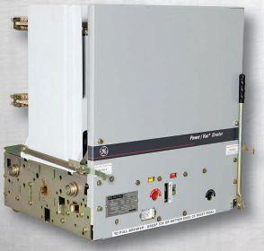
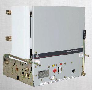


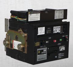
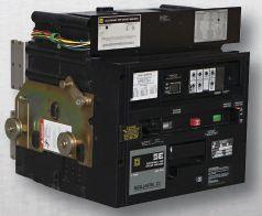


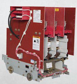
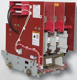


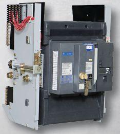
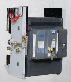



www.bcsswitchgear.com Are you having Power Equipment Problems? BCS HAS THE SOLUTION! new ∙ used ∙ obsolete ∙ reconditioned TEXAS OFFICE 4790 Hwy 377 South Krugerville, TX 76227 FAX 940-365-1808 ABB ∙ GENERAL ELECTRIC ∙ ITE GOULD ∙ WESTINGHOUSE ∙ SIEMENS SQUARE D · ALLIS CHALLMERS ∙ FEDERAL PACIFIC Call Toll Free: 888-599-0486 SWITCHGEAR, INC. Powering industry with superior equipment since 1999.
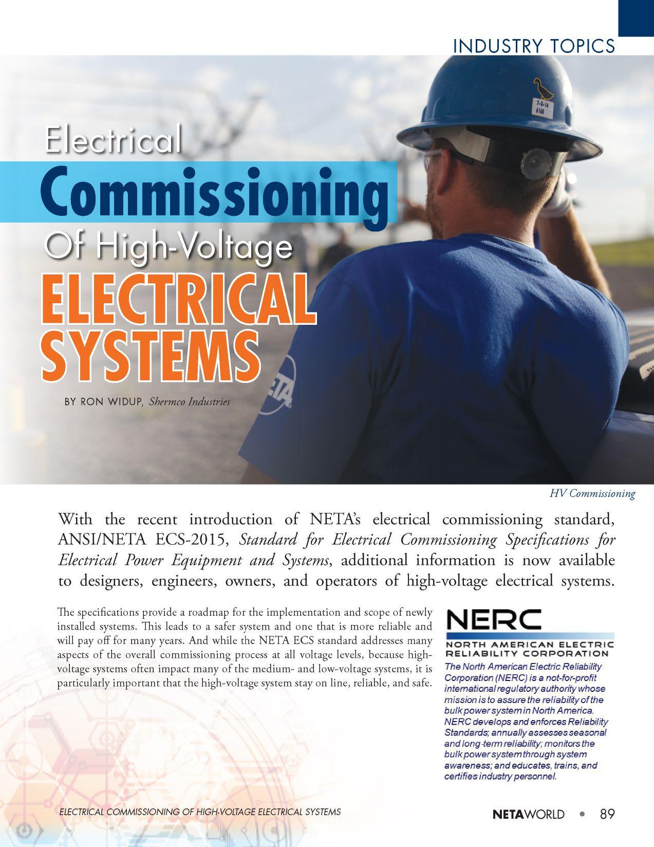
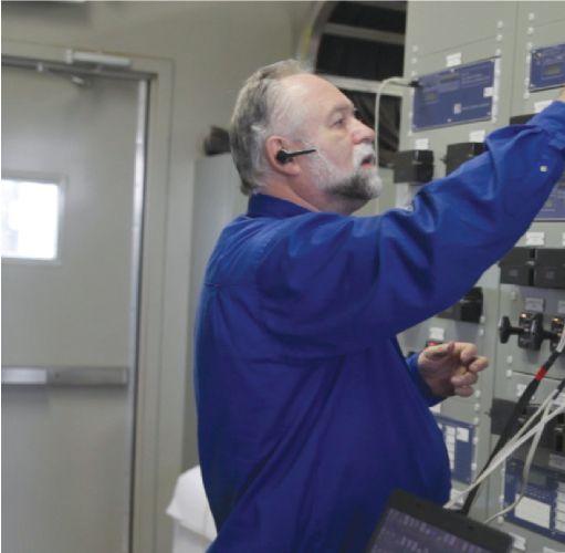
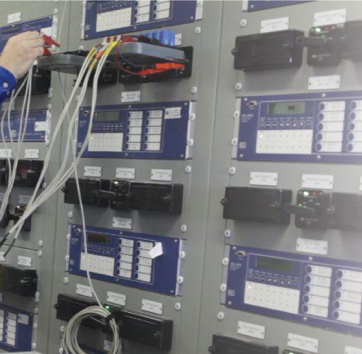

Remember the Northeast blackout in August 2003 that affected 50 million people? Starting in Ohio, overgrown trees triggered a regional outage that eventually affected eight northeastern states and portions of Canada. The equipment affected in the 2003 outage included high-voltage systems that had a widesweeping impact to downstream devices and placed many people in the dark and without power. When initial fault events such as this occur, it is critical that protection and control equipment reacts as intended and as designed, which is why the initial commissioning process is so important.
COMMISSIONING OF HIGH-VOLTAGE SYSTEMS
Why should you care about commissioning high-voltage systems? The obvious answer is to provide a safer system for personnel and for overall system reliability; depending on the classification of the equipment, the North American Electric Reliability Corporation (NERC) cares as well.

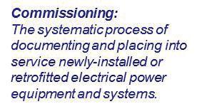
NERC is an international regulatory authority whose mission is to assure the reliability of the bulk power system in North America. NERC develops and enforces Reliability Standards; annually assesses seasonal and long‐term reliability; monitors the bulk power system through system awareness; and educates, trains, and certifies industry personnel.
In 2007, the U.S. Federal Energy Regulatory Commission (FERC) issued Order No. 693, which mandates that all users, owners, and operators of the bulk power system comply with electric reliability standards. To address the FERC comments from this order, NERC developed Standard PRC-005-2, Protection System Maintenance.
INDUSTRY TOPICS 90 • SPRING 2016
ELECTRICAL COMMISSIONING OF HIGH-VOLTAGE ELECTRICAL SYSTEMS
Protection System Commissioning
When it comes to electrical commissioning of high-voltage power systems, the interests of NERC are highlighted in “Lessons Learned” documentation it presents to industry. One such lesson published on March 11, 2014, titled Verification of Alternating Current Quantities during Protection System Commissioning, highlights the importance of electrical commissioning:
Problem Statement: Failure to employ effective commissioning testing practices can lead to protection system misoperations. Protection system misoperations impact the reliability of the bulk power system and can cause a significant increase in the magnitude and scope of a disturbance.
Details: Effective commissioning and testing practices were not implemented during the installation of a new transformer. As a result, associated line relays were placed into service with the incorrect Current Transformer (CT) ratio. The defect remained undetected until a system disturbance occurred when the relaying operated incorrectly, increasing the disturbance’s magnitude and scope.
Corrective Actions: The affected relays were rewired to the correct CT ratio, and an in-service
test was performed to verify current magnitudes and phase angles were correct. Lesson learned: Commissioning testing must include installation tests and effective in-service tests. In-service tests provide an overall check of current and potential circuits to verify these circuits are properly connected and measured levels of voltage and current are as expected. In-service tests can uncover errors that were not discovered during installationtests. installation tests.
Whiletheaboveinformationisbutone While the above information is but one example of an actual issue found with a highvoltage electrical system, it provides clarity and substantiation for the argument to perform electrical commissioning of power systems.
NETA Accredited Companies (NACs) find similar issues on a daily basis when performing electrical commissioning of low-, medium-, and high-voltage systems. Issues are often discovered on systems that were not properly commissioned when initially installed. To reiterate, it is all that more important to find the issues on a highvoltage system, as the cascading effects from a failure at the top of the electrical food chain can have resounding impacts across the entire system and all voltage classes.
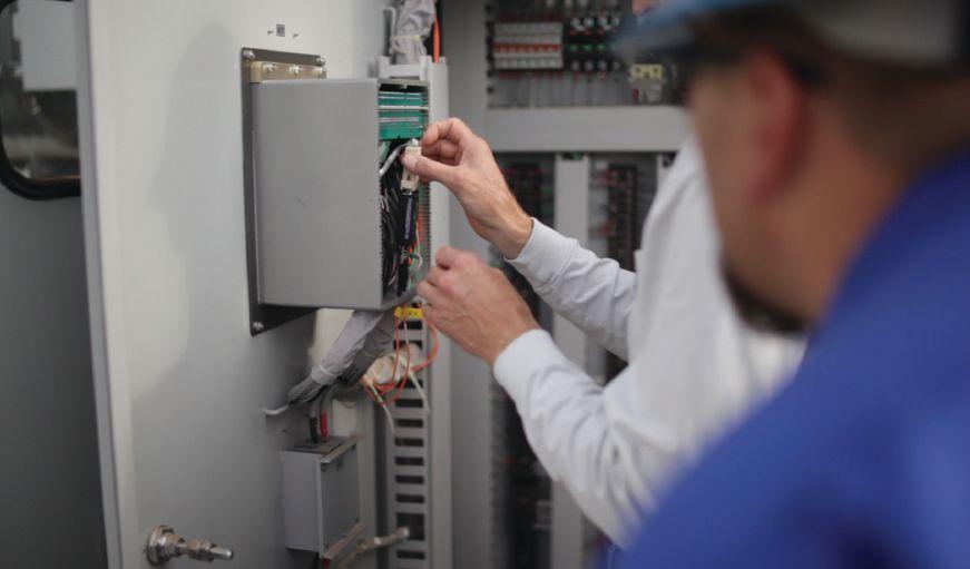

NETAWORLD • 91
INDUSTRYTOPICS INDUSTRY TOPICS ELECTRICALCOMMISSIONINGOFHIGH-VOLTAGEELECTRICALSYSTEMS ELECTRICAL COMMISSIONING OF HIGH-VOLTAGE ELECTRICAL SYSTEMS Verifying Communications

DETERMINING WHEN TO PERFORM COMMISSIONING TASKS
The NETA ECS document does a great job of identifying and specifying the necessary items and tasks related to electrical commissioning of power systems. In doing so, the standard coversitemssuchas: covers items such as:
Section1: Section 1: General scope
Section2: Section 2: Applicable references to codes, standards, and other publications
Section 3: Qualifications for the commissioning entity and their personnel
Section4: Section 4: Division of responsibility for the project
Section5: Section 5: General safety, test equipment, anddocumentation and documentation
Section6: Section 6: The commissioning process, intent, basis of design, and plan
Section7: Section 7: The specific inspection and commissioning procedures necessary
Section8: Section 8: Asectionreservedforfuturedata A section reserved for future data on secondary power sources
Section9: Section 9: Thermographic survey requirements and documentation
Section10: Section 10: Transferofinformationtothe Transfer of information to the owner or operator
By laying out the standard in this logical sequence, the user is guided to do only the necessary tasks and not those that are possibly replicated somewhere else.
The high-voltage procedures are outlined in Section 7.3, with tasks and procedures outlined in the logical sequence of (1) preenergization with 39 separate and distinct specification points, (2) energization with 15 separate and distinct specification points, and (3) post-energization with eight separate and distinct specification points.
While there are many factors to a successful commissioning process, a key facet in the preenergization stage is to verify that all equipment has been tested according to the most recent edition of the ANSI/NETA Standard for Acceptance Testing Specifications for Electrical Power Equipment and Systems (ANSI/NETA ATS). Because there is a direct correlation between acceptance testing and commissioning, for more information on bridging the gap from acceptance testing to commissioning, refer to a Spring 2015 NETA World Journal article of the same title (see http://www.netaworld.org/neta-world-journal).
EXAMPLES OF ISSUES FOUND WITH ELECTRICAL COMMISSIONING
NERC’s System Protection and Control Subcommittee (SPCS) states:
Need (Problem) Statement: The SPCS agrees with the problem statement. It is clear that “protection systems can be set up to misoperate if not adequately tested during commissioning.” Inadequate or improper testing of protection systems during any time in the life cycle of a protection system may lead to a future misoperation.
NETA Accredited Companies find issues on an almost daily basis when performing electrical commissioning tasks prior to placing a highvoltage system on line; they also uncover issues on systems that were not commissioned properly and have to re-commission the electrical system. Here are just a few examples.
The Case of the Rolled CTs
A new wind farm was built and placed in service without performing a comprehensive commissioning process. It was assumed that the phase rotation was A-B-C as the print showed, but this was not verified. During initial load checks, the customer discovered it was actually A-C-B.
The station was placed on line, but instead of fixing it correctly, someone swapped the current and voltage wires on the back of the protective relays and rolled the A and C
92 • SPRING 2016
INDUSTRYTOPICS INDUSTRY TOPICS ELECTRICALCOMMISSIONINGOFHIGH-VOLTAGEELECTRICALSYSTEMS ELECTRICAL COMMISSIONING OF HIGH-VOLTAGE ELECTRICAL SYSTEMS
phases. The balance of the system protection wiring was left incorrectly wired. Ultimately, this required rewiring of the potential transformer and current transformer wiring within the entire substation so the protection would function properly.

The Pinched GSU Current Transformer Wiring
This is an example of a situation that could have been significant if an electrical fault occurred, as the current circuit for differential protection on a large power transformer was not functioning properly.
The C phase current transformer (CT) in a generator step-up (GSU) transformer was saturating at a much lower voltage than at the A and B phases. The defective CT was saturating at approximately 40 volts, and the other two phases were saturating near 980 volts. Since the unit was tied to a differential circuit, it could have led to misoperation of the protective circuit. (See Figures 1 and 2 for an illustration of good and problematic CT curves.)
Upon inspection, the secondary wires inside the transformer tank were pinched during the original installation, damaging the insulation of the CT leads coming out of the assembly. The secondary wiring would appear as a [false] short-circuit once voltage rose over above a minimal level, and the CT would
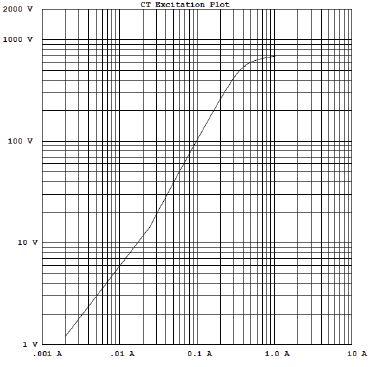
only produce about 40 volts. If the CT had to produce more than 40 volts to perform a trip or operate on a through fault, it would not be able to produce the voltage because it would saturate at the lower level. The wiring was repaired and the CT replaced.
From One End to Another, the Problems Never Seemed to End
While performing NERC maintenance testing, which included end-to-end testing of the line relays, the test plans were provided by the utility company; they also provided the Protection & Control (P&C) crew to perform the work at their substation.
As testing began, immediately there were issues with the line differential tests. A differential metering test was performed, and it was determined there were current input issues on the customer side of the switchyard. It was discovered that the current circuits on the relay had been visibly manipulated, which was unknown to the customer.
Troubleshooting the issues, a transmission line was found to have been rolled, which caused phasing issues for the substation. This phasing issue made its way to the turbine feeder breakers and transformer CT circuits. The line phasing and wiring errors were corrected, and the end-to-end testing completed.
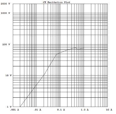
NETAWORLD • 93
INDUSTRY TOPICS ELECTRICAL COMMISSIONING OF HIGH-VOLTAGE ELECTRICAL SYSTEMS
Figure 1: A Good CT Excitation Curve
Figure 2: A Problematic CT Excitation Curve
INDUSTRY TOPICS
Don’t be Alarmed — It’s Just a Battery, a Switch, and a Jumper
While commissioning the controls in a 230 kV substation, the battery charger dc low-voltage alarm did not function due to incorrect wiring within the battery charger. The transformer differential relay status did not function due to incorrect wiring. The stand-alone dc panel was labeled improperly. The ground fault enable/disable switches were installed such that the disable position enabled ground fault protection, and the enable position disabled ground fault protection. Furthermore, 230 kV breaker control switches were improperly wired, allowing closing of switches remotely by SCADA when they were in a green-flag condition per the basis of design. Jumpers within the control switch were found in the wrong position and removed.
Control House Wiring and the Incorrect Voltage Rating
While commissioning a 138 kV substation lineup, the switchgear interconnection wiring was installed by the electrical contractor. Upon energization of the dc control circuit, it was noticed that the dc indicator lights were flickering. During troubleshooting, the interconnecting wiring had been installed below the field-installed wiring, which
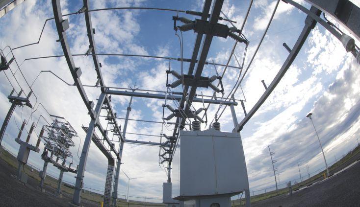
prevented access to the connection terminal block; this created wiring issues due to the inaccessibility of the connection points.
In addition, the indicator lights were running at elevated temperatures, as the system voltage was 48-volts dc. However, the indicator lights as supplied were rated at 28-volts dc and had to be replaced with the proper voltage rating.
Furthermore, during the function testing of the lock-out scheme for the generator circuit breaker, the system would not function as
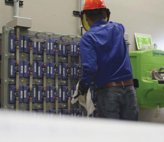
intended. Upon investigation, it was found that one of the indicating light resistors was rated at 120-volts dc at 2,000 ohms. This created a voltage drop that prevented the lock-out relay from operating. After checking the remaining resistors, five were found to be 120-volts dc and required replacement.
Breaker, Breaker — Catch You on the Flip Side
While commissioning a new wind farm substation during the current transformer (CT) testing, it was noted that the ratios of the CTs being tested did not match the ratios on the prints.
94 • SPRING 2016 High-Voltage Substation
ELECTRICAL COMMISSIONING OF HIGH-VOLTAGE ELECTRICAL SYSTEMS
Battery System Commissioning
Upon investigation, it was discovered that the SF6 circuit breakers had been installed backwards, which placed the bus protection CTs on the wrong side of the line. To correct this — and because it would not have been a reasonable option to swap the line and load CTs in the field — every breaker (six of them) had to be lifted off of foundation and rotated 180 degrees.
Additionally, the A- and C-phase CT connections had to be swapped. The main breaker was also installed incorrectly, but the CTs were of the same ratio on the line and load, so it was left as installed.
SUMMARY
For a safe and reliable power system, the proper commissioning of high-voltage electrical systems is critical. Not only do the federal regulators validate this fact with their rulings and rulemaking, but also actual scenarios in this article serve as examples to the industry.
NETA Accredited Companies are critical to the commissioning process, as the discovery of installation errors, design issues, wiring mistakes, etc., must be found before the systems are placed on line. This — plus using the ANSI/NETA ECS standard in conjunction with a qualified NAC commissioning team — is a combination that makes for a safer and more reliable overall system.
After all, who wants another 50 million people inthedark? in the dark?
REFERENCES
ANSI/NETA ECS-2015 Standard for Electrical Commissioning Specifications for Electrical Power Equipment and Systems, NETA www.netaworld.org
North American Electric Reliability Corporation (NERC), www.nerc.com
“SEL Recommendations on Periodic Maintenance Testing of Protective Relays,” Karl Zimmerman, Schweitzer Engineering Laboratories, Inc., SEL White Paper No. LWP0005, March 24, 2014
“Verification of Alternating Current Quantities during Protection System Commissioning,” NERC Lesson Learned #20140302, March 11, 2014, http://bit.ly/1LuFpIA
ANSI/NETA ATS-2013, Standard for Acceptance Testing Specifications for Electrical Power Equipment and Systems, NETA, www.netaworld.org
“SPCS Response to Standards Committee Request for Research,” NERC Project 2012-04, Protection System Commissioning Testing, March 5, 2013, http://bit.ly/1Nsfl5A

Ron Widup is CEO of Shermco Industries has been with the company since 1983. He is a Principal member of the Technical Committee on “Electrical Safety in the Workplace” (NFPA 70E) and a Principal member of the National Electrical Code (NFPA 70) Code Panel 11. He is a member of the technical committee “Recommended Practice for Electrical Equipment Maintenance” (NFPA 70B), President of NETA and a member of the NETA Board of Directors and Standards Review Council. He is also a NETA Level IV Senior Test Technician.
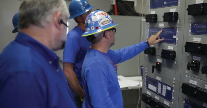


NETAWORLD • 95
System Checkout ELECTRICALCOMMISSIONINGOFHIGH-VOLTAGEELECTRICALSYSTEMS ELECTRICAL COMMISSIONING OF HIGH-VOLTAGE ELECTRICAL SYSTEMS INDUSTRY TOPICS
CALL FOR SPONSORS





ANAHEIM • CALIFORNIA February 27 - March 3 • 2017 DISNEYLAND HOTEL POWERTEST.ORG 888.300.6382 THE PREMIER ELECTRICAL MAINTENANCE & SAFETY EVENT A premier reservation. Sponsorships are now available. Reach hundreds of leading decision–makers at PowerTest
advertising and press reaching 24,000+ industry professionals before, during, and after the event
in all price ranges
Receive
Available
ANSI/NETA STANDARDS UPDATE
STAN DARD FOR CERTIFICATION OF ELECTRICALTESTING TECHNICIANS
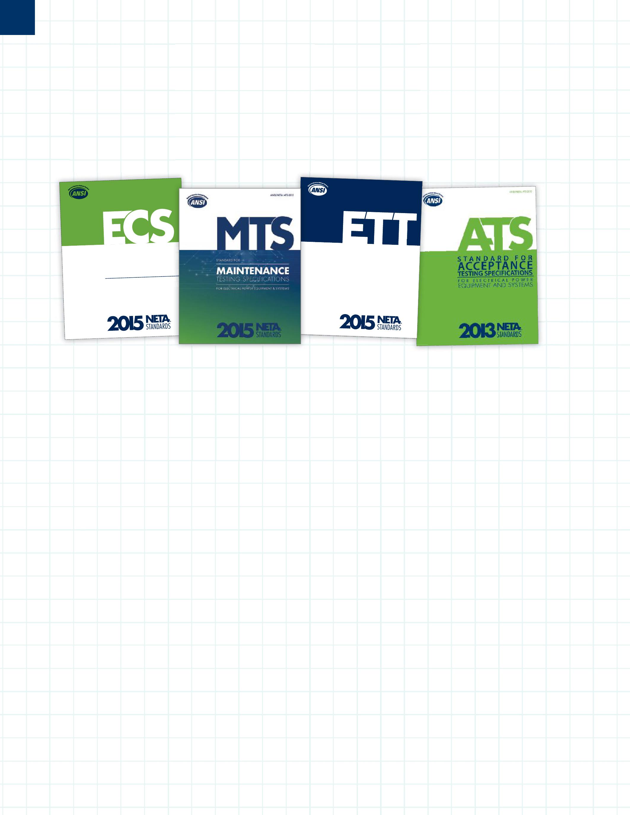
ANSI/NETA ECS-2015 NEWAMERICAN NEW AMERICAN NATIONAL STANDARD
TheANSI/NETAECSS
The ANSI/NETA ECS Standard for Electrical Commissioning of Electrical Power Equipment and Systems, 2015 edition, was approved as an American National Standard on December 3, 2014. This new standard is available for purchase in the NETA Bookstore online at netaworld.org.
equipment, mechanical instrumentation systems, and related components.
Voltage classes addressed include:
• Low-Voltage Systems (less than 1,000 volts)
• Medium-Voltage Systems (greater than 1,000 volts and less than 100,000 volts)
• High-Voltage and Extra-High Voltage Systems (greater than 100 kV and less than 1,000 kV)
TheANSI/NETAECSdescribesthe
The ANSI/NETA ECS describes the systematic process of documenting and documenting placing into service newly installed or installed or retrofitted electrical power equipment power and systems. This document shall be used in conjunction with the most recenteditionoftheANSI/NETA recent edition of the ANSI/NETA Standard for Acceptance Testing Specifications for Electrical Power Equipment and Systems.Theindividual . The individual electrical components shall be subjected to factory and field tests, as required, to validate the individual components. It is not the intent of these specifications to provide comprehensive details on the commissioning of mechanical
References
ASHRAE, ANSI/NETA ATS, NECA, NFPA 70E, OSHA, GSA Building Commissioning Guide
ANSI/NETA MTS-2015 NEW EDITION
TheANSI/NETAMTS The ANSI/NETA MTS Standard for Maintenance Testing Specifications for Electrical Power Equipment and Systems, 2015 edition, was approved as an American National Standard on December 3, 2014, and supersedes the ANSI/NETA MTS2011.Thisnewstandardisavailablefor 2011. This new standard is available for purchase in the NETA Bookstore online at netaworld.org.
TheANSI/NETAMTScontains The ANSI/NETA MTS contains specifications that cover suggested field tests and inspections available to assess the suitability for continued service and reliability of electrical power equipment and systems. The purpose of these specifications is to assure that tested electrical equipment and systems are operational and within applicable standards and manufacturers’ tolerances, and that the equipment and systems are suitable forcontinuedservice. for continued service.
Revisionsinclude: Revisions include:
• New numbering system for more accurate referencing
• Protective relays
• Instrumenttransformers Instrument transformers
• Rotating machinery
• NewTable100.11 New Table 100.11
• RevisedTable100.1 Revised Table 100.1
• Updated references to industry standards
• Many more revisions, all marked in the margins for ease of use
98 • SPRING 2016 ANSI/NETA STANDARDS UPDATES SPECIFICATIONS AND STANDARDS ACTIVITY
ANSI/NETA ECS-2015 STANDARD FOR ELECTRICAL COMMISSIONING SPECIFICATION S F OR EL ECTR ICALPOWER EQUIPMENT ANDSYSTEMS GSPECIFICATIONS ANSI/NETA ETT-2015
2015 R L NG N E R MS
PARTICIPATION
Comments and suggestions on any of the standards are always welcome and should be directed to the NETA office at neta@netaworld.org or 888-300-6382. To learn more about the NETA standards review and revision process, to purchase these standards, or to get involved, please visit www.netaworld.org or call 888-300-6382.
ANSI/NETA ETT-2015 NEW EDITION
The ANSI/NETA ETT Standard for Certification of Electrical Testing Technicians, 2015 edition, was approved as an American National Standard on December 3, 2014, and will supersede the ANSI/NETA ETT2010.Thisnewstandardisavailablefor 2010. This new standard is available for purchase in the NETA Bookstore online at netaworld.org.
TheANSI/NETAETTestablishes The ANSI/NETA ETT establishes minimum requirements for qualifications, certification, training, and experience for the electrical testing technician. It also provides criteria for documenting qualifications forcertificationanddetailstheminimum for certification and details the minimum qualifications for an independent and impartial certifying body to certify electrical testing technicians.
ANSI/NETA ATS-201X REVISION IN PROCESS
TheANSI/NETA The ANSI/NETA Standard for Acceptance Testing Specifications for Electrical Power Equipment and Systems began the review and revision process in October 2014 at the Standards Review Council meeting. The ballot pool for this document is now closed, but applications are always accepted for futurerevisions. future revisions.
The ANSI/NETA ATS covers the suggested field tests and inspections that are available to assess the suitability for initial energization of electrical power equipment and systems. The purpose of these specifications is to assure that tested electrical equipment and systems are operational, are within applicable standards and manufacturers’ tolerances, and are installed in accordance with design specifications.
ANSI/NETA STANDARDS UPDATES
Reliable Power System Solutions
Accredited Company 204 Gale Lane Kennett Square, PA 19348 484.731.0200 enerGtest.com Serving clients
Pennsylvania, Delaware, New Jersey, Maryland, Washington, DC and New England.
ener es ™ testing
preventive maintenance,
EnerGTest to keep the power on.
in
We deliver optimum system reliability and performance while reducing the chances of costly unplanned power outages. Whether you need acceptance
or
depend on


Inc.
Industrial Electric Testing,





CALL FOR EXHIBITORS California is calling. Join 400+ electrical testing professionals Leading decision makers looking for new products and services For attendee profile and additional information, visit www.powertest.org ANAHEIM • CALIFORNIA February 27 - March 3 • 2017 DISNEYLAND HOTEL POWERTEST.ORG 888.300.6382 THE PREMIER ELECTRICAL MAINTENANCE & SAFETY EVENT
REPORT ON THE NEC CMP 13 SECOND REVISION MEETING
November 9-11, 2015, In San Diego, California
BY JIM WHITE, Shermco Industries
At the November 2015 meeting, Code Making Panel 13 considered and reviewed the work of several task groups and completed work on 25 second revisions based on 30 public comments. The meeting lasted three days and included input from CMP 13 members and visitors.
KEY HIGHLIGHTS
NETA member companies will be interested in several of the topics discussed during the meetings. Here are descriptions of some of the more impactful second revisions and proposed newarticles. new articles.
New Section 700.3 (F) Second Revision
This new section adds the requirement for emergency systems that rely on a single source of power, which will be disabled for maintenance or repair, to be provided with a permanent switching means to connect a temporary alternate source for the duration of the maintenance or repair.
Some facilities may have to retrofit their emergency power systems with docking stations for temporary generator connection and a switching means with interlock capabilities that allows all three power sources (normal, emergency, and temporary) to be connected independently. The benefit is that

the temporary connection and switching means can also be used for connecting loadbank testing equipment. This will eliminate the common practice of disconnecting the emergency generator load cables during loadbank testing of the emergency source.
New Article 706 — Energy Storage Systems (Proposed)
This proposed new article was developed by a committee task group chaired by John Kovacik, UL LLC. The task group had 79 members, combining input from other sources such as IEEE battery group, article 690 task group, andNEMA. and NEMA.
Provisions for storage batteries are covered in Article 480 of the 2014 NEC. All battery requirements from existing article 480 are now in new article 706, which covers batteries of all types and expands the new article for all types of energy storage systems.
REPORTONTHENECCMP13SECONDREVISIONMEETING REPORT ON THE NEC CMP 13 SECOND REVISION MEETING NOVEMBER 9-11, 2015, IN SAN DIEGO, CALIFORNIA 102 • SPRING 2016 SPECIFICATIONS
ACTIVITY
AND STANDARDS
Combining article 480 into new article 706 places all requirements for these types of systems in one place. It also allows for expansion as new technologies are developed and deployed.
New Articles 710 and 712 — Microgrids and dc Microgrids, Respectively
Thesetwonewarticlesareintendedtocover These two new articles are intended to cover this new type of installation. They already exist in significant numbers in the U.S. With the rise of interactive photovoltaic systems, fuel cell, battery-type energy storage systems, and smallscale wind — all potentially interconnected — the need for the new articles is apparent. Currently, no single place in the NEC relates to these stand-alone systems.
As new technologies evolve over the next code cycle, these new articles provide a place for microgrid requirements. The microgrid market is estimated to reach $17 billion by 2017.
Jim White is nationally recognized for technical skills and safety training in the electrical power systems industry. He is the Training Director for Shermco Industries, and has spent the last twenty years directly involved in technical skills and safety training for electrical power system technicians.
Jim is a Principal member of NFPA 70B respresenting Shermco Industries, NETA’s alternate member of NFPA 70E, and NETA's principle representative to ASTM F18 Committee “Electrical Protective Equipment for Workers”.
specialist level knowledge of Circuit Breakers, Fuses, and Protective Relays with this convenient take-anywhere eBook.
REPORTONTHENECCMP13SECONDREVISIONMEETING REPORT ON THE NEC CMP 13 SECOND REVISION MEETING NOVEMBER 9-11, 2015, IN SAN DIEGO, CALIFORNIA
NEW eBOOK PACKED FULL OF TECHNICAL INFORMATION! ELECTRICAL CIRCUIT BREAKERS, FUSES AND PROTECTIVE RELAYS by L.W. Brittian
AVAILABLE NOW ON AMAZON.COM IN THE KINDLE STORE
Only
Achieve
900+ pages 200+ pictures 125+ Charts and Tables
$5.99

EXPERT KNOWLEDGE.


Staying on the forefront of the new energy economy requires cutting-edge information from authoritative voices. Each month, Wind Systems keeps its readers attuned to the latest innovations in the wind energy industry. Let us be your partner in driving sustainability—and your business—to new heights.

For your FREE subscription to Wind Systems, log on to windsystemsmag.com.


SUSTAINABLE FOCUS.
the test equipment answer
We support testing
Protective Relays and Metering
Batteries and UPS
Transformers
VLF, Tan Delta and Partial Discharge
Cable fault location
Substations & High Voltage Circuit Breakers
SF6 Analysis
Low & Medium Voltage Circuit Breakers
Motors and Rotating Apparatus
Power Monitoring
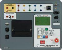

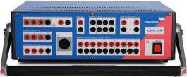

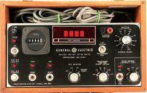

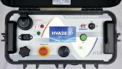

888.902.6111 | info@intellirentco.com | intellirentco.com
rental | support | logistics

“COMING TOGETHER IS A BEGINNING, STAYING TOGETHER IS PROGRESS, AND WORKING TOGETHER IS SUCCESS.”
–HENRYFORD – HENRY FORD
BY JILL HOWELL, NETA
The goal of the NETA Alliance Program and the Corporate Alliance Program is to bring together subject matter experts from across the many business sectors of the electrical testing industry, creating a network of professionals committed to the education, advancement, quality, safety, and reliability of our industry.
The NETA Member & Alliance Meeting, held annually the Sunday before PowerTest, offers a forum where individuals can share information, consider issues and insights, and identify ways to collaborate on advancing the industry. Participating in the Alliance Program offers many benefits, but none as important as building relationships with companies and colleagues, staying in touch with important developments and trends, and working together to shape the industry’s future. The Member Alliance Meeting is just one opportunity for bridge building throughout the PowerTest 2016 conference.
2016 NETA ACCREDITED COMPANY AND ALLIANCE PARTNER EVENTS MARK YOUR CALENDARS!
NETA Member & Alliance Meeting. All NETA Alliance Partners and Corporate Alliance Partners are welcome to attend. The gathering provides opportunity for interaction between colleagues fromthe NETA Accredited Companies, engineering firms, utilities, operations and maintenance managers,equipment manufacturers, and professionals engaged in the installation and maintenance of power ystems. Because the meeting takes place on the Sunday before PowerTest, it is an excellent way to meet new people and get your bearings before PowerTest begins on Monday morning. It also gives those who are unable to break away during the work week the opportunity to attend and stay involved.
UPCOMINGALLIANCEMEETING UPCOMING ALLIANCE MEETING
106 • SPRING 2016
NETA Member & Alliance Meeting
Fort Worth, Texas
March 13, 2016
2:00 PM – 5:00 PM

Agenda
• Welcome
• NETA Report and Program Overview
• TechnicalResourcesReview Technical Resources Review
• Training and Education
• Roundtable Discussions — Led by Corporate Alliance Partners
• Technical Reports, Industry Standards, and Code Updates
• ANSI/NETA Standards Update
• PowerTest2016Preview PowerTest 2016 Preview
NETAMember&AllianceLuncheon. NETA Member & Alliance Luncheon. This event takes place on Monday during PowerTest 2016 from 12:15 PM to 2:15 PM, following the morning technical presentations. NETA members and Alliance Partners sit together for a networking lunch, awards ceremony, and a round table working session.
NETA Member & Alliance Luncheon
Fort Worth, Texas
March 14, 2016
12:15 PM – 2:15 PM
Agenda
•Welcome
• Welcome
• Corporate Alliance Partner Introduction
• NETA Alliance Recognition Award
• NETA Outstanding Achievement Award
• RoundTableDiscussion Round Table Discussion
• Networking
2016 is the year to get involved and demonstrate your leadership in the shared responsibility of advancing the electrical power systems industry. Besides participating in NETA’s Alliance events, consider volunteering on one of NETA’s Technical Working Committees. Each committee is engaged in a specific project that will help improve electrical power quality, safety, and reliability.
For information on NETA Technical Working Committees, contact Jill Howell at jhowell@netaworld.org.
If you would like to join the NETA Alliance Partnership Program or recommend participation to a colleague, please visit www.netaworld.org and click on the Alliance Program tab for program details, or contact the NETA Office at (888)300-6382 (NETA).
NETAWORLD • 107 UPCOMINGALLIANCEMEETING UPCOMING ALLIANCE MEETING







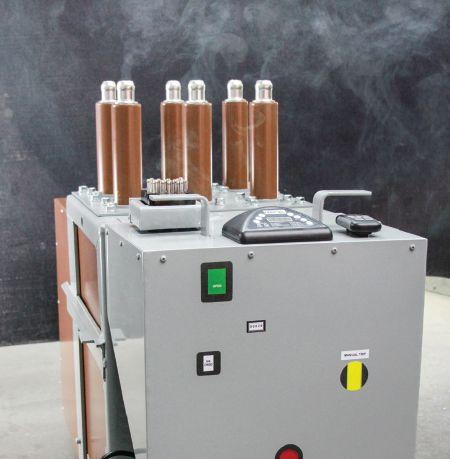
When your electrical equipment is failing, getting the parts you need shouldn’t be part of the problem. With a huge inventory of new, surplus and repurposed electrical circuit breaker and switchgear products, National Switchgear can be a big part of your solution. We have millions of parts, but we also have the expertise to see the whole picture, to understand your problem and to recommend the best total solution. Of course, if you already know exactly what you need, it’s easy to buy online on our constantly updated website, where you’ll also discover hard-to-find resources like installation manuals, wiring diagrams and more. Whatever you need, we’re ready to share our expertise. 800-322-0149
WE’RE MORE THAN JUST PARTS. WE’RE PART OF THE SOLUTION. LET’S MEAT AT POWERTEST! Visit Booth 222 and enter to win our custom built MagneBlast smoker!
nationalswitchgear.com
2016 – NEW PRODUCT FORUM
BASLER ELECTRIC COMPANY
www.basler.com
ES Series Protection Relays
Basler Electric announces the newly designed ES Series Protection Relays. Designed to simplify protection, ES Protection Relays cover a wide range of applications including generator, transformer, distribution, process control, Auto Transfer schemes, and motors.
ES Relays are equipped with many high-end, sophisticated features not typically found in a low-cost device. ES Series Protection Relays offer the security and performance users have come to expect from Basler Electric with more than 50 years of providing protective relay solutions.
Fundamental Sensing technology, not usually found in a low-cost product, provides high-end harmonic protection capabilities that prevent false tripping and allow users to be more selective.
BCS SWITCHGEAR, INC.
www.bcsswitchgear.com
Insulated Case Breakers
BCS Switchgear has rapidly expanded into the Insulated Case industry in recent years. Our techs perform a wide range of tests ensuring that what we send you is in proper working order. We take it a step further and offer standard one-year warranties on everything that ships out of our warehouse in Texas.
Our every-growing inventory enables us to handle and deliver all of your electrical wants/needs. Our knowledgeable sales team is more than equipped to answer your questions and make sure you are well taken care of.
CBS ARCSAFE, INC.
www.cbsarcsafe.com
CBS ArcSafe® Partial Discharge Sensor
In the event of a breakdown in line-to-line or line-to-ground insulation, CBS Arc Safe’s new PD Alert radio frequency (RF) non-contact partial discharge sensor issues a visual strobe alarm or digital alarm via email or SMS text message. Advanced signal processing and field configurable setup allows the operator to set do-not-exceed thresholds for partial discharge values, or to issue an alert if partial discharge values indicate a condition that could be dangerous to technicians. The PD Alert can be used with any of CBS ArcSafe’s remote circuit breaker racking systems, or as a stand-alone partial discharge sensor for monitoring critical electrical distribution equipment.
CIRCUIT BREAKER SALES CO., INC.
www.circuitbreakersales.com
Tough Duty Vacuum Circuit Breaker
The Tough Duty vacuum circuit breaker by Circuit Breaker Sales is a roll-in replacement for existing GE PowerVac circuit breakers. Tough Duty breakers feature robust encapsulated poles and a proven USA-made mechanism. Tough Duty means resistance to harsh environmental conditions, long service life, and less maintenance requirements. Circuit Breaker Sales backs the Tough Duty line with a five-year, 3,000 operation warranty. No modifications to existing switchgear are required. Tough Duty breakers are available in 5kV-15kV, 1200A-2000A, 31.5kA and 50Hz/60Hz ratings.
DOBLE ENGINEERING COMPANY
www.doble.com
Field Force Automation
Doble’s Field Force Automation solution makes it easy for you to adapt to regulatory changes through a combination of rugged controllers, testing software, custom engineering and data management processes. The goal is to make sure that your test controllers are compliant and that customer data is secure – all while making it easier for crews to focus on testing.
Key Program Features:
• Tailored to your requirements, define your customization level
• Standardize processes across your workforce
• Data management process is automated and behind the scenes
• Rugged controllers with sunlight readable screens seamlessly connect with your Doble equipment
EA TECHNOLOGY, LLC.
www.eatechnologyusa.com
UltraTEV+ Mark 2
The workhorse UltraTEV+ has been upgraded with exciting new features that enhance the capabilities of this best-selling partial discharge instrument. The proven cable testing capabilities of the CableData Collector have been added to allow instant reading of cable PD levels. A unique ultrasonic classification system automatically tells the technician when PD is present. The UltraTEV+ Mark 2 also records the data to simplify reporting and enhance accuracy. All existing probes work with the MK2 and economic upgrades are available for existing owners. Hotstick mounted RFCTs are now available for the UltraTEV and CDC.
110 • SPRING 2016 NEW PRODUCT FORUM
ELECTRO RENT CORPORATION
www.electrorent.com
New Products to Rental Inventory
Established in 1965, Electro Rent Corporation adds new products to its rental inventory every month. Recent additions include High Voltage Diagnostics’ HVA-90 VLF and the Ludeca Pruftechnik Rotalign laser alignment tool. Electro Rent has recently opened a stocking center in Houston, TX. Electro Rent’s calibration lab is A2LA ISO/IEC 17025: 2005 certified to ensure your equipment is calibrated correctly when you receive it. For daily and monthly test equipment rentals, please call our experienced staff at 800.688.1111 (USA) or 800.268.0216 (Canada). Email us at sales@electrorent.com.
ELECTROSWITCH
www.electroswitch.com
Series 24 Push-to-Turn Handle and Series 24 Lockout Relay
The Series 24 Push-to-Turn Handle prevents unintentional operation of your breaker control switch by requiring deliberate two-step operation. To operate the switch, the handle must be aligned and pushed in to engage before turning.
The Series 24 Lockout Relay now has an option that allows the LOR to be mechanically tripped from the front of the panel. This option allows the operator to stay in front of the panel when running functional testing of LOR circuits. An additional hole on the panel is required to provide access to the tripping mechanism.
GE INDUSTRIAL SOLUTIONS
www.geindustrial.com
GE EntelliGuard “Trip Unit Toolkit” Software
Features
• Customize: change language, synchronize date, change name update firmware, change settings
• Troubleshoot: see waveform capture, event log, and real-time data including metering, phase or diagram, and status
• Test: digitally test the protection functions of the breaker
Customer Benefits
• Easy and quick: users can leverage the power of laptop devices
• Safe:
- Hardwired: only connect to read or write; programming possible on workbench outside of arc zone
- Wi-Fi: always work outside arc flash zone
• Preventive maintenance: mechanism timing, contact wear
2016 – NEW PRODUCT
HAEFELY HIPOTRONICS
www.haefely-hipotronics.com
800PL-DC Hipots
The 800PL-DC hipots are a modern solution for testing the insulation strength of electrical apparatus. Outfitted with a digital interface and extensive safety features, the 800PL-DC ensures simplistic operation and operator safety under all circumstances. Available in 40kV and 80kV full-wave outputs and weighing 57 lbs, the 800PL-DC hipots measure output voltage, leakage current, insulation resistance, and polarization index and are also capable of exporting test data in a .csv format. The operator can input test parameters such as target voltage, rate of rise, maximum leakage current, and dwell time for completing an automated test sequence or operate it manually.
INOLECT, LLC.
www.inoLECT.com
ABB Advac Interlock Actuator
This newly designed connection tool allows inoLECT’s universal Remote Racking device, the inoRAC2, to perform racking functions on ABB Advac circuit breakers. The custom-designed tool is a lightweight, aluminum housing, surrounding a linear actuator equipped with a roller. It easily attaches to switchgear doors with industrial-strength magnets and requires no modifications. When operating, the actuator/roller engages the breaker’s interlock lever, allowing it to perform disengage/engage functions. The tool is installed quickly, very user-friendly and requires one connection cable. This is only one of the many solutions that make the inoRAC2 the most universal remote racking product on the market.
MADDOX INDUSTRIAL TRANSFORMER
www.maddoxtransformer.com
Introduction to Maddox Industrial Transformer
Maddox Industrial Transformer was founded in 2015 to focus exclusively on the transformer needs of commercial and industrial clients.
With new stocking locations throughout the country, and a desire to work hand-in-hand with testing and field service organizations, Maddox wants to be your first call for any transformer need.
With massive inventory expansion, we now have thousands of three-phase transformers in stock, new or reconditioned with full warranty and available for immediate shipment.
NETAWORLD • 111 NEW PRODUCT FORUM
FORUM
2016 – NEW PRODUCT FORUM
MEGGER
www.megger.com/us
DLRO100: 100 A Portable Micro-Ohmmeter with DualGround Safety
The Megger DLRO100 delivers the freedom to test in remote and harsh environments while keeping a strong focus on user safety. The DLRO100 allows low resistance measurement across multiple applications without needing an AC source. It’s the only continuous battery operated 100 A unit on the market. The internal Li-ion battery supplies a constant 100 A current for up to 200 automatic or manual tests. Advanced features ensure safe operation of the instrument in the most adverse conditions, including a CAT IV 600 V safety rating in accordance with IEC61010. A DualGround feature is available, which adds to operator safety by grounding both sides of the breaker under test.
MVA DIAGNOSTICS, INC.
www.mvadiagnostics.com
MVA Dashboard – Paperless Sample Tracking
MVA Diagnostics, a top ranked transformer oil diagnostic laboratory, is pleased to introduce paperless sample tracking for our clients. No longer will your Field Service Technicians need to fill out paperwork to record the nameplate information and tests. Instead, simply log in to the MVA Dashboard, select which serial number you are testing, pick which tests you want performed and ship us the samples. It’s that easy. This unique operating system saves you money by eliminating time spent filling out forms and correcting mistakes from transposed serial numbers. You win with MVA. Call us today so we can help you!
OFIL - USA
www.ofilsystems.com
Ofil's 2016 New Corona Camera Model: UVollé-VX
Ofil's new handheld corona camera model UVollé-VX features low weight, slender design, good hands grip, an extended wide VGA LCD and high UV detection capabilities. UVollé-VX offers a cost effective combination of performance and price enabling safe testing, fast detecting, recording and display of corona partial discharges. UVollé-VX incorporates Ofil's proprietary DayCor® technology and is designed ergonomically to match outdoors and indoors inspection conditions. UVollé offers more than seven hours ongoing continuous battery run time operation without overheating.
OMICRON ELECTRONICS CORP. USA
www.omicronusa.com
CT Analyzer (CTA) and Primary Test Manager (PTM)
The certification of current transformers and the gathering of current transformer test data is of particular importance for protective relays as well as revenue metering to ensure proper operation of the entire power system. Our CT Analyzer provides a unique method of not only measuring, but analyzing the CT characteristics for adherence to the IEEE and IEC standards. The CTA can detect if the CT is a metering class or protection class instrument, provide performance characteristics at different burdens, and error tables for any of those burden classes.
PRIMARY TEST MANAGER
(PTM) Our all-inclusive workflow guided software is now capable of driving three of our substation testing devices: our transformer test set (CPC100/ TD1), our Frequency Response Analyzer (FRANEO 800), and our circuit breaker test set (CIBANO 500). Only one software package to learn, saving time in the field testing and back in the office compiling the report.
Come see both products at our booth #301.
PARTS SUPER CENTER
www.partssupercenter.com
OEM Switchgear Uprates
Part Super Center, formerly GE Parts Super Center, is now able to provide OEM switchgear uprates for GE Magneblast switchgear cubicles. Whether you are looking to increase the continuous current rating of your bus, raise the momentary withstand of your Magneblast switchgear to match vacuum roll-in replacement breakers, or just change current transformers, Parts Super Center can provide you with an OEM uprate kit or turnkey solution using genuine OEM designs and parts. Parts Super Center is exclusively responsible for the manufacture and sale of all OEM parts, engineering support, and equipment modifications for the GE Magneblast product line.
112 • SPRING 2016 NEW PRODUCT FORUM
POWER DIAGNOSTIC SERVICE CO., LTD.
www.pdservice.com
PDSimply Portable
PDSimply Portable is a perfect Partial Discharge (PD) measuring device for severe environment, thanks to its WiFi function, compact design, and firm body. Based on extensive field experience, PDSimply Portable adopts three characteristics: the state of art UHF (Ultra-High-Frequency), AE (Acoustic Emission) PD detection technology, and the rule of thumb. This makes on-line PD measurement easier and more accurate than ever.
PDSimply Portable covers a wide range of applications, from medium to high voltage electrical equipment such as switchgear, transformer, GIS, and cables. With its dual detection method, PD signal can be measured, distinguished, and located precisely. It is capable of performing both UHF and AE measurement and display simultaneously.
POWER GRID ENGINEERING
www.powergridengineering.com
“Quality Assurance for Protection & Control” Report
IEEE PSRC has recently published a report “Quality Assurance for Protection & Control” chaired by Andre Uribe, Vice President of Power Grid Engineering, LLC. This report illustrates industry practices to be applied in a Quality Assurance Program for protection and control design drawing packages from conception to final “as-built.” The quality of an engineering package greatly impacts the testing and commissioning function in the field. Highlights of the report will be shared during the New Product Forum for industry awareness.
POWER MONITORING AND DIAGNOSTIC TECHNOLOGY, LTD.
www.powermdt.com
Generation II PDetector
The PMDT Generation II PDetector is the world’s most powerful handheld Online Partial Discharge testing instrument with these unique advanced features:
• Employs five types of sensor technology (TEV, UHF, HFCT, AE, and Ultrasonic) to detect all types of PD on all kinds of substation equipment;
• Displays acoustic amplitude, phase, fly and waveform spectrums; UHF & HFCT amplitude, phase and PRPD-2D / PRPS-3D spectrums;
• Determines PD or noise, PD type, severity, and approximate PD location;
• Wireless sensor technology;
•On-board data storage;
• Intelligent patrol and RFID asset tagging;
• Data management software.
PROTEC EQUIPMENT RESOURCES
www.protecequip.com
Calibration Services
Protec now offers calibration services out of our corporate office located in the Dallas Fort Worth area. Working in our in-house laboratory, our qualified technicians will guarantee that your electrical test instruments are working at peak performance and meet all manufacturer standards. Quick turnaround is standard, with most equipment completed in five business days or less.
We offer expedited and emergency service just in case you need a quick turnaround on your piece of equipment. We keep track of your calibration as well, so when your equipment is due for calibration, you will be notified. If you can’t afford to have any down time on a job, we also offer rental options for you to continue your work while we are calibrating your equipment.
NETAWORLD • 113 NEW PRODUCT FORUM
FORUM
2016 – NEW PRODUCT
RAYTECH USA
www.raytechusa.com
2016 – NEW PRODUCT FORUM
CT-T1 Current Transformer (CT) Tester
Raytech Brings Speed and Unmatched Accuracy to Current Transformer (CT) Testing with the Release of the CT-T1
The CT-T1 Current Transformer (CT) Tester has been designed to make CT testing a more simple and accurate process. It offers unique features, easy operation, and high accuracy at an attractive price point.
Able to perform fully automatic knee point measurements, with a ratio range up to 15,000:1, this new CT tester can offer accuracies of ±0.05%. The CT-T1, like all Raytech test instruments, is designed to be the most accurate, reliable and rugged CT tester available with a five-year warranty.
Raytech, an industry leader in the design and manufacture of transformer testing equipment, is known for its innovative, precision-made instruments worldwide.
For more information, please contact Raytech USA at 888 484 3779 or email us at Welcome@RaytechUSA.com. www. RaytechUSA.com
SCHWEITZER ENGINEERING LABORATORIES, INC.
www.selinc.com
SELU Training and Courses
SEL University (SELU) is committed to providing unprecedented quality, depth, value, and experience to meet your power system training needs. Whether you attend courses scheduled in a nearby city or a tailored training program at your site, SELU can help you optimize the value of your protection system by producing a well-trained workforce capable of achieving superior system performance. Visit SEL in booth 329 to learn more!
SMC INTERNATIONAL
www.smcint.com
PRIME 600 – Dynamic Resistance Measurement
For many applications, high current for measuring contact resistance is important to get a higher voltage drop value, with less noise making it easier to measure. With a power of 600A@6V gives a Pure DC signal and allows longer test leads.
An outstanding built in feature of the PRIME 600 is Dynamic Resistance Measurement. DRM tells you the status of an SF6 or Vacuum breaker, without the need to disassemble it.
Also included; DUAL Ground ,Touch-sensitive Display, Pre-define test modes, Automatic De-magnetization, Built-in printer, Removable USB storage, PC downloadable, in a waterproof ABS case.
SONEL
PQM-711 Power Quality Analyzer
The Sonel PQM-711 Power Quality Analyzer is a portable IEC 61000 class A analyzer that provides comprehensive measurement and recording of power quality parameters. It records voltage transients as brief as 650ns with a sampling frequency of 10 MHz. A built-in GPS module tags events with precise time-stamps, and an integrated GSM modem allows for remote control and data retrieval. Voltage, current, power values, and event waveforms are logged on its 8GB of internal memory. Ruggedly constructed, it can be left outdoors at temperatures from -20 deg C to + 55 deg C (130 deg F).
114 • SPRING 2016 NEW PRODUCT FORUM
www.sonel.pl Sonel
UTILITY RELAY COMPANY
www.utilityrelay.com
Sluggish Breaker Detection
We all know the important role that circuit breakers play.
Breaker maintenance is always important and especially so with Arc Flash Hazard calculations that rely on the breaker interrupting a fault per its specifications; however, this may not be true if the breaker mechanism needs maintenance.
URC’s patented Sluggish Breaker Detection feature automatically measures the critical first operation time of a breaker in milliseconds. That measurement is a real indication of the condition of the breaker mechanism and if it requires maintenance.
Sluggish Breaker Detection is a standard feature in the new ACPRO-II and the AC-PRO-MP retrofit trip units.
VACUUM INTERRUPTERS, INC.
www.vacuuminterruptersinc.com PVEP
Vacuum Interrupters, Inc., an affiliate of Groups CBS, announces the development and release of encapsulated poles for the legacy GE PowerVac circuit breaker. It is available now in selected ratings and will be available within the next two years in all ratings. By encasing the vacuum interrupter in epoxy, the assembly is substantially tougher and better suited to sustain contaminants, moisture, and all types of overloads. ANSI tested and certified for use on legacy GE PowerVacs, this hardened, superior assembly will enable the user to extend the life of original equipment and, if combined with proper mechanical maintenance, extend the life of that equipment another twenty-plus years.
VALENCE ELECTRICAL TRAINING SERVICES
www.relaytraining.com
New
Protective Relay Training Courses
Valence Electrical Training Services is proud to offer protective relay training that makes you, or your team, more effective and efficient during relay testing projects. We teach you how to test any relay with your equipment, and how to find the most common problems in digital relays that can’t be detected using standard test techniques. Earn NETA CTDs with our open-enrollment classes across the country, sign up for our new Phasor Diagrams for Relay Testers online training course, or bring Chris Werstiuk, author of The Relay Testing Handbook, to your location to get the course tailored to your needs.
WEIDMANN ELECTRICAL TECHNOLOGY, INC.
www.weidmann-electrical.com
InsuLogix® Q Integrator
WEIDMANN introduces the latest member of the InsuLogix® family of monitors, the InsuLogix® Q Integrator designed to meet the modern demands of power transformer operators. The InsuLogix® Q is the latest generation advanced data integrator and communication platform that can receive inputs from any intelligent electronic device on your transformer and communicate the information using all modern communication protocols. The InsuLogi® Q comes with WEIDMANN Optimum Performance Monitoring™ and eNamePlate™ software and is scalable up to 32 inputs. The InsuLogix® Q can monitor and present via the OPM™ software dashboard bushing power factor, winding temperatures, oil temperatures, moisture and dissolved gasses in oil. The InsuLogix® Q and the embedded OPM™ software can provide information on optimal load, nominal load, load thresholds. time-to-peak, loss of life rate per cycle, load margin, and remaining life. The InsuLogix® Q can acquire, aggregate, record and make available key data to SCADA, EMS and DCS data from any WEIDMANN or 3rd party monitors and sensors. The WEIDMANN InsuLogix® Q and Optimum Performance Monitoring™ software allows the operator to measure the health and performance of transformers during normal, fault, or emergency operation. For more information, please visit us at Booth # 201
NETAWORLD • 115 NEW PRODUCT FORUM 2016 – NEW PRODUCT FORUM






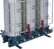


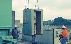

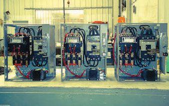




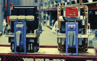


Relevant information the electrical power systems industry, from testing procedures andtroubleshooting to encountered in the field. It’s real world learning at your fingertips.
Discover page after page of comprehensive, componentspecific, technical resources for both training and reference purposes.
The Handbooks bring together a collection of over of the best articles from past issues of NETA World Journal and the most well received technical presentations from NETA’s PowerTest conferences.
For more informationon the NETA Handbooks or other NETA publications visit the NETA ookstore at www.netaworld.org or 888-300-6382 (NETA). $195* For the 13 volume set
15* For each issue * Additional cost for shipping and handling
$


ANSWERS


No.113 No. 113

ANSWERS

1. d. Circuit breakers often sit for extended periods of time without operating. As they sit, current is flowing through them, drying out their lubricants. When called on to operate, maybe they will do so correctly or maybe they won’t. The problem is that they will often work just fine after a few operations, but what will they do on that very first trip? That’s the one that really counts.
2. b. Voids and air pockets in insulation can have electrical discharges (ionization) when they are in high-voltage fields. This discharge can be measured and monitored, either while the equipment is energized (for continuous monitoring) or during specific tests.
3. a. 0.5%/1%pf. Usually I look for 0.5% on a new transformer, per Doble recommendations, but there are variations between specimens. Some transformers can have higher percent power factors and be perfectly fine. That is why the insulation power factor test is not considered to be rigidly interpreted test. It is more of


a screening test to show that here may be a problem. Further testing can make a final determination.
4. c. 16 kV rms
5. c. 100 MΩ

6. a. VLF testing is typically performed at 0.1 Hz. The advantage of this test is that it does not create treeing inside power cable insulation. The downside is it can cause existing treeing to grow, possibly failing the cable under test.
7. c. Unless there is a different value provided by the manufacturer, ≤ 200 ppm is recommended.
NFPA Disclaimer: Although Jim White is a member of the NFPA Technical Committee for both NFPA 70E “Standard for Electrical Safety in the Workplace” and NFPA 70B “Recommended Practice for Electrical Equipment Maintenance,” the views and opinions expressed in this message are purely the author’s and shall not be considered an official position of the NFPA or any of its technical committees and shall not be considered to be, nor be relied upon as, a formal interpretation or promotion of the NFPA. Readers are encouraged to refer to the entire text of all referenced documents.
TECH QUIZ ANSWERS
TECHQUIZ
118 • SPRING 2016
We’re taking the West by storm! Now open in the Reno - Tahoe Area WEST 924 Greg Street Sparks, Nevada 89431 (775) 984-5223 NATIONWIDE 1517 West Carrier Pkwy Suite 116 Grand Prairie, TX 75050 (866) 352-5550 SOUTH 7102 Brookside Rd Suite 102 Pearland, TX 77581 (832) 251-7047 MIDWEST 1517 Wright Blvd Schaumburg, IL 60193 (847) 434-5808 EAST 200 Gates Rd, Suite E Little Ferry, NJ 07643 (201) 450-9743 protecequip.com We offer more locations to better serve your needs and electrical test equipment rental options that work for you. Vanguard InstrumentsCompany, Inc. www.vanguard-instruments.com Electro Rent answers your every test need. Learn more at: www.electrorent.com/electr ica l-power 800.304.4744 | sales@electrorent.com » Largest inventory » Consistent, reliable delivery service » Immediate availability » ISO and ANSI accredited labs 19 1965-2065-2015 15 Y EAR S Electro Rent is Now a NETA Gold Corporate Alliance Partner Electro Rent Turns 50 Count on Electro Rent to get the test equipment you need fast, with experienced customer support you can rely on, 24x7. From motor test equipment to borescopes: if it tests, we’ve got it and we’re ready to meet your need.

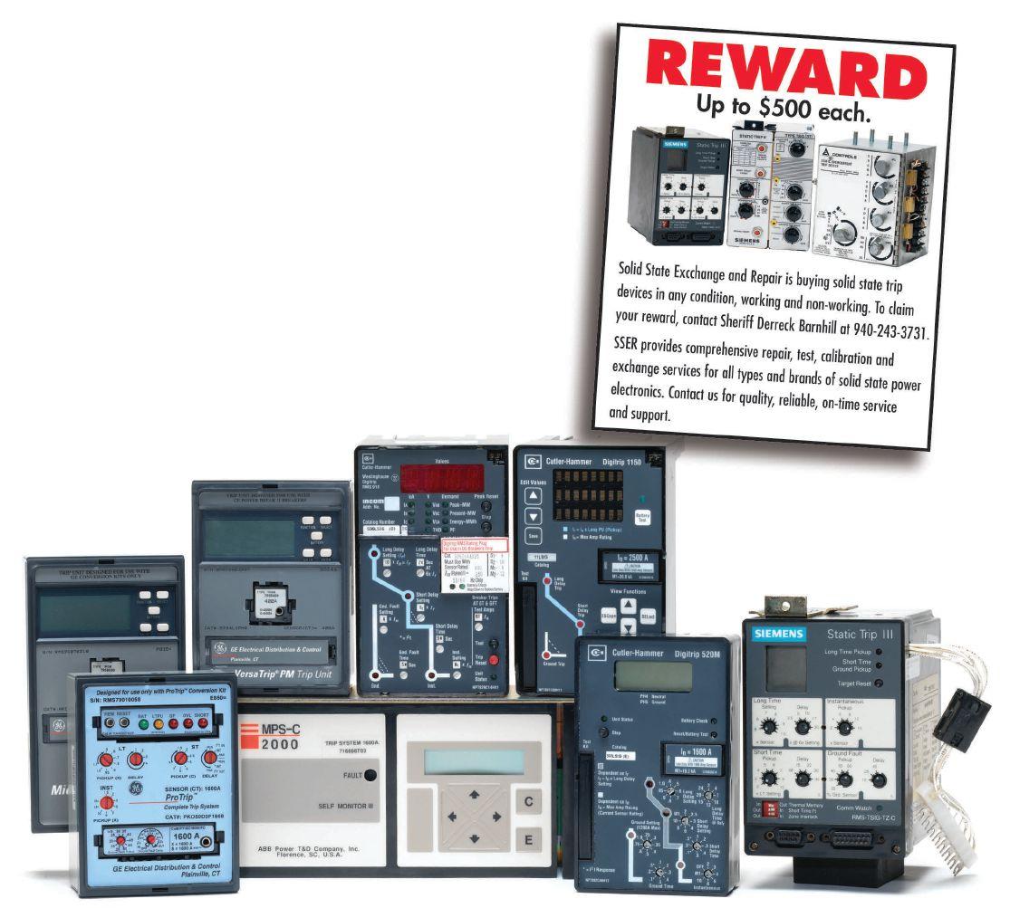
We Buy, Sell, Trade, Calibrate, Repair
Featuring quality, reliable, on-time service and support for all brands and types of solid state power electronics.
Power electronics are our business
Let us suppoort you with our quality repair, calibration and servicing of your solid state equipment. We also buy, sell and trade:
•Communications devices for power equipment
•Protective relays
•Circuit breaker trip devices
•Motor overload relays
•Rating plugs
4701 Spartan Drive • Denton, TX 76207 (877-874-7349) • Phone: 940-243-3731 • Fax: 940-387-8277 Email: info@solidstaterepair.com • Web: www.solidstaterepair.com
“SOLID STATE” INDUSTRIAL ELECTRONICS “SOLID STATE” INDUSTRIAL ELECTRONICS Toll Free 877-TRIP-FIX NOWRENTING TESTEQUIPMENT


NETA Training Opportunities for the Electrical Power Systems Industry TRAINING Online Training Courses Self-Paced Technical Seminars (SPTS) Electrical Safety Training System (ESTS) * Learn at your own pace. Advance your knowledge.
NETA ACCREDITED COMPANIES Setting the
A&F Electrical Testing, Inc.
80 Lake Ave. South, Ste. 10 Nesconset, NY 11767 (631) 584-5625 Fax: (631) 584-5720
kchilton@afelectricaltesting.com www.afelectricaltesting.com
Kevin Chilton
A&F Electrical Testing, Inc.
80 Broad St. 5th Floor
New York, NY 10004 (631) 584-5625 Fax: (631) 584-5720 afelectricaltesting@afelectricaltesting.com www.afelectricaltesting.com
Florence Chilton
ABM Electrical Power Solutions
3602 East Southern Ave., Ste. 1 Phoenix, AZ 85040 (602) 722-2423
www.ABM.com
Doug Bukowski
ABM Electrical Power Solutions
9800 E. Geddes Avenue, Unit A-150 Englewood, CO 80112 (303) 524-6560 Fax: (303) 524-6581
www.ABM.com
Brian Smith
ABM Electrical Power Solutions
2142 Rheem Drive Pleasanton, CA 94588 (408) 466-6920
www.ABM.com
John Marvulli
ABM Electrical Power Solutions
3940 Ruffin Rd., Ste. C San Diego, CA 92123 (858) 754-7963
www.ABM.com
Ben Thomas
ABM Electrical Power Solutions
6280 South Valley View Blvd., Ste. 618 Las Vegas, NV 89118 (602) 300-2188 Fax: (602) 437-3894 www.ABM.com
Jason Black
ABM Electrical Power Solutions
814 Greenbrier Circle, Ste. E Chesapeake, VA 23320 (757) 548-5690 Fax: (757) 548-5417
www.ABM.com
Mark Anthony Gaughan, III
ABM Electrical Power Solutions
3700 Commerce Dr. #901-903 Baltimore, MD 21227 (410) 247-3300 Fax: (410) 247-0900
www.ABM.com
Bill Hartman
ABM Electrical Power Solutions 5809 Departure Dr., Ste. 104 Raleigh, NC 27616 (919) 877-1008 Fax: (919) 501-7492
www.ABM.com
Rob Parton
ABM Electrical Power Solutions
317 Commerce Park Dr. Cranberry Township, PA 16066-6427 (724) 772-4638 Fax: (724) 772-6003 william.mckenzie@abm.com www.ABM.com
William (Pete) McKenzie
ABM Electrical Power Solutions 4390 Parliament Place, Ste. S Lanham, MD 20706 (301) 967-3500 Fax: (301) 735-8953 www.ABM.com
Frank Ceci
ABM Electrical Power Solutions
3600 Woodpark Blvd., Suite G Charlotte, NC 28206 (704) 273-6257 Fax: (704) 598-9812 ernest.goins@abm.com www.ABM.com
Ernest Goins
ABM Electrical Power Solutions
720 S. Rochester Ave., Suite A Ontario, CA 91761 (800) 597-1225 Fax: (909) 937-6798 www.ABM.com
Mike Bivens
Absolute Testing Services 6829 Guhn Rd. Houston, TX 77040 (832) 467-4446 Fax: (713) 849-3885 rgamble@absolutetesting.com www.texasats.com
Richard Gamble
Accessible Consulting Engineers, Inc. 1269 Pomona Rd., Ste. 111 Corona, CA 92882 (951) 808-1040 info@acetesting.com www.acetesting.com
Iraj Nasrolahi
Advanced Testing Systems 15 Trowbridge Dr. Bethel, CT 06801 (203) 743-2001 Fax: (203) 743-2325 pmaccarthy@advtest.com www.advtest.com
Pat MacCarthy
American Electrical Testing Co., Inc.
480 Neponset St., Building 6 Canton, MA 02021-1970 (781) 821-0121 Fax: (781) 821-0771 sblizard@aetco.us www.99aetco.com
Scott A. Blizard
American Electrical Testing Co., Inc. 34 Clover Dr. South Windsor, CT 06074 (860) 648-1013 Fax: (781) 821-0771 jpoulin@aetco.us www.99aetco.com
Gerald Poulin
American Electrical Testing Co., Inc. 76 Cain Dr. Brentwood, NY 11717 (631) 617-5330 Fax: (631) 630-2292 mschacker@aetco.us www.99aetco.com
Michael Schacker
American Electrical Testing Co., Inc. 50 Intervale Rd., Ste. 1 Boonton, NJ 07005 (973) 316-1180 Fax: (781) 316-1181 jsomol@aetco.us www.99aetco.com
Jeff Somol
American Electrical Testing Co., Inc. 4032 Park 65 Dr. Indianapolis, IN 46254 (317) 487-2111 Fax: (781) 821-0771 scanale@aetco.us www.99aetco.com
Stephen Canale
American Electrical Testing Co., Inc. Green Hills Commerce Center 5925 Tilghman St., Ste. 200 Allentown, PA 18104 (215) 219-6800 jmunley@aetco.us www.99aetco.com
Jonathan Munley
American Electrical Testing Co., Inc. 12566 W. Indianola Ave. Avondale, AZ 85392 (480) 383-9242 dmadaglia@aetco.us www.99aetco.com
Donald Madaglia
AMP Quality Energy Services, LLC 4220 West Schrimsher SW Site W1 P.O. Box 526, Huntsville, AL 35804 (256) 513-8255
Brian Rodgers
Apparatus Testing and Engineering 11300 Sanders Dr., Ste. 29 Rancho Cordova, CA 95742 (916) 853-6280 Fax: (916) 853-6258 info@apparatustesting.com www.apparatustesting.com
Harold (Jerry) Carr
Apparatus Testing and Engineering
7083 Commerce Circle, Ste. H Pleasanton, CA 94588 (925) 454-1363 Fax: (925) 454-1499 info@apparatustesting.com www.apparatustesting.com
Harold (Jerry) Carr
Applied Engineering Concepts 1105 N. Allen Ave. Pasadena, CA 91104 (626) 398-3052 Fax: (626) 398-3053 michel.c@aec-us.com www.aec-us.com
Michel Castonguay
BEC Testing 50 Gazza Blvd. Farmingdale, NY 11735 (516) 531-9136 Fax: (631) 249-6115 wfernandez@banaelectric.com www.bectesting.com
William Fernandez
Burlington Electrical Testing Co., Inc.
300 Cedar Ave. Croydon, PA 19021-6051 (215) 826-9400 (221) Fax: (215) 826-0964 waltc@betest.com www.betest.com
Walter P. Cleary
C.E. Testing, Inc. 6148 Tim Crews Rd. Macclenny, FL 32063 (904) 653-1900 Fax: (904) 653-1911 cetesting@aol.com
Mark Chapman
CE Power Solutions,LLC 4040 Rev Dr. Cincinnati, OH 45232 (513) 563-6150 Fax: (513) 563-6120 info@cepowersol.net www.cepower.net
Rhonda Harris
CE Power Solutions of Minnesota,LLC 7674 Washington Ave. South Eden Prairie, MN 55344 (877) 968-0281 Fax: (952) 400-8772 jason.thompson@cepower.net www.cepower-mn.net
Jason Thompson
Control Power Concepts
353 Pilot Rd; Ste. B Las Vegas, NV 89119 (702) 448-7833 Fax: (702) 448-7835 www.controlpowerconcepts.com
John Travis
NETA ACCREDITED COMPANIES
Standard
122 • SPRING 2016
Dude Electrical Testing LLC
145 Tower Dr., Unit# 9 Burr Ridge, IL 60527 (815) 293-3388 Fax: (815) 293-3386
scott.dude@dudetesting.com www.dudetesting.com
Scott Dude
DYMAX Service, LLC
46918 Liberty Dr. Wixom, MI 48393 (248) 313-6868 Fax: (248) 313-6869 www.dymaxservice.com
Bruce Robinson
DYMAX Service, LLC
4213 Kropf Ave. Canton, OH 44706 (330) 484-6801 Fax: (740) 333-1271 www.dymaxservice.com
Chuck Baker
Eastern High Voltage
11A South Gold Dr. Robbinsville, NJ 08691-1606 (609) 890-8300 Fax: (609) 588-8090 joewilson@easternhighvoltage.com www.easternhighvoltage.com
Joseph Wilson
ELECT, P.C.
7400-G Siemens Rd., P.O. Box 2080 Wendell, NC 27591 (919) 365-9775 Fax: (919) 365-9789 btyndall@elect-pc.com www.elect-pc.com
Barry W. Tyndall
Electric Power Systems, Inc. 21 Millpark Ct. Maryland Heights, MO 63043 (314) 890-9999 Fax: (314) 890-9998 www.epsii.com
Electric Power Systems, Inc. 557 E. Juanita Ave., #4 Mesa, AZ 85204 (480) 633-1490 Fax: (480) 633-7092 www.epsii.com
Electric Power Systems, Inc. 4436 Parkway Commerce Blvd. Orlando, FL 32808 (407) 578-6424 Fax: 407-578-6408 www.epsii.com
Electric Power Systems, Inc.
7000 E. 47th Avenue Drive, Suite 100 Denver, CO 80216 (720) 857-7273 Fax: 303-928-8020 www.epsii.com
Electric Power Systems, Inc. 23823 Andrew Rd. Plainfield, IL 60585 (815) 577-9515 Fax: (815) 577-9516 www.epsii.com
NETA ACCREDITED COMPANIES
Electric Power Systems, Inc. 2601 Center Rd., # 101 Hinckley, OH 44233 (330) 460-3706 Fax: (330) 460-3708 www.epsii.com
Electric Power Systems, Inc.
56 Bibber Pkwy #1 Brunswick, ME 04011 (207) 837-6527 www.epsii.com
Electric Power Systems, Inc. 4100 Greenbriar Dr., Ste. 160 Stafford, TX 77477 (713) 644-5400 www.epsii.com
Electric Power Systems, Inc. 11861 Longsdorf St. Riverview, MI 48193 (734) 282-3311 www.epsii.com
Electric Power Systems, Inc. 827 Union St., Salem, VA 24153 (540) 375-0084 Fax: (540) 375-0094 www.epsii.com
Electric Power Systems, Inc. 915 Holt Ave., Unit 9 Manchester, NH 03109 (603) 657-7371 Fax: 603-657-7370 www.epsii.com
Electric Power Systems, Inc.
146 Space Park Dr. Nashville, TN 37211 (615) 834-0999 Fax: (615) 834-0129 www.epsii.com
Electric Power Systems, Inc. 8515 Cella Alameda NE, Ste. A Albuquerque, NM 87113 (505) 792-7761 www.epsii.com
Electric Power Systems, Inc. 7140 Dean Martin Drive, Suite 900 Las Vegas, NV 89118 (702) 815-1342 www.epsii.com
Electric Power Systems, Inc.
319 US Hwy. 70 E, Unit E Garner, NC 27529 (919) 322-2670 www.epsii.com
Electric Power Systems, Inc. 1090 Montour West Industrial Blvd. Coraopolis, PA 15108 (412) 276-4559 www.epsii.com
NETA ACCREDITED COMPANIES
Electric Power Systems, Inc. 6141 Connecticut Ave. Kansas City, MO 64120 (816) 241-9990 Fax: (816) 241-9992 www.epsii.com
Electric Power Systems, Inc. 2495 Boulevard of the Generals Norristown, PA 19403 (610) 630-0286 www.epsii.com
Electric Power Systems, Inc. 1129 East Hwy. 30 Gonzalez, LA 70817 (225) 644-0150 Fax: (225) 644-6249 www.epsii.com
Electric Power Systems, Inc. 7925 Dunbrook Rd., Ste. G San Diego, CA 92126 (858) 566-6317 www.epsii.com
Electrical & Electronic Controls 6149 Hunter Rd. Ooltewah, TN 37363 (423) 344-7666 (23) Fax: (423) 344-4494 eecontrols@comcast.net
Michael Hughes
Electrical Energy Experts, Inc. W129N10818, Washington Dr. Germantown, WI 53022 (262) 255-5222 Fax: (262) 242-2360 bill@electricalenergyexperts.com www.electricalenergyexperts.com
William Styer
Electrical Equipment Upgrading, Inc. 21 Telfair Place, Savannah, GA 31415 (912) 232-7402 Fax: (912) 233-4355 kmiller@eeu-inc.com www.eeu-inc.com
Kevin Miller
Electrical Maintenance & Testing Inc. 12342 Hancock St., Carmel, IN 46032 (317) 853-6795 Fax: (317) 853-6799 info@emtesting.com www.emtesting.com
Brian K. Borst
Electrical Reliability Services 1057 Doniphan Park Circle, Ste. A El Paso, TX 79922 (915) 587-9440 Fax: (915) 587-9010 www.electricalreliability.com
Electrical Reliability Services 1775 W. University Dr., Ste. 128 Tempe, AZ 85281 (480) 966-4568 Fax: (480) 966-4569 www.electricalreliability.com
Electrical Reliability Services 1426 Sens Rd. Ste. 5 Houston, TX 77571 (281) 241-2800 Fax: (281) 241-2801 www.electricalreliability.com
Electrical Reliability Services 4099 SE International Way, Ste. 201 Milwaukie, OR 97222-8853 (503) 653-6781 Fax: (503) 659-9733 www.electricalreliability.com
Electrical Reliability Services 5909 Sea Lion Place, Ste. C Carlsbad, CA 92010 (858) 695-9551 www.electricalreliability.com
Electrical Reliability Services 8500 Washington Pl. NE, Ste. A-6 Albuquerque, NM 87113 (505) 822-0237 Fax: (505) 822-0217 www.electricalreliability.com
Electrical Reliability Services 1380 Greg Street, Ste. 217 Sparks, NV 89431 (775) 746-8484 Fax: (775) 356-5488 www.electricalreliability.com
Electrical Reliability Services 2275 Northwest Pkwy SE, Ste. 180 Marietta, GA 30067 (770) 541-6600 Fax: (770) 541-6501 www.electricalreliability.com
Electrical Reliability Services 7100 Broadway, Ste. 7E Denver, CO 80221-2915 (303) 427-8809 Fax: (303) 427-4080 www.electricalreliability.com
Electrical Reliability Services 348 N.W. Capital Dr. Lee's Summit, MO 64086 (816) 525-7156 Fax: (816) 524-3274 www.electricalreliability.com
Electrical Reliability Services 6900 Koll Center Parkway, Ste. 415 Pleasanton, CA 94566 (925) 485-3400 Fax: (925) 485-3436 www.electricalreliability.com
Electrical Reliability Services 10606 Bloomfield Ave. Santa Fe Springs, CA 90670 (562) 236-9555 Fax: (562) 777-8914 www.electricalreliability.com
Electrical Reliability Services
3535 Emerson Parkway, Ste. A Gonzales, LA 70737 (225) 755-0530 Fax: (225) 751-5055 www.electricalreliability.com
Setting the Standard NETAWORLD • 123
NETA ACCREDITED COMPANIES Setting the
Electrical Reliability Services
245 Hood Rd. Sulphur, LA 70665 (337) 583-2411 Fax: (337) 583-2410 www.electricalreliability.com
Electrical Reliability Services
11000 Metro Pkwy., Ste. 30 Ft. Myers, FL 33966 (239) 693-7100 Fax: (239) 693-7772 www.electricalreliability.com
Electrical Reliability Services
2222 West Valley Hwy. N., Ste 160 Auburn, WA 98001 (253) 736-6010 Fax: (253) 736-6015 www.electricalreliability.com
Electrical Reliability Services
3412 South 1400 West, Unit A West Valley City, UT 84119 (801) 975-6461 www.electricalreliability.com
Electrical Reliability Services
6351 Hinson St., Ste. B Las Vegas, NV 89118 (702) 597-0020 Fax: (702) 597-0095 www.electricalreliability.com
Electrical Reliability Services
9636 St. Vincent, Unit A Shreveport, LA 71106 (318) 869-4244 www.electricalreliability.com
Electrical Reliability Services
610 Executive Campus Dr. Westerville, OH 43082 (877) 468-6384 Fax: (614) 410-8420 info@electricalreliability.com www.electricalreliability.com
Electrical Testing and Maintenance Corp. 3673 Cherry Rd., Ste. 101 Memphis, TN 38118 (901) 566-5557 r.gregory@etmcorp.com www.etmcorp.net Ron Gregory
Electrical Testing, Inc. 2671 Cedartown Hwy. Rome, GA 30161-6791 (706) 234-7623 Fax: (706) 236-9028
steve@electricaltestinginc.com www.electricaltestinginc.com
Electrical Testing Solutions
2909 Green Hill Ct. Oshkosh, WI 54904 (920) 420-2986 Fax: (920) 235-7136 tmachado@electricaltestingsolutions.com www.electricaltestingsolutions.com
Tito Machado
Elemco Services, Inc.
228 Merrick Rd. , Lynbrook, NY 11563 (631) 589-6343 Fax: (631) 589-6670
courtney@elemco.com www.elemco.com
Courtney O'Brien
EnerG Test
204 Gale Lane Bldg. 2 - 2nd Floor Kennett Square, PA 19348 (484) 731-0200 Fax: (484) 713-0209 kbleiler@energtest.com www.energtest.com
Katie Bleiler
Energis High Voltage Resources, Inc. 1361 Glory Rd. Green Bay, WI 54304 (920) 632-7929 Fax: (920) 632-7928 info@energisinc.com www.energisinc.com
Mick Petzold
EPS Technology
29 N. Plains Hwy., Ste. 12 Wallingford, CT 06492 (203) 679-0145 www.eps-technology.com
Grounded Technologies, Inc.
10505 S. Progress Way, Ste. 105 Parker, CO 80134 P-(303) 781-2560 F- (303) 781-5240 jodymedina@groundedtech.com www.groundedtech.com
Jody Medina
Grubb Engineering, Inc. 3128 Sidney Brooks San Antonio, Tx 78235 (210) 658-7250 Fax: (210) 658-9805 joy@grubbengineering.com www.grubbengineering.com
Robert D. Grubb Jr.
Hampton Tedder Technical Services 4571 State St. Montclair, CA 91763 (909) 628-1256 x214 Fax: (909) 628-6375 matt.tedder@hamptontedder.com www.hamptontedder.com
Matt Tedder
Hampton Tedder Technical Services
4920 Alto Ave. Las Vegas, NV 89115 (702) 452-9200 Fax: (702) 453-5412 www.hamptontedder.com
Roger Cates
Hampton Tedder Technical Services 3747 West Roanoke Ave. Phoenix, AZ 85009 (480) 967-7765 Fax: (480) 967-7762 www.hamptontedder.com
Harford Electrical Testing Co., Inc. 1108 Clayton Rd. Joppa, MD 21085 (410) 679-4477 Fax: (410) 679-0800 testing@harfordtesting.com www.harfordtesting.com
Vincent Biondino
High Energy Electrical Testing, Inc. 515 S. Ocean Ave. Seaside Park, NJ 08752 (732) 938-2275 Fax: (732) 938-2277 hinrg@comcast.net www.highenergyelectric.com
Charles Blanchard
High Voltage Maintenance Corp. 24 Walpole Park South Dr. Walpole, MA 02081 (508) 668-9205 www.hvmcorp.com
High Voltage Maintenance Corp. 941 Busse Rd. Elk Grove Village, Il 60007 (847) 640-0005 www.hvmcorp.com
High Voltage Maintenance Corp. 7200 Industrial Park Blvd. Mentor, OH 44060 (440) 951-2706 Fax: (440) 951-6798 www.hvmcorp.com
High Voltage Maintenance Corp. 3000 S. Calhoun Rd. New Berlin, WI 53151 (262) 784-3660 Fax: (262) 784-5124 www.hvmcorp.com
High Voltage Maintenance Corp. 8320 Brookville Rd. #E Indianapolis, IN 46239 (317) 322-2055 Fax: (317) 322-2056 www.hvmcorp.com
High Voltage Maintenance Corp. 1250 Broadway, Ste. 2300 New York, NY 10001 (718) 239-0359 www.hvmcorp.com
High Voltage Maintenance Corp. 355 Vista Park Dr. Pittsburgh, PA 15205-1206 (412) 747-0550 Fax: (412) 747-0554 www.hvmcorp.com
High Voltage Maintenance Corp. 150 North Plains Industrial Rd. Wallingford, CT 06492 (203) 949-2650 Fax: (203) 949-2646 www.hvmcorp.com
High Voltage Maintenance Corp. 9305 Gerwig Ln., Ste. B Columbia, MD 21046 (410) 309-5970 Fax: (410) 309-0220 www.hvmcorp.com
High Voltage Maintenance Corp. 24371 Catherine Industrial Dr, Ste. 207 Novi, MI 48375 (248) 305-5596 Fax: (248) 305-5579 www.hvmcorp.com
High Voltage Maintenance Corp. 5100 Energy Dr. Dayton, OH 45414 (937) 278-0811 Fax: (937) 278-7791 www.hvmcorp.com
High Voltage Service, LLC 4751 Mustang Circle St. Paul, MN 55112 (763) 784-4040 Fax: (763) 784-5397 www.hvserviceinc.com
Mike Mavetz
HMT, Inc.
6268 Route 31 Cicero, NY 13039 (315) 699-5563 Fax: (315) 699-5911 jpertgen@hmt-electric.com www.hmt-electric.com
John Pertgen
Industrial Electric Testing, Inc. 11321 West Distribution Ave. Jacksonville, FL 32256 (904) 260-8378 Fax: (904) 260-0737 gbenzenberg@bellsouth.net www.industrialelectrictesting.com
Gary Benzenberg
Industrial Electric Testing, Inc. 201 NW 1st Ave. Hallandale, FL 33009-4029 (954) 456-7020 www.industrialelectrictesting.com
Industrial Electronics Group
850369 Highway 17 South P.O. Box 1870 Yulee, FL 32041 (904) 225-9529 Fax: (904) 225-0834 butch@industrialgroups.com www.industrialgroups.com
Butch E. Teal
Industrial Tests, Inc.
4021 Alvis Ct., Ste. 1 Rocklin, CA 95677 (916) 296-1200 Fax: (916) 632-0300 greg@indtest.com www.industrialtests.com
Greg Poole
NETA ACCREDITED COMPANIES
Standard
124 • SPRING 2016
Infra-Red Building and Power Service 152 Centre St. Holbrook, MA 02343-1011 (781) 767-0888 Fax: (781) 767-3462 tom.mcdonald@infraredbps.com www.infraredbps.com
Thomas McDonald Sr.
Longo Electrical-Mechanical, Inc.
One Harry Shupe Blvd., Box 511 Wharton, NJ 07885 (973) 537-0400 Fax: (937) 537-0404 jmlongo@elongo.com www.elongo.com
Joe Longo
Longo Electrical-Mechanical, Inc. 1625 Pennsylvania Ave. Linden, NJ 07036 (908) 925-2900 Fax: (908) 925-9427 jmlongo@elongo.com www.elongo.com
Joe Longo
Longo Electrical-Mechanical, Inc.
1400 F Adams Rd. Bensalem, PA 19020 (215) 638-1333 Fax: (215) 638-1366 jmlongo@elongo.com www.elongo.com
Joe Longo
M&L Power Systems, Inc.
109 White Oak Ln., Ste. 82 Old Bridge, NJ 08857 (732) 679-1800 Fax: (732) 679-9326 milind@mlpower.com www.mlpower.com
Milind Bagle
Magna IV Engineering 1103 Parsons Rd. SW Edmonton, AB T6X 0X2 Canada (780) 462-3111 Fax: (780) 450-2994 info@magnaiv.com www.magnaiv.com
Virgina Balitski
Magna IV Engineering 200, 688 Heritage Dr. Calgary, AB T2H 1M6 Canada (403) 723-0575 Fax: (403) 723-0580 info.calgary@magnaiv.com
Dave Emerson
Magna IV Engineering 8219D Fraser Ave. Fort McMurray, AB T9H 0A2 Canada (780) 791-3122 Fax: (780) 791-3159 info.fmcmurray@magnaiv.com
Ryan Morgan
Magna IV Engineering
96 Inverness Dr. East, Unit R Englewood, CO 80112 (303) 799-1273 Fax: (303) 790-4816 info.denver@magnaiv.com
Aric Proskurniak
Magna IV Engineering Avenida del Condor #590 Oficina 601 Huechuraba, Santiago 8580676 Chile +(56) 9-9-517-4642 info.chile@magnaiv.com
Harvey Mendoza
Magna IV Engineering 1040 Winnipeg St. Regina , SK S4R 8P8 Canada (306) 585-2100 Fax: (306) 585-2191 info.regina@magnaiv.com
Andrew Westerman
Magna IV Engineering 106, 4268 Lozells Ave. Burnaby, BC VSA 0C6 Canada (604) 421-8020
Scott Nixon
National Field Services 649 Franklin St. Lewisville, TX 75057 (972) 420-0157 www.natlfield.com
Eric Beckman
Nationwide Electrical Testing, Inc. 6050 Southard Trace Cumming, GA 30040 (770) 667-1875 Fax: (770) 667-6578 Shashi@N-E-T-Inc.com www.n-e-t-inc.com
Shashikant B. Bagle
North Central Electric, Inc. 69 Midway Ave. Hulmeville, PA 19047-5827 (215) 945-7632 Fax: (215) 945-6362 ncetest@aol.com www.ncetest.com
Robert Messina
Northern Electrical Testing, Inc. 1991 Woodslee Dr. Troy, MI 48083-2236 (248) 689-8980 Fax: (248) 689-3418 ldetterman@northerntesting.com www.northerntesting.com
Lyle Detterman
NETA ACCREDITED COMPANIES
Orbis Engineering Field Services Ltd. #300, 9404 - 41st Ave. Edmonton, AB T6E 6G8 Canada (780) 988-1455 Fax: (780) 988-0191 lorne@orbisengineering.net www.orbisengineering.net
Lorne Gara
Pacific Power Testing, Inc. 14280 Doolittle Dr. San Leandro, CA 94577 (510) 351-8811 Fax: (510) 351-6655 steve@pacificpowertesting.com www.pacificpowertesting.com
Steve Emmert
Pacific Powertech, Inc. #110, 2071 Kingsway Ave. Port Coquitlam, BC V3C 6N2 Canada (604) 944-6697 Fax: (604) 944-1271 jkonkin@pacificpowertech.ca www.pacificpowertech.ca
Josh Konkin
Phasor Engineering Sabaneta Industrial Park #216 Mercedita, PR 00715 Puerto Rico (787) 844-9366 Fax: (787) 841-6385 rcastro@phasorinc.com
Rafael Castro
Potomac Testing, Inc. 1610 Professional Blvd., Ste. A Crofton, MD 21114 (301) 352-1930 Fax: (301) 352-1936 kbassett@potomactesting.com www.potomactesting.com
Ken Bassett
Power & Generation Testing, Inc., a CE Power Company 480 Cave Rd. Nashville, TN 37210 (615) 882-9455 Fax: (615) 882-9591 mose@pgti.net www.pgti.net
Mose Ramieh
Power Engineering Services, Inc. 9179 Shadow Creek Lane Converse, TX 78109 (210) 590-4936 Fax: (210) 590-6214 engelke@pe-svcs.com www.pe-svcs.com
Miles R. Engelke
POWER PLUS Engineering, Inc. 46575 Magellan Novi, MI 48377 (248) 344-0200 Fax: (248) 305-9105 smancuso@epowerplus.com www.epowerplus.com Salvatore Mancuso
Power Products & Solutions, LLC 12465 Grey Commercial Rd. Midland, NC 28107 (704) 573-0420 x12 Fax: (704) 573-3693
ralph.patterson@powerproducts.biz www.powerproducts.biz
Ralph Patterson
Power Products & Solutions, LLC 13 Jenkins Ct. Mauldin, SC 29662 (800) 328-7382 ralph.patterson@powerproducts.biz www.powerproducts.biz
Raymond Pesaturo
Power Services, LLC 998 Dimco Way, P.O. Box 750066 Centerville, OH 45475 (937) 439-9660 Fax: (937) 439-9611
mkbeucler@aol.com
Mark Beucler
Power Solutions Group, Ltd. 425 W. Kerr Rd. Tipp City, OH 45371 (937) 506-8444 Fax: (937) 506-8434 bwilloughby@powersolutionsgroup.com www.powersolutionsgroup.com
Barry Willoughby
Power Solutions Group, Ltd. 135 Old School House Rd. Piedmont, SC 29673 (864) 845-1084 Fax:: (864) 845-1085 fcrawford@powersolutionsgroup.com www.powersolutionsgroup.com
Anthony Crawford
Power Solutions Group, Ltd.
670 Lakeview Plaza Blvd. Columbus, OH 43085 (614) 310-8018
sspohn@powersolutionsgroup.com www.powersolutionsgroup.com
Stuart Spohn
Power Systems Testing Co.
4688 W. Jennifer Ave., Ste. 108 Fresno, CA 93722 (559) 275-2171 ext 15 Fax: (559) 275-6556 dave@pstcpower.com www.powersystemstesting.com
David Huffman
Power Systems Testing Co.
600 S. Grand Ave., Ste. 113 Santa Ana, CA 92705-4152 (714) 542-6089 Fax: (714) 542-0737 www.powersystemstesting.com
NETA ACCREDITED COMPANIES
Setting the Standard NETAWORLD • 125
NETA ACCREDITED COMPANIES
Power Systems Testing Co.
6736 Preston Ave, Ste. E Livermore, CA 94551 (510) 783-5096 Fax: (510) 732-9287
www.powersystemstesting.com
Power Test, Inc.
2200 Highway 49 Harrisburg, NC 28075 (704) 200-8311 Fax: (704) 455-7909 rich@powertestinc.com www.powertestinc.com
Richard Walker
POWER Testing and Energization, Inc. 14006 NW 3rd Ct., Ste. 101 Vancouver, WA 98685 (360) 597-2800 Fax: (360) 576-7182 chris.zavadlov@powerte.com www.powerte.com
Chris Zavadlov
POWER Testing and Energization, Inc.
731 E. Ball Rd., Ste. 100 Anaheim, CA 92805 (714) 507-2702 www.powerte.com
POWER Testing and Energization, Inc.
22035 70th Ave. South Kent, WA 98032 (253) 872-7747
www.powerte.com
Powertech Services, Inc.
4095 South Dye Rd. Swartz Creek, MI 48473-1570 (810) 720-2280 Fax: (810) 720-2283 kirkd@powertechservices.com www.powertechservices.com
Kirk Dyszlewski
Precision Testing Group 5475 Highway 86, Unit 1 Elizabeth, CO 80107 (303) 621-2776 Fax: (303) 621-2573 glenn@precisiontestinggroup.com
Glenn Stuckey
Premier Power Maintenance Corporation 6525 Guion Rd. Indianapolis, IN 46268 (317) 879-0660
kevin.templeman@premierpower.us www.premierpowermaintenance.com
Kevin Templeman
Premier Power Maintenance Corporation 2725 Jason Rd. Ashland, KY 41102 (606) 929-5969
jay.milstead@premierpower.us www.premierpowermaintenance.com
Jay Milstead
Premier Power Maintenance Corporation 3066 Finley Island Cir NW Decatur, AL 35601 (256) 355-1444
johnnie.mcclung@premierpower.us www.premierpowermaintenance.com
Johnnie McClung
Premier Power Maintenance Corporation 4301 Iverson Blvd., Ste. H Trinity, AL 35673 (256) 355-3006
kevin.templeman@premierpower.us www.premierpowermaintenance.com
Kevin Templeman
Premier Power Maintenance Corporation 7301 E County Road 142 Blytheville, AR 72315 (870) 762-2100
kevin.templeman@premierpower.us www.premierpowermaintenance.com
Kevin Templeman
Premier Power Maintenance Corporation 7262 Kensington Rd. Brighton, MI 48116 (517) 230-6620
brian.ellegiers@premierpower.us www.premierpowermaintenance.com
Brian Ellegiers
Premier Power Maintenance Corporation 4537 S. Nucor Rd. Crawfordsville, IN 47933 (317) 879-0660
kevin.templeman@premierpower.us www.premierpowermaintenance.com
Kevin Templeman
Reuter & Hanney, Inc. 149 Railroad Dr. Northampton Industrial Park Ivyland, PA 18974 (215) 364-5333 Fax: (215) 364-5365 mikereuter@reuterhanney.com www.reuterhanney.com
Michael Reuter
Reuter & Hanney, Inc. 4270-I Henninger Ct. Chantilly, VA 20151 (703) 263-7163 Fax: 703-263-1478 www.reuterhanney.com
Reuter & Hanney, Inc. 11620 Crossroads Circle, Suites D-E Middle River, MD 21220 (410) 344-0300 Fax: (410) 335-4389 www.reuterhanney.com
Michael Jester
REV Engineering, LTD 3236 - 50 Ave. SE Calgary, AB T2B 3A3 Canada (403) 287-0156 Fax: (403) 287-0198 rdavidson@reveng.ca www.reveng.ca
Roland Nicholas Davidson, IV
Saber Power Services 9841 Saber Power Lane Rosharon, TX 77583-5188 (713) 222-9102 info@saberpower.com www.saberpower.com
Mark Reid
Scott Testing Inc. 1698 5th St. Ewing, NJ 08638 (609) 882-2400 Fax: (609) 882-5660 rsorbello@scotttesting.com www.scotttesting.com
Russ Sorbello
Sentinel Power Services, Inc. 7517 E. Pine St. Tulsa, OK 74115 (918) 359-0350 gellis@spstulsa.com www.sentinelpowerservices.com
Greg Ellis
Sentinel Power Services, Inc. 1110 West B St., Ste. H Russellville, AR 72801 (918) 359-0350 gellis@spstulsa.com www.sentinelpowerservices.com
Greg Ellis
Shermco Industries 2425 E. Pioneer Dr. Irving, TX 75061 (972) 793-5523 Fax: (972) 793-5542 rwidup@shermco.com www.shermco.com
Ron Widup
Shermco Industries 112 Industrial Dr., PO Box 606 Minooka, IL 60447 (815) 467-5577 Fax: (815) 467-5883 rwidup@shermco.com www.shermco.com
Ron Widup
Shermco Industries 1705 Hur Industrial Blvd. Cedar Park, TX 78613 (512) 267-4800 Fax: (512) 258-5571 cking@shermco.com www.shermco.com
Chris King
Shermco Industries 33002 FM 2004 Angleton, TX 77515 (979)848-1406 Fax: (979) 848-0012 cking@shermco.com www.shermco.com
Chris King
Shermco Industries
1357 N. 108th E. Ave. Tulsa, OK 74116 (918) 234-2300 jharrison@shermco.com www.shermco.com
Jim Harrison
Shermco Industries 796 11th St. Marion, IA 52302 (319) 377-3377 Fax: (319) 377-3399 jedwards@shermco.com www.shermco.com
Jason Edwards
Shermco Industries 2100 Dixon St., Ste. C Des Moines, IA 50316 (515) 263-8482 jedwards@shermco.com www.shermco.com
Jason Edwards
Shermco Industries 4383 Professional Parkway Groveport, OH 43125 (614) 836-8556 Fax: (614) 836-8557 jharrison@shermco.com www.shermco.com
Jim Harrison
Shermco Industries 998 East Berwood Ave. Saint Paul, MN 55110 (651) 484-5533 Fax: (651) 484-7686 jedwards@shermco.com www.shermco.com
Jason Edwards
Shermco Industries 12000 Network Blvd., Bldg D,, Ste. 410 San Antonio, TX 78249 (512) 267-4800 Fax: (512) 267-4808 cking@shermco.com www.shermco.com
Chris King
Shermco Industries Canada Inc. 1033 Kearns Crescent, Box 995 Regina, SK S4P 3B2 Canada (306) 949-8131 Fax: (306) 522-9181 kheid@magnaelectric.com www.shermco.com
Kerry Heid
NETA ACCREDITED COMPANIES
Setting the Standard 126 • SPRING 2016
Shermco Industries Canada Inc. 851-58th St. East Saskatoon, SK S7K 6X5 Canada (306) 955-8131 Fax: (306) 955-9181 ajaques@magnaelectric.com www.shermco.com
Adam Jaques
Shermco Industries Canada Inc. 3731-98 St. Edmonton, AB T6E 5N2 Canada (780) 436-8831 Fax: (780) 468-9646 cgrant@magnaelectric.com www.shermco.com
Cal Grant
Shermco Industries Canada Inc. 3430 25th St. NE Calgary, AB T1Y 6C1 Canada (403) 769-9300 Fax: (403)769-9369 cgrant@magnaelectric.com www.shermco.com
Cal Grant
Shermco Industries Canada Inc. 1375 Church Ave. Winnipeg, MB R2X 2T7 Canada (204) 925-4022 Fax: (204) 925-4021 cbrandt@magnaelectric.com www.shermco.com
Curtis Brandt
Sigma Six Solutions, Inc. 2200 West Valley Hwy., Ste. 100 Auburn, WA 98001 (253) 333-9730 Fax: (253) 859-5382 jwhite@sigmasix.com www.sigmasix.com
John White
Southern New England Electrical Testing, LLC 3 Buel St., Ste. 4 Wallingford, CT 06492 (203) 269-8778 Fax: (203) 269-8775 dave.asplund@sneet.org www.sneet.org
David Asplund, Sr.
Southwest Energy Systems, LLC 2231 East Jones Ave., Ste. A Phoenix, AZ 85040 (602) 438-7500 Fax: (602) 438-7501 bob.sheppard@southwestenergysystems.com www.southwestenergysystems.com
Robert Sheppard
Taurus Power & Controls, Inc. 9999 SW Avery St. Tualatin, OR 97062-9517 (503) 692-9004 Fax: (503) 692-9273 robtaurus@tauruspower.com www.tauruspower.com
Rob Bulfinch Taurus Power & Controls, Inc. 19226 66th Ave. S, Ste. L102 Kent, WA 98032 (425) 656-4170 Fax: (425) 656-4172 servicereq@tauruspower.com www.tauruspower.com
David Koons
3C Electrical Co., Inc. 40 Washington St. Westborough, MA 01581 (508) 881-3911 Fax: (508) 881-4814 jim@three-c.com www.three-c.com
Jim Cialdea
3C Electrical Co., Inc. 72 Sanford Dr. Gorham, ME 04038 (800) 649-6314 Fax: (207) 782-0162 jim@three-c.com www.three-c.com
Jim Cialdea
Tidal Power Services, LLC
4202 Chance Lane Rosharon, TX 77583 (281) 710-9150 Fax: (713) 583-1216 monty.janak@tidalpowerservices.com www.tidalpowerservices.com
Monty C. Janak
Tidal Power Services, LLC 8184 Highway 44, Ste. 105 Gonzales, LA 70737 (225) 644-8170 Fax: (225) 644-8215 www.tidalpowerservices.com
Darryn Kimbrough
Tidal Power Services, LLC 1056 Mosswood Dr. Sulphur, LA 70663 (337) 558-5457 Fax: (337) 558-5305 www.tidalpowerservices.com
Steve Drake
Tony Demaria Electric, Inc. 131 West F St. Wilmington, CA 90744 (310) 816-3130 (310) 549-9747 neno@tdeinc.com www.tdeinc.com
Nenad Pasic
NETA ACCREDITED COMPANIES
Trace Electrical Services & Testing, LLC
293 Whitehead Rd. Hamilton, NJ 08619 (609) 588-8666 Fax: (609) 588-8667 jvasta@tracetesting.com www.tracetesting.com
Joseph Vasta
Utilities Instrumentation Service, Inc. 2290 Bishop Circle East Dexter, MI 48130 (734) 424-1200 Fax: (734) 424-0031 GEWalls@UISCorp.com www.uiscorp.com
Gary E. Walls
Utility Service Corporation 4614 Commercial Dr. NW Huntsville, AL 35816-2201 (256) 837-8400 Fax: (256) 837-8403 apeterson@utilserv.com www.utilserv.com
Alan D. Peterson
Western Electrical Services, Inc. 14311 29th St. East Sumner , WA 98390 (253) 891-1995 Fax: (253) 891-1511 dhook@westernelectricalservices.com www.westernelectricalservices.com
Dan Hook
Western Electrical Services, Inc. 3676 W. California Ave., #C, 106 Salt Lake City, UT 84104 (888) 395-2021 Fax: (253) 891-1511 rcoomes@westernelectricalservices.com www.westernelectricalservices.com
Rob Coomes
Western Electrical Services, Inc. 5680 South 32nd St. Phoenix, AZ 85040 (602) 426-1667 Fax: (253) 891-1511 carcher@westernelectricalservices.com www.westernelectricalservices.com
Craig Archer
Western Electrical Services, Inc. 4510 NE 68th Dr., Ste. 122 Vancouver, WA 98661 (888) 395-2021 Fax: (253) 891-1511 Tasciutto@westernelectricalservices.com www.westernelectricalservices.com
Tony Asciutto
Setting the Standard NETA ACCREDITED COMPANIES NETAWORLD • 127
This issue’s advertisers are identified below. Please thank these advertisers by telling them you saw their advertisement in YOUR magazine –NETA World.


128 • SPRING 2016 ADVERTISERS
Absolute Testing Services, Inc. 38 American Electrical Testing Co., Inc. ................ 33 Apparatus Testing and Engineering ..................54 Burlington Electrical Testing Co., Inc. ...............39 Eastern High Voltage...............................33 Electrical Energy Experts, Inc. .......................39 Electrical Reliability Services ........................23
Services, Inc. ...............................97 EnerG Test ........................................99 Harford Electrical Testing Co., Inc. ...................6 High Voltage Maintenance Corp. ...................97 Industrial Electric Testing, Inc. ....................100 Infra-Red Building and Power Service ................6 Nationwide Electrical Testing, Inc ...................54 National Field Services .............................37 North Central Electric, Inc. .........................99 Orbis Engineering Field Services, Ltd. ...............54 Potomac Testing, Inc. ..............................72 Power & Generation Testing, Inc. ...................97 Power Products & Solutions, Inc. ....................68 Power Services, LLC ...............................68 Power Systems Testing Co. .........................100 POWER Testing and Energization, Inc. .............103 PRIT Service, Inc. .................................80 Scott Testing, Inc. ..................................68 Shermco Industries. ................................10 Sigma Six Solutions ................................15 Taurus Power & Controls, Inc. ......................15 3C Electrical Co. Inc. ..............................17 Tony Demaria Electric, Inc. ..........................9 Trace Electrical Services & Testing, LLC .............87 Utility Service Corporation ........................20 MANUFACTURERS AND OTHER SERVICE PROVIDERS AEMC ................................................... 87 Aero Tec Laboratories ...................................... 27 Ampteks .................................................. 80 Arbiter Systems, Inc. ....................................... 62 AVO Training Institute, Inc. . ............................... 82 BCS Switchgear, Inc. ....................................... 88 Belyea Company ...........................................62 Burlington Safety Laboratory, Inc. ...........................27 Doble Engineering Company ............................... 16 Dranetz ................................................... 17 ECP Solutions ............................................ 108 Electro Rent ........................................... 23, 119 Elsco .................................................. 73, 116 Group CBS, Inc. ........................................... 74 Hampton Tedder ...........................................8 High Voltage, Inc........................................... 27 High Voltage Electrical Services .............................21 HV Diagnostics, Inc. ....................................... 25 Instel Power Products . .................................... 116 Intellirent ................................................105 IRISS .....................................................56 L.W. Brittain .............................................103 Maintenance Technology ...................................45 Megger ....................................Inside Front Cover Monster Fuses ............................................ 121 National Switchgear ....................................... 109 National Training Center ...................................48 NETA PowerTest Call for Sponsors .........................96 NETA PowerTest Call for Speakers ......................... 63 NETA PowerTest Save The Date ............................ 47 NETA PowerTest Call for Exhibitors .......................101 NETA PowerTest Thank You Sponsors.......................32 NETA Alliance Program ................................... 81 NETA Handbooks .......................................117 NETA Training ........................................... 121 NETA Why Hire NAC? ...................................49 OMICRON electronics Corp. USA.................Back Cover Phenix Technologies, Inc. .................................. 39 PMDT ...................................................40 Protec Equipment Resources ..............................119 Quality Switchgear, Inc. ................................... 121 Raytech .................................... Inside Back Cover SMC International .........................................55 Solid State Exchange & Repair Co.......................... 120 Southland Electrical ........................................24 Technitrol, Inc. ............................................31 Thyritronics, Inc............................................31 Utility Relay Company .....................................69 Vacuum Interrupters, Inc. ....................................5 Vanguard Instrument Co., Inc. ......................... 25, 108 Widespread Electrical Sales .................................73 Wind Systems ............................................104 ADVERTISERS
INDEPENDENT NETA ACCREDITED COMPANIES
Elemco


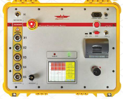



RAYTECH’S NEW CT TESTER No competing product comes close in terms of features, ease of use, and price. TROUBLE-FREE AND BACKED BY OUR 5 YEAR WARRANTY! Toll free 888 484 3779 | Phone 267 404 2676 | Fax 267 404 2685 118 South 2nd St., Perkasie, PA 18944 www.RaytechUSA.com
Charles Sweetser Regional Application Engineer

Save time and increase safety when testing circuit breakers.
As an application engineer I know how time consuming it is to change the wiring setup several times between measurements. So I helped to develop a solution, which combines a timing and travel analyzer, a digital low-resistance ohmmeter and a coil and motor supply in one device. We’ve cut down thewiringeffortto a minimum, which greatly reduces the testing time and probability of measuring errors. This pays off with every CB you test.
www.omicronenergy.com +1-800 OMICRON


 By Don Brown, EASi


 Ron Widup President NETA – InterNational Electrical Testing Association


 BY JIM WHITE, Shermco Industries


 BY KRISTEN WICKS, NETA


 BY RICHARD FURMAN, Southwest Energy Systems, LLC


