
Utility Grade 15kV Insulation
Resistance Tester
Megger’s S1-1568 Utility Grade 15kV Insulation
Resistance Tester is designed to make accurate and stable meaurements in noisy environments, including 765kV substations, with up to 8 mA of noise reduction.
We help you cut out the noise so you can power on.
Get Rid Of That
us.megger.com/s1 NOISE.
Annoying S1-1568





ENERGIZE YOUR FUTURE ANAHEIM • CALIFORNIA February 27 - March 3 • 2017 DISNEYLAND HOTEL POWERTEST.ORG 888.300.6382 THE PREMIER ELECTRICAL MAINTENANCE & SAFETY EVENT Join us in the golden land of promise. February 27 through March 3

DAY 1 Monday
We’ve gathered leaders in the industry and will stage a full day of engaging, 45-minute presentations sure to expand your thinking and generate new ideas. Choose from 27 detailed presentation track topics.
ELECTRICAL SAFETY
• Improving Human Performance
D. Ray Crow, DRC Consulting Ltd.
• Electrical Safety for Contractors (Multi-Employer) Working in Industrial Facilities
Dennis Neitzel, AVO Training Institute, Inc.
• Guarded or Unguarded and Why It Makes a Safety Difference
Jim White, Shermco Industries
• Application of Work Flow Process in an Electrical Safety Program
Terry Becker, ESPS Electrical Safety Program Solutions INC.
• Human Performance Best Practices in Electrical Safety
Mike Doherty, eHazard
• Design, Implementation and Testing of Arc-Flash Mitigation on Low and Medium-Voltage Systems
Christopher Inshaw, Southwest Energy Systems, LLC
PROTECTIVE RELAYS
• Testing High Magnitude Faults on a Transmission Line Using COMTRADE Records: A Case Study
Mohit Sharma, Chinmay Desai, and Vijay Sundaram, Megger
• Testing Protective Relays – A Procedural Review
John Cadick and Jefferson Bronfeld, Cadick Corporation and Dennis Moon, AVO Training Institute, Inc.
• Influence of Non-Linear Loads on Generator Differential Protection
Vijay Sundaram and Dhanabal Mani, Megger
• Understanding Basic High Speed Tripping and Communications (Basics of Tone and Carrier Schemes)
Jay Garnett, Doble Engineering Company
• End-To-End Testing Methods Compared
Christopher Pritchard and Will Knapek, OMICRON electronics Corp. USA
• Man-Made Faults – Line Protection Operation for an Unintended Phase Cross-Connect Condition
Ryan McDaniel and Jon Larson, Schweitzer Engineering Laboratories, Inc.
EQUIPMENT & RELIABILITY
• How Vacuum Interrupters Work and How They Fail
Finley Ledbetter, Group CBS, Inc.
• Commissioning of Plant Electrical System Using Distributed Testing
Randall Sagan, MBUSI
Mose Ramieh III, PGTI, a CE Power Company
Will Knapek, OMICRON electronics Corp. USA
• Primary Current Injection Testing: Then and Now
Robert Probst, Megger
• How to Choose the Right Power Monitoring Tools
Ross Ignall, Dranetz Technologies
• Making Reliability Lean & Mean
Noah Bethel, PdMA
• Grounding Fundamentals That Help Avoid Electrical Disasters
David Brender, Copper Development Association
POWER TRANSFORMERS
• Why Get Excited about Excitation Current Tests
Keith Hill, Doble Engineering Company
• Understanding the Value of Electrical Testing for Power Transformers
Charles Sweetser, OMICRON electronics Corp. USA
• Sweep Frequency Response Analysis (SFRA) and the Best Practices for Reliable Results
Sanket Bolar and Robert Foster, Megger
• Emergency Transformer Bushing Replacement
Mark Haas, Power Asset Recovery Corporation and Randy Williams, ABB
• A Systematic Approach to Analyzing Exciting Current Measurements on Power Transformers
Brandon Dupuis, OMICRON electronics Corp. USA
• Cable Fault Location Techniques when Faced with Corroded Neutrals
Robert Probst and Jason Souchak, Megger
BATTERY SYSTEMS
• Battery Testing by the Standards and Field Experiences
Daniel Carreño-Perez and Volney Naranjo, Megger
• Station Battery Maintenance 101: What You Need to Know
Tom Sandri, Shermco Industries
• NERC Requirements for Battery Acceptance and Maintenance Testing
Steve Canale, American Electrical Testing Co., Inc.
SYMPOSIUM
Medium-Voltage Vacuum Circuit Breakers: An Industy Update
Moderator: David Huffman, Power Systems Testing Co.
Medium-voltage circuit breakers are key and integral to system reliability and electrical power system performance, and have been a part of the electrical landscape for many years. This symposium will focus on the medium-voltage circuit breaker technology, both new and old, and will provide insight and updates from medium-voltage circuit breaker subject matter experts.



DAY 2 Tuesday
Join in the discussion during the Tuesday morning Panel Sessions. Select two of the four panel topics and get ready to learn from experts and peers alike.
Panels:
Electrical Safety
Moderator: Jim White, Shermco Industries Relays
Moderator: Rod Hageman, Shermco Industries Circuit Breakers
Moderator: Dan Hook, Western Electrical Services, Inc Power Transformers
Moderator: Jean-Pierre Wolff, Applied Engineering Concepts
DAY 3 & 4 Wednesday & Thursday
Two days are dedicated to high-power learning. Choose from 12 in-depth, four hour seminar presentations. PowerTest 2017 Technical Seminars cover current topic and important industry issues that will broaden your horizons and expand your knowledge, preparing you for challenges ahead.
SEMINAR TITLES
• 2018 Edition of NFPA 70E Changes
Jim White, Shermco Industries
D. Ray Crow, DRC Consulting Ltd.
Daleep Mohla, DCM Electrical Consulting Services
• Relay Troubleshooting 2.0
Ryan McDaniel, Schweitzer Engineering Laboratories, Inc.
• Power Transformer Commissioning
Donald Platts and Brandon Dupuis, OMICRON electronics Corp. USA
• Understanding Generator Protection
J. Scott Cooper, OMICRON electronics Corp. USA
• What Does a Partial Discharge Tell Me and How Do I Perform the Test?
Tom Sandri, Shermco Industries
• Interpretation of Power Factor and Excitation Test Data
Keith Hill and Jay Garnett, Doble Engineering Company
• Exploring the Techniques and Philosophies of Testing Electrical Insulation
Tom Sandri, Shermco Industries
• Ground Fault Testing per ANSI/NETA ATS and MTS
Tim Reed, Electrical Reliability Services
• Mechanical Condition Assessment of Transformers Using Sweep Frequency Response Analysis
Dinesh Chhajer and Robert Foster, Megger
• Advance Ground Testing Concepts and Techniques
John Humphrey and Hilton Mills, Hood-Patterson and Dewar
• Advanced Test Techniques for Generator and Transformer Protection
Steve Turner, Beckwith Electric Co., Inc.
• Exploring Ohmic Trending of Battery Systems and Battery Capacity Testing – What Do These Tests Tell Me? Which One Should I Use?
Tom Sandri – Shermco Industries
Tuesday Afternoon PowerTest 2017 Trade Show
The PowerTest 2017 Trade Show promises more than 100 top-tier electrical power vendors whose mission is electrical safety and reliability. Enjoy a complimentary lunch and beverages as you tour the show and make connections. The PowerTest 2017 Trade Show will take place from 12:00 PM – 5:30 PM.
Tuesday Evening
Don’t miss the PowerTest 2017 – PowerBash Reception!
A gathering you don’t want to miss. Enjoy an evening of Southern California charm, awards, and recognitions, while mixing and mingling to musical entertainment. Tuesday evening from 7:00 PM – 10:00 PM.
DAY 5 Friday
The Doble Laboratory Seminar is designed for engineers, chemists, and others responsible for reviewing data to interpret laboratory results to detect and identify problems within electric apparatus. The seminar will be interactive, combining theoretical background with practical experience and hands-on examples including case studies illustrating common problems found in the field.
Hospitality Suites
Mingle with colleagues and a host of leaders at Monday night’s hospitality suites. Eight companies will offer their own brand of hospitality with uniquely themed suites. 6:00 PM – 10:00 PM


Early Bird Registration is now Open!

Monday & Tuesday $ 995 $ 895
Monday - Thursday $1895 $1695
Single Day $ 580 $ 550
DobleSeminar Doble Seminar $ 445 $ 445
To register for PowerTest 2017, save time by registering on-line. You’ll find a complete brochure and registration form available at www.power test.org.
Disneyland Hotel
714.520.5005 February 4, 2017 1150 Magic Way Anaheim, CA 92802 PowerTest/NETA $199
*Once you register for PowerTest 2017, you will receive a link via email to secure your hotel reservations at the Disneyland Hotel.
NETA accepts all major credit cards. Save time and register on-line at www.power test.org or call 888-300-6382 (NETA)
PowerTest 2017 Technical Papers – Registered conference attendees will receive all PowerTest technical presentations on a USB drive on site in their registration bag.
Includes admission to the Hospitality Suites, Trade Show, and the PowerBash reception. $60 per person. Those registered for Mon-Thurs technical sessions do not need to purchase a social pass, as it is included with registration (with exception of the PowerBash - this is an additional $25).
1. Go to www.powertest.org and review the complete PowerTest 2017 on-line brochure.
2. Decide the number of days you will attend the conference.
3. Tuesday attendees select up to two panels. (Cost of panels included in the registration fees.)
4. Wednesday attendees register for up to two seminars. (Cost of seminars included if registered for Monday –Thursday.)
5. Thursday attendees register for up to two seminars. (Cost of seminars included if registered for Monday –Thursday.)
6. Register for Doble Lab Seminar. (Cost of seminar is in addition to the registration fees.)
7. Sign up for Social Passes. Social pass only needed for guests of attendees that wish to attend the hospitality suites, the Trade Show, and the PowerBash Reception (Cost of passes is in addition to the registration fees.)
8. Sign up for PowerTest 2017 conference polo shirts and select size. (Cost of polo shirts is in addition to the registration fees.)
NonMembers
Non Members NAC/Alliance
Sponsors

Megger Best Practices
Join us as Megger hosts a FREE Hands-On Best Practices Seminar at NETA’s PowerTest 2017! Megger’s Best Practices Seminars are designed to bring you up to speed on new testing techniques and technology as well as offer the opportunity to engage in hands-on learning with our expert engineers. Megger’s world-class Applications Engineers utilize their vast industry knowledge and experience to craft an in-depth program backed by Megger’s expertise in the market. This full-day of quality education includes training related to key industry topics as well as 2 hours of hands-on instruction.
PowerDBUser’ PowerDB User’s Group
Annual User’s Group Meeting open to licensed users of PowerDB Pro Software. Agenda will include presentations by the PowerDB Pro development team as well as utility, industrial and contractor groups discussing how this product is an integral part of their business operations. Pre-registration is required by contacting PowerDB at (979) 690-7925 ext. 702 or by registering at www.powerdb.com.
NewProductForum New Product Forum
Learn about dozens of the latest products and innovations, and major expansions by leading industry-specific manufacturers and suppliers.
PREMIUM SPONSORS HIGH VOLTAGE SPONSORS MEDIUM VOLTAGE SPONSORS LOW VOLTAGE SPONSORS GENERAL SPONSORS
CONFERENCE

50 Understanding and Maintaining nderstanding Critical Service Equipment
All institutions and businesses strive to maintain areliableandconsistentlevelofservicetotheir a reliable and consistent level of service to their customers. Many also establish disaster and recovery plans for unexpected natural disasters or other crisis situations. An often overlooked but foreseeable disasteristhefailureofthemainelectricalservice disaster is the failure of the main electrical service switch for the facility.
John Weber, The Hartford Steam Boiler Inspection and Insurance Company
FEATURES
7 President’s Desk
Ron Widup, Shermco Industries
NETA President
58 Second Draft Meeting for NFPA 70E
Ron Widup and Jim White, Shermco Industries
64 Why Do A Risk Assessment?
Jim White, Shermco Industries

See Special PowerTest 2017 Insert. Early Bird Registration Open Now!
TABLE OF CONTENTS TABLE OF CONTENTS NETAWORLD • 3
COVER STORY
50
11 NFPA 70E and NETA
What Do You Mean, Guarded?
Ron Widup and Jim White, Shermco Industries
18 No-Outage Corner
Gauging Transformer Condition
Don A. Genutis, Halco Testing Services
22 Tech Quiz
Electrical Risk Assessment
Jim White, Shermco Industries
28 Tech Tips
Hazmat Grounding
Jeff Jowett, Megger
34 Safety Corner
Pre-Job Briefings: An Indispensable Safety Tool
Paul Chamberlain, American Electrical Testing Co., Inc.
39 Relay Column
High-Speed, Communication-Assisted Tripping and Sectionalizing for Distribution Systems
Steve Turner, Beckwith Electric Company, Inc.
69 The Basis for Performing Insulation
Power- Factor Testing on Large Cast Coil Transformers
Bruce Rockwell, American Electrical Testing Co., Inc.
79 Evaluating Digital Relay Testing Strategies
Brian Cronin, CSA Engineering Services, LLC
89 Cable Fault Location – Not for the Faint of Heart
Tom Sandri, Shermco Industries
ADVANCEMENTS IN TECHNOLOGY
Mark Siira, ComRent International
Company – Electrical Testing and Maintenance Corporation
4 • FALL 2016 TABLE OF CONTENTS TABLE OF CONTENTS
ISSUE
IN EVERY
TOPICS
INDUSTRY
99
Precision Commissioning Through Integrated System Testing
SPECIFICATIONS AND STANDARDS 114 ANSI/NETA Standards Update NETA NEWS 20 NETA Quarterly Activities 24 NETA Welcomes Newest Accredited Company – Halco Testing Services 48 NETA Welcomes Newest
108
of Excellence NETA NEWS – IMPORTANT LISTS 120 NETA Accredited Companies 126 Advertiser List
Accredited
Join NETA in Celebrating 45 Years


OSHA 29CFR1910.399 definition of a qualified person:
“Qualified person. One who has received training in and has demonstrated skills and knowledge in the construction and operation of electric equipment and installations and the hazards involved.”
Shermco’s Electrical Safety for Qualified Workers course meets the minimum mandated requirements of both OSHA and NFPA 70E.
Shermco’s field service technicians are required to complete this course. Shouldn’t you be training with the people who are in the field every day?
Don’t risk fines and events due to “check-the-box” training. Train with the experts. Train with Shermco www.shermco.com
888-SHERMCO INTELLIGENT TRANSFORMER MANAGEMENT® SDMyers.com | 800.444.9580 180 South Avenue, Tallmadge, Ohio 44278, USA Traci Warren Your Training & Education Advisor Knowledge is power SDMyers courses are eligible for NETA CTDs
required
NETA continuing technical development (CTDs) units are
of NETA Certified Technicians
By Alan M Ross, SD Myers
 By Wayne Bishop, Jr., OMICRON
By Steve Skinner, Doble Engineering Company
By Joseph O’Dwyer and Kevin Kelly, O’Dwyer Technical Services
By Chris Allaire, Shermco Industries
• Circuit Breaker Seminar: October 3-7, 2016 | Pittsburgh, PA • Life of a Transformer Seminar: February 20-24, 2017 | Huntington Beach, CA • Rotating Machinery & Electrical Plant Reliability Workshop: March 2017 | Boston, MA • Laboratory Seminars: offered throughout the year • Protection Training Courses: various topics offered throughout the year TRAINING OPPORTUNITIES www.doble.com/training Learn from the industry’s top experts, receive real-world training you can immediately apply, and build your professional network with various educational programs offered throughout the year. Make training a priority for you & your team LEARN MORE THE RELIABILITY REVOLUTION: ARE YOU PREPARED?
TRAINING AND KNOWLEDGE TRANSFER: THE KEY TO OUR CHANGING INDUSTRY
CIRCUIT BREAKER TRAINING: BUILD A NETWORK TO BRIDGE THE KNOWLEDGE GAP
CRITICAL SWITCHING PROCEDURES IN TIER 3 AND TIER 4 DATA CENTERS
GETTING THE MOST OUT OF YOUR TRAINING PROGRAM
DIRECTORY OF TECHNICAL AND PROFESSIONAL TRAINING FALL 2016 04 06 10 12 16 21 A NETA World Journal Special Publication A publication dedicated to disseminating information on technical and professional training for the advancement of the electrical power systems industry.
THE RELIABILITY REVOLUTION: ARE YOU PREPARED?
BY ALAN M ROSS, SD Myers
We are all aware that risk is increasing: security risk, safety risk, and loss ratios from unplanned outages. The problem is that loss ratios — the metrics that the insurance industry uses to determine how often and how much a failure costs them — are too often ignored or accepted as the norm. But given how much of the risk of failure is assumed by the transformer owner, the problem is greater than that. With the coming reliability revolution, that risk — which is a risk of failure of mission-critical assets — is a category of risk that we can do something about.
The first step in developing a game plan for adapting to the coming challenges every organization will face due to a greater focus on asset reliability is to understand the importance of developing our people and adapting best processes — much like embracing recommended best practices.
While the analysis of each of the main challenges is well beyond the scope of this article, the following is a brief explanation of the factors to consider in planning
the development of people and the processes they can employ to mitigate risk and increase reliability.
ISO 55000
At the recent International Asset Management (theIAM.org) conference in the UK, senior management from all over the globe addressed this new ISO certification program. While it is relatively new to the United States, it is growing in popularity in financial and risk management circles because it will create an audit process for evaluating the reliability of major assets (including mission critical transformers). We need to be ready for it.
A recent implementation of ISO 55000 within the utility world resulted in a tremendously more robust way that every level of management looked at assets. The principle behind “line of sight” means that every level of an organization has access to the same information for planning purposes. High-energy users or providers in every sector of industry will begin adopting some of the ISO 55000 principles as the auditing processes undergo further refinement. It will impact every aspect of a company.
UNPLANNED OUTAGES
Heavy industry throughout the world is under pressure to maximize capacity, which means maximizing the availability of production and eliminating unplanned downtime. Margins for many commodity products are tight and there is little room for error. A Mission Critical Failure (loss of production for a sustained period of time) or a Systems Critical Failure (loss of supporting system or plant that leads to significant increased costs) can affect the bottom line of a company more now than ever simply because we are running so lean and mean.
Failure is not an option. The move from preventive maintenance to predictive maintenance and the adoption of more advanced monitoring technologies, especially in the substation world, means employees will be required to know more, do more, and manage more. Preparing them will be the challenge as technology changes.
NEW TRANSFORMER MANUFACTURING
Our work with the insurance industry is focusing on new transformers that are built to rating —not
4 | TRAINING TALK | A NETA WORLD JOURNAL SPECIAL PUBLICATION
• Test Data Only
• Reactive Maintenance
• Test Interpretations & Recommendations
• Field Inspection
• Basic Competency Training
• Asset Health Data Base
overbuilt beyond rating, which is what we have relied upon for decades. New equipment of every type will need better testing, maintenance, and monitoring than required by earlier manufactured models.
In 2010, our company had the opportunity to see this difference firsthand when we managed the installation of a new 950 MVA transformer. The 880 MVA we were decommissioning to commission this new unit was five tons heavier than the new unit. That’s right: 10,000 lbs of something was removed, yet the new unit was built to a higher rating than the old.
RISK-DRIVEN UNDERWRITING
Speaking of insurance companies, our work with several insurers or re-insurers of transformers indicates there will be increased scrutiny of those very same testing, maintenance, and monitoring processes because doing so will mitigate risk. SD Myers has published the RCM scale (Figure 1) to

• Infrared scanning at same time of oil testing
• Single Gas Real-time Monitoring
• Predictive Maintenance
• Electrical Testing
• Advanced Maintenance Training
• Multi-gas, Real-time Monitoring
• Advanced Bushing and PD monitoring
• Engineer evaluation & Review
• Preventative Maintenance
• Life Cycle Advanced Training
help reliability professionals determine the right testing, maintenance, and monitoring approaches needed based on the risk they face.
CONCLUSION
A much greater emphasis on data collection, management, and analytics will require a bettertrained maintenance and reliability workforce. Facilitating that training from the best providers is one of the areas where NETA will bring the greatest value for generations to come.
Each of these challenges alone signifies the need for change in how organizations manage their electrical systems; taken as a whole, they point the way for sweeping changes in our landscape. These changes are affecting the way we manage and plan for our aging infrastructure. The leaders who anticipate these changes and prepare their people and processes to develop a robust electrical system reliability program will be the leaders who succeed.
ALAN M. ROSS is the Vice President of Reliability at SD Myers, Inc., in Tallmadge, Ohio. He is responsible for developing and executing long-term reliability strategies and next-generation leadership for all operating units, both domestically and internationally. He often presents at industry conferences and has authored several trade publication articles on transformer maintenance and reliability, including articles featured in Solutions and Uptime magazines, and has written two books: Unconditional Excellence and Beyond World Class. He completed his undergraduate work in Mechanical Engineering at Georgia Institute of Technology and an MBA in Marketing from Georgia State University, graduating Magna cum Laude. Alan is a Certified Reliability Leader and a member of the IEEE Reliability Society.
A NETA WORLD JOURNAL SPECIAL PUBLICATION | TRAINING TALK | 5
Figure 1: The Reliability-Centered Maintenance Program for Transformers
Level 1
Level 2
Level 3
Level 4
TRAINING AND KNOWLEDGE TRANSFER: THE KEY TO OUR CHANGING INDUSTRY
BY WAYNE BISHOP, JR., OMICRON
As the old saying goes, you would have to be living under a rock not to see all of the changes taking place in our industry. Some in the industry have said that more changes have taken place in the past five years than the last 100 years.
For someone mid-career like me (25 years), these changes in the power industry can be challenging at times, but also extremely exciting. The changes and buzzwords include: Distributed Energy Resources (DER), wind and solar, microgrids, energy storage, electric vehicles, decrease in coal and nuclear, etc.
DISTRIBUTED ENERGY RESOURCES
President Barack Obama recently announced that the United States will team up with Canada and Mexico to help North America achieve a goal of obtaining half its electricity from clean power sources by 2025. Duke Energy plans to own or purchase 8,000 megawatts of wind, solar, and biomass capacity by 2020 — a 33 percent rise from the goal of 6,000 megawatts established in 2013.
The Solar Energy Industries Association (SEIA) has reported that there are more than 1 million solar PV installations currently operating in the United
States, and more than 90 percent came online during this decade. According to EnergyWire, Consolidated Edison of New York plans to add 800 MW of DERs by 2020 with enough distributed solar power to offset up to 60 MW of peak demand.
MICROGRIDS
These self-sufficient power grids can draw power from the main grid or operate completely independently as an island. According to the Department of Energy: “A microgrid connects to the grid at a point of common coupling that maintains voltage at the same level as the main grid unless there is some sort of problem on the grid or other reason to disconnect. A switch can separate the microgrid from the main grid automatically or manually, and it then functions as an island.”
A few decades ago, it was all about centralizing, and now there is a lot of discussion about decentralization of the grid. Many utilities are looking into this, and several have launched projects. Commonwealth Edison of Chicago, for example, is investing $300 million in construction of six microgrids.
ENERGY STORAGE
According to GTM Research, the U.S. Energy Storage market grew 243 percent last year. They are also predicting tremendous future growth with projections at 1.7 gigawatts by 2020. By 2021, the energy storage market in the United States is expected to be worth $2.9 billion, a six-fold increase from 2015. Utility Dive conducted a survey and found that 400 utility executives named it as their top emerging technology.
“Energy storage is changing the paradigm on how we generate, distribute, and use energy,” says Matt Roberts, Executive Director of the Energy Storage Association. “The net result will be a more resilient and flexible grid infrastructure that benefits American businesses and consumers.”
ELECTRIC VEHICLES
Since 2008, more than 350,000 electric vehicles have been sold in the United States. They continue to rise in popularity. This is especially true in California where San Diego Gas and Electric is installing 3,500 charging stations. EV maker Tesla is mentioned weekly — if not daily — in the news. Goldman Sachs has projected that electric vehicles will make up 22 percent of the global car market by 2025.
6 | TRAINING TALK | A NETA WORLD JOURNAL SPECIAL PUBLICATION
DECREASE IN COAL
According to SNL Energy, about 25,000 MW of coal capacity retired since 2009 with an additional 25,000 MW of coal-fired power plants set to close by 2022. Many states are closing their coal-fired plants to comply with federal emission standards. According to RE Magazine, the state of Florida will shutter 27 of its 30 coal-fired power plants. Duke Energy, for example, has retired 40 of its coal plants since 2011, which represents more than half of its coal fleet.
These have been replaced with natural gas. The Energy Information Administration forecasts that 2016 will be the first year ever that natural-gas generation exceeds coal generation in the U.S.
On June 16, 2016, the Obama Administration issued a fact sheet summarizing federal and private-sector actions on renewable energy and storage. The fact sheet reported that “Pacific Gas and Electric plans to invest approximately $3 billion a year through 2020 to make the grid more resilient and facilitate its vision of a grid that will integrate distributed solar, energy storage, electric vehicles, and low-carbon technologies.”
TRAIN FOR CHANGE
With the industry facing multiple challenges at once — increase in distributed energy resources, decrease in coal plants, increase in other technologies such as EVs, energy storage, and microgrids — there is an even greater need for training. The latter cannot be overemphasized. We need to be well versed and trained on these new and emerging technologies and how they impact our industry.
Training can take various forms including traditional classroom training, on-demand training onsite, or web-based training through webinars and video.
Posting videos on YouTube for training has become very popular in recent years. OMICRON, for example, has its own YouTube channel called OMICRON Energy where you can view more than 370 different videos in seven different languages. The training videos cover microprocessor-based relays, power transformer testing, circuit breaker testing, partial discharge measurement, IEC 61850, Sweep Frequency Response Analysis, testing CTs, protection CT testing, instrument transformers, testing meters and transducers, dielectric response analysis, etc.
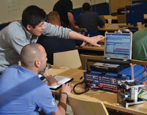
Individualized Training on Protective Relay Testing
According to Jackie M. Peer, Director of SEL University and SEL’s Modern Solutions Power Systems Conference, “Everyone’s training objectives and schedules are different. That’s why SEL University offers a variety of topics and course formats to help you meet the industry’s professional development needs. SEL University offers more than 60 existing courses ranging from fundamentals to advanced training.
“With today’s training landscape changing, many organizations including SEL also offer the convenience of eLearning training,” Peer continues. “This allows students to have control and comfortably complete courses at their own pace. They can access learning content online and enjoy an interactive and convenient experience.”
Kenneth G. Peterson, Vice President – Utility Testing Services at Hampton Tedder Technical Services, Inc. (HTTS), explains, “Since 2010, Hampton Tedder has been able to add a few retired utility test technicians, each with over 25 years of experience in the industry. We have been able to implement a mentor program with our junior test technicians and a senior test technician. We found this has been instrumental to fill in the gap of new technology and seasoned equipment in the field today.”
Peterson says HTTS has used several options for CEUs over the years to continue to keep its field technicians
A NETA WORLD JOURNAL SPECIAL PUBLICATION | TRAINING TALK | 7
trained in new technology and testing techniques, such as in-house HTTS engineering staff teaching classes on NETA ATS-2013 testing procedures and proper documentation. The company also implemented 10day safety topics that are included every other Monday during its crews’ morning safety tailboards. “We strive to help our field staff stay current in this growing age of technology each year,” he adds. Some of the additional training programs at HTTS include:
■ NETA on-line classes for continued education for NETA Level III/IV Test Technicians
■ NETA PowerTest Safety and Technical Conferences
■ TechCon North America Technical Conferences
■ OMICRON Seminars
■ Megger Seminars
■ Doble Engineering Seminars
With the industry facing an increase in distributed energy resources, decrease in coal plants, and an increase in technologies like EVs, energy storage, and microgrids, there is an even greater need for training.
working with senior members of their organization. This includes learning from more experienced coworkers, especially from those who are retiring. It is the individual’s responsibility to reach out and look for mentors and to gather knowledge and information from the more experienced members of their organization as well as individuals from other companies in the industry. Organizations play an extremely important role in the subject of promoting mentoring programs. The management team of any organization should do whatever it takes to encourage and support the knowledge transfer before expertise goes out the door when people retire.
One way organizations can transfer knowledge is through a mentoring program. From the days of the caveman, knowledge has been passed from one person to another. The practice of knowledge management became widely recognized when it was introduced at British Petroleum for the exploration of oil. BP would record its lessons-learned and share these with all employees.
Another early adopter of knowledge management and knowledge transfer in our industry is CLP Power in Hong Kong, which provides power to over 2 million homes. CLP has adopted knowledge management as a strategy for improving reliability and continuous improvement. In a 2005 article in South China Post, CLP Manager Lo Kin-Chung explains, “Our mission is to provide electricity reliably, safely, and at reasonable cost, and this requires a lot of know-how. Much information is recorded, but a lot of valuable experience gathered by staff is not. We are a very knowledge-intensive industry, operating and maintaining a great variety of equipment in countless different locations. The idea is to make better use of this collective expertise.”
The workforce shortage in our industry and the need to train the future workforce is a recognized challenge. Peterson says a great deal of training takes place on the job. This on-the-job training between younger workers and more seasoned HTTS workers also has the benefit of being a knowledge-transfer program enabling tomorrow’s workforce to be trained.
THE VALUE OF KNOWLEDGE TRANSFER
Individuals who are currently in the electric power industry can gain knowledge in their field through
He went on to explain that a lot of practical tips that are not in procedural manuals can be passed on and transferred to other workers. CLP has regular knowledge-management meetings that they call interviews. These meetings are recorded, and the questions and answers are posted on a company intranet with a sophisticated search engine. The internal knowledge portal is accessible to all CLP employees. Everything is logged into the system, from dealing with suppliers on procurement-related issues to highly technical information. They also pair up junior workers with senior workers for mentoring
8 | TRAINING TALK | A NETA WORLD JOURNAL SPECIAL PUBLICATION
and experience sharing. Industry best practices are also included in the portal. By having this knowledge portal in place, CLP will enable the next generation of utility workers to access the knowledge of their predecessors.
It’s important to document procedures beginning with the most crucial. The documentation should include the often forgotten, but more important, tacit knowledge. These unwritten tricks-of- the-trade are the most valuable and most difficult to transfer and capture. They are the things engineers and technicians learn just because they have been around for a while. The Electric Power Research Institute has estimated that as much as 80 percent of the knowledge a person uses to carry out his or her job is undocumented.
Finally, as someone recently told me, “You don’t have to have gray hair to have a good idea.” Companies should tap younger employees for ideas and knowledge. Those who are on the front lines often know the job best and should be involved in the knowledge transfer and documentation. One of the best strategies is to have a combination of several worker generations when performing knowledge transfer. This way, learning is maximized. Mentor programs and knowledge transfer are an important form of training.
Most will agree that not only will our electric grid look very different in the next five to 10 years, but our workforce will also look very different with many Baby Boomers retiring and the next generation of workers fully engaged in our industry.
CONCLUSION
All organizations should develop formal, knowledgetransfer training programs along with implementing mentor programs. What’s more, make sure all


Group Training on Transformer Testing and Diagnostics
intellectual knowledge is documented, bearing in mind that there is tacit and explicit knowledge. Finally, recognize that with all of the new and challenging technologies in our industry (DERs, energy storage, microgrids, etc.), this is not an easy task.
WAYNE BISHOP, JR. has been the Marketing Manager at OMICRON since 2009. Prior to OMICRON, he was employed at Doble Engineering for more than 16 years in several senior management positions. He is an active member of IEEE PES, where he chairs the PES Marketing Committee, and is also a member of the IEEE PES Long Range Planning Committee. Bishop is a graduate of Merrimack College, Harvard University, and the Executive MBA Program at Suffolk University in Boston, graduating with honors. He is a recipient of the Suffolk Executive MBA Great Leaders Executive Excellence Award and was inducted into Beta Gamma Sigma — the National Honor Society of Business Schools. Bishop is an Eagle Scout, and serves on several non-profit and volunteer boards, including the Merrimack College Leadership Council.
A NETA WORLD JOURNAL SPECIAL PUBLICATION | TRAINING TALK | 9
CIRCUIT BREAKER TRAINING:
BUILD A NETWORK TO BRIDGE THE KNOWLEDGE GAP
BY STEVE SKINNER, Doble Engineering Company
The energy sector is facing tremendous strain and challenges due to the shrinking pool of talented and skilled workers. According to one estimate, at least 40 percent of the energy industry sector’s workforce was expected to either retire or leave by 2016. Even though some have opted to postpone retirement, now that it is 2016, that means a significant segment of the power industry workforce is relatively inexperienced.
A 2007 survey conducted by National Electricity Reliability Corporation (NERC) stated that the aging workforce and a lack of skilled workers was ranked first among all business issues with the highest likelihood and highest impact on reliability.
The major issue of replacing experienced workers is concentrated around engineers and field technicians. This problem of shrinking workforce, although widespread around the energy sector, is very significant as it relates to technicians working the area of substation operations and maintenance, including but not limited to the maintenance, operation, and testing of circuit breakers.
TYPICAL SUBSTATION CIRCUIT BREAKER PROFILE
In many substations today, a large variety of circuit breakers range in age from nearly new to 50 or even 60 years old. All of these circuit breakers are mechanical devices that are required to remain in a static condition for long periods of time but must change state reliably on command.
There are numerous methods to interrupt current safely, using insulation mediums such as oil, air, highpressure air, vacuum, two-pressure SF6, and pufferstyle SF6, to name a few. There are also numerous methods to store the energy required to make these mechanical devices operate on command including spring, pneumatic, hydraulic, and combinations of these.
The operating voltage of these circuit breakers may range from 600 V to 800 kV, with current interrupting ratings as high as 80,000 amps.
Finally, there are many types of breakers and a variety of manufacturers, meaning anyone responsible for testing breakers must have a vast amount of knowledge to perform testing safely and accurately — knowledge about testing and knowledge about that specific type of breaker.
THE DOCUMENTATION GAP
If you are testing a breaker that’s more than a few decades old, its documentation is probably missing. When that breaker was installed, it most likely came with detailed information in hard copy from the manufacturer. Eventually, we lose access to critical details because paper manuals are easily lost over time. Luckily, documentation has moved to electronic format, so if you need a copy of a manual about a newer breaker, it’s most likely on file somewhere; however, there’s no guarantee with older breakers. In those cases, we are often relying on insider knowledge that was never written down.
HOW DO WE SUCCEED?
People are retiring, documentation is missing, but testing still needs to be done. That’s why training is so important, but also seems nearly impossible due to the breadth of knowledge one needs to retain. Don’t be overwhelmed — just start.
10 | TRAINING TALK | A NETA WORLD JOURNAL SPECIAL PUBLICATION
Training is a career-long commitment. A robust internal training program is ideal, whether it is education provided by your own team, an external provider, or a combination of the two. An organizational commitment to participating in accelerated educational programs — on-site training, in-depth seminars, and on-line programs — can equip you and your teams with the tools needed to succeed.
THE TECHNICIAN’S NETWORK
What we need to remember is that it’s not just about learning the ins and outs of testing and the quirks and challenges of specific types of breakers; it’s also about building a network of people who can help you when you need advice about a challenging job.
That’s how field techs have been able to test and maintain substation equipment over the years, even during the worst circumstances. They are part of a network of people who rely on each other to answer their questions. Even the most experienced technician will encounter a troublesome breaker — or a breaker type he’s never tested before — and would like to confer with a colleague.
Your own network can consist of people within your own company, breaker manufacturers, utilities, and equipment providers; these are the people you meet on the job and at training throughout your career. Cultivate this network because these are the people you can call to get answers. Education doesn’t happen overnight, but knowledge and your network are the critical pieces to career-long success.
CONCLUSIONS
Power companies are under pressure to keep the lights on, while at the same time ensuring the safety of employees and the general public and protecting equipment in the power network. Power companies

BUILDING YOUR NETWORK
Here are a few resources to help you learn and build your educational network:
■ LinkedIn Professional Group Forums — Electrical Power System Analysis and Control
■ LinkedIn Professional Group Forums — Power Transmission
■ LinkedIn Professional Group Forums NFPA 70E / CSA Z462
■ Engineering 360 — Powered by IEEE GlobalSpec (www.globalspec.com)
■ IEEE Switchgear Committee — meets twice yearly (www.ewh.ieee.org/soc/pes/switchgear)
■ Electrical4u.com — electrical engineering study site, topics from basic engineering to advanced and modern topics related to electrical engineering and technology
■ Circuit Breaker Seminar — October 3–7, 2016, in Pittsburgh, Pennsylvania (events.doble.com/circuitbreakers)
■ Doble Circuit Breaker Committee — one of a number of committees open to Doble Clients; meets twice yearly at the Doble Client Committee Meetings (www.events.doble.com/ccm) and International Conference of Doble Clients (www.events.doble.com/boston)
■ Circuit Breaker Manufacturers Training — various manufacturers provide training throughout the year; details listed on company websites
■ NETA PowerTest Conference, February 27–March 3, 2017, Anaheim, California (www.powertest.org)
have a population of circuit breakers that span many interrupting and mechanism technologies and range in age from 1950s technology to present day.
There has been — and will continue to be — a large, knowledgeable group of employees who retire, leaving organizations scrambling to replace that knowledge and experience. To address the knowledge gap, training will be a required part of any organization’s success. Companies also need to provide technicians with opportunities to build their network of people so they have other experts to contact for answers.
STEVE SKINNER is an Implementation Engineer at Doble Engineering Company. He began his career at Idaho Power in 1977 working on crews that erected the equipment in the substation yard, including 345 kV/230 kV transformers, 345 kV SF6 breakers, 230 kV and 138 kV oil breakers, the substation bus, and all associated structures. He spent three years on wiring crews that wired the control panels, installed the cabling, inspected wiring, and commissioned the stations being built. He then moved to one of Idaho Power’s operating regions, overseeing the operation, troubleshooting, testing, and maintaining all of the station equipment in the region. He later joined Idaho Power Company’s Substation Engineering Group as an Engineering Support Specialist serving as an on-site project leader, analyzing equipment failures, and teaching Substation Apprentice classes.
A NETA WORLD JOURNAL SPECIAL PUBLICATION | TRAINING TALK | 11
SWITCHING PROCEDURES IN TIER 3 AND TIER 4 DATA CENTERS
BY JOSEPH O’DWYER AND KEVIN KELLY, O’Dwyer Technical Services
The phone rings at 2:15 AM. When you finally gain your senses, you realize that this can only be one of a few things — and none of them good. You think of family, the elderly, and when you deduce that all are present and accounted for, you determine that it must be a serious issue with the data center.
Not just any data center — oh no, this is a two-yearold Tier 4 system — the kind that requires 99.995 percent reliability with downtime no greater than 0.04 hours annually. Your system has now been down for the last five minutes. You leave your house for the facility.
We all know that life is not 100-percent dependable in the data center world and that sometimes things go south so fast in the electrical world that there is no time to react. To combat these issues, we have codes and standards and arc-flash studies to assist in developing policies, providing training, etc.
The Ponemon Institute released a study in 2016 regarding the factors that lead to downtime in Tier 4 data center applications. The study surveyed 63
respondents over a 12-month period. The highlights of these findings were very interesting:
■ The average total cost per minute of an unplanned outage increased from $5,617 in 2010 to $7,908 in 2013, and to $8,851 in this 2016 report.
■ The average cost of a data center outage rose from $505,502 in 2010 to $690,204 in 2013, and to $740,357 in the latest study. This represents a 38 percent increase in the cost of downtime since the first study in 2010.
■ Maximum downtime costs are rising faster than average, increasing 81 percent since 2010 to a current high of $2,409,991.
UPS system failure, including UPS and batteries, is the No. 1 cause of unplanned data center outages, accounting for one-quarter of all such events. Cybercrime represents the fastest growing cause of data center outages, rising from 2 percent of outages in 2010 to 18 percent in 2013 and to 22 percent for those sampled in the latest cost of downtime study.

$7,908 $8,851 $5,617 $505,502 $690,204 $740,357

12 | TRAINING TALK | A NETA WORLD JOURNAL SPECIAL PUBLICATION
Average
a Data Center Outage
Unplanned Outage 2010 2013 2016 2010 2013 2016 SOURCE: PONEMON INSTITUTE STUDY
Cost of
Average Total Cost Per Minute of an
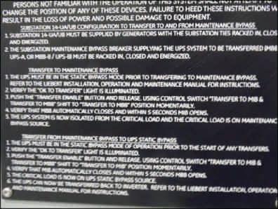
One obvious identifier found in the study was the need for clear instruction to provide technicians with a thorough understanding of proper alignment of switchgear in all applicable scenarios.
In complex data center systems, we have all seen the black-and-white placards (See Figure 1) attached to the switchgear and have done our best to take photos or write down applicable procedures. These procedures are extremely complex, and the possibilities of switching the wrong breaker or being unaware of unique applications are all cause for concern.
With system design being so much more complex to ensure redundancy, it is imperative that we train our staff and provide them accurate, user-friendly procedures that address these complex systems.
The training of staff requires a program addressing policy, procedures, as well as training that gives staff a clear understanding of the larger picture — having an understanding of systems and not just the task at hand.
Issues that need to be addressed when conducting switching in a Tier 4 data center include personal protective equipment, incident energy, boundaries, lock out/tag out, vetted switching procedures, emergency response, etc. In addition, having training standards and measurable goals for the staff provides a twofold approach for success:
1. The staff receives a managed curriculum developed by subject matter experts who incrementally guide the student to more complex, in-depth systems that they will be responsible for eventually.
2. Management ensures that the standards required to maintain the 99.997 percent reliability are adhered to. This is accomplished by proper staffing to secure availability of qualified personnel to address instances such as power outages and fluctuations, lightning strikes, NETA-based maintenance schedules, etc.
With the complexities of Tier 4 data centers, the process to develop curriculum and identify each switching need and its associated risks takes significant time. With various systems, manufacturers, and applications, it is paramount to build upon the information in a fashion that allows the staff to build on prior lessons. It all comes down to how the staff is able to receive the transfer of information from the instructor.
With the complexities of Tier 4 data centers, the process to develop curriculum and identify each switching need and its associated risks takes significant time.
As discussed, with the cost of downtime in a Tier 4 data center, it is impactful to not only the center itself but, more importantly, to the clients and the missions they support.
With data center managers tasked with more duties and responsibilities, it is imperative to establish the need and develop, properly vet, and implement critical procedures to provide the very best defense to ensure that risks are effectively managed.
A NETA WORLD JOURNAL SPECIAL PUBLICATION | TRAINING TALK | 13
Figure 1: Complex instructions require training
Examples that are paramount to ensuring reliability while conducting daily operations include:
Normal UPS system operations — essentially, what the system is to look like in normal operation. This includes indicator lights, operational switches, volts/current parameters, etc. (Figure 2)
1
At MDP-USP-2 Control Panel
MDP-USP-2 Bypass switch is in UPS ENABLED
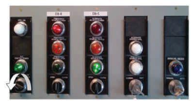
DB-6 Operation switch is in the neutral position
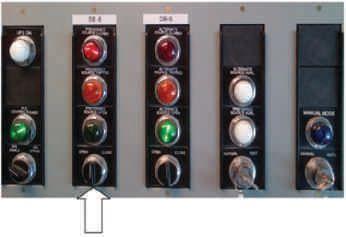
DB-5 Alternate Source Open light is illuminated
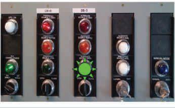
2 Going from Normal to MBB (Maintenance Bypass Breaker) and then back to Normal (Figure 3). This is done when performing maintenance
Warning: During switching operation, personnel must have Category 0 Arc Flash safety clothing, including nonmelting or untreated natural fiber long sleeve shirt and pants.
Ensure MDB-UPS-2 is in the UPS Bypass mode of operation
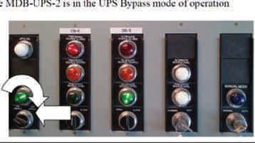
Close MBB. Verify that MBB is in the closed position. Caution: Failure to close MBB will interrupt power to load.
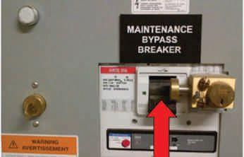
Insert key K2 in the solenoid unit and turn. Solenoid unit will capture key K2.

3: Transfer Load from Alternate Source to Preferred Source
14 | TRAINING TALK | A NETA WORLD JOURNAL SPECIAL PUBLICATION
Figure 2: Normal MDP-UPS-2 Operations
Figure
Warning: During switching operation, personnel must have Category 0 Arc Flash safety clothing, including non-melting or untreated natural fiber long sleeve shirt and pants.
1. Follow procedure to Transfer Load from Preferred Source to Alternate Source
2. Remove key K3 from relay K3 at MIB
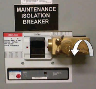
on batteries, or, as addressed in the study, not performed due to staff being unsure of proper alignment of switchgear. Improper switching can cause millions of dollars in damage.
3 When testing your Data Center, to go from Normal to Load Bank Breaker (LBB), then back to Normal (Figure 4). To conduct these and other procedures safely and without interruption can be a very complex task on a Tier 4 system.
There are countless others to address; our attempt is to convey the need to have these developed

either with in-house staff, outside consultants, or a combination of the two.
The purpose of these examples is to demonstrate that any qualified operator must be able to quickly identify the proper operations of any condition and accurately align switchgear to ensure proper operation. These are the telltale signs of a culture that has identified the risks, has the necessary tools in place to permit the operations staff to operate effectively, and limits downtime through policies, procedures, and training.
JOSEPH O’DWYER is president of O’Dwyer Technical Service. He has 30 years of experience in both electrical and mechanical systems with extensive training in both power production and facility operations. He served in the U.S. Air Force from 1981 through 1989 and graduated from the College of the Air Force with a degree in Electrical Power Systems. Joseph joined Johnson Controls in 1989 as a Controls System Representative and then transitioned to Emerson Network Power as a Senior Consultant. In 2012, Joseph identified an industry need and formed O’Dwyer Technical Services. His areas of specialty include low- and medium-voltage systems, power-plant operations, utility operations, data-center operations, and critical procedure development.
KEVIN KELLY is Vice President / Director of Consulting Services. He has over 18 years of experience in low and medium voltage power applications. A graduate of the U.S. Naval Nuclear Propulsion Academy, he managed a nuclear power generation platform for 11 years, and oversaw the maintenance, repair, and operations of marine power plants for 5 years. Kevin holds a Journeyman Industrial Electricians License and served as a Naval Nuclear Power instructor, teaching students the policies and procedures for the operation of a nuclear power plant. In 2005, Kevin joined Emerson Network Power as an Instructor in conjunction with consulting in low- and medium-voltage work centers. He joined O’Dwyer Technical Services in 2012.
A NETA WORLD JOURNAL SPECIAL PUBLICATION | TRAINING TALK | 15
Figure 4: Transfer MDP-UPS-2 from Preferred Source to System Load Bank
GETTING THE MOST OUT OF YOUR TRAINING PROGRAM
PART 1 — THE TRAINER WITHIN
BY CHRIS ALLAIRE, Shermco Industries
When did you learn the “how” of the tasks you perform each day?
More specifically, when did you learn and truly understand all the various connection configurations when power-factor testing a transformer? When was it that you actually understood low-voltage breaker curves and programmer settings? When was it that you really understood the theory of insulation testing?
If you are anything like most technicians, you learned power-factor testing in the field, testing a transformer with a senior tech. Or maybe you were in the substation when you were learning how to operate a high-current test set with a qualified breaker tech. You most likely learned the “how” on the job from an experienced technician.
Now it may be your turn to pass on your experience and knowledge. A lot of technicians say they aren’t
teachers or don’t think they have the talent or qualifications for teaching. We will explore some very practical ways to help you bridge the gap between the “why” (sometimes referred to as booklearning) and the “how” (hands-on training) as you take on the role of trainer/mentor on the jobsite.
TRAIN THE TRAINER
A great deal has been written about the art and science of adult education and learning, much of it concerning the classroom or lab. Technical training in the classroom is primarily intended to teach the theory behind the “why.” Labs and exercises that simulate the real world are often included in technical training.
A good instructor-led class will include many handson activities to demonstrate the theory behind the lesson. This is why the most effective technical training is presented in a classroom/lab rather than by video or webinar. But to truly merge the book learning of the classroom with the hands-on skills necessary to become a skilled technician, on-thejob training is essential. This is where you, as the qualified technician, come in.
We are always teaching the new hands how to do things, and we are often responsible for training other technicians. The one shortcoming is that although we are expected or required to teach people, we never actually get any training on how to do so. In my case, I learned from guys who taught me successfully and also from the ones who didn’t (where I learned what not to do). It’s ironic that no one thinks about the fact that all of us in the trades have to teach people things, but we have not been taught how to teach effectively. In short, we need some train-the-trainer coaching.
Observational learning may be the oldest form of training. Remember how you figured out the playground equipment at recess? You watched the older kids and did what they did. This may be the worst form of employee training, but unfortunately, it is practiced every day. Typical on-the-job training is somewhat better than observational training but has its drawbacks.
In their book Managing Human Resources, Scott Snell and Shad Morris describe on-the-job training as “one-on-one training located on the job site, where someone who knows how to do a task shows
16 | TRAINING TALK | A NETA WORLD JOURNAL SPECIAL PUBLICATION
another how to perform it.” Snell continues, “… it requires only a person who knows how to do the task, and the tools the person uses to do the task. It may not be the most effective or most efficient method at times.” Basic on-the-job training may be good enough for simple or repetitive tasks, but for most of the technical tasks we perform, we will need to go beyond simply show-and-tell instruction.
CREATE LEARNING OBJECTIVES
So, how do you take your job-site training and mentoring to the next level? How can you be sure the technician learning from your knowledge and years of experience truly understands what you have to offer? How can you take on the role of technical trainer when your primary function is that of job lead or project manager?
The answer is simpler than you think: Be prepared to discuss the technical aspects (the “why”) of the task and the practical aspects (the “how”) of what is needed to get the job done. In other words, have a plan. In the training world, we call this plan the learning objectives. Learning objectives are nothing more than a simple statement that describes what your learner should know and be able to do after completing your training.
For example, when instructing a junior technician in the proper way to rack-in or rack-out a lowvoltage power circuit breaker, have a plan or learning objective to follow. This will ensure you don’t miss any of the important steps. In some cases, the objectives you need will already have been developed for you in the form of your organization’s standard operating procedures (SOPs) or safe work practices (SWPs). Be prepared to discuss such things as primary and secondary disconnect, interlocks, control wiring, etc.
More important, you will want to explain any safety issues associated with the task, such as arc flash and shock hazards. In this example, you will want to discuss the differences between racking a breaker on a hot bus as opposed to a deenergized bus. A written set of objectives will not only assure you cover all the steps, but also assure others in your organization are teaching the same thing.
As the subject matter expert (SME) on a particular task or topic, you may be called upon to develop the
learning objectives for that task. In other instances, you may want to get with other technicians to develop the objectives. Don’t neglect to use all the information at your disposal such as NETA MTS and ATS, manufacturers’ literature, your company’s SOPs and safe work practices, or other material you may find on the web.
PREPARE TO TEACH
Teaching others is one of the most rewarding and enjoyable jobs that I’ve ever had. That said, I’m not sure teaching comes all that natural to me. Like you, I must prepare material in advance to provide effective training.
Most of us have experienced the expert trainer who can’t seem to explain things on our level of understanding. Don’t fall into the trap of not preparing for worksite training and thinking you can just wing it when the time comes. In Tips for Great On-the-Job Training (OJT) Programs, Jeffrey Dalto points out that under an unprepared trainer, workers are left without the knowledge, skills, and abilities necessary to succeed at their jobs.
In their book, Telling Ain’t Training, authors Harold Stolovitch and Erica Keeps make the point that simply telling someone something is not training. Have you ever said something like, “I told him numerous times, and he still doesn’t get it?” We have a poster in our training room attributed to Benjamin Franklin, who wrote: Tell me and I forget. Show me and I may remember. Involve me and I learn.
FOLLOW THESE STEPS
A few more suggestions should help you on your way to providing great jobsite instruction:
■ Set aside time to explain the task to your learner. Remember, you are not just showing how to do a task, but explaining the “why” as well. Remind the technician of the theory behind the task for better understanding.
■ Clearly explain what is expected of your learner to perform the task safely and efficiently. Explain all the steps of the process before you start. This will help the technician get a feel for the big picture. If necessary, break down the process into
A NETA WORLD JOURNAL SPECIAL PUBLICATION | TRAINING TALK | 17
bite-size chucks. Treat each task as a separate topic and make sure each step in the task is not skipped.
■ Only include information and activities designed to support the learning objective. Resist the temptation to add additional material. You risk confusing or overwhelming your learner. I’ve heard it said, “You ask him what time it is, and he tells you how to build a clock.” More is not better; stick to the subject. Albert Einstein is credited with saying, “If you can’t explain it simply, you don’t know it well enough.”
■ Have all your objectives prepared ahead of time. This will require some planning and extra work on your part. Will you need a copy of the NETA MTS? Determine if you should print out material before you leave for the job. Our customers are not paying us to hold class on their nickel; therefore, being prepared will help make the training part of the job much more efficient.
■ Involve the person you are training in the task you are demonstrating. Technicians are handson people. Let the technician get his hands on it. The best way to learn how to run a high-current test set is to run a high-current test set.
PART 2 — LEARNING MANAGEMENT SYSTEMS: MORE THAN JUST A FILE CABINET
In our digital world, an engineer, technician, or administrative assistant can acquire abundant information on just about any topic from videos, online forums, Wikipedia, social media, blogs, technical publications, and so forth. Senior technicians and engineers will research specific
There is one last thing you will want to do to ensure your on-the-job training accomplishes your intended goal. You can’t assume that the tech will “get it” just because you provided training. To ensure he or she can perform all the steps that make up the task, it is important to evaluate the trainee’s performance.
Have a plan for evaluating their skills and abilities. To be fair to other technicians, your assessment should be the same one used by other OJT trainers. In some cases, a check-off list works fine when observing the person doing the task. In other cases, you may want to develop a question-and-answer assessment. The key to a good assessment is that it only evaluates proficiency on the objectives for the specific task.
CONCLUSION
While your primary job function may not be that of trainer or instructor, you may still be called upon to train other technicians. Going beyond basic showand-tell will ensure junior technicians understand the “why” as well as the “how.” Having material developed ahead of time assures everyone is being trained the same way and nothing is forgotten or left out. Finally, assessing the trainee’s performance and competency on the given task will ensure your learner “gets it.”
topics as needed, but this is not a good long-term employee development strategy. If employees are left to gain technical knowledge on their own, it is impossible to measure and track progress, assure the information matches company practices and policies, and ascertain whether the information is factual and complete. Using a Learning Management System (LMS) is the best — and arguably, the only — way to provide a systematic and centralized employee learning process.
Simply put, an LMS is a system used to manage learning. An important distinction between training and learning is that training is more instructorfocused, while learning focuses on the student and how they learn. While most folks in the training and development world would disagree with me, an LMS
18 | TRAINING TALK | A NETA WORLD JOURNAL SPECIAL PUBLICATION
could be as simple as a file drawer with a manila folder for each employee’s training record — of course, a file drawer is not the most efficient system for managing learning. A more universally recognized definition of an LMS found on Wikipedia states, “A learning management system (LMS) is a software application for the administration, documentation, tracking, reporting, and delivery of electronic educational technology (also called e-learning) courses or training programs.” For our discussion, we will forgo the file drawer and use the latter definition.
Before evaluating an LMS, first evaluate your own employee development and training requirements. It is never a good idea to have an LMS vendor’s sales representative define your needs. Evaluate the number of users you expect to accommodate now and in the future. A good LMS is scalable, allowing the system to grow as you add employees. Keep in mind, the LMS should be designed with all employees in mind, not just the technical staff. Evaluate your current IT infrastructure and its limitations. Typically, LMS products are sold as either a locally hosted enterprise product, which is hosted on an organization’s own servers, or as a Software-as-a-Service (SAAS) offering, which is hosted on the vendor’s servers and is accessible from anywhere because data is stored in the cloud.
The most critical aspect of selecting an LMS is evaluating training requirements and learning objectives. As you evaluate, be clear and specific. Both classroom training and e-learning can be effective training methodologies; however, they are very different learning methods. To select the most effective methodology and corresponding LMS, examine your training methodologies from several perspectives.
How is your workforce organized?
■ Is your workforce in one place or is it dispersed in several locations?
■ Is your workforce mobile?
What is the best way to teach your workforce?
■ Does your workforce respond well to instructorled, hands-on instruction?
■ Does your workforce respond better to e-learning?
■ Should the learning opportunity be a combination of both?
Your LMS is a tool that technicians and support staff use to manage their learning and career development. As authors John Phillipo and Sarah Krongard point out in their article, “Learning Management Systems (LMS); the Missing Link and Great Enabler,” most instruction should not be managed through a technology solution. “Rather, educators must focus more systemically on the main goal: learning and the management thereof,” they explain. Learning is considered student-centered, whereas training is more trainer-centered. A student-centered LMS must be accessible, easy to use, and support the learner in the pursuit of increased skills and knowledge.
About 600 varieties of LMSs are available for purchase today, each with features designed for a variety of trainers and educators. I use a variety of LMSs each day — one with my day job as technical instructor/ developer, another as an adjunct instructor for a local college, and another as a contract training provider for Texas Workforce Development projects. Many off-the-shelf, e-learning products come packaged with a custom LMS for the product.
In general, an LMS should provide participant registration, activity tracking, and progress gauging as staff proceeds through online coursework and instructor-led classes. Some of the more useful components to look for:
■ The LMS should manage certification, skills, and competencies. While some certifications and safety trainings expire yearly, others may be good for three years. A technician’s skills and competencies change continually, requiring a system to keep up with the progress.
■ Course content delivery such as training videos, instructor notes and outlines, policy and procedural documents, manufacturers’ literature, and industry standards should be available on the LMS.
■ The LMS should offer self-registration and allow for proxy enrollment for mandatory training. Cross-training is greatly enhanced if employees have access to a variety of training outside their normal job function. Proxy enrollment allows the LMS administrator to enroll large groups of people for required training.
■ The LMS is a good place to schedule and manage training events such as instructor-led classes,
A NETA WORLD JOURNAL SPECIAL PUBLICATION | TRAINING TALK | 19
webinars, e-learning opportunities, and training provided by outside providers.
■ Individual development plans (IDP) and the ability to interact with your current Human Resource Information System (HRIS) is a tremendous time saver.
■ Professional and social networking can be done within most quality LMSs. The ability for LMS users and administrators to form discussion groups around common interests and themes will greatly enhance the learning experience. Learning improves significantly as participants discuss ideas and benefit from each other’s experiences.
■ Reporting and training-record management is one of the most important functions of an LMS. Regulatory training that is not documented is not considered done. Accurate recordkeeping of required safety and site-specific training is essential considering the number of customers the typical technician visits in a year.
BLENDED LEARNING
A quality LMS also allows for blended learning. In her article, “The Basics of Blended Instruction,” author Catlin Trucker states: “Blended learning combines classroom learning with on-line learning, in which students can, in part, control the time, pace, and place of their learning. I advocate a teacherdesigned blended learning model, in which teachers determine the combination that’s right for them and their students.”
Blended learning consists of three main parts: classroom instruction, on-the-job training, and e-learning. Technical training is best presented as instructor-led with plenty of hands-on activities. Accompanying classroom instruction is verifiable on-the-job training and demonstrations of skills to reinforce the learning. A third component of blended

learning is e-learning. Blended courses (also known as hybrid or mixed-mode courses) are classes where a portion of the traditional face-to-face instruction is replaced by web-based learning. The ratio of faceto-face instruction to online coursework will vary by topic complexity and the learning objective.
One of the major advantages of an LMS is its ability to support the creation of a blended learning curriculum. The trainer can provide multiple resources to reinforce learning objectives. Part of the blended learning may include assignments to be completed on-site and verified by a senior technician. When blended learning is properly implemented, it results in improved student success, satisfaction, and retention. Blended learning also addresses your mobile workforce and remote offices, allowing employees to access learning on the LMS prior to attending instructor-led classes or taking on a new challenge. This technology supports multimedia and interactivities, making learning more interesting and effective.
CONCLUSION
An LMS is much more than an electronic folder used for storing training records. Choosing the best LMS requires a thorough review of training and development needs. Implemented correctly, an LMS becomes an indispensable tool for managing workforce training and development. The LMS also allows managers to assign required technical and safety classes to individuals or entire work groups. Most importantly, your LMS is a tool that technicians and support staff will use to manage learning and career development. The LMS supports each employee, providing review of individual training records and registration for additional training based on their development plan. Further, the LMS accommodates a blendedlearning curriculum, allowing for a more effective and comprehensive employee training experience.
CHRIS ALLAIRE is a Technical Instructor/Developer for Shermco Industries and an Adjunct Instructor for Texas State Technical College as well as North Lake College. Previously, he served as Lead Electrical Instructor at Everest College in Arlington, Texas. Allaire spent close to 30 years with General Electric, starting in the motor shop as a motor mechanic and test technician. The second half of his GE career was spent as a field service technician performing startup and commissioning at water treatment plants, data centers, and industrial facilities. He earned his Bachelor of Science in Technical Management from DeVry University, majoring in Electronic Engineering Technology, and his Master of Education in Curriculum and Instruction from American College of Education.
20 | TRAINING TALK | A NETA WORLD JOURNAL SPECIAL PUBLICATION
Doble Engineering Company: Learn from the Industry’s Top Experts
Throughout the year, Doble hosts accredited technical trainings on a variety of topics to help engineers and technicians of all levels be more efficient, effective, and safe in the field. Learn from the industry’s top experts, receive real-world training that you can immediately apply, and build your professional network.
2016-2017 Course Listings
• Circuit Breaker Seminar
October 3-7, 2016, Pittsburgh, PA and October 2-6, 2017 Pittsburgh, PA
Brush up on fundamentals, get practical hands-on training, and learn from the experts at the industry’s best circuit breaker educational seminar. Gain new skills to do your job safely and efficiently.
• Life of a Transformer™ Seminar
February 19-24, 2017, Huntington Beach, CA
Learn practical information from industry experts for immediate, measurable impact at any point in the lifecycle of your transformers. The seminar now includes programs for Transformer Differential Protection, Transformer Maintenance, and Asset & Maintenance Strategies.
• Rotating Machinery & Electrical Plant Reliability Workshop
March 2017, Boston, MA
At the Rotating Machinery & Electrical Plant Reliability Workshop learn everything you need to know to reliably operate and maintain the electrical side of your generating or industrial plant. We cover all aspects of theory, application, design, manufacturing, operations and maintenance of turbo-generators and synchronous and induction motors.
• Laboratory Seminars
Offered throughout the year
Doble offers day-long Laboratory Seminars for engineers, chemists, and others who review data to assess transformer condition. This interactive seminar combines theoretical background with practical experience and hands-on examples, using case studies to illustrate common problems found in the field.
• Protection Training Courses
Offered throughout the year
Choose from a wide range of protection training courses that will help prepare you for a modern grid, power plant, and industrial facility.
Many Doble training courses are eligible for NETA Continuing Technical Development Credits (CTDs) as well as IACET certified Continuing Education Units (CEUs).
For more information, visit www.doble.com/earning-ceus/
www.doble.com/training events@doble.com 617.926.4900 DIRECTORY OF TECHNICAL AND PROFESSIONAL TRAINING
AVO Training Institute: The One Stop for Electrical Safety Training,
Electrical Maintenance Training, and Electrical Technicial Certifications
Many AVO courses are eligible for NETA CTDs.*
If it’s electrical, AVO Training is focused on it. Electrical safety training, electrical maintenance training, and electrical consulting is not just a part of our offering, it’s our total focus. That’s why we offer more electrical safety and electrical maintenance training courses than any other training facility. With over 52 different courses, we offer the widest selection of courses available. To complement our training courses, we have a stand-alone Engineering Division that offers Arc Flash Studies, Risk Assessment Analysis, and a full menu of electrical engineering services.
Available Courses:
Protective Relay
• Protective Relay Maintenance - Basic
• Protective Relay Maintenance - Advanced
• Protective Relay Maintenance - Generation
• Protective Relay Maintenance - Solid State
• Microprocessor Based Relay Testing - Generation
• Microprocessor Based Relay Testing - Distribution/ Industrial
• Advanced Visual Testing Software
Circuit Breaker
• Circuit Breaker Maintenance, SF6
• Circuit Breaker Maintenance, Molded- and Insulated-Case
• Circuit Breaker Maintenance, Medium-Voltage
• Circuit Breaker Maintenance, Low-Voltage
Cable U
• Cable Splicing and Terminating, Medium-Voltage
• Cable Fault Location and Tracing, Medium-Voltage
• Cable Testing and Diagnostics, Medium-Voltage
Substation
• Battery Maintenance and Testing
• Transformer Maintenance and Testing
• Advanced Transformer Maintenance and Testing
• Substation Maintenance I
• Substation Maintenance II
• Power Factor Testing
Safety
• NFPA 70E 2015 Electrical Safety
• Electrical Safety for Utilities
• Electrical Safety for Mining
• Electrical Safety for Industrial Facilities
• Electrical Safety for Inspectors
• Electrical Safety for Overhead Contact Systems
• 2017 National Electrical Code
• OSHA Electrical Safety Related Work Practices
• Maritime Electrical Safety
Basics
• Basic Electricity
• Basic Electrical Troubleshooting
• Electronics Troubleshooting
• Electronics for Electricians
• Electrical Print Reading
• Grounding & Bonding
Engineering
• Short Circuit Analysis
• Protective Device Coordination Utilities
• Protective Device Coordination Industry
• Power Quality & Harmonics
Motors/Controls
• Programmable Logic Controllers
• Maintenance & Trouble Shooting
• Motor Maintenance and Testing
• Motor Controls and Starters, Low-Voltage
WWW.AVOTRAINING.COM • 877-594-3156 *NETA continuing technical development (CTDs) units are required of NETA Certified Technicians. DIRECTORY OF TECHNICAL AND PROFESSIONAL TRAINING
SDMyers: In Electrical System Maintenance and Management, Knowledge Means Power
Effective transformer management requires special skills acquired from years of hands-on experience. The diminishing number of experts is causing a growing need for specialized training to ensure these skills are not lost. SDMyers offers your team the opportunity to benefit from our 50 years of transformer maintenance expertise. We offer a variety training options including enhanced e-learning courses; seminars; and onsite, online, and customized courses.
Introductory
• Principles of Transformer Maintenance
Basics of transformers: electric concepts, solid and liquid insulation, oil testing and analysis, basic electrical testing, and maintenance. Available at sdmyers.com/training.
• Principios de Mantenimiento de Transformadores
Este curso introduce al alumno en una serie de temas que resumen los fundamentos básicos de los transformadores y de mantenimiento del transformador. Available at sdmyers.com/training.
• In-Service Inspection & Sampling of Fluid-Filled Transformers
Learn safe procedures needed to obtain a representative sample of dielectric fluid. Features a sampling demonstration and practical exercises to obtain accurate oils samples for use in lab analysis.
Intermediate
• Half-Century Transformer
Foundational understanding of transformers: operation, maintenance implementation, and related industry standards.
• Half-Century Transformer - Applied Maintenance
Foundational understanding of transformers: operation, maintenance implementation, and related industry standards. Includes lab and equipment tours, rewind facility tour, case studies, and expert panel discussion.
• Advanced DGA Diagnostics
Learn to identify fault gases and what causes their formation, learn how to evaluate the condition of cellulose insulation, examine the role DGA plays in new oil testing, and discuss obtaining samples from transformers.
• Load Tap Changer Principles & Maintenance
Load tap changing, styles of tap changers and their operation, and how to develop a preventative load tap changer (LTC) maintenance program.
• Electrical Testing - Power Factor Testing for Transformers, Bushings, and Breakers
The Power Factor is a measurement of the efficiency of the transformer’s insulation system and a reliable electrical test to detect deterioration.
• Transformer 360 Course is 3 days — take any or all. Day 1: Re-energized Half-Century course as part of a transformer reliability program. Day 2: Risk & Reliability and DGA. Day 3: LTC Testing & Maintenance and Electrical Testing.
Advanced
• Transformer Lifecycle Management
Manage the lifecycle of the transformer including specification and purchasing, transportation, assembly and start-up, field and shop repair, overall risk and asset management, and end-of-life options. Learn to develop and manage a reliability-based maintenance program.
• Advanced Transformer Maintenance and Planning
Reactive, predictive, and preventative maintenance of transformers, and building a cost-effective testing and maintenance plan to prolong the reliable life of transformers. Includes substation equipment, transformer design and construction, and how to make critical maintenance and planning decisions.
SD Myers courses are eligible for NETA CTDs.*
*NETA continuing technical development (CTDs) units are required of NETA Certified Technicians
DIRECTORY OF TECHNICAL AND PROFESSIONAL TRAINING
Register by phone: 330.630.7000 x.4018 Register online: sdmyers.com/training For class dates and locations visit sdmyers.com/training/calendar 180 South Avenue, Tallmadge, Ohio 44278, USA
Shermco Industries: Your Electrical Safety Experts
SSafety Training Course Schedule 2016 -2017
• Electrical Safety for Qualified Electrical Workers
Austin, TX
2016 Oct 11
2017 Jan 4, Apr 4, Jul 11, Oct 14
Dallas, TX
2016 Sep 13, Oct 18, Nov 15, Dec 13
2017 Jan 10, Feb 7, Mar 14, Apr 11, May 16, Jun 20, Jul 18, Aug 15, Sep 12, Oct 17, Nov 14, Dec 12 Houston, TX
2016 Sep 13, Dec 6
2017 Mar 7, Sep 12, Dec 5 St. Paul, MN
2016 Sep 20, Dec 13
2017 Mar 14, Jun 13, Sep 19, Dec 12 Tulsa, OK
2016 Sep 13, Dec 13
2017 Mar 7, Jun 6, Sep 12, Dec 12
• Electrical Safety for Managers
Austin, TX
2016 Sep 27
2017 Jan 26, May 16, Sep 26
Dallas, TX
2016 Oct 25
2017 Feb 2, Jun 15, Oct 26
• Lab Session – Electrical Safety for Qualified Electrical Workers
Dallas, TX
2016 Sep 16, Oct 21, Nov 18, Dec 16
2017 Jan 13, Feb 10, Mar 17, Apr 14, May 19, Jun 23, Jul 21, Aug 18, Sep 15, Oct 20, Nov 17, Dec 15
• Electrical Safety for Non-Electrical Personnel
Austin, TX
2017 Apr 4, Jun 13
Dallas, TX
2016 Sep 12, Dec 12
2017 Mar 7, Jun 20, Sep 12, Dec 12
Houston, TX
2016 Dec 5
2017 Jun 6, Dec 5
Tulsa, OK
2016 Dec 12
2017 Jun 13, Dec 12
• Electrical Safety for Utilities
Austin, TX
2016 Sep 7
2017 Jan 11, May 9, Sep 6
10% Discount to NETA Member Companies! Limited time offer. Expires April 1, 2017 Use Discount code Netaworld
Dallas, TX
2016 Sep 20
2017 Jan 24, May 22, Sep 18
Tulsa, OK
2016 Sep 14
2017 Jan 12, May 2, Sep 12
• Electrical Safety Refresher
Austin, TX
2017 Jan 9, Jul 10
Dallas, TX
2016 Oct 17
2017 Jan 16, May 15, Oct 16
Houston, TX
2016 Sep 16
2017 Mar 6, Sep 18
Tulsa, OK
2016 Sep 16
2017 Mar 13, Sep 15
• Understanding the NFPA 70E & 2015 Changes
Austin, TX
2017 Jan 9, Jul 10
Dallas, TX
2017 Feb 10, Aug 25
St. Paul, MN
2017 Jan 12, Jul 13
Tulsa, OK
2016 Dec 16
2017 Jun 8, Dec 14
hermco is a leader in electrical power systems maintenance, repair, testing, and training. Offering both onsite and classroom based training, Shermco conducts a wide variety of courses covering Maintenance Training, Safety Training, General Technical Training, and Canadian Training. Some of the most influential leaders in electrical safety work at Shermco Industries. Now you have direct access to that experience and expertise! Shermco offers technical and electrical safety programs year-round and at multiple locations in the U.S. and Canada. Train with the experts. Train with Shermco. Enroll today by visiting www.shermco.com/training or call 888-Shermco and mention your promotional code.
For more information, to download our current course catalog, or to register online go to www.shermco.com/training or email training@shermco.com Shermco.com • 888-shermco

DIRECTORY OF TECHNICAL AND PROFESSIONAL TRAINING
TechCon North America: Where Technology and Innovation Meet
February 14-16, 2017 • Westin Houston - Memorial City • 945 Gessner Rd., Houston, TX
TechCon® Worldwide Conferences and Expos are annual events devoted to the discussion of technology development and solutions which improve key high voltage maintenance programs and asset management strategies for the aging electrical grid infrastructure. Meet utility industry experts as presenters, utility workforce members, corporate suppliers, and decision makers eager to network and share their vast knowledge. Your career will be enriched by your attendance.
Keynote Speaker

Presenters

Dr. Michel Duval
IREQ - HydroQuebec, Canada
John McDonald, P.E. GE-Grid Solutions / Global SmartGrid Strategy Group
Training Session Topics
• Transformer Diagnostics by OMICRON
• Load Tap Changer University by Reinhausen Manufacturing
• Having LTC or Accessory Issues? Here’s How to Become a Hero for Your Company by ABB
• Categorizing Transformer Faults via Dissolved Gas Analysis by GE
• Power Transformers 101- Fundamentals
• Power Transformers 102 - Advanced by Siemens

Dr. Yannick Kieffel GE-Grid Solutions



Jim McIver Siemens

Utility Employees: Request a 25% Buddy Discount
After the first attendee registers, the attendee can reply to the confirmation email with a request for our 25% Discount Code for their buddies to register. It’s that simple!

Contact info:
TechCon North America • TJ|H2b Analytical Services 3123 Fite Circle, Suite 106, Sacramento, CA 95827
Phone: +1 916-361-7177
TechCon Sessions are eligible for NETA CTD credits. Register today at www.techcon.info
DIRECTORY OF TECHNICAL AND PROFESSIONAL TRAINING
Randy Williams ABB
Randy Cox
GE-Grid
Solutions
electronics USA
Don Platts
OMICRON
NETA Training: Learn to Test, Assess, and Validate
NETA Self-Paced Technical Seminars (SPTS) are training materials created for distance learning. Every year, PowerTest offers in-depth seminars covering a wide variety of topics. Two seminars are selected by the Conference Committee each year to be recorded and produced into an SPTS.
NETA’s online training courses cover specific sections of the ANSI/NETA, Standard for Acceptance Testing Specifications for Electrical Power Equipment and Systems (ANSI/NETA ATS-2013). This training material assists the field service technician in understanding and acquiring the knowledge to properly test, assess, and validate various systems and electrical power equipment as required by the ANSI/NETA ATS.
Self-Paced Technical Seminars
SPTS HIGHLIGHTS:
• Four-hour run time
• DVD or USB of the recorded technical seminar and printed hard copy of the presentation
• One access to the proficiency exam
• Earn four NETA CTD Credits (NETA Certified Technicians) or submit for CEUs
AVAILABLE COURSES:
• Power Transformer Testing and Maintenance
Jim White, Shermco Industries
• Critical Maintenance for Circuit Breakers
Jim White, Shermco Industries
• Electrical Testing Basics: What You Need to Know to Succeed — Part 1
Jim White, Shermco Industries
• Electrical Testing Basics: What You Need to Know to Succeed — Part 2
Jim White, Shermco Industries
• A Primer on MCC Maintenance and Testing Malcom Frederick, Shermco Industries
• Primer on Transformer Diagnostics
Charles Sweetser, OMICRON electronics Corp. USA
• Transformer Dielectric Fluids: Use of DGA and Furans
Melvin Wright, LICA Consulting, LLC
• Using Partial Discharge Detection
Don Genutis and Neil Davies, No-Outage Electrical Testing, Inc.
• Hazards of Electricity, Shock, Arc, and Blast: An Educational Journey Through Case Studies
Jim White, Shermco Industries
• Electrical Testing MediumVoltage Stator Windings
Tom Sandri, Shermco Industries, and Vicki Warren, Iris Power – A Qualitrol Company
• How Do They Do It? Electrical Power Measurement Methods, Practices, and Standards
Ross Ignall, Dranetz Technologies
• The Practical Application of NFPA 70E in Routine Work Tasks
Jim White, Shermco Industries
• Condition of Maintenance: A Practical Approach to Compliance within the Industry
Jim White, Shermco Industries
• Acceptance and Maintenance Testing for Medium-Voltage Electrical Power Cables: Exploring Technology Developments Over the Past 20 Years
Tom Sandri, Shermco Industries
• Risk Assessment Techniques Using NFPA 70E: A Primer Presented by: Jim White, Shermco Industries
• Maintenance and Testing of Battery Systems Presented by: Tom Sandri, Shermco Industries
Online Courses
Developed by the NETA Training Committee Approved by the NETA Standards Review Council
EACH PURCHASE INCLUDES:
• An individual account with access to NETA’s Online Training Center
• One access to the proficiency exam (additional attempts may be purchased separately)
• Earn NETA CTD Credits (NETA Certified Technicians or submit for CEUs)
AVAILABLE COURSES:
• Grounding Systems Acceptance Testing
• Cable Systems Acceptance Testing
• Instrument Transformer Acceptance Testing
Electrical Safety Training Systems
DIRECTORY OF TECHNICAL AND PROFESSIONAL TRAINING
NETA - InterNational Electrical Testing Association netaworld.org • 888-300-6382 (NETA) NETA Training Courses can be submitted for CTDs or CEUs





CALL FOR EXHIBITORS California is calling. Join 400+ electrical testing professionals Leading decision makers looking for new products and services For attendee profile and additional information, visit www.powertest.org ANAHEIM • CALIFORNIA February 27 - March 3 • 2017 DISNEYLAND HOTEL POWERTEST.ORG 888.300.6382 THE PREMIER ELECTRICAL MAINTENANCE & SAFETY EVENT
Electrical Distribution System

3050 Old Centre Avenue, Suite 102
Portage, MI 49024
Toll free: 888.300.NETA (6382)
Phone: 269.488.NETA (6382)
Fax: 269.488.6383 neta@netaworld.org
www.netaworld.org
EXECUTIVEDIRECTOR: Missy Richard
NETA Officers
PRESIDENT: Ron Widup, Shermco Industries
FIRSTVICEPRESIDENT: Jim Cialdea, Three-C Electrical Co., Inc.
SECONDVICEPRESIDENT: Scott Blizard, American Electrical Testing Co., Inc.
SECRETARY: Eric Beckman, National Field Services
TREASURER: John White, Sigma Six Solutions
NETA Board of Directors
Ken Bassett (Potomac Testing, Inc.)
Eric Beckman (National Field Services)
Scott Blizard (American Electrical Testing Co., Inc.)
Jim Cialdea (Three-C Electrical Co., Inc.)
Lorne Gara (Orbis Engineering Field Services, Ltd.)
Dan Hook (Western Electrical Services, Inc.)
David Huffman (Power Systems Testing)
Alan Peterson (Utility Service Corporation)
John White (Sigma Six Solutions)
Ron Widup (Shermco Industries)
NETA World Staff
TECHNICALEDITORS: Roderic L. Hageman, Tim Cotter
ASSISTANT TECHNICAL EDITORS: Jim Caldea, Dan Hook, Dave Huffman, Bob Sheppard
ASSOCIATEEDITOR: Resa Pickel
MANAGINGEDITOR: Jayne Tanz, CMP
ADVERTISINGMANAGER: Laura McDonald
DESIGNANDPRODUCTION: Hour Custom Publishing
NETA Committee Chairs
CONFERENCE: Ron Widup; MEMBERSHIP: Ken Bassett; PROMOTIONS/MARKETING: Scott Blizard; SAFETY: Scott Blizard and Jim White; TECHNICAL: Alan Peterson; TECHNICALEXAM: Ron Widup; CONTINUINGTECHNICALDEVELOPMENT: David Huffman; TRAINING: Kerry Heid; FINANCE: John White; NOMINATIONS: Alan Peterson; STRATEGY: Mose Ramieh; ALLIANCEPROGRAM: Jim Cialdea
© Copyright 2016, NETA
NOTICE AND DISCLAIMER
NETA World is published quarterly by the InterNational Electrical Testing Association. Opinions, views and conclusions expressed in articles herein are those of the authors and not necessarily those of NETA. Publication herein does not constitute or imply endorsement of any opinion, product, or service by NETA, its directors, officers, members, employees or agents (herein “NETA”).
All technical data in this publication reflects the experience of individuals using specific tools, products, equipment and components under specific conditions and circumstances which may or may not be fully reported and over which NETA has neither exercised nor reserved control. Such data has not been independently tested or otherwise verified by NETA.
NETA MAKES NO ENDORSEMENT, REPRESENTATION OR WARRANTY AS TO ANY OPINION, PRODUCT OR SERVICE REFERENCED OR ADVERTISED IN THIS PUBLICATION. NETA EXPRESSLY DISCLAIMS ANY AND ALL LIABILITY TO ANY CONSUMER, PURCHASER OR ANY OTHER PERSON USING ANY PRODUCT OR SERVICE REFERENCED OR ADVERTISED HEREIN FOR ANY INJURIES OR DAMAGES OF ANY KIND WHATSOEVER, INCLUDING, BUT NOT LIMITED TO ANY CONSEQUENTIAL, PUNITIVE, SPECIAL, INCIDENTAL, DIRECT OR INDIRECT DAMAGES. NETA FURTHER DISCLAIMS ANY AND ALL WARRANTIES, EXPRESS OF IMPLIED, INCLUDING, BUT NOT LIMITED TO, ANY IMPLIED WARRANTY OF FITNESS FOR A PARTICULAR PURPOSE.
ELECTRICAL TESTING SHALL BE PERFORMED ONLY BY TRAINED ELECTRICAL PERSONNEL AND SHALL BE SUPERVISED BY NETA CERTIFIED TECHNICIANS/ LEVEL III OR IV OR BY NICET CERTIFIED TECHNICIANS IN ELECTRICAL TESTING TECHNOLOGY/LEVEL III OR IV. FAILURE TO ADHERE TO ADEQUATE TRAINING, SAFETY REQUIREMENTS, AND APPLICABLE PROCEDURES MAY RESULT IN LOSS OF PRODUCTION, CATASTROPHIC EQUIPMENT FAILURE, SERIOUS INJURY OR DEATH.
24 Hour Emergency Services (937) 439-9660

SUMMER IS COMING TO A CLOSE AND FALL IS HERE!
For many of us, the fall season is one of our busiest. Many facilities are experiencing fall outages, and the work days can be longer and more stressful than normal. Even if your days throughout the fall season are not that much different, one thing we must constantly do is evaluate and mitigate exposures to risk.
One of your best defenses against risk is education. The more you know, the less likely you are to have an unfortunate incident. So read this edition of NETA World from cover to cover — from technical topics to safety information, you’ll find many articles and bits of valuable content to assist you in mitigating risk.
Even something as simple as understanding the difference between “guarded” and “unguarded” parts — insert shameless plug here for an article Jim White and I wrote this time — can be informative. But seriously, having a complete understanding of this basic concept is important.
As for the Association, don’t forget to mark your calendars: PowerTest 2017 is February 27 thru March 3, 2017, at the Disneyland Hotel in Anaheim, California. The PowerTest Conference Committee has already met on site, along with members from the local area who comprise our Local Organizing Committee, and I can tell you the venue and program for PowerTest 2017 is sure to be great.
Invite your clients, co-workers, and industry partners to this premier electrical maintenance and safety event — and again, mark those calendars.
Have a safe and productive fall season — Go, Cowboys!
Sincerely,
 Ron Widup President NETA – InterNational Electrical Testing Association

PRESIDENT’SDESK PRESIDENT’S DESK PRESIDENT’S DESK

So you thought school was out?

Training updated for lastest safety standards
training?
2425 E Pioneer Drive Irving, TX US 75061 +1.972.793.5523 WWW.SHERMCO.COM SAFETY TRAINING
Training topic examples: Who does your
• •
•
•
• Cable Fault Location • • • • • Ground Grid Advanced Test Equipment Rentals 800-404-ATEC (2832) rentals@atecorp.com www.atecorp.com
Transformers & Motor Analysis
Partial Discharge/Corona
Current Injection


Get Empowered with Doble.
Learn more about our in-service testing tools which help you to identify and locate electrical partial discharge, low-voltage arcing and mechanical system defects before they lead to asset failure.
www.doble.com/NETA
Empowering the industry with services, solutions and unmatched knowledge.
For nearly a century, Doble has been amassing an unprecedented amount of knowledge and practical experience in preventing asset failure. We share this knowledge through our products, services and training programs. We make sure you have the tools and information you need to perform your job and meet the needs of your customers.
We put the we in Empower


WHAT DO YOU MEAN, GUARDED?
BY JAMES R. WHITE AND RON WIDUP, ShermcoIndustries Shermco Industries

For the technician or engineer in the field, it is important to completely understand the term “guarded” and the implications when equipment is guarded. It is even more important when equipment is “unguarded.”
Understanding the terms and the aligning behaviors can have a significant impact on workers performing tasks safely and error-free.
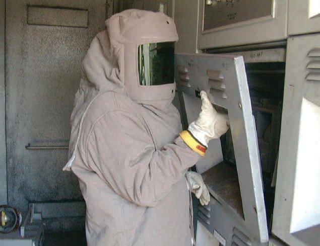

Workers often have to determine whether electrical equipment is guarded or unguarded.
NFPA 70, National Electrical Code (NEC) and NFPA 70E, Standard for Electrical Safety in the Workplace define guarded in the same manner:
Guarded. Covered, shielded, fenced, enclosed, or otherwise protected by means of suitable covers, casings, barriers, rails, screens, mats, or platforms to remove the likelihood of approach or contact by persons or objects to a point of danger.
SCENARIO NO. 1
Guarded. Why is this word important to those working in the field? What role does it play in electrical safety? To answer these questions, let’s look at a common scenario.
A motor control center (MCC) starter located in an MCC lineup is acting up, and needs testing and troubleshooting. A work order is issued; the assigned worker (a qualified person) reviews the company’s standard operating procedure and determines that an energized electrical work permit (EEWP) must be completed. The worker is encouraged to fill one out as part of the risk assessment procedure. An alternative is to use

NETAWORLD • 11 WHAT DO YOU MEAN, GUARDED? THENFPA70EANDNETA THE NFPA 70E AND NETA
a separate risk assessment form. The worker opts to complete the EEWP, but since this is a troubleshooting task, does not have it signed by management.
As part of the overall risk assessment process, a shock-risk assessment, an arc-flash risk assessment, and a personal protective equipment (PPE) analysis are completed. Boundaries for shock and arc flash are determined, and appropriate barriers are set up to prevent entry into an area that is prohibited to unqualified persons. The tools, instruments, and other items required to complete the task safely are entered in the appropriate fields of the EEWP, and a second qualified person reviews the completed EEWP.
(Important note: Review by a second qualified person is an important step to ensure nothing was missed that could cause a safety issue. Often, it is not performed in the field.)
ExecutionoftheTask Execution of the Task
The worker inspects, then puts on the necessary rubber-insulating (shock) and arc-rated PPE and clothing, in this case Category 2 arc-rated clothing with Class 00 rubber insulating gloves and leather protectors. Company policy does not mandate the use of a safety backup for this task, so none is present. Using an insulated screwdriver, the worker opens the door of the MCC, exposing the bucket, which is energized. The worker is confronted with one of two configurations: one wherethelinesideofthemaindisconnectis where the line side of the main disconnect is guarded by a plastic cover and one in which the line side is unguarded.
Whether a piece of equipment is guarded or not comes into play in various ways in this scenario. As the worker approaches the MCC, all doors are closed and properly secured, which means the equipment is guarded. Nothing can make contact with any energized conductor or circuit part. Because of this, there are no shock or arcflash boundaries because the closed door guards the energized conductors and circuit parts. If this were a piece of equipment that could be inserted or removed (racked) with the doors closed, an arcflash boundary might be imposed (depending on its design) while it is being inserted or removed. In
this case, guarded means contact cannot be made; therefore, these boundaries would not apply. But to clarify, if the worker removed the MCC bucket while energized, the arc-flash boundary would exist and would have to be enforced, unless its design is such that PPE is not required.
AssoonasthedoortotheMCCbucketis As soon as the door to the MCC bucket is opened, it is now unguarded, meaning there are exposed energized conductors or circuit parts, and all the requirements of NFPA 70E Article 130 must be met. The shock and arc-flash boundaries are now in play, and appropriate PPE must be worn. Appropriate clothing and PPE must be worn during the troubleshooting process, as the worker is now exposed to electrical hazardsandrisksassociatedwiththosehazards. hazards and risks associated with those hazards. Since the troubleshooting process usually requires the circuits to be energized, the worker is required to wear shock and arc-rated clothing and PPE during this task.
Guarded or unguarded status is also applicable when placing this equipment into an electrically safe work condition for repair activities. If the line sideofthemaincircuitbreakerorfuseddisconnect side of the main circuit breaker or fused disconnect is guarded by a plastic shield, it is guarded; once it is locked out, tagged out, tested, and verified to be electrically safe, no shock or arc-rated clothing or PPE is required to replace components or to perform repairs.

GUARDED?
WHAT DO YOU MEAN,
THENFPA70EANDNETA THE NFPA 70E AND NETA
GuardedMotorControlCenterMain Guarded Motor Control Center Main 12 • FALL 2016
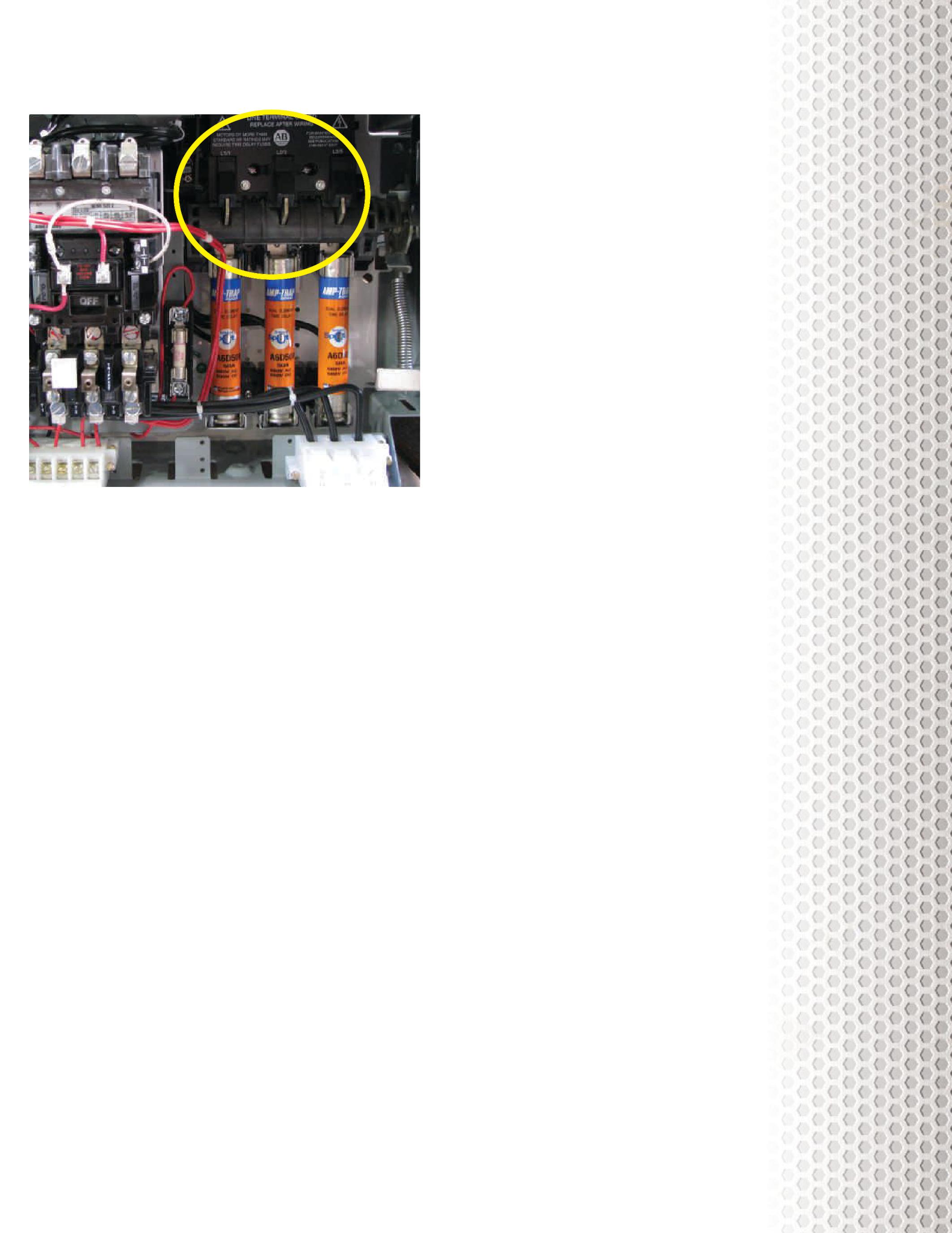
However, if the equipment is configured without the plastic shield, this is unguarded. Even though the load side is de-energized, the line side is still exposed and energized and presents a risk to the worker. There are different ways to handle this risk, but at this point, an EEWP needs to be completed and signed by management if it must be repaired while energized.
There are four options:
1) Repairs could proceed with the line side of the main exposed and energized. Shock and arc-rated clothing and PPE are required. This is the least desirable methodandistheonethatinvolvesthe method and is the one that involves the most risk. This option is only allowable if the company can show that de-energizing isnotfeasibleorcreatesadditionalor is not feasible or creates additional or increasedhazards/risks. increased hazards/risks.
2) RemovethebucketfromtheMCC. Remove the bucket from the MCC. This may be the better option since it allows for the safe testing of all the components. By removing the MCC bucket, there issomemeasureofincreasedriskwhen is some measure of increased risk when removing and inserting the bucket
because a component failure may cause another component to fail or weaken or it is caused by another component failing. The additional risks involved have to be weighed against whether the more thorough testing would be worthwhile.
3) Guard the line side using rubber insulating shielding. ThisisnotarubberThis is not a rubberinsulating blanket, which is much heavier, but is thin, light, and comes rated at 500 V. A section of this shielding can be secured aroundthelinesideofthemainand around the line side of the main and effectively guard it from contact. Shock and arc-rated clothing and PPE must be worn while it is being put into place and removed, but once it is in place, the PPE canberemoved.Thedownsideofthis can be removed. The downside of this option is increased risk while putting the guarding into place and the fact that testing individual components may not be practical. Extra care must also be exercised while the guarding is in place so it is not disturbed or removed.
4) Turnitoff. Turn it off. This requires the complete de-energization of the MCC, including the unit that needs repair. This may require scheduling during off-hours or weekends to accomplish without impacting production. It may also mean suspending production while repairs take place if proper justification cannot be produced.
The best option depends on several factors beyond this article. Your risk assessment should point to the most appropriate method and provide guidance on what measures must be taken to implement it successfully. Other than the obvious option #4 — turn it off — it is likely that options #2 or #3 are the ones to consider; however, only the person who is qualified and performing the work and the risk assessmentcanmakethatdecision. assessment can make that decision.
NETAWORLD • 13
THENFPA70EANDNETA THE NFPA 70E AND NETA WHAT DO YOU MEAN, GUARDED?
Unguarded Motor Control Center Main
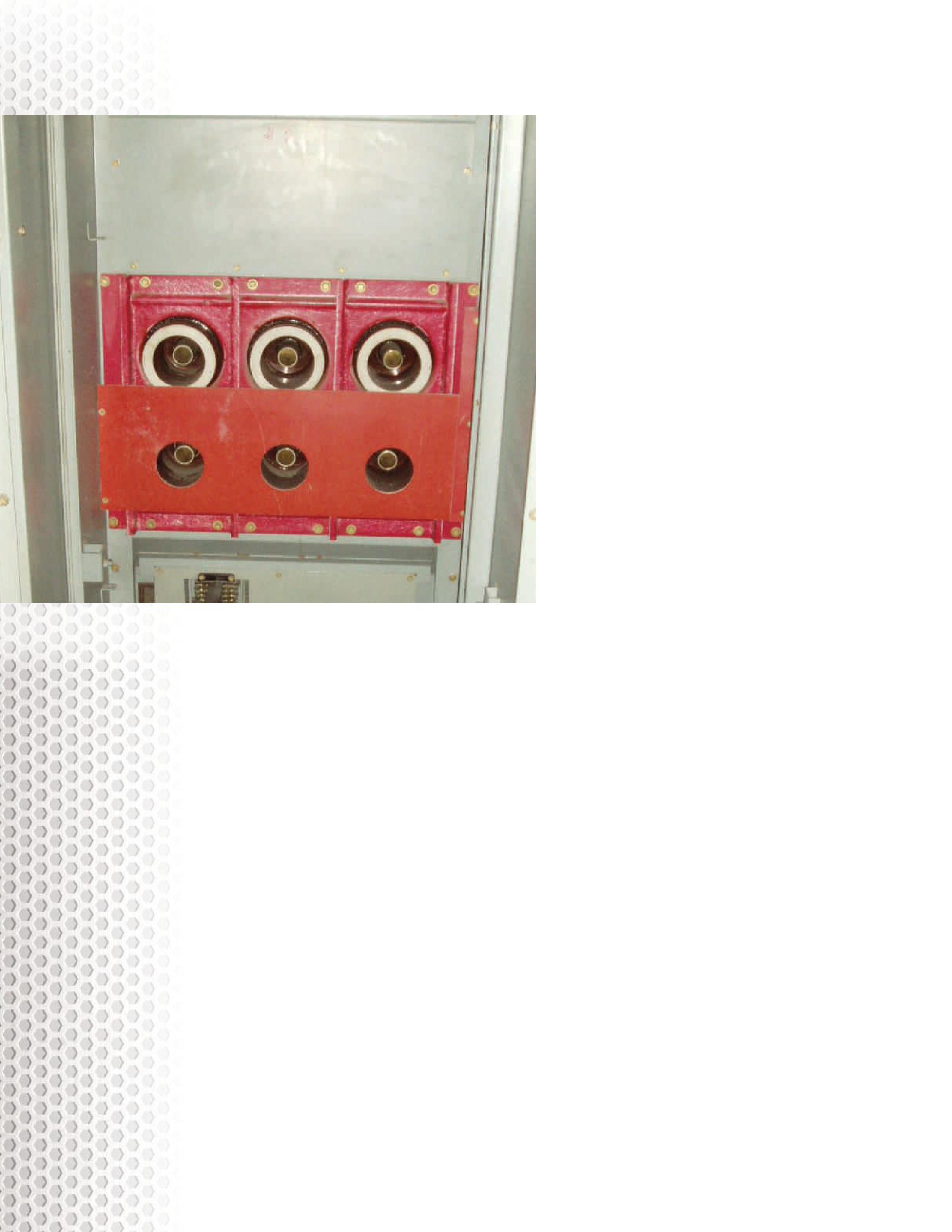
SCENARIO NO. 2
Is it really guarded? A 15 kV circuit breaker has an issue with its control circuit. It is necessary to troubleshootthecontrolcircuitonthedoor.The troubleshoot the control circuit on the door. The worker goes through the preliminary steps as outlined previously, but in addition, the circuit breaker has been racked out, and the shutter is covering the energized stabs. This scenario recently happened at Shermco, and the technicians working this job pulled a Stop Work Card. This is not really a card, but initiates a process that contacts engineering and safety supervisors for guidance.
Theconcernwaswhethertheshutterhad The concern was whether the shutter had sufficient dielectric strength to protect the otect worker.Theshortansweristhatitdoesn’tmatter. worker. The short answer is that it doesn’t matter. Many medium-voltage draw-out circuit breakers have metal shutters, and they are conductive. The circuit-breakercubiclesarebuiltsothereismore circuit-breaker cubicles are built so there is more than adequate clearance from the energized stab to the shutter, so the shutter’s dielectric strength is not an issue. The stop-work process worked;
we discussed the issue, provided training and analysis of the risks, and educated the workers on the process. What we did not want to do was impede our technicians from stepping back and questioning potentially risky situations, causing them to lose confidence in our process.
There is no wrong answer to this particular scenario. Some people would insist it is too risky, while others would say it is workable with a qualified person performing the task as long as the shutter is not disturbed. We agree with this opinion. If the circuit breaker had some other issue, such as extreme dirt or difficulty racking inorout—orsomeotherissuewherethestabs in or out — or some other issue where the stabs could potentially be exposed while energized — then we would have a different opinion. With the shutter down and the energized stabs covered, however, the system is guarded. Could there be some catastrophic failure that could cause an arc flash? It is possible, but not likely.
Situationslikethismustbeevaluatedontheirown
Situations like this must be evaluated on their own merits and under the conditions that are present at the time the task is performed, recognizing thatthecircumstancesarefluid.Conditions that the circumstances are fluid. Conditions can change rapidly and the qualified persons performing the task(s) are the only ones who can adequately evaluate the conditions where they are. There may be other factors that our engineering and safety people cannot see, so to second-guess our workers is not appropriate. However, we want to make certain they are making their decisions based on the best work practices we can provide.
SUMMARY
Knowing what guarded or unguarded means and how to apply these terms for electrical safety is important to successfully and safely completing tasks. Qualified persons often misunderstand whether equipment is safe to work on or not because they don’t understand this basic concept.
The key is that guarded conductors and circuit parts do not normally present an electrical risk becauseaworkercannotmakecontactwith because a worker cannot make contact with them. If we are interacting with the equipment in a manner that could cause failure, then guarding is not a part of the consideration. NFPA 70E provides examples, including
MEAN, GUARDED?
THENFPA70EANDNETA THE NFPA 70E AND NETA
WHAT DO YOU
14 • FALL 2016
15 kV Circuit Breaker Cell, Shutters Raised to Illustrate Clearances
racking of circuit breakers and inserting or removing MCC buckets. Operating circuit cuit breakersorswitchesisnotconsideredinthis breakers or switches is not considered in this category, as long as the equipment has been properly installed, properly maintained, and shows no evidence of impending failure.
A word of caution: Your company may require PPE to be worn when operating switches or circuit breakers. If it does, you must wear the required PPE, or disciplinary action could result. NFPA 70E provides the minimum safe work practices — not the best — so it is often necessary to exceed those requirements.
Lastly, though it may be unlikely that normaloperating equipment could fail, it certainly does. Be smart and protect yourself.
Evaluating risk and making sound decisions is a big responsibility for those of us in the electrical power business. We have to use all the resources wecantomakethosecriticaldecisions. we can to make those critical decisions.

Ron Widup and Jim White are NETA’s representatives to NFPA Technical Committee 70E (Electrical Safety Requirements for Employee Workplaces). Both gentlemen are employees of Shermco Industries in Dallas, Texas, a NETA Accredited Company. Ron Widup is CEO of Shermco and has been with the company since 1983. He is a Principal member of the Technical Committee on Electrical Safety in the Workplace (NFPA 70E) and a Principal member of the National Electrical Code (NFPA 70) Code Panel 11. He is also a member of the technical committee Recommended Practice for Electrical Equipment Maintenance (NFPA 70B), and a member of the NETA Board of Directors and Standards Review Council. Jim White is nationally recognized for technical skills and safety training in the electrical power systems industry. He is the Training Director for Shermco Industries, and has spent the last twenty years directly involved in technical skills and safety training for electrical power system technicians. Jim is a Principal member of NFPA 70B representing Shermco Industries, NETA’s alternate member of NFPA 70E, and NETA’s Principal representative to the ASTM F18 Committee Electrical Protective Equipment for Workers.
Ron Widup
Jim White
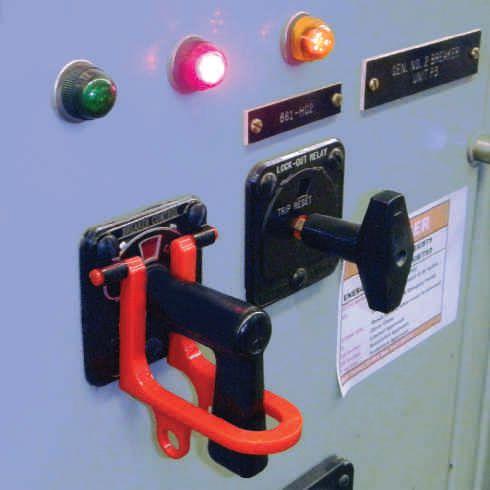
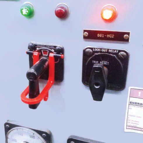

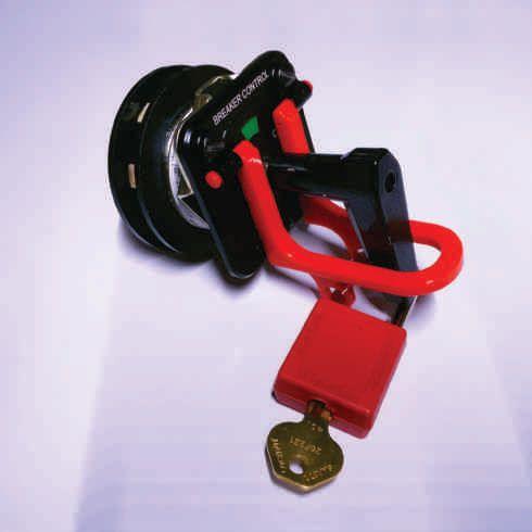





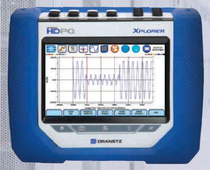


Up Your Production And Stay In The Game! PQ Analyzers with Remote Wireless Communications 732.287.3680 1000 New Durham Road Edison, New Jersey 08817 Control your Dranetz HDPQ from your smartphone, tablet, or computer! sales@dranetz.com www.dranetz.com ® ® A Company


GAUGING
 BY DON A. GENUTIS, Halco Testing Services
Fluid-filled transformers are unique compared to other electrical equipment in that basic visual inspections can often provide a wealth of condition-related information.

The fluid in a liquid-filled transformer provides several critical functions, including electrical insulation and cooling. The high dielectric strength of the fluid allows more consistent insulating capabilities compared to air and also functions as a coolant to allow heat transfer away from the windings. Cooling fins allow the warm fluid to cool and help preserve the paper winding insulation.
Fluid-filled transformers are typically equipped with three primary gauges that can provide important operating information.
1. Vacuum-pressure gauge. Large substation transformers are filled with mineral oil that typically does not have oxygen inhibitors or other additives. It therefore is more critical to maintain a positive nitrogen blanket so that oxygen does not have a chance to cause adverse effects on the oil and create corrosion of internal metallic components. A slight positive pressure is desired when inspecting the top gas-pressure gauge. The pressure can fluctuate because of temperature variations due to loading and ambient
temperature changes. A gauge that is always at zero may be an indication of a leak that can allow moisture and other contaminants to enter the transformer.
2. Oil-level gauge. This gauge only displays the 25 degrees C mark which is related to present fluid level indicated by the needle. If the present transformer temperature is not 25 degrees C, the needle will fluctuate accordingly; however, if the fluid temperature is near 25 degrees C, the needle should be near this mark. This gauge is very useful to spot low coolant levels, which can impede proper cooling functions and create transformer overheating, which can substantially reduce operating lifetime.
3. Temperature gauge. The temperature gauge provides the present oil temperature. Since fluid temperature can vary, the maximum temperature indicator (if equipped) is useful to determine how hot the transformer got since the indicator was last reset. This indication should be compared to the rating of the transformer to spot possible overheating.
18 • FALL 2016 GAUGING TRANSFORMER CONDITION
NO-OUTAGECORNER NO-OUTAGE CORNER
WINDINGTEMPERATURE GAUGE
There is another less common and slightly more complex gauge to consider when performing transformer inspections. The winding-temperature gauge is often used to control auxiliary cooling systems such as fans and pumps, which operate when a set winding temperature is reached. The winding-temperature gauge typically determines the winding temperature indirectly by measuring the top oil temperature plus the temperature produced by a small internal heater circuit in close proximity to the temperature bulb. This heater circuit is connected by a current transformer (CT) to one of the low-voltage phases. As the transformer secondary current and thus CT current increase, the heater circuit elevates the temperature of the bulb, thus simulating actual winding temperature.
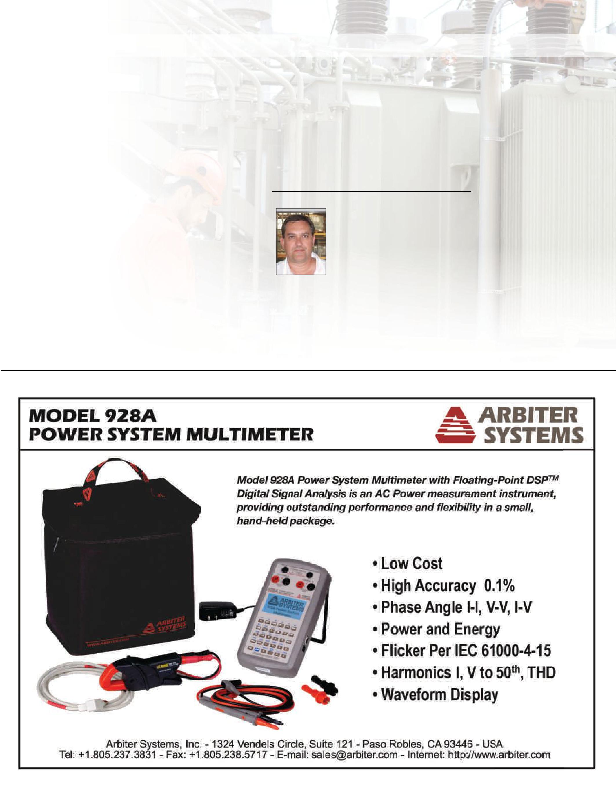
Other transformer gauges may include the bushing oil-level gauge and the conservator tank oil-level gauge.
Collectively, transformer gauges provide a simple overview of transformer operating conditions and should be considered when performing nooutage transformer inspections.
DonA.Genutis Don A. Genutis holds a Bachelor of Science degree in Electrical Engineering and has been a NETA Certified Technician for more than 15 years. He has held various principal positions during his 30-year career in the electrical testing field and has primarily focused on advancing no-outage-testing techniques for the last 15 years. Don presently serves as President of Halco Testing Services in Los Angeles, California.
NO-OUTAGECORNER NO-OUTAGE CORNER

NETA QUARTERLY ACTIVITIES – APRIL 1 THROUGH JUNE 30, 2016
International Conference of Doble Clients, April 3 – 8, 2016
Held annually in Boston, Massachusetts, the Doble International Conference is considered one of the world’s leading events for the electrical power distribution industry. NETA’s annual participation provides attendees access to electrical testing standards, training, and important industry information with the goal of supporting utility professionals and advancing electrical power system safety and reliability.
Strategy Meeting and Board of Directors Meeting, June 16 – 17, 2016
NETA held a Strategy Planning meeting and Board of Directors meeting in Annapolis, Maryland, in June. Strategy discussions focused on committee proposals for the coming year, outlining initiatives to keep NETA on track to achieve the goals established at the SWOT (Strengths, Weaknesses, Opportunities, and Threats) meeting held in May 2015.
The NETA Board of Directors reviewed the past year as well as plans for fiscal 2017. A highlight of the agenda was the welcoming of two new Board Members: Dan Hook of Western Electrical Services and Eric Beckman of National Field Services. Additionally, each Committee Chair presented plans and budgets for NETA’s many programs assuring NETA’s vision and alignment with its mission.
CBS MaxiVac’sTM new Tough DutyTM line of roll-in replacement circuit breakers replaces aging Power/Vac® breakers without any modifications to existing cells or switchgear. The Tough DutyTM breakers are tested per ANSI/IEEE certification standards, are available in all standard ratings, and include the newest encapsulated pole assemblies from Vacuum Interrupters, Inc. Encapsulated poles harden your breakers against environmental contamination, extending the life of your power distribution equipment.
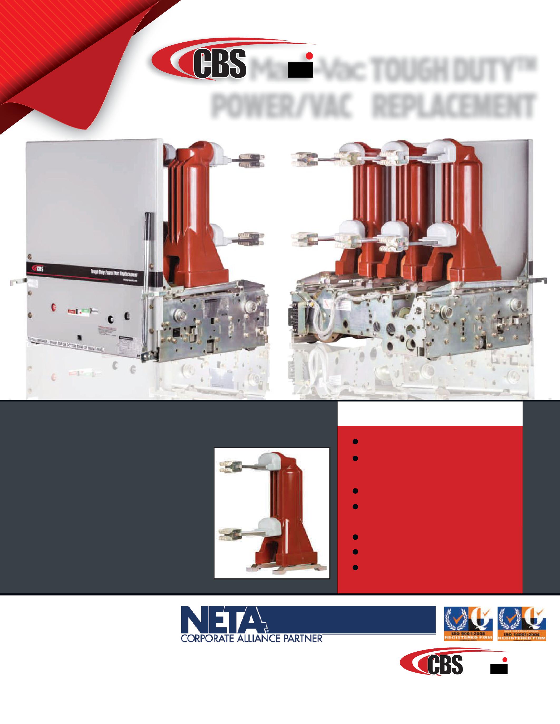
TOUGH
Direct Roll-In Replacement Meets or Exceeds ANSI/IEEE
Testing Standards
5-year, 3,000-Operation Warranty
New Rugged Encapsulated Vacuum Interrupter Pole Design
Mechanism Made In USA
Extended Warranties Available Utilizes Trusted ML-17 and ML-18 Mechanisms
TOUGH DUT Y TM POWER/VAC REPLACEMENT FOR MORE INFORMATION: Contact your local Group CBS Office or call (800) 232-5809. All third-party trademarks are the property of their respective owners CircuitBreaker.com/ToughDuty Formoreinformation,visit CircuitBreaker.com/ToughDuty Max -Vac
ADVANTAGES Tough DutyTM Power/Vac Replacement CircuitBreaker.com/ToughDuty Max -Vac ® ®
DUTYTM
James R. (Jim) White is the Training Director of Shermco Industries, Inc., in Dallas, Texas. He is the principal member on the NFPA technical committee Recommended Practice for Electrical Equipment Maintenance (NFPA 70B). Jim represents NETA as an alternate member of the NFPA Technical Committee Electrical Safety in the Workplace (NFPA 70E) and represents NETA on the ASTM F18 Committee Electrical Protective Equipment For Workers. Jim is an IEEE Senior Member and in 2011 received the IEEE/PCIC Electrical Safety Excellence award. Jim is a past Chairman (2008) of the IEEE Electrical Safety Workshop (ESW).

No.115 No. 115
ELECTRICAL RISK ASSESSMENT
BY JIM WHITE, Shermco Industries

NFPA 70E can be a useful resource for performing and understanding electrical risk assessments. This month’s quiz mostly comes from the 70E, but also requires some problem-solving on your part.
1. NFPA 70E Section 110.1(G) contains Informational Note 2 specifying three items that may be required in a risk assessment. What are they?
a. PPE, equipment, and the experience of the second person
b. Training, equipment, and certification
c. Equipment, experience, and PPE
d. Training, PPE, and certification
e. PPE, training, and experience
2. What one step could a technician in the field take to reduce the possibility of electrical accidents?
a. Test for the absence of voltage
b. Inspect the equipment carefully
c. Get the supervisor’s approval
d. Complete a safety checklist
3. Who does OSHA hold responsible for performing a risk assessment?
a. The employee
b. The site safety specialist
c. Anyone involved in the task(s)
d. The safety backup
e. The employer

4. In NFPA 70E Section 130.4, Shock Risk Assessment, if additional protective measures are required, what should be identified (mark all correct answers)?
a. The design of the electrical equipment, including its over-current protective device
b. The voltage to which personnel will be exposed
c. The minimum arc rating of protective equipment
d. Personal and other protective equipment required
e. The boundary requirements
5. NFPA 70E provides ____________.
a. Electrical and mechanical safe work practices
b. Industry-best safe work practices
c. International safe work practices
d. Exceptional safe work practices
e. Minimum safe work practices
22 • FALL 2016 TECHQUIZ TECH QUIZ See answers on page 116.


Taiwan
+886.2.2835.9738 info@phenixasia.com
Switzerland
+41.61.383.2770 info@phenixsystems.com
35+ Years Experience
ISO
Ideal


Features: Proven
High Current Circuit Breaker Test Sets
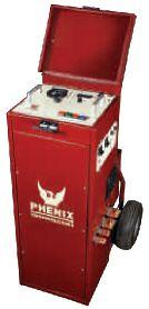

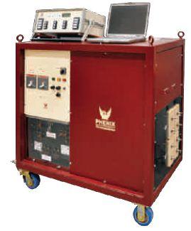
Mobile units offer: Manual or computer operation with numerous automated modes. Precise, repeatable current pulses, minimal distortion. Current wave form display with WIN HC.


9001 C E R T I F I E D
HIGH VOLTAGE - HIGH CURRENT - HIGH POWER TEST SYSTEMS and COMPONENTS 1-301-746-8118 www.PhenixTech.com info@phenixtech.com • 75 Speicher Drive, Accident, MD 21520 USA
ground fault trip devices, plus other applications requiring a high current
for field testing.
up to 75,000
for testing thermal, magnetic, and solid state relays, molded case circuit breakers and
source. Made
Models
Amps.
duty
cycle Auto-jog and current-hold capabilities.
NETA WELCOMES NEWEST
C C R E D I T E D C O M P A N Y — H A L C O
T E S T I N G S E R V I C E S
NETA, the InterNational Electrical Testing Association, is pleased to add Halco Testing Services to the community of electrical testing companies committed to meeting the ever-increasing demand for qualified testing firms and personnel.
Halco Testing Services began as a construction company with origins dating back to 1949, evolving into an organization focused solely on testing. Harold Orum formed the company in 1976 and transferred the business management to Don Genutis and Keith Orum in 2013. The company serves Southern California out of its original Los Angeles location.
Halco maintains a full staff of experienced personnel, including project managers, engineers, and technicians who promote a team concept to ensure operative, on-time completion of the work. Maintenance and acceptance testing services for low-, medium-, and high-voltage equipment includes traditional testing

services, power monitoring, power engineering studies, and no-outage testing. Typical customers include commercial high-rise office facilities, hotels, movie studios, power plants, hospitals, renewable power facilities, consulting engineers, and electrical contractors.
Halco is a NECA member, affiliated with the IBEW, and certified to perform California Title 24 lighting controls acceptance. “Halco is pleased to become a NETA Accredited organization and looks forward to being an integral part of the NETA community,” says Halco President Don Genutis. “Providing high-level acceptance and maintenance services is a vital and integral part of our success.”
ACCREDITEDCOMPANY—HALCOTESTINGSERVICES ACCREDITED COMPANY — HALCO TESTING SERVICES
• FALL 2016
24
CHOOSE BETWEEN KEEPING MAINTENANCE COSTS DOWN AND KEEPING UP WITH PRODUCTION DEMAND…OR DO BOTH. THAT’S THE CRITICAL DIFFERENCE. NETA certified experts at Electrical Reliability Services will keep you in perfect balance. To ensure the reliability of your electrical power, you have to balance the need to reduce maintenance costs with the need to perform regular maintenance. Only the team from Electrical Reliability Services delivers cost-effective services and system expertise to keep you up and running 24/7. Emerson, Business-Critical Continuity, Emerson Network Power and the Emerson and Double Helix Design are trademarks and service marks of Emerson Electric Co. ElectricalReliability.com www.BurlingtonSafety.com info@BurlingtonSafety.com Buy Online Now! Metro NY/NJ/PA 800-220-2120 Calif (SF) 888-817-1412 Calif (LA) 800-296-2803 And Your Source for NFPA 70E Compliant Protective Gear
HVI - The World’s Source for High Voltage Test Equipment
+1.518.329.3275 |
VLF & TD from High Voltage, Inc. HVI – with the newest designs available offering the most in control, communications and data reporting.
VLF-34E Solid State Design TD-34E
0 – 34 kVac peak, sinusoidal or square wave
0.5 F – 5.0 F @ 0.1 Hz – 0.01 Hz
+/- 34 kVdc, Sheath Testing, Load Burn
USB Port for data collection and removal Full Remote Control Wireless with XBee
XBee for Reliable Wireless - no Bluetooth
VLF-65E Solid State Design TD-65E
0 – 65 kVac peak, sinusoidal or square wave
1.0 F – 10.0 F @ 0.1 Hz – 0.01 Hz
+/- 65 kVdc, Sheath Testing, Load Burn
USB Port for data collection and removal Full Remote Control Wireless with XBee
XBee for Reliable Wireless - no Bluetooth
All HVI Products are Made in the USA
NEW!
<
<
HIGH VOLTAGE, INC. VLFHVOutput ToTestCable Ground ISO 9001 2008
sales@hvinc.com www.hvinc.com


this shouldn’t be the first time you think about ELECTRICAL TESTING and MAINTENANCE Routine Maintenance and Testing will help avoid unplanned outages. (855) 881-3911 www.three-c.com Serving the Northeast 40 Washington Street Westborough, MA 01581 SAFETY QUALITY VALUE Let 3C provide Peace of M ind Peace Mind 228 Merrick Road Lynbrook, NY 11563 (631) 589-6343/Fax (516) 596-3680 601 Union Street Brooklyn, NY 11215 (718) 786-4900


HAZMAT
BY JEFF JOWETT, Megger
Electrical grounding is installed primarily for safety and also for the efficient functioning of the electrical system and installed equipment. The grounding system diverts unwanted currents (fault currents) safely into the ground and away from persons and equipment to protect against potential electrocution and fire. The grounding system also mitigates noise and establishes a firm zero reference for voltage rating, thereby aiding proper and efficient functioning of electrical equipment. These core functions are well known and are commonly implemented by permanent grounding structures in the soil, from a simple rod for a residential ground to a complex and extensive grid underlying a power substation or commercial facility.
However, there are less well known but equally important protective functions of grounding. One of those is HAZMAT (hazardous materials) grounding during transportation. This includes highways and railways as well as accident situations and normal operation. Performance isn’t the issue; it’s all about safety. The grounding electrode isn’t normally a permanent part of the larger electrical system, but often a hastily installed rod in a race against time.
Tanker trucks and tank cars on railways can carry volatile and potentially dangerous materials and become involved in accidents.

HAZMAT GROUNDING TECHTIPS TECH TIPS 28 • FALL 2016
Tipped Truck with Ground
When this happens, the previously wellprotected dangerous material can become instantly exposed to potentially catastrophic consequences. One of the worst of these hazards is ignition. Volatile materials can be readily ignited to explode or catch fire. Given tank-car quantities, the ensuing conflagration can wipe out a small town. The responsibility for averting or successfully containing such potential disasters usually falls upon the local or municipal fire department.
A major culprit causing the ignition of volatile materials is static electricity. Just picture the shower of sparks flying as a metallic body goes careening down a road surface. Such violent stressinaconductivemateriallikeatanker stress in a conductive material like a tanker hull can readily cause a separation of charge. Static charge will usually dissipate on its own aselectronsflowtoreconstituteaneutralstate. as electrons flow to reconstitute a neutral state. But if the separation of charge is across an air gap, even of miniscule dimension, an arc may occur. If this happens in the presence of volatile material, the heat of the spark can start a monumental chain reaction and a devastating explosion.
Safe, non-volatile dissipation of charge can be readily accomplished by effective grounding. The quicker a good, low-resistance ground can be established, the better. A heavy-gauge grounding conductor of negligible resistance is attached to a ground rod driven into the earth withtheotherendconnectedtothehullofthe with the other end connected to the hull of the strickentanker. stricken tanker.
Firefighters and first responders are trained to move the potential spark or arc out ahead of them. They would connect the cable to the tanker first and then take it to the earth ground. This is a safety feature to protect firefighters and first responders. Once a good electron path is established, safe equalization of charge can occur through the earth.
Although soil in small quantities is not considered a good conductive material, planet Earth is a good conductor, principally because there is so much of it. The important thing is to have the ground rod make an efficient

low-resistancecontactwiththevastnessofthe low-resistance contact with the vastness of the surrounding soil. Simply driving a standard rod may provide a good ground, or it may not. The conductive quality of soil varies considerably and is profoundly affected by local conditions, everything from weather to local construction. To be thorough and rigorous, as well as to conformwithvariousauthoritiessuchas conform with various authorities such as insurance coverage and local safety codes, you may be required to test the rod.
At crash sites, time is of the essence. Even though a resistance test of the temporary ground rod may be advised or required, it may be skipped over for the sake of expediency. To actually perform the task, the obvious method of choice would be the clamp-on test. To review, a clamp-on ground tester is similar to a clamp-on ammeter; the jaws are opened and clamped around the test item, and viola — there’s the measurement. Sorry, Charley, it’s not that easy. A clamp-on ground tester has two circuits and two windings in the jaws, one for current and one for voltage. A test current is induced on the grounding system and the voltage drop measured around the circuit. Ohm’s Law performs the resistance calculation. The technique works well in utility-grounded systems where the multi-grounded neutral provides a convenient low-resistance return. But on an overturned tanker, no such circuit exists. The tester merely reads an open circuit.
HAZMAT GROUNDING TECH TIPS
C H T I P S NETAWORLD • 29
TraintankerwithGround Train tanker with Ground

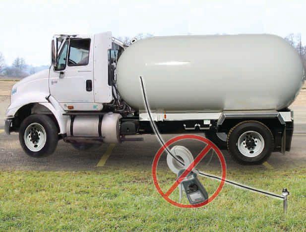
Indeed, a temporary return can be rigged by running a wire back from a metal fence post, but this is a drop-dead or better-than-nothing alternative at best. It wouldn’t fare well under intense third-party scrutiny. A more traditional method is called for: in this case, a standard three- or four-terminal ground tester. Here, in place of windings in a clamp, the voltage and potential circuits are extended out by long wires from terminals on the tester to probes driven into the ground at discrete distances.
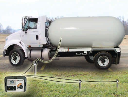
These distances are largely dependent on soil conditions and can be hundreds of feet, hardly amenable to a quick test under pressure. The full procedure, as described in IEEE Std. 81, is to graph a series of readings taken at regular intervals as the potential probe is moved toward the current probe. The graph then reveals the maximum resistance at the limits of the electrical field around the ground rod, beyond which no additional resistance is encountered. This procedure is called Fall of Potential (FOP) and is regularly described in the literature. Its limitation is obvious: time. For a permanent structure, like a building ground, it’s the method of choice. But for HAZMAT grounding, a quicker method is the order of the day.
Experienced ground testing technicians often take a shortcut around Fall of Potential by merely moving the potential probe back and forth five or 10 feet and taking two or three additional readings, as opposed to plotting and graphing the entire distance. The measurement displayed on the test instrument is the soil resistance to the point of placement of the potential probe. The three or four readings so collected may vary by a few ticks due to localized inconsistencies in the soil. They can be averaged to get an acceptable measurement. What one does not want to see are steadily rising numbers as the potential probe is moved away from the ground under test. This would indicate that the maximum resistance that defines the quality of the ground connection has not been reached. The test is being conducted within the electrical field of the test ground, not beyond it. The probes would have to be moved to greater distances and the test rerun.
As every such measurement may not be exactly the same to the last decimal, a degree of operator interpretation is involved in accepting or rejecting the result. Therein lies a possible source of error. To make such a test more objectively reliable, one can go to the Simplified Fall of Potential. The test procedure is basically the same, involving only three measurements. But instead of the operator deciding, a brief mathematical proof separates an acceptable test from a spurious one. The three readings are taken
30 • FALL 2016 TECH TIPS
HAZMAT GROUNDING TECHTIPS TECH TIPS
Traditional Fall-of-Potential Ground Test
Truck with Clamp-On Ground Tester
halfway and at 40 percent and 60 percent of the distance to the current probe. The readings are averaged, and the one that deviates most from the average is expressed as a percentage of the average. This figure is then multiplied by a correction factor of 1.2. The resulting calculation is the percentage accuracy of the average, like an accuracy statement for a meter. The same general rules apply. For example, if a calculation of 10.2 Ω calculates to a 1.5 percent accuracy, that’s good. If it calculates to greater than a 10 percent accuracy (industry standard), the test should be considered unacceptable and repeated with new probe spacing. Submitting the calculation in a test report gives the test objectivity and removes the stigma of possible operator misjudgment in the eyes of third parties.
Taking the reduction of test time one step further to its optimal single measurement brings us to the familiar 62-percent rule. Seen widely in ground-testing literature, the method consists of placing the potential probe at 62 percent of the distance to the current probe and taking a single measurement. Yes, this actually works, but it is based on ideal test conditions. The theory behind it states that a FOP graph will coincide with the probe position for the perfect measurement at 62 percent (actually 61.8 percent) of the distance to the current probe.
As a complete FOP graph covers all the points from virtually zero at the test ground to some value higher than that of the test ground, because of the superimposed resistance of the current probe, the graph must coincide at some point with the correct measurement. This point is at 62 percent. However, this isn’t a universal test procedure because it relies on ideal conditions. Among numerous factors, these include soil uniformity, underground objects, and current probe placement at a sufficient distance that its own resistance is not included. These conditions are frequently not met in practical testing, necessitating other methods. Nonetheless, the 62-percent method does have reference in IEEE Std. 81 and in many cases, will yield the correct measurement, more or less by luck. Under the time pressures that often accompany HAZMAT clearance, it may be the best choice.
The ground rod has now been verified, but the grounding conductor that runs from the tank to the rod must also be verified as providing a continuous, low-impedance path. This is relatively easy with a three- or four-terminal ground tester. It does not require an additional piece of test equipment. Modern testers have a selector switch, allowing the operator to engage the desired number of terminals for the required test. Physical jumpering of terminals is no longer required as it was in the old days; just turn the selector to the two-terminal position and run test leads from the tank to the rod. In seconds, the resistance of the grounding conductor will be displayed and should be less than one ohm. If a high reading appears, take measures to tighten the contact at both ends. Alternatively, replacement of the conductor may be necessary.

The site has now been grounded and static charges dissipated harmlessly into the soil. But the job is not finished. Dangerous materials must be offloaded into safe containers or tanks. Normally, fluids passing through hoses are considered benign, but in fact, the friction involved can again separate the charge in the hose material, and the site reverts to a dangerous condition with a risk of arcing. To guard against this,
NETAWORLD • 31 HAZMAT GROUNDING
Bonding Test Showing Selector Switch
TECH TIPS

hoses have to be electrically tested. A new piece of test equipment, an insulation tester, is now required. Fortunately, none of the requirements are demanding, and so an economical basicfunction tester may be employed. Industry standard is to perform a 500-volt test, end to end.Resistanceofthehosematerialmustbe end. Resistance of the hose material must be low enough to permit movement of charge to counter the effects of the rapidly passing fluid within, so that dangerous separation of charge doesn’t develop on the surface and build voltage to the point of arcing. Since the hoses are made of insulating material, much higher resistances are involved, and hence, the need for greater test voltage. Different materials have slightly different properties, and manufacturers should be consulted on their recommendations. Resistance must be adjusted to hose length, but
in general, an industry standard of less than 1 MΩ is recognized.
HAZMAT sites can be volatile and dangerous, but all the procedures are established and in place to render sites safe through diligent application of safe working practices.

Jeffrey R. Jowett is a Senior Applications Engineer for Megger in Valley Forge, Pennsylvania, serving the manufacturing lines of Biddle, Megger, and multi-Amp for electrical test and measurement instrumentation. He holds a BS in Biology and Chemistry from Ursinus College. He was employed for 22 years with James G. Biddle Co. which became Biddle Instruments and is now Megger.



TECHTIPS TECH TIPS
A FULL SERVICE NETA ACCREDITED ELECTRICAL TESTING COMPANY. Serving the Sacramento and San Francisco Bay Area 916-853-6280 www.apparatustesting.com • Acceptance Testing • Commissioning • Maintenance Testing • High Voltage Substations • Short Circuit and Coordination Studies • Data Centers and UPS Systems
HERE’S WHY ELECTRICAL TECHNICIANS TURN TO US FOR SOLUTIONS
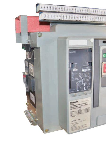

CERTIFIED TECHNICIANS
Our technicians perform to a higher standard than the industry requires to make sure you have safe and reliable electrical equipment.
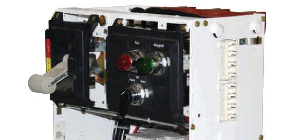
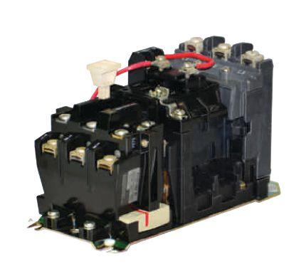
MORE TESTING OPTIONS
We lead the industry in the testing and service of Electrical Power
Distribution and include easy to read Test Reports.
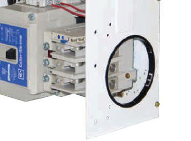
MASSIVE INVENTORY
From the 1950s to 2016 and everything in between. Our 200,000 square feet of inventory holds all the spares, replacement parts and rental options you need to stay up and running.


CUSTOMER-1ST FOCUS
Our expert staff does whatever it takes, even the seemingly impossible, to get you what you need when you need it.
COMPETITIVE PRICING
We offer the most reasonable prices on electrical equipment and service. We beat OEM prices for

S
1.800.476.1486 SOUTHLANDELECTRICAL.COM
EMERGENCY SERVICE call us for


AN INDISPENSABLE
BY PAUL CHAMBERLAIN, American Electrical Testing Co., Inc.

Protection from hazards always begins with proper prior planning. An important aid to planning a job correctly and thoroughly includes using a tool known throughout the industry as a pre-job briefing (PJB). These tools are commonly called tailgates or tailgate meetings in construction parlance, but no matter what they are called, they are designed to do the same thing: identify relevant hazards on the jobsite or during performance of a task and communicate those hazards to all persons on the job who may be affected.
Per the NFPA 70E 2015, Standard for Electrical Safety in the Workplace, Article 110.1(H) clarifies when a job briefing should be conducted:
Before starting each job, the employee in charge shall conduct a job briefing with the employees involved. The briefing shall cover such subjects as hazards associated with the job, work procedures involved, special precautions, energy source controls, PPE requirements, and the information on the energized electrical work permit, if that might affect the safety of employees occur during the course of the work.
The NFPA also includes a sample Job Briefing and Planning Checklist under Informative Annex I (Table 1). Although this specific form is not required, a similar form should be created to aid the employee in the identification and mitigation of potential hazards.
Even the Occupational Safety and Health Administration (OSHA), under 29 CFR 1910.269
– Electric Power Generation, Transmission, and Distribution Standard, specifies the requirement for a PJB.
• 1910.269(c)(1)(i): In assigning an employee or a group of employees to perform a job, the employer shall provide the employee in charge of the job with all available information that relates to the determination of existing characteristics and conditions.
• 1910.269(c)(1)(ii): The employer shall ensure that the employee in charge conducts a job briefing that meets paragraphs (c)(2), (c)(3), and (c)(4) of this section with the employees involved before they start each job.
OSHA also requires that the PJB cover “hazards associated with the job, work procedures involved, special precautions, energy-source controls, and personal protective equipment requirements.”
PRE-JOB BRIEFINGS: AN INDISPENSABLE SAFETY TOOL
SAFETYCORNER SAFETY CORNER 34 • FALL 2016
Additional PJBs may be required should the task or workplace location change significantly enough to change the hazards involved in performing the work. The more potential hazards, the more detailed the PJB should be. Additionally, more extensive PJBs may be required for inexperienced employees. The only time a PJB does not need to be conducted, per OSHA 1910.269(C)(5), is if an employee will be working alone. It states: “However, the employer shall ensure that the tasks to be performed are planned as if a briefing were required.”

OSHA’s website, under its e-tools, suggests that a checklist be used to facilitate the PJB:
Keeping a written record of job briefings is not specifically covered by the standard, but it is a best practice to do so. A written checklist can include the hazards, procedures, precautions, and PPE requirements associated with a job, as well as a column for employee signatures indicating they are knowledgeable about job hazards and safety procedures. Such documentation can help ensure that proper briefings are held at the right times (for example, beginning of a shift) and that everyone has been informed. For an example checklist, see the Job Briefing and Planning Checklist in Annex I of the National Fire Protection Association’s NFPA 70E, Standard for Electrical Safety in the Workplace, 2004Edition. 2004 Edition.
As seen in this quote, even OSHA refers back to the sample PJB in the NFPA 70E.
Table1: Table 1: Sample Job Briefing and Planning Checklist
Source:NFPA70E2015,Article110.1(H),InformativeAnnexI
Identity
❏ Hazards
❏ Voltage levels involved
❏ Skills required
❏ Any “foreign” (secondary source) voltage source
❏ Any unusual work conditions
❏ Number of people needed to do the job
Ask
❏ Can the equipment be de-energized?
Source: NFPA 70E 2015, Article 110.1(H), Informative Annex I
❏ Shock protection boundaries
❏ Available incident energy
❏ Potential for arc flash (Conduct an arc flash hazard analysis.)
❏ Arc flash boundary
❏ Is a standby person required?
❏ Are backfeeds of the circuits to be worked on possible?
Check
❏ Job plans
❏ Single-line diagrams and vendor prints
❏ Status board
❏ Information on plant and vendor resources is up to date
Know

❏ What the job is
❏ Who else needs to know — Communicate!
Think
❏ About the unexpected event... What if?
❏ Look — Tag — Test — Try
❏ Test for voltage — FIRST

PJBs come in a variety of versions and styles. They come from utilities, large manufacturers, and from individual testing companies. All of them are designed to do one thing, and they do it fairly well: They aid the task performer(s) in identifying and minimizing risks associated with the hazards of performing the task. Some PJBs focus strongly on physical hazards, others focus on task-specific procedures, and some help identify human-error traps. Since a PJB is designed to be a quick and simple-to-use tool for the task performer, it is hard to develop a

❏ Use the right tools and equipment, including PPE
Prepare for an emergency
❏ Is the standby person CPR trained?
❏ Is the required emergency equipment available? Where is it?
❏ Where is the nearest telephone?
❏ Where is the fire alarm?
❏ Is confined space rescue available?
❏ Safety procedures
❏ Vendor information
❏ Individuals are familiar with the facility

❏ Who is in charge
❏ Install and remove temporary protec tive grounding equipment
❏ Install barriers and barricades
❏ What else...?
❏ What is the exact work location?
❏ How is the equipment shut off in an emergency?
❏ Are the emergency telephone numbers known?
❏ Where is the fire extinguisher?
❏ Are radio communications available?
form that encapsulates all of those needs. The employer should be able to identify which hazards are greatest or are a more pressing need to address within the workforce, and
NETAWORLD • 35 PRE-JOB BRIEFINGS: AN INDISPENSABLE SAFETY TOOL
SAFETYCORNER SAFETY CORNER

develop a PJB adequate enough to identify those hazards.
One item of concern that should be addressed in every PJB is the need to identify the means of preventing the inadvertent or unexpected release of electrical energy. Since that is one of the greater and most prevalent hazards within the testing industry, it is also a good idea to identify how it will be controlled. Whether it is controlled via individual lock out/tag out, switching and tagging, live-line clearances, and/ or the use of grounding, it should be indicated on the PJB. Additionally, it is wise to allow the performer a space within the form to indicate lock or tag or ground locations to ensure the proper removal when the work is completed.
Addressing and indicating the limited, restricted, and arc-flash boundaries on the form is also recommended. This will make it easier for performers to advise visitors to the work location of the various approach distances. Additionally, the hazard/risk category level, PPE level category, and any additional PPE required to complete the task should be indicated on the form.
The person in charge who fills out a PJB form should review all hazards with the performer(s) of the task and give them ample opportunity to ask questions. A PJB should be a give-and-take discussion, not a dictation. The review of the PJB should be conducted with all personnel who may be affected by task performance or with anyone else whose work may impact the task. This includes contractors, subcontractors, and peripheral
workers on the jobsite. Once the review is complete, the names of all persons attending the PJB review should be noted. It may be as simple as printing each name on the PJB itself, or the PJB may have a separate signin sheet. Should the task or the job location significantly change, a new PJB or review/ amendment of the old PJB form may be necessary. Should a visitor arrive on-site, they should be immediately stopped from encroaching upon the work area, and the PJB should be discussed, apprising them of the potential hazards on the job site.
Identifying and mitigating potential job hazards is important in the prevention of possible injuries or accidents. It is up to the employer to provide an adequate means of identifying and addressing those hazards. A PJB form is required in most cases, and is an easy and effective means of identification. The employer should ensure it is adequate for the tasks the employees will be performing, and the employee should use the provided form to help prevent potential injuries. Should an employee have suggestions on improving the form, they should voice those suggestions to the employer. After all, it is the employee’s form to use.

Paul Chamberlain has been the Safety Manager for American Electrical Testing Co., Inc. since 2009. He has been in the safety field for the past 17 years, working for various companies and in various industries. He received a bachelor of science degree from Massachusetts Maritime Academy.
36 • FALL 2016 PRE-JOB BRIEFINGS: AN INDISPENSABLE SAFETY TOOL
SAFETYCORNER SAFETY CORNER






THEY’RE READY. ARE YOU? The NETA Series II Handbooks are now available. For more information on the NETA Handbooks or other NETA publications, visit the NETA bookstore at www.netaworld.org or call 888-300-6382 (NETA). $195* $ 15* For the 13 volume set For each issue *Additional cost for shipping and handling Put real-world learning at your fingertips. The NETA Handbooks house valuable resources related to electrical power systems testing and maintenance and are the perfect combination of technical and practical applications. Order Today for Special Pricing! Become a NETA Alliance Partner and save 20%!
COMMUNICATION-ASSISTED TRIPPING AND SECTION ALIZING FOR DISTRIBUTION SYSTEMS
BY STEVE TURNER, Beckwith Electric Company, Inc.
This article demonstrates how to perform high-speed, communicationassisted tripping and sectionalizing on distribution systems. All faults are quickly cleared and the distribution system is rapidly sectionalized to restore service to the most customers possible. Inherent time delays embedded in the traditional approach are eliminated.
Portions of rural electric distribution systems can operate in a network. This application is limited since the majority of rural electric distribution systems consist of long, tapped radial feeders; however, sometimes, a portion of a system can be operated as a looped network. The main advantage of a network is less chance of customer outages when a primary source is lost — a very important consideration for critical-need customers such as hospitals.
The Smart Grid era has ushered in a new age, revitalizing our distribution assets. The Smart Grid uses digital technology like high-speed communication at the enterprise level. Many rural areas still lack a Digital Subscriber Line (DSL) and cable modem services. In such cases, the least expensive type of non-dial-up connection remains a 64-kbit/s frame-relay line (Figure 1). Smart Grid could provide rural electric utilities an incentive to loop their feeders to improve service. A series of simple examples illustrates how to protect looped feeders since conventional protection such as time overcurrent relays are inadequate.
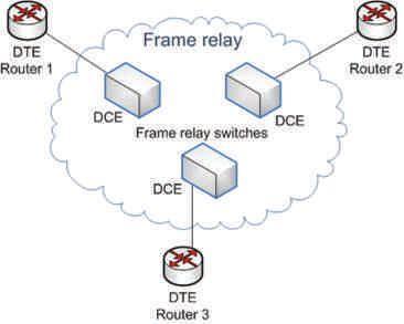
HIGH-SPEED, COMMUNICATION-ASSISTED TRIPPING (HSCAT)


Figure 2 illustrates two distribution feeders tied together by a section of feeder (length equal to d). The tie switch (S) is shown located beside the first feeder for practicality. The two substations must share a high-speed communications channel that allows the numerical line relays located at each terminaltotransmitandreceivedatafromeach terminal to transmit and receive data from each other. The HSCAT scheme logic does not need to know the state of the tie switch.

HIGH-SPEED, COMMUNICATION-ASSISTED TRIPPING AND SECTIONALIZING FOR DISTRIBUTION SYSTEMS RELAYCOLUMN RELAY COLUMN NETAWORLD • 39
Figure 1: Frame Relay Topology

Where:
R1 Recloser #1
R2 Recloser #2
L1 Feeder Relay #1
L2 Feeder Relay #2

D1 Sectionalizer #1 (motor-operated, no remote control)
D2 Sectionalizer #2 (motor-operated, no remote control)
The normal practice is to only close the tie switch when one of the reclosers is open to pick up the entire load on that feeder. HSCAT provides high-speed tripping at both ends via the communication channel for faults anywhere in between when the tie switch is closed. Highspeed tripping the two reclosers eliminates the need for coordination between the reclosers with their respective sectionalizers for the first trip. Most faults are transient in nature (> 90 percent) and should have cleared prior to the first reclose. The next section discusses how to rapidly sectionalize the system to restore service when the fault is permanent. Motor-operated sectionalizers cannot break current and only trip after sensing the fault current has cleared.
Figure 3 shows simple conceptual scheme logic for HSCAT. This is often referred to as a permissive overreaching transfer trip (POTT) scheme. Note that the voltage transformers (VTs) and current transformers (CTs) at each end must be connected such that both numerical relays can distinguish
between a feeder fault (forward) and an external fault located behind the terminal (reverse). Modern numerical feeder relays have directional elements that can determine if a fault is forward or reverse with respect to its own location.
• If a fault is between the two terminals and the tie switch is closed, then both numerical feeder relays declare a forward fault and trip their respective breakers after receiving permission from the remote end, quickly clearing the fault.
• If the tie switch is open, then one numerical line relay will not see the fault, and the feeder protection reverts back to classic coordinated time-overcurrent protection.
• If there is an out-of-section fault and the tie switch is closed, one numerical relay sees the fault as reverse and blocks tripping at both terminals. If the reclosers are fed by delta/ wye distribution transformers, then ground directional elements will not see single phaseto-ground faults on the interconnected transmission system (Figure 4).
HIGH-SPEED, COMMUNICATION-ASSISTED TRIPPING AND SECTIONALIZING FOR DISTRIBUTION SYSTEMS RELAYCOLUMN RELAY COLUMN
40 • FALL 2016
Figure 2: Single-Line Diagram for HSCAT Scheme
Figure 3: HSCAT Scheme Logic
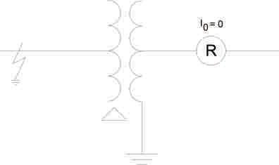
HIGH-SPEED SECTIONALIZING FOR PERMANENT FAULTS
If the fault is permanent, then it is possible to rapidly sectionalize the distribution system and quickly restore service. The tie switch must have a numerical control with access to the highspeed communications channel so that the numerical feeder relays can send remote trip and close commands.
Figure 5 shows where faults can occur on the distribution system from our first example. This section covers the number of steps and what actions must be performed to properly isolate the fault for each location. We only need to cover the odd-numbered fault locations due to the symmetry of the distribution system for this example. Note that once the tie switch is initially tripped open, the recloser and sectionalizer on the faulted segment rely upon traditional coordination to trip during the second step.
Fault Location F1
Step 1. Trip both reclosers R1 and R2 via HSCAT scheme.
Step 2. Trip the tie switch S.
Step 3. High-speed reclose reclosers R1 and R2.
Step 4. Trip and lockout recloser R1.
Fault Location F3
Step 1. Trip both reclosers R1 and R2 via HSCAT scheme.
Step 2. Trip the tie switch S.
Step 3. High-speed reclose reclosers R1 and R2 (first shot).
Step 4. Trip recloser R1.
Step 4. Trip and lockout sectionalizer D1.
Step 5. Reclose recloser R1 (second shot).
Fault Location F5
The fault appears as external to the HSCAT scheme since the fault is reversed with respect to the numerical line relay at Substation No. 1 and forward with respect to the numerical feeder relay at Substation No. 2. The transformer differential protection can trip and lockout recloser R1 if the CTs are connected as shown in Figure 6.
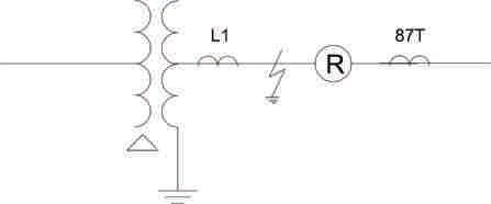

HIGH-SPEED, COMMUNICATION-ASSISTED TRIPPING AND SECTIONALIZING FOR DISTRIBUTION SYSTEMS NETAWORLD • 41 RELAYCOLUMN RELAY COLUMN
Figure 4: Ground Faults on Transmission System
Figure 6: CT Locations for Bus Faults
Figure 5: Fault Locations
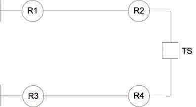
Figure 7: Looped Distribution System
COMPLEX DISTRIBUTION SYSTEM
The distribution systems considered so far are very simple to help present the main concepts. Figure 7 represents a more complex looped distribution system. We shall now analyze how to apply the HSCAT scheme logic for this system.
Reclosers R1 and R3 are located at the two substations, while reclosers R2 and R4 are out in the system. TS is the normally closed tie switch. All of these devices must share the same highspeed communications channel that allows the numerical line relays located at each terminal (including the tie switch) to transmit and receive data from each other. Assume that the forward direction for reclosers R1 and R3 is looking out into the system, while reclosers R2 and R4 are looking back toward their respective substations.
First Case — F1
Figure 8 illustrates a fault located between reclosers R1 and R2.
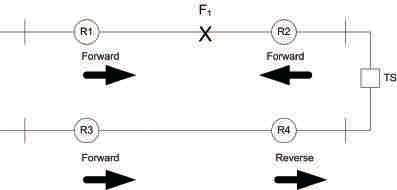
8:
Second Case — F2
Figure 9 illustrates a fault located between reclosers R3 and R4.
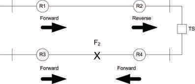
9: Fault Between
Third Case — F3
R3 and R4
Figure 10 illustrates a fault located between reclosers R2 and R4.
10:
Fourth Case — F4
Figure 11 illustrates a fault located behind R1.
11: Fault Behind
Fifth Case — F5
Figure 12 illustrates a fault located behind R3.
Figure 12: Fault Behind Recloser R3
HIGH-SPEED, COMMUNICATION-ASSISTED TRIPPING AND SECTIONALIZING FOR DISTRIBUTION SYSTEMS 42 • FALL 2016 RELAYCOLUMN RELAY COLUMN
Figure
Fault Between Reclosers R1 and R2
Figure
Reclosers
Figure
Fault Between Reclosers R2 and R4
Figure
Recloser R1
Table 1 shows the directional decisions made by the numerical feeder relays for each fault location.
Table 1: Relay Directional Decisions
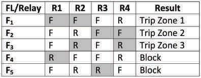
Figure 13 shows how to apply HSCAT to protect the looped system:
• The numerical feeder relays at R1 and R2 provide the first zone of protection for the feeder between them, i.e., forward-looking directional elements.
• The numerical feeder relays at R3 and R4 provide the second zone of protection for the feeder between them, i.e., forward-looking directional elements.
• The numerical relays at R2 and R3 provide the final zone of protection for the feeder between them, i.e., reverse-looking directional elements.
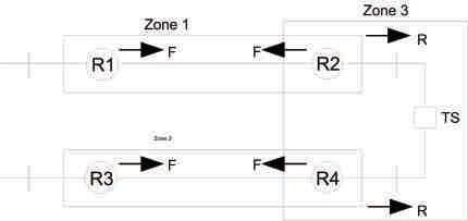
HIGH-SPEED SECTIONALIZING FOR PERMANENT FAULTS
Figure 14 is the same looped system shown in Figure 6 with sectionalizers included to better represent an actual system, and it shows all of the internal fault locations. If the fault is permanent, then it is possible to rapidly sectionalize the distribution system and quickly restore service. The tie switch must have a numerical control with access to the high-speed communications channel so that the numerical feeder relays can send remote trip and close commands. Assume that the sectionalizers are motor-operated and provide remote fault indication. This section covers the number of steps and what actions must be performed to properly isolate the fault for each location. For this example, only the oddnumbered fault locations need to be covered due to the symmetry of the distribution system.
Fault Location F1
Step 1. Trip both reclosers R1 and R2 via HSCAT scheme (no fault indication from D1).
Step 2. High-speed reclose reclosers R1 and R2.
Step 3. Trip and lockout reclosers R1 and R2.
Fault Location F3
Step 1. Trip both reclosers R1 and R2 via HSCAT scheme (fault indication from D1).
Step 2. High-speed reclose reclosers R1 (first shot).
Step 3. Trip recloser R1.
Step 4. Trip and lockout sectionalizer D1.
Step 5. Reclose recloser R1 (second shot).
Fault Location F5
Therefore, the minimum requirements for pointto-point communications are:
•R1 to R2 (if necessary, R1 can transfer trip TS via R2)
•R3 to R4 (if necessary, R3 can transfer trip TS via R4)
• R2 to TS
• R3 to TS
Step 1. Trip both reclosers R2 and R4 via HSCAT scheme (fault indication from D2).
Step 2. Trip open tie switch S.
Step 2. High-speed reclose reclosers R2 and R4 (first shot).
Step 3. Trip recloser R2.
Step 4. Trip and lockout sectionalizer D2.
Step 5. Reclose recloser R2 (second shot).
NETAWORLD • 43 HIGH-SPEED, COMMUNICATION-ASSISTED TRIPPING AND SECTIONALIZING FOR DISTRIBUTION SYSTEMS
RELAYCOLUMN RELAY COLUMN
Figure 13: Overlapping Zones of Protection

Fault Location F7
Step 1. Trip both reclosers R2 and R4 via HSCAT scheme (no fault indication from D2 or D4).
Step 2. Trip open tie switch S.
Step 3. High-speed reclose reclosers R2 and R4 (first shot).
Step 4. Trip and lockout recloser R2.
SPECIAL CONSIDERATIONS
There are special conditions associated with operating a looped distribution system, including ground sources, single-pole tripping, and directional element-polarizing quantities.
Ground Sources. Three-phase transformers out in the system that have a star-connected winding facing the distribution system can provide a ground path and back feed external faults tripped at one end of a looped feeder. The numerical feeder relay located at R1 in Figure 15 should identify the ground fault as external due to its directional elements.

Single-Pole Tripping. Single-pole tripping on distribution feeders has become popular in areas like Florida since many loads are single phase (residential). Tripping only the faulted phase during a single line-to-ground fault prevents interruption of service to single-phase load connected to the unfaulted phases (Figure 16).
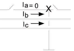
Negative-sequence and zero-sequence currents flow through the unfaulted phases during the dead time following a single-pole trip prior to reclosing.
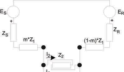
17: Symmetrical Component Diagram for Single-Pole Open
44 • FALL 2016 HIGH-SPEED, COMMUNICATION-ASSISTED TRIPPING AND SECTIONALIZING FOR DISTRIBUTION SYSTEMS
Figure 14: Looped Distribution System with Sectionalizers
Figure 15: Back-Fed Ground Fault
Figure 16: A-Phase Tripped Open
RELAYCOLUMN RELAY COLUMN
Figure
Figure 17 is a symmetrical component diagram for single-pole open on a looped distribution feeder. The unbalanced current flows through the parallel combination of the negativesequence and zero-sequence system impedances at the point where the open pole exists.
ES Equivalent Source at Substation S
ER Equivalent Source at Substation R
ZS Equivalent Source Impedance at Substation S
ZR Equivalent Source Impedance at Substation R
M distance to open pole from Substation S
Z1 Positive-Sequence Feeder Impedance
Z2 Negative-Sequence System Impedance
Z0 Zero-Sequence System Impedance
I2 Negative-Sequence Current
I0 Negative-Sequence Current
This condition can cause false operation of directional elements that are polarized by negativesequence or zero-sequence quantities. Analysis is required to determine if the directional elements will work properly during the open pole and what actions, if any, must be taken to prevent misoperations from occurring.
DIRECTIONAL ELEMENT
POLARIZING QUANTITIES
The choice of polarizing quantities is important to ensure reliability and security of the highspeed, communication-assisted tripping scheme. Generally, negative-sequence is chosen for unbalanced faults, while positive-sequence is required for three-phase balanced faults. Exercise caution during the selection of the polarizing quantity for unbalanced faults when single-pole tripping is enabled. Due to the open pole, negative-sequence and zero-sequence current actually flow backwards. Figure 18 shows the directional decision for a negativesequence, voltage-polarized directional element during a forward fault. If I2 is lagging –V2 by 90 degrees, then the fault is declared forward.
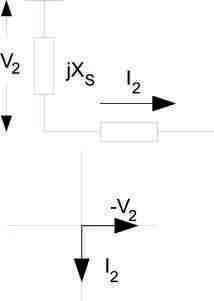
Figure 18: Negative-Sequence, VoltagePolarized Directional Decision for Forward Fault (CCW Rotation)
Fault
The phase of the negative-sequence voltage is inverted for a reverse fault. So, for the case of reverse flow of the negative-sequence current during an open pole, a negative-sequence, voltage-polarized directional element can still correctly determine the actual direction of the open pole with respect to the relay terminal (Figure 19). However, directional elements that operate on impedance calculations can misoperate if not set properly.
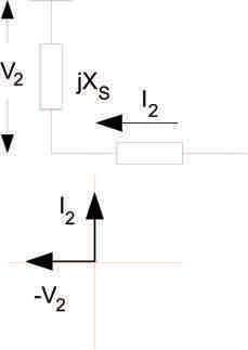
Figure 19: Negative-Sequence, Voltage-Polarized Directional Decision for Reverse Fault (CCW Rotation)
NETAWORLD • 45 HIGH-SPEED, COMMUNICATION-ASSISTED TRIPPING AND SECTIONALIZING FOR DISTRIBUTION SYSTEMS
Forward
V2 = -jXS•I2 I2 = -j|I2| V2 = -XS•|I2|
RELAY COLUMN

If the distribution system is radial following the first trip, then directional elements can be disabled to prevent misoperations and rely upon traditional coordination.
CONCLUSIONS
In performing high-speed, communication-assisted tripping and sectionalizing on distribution systems, all faults are quickly cleared. The distribution system is rapidly sectionalized to restore service to the most customers possible. Inherent time delays embedded in the traditional approach are eliminated.

Steve Turner, an IEEE Senior Member, is a Senior Applications Engineer at Beckwith Electric Company. His previous experience includes work as an application engineer with GEC Alstom and as an application engineer in the international market for SEL, focusing on transmission line-protection applications. Steve worked for Duke Energy (formerly Progress Energy), where he developed a patent for double-ended fault location on overhead transmission lines. He has a BSEE and MSEE from Virginia Tech. Steve has presented at numerous conferences, including Georgia Tech Protective Relay Conference, Western Protective Relay Conference, Energy Council of the Northeast, and Doble User Groups, as well as various international conferences.


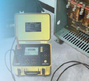



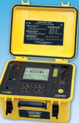


RELAYCOLUMN RELAY COLUMN AEMC® has Expert Tools for Testing Insulation Safely & Accurately! Chauvin Arnoux®, Inc. d.b.a. AEMC® Instruments 200 Foxborough Blvd., Foxborough, MA 02035 USA Phone: (800) 343-1391 • Fax: (508) 698-2118 www.aemc.com • Voltage testing: 500, 1000, 2500, 5000, 10,000 & 15,000 • Variable voltage testing • Ramp voltage testing • Step voltage testing • Resistance measurement range: 10k to 30T • Selectable test current modes • Test current: up to 5mA short circuit current • Ratio calculations: DAR, PI and DD 15kV Digital Megohmmeter Model 6555 IP Rated 53




EARLY BIRD REGISTRATION ANAHEIM • CALIFORNIA February 27 - March 3 • 2017 DISNEYLAND HOTEL POWERTEST.ORG 888.300.6382 THE PREMIER ELECTRICAL MAINTENANCE & SAFETY EVENT Save $100 September 1 through December 31, 2016 HIGH-POWER SEMINARS • NETWORKING WITH INDUSTRY LEADERS OPEN NOW! REGISTER TODAY!
ELECTRICAL TESTING AND MAINTENANCE CORPORATION
NETA, the InterNational Electrical Testing Association, is proud to add Electrical Testing and Maintenance Corporation to the community of electrical testing companies committed to meeting the ever-increasing demand for qualified testing firms and personnel.
Founded in 1994, Electrical Testing and Maintenance Corporation serves the Mid-South region of the United States, which includes Tennessee, Mississippi, and Arkansas, as well as parts of Missouri, Kentucky, Louisiana, and Alabama. Electrical Testing and Maintenance's goal is to provide customers with state-ofthe-art, value-added power system services necessary to ensure the reliable, safe, and efficient operation of a facility
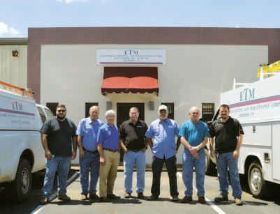

and its related electrical components. ETM offers the Mid-South area the most up-to-date services for repair, maintenance, and inspection of electrical apparatus for utility, industrial, and commercial customers.
Ron Gregory, President and NETA Accredited Representative for ETM, is proud to be part of NETA. “We have been looking forward to joining NETA for a long time. We’ve admired the organization over the years, and now, as a NETA Accredited Company, ETMcanofferbenefitsandservicestoourcustomers ETM can offer benefits and services to our customers wewouldnothavebeenabletoofferbefore.Welook we would not have been able to offer before. We look forward to an exciting year!”
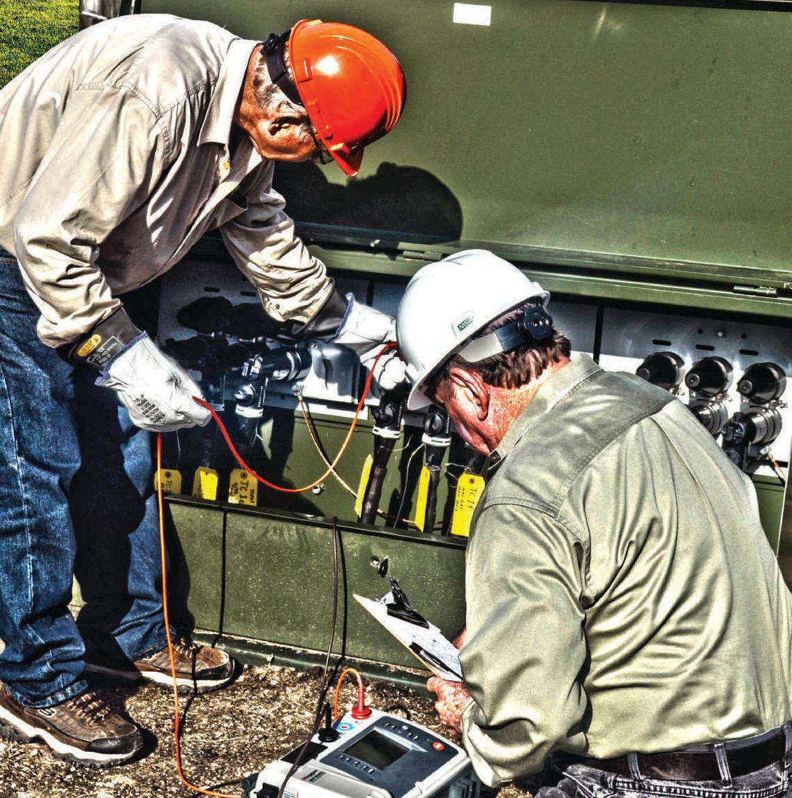


After years of careful planning, design and construction, AVO’s Cable U is here. Designed to accommodate our new Medium-Voltage Cable Fault Location & Tracing and Cable Testing & Diagnostics courses, It allows cable technicians the most technologically advanced “real world” place for every electrical cable testing and diagnostic application. The study of cable just got a lot smarter. WWW.AVOTRAINING.COM 877-594-3156 Introducing AVO’s Cable U. U CABLE AVO Many AVO training courses are eligible for NETA ctd’s.* A one of a kind cable field for the most complete cable testing and diagnostic study found anywhere.


UNDERSTANDING AND MAINTAINING CRITICAL SERVICE EQUIPMENT
BY JOHN WEBER, The Hartford Steam Boiler Inspection and Insurance Company

All institutions and businesses strive to maintain a reliable and consistent level of service to their customers. Many also establish disaster and recovery plans for unexpected natural disasters or other crisis situations. An often overlooked but foreseeable disaster is the failure of the main electrical service switch for the facility.
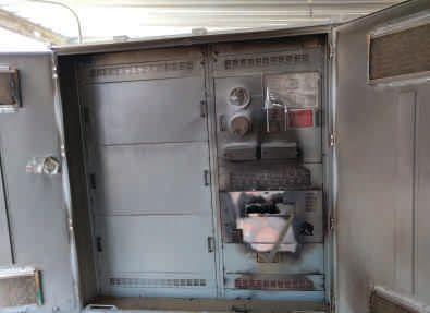

The main switch of a facility can fail catastrophically if the manufacturer’s required maintenance is ignored.
Extended loss of electrical power to a facility due to catastrophic equipment failure usually disrupts all business function and creates many unexpected and unplanned expenses. Most service equipment failures are preventable by following manufacturers’maintenancerecommendationsor manufacturers’ maintenance recommendations or
requirements for the installed service equipment. Electrical equipment failures should be included in the disaster plan, and the process begins with conducting an electrical equipment failure risk assessment.
When performing an electrical equipment failure risk assessment for a facility, one of the most important considerations is the reliability of the service equipment. The National Electrical Code, NFPA 70-2014 Article 100 Definitions defines service equipment as:
The necessary equipment, usually consisting of a circuit breaker(s) or switch(es) and fuse(s) and their accessories, connected to the load end of the service conductors to a building or other structure, or an otherwise designated area, and intended to constitute the main control and cutoff of the supply.
When the service equipment fails to perform as intended or fails catastrophically, a complete shutdown of all business activities occurs. A catastrophic failure usually results in expediting standby generators to the site and the use of many electricians working around the clock to re-establish power to the facility. Damage to the service equipment makes it very difficult to connect a standby generator at a single termination point. Sometimes the feeder sections need to be subdivided or isolated from the busbars for the standby generator connections.
FEATURE UNDERSTANDING AND MAINTAINING CRITICAL SERVICE EQUIPMENT 50 • FALL 2016
Recovering from service equipment failures typically includes costs for generator rental and fuel oil, generator power cable rental, overtime electrical trade labor, additional security guard coverage, and equipment transportation. The analysis shown in Figure 1 highlights the total cost associated with standby generator requirements. When long-term outages are expected, temporary transformers or rerouted service conductors may be more cost effective than running generators. Keep in mind that all of these costs are only for the temporary emergency re-establishment of power.

Additional time and expense is expended working with designers and electrical contractors to determine the extent of the damages and solutions for permanent equipment replacement. Catastrophic service equipment failures are often accompanied by electrical equipment meltdown, fire, smoke, and water damage. Depending on the degree of equipment failure, major NEC-code upgrades may be required for the equipment room and electrical equipment before it can pass current electrical and building code requirements.


NETAWORLD • 51 UNDERSTANDING AND MAINTAINING CRITICAL SERVICE EQUIPMENT FEATURE
Figure 1: Standby generator rental cost is a fraction of the total cost associated with the use of a temporary generator installation.


Required code upgrades can create additional unexpected expenses. Depending on new or used equipment availability, final electrical and building repairs can take weeks or months.Inadditiontoallof months. In addition to all of the costs for temporary and permanent electrical repairs, the occupants typically suffer a major business interruption. Many key personnel are diverted to expediting activities and emergency resolutions of the currentbusinesscrisis.Who current business crisis. Who is left to manage the day-today business, and how many customers’ needs are not being met because of this unexpected and untimely electrical failure?

The proactive review and execution of main switch maintenance requirements can help prevent switch failures, power outages, and costly business interruptions.
Knowing that all of these costs typically follow an unexpected service equipment failure, the best solution is to avoid the failure in the first place. This requires that the owner is aware of the type of installed electrical equipment and the maintenance requirements specified by the equipment manufacturers. As with any type of service equipment, if the manufacturers’ maintenance requirements are ignored, the consequences can devastate a business and resultinunrecoverablebusinesslossesand result in unrecoverable business losses and crushing financial burdens.

One common type of service equipment switch used by a wide range of facilities is the bolted pressure switch. By evaluating the results of a catastrophic bolted pressure switch failure, the importance of proper service equipment maintenancebecomesevident. maintenance becomes evident.
No business owner wants to respond to an emergency call at their facility to find a bolted pressure switch failure. The bolted pressure switch failure shown in this photo occurred catastrophically with all of the consequences described previously.

What caused this to happen? How could ignoring required maintenance on this switch result in such total destruction of the switchgear? What could have been done to prevent this catastrophe?
After a service equipment failure of this magnitude, owners, contractors, engineers, and facilities managers quickly assemble to try to understand how this could have happened. The discussions usually include questions such as:
• Was an electrical risk assessment ever conducted for the site?
• Were electrical experts included in the risk assessment process?
• Was there an awareness that the electrical equipment required periodic maintenance?
• Was any preventive maintenance ever performed on the service equipment?
• Was it known that a bolted pressure switch was installed on the premises?
• Were the manufacturer’s service requirements and frequencies known?
• Were qualified electrical personnel employed at the facility to evaluate and design
FEATURE 52 • FALL 2016 UNDERSTANDING AND MAINTAINING CRITICAL SERVICE EQUIPMENT
a comprehensive electrical preventive maintenance program?
• Was there an awareness of the potentially catastrophic consequences of not performing the manufacturer’s maintenance recommendations?
Knowing that service equipment failures typically follow this response pattern, what can be learned in the interest of prevention? After a disaster has occurred, there is always great interest in what can be done to prevent a recurrence. The real benefit of this discussion is to forewarn owners and facilities managers to proactively consider all of the above questions before a catastrophic service switch failure occurs.
As an example, bolted pressure switch manufacturers typically require annual inspection and lubrication of the conductive blade parts and the operating mechanism. Depending on the presence of adverse environmental conditions, such as excessive temperatures or dirty or wet conditions, more frequent inspection and maintenance may be required. If a bolted pressure switch is involved in an event where fuses have blown or if it has interrupted a ground fault, a complete switch inspection should be performed. One manufacturer states that, after a switch has interrupted a fault, switch design standards indicate that an unserviced switch is not suitable for reuse. After a fault opening, contaminated lubrication may need to be removed. Pitting, splatter and weld marks may need to be addressed. In addition, arc quenchers and barriers may need inspection and repairs. Contamination from the fault may prevent proper future operation of the opening and closing mechanisms. Each manufacturer provides additional details for the type of lubricants to use for the cleaning and re-lubrication process to follow. Even though a riveted nameplate was installed with large font size and bold lettering to stress the requirement of annual lubrication, the proper maintenance was not performed. Note that the instructions use the word required versus recommended.
Many facilities use bolted pressure switches as the main service equipment for the facility. Annual inspections and servicing of these

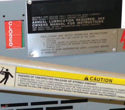
Annual lubrication is stressed by the manufacturer on this nameplate. Many owners and facility managers believe that the main switch is “maintenance-free.”

switches requires planned shutdowns. NFPA 70E, Standard for Electrical Safety in the Workplace requires electrical equipment to be de-energized, locked out, and tagged out before performing electrical work. NFPA 70E also requires personal protective equipment (PPE) for electrical workers. The frequent requirement for annual maintenance on a bolted pressure switch often conflicts with the typical needs of most businesses trying to maintain continual uptime for 24/7 productivity reasons.
Options exist to replace existing bolted pressure switcheswithacircuitbreaker.Thiscanbe switches with a circuit breaker. This can be accomplished without purchasing all new switchgear enclosures. The benefit of the retrofit is that, under normal operating conditions, many new circuit breakers allow for significantly longer maintenance intervals. The differences inthevulnerabilitiesofthemechanical in the vulnerabilities of the mechanical operating mechanisms account for the extended maintenance-interval requirements. This can be a good option when it is impractical or logistically complicated to perform frequent annual maintenance on bolted pressure switch service equipment. Not performing the required maintenance on a bolted pressure switch should never be an option.


FEATURE NETAWORLD • 53 UNDERSTANDING AND MAINTAINING CRITICAL SERVICE EQUIPMENT

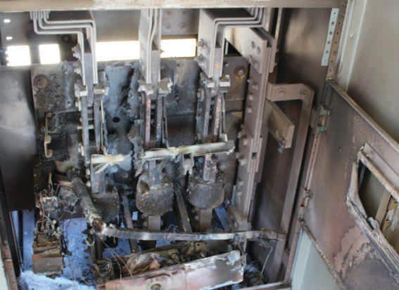
Thisbarshouldbeverticalandnotat45°
Lack of proper maintenance prevented this switch from closing and clamping completely.

Bolted pressure switches typically have two movable blades per phase. When the switch blades rotate vertically to the closed positon, the two movable blades straddle the upper stationary contacts. With continuous motion, the three pairs of movable blades are clamped tightly at the stationary contacts and at the lower hinge points of the switch blades. The clamping action is usually achieved by rotating a screw that is linked to the switch-closing mechanism.
The insulated crossbar picture shown here indicates that the crossbar arm did not complete its stroke. The bar is at a 45-degree angle. It should be in the vertical position when fully closed and clamped. If the required maintenance is not performed, an event like the one seen in this photo can occur.
In this case, the switch mechanism did not complete its full stroke to close the blades and clamp them properly. As a result, the switch operated with high contact resistance at all six of the unclamped switch blade locations. High amperage on the main switch caused excessive heat to occur on the blades. This became a worsening condition with increased heating and increased resistance over time. The loose, overheated connections began arcing. Typically, arcing in a nominal 480-volt switch will result
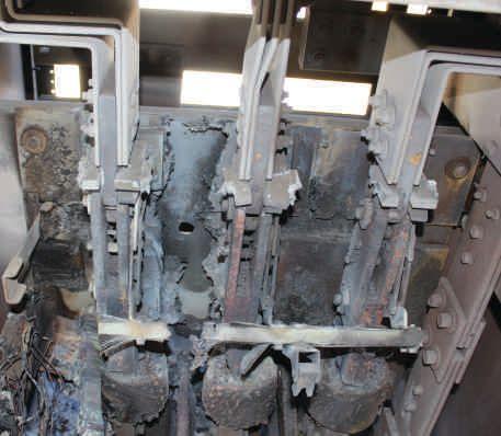
The six un-clamped switch joints operated with high contact resistance. Excessive heat and arcing destroyed this bolted pressure switch.
in phase-to-ground and phase-to-phase arcing faults. Arcing faults can destroy the switchgear enclosures and the internal switchgear components. The arcing burned a hole through the thick metal mounting plate for this switch. Many owners may not be aware of the arcing fault phenomenon and the degree of equipment destruction associated with arcing faults.
Once established, arc faults tend to travel in a direction moving away from the source. This is caused by the magnetic forces acting between the arc itself and the magnetic flux produced in the busbars. This effect is similar to the electromagnetic forces that cause a motor shaft to rotate. The arc will travel at varying speeds depending on the fault current developed. When the fault currents are over 5,000 amperes, the fault can produce a gunblast noise. An arcing fault will do the most damage at locations where the arc is physically restrained from traveling due to barriers. In the pair of photos shown here, the insulated fuse sleeves restrained the physical travel of the arc. The intense heat of the arc burned away the thick, switch mechanism crossbar and the insulated switch-mounting panel.
The devastating effects of not performing the required maintenance on bolted pressure
FEATURE 54 • FALL 2016
UNDERSTANDING AND MAINTAINING CRITICAL SERVICE EQUIPMENT
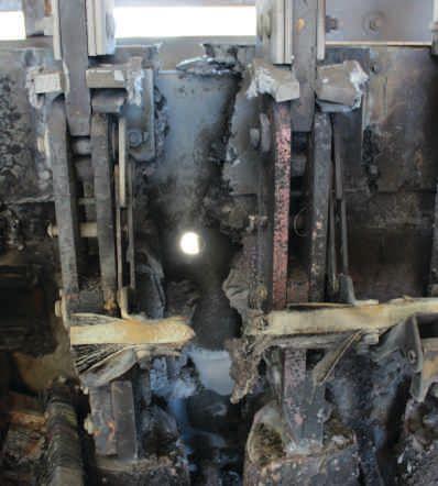
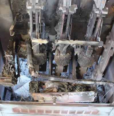
The GFPE current transformer melted and fell from its mounting bracket. The mounting bracket can be seen on the left side above the CT.
switches are evident in the top photo.
All three of the main fuses are damaged. The ground fault protection of equipment (GFPE) system is destroyed. The yellow arrow shows the melted and dislodged ground fault current transformer that surrounds all four of the phase and neutral busbars. The GFPE relay is melted beyond recognition. Conductor insulation is damaged. The smoke and combustion products
produced in the enclosure have contaminated the entire enclosure.
HOW TO MAKE A POSITIVE CHANGE
It is important to realize that many building owners are not aware of the type of service equipment installed in their facility. In many cases, an owner assumes that a service switch does not require any maintenance. It is understandable that this idea would exist in the owner’s mind. Compare the bolted pressure switch annual maintenance requirements to the extended maintenance interval requirements for the circuit breaker installation.
How does the building owner know which one is installed in his facility? Who in the organization is qualified to inspect, identify, and implement the proper preventive maintenance routines for the installed equipment? Although the technical documents for the service equipment and the maintenance requirements probably exist somewhere in an archived file drawer, who is technically qualified to read them and create a maintenance and disaster prevention plan?
In this regard, a positive change and a reduction in catastrophic service equipment failures can be achieved when:
•Electrical design engineers consider the maintenance requirements of service equipment when evaluating and specifying equipment suitable for the customer’s actual use. Are the future maintenance requirements ever considered in the electrical equipment selection process? For example, if a building is designed for 24/7 intense manufacturing processes, should a service switch requiring annual maintenance or one requiring extended maintenance intervals be selected? Is it realistic to think that 24/7 types of use could accommodate frequent annual service intervals? Will the intense pressures for productivity always overrule the shutdown requirements for maintenance?
• Electrical contractors proactively notify customers where known service equipment


FEATURE NETAWORLD • 55 UNDERSTANDING AND MAINTAINING CRITICAL SERVICE EQUIPMENT
MeltedGFPE current transformer
The downward traveling arc burned through the insulated crossbar and burned the tops of the fuses.
is not receiving the proper maintenance required by the manufacturer. In many cases, the owner and his employees are not technically qualified to make this assessment. If facility operations and schedules cannot accommodate annual shutdowns, then appropriate extended maintenance interval equipment options could be suggested. This would avoid the continued operation of an unmaintained bolted pressure switch.
• NETA Accredited electrical companies continueaconcertedefforttoeducate continue a concerted effort to educate owners. Owners and facility managers must beinformedoftherisksassociatedwith be informed of the risks associated with not following manufacturers’ maintenance recommendations for bolted pressure switches and other critical electrical equipment.
Owners and facility managers should receive additional resources, such as this article, to explain the destruction of equipment that can occur when a relatively small internal malfunction of a switch mechanism develops into an arcing-fault switchgear meltdown and business interruption disaster.
John Weber is Principal Electrical Engineer for The Hartford Steam Boiler Inspection and Insurance Company. He has over 30 years of experience in facilities/electrical engineering and management roles. John has a Bachelor’s Degree in Electrical Engineering and has a strong background in electrical engineering, HVAC, energy management, building automation controls, and National Electrical Code compliance.

Results to Our Customers.
AET delivers the best value in at competitive prices. With a an industry leader and one of the
The Power of Positive Results
To learn more about AET’s full range of testing and engineering services, visit www.aetco.us • 800.992.3826
FEATURE
A Nationwide Service Provider
An Company
Delivering Powerful Reliability Solutions
Power System Acceptance Testing
Commissioning and Start-up
Maintenance
Life-Cycle Extension
Troubleshoot and Repair
Training and Engineering Services
Planning and Operations Support
Project Management
Sigma Six Solutions, Inc.
2200 West Valley Hwy North, Suite 100 | Auburn, WA 98001
|





SECOND DRAFT MEETING FOR

 BY RON WIDUP AND JIM WHITE, Shermco Industries
The NFPA has a long-standing and well-established process for its consensus-based standards, and revision for the 2018 edition of NFPA 70E, Standard for Electrical Safety in the Workplace, follows these tried-and-true NFPA processes. Two of the larger milestone events are the first and second draft meetings. This article speaks to the work accomplished at the second draft meeting.
The NFPA 70E Technical Committee met in Salt Lake City from July 18 through July 22, with task group meetings taking place July 16 and 17. The task group work is particularly important in completing the Second Draft of the 70E, as task groups hammer out the details on many of the public comments (PCs), which saves time in the main committee meeting. Once the task groups agree on the PCs, the full technical committee meets to discuss and vote on the task group work. This is not to say that the recommendations of the task groups are rubber-stamped by the full committee. Often, the task group’s recommendations are not followed, or they are modified once the full committee discusses them. This may seem a waste of time, but it is necessary to ensure that the process is streamlined and that full consideration is given to all parties.
The last 70E column in NETA World Journal covered major changes in the standard,
including changes to the tables. Although those are the changes that affect most people, other changes are also important. One such change to Article 110.1 concerns the risk-assessment procedure, which states:
(2) The risk assessment shall take into consideration the potential for human error and its negative consequences on people, processes, the work environment, and equipment. Informational Note: The potential for human error will vary with factors such as tasks and the work environment.
Human error and its effects can cause serious safety issues. What are the possible human error elements that could occur? If one of these were to occur, what would the consequences be? What can be done to eliminate or compensate for these errors? A thorough risk assessment would consider human error, but the 70E
FEATURE SECOND DRAFT MEETING FOR NFPA 70E 58 • FALL 2016
Committee wanted to be as specific as possible about what a risk assessment should contain.
A new section in Article 110 regarding job safety planning completes the primary steps in a job safety assessment: planning the job. A risk assessment would list the tasks, the steps to complete the task, and then determine whether it is safe to perform those steps and tasks. The job safety plan would be completed to document what is required to perform the work, including the equipment, PPE, barriers, etc. The job briefing would communicate those requirements to anyone involved in the performance of the work.
(1) Job Safety Planning. The job safety plan shall be in accordance with the following:
(1) Be completed by a qualified person
(2) Be documented
(3) Include the following information:
a. A description of the job and the individual tasks
b. Identification of the electrical hazards associated with each task
c. A shock risk assessment in accordance with Article 130.4 for tasks involving a shock hazard
d. An arc flash risk assessment in accordance with Article 130.5 for tasks involving an arc flash hazard
e. Work procedures involved, special precautions, and energy source controls
In Article 110.2(C), the requirements for emergency response training have been changed to read:
(2)(d) Refresher training shall occur at a frequency that satisfies the requirements of the certifying body.
Previously, the requirement was to perform such training annually because it is unlikely that people will remember how to perform such tasks effectively in an emergency situation. As an example, 99 percent of electrical workers have probably not performed CPR on a live person, and, if called upon to do so, would have difficulty remembering exactly what to
do or how to do it. Performing CPR and other critical tasks is much different when done in the field as opposed to the classroom. However, the full committee decided to rely on more general requirements in this case.
One area that created a lot of discussion (and confusion) was in regard to the original electrical and interval testing of rubber insulating gloves, specifically related to the note in Table 130.7(C)(7)(c). That footnote reads:
“If the insulating equipment has been electrically tested, but not issued for service, it may not be placed into service unless it has been electrically tested within the previous 12 months.”
OSHA has the same language in Footnote 1 of Table I-5 in 29 CFR 1910.137, which could be interpreted in several ways…and we believe several members of the 70E committee probably did just that.
“Issued for service” was interpreted as: 1) when the manufacturer sold the glove; 2) when the glove was physically issued to a worker; or 3) when the glove was received by the purchaser. Each scenario would provide a different time period. David Wallis, formerly the Director of the Office of Engineering Safety, stated that OSHA considers the date the manufacturer (or a third-party) electrically tested the glove to be the “golden” date.
This could cause problems for the end user, as that date is not readily apparent. The manufacturer could be queried based on the control number stamped onto the glove cuff, but most people don’t ask. At Shermco, we have the gloves tested and the cuff stamped when we purchase them. This bypasses that problem, but many companies don’t have them tested when purchased. The 2018 edition of NFPA 70E will try to clarify the language used by OSHA (and ASTM) by revising the existing note in the table as follows:
“New insulating equipment is not permitted to be placed into service unless it has been electrically tested within the previous 12 months. Insulating equipment that has been issued for service is not new and must be retested in accordance with the intervals in this table.”


NETAWORLD • 59 SECOND DRAFT MEETING FOR NFPA 70E
FEATURE


The new language will help users of NFPA 70E understand that 1) “new” rubber insulating gloves cannot be “issued for service” unless they have been electrically tested within 12 months, and 2) once they have been “issued for service” they are no longer new and must be retested every six months. As David Wallis put it, “Gloves are only new once.”
Article 130.2 Normal Operation is being changed to read Normal Operating Condition to better clarify when normal operation is permitted. Item number (3) underlined below is being added. Other underlined portions are what is modified.
(4) Normal Operation Operating Condition.
Normal operation of electric equipment shall be permitted where a normal operating condition exists. A normal operating condition exists when all of the following conditions are satisfied:
(1) The equipment is properly installed.
(2) The equipment is properly maintained.
(3) The equipment is used in accordance with instructions included in the listing and labeling and in accordance with manufacturer’s instructions.
(4) The equipment doors are closed and secured.
(5) All equipment covers are in place and secured.
(6) There is no evidence of impending failure.
Some committee members suggested that the section really specifies when electrical equipment could be operated in the manner the manufacturer recommends. This does not include operations where there is an increased risk of arc flash, such as racking a circuit breaker or inserting or removing a MCC bucket.
In Article 130.5 (E) Equipment Labeling, the exception is being changed, as the 2015 edition contained a specific date, and that date is losing relevance. The section will now read:
Exception No. 1: Unless changes in electrical distribution system(s) render the label inaccurate, labels applied prior to the effective date of this edition of the standard shall be acceptable if they complied
with the requirements for equipment labeling in the standard in effect at the time the labels were applied.
This change allows the exception to be applicable to all labels, regardless of when they may have been (or will be) applied.
Lastly, a new requirement is being added to Article 130.7(C)(16) concerning PPE Conformity.
(16) Personal Protective Equipment Conformity Assessment.
(a) All personal protective equipment referenced in Table 130.7(C)(14) shall comply with the associated referenced standard.
(b) Effective January 1, 2018, all personal protective equipment shall comply with ANSI/ISEA 125, American National Standard for Conformity Assessment of Safety and Personal Protective Equipment, conformity assessment Level 1, 2, or 3 in its entirety, and shall be marked in accordance with Section 9 of ANSI/ISEA 125.
This requirement is needed due to the flood of arc-rated and other PPE being imported.
The photo below shows a confusing flameresistant clothing label. It has an ATPV, a label with HRC2 on it, but states inside that it only meets NFPA 2112, which is not a test for electrically-rated/arc-rated clothing. All arcrated clothing must meet ASTM F1506 and NFPA 70E. NFPA 2112, is for clothing rated
SECOND DRAFT MEETING FOR NFPA 70E 60 • FALL 2016
FEATURE
A Confusing Flame-Resistant Clothing Label
for flash fires — not electrical arcs — but the wording on this label implies it is arc-rated.
There is clothing with both ratings, but they clearly state this. The new section on conformity should help weed out such mislabeling, as manufacturers or assemblers would have to certify that their clothing, PPE, etc., conforms to the standards listed in NFPA 70E Table 130.7(C)(14).
SUMMARY
As previously stated, this column only touches the tip of the iceberg, especially when we are talking about all of the changes to the 2018 edition of the 70E. And while the 70E affects almost all workplaces and certainly all employees performing electrically related tasks, small changes may be of special concern to some companies. It is important to stay up to date and informed on the changes, and keep coming back for more information.


Ron Widup and Jim White are NETA’s representatives to NFPA Technical Committee 70E Electrical Safety Requirements for Employee Workplaces. Both gentlemen are employees of Shermco Industries in Dallas, Texas, a NETA Accredited Company. Ron Widup is CEO of Shermco and has been with the company since 1983. He is a Principal member of the Technical Committee on Electrical Safety in the Workplace (NFPA 70E) and a Principal member of the National Electrical Code (NFPA 70) Code Panel 11. He is also a member of the technical committee Recommended Practice for Electrical Equipment Maintenance (NFPA 70B), and a member of the NETA Board of Directors and Standards Review Council. Jim White is nationally recognized for technical skills and safety training in the electrical power systems industry. He is the Training Director for Shermco Industries, and has spent the last twenty years directly involved in technical skills and safety training for electrical power system technicians. Jim is a Principal member of NFPA 70B representing Shermco Industries, NETA’s alternate member of NFPA 70E, and NETA’s Principal representative to the ASTM F18 Committee Electrical Protective Equipment for Workers.

level
of Circuit Breakers, Fuses, and Protective Relays
this convenient take-anywhere eBook.



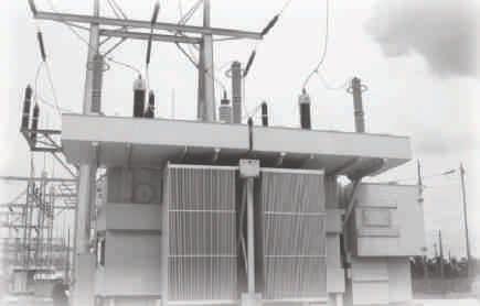








NEW eBOOK PACKED FULL OF TECHNICAL INFORMATION! ELECTRICAL CIRCUIT BREAKERS, FUSES AND PROTECTIVE RELAYS by L.W. Brittian Achieve specialist
with
AVAILABLE NOW ON AMAZON.COM IN THE KINDLE STORE 900+ pages 200+ pictures 125+ Charts and Tables Only $5.99 ® FLEXIBLE / COLLAPSIBLE AIR-CELLS 2-DAY AVERAGE! STANDARD SIZES PLUS CUSTOM AIR-CELLS TO FIT ANY TRANSFORMER INSTALLATION! ® MADE IN AMERICA - 40 YEARS STRONG800-526-5330•+1-201-825-1400•ATLINC.com 800-526-5330 • +1-201-825-1400 • ATLINC.com TOLL FREE: TELEPHONE: WEB: U S E D B Y: USED BY: WAUKESHA, CALPINE, TVA, FIRST ENERGY, PSE&G, L.A. DEPT. OF WATER & POWER, JACKSONVILLE ELEC. AUTHORITY & MANY MORE! COLLAPSED BLADDER PILLOW TANKS FOR DIELECTRIC OIL, TOO! SECOND DRAFT MEETING FOR NFPA 70E
knowledge
Ron Widup
Jim White


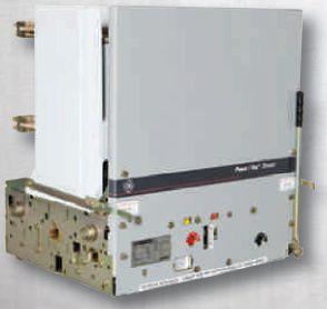


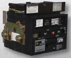


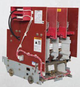
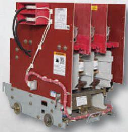


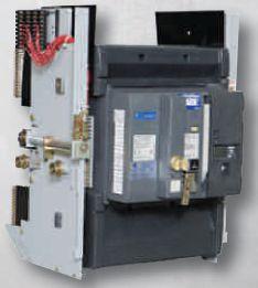


www.bcsswitchgear.com Are you having Power Equipment Problems? BCS HAS THE SOLUTION! new ∙ used ∙ obsolete ∙ reconditioned TEXAS OFFICE 4790 Hwy 377 South Krugerville, TX 76227 FAX 940-365-1808 ABB ∙ GENERAL ELECTRIC ∙ ITE GOULD ∙ WESTINGHOUSE ∙ SIEMENS SQUARE D · ALLIS CHALLMERS ∙ FEDERAL PACIFIC Call Toll Free: 888-599-0486 SWITCHGEAR, INC. Powering industry with superior equipment since 1999.


ASSESSMENT DO A ?
BY JIM WHITE, ShermcoIndustries Shermco Industries
This article discusses the whys of performing a job safety assessment (JSA) or a job hazard assessment (JHA). This often comes up during safety classes where attendees say, “Oh, I had no idea why we did those. It was just something we were told to do.” While employees should comply with standard operating procedures (SOPs) or company directives, since we are dealing with adults, they also need to understand why we do things. Once they do, compliance goes way up.
RISK VERSUS FREQUENCY
Risk is defined by NFPA 70E as “acombination “a combination of the likelihood of occurrence of injury or damage to health and the severity of injury or damage to health that results from a hazard.” Riskassessment Risk assessment is defined as “an overall process that identifies hazards, estimates the potential severity of injury or damage to health, estimates the likelihood of occurrence of injury or damage to health, and determines if protective measures are required.” NFPA 70E adds this to the definition of risk assessment: “Informational Note: As used in this standard, arc-flash risk assessment and shock risk
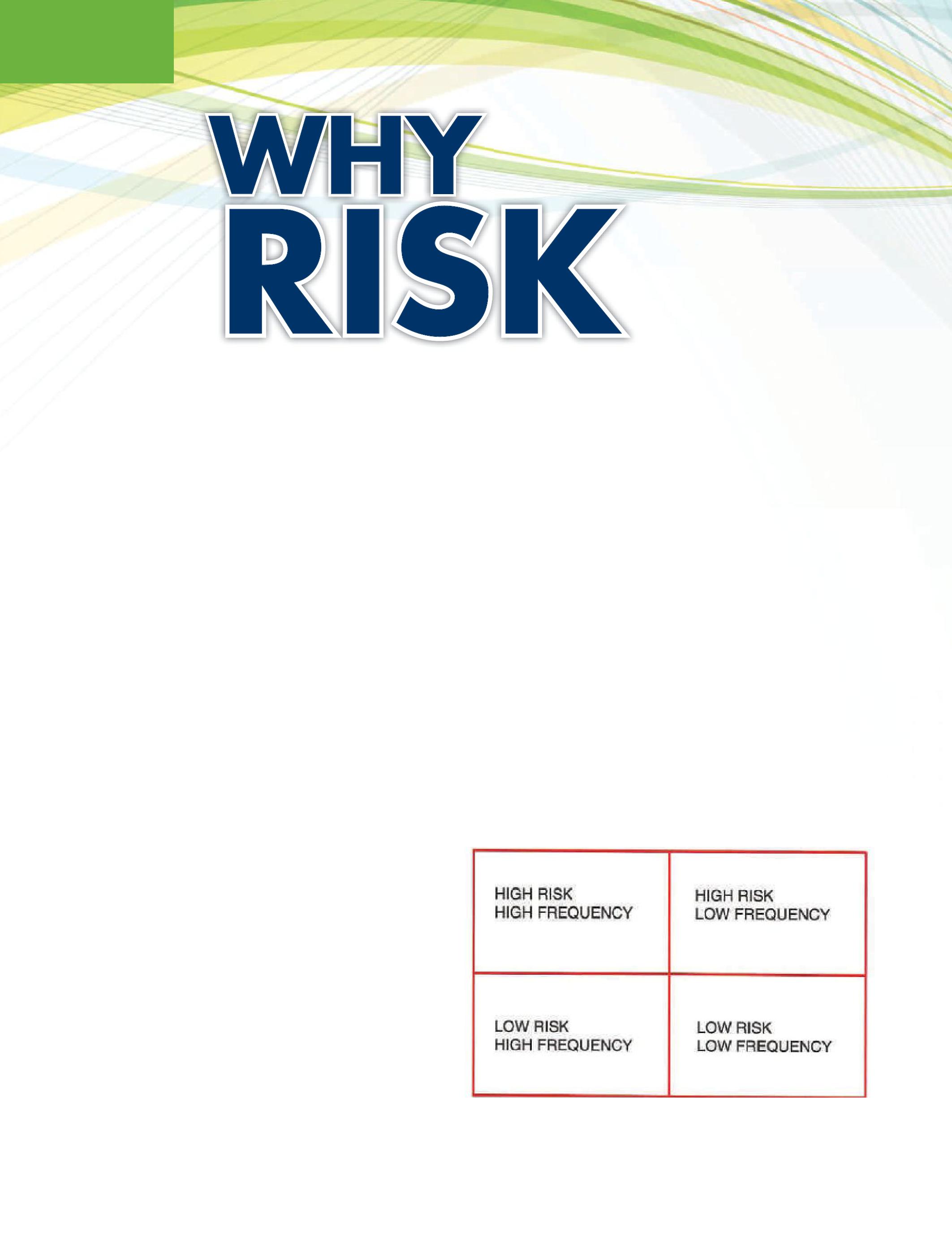
assessment are types of risk assessments.” Frequency, of course, is how often a task is performed during the work day. Figure 1 shows the four quadrants comparing risk to frequency.
FEATURE WHY DO A RISK ASSESSMENT? 64 • FALL 2016
Figure 1: Risk versus Frequency
High Risk/High Frequency tasks include utility work on overhead lines or live-line bare-hand work on energized electrical lines or equipment. Most industrial companies try to limit or eliminate tasks such as these to prevent electrical events. Utilities, however, operate in this environment frequently. High Risk/Low Frequency tasks include racking a circuit breaker in or out of its enclosure and removing or installing a MCC bucket or a bus duct fuse. These tasks are rarely done, but the risks involved are high. Low Risk/ High Frequency tasks are things like driving a car, walking, or climbing stairs. These tasks are performed thousands of times each day, but accidents are infrequent. Examples of Low Risk/Low Frequency tasks are riding a merry-go round, playing billiards, or other similar activities.
Of these four types of tasks, which one would have more injuries? Surprisingly (or, maybe not), most events happen in the Low Risk/High Frequency category. We perform these tasks day in and day out, hardly giving them a thought — and that is where we get into trouble. Our brain goes into auto-pilot mode, and we just go through the motions. For example, as we drive on an interstate highway, we tend to use only that portion of our brain really needed to get us from point A to point B. Since our brain is the biggest energy user of our entire body, it automatically throttles back to conserve energy. We don’t consciously do this; it just happens. If a police car comes up behind us with its lights flashing and siren blaring, we go into full alert mode. Once that police car passes us, we drop back into interstate driving mode. We are conserving energy.
Many would argue that driving a vehicle is not low risk, but consider how many millions of miles are driven each year and the number of vehicles on the road at any given time. According to the National Highway Safety Traffic Administration, there were 32,719 deaths attributed to traffic accidents in 2013. That’s a lot, but there were also about 212 million drivers who drove about 2.96 trillion
miles. This works out to 1.13 fatalities per million miles driven. Those fatalities were not in any way acceptable, but for the number of miles driven, the fatality rate is relatively low.
The implications of the way our brain operates are tremendous. The first time we perform a task, we are focused and sharp. As we perform the task repeatedly, we tend to be less focused. Our brain is conserving energy, preserving our energy stores in case we have to run from a saber tooth tiger, climb a tree, or some other survival-related task. We go through the motions, not really paying attention. If anything different should happen — anything not planned for — we could quickly be in a safety-critical position.
PROBABILITY VERSUS CONSEQUENCE
We are all familiar with the concept of probability. We constantly weigh probabilities, sometimes more successfully than others. If we make a sudden lane change or we decide to answer a cell phone call while driving, we are weighing the probability of an accident, and we all deal with the consequences of decisions made every day.
Figure 2 shows probability versus consequence. Low Probability/High Consequence would be a task such as racking a circuit breaker in or out or inserting/removing MCC buckets. We don’t do these often, and the probability of failure is small; but if a failure does occur, the consequence of failure could be very high — even life-threatening. High Probability/High Consequence tasks are those that have a high probability of injury and the consequences would be high. Going back to utility linemen as an example, they work in close proximity to energized lines and equipment. If they should make contact, the consequences would be high. Low Probability/Low Consequence tasks are such tasks as sharpening a pencil or brushing your teeth, etc. The chances of injury are small, and, if it did occur, the resulting consequence would be very minor. High Probability/Low Consequence tasks are those that have a high probability of an


NETAWORLD • 65 WHY DO A RISK ASSESSMENT?
FEATURE
–
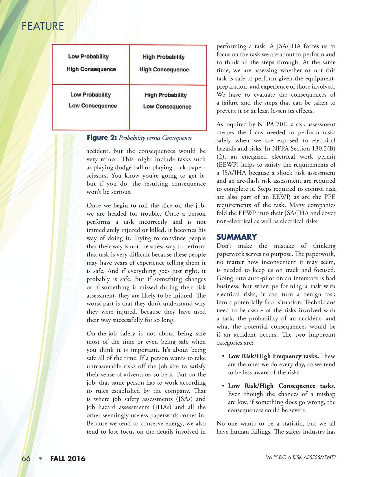








THE BASIS FOR PERFORMING INSULATION POWER-FACTOR TESTING ON LARGE CAST-COIL
 BY BRUCE M. ROCKWELL, American Electrical Testing, Inc.
This article discusses the industry basis and value of performing an insulation power-factor test on dry-type transformers, specifically the cast-coil design. The basis for performing this test as outlined in the industry standards is discussed. The value of performing the test based on the transformer application, site conditions, and customer objectives is presented. The intent is to provide insight into when it is prudent to apply insulation power-factor testing to dry-type transformers.
The Institute of Electrical and Electronic Engineers (IEEE) publishes a voluntary consensus standard, IEEE Std. C57.12.01 (2015), IEEE Standard for General Requirements for Dry-Type Distribution and Power Transformers. This standard was first published in 1979, and its purpose is to provide a basis for establishing performance and interchangeability requirements for dry-type transformers. This standard describes electrical and mechanical requirements of single- and poly-phase as well as ventilated, non-ventilated, and sealed dry-type distribution and power transformers or autotransformers with a voltage of 601 volts or higher in the highest voltage winding. This standard applies to all dry-type transformers, including those with solid cast and/or resin-encapsulated windings.

Section8oftheC57.12.01standardaddresses Section 8 of the C57.12.01 standard addresses testing. Specifically, paragraph 8.3 addresses routine, design, and other tests for transformers. Dry-type transformer tests are summarized in Table 16. The insulation power-factor test is listed under “other” tests. The standard implies that other tests are those that are specified individually as deemed appropriate. Thus, the standards recognize it is common practice to consider insulation power-factor testing for dry-type transformers.
A companion standard to IEEE C57.12.01 is IEEE C57.12.91 (2011), IEEEStandard IEEE Standard Test Code for Dry-Type Distribution and Power Transformers. This standard provides

INDUSTRY TOPICS
THE BASIS FOR PERFORMING INSULATION POWER-FACTOR TESTING ON LARGE CAST-COIL TRANSFORMERS NETAWORLD • 69


information regarding procedures for testing dry-type transformers. It identifies that transformer requirements and specific test criteria are not part of this standard but are contained in appropriate standards such as IEEE C57.12.01 or in other user-developed specifications. Thus, there is some basis that applications vary, and as such, different testing may be applicable for different conditions.
Within IEEE Std. C57.12.91, the following commentary is noted:


While the real significance that can be attached to the insulation power factor of drytype transformers is still a matter of opinion, experience has shown that insulation power factor is helpful in assessing the probable condition of the insulation when good judgment is used. In interpreting the results of insulation power-factor test values, the comparative values of tests taken at periodic intervals are useful in identifying potential problems rather than an absolute value of insulation power factor. A factory insulation-power-factor test is of value for comparison with field insulation-powerfactor measurements to assess the probable condition of theinsulation.Ithasnot the insulation. It has not been feasible to establish standard insulation-powerfactor values for dry-type transformers because experience has indicated that littleornorelationexists little or no relation exists between insulation power factor and the ability of the transformer to withstand the prescribed dielectric tests.
Anotherfactorcitedfor Another factor cited for the inability to establish a standard insulation-powerfactortestvalueisthe factor test value is the wide variation in size, type, and quantity of insulating materials used in large drytype transformers. However, practice has proven the value in trending the insulation
power factor over time as a predictor of overall insulation quality. Such trend test data is helpful in identifying degradation or verifying insulation quality improvement from drying/cleaning. Such testing is also helpful in identifying potential issues (insulation voids/carbonization) that may not be observed externally.
Large (>500 kVA) cast-coil transformers (standalone or unit substation types) are generally applied (in lieu of open-wound or encapsulated types) where additional strength and protection is required. These units are intended for harsh environments and/or outdoor applications and are applied for their superior short-circuit strength and short-duration overloads as are typically experienced in industrial process applications.
One noted disadvantage when applying or using a cast-coil transformer is that the coefficient of expansion of the epoxy insulation is less than that of the copper (or aluminum) windings. If the transformer is exposed to environmental or operating conditions that create cyclical expansion and contraction by heating and cooling the coils, this can lead to cracking of the cast-coil epoxy-resin insulation over time.
THE TEST COMMUNITY UNIVERSALLY RECOGNIZES APPLYING THE INSULATION POWER-FACTOR TEST PERIODICALLY FOR MAINTENANCE AND USING THE TREND-TEST DATA TO VALIDATE THE QUALITY OF DRYTYPE TRANSFORMER INSULATION AS AN ESTABLISHED INDUSTRY BEST PRACTICE.
General Electric published a service bulletin titled Test Application Data for Secondary Substation Transformers. In this test application guide, the insulation power-factor test is listed as an optional test; however, it is noted that this test is useful for checking the condition of the insulation. This service guide identifies that comparative measurements made at periodic (i.e., maintenance) intervals are useful in identifying potential problems rather than the absolute test value. Thus, GE is one manufacturer that readily acknowledges
INDUSTRYTOPICS INDUSTRY TOPICS
THE BASIS FOR PERFORMING INSULATION POWER-FACTOR TESTING ON LARGE CAST-COIL TRANSFORMERS 70 • FALL 2016
the value of using the insulation power-factor test trend data as a maintenance test.
The American National Standards Institute (ANSI) publishes the ANSI/NETA MTS, Standard for Maintenance Testing Specifications for Electrical Power Equipment and Systems, 2015 edition.
The ANSI/NETA MTS-2015 test specifications identify the insulation power-factor test as a standard (routine) test. Additionally, the specifications identify an insulation powerfactor tip-up test as an option. Industry practice has established the value of performing this additional test when the standard insulationpower-factor test results are suspect.
The industry body of knowledge referenced herein provides guidance on transformer testing by considering the type of insulation system: dry-type or liquid-filled. There is some distinction with respect to size. Transformers larger than 500 kVA (threephase) are generally considered significantly more critical to business operations. The standards make no distinction with respect to the test specifications based on the various types of dry-type insulation system designs such as cast coil, resibloc, vacuum-pressure impregnated (VPI), or vacuum-pressure encapsulated (VPE). Industry standards further guide the user toward good engineering judgment and apply reasonable economic justification based on additional factors such as reliability, criticality, environment, and serviceaged conditions.
Having data on the frequency and magnitude of through-faults experienced by a transformer are criteria that warrant consideration with respect to specifying more or less testing. In facilities and plant sites that have high available fault currents, and in situations where a transformer has been subjected to a through-fault, it is prudent to perform insulation power-factor testing to verify the insulation quality.
Doble Engineering Company suggests the following as acceptable, stand-alone insulationpower-factor test values:
1. Ventilated Dry-Type
• CHL (high-to-low) 2 percent
• CL (low-to-ground) 4 percent
• CH (high-to-ground) 3 percent
2. Epoxy Encapsulated Dry-Type
• CHL 1 percent
• CL 2 percent
• CH 3 percent
It is important to note that CL power factors as high as 8 percent have been noted in some manufacturers’ transformers, and these levels may be considered acceptable. Thus, having trend data is very helpful in monitoring/ identifying normal and degraded conditions. Literature published by electrical test instrument manufacturer Megger Group Ltd. provides the following insight: “Higher overall powerfactor results may be expected on dry-type transformers; however, the majority of test resultsforPFarefoundtobebelow2.0 results for PF are found to be below 2.0 percent, but can range up to 10 percent.”

The test community universally recognizes applying the insulation power-factor test periodically for maintenance and using the trend-test data to validate the quality of dry-type transformer insulation as an established industry best practice. This practice is also recommended by ANSI/NETAasaroutinemaintenancetest. ANSI/NETA as a routine maintenance test.

The insulation power-factor tip-up test is an additional test recognized in the ANSI/ NETA MTS-2015 industry standard. This test is performed to further clarify what the insulation power-factor test results may be indicating. When performed, this optional test is useful in evaluating and discriminating whether moisture or corona are present in the insulation system. To perform the tip-up test, the applied test voltage starts at about 1 kV and increases in intervals up to 10 kV or the line-toground rating of the winding insulation. If the insulation power-factor does not change as the test voltage is increased, moisture is suspected as a probable cause. If the insulation powerfactor increases as the voltage is increased, carbonizationoftheinsulationorionizationin carbonization of the insulation or ionization in voids is a probable cause.-


THE BASIS FOR PERFORMING INSULATION POWER-FACTOR TESTING ON LARGE CAST-COIL TRANSFORMERS
INDUSTRYTOPICS INDUSTRY TOPICS NETAWORLD • 71

CONCLUSION
It is reasonable to perform the insulation powerfactor test on dry-type transformers, including cast-coil designed units. The insulation powerfactor test may add two to four hours to the testing scope; thus, it can be significant in the price of the work. It is important to understand how to prioritize the value of this test with customer economic expectations.

In some aspects, this is akin to the mindset that transformers only need to be tested on the applied tap setting. However, turn-toturn winding shorts are found often enough to justify testing a transformer on all of its available tap positions, and time added for this testing is minimal. Understanding the value of the test, the added scope/cost, and when it may provide the best value to the customer are all things to consider when specifying testing for dry-type cast coil transformers.


Bruce Rockwell is the Director of Engineering for American Electrical Testing, Inc., Boonton, New Jersey. Bruce has more than 35 years of engineering and operations experience spanning industrial and utility power systems in transmission, distribution, substation, generation, and rail transit from low voltage to 500 kV. He has a Bachelor of Science in Electrical Engineering from the New Jersey Institute of Technology and an MBA from Monmouth University. Bruce is a licensed Professional Engineer in 22 states, a licensed Electrical Contractor in New Jersey, and a New Jersey State-Certified Continuing Education Instructor for electrical contractors. He is a senior member of IEEE and has been recognized many times for his contributions to various publications and as a speaker at various electric power industry conferences. Bruce was recently appointed as an alternate to the NECCode Panel 10.
Industrial Electric Testing, Inc.

INDUSTRYTOPICS INDUSTRY TOPICS
Electro Rent is proud to introduce its new Regional Service Center, serving your test needs better and faster than ever with experienced customer support 24x7. If it tests, we’ve got it— and we’re ready to deliver in Houston.
NOW IN HOUSTON
» Largest inventory » Consistent, reliable delivery service » Immediate availability » ISO and ANSI accredited labs Vanguard Instruments Company, Inc. www.vanguard-instruments.com 19 6 5 - 2 965-2 01 015 Y EAR S Electro Rent answers your every test need. Learn more at: www.electrorent.com/electr ical-power 800.304.4744 | sales@electrorent.com E l e c t r Electro R e n t i s N o o Rent is Now a N E T w a NETA G o A Gol d ld C o r Cor p o r pora te A l l i a n c e e Alliance Pa r ar t n e r tner E l e c t r Electro R e n t o Rent Tu r ur n s 5 0 ns 50
NETA INDUSTRY LEADERS THANK BOARD MEMBER FOR LONG-TIME SERVICE
BY CARLA KALOGERIDIS
MembersoftheNETABoardofDirectorscommit Members of the NETA Board of Directors commit to two-year terms when they agree to serve. Someone apparently forgot to tell that to Rod Hageman, who is retiring from the NETA Board after 28 years of service.
“My time on the NETA Board was my service to the industry,” Hageman says.
Hageman took over Illinois-based PRIT Service, Inc., in 1972 from his father, Lynn Hageman, who had established the company as an independent testing and engineering services firm in the 1950s. Over the last 40 years, PRIT Service has been part of a growing industry, servicing industrial and power-producing companies throughout the Midwest. PRIT Service joined NETA in 1986 and shared its technical knowledge through Hageman’s participation on the Board; his service (along with that of his respected and beloved late wife, Diane)as Diane) as NETA World Journal’s Technical Editor; and his leadership roles on the Standards Review Council (SRC) and NETA Technical Exam Committee. He has also represented NETA on other industry committees, suchasNFPACMP-10. such as NFPA CMP-10.
“I particularly enjoy my work with the SRC,” Hageman says. “It’s a great group of highly skilled technical people who put away their egos and listen to each other.” The SRC is responsible for the technical oversight and review of NETA's programs, products, and services including the ANSI/NETA standards and the NETA Certification Program.
Hageman, whose company was acquired by Shermco Industries earlier this year, would like to continue working on the SRC and stay connected to the industry. “The
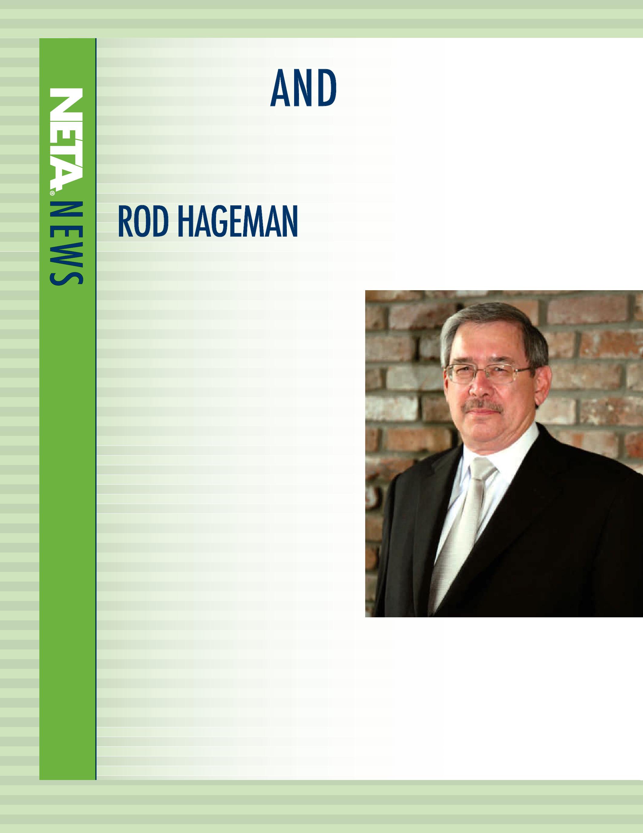
problem with retiring is that then you become one of those guys who used to know everything,” he says. “I hope to stay involved with NETA wherever I can contribute.”
Through the years, Hageman has been particularly proud of the NETA Board’s recognition of and willingness to change when change was needed. “For example, re-doing the NETA Certification Exam, which was a project that began in October of 2014, was very important work,” he says. “I appreciated that the Board agreed to let us get that
Rod and Diane at dinner with friends in Jackson Hole, Wyoming.
done.” NETA Certification is a credential earned by individuals who perform electrical maintenance testing, acceptance testing, and commissioning of electrical power equipment and systems. The NETA credential is the industry-leading certification program for this career path.
That being said, Hageman has seen the Board make some tough decisions, too. “We’ve had to make changes as the world is changing around us,” he says. “Board members listen to each other and learn from each other. When you come through that door, you have to park your attitude about how you run things in your business at the door. The NETA Board always keeps the interests of the organization and its members at heart.”
Looking ahead, Hageman says the NETA Board is on solid ground. “I hear people raise concerns periodically about succession, but I don’t see that as a problem for the NETA Board or in the technical arena,” he says. “The young men and women I see entering our industry are smart and have the same work ethic we do. The NETA organization will remain strong for the foreseeable future.”
PERSONAL AND PROFESSIONAL REFLECTIONS
No one works in an industry and volunteers with its leading association for decades without making a few acquaintances along the way. Hageman has a long list of colleagues who respect his work and leadership and who love him as a person.
“I’ve known Rod more years than either of us would like to admit,” says Mose Ramieh, former President of Power & Generation Testing, Inc. and a long-time member of NETA’s Board of Directors. “When I joined NETA, Rod wasthefirstBoardmemberImetandwehititofffrom was the first Board member I met and we hit it off from the start.” Later, after Ramieh’s election to the Board, they became close friends. “He and Diane were very helpful after my wife died, and our bond became even closer.”

A friendly game of pool with Mose Ramieh, John White, Rod Hageman, and Ken Bassett in Jackson Hole, Wyoming.
Ramieh describes Hageman as loyal, honest, smart, compassionate, and humble. “If I had to pick one word to describe him personally, it would be sensitive, but that still leaves a lot on the table,” Ramieh says.
Professionally, Ramieh knows Hageman as a lover of all things technical with a passion for sharing knowledge. “Rodhasbeenatrendsetterinthetechnicalsideof “Rod has been a trendsetter in the technical side of NETA and the industry. He has been a pioneer in the protective relay world. His technical review and scrutiny of NETA World Journal has given NETA a respected place in the industry. He has — like so many others in the NETA family — contributed much to make us the 800-pound gorilla in the testing industry.”
Ron Widup, CEO of Shermco Industries and President of the NETA Board, has worked with Hageman on the Board, the SRC, PowerTest, several ad hoc committees, and other miscellaneous projects for the Association. “Rod has been a fantastic resource,” he says, “always willing to jump in and help out.”
Widup describes Hageman as a smart man who has had a direct impact on the technical competence and industryleading position of NETA. “His attention to detail, his high expectations of accuracy and validation — for both
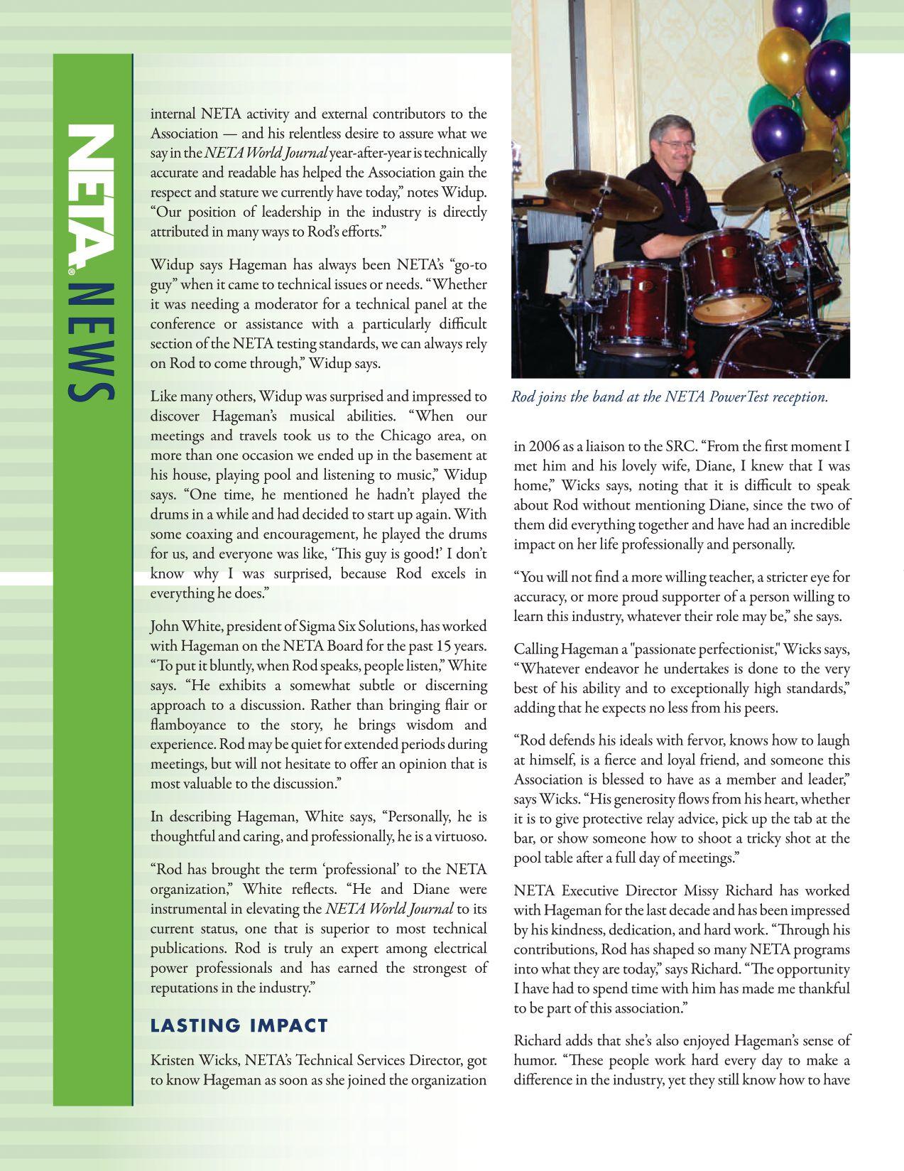
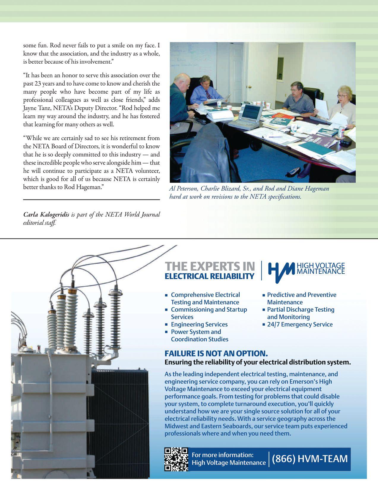
EVALUATING
TESTING STRAT EGIES
BY BRIAN CRONIN, CSA Engineering Services, LLC
Look at a sales brochure, or even an instruction manual, for many relays available today and you’ll find only a small portion of it dedicated to protection. Much of what you’ll find is dedicated to the integration of the device into the power system so it can replace what was previously performed by a myriad of devices. Metering, monitoring, and control features allow for significantly more functions than the predecessor to the modern digital relay. These additional features are part of the digital relay and can be used to remotely control and monitor portions of a system. To implement these remote features, the relay must be incorporated into a communications system, which requires the selection of appropriate network architecture. In addition to the remote control and monitoring, one incredibly powerful feature of the digital relay is its ability to record and evaluate system events. Recorded data can also be used to aid in operations. Many of these devices require a significant number of settings to take advantage of these features and often times these ancillary elements may be overlooked.
The ANSI/NETA Standard for Acceptance Testing
Specifications for Electrical Power Equipment and Systems, 2013 edition, identifies various methods to inspect and test microprocessor-based relays. These procedures identify the recommended methods for testing the protective functions, inputs, and outputs associated with digital relays; however, many of the functions available in the digital relay requiring testing are not included in these specifications. Testing of metering and

the relay logic are indicated in this standard, although no specific methods are identified. Perhaps the accuracy of additional features such as fault recording and display data does not seem apparent; however, when properly used, these features are extremely helpful in evaluating events.
As with any product class, the functions and features of digital relays will vary between manufacturers and even within the varying
INDUSTRYTOPICS INDUSTRY TOPICS NETAWORLD • 79
EVALUATING DIGITAL RELAY TESTING STRATEGIES
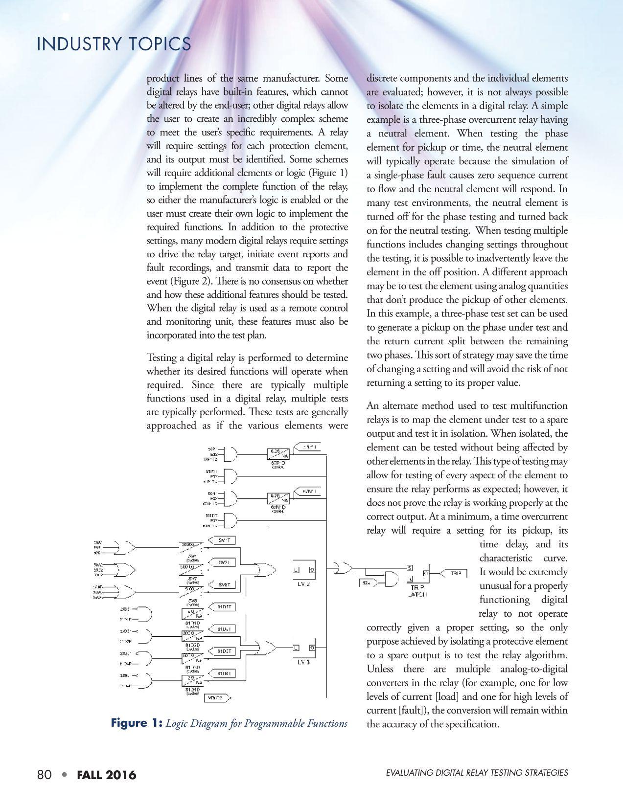
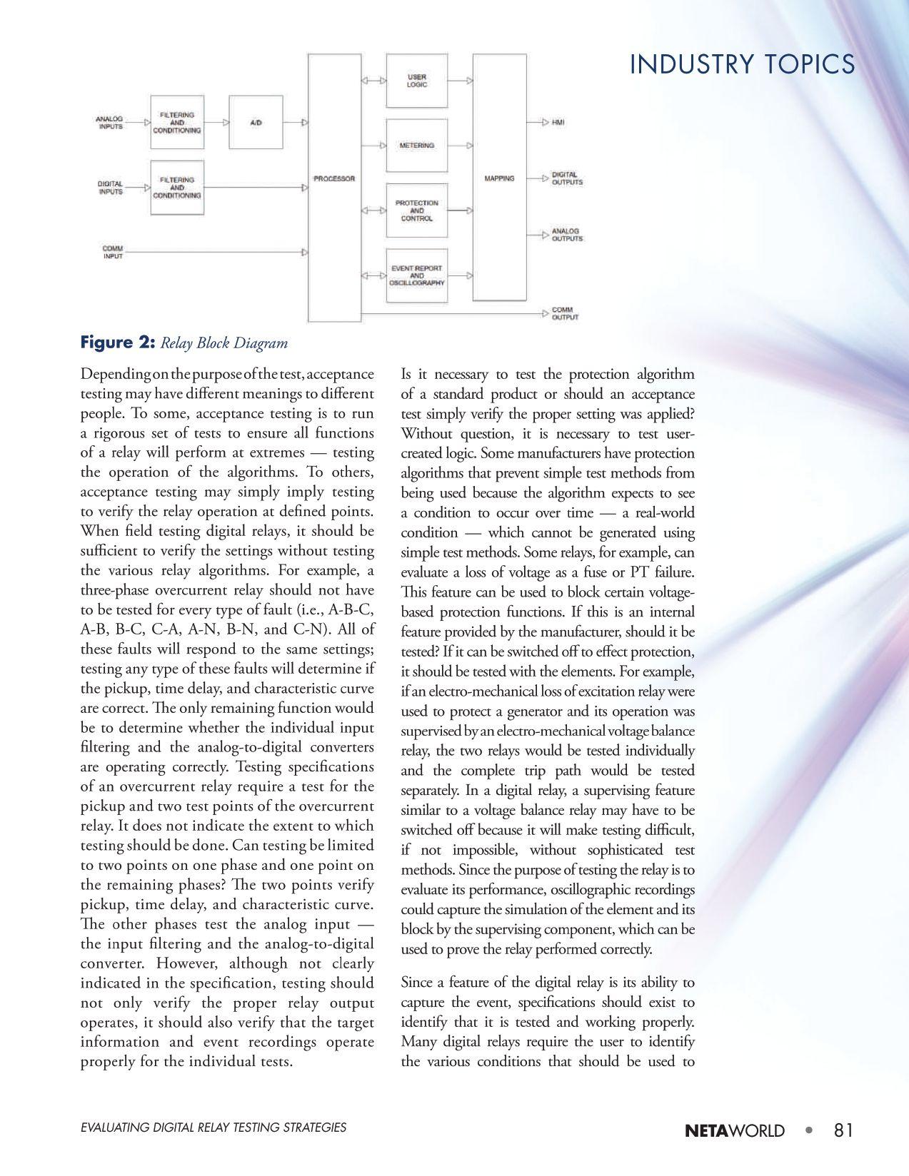
collection of individual items in a singular device and the acceptance test includes the testing of these, individual testing should include the following items:
• Verification of all metering functions
• Verification of required protection elements
• Verification of required inputs
• Verification of required outputs
• Verification of device targets
• Verification of event records
•Verification of protection logic (including its interaction with internal and external elements)
Generally, acceptance testing exists in a vacuum, and it is not until systems are commissioned that the device integration into a larger system is evaluated. A digital relay is truly a small system and must be tested as such. ANSI/ NETA ATS calls for testing of pilot schemes and in-service monitoring. These are tests that can only be performed when other components are in service. Instrument transformers, external contacts, coils, and other devices must be tested with the digital relay as part of its system, and its testing should be as detailed as the acceptance testing. The digital relay should be tested using a method that closely represents the system that it is intended to protect and the conditions it will be expected to withstand. It should also be tested for all functions and features it is expected to perform. The ANSI/NETA, Standard for Electrical Commissioning Specifications for Electrical Power Equipment and Systems,2015 edition, provides good direction on developing complete testing protocols to ensure the digital relay system will provide its intended function.

Brian Cronin, PE, is the President of CSA Engineering Services, LLC. He has over 30 years in the electric power industry with extensive control and protection engineering experience, both as a Senior Protection Utility Engineer for a privately-owned electric utility and as a Field Applications Engineer/ Business Development Manager for a major OEM. Brian holds a BS in Electrical Engineering from Manhattan College and an MBA from New York Institute of Technology. He is a Registered Professional Engineer, a member of the NYC Electric Code Interpretation Committee, a member of IEEE, and a member of NFPA.
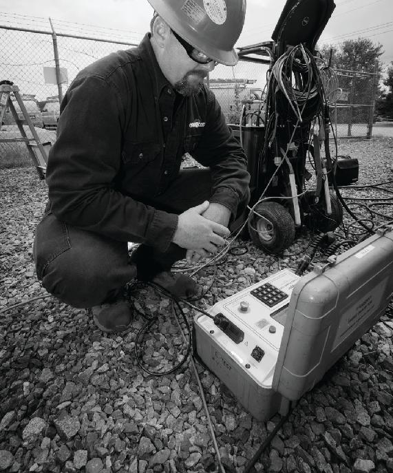
Reliable Power System Solutions
We deliver optimum system reliability and performance while reducing the chances of costly unplanned power outages. Whether you need acceptance
testing or preventive maintenance, depend on EnerGTest to keep the power on.

Serving clients in Pennsylvania, Delaware, New Jersey, Maryland, Washington, DC and New England.
EVALUATING DIGITAL RELAY TESTING STRATEGIES
Accredited Company 204 Gale Lane Kennett Square, PA 19348 484.731.0200 enerGtest.com
ener es
EXCLUSIVE INVITATION TO NETA EVENTS
Annual Member/Alliance Meeting
Annual Member/Alliance Luncheon
Meeting of the Minds
EXCLUSIVE DISCOUNTS
Discounted PowerTest Registration
50% off one ANSI/NETA Standard ($138 value)
20% off NETA Bookstore Purchases
20% off NETA Training and SPTS Courses
STAY INFORMED
NETA World Journal ($40 value)
SHARE INFORMATION
Post Press Releases
Participate in Technical Working Committee Activities
ATTENTION NETA ALLIANCE PARTNERS.
The
Program is designed for individuals working in and connected to the electrical power systems industry. Partners
benefits:
www.netaworld.org
NETA Alliance
enjoy many
ALLIANCE PARTNERSHIP $150
Value) Take advantage of YOUR benefits today. Ask About Joining the NETA Alliance Partnership Program. Get Involved and Stay Connected! Go to www.powertest.org or give us a call at 888-300-6382
($285

BUSY PRODUCTION TRAINING ACTIVITIES
BY CHRIS ALLAIRE, ShermcoIndustries Shermco Industries
Henry Ford is credited with the adage: “What if we train them and they leave? What if you don’t train them and they stay?” The reality of this saying affects everyone from the owner to the manager, the technician, and down to the new hire.
No doubt, we will agree that in our extremely technical and ever-changing industry, a highly skilled and educated workforce is paramount to the success of our organizations. We can also agree that the demands of our hectic dayto-day life, be it job related or personal, seem to always get in the way of participating in training for ourselves or providing training for ourtechnicians. our technicians.
Therefore, if we can agree that training is essential — not to mention, in some cases, regulatory — we must find ways to fit training activities into an already full schedule. What canwedo?Twochoices: can we do? Two choices:
1. Complain that there is never enough time, and the only option is the minimum required training.
2. Find a solution and prosper.
Let’s stay optimistic and look at strategies to fit training into a hectic production schedule and personal life. We will explore training from two perspectives and consider ways to increase participation and alleviate stresses created by conflicting goals.
SPEAKING TO THE MANAGER
As manager or scheduler, you know all too well how difficult it can be to juggle customers’ needs and expectations with available resources. And just when you have the production schedule all worked out, the emergency call comes in. You then must pull personnel off one job to send to the emergency and move others around to cover for them. You find it easier to pull resources from scheduled technical training when the emergency job suddenly must be manned.
The key is to consciously put a higher priority on technical training and safety training. Both are easily sidetracked, but it is important to commit to holding training onceitisscheduled.Weallunderstandthat once it is scheduled. We all understand that the customer comes first, but that does not mean that training should come last. When your technicians see that training is a high priority to you, they will be more inclined to value it and take advantage of training opportunities. Richard Branson, founder and CEO of Virgin Airlines, said: "Train people well enough so they can leave; treat them well enough so they don't want to."
INDUSTRYTOPICS INDUSTRY TOPICS
NETAWORLD • 85 BALANCING A BUSY PRODUCTION SCHEDULE WITH TRAINING ACTIVITIES

Look for ways you can provide the muchneeded training that will not negatively impact your production schedule. Here are a few ideas:
• Break training into smaller segments. For example, you may break an eight-hour class into two-hour increments taught over thenextfewweeks.Mostofuslearnbetter the next few weeks. Most of us learn better in shorter classes anyway.
• Present training in an e-learning format to better fit in the tech’s schedule. Don’t make the mistake of substituting e-learning as your primary delivery method for training. That said, an advantage to e-learning is that your technicians can access the training as their schedule allows. E-learning may also address your technicians’ need for on-demand training.

offer webinars free of charge. Look around for topics that best fit your needs, and make your technicians aware of the date and time of the webinar. Keep in mind that many field technicians feel they commit enough time to the company as it is, so you may consider offering some kind of incentive. For example, you could plan a pizza party to view the webinar as a group.
• Send some of your top performers to PowerTest, but take it one step further. Explain to them that you consider PowerTest a train-the-trainer activity, and that you expect each of them to lead an informative discussion on a given topic once they return.

• Consider providing tuition assistance or recognition for completed courses. Most community colleges have night or weekend classes. Some community college courses are presented online, with labs offered once a week on campus.
• Provide suggestions for self-study such as trade journals, technical papers, or manufacturers’ literature. You most likely know where to find the best articles and materials relevant to your technicians’ needs. Be sure to ask for feedback in a week or so as a follow up.
• Encourage reading a specific article in the NETA World Journal and then lead a short discussion as part of a weekly safety meeting. You may want to ask technicians for topic-of-the-month suggestions such as transformer testing or reading breaker curves.
• Take advantage of your senior technicians’ knowledge and experience. Most are willing to provide on-the-job training to the newer technicians. I am amazed at the wide-ranging depth of knowledge possessed by NETA Level III and Level IV technicians.
• Offer technical webinars during the day or in the evenings. Many organizations
When you have a project coming up that requires particular safety training or site-specific orientation, make certain the technicians receive it. You have no choice; you must provide proof of required training to get them on the job. Treat your technical training with the same must-do mindset as you do required regulatory training. Encouraging professional development and technical training delivers the benefit of more loyal and knowledgeable employees.
SPEAKING TO THE TECHNICIAN
Are you willing to do what it takes to get the training you want and need? How much self-study time are you willing to devote to better yourself and advance your career? The answers to these very important questions indicate your personal commitment to selfimprovement. Arnold Schwarzenegger, once said, “Bodybuilding is much like any other sport. To be successful, you must dedicate yourself 100 percent to your training, diet, and mental approach.” How dedicated are you to your future?
Of course, managers can help provide technicians with technical training, but it is up to them to take advantage of learning opportunities offered by the company. Employees should be encouraged to explore other ways to better themselves apart from training offered by their employer. Either way,
INDUSTRYTOPICS INDUSTRY TOPICS 86 • FALL 2016
BALANCING A BUSY PRODUCTION SCHEDULE WITH TRAINING ACTIVITIES
training and self-improvement are ultimately the individual’s responsibility.
For example, I am currently taking a series of six online classes with a friend from work through the local community college. After I complete these six eight-week courses, I will be a Certified Instructional Designer and a Certified Training Manager. If your work schedule is anything like mine, you don’t have time to sit in class. Taking classes online is the only way I am able toworkonthesecertifications.Onlineclasses to work on these certifications. Online classes canbetakenathomeorinahotelroomwhen can be taken at home or in a hotel room when you are on an out-of-town job. Just make sure you are willing to commit the time necessary to complete the course.
Instructor-led classes are one of the better ways to learn new things or to brush-up on new technology. In a classroom setting or webinar, participants have the opportunity to ask questions and interact with other learners. Most good technical training will include some form of hands-on activity to reinforce the subject matter. To get the most out of instructor-led training, I suggest that participants try to learn something about the subject before taking the class. The more you already know, the more you will get out of the training. For example, if scheduled for a Tan Delta class, look up articles in past issues of the NETA World Journal orcheckout or check out some YouTube videos before taking the training.
It is not necessary that all your training is technical in nature. Look for a technical writing course to improve your report-writing skills as well as grammar and punctuation. Consider taking a Microsoft Word or Excel class to better your computer skills. I teach a basic GED math class on Monday nights at the Community Enrichment Center near my house. Classes such as these are offered free of charge and
often include the textbook. Improving your math skills can go a long way in helping to improve your technical skills. Rorry Philips, Shermco’s Human Resources Director, teaches a course titled “The 7 Habits for Managers: Essential Skills and Tools for Leading Teams” for employees in leadership positions.
SUMMARY
Let’s face it: It can be as difficult for managers to schedule training as it is for technicians to attend training. In our industry, being difficult has never been an excuse to not meet goals or exceed expectations. The key to personal success is the effort put into it. If unhappy with the results received on the job (or life in general), take a step back and honestly evaluate why this is the case. There are people willing to take the necessary steps to pull ahead of the pack and those who eat their dust. Which type are you?

ChrisAllaire Chris Allaire isaTechnical is a Technical Instructor/Developer for Shermco Industries and an Adjunct Instructor for Texas State Technical College and North Lake College. Chris previously served as Lead Electrical Instructor at Everest College in Arlington, Texas. He earned a Bachelor of Science in Technical Management from DeVry University, majoring in Electronic Engineering Technology, and a Master’s of Education in Curriculum and Instruction from American College of Education. Chris spent nearly 30 years with General Electric, starting in the motor shop as a Motor Mechanic and Test Technician. The second half of his GE career was spent as a Field Service Technician, performing start-up and commissioning at water treatment plants, data centers, and industrial facilities.
NETAWORLD • 87 BALANCINGABUSYPRODUCTIONSCHEDULEWITHTRAININGACTIVITIES BALANCING A BUSY PRODUCTION SCHEDULE WITH TRAINING ACTIVITIES
INDUSTRY TOPICS
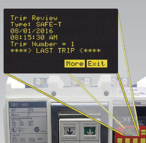
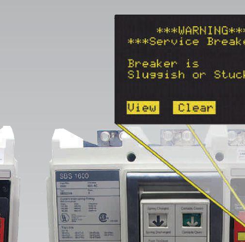




Can you tell at a glance which breaker mechanism needs service? Can you tell at a glance which breaker mechanism needs service? 21 Years of Exceptional Products & Exceptional Service With the SAFE-T-TRIP® and the new AC-PRO-II®, you can trip a breaker from a safe distance and the Sluggish Breaker Detection® feature will record the mechanism operating time, on the first operation. Contact: 888-289-2864 www.UtilityRelay.com URC Utility Relay Company With the patented Sluggish Breaker Detection® in AC-PRO-II With hardened lubrication or bad bearings a “Warning Service Breaker” screen will be displayed on the AC-PRO-II® Now You Can! Now You Can! WiththepatentedSluggishBreakerDetection inACPROII
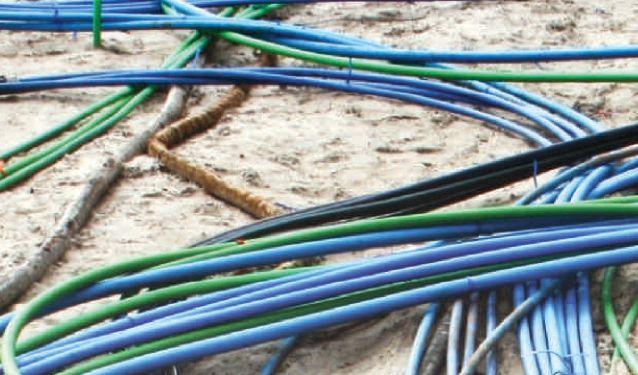


CABLE FAULT LOCATION — NOT FOR
 BY THOMAS SANDRI, ShermcoIndustries Shermco Industries
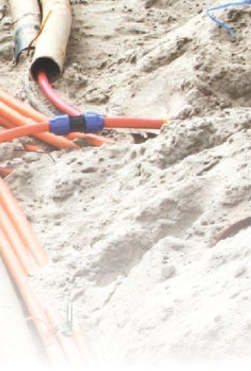
The mere mention of cable fault location sends shivers down many a spine. Don’t lose heart; all is not lost. Remember, cable fault location, like any other craft, simply requires some basic skills, proper tools, and a sound procedure. Don’t be fooled into over-simplifying the problem or relying on a single technique or instrument for every situation. Although many faults exhibit similar properties, all faults are unique. A fault-locating technique or instrument that works well in one situation may be completely useless in another.
A skilled golfer must be able to analyze a situation before reaching into their bag and selecting a club. A variety of clubs, and knowledge of their performance, allows the golfer to select the most efficient tool for the job. The same is true for a skilled cable-fault locator. As in diagnosing any complex problem, following a step-by-step procedure will help in arriving at the solution — in this case, locating the fault efficiently.
Gather as much information as possible about the cable that needs testing. Understand the test and measurement equipment available to you and the application it was designed for. Know how to properly operate the equipment and know its performance capabilities and limitations. The first step in a healthy procedure is to conduct basic performance tests to determine the nature of the problem. Tests and equipment available for this step include, but are not limited to:
INDUSTRY TOPICS
NETAWORLD • 89 CABLEFAULTLOCATION—NOTFORTHEFAINTOFHEART CABLE FAULT LOCATION — NOT FOR THE FAINT OF HEART


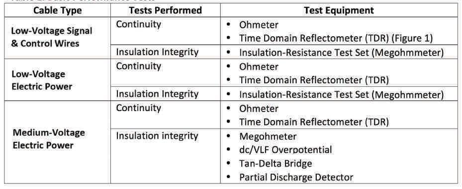
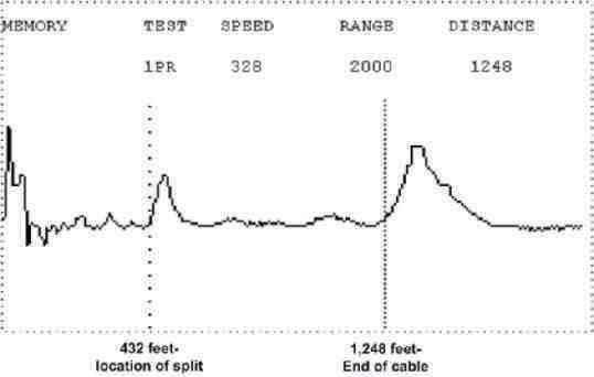

Even with the proper equipment and experience, cable fault locating can present challenges. These challenges are minimized significantly by understanding the equipment and techniques available, and perhaps most important, developing and adhering to a sound procedure.
After the cable has been tested, the results must be interpreted and the type of failure identified. Proper interpretation of test results and selection of a fault-locating technique best suited for the parameters identified will save
time, money, and stress for the technician and cable under test.
Fault-locating techniques can be placed into two different categories: pre-locating techniques and tracking techniques. Pre-locating techniques measure the approximate distance to the cable fault from a single test point on the circuit. A tracking technique requires the technician to probe or test along the entire cable path in search of the fault. In most situations, tracking techniques will also serve as pinpointing techniques.
INDUSTRY TOPICS 90 • FALL 2016 CABLE FAULT LOCATION — NOT FOR THE FAINT OF HEART
Figure 1: Cable Termination Detected with TDR at 1,248 Feet
Cable Insulation Testing with VLF Overpotential Test Set
I N
Table 1: Basic Performance Tests
Table 2: Pre-locating Techniques
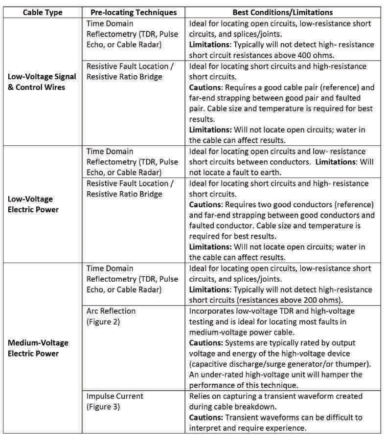
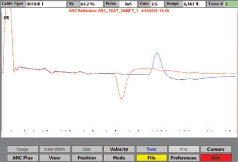
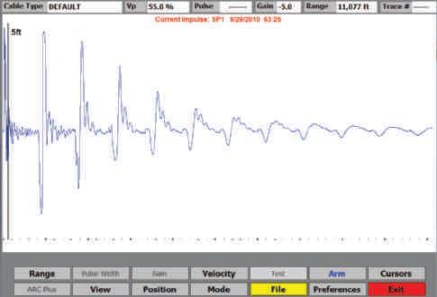
NETAWORLD • 91 CABLE FAULT LOCATION — NOT FOR THE FAINT OF HEART INDUSTRYTOPICS INDUSTRY TOPICS
Figure 2: Arc Reflection Test Reveals Fault at 3,126 Feet
Figure 3: Impulse Current Test Reveals Fault at 974 Feet

Most cable-fault-locating failures and wasted time can be attributed to technicians not properly interpreting test results, selecting the wrong tools for the job, or taking short cuts in the process.
Table 3: Tracking and Pinpointing Techniques
Obtaining an approximate location of a fault prior to tracking along the cable path saves time and effort and reduces potential stress to the cable. Keep in mind that although an approximate location can be obtained, a pinpointing technique is still advised.
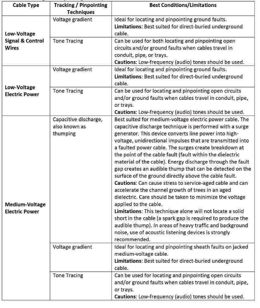
INDUSTRY TOPICS CABLE FAULT LOCATION — NOT FOR THE FAINT OF HEART
I N 92 • FALL 2016
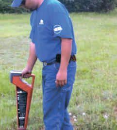
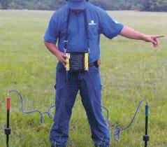
When faults occur, the pressure is on. Keep a cool head and stick to your step-by-step procedures; they will serve you well and keep you on the right path. Never rush out to the job site without collecting basic information about the task at hand. This will allow you to prepare the right tools for the task and will greatly improve your success.

Thomas D. Sandri is a Senior Technical Instructor at Shermco Industries. He has been active in the field of electrical power and telecommunications for over 30 years. During his career, he has developed numerous training aids, training guides, and has conducted domestic and international seminars. Thomas supports a wide range of electrical and telecommunication maintenance application disciplines. He has been directly involved in supporting test and measurement equipment for over 20 years and is considered an industry expert in application disciplines, including battery and dc systems testing and maintenance, medium- and high-voltage cables, ground testing, and partial discharge analysis. He holds a Bachelor of Science degree in Electrical Engineering from Thomas Edison University in Trenton, New Jersey.

 Tone Tracing a Direct Buried Cable
Acoustic Pinpoint Using Thumper and Acoustic Detector
Sertec Can Bring That Relay Back to Life
Sertec Relay Services buys and sells protective relays and specializes in extending the life of obsolete electromechanical relays by providing quality repair, remanufacture, and retrofit services for relays of all types and manufacture. We also service specialty electronics used in electrical power systems.
Instantaneous Overcurrent Relays
Time Overcurrent Relays
Directional Overcurrent Relays
Undervoltage Relays
Frequency Relays
Distance/Impedance Relays
RELAY MANUFACTURERS
General ElectricTM
WestinghouseTM
ABBTM
BaslerTM
Differential Relays
Reverse Power Relays
Phase Balance Relays
Schweitzer-SELTM
GE MultiLinTM, and more!
* Third-party trademarks are the property of their respective owners

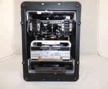

www.sertecrelayservices.com






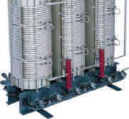


For more emergency contact phone numbers, visit: cbsalesne.com/services/field-services
WALLINGFORD, CT P:(203) 888-7500 SERTEC@CBSALESNE.COM Emergency support 24/7 203-888-7500

We support testing
Relay and Protective Device Test Equipment
Battery Analysis and Battery Discharge Test Equipment
Low Voltage Circuit Breaker and Switchgear Test Equipment
Medium/High Voltage Circuit Breaker and Substation Test Equipment
SF6 Chemical Analysis Equipment
Transformer Testing and Diagnostic Equipment
DC, VLF, Online PD and Offline PD Test Equipment for Cables
Cable Fault Location Equipment
Power Quality and Load Analysis
Data Acquisition and Recorders
Meter Analysis Equipment
Online and Offline Partial Discharge for Apparatus and Substations
Low Resistance Ohmmeters
Insulation Resistance / Megohmmeters
Ground Test Equipment
Photovoltaic Test Equipment
Infrared Cameras
Ultrasound and TEV Analysis Equipment
Motor and Rotating Apparatus Test Equipment
Patient Care Area Test Equipment
AC and DC Load Banks
AC High Potential Test Sets to 200kV
DC High Potential Test Sets to 200kV
VLF and Tan Delta to 90kV
888.902.6111

intellirentco.com rental support logistics
ir
info@intellirentco.com
intellirent





ANSI/NETA MTS - 2015 UPDATED EDITION To learn more about the newest edition of the ANSI/NETA MTS Standard for Maintenance Testing Specifications, visit netaworld.org/standards. ORDER NOW!


NETA has been connecting designers, specifiers, architectsan s and users of electrical power equipmenta t and systemswit s with idependent, third-party electrical testing companies since1 ce 1972


NETAA TA Accredited Companiestestt ies test thec e complete system in accordancewit ce with industry codesa des andst d standardst ds to provide accurate test reports you can count t on every time.


HIRE A NETA ACCREDITED COMPANY. For more informationon NETA or our ANSI/NETA Standa Standards rds give us a call at 888-300-NETA (6382) or a complete listing of NETA Accredited Companies visit www.netaworld.org.
Reliability.
Ensure YOUR Safety and

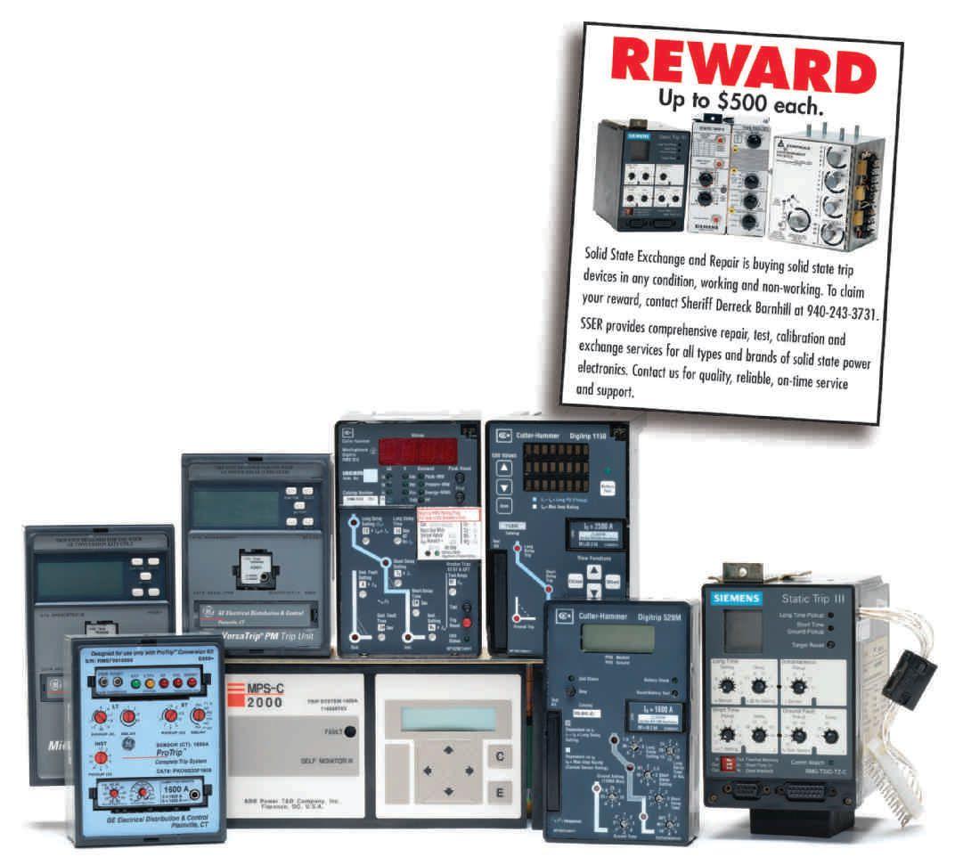
We Buy, Sell, Trade, Calibrate, Repair
Featuring quality, reliable, on-time service and support for all brands and types of solid state power electronics.
Power electronics are our business
Let us suppoort you with our quality repair, calibration and servicing of your solid state equipment. We also buy, sell and trade:
•Communications devices for power equipment
•Protective relays
•Circuit breaker trip devices
•Motor overload relays
•Rating plugs
4701 Spartan Drive • Denton, TX 76207 (877-874-7349) • Phone: 940-243-3731 • Fax: 940-387-8277 Email: info@solidstaterepair.com • Web: www.solidstaterepair.com
“SOLID STATE” INDUSTRIAL ELECTRONICS “SOLID STATE” INDUSTRIAL ELECTRONICS Toll Free 877-TRIP-FIX NOWRENTING TESTEQUIPMENT
ADVANCEMENTS IN TECHNOLOGY
DATA CENTER CONTAINMENT SYSTEMS
For those unfamiliar with data center thermal management containment systems, the following is a summary of the main approaches. This will form the basis for a discussion on testing practices.
In-Row Cooling Configuration. In-row cooling offers capacity and efficiency gains by moving the air conditioner from the perimeter of the room closer to the actual load. This system provides local, focused cooling at the rows of server cabinets that fill the data center. The cooling mechanism is generally situated between the equipment racks and arranged in single or and multiple rows (Figure 1).
Overhead Cooling Configuration. Similarly, an overhead cooling arrangement (Figure 2) contains a cooling mechanism situated over the racks and/or rack rows. Here again, the strategy is to manage the heat loads at the source — an approach that is well published and proven to yield higher efficiencies.
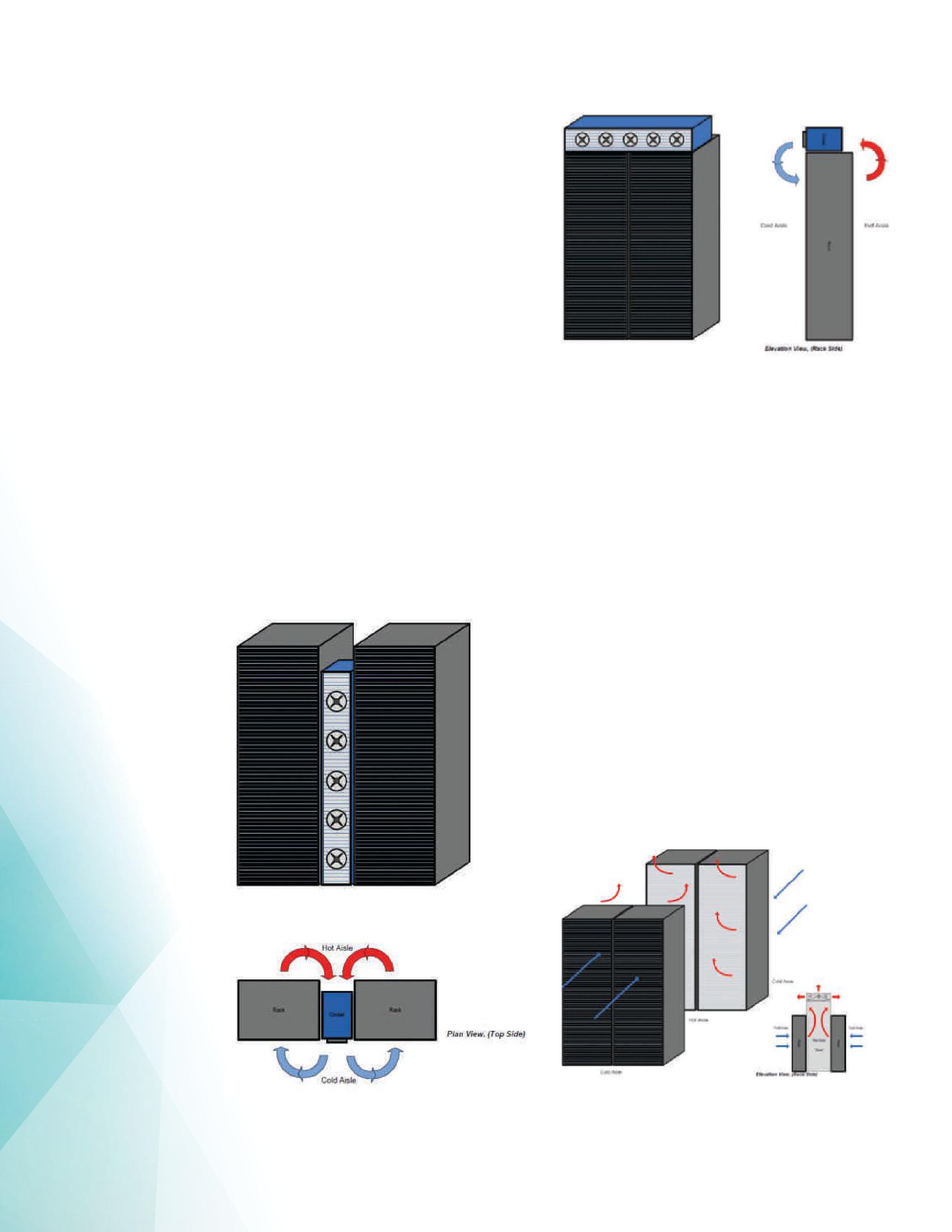
Hot Aisle Containment Scheme. Most IT equipment flows cooling air from front to rear. The conventional approach is to align equipment racks in a side-to-side row arrangement, forming a physical separation between the cooler intake air on the fore side (cold aisle) and the warmer exhaust air on the aft side (hot aisle). Hot-aisle containment (Figure 3) contains and manages the hot-aisle air before it migrates to other areas of the data center. This zone-controlled thermal management strategy results in heightened HVAC system efficiencies and reduced cap-ex and op-ex costs.
LOAD-BANK TESTING IN DATA CENTERS
Bulk Room Testing. Many data centers are tested and commissioned using bulk-room power and thermal load simulation. In these
100 • FALL 2016
PRECISION COMMISSIONING THROUGH INTEGRATED SYSTEM TESTING
Figure 1: In-Row Cooling
Figure 2: Overhead Cooling Configuration
Figure 3: Hot-Aisle Containment
cases, floor-mounted load banks (sometimes referred to as suitcase load banks) are dispersed throughout the room to simulate the power and heat generated by the rack-level equipment as specified in the data center design.
This method is generally straightforward due to the plug-and-play nature of suitcase units. Although they can be deployed quite rapidly, the efficiencies gained in set-up time are outweighed by the deficiencies that result from inaccurate emulation of rack-level thermal loading. Here, disproportionate temperature readings between that of macro-level load simulation and that of the actual and more discrete rack-level equipment may lead to over-sized HVAC equipment and reduced energy efficiency.
Discrete Zone Testing. A preferred alternative to bulk-room data center simulation is discrete zone simulation. In many cases, testing can be performed with rack-mounted load banks. Rack-mounted units can more precisely simulate the power and heat load distribution of the actual rack-level equipment as specified in the data center design.
Although the set-up of rack-mounted load banks is not as expedient as suitcase units, the advantages gained through closer simulation of rack-level architectures are great. For example, closer modeling of airflow throughout the rack yields areas where hot or dead zones must be addressed by containment or other HVAC strategies. Actual rack-level equipment can be reconfigured if rack-mounted load bank testing reveals extreme temperature gradients on the intake and/or exhaust sides of the racks. Moreover, closer simulation of the actual rack architecture allows HVAC equipment to be right-sized versus over-sized.
THE ENGENDREN/COMRENT EVALUATION
Test Arrangement. Although testing using rackmount load banks was generally considered to be a more accurate method for commissioning, little data is available to support this. To capture this data, ComRent configured a two-rack, single-row test cell (Figure 4) of four-post, open-
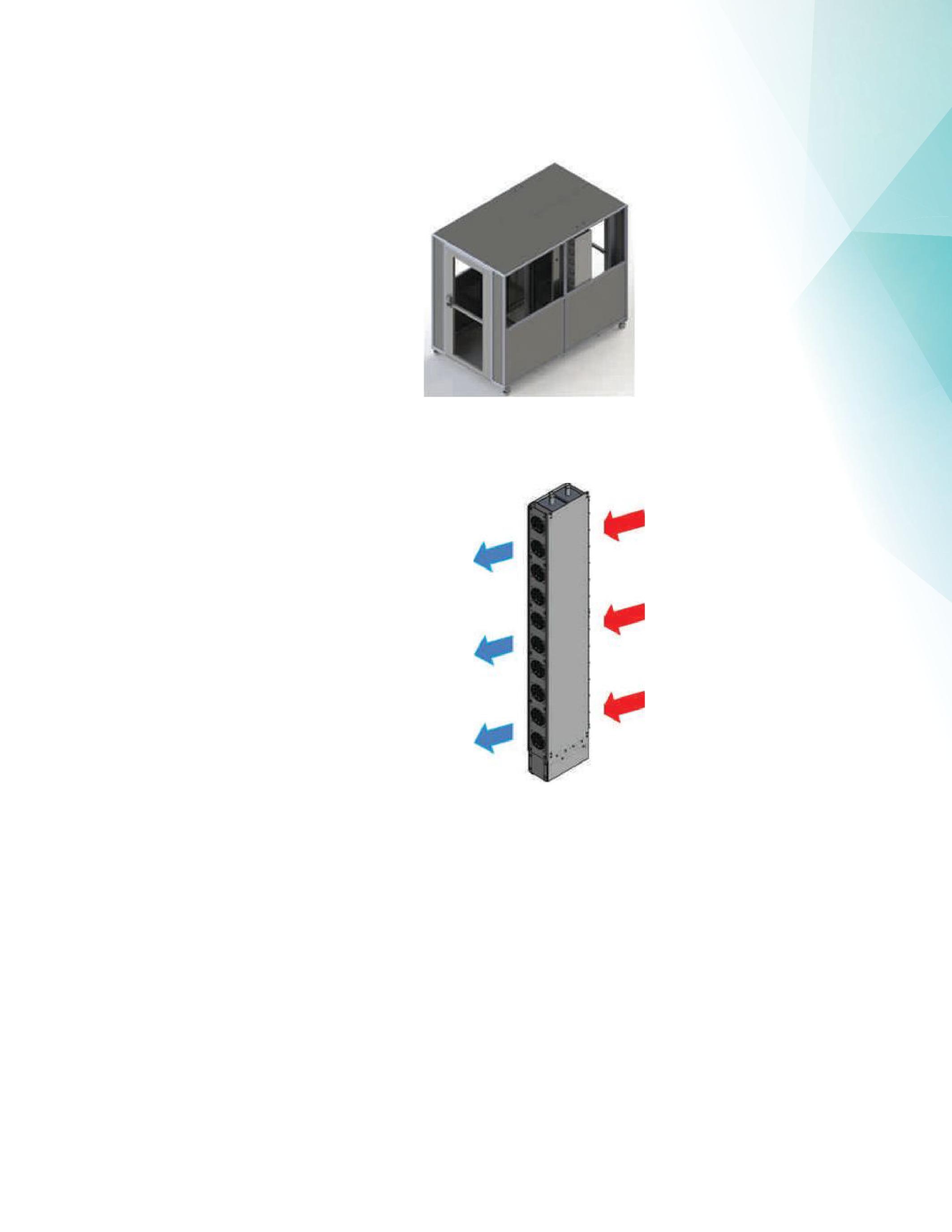
face racks at Engendren’ s facility in Kenosha, Wisconsin.Acontainmentzonewasestablished Wisconsin. A containment zone was established with a footprint of 5-foot width x 9-foot length x 8-foot height.
Thermal management was by in-row cooling per Engendren’s Thermodule technology (Figure 5). The variablespeed dc fans incorporated in Engendren’s Thermodule were controlled by the coldaisle temperature; they accurately held the cold-aisle temperature constant during the test.
NETAWORLD • 101
PRECISION COMMISSIONING THROUGH INTEGRATED SYSTEM TESTING
IN TECHNOLOGY
ADVANCEMENTS
Figure 5: Engendren’s Thermodule Technology
Figure 4: Engendren Test Cell


Rack loads (Figure 6) were simulated with various load bank arrangements, including:
• A single suitcase load bank positioned in the hot aisle
various load bank arrangements (Figure 7). Power draw was recorded for the auxiliary HVAC system as it reached equilibrium for each load bank arrangement.


• Two 9u rack-mounted load banks as located in the racks
• Four 5u load banks as located in the racks


Data Acquisition. Temperature and air flow readings in the hot and cold aisles were recorded from floor to ceiling in accordance with the
During data acquisition, temperature and air flow readings in the hot and cold aisles were recorded from floor to ceiling.
Test Results. Graph 1 demonstrates the equivalent of the occupant temperature in a room to that of
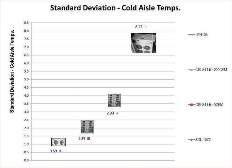
Graph 1: The accuracy of rack-mounted load banks is significantly better than floor load banks from a thermal mapping perspective.
102 • FALL 2016
PRECISION COMMISSIONING THROUGH INTEGRATED SYSTEM TESTING
ADVANCEMENTS IN TECHNOLOGY
Figure 7: Test Arrangement for Two-Rack System
Figure 6: Thermocouple Placement
a cold aisle temperature in a data center space. Cold aisle temperatures, like creature comfort temperatures, set the design basis for the HVAC industry (see ASHRAE TC 9.9, 2011 Thermal Guidelines for Data Processing Environments — Expanded Data Center Classes and Usage Guidance ). Inevitably, poorly distributed temperatures in a computer room will lead to specifying larger equipment and/or the occupant adjusting the thermostat to compensate for the hot pockets. The first leads to excessive capital equipment investments and lower efficiency, whereas the latter leads to higher capital and/or operating costs.
Similarly, Graph 1 demonstrates that improved emulation of load bank size and configuration to that of the actual server equipment leads to more realistically profiled cold aisle temperatures. The result: Heightened precision of empirical data allows for more accurate designing, selecting, and operating facilities equipment.
ADVANCEMENTS IN TECHNOLOGY
Like the cold aisle temperature, the data center industry references Power Use Effectiveness (PUE) as a benchmark efficiency target. PUE is the ratio of total consumed power (entire infrastructure load) to total consumed IT power (IT load). For testing, this is calculated as:
(HVAC auxiliary load + Load Bank Setting) / Load Bank Setting
where the load bank accurately represents the IT load — electrical and thermal. The ideal PUE ratio approaches 1, but is 1.5 for an efficient facility with an average facility at 2.0. Poorly distributed thermal loads during testing will lead to false-positive efficiencies of a data center. In this case (Graph 2), the load banks that more closely simulate that of rack-level equipment result in lower PUE. Bulk-average, suitcase, or floor-mountedloadbankscause floor-mounted load banks cause the auxiliary equipment to compensate where input power must increase, resulting in higher and effectively false PUE values.
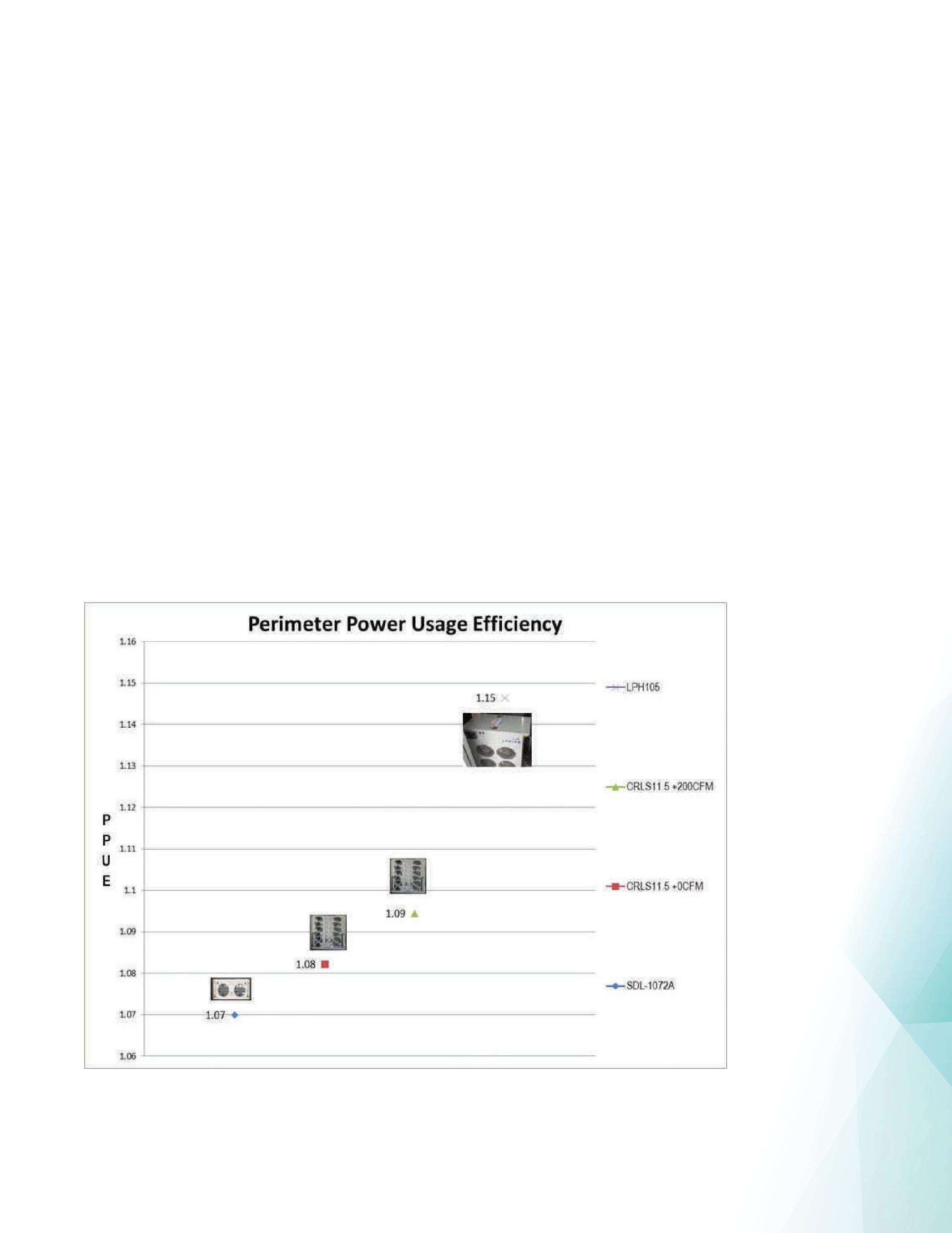
Graph 2: The PPUE graph shows that the accuracy of rack-mounted load banks is significantly better than floor loadbanks — from a power-use efficiency perspective.
NETAWORLD • 103
PRECISION COMMISSIONING THROUGH INTEGRATED SYSTEM TESTING
ADVANCEMENTS IN TECHNOLOGY
OPPORTUNITY FOR IMPROVEMENT IN COMMISSIONING TESTING
The data also shows opportunity to fine-tune the designs of load banks using these testing scenarios. For example, the thermal image shown here (Figure 8) illustrates that the hotaisle air is being pushed into the cold aisle due to the high fan speed. This could be curtailed by more precise resolution of fan speed control.
COMMISSIONING BEST PRACTICES
For maintenance professionals and technicians supporting facilities that must meet energy consumption targets, install integrated and complex systems, and introduce new technologies and concepts, commissioning in the design phase will help achieve energy performance parameters.
Some overall best practices for commissioning include:
1. Integrated Systems Testing
• Perform integrated systems testing as a test of all electrical systems under expected
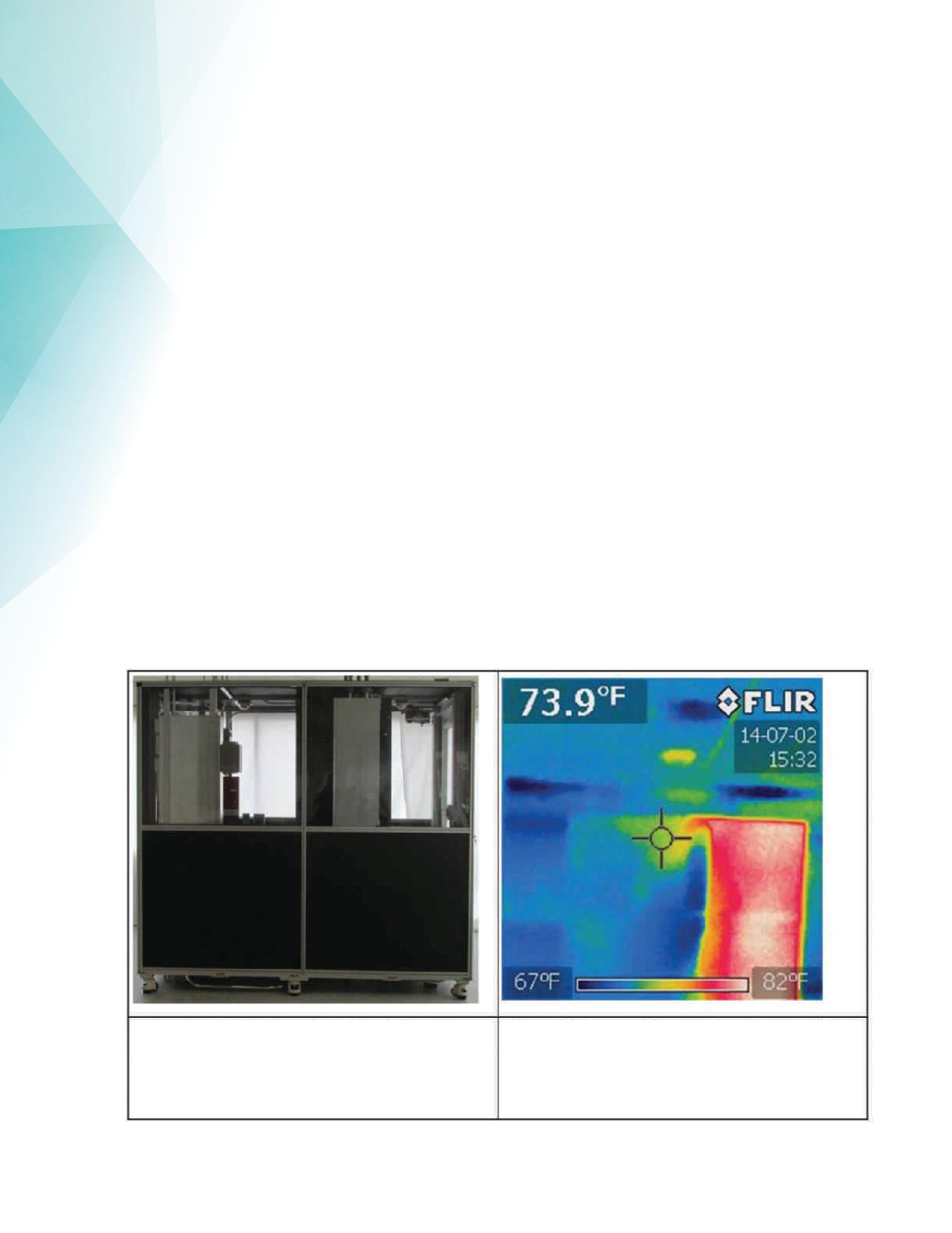
loads as they have been installed. In the case of critical facilities, the system is also tested and optimized during this phase.
• Use rack-mounted load banks to precisely simulate computer equipment electrical loads, thermal distribution and airflow in hot aisle/cold aisle containment
2. Comprehensive Test Planning
• Include commissioning test planning in all phases of a project as well as maintenance and installation functions.
• Use data captured during the commissioning of a project as a baseline for maintenance testing and other maintenance activities.
• Determine which high-performance building standards will require verification through testing and commissioning and which tests will need to be run, as well as which stakeholders in the commissioning process need to be involved.
104 • FALL 2016
PRECISION COMMISSIONING THROUGH INTEGRATED SYSTEM TESTING
Figure 8a: Test Setup: Cold Aisle at Left, Hot Aisle at Right
Figure 8b: Thermal Image When Fan Speed is Set Too High

• Determine what equipment is required to conduct these tests, how to capture the necessary data, and determine the proper amount of time for reports to be created.
3. Evaluation of Equipment Requests in Relation to Testing Objectives
• Determine if the equipment is the right tool for the job, if it is readily available and cost effective, and if it will arrive on time in proper working order.
• Determine if the power quality measurement data and reporting are efficient.
• Ensure that the equipment is properly maintained and operated in a safe manner.
• Implement a commissioning test plan that accurately simulates the electrical and thermal load characteristics of the equipment to be used in the data center. This will result in optimized efficiency and lower maintenance costs.
4. Employ New Tools and Equipment that Faciliate Optimization
•Use newly available products and techniques to make the precision testing easier to perform with less testing and setup time. New products will include a more flexible application through improved adjustability.
•Use multiple methods for power connection to the rack-mounted load bank.
•Take advantage of the ability to adjust power demand in much smaller increments.
•Make sure airflow is adjusted more precisely.
• Set up the test so the thermal distribution simulates what’s expected after computer equipment installation.
ADVANCEMENTS IN TECHNOLOGY
5. Gain Greater Control and Save Time in Test Setup and Operation
• Use mounting and setup of the load banks as a much faster and safer alternative than currently available products
• Use remote controls to allow multiple load banks or the entire test to be controlled from a single remote control.
This article provides information on best practices in commissioning that are not generally known in the industry. ComRent provides NETA member companies with support in developing leading practices that tie commissioning and maintenance to improve facility availability.
Special thanks to Al Meissner, Chief Technology Officer, Engedren
Mark Siira is the Director of Technology Strategy for ComRent International, a leader in load-testing solutions. He is a senior member of IEEE, including a member of the IEEE Standards Coordinating Committee 21, which establishes standards for grid interconnection and smart grid interoperability; Working Group Chair of IEEE 2030.2 Guide for Interoperability of Energy Storage Systems; Vice Chair for IEEE1547 Interconnection Standard Revision, focusing on interoperability, simulation and modeling, and testing; and is starting activity on IEEE1547.1 Test Procedures for Interconnection. Mark is an active participant in the IEEE Power Systems Relaying Committee; Vice Chair of Committee K10 - SCC21 Distributed Resources Standard Coordination; and a member of Committee I25 Substation Commissioning Best Practices Report to NERC. He is a member of the UL Standards Technical Panels 1741 (Inverters), UL2200 (Generators), and 6171 (Wind Farms Interconnection), and Sub-Group Chair of the EPRI Energy Storage Integration Council, which is leading an effort to define commissioning practices for energy storage and PV systems. Mark has spent 20 years in the distributed power generation industry developing products and solutions for an inverter and energystorage appliance, combined heat and power systems, critical power systems paralleling switchgear, and microturbines. He has a Bachelor of Science in Mechanical Engineering from GMI Engineering and Management Institute (now Kettering University) and an MBA from Harvard University.
NETAWORLD • 105
PRECISION COMMISSIONING THROUGH INTEGRATED SYSTEM TESTING


www.youtube.com/tdeinc2www.twitter.com/tdeincwww.facebook.com/tdeinc


ENGINEERING SERVICES • TECHNICAL SERVICES • COMMISSIONING Protection Systems Design, Relay Testing
F Street
90744 Los Angeles Area | |
131 W
Wilmington, CA
CA LICENSE #315448 TRAINING
www.linkedin.com/company/tony-demaria-electric

Test your industry knowledge with the images and questions on pages 109-110 in the Fall issue of the NETA World Journal.
Watch for additional trivia quizzes in the upcoming issues of the NETA World Journal, online, and through NETA’s Facebook and LinkedIn networks.
Answers must be submitted by email to neta@netaworld.org to be eligible for the prize drawing at PowerTest 2017.
NETA’s 45th Anniversary Celebration will culminate at the PowerTest 2017’s Power Bash Reception, on February 28, 2017, in Anaheim, California. Watch for other exciting celebratory events leading up to and during PowerTest 2017.


ANAHEIM • CALIFORNIA February 27 - March 3 • 2017 DISNEYLAND HOTEL THE PREMIER ELECTRICAL MAINTENANCE & SAFETY EVENT POWERTEST.ORG • 888.300.6382 Complete Your Early Bird Registration Today and Save $100 ch 3 • 2017 D I S NEY L 00 JOINNETA IN CELEB R A T I N G 4 5 Y E ARS OF EXCELLENCE The countdown to NETA’s 45th Anniversary Celebration begins now!
JOIN NETA IN CELEBRATING 45 YEARS OF EXCELLENCE
NETA — The InterNational Electrical Testing Association begins the countdown to its 45th Anniversary celebration event at PowerTest 2017 with the announcement of industry-wide activities and challenges and recognition of milestone accomplishments.
NETA — The InterNational Electrical Testing Association is kicking off a series of activities and events to engage members and the electrical power systems industry at large in the celebration of its 45th Anniversary. The celebration will include a historical look back at the progress and accomplishments of the organization and the industry it serves, interesting Trivia Challenges, and a special event at PowerTest 2017dedicatedtothe45 2017 dedicated to the 45th Anniversary.
Founded in 1972 by nine electrical testing companies, NETAwascreatedtoestablishstandardsforelectrical NETA was created to establish standards for electrical testing of electrical power equipment and systems. In the early days of NETA, membership focused on electrical testing. Standards were authored by NETA’s early members to codify testing procedures that clarify industry best practices and improve the quality of testing, safety, and system reliability. As time passed and technology advanced, electrical testing came to include more services, allowing wider diversity among companies eligible to become accreditedwithNETA. accredited with NETA.
Today, NETA is the only accrediting body of electrical testing organizations, providing assurances that its member NETA Accredited Companies meet specific requirements necessary to perform electrical testing to the industry’s highest standards. Withtheintroductionofthe With the introduction of the ANSI/NETAStandard ANSI/NETA Standard for Electrical Commissioning Specifications in 2015, NETA now publishes and maintains four ANSI-approved standards that are used by testing companies, engineering firms, power distribution

organizations, and those responsible for power system maintenance across the many industries that supply this economy.
“NETA and the industry have come a long way in 45 years, thanks to a collective commitment toward continual improvement across all sectors of the electrical power industry,” says Ron Widup, CEOofShermcoIndustriesandNETA’sBoard CEO of Shermco Industries and NETA’s Board President.“NETAwillcelebrateitssharedsuccesses President. “NETA will celebrate its shared successes with a salute to the industry’s advancements and achievements, and with a challenge to all powerrelatedbusinessestocontinuetoraisethebaron related businesses to continue to raise the bar on quality, safety, and reliability.”
As part of the Anniversary celebration, the next severalissuesof several issues of NETA World Journal will inspire readers to consider the electrical power system industry’s 45-year evolution of technology and progress. NETA will partner with suppliers, service providers, testing companies, electrical and test equipment manufacturers, and other professionals to recognize the industry’s milestone achievements and excellence — accomplishments that were born and spirited through collaboration and volunteerism.
TokickoffNETA’s45 To kick off NETA’s 45th Anniversary Celebration, NETA is sponsoring a historical Trivia Challenge with questions provided by industry suppliers and NETA Accredited Companies. Open to anyone in the industry, test your industry knowledge with the images and questions in this article, the first in a series of trivia quizzes. Participants are encouraged to submit quiz answers to neta@
JOIN NETA IN CELEBRATING 45 YEARS OF EXCELLENCE
108 • FALL 2016
netaworld.org to be eligible for a prize drawing at PowerTest 2017, where the 45th Anniversary celebrationwillculminate. celebration will culminate.
With the assistance of its many industry friends, the45 the 45th Anniversary special event at PowerTest will also include a fascinating historical display of industry apparatuses and equipment, with additional opportunities to test your knowledge.
“NETAisexcitedtocelebratemorethan “NETA is excited to celebrate more than four decades of serving the electrical power systems industry over the coming months, and we welcome everyone to participate in these unique activities leading up to the special event at PowerTest 2017,” says Missy Richard, NETA’s Executive Director. For more information on PowerTest, please visit www.powertest.org.
NETA’s 45th Anniversary
TRIVIACHALLENGE—SERIES1 TRIVIA CHALLENGE — SERIES 1
TESTYOURINDUSTRYKNOWLEDGE TEST YOUR INDUSTRY KNOWLEDGE
Note: Please submit answers by emailing neta@netaworld.org to be entered into the prize drawing at PowerTest 2017.
Trivia Challenge #1
Vintage Circuit breaker
The photo below is of a vintage breaker recently in service at a sawmill in Florida.
Questions:
1. What years were these type of circuit breakersmade? breakers made?
2. ThemanufacturerisITE–Whatdoes The manufacturer is ITE – What does ITEstandfor? ITE stand for?
3. Whatistheframesize? What is the frame size?
4. Whatisthemodel? What is the model?

The above photo shows the back of six of the same vintage breakers as shown left. One breaker failed at the cable connection point which caused an arc flash and damaged one of the breakers. Replacement parts were available to repair this breaker, but the loss wassubmittedasaninsuranceclaim.From was submitted as an insurance claim. From the photo, you can see this configuration used six breakers with no main and no bus, just cable connections, which is no longer valid per the current NEC. The insurance company would not allow for a non-NEC-compliant installation to be repaired, so all the gear was pulled out and replaced with a new line-up.
Photos and questions contributed by Group CBS
NETAWORLD • 109 JOIN NETA IN CELEBRATING 45 YEARS OF EXCELLENCE
Questions:
1.WhatisanEvershedTest?
1. What is an Evershed Test?
2.WhoisEvershed? 2. Who is Evershed?
3. What do you think it says under the whitemask? white mask?
Trivia Challenge #2 Vintage Evershed’s Testing Set
contributed by 3-C Electrical Co.,
Independent Electrical Testing and Preventive Maintenance PROFESSIONAL SERVICES 609-890-8300 www.easternhighvoltage.com
Photos and questions
Inc.

Extend their life, avoid downtime, and save $$$ with NEW Encapsulated Pole replacement assemblies
EXTEND THE LIFE OF YOUR POWER/VAC® CIRCUIT BREAKERS WITH NEWENCAPSULATED POLES
EPOXY-ENCASEDPOLESRESISTCONTAMINATION,MOISTURE, ANDOTHERADVERSE ENVIRONMENTALCONDITIONS
EXTENDSTHELIFEOFYOURBREAKER,ALLOWINGRE-USEOF TRUSTED USA-MADEMECHANISM
FUTUREMODELSWILLACCOMMODATEALL POWER/VAC® RATINGSUPTO27kV AND63kA
DON’T SAY GOODBYE TO YOUR OLD POWER/VAC® ®
CIRCUIT BREAKERS
13765 BETA ROAD, FARMERS BRANCH, TEXAS 75244 | 214-442-5877 VACUUMINTERRUPTERSINC.COM | INFO@VACUUMINTERRUPTERSINC.COM One of these is abrand new vacuum interrupter. The other two are 30-year-old hand grenades. Which one is in your circuit breaker? MAC-TS4 The world’s first predictive test system for vacuum interrupters 13765 BETA ROAD, FARMERS BRANCH, TEXAS 75244 | 214-442-5877 VACUUMINTERRUPTERSINC.COM | INFO@VACUUMINTERRUPTERSINC.COM LEARN MORE AT VACUUMTESTING.COM Replacement vacuum interrupters | Vacuum interrupter test systems | Portable circuit breaker timer test systems US PATENTNO.9,031,795 B1 And replacements for every othervacuumbreaker other vacuum breaker evermadetoo! ever made too! Need a vacuum interrupter from We have it in stock.
TWO NEW SELF-PACED TECHNICAL SEMINARS (SPTS)
*CTDs awarded when participant receives a passing score on the proficiency exam. Maintenance and Testing of
Learn at your own pace. Advance your knowledge. Ask about continuing education. Earn CTD*Credits for NETA Level III and IV Technicians. Order online at: www.netaworld.org or call 888-300-6382 (NETA)

ADDITIONAL COURSES AVAILABLE
Battery Systems Risk Assessment Techniques Using NFPA 70E: A Primer
ANSI/NETA STANDARDS UPDATE
BY KRISTEN WICKS, NETA
ANSI/NETA ATS-201X REVISION IN PROCESS
The ANSI/NETA, Standard for Acceptance Testing Specifications for Electrical Power Equipment and Systems began the review and revision process in October 2014 at the Standards Review Council meeting. The initialballotanddraftdocumentwillbe initial ballot and draft document will be issued on May 31, 2016, with a closing date of June 30, 2016. The draft document will be available for public comment from April 22 through June 6, 2016. The document is expected to be published as a revised ANSI standard in the spring of 2017.
ANSI/NETA ECS-2015 FIRST EDITION AMERICAN NATIONAL STANDARD
The ANSI/NETA ECS, Standard for Electrical Commissioning of Electrical Power Equipment and Systems, 2015 edition, was approved as an American National Standard on December 3, 2014. This new standard is available for purchase in the NETABookstore NETA Bookstore www.netaworld.org .
instrumentation systems, and related components.
Voltage classes addressed include:
• Low-Voltage Systems (less than 1,000 volts)
• Medium-Voltage Systems (greater than 1,000 volts and less than 100,000 volts)
• High-Voltage and Extra-High Voltage Systems (greater than 100 kV and less than 1,000 kV)
References
TheANSI/NETAATS-201Xcoversthe
The ANSI/NETA ATS-201X covers the suggested field tests and inspections that are available to assess the suitability for initial energization of electrical power equipment and systems. The purpose of these specifications is to assure that tested electrical equipment and systems are operational, are within applicable standards and manufacturers’ tolerances, andareinstalledinaccordancewith and are installed in accordance with design specifications.
TheANSI/NETAECSdescribesthe The ANSI/NETA ECS describes the systematic process of documenting and placing into service newly installed or retrofitted electrical power equipment and systems. This document shall be used in conjunction with the most recent edition of the ANSI/NETA, Standard for Acceptance Testing Specifications for Electrical Power Equipment and Systems. The individual electrical components shall be subjected to factory and field tests, as required, to validate the individual components. It is not the intent of these specifications to provide comprehensive details on the commissioning of mechanical equipment, mechanical
ASHRAE, ANSI/NETA ATS, NECA, NFPA 70E, OSHA, GSA Building Commissioning Guide
ANSI/NETA MTS-2015 NEW EDITION
The ANSI/NETA MTS, Standard for Maintenance Testing Specifications for Electrical Power Equipment and Systems, 2015 edition, was approved as an American National Standard on December 3, 2014, and supersedes the ANSI/NETA MTS2011.Thisnewstandardisavailable 2011. This new standard is available
114 • FALL 2016 ANSI/NETA STANDARDS UPDATES SPECIFICATIONS AND STANDARDS ACTIVITY
ANSI/NETA ECS-2015 S T A N D ARD FO R EL E C T RI C A L COMMISSIONING S P EC IFI C A T IO N S F OR EL ECTR ICALPOWER EQUIPMENT AND SYSTEMS GSPECIFICATIONS ANSI/NETA ETT-2015 S T AN D ARDF ARD F O R CERTIFICATION OF ELEC TRICAL TESTING T EC HN ICI A N S 2015 N E R
for purchase in the NETA Bookstore online at www.netaworld.org.
The ANSI/NETA MTS contains specifications that cover suggested field tests and inspections available to assess the suitability for continued service and reliability of electrical power equipment and systems. The purpose of these specifications is to assure that tested electrical equipment and systems are operational and within applicable standards and manufacturers’ tolerances, and that the equipment and systems are suitable for continuedservice. continued service.
Revisionsinclude: Revisions include:
• New numbering system for more accurate referencing
• Protective relays
• Instrumenttransformers Instrument transformers
• Rotating machinery
• RevisedTable100.1 Revised Table 100.1
• NewTable100.11 New Table 100.11
• Updated references to industry standards
• Many more revisions, all marked in the margins for ease of use
ANSI/NETA ETT-2015 NEW EDITION
The ANSI/NETA ETT, Standard for Certification of Electrical Testing Technicians, 2015 edition , was approved as an American National Standard on December 3, 2014, and supersedes the ANSI/NETA ETT-2010. This new standard is available for purchase in the NETABookstoreonlineat NETA Bookstore online at www.netaworld.org
The ANSI/NETA ETT establishes minimum requirements for qualifications, certification, training, and experience for the electrical testing technician. It also provides criteria for documenting qualifications for certification and details the minimum qualifications for an independent and impartial certifying body to certify electrical testing technicians.
PARTICIPATION
Comments and suggestions on any of the standards are always welcome and should be directed to the NETA office at neta@netaworld.org or 888-300-6382. To learn more about the NETA standards review and revision process, to purchase these standards, or to get involved, please visit www.netaworld.org or call 888-300-6382.
FULL SERVICE INDEPENDENT ELECTRICAL TESTING Acceptance Testing Services Low, Medium, and High Voltage Preventative Maintenance & Testing Switchgear Transformers Engineering Services 781-767-0888 Email: infrared.ma@verizon.net 152 Centre Street Holbrook, MA 02343 www.Infraredbps.com Years of Experience Years of Reliability 25
ANSWERS

ANSWERS
1. e. NFPA 70E specifies the requirements for a safety backup or standby person (second person). The electrical safety program should specify what PPE, training, and experience that person should have. Informational Notes cannot contain requirements but are used to clarify and provide additional direction as to the committee’s thinking on a subject. Even though Informational Note No. 2 says that such information may be specified, this information should be considered whenever a safety backup is used.

5. e. This is a topic that comes up frequently at NFPA 70E committee meetings. Some committee members believe that the 70E should provide best safe work practices. As NETA Board President Ron Widup once stated, if that were the case, the 70E could be boiled down into one sentence: Turn it off!

2. a. In all the electrical incidents I have seen over the years, one step might have prevented 90 percent of these incidents. If technicians would faithfully perform an absence-ofvoltage test — whether they think the circuit is energized or not — they could save themselves and their families a lot of pain, suffering, and grief. It is the single most important safety task to perform.
3. e. OSHA uses what is called a single point of responsibility. That single point is the employer. OSHA will always hold the employer responsible for their employees’ safety. Job safety assessments, risk assessments, etc., are all required to be completed by the employer. This may simplify OSHA’s task of assessing responsibility, but the fact of the matter is that the employee is the one who suffers from a mishap. No employer can be everywhere a technician is about to work, nor can that employer be at the site in front of the equipment to assess risk. Only the technician preparing to perform a task can make the final risk assessment. This is especially true for NETA Field Service Technicians.
4. a, d, and e. NFPA 70E Section 130.4 covers the shock hazard and risk assessment, while Section 130.5 covers arc flash. Additional protective measures could include guarding the energized conductors or circuit parts, setting up safety barrier tape, identification of look-alike equipment, or other measures as called out by NFPA 70E.
What the 70E really provides is the minimum acceptable safe work practices, much as OSHA regulations do. Employers and employees are expected to exceed these minimum requirements to protect their safety. Unfortunately, many people take the 70E at face value and do not do what is needed to prevent themselves or others from being injured.
NFPA Disclaimer: Although Jim White is a member of the NFPA Technical Committee for both NFPA 70E, Standard for Electrical Safety in the Workplace and NFPA 70B, Recommended Practice for Electrical Equipment Maintenance,”the views and opinions expressed in this message are purely the author’s and shall not be considered an official position of the NFPA or any of its technical committees and shall not be considered to be, nor be relied upon as, a formal interpretation or promotion of the NFPA. Readers are encouraged to refer to the entire text of all referenced documents.
TECH QUIZ ANSWERS
No.115
No. 115
TECHQUIZ
116 • FALL 2016
RESPONSIBLE FOR ELECTRICAL POWER SYSTEM COMMISSION? Get the ANSI/NETA Standard for Acceptance Testing and the ANSI/NETA Standard for Electrical Commissioning. Save 28% when you purchase the ANSI/NETA ATS 2013 and ANSI/NETA ECS 2015 together. To order: visit www.netaworld.org, call 888.300.6382, or email neta@netaworld.org New! BUNDLE YOUR ORDER AND SAVE! Vanguard InstrumentsCompany, Inc. www.vanguard-instruments.com Electro Rent answers your every test need. Learn more at: www.electrorent.com/electr ica l-power 800.304.4744 | sales@electrorent.com » Largest inventory » Consistent, reliable delivery service » Immediate availability » ISO and ANSI accredited labs 19 1965-2065-2015 15 Y EAR S Electro Rent is Now a NETA Gold Corporate Alliance Partner Electro Rent Turns 50 Count on Electro Rent to get the test equipment you need fast, with experienced customer support you can rely on, 24x7. From motor test equipment to borescopes: if it tests, we’ve got it and we’re ready to meet your need.
Absolute confidence. Every time.
You can count on us for specialized experience in healthcare, data center, office complex, and commercial acceptance and maintenance testing. Absolutely Power generation, petrochemical, oil & gas, and heavy industries also look to us for high demand services such as start-up commissioning, maintenance testing, shut-down and turnarounds, and breaker shop repair. Get started today.


Email: Alan Postiglione apost@absolutetesting.com

6829
Road,
77040
absolutetesting.com Like us on:
Toll free: 832.467.4446
Guhn
Houston, Texas
SOLUTION.





When your electrical equipment is failing, getting the parts you need shouldn’t be part of the problem. With a huge inventory of new, surplus and repurposed electrical circuit breaker and switchgear products, National Switchgear can be a big part of your solution. We have millions of parts, but we also have the expertise to see the whole picture, to understand your problem and to recommend the best total solution. Of course, if you already know exactly what you need, we make it easy to buy online on our constantly updated website, where you’ll also discover hard-to-find resources like installation manuals, wiring diagrams and more. If you need advice, customized equipment, remanufacturing or reconditioning, we’re ready to share our expertise. Because integrity is always in stock. 800-322-0149 nationalswitchgear.com
WE’RE MORE THAN JUST PARTS. WE’RE PART OF THE
NETA ACCREDITED COMPANIES Setting the
A&F Electrical Testing, Inc.
80 Lake Ave. South, Ste. 10 Nesconset, NY 11767 (631) 584-5625 Fax: (631) 584-5720 kchilton@afelectricaltesting.com www.afelectricaltesting.com
Kevin Chilton
A&F Electrical Testing, Inc.
80 Broad St. 5th Floor
New York, NY 10004 (631) 584-5625 Fax: (631) 584-5720 afelectricaltesting@afelectricaltesting.com www.afelectricaltesting.com
Florence Chilton
ABM Electrical Power Solutions
3602 East Southern Ave., Ste. 1 Phoenix, AZ 85040 (602) 722-2423 www.ABM.com
Doug Bukowski
ABM Electrical Power Solutions
9800 E. Geddes Avenue, Unit A-150 Englewood, CO 80112 (303) 524-6560 Fax: (303) 524-6581 www.ABM.com
Brian Smith
ABM Electrical Power Solutions
2142 Rheem Drive Pleasanton, CA 94588 (408) 466-6920 www.ABM.com
John Marvulli
ABM Electrical Power Solutions
3940 Ruffin Rd., Ste. C San Diego, CA 92123 (858) 754-7963 william.mckenzie@abm.com www.ABM.com
William McKenzie
ABM Electrical Power Solutions
6280 South Valley View Blvd., Ste. 618 Las Vegas, NV 89118 (602) 300-2188 Fax: (602) 437-3894 www.ABM.com
Jason Black
ABM Electrical Power Solutions 814 Greenbrier Circle, Ste. E Chesapeake, VA 23320 (757) 548-5690 Fax: (757) 548-5417 www.ABM.com
Mark Anthony Gaughan, III
ABM Electrical Power Solutions
3700 Commerce Dr. #901-903 Baltimore, MD 21227 (410) 247-3300 Fax: (410) 247-0900 www.ABM.com
Bill Hartman
ABM Electrical Power Solutions
5809 Departure Dr., Ste. 104 Raleigh, NC 27616 (919) 877-1008 Fax: (919) 501-7492 www.ABM.com
Rob Parton
ABM Electrical Power Solutions
317 Commerce Park Dr. Cranberry Township, PA 16066-6427 (724) 772-4638 Fax: (724) 772-6003 christopher.smith@abm.com www.ABM.com
Christopher Smith
ABM Electrical Power Solutions 4390 Parliament Place, Ste. S Lanham, MD 20706 (301) 967-3500 Fax: (301) 735-8953 www.ABM.com
Frank Ceci
ABM Electrical Power Solutions 3600 Woodpark Blvd., Suite G Charlotte, NC 28206 (704) 273-6257 Fax: (704) 598-9812 ernest.goins@abm.com www.ABM.com
Ernest Goins
ABM Electrical Power Solutions
720 S. Rochester Ave., Suite A Ontario, CA 91761 (800) 597-1225 Fax: (909) 937-6798 www.ABM.com
Mike Bivens
Absolute Testing Services 6829 Guhn Rd. Houston, TX 77040 (832) 467-4446 Fax: (713) 849-3885 rgamble@absolutetesting.com www.absolutetesting.com
Richard Gamble
Accessible Consulting Engineers, Inc. 1269 Pomona Rd., Ste. 111 Corona, CA 92882 (951) 808-1040 info@acetesting.com www.acetesting.com
Iraj Nasrolahi
Advanced Testing Systems 15 Trowbridge Dr. Bethel, CT 06801 (203) 743-2001 Fax: (203) 743-2325 pmaccarthy@advtest.com www.advtest.com
Pat MacCarthy
American Electrical Testing Co., Inc.
25 Forbes Blvd., Ste. 1 Foxboro, MA 02035 (781) 821-0121 Fax: (781) 821-0771 sblizard@aetco.us www.99aetco.com
Scott A. Blizard
American Electrical Testing Co., Inc. 34 Clover Dr. South Windsor, CT 06074 (860) 648-1013 Fax: (781) 821-0771 jpoulin@aetco.us www.99aetco.com
Gerald Poulin
American Electrical Testing Co., Inc. 76 Cain Dr. Brentwood, NY 11717 (631) 617-5330 Fax: (631) 630-2292 mschacker@aetco.us www.99aetco.com
Michael Schacker
American Electrical Testing Co., Inc. 50 Intervale Rd., Ste. 1 Boonton, NJ 07005 (973) 316-1180 Fax: (781) 316-1181 jsomol@aetco.us www.99aetco.com
Jeff Somol
American Electrical Testing Co., Inc. 4032 Park 65 Dr. Indianapolis, IN 46254 (317) 487-2111 Fax: (781) 821-0771 scanale@aetco.us www.99aetco.com
Stephen Canale
American Electrical Testing Co., Inc. Green Hills Commerce Center 5925 Tilghman St., Ste. 200 Allentown, PA 18104 (215) 219-6800 jmunley@aetco.us www.99aetco.com
Jonathan Munley
American Electrical Testing Co., Inc. 12566 W. Indianola Ave. Avondale, AZ 85392 (480) 383-9242 dmadaglia@aetco.us www.99aetco.com
Donald Madaglia
AMP Quality Energy Services, LLC 4220 West Schrimsher SW Site W1 P.O. Box 526, Huntsville, AL 35804 (256) 513-8255
Brian Rodgers
Apparatus Testing and Engineering 11300 Sanders Dr., Ste. 29 Rancho Cordova, CA 95742 (916) 853-6280 Fax: (916) 853-6258 info@apparatustesting.com www.apparatustesting.com
Harold (Jerry) Carr
Apparatus Testing and Engineering
7083 Commerce Circle, Ste. H Pleasanton, CA 94588 (925) 454-1363 Fax: (925) 454-1499 info@apparatustesting.com www.apparatustesting.com
Harold (Jerry) Carr
Applied Engineering Concepts 1105 N. Allen Ave. Pasadena, CA 91104 (626) 398-3052 Fax: (626) 398-3053 michel.c@aec-us.com www.aec-us.com
Michel Castonguay
BEC Testing 50 Gazza Blvd. Farmingdale, NY 11735 (516) 531-9136 Fax: (631) 249-6115 wfernandez@banaelectric.com www.bectesting.com
William Fernandez
Burlington Electrical Testing Co., Inc.
300 Cedar Ave. Croydon, PA 19021-6051 (215) 826-9400 (221) Fax: (215) 826-0964 waltc@betest.com www.betest.com
Walter P. Cleary
C.E. Testing, Inc. 6148 Tim Crews Rd. Macclenny, FL 32063 (904) 653-1900 Fax: (904) 653-1911 cetesting@aol.com
Mark Chapman
CE Power Solutions,LLC 4040 Rev Dr. Cincinnati, OH 45232 (513) 563-6150 Fax: (513) 563-6120 info@cepowersol.net www.cepower.net
Rhonda Harris
CE Power Solutions of Minnesota,LLC 7674 Washington Ave. South Eden Prairie, MN 55344 (877) 968-0281 Fax: (952) 400-8772 jason.thompson@cepower.net www.cepower-mn.net
Jason Thompson
Control Power Concepts 353 Pilot Rd; Ste. B Las Vegas, NV 89119 (702) 448-7833 Fax: (702) 448-7835 www.controlpowerconcepts.com
John Travis
NETA ACCREDITED COMPANIES
Standard
120 • FALL 2016
Dude Electrical Testing LLC
145 Tower Dr., Unit# 9 Burr Ridge, IL 60527 (815) 293-3388 Fax: (815) 293-3386 scott.dude@dudetesting.com www.dudetesting.com
Scott Dude
DYMAX Service, LLC
46918 Liberty Dr. Wixom, MI 48393 (248) 313-6868 Fax: (248) 313-6869 www.dymaxservice.com
Bruce Robinson
DYMAX Service, LLC
4213 Kropf Ave. Canton, OH 44706 (330) 484-6801 Fax: (740) 333-1271 www.dymaxservice.com
Chuck Baker
Eastern High Voltage
11A South Gold Dr. Robbinsville, NJ 08691-1606 (609) 890-8300 Fax: (609) 588-8090 joewilson@easternhighvoltage.com www.easternhighvoltage.com
Joseph Wilson
ELECT, P.C.
7400-G Siemens Rd., P.O. Box 2080 Wendell, NC 27591 (919) 365-9775 Fax: (919) 365-9789 btyndall@elect-pc.com www.elect-pc.com
Barry W. Tyndall
Electric Power Systems, Inc. 21 Millpark Ct. Maryland Heights, MO 63043 (314) 890-9999 Fax: (314) 890-9998 www.epsii.com
Electric Power Systems, Inc. 557 E. Juanita Ave., #4 Mesa, AZ 85204 (480) 633-1490 Fax: (480) 633-7092 www.epsii.com
Electric Power Systems, Inc. 4436 Parkway Commerce Blvd. Orlando, FL 32808 (407) 578-6424 Fax: 407-578-6408 www.epsii.com
Electric Power Systems, Inc.
7000 E. 47th Avenue Drive, Suite 100 Denver, CO 80216 (720) 857-7273 Fax: 303-928-8020 www.epsii.com
Electric Power Systems, Inc.
23823 Andrew Rd. Plainfield, IL 60585 (815) 577-9515 Fax: (815) 577-9516 www.epsii.com
NETA ACCREDITED COMPANIES
Electric Power Systems, Inc.
2601 Center Rd., # 101 Hinckley, OH 44233 (330) 460-3706 Fax: (330) 460-3708 www.epsii.com
Electric Power Systems, Inc.
56 Bibber Pkwy #1 Brunswick, ME 04011 (207) 837-6527 www.epsii.com
Electric Power Systems, Inc. 4100 Greenbriar Dr., Ste. 160 Stafford, TX 77477 (713) 644-5400 www.epsii.com
Electric Power Systems, Inc. 11861 Longsdorf St. Riverview, MI 48193 (734) 282-3311 www.epsii.com
Electric Power Systems, Inc. 827 Union St., Salem, VA 24153 (540) 375-0084 Fax: (540) 375-0094 www.epsii.com
Electric Power Systems, Inc. 915 Holt Ave., Unit 9 Manchester, NH 03109 (603) 657-7371 Fax: 603-657-7370 www.epsii.com
Electric Power Systems, Inc.
146 Space Park Dr. Nashville, TN 37211 (615) 834-0999 Fax: (615) 834-0129 www.epsii.com
Electric Power Systems, Inc. 8515 Cella Alameda NE, Ste. A Albuquerque, NM 87113 (505) 792-7761 www.epsii.com
Electric Power Systems, Inc. 7140 Dean Martin Drive, Suite 900 Las Vegas, NV 89118 (702) 815-1342 www.epsii.com
Electric Power Systems, Inc.
319 US Hwy. 70 E, Unit E Garner, NC 27529 (919) 322-2670 www.epsii.com
Electric Power Systems, Inc. 1090 Montour West Industrial Blvd. Coraopolis, PA 15108 (412) 276-4559 www.epsii.com
NETA ACCREDITED COMPANIES
Electric Power Systems, Inc. 6141 Connecticut Ave. Kansas City, MO 64120 (816) 241-9990 Fax: (816) 241-9992 www.epsii.com
Electric Power Systems, Inc. 2495 Boulevard of the Generals Norristown, PA 19403 (610) 630-0286 www.epsii.com
Electric Power Systems, Inc. 1129 East Hwy. 30 Gonzalez, LA 70817 (225) 644-0150 Fax: (225) 644-6249 www.epsii.com
Electric Power Systems, Inc. 7925 Dunbrook Rd., Ste. G San Diego, CA 92126 (858) 566-6317 www.epsii.com
Electrical & Electronic Controls 6149 Hunter Rd. Ooltewah, TN 37363 (423) 344-7666 (23) Fax: (423) 344-4494 eecontrols@comcast.net
Michael Hughes
Electrical Energy Experts, Inc. W129N10818, Washington Dr. Germantown, WI 53022 (262) 255-5222 Fax: (262) 242-2360 bill@electricalenergyexperts.com www.electricalenergyexperts.com William Styer
Electrical Equipment Upgrading, Inc. 21 Telfair Place, Savannah, GA 31415 (912) 232-7402 Fax: (912) 233-4355 kmiller@eeu-inc.com www.eeu-inc.com
Kevin Miller
Electrical Maintenance & Testing Inc. 12342 Hancock St., Carmel, IN 46032 (317) 853-6795 Fax: (317) 853-6799 info@emtesting.com www.emtesting.com
Brian K. Borst
Electrical Reliability Services 1057 Doniphan Park Circle, Ste. A El Paso, TX 79922 (915) 587-9440 Fax: (915) 587-9010 www.electricalreliability.com
Electrical Reliability Services 1775 W. University Dr., Ste. 128 Tempe, AZ 85281 (480) 966-4568 Fax: (480) 966-4569 www.electricalreliability.com
Electrical Reliability Services 1426 Sens Rd. Ste. 5 Houston, TX 77571 (281) 241-2800 Fax: (281) 241-2801 www.electricalreliability.com
Electrical Reliability Services 4099 SE International Way, Ste. 201 Milwaukie, OR 97222-8853 (503) 653-6781 Fax: (503) 659-9733 www.electricalreliability.com
Electrical Reliability Services 5909 Sea Lion Place, Ste. C Carlsbad, CA 92010 (858) 695-9551 www.electricalreliability.com
Electrical Reliability Services 8500 Washington Pl. NE, Ste. A-6 Albuquerque, NM 87113 (505) 822-0237 Fax: (505) 822-0217 www.electricalreliability.com
Electrical Reliability Services 1380 Greg Street, Ste. 217 Sparks, NV 89431 (775) 746-8484 Fax: (775) 356-5488 www.electricalreliability.com
Electrical Reliability Services 2275 Northwest Pkwy SE, Ste. 180 Marietta, GA 30067 (770) 541-6600 Fax: (770) 541-6501 www.electricalreliability.com
Electrical Reliability Services 7100 Broadway, Ste. 7E Denver, CO 80221-2915 (303) 427-8809 Fax: (303) 427-4080 www.electricalreliability.com
Electrical Reliability Services 348 N.W. Capital Dr. Lee's Summit, MO 64086 (816) 525-7156 Fax: (816) 524-3274 www.electricalreliability.com
Electrical Reliability Services
6900 Koll Center Parkway, Ste. 415 Pleasanton, CA 94566 (925) 485-3400 Fax: (925) 485-3436 www.electricalreliability.com
Electrical Reliability Services 10606 Bloomfield Ave. Santa Fe Springs, CA 90670 (562) 236-9555 Fax: (562) 777-8914 www.electricalreliability.com
Electrical Reliability Services 3535 Emerson Parkway, Ste. A Gonzales, LA 70737 (225) 755-0530 Fax: (225) 751-5055 www.electricalreliability.com
Setting the Standard NETAWORLD • 121
NETA ACCREDITED COMPANIES Setting the
Electrical Reliability Services
245 Hood Rd. Sulphur, LA 70665 (337) 583-2411 Fax: (337) 583-2410 www.electricalreliability.com
Electrical Reliability Services
11000 Metro Pkwy., Ste. 30 Ft. Myers, FL 33966 (239) 693-7100 Fax: (239) 693-7772 www.electricalreliability.com
Electrical Reliability Services
2222 West Valley Hwy. N., Ste 160 Auburn, WA 98001 (253) 736-6010 Fax: (253) 736-6015 www.electricalreliability.com
Electrical Reliability Services
3412 South 1400 West, Unit A West Valley City, UT 84119 (801) 975-6461 www.electricalreliability.com
Electrical Reliability Services
6351 Hinson St., Ste. B Las Vegas, NV 89118 (702) 597-0020 Fax: (702) 597-0095 www.electricalreliability.com
Electrical Reliability Services
9636 St. Vincent, Unit A Shreveport, LA 71106 (318) 869-4244 www.electricalreliability.com
Electrical Reliability Services
610 Executive Campus Dr. Westerville, OH 43082 (877) 468-6384 Fax: (614) 410-8420 info@electricalreliability.com www.electricalreliability.com
Electrical Testing and Maintenance Corp. 3673 Cherry Rd., Ste. 101 Memphis, TN 38118 (901) 566-5557 r.gregory@etmcorp.com www.etmcorp.net Ron Gregory
Electrical Testing, Inc. 2671 Cedartown Hwy. Rome, GA 30161-6791 (706) 234-7623 Fax: (706) 236-9028 steve@electricaltestinginc.com www.electricaltestinginc.com
Electrical Testing Solutions
2909 Green Hill Ct. Oshkosh, WI 54904 (920) 420-2986 Fax: (920) 235-7136 tmachado@electricaltestingsolutions.com www.electricaltestingsolutions.com
Tito Machado
Elemco Services, Inc.
228 Merrick Rd. , Lynbrook, NY 11563 (631) 589-6343 Fax: (631) 589-6670 courtney@elemco.com www.elemco.com
Courtney Gallo
EnerG Test 204 Gale Lane Bldg. 2 - 2nd Floor Kennett Square, PA 19348 (484) 731-0200 Fax: (484) 713-0209 kbleiler@energtest.com www.energtest.com
Katie Bleiler
Energis High Voltage Resources, Inc. 1361 Glory Rd. Green Bay, WI 54304 (920) 632-7929 Fax: (920) 632-7928 info@energisinc.com www.energisinc.com
Mick Petzold
EPS Technology
29 N. Plains Hwy., Ste. 12 Wallingford, CT 06492 (203) 679-0145 www.eps-technology.com
Grounded Technologies, Inc. 10505 S. Progress Way, Ste. 105 Parker, CO 80134 P-(303) 781-2560 F- (303) 781-5240 jodymedina@groundedtech.com www.groundedtech.com
Jody Medina
Grubb Engineering, Inc. 3128 Sidney Brooks San Antonio, Tx 78235 (210) 658-7250 Fax: (210) 658-9805 joy@grubbengineering.com www.grubbengineering.com
Robert D. Grubb Jr.
Hampton Tedder Technical Services 4571 State St. Montclair, CA 91763 (909) 628-1256 x214 Fax: (909) 628-6375 matt.tedder@hamptontedder.com www.hamptontedder.com
Matt Tedder
Hampton Tedder Technical Services 4920 Alto Ave.
Las Vegas, NV 89115 (702) 452-9200 Fax: (702) 453-5412 www.hamptontedder.com
Roger Cates
Hampton Tedder Technical Services 3747 West Roanoke Ave. Phoenix, AZ 85009 (480) 967-7765 Fax: (480) 967-7762 www.hamptontedder.com
Harford Electrical Testing Co., Inc. 1108 Clayton Rd. Joppa, MD 21085 (410) 679-4477 Fax: (410) 679-0800 testing@harfordtesting.com www.harfordtesting.com
Vincent Biondino
High Energy Electrical Testing, Inc. 515 S. Ocean Ave. Seaside Park, NJ 08752 (732) 938-2275 Fax: (732) 938-2277 hinrg@comcast.net www.highenergyelectric.com
Charles Blanchard
High Voltage Maintenance Corp. 24 Walpole Park South Dr. Walpole, MA 02081 (508) 668-9205 www.hvmcorp.com
High Voltage Maintenance Corp. 941 Busse Rd. Elk Grove Village, Il 60007 (847) 640-0005 www.hvmcorp.com
High Voltage Maintenance Corp. 7200 Industrial Park Blvd. Mentor, OH 44060 (440) 951-2706 Fax: (440) 951-6798 www.hvmcorp.com
High Voltage Maintenance Corp. 3000 S. Calhoun Rd. New Berlin, WI 53151 (262) 784-3660 Fax: (262) 784-5124 www.hvmcorp.com
High Voltage Maintenance Corp. 8320 Brookville Rd. #E Indianapolis, IN 46239 (317) 322-2055 Fax: (317) 322-2056 www.hvmcorp.com
High Voltage Maintenance Corp. 1250 Broadway, Ste. 2300 New York, NY 10001 (718) 239-0359 www.hvmcorp.com
High Voltage Maintenance Corp. 355 Vista Park Dr. Pittsburgh, PA 15205-1206 (412) 747-0550 Fax: (412) 747-0554 www.hvmcorp.com
High Voltage Maintenance Corp. 150 North Plains Industrial Rd. Wallingford, CT 06492 (203) 949-2650 Fax: (203) 949-2646
www.hvmcorp.com
High Voltage Maintenance Corp. 9305 Gerwig Ln., Ste. B Columbia, MD 21046 (410) 309-5970 Fax: (410) 309-0220 www.hvmcorp.com
High Voltage Maintenance Corp. 24371 Catherine Industrial Dr, Ste. 207 Novi, MI 48375 (248) 305-5596 Fax: (248) 305-5579 www.hvmcorp.com
High Voltage Maintenance Corp. 5100 Energy Dr. Dayton, OH 45414 (937) 278-0811 Fax: (937) 278-7791 www.hvmcorp.com
High Voltage Service, LLC 3890 Pheasant Ridge Dr. NE, Ste. 170 Blaine, MN 55449 (763) 784-4040 Fax: (763) 784-5397 www.hvserviceinc.com
Mike Mavetz
HMT, Inc. 6268 Route 31 Cicero, NY 13039 (315) 699-5563 Fax: (315) 699-5911 jpertgen@hmt-electric.com www.hmt-electric.com
John Pertgen
Industrial Electric Testing, Inc. 11321 West Distribution Ave. Jacksonville, FL 32256 (904) 260-8378 Fax: (904) 260-0737 gbenzenberg@bellsouth.net www.industrialelectrictesting.com
Gary Benzenberg
Industrial Electric Testing, Inc. 201 NW 1st Ave. Hallandale, FL 33009-4029 (954) 456-7020 www.industrialelectrictesting.com
Industrial Electronics Group 850369 Highway 17 South P.O. Box 1870 Yulee, FL 32041 (904) 225-9529 Fax: (904) 225-0834 butch@industrialgroups.com www.industrialgroups.com
Butch E. Teal
Industrial Tests, Inc. 4021 Alvis Ct., Ste. 1 Rocklin, CA 95677 (916) 296-1200 Fax: (916) 632-0300 greg@indtest.com www.industrialtests.com
Greg Poole
NETA ACCREDITED COMPANIES
Standard
122 • FALL 2016
Infra-Red Building and Power Service
152 Centre St. Holbrook, MA 02343-1011 (781) 767-0888 Fax: (781) 767-3462 tom.mcdonald@infraredbps.com www.infraredbps.com
Thomas McDonald Sr.
Longo Electrical-Mechanical, Inc.
One Harry Shupe Blvd., Box 511 Wharton, NJ 07885 (973) 537-0400 Fax: (937) 537-0404 jmlongo@elongo.com www.elongo.com
Joe Longo
Longo Electrical-Mechanical, Inc. 1625 Pennsylvania Ave. Linden, NJ 07036 (908) 925-2900 Fax: (908) 925-9427 jmlongo@elongo.com www.elongo.com
Joe Longo
Longo Electrical-Mechanical, Inc.
1400 F Adams Rd. Bensalem, PA 19020 (215) 638-1333 Fax: (215) 638-1366 jmlongo@elongo.com www.elongo.com
Joe Longo
M&L Power Systems, Inc.
109 White Oak Ln., Ste. 82 Old Bridge, NJ 08857 (732) 679-1800 Fax: (732) 679-9326 milind@mlpower.com www.mlpower.com
Milind Bagle
Magna IV Engineering 1103 Parsons Rd. SW Edmonton, AB T6X 0X2 Canada (780) 462-3111 Fax: (780) 450-2994 info@magnaiv.com www.magnaiv.com
Virgina Balitski
Magna IV Engineering 200, 688 Heritage Dr. Calgary, AB T2H 1M6 Canada (403) 723-0575 Fax: (403) 723-0580 info.calgary@magnaiv.com
Dave Emerson
Magna IV Engineering 8219D Fraser Ave. Fort McMurray, AB T9H 0A2 Canada (780) 791-3122 Fax: (780) 791-3159 info.fmcmurray@magnaiv.com
Ryan Morgan
Magna IV Engineering
96 Inverness Dr. East, Unit R Englewood, CO 80112 (303) 799-1273 Fax: (303) 790-4816 info.denver@magnaiv.com Aric Proskurniak
Magna IV Engineering Avenida del Condor #590 Oficina 601 Huechuraba, Santiago 8580676 Chile +(56) 9-9-517-4642 info.chile@magnaiv.com
Harvey Mendoza
Magna IV Engineering 1040 Winnipeg St. Regina , SK S4R 8P8 Canada (306) 585-2100 Fax: (306) 585-2191 info.regina@magnaiv.com
Andrew Westerman
Magna IV Engineering 106, 4268 Lozells Ave. Burnaby, BC VSA 0C6 Canada (604) 421-8020
Scott Nixon
Magna IV Engineering
11811 North Freeway, Ste. 500 Houston, TX 77060 (281) 436-7329 www.magnaiv.com
National Field Services 649 Franklin St. Lewisville, TX 75057 (972) 420-0157 www.natlfield.com
Eric Beckman
Nationwide Electrical Testing, Inc. 6050 Southard Trace Cumming, GA 30040 (770) 667-1875 Fax: (770) 667-6578
Shashi@N-E-T-Inc.com www.n-e-t-inc.com
Shashikant B. Bagle
North Central Electric, Inc. 69 Midway Ave. Hulmeville, PA 19047-5827 (215) 945-7632 Fax: (215) 945-6362 ncetest@aol.com www.ncetest.com
Robert Messina
Northern Electrical Testing, Inc. 1991 Woodslee Dr. Troy, MI 48083-2236 (248) 689-8980 Fax: (248) 689-3418
ldetterman@northerntesting.com www.northerntesting.com
Lyle Detterman
NETA ACCREDITED COMPANIES
Orbis Engineering Field Services Ltd. #300, 9404 - 41st Ave. Edmonton, AB T6E 6G8 Canada (780) 988-1455 Fax: (780) 988-0191 lorne@orbisengineering.net www.orbisengineering.net
Lorne Gara
Pacific Power Testing, Inc. 14280 Doolittle Dr. San Leandro, CA 94577 (510) 351-8811 Fax: (510) 351-6655 steve@pacificpowertesting.com www.pacificpowertesting.com
Steve Emmert
Pacific Powertech, Inc. #110, 2071 Kingsway Ave. Port Coquitlam, BC V3C 6N2 Canada (604) 944-6697 Fax: (604) 944-1271 jkonkin@pacificpowertech.ca www.pacificpowertech.ca
Josh Konkin
Phasor Engineering
Sabaneta Industrial Park #216 Mercedita, PR 00715 Puerto Rico (787) 844-9366 Fax: (787) 841-6385 rcastro@phasorinc.com
Rafael Castro
Potomac Testing, Inc. 1610 Professional Blvd., Ste. A Crofton, MD 21114 (301) 352-1930 Fax: (301) 352-1936 kbassett@potomactesting.com www.potomactesting.com
Ken Bassett
Power & Generation Testing, Inc., a CE Power Company 480 Cave Rd. Nashville, TN 37210 (615) 882-9455 Fax: (615) 882-9591 mose@pgti.net www.pgti.net
Mose Ramieh
Power Engineering Services, Inc. 9179 Shadow Creek Lane Converse, TX 78109 (210) 590-4936 Fax: (210) 590-6214 engelke@pe-svcs.com www.pe-svcs.com
Miles R. Engelke
POWER PLUS Engineering, Inc. 46575 Magellan Novi, MI 48377 (248) 344-0200 Fax: (248) 305-9105 smancuso@epowerplus.com www.epowerplus.com
Salvatore Mancuso
Power Products & Solutions, LLC
12465 Grey Commercial Rd. Midland, NC 28107 (704) 573-0420 x12 Fax: (704) 573-3693 ralph.patterson@powerproducts.biz www.powerproducts.biz
Ralph Patterson
Power Products & Solutions, LLC 13 Jenkins Ct. Mauldin, SC 29662 (800) 328-7382 ralph.patterson@powerproducts.biz www.powerproducts.biz
Raymond Pesaturo
Power Services, LLC 998 Dimco Way, P.O. Box 750066 Centerville, OH 45475 (937) 439-9660 Fax: (937) 439-9611 mkbeucler@aol.com
Mark Beucler
Power Solutions Group, Ltd. 425 W. Kerr Rd. Tipp City, OH 45371 (937) 506-8444 Fax: (937) 506-8434 bwilloughby@powersolutionsgroup.com www.powersolutionsgroup.com
Barry Willoughby
Power Solutions Group, Ltd. 135 Old School House Rd. Piedmont, SC 29673 (864) 845-1084 Fax:: (864) 845-1085 fcrawford@powersolutionsgroup.com www.powersolutionsgroup.com
Anthony Crawford
Power Solutions Group, Ltd. 670 Lakeview Plaza Blvd. Columbus, OH 43085 (614) 310-8018 sspohn@powersolutionsgroup.com www.powersolutionsgroup.com
Stuart Spohn
Power Systems Testing Co. 4688 W. Jennifer Ave., Ste. 108 Fresno, CA 93722 (559) 275-2171 ext 15 Fax: (559) 275-6556
dave@pstcpower.com www.powersystemstesting.com
David Huffman
Power Systems Testing Co. 600 S. Grand Ave., Ste. 113 Santa Ana, CA 92705-4152 (714) 542-6089 Fax: (714) 542-0737 www.powersystemstesting.com
NETA
ACCREDITED COMPANIES
Setting the Standard NETAWORLD • 123
NETA ACCREDITED COMPANIES
Power Systems Testing Co.
6736 Preston Ave, Ste. E Livermore, CA 94551 (510) 783-5096 Fax: (510) 732-9287 www.powersystemstesting.com
Power Test, Inc.
2200 Highway 49 Harrisburg, NC 28075 (704) 200-8311 Fax: (704) 455-7909 rich@powertestinc.com www.powertestinc.com
Richard Walker
POWER Testing and Energization, Inc.
14006 NW 3rd Ct., Ste. 101 Vancouver, WA 98685 (360) 597-2800 Fax: (360) 576-7182 chris.zavadlov@powerte.com www.powerte.com
Chris Zavadlov
POWER Testing and Energization, Inc.
731 E. Ball Rd., Ste. 100 Anaheim, CA 92805 (714) 507-2702 www.powerte.com
POWER Testing and Energization, Inc.
22035 70th Ave. South Kent, WA 98032 (253) 437-3100 www.powerte.com
Powertech Services, Inc.
4095 South Dye Rd. Swartz Creek, MI 48473-1570 (810) 720-2280 Fax: (810) 720-2283 kirkd@powertechservices.com www.powertechservices.com
Kirk Dyszlewski
Precision Testing Group 5475 Highway 86, Unit 1 Elizabeth, CO 80107 (303) 621-2776 Fax: (303) 621-2573 glenn@precisiontestinggroup.com
Glenn Stuckey
Premier Power Maintenance Corporation 6525 Guion Rd. Indianapolis, IN 46268 (317) 879-0660
kevin.templeman@premierpower.us www.premierpowermaintenance.com
Kevin Templeman
Premier Power Maintenance Corporation 2725 Jason Rd. Ashland, KY 41102 (606) 929-5969
jay.milstead@premierpower.us www.premierpowermaintenance.com
Jay Milstead
Premier Power Maintenance Corporation
3066 Finley Island Cir NW Decatur, AL 35601 (256) 355-1444
johnnie.mcclung@premierpower.us www.premierpowermaintenance.com
Johnnie McClung
Premier Power Maintenance Corporation 4301 Iverson Blvd., Ste. H Trinity, AL 35673 (256) 355-3006
kevin.templeman@premierpower.us www.premierpowermaintenance.com
Kevin Templeman
Premier Power Maintenance Corporation 7301 E County Road 142 Blytheville, AR 72315 (870) 762-2100
kevin.templeman@premierpower.us www.premierpowermaintenance.com
Kevin Templeman
Premier Power Maintenance Corporation
7262 Kensington Rd. Brighton, MI 48116 (517) 230-6620
brian.ellegiers@premierpower.us www.premierpowermaintenance.com
Brian Ellegiers
Premier Power Maintenance Corporation 4537 S. Nucor Rd. Crawfordsville, IN 47933 (317) 879-0660
kevin.templeman@premierpower.us www.premierpowermaintenance.com
Kevin Templeman
Reuter & Hanney, Inc.
149 Railroad Dr. Northampton Industrial Park Ivyland, PA 18974 (215) 364-5333 Fax: (215) 364-5365 mikereuter@reuterhanney.com www.reuterhanney.com
Michael Reuter
Reuter & Hanney, Inc. 4270-I Henninger Ct. Chantilly, VA 20151 (703) 263-7163 Fax: 703-263-1478 www.reuterhanney.com
Reuter & Hanney, Inc. 11620 Crossroads Circle, Suites D-E Middle River, MD 21220 (410) 344-0300 Fax: (410) 335-4389 www.reuterhanney.com
Michael Jester
REV Engineering, LTD 3236 - 50 Ave. SE Calgary, AB T2B 3A3 Canada (403) 287-0156 Fax: (403) 287-0198 rdavidson@reveng.ca www.reveng.ca
Roland Nicholas Davidson, IV
Saber Power Services 9841 Saber Power Lane Rosharon, TX 77583-5188 (713) 222-9102 info@saberpower.com www.saberpower.com
Mark Reid
Scott Testing Inc. 1698 5th St. Ewing, NJ 08638 (609) 882-2400 Fax: (609) 882-5660 rsorbello@scotttesting.com www.scotttesting.com
Russ Sorbello
Sentinel Power Services, Inc. 7517 E. Pine St. Tulsa, OK 74115 (918) 359-0350 gellis@spstulsa.com www.sentinelpowerservices.com
Greg Ellis
Sentinel Power Services, Inc. 1110 West B St., Ste. H Russellville, AR 72801 (918) 359-0350 gellis@spstulsa.com www.sentinelpowerservices.com
Greg Ellis
Shermco Industries 2425 E. Pioneer Dr. Irving, TX 75061 (972) 793-5523 Fax: (972) 793-5542 rwidup@shermco.com www.shermco.com
Ron Widup
Shermco Industries 112 Industrial Dr., PO Box 606 Minooka, IL 60447 (815) 467-5577 Fax: (815) 467-5883 rwidup@shermco.com www.shermco.com
Ron Widup
Shermco Industries 1705 Hur Industrial Blvd. Cedar Park, TX 78613 (512) 267-4800 Fax: (512) 258-5571 cking@shermco.com www.shermco.com
Chris King
Shermco Industries 33002 FM 2004 Angleton, TX 77515 (979)848-1406 Fax: (979) 848-0012 cking@shermco.com www.shermco.com
Chris King
Shermco Industries 1357 N. 108th E. Ave. Tulsa, OK 74116 (918) 234-2300 jharrison@shermco.com www.shermco.com
Jim Harrison
Shermco Industries 796 11th St. Marion, IA 52302 (319) 377-3377 Fax: (319) 377-3399 jedwards@shermco.com www.shermco.com
Jason Edwards
Shermco Industries 2100 Dixon St., Ste. C Des Moines, IA 50316 (515) 263-8482 jedwards@shermco.com www.shermco.com
Jason Edwards
Shermco Industries 4383 Professional Parkway Groveport, OH 43125 (614) 836-8556 Fax: (614) 836-8557 jharrison@shermco.com www.shermco.com
Jim Harrison
Shermco Industries 998 East Berwood Ave. Saint Paul, MN 55110 (651) 484-5533 Fax: (651) 484-7686 jedwards@shermco.com www.shermco.com
Jason Edwards
Shermco Industries 12000 Network Blvd., Bldg D,, Ste. 410 San Antonio, TX 78249 (512) 267-4800 Fax: (512) 267-4808 cking@shermco.com www.shermco.com
Chris King
Shermco Industries Canada Inc. 1033 Kearns Crescent, Box 995 Regina, SK S4P 3B2 Canada (306) 949-8131 Fax: (306) 522-9181 kheid@magnaelectric.com www.shermco.com
Kerry Heid
NETA ACCREDITED COMPANIES
Setting the Standard 124 • FALL 2016
Shermco Industries Canada Inc. 851-58th St. East Saskatoon, SK S7K 6X5 Canada (306) 955-8131 Fax: (306) 955-9181 ajaques@magnaelectric.com www.shermco.com
Adam Jaques
Shermco Industries Canada Inc. 3731-98 St. Edmonton, AB T6E 5N2 Canada (780) 436-8831 Fax: (780) 468-9646 cgrant@magnaelectric.com www.shermco.com
Cal Grant
Shermco Industries Canada Inc. 3430 25th St. NE Calgary, AB T1Y 6C1 Canada (403) 769-9300 Fax: (403)769-9369 cgrant@magnaelectric.com www.shermco.com
Cal Grant
Shermco Industries Canada Inc. 1375 Church Ave. Winnipeg, MB R2X 2T7 Canada (204) 925-4022 Fax: (204) 925-4021 cbrandt@magnaelectric.com www.shermco.com
Curtis Brandt
Sigma Six Solutions, Inc. 2200 West Valley Hwy., Ste. 100 Auburn, WA 98001 (253) 333-9730 Fax: (253) 859-5382 jwhite@sigmasix.com www.sigmasix.com
John White
Southern New England Electrical Testing, LLC
3 Buel St., Ste. 4 Wallingford, CT 06492 (203) 269-8778 Fax: (203) 269-8775 dave.asplund@sneet.org www.sneet.org
David Asplund, Sr.
Southwest Energy Systems, LLC 2231 East Jones Ave., Ste. A Phoenix, AZ 85040 (602) 438-7500 Fax: (602) 438-7501 bob.sheppard@southwestenergysystems.com www.southwestenergysystems.com
Robert Sheppard
Taurus Power & Controls, Inc.
9999 SW Avery St. Tualatin, OR 97062-9517 (503) 692-9004 Fax: (503) 692-9273 robtaurus@tauruspower.com www.tauruspower.com
Rob Bulfinch
Taurus Power & Controls, Inc. 19226 66th Ave. S, Ste. L102 Kent, WA 98032 (425) 656-4170 Fax: (425) 656-4172 servicereq@tauruspower.com www.tauruspower.com
David Koons
3C Electrical Co., Inc. 40 Washington St. Westborough, MA 01581 (508) 881-3911 Fax: (508) 881-4814 jim@three-c.com www.three-c.com
Jim Cialdea
3C Electrical Co., Inc. 72 Sanford Dr. Gorham, ME 04038 (800) 649-6314 Fax: (207) 782-0162 jim@three-c.com www.three-c.com
Jim Cialdea
Tidal Power Services, LLC
4202 Chance Lane Rosharon, TX 77583 (281) 710-9150 Fax: (713) 583-1216 monty.janak@tidalpowerservices.com www.tidalpowerservices.com
Monty C. Janak
Tidal Power Services, LLC 8184 Highway 44, Ste. 105 Gonzales, LA 70737 (225) 644-8170 Fax: (225) 644-8215 www.tidalpowerservices.com
Darryn Kimbrough
Tidal Power Services, LLC 1056 Mosswood Dr. Sulphur, LA 70663 (337) 558-5457 Fax: (337) 558-5305 www.tidalpowerservices.com
Steve Drake
Tony Demaria Electric, Inc. 131 West F St. Wilmington, CA 90744 (310) 816-3130 (310) 549-9747 neno@tdeinc.com www.tdeinc.com
Nenad Pasic
Trace Electrical Services & Testing, LLC
293 Whitehead Rd. Hamilton, NJ 08619 (609) 588-8666 Fax: (609) 588-8667 jvasta@tracetesting.com www.tracetesting.com
Joseph Vasta
Utilities Instrumentation Service, Inc. 2290 Bishop Circle East Dexter, MI 48130 (734) 424-1200 Fax: (734) 424-0031 GEWalls@UISCorp.com www.uiscorp.com
Gary E. Walls
Utility Service Corporation 4614 Commercial Dr. NW Huntsville, AL 35816-2201 (256) 837-8400 Fax: (256) 837-8403
apeterson@utilserv.com www.utilserv.com
Alan D. Peterson
Western Electrical Services, Inc. 14311 29th St. East Sumner , WA 98390 (253) 891-1995 Fax: (253) 891-1511 dhook@westernelectricalservices.com www.westernelectricalservices.com
Dan Hook
Western Electrical Services, Inc. 3676 W. California Ave., #C, 106 Salt Lake City, UT 84104 (888) 395-2021 Fax: (253) 891-1511 rcoomes@westernelectricalservices.com www.westernelectricalservices.com
Rob Coomes
Western Electrical Services, Inc. 5680 South 32nd St. Phoenix, AZ 85040 (602) 426-1667 Fax: (253) 891-1511 carcher@westernelectricalservices.com www.westernelectricalservices.com
Craig Archer
Western Electrical Services, Inc. 4510 NE 68th Dr., Ste. 122 Vancouver, WA 98661 (888) 395-2021 Fax: (253) 891-1511 Tasciutto@westernelectricalservices.com www.westernelectricalservices.com
Tony Asciutto
COMPANIES Setting the Standard NETA ACCREDITED COMPANIES NETAWORLD • 125
NETA ACCREDITED
This issue’s advertisers are identified below. Please thank these advertisers by telling them you saw their advertisement in YOUR magazine –NETA World.


INDEPENDENT NETA ACCREDITED
126 • FALL 2016 ADVERTISERS
Absolute Testing Services, Inc. 118 American Electrical Testing Co., Inc. ................56 Apparatus Testing and Engineering ..................32 Burlington Electrical Testing Co., Inc. ..............115 Eastern High Voltage..............................110 Electrical Energy Experts, Inc. ........................6 Electrical Reliability Services ........................25 Elemco Services, Inc. ...............................27 EnerG Test ........................................83 Hampton Tedder ...................................5 Harford Electrical Testing Co., Inc. ..................20 High Voltage Maintenance Corp. ...................77 Industrial Electric Testing, Inc. .....................72 Infra-Red Building and Power Service ..............115 Nationwide Electrical Testing, Inc ...................26 North Central Electric, Inc. .........................83 Orbis Engineering Field Services, Ltd. ...............20 Potomac Testing, Inc. ..............................68 Power Products & Solutions, Inc. ...................113 Power Services ...................................... 6 Power Systems Testing Co. ..........................57 POWER Testing and Energization, Inc. ..............57 Scott Testing, Inc. ..................................32 Shermco Industries. .................................8 Sigma Six Solutions ................................57 Taurus Power & Controls, Inc. ......................25 3C Electrical Co. Inc. ..............................27 Tony Demaria Electric, Inc. ........................106 Trace Electrical Services & Testing, LLC ............113 MANUFACTURERS AND OTHER SERVICE PROVIDERS 45th Anniversary ......................................... 107 Advanced Test Equipment Rentals (ATE Corp) ...............9 AEMC ................................................... 46 Aero Tec Laboratories ...................................... 61 Ampteks .................................................. 48 ANSI/NETA ATS & ECS Bundle .........................117 ANSI/NETA MTS ........................................96 Arbiter Systems, Inc. ....................................... 19 AVO Training Institute, Inc. . ............................... 49 BCS Switchgear, Inc. ....................................... 62 Belyea Company ...........................................15 Burlington Safety Laboratory, Inc. ...........................25 Doble Engineering Company ............................... 10 Dranetz ................................................... 17 Electro Rent ........................................... 73, 117 Elsco ................................................... 17, 94 Group CBS, Inc. ........................................... 21 High Voltage, Inc........................................... 26 High Voltage Electrical Services .............................16 HV Diagnostics, Inc. ...................................... 106 Instel Power Products . ..................................... 73 Intellirent .................................................95 IRISS .....................................................37 L.W. Brittain ..............................................61 Megger ....................................Inside Front Cover Monster Fuses ............................................. 27 National Switchgear ....................................... 119 NETA Alliance Program ...................................84 NETA PowerTest Call for Exhibitors ........................63 NETA PowerTest Early Bird Registration .................... 47 NETA Series II Handbooks ................................38 NETA Why Hire NAC? ...................................97 OMICRON electronics Corp. USA.................Back Cover Phenix Technologies, Inc. .................................. 23 Protec Equipment Resources ...............................93 Quality Switchgear, Inc. .................................... 78 Raytech .................................... Inside Back Cover Sertec Relay Services .......................................94 Solid State Exchange & Repair Co........................... 98 Southland Electrical Supply .................................33 SPTS ....................................................112 Technitrol, Inc. ............................................96 Thyritronics, Inc............................................38 Utility Relay Company .....................................88 Vacuum Interrupters, Inc. ..................................111 Vanguard Instrument Co., Inc. .......................... 23, 78
COMPANIES
ADVERTISERS
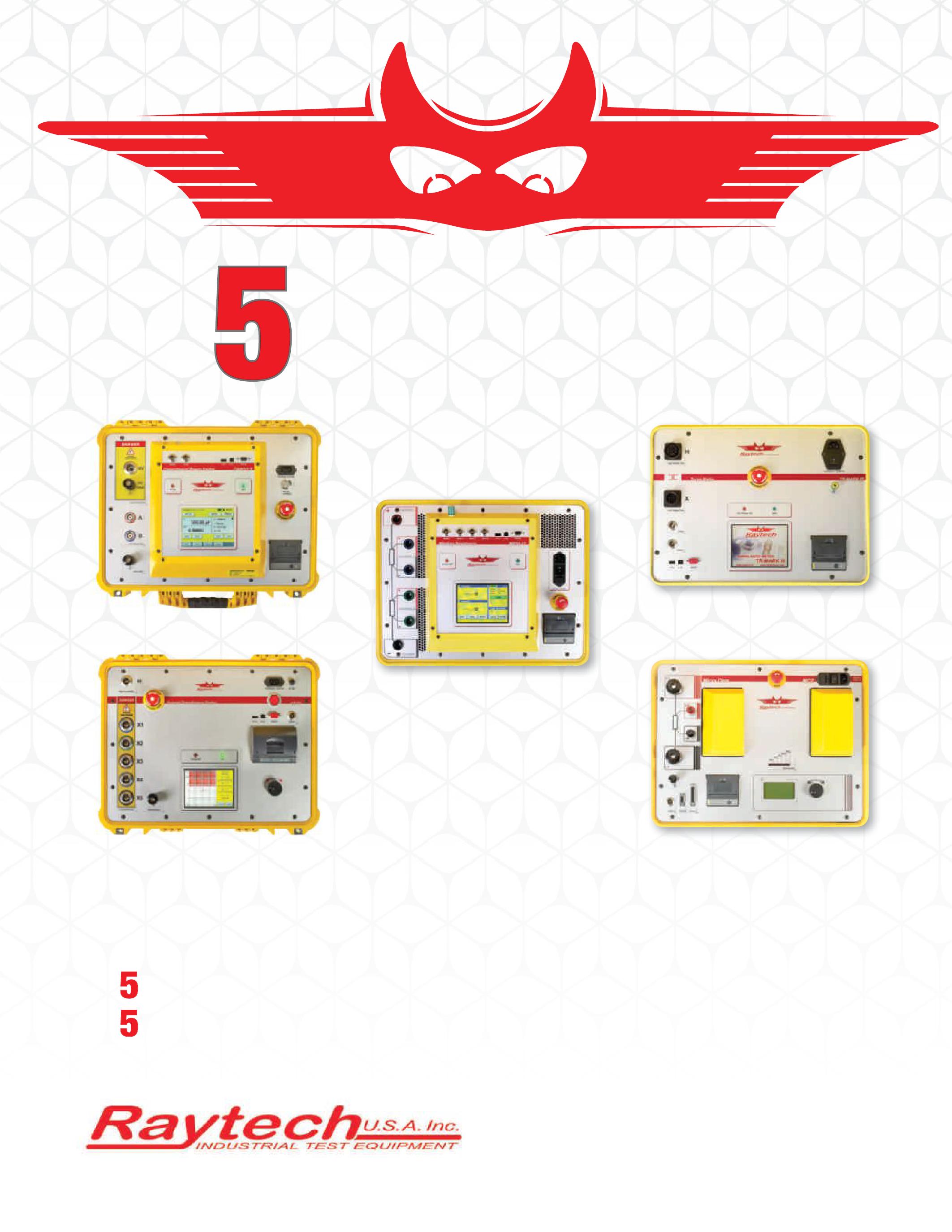
focuses on 5 product lines, ensuring expertise in each one. Our instruments combine superior quality with ease-of-use.
lines
most reliable and rugged instruments
market.
warranty
charge.
Lines Year Warranty Toll free 888 484 3779 | Phone 267 404 2676 | Fax 267 404 2685 118 South 2nd St., Perkasie, PA 18944 www.RaytechUSA.com Winding Resistance with Core Demagnetization 10A and 200A Contact Resistance Single and 3-Phase Ratiometers Power Factor Test Sets Current Transformer Test Sets
Raytech
product
of the
on the
year
with every instrument at no additional
Product
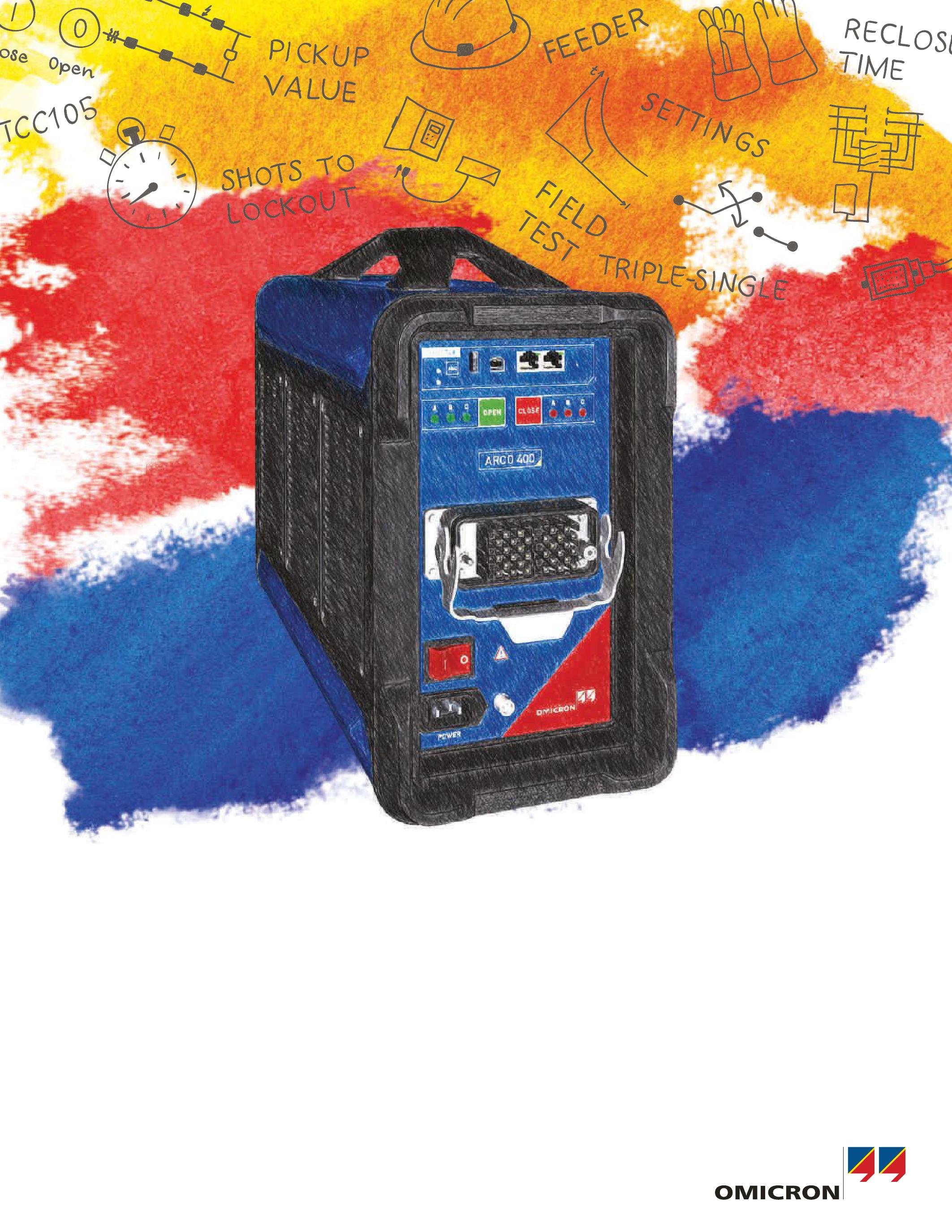
ARCO 400:
Recloser
control testing
In developing a universal test solution for recloser controls we have significantly improved existing work routines. To achieve this, our engineers thoroughly considered all existing procedures and local conditions. With ARCO 400 we were able to develop an excellent plugand-play solution that meets all your needs: compact and lightweight, rugged, easy to use, and suitable for any recloser control.
Discover ARCO 400 and the new way of testing recloser controls.
redefined!
www.omicronenergy.com/newARCO400 +1-800 OMICRON


 By Wayne Bishop, Jr., OMICRON
By Steve Skinner, Doble Engineering Company
By Joseph O’Dwyer and Kevin Kelly, O’Dwyer Technical Services
By Chris Allaire, Shermco Industries


 Ron Widup President NETA – InterNational Electrical Testing Association


 BY DON A. GENUTIS, Halco Testing Services


 BY RON WIDUP AND JIM WHITE, Shermco Industries


 BY BRUCE M. ROCKWELL, American Electrical Testing, Inc.


 BY THOMAS SANDRI, ShermcoIndustries Shermco Industries


 Tone Tracing a Direct Buried Cable
Acoustic Pinpoint Using Thumper and Acoustic Detector


