


SPRING 2013 ISSN 2167-3594 NETA WORLD JOURNAL PRINT ISSN 2167-3586 NETA WORLD JOURNAL ONLINE SPRING 2015 ISS N N2 167 35 4 94 N NETAAW ORL OUR NA NAL N INT PAGE 96
TESTING FROM TO PAGE 96 I N T R O D U C I N G ELECTRICAL COMMISSIONING SPECIFICATIONS ANSI/NETA STANDARD FOR
ACCEPTANCE
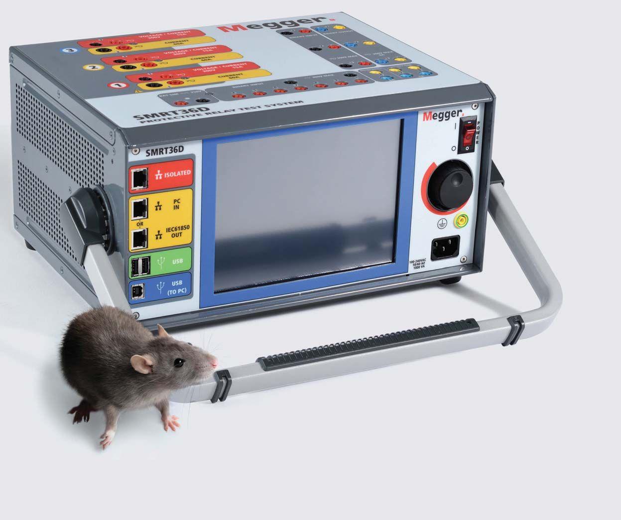
NOT JUST A PRETTY (INTER)FACE

Introducing the SMRT36D
The SMRT Series is Megger’s flagship all-purpose relay test equipment. The latest addition to the family includes a fully integrated touchscreen controller so you don’t have to carry a laptop. Like other models in the SMRT series, the SMRT36D features:
High compliance voltage for testing high impedance relays
Three-phase transformer differential protection testing made easy
Effortless click-on-fault impedance testing
Binary inputs for direct reading of IRIG-B signals for end-to-end testing
Complete solution for IEC 61850 GOOSE testing
Visit megger.com for more information or call 1-800-723-2861 to schedule a demo today!
© Megger 2014.
COVER STORY


96Bridging the Gap from Acceptance Testing to Commissioning
As you go about your everyday life, reliable and safe electrical power equipment and systems are important and vital to all aspects of commerce, daily activities, and safety. If you don’t believe that, try to go without electricity for a while…and you will soon have a renewed appreciation for this very important piece of daily existence. It is something that we should not take for granted, nor should we minimize the knowledge and expertise required to properly install and assure correct functionality of this very complicated and intertwined mass of wires, bus bars, connectors, steel, electronics, insulators, and other components of an electrical system.
Ron Widup, Shermco Industries
FEATURES
7 President’s Desk
David Huffman, Power Systems Testing Co.
NETA President
68
78
84
Planning and Performing a Power Quality Survey
Ross Ignall and Richard Bingham, Dranetz
Electrical Commissioning: Top Priorities to Ensure a Successful Project
Dan Hook and Tim Conley, Western Electrical Services, Inc.
Electrical Commissioning for Improved Availability, Safety & Cost Savings
Michael Donato, Electrical Reliability Services
90 Commissioning of Power Plant in Peru: A Case Study
Paul Hartman, DLB Associates

TABLE OF CONTENTS TABLE OF CONTENTS NETAWORLD • 3
68 96
David Wallis Retires from OSHA
Ron Widup and Jim White, Shermco Industries
Jim White, Shermco Industries
Testing Rotating Machinery
Insulation-Resistance Test
Vicki Warren, Iris Power LP
Niche Market
Arc-Flash Analysis is Going Global
Lynn Hamrick, Shermco Industries
Tech Tips
More On Fault Clearance
Jeff Jowett, Megger 40 No-Outage Corner
The Current Transformer A Valuable No-Outage Tool
Don A. Genutis, Halco Testing Services
IEEE Transformer Committee
Al Peterson, Utility Service Corporation
Beautiful Michigan Autumn Weather Greets
NETA Standards Review Council
Kristen Wicks, NETA
"If Everyone is Moving Forward Together, Then Success Takes Care of Itself."
Jill Howell, NETA
Make Your Electrical Safety Program Your Own Don Brown, SunPower Solar
Modern Testing & Diagnosis of Power
Cables using Damped AC Voltages
Edward Gulski and Rogier Jongen, Onsite HV
Solutions ag, Switzerland and Ralph Patterson, Power Products & Solutions LLC
up
Tim Gauthier, AVO Training Institute
Choosing the Right Wave Shape for
Yier Toh, Megger
Jill Howell, NETA
Valley
Kristen Wicks, NETA
4 • SPRING 2015 TABLE OF CONTENTS TABLE OF CONTENTS IN EVERY ISSUE 10 NFPA 70E
and NETA
14
Tech Quiz Commissioning
18
28
36
INDUSTRY TOPICS
58
50
ADVANCEMENTS IN TECHNOLOGY 104
Keeping
with Advancements in Technology Means Keeping up with Advancements in Training
Partial
Testing
110
Discharge
SPECIFICATIONS AND STANDARDS 114 ANSI/NETA Standards Update 118
122
ASTM F18 Committee Report Jim White, Shermco Industries
NETA NEWS 34
54
NETA
24 NETA
NEWS – SETTING THE STANDARD
and East
Institute of Technology Launch New Electrical Testing Technician Curriculum
46 Onward and
Growth in
Upward – New
the NAMO Program
NETA NEWS - POWERTEST CONFERENCE 12 Thank You Sponsors 22 Save the Date 27 Call for Sponsors 43 Call for Exhibitors 88 Call for Speakers 130 PowerTest 2015 New Product Forum NETA NEWS – IMPORTANT LISTS 136 NETA Accredited Companies 142 Advertiser List


Part of the definition of Commissioning is “a quality focused process for enhancing the delivery of a project.” I like such a succinct definition.
I hope your holidays were pleasant and that you were able to enjoy them with family and friends. Hopefully there weren’t too many emergency calls and holiday shutdowns keeping you away from home.
As you are reading this, PowerTest 2015 the NETA Electrical Safety and Maintenance Conference is upon us. I sincerely hope you’re able to attend. Our focus for this conference is electrical commissioning. The ANSI/NETA document covering this should be available at the conference as well as other ANSI/NETA standards.
Speaking of commissioning, as I’m writing this some technicians I work with are troubleshooting the synchronizing circuit for a generator. The unit closed in out-of-phase after a relay upgrade. Unfortunately, no commissioning of any kind was performed subsequent to replacing the protective and control relays. This highlights one of the reasons acceptance testing and commissioning are so important.
I wish you well, and am grateful to be writing this for the association. As always, be safe out there.
Sincerely,
David Huffman President InterNational Electrical Testing Association


PRESIDENT’S DESK PRESIDENT’S DESK

MIDAS micro
Introducing the smallest, most compact power factor / tan tester on the market - used to measure all capacitive loads in substations.
FEATURES & BENEFITS
55 lb single box design
12 kV voltage source
Variable frequency, 15 - 400 Hz
7 inch color touch screen
3 operating modes: basic, guided, advanced
PRODUCT DEMO VIDEOS
Visit our YouTube channel!
Safe operation with interlock, e-stop, etc. www.bit.ly/MIDASmicro2883
TEST APPLICATIONS
Circuit breakers
Transformers Bushings
Capacitors
Surge arrestors
PREMIUM SOLUTIONS IN HIGH VOLTAGE. SINCE 1904. +1 845 279 3644 sales@hipotronics.com US Office: Brewster, NY www.hipotronics.com
Designed by

DAVID WALLIS FROM OSHA RETIRES
BY RON

If
you don’t know David Wallis you might be asking
“Who the heck is this guy and why should I care?”
Those are fair questions. To start with, David was the principle OSHA representative to the NFPA 70E Committee for several years and was the originator of the new arc-flash PPE table format. Throughout his membership on the 70E committee, David offered OSHA’s perspective on proposals and comments and is respected for his knowledge and common sense approach to the issues. How long has David been on the 70E Committee? Since its inception. Those of you who have the earliest copies of the 70E will find David as the alternate for Joe Pipkin, who was David’s predecessor.

In his role as Supervisory Electrical Engineer OSHA, Directorate of Standards and Guidance, David has, over the course of 40 years as an electrical/safety engineer at the agency, contributed heavily to OSHA’s electrical standards-setting process. David began his career at the Department of Labor as an electrical engineer for OSHA in September, 1973. As a standards writer for OSHA some of his early accomplishments included working on, developing, and publishing several standards: the telecommunication standards in Subpart R, the general industry electrical standards in Subpart S, and the construction electrical

standards in Subpart K, including the Ground Fault Protection Standard.

He is the primary author of most of OSHA’s electrical standards, including the recent changes to the electric power standards in 29 CFR 1910.269 and 29 CFR Part 1926, Subpart V and the electrical standards for general industry and construction in 29 CFR Part 1910, Subpart S, and 29 CFR Part 1926, Subpart K. He also contributed to the promulgation of several other OSHA safety standards, such as the permit-required confined space standard in 29 CFR 1910.146. Mr. Wallis represented OSHA as an expert witness in several cases before the Occupational Safety and Health Review Commission. To say David is a heavy hitter would be an understatement.
David is also known as a consummate gentleman. Soft-spoken and modest, David has never been known to get ruffled or angry in the time we have been on the committee. David often points out inconsistencies between the OSHA regulations and the 70E, but never tries to force his opinion on the committee. During the last 70E cycle, the committee once again became involved in spirited discussions on the Table Method. Everyone was aware of its shortcomings, but no one had a viable alternative. One of the biggest criticisms of the tables is that they can be very subjective and are often misused.

10 • SPRING 2015 DAVID WALLIS RETIRES FROM OSHA
THE NFPA 70E AND NETA
Figure 1: Mr. David Wallis
WIDUP AND JIM WHITE, Shermco Industries
By reducing the HRC number by 1, 2, or 3 numbers based on risk, the potential was very real that someone could to be under protected. Although the 70E Committee had not heard of such an instance, the possibility was there. David recommended a new format that eliminated risk from being a factor. As David put it “This is how OSHA looks at the arc-flash hazard.”
In the new Table Method, arc-flash clothing and PPE is either required or not without incorporating any type of reduction factor. In other words, if arc-rated clothing and PPE is required by Table 130.7(C)(15)(A)(a), full arc-rated protection is required; no reduction of the protection based on risk is taken. After much wrangling, the 70E Committee accepted the new tables, and we believe it will be easier to implement in the field and will also protect workers with a higher degree of certainty.
In addition to the 70E Committee, David was also active on the following committees: ASTM F18 Electrical Protective Equipment for Workers, IEEE Engineering in the Safety, Maintenance, and Operations of Lines Subcommittee, and NESC Subcommittee 8 on Work Rules


THE NFPA 70E AND NETA
David has shared some personal information with us. He has been married to his wife Patricia since 1977 (37 years!). Congratulations David and Patricia! That’s no small feat in today’s easy-come, easy-go society. They have two daughters and one grandchild, who is two years old. As he did at OSHA, it’s obvious that David also built stability in his private life. And for those who didn’t know, David lives a secret life as one of the Blues Brothers. Well, at least that’s our take on Figure 2. Fun times!

David sums up his career at OSHA with this statement, “My best achievement was doing my job to the best of my ability. The standards I worked on over the course of my career have saved thousands of lives. OSHA estimated that the GFCI rule alone saved between 650 and 1,100 lives in the 28 years from 1977 through 2006. The results always made the lengthy rulemaking process worthwhile in the end.”
We agree, David. Job well done.


Ron Widup and Jim White are NETA’s representatives to NFPA Technical Committee 70E (Electrical Safety Requirements for Employee Workplaces). Both gentlemen are employees of Shermco Industries in Dallas, Texas, a NETA Accredited Company. Ron Widup is CEO of Shermco and has been with the company since 1983. He is a Principal member of the Technical Committee on “Electrical Safety in the Workplace” (NFPA 70E) and a Principal member of the National Electrical Code (NFPA 70) Code Panel 11. He is also a member of the technical committee “Recommended Practice for Electrical Equipment Maintenance” (NFPA 70B), and a member of the NETA Board of Directors and Standards Review Council. Jim White is nationally recognized for technical skills and safety training in the electrical power systems industry. He is the Training Director for Shermco Industries, and has spent the last twenty years directly involved in technical skills and safety training for electrical power system technicians. Jim is a Principal member of NFPA 70B respresenting Shermco Industries, NETA’s alternate member of NFPA 70E, and a member of ASTM F18 Committee “Electrical Protective Equipment for Workers”.

NETAWORLD • 11 DAVID WALLIS RETIRES FROM OSHA
Figure 2: Too Cool!
Ron Widup
Jim White
a special thanks to our sponsors Hosted by 888.300.6382 (NETA) www.powertest.org TONY DEMARIA ELECTRIC SAFETY QUALITY SATISFACTION TDE Premium High Voltage Low Voltage Medium VoltageGeneral protecequip.com We would like to acknowledge and thank our sponsors for helping make PowerTest 2015 possible. A special thanks to our PowerTest 2015 Hospitality Suite Sponsors: Shermco Industries Megger/ AVO Training Institute, Inc.
CBS, Inc.
Equipment Resources SMC International ENOSERV ECP Solutions RESA Power Solutions
Group
Protec


James R. (Jim) White is the Training Director of Shermco Industries, Inc., in Dallas, Texas. He is the principal member on the NFPA technical committee “Recommended Practice for Electrical Equipment Maintenance” (NFPA 70B). Jim represents NETA as an alternate member of the NFPA Technical Committee “Electrical Safety in the Workplace” (NFPA 70E) and represents NETA on the ASTM F18 Committee “Electrical Protective Equipment For Workers”. Jim is an IEEE Senior Member and in 2011 received the IEEE/PCIC Electrical Safety Excellence award. Jim is a past Chairman (2008) of the IEEE Electrical Safety Workshop (ESW).


COMMISSIONING
BY JIM WHITE, Shermco Industries


Commissioning involves many aspects of testing and operability verification. Commissioning ensures the electrical power system and all connected devices will function in the way it was designed.
1. One aspect of commissioning is acceptance testing. List three primary purposes of commissioning (wording does not have to be exact):
a. ______________________________
b. ______________________________
c. ______________________________
2. Before acceptance testing begins, what steps should be taken as part of the commissioning process?
a. Inspect devices for proper settings and installation completeness
b. Perform a seismic drop test on each device to be installed
c. Inspect devices for variations from design specifications
d. Both b and c
e. Both a and c
3. The series of checks that verify all parts of a system are working together is known as:
a. End-to-end testing
b. Acceptance testing
c. Maintenance testing
d. System functional testing
e. “Ringing out” the wires
4. When energizing a substation after commissioning, what is one of the most important safety steps that should be taken?
a. Restrict access to only those directly involved in the energization process
b. Make sure all the test equipment has been properly calibrated within the last year
c. Verify that all employees have a current electrical safety orientation sticker
d. Move everyone back from the substation a minimum of 100 feet from the area
5. There are several steps that should be taken after energization. Which one of the following would not be one of those?
a. Remove personal protective grounds
b. Obtain post-energization oil and gas analysis on applicable devices
c. Verify temperature monitoring and protective devices are set up to established criteria and parameters
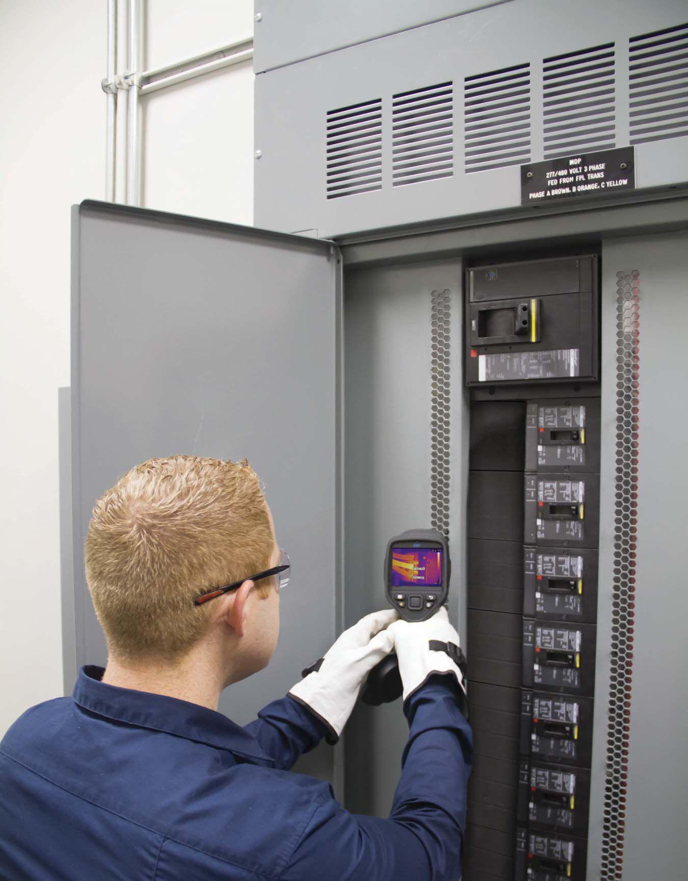
d. Perform thermographic survey of equipment
14 • SPRING 2015 TECH QUIZ TECH QUIZ See answers on page 126.
No. 109


ENGINEERING SERVICES • ELECTRICAL TESTING • COMMISSIONING SPECIALTIES Complete Relays and Transformers Testing 131 W F Street Los Angeles, CA 90744 Fax (310) 549-9747 TONY DEMARIA ELECTRIC SAFETY QUALITY SATISFACTION TDE www.youtube.com/tdeinc2 www.twitter.com/t deinc www.facebook.com/tdeinc www.linkedin.com/company/tony-demaria-electric CA LICENSE #315448

TESTING ROTATING MACHINERY


INSULATIONRESISTANCE TEST
BY VICKI WARREN, Senior Product Engineer, Iris Power LP
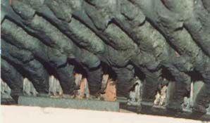


The insulation-resistance test [IEEE i Std. 432013], is a useful indicator of contamination (Figure 1) and moisture on the exposed insulation surfaces of a stator winding, salient pole or cylindrical rotor windings, especially when there are cracks or fissures in the insulation. The test is easily done and is one of the most common tests performed on any motor or generator winding. Since squirrel cage induction motor rotor windings are not insulated, this test is not appropriate for such motors .
The insulation-resistance and/or the polarizationindex test should be done prior to application of any high voltage tests to assure that the winding is not wet or dirty enough to pose a risk of failure that could be averted by a cleaning and drying-out procedure. However, insulation-resistance testing is principally a pass/fail criterion and cannot be relied upon to predict the condition of the main insulation except when the insulation has already faulted. That is, since the insulation-resistance test is insensitive to internal insulation problems; a high insulation-resistance reading does not imply that the winding is in good condition. See Fall 2011 NetaWorld issue for more information about the insulation-resistance test theory and test configuration.

TEMPERATURE CORRECTION
IEEE 43-2013 (Sec 6.2), the insulation resistance can vary inversely, on an exponential basis, with the winding temperature. “Regardless of the cleanliness of the winding surface, if the winding temperature is at or below the dew point of the ambient air, a film of moisture may form on the insulation surface, which can lower the insulation resistance or polarization index. The effect is more pronounced if the surface is also contaminated, or if cracks in the insulation are present.” From Section 6.3.1, in metals the free electrons at higher temperatures increase thermal agitation and thus increase resistivity; whereas, in insulators the higher thermal agitation frees electrons and decreases resistivity. The result is that


18 • SPRING 2015
TESTING ROTATING MACHINERY INSULATION RESISTANCE TEST
Figure 1: An example of a Contaminated Winding


TESTING ROTATING MACHINERY


the expected results of insulation resistance will decrease at higher temperatures. Since the recommended values are all at 40°C, then different recommended values are necessary when the test specimen is at different temperatures.
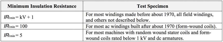
Table 1 shows the recommended minimum insulation resistances temperature corrected as defined by IEEE 43-2013 (Sec 12.3).
Notes from IEEE 43-2013 (Sec. 12.3) regarding Table 1:
1) IR 1min is the recommended insulation resistance, in megohms, at 40°C of the entire machine winding (all phases). Tests on individual phases would be expected to be twice the above values .
5) The values in the above table do not apply to green windings before global vacuum impregnation treatment.


2) kV is the rated line-to-line voltage for three-phase ac machines, line-toground voltage for single-phase machines, and rated direct voltage for dc machines or field windings.
3) It may not be possible to obtain the above minimum IR 1 min values for stator windings having extremely large end arm surface areas, or for dc armature windings with commutators. For such windings, trending of historical IR 1 min values can be used to help evaluate the condition of their insulation.
4) The values in Table 1 may not be applicable, in some cases, specifically when the complete winding overhang is treated with grading material.

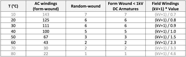
In order to avoid the effects of temperature in trend analysis, subsequent tests should be conducted when the winding is near the same temperature as the previous test. However, if the winding temperature cannot be controlled from one test time to another, it is recommended that all insulation test values be compared to acceptance values corrected to a common base temperature of 40°C. Though this corrected value is an approximation, this permits a more meaningful comparison of insulation-resistance values obtained at different temperatures. [Table 2 and Table 3 derived from IEEE 43-2013 (Sec 6.3.3 and Sec 12.3)].
Note: Tables 2 and 3 are an approximation and could lead to significant errors if used to evaluate insulation resistance at temperatures outside the range from 20 to 60 oC (shown


Table 2: Recommended minimum insulation resistance for THERMOSETTING insulation stator winding systems built after about 1970 (All values in MΩ).


NETAWORLD • 19 TESTING ROTATING MACHINERY INSULATION RESISTANCE TEST

TESTING ROTATING MACHINERY

Table 3: Recommended minimum insulation resistance for THERMOPLASTIC insulation stator winding systems built before about 1970 (All values in MΩ).
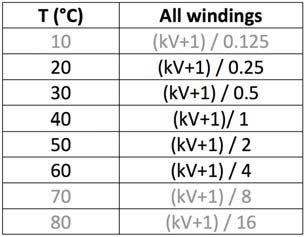
TREND
Multiply the value in column 2 by kV + 1 where kV is the rated line-to-line voltage for three-phase ac machines, line-to-ground voltage for single-phase machines, and rated direct voltage for dc machines or field windings.

FAILED TESTS
When machines are tested that have been out-of-service and when the winding temperature is below the dew point, the resultant values may be considered too low. These machines may need to be cleaned and/or dried out to meet expected levels. The history of the machine should help to determine the potential risk for returning a failed winding to service; however, further high-voltage testing is not recommended for such. Note that the effects of moisture contamination on a healthy winding should not preclude obtaining acceptable readings.

Trend analysis is often ambiguous, since moisture contamination normally lowers the insulationresistance and/or polarization-index readings. As long as the insulation resistance remains fairly level, the insulation system is in good condition. High humidity can cause resistance values to drop, so lower resistance readings on one test do not always mean the insulation is beginning to deteriorate. (For this reason it is a good idea to record humidity readings for each test.) If resistance drops for two or three successive tests (maintaining the same test interval), the winding should be cleaned, dried and tested again. If the resistance does not increase, the machine should be rewound. It is difficult to predict the effect of moisture condensation on the surface if testing below the dew point, therefore an attempt to trend these values would introduce an unacceptable error. In such cases, it is recommended that the history of the machine tested under similar conditions be the predominant factor in determining suitability for return to service.
REFERENCES


iIEEE std. 43-2013, IEEE Recommended for Testing Insulation Resistance of Rotating Machinery.


Vicki Warren, Senior Product Engineer, Iris Power LP. Ms. Warren is an Electrical Engineer with extensive experience in testing and maintenance of motor and generator windings. Prior to joining Iris in 1996, she worked for the U.S. Army Corps of Engineers for 13 years. While with the Corps she was responsible for the testing and maintenance of hydrogenerator windings, switchgear, transformers, protection and control devices, development of SCADA software, and the installation of local area networks. At Iris, Ms. Warren has been involved in using partial discharge testing to evaluate the condition of insulation systems used in medium to high voltage rotating machines, switchgear and transformers. Additionally, Ms. Warren has worked extensively in the development and design of new products used for condition monitoring of insulation systems, both periodical and continual. Ms. Warren also actively participated in the development of multiple IEEE standards and guides, and was Chair of the IEEE 43-2000 Working Group.


20 • SPRING 2015 TESTING ROTATING MACHINERY INSULATION RESISTANCE TEST

A Full-Service Industrial Test Equipment Company
supports
your testing needs,
on-site Providing
support
Professional, expert service
advice
Free evaluations
60-Day
Visit us at the PowerTest 2015 Conference in Nashville, TN: March 2-6, 2015. Booth # 418. www.AVOXTechnologies.com AVOX Technologies 118 South 2nd Street
800 272 2818
267 404 2681
Sales@AVOXTechnologies.com Proud to be the exclusive distributor and support facility for the entire Metrel line of testing instruments.
Built on Solutions AVOX Technologies
all of
from
exceptional service and
for more than 90 different •
and
•
•
Service Warranty • The shortest repair turnaround times possible
Phone:
Fax:
E-mail:
When it comes to Commissioning, we view our Electrical Functions Testing as a critical step. Practicing a PGTI core value to “Do It Right,” your systems are audited by trained technicians, ensuring that equipment operates as drawings and specifications reflect. No sloppy shortcuts. No excuses. If getting it right is part of your plan, trust the professionals at PGTI.
PGTI.net PGTI All according
plan.
to
Safe, Smart, Right! Power & Generation Testing, Inc. 480 Cave Road – Nashville, TN 37210 615.882.9455 24 Hour Emergency Services (937) 439-9660 Electrical Distribution System
AND EAST VALLEY INSTITUTE OF TECHNOLOGY LAUNCH NEW ELECTRICAL POWER TESTING TECHNICIAN CURRICULUM
BY JILL HOWELL, NETA
In July, 2015, the East Valley Institute of Technology (EVIT), in partnership with the InterNational Electrical Testing Association (NETA), will launch a new post-secondary adult education program, the Electrical Power Testing Technician (EPTT) Program. The goal of this program is to offer a curriculum that prepares graduates of this course for the NETA ETT Assistant Level II examination once they are employed by a NETA Accredited Company. Participants should be able to complete the coursework and graduate within six to eight months of initiating the course. At the time of completion, graduates will have completed OSHA 30 training, numerous hours of electrical safety training, and first aid and CPR certifications. Upon completion of the program, a typical graduate should be an ideal candidate for employment at a NETA Accredited Company as an ETT Trainee Level I. This strong foundation should help prepare them to attempt the examination for ETT Assistant Level II once all examination prerequisite criteria are met. The program will consist of seven courses as well as lab instruction, specifically designed to fit into busy schedules. The coursework will take place four to five days a week during the six to eight month program.
Courses include:
1. Electrical Theory and Principles Part I
2. Electricity Theory and Principles Part II
3. General And Electrical Safety
4. Conductors
5. Circuit Breakers
6. Transformers
7. Switchgear, Switchboards, and Motor Control Centers
Bob Sheppard, who initially brought the program development opportunity to NETA, said that the EVIT electrical testing technician curriculum was developed to respond to the growing need for qualified electrical testing technicians. Sheppard says, “This program delivers a quality training course to serve our industry with immediate and long term needs for technicians. Our hope is to provide above entry level technicians with the skills and knowledge to be ready for the challenge of our exciting industry.”
The development of the curriculum has been overseen by NETA and led by Bob Sheppard, Principal, and Larry Lind, Technical Training & Safety Coordinator, of Southwest Energy Systems, LLC, who have worked closely with John Underwood, EVIT Program Director, to design the educational program. Additional contributors towards lab development include the following NETA Accredited Companies: Western Electrical Services, Tony Demaria Electric, and Shermco Industries. All test equipment will be supplied by Intellirent.
For more information on the EVIT Electrical Power Testing Technician Program, Contact Jill Howell at jhowell@netaworld.org.

For information on the EPTT program or enrollment visit evit.com/programs-adult education
NETA AND EAST VALLEY INSTITUTE OF TECHNOLOGY LAUNCH NEW ELECTRICAL TESTING TECHNICIAN CURRICULUM
IN ELECTRICAL T 24 • SPRING 2015


FROM BREAKER PARTS TO ENGINEERED SOLUTIONS. TIME-TESTED. Our company’s heritage pre-dates the opening of the Grand Ole Opry in 1925. We heard Nashville’s first radio station in 1941, saw the crowning of “The King”, and witnessed the birth of “Music City” as we know it today. It’s no surprise that experienced NETA service providers across the country rely on RESA for circuit breaker parts and rebuilds all the way to up to engineered switchgear solutions. Put RESA Power to work for you at WWW.RESAPOWER.COM or call 1.800.576.RESA. Life Extension Solutions for Electrical Equipment. NETA POWERTEST 2015. RENAISSANCE NASHVILLE HOTEL. JOIN US @ BOOTH 301. Copyright © 2015. RESA Power Solutions, LLC. All rights reserved.


OMNI FORT WORTH HOTEL
MARCH 14-18, 2016
www.powertest.org


the way. Sponsorships are now available.
Reach hundreds of leading decision–makers at PowerTest
Receive advertising and press reaching 24,000+ industry professionals before, during, and after the event
Available in all price ranges

FORT WORTH, TEXAS
THE PREMIER ELECTRICAL MAINTENANCE AND SAFETY EVENT HOSTED BY
SPONSORS
Pave

models postulated by Stoll and Chianti 2 to derive his equations. In 2000, Doughty, Neal and Floyd 3, added a piece to the puzzle by publishing a paper on their research that considered variations in incident energies in open air versus incident energies from an enclosure or box. A combination of these efforts resulted in the basis for the arc flash analysis calculations in NFPA 70E. From there, IEEE performed more practical testing and empiricallyderived calculations were presented in IEEE 1584 4. After IEEE 1584 was published, the next version of NFPA 70E added that it has an acceptable, alternative method for performing arc-flash hazard analysis.
specific guidance or consensus methodology for performing an arc flash analysis in Europe. Germany’s BGI 5188 7 was published in October 2012 and is similar to the NFPA 70E methodology in that it calculates a heat flux in various configurations (i.e., open air, in a box, against a wall, etc.) in combination with Stoll’s burn model to evaluate an arc flash hazard. However, it will probably be years before the European community agrees to endorse this or any other guide as a consensus standard. Until that happens and specifically with North Americanbased companies, IEEE 1584 is being used extensively throughout Europe to meet the EN 50110 requirement.


Currently, IEEE 1584 is the most widely used standard for arc-flash incident energy calculations globally. With the exception of the calculations provided in NFPA 70E, IEEE 1584 is the only generallyaccepted methodology for performing these calculations for three-phase, lowvoltage systems. When using this standard, it should be noted that it is limited to arc flash analyses for infrastructure below 15 kV. Fortunately, the empirically-derived calculations suggested within the standard have weathered the test of time in that they appear to be fairly accurate in low voltage applications (< 1000 V), which is the majority of the applications where arc flash analysis is most beneficial. However, IEEE 1584 has received some criticism from the international community with regard to its methodology and test setup 5. Further research on arc flash calculations is being carried out as a collaborative effort of NFPA and IEEE. This effort includes some international involvement, so it is hopeful that this criticism will be minimized with future revisions of the standard.
The latest revision of the European electrical safety standard, EN 50110 6, requires that an arc flash risk assessment (analysis) be performed. Unfortunately, there is no

There are some things to consider when using IEEE 1584 outside of North America. When performing an arc-flash analysis in accordance with IEEE 1584, information associated with the electrical infrastructure is used as input (i.e., voltage levels, bolted fault currents, fault clearing times, etc.) to perform the calculations. Specifically, the source of the bolted fault information has resulted in some concern as to the effectiveness of the analysis. In North American, bolted fault calculations are typically performed using IEEE 141 8 as the methodology for evaluating bolted fault currents. This methodology uses a comprehensive network approach to determine bolted fault currents. For most applications, the European community prefers the use of the methodology in IEC 60909 9 for evaluating bolted fault currents. This methodology uses the fault current associated with the first ½ cycle of the fault to determine the bolted fault current. This article will not discuss the merits of either methodology for determining bolted fault currents. It should be noted that the results using either methodology will be similar; however, there may be some disagreement as to which methodology is appropriate for use in this application. Typically, the selection of the bolted fault


NICHE MARKET TESTING ARC-FLASH ANALYSIS IS GOING GLOBAL NETAWORLD • 29
NICHE MARKET TESTING

current determination methodology for use in evaluating arc flash hazards is not a problem. However, when performing arc flash analysis anywhere other than North America, it is highly recommended that the methodology to be used is agreed upon prior to performing the analysis.
It should be noted that most of the available comprehensive modeling tools for performing power system studies can perform shortcircuit analysis using either the IEEE 141 or IEC 60909 methodology. However, the companion arc-flash evaluation program may not be fully integrated with the IEC 60909 modeling version of the tool. This means that you may have to manually enter the short-circuit information into the arc flash evaluator to perform an arc-flash analysis.


ARC-RATED PPE SELECTION
Another challenge that may be encountered when implementing protective measures associated with arc-flash is the methodology used in determining the appropriate arc-flash PPE. In the US, arc-rated PPE is selected based on the incident energy at a given working distance. This arc rating for the PPE is established by determining the arc thermal performance value (ATPV) of the material in accordance with ASTM F1959 10 , which is endorsed by NFPA 70E.


Concurrent with the development of this US standard, the international community has been developing the IEC 61482 series of standards. IEC 61482-2 11 is also provided as the requirements portion of the standard series. IEC 61482-1-1 12 is equivalent to ASTM F1959 in that it evaluates the ATPV of the material. This standard is preferentially used in North America. IEC 61482-1-2 13 is based on a European standard (formerly ENV 50354) which uses a specific box test and heat flux measurement to classify the material for use in an application. Both of these standards are acceptable; however, they are not interchangeable. In Europe, arc-rated
clothing receives a CE certification that is based on the specific type of risk analysis that is used to determine the extent of the arc-flash hazard. This means that clothing certified to IEC 61482-1-1, or by ATPV testing, should be used when IEEE 1584 is the method used for the arc-flash analysis. Further, clothing certified to IEC 614821-2, or by box testing classification, should be used when a guide like BGI 5188 is the method used for arc flash analysis.
CONCLUSIONS
NFPA 70E is a standard for specifying arcflash PPE and provides a good overview of arc flash hazard calculations. Additionally, IEEE 1584 is the most widely used standard for arc flash incident energy calculations. Most of the global community has embraced these standards and is applying them as its own. However, in some of the global community, mostly within the European Union, alternate standards are being developed to address arc flash hazards. So, there are some things to agree upon prior to performing an arc flash analysis outside of North America:


• The methodology for determining bolted fault currents (i.e., IEEE 141 or IEC 60909).
• The selection of certified arc-rated PPE (i.e., ASTM F1959 and IEC 61482-11, or IEC 61482-1-2).

If IEEE 1584 is to be used as the methodology for performing an arc flash analysis, the appropriate bolted fault calculation method must be defined. If IEC 60909 is to be used with a comprehensive modeling tool, verify that the companion arc flash evaluation program is fully integrated with the IEC 60909 modeling version of the tool. Further, the arc-rated PPE to be used must be certified in accordance with IEC 614821-1 or ASTM F1959.


30 • SPRING 2015
ARC-FLASH ANALYSIS IS GOING GLOBAL

REFERENCES
1 Lee, R. The Other Electrical Hazard: Electrical Arc Blast Burns, IEEE Transactions on Industry Applications, Vol. IA-18, no. 3, pp. 246–251, May/June 1982.
2 Stoll, AM and Chianta, MA. Method and Rating System for Evaluation of Thermal Protection, Aerospace Medicine, Vol. 40, No. 11, pp. 1232-1238, Nov 1969.
3 Doughty, RL., Neal, TE, and Floyd HL. Predicting Incident Energy to Better Manage the Electric Arc Hazard on 600-V Power Distribution Systems, IEEE Trans. Ind. Appl., Vol. 36, No. 1, pp. 257--269, Jan./Feb. 2000.
4 IEEE Standard 1584—2002, IEEE Guide for Performing ArcFlash Hazard Calculations.
5 Stokes, AD and Sweeting, DK. Electric Arcing Burn Hazards, IEEE Transactions on Industry Applications, Vol. 42, No. 1, pp. 134–140, January/February 2006.
6 EN 50110-1: 2013, Operation of Electrical Installations. General Requirements.
7 BGI/GUV-I 5188 E, Thermal Hazards from Electric Fault Arc–Guide to the Selection of Personal Protective Equipment for Electrical Work, October 2012.
8 IEEE Standard 141—1993, IEEE Recommended Practice for Electrical Distribution for Industrial Plants
9 IEC 60909-0—2001, Short Circuit Currents in Three Phase A.C. Systems—Part 0: Calculation of Currents.


10 ASTM Standard F1959/F1959M-14, Standard Test Method for Determining the Arc Thermal Performance Value of Materials for Clothing.
11 IEC 61482-2—2009, Live Working—Protective Clothing Against the Thermal Hazards of an Electric Arc—Part 2: Requirements.
12 IEC 61482-1-1—2009, Live Working—Protective Clothing Against the Thermal Hazards of an Electric Arc—Part 1-1: Test Methods–Method 1: Determination of the Arc Rating (ATPV or EBT50) of Flame Resistant Materials for Clothing.
13 IEC 61482-1-2—2007, Live Working—Protective Clothing Against the Thermal Hazards of an Electric Arc—Part 1-2: Test Methods–Method 2: Determination of the Arc Protection Class of Material and Clothing by Using a Constrained and Directed Arc (Box Test).


NICHE MARKET TESTING


Lynn Hamrick brings over 25 years of working knowledge in design, permitting, construction, and startup of mechanical, electrical, and instrumentation and controls projects as well as experience in the operation and maintenance of facilities.
Lynn is a Professional Engineer, Certified Energy Manager and has a BS in Nuclear Engineering from the University of Tennessee.


ARC-FLASH ANALYSIS IS GOING GLOBAL

Far From Work, But Close To Data PQ Analyzers with Remote Wireless Communications 732.287.3680 1000 New Durham Road Edison, New Jersey 08817 Control your Dranetz HDPQ from your smartphone, tablet, or computer! sales@dranetz.com www.dranetz.com ® ® A Company
® FLEXIBLE / COLLAPSIBLE AIR-CELLS 2-DAY AVERAGE! STANDARD SIZES PLUS CUSTOM AIR-CELLS TO FIT ANY TRANSFORMER INSTALLATION! ® MADE IN AMERICA - 40 YEARS STRONG 800-526-5330 • +1-201-825-1400 • ATLINC.com TOLL FREE: TELEPHONE: WEB: USED BY: WAUKESHA, CALPINE, TVA, FIRST ENERGY, PSE&G, L.A. DEPT. OF WATER & POWER, JACKSONVILLE ELEC. AUTHORITY & MANY MORE! COLLAPSED BLADDER PILLOW TANKS FOR DIELECTRIC OIL, TOO!
BEAUTIFUL MICHIGAN AUTUMN WEATHER GREETS NETA STANDARDS REVIEW COUNCIL
BY KRISTEN WICKS, NETA
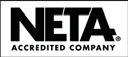
The NETA Standards Review Council (SRC) met October 23-25, 2014, in Traverse City, Michigan, at the Grand Traverse Resort. The SRC is charged with managing NETA’s many technical programs, and this agenda focused on the ANSI/NETA Standards, the new 2014 Self-Paced Technical Seminars, and the NETA Certification Exams among other technically-related items.
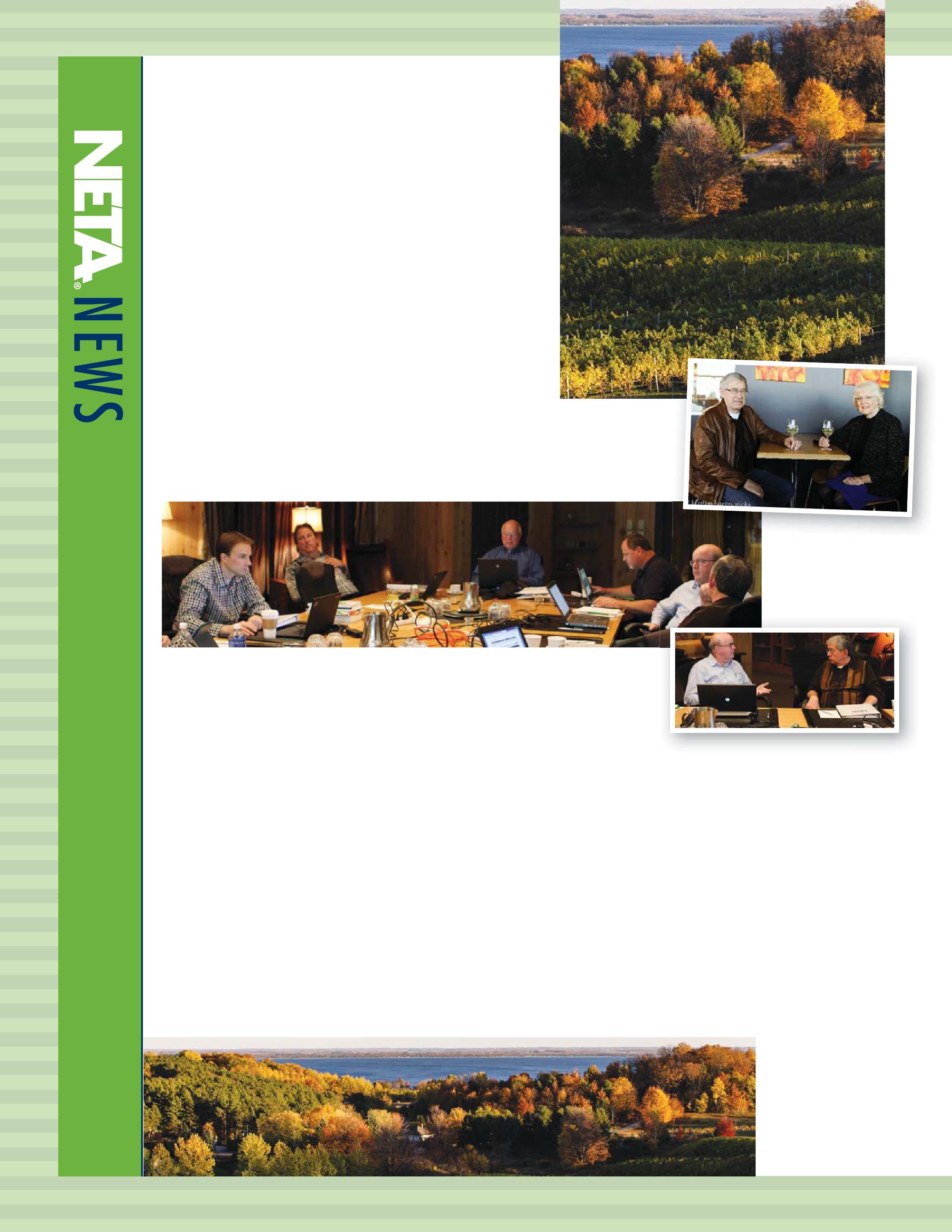
A peek at the inner-workings of the NETA SRC.
The SRC responded to some final comments received during the second balloting of the ANSI/NETA Standards and reviewed the details of the returned ballots. The ANSI/NETA ETT Standard for Certification of Electrical Testing Technicians, ANSI/NETA MTS Standard for Maintenance Testing Specifications for Electrical Power Equipment and Systems, and ANSI/NETA ECS Standard for Electrical Testing Specifications for Electrical Equipment and Systems (NETA’s newest American National Standard) will be available for purchase in 2015 at PowerTest in Nashville, Tennessee.
Revisions on the ANSI/NETA ATS Standard for Acceptance Testing Specifications for Electrical Power Equipment and Systems also began at this meeting, and the timeline for the revision of this document was approved. This edition of the ANSI/ NETA ATS intends to make revisions to the relay,
rotating machinery, and instrument transformer sections that will be similar in nature to revisions made in the 2015 edition of the MTS.
a technical question.
The numbering system is also being updated to align with the ANSI/NETA MTS-2015 in hopes that referencing lines within the standards will be simplified for end users of the document.
Seasons come and go, but NETA’s SRC remains dedicated to assuring that NETA’s foundation as a technical organization remains firmly intact even as the association expands and grows.
Fall colors along the shoreline at Chateau Chantal Winery, Old Mission Peninsula, Traverse City, Michigan.
Rod and Diane Hageman enjoy a glass of wine at 2 Lads Winery.
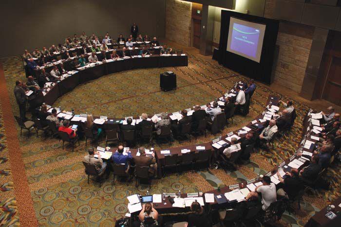
Tim Cotter (left) and Rod Hageman (right) hash out
TiC tt a dRd
FAULT CLEARANCE
BY JEFF JOWETT, Megger
In the last column some specifications and operational procedures for protective devices during fault clearance were reviewed. The differences between short circuit and ground fault clearances were emphasized, and the significance of ground impedance, voltage, and current path were discussed. Systems with a grounded neutral were described and compared to those without, and the inherent efficiencies and dangers associated with one or the other were compared.
For purposes of clarity, relatively simple circuits were used in the descriptions, but all that was indicated applies just as well to threephase circuits or any multi-wire, multi-phase grounded system. A 3-phase power system from a grounded transformer must have the neutral or grounded conductor brought into the service for fault clearance as previously described [NEC® (Nat’l Electric Code®) 25024 (C)].
In any grounded system, the resistance of the grounding electrode to remote earth is not the only consideration. It is also vital to have a low-impedance equipment grounding conductor in order to establish an effective clearance path to safely divert fault currents and operate protective devices. Metal conduit can be employed as the grounding conductor. The NEC does not restrict length or size of metallic conduit or metallic tubing when used as the grounding conductor, but independent studies have been performed that shed light on the considerations applicable to size and
length. An important third consideration in addition to size and length that differentiates use of conduit is that of continuity across connections. A single wire conductor can be run for hundreds of feet with the only connection concerns being the terminations; but conduit is installed in discrete sections, each of which must be properly mated to adjoining sections at appropriately low contact resistance. Raceways, busways, and other similar metallic support structures, steel or aluminum, can serve as grounding paths, but the possibility of joints developing a higher resistance has led some authorities to require a supplementary equipment grounding structure. Properly installed and maintained, these alternate ground paths can have sufficient cross sectional area to be adequate for carrying enough fault current to clear the fault. Average busway up to 1500 amperes rating can be expected to have enough steel to provide an acceptable equipment grounding conductor. At higher ratings it is doubtful that a steel enclosure would be sufficient to carry
MORE ON FAULT CLEARANCE TECH TIPS 36 • SPRING 2015


enough fault current. Aluminum enclosures exhibit better conductivity and so may be adequate.
As an example, consider a thousand feet of 3-inch conduit. Using the 600 percent standard of overcurrent device rating for a 400 ampere service, as described in the previous article, the conduit would have to be able to carry 2400 amperes. The expected impedance for 3-inch conduit would be 0.0875 Ω/1000 feet at this fault current. Assume a 208Y/120 volt system with zero impedance at the point of fault. This would produce about 1400 amperes of fault current, adequate to operate a 400 ampere highinterrupting capacity current-limiting fuse within two seconds. An additional problem, however, is that such faults are typically arcing faults, which introduces additional resistance. Fault current would drop with increased impedance so that a typical increase to 0.129 Ω/1000 feet would be expected. Allowing for arc impedance, increased conduit impedance plus the cascading effect of increasing impedance with decreasing current, ground fault current can quite possibly be reduced in this circuit to about 300 amperes, below the clearing capacity of the protective device.


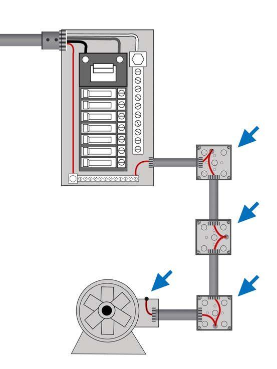

If the circuit were only 100 feet long, a similar situation would produce a fault current of about 3000 amperes, with no problem of clearing by the protective device. Long feeders, therefore, can be a source of additional problems for fault clearance that require increase in conductor size to remedy. It can be seen, then, that adequate fault protection requires consideration of all possible contributing factors. An effective way to assure adequate fault clearance is to add an equipmentgrounding conductor within the conduit. Such a parallel reinforcement is more effective if bonded frequently to the conduit, not just at the terminations (Figure 1). If such corrective action is taken, the supplementary grounding conductor must be run within the conduit, as close as practical to the phase conductors. It must never be run outside the conduit.
The NEC (Section 110.9) describes the essential performance characteristics of


protective devices like circuit breakers, fuses, disconnect switches, and the like. It is important to keep in mind that grounding conductors, phase conductors, bus bars, bonding jumpers, and such are not intended to break current (Section 110.10, 240-1 Informational Note, 250.4, 250.90, and 250.96). Their function is to enable the overcurrent protective device to function in order to clear the fault. They must be sized adequately and if too small can actually become a danger. If they burn open during ground fault conditions, the equipment that is intended to be protected can become live and present a shock hazard. Another point to consider is that grounding conductors are permitted to be bare (uninsulated) wire. As they are commonly run in the same raceway or conduit as the phase conductors, during


NETAWORLD • 37 MORE ON FAULT CLEARANCE TECH TIPS
Figure 1: Grounding Conductor Bonded to Conduit

TECH TIPS


fault clearance the grounding conductor could achieve a temperature rise that damages adjacent insulation on the phase conductors. Insulation can melt, further contributing to damage and hazard. This is another reason to carefully limit the clearance time. For copper conductors, it has been found that clearing time and short-circuit current must be limited to one ampere per five seconds per every 42.25 circular mils of conductor size. This relationship is commonly expressed as ampere squared seconds (I2t). As an example, from tables in the NEC, a number 8 AWG conductor has a cross-sectional area of 16,510 circular mils. Using the expression for ampere squared seconds, one can see that the conductor’s 5-second withstand rating is 391 amperes:
16,510/42.25 = 391
The conductor, therefore, has an amperes x amperes x time 5-second rating of:
391 x 391 x 5 = 765,405 ampere squared seconds
From this I2t value the conductor’s withstand rating for other values of time or current can be calculated. For example, suppose one desired to know the current value of the circuit for a 2-cycle opening time. A 2-cycle opening time is 0.0333 seconds. Therefore:
I2 = 764,405 / t
size against multiples of thousands of amperes and indicate relative opening times.
Installers need to consider safe values for insulated conductors and bolted connections in addition to unsafe, or melting, values for conductors. These are available in tables in the literature. The weak link in a grounding protection system is considered to be the insulation shortcircuit withstand rating. Different specifying organizations offer somewhat different recommendations, but the most stringent are those of the ICEA (Insulated Cable Engineers Association) and are therefore preferable as the deciding factor. If it is positively assured that the equipment grounding conductor will not come into contact with the current-carrying conductors, then the ampere squared seconds value becomes somewhat more forgiving and is expressed as one ampere per five seconds per every 29.1 circular mils of conductor, as opposed to the 42.25 circular mils used in the above examples. (This is with respect to copper conductors.) In this case, the limiting factor is the bolted connection rather than the insulation withstand of current-carrying conductors as shown above.

I = √764,405/0.0333 = 4791 A
For comparison, suppose the desired opening time was reduced to ¼ cycle (0.0042 seconds). Using the calculation, the resultant current would be 13,491 amperes. The point of this comparison of circumstances is to illustrate that the allowable fault current that the conductor will endure can be increased with shorter opening times. For convenience as well as reliability, conductor sizes can be determined directly from Table 250.122 provided in the NEC. For high available fault currents and clearance times longer than ¼ cycle, figures are found in the National Electric Code (11-14) that relate conductor

In conclusion, it can be readily seen that to establish an effective ground clearance path, numerous factors have to be taken into consideration and evaluated in a quantized manner against established industry standards. Merely connecting to a convenient metallic path will often leave the electrical plant unprotected and potentially dangerous.

REFERENCES
Source of information: International Association of Electrical Inspectors (IAEI) Soares Book on Grounding


Jeffrey R. Jowett is a Senior Applications Engineer for Megger in Valley Forge, Pennsylvania, serving the manufacturing lines of Biddle, Megger, and multi-Amp for electrical test and measurement instrumentation. He holds a BS in Biology and Chemistry from Ursinus College. He was employed for 22 years with James G. Biddle Co. which became Biddle Instruments and is now Megger.

38 • SPRING 2015 TECH TIPS
MORE ON FAULT CLEARANCE

THE CURRENT TRANSFORMER
A VALUABLE NO-OUTAGE TOOL
 BY DON A. GENUTIS, Halco Testing Services
Current transformers (CTs) are versatile components that can be used in many types of instruments to provide technicians with a wealth of information. CTs are so common in the electrical field that they are often taken for granted and their importance is often overlooked. They are a great example of how no-outage technology can be applied to energized circuits to determine operating conditions. This article will examine some of the more common uses for current transformers and how they are used in no-outage testing.
CT BASICS
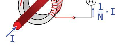
CTs are typically used to measure current. Their basic construction generally consists of a solid core or split-core toroidal ferrite material that is wrapped with one or more turns of wire. The primary current, represented as I in Figure 1, produces a magnetic field in the core which then induces a current in the secondary winding.
The relationship between the primary and secondary currents is proportional to the number of secondary wiring turns, commonly known as the ratio. Solid cores are typically used for permanent applications, while split-cores are typically used for handheld instrument applications.
GENERAL APPLICATIONS


By far the most common use of CTs in the electrical power industry is to measure current. CTs provide insulation from the primary circuit and reduce currents to manageable magnitudes for instruments. They can be found permanently installed in substations, switchgear, and switchboards to provide current inputs for ammeters, kilowatt-hour meters, and protective relays. Ratio, accuracy class, burden, and saturation are some of the characteristics that must be carefully considered when designing circuits that employ CTs.


NO-OUTAGE CORNER THE CURRENT TRANSFORMER—A VALUABLE NO-OUTAGE TOOL 40 • SPRING 2015
Figure 1: CT Circuit

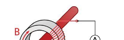
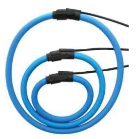
CTs are also widely used in field instruments to temporarily measure and record loads and power quality. The temporary measurement of current is one of the most common field tests performed, ranging from simple field troubleshooting in order to identify an anomaly to recording loads over an extended period of time in order to determine available ampacity for future circuit addition projects. CTs are also used with field power quality instruments to measure and record harmonics, swells, sags, and other power disturbances. In addition to the split-core CT, instruments may also utilize flexible core CTs such as those shown in Figure 2. These types of CT’s are based on the Rogowski coil circuit (Figure 3) and have an aircore instead of a ferrite core which allows for the enhanced flexibility. Flexible CTs are especially valuable when one is making measurements in tight areas or when one needs to measure currents in large switchboard bus segments. It should be noted that the output of the Rogowski coil does not produce a direct ratio of the current such as the ferrite core creates, but rather produces a voltage which requires special circuitry that integrates and processes the output signal in order to convert it to a useful current.
OTHER APPLICATIONS


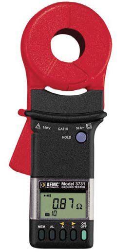
Current transformers can also be used to determine grounding system integrity in the field. Instruments such as the one shown in Figure 4 provide a resistance measurement of the conductor to ground by using a split-core CT circuit to transmit a test current and another CT circuit to measure the test current back to the instrument, thus allowing resistance to be calculated. These instruments can be valuable for quickly determining circuit ground resistance but require understanding how the test circuit works in order to avoid misapplication or inaccuracies. For instance, attempting to measure a ground rod’s resistance to earth can be achieved if the test device can measure current only in the tested rod. If the test device is connected such that it measures the rod and another ground cable tied to the grounding grid, the result will be incorrectly low with respect to the rod under test.


CTs can also be used to detect partial discharge (PD) activity. PD activity in medium voltage equipment and components create small radio frequency (RF) currents that flow to ground. Specially constructed splitcore CTs that are designed to pick up these RF signals can be safely placed around the equipment’s grounding electrode to decouple the signals and send them to an oscilloscope or other instruments for recording and analysis.
PRECAUTIONS WHEN USING CTS
• Never allow the CT secondary circuit to become open when current is flowing through the primary. This can create a dangerous high voltage condition at the open in the secondary winding.

NO-OUTAGE CORNER THE CURRENT TRANSFORMER—A VALUABLE NO-OUTAGE TOOL NETAWORLD • 41
Figure 2: Flex Core CTs
Figure 3: Rogowski Coil
Figure 4: Clamp-On Ground Resistance Tester

NO-OUTAGE CORNER


• Be careful to avoid contacting an energized bare bus with the open jaws of a split-core CT. Flex core CTs are generally much safer choices when measuring current in these situations.
• Make sure that the jaws of a clampon CT are fully closed before taking a measurement.
• Carefully position the CT around the conductor under test so that the conductor is in the approximate center of the CT loop in order to obtain the most accurate readings.
• Avoid the influence of external magnetic fields which can cause inaccuracies even though this can be difficult when making measurements in crowded areas.
SUMMARY
Operating quietly and reliably, the CT is often taken for granted, but it is an indispensable device with a wide range of uses for no-outage testing applications.

Don A. Genutis holds a BSEE from Carnegie-Mellon University. He has over 30 years of electrical testing experience. Don serves as President of Halco Testing Services based in Los Angeles, California.


FORT WORTH, TEXAS OMNI FORT WORTH HOTEL MARCH 14-18, 2016
Join 400+ electrical testing professionals Leading decision makers looking for new products and services For attendee profile and additional information visit www.powertest.org EXHIBITORS Take the bull by the horns. THE PREMIER ELECTRICAL MAINTENANCE AND SAFETY EVENT HOSTED BY
www.powertest.org
781-767-0888
Email: infrared.ma@verizon.net 152 Centre Street Holbrook, MA 02343 www.Infraredbps.com
CHOOSE BETWEEN KEEPING MAINTENANCE COSTS DOWN AND KEEPING UP WITH PRODUCTION DEMAND…OR DO BOTH. THAT’S THE CRITICAL DIFFERENCE. NETA certified experts at Electrical Reliability Services will keep you in perfect balance. To ensure the reliability of your electrical power, you have to balance the need to reduce maintenance costs with the need to perform regular maintenance. Only the team from Electrical Reliability Services delivers cost-effective services and system expertise to keep you up and running 24/7. Emerson, Business-Critical Continuity, Emerson Network Power and the Emerson and Double Helix Design are trademarks and service marks of Emerson Electric Co. ElectricalReliability.com FULL SERVICE INDEPENDENT ELECTRICAL TESTING Acceptance Testing Services Low, Medium, and High Voltage
Maintenance & Testing Switchgear Transformers
Services
Preventative
Engineering
Years of Experience Years of Reliability 25


ONWARD AND UPWARD


 BY KRISTEN WICKS, NETA

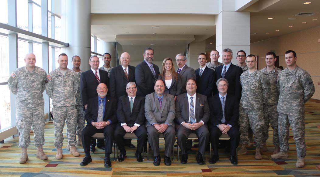
The 249th is a versatile power generation battalion assigned to the U.S. Army Corps of Engineers that provides commercial-level power to military units and federal relief organizations during fullspectrum operations. Additionally, the commander serves as the Commandant of the U.S. Army Prime Power School, the institution responsible for the development of army and navy power generation specialists. The organization is charged with the rapid provision of army generators to support worldwide requirements.
Each platoon has the capability of producing approximately three megawatts of power at 4160 volts (medium voltage.) The newly fielded individual generator size is 840 kilowatts. These mediumvoltage generators require transformers to convert the voltage to a user level (120/208/277/480 volts).


– NEW GROWTH IN THE NAMO PROGRAM

Since 2011, NETA has had the special privilege of serving a unique branch of the armed forces, the 249th Engineer Battalion (Prime Power), through its NAMO (NETA Approved Military Organization) program. This program was developed by NETA in concert with the 249th and has grown from seeing a small number of soldiers certified in the nascent stages of the program to being a program that offers online and self-paced training modules, participation at PowerTest, and ever increasing registration for NETA Certification exams.
The battalion offers a variety of services including electrical power requirement assessment; power production; transformer inspection and test analysis; maintenance and repair of power plants,


substations, and government owned or managed transmission and distribution systems; circuit breaker and relay maintenance; infrared surveys; medium-voltage electrical contractor oversight; and training for personnel to operate and maintain prime power distribution and generation equipment. This close alignment with NETA’s mission makes Prime Power an excellent member of the NAMO program.
Prime Power participated in operations Iraqi Freedom, Enduring Freedom, Noble Eagle, New York City and Pentagon Terrorist Attacks, Just Cause, Desert Storm, Desert Shield, Provide Comfort, Provide Hope, Uphold Democracy, Support Hope, Joint Endeavor and Joint Guard, and numerous disaster relief missions. The battalion has earned three Superior Unit Awards for disaster relief operations, 1992; for worldwide missions support, 1995; and for participation in Task Force Eagle Implementation Force, 1996.

These brave soldiers are often some of the first on

ONWARD AND UPWARD – NEW GROWTH IN THE NAMO PROGRAM
46 • SPRING 2015


the ground, working to generate life-saving power to supply troops on the ground. They are also heavily relied upon when disaster strikes our homeland, being deployed to provide aid following catastrophic events like Hurricane Sandy. NETA thanks its NETA Accredited Companies for supporting the NAMO program, and all of the soldiers who have decided to raise the bar even higher by becoming NETA Certified Technicians.
The NAMO program is one that offers benefits to soldiers by providing them a path with benchmarks while they are actively serving in the military and the added benefit of offering them a career path after they exit the military. NETA Accredited Companies are always searching for new, talented electrical testing technicians, and individuals exiting the 249th are held in high regard and often find a new home with a NETA Accredited Company. With the continued support from NETA’s Accredited Companies and the dedication of the 249th soldiers, the sky’s the limit for this program.


NETA ACCREDITED COMPANIES ARE ALWAYS SEARCHING FOR NEW, TALENTED ELECTRICAL TESTING TECHNICIANS, AND INDIVIDUALS EXITING THE 249TH ARE HELD IN HIGH REGARD AND OFTEN FIND A NEW HOME WITH A NETA ACCREDITED COMPANY.


NETAWORLD • 47 ONWARD AND UPWARD – NEW GROWTH IN THE NAMO PROGRAM
249th Engineer Battalion Soldiers with NETA’s Board of Directors at PowerTest 2014 in Denver, Colorado


MAKE YOUR ELECT RICAL SAFETY PROGRAM YOUR OWN


PART 3: Implementation of an Electrical Safety Program
BY DON BROWN, SunPower Solar
This is the third and final part of a series about creating and implementing an effective electrical safety program. Part 1 discussed the need for a company specific electrical safety program. Part 2 discussed the requirements for that program. Here, in the final part of the series, we will discuss the implementation of the program that you just spent all that time and effort creating.


Now that you have this wonderful, new creation in your possession, what do you do with it? The one thing you do not do is put it on a shelf and leave it there. There are too many companies with a very well written program that they don’t know how to implement, so they just do nothing! This does a disservice not only to your development team, but to your employees as well. Safety is about one thing and one thing only: sending your workers home at the end of the day in the same condition that they arrived at work in that morning, maybe a little tired or a little sore, but all in all, completely intact. No one wants to go home after a side trip to the hospital or with bandages. Most of all everyone wants to go home. Being the person that has to make the call or visit to the family of someone who has been hurt or fatally injured at work is not a position that anyone wants. This is why proper implementation of your new electrical safety program is important.
Before implementation begins, safety must be a part of the company’s culture. It cannot be a

priority. Yes, you read that right, safety cannot be a priority. It has to be a part of the company culture and the way that everyone lives his or her daily life. Everyone knows that priorities change, not only daily, but sometimes minute by minute. If safety becomes a priority, it can be changed to a lower priority and you will be putting your employees at risk. In order for safety to be a part of the company culture, it has to be brought into the values and the mission of the company, and this comes from upper management and flows downward, not the other way around. Everyone from the CEO to the company president to the directors to the managers to the supervisors to the front line workers needs to be a part of the process of implementing the safety program you just finished creating.
Using the right team is crucial in the rollout of the program, but so is incrementally implementing the program. A phased rollout is one in which the program is introduced to the company’s employees one section at a time. This could be something as simple as introducing a new training matrix for


INDUSTRY TOPICS
MAKE YOUR ELECTRICAL SAFETY PROGRAM YOUR OWN PART 3: IMPLEMENTATION OF AN ELECTRICAL SAFETY PROGRAM 50 • SPRING 2015

qualified and unqualified workers. In most cases, everyone will start with the unqualified person training and move into more detailed training for the qualified person. Not every employee will need to be designated as a Qualified Person for electrical work, but there are some that definitely need additional training, even if they have been doing a specific task for a number of years. The key part of the training is the documentation of that training as discussed in Part 2 of this series. Remember, if the training is not documented, the training never took place! Once the first part of the new program has been introduced to the masses, a second part, such as a section on PPE, can be introduced. It does not matter which section of the program gets introduced. The main issue is that you do not want to create the whole program, throw it out there, and tell everyone “Here it is! Now you have to do it.” Think of it like drinking from a fire hose or a glass. Which is easier to handle? By introducing and training your people on the program one section at a time, there is a much higher adoption rate and a higher success rate. These in turn will lower accident and incident rates, which will in turn help lower insurance premiums, etc. It is all connected.

Putting together the proper implementation team is critical before taking it to the rest of the employees. There needs to be representation from each level of the organization from the top all the way down. However, you also need to include someone from each department. Now, before you turn away, hear this out. You need someone from operation, someone from maintenance, someone from human resources, someone from safety, and someone from each pertinent department in the company and the person from each department must be committed to the program, which also means they need to be a part of the creation process. You can have a safety professional create the baseline program, but there must be input from each department to help with the necessary customization. Each company will be a little different, but it all comes down to the team. Each member of the team with support from the safety department will be responsible for explaining to his or her own department how the new program will impact the coworkers in that department.

ANSI/AIHA Z10 – Occupational Health and Safety Management Systems states that top management leadership and effective employee participation are crucial for the success of an occupational health and safety management system (OHSMS). From Section 3, as paraphrased below:
Top management shall direct the organization to establish, implement and maintain an OHSMS.
The organization’s top management shall establish a documented occupational health and safety policy.
Top management shall provide leadership and assume overall responsibility

The organization shall establish and implement process to ensure effective participation in the OHSMS by its employees at all levels (AIHA).
The content of this is fairly straightforward. It is up to top management to ensure that a complete and comprehensive safety program is established and implemented. By utilizing members from top management as well as those on the front lines, the organization will be able to get full participation in the newly-created electrical safety program. When everyone is involved, and there are many owners of a program, a higher level of participation and acceptance occurs. Then the program permeates the organization and becomes a part of the culture of the company.

Once we have the electrical safety program created, the implementation process has been finished, and everyone believes and participates in the program, the final part of the process comes into play. Reviews and updates are very important pieces of the puzzle. NFPA70E states that electrical safety programs must be audited with a frequency not to exceed three years. ANSI/AIHA Z10 says that the organization shall establish and implement a process for top management to review the OHSMS at least annually. It would appear that this is a conflict in recommendations. However, there are other ways to look at it. NFPA 70E covers the electrical safety program, while


INDUSTRY TOPICS NETAWORLD • 51 MAKE YOUR ELECTRICAL SAFETY PROGRAM YOUR OWN PART 3: IMPLEMENTATION OF AN ELECTRICAL SAFETY PROGRAM I N D U S T R Y


the ANSI/AIHA Z10 covers the organization’s entire safety program. If the organization reviews the entire safety program every year, is not the 70E requirement being met? Of course it is. But does it require an extensive overhaul every year? Absolutely not. If the standards have not changed, the main review will consist of corporate changes to procedures and policies. If the standards have changed, then there may be a need to overhaul the particular sections of the corporate safety program, such as the electrical safety program. The NFPA 70E standards change every three years with few exceptions. In most cases, there will be a few changes to your electrical safety program every three years. Currently there are changes being brought about due to the sweeping changes to the OSHA electrical regulations in 1910 and 1926, and these will have an impact on your program. During the times that the electrical standards and regulations are not being changed, you can focus your efforts on the other portions of the corporate safety program.


Your electrical safety program is a living, breathing document that needs to be utilized, updated, and cared for every single day you are working. Conditions change that may have an impact on your program; new workers may show up on the jobsite; new equipment and procedures that your employees are not familiar with may come


up. That is just a fact of life. That is the reason for conducting your site safety assessments. That is why you conduct job briefings before work starts each and every day. If you have a good electrical safety program, and you take care of it by following it and updating it as standards and regulations change, your program will take care of you. If you do not know what your electrical safety program contains, it is time for you to look into it and begin asking questions. Now, go out there and plan your work and work your plan. Be safe and come back to work tomorrow so you can do it over and over again.

Don Brown is the Environmental, Health, Safety and Sustainability Manager for Operations and Maintenance at SunPower Solar in Austin, Texas. He has been in the electrical industry for over forty years and has been implementing and training electrical safety for more than fifteen years. Mr. Brown is a Certified Electrical Safety Compliance Professional (CESCP). He currently has oversight for more than four hundred solar power generation installations in the United States and across the world. He has written electrical safety programs for large data centers, petrochemical facilities, and manufacturing facilities. Don is in the process of updating electrical safety programs and policies at SunPower and is conducting safety assessments on many of its installations to ensure compliance with the latest OSHA and NFPA 70E-2015 standards.


INDUSTRY TOPICS 52 • SPRING 2015
MAKE YOUR ELECTRICAL SAFETY PROGRAM YOUR OWN PART 3: IMPLEMENTATION OF AN ELECTRICAL SAFETY PROGRAM
 Industrial Electric Testing, Inc.


“IF EVERYONE IS MOVING FORWARD TOGETHER, THEN SUCCESS TAKES CARE OF ITSELF.”
– HENRY FORD –
BY JILL HOWELL, NETA
NETA Accredited Companies and NETA Alliance Partners come together throughout the year to take advantage of the opportunity for all business sectors across the electrical power systems industry to share information, consider issues and insights, and identify ways to collaborate on advancing the industry. Participating in the Alliance Program offers many benefits, but none as important as building relationships with companies and colleagues, staying in touch with important developments and trends, and working together to shape the industry’s future.
2015 NETA ACCREDITED COMPANY AND ALLIANCE PARTNER EVENTS
Mark Your Calendars!
The NETA Member & Alliance Meeting is an event that gives Alliance Partners the opportunity to interact with colleagues and employees of NETA Accredited Companies. The meeting, which takes place on the Sunday
before PowerTest, is an excellent place to meet new people and get your bearings before PowerTest begins on Monday morning. It also gives those who are not able to break away during the work week the opportunity to attend and stay involved. The agenda will include the following topics:
NETA Member & Alliance Meeting
Nashville, Tennessee March 1, 2015 2:15 PM – 5:00 PM
• Welcome
• Technical Resources Review
• Training and Education
• Alliance Program Overview and Events
• Corporate Alliance Partnership Industry Insights
• Technical Reports, Industry Standards, and Code Updates
• ANSI/NETA Standards Update
• PowerTest 2015 Highlights
• PowerTest 2016 Preview

The NETA Member & Alliance Luncheon takes place on Monday during PowerTest 2015 from 12:15 PM to 2:15 PM following the morning technical presentations. NETA members and Alliance Partners sit together for a networking lunch, award ceremonies, and a round table working session. The agenda follows:
NETA Member & Alliance Luncheon
Nashville, Tennessee
March 2, 2015
12:15 PM – 2:15 PM
• Welcome
• Corporate Alliance Partner Introduction
• NETA Member Fall Meeting Schedule
• NETA Alliance Partner Fall Meeting Schedule
• Technical Resources Overview
• ANSI/NETA Standards Update
• NETA Alliance Recognition Award
• NETA Outstanding Achievement Award
• Round Table Discussion
• Networking
NETA’s Second Annual Meeting of the Minds will take place in Houston, Texas, in early October, 2015. The event will be attended by representatives from NETA Accredited Companies and Alliance Partners. It is also open to all other interested parties who would like to learn more about NETA and its many programs. Meeting of the Minds, which features refreshments and hors d’oeuvres, is designed to encourage spirited conversation and the exchange of ideas. Technical discussions will focus on electrical-related industry topics that will inspire input and collaboration across the varied business sectors represented. A tentative agenda follows:
NETA’s Meeting of the Minds
Houston, Texas
October 7, 2015
5:30 PM – 8:00 PM
• Welcome
• Alliance Program Events
• NETA and Alliance Program News
• Technical Discussion
• NETA Technical Working Committee Report
• Networking
2015 is the year to get involved and demonstrate your leadership in the shared responsibility of advancing the electrical power systems industry. Besides participating in NETA’s Alliance events, consider volunteering on one of NETA’s Technical Working Committees. Each committee is engaged in a specific project that will help improve electrical power quality, safety, and reliability.
For information on NETA Technical Working Committees, contact Jill Howell at jhowell@netaworld.org.
If you would like to join the NETA Alliance Partnership Program or recommend participation to a colleague, please visit www.netaworld.org and click on the Alliance Program tab for program details, or contact the NETA Office at (888) 300-6382 (NETA).


Affordable, portable and powerful test equipment 3 year warranty Best support in the industry TWA40D - Tap Changer & Winding Analyzers RMO SeriesMicro Ohmmeters CAT Series - Circuit Breaker Analyzers & Timers TRT Series - Three-Phase Transformer Turns Ratio Testers
Battery Load
Smart test devices for reliable electric power systems www.dv-power.com HQ: Orlando FL tel: 407 332 8678, info@progusa.net Exclusive distributor for USA: The most powerful portable devices on the market TWA40D RMO series Circuit Breaker Analyzer TRT series BLU200 POB/SAT series SAT series - CB Coil Analyser & Motor Power Supply
BLU -
Unit


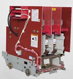
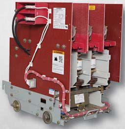


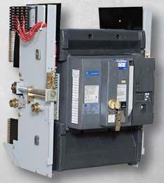
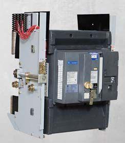


www.bcsswitchgear.com Are you having Power Equipment Problems? BCS HAS THE SOLUTION! new ∙ used ∙ obsolete ∙ reconditioned TEXAS OFFICE 4790 Hwy 377 South Krugerville, TX 76227 FAX 940-365-1808 ABB ∙ GENERAL ELECTRIC ∙ ITE GOULD ∙ WESTINGHOUSE ∙ SIEMENS SQUARE D · ALLIS CHALLMERS ∙ FEDERAL PACIFIC Call Toll Free: 888-599-0486 SWITCHGEAR, INC. Powering industry with superior equipment since 1999.
DIAGNOSIS OF POWER CABLES USING DAMPED AC VOLTAGES & MODERN TESTING


 BY EDWARD GULSKI AND ROGIER JONGEN , Onsite HV Solutions ag, Switzerland AND RALPH PATTERSON , Power Products & Solutions LLC, United States
Modern on-site testing and diagnosis of power cables up to 230 kV consists of voltage testing, partial discharge detection, and dissipation factor measurements. Since the last 10 years in addition to continuous ac or VLF energizing, the use of damped ac energizing is getting more and more worldwide attention. Having in mind the forthcoming IEEE 400.4 guide for the use of damped ac testing in this paper the application of damped ac voltages for on-site testing and diagnosis of underground power cables up to 230 kV will be presented.
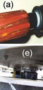

Insulation failure of a power cable can occur as a result of the normal operational voltage or during a transient voltage due to lightning or switching surges. Examples of failures are shown in Figure 1.
Most failures occur as a result of localized electrical stresses that are higher than the dielectric strength of the dielectric materials in the area of the localized stress or if the bulk dielectric material degrades to the point where it cannot withstand the applied voltage. To find
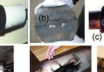
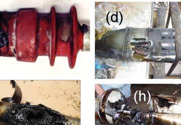

Figure 1: Examples of Insulation Defects in Power Cables:
Distribution cables: (a) bad positioning of field grading; (b) large crack in the center of an epoxy resin joint; (c) interfacial problems in a termination; (d) connector sharp edges inside mass insulated cable termination


Transmission cables: (e) termination of 132 kV XLPE cable with unsealed bottom resulting in contamination and moisture ingress in side insulator; (f, h) cable movement due to expansion of oil due to high temperatures, directly resulting in cracks and voids in joint insulation with final breakdown; (g) electrical treeing in 150 kV gas pressure cables resulting in long term insulation degradation and finally cable breakdown

MODERN TESTING AND DIAGNOSIS OF POWER CABLES USING DAMPED AC VOLTAGES
INDUSTRY TOPICS
58 • SPRING 2015
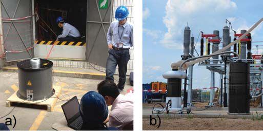
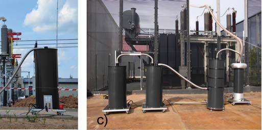
2: Example of On-site Testing Using Sinusoidal Damped ac Voltages (a) diagnostic testing by damped ac system 30 kV of a 3 km long 10 kV XLPE insulated cable; (b) after-laying testing by a damped ac 190 kV system of a 12 km long 110 kV XLPE cable; (c) after-laying testing by a damped ac 270 kV system of a 6 km long 150 kV XLPE cable
these defects prior to a failure, on-site tests, as shown in Figure 2, are applied to assess the quality and cable system integrity as well as the availability and reliability of the cable circuit.
In relation to the applied damped ac testing procedures, the IEEE 400.4: Guide for FieldTesting of Shielded Power Cable Systems Rated 5 kV and above with Damped Alternating Current Voltage (Damped ac), document is under balloting. This guide includes practical considerations, based on user experience during the last 10 years in relation to several IEC standards. Examples of such considerations include the number of damped ac excitations applied during testing and the minimum recommended test voltage level. User feedback has confirmed the following test parameters:
(a) Maximum damped ac test voltage levels:
a. For MV cables (6-35 kV) up to 2.0 U0 (U0 is the rated phase to ground voltage)
b. For HV cables (36-150 kV) up to 1.73 – 2.0 U0
c. For EHV cables (150-230 kV) up to 1.4 – 1.7 U0
(b) Number of damped ac excitations at maximum applied damped ac voltage withstand level: 50.
In this paper, the use of damped sinusoidal ac voltages (damped ac) for monitored testing of
power cables will be discussed based on general considerations and practical examples.
ON-SITE ENERGIZING METHOD AT DAMPED AC VOLTAGES
Damped ac testing can be used as a simple withstand test or in combination with partial discharge (PD) and dissipation factor (DF) measurements for new installed and service-aged cables, Figure 3. The use of damped ac voltages for testing power cables is in compliance with relevant IEC, IEEE, and Cigre international standards and guidelines.

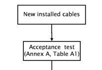
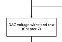
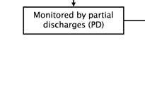
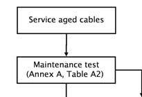
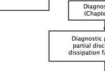
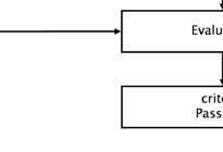
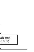
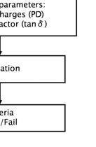
Figure 3: General Overview of Damped ac (DAC) Field Test Possibilities for Different Testing Goals of Cable Systems [IEEE 400.4/ D8 under balloting]


MODERN TESTING AND DIAGNOSIS OF POWER CABLES USING DAMPED AC VOLTAGES INDUSTRY TOPICS
NETAWORLD • 59
Figure
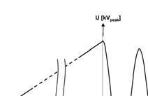
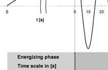
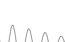
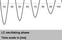

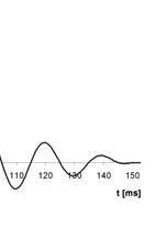

Figure 4: Schematic Overview of One Damped ac Excitation. The maximum damped ac voltage level is determined by the voltage peak values (Vdamped ac) and respective RMS-values (Vdamped ac/√2) of the 1st damped ac cycle.
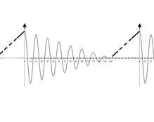
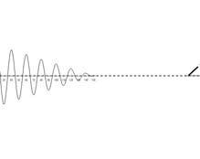
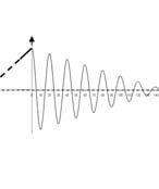
Figure 5: Schematic overview of withstand test by damped sinusoidal ac voltage excitations. The duration of the test is determined by the number of damped ac excitations which are applied to the power cable at a selected damped ac test voltage. The maximum damped ac withstand voltage level is determined by the voltage peak values Vdamped ac and respective rms-values Vdamped ac/√2 of the first damped cycle.
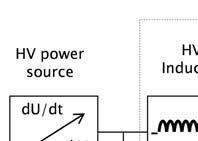
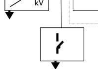
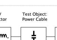
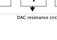

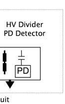

Figure 6: Schematic Diagram of Damped ac (DAC) Systems for On-site Testing and PD Detection of Distribution and Transmission Power Cables
To generate damped ac voltages with durations of a few tens of cycles of ac voltage at frequencies up to a few hundreds of Hz, a test system has been developed. This method is used to energize and to test on-site power cables with sinusoidal ac frequencies. The system consists of a digitally controlled high voltage power supply to energize capacitive load of power cables with large capacitance (e.g., 10 μF), Figure 6. With this method, the cable under test is energized during a time tcharge=Umax Ccable/ Iload with continuously increasing voltage, see Figure 4. During this phase the test object is stressed with an increasing unipolar voltage. The energizing time depends on the maximum available load current of the voltage supply, the test voltage, and the capacitance of the test object. As a result, due to ac field distribution, dc stress, steady-state condition, and space charges are not applied to the test object, and the damped ac stress as applied to the test object can be considered as similar to factory testing conditions.
At maximum selected test voltage, a specially designed solid-state switch connects an aircore inductor to the cable sample in a closing time of <1μs. Due to relatively low cable inductance, no transient overvoltages will occur in the test object. At this moment, the series of ac voltage cycles starts with the resonance frequency of the circuit f damped ac= 1/ (2∏√(L . C cable)) where L represents the fixed inductance of the air core and C cable represents the capacitance of the cable sample, Figure 6. The air core inductor has a low loss factor and design, resulting in a slowly decaying ac waveform of test voltage applied to the cable sample. During a number of ac voltage cycles, the PD signals are initiated in a way similar to 50(60) Hz inception conditions. This procedure can be repeated for multiple excitations followed after each other to perform a voltage withstand test as shown in Figure 5.
The DF can be measured with the decay characteristics of the damped ac voltage wave and the evaluation of the DF can be
INDUSTRY TOPICS MODERN TESTING AND DIAGNOSIS OF POWER CABLES USING DAMPED AC VOLTAGES
60 • SPRING 2015

especially valuable for finding insulation ageing development in paper-oil insulated cables.
DAMPED AC VOLTAGE WITHSTAND TESTING
The application of withstand tests can be divided into two classes:
1. Unmonitored damped ac hold test: a number of damped ac excitations is applied and the ability to hold the maximum damped ac voltage (i.e., no breakdown occurs) is recorded as seen by the black dotted lines in Figures 7a and 7b. The intent of a simple damped ac withstand test is to cause weak points in the cable insulation to fail during voltage application (with minimal fault current) at a time when the impact of the failure is low (no systems or customers affected) and repairs can be made more cost effectively. If a failure occurs during the test, see the vertical dotted line in Figure
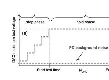
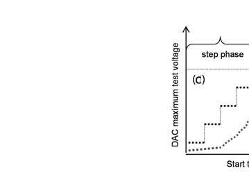
7c breakdown, then the failure should be located through a fault location process and repaired and the circuit retested. The results of these tests are described as either pass or fail.


2. Monitored damped ac hold test: a number of damped ac excitations are applied and one or more additional attributes are measured and used to determine whether the cable passes or fails the damped ac test. In the graphs in Figure 7, the black dotted lines represent the applied damped ac voltage and the grey dotted lines represent the PD detection. Due to additional information as provided by PD detection, the monitoring insulation properties during a damped ac withstand test, and the effect of the test voltage during its application can improve the evaluation of the insulation condition.
The applied maximum test voltage levels for voltage withstand testing of newly installed cables are given in Table 1.
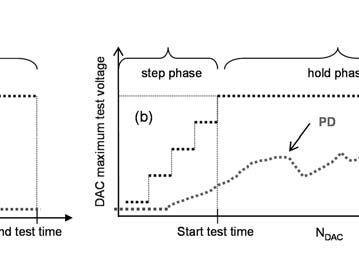


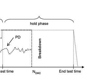


Figure 7: Schematic Overview of Three Different Situations of Damped ac (DAC) Voltage Withstand Test: (a, b) during selected number of Ndamped acexcitations (black dotted lines) no breakdown has occurred and alternatively above the PD background noise PD has been observed or not (grey dotted lines); (c) before the selected number of Ndamped acexcitations for the damped ac withstand test has been applied breakdown has occurred, and above the PD background noise PD has been observed.

INDUSTRY TOPICS MODERN TESTING AND DIAGNOSIS OF POWER CABLES USING DAMPED AC VOLTAGES
NETAWORLD • 61
INDUSTRY TOPICS
Table 1: Damped ac test voltages levels (20 Hz–500 Hz) as used for damped ac testing (50 damped ac excitations) of recently installed power cables [IEC 60502, IEC 60840, IEC 62067].


PRACTICAL EXAMPLES

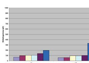
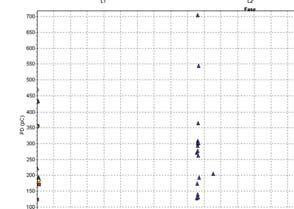
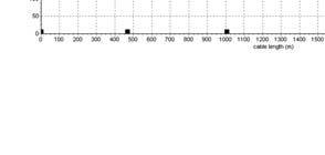

The application of damped ac voltages for testing and diagnosis of transmission power cables up to 230 kV has a history of more than 10 years. In this section, examples are presented and discussed to highlight the importance of monitored testing.
Example 1: A newly installed 2.1 km long, 10 kV XLPE insulated underground cable circuit has been tested in accordance with the IEC 60502 Standard which recommends voltage withstand testing using sinusoidal ac voltage up to 2 U0. Monitored withstand testing was performed by using a damped ac resonant circuit with damped sinusoidal ac voltages at 224 Hz for 50 damped ac excitation at 2.0 U0. For the duration of the withstand test, standardized PD detection was applied. During the application of damped ac over-voltage, no breakdown was observed. It follows from Figures 8 and 9 that internal PD activity was registered in a joint in phase L3. The joint was investigated and the PD source

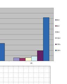
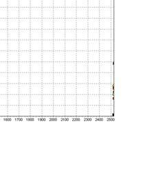

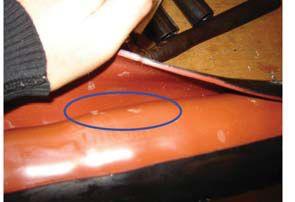


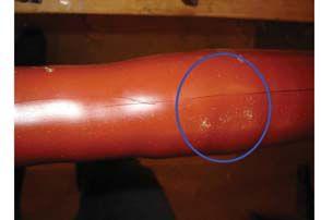
Voids between the crimp tubes due to improper crimping Sand in between the crimp tubes


8: PD Results of an After-laying Testing of a 10 kV 2.1 km Long XLPE Cable Section


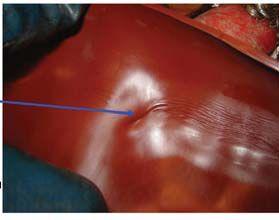

9: Investigation of the Joint at 955 m Location Having PD up to 800 pC at 2 U0

MODERN TESTING AND DIAGNOSIS OF POWER CABLES USING DAMPED AC VOLTAGES
Figure
Power cable rated voltage U [kV] phase-to-phase U0 [kV] DAC test voltage level VT [kVpeak] phase-to-ground 336 6412 10617 15926 201234 251543 301851 352160 45-472674 60-693599 110-11564181 132-13877187 150-16187212 220-230127254
PD level: PDIV L3 = 1.7 UO PD level L3 = 200pC @ PDIV PD level L3 = 800[C @ 2xUO PD
L3: 1 joint at 955 meter
Figure
location:
62 • SPRING 2015

was identified in the crimping tube. After the repair, the complete cable system was free of PD and the test was considered successful.
Example 2: Maintenance testing was performed on a service-aged 2.0 km long 30 kV XLPE insulated underground circuit. Starting from 0.6U0, PD activity up to 9000 pC was registered in one of the joints. Increasing the damped ac test voltage up to 1.7 U0 resulted in concentrated PD activity in this particular joint (Figure 10). Due to the fact that the PD inception voltage is below U0, increased network stresses may result in inception of, and an increase in PD activity during normal operation. Recommended replacement of the joint was accomplished, and the investigation confirmed a PD source (Figure 11).
Example 3: A newly installed 13.3 km long, 220 kV XLPE insulated underground cable circuit was tested using a damped ac resonance system at 49 Hz, applying up to 1.3 U0, (Figures 12-14). Monitored withstand testing was performed. As the damped ac test voltage was increased starting from 0.2 U0, PD activity was observed in phase L1. An increase in the test voltage resulted in an increase of PD activity, At 0.4 U0 test voltage, a breakdown at the discharging site occurred. PD mapping revealed the PD concentration at 5.3 km indicated the breakdown position in the cable. The defect produced PD before an actual breakdown occurred, and with TDR analysis, the PD defect location could be determined. The other two phases fulfilled the after laying conditions and successfully passed the test. No internal PD activity in the cable insulation and accessories and no breakdown occurred during the tests of the other phases. The measurement was repeated from the other end of the L1 cable. The PD activity occurring before the breakdown could be localized at 8 km, which is the same location seen from the original tests (13.3 – 8 = 5.3 km).

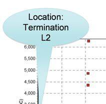
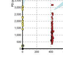

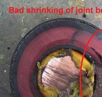
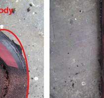
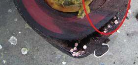
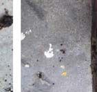
Example 4: Maintenance testing (damped ac frequency 62 Hz) was performed on a serviceaged 35-year old 2.2 km long 66 kV XLPE insulated underground circuit: see Figures


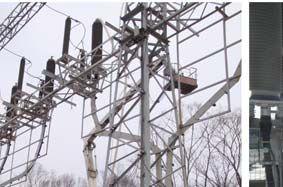
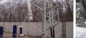

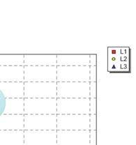
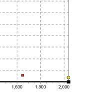

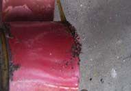
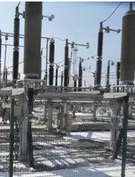

MODERN TESTING AND DIAGNOSIS OF POWER CABLES USING DAMPED AC VOLTAGES
Figure 10: PD Results of a Maintenance Testing of a 10 kV 2.0 km Long XLPE Cable Section
Figure 11: Investigation of the Joint at 415 m Location Having PD up to 9000 pC at 1.7 U0
Figure 12: On-site Testing of a 220 kV 13.3 km Long
INDUSTRY TOPICS NETAWORLD • 63
XLPE Cable Circuit: The damped ac system HV30 is connected to one of the cable section phases.
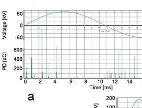
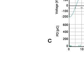
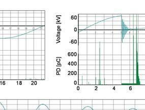
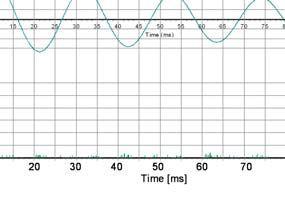
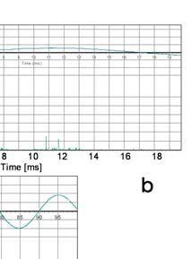
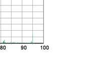
Figure 13: Damped ac Voltages and PD Patterns as Observed during Damped ac Monitored Voltage Withstand Testing of a 220 kV XLPE Cable Underground Circuit (13.3 km): (a) example of PD pattern at 0.2U0 of phase L1, (b) example of PD pattern at breakdown voltage of 0.4 U0 of phase L1, (c) PD pattern at 1.3 U0 of phases L2 and L3
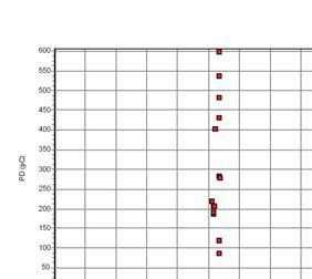
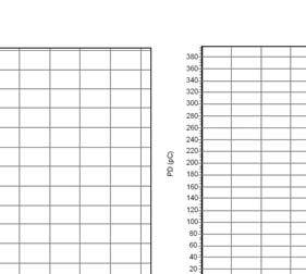
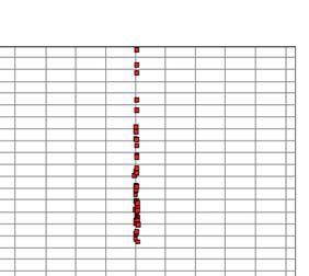
Figure 14: PD Mapping as Made up to 1.3U0 during Damped ac On-site Testing of a 220 kV 13.3 km Long Cable Circuit. The PD concentration at 5.3 km distance indicates the breakdown site of phase L1(left).Measurement from the other end confirmed this location at 8.0 km.(right).
15 and 16. Starting from 1.1 U0, PD activity of up to 100 pC was registered in one of the joints. Increasing the damped ac test voltage up to 1.5 U0 resulted in concentrated PD activity in three joints. Based on this test, it was concluded that if this cable section were energized for network operation, there was a possible risk of failure during operation. Due to the fact that PDIV was very close to U0 and increased network stresses could
result in an inception and increase of PD activity, the risk of a failure depends on the overvoltage stresses during operation. Replacement of the joint or performing the next maintenance tests within approximately six months was recommended in order to evaluate the progress of the degradation at the above mentioned locations by comparing the change of PD activity over time.
MODERN TESTING AND DIAGNOSIS OF POWER CABLES USING DAMPED AC VOLTAGES
INDUSTRY TOPICS 64 • SPRING 2015

CONCLUSIONS
The following conclusions may be drawn:
1. Monitored voltage withstand testing is becoming more and more common practice. PD measurement, including PD-pattern information and time domain reflectometry (PD localization), helps detect and locate discharging defects in the insulation and accessories of power cables.
2. The combination of damped ac voltage measurements and PD detection are an alternative to continuous ac test voltage testing of distribution and transmission power cables.
3. In the context of detecting and locating discharging defects in cable accessories, monitored testing using damped ac voltages can be less destructive and more sensitive than unmonitored continuous ac voltage testing.
4. Damped ac voltage measurements are useful for after-laying testing of newly installed cables, maintenance testing of repaired cables, and diagnosis and condition assessment of service-aged cables.
5. The upcoming IEEE 400.4 guide will support users around the world with the application of the damped ac technology for diagnosing and testing underground power cables.


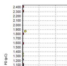
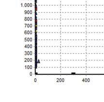

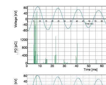
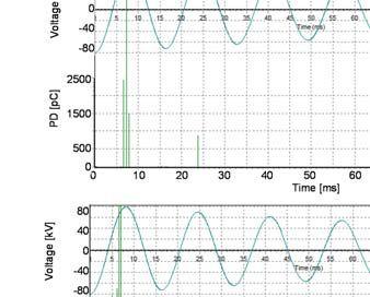
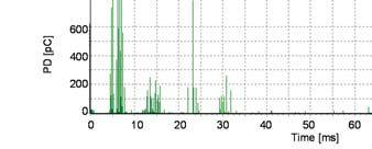

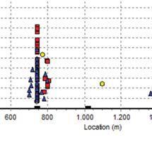
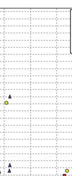
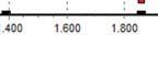

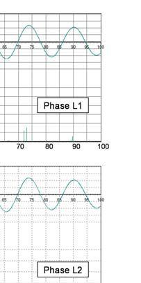
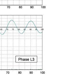


MODERN TESTING AND DIAGNOSIS OF POWER CABLES USING DAMPED AC VOLTAGES
Figure 16: PD Mapping as Made up to 1.5 U0 During Maintenance Testing of a 30-year Old 66 kV XLPE Insulated 2.2 km Long Underground Circuit
Figure 15: PD Patterns as Observed at 1.5 U₣ during Maintenance Testing of a 30-year Old 66 kV XLPE Insulated 2.2 km Long Underground Circuit
INDUSTRY TOPICS NETAWORLD • 65


Edward Gulski (Fellow IEEE) was born in Poland. He received his MS Degree in Information Technology in 1982 from Dresden University of Technology in Germany, his PhD Degree from Delft University of Technology in the Netherlands in 1991, and his Doctor Habilitatus degree from Warsaw University of Technology, Poland, in 2004. At present he is CEO of onsite.hv.solutions AG in Switzerland, an international organization providing knowledge support for power utilities. As a part-time professor at Poznan University of Technology in Poland he is involved in research and education in the field of insulation diagnosis of HV components and asset management. He is chairman of CIGRE WG D1.37 Guidelines for Basic and Practical Aspects of Partial Discharge Detection Using Conventional (IEC60270) and Unconventional Methods, member of CIGRE Study Committee D1 Materials and Emerging Test Technologies, member of the IEEE Insulating Conductors Committee, chairman of the IEEE Working Group PE/ IC/F05W/400.4 P400.4 and Swiss member of Cigré WG B1.38 “After laying tests on ac and dc cable systems with new technologies.” He is author or coauthor of more than 350 publications and three books in the fields of HV diagnosis and asset management.


Rogier Andreas Jongen was born in The Netherlands and graduated with a MS Degree in Electrical Engineering from Delft University of Technology in 2004. After graduation he joined the Department of High Voltage Technology & Management of the same university. In 2012 he received the Ph.D. degree for research on statistical failure analysis of component lifetime data, and its relation to asset management decisions. He worked for almost four years from 2009 with the Swiss company Seitz Instruments AG, as product manager of testing and diagnostic measurement equipment for HV network components. Now he works with onsite.hv.solutions AG in Switzerland as technical manager in the field of on-site testing and diagnosis of high voltage equipment, especially high voltage cables and power transformers.


Ralph Patterson is President of Power Products and Solutions, located in Charlotte, North Carolina. His professional background includes working as a design engineer of transformers and as a specifying engineer of insulated conductors. He has more than 25 years in power engineering, particularly in insulation diagnosis and evaluation of electrical distribution equipment. He serves on the NETA Standards Review Council, is the NETA liaison for the IEEE Insulated Conductor Committees working groups, and received NETA’s 2001 Outstanding Achievement Award.

MODERN TESTING AND DIAGNOSIS OF POWER CABLES USING DAMPED AC VOLTAGES
66 • SPRING 2015 INDUSTRY TOPICS
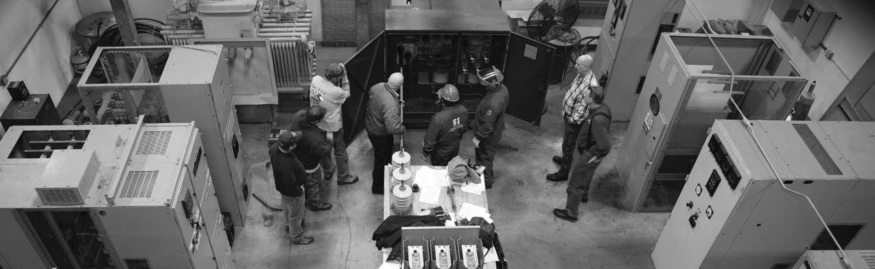
So you thought school was out?
Training updated for lastest safety standards
does your training?
2425 E Pioneer Drive Irving, TX US 75061 +1.972.793.5523 WWW.SHERMCO.COM SAFETY TRAINING
Training topic examples: Who


behind the closed doors of cabinets or switchgear and remotely monitored by server software using an Ethernet or fiber network. Oftentimes, multiple permanent PQ monitors are installed at key points within a facility creating a monitoring system such as at the PCC and at critical loads. Recorded trend and PQ event data is automatically transferred to the server software for use by facility personnel to proactively monitor the quality of supply or to reactively resolve PQ problems as they occur.
Regardless of whether a portable or permanent solution is used, PQ monitors from various manufacturers can have different features and, more importantly, monitoring capabilities and technology. It’s important to make sure that the instrument being used can capture the full spectrum of power quality problems or at least the types of problems suspected. Otherwise, the survey results could be misleading and misreported, wasting valuable time and money.


PLANNING AND PREPARING THE SURVEY
Modern power quality instruments should be Class A compliant with IEC 610004-30 which is an international standard for power quality measurement. Initially released in 2003 and updated in 2008 (next update is pending), IEC 61000-430 specifies the measurement techniques that should be employed to appropriately and accurately measure the quality of supply. Being Class A compliant means the instrument fully complies with the standard, is from a reputable manufacturer, and provides accurate and repeatable measurements. Although IEC 61000-430 is an international standard, in the United States, the IEEE is in the process of harmonizing to this well-established standard which will be included as part of new editions of IEEE 1159 (power quality) and IEEE 519 (harmonics). An example is the recently released IEEE 519:2014 that adopted the harmonic measurement techniques of IEC 61000-4-7, with added compliance limits for voltage and current.
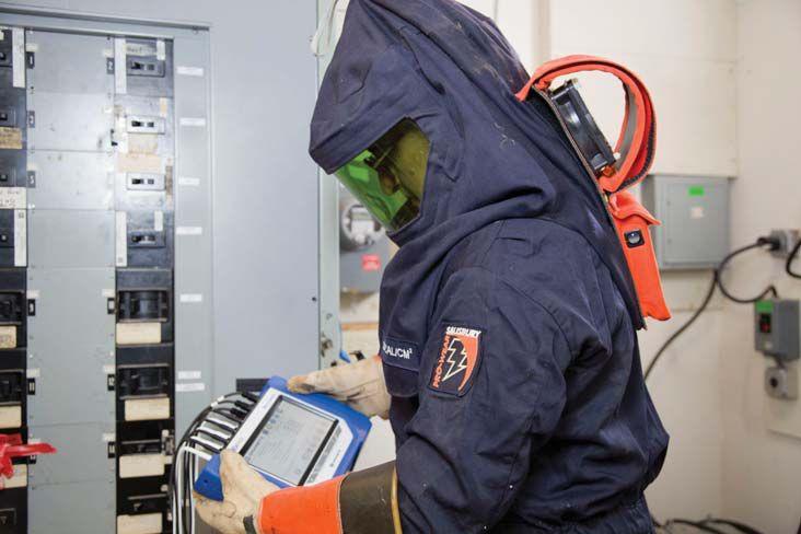

Like any good investigative reporter trying to get to the bottom of the story, the process essentially involves finding out the what, where, when, how, and why of the power related problem(s) at hand. Defining objectives not only keeps the project in focus, but also helps identify the specific equipment resources needed to get the job done. Where to monitor depends on where the problems are observed or suspected. If the problem is localized to one piece of equipment, then placing a monitor at the connection point where the equipment is powered is a good starting point. Sometimes equipment can be both a contributor to and a victim of powering and grounding incompatibilities in the power system. You can then work backward to the point of common coupling (PCC) with the utility if the source of the problem is not found at the equipment. Conversely, if the entire facility is being affected, or if you want to conduct a baseline survey to determine the quality of the supply from the electric utility, starting at the PCC is the logical choice. You can then work down through each feeder circuit to specific loads.


NETAWORLD • 69 PLANNING AND PERFORMING A POWER QUALITY SURVEY FEATURE
Figure 1: Portable power quality monitor being installed by an electrician wearing PPE clothing


The time when the problem occurs can also provide important clues about the nature of the power problem. If the problem only occurs at a certain time of day, then any equipment switched on at that time should be suspect. Utility operations, such as power factor capacitor switching should also be considered as a potential source of problems that occur regularly and at the same time each day. The monitoring period should last at least as long as a business cycle , which is how long it takes for the process in the facility to repeat itself. Some processes run identically for three shifts, seven days a week. Other operations are different each day of the week, in which case the minimum monitoring period would be one week.


As part of the planning and preparation process, it is necessary to obtain a site history for the facility or equipment being investigated. Asking questions of equipment operators or others familiar with operations is an important part of acquiring the site history. Typical site data of interest would include: determining the time, both occurrence and duration, of recurrent system problems; recording failure symptoms or hardware failures; noting any recent equipment changes, additions, or facility renovations; and logging the operating cycles of major electrical equipment in the facility.
INSPECTING THE SITE
The site examination begins by visually inspecting outside the facility and around the vicinity in order to gain a better perspective of the utility service area. Things to look for include type of electrical service (for example, underground), utility power factor correction capacitor installations, neighboring facilities which might be backfeeding interference onto a shared utility feeder, nearby substations, and other potentially problematic conditions.
Inspecting the facility helps to identify equipment that might cause interference. It will also surface electrical distribution system problems such as broken or corroded conduits, hot or noisy transformers, poorly
fitting electrical panel covers, and more. An infrared camera can be very helpful with this. Major electrical loads such as large photocopiers, UPS systems, air compressors, and so forth, should be reviewed. Give special attention to loads near trouble equipment.
Any inspection should include a physical review of the wiring from the critical load to the electrical service entrance to identify any load which might cause power problems. All necessary safety precautions should be observed, such as NFPA 70E, and only qualified personnel should perform any required testing and maintenance work. As Table 1 shows, common wiring problems are a frequent cause of power quality problems. Loose connections and other discrepancies noted during inspection of the electrical distribution system should be corrected prior to monitoring. Particular attention should be paid to equipment power cords and plugs, receptacles, under carpet wiring, electrical panel-boards, electrical conduits, transformers, and the electrical service entrance.

MONITORING THE POWER
The power monitors should be placed at the locations determined during the planning and inspection activities. In general, to determine the overall power quality of the facility, place the monitor at the service entrance. To solve a power problem for a single piece of equipment, place the monitors as close to the equipment load as possible. It’s important to monitor both the voltage and current. Monitoring the voltage identifies the occurrence of a power quality problem, but by also monitoring the current you can determine the source of the problem as either originating upstream or downstream from the equipment load.
The three-step monitoring process involves: (1) using the instrument’s scope mode to see voltage and current magnitudes and wave shapes, (2) using the time interval setting to record background events and slow changes, and (3) using the limits and sensitivity threshold setting to record disturbances or

FEATURE 70 • SPRING 2015 PLANNING AND PERFORMING A POWER QUALITY SURVEY

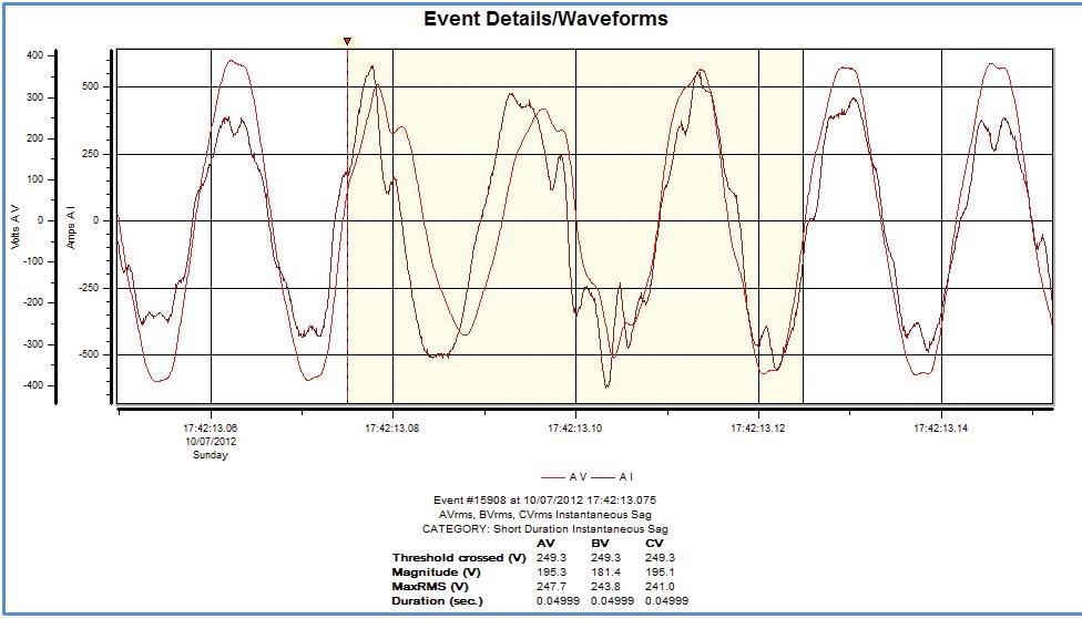
2: Instantaneous downstream Sag: the current increases causing the voltage to decrease
events that may affect the equipment or process being monitored. Periodically checking the captured data allows the user to tweak the thresholds to capture only those events that are critical to the equipment’s performance. (Why capture the entire ocean, when all you want are the fish?)
ANALYZING THE MONITORING AND INSPECTION DATA

To identify equipment problems, it is key to analyze data in a systematic manner. First, look for power events that occurred during intervals of equipment malfunction. Next, identify power events that exceed performance parameters for the affected equipment. Also, review power monitor data to identify unusual or severe events. Finally, correlate problems found during the physical inspection with equipment symptoms. A number of additional procedures must also be performed, including:
• Review all inspection records, site data, and equipment event logs to plot key event summaries.
• Compare power events to equipment event logs and performance specs.

• Extract key power monitoring events which may cause equipment malfunction.
• Classify key power monitoring events into groups to simplify analysis.
• Correlate and validate power monitoring events with equipment symptoms.
• Identify cause in terms of voltage sag, ground or neutral event, transient or voltage distortion (Table 2).
APPLYING CORRECTIVE SOLUTIONS

Adding new wiring, UPS systems, transformers, filters, or other mitigation devices as appropriate may resolve the problems identified during the survey. Moving an interference source to a different circuit sometimes also works. However, make sure that you or the power professional analyzing the survey results has the expertise to safely and properly resolve the problems found. Significant time and money can be wasted deploying inadequate solutions, only to replace them with more appropriate solutions in the future. It is also recommended to repeat the power survey after the problem has been mitigated to prove the problem has been properly


FEATURE NETAWORLD • 71 PLANNING AND PERFORMING A POWER QUALITY SURVEY
Figure


resolved and that the power system is now operating as expected.
A more proactive approach is to permanently install a power quality monitoring system at the PCC, each distribution panel, UPS, and each critical load. Monitoring the system in this way produces a more complete, continuous picture of the entire system’s performance. Such systems record power quality (and usually demand and energy) continually and will be online should any problem occur, large or small. Proactive power monitoring can not only be used for continual system improvements and management, but also for automatic notification of a deterioration or change in the power systems, preventing future interruptions, downtime, and lost productivity from occurring.
OBSERVE THE RULES
There are five simple rules to keep in mind while performing a power quality survey:
1. Apply the test of reasonableness to all data and


information. Basic laws of physics cannot be temporarily repealed to make something believable.
2. Know the performance as well as the safety limitations of monitoring and test equipment.
3. Look for the obvious. Most power problems are solved like peeling onions – one layer at a time.
4. Don’t fall victim to paralysis by analysis. Set reasonable monitor thresholds, concentrate on the larger events, and then work your way down.
5. Probably the most important rule: start with the simple things first. People are always amazed to find out how often power problems are caused by nothing more mysterious than loose wiring connections. (Table 1).

To find the symptoms, causes, and solutions for the various power events in upper left column, match the adjacent code numbers to the corresponding descriptions in the chart.
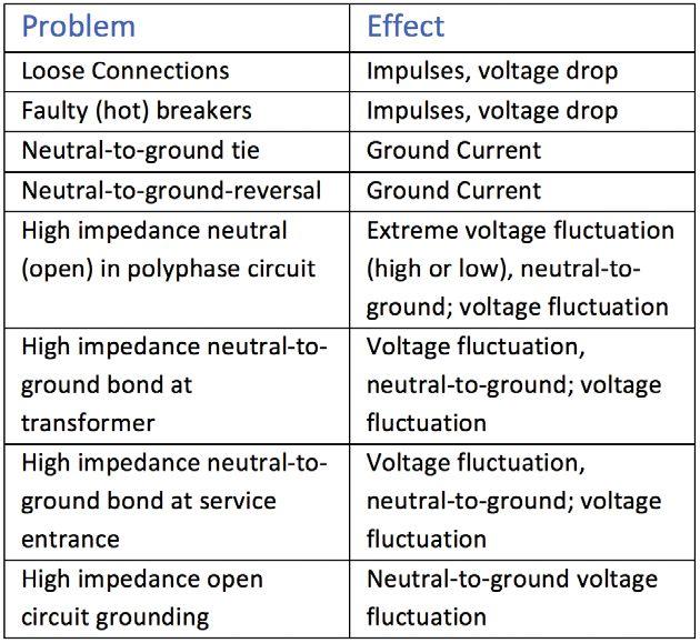


72 • SPRING 2015
FEATURE
PLANNING AND PERFORMING A POWER QUALITY SURVEY
Table 1: Typical PQ causes and events


Table 2: Symptoms, causes, and solutions for various power events.
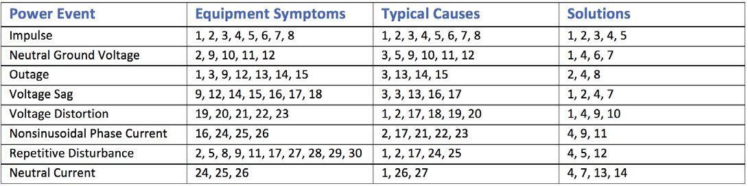


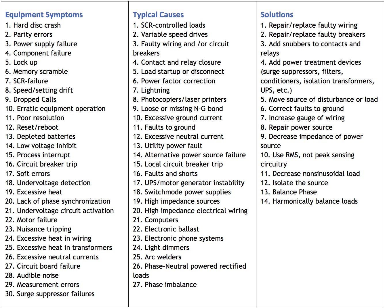


NETAWORLD • 73 FEATURE
PLANNING AND PERFORMING A POWER QUALITY SURVEY


Richard P. Bingham retired in 2008 as the VP of Product Development and Marketing for WPT, which includes Dranetz-BMI, Electrotek Concepts, and Daytronic. He presently works as a consultant for Dranetz and PowerCET providing project management, power quality audits, and expert witness. Following completion of his BSEE at the University of Dayton, he joined the company in 1977, and has held positions as project engineer, chief technologist, VP of Engineering, and, VP of Strategic Planning at Dranetz. Richard also has an MSEE in Computer Architecture and Programming from Rutgers University. He is a member of IEEE Power and Energy Society, and the Tau Beta Pi (the Engineering Honor Society). Richard also serves as the chairperson of the IEEE PQ Subcommittee and formerly chair of the NFPA 70B Electrical Equipment Maintenance committee, as well as a principal member of Code Making Panel 20 of NEC on HomeLand Security. He also serves as secretary/vice-chair/ chair and member of the numerous other IEEE PQ power quality related committees. He holds one patent.


Ross Ignall graduated from Trenton State College (now The College of New Jersey) in 1986 with a Bachelor of Science in Electronics with a minor in Computer Science. Ross has more than 20 years of experience in the design, development, marketing and application of test and measurement instrumentation. Ross joined Dranetz in 1990 as a Design Engineer, ultimately working as a Group Leader and Senior Engineer leading new product development projects. Ross is presently the Director of Product Management working on the specification, development and application of portable and permanently installed power monitoring instruments and systems.
Ross is a frequent domestic and international speaker and has written many seminars, papers and articles on power instrumentation, power quality, energy monitoring and their applications. Ross is also a contributing author for several books on power quality and power monitoring and is co-inventor of a US patent titled Electrical Parameter Analyzer used as the foundation for Dranetz’ Power Platform family of products.
74 • SPRING 2015
FEATURE PLANNING AND PERFORMING A POWER QUALITY SURVEY
the test equipment answer
We support testing
Protective Relays and Metering
Batteries and UPS
Transformers
VLF, Tan Delta and Partial Discharge
Cable fault location
Substations & High Voltage Circuit Breakers
SF6 Analysis
Low & Medium Voltage Circuit Breakers
Motors and Rotating Apparatus
Power Monitoring


888.902.6111 | info@intellirentco.com | intellirentco.com
rental | support | logistics
• Vacuum interrupter replacements rated up to 38kV, 3000A
• Repair and replacement services for all major OEM interrupters, including GE, Eaton, CH, Westinghouse, ABB, Siemens, and many more
• Pole assemblies, parts, and components
• Custom design/manufacture services for obsolete interrupters, breakers
• Field and in-shop vacuum interrupter replacement services
• Rental vacuum breakers available while yours are being serviced
videos.vacuuminterruptertesting.com download our technical paper on predicting the remaining life of vacuum interrupters WATCH the MAC-TS4 in Action! (214) 442-5877 EMAIL info@VacuumInterruptersInc.com Vacuum Interrupters Inc .com MAC-TS4:
Only Predictive Vacuum Interrupter Test Set WE HAVE THE WORLD’S LARGEST SELECTION OF REPLACEMENT VACUUM INTERRUPTERS
The World’s
ELECTRICAL COMMISSIONING:
TOP PRIORITIES TO ENSURE A SUCCESSFUL
BY DAN HOOK AND TIM CONLEY,

Electrical commissioning is a multistep and complex process focusing on the verification and documentation of an electrical system to ensure it performs as intended and meets applicable standards and manufacturers’ tolerances. Electrical commissioning should identify and document the correction of discrepancies so that it is a reliable system that has been installed in accordance with design specifications when it is turned over to the owner. A successful electrical commissioning project also provides the necessary baseline data for the system against which future maintenance tests can be compared for accurately trending the health of the electrical system.
Electrical acceptance testing and electrical commissioning are terms that have been and continue to be used interchangeably. Although electrical acceptance testing may be the largest component, the commissioning process is more comprehensive. Typically, commissioning activities begin prior to acceptance testing and ideally will commence very early in the overall project schedule. In our experience the inclusion of a commissioning process in the early stages of the project can identify problems that will be encountered later and allow for correction of those issues in a timely manner.
DOCUMENTATION
All required design documentation should be gathered prior to formulating a commissioning plan. On the surface this may appear like elementary guidance that is easily provided by the customer. However, there are many situations that may arise which present challenges to obtaining
PROJECT
accurate documentation. Change orders can happen in the design and construction phases of a project. This can result in many revisions to drawings and specifications, even those marked as released for construction. Often there is more than one entity responsible for the documentation required to adequately develop a commissioning plan. It can be very frustrating to dedicate significant time and effort to a project, only to learn that the documentation provided was not correct, with the result that the work must be redone. At a minimum the following items are recommended to generate a comprehensive commissioning plan, with a brief statement of explanation for each.
ELECTRICAL PLANS
One-Line Diagrams


This overall view of the electrical distribution system is absolutely critical to identifying the individual components of the system that will undergo electrical acceptance testing in the field.
One-line diagrams also show the interconnection of various parts of the system in a simple view that can be used for switching order development and is a large, but not all inclusive, part of developing lockout-tagout requirements.
Three-Line Diagrams
Three-line diagrams allow the test team to determine if the wiring supports the anticipated functionality. Three-lines are critical to the technician and the commissioning party in that they enable the development of test plans, especially when dealing with instrument


FEATURE ELECTRICAL COMMISSIONING: TOP PRIORITIES TO ENSURE A SUCCESSFUL PROJECT
Western Electrical Services, Inc.
78 • SPRING 2015
transformers and how they are required to be connected to metering and protection circuits.
Schematics, Control Device Truth Tables, and Connection Diagrams


These drawings, which show the actual physical locations of connections, electrical connection points, and appropriate states of contacts and other control devices, are essential in developing point-to-point continuity test requirements. They are also of critical importance in the event that a discrepancy is found and must be corrected. These drawings are often altered or updated during the installation and testing activities, commonly referred to as red-line updates, and can present a challenge near the end of a project with regard to ensuring the customer has the most up to date set. One of the most important goals of the commissioning process is the accurate documentation and updating of the actual system configuration, or as builts, of the final product.
ELECTRICAL SPECIFICATIONS
Design Criteria

missing critical items such as this is reduced.
Field Electrical Acceptance Testing Requirements
Field acceptance testing criteria must be clearly delineated. In some cases there are optional tests or alternate testing methods required. For example, medium voltage cables have multiple approved methods for performing acceptance tests. The commissioning team must ensure the correct method of testing is performed by the testing agency.
MANUFACTURER’S DOCUMENTATION

The design criteria are of paramount importance for the commissioning team to fully understand how the system is required to perform. Recent trends show an increase in design-build type projects. One of the goals when this project structure is chosen is a more cohesive relationship between the design team and construction team. Often these structures are chosen in an attempt to shorten the project timeline as well as streamline project actions and smoothly address issues that may arise during construction. In any case the project drawings and specifications must be developed and approved prior to beginning construction.
Factory Test Requirements

Manufacturers often have specific installation instructions and startup/commissioning guidelines. Some specialized equipment may have unique requirements that even a very experienced electrical contractor and testing technician may not know. The commissioning team is responsible to the owner for correct installation and startup and, therefore, must have this information when developing the commissioning plan.
POWER SYSTEM STUDIES
Short Circuit Study
Requirements in the National Electric Code for labeling of switchgear have been updated to include available fault current information. The short circuit study is the source for that information. The design requirements for switchgear ratings should stem from this study and must be verified by the commissioning team.

Coordination Study with Device Setting

Sheets/Set Point Files
In many specifications factory testing is required to be performed and witnessed by a designated representative. The factory witness testing requirement is often missed and may create delays in shipping the materials to the job site, or worse yet, may cause delays on site because problems that should have been found during factory witness testing are not found until commissioning begins. When the commissioning process is started and approved early in the project’s timeframe, the chance of
The protective device settings verification must be documented in the commissioning plan. Protective devices are usually shipped from the factory with minimum or default settings applied. Protective device settings can be altered during the testing and startup process. The final commissioning report should include all finalized settings.
A coordination study is an integral part to be incorporated into a set point file, but it must be understood that a qualified protective relay engineer with a programming background must generate accurate set point files that include the logic necessary to perform all required functions based on system design demands.

NETAWORLD • 79 ELECTRICAL COMMISSIONING: TOP PRIORITIES TO ENSURE A SUCCESSFUL PROJECT
FEATURE
FEATURE

Arc-Flash Hazard Analysis
This power system study continues to be at the forefront of the electrical safety industry. The commissioning team must verify labeling requirements.
COMMISSIONING PLAN
The components of the commissioning plan should be finalized early. By its very nature, the commissioning plan often has implications and requirements prior to the mobilization of construction crews and the independent testing organization. For example, the contracted companies and the personnel themselves may be required by the specifications to submit qualifications for approval. The commissioning plan may also require specific tests to be performed or specific test methods to be used during acceptance testing. If this plan has not been developed and approved prior to the testing period, the acceptance testing firm may perform testing by their own standard operating procedures and practices, rather than by the requirements for the project.
INSTALLATION INSPECTIONS
Installation inspections can be performed by the commissioning team or by a quality assurance representative of the electrical contractor depending on project requirements. In some cases an installation inspection must be performed prior to moving on to the next step in the construction process.
PREENERGIZATION
• Summarized scope of work statement
• Test team organization
• Testing prerequisites (plant conditions)
• Sequential procedural steps for the testing
• Expected system responses
• Actions to be taken in the event of a failure
• Safe back out points including actions to establish safe plant conditions should the need arise to cease testing operations
• Safety Briefing
System Parameter Measurements
System parameter measurements should be included during the energization procedure. Phase rotation, and phase sequence are of paramount importance. Prior to system functional testing, other installed indications should be checked. Metering and protective relay indication checks will ensure that the instrument transformers, wiring, and programming are as specified.


Preenergization (Electrical Acceptance Testing) testing typically includes component testing, continuity testing on interconnections, and functional testing on controls and interlocks.
ENERGIZATION
The first energization event for newly installed electrical equipment should address two important items. The first is safety and the second is confirmation of the expected system parameters.
Commissioning Plan
The commissioning plan should include or reference the job hazard analysis for required testing procedures. A detailed Method of Procedure (MOP) needs to be developed and include the following:

POST ENERGIZATION
Post energization (System Functional) testing occurs near the end of the physical process. All component testing has been completed; interconnection continuity has been verified; and controls schemes have also been verified. The system has been energized and all indications verified such that simulations of real life situations may be performed.
Transfer between Modes
This testing may include switching power supplies from normal to emergency in an overall system test where utility power is removed, or a simple transferring from double ended to single ended on a capable substation.
Load Banking
The purpose of this test to replicate real load, or perhaps full load conditions at nominal voltage to prove the system will operate as intended.
Power Quality Testing
In our experience an increasing number of specifications require the documentation of power quality on the newly-installed system, especially when UPS systems are involved.
Utility Parallel Operation
The ability to parallel safely with the serving utility


ELECTRICAL COMMISSIONING: TOP PRIORITIES TO ENSURE A SUCCESSFUL PROJECT 80 • SPRING 2015

and in some cases document power flow in both directions may be one of the most critical post energization tests that can be performed. Many serving utilities will have specific requirements and complex steps to perform this work.
DISCREPANCY LOG
Maintain a sequential discrepancy log during the entire commissioning process including resolution for each discrepancy. This log can serve many purposes near the end of the project but can be nearly impossible to recreate after the fact. This record can be thought of as a type of journal for the project and assist with contract management, troubleshooting of systemic discrepancies, and provide a track record of such. The size and complexity of the job will drive the extent of the discrepancy log. A practice incorporated successfully on large projects is to generate a rapid deficiency report with pictures along with the daily progress reports. This enables a deficiency to be identified for quick release to a quality control representative. It then allows the builder or others to take corrective actions and lessens administrative delays.
ELECTRICAL ACCEPTANCE TESTING


and expertise cannot be understated. A successful commissioning team must attain a practical hierarchy with the owner while operating within the contractual hierarchy present.
The complexity of the electrical systems being installed and their interrelation with other systems is growing. The electrical commissioning process is included in an increasing number of projects as a strategy to combat issues during construction, testing, and operation systems. The ultimate goal is to turn over a safe and reliable system that will operate as designed to the owner. The ANSI/NETA ECS-2015 Standard for Electrical Commissioning Specifications for Electrical Power Equipment and Systems has been designed to establish an industry recognized standard for these activities.


Utilize industry-recognized standards for acceptance testing by an independent, third party that can function as an unbiased testing authority, professionally independent of the manufacturers, suppliers, and installers of equipment or systems being evaluated. When performing functionality testing, one may need to tailor data sheets to address all aspects of the installed design features. A simple block on a check sheet with a pass/fail often will not meet the project specifications and requirements.
HIERARCHY
In many projects the commissioning team is part of the overall contract from the owner and could be a subcontractor to the prime contractor, or a secondary subcontractor to the electrical subcontractor. However the commissioning team has a professional responsibility to the owner to deliver a reliable system with all required documentation, even if the prime contractor has the ultimate responsibility. Commissioning is a quality assurance engagement where the importance of professional relationships

Tim Conley is a Senior Technical Advisor at Western Electrical Services, Inc., where he has previously held Field Service Technician and Project Manager Positions. Tim is a NETA Certified Technician Level III as well as NICET Level III. He is a member of Electronics Advisory Committee for Olympic College in Bremerton, WA. Tim has direct experience with the commercial nuclear industry as well as disaster recovery, represented by the year he spent with the Eaton Corporation deal with Hurricane Ike recovery for most of his tenure there. Tim spent nearly 24 years in the US Navy as an Electrician’s Mate leading the divisions and department maintaining and testing all aspects of generation, distribution, control equipment, and distribution system protection as it applied to nuclear submarines. In addition, he completed successful Nuclear Instructor tours mentoring the US Navy’s future nuclear officers and enlisted men.

Dan Hook is the Executive Vice President in charge of Business Development at Western Electrical Services, Inc. where has previously held Field Service Engineer, Sales Engineer, and Chief Operating Officer positions. He has been in the industrial electrical industry for over 20 years with US Navy and civilian experience. Dan holds a master’s degree in Electric Power Engineering from Rensselaer Polytechnic Institute in Troy, New York, and he maintains his professional engineer’s license in Washington, Utah, Arizona, and Oregon. He earned an MBA in 2012 from Pacific Lutheran University with a concentration in Entrepreneurship and Closely Held Businesses.
Dan is a certified NETA Certified Senior Technician Level IV as well as a NICET Level IV.


FEATURE
NETAWORLD • 81 ELECTRICAL COMMISSIONING: TOP PRIORITIES TO ENSURE A SUCCESSFUL PROJECT
To learn more about NETA’s newest standard, the ANSI/NETA ECS Standard for Electrical Commissioning Specifications, visit netaworld.org/standards.

NEW! ANSI/NETA ECS -
2015
ORDER
NOW!
Delivering Powerful Reliability Solutions
Power System Acceptance Testing
Commissioning and Start-up
Maintenance
Life-Cycle Extension
Troubleshoot and Repair
Training and Engineering Services
Planning and Operations Support
Project Management
2200 West Valley Hwy North, Suite 100 | Auburn, WA 98001
THE EXPERTS IN ELECTRICAL RELIABILITY
Comprehensive Electrical
Testing and Maintenance
Commissioning and Startup Services
Engineering Services
Power System and Coordination Studies
FAILURE IS NOT AN OPTION.
Predictive and Preventive Maintenance
Partial Discharge Testing and Monitoring
24/7 Emergency Service
Ensuring the reliability of your electrical distribution system.
As the leading independent electrical testing, maintenance, and engineering service company, you can rely on Emerson’s High Voltage Maintenance to exceed your electrical equipment performance goals. From testing for problems that could disable your system, to complete turnaround execution, you’ll quickly understand how we are your single source solution for all of your electrical reliability needs. With a service geography across the Midwest and Eastern Seaboards, our service team puts experienced professionals where and when you need them.
For more information: High Voltage Maintenance (866) HVM-TEAM
Sigma Six Solutions, Inc.
|


ELECTRICAL COMMISSIONING for
Improved Availability, Safety & Cost Savings

 BY MICHAEL DONATO, Electrical Reliability Services
While commissioning has existed as a building construction industry discipline for nearly three decades, the commissioning industry is evolving. Commissioning activities are continually being refined and updated by practitioners and industry organizations. In fact, the American National Standards Institute (ANSI) together with the InterNational Electrical Testing Association (NETA) is currently developing the new Standard for Electrical Commissioning Specifications for Electrical Power Equipment and Systems (ANSI/NETA ECS).


For critical facilities, commissioning often involves much more than just the electrical power equipment. However, the purpose of this article is to clearly define electrical system commissioning, highlight the need for this commissioning within critical facilities, and explain some of the many commissioning benefits.
DEFINITION AND SCOPE
The definition of commissioning varies greatly from one commissioner to the next and one building owner to the next. However, industry experts generally concur with the American Society of Heating, Refrigerating and Air-Conditioning Engineers (ASHRAE), which asserts that the focus of commissioning is “verifying and documenting that the facility and all of its systems and assemblies are planned, designed, installed, tested, operated, and maintained to meet the needs of the owner.” More specifically, the electrical system commissioning is the systematic process of documenting and placing into service newly-installed or retrofitted electrical power equipment and systems.
The scope of ANSI/NETA ECS is to assure that tested electrical systems are safe, reliable, and operational; are in conformance with applicable standards and manufacturers’ tolerances; and are installed in accordance with design specifications. Additionally, the standard specifically states that “only qualified and authorized persons with adequate and relevant commissioning experience should conduct the work” described in the standard.
One of the best ways for commissioners to ensure that the full scope of electrical system testing is met and that their commissioning team is meeting regulatory requirements is to work with a NETA Accredited Company. This designation confirms that technicians

84 • SPRING 2015
ELECTRICAL COMMISSIONING FOR IMPROVED AVAILABILITY, SAFETY & COST SAVINGS
FEATURE


have the proper knowledge, training, and equipment. Additionally, it verifies that the testing organization is a well-established, full-service electrical testing business.
Another approach that many complex, critical facilities such as data centers, use to ensure successful electrical system commissioning is to hire a Commissioning Authority (CxA) to oversee and execute the entire process. ANSI/ NETA ECS outlines the responsibilities of the owner’s representative, a role that the CxA would fulfill.

While CxAs do not have any decisionmaking power relative to the owner, a quality CxA will offer the expertise, guidance, and direction the owner needs to make informed decisions and realize the most value from electrical system commissioning.
much more is involved for a complete commissioning project.
As stated in ANSI/NETA ECS, the commissioning standard should be used in conjunction with the most recent edition of the acceptance testing standard. Furthermore, the NETA standards should be used together with other commissioning documents to expand the scope to include all applicable systems such as mechanical instrumentation, heating and refrigeration, and building systems.

Ideally, a CxA would be brought on to a project at the very beginning—during the predesign or design phase. This gives a CxA the ability to influence the details of the owner’s project requirements (OPR). The OPR becomes the keystone of the electrical system commissioning project, and the CxA makes sure that all activities align with meeting these requirements.

NEED FOR COMMISSIONING
A major impetus behind commissioning electrical systems of critical facilities is the increasing complexity of the systems themselves, which presents more opportunities for problems, and the fact that there is virtually zero tolerance for unplanned downtime due to the staggering financial and reputational costs of outages.
Appropriate electrical system commissioning activities can ensure uptime by identifying the causes of failures and outages. Nearly 70 percent of early equipment failures can be traced to design, installation, or startup deficiencies. Electrical system commissioning can help to detect and correct these problems before the failures or outages occur.

An OPR should always be developed in order to streamline design time, establish performance targets and measure project success. One recommendation for ensuring the creation of a comprehensive, user-friendly document is to hold an OPR workshop that brainstorms project requirements and gets buy-in and involvement from all the key stakeholders.
During this workshop is an opportune time to discuss the roles and responsibilities of all involved, as often commissioning is confused with other types of testing and processes. For example, some firms consider just acceptance testing and/or equipment startup to be commissioning. While those tasks are part of electrical system commissioning,


Commissioning is also the answer to a wide variety of other owner concerns. Issues such as ensuring the operations and maintenance (O&M) staff has adequate resources, improving safety, and boosting efficiency of critical facilities can all be addressed by specifying the right commissioning activities. Therefore, the appropriate scope of commissioning relates directly to owners’ requirements for their critical facilities.
It is the opinion of Electrical Reliability Services (ERS) that a comprehensive approach to commissioning—one that encompasses a wide range of building systems and spans the entire design/build process—results in the greatest value to project owners. However,


NETAWORLD • 85 FEATURE ELECTRICAL COMMISSIONING FOR IMPROVED AVAILABILITY, SAFETY & COST SAVINGS


even if commissioning activities only include the electrical equipment and systems, owners can still realize many of the following benefits when critical facility commissioning best practices are incorporated.
BENEFITS
Less
Unplanned Downtime and Fewer Repairs
Preventing or greatly reducing the possibility of unplanned downtime is perhaps the greatest value electrical system commissioning provides for critical facilities. Commissioning activities ensure that mission-critical equipment is correctly installed and that systems are fully integrated. The process checks for redundancy and single points of failure. It includes comprehensive system testing to verify availability in all operating modes. These activities help identify potential system-related problems so they can be resolved before leading to major equipment damage or disruption of service. Commissioning can also ensure a well-trained and well-equipped O&M staff that is less likely to make mistakes that lead to system failure.

Reduced Life Cycle Costs
Done correctly, electrical system commissioning improves system performance throughout the facility life cycle. In addition to optimized performance, it also decreases operation and maintenance costs and cuts down on energy consumption for smaller utility bills.
Full System Integration
used to identify future problems with the system, maintain optimal operations, and evaluate future maintenance decisions.
Improved Efficiency
If efficiency features have been designed and built into the electrical system, commissioning activities can verify that the features function as intended. Therefore, the owner will be able to realize the resulting energy cost savings.
Enhanced Safety and Compliance
The electrical system commissioning process produces a safer facility and reduces owner liability by uncovering safety problems before, during, and after energization Commissioners can verify compliance with National Fire Protection Association’s safety-related maintenance practices (NFPA 70E).They can also ensure that owners and O&M staff have all equipment manuals and operation instructions pertaining to electrical equipment.

For maximum availability, all critical systems— electrical, mechanical and controls—must function together and be a fully integrated system. Historical approaches to testing and startup verified only that each individual system’s components functioned independently. Today, a CxA employs more sophisticated processes and tests to verify that all electrical components work together to support an integrated system.
Benchmarking Data
Electrical system commissioning creates extensive documentation for benchmarking system changes and trends. The data can be
Return on Investment
The benefits of electrical system commissioning can create a return on investment that exceeds its cost. In a recent study of commissioning projects performed by Electrical Reliability Services, the analysis revealed that the key issues discovered and corrected during the commissioning process resulted in cost savings and/or revenue earning potential for the owner that well exceeded the total cost of commissioning. Additionally, proper commissioning extends equipment life and lowers operation and maintenance costs for a lower total cost of ownership.


Speed to Deploy
Under the CxA’s oversight, projects experience fewer change orders, delays, and rework, avoiding the considerable costs of late occupancy, liquidated damages, extended equipment rentals, and other costs associated with delays. Commissioned facilities are more likely to be deployed on time and on budget.


86 • SPRING 2015 FEATURE ELECTRICAL COMMISSIONING FOR IMPROVED AVAILABILITY, SAFETY & COST SAVINGS

CONCLUSION
Commissioning is verifiably a critical step when placing newly-installed or retrofitted electrical power equipment into service within a critical facility. To realize the greatest value, owners should look for a CxA that has the knowledge and experience needed to streamline the project. Owners should also seek the electrical system testing expertise of a NETA Accredited Company to help execute the commissioning plan. When done right, commissioned electrical power equipment and systems offer a number of benefits including improved availability and safety, as well as cost savings. Ultimately, commissioning produces a higher level of owner satisfaction at the time of turnover and for many years to follow.


Michael Donato has more than 27 years experience performing and managing electrical testing, maintenance and engineering services for Emerson’s Electrical Reliability Services group.
In his current role and for the past 15 years, his particular expertise is in commissioning data center facilities. Michael has successfully commissioned hundreds of data centers ranging from small telecom sites to large Tier IV data centers including some LEED certified facilities. His focus has been to provide measurable value to owners at all phases of the commissioning process.

Michael has earned his QCxP and LEED AP certifications and continues his education in commissioning theory and implementation through the University of Wisconsin.


NETAWORLD • 87 FEATURE ELECTRICAL COMMISSIONING FOR IMPROVED AVAILABILITY, SAFETY & COST SAVINGS


FORT WORTH, TEXAS
OMNI FORT WORTH HOTEL
MARCH 14-18, 2016
HOSTED BY


Call for SPEAKERS
The Premier
Electrical Maintenance and Safey Event
• Communicate Your Knowledge
• Assist the Industry
• Gain Visibility
PRESENTATIONS SOUGHT
Review of basics
Industry-specific skills
Insights into new methods, technologies, and advancements
New testing procedures, safety procedures, and OSHA laws
New types of electrical power equipment
Uptime and reliability issues
ABSTRACTS DUE MAY 1, 2015 SUBMIT AT WWW.POWERTEST.ORG 888-300-6382(NETA)
Independent Electrical Testing and Preventive Maintenance PROFESSIONAL SERVICES 609-890-8300 www.easternhighvoltage.com
POWER PLANT IN PERU: COMMISSIONING OF A CASE STUDY
BY PAUL HARTMAN, DLB Associates
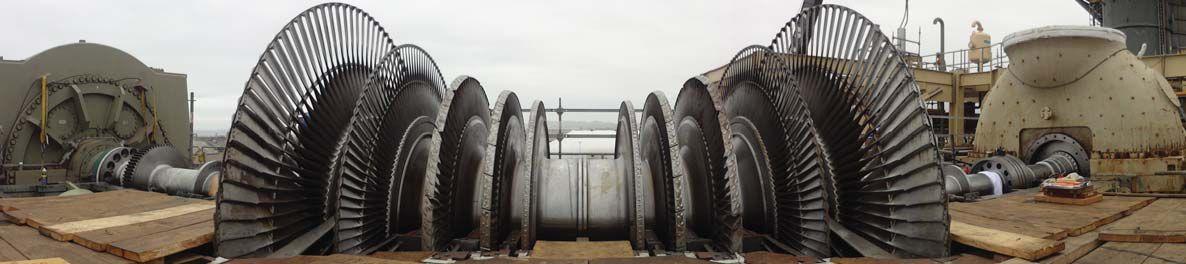
PROLOGUE

Steam turbine shaft with high pressure turbine on the right, low pressure turbine blades in the center and 223 MVA generator on the left.
“If this economy gets any worse I am going to have to hire ten more technicians and open a new office just to keep up with the work that is coming in.” That is a direct quote from an owner of a NETA Accredited Company, commenting on the effects that the slow economy was having on his business. Even during slow economic times the electrical testing industry continues to thrive, which is a compliment to NETA’s willingness and ability to adapt and change with the times, which in turn has helped testing companies meet or exceed their clients’ needs.
The days of the sole electrical quality program being the performance of NETA acceptance testing procedures are long gone. I certainly am not implying that the NETA testing procedures have lost any value; I believe they provide greater value now than they ever have because now they are part of the grand quality scheme of things that helps clients prove the overall integrity of their systems. This fits right into what clients are

striving for, that holy grail of QA/QC. They want to ensure that their facilities are built in such a way that they will never go off line; they want guaranteed 100 percent uptime. Obviously, that guarantee is virtually unattainable; however, that does not stop the industry from making the effort to strive towards that perfect number, which in turn helps our clients meet their goal of reducing their exposures and their risks.


90 • SPRING 2015
FEATURE
COMMISSIONING OF POWER PLANT IN PERU: A CASE STUDY

In general there are five major types of commissioning associated with facilities:
• Electrical
• Mechanical
• Fire
• Security
• Building Envelope
In this article we are focusing on electrical commissioning, while at the same time keeping in mind that today’s electrical commissioning process often overlaps other types of commissioning. For example, the merging of Building Management Systems (BMS) and Power Monitoring Systems (PMS) into one software package often has both the mechanical and electrical commissioning teams working off the same software platform, and sometimes through the same Human Machine Interface (HMI).


Throughout this quality evolution the original basic concept of greenfield site to completion commissioning has evolved for the better. In the early stages of this development, commissioning had very clear lines of delineation as to which entity would perform each of the following process segments:
• Design review
• Factory witness testing
• Component testing
• Manufacturer’s startup
• Document verification
• Systems proof
CASE STUDY:
THE POWER PLANT IN PERU
There is sometimes a perception that commissioning tasks should fit into a nice little commissioning box . In other words, “This is the commissioning we are going to do and this is how we are going to do it.” This concept gives everyone a known strategy that works well for a project quality control plan. It is the unknown parts of a project that can truly make commissioning a challenge.
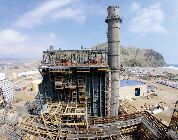
The heat recovery steam generator and combustion turbine exhaust stack are shown with the Pacific Ocean in the background.


To put some practical application into the unknowns of a commissioning process, I will review a recent power plant project where I was involved in the testing and commissioning process. This project was on the coast of south central Peru. The design of the power plant is what is commonly known as a two-on-one combined cycle design. Twoon-one means that there are two combustion turbines, in this case natural gas fired, that each spin a generator to produce power. The exhaust from the two combustion turbines is routed through a heat recovery steam generator (HRSG) unit, which converts the exhaust heat into high pressure steam. The combined steam energy that is captured from the two combustion turbines is enough to spin one sizable steam turbine/generator package. Each of the three generators produced more than 250 MW of power that is stepped up to 500,000 volts before being sent to the 500-kV, sulfur hexafluoride (SF 6) gas-insulated substation (GIS).


NETAWORLD • 91 FEATURE COMMISSIONING OF POWER PLANT IN PERU: A CASE STUDY


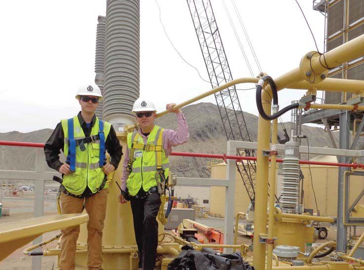

DLB team members Paul and Sean performing final inspections on top of one of the 220-MVA transformers.
amount of time supporting one another. This meant that during critical junctures in the commissioning process it was not uncommon to have the entire acceptance testing team wearing their commissioning hats.
SURPRISES
From the very onset of the Peru project there were challenges, serious challenges . Electrical testing was scheduled to start in September, thus a trip was made to the site in June to prepare for the arrival of the team. Arrangements were made for office space, test equipment storage, documentation copies, reporting structure, and international shipping of the test equipment. The client agreed to handle all of the test equipment shipping if we would get the equipment to a Houston airport three weeks before it was needed on site.


This power plant, from an electrical power perspective, was very similar to a power plant that I had tested in Pakistan in 1998. Fast forward 15 years and the electrical testing scope is relatively unchanged. And, as might be expected, the electrical commissioning portion of the project has changed dramatically from the scope of the project in Pakistan 15 years earlier.
In Peru, the electrical testing and commissioning teams were on site during the preenergization, energization, and synchronization of the plant. The overall plant commissioning was managed by a division of the construction company, and, for the most part, the testing/ commissioning process was divided into three segments: electrical, manufacturer (mostly the turbines), and mechanical, the latter being the largest portion of the process. Although contractually the testing and commissioning tasks were clearly divided, as can be expected in this type of remote construction environment, the site testing and commissioning teams spent a fair
A couple of months later the equipment was shipped well in advance of the required three weeks. So far so good, until the team arrived on site in mid-September and discovered there was no test equipment. It was stuck in customs! The client assured us that it would be released within a week. Two weeks went by, and there was still no test equipment. By then I was making daily trips to the Peruvian customs house to try to move the process along. Meanwhile, the first electrical milestone continued to get closer and there was no indication that the client was interested in shifting that date. An attempt was made to rent test equipment in Peru; however, the small number of pieces of equipment that were available were not calibrated.


By then the testing team had performed every inspection possible, filled out as many data sheet blanks as possible, and were chomping at the bit to get to work. Finally (three weeks late), the equipment arrived on site, and, with all of the possible prepreparation completed, the race was on. The challenge was to see if we could meet the first backfeed


92 • SPRING 2015 FEATURE COMMISSIONING OF POWER PLANT IN PERU: A CASE STUDY

milestone date, which true to their word the client had not extended. Through the combined effort of the Peruvian electrical contractor and the testing and commissioning teams, rapid progress was being made and there was a high level of confidence that the goal could be met. Confidence was high up to the point that it became clear that the electrical equipment was not in quite as good a shape (electrically) as was expected.
It turned out that most of the electrical equipment for the power plant had been purchased and delivered to the site long before it was needed, in some instances more than a year early. Normally that would not be an issue, except that in this case the power plant was at an elevation of 12 feet above sea level and a mere 200 yards from the crashing waves of the Pacific Ocean.


involved. This issue became a factor during the commissioning of the protective relay circuits. The onsite team discovered that the protective relay CT wiring drawings were different than the large transformer CT nameplate, which was different than the actual wiring in the CT marshalling cabinet.
A request for clarification was sent out, and the reply that came back seemed to miss the point as there was no clear direction or clarifications even though the reply also implied that the issues were resolved.
It was time to take a step back and look at the communication process. It did not take long to see how a communication breakdown could have occurred, as I was communicating from Peru to the United States and Asia. No doubt this process added a level of ambiguity to the initial request.
This led to cases of exposure to the harsh saltladen air even though the equipment had been stored in its original shipping containers. Corrosion affected some conductivity test values, while an almost invisible layer of contamination on insulating surfaces affected insulation test values. A major cleaning was required, and, once again, the milestone date looked unachievable.
The commissioning team took the lead getting crews that were dedicated to cleaning the equipment and checking connections prior to further tests being performed. At this point both testing and commissioning tasks were being performed simultaneously, and the effort by all involved allowed us to meet the first milestone with one day to spare. The experience of the testing and commissioning personnel was a decisive factor in being able to adapt on the fly and develop a situational plan to be successful.


COMMUNICATION
More lessons were learned as the Peruvian project progressed, such as how to effectively communicate when multiple languages are

It was time to adapt the communication process, to approach it from an angle that insured everyone was on the same page. A second request for clarification was sent out, and this time it was accompanied with detailed questions and photos. The questions were very simple and direct, and attached to the request were photos of the equipment nameplate, the CT engineered drawings, the CT as-found drawings, and the CT terminal blocks–for which all the photos were adequately annotated.
The second response from the recipents was much different. It turned out there had been a revision to the CT drawings, and the factory had not wired the transformer to the last revision. As far as the nameplate was concerned, the CTs had been installed with polarity opposite to that of the drawings; therefore, the nameplate was correct for physical location, but incorrect with respect to the drawings. From that point forward, the improved communication process helped us proceed without incident.

NETAWORLD • 93 FEATURE COMMISSIONING OF POWER PLANT IN PERU: A CASE STUDY

POST COMMISSIONING
Since we are addressing the anomalies associated with the commissioning process, I thought it would be prudent to address the after commissioning issues such as changes made to a piece of equipment after it has been commissioned. In an ideal world, anytime a piece of equipment is modified post commissioning, that piece of equipment should be recommissioned. Logically speaking the degree of recommissioning would depend upon the degree of modification made.
In reality, changes to equipment do occur after commissioning and are often dismissed as insignificant. For instance, the owner decided they wanted to activate an alarm point in their medium-voltage protective relays. The change was made to the software program on several relays, and the new program was uploaded into the relays. The owner decided that no additional testing was required since the change was minimal.
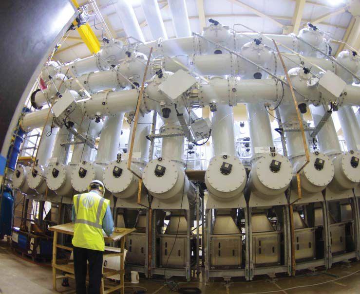
The next day a medium-voltage circuit breaker tripped on transformer inrush. An investigation into the trip revealed that the recent relay software program uploads had a trip setting that had been inadvertently modified. After the trip event, the client decided that a new software program would be created and uploaded into the relays and all of the medium-voltage protection system would be retested.
Another example of how an unexpected change can affect the equipment’s performance occurred when a leak was discovered around the flange of a large transformer’s oil contamination monitor.


After completion of commissioning, the flange was removed, a rubber gasket was made on site, and the leak was fixed. Two weeks later the transformer tripped offline due to a high particulate contamination count in the insulating fluid. A testing team along with the necessary transformer test equipment were flown to the site; simultaneously, the manufacturer sent an engineer to the site so that he could oversee the trip investigation. The transformer was tested from top to bottom, and an insulating fluid sample was sent to the lab for analysis. A visual inspection of the transformer did not reveal any anomalies except that the oil contamination monitor flange was leaking again.


Removal of the flange revealed that the rubber material that had been used to make the gasket had seriously deteriorated from contact with the transformer’s insulating fluid. This deteriorating gasket was at the intake to the oil contamination monitor, which [falsely] caused the unit to see extremely high concentrations of contaminants. Installing a gasket made from the wrong material created over $30,000.00 in costs associated with troubleshooting the transformer, not to mention the cost of downtime. Even though the commissioning


A DLB engineer testing the 500-kV, SF 6 gas insulated substation. 94 • SPRING 2015 COMMISSIONING OF POWER PLANT IN PERU: A CASE STUDY FEATURE

team had identified the initial problem, they had not been involved in verifying that the correct fix had been made.
SUMMARY
There is no doubt that the commissioning of electrical systems is here to stay and that the processes and methodologies associated with commissioning will continue to evolve, continuously changing the way testing companies, manufacturers, owners, engineers, and commissioning authorities approach project quality.
Commissioning standards will need to be regularly evaluated and adapted to ensure they meet whatever changes and challenges the remainder of the Twenty-first century sends our way.


Paul Hartman is the International Commissioning Manager for DLB Associates in Atlanta, Georgia. Paul has over 25 years of experience in the start-up, commissioning, design review, and maintenance of large facilities in the petrochemical, generation, and data center environments, including projects in Pakistan, Indonesia, Thailand, Brazil, Korea, Japan, Finland, Belgium, Peru, and England. Paul is currently involved in the oversight of the electrical testing and commissioning of power generation facilities and large data facilities both domestic and overseas. He has been a contributor to NETA World for over fifteen years and has been a frequent speaker at past NETA conferences.

NETAWORLD • 95 COMMISSIONING OF POWER PLANT IN PERU: A CASE STUDY FEATURE
ACCEPTANCE TESTING COMMISSIONING
BY RON WIDUP, Shermco Industries

As you go about your everyday life, reliable and safe electrical power equipment and systems are important and vital to all aspects of commerce, daily activities, and safety. If you don’t believe that, try to go without electricity for a while…and you will soon have a renewed appreciation for this very important piece of daily existence. It is something that we should not take for granted, nor should we minimize the knowledge and expertise required to properly install and assure correct functionality of this very complicated and intertwined mass of wires, bus bars, connectors, steel, electronics, insulators, and other components of an electrical system.
Now take that same reliance on electrical infrastructure and place it into a workplace or an industrial setting. The same importance holds true yet on a grander scale. So how is it that the systems get installed, connected, tested, and checked out for complete and appropriate operation? After all, isn’t it like buying a new computer and connecting to Wi-Fi—it just works when you turn it on, right? (OK, maybe that’s a bad example, but hopefully you get the point.) And we all know electrical systems don’t just magically appear
and start to work. There is an entire process involving many different crafts, disciplines, and engineering expertise that make it all work in concert, reliably and safely.
The bad news is this: quite often electrical power systems and equipment are not installed, tested, and commissioned properly, which can lead to disastrous consequences. But the good news is this: we now know more about executing a global application of processes and procedures for new electrical
96 • SPRING 2015 FEATURE
BRIDGING THE GAP FROM ACCEPTANCE TESTING TO COMMISSIONING
installations that will not only assure the owner that his equipment will function as intended and designed when he turns it on, it will also do so for many years, economically and with a high degree of reliability and safety---provided the systems are installed, tested, and commissioned properly!
While there are slight variations in the industry definition of electrical commissioning, most are fairly close in context. NETA’s 2015 Commissioning Standard ANSI/ NETA ECS-2015 Standard for Electrical Commissioning Specifications for Electrical Power Equipment and Systems (ANSI/NETA ECS) defines commissioning as “the systematic process of documenting and placing into service newly-installed or retrofitted electrical power equipment and systems.”
BRIDGING THE GAP
No matter what type of industry sector you are in, when it comes to electrical power equipment, it is important that you understand the processes and procedures that take place from a system’s initial concept to final acceptance and energization at your facility whether it is a steel mill, refinery, paper mill, electrical utility, data center, hospital, or commercial building. Regardless of the industry, all require the individual pieces of electrical equipment to interconnect with each other and work together as a system if safety and reliability is to be assured. The difference becomes the complexity of the system and how much interconnection of equipment is required to complete “the system.”
After design, procurement, and installation, one of the first steps in the commissioning process is performing electrical acceptance testing. And this is good time to point out one of the main themes of this article--electrical acceptance testing is different than electrical commissioning, but both are equally important!

Commissioning is the systematic process of documenting and placing into service newly-installed or retrofitted electrical power equipment and systems.
It is also important to understand what acceptance testing tasks are meant to accomplish. This is clarified within the scope of the ANSI/NETA document Standard for Acceptance Testing Specifications for Electrical Power Equipment and Systems (ANSI/NETA ATS). The ANSI/NETA ATS standard states “These specifications cover the suggested field tests and inspections that are available to assess the suitability for initial energization of electrical power equipment and systems.” The standard goes on to say “The purpose of these specifications is to assure that tested electrical equipment and systems are operational, are within applicable standards and manufacturer’s tolerances, and are installed in accordance with design specifications.”
NETAWORLD • 97 FEATURE BRIDGING THE GAP FROM ACCEPTANCE TESTING TO COMMISSIONING
NETA recognized that electrical commissioning has not been well defined in the industrial and utility markets although there is a greater degree of documentation and guidance within the data center sector. This was one of the motivations for NETA to develop a commissioning specification that was able to be applied on a global basis to many industries. Thus, the NETA commissioning standard was developed and approved as a consensus-based standard.
Also contributing to the need to develop an electrical commissioning document and bridge the gap between acceptance testing and final energization was the fact that the ANSI/NETA ATS addresses post-energization tasks within Section 8, System Function Tests , but does not completely address the complexity and requirements of a comprehensive electrical commissioning work scope. It is this need and requirement to bridge the gap between acceptance testing and electrical commissioning that completes the electrical system overall acceptance process. Again, from individual component testing to assurance that all integral components are functioning as a complete unit within design requirements and manufacturer’s published data; along with the correct operation of all interlock safety devices for fail-safe functions; and the correct operation of all sensing devices, alarms, and indicating devices.
Acceptance testing tasks are very important and provide the data necessary to assure the owner that he has electrical equipment that has not only been installed properly but is also functioning as intended and designed… but will it all work in concert and in accordance to the basis of design? (See inset for definition of Basis of Design.)
Now include electrical commissioning as we bridge the gap from acceptance testing….
ELECTRICAL COMMISSIONING: THE BASIC FRAMEWORK OF SCOPE
There are three voltage classes of equipment detailed within the ANSI/NETA ECS:
• Low-Voltage Systems (less than 1,000 volts)
• Medium-Voltage Systems (greater than 1,000 volts and less than 100,000 volts)
• High-Voltage and Extra-High Voltage Systems* (greater than 100 kV and less than 1,000 kV)
Within each voltage class, many of the commissioning tasks are the same; however, there are some differences in execution between equipment classes due to different types of construction or complexity of operation. By breaking the standard into voltage classes, NETA is able to address the various nuances and requirements of commercial, industrial, and utility grades of equipment, independent of the industry at which the equipment is located.
98 • SPRING 2015 FEATURE BRIDGING THE GAP FROM ACCEPTANCE TESTING TO COMMISSIONING

*NOTE: High and extra-high voltage systems are combined into one category in the ANSI/NETA ECS.
For instance, the commissioning of a low-voltage power circuit breaker and related system is typically not as complex as that of a mediumvoltage circuit breaker and the related system[s].
KEY POINT!
First, make sure you are starting out with a qualified commissioning organization and personnel. There are many ways to verify that the organization and its personnel are qualified, but make sure you are diligent on this aspect of the process. At a minimum make sure the organization and key project personnel have prior commissioning experience on the voltage class of your equipment and check on their references and previous electrical commissioning project. Call the references on the list!
Some of the main attributes you are looking for in the commissioning organization are:
• An independent, third-party entity which can function as an unbiased authority, professionally independent of the manufacturers, suppliers, architects, and installers of equipment or systems being evaluated.
• Regularly engaged in the commissioning of electrical equipment, devices, installations, and systems.
• Personnel who are regularly employed for electrical commissioning services.
• The ability to submit appropriate documentation to demonstrate that it satisfactorily complies with these requirements.
• The ability to provide the necessary services and technical expertise to conduct electrical commissioning.
• The ability to provide notification to
the designated representative(s) prior to the commencement of any electrical commissioning activity.
• Timely notification of deficiencies based on the results of the commissioning activities.
• A written record of all electrical commissioning activities and a final report.
And when evaluating the personnel, make sure the person or persons performing commissioning activities are
• Trained and experienced concerning the apparatus and systems being evaluated.
• Capable of conducting the tests in a safe manner and with complete knowledge of the hazards involved.
• Able to evaluate the test data and make a judgment on the serviceability of the specific equipment.
Once the commissioning organization and personnel have been selected, it is important
The Basis of Design
(BOD) is a document that records the concepts, calculations, decisions, and product selections used to meet the Owner’s
Project Requirements (OPR) and to satisfy applicable regulatory requirements, standards, and guidelines. The document includes narrative descriptions and lists of individual items that support the design process.
NETAWORLD • 99 FEATURE BRIDGING THE GAP FROM ACCEPTANCE TESTING TO COMMISSIONING
Data centers were one of the first sectors to develop comprehensive commissioning plans.
that you partner with the organization so there is a clear understanding of the commissioning intent, owner’s project requirements, the basis of design, and the overall commissioning plan. It is during this part of the process that experience and expertise really pays off as there is not one “magic answer” to determine the best course of action. Each project is different, and each project has variations and requirements that will only apply to that project. The ability to identify the scope in a clear and concise manner and apply those findings in such a way that will ultimately make your electrical equipment safe and reliable are necessary skills, which will end up saving your facility money in overall operating costs and uptime. Working with a qualified provider and applying smart processes to your project prevents you from having to lament about the old adage “The high cost of the low bid.”
THE TECHNICAL PART: EXECUTION OF COMMISSIONING TASKS
As mentioned earlier, the ANSI/NETA ECS is divided into three voltage classes (low, medium, and high and extra-high voltage) which is different than the NETA acceptance testing specification as it has categories based upon specific types of equipment,
with some equipment groupings based upon voltage class.
Regardless of the voltage class of the electrical system or systems being commissioned, there are some basic aspects that apply to all. Listed below are several of the basic steps that will be applied globally to all systems, but be aware there are many voltage and project specific tasks that are not listed below. Refer to the ANSI/NETA ECS for a more comprehensive listing.
For all systems and before energization you should
• Review the owner’s project requirements (OPR), basis of design (BOD), project specifications, and regulatory requirements for information specifically related to the commissioning of the electrical system.
• Make sure applicable equipment manuals and operational instructions are readily available for the commissioning team and the owner.
• Review factory and field acceptance test data, documentation, results, and deficiencies to verify acceptable condition and suitability for initial energization and final acceptance.
100 • SPRING 2015 BRIDGING THE GAP FROM ACCEPTANCE TESTING TO COMMISSIONING FEATURE
Industrial facilities (such as steel mills) have a need for electrical commissioning.
• Verify all equipment has been tested according to the most recent edition of the ANSI/NETA Standard for Acceptance Testing Specifications for Electrical Power Equipment and Systems (ANSI/NETA ATS).
For all systems and at energization you should
• Restrict access to electrical equipment during energization and commissioning activities.
• Verify emergency exits are correctly secured to prevent the entrance of an unauthorized person from outside while simultaneously allowing free escape from inside.
• Verify removal of temporary protective grounding equipment.
• Verify correct position of switches, circuit breakers, and transfer switches for control circuits, instrument transformer circuits, and power circuits.
• Verify test switches and terminal block disconnects/switches are in the correct position in accordance with the energization plan.
• Follow and document the steps of the energization plan.
• Verify correct current and voltage values to protective devices and metering.
As part of the commissioning process, perform thermography after energizing electrical equipment (but leave the cat alone).
For all systems and post energization you should
• Obtain post-energization oil and gas analysison applicable devices.
• Verify temperature monitoring and protective devices have established baseline parameters and criteria.
• Perform a thermographic survey of equipment.
• Notify the manufacturers of installed equipment of the actual energization date for warranty purposes
• Monitor equipment loading and compare to design criteria
SUMMARY
Whether you have a low-voltage, mediumvoltage, or high-voltage electrical power system, part of the project plan should be to include specifications for both acceptance testing and commissioning to assure safe and reliable performance.
And remember, these two tasks are different but dependent upon each other. After the acceptance testing is complete (and performed via NETA’s acceptance testing specifications) you should bridge the gap from testing to commissioning by utilizing a comprehensive commissioning specification, for which guidance can be found in NETA’s electrical commissioning standard.
The overall result? A safer electrical power system that will perform as intended and as designed – and that ain’t too bad.
Ron Widup is CEO of Shermco and has been with the company since 1983. He is a Principal member of the Technical Committee on “Electrical Safety in the Workplace” (NFPA 70E) and a Principal member of the National Electrical Code (NFPA 70) Code Panel 11. He is also a member of the technical committee “Recommended Practice for Electrical Equipment Maintenance” (NFPA 70B), and a member of the NETA Board of Directors and Standards Review Council. He is also a NETA Level IV Senior Test Technician.
NETAWORLD • 101 BRIDGING THE GAP FROM ACCEPTANCE TESTING TO COMMISSIONING
FEATURE
Vanguard Instruments Company, Inc. www.vanguard-instruments.com

Continuing Our Tradition of Innovation
Vanguard Instruments has been at the forefront of developing innovative precision sub-station test instruments for over 20 years, and we are continuing our tradition with our latest products such as the CT-7000 S3 and CT-8000 S3 circuit breaker analyzers with Dual Ground testing feature and our new line of test instruments featuring convenient Bluetooth wireless interfaces. Visit us today at vanguard-instruments.com to find the latest solutions for all of your sub-station testing needs.
Transformer Turns-Ratio Meters Circuit Breaker Analyzers Insulation Resistance Meter Winding Resistance Meters Current Transformer Testers Relay Test Equipment Vacuum Bottle Testers Reliability through instrumentation. Vanguard Instruments Company, Inc. 1520 S Hellman Avenue Ontario, CA 91761 USA PHONE 909.923.9390 FAX 909.923.9391 EMAIL sales@vanguard-instruments.com www.vanguard-instruments.com
innovative precision test instruments for over 20 years
building


ADVANCEMENTS ADVANCEMENTS


KEEPING UP IN TRAINING WITH IN TECHNOLOGY MEANS KEEPING UP WITH


When

 BY TIM GAUTHIER, AVO Training Institute
it comes to improving quality, safety, and reliability within the electrical power industry, the knowledge base of our skilled workers has to keep up with the advancements in technology in the industry. Not all issues
related to improving quality, safety, and reliability within the electrical power industry are black and white.


There are a lot of gray areas when it comes to quality training. How you train, who you train, and how efficient the training of your work force is becomes even more critical as our workforce also becomes gray. A part of adult teaching methodology is that in order to learn we need to have all our senses active in the learning process. Using myself as an example, what I read I may understand a lot better than what I hear because I sometimes do not hear very well (my wife still has not decided whether my condition is selective listening or a medical hearing condition). In order to teach adults, you have to show them, read it to them, let them read it, have them write it down, let them look at it, and let them work on it. These are the essential elements of adult education. You may have some of these elements dispersed in your training

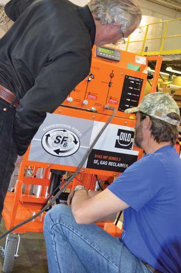
environment, but not all of the elements in all of them. How do we train? How do we evaluate learning comprehension? How do we test electrician skills, knowledge, and demonstrated ability? If this sounds like a lot of OSHA talk, it’s because it is. Your electrical workforce has to have the skills, knowledge, and demonstrated ability to work safely on or around electrical equipment.
When your experienced technician starts with a new apprentice, does he or she skip right to application? While this type of focus is essential to continuing work during training, as a starting point for apprentices, it is fundamentally flawed. What is the proper procedure and where do you find the procedure? Familiarization with ANSI/NETA ATS and MTS should be the first step of any training program. To

KEEPING UP WITH ADVANCEMENTS IN TECHNOLOGY MEANS KEEPING UP WITH ADVANCEMENTS IN TRAINING 104 • SPRING 2015
ADVANCEMENTS IN TECHNOLOGY

train an effective electrical maintenance technician, you must start by building a foundation of fundamental knowledge---those things veteran electrical testing technicians may take for granted or may not adequately pass on. Does your training department (if you have one) keep up-to-date with the latest maintenance testing standards?
ELECTRICAL SAFETY RESOURCE
Identifying what critical issues stand in the way of a successful electrical safety program, establishing training and retraining guidelines for technicians, and addressing the specific regulatory requirements of industry are just three ways to keep up with the advancements in technology in the electrical industry. Any industry should first focus on reducing electrical hazards in your facility. Your facility should be in compliance with the latest design requirements for specific types of electrical protective equipment as outlined in OSHA 1910.137 and the revised Electric Power Generation, Transmission, and Distribution portion of OSHA 1910.269. And, if that isn’t enough, a plan that provides electrical safety and maintenance training for NFPA 70E 2015 edition is also required. With so many major changes taking place in the electrical power industry, having the right electrical safety resources and training provided by competent electrical professionals is key to maintaining a successful maintenance staff and program.
ADVANCEMENTS

theory of operation, direct the attention of the students to the job, demonstrate the task, and then allow the student to demonstrate what they have learned. Students should be able to tell what they are going to do, tell how they are going to do it, and then demonstrate that they can do the job safely.
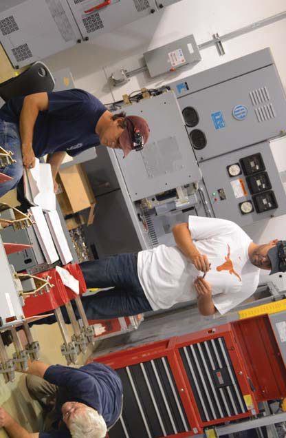
It is important that the training your electrical group receives is composed of quality courses that are recognized by the InterNational Electrical Testing Association (NETA®) for continuing technical development (CTDs) or recognized by other industry organizations for continuing education units (CEUs) in order to be completely assured of the quality of instruction received and course content presented.
HANDS-ON SKILLS PROVIDED WITH TRAINING
Electrical training should dedicate resources to ensure each student has hands-on time with the equipment. An adult training methodology should show how to do the job, explain the operation of the equipment, present any related


If at all possible, hands-on training should be provided by instructors who stay connected with industry associations by attending conferences and participating in research committees that support the advancement of the electrical safety and standards in the industry around the world because, in many cases, those individuals do not just attend the committee meetings, they sit on the panels that write the standards. In every adult learning situation, it is essential that we ensure each student has ample hands-on time with maintenance testing equipment demonstrated and evaluated by a competent trainer.
When choosing a training provider, look for one with extensive experience in training that can be customized, on-site at your facility and on your equipment, and on-line.


NETAWORLD • 105 KEEPING UP WITH ADVANCEMENTS IN TECHNOLOGY MEANS KEEPING UP WITH ADVANCEMENTS IN TRAINING
IN TECHNOLOGY


ADVANCEMENTS IN TECHNOLOGY
CUSTOMIZED TRAINING

Courses should fit your specific equipment or the training needs and the objectives of your personnel.
The Benefits of Customized Training
• Ability to tailor business specific policy, procedures, and concerns
• Choose a date, time, or shift that works best for your facility
• Training content flexibility based on your needs
• Employees receive the same level of training over several sessions
• Pre and post testing available to measure before and after knowledge
• Training on your equipment or products eliminates generalities
ON-LINE TRAINING

ON-SITE TRAINING
On-site training keeps travel expenses down while allowing the benefits of an effective electrical maintenance and safety-training program. Onsite training allows you to train larger numbers of employees in their familiar work and equipment environment because the training takes place in your facility.
The Benefits of On-Site Training
• Eliminate personnel travel time and associated expenses
• Address your specific equipment and systems
• You choose the course schedule
• Customize course length by adjusting content covered
• Customize course content by adjusting topics and equipment

On-line courses help individuals who may otherwise find it difficult to attend classes through a more traditional route. Online learning also provides an avenue for those with part- or fulltime jobs to continue their studies around their work schedule.
The Benefits of On-Line Training
• Courses are affordable
• Learn at your own pace and your own schedule
• Attend class from just about anywhere that has Internet access
• Course material is always accessible
• Online learning lets you attend class in convenient increments
• Ensures that each lesson or material is completely understood before moving on
• Online education offers a lot of savings because there are no additional costs for transportation and accommodations


• Courses are presented at the knowledge level of your personnel
• Your maintenance personnel are on-site should an emergency occur
In order for your industry to keep up with the pace of advancements in technology, it must first keep up with the advancements in training a competent work force.


Tim Gauthier, CESCP has over 30 years of electrical experience including the installation, inspection, and repair of electrical, electronic, and mechanical equipment including component-level troubleshooting, metal fabrication, machine building, and Mig welding. Additionally, his expertise includes troubleshooting and repair of PLC, SLC, and FANUC programmable logic controllers; troubleshooting and repair of pneumatic and hydraulic systems; preventive/predictive maintenance programs; implementing process development and inventory control; assisting engineering department with design modifications, system development, and component selection; and knowledge of International Quality Systems Standards (ISO and QS 9000), NEC, MIOSHA Stds, 5S, and lean manufacturing. Tim is secretary of the IEEE P45.5 (shipyard safety) and a workgroup member of IEEE 1584, and IEEE Communications Society.


KEEPING UP WITH ADVANCEMENTS IN TECHNOLOGY MEANS KEEPING UP WITH ADVANCEMENTS IN TRAINING 106 • SPRING 2015
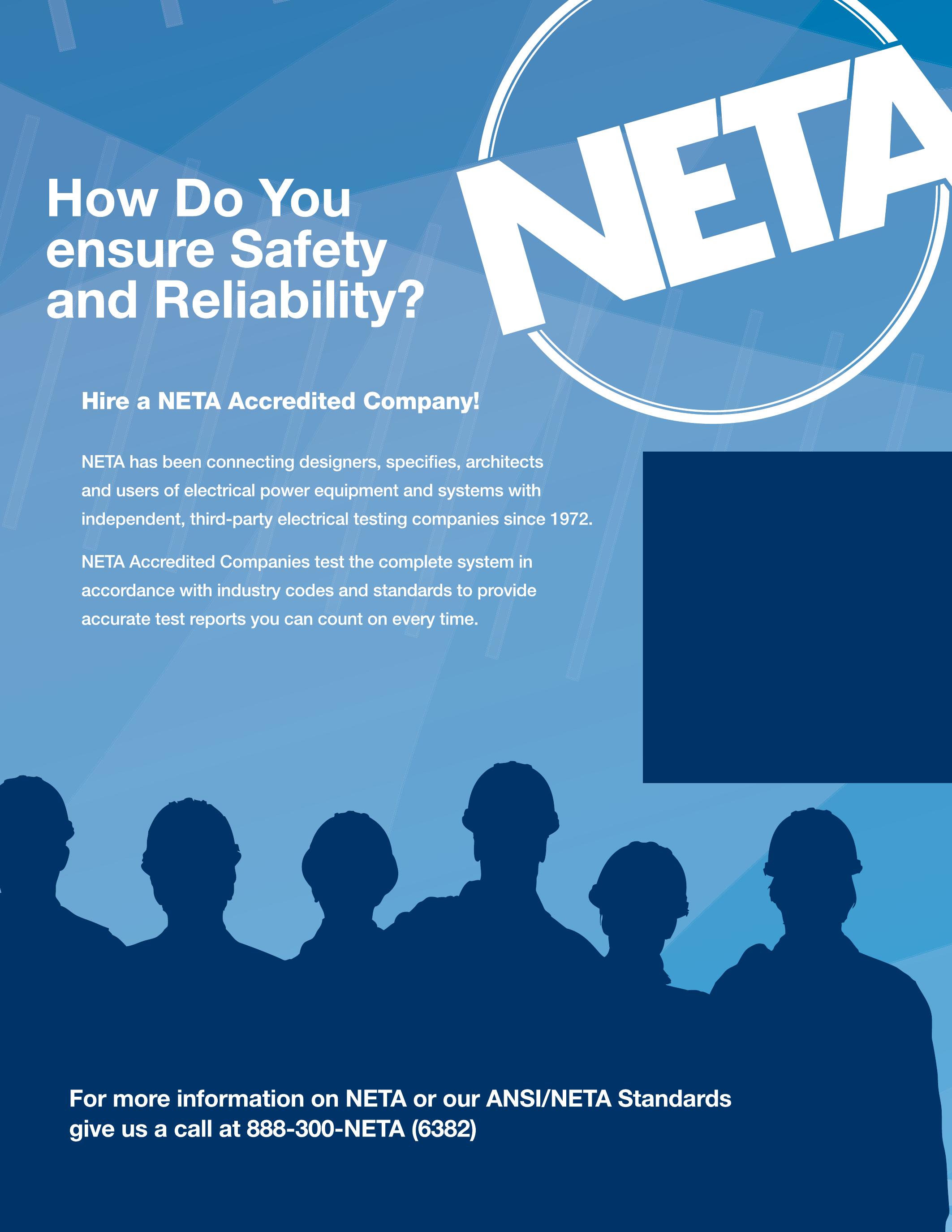
For a complete listing of NETA Accredited Companies turn to page 136 or visit www.netaworld.org.

Attention NETA Alliance Partners! Take Advantage of Your Benefits Today! Gold Alliance Benefits: Complimentary PowerTest Registration Complimentary ANSI/NETA Standard Standard Alliance Benefits: 20% discount on PowerTest 2016 50% discount on one ANSI/NETA Standard Annual NETA World Journal subscription 20% discount on NETA publications Access to the NETA technical community Seat at the NETA Annual Meeting (non-voting) Subscription to the NETA Alliance Newsletter Place announcements in the NETA Alliance Newsletter Also included in Gold Alliance Benefits Ask About Upgrading to Gold and Attend PowerTest 2016! March 14-18, 2016 Go to www.powertest.org or give us a call at 888-300-6382 (NETA) Fort Worth, Texas ALLIANCE PROGRAM ®
CHOOSING THE RIGHT FOR PARTIAL DISCHARGE TESTING
BY YIER TOH, Megger
INTRODUCTION
Partial discharge (PD) measurements are increasingly used as a reliable and non destructive diagnostic method to detect weak spots in the insulation of underground cables. PD measurements are routinely utilized in laboratories for testing cable reels prior to commissioning and also in the field to verify installation quality.
THE NEED FOR ALTERNATIVE TEST WAVE SHAPES
Laboratory testing typically uses a 50/60 Hz high-voltage power supply because many factory testing standards require this. However, the same 50/60 Hz has proven to be very impractical when it comes to field testing due to high energy generation requirements.
The most important factor to consider when choosing an alternative test frequency is that the PD characteristics at the new frequency must be similar to that at 50/60 Hz. Otherwise, the results cannot be reliably interpreted. This is especially true when measuring the partial discharge inception voltage (PDIV), the voltage at which PD first occurs. PDIV is one of the most important parameters used to characterize PD. If the PDIV measurement at the new frequency is higher than at 50/60 Hz, it may

create false negatives, making problems appear noncritical when they could in fact be critical at the operating voltage.
COMMONLY USED TEST WAVE SHAPES
Many research papers have addressed the comparability of PD characteristics at various test frequencies and wave shapes. Here is a quick overview of the most commonly used test wave shapes.
1.
0.1 Hz Sinusoidal
The very low frequency (VLF) sinusoidal wave shape was introduced for PD testing in the 90’s. Research has shown that PD is frequency dependent and diminishes at low frequencies; therefore, it is often challenging to measure PD at low frequencies such as 0.1 Hz. Seven different papers reported a 10 percent to 250 percent difference between the PDIV values measured at 50 Hz and 0.1 Hz.
This huge discrepancy is due to the characteristics of interfacial discharge. Most interfacial discharges in cable systems occur at the terminations and in splices and are very dependent on the voltage gradient. A change in voltage gradient could make the discharge 500 times smaller at 0.1 Hz
ADVANCEMENTS IN TECHNOLOGY
110 • SPRING 2015 CHOOSING THE RIGHT WAVE SHAPE FOR PARTIAL DISCHARGE TESTING
compared to 50 Hz. This is a critical factor to consider when making measurements with a VLF sinusoidal test voltage.
2. Damped AC
Over the past 10 years, the damped ac (DAC) method has been established as a very effective method for PD testing. It is one of the voltage shapes listed in IEEE 400.3 for field PD testing. There have been numerous examples of successful field test data collected which showed very good correlation between 50/60 Hz and DAC results.
3. 0.1 Hz Cosine Rectangular
The first VLF systems used a cosine rectangular (CR) wave which proved very effective and is still widely used today because the time interval of its polarity change replicates that of a 50/60 Hz wave. Figure 1 shows the characteristic shape of the 0.1 Hz CR wave compared to the DAC and the 0.1 Hz sine wave.
ADVANTAGES OF VLF CR FOR PD DIAGNOSTICS AND WITHSTAND TESTING
One of the most significant advantages of CR technology is its capability to store and recover 90 percent of the energy within the charged cable via a choke. The stored energy is used to charge the cable in the opposite polarity during the next half cycle. This allows substantially higher test loads to be driven with fairly small input power compared to sinusoidal VLF systems. VLF CR systems with up to 25 μF and 20 to 80 kV rms are commercially available. The second advantage of the VLF CR system is that its polarity reversal time interval very closely matches the one at 50/60 Hz. This closely mimics the electrical stress on the insulation under operating conditions, making the technology an excellent candidate as a power supply in off-line PD testing.
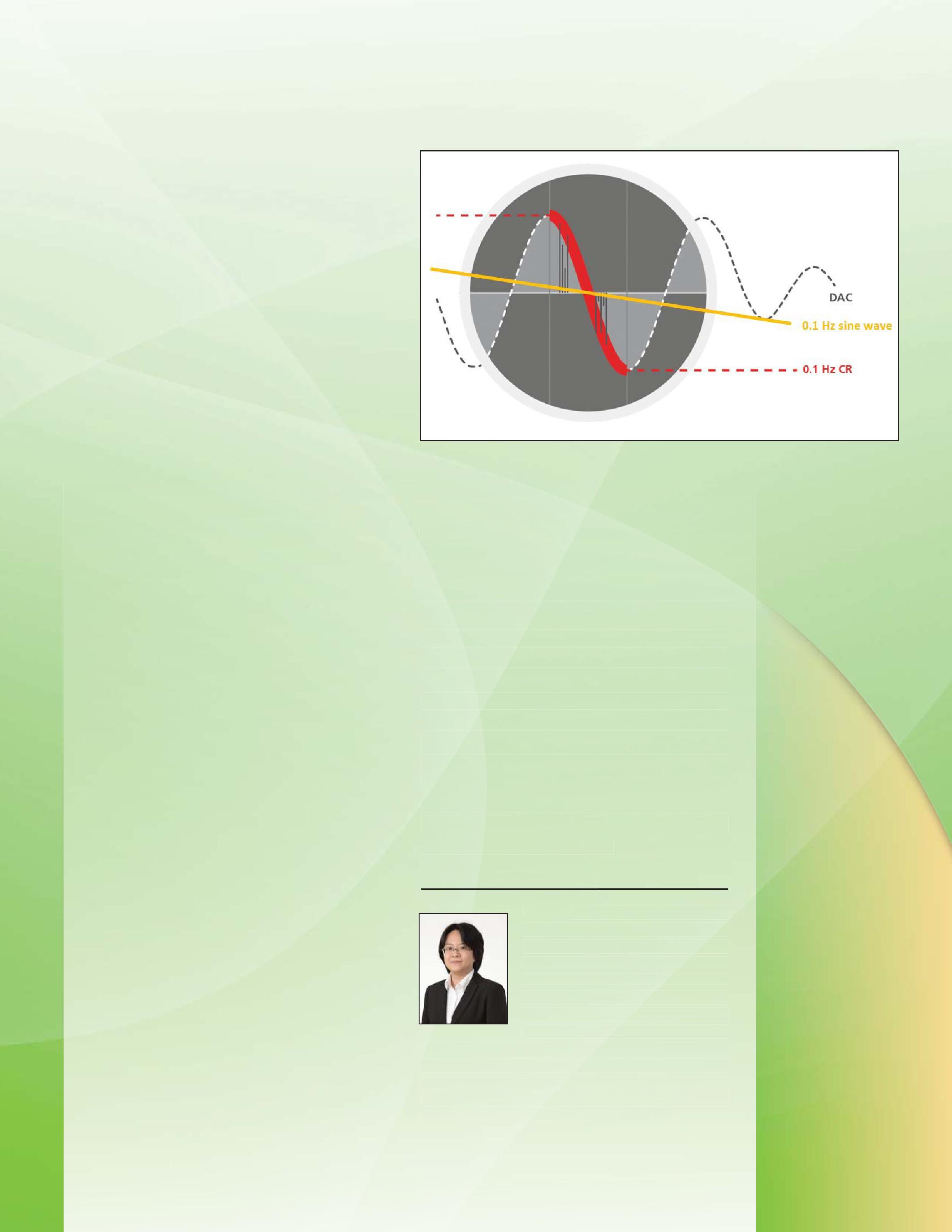
Figure 1: Comparison of DAC, 0.1 Hz sine wave and 0.1 Hz CR wave. The time taken for polarity reversal in the VLF CR closely matches that of the DAC, but the peak voltage is maintained for five seconds until the next cycle in the VLF CR system.
The same two characteristics also make VLF CR technology a very effective tool for withstand testing (with or without PD monitoring), enabling the testing of very long cables or simultaneous testing of three phases at 0.1 Hz. In contrast, DAC technology is not ideal for withstand testing because it requires a substantial number of test cycles to generate an equivalent amount of electrical stress for the same duration. This shorter exposure time to the electrical stress at power frequency is exactly what makes DAC perfect for truly nondestructive PD diagnosis.
two thstand ng), the multaneous phases contrast, DAC technology is not tand because it mber ount of electrical stress for shorter ss at frequenc y is perfect nosis. ed
stern Australia. She as a
ce. She has been cientific entists on the alization and ed ng test testing
Yier Toh received her BEng in Electrical and Electronic Engineering from the University of Western Australia. She started her career as a biomedical researcher and has coauthored several papers on neuroscience. She has been a sales engineer at a scientific imaging company, advising scientists on the best techniques for 3D and 4D image visualization and analysis. After completing her MBA, she joined Megger as a Marketing Communications Engineer, creating technical content that helps customers understand the latest testing technology and industry best practices.
IN TECHNOLOGY
ADVANCEMENTS
CHOOSING THE RIGHT WAVE SHAPE FOR PARTIAL DISCHARGE TESTING
NETAWORLD • 111
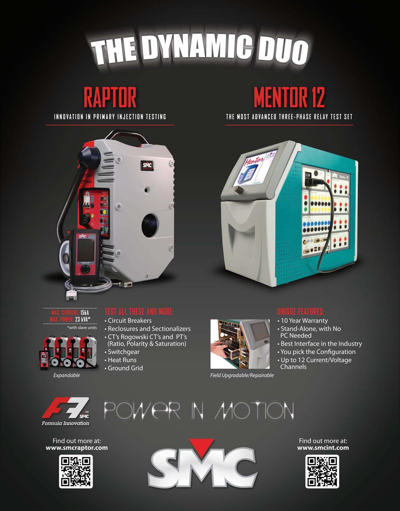


BRINGING MORE SMARTS TO GETTING YOU YOUR PARTS. HAVING MILLIONS OF PARTS IS ONLY PART OF THE STORY. National Switchgear has millions of new, surplus and repurposed electrical circuit breaker & switchgear products. And now, with a suite of e-commerce solutions, we’re making it easier than ever for you to find the part that’s perfect for you. You can browse, filter results by category, manufacturer or specs, see your pricing level, and more – 24/7. Just go to nationalswitchgear.com and see our latest innovations. It’s the fastest lane to our massive inventory. If you’re ordering parts from anyone else, it’s time to switch. 800-322-0149 nationalswitchgear.com Visit us at PowerTest BOOTH 222
ANSI/NETA STANDARDS UPDATE
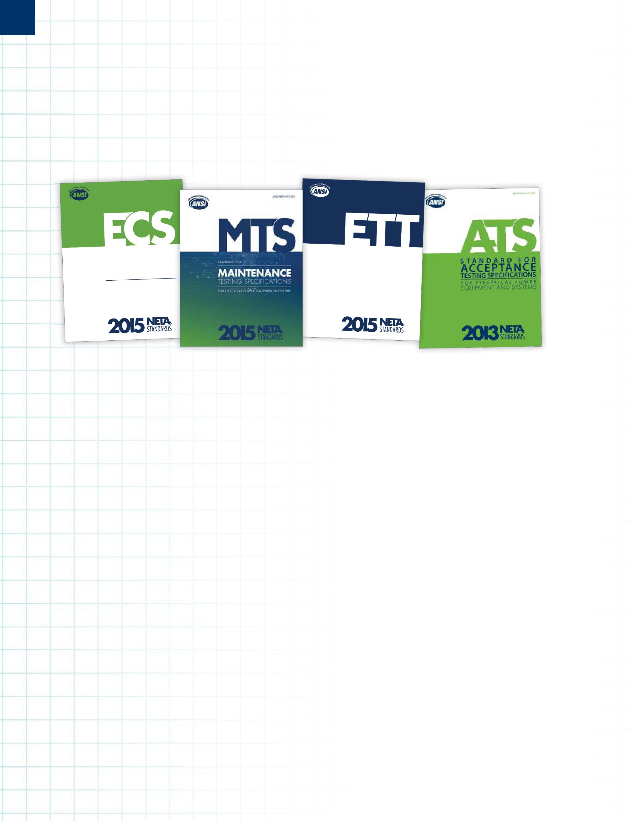
ANSI/NETA ECS-2015 NEW AMERICAN NATIONAL STANDARD
The ANSI/NETA ECS Standard for Electrical Commissioning of Electrical Power Equipment and Systems, 2015 edition, was approved as an American National Standard on December 3, 2014. The document will be available for purchase in March, 2015, at PowerTest in Nashville, Tennessee.
The ANSI/NETA ECS describes the systematic process of documenting and placing into service newly-installed or retrofitted electrical power equipment and systems. This document shall be used in conjunction with the most recent edition of the ANSI/NETA Standard for Acceptance Testing Specifications for Electrical Power Equipment and Systems The individual electrical components shall be subjected to factory and field tests, as required, to validate the individual components. It is not the intent of these specifications to provide comprehensive details on the commissioning of mechanical equipment, mechanical instrumentation systems, and related components.
ANSI/NETA MTS-2015 NEW EDITION
The ANSI/NETA MTS Standard for Maintenance Testing Specifications for Electrical Power Equipment and Systems, 2015 edition, was approved as an American National Standard on December 3, 2014 and will supersede the ANSI/NETA MTS-2011. The document will be available for purchase in March, 2015, at PowerTest in Nashville, Tennessee.
The ANSI/NETA MTS contains specifications that cover the suggested field tests and inspections that are available to assess the suitability for continued service and reliability of electrical power equipment and systems. The purpose of these specifications is to assure that tested electrical equipment and systems are operational and within applicable standards and manufacturers’ tolerances and that the equipment and systems are suitable for continued service.
ANSI/NETA ETT-2015 NEW EDITION
The ANSI/NETA ETT Standard for Certification of Electrical Testing Technicians, 2015 edition was approved as an American National Standard on December 3, 2014, and will supersede the ANSI/NETA ETT-2010. The document will be available for purchase in March, 2015, at PowerTest in Nashville, Tennessee.
The ANSI/NETA ETT establishes minimum requirements for qualifications, certification, training, and experience for the electrical testing technician. It also provides criteria for documenting qualifications for certification and details the minimum qualifications for an independent and impartial certifying body to certify electrical testing technicians.
114 • SPRING 2015 ANSI/NETA STANDARDS UPDATES SPECIFICATIONS AND STANDARDS ACTIVITY
ANSI/NETA ECS-2015 STANDARD FOR ELECTRICAL COMMISSIONING SPECIFICATIONS F OR EL ECTR ICAL POWER EQUIPMENT AND SYSTEMS GSPECIFICATIONS ANSI/NETA ETT-2015
2015 R L NG N S E R MS
STAN DARD FOR CERTIFICATION OF ELECTRICAL TESTING TECHNICIANS

PARTICIPATION
Comments and suggestions on any of the standards are always welcome and should be directed to the NETA office at neta@ netaworld.org or 888-300-6382. To learn more about the NETA standards review and revision process, to purchase these standards, or to get involved, please visit www.netaworld.org or call 888-300-6382.


ANSI/NETA ATS-201X REVISION IN PROCESS
The ANSI/NETA Standard for Acceptance Testing Specifications for Electrical Power Equipment and Systems began the review and revision process in October, 2014, at the Standards Review Council meeting. Individuals interested in participating as members of the ANSI/NETA ATS-2017 ballot pool should submit a ballot pool application to the NETA office no later than March 9, 2015. Positions on the ballot pool are determined by the NETA Standards Review Council and are subject to availability within each interest group (producers, users, general interest).


The ANSI/NETA ATS covers the suggested field tests and inspections that are available to assess the suitability for initial energization of electrical power equipment and systems. The purpose of these specifications is to assure that tested electrical equipment and systems are operational, are within applicable standards and manufacturers’ tolerances, and are installed in accordance with design specifications.

STANDARDS
ANSI/NETA
UPDATES

sales@widespread.com 877.999.7077 / widespread.com

It’s real world learning at your fingertips. These handbooks deliver relevant information on the electrical power systems industry, including testing procedures, troubleshooting and real-life solutions encountered in the field every day.
You’ll discover page after page of comprehensive, component-specific, technical resources for training and reference purposes.
The NETA Handbooks bring together a collection of over 200 of the very best articles from past issues of NETA World Journal and the most well received technical presentations from NETA’s PowerTest conferences.
For more information on the NETA Handbooks or other NETA publications visit the NETA bookstore at www.netaworld.org or 888-300-6382. (NETA) $195* For the 13 volume set $15* For each issue * Additional cost for shipping and handling


ASTM F18 COMMITTEE REPORT
BY JIM WHITE, Shermco Industries


The ASTM F18 committee is responsible for all rubber insulating PPE as well as arcflash PPE, live-line tools, insulated tools, temporary personal protective grounds, and insulated bucket trucks. The F18 committee met in Orlando, Florida from October 19 to 22, 2014. The next meeting is scheduled to be in Anaheim, California, from April 26 to 29, 2015.


The F1506 task group is reviewing the need for testing of the arc plasma stream, as opposed to radiant heat created by an arc. Some studies suggest that when arc-rated fabric clothing is subjected to an arc stream, such as that which could be created by equipment with horizontal stabs (drawout circuit breakers, etc.), that arc rating may be need to be increased. Rating increases up to 50 percent have been suggested. No field data collected to this point in time supports this suggested increase. Proposals are suggesting a pass/fail type of criteria as opposed to a new arc rating.

One committee member brought up an arcflash incident where a worker used the arcflash tables in NFPA 70E and died. Further questioning revealed that the worker ignored his company’s safety requirements to use a 40 cal/cm2 arc-rated suit and used no arcrated clothing because the tables in the 70E indicated he didn’t require any; however, the available short circuit current and operating time of the OCPD were well above the limits in the tables, and the Table Method would

not have been acceptable. This was not brought out until the member was questioned more closely about the incident. The 40 cal/ cm2 arc-flash clothing and PPE may still have been inadequate, as there was over 70 cal/cm2 incident energy estimated at that location. This incident emphasizes the need for proper training of qualified persons and incident energy analysis.

The F1506 TG is also working on how to determine and certify the origins of materials used in arc-rated clothing. Some utility members believe this is important information for their field workers.
A concern was voiced that when a thicker fabric is tested by the current ASTM method the angle of the clothing to the arc source may not be correct. This is due to the deflection of the material when it is clamped into placed. It has a tendency to bow out in the middle and be at various angles at the clamping site. Kinetrics Laboratory has an adjustable fixture that helps to compensate for this deflection. More testing is planned to verify whether or not this is an issue that needs to be addressed in the standard.

Some imported arc-rated materials have been shown to have an excessive amount of shrinkage when laundered according to the test method and procedures. This could cause the tested arc rating to be greater than what it is reported to have at the manufacturing

ASTM F18 COMMITTEE REPORT 118 • SPRING 2015 SPECIFICATIONS AND STANDARDS ACTIVITY


level. Laundering can cause the fibers to shrink together, creating a denser fabric which increases arc rating. Wording is being suggested to prevent fabrics that have exhibited such excessive shrinking from being tested.
The F1959 task group noted that wet garments may have a slightly better arc rating up to their rated ATPV from the evaporation of the water. However, when the incident energy goes above the ATPV, the wet clothing may cause some injuries from the steam being created.
Some discussions were also held in the F18.15.10 task group meeting on nonleather hand protection. This is a new standard that is being developed. No glove currently on the market meets the requirements of this standard. The task group is soliciting input from field workers concerning what attributes they want a nonleather protector to have. It was reported that a company in Canada is using a Kevlar® glove with a leather back over their rubber insulated gloves. A question for NETA World readers and their employees: what attributes are important for a nonleather glove to have? Some of the attributes mentioned:

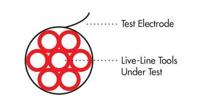
Figure 1: Bundling of live-line tools for testing can create errors.

concern NETA Accredited Companies. It is reported that some companies (internal and external) are bundling live-line tools together to test. The test electrode has to have contact with the entire outside surface of the live-line tool being tested, but bundling can cause inadequate contact such as shown in Figure 1. Parallel testing of live-line tools is acceptable, as long as the test electrode makes contact around the full circumference of the tool. The language in the standard (F712) is being reviewed to correct this issue, but until then NETA Accredited Companies should verify how their live-line tools are being tested.


A. Enhanced grip
B. Cut resistant
C. Puncture resistant
D. More flexibility
E. Oil resistant
F. Water resistant

G. Abrasion resistant
H. Arc-rated
Rate the above on a scale of 1 to 10 and send it back to me at jrwhite@shermco.com. If you have other attributes that are important in your jobs, please include it in the list as a write in. The more members participate, the more influence this survey will have.
Another important issue came up that could


In the F855 meeting there was a lot of discussion concerning testing temporary personal protective grounds. F855 considers the cable to be the weakest part of the assembly; that is, it will fail the test before the clamp or ferrule will fail. Recent testing has shown that this may not be the case, as the clamp or ferrule may fail before the cable. For safety reasons, a correctly-designed assembly will allow the cable to fail before the other components. For ASTM testing, a 10-foot length of cable is specified.
Another issue that may affect NETA Accredited Companies is that under the current standard, a temporary personal protective ground assembly may be tested to either the withstand rating or the ultimate rating, but not both. Using these ratings interchangeably is not possible, because while the assembly may pass one test, it may not


NETAWORLD • 119 ASTM F18 COMMITTEE REPORT SPECIFICATIONS AND STANDARDS ACTIVITY


pass the other. The withstand rating should be specified and used when the thermal (longerterm) issue is the primary concern and the ultimate rating should be specified when the mechanical (high-shock loading) issue is of primary concern. Some companies stated they test their assemblies to both ratings, but to which rating the assembly is tested should be specified by the NETA Accredited Company when grounds are ordered.
Again, please participate in the survey for nonleather glove protectors, as I know this will benefit our field technicians greatly.

Jim White is nationally recognized for technical skills and safety training in the electrical power systems industry. He is the Training Director for Shermco Industries, and has spent the last twenty years directly involved in technical skills and safety training for electrical power system technicians. Jim is a Principal member of NFPA 70B representing Shermco Industries, NETA’s alternate member of NFPA 70E, and a member of ASTM F18 Committee “Electrical Protective Equipment for Workers”.


AND STANDARDS ACTIVITY
SPECIFICATIONS
NEW eBOOK PACKED FULL OF TECHNICAL INFORMATION! ELECTRICAL CIRCUIT BREAKERS, FUSES AND PROTECTIVE RELAYS by L.W. Brittian Achieve specialist level knowledge of Circuit Breakers, Fuses, and Protective Relays with this convenient take-anywhere eBook. AVAILABLE NOW ON AMAZON.COM IN THE KINDLE STORE 900+ pages 200+ pictures 125+ Charts and Tables Only $5.99
Get empowered with Doble. Meet the Doble team at PowerTest 2015
Join us for the NETA Doble Software Users Group – Monday, March 2, 2015 | 12:15 – 2:15 PM. Register for the one-day Laboratory Diagnostics Seminar – Friday, March 6, 2015 | 8:00 AM – 5:00 PM. Learn more about our diagnostic solutions at Booth #421. www.doble.com/NETA

For nearly a century, Doble has been amassing an unprecedented amount of knowledge and experience. We’re sharing it with our partners and customers through products, services and learning programs. We make sure you have the tools and information you need to ensure power system safety and reliability.
Empowering the industry with services, solutions and unmatched knowledge.
We put the we in Empower


IEEE TRANSFORMER COMMITTEE
BY AL PETERSON, Utility Service Corporation
FALL 2014 MEETING
The fall 2014 IEEE C57 Transformer Committee met in the Washington, D.C. area October 1924, 2014. Sixty-five Working Groups and Task Forces met during the eight day session. The following notes of the discussions held during the week that may be of interest to NETA World readers are listed below.


C57.93 Guide for Installation & Maintenance of Liquid-Immersed Power Transformers
• Discussion of dry-out end point
• Testing of transformer under vacuum
• Vacuum hold times
• Hold, set, and stand times should have one word that describes this procedure.
• Soak times were discussed with and without vacuum.

C57.637 Guide for the Reclamation of Mineral Insulating Oil & Criteria for its Use and
C57.106 Guide for Acceptance & Maintenance of Insulating Mineral Oil in Electrical Equipment

• Move all tables in 637 to 106 and consolidate them
• Eliminate all references to oil circuit breakers from both standards*
*This will require the IEEE Switchgear Committee to develop standards for insulating oil in circuit breakers which will take place in the coming years.


NETA recommends that organizations that own, service, maintain, or have an interest in oil circuit breakers secure a copy of the current editions of these standards so they have the present data on oil for circuit breakers to use until such time that the IEEE Switchgear Committee can develop and issue oil standards for use in circuit breakers.


Alan D. Peterson received his formal education in electrical engineering at Northeastern University, Boston. In addition, he completed advanced studies at the Massachusetts Institute of Technology, Cambridge. He was employed by Brockton Edison Company (now Eastern Edison), Brockton, Massachusetts, through Northeastern's Cooperative Program in the meter, line, and engineering departments. He was inducted into the US Army and served his term of service as an instructor at the US Army Ordinance Guided Missile School at Redstone Arsenal, Alabama. In 1963, Mr. Peterson founded Peterson Electric Company, an electrical construction firm in Huntsville, Alabama. He holds Journeyman and Master Electrician certificates from several states. In 1976, he founded Utility Service Corporation in Huntsville. Utility Service Corporation is an independent testing, engineering, and maintenance organization for electrical power systems and equipment. He served on the national Board of Directors of AIECA (now IEC) and held the offices of National Vice President and National Treasurer. He has served on the National Affairs Subcommittee of the Chamber of Commerce. Mr. Peterson has served on several committees of NETA and has held the offices of president and first and second vice president. He is presently Technical Committee Chair, a member of the Board of Directors, and a member of the Standards Review Council. He is a past member of American National Standards Institute (ANSI) Board of Standards Review (BSR). This 13 member board is charged with the approval of all American National Standards. Prior to his appointment to the BSR, he served on ANSI’s Electrical and Electronic Standards Board. Mr. Peterson has been a participant on several ANSI Accredited Standards Committees, specifically ANSI/IEEE C-37, ANSI/IEEE C-57 and ANSI/IEEE C-62.


IEEE TRANSFORMER COMMITTEE 122 • SPRING 2015 SPECIFICATIONS AND STANDARDS ACTIVITY
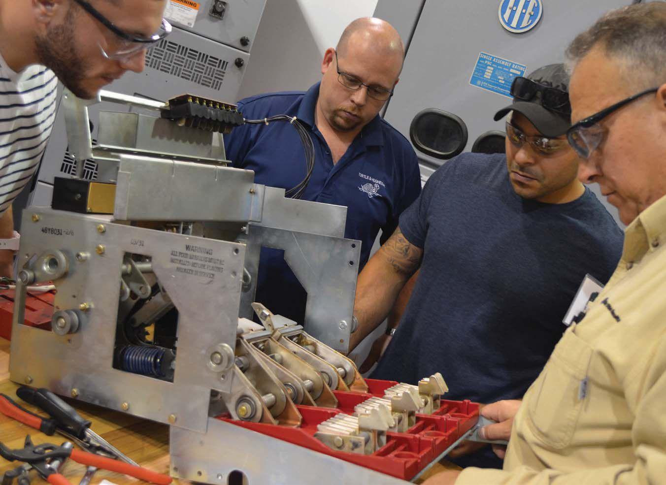


Your One-Stop for many hands-on safety & maintenance training courses eligible for NETA CTDs.* AVO Training Institute continues to lead the industry by developing the courses, the curriculums and the tools that make working with electrical systems safer. After our first 50 years, our commitment to industry leadership still means analyzing its needs in terms of education, safety, and maintenance. We stand ready with our electrical safety knowledge and expertise to help you with your safety development projects, while saving time and money. Experience the AVO hands-on difference. WWW.AVOTRAINING.COM 877-594-3156 *NETA continuing technical development (CTDs) units are required of NETA certified technicians.
From Apollo 7 to Today’s Smart Grid


Utility Service Corporation has been providing electrical and technical services for government and industry since 1962.
Solving complex problems, testing under difficult and unusual circumstances and servicing the commissioning and maintenance needs of today’s electrical power systems both new and aged.
Preventative Maintenance Acceptance Testing High Potential Testing Commissioning Services System Studies Arc Flash Analysis Engineering & Consulting Construction Supervision System Trouble Shooting (256) 837-8400 Services:
To learn more about the newest edition of the ANSI/NETA MTS Standard for Maintenance Testing Specifications, visit netaworld.org/standards.

ANSI/NETA MTS - 2015 NEW EDITION
ORDER
NOW!


ANSWERS


ANSWERS

1. a. To verify proper functioning of the equipment/system after installation
b. To verify the installed equipment meets design and manufacturer’s specifications


c. To capture and record performance data of the installation as the baseline for future operation and maintenance
2. e. The seismic drop test is dropping a component from a 3 foot height and then sweeping the pieces up. Not recommended for NETA test companies. Answer e is the most correct answer. Both of these (a and c) go to the heart of the commissioning process; verify settings against specifications and inspect devices for deviations from specifications. It’s amazing (maybe not once you’ve been in the field for a while) how often the wrong part or device gets shipped, and no one seems to catch it until the drop dead date.


3. d. Once the components and devices are installed, they must be functionally tested to ensure they will operate as a system. The name may change somewhat from region to region, but the idea is to test the system for functionality.
4. Personally, I’d vote for answer d, but answer a is the correct answer. The larger the number of people present, the greater the chance for things to go wrong. Limiting access also limits the number of people who might be injured if something should go wrong.
5. a. It would really be a good plan to remove personal protective grounds prior to energizing. The other items may be included post-energiziation.
NFPA Disclaimer: Although Jim White is a member of the NFPA Technical Committee for both NFPA 70E “Standard for Electrical Safety in the Workplace” and NFPA 70B “Recommended Practice for Electrical Equipment Maintenance,” the views and opinions expressed in this message are purely the author’s and shall not be considered an official position of the NFPA or any of its technical committees and shall not be considered to be, nor be relied upon as, a formal interpretation or promotion of the NFPA. Readers are encouraged to refer to the entire text of all referenced documents.
TECH QUIZ ANSWERS
No. 109
126 • SPRING 2015 TECH QUIZ

Vanguard Instruments Company, Inc.
www.vanguard-instruments.com
www.hvinc.com ISO 9001 : 2008 Ground VLFHVOutput ToTestCable Optional Commission Testing Electrical Apparatus & Cables? HVI – For all your high voltage test equipment needs ® Here’s what you need to get it done . . . 0 - 34 kVac peak w/TD .5 - 5 F @ 0.1 - 0.01 Hz 0 - 30 kVac peak 0.4 F @ 0.1 Hz 0 - 60 kVac 0 - 30 kVac @ 1 kVA 0 - 50 kVac @ 3 kVA Shielded cable output & one piece 0 - 60 kVac @ 7 kVA 0 - 60/120 kVac @ 6 kVA or maybe 0 - 80 kVdc @ 10 mA with HV Megohmmeter VLF/Thumper w/VLF Burner 0 - 33 kVac peak, 0.1 Hz, 1.0 F 0 - 13 kVdc @ 760 joules discharge 0 - 65 kVac peak w/TD 1.0 - 10 F @ 0.1 - 0.01 Hz 2 AC Hipots 1 Field Portable AC Hipot with higher kVA rating 2 or 3 Very Low Frequency AC Hipots with Tan Delta Diagnostic Accessories 1 Oil Dielectric Tester 1 DC Hipot w/Megohmmeter All HVI Products are Made in the USA
FRESH OFF THE DRAWING BOARD


successor to the industry leading AC-PRO
The AC-PRO-II is fully backwards compatible with the CTs, actuators and wiring harnesses of the original AC-PRO

55% smaller then the original AC-PRO, with double the features.
RS-485 Modbus RTU communications is standard


Sluggish Breaker™ detection to determine if the breaker mechanism needs service.


UtilityRelay.com The AC-PRO-II™ is the smaller and more feature packed
2015 – NEW PRODUCT FORUM
AEMC INSTRUMENTS
www.aemc.com
AEMC’s 15kV Megohmmeter Model 6555
AEMC’s 15kV Megohmmeter Model 6555 is an expert tool for testing insulation safely and accurately and ideal for use on rotating equipment and machinery operating up to 15kV. It is the only fully automated 15,000V graphical insulation tester. It provides insulation measurements up to 30,000GΩ (30TΩ). Test results include DAR, PI, DD, ΔR, Capacitance, Leakage Current, as well as programmable temperature correction of resistance readings. The Model 6555 also offers the ability to program up to three step voltage and ramp voltage profiles from 40 to 15,000V. Three test current techniques (I-limit, I-break and I-Burn) are also available. The unit has a USB interface and a data storage function, which permits storage of test results in files specific to the device under test.
AVOX TECHNOLOGIES
www.avoxtechnologies.com
The Metrel MI 3108 EurotestPV
The Metrel MI 3108 EurotestPV is a complete system that allows you to test everything you’ll need during the life of the PV installation –from performing the tests for the initial inspection of a PV system to the periodic maintenance, evaluation, and troubleshooting tests – it’s the only testing instrument you will need.
Key features include: BT connectivity, graphic display of I-U Curve, 2 voltages and 2 current channels for simultaneous AC & DC measurements, insulation measurements up to 1000V, and PC software for downloading, review, analysis and printing of test results.
BCS SWITCHGEAR, INC.
www.bcsswitchgear.com
Molded/Insulated Case Circuit Breakers
Over the past year BCS Switchgear has expanded into the Molded/Insulated Case Circuit Breakers. We not only sell but service and repair molded/Insulated case breakers. Having stock on a wide range of types allows us to be your first stop when needing a piece of gear.
You can view various types of breakers and new stock via our new website bcsmoldedcase.com. The website has new arrival stock, downloadable material, online chat with our sales team and much more!
BCS has you covered whether you need new, recon, rental whatever your needs give us a call today!
CBS ARCSAFE, INC.
www.cbsarcsafe.com
CBS ArcSafe® RSA-174F
The CBS ArcSafe® RSA-174F remote switch actuator is designed to open and close the ABB Tmax T7 frame molded case circuit breaker safely and remotely without having to make any modifications to the existing gear. The operation can be done from a distance of up to 300 feet while stationed outside of the arc-flash perimeter. By eliminating all manual contact with the electrical equipment during operation, the CBS ArcSafe® RSA174F may reduce or eliminate the need for bulky and expensive arc flash hazard suits. The RSA-174F is designed, manufactured, and assembled in the USA.
ECP SOLUTIONS
www.ecpsales.com
ECP TracerSM
Do you find yourself looking for that 3 phase relay test set, power factor unit, VLF or power analyzer and wondering why you’re renting another one when you already own five? Are you familiar with the power of new tracking technologies? Equipment coordination challenges are something every service firm faces. Let ECP TracerSM help you track your high value assets and maximize their utilization to save you time and money immediately. Save on leases that were never needed, insurance costs, shipping costs, time spent locating assets, lost revenue from idle equipment, buying more equipment than you really need and recovery of lost or stolen assets. Learn about the benefits you can gain from our innovative Equipment Coordination Program.
ELECTRICAL RELIABILITY SERVICES
www.electricalreliability.com
Mobile DC Power Services Units
Emerson’s Electrical Reliability Services recently expanded its power system protection services to offer more comprehensive battery management and relay upgrade solutions to utility and industrial customers. These services encompass capacity and load testing, battery charger maintenance, and battery replacement, as well as relay retrofits and logic design. To deliver the expanded battery services to customers, new Mobile DC Power Services units have launched across the United States. These customengineered units enable on-site DC system maintenance with all necessary power and safety equipment conveniently located in a mobile unit—ensuring a reliable temporary power source when conducting required DC system maintenance.
130 • SPRING 2015 NEW PRODUCT FORUM
ELECTROSWITCH
www.electroswitch.com
Breaker Control Switch Relay with Time Delay Trip and Close Provides Arc Flash Mitigation Protection
The Time Delay Control Switch Relay (TD-CSR) provides a means of Arc Flash Mitigation by allowing personnel time to clear the arc flash area during local breaker operation.
The TD-CSR with standard 10 second time delay and intuitive push button design simplifies training and requires no special installation wiring compared to standard CSRs. Other features include local LED indication, a remote SCADA contact alarm, and a single or dual trip coil monitoring, safety inter-lock (Turn to Latch) option. Please stop by our booth # 529
GENERAL ELECTRIC – INDUSTRIAL SOLUTIONS
www.geindustrial.com
GE’s EntelliGuard R and SecoVac R Retrofills
Aging switchgear can be a major concern since even normal circuit breaker wear and tear can create unacceptable losses of electrical system protection and reliability.
The GE Retrofills provide a streamlined solution to update your legacy systems with modern LV & MV circuit breakers, to give your existing switchgear a new lease on life. This simple solution also offers the option for the ArcWatch® solution providing simultaneous enhanced arc flash protection and selectivity. Visit www.geindustrial.com to learn more about how GE can improve your electrical system safety and reliability.
HAEFELY HIPOTRONICS
www.hipotronics.com
MIDAS micro 2883
The MIDAS micro 2883 is the smallest and most compact insulation diagnosis set on the market. The weight of only 25 kg / 55 lbs and the one box design makes it the ideal tool for power / dissipation factor / tan δ and capacitance testing in the field and in the factory. State-of-the art electronic design, advanced digital filtering and sophisticated calculation algorithms ensure highly stable results even under adverse conditions.
2015 – NEW PRODUCT
HALCO TESTING SERVICES
www.halcotestingservices.com
The PD-SGS by IPEC is a dual sensor handheld Partial Discharge detector for Medium and High Voltage Switchgear and equipment. The instrument detects TEV signals generated by internal discharge, as well as acoustic discharge signals generated by surface tracking.
This instrument offers technicians rapid, non-intrusive surveying of their electrical assets for insulation problems and potential weak points without requiring an outage. The revolutionary in built algorithms help eliminate background noise and ensure substation staff get accurate results in order to improve personnel safety, prevent switchgear failure and proactively maintain substation equipment integrity.
MEGGER
www.megger.com/us
TDS NT: Very Low Frequency and Partial Discharge Testing Solution
Megger’s revolutionary new TDS NT is a unique, all-in-one cable testing and diagnosis system. It offers two well-proven wave forms – Very Low Frequency Cosine Rectangular (VLF CR) for withstand testing and Damped AC voltage (DAC) for nondestructive Partial Discharge diagnosis. These can be used to test cables to international standards such as the IEEE 400.3 and IEC 60502-2. The TDS can also be used for DC tests and sheath tests to the IEC 60229 standard. When paired with a step voltage sensor, it can even be used for precise pinpointing of sheath faults.
MERSEN
www.ep.mersen.com
Medium Voltage Controllable Fuse
Mersen introduces the next generation of MV arc-hazard protection!
The Medium Voltage Controllable Fuse (MVCF) can accept a trip signal from existing arc-flash detection relay to open the circuit and can limit the arc-hazard to a PPE category of 2 or less! During normal operation, the fuse functions as a typical MV fuse when protecting MV transformers from short circuits and overloads. By designing it to fit into the existing fuse clips, Mersen has given users the ability to implement a high level of protection with minimal downtime and at a fraction of the cost of alternative equipment.
NETAWORLD • 131 NEW PRODUCT FORUM
FORUM
2015 – NEW PRODUCT FORUM
NATIONAL SWITCHGEAR
www.nationalswitchgear.com
E-commerce Solutions
National Switchgear now has a suite of e-commerce solutions to make it easier than ever to find the part that is perfect for you. We offer millions of new, surplus and repurposed electrical circuit breaker and switchgear products. Now, you can browse or filter results by category, manufacturer specifications, pricing level and more. Then, it is your choice whether to order online or place a request for more information, day or night. To find out more about our suite of e-commerce solutions and receive a $20 Amazon gift-card, just stop by the National Switchgear booth #222.
NORTH AMERICAN SWITCHGEAR, INC.
www.naswgr.com
Masterpact Replacement MP Coils
Masterpact replacement MP coils (US patent pending) - North American Switchgear, Inc. is proud to introduce the solution to the recent obsolescence of old-style Masterpact M/MP open/close & UV coils. We are now offering unique conversion clips that allow new-style NW open/close & UV coils to be retrofitted for use in oldstyle type M/MP breakers. Complete new-style NW coils converted for use in old-style MP breakers are available (all voltages) as well as conversion clip & pin connector kit only . These clips have been in use across Europe for the past several years - conversion is easy and installation is hassle free, thereby helping to extend the useful life of your old-style type M/MP breakers. For more information, please visit us at http://www.naswgr-store.com and search MASTERPACT
OFIL LTD.
www.ofilsystems.com
SCALAR
SCALAR is a compact, lightweight, palm held, bi-spectral UVVisible video and stills camera for indoors, that meets reliability engineering and condition based maintenance criteria for performance, physical dimensions and price.
Performance – scans medium & high voltage electrical apparatuses located in illuminated or dark rooms, equipped with a powerful LED flashlight, wide field of view, adjustable display properties
Dimensions – compact, extra light with a large LCD
Price – $17,600
Features: Clear view of corona UV signals and their sources; Zoom; Flashlight; Backlit buttons; Enduring battery; Humidity/ temperature meter.
SCALAR – the essential cost effective NDT for indoors electrical apparatuses’ inspection
OMICRON
www.omicronusa.com
VOTANO 100 – Accurate and Mobile Testing of Voltage Transformers
VOTANO 100 can test all of the important parameters of voltage transformers (VTs) quickly. It is the first portable test system to also offer high accuracy. The measured results are automatically assessed in accordance with IEEE C57.13, ANSI C93.1 and IEC standards.
Key Benefits
• Very high accuracy allows field calibration of VTs up to the 0.1 and 0.15 accuracy classes
• Excellent mobility through compact size and low weight (< 33 lbs / 15 kg)
• Automatic result assessment as per IEEE, ANSI and IEC standards directly after the test
• Short testing time compared to conventional methods (< 20 min)
132 • SPRING 2015 NEW PRODUCT FORUM
POWER DIAGNOSTIC SERVICE CO., LTD.
www.pdservice.com
PDSimply and PDCare
PDSimply is an integrated monitoring system, adopting UHF technology, which is proven to be an efficient and effective in PD detection. The wide application with equipped 6 channels helps user to save more by installing more. Two stage threshold provides double safety to all monitored power assets.
PDCare is a full function monitoring service, which allows user to achieve cost reduction, while maintaining industry performance. Instead of buying expensive equipment, user only pays an inexpensive annual fee for this continuous analyzing service, which allows user to understand the system status at anywhere and anytime with Internet access.
POWER MONITORING AND DIAGNOSIS TECHNOLOGY LTD.
www.powermdt.com
PDiagnosisM
The PDiagnosisM is a Portable Online Partial Discharge Monitoring System which has proven to be a useful tool that provides non-permanent online partial discharge monitoring for the power assets with PD activity. It is applicable for a multitude of medium and high voltage electrical equipment such as GIS, MV switchgear, power cables, and transformers.
• UHF, AE, and HFCT sensor technologies
• 10 customizable channels
• PRPD & PRPS spectrums; pulse waveforms
• Indoor/outdoor applications
• Easily portable to multiple sites
• Supplied with PDiagnosis software
2015 – NEW PRODUCT FORUM
SMC INTERNATIONAL
www.smcint.com
RAPTOR – HV Applications and RAPTOR – PT
RAPTOR-HV
When your testing requires the use of high AC voltage the RAPTOR-HV is there delivering up to 2KV.
The Raptor-HV works in combination with the Raptor-MS, powered through the expansion port and weighing in at only 62lbs.
Applications:
CT, VT, and PT withstand voltage tests
CT, and VT, excitation current measurement, Knee Point
VT and PT ratio measurement
Polarity test in VT’s secondary winding
Testing voltage sensors and converters
RAPTOR-PT
A wireless handheld unit that quickly allows you to verify if the polarity is correct via a, green, red, orange indicators.
SMC & RAPTOR-TESTING IT ALL!!
UTILITY RELAY COMPANY
www.utilityrelay.com
SAFE-T-TRIP®
The new SAFE-T-TRIP® device from Utility Relay Company provides a means for an operator to trip (open) a circuit breaker without standing in front the breaker, which reduces the operator’s arc flash risk.
SAFE-T-TRIP is a hand held device with a control panel and an attached 5 meter USB cable which plugs into either the AC-PROII, AC-PRO-MP or the AC-PRO-MP-II trip units.
SAFE-T-TRIP can also be used with Utility Relay Company’s patented Sluggish Breaker® detection feature which is part of its newer trip units. Sluggish Breaker detection measures the breaker mechanism opening time and alarms when breaker maintenance is required.
NETAWORLD • 133 NEW PRODUCT FORUM
2015 – NEW PRODUCT FORUM
VACUUM INTERRUPTERS, INC.
www.vacuuminterrupters.com
CBT – 1201 Circuit Breaker Timer
Introducing the CBT-1201 circuit breaker timer, a self-contained, multi-use test set designed to operate and interact with all types of circuit breakers. Incorporating a digital timer to capture and store trip, close and bounce times, it is a handy, field portable unit that also incoporates a power supply for charging spring charged breakers while outside their cubicle, switching to trip and close the breaker, and has unique cable sets which speed and simplify connection to the breaker under test.
VALENCE ELECTRICAL TRAINING SERVICES
www.relaytraining.com
New Relay Testing Training Services
Our goal is to help you become a better relay tester and a true craftsman! We have created relay testing training material in different formats at our electrical training center so that you can choose the training method that works best for your needs and schedule:
• The Relay Testing Handbook
• Online Training Courses
• Hands-on Relay Training Courses - our instructors discuss the theory and application of relay testing for the most effective relay training classes possible. Come to us or we can come to you.
• Receive NETA Continuing Education Credits (CTDs)
WEIDMANN ELECTRICAL TECHNOLOGY
www.weidmann-electrical.com
Insulogix® Monitoring Products
WEIDMANN Insulogix® Monitoring Products provide economical and simple monitoring solutions that help you manage your transformer fleet operation. Our design approach is to make our devices easy to install, operate, and maintain. We provide simple tools and directions along with comprehensive training and education about normal and faulty transformer operation. The NEWEST monitor in our fleet is the InsuLogix Q® system integrator. All InsuLogix® monitors can be integrated into one system via the Q. In addition, our newest software is included with the Q. It is called eNamePlate™which takes a transformer's static nameplate data and automates it allowing for dynamic simulations of loading affects and loss of life calculations. Other monitors in our fleet: InsuLogix® T, InsuLogix® B, InsuLogix® H and InsuLogix® HM.
134 • SPRING 2015 NEW PRODUCT FORUM

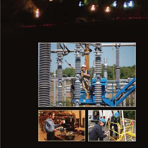


NETA ACCREDITED COMPANIES Setting
A&F Electrical Testing, Inc.
80 Lake Ave. South, Ste. 10 Nesconset, NY 11767 (631) 584-5625 Fax: (631) 584-5720 kchilton@afelectricaltesting.com www.afelectricaltesting.com
Kevin Chilton
A&F Electrical Testing, Inc.
80 Broad St. 5th Floor New York, NY 10004 (631) 584-5625 Fax: (631) 584-5720 afelectricaltesting@afelectricaltesting.com www.afelectricaltesting.com
Florence Chilton
ABM Electrical Power Solutions
3602 East Southern Ave., Ste. 1 Phoenix, AZ 85040 (602) 722-2423
www.ABM.com
Doug Bukowski
ABM Electrical Power Solutions
9800 E. Geddes Avenue, Unit A-150 Englewood, CO 80112 (303) 524-6560 Fax: (303) 524-6581
www.ABM.com
Brian Smith
ABM Electrical Power Solutions
2142 Rheem Drive Pleasanton, CA 94588 (408) 466-6920
www.ABM.com
John Marvulli
ABM Electrical Power Solutions
3940 Ruffin Rd., Ste. C San Diego, CA 92123 (858) 754-7963 www.ABM.com
Ben Thomas
ABM Electrical Power Solutions
6280 South Valley View Blvd., Ste. 618 Las Vegas, NV 89118 (602) 300-2188 Fax: (602) 437-3894 www.ABM.com
Jason Black
ABM Electrical Power Solutions
814 Greenbrier Circle, Ste. E Chesapeake, VA 23320 (757) 548-5690 Fax: (757) 548-5417
www.ABM.com
Mark Anthony Gaughan, III
ABM Electrical Power Solutions
3700 Commerce Dr. #901-903 Baltimore, MD 21227 (410) 247-3300 Fax: (410) 247-0900
www.ABM.com
Bill Hartman
ABM Electrical Power Solutions
5809 Departure Dr., Ste. 104 Raleigh, NC 27616 (919) 877-1008 Fax: (919) 501-7492
www.ABM.com
Rob Parton
the Standard
ABM Electrical Power Solutions
317 Commerce Park Dr. Cranberry Township, PA 16066-6427 (724) 772-4638 Fax: (724) 772-6003 william.mckenzie@abm.com www.ABM.com
William (Pete) McKenzie
ABM Electrical Power Solutions
4390 Parliament Place, Ste. S Lanham, MD 20706 (301) 967-3500 Fax: (301) 735-8953 www.ABM.com
Frank Ceci
ABM Electrical Power Solutions
3600 Woodpark Blvd., Suite G Charlotte, NC 28206 (704) 273-6257 Fax: (704) 598-9812 ernest.goins@abm.com www.ABM.com
Ernest Goins
ABM Electrical Power Solutions
720 S. Rochester Ave., Suite A Ontario, CA 91761 (800) 597-1225 Fax: (909) 937-6798 www.ABM.com
Mike Bivens
Absolute Testing Services 6829 Guhn Rd. Houston, TX 77040 (832) 467-4446 Fax: (713) 849-3885 rgamble@absolutetesting.com www.texasats.com
Richard Gamble
Accessible Consulting Engineers, Inc. 1269 Pomona Rd., Ste. 111 Corona, CA 92882 (951) 808-1040 info@acetesting.com www.acetesting.com
Iraj Nasrolahi
Advanced Testing Systems 15 Trowbridge Dr. Bethel, CT 06801 (203) 743-2001 Fax: (203) 743-2325 pmaccarthy@advtest.com www.advtest.com
Pat MacCarthy
American Electrical Testing Co., Inc.
480 Neponset St., Building 6 Canton, MA 02021-1970 (781) 821-0121 Fax: (781) 821-0771 sblizard@aetco.us www.99aetco.com
Scott A. Blizard
American Electrical Testing Co., Inc. 34 Clover Dr. South Windsor, CT 06074 (860) 648-1013 Fax: (781) 821-0771 jpoulin@aetco.us www.99aetco.com
Gerald Poulin
American Electrical Testing Co., Inc. 76 Cain Dr. Brentwood, NY 11717 (631) 617-5330 Fax: (631) 630-2292 mschacker@aetco.us www.99aetco.com
Michael Schacker
American Electrical Testing Co., Inc. 50 Intervale Rd., Ste. 1 Boonton, NJ 07005 (973) 316-1180 Fax: (781) 316-1181 jsomol@aetco.us www.99aetco.com
Jeff Somol
American Electrical Testing Co., Inc. 4032 Park 65 Dr. Indianapolis, IN 46254 (317) 487-2111 Fax: (781) 821-0771 scanale@aetco.us www.99aetco.com
Stephen Canale
American Electrical Testing Co., Inc. Green Hills Commerce Center 5925 Tilghman St., Ste. 200 Allentown, PA 18104 (215) 219-6800 jmunley@aetco.us www.99aetco.com
Jonathan Munley
American Electrical Testing Co., Inc. 12566 W. Indianola Ave. Avondale, AZ 85392 (480) 383-9242 dmadaglia@aetco.us www.99aetco.com
Donald Madaglia
AMP Quality Energy Services, LLC 4220 West Schrimsher SW Site W1 P.O. Box 526, Huntsville, AL 35804 (256) 513-8255
Brian Rodgers
Apparatus Testing and Engineering 11300 Sandew Dr., Ste. 29 Rancho Cordova, CA 95742 (916) 853-6280 Fax: (916) 853-6258 info@apparatustesting.com www.apparatustesting.com
Harold (Jerry) Carr
Apparatus Testing and Engineering 7083 Commerce Circle, Ste. H Pleasanton, CA 94588 (925) 454-1363 Fax: (925) 454-1499 info@apparatustesting.com www.apparatustesting.com
Harold (Jerry) Carr
Applied Engineering Concepts 1105 N. Allen Ave. Pasadena, CA 91104 (626) 398-3052 Fax: (626) 398-3053 michel.c@aec-us.com www.aec-us.com
Michel Castonguay
BEC Testing 50 Gazza Blvd. Farmingdale, NY 11735 (516) 531-9136 Fax: (631) 249-6115 wfernandez@banaelectric.com www.bectesting.com
William Fernandez
Burlington Electrical Testing Co., Inc. 300 Cedar Ave. Croydon, PA 19021-6051 (215) 826-9400 (221) Fax: (215) 826-0964 waltc@betest.com www.betest.com
Walter P. Cleary
C.E. Testing, Inc. 6148 Tim Crews Rd. Macclenny, FL 32063 (904) 653-1900 Fax: (904) 653-1911 cetesting@aol.com
Mark Chapman
CE Power Solutions, LLC 4040 Rev Dr. Cincinnati, OH 45232 (513) 563-6150 Fax: (513) 563-6120 info@cepowersol.net www.cepowersol.com
Rhonda Harris
CE Power Solutions of Minnesota, LLC 7674 Washington Ave. South Eden Prairie, MN 55344 (877) 968-0281 Fax: (952) 400-8772 jason.thompson@cepower.net www.cepower-MN.com
Jason Thompson
Control Power Concepts
353 Pilot Rd; Ste. B Las Vegas, NV 89119 (702) 448-7833 Fax: (702) 448-7835 www.controlpowerconcepts.com
John Travis
Dude Electrical Testing LLC
145 Tower Dr., Unit# 9 Burr Ridge, IL 60527 (815) 293-3388 Fax: (815) 293-3386 scott.dude@dudetesting.com www.dudetesting.com
Scott Dude
DYMAX Service, LLC
46918 Liberty Dr. Wixom, MI 48393 (248) 313-6868 Fax: (248) 313-6869 www.dymaxservice.com
Bruce Robinson
DYMAX Service, LLC
4213 Kropf Ave. Canton, OH 44706 (330) 484-6801 Fax: (740) 333-1271 www.dymaxservice.com
Chuck Baker
NETA ACCREDITED COMPANIES
136 • SPRING 2015
Eastern High Voltage 11A South Gold Dr. Robbinsville, NJ 08691-1606 (609) 890-8300 Fax: (609) 588-8090 joewilson@easternhighvoltage.com www.easternhighvoltage.com
Joseph Wilson
ELECT, P.C.
7400-G Siemens Rd., P.O. Box 2080 Wendell, NC 27591 (919) 365-9775 Fax: (919) 365-9789 btyndall@elect-pc.com www.elect-pc.com
Barry W. Tyndall
Electric Power Systems, Inc. 21 Millpark Ct. Maryland Heights, MO 63043 (314) 890-9999 Fax: (314) 890-9998 www.epsii.com
Electric Power Systems, Inc.
557 E. Juanita Ave., #4 Mesa, AZ 85204 (480) 633-1490 Fax: (480) 633-7092 www.epsii.com
Electric Power Systems, Inc.
4436 Parkway Commerce Blvd. Orlando, FL 32808 (407) 578-6424 Fax: 407-578-6408 www.epsii.com
Electric Power Systems, Inc.
7000 E. 47th Avenue Drive, Suite 100 Denver, CO 80216 (720) 857-7273 Fax: 303-928-8020 www.epsii.com
Electric Power Systems, Inc. 23823 Andrew Rd. Plainfield, IL 60585 (815) 577-9515 Fax: (815) 577-9516 www.epsii.com
Electric Power Systems, Inc. 2601 Center Rd., # 101 Hinckley, OH 44233 (330) 460-3706 Fax: (330) 460-3708 www.epsii.com
Electric Power Systems, Inc.
56 Bibber Pkwy #1 Brunswick, ME 04011 (207) 837-6527 www.epsii.com
Electric Power Systems, Inc.
4100 Greenbriar Dr., Ste. 160 Stafford, TX 77477 (713) 644-5400 www.epsii.com
Electric Power Systems, Inc. 11861 Longsdorf St. Riverview, MI 48193 (734) 282-3311 www.epsii.com
Electric Power Systems, Inc.
827 Union St., Salem, VA 24153 (540) 375-0084 Fax: (540) 375-0094 www.epsii.com
Electric Power Systems, Inc.
915 Holt Ave., Unit 9 Manchester, NH 03109 (603) 657-7371 Fax: 603-657-7370 www.epsii.com
Electric Power Systems, Inc.
146 Space Park Dr. Nashville, TN 37211 (615) 834-0999 Fax: (615) 834-0129 www.epsii.com
Electric Power Systems, Inc. 8515 Cella Alameda NE, Ste. A Albuquerque, NM 87113 (505) 792-7761 www.epsii.com
Electric Power Systems, Inc.
7140 Dean Martin Drive, Suite 900 Las Vegas, NV 89118 (702) 815-1342 www.epsii.com
Electric Power Systems, Inc.
319 US Hwy. 70 E, Unit E Garner, NC 27529 (919) 322-2670 www.epsii.com
Electric Power Systems, Inc. 1090 Montour West Industrial Blvd. Coraopolis, PA 15108 (412) 276-4559 www.epsii.com
Electric Power Systems, Inc. 6141 Connecticut Ave. Kansas City, MO 64120 (816) 241-9990 Fax: (816) 241-9992 www.epsii.com
Electric Power Systems, Inc. 2495 Boulevard of the Generals Norristown, PA 19403 (610) 630-0286 www.epsii.com
Electric Power Systems, Inc. 1129 East Hwy. 30 Gonzalez, LA 70817 (225) 644-0150 Fax: (225) 644-6249 www.epsii.com
Electric Power Systems, Inc. 7925 Dunbrook Rd., Ste. G San Diego, CA 92126 (858) 566-6317 www.epsii.com
NETA ACCREDITED COMPANIES
Electrical & Electronic Controls 6149 Hunter Rd. Ooltewah, TN 37363 (423) 344-7666 (23) Fax: (423) 344-4494 eecontrols@comcast.net
Michael Hughes
Electrical Energy Experts, Inc. W129N10818, Washington Dr. Germantown, WI 53022 (262) 255-5222 Fax: (262) 242-2360 bill@electricalenergyexperts.com www.electricalenergyexperts.com
William Styer
Electrical Equipment Upgrading, Inc. 21 Telfair Place, Savannah, GA 31415 (912) 232-7402 Fax: (912) 233-4355 kmiller@eeu-inc.com www.eeu-inc.com
Kevin Miller
Electrical Maintenance & Testing Inc. 12342 Hancock St., Carmel, IN 46032 (317) 853-6795 Fax: (317) 853-6799 info@emtesting.com www.emtesting.com
Brian K. Borst
Electrical Reliability Services 1057 Doniphan Park Circle, Ste. A El Paso, TX 79922 (915) 587-9440 Fax: (915) 587-9010 www.electricalreliability.com
Electrical Reliability Services 1775 W. University Dr., Ste. 128 Tempe, AZ 85281 (480) 966-4568 Fax: (480) 966-4569 www.electricalreliability.com
Electrical Reliability Services 1426 Sens Rd. Ste. 5 Houston, TX 77571 (281) 241-2800 Fax: (281) 241-2801 www.electricalreliability.com
Electrical Reliability Services 4099 SE International Way, Ste. 201 Milwaukie, OR 97222-8853 (503) 653-6781 Fax: (503) 659-9733 www.electricalreliability.com
Electrical Reliability Services 5909 Sea Lion Place, Ste. C Carlsbad, CA 92010 (858) 695-9551 www.electricalreliability.com
Electrical Reliability Services 8500 Washington Pl. NE, Ste. A-6 Albuquerque, NM 87113 (505) 822-0237 Fax: (505) 822-0217 www.electricalreliability.com
Electrical Reliability Services 1380 Greg Street, Ste. 217 Sparks, NV 89431 (775) 746-8484 Fax: (775) 356-5488 www.electricalreliability.com
Electrical Reliability Services 2275 Northwest Pkwy SE, Ste. 180 Marietta, GA 30067 (770) 541-6600 Fax: (770) 541-6501 www.electricalreliability.com
Electrical Reliability Services 7100 Broadway, Ste. 7E Denver, CO 80221-2915 (303) 427-8809 Fax: (303) 427-4080 www.electricalreliability.com
Electrical Reliability Services 348 N.W. Capital Dr. Lee's Summit, MO 64086 (816) 525-7156 Fax: (816) 524-3274 www.electricalreliability.com
Electrical Reliability Services 6900 Koll Center Parkway, Ste. 415 Pleasanton, CA 94566 (925) 485-3400 Fax: (925) 485-3436 www.electricalreliability.com
Electrical Reliability Services 10606 Bloomfield Ave. Santa Fe Springs, CA 90670 (562) 236-9555 Fax: (562) 777-8914 www.electricalreliability.com
Electrical Reliability Services 14141 Airline Hwy., Bldg 1; Ste. X Baton Rouge, LA 70817 (225) 755-0530 Fax: (225) 751-5055 www.electricalreliability.com
Electrical Reliability Services 121 Highway 108 East Sulphur, LA 70665 (337) 583-2411 Fax: (337) 583-2410 www.electricalreliability.com
Electrical Reliability Services 11000 Metro Pkwy., Ste. 30 Ft. Myers, FL 33966 (239) 693-7100 Fax: (239) 693-7772 www.electricalreliability.com
Electrical Reliability Services 2222 West Valley Hwy. N., Ste 160 Auburn, WA 98001 (253) 736-6010 Fax: (253) 736-6015 www.electricalreliability.com
Electrical Reliability Services 3412 South 1400 West, Unit A West Valley City, UT 84119 (801) 975-6461 www.electricalreliability.com
Electrical Reliability Services 6351 Hinson St., Ste. B Las Vegas, NV 89118 (702) 597-0020 Fax: (702) 597-0095 www.electricalreliability.com
Electrical Reliability Services 9636 St. Vincent, Unit A Shreveport, LA 71106 (318) 869-4244 www.electricalreliability.com
NETA ACCREDITED COMPANIES
Setting the Standard NETAWORLD • 137
NETA ACCREDITED COMPANIES Setting
Electrical Reliability Services
610 Executive Campus Dr. Westerville, OH 43082 (877) 468-6384 Fax: (614) 410-8420 info@electricalreliability.com www.electricalreliability.com
Electrical Testing, Inc.
2671 Cedartown Hwy. Rome, GA 30161-6791 (706) 234-7623 Fax: (706) 236-9028 steve@electricaltestinginc.com www.electricaltestinginc.com
Electrical Testing Solutions
2909 Green Hill Ct. Oshkosh, WI 54904 (920) 420-2986 Fax: (920) 235-7136 tmachado@electricaltestingsolutions.com www.electricaltestingsolutions.com
Tito Machado
Elemco Services, Inc.
228 Merrick Rd. , Lynbrook, NY 11563 (631) 589-6343 Fax: (631) 589-6670 courtney@elemco.com www.elemco.com
Courtney O'Brien
EnerG Test
204 Gale Lane Bldg. 2 - 2nd Floor Kennett Square, PA 19348 (484) 731-0200 Fax: (484) 713-0209 kbleiler@energtest.com www.energtest.com
Katie Bleiler
Energis High Voltage Resources, Inc. 1361 Glory Rd. Green Bay, WI 54304 (920) 632-7929 Fax: (920) 632-7928 info@energisinc.com www.energisinc.com
Mick Petzold
EPS Technology
29 N. Plains Hwy., Ste. 12 Wallingford, CT 06492 (203) 679-0145 www.eps-technology.com
Grounded Technologies, Inc.
10505 S. Progress Way, Ste. 105 Parker, CO 80134 P-(303) 781-2560 F- (303) 781-5240 jodymedina@groundedtech.com www.groundedtech.com
Jody Medina
Grubb Engineering, Inc.
3128 Sidney Brooks San Antonio, Tx 78235 (210) 658-7250 Fax: (210) 658-9805 joy@grubbengineering.com www.grubbengineering.com
Robert D. Grubb Jr.
the Standard
Hampton Tedder Technical Services 4571 State St. Montclair, CA 91763 (909) 628-1256 x214 Fax: (909) 628-6375
matt.tedder@hamptontedder.com www.hamptontedder.com
Matt Tedder
Hampton Tedder Technical Services 4920 Alto Ave. Las Vegas, NV 89115 (702) 452-9200 Fax: (702) 453-5412 www.hamptontedder.com
Roger Cates
Hampton Tedder Technical Services 3747 West Roanoke Ave. Phoenix, AZ 85009 (480) 967-7765 Fax: (480) 967-7762 www.hamptontedder.com
Harford Electrical Testing Co., Inc. 1108 Clayton Rd. Joppa, MD 21085 (410) 679-4477 Fax: (410) 679-0800 testing@harfordtesting.com www.harfordtesting.com
Vincent Biondino
High Energy Electrical Testing, Inc. 515 S. Ocean Ave. Seaside Park, NJ 08752 (732) 938-2275 Fax: (732) 938-2277 hinrg@comcast.net www.highenergyelectric.com
Charles Blanchard
High Voltage Maintenance Corp. 24 Walpole Park South Dr. Walpole, MA 02081 (508) 668-9205 www.hvmcorp.com
High Voltage Maintenance Corp. 941 Busse Rd. Elk Grove Village, Il 60007 (847) 640-0005 www.hvmcorp.com
High Voltage Maintenance Corp. 7200 Industrial Park Blvd. Mentor, OH 44060 (440) 951-2706 Fax: (440) 951-6798 www.hvmcorp.com
High Voltage Maintenance Corp. 3000 S. Calhoun Rd. New Berlin, WI 53151 (262) 784-3660 Fax: (262) 784-5124 www.hvmcorp.com
High Voltage Maintenance Corp. 8320 Brookville Rd. #E Indianapolis, IN 46239 (317) 322-2055 Fax: (317) 322-2056 www.hvmcorp.com
High Voltage Maintenance Corp. 1250 Broadway, Ste. 2300 New York, NY 10001 (718) 239-0359 www.hvmcorp.com
High Voltage Maintenance Corp. 355 Vista Park Dr. Pittsburgh, PA 15205-1206 (412) 747-0550 Fax: (412) 747-0554 www.hvmcorp.com
High Voltage Maintenance Corp. 150 North Plains Industrial Rd. Wallingford, CT 06492 (203) 949-2650 Fax: (203) 949-2646 www.hvmcorp.com
High Voltage Maintenance Corp. 9305 Gerwig Ln., Ste. B Columbia, MD 21046 (410) 309-5970 Fax: (410) 309-0220 www.hvmcorp.com
High Voltage Maintenance Corp. 24371 Catherine Industrial Dr, Ste. 207 Novi, MI 48375 (248) 305-5596 Fax: (248) 305-5579 www.hvmcorp.com
High Voltage Maintenance Corp. 5100 Energy Dr. Dayton, OH 45414 (937) 278-0811 Fax: (937) 278-7791 www.hvmcorp.com
High Voltage Service, LLC 4751 Mustang Circle St. Paul, MN 55112 (763) 784-4040 Fax: (763) 784-5397 www.hvserviceinc.com
Mike Mavetz
HMT, Inc. 6268 Route 31 Cicero, NY 13039 (315) 699-5563 Fax: (315) 699-5911 jpertgen@hmt-electric.com www.hmt-electric.com
John Pertgen
Industrial Electric Testing, Inc. 11321 West Distribution Ave. Jacksonville, FL 32256 (904) 260-8378 Fax: (904) 260-0737 gbenzenberg@bellsouth.net www.industrialelectrictesting.com Gary Benzenberg
Industrial Electric Testing, Inc. 201 NW 1st Ave. Hallandale, FL 33009-4029 (954) 456-7020 www.industrialelectrictesting.com
Industrial Electronics Group 850369 Highway 17 South P.O. Box 1870 Yulee, FL 32041 (904) 225-9529 Fax: (904) 225-0834 butch@industrialgroups.com www.industrialgroups.com
Butch E. Teal
Industrial Tests, Inc. 4021 Alvis Ct., Ste. 1 Rocklin, CA 95677 (916) 296-1200 Fax: (916) 632-0300 greg@indtest.com www.industrialtests.com
Greg Poole
Infra-Red Building and Power Service 152 Centre St. Holbrook, MA 02343-1011 (781) 767-0888 Fax: (781) 767-3462 tom.mcdonald@infraredbps.com www.infraredbps.com
Thomas McDonald Sr.
Longo Electrical-Mechanical, Inc. One Harry Shupe Blvd., Box 511 Wharton, NJ 07885 (973) 537-0400 Fax: (937) 537-0404 jmlongo@elongo.com www.elongo.com
Joe Longo
Longo Electrical-Mechanical, Inc. 1625 Pennsylvania Ave. Linden, NJ 07036 (908) 925-2900 Fax: (908) 925-9427 jmlongo@elongo.com www.elongo.com
Joe Longo
Longo Electrical-Mechanical, Inc. 1400 F Adams Rd. Bensalem, PA 19020 (215) 638-1333 Fax: (215) 638-1366 jmlongo@elongo.com www.elongo.com
Joe Longo
M&L Power Systems, Inc. 109 White Oak Ln., Ste. 82 Old Bridge, NJ 08857 (732) 679-1800 Fax: (732) 679-9326 milind@mlpower.com www.mlpower.com
Milind Bagle
Magna IV Engineering 1103 Parsons Rd. SW Edmonton, AB T6X 0X2 Canada (780) 462-3111 Fax: (780) 450-2994 info@magnaiv.com www.magnaiv.com Virgina Balitski
Magna IV Engineering 200, 688 Heritage Dr. Calgary, AB T2H 1M6 Canada (403) 723-0575 Fax: (403) 723-0580 info.calgary@magnaiv.com
Dave Emerson
Magna IV Engineering
8219D Fraser Ave. Fort McMurray, AB T9H 0A2 Canada (780) 791-3122 Fax: (780) 791-3159 info.fmcmurray@magnaiv.com
Ryan Morgan
NETA ACCREDITED COMPANIES
138 • SPRING 2015
Magna IV Engineering 96 Inverness Dr. East, Unit R Englewood, CO 80112 (303) 799-1273 Fax: (303) 790-4816 info.denver@magnaiv.com Aric Proskurniak
Magna IV Engineering Avenida del Condor #590 Oficina 601 Huechuraba, Santiago 8580676 Chile +(56) 9-9-517-4642 info.chile@magnaiv.com Cristian Fuentes
Magna IV Engineering 1040 Winnipeg St. Regina , SK S4R 8P8 Canada (306) 585-2100 Fax: (306) 585-2191 info.regina@magnaiv.com
Andrew Westerman
Magna IV Engineering 106, 4268 Lozells Ave. Burnaby, BC VSA 0C6 Canada (604) 421-8020
William Kulsky
Magna IV Engineering 1005 Spinney Dr. Dawson Creek, BC V1G 1K1 Canada (780) 462-3111 Fax: (780) 462-9799 info@magnaiv.com
David Limb
National Field Services 649 Franklin St. Lewisville, TX 75057 (972) 420-0157 www.natlfield.com Eric Beckman
Nationwide Electrical Testing, Inc. 6050 Southard Trace Cumming, GA 30040 (770) 667-1875 Fax: (770) 667-6578 Shashi@N-E-T-Inc.com www.n-e-t-inc.com Shashikant B. Bagle
North Central Electric, Inc. 69 Midway Ave. Hulmeville, PA 19047-5827 (215) 945-7632 Fax: (215) 945-6362 ncetest@aol.com
Robert Messina
Northern Electrical Testing, Inc. 1991 Woodslee Dr. Troy, MI 48083-2236 (248) 689-8980 Fax: (248) 689-3418 ldetterman@northerntesting.com www.northerntesting.com
Lyle Detterman
Orbis Engineering Field Services Ltd. #300, 9404 - 41st Ave. Edmonton, AB T6E 6G8 Canada (780) 988-1455 Fax: (780) 988-0191 lorne@orbisengineering.net www.orbisengineering.net
Lorne Gara
Pacific Power Testing, Inc. 14280 Doolittle Dr. San Leandro, CA 94577 (510) 351-8811 Fax: (510) 351-6655 steve@pacificpowertesting.com www.pacificpowertesting.com
Steve Emmert
Pacific Powertech, Inc. #110, 2071 Kingsway Ave. Port Coquitlam, BC V3C 6N2 Canada (604) 944-6697 Fax: (604) 944-1271 jkonkin@pacificpowertech.ca www.pacificpowertech.ca
Josh Konkin
Phasor Engineering Sabaneta Industrial Park #216 Mercedita, PR 00715 Puerto Rico (787) 844-9366 Fax: (787) 841-6385 rcastro@phasorinc.com
Rafael Castro
Potomac Testing, Inc. 1610 Professional Blvd., Ste. A Crofton, MD 21114 (301) 352-1930 Fax: (301) 352-1936 kbassett@potomactesting.com www.potomactesting.com
Ken Bassett
Potomac Testing, Inc.
11179 Hopson Rd., Ste. 5 Ashland, VA 23005 (804) 798-7334 Fax: (804) 798-7456 www.potomactesting.com
Power & Generation Testing, Inc. 480 Cave Rd. Nashville, TN 37210 (615) 882-9455 Fax: (615) 882-9591 mose@pgti.net www.pgti.net
Mose Ramieh
Power Engineering Services, Inc. 9179 Shadow Creek Lane Converse, TX 78109 (210) 590-4936 Fax: (210) 590-6214 engelke@pe-svcs.com www.pe-svcs.com
Miles R. Engelke
POWER PLUS Engineering, Inc. 46575 Magellan Novi, MI 48377 (248) 344-0200 Fax: (248) 305-9105 smancuso@epowerplus.com www.epowerplus.com
Salvatore Mancuso
NETA ACCREDITED COMPANIES
Power Products & Solutions, LLC 12465 Grey Commercial Rd. Midland, NC 28107 (704) 573-0420 x12 Fax: (704) 573-3693 ralph.patterson@powerproducts.biz www.powerproducts.biz
Ralph Patterson
Power Products & Solutions, LLC 13 Jenkins Ct. Mauldin, SC 29662 (800) 328-7382 ralph.patterson@powerproducts.biz www.powerproducts.biz
Raymond Pesaturo
Power Services, LLC 998 Dimco Way, P.O. Box 750066 Centerville, OH 45475 (937) 439-9660 Fax: (937) 439-9611 mkbeucler@aol.com
Mark Beucler
Power Solutions Group, Ltd. 425 W. Kerr Rd. Tipp City, OH 45371 (937) 506-8444 Fax: (937) 506-8434 bwilloughby@powersolutionsgroup.com www.powersolutionsgroup.com
Barry Willoughby
Power Solutions Group, Ltd. 135 Old School House Rd. Piedmont, SC 29673 (864) 845-1084 Fax:: (864) 845-1085 fcrawford@powersolutionsgroup.com www.powersolutionsgroup.com
Anthony Crawford
Power Solutions Group, Ltd. 670 Lakeview Plaza Blvd. Columbus, OH 43085 (614) 310-8018 sspohn@powersolutionsgroup.com www.powersolutionsgroup.com
Stuart Spohn
Power Systems Testing Co. 4688 W. Jennifer Ave., Ste. 108 Fresno, CA 93722 (559) 275-2171 ext 15 Fax: (559) 275-6556 dave@pstcpower.com www.powersystemstesting.com
David Huffman
Power Systems Testing Co. 600 S. Grand Ave., Ste. 113 Santa Ana, CA 92705-4152 (714) 542-6089 Fax: (714) 542-0737 www.powersystemstesting.com
Power Systems Testing Co. 6736 Preston Ave, Ste. E Livermore, CA 94551 (510) 783-5096 Fax: (510) 732-9287 www.powersystemstesting.com
Power Test, Inc. 2200 Highway 49 Harrisburg, NC 28075 (704) 200-8311 Fax: (704) 455-7909 rich@powertestinc.com www.powertestinc.com
Richard Walker
POWER Testing and Energization, Inc. 14006 NW 3rd Ct., Ste. 101 Vancouver, WA 98685 (360) 597-2800 Fax: (360) 576-7182 chris.zavadlov@powerte.com www.powerte.com Chris Zavadlov
POWER Testing and Energization, Inc. 731 E. Ball Rd., Ste. 100 Anaheim, CA 92805 (714) 507-2702 www.powerte.com
POWER Testing and Energization, Inc. 22035 70th Ave. South Kent, WA 98032 (253) 872-7747 www.powerte.com
Powertech Services, Inc. 4095 South Dye Rd. Swartz Creek, MI 48473-1570 (810) 720-2280 Fax: (810) 720-2283 kirkd@powertechservices.com www.powertechservices.com Kirk Dyszlewski
Precision Testing Group 5475 Highway 86, Unit 1 Elizabeth, CO 80107 (303) 621-2776 Fax: (303) 621-2573 glenn@precisiontestinggroup.com Glenn Stuckey
PRIT Service, Inc. 112 Industrial Dr., P.O. Box 606 Minooka, IL 60447 (815) 467-5577 Fax: (815) 467-5883
Rod.Hageman@pritserviceinc.com www.pritserviceinc.com Rod Hageman
Reuter & Hanney, Inc. 149 Railroad Dr. Northampton Industrial Park Ivyland, PA 18974 (215) 364-5333 Fax: (215) 364-5365 mikereuter@reuterhanney.com www.reuterhanney.com Michael Reuter
Reuter & Hanney, Inc. 4270-I Henninger Ct. Chantilly, VA 20151 (703) 263-7163 Fax: 703-263-1478 www.reuterhanney.com
Reuter & Hanney, Inc. 11620 Crossroads Circle, Suites D-E Middle River, MD 21220 (410) 344-0300 Fax: (410) 335-4389 www.reuterhanney.com
Michael Jester
NETA ACCREDITED COMPANIES
Setting the Standard NETAWORLD • 139
NETA ACCREDITED COMPANIES
REV Engineering, LTD
3236 - 50 Ave. SE Calgary, AB T2B 3A3
Canada (403) 287-0156 Fax: (403) 287-0198
rdavidson@reveng.ca www.reveng.ca
Roland Nicholas Davidson, IV
Saber Power Services
9841 Saber Power Lane Rosharon, TX 77583-5188 (713) 222-9102 info@saberpower.com www.saberpower.com
Phil Collins
Scott Testing Inc. 1698 5th St. Ewing, NJ 08638 (609) 882-2400 Fax: (609) 882-5660 rsorbello@scotttesting.com www.scotttesting.com
Russ Sorbello
Shermco Industries
2425 E. Pioneer Dr. Irving, TX 75061 (972) 793-5523 Fax: (972) 793-5542 rwidup@shermco.com www.shermco.com
Ron Widup
Shermco Industries
1705 Hur Industrial Blvd. Cedar Park, TX 78613 (512) 267-4800 Fax: (512) 258-5571 kewing@shermco.com www.shermco.com
Kevin Ewing
Shermco Industries 33002 FM 2004 Angleton, TX 77515 (979)848-1406 Fax: (979) 848-0012 mfrederick@shermco.com www.shermco.com Malcom Frederick
Shermco Industries 1357 N. 108th E. Ave. Tulsa, OK 74116 (918) 234-2300 jharrison@shermco.com www.shermco.com
Jim Harrison
Shermco Industries 796 11th St. Marion, IA 52302 (319) 377-3377 Fax: (319) 377-3399 lhamrick@shermco.com www.shermco.com
Lynn Hamrick
Shermco Industries 2100 Dixon St., Ste. C Des Moines, IA 50316 (515) 263-8482
lHamrick@shermco.com www.shermco.com
Lynn Hamrick
Shermco Industries
Boulevard Saint-Michel 47 1040 Brussels Brussels, Belgium
+32 (0)2 400 00 54 Fax: +32 (0)2 400 00 32 pIdziak@shermco.com www.shermco.com
Paul Idziak
Shermco Industries
12000 Network Blvd., Bldg D,, Ste. 410 San Antonio, TX 78249 (512) 267-4800 Fax: (512) 267-4808 kewing@shermco.com www.shermco.com
Kevin Ewing
Shermco Industries Canada Inc. 1033 Kearns Crescent, Box 995 Regina, SK S4P 3B2 Canada (306) 949-8131 Fax: (306) 522-9181 kheid@magnaelectric.com www.shermco.com
Kerry Heid
Shermco Industries Canada Inc. 851-58th St. East Saskatoon, SK S7K 6X5 Canada (306) 955-8131 Fax: (306) 955-9181 ajaques@magnaelectric.com www.shermco.com
Adam Jaques
Shermco Industries Canada Inc. 3731-98 St. Edmonton, AB T6E 5N2 Canada (780) 436-8831 Fax: (780) 468-9646 cgrant@magnaelectric.com www.shermco.com
Cal Grant
Shermco Industries Canada Inc. 3430 25th St. NE Calgary, AB T1Y 6C1 Canada (403) 769-9300 Fax: (403)769-9369 cgrant@magnaelectric.com www.shermco.com
Cal Grant
Shermco Industries Canada Inc. 1375 Church Ave. Winnipeg, MB R2X 2T7 Canada (204) 925-4022 Fax: (204) 925-4021 cbrandt@magnaelectric.com www.shermco.com
Curtis Brandt
Sigma Six Solutions, Inc. 2200 West Valley Hwy., Ste. 100 Auburn, WA 98001 (253) 333-9730 Fax: (253) 859-5382 jwhite@sigmasix.com www.sigmasix.com
John White
Southern New England Electrical Testing, LLC 3 Buel St., Ste. 4 Wallingford, CT 06492 (203) 269-8778 Fax: (203) 269-8775 dave.asplund@sneet.org www.sneet.org
David Asplund, Sr.
Southwest Energy Systems, LLC 2231 East Jones Ave., Ste. A Phoenix, AZ 85040 (602) 438-7500 Fax: (602) 438-7501 bob.sheppard@southwestenergysystems.com www.southwestenergysystems.com
Robert Sheppard
Taurus Power & Controls, Inc. 9999 SW Avery St. Tualatin, OR 97062-9517 (503) 692-9004 Fax: (503) 692-9273 robtaurus@tauruspower.com www.tauruspower.com Rob Bulfinch
Taurus Power & Controls, Inc. 6617 S. 193rd Place, Ste. P104 Kent, WA 98032 (425) 656-4170 Fax: (425) 656-4172 jiml@tauruspower.com www.tauruspower.com
Jim Lightner
3C Electrical Co., Inc. 40 Washington St. Westborough, MA 01581 (508) 881-3911 Fax: (508) 881-4814 jim@three-c.com www.three-c.com
Jim Cialdea
3C Electrical Co., Inc. 72 Sanford Dr. Gorham, ME 04038 (800) 649-6314 Fax: (207) 782-0162 jim@three-c.com www.three-c.com
Jim Cialdea
Tidal Power Services, LLC 4202 Chance Lane Rosharon, TX 77583 (281) 710-9150 Fax: (713) 583-1216 monty.janak@tidalpowerservices.com www.tidalpowerservices.com
Monty C. Janak
Tidal Power Services, LLC 8184 Highway 44, Ste. 105 Gonzales, LA 70737 (225) 644-8170 Fax: (225) 644-8215 www.tidalpowerservices.com
Darryn Kimbrough
Tidal Power Services, LLC 1056 Mosswood Dr. Sulphur, LA 70663 (337) 558-5457 Fax: (337) 558-5305 www.tidalpowerservices.com
Steve Drake
Tony Demaria Electric, Inc. 131 West F St. Wilmington, CA 90744 (310) 816-3130 (310) 549-9747 neno@tdeinc.com www.tdeinc.com Nenad Pasic
Trace Electrical Services & Testing, LLC 293 Whitehead Rd. Hamilton, NJ 08619 (609) 588-8666 Fax: (609) 588-8667 jvasta@tracetesting.com www.tracetesting.com
Joseph Vasta
Utilities Instrumentation Service, Inc. 2290 Bishop Circle East Dexter, MI 48130 (734) 424-1200 Fax: (734) 424-0031 GEWalls@UISCorp.com www.uiscorp.com
Gary E. Walls
Utility Service Corporation 4614 Commercial Dr. NW Huntsville, AL 35816-2201 (256) 837-8400 Fax: (256) 837-8403 apeterson@utilserv.com www.utilserv.com
Alan D. Peterson
Western Electrical Services, Inc. 14311 29th St. East Sumner , WA 98390 (253) 891-1995 Fax: (253) 891-1511 dhook@westernelectricalservices.com www.westernelectricalservices.com
Dan Hook
Western Electrical Services, Inc. 3676 W. California Ave., #C, 106 Salt Lake City, UT 84104 (888) 395-2021 Fax: (253) 891-1511 rcoomes@westernelectricalservices.com www.westernelectricalservices.com
Rob Coomes
Western Electrical Services, Inc. 5680 South 32nd St. Phoenix, AZ 85040 (602) 426-1667 Fax: (253) 891-1511 carcher@westernelectricalservices.com www.westernelectricalservices.com
Craig Archer
Western Electrical Services, Inc. 4510 NE 68th Dr., Ste. 122 Vancouver, WA 98661 (888) 395-2021 Fax: (253) 891-1511 Tasciutto@westernelectricalservices.com www.westernelectricalservices.com
Tony Asciutto
NETA ACCREDITED COMPANIES
Setting the Standard 140 • SPRING 2015
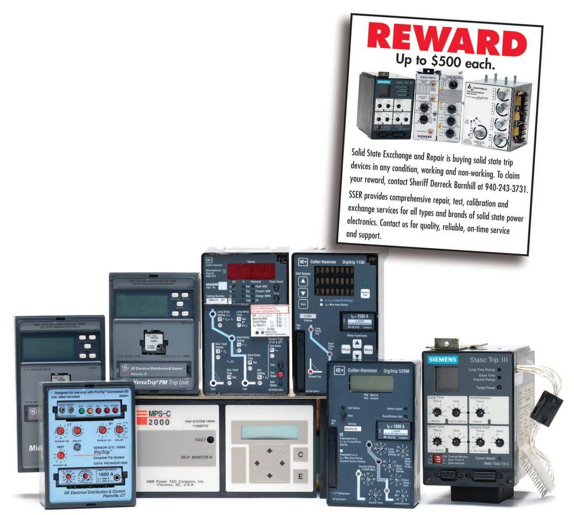
We Buy, Sell, Trade, Calibrate, Repair
Featuring quality, reliable, on-time service and support for all brands and types of solid state power electronics.
Power electronics are our business
Let us suppoort you with our quality repair, calibration and servicing of your solid state equipment. We also buy, sell and trade:
•Communications devices for power equipment
•Protective relays
•Circuit breaker trip devices
•Motor overload relays
•Rating plugs
4701 Spartan Drive • Denton, TX 76207 (877-874-7349) • Phone: 940-243-3731 • Fax: 940-387-8277 Email: info@solidstaterepair.com • Web: www.solidstaterepair.com
“SOLID STATE” INDUSTRIAL ELECTRONICS “SOLID STATE” INDUSTRIAL ELECTRONICS Toll Free 877-TRIP-FIX NOWRENTING TESTEQUIPMENT
This issue’s advertisers are identified below. Please thank these advertisers by telling them you saw their advertisement in YOUR magazine –NETA World.


142 • SPRING 2015 ADVERTISERS
INDEPENDENT
ACCREDITED COMPANIES Absolute Testing Services, Inc. ......................35 American Electrical Testing Co. ....................42 Apparatus Testing and Engineering ...................6 Burlington Electrical Testing Co., Inc. ...............15 Eastern High Voltage...............................89 Electrical Energy Experts, Inc. .......................15 Electrical Reliability Services ........................45 Elemco Services, Inc. ...............................44 EnerG Test .........................................6 Hampton Tedder . ..................................5 Harford Electrical Testing Co., Inc. ..................45 High Voltage Maintenance Corp. ...................83 Industrial Electric Testing, Inc. .....................53 Infra-Red Building and Power Service ...............45 Nationwide Electrical Testing, Inc ....................8 North Central Electric, Inc. ........................115 Orbis Engineering Field Services, Ltd. ...............33 Potomac Testing, Inc. .............................135 Power & Generation Testing, Inc. ...................23 Power Products & Solutions, Inc. ....................53 Power Services, LLC ...............................23 Power Systems Testing Co. ..........................33 POWER Testing and Energization, Inc. ..............44 PRIT Service, Inc. ..................................8 Scott Testing, Inc. ..................................39 Shermco Industries. ................................67 Sigma Six Solutions ................................83 Taurus Power & Controls, Inc. ......................83 3C Electrical Co. Inc. .............................102 Tony Demaria Electric, Inc. .........................16 Trace Electrical Services & Testing, LLC .............44 Utility Service Corporation .......................124 MANUFACTURERS AND OTHER SERVICE PROVIDERS Advance Test Equipment Rentals (ATE Corp) ...............15 AEMC ................................................... 17 Aero Tec Laboratories ...................................... 33 ANSI/NETA ECS ........................................ 82 ANSI/NETA MTS ....................................... 125 Ampteks .................................................. 17 Arbiter Systems, Inc. ....................................... 23 AVO Training Institute . ................................. 123 Avox Technologies ......................................... 21 BCS Switchgear, Inc. ....................................... 57 Burlington Safety Laboratory, Inc. ...........................39 CBS ArcSafe .............................................. 26 CBS ArcSafe - Circuit Breaker Analyzer. ..................... 26 CBS Vacuum Interrupters, Inc. . ............................. 76 DV Power/Prog USA ...................................... 56 Doble .................................................... 121 Dranetz ................................................... 32 ECP Solutions ............................................. 89 Electric Service Co. .................................... 56, 128 ElectroRent ......................................... 102, 127 Group CBS, Inc. ........................................... 48 HAEFELY HIPOTRONICS ............................... 9 High Voltage, Inc.......................................... 128 HV Diagnostics, Inc. ....................................... 39 Instel Power Products . .................................... 127 Intellirent .................................................75 IRISS .....................................................13 L.W. Brittain .............................................120 Manta Test Systems .......................................107 Megger ....................................Inside Front Cover Monster Fuses ............................................ 115 National Switchgear ....................................... 113 NETA PowerTest Call for Sponsors .........................27 NETA PowerTest Call for Exhibitors ........................43 NETA PowerTest Call for Speakers .......................... 88 NETA PowerTest Save the Date ............................. 22 NETA PowerTest Sponsor Thank You ....................... 12 NETA Alliance Program .................................. 109 NETA Handbooks .......................................117 NETA Training ............................................ 77 NETA Why Hire NAC? .................................. 108 OMICRON electronics Corp. USA.................Back Cover Phenix Technologies, Inc. .................................. 49 Protec Equipment Resources ...............................49 Quality Switchgear, Inc. ................................... 116 Raytech .....................................Inside Back Cover SMC International ........................................ 112 Solid State Exchange & Repair Co.......................... 141 Technitrol, Inc. ...........................................124 Thyritronics, Inc...........................................107 Utility Relay Company ....................................129 Vanguard Instrument Co., Inc. ............................. 103 Widespread Electrical Sales ................................116
NETA
ADVERTISERS


WHAT DOES A 5-YEAR WARRANTY MEAN TO YOU?

Our customers know that the Raytech standard 5-year warranty means they will have years of troublefree operation, without the cost of replacing their instruments.
Each Raytech system undergoes extensive design and testing with valued input from our customers. This unique design approach of the engineering team at Raytech has resulted in the development of highly regarded, rugged measuring instruments, which have set new standards in the electrical testing industry. We can offer a 5-year standard warranty because we are confident in our instruments’ performance for years to come.

If you aren’t using a Raytech Turns Ratiometer, Winding Resistance Meter, or Contact Resistance Meter, find out what a 5-year warranty could mean to you!

www.RaytechUSA.com Toll free 888 484 3779 | Phone: 267 404 2676 | Fax: 267 404 2685 118 South 2nd St., Perkasie, PA, 18944 5YEARS Winding Resistance with Core Demagnatization 10A and 200A Contact Resistance Single and 3-Phase Ratiometers Visit us at the PowerTest 2015 Conference in Nashville, TN. March 2-6, 2015 Booth #415
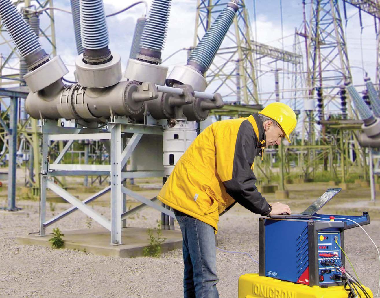
The future of circuit breaker testing
The new CIBANO 500 is the world's first 3-in-1 test system to combine:
» a micro-ohmmeter
» a timing and travel analyzer
» a circuit breaker power supply
This helps you to carry out all kinds of tests on all types of circuit breakers, quickly and with little wiring. Even better, it weighs only 44 lbs.
You can perform tests with both sides of the circuit breaker grounded and you don't need to rewire between the single tests.
The CIBANO 500 is driven by OMICRON's Primary Test Manager™ (PTM). This enables you to manage your test plans, perform test s, assess measurements, and create reports.
Circuit breaker testing has never been so easy! www.omicronusa.com
| 1-800-OMICRON
