
DISCHARGE TESTING:
IMPLEMENTINGNERCST IMPLEMENTING NERC STANDARDS ANDFIELDEXPERIENCES AND FIELD EXPERIENCES
Feel The Need... For Speed?


Test Your Transformer 10 Times Faster with the MTO250.



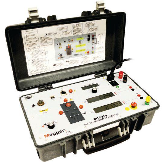
Megger’s new MTO250 retains the size and weight of our popular MTO series of winding resistance ohmmeters, while providing 50 A of test current with 50 V compliance voltage. The higher current can speed up testing time on 1,000 MVA transformers by up to 10 times when compared with traditional 10 A units. Its two channels allow simultaneous injection and testing of two windings, halving your test time. The core demagnetization


function has also been automated and improved so you can confidently put your transformer back in service.
REGISTER FOR OUR WEBINAR!
Visit www.us.megger.com/MTO250 to register for our upcoming October 16th webinar and to learn more about the MTO250, or call 1-800-723-2861 to schedule a demo.


Energize Your Future
AT THE PREMIER ELECTRICAL MAINTENANCE AND SAFETY EVENT

PowerTest heads to Fort Worth, Texas in 2016
If you ask the people of Fort Worth, Texas to talk about their city, they might recount beginnings as a small outpost on a lonely frontier. Unusual, perhaps, in a state where everything is bigger. But, eventually Fort Worth lived up to its state’s big reputation, by growing to the fifth-largest city in Texas with about 800,000 people today who are ready to take on modern challenges for expansion and growth. Its cattle and oil beginnings have been interwoven with an array of diverse industries.
PowerTest draws many parallels to Fort Worth. While no one can claim they have been lonely at PowerTest, the premier electrical maintenance and safety event has grown in similar fashion, seizing opportunities to help industry professionals grab the bull by the horns and jump to the top of their game. Fort Worth’s mission to work together to build a strong community describes the PowerTest commitment to build a network of knowledgeable professionals in the electrical safety industry, working together to uphold the standards and improve safety and reliability.
Deep in the heart of Texas, PowerTest 2016 comes to Fort Worth to plug into the city’s vast energy and connect attendees with leading industry experts, high power learning, and networking. Everything’s bigger in Texas, including the opportunities for you at PowerTest 2016.
FORT WORTH, TEXAS
MARCH 14-18, 2016

 Gary Norland Safety Presentations
Keynote Speaker: Gary Norland
Gary Norland is a husband, father, electrician and speaker.
Gary spent several years traveling and working various jobs in construction. He eventually went to work as a union maintenance electrician for his local pulp and paper mill – no more travel, a good income and stability.
He was a healthy 6’3”, 240 lbs. man who loved his work. His attitude was always about getting the job done. But one day his life changed when he was electrocuted by a 12,500 volt 200 amp overhead power line. He is here to share with you how hard work and dedication to your job should be a focus, but not your only focus. Gary wants others to understand that if you don’t take safety seriously, your life could resemble his in less than a second.


Monday
We’ve gathered leaders in the industry and will stage a full day of engaging, 45-minute presentations sure to expand your thinking and generate new ideas. Choose from 27 detailed presentation track topics.
Technical Presentations
ELECTRICAL SAFETY
• Protective Devices Maintenance and the Potential Impact on Arc Flash Incident Energy
Dennis Neitzel, AVO Training Institute, Inc.
• Beliefs Drive Behaviors
D. Ray Crow, DRC Consulting Ltd.
• Potential Impact of ISO 55000 on Maintenance Critical to Electrical Safety
H. Landis Floyd, Electrical Safety Group, Inc.
• Electrical Safety Management System Principles and Practices
Mike Doherty, Shermco Industries Canada
• Overview of an Electrical Safety Program Development Guide
Terry Becker, Electrical Safety Program Solutions, Inc.
• Arc-Flash Mitigation by Transformer Differential Relay Protection
Mose Ramieh III, PGTI
Randall Sagan, MBUSI
RELIABILITY
• System Testing of Protection Devices and Schemes – What Is It and Why Do We Need It?
Will Knapek, Benton Vandiver, and Alexander Apostolov, OMICRON electronics Corp. USA
• Improving Safety through Partial Discharge Surveying
Tony McGrail, Doble Engineering Company
• Transformer Failures and Case Study
Shuzhen Xu, FM Global
• Protecting Batteries that Protect Your Power System
Brandon Schuler, Electrical Reliability Services
• Power Quality Monitoring and Communications Standards Update
Ross Ignall, Dranetz Technologies
• How Disruptions in DC and Communications Affect Protection
Karl Zimmerman and David Costello, Schweitzer Engineering Laboratories, Inc.
EQUIPMENT
• Bushing Replacement – It Fits, But Will It Work?
Keith Hill, Doble Engineering Company
• Gaps in Motor Reliability
Lona Mazzeo, PDMA
• Reliability of Electrical Systems: From Testing to Monitoring
Alan Ross, SD Myers
• Understanding and Testing Motor Overload Protection and Thermal Models
Daniel Ransom, Doble Engineering Company
• Electric & Dielectric Condition Assessment of HV Current Transformers
Diego Robalino, Megger
• Understanding Transformer Differential Protection
J Scott Cooper, OMICRON electronics Corp. USA
CIRCUIT BREAKERS
• Power Factor Testing for SF6 Breakers
Rick Youngblood, Doble Engineering Company
• Vacuum Interrupters: Pressure Vs. Age – A Study of Vacuum Levels in 314 Service Age Vacuum Breakers
John Cadick, Cadick Corporation
• Effects of Low Resistance Measurement Instruments on Protection and Control Devices
Dinesh Chhajer and Jammie Lee, Megger
• Diagnostic Testing Practices for SF6 Filled Dead Tank Circuit Breakers
Charles Sweetser, OMICRON electronics Corp. USA
• What is TankLoss Index?
Rick Youngblood, Doble Engineering Company
• Circuit Breaker and Transducer: Where Do I Connect?
Robert Foster, Megger
TECHNICAL REPORTS SYMPOSIUM: COMMUNICATING WITH YOUR CLIENT
Moderator: Ron Widup, Shermco Industries
When personnel perform electrical testing and maintenance tasks in the field, a critical aspect of communication is providing a succinct and technically accurate summary of the work to the client or owner.
From a small single-item test or a large multi-craft maintenance outage and all projects in between, all require clear lines of communication, correct use of grammar, absence of slang terms, and generally must exhibit an overall professional style and framework.
This symposium will describe challenges, provide reference materials, and allow attendees to interact with subject matter experts on technical report structure and readability. A must attend event for all!
DAY 2 DAY 3 & 4
Tuesday MorningWednesday and Thursday
Join in the discussion during the Tuesday morning Panel Sessions. Select two of the four panel topics and get ready to learn from experts and peers alike.
Panels:
Electrical Safety
Cable Testing
Circuit Breaker Maintenance
Protection and Control
Tuesday Afternoon
POWERTEST 2016 TRADE SHOW
The PowerTest 2016 Trade Show promises more than 100 top-tier electrical power vendors whose mission is electrical safety and reliability. Enjoy a complimentary lunch and beverages as you tour the show and make connections. New this year, we have expanded the hours of the trade show. The PowerTest 2016 Trade Show will take place from 12:00 PM – 6:00 PM.
Tuesday Evening
DON’T MISS THE POWERTEST 2016 – POWERBASH RECEPTION!
A gathering you don’t want to miss. Enjoy the Western charm and music of Texas, celebrate the best of PowerTest, mix and mingle. Tuesday evening from 7:00 PM – 10:00 PM.

Two days are dedicated to high-power learning. Choose from 12 in-depth, four hour seminar presentations.
PowerTest 2016 Technical Seminars cover current topic and important industry issues that will broaden your horizons and expand your knowledge, preparing you for challenges ahead.
SEMINAR TITLES
• Basic Power Factor Theory
Keith Hill and Rick Youngblood, Doble Engineering Company
• Maintenance and Testing of Battery Systems
Tom Sandri, Shermco Industries
• Introduction to IEC61850 Protection
Jay Gosalia, Doble Engineering Company
• Power Factor Testing of Instrument Transformers
Keith Hill and Rick Youngblood, Doble Engineering Company
• Hands-On Protection Troubleshooting 2.0 Session
Karl Zimmerman and Dave Costello, Schweitzer Engineering Laboratories
• Risk Assessment Techniques Using NFPA 70E : A Primer
Jim White, Shermco Industries
• Cable Fault Location… Not for the Faint of Heart
Tom Sandri, Shermco Industries
• Commissioning of Power Transformers
Donald Platts, OMICRON electronics Corp. USA
• Human Error Reduction
Stacey Hefner, Practicing Perfection Institute
• Power Factor Testing of Power Transformers
Keith Hill and Rick Youngblood, Doble Engineering Company
• Event Analysis with Practical Examples for Testing and Commissioning
Karl Zimmerman and Dave Costello, Schweitzer Engineering Laboratories
• Understanding Ground Resistance and Resistivity Testing
Tom Sandri, Shermco Industries
DAY 5
Hospitality Suites
Enjoy some Texas Hospitality at the Sponsored Suites from 6 PM – 10 PM Monday evening. Talk with the experts, find solutions for your business, and catch up on the latest products and services as each sponsoring company shares its own brand of hospitality.
Friday
The Doble Laboratory Seminar is designed for engineers, chemists, and others responsible for reviewing data to interpret laboratory results to detect and identify problems within electric apparatus. The seminar will be interactive, combining theoretical background with practical experience and hands-on examples including case studies illustrating common problems found in the field.
EARLY BIRD REGISTRATION IS NOW OPEN
Or call 888-300-6382 (NETA)
Monday & Tuesday$995$895
Monday - Thursday$1895$1695
Single Day$580$550
Doble Seminar$445$445
REGISTER ON-LINE
To register for PowerTest 2016, save time by registering on-line. You’ll find a complete brochure and registration form available at www.powertest.org
HOTEL RESERVATIONS *
Omni Fort Worth Hotel 888.444.OMNI
1300 Houston Street Fort Worth, TX 76102
Reservation Deadline: February 5, 2016
Group Name: NETA/PowerTest Group Rate: $209
* Once you register for PowerTest 2016, you will receive a link via email to secure your hotel reservations at the Omni Fort Worth.
PAYMENT
NETA accepts all major credit cards. Save time and register on-line at www.powertest.org or call 888-300-6382 (NETA)
EXTRAS
PowerTest 2016 Technical Papers – Registered conference attendees will receive all PowerTest technical presentations on a USB drive on site in their registration bag.

Easy Steps for Registration
1. Go to www.powertest.org and review the complete PowerTest 2016 on-line brochure.
2. Decide the number of days you will attend the conference.
3. Tuesday attendees select up to two panels. (Cost of panels included in the registration fees.)
4. Wednesday attendees register for up to two seminars.
(Cost of seminars included if registered for Monday – Thursday.)
5. Thursday attendees register for up to two seminars (Cost of seminars included if registered for Monday – Thursday.)
6. Register for Doble Lab Seminar. (Cost of seminar is in addition to the registration fees.)
7. Sign up for Spouse/Guest Passes. (Cost of passes is in addition to the registration fees.)
8. Sign up for PowerTest 2016 conference polo shirts and select size. (Cost of polo shirts is in addition to the registration fees.)
SPONSORS

Sunday, March 13
9:00 AM – 4:00 PM
Megger Best Practices
Megger’s seminar will address many of the critical and costly aspects of substation maintenance. The interactive session will feature practical presentations on current methods and practices to help ensure the reliability of high-voltage circuit breakers, power transformers, and batteries. You must preregister for this event by contacting Megger: 214-330-3514
Monday, March 14
12:00 PM – 2:00 PM
Power DB User Group
Annual User’s Group Meeting open to licensed users of PowerDB Pro Software. Agenda will include presentations by the PowerDB Pro development team as well as utility, industrial and contractor groups discussing how this product is an integral part of their business operations.
5:00 PM – 6:00 PM
New Product Forum
Attendees will have the opportunity to learn about dozens of the latest products and innovations, major expansions, and significant improvements by the leading industry-specific manufacturers and suppliers at the Tuesday Trade Show. Stay until the end for the chance to win an exclusive prize! Must be present to win.
SPOUSE/GUEST PASS
A special lounge exclusively for spouses and guests of PowerTest attendees, stocked daily with light refreshments and information on local activities. Includes admission to Hospitality Suites Monday evening, Tuesday Trade Show, and Tuesday evening PowerBash reception. $75 per person
SOCIAL PASS
The Social Pass includes admission to the Hospitality Suites, Trade Show, and the PowerBash reception. $50 per person
COVER STORY

71 Battery Discharge Testing: Implementing NERC Standards and Field Experiences
As the electrical grid ages and expands, it is more apparent that testing and maintenance is critical to the reliability of the network. While many utilities have developed maintenance plans, regulatory committees such as the Federal Energy Regulatory Commission (FERC) and North American Electric Reliability Corporation (NERC) havesetforthmandatestoensurethatthe have set forth mandates to ensure that the equipment related to protection and controls is being maintained properly.
Dinesh Chhajer and Robert Foster, Megger
FEATURES
7 President’s Desk
Ron Widup, Shermco Industries
NETA President
52 How to Maintain Station Batteries
Tom Sandri, Shermco Industries
60 NERC Requirements for Substation DC Supply Systems
Lynn Hamrick, Shermco Industries
IN EVERY
11 NFPA 70E and NETA
NFPA’s Research Report: Occupations Injuries from Electrical Shock and Arc Flash Events
Ron Widup and Jim White, Shermco Industries
14 Tech Quiz
Batteries and Battery Chargers
Jim White, Shermco Industries
18 Niche Market
A Primer on Substation Battery Systems
Lynn Hamrick, Shermco Industries
28 No-Outage Corner
How New PD Technology Can Make You Hero of the Day
Don A. Genutis, Halco Testing Services
36Tech Tips
Personal Protective Grounding
Jeff Jowett, Megger
42 Safety Corner
Human Error & Safety
Paul Chamberlain, American Electrical Testing Co., Inc.
INDUSTRY TOPICS
88Evolution of Power System Protection Testing
Ed Khan, Doble Engineering Company
98 On-Line Partial Discharge Testing: Introduction to Detection and Analysis of Electromagnetic and Acoustic Partial Discharge Signals
Louis Nemec, Power Monitoring and Diagnostic Technology Ltd.
106 Testing Numerical Distribution Relays Using Relay Vendor Software Tools
Steve Turner, Beckwith Electric Company, Inc.
ADVANCEMENTS IN TECHNOLOGY
83 Powering Up the Latest HV Circuit Breaker Testing Technologies
Charles Sweetser, OMICRON electronics Corp. USA
SPECIFICATIONS
AND STANDARDS
112 ANSI/NETA Standards Update
116 IEEE – C57 Transformer Committee Report
Lorne Gara, Orbis Engineering Ltd.
NETA NEWS
24 NETA Attends the 2015 Saskatchewan Electrical Symposium on Electrical Power System Safety
Jill Howell, NETA
35 NETA Welcomes a New President and Plans for Fiscal 2016 Kristen Wicks, NETA
48NETA Welcomes Premier Power Maintenance as a NETA Accredited Company
NETA NEWS – SETTING THE STANDARD
80NETA Connects with Utility Industry Leaders
Jill Howell, NETA
120NETA Travels to Calgary, Alberta to Train Facility Maintenance Supervisors and Electrical Engineers on the ANSI/NETA Standards Jill Howell, NETA
NETA NEWS – IMPORTANT LISTS
124NETA Accredited Companies
130Advertiser List

Reliable Power System Solutions
We deliver optimum system reliability and performance while reducing the chances of costly unplanned power outages. Whether you need acceptance
es testing or preventive maintenance, depend on EnerGTest to keep the power on.
Serving clients in Pennsylvania, Delaware, New Jersey, Maryland, Washington, DC and New England.

3050 Old Centre Avenue, Suite 102
Portage, MI 49024
Toll free: 888.300.NETA (6382)
Phone: 269.488.NETA (6382)
Fax: 269.488.6383
neta@netaworld.org
www.netaworld.org
EXECUTIVEDIRECTOR: Jayne Tanz, CMP
NETA Officers
PRESIDENT: Ron Widup, Shermco Industries
FIRSTVICEPRESIDENT: Jim Cialdea, Three-C Electrical Co., Inc.
SECONDVICEPRESIDENT: Scott Blizard, American Electrical Testing Co., Inc.
SECRETARY: Mose Ramieh, Power & Generation Testing, Inc.
TREASURER: John White, Sigma Six Solutions
NETA Board of Directors
Ken Bassett (Potomac Testing, Inc.)
Scott Blizard (American Electrical Testing Co., Inc.)
Jim Cialdea (Three-C Electrical Co., Inc.)
Lorne Gara (Orbis Engineering Field Services, Ltd.)
Roderic Hageman (PRIT Service, Inc.)
David Huffman (Power Systems Testing)
Alan Peterson (Utility Service Corporation)
Mose Ramieh (Power & Generation Testing, Inc.)
Bob Sheppard (Southwest Energy Services, LLC)
John White (Sigma Six Solutions)
Ron Widup (Shermco Industries)
NETA World Staff
TECHNICALEDITOR: Roderic L. Hageman, Tim Cotter
ASSOCIATEEDITORS: Resa Pickel
MANAGINGEDITOR: Jayne Tanz, CMP
ADVERTISINGMANAGER: Laura McDonald
DESIGNANDPRODUCTION: Hour Custom Publishing
NETA Committee Chairs
CONFERENCE: Ron Widup; MEMBERSHIP: Ken Bassett; PROMOTIONS/MARKETING: Scott Blizard; SAFETY: Scott Blizard and Jim White; TECHNICAL: Alan Peterson; TECHNICALEXAM: Ron Widup; CONTINUINGTECHNICALDEVELOPMENT: David Huffman; CONTINUINGTECHNICALDEVELOPMENT: David Huffman; TRAINING: Kerry Heid; FINANCE: John White; NOMINATIONS: Alan Peterson; STRATEGY: Mose Ramieh; ALLIANCEPROGRAM: Jim Cialdea
© Copyright 2015, NETA
NOTICE AND DISCLAIMER
NETA World is published quarterly by the InterNational Electrical Testing Association. Opinions, views and conclusions expressed in articles herein are those of the authors and not necessarily those of NETA. Publication herein does not constitute or imply endorsement of any opinion, product, or service by NETA, its directors, officers, members, employees or agents (herein “NETA”).
All technical data in this publication reflects the experience of individuals using specific tools, products, equipment and components under specific conditions and circumstances which may or may not be fully reported and over which NETA has neither exercised nor reserved control. Such data has not been independently tested or otherwise verified by NETA.
NETA MAKES NO ENDORSEMENT, REPRESENTATION OR WARRANTY AS TO ANY OPINION, PRODUCT OR SERVICE REFERENCED OR ADVERTISED IN THIS PUBLICATION. NETA EXPRESSLY DISCLAIMS ANY AND ALL LIABILITY TO ANY CONSUMER, PURCHASER OR ANY OTHER PERSON USING ANY PRODUCT OR SERVICE REFERENCED OR ADVERTISED HEREIN FOR ANY INJURIES OR DAMAGES OF ANY KIND WHATSOEVER, INCLUDING, BUT NOT LIMITED TO ANY CONSEQUENTIAL, PUNITIVE, SPECIAL, INCIDENTAL, DIRECT OR INDIRECT DAMAGES. NETA FURTHER DISCLAIMS ANY AND ALL WARRANTIES, EXPRESS OF IMPLIED, INCLUDING, BUT NOT LIMITED TO, ANY IMPLIED WARRANTY OF FITNESS FOR A PARTICULAR PURPOSE.
ELECTRICAL TESTING SHALL BE PERFORMED ONLY BY TRAINED ELECTRICAL PERSONNEL AND SHALL BE SUPERVISED BY NETA CERTIFIED TECHNICIANS/ LEVEL III OR IV OR BY NICET CERTIFIED TECHNICIANS IN ELECTRICAL TESTING TECHNOLOGY/LEVEL III OR IV. FAILURE TO ADHERE TO ADEQUATE TRAINING, SAFETY REQUIREMENTS, AND APPLICABLE PROCEDURES MAY RESULT IN LOSS OF PRODUCTION, CATASTROPHIC EQUIPMENT FAILURE, SERIOUS INJURY OR DEATH.



To all the NETA Accredited Companies and industry partners, it is with humble thanks and appreciation that I accept the responsibility of president of the Association.
Dave Huffman has done a fantastic job guiding the NETA ship over the last two years, and it is in large part because of Dave’s leadership that we have grown as an association during his tenure as president. Thank you, Dave!
This is actually my second round as president, with my last time in this role going back to 1998-2000. No doubt, a lot of positive change and growth has occurred within the NETA organization since then!
The big news during my last presidency was the announcement of the approval and official acceptance of our first ANSI standard, ANSI/NETA ETT-2000, Standard for the Certification of Electrical Testing Technicians. It was put in to place on March 15, 2000, and since then, we have added three more ANSI standards to our NETA portfolio: (1) the maintenance testing specifications standard, (2) the acceptance testing specifications standard, and (3) the recently approved electrical commissioning specifications standard.
And just as the ETT document was created to codify the experience, education, and training requirements necessary for an individual to obtain a level of competency as an electrical test technician, NETA continues to carefully examine the qualifications of each NETA Accredited Company (NAC) in addition to certifying the individual technician employed by that NAC.
It’s NETA’s one-two punch of individual certification and company accreditation that provides a service to the electrical power industry like no other, a service that includes NETA leadership and influence in standardsmaking organizations; electrical safety initiatives; federal, state, and local governments; and the industries we serve across a whole host of sectors and markets.
Thank you.
Ron Widup President InterNational Electrical Testing Associationhe o obtain a level of tinues to yed by that NAC. and company wer like influence in standardsal, state, and local e host of sectors s Review r, it is an honor to orks and what e after all,
As a NETA board member, a member of the Standards Review Council, Exam committee chair and PowerTest conference chair, it is an honor to help all of you in any way I can. Please let me know what works and what doesn’t — and participate in the Association — because after all, you get out what you put in.


IN HOUSTON
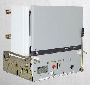
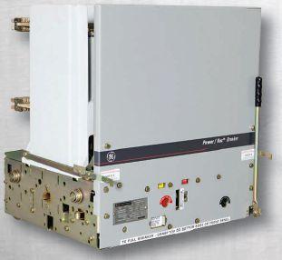
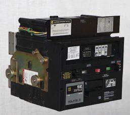
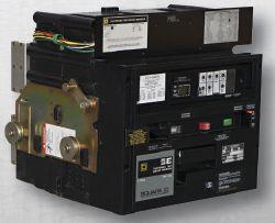
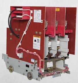
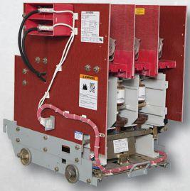
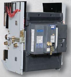
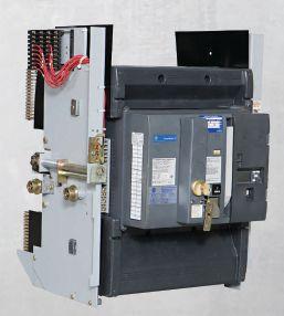
Electro Rent is proud to introduce its new Regional Service Center, serving your test needs better and faster than ever with experienced customer support 24x7. If it tests, we’ve got it— and we’re ready to deliver in Houston.


We Buy, Sell, Trade, Calibrate, Repair
Featuring quality, reliable, on-time service and support for all brands and types of solid state power electronics.
Power electronics are our business
Let us suppoort you with our quality repair, calibration and servicing of your solid state equipment. We also buy, sell and trade:
•Communications devices for power equipment
•Protective relays
•Circuit breaker trip devices
•Motor overload relays
•Rating plugs










NFPA’S RESEARCH REPORT: RESEARCH
OCCUPATIONAL INJURIES FROM ELECTRICAL SHOCK AND ARC FLASH EVENTS
BY RON WIDUP AND JIM WHITE, Shermco IndustriesNFPA recently released a research report titled Occupational Injuries from Electrical Shock and Arc Flash Events . The report analyzed OSHA studies as well as indicators from the Bureau of Labor Statistics (BLS) along with other sources of data. The report includes important information of direct concern to all NETA Accredited Companies and their employees. David Dini of Underwriter’s Laboratories (UL), Chair of the NFPA 70E Technical Committee, coauthored the report along with Dr. Richard Campbell who works for NFPA.
From 2003 through 2013, approximately 6,000 fatalities and 24,100 non-fatal injuries occurred from electrical hazards. While fatalities have steadily decreased over this time period, the number of electrical hazard injuries varies from year to year. The report did note that the number of injuries from electrical hazards was lowest from 2010 through 2013, with 1,700 injuries in 2013. The highest number of electricallyrelated injuries was 2,950 recorded in 2005. Compared to the general industry workforce, the injury rate from electrical hazards remains fairly steady at 0.2 to 0.3 injuries per 10,000 workers. Figure 1 illustrates the decline in fatal electrical injuries from 1992 to 2013.
The BLS changed the event injury codes in 2010, making data comparison before and after that date difficult. That being said, the leading event causing death from electrical hazards was the category “Contact With Overhead Power Lines,” which accounted for 46 percent of



Figure 1: Fatal Work-Related Electrical Injuries 1992-2013
From NFPA Report Titled Occupational Injuries from Electrical Shock and Arc Flash Events
recorded fatalities, while accounting for only two percent of non-fatal injuries. Figure 2 shows events with the highest percentage of fatalities.

THE NFPA 70E AND NETA
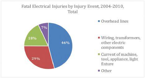
Figure 2: Fatal Electrical Injuries By Event 2004-2010 From NFPA Report Titled Occupational Injuries from Electrical Shock and Arc Flash Events
Figure 3 shows non-fatal electrical events during the same period. The construction industry had the highest number of fatal and non-fatal injuries. Note that non-fatal injuries are not minor injuries; they have to be a recordable injury, which means they required more than first-aid treatment and included a doctor’s care.
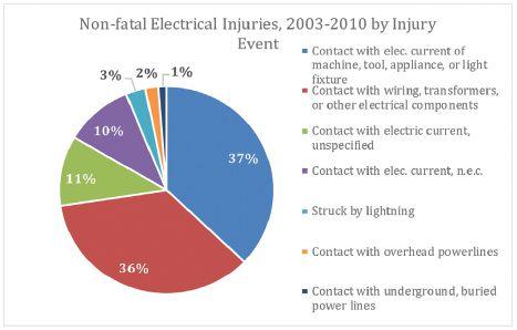
Figure 3: Non-Fatal Electrical Injury Events From NFPA Report Titled Occupational Injuries from Electrical Shock and Arc Flash Events
IT’S ABOUT ALL OF US
Construction workers have higher injury and fatality rates than other workers in general industry and are four times as likely to be electrocuted. Young construction workers (age 16 to 19) have the greatest risk of being electrocuted. Figure 4 shows work-related electrical fatalities by industry.

Figure 4: Work-Related Electrical Fatalities, By Industry 2004-2013 From NFPA Report Titled Occupational Injuries from Electrical Shock and Arc Flash Events
Some other interesting facts from this report:
• The need for training is emphasized in a number of studies.
• A study of burn center patients revealed that 69 percent of patients injured at work identified themselves as electrical workers.
• Another corporate study found that 40 percent of electrical incidents at 250 volts or less involved individuals who did not understand the risks involved with low voltage, thinking it only applied to highvoltage work.
• 50 percent of electrical incidents involve non-electrical workers, indicating the need for electrical safety training for this group.
• Construction industry employers with fewer than 10 employees have the highest rate of fatalities.
• One study at a Michigan burn center found that 34 percent of patients injured on the job received arc flash injuries, with the remaining 66 percent experienced injuries from direct contact with electricity.
• An Ontario, Canada burn center study found that 55 percent of patients injured on the job were from electrical arc flash, and 37 percent were from direct contact with electricity.
• A recent study of 54 workers injured in 40 arc flash events found that half of those injured were not wearing gloves or arc-rated face shields, and two-thirds did not conduct a risk assessment.

THE HIGH COST OF BEING INJURED
The direct costs associated with electrical injuries are fairly straightforward. These costs include workers’ compensation payments, medical costs, legal expenses, and rehabilitation. Indirect costs include work stoppage, administrative expenses related to the injury, property damage and repair, training and compensation for replacement workers, lost productivity, fines, and potential increases in absenteeism or decreasesinmorale.OSHAestimatesthat decreases in morale. OSHA estimates that indirectcostscanbe4.5timesthatofthe indirect costs can be 4.5 times that of the direct costs, but the American Society of Safety Engineers estimates they can be as high as 20 times direct costs. One recent paper states that none of the published ratios are valid because indirect costs have risen at a much greater rate than direct costs in the past 15 years. (Manuele, 2011)
One study of 62 work-related electrical injuries puts direct costs at $49,823, which is $80,023 in 2014 dollars. (Lutton, 1994)
A 2006 study estimated costs associated with electrical arc flash injuries between September 2000 and December 2005 in excess of $1.3 million. (Washington State Department of Labor and Industries, 2006) Although costs may be difficult to estimate, it is evident that a serious electrical injury will be very expensive, not only for the employee but also for the employer.
SUMMARY
The report is quite detailed and contains much moreinformationthancanbeincludedinthis more information than can be included in this column. It is very comprehensive and uses multiple peer-reviewed studies, as well as data fromtheBLSandOSHA.Loadedwithfactsand from the BLS and OSHA. Loaded with facts and data, the report is not easy reading. However, it provides a broader look at electrically-related injuries and fatalities than what has been previously available, and for that reason alone, NETAmembersareadvisedtoreviewit. NETA members are advised to review it.
NETA and its member companies work hard to provide a safe workplace for their employees. What is clear in this report is that many injuries
and fatalities are the result of improper or inadequate training. It begs the question: “How qualified are your qualified workers?”
To download a free PDF of the report at www.nfpa. org, just type the report name in the search field.
WecommendNFPAandtheauthorsforthis We commend NFPA and the authors for this informative and very relevant research regarding electrical safety.
REFERENCES
Lutton CE (1994). Economic Impact of Injuries Associated with ElectricalEvents. Electrical Events. Annals of the New York Academy of Sciences 720:272-276.
Manuele FA (2011). Accident Costs: Rethinking Ratios of Indirect to Direct Costs. Professional Safety, Journal of the American Society of Safety Engineers 56:39-47.
Washington State Department of Labor and Industries (2006). Arc Flash/Blast. Burn Injury Facts. Olympia, WA: Report #86-1-2006. # 86-1-2006.
NFPA(2015). NFPA (2015). Occupational Injuries From Electrical Shock and Arc Flash Events.
Ron Widup and Jim White areNETA’s are NETA’s representatives to NFPA Technical Committee 70E (Electrical Safety Requirements for Employee Workplaces). Both gentlemen are employees of Shermco Industries in Dallas, Texas, a NETA Accredited Company. Ron Widup is CEO of Shermco and has been with the company since 1983. He is a Principal member of the Technical Committee on “Electrical Safety in the Workplace” (NFPA 70E) and a Principal member of the National ElectricalCode(NFPA70)Code Electrical Code (NFPA 70) Code Panel 11. He is also a member of the technicalcommittee“Recommended technical committee “Recommended Practice for Electrical Equipment Maintenance” (NFPA 70B), and a member of the NETA Board of Directors and Standards Review Council. Jim White is nationally recognized for technical skills and safety training in the electrical power systems industry. He is the Training Director for Shermco Industries, and has spent the last twenty years directly involved in technical skills and safety training for electrical power system technicians. Jim is a Principal member of NFPA 70B respresenting Shermco Industries, NETA’s alternate member of NFPA 70E, and a member of ASTM F18 Committee “Electrical Protective Equipment for Workers”.


James R. (Jim) White is the Training Director of Shermco Industries, Inc., in Dallas, Texas. He is the principal member on the NFPA technical committee
“Recommended Practice for Electrical Equipment Maintenance” (NFPA 70B). Jim represents NETA as an alternate member of the NFPA Technical Committee “Electrical Safety in the Workplace” (NFPA 70E) and represents NETA on the ASTM F18 Committee “Electrical Protective Equipment For Workers”. Jim is an IEEE Senior Member and in 2011 received the IEEE/PCIC Electrical Safety Excellence award. Jim is a past Chairman (2008) of the IEEE Electrical Safety Workshop (ESW).


No.111 No. 111
BY JIM WHITE, Shermco Industries


BATTERIES AND BATTERY CHARGERS

Batteries and their supporting charging equipment can easily be overlooked — until they’re needed. Many facilities use a battery bank to supply dc operating current for opening and closing circuit breakers, spring-charging motors, and indicators. Without the dc supply available, circuit breakers will not operate.
1. One indication that a vented lead-acid battery is in trouble is when its internal impedance increases ___ percent above its as-installed impedance.
a. 5 percent
b. 20 percent
c. 30 percent
d. 45 percent
2. Which of the following is not an example of a valve-regulated lead-acid (VRLA) battery?
a. Nickel-Metal Hydride
b. Gel cell
c. Absorbed glass mat
d. Maintenance free
3. Sulfation in flooded-cell lead-acid batteries is indicated by:
a. Streaks of oil on the surface of the electrolyte
b. Brownish nodules adhering to the case
c. White salts appearing on the surface of the plates
d. White milky substance that appears on the cells and jar
4. When performing a load test on a battery bank, what percent remaining capacity indicates the need to replace the batteries?
a. 20 percent
b. 40 percent
c. 60 percent
d. 80 percent
5. The only repair for sulfation is to:
a. Equalize and increase float voltage
b. Use a mixture of boric acid and potassium hydroxide
c. Replace the batteries with new ones
d. Retighten all intercell connections
the test equipment answer
We support testing
Protective Relays and Metering
Batteries and UPS
Transformers
VLF, Tan Delta and Partial Discharge
Cable fault location
Substations & High Voltage Circuit Breakers
SF6 Analysis
Low & Medium Voltage Circuit Breakers
Motors and Rotating Apparatus
Power Monitoring


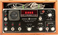

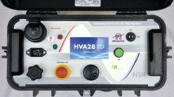


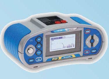


SUBSTATION BATTERY
 BY LYNN HAMRICK, ShermcoIndustries

INTRODUCTION — THE BATTERY SYSTEM
A battery consists of two or more cells electrically connected to form a discrete electrical source. These electrical sources are typically described in terms of dc voltage and amp-hour ratings. A cell is the basic electrochemical unit used to store electrical energy. Cells are usually vented or sealed. Vented cells are described as wet, vented lead-acid (VLA), or flooded lead-acid (FLA); when properly maintained, they typically last between 15 to 20 years before replacement. Sealed cells are described as valve-regulated lead-acid (VRLA) and, when properly maintained, typically last between five to 10 years before replacement. Another type of vented cell is the nickel-cadmium (NiCad) cell.
A battery combined with a charging and alarming system is referred to as a battery system. Substation battery systems operate at nominal voltages ranging from 44 V dc to 250 V dc with 125 V dc being the most frequent application. Most substation battery systems utilize either VLA or VRLA cells due to the cost and experience with these types of battery systems. However, NiCad cells are also in use. The figure below provides a simple schematic of a battery system.


In this article, the electrochemistry of substation batteries systems associated with VLA, VRLA, and NiCad batteries will be discussed. Additionally, a table of the pros and cons associated with each battery type is provided.
THE LEAD-ACID BATTERY
For a lead-acid battery like the VLA or VRLA type, lead dioxide (PbO 2) is the active ) material in the positive electrode and lead (Pb) is the active material in the negative electrode.Thebasicelectrochemicalreaction electrode. The basic electrochemical reaction equation for a lead-acid battery is:
Pb+2H Pb + 2H 2SO 4 +PbO + PbO 2 2PbSO 4 + 2H 2O + energy
The electrolyte in the battery is the sulfuric acid (H 2 SO 4 ) and the water (H 2 O) associated withthechemicalreaction.Thedirection with the chemical reaction. The direction of the reaction depends on whether the battery is charging or discharging. In a discharging battery, the lead dioxide and leadreactwiththesulfuricacidtocreate lead react with the sulfuric acid to create lead sulfate (PbSO 4 ), water, and energy. When the battery is being charged, the cycle is reversed, with energy being added (charging) and the lead sulfate and water electrochemically reacting to form lead and leaddioxide. lead dioxide.
Lead dioxide, the active material in the positive electrode, is in the same family as rust (FeO 2 ), which is considered a corrosive molecule. When charging a lead-acid battery, the reaction is reforming the corrosive layer of the positive electrode, which is necessary for optimal battery performance. To properly corrode the positive electrode, the battery voltage has to reach and then slightly exceed the gassing potential of the battery. When a battery is charging, the electrolytic breakdown of the water in the electrolyte produces oxygen on the positive plates and hydrogen on the negative plates. This is normal. However, if a high charging rate is continued after the battery has been
brought to its gassing voltage, the gassing becomes excessive, and abnormal amounts of hydrogen and oxygen gases are produced.
The best indication of excessive gassing is a very noticeable bubbling action of the electrolyte as well as high electrolyte temperature. Some gassing in the electrolyte is beneficial since it acts to stir the liquid. Without gassing, electrolyte stratification can occur, where the heavier electrolyte sinkstothebottomofthecell.Inthe sinks to the bottom of the cell. In the electrolyte, the sulfuric acid is heavier than water, so the acid will sink and concentrate at the bottom of the battery. Therefore, an inadequate charging environment will result in ineffective corrosion of the positive plate and inadequate gassing, which will lead to electrolyte stratification and reduced performance and shortened life of the battery.
In a new battery, the electrochemical reaction occurs efficiently. Unfortunately, as a battery ages, sulfation occurs. Sulfation is the process where the lead (Pb) and sulfates (SO 4 ) bond and form crystals. In a crystalline form, more energy is required to break the bond; the longer the crystal lasts and grows, the more difficult this bond is to break. These growing crystals of lead sulfateareinsoluble.Theformationof sulfate are insoluble. The formation of these crystals can cause the plate material to warp, which can cause the case to bulge or push adjacent plates together. Further, electrolyte stratification can cause the lower portion of the plates to become inactive, which enhances the sulfation process.
Undercharging a battery — even to a small degree — can lead to excessive sulfation. Thesameistrueofbatteriesthathavebeen The same is true of batteries that have been left standing in an undercharged state for an extended period. When batteries are left standing in a partially charged condition, high temperatures rapidly accelerate sulfation. The cells of a sulfated battery will have low specific gravity and open circuit voltage readings. On charge, voltage readings will
NICHE MARKET TESTING
be unusually high. The battery will not become fully charged after a normal charging cycle when sulfation has taken place over a prolonged period.
As a safety measure, VRLA batteries contain a resealable vent for handling the buildup of pressure during overcharges. The primary feature that distinguishes the VRLA battery from the flooded, VLA battery is an immobilized electrolyte .
As stated earlier, lead acid batteries basically consist of two types, the vented lead acid (VLA) or flooded battery and the valveregulated lead acid battery (VRLA). Both batteries utilize the same chemical reaction to perform their purpose. Flooded batteries contain flat pasted plates that are submerged in an electrolyte pool, are not recombining, and can vent flammable gases. A VRLA cell is made up of positive and negative electrodes with spirally wound separators. The electrodes contain lead grids affixed with lead oxides, which are converted to the appropriate materials when the cell is initially charged. As a safety measure, VRLA batteries contain a resealable vent for handling the buildup of pressure during overcharges. The primary feature that distinguishes the VRLA battery from the flooded, VLA battery is an immobilized electrolyte. Immobilization of the electrolyte is achieved by either gelling the electrolyte or by using glass mat separators to absorb the electrolyte. Thus the VRLA battery is sealed versus flooded.
THE NICKEL-CADMIUM BATTERY
The cell is the basic unit of the NiCad battery. It consists of positive and negative plates, separators, electrolyte, cell vent, and cell container. The positive plates are made from a porous plaque on which nickel-hydroxide has been deposited. The negative plates
are made from similar plaques on which cadmium-hydroxide is deposited. The plates are separated from each other by a continuous strip of porous plastic. Typically, the electrolyte used in the NiCad battery is a 30 percent solution of potassium hydroxide (KOH) in distilled water. The specific gravity of the electrolyte is usually between 1.240 and 1.300 at room temperature. The basic reaction in a potassium hydroxide (alkaline) electrolyte is:
It must be noted that no appreciable changes occur in the electrolyte during charge or discharge. Because of this, the battery charge cannot be determined by a specific gravity check of the electrolyte (like with a lead-acid battery). The electrolyte level should be maintained just above the tops of the plates.
When a charging current is applied to a NiCad battery, the negative plates lose oxygen and begin forming metallic cadmium. The active material of the positive plates, nickel-hydroxide, becomes more highly oxidized. This process continues while the charging current is applied or until all the oxygen is removed from the negative plates and only cadmium remains. Toward the end of the charging cycle, the cells emit gas; this will also occur if the cells are overcharged. The gas is caused by decomposition of the water in the electrolyte into hydrogen at the negative plates and oxygen at the positive plates. The voltage used during charging, as well as the temperature, determines when gassing will occur. To completely charge a NiCad battery, some gassing, however slight, must take place; thus, some water will be used.
The chemical action is reversed during discharge. The positive plates slowly give up oxygen, which is regained by the negative plates. This process results in chemical
energy converting into electrical energy. During discharge, the plates absorb a quantity of the electrolyte. On recharge, the electrolyte level actually rises; at full charge, the electrolyte will be at its highest level. Therefore, water should be added only when the battery is fully charged.
The electrolyte in a NiCad battery, with potassium hydroxide, is chemically opposite to the sulphuric acid used in a lead-acid battery. Fumes from a lead-acid battery can actually contaminate the electrolyte in a NiCad battery. Every possible precaution must be taken to keep anything containing acid away from NiCad battery shops. The potassium hydroxide electrolyte used in NiCad batteries is extremely corrosive. When potassium hydroxide and distilled water are mixed to make the electrolyte, the potassium hydroxide should be slowly added to the water, not vice versa. The table below provides a brief comparison of the different cell types discussed previously.
BATTERY MAINTENANCE AND TESTING STANDARDS
The following standards are available from IEEE and provide recommended maintenance activities associated with each of these battery cell types:
•IEEE Standard 450-2010, IEEE Recommended Practice for Maintenance, Testing, and Replacement of Vented Lead-Acid Batteries for Stationary Applications
•IEEE Standard 1188-2005, IEEE Recommended Practice for Maintenance, Testing, and Replacement of Valve-Regulated Lead-Acid (VRLA) Batteries for Stationary Applications
•IEEE Standard 1106-2005, IEEE Recommended Practice for Installation, Maintenance, Testing, and Replacement of Vented Nickel-Cadmium Batteries for Stationary Applications.
A substation’s protective systems utilize dc supply systems in support of critical protection systems. Most of these systems include batteries for improved reliability and
NICHE MARKET TESTING
availability. Because of this, much time and effort is devoted to selecting the battery type to maximize the system’s operating reliability and life. Most substation battery systems utilize battery systems with VLA or VRLA cells due to the cost and experience with these types of battery systems. In some cases, NiCad cells have been substituted. To appropriately maintain a battery system, one must first understand the chemistry associated with the battery system. Based on the battery chemistry and the criticality of the system, a very specific preventive maintenance program can then be implemented. IEEE has developed standards to assist users in maintaining, testing, and replacing each of the battery types discussed.


Lynn Hamrick brings over 25 years of working knowledge in design, permitting, construction, and startup of mechanical, electrical, and instrumentation and controls projects as well as experience in the operation and maintenance of facilities.
Lynn is a Professional Engineer, Certified Energy Manager and has a BS in Nuclear Engineering from the University of Tennessee.


PaulHebertandhiswifeLorrainekickedoffthe2015 Paul Hebert and his wife Lorraine kicked off the 2015 Saskatchewan Electrical Symposium with a compelling introduction to a full day of safety presentations. Paul, an experienced lineman, was gripping a high-voltage cable when 14,000 volts surged through the line. Paul relayed the details of his survival and recovery, emphasizing important lessons learned, cautioning against becoming complacent and making assumptions, and underscoring the criticality of clear communications.
On May 6, 2015, the Saskatchewan Electrical Symposium drew electrical safety and maintenance industry professionals from across Canada. The event was hosted in Regina, Saskatchewan, by Shermco Industries, a NETA Accredited Company.
Fourteen training sessions were offered, including specific classes for managers and frontline technicians. Among the presenters were Jim White, Tom Sandri, and Mike Doherty from Shermco Industries. Joining the Shermco presenters were Andy Thorne, Cameco Corporation; Travis Wiens, FLIR Systems; Daniel Roberts, Schneider Electric Canada; Terry Becker, ESPS; Ray Anthony,
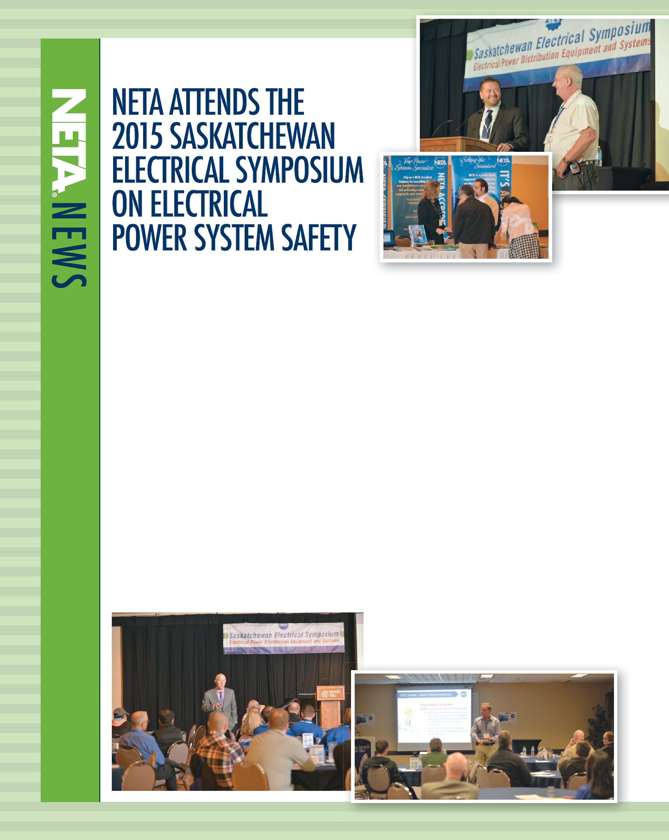
Saskatchewan Ministry of Labor Relations; and Don Beahm, D.B. Safety Solutions.
In addition, the symposium included a tradeshow exhibition, allowing 10 vendors to interact with attendees interested in learning about various new products and services. Attendees learned more about NETA, gaining an appreciation and understanding for NETA’s accreditation process, NETA Certified Technicians, as well as NETA standards, publications, and training courses.
Taking a page from the PowerTest conference model, the Saskatchewan Electrical Symposium also provided a chance for vendors to showcase their newest offerings viatheNewProductForum.Inameretwominutes via the New Product Forum. In a mere two minutes each, participants relayed information about how their newest products and services could help attendees accomplish their safety and testing goals.
NETA is pleased to have had the opportunity to participate in the Saskatchewan Electrical Symposium and supports the mission of raising awareness and understanding of electrical power systems maintenance and safety. To learn more about this event, please visit saskelectricalsymposium.com.

Continuing Our Tradition of Innovation
Vanguard Instruments has been at the forefront of developing innovative precision sub-station test instruments for over 20 years, and we are continuing our tradition with our latest products such as the CT-7000 S3 and CT-8000 S3 circuit breaker analyzers with Dual Ground testing feature and our new line of test instruments featuring convenient Bluetooth wireless interfaces. Visit us today at vanguard-instruments.com to find the latest solutions for all of your sub-station testing needs.




HOW NEW PD TECHNOLOGY CAN MAKE YOU HERO OF THE DAY
BY DON A. GENUTIS, Halco Testing ServicesThe electrical field testing business can be very trying. Often our work involves long, lonely hours. These hours may be far from home and sometimes in difficult environments or circumstances, or perhaps be under ambitious time constraints. For numerous reasons our best-made plans may require modifications and adjustments along the way, making quick thinking, knowledge of new technologies, improvising, and changing courses necessary to meet customer demands.
So why do we continue to endure these challenges? Reward. While monetary reward is appreciated, the satisfaction of knowing that you did a good job is what brings us back time and time again. And, every once in a while, there is that especially gratifying reward when we are actually the hero of the day.
Recently, I was in the field to perform cable partial discharge testing at a campus-like facility, consisting of an extensive 15kV class underground distribution system. This is a task I have performed hundreds of times, but this day, I was armed with the latest, most advanced cable partial-discharge testing technology. Having thoroughly studied this new technology in advance and conducted some dry run experiments in the lab, I was cautiously optimistic about how the day would go. Given that this new technology was not well known to my customer, I was also conscious of the fact that they would be looking over my shoulder throughout the day,

evaluating both my work and the new PD testing equipment.
Previous cable testing had been performed by another testing firm using standard PD test equipment, which did not fulfill expectations. Most recently, use of a standard PD testing instrument resulted in misdiagnoses of noise signals for PD. That led the customer to unnecessarily replace a perfectly good segment of cable and several good terminations, costing significant time and money. During this testing procedure, I explained the difference between the standard technology and the wavelet technology. As the day unfolded, the customer seemed optimistic and open-minded regarding the new technology.
Notmuchhasbeenwrittenabouton-linecable
Not much has been written about on-line cable PD testing because little has changed in the last several years. Recently, new advancements in computer algorithms have allowed for the recognition of small and moderate PD pulses
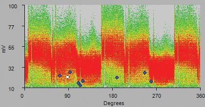
in heavy noise conditions. Having given up that this breakthrough would ever occur, my last cable PD column (NETA World Journal, Winter 2012) discussed the use of standard PD testing equipment, the need for filtering, and the compromises that must be taken in heavy noise conditions. These compromises include inhibiting the ability to look down the cable and only allowing the technician to “see” components close to the test point.
With partial discharge wavelet technology, these limitations no longer exist. As shown in Figure 1, newly perfected software can now
detect pulses characteristic of PD “underneath” thenoise. the noise.
PD-like waveforms are spotted by the software deep within the noise and separated out on the instrument display panel. The techniciancanclickonthePDwaveforms technician can click on the PD waveforms highlighted on the instrument’s display panel, analyze the computer’s assessment, and make final PD verifications (see Figure 2). The new technology is easy to use, makes system diagnostics nearly automatic, and the identificationofPDmuchmoreaccurate. identification of PD much more accurate. More details related to distinguishing PD


NO-OUTAGE CORNER
pulse characteristics will be featured in greater detail in a future No-Outage column.
Often spending grueling hours at the customer’s campus, on this particular Friday afternoon, I was happy to complete the job in only a few hours and jump into my air-conditioned vehicleforthe90-minutedrivebackhome vehicle for the 90-minute drive back home against Los Angeles traffic. Unfortunately, therewasanautoaccidentthataddedanhour there was an auto accident that added an hour to the journey, making it still a 14-hour day. But when I arrived home, I was still in good spirits from the gratifying day's work and the knowledge that new technology is always a beautiful thing.
As I sat down at home to remove my dusty shoes, my cell phone buzzed indicating a new email. I sat back, and as I read the following message from our customer and reflected on it, a tear came to my eye.
PARTIAL DISCHARGE WAVELET TECHNOLOGY
Partial discharge is caused by the deterioration of insulation materials. To prevent insulation breakdown and catastrophic failures, its detection and accurate measurement are very important. PD detection in cable systems is a promising approach in non-intrusive on-line tests. However, electrical interference from the background environment is a major barrier to improving its measuring accuracy.
The combination of wavelet analysis for revealing local features and entropy for measuring disorder can just fulfill the requirements of PD signal analysis and is thus investigated in this paper. Then, a wavelet entropy-based PD recognition method is proposed. The pulse features characterized by wavelet entropy are employed as the input pattern of a classifier constructed with feed-forward back-propagation neural network. Finally, some PD groups with noisy interferences are tested by a trained network. The recognition rate of real PD pulses demonstrates the proposed wavelet entropy-based method is effective in PD signal de-noising.
For the full-length paper, visit IEEE Xplore Library and search for the article titled, “Recognition of partial discharge using wavelet entropy and neural network for TEV measurement.”
Don,
Thanks for coming out today. What you do is so appreciated — you have no idea.
It makes one feel there is real care and hope for being able to manage a medium-voltage system.
You have no idea how much we appreciate your expertise, professionalism, and ability, and we know one thing for absolute certain — advancing this developing science of effective partial discharge analysis is going to save many innocent people’s lives in the future and many innocent people’s professions and careers as well. Nothing could be more sincere and from the heart because you know it's true what a difference this will make. I know this can be a truly thankless profession, but you're really doing something that broadly helps, even if many of those being helped don’t even necessarily know it, and this is NOT taken for granted.
Next time, it might be your turn to be hero of the day. Covet those times, and don’t forget that for every thank-you and smile that we receive from our customers, there are many other times that they feel just as much appreciation, but do not express it. Of course, we understand that the electrical testing technician’s job is important, saves lives, and ensures reliability, so we don’t necessarily need a pat on the back. I guess that’s why we keep coming back.
Don A. Genutis holds a BSEE from Carnegie-Mellon University. He has over 30 years of electrical testing experience. Don serves as President of Halco Testing Services based in Los Angeles, California.


www.powertest.org


Panels:







Times Square, New York City — NETA members and guests kept pace with the city that never sleeps.
NETA WELCOMES A NEW PRESIDENT AND PLANS FOR FISCAL 2016
BY KRISTEN WICKS, NETAAs a new fiscal year arrives each June, NETA welcomes new leadership to the helm as well as new plans for advancing the association. This year was no different, with Ron Widup presiding over his first NETA meetings as President at the June 2015 strategy, promotions and marketing, and board meetings at the Hyatt Times Square in New York City. These meetings allow the Board of Directors to take a retrospective review of the past year as they plan for the future of NETA’s many programs, assuring alignment with NETA’smissionandvision. NETA’s mission and vision.
NETA always packs a lot of business into each meeting, and these June sessions were no exception. Participant energy and enthusiasm for the discussions at hand were well-matched by the vibes outside the doors in Times Square: excitement, collaboration, and innovation. After a full slate of business, board nd members and their guests participated in their favorite part of NETA — the friendship and fellowship — as they joined each other for dinner and a Broadway show. New York may be the city that never sleeps, but NETA members kept pace just fine.
NETA 2016 Fiscal Planning in New York City
PERSONAL Protective

 BY JEFF JOWETT, Megger
It is a common expression in firearm safety that many a person has been killed by an unloaded gun. This, of course, refers to the consequences of carelessness or inattention to detail. The electrical of to industry has a clear parallel in the de-energized circuit; in ordinary speech, the equipment or circuit that has been (supposedly) turned off.
Even when effectively isolated from its own power source, electrical equipment in highenergy environments like switchyards and substations can still develop dangerous voltages from induction by nearby live circuits, as well as what the utilities refer to as an “event” — an unexpected rise in voltage fromadisturbanceonthelinesuchasa from a disturbance on the line such as a lightning stroke. An indispensable safeguard against such contingencies is the installation of protective grounds.


Personal protective grounding prevents accidental death or injury by minimizing the magnitude anddurationofshockhazard. and duration of shock hazard.
The description and implementation of protective grounding has been well established by organizations such as OSHA. Personal protective grounds provide maximum safety for personnel working on de-energized systems or equipment by equalizing voltage differences at the worksite.
(See Figure 1) The aim is to keep the voltage acrosstheworkeratasafelevelintheeventof across the worker at a safe level in the event of the equipment or system becoming accidentally energized from any possible source. Personal protective grounds dissipate static voltages and protect against induced voltages from adjacent energized systems. In addition, they enable protective devices to trip as quickly as possible.

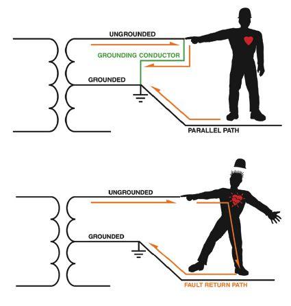
Figure 1: Consequences of Protected and Unprotected Circuits

OSHA 1910.333(c)(3) states:
If work is to be performed near overhead lines, the lines shall be de-energized and grounded, or other protective measures shall be provided before work is started. If the lines are to be de-energized, arrangements shall be made with the person or organization that operates or controls the electric circuits involved to de-energize and ground them.
The requirements for compliance on transmission anddistributionlinesareaddressedinOSHA and distribution lines are addressed in OSHA 1910.269(n). The application of grounds shall create an equipotential zone protecting the employee. The grounds shall be capable of conducting the maximum available fault current at the grounded point for the time necessary to clear the fault; the ampacity of a 2 AWG copper conductoristheminimum.Thecircuitmustbe conductor is the minimum. The circuit must be de-energized and tested for absence of nominal voltage before grounds are installed. The ground end of the grounding conductor must always be installed first, and then the other end is connected to the equipment to be serviced, using a live-line tool. Conversely, when the protective grounds are removed upon completion of the task, the conductor-endconnectionisremoved conductor-end connection is removed first, again using a live-line tool. When working on cablesatalocationremotefromtheterminal cables at a location remote from the terminal end, the terminal end may not be grounded if the possibility of hazardous transfer of potential exists. During testing procedures, if grounds need to be removed for test implementation, workers must use insulating equipment and be isolated from any hazard.
Situations may also arise where the installation of protective grounds is impracticable or would present greater hazards than working without. In such cases, the installation of protective grounds may be excused. As described in 1910.269(n) (2)(i)-(iii), lines and equipment may be treated as de-energized, provided three conditions are met: (1) Assurance that lines and equipment are de-energized under the provisions of paragraph (m) of this section, (2) no possibility of contact with another energized source exists, and (3) the hazard of induced voltage is not present.
Proper sizing of personal protective grounds is critical and must be implemented in detail because
protective grounding doesn’t merely contend with nominal current but also must be adequate for all available fault current. Protective grounds must be capable of withstanding all electrical and electromagnetic stresses. The requirement can be implemented with a three-step process:
Step One – Calculate the maximum available fault current for all interconnection points throughout the electrical system in question. Relative information includes the utility interconnection, transformer sizes and impedances, and conductor sizes and lengths. It may be presented in the form of a single line diagram, with symmetrical and asymmetrical fault currents notedforeachbus. noted for each bus.
Step Two – Determine the appropriate type and size of grounding conductors for each system part. Appropriate grounding conductor size is then incorporated into the Lock Out/Tag Out procedures.
Step Three – Thoroughly inspect grounding equipment prior to each use. Clamps, ferrules, serrated jaw inserts and the like should be inspected for tightness. The standard for inspection and test is ASTM F-2249, Standard Specification for In-Service Test Methods for Temporary Grounding Jumper Assemblies Used on De-Energized Electric Power Lines and Equipment.Thisconsistsofthree . This consists of three parts: (1) Testing grounding jumper assemblies on a time interval established by the user to ensure defectiveassembliesareremovedfromserviceina defective assemblies are removed from service in a timely manner; (2) retesting after performing any maintenance that may have affected the integrity of the assembly; and (3) retesting again after any assembly may have been subjected to short circuit or lightning surge.
Sometimes conflicting information exists in the literatureontheeffectsofcurrentonthehuman literature on the effects of current on the human body, but significant early research conducted by Charles Dalziel in the 1940s culminated in theformula: the formula:

Where I = current (amps), k isafunctionof is a function of shock energy, and t is time (seconds). The formula indicates a time/current relationship,
which is expressed as function of shock energy. The effect on the human body is based on the amount of current and the duration of exposure, such that k50 is 116 for a 110-lb body, and k70 is 157 for a 155-lb body. The formula can calculate current magnitude for heart fibrillation, producing a time/current curve as seen in Figure 2. Human body resistance is placed from 500 to 1000 ohms, hand to foot or hand to hand. This figure is profoundly affected in work situations by the wearing of insulating gloves and boots. But a contravening factor is that reclosers may not have been disabled, with short intervals between reclose not allowing the body to recover from a first shock before receiving a second. Shocks above the 600 V level may further reduce body resistance by puncturing the skin, thereby exposing internal organs, which have less resistance to higher current levels.
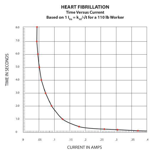
An example: A worker with a 110-lb body weight could receive a shock of 67 mA for three seconds before going into heart fibrillation, whereas a 155-lb worker would tolerate 91 mA for three seconds.
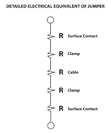
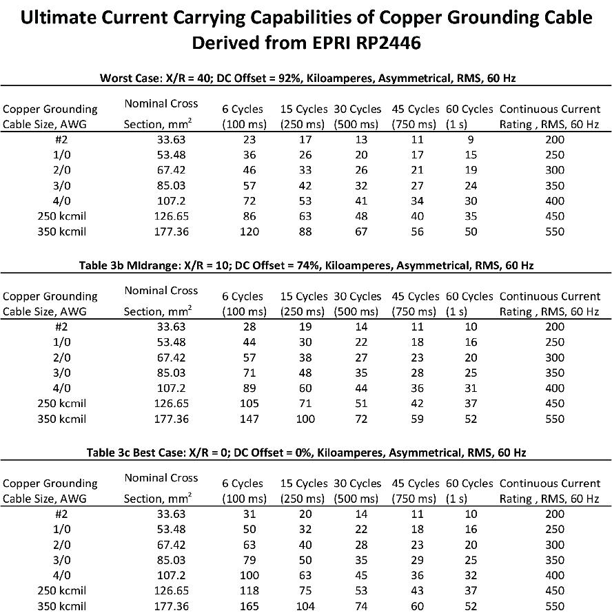
Accordingly, the protection afforded by Personal Protective Equipment (PPE) grounds is designed to reduce voltage drop across the worker’s body well below the value that would produce fibrillation, burns, or other injury. A successful equipotential grounding method places the worker in a parallel path with a jumper of sufficiently low resistance to divert all but a harmless level of current around, as opposed to through, the worker. (See Figure 3) Voltage rise across the worker is minimized, while fast clearing of protective devices is effectively implemented. The jumper must have adequate ampacity to maintain a low resistance during the fault clearance. The design of PPE grounding, therefore, must ensure that heart fibrillation current will never be reached under system fault conditions. Critical data is provided in Table 1, regarding the ampacity and resistance of various sizes and types of grounding conductors. A worst-case scenario is also provided in Table 1 because it would require significant calculations to determine dc offset and X/R ratio for various load and short-circuit situations. Updated Short Circuit and Coordination Studies are necessary to determine adequate sizing.
The next column in NETA World will continue with description of the parameters for safe and effective grounding equipment.
REFERENCES
Dalziel, Charles F., The Effects of Electric Shock on Man, IRE Trans. on Medical Electronics (PGME-5), May 1956. AVO Training Institute, Dallas, Texas

Jeffrey R. Jowett is a Senior Applications Engineer for Megger in Valley Forge, Pennsylvania, serving the manufacturing lines of Biddle, Megger, and multi-Amp for electrical test and measurement instrumentation. He holds a BS in Biology and Chemistry from Ursinus College. He was employed for 22 years with James G. Biddle Co. which became Biddle Instruments and is now Megger.




HUMAN ERROR &
 BY PAUL CHAMBERLAIN, American Electrical Testing Co., Inc.
What is human error? Human error is the outcome of an action that does not produce the human’s intended result(s). It can be summed up by saying things did not go as planned. James Reason stated, “Human error is a consequence, not a cause. Errors are shaped by upstream workplace and organizational factors… Only by understanding the context of the error can we hope to limit its reoccurrence.”
The 6 P rule (Proper Prior Planning Prevents Poor Performance) can go a long way to preventing a human error, but there is still that human factor. Human beings are fallible and make mistakes. Those mistakes are usually caused by only a few factors.
TIME PRESSURE
When employees rush to complete a project or a task, they can have a lapse of judgement. Missing steps, improper communication, and failing to recognize warning signs are just a few of the issues that can occur when rushing. Being in a rush is caused by either internal or externalforces. external forces.
Internal could mean a need to get home at the end of the day or scheduling conflicts with the individual’s personal life. A good example of external forces is a critical project that needs to be completed by the end of the week, but has been delayed due to rain. Perhaps internal forces are in play for the employee working
on the project because his son is scheduled to pitch his first high school baseball game that Friday evening, but the work is still unfinished. To make it to the game for the first pitch, the employee completes his tasks for the day quickly. Hopefully, rushing through the work does not produce any mistakes — but it can. And those mistakes can lead to incorrectly operated equipment, potential injuries, or worse.
External time pressure can occur when a boss or peer is pressuring another employee to complete the work quickly. Maybe they need to move on to another location or task, or maybe there is only a limited outage window that was impacted by some external force (e.g. other contractors eating up outage time).
Be aware of Mondays and Fridays. On Mondays, some employees may not be fully recovered from a full and exciting weekend. This can cause mental lapses in judgement due to being tired or not fully engaged in the work. On Fridays, they may be in a rush to get out the door and start an exciting weekend, causing mental disengagement with the task. Mental disengagement is not exclusive to Mondays and Fridays; it also applies after any prolonged absence from work, such as before and after long weekends, vacations, lay-offs, etc.
No matter where the need to rush comes from, there must always be the need to push back and realize that this time pressure can lead to a mistake. Take the time to slow things down; it is quicker to do things right once, then to do it wrong and have to do it a second time.
DISTRACTIONS
Being distracted either mentally or physically can lead to a lapse of judgement or a missed step. When doing something critical that requires intense awareness, always ensure that distractions are kept to a minimum. In this technological day and age, cellular phones are a major distraction. Make it a habit to power them down or put them elsewhere and on vibrate whenever doing something critical. Cell phones are a good example of mental and physical distraction. Using a phone requires a physical interaction to enableacallandtohaveaconversationwiththe enable a call and to have a conversation with the caller. Mentally, a caller is required to engage in the conversation and make judgement calls or opinions based upon the information the caller is sending or receiving.
Other distractions can include a change in work shift, which can contribute to tiredness and dulled senses. If the weather changes drastically from hot to cold or vice versa, it can beadistraction.Distractionscanalsocome be a distraction. Distractions can also come fromoutsidetheworkenvironment.Troubleat from outside the work environment. Trouble at home, kids getting bad grades, and money issues all contribute to a mental distraction, which can bedetrimentalintheworkenvironment. be detrimental in the work environment.
It is a good idea to always ensure that any distraction, whether a phone or not, is minimized during any act where improper action can cause significant consequences.

COMMUNICATION
Ensuring that a message is properly sent and received is critical. Using the phonetic alphabet (See Table 1) and numerals is necessary when communicating equipment identifications or other nomenclature. This prevents peers and other employees from going to the wrong equipment or potentially using incorrect or misheard settings.
It is always a good idea to use a three-part communication when doing critical tasks. Three-part communication consists of:
1. A sender saying a direction or information
2.Ar 2. A receiver repeating the information eceiver verbatim
3. The sender acknowledging that the informationiscorrect information is correct
Ifth If th e information is repeated back incorrectly, thenthesenderstatesthattheinformation then the sender states that the information is incorrect, and then repeats step 1. Using three-part communication ensures that the message sent is the message received.
As a receiver of information, it is also important to get all the information needed to successfully complete the task. This means that everything needs to be questioned. Question why certain test procedures are used, question why there was a lockout performed and by whom and when. To ensure that the big picture is achieved, get an understanding of all aspects of the job. As the sender of information, ensure that the receiver truly understands what is necessary. Emphasize and repeat the steps needed and the results expected. Write it down and give notestothereceiver.Thisensuresthatthere notes to the receiver. This ensures that there is complete understanding, whether it is between membersofaworkcreworifturnoverofwork members of a work crew or if turnover of work is conducted from one work group to another.
PLACE KEEPING
Place keeping is used to mark the steps in a procedure or work document that have been completed so that steps are not accidentally omitted or repeated. Use place keeping when using a procedure or work document to perform critical activities. When suspending performance of a procedure, place keeping is used to identify the last step completed. Prior to restarting the work, conduct a thorough re-review of the procedure.
FLAGGING AND OPERATIONAL BARRIERS
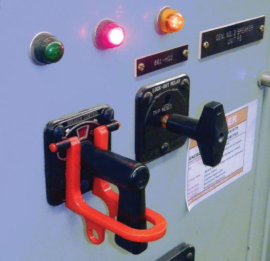
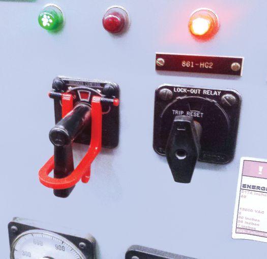
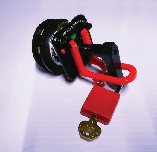
Flagging involves highlighting a component to improve the chances of performing actions on the correct component. Operational barriers are used to mark or cover components that are not to be worked on or manipulated during an evolution. Flagging and operational barriers are particularly helpful when several similar components are in close proximity to those affected by the work activity. Research indicates that several events can be attributed to an individual starting an activity on one component, taking a break or becoming otherwise distracted from the component, and returning only to perform manipulations on the wrong component.
THE BIG PICTURE
All of the previous human conditions contribute to an employee or peer making an error. The first and most effective means of reducing that
error is to first be fully engaged in the task at hand. Identify those things that may be a distraction or may contribute to a mistake, andeliminatethoseitemsfromtheworktask. and eliminate those items from the work task. Many accidents occur because the employee continued blindly on in a task without heeding any of the little warning signs that may occur. When something doesn’t seem right, stop, take a step back to reevaluate, and ask questions of the team performing the work. Find out why things aren’t right, and heed those little warnings. Be cognizant of any internal problems and acknowledge that they may affect the work — and discuss that with fellow workers. Doing this will minimize the possibility of a problem occurring.
Simple, everyday tools can help mitigate human fallibility. Taking notes with pen and paper is the old-school, tried-and-true method. Using laptops and scheduling programs are a newer methodology. Write things down so they won’t be forgotten, either on paper or electronically. Come up with plans and procedures for the task, and write them down step by step before the work begins. This helps ensure that the right skills, tools, equipment, and personnel are present for the work. Pre-job briefings are an effective means of documenting and communicating steps as well as hazards on the job. The more complex or unfamiliar a task is, the more complex the pre-job briefing must be. Ensure that all people affected by the task attend the pre-job briefing. This can include other contractors not directly involved in the scope of workbutwhoareinorneartheworkareawhere work but who are in or near the work area where the task is being performed.
Being aware of all contributing factors and planning for their mitigation helps make the work environment safer for all. Everyone makes mistakes, but we can identify and minimize the factorsthatcontributetothosemistakes. factors that contribute to those mistakes.
PaulChamberlain Paul Chamberlain has been the Safety Manager for American Electrical Testing Company Inc.since2009.Hehasbeeninthe Inc. since 2009. He has been in the safety field for the past 12 years, working for various companies and in various industries.HereceivedaBachelor’s industries. He received a Bachelor’s of Science degree from Massachusetts Maritime Academy.





Relevant information the electrical power systems industry, from testing procedures andtroubleshooting to encountered in the field. It’s real world learning at your fingertips.
Discover page after page of comprehensive, componentspecific, technical resources for both training and reference purposes.
The Handbooks bring together a collection of over of the best articles from past issues of NETA World Journal and the most well received technical presentations from NETA’s PowerTest conferences.
For more information on the NETA Handbooks or other NETA publications visit the NETA ookstore at www.netaworld.org or 888-300-6382 (NETA). $195* For the 13 volume set
15* For each issue * Additional cost for shipping and handling
Founded in 1985 by Andy and Eileen Templeman, PremierPowerMaintenancewasformedaroundthecore Premier Power Maintenance was formed around the core function of electrical testing and maintenance. Premier Power Maintenance has been family owned and operated since its inception. Premier’s five owners — Andy and Eileen, along with their children Kevin, Brian, and Megan — work daily with all team members, including field and office personnel. Premier Power Maintenance is a company grounded in family values, providing a relaxed, professional, and challenging atmosphere that encourages personal and professional growth.
Premier Power Maintenance prides itself on being extremely versatile, capable of servicing the entire spectrum of its customer’s distribution system needs up to 500 kV. Core competencies include safety/safety training, preventative maintenance/testing, commissioning,

engineering, repair, and modifications/retrofitting on all brands of electrical power apparatus.
Premier Power Maintenance’s corporate office is in Indianapolis, Indiana, with five supporting offices strategically located throughout the Midwest to best service its customer base. Each location is staffed with industryleading test technicians and engineers, combined with a vast array of state-of-the-art service, testing, and specialty equipment. This provides all customers with a tenured staff and the appropriate modern technology, allowing maximum efficiency on all projects and completion on budget, on time, and most importantly, safely.
Premier Power Maintenance is very excited to be a part of NETA. As the company continues to grow and expand, Premier Power Maintenance anticipates becoming an active participant in all aspects of NETA.

THE EXPERTS IN ELECTRICAL RELIABILITY
Comprehensive Electrical Testing and Maintenance

Commissioning and Startup Services
Engineering Services Power System and Coordination Studies
Predictive and Preventive Maintenance
Partial Discharge Testing and Monitoring
24/7 Emergency Service
FAILURE IS NOT AN OPTION. Ensuring the reliability of your electrical distribution system.


As the leading independent electrical testing, maintenance, and engineering service company, you can rely on Emerson’s High Voltage Maintenance to exceed your electrical equipment performance goals. From testing for problems that could disable your system, to complete turnaround execution, you’ll quickly understand how we are your single source solution for all of your electrical reliability needs. With a service geography across the Midwest and Eastern Seaboards, our service team puts experienced professionals where and when you need them.





So you thought school was out?


Training updated for lastest safety standards
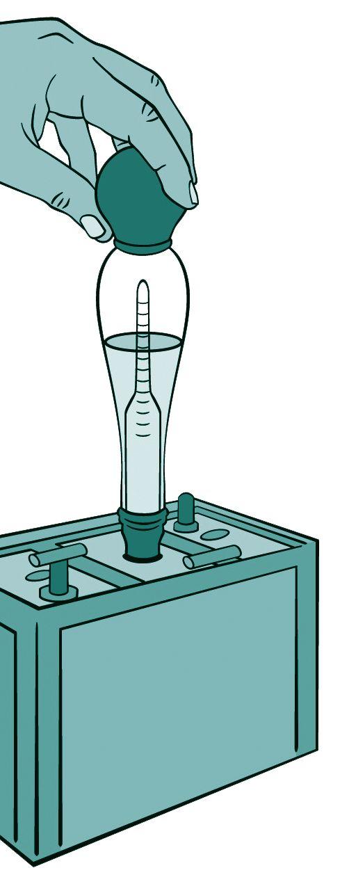 BY TOM SANDRI, Shermco Industries
There are various philosophies and opinions for maintaining and testing station battery systems. These approaches can range from doing nothing and replacing when the battery fails to an intense, time-based battery maintenance regimen. Obviously the “do nothing” approach appears a little flawed. Keep in mind that batteries are perishable items with a useful life, and their variability is based on a number of factors. They require a constant float charge to maintain freshness as well as periodic inspections to ensure that they are maintaining the proper charge and can deliver the rated output.
Besides being perishable, another unique feature of a battery compared to other electrical assets is that it uses chemicals, metal alloys, plastics, welds, and bonds that must interact with each other to produce a constant dc source. For this reason, the type of battery (flooded lead-acid, sealed/valve-regulated lead-acid, or nickelcadmium) should be considered before embarking on a battery maintenance program. Such a program can employ a number of recommended practices and typically includes inspections, actions, and measurements conducted under normal float conditions and capacity tests usually performed with the battery system off line.
The most commonly recommended practices are contained in three standards of The Institute of Electrical and Electronics Engineers (IEEE):
• IEEE 450 Recommended Practice for Maintenance, Testing, and Replacement of Vented Lead-Acid Batteries for Stationary Applications.

• IEEE1188 IEEE 1188 Recommended Practice for Maintenance, Testing, and Replacement of Valve-Regulated Lead-Acid (VRLA) Batteries for Stationary Applications.
• IEEE1106 IEEE 1106 Recommended Practice for Maintenance, Testing, and Replacement of Nickel-Cadmium Batteries for Stationary Applications.
If the application involves the generation transmission, or distribution of bulk electrical power, it is likely subject to North American Electric Reliability Corporation (NERC) requirements. Those requirements are outlined inStandardPRC-005-2 in Standard PRC-005-2 Protection System Maintenance. WhiletheIEEEstandardswere While the IEEE standards were consultedtoarriveatcertaindetailsofthe consulted to arrive at certain details of the PRC-005-2 maintenance procedures, the former are recommended practices while the latter are mandatory and enforced by NERC.
BASIC INSPECTIONS
It is important to understand that no single test or procedure tells the whole story. The purpose of tests and inspections is to determine what condition the batteries are in, and hopefully, provide some idea ofwherethatconditionisheadedandhowfast.A of where that condition is headed and how fast. A power outage is the wrong time to find out that the batteries did not have sufficient capacity, the load was dropped sooner than designed, or that the entire system failed due to a single component failure—andthatallofthiscouldhavebeen failure — and that all of this could have been predicted and prevented. Therefore, it is important tohaveallusabletestdataavailableandtorecord to have all usable test data available and to record it properly.
Visual Inspection. It is important that the entire system is examined. The battery surfaces should be clean and free of dust, dirt, tools, and electrolyte. Floors should be clean, and the mechanical system supporting the batteries should not have any rust or look distressed in any way. Make sure ventilation systems are verified and thermostat setting is checked and recorded. Check each battery jar for signs of leaks or cracks and inter-cell straps for signs of corrosion. Whether correct or not, each of these items should be recorded, corrected if needed, and notedwhenthecorrectionwasmade. noted when the correction was made.
Charger Output Voltage and Current. The charger’s output voltage and current are typically measured and displayed on the charger itself. However, it is important to understand that the measurement and/or the charger display may not be accurate. Because the charger plays such an important role in the life of the battery, the output voltage of the charger should be verified with a dc voltmeter and the charger output current be verified with a dc ammeter and adjusted accordingly. This should be done at float levels as well as equalization charge levels, if available.
Float Voltage. Float voltage should be measured andrecorded and recorded across each cell at the battery posts. The measurement is made on the battery post and not on the straps or hardware. This should be measured during float conditions and not float during discharge or recharge. The value obtained should be compared to the manufacturer’s recommended value of float voltage per cell. The sum of each individual cell’s float voltage should equal that of the charger output.
CURRENT AND CONNECTION RESISTANCE TESTS
Another important battery maintenance consideration is measurement and/or monitoring ofcurrentandconnectionresistances.Excessive of current and connection resistances. Excessive current flow — either dc or ac — indicates a problem in a battery cell or with the charger and rectifier circuit. With loose connections, continuity in the battery string is compromised and the resulting esulting high-resistance areas can overheat.
DCFloatCurrent. DC Float Current. Floatcurrentisthedccurrent Float current is the dc current that flows through the battery string during float conditions. It is the result of float voltage applied to the cell’s internal resistance. Because of Kirchhoff’s Current Law, float current can be measured anywhere within the series string. Adifferenceincurrentmeasurementatthe A difference in current measurement at the beginning of the string compared to the end is an indicator that current is flowing to ground through a damaged cell.
When originating in the string, the ground current value can be very small and difficult to measure. Normal float currents are typically less
than one amp and vary by size and manufacturer. Ifthemanufacturerdoesnotrecommenda If the manufacturer does not recommend a float current value under normal conditions, thenvaluesfromonetesttoanothershouldbe then values from one test to another should be compared to look for gross increases from previous measurements. This is especially important in VRLA batteries, as increased float current can lead to thermal runaway. Float current should be measured during float conditions and not during discharge or recharge. (See Figure 1)

AC Ripple Current. Ripple current is measured withanacmeter.Themeasurementshouldbe with an ac meter. The measurement should be taken through each series string during float
conditions. Ripple current and ambient temperature should be analyzed together because high ripple current in the presence of a high ambient temperature will have more of an adverse effect on the battery than high ripple current alone. IEEE recommends that ripple current not exceed five amps for every 100Ah of battery capacity. The less the ripple current, the longer the battery life will be.
Ripple current measurements (and charger designs that minimize it) are suggested in IEEE-1188 in particular because the heating that results can contribute to a condition of thermal runaway in VRLA batteries. (See Figure 2)
Inter-CellResistance. Inter-Cell Resistance. Inter-cell resistance (also called strap resistance) is an important measurementandshouldnotbeoverlooked. measurement and should not be overlooked. While application of the correct torque to the strap bolt and nut is important, it is not sufficienttoensurealowresistanceconnection. sufficient to ensure a low resistance connection. Resistance should be measured across each strap by making contact at the battery terminals and not on the straps themselves. (See Figure 3)
The reason for making contact at the battery post and not on the strap is that the measurement mustincludethecontactresistancebetweenthe must include the contact resistance between the strap and the post. The junction between the strap and the post is where most high resistances will occur, usually due to a loose connection or the presence of foreign material.
SPECIFIC GRAVITY AND DISCHARGE TESTING
Specific gravity is the ratio of the weight of a solution to the weight of an equal volume of water at a specified temperature. As applied to battery maintenance, the measurement of specific gravity is an indicator of the state of charge (SOC) of a cell or battery. During battery discharge, the specific gravity decreases to a value near that of pure water, and it increases during a recharge. The battery is considered fully charged when specific gravity reaches its highest possible value.
Specific gravity tests are performed on vented/wet cells. As mentioned earlier, this measurement is temperature dependent, and all measured values must be compensated for electrolyte temperatures above or below 25°C (77°F). Electrolyte level can affect the specific gravity measurement because water is lost during the recharge cycle. If there is less water andthesameamountofacidduetoafull and the same amount of acid due to a full recharge, then the specific gravity measurement will be higher than it should.
Because sulphuric acid has a higher density than water, the sulphuric acid often migrates to the bottom of the jar. This can lead to a lower specific gravity measurement at the top of the jar than at the bottom. Normally, an equalization charge will mix the electrolyte so that the specific gravity measurement is accurate at any level measured. (See Figure 4)

Discharge Tests. There are three types of load tests: the acceptance test, the performance test, andtheservicetest. and the service test.
The acceptance test is made at the beginning of battery life, is usually performed at the factory or at installation, and is based on the battery’s design capacity.
The performance test, which is also based on battery capacity, is typically performed two to three years after installation and then every five years, based on the IEEE recommendation.
The service test, which is performed as needed, is based on the load and determines if the battery will correctly supply the load.
Load testing or discharge testing is the absolute assessment of whether a battery is going to be capable of supplying the amount of current for
the designed amount of time. However, there aresomedrawbacks: are some drawbacks:
• First, every battery has a certain number of deep discharges that it can tolerate before failure, so each discharge test reduces battery life.
• The second drawback is the complexity, cost, and time to correctly perform a discharge test.
If the battery system being tested is in service, a backup system should be installed to prepare for a potential power outage. A temporary external load comparable to the normal load served should be connected to the main system under test. The time of the test can last as long as the rating on the battery.
The cell’s impedance (Z) is derived from:
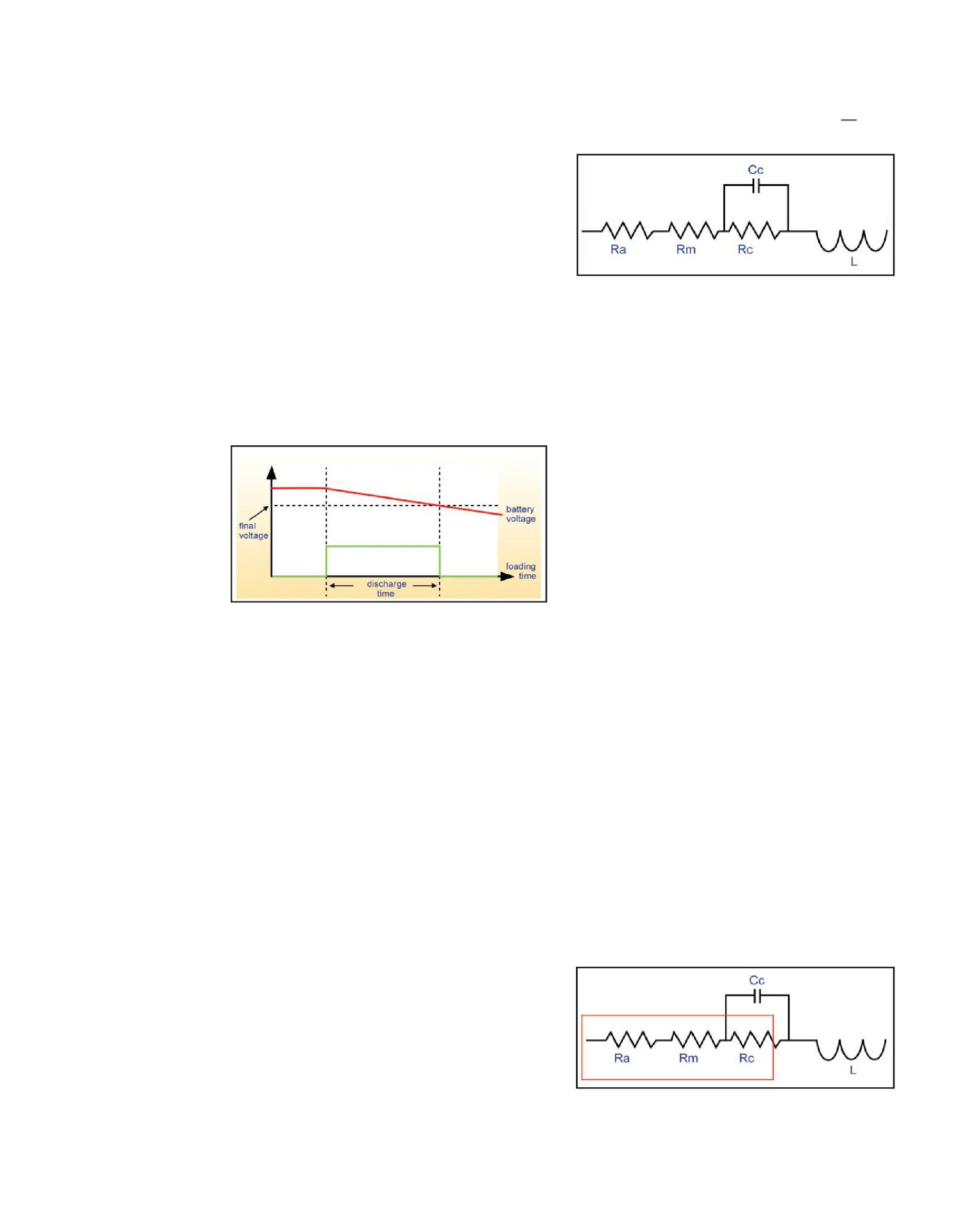
Figure 5: Battery Load/Discharge Test
OHMIC TRENDING
There are three types of ohmic battery testers: impedance testers, conductance testers, and resistance testers. Each method is recognized by IEEE and is a means of determining the Stateof-Health (SOH) of a battery. Perhaps one of the greatest values of ohmic testing is that it is performed while the battery is online, filling the gap between discharge tests by providing a correlation to a cell’s capacity.
ACTestMethods. AC Test Methods. Impedance testers apply an ac test current to the battery under test and measurethevectorsumoftheinternalcell measure the vector sum of the internal cell resistance and the capacitive reactance of the cell plate.
The measurement theory is based on Ohm’s Law. The products inject an ac test current of either 50 or 60 hertz (I) into a battery or cell; the ac current is measured by the receiver, and the ac potential drop across the cell (E) is measured using potential probes.
Figure 6: Equivalent Battery Circuit — ac Measured Components
Ra=Resistanceoftheacid Ra = Resistance of the acid
Rm = Metallic resistance, including grids, top lead, posts
Cc = Capacitance of cell
Rc = Charge transfer resistance
L=Inductance L = Inductance
Conductancetestersalsomeasuretheflowofac Conductance testers also measure the flow of ac current through a battery; however, they measure the conductance rather than the impedance.
DCTestMethods. DC Test Methods. Resistancetestersmeasure Resistance testers measure the drop in dc voltage by applying resistance. A resistance tester places the battery cell under momentary load (approximately three-second load of approximately 72 amps). The instantaneous voltage drop at time zero and voltage recovery when the load is removed will show a voltage drop across the internal resistance.
Ra=Resistanceoftheacid Ra = Resistance of the acid
Rm = Metallic resistance, including grids, top lead, posts
Cc = Capacitance of cell
Rc = Charge transfer resistance
L=Inductance L = Inductance
Figure 7: Equivalent Battery Circuit — dc Measured Components
Although different techniques are used to capture internal ohmic values of a battery cell, the data can be managed in a similar manner. In short-term analysis, each individual cell’s ohmic reading can be compared to the average ohmic value for all of the cells. This analysis will quickly expose possible weak cells that are falling outside the bank average.
If a baseline is established for the battery, the readings can be compared against the baseline to determine approximately how much life has been used. Baselines are best established from a known healthy cell or after a capacity test. Finally, by comparing readings over time, the aging rate of the battery can be established.
BATTERY MAINTENANCE SUMMARY
A battery is a complex electro-chemical device. Batteries are the only element of a Protection System that is perishable and has a limited life. As perishable items, batteries require not only a constant float charge to maintain their freshness (charge), but also periodic inspection to determine if problems exist with their aging process as well as testing to see if they are maintaining a charge or can still deliver their rated output as required.
Besides being perishable, a second unique feature of a battery that is unlike any other Protection System element is that a battery uses chemicals, metal alloys, plastics, welds, and bonds that must interact with each other to produce the constant dc source required for
Protection Systems, independent of issues and disturbances on the ac system.
No battery manufactured today for Protection System application is free from problems that can only be detected over time by inspection and test. These problems can arise from variances in the manufacturing process, chemicals and alloys used in the construction of the individual cells, quality of welds and bonds to connect the components, the plastics used to make batteries, and the cell-forming process for the individual battery cells.
Other problems that require periodic inspection and testing can result from harm caused during transportation from the factory to the job site, length of time before a charge is put on the battery, the method of installation, the voltage level and duration of equalize charges, the float voltage level used, load characteristics, and the battery’s installation environment.

Thomas Sandri received his BSEE from Thomas Edison University in Trenton, N.J. He has been active in the field of electrical power and telecommunications for over 30 years. During his career he has developed numerous training aids, training guides, and has conducted seminars-both domestic and international. Thomas supports a wide range of electrical and telecommunication maintenance application disciplines. He has been directly involved with and supported test and measurement equipment for over twenty years and is considered an industry expert in application disciplines including battery and dc systems testing and maintenance, medium and high voltage cable, ground testing, and partial discharge analysis.
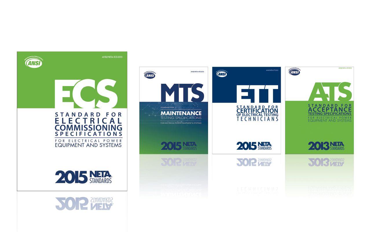

NEW! ANSI/NETA ECS - 2015
ANSI/NETA ECS-2015
Standard for Electrical Commissioning Specifications for Electrical Power Equipment and Systems
Scope
It is the purpose of this specification to assure that tested electrical equipment and systems are operational, are within applicable standards and manufacturer’s tolerances, and are installed in accordance with design specifications.
Three voltage classes of equipment are detailed within the ANSI/NETA ECS
• Low-Voltage Systems (less than 1,000 volts)
• Medium-Voltage Systems (greater than 1,000 volts and less than 100,000 volts)
• High-Voltage and Extra-High Voltage Systems (greater than 100 kV and less than 1,000 kV)
References
ASHRAE, ANSI/NETA ATS, NECA, NFPA 70E, OSHA, GSA Building Commissioning Guide
BRIDGING THE GAP FROM ACCEPTANCE TESTING TO COMMISSIONING
Acceptance Testing
The systematic process of performing field tests and inspections that are available to assess the suitability for initial energization and final acceptance of electrical power equipment and systems to ensure
Electrical Commissioning
The systematic process of documenting and placing into service newly-installed or retrofitted electrical power equipment and systems.
“It is this need and requirement to bridge the gap between acceptance testing and electrical commissioning that completes the electrical system overall acceptance process. Again, from individual component testing to assurance that all integral component s are functioning as a complete unit within design requirements and manufacturer’s published data; along with the correct operation of all interlock safety devices for fail-safe functions; and the correct operation of all sensing devices, alarms, and indicating devices.”
Ron Widup, “Bridging the Gap from Acceptance Testing to Commissioning” NETA World Journal, Spring 2015, page 96
To learn more and order the ANSI/NETA ECS-2015
Visit www.netaworld.org/standards or call 888-300-6382
REQUIREMENTS FOR SUBSTATION DC SUPPLY SYSTEMS
BY LYNN HAMRICK, Shermco IndustriesOn August 14, 2003, large portions of the Midwest and Northeast United States and Ontario, Canada, experienced an electric power blackout. The outage affected an estimated 50 million people with 61,800 megawatts (MW) of electric load in the states of Ohio, Michigan, Pennsylvania, New York, Vermont, Massachusetts, Connecticut, New Jersey, and Ontario. The blackout began about 4:00 PM, and power was not restored in some parts of the United States for 4 days. Parts of Ontario suffered rolling blackouts for more than a week before full power was restored. Total cost estimates in the United States and Canada exceeded $2 billion.
As a result of this blackout, the North American Electrical Reliability Corporation (NERC) was formed and tasked with developing standards for utilities and other producers regarding reliability and maintenance of the Bulk Electrical System (BES). NERC was also given the authority to enforce these standards. On December 19, 2013, the Federal Energy Regulatory Commission (FERC) approved NERC Reliability Standard PRC-005-2, Protection System Maintenance.Includedinthe . Included in the federal register was Docket No. RM13-7-000, Order No. 793. In this submittal was FERC’s approval of NERC’s proposed implementation plan for the standard, “which requires entities to develop a compliant protection system maintenance program within 12 months, but allowsforthetransitionovertimeofmaintenance allows for the transition over time of maintenance

activities and documentation to conform to the new minimum maintenance activities and maximum maintenance intervals.” This standard includes requirements associated with maintaining and testing BES substation batteries.
Utilities are required to develop a protection system maintenance program (PSMP) that conforms to the new PRC-005-2 minimum maintenance activities and maximum maintenance intervals. Based on a utility’s experience with substation battery systems, the utility should select and implement an appropriate maintenance program to perform at an appropriate interval. The standard also states that for batteries associated with the station dc supply, a time-based maintenance program shall be implemented.
PRC-005-2 Tables 1-4 (a), (b), and (c)
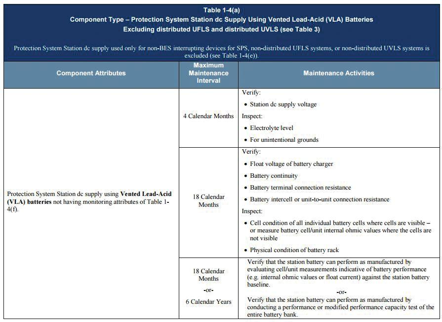
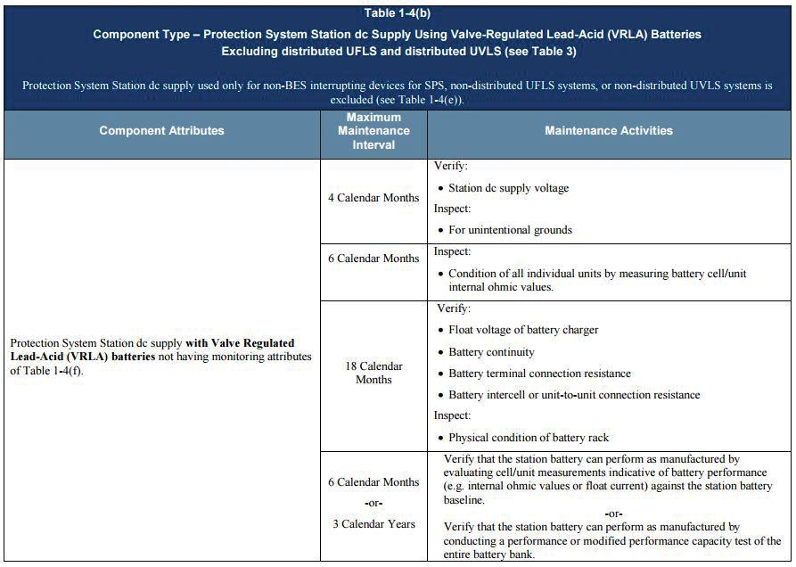
PRC-005-2 Table 1-4 (c)
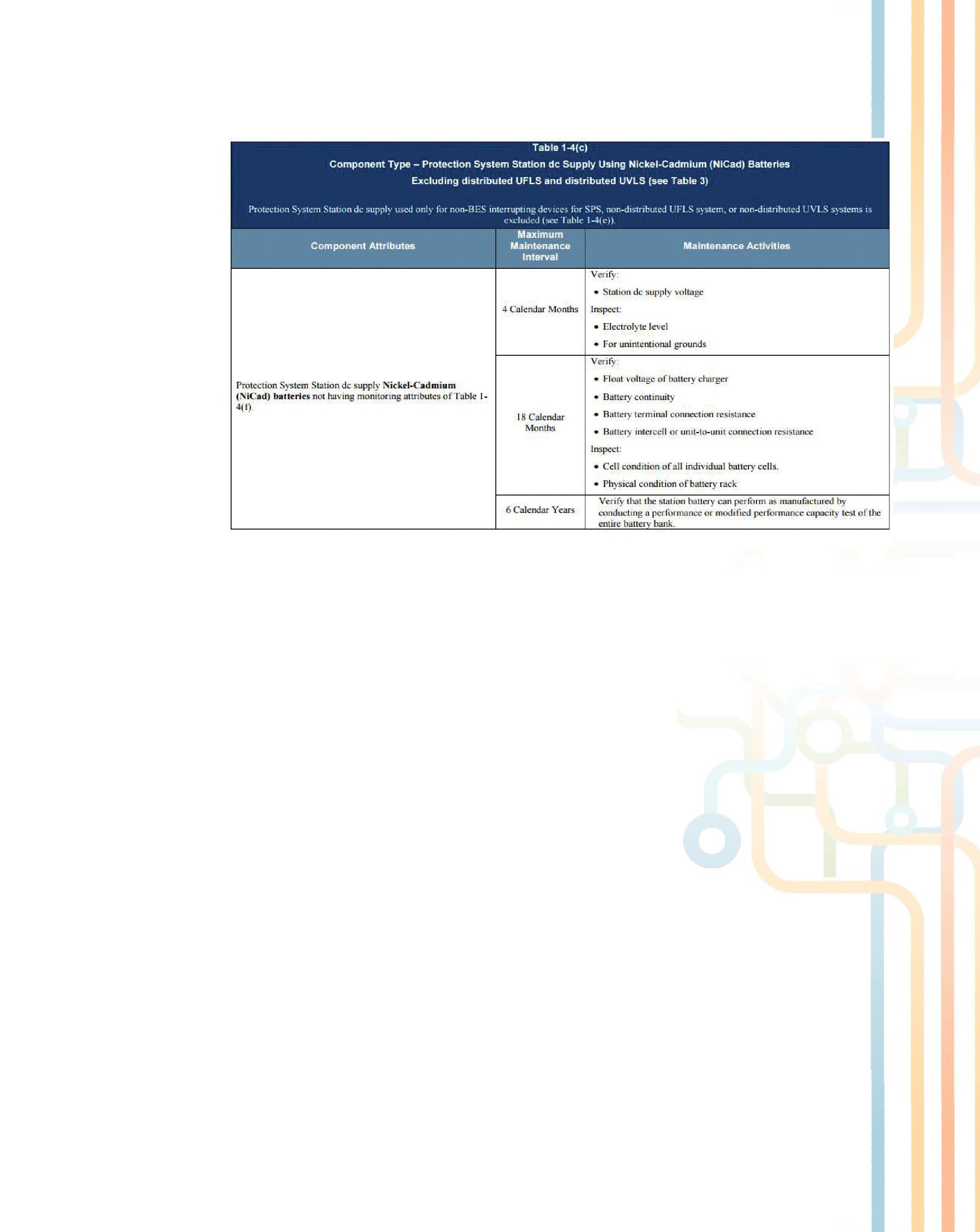
Most substation battery systems use battery systems with vented lead acid (VLA or flooded) or valve-regulated lead acid (VRLA or sealed) battery systems due to the cost and experience with these types of systems. However, nickelcadmium (NiCad) battery systems are also in use. Accordingly, slightly different maintenance and testing requirements are provided in the NERC standard for each of these different battery types. PRC-005-2, Tables 1-4(a), 1-4(b), and 1-4(c) provide the minimum maintenance activities andmaximummaintenanceintervalsforvented and maximum maintenance intervals for vented lead acid (VLA or flooded), valve-regulated lead acid (VRLA or sealed), and NiCad battery systems respectively. The standard also provides an exclusion to these time-based maintenance activities if the monitoring attributes of PRC-0052, Table 1-4(f) have been implemented. Although this table has been provided for information purposes, only the time-based maintenance program requirements will be discussed herein.
In accordance with PRC-005-2, Table 1-4(a), -4(b) and -4(c), the following activities should be performed and documented at least every four months for all battery system types:
• Verify dc supply voltage — Battery charging is an important factor in battery system maintenance. A properly functioning battery charging system with a healthy battery condition will result in a fully charged and reliable battery system that is available forservicewhenneeded.Aconsistent for service when needed. A consistent dc supply voltage from the battery charger is necessary for a healthy battery system.
• Inspect for unintentional grounds — Battery systems are typically ungrounded systems. Unintentional grounds can adversely affect the operation and reliability of battery systems as well as pose safety hazards to personnel.
Additionally, in accordance with PRC-005-2, Tables 1-4(a) and -4(c), the following activities should be performed and documented at least every four months for VLA and vented NiCad battery system types:
• Inspect electrolyte level — Ventedor Vented or flooded cells have translucent or transparent jars, so the electrolyte level can easily be compared to a recommended level that

is marked on the cells. The frequency of watering depends on usage, charge method, and operating temperature. Avoid exposed plates at all times, as this will result in damage, leading to reduced capacity and lower performance.
o For VLA battery cells, an unusually high usage of water indicates excessive gassing. If excessive gassing exists, troubleshoot the battery and charging equipment. An excessive amount of charge results in high battery temperature and a reduced battery service life.
o For vented NiCad cells, during discharge the plates absorb a quantity of the electrolyte. On recharge, the level of the electrolyte actually rises; and at full charge, the electrolyte will be at its highest level. Therefore, water should never be added to the battery until three or four hours after it has been fully charged. If it is necessary to add water, use only distilled or demineralized water. In addition, be careful not to overfill the battery with water. Removing some of the electrolyte will reduce the concentration of potassium hydroxide in the cell and adversely affect its operation. Similar to VLA battery cells, an unusually high usage of water indicates excessive gassing, and troubleshooting of the battery and charging equipment should be performed.
In accordance with PRC-005-2, Tables 1-4(b), the following activity should be performed and documented at least every six months for VRLA battery system types:
• Inspect cell condition by measuring cellinternalohmicvalue— cell internal ohmic value — Measuring cell internalohmicvaluescanassistin internal ohmic values can assist in determining battery health. The most common methods of measuring cell internal ohmic values include using dc voltage to measure resistance or ac voltage to measure conductance or impedance. A cell’s internal resistance provides useful
information in detecting problems and can be used for indicating when a battery or battery cell should be replaced. A change in cell resistance relates to aging and provides some failure indications. Rather than relying on an absolute resistance reading, measurements are trended against previous cell resistances with subtle changes requiring further investigation. When using dc voltage, resistance is measured in ohms. When using ac voltage, impedance is also measured in ohms. An increase in resistance/ impedance of 25 percent over an initial baseline (100 percent) or related cells indicates a performance drop to about 80 percent. When using ac voltage and the measurement is conductance, the units employed are mhos, or siemens. As conductance declines, so does a battery’s ability to meet its specified capacity and supply energy. A decrease in conductance of 25 percent over an initial baseline (100 percent) or related cells indicates a performance drop to about 80 percent.
In accordance with PRC-005-2, Table 1-4(a), -4(b), and -4(c), the following activities should be performed and documented at least every 18 months for all battery types:
• Verify float voltage — Charger float voltage is the typical voltage output for a normal charging process. This voltage should be in accordance with manufacturer recommendations, but may need to be increased as the battery ages or degrades.
• Battery continuity — All cells within the battery should be connected in a continuous manner to support proper battery operation. When called upon for use, each cell provides a specific voltage in support of the battery system voltage. For VLA batteries, the cell voltage is typically ~2 vdc. For VRLA batteries, the cell voltage can vary from 2 to 12 vdc. For vented NiCad batteries, the cell voltage is typically 1.2 vdc.
• Battery terminal connection resistance — The battery terminal connection is where the battery connects via cabling to the rest of the dc system. As with any electrical circuit, connection points within the system must be maintained at a very low resistance to minimize overheating and subsequent connection failure. Increases in battery terminal connection resistance over time are indicative of a degrading connection.
•Intercell connection resistance — As with the battery terminal connection, connections between the battery cells must also be maintained at a very low resistance to ensure proper battery continuity as well as minimize overheating and possible cell failure within the battery. Increases in intercell connection resistance over time are indicative of a degrading connection that could be caused by battery post corrosion or a loose or otherwise defective connection.
• Inspect physical condition of rack — In most substation applications, battery cells are numerous and heavy. Therefore, the racks supporting the battery cells should be structurally capable of supporting the weight and position of the cells. Any movement of the rack could stress the cells, the cell posts, and the intercell connections and lead to a degraded battery. The racks should be inspected for signs of corrosion as this is indicative of possible electrolyte leakage from a cell on the rack.
Additionally, in accordance with PRC-005-2, Tables 1-4(a) and -4(c), the following activities should be performed and documented at least every 18 months for VLA and vented NiCad battery system types:
• Inspect cell condition — Most cells have translucent or transparent jars, so the inside of the jar may be inspected. As discussed previously, electrolyte level can easily be compared to a recommended level marked on the cells. Look for cracks,
breaks, and pieces hanging on the side, as this is indicative that the cell may need to be replaced and that other cells may also have a similar problem.
– For VLA battery cells, the positive plates are located toward the center of the jar and are typically the first to wear out. They should be dark brown or black. Sparkle is evidence of sulfation or undercharge. The negative plates are thinner than the positive plates and sit toward the outside of the jar. These should have a clean lead color from top to bottom. Pink discoloration indicates copper contamination. Inspection of the sediment should provide a general idea of the battery conditional trend from the last inspection. Accumulation of gray material under the negative plates, accompanied by sparse black sediment, is indicative of an undercharging condition. Excess black sediment under the positive plates with little negative sediment is indicative of an overcharging condition or excess temperature. If excess sediment covers the bottom of the jar, the battery has been cycled heavily or operated at high temperature. A crusty trail or accumulation is evidence of electrolyte leakage. Signs of corrosion on the terminal connections, intercell connections, and racks are also indicative of electrolyte leakage.
–For NiCad battery cells, spilled electrolyte can react with carbon dioxide to form potassium carbonate crystals. These crystals, which are non-toxic and noncorrosive, can be loosened with a fiber brush and wiped off with a damp cloth. When potassium carbonate forms on a properly serviced battery it may indicate the battery is overcharging because the voltage regulator is out of adjustment.
• Measure cell internal ohmic value — For VLA batteries, this alternative method of inspection can be performed, particularly when cells are not visible to inspect. Measuring cell internal ohmic values can assist in determining battery health.
The most common methods of measuring cell internal ohmic values include using dc voltage to measure resistance or ac voltage to measure conductance or impedance. A cell’s internal resistance provides useful information in detecting problems and can be used for indicating when a battery or battery cell should be replaced. A change in cell resistance relates to aging and provides some failure indications. Rather than relying on an absolute resistance reading, measurements are trended against previous cell resistances with subtle changes needing further investigation. When using dc voltage, resistance is measured in ohms. When using ac voltage, impedance is also measured in ohms. An increase in resistance of 25 percent over an initial baseline (100 percent) or related cells indicates a performance drop to about 80 percent. When using ac voltage, the measurement can be conductance in mhos, or siemens. As conductance declines, so does a battery’s ability to meet its specified capacity and supply energy. A decrease in conductance of 25 percent over an initial baseline (100 percent) or related cells indicates a performance drop to about 80 percent.
In accordance with PRC-005-2, Table 1-4(a), -4(b), and -4(c), some form of battery performance or capacity test should be performed for each battery type. However, the type of test and the required interval for performing the test varies for each battery type.
• Verify battery performance — Battery performance is verified by evaluating cell measurement against baseline (i.e., internal ohmic values or float current) or performing a battery capacity by load test. For VLA batteries, the load test option is performed at least every six years, and for VRLA batteries, every three years. For NiCad batteries, the only option is the battery capacity by load test performed at least every six years.
– Verify battery performance by evaluating cell measurement against baseline (i.e., internal ohmic values or float current).
A cell’s internal ohmic value provides useful information in detecting problems and can indicate when a battery or battery cell should be replaced. However, measuring resistance, impedance, or conductance cannot provide a linear correlation to the battery’s capacity. As stated previously, an increase in resistance of 25 percent over an initial baseline (100 percent) or related cells indicates a performance drop to about 80 percent. Further, as conductance declines, so does a battery’s ability to meet its specified capacity and supply energy. A decrease in conductance of 25 percent over an initial baseline (100 percent) or related cells indicates a performance drop to about 80 percent. When evaluating battery health, factory internal ohmic measurements should not be used as a baseline for future reference. A battery should be installed and commissioned in accordance with manufacturer’s recommendations, which should include an initializing equalization charge, followed by placement in normal float conditions for a short time before taking baseline measurements. Internal ohmic values can change drastically from factory measurements after a battery is in its operating configuration and has undergone the initial equalizing charge. Regarding float current, the float charging current flowing into a battery string is dependent on the basic cell electrochemistry, the applied charging voltage, the average internal cell temperature, and the string’s state-ofcharge. The normal float charging current is the expected current flowing into a fully charged battery, under a given applied charging voltage, and at a given average cell temperature to keep the battery fully charged. Since the cells are electrically connected in series, the current flow is the same through each cell, although individual cell temperatures and voltages may be different. Therefore, float current reflects the average condition
of all the cells in the string. Most manufacturers provide the normal float current expected under specified conditions. Typically, float current increases because of a ground fault on a floating battery system or some type of internal battery problem. Therefore, an increase in float current is indicative of a battery problem.
– A battery capacity or load test is the only way to get an accurate measurement of the actual capacity of the battery. The test involves putting the battery on a load bank and discharging the battery while measuring cell parameters, as well as battery performance over time. If the battery meets the load and time characteristics as designed, it passes. A load test should be performed when the battery is first installed. When performed within a time-based maintenance program, the capacity test is also useful in monitoring the battery’s health and estimating the remaining battery life. For substation battery systems, rated capacity values are typically available fromthemanufacturer. from the manufacturer.
Table 1-4 (f)
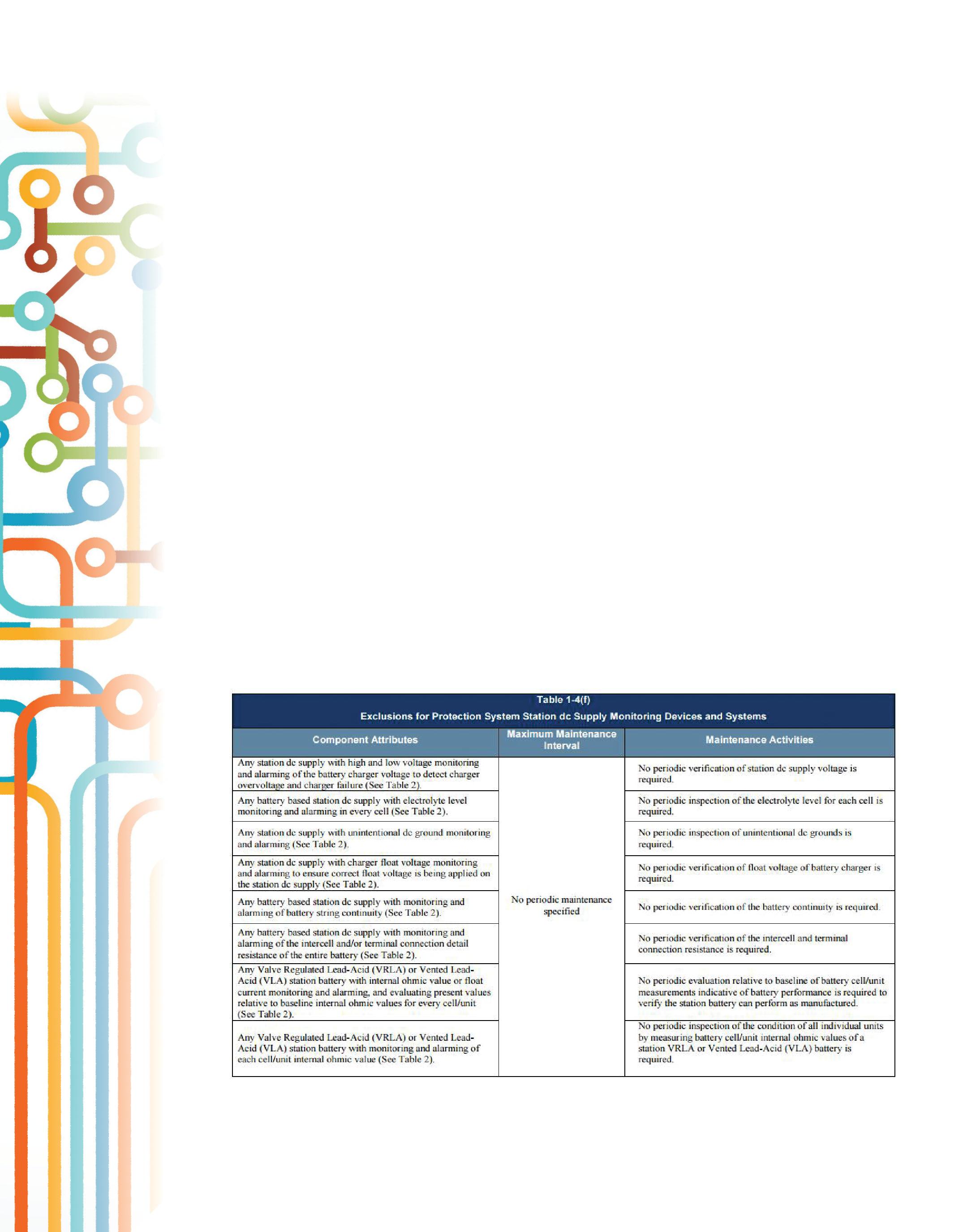
The following general industrial standards are excellent resources for maintaining and testing the respective battery systems. Additionally, these standards provide specific recommendations associated with the performance of battery capacity tests.
•IEEE Standard 450-2010, IEEE Recommended Practice for Maintenance, Testing, and Replacement of Vented Lead-Acid Batteries for Stationary Applications
• IEEE Standard 1188 -2005, IEEE Recommended Practice for Maintenance, Testing, and Replacement of ValveRegulated Lead-Acid Batteries for Stationary Applications
•IEEE Standard 1106 -2005, IEEE Recommended Practice for Installation, Maintenance, Testing, and Replacement of Vented Nickel-Cadmium Batteries for Stationary Applications.
As stated previously, below is a copy of NERC standard PRC-005-2, Table 1-4(f), which is provided for information only.
In summary, utilities are required to develop a PSMP that conforms to the new minimum maintenance activities and maximum maintenance intervals provided in PRC-005-2. Based on a utility’s experience with substation battery systems, the utility should select and implement an appropriate maintenance program to be performed at an appropriate interval. Most substation battery systems use battery systems with vented lead acid (VLA or flooded) or valve-regulated lead acid (VRLA or sealed) battery systems due to the cost and experience with these types of battery systems. However, NiCad battery systems are also in use. Accordingly, slightly different maintenance and testing requirements are
provided in the NERC standard for each battery type. PRC-005-2, Tables 1-4(a), 1-4(b), and 1-4(c) provide the minimum maintenance activities and maximum maintenance intervals for these battery systems.

Lynn Hamrick brings over 25 years of working knowledge in design, permitting, construction, and startup of mechanical, electrical, and instrumentation and controls projects as well as experience in the operation and maintenance of facilities.
Lynn is a Professional Engineer, Certified Energy Manager and has a BS in Nuclear Engineering from the University of Tennessee.
+1.518.329.3275 |
HVI - The World’s Source for High Voltage Test Equipment
VLF & TD from High Voltage, Inc. HVI – with the newest designs available offering the most in control, communications and data reporting.
VLF-34E Solid State Design – All New
0 – 34 kVac peak, sinusoidal or square wave
0.5 F – 5.0 F @ 0.1 Hz – 0.01 Hz
+/- 34 kVdc, Sheath Testing, Load Burn
USB Port for data collection and removal
Full Remote Control Wireless with XBee

VLF-65E Solid State Design – All New
0 – 65 kVac peak, sinusoidal or square wave
1.0 F – 10.0 F @ 0.1 Hz – 0.01 Hz
+/- 65 kVdc, Sheath Testing, Load Burn
USB Port for data collection and removal
Full Remote Control Wireless with XBee


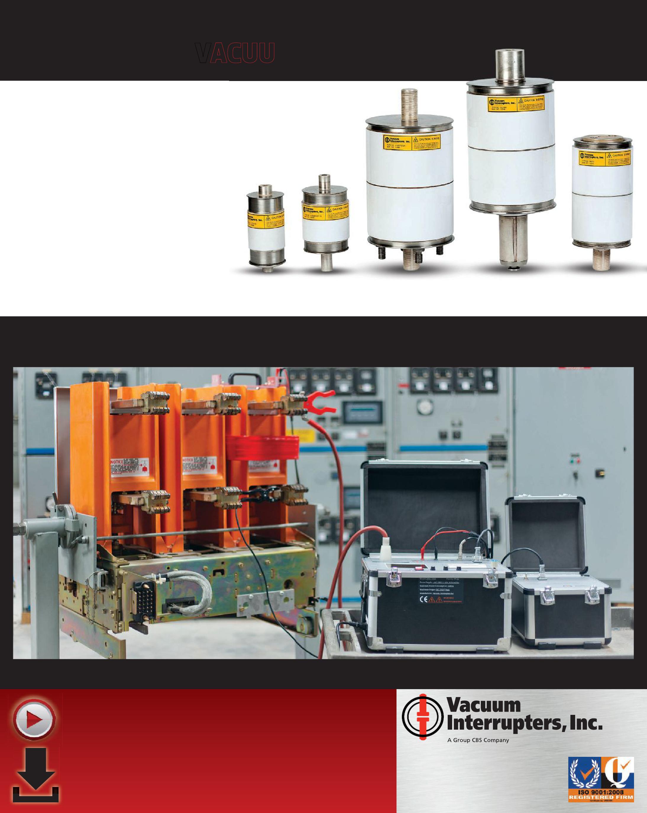
• Vacuum interrupter replacements rated up to 38kV, 3000A
• Repair and replacement services for all major OEM interrupters, including GE, Eaton, CH, Westinghouse, ABB, Siemens, and many more
• Pole assemblies, parts, and components
• Custom design/manufacture services for obsolete interrupters, breakers
• Field and in-shop vacuum interrupter replacement services
• Rental vacuum breakers available while yours are being serviced
BATTERY
DISCHARGE TESTING:
BY DINESH CHHAJER AND ROBERT FOSTER, MeggerAs the electrical grid ages and expands, it is more apparent that testing and maintenance is critical to the reliability of the network. While many utilities have developed maintenance plans, regulatory committees such as the

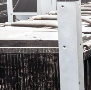
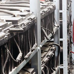
AND FIELD EXPERIENCES
Federal Energy Regulatory Commission (FERC) and North American Electric Reliability Corporation (NERC) have set forth mandates to ensure that the equipment related to protection and controls is being maintained properly.

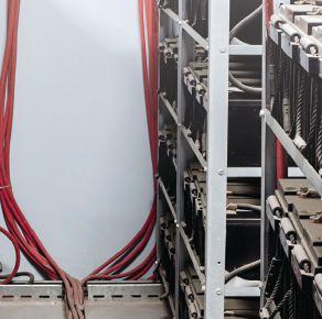

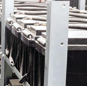


Batteries provide power to the protection and control equipment, including relays, circuit breakers, and other auxiliary devices. If the battery fails, then the substation is left unprotected. Due to the criticality of the batteries for protection, NERC has laid out requirements on maintaining and testing the stationary batteries. Although many tests can be performed to assess the condition of the batteries such as ohmic testing, specific gravity, state of charge etc., only the capacity test, commonly referred to as the discharge or load test, can measure the true capacity of the battery system anddeterminethebatteries’stateofheath. and determine the batteries’ state of heath.
The capacity tests suggested by NERC standard PRC 005-2 are the performance test and the modified performance test. Before performing these tests, certain conditions must be met and a decision must be made on how to discharge the batteries. The battery may be tested to verify that the capacity is equal to or greater than the manufacturer’s specification or that it will meet the duty cycle required by the load. In the end, capacity can be determined by calculation based on a rateadjusted or time-adjusted method. This paper references the IEEE 450 standard to explain different test methods, test preparation, and test performance. The standard can be consulted for furtherdetails. further details.
FERC AND NERC REGULATIONS
Blackouts have a huge economic impact on affectedareas.Toensureastablenationwide affected areas. To ensure a stable nationwide grid, even distribution of the bulk electric supply, and more reliable power system network, independent regulatory agencies such as FERC andNERCwereformedtomonitorthese and NERC were formed to monitor these activities. FERC is an independent government agency, and its goal is to assist consumers in obtaining reliable, efficient, and sustainable energy services at a reasonable cost through appropriate regulatory and market means. NERC is a self-regulatory organization whose mission is to ensure the reliability of the North American bulk power system. It is subjected to oversight by FERC. NERC has the legal authority to enforce reliability standards with all users, owners, and operators of the bulk power system in the United States and Canada.
The existing reliability standard that applies to battery testing and maintenance is NERCStandardPRC-005-2 NERC Standard PRC-005-2 Protection System Maintenance.Thisstandardensuresthatall . This standard ensures that all protection systems affecting the reliability of the Bulk Electric System (BES) are maintained, tested, and kept in working order. It is applicable to all generation owners, transmission owners, and distribution providers. NERC’s PRC-005-2 standard provides recommendations for maintaining, testing, and recording data for the stationary batteries. In the standard, Table 1-4 (a) lists the testing and maintenance intervals for ventedlead-acidbatteries. vented lead-acid batteries.
Key maintenance activities recommended in the tablearelistedbelow: table are listed below:
• Every four months, verify station dc supply voltage and check the electrolyte level and any unintentional grounds.
• Every 18 months, check float voltage, internal ohmic value, inter-cell connection resistance, and battery rack structure.
• Perform internal ohmic test, and compare against baseline once every 18 months or verify that the station battery can perform as manufactured by conducting a performance or modified performance capacity test of the entire battery bank at least once every six years.
PERFORMANCE TEST
IEEE Standard 450-2010, IEEERecommended IEEE Recommended Practice for Maintenance, Testing, and Replacement of Vented Lead-Acid Batteries for Stationary Applications, defines a performance test as “a constant-current or constant-power capacity test made on a battery after it has been in service.” It is the most commonly used discharge test method, and it determines if the battery is performing according to the manufacturer’s specifications and/or if it is within acceptable limits.Itcanbeusedforbenchmarkaswellas limits. It can be used for benchmark as well as maintenance practices.
For the performance test, a constant current specified by the manufacturer is applied for an accompanying specified time. Battery manufacturers publish tables that include
different discharge rates specified for different periods of time. Each discharge rating has an end-point cell voltage as the stop criteria for the discharge test. Depending on the load requirements, amount of time available, or the capabilities of the test equipment the user in the field can determine the appropriate discharge rate. The measured capacity is generally corrected to 25°C, but temperature correction can vary by manufacturer. It is recommended that this test be performed within the first two years after the battery is in service; thereafter, the test interval should be at 25 percent of the expected service life. It should be performed annually if the battery shows any sign of degradation or has reached 85 percent of the service life expected for the application. However, if the battery has reached 85 percent of service life but delivers a capacity of 100 percent or greater of the manufacturer’s rated capacity and has shown no signs of degradation, performance testing attwo-year intervals is acceptable.
MODIFIED PERFORMANCE TEST
A modified performance test is defined as a test in the “as found” condition of battery capacity that measures the battery’s ability to satisfy the duty cycle. The modified performance test is similar to the performance test in that it verifies manufacturer’s specifications and tests the capacity of the battery. It also has the added benefit of verifying that the battery will meet the specified duty cycle. The test is designed to encompass the entire duty cycle, so a chosen current is applied for a certain amount of time and then modified and applied for a different amount of time. This is repeated until the entire duty cycle is completed. Once the duty cycle is satisfied, the remainder of the test is dedicated to meeting the manufacturer’s specifications while taking into account the aging margin.
A detailed description of modified performance tests and case examples can be found in IEEE 450 Annex I.
EFFECT OF TEMPERATURE
Cell temperature can greatly affect the battery’s performance, including the state of charge and
state of health of the battery. Batteries perform best when they are operated at or close to their published rated temperature. At higher temperatures, the internal resistance of the cell goes down, accelerating the rate of chemical reaction and thereby improving the capacity of the battery. However, operating the battery at elevated temperature reduces the service life of the battery.
Conversely, at colder temperatures, the chemical reaction rate slows down and the capacity decreases. Manufacturers recommend operating the battery at published temperature to derive the published capacity and optimize the service life of a battery. When a capacity test is performed outside the manufacturer-specified temperature, correction factors are applied (per IEEE 450 or manufacturer recommendations) to capacity calculations for baseline comparison and trending of results.
BATTERY DERATING FACTOR
Batteries are sized to serve the designed load requirements throughout their expected service life. Like any other electrical asset, battery performance deteriorates with age, temperature, charge-discharge cycles, maintenance practices, charger settings, and a number of other factors. Therefore, batteries are sized with an aging factor so that they can deliver a charge to the specified load until the end of their life cycle.
Aging factor is the safety margin built into the sizing calculation when selecting the battery’s rated capacity. The derating factor is based upon the aging factor. It is indicative of reduced capacity as the battery approaches the end of its service life. A battery sized with an aging factor of 1.11 will have a derating factor of 0.9. In this case, a battery having 90 percent published capacity remaining will marginally meet specified load requirements with no safety factor. It also marks the end of the battery’s service life, where any further decrement in capacity would put the system at risk.
THIS STANDARD ENSURES THAT ALL PROTECTION SYSTEMS AFFECTING THE RELIABILITY OF THE BULK ELECTRIC SYSTEM (BES) ARE MAINTAINED, TESTED, AND KEPT IN WORKING ORDER.
CAPACITY CALCULATION METHODS
A battery’s capacity is defined in amp hours. It is typically expressed as a percentage, as a ratio of measured amp hour capacity to manufacturer’s published capacity (rate x time). Two different methods measure the capacity of a battery bank:
(1) Time-adjusted method. In the time-adjusted method, the test current is kept constant and is defined by the published rate (discharge current) forthedesiredtimeduration. for the desired time duration.

The capacity test is performed until the voltage reaches the end cell terminal voltage. In Table 1, for a 1.75 V end-cell voltage and an eight-hour test, the rate will be 15.8 A. Since the rate is kept constant and is equal to a published rate, battery capacity is calculated as the ratio of measured discharge time to published discharge time.
% C = ( Ta x 100) ( Tm x Kt )
Where,
C = Capacity at 25°C
Ta = Actual time duration of test to specified terminal voltage
the battery’s derating factor. IEEE 485 states, “To ensure that the battery is capable of meeting its design loads throughout its service life, the battery’s rated capacity should be at least 125percent (1.25 aging factor) of the load expected at the end of its service life.” This means the battery would reach theendofitsservicelifewhenitreaches80 the end of its service life when it reaches 80 percent of its specified performance.
Referring to Table 1, for a 15-minute test duration and a derating factor of 0.8, the rate is adjusted to 182 A (80 percent of 228 A). The testisconductedwith15-minuteand182-A test is conducted with 15-minute and 182-A settings until the specified end voltage is reached. Capacity is calculated by taking the ratio of the test rate and published rate corresponding to actual test duration using manufacturer’s data.
% C = ( Xa x K c) x 100 Xt
Where,
C = Capacity at 25°C
Xa=Actualrateusedforthetest Xa = Actual rate used for the test
Kc = Temperature correction factor as per IEEE 450 Table (2)
Xt = Published rating for time to specified terminal voltage
Thismethodcanbedifficulttousebecausethe This method can be difficult to use because the discharge rate corresponding to actual test time sometimesisnotavailableinmanufacturersometimes is not available in manufacturerpublished data; in some cases, interpolation and other curve-fitting techniques determine it.
Tm=Publishedratedtimetoreachterminal
Tm = Published rated time to reach terminal voltage
Kt = Temperature correction factor as per IEEE 450 Table (1)
(2) Rate-adjusted method. The rate-adjusted method is more complex than the time-adjusted method. In this method, time duration is kept constant, and the rate is adjusted based upon
Two factors that affect the capacity calculation numbers are degradation in battery quality and reduction in battery efficiency at high discharge rates. It is a well-known fact that battery efficiency decreases with increased discharge rate. The capacity measured at the 1 hour discharge rate is different than the capacity measured with an 8 hour discharge rate. The time-adjusted method provides a conservativeend-of-lifeassessmentbecauseit conservative end-of-life assessment because it
does not consider changes in battery efficiency with discharge time.
Technically, the rate-adjusted method provides more realistic results as it takes into account the battery sizing criteria and derating factor. When high-rate, short-duration tests are performed, the rate-adjusted method yields more accurate results than the time-adjusted method. Both test methods yield the same results when tested for long durations (typically eight hours). Because of simplicity, it is recommended to use the time-adjusted method for long-duration tests (60 minutes or greater). Though complex, the rate-adjusted method is preferred when performing a short-duration (60 minutes or less), high-discharge test because results will not be masked by the battery efficiency factor.
SITE PREPARATION
Site preparation is important to ensure that testing is performed safely and correctly. Before performance or modified performance testing can begin, certain initial conditions must be met. The load connected to the battery should be connected to backup power prior to disconnecting the bank for testing. The minimum PPE required is goggles and face shields, acid-resistant gloves, and a protective apron. Additionally, safety guidelines recommended by IEEE 450 as well as federal, state, and local safety precautions should be followed.
Since the pre-test conditions can greatly affect the outcome of the test, it is recommended that key parameters are checked before initiating the test. Prior to testing, the battery should be under float conditions for at least 72 hours. Individual cell voltage, float current from the charger, and battery terminal float voltage should be measured to verify the float conditions. Stabilized float current measurement determines the fully charged state of the battery. The battery connections and resistance measurements should be checked. Additionally, the temperature of the electrolyte in 10 percent or more of the cells should be measured. Make sure the battery is isolated from any other battery or critical load.
Once all initial conditions are met, the load bank
and any other necessary test equipment should be set up and the battery disconnected from the charger and connected to the load bank. If it is not possible to disconnect the charger, the load should be adjusted to compensate for the current that the charger is providing.
DISCHARGE TEST PROCESS
After the initial preparation, the discharge rate and test duration is selected using manufacturer’s published data. These test parameters will depend on the selected test and on the method used for capacity calculations. Note that current values are not adjusted for temperature; temperature is taken into consideration when the capacity is calculated. Timing starts when the load begins to discharge the battery at the selected discharge rate.
The battery should be discharged until it reaches minimum terminal voltage. The minimum terminal voltage is determined by multiplying the number of cells to the minimum average voltage of the cell specified by the design. A minimum of three measurements of both the battery terminal voltage and individual cell voltages should be measured over the course of the discharge — one at the beginning of the test when the load is applied (to detect any initial voltage drop due to application of the load), one or more at specified intervals, and one at the end of the test. To include the voltage drop across the inter-cell connectors, the voltage of each individual cell should be measured between posts of the same polarity, from one cell to an adjacent cell.
Figure 1 shows cells connected to battery voltage monitors, which monitor individual cell voltage and overall terminal voltage at specified intervals for the duration of the test. While the test is being performed, the connectors between the cells should be monitored for any abnormal heating. It is allowed to pause the discharge test for up to 10 percent of the total test time or six minutes, whichever is shorter. This allows the user to fix any problems that arise during the test, such as bypassing an individual weak cell or fixing any problem with the connections or test equipment. Only one pause is allowed for
the duration of the test, and the pause time should not be counted in the total discharge time. Once the test is completed, determine the battery capacity. The test equipment can then be disconnected.
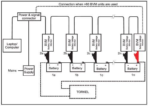
CELL BYPASS AND POLARITY REVERSAL
While performing the discharge test, one should be prepared to bypass weak cells approaching polarity reversal. Polarity reversal takes place when one or more cells are weaker than the other cells in the string. Since, all the cells are in series and the discharge current is the same, the weak cells tend to overheat and discharge faster than the others. This can bring the whole battery string down. If any cell voltage drops to one volt or below, it is approaching polarity reversal.
In the event of polarity reversal, it is recommended to pause the test, disconnect the weak cell, and bypass it with a jumper suitable to handle the discharge test current. All safety and precautionary measures should be followed when performing this. The end voltage should be recalculated, and the test should be resumed with a modified end terminal voltage. The maximum allowed time to bypass a weak cell and then resume the test is defined by the lesser of 10 percent of test time duration or six minutes.
Only one pause is allowed for the duration of the test. Pause time should not be counted in total discharge time. If cell reversal is identified at the very end of the discharge testing, finish the test and do not take any action. Bypassing weak cells is not allowed during the duty cycle portion of a modified performance test.
BATTERY REPLACEMENT CRITERIA
Upon completion of a capacity test, the measured capacity should be reviewed based on sizing criteria used during installation to determine if the battery is still able to meet the load requirements. The most common recommended practice is to replace the battery bank, if measured capacity is less than 80 percent of the manufacturer’s published rating. The replacement should be made as soon as possible, without exceeding one year from the date of the capacity test. When looking for a replacement, follow the IEEE 485 guidelines to perform the sizing calculations, and contact the battery manufacturer for recommendations on the appropriate battery style and design to meet the requirements. Per IEEE guidelines, a new capacity baseline for the replacement bank should be established by performing an acceptance test on site.
In the event that only one or a few cells need replacement, the battery manufacturer should be consulted on compatibility with the existing battery installation, overall duty cycle, and load requirements. Efforts should be made to identify replacement cells that have performance characteristics similar to the existing installation. Per the IEEE acceptance criteria, all replacement cells should be tested for capacity before installation. After the replacement, benchmark capacity of the battery bank should be re-established, using either the time-adjusted or the rate-adjusted method.
FIELD CHALLENGES ASSOCIATED WITH DISCHARGE TESTING
Load selection for discharge test. Battery manufacturer’s published discharge times range from one to 20 hours or more. It is

preferred to test the batteries in a reasonable amount of time. A performance test with time duration of three to four hours is common, but such shorter test times require higher loads. The discharge current required for theseshort-durationtestscanexceedthe these short-duration tests can exceed the nominal capacity of portable instruments. This problem can be solved by connecting additional load units in parallel. Advanced planning is needed if extra units are required to achieve the desired discharge rate and time frame assigned for the activity. In any case, no matter how big the load is, power is dissipated in the instrument as heat during the test. Take care to direct the heat dissipation away from the batteries and/or properly ventilate the area to avoid heating the room or batteries while testing. Also, if several units are connected in parallel, there might not be enough space at the end posts to connect the cables from the load units. A good practice is to have a piece of cable or bar available to extend the post a little and provide space to connect the cables from multiple load banks.
Backup power. Backup power can be provided through a mobile dc power system or through a backup battery bank at the substation. If no backup power is available, an on-line discharge test can be performed. During this type of test, the regular substation load is always connected to the battery and is continuously monitored. The load bank maintains the desired constant current by regulating the remaining current needed in additiontothesubstationloadcurrent.This addition to the substation load current. This method requires an additional CT accessory tomonitorthesubstationloadcurrent. to monitor the substation load current.
Connection to insulated posts. Some batteries might have the post and straps totally insulated with just a small access to measure the voltage with a digital voltmeter. Thiscouldmaketheinstallationoftheload This could make the installation of the load cables, and especially the individual voltage monitors, very difficult. The batteries should be prepared for the connections; several different types of clips or leads should be available to connect the individual voltage monitorstothebatteries. monitors to the batteries.
Bypass a cell. Bypassing a cell might be required during the test. If a cell hits one volt or less, it should be bypassed. The time allowed by the IEEE 450 standard for bypassing a cell is very short. It is a simple procedure, but it requires being ready with a bypass cable of the right gauge and length. Check historic tests to determine if a bypass might be required and prepare the proper cable for it. Insulated tools should be available for this procedure to avoid a short circuit during the cell bypass.
SUMMARY
With regulations set forth by NERC and FERC, all generation and transmission owners as well as distribution providers must be compliant, or they will face heavy penalties imposed by these regulatory agencies. Maintenance must not only be performed but also well documented. Testresultsandmaintenancerecordsmustbe Test results and maintenance records must be provided to NERC upon request. The capacity pacity test determines the true health of a battery. Safety precautions should be taken and certain initial conditions met before the capacity test can be performed.
A performance test is used to verify the battery’s capacity related to the manufacturer’s specifications. The modified performance test will also verify that the battery meets the specified capacity, and it will test the duty cycle required by the load. The test method should be determined prior to testing, and the same method should be repeated for the remainder of the battery life. The capacity can be calculated using the time-adjusted or the rate-adjusted method. The effect of temperature is taken into account by using temperature-correction factors during the capacity calculations.
Proper maintenance not only ensures that the battery owners are compliant but also determinesthehealthofthebatteries.The determines the health of the batteries. The capacity test will help owners verify that the battery will supply the load needed when called upon to protect valuable assets. Additionally, it provides guidance for scheduling replacement when the battery approaches the end of its servicelife. service life.
REFERENCES:
1. NERC Standard “PRC-005-2 – Protection System Maintenance” 2012
2. IEEE Standard 450-2010, “IEEE Recommended Practice for Maintenance, Testing, and Replacement of Vented LeadAcid Batteries for Stationary Applications”
3. IEEE Standard 485-1997, “IEEE Recommended Practice for Sizing Lead-Acid Batteries for Stationary Applications”
4. Discharging at high and low temperatures, “http://battery university.com/learn/article/discharging_at_high_and _low_temperatures”
5. Steve Clark, “Rate adjusted battery capacity testing and calculations, including what to do when someone says oops!” The BattCon Proceedings, 2007

Dinesh Chhajer received his M.S. degree from the University of Texas at Arlington in 2006. Currently, he is working as a Sr. Applications Engineer for Megger. At Megger, his responsibilities include providing engineering consultation and recommendations in relation to the testing of transformers, circuit breakers, batteries and other substation assets. Dinesh has previously worked as a substation maintenance engineer and substation design engineer with POWER Engineers, Inc. He is a IEEE member. He is currently a licensed professional engineer (PE) in the state of Texas.

Robert Foster is an Applications Engineer with Megger, specializing in high voltage circuit breaker and transformer testing. He graduated from California State University, Chico with a Bachelors of Science in Physics and Mechatronic Engineering. After graduation he worked as a Field Service Engineer for ABB in the high voltage dead tank circuit breaker division. He is involved with customers and product development supporting products and applications throughout North America.
Delivering Powerful Reliability Solutions
Power System Acceptance Testing
Commissioning and Start-up
Maintenance
Life-Cycle Extension
Troubleshoot and Repair
Training and Engineering Services
Planning and Operations Support
Project Management
Sigma Six Solutions, Inc.
2200 West Valley Hwy North, Suite 100 | Auburn, WA 98001 |





National Switchgear has millions of new, surplus and repurposed electrical circuit breaker & switchgear products. And now, with a suite of e-commerce solutions , we’re making it easier than ever for you to find the part that’s perfect for you. You can browse, filter results by category, manufacturer or specs, see your pricing level, and more – 24/7. Just go to nationalswitchgear.com and see our latest innovations. It’s the fastest lane to our massive inventory.
If you’re ordering parts from anyone else, it’s time to switch.
800-322-0149 nationalswitchgear.com

NETA offers information on the ANSI/ NETA standards and NETA training at the Tech Con 2015 Expo.

CONNECTS WITH UTILITY INDUSTRY LEADERS
BY JILL HOWELL, NETAThe power utility industry is developing strategic maintenance management (SMM) programs as an integral part of its management process. NETA met with power utility industry leaders to share standards and best practices during TechCon North America and the Doble International Conference in 2015.
At TechCon North America 2015, NETA representatives Scott Blizard, American Electrical Testing Co., Inc. and Lorne Gara, Orbis Engineering Field Services Ltd., presented a paper titled, Protection System Maintenance and Testing —The Fundamentals of Meeting NERC PRC 005.3 Standards, and Testing Program Options.
This NETA presentation highlighted NERC PRC-005.3 Implementation Plan and electrical power system maintenance testing requirements, addressing key questions regarding the use of consensus standards, including the ANSI/NETA MTS-2015 Standard for Maintenance Testing Specifications and Protection System Maintenance Programs (PSMP).
Following the presentation, Conference Co-Chair Chris Stefanski, independent Electric Utility Consultant, said the audience connected with NETA’s presentation because many attendees are considering their approach to developing maintenance plans and compliance with NERC. Stefanski suggested that NETA should host a working session demonstrating specific processes for establishing time-based, condition-based, and performance-based maintenance plans.

NETA presents at Tech Con North America 2015 advocating for advancement in quality, safety and reliability across the electrical power systems industry.
TechCon North America 2015 was hosted in Sacramento, California, February 17-19. NETA also participated as an exhibitor and shared the 2015 edition of the ANSI/NETA MTS, Standard for Maintenance Testing Specifications of Electrical Equipment and Systems along with training tools, technical courses, and industry publications.
NETA showcases new ANSI/ NETA Standard for Electrical Commissioning Specifications at The International Doble Conference.
This year’s International Doble Conference was held in Boston, Massachusetts, March 22-27. It is considered one of the world’s leading events for the electrical power systems industry. NETA’s annual participation provides an excellent opportunity to meet with subject matter experts and company leaders with the goal of supporting utility professionals and advancing electrical power system safety and reliability.
During the International Doble exhibition, NETA promoted and sold ANSI/ NETA standards, along with NETA training and publication resources that support continuing education within the power generation and transmission industry.
For more information on NETA, ANSI/NETA Standards, and NETA Training, visit netaworld.org.

From Apollo 7 to Today’s Smart Grid

Preventative Maintenance

Acceptance Testing
High Potential Testing
Utility Service Corporation has been providing electrical and technical services for government and industry since 1962.
Solving complex problems, testing under difficult and unusual circumstances and servicing the commissioning and maintenance needs of today’s electrical power systems both new and aged.
Commissioning Services
System Studies Arc Flash Analysis
Engineering & Consulting
Construction Supervision
System Trouble Shooting


ENGINEERING SERVICES • ELECTRICAL TESTING • COMMISSIONING
Protection Systems Design, Commissioning, Relays, and PT’s/CT’s Testing
www.youtube.com/tdeinc2 www. twitter.com/tdeinc www.facebook.com/tdeinc
www.linkedin.com/company/tony-demaria-electric CA LICENSE #315448

THE LATEST HV CIRCUIT BREAKER TESTING
BY CHARLES SWEETSER, OMICRON electronics Corp. USA
Understanding diagnostic testing of HV circuit breakers is essential. When diagnostic tests are performed on HV circuit breakers, valuable information can be extracted. From a technical maintenance perspective, these diagnostic tests provide critical information about the condition of the HV circuit breakers.
Standard field tests widely applied today in HV circuit breaker diagnostics include:
• Timing and travel
• Contact resistance (static and dynamic)
• Coil and motor current signatures
• Minimum pick-up
Circuit breaker technology varies depending on the application. Also, the preferred technology is dependent on the geographical region in which it is applied. Case in point, dead tank SF6-filled circuit breakers and bulk oil circuit breakers are primarily used in North America in HV applications, while the rest of the world prefers live tank circuit breaker technology.
Regardless of type and technology, circuit breakers are generally designed with the following three functions in mind:
• Direct current flow between desired sections of an electric power system
• Interrupt current flow under abnormal power system events and conditions, such as faults
• Carry load current under normal power system conditions with minimal losses
These three functions must be performed under normal and abnormal (fault) conditions as well as under strict performance specifications.
Circuit breakers vary by subsystems:
• Insulation System
• Arc quenching method
•Mechanism
• Mechanism

• Contact technology
• Controlcircuitschemes Control circuit schemes
These subsystems above need to be analyzed both separately and as a complete electro-mechanical system.
TIMING AND TRAVEL
Circuit breaker timing and travel measurements entail three steps:
1. Perform a dynamic timing and travel measurement
2. Calculate performance characteristics
3. Compare results to the manufacturer’s recommendationsoruser-definedlimits recommendations or user-defined limits
Table 1 provides the fundamental tests and calculations involved in circuit breaker timing measurements and diagnostics.

ADVANCEMENTS IN TECHNOLOGY
Table 1: Circuit Breaker Timing Fundamentals
CONTROL MEASUREMENT CALCULATIONS
Trip (O)
Close (C)
ReClose (O-C)
TripFree (C-O)
(O-CO)
(O-CO-CO)
Displacement
Contact State (O-R-C)
Command CoilCurrent Coil Current
Auxiliar y Contact State (OW-OD-C)
Battery Voltage
Phase Currents (First Trip)
Slow Close (C) Dynamic Resistance (DRM)
First Trip (O)
Main Contact Timing
ResistorSwitchT Resistor Switch Timing
DeltaT Delta Timing (Pole Spread)
Velocity elocity
TotalTravel Total Travel
OverT Over Travel
Rebound
Stroke
Contact Wipe
Dwell Time (TripFree C-O)
Dead Time (ReClose O-C)
CONTACT RESISTANCE (STATIC AND DYNAMIC)
Contact resistance can be a complicated subject. Contact assemblies can consist of main and arcing contact components. To see both components, the contact resistance is analyzed, statically and dynamically, respectively.
Using a dc current source, a static contact measurement is performed on each phase. Typical measurements are less than 100 μΩ; however, the manufacturer’s literature should help determine the actual expected value. Considering all breaker types, experience has shown measurements range from 10 to 150 μΩ depending on the type, with low-voltage vacuum breakers associated with very low measurements and higher voltage SF6 dead tank breakers producing the higher measurements. At least 100A dc should be injected for this test. Also, if the breaker is equipped with CTs, it may take several seconds to stabilize the opposing effects. Take precautions to ensure that the injected high primary current does not affect protection circuits.
The dynamic resistance measurement is a diagnostic tool to assess the condition of the arcing contacts in SF6 nozzle style interrupters. By measuring the current, voltage, and displacement associated with the contact assembly, it is possible to determine the wear level and integrity
of the arcing contact. Like the static contact resistance measurement, this measurement requires high-current injection to be successful. Common practice is to use at least 100A DC.
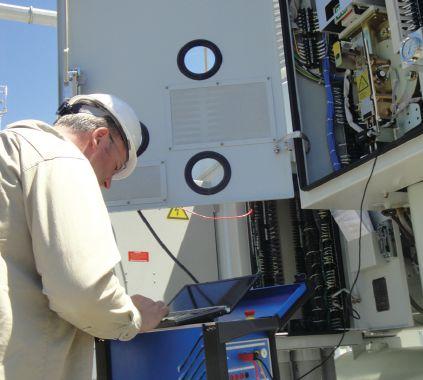
Performing Diagnostic Tests on a SF6
Circuit Breaker
COIL AND MOTOR CURRENT SIGNATURES
Information regarding lubrication, electrical coil performance, and latch operation can be extracted by analyzing the command coil signatures. Lubrication problems are easiest to identify in this scenario. As the armature of the command moves, an expected command coil signature is generated.
With motor current signatures, the behavior of the motor current shows you the power needed and how it is consumed by the motor. Unusual current levels and motor timing indicate a potential electrical fault in the motor.
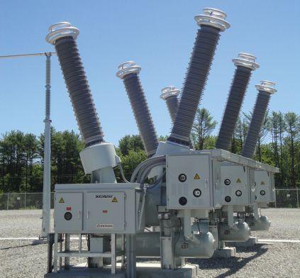
MINIMUM PICK-UP
The minimum pick-up measurement is performed to determine the minimum command coil voltage (trip or close) required to operate the circuit breaker. This is the minimum energy need for the command coil to release the latch. The latch can either be a mechanical release mechanism or a value used to control a pneumatic or hydraulic system.
This test is done for each control coil of a circuit breaker. Different considerations must be given to ganged versus independent pole operation (IPO) circuit breakers. All command coils should be tested independently. The IPO breaker may require several more tests to include all command coils.
OPTIMIZED TOOLSET
Modern diagnostic test instruments are more than just a data acquisition system. The circuit breaker toolset must include not only measurement capabilities, but also an advanced power source. This power source is needed for contact resistance and minimum pick-up. What’s more, by having this power source makes it possible to operate control
ADVANCEMENTS IN TECHNOLOGY
circuits, coils, and motors when substation power is unavailable.
The diagnostic circuit breaker toolset must provide three functions:
• Timing and travel analyzer
• μ-ohm meter (contact resistance)
• Advanced power supply
Therefore, the functions will provide the ability for performing the following tests:
• Timing and travel
• Contact resistance (static and dynamic)
• Coil and motor current signatures
• Minimum Pick-Up
It is important today that we are not only monitoring the performance of circuit breakers, but also determining key condition indicators. Utilizing an optimized and pertinent toolset is essential when determining and assessing circuit breaker health. It is important to recognize the value of all available diagnostic tools, beyond just timing and travel, and to implement them appropriately. Understanding the benefits of timing and travel tests, contact resistance (static and dynamic), coil and motor current signatures, and minimum pick-up is a key component to extending the life and maintaining proper operation of circuit breakers.


Charles Sweetser receivedaB.S.in received a B.S. in Electrical Engineering in 1992 and an M.S. in Electrical Engineering in 1996 from the University of Maine. He joined OMICRON electronics Corp. USA in 2009, where he serves as PRIM Engineering Services Manager for North America. Prior to joining OMICRON, he worked 13 years in the electrical apparatus diagnostic and consulting business. He has published several technical papers for IEEE and other industry forums. As a member of IEEE Power & Energy Society (PES) for 15 years, he actively participates in the IEEE Transformers Committee, where he held the position of Chair of the FRA Working Group PC57.149 until publication in March 2013. He is also a member of several other working groups and subcommittees. Additional interests include condition assessment of power apparatus and partial discharge.








EVOLUTION OF POWER SYSTEM PROTECTION TESTING

 BY ED KHAN, Doble Engineering Company
In any electrical system, protection plays a very important role in ensuring reliability and continuity of power to the end user. Improper operation or non-operation of protective relays or other elements of the protection system can cause havoc in any electrical distribution system. Hence, the relays must be selected, set, and maintained in strict compliance with specific rules and standards. There is no room for slack or error.
In years past, it was not uncommon to see cascading failures that started with misoperation of relays within a grid at a specific location and soon engulfed a large portion of the electrical system. Widespread blackouts were the result.
Figure 1 below shows the impact of various blackoutsintermsofaffectedcustomers. blackouts in terms of affected customers.


Figure 1: Impact of Blackouts in Terms of Affected Customers

Although, not all blackouts can be attributed to misoperation of the protection system, the latter does contribute its share toward cascading events.

Maintenance of protective relays has evolved from what used to be a simple task to what is often a relatively complex procedure. Relay maintenance has kept pace with technological advancements, new automation standards, and to some extent, government regulations in the United States and Europe.
The first electromechanical induction disk relay wasintroducedaround1910.Thatwasfollowed was introduced around 1910. That was followed by the introduction of solid-state (static) relays around 1955. Early digital relays were introduced in 1982, and since that time have continued to advance tremendously in features and capabilities.
Hand-in-hand with the progression of relay technology is a similar progression of relay test sets. Refer to Figures 2 and 3.


Time
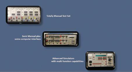


Assuring correct operation of protective relays is often difficult because under normal operating conditions, the protection provides little or no indication of its operational status. Relays that are not operational or set incorrectly may not prevent a system from operating. For example, if all settings on the relays are set too high, the system will operate correctly until a fault occurs, effectively defeating the protection. Furthermore, protective systems can be very complex and require careful attention to achieve meaningful testing.
Protective relay and system testing can be divided into three main types, with a fourth added in somecases: some cases:
1. Factory Tests
2. Commissioning Tests
3. Pre-Commissioning (in some instances)
4.PeriodicMaintenanceTests
4. Periodic Maintenance Tests
Each of these can utilize different tools, procedures, and methods of testing.
FACTORY TESTS
FACTORY TESTS
Factory tests are divided into two parts. The first part consists of tests in which the operating parameters of the relay are simulated. A good setup to perform these types of tests uses realtimesimulations. time simulations.


Figure 4 shows the test setup using real-time simulators. These simulators provide accurate simulation of power system conditions and enable relay testing under a wide range of system conditions.Thereal-timesimulatorssimulate conditions. The real-time simulators simulate real systems in digital form, with actual voltage and current output in the form of analog signals. Because these simulators provide a low signal level, amplifiers are needed to bring the signals to levels suitable for relays. Relay response is fed back to the simulator; the simulator accounts for this status change and modifies the calculation. This process continues in a loop, and hence, is called a closedloop process.

Real-time simulators are used extensively at large relay manufacturing facilities to perform real-time transient testing and simulation for their products. Manufacturersalsouseconventionaltestsetswhen Manufacturers also use conventional test sets when required as part of overall factory testing.
The second part of the factory tests addresses a devices capability to withstand vibration, stress due to temperature, electromagnetic compatibility, and impact. Many of these relay factory tests are also termed type testing since they are performed on one relay which represents a specific product line.

COMMISSIONING TESTS
Commissioning tests are performed to achieve the following:
• Ensure that equipment has not been damaged in transit and is in acceptable condition to be placed in service
• Confirm that equipment is installed correctly and as per specifications
• Verify the settings are installed correctly and the relay/protection system operates as intended
• Document all drawings, references, and settings for future use
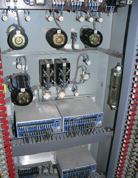
Testing methods can involve steady-state, dynamic, or transient tests.
One item that differentiates commissioning tests from factory and preventative maintenance is the scope of work. Commissioning tests deal with not only the protective relays and associated controls, auxiliary relays, but also with the related primary equipment such as breakers, CTs, and VTs. In commissioning tests, all wiring must be ringed, or traced out, to verify conformity with
applicable drawings. Figure 5 shows a typical installation that requires such verification.
PRE-COMMISSIONING TESTS
For some large and critical projects such as 500 kV to 1000 kV transmission lines or lines that have series compensation, another level of tests is frequently utilized. These tests are performed using real-time simulations with actual relays wired to a simulator. These tests can include several simulations involving different types of faults at different locations under different system and fault configurations. Pre-commissioning tests makes commissioning tests easier and can save time during that stage. Various bugs related to items such as settings, relay design, and application. can be identified and resolved during pre-commissioning tests.
PERIODIC MAINTENANCE TESTS
This type of maintenance is very important and has gained significant attention due to preventable blackouts that have taken out large areas of transmission systems. Protection is a very sensitive component in any power system. On an installed cost basis, a substation’s protection is a small expense compared to the cost of other system components, such as transformers, breakers, etc. However, from the impact point of view, the protection can have very significant importance.
Statistics show that protective relay misoperations are often attributed to the following:
•Limitations in the design of protective scheme
• Faulty relays
• Defects in the secondary wiring
• Incorrect connections
• Incorrect settings
• Known application shortcomings accepted as improbable
• Faulty pilot wires due to previous damage of which the maintenance staff was unaware
• Various other causes of misoperation, such as switching errors, testing errors, and the operation of relays from mechanical shock
Periodic maintenance testing is conducted using three methods:
1. Steady-State Testing
2. Dynamic Testing
3. Transient Testing
Steady-state testing is the simplest and was performed by early generation test sets. As newer and more complex relays entered the market, test sets and testing methods progressed into dynamic and transient testing. Even though advanced test sets are readily available, not all utilities perform dynamic and transient testing. The size of the utility, the sophistication of the testing staff, and funds available determine the type of periodic testing selected.
STEADY-STATE TESTING
A steady-state test is defined as applying phasors to confirm relay settings and correct operation by varying relay inputs. This testing method often involves a relay being placed on a test bench, then subjected to sinusoidal currents and/or voltages. Depending on the relay type, the operating quantity is ramped up or ramped down until the relay operates. There are several ways in which these quantities are varied. The variable(s) can be one or a combination of the following: voltage, current, frequency, or phase angle depending on the relay or element under test.
In the early days, before sophisticated relay test sets were marketed, the steady-state test was conducted with manually operated instruments. The test sets had all controls on the front panel with few limited display screens. For example, the control was done via control knobs, thumbwheels, toggle switches. Figure 6 shows one such test.
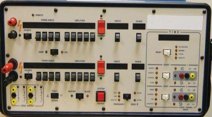
As technology progressed, newer test sets appeared. These had either a more sophisticated front panel located on the instrument itself, a separate hand-held controller, or operational control via a computer. In a test set controlled by computer, a control panel program normally provides a virtual screen. This screen has all the looks of the controls available on held-held devices or mimics the controls available on the instrument itself. Figure 7 shows a test set controlled by a computer program that emulates all the controls.

Steady-state testing is not automated. Measured variables such as current are manually ramped up or down; when the contact status changes, an audio or visual indication is provided. Once the contact transitions, the current or voltage injection is usually terminated. Some test sets are provided with an enhanced front panel that is part of the test set or a separate handheld device employed by various manufacturers. Touch screen options may also be available.
During the last 20 years, various manufacturers have enhanced steady-state testing by providing software that performs all the manual steps in a batch-mode form, which makes the test automated. The user has to define several variables, and then the program performs all the required steps without any manual intervention. Figure 8 shows an automated test to determine the pickup of an overcurrent element. The user enters the following values:
INDUSTRY TOPICS
• Expected pickup
• Tolerance
• Offset Current
• Offset Duration
• Delta current
• Delta Time
• Current limit
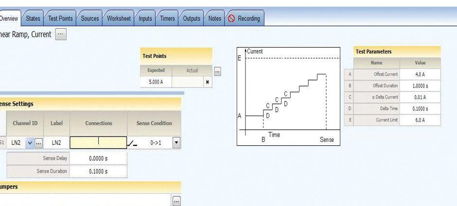
The first entry needed is a definition of the expected pickup, and this is directly obtained from the relay setting. A setting of five ampere pickup means the expected pickup is five amperes, and the tolerance can be defined as plus or minus five percent. The tolerance is obtained from the relay instruction manual or from a specific industry standard. The offset setting is needed to start the test at some point close to the expected pickup; in a manual test, the same approach is employed. Current injection is not started at one ampere if the expected pickup is five amperes; a starting point close to the expected pickup is selected. In this case, four amperes is selected as the starting point, and the test set will run at four amperes for some time (offset duration).
As in the manual test, the value of current injection is increased by increments. In the automated test, this is defined as delta current; the time at each level of current is the delta time. The last entry is the current limit, which is the point at which the test is terminated if the relay does not pick up. This entire process is automated. The same types of macros or batch mode commands are built for other types of tests. As stated earlier, these tests are steady-state. The
relay is not subjected to actual system conditions that appear during a fault.
DYNAMIC TESTING
In dynamic testing, the intent is to come closer to actual system conditions while using sinusoidal quantities at normal system frequency. Typically, a steady-state, short-circuit program output related to a specific fault can be obtained and mated with a dynamic testing program.
Basically, the entire testing cycle is divided into three states: pre-fault, fault, and post-fault. All three can be imported into the dynamic program. The test set runs the three fault states, and relay response is recorded. This type of testing is implemented by various manufacturers under different names. The transition from one state to the other can be based on a maximum time allowed to run that state or conditioned upon transition of a contact. For example, in the case of three states, the prefault could be allowed to run for a period of several cycles or seconds. The fault state could be allowed to run until relay contact operation is sensed by the test set. The software receives this information on contact transition and operation and changes to the next state. The final state, post fault, can run for several cycles or be terminated by some specified contact transition. While this dynamic test description is a very simple example, the testing could expand to more states, allowing for simulation of a variety of sequential system events. One example of a type of testing is to simulate the multiple operations of a recloser. Figure 9 shows a three-state test setup.
TRANSIENT TESTING
Transient testing is the most realistic testing type and can be used for an entire protection system as well as individual microprocessor or electro-mechanical relays. The main advantage of transient testing is that it comes closest to simulating exact system conditions and does not have the inherent limitations of the more commonly used steady-state waveforms. However, transient testing can be expensive since it can be elaborate and requires careful planning and analysis.
The first step in conducting a transient relay test is to model the system under study in a transient relay testing software program. Once the system is modeled, various faults are simulated on the line or lines under study. The system could involve two, three, or four terminals. Results of the fault analysis are saved in COMTRADE or PL4 format. The behavior of the relays applied at the terminals of the lines under study is of most interest. Thus, the values of the voltages, currents, and phase angles at the terminals are determined as the system moves from a prefault state to a fault state and then to a post-fault state. The relevant information is captured in a COMTRADE format file used by the transient program of a relay test set manufacturer. The file can be viewed as a waveform, and Figure 10 shows a waveform as viewed by one such program.
The next step is to modify the file in terms of assignment of sources, logic inputs, outputs, etc. After preparing this file, it is saved and downloaded to the test set. The test set starts putting out voltages and currents with correct phase angles in accordance with what is contained in the software. Figure 10 shows the waveform obtained by one relay test set manufacturer’s program.
This type of transient testing can be used for testing each element of a microprocessor relay or a specific electromechanical relay. However, it is more typically used for conducting end-to-end testing as described in the next section.
END-TO-END TESTING
End-to-end testing is a very sophisticated type of protective device testing used as a commissioning test or a routine test to ensure the integrity and design compliance of a communicationassisted protection scheme, also referred to as teleprotection. The test is conducted using dynamic tests that use sinusoidal waveforms with pre-fault, fault, and post-fault states, or using COMTRADE files under the transient test.
Figure 11 illustrates the setup required to conduct an end-to-end test. As shown, a test set with the appropriate files is downloaded to the relays at each end. The two test sets are synchronized via global positioning satellite inputs. The test sets start at the same time to simulate a specific fault along the line, and the behavior of each relay is recorded; the test either passes or fails depending on the performance of the relays at each end.

End-to-end testing can be expensive since it involves a significant amount of preparation time; the time to conduct the test can also be considerable. However, this type of test has many advantages, and can be a valuable tool when performing periodic maintenance testing as well as during acceptance and commissioning of equipment and systems.

End-to-end testing can verify that:
• The protection scheme is working correctly and as designed
• Communication signals are sent and received correctly
• Protection operates correctly for faults in all parts of the line
• The entire scheme is functional at the component level as well as a system
SUMMARY
In summary, the industry has seen significant changes and advances in testing regimens for protection assets over the last 30 years. Changes were driven by advances in relay technology and new testing requirements such as dynamic and transient testing. Testing and maintenance of protection assets is a very robust and everdeveloping field. There are significant changes to the execution and methodology of relay protection, and these changes are occurring both now and most likely in the not-so-distant future. Some of the changes occurring and those that are expected to occur over a period of time are being driven by the following:
1. Government regulations. NERC (North American Electric Reliability Corporation) is mandating testing procedures and maximum maintenance intervals for protection assets. Audits verify that utilities are following the mandate. This is forcing utilities to create centralized databases for all of their protection assets. Testing is no longer a standalone function. Test results and related data must be controlled and consolidated. Hence, testing now involves strict database management in addition to the technical aspects.
2. New substation automation standard. One communication/substation automation standard that is expanding at varying rates in the U.S., Canada, and rest of the world is IEC 61850. Relays complying with this standard have very different testing procedures from
those associated with conventional relays. Relays complying with IEC 61850 do not have hard-wired contacts, and they accept digitized voltage and current signals instead of conventional analog voltage and current. There are test sets available to test these relays associated with what is called a digital substation.
3. Rapid replacement of electromechanical relays with microprocessor relays. On average, the current U.S. utility has approximately 60% electromechanical relays. This percentage is expected to drop significantly in coming years with corresponding increase in microprocessor relays. Testing microprocessor relays is best done using dynamic and transient testing. This will result in increased use of dynamic and transient testing.
Going forward, we are sure to see many more changes and advances that will require testing procedures to be more integrated with the communication aspects of a power system. Also, as part of smart grid initiatives, we are seeing integration of microgrids and distributed power systems tied through communication links. This will lead to a new area of testing - testing components as an entire system, a system in which circuit protection will be an important part.

Ed Khan has been with Doble Engineering Company for the last 7 years working in various capacities, including product manager for protection tested related instruments. Currently, he is the Director of Protection R&D and Training at Doble Engineering.
Prior to Doble, Mr. Khan has worked for GE, ABB, SEL, KEMA and others in various capacities. He has 34 years of experience in system studies, protection applications, relay design, power plant design, presentation of courses and training and product management. He has a thorough knowledge about product development, protection, harmonic analysis, harmonic filter design, system design, power system studies, real time digital simulations, etc. He has presented courses on behalf of Doble Engineering and GE in US and overseas. His experience covers utilities, industrials, and power plants. He is a member of CIGRE WG 5.56 Optimization of Protection, Automation, and Control Sysytems.





ON-LINE PARTIAL DISCHARGE TESTING: INTRODUCTION TO DETECTION AND ANALYSIS OF ELECTROMAGNETIC AND ACOUSTIC PARTIAL DISCHARGE SIGNALS
 BY LOUIS NEMEC, Power Monitoring and Diagnostic Technology Ltd.


It’s no secret that insulation breakdown is responsible for the vast majority of electrical failures (see IEEE Gold Book Table 36). Partial discharge activity (PD) usually begins long before a complete insulation failure. PD testing enables discovery of insulation defects before they give rise to insulation failures and unplanned outages.
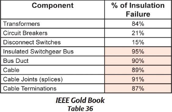

According to IEC 60270, PD testing has been performed offline. These tests can derive the apparent charge (pC) of a PD. However, for many of today’s power systems, insulation tests must be performed on-line while systems remain energized and in service. On-line PD testing incorporates

many of the concepts involved in off-line testing. On-line testing works by measuring emission signals, which emit from PD activity with a specific pattern. PD can be quickly detected and confirmed using on-line methods. The apparent charge (pC) cannot be calculated using on-line methods.

On-Line Partial Discharge (OLPD) is able to accurately pinpoint and characterize partial discharges. Currently, no global standard is specifically designed for on-line PD tests. OLPD has been around for several decades, yet many challenges and nuances have persisted. Electrically noisy environments and disturbance signals have plagued on-line testing efforts by masking PD signals or producing false-positive results. Many OLPD test instruments have failed to provide sufficient evidence to warrant a service interruption for further inspection ormaintenance. or maintenance.

Technology available today can overcome the challenges of on-line testing. OLPD can be performed efficiently and cost effectively. Virtually all insulation defects can be discovered and localized. This provides an optimum level of insurance for power system managers. A practical approach to on-line partial discharge testing includes measurements of electromagnetic emissions and acoustic emissions, which are emitted as a bi-product of partial discharge. It’s important to consider the ambient electromagnetic andacousticenvironment.Phase-resolved and acoustic environment. Phase-resolved measurements are used to compare the incoming acoustic and electromagnetic signals to the power frequency.
Partial discharges will always produce electromagnetic emissions in the UHF spectrum and acoustic emissions in the ultrasonic range. Three main types of electromagnetic sensors apply to OLPD, and two main types of acoustic sensor technology apply to OLPD.
Handheld PD Detection devices are available, which include all of the sensors and analysis modes described. Multi-channel diagnostic equipment may be required to perform certain diagnostic functions involving multiple simultaneous sensors. This paper introduces OLPD concepts and methods. . Corona cameras and infrared cameras are also helpful, along with DGA reports from oil samples.
ON-LINE PARTIAL DISCHARGE TESTING: INTRODUCTION TO DETECTION AND ANALYSIS OF ELECTROMAGNETIC AND
ACOUSTIC
PARTIAL DISCHARGE SIGNALS
On-line partial discharge sensor technology includes:
1. Electromagnetic sensor technology
a. UHF — ultra-high frequency sensor, 300 MHz to 1.5GHz, directional electromagnetic coupling antenna. Measures airborne UHFtransmittedfromthePDsource. UHF transmitted from the PD source. UHF signals can be carried on metalwork. Every PD has an emission in UHF spectrum.
b. TEV — transient earth voltage sensor, three to 100MHz, capacitive coupler, handheldTEVsensorformetal-clad handheld TEV sensor for metal-clad switchgear.
c. HFCT — high-frequency current transformer, 0.5 to 50MHz, doughnut-sized CT to measure PD pulses on ground leads. These HF pulses can travel dozens or hundreds of feet on ground shields and on the ground grid.
2. Acoustic Emissions (AE)
a. Acoustic contact sensor, 20 to 300 kHz piezoelectric sensor — for in-tank PD detection and localization in fluid dielectric, suchasoilorSF6. such as oil or SF6.
b. Ultrasonic microphone(s), 40 kHz centerfrequency, airborne ultrasonic — for external, surface PD. Ultrasonic microphone for close range PD detection and localization. Ultrasonic microphones can also be built in to a parabolic dish concentrator for long-range pinpointing.
Each sensor technology has certain applications, limitations, advantages, and disadvantages. In general, they can all be applied to substation apparatus, including all types and components of MV and HV switchgear, GIS, transformers, and power cables.
Partial discharges are defined in IEC 60270 as “localized electrical discharges that only partially bridge the insulation between conductors and which can or cannot occur adjacent to a conductor. Partial discharges are, in general, a consequence of localelectricalstressconcentrationsintheinsulation local electrical stress concentrations in the insulation or on the surface of the insulation. Generally, such discharges appear as pulses having a duration of much less than one μs.”
I. ELECTROMAGNETIC EMISSIONS
1. UHF (300MHz to 1.5GHz). A UHF pulse propagates in all directions from the site of the insulationdefect.Eachtimethe60Hzsine insulation defect. Each time the 60Hz sine wave approaches a positive- or negative-peak, wideband electromagnetic pulses are emitted and transmitted through the air. These UHF signals are detectable with a UHF sensor. The timing of the pulses is in sync with the 60Hz ac sine wave of the grid, which is


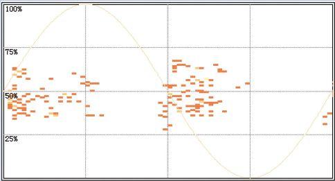
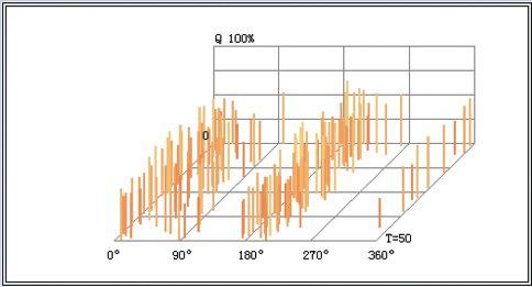


Figures 1A and 1B: 2D and 3D phase resolved charts indicating floating electrode partial discharge activity. 2D phase resolved partial discharge (PRPD) and 3D phase resolved pulse sequence (PRPS) PD signals appear on PRPS charts as groups of pulses, which occur 180 degrees apart. The magnitude of the pulse depends on the distance from the defect to the sensor and the direction the UHF sensor is facing. Magnitude of measured signal also depends on the nature and location of the defect, whether it is internal or surface PD. The structure of the apparatus will affect the ability of the UHF signal to spread into the air. The incoming UHF pulses are plotted as amplitude versus time (phase angle) on the x-y plane. In 3D PRPS view, the z-axis looks back five seconds into the past. This allows viewing the continuity of the signal in real time.(T=50 means the z-axis is 50 ds, 5000ms, five seconds). The PRPD and PRPS charts are used with UHFandHFCTsensors. UHF and HFCT sensors.
Let’s consider how partial discharges happen. What are the mechanisms of partial discharge? Where are certain types of PD activity found? What do different types of PD look like on the phase-resolved display?
a. Floating electrode. Floating electrode discharge is the most common type of PD (see Figure 1). It occurs when an energized conductor
is exposed to another conductive surface of different potential, which is not grounded but is intheelectricfieldbetweenmainconductorand in the electric field between main conductor and ground. It can be metal-to-insulation or metalto-metal. Floating electrode PD can be caused by loose parts, manufacturer’s defects, or by nongrounded metal within the electric field of the energized conductor. It is often caused by human interaction. For example, conductors are not positioned properly or a foreign or loose object is within the electric field. Floating electrode defects are normally found near the surface. Detectable UHF signal amplitudes are very high. Corona cameras may also be useful to locate floating electrode PD. Not much heat is produced. The sensors that apply: UHF, AE ultrasonic and contact probe, TEV, and HFCT sensors can apply.
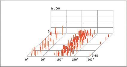
Figure 2: Void discharge depicted on PRPS (Phase Resolved Pulse Sequence)


b. Void discharge —occursindefectsinsolid — occurs in defects in solid dielectrics such as resins, rubber, polymers, and porcelain (see Figure 2). Voids are found in cables, bushings, GIS junction insulation, etc. Voids are highly destructive to insulation and typically continue to grow until failure. If a void PD is discovered, the insulator might
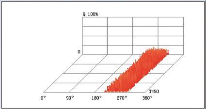
Figure 3: Corona discharge depicted on PRPS (phase resolved pulse sequence)

need to be replaced. The sensors that apply are UHF, HFCT, AE contact probe, and TEV.
c. Corona discharge — a discharge to air from the surface of an insulator (see Figure 3). This activity is destructive to insulation. Mostly appears in the negative half-cycle. Sometimes it can become bipolar (discharges twice per cycle) as it evolves into surface PD. Found in many places on GIS, MV switchgear, transformers, bolted connections and terminations. The sensors that apply are ultrasonic, UHF, and HFCT.
Harmless corona is not an issue, if it occurs on sharp ends or corners of high-voltage conductors. Irregular magnetic field strengths cause some parts of the air to become conductive. Relaxation of excited electrons in these conductive air regions give off UHF and ultrasonic emissions, and possibly, audile sounds. It’s very common on EHV systems. Ultrasonic dish or corona camera can determine if it originates from the insulator or from the conductor.
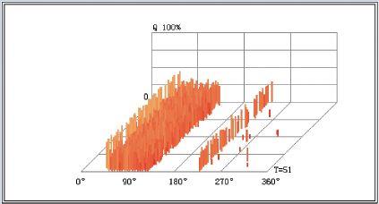
Figure 4: Surface PD depicted on phaseresolved pulse sequence (3D PRPS) chart
d. Surface discharge — destructive discharge along the surface of insulation, also known as surface tracking (see Figure 4). Usually, it’s caused by contamination or weathering of an insulator surface. It is different from corona because it tends to track to grounded metal; corona discharges to air. Corona can evolve into surface PD as it becomes more severe. Surface PD can happen on any MV and HV equipment. It occurs when the surface of the insulation breaks down, often in humid environments. Poor equipment maintenance
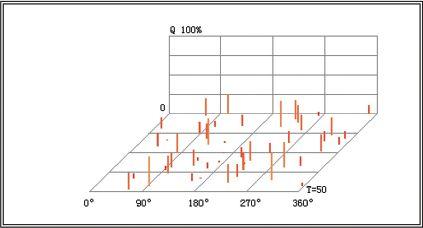
Figure 5: Particle discharge depicted on Phase-Resolved Pulse Sequence (3D PRPS) chart
can lead to this phenomenon. Moisture intrusion is also a common cause of surface PD.
Applicable sensors include AE ultrasonic and contact probe, UHF, and TEV (low magnitude).
e. Particle discharge — occurs in GIS (SF6 gas) and in oil-filled equipment (see Figure5). Caused when conductive particles contaminate insulating fluids. Allows charges to jump from particle to particle. In GIS, the particles can bounce inside the tank because of vibrations. Applicable sensors include UHF, AE contact probe, and HFCT.
To determine if PD activity is present inside electrical apparatus by use of directional UHF sensor, the incoming signals must be in phase with the ac sine wave (180 degrees apart). They should be nearly continuous, as shown in the Figure 1 PRPS. The source of the UHF signal must come from the HV apparatus. UHF source is determined by comparison of UHF charts at various locations in the substation. A real PD signal has increasing magnitude as the switchgear inspection window is approached with the UHF sensor. The signal should reach peak magnitude when the sensor is pointed into the inspection window or cabinet door seam.
2. High-frequency current (0.5 to 50MHz). Partial discharge pulses also induce a highfrequency current signal onto case grounds of metal-enclosed apparatus. A split-core high frequency current transformer (HFCT) is placed around grounding leads of metalenclosed MV or HV equipment. The HF currents on the ground grid can be compared to the 60Hz ac sine wave by using phase-resolved
FLOATING ELECTRODE PD CAN BE CAUSED BY LOOSE PARTS, MANUFACTURER’S DEFECTS, OR BY NON-GROUNDED METAL WITHIN THE ELECTRIC FIELD OF THE ENERGIZED CONDUCTOR.
IS NOT IN PHASE WITH THE POWER
IT IS AUTOMATICALLY FILTERED BY THE PHASE-RESOLVED MEASUREMENTS.
measurements. The PRPD and PRPS charts for HFCT and UHF look the same (see Figures 1-5). The type of PD can be determined with HFCT. The magnitude of the HFCT signal can be compared at different locations. HFCT is a reliable method to check for PD inside of oilfilled transformers, where airborne emissions are not likely.
3. TEV high-frequency radio signals (three to 100MHz). These may become present on the switchgear enclosures when PD activity is inside, or when common noise from lighting systems is induced on the switchgear. These are called transient earth voltage (TEV) signals. It can become induced or reflected on any metal work and onto grounded enclosures and switchgear cabinets. TEV is always detectable when PD activity is in metal-clad switchgear, but the signal tends to spread out along multiple, unpredictable paths to ground. TEV usually becomes detectable on all nearby metal work. For this reason, it is usually difficult to locate the source of a TEV signal. A high-level (50 dB) TEV signal may be present on metal posts, fences, and cabinets near the defect. TEV signals are good indicators of PD. However, TEV is also commonly caused by noise from lighting systems. False PD signals from lighting ballasts will produce detectable TEV signals on most metal structures nearby or all over an entire indoor substation. Turning off the lights for a moment is a good way to check if the lights are the source of the TEV signal. Additional information from UHF or acoustic sensors is usually needed to reach a conclusion.
Noise is not in phase with the power frequency; it is automatically filtered by the phase-resolved measurements. It’s merely energy in the same bandwidth of the sensor, but has no relationship to 60Hz. It shows up at random points along the x-axis, whereas PD always shows up 180 degrees apart.
Disturbance noise: Lighting systems, variable frequency drives, and motors can produce UHF emissions, which also fit the profile of PD signals. These are PD look-alikes. Do not be fooled. Comparison of UHF signal amplitudes
can be made from many different locations and directions around the apparatus. UHF signals that resemble PD will become induced onto metal work from nearby lighting systems and motors. Typically, the UHF noise signal will be detected in the air near the switchgear and also far away from the switchgear. When the UHF sensor is pointed into the window of the switchgear, the amplitude of the noise signal will decrease. If PD and noise are present, then the origin of the real PD signal is from inside the switchgear. The amplitude will increase when the sensor is pointed inside the switchgear.
In heavy industrial environments, false or lookalike PD signals are common. It is important to compare the change in UHF amplitudes as the sensor is changing locations and directions. Observe the rate of change of the amplitude with respect to the position of the UHF sensor. Simply walk around the station with the UHF sensor while looking at the changes in amplitude on PRPS chart. You will be able to conclude if there is a PD inside the HV equipment or not — usually PD is not present. The origin of the false signal is often related to lights or machines. Occasionally, it is not possible to determine the source of a UHF emission using only one sensor. Level II diagnostic equipment with multiple UHF sensors and time-of-flight measurement capabilities is required to verify the source.
II. ACOUSTIC EMISSIONS (AE)
Mostly ultrasonic and inaudible acoustic energy will emit from the site of the defect. Some of the more intense PD may become audible. Audibility may also depend on the upper frequency limit of your hearing.
1. Airborne ultrasonic emissions. PD at or near the surface of an insulator will produce airborne ultrasonic emissions centered near 40 kHz. Ultrasonic microphones with 40kHz center frequency and detection band from 20 to 80 kHz are commercially available. Airborne acoustic emissions may travel for only a few feet or as far as 40 feet, depending on the magnitude and location of the PD and the structure of the electrical apparatus. The amplitude of the

airborneultrasonicemissionisdetermined airborne ultrasonic emission is determined by the point of detection. How far away is the microphone from the defect? Surface PD and corona will produce airborne ultrasonic emissions. The ability of the ultrasonic signal to spread out into the air depends on the structure of the apparatus. Phase-resolved measurements are also used for acoustic signal analysis. The signal should occur twice per cycle — once at the positive wave peak and once at the negative peak. The acoustic waveform should have four distinct peaks on a cycle interval (720 degrees or 33.2ms).
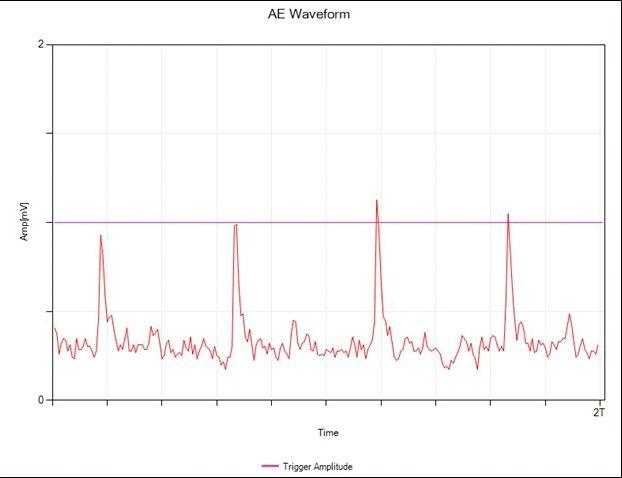
Figure 6: Phase-resolved waveform of airborne ultrasonic PD signal. The x-axis shows a two-cycle time interval (720 degrees). The Y axis shows the amplitude of the measured signal (mV).

2.In-tankultrasonicemissions.
2. In-tank ultrasonic emissions. PDinsideof PD inside of sealed equipment will produce ultrasonic signals in the 90 to 160 kHz range. These are detected using piezoelectric acoustic contact sensors. These acoustic pulses can travel through dense material, such as solid or fluid dielectrics or along metal tank walls. Typically, acoustic PD signals in GIS and oil-filled transformers will be detectable on the exterior walls of the tank; however, they cannot travel through air. Vacuum gel is used to provide a path between the exterior ofthetankandtheacousticemissionsensor. of the tank and the acoustic emission sensor.
Acoustic/ultrasonic testing provides the ability to precisely locate PD sources. If the signal
is airborne, the parabolic dish concentrator can isolate the PD emission using amplitude comparison. When a PD is inside of GIS or inside of a transformer, an amplitude comparison may lead you close to the source. Level II diagnostics can utilize multiple acoustic sensors. If PD is in between two sensors, then the Time Difference of Arrival (TDOA) method can determine the plane of the PD. A third measurement in the other plane will give the exact position of the PDfault. PD fault.


In addition to electromagnetic and acoustic emissions, PD can also produce — and therefore be identified — by recognizing the presence of three physical phenomenon: Light —sometimes — sometimes visible, sometimes not. Arcing may be visible, but you probably don’t have visual access to the location of the activity. For overhead insulators, useacoronacameratoseeUVemissions.The use a corona camera to see UV emissions. The UHF sensor also overlaps into the corona/UV spectrum. Heat –releaseoflowlevelsofinfrared – release of low levels of infrared energy. Infrared cameras are readily available. When conductors have issues, the resistance goes up and hot spots appear on the camera. But when PD occurs in the insulation, only a small temperature rise occurs. Typically, IR inspections overlook most PD. Actually, IR and PD inspections complement each other quite well.PDisforinsulationasIRisforconductors. well. PD is for insulation as IR is for conductors. Look for a very slight temperature rise, e.g. one to four degrees F. Chemical — ozone, verdigrisnitric acid (nitrous oxide + H2O), hydrogen gas in oil, combustible gasses in oil, other gasses with odor, SF6 decomposition products. DGA oilinsulationandSF6testscanindicatePD oil insulation and SF6 tests can indicate PD activity, but these samples cannot locate the PD specifically. PD near the surface of insulators may leave track marks, burn marks, white powder, or other visual evidence. However, it’s not easy to spot these signs unless one knows exactly where to look before opening any cabinets or inspecting. When a PD is suspected by electromagnetic or ultrasonic detection, it is likely that some chemical evidence will be observable when the apparatus is inspected.
Synthesis of information from each sensor is the key to OLPD. Typically, a single instance of PD


can be detected by more than one of the sensor technologies discussed here. Electromagnetic and acoustic tests will usually agree and confirmeachother.MostPDcanbedetected confirm each other. Most PD can be detected and localized using the concepts outlined in this article. In part two, more advanced concepts that apply to Level II PD diagnostics will be discussed. Cable testing and PD signal separation techniques, analysis of waveforms, time-of-flight measurements, 3D localization, andmoderninstrumentationwillbecovered. and modern instrumentation will be covered.

LouisNemec Louis Nemec attended Georgia Institute of Technology where he studied electrical engineering and chemical engineering. In 2009, he earned his bachelor’s of science with a major in analytical chemistry from Georgia State University. Since that time, Louis has been working in the high-voltage test and measurement field for over six years. He spent four years as a technical representative for ProgUSA where he gained experience with testing and maintenance of high-voltage and mediumvoltage power transmission and distribution systems. In 2013, he became involved in the sales of partial discharge test equipment. In 2015, Louis joined with Dustin Ashleigh to manage a global sales network for Power Monitoring and Diagnostic Technology Ltd., a company dedicated to partial discharge detection and diagnosis



TESTING NUMERICAL DISTRIBUTION RELAYS USING
RELAY VENDOR SOFTWARE TOOLS
BY STEVE TURNER, Beckwith Electric Company, Inc.Testing numerical distribution relays can be a complex task. Some of the issues include:
• Multiple settings groups (e.g., fuse-blow scheme versus fuse-save scheme)
• Multishot automatic reclosing
• Complex programmable relay logic
The goal of testing protective relays in general is to verify that the overall application works properly, according to design, and no hidden flaws can lead to a human performance event. Using software tools provided by the relay vendor for support can greatly simplify testing and decrease the overall time required. Test personnel and field craft should consider using these software tools. Relay vendor software is designed to support the product and has inherent advantages when used in conjunction with relay test set software.
RELAY SELF-TEST AND AUTOMATIC ALARMING
In the past, numerical relays provided only an output contact to alarm for general conditions, such as the power supply is being energized or the relay self-test failed. Modern numerical relays provide much more detailed self-test results that can be monitored through output contacts or communication protocols, such as Modbus or DNP. Figure 1 shows an example of multiple alarm points that can be individually monitored to pinpoint the root cause of the alarm.
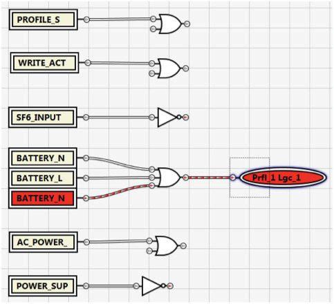
Figure 1: Multiple Point Alarm Using Programmable Logic
The following alarm points are monitored in Figure 1:
• Profile Switch (settings group has changed)
• SF6 Input OK
• Write Activity (e.g., setting has changed)
• Battery Not Charging
• Battery Load Test Failure
• Battery Not Present
• AC Power Error
• Power Supply OK
The individual battery alarms are shown ganged together driving one OR gate for a general battery
alarm; however, they can also be individually monitored. Other alarm points are available, such as protection enabled-disabled, hot-line tag, and remote-control disabled. Note that the programmable logic can be tested using the logic editor as well.
TOOLS FOR MULTISHOT AUTOMATIC RECLOSING
Figure 2 shows example settings for a four-shot automatic reclose sequence.

51P phase time overcurrent protection elements (see Figures 4A and 4B) drive the phase-shot sequence, and 51GS sensitive ground-time overcurrent protection elements drive the ground-shot sequence. HCL (high current lockout) is a high-set phase overcurrent element that drives the automatic reclosing cycle straight to lockout (see Figure 3).

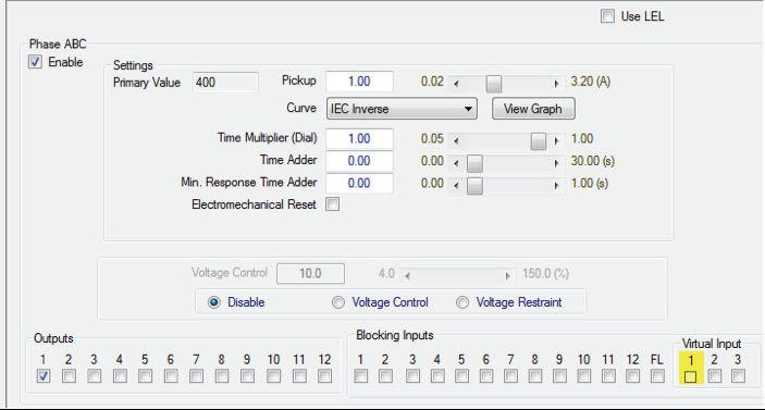
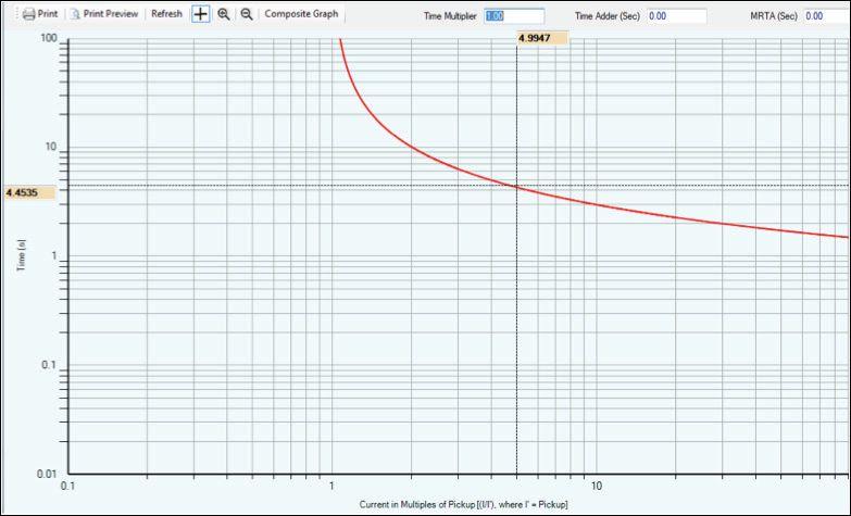
The time-current characteristics can be exported to facilitate testing these elements (see Figures 5A and 5B).

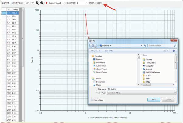
Figure 5B: Exporting Time Overcurrent Characteristics — CurveSelection Curve Selection
REAL TIME AUTOMATIC RECLOSER STATE MONITOR
Figure 6 shows the real-time automatic recloser state monitor (RTARSM).
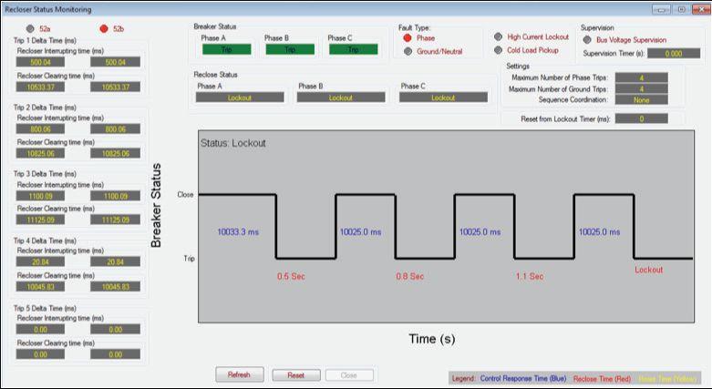
6: Real-TimeAutomaticRecloserStateMonitor Real-Time Automatic Recloser State Monitor
The RTARSM displays the following information:
• Recloser state (reset, reclose in progress, orlock or lockout)
• Breaker state (52A open or 52B closed)
• Trip time (per shot)
• Recloser interrupting time (per shot)
• Timetoresetfromlockout Time to reset from lockout
• Fault type (phase or ground)
• HCL operation
• Cold load pickup asserted
• Bus voltage supervision asserted
The cold load pickup function substitutes alternative settings for overcurrent protection elements after the breaker is tripped and has been locked out for a period exceeding the programmable timer setting. Higher pickup settings prevent unwanted tripping due to in rush when the breaker is closed. This is available and independently settable for phase and ground overcurrent inrush.
Bus voltage supervision prevents an autoreclosing cycle from starting until all the supervisory conditions are met, which are selectable — bus or feeder undervoltage and synchronism across the breaker. If the timer expires before these conditions are met, the logic goes to lockout.
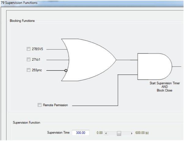
7: Bus Voltage Supervision
VISUALIZATION TOOLS
Tools that aid test personnel and field craft in visualizing the functions they are testing are extremely important because they help them to understand how they actually operate. Consider Figure 8 for a directional overcurrent element as an example. The vector residing at zero degrees in Figure 8 corresponds to the polarizing voltage (Vpol), which is the reference. The classic directional element has one maximum sensitivity angle, which corresponds to the operate current (Iop) for maximum torque conditions, such as a bolted fault on the distribution feeder. If the fault current is inside the forward-operating side of the characteristic, then a trip occurs (i.e., ±90°).
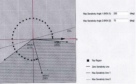
Figure 8: Directional Overcurrent Operating Characteristic
The second maximum sensitivity angle (MSA2) creates a tent characteristic (shaded) for the purpose of securely restricting the trip region of the characteristic (see Figure 8). The restricted operating characteristic region is given as follows: MSA1 ± MSA2
Figures 9A and 9B illustrate how the directional element is derived from the fault voltage and current. An impedance angle of 75 degrees corresponds to the maximum sensitivity angle (MSA1) as shown. Note that the operating current lags the polarizing voltage by this angle.
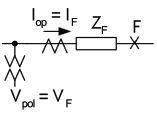
Figure 9A: Directional Overcurrent Operating and Polarizing Signals as Fault Signals
CONCLUSION
Numerical distribution protection relays are multifunctional, and as such, many individual functions must be tested. Using the software and visualization tools provided by the relay vendor can greatly simplify testing and decrease the
overall time required. Test personnel and field craft should consider using these tools.
Relay vendor software is designed to support the product, which has inherent advantages when used in conjunction with relay test set software.
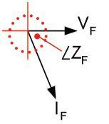
9B: DirectionalOvercurrent Directional Overcurrent Operating and Polarizing Signals as Phasors

Steve Turner is a Senior Applications Engineer at Beckwith Electric Company, Inc. His previous experience includes working as an application engineer with GEC Alstom for five years, focusing on transmission line protection in the United States. He also was an application engineer in the international market for SEL, Inc. focusing on transmission line protection applications. Steve Turner wrote the protection-related sections of the instruction manual for SEL line protection relays, as well as application guides on various topics such as transformer differential protection and out-of-step blocking during power swings. He also worked for Progress Energy in North Carolina, where he developed a patent for double-ended fault location on transmission lines and was in charge of all maintenance standards in the transmission department for protective relaying.
Steve Turner has both a BSEE and MSEE from Virginia Tech. He has presented at numerous conferences, including Georgia Tech Protective Relay Conference, Western Protective Relay Conference, ECNE and Doble User Groups, as well as various international conferences. Steve Turner is also a senior member of the IEEE.
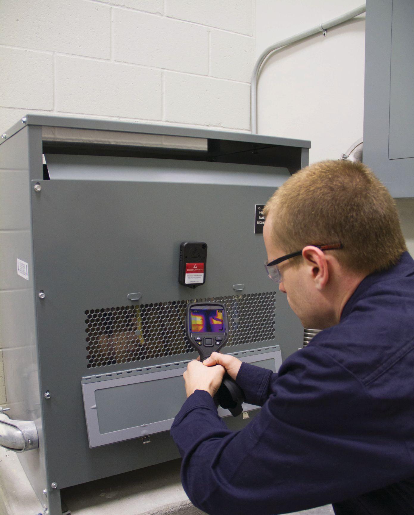
Absolute confidence. Every time.
You can count on us for specialized experience in healthcare, data center, office complex, and commercial acceptance and maintenance testing. Absolutely. Power generation, petrochemical, oil & gas, and heavy industries also look to us for high demand services such as start-up commissioning, maintenance testing, shut-down and turnarounds, and breaker shop repair. Get started today.


Email: Alan Postiglione apost@absolutetesting.com




ANSI/NETA STANDARDS UPDATE

ANSI/NETA ECS-2015 NEWAMERICAN NEW AMERICAN NATIONAL STANDARD
TheANSI/NETAECSS
The ANSI/NETA ECS Standard for Electrical Commissioning of Electrical Power Equipment and Systems, 2015 edition, was approved as an American National Standard on December 3, 2014. This new standard is available for purchase in the NETA Bookstore online at netaworld.org.


equipment, mechanical instrumentation systems, and related components.
Voltage classes addressed include:
• Low-Voltage Systems (less than 1,000 volts)

The ANSI/NETA ECS describes the systematic process of documenting and documenting placing into service newly installed or installed or retrofitted electrical power equipment power and systems. This document shall be used in conjunction with the most recenteditionoftheANSI/NETA recent edition of the ANSI/NETA Standard for Acceptance Testing Specifications for Electrical Power Equipment and Systems.Theindividual . The individual electrical components shall be subjected components to factory and field tests, as required, to validate the individual components. It is not the intent of these specifications to provide comprehensive details on the commissioning of mechanical
TheANSI/NETAECSdescribesthe

• Medium-Voltage Systems (greater than 1,000 volts and less than 100,000 volts)
• High-Voltage and Extra-High Voltage Systems (greater than 100 kV and less than 1,000 kV)
References
ASHRAE, ANSI/NETA ATS, NECA, NFPA 70E, OSHA, GSA Building Commissioning Guide
ANSI/NETA MTS-2015 NEW EDITION



TheANSI/NETAMTS The ANSI/NETA MTS Standard for Maintenance Testing Specifications for Electrical Power Equipment and Systems, 2015 edition, was approved as an American National Standard on December 3, 2014, and supersedes the ANSI/NETA MTS2011.Thisnewstandardisavailablefor 2011. This new standard is available for purchase in the NETA Bookstore online at netaworld.org.

TheANSI/NETAMTScontains The ANSI/NETA MTS contains specifications that cover suggested field tests and inspections available to assess the suitability for continued service and reliability of electrical power equipment and systems. The purpose of these specifications is to assure that tested electrical equipment and systems are operational and within applicable standards and manufacturers’ tolerances, and that the equipment and systems are suitable forcontinuedservice. for continued service.
Revisionsinclude: Revisions include:
• New numbering system for more accurate referencing
• Protective relays
• Instrumenttransformers Instrument transformers


• Rotating machinery
• NewTable100.11 New Table 100.11
• RevisedTable100.1 Revised Table 100.1
• Updated references to industry standards
• Many more revisions, all marked in the margins for ease of use


PARTICIPATION
Comments and suggestions on any of the standards are always welcome and should be directed to the NETA office at neta@netaworld.org or 888-300-6382. To learn more about the NETA standards review and revision process, to purchase these standards, or to get involved, please visit www.netaworld.org or call 888-300-6382.

ANSI/NETA ETT-2015 NEW EDITION
TheANSI/NETAETT The ANSI/NETA ETT Standard for Certification of Electrical Testing Technicians, 2015 edition, was approved as an American National Standard on December 3, 2014, and will supersede the ANSI/NETA ETT2010.Thisnewstandardisavailablefor 2010. This new standard is available for purchase in the NETA Bookstore online at netaworld.org.

TheANSI/NETAETTestablishes The ANSI/NETA ETT establishes minimum requirements for qualifications, certification, training, and experience for the electrical testing technician. It also provides criteria for documenting qualifications forcertificationanddetailstheminimum for certification and details the minimum qualifications for an independent and impartial certifying body to certify electrical testing technicians.

ANSI/NETA ATS-201X REVISION IN PROCESS
TheANSI/NETA The ANSI/NETA Standard for Acceptance Testing Specifications for Electrical Power Equipment and Systems began the review and revision process in October 2014 at the Standards Review Council meeting. The ballot pool for this document is now closed, but applications are always accepted for futurerevisions. future revisions.
The ANSI/NETA ATS covers the suggested field tests and inspections that are available to assess the suitability for initial energization of electrical power equipment and systems. The purpose of these specifications is to assure that tested electrical equipment and systems are operational, are within applicable standards and manufacturers’ tolerances, and are installed in accordance with design specifications.

ANSI/NETA STANDARDS UPDATES



Electrical Distribution System
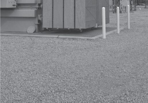


Protective Relay Test Sets · VLF/AC/DC Hipots · Tan Delta
Primary Current Injection · Thumpers · Circuit Breakers
Relay Testers · TTR Test · Megohmmeters · Partial Discharge
Power Analyzers and more...


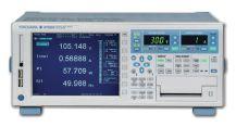
Megger · Omicron · Hipotronics · High Voltage Inc.
Fluke · Phenix · SKF/Baker · Tettex · Doble · AEMC
Rosemount/Hart


FRESH OFF THE DRAWING BOARD

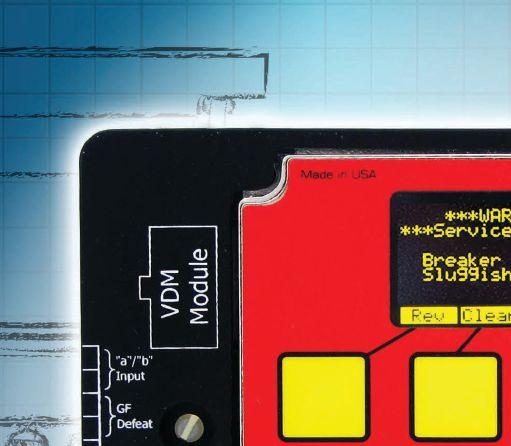
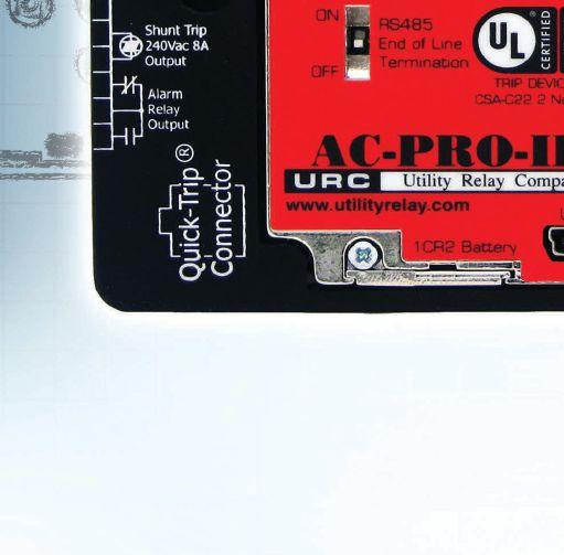
successor to the industry leading AC-PRO
The AC-PRO-II is fully backwards compatible with the CTs, actuators and wiring harnesses of the original AC-PRO

55% smaller then the original AC-PRO, with double the features.
RS-485 Modbus RTU communications is standard


Sluggish Breaker™ detection to determine if the breaker mechanism needs service.


IEEE – C57 TRANSFORMER
Spring 2015 Meeting Report
IEC AND IEEE COLLABORATION
The Institute of Electrical and Electronics Engineers (IEEE) and the International Electrotechnical Commission (IEC) have worked together for a number of years, jointly adopting and developing anumberofstandards. a number of standards.
Today’s global market demands interoperability of products and services and global standards. IEC and IEEE have been working on the adoption, revision, and joint development of market-relevant standards. In addition, IEC and IEEE created a dual logo agreement in 2002 and have since developed a dual logo maintenance agreement and a joint development agreement.
A guide to the IEC/IEEE cooperation contains detailed information and flowcharts regarding the adoption, revision, and joint development agreements and is available on the IEEE website.
Some of the adopted standards specific to the C57transformercommitteeinclude: C57 transformer committee include:
• IEC 62032 Ed. 1 (2005-03) (IEEE C57.135-2001) Guide for the Application, Specification and Testing of Phase Shifting Transformers
• IEC 60076-21 Ed. 1 (2011-12) (IEEE C57 .15-2009) Power Transformers – Part 21: Standard Requirements, Terminology, and Test Code for Step-Voltage Regulators
BY LORNE GARA, Orbis Engineering Ltd.Within the IEEE C57 Transformer Committee, a Task Force was created to compare IEEE and IEC StandardsforCrossReference.Thisisanewtask Standards for Cross Reference. This is a new task force that will compare existing IEEE and IEC transformer standards and provide its findings to thecommittee. the committee.
The dual logo standards will be accepted globally and will reduce development efforts as well as the development time for international standards. These new standards will undergo a revision within 10 years of IEEE-SA Standards Board approval. Existing standards will be compared to each other and considered for dual logo standards, or at minimum, the differences willbediscussedandtakenintoconsideration will be discussed and taken into consideration with both standard organizations.
LorneGara Lorne Gara is a Technical Manager for Orbis Engineering. He provides technical support for the engineering, field services, and automation departments of Orbis and many of its Clients. Lorne has a has wide range of experience in engineering, commissioning, maintenance, fault maintenance, fault analysis, and start-up of utility and industrial power systems across North America. He has extensive experience with protective relay setting development, commissioning, and testing protection and control systems.









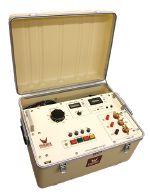
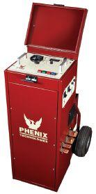
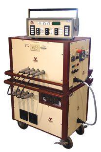

TO TRAIN FACILITY MAINTENANCE

NETAandShermcoIndustries NETA and Shermco Industries teamed up to host a full day of training at the famous Bow Building in Calgary, Alberta.
BY JILL HOWELL, NETANETA recently hosted two training sessions — one to provide an in-depth review of NETA’s specifications for maintenance testing and another on acceptance testing and electrical commissioning.
NETA President Ron Widup and Kerry Heid, both with Shermco Industries, a NETA Accredited Company, tag-teamed the sessions to provide a thorough analysis of the testing procedures, rationale behind test voltages, interpretation of test results, and an overview of test equipment and test intervals.
Attendees included representatives from the utility sector, industrial manufacturing, petrochemical, and architectural engineering. Ron Bustamante of Primary Engineering said, “I appreciated the chance to learn from some of our industry leaders’ firsthand experiences and get their input on challenges we face as we move forward. It was a tremendous learning experience.”
NETA meets with industry professionals across all business sectors to share information on the ANSI/NETA standards and promote the importance of acceptance and maintenance testing to ensure the highest level of safety and reliability. The ANSI/NETA standards provide the specifications for testing electrical power equipment and systems and for the qualifications of testing organizations and testing technicians. NETA Accredited Companies are uniquely experienced in performing these tests and meet the highest level oftheANSI/NETAstandards. of the ANSI/NETA standards.
The NETA training event was sponsored by Shermco Industries and held at the Bow, in downtown Calgary, June 10, 2015. The Bow, the tallest build in Calgary and an impressive architectural attraction was an inspiring setting for the ANSI/NETA standards training. Special thanks to Kerry Wycislik of Cenovus for inviting NETA to host the meetings at his corporate offices. Additional details on the ANSI/NETA standard are available at networld. org/standards. For more information on NETA training, contact Jill Howell at jhowell@ netaworld.org.


ANSWERS


No.111 No. 111

ANSWERS

1. b. When the internal impedance of a cell increases by more than 20 percent, it is an indication that the battery is starting to deteriorate and should be monitored more closely. This test is often referred to as the ohmic test and is performed by applying an ac voltage across the battery and measuring the internal impedance of the battery.
2. a. Increasingly, VRLA batteries are used for various stand-by electrical power applications, including emergency generators and switchgear. The most common types of VRLA batteries are gel cells and absorbed glass mat. These batteries are often referred to as “maintenance free,” although “low maintenance” would better describe them.
3. c. Sulfation results from the battery being in an undercharged state for an extended time. As the battery discharges, the active lead material on the plates will react with the sulfates in the electrolyte and form a lead sulfate on the plates. This appears as a white, granular deposit on the plates.


4. d. When battery capacity decreases to 80 percent of its initial rating, replacement is needed. It probably won’t last a year without problems.

5. a. Since sulfation occurs when a battery is in a discharged state, equalizing is the cure. The problem is that all of the sulfates usually don’t recombine, and the battery loses some capacity. This is a normal part of the charge/discharge cycle; but when a battery stays in a low state of charge, sulfation can be permanent. Battery shedding will also increase, as the discharged electrolyte now contains more water and will soften the lead plate material. If that shedded material builds up about half-way to the plates, a constant discharge begins between the shedded material and the plates, resulting in a battery that won’t maintain a charge.
NFPA Disclaimer: Although Jim White is a member of the NFPA Technical Committee for both NFPA 70E “Standard for Electrical Safety in the Workplace” and NFPA 70B “Recommended Practice for Electrical Equipment Maintenance,” the views and opinions expressed in this message are purely the author’s and shall not be considered an official position of the NFPA or any of its technical committees and shall not be considered to be, nor be relied upon as, a formal interpretation or promotion of the NFPA. Readers are encouraged to refer to the entire text of all referenced documents.
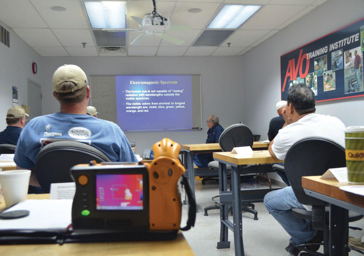


NETA ACCREDITED COMPANIES Setting the
A&F Electrical Testing, Inc.
80 Lake Ave. South, Ste. 10 Nesconset, NY 11767 (631) 584-5625 Fax: (631) 584-5720
kchilton@afelectricaltesting.com www.afelectricaltesting.com
Kevin Chilton
A&F Electrical Testing, Inc.
80 Broad St. 5th Floor
New York, NY 10004 (631) 584-5625 Fax: (631) 584-5720 afelectricaltesting@afelectricaltesting.com www.afelectricaltesting.com
Florence Chilton
ABM Electrical Power Solutions
3602 East Southern Ave., Ste. 1 Phoenix, AZ 85040 (602) 722-2423
www.ABM.com
Doug Bukowski
ABM Electrical Power Solutions
9800 E. Geddes Avenue, Unit A-150 Englewood, CO 80112 (303) 524-6560 Fax: (303) 524-6581
www.ABM.com
Brian Smith
ABM Electrical Power Solutions
2142 Rheem Drive Pleasanton, CA 94588 (408) 466-6920
www.ABM.com
John Marvulli
ABM Electrical Power Solutions
3940 Ruffin Rd., Ste. C San Diego, CA 92123 (858) 754-7963
www.ABM.com
Ben Thomas
ABM Electrical Power Solutions
6280 South Valley View Blvd., Ste. 618 Las Vegas, NV 89118 (602) 300-2188 Fax: (602) 437-3894 www.ABM.com
Jason Black
ABM Electrical Power Solutions
814 Greenbrier Circle, Ste. E Chesapeake, VA 23320 (757) 548-5690 Fax: (757) 548-5417
www.ABM.com
Mark Anthony Gaughan, III
ABM Electrical Power Solutions
3700 Commerce Dr. #901-903 Baltimore, MD 21227 (410) 247-3300 Fax: (410) 247-0900
www.ABM.com
Bill Hartman
ABM Electrical Power Solutions 5809 Departure Dr., Ste. 104 Raleigh, NC 27616 (919) 877-1008 Fax: (919) 501-7492
www.ABM.com
Rob Parton
ABM Electrical Power Solutions
317 Commerce Park Dr. Cranberry Township, PA 16066-6427 (724) 772-4638 Fax: (724) 772-6003 william.mckenzie@abm.com www.ABM.com
William (Pete) McKenzie
ABM Electrical Power Solutions 4390 Parliament Place, Ste. S Lanham, MD 20706 (301) 967-3500 Fax: (301) 735-8953 www.ABM.com
Frank Ceci
ABM Electrical Power Solutions
3600 Woodpark Blvd., Suite G Charlotte, NC 28206 (704) 273-6257 Fax: (704) 598-9812 ernest.goins@abm.com www.ABM.com
Ernest Goins
ABM Electrical Power Solutions
720 S. Rochester Ave., Suite A Ontario, CA 91761 (800) 597-1225 Fax: (909) 937-6798 www.ABM.com
Mike Bivens
Absolute Testing Services 6829 Guhn Rd. Houston, TX 77040 (832) 467-4446 Fax: (713) 849-3885 rgamble@absolutetesting.com www.texasats.com
Richard Gamble
Accessible Consulting Engineers, Inc. 1269 Pomona Rd., Ste. 111 Corona, CA 92882 (951) 808-1040 info@acetesting.com www.acetesting.com
Iraj Nasrolahi
Advanced Testing Systems 15 Trowbridge Dr. Bethel, CT 06801 (203) 743-2001 Fax: (203) 743-2325 pmaccarthy@advtest.com www.advtest.com
Pat MacCarthy
American Electrical Testing Co., Inc.
480 Neponset St., Building 6 Canton, MA 02021-1970 (781) 821-0121 Fax: (781) 821-0771 sblizard@aetco.us www.99aetco.com
Scott A. Blizard
American Electrical Testing Co., Inc. 34 Clover Dr. South Windsor, CT 06074 (860) 648-1013 Fax: (781) 821-0771 jpoulin@aetco.us www.99aetco.com
Gerald Poulin
American Electrical Testing Co., Inc. 76 Cain Dr. Brentwood, NY 11717 (631) 617-5330 Fax: (631) 630-2292 mschacker@aetco.us www.99aetco.com
Michael Schacker
American Electrical Testing Co., Inc. 50 Intervale Rd., Ste. 1 Boonton, NJ 07005 (973) 316-1180 Fax: (781) 316-1181 jsomol@aetco.us www.99aetco.com
Jeff Somol
American Electrical Testing Co., Inc. 4032 Park 65 Dr. Indianapolis, IN 46254 (317) 487-2111 Fax: (781) 821-0771 scanale@aetco.us www.99aetco.com
Stephen Canale
American Electrical Testing Co., Inc. Green Hills Commerce Center 5925 Tilghman St., Ste. 200 Allentown, PA 18104 (215) 219-6800 jmunley@aetco.us www.99aetco.com
Jonathan Munley
American Electrical Testing Co., Inc. 12566 W. Indianola Ave. Avondale, AZ 85392 (480) 383-9242 dmadaglia@aetco.us www.99aetco.com
Donald Madaglia
AMP Quality Energy Services, LLC 4220 West Schrimsher SW Site W1 P.O. Box 526, Huntsville, AL 35804 (256) 513-8255
Brian Rodgers
Apparatus Testing and Engineering 11300 Sanders Dr., Ste. 29 Rancho Cordova, CA 95742 (916) 853-6280 Fax: (916) 853-6258 info@apparatustesting.com www.apparatustesting.com
Harold (Jerry) Carr
Apparatus Testing and Engineering
7083 Commerce Circle, Ste. H Pleasanton, CA 94588 (925) 454-1363 Fax: (925) 454-1499 info@apparatustesting.com www.apparatustesting.com
Harold (Jerry) Carr
Applied Engineering Concepts 1105 N. Allen Ave. Pasadena, CA 91104 (626) 398-3052 Fax: (626) 398-3053 michel.c@aec-us.com www.aec-us.com
Michel Castonguay
BEC Testing 50 Gazza Blvd. Farmingdale, NY 11735 (516) 531-9136 Fax: (631) 249-6115 wfernandez@banaelectric.com www.bectesting.com
William Fernandez
Burlington Electrical Testing Co., Inc.
300 Cedar Ave. Croydon, PA 19021-6051 (215) 826-9400 (221) Fax: (215) 826-0964 waltc@betest.com www.betest.com
Walter P. Cleary
C.E. Testing, Inc. 6148 Tim Crews Rd. Macclenny, FL 32063 (904) 653-1900 Fax: (904) 653-1911 cetesting@aol.com
Mark Chapman
CE Power Solutions,LLC 4040 Rev Dr. Cincinnati, OH 45232 (513) 563-6150 Fax: (513) 563-6120 info@cepowersol.net www.cepowersol.com
Rhonda Harris
CE Power Solutions of Minnesota,LLC 7674 Washington Ave. South Eden Prairie, MN 55344 (877) 968-0281 Fax: (952) 400-8772 jason.thompson@cepower.net www.cepower-MN.com
Jason Thompson
Control Power Concepts
353 Pilot Rd; Ste. B Las Vegas, NV 89119 (702) 448-7833 Fax: (702) 448-7835 www.controlpowerconcepts.com
John Travis
Dude Electrical Testing LLC
145 Tower Dr., Unit# 9 Burr Ridge, IL 60527 (815) 293-3388 Fax: (815) 293-3386
scott.dude@dudetesting.com www.dudetesting.com
Scott Dude
DYMAX Service, LLC
46918 Liberty Dr. Wixom, MI 48393 (248) 313-6868 Fax: (248) 313-6869 www.dymaxservice.com
Bruce Robinson
DYMAX Service, LLC
4213 Kropf Ave. Canton, OH 44706 (330) 484-6801 Fax: (740) 333-1271 www.dymaxservice.com
Chuck Baker
Eastern High Voltage
11A South Gold Dr. Robbinsville, NJ 08691-1606 (609) 890-8300 Fax: (609) 588-8090 joewilson@easternhighvoltage.com www.easternhighvoltage.com
Joseph Wilson
ELECT, P.C.
7400-G Siemens Rd., P.O. Box 2080 Wendell, NC 27591 (919) 365-9775 Fax: (919) 365-9789 btyndall@elect-pc.com www.elect-pc.com
Barry W. Tyndall
Electric Power Systems, Inc. 21 Millpark Ct. Maryland Heights, MO 63043 (314) 890-9999 Fax: (314) 890-9998 www.epsii.com
Electric Power Systems, Inc. 557 E. Juanita Ave., #4 Mesa, AZ 85204 (480) 633-1490 Fax: (480) 633-7092 www.epsii.com
Electric Power Systems, Inc. 4436 Parkway Commerce Blvd. Orlando, FL 32808 (407) 578-6424 Fax: 407-578-6408 www.epsii.com
Electric Power Systems, Inc.
7000 E. 47th Avenue Drive, Suite 100 Denver, CO 80216 (720) 857-7273 Fax: 303-928-8020 www.epsii.com
Electric Power Systems, Inc. 23823 Andrew Rd. Plainfield, IL 60585 (815) 577-9515 Fax: (815) 577-9516 www.epsii.com
NETA ACCREDITED COMPANIES
Electric Power Systems, Inc. 2601 Center Rd., # 101 Hinckley, OH 44233 (330) 460-3706 Fax: (330) 460-3708 www.epsii.com
Electric Power Systems, Inc.
56 Bibber Pkwy #1 Brunswick, ME 04011 (207) 837-6527 www.epsii.com
Electric Power Systems, Inc. 4100 Greenbriar Dr., Ste. 160 Stafford, TX 77477 (713) 644-5400 www.epsii.com
Electric Power Systems, Inc. 11861 Longsdorf St. Riverview, MI 48193 (734) 282-3311 www.epsii.com
Electric Power Systems, Inc. 827 Union St., Salem, VA 24153 (540) 375-0084 Fax: (540) 375-0094 www.epsii.com
Electric Power Systems, Inc. 915 Holt Ave., Unit 9 Manchester, NH 03109 (603) 657-7371 Fax: 603-657-7370 www.epsii.com
Electric Power Systems, Inc.
146 Space Park Dr. Nashville, TN 37211 (615) 834-0999 Fax: (615) 834-0129 www.epsii.com
Electric Power Systems, Inc. 8515 Cella Alameda NE, Ste. A Albuquerque, NM 87113 (505) 792-7761 www.epsii.com
Electric Power Systems, Inc. 7140 Dean Martin Drive, Suite 900 Las Vegas, NV 89118 (702) 815-1342 www.epsii.com
Electric Power Systems, Inc.
319 US Hwy. 70 E, Unit E Garner, NC 27529 (919) 322-2670 www.epsii.com
Electric Power Systems, Inc. 1090 Montour West Industrial Blvd. Coraopolis, PA 15108 (412) 276-4559 www.epsii.com
NETA ACCREDITED COMPANIES
Electric Power Systems, Inc. 6141 Connecticut Ave. Kansas City, MO 64120 (816) 241-9990 Fax: (816) 241-9992 www.epsii.com
Electric Power Systems, Inc. 2495 Boulevard of the Generals Norristown, PA 19403 (610) 630-0286 www.epsii.com
Electric Power Systems, Inc. 1129 East Hwy. 30 Gonzalez, LA 70817 (225) 644-0150 Fax: (225) 644-6249 www.epsii.com
Electric Power Systems, Inc. 7925 Dunbrook Rd., Ste. G San Diego, CA 92126 (858) 566-6317 www.epsii.com
Electrical & Electronic Controls 6149 Hunter Rd. Ooltewah, TN 37363 (423) 344-7666 (23) Fax: (423) 344-4494 eecontrols@comcast.net
Michael Hughes
Electrical Energy Experts, Inc. W129N10818, Washington Dr. Germantown, WI 53022 (262) 255-5222 Fax: (262) 242-2360 bill@electricalenergyexperts.com www.electricalenergyexperts.com
William Styer
Electrical Equipment Upgrading, Inc. 21 Telfair Place, Savannah, GA 31415 (912) 232-7402 Fax: (912) 233-4355 kmiller@eeu-inc.com www.eeu-inc.com
Kevin Miller
Electrical Maintenance & Testing Inc. 12342 Hancock St., Carmel, IN 46032 (317) 853-6795 Fax: (317) 853-6799 info@emtesting.com www.emtesting.com
Brian K. Borst
Electrical Reliability Services 1057 Doniphan Park Circle, Ste. A El Paso, TX 79922 (915) 587-9440 Fax: (915) 587-9010 www.electricalreliability.com
Electrical Reliability Services 1775 W. University Dr., Ste. 128 Tempe, AZ 85281 (480) 966-4568 Fax: (480) 966-4569 www.electricalreliability.com
Electrical Reliability Services 1426 Sens Rd. Ste. 5 Houston, TX 77571 (281) 241-2800 Fax: (281) 241-2801 www.electricalreliability.com
Electrical Reliability Services 4099 SE International Way, Ste. 201 Milwaukie, OR 97222-8853 (503) 653-6781 Fax: (503) 659-9733 www.electricalreliability.com
Electrical Reliability Services 5909 Sea Lion Place, Ste. C Carlsbad, CA 92010 (858) 695-9551 www.electricalreliability.com
Electrical Reliability Services 8500 Washington Pl. NE, Ste. A-6 Albuquerque, NM 87113 (505) 822-0237 Fax: (505) 822-0217 www.electricalreliability.com
Electrical Reliability Services 1380 Greg Street, Ste. 217 Sparks, NV 89431 (775) 746-8484 Fax: (775) 356-5488 www.electricalreliability.com
Electrical Reliability Services 2275 Northwest Pkwy SE, Ste. 180 Marietta, GA 30067 (770) 541-6600 Fax: (770) 541-6501 www.electricalreliability.com
Electrical Reliability Services 7100 Broadway, Ste. 7E Denver, CO 80221-2915 (303) 427-8809 Fax: (303) 427-4080 www.electricalreliability.com
Electrical Reliability Services 348 N.W. Capital Dr. Lee's Summit, MO 64086 (816) 525-7156 Fax: (816) 524-3274 www.electricalreliability.com
Electrical Reliability Services 6900 Koll Center Parkway, Ste. 415 Pleasanton, CA 94566 (925) 485-3400 Fax: (925) 485-3436 www.electricalreliability.com
Electrical Reliability Services 10606 Bloomfield Ave. Santa Fe Springs, CA 90670 (562) 236-9555 Fax: (562) 777-8914 www.electricalreliability.com
Electrical Reliability Services
3535 Emerson Parkway, Ste. A Gonzales, LA 70737 (225) 755-0530 Fax: (225) 751-5055 www.electricalreliability.com
NETA ACCREDITED COMPANIES Setting the
Electrical Reliability Services
245 Hood Rd. Sulphur, LA 70665 (337) 583-2411 Fax: (337) 583-2410 www.electricalreliability.com
Electrical Reliability Services
11000 Metro Pkwy., Ste. 30 Ft. Myers, FL 33966 (239) 693-7100 Fax: (239) 693-7772 www.electricalreliability.com
Electrical Reliability Services
2222 West Valley Hwy. N., Ste 160 Auburn, WA 98001 (253) 736-6010 Fax: (253) 736-6015 www.electricalreliability.com
Electrical Reliability Services
3412 South 1400 West, Unit A West Valley City, UT 84119 (801) 975-6461 www.electricalreliability.com
Electrical Reliability Services
6351 Hinson St., Ste. B Las Vegas, NV 89118 (702) 597-0020 Fax: (702) 597-0095 www.electricalreliability.com
Electrical Reliability Services
9636 St. Vincent, Unit A Shreveport, LA 71106 (318) 869-4244 www.electricalreliability.com
Electrical Reliability Services
610 Executive Campus Dr. Westerville, OH 43082 (877) 468-6384 Fax: (614) 410-8420 info@electricalreliability.com www.electricalreliability.com
Electrical Testing, Inc. 2671 Cedartown Hwy. Rome, GA 30161-6791 (706) 234-7623 Fax: (706) 236-9028 steve@electricaltestinginc.com www.electricaltestinginc.com
Electrical Testing Solutions
2909 Green Hill Ct. Oshkosh, WI 54904 (920) 420-2986 Fax: (920) 235-7136 tmachado@electricaltestingsolutions.com www.electricaltestingsolutions.com
Tito Machado
Elemco Services, Inc. 228 Merrick Rd. , Lynbrook, NY 11563 (631) 589-6343 Fax: (631) 589-6670 courtney@elemco.com www.elemco.com
Courtney O'Brien
EnerG Test
204 Gale Lane Bldg. 2 - 2nd Floor
Kennett Square, PA 19348 (484) 731-0200 Fax: (484) 713-0209 kbleiler@energtest.com www.energtest.com
Katie Bleiler
Energis High Voltage Resources, Inc. 1361 Glory Rd. Green Bay, WI 54304 (920) 632-7929 Fax: (920) 632-7928 info@energisinc.com www.energisinc.com
Mick Petzold
EPS Technology 29 N. Plains Hwy., Ste. 12 Wallingford, CT 06492 (203) 679-0145 www.eps-technology.com
Grounded Technologies, Inc. 10505 S. Progress Way, Ste. 105 Parker, CO 80134 P-(303) 781-2560 F- (303) 781-5240 jodymedina@groundedtech.com www.groundedtech.com
Jody Medina
Grubb Engineering, Inc. 3128 Sidney Brooks San Antonio, Tx 78235 (210) 658-7250 Fax: (210) 658-9805 joy@grubbengineering.com www.grubbengineering.com
Robert D. Grubb Jr.
Hampton Tedder Technical Services 4571 State St. Montclair, CA 91763 (909) 628-1256 x214 Fax: (909) 628-6375 matt.tedder@hamptontedder.com www.hamptontedder.com
Matt Tedder
Hampton Tedder Technical Services 4920 Alto Ave. Las Vegas, NV 89115 (702) 452-9200 Fax: (702) 453-5412 www.hamptontedder.com
Roger Cates
Hampton Tedder Technical Services 3747 West Roanoke Ave. Phoenix, AZ 85009 (480) 967-7765 Fax: (480) 967-7762 www.hamptontedder.com
Harford Electrical Testing Co., Inc. 1108 Clayton Rd. Joppa, MD 21085 (410) 679-4477 Fax: (410) 679-0800 testing@harfordtesting.com www.harfordtesting.com
Vincent Biondino
High Energy Electrical Testing, Inc. 515 S. Ocean Ave. Seaside Park, NJ 08752 (732) 938-2275 Fax: (732) 938-2277 hinrg@comcast.net www.highenergyelectric.com
Charles Blanchard
High Voltage Maintenance Corp. 24 Walpole Park South Dr. Walpole, MA 02081 (508) 668-9205 www.hvmcorp.com
High Voltage Maintenance Corp. 941 Busse Rd. Elk Grove Village, Il 60007 (847) 640-0005 www.hvmcorp.com
High Voltage Maintenance Corp. 7200 Industrial Park Blvd. Mentor, OH 44060 (440) 951-2706 Fax: (440) 951-6798 www.hvmcorp.com
High Voltage Maintenance Corp. 3000 S. Calhoun Rd. New Berlin, WI 53151 (262) 784-3660 Fax: (262) 784-5124 www.hvmcorp.com
High Voltage Maintenance Corp. 8320 Brookville Rd. #E Indianapolis, IN 46239 (317) 322-2055 Fax: (317) 322-2056 www.hvmcorp.com
High Voltage Maintenance Corp. 1250 Broadway, Ste. 2300 New York, NY 10001 (718) 239-0359 www.hvmcorp.com
High Voltage Maintenance Corp. 355 Vista Park Dr. Pittsburgh, PA 15205-1206 (412) 747-0550 Fax: (412) 747-0554 www.hvmcorp.com
High Voltage Maintenance Corp. 150 North Plains Industrial Rd. Wallingford, CT 06492 (203) 949-2650 Fax: (203) 949-2646 www.hvmcorp.com
High Voltage Maintenance Corp. 9305 Gerwig Ln., Ste. B Columbia, MD 21046 (410) 309-5970 Fax: (410) 309-0220 www.hvmcorp.com
High Voltage Maintenance Corp. 24371 Catherine Industrial Dr, Ste. 207 Novi, MI 48375 (248) 305-5596 Fax: (248) 305-5579 www.hvmcorp.com
High Voltage Maintenance Corp. 5100 Energy Dr. Dayton, OH 45414 (937) 278-0811 Fax: (937) 278-7791 www.hvmcorp.com
High Voltage Service, LLC 4751 Mustang Circle St. Paul, MN 55112 (763) 784-4040 Fax: (763) 784-5397 www.hvserviceinc.com
Mike Mavetz
HMT, Inc. 6268 Route 31 Cicero, NY 13039 (315) 699-5563 Fax: (315) 699-5911 jpertgen@hmt-electric.com www.hmt-electric.com
John Pertgen
Industrial Electric Testing, Inc. 11321 West Distribution Ave. Jacksonville, FL 32256 (904) 260-8378 Fax: (904) 260-0737 gbenzenberg@bellsouth.net www.industrialelectrictesting.com
Gary Benzenberg
Industrial Electric Testing, Inc. 201 NW 1st Ave. Hallandale, FL 33009-4029 (954) 456-7020 www.industrialelectrictesting.com
Industrial Electronics Group 850369 Highway 17 South P.O. Box 1870 Yulee, FL 32041 (904) 225-9529 Fax: (904) 225-0834 butch@industrialgroups.com www.industrialgroups.com
Butch E. Teal
Industrial Tests, Inc. 4021 Alvis Ct., Ste. 1 Rocklin, CA 95677 (916) 296-1200 Fax: (916) 632-0300 greg@indtest.com www.industrialtests.com
Greg Poole
Infra-Red Building and Power Service 152 Centre St. Holbrook, MA 02343-1011 (781) 767-0888 Fax: (781) 767-3462 tom.mcdonald@infraredbps.com www.infraredbps.com
Thomas McDonald Sr.
Longo Electrical-Mechanical, Inc. One Harry Shupe Blvd., Box 511 Wharton, NJ 07885 (973) 537-0400 Fax: (937) 537-0404 jmlongo@elongo.com www.elongo.com
Joe Longo
Longo Electrical-Mechanical, Inc. 1625 Pennsylvania Ave. Linden, NJ 07036 (908) 925-2900 Fax: (908) 925-9427 jmlongo@elongo.com www.elongo.com
Joe Longo
Longo Electrical-Mechanical, Inc. 1400 F Adams Rd. Bensalem, PA 19020 (215) 638-1333 Fax: (215) 638-1366 jmlongo@elongo.com www.elongo.com
Joe Longo
M&L Power Systems, Inc.
109 White Oak Ln., Ste. 82 Old Bridge, NJ 08857 (732) 679-1800 Fax: (732) 679-9326 milind@mlpower.com www.mlpower.com
Milind Bagle
Magna IV Engineering 1103 Parsons Rd. SW Edmonton, AB T6X 0X2 Canada (780) 462-3111 Fax: (780) 450-2994 info@magnaiv.com www.magnaiv.com
Virgina Balitski
Magna IV Engineering 200, 688 Heritage Dr. Calgary, AB T2H 1M6 Canada (403) 723-0575 Fax: (403) 723-0580 info.calgary@magnaiv.com
Dave Emerson
Magna IV Engineering 8219D Fraser Ave. Fort McMurray, AB T9H 0A2 Canada (780) 791-3122 Fax: (780) 791-3159 info.fmcmurray@magnaiv.com
Ryan Morgan
Magna IV Engineering 96 Inverness Dr. East, Unit R Englewood, CO 80112 (303) 799-1273 Fax: (303) 790-4816 info.denver@magnaiv.com Aric Proskurniak
Magna IV Engineering Avenida del Condor #590 Oficina 601 Huechuraba, Santiago 8580676 Chile +(56) 9-9-517-4642 info.chile@magnaiv.com
Harvey Mendoza
Magna IV Engineering 1040 Winnipeg St. Regina , SK S4R 8P8 Canada (306) 585-2100 Fax: (306) 585-2191 info.regina@magnaiv.com
Andrew Westerman
Magna IV Engineering 106, 4268 Lozells Ave. Burnaby, BC VSA 0C6 Canada (604) 421-8020 Scott Nixon
National Field Services 649 Franklin St. Lewisville, TX 75057 (972) 420-0157 www.natlfield.com
Eric Beckman
Nationwide Electrical Testing, Inc. 6050 Southard Trace Cumming, GA 30040 (770) 667-1875 Fax: (770) 667-6578 Shashi@N-E-T-Inc.com www.n-e-t-inc.com
Shashikant B. Bagle
North Central Electric, Inc. 69 Midway Ave. Hulmeville, PA 19047-5827 (215) 945-7632 Fax: (215) 945-6362 ncetest@aol.com www.ncetest.com
Robert Messina
Northern Electrical Testing, Inc. 1991 Woodslee Dr. Troy, MI 48083-2236 (248) 689-8980 Fax: (248) 689-3418 ldetterman@northerntesting.com www.northerntesting.com
Lyle Detterman
Orbis Engineering Field Services Ltd. #300, 9404 - 41st Ave. Edmonton, AB T6E 6G8 Canada (780) 988-1455 Fax: (780) 988-0191 lorne@orbisengineering.net www.orbisengineering.net
Lorne Gara
Pacific Power Testing, Inc. 14280 Doolittle Dr. San Leandro, CA 94577 (510) 351-8811 Fax: (510) 351-6655 steve@pacificpowertesting.com www.pacificpowertesting.com
Steve Emmert
NETA ACCREDITED COMPANIES
Pacific Powertech, Inc. #110, 2071 Kingsway Ave. Port Coquitlam, BC V3C 6N2 Canada (604) 944-6697 Fax: (604) 944-1271 jkonkin@pacificpowertech.ca www.pacificpowertech.ca
Josh Konkin
Phasor Engineering Sabaneta Industrial Park #216 Mercedita, PR 00715 Puerto Rico (787) 844-9366 Fax: (787) 841-6385 rcastro@phasorinc.com
Rafael Castro
Potomac Testing, Inc. 1610 Professional Blvd., Ste. A Crofton, MD 21114 (301) 352-1930 Fax: (301) 352-1936 kbassett@potomactesting.com www.potomactesting.com
Ken Bassett
Power & Generation Testing, Inc. 480 Cave Rd. Nashville, TN 37210 (615) 882-9455 Fax: (615) 882-9591 mose@pgti.net www.pgti.net
Mose Ramieh
Power Engineering Services, Inc. 9179 Shadow Creek Lane Converse, TX 78109 (210) 590-4936 Fax: (210) 590-6214 engelke@pe-svcs.com www.pe-svcs.com
Miles R. Engelke
POWER PLUS Engineering, Inc. 46575 Magellan Novi, MI 48377 (248) 344-0200 Fax: (248) 305-9105 smancuso@epowerplus.com www.epowerplus.com
Salvatore Mancuso
Power Products & Solutions, LLC 12465 Grey Commercial Rd. Midland, NC 28107 (704) 573-0420 x12 Fax: (704) 573-3693 ralph.patterson@powerproducts.biz www.powerproducts.biz
Ralph Patterson
Power Products & Solutions, LLC 13 Jenkins Ct. Mauldin, SC 29662 (800) 328-7382 ralph.patterson@powerproducts.biz www.powerproducts.biz
Raymond Pesaturo
Power Services, LLC 998 Dimco Way, P.O. Box 750066 Centerville, OH 45475 (937) 439-9660 Fax: (937) 439-9611
mkbeucler@aol.com
Mark Beucler
Power Solutions Group, Ltd. 425 W. Kerr Rd. Tipp City, OH 45371 (937) 506-8444 Fax: (937) 506-8434 bwilloughby@powersolutionsgroup.com www.powersolutionsgroup.com
Barry Willoughby
Power Solutions Group, Ltd. 135 Old School House Rd. Piedmont, SC 29673 (864) 845-1084 Fax:: (864) 845-1085 fcrawford@powersolutionsgroup.com www.powersolutionsgroup.com
Anthony Crawford
Power Solutions Group, Ltd. 670 Lakeview Plaza Blvd. Columbus, OH 43085 (614) 310-8018 sspohn@powersolutionsgroup.com www.powersolutionsgroup.com
Stuart Spohn
Power Systems Testing Co. 4688 W. Jennifer Ave., Ste. 108 Fresno, CA 93722 (559) 275-2171 ext 15 Fax: (559) 275-6556 dave@pstcpower.com www.powersystemstesting.com
David Huffman
Power Systems Testing Co. 600 S. Grand Ave., Ste. 113 Santa Ana, CA 92705-4152 (714) 542-6089 Fax: (714) 542-0737 www.powersystemstesting.com
Power Systems Testing Co. 6736 Preston Ave, Ste. E Livermore, CA 94551 (510) 783-5096 Fax: (510) 732-9287 www.powersystemstesting.com
Power Test, Inc. 2200 Highway 49 Harrisburg, NC 28075 (704) 200-8311 Fax: (704) 455-7909 rich@powertestinc.com www.powertestinc.com
Richard Walker
POWER Testing and Energization, Inc. 14006 NW 3rd Ct., Ste. 101 Vancouver, WA 98685 (360) 597-2800 Fax: (360) 576-7182 chris.zavadlov@powerte.com www.powerte.com
Chris Zavadlov
NETA ACCREDITED COMPANIES
POWER Testing and Energization, Inc.
731 E. Ball Rd., Ste. 100 Anaheim, CA 92805 (714) 507-2702
www.powerte.com
POWER Testing and Energization, Inc.
22035 70th Ave. South Kent, WA 98032 (253) 872-7747
www.powerte.com
Powertech Services, Inc.
4095 South Dye Rd. Swartz Creek, MI 48473-1570 (810) 720-2280 Fax: (810) 720-2283 kirkd@powertechservices.com www.powertechservices.com
Kirk Dyszlewski
Precision Testing Group
5475 Highway 86, Unit 1 Elizabeth, CO 80107 (303) 621-2776 Fax: (303) 621-2573
glenn@precisiontestinggroup.com
Glenn Stuckey
Premier Power Maintenance Corporation
6525 Guion Rd. Indianapolis, IN 46268 (317) 879-0660
kevin.templeman@premierpower.us www.premierpowermaintenance.com
Kevin Templeman
Premier Power Maintenance Corporation 2725 Jason Rd. Ashland, KY 41102 (606) 929-5969
jay.milstead@premierpower.us www.premierpowermaintenance.com
Jay Milstead
Premier Power Maintenance Corporation
3066 Finley Island Cir NW Decatur, AL 35601 (256) 355-1444
johnnie.mcclung@premierpower.us www.premierpowermaintenance.com
Johnnie McClung
Premier Power Maintenance Corporation 4301 Iverson Blvd., Ste. H Trinity, AL 35673 (256) 355-3006
kevin.templeman@premierpower.us www.premierpowermaintenance.com
Kevin Templeman
Premier Power Maintenance Corporation
7301 E County Road 142 Blytheville, AR 72315 (870) 762-2100
kevin.templeman@premierpower.us www.premierpowermaintenance.com
Kevin Templeman
Premier Power Maintenance Corporation 7262 Kensington Rd. Brighton, MI 48116 (517) 230-6620
brian.ellegiers@premierpower.us www.premierpowermaintenance.com
Brian Ellegiers
Premier Power Maintenance Corporation
4537 S. Nucor Rd. Crawfordsville, IN 47933 (317) 879-0660
kevin.templeman@premierpower.us www.premierpowermaintenance.com
Kevin Templeman
PRIT Service, Inc.
112 Industrial Dr., P.O. Box 606 Minooka, IL 60447 (815) 467-5577 Fax: (815) 467-5883
Rod.Hageman@pritserviceinc.com
www.pritserviceinc.com
Rod Hageman
Reuter & Hanney, Inc.
149 Railroad Dr. Northampton Industrial Park Ivyland, PA 18974 (215) 364-5333 Fax: (215) 364-5365 mikereuter@reuterhanney.com www.reuterhanney.com
Michael Reuter
Reuter & Hanney, Inc. 4270-I Henninger Ct. Chantilly, VA 20151 (703) 263-7163 Fax: 703-263-1478 www.reuterhanney.com
Reuter & Hanney, Inc.
11620 Crossroads Circle, Suites D-E Middle River, MD 21220 (410) 344-0300 Fax: (410) 335-4389 www.reuterhanney.com
Michael Jester
REV Engineering, LTD 3236 - 50 Ave. SE Calgary, AB T2B 3A3 Canada (403) 287-0156 Fax: (403) 287-0198 rdavidson@reveng.ca www.reveng.ca
Roland Nicholas Davidson, IV
Saber Power Services 9841 Saber Power Lane Rosharon, TX 77583-5188 (713) 222-9102 info@saberpower.com www.saberpower.com
Mark Reid
Scott Testing Inc. 1698 5th St. Ewing, NJ 08638 (609) 882-2400 Fax: (609) 882-5660
rsorbello@scotttesting.com www.scotttesting.com
Russ Sorbello
Sentinel Power Services, Inc. 7517 E. Pine St. Tulsa, OK 74115 (918) 359-0350 gellis@spstulsa.com www.sentinelpowerservices.com
Greg Ellis
Sentinel Power Services, Inc. 1110 West B St., Ste. H Russellville, AR 72801 (918) 359-0350 gellis@spstulsa.com www.sentinelpowerservices.com
Greg Ellis
Shermco Industries
2425 E. Pioneer Dr. Irving, TX 75061 (972) 793-5523 Fax: (972) 793-5542 rwidup@shermco.com www.shermco.com
Ron Widup
Shermco Industries 1705 Hur Industrial Blvd. Cedar Park, TX 78613 (512) 267-4800 Fax: (512) 258-5571 kewing@shermco.com www.shermco.com
Kevin Ewing
Shermco Industries 33002 FM 2004 Angleton, TX 77515 (979)848-1406 Fax: (979) 848-0012 mfrederick@shermco.com www.shermco.com Malcom Frederick
Shermco Industries 1357 N. 108th E. Ave. Tulsa, OK 74116 (918) 234-2300 jharrison@shermco.com www.shermco.com
Jim Harrison
Shermco Industries 796 11th St. Marion, IA 52302 (319) 377-3377 Fax: (319) 377-3399 lhamrick@shermco.com www.shermco.com
Lynn Hamrick
Shermco Industries 2100 Dixon St., Ste. C Des Moines, IA 50316 (515) 263-8482 lhamrick@shermco.com www.shermco.com
Lynn Hamrick
Shermco Industries
Boulevard Saint-Michel 47 1040 Brussels Brussels, Belgium +32 (0)2 400 00 54 Fax: +32 (0)2 400 00 32 pIdziak@shermco.com www.shermco.com
Paul Idziak
Shermco Industries 12000 Network Blvd., Bldg D,, Ste. 410 San Antonio, TX 78249 (512) 267-4800 Fax: (512) 267-4808 kewing@shermco.com www.shermco.com
Kevin Ewing
Shermco Industries Canada Inc. 1033 Kearns Crescent, Box 995 Regina, SK S4P 3B2 Canada (306) 949-8131 Fax: (306) 522-9181 kheid@magnaelectric.com www.shermco.com
Kerry Heid
Shermco Industries Canada Inc. 851-58th St. East Saskatoon, SK S7K 6X5 Canada (306) 955-8131 Fax: (306) 955-9181 ajaques@magnaelectric.com www.shermco.com
Adam Jaques
Shermco Industries Canada Inc. 3731-98 St. Edmonton, AB T6E 5N2 Canada (780) 436-8831 Fax: (780) 468-9646 cgrant@magnaelectric.com www.shermco.com
Cal Grant
Shermco Industries Canada Inc. 3430 25th St. NE Calgary, AB T1Y 6C1 Canada (403) 769-9300 Fax: (403)769-9369 cgrant@magnaelectric.com www.shermco.com Cal Grant
Shermco Industries Canada Inc.
1375 Church Ave. Winnipeg, MB R2X 2T7 Canada (204) 925-4022 Fax: (204) 925-4021 cbrandt@magnaelectric.com www.shermco.com
Curtis Brandt
Sigma Six Solutions, Inc.
2200 West Valley Hwy., Ste. 100 Auburn, WA 98001 (253) 333-9730 Fax: (253) 859-5382 jwhite@sigmasix.com www.sigmasix.com
John White
Southern New England Electrical Testing, LLC
3 Buel St., Ste. 4 Wallingford, CT 06492 (203) 269-8778 Fax: (203) 269-8775 dave.asplund@sneet.org www.sneet.org
David Asplund, Sr.
Southwest Energy Systems, LLC
2231 East Jones Ave., Ste. A Phoenix, AZ 85040 (602) 438-7500 Fax: (602) 438-7501 bob.sheppard@southwestenergysystems.com www.southwestenergysystems.com
Robert Sheppard
Taurus Power & Controls, Inc. 9999 SW Avery St. Tualatin, OR 97062-9517 (503) 692-9004 Fax: (503) 692-9273 robtaurus@tauruspower.com www.tauruspower.com
Rob Bulfinch
Taurus Power & Controls, Inc. 6617 S. 193rd Place, Ste. P104 Kent, WA 98032 (425) 656-4170 Fax: (425) 656-4172 jiml@tauruspower.com www.tauruspower.com
Jim Lightner
3C Electrical Co., Inc.
40 Washington St. Westborough, MA 01581 (508) 881-3911 Fax: (508) 881-4814 jim@three-c.com www.three-c.com
Jim Cialdea
3C Electrical Co., Inc. 72 Sanford Dr. Gorham, ME 04038 (800) 649-6314 Fax: (207) 782-0162 jim@three-c.com www.three-c.com
Jim Cialdea
Tidal Power Services, LLC
4202 Chance Lane Rosharon, TX 77583 (281) 710-9150 Fax: (713) 583-1216
monty.janak@tidalpowerservices.com www.tidalpowerservices.com
Monty C. Janak
Tidal Power Services, LLC
8184 Highway 44, Ste. 105 Gonzales, LA 70737 (225) 644-8170 Fax: (225) 644-8215 www.tidalpowerservices.com
Darryn Kimbrough
Tidal Power Services, LLC 1056 Mosswood Dr. Sulphur, LA 70663 (337) 558-5457 Fax: (337) 558-5305 www.tidalpowerservices.com
Steve Drake
Tony Demaria Electric, Inc.
131 West F St. Wilmington, CA 90744 (310) 816-3130 (310) 549-9747 neno@tdeinc.com www.tdeinc.com
Nenad Pasic
Trace Electrical Services & Testing, LLC
293 Whitehead Rd. Hamilton, NJ 08619 (609) 588-8666 Fax: (609) 588-8667 jvasta@tracetesting.com www.tracetesting.com
Joseph Vasta
Utilities Instrumentation Service, Inc. 2290 Bishop Circle East Dexter, MI 48130 (734) 424-1200 Fax: (734) 424-0031 GEWalls@UISCorp.com www.uiscorp.com
Gary E. Walls
Utility Service Corporation 4614 Commercial Dr. NW Huntsville, AL 35816-2201 (256) 837-8400 Fax: (256) 837-8403 apeterson@utilserv.com www.utilserv.com
Alan D. Peterson
Western Electrical Services, Inc. 14311 29th St. East Sumner , WA 98390 (253) 891-1995 Fax: (253) 891-1511 dhook@westernelectricalservices.com www.westernelectricalservices.com
Dan Hook
Western Electrical Services, Inc. 3676 W. California Ave., #C, 106 Salt Lake City, UT 84104 (888) 395-2021 Fax: (253) 891-1511 rcoomes@westernelectricalservices.com www.westernelectricalservices.com
Rob Coomes
Western Electrical Services, Inc. 5680 South 32nd St. Phoenix, AZ 85040 (602) 426-1667 Fax: (253) 891-1511 carcher@westernelectricalservices.com www.westernelectricalservices.com
Craig Archer
Western Electrical Services, Inc. 4510 NE 68th Dr., Ste. 122 Vancouver, WA 98661 (888) 395-2021 Fax: (253) 891-1511 Tasciutto@westernelectricalservices.com www.westernelectricalservices.com
Tony Asciutto
Please thank these advertisers by telling them you saw their advertisement in YOUR magazine –NETA World.


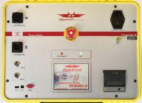


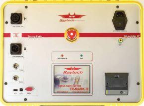

2010–2014: TR-Mark III Still Supported 2012–Present: TR-Mark III 250V Still Supported

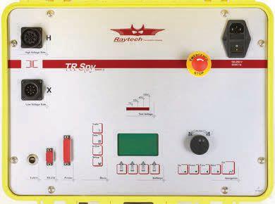

2001–2010: TR-Spy Mark II Still Supported


Raytech supports every product we’ve ever introduced.
You need equipment that remains functional, even after it’s no longer sold. We fully support all of our products for the entire time you own them.


Raytech stands behind its custom-made, high-quality measuring and testing equipment developed and produced for the international power industry.



The future of circuit breaker testing
The new CIBANO 500 is the world's first 3-in-1 test system to combine:
» amicro-ohmmeter
» a timing and travel analyzer
» a circuit breaker power supply
This helps you to carry out all kinds of tests on all types of circuit breakers, quickly and with little wiring. Even better, it weighs only 44 lbs.
You can perform tests with both sides of the circuit breaker grounded and you don't need to rewire between the single tests.
The CIBANO 500 is driven by OMICRON's Primary Test Manager™ (PTM). This enables you to manage your test plans, perform tests, assess measurements, and create reports.
Circuit breaker testing has never been so easy!
