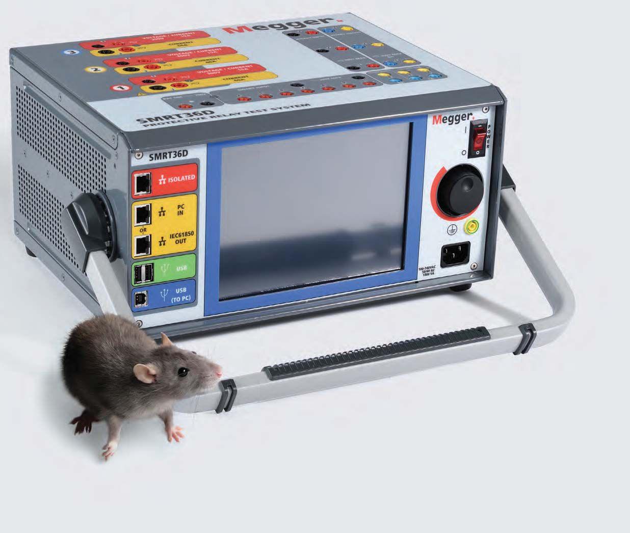


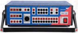
The SMRT Series is Megger’s flagship all-purpose relay test equipment. The latest addition to the family includes a fully integrated touchscreen controller so you don’t have to carry a laptop. Like other models in the SMRT series, the SMRT36D features:
High compliance voltage for testing high impedance relays
Three-phase transformer differential protection testing made easy
Effortless click-on-fault impedance testing
Binary inputs for direct reading of IRIG-B signals for end-to-end testing
Complete solution for IEC 61850 GOOSE testing
Visit megger.com for more information or call 1-800-723-2861 to schedule a demo today!


PowerTest 2015 will be held in the heart of Music City, USA at the Renaissance Nashville Hotel in Nashville, Tennessee. With a melting pot of music, education, sports, and Southern charm, this superb location puts you a few steps away from the world-renowned Ryman Auditorium (the original home of the Grand Ole Opry), Tootsies, and Music Row on Broadway. This four-star hotel is also in close proximity to such attractions as Hatch Show Print, one of the nation’s oldest working letterpress facilities made iconic through its association with the Ryman Auditorium and musicians like Johnny Cash, Dolly Parton, and Elvis Presley. Nashville’s culinary scene is not to be missed. Attendees can satisfy cravings for everything from fried chicken at Prince’s Hot Chicken to Slow Food Cuisine at Silo.
The birthplace of Country music, where dreams and hard work make anything possible, serves as a perfect backdrop for PowerTest and its attendees who are dedicated to education and excellence in all facets of the electrical power systems industry. Join us at PowerTest and “Energize Your Future” where you have access to the newest technologies and products presented by industry leaders and experts. To borrow a turn of phrase from the Hatch Brothers, founders of Hatch Show Print, who said, “Advertising without posters is like fishing without worms,” your electrical education for the year just isn’t complete without PowerTest. We’ll see you there!

MARCH 2–6, 2015 NOW FIVE FULL DAYS!

We’ve gathered leaders in the industry and will stage a full day of engaging, 45-minute presentations sure to expand your thinking and generate new ideas. Choose from 27 detailed technical presentation track topics.
• The Impact of Electrical Safety to Maintenance:
NFPA 70B and CSA Z463
Jim White and Kerry Heid, Shermco Industries
• Extension Cord Safety
Dennis Neitzel, AVO Training Institute, Inc.
• What’s In Your Wallet?
Or What Won’t Be Left In Your Wallet
Don Brown, Shermco Industries
• Changes to OSHA’s .269 and 1926 Regulations
Jim White, Shermco Industries
• 12.5 Still Alive – The Impact of an Injury?
What Are you Risking?
Gary Norland, Gary Norland Safety Presentations
• Electrical Safety Audits
Dave Kreger, Electrical Reliability Services
• Discovery of Transformer Short Circuit Winding before Failure
Keith Burgess, Shermco Industries
• A Comprehensive Maintenance Strategy for Medium–Voltage Cable Testing
Ashley Harkness, Electrical Reliability Services
• Sweep Frequency Response Analysis –Why It Should Be In Your Diagnostic Toolbox
William Keith Hill, Doble Engineering Company
• Bushings That Bite –What You Don’t Know Can Hurt You!
Tony McGrail, Doble Engineering Company
• Switchgear and Circuit Breakers Failure and Case Study
Shuzhen Xu, FM Global
• Battery Discharge Testing: Implementing NERC Standard and Field Experiences
Dinesh Chhajer and Robert Foster, Megger

• The Trifecta of Motor Maintenance
Noah Bethel, PdMA Corporation
• Practices and Designs for VT and CT Isolation Devices
Scott Short, Doble Engineering Company
• Understanding Testing and Diagnostic Challenges Associated with Magnetically Actuated Vacuum Circuit Breakers
Charles Sweetser, OMICRON electronics Corp. USA
• QA Electrical Testing of Medium–Voltage Global VPI Stator Windings
Vicki Warren, Iris Power – A Qualitrol Company
• Five Things to Know about Power Quality Monitoring
Ross Ignall, Dranetz Technologies
• Maintenance Testing of Low – Voltage Power Circuit Breakers in a Large Automotive Assembly Plant
Mose Ramieh III, PGTI
Randall Sagan, MBUSI
• Improving Reliability – Beyond Compliance
Karl Zimmerman and David Costello, Schweitzer Engineering Laboratories
• Basic Transformer Differential Protection
Jay Garnett, Doble Engineering Company
• Configuring Your Microprocessor – Based Relay System for Maximum Value
Steve Nollette, Electrical Reliability Services
• Open-Circuited CT Misoperation and Investigation
Karl Zimmerman and David Costello, Schweitzer Engineering Laboratories
• Test the System, Not the Element
William Knapek, OMICRON electronics Corp. USA
• Transmission Line Protection 101
Tim Walker, OMICRON electronics Corp. USA

(continued)
• Commissioning Your Data Center: Achieve Greater Availability, Safety, and Efficiency While Reducing Costs Throughout the Cycle
Michael Donato, Electrical Reliability Services
• Understanding and Implementing the NETA Electrical Commissioning Standard ECS-2015
Lorne Gara, Orbis Engineering
Ron Widup, Shermco Industries
• Commissioning Progress Communication
Michael Lewark, SNC Lavalin
Moderator : Lorne Gara, Orbis Engineering
Participate in the afternoon Electrical Commissioning Symposium. Lorne Gara of Orbis Engineering and expert panelists help audience participants navigate open discussions on current challenges and insights in the electrical power systems industry.

5:00 PM – 6:00 PM
In just 60 minutes, attendees receive a fun, lightning fast top-line on new products and technologies that will be featured at the PowerTest 2015 Trade Show.
For those that stay until the end, you’ll have a chance to win big from the New Product Forum Door Prizes! Must be present to win.
HOSPITALITY SUITES
6:00 PM – 10:00 PM
Mingle with a host of leaders at Monday night’s Hospitality Suites. Talk with the experts, find solutions for your business, and catch up on the latest products and services as each sponsoring company shares their own brand of hospitality.

Actually, insulating oil and SF6 gas analysis and processing is now a big part of Shermco’s analysis services. With 15 locations throughout the central USA and Canada, we o er specialty services to support NETA companies as well as our own industrial and utility customers. Our new sample kits provide all you need to take insulating oil samples and we have the fastest turn-around times in the industry. Just pull the samples and drop o at the nearest UPS pickup sitewe’ll do the rest!
Plus, our oil processing and SF6 trailers and technicians are available around the clock, with an experienced team that is ready to travel anywhere, anytime to get equipment back on-line quickly.
And don’t forget, we also o er some of the fastest response times for remanufacturing circuit breakers at three locations or, for big jobs, from our mobile circuit breaker remanufacturing trailer. Replacement parts, too!
So remember, when you need both rapid service and the highest quality, Shermco has the right people and the best tools ready for you.
www.shermco.com | 888.SHERMCO | Booth #400

Join in the discussion during the Tuesday morning Panel Sessions. Select two of the four panel topics and get ready to learn from experts and peers alike.
Moderator: Jim White, Shermco Industries TRANSFORMERS
Moderator: Bruce Rockwell, American Electrical Testing Co., Inc.
Moderator: Tom Sandri, Shermco Industries
Moderator: Mose Ramieh III, Power & Generation Testing, Inc.



Tuesday Afternoon
POWERTEST 2015 TRADE SHOW
The PowerTest 2015 Trade Show promises more than 100 top-tier electrical power vendors whose mission is electrical safety and reliability. Enjoy a complimentary lunch and beverages as you tour the show and make connections.
Tuesday Evening
Don’t miss the PowerTest 2015 PowerBash
Enjoy the Southern charm and music of Nashville, celebrate the best of PowerTest, mix and mingle. Tuesday evening from 5:30 PM – 8:30 PM.




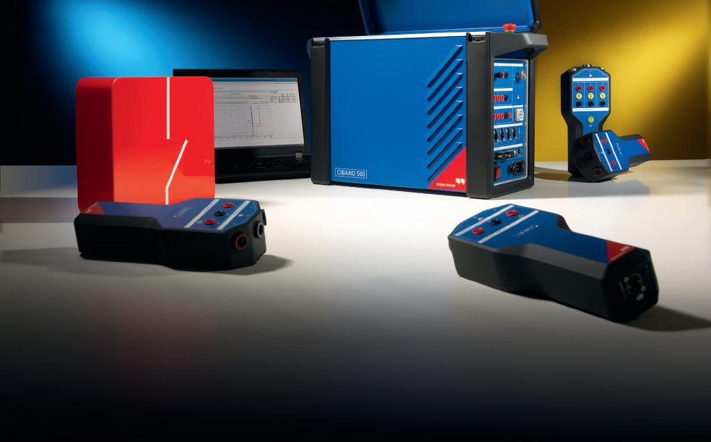
The new CIBANO 500 is the first 3-in-1 test system worldwide to combine a micro-ohmmeter, a timing analyzer, and a circuit breaker supply in one device. This helps you to carry out all kinds of tests on all types of circuit breakers, quickly and with little wiring. Even better, it weighs only 44 lbs.


The unique wiring concept makes circuit breaker testing safer and easier. All tests can be carried out with both sides of the circuit breaker grounded and you don’t need to rewire between the single tests. And now that measured data can be transmitted digitally, interference is history. The Primary Test Manager™ (PTM) software gives you one overall report of all results.

Circuit breaker testing has never been so easy. Check it out for yourself and visit us at booth no. 136/138!


Tuesday 12:00 PM - 4:30 PM
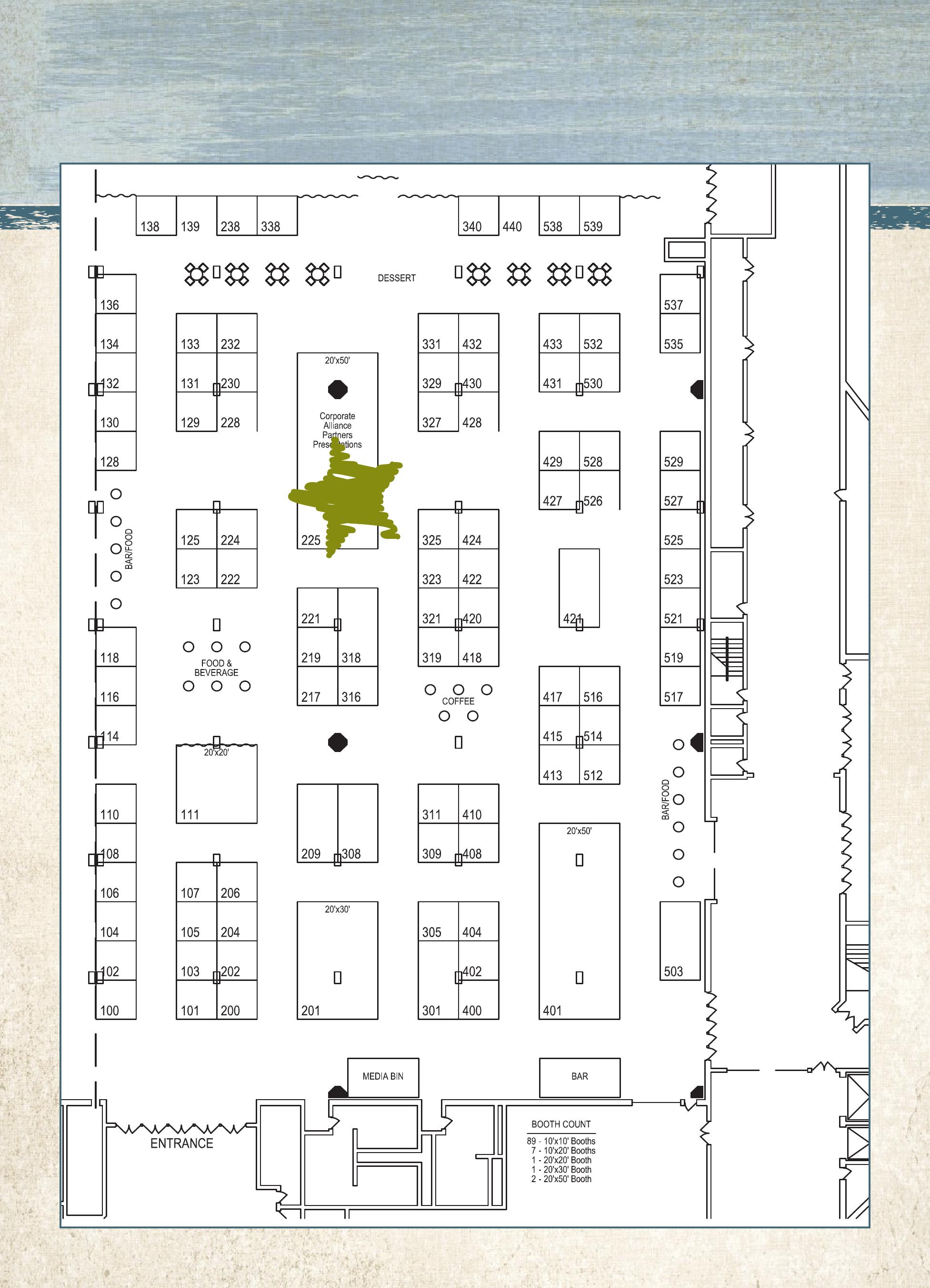
NETA’s Gold Corporate Alliance Partners will share insights, ideas, and best practices throughout the PowerTest 2015 Trade Show.
WEIDMANN Electrical Technology
12:30 PM - 12:45 PM
Smart Insulation, the Software Side
- Getting to Optimum Transformer Performance
Megger
1:00 PM - 1:15 PM
TDS NT Series: Very Low Frequency (VLF) and Partial Discharge (PD) Testing Solution
Intellirent
1:30 PM - 1:45 PM
Safe and Smart Cable Testing
AVO Training Institute
2:00 PM - 2:15 PM
The Changes in NFPA 70E 2015 and What it Means to You


Circuit Breaker Sales
2:30 PM - 2:45 PM
One Stop for Your Electrical NeedsThe CircuitBreakerStore.com
Electro Rent
3:00 PM - 3:15 PM
Test Equipment Problems and Solutions in the Field
Doble Engineering Company
3:30 PM - 3:45 PM
In-Service Partial Discharge Testing: The Right Tool at the Right Time
ComRent Load Bank Solutions
4:00 PM - 4:15 PM
Insights and Best Practices for Load Bank Testing
Door Prize Drawing 4:15 PM


Wednesday
8:00 AM – 11:45 AM
• Commissioning Generator Protector Relays
Scott Cooper, OMICRON electronics Corp. USA
• Wedded Bliss: How Syncrude Canada Married Commissioning Contractors and In-House
Technicians to Produce a Healthy Testing Program
Dennis Moon, AVO Training Institute, Inc
• Electrical Testing Medium-Voltage Stator Windings
Tom Sandri, Shermco Industries
■ Custom cases for a secure trip
■ Double walled boxes for round trip protection
■ Shipment tracking...just in case
■ Return shipment packaging and labels, for the return trip
■ Travel companion laptop if required
■ All to ensure you can do your job out of the box ready to go

1:15 PM – 5:00 PM
• Digital Relay Event Report Analysis
Karl Zimmerman and David Costello, Schweitzer Engineering Laboratories
• Field Testing of Oil-Filled Power Transformers: From IEEE 62 to IEEE C57.152
Diego Robalino and Dinesh Chhajer, Megger
• Acceptance and Maintenance Testing for MediumVoltage Electrical Power Cables: Exploring Technology Developments Over the Past 20 Years
Tom Sandri, Shermco Industries


8:00 AM – 11:45 AM
• Relay Troubleshooting 2.0
Karl Zimmerman and David Costello, Schweitzer Engineering Laboratories
• Assistant Electrical Testing Technician –Level II Study Session
Ron Widup, Shermco Industries
• HVCB Testing Seminar
Robert Foster and Volney Naranjo, Megger
1:15 PM – 5:00 PM
• What Type of Insulating Liquid is within Electrical Equipment?
David Koehler and Lance Lewand, Doble Engineering Company
• Commissioning Multifunction Digital Relays –Are We Taking Too Many Shortcuts?
Will Knapek, Scott Cooper, and Tim Walker, OMICRON electronics Corp. USA
• Certified and Certified Senior Electrical Testing Technician – Level III & IV Study Session
Ron Widup, Shermco Industries
VLF & DC Output | Sheath Testing | Cable Burning
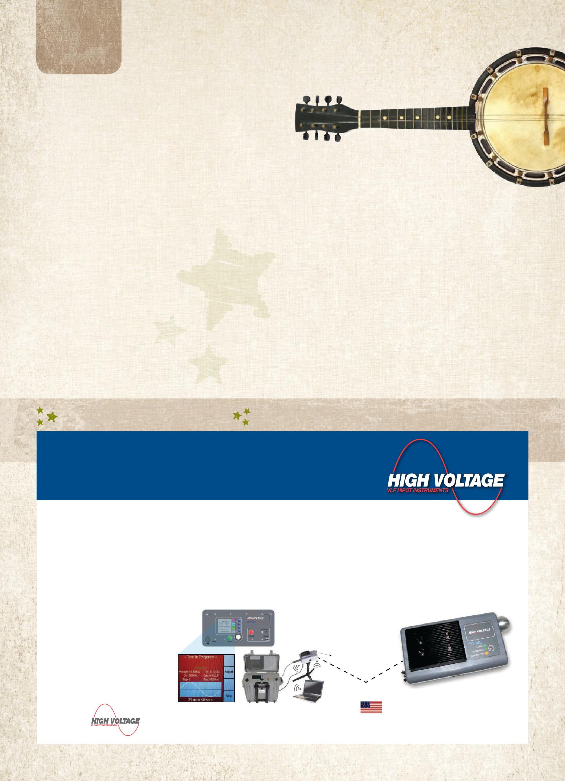
The VLF-34E is a new generation VLF AC Hipot that uses a solid state design with microprocessor controls. It meets the requirements of applicable world standards regarding cable testing up to 25kV class maintenance testing. It is light, compact, rugged, and very portable. Its sine wave output is suitable for using external TD and PD detection equipment. Using a TD and PD option, the VLF-34E is all that is needed for nearly all cable testing up to 25kV class.
Easy to use controls. Programmable test sequences & manual control, USB, XBEE® wireless, RS-232/422 port for downloading data and for unlimited test report capture, wireless computer interface to control and download Tan Delta diagnostics and for remote control operation via laptop.
VLF-TD Cable Diagnostic Testing
The TD-34E, along with the HVI VLF-34E AC hipot, is the latest in design using current electronic technology. Together they permit the user to perform all VLF and VLF-TD tests possible and offer the best wireless operation and data collection, aided by the HVI custom application software written solely for the two devices. There is no better alternative. HVI has been supplying the world with VLF and Tan Delta technology since 1998, with more models, greater voltage range, and higher power capability, all with the superior sales and service that HVI is well known for worldwide.

Friday
8:00 AM - 5:00 PM
Designed for engineers, chemists, and others responsible for reviewing data to interpret laboratory results to detect and identify problems within electric apparatus. The seminar will be interactive, combining theoretical background with practical experience and hands-on examples including case studies illustrating common problems found in the field.

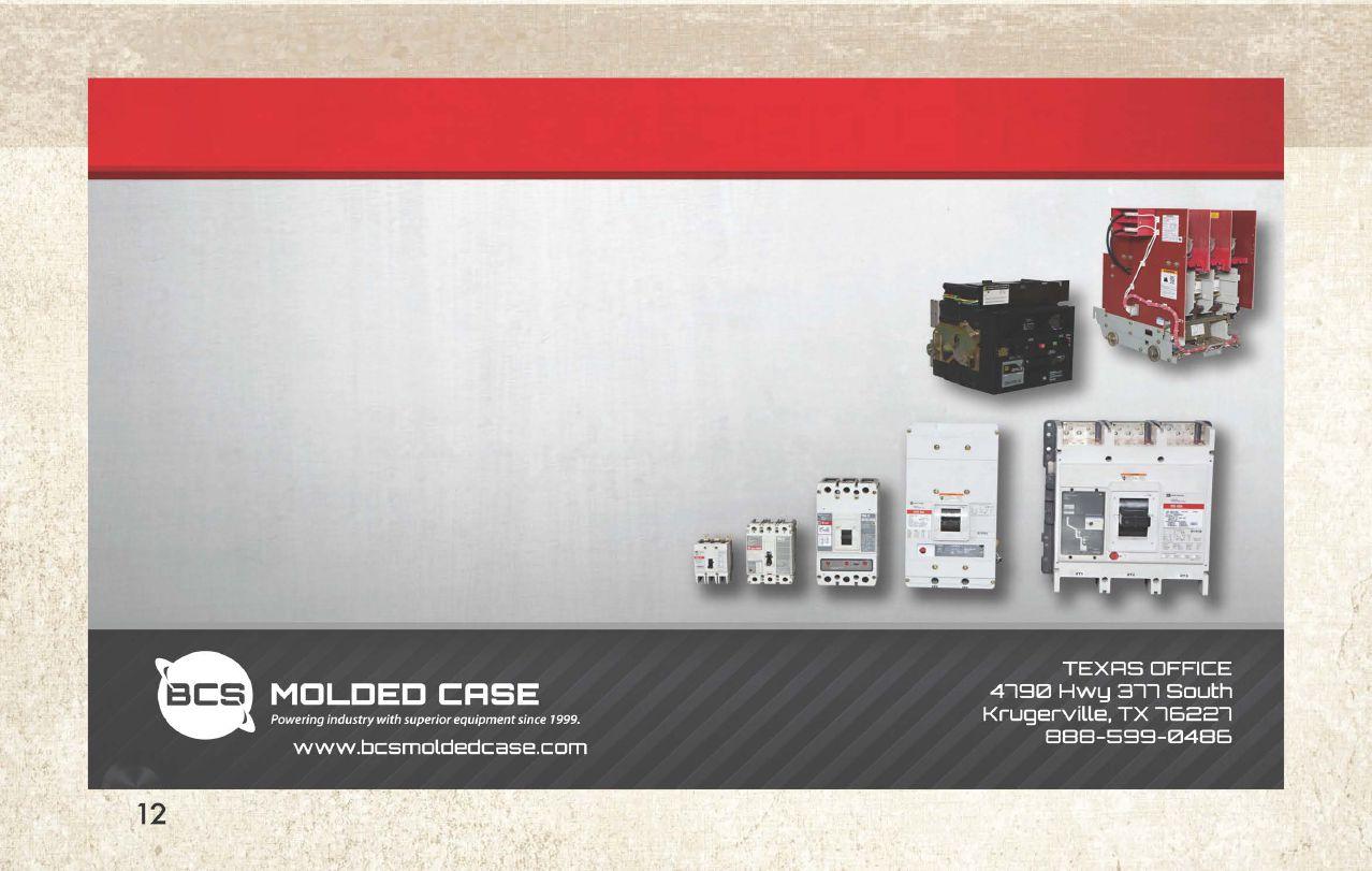
BCS Switchgear has rapidi!:J expanded into the Molded Case industr!:J in recent !:Jears. Our techs perform a wide range of tests ensuring that what we are sending !:JOU is in proper working order. We take it a step further and offer standard 1 !:Jear warranties on ever!:Jthing that ships out of our warehouse in Texas.
Our ever-growing inventor!:J enables us to handle and deliver all of !:JOUr electrical wants/needs. Our knowledgeable sales team is more than equipped to answer !:JOUr questions and make sure !:JOU are well taken care of.

Sunday, March 1, 9:00 AM - 4:00 PM
Megger’s Seminar will address many of the critical and costly aspects of substation maintenance. The interactive session will feature practical presentations on current methods oand practices to help ensure the reliability of high-voltage circuit breakers, power transformers, and batteries. You must preregister for this event by contacting Megger: 214.330.3539
Sunday, March 1, 5:30 PM - 8:30 PM
Come experience a unique side of Nashville! Enjoy four Music Row watering holes, listen to Nashville’s upand-coming artists, learn line dancing, or take center stage to display your own chops during karaoke. Let’s crawl, Y’all! $155 per person.
Monday, March 2, 12:15 PM - 2:15 PM
Join us for a special session on Doble’s testing software, including Protection Suite, ProTesT, DTA and T-Doble. Learn more about what’s new with these various software solutions. This is also your chance to share your feedback. Doble’s Solutions Directors for protection and off-line testing & assessment equipment will be conducting this users group and they want your input on the features and enhancements you’d like to see in Doble software. This session is exclusively for users of Doble test equipment and software. Register at: www.doble.com/NETA
POWERDB USER GROUP
Monday, March 2, 12:15 PM - 2:15 PM
Free user’s group meeting open to all users of PowerDB software. You must preregister for this event by contacting Megger: 214.330.3539

Stocked with refreshments, information on local restaurants, shops, tours, and attractions, the Gathering Lounge allow guests to connect and enjoy Nashville together or on their own. The pass also includes a tour of the Grand Ole Opry, the Trade Show, and PowerBash. $75 per person
Want to keep it simple? Forego the tour and lounge that are included in the Spouse/Guest Pass and instead add the Social Pass for guests who want to attend Monday evening’s Hospitality Suites and Tuesday’s Trade Show and PowerBash. $40 per person.


Register On-line:
To register for PowerTest 2015, save time by registering on-line. You’ll find a complete brochure and registration form available at www.powertest.org.
Join & Save
Join the Gold Alliance Program for $800 and your PowerTest 2015 conference registration is included!
Standard Alliance Program participants can upgrade to Gold Alliance status for only $625 to receive a complimentary PowerTest conference registration.
Hotel Reservations:
Renaissance Nashville Hotel 877.901.6632
611 Commerce Street Nashville, TN 37203
Reservation Deadline: January 29, 2015
Group Name: NETA/PowerTest
Group Rate: $195
Or for web registrations, use the following link: https://resweb.passkey.com/Resweb.do?mode=welcome_ei_new&eventID=11599514
Payment:
NETA accepts all major credit cards. Save time and register on-line at www.powertest.org or call 888-300-6382 (NETA).
Extras:
PowerTest 2015 Technical Papers- Registered conference attendees will receive all PowerTest technical presentations on a USB drive on site in their registration bag.


1. Go to www.powertest.org and review the complete PowerTest 2015 on-line brochure.
2. Decide the number of days you will attend the conference.
3. Tuesday attendees select up to two panels. (Cost of panels included in the registration fees.)
4. Wednesday attendees register for up to two seminars. (Cost of seminars is in addition to the registration fees.)
5. Thursday attendees register for up to two seminars. (Cost of seminars is in addition to the registration fees.)
6. Register for two or more seminars and receive 15% off. Use code SEM2015PT to receive this discount.
7. Register for Doble Lab Seminar. (Cost of seminar is in addition to the registration fees.)
8. Sign up for Spouse/Guest Passes. (Cost of passes is in addition to the registration fees.)
9. Sign up for PowerTest 2015 conference polo shirts and select size. (Cost of polo shirts is in addition to the registration fees.)


With the revision of the NFPA 70E, the Standard for Electrical Safety in the Workplace, one thing remains constant, the risk of an arc-flash hazard will need to be performed.
Although the risk hazard tables are presented inadifferentmannerwiththelatestrevision in a different manner with the latest revision of NFPA 70E, one of the goals to this analysis will continue to ensure the proper personal personal protective equipment (PPE) is used under specific conditions.
Brian Cronin, CSA Engineering Services, LLC
7 President’s Desk
David Huffman, Power Systems Testing Co.
NETA President
84
Condition of Maintenance in the 2015 NFPA 70E
Jim White, Shermco Industries
90 Risk Assessment and Other Revisions New to NFPA 70E-2015
Dennis K. Neitzel, D. Ray Crow, and Daleep Mohla
104 Electrical Safety: Myths and Rumors
David K. Kreger, Electrical Reliability Services
10 NFPA 70E and NETA
How OSHA and NFPA 70E Work Together
Ron Widup and Jim White, Shermco Industries
14Tech Quiz
NFPA 70E
Jim White, Shermco Industries
18Testing Rotating Machinery
QA Tests for MV GVPI Stator Windings
Vicki Warren, Iris Power LP
28Safety Corner
NFPA 70B Recommended Practices for Electrical Equipment Maintenance and Its Relation to Electrical Safety in the Workplace
Scott Blizard, American Electrical Testing Co., Inc.
36Tech Tips
Fault Clearance on Grounded Neutral Systems
Jeff Jowett, Megger
42No-Outage Corner
IR vs. PD and the Winner Is …
Don Genutis, Halco Testing Services
72 Make Your Electrical Safety Program Your OwnPart 2: What Should Be in an Electrical Safety Program?
Don Brown, Shermco Industries
76Performance Testing of Ground Fault Protection Systems
Ron Widup, Shermco Industries
Insulated Conductor Committee News
50AIA Masterspec® – Division 26 Electrical Sections to Include Accredited NETA Company and ANSI/NETA ATS
Michael A. Heinsdorf, ARCOM and Jill Howell, NETA
NETA’s New Addition – Coming This Spring Jill Howell and Kristen Wicks, NETA
ASTM F18 Committee Meeting
Jim White, Shermco Industries 122NETA Representation Technical Update
Ralph Patterson, Power Products and Solutions
Attending Powertest: A Practical Guide to Who, What, When, Where, and Why
Corporate Alliance Partners in the Spotlight
Alliance Partnership–A Golden Opportunity
Expands Learning Opportunities at PowerTest
Bridges in the Land of the Golden Gate
NETA Welcomes Grounded Technologies, Inc. as a NETA Accredited Company
NETA Welcomes High Voltage Service as a NETA Accredited Company
Welcomes BEC Testing as a NETA Accredited Company
AVO Training Institute, Inc. – Corporate Alliance Partner

3050 Old Centre Avenue, Suite 102
Portage, MI 49024
Toll free: 888.300.NETA (6382)
Phone: 269.488.NETA (6382)
Fax: 269.488.6383
neta@netaworld.org
www.netaworld.org
EXECUTIVEDIRECTOR: Jayne Tanz, CMP
NETA Officers
PRESIDENT: David Huffman, Power Systems Testing Co.
FIRSTVICEPRESIDENT: Ron Widup, Shermco Industries
SECONDVICEPRESIDENT: Jim Cialdea, Three-C Electrical Co., Inc.
SECRETARY: Mose Ramieh, Power & Generation Testing, Inc.
TREASURER: John White, Sigma Six Solutions
NETA Board of Directors
Ken Bassett (Potomac Testing, Inc.)
Scott Blizard (American Electrical Testing Co., Inc.)
Jim Cialdea (Three-C Electrical Co., Inc.)
Lorne Gara (Orbis Engineering Field Services, Ltd.)
Roderic Hageman (PRIT Service, Inc.)
David Huffman (Power Systems Testing)
Alan Peterson (Utility Service Corporation)
Mose Ramieh (Power & Generation Testing, Inc.)
Bob Sheppard (Southwest Energy Services, LLC)
John White (Sigma Six Solutions)
Ron Widup (Shermco Industries)
NETA World Staff
TECHNICALEDITOR: Roderic L. Hageman
ASSOCIATEEDITORS: Diane W. Hageman, Resa Pickel
MANAGINGEDITOR: Jayne Tanz, CMP
ADVERTISINGMANAGER: Laura McDonald
DESIGNANDPRODUCTION: Hour Custom Publishing
NETA Committee Chairs
CONFERENCE: Ron Widup; MEMBERSHIP: Ken Bassett; PROMOTIONS/MARKETING: Scott Blizard; SAFETY: Scott Blizard and Jim White; TECHNICAL: Alan Peterson; TECHNICALEXAM: Ron Widup; WORLDADVISORY: Diane Hageman; CONTINUINGTECHNICALDEVELOPMENT: David Huffman; TRAINING: Kerry Heid; FINANCE: John White; NOMINATIONS: Alan Peterson; STRATEGY: Mose Ramieh; ALLIANCEPROGRAM: Jim Cialdea
© Copyright 2014, NETA
NOTICE AND DISCLAIMER
NETA World is published quarterly by the InterNational Electrical Testing Association. Opinions, views and conclusions expressed in articles herein are those of the authors and not necessarily those of NETA. Publication herein does not constitute or imply endorsement of any opinion, product, or service by NETA, its directors, officers, members, employees or agents (herein “NETA”).
All technical data in this publication reflects the experience of individuals using specific tools, products, equipment and components under specific conditions and circumstances which may or may not be fully reported and over which NETA has neither exercised nor reserved control. Such data has not been independently tested or otherwise verified by NETA.
NETA MAKES NO ENDORSEMENT, REPRESENTATION OR WARRANTY AS TO ANY OPINION, PRODUCT OR SERVICE REFERENCED OR ADVERTISED IN THIS PUBLICATION. NETA EXPRESSLY DISCLAIMS ANY AND ALL LIABILITY TO ANY CONSUMER, PURCHASER OR ANY OTHER PERSON USING ANY PRODUCT OR SERVICE REFERENCED OR ADVERTISED HEREIN FOR ANY INJURIES OR DAMAGES OF ANY KIND WHATSOEVER, INCLUDING, BUT NOT LIMITED TO ANY CONSEQUENTIAL, PUNITIVE, SPECIAL, INCIDENTAL, DIRECT OR INDIRECT DAMAGES. NETA FURTHER DISCLAIMS ANY AND ALL WARRANTIES, EXPRESS OF IMPLIED, INCLUDING, BUT NOT LIMITED TO, ANY IMPLIED WARRANTY OF FITNESS FOR A PARTICULAR PURPOSE.
ELECTRICAL TESTING SHALL BE PERFORMED ONLY BY TRAINED ELECTRICAL PERSONNEL AND SHALL BE SUPERVISED BY NETA CERTIFIED TECHNICIANS/ LEVEL III OR IV OR BY NICET CERTIFIED TECHNICIANS IN ELECTRICAL TESTING TECHNOLOGY/LEVEL III OR IV. FAILURE TO ADHERE TO ADEQUATE TRAINING, SAFETY REQUIREMENTS, AND APPLICABLE PROCEDURES MAY RESULT IN LOSS OF PRODUCTION, CATASTROPHIC EQUIPMENT FAILURE, SERIOUS INJURY OR DEATH.

“There is no task so monumental, no job so important, that it cannot be done safely” –author unknown
Certainly in the realm of private industry, this simple statement holds true. This edition of NETA World addresses some of the changes in NFPA 70E, as well as the condition of the equipment, and how it applies to personnel safety.
It wasn’t in the too distant past that relaxing safety measures at times was not only accepted but requested. “Can’t this be done energized?” is a question that’s been asked, usually by people who simply are not understanding the risks. Bringing safety to the forefront and educating people can change that question to a statement more like “We will organize a shutdown to perform that work.”
Hopefully, you’re enjoying reasonable weather and getting ready to spend time with family and loved ones for the holidays. And if the weather isn’t cooperating, you can always join us in a couple months for the January membership meeting! Wishing you the happiest holiday season,
David Huffman President InterNation ElectricalTesting Association.




CHOOSE BETWEEN KEEPING MAINTENANCE COSTS DOWN AND KEEPING UP WITH PRODUCTION DEMAND…OR DO BOTH.
NETA certified experts at Electrical Reliability Services will keep you in perfect balance. To ensure the reliability of your electrical power, you have to balance the need to reduce maintenance costs with the need to perform regular maintenance. Only the team from Electrical Reliability Services delivers cost-effective services and system expertise to keep you up and running 24/7.


Vanguard Instruments has been at the forefront of developing innovative precision sub-station test instruments for over 20 years, and we are continuing our tradition with our latest products such as the CT-7000 S3 and CT-8000 S3 circuit breaker analyzers with Dual Ground testing feature and our new line of test instruments featuring convenient Bluetooth wireless interfaces. Visit us today at vanguard-instruments.com to find the latest solutions for all of your sub-station testing needs.
 BY RON WIDUP AND JIM WHITE, Shermco Industries
Here we are at the 2015 release of a new edition of NFPA 70E, Standardfor Electrical Safety in the Workplace.
NFPA 70E is a fairly new standard, as standards go. In 1976 OSHA approached NFPA about developing a safety standard that could be used to formulate an electrical safety regulation,SubpartS. NFPA agreed, and in 1979 the first edition of 70E was published. OSHA used 70E as a template, using broader non-prescriptive language suitable for a Federal regulation and in 1990 issued the ElectricalSafety-RelatedWork Practices regulations into the Federal Register, 29CFR1910.331 - .335.
The language used in the writing of those electrical safety regulations is amongst the clearestusedinaregulation.We'renotsaying they are clear, mind you, just that they are much easier to understand and implement in comparison to other regulations. Those regulations have remained static since they were issued. On a side note, I realize OSHA likes to refer to their regulations as "standards." (See Figure 1). Standards are by definition voluntary. OSHA "standards" are federal law and are not voluntary. Ask anyone who has been cited for infractions.
The 1976 edition of NFPA 70E used
Code (NEC) as Part I, Installation Safoty Requirements. There were six chapters in Part I, all based on the NEC. It
seems odd now that a standard on electrical safety-related work practices would lead off with installation requirements, but at that time the bulk of the information in 70E wasNEC-based. Part 2 contained the electrical safety-related work practices and mirrored the then-current OSHA regulations. With each edition of NFPA 70E, the work practices chapter has grown and became more pertinent to the electrical worker. For the most part, it is safe to say that when first released NFPA 70E was a minor standard and not widely used in the electrical industry.
It wasn't until the 2000 edition ofNFPA 70E that the electrical industry started to pay close attention to it. Table 3-3.9.1, Hazard Risk Category Classifications was first published in 70E. (See Figure 2). For the first time, electrical workers, their supervisors, and companies had guidance on what type of arc-rated PPE and clothing should be worn for performing specific tasks. It was revolutionary. Paul Hamer, representative for The American Petroleum Institute (API) who worked for Chevron Research and Technology, proposed the use of a table that was being used internally by Chevron at the time. That table was accepted and hasbeen thebasis for the table method of choosing arc-rated PPE and clothing since. The tables have always been controversial. Being task based, they have not been directly tied to incident energy and
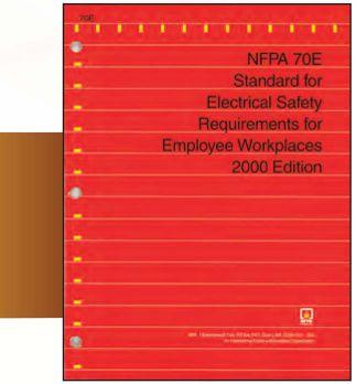
Figure 2: NFPA 70E2000 Edition

they derated the level of protectionbased on risk. However,looking at the tables in the context of the times, theypropelledarc-flash protectionto the front lines where workers reallyneededit.
and using chapters and sections in compliance withtheNECStyleManual. The ElectricalSafetyRelated WOrk Practices chapter became Chapter 1 and the Electrical Installation Requirements became Chapter 4. This was done to place more emphasisontheworkpractices. Thechapters were renumbered to follow the NEC Style Manual. Table 3-3.9.1 became Table 130.7(C)(9)(a). The title for NFPA 70E was changed from "Stand4rd for Electrical Safety Requirements in Employee WOrkplaces" to "Stancl£trdfor Electrical Safety in the WOrkplace': (SeeFigure4).
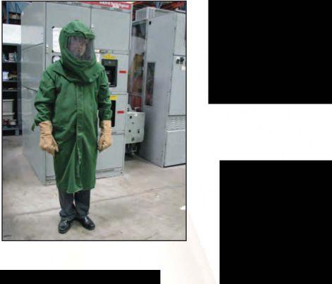
Figure 3: Not the BestPPE System
RayJones, the chair of the 70E committee at the time, once stated, '1t is more important that people wear some type of arc flash PPE to protect themselves, because right now they are wearing nothing at _ alL Something is better than nothing." The IEEE1584workgroup did not publish their findings until 2002, so the committee used the best information it had available at the time. In 1996 arc testing of fabrics also became available and showed that much of the flame-resistant clothing and PPE in use at that time would not provide the protection everyone thought it would.
The2009cycleturnedouttobefouryears, instead of three, as the 70E committee wrangled over the use of thehazard/riskcategory tables. An extra meeting had to be held to iron out differences. In the end, the committee voted to keep the tables intact and the standard was published as the 2009 edition. (SeeFigure5).
A significant change to the 2009 edition was the elimination of Chapter 4, lnstalhtion Sqfety Requirements, because it was a duplicate of the NEC installation requirements. Also, the 70E Committee noted that the NEC and NFPA 70E are on different revision cycles which could lead to confusion and misapplications.

Unfortunately, we still see people and companies use unmarked, unratedPPE andarc-flash clothing in thefield asshown inFigure3.

Arc testing showed that the double-layer NOMEX'M was good for about 20 cal/cm2, but the polycarbonate face shield would melt onto the mannequins face at about 1.5 cal/cm2-probably not the best outcome for someone involved in an arc-flash event. OSHA will cite companies for using unrated, unmarked PPE and clothing. It must have an ATPV (arc thermal performance value) and meet ASTM F1506 andNFPA 70E to be compliant.
The 2004 edition of NFPA 70E saw a major reorganization to the standard, eliminating parts
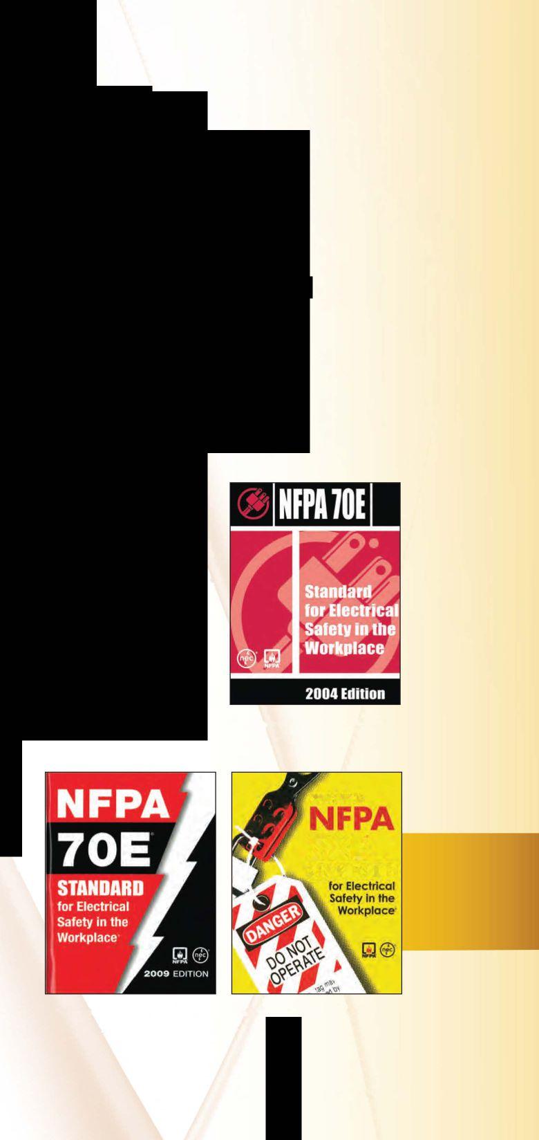
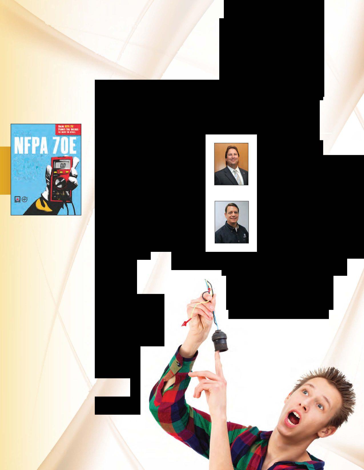
One important focus of the 2009 cycle was to simplifY the language in the 70E and to improve its usability.
Sometime during the life of this edition, 70E became the second-best selling standard byNFPA. TheNEC continues to be their number one seller.
The 2012 edition of NFPA 70E brought easier and simpler language to the standard, and also saw the hazard/risk category tables improved. The emphasis of the committee for this edition was to make it more user friendly and eliminate vague or unclear requirements. (See Figure 6).
Now the 2015 edition has been released. The committee work is finished and the emphasis again has been to clarifY the requirements. New task tables for arc-rated PPE have been accepted, and this column has noted how these tables will simplifY and enhance the use of arc-rated PPE and clothing. As is always the case, while some things will be an improvement, others maybe not so much; however,NFPA 70E is a living document. It reflects the best opinions and research from a wide representation of the electrical industry. NFPA has done an excellent job of maintaining a well-balanced committee, working to ensure that any one segment does not have undue influence on the balloting. (See Figure 7).
Is the 2015 edition ofNFPA 70E the best written so far? We believe so. Its language has been simplified and improved; many somewhat vague requirements have been clarified; and unneeded or outdated requirements have been removed. We are already discussing what changes might be appropriate for the 2018 edition. That's the way it is on the committee. We know 70E will never be perfect, and we strive to improve it as our understanding of electrical safety continues to develop. We are eagerly awaiting the results of the IEEE/
NFPA Arc Flash Phenomena Collaborative Research Project to see how their findings will affect our understanding of the arc flash hazard.
Don't sit on the sidelines. Be a player. Go the NFPA website (www.nfpa.org/nfpa70e) and submit public inputs (proposals) for the next edition. Do your part to make 70E the best electrical safety standard it can be and help protect yourself, your fellow employees, and maybe even your own children.
Ron Widup andJim White are NETA's representatives to NFPA Technical Committee 70E (Electrical Safety Requirementsfor Employee Workplaces). Both gentlemen are employees ofShermco Industries in Dallas, Texas, a NETA Accredited Company. Ron Widup is President of Shermco and has been with the company since 1983. He is a Principal member of the Technical Committee on "Electrical Safety in the Workplace" (NFPA 70E) and a Principal member of the National Electrical Code (NFPA 70) Code Panel 11. He is also a member ofthe technical committee "Recommended Practice for jim White Electrical Equipment Maintenance" (NFPA 70B), and a member of the NETA Board ofDirectors and Standards Review Council. jim White is nationally recognized for technical skills and safety training in the electrical power systems industry. He is the Training Directorfor Shermco Industries, and has spent the last twenty years directlyinvolved in technical skills and safety trainingfor electrical power system technicians. jim is a Principal member ofNFPA 70B respresenting Shermco Industries, NETA's alternate member ofNFPA 70E, and a memberofASTM FIB Committee ''Electrical Protective Equipmentfor Workers'�
the test equipment answer
Protective Relays and Metering
Batteries and UPS
Transformers
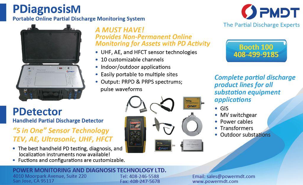
VLF, Tan Delta and Partial Discharge
Cable fault location
Substations & High Voltage Circuit Breakers
SF6 Analysis
Low & Medium Voltage Circuit Breakers
Motors and Rotating Apparatus
Power Monitoring




James R. (Jim) White is the Training Director of Shermco Industries, Inc., in Dallas, Texas. He is the principal member on the NFPA technical committee “Recommended Practice for Electrical Equipment Maintenance” (NFPA 70B). Jim represents NETA as an alternate member of the NFPA Technical Committee “Electrical Safety in the Workplace” (NFPA 70E) and represents NETA on the ASTM F18 Committee “Electrical Protective Equipment For Workers”. Jim is an IEEE Senior Member and in 2011 received the IEEE/PCIC Electrical Safety Excellence award. Jim is a past Chairman (2008) of the IEEE Electrical Safety Workshop (ESW).


With this NETAWorld Journal’s focus on NFPA 70E, it’s only appropriate to have the Tech Quiz look at some of the finer points of it. I hope everyone scores 100%onthisone. 100% on this one.
1. In order to be considered a qualified worker, list five demonstrated skills or knowledge required:
a. ______________________________
b. ______________________________
c. ______________________________
d. ______________________________
e. ______________________________
2. How often does the 70E require retraining for qualified persons?
a. Every year
b. Every 2 years
c. Every 3 years
d. Every 4 years
e. Every 5 years
3. Using the given information, determine the approximate short circuit current available at a transformer’s secondary:
Voltages: 13.8 kV to 277Y/480 V
Impedance: 5%
kVA: 2,500
a. 60,000 A
b. 54,500 A
c. 42,000 A
d. 37,500 A
e. 25,000 A

4. State the Limited and Restricted Approach Boundaries for the following voltages:
a. 208 V
Limited ___________
Restricted ___________
b. 480 V
Limited ___________
Restricted ___________
c. 4.16 kV
Limited ___________
Restricted ___________
d. 13.8 kV
Limited ___________
Restricted ___________
d. 25 kV
Limited ___________
Restricted ___________
5. When can an unqualified person enter the Limited Approach Space?
a. When continuously escorted
b. When performing minor housekeeping duties
c. They are never allowed within the Limited Approach Space
d. When monitored by the site electrical safety compliance manager
e. After the proper JSA and energized electrical work permits have been completed


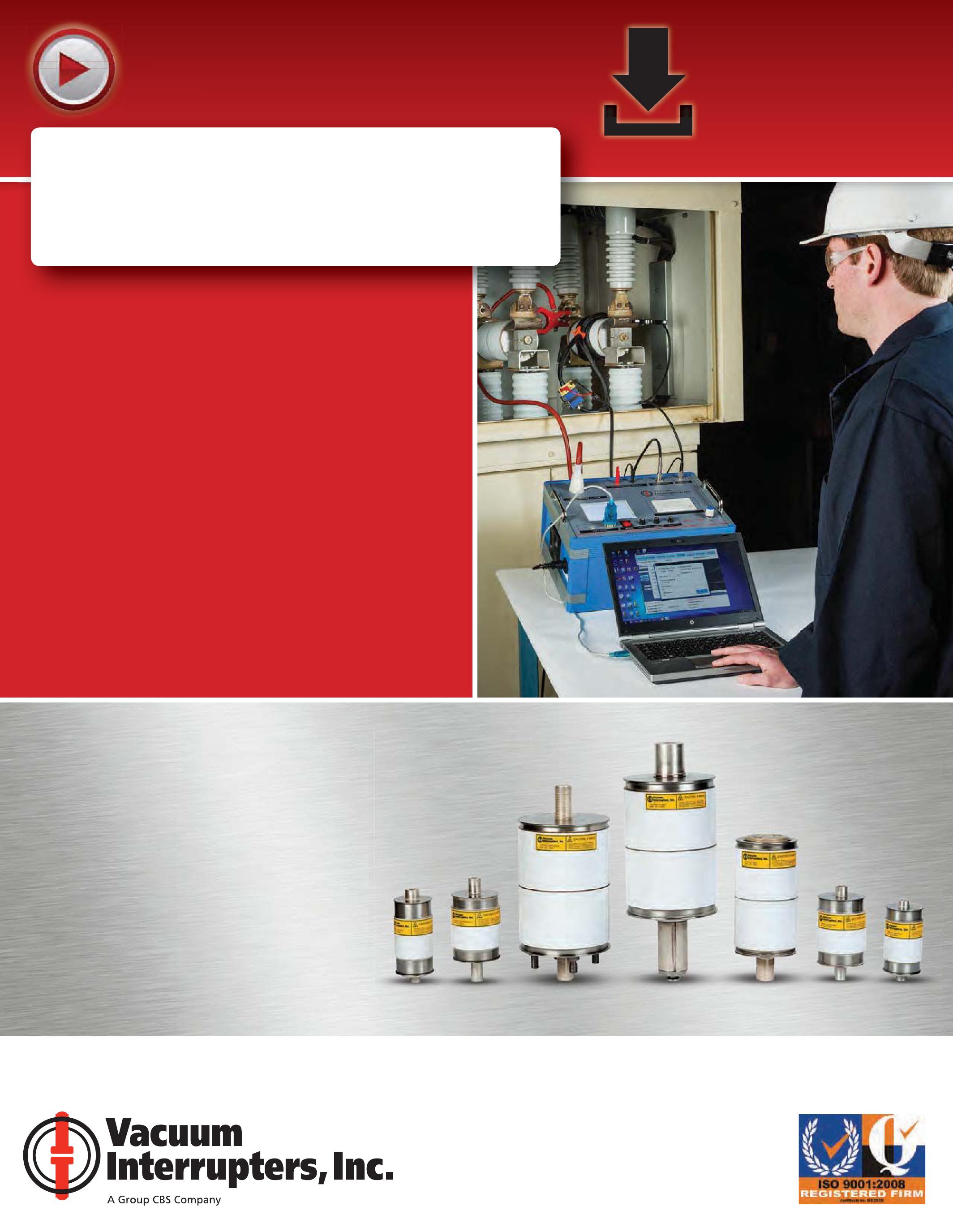
• WORLD’S FIRST VACUUM INTERRUPTER TEST SYSTEM CAPABLE OF PREDICTING REMAINING LIFE
• WORLD’S FIRST TEST SYSTEM CAPABLE OF TESTING VACUUM INTERRUPTERS IN BOTH THE SHOP AND FIELD
• BASED ON SAME OEM LEAK-RATE TEST PERFORMED AT THE FACTORY
• MEASURES ACTUAL ION CURRENT AGAINST KNOWN VALUES TO DETERMINE VACUUM INTERRUPTER INTERNAL PRESSURE


According to the NETA Acceptance and Maintenance Testing Specifications sections 7.15.1 and 7.15.2 for Electrical Testing of Rotating Machines there are three required tests: insulation-resistance, de withstand, and phase-to-phase stator resistance. The required tests of insulationresistance, polarization index (IEEE 43), and controlled de high voltage (IEEE 95) have been effective in evaluating certain aspects of medium-voltage (4 kV-13 kV) global vacuum pressure impregnation (GVPI) stator windings; however, they have not proven adequate for determining whether or not the insulation system is well consolidated. As a result, there is some concern that the required tests are not sufficient for quality assessment (QA) of either a new or existing medium-voltage (MV) winding. The NETA specifications include three optional tests: power-factor or dissipation-factor, tip-up, and partial discharge 1•
See NETA World Spring 2014 and Fall 2014 for more information about the need for these additional dielectrics characteristic tests.
Initially, tie all three phase leads together to start the test. If the test results are unacceptable, then split the phase HV leads
and connect the sensor to each HV lead to further locate the problem (Figure 1).
There are basically two approaches: one is to use an instrument that performs all three tests simultaneously but requires an external ac power supply (Figure 2), and the other is to add PD testing to an existing DF/PF testing program where the DF/PF test provides the ac power supply (Figure 3).
Definitions
• LV-low voltage, defined as value at 0.2E (E is defined as phase-to-ground (rms))
• HV-high voltage, defined as value at l.OE
• Ll-change from LV to HV, defined as (HV-LV)/LV expressed in percentage
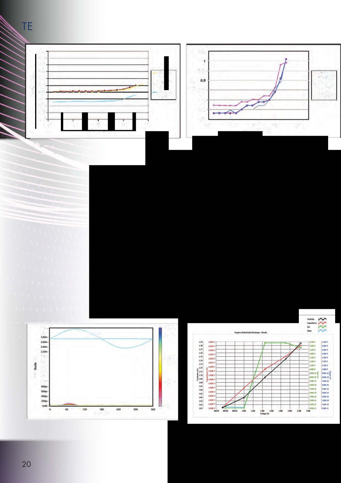
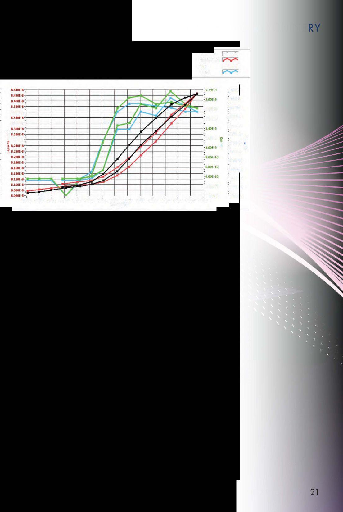
• PDIV-Partial Discharge Inception Voltage, defined as voltage step at which PD appears and/or Cap, DF or PF are seen as voltage dependent (the knee) (Figures 4-8)
• PDEV-Partial Discharge Extinction Voltage, defined as voltage step at which PD disappears and CAP, DF or PF are no longer seen as voltage dependent (below the knee) (Figure 8)


3-phase machine winding
Single-phasehigh voltageACtestset
Figure 1: Winding Configurationfor Testing
Tests should be done with all three phases tied together with the coupler (AL, BL, CL)
2: Combined Test Instrument
3: PartialDischarge Test Added to a DF Test
Caution: keep all HV leads away from grounded leads
• Initial voltage (LV) is 0.2E
o E is definedas phase-to-ground (rms)
• Target voltage (HV) is l.OE
• Steps going up are 0.2E
• Stepsgoing down are 0.2E
o Note that IEEE 56 recommendsyougo upto the maximum and record the levels, then go downtothe PDEV andthenbackupto PDN.
Some instruments apply voltage in short increments and not in an increasing manner. This may lead to variable results, as the discharge activity within a void is erratic over the first few minutes of voltage application. If at all possible, tests should be done with a constant voltage that is slowly stepped to the next voltage level.

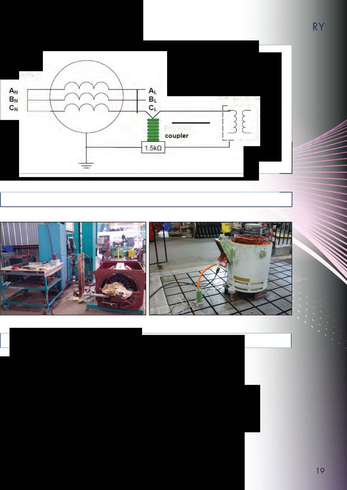
Figure 4: Capacitance-PDIV(Knee) Occurs ,5.5 kV
Figure 5: Dissipation Factor- PDIV (Knee) Occurs ,5 kV
• Actual voltage
• Capacitance (Cap)
• Dissipation factor (OF) or power factor (PF)
• Partial discharge (PO)
As of now, there is no difference based on voltage class; however, there is some doubt about the relevancy of these acceptance levels for windings greater than 7 kV that will have silicon carbide coating.
• Cap/DF/PF at LV- measure of curing/ contamination
o CapLv- no recommendation
Figure 6: Emergence ofPartial Discharge (PDIV)

o DF/PF LV - �2% rewind and proposed �3% on refurbishment [1][2]
• 11- measure of delamination
o 11 Cap --� 1o/o [2]
o 11 DF/PF � 1o/o (note that this may only be applicable to windings rated less than 7 kV) [1][2]
• PDIV/PDEV > 0.5E measure of internal voids [2] [3]
o PDHv - check with PO instrument manufacturer for recommendations
Figure 7: PDIV ,J.OkVonlythe PartialDischarge (Green/ Blue) Detectedthe Knee which SuggestsanIsolatedProblem
TanDefta � capacitance I� Qm � TangensDetta/PartialOisc.harge • Results Qapp I�
-2.40E9
�2.20E9 :200E9
�180E9
8.220E8 -+--+---+---t--+- - f--f---t--
8.200E-8 --+--+--+--+--+--++- f-- ,__--I---II II---I----8. E-10
8.180�s I----I----+--+--+---+- /
8.120E8
�1.60E-9
�1.40E-9
-UOE-9 0 :lOOE-9
�8.00E·l0
�600E-10
�400HO
�2.00E-10
Figure 8: PDIVIPDEVat ::::3.1 kV (Note that the duplicate blue, green, red and black lines are from going up and then down in voltage.)
Though these tests are referenced in other guides and standards, these are the documents that are actually proposing acceptance numbers.
1. IEEE 286-2000 Recommended Practice for Measurement of Power-Factor Tip-Up of Rotating Machinery Stator Coil Insulation. The recommendation is actually provided by the Doble Engineering Company.
2. EPRI LEMUG Report 1016679 (Dec. 2008) Repair and Reconditioning
Specification for AC Squirrel-Cage Motors with Voltage Ratings of 2.3 - 13.2 kV.
3. IEEE 56-2012 (Draft) Guidefor Insulation
Maintenance of Large Alternating-Current Rotating Machinery (10,000 kVA and Larger)

Vicki �rren, Senior Product Engineer, Iris Power LP. Vicki is an electrical engineer with extensive experience in testing and maintenance of motor and generatorwindings. PriortojoiningIrisin 1996, she workedfor the U.S. Army Corps ofEngineersfor 13 years. While with the Corps, she was responsiblefor the testing and maintenance of hydrogenerator windings, switchgear, transformers, protection and control devices, development of SCADA software, and the installation oflocal area networks. At Iris, Vicki has been involved in using partial discharge testing to evaluate the conditionofinsulationsystemsusedinmedium-tohigh-voltage rotatingmachines, switchgear andtransformers. Additionally, shehasworkedextensivelyinthedevelopmentanddesignofnew products usedfor condition monitoring ofinsulation systems, bothperiodicaland continual Vicki also actively participated inthedevelopmentofmultipleIEEEstandardsandguidesand was ChairoftheIEEE 43-2000 Working Group.


So you thought school was out?


Training updated for lastest safety standards
Acceptance Testing Services
Low, Medium, and High Voltage
Preventative Maintenance & Testing Switchgear
Transformers
Engineering Services
781-767-0888
Email: infrared.ma@verizon.net
152 Centre Street Holbrook, MA 02343 www.Infraredbps.com

Power System Acceptance Testing
Commissioning and Start-up
Maintenance
Life-Cycle Extension
Troubleshoot and Repair
Training and Engineering Services
Planning and Operations Support
Project Management


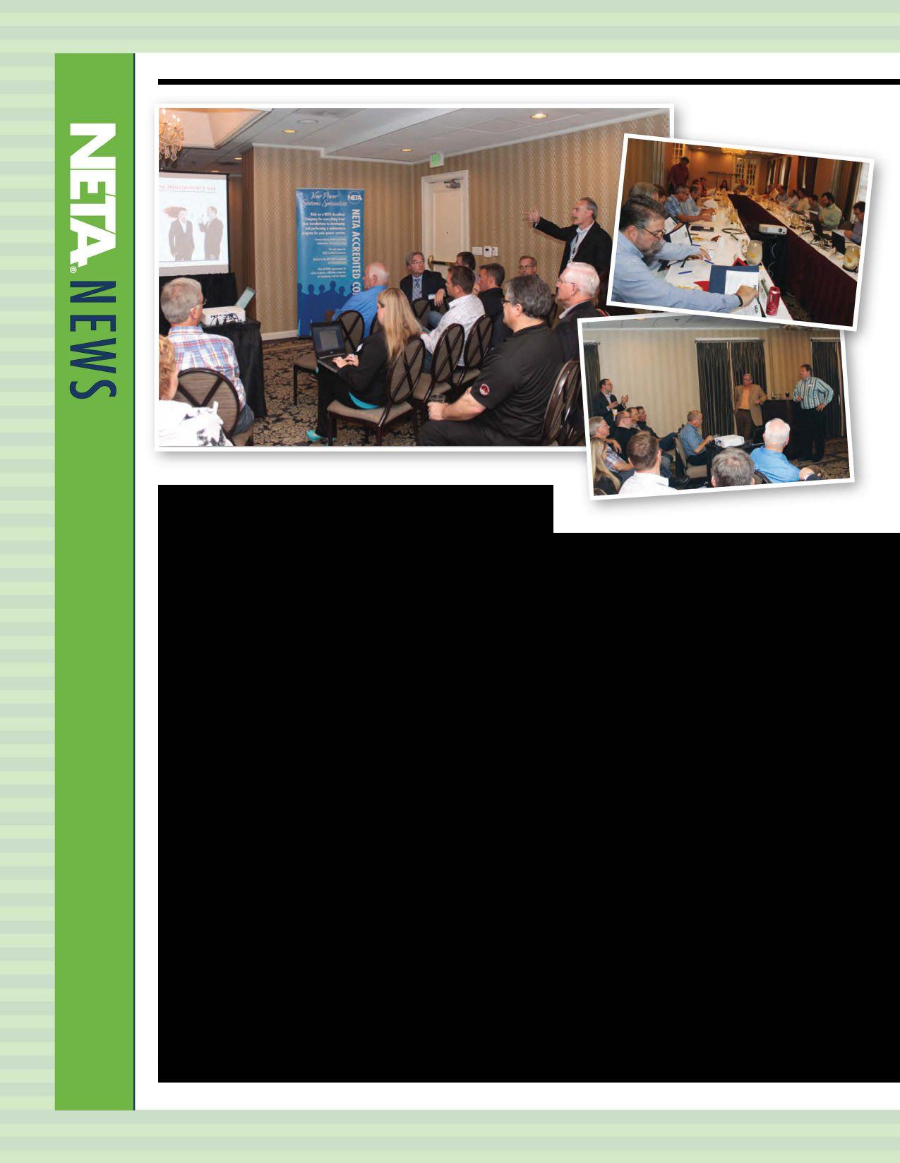
NETA members and Alliance panners came together for meetings and networking in the beautiful hills of San Francisco,California. Meetings took place over three days from September 11-13, 2014, following the Shermco andNETAcohosted hospitality suite at IEEE lAS PCIC. The NETA Board of Directors met on Thursday, September12, followed by theNETAmembership meeting on Friday, September 13, 2014. These two meetings were filled with association activity and program progressupdates.
NETAisworkingwithitsalliancecommitteetocreatemore opportunities for NETA Corporate Alliance Program partners andNETA Alliance Partners to come together with NETA Accredited Companies. One of these opportunities occurred on Wednesday, September 10, at theNETAAlliancePanner eventthat featured an evening oftechnicaldiscussionofbestpracticesrelatedtomolded-case circuit breakers as well as some discussion ofNFPANEC 70, Article 230.95C, and the desire to see ground fault protection systems tested by means of primary current injection. NETA Accredited Members, current and prospective alliance partners, and corporate alliance partners were invited to the discussions that included
presentations of material prior to an open forum for discussion from the floor. From this discussion, attendees transitioned into working groups that focused on specific areas from which individuals were able to select various technical subjects.
These technical working committee subgroups will hopefully contribute to the creation of new materials for the association while providing quality interaction between important industry players from manufacturers, architects and engineers, contractors, electrical testing firms, and others. This type of meeting, combined with discussion and workshop, is a great way for people with differing perspectives to come together and gain insight and understanding about aspects of the electrical power systems industry with which they may not be exposed on a daily basis. NETA wants to help bridge gaps in knowledge and bring people together to better the industry as a whole. To learn more about the NETA Alliance Partner Program, NETA accreditation and membership, and additional technical working session attendance opportunities, please contact theNETA office at www.netaworld.org.



With the release of the new edition of NFPA 70E Standard for Electrical Safety in the Workplace and additional changes brought forth throughout the standard, there will be an additional focus on condition of maintenance as it relates to safety of personnel. This article will focus on NFPA 70B, Recommended Practices for Electrical Equipment Maintenance and how NFPA 70B works in conjunction with NFPA 70E.
Consensus standards like NFPA 70E and NFPA 70B are recommended best practices. As such, they are considered to be recommendations and therefore have no legal enforceability. However, because OSHA recognizes consensus standards such as NFPA70E and NFPA 70B, it will often cite these standards in the issuance of violations and/or in the event of a workplace accident. Maintenance of electrical equipment has such strong cause and effect directly related to electrical workplace safety, these standards often reference each other.

In the 2015 Edition NFPA of 70E the 70E Technical Committee has added the following:
110.1(A) "General. InformationalNoteNo. 1: Safety-relatedworkpracticessuchasverification of proper maintenance and installation, alerting techniques, auditing requirements, and training requirements provided in this standard are administrative controls and part ofan overall electrical safety program. "
110.1(B) "Maintenance. 7he electrical safety program shall include elements that considercondition ofmaintenance ofelectrical
equipment and systems. " For the first time, condition of maintenance is required to be part of the electrical safety program.
130.5 '/Ire Flash Risk Assessment. (3) Take intoconsiderationthedesignoftheovercurrent protectivedeviceanditsopeningtime,including itsconditionofmaintenance."
"Informational Note No. 1: Improper or inadequate maintenance can result in increased opening time of the overcurrent protectivedevice, thusincreasingtheincident energy. Where equipment is not properly installed or maintained, PPE selection basedonincident energy analysisor thePPE category method may not provide adequate protectionfromarcflashhazards."
NFPA 70B has grown from a four-chapter document serving as an overview of an effective electrical preventive maintenance (EPM) program to the current version which consists of 35 chapters, 15 annex sections, and spans more than 270 pages. The 2013 version of NFPA 70B covers topics from reliabilitycentered maintenance (RCM) to personnel safety Inadditiontothesafetyandfundamentals of EPM, individual chapters cover topics such as substations and switchgear assemblies, power cables, motor control equipment, electronic equipment, molded-case circuit-breaker power panels, ground-fault protection, fuses, rotating equipment, lighting, wiring devices, testing and test methods, cable tray and busway, uninterruptible power supply systems, power quality, grounding, electrical disaster recovery, photovoltaic systems, electrical vehicle charging systems, wind power electric systemsandassociatedequipmentandEPMfrom acceptance testing through maintenance. The annexes are a useful resource which contains inspectionchecklist, formsforinspection, testingandrepair recommendations, maintenance guidelines, long-term maintenance guidelines, recommended maintenance intervals, and reliability-centeredmaintenanceguidelines.
Attention to maintenance of electrical systems is very critical to the reliability and safety of
any organization. The electrical systems that supportalltypesofoperationsarethebackbone of every facility and most organizations understand the nuisance of unplanned operationalinterruptions.
With proper planning for maintenance, most potential electrical system failures can be eliminated. Maintenance cannot prevent electrical accidents, but it can reduce associated hazards in the system which could lead to injuries to workers if an accident does occur. The NPFA 70B, Recommended Practice for Electrical EquipmentMaintenance, 2013 edition, is an invaluable resource for guidance on how to implement a maintenance strategy that will pay dividends on improved reliability and workplace safety.
Section 5 of the standard describes what an effective electrical preventive maintenance programisandoutlinestheessentialelements of an EPM program. It must ensure all personnel implementing the procedures are trained on what constitutes electrically safe workenvironments.
5.1 Introduction. An effictive electrical preventive maintenance (EPM) program should enhance safety and also reduce equipmentfailure to a minimum consistent withgoodeconomicjudgment.
5.2 EssentialElementsofanEPMProgram.
An EPM program should consist of the followingessentialelements:
(1) Responsibleandqualifiedpersonnel
(2) Regularly scheduled inspection, testing, andservicingofequipment
(3) Surveyandanalysisofelectricalequipment and systems to determine maintenance requirementsandpriorities
(4) Programmedroutineinspectionsand suitabletests
(5) Accurate analysis of inspection and test reportssothatpropercorrectivemeasurescan beprescribed
(6) Performanceofnecessarywork
(7) Concisebutcompleterecords


5.3 Planning an EPM Program. The following factors should be considered in the planning of an EPMprogram.
(1) Personnel safety: Will an equipment failure endanger or threaten the safety of anypersonnel?Whatcanbedonetoensure personnel safety?
(2) Equipmentloss: Isinstalledequipment - electrical and mechanical - complex or so unique that required repairs would be unusually expensive?
(3) Productioneconomics:Willbreakdown repairsor replacementoffailed equipment require extensive downtime? How many production dollars will be lost in the event of an equipment failure? Which equipment is most vital to production?
Section 5 covers other essential parts of an EPM such as personnel, surveys and analysis, program inspections, analysis of inspections, testreports, records, andtrainingrequirements.
Another important change in NFPA 70B is the implementation ofa test or calibration decal system, as stated in the following:
11.27.1 General. Afterequipmenttesting, device testing, or calibration, a decal on equipment, in conjunction with test records, can communicate the condition of electrical equipment to maintenance and service personnel. This can be important for assessing the hazard identification and risk assessment for electrical safety procedures as well as the condition of electrical equipment.
11.27.2 Decal. After a piece of electrical equipment or device is tested and/or calibrated, a color-coded decal should be attached on the exterior enclosure of that particular equipment.
Thedecalshouldincludethefollowing:
(1) Dateoftestorcalibration
(2) Person or outside company who performed thetestingor calibration
(3) Color codingindicatingtheservice classificationas describedin 11.21.3
11.27.3 Service Classifications and Related Decal Color Codes. The test or calibration decalsystemhasacolorcodethatcommunicates one of three service classifications in 11.27.3.1 through 11.21.3.3. (SeeFigure 11.21.3.)
11.27.3.1 White Decal: Serviceable. If a device passes all tests satisfactorily and has met the requirements of the testing specifications, then a white decal should be attached to the device. This indicates that the device is electrically and mechanically sound and acceptable for return to service. There could be some minor deficiencies with the equipment but none that affect the equipment electrically or mechanically to any large degree. Examples of deficiencies includeevidenceofslightcorrosion, incorrect circuit ID, and nameplate missing.
11.27.3.2 Yellow Decal: Limited Service. If the device under test has a minor problem that is not detrimental to the protective operation or major design characteristicsofthatparticulardevice, then a yellow "Limited Service" decal should be attached to the device. Examples of limited serviceclassificationsincludeindicatingtrip targets that don't function properly, slightly lower than acceptable insulation resistance readings, and chipped arc chute.
11.27.3.3 Red Decal: Non-serviceable. Ifthe device under test has a problem that is detrimental to the proper electrical or mechanical operation of that device, then a red "Nonserviceable" decal should be attached to the device. The nonserviceable decal would be attached to the device after attempts atfield repair weremade. Examples of nonserviceable classifications include: no trip on one or more phases, low insulation resistancereadings, mechanicaltripproblems, and high contact resistance readings. In addition, management or the owner should be advised of this condition.
Annex L deals with maintenance intervals guidelines. (See the example of Substation (Outdoor) in Table L.l.)
L. 1 : Interval Guidelines
Item/Equipment
Substations (Outdoor)
Insulators

Conductors
Infrared scanning
Annually
Visual inspection 4-6 months
Corona detection 4-6 months
Electrical tests As indicated by other PM
Visual inspection of connections 4-6 months
Check connections for tightness As indicated by other PM
Air-disconnecting Visual inspection switches
Operation check
Contact inspection
This annex provides, in Table L.l, an initial guideline for maintenance intervals for equipment. It should be stressed that environmental or operating conditions of a specific installation should be considered and might dictate a different frequency of maintenance than is suggested in thisannex.
NFPA 70B references manufacturers' recommendations and specifications from the InterNational Electrical Testing Association (NETA). The data from the manufacturers is essential to ensure that equipment is installed and used in accordance with any product limitations. The NETA specifications are used for acceptance testing and periodic maintenance testing to ensure system reliability and correct operation of electrical equipment. Acceptance testing verifies that the equipment functions as intended by the design specifications and provides a benchmark for comparing future test results. The comparison can identify any change in reliability or safety for the equipment being tested. Maintenance tests enable a company to verify the electrical equipment is working as designed, develop trending, and identify
4-6 months
Annually
Annually
potential failures before they occur.
When electrical equipment is adequately maintained, the risk of equipment failure is significantly reduced, thus providing enhanced safety in the workplace. Employers mustdetermineandimplementamaintenance strategyandemploythenecessarycomponents of the selected strategy. A maintenance program is necessary to maximize electrical safetyandensurepropermechanicaloperation of the electrical equipment as well as the associated protection and control devices. Utilizing NFPA 70B is a necessary tool in developing an EPM program that will reduce failures in electrical equipment.
Scott Blizard has been the Vice President and Chief Operating Officer of American Electrical Testing Co., Inc. since 2000. During his tenure, Scott acted as the Corporate Safety Officer for nine years. In addition, he has over 25 years of experience in the field as a master electrician, journeyman, wireman and NETA Level IV Senior Technician.



Shermco and NETA pair some of California's best offerings with solutionsinelectricaltestingandmaintenanceatPCIC2014
AttendeesatIEEE lASPCICweretreatedtoanindulgent evening of decadent desserts featuring some of the area's best chocolates paired with local wines at the hospitality suitejointly hosted byShermco andNETA. This elegant atmosphere was the background for conversations about how to meet the increasingdemand for electrical testing andmaintenanceinthepetrochemicalindustry.
Attendees were able to talk to NETA Certified Testing TechniciansabouthowworkingwithaNETAAccredited Company (NAC) can help manage the process of maintaining the electrical power systems and equipment thatarethebackboneof this industry. Conversations ranged from using anNAC as a consultant to help shape an in-house testing and maintenance program to bringing in the NAC as a contractor to provide services from assessment through completion. NACs are able to work with clients to meet the specific demands of each unique installation within the operationalparameterssetforthbytheclient.
NETA also had a presence during the technical sessions at PCIC withthepresentationof ElectricalMaintenance Practicesfor Safety: an Industry Update. Ron Widup,

Kerry Heid, and Jim White of Shermco Industries and Tony Demaria of Tony Demaria Electric worked together to present best practices and how to most effectively apply strategies that include safety-related aspects to electrical equipment maintenance. With condition of maintenance as a cornerstone of safety, there are many options and strategies that one can implement and follow from preventive maintenance (PM), to predictive maintenance (PdM), to reliabilitycentered maintenance (RCM). Additionally, there are standards such as the ANSI!NETA Maintenance TestingSpecifications and NFPA 70B, Recommended Practicefor Electrical Equipment Maintenance that provide guidance on best practices, as well as manufacturers' instruction books for their equipment. When you combine these resources, the combination does not necessary clearly communicate the safetyrelated elements. This tutorial clarified (with a focus on new or proposed requirements) what these standards are, for what they are intended, and how to effectively apply them. The differences between PM, PdM, andRCMandnew requirements intheupcoming NFPA 70E that relate tocondition ofmaintenancewere alsocovered.


Raytech offers:
• Professional, expert service and advice
• No-charge service evaluations
• Hardware, firmware, and software updates
• 60-Day Service Warranty
• Full and continued support on all retired products
• Certifications available at no extra charge in pdf format


• Shortest repair turnaround times


As described by the National Electrical Code® (NEC®), effective grounding must include three elements. It shall provide a permanent and continuous path from structure or equipment. It shall have ample carrying capacity to conduct any fault current likely to be imposed upon it, and it shall have sufficiently low impedance to limit voltage to ground and facilitate operation of protective devices.
As described in the previous article, it is recommendedtohavethegroundingpathand circuit conductors housed within the same metallic enclosure, or the metallic enclosure itself may be used to provide the grounding pathforthecircuitconductorswithin.
will have different curves depending on the number of poles and ampere ratings. The multipleofthecircuitbreakerratingatwhich itreachesitsinstantaneouspickupratingisthe zero time delay in operation of that breaker. Thesameprocessisappliedtotheselectionof appropriatelyratedfuses.
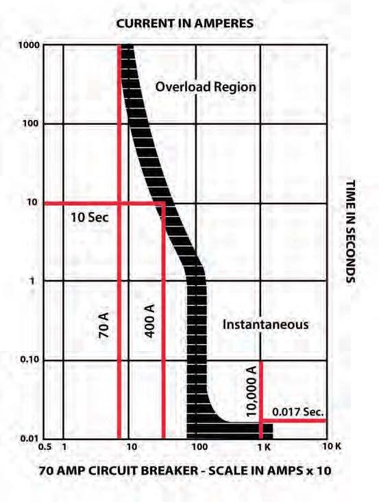
RatherthanspecifYingamaximumimpedance oftheground-faultcircuit,theCode[250.4(A) (5)] indicatesthatitshouldbesufficientlylow to facilitate operation of protective devices; i.e., thefuseorcircuitbreakershallbeableto reachitsinstantaneouspickupoperatingrange. The overcurrent device will thereby operate quickly to remove the fault. Fault currents less than the instantaneous operating value willextendtheopeningtimeoftheprotective device. Manufacturers of fuses and circuit breakerspublishoperatingortripcurvecharts (Figure 1). These charts serve the purpose of providing a convenient means for assuring that the ground-fault path has sufficiently low impedance to permit protective devices to operate quickly and without heat damage to the circuit or equipment. Circuit breakers

Clearing a short-circuit (fault from conductor to conductor) is the same for grounded and ungrounded systems and involves installing an overcurrent device in series with each ungrounded system conductor. Clearance time may have to be as low as a fraction of a cycle depending on the magnitude of shortcircuit current and the characteristics of the device. High-interrupting capacity, currentlimiting fuses accomplish this for virtually all ranges of short-circuit currents.Similarly, current-limiting circuit breakers are available. Underwriters Laboratories defines currentlimiting as: "The term 'current-limiting' indicatesthatafuse,whentestedonacircuit capable ofdelivering aspecificshort-circuit current (rms amperes symmetrical) at rated


voltage, will start to melt within 90 electrical degrees and will clear the circuit within 180 electrical degrees (1/2 cycle).”1 They also clarify that a fuse may not be current-limiting on a circuit of lower maximum available current.
The standard also defines current-limiting circuit breakers: “…one that does not employ a fusible element and when operating within its current-limiting range, limits the letthrough I2t (current squared time) to a value less than the I2t of a ½ cycle wave of the symmetrical prospective current. Currentlimiting circuit breakers are marked currentlimiting and are marked either to indicate the let-through characteristics or to indicate where such information may be obtained.”2

In addition to current-limiting circuit breakers, there are also circuit breaker current limiters. These UL describes as: “…designed in conjunction with specific circuit breakers and to be directly connected to the load terminals of the circuit breakers. They contain fusible elements which function only to increase the fault current interrupting ability of the combination which is intended for use in the same manner as the circuit breakers when installed at the service and for branch circuit protection. The limiters are rated 600 volts or less.”3 Because of the specific mating of these devices to protected circuits, it is vital to scrupulously adhere to manufacturer’s instructions when installing.


It is important to be aware of the inverse time nature of overcurrent devices. This means that as current increases, operating time decreases (the more potentially destructive the current, the more quickly it is extinguished). Overcurrent devices see fault current at lower operating ranges as a load and do not react as quickly as at their current-limiting range. Often, two or more circuit breakers or fuses are installed in series. Tested for operating compatibility, the manufacturer may have marked them with a series-combination rating. In general practice, the device installed closest to the source is rated at or above available fault



current at the terminals while the downstream overcurrent device is rated below fault current. This practice helps isolate the faulted circuit only without taking out circuits connected upstream. For such installations, equipment must have been tested for suitability to such configurations. This is determined by manufacturer’s identification of components on decals located on the devices.
Time-current characteristic curves for fuses reveal that at currents of five to six times the fuse rating, clearing times are down to about one second. Increase the current to fifty times rating and clearance is less than one cycle. High-interrupting capacity, current-limiting fuses can, therefore, effectively limit current at values as much as fifty times rating. Placing an overcurrent protective device at the source of supply will provide short-circuit protection for the conductor. Finally, conductors are

ure 2: Service Conductor Grounded to Service
re 3: Service Conductor Not Grounded to Service
protected in accordance with rated ampacity [240.4(G)].
Ground fault clearance is determined by the impedance of the circuit and the available short-circuit current of the system. The circuit here, however, is much different than that of a short circuit. In this case, the impedance of the ground-fault circuit can be high enough to become the controlling factor for current flow. The available capacity of the system is no longer the determining factor as it is in a short-circuit fault, but rather its ability to maintain full voltage. A relatively large voltage drop must be tolerated in the grounding conductor. A useful rule is that the impedance from the point of fault back to the transformer should never be higher than would allow a minimum current flow of about 600 percent of the protective device rating. This should overcompensate for the variable impedance that may result from the point of fault. Even with a comparatively low 2000 ampere overcurrent device and a fault current of 12,000 amperes (600 percent), clearing time will be less than a second. This is generally satisfactory if hazards are kept to a reasonable minimum.
The service entrance is especiallyvulnerable to ground faults because there is no overcurrent protection on the incoming line. This is protected only by the utility transformer's shortcircuitprotection on the primary, which can be many times the rating of a secondary overcurrent device. Overload protection is provided by the overcurrent device in series with the service-entrance conductors at the load end, and is required by the NEC to be outside the building or at least nearest the point of entry of the conductors into the building [230-70(A)(l)]. If a ground fault does not develop on the load side, it can only be cleared by the transformer's primary fuse whichcanbemanytimestherating. Oftenthis results in the fault only clearing by burning itself clear or developing into a short circuit. The NECrequirement, then, limits the risk of havingconductors with no protectioninsidea

building. If equipment on the line side of the service entrance is not properly bonded and a properly-sized main bonding jumper in place, it is unlikely that enough current will pass to clear the fault through protective devices on the line side of the utility transformer.
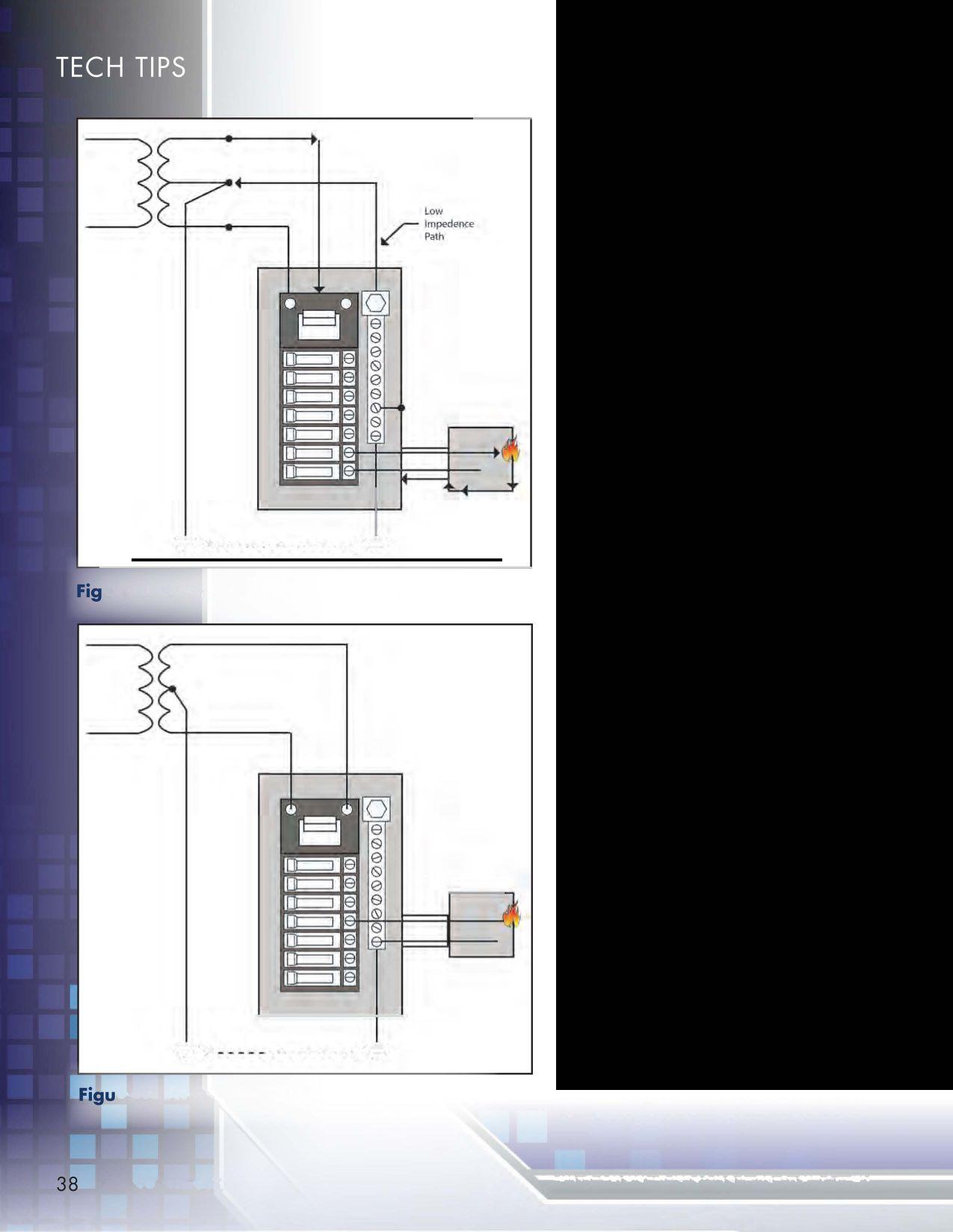
The neutral of a grounded system serves to energize loads at line-to-neutral voltage and carry unbalanced current back to the source. It also provides a low-impedance path for fault currents to facilitate the operation of overcurrent devices. Whether needed for voltage requirements or not, the neutral still must be connected to the equipment grounding conductor at the service [25024(C)]. On a balanced load and carrying no load current, the neutral is still serving a vital rolein faultclearance asa grounded conductor. It provides a low-impedance path directly to the transformer.A fault current is not required to travel through the earth, as the grounded neutral will allow sufficient current flow to operate the protective device. In parallel, the grounding electrode and earth still operate as a fault-current path, but typically 90 percent or more of the current returns through the grounded neutral(Figure 2). This configuration is essential for circuit protection even when the neutral is not required to serve the load. In situations where the neutral is required to serve the load, it must be remembered to size the neutral not only against the load but also include the fault current and overcurrent protection requirements.
What is the situation in the case where there is no grounded neutral? Consider a 120/240V single-phase groundedsystemwheretheloadis supplied at 240. A grounding conductor from the load is properly connected to a grounding electrode and bonded to the equipment grounding conductor. But the neutral is not carried into the service equipment, as all power utilization is at 240 volts (Figure 3). If a ground fault should occur, voltage between equipment and ground will rise, often to a dangerous level. The fault path consists of the impedance of the fault, then the grounding conductor and the grounding electrode, as
determined by the surrounding earth. The fault current must travel through the earth to the neutral ground at the transformer, then through the transformer and back to the service and the overcurrent device to the point of the fault.
As all the series impedances are added up, this circuit is unlikely to have an impedance of less than 22 ohms. For the circuit as described, the maximum current would be 5.5 amperes. With a typical 100 ampere service and 20 ampere overcurrent device, the circuit protection would not operate and a serious shock and fire hazard would exist, for minutes and possibly even days. Imagine, finally, that the remote but possible situation of the transformer and electrical system being grounded to the same water pipe system existed. The resistance of the fault path would be greatly reduced, but because of the wide separation in distance, reactance and therefore impedance of the fault circuit would still be high. The fault current might still not reach a level to operate overcurrent devices and the shock hazard remain.
1 Underwriters Laboratories Electrical Construction Materials Directory Guide Card QCQR)
2 Ibid. ((DIVQ)
3 Ibid. (DIRW)
Source of information: Int'lAss'n ofElectrical Inspectors (IAEI) Soares Book on Grounding
]iffrey R. Jowett is a Senior Applications Engineer for Megger in Valley Forge, Pennsylvania, serving the manufacturing lines ofBiddle,Megger, andmulti-Ampfor electrical test and measurement instrumentation. He holds a BS in Biology and Chemistry from Ursinus College. He was employedfor 22years with james G. Biddle Co. which became Biddle Instruments and is nowMegger.
Foundedin 2001 byJody Medina as a small, solutionoriented third-party testing company serving Denver, Colorado, and its surrounding areas, Grounded Technologies, Inc. (GTI) has grown into a trusted member of the testing community not only in Colorado, but throughout the United States. With our newest milestone of proudly becoming an accredited member ofNETA, GTI looks forward to further solidifying its relationships with the mission critical, hospital, oil and gas, and commercial markets.
The GTI staff has an electrical infrastructure know!-
edge base that combines over 50 years of electrical field experience. GTI has worked hard to establish trusted partnerships with quality contractors and manufacturers, which has allowed us to be a part of many exciting projects over the years. With membership in place, our team is eager to embrace the many benefitsNETA has to offer and to become an active participant in theNETA community.
Please visit usat www.groundedtech.com, or emailfor more information at info@groundedtech.com. We look forward to working with you.


It's not unusual for someone to ask Which Technology is Better, Infrared or Partial Discharge?
Certainly, both technologies are valuable, and answering the question is not very easy. This article will examine some of the strengths and weaknesses of each technology and will, however, attempt to provide a fair evaluation of both technologies 1n order to decide which technology is the winner.
Our readers are very likely to already be quite familiar with infrared (IR) technology and especially applying IR surveys on electrical systems. IRessentially allows the technicianto show the heat emitted from an object on the camera's viewing monitor.
For electrical systems, the heat is often caused duetoapoorconnection.Thepoorconnection has greater resistance and heat is generated in accordance with the FR formula. Therefore, current is the culprit. WhenusingIRtechnology we are looking for problems with conductors. Conductor heat generation is proportional to the square of the current and is not voltage dependent so IR technology works well on equipmentatallvoltagelevels.
Partial discharge (PD) is a much newer technology in regards to field applications
in the United States. Understanding of this technology is not nearly as widespread as the understanding of infrared. PD testing techniques essentially detect signals emitted from partially failing insulation. Partially failing insulation creates several types of signals, bur primarily electromagnetic and ultrasonicemissions are the easiest to detect.


Medium- and high-voltage insulationfailure occurs due to compromises in the electrical field which can be caused by a number of things including, but not limited to, poor workmanship, mechanical damage, environmental contamination, and internal voidsfrominadequatemanufacturingprocesses. Voltage stressesatthelocalcompromisedareas of the insulation will partially breakdown or spark, thus creating the resulting signals. The purpose of the insulation is to keep the separated phases of an electrical system from contacting each other or ground. Therefore, PDisrelatedtovoltagemagnitude. Ingeneral,


the greater the voltage the more difficult it becomes to create and maintain insulation. Typically, 600 volt clas and below equipment does not have high enough voltage present during normal operation for PD to occur; thus PD techniques are limited to medium-voltage and higher applications.
In the following, we will compare IR with PD in some of the more important categories.
No Outage-This one is a tie, both technologies are performed during normal operation and do not require an outage.
can potentially lead to a large-scale disaster but since infrared has been used so frequently over the years, the problems that are being detected today are less severe overall. Since PD is focused on medium- and high-voltage equipment, which is usually more critical to operations, the impact will generally be much more severe. Edge to PD.

Eas e of Use-Both technologies are fairly easy to use but both can get a bit tricky at times. Since IR has been utilized longer, technicians have been exposed to more training and more field applications than PD. Edge to IR.
Data Interpretation-Again edge to IR. IR training and usage has helped technicians get through the early misinterpretation of reflections and other false positive diagnoses. Correct application of PD techniques must include the ability to distinguish noise from PD and this requires training.
Saftry-IR requires the removal of covers in order to perform the inspections. NFPA 70E requirements and IR viewing ports have made this work much safer, but PD inspections do not require cover removal and are therefore generally much safer. Advantage to PD.
Equipmentvoltage cl ass-PD iseffective only on medium- and high-voltage equipment, while IR also works well on low voltage equipment. However, IR does not detect the prominent failure mode for medium- and high-voltage equipment (PD). Slight edge to IR since PD isn't effective on low voltage equipment.
Equipmentoperatingconditions-PD iseffective as long as voltage is present. IR could miss a potential problem if a circuit happens to be off or lightly loaded. Slight edge to PD.
Value (ROI)-This is a difficult category to rate since the cost of a failure can vary considerably on a case by case basis. Certain types of failures
Statistics-Some statistics indicate that up to 30 percent of electrical failures are caused by loose connections. However, these statistics were largely derived decades ago. If a facility has been performing annual infrared scans for many years, there isn't the amount of overall problems present as there once was. IR, as expected, has taken a bite out of electrical problems statistically. Stop performing IR, and these statistics will again rise.
Other statisticsindicate that around 90 percent of medium-voltage equipment failures are due to PD activity. It's remarkable that some facilities will perform annual IR inspections on medium-voltage switchgear and never find a problem, while overlooking a technology that will likely detect 90 percent of failure symptoms. Big advantage to PD for mediumand high-voltage equipment only.
As we can see from above, IR detects currentrelated problems while PD detects voltagerelated problems, and both technologies are very valuable for providing early warning prior to failure. One technology simply cannot do what the other one does and, therefore, cannot be directly compared. The two technologies are actually complementary, and both techniques should be regularly used as part of any maintenance program.
Don A. Genutis holds a BSEE from Carnegie-Mellon University. He has over 30years ofelectrical testing experience. Don serves as President ofHalco Testing Services based in Los Angeles, California.


Electrical Testing-Safety-Engineering
High Voltage Service helps prevent and solves electrical power problems through electrical engineering, electrical testing, preventative maintenance,repair,replacement,and power systemanalysison eitheraroutineor an emergency basis. The company's mission is to provide the highest quality electrical power solutions while maintaining a focusand responsivenesstoclientselectrical powerneeds.
High Voltage Service has partnered with our customers, from Fortune 500 companies to utilities, to solve problems. High Voltage test technicians are members of IBEW (International Brotherhood of Electrical Workers) St. Paul localllO.
High Voltage Service offers a systematic and safe approach to electrical services. Capabilities include transformer services, switchgear services, electrical equipment maintenance, electrical testing, repairs, replacement, and circuit breaker remanufacturing. High Voltage Service can help prevent downtime by
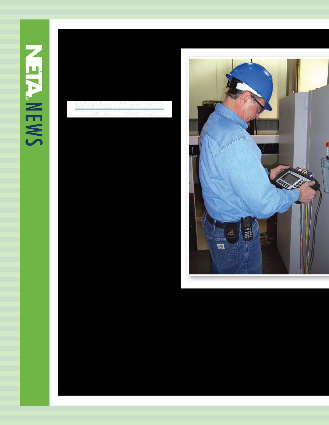
implementing a regular electrical system maintenance schedule. In emergency situations, HighVoltage Service responds quickly to getelectrical power operations back up and running.
To ensure safety and reliable results, our technicians follow a proven, step-by-step approach to electrical troubleshooting and preventative maintenance. Our NETA CertifiedElectrical Test Technicians are some of the best trained and most qualified professionals in the electrical power industry.

POWER Testing and Energization can provide you with acceptance and maintenance testing of electrical system equipment, 480 V through 500 kV, helping to ensure the continued operation, reliability and integrity of your electrical system,
flectrical Testing Services Include: NationwideServicesInclude:
Substation Maintenance
Breaker Repair & Modification
Cable Hi-Pot Fault Location
Emergency Transfer Controls
Doble Power Factor Testing
Surge & Transient .Protection
Infra-red Scanning
Measurement & Diagnostic Services
Relays & Meter Calibration
Marine Electrical Repairs
Switchgear Service & Testing
Engineering Supervision

» Commissioning Electrical Systems
» Acceptance & Mamtenance Testing
» Protective Relay Systems
>> Troubleshooting & Repairs
» Electrical Equipment Upgrades
» NERC Compliance Support
» Short Circuit I Coordination I Arc Flash Studies
» Safety I Commissioning I Operation & Maintenance Program Development
Utility Service Corporation has been providing electrical and technical services for government and industry since 1962.
Solving complex problems, testing under difficult and unusual circumstances and servicing the commissioning and maintenance needs of today's electrical power systems both new and aged.
Engineering & Consulting Construction Supervision System Trouble Shooting
The following company was inadvertently omitted from the list of Corporate Alliance Partners that offered demonstrations at their exhibit booths throughout the PowerTest Trade Show. (See pages 106-109, NETA World, Summer, 2014.)
AVO Training, one of the seven NETA Corporate Alliance Partners, participated in the Industry Leadership Exchange at PowerTest 2014.
In keeping with AVO Training's philosophy of offering the types of electrical safety training courses that industry and utilities require, the following new course subjects were added to the over 50 courses currently available at the institute.
These courses include:
Circuit Breaker Maintenance - SF6
Thiscoursecoversall elements of SF6 circuitbreaker maintenance from routine inspection to major overhaul. Instruction includes the hazards involved in working with SF6 gas as well as the important differences between SF6 circuit breakers and
thosewithconventional insulating mediums.
Programmable Logic
Controllers
Maintenance & Troubleshooting
This course will provides the foundation to program and troubleshoot the PLC system resulting in less downtime andincreaseduptime.
Infrared Thermography Level I
This training course willbenefit the student who has a desireto learn thebasicsof infrared thermography
The AVO Training Difference
• HANDS-ONSKILLS YOU CANUSETODAY
• HIGHLY EXPERIENCED NSTRUCTORS
• INDUSTRY RECOGNIZED TRAINING
NETA wishes to thank AVO Training Institute for participating in the NewProductForum and exchange of knowledge andideasat PowerTest2014.


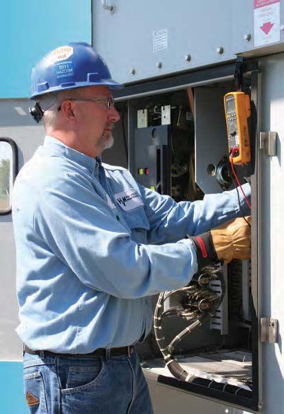
Failure is not an option. Ensuringthereliabilityof your electricaldistribution system.
As theleadingindependentelectrical testing,maintenance,andengineering service company, you canrelyon Emerson’sHigh VoltageMaintenance to exceed yourelectricalequipment performance goals. From testing for problems that coulddisable your system, to complete turnaround execution, you’llquicklyunderstandhowweare your single source solution forall of yourelectricalreliabilityneeds. With anetworkofmore than12 service locations,our service teamputs experiencedprofessionalswhereand when youneed them. ComprehensiveElectrical
BEC Testing has been serving Long Island and the New York City area since 2006 with 24/7 emergency service.
BEC Testing is an elite electrical testing company dedicated to advancing the industry's standards for power system acceptance and maintenance testing, engineering, installation, and troubleshooting. BEC Testing's certified and extensively trained engineers, technicians, and staffensure the highest level of reliability and electrical safety. BEC Testing offers full service support for all electrical distribution systems to help maintain a reliable, safe working environment and keep facility costs under control.

BEC Testing believes that its customers should not have to worry about their electrical systems. They should be able to focus on their core business and have their electrical systems operating trouble-free and in the background. BEC Testing's accreditation with NETA makes this possible.
BEC Testing provides electrical testing, maintenance, and engineering for the area's major hospitals and facilities, including the 355 megawatt Caithness Energy Center, the second largest power plant in the history of Long Island. BEC Testing is proud to join the prestigious ranks of NETA Accredited Companies and looks forward to future growth and achievements.





Two organizations collaborate with the shared vision of advancing the quality of construction safety and reliability. NETA and ARCOM* are working cooperatively to enhance electrical testing requirements in the electrical specifications of The American Institute of Architects' (AlA) MasterSpec® master specification system. Over the next several years, the MasterSpec electrical library, currently consisting of approximately 80 sections, will be reviewed and updated to include detailed testing requirements from the ANSIINETA Standard for Acceptance Testing Specificationsfor Electrical Power Equipment andSystems (ANSIINETAAT S).
*MasterSpec is published by ARCOMfor 1he American Institute ofArchitects.
NETA and ARCOM recently met at ARCOM's biannual MasterSpec Engineering Review Committee (MERC) electrical review meeting on July 26, 2014. MERC is comprised of eight practicing electrical engineers who, using their over 200 years of combined experience, review and advise ARCOM on electrical specification sections.
MERC met with NETA to finalize an approach to inserting NETA testing requirements into MasterSpec and to discuss how to address testing organizations and test technician qualifications. Following these in-depth discussions, MERC agreed that including certain ANSIINETA ATS electrical tests appropriate for the equipment described in the specification would be valuable to the electrical engineers who use MasterSpec.
This collaboration with NETA will allow
MasterSpec to provide engineers with clear options for specifying electrical acceptance testing without requiring further research or definition. Accordingly, the Quality Assurance article of MasterSpec electrical sections will be revised to include the option of hiring a testing agency and will state: "Testing Agency Qualifications: Accredited by NETA." ARCOM made the decision to reference NETA Accredited Companies directly rather than including testing agency and test technician qualifications due to ARCOM's recognition that NETA Accredited Companies, by their accreditation, inherently provide the quality specifications required for acceptance testing. By specifying testing agencies accredited by NETA, the specifying engineer or contractor is specifying an independent, thirdparty testing agency and is not required to further validate qualifications.
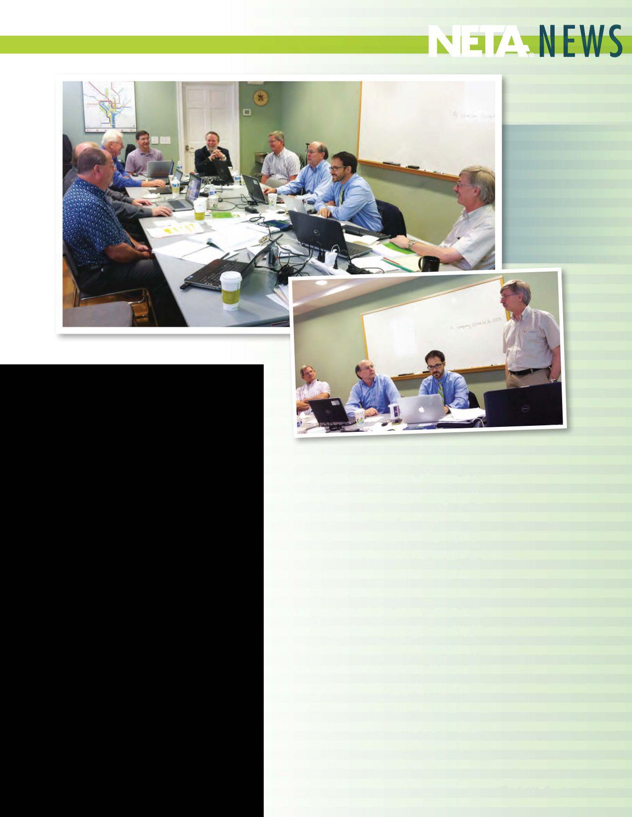
ARCOM furtherclarified that the MasterSpec electrical sections will provide the specifying engineer with the following options relative to electrical acceptance testing:
• Testing bya testing agency accredited byNETA
• Testing bythe manufacturer's field service personnel/department
• Testing bythe contractor
The engineer will now be able to choose from multiple testing options depending upon the project. For projects that require complex testing, there are clear instructions on how to specify and require a testing agency accredited byNETA.
PART I-GENERAL contains testing agency qualifications and submittal requirements for testreports. Note that blue text is instructions for the specifier
Coordinate "Qualification Data'' Paragraph below with qualification requirements in Section 0014000 "Quality Requirements" and as maybe supplementedin "Quality Assurance" Article.
A. �alification Data For [manufacturerauthorized service representative] [testing agency]
Retain "Testing Agency Qualifications" Paragraph below if Contractor is required to provide services of a qualified testing agency in "Field Quality Control" Article. Qualification requirements are in addition to thosespecifiedin Section °014000 "Quality Requirements." See the Evaluations for discussion of NETA ATS andmanufacturer's testing procedures.
A. TestingAgencyQualifications:Accredited byNETA.

PART 3-EXECUTION contains the Field Quality Control article that describes who does the testing andthe teststo beperformed.Thisis where selectedtestsandinspectionsderivedfromSections
7.1 through7.25 of theANSI/NETAATS willbe insertedintoeachoftheDivision26specifications.
Note that blue text isinstructions to the specifier.
Retain one offirstfourparagraphs below.
Retain first "Testing Agency" Paragraphbelow and deletetheremainderofthisarticleifOwner will hire independent testing agency. Delete "Field quality control test reports" paragraph in "Informational Submittal" Article. Delete 'Tests and Inspections" Paragraphbelow.
A Testing Agency: Owner will engage a qualified testing agency to perform tests and inspections.
Retain first "Testing Agency" Paragraph below to require Contractor to engage an independent testing agency Retain "Field quality control test reports" paragraph in "Informational Submittal" Article. Retain "Tests and Inspections" Paragraph below.
B. TestingAgency:Engageaqualifiedtesting agency to performtests and inspections.
Retain "Manufacturer's Field Service" Paragraph below to require a factory-authorized service representative to perform tests and inspections. Retain"Fieldqualitycontroltestreports"paragraph in "InformationalSubmittal"Article. Retain"Tests and Inspections" Paragraphbelow.
C. Manufacturer's Field Service: Engage a factory-authorized service representative to test and inspect components, assemblies, and equipment installations, including connections.
Retain"Performthefollowingtestsandinspections" Paragraph below to requireContractor to perform tests and inspections. Retain "Field quality control test reports" paragraph in "Informational Submittal" Article. Retain "Tests and Inspections"
Paragraphbelow.
D. Perform the tests and inspections [with the assistance of a factory-authorized service representative].
Retain test requirements below with any combination of paragraphs above. See Evaluations for discussion of tests and inspections and the NETAATS.
In the Evaluations, a well-researched document that accompanies each MasterSpec section and describes the products covered in the section, ARCOM will insert the following paragraph to inform the engineer about the incorporation of tests andinspectionsfromANSI/NETAATS into the specification:
The InterNational Electrical Testing Association (NETA) develops and publishes the ANSIINETA Standardfor Acceptance Testing Specifications for Electrical Power Equipment and Systems (ATS). The tests and inspections described in ANSI! NETA ATS help identifY damage that may have occun-ed during shipping, verifY correct installation, and test both components and the entire system to ensurecorrectoperation. Testsandinspectionsapplicable to the equipment described in this section have been included in Part 3 ofthe section. Only those tests directly applicable tofieldtesting equipment described in the section have been included, and the format and language has been altered to match MasterSpec. Review NETA ATS to ensure inclusion ofthe proper test procedures on both system and component levels and coordinate with Part I of the section, other sections, and Division 0I. Consider reviewing the scope oftesting with a third-party testing agencyfor complicated installations or to verifY the testing scope.
In the coming months, ARCOM will work with NETA representatives on each of the MasterSpec electrical sections as they are updated. NETA representatives attending the meeting with MERC included David Huffman of Power Systems Testing Company, Lorne Gara of OrbisEngineering Field Services, and Jill Howell of NETA.

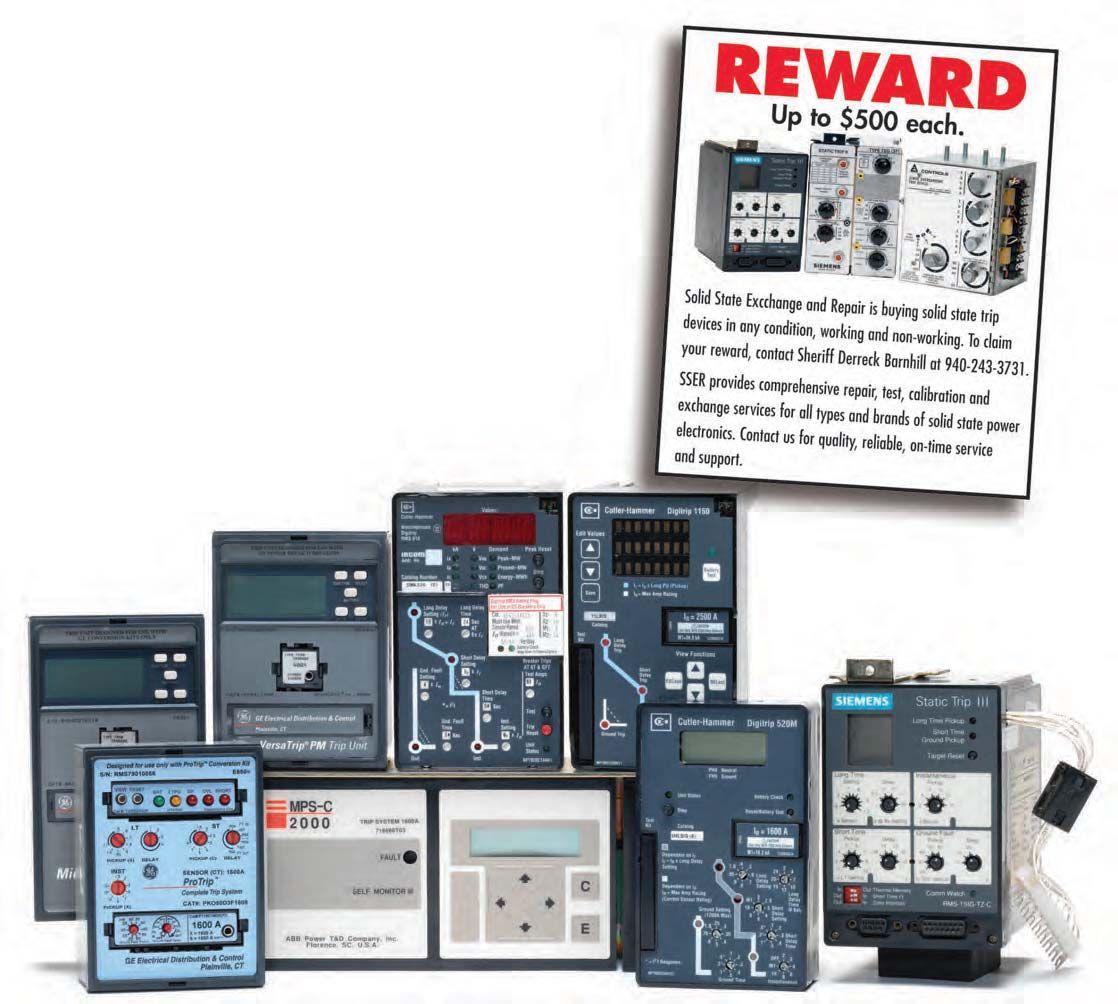
Featuring quality, reliable, on-time service and support for all brands and types of solid state power electronics.
Power electronics are our business
Let us suppoort you with our quality repair, calibration and servicing of your solid state equipment. We also buy, sell and trade:
•Communications devices for power equipment
•Protective relays
•Circuit breaker trip devices
•Motor overload relays
•Rating plugs
VLF & DC Output | Sheath Testing | Cable Burning
The VLF-34E is a new generation VLF AC Hipot that uses a solid state design with microprocessor controls. It meets the requirements of applicable world standards regarding cable testing up to 25kV class maintenance testing. It is light, compact, rugged, and very portable. Its sine wave output is suitable for using external TD and PD detection equipment. Using a TD and PD option, the VLF-34E is all that is needed for nearly all cable testing up to 25kV class.
Easy to use controls. Pr test sequences & manual contr XBEE® wir downloading data and for unlimited test report capture, wireless computer interface to control and download Tan Delta diagnostics and for remote control operation via laptop.

VLF-TD Cable Diagnostic Testing
The TD-34E, along with the HVI VLF-34E AC hipot, is the latest in design using current electronic technology. Together they permit the user to perform all VLF and VLF-TD tests possible and offer the best wireless operation and data collection, aided by the HVI custom application software written solely for the two devices. There is no better alternative. HVI has been supplying the world with VLF and Tan Delta technology since 1998, with more models, greater voltage range, and higher power capability, all with the superior sales and service that HVI is well known for worldwide.
www.hvinc.com ISO 9001 : 2008
Vanguard Instruments Company, Inc. www.vanguard-instruments.com

IT SEEMS THATEACHYEAR BRINGS WITH IT MORE OPPORTUNmES TO ATTEND PROFESSIONAL DEVELOPMENT EVENTS REGARDLESS OF THE TYPE OF INDUSTRY IN WHICH ONE WORKS.
People love the ability to stretch their legs, trade in their desk for some faceto-face networking, and expand their horizons in ways that aren't part of the day-to-day landscape of telecommuting, webcasts, and conference calls. While in theory this presents plenty of places to interact with and learn from peers and experts, time remains a constant and limiting factor in the equation of fittingcontinuingeducation into a year of productivity. Until someone invents a way to increase the number of hours in a day, selecting a conference that is the perfect fit is a great way to make the most out of conference attendance. There are some basic questions one can use to narrow down the options. Who is hosting and attending the event? What topics will be discussed? When is the event taking place, and does it fit into my schedule? Where is the event taking place? Why should I attend? Employers want to avoid the lost productivity caused when their best people are sitting in classrooms without learning something that will increase productivity when they return. By asking and answering the five W's, one can see that it is possible to strike a balance between time, money, and quality.
Exploring Technology Developments over the Past 20 Years with Tom Sandri, Shermco Industries, to Relay Troubleshooting 2.0 with Dave Costello and Karl Zimmerman, Schweitzer Engineering Laboratories. Even after in-depth sessions conclude, it is not unusual to see speakers continuing their conversations over coffee while jotting down formulae and diagrams on cocktail napkins.
New this year is the Doble One-Day Laboratory Seminar co-hosted with NETA on Friday. NETA and Doble have a long history of working together, with many NETA Accredited Companies utilizing Doble equipment and services on a daily basis. Doble has a reputation as an industry leader and contributes regularly to NETA by contributing to NETAWorld NETA World and giving presentations at PowerTest. It seemed like a natural progression for NETA and Doble to build on this strong foundation, and the result of their efforts is showcased in the newlyminted Doble One-Day Laboratory Seminar on Friday, March 6, 2015, following the regularly scheduled PowerTest events taking place earlier in the week.
This event is targeted for engineers, chemists, and others responsible for reviewing data to interpret laboratory results to detect and identify problems with electric apparatus. The seminar will be interactive, combining theoretical background with practical experience and hands-on examples including case studies to illustrate common problems found in the field.
While classroom settings and interaction are valuable for honing in on specific topics, there is a lot to be said for the old-fashioned networking donewithdrinkinhand.ThePowerTesttrade done with drink in hand. The PowerTest trade show, hospitality suites, and PowerBash are prime locations to make new connections with potential clients and suppliers, get answers to
• 5 DAYS OF EDUCATION
• 30 TWO-MINUTE NEW PRODUCT PRESENTATIONS
• 27 45-MINUTE TECHNICAL PRESENTATIONS
• 4 PANEL SESSIONS
• 1 SYMPOSIUM
• 4.5 HOUR TRADE SHOW

• 100+ TOP-TIER VENDORS
• 8 HOSPITALITY SUITES
• ENDLESS NETWORKING
• POWERBASH BANQUET AND AWARDS CEREMONY
• NEW! DOBLE ONEDAY LABORATORY SEMINAR
tough issues facing one in the field, and forge bonds that hold up across the miles in day-today life. Many attendees find that even without competing events during the networking opportunities, there is a shortage of time when itcomestothisoften-overlookedbenefitof it comes to this often-overlooked benefit of attending PowerTest.
For many people winter’s colder temperatures are motivation to get out of Dodge and find a sunnier spot to work for a while. PowerTest 2015 will take place in the heart of Music City, Nashville, Tennessee at the Renaissance Nashville Hotel on March 2-6, 2015. While it may not be flip-flop weather, attendees can be assured that they won’t have to walk uphill through the snow both ways as all events will take place in the hotel and the adjacent conventioncenter.Attendeescaneventake convention center. Attendees can even take a line item out of their budgets for food and entertainment with breakfast being catered each day, luncheon opportunities on Monday

for alliance partners and members and Tuesday at the trade show for everyone, and hospitality events at night like the pre-conference event, hospitality suites, and PowerBash. There is always an abundance of coffee, water, and soda available to stave off the afternoon slump that

can occur from eating a little more than usual. PowerTest is all about perks when it comes to taking care of the conference-goers' comfort and well-being. After all, it's hard to learn when you're hungry.
• REGISTER ONLINE AT WWW.POWERTEST.ORG
• CALL 888.300.6382 (NETA)
Hopefully by now you are asking yourself, "Why not?" PowerTest offers a diversity of material presented by subject matter experts to an audience of individuals whose jobs encompass a range of responsibilities, but who are united by their dedication to the electrical power systems industry. These people are brought together in an engaging atmosphere with endless opportunities to listen and learn as well as interact with peers both in and out of technical sessions. As the classic commercial says, "Airfare-$587. Hotel room$225. Overpriced grande caramel macchiato from the hotel lobby including a tip for the barista who spelled your name correctly on the cup-$8. Energizing your future at PowerTest-Priceless."


• Technical Presentations: Electrical Safety, Reliability, Equipment, Electrical Commissioning, Relays
• Safety Summit
• Panels: Electrical Safety, Transformer, Testing Methodologies, Medium-Voltage Equipment
• In-Depth, Four-Hour Seminars
• Networking with Industry Leaders
Renaissance Nashville Hotel
MARCH 2–6, 2015

In addition to the complimentary social events, there are also some opportunities for more interactionattheMemberandAlliancePartner interaction at the Member and Alliance Partner Luncheon on Monday, the PowerBash Awards and Banquet on Tuesday, the Spouse/Guest Lounge, and the preconference event following the Member and Alliance Partner Meeting on the Sunday preceding PowerTest. There are nominal feesassociatedwiththeseeventstoassurethat fees associated with these events to assure that everyone has a seat and ample food and beverages are provided. All are welcome at PowerBash and the Spouse/Guest Lounge.
Attendance at a chili cook-off, second line parade, murder mystery dinner, pub crawls, and scavenger hunts are a few ways PowerTest attendees have broken the ice during past preconference events. There is no shortage of entertainment as people get toknoweachotheralittlebetteronthesidewalks to know each other a little better on the sidewalks of the host city. In 2015 Nashville should provide lots of boot-scootin’ and boogying, so get ready to line up for some dancing to stretch your legs before the hard-core learning begins on Monday.
GOLDALLIANCEPARTNERSENJOY GOLD ALLIANCE PARTNERS ENJOY ADDITIONAL BENEFITS, SUCH AS COMPLIMENTARYREGISTRATIONEACHYEAR COMPLIMENTARY REGISTRATION EACH YEAR ATPOWERTEST.FORMOREINFORMATION AT POWERTEST. FOR MORE INFORMATION ABOUT THE ALLIANCE PROGRAM, TURN TO PAGE66ORVISITTHENETAWEBSITEAT PAGE 66 OR VISIT THE NETA WEBSITE AT WWW.NETAWORLD.ORG.

The Spouse/Guest Lounge is a cozy area that offers a place to meet, grab some snacks, and post plans for excursions. This year people who purchase the pass can opt in to share their contact information with other guests to make sure everyone is included in daily activities. Shopping, cooking classes, and tours of the local area are usually on the docket, and the best part is that activities are directed by participants so everyone has a chance to help plan the day or can just go along for the ride.
SUNDAY, MARCH 1ST—PRE-CONFERENCE EVENT
MONDAY, MARCH 2ND—MEMBER AND ALLIANCE PARTNER LUNCHEON MONDAY, MARCH 2ND—HOSPITALITY SUITES
TUESDAY, MARCH 3RD—TRADE SHOW
TUESDAY, MARCH 3RD—POWERBASH
ONGOING—SPOUSE/GUEST LOUNGE, BREAKFAST, COFFEE BREAKS
TheMemberandAlliancePartnerLuncheonon
The Member and Alliance Partner Luncheon on Monday is another social event combined with a lot of technical information. Each year a series of technical topics are selected to be discussed over lunch. Table leaders take notes, which are then passed off to moderators who present the discussion points during dessert. Lunch closes with the presentation of the Alliance Recognition Award and the Outstanding Achievement Award, and everyone usually gathers for a group photo on the way to their afternoon sessions.
The member and alliance events are open to allattendeeswhoareeitherNETAAccredited all attendees who are either NETA Accredited Company members or alliance program partners. The alliance partner program is a fee-based program that is open to individuals interested in NETA, and requires no application process or credentialing.
PowerBash on Tuesday following the trade show is a mid-week pause to look back at the first two busy days and recognize all of the people who worksohardtomakePowerTestanincredible work so hard to make PowerTest an incredible event.ThebestofPowerTestwithawardsforeach event. The best of PowerTest with awards for each technical track, the best overall presentation, the best of the trade show, and best of the hospitality suites are all given a well-deserved round of applause and a nice award as a small token of appreciation for their generous donation of time and talent. It is also the midway point for attendees who registered for additional seminars on Wednesday, Thursday, and Friday.
Whether you are a social butterfly or more of a wall flower, you would be hard-pressed to avoid having a good time while you are atPowerTest. at PowerTest.
NETA is certainly an organization that honors tradition and believes in building

knowledge based on a firm foundation of electrical theory even when there is technology available that takes the slide rule out of the picture. It’s safe to say that some people approach social networking the same way, adding some Facebook time as a perk to the face time they get at meetings and events like PowerTest. It may be old school, but it’s nice to know that not all friendships live and die by the like button.
When planning your PowerTest experience, be sure to add networking opportunities to your personalized schedule in the PowerTest App, available as a free download in the iTunes App Store for Apple and Google play for Andriod. A new feature this year, the App will display names and company affiliations of attendees so people can be sure to connect in person while they are at PowerTest. No matter your preferred method of networking, be social, share!
• FREE DOWNLOAD
• ITUNES APP STORE FOR APPLE AND GOOGLE PLAY FOR ANDROID
• ABSTRACTS, SPEAKER BIOS, TRADE SHOW FLOOR PLAN, AND MAPS
• SCHEDULE-AT-A-GLANCE
• PERSONALIZED SCHEDULE AND FAVORITE OPTIONS
• REMINDERS AND PUSH NOTIFICATION OPTIONS
• BOOKSTORE INFORMATION
• SURVEYS
• SPONSOR INFORMATION
• SOCIAL MEDIA LINKS



Sunday, March 1, 2015, 5:30-8:30 PM

Come experience a unique side of Nashville! Enjoy four Music Row watering holes, listen to Nashville’s up-and-coming artists, learn line dancing, or take center stage to display your own chops during karaoke. Let’s crawl, Y’all! $155 per person.
Monday, March 2, 2015, 5:00-6:00 PM
Learn about the latest products and innovations, major expansions, and significant improvements by the leading industry-specific manufacturers and suppliers at the Tuesday Trade Show. Stay until the end for the chance to win an exclusive prize!
Monday, March 2, 2015, 6:00-10:00 PM
Mingle with a host of leaders at Monday night’s Hospitality Suites. Talk with experts, find solutions for your business, and catch up on the latest products and services as each sponsoring company shares its own brand of hospitality.
Tuesday, March 3, 2015, 5:30-8:30 PM
Dinner and drinks are highlighted by an awards presentation that acknowledges the best of the best at PowerTest. Each year, PowerTest attendees have the chance to vote for their favorite presentations, Hospitality Suites, and Trade Show booths. RSVP when you register for PowerTest to reserve your seat! $25 per person.

Accompanied by a spouse or guest? Include them in the fun by adding either a Spouse/Guest Pass or Social Pass to your conference registration.
Stocked with refreshments, information on local restaurants, shops, tours, and attractions, the Gathering Lounge allows guests to connect and enjoy Nashville together or on their own. The pass also includes a tour of the Grand Ole Opry, access to the Hospitality Suites, the Trade Show, and PowerBash. $75 per person.
Want to keep it simple? Forego the tour and lounge that are included in the Spouse/Guest Pass and instead add the Social Pass for guests who want to attend Monday evening’s Hospitality Suites and Tuesday’s Trade Show and PowerBash. $40 per person.


THE NETA CORPORATE ALLIANCE PROGRAM KEEPS GAINING MOMENTUM IN ITS SOPHOMORE YEAR AND WILL BE CELEBRATED ON THE SPOTLIGHT STAGE AT POWERTEST 2015.
The corporate alliance program establishes a networktoexchangeinformationacrossrepresentative segments from all facets of the electrical power industry, whereby new ideas, research, and strategiescanbesharedtoimprovequality, safety, and reliability. These corporate partners support NETA Accredited Companies in many ways but are very distinct in their differences from companiesthatareNETAaccredited.
Corporate partnerships begin with an invitation from NETA to companies that have been identified as supporting work of NETA Accredited Companies. Companies invited to join the alliance program have demonstrated theircommitmenttoresearchanddevelopment, advancing technology, improving services, or
education and in sharing their findings and knowledgeacrosstheindustry.
Eachyear,PowerTestprovidesanexcellentforum for the NETA Corporate Alliance Program partners to present product information and technological advances to NETA Accredited Company members, individualalliancepartners, andconferenceattendeesatthePowerTestTrade Show. Manytradeshowattendeesstopintolisten and learn about technological advancements during each 15-minute presentation. Attendees at PowerTest 2015 can expect to interact with the NETA CorporateAlliance partnerslistedon thefacingpage. Be sureto stopby the Spotlight Stage during theTrade Show-you will be glad youdid!


Spotlight Stage Presentations
Tuesday, March 3, 2015
During the PowerTest 2015 Trade Show in the exhibit hall.
Join NETA’s Corporate Alliance Partners as they share insights and best practices on the
12:30 PM – 12:45 PM
WEIDMANN Electrical Technology
Smart Insulation, the Software Side - Getting to Optimum Transformer Performance
1:00 PM – 1:15 PM
Megger
TDS NT Series: Very Low Frequency (VLF) and Partial Discharge (PD) testing solution
1:30 PM – 1:45 PM
Intellirent
Safe and Smart Cable Testing
2:00 PM – 2:15 PM
AVO Training Institute, Inc.
The Changes in NFPA 70E 2015 and What it Means to You
2:30 PM – 2:45 PM
Circuit Breaker Sales
One Stop for Your Electrical Needs –The CircuitBreakerStore.com
3:00 PM – 3:15 PM
Electro Rent
Test Equipment Problems and Solutions in the Field
3:30 PM – 3:45 PM
Doble Engineering Company
In-Service Partial Discharge Testing: The Right Tool at the Right Time
4:00 PM – 4:15 PM
ComRent Load Bank Solutions
Insights and Best Practices for Load Bank Testing
4:15 PM
Door Prize Drawing


AND DOBLE
A
Doble has a reputation as an industry leader and contributes regularly to s and through presentations at PowerTest. It seemed like a natural progression for NETA and Doble to build on this strong foundation and the result of their efforts is showcased in the newly-minted Doble One-Day Laboratory Seminar co-hosted with NETA on Friday, March 6, 2015, following the regularly scheduled PowerTest events taking place earlier in the week.
The Doble Laboratory Seminar is designed for
BE SURE TO EXTEND YOUR HOTEL ESERVATION THROUGH FRIDAY NIGHT AND REGISTER FOR THIS EXCITING EVENT ONLINE AT WWW.POWERTEST.ORG OR CALL THE NETA OFFICE AT 888.300.6382.
engineers, chemists, and others responsible for reviewing data to interpret laboratory results to detect and identify problems within electric apparatus. The seminar will be interactive, combining theoretical background with practical experience and hands-on examples including case studies illustrating common problems found in the field.
Participants will:
• Learn about the quality of oils on the market today
• Discover how knowing about the aging characteristics of insulating materials can help extend the life of assets
• Learn how to take oil samples, avoiding common pitfalls and saving time and money by sampling only once
• Diagnose apparatus problems with dissolved gas-in-oil analysis
• Find out how to assess the condition of the paper insulation
• Detect the presence of incipient-fault conditions and categorize them
• Establish the correct method of analyzing the moisture-in-oil results
• Study the significance of dissolved and particulate metals and other particle contamination found in electrical apparatus
• Understand how to determine the condition of electrical apparatus using laboratory tests
Presentations include:
• DGA and Interpretation of Dissolved Gases in Oil
• Explosive Gases in Oil and Personnel Safety
• Water, Solubility, Relative Saturation and Importance in Insulation Systems
• Determination of Solid Insulation Life through DP and Furans
• Dissolved and Particulate Metals in Oil
• Oil Quality Tests, Meeting Specification and In-Service Requirements, What the Results Mean
• Condition Assessment of Load Tap Changers and Oil Circuit Breakers Using Laboratory Oil Tests
• Sampling of Dielectric Liquids and Its Impact on Test Results



Get empowered with Doble. Get with Doble.
Hear from the Doble team throughout the week at PowerTest 2015 and visit us at booth 421!
PLUS: Register for the Doble One-Day Laboratory Seminar co-hosted with NETA on Friday, March 6, 2015.
For nearly a century, Doble has been amassing an unprecedented amount of knowledge and experience. We’re sharing it with our partners and customers through products, services and learning programs. We make sure you have the tools and information you need to ensure power system safety and reliability.
And learn more about Doble’s diagnostic test equipment at www.doble.com/NETA Empowering




Every 3 years the NFPA 70E Standard is updated to keep people safe by reducing exposure to major electrical hazards. Per OHSA standard CFR 1910.331-335, any person working on, near, or around electrical equipment is exposed to a hazard and must be trained to the level of their exposure to the hazard.
With this year’s update comes important changes that you need to be aware of to not only stay compliant, but to avoid injury and possibly death. Our new NFPA 70E 2015 Electrical Safety Course not only gives you the training and information you need, but allows you to get it from the most experienced experts in the industry. When it comes to staying safe from the dangers of electricity, you want to get the best training available – contact us today or sign up online.
This is the second in a three-part series in the creation of an electrical safety program (ESP). Part 2 will discuss what should be included in a company-specific ESP. Part 1 addressed the need for a company specific ESP. Part 3 will explain the implementation process of your newly created program.
A complete electrical safety program consists of manyparts. Someofthecomponentsofaneffective electrical safety program are safe work practices, including the need for an energized electrical work permit, personal protective equipment, training requirements, and insulated tools We will be discussing these in a broad overview of each category. Keep in mind that it is essential that the safety program be based onyour site-specific needs as were ourlined in Part 1 of this series.
This section includes the purpose for the ESP; the scope of the policy; the responsibilities of the employer, employees, and contractors; disciplinary procedures for noncompliance; auditing; and documentation. It should also include a list of all of the referenced documents that are a part of the electrical safety program. These can be ASTD, IEEE, NFPA, and ANSI standards as well as references to applicable portions of the OSHAregulations. The referenced sections should be called out specifically, such as 29CFR1910.147-7he Control of Hazardous

Energy, and NFPA ?OE-2012, 7he Standardfor ElectricalSafety in the Workplace.
Training must be identified for each person that willbe exposed to the hazards of electricity, whether that person is a qualified electrical worker, or someone that is not generally going to be working on the electrical components, but may be exposed to the hazards in the normal daily work. There are different classifications of electrical hazards such as shock, arc flashand arc blast. These hazardsmust be addressed in the individual's training requirements. Keep in mind that a person can be trained to a specific level of qualification on some equipment but not be qualified to work on other equipment.
Once the training is finished, it must be documented.Documentation is a key component of the electrical safety program as far as being able to prove that someone has had the necessary training for a particular job. There are many ways to document the training that an individual has taken. It can be in the form of the class sign in

sheet, a copy of the course completion certificate if awarded, or computer tracked identification badge log-in. The correct information must make ittothe individual's personnelfileortrainingfileto show that the student attended the course.
Just as important as documenting the training is documenting the content of the class that was completed. NFPA 70E 110.2(E) Training Documentation states "The documentation shall containthecontentofthetraining, eachemployee's name and the dates of the training." The "content of the training" means notjust a short description of the course, such as safety training, but what information was covered in that trainingsession.
The last part of the training documentation outlined in NFPA 70E 110.2(E) states "This documentation shall be made when the employee demonstrates proficiency in the work practices involved and shall be maintained for the duration oftheemployee'semployment." Brokendowninto two parts, the main topic here is the"demonstrates proficiency'' section. To demonstrate, one has to "explain workings of something; to explain or describe how something works or how to do something; show validity of something; to show or prove something clearly and convincingly." And proficiency isdefined as "mastery of a specific behavior or skill demonstrated by consistently superiorperformance,measuredagainstestablished or popular standards." Put verysimply, that means that one has to prove that they have mastered a particularskillsetbyperformingthatskill.Thisalso meansthat onecannotdemonstrateproficiencyby takinga written test or takingaclasson line. Once the demonstration is done, the documentation is completed and the record placed in that person's training or personnel record for the duration of their employment.
We are all aware that personal protective equipment is required, but how much is really needed, and do we have to wear it all? There is a simple answer to this question, and it goes like this. You need to wear all of the PPE that will protect you from all of the hazards you will
face in a given situation, every time. If there is no chance of electrical shock, but there is the possibility of an arc flash, you must wear arc rated clothing to protect you to the level of that arc flash. If there is no possibility of an arc flash, but there is the potential for an exposure to shock, you have to be protected from the shock by wearing the proper protective insulating clothing, whetherthat isrubberinsulatinggloves withleather protectors, rubberinsulatingsleeves, or installing rubber insulating blankets over the exposed energized parts.And in many cases, you may be required to wear clothing and PPE that will protect you from all of these hazards. That means that you need to do a hazard assessment as well as a risk assessment for each potential hazard and provide the proper level of PPE for each worker to wear based on that hazard.
Personal protective equipment can range from rubber insulating gloves to arc-rated clothing to arc-rated faceshields and hoods. Also required is that the workers be provided with electrically insulated tools and equipment for the work to be performed. Voltage rated tools such as screwdrivers, wire strippers, wrenches, and socket sets are fairly common things to provide to each worker. Many of those tools can be used in daily activities. However, equipment such as hot sticks, shotgun sticks, and personal protective ground sets also fall into this category. These are the types of tools that are specialty tools and need to be identified for a specificjob task, unlike insulated hand tools.
An Energized Electrical Work Permit (EEWP) is required any time that work is performed on electrical equipment that has not been placed in an electrically safe work condition and work is performed within the Limited Approach Boundary or the Arc-Flash Boundary. This does not include basic testing and troubleshooting. However it does include repair and installation of equipment while energized.
There are a number of requirements for inclusion in an EEWP. Some of these are the description of the circuit or equipment to be worked on, the justificationforworkingonenergizedequipment, a

listofthespecificsafeworkpracticestobeemployed while working, the results of the arc-flash and shock-hazard assessments, methods used to limit access to the area while work is begin performed, documentation of holding a job briefing, and last, but by no meansleast, the energized work approval whichshouldbesignedbytheresponsiblemanager, safety manager, or facility owner. Each of these requirements must be documented on a single form (multipage, if necessary), and signed by that person responsible for the work. The document should be succinct enough to make it a userfriendly document, but detailed enough to include all of the listed information. General forms such as the one included inAnnexJ of the NFPA 70E are a good starting point, but the document needs to be site-specific enough to cover the requirements of the facility.
A strong case can be made that safe work practices include all that has been described previously-and withgood reason.These are allpart of the safe work practices outlined in the NFPA 70E.What is being discussed inthispart of the article istheactual work that is being performed, lockout/tagout, testing, troubleshooting, selection ofPPE, and all potential emergency responses or emergency action plans that need to be addressed.
The best and safest way to protect from the hazards of electricity is to engineer out the hazard during the design phase of a project. If you can totally eliminate the hazard, then everyone would be safe. Is that always possible? No. However, there are ways to minimize the hazards that are faced. One way is to control the hazardous energy using correct lockout!tagout procedures. There is not enough time or space in this article to address all of the requirements for an electrical lockout/ tagout of a piece of equipment. We will leave that for another time. Just keep in mind that it is not always possible, for reasons that will vary from facility to facility and from company to company, that electrical equipment may not be able to be de-energized and locked out. This is when good, safe work practices come into play. Looking at the equipment that needs to be worked on, one must look at not only the electrical hazards that
he or she faces, but other potential hazards such as falls, other equipment operating in the area, other people working in the area, and many others. There will be times when a worker faces multiple hazards in a work environment. The authority having jurisdiction may grant special provisions to allow the worker to wear clothing that is not arcrated, provided that it can be shown that the level of protection is adequate to address the arc-flash hazard (NFPA 70E-2012, Article 130.7 (C)(12): Exception 2). That does not give permission to ignore the shock- or arc-flashhazard.Those hazards must still be addressed. For example, this addresses the issue of work being performed in an area that may require suchPPE as respirator protection.
Not only is the person performing the work required to be protected, but the other workers in the area of the work must be protected as well. There are many ways to protect other workers. One of the best ways to protect others is by communication. Keep everyone informed of the hazards of the work being done on equipment while energized. Another way is to set barricades to limit, or prevent, access by unauthorized and unqualified workers. If you can keep others from coming into the area where work is being done, that will help protect them from the hazards, as well as keeping the worker doing the work from being distracted while working.
We couldgo onfor alongtimediscussingsafe work practices when it comes to working on or around electrical equipment. However, if you approach it from the perspective that you should look for a way thatyou could get injured while working, then take whatever precautions necessary to prevent that injury from happening, you will be well on your way to a safe work day.
These items are by no means the only components of an electrical safety program. These are meant to be building blocks for your specific program. As we mentioned in the first part of this series, you need to have your electrical safety program custom tailored to your company, then to your individual facility. Since some companies have multiple locations, there is no one way to address
eachandeverysituationthroughoutthecompany. There can be a corporate electrical safety policy, buteachfacilitymusthaveanindividualprogram atthatlocation. Somefacilitiesmayhavemobile equipmentsuchascranesandforkliftsoperating, while others may not. Some may have control of the substations that power their buildings whileothersmaynot.Andsomecompaniesmay haveinstanceswhen workerscouldbeinremote locations with no one around. These issues are company and facility specific and must be addressed as such.Attheendoftheday,itcomes to this - where are you working, who are you working with (if anyone), what are the hazards youareworkingaround, andhowareyougoing to control those hazards. If you cannot address thesesimpleitems,youhavesomeworktodo. If youhaveaddressedthese,youareonyourwayto asafeworkenvironment.
One thing to remember: Your electrical safety program is a living, breathing document that needs to be used daily. Don't create a program
andputitonashelfItwilldoyounogoodthere. Keepyourworkerssafe.
The next and final article in this series will discuss how to implement the safety program thatyouhavejustcreated.Wewillputallofthe pieces together and show you how to make it workfor you, as long asyoukeep itinfront of yourworkers.

Don Brown is the Senior Programs Developer for Shermco Industries in Irving, Texas. He has been in the electrical industry for over 40 years and has been implementing and training electrical saftty for the last 15+ years. Mr. Brownjust completed his certification through NFPA as a CertifiedElectrical Saftty Compliance Proftssional (CESCP). He has written electrical saftty programs for large data centers, petrochemical facilities, and manufacturing facilities, and is in the process of updating many of these to include the upcoming changes in the NFPA 70E-2015Edition.


Figure 2: Phase-to-GroundArcing
components will ultimately wear out, especiallyiftheyarenotproperlymaintained over the lifecycle of the system. But don't worry! If you take precautions when the system is new (perform acceptance testing and commissioning), and then continue to properly maintain the components and the system throughout their useful life you can be assured of many years of safe and reliable operation. Not doing so and the results can be dire at the very time you need the equipment to operate at peak performance (seefigure 2).
So electrical equipment is critical and the proper performance is key, but how do you assure yourself it will work? Well, you don't have to look too far as the industry has basically figured it out, and already has requirements in place that get us most of the way there, such as language found within the NEC®.
Early on, both industry and the NFPA established two very important criteria when dealing with electrical equipment: safeguarding of persons and establishing
standards necessary for safety. Keep these very important thoughts in mind as we continue on with the discussion.
Found within the purpose section of the 2014 edition of the NEC, the standard states:
1. "The purpose of this Code is the practical safeguarding of persons and property from hazards arising from the use of electricity." [Article 90.1 (A)]
2. "This Code contains provisions that are considered necessary for safety." [Article 90.1(B)]
Soyouhaveanewbuildingoraninstallation that has a GFPR as part of the service entrance.Youwanttomakesureyouprotect your people and your property, and you want a high degree of certainty that it will perform as intended and as designed. Well then how? It's reallyquite simple, actually:


The acceptance testing of components and the electrical commissioning of a system is critical to safety and reliability. There are many things that can go wrong with the installation, especially when it comes to a GFPR system. From the experience of having actually tested and commissioned literally hundreds and hundreds of GFPR's, we know that some of the more common problems found prior to, and sometimes well after, initial energization are
• Incorrect wiring from the current sensor to the GFP relay
• Indicating lamp failure
• Defective or misapplied current sensors
• Improper bonding and/or location of the neutral link connection
• Pickup and delay settings not established or coordinated correctly
• Control powercircuitsnonexistent or defective
• Defective GFPR control modules
• Main switch/disconnect that will not open on ground-fault signal
As it relates to providing a safer application, and as an electrical maintenance testing provider, the frustrating part about nonfunctioning or outof-tolerance GFPR systems is that the problems are very easily found and corrected in the field simply by applying comprehensive performance testing techniques, yet so many times the complete performance testing tasks are not done. Often, the push to test button is deemed acceptable as a complete test, when in fact it is not.
What does the NEC® say about performance testing of ground-fault protection systems? Let's start in Chapter 2, Article 230, Services section of the 2014 Edition of the NEe, specifically Article 230.95(C) PerfimnanceTesting which states:
(C) Peiformance Testing. The ground-fault protectionsystemshallbeperfimnancetestedwhen firstinstalledonsite. Thetestshallbeconductedin accordancewithinstructionsthatshallbeprovided
withtheequipment. A writtenrecordofthistest shall be made and shall be available to the authorityhavingjurisdiction(seefigure3).
While the NEC is clear in that the ground-fault protection system shall be pqformance tested, what is missing (in the author's opinion) are the words "and shall be conducted by primary current injection."
As stated above, the GFPR must be tested as a system, and the only way to completely test the unit as a system is to inject primary current through the main bus or current sensor, through the secondary CT wiring, into the ground-fault protection module, and into the main disconnect switch shunt trip device.
If youplan the process and execute acomprehensive performance testing plan for GFPRs, there is a large number of performance-related failures that can be uncovered during the performance testing activities. As stated earlier, the problems range from relatively minor modes of failure, such as an indicating lamp not functioning to major modes of failure, such as no trip under primary fault current conditions.
Ground faultsystems are notlimited to components, but rather, they are a complete system that must be validated and performance tested as azystem if the owner and theAuthorityHavingJurisdiction (AHJ) are to be assured of a properly functioning ground fault protection system. Many of the instructions provided with ground fault protection systems only address one main component, the protective
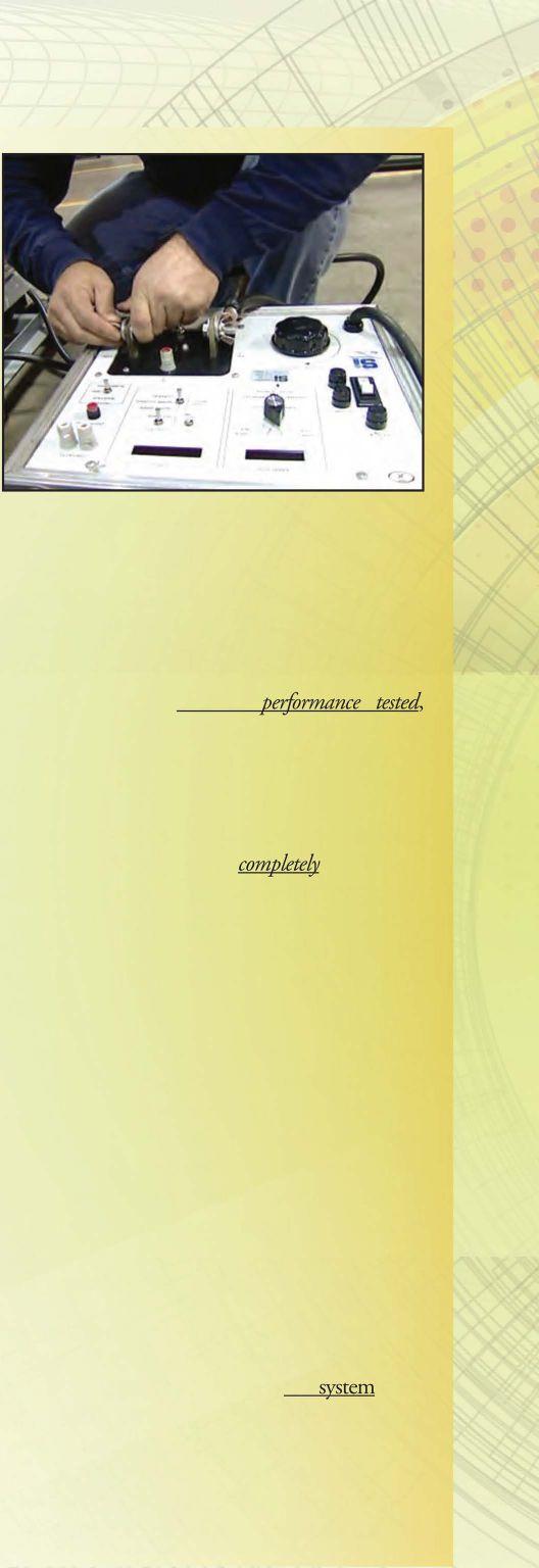

relay, andonly require apush to test simulation that doesnotverifYthatthe otheressentialcomponents are operational and interconnectedcorrectly.
The push to test function, because it is not done by primary current injection, does not completely verifY nor validate the performance of the primary sensor, the current transformer windings, the control wiring, and the control power. Nor does it address the location and connection of the main neutral bonding jumper. Because of this it puts the owner at risk of a nonfunctioning ground fault protection system, increasing the possibility of extensive equipment damage and fires when subjected to ground-faultconditions.
The procedures for performance testing of both newly-installed and service-aged ground fault protection systems is recognized by industry under the national consensus testing standards
ANSIINETA ATS-2013, Acceptance Testing Specifications for Electrical Power Distribution Equipment and Systems[3] and ANSI/NETA MTS-2011, Standard for Maintenance Testing Specifications for Electrical Power Distribution EquipmentandSystems (see figure 4).
As an easily-executed field test procedure for the performance testing of ground fault protection systems, industry standard procedures (from NETA) dictate the following electrical tests... and of special note is item No. 4. While it is not the author's intent to add all of the industry consensus standard procedures listed below as NEe requirements, item No. 4 is highlighted as a normal and recognized practice for performance testing in the field of ground fault protection systems.Excerpts from NETAATS-2013, Section 7.14, Ground-Fault Protection Systems, Low-Voltage; Electrical Tests are as follows:
1. Perform resistance measurements through bolted connections with a low-resistance ohmmeter, if applicable, in accordance with Section 7.14.1.
2. Measure the system neutral-to-ground insulation resistance with the neutral disconnectlink temporarily removed.Replace the neutraldisconnectlink after testing.
3. Perform insulation resistance test on all control wiring with respect to ground. Applied potentialshallbe 500 voltsdefor300-voltrated cableand1000volts defor600-voltratedcable. Test duration shall be one minute. For units with solid-state components or control devices that cannot tolerate the applied voltage, follow manufacturer's recommendation.
4. Perform ground fault protective device pickup tests using primary injection.
5. For summation type systems utilizing phase and neutral current transformers, verifY correct polarities by applying current to each phaseneutral current transformer pair. This test also applies to molded-case breakers utilizing an externalneutralcurrenttransformer.
6. Measure time delay of the ground fault protective device at a value equal to or greater than 150percent of the pickup value.
7.VerifY reduced control voltage tripping capability is 55 percent for ac systems and 80percent for desystems.
8. VerifY blocking capability of zone interlock systems.


There are many reasons why you need your ground-fault protection system to function properly, and one of the real dangers of a nonfunctioning GFPR system is an arcing ground fault especially one that occurs below the pickup levels of the upstream overcurrent protective devices, which can create a condition that causes extensive damage to property and can possibly injure personnel.
NETA provides guidance on what to do to perform acceptance and maintenance tests on ground-fault protection systems in the field, and the NFPA, in addition to the performance testing requirements found in Article 230.95(C) the NEe, offers additional guidance in Article 225, Article 708, and Informative Annex "F", which even further highlights the need to test these critical components in industrial and commercial power systems.
So forego the push-to-testbutton andtestyour GFPR as a system by primary currentinjection as detailed in the NETA testing standards to provide peace of mind that the system will work when called upon.
If you don't think ground-fault relays are that important, come along on one of the projects I'm sure we will have in the upcoming months that require equipment repair and replacement due to an inoperable ground fault protection relay...
1. Bussmann; Selecting Protective Devices Handbook (SPD) Based on the 2014 NEC
2. National Fire Protection Association; NFPA 70, National Electrical Code, 2014 Edition
3. InterNational Electrical Testing Association, ANSIINETA ATS-2013, Standard for Acceptance Testing Specifications for Electrical Power Equipment and Systems
Ron Widup is President ofShennco and has been with the company since 1983. He is a Principal member ofthe Technical Committee on "Electrical Safety in the Workpl£lce" (NFPA 70E) and a Principal member of the National Electrical Code (NFPA 70) Code Panel 11. He is also a member ofthe technical committee "Recommended Practice for Electrical Equipment Maintenance" (NFPA lOB), and a member ofthe NETA BoardofDirectors and StandardsReview CounciL


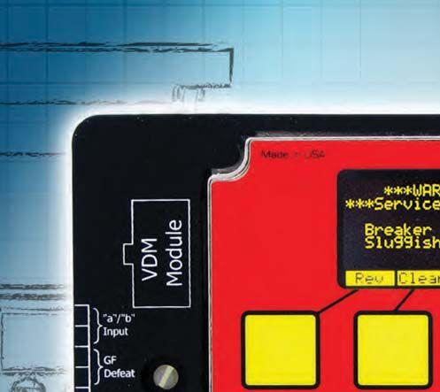
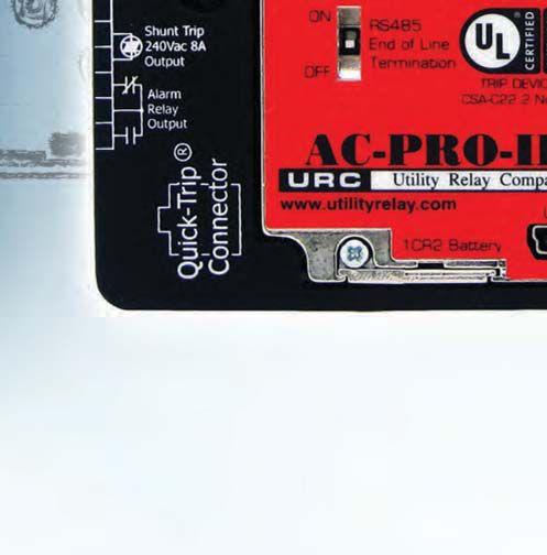
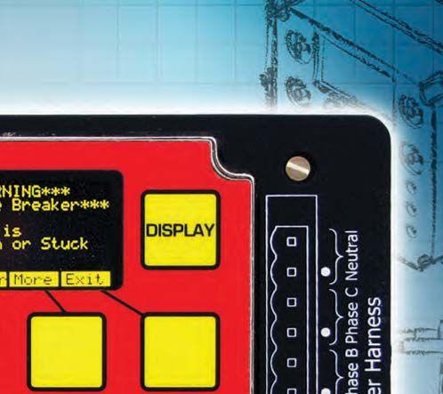
successor to the industry leading AC-PRO
The AC-PRO-II is fully backwards compatible with the CTs, actuators and wiring harnesses of the original AC-PRO

55% smaller then the original AC-PRO, with double the features.
RS-485 Modbus RTU communications is standard


Sluggish Breaker™ detection to determine if the breaker mechanism needs service.



National Switchgear has millions of new, surplus and repurposed electrical circuit breaker & switchgear products. And now, with a suite of e-commerce solutions , we’re making it easier than ever for you to find the part that’s perfect for you. You can browse, filter results by category, manufacturer or specs, see your pricing level, and more – 24/7. Just go to nationalswitchgear.com and see our latest innovations. It’s the fastest lane to our massive inventory.
If you’re ordering parts from anyone else, it’s time to switch.
800-322-0149 nationalswitchgear.com








 BY JIM WHITE, Shermco Industries
NFPA 70E, Standard for Electrical Safety in the Workplace, is a national consensus standard that provides specific guidance to personnel to assist themwith electrical safety-relatedworkpractices. There is no doubt that, based on the tide and the focus of the standard, these objectives are metwithin the pages of the document.
However, over the last three rev1s10n cycles, and especially this past revision cycle, questions have been raised and concerns voiced about the impact maintenance and testing can have on the electrical power system and, more importantly, personnel safety. If components

within an electrical power system, especially the overcurrent protective devices, such as circuit breakers, protective relays, and even fuses, are not maintained to consensus standards and/or manufacturer's specifications, what impact will that have on workers operating, servicing, and maintaining such systems?
For those of us in the testing and maintenance industry the direct correlation of equipment performance to safety performance is obvious. Mostofushaveseentheresultsofmalfunctioning electricalequipment.Whileitisfairlyrare, when itdoes happen it can make quite a mess. Figure 1 showsthetotaldestruction ofa 13.8 kVlineup of switchgear at an industrial facility. The short circuit [fault] cascaded through several circuit breakers due to an underground feeder cable failure. There were many factors that coalesced to make this event occur. But the bottom line to the incident that should get us all thinking is that if anyone was in that substation when this event happened he or she would have been seriously injured... or killed.
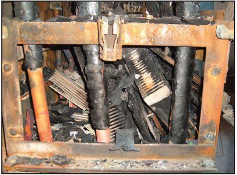
In the 2009 edition of the 70E, the committee added a definition for Arc Flash Hazard, /1 dangerouscondition associated with the possible release ofenergy caused by an electric arc." A Fine Print Note was added to help clarifY the committees mtent:
"FPNNo.1-Anarcflashhazardmayexistwhen energized electrical conductors or circuit parts are within equipment in a guardedor enclosed condition, provideda person isinteracting with theequipmentinamannerthatcouldcausean electricarc. Undernormaloperatingconditions, enclosed energized electrical equipment that has been properly installed and maintained is not likelytoposeanarcflashhazard."
Often readers of the 70E will skip over details, such as the definitions. After all, we all know what an arc-flash hazard is, right? Well.....yes and no. The real question is, how does the 70E committee define it? What parameters do they use to determine how to address it? If the reader does not understand these basic concepts, it will be difficult to understand the committee's intent and direction. When people don't understand the 70E, it is likely because they are only reading select parts and not getting into the details. After all, it is not as much fun as cruising the internet, or reading a good novel, or even sipping a beer, but it is something that could make the difference between going
home and having that beer or lying in a burn ward waiting to see what the doctors decide to do next. Something that every field service technicianandengineer shoulddo is participate in training and understand electrical hazards, typically in courses that specifically address electrical safety for qualified electrical workers.
The key to FPN No. 1 is understanding what constituted "properly installed and properly maintained." The committee believed that is fairly obvious and there was not a lot of discussion on that point. In addition to the definition of an arc-flash hazard, 130.3 Arc Flash Hazard Analysis included a new FPN No. 1 '7mproperorinadequatemaintenancecan resultinincreasedopeningtimeoftheovercurrent protective device, thus increasing the incident energy. "We all understood how incident energy is proportional to time and also knew that the overcurrent protective devices in the electrical systemareofparamountimportancetoensuring safe operation and maintenance. Figure 2 shows one example of improper installation. Even an inspection of the installation may not uncover defects such as this.
Chapter 2, Electrical Safety-Related Maintenance Requirements in NFPA 70E included a new section 200.5 General Maintenance Requirements - "Overcurrent protective devices shall be maintained in accordance with the
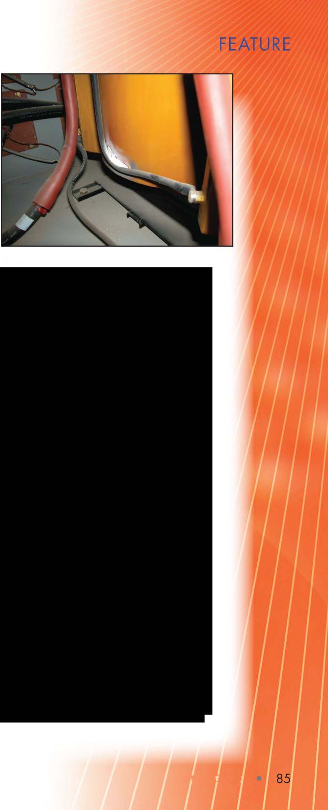
 Figure 1 : 13.8-kVSwitchgearDamaged BeyondRepair
manufocturer's instructions or industry consensus standards." A FPN in Section 200.1 pointed the reader to ANSI/NETA MTS and NFPA 70B if the manufacturer's instructions are not available.
Now let's roll forward to the 2012 edition of NFPA 70E.
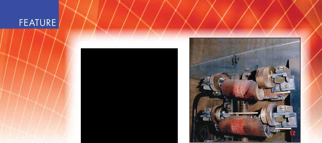


The committee decided that without electrical OCPD and general electrical equipment maintenance, the work and operation of that equipment can not be performed safely. Degraded switchgear, racking mechanisms and tracking across the surfaces of electrical insulators can be of as much consequence as a malfunctioning piece of electrical equipment, and the committee decided to add 200.3 GeneralMaintenanceRequirements. "Electrical equipment shall be maintained in accordance with manufocturer's instructions or industry consensus standards to reduce the risk offailure and the subsequent exposure ofthe employee to electrical hazards." Section 200.5 was moved to 205.4 and renamed Overcurrent Protective Devices. Again, catastrophic electrical failures are not common, but the consequences of such failures can be deadly The committee wants to ensure that workers have a safe work environment and are not placed in unnecessary danger due to lack of maintenance.
Section 130.7 added a new Informational Note (formerly called a FPN) stating '1t is the collective experience ofthe Technical Committee onElectricalSafetyinthe workplacethatnormal operation of enclosed electrical equipment operating at 600 Vor less, that has been properly installed and maintained by qualified persons is not likely to expose the employee to an electrical hazard." This IN is very similar to the FPN originally placed into the 2009 edition of NFPA 70E in Section 130.3, but adds a couple of qualifiers. One is that the electrical equipment must be maintained by qualified persons. It also states that it is the opinion of the Technical Committee. This blends into the statement that such equipment is not likely to expose an employee to electrical hazards. Likely is the key word, in myopinion. Likely does not mean never; it does not mean
Figure 3: 200A Replaceable-Element Cartridge Fuseswith 400A Elements:NotaGoodCombination for Safe Operation
forget about it; it does not mean free pass. It means that the probability is low, but such an event could happen even if all the conditions are met. To me, this means the worker must be qualified enough to determine if such a failure is likely, and if there is a likelihood of failure, you should take the appropriate action to mitigate the risk.
Most field workers don't give this enough thought when operating or working on energized electrical equipment. They tend to rely on someone else's judgment or the Tables in the 70E or arc-flash warning labels, all of which are good indicators, but at the conclusion of the analysis, who is the one standing in front of the equipment? Who is the one who will suffer if things go sideways? It is that person (you) who needs to take that extra level of precaution (see figure 3).
During the 2015 revision of NFPA 70E (due out in October 2014) a question repeatedly raisedwas "Howdoweknowelectricalequipment isproperlymaintained? Ifwedon'tknow, howcan we say it is safe to work on?" This is a valid issue to bring to the front. Can we expect every field technician to ferret out that information? For example, one can argue that it is impractical for
workers who are not employed at a particular facility to know if and when the electrical power system equipment was last maintained. The good news is that in the last cycle of NFPA70B, Recommended Practicefor Electrical Equipment Maintenance Section 11.27. "Test or Calibration Decal System" was added. Tim Crnko of Cooper-Bussmann proposed this system and it is based on a system that NETA Accredited Companies have used for years.
11.27 states, "11.27.1. General. After equipment testing, device testing, or calibration, a decal on equipment, in conjunction with test records, can communicate the condition of electrical equipment to maintenance and service personnel. 7his can be important for assessing the hazard identification and risk assessment for electrical safety procedures as well as the condition ofelectrical equipment.
11.27.2 Decal. After a piece of electrical equipment or device is tested and/or calibrated, a color-coded decal should be attached on the exterior enclosure to that particular equipment. 7he decal should include thefollowing:
(I) Date oftest or calibration
(2) Person or outside company who performed the testing or calibration
(3) Color coding indicating the service classification as described in 11.27.3."
This calibration decal system uses three color-coded labels: red, yellow, and white. Red indicates there is a major defect and the equipment should either not be placed into service or should be removed immediately from service until the defect is corrected. Yellow means there is a minor defect that does not directly affect the serviceability or safety of the equipment, but it should be addressed as soon as possible. White means there were no defects found and the equipment is fully ready for continued service. Figures 4a and 4b show how the labels look in NFPA 70B and in the field. SinceNFPA70Bisprintedinblackandwhite,the labelsare in gray-scale,notcolor (seefigure4a & 4b).
We have only heard one negative comment when this system was discussed with others. That person said, "You mean you put a label on every piece ofequipment? 7hat would mean


hundreds oflabels!"Actually, it can be thousands oflabels on a large shutdown. These are small, unobtrusive labels and do not interfere with the larger safety-oriented labels that may be required by manufacturing standards, OSHA and NFPA 70E.


Thebiggestadvantagetothethree-colorlabeling system isthatitallows instant verificationof the state of equipment maintenance and when that maintenance was performed. Wading through reams of paper or databases is not needed to determine if the electrical device has been maintained within recent and reasonable time frames, which then helps the worker determine if it issafe to proceed withthattestor to operate that piece of equipment. But please note: It does not eliminate the need for common sense. Just because a label is in place and indicates the equipment is safe for continued service at the time of test does not relieve the worker of the responsibility to properly assess the current state of the equipment or to do a proper Job Hazard Analysis. To this point, there was a worker being interviewed in a safety video about an arc-flash accident in which he was involved and he states, "Ifyou don't wear your PPE, you're being selfish, because it afficts your family and everyone you know." Sounds on target to me.
Thislabelingsystemhasbeen utilized byNETA Accredited Companies for years with great success. Customers appreciate being able to quickly determine the electrical power system's condition and coordinate with technicians during shutdowns and turnarounds to make their personal notes on what equipment needs immediate attention and which will need further work at another time. If the equipment cannot be repaired during the shutdown, the labels provide a reminder system that encourages the defects to be addressed as soon as possible. It's a great customerservice feature that all facilities and test and maintenance companies should employ. Its inclusion into NFPA 70B provides access to all companies and its [soon to be] reference
in the 2015 NFPA 70E (Chapter 2, Section 205.3, General Maintenance Requirements, Informational Note) should encourage more companies to demand it. This IN in 70E states, "Informational Note: Common industry practice is to apply test or calibration decals to equipment to indicate the test or calibration date and overall condition ofequipment that has been tested and maintained in thefield. These decals provide the employee immediate indication of last maintenance date and ifthe tested device or system was found acceptable on the date oftest. This local information can assist the employee in the assessment ofoverall electrical equipment maintenance status."
Condition of maintenance is one very important aspect of worker electrical safety. You cannot have assurance that it is safe to operate an electrical power system that has not been properly installed or maintained. For installations wehave variouscodesandstandards in place, professional engineers must place their stamp on drawings and plans showing they meet minimal engineering specifications, and an inspection system using AHJs, and experts follows that up toensurethe installation is safely designed and installed. Until now there has not been a formal system for assessingthe condition of maintenance of electrical power system equipment. The newsectionsinNFPA 70B and the 2015 edition of NFPA 70E willhelp fill that gap, but only if more people and companies are aware of it and implement it.

Jim White is nationally recognized for technical skills and safety training in the electrical power systems industry. He is the Training Director for Shermco Industries, and has spent the last twentyyears directly involvedin technical skillsandsafetytraining forelectricalpowersystem technicians.Jimisa PrincipalmemberoJNFPA 70Brepresenting Shermco Industries, NETA's alternate member of NFPA 70E, and a member ofASTM FIB Committee "Electrical Protective Equipmentfor WOrkers':

The National Fire Protection Association's (NFPA)NFPA 70£, Standardfor Electrical Safety in the Workplace, wasfirst introducedto industry in 1979 and has beencontinuouslyupdated and revised to include the latest information and safety requirements for protecting employees in the workplace from electrical hazards.The 2015 edition, which will be available in September 2014, will provide the latest and most up-todate informationfor electricalsafety Theprocess for making revisions to NFPA 70£ changed with the 2015 edition in that there is no longer a Report on Proposals (ROP) and a Report on Comments (ROC), as in past revisions cycles. The new process is noted with the following information: there were 448 public inputs, resulting in 173 first revisions; andfollowing the issue of the first revision there were 227 public
comments, resulting in 68 second revisions.The second revision is available throughNFPA.
One primary focus of NFPA 70£ has been the emphasis on electrical hazard assessments or analysis required to determine the level of the shock and arc flash hazards along with the required safe work practices and personal protective equipment (PPE), with very little reference in the past to the need for performing a risk assessment.Thisarticle will address several major revisions, but not all, and will focus on the new risk assessment requirements.
The term Prohibited Approach Boundary was deletedandallreferencestoitweredeletedfromthe standard. It was determined that the Prohibited Approach Boundary did not require any
There were several global changes of terms that clarify the intent of various requirements of the standards. The following provides the 2012 edition terms followed by the 2015 edition terms:
NFPA ZOE-2012 Term NFPA ZOE-2015 Terms
hazard analysis.........................
hazard risk assessment
All references to Hazard Risk Category and HRC were deletedfrom the standard

additional qualification requirements, PPE, or work practices. All it did was provide notice that the qualified person was closer to the energized parts. When the qualified person crosses the Restricted Approach Boundary they are required to be wearing all appropriate PPE for electric shock, so nothing is added with the Prohibited Approach Boundary. Risk is strongly emphasized in rhe 2015 edition of NFPA 70E. When a person enters the Restricted Approach Boundary, the risk of electric shock is near 100 percent; therefore, qualified persons following safe work procedures and donning appropriately rated PPE is vital to their safety.
The definitions to several terms were revised and several new terms were added, which are also global in application.
New definitions include Hazard: A source of possible injury or damage to health
Hazardous: Involving exposure to at least one hazard
Risk: is defined as a combination of both the likelihood of injury or damage occurrence as well as the severity that results for a hazard
Risk Assessment: A process that identifies the hazards, estimates the severity of injury or damage to health, estimates the likelihood of injury or damage to health, and determines if protective measures will be required.
You will notice that the first things thatmust be determined are the hazards, which implies that the electrical hazard analysis must still be done before the risk assessment can be conducted.
Revised definitions include
Boundary, Restricted Approach: The word risk has been replaced by likelihood
Incident energy: This definition now changed the word energy to thermal energy.
from one who has the skills and knowledge to one who has demonstrated the skills and knowledge. Also the word recognize has been changed to identify and avoid the hazards.
This revision to qualified person is now in line with the OSHA 29 CFR 1910.399 definition which also requires demonstrated skills and knowledge.

Qualified Person: This definition changed
In order to further emphasize the importance of maintenance and the impact it can have on the risk of an incident occurring, Section 90.2(A), Covered, added the words "safetyrelated maintenance requirements, and other administrativecontrols".Section110.1,Electrical Safety Program, added a new paragraph (B) Maintenance, rhat requires the electrical safety programtoincludetheelementsthatconsiderthe condition of maintenance of electrical systems and equipment. These additional requirements add to the new requirements stated in Section 130.2(A)(4) Normal Operation, which states that normal operation of electrical equipment is only permitted when the equipment is properly maintainedandthereisnoevidenceofimpending failure, which is generally a maintenance item. The new Informational Note explains that properly maintained refers to equipment that has been maintained in accordance with the manufacturer's recommendations or applicable industry standards and codes. It also explains that impending failure includes evidence of overheating, arcing, visible damage, bound or loose parts, or deterioration, all of which can be identified and corrected when proper maintenance is performed. Beware when a person does not wear arc-rated PPE when he or she interacts with energized equipment where the incident energy is equal to or greater than 1.2 cal/cm2• We all know that arc-flash events are caused not only by equipment that is incorrectly installed and maintained. How does the person interacting with the equipment know that an arc-flash event will never occur? He or she does not. The risk of an arc flash is greater when a disconnect or a circuit breaker is operated (opening and closing), because they are breaking and making against an energized bus.


Other sections of NFPA 70E-2015 that emphasizemaintenanceinclude130.5(3) which requires the condition of maintenance as part of the arc-flash risk assessment, 205.3 that requires electrical equipment to be maintained per the manufacturer's instructions or industry consensusstandardstoreducetheriskassociated withfailureoftheequipmentand205.4requires overcurrent protective devices to be maintained andrequiresthemaintenancetobedocumented. The risk of an arc flash occurring or equipment having exposed energized conductors or circuit parts can be reduced through proper maintenance of electrical equipment; therefore, theriskassessmentmustincludeaninspectionof theelectricalequipment maintenance programs and procedures as well as the documentation thatthe work has beendone.
As noted earlier, the term hazard identification and risk assessment was changed to risk assessment. The Risk Assessment Procedure, foundin110.1(G), requirestheElectricalSafety Program to include a risk assessment procedure to address employee exposure to electrical hazards. This procedure is required to identify hazards, assess the risks, and implement risk control.InformationalNoteNo.1referencesthe ANSIIAIHA Z10, which specifies the hierarchy ofriskcontrolmethodsthatincludeelimination, substitution, engineering controls, awareness, administrativecontrols, andPPE.Informational Note No. 2 states that the risk assessment may alsoidentifytheneedforasecondpersonandthe specifictrainingrequirements for that person.
Section 110.4(B)(4) requires ground-fault circuit-interrupters (GFCI) to be used for protection of personnel when they are using portable electric equipment in conductive locations. The Informational Note to this sectionstatesthattheriskassessmentcaninclude identifying these work locations and provide a recommendation to use equipment powered by batteries, hydraulics, or pneumatics instead of using 120-volt ac equipment.
Another consideration in conducting a risk assessmentisinidentifyingtheneedtoestablishan electricallysafeworkcondition.Therequirements
arefoundinArticle120, EstablishinganElectrically Safo Work Condition, and reinforced in Article 130 Work Involving Electrical Hazards, Section 130.2 Electrically Safe Working Condition, which provides direction for the conductors and circuit parts to be put into an electrically safe work condition prior to the employee entering the limited approach boundary or interacting with the equipment. The exception to this rule is that the electrically safe work condition is not required if the risk assessment is performed and itdoesnotidentify anyunacceptablerisksfor the taskbeing performed.
NFPA 70E-2012, Section 130.7(C)(15) Selection of Personal Protective Equipment When Required for Various Tasks, provided Hazard/Risk Category Classification tables. These tables have been replaced in NFPA 70E2015 with Table 130.7(C)(15)(A)(a) Arc Flash Hazard Identification for Alternating Current (ac) and Direct Current(de)Systems.Thistable hasthreecolumns:Tasks,EquipmentCondition, and Arc-Flash PPE Required. The first column identifies various tasks for ac and de systems. The second column identifies equipment condition that includes equipment properly installed, equipment properly maintained, all equipment doors dosed and secured, all equipment covers in place and secured, and no evidence of impending failure. If all of these questions can be answered affirmatively, then column three indicates that no arc flash PPE is required. However, if the answer to any one of these questions is no or is questionable, the arcflashPPE is required. There is a note atthe end of the table thatstatesthat hazardidentification is one component of the risk assessment. It also states that the risk assessment determines the likelihood of the incident occurring that results fromahazardthatcouldcause injury ordamage to health. This table does not address every possible situation orcondition.Where the table indicates that no arc-flash PPE is required, it doesnotindicatethatan arc-flash cannot occur. Useextremecaution whenusingthetableinlieu ofthe incident energycalculations.
Another consideration for performing a risk assessment is prior to cutting or drilling into

electrical equipment or through floors, walls or other structural elements where there is a likelihood of contactingenergized parts. The risk assessment must include the identification and marking of the location of all conductors, cables, raceways, or equipment; determining the need to create an electrically safe work condition; or identifYtherequiredsafeworkpracticesandPPE.
Informative Annex FRiskAssessmentProcedure provides important guidelines for performing a risk assessment. These guidelines include risk estimation and risk evaluation which provides helpin determiningthe protective measuresthat are needed to reduce the likelihood of personnel injury and damage to health.
NFPA 70£-2015 has been revised to emphasize therequirementsforperformingariskassessment. It does not replacethe requirement to analyze the electrical hazards, since the first requirement of the risk assessment is toknow what hazards exist. The2015 edition ofNFPA70E will be extremely helpful to the employer in performing the risk assessment and to the employee for doing his or her work as safely aspossible.
Dennis K Neitzel, CPE is Director Emeritus of AVO Training Institute, Inc., Dallas, Texas. He has over 46 years of industrial, commercial, and utility electrical power systems experience in engineering, maintenance, testing, and saftty. Mr. Neitzel is a principalcommittee member ofthe NFPA 70E Standard for Electrical Safety in the Workplace Technical Committee. He is also a co-author ofthe Electrical Saftty Handbook published by McGraw-Hill. Mr. Neitzel can be contacted at dennis. neitzel@avotraining.com.
Daleep Mob/a, an Institute ofElectrical and Electronic Engineers (IEEE) Life Fellow, is a Registered Proftssional Engineer in the State ofTexas, a member of NFPA 70E Technical Committee for Standard for Electrical saftty in the Workplace, and a member of National Electrical Code Panel 5 on Grounding and Bonding. Daleep
workedfor Pullman Consulting, Union Carbide, and Dow for thirty years and has been the owner ofhis own company for the last ten years. He is a prolific author and presenter of numerous technical papers and tutorials at the IEEE conftrences and other saftty forums that promote electrical saftty and electrical saftty by design concepts. Daleep was elevated to IEEE Fellow in 2006 for contributions to electrical saftty design concepts to reduce workplace hazards. He received the 2007 IEEE Industrial Applications Society (!AS) Petroleum and Chemical Industry Committee's David Azbill Award and the 2011 IEEE Standards Association Charles Steinmetz awardfor contributions to the preparation, dissemination, and advocacy ofconsensus saftty standardsfor operation and maintenance of industrial and commercial power systems to include saftty concepts. Daleep Mohla is the Owner andPrincipal ConsultingEngineerfor DCMElectrical Consulting Services in Missouri City, Texas His company provides consulting services in National Electrical Code and NFPA 70E training, preparation and audit ofelectrical safety programs andfacilities, andforensic investigations.
Daryld Ray Crow graduated from the University of Houston in 1969 with a BSEE degree. After graduation Ray went to workfor the Aluminum Company of America where he provided engineering support for Alcoa plants worldwide on the design, installation, and operation of power and rectifier systems, provided plant engineering support, which included electrical saftty, served as team leader for writing a number ofAlcoa electrical standards including the development of and training for Alcoa's electrical saft work practice standard. He retired from Alcoa in 1996 After retiring from Alcoa, Ray worked for Fluor Global Services and Duke Energy as a Principal Technical Specialist providing design and consulting electrical engineering for plant power distribution systems and saft work practice programs, standards, and assessments/audits. Ray presently is the Principal Technical Specialist for DRC Consulting Ltd. and performs consulting work on electrical saft work practices standards, assessments/audits, electrical saft work practice training, and electrical engineering projects. He was chair ofthe Petroleum and Chemical Industry (PCIC) saftty subcommittee 2004-2006, chair of the 2004 IEEE lAS Electrical Saftty Workshop, is an alternate member on the NFPA 70E technical committee Standardfor Electrical Saftty in the Workplace, a member of the IEEE 1584 Committee, and was the working group vice chair for the 2012 revisions to IEEE 463 Standardfor Electrical Saftty Practices in Electrolytic Cell Line Working Zones. Ray has co-authored and presented papers and tutorials on electrical saftty and auditing for the IEEE lAS Petroleum and Chemical Industry Conftrence (PCIC) and has presented saftty topics and tutorials at the IEEE Industry Applications Society Electrical Saftty Workshops, IEEE lAS Pulp and Paper Industry Conftrence, and the PowerTest conftrence. In 2010 Ray received the IEEE lAS Petroleum and Chemical Industry Committee Electrical Saftty Excellence award.

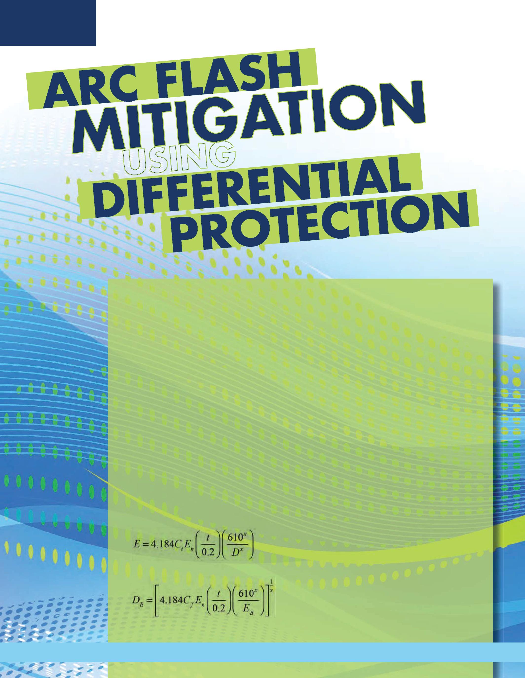
With the revision of the NFPA 70E, the Standard 70E, for Electrical Safety in the Workplace, one thing remains constant, the risk of an arc-flash hazard will need to be performed. Although the risk hazard tables are presented in a different manner different with the latest revision of NFPA 70E, one of the NFPA goals to this analysis will continue to ensure the proper personal protective equipment (PPE) is used under specific conditions.
When performing arc-flash hazard calculations, all factors must be included to accurately predict the incident energy. Some of these factors include short-circuit current, fault clearing time and worker distance to source. The procedures set forth in IEEE 1584, Guide to Performing Arc-Flash Calculations, are most commonly Calculations, used in calculating incident energy and the arc the flash boundary. The basic formulas presented in IEEE1584areasfollows: IEEE 1584 are as follows:
BY BRIAN CRONIN, CSAWhere
E: Incident Energy [J/cm2]
C t :CalculationFactor : Calculation Factor
En: Incident Energy Normalized
t: Arcing Time [sec]
D: Working Distance [mm]
DB: Arc-Flash Boundary [mm]
EB: Incident Energy :
Upon inspection of these equations, it can be of equations, seen that the arcing time will directly affect the incident energy and in almost all cases have a direct effect on the arc-flash boundary. Since reducing the time to clear a fault directly clear affects the incident energy, the application incident of differential relaying should be considered because its operation is independent of any other other protective devices so clearing time is minimized. Although not shown in this equation, the level offaultcurrentwillalsohaveadirecteffect of fault current will also have a direct effect on the incident energy. The pickup level of a a differential relay is typically well below fault below current levels so arcing currents do not tend to have an effect on the trip time of the relay.
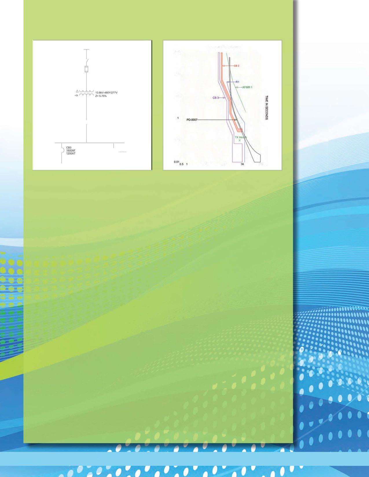
In an effort to reduce incident energy levels, various methods have been implemented to allowfor increased worker safety. The method that should always be considered first is to perform work on de-energized equipment; however, this is not possible in all cases. A system available from several manufacturers applies a temporary low level instantaneous overcurrent device to reduce the fault clearing times; however, these devices tend to reduce or eliminate coordination between adjacent protective devices. Differential relays are high speed protection devices. Because current through the differential relay is nearly zero for all conditions except a fault in its zone of protection, it can be set to be much more sensitive than a fast instantaneous overcurrent deviceandnotaffectcoordinationandcanalso remain in service under all conditions. The effectiveness of differential relaying is often overlooked when evaluating arc-flash hazard. Other methods to improve worker safety include increasing worker distance to the arc source with the use of remote control and remote racking equipment. The application of differential protection provides improved coordination and arc-flash hazard mitigation.
A typical system depicted in figure 1 shows a 1500 kVA transformer supplying lowvoltage switchgear. Figure 2 graphically illustrates the coordination of typical protective devices found on a system of this type. Ideally, the feeder breaker, for example CB3, should operate to clear a fault before the main circuit, CB2. To allow for coordination, the main circuit breaker protection must be delayed to allow for the feeder breaker to clear a fault. This time must be increasedas more protective devices are installed in series. Many applications apply an instantaneous element on the main circuit breaker, but the application of instantaneous protection on the main circuit breaker prevents coordination with downstream devices for fault levels above the pickup setting. To ensure coordination, the delay set on the main circuit breaker typically leads to a dangerous arc-flash condition. A bolted fault of 29.7 kA would be typical for the system shown in Figure 1. Applying the incident energy calculation for a fault with bolted fault current of 29.7 kA, arcing fault current of 15.6 kA and a clearing time of 1.9 seconds, values typical for the system shown in Figure 1, results

in an incident energy value of 273 Jlcm2• PPE ratings are typically in units of call cm2• Converting the metric 273 Jlcm2 yields a value of 65 callcm2• This is considerably greater than the 40 cal!cm2 level above which the NFPA 70E indicates that there is no safe level of PPE available. If a temporary instantaneous setting is applied during periods of maintenance, the arc-flash hazard can be reduced to a Category 2 because the operating time is reduced to about 80 msec. During this period of maintenance, the arcflash hazard is reduced; however, there will be a loss of coordination with downstream protective devices. While procedures will be written to turn on and turn off this temporary setting, human error may prevent either its use or prevent coordination during normal conditions if the temporary setting remains after maintenance is completed. Also, the unanswered question that remains at many facilities is "How is the equipment to be labeled?" The use of a differential relay in this application would reduce the incident energy to 5.2 cal/cm2 and would not be required to be switched in and out of service. Additionally, the traditional reason for using a differential relay applies, which limits the damage caused by the fault due to the reduced clearing time.
Depending on the application, a single differential relay could be used to protect the transformer and the bus or two separate differentialrelays couldbe usedto protect the zones individually. When the transformer is includedin the zone of protection, the effects of the phaseshift and voltagedifferencemust be incorporated into the application of the relay. When selecting current transformers (CTs), the classical approach would require the available fault current not exceed 100 amperes (20x nominal) on the CT secondary and the connected burden be less than the rated burden. This approach does not take time to saturation into consideration. With the use of numerical relays, the burden on the CT in a differential relay is significantly less than an electromechanical relay, but CT
Figure 3: Relay One line
secondary winding and cable impedances remain the same. Care must be given when selecting the CT to avoid saturation. If the transformer and bus are protected as a single zone, a set of CTs must be installed on the transformer primary and a set of CTs must be installed on each feeder as shown in Figure 3. In Figure 3, an internal fault is marked by F 1 and an external fault is marked by F2. If a fault occurs at F 1, a differential relay will clear a fault without intentional time delay, much like a temporary maintenancesetting. However, should a fault occur at F2, the differential relay will restrain and not operate, where the maintenance setting will not be able to distinguish between an internal and external fault, causing an unnecessary outage to the entire bus. Also, under normal conditions, the damage of fault F 1 is minimized when differential protection is applied because it can clear a fault much quicker than the time delayed overcurrent protection on the secondary main.
Differential protection can be summarized by understanding that the current into the

zone of protection must equal the outgoing current or else an internal fault exists. Again, referring to figure 3, for a fault at F2 current flows through the high side CTs (CTl) and also flows through the feeder CTs (CT4); CT4 providesthe balance current that allowsfor the relay to restrain- essentially the input current matches the output for a result of zero. For a fault at F 1, current flows in CT1; however, no current flows out of any other CT, so the relay has no restraint. Should a power source from any of the feeders be present, the direction of current from the feeder is reversed, so the relay will see additional current, not less current. The direction of the CT and its wiring are often the cause of differential relay misoperation, so it is important that the installation of the differential relay is correct and verified during acceptance testing. When numerical relays are used, internal settings can compensate for the different CT ratios and the phase shift in the transformer. When an electromechanical relay is used, taps are available to adjust for the difference in the CTs and the CT wiring must adjust for the phase shift. It should be noted that the above description is based on low impedance differential relays. High impedance relays are typically not suited to include a transformer in its zone of protection.
Differential protection has not typically been applied to transformers less than 10 MVA, unless there was some critical importance. This size limitation is mostly due to the cost benefit relationship to the use of differential protection. Worker safety is an intangible aspect of the cost benefit analysis. Due to the relatively low number of worker injuries that could have been prevented with the installation of differential protection, it is difficult to make an argument using a cost benefit basis; however, the cost associated with electrical injuries is also difficult to quantify. The transformer identified in Figure 1 is typically protected using three single phase fuses. Depending on the specifics of the application, the installation of a three phase fuse may cost $25k. This is far less than
the cost to install a medium-voltage circuit breaker, CTs, a relay and all other required control work. The circuit breaker, or similar device, may have the added advantage of protecting against single-phasing conditions. The differential relay may be able to clear certain faults that cannot be isolated by high side fuses. Fuses do not have metering and monitoringcapabilitieslike numerical relays, so certain operational improvements are available with the installation of relay based protective systems. Maintenance costs are also greater for relaybasedsystemsthanfuseprotection. Relays, CTs, circuit breakers and batteries require significantly more resources for maintenance than fuses. Also, the cost to repair or replace a small transformer or switchgear may not be significantlydifferent if the system is protected by fuses or relaying. Where coordination is paramount, the installation of differential protection has merit. If the only purpose of installing the differential relay is to reduce arc flash levels on the secondary bus, there would be no need to install a high-side circuit breaker. Tripping the low-side main would perform the same function at a substantial cost reduction.
In considering the coordination in Figure 2, onecanseethefuseisnotfully selective withthe low voltage circuit breaker. This condition is often required because the upstream fuse must coordinate with the transformer fuse or else an even larger outage could occur unnecessarily. Since the operation of the transformer fuse and the main circuit breaker will result in the loss of the same load and coordination requires compromise, this area offers a good point of compromise. A drawback to this sort of compromise is seen when trying to determine the location of the fault. If the fuse operates, it is assumed the fault is between the fuse and the main circuit breaker; however, when coordination is not fully selective, the device upstream may operate faster than the downstream device, which can lead to confusion. R1 in Figure 2 represents a relay curve, which can be set to better conform to the characteristics of the downstream device. If transformer and bus differential protection
are provided, coordination with adjacent protective systems becomes less troublesome because the differentialprotection actsto clear the fault without any unnecessary time delay. Although coordination will still be required with backup protection, more compromise between protective devices can usually be found when using differential protection.
Overcurrent protection using fuses is a far simpler and less expensive approach than the installation of a relay system, but the added benefit of a relay system should be understood. With respect to arc-flash hazard, differentialprotection willreducetheincident energy relative to time-delayed overcurrent protection. When considering coordination, numerical relays offer a superior alternative to fuses because of the myriad of possibilities to shape the protective characteristic. The added metering, monitoring, and recording features of a numerical relay can provide tremendous operational information, which
may be a feature to include in the cost benefit analysis. Zone Interlocking offers a similar alternative to differential protection, but performing primary simulation can be cumbersome. Maybe not every 1500 kVA transformer should have differential protection, but given equipment available today and its capabilities, it may be prudent to consider the 10 MVA limit as too high.
Brian Cronin, PE is the President of CSA Engineering Services, LLC and has extensivecontrolandprotectionengineering experience, both as a Senior Protection Utility Engineer for a privatery owned electric utility and as afield applications engineer/business development manager for a major OEM Mr. Cronin holds a BEEfomManhattan College, an MBA from New York Institute of Technology. Additionalry, heisaregisteredprofossionalengineer, a member of theNYC Electric Code Interpretation Committee, a member of IEEE, anda memberNFPA.








Wind Systems empowers its readers with the valuable, authoritative information necessary to navigate the ever-evolving wind energy landscape. Monthly sections dedicated to the “building block” segments of the industry, combined with in-depth special reports, news, and analysis, provide expert guidance for wind energy personnel, in turn GIVING WIND DIRECTION.
EPS Technology is a NETA Accredited Company and an independent electrical testing services organization based out of central Connecticut and northern New Jersey. EPS Technology is dedicated to maintaining an elitestaffandperformingservicesforallofourcustomers. Thecompany specializes incommissioning, start up, and maintenance testing for utility, industrial, government, transit, and high tech industries. EPS Technology has been active in the testing industry since 2007 and has developed a select staff of technicians and engineers with a broad spectrum of capabilities tomeet any testing needs.EPS Technology maintains a staff largeenough to handleany project,nomatter howextensiveit may be.
As a member of the InterNational Electrical Testing Association, EPS Technology requires all of its technicians to be tested todemonstratetheir knowledge in several categories including safety and independent

electrical testing methods. In addition, EPS Technology has an in house safety and training program to educate its technicians and to ensure that they continue to work safely and effectively, even with constantly changingtechnology.
EPS Technology providesacomplementofotherservices including engineering design, engineering studies including arc-flash hazard analysis and short circuit studies and oil processing services for large transformers andoilcircuit breakers.
EPS Technology is a full service testing, engineering, and maintenance service company for the electrical industry that prides itself on providing excellent service, whether it be a small cable testingjob or a large, turnkey substation installation.
Use your Windows y-compatible tablet or PC with the CBAnalyzerTM system to test your circuit breakers in place Operate the breaker in any sequence you desire: for example, trip- charge- close. The vibration data created by the breaker operation is captured and analyzed, and the result is instantly returned to your device. The data is saved in your online account for equipment management, trending, and further analysis options, including specialized issue diagnosis.
• WORKS ON A WINDOWS 7-COMPATIBLE TABLET, PC, AND iPHONE
• INCREASES IN-SERVICE TESTING FREQUENCY, BOOSTS UPTIME
• EVALUATES OVERALL MECHANICAL CONDITION
• TESTS ALL TYPES AND RATINGS OF BREAKERS
• DETERMINES BREAKER OPENING AND CLOSING TIMES
• PROVIDES FIRST TRIP DATA
When it comes to electrical safety, much has changed over the past 10 years. The National Fire Protection Association has made a number of updates to NFPA 70E, including the most recent publication of NFPA 70E-2015. OSHA also recently published its first-ever arc flash protection requirements for the electric power generation, transmission, and distribution industry, making significant changes to electrical safety requirements for utilities and industrial establishments.
Unfortunately, many of the major misconceptions related to these standards have not changed. I'm still flabbergasted by comments and questions Ihearfrom traineesand qualifiedelectrical workers alike regarding requirements to maintain a safe workenvironment.Belowis myattempttodebunk and demystifY some of the most common myths about electrical safety standards, so that everyone can beon the same page when it comes to keeping electrical workers safe.
1. OSHAhas a new requirementtoperform a hazard or risk analysis before beginning eachjob.
Technically speaking, this one is half true. In April 2014, OSHA did publish revisions to standard 1910.269 requiring high-voltage utilities and facilities to assess the workplace for potential flame or electric-arc hazards,

to estimate the incident heat energy of those hazards, and to provide exposed workers with the appropriate clothing and other personal protective equipment (PPE).
However, CFR 29, 1910.132(d)(l), which requires employers to assess the workplace for hazards and provide affected employees with PPE, has been in place for decades. What's more, since OSHA's inception in the early 1970s, theentirepremisehas been toensure, as much as possible, a safework environmentfor employees. Each employer has an obligation to determine what hazards an employee may face on the job. Once the hazard has been identified, theemployerhas furtherobligation to provide the appropriate training, PPE, or other work procedures that would allow the employee to perform the task safely.
Several hazards are specific to the electrical industry-primarily shock and arc-flash burns. Qualified workers need to be aware of these hazards in order to be considered qualified. Therefore, the employer has always had an obligation to identify possible shock hazards, identify possible flash-burn hazards, and provide the appropriate tools, PPE, or work procedures to mitigate these hazards. The new OSHA 1910.269 simply makes that official.
I will add that, even though the appropriate tools and PPE are available, the supposedly qualified worker may not know what to do with them. For example, I once witnessed a 20-year veteran pull the insulating rubber gloves on over the leather gauntlets. When questioned, he responded, "I always wears them like that since the rubber part is the shock protection part and the leather inside keeps my hands from getting sticky."
2. Insulated gloves should never be worn when using insulated live-line tools. If the insulation on the tool is bad, the worker would never know it while wearing insulatedgloves.
This statement also was posed by a 20-year veteran. I had to think about that a moment. Hmm, would I want to find out the tool is bad by not wearing gloves? Those of you who have ever watched insulation break down when performing high-potential testing will testify that the breakdown happens quickly - faster than you could drop a bad switch stick!
3. We would like to adopt NFPA 70E as our working electrical safety policy, but it is entirely too cumbersome.
I have advocated NFPA 70E in its forms throughout the years and do admit, in some cases, the recommendationsmaybeabitcumbersome. However, realizing the intent of the publication should shed light on how to implement the appropriate policies.Thereisnot, tomyknowledge, a single safety document covering every possible scenarioin theelectricalindustry, nor will there ever be, sinceours is suchadynamicfield. In the absence of specific rules from OSHA, the intent should still betoprotecttheworkforcefromhazards.Therefore,
a site-specific or activity-specific policy would be appropriate, as long as it meets the intent of protecting the workforce.
I keep a keen eye on the citations and violations of federal and many state OSHA organizations, and have yet to see a citation for not following an NFPA 70E recommendation verbatim. While OSHA continues to publish updates to its standards that do reflect specific NFPA 70E recommendations, such as the recent update to OSHA 1910.269, NFPA 70E is not, in its entirety, an enforceable document - at least not yet. It is a guideline for developing a safe electrical work environment and has many practical applications the employer could use or modify, if necessary, to meet specific needs. If an employer were to adopt the new NFPA 70E-2015 in its entirety, I am certain it would be following all the OSHA rules.
4. If I were actually to develop a risk assessment and energized electrical work permit before performing every task, as recommended in NFPA 70E, I would spend all day doing risk assessments and nevergetthe workdone.
If you are not already doing some form of risk assessment before performing electrical work, I would say you should find a different occupation. The recommendation to perform a risk assessment and develop a written energized electrical work pennit plan for hazard mitigation applies to those tasks that are not routine in nature (not routine being less frequently than annually). The system will not be locked and tagged, and the system will be energized or possibly energized. If the task is performed frequently, an original risk assessment with successful mitigation techniques should already be in place in one form or another. Thus, another assessment is not required.
To give an example, a qualified worker should already know thehazardsinvolvedin taking current measurements in a motor control center. Would the hazards change from one bucket to another? I would say no. Therefore, the same techniques found to be successful in one application of shock and flash protection would be successful in other similar applications. There is no reason to


perform multiple (written) hazard assessments and mitigation procedures for basically the same task.
Further, the newer versions of NFPA 70E limit areas where electrical work permits are required to those areas within the limited-approach boundary or arc-flash boundary. In addition, NFPA 70E, 2015, Article 130.2(B)(3) Exemptions to WOrk Pennit says that an energized work permit is not required for work performed on or near live parts when qualified persons are performing tasks such as testing, troubleshooting, or voltage measuring; thermography and visual inspection up to the Restricted Approach Boundary; access/egress withnoelectrical workuptotheRestrictedApproach Boundary; and general housekeeping up to the Restricted Approach Boundary, as long as appropriate safe work practices and PPE are provided and used in accordance with Chapter 1.
5. OSHAhasanewrequirement toperform an arc-flash hazard assessment and to mark the equipment.
Yes and no. The new OSHA 1910.269 requirements mandate that high-voltage utilities and facilities need to estimate the incident heat energy of arc hazards and provide exposed workers with the appropriate protective clothing and equipment. However, for many years there has been an existing requirement to perform a hazard analysis for any hazard an employee may face on the job (see 1910.132(d)(l) in #1 above). The new requirement provides guidance on tools and methods that can be used to estimate available heat energy. The 2014 NationalElectrical Code (NEC) Article 110.16 requires the marking of flash hazards on electrical equipment. This is not an OSHA mandate, it is an NEC requirement.
6.Anythingthat'selectricalin theworkplace needs to be labeled.
Since the 2002 edition of the NEC introduced the requirement for marking flash hazards on electrical equipment in the field, the issue has beena hot and somewhat misunderstood topic. Adding to the confusion was the fact that NEC and NFPA70E did not specifY which electrical equipment needed to be labeled, but only that electrical equipment
should be marked wherever the possibility of energized work exists.
However, the intent of Article 110.16 has always been to arm the qualified worker with enough information to make an intelligent choice when selecting the appropriatePPE. The fine print note associated with NECArticle110.16says to refer to NFPA70E for additional guidance. New updates to NFPAlOE-2015 and NEC shed light on the topic by spelling out the types of equipment that need to be labeled (i.e., switchboards, switchgear, panelboards, industrialcontrol panels, meter socket enclosures, and motor control panels). Today's requirements also make it clear that only electrical equipment that is likely to require examination, adjustment, servicing, or maintenance while energized needs to be field marked. Additionally, NFPA70E section 130.5(B) includes an exception that permits continued use of labels applied prior to September 30, 2011, as long as those labels contain the available incident energy or required level ofPPE.
New language in 130.5 also says that labels need to be updated if the arc-flash hazard risk assessment shows that the labels are inaccurate and that the owner of the electrical equipment is responsible for documentation, installation, and maintenance of the field-marked labels.
7. If therewereasignonapieceofequipment that said, "DANGER - VOLTI\GE," would that be sufficient information for a qualified worker to select the appropriate insulated gloves or tools?
I think not. The voltage level is what quantifies the hazard so the appropriatePPE and tools can be selected. The intent of the arc-flash protection program should be the same. Simply putting a signon a piece of equipment that says, "DANGER - VOLTAGE" would not be sufficient information for a qualified worker to select the appropriate fire-retardant materials or flashprotection equipment.
One of the requirements to be considered qualified to perform electrical work is the ability to identifY exposed energized equipment and to identifY the


nominal voltage of that equipment. The purpose ofthistrainingrequirementistwofold: providethe ability to determine when a shock hazard exists, andtheabilitytodeterminelevelofinsulatingtools or gloves required.There should also be a training requirement associated with arc-flash protection. Never have I seen so many blank stares from supposedly qualified electrical workers as when I showanexampleofanarc-flashwarningsignindicating magnitudeof hazard at a workingdistance.
Tohelp withthis problem, changes to NFPA 70E2015 make it dear what information needs to be included on field labels.Specifically, it states that the label shouldinclude:
• Nominalsystemvoltage
• Arc flash boundary
• Atleast oneofthefollowing:
• Incident energy and workingdistance
• PPE categoryfromNFPA 70E table
• MinimumPPE arc rating
• Site-specificlevel ofPPE
8. That signsays there are 11.4 caloriesat 18 inches. I ate 10 timesthatmany calories for breakfast this morning!
This is undoubtedly the most significant training challenge I continue to face.How do you take a group of electricians or instrument technicians from volts, amperes, and time to calories per square centimeter (or, worse yet, Joules per square centimeter) at a given working distance? Don't blame it on the aptitude of the audience either.I once received much the same response from the audienceatan IEEE meeting.
A thoroughexplanationis needed ofthe transition from watt-seconds (which most understand) through Joules (which some understand) to calories applied to square centimeters of bare skin (which no one understands).Such an explanation usually results in positive head nods or the Iget it! looks.Of course, showing the gory electrical burn victimmovieshelpsto drivehomethe point.
I would hope that those engineers performing incidentenergystudieswillkeepinmindthetarget audiencefortheresults.ProvidingareportinJoules
per square centimeter as well as recommendations forarc-ratedPPE withratingsofcaloriespersquare centimeter will not help those that are already confused.Helpthemout-providesometraining along with the results of the incident energy study correlating study findings with minimum arc thermalprotectionvaluesandmaybetrytoexplain heat attenuation factor percentages too.
9. The NFPA 70E arc-flash PPE tables are confusing and make it difficult to know which arc-rated clothingto choose.
In the past, the NFPA 70E table method for choosing arc-rated clothing was somewhat cumbersome.Inthe20 15 versionofthestandards, new task-based tables have been added for determining when arc-flash PPE is necessary for ac and de systems. For each task, the table indicates if there is an arc-flash hazard (yes or no). If yes, further engineering analysis must be performed to determine what level of arc-flash protectionwillberequired.
10. I have longer arms than you. Does that mean I can wear different flame retardant clothes?
No, because I sweat more than you do...
David K Kreger has nearly three decades of experience with high-, medium-, and low-voltage power generation, transmtsszon, and distribution systems. His formal education includes a BS in physics .from New York State University and an AA .from the University of Maryland He gained extensive experience as a field engineer through testing, troubleshooting, commissioning, and repairing power systems as well as through high-voltage work as a utility lineman. He is a licensed power engineer, NETA Level III Certified Technician, member ofthe NFPA (electrical section), and master instructorfor the training group ofEmerson's Electrical ReliabilityServices.

SPRING 2014 BREAKOUT WORKING GROUPS/DISCUSSION GROUPS
GROUP NO.
F04W Partial Discharge Testing in Discussion on new contributions to LEVINE/WALTON the Field (P400.3) the next revision of the PD Guide
F05W Damped AC Voltage Test- Approved by Working Group; will be GULSKI/PAT TERSON ing (P400.4) going forward as an IEEE Standard
F07 Guide on Neutral Corrosion It was determined that the guide will in MV Underground Cables be reviewed and reissued. BUCHHOLZ (1617)
FlOD Diagnostic Testing for Cable Presentations: Diagnostic Testing of JIANG/HAYDEN Joints and Terminations Cable Accessories
F11D Constant Voltage AC Field Presentations on experiences with Testing of Cable Systems ac withstand testing of MV, HV, and FENGER/DENMON EHV Cable Systems
During May, 2014, the ICC working groups, including engineers and scientists, came together in Kansas City, Missouri, for the spring 2014 IEEE/ICC meeting.
ThisisanongoingopportunityfortheinterNational ElectricalTestingAssociation to be recognized and offer a field testing perspective to the working groups as documents are developed. The working groups are set up of cable manufacturers, utilities, test equipment manufacturers, and end users.
At the meeting it was announced that Nigel HamptonandJacquesCotehaverelinquishedtheir positions and that Mark Fenger is the new Chair for Subcommittee F. As new material becomes available additional changes and methodologies will be incorporated into the IEEE specifications.
IEEE 400.3 working group is active and presently collecting information along with methodologies for incorporation into the document.
IEEE 400.4 Damped AC Voltage testing has been approved by the working group and will be submitted to IEEE for ballot.
The Insulated Conductors Committee is a professional organization within the Power Engineering Society of the Institute of Electrical andElectronics Engineers.
The 2014 SprintMeetinginKansasCity,Missouri, was a great success. We are looking forward to the 2014 FallMeetinginColoradoSprings, Colorado.
Ralph Patterson is President of Power ProductsandSolutions, locatedinCharlotte, North Carolina. NC. His professional background includes working as a design engineer of tramfonners and as a specifYing engineer of insulated conductors. He has more than 25 years in power engineering particularf:y in imulation diagnosis and evaluation of electrical distribution equipment. He serves on the NETA StandardsReview CouncilandBoard orDirectors, is the NETA liaison for the IEEE Insulated Conductor Committees working groups and received NETAs 2001 Outstanding Achievement Award.

ANSI/NETA Standard for Acceptance Testing Specifications for Electrical Power Equipment and Systems
This document specifies field tests and inspections used to assess the suitability for initial energization of electrical power equipment and systems.
ANSI/NETA ATS-2013 covers equipment such as:
Switchgear
Transformers
Cables
Switches
Circuit breakers
Protective relays
Rotating machinery
Motors
Capacitors and reactors
Regulating apparatus
Grounding systems
Batteries
Emergency systems and more...
ANSI/NETA ATS-2013 provides the most up-to-date references to other industry standards such as ASTM, EASA, ICEA, IEEE, NECA, NEMA, NFPA, UL, and others.
With so many standards-developing organizations in existence publishing countless lines of codes, specifications, standards, and best practices, it seems as if there would not be any new ground left to cover. And yet, many issues of ANSI's Standards Action announce new proj ect intent notifications in the weekly publication, demonstrating that improving upon standard processes requires an ongoing effort and the horizon keeps moving in the distance.
NETA determined that there is a segment of the electrical testing industry that is impacted by the work performed by NETA Accredited Companiesthathasnotbeenaddressedineither the ANSI/NETA ATS Standard for Acceptance Testing for Electrical Power Equipment and Systems or the ANSI/NETA MTS Standard for Maintenance Testing for Electrical Power Equipment and Systems.
benefit from and demands more distinction in the type of work previously classified as pure acceptance testing in the minds of many.

Since the early 1970s NETA companies have classified NETA-related work into two basic categories: field acceptance testing and field maintenance testing. These two categories have served the industry well for more than forty years. Since electrical equipment is either newly-installed or service-aged, it makes sense to create a line of demarcation between the two (acceptance testing and maintenance testing) when it comes to visual and mechanical inspections, electrical tests, and test results.
Like everything else, though, the electrical testing industry has evolved to apointthatgains


The ANSI/NETA ATS provides a performance standard that outlines the suggested field tests and inspections that are available to assess the suitability for initial energization and final acceptance of electrical power equipment and systems. The purpose of these specifications is to assure the owner of the equipment that the tested electrical equipment and systems are operational, are within applicable standards and manufacturers' tolerances, and are installed in accordance with design specifications.
While this document plays a large role in the overall commissioning process of electrical power systems, it does not specifically outline the steps that should be followed during the electrical commissioning process for a new electrical system.
While there is some guidance within industry for various aspects of electrical components,
NETA's Board of Directors recognized there is an emerging market in the commissioning of electrical power equipment and systems that is not addressed by the existing ANSIINETA standards or any other standards developing organization'sdocuments.Thatnewawarenessis whatpromptedthedevelopmentofthecandidate standard ANSIINETA ECS Standard for Electrical Commissioning Specifications for Electrical Power Equipment and Systems.
The intent of the document is to work in concert with the ANSIINETA ATS and other industry standards to provide a comprehensive specification with a direct focus on the electrical power system. It is not the intent of NETA to replicate or challenge standard industry guidelines already established by existing consensusbased documents, but rather to set forth unique specifications for systems and components that have not been previously addressed.
When asked why the need for this type of document emerged when it did, Scott Blizard of American Electrical Testing Co., Inc. shared his perspective, "Different industries have had their own commissioning specifications for many years without a standard to reference. The demand for commercial, industrial, utility, and generation commissioning has been on the rise over the last 10 to 15 years, much of which is being driven by deregulation of the utility industry New codes are requiring testing the functionality of the system per the system's design. While there are commissioning standards for industrial and commercial systems, they do not include specifications for other electrical systems. TheANSI/NETA ECS gives the industry a tool for commissioning electrical systems that encompasses the electrical industry as a whole."
Vicki Warren, Senior Product Engineer at IRIS Power LP, added, "My take is that commissioning standards are necessary to ensure that when something is deemed good or bad, that it is done so from an objective
and consistent perspective so that equipment owners know that not only were their assets thoroughly and properly evaluated, but that the evaluations are done without preconceived opinions regarding condition. In a nutshell, it is sothatgoodisgoodandbadisbad, regardless of who does the testing."
Within this standard, commissiOning is defined as the systematic process of verifYing, documenting, and placing into serviCe
STANDARD FOR ELECTRICAL COMMISSIONING SPECIFICATIONS
newly-installed or retrofitted electrical power equipment and systems. Commissioning is criticalforallneworretrofitinstallationprojects to verifY the correct system operation to the design, thus contributing tothesafeandreliable operation of the system. The commissioning process involves owner's project requirements (OPR), basis of design documentation (BOD), factory acceptance tests, field acceptance tests, verificationofthecomponentinterconnections, and functional testing of the system in part and in whole. Additionally, acceptance tests and commissioning work provide baseline results for future routine maintenance of the system and related components.


Blizard explains it as follows, "The ANSI/ NETAECSisdesigned to integrate the ANSI/ NETA ATS into the commissioning process. Acceptanceand commissioning testingservices willutilizethemanufacturertestingacceptance specifications and the ANSIINETA ATS for individual equipment testing. In essence, the acceptance testing proves the equipment functionality and correct installation, the ANSIINETA ECS will prove the functionality of the electrical system as a whole."
Documents such as ASHRAE Guideline 0, The Commissioning Process; NECA 090-2004, Commissioning Building Electrical Systems; NFPA 70E, Standard for Electrical Safety in the Workplace; and Occupational Safety and Health Act 29 CFR Part 1910 and 1926 were taken into consideration when drafting the ANSIINETA ECS. The drafted scope of the ANSIINETA ECS isasfollows:
1. These specifications describe the systematic process of documenting, and placing into service newly-installed or retrofitted electricalpowerequipmentandsystems.This documentshall be usedinconjunctionwith the most recent edition of the ANSI/NETA Standard for Acceptance Testing Specifications for Electrical Power Equipment and Systems(ANSIINETA ATS). The individual electrical components shall be subjected tofactory and field tests, as required, to validatethe individualcomponents.
to the use of these specifications.
4. Thesespecificationsarespecificallyintended forapplicationonelectricalpowerequipment and systems. It is not the intent of thesespecificationstoprovidecomprehensive detailson the commissioning of mechanical equipment, mechanical instrumentation systems, andrelatedcomponents.
Thedocumentisdividedintosectionsthataddress qualifications of personnel andcommissioning organizations,divisionofresponsibility,general information and requirements for equipment and documentation, power system studies, the commissioning process, inspection and comm1sswning procedures, thermographic surveys,transfertoowner/operator,definitions, acronyms, and some additional appendices for reference purposes which are not part of the standard. The section in inspection and commissioning procedures, Section 7, is divided into three categories: low-voltage systems(<1 kV); medium-voltagesystems(> 1 kVand < 100 kV); andhigh-voltageandextrahigh voltage systems(> 100 kV and < 1,000 kV). These sections are, in turn, divided into visualandmechanicalinspection,energization, and post-energization.

2. The purpose of these specifications is to assure that tested electrical systems are safe, reliable,andoperational;areinconformance withapplicablestandardsandmanufacturers' tolerances; and are installed in accordance with design specifications.

3. The work specified in these specifications may involve hazardous voltages, materials, operations, and equipment. These specifications do not purport to address all of the safety issuesassociated withtheir use. It is the responsibility of the user to review all applicable regulatory requirements prior
This new standard by NETA will provide a greater understanding of the requirements involved in successfully commissioning newlyinstalled equipment and systems, which in turn lends to successful maintenance and testing based on relevant, accurate, and usable historical data collected early in the life of the system.
Thisdocumentisintendedtobeusedbyelectrical testing agencies, electrical comm1sswning agencies, utilities, facility mangers, electrical engineers, architect and engineering firms, electrical inspectors, owners and operators, industrial facilities, electrical and general contractors,andanyoneresponsibleforassuring the safe and accurate installation and eventual operation of electrical power equipment and systems.
Asitiswithallnascentstandards,therewillbe roomtogrowandimproveuponthedocument infutureeditionsasawarenessincreasesandas theindustryinvolves. PaulHartman,Ballot Poolparticipant,agrees:"Thereisarealneedfor anElectricalCommissioningStandard,andI amgladtoseeNETAtaketheleadonthistask. NETA'sexperienceindevelopingotherquality ANSIstandardsmakestheorganizationagreat fitfordevelopingthisdocument. Theyknow thattheprocessismoreofajourneythana destinationandthatthefirsteditionwillbea foundationtobuilduponforfuturerevisions."
Asalways,NETAwelcomesparticipationfrom allwhoarevestedinthesetypesofelectrical installations.
As it stands, NETA is proud to introduce this new ANSIINETA standard into the familyofdocumentsthatarethecornerstone of the association and looks forward to its promulgation within the industry. The ANSIINETA ECS Standard for Electrical CommissioningSpecificationsfor Electrical Power Equipment and Systems willbeavailableinthe springof 2015 atPowerTest 2015 inNashville, Tennessee,andonlineat www.netaworld.org.

• Substation Maintenance and Repairs
• Preventive Maintenance & AcceptanceTesting
o Transformer Oil, Insulation, Power Factor, & LTCTesting
o Circuit Breaker High Current & Solid State Testing; Solid State Conversions
o Cable Fault Locating
• Infrared Inspections

• Short CircuitAnalysis
• Coordination Study
• Arc Flash Hazard Analysis
• Load Survey, Harmonic Analysis, Power Factor Study
• System Upgrades
• One-line Diagram Development
Accessible Consulting Engineers, Inc. (ACE) is an electrical engineering, consulting, and testing company specializing in electrical system design and testing. Services include new and retrofit construction in industrial, commercial, and technical facilities. ACE prides themselves on providing quality service with a strong focus on cost and efficiency.
ACE is approved as an independent electrical testing company by local jurisdictions in Southern California. Their registered electrical engineers evaluate and certify non-listed electrical equipment for compliance to nationally recognized safety standards. Acceptance and maintenance testing is performed per the InterNational Electrical Testing Association (NETA) standards. ACE’s test equipment is calibrated by a certified third-party company traceable to the National Institute of Standards and Technology (NIST).
ACE acceptance and maintenance testing services include high-, medium-, and low-voltage electrical systems. ACE personnel collectively have over 100 years

of experience testing and troubleshooting electrical equipment.
Since 1996, ACE engineers have assisted hundreds of clients in electrical system design, power distribution, lighting design, system protection, power quality, equipment evaluation, testing, and code compliance. Over 2,200 contracted projects have been completed, representing approximately 98 percent of all projects on which the company has bid. Each of these projects was completed within the proposed budget and time frame.
ACE’s commitment is to provide high quality, innovative engineering and testing services with highest safety standards in mind. ACE is proud to be a NETA Accredited Company.


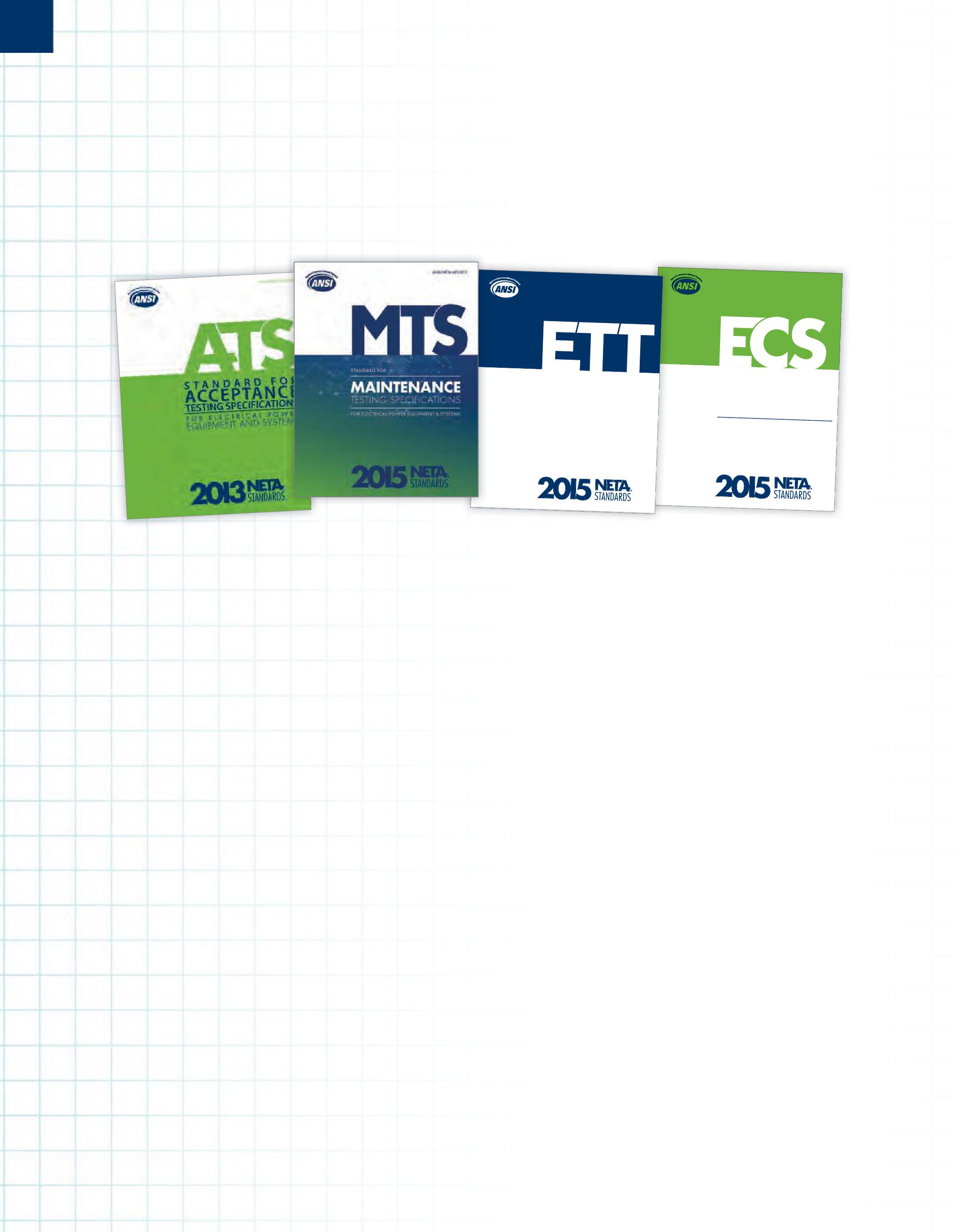
The second public review period for responses to comments resulting from the initial ballot of the ANSI/NETA MTS concluded on September 1, 2014. This public review period coincided with the balloting of the responses to comments from members of the ballot pool. Approval of this document is expected in early 2015, with the publication available in March, 2015, at PowerTest in Nashville, Tennessee. This document contains specifications that cover the suggested field tests and inspections that are available to assess the suitability for continued service and reliability of electrical power equipment and systems. The purpose of these specifications is to assure that tested electrical equipment and systems are operational and within applicable standards and manufacturers’ tolerances and that the equipment and systems are suitable for continued service.
The second public review period for responses to comments resulting from the initialballotoftheANSI/NETAETT initial ballot of the ANSI/NETA ETT concluded on September 1, 2014. This public review period coincided with the balloting of the responses to comments from members of the ballot pool. Approval of this document is expected in early 2015, with the publication available in March, 2015, at PowerTest in Nashville, Tennessee. The ANSI/NETA Standard for Certification of Electrical Testing Technicians was approved as a revisedAmericanNationalStandardon revised American National Standard on January 8, 2010. This standard establishes minimum requirements for qualifications, certification, training, and experience for the electrical testing technician. It also provides criteria for documenting qualifications for certification and details the minimum qualifications for an independent and impartial certifying body to certify electrical testing technicians.
The second public review period for responses to comments resulting from the initialballotoftheANSI/NETAECS initial ballot of the ANSI/NETA ECS concluded on September 1, 2014. This public review period coincided with the balloting of the responses to comments from members of the ballot pool. The StandardsReviewCouncilreviewedall Standards Review Council reviewed all comments submitted during the SRC meeting that took place October 23-25, 2014. The document is projected to be approved in early 2015, and should be available by March 2015 at PowerTest in Nashville, Tennessee. The ANSI/NETA ECS describes the systematic process of documenting and placing into service newly–installed or retrofitted electrical power equipment and systems. This document shall be used in conjunction withthemostrecenteditionofthe with the most recent edition of the ANSI/NETA Standard for Acceptance Testing Specifications for Electrical Power Equipment and Systems.Theindividual . The individual electrical components shall be subjected to factory and field tests, as required, to validate the individual components. It

No.108 No. 108
1. To be a qualified worker (having the skills and knowledge required to work on or near energized electrical conductors and circuit parts) is not a simple thing. Many workers believe that they are qualified if they have the technical skills needed for the job. That is only half right. OSHA and 70E require a level of electrical safety knowledge and skill, as well. Without those, a person is unqualified. Reference NFPA 70E Section 110.2(D)(1).
a. Skills and techniques to determine energized parts from deenergized parts
b. Skills and techniques to determine the nominal voltage
c. Skills and techniques to determine the minimum safe approach distances to energized conductors and circuit parts
d. Correct use of precautionary techniques
e. Correct use of PPE, including arc flash suit
f. Correct use of insulating and shielding materials
g. Correct use of insulated and insulating tools
h. Ability to determine the degree and extent of the hazard and be able to plan the job safely

A simple way to determine the full-load current of a 480 V transformer is that for every 500 kVA of transformer size, there is approximately 600 A of full-load current. Our example 2,500 kVA transformer would then have about 3,000 A capacity. The percent impedance of the transformer is divided by 100 to make it an actual impedance, so 5% becomes 0.05. Plugging the numbers in:
2,500 kVA = 60,000 A short-circuit available current at the secondary. 5%
100
2. c. Retraining is required every three years. Note that retraining is required, not just refresher training. Refresher training can take place at shorter intervals (and should), but the intent of this section was to have people receive training that would cover the changes in NFPA 70E and any changes to procedures or their electrical safety program that needed to be communicated. Reference Section 110.2(D)(3).
3. a. Everyone should be able to perform this calculation. Sometimes accurate information is just not available and the nearest upstream transformer has to be used to determine the available short circuit current. It is a conservative method, but that is not a bad thing in this case. The equation is:

4. This is another piece of knowledge every field service technician should know. The approach distances for the following voltages:
a. 208 V
Limited – 42” (3’ 6”) Restricted - Avoid contact
b. 277Y/4890 V
Limited – 42” (3’ 6”) Restricted -12” (1’)
c. 4.16 kV
Limited – 60” (5’) Restricted - 26” (2’ 2”)
d. 13.8 kV
Limited – 60” (5’) Restricted – 26” (2’ 2”)
e. 25 kV
Limited – 72” (6’) Restricted – 31” (2’ 7”)
5. a. By definition an unqualified person cannot determine the hazards or be able to avoid them. The only time an unqualified person can be in the Limited Space (the space between the Limited and Restricted Approach Boundaries) is if they are continuously escorted. Continuously is the key word. If their escort leaves the Limited Space, the unqualified person must also leave it. An unqualified person can not cross the Restricted Approach Boundary under any circumstances.
NFPA Disclaimer: Although Jim White is a member of the NFPA Technical Committee for both NFPA 70E “Standard for Electrical Safety in the Workplace” and NFPA 70B “Recommended Practice for Electrical Equipment Maintenance,” the views and opinions expressed in this message are purely the author’s and shall not be considered an official position of the NFPA or any of its technical committees and shall not be considered to be, nor be relied upon as, a formal interpretation or promotion of the NFPA. Readers are encouraged to refer to the entire text of all referenced documents.
MODELS 407 & 607 are available with an Android™ application for easy programming, data downloading, printing and e-mailing test results from your mobile device. With its mobile GPS capability, users are now able to easily locate the site associated with the measurements.
Measures up to 2000AAC and 3000ADC (600 series)
Measures up to 1000VAC/DC (1400V peak) and AC+DC with resolution to 10mV
Measures single- and three-phase power
Auto selects AC or DC measurement
True InRush ® current measurement with 1 ms peak capture measures start up and running Inrush
10,000 count blue electroluminescent backlit display
Measures TDH and individual harmonics up to the 25th
Records up to 1000 measurements
UL94 VI Flame retardant self-extinguishing (model dependent)
Leads are constructed with a flexible silicone material
Wireless Bluetooth data transfer (model dependent)
The Spring meetingoftheASTM F18Committee (Electrical Protective Equipment forWorkers) was conducted in Toronto, Canada this year. The F18 Committee has responsibility for a wide range of electrical protective devices and clothing associated with electrical workers. Some examples are insulated and insulating gloves and hand tools, arc-rated clothing and PPE, personal protective grounds, eyewear, footwear, live-line tools and even insulating links for cranes. Because of its scope,NETA represents the interests ofits member companies on F18.

at voltage less than 600 volts and not usually above that. Some discussion revolved around whether or not to include it in the current F696, but a preliminary decision was to introduce a new standard so F696 would not be impacted when it came up for revision. NETA-member companies will often be required to wear a cut-resistant glove when performing maintenance or other tasks. At times, technicians are forced to wear cut-resistant gloves over rubber insulating gloves and leather protectors, greatly hindering dexterity which in itself can be hazardous. The development of this standardwouldaid all NETA-membercompanies.

In my opinion, the primary item on the docket for this meeting was the guide for arc rating hand protection. This had been set aside on numerous occasions and has been ten years in trying to move it through the F18 Committee. The primary objection seemed to be that the utility members on the committee did not believe it was needed and would add cost to a widely-used product. By makingit aguide,the requirements includedinthe new standard will not be mandatory, but can be referred towhen customers request it. Many of the manufacturers attendingsaidthey werealreadyarcrating gloves on request. The new guide is F2675/ F2675M-13 Standard Test Methodfor Determining Arc Ratings ofHand Protective Products Developed and Usedfor ElectricalArc Flash Protection.
Onarelatedtopic, nonleatherprotectorgloveswere discussed. There have been requests to the F18 committee about a standard for composite gloves that have cut and grip capabilities not present in leather protectors. This type of gloves is needed

Someothernotesfromthesubcommittee meetings that are of interest:
• In the F1959 meeting it was brought out that some arc-rated shorts may have one rating on the front but a lower rating on the back. This should not be a concern to NETA-member companies or their technicians, but it would be worth asking the distributor if this is the case. It is always worthwhile to know what you are buying and comparing to.
• Plastic zippers included in arc-rated clothing will fail at about 20 cal/cm2. Since most are covered by arc-rated fabric and grip-and-lock closures, this again may not be an issue. I've had some discussions with members about arc-rated clothing that does not include zipper-type closures, with them voicing the opinion that zippers add considerably to the safety of the garment. I do believe that they
allow an easier dosing of the front of the garment,but the wearer needs to be doubly certain that there is no opening to expose the zippertotheheatoftheelectrical arc.
• When using hand-held portable live-line tool testers,be certain to follow the manu&cturer's instructions. Someoftheselive-linetestershave to make up to four passes to complete the test while others do not. Again,NETA-member companies need to understand what they are abouttopurchaseandareusinginthefield.
• Some discussion was made about the accuracy of the voltmeters used for testing rubber insulating protective equipment. The questions concerned what a "true rms meter". Analog meters are true rms,while digital meters may approximate the rms reading. This can have an effect on the indicated voltage. The standard now reads "The correct rms value of the sinusoidal
voltage form..." The current language is proposedto be clarified for the next revision cycle so its intentis betterunderstood.
• The mechanical apparatusstandardcontinues todeal withthenegativesfromDr. Pratt,who believes the standard is not requiring safe testing of insulating links for cranes. There has been no concrete evidence of any failure underthecurrentstandardthathasresultedin aninjuryor fatality.
There were not as many NETA-related topics at this meeting as some in the past,but NETAmembers can begreatlyaffected bywhatF18 does ordoesnotdo. I wouldencourageotherinterested parties to attend F18 meetings and to participate in the balloting for these various standards so our voice can be heard. Attendance at the committee meetings is not necessary and can be done by proxie. The next ASTM F18 meeting is in Orlando,Florida,October19-24,2014.



David Huffman,NETAAccredited Representative and president of Power Systems Testing Co., represents NETA on NFPA 70B Recommended Practicefor Electrical Equipment Maintenance. NFPA 70B details preventive maintenance for electrical, electronic, and communication systems and equipment, such as those used in industrial plants, institutional and commercial buildings, and large multifamily residential complexes, to prevent equipment failures and worker injuries. The standard explains why an effective electrical preventive maintenance (EPM) program is essential to protect lives and property, how to plan and develop an EPM and provide protection for maintenance personnel, and provides guidance concerning all types of equipment and assemblies.
Dave reports that the NFPA 70B committee met in San Antonio from March 12 to March 14, 2014 for the first draft meeting, formerly known as the report on proposals (ROP) meeting. The committee broke up into task groups to address various issues. Public input items were also addressed. The first revision ballot opened May 6, 2014, and is now closed. The NFPA 70B correlating committee held a conference call on June 1, 2014, to continue its work.
As an ANSI Accredited Standards Developing Organization, it is imperative that NETA stay informed and involved with other standards making organizations within the electrical industry. NETA representatives to other organization code panels and standards bodies are not only able to assure that NETA's standards are accurately and correctly referenced when appropriate, but that NETA's references to documents such as NFPA 70B, NFPA 70E, NFPA 70, along with documents from ASTM, EASA, ICC, ICEA, IEEE, NEMA (to list a few), are also referenced correctly within the NETA standards. This assures that NETA is in compliance with ANSI's requirements that there is not duplication or conflict between standards documents.
It is vital that standards developers keep the lines of communication open to assure that every standard is as accurate and relevant to real-world situations as possible. There is so muchtomanagewhenit comes to standardized practices that no single organization can do it alone. NETA thanks all those who volunteer their time to create industry standards, be it on one committee or several. Each person who donates his or her time and talent helps keep the lights on and makes the workplace a little safer each day.



A&F Electrical Testing, Inc.
80 Lake Ave. South, Ste. 10 Nesconset, NY 11767 (631) 584-5625 Fax: (631) 584-5720 kchilton@afelectricaltesting.com www.afelectricaltesting.com
Kevin Chilton
A&F Electrical Testing, Inc.
80 Broad St. 5th Floor New York, NY 10004 (631) 584-5625 Fax: (631) 584-5720 afelectricaltesting@afelectricaltesting.com www.afelectricaltesting.com
Florence Chilton
ABM Electrical Power Solutions
3602 East Southern Ave., Ste. 1 & 2 Phoenix, AZ 85040 (602) 796-6583
www.ABM.com
Ben Thomas
ABM Electrical Power Solutions
9800 E. Geddes Avenue, Unit A-150 Englewood, CO 80112 (303) 524-6560 Fax: (303) 524-6581 www.ABM.com
Ben Thomas
ABM Electrical Power Solutions
2142 Rheem Drive Pleasanton, CA 94588 (408) 399-3030 Fax: (800) 597-1225
www.ABM.com
Ben Thomas
ABM Electrical Power Solutions
3711 Saunders Ave. Richmond, VA 23227 (804) 253-9079 Fax: (804) 254-5799
www.ABM.com
Barry Maitland
ABM Electrical Power Solutions
6280 South Valley View Blvd., Ste. 618 Las Vegas, NV 89118 (702) 216-0982 Fax: (702) 216-0983 www.ABM.com
Ben Thomas
ABM Electrical Power Solutions
814 Greenbrier Circle, Ste. E Chesapeake, VA 23320 (757) 548-5690 Fax: (757) 548-5417 www.ABM.com
Mark Anthony Gaughan, III
ABM Electrical Power Solutions
3700 Commerce Dr. #901-903 Baltimore, MD 21227 (410) 247-3300 Fax: (410) 247-0900 www.ABM.com
Bill Hartman
ABM Electrical Power Solutions
5809 Departure Dr., Ste. 104 Raleigh, NC 27616 (919) 877-1008 Fax: (919) 501-7492 www.ABM.com
Rob Parton
ABM Electrical Power Solutions
317 Commerce Park Dr. Cranberry Township, PA 16066-6427 (724) 772-4638 Fax: (724) 772-6003
william.mckenzie@abm.com
www.ABM.com
William (Pete) McKenzie
ABM Electrical Power Solutions
4390 Parliament Place, Ste. S Lanham, MD 20706 (301) 967-3500 Fax: (301) 735-8953 www.ABM.com
Frank Ceci
ABM Electrical Power Solutions
3600 Woodpark Blvd., Suite G Charlotte, NC 28206 (704) 273-6257 Fax: (704) 598-9812 ernest.goins@abm.com www.ABM.com
Ernest Goins
ABM Electrical Power Solutions
720 S. Rochester Ave., Suite A Ontario, CA 91761 (951) 522-8855 Fax: (909) 937-6798 www.ABM.com
Ben Thomas
Accessible Consulting Engineers, Inc. 1269 Pomona Rd., Ste. 111 Corona, CA 92882 (951) 808-1040 info@acetesting.com www.acetesting.com
Iraj Nasrolahi
Absolute Testing Services 6829 Guhn Rd. Houston, TX 77040 (832) 467-4446 Fax: (713) 849-3885 rgamble@absolutetesting.com www.texasats.com
Richard Gamble
Advanced Testing Systems 15 Trowbridge Dr. Bethel, CT 06801 (203) 743-2001 Fax: (203) 743-2325 pmaccarthy@advtest.com www.advtest.com
Pat MacCarthy
American Electrical Testing Co., Inc.
480 Neponset St., Building 6 Canton, MA 02021-1970 (781) 821-0121 Fax: (781) 821-0771 sblizard@aetco.us www.99aetco.com
Scott A. Blizard
American Electrical Testing Co., Inc. 34 Clover Dr. South Windsor, CT 06074 (860) 648-1013 Fax: (781) 821-0771 jpoulin@aetco.us www.99aetco.com
Gerald Poulin
American Electrical Testing Co., Inc. 76 Cain Dr. Brentwood, NY 11717 (631) 617-5330 Fax: (631) 630-2292 mschacker@aetco.us www.99aetco.com
Michael Schacker
American Electrical Testing Co., Inc. 50 Intervale Rd., Ste. 1 Boonton, NJ 07005 (973) 316-1180 Fax: (781) 316-1181 jsomol@aetco.us www.99aetco.com
Jeff Somol
American Electrical Testing Co., Inc. 4032 Park 65 Dr. Indianapolis, IN 46254 (317) 487-2111 Fax: (781) 821-0771 scanale@aetco.us www.99aetco.com
Stephen Canale
American Electrical Testing Co., Inc. Green Hills Commerce Center 5925 Tilghman St., Ste. 200 Allentown, PA 18104 (215) 219-6800 jmunley@aetco.us www.99aetco.com
Jonathan Munley
American Electrical Testing Co., Inc. 12566 W. Indianola Ave. Avondale, AZ 85392 (480) 383-9242 dmadaglia@aetco.us www.99aetco.com
Donald Madaglia
AMP Quality Energy Services, LLC 4220 West Schrimsher SW Site W1 P.O. Box 526, Huntsville, AL 35804 (256) 513-8255
Brian Rodgers
Apparatus Testing and Engineering PO Box 984, Folsom, CA 95763-0984 (916) 853-6280 Fax: (916) 853-6258 jlawler@apparatustesting.com www.apparatustesting.com
James Lawler
Apparatus Testing and Engineering 7083 Commerce Circle, Ste. H Pleasanton, CA 94588 (925) 454-1363 Fax: (925) 454-1499 info@apparatustesting.com www.apparatustesting.com
Harold (Jerry) Carr
Applied Engineering Concepts 1105 N. Allen Ave. Pasadena, CA 91104 (626) 398-3052 Fax: (626) 398-3053 michel.c@aec-us.com www.aec-us.com
Michel Castonguay
BEC Testing
50 Gazza Blvd. Farmingdale, NY 11735 (576) 531-9136 Fax: (631) 249-6115 wfernandez@bandelectric.com www.bectesting.com
William (Billy) Fernandez
Burlington Electrical Testing Co., Inc. 300 Cedar Ave. Croydon, PA 19021-6051 (215) 826-9400 (221) Fax: (215) 826-0964 waltc@betest.com www.betest.com
Walter P. Cleary
C.E. Testing, Inc. 6148 Tim Crews Rd. Macclenny, FL 32063 (904) 653-1900 Fax: (904) 653-1911 cetesting@aol.com
Mark Chapman
CE Power Solutions, LLC 4040 Rev Dr. Cincinnati, OH 45232 (513) 563-6150 Fax: (513) 563-6120 info@cepowersol.net www.cepowersol.com
Rhonda Harris
CE Power Solutions of Minnesota, LLC 7674 Washington Ave. South Eden Prairie, MN 55344 (877) 968-0281 Fax: (952) 400-8772 jason.thompson@cepower.net www.cepower-MN.com
Jason Thompson
Control Power Concepts
353 Pilot Rd; Ste. B Las Vegas, NV 89119 (702) 448-7833 Fax: (702) 448-7835 www.controlpowerconcepts.com
John Travis
Dude Electrical Testing LLC
145 Tower Dr., Unit# 9 Burr Ridge, IL 60527 (815) 293-3388 Fax: (815) 293-3386 scott.dude@dudetesting.com www.dudetesting.com
Scott Dude
DYMAX Service, LLC
46918 Liberty Dr. Wixom, MI 48393 (248) 313-6868 Fax: (248) 313-6869 www.dymaxservice.com
Bruce Robinson
DYMAX Service, LLC
4213 Kropf Ave. Canton, OH 44706 (330) 484-6801 Fax: (740) 333-1271 www.dymaxservice.com
Chuck Baker
Eastern High Voltage 11A South Gold Dr. Robbinsville, NJ 08691-1606 (609) 890-8300 Fax: (609) 588-8090 joewilson@easternhighvoltage.com www.easternhighvoltage.com
Joseph Wilson
ELECT, P.C.
7400-G Siemens Rd., P.O. Box 2080 Wendell, NC 27591 (919) 365-9775 Fax: (919) 365-9789 btyndall@elect-pc.com www.elect-pc.com
Barry W. Tyndall
Electric Power Systems, Inc. 21 Millpark Ct. Maryland Heights, MO 63043 (314) 890-9999 Fax: (314) 890-9998 www.epsii.com
Electric Power Systems, Inc.
557 E. Juanita Ave., #4 Mesa, AZ 85204 (480) 633-1490 Fax: (480) 633-7092 www.epsii.com
Electric Power Systems, Inc.
4436 Parkway Commerce Blvd. Orlando, FL 32808 (407) 578-6424 Fax: 407-578-6408 www.epsii.com
Electric Power Systems, Inc.
7000 E. 47th Avenue Drive, Suite 100 Denver, CO 80216 (720) 857-7273 Fax: 303-928-8020 www.epsii.com
Electric Power Systems, Inc. 23823 Andrew Rd. Plainfield, IL 60585 (815) 577-9515 Fax: (815) 577-9516 www.epsii.com
Electric Power Systems, Inc. 2601 Center Rd., # 101 Hinckley, OH 44233 (330) 460-3706 Fax: (330) 460-3708 www.epsii.com
Electric Power Systems, Inc. 56 Bibber Pkwy #1 Brunswick, ME 04011 (207) 837-6527 www.epsii.com
Electric Power Systems, Inc. 4100 Greenbriar Dr., Ste. 160 Stafford, TX 77477 (713) 644-5400 www.epsii.com
Electric Power Systems, Inc. 11861 Longsdorf St. Riverview, MI 48193 (734) 282-3311 www.epsii.com
Electric Power Systems, Inc.
827 Union St., Salem, VA 24153 (540) 375-0084 Fax: (540) 375-0094 www.epsii.com
Electric Power Systems, Inc.
915 Holt Ave., Unit 9 Manchester, NH 03109 (603) 657-7371 Fax: 603-657-7370 www.epsii.com
Electric Power Systems, Inc.
146 Space Park Dr. Nashville, TN 37211 (615) 834-0999 Fax: (615) 834-0129 www.epsii.com
Electric Power Systems, Inc. 8515 Cella Alameda NE, Ste. A Albuquerque, NM 87113 (505) 792-7761 www.epsii.com
Electric Power Systems, Inc.
7140 Dean Martin Drive, Suite 900 Las Vegas, NV 89118 (702) 815-1342 www.epsii.com
Electric Power Systems, Inc.
319 US Hwy. 70 E, Unit E Garner, NC 27529 (919) 322-2670 www.epsii.com
Electric Power Systems, Inc. 1090 Montour West Industrial Blvd. Coraopolis, PA 15108 (412) 276-4559 www.epsii.com
Electric Power Systems, Inc. 6141 Connecticut Ave. Kansas City, MO 64120 (816) 241-9990 Fax: (816) 241-9992 www.epsii.com
Electric Power Systems, Inc. 2495 Boulevard of the Generals Norristown, PA 19403 (610) 630-0286 www.epsii.com
Electric Power Systems, Inc. 1129 East Hwy. 30 Gonzalez, LA 70817 (225) 644-0150 Fax: (225) 644-6249 www.epsii.com
Electric Power Systems, Inc. 7925 Dunbrook Rd., Ste. G San Diego, CA 92126 (858) 566-6317 www.epsii.com
Electrical & Electronic Controls 6149 Hunter Rd. Ooltewah, TN 37363 (423) 344-7666 (23) Fax: (423) 344-4494 eecontrols@comcast.net
Electrical Energy Experts, Inc. W129N10818, Washington Dr. Germantown, WI 53022 (262) 255-5222 Fax: (262) 242-2360 bill@electricalenergyexperts.com www.electricalenergyexperts.com
William Styer
Electrical Equipment Upgrading, Inc. 21 Telfair Place, Savannah, GA 31415 (912) 232-7402 Fax: (912) 233-4355 kmiller@eeu-inc.com www.eeu-inc.com
Kevin Miller
Electrical Maintenance & Testing Inc. 12342 Hancock St., Carmel, IN 46032 (317) 853-6795 Fax: (317) 853-6799 info@emtesting.com www.emtesting.com
Brian K. Borst
Electrical Reliability Services 1057 Doniphan Park Circle, Ste. A El Paso, TX 79922 (915) 587-9440 Fax: (915) 587-9010 www.electricalreliability.com
Electrical Reliability Services
1775 W. University Dr., Ste. 128 Tempe, AZ 85281 (480) 966-4568 Fax: (480) 966-4569 www.electricalreliability.com
Electrical Reliability Services
1426 Sens Rd. Ste. 5 Houston, TX 77571 (281) 241-2800 Fax: (281) 241-2801 www.electricalreliability.com
Electrical Reliability Services
4099 SE International Way, Ste. 201 Milwaukie, OR 97222-8853 (503) 653-6781 Fax: (503) 659-9733 www.electricalreliability.com
Electrical Reliability Services
5909 Sea Lion Place, Ste. C Carlsbad, CA 92010 (858) 695-9551 www.electricalreliability.com
Electrical Reliability Services
8500 Washington Pl. NE, Ste. A-6 Albuquerque, NM 87113 (505) 822-0237 Fax: (505) 822-0217 www.electricalreliability.com
Electrical Reliability Services
1380 Greg Street, Ste. 217 Sparks, NV 89431 (775) 746-8484 Fax: (775) 356-5488 www.electricalreliability.com
Electrical Reliability Services
2275 Northwest Pkwy SE, Ste. 180 Marietta, GA 30067 (770) 541-6600 Fax: (770) 541-6501 www.electricalreliability.com
Electrical Reliability Services 7100 Broadway, Ste. 7E Denver, CO 80221-2915 (303) 427-8809 Fax: (303) 427-4080 www.electricalreliability.com
Electrical Reliability Services 348 N.W. Capital Dr. Lee's Summit, MO 64086 (816) 525-7156 Fax: (816) 524-3274 www.electricalreliability.com
Electrical Reliability Services 6900 Koll Center Parkway, Ste. 415 Pleasanton, CA 94566 (925) 485-3400 Fax: (925) 485-3436 www.electricalreliability.com
Electrical Reliability Services 10606 Bloomfield Ave. Santa Fe Springs, CA 90670 (562) 236-9555 Fax: (562) 777-8914 www.electricalreliability.com
Electrical Reliability Services 14141 Airline Hwy., Bldg 1; Ste. X Baton Rouge, LA 70817 (225) 755-0530 Fax: (225) 751-5055 www.electricalreliability.com
Electrical Reliability Services 121 Highway 108 East Sulphur, LA 70665 (337) 583-2411 Fax: (337) 583-2410 www.electricalreliability.com
Electrical Reliability Services 11000 Metro Pkwy., Ste. 30 Ft. Myers, FL 33966 (239) 693-7100 Fax: (239) 693-7772 www.electricalreliability.com
Electrical Reliability Services 2222 West Valley Hwy. N., Ste 160 Auburn, WA 98001 (253) 736-6010 Fax: (253) 736-6015 www.electricalreliability.com
Electrical Reliability Services 3412 South 1400 West, Unit A West Valley City, UT 84119 (801) 975-6461 www.electricalreliability.com
Electrical Reliability Services 6351 Hinson St., Ste. B Las Vegas, NV 89118 (702) 597-0020 Fax: (702) 597-0095 www.electricalreliability.com
Electrical Reliability Services 9636 St. Vincent, Unit A Shreveport, LA 71106 (318) 869-4244 www.electricalreliability.com
Electrical Reliability Services 6135 Lakeview Rd., Ste 500 Charlotte, NC 28269 (704) 441-1497 www.electricalreliability.com
NETA ACCREDITED COMPANIES
Michael Hughes
Electrical Reliability Services
610 Executive Campus Dr. Westerville, OH 43082 (877) 468-6384 Fax: (614) 410-8420 info@electricalreliability.com www.electricalreliability.com
Electrical Testing, Inc.
2671 Cedartown Hwy. Rome, GA 30161-6791 (706) 234-7623 Fax: (706) 236-9028 steve@electricaltestinginc.com www.electricaltestinginc.com
Electrical Testing Solutions
2909 Green Hill Ct. Oshkosh, WI 54904 (920) 420-2986 Fax: (920) 235-7136 tmachado@electricaltestingsolutions.com www.electricaltestingsolutions.com
Tito Machado
Elemco Services, Inc.
228 Merrick Rd. , Lynbrook, NY 11563 (631) 589-6343 Fax: (631) 589-6670 courtney@elemco.com www.elemco.com
Courtney O'Brien
EnerG Test
204 Gale Lane Bldg. 2 - 2nd Floor Kennett Square, PA 19348 (484) 731-0200 Fax: (484) 713-0209 kbleiler@energtest.com www.energtest.com
Katie Bleiler
Energis High Voltage Resources, Inc. 1361 Glory Rd. Green Bay, WI 54304 (920) 632-7929 Fax: (920) 632-7928 info@energisinc.com www.energisinc.com
Mick Petzold
EPS Technology
29 N. Plains Hwy., Ste. 12 Wallingford, CT 06492 (203) 679-0145 www.eps-technology.com
Grounded Technologies, Inc.
10505 S. Progress Way, Ste. 105 Parker, CO 80134 P-(303) 781-2560 F- (303) 781-5240 jodymedina@groundedtech.com www.groundedtech.com
Jody Medina
Grubb Engineering, Inc.
3128 Sidney Brooks San Antonio, Tx 78235 (210) 658-7250 Fax: (210) 658-9805 joy@grubbengineering.com www.grubbengineering.com
Robert D. Grubb Jr.
Hampton Tedder Technical Services 4571 State St. Montclair, CA 91763 (909) 628-1256 x214 Fax: (909) 628-6375
matt.tedder@hamptontedder.com www.hamptontedder.com
Matt Tedder
Hampton Tedder Technical Services 4920 Alto Ave.
Las Vegas, NV 89115 (702) 452-9200 Fax: (702) 453-5412 www.hamptontedder.com
Roger Cates
Hampton Tedder Technical Services 3747 West Roanoke Ave. Phoenix, AZ 85009 (480) 967-7765 Fax: (480) 967-7762 www.hamptontedder.com
Harford Electrical Testing Co., Inc. 1108 Clayton Rd. Joppa, MD 21085 (410) 679-4477 Fax: (410) 679-0800 testing@harfordtesting.com www.harfordtesting.com
Vincent Biondino
High Energy Electrical Testing, Inc. 515 S. Ocean Ave. Seaside Park, NJ 08752 (732) 938-2275 Fax: (732) 938-2277 hinrg@comcast.net www.highenergyelectric.com
Charles Blanchard
High Voltage Maintenance Corp. 24 Walpole Park South Dr. Walpole, MA 02081 (508) 668-9205 www.hvmcorp.com
High Voltage Maintenance Corp. 941 Busse Rd. Elk Grove Village, Il 60007 (847) 640-0005 www.hvmcorp.com
High Voltage Maintenance Corp. 7200 Industrial Park Blvd. Mentor, OH 44060 (440) 951-2706 Fax: (440) 951-6798 www.hvmcorp.com
High Voltage Maintenance Corp. 3000 S. Calhoun Rd. New Berlin, WI 53151 (262) 784-3660 Fax: (262) 784-5124 www.hvmcorp.com
High Voltage Maintenance Corp. 8320 Brookville Rd. #E Indianapolis, IN 46239 (317) 322-2055 Fax: (317) 322-2056 www.hvmcorp.com
High Voltage Maintenance Corp. 1250 Broadway, Ste. 2300 New York, NY 10001 (718) 239-0359 www.hvmcorp.com
High Voltage Maintenance Corp. 355 Vista Park Dr. Pittsburgh, PA 15205-1206 (412) 747-0550 Fax: (412) 747-0554 www.hvmcorp.com
High Voltage Maintenance Corp. 150 North Plains Industrial Rd. Wallingford, CT 06492 (203) 949-2650 Fax: (203) 949-2646 www.hvmcorp.com
High Voltage Maintenance Corp. 9305 Gerwig Ln., Ste. B Columbia, MD 21046 (410) 309-5970 Fax: (410) 309-0220 www.hvmcorp.com
High Voltage Maintenance Corp. 24371 Catherine Industrial Dr, Ste. 207 Novi, MI 48375 (248) 305-5596 Fax: (248) 305-5579 www.hvmcorp.com
High Voltage Maintenance Corp. 5100 Energy Dr. Dayton, OH 45414 (937) 278-0811 Fax: (937) 278-7791 www.hvmcorp.com
High Voltage Service, LLC 4751 Mustang Circle St. Paul, MN 55112 (763) 784-4040 Fax: (763) 784-5397 www.hvserviceinc.com
Mike Mavetz
HMT, Inc. 6268 Route 31 Cicero, NY 13039 (315) 699-5563 Fax: (315) 699-5911 jpertgen@hmt-electric.com www.hmt-electric.com
John Pertgen
Industrial Electric Testing, Inc. 11321 West Distribution Ave. Jacksonville, FL 32256 (904) 260-8378 Fax: (904) 260-0737 gbenzenberg@bellsouth.net www.industrialelectrictesting.com Gary Benzenberg
Industrial Electric Testing, Inc. 201 NW 1st Ave. Hallandale, FL 33009-4029 (954) 456-7020 www.industrialelectrictesting.com
Industrial Electronics Group 850369 Highway 17 South P.O. Box 1870 Yulee, FL 32041 (904) 225-9529 Fax: (904) 225-0834 butch@industrialgroups.com www.industrialgroups.com
Butch E. Teal
Industrial Tests, Inc. 4021 Alvis Ct., Ste. 1 Rocklin, CA 95677 (916) 296-1200 Fax: (916) 632-0300 greg@indtest.com www.industrialtests.com
Greg Poole
Infra-Red Building and Power Service 152 Centre St. Holbrook, MA 02343-1011 (781) 767-0888 Fax: (781) 767-3462 tom.mcdonald@infraredbps.com www.infraredbps.com
Thomas McDonald Sr.
Longo Electrical-Mechanical, Inc. One Harry Shupe Blvd., Box 511 Wharton, NJ 07885 (973) 537-0400 Fax: (937) 537-0404 jmlongo@elongo.com www.elongo.com
Joe Longo
Longo Electrical-Mechanical, Inc. 1625 Pennsylvania Ave. Linden, NJ 07036 (908) 925-2900 Fax: (908) 925-9427 jmlongo@elongo.com www.elongo.com
Joe Longo
Longo Electrical-Mechanical, Inc. 1400 F Adams Rd. Bensalem, PA 19020 (215) 638-1333 Fax: (215) 638-1366 jmlongo@elongo.com www.elongo.com
Joe Longo
M&L Power Systems, Inc. 109 White Oak Ln., Ste. 82 Old Bridge, NJ 08857 (732) 679-1800 Fax: (732) 679-9326 milind@mlpower.com www.mlpower.com
Milind Bagle
Magna Electric Corporation 1033 Kearns Crescent, Box 995 Regina, SK S4P 3B2 Canada (306) 949-8131 Fax: (306) 522-9181 kheid@magnaelectric.com www.magnaelectric.com
Kerry Heid
Magna Electric Corporation 851-58th St. East Saskatoon, SK S7K 6X5 Canada (306) 955-8131 Fax: (306) 955-9181 ajaques@magnaelectric.com www.magnaelectric.com
Adam Jaques
Magna Electric Corporation 3430 25th St. NE Calgary, AB T1Y 6C1 Canada (403) 769-9300 Fax: (403)769-9369 cgrant@magnaelectric.com www.magnaelectric.com
Cal Grant
Magna Electric Corporation 1375 Church Ave. Winnipeg, MB R2X 2T7 Canada (204) 925-4022 Fax: (204) 925-4021 cbrandt@magnaelectric.com www.magnaelectric.com
Curtis Brandt
Magna IV Engineering 1103 Parsons Rd. SW Edmonton, AB T6X 0X2 Canada (780) 462-3111 Fax: (780) 450-2994 info@magnaiv.com www.magnaiv.com
Virgina Balitski
Magna IV Engineering 200, 688 Heritage Dr. Calgary, AB T2H 1M6 Canada (403) 723-0575 Fax: (403) 723-0580 info.calgary@magnaiv.com
Dave Emerson
Magna IV Engineering 8219D Fraser Ave. Fort McMurray, AB T9H 0A2 Canada (780) 791-3122 Fax: (780) 791-3159 info.fmcmurray@magnaiv.com
Ryan Morgan
Magna IV Engineering 96 Inverness Dr. East, Unit R Englewood, CO 80112 (303) 799-1273 Fax: (303) 790-4816 info.denver@magnaiv.com Aric Proskurniak
Magna IV Engineering Avenida del Condor #590 Oficina 601 Huechuraba, Santiago 8580676 Chile +(56) 9-9-517-4642 info.chile@magnaiv.com
Cristian Fuentes
Magna IV Engineering 1040 Winnipeg St. Regina , SK S4R 8P8 Canada (306) 585-2100 Fax: (306) 585-2191 info.regina@magnaiv.com
Andrew Westerman
Magna IV Engineering 106, 4268 Lozells Ave. Burnaby, BC VSA 0C6 Canada (604) 421-8020
William Kulsky
Magna IV Engineering
1005 Spinney Dr. Dawson Creek, BC V1G 1K1 Canada (780) 462-3111 Fax: (780) 462-9799 info@magnaiv.com
David Limb
National Field Services 649 Franklin St. Lewisville, TX 75057 (972) 420-0157 www.natlfield.com
Eric Beckman
Nationwide Electrical Testing, Inc. 6050 Southard Trace Cumming, GA 30040 (770) 667-1875 Fax: (770) 667-6578 Shashi@N-E-T-Inc.com www.n-e-t-inc.com
Shashikant B. Bagle
North Central Electric, Inc. 69 Midway Ave. Hulmeville, PA 19047-5827 (215) 945-7632 Fax: (215) 945-6362 ncetest@aol.com
Robert Messina
Northern Electrical Testing, Inc. 1991 Woodslee Dr. Troy, MI 48083-2236 (248) 689-8980 Fax: (248) 689-3418 ldetterman@northerntesting.com www.northerntesting.com
Lyle Detterman
Orbis Engineering Field Services Ltd. #300, 9404 - 41st Ave. Edmonton, AB T6E 6G8 Canada (780) 988-1455 Fax: (780) 988-0191 lorne@orbisengineering.net www.orbisengineering.net
Lorne Gara
Pacific Power Testing, Inc. 14280 Doolittle Dr. San Leandro, CA 94577 (510) 351-8811 Fax: (510) 351-6655 steve@pacificpowertesting.com www.pacificpowertesting.com
Steve Emmert
Pacific Powertech, Inc. #110, 2071 Kingsway Ave. Port Coquitlam, BC V3C 6N2 Canada (604) 944-6697 Fax: (604) 944-1271 jkonkin@pacificpowertech.ca www.pacificpowertech.ca
Josh Konkin
Phasor Engineering
Sabaneta Industrial Park #216 Mercedita, PR 00715 Puerto Rico (787) 844-9366 Fax: (787) 841-6385 rcastro@phasorinc.com
Rafael Castro
Potomac Testing, Inc. 1610 Professional Blvd., Ste. A Crofton, MD 21114 (301) 352-1930 Fax: (301) 352-1936 kbassett@potomactesting.com www.potomactesting.com
Ken Bassett
Potomac Testing, Inc. 11179 Hopson Rd., Ste. 5 Ashland, VA 23005 (804) 798-7334 Fax: (804) 798-7456 www.potomactesting.com
Power & Generation Testing, Inc. 480 Cave Rd. Nashville, TN 37210 (615) 882-9455 Fax: (615) 882-9591 mose@pgti.net www.pgti.net
Mose Ramieh
Power Engineering Services, Inc. 9179 Shadow Creek Lane Converse, TX 78109 (210) 590-4936 Fax: (210) 590-6214 engelke@pe-svcs.com www.pe-svcs.com
Miles R. Engelke
POWER PLUS Engineering, Inc. 46575 Magellan Novi, MI 48377 (248) 344-0200 Fax: (248) 305-9105 smancuso@epowerplus.com www.epowerplus.com
Salvatore Mancuso
Power Products & Solutions, LLC 12465 Grey Commercial Rd. Midland, NC 28107 (704) 573-0420 x12 Fax: (704) 573-3693 ralph.patterson@powerproducts.biz www.powerproducts.biz
Ralph Patterson
Power Products & Solutions, LLC 13 Jenkins Ct. Mauldin, SC 29662 (800) 328-7382 ralph.patterson@powerproducts.biz www.powerproducts.biz
Raymond Pesaturo
Power Services, LLC 998 Dimco Way, P.O. Box 750066 Centerville, OH 45475 (937) 439-9660 Fax: (937) 439-9611 mkbeucler@aol.com
Mark Beucler
Power Solutions Group, Ltd. 425 W. Kerr Rd. Tipp City, OH 45371 (937) 506-8444 Fax: (937) 506-8434 bwilloughby@powersolutionsgroup.com www.powersolutionsgroup.com
Barry Willoughby
Power Solutions Group, Ltd. 135 Old School House Rd. Piedmont, SC 29673 (864) 845-1084 Fax:: (864) 845-1085 fcrawford@powersolutionsgroup.com www.powersolutionsgroup.com
Anthony Crawford
Power Solutions Group, Ltd. 670 Lakeview Plaza Blvd. Columbus, OH 43085 (614) 310-8018 sspohn@powersolutionsgroup.com www.powersolutionsgroup.com
Stuart Spohn
Power Systems Testing Co. 4688 W. Jennifer Ave., Ste. 108 Fresno, CA 93722 (559) 275-2171 ext 15 Fax: (559) 275-6556 dave@pstcpower.com www.powersystemstesting.com
David Huffman
Power Systems Testing Co. 600 S. Grand Ave., Ste. 113 Santa Ana, CA 92705-4152 (714) 542-6089 Fax: (714) 542-0737 www.powersystemstesting.com
Power Systems Testing Co. 6736 Preston Ave, Ste. E Livermore, CA 94551 (510) 783-5096 Fax: (510) 732-9287 www.powersystemstesting.com
Power Test, Inc. 2200 Highway 49 Harrisburg, NC 28075 (704) 200-8311 Fax: (704) 455-7909 rich@powertestinc.com www.powertestinc.com
Richard Walker
POWER Testing and Energization, Inc. 14006 NW 3rd Ct., Ste. 101 Vancouver, WA 98685 (360) 597-2800 Fax: (360) 576-7182 chris.zavadlov@powerte.com www.powerte.com Chris Zavadlov
POWER Testing and Energization, Inc. 731 E. Ball Rd., Ste. 100 Anaheim, CA 92805 (714) 507-2702 www.powerte.com
POWER Testing and Energization, Inc. 22035 70th Ave. South Kent, WA 98032 (253) 872-7747 www.powerte.com
Powertech Services, Inc. 4095 South Dye Rd. Swartz Creek, MI 48473-1570 (810) 720-2280 Fax: (810) 720-2283 kirkd@powertechservices.com www.powertechservices.com Kirk Dyszlewski
Precision Testing Group
5475 Highway 86, Unit 1 Elizabeth, CO 80107 (303) 621-2776 Fax: (303) 621-2573 glenn@precisiontestinggroup.com
Glenn Stuckey
PRIT Service, Inc.
112 Industrial Dr., P.O. Box 606 Minooka, IL 60447 (815) 467-5577 Fax: (815) 467-5883
Rod.Hageman@pritserviceinc.com www.pritserviceinc.com
Rod Hageman
Reuter & Hanney, Inc.
149 Railroad Dr. Northampton Industrial Park Ivyland, PA 18974 (215) 364-5333 Fax: (215) 364-5365 mikereuter@reuterhanney.com www.reuterhanney.com
Michael Reuter
Reuter & Hanney, Inc.
4270-I Henninger Ct. Chantilly, VA 20151 (703) 263-7163 Fax: 703-263-1478 www.reuterhanney.com
Reuter & Hanney, Inc.
11620 Crossroads Circle, Suites D-E Middle River, MD 21220 (410) 344-0300 Fax: (410) 335-4389 www.reuterhanney.com
Michael Jester
REV Engineering, LTD
3236 - 50 Ave. SE Calgary, AB T2B 3A3 Canada (403) 287-0156 Fax: (403) 287-0198 rdavidson@reveng.ca www.reveng.ca
Roland Nicholas Davidson, IV
Saber Power Services 9841 Saber Power Lane Rosharon, TX 77583-5188 (713) 222-9102 info@saberpower.com www.saberpower.com
Phil Collins
Scott Testing Inc. 1698 5th St. Ewing, NJ 08638 (609) 882-2400 Fax: (609) 882-5660 rsorbello@scotttesting.com www.scotttesting.com
Russ Sorbello
Shermco Industries 2425 E. Pioneer Dr. Irving, TX 75061 (972) 793-5523 Fax: (972) 793-5542 rwidup@shermco.com www.shermco.com
Ron Widup
Shermco Industries 1705 Hur Industrial Blvd. Cedar Park, TX 78613 (512) 267-4800 Fax: (512) 258-5571 kewing@shermco.com www.shermco.com
Kevin Ewing
Shermco Industries 33002 FM 2004 Angleton, TX 77515 (979)848-1406 Fax: (979) 848-0012 mfrederick@shermco.com www.shermco.com Malcom Frederick
Shermco Industries 1357 N. 108th E. Ave. Tulsa, OK 74116 (918) 234-2300 jharrison@shermco.com www.shermco.com
Jim Harrison
Shermco Industries 796 11th St. Marion, IA 52302 (319) 377-3377 Fax: (319) 377-3399 lhamrick@shermco.com www.shermco.com
Lynn Hamrick
Shermco Industries 2100 Dixon St., Ste. C Des Moines, IA 50316 (515) 263-8482 lHamrick@shermco.com www.shermco.com
Lynn Hamrick
Shermco Industries Boulevard Saint-Michel 47 1040 Brussels Brussels, Belgium +32 (0)2 400 00 54 Fax: +32 (0)2 400 00 32 pIdziak@shermco.com www.shermco.com
Paul Idziak
Shermco Industries
12000 Network Blvd., Bldg D,, Ste. 410 San Antonio, TX 78249 (512) 267-4800 Fax: (512) 267-4808 kewing@shermco.com www.shermco.com
Kevin Ewing
Sigma Six Solutions, Inc. 2200 West Valley Hwy., Ste. 100 Auburn, WA 98001 (253) 333-9730 Fax: (253) 859-5382 jwhite@sigmasix.com www.sigmasix.com
John White
Southern New England Electrical Testing, LLC
3 Buel St., Ste. 4 Wallingford, CT 06492 (203) 269-8778 Fax: (203) 269-8775 dave.asplund@sneet.org www.sneet.org
David Asplund, Sr.
Southwest Energy Systems, LLC 2231 East Jones Ave., Ste. A Phoenix, AZ 85040 (602) 438-7500 Fax: (602) 438-7501 bob.sheppard@southwestenergysystems.com www.southwestenergysystems.com
Robert Sheppard
Taurus Power & Controls, Inc. 9999 SW Avery St. Tualatin, OR 97062-9517 (503) 692-9004 Fax: (503) 692-9273 robtaurus@tauruspower.com www.tauruspower.com
Rob Bulfinch
Taurus Power & Controls, Inc. 6617 S. 193rd Place, Ste. P104 Kent, WA 98032 (425) 656-4170 Fax: (425) 656-4172 jiml@tauruspower.com www.tauruspower.com
Jim Lightner
3C Electrical Co., Inc. 40 Washington St. Westborough, MA 01581 (508) 881-3911 Fax: (508) 881-4814 jim@three-c.com www.three-c.com
Jim Cialdea
3C Electrical Co., Inc. 72 Sanford Dr. Gorham, ME 04038 (800) 649-6314 Fax: (207) 782-0162 jim@three-c.com www.three-c.com
Jim Cialdea
Tidal Power Services, LLC 4202 Chance Lane Rosharon, TX 77583 (281) 710-9150 Fax: (713) 583-1216 monty.janak@tidalpowerservices.com www.tidalpowerservices.com
Monty C. Janak
Tidal Power Services, LLC 8184 Highway 44, Ste. 105 Gonzales, LA 70737 (225) 644-8170 Fax: (225) 644-8215 www.tidalpowerservices.com
Darryn Kimbrough
Tidal Power Services, LLC 1056 Mosswood Dr. Sulphur, LA 70663 (337) 558-5457 Fax: (337) 558-5305 www.tidalpowerservices.com
Steve Drake
Tony Demaria Electric, Inc. 131 West F St. Wilmington, CA 90744 (310) 816-3130 (310) 549-9747 neno@tdeinc.com www.tdeinc.com Nenad Pasic
Trace Electrical Services & Testing, LLC 293 Whitehead Rd. Hamilton, NJ 08619 (609) 588-8666 Fax: (609) 588-8667 jvasta@tracetesting.com www.tracetesting.com
Joseph Vasta
Utilities Instrumentation Service, Inc. 2290 Bishop Circle East Dexter, MI 48130 (734) 424-1200 Fax: (734) 424-0031 GEWalls@UISCorp.com www.uiscorp.com
Gary E. Walls
Utility Service Corporation 4614 Commercial Dr. NW Huntsville, AL 35816-2201 (256) 837-8400 Fax: (256) 837-8403 apeterson@utilserv.com www.utilserv.com
Alan D. Peterson
Western Electrical Services, Inc. 14311 29th St. East Sumner , WA 98390 (253) 891-1995 Fax: (253) 891-1511 dhook@westernelectricalservices.com www.westernelectricalservices.com
Dan Hook
Western Electrical Services, Inc. 3676 W. California Ave., #C, 106 Salt Lake City, UT 84104 (888) 395-2021 Fax: (253) 891-1511 rcoomes@westernelectricalservices.com www.westernelectricalservices.com
Rob Coomes
Western Electrical Services, Inc. 5680 South 32nd St. Phoenix, AZ 85040 (602) 426-1667 Fax: (253) 891-1511 carcher@westernelectricalservices.com www.westernelectricalservices.com
Craig Archer
Western Electrical Services, Inc. 4510 NE 68th Dr., Ste. 122 Vancouver, WA 98661 (888) 395-2021 Fax: (253) 891-1511 Tasciutto@westernelectricalservices.com www.westernelectricalservices.com
Tony Asciutto
This issue’s advertisers are identified below. Please thank these advertisers by telling them you saw their advertisement in YOUR magazine –NETA World.



My Dad says that communication in data networks works like a conversation between people. The important aspect here is that all information arrives safely and is also understood. In his work with protection and automation systems, my Dad trusts his new DANEO 400. This hybrid device records and analyzes both conventionalsignals, such as voltages and currents, and IEC 61850 data traffic.
My Dad uses the DANEO Control PC software to control multiple units with time synchronization and thereby gains an up-to-date image of all processes in the data network. An integrated web interface also offers him additional remote flexibility.
And when my Dad is at home with us in the evening, his DANEO 400 can continue working on its own.
www.omicronusa.com|www.omicron.at
Dad