


THEORY, APPLICATION, AND COMMISSIONING OF GENERATOR 100 PERCENT STATOR GROUND FAULT PROTECTION USING LOW FREQUENCY








THEORY, APPLICATION, AND COMMISSIONING OF GENERATOR 100 PERCENT STATOR GROUND FAULT PROTECTION USING LOW FREQUENCY


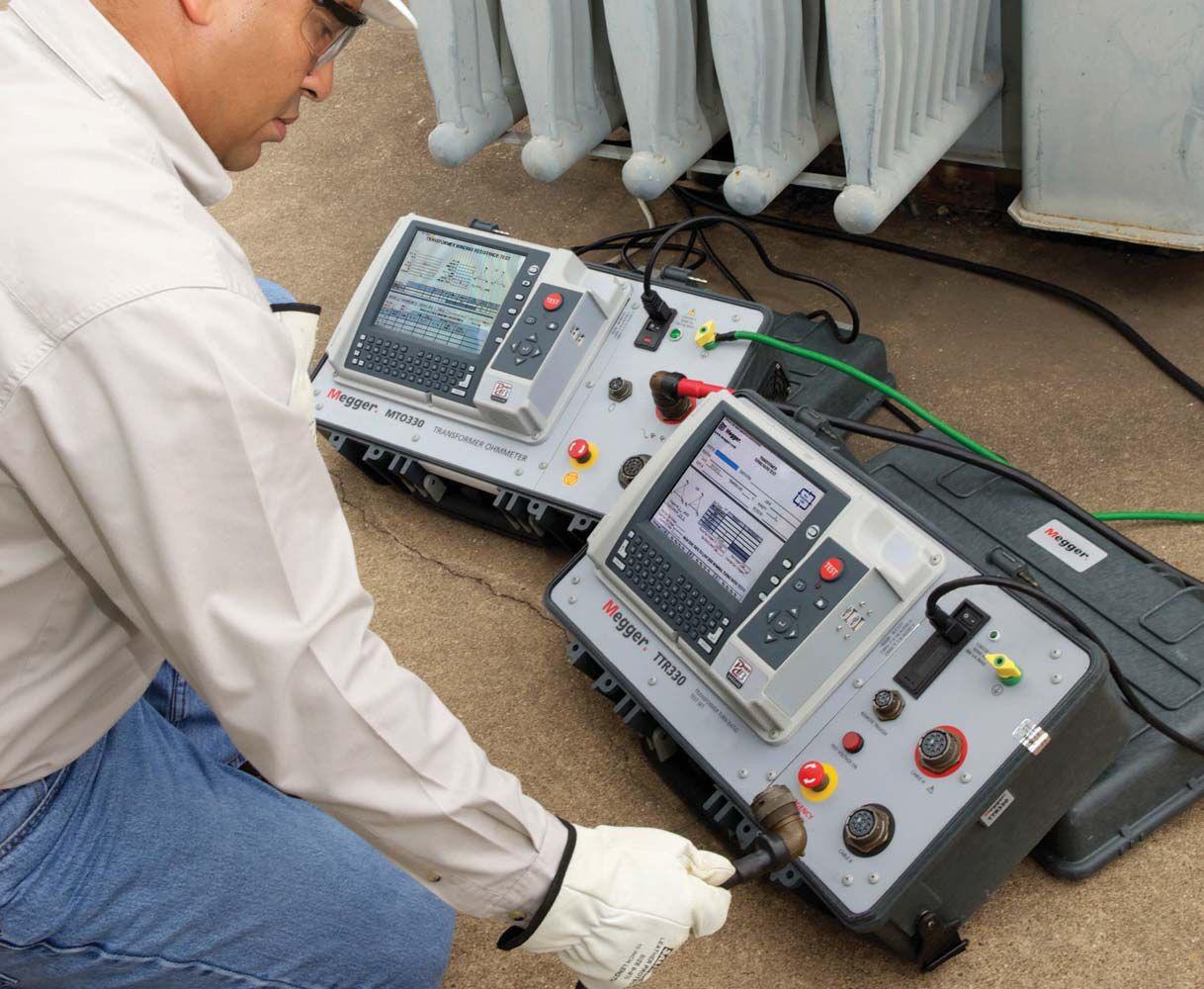
The MTO330 transformer ohmmeter and the TTR300 series of 3-phase transformer turns ratio test sets have interchangeable leads, a single user interface and the same set-up file, saving you the cost of additional leads and time learning new interfaces and files.
The MTO330 transformer ohmmeter delivers full eight-terminal/six-winding resistance measurement capability. It is designed to save time by testing all six windings without having to disconnect and reconnect leads.
Any member of the TTR300 series of 3-phase transformer turns ratio test sets can run either stand-alone or remote-controlled.
The one-two power punch of the MTO330 and the TTR300 series can help you save a bit on the bottom line without compromise on performance or productivity.
For more information, call 1-800-723-2861 or email sales@megger.com.


68 64S Protection Guide Theory, Application, and Commissioning of Generator 100 Percent Stator Ground Fault Protection Using Low Frequency Injection
Steve Turner, Beckwith Electric Company, Inc.
Th is paper covers practical considerations for proper application and commissioning of this special protection. Th e total capacitance to ground of the generator stator windings, bus work, and deltaconnected unit transformer windings is a very important factor as will be shown.
7 President’s Desk
David Huffman, Power Systems Testing Co.
NETA President
58 Condition-Based Assessment of Insulation Systems for Air-Cooled Medium-Voltage Motors and Generators
Vicki Warren, Iris Power LP

10 Key Changes to the 2015 NFPA 70E
Ron Widup and Jim White, Shermco Industries
14 Tech Quiz
Rotating Machinery and Protection
Jim White, Shermco Industries
18 Niche Market
The Benefits of Applying High Resistance
Grounds for an Ungrouned Power System
Jim Vermeer, Shermco Industries
28 Testing Rotating Machinery
Best Practices for Impact Bump Testing
Stator End Windings
Vicki Warren and John Letal, Iris Power LP
34 Safety Corner
Rotating Machinery Hazard Awareness
Scott Blizard and Paul Chamberlain,
American Electrical Testing Co., Inc.
44 Tech Tips
Substation Grounding and Personnel Safety, Part 2
Jeff Jowett, Megger
50 No-Outage Corner
Get the Most Bang for Your Buck
Top Five Tests for Best Return on Investment
Don Genutis, Halco Testing Services
86 Reliable Demagnetization of Transformer Cores
Markus Pütter and Michael Rädler, OMICRON electronics GmbH
That Have Implications on
Mark Siira, ComRent International
24 High-Tech Company Moves to Dexter Utilities Instrumentation Services 40 NETA Alliance Recognition Award
2014: Vicki Warren
Richard Piet, NETA
54 NETA Leadership – Changing of the Guard
Kristen Wicks, NETA 96 NETA's MVP Receives 2014 NETA
Outstanding Achievement Award
Richard Piet, NETA
Introducing the NETA Handbooks, Series II
NETA and Industry Leaders Exchange Ideas, Share Knowledge, and Work Together to Improve Quality in the Industry
111 Raising the Bar in the Mile High City Powertest 2014 in Review
Kristen Wicks, NETA
118 Go Big or Go Home
Kristen Wicks, NETA
121 Rocking the Rockies NETA-Style
Kristen Wicks, NETA
123 PowerTest 2014 - Sponsorship Thank You
NETA Accredited Companies
Advertiser List


3050 Old Centre Avenue, Suite 102
Portage, MI 49024
Toll free: 888.300.NETA (6382)
Phone: 269.488.NETA (6382)
Fax: 269.488.6383
neta@netaworld.org
www.netaworld.org
EXECUTIVE DIRECTOR: Jayne Tanz, CMP
NETA Officers
PRESIDENT: David Huffman, Power Systems Testing Co.
FIRST VICE PRESIDENT: Ron Widup, Shermco Industries
SECOND VICE PRESIDENT: Jim Cialdea, Three-C Electrical Co., Inc.
SECRETARY: Mose Ramieh, Power & Generation Testing, Inc.
TREASURER: John White, Sigma Six Solutions
NETA Board of Directors
Ken Bassett (Potomac Testing, Inc.)
Scott Blizard (American Electrical Testing Co., Inc.)
Jim Cialdea (Three-C Electrical Co., Inc.)
Lorne Gara (Orbis Engineering Field Services, Ltd.)
Roderic Hageman (PRIT Service, Inc.)
David Huffman (Power Systems Testing)
Alan Peterson (Utility Service Corporation)
Mose Ramieh (Power & Generation Testing, Inc.)
Bob Sheppard (Southwest Energy Services, LLC)
John White (Sigma Six Solutions)
Ron Widup (Shermco Industries)
NETA World Staff
TECHNICAL EDITOR: Roderic L. Hageman
ASSOCIATE EDITORS: Diane W. Hageman, Resa Pickel
MANAGING EDITOR: Jayne Tanz, CMP
ADVERTISING MANAGER: Jill Howell
DESIGN AND PRODUCTION: Hour Custom Publishing
NETA Committee Chairs
CONFERENCE: Ron Widup; MEMBERSHIP: Ken Bassett; PROMOTIONS/MARKETING: Scott Blizard; SAFETY: Scott Blizard and Jim White; TECHNICAL: Alan Peterson; TECHNICAL EXAM: Ron Widup; WORLD ADVISORY: Diane Hageman; CONTINUING TECHNICAL DEVELOPMENT: David Huffman; TRAINING: Kerry Heid; FINANCE: John White; NOMINATIONS: Alan Peterson; STRATEGY: Mose Ramieh; ALLIANCE PROGRAM: Jim Cialdea
© Copyright 2014, NETA
NOTICE AND DISCLAIMER
NETA World is published quarterly by the InterNational Electrical Testing Association. Opinions, views and conclusions expressed in articles herein are those of the authors and not necessarily those of NETA. Publication herein does not constitute or imply endorsement of any opinion, product, or service by NETA, its directors, officers, members, employees or agents (herein “NETA”).
All technical data in this publication reflects the experience of individuals using specific tools, products, equipment and components under specific conditions and circumstances which may or may not be fully reported and over which NETA has neither exercised nor reserved control. Such data has not been independently tested or otherwise verified by NETA.
NETA MAKES NO ENDORSEMENT, REPRESENTATION OR WARRANTY AS TO ANY OPINION, PRODUCT OR SERVICE REFERENCED OR ADVERTISED IN THIS PUBLICATION. NETA EXPRESSLY DISCLAIMS ANY AND ALL LIABILITY TO ANY CONSUMER, PURCHASER OR ANY OTHER PERSON USING ANY PRODUCT OR SERVICE REFERENCED OR ADVERTISED HEREIN FOR ANY INJURIES OR DAMAGES OF ANY KIND WHATSOEVER, INCLUDING, BUT NOT LIMITED TO ANY CONSEQUENTIAL, PUNITIVE, SPECIAL, INCIDENTAL, DIRECT OR INDIRECT DAMAGES. NETA FURTHER DISCLAIMS ANY AND ALL WARRANTIES, EXPRESS OF IMPLIED, INCLUDING, BUT NOT LIMITED TO, ANY IMPLIED WARRANTY OF FITNESS FOR A PARTICULAR PURPOSE.
ELECTRICAL TESTING SHALL BE PERFORMED ONLY BY TRAINED ELECTRICAL PERSONNEL AND SHALL BE SUPERVISED BY NETA CERTIFIED TECHNICIANS/ LEVEL III OR IV OR BY NICET CERTIFIED TECHNICIANS IN ELECTRICAL TESTING TECHNOLOGY/LEVEL III OR IV. FAILURE TO ADHERE TO ADEQUATE TRAINING, SAFETY REQUIREMENTS, AND APPLICABLE PROCEDURES MAY RESULT IN LOSS OF PRODUCTION, CATASTROPHIC EQUIPMENT FAILURE, SERIOUS INJURY OR DEATH.

Rotating machines are at the heart of every type of facility and a fundamental piece of every bulk power system.
It’s an honor to continue writing the President’s Desk going into my second term as President. Thank you all for the support in making NETA as great as it is. I’m looking forward to another year!
I am always reminded of the motors in everyday systems. As an example, today was a driving day for me, and, while on the road, I saw several electric vehicles. I wondered “what technology are they using to monitor the health of the motors?”
If you were unable to attend some of the presentations at PowerTest, here is a good opportunity to read up on some of the aspects of caring for and control of your rotating machinery. By the time you read this, many facilities will have concluded their early or mid-year outages, and perhaps some of you have concerns about the results in your test reports. It’s possible you may find a colleague here you can collaborate with in this issue.
I’m looking forward to seeing many of you at the September meeting in San Francisco. Have a great summer, and be safe as always!
Sincerely,
David Huffman President InterNational Electrical Testing Association







CBS ArcSafe’s remote racking and remote switching solutions reduce arc-flash dangers and technician fatigue during dangerous operations.

Remote racking solutions reduce the need for full-body arc-flash h azard suits by taking technicians outside the arc-flash boundary.
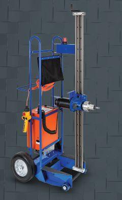

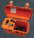
Universal remote racking solutions offer adjustable height settings.


All CBS ArcSafe remote racking and remote actuation solutions are battery- or AC-powered portable units that do not require any modifications to your electrical equipment.

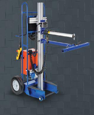

No equipment modifications required.
Remote switching solutions keep technicians outside the arc-flash b oundary during dangerous operations.
No modifications required due to magnetic latching.

Remote switching solutions are available for virtually any style o
r piece of electrical equipment.


Use your Windows 7-compatible tablet or PC with the CBAnalyzer™ system to test your circuit breakers in place. Operate the breaker in any sequence you desire: for example, trip – charge – close. The vibration data created by the breaker operation is captured and analyzed, and the result is instantly returned to your device. The data is saved in your online account for equipment management, trending, and further analysis options, including specialized issue diagnosis.
• WORKS ON A WInDOWS 7-COMPATIBLE TABLET, PC AnD iPhOnE
• INCREASES IN-SERVICE TESTING FREQUENCY, BOOSTS UPTIME
• EVALUATES OVERALL MECHANICAL CONDITION
• TESTS ALL TYPES AND RATINGS OF BREAKERS
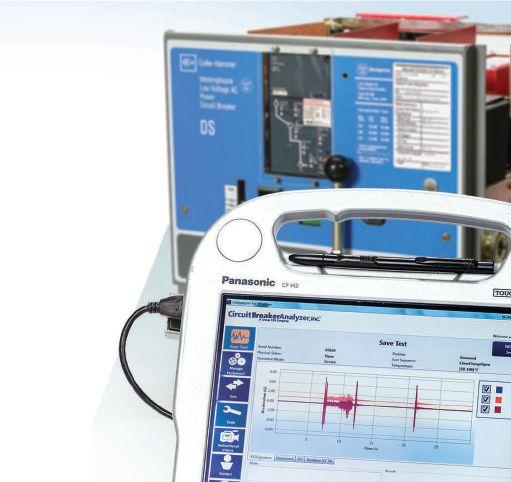
• DETERMINES BREAKER OPENING AND CLOSING TIMES
• PROVIDES FIRST TRIP DATA







 BY RON WIDUP AND JIM WHITE, Shermco Industries


In the last column we discussed the big three changes coming up in the 2015 edition of NFPA 70E. They were
1. New PPE selection tables
2. Eliminating Hazard Risk Category “0”
3. Eliminating the Prohibited Approach Boundary


At the time of writing this column the 2015 edition of NFPA 70E is almost finalized, and we know of two tentative interim amendments (TIA) that will be voted upon. A tentative interim amendment is temporary in that it only lasts until the next edition. It is also automatically issued as a public Input for the next revision cycle so the committee can discuss it and vote on it. It is part of the standard during this interim period and is to be used as a part of the standard. It is an amendment because upon approval it will have modified the standard as previously voted on and approved.

The second TIA is a proposal to delete text in 130.7(C)(10)(b)(1) and to modify wording in Table H.3(a) and Table H.3(b).

This TIA is a proposal to modify Table 130.7(C)(15) (A)(a). The issue, and rationale for the TIA, is that the revised table does not state that the use of clothing containing meltable fibers is prohibited for tasks that are identified as No in the Arc-Flash PPE Required column, and with the elimination of HRC 0, the table no longer states that the use of clothing containing meltable fibers is prohibited for those tasks.
The TIA seeks to clarify that the use of clothing containing meltable fibers is prohibited for tasks that are identified as No in the Arc-Flash PPE Required column.

The TIA proposal for 130.7(C)(10)(b)(1) is to delete the phrase “and the anticipated incident energy exposure is greater than 4 cal/cm2.” If the TIA is approved, the text will revert to the language of the 2012 edition.
The proposed changes will make it mandatory to wear an arc-rated face shield and balaclava (or arcrated hood) when the incident energy is above 1.2 cal/cm2 and whenever using the table method. During this cycle, some members of the committee wanted to require the use of a balaclava, as they believed that the back of the head could be exposed to the arc even at the HRC 1 level. In the past, the 70E has not required the use of a balaclava when wearing HRC 1 arc-rated clothing and PPE.

The clarification will be the addition of a note to the table, and the prohibition against using clothing with meltable fiber will be a requirement as the instructions contained in table notes are mandatory, not informational. The concern is that workers may view the elimination of HRC 0 as permission to wear permanent press or other fibers that could melt from the heat of an electrical arc.

Votes and comments from the committee are required to be returned by April 8, 2014. TIAs often do not make it through the committee balloting process because they must be emergency in nature and correct a technical issue; that is they must have safety implications, be a typographical error or unclear wording that could cause the standard to be misinterpreted, or be a technical oversight that the committee believes is necessary for the document. TIAs often fail to meet the emergency requirement of the process.
If the TIAs fall short of the required three-fourths acceptance by the NFPA Technical Committee 70E and the Technical Correlating Committee, then the NITMAM (Notice of Intent to Make a Motion) and appeal to the NFPA technical oversight committee are not likely to succeed. Only time will tell on this.


The NFPA has issued the TIAs and will ask for public comment, which is for the readers of this column. Your input is necessary to ensure the committees understand the public perception of the issues.
Some of the other changes that will likely take place are the phrase hazard/risk category and the acronym HRC will no longer be used. The categories are now called arc-flash PPE categories to reflect the changes in the new task tables. The limits from the current version of the tables are still retained, but the ac and dc tables have been combined. This was done to simplify their use. PPE category 1 will have the same limits as HRC 1; PPE category 2 the same limits as HRC 2; and so on. The only change to this is that there will not be a HRC 0 or PPE category 0. We believe the new tables will be easier to use in the field and will clarify when arc-rated clothing and PPE is mandatory. As we have said many times in the past, the fact that the tables do not mandate the use of arc-rated clothing or PPE, does not mean a worker should not wear arc-rated protection if there is any doubt about the equipment or circuit he or she is about to work on or operate.


Another change is in the scope of NFPA 70E. In the past, the Technical Correlating Committee (the oversight committee for the 70E) has rejected changes to the scope of the standard. During this cycle, the 70E committee received bulletins from MSHA which stated that they recognize NFPA 70E to be a guide for the enforcement of MSHA regulations. Since MSHA has accepted NFPA 70E in the same manner that OSHA has, the committee thought it prudent to include mining operations in the scope.
An addition to the Electrical Safety Program (ESP) section of Section 110 states that the condition of maintenance must be considered as part of the ESP. While this is nothing new to those of us that perform maintenance services in industrial settings, this moves maintenance up a level and solidifies the need for maintenance to ensure a safe electrical system. Chapter 2 already contains requirements for maintenance, but adding maintenance to the ESP ensures it will have wider exposure and, we hope, wider implementation.
have asked for relief from the requirement of wearing arc-rated clothing and PPE as it interfered with using the cameras. Effective with the 2015 edition, if they are outside the arc-flash boundary, they will not be required to wear the full arc-rated PPE as does the worker removing the panels. As with anything else regarding the table method, users need to be cautious when they decide not to wear arc-rated clothing and PPE. A few minutes of discomfort is a small price to pay for missing that helicopter ride to the burn clinic.


As NFPA 70E evolves, it becomes easier to use and is clearer in its requirements. New information is available to the 70E committee at each revision cycle and this is why the 70E changes the way it does. As a standard, the 70E does not yet have the maturity or history of the NEC, but it has progressed incredibly well over the last ten years or so. And if some of the new changes do not pan out, the 70E Committee will be able to make adjustments during the next cycle. It is important that anyone who has an opinion about the TIAs to voice that opinion officially.. The 70E Committee wants to hear from you, the end user, to help guide its actions.






One last change is for infrared thermographers. For the last couple of cycles, infrared thermographers

Ron Widup and Jim White are NETA’S representatives to NFPA Technical Committee 70E (Electrical Safety Requirements for Employee Workplaces). Both gentlemen are employees of Shermco Industries in Dallas, Texas, a NETA Accredited Company. Ron Widup is President of Shermco and has been with the company since 1983. He is a Principal member of the Technical Committee on “Electrical Safety in the Workplace” (NFPA 70E) and a Principal member of the National Electrical Code (NFPA 70) Code Panel 11. He is also a member of the technical committee “Recommended Practice for Electrical Equipment Maintenance” (NFPA 70B), and a member of the NETA Board of Directors and Standards Review Council. Jim White is nationally recognized for technical skills and safety training in the electrical power systems industry. He is the Training Director for Shermco Industries, and has spent the last twenty years directly involved in technical skills and safety training for electrical power system technicians. Jim is a Principal member of NFPA 70B representing Shermco Industries, NETA’s alternate member of NFPA 70E, and a member of ASTM F18 Committee “Electrical Protective Equipment for Workers”.


Featuring quality, reliable, on-time service and support for all brands and types of solid state power electronics.
Power electronics are our business
Let us suppoort you with our quality repair, calibration and servicing of your solid state equipment. We also buy, sell and trade:
•Communications devices for power equipment
•Protective relays
•Circuit breaker trip devices
•Motor overload relays
•Rating plugs


James R. (Jim) White is the Training Director of Shermco Industries, Inc., in Dallas, Texas. He is the principal member on the NFPA technical committee “Recommended Practice for Electrical Equipment Maintenance” (NFPA 70B). Jim represents NETA as an alternate member of the NFPA Technical Committee “Electrical Safety in the Workplace” (NFPA 70E) and represents NETA on the ASTM F18 Committee “Electrical Protective Equipment For Workers”. Jim is an IEEE Senior Member and in 2011 received the IEEE/PCIC Electrical Safety Excellence award. Jim is a past Chairman (2008) of the IEEE Electrical Safety Workshop (ESW).


Low-voltage circuit breaker testing technology is moving forward, albeit at a relaxed pace, it seems. Field testing can include a number of different test methods and types of test equipment. Your task, if you choose to accept it, will be to successfully answer the Tech Quiz questions this issue. As always, choose the most correct answer.
1. With electromechanical relay motor protection, what two types of relays were not provided for induction motor protection?
a. Overcurrent and undervoltage
b. Differential and overvoltage
c. Current balance and thermal replica
d. Loss-of-field and sync-check
2. The biggest enemy to insulating systems is heat. Current magnitude during most of the starting acceleration time is very close to locked-rotor current. What is the typical current range for locked-rotor current of a large induction motor?
a. 2 to 4 times rated current
b. 4 to 6 times rated current
c. 6 to 8 times rated current
d. 8 to 10 times rated current
e. 10 to 12 times rated current


3. Digital motor protection relays contain several functions that mimic older electromechanical protective relays. Which function uses thermal damage characteristics (I2t) for motor protection?
a. Thermal replica
b. Locked rotor
c. Overcurrent
d. All the above
e. None of the above
4. Which of the following functions do not use the thermal damage characteristics?
a. Overcurrent (50/51)
b. Current Unbalance (46)
c. Differential (87)
d. Number of Starts Per Time Period (66)
e. Time Between Starts
5. During normal operation of a motor, when is a locked rotor condition produced?
a. During starting
b. If a phase is dropped to the motor
c. If the gearbox or coupling is misaligned
d. If there is a short circuit in the motor windings
e. When more than rated voltage is applied to the motor





MODELS 407 & 607 are available with an Android™ application for easy programming, data downloading, printing and e-mailing test results from your mobile device. With its mobile GPS capability, users are now able to easily locate the site associated with the measurements.

► Measures up to 2000AAC and 3000ADC (600 series)
► Measures up to 1000VAC/DC (1400V peak) and AC+DC with resolution to 10mV
► Measures single- and three-phase power
► Auto selects AC or DC measurement
► True InRush ® current measurement with 1 ms peak capture measures start up and running Inrush


► Records up to 1000 measurements
► Measures TDH and individual harmonics up to the 25th

► 10,000 count blue electroluminescent backlit display

► UL94 VI Flame retardant self-extinguishing (model dependent)


► Leads are constructed with a flexible silicone material


► Wireless Bluetooth data transfer (model dependent)


Power system grounding is provided to improve safety and minimize equipment damage during a fault condition. This article discusses some of the options that are implemented for power system grounding. Further, a case study is provided to support the implementation of a high resistance grounding system for ungrounded power systems.
The most commonly used grounding configuration for industrial, commercial, and institutional power distribution systems is the solidly-grounded system. From IEEE 142 – 2007, IEEE Recommended Practice for Grounding of Industrial and Commercial Power Systems , a solidly grounded system is defined as a system that is “connected directly through an adequate ground connection in which no impedance has been intentionally inserted.” Article 250 of the NEC goes to great lengths to define and describe an adequate ground connection, so the reader should use that as a reference for further research for the implementation of grounds in a solidly grounded system.
In lieu of a solidly grounded system, many industrial power distribution systems have implemented an
ungrounded system. Also from IEEE 142 –2007, an ungrounded system is defi ned as a system “without an intentional connection to ground except through potential indicating or measuring devices or other very highimpedance devices.” An ungrounded system can be implemented where service continuity
is a prime concern and tripping the power distribution system off -line due to a ground fault cannot be tolerated. Th is type of system is allowed by the NEC if there are no line-toneutral loads (i.e., single phase loads) within the ungrounded power system.
As stated, an ungrounded system is one in which there is no intentional connection between the conductors and earth ground. However, as in any system, a capacitive coupling exists between the system conductors and the adjacent grounded surfaces. Consequently, the ungrounded system is, in reality, a capacitively-grounded system by virtue of the distributed capacitance. Under normal operating conditions, this distributed capacitance causes no problems. In fact, it is benefi cial because it establishes, in eff ect, a neutral point for the system. As a result, typically the phase conductors are stressed at only line-to-neutral voltage above ground. However, if a ground fault exists on one phase, a full line-to-line voltage will appear on the ungrounded phases. Th us, a voltage 1.73 times the normal voltage is present on all phase-to-ground insulation of the ungrounded phases in the system when one line is faulted to ground. Th is situation can often cause failures in older motors and transformers, due to insulation breakdown. Th e interaction between the faulted system and its distributed capacitance may also cause transient overvoltages (several times normal) to appear from line-to-ground during normal switching of a circuit having a line-to-ground fault (short). Th ese over voltages may cause insulation failures at points other than the original fault. In addition, a second fault on another phase could occur before the fi rst fault can be cleared. Th is can result in very high line-to-line fault currents, equipment damage, and disruption of both circuits.
To mitigate the potential harm of a ground fault in an ungrounded system, it is typically recommended that the ground faults should be cleared within a short time period (i.e., within 24 hours). Unfortunately, ungrounded systems complicate locating faults. Fault

location involves a tedious process of trial and error: fi rst isolating the correct feeder, then the branch, and fi nally, the equipment at fault. Th e result is unnecessarily lengthy and expensive downtime, which ultimately may not improve service continuity. An ungrounded system, despite the drawbacks, does have one main advantage. After the fi rst ground fault, assuming it remains as a single fault, the circuit may continue in operation, permitting continued production until a convenient shut down for maintenance can be scheduled.

An alternative to an ungrounded system is a resistance-grounded system. From IEEE 142 – 2007, a resistance-grounded system is “designed to limit ground fault current to a value that can be allowed to flow for an extended period of time, while still meeting the criteria of R 0 <X C0 , so that transient voltages from arcing ground faults are reduced. The ground-fault current is usually limited to less than 10 A, resulting in limited damage even during prolonged faults.” For informational purposes, R 0 is the per phase zero-sequence resistance of the system and


X C0 is the distributed per phase capacitive reactance to ground of the system. Resistance grounding protects a system against transient overvoltages caused by arcing ground faults and provides adequate fault current for selective ground-fault detection and coordination. Resistance grounding may be either of two classes, low-resistance or highresistance, distinguished by the magnitude of ground-fault current permitted to fl ow. Although there are no recognized standards for the levels of ground-fault current that defi ne these two classes, in practice there is a clear diff erence.
Low-resistance grounding employs a neutral resistor of lower ohmic value and is designed to limit ground-fault current to a range between


100A and 1000A, with 400A being typical. Low-resistance grounding has the advantage of facilitating the immediate and selective clearing of a grounded circuit. This requires that the minimum ground-fault current be large enough to positively actuate the applied ground-fault relay. One method of detecting the presence of a ground fault uses an overcurrent relay, 51G.

The general practice is to consider that the full system line-to-neutral voltage appears across the grounding resistor. Low-resistance grounding finds application in medium-voltage systems of 15 kV and below, particularly where large rotating machinery is used. By limiting groundfault currents to hundreds of amperes, instead of thousands of amperes, damage to expensive equipment is reduced.
High-resistance grounding employs a neutral resistor of high ohmic value. Typically, the neutral resistor is selected to limit the fault current to 10A. High-resistance grounding usually does not require immediate clearing of a ground fault since the fault current is limited to a very low level. The protective scheme associated with high-resistance grounding is usually detection and alarm rather than


immediate trip out. High-resistance grounding is generally employed in low voltage applications where there are no line-to-neutral loads and as a retrofit of previously ungrounded systems where it is desired to reduce transient overvoltages potentially caused by ground faults.
An industrial customer installed power monitors for the monitoring and allocation of power consumption by department. Due to motor insulation issues within the plant, there have been concerns associated with grounding and ground faults in the plant electrical power distribution system, which is an ungrounded system. Th is power system was ground fault tolerant. But the ground faults have had detrimental impact to insulation systems in cabling and motors. Accordingly, the monitors were programmed to capture trend and triggered data. A power quality investigation was in process in an eff ort to determine the frequency and impact of the ground faults on their system. During this investigation, an actual ground fault transient was captured. A plot of the voltage transient is provided below.
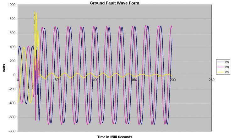
As can be seen with the plot, the peak phase-toground voltages are on the order of 400 volts (nominal 277 volts rms). It should be noted that this waveform is typical of what would be expected with a 480 volts power system. The actual measured phase rms voltages were 262 volts, 257 volts, and 314 volts. At the onset of the ground fault transient, there was a peak voltage of 900 volts on C-phase which had the ground fault. The actual peak voltage was probably higher due to the limited resolution of this meter. This level of voltage would be detrimental to insulation systems associated with motors, cabling, etc. Further following the transient, the ground fault was still present. On an ungrounded system, a ground fault condition for one phase can be present and yet the system can continue to operate for an indefinite period.
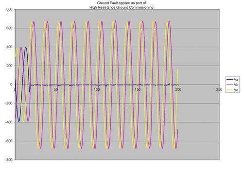
In an attempt to remedy this possible groundfault related, transient voltage issue, this industrial customer implemented a high resistance grounding (HRG) system on the transformer’s 480 volt secondary. As part of the commissioning activities associated with the HRG system, a ground fault was applied through a testing configuration which included a fused circuit from A-phase to ground. Below is a plot of the associated ground fault transient after the HRG system was installed.
As can be seen on the plotted wave form, prior to the ground fault, the typical peak phase voltages are as expected. The actual measured phase rms voltages were 278 volt, 272 volt, and 277 volt, which suggest an improved voltage balance for the power system with the HRG system in place. At the onset of the applied ground fault, the power system did not experience the voltage transient which includes excessive voltage spikes. Following the transient, the ground fault is still present.
There are many options to consider when implementing a grounding system for any power distribution system. Most applications include the implementation of a solidly grounded system. However, many




industrials have implemented an ungrounded system for improved continuous operations. Unfortunately, with an ungrounded system, when a ground fault is present, the associated voltage transient could be detrimental to the affected insulations systems. With the implementation of a HRG system for ungrounded power systems, these voltage transients can be mitigated. Further, the benefit of continuous operation during a fault condition as well as an additional benefit for improved power system voltage balancing should be realized. Jim Vermeer has a degree in physics from Central College in Pella, Iowa, and works as a project manager w ith Shermco Industries. His specialty is industrial medium- and low-voltage power distribution systems and power quality. Jim is also a Level III NETA Certified Electrical Testing Technician.



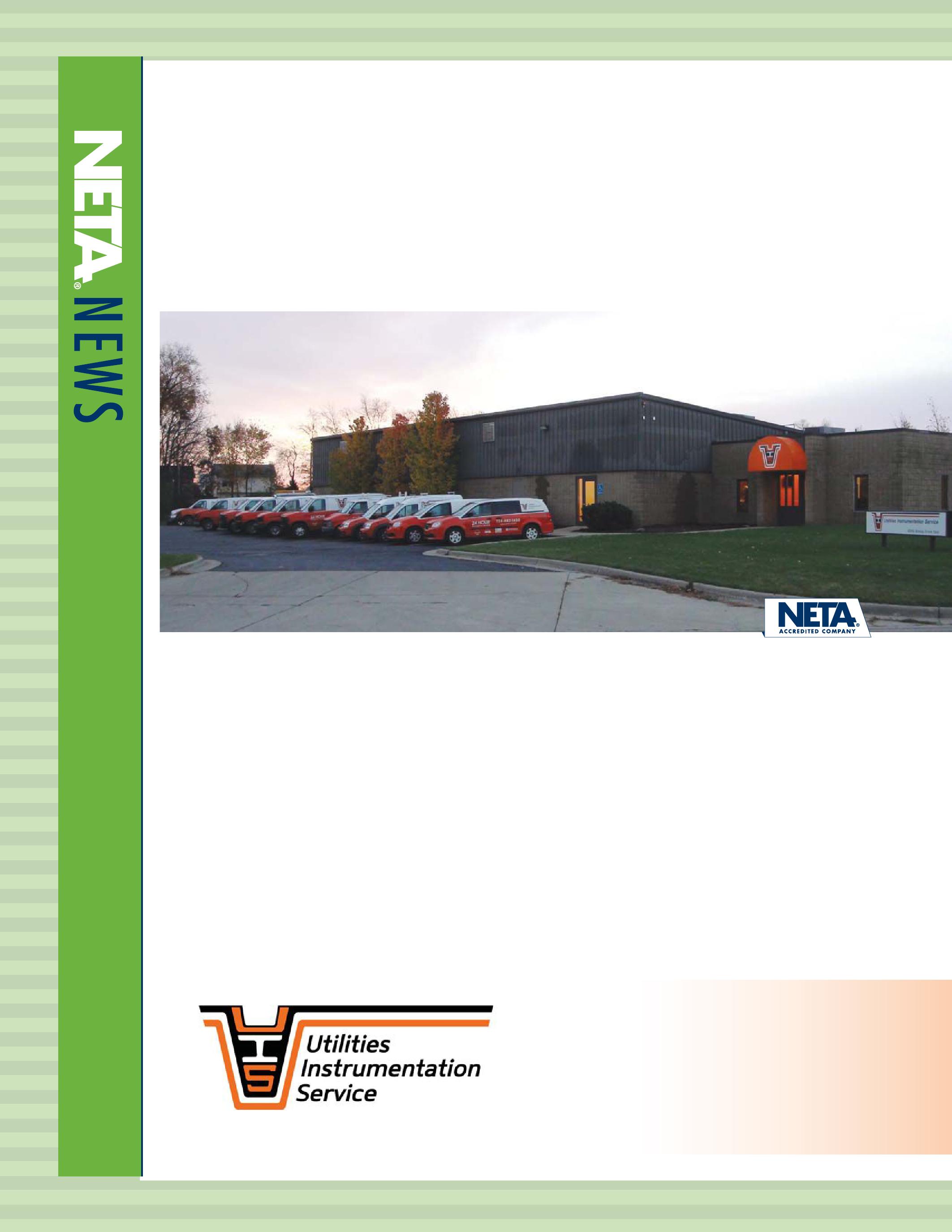
Dexter, Michigan, December, 2013: Utilities Instrumentation Service, Inc., (UIS), formerly operating out of Ypsilanti, Michigan, moved to Dexter, Michigan. They needed a new location to accommodate their growing business with easy access to highways 94 and 23.
“Dexter is a great area for serving customers who are located throughout Michigan, Ohio, Indiana, and Illinois. We have a fleet of service vehicles travelling somewhere within the four-state area,“ says John Patry, one of the two owners of UIS. The building is located at 2290 Bishop Circle. It is an 8500 square foot building that was renovated to provide about 4000
square feet of modern office space and 4500 square feet of warehouse space. “The location is perfect for us,” said Gary Walls, the other owner and a resident of Dexter for many years.
Utilities Instrumentation Service, Inc. founded in 1976, is an electrical testing, maintenance, and SCADA company. It has 35 employees helping municipalities, power plants, education facilities, manufacturers, hospitals, airports, and commercial businesses. UIS is the 911 responder to electrical equipment trouble. They install, repair, calibrate, program, and service almost all electrical instrumentation, controls, and apparatus.
Gary Walls
Utilities Instrumentation Service, Inc.
2290 Bishop Circle East Dexter, MI 48130
Gary.Walls@uiscorp.com www.uiscorp.com 734-424-1200
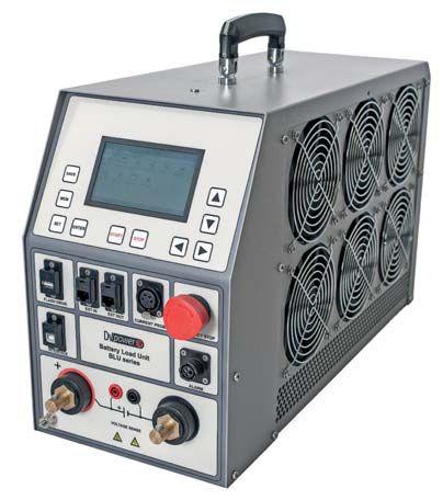
BLU200A - 18 kW, 14.5 kg/32 lbs
220/240 V - 60 A 110/120 V - 120 A 24/48 V - 200 A
Affordable, portable and powerful test equipment
3 year warranty supported in the USA by ProgUSA LLC
Test preparation, control and results analysis supported by DV-Win software applications
Best customer support in the industry
ACCESSORIES
BVR – Battery Voltage Recorder
Hand-held tool measuring battery voltage and its temperature with a battery either connected or disconnected from the network. RFID cell recognition and electrolyte density check also available.
BVS – Battery Voltage Supervisor
voltages in a real-time mode. Most effective when using in a combination with BLU instruments. Up to 120 individual BVS units in chain covers any practical test need. Connects to a Central Communication Hub using RS485.


Protective Relay Test Sets · VLF/AC/DC Hipots · Tan Delta
Primary Current Injection · Thumpers · Circuit Breakers
Relay Testers · TTR Test · Megohmmeters · Partial Discharge
Oil Dielectric Test · TDR · Battery Test · Cable Fault Locators
Power Analyzers and more!
Fluke · Phenix · SKF/Baker · Tettex · Doble · AEMC Rosemount/Hart · Vanguard and more...



 BY VICKI WARREN AND JOHN LETAL, Iris Power LP


Common off-line tests of stator windings, IR/PI, dc high potential, PD, power factor, etc. overlook one large aspect of the stator winding: the overhang winding from the slot exit to the end caps or the stator end winding. Because stator end-winding problems are a result of excessive motion, common off-line electrical tests are not suitable for evaluation, and vibration testing on the bearings and shaft are not usually sensitive to problems in the stator end-winding area.



As machines age, the end-winding support materials loosen resulting in components being more prone to vibration problems. In extreme cases the end-winding support structure may be in a resonant condition resulting in excessive vibration amplitudes that can be catastrophic if left uncorrected. This is unfortunate, since most end-winding problems can be identified early and by using nonintrusive measures can be corrected.
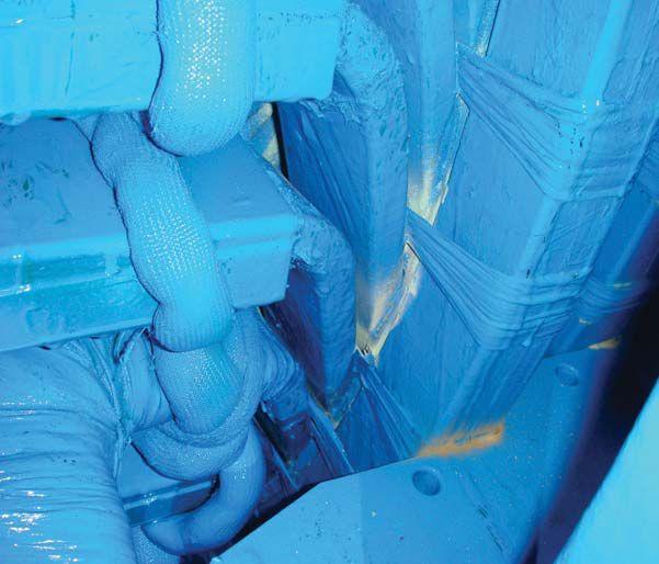
Determining which stator end windings may be at risk of deterioration due to vibration can be assessed with impact (or bump) and modal testing. The goal is to establish the end winding structure natural frequencies and determine if they may be resonant during operation causing amplified vibration levels. This amplification can result in insulation fretting (Figure 1), greasing, high cycle copper conductor fatigue, and series connection failure.


• Vibration frequency — rate at which the component vibrates
• Natural frequency — frequency at which a structure will vibrate if deflected and then let go
• Operational forcing frequency — frequency of the electromechanical forces of a generator determined by power frequency and rotational speed; vibration of a generator will tend to be at frequencies related to these.
• Resonant condition — when the operational forcing frequencies of the generator influence the natural frequency of the end-winding structure
• Force hammer — device calibrated to exert a known force
• Accelerometer — device used to measure the frequency response (rate of vibration) during operation or due to a force hammer
• Frequency response function — transfer function of acceleration to applied force ratio expressed in the frequency domain
• Modal analysis — measuring motion at various points of a structure when it is excited by some driving force
Part 1 of this article discussed theory and equipment used for impact testing on stator end windings. NETA World –Winter 2013




The goal of impact testing is to establish a dynamic signature for the structure by doing Fourier analysis. There are two impact test procedures that can be used to determine the natural characteristics of a stator end-winding structure: driving point and modal analysis.


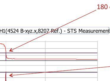
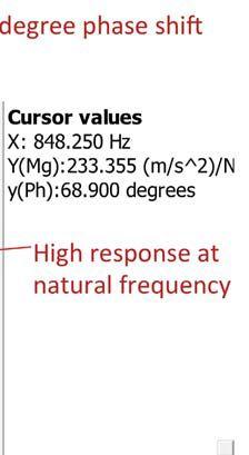
In the driving point test, the force hammer and the accelerometer are at the same location. This localized test can be used to identify components with maximum deflection. The result is a measured response at the excitation point or frequency response function (FRF). This transfer function is expressed in the frequency domain, Figure 2.

The phase relationship between the force input and the acceleration output will be between 0 and 180 degrees or 180 and 360 degrees and be 90 degrees at a natural frequency. To identify a natural frequency, two observations are required. As the driving frequency approaches an undamped natural frequency, 1) the magnitude approaches a maximum and; 2) a phase shift crosses through 90°, Figure 2.


The critical bands of natural frequencies for a motor or turbine generator are around rotational speed frequency and twice line frequency. Therefore, applied forces in the end-winding structure of a








two-pole, 60-Hz generator are at rotor rotational frequency, 60 Hz and at alternating load current electromagnetic forces, 120 Hz. Frequency bands are used to assess the risk of vibration amplification when the natural frequencies influence these operational forcing frequencies. In service the natural frequencies may drift into the bands due to temperature, aging, and other variable factors. Thus, an acceptance band should be defined with these factors in mind. Acceptance criteria are based on the magnitude of the acceleration over force through these critical bands, for example the maximum accelerance limit can be 0.44m/s2/N between 54-72Hz and 108-144Hz.
Th e impact test should not be considered as a stand-alone test or replacement to a modal analysis test.
Modal analysis consists of measuring motion at various points of a structure when it is excited by a driving force. Practically this test can either be performed using one force input location and multiple acceleration response locations or vice versa. The pattern of motion usually takes certain shapes which are related to the natural frequencies of the structure. This provides a model of structural characteristics through curve fitting techniques to generate a shape table that closely represents the dynamics of a structure, that is, the global tendency of motion.
1. Linear: The response will be proportional to the input force. This can be checked by performing a driving point test with different sizes of force hammers and obtaining the same FRF.
2. Invariant: The parameters are constant during testing. Ambient and winding temperature should be recorded through impact testing and not fluctuate significantly.
3. Passive: Th e response is due to the measured forces. It is best to perform impact testing when background/operational forces are a minimum.
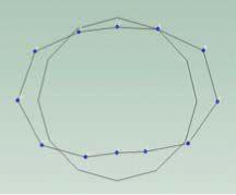
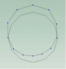
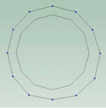
An end-winding structure can be modeled with a circular ring. When the structure takes certain shapes at similar frequencies to a force, the resonant condition amplifi es the vibration on an end winding. For a twopole machine, the shape for twice supply frequency defl ection is oval, Figure 3. Th is shape is not the only mode that can be excited by forces within the rotating machine. Other modes such as cantilever modes, Figure 4, or breathing modes, Figure 5, could also become resonant. However, the oval mode shape in Figure 3, for two-pole machines is the most critical for vibration analysis of the stator because it is naturally driven by the rotor forces during operation. It is critical that natural frequencies for the mode shapes into which the end winding can be deformed are far away from the driving frequencies (60 Hz and 120 Hz) to avoid the results of excessive motion, Figure 1.
Modal data should be collected at locations on the stator overhang where the end windings are most responsive, that is, near the end caps and between each ring of blocking. As well, it is useful to collect data on the core. For each ring enough points must be measured to resolve the mode shape of interest. In general, for two-pole machines, 12 points are suffi cient to defi ne the oval mode shape. Quite often though, it is of interest to identify the shape of the modes near the electromagnetic force during operation, so the mode shape above 120 Hz should have suffi cient resolution in order to avoid misinterpretation.
Impact testing is an off -line test that can be used to assess whether stator end windings are likely to vibrate in resonance with operational forces. A driving point test procedure is used to identify local natural frequencies of a particular component of a structure whereas modal analysis is used to identify the global tendency of motion for a complex structure. Both can be used in conjunction to evaluate the condition


of a stator end-winding support structure and determine the likelihood for excessive motion during operation due to resonance.


John Letal is a rotating machines engineer at Iris Power responsible for supporting rotating machine mechanical monitoring initiatives including stator endwinding vibration. Prior to Iris, he spent most of his career as a field service engineer troubleshooting large rotating equipment using such tools as vibration analysis, force response measurements, and modal analysis. He was also involved in the implementation and execution of vibration analysis programs.




John holds a Bachelor of Science degree in Manufacturing Engineering from the University of Calgary and is registered as a professional engineer.
Vicki Warren, Senior Product Engineer, Iris Power LP. Vicki is an electrical engineer with extensive experience in testing and maintenance of motor and generator windings. Prior to joining Iris in 1996, she worked for the U.S. Army Corps of Engineers for 13 years. While with the Corps, she was responsible for the testing and maintenance of hydrogenerator windings, switchgear, transformers, protection and control devices, development of SCADA software, and the installation of local area networks. At Iris, Vicki has been involved in using partial discharge testing to evaluate the condition of insulation systems used in medium- to high-voltage rotating machines, switchgear and transformers. Additionally, she has worked extensively in the development and design of new products used for condition monitoring of insulation systems, both periodical and continual. Vicki also actively participated in the development of multiple IEEE standards and guides and was Chair of the IEEE 43-2000 Working Group.


Editor's note: Although the technical expertise of NETA Accredited Companies is generally directed toward electrical testing services, it is useful to be aware of other characteristics of the devices we test along with applicable methods of evaluation. If we can assist our clients by directing them when necessary to these other methods of problem resolution or equipment condition assessment, they are likely to be just as grateful as they are when our standard services are of benefi t to them.



No matter where you are, no matter what you run, if it’s electrical, Shermco’s the one.
Power plants? No problem. Utility substations? We can handle ‘em. Wind farms? Absolutely. Data centers? Just say where and when. The fact is, Shermco has the growing capacity to support your utility or electrical power needs in virtually any location, with all the manpower, equipment and technical knowledge it takes to get the job done and done safely!
While other companies are sending their equipment and workforces out to pasture, we’re upgrading ours and sending them into the field. Call Shermco for anything. Fromlarge-scale engineering projects and planned facility outages, to new system acceptance testing and safe start-up, one company does it all. Shermco. We got your back.



Performing a condition analysis or maintenance on rotating machinery is a hazardous task which requires an experienced individual capable of performing the duty and possessing an ability to identify potential hazards and mitigate risks.
A number of tragic, inadvertent injuries can occur, such as crushed hands or arms, severed fingers, or blindness if extreme caution is not exercised when working with rotating machinery. The use of lockout /tagout, personal protective equipment (PPE), and other means of safeguarding will mitigate possible injuries.
Condition analysis of rotating equipment may be performed by employing equipment designed to be used to access equipment when operating, such as infrared camera, partial discharge detection equipment, and vibration analysis equipment. PPE should be appropriate and adequate for all tasks to be performed. Long sleeves, long hair, jewelry, and other loose articles are an invitation for disaster when one is around rotating machines. Make sure sleeves are tight, hair is pulled back and any other sources of entanglement are removed.
Any machine part, function, or process which many cause injury must be safeguarded. When the operation of a machine or accidental contact with a machine can injure the operator or others in the vicinity, the hazards must be either controlled or eliminated.
When performing a visual inspection of rotating machinery make sure that all guards are correctly installed according to the manufacturer’s instruction and that they comply with the Machinery and Machine Guarding OSHA Regulations 29 CFR 1910.212 – General Requirements for All Machines, and 29 CFR 1910.219 – Mechanical Power-Transmission Apparatus. Depending on the type of machinery being inspected, other OSHA regulations may apply.
The following paragraphs identify and examine hazards and their means of safeguarding and mitigating the associated risks. As always, this article does not include every potential hazard of performing a task, but explores potential hazardous situations. Additional hazards potentially exist, depending upon the type or condition of the equipment. Take all procedures seriously and verify that the instruction manuals used are specific to the equipment present. Check for and identify potential hazards prior to beginning every task by using a pre-job brief worksheet.
Improper lockout/tagout is a major contributing factor to injuries caused by rotating machinery. Controlling the hazardous energy of the motor is essential, and there are many forms of energy that may be involved. Always refer to the appropriate OSHA regulation or required procedure, such as 29 CFR 1910.147 and .333, and the manufacturer’s instructions to determine the correct or required lockout/tagout procedures. The most obvious hazardous energy source that could cause injury is electrical.
Electrically de-energize the rotating machinery from its primary energy source and ensure the equipment is disconnected from all sources of power, both ac and dc, if applicable. Once deenergized, verify that the equipment is at a zero energy state using the manufacturer’s approved method. Verify the accuracy of the detection or voltage measuring device against a known source, then check for zero energy on the de-energized equipment, and finally test the detection equipment against a known source again. This will verify that the detection meter used was functional during the check. Testing for voltage will require its own level of PPE depending upon the voltage and test procedure per NFPA 70E 2012 Table 130.7(C)(15)(a) – Hazard/ Risk Category Classifications and Use of Rubber Insulating Gloves and Insulated and Insulating Hand Tools-Alternating Current Equipment (Formerly Table 130.7(C)(9) in the NFPA 2009).
However, as previously stated, electrical energy is not the only energy that requires lockout/tagout. Rotating machinery may also contain a large amount of mechanical energy. This energy must be dissipated prior to servicing or serious injury could occur. Once the energy has been discharged or dissipated, it is also advisable to lockout/tagout the source of the stored energy, if feasible. Ensure that remote operating handles are tagged in a local or manual mode. This will prevent someone from inadvertently operating the machinery.
Machinery operating mechanisms may also be pressurized. Ensure that the unit is depressurized and/or discharged and the source of the pressure
is disabled. Ensure that any valves both upstream or downstream of the device are closed and lockout/tagout each valve. Once disabled this source must also be locked out and tagged out prior to performing maintenance.
Chemicals can be a hazard, depending upon the type of rotating machinery and the process that the machine is associated with. Caution must be taken with gases, chemicals, and liquids. Many processes can produce gases that may be denser than air, so it displaces oxygen in lower lying areas. Ventilation must be used to avoid these gasses from being trapped.
Some lubricants and cleaners may cause a respiratory and skin irritant if used in enclosed areas or on bare skin. Knowledge of the material, reading its label, and checking the Material Safety Data Sheet is advised to identify any potential health effects from its use. Once again, use of proper PPE is necessary for using some cleaners and lubricant. For example, nitrile gloves, safety glasses, faceshield, and even in some cases respiratory protection may be needed.
When performing the visual inspection, mechanical inspection, maintenance, or electrical tests on rotating machinery, gravity is an energy that may also need to be controlled. The size and weight of panel covers and inspection plates may make them difficult to handle. Should gravity be a potential energy source, through an inclined loaded conveyor belt for example, ensure that the energy is dissipated and any flywheels or other sources of energy or moving parts are chained or locked in position prior to performing lockout/tagout and maintenance.
Human error, simply put, is a person (or persons) making a mistake. To prevent an error, follow a procedure or checklist while performing the task. If one doesn’t exist, create one.
Nomenclature should be verified, and reverified upon approaching a piece of equipment. Perform
a self check and a peer check to ensure that the task is being performed on the correct component. Utilize markings such as flagging when working around similar looking pieces of equipment to identify the components that should not be touched. Flagging can take several forms depending upon the company’s or client’s policy and procedures. Do not forget to identify, mark, then lockout/tagout all associated equipment (i.e., associated cables and compartments). Flagging could be utilized to indicate a component that is not operating normally.
Barricading off a safe work zone prevents other workers from inadvertently entering the work area. This will ensure that maintenance and testing is conducted in a controlled area; utilize a test stand in this area if applicable. Ensure that any control voltage required to operate the equipment during testing is within a secured area.
After verification that the rotating machinery is de-energized, the method of disconnecting the equipment may require a different form or class
or PPE. Ensure that correct PPE is utilized for the class of disconnecting means. Refer to the NFPA 70E 2012 – Table 130.7(C)(15)(a) for the required PPE and hazard/risk class. It will indicate what level of protection that is required for the disconnecting means to be worked on. Identifying the correct level of PPE and gloves will aid in the mitigation of injury from a potential arc flash. However, this table provides information based upon known values of the short-circuit current available, the clearing time in cycles, and minimum working distance. If those factors are unknown, more information must be gathered prior to performing the work in order to ensure personnel safety.
The following are examples of the PPE requirements per the NFPA for some tasks involving one type of 600 volt class motor control centers (MCCs);
As can be seen in the table 1, depending on the task, various levels of protection may be required. Th is protection level includes some combination of the clothing indicated in table 2, which is taken from NFPA 70E 2012 – Table 130.7(C)(16).
600 V class motor control centers (MCCs)
Parameters:
• Maximum of 65 kA short circuit current available; maximum of 0.03 sec (2 cycle) fault clearing time; minimum 18 in. working distance
• Potential arc-flash boundary with exposed energized conductors or circuit parts using above parameters: 53 in.
CB or fused switch or starter operation with enclosure doors closed
CB or fused switch or starter operation with enclosure doors open
Table 2: Protective clothing and PPE according to risk category.
Hazard / Risk
CategoryProtective
Clothing and PPE
Protective Clothing, Nonmelting or Untreated Natural Fiber (i.e., untreated cotton, wool, rayon, or silk, or blends of these materials) with a fabric weight of at Least 4.5 oz./yd2
1. Shirt (long sleeve)
2. Pants (long)
Protective Equipment
1. Safety glasses or safety goggles (SR)
2. Hearing protection (ear canal inserts)
3. Heavy duty leather gloves (AN) (See Note 1.)
Arc-Rated Clothing, Minimum Arc Rating of 4 cal/cm2 (See Note 3.)
1. Arc-rated long-sleeve shirt and pants or arc-rated coverall
2. Arc-rated face shield (see Note 2) or arc fl ash suit hood
3. Arc-rated jacket, parka, rainwear, or hard hat liner (AN)
Protective Equipment
1. Hard hat
2. Safety glasses or safety goggles (SR)
3. Hearing protection (ear canal inserts)
4. Heavy duty leather gloves (See Note 1.)
5. Leather work shoes (AN)
Arc-Rated Clothing, Minimum Arc Rating of 8 cal/cm2 (See Note 3.)
1. Arc-rated long-sleeve shirt and pants or arc-rated coverall
2. Arc-rated flash suit hood or arc-rated face shield (See Note 2) and arc-rated balaclava
3. Arc-rated jacket, parka, rainwear, or hard hat liner (AN)
Protective Equipment
1. Hard hat
2. Safety glasses or safety goggles (SR)
3. Hearing protection (ear canal inserts)
4. Heavy duty leather gloves (See Note 1.)
5. Leather work shoes
Examination of table 2 indicates that there are several notes. Always reference these notes when identifying PPE requirements (see table 3).
Grounds are an excellent secondary means of protecting the worker from inadvertent energization. Refer to any applicable OSHA
regulations such as 29 CFR 1910.269, NFPA 70E, and ATSM F855 for specific guidance on grounding locations and sizing of grounds required for the task. Grounds must always create an equipotential zone around the equipment and as close to the work as possible. Using correctly sized and applied grounds are an additional safeguard for employees should there be a form of electrical energy introduced
Table 3: Notes for identifying PPE requirements.
AN: as needed (optional). AR: as required. SR: selection required.
Notes:
(1) If rubber insulating gloves with leather protectors are required by Table 130.7(C)(9), additional leather or arc-rated gloves are not required. The combination of rubber insulating gloves with leather protectors satisfies the arc flash protection requirement.
(2) Face shields are to have wrap-around guarding to protect not only the face but also the forehead, ears, and neck, or, alternatively, an arc-rated arc flash suit hood is required to be worn.
(3) Arc rating is defined in Article 100 and can be either the arc thermal performance value (ATPV) or energy of break open threshold (EBT). ATPV is defined in ASTM F 1959, Standard Test Method for Determining the Arc Thermal Performance Value of Materials for Clothing, as the incident energy on a material, or a multilayer system of materials, that results in a 50 percent probability that sufficient heat transfer through the tested specimen is predicted to cause the onset of a second-degree skin burn injury based on the Stoll curve, in cal/cm2. EBT is defined in ASTM F 1959 as the incident energy on a material or material system that results in a 50 percent probability of breakopen. Arc rating is reported as either ATPV or EBT, whichever is the lower value.
5. Shock vs. Burn Injuries From “Trends in Electrical Injury”
into the system or equipment where the work is being performed. Induced voltage or backfeed are just two of the forms of energy that may be inadvertently introduced into a system that has been correctly locked out/tagged out.
There are many things to be aware of when performing maintenance and testing on rotating machinery.
1. Obtain all service bulletins, maintenance documents, arc-flash studies, and manuals prior to beginning work on that specific device
2. Review all prints and one lines associated with the equipment
3. Establish a safe work area, and barricade off the work area
4. Perform a prejob brief with all employees on-site
5. Wear proper PPE
6. Disconnect the electrical feed and control circuit(s), verify mechanical interlocks are properly engaged and test equipment before performing visual or mechanical inspections
7. If applicable, verify that there is zero energy (test, check, test) and discharge all stored energy, including pressurized gasses and gravity
8. If possible, lockout/tagout all energy sources
9. Connect grounds where and/if applicable
10. Identify, visually mark and/or flag the equipment being worked on
Being aware of and mitigating the hazards listed above can lead to a safer work environment while performing inspection, maintenance, and testing of rotating machinery.

Paul Chamberlain has been the Safety Manager for American Electrical Testing Company Inc. since 2009. He has been in the safety field for the past 16 years, working for various companies and in various industries. He received a Bachelor of Science degree from Massachusetts Maritime Academy.
Scott Blizard has been the Vice President and Chief Operating Officer of American Electrical Testing Co., Inc. since 2000. During his tenure, Scott acted as the Corporate Safety Officer for nine years. In addition, he has over 25 years of experience in the field as a master electrician, journeyman, wireman and NETA Level IV Senior Technician.


National Switchgear has millions of new, surplus and repurposed electrical circuit breaker & switchgear products. And now, with a suite of e-commerce solutions , we’re making it easier than ever for you to find the part that’s perfect for you. You can browse, filter results by category, manufacturer or specs, see your pricing level, and more – 24/7. Just go to nationalswitchgear.com and see our latest innovations. It’s the fastest lane to our massive inventory. If you’re ordering parts from anyone else, it’s time to switch. 800-322-0149 nationalswitchgear.com
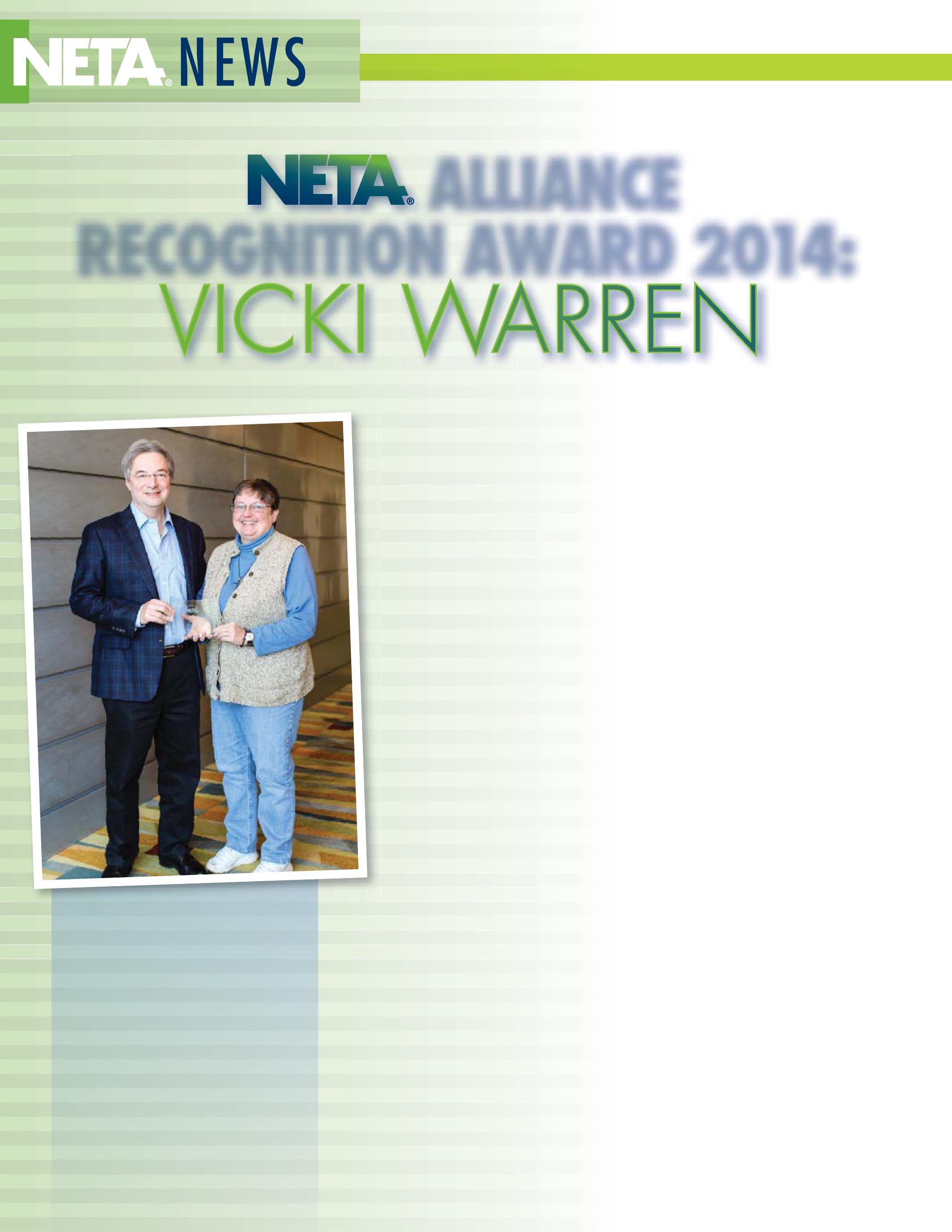
NETA Alliance Committee
Chairman Jim Cialdea with 2014 Alliance Recognition Award recipient, Vicki Warren.
BY RICHARD PIET, NETA“At NETA, we talk about the many programs that comprise the association as being the pillars that support the mission of the organization,” NETA President Dave Huffman said, introducing the 2014 recipient of the Alliance Recognition Award, Vicki Warren. “The technical pillars of the association are as strong as they are because of talented individuals like Vicki.” Each year, NETA seeks to spotlight an Alliance partner whose contributions have furthered the industry and inspired others to do the same.
A daunting task as the possibilities are many, but, considering the contributions and passion Vicki Warren brings to the table, Vicki makes for an excellent fi t.
“Th is year’s recipient has been a long standing supporter of NETA, and her presentations at PowerTest are always well received,” Huff man said. “As a regular contributor to NETA World, Vicki’s articles are lauded for being both technical and engaging.” NETA Executive Director Jayne Tanz agrees. “Vicki Warren is outstanding in her fi eld,” Tanz said. “She is always ready to assist and shares her knowledge with enthusiasm. NETA is fortunate to have her as an advocate. It is a sincere pleasure to have witnessed this award for Vicki. It is one well deserved.”
Vicki Warren has built her career on making connections and educating people about testing rotating machinery. As a senior product engineer for Iris Power LP, she is often on the road visiting fi rms where the testing and maintaining of rotating machinery is an ongoing process. “Customers are desperate for electrical testing experts who are qualifi ed
to work with rotating machines,” she writes while on a trip to the west coast. “[Th ey] need the help of NETA members.”
Vicki is passionate about forging strong working relationships between the end users and the individuals who service the equipment in an eff ort to bolster the overall health of the rotating machinery industry where she thinks it could use more support. “Right now, the need is being somewhat fulfi lled by the test instrument manufacturers, but the lack of long-term relationships and continuity have led to limited support,” she said. NETA Accredited Companies off er testing and maintenance services that fulfi ll the needs of many of Vicki’s clients.
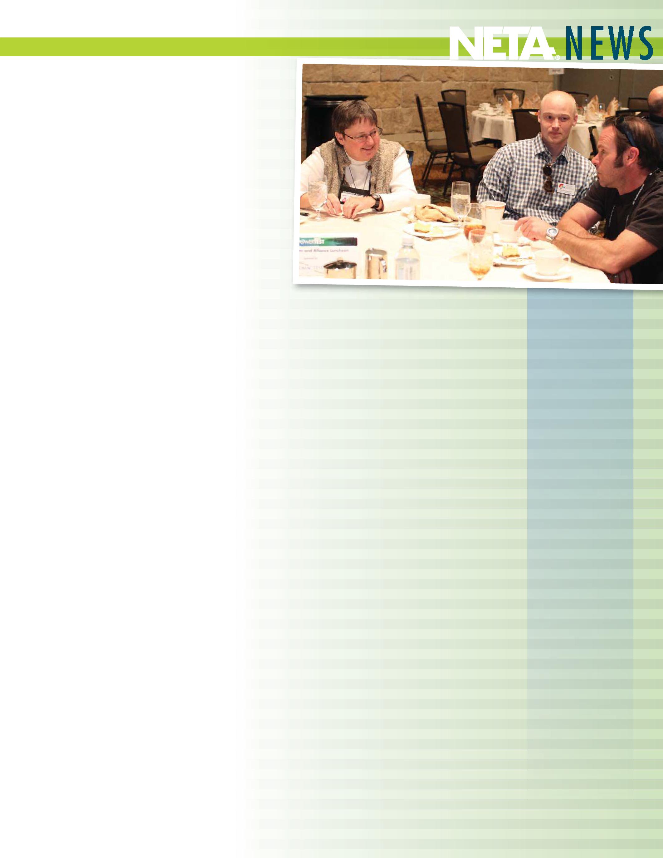
Just before espousing her passion for this segment of the industry during the technical presentations at PowerTest 2014, Vicki sat down at the NETA Member and Alliance Luncheon in Denver at PowerTest 2014 and shortly thereafter heard her name called as the recipient of the 2014 NETA Alliance Recognition Award. “I was defi nitely honored and humbled,” she said. “My goal has been to share my experiences and that NETA folks are interested is a humbling experience.”
And interested they are. Her years of field experience have resulted in a perspective that is appreciated by the audience of NETA World Journal who enjoy her regular contributions to the journal, sometimes more than one article per issue. This perspective comes from the first hand, ear-to-the-ground information gathering she has practiced in her travels to the front lines of testing and maintenance. “When I talk to a customer who is having problems with a rotating machine, I want to do two things: give them information they need to correctly evaluate their machines, and also link them to someone locally who can assist them with testing and evaluation,” Vicki said. She hopes her involvement with NETA helps fill the bill. “As I travel the world I hear from customer after customer how much help they need in testing their rotating machines.
If I can encourage NETA members to meet those needs, then the industry will benefit,” she said.
Vicki’s career began as a software code writer, where she wrote code to remotely control power plant facilities. “While troubleshooting control software, I learned to troubleshoot the relays and machines themselves. Using electrical tests to evaluate what was actually happening within the rotating machine’s cabinet became a passion,” she said. Much of her experience prior to joining Iris Power came from Vicki’s 13 years with the U.S. Army Corps of Engineers, where she was responsible for testing and maintenance of hydrogenerator windings, switchgear, transformers, and protection and control devices, among other things.
Vicki joined Iris Power LP in 1996 and has since been involved in using partial discharge testing to evaluate the condition of insulations systems used in medium- to high-voltage rotating machines, switchgear, and transformers. “I joined Iris Power where the focus was to share that knowledge with anyone who would listen throughout the world,” she said. She has worked extensively on the development and design of new products used for condition monitoring of insulation systems and is a past participant in the development of multiple IEEE standards and guides, having been chair of the IEEE 43-2000 Working Group.

Vicki continues working to inspire others to spread the word about the importance of maintenance and testing of rotating machinery as she has done over the years. She attended several sessions at PowerTest in Denver, including that of her Iris Power colleague John Letal: Optimize Stator End-Winding Vibration Monitoring with Impact Testing. “I’m here for moral support,” Vicki said of her attendance at the session. In between sessions she could be found working on one of her presentations or giving impromptu tutorials to eager conference goers during breaks between sessions. Her excitement and passion for her field are truly gifts, the kind that separate the great teachers from the good ones. She manages to present highly technical information in a very accessible manner to the benefit of all levels of expertise in the audience. If you haven’t yet had the pleasure of learning something from Vicki, it is something to work toward.
Rod Hageman, a technical editor of NETA World Journal remembers meeting Vicki in the audience of a panel he was moderating. “At first I thought Vicki was one of those people that liked to hear their own voice. Vicki had an answer for every question that came up. Then I started to realize that Vicki’s comments made very good sense and were coming from a very thorough knowledge of the subject matter. After the Panel was over I had the pleasure of talking with Vicki and convincing her that she should spread that knowledge and passion of the subject matter by writing a column for NETA World. We are all fortunate that she agreed to the request.”
When Vicki finds time to head home and turn her attention to leisure activities and other passions, she focuses on mission work with the persecuted by being active in her local church just outside of Nashville. She is an avid reader and a fan of Bluegrass music and loves hitting the road on her Honda Goldwing Trike. Vicki embodies the idea of living life to the fullest, and it is clear to see in all aspects of how she decides to spend her time, both professionally and personally. Her zest for life, passion for education, and pursuit of technical excellence are some of the reasons she is sought after as an instructor and author. She’s also a lot of fun if you’re just shooting the breeze. NETA is grateful for her willingness to share her time and talents with the organization and its patrons and looks forward to many more articles and presentations in the years to come.
Power System Acceptance Testing
Commissioning and Start-up
Maintenance
Life-Cycle Extension
Troubleshoot and Repair
Training and Engineering Services
Planning and Operations Support
Project Management
2200 West Valley Hwy North, Suite 100 | Auburn, WA 98001






 BY JEFF JOWETT, Megger
The previous column dealt with substation grounding and the function of the grid in limiting fault currents, dissipating lightning, and switching surges, enabling the proper function of overcurrent protective devices and equalizing potential around the substation so as to protect personnel.
Step and touch potentials were defi ned and reviewed in this context as well as the role of current, its eff ect on the human body, and its limitation. Protective structural features and design were described for establishing and ensuring redundant safety of workers in substation environs. Some additional detail with respect to equipment and connections and testing to assure eff ective function are now reviewed.
Th e independent standards authorities in this fi eld are the National Electric Code® (NEC®) and the National Electrical Safety Code (NESC). Th ey go into great detail to provide grounding requirements and applications. NEC Article 250-51, Eff ective Grounding Path , requires that the ground path from circuits, equipment, and enclosures shall be permanent and continuous, have suffi cient capacity to safely conduct any likely fault current, and have suffi ciently low impedance


to limit voltage to ground and facilitate operation of protective devices. System grounding connections are described in NEC article 250, Section K, Grounding Conductor Connections . Article 250-113 states that grounding conductors, bonding jumper connections to conductors and equipment must be connected by pressure connectors, clamps, or similar approved means. Solder connections are banned because the heat generated by fault currents will readily open solder connections and render them ineff ective. Article 250-115, Connection to Electrodes, completes the fault current path to ground by describing the connections to the grid. Grounding conductors are required to be connected by suitable lugs, pressure connectors, clamps, or other approved means. Th is may seem like a statement of the obvious. But it is all too easy, having completed the physical task of stringing conductors and completing the wire map, to fi nish the job


with an inadvertent connection method that will degrade and open during fault clearance, leaving the system dangerously exposed to voltage rise.
Verifying and maintaining a low impedance path as described by the NEC can be made easier by the use of a loop tester. Th is is a fairly simple handheld instrument that measures impedance around the entire electrical circuit to which it is connected. Th e test connection can be made by either a pair of alligator clips or by plugging into the relevant outlet. Th e test can be done either hot to ground or to neutral and is performed on an energized circuit. Depending on the hookup, the tester briefl y shorts the hot or neutral to ground. Don’t worry; breakers won’t trip. Th e test is completed so quickly (less than a cycle) that protective devices never see it. What is measured is the impedance of the circuit, all the way to the utility feed and back through the hot to the point of test. As the name indicates, this is an electrical loop test. It will not give the individual impedance of the grounding conductor by itself, as described in the NEC mandate, but if a comfortably low reading is shown for the entire loop, then the grounding conductor (or neutral, depending on test hookup) is substantially lower. If a high or suspicious reading is obtained, then the system needs to be investigated in more detail.
Th e NESC goes into greater detail in covering grounding methods. Section 9, Grounding Methods for Electrical Supply and Communication Facilities , provides practical methods of grounding. Sections 93.A, 93.B, and 93.E describe connection requirements. Joints must be made and maintained so as not to materially increase the resistance of the grounding conductor, as in 93.A. Th ey must have appropriate mechanical and corrosionresistant properties. Means of connection must be compatible with both the grounded and ungrounded conductor and suitable to prevailing environmental conditions, as described in 93.B. Th e requirements in 93.E.2 state that uninsulated joints and splices that
are to be buried should be welded, brazed, or compression type in order to minimize the possibility of loosening or corrosion.
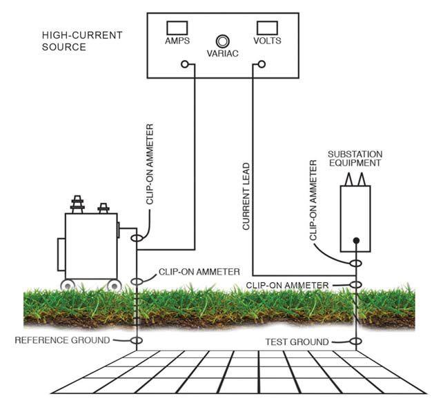
Note that while these requirements are most seriously considered at the time of installation, they are permanent and should remain in an effective condition throughout the life of the grid and conductors. While much of the structure is out of site, it can still be routinely tested by employing a high-current injection device and the use of a current clamp meter. Since the substation structure is intended to be maintained at equipotential, current distribution should be uniform. Any deviation indicates a diversion of current such as that caused by a poor connection (Figure 1). The technology is available to readily test and maintain a grounding system even on the below-grade level.
Th e connector must not be the weak



link in the grounding system. Accordingly, grounding connectors must meet three requirements:
• Ampacity is not less than that of the conductor.
• Do not deteriorate with age.
• Are able to withstand repeated faults.
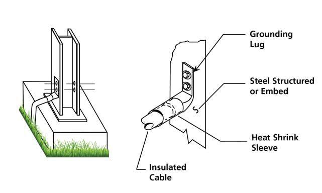
Th ere are two types of acceptable connections: exothermic and compression. Th ere are several types of pressure connectors, but those most used in utility grounding are crimptype compression connectors. Th e connector sleeve is crimped over the conductor by use of a crimping tool, either hand-operated, pneumatic, or hydraulic. Th e tool exerts a pressure that changes the shape of the connector, causing the conductor strands to fl ow into the serrations of the connector barrel, which then compresses around them. Th e result is a joint with good electrical continuity as well as mechanical strength (Figure 2).
A bit more involved to implement but also eff ective and durable is the exothermic weld (also known widely as Cadweld®). No outside source of heat or power is required. Powdered copper oxide and aluminum are placed in a graphite crucible that surrounds
the conductors to be joined and ignited with a fl int igniter. Th e two metals interact exothermically, releasing heat, and produce a molten copper and aluminum oxide slag (note the transfer of electrons and rearrangement of the chemical structure of the components). Th e molten copper fl ows over the conductors in the graphite mold, melting and welding them together (Figure 3). Th e resultant connection has good mechanical strength and electrical characteristics, and a current-carrying capacity equal to that of the conductors. It is a permanent molecular bond that cannot loosen or corrode. It will withstand repeated electrical faults and will not deteriorate with age.
Compression-type lugs are typically used for connecting copper grounding conductors and bonding jumpers to ground buses, equipment frames, metal enclosures, switchyard steel connections, and cable trays. Th ey are most commonly utilized in exposed areas. Th ey are standard power cable connections, in this case being utilized for grounding applications. Th ey are normally two-hole termination lugs, installed in accordance with manufacturer’s instructions. Lugs and connectors should be color-coded and crimp-type. Crimping tools and dies are either hexagonal or circumferential crimptype and color-coded with the connectors. Manufacturer’s instructions are followed in application of compression dies. Prior to crimping, the ground conductor should have all surface material removed and be wirebrushed to remove oxide. As compression connectors are tin-plated, no additional preparation of them is required. Install approved bolts, nuts, and washers. Outdoor applications require silicon-bronze hardware. Exothermic welds are typically specifi ed for below-grade, embedded (e.g., in concrete), building steel, and similar connections that are inaccessible or demand a high degree of reliability. Th ey include cable-to-cable and cable-to-ground rod splices, cable-tobuilding steel, and cable lug terminations.
Additional safety considerations involve surface resistivity, operating handles, and fences. Resistivity of the substation surface is maintained at a high value. Th is is important in reducing step and touch potentials. Th e earth surface is covered by a four to six inch layer of crushed rock, which typically has a resistivity around 500,000 Ω∙cm. Th ere must be no intrusion of underlying earth into the rock, nor contamination such as tracking of soil by vehicles. Mixing of the rock layer with earth lowers overall resistivity and diminishes the rock layer’s protective value. Operating handles for disconnecting switches can be particularly dangerous. Augmented protection is in order, such as that provided by a mat of conductors or mesh covering the area where the person stands and connected directly to the operating handle. A diagram of this solution was presented in Substation Grounding and Personal Safety , NETA World , Spring 2014. Fences can present a hazard to passersby from the general public. Th e ground grid can be extended outward to include the fence or a conductor can be buried one meter under or outside the fence and connected to the grid.
Adherence to the well-established design principles and considerations described here will assure that the grounding system is safe upon installation; however, for the reasons listed above, a substation grid is subject to considerable trial and stress. Routine testing should be implemented to make sure that the grid retains its full protective capabilities. Two specialized tests have already been discussed above. For the most basic function, resistance to remote earth, there are fi ve tests commonly employed: fall-of-potential method, simplifi ed fall-ofpotential method, two-point method, slope method, and intersecting curves method. All of these have been previously described in detail in editions of NETA World . Th e fallof-potential method is the most thorough, rigorous, and reliable method. It takes time and is somewhat labor intensive. Th e simplifi ed fall-of-potential method relieves
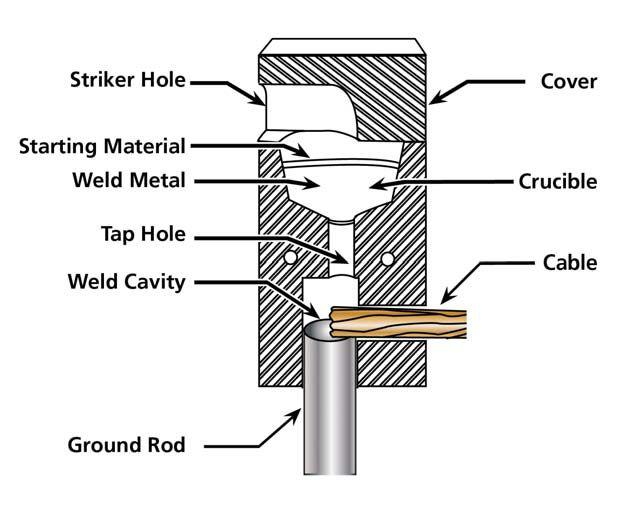

some of the work required, but substitutes a mathematical proof of results. Th e slope method is the most commonly employed for large grids that would otherwise demand too much space for a fall-of-potential test to yield the requisite readable graph. Th e intersecting curves method is the most labor intensive of all but can be used for sites where space is so tight that even the slope method cannot be used. Finally, the two-point, or dead earth , method provides a quick and easy backup test where nothing else works, but is neither rigorous nor thoroughly reliable.


Jeffrey R. Jowett is a Senior Applications Engineer for Megger in Valley Forge, Pennsylvania, serving the manufacturing lines of Biddle, Megger, and multiAmp for electrical test and measurement instrumentation. He holds a BS in Biology and Chemistry from Ursinus College. He was employed for 22 years with James G. Biddle Co. which became Biddle Instruments and is now Megger.






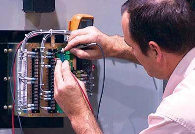


 BY DON GENUTIS, Halco Testing Services
This article expresses the author’s experience-based opinion of the best technologies available that provide the most useful information related to equipment condition for the best value. These best bang for the buck technologies are must haves to be included in every electrical maintenance testing program and will go a long way toward preventing an electrical bang.
Obtaining an outage is costly, so it is not surprising that no-outage testing techniques lead the way. Listed below are the five best tests and why they provide the best return on investment.
These often overlooked inspections are very inexpensive to perform, but they can provide a great deal of information related to equipment condition. The inspections are very safe and relatively easy to conduct, but they are typically limited to what can be viewed externally. Permanently mounted instrumentation, even in the form of simple gauges, can often provide information related to internal equipment conditions.
Nonintrusive partial discharge surveys of medium-voltage switchgear can efficiently detect a multitude of problems long before complete failure occurs, allowing precious time to schedule repairs. Partial discharge surveys are relatively inexpensive to perform and should be conducted annually. The only drawback for this technology is that it is not effective on low-voltage equipment.


Over many years this technique has evolved from testing the condition of the fluid by determining its electrical, mechanical, and


chemical characteristics to determining the condition of the transformer itself by dissolved gas analysis. This technology can arguably be ranked as number one. Where else can a two hundred dollar test be relied upon to assess the condition of an expensive piece of equipment? However, the test is not completely nonintrusive and does introduce some personnel risk when performing sampling when the transformer is energized.
A great deal of information related to the mechanical operation, and thus the electrical performance, of any circuit breaker can be derived by techniques based upon applying accelerometers to the breaker during operation to record timing and operation signature. The resulting data can then be used to calculate first trip time and to spot mechanical anomalies that affect breaker operation. The test is inexpensive, but it provides a good indication of breaker condition. The drawback is that the test requires tripping the breaker which of course takes it off-line, as does almost all breaker tests.
inexpensive test that can detect termination and splice problems which contribute to the majority of cable system failures. The drawback to this test is that it does not apply to low-voltage cables and requires stringent safety precautions.
Like visual inspections and PD surveys, RFI surveys of outdoor substations can cover a lot of ground in a short period of time. With a main substation, which may be the sole distribution bottleneck to an entire facility, the value of detecting an anomaly safely and nonintrusively while the equipment remains in service is a big reward. However, the technology is limited to outdoor open bus substations and switchyards.

This is a very good test that covers a lot of ground and is a favorite of facility insurers. The survey itself is less efficient and provides greater personnel risk due to necessary panel cover removal. This technique could be safer if infrared inspection windows are installed.
The following two technologies didn’t make the top five but are still worthy of mentioning.
There is a massive amount of aging medium voltage cable in service throughout our country and a much of it has never been tested. Online partial discharge testing while the system remains energized is a relatively efficient and


While reviewing the above list of technologies, it can quickly be seen that although all items listed provide great potential ROI, it is also apparent that each technology has unique strengths and weaknesses. These considerations must be carefully taken into account when developing an effective maintenance testing program. In addition to these technologies, traditional and more thorough outage-based testing and maintenance procedures, which address a much greater level of detail and ensure proper mechanical operation, must be included in any maintenance testing program for it to be effective.




Don A. Genutis holds a BSEE from Carnegie-Mellon University. He has over 30 years of electrical testing experience. Don serves as President of Halco Testing Services based in Los Angeles, California.


Vanguard’s precision substation testing instruments are designed to be intuitive and easy to use so that you can focus on testing instead of wasting time in training. Our versatile instruments offer a built-in thermal printer and on-board test record storage so that tests can be conducted in stand-alone mode in the field. A computer interface is also offered so that tests can be easily conducted from a PC.
And all of our instruments are competitively priced to provide cost-effective accuracy. For a virtual experience of our instruments, check out the interactive demos on our site at:
www.vanguard-instruments.com/demos

BY KRISTEN WICKS, NETA
“The best way to find your self is to lose yourself in the service of others.” – Mahatma Gandhi
Each year, NETA’s members are presented with a slate of nominees for the various offices within the association that present offices with terms up for renewal as well as to fill the spaces of those who are exiting a term of office. This process takes place during the NETA Membership Meeting preceding PowerTest each year. This meeting typically hosts the greatest representation of NETA Accredited Companies, presenting the greatest opportunity for members to have a voice.
Every so often a member will exit the Board of Directors, prompting the decision to make a new addition to the board. Walt Cleary, Burlington Electrical Testing Co., Inc., stepped away from his seat on the Board of Directors as of May 31, 2014. Walt has served on the NETA Board of Directors since 2008 and as the secretary since 2010. NETA extends its sincerest gratitude to Walt for his years of service to the organization and is thankful that he will continue to remain active in the association as the Accredited Representative for Burlington Electrical Testing Co., Inc. as well as part of the Membership Application Review Committee.
With Walt’s departure from the board, NETA welcomes Lorne Gara, Technical Manager for Orbis Engineering, as its newest board member. Lorne was elected to the Board of Directors in March of 2014, and his term officially began on June 1, 2014. Lorne has become increasingly involved in the technical business of the association since Orbis Engineering became accredited in 2005. He participates on the Member Application Review Committee and joined the NETA Standards Review Council in 2013. The board is pleased to welcome Lorne to the table and looks forward to his continued involvement in the leadership of the organization.
NETA’s reputation as the leader in electrical testing and maintenance is forged by our NETA Accredited Companies and the individuals who step up to help form and shape the organization in these key positions. It is both inspiring and energizing to witness people so passionate about their vocation that they dedicate their personal time to bettering the world around them. Thank you, Lorne and Walt, for your commitment to serve and for helping make NETA what it is today.
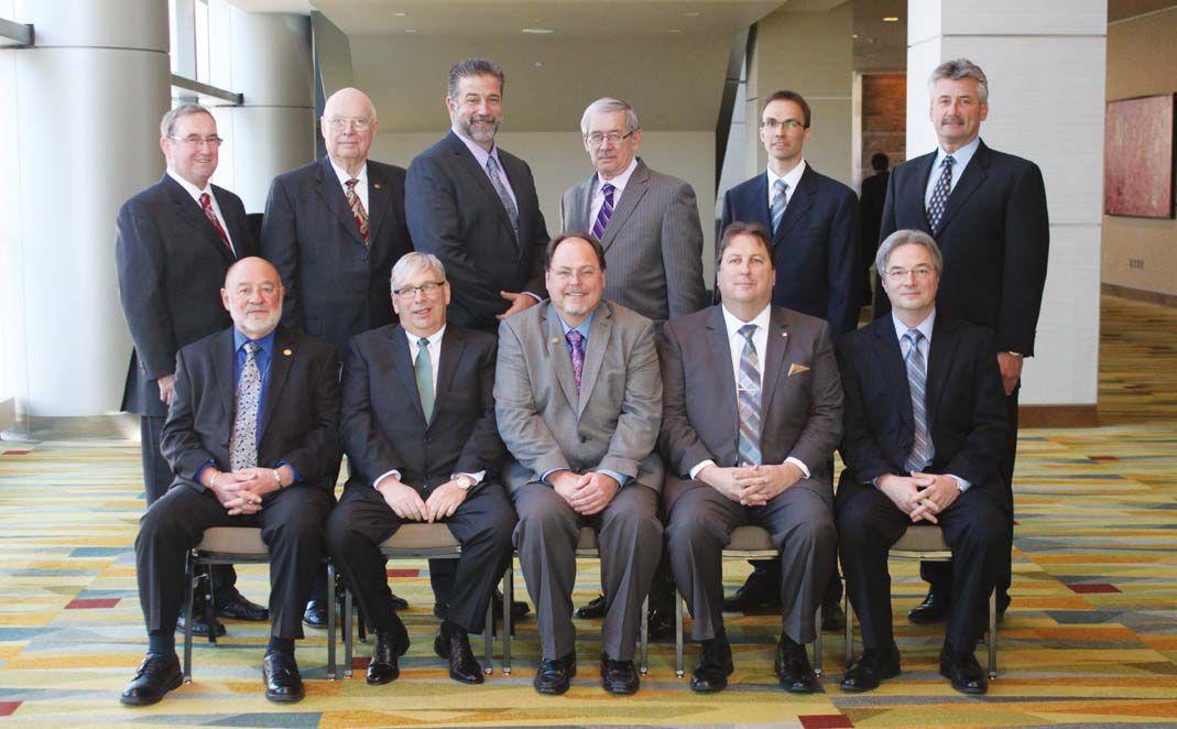

 Front Row: Mose Ramieh, Scott Blizard, Dave Huffman, Ron Widup, Jim Cialdea
Back Row: John White, Al Peterson, Bob Sheppard, Rod Hageman, Lorne Gara, Ken Bassett
Walt ClearyLorne Gara

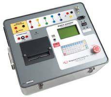


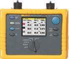

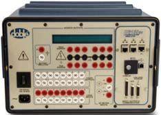


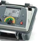

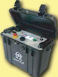


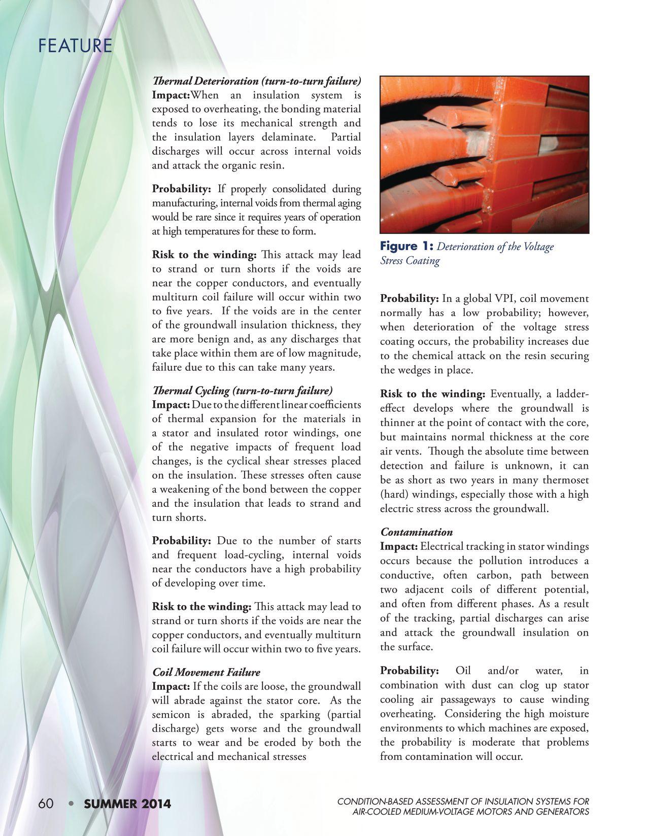
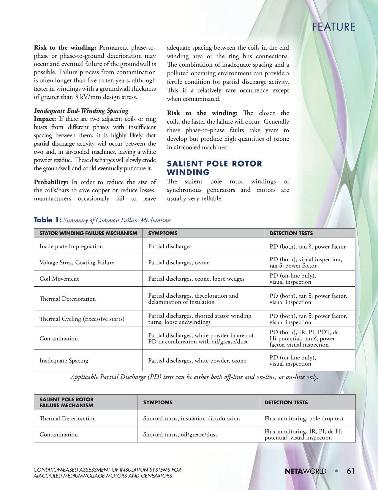
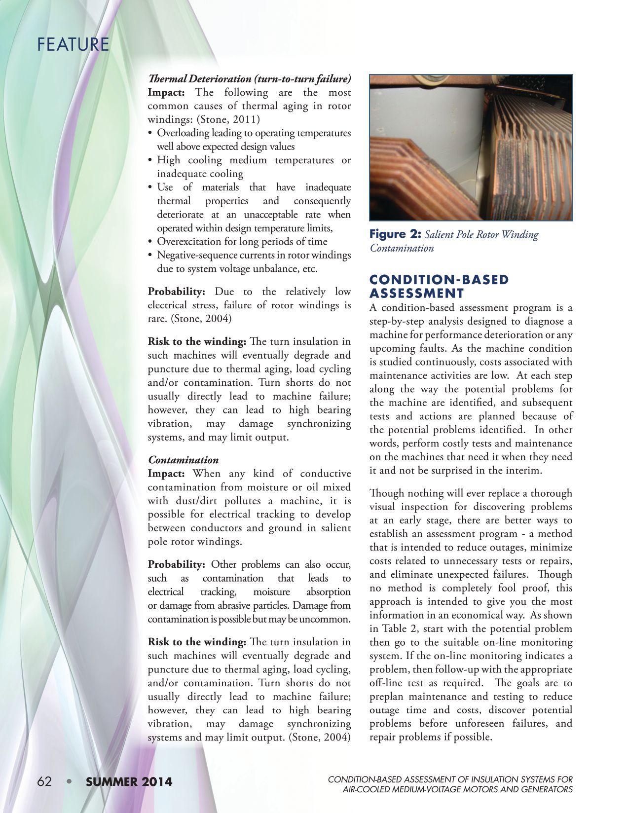
Potential Problem
Stator Winding Groundwall Delamination and Separation from Conductor Stack (high risk of shorted turns in stator winding)

On-Line Monitoring
Off-Line Testing Technique
PD Monitor (IEEE 1434) (IEC 60034-27-2)
NETA WORLD Winter 2012, Spring 2013
(Negative PD predominant)
Coil Movement (high risk of damage to groundwall insulation)
PD Monitor (IEEE 1434) (IEC 60034-27-2)
NETA WORLD Winter 2012, Spring 2013
(PD increases with load)
Advantages and Disadvantages Tests
Advantages:
• In-service voltage distribution in windings
• Determines the effects of temperature on voids in winding
• Increase in number and size of voids can be determined by trending
Disadvantages:
• Does not indicate how general the problem is
Advantages:
• Effects of load variations on PD levels can be determined
• Condition can be trended to determine if it is getting worse
Disadvantages:
• Requires installed sensors and signal processing
Off-line PD (IEEE 1434) (IEC 60034-27)
NETA WORLD Spring 2014
Dissipation Factor
Power Factor (IEEE 286)
Visual Inspection
Advantages and Disadvantages
Advantages:
• Results of PD, dissipation factor and power factor can be trended to determine if the groundwall delamination is becoming more severe
Disadvantages:
• Whole winding is raised to the same voltage so voltage distribution is different from that in service. Thus for PD test on- and off-line values cannot be directly compared.
Advantages:
• Determines the exact location of the winding looseness
Disadvantages:
• Requires machine shutdown, opening up, and perhaps a rotor pull
• Ineffective for global VPI windings
• Difficult to determine what is really loose
Voltage Grading Coating Deterioration (moderate risk – but may lead to coil movement)
PD Monitor (IEEE 1434) (IEC 60034-27-2)
NETA WORLD Winter 2012, Spring 2013
(PD influenced by humidity, but NOT load)
Shorted rotor winding (moderate risk for failure – but may lead to high vibration)
Flux Monitor
NETA WORLD Fall 2013
(Decreased flux in shorted turns)
Contamination (low risk for failure but can accelerate aging)
PD Monitor (IEEE 1434) (IEC 60034-27-2)
NETA WORLD Winter 2012, Spring 2013
(PD influenced by humidity and erratic patterns)
Advantages:
• Effects of temperature and humidity on semicon and grading materials performance can be determined
• Condition can be trended to determine if it is getting worse
Disadvantages:
• Requires installed sensors and signal processing
Advantages:
• Effects of load variations on PD levels can be determined
• Condition can be trended to determine if it is getting worse
Disadvantages:
• Requires installed sensors and signal processing
Advantages:
• Effects of temperature and humidity can be determined
• Condition can be trended to determine if it is getting worse
Disadvantages:
• Requires installed sensors and signal processing
Dissipation Factor
Power Factor (IEEE 286)
Off-line PD (IEEE 1434) (IEC 60034-27)
NETA WORLD Spring 2014
Pole Drop Test
NETA WORLD Summer 2013
Advantages:
• Exact location of the problem can be determined
Disadvantages:
• Requires machine shutdown, opening up and perhaps a rotor pull
Advantages:
• Exact location of the problem can be determined
Disadvantages:
• Requires machine shutdown, opening up
IR/PI/PDT
NETA WORLD Winter 2011, Spring 2012, Spring 2014
Dissipation Factor
Power Factor (IEEE 286)
Off-line PD (IEEE 1434) (IEC 60034-27)
NETA WORLD Spring 2014
Advantages:
• Can determine conductivity of contaminant
Disadvantages:
• Requires machine shutdown, opening up and perhaps a rotor pull
• Cannot evaluate the impact of ambient conditions on results
Inadequate spacing (rare occurrence with low risk of failure unless severely contaminated)
PD Monitor (IEEE 1434) (IEC 60034-27-2)
NETA WORLD Winter 2012, Spring 2013
(PD based on phase-tophase voltage)
Advantages:
• Measure at phase-to-phase voltage stress
• Condition can be trended to determine if it is getting worse
Disadvantages:
• Requires installed sensors and signal processing
Visual Inspection
Advantages:
• Determines the exact location of the winding looseness
Disadvantages:
• Requires machine shutdown, opening up and perhaps a rotor pull
• Difficult to locate due to accessibility





THIRD-GENERATION MAC-TS4 VACUUM INTERRUPTER TEST SET NOW WORKS WITH YOUR PC TO SIMPLIFY TEST REPORTS AND ASSET MANAGEMENT
• WORLD’S FIRST VACUUM INTERRUPTER TEST SYSTEM C APABLE OF P REDICTING REMAINING LIFE
• WORLD’S FIRST TEST SYSTEM CAPABLE OF TESTING VACUUM INTERRUPTERS IN BOTH THE SHOP AND FIELD
• BASED ON SAME OEM LEAK-RATE TEST PERFORMED AT THE FACTORY
• ME ASURES ACTUAL ION CURRENT AGAINST KNOWN VALUES TO DETERMINE VACUUM INTERRUPTER INTERNAL PRESSURE





The multi-functional measuring system SHERLOG CRX captures and analyzes all the processes in an electricity supply system precisely and reliablyeven under extreme conditions!
Digital fault recorder
Impedance-based fault locator
RMS recorder
Continuous data recorder
Power quality analyzer
Phasor measurement unit
Event recorder
Sequence of events recorder
Real-time monitoring system

This paper covers practical considerations for proper application and commissioning of this special protection. The total capacitance to ground of the generator stator windings, bus work, and delta-connected unit transformer windings is a very important factor as will be shown. This protection can:
• Detect a stator ground when the winding insulation first starts to break down and trip the unit before catastrophic damage occurs
• Be set to trip in the order of cycles since the 20 Hz signal is decoupled from the 50 or 60 Hz power system
• Detect grounds close to the machine neutral or even right at the neutral thus providing 100 percent coverage of the stator windings
• Detect grounds when the machine is starting up or offline
• Reliably operate with the generator in various operating modes such as a synchronous condenser and at all levels of real and reactive power output.
Special steps should be taken in the design of this protection as there are cases when it is difficult to distinguish between normal
operating conditions and an actual ground fault. The protection must reject fundamental frequency (50 or 60 Hz) voltage and current signals that are present during ground faults on the stator windings. A real life example for a pump storage facility is included.
In-service stator winding failure to ground is a common generator failure, and there are many possible causes such as mechanical damage to the ground wall insulation (category #1) and fracturing of the current carrying conductor that result in the ground wall insulation burning away (category #2).
Examples of category #1 failures:
• ground wall insulation wear-through from a foreign object or loose component


• fracture of the ground wall due to a sudden short circuit
• deficient ground wall insulation system
• partial discharge combined with vibration
• vibration sparking, inadvertent damage during maintenance
• wet insulation due to strand header water leak, bar vibration in the slot
Examples of category #2 failures:
• fracture of stator bar copper conductors due to high cycle fatigue associated with vibration
• fracture of bar copper due to gross overheating of the copper
• core iron melting, failure of a bolted connection
• failure of a brazed or welded joint
• failure of a series or phase connection

Category #1 failures are typically benign, unless a second ground occurs, in which case there is massive arcing. Category #2 failures are always highly destructive to the generator. Current will temporarily continue to flow uninterrupted within the stator bar ground wall insulation (i.e., welding arc) when a conductor breaks and the heat generated is extremely high. This current will flow inside the insulation until it is mechanically destroyed. Experience has shown that the copper is vaporized for perhaps 8 to 12 inches before the internal arcing breaks through the insulation wall and arcs to ground as shown in Figures 1-3.

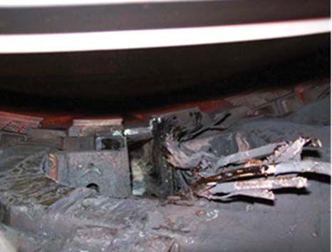
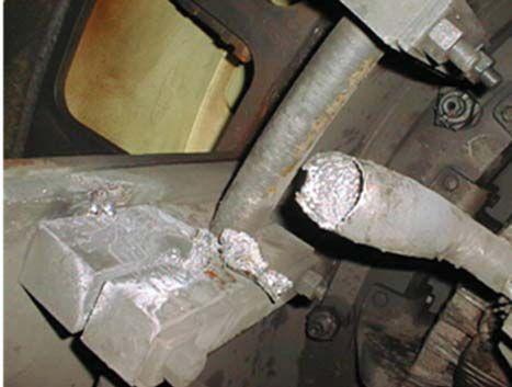

Conventional neutral overvoltage protection (59N) cannot detect grounds in the last 5 to 10 percent of the stator winding. If a failure occurs in a lower voltage portion of the winding near the neutral, a generator trip will not typically occur until some other relay protection detects there is a problem, (e.g., arcing becomes so widespread that other portions of the winding become involved). There has been recent experience with four such failures in large generators that demonstrate the lack of proper protection can be disastrous. Each of the four failures caused massive damage
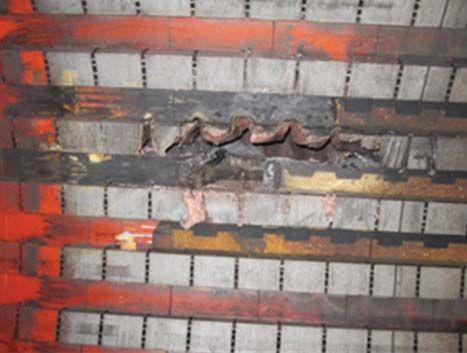

to the generator and collectively had a total cost, including repair and loss of generation, close to $500,000,000 1 . This demonstrates that failure of stator windings in the last five percent of the winding is not uncommon.
One hundred percent stator ground fault protection is provided by injecting a 20 Hz voltage signal (64S) into the secondary of the generator neutral grounding transformer through a band-pass filter. The band-pass filter passes only the 20 Hz signal and rejects out of band signals. The main advantage of this protection is it provides 100 percent protection of the stator windings for ground faults–including when the machine is off-line (provided that the 20 Hz signal is present).
Figure 4 illustrates a typical application. A 20 Hz voltage signal is impressed across the grounding resistor (R N) by the 20 Hz signal
generator. Th e band-pass fi lter only passes the 20 Hz signal and rejects out of band signals. Th e voltage across the grounding resistor is also connected across the voltage input (V N) of the 64S function. The current input (IN) of the 64S function measures the 20 Hz current flowing on the secondary side of the grounding transformer and is stepped down through a CT. It is important to note that the relay does not measure the 20 Hz current flowing through the grounding resistor; it measures the 20 Hz current flowing into the power system. The 20 Hz current magnitude increases during ground faults on the stator winding and an overcurrent element that operates on this low frequency current provides the protection.


The following method shows how to calculate the 20 Hz voltage and current measured by the 64S function.
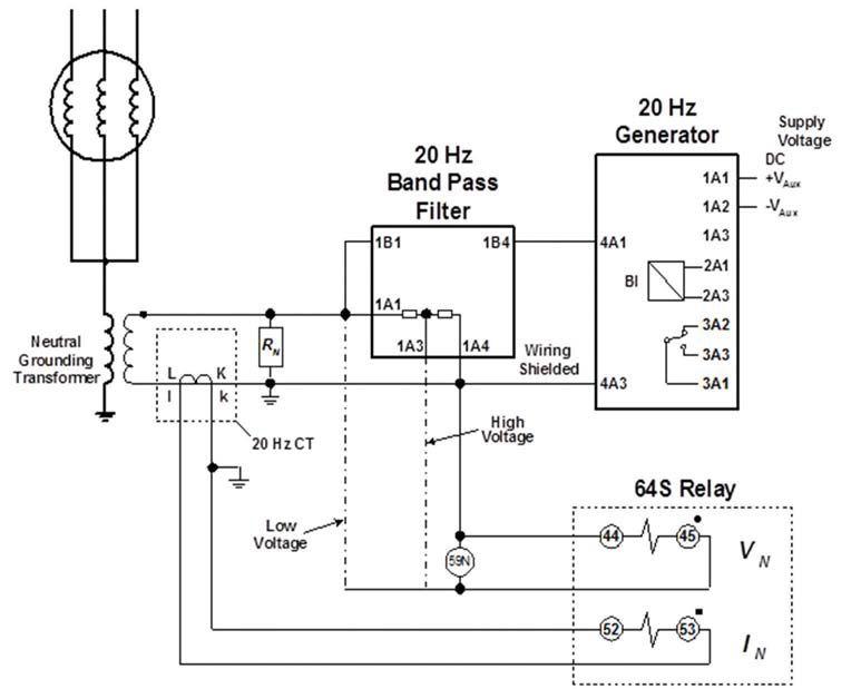


Grounding Transformer Turns Ratio (N)
Assume that the turns ratio of the grounding transformer is equal to: (1) N = 8,000 240
Capacitive Reactance
The total capacitance to ground of the generator stator windings, bus work, and delta connected transformer windings of the unit transformer is expressed as C0. Generator step up transformers have delta connected windings facing the generator so capacitance on the high side is ignored. The corresponding capacitive reactance is calculated as follows:
X CO = 1 2 fo C o (2)


Assume the capacitance to ground is 1 microfarad:
X CO = 1 2 • • (20 Hz ) • (10 6 F ) = 7,958 primary
Refl ect the capacitive reactance to the secondary of the grounding transformer:
X CO = 7,958 N 2 = 7,958 8,000 240 ()2 = 7.162 secondary
Grounding Resistor (RN)
Th e ohmic value of the grounding resistor can be sized as follows so as to avoid high transient overvoltage due to ferroresonance 2:
R N = X c 0 3 (3) R N = 7.162 sec 3 = 2.387 secondary
A value of 2.5 ohms secondary is used for this example.
The 20 Hz signal generator output is 25 volts RMS and the band-pass filter has a resistance equal to eight ohms.
Vsource = 25 0° volts (4)
R Filter = 8 secondary (5)
Stator Insulation Resistance (RS)

RS is the total insulation resistance from the stator windings to ground. A typical value for nonfault conditions is 50,000 ohms primary. Reflect the insulation resistance to the secondary of the grounding transformer. R s = 50,000 pri N 2 = 50,000 pri 8,000 240 ()2
= 45 secondary
Current Transformer
Th e current input (I N) of the 64S function measures the 20 Hz current fl owing on the grounded side of the grounding transformer and is stepped down through a CT.

CTR = 400/5 = 80/1 (6)
These are all of the elements needed to mathematically derive the grounding network and determine the 20 Hz signals measured by the 64S function. Figure 5A shows the insulation resistance and the stator windings referred to the primary of the grounding transformer. Figure 5B shows the insulation resistance and the stator windings reflected to the secondary of the grounding transformer.


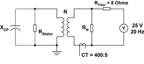
Figure 5A: 20 Hz Grounding Network – Referred to Grounding Transformer Primary
XC = total capacitance to ground
R stator = stator insulation resistance to ground
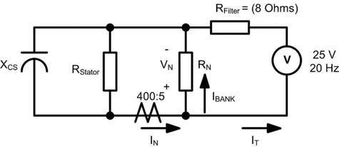
Figure 5B: 20 Hz Grounding Network – Reflected to Grounding Transformer Secondary
RN = neutral resistor
RFilter = band-pass filter resistance
VN = voltage drop across RN

20 Hz Current (IN) Measured by 64S Function
The current input (IN) of the 64S function measures the 20 Hz current flowing in the secondary of the grounding transformer and is stepped down through a CT. As noted previously the relay does not measure the 20 Hz current flowing through the grounding resistor.
Total 20 Hz Current Supplied by Signal Generator – The 20 Hz signal generator looks into the band pass filter resistance (RFilter) which is in series with the parallel combination of the following: • ZCO • Rs • RN
Therefore, the total loop impedance of the 20 Hz grounding network can be expressed as follows:
• RS • Z CO
+ Z CO
T = R Filter +
+ RS • Z CO
+ Z CO (7)
IN = current from system
IBANK = current flow in RN
IT = IBANK + IN
T = 8 + 2.5 () //45() // 7.162j () = 10.135 – 0.706j secondary
The total 20 Hz current supplied by the signal generator is determined as follows:

20 Hz Current Measured by 64S Function (I N ) during Nonfaulted Conditions
The 20 Hz current measured by the 64S function is the ratio of the total current that flows into the primary side of the grounding network ( Z C O //R s ):


= 9.779 mA Nonfaulted ()
20 Hz Current Measured by 64S Function (I N ) during Ground Fault on Stator Windings
A typical value to represent the insulation resistance of the stator windings when it is breaking down during a ground fault is 5,000 ohms primary. If the calculations for equations 7 through 9 are repeated for a fault resistance equal to 5,000 ohms primary (4.5 ohms secondary), then the 20 Hz current measured by the relay is as follows:

R S (primary)|I N| (secondary)
50,000 Ω9.779 mA
5,000 Ω13.486 mA
1,000 Ω26.640 mA
Here are three important aspects to consider when applying 100 percent stator ground fault protection by 20 Hz injection:
• slight change in fault current measured by relay
• rejection of fundamental frequency (50 or 60 Hz) voltage and current signals
• under-frequency inhibition
|IN| = 13.486 mA (5,000 ohm primary ground fault)
If the calculations for equations 7 through 9 are repeated for a fault resistance equal to 1,000 ohms primary (0.9 ohms secondary), then the 20 Hz current measured by the relay is as follows:
|IN| = 26.640 mA (1,000 ohm primary ground fault)

Table 1 summarizes the 20 Hz current measured by the relay for nonfaulted and faulted conditions. Often the 64S protection can detect the ground for insulation resistance is much higher than 5,000 ohms primary.

A very large capacitance to ground (C0) coupled with a small value for the grounding resistor (RN) can result in very little margin between the fault and nonfault current measured by the 64S function. Generator windings and isophase bus work (see Figure 6) are both sources of high capacitance to ground (ex., a long run of bus from the generator to the step-up transformer).

The 64S function can easily distinguish between nonfault and stator ground faults for this example. Set the pickup of the 64S, 20 Hz tuned, overcurrent element above the current measured during normal operating conditions but below the current measured for a stator ground fault equal to 5,000 ohms primary.

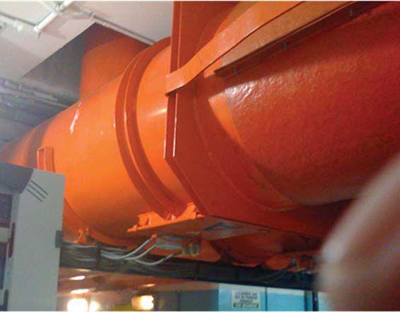

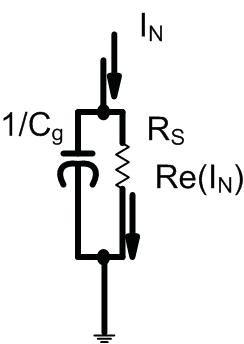
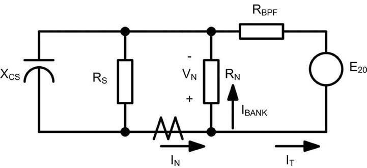

Figure 7 illustrates why there is not a significant change in the magnitude of the total neutral current when there is high capacitance. If the capacitive reactance is low enough, then only a small portion of the total neutral current flows through the insulation resistance. To overcome this challenge, calculating the real component of the total neutral current can reliably detect a stator ground fault for such a system.
Consider the following grounding network parameters:

C 0 = 10μF Z CO = -0.716j secondary
R N = 0.25 secondary
Determine the 20 Hz current measured by the 64S function for nonfaulted and stator ground fault conditions using the equations presented in the previous application section as shown in Table 2 below.
Table 2: 20 Hz Current Measurements for High Capacitance
8: Current Flow in Secondary Network R S (primary)|I N| (secondary) 50,000Ω12.465 mA
The 64S 20 Hz tuned overcurrent element pickup cannot be set such that it reliably discriminates between nonfaulted and stator ground fault conditions. The solution is for the relay to calculate the real component of the 20 Hz current with respect to the neutral voltage. To do so, first determine the 20 Hz voltage measured by the relay voltage input (VN). The 20 Hz voltage is equal to the drop across the grounding resistor due to the portion of the total current flowing through this branch of the grounding network (i.e., IBANK). Use Figure 8 above to determine the corresponding equations (10 – 13).
20 Hz Current Flowing through the Grounding Transformer
IBank = IT – IN (10)

20 Hz Voltage Drop Across the Grounding Resistor
VN = IBank•RN (11)

Real Component of 20 Hz Current Measured by 64S Function
Calculate the real component of the relay current based upon the angle between the relay neutral voltage (VN) and current (IN) as shown in Table 3. = VN IN (12) IReal = IN i COS( ) (13)

Table 3: 20 Hz Current Measurements for High Capacitance Including Real Component
R S (primary) |I N| (secondary) R e ( I N)
50,000Ω12.465 mA0.198 mA
5,000Ω12.096 mA1.900 mA
1,000Ω12.863 mA8.001 mA

A 20 Hz tuned overcurrent element that operates on the real component of 20 Hz current measured by the 64S function can reliably distinguish between nonfaulted and stator ground fault conditions when there is high-capacitive coupling to ground on the stator winding. A good rule of thumb is to use the real component of 20-Hz current for sensitive protection if C0 is greater than 1.5 microfarads and the grounding resistor is less than 0.3 ohms secondary. The user can follow the commissioning instructions that appear at the end of this paper to determine the total capacitance to ground (C0). If the values for RN and C0 do not clearly fall under the category defined by this rule of thumb, then use the equations provided earlier in this paper to determine if use of the real component of neutral current is necessary.
NOTE

Figure 9 illustrates the fundamental voltage drop (50 or 60 Hz) across the grounding resistor as a function of the ground fault location along the stator windings. Table 4 shows the voltage drop as the fault location moves from the neutral end of the stator windings to the output terminals. Th egrounding transformer is rated 110 volts secondary; the grounding resistor is sized 0.32 ohms secondary; and the CT ratio is 400:5 (80:1). Th e corresponding fundamental component circulating current is shown as well. If the fundamental current is not well rejected, then high magnitude circulating current can saturate the neutral current input and, as a result, the protection will measure a value of 20 Hz current less than the actual value. Saturation causes the following problems:

• delayed operation or, even worse, no operation at all
• less than 100% coverage of the stator windings as the ground fault location moves towards the generator output terminals.

NOTE
Saturation is most likely to occur when the grounding resistor is sized less than one ohm secondary.
If the 64S function uses the real component, it should also use the total neutral current as a backup for the case of a solid short circuit located right at the machine neutral (i.e., the real component equals zero for this case since there is no reference voltage).
Rejection of Fundamental Frequency (50 or 60 Hz) Voltage and Current Signals
Fundamental component voltage and current present at the relay measuring inputs during stator ground faults can prevent the 64S function from operating properly unless they are well rejected. Note that these signals are not eliminated by the band-pass filter since they are due to the fundamental voltage drop across the secondary of the grounding transformer.
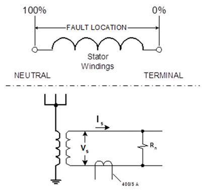


9: Fundamental Voltage across RN as Function of Ground Fault Location


Table 4 provides magnitudes of the variables at various fault locations along the winding.
Underfrequency Inhibition
Sometimes it is necessary to block the 64S function during conditions such as startup when the system voltage measured by the relay is 40 Hz or lower. Th e third harmonic of 7 Hz is very close to 20 Hz during startup when the generator is transitionally through the lower frequencies and can cause unwanted operation.
Figure 10 illustrates how to configure the 64S protection for commissioning.

NOTE
Use the 20 Hz signals captured during normal operating conditions to determine appropriate overcurrent pickup settings. Determine the
total capacitance to ground and calculate the overcurrent pickup setting based upon these field measurements as a check.
Stator Ground Fault at Machine Neutral Configure the power system as follows:
• High side breaker is open.
• Th e generator is offl ine.
• Generator terminals are connected to delta windings of the generator step up transformer.
• Switch F 1 is closed.
• Switch F 2 is open.
• 20 Hz signal generator is online.

Place a single line-to-ground fault at location F 1 (switch F 1 closed) and measure the 20 Hz I N. Th is measurement corresponds to a short circuit applied at the neutral of the machine (see Figure 11 on the following page).
Th e total 20 Hz neutral current (I N) should be very close in magnitude to 39 mA.


I sc = 25
8 ohmsX 400 5 = 39 mA
NOTE
This is the first step and is a quick check to see if all the wiring is correct.
Normal Operating Conditions
Configure the power system as follows:
• High side breaker is open.
• Generator terminals are connected to delta windings of the generator step up transformer.

• Switch F1 is open.
• Switch F2 is open.
• 20 Hz signal generator is online.
• Preferably the generator is online.
Measure the following 20 Hz signals:
• VN (neutral voltage)
• IN (neutral current)
• Re(IN)(real component of neutral current)
These signals correspond to normal operating conditions.
VN and IN are the 20 Hz signals applied to the relay inputs. Record VN, IN, and Re(IN). Modern numerical generator relays can meter these values. The signals recorded in Figure 11 were captured while commissioning a large pumped storage hydroelectric unit while operating in the motoring (pumping) mode.

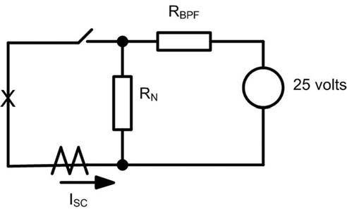

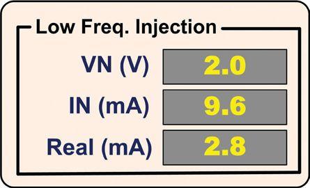


This special protection provides 100 percent coverage of the stator windings for ground faults under all operating conditions including variable real and reactive power output and when off-line. Grounds on the last five percent of the stator windings do occur and can be disastrous if not quickly detected. Traditional protections (59N, 27TH, 27D) may not reliably operate for faults in the last five percent of the stator winding.
The total capacitance-to-ground of the generator stator windings, bus work, and delta-connected unit transformer windings is a very important factor and must be known to ensure the protection settings are correctly determined. This value can be determined during commissioning.
There are cases when it is difficult to distinguish between normal operating conditions and an actual stator ground fault unless special steps are taken in the design of this protection. A good rule of thumb to decide if the real component of 20 Hz current is necessary is when C0 is greater than 1.5 microfarads and the grounding resistor is less than 0.3 ohms secondary. Use the real component of the 20 Hz current measured by the relay for these cases.
The protection must reject fundamental frequency (50 or 60 Hz) voltage and current
signals that are present at the relay measuring inputs during ground stator ground faults.
Use an under-frequency element that operates on the system voltage to block the 64S function if nuisance tripping occurs during either startup or shutdown of the generator.
1. Maughan, Clyde V., “Stator Winding Ground Protection Failures”, ASME POWER 98151-2013
2. Macon, Russell C., “The Art and Science of Protective Relaying”, Wiley 209-210, 1956



Steve Turner is a Senior Applications Engineer at Beckwith Electric Company, Inc. His previous experience includes working as an application engineer with GEC Alstom for five years, an application engineer in the international market for SEL, focusing on transmission line protection applications. Steve worked for Progress Energy, where he developed a patent for double-ended fault location on transmission lines and was in charge of all maintenance standards in the transmission department for protective relaying.
Steve has both a BSEE and MSEE from Virginia Tech University. He has presented at numerous conferences including Georgia Tech Protective Relay Conference, Western Protective Relay Conference, ECNE, and Doble User Groups, as well as various international conferences. Steve Turner is also a senior member of the IEEE.




Preventative Maintenance

Acceptance Testing
High Potential Testing

Utility Service Corporation has been providing electrical and technical services for government and industry since 1962.
Solving complex problems, testing under difficult and unusual circumstances and servicing the commissioning and maintenance needs of today’s electrical power systems both new and aged.
Commissioning Services
System Studies
Arc Flash Analysis
Engineering & Consulting
Construction Supervision
System Trouble Shooting




BY MARK SIIRA, ComRent International


As the physical infrastructure across the United States is being upgraded, many people are not aware that equally massive changes are being made to several industry standards that provide the regulatory foundation for how our power systems will be built and operated in the future.
The following is a brief review of several important changes pending in interconnection and smart grid standards.
Standards have always been an important consideration in the work of engineers. They frequently play a large role in ensuring that safe, reliable, and consistent practices are used when working in potentially harmful environments. The role of standards is increasing with the global implementation of the smart grid and the revolutionary changes being brought about to the way in which buildings interact with electricity. For the first time, the use of standards to determine interface protocols and limitations is a primary goal.

There are a number of standards that enable interoperability, interconnection, and integration of systems from various perspectives. Power systems, information technology, and communications are interrelated in the evolving smart grid road map and standards.
Although the nomenclature of standards from organizations like IEEE, UL, ANSI, and NETA may seem confusing at first, there is order to the ways that the various standards produced by different bodies interplay.
For example, if a roof-mounted solar panel is being installed and connected to the grid through an inverter, there is a host of standards to which power engineers can look for guidance, such as Article 690 of the National Electrical Code (NEC) for minimizing electrical hazards in installation and operation, Underwriters Laboratory (UL) 1741 for additional fire and safety considerations. With regard to a dc power source, like a solar panel and its conversion to ac power, IEEE 1547 Standard for Interconnecting Distributed Resources with Electric Power Systems for the basis of the interconnection of the photovoltaic device itself to the power grid and IEEE 1547.1 Standard Conformance Test Procedures for Equipment Interconnecting Distributed Resources with Electric Power Systems for commissioning tests.

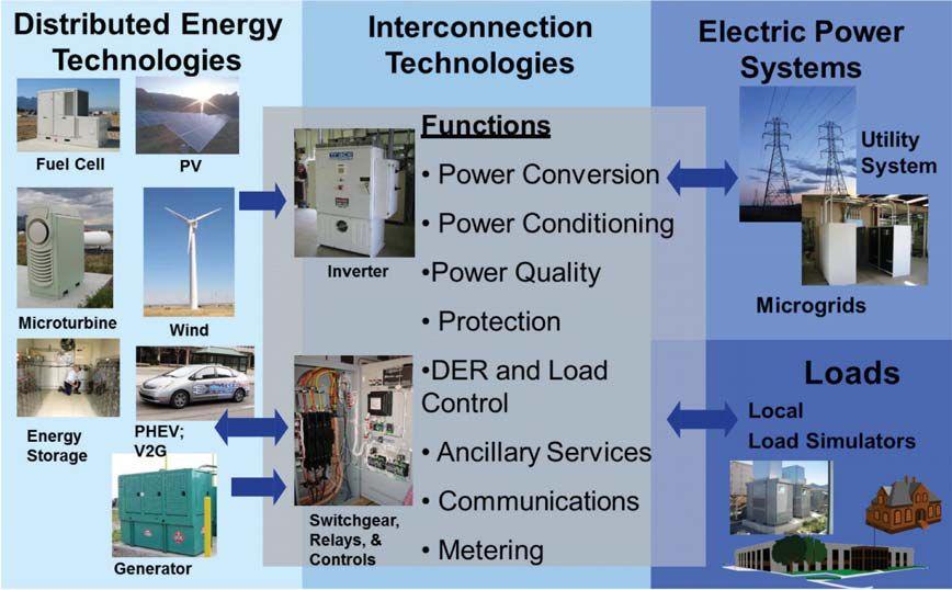
System-level standards are an area of focus for IEEE with regard to the smart grid. These updated reference standards will take into account both the physical technology required to support smart grid requirements and the interface protocols of communications, and information technology.
The IEEE 1547 family of standards has been steadily updated to reflect the evolution of UL 1741. Work is underway in fact, on a new full revision of IEEE 1547. To complete the full revision of IEEE 1547, many technologies and applications will need to be addressed—microgrids, islanding, inverter communications, ride-through frequencies and voltages, higher renewable penetrations, and synchrophasors, among others.
IEEE 2030 Guide for Smart Grid Interoperability of Energy Technology and Information Technology Operation with the Electric Power System (EPS), End-Use Applications, and Loads takes a similar system-of-systems approach.
When IEEE 2030 was released in 2011, it established the world’s first interface-by-interface guide to interoperability across the smart grid. IEEE 2030 is a road map to the standards and

functional interfaces for securely integrating the electric power system with communications and information technology and facilitating data exchange across the smart grid.

IEEE 2030 developed the smart grid interoperability reference model that looks at the power system from three perspectives.
• Power and Energy: Defines the numerous data flows necessary for reliable, secure, bidirectional flow of power and energy throughout the entire electric power system
• Communications: Identifies the communications infrastructure necessary for the smart grid, from high-speed synchrophaser data to in-premise meter and customer notification systems


• Information technology: Defines the system-to-system communication requirements and data flow to leverage individual systems into a system of systems
The smart grid is bringing definitive change to the ways that buildings relate to electricity. In the past, most buildings have been only consumers of electricity. However, as we are seeing with the


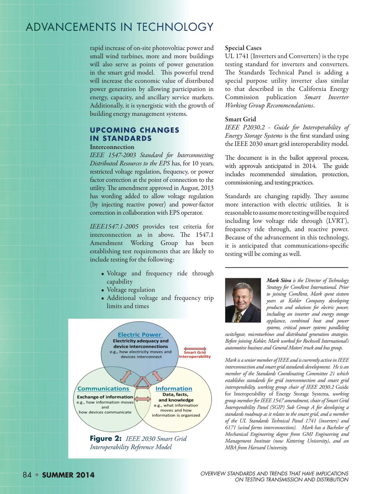
*NETA continuing technical development (CTDs) units are required of NETA certified technicians.

SUBSTATION MAINTENANCE I
DALLAS, TX
Mar 3-7
Apr 21-25
May 12-16
June 16-20
PASADENA, CA
Apr 21-25
June 2-6
PORTLAND, OR
Mar 17-21
May 5-6
VALLEY FORGE, PA
Mar 17-21
June 2-6
SUBSTATION MAINTENANCE II
DALLAS, TX
Mar 10-14
Apr 28-May 2
May 19-23
June 23-27
PASADENA, CA
Apr 28-May 2
June 9-13
PORTLAND, OR
Mar 24-28
May 12-16
VALLEY FORGE, PA
Feb 24-28
Mar 24-28
BATTERY MAINTENANCE & TESTING
DALLAS, TX
Mar 17-19
May 27-30
PORTLAND, OR Apr 14-17
June 10-13
VALLEY FORGE, PA
June 23-26
PROTECTIVE RELAY MAINTENANCE BASIC
DALLAS, TX
Mar 31-Apr 4
May 5-9
June 2-6
PASADENA, CA
May 5-9
PORTLAND, OR Apr- May 2
VALLEY FORGE, PA
Mar 17-21
June 16-20
YOUNGSVILLE, NC
Apr 21-25
PROTECTIVE RELAY MAINTENANCE ADVANCED
DALLAS, TX
Apr 7-11
June 9-13
VALLEY FORGE, PA
Mar 24-28
June 23-27
TRANSFORMER MAINTENANCE & TESTING
DALLAS, TX
May 5-9
VALLEY FORGE, PA Mar 31-Apr 4
CIRCUIT BREAKER MAINTENANCE, LOW-VOLTAGE
DALLAS, TX
Mar 10-14
May 1-16
June 9-13
VALLEY FORGE, PA Apr 7-11
CIRCUIT BREAKER MAINTENANCE, MEDIUM-VOLTAGE
DALLAS,TX
Apr 1-4
June 2-5
VALLEY FORGE, PA
Mar 3-6
May 5-6
NEC CODE 2014
DALLAS, TX
Apr 22-25
VALLEY FORGE
Mar 17-20
May 13-16
PORTLAND, OR
Mar 3-6
June 2-5
Whenever a power or distribution transformer is isolated from the power system, it is very probable that residual magnetism remains in the core due to the phase shift. However, residual magnetism also occurs when performing winding resistance tests. Since manufacturers use these measurements in their routine testing and these tests are typically performed for on-site condition assessment, transformers can be regularly influenced by the effect of residual magnetism.
Residual magnetism leads to high inrush currents, which put a large and unnecessary load on the transformer. A great number of diagnostic measurements are also aff ected by residual magnetism making it is diffi cult to obtain a reliable condition assessment of transformers.
Therefore, demagnetizing the transformer is recommended before reenergizing or performing diagnostic measurements. Within the last few years, the first testing devices that allow practical demagnetization of transformers on-site have been launched.
When a transformer is reenergized, an inrush current occurs that can greatly exceed the nominal current. If the transformer core still contains residual magnetism, the first peak current can reach the level of the short-circuit current. These high currents can
cause undesirable effects, such as mechanical deformation of the windings, incorrect triggering of protection equipment, increased stress on the installation, and voltage dips in the grid. Only the ohmic components, such as the winding resistance, are capable of attenuating the high inrush currents to a stable level within just a few cycles (Figure. 1).
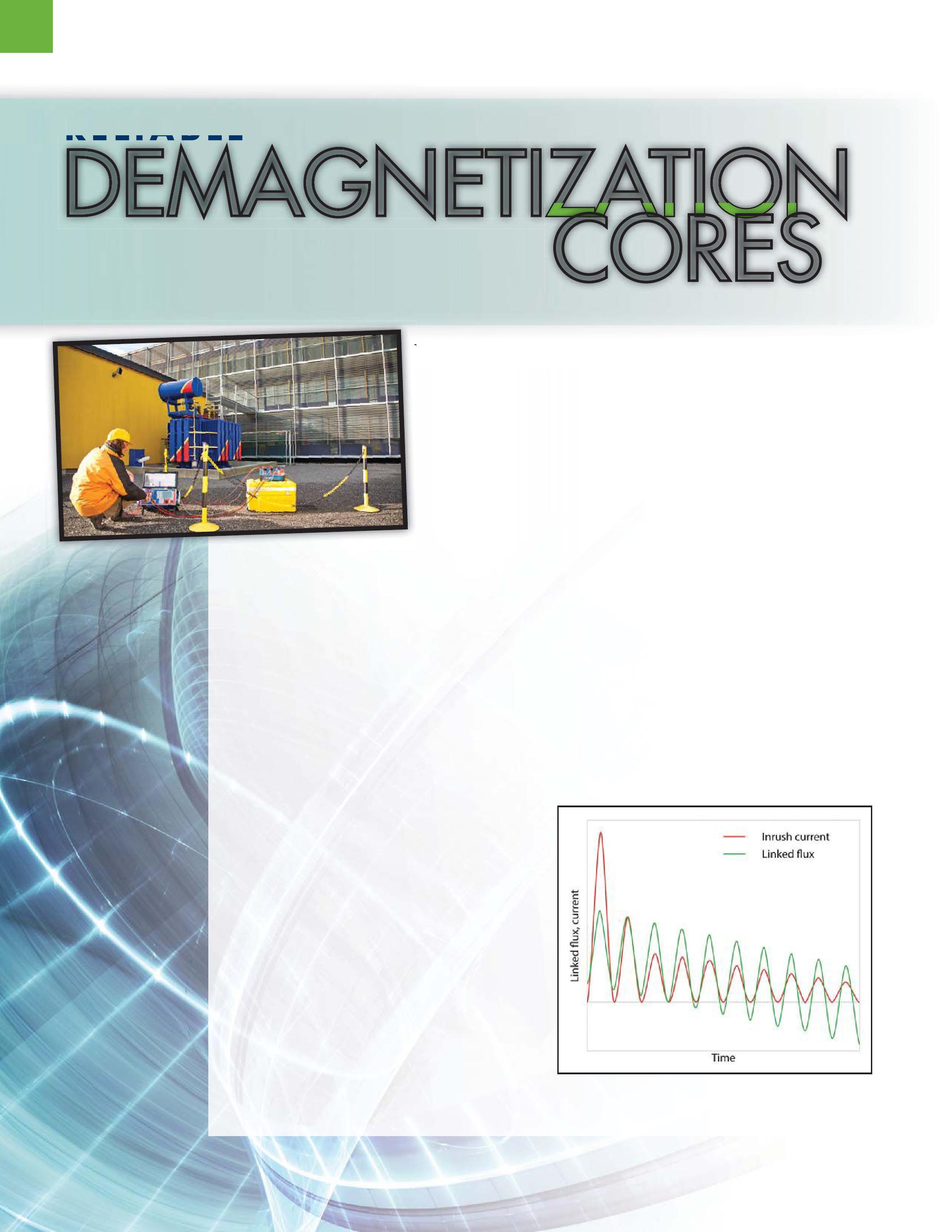
1: Attenuating the Inrush Current Over Time


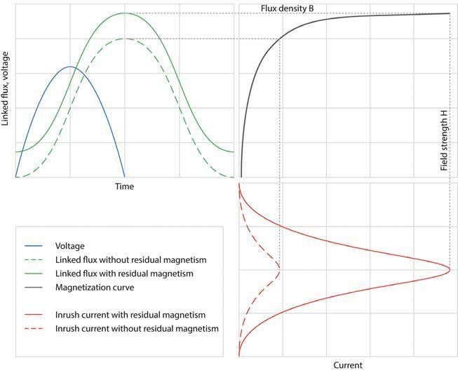


The highest inrush current occurs when the voltage is applied near the zero crossing and the polarity of the voltage is applied in the same direction as the residual magnetism in the core or the corresponding limb (Figure. 2, [Formulas 1-3]). If the core reaches saturation, the transformer’s inductance is greatly reduced. The current is now only limited by the winding resistance on the high-voltage side and the impedance of the connected transmission line.
The residual magnetism can be as high as 90 percent of the magnetic flux density (B) during operation. In the event of a fault or during routine testing, various electrical diagnostic techniques can be used for analyzing the condition of a transformer. Residual magnetism influences certain diagnostic measurements in such a way that a reliable and meaningful analysis becomes nearly impossible.

Particularly, when performing exciting current measurements, the magnetic balance test, or sweep frequency response analysis for localization of faults in the core, residual magnetism may have such a negative effect that results become unsolvable.
Measuring the exciting current can provide evidence for potential faults in the core. Faults in the core lead to an increasing exciting current. If reference values for the exciting current are available, these can be used for the assessment. Since exciting currents do not have a linear behavior to the applied voltage, measurements for comparison with the reference values must be performed at the same voltage. The assessment is performed based on a typical pattern of a three-limb or five-limb transformer or on reference measurements if they are available. The magnitude of the magnetization current depends on the length of the magnetized path. This is virtually identical for the windings on the outer limbs,


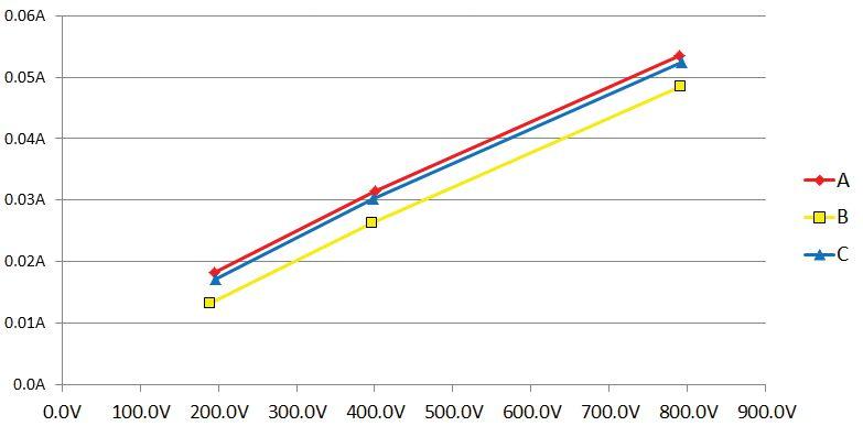
but lower for the winding on the middle limb (Figure. 3). For example, if there is residual magnetism on the middle limb, this can easily lead to incorrect interpretations and a reliable diagnosis becomes impossible (Figure. 4).

The magnetic balance test, (i.e., a test of the flux ratio), is appropriate as a routine electrical field test and as an additional diagnostic method when a fault is suspected

in the core. In the magnetic balance test, ac voltage is applied to a winding and the induced voltage is measured on the two other phases.
This should result in a typical pattern. For example, if a voltage of 100 V is applied to the winding on the middle limb, the measured voltages on the other windings should each display a value of approximately 50 V. This can be explained by the two magnetic paths with the same length. Applying a voltage to


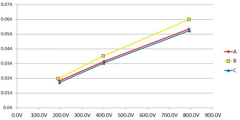


one of the windings on the outer limbs results in a different pattern because the magnetic paths have different lengths. Deviation of the recorded pattern from the anticipated pattern indicates either problems in the core or undesirable effects of residual magnetism.


The sweep frequency response analysis (SFRA or FRA) uses frequency response analyses to describe the dynamic characteristics of an oscillating network based on its input and output signals. The SFRA measurement method is described in IEC 60076-18 and IEEE C57.149-2012 and has become increasingly accepted as a diagnostic method.
A transformer reflects such an oscillating system, consisting of various series and parallel resonances with corresponding inductances (L), capacitances (C), and resistances (R). When one parameter is changed, such as the main inductance due to a core problem or the geometric shift of a winding, one or more characteristic resonance points is also displaced or shifted.

Every electrical network has a unique frequency response, its so-called fingerprint. Interpretation of an SFRA measurement is based on a comparison of measurements, for example with the initial fingerprint or with other transformers of the same type. The plot of a fingerprint should not change throughout the entire life cycle of a transformer. Therefore, all influences that could affect SFRA measurements must be avoided as they could lead to misinterpretation of the obtained test results.


Since residual magnetism influences the frequency response particularly at lower frequencies where the magnetization inductance dominates the response, it is vital to ensure that the transformer has been demagnetized before performing the measurement. Meanwhile, because of this pronounced and well understood influence at the lower frequencies, an SFRA measurement is effective in verifying residual magnetism.
The SFRA measurement reflects the main inductance through the first resonance points. Figure. 5 shows the typical resonance points of a three-limb transformer’s main inductance. Two significant parallel and series resonance points


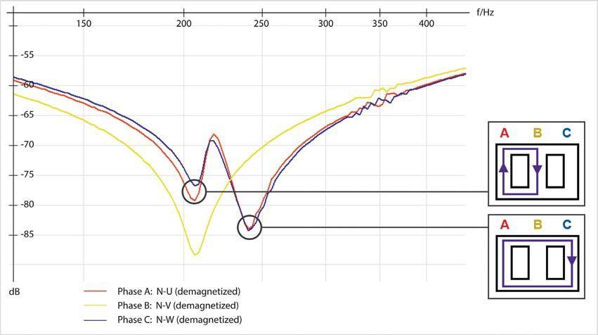


can clearly be seen on the outer windings. This can be ascribed to the two magnetic paths with different lengths. In comparison with this, the winding on the middle limb displays only one characteristic single resonance point.


As previously explained for the inrush current, the inductance changes depending on the degree of core magnetization, whereby Ldemag > Lmag. A resonance point comprises a network of capacitances and inductancesand can be described using Formula 4. The lower the inductance becomes, as reflected by a state of higher residual magnetism, the more the resonance points move toward higher frequencies.
The following three methods are available for demagnetizing magnetic materials:
1. Demagnetization through vibration
2. Demagnetization through heating up to Curie temperature
3. Electrical demagnetization.
Since the first two methods cannot be used for a transformer, the electrical method becomes the sole option. Manufacturers can apply nominal voltage at nominal frequency on transformers. By gradually reducing the voltage, one can progressively demagnetized the core (Figure. 6). Often the only option for demagnetizing transformer cores on-site is to use reduced voltage and frequency signals. In many cases no adjustable voltage source that can provide the nominal voltage of the
transformer is available. Instead, only a singlephase source is available.
Demagnetization of single-phase and three-phase transformers can be performed in a similar way. When working on a three-phase transformer, it is important to consider that magnetic coupling takes place between the phases. Therefore, the phase or limb used during the demagnetization procedure is extremely important and deliberately chosen. It also makes sense to use the high-voltage side for demagnetization as there are more turns associated with this winding to generate the magnetic flux. Hence, the total time for demagnetization can be reduced. Experiments have shown that the middle limb is the most suitable for demagnetization with a single-phase source. Thereby, the flux is distributed symmetrically over the two outer limbs. To determine which winding is associated with the middle limb in a delta winding, the transformer’s vector group is required.


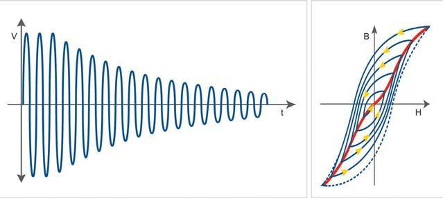


There are various approaches for electrical demagnetization. One of these is to reduce the voltage with respect to time in predetermined steps. Small distribution transformers and large power transformers have very different hysteresis parameters. The disadvantage of this approach is that it takes a long time to ensure that both types of transformers can be reliably demagnetized using the same procedure.
To counteract this problem, the current can be additionally triggered while the test is still running to start the next hysteresis cycle. However, since the magnetization current increases very rapidly when the transformer core reaches saturation, this process is fairly inaccurate. Various experiments have shown that small transformers, particularly, become re-magnetized during the fi nal cycle, which leads to high inrush currents at energization.


Demagnetization based on the measurement of the magnetic fl ux has proven to be the


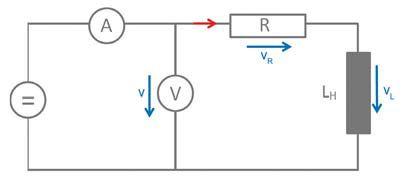
Figure 7: Simplified Equivalent Electric Circuit for the Measurement Procedure


safest and most effi cient approach, as it works reliably with both small and large transformers. However, this approach places very strict measuring requirements on the test equipment as the voltage needs to be continuously measured over time and the integral of voltage with respect to time calculated. [See Formula 5]. It is important to avoid any secondary hysteresis during demagnetization. Th e occurring residual magnetism can lead to an apparent demagnetization.

transformer are then determined and the initial flux is calculated. On the basis of these parameters, an iterative algorithm is then used to change both the voltage and the frequency. While this is taking place, the test equipment is constantly measuring the flux ф in the core. Using multiple iterations, the core is demagnetized to below 1 percent of its maximum value. Following the demagnetization procedure, several magnetic domains revert back into their preferred orientation. This procedure is also referred to as magnetic viscosity. The effect can be determined when performing demagnetization once again, although it is actually negligible and therefore is not really important in practice.


Since the voltage and thereby also the magnetic fl ux of the main inductance LH cannot be measured directly, this voltage needs to be calculated (Figure. 7, [Formula 6]). Th erefore, the winding resistance R must be measured in advance and the voltage drop of the winding resistance then subtracted from the measured voltage. Formula 7 shows the calculation of the magnetic fl ux on the main inductance. Th ereby ф R(0) represents the initial fl ux, which corresponds to the residual magnetism.
The test equipment for demagnetization is very simple. If a switchbox is used, rewiring is not necessary after measuring transformer’s ratio or winding resistance. The transformer’s vector group must be known and the test current chosen. Then the procedure can reduce the residual magnetism to virtually zero.
A 350 MVA-YNyn0 power transformer manufactured in 1971 and rated 400/30kV was tested.
For verification of state purposes, SFRA measurements were conducted. The transformer’s condition was recorded immediately after removing it from service with an initial SFRA measurement. Subsequently, a dc winding resistance measurement was carried out on phase B, (which was wound on the middle core limb), and another SFRA measurement was taken. Lastly, the transformer was demagnetized using the previously described method and checked by performing a final SFRA measurement. The results after the demagnetization procedure are shown in Table 1.

Table 1: Results Following Demagnetization of the 350 kV Transformer

The core can be saturated in both directions. The specific hysteresis parameters per
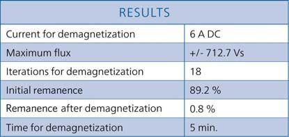


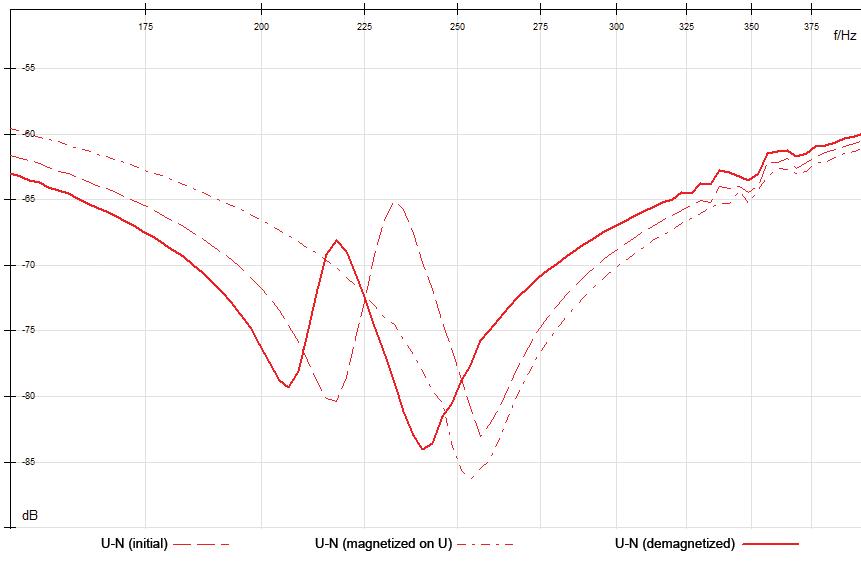


When comparing the SFRA results of the individual phases, one can see that the transformer displays residual magnetism after being isolated from the power system (Figure. 8). After the demagnetization procedure, all resonance points moved towards lower frequencies as expected, and the typical SFRA pattern of a three-limb transformer can be seen. Th e transformer can therefore be considered as demagnetized.


This article highlights the importance and the effect of residual magnetism. It should also increase the awareness of the associated risks with reenergizing transformers after an outage.
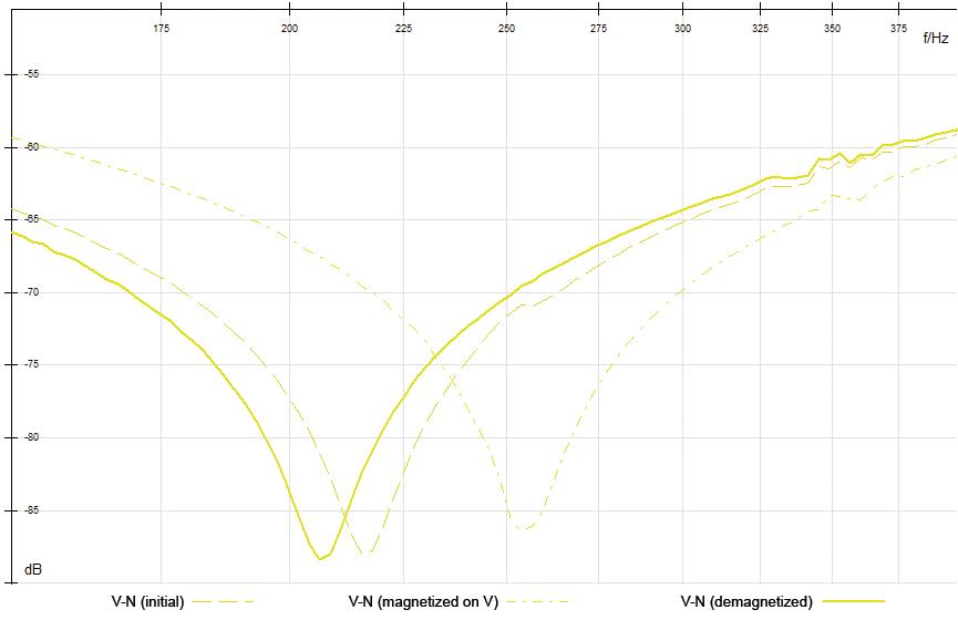
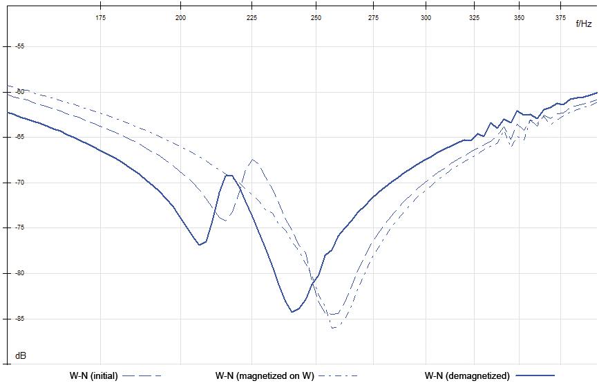


Within the last few years, the first testing devices have been developed to allow reliable on-site demagnetization of transformers without any major additional effort. Demagnetized transformer cores minimize the risk to personnel and equipment during installation. The SFRA measurement method is described in IEC 60076-18 and IEEE C57.149-2012 and has become increasingly accepted as a diagnostic method. To gain reliable and reproducible measurement results, we recommend demagnetizing the transformer core before performing SFRA measurements.
On the ringdown transient on transformers, N. Chiesa, A. Avendano, H. K. Høidalen, B. A. Mork, D. Ishchenko, and A. P. Kunze
Investigation on the Behavior of the Remanence Level of Protective Current Transformers, J. Dickert, R. Luxenburger, and P. Schegner
Mitigation of Inrush Currents in Network Transformers by Reducing the Residual Flux with an Ultra-Low-Frequency Power, Baris Kovan, Francisco de León, Dariusz Czarkowski, Zivan Zabar, und Leo Birenbaum

Remanent Flux Measurement and Optimal Energization Instant Determination of Power Transformer, Goran Petrović, Tomislav Kilić, and Stanko Milun


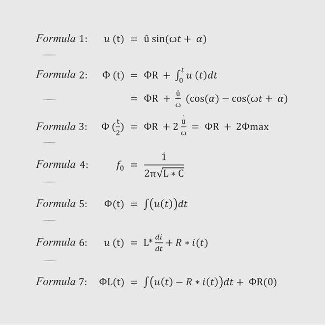


Markus Pütter is product manager for OMICRON electronics GmbH, Austria. He has 14 years of experience in the field of power transformer testing. Markus received a Dipl-Ing. in Electrical Engineering from the University Paderborn in 1997.

Michael Rädler (November 27, 1987) works for OMICRON electronics GmbH as a Product Manager for testing and diagnostic solutions for primary assets, mainly focusing on power transformer applications since January 2008. He graduated at the Federal Higher Technical Institute in Bregenz, Austria with focus on electrical engineering.






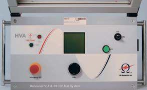


the test equipment answer
Relay and Protection Systems
Switchgear and Breakers (Low, Medium and High Voltage)
Cable and Bus
Transformers
Batteries
Motors and Rotating Apparatus
Watthour Metering
Power Quality and Consumption
Analysis


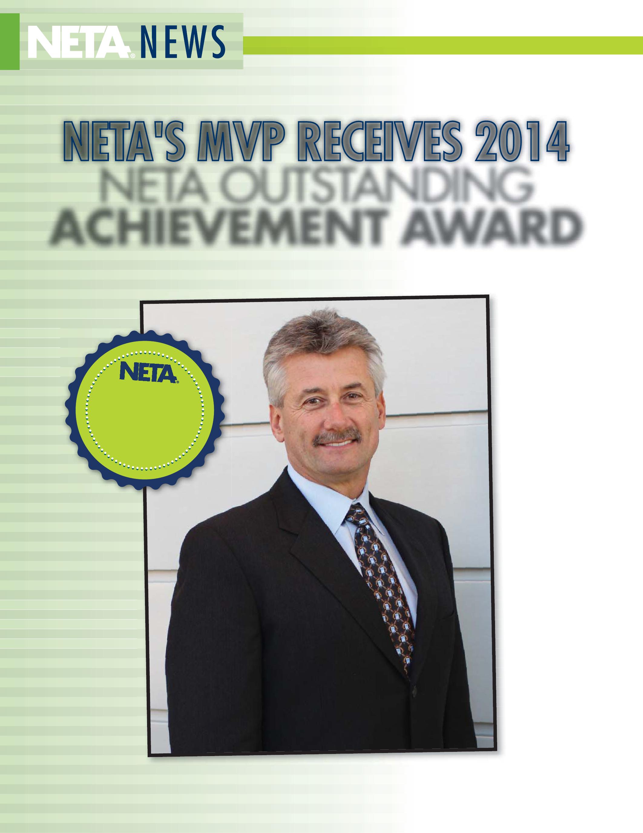
OUTSTANDING ACHIEVEMENT AWARD
NETA Member and Alliance Luncheon attendees were settled in and enjoying their meals on Monday afternoon at PowerTest 2014 in Denver this year. The sounds of clanking dishes and light conversation eventually gave way to a program of industry discussion, challenges, and solutions, with table hosts engaging their tablemates in the process. After coming to a consensus at each table, answers were presented, allowing everyone to benefit from the exchange of thoughts and ideas….
Then, out of nowhere, Ken Bassett was being compared to Tom Selleck. Not because Ken rolled up to the Hyatt Regency Denver in a red Ferrari, or because he just finished a stint as the New York City police commissioner. Perhaps it is best to start at the beginning.
In what has always been a cause for celebration at the NETA Member and Alliance Luncheon, the NETA president proudly announced the honoree for the annual Outstanding Achievement Award. As tradition dictates, the president is faced with the challenge of keeping the honoree’s name a secret until the big reveal at the end of his award presentation.
A series of clues about the recipient act as a trail of breadcrumbs, leading the audience down a path wondering, “Who could it be?” Many NETA members share similar backgrounds in electrical testing, are NETA Certified Testing Technicians, and enjoy a drink with friends when time allows. It could be almost anyone. Until the clues get more specific, that is.
Dave began, “The Outstanding Achievement Award is an award that recognizes one individual from a NETA Accredited Company who is one of the unsung heroes. This person does more for NETA than anyone will ever know. They are selfless with their time; they go above and beyond for a job that pays in handshakes and thank yous rather than in dollars.” Photos and other images graced the big screens on either side of the podium, illustrating NETA President Dave Huffman’s

words as he wholeheartedly described this year’s most valuable player and his years of service. The litany included mention of this person recently serving on six NETA committees as the chair of one and taking a leadership role for the association on the NETA Board of Directors.
“He is a level III technician and has only missed one NETA meeting in the past 12 years,” continued Huffman; and then there was a pause.
Huffman suddenly delivered a straight-faced comparison of the 2014 honoree’s moustache to that of Selleck’s, suggesting it is as much a trademark for 2014 award winner as it was for Selleck. The luncheon audience was somewhat quiet as the words sunk in; then a larger than life Magnum, P.I., image of Selleck appeared on the screens, and the room erupted in laughter. “He is Ken Bassett,” Huffman said, finally announcing the honoree’s name, as applause filled the room.
“I was very surprised,” Ken said of the award. “There are so many unique individuals who contribute to the success of NETA. It’s a true honor.”
Launched in 1985, Ken’s electrical testing firm, Potomac Testing, Inc., has always been, and continues to be, a family operation. Ken was still in college at Maryland’s Frostburg State when his father introduced him to the electrical testing industry. “I worked summers with my father at Roger’s Electric, which later became a NETA Accredited Company, Substation Test Company. It gave me an opportunity to gain insight into the electrical industry and our unique niche industry, testing of electrical apparatus,” he said.
Ken studied for some time, successfully completing apprenticeship training, supplemental industry specific training, and OJT, among other accomplishments. Father and son then established Potomac Testing, which became incorporated in 1990. Initially focused on acceptance and maintenance testing, Potomac offers full range power system support.
“The belief in our organization stems from the people that I have been fortunate enough to have spent time with when we joined NETA in 1993,” Ken said. “These past leaders had great vision and represented our association well. They provided insight into what we, as an association, could be; what we are capable of accomplishing; and how we could help the industry create a safer environment.”
Ken became more involved with NETA, including being nominated for and elected to the board of directors and eventually chairing the membership committee, which he continues to do today. His responsibilities at Potomac also grew. “When my father stepped back from
the business in 1997, I became president and in charge of day-to-day operations,” Ken said. “While our business has grown substantially since, we continue to maintain a high level technical expertise in assisting our clients with their requirements.”
Potomac continues to be a family operation today, with Ken’s sister Donna Biggs serving as the company accounting manager; her husband Craig, a NETA Level IV Certified Senior Technician, as the lead relay technician; Ken’s brother, Tres Bassett, also a NETA Level IV Certified Senior Technician, as the company’s safety officer; and Ken’s oldest daughter, Crystal, a 26-year-old graduate of Clemson University, as the office manager. “We also have a niece and a step-sister helping us provide great service to our clients,” Ken said.
While Ken talks about Potomac being a family business, he describes the people of NETA in similar terms. “I consider some of my closest friends among the members of this association,” he said. “They are an extension of family. We work toward the same mission: work hard, play hard.” The connections Ken feels with his NETA family started early on when he became part of the association. “I am really fortunate to serve with people who became mentors, like Al Peterson, Rod Hageman, and Charlie Blizard,” he said.
“I remember when Ken started coming to NETA meetings,” said Rod Hageman, President of PRIT Service and a member of the NETA Board of Directors with Ken. “Ken seemed eager to learn and very willing to contribute his time to NETA. Initially, he seemed hesitant to volunteer. We talked frequently at the meetings and I encouraged him to get involved. I am very glad that I did. Ken has been a force in NETA and has contributed untold hours of his time in service to our association. In addition to what he does for NETA, I am pleased to think that Ken is a great friend, and we have had much fun over the years.
Rod’s wife, Diane (the only woman to receive
NETA’s Man of the Year Award, as it was called then) has a few words about Ken: “Ken is a great representative for NETA. Ken has been setting an example for all representatives of Member Companies. If there is a board meeting, a member meeting, a committee meeting, or a conference call, Ken is there. Of course, if there is a dinner, a party, or a competitive sport, Ken is there also.
“Ken is most deserving of this recognition,” said Ron Widup, PowerTest Conference Chair and CEO of Shermco Industries. “As Membership Chair, he has one of the toughest, if not the toughest, jobs in the association.”
The Membership Chair is in charge of the process of vetting applications for companies applying for accreditation as third-party, independent electrical testing firms that meet all the criteria set forth in the NETA bylaws and policies, an involved process that includes coordinating and wading through a mountains of information, performing
site visits, coordinating with the application review committee, and ultimately distilling the information down for review and decision making by the NETA Board of Directors. “Not to mention the challenges that sometimes face the existing members and require Ken’s time and attention to resolve,” Widup said. “And Ken does a great job with all of it.”
John White, another member of the NETA Board of Directors, agrees. “There is a quote from UCLA basketball coach John Wooden that goes like this, ‘Whatever you do in life,
surround yourself with smart people who’ll argue with you,’” White said. “While you need to use the proper context for the word ‘argue,’ this quote is one I firmly believe in, and Ken is one of those smart people I would choose to have around me. He is seldom without comment and always willing to debate the merits in a friendly fashion. I respect that.”
As a result of the work NETA does, Ken said workplaces are safer and electrical equipment is more reliable because it is serviced by certified technicians. As for the future, Ken expects the continued growth of NETA at the standards
development level. “I think we could identify other standards NETA can help develop,” he said. “The certification process could even be expanded to include other industries, other membership groups, allowing them to navigate a certification process as well.”
NETA Executive Director Jayne Tanz said Ken’s commitment is all motivated by his interest in advancing the industry. “He carries a high level of dedication that is completely NETAcentered.” Jayne continued, saying, “Ken operates on the belief that working on industry advancement through NETA helps everyone involved.” Jayne also credits Ken’s ability to evaluate before acting as a tremendous attribute. “He is always one to listen first, to be sure of the needs at hand and perspective of those he works with,” she said.
Jayne and Ken have been acquainted professionally for several years through NETA, but a few years ago, a personal relationship blossomed, which led to a partnership. “He invests himself in his personal relationships, with me, his daughters, his friends and acquaintances, with the same level of care, consideration, and commitment that he does with his professional endeavors,” she said.
An example of those personal relationships is the role of soccer coach for a group of girls whom Ken has coached since they were seven years old.
One of them is his youngest daughter Michelle, 18, who will graduate high school this year. “I’ve coached youth athletics for over 34 years and have achieved various licenses that are required at advanced levels in many sports,” Ken said. In addition to spending time with his two daughters and Jayne’s son Marshall, 11, Ken enjoys running and cheering on the Washington Redskins.
“We have a long standing tradition of a little wager on the Cowboys and Redskins,” Dallas fan Ron Widup said. “We bet $100 on the game, no points, and they play each other twice a year. The same hundred-dollar bills keep floating back and forth between Dallas and D.C.,” he said. “Although, I should mention that I currently have both of them from last year,” Widup says with a smile.
Ken and Jayne also enjoy spending time at their Ocean City, Maryland, beach home during the summer months, especially during the big family weekends they host there. “We have a boat, Jet Skis, and a bunch of other toys everyone can enjoy,” Ken said. “We’re able to visit some of our favorite clamming spots, do some fishing, stop by a refreshment bar, and return back to the house for a big evening feast. Family is a big part of what I’m about.”
And when those family gatherings are over, and it is back to work at Potomac, Ken – who was also NETA’s Outstanding Achievement Award recipient in 2006 – is in his element. “I have so much passion for what I do at Potomac,” he said. Whenever Ken interviews someone who could be a potential addition to the company, “they feel the energy for what it is that I do,” he said. Undoubtedly, others at Potomac and those at NETA do too.










On April 19, 2013, NETA published notice of intent to revise ANSI/NETA Standard for Maintenance Testing Specifications for Electrical Power Equipment and Systems as a revised American National Standard. This document contains specifications which cover the suggested field tests and inspections that are available to assess the suitability for continued service and reliability of electrical power equipment and systems. The purpose of these specifications is to assure that tested electrical equipment and systems are operational and within applicable standards and manufacturers’ tolerances and that the equipment and systems are suitable for continued service.


Th is document is due to be published as a revised standard in 2015. A PINs notice was published in ANSI Standards Action on November 29, 2013, with the 45 day public comment period closing on January 13, 2014. The ANSI/NETA Standard for Certification of Electrical Testing Technicians was approved as a revised American National Standard on January 8, 2010. Th is standard


establishes minimum requirements for qualifications, certification, training, and experience for the electrical testing technician. It also provides criteria for documenting qualifications for certification and details the minimum qualifications for an independent and impartial certifying body to certify electrical testing technicians.


NETA is announcing the intent to draft a new standard that will be submitted as an ANSI candidate standard. The PINs for this document appeared in the December 6, 2013, edition of ANSI Standards Action with a closing date of January 20, 2014. These specifications describe the systematic process of documenting and placing into service newly–installed or retrofitted electrical power equipment and systems. This document shall be used in conjunction with the most recent edition of the ANSI/NETA Standard for Acceptance Testing Specifications for Electrical Power Equipment and Systems. The individual electrical components shall be subjected to factory and field tests, as required, to validate the individual components. It is not the intent of these specifications


to provide comprehensive details on the commissioning of mechanical equipment, mechanical instrumentation systems, and related components.


The ANSI/NETA Standard for Acceptance Testing Specifications for Electrical Power Equipment and Systems was approved as an American National Standard on January 25, 2013. These specifications cover the suggested field tests and inspections that are available to assess the suitability for initial energization of electrical power equipment and systems. The purpose of these specifications is to assure that tested electrical equipment and systems are operational, are within applicable standards and manufacturers’ tolerances, and are installed in accordance with design specifications.
Comments and suggestions on any of the standards are always welcome and should be directed to the NETA office at neta@ netaworld.org or 888-300-6382. To learn more about the NETA standards review and revision process, to purchase these standards, or to get involved, please visit www.netaworld.org or call 888-300-6382.


NETA is proud to announce that the NETA Handbooks, Series II, are now available, giving electrical power system industry professionals more reference and training options. More than 14,000 copies of the first NETA Handbooks series, covering subjects like circuit breakers, protective relays, transformers, arc-flash safety, and online diagnostics, were sold.
The material contained in the handbooks is a collection of more than 200 of the best articles published in past issues of NETA World and the most well-received technical presentations from PowerTest, the premier electrical maintenance and safety event, which is hosted by NETA.
NETA Handbooks, Series II, provide a valuable resource for two major groups of individuals in the power system industry. First, they serve as a reference tool for new employees needing a solid overview of the industry and for technicians preparing for the NETA exam. Second, NETA Handbooks, Series II, assist electrical engineers working for consulting firms, manufacturer sales representatives, and facility management engineers.
NETA Handbooks, Series II, content covers the most up-to-date and relevant information from standard testing procedures to troubleshooting and every day, real-life situations applicable in the field. The new series is made possible thanks to the following sponsors who are dedicated to education and improvement throughout the industry: Ampteks, CBS ArcSafe, Circuit Breaker Analyzer, Shermco Industries, Intellirent, IRISS, Megger Distributor Group, Raytech USA, Inc., SMC International, Tony Demaria Electric, Inc., and Vacuum Interrupters, Inc.
NETA Handbooks, Series II, are being offered at $15.00 per volume or $195.00 for the entire 13-volume set (plus shipping and handling). Subscribers to the NETA Alliance Program, (NETA’s nontesting professional network) receive 20 percent off the regular price.
NETA is an association dedicated to quality in the industry. NETA has a wide variety of training options available. For more information, contact the NETA office at 888.300.6382 or www.netaworld.org.
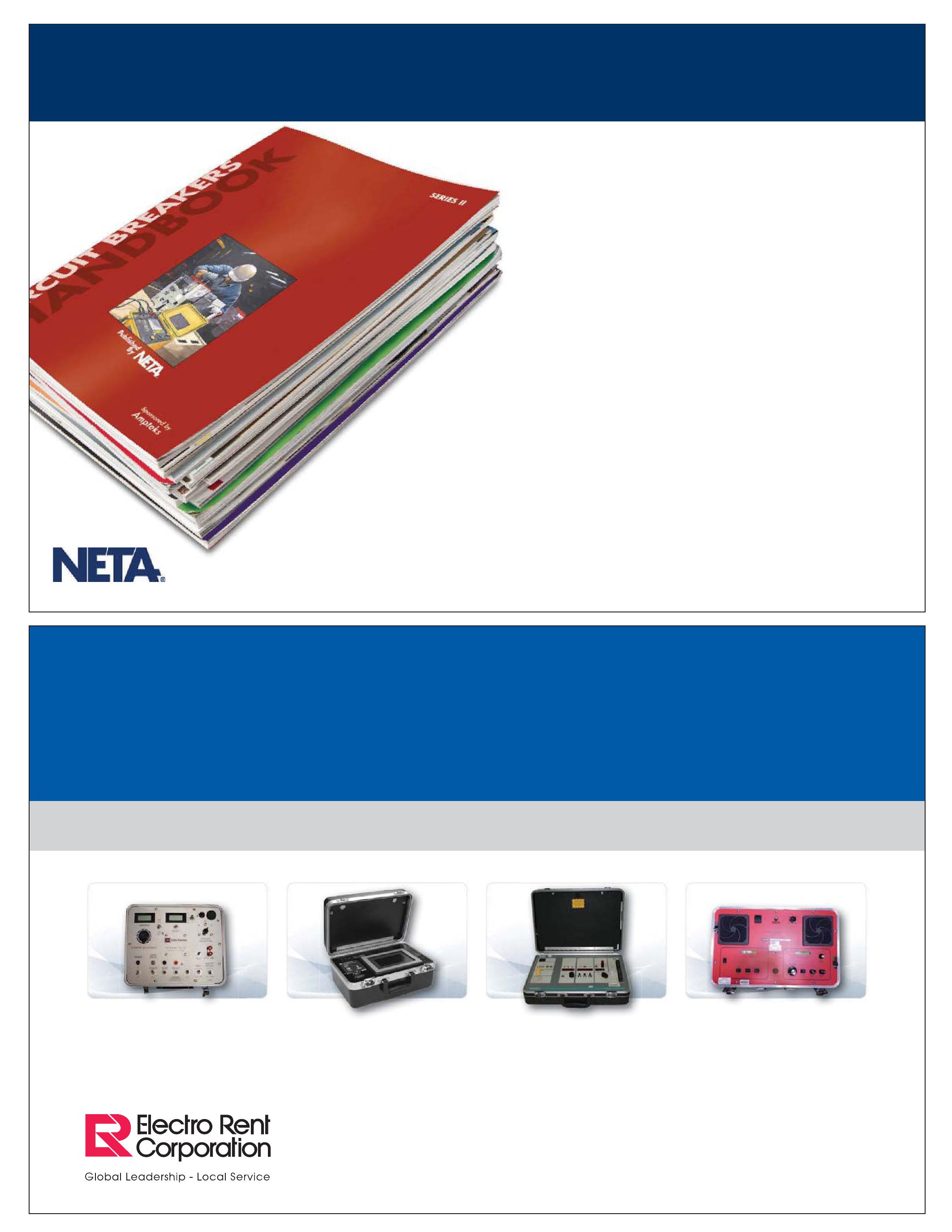
NETA launched the NETA Corporate Alliance Partnership Program during PowerTest 2014. The corporate alliance program vision is to establish a network of information exchange across representative segments from all facets of the electrical power industry, where new ideas, research, and strategies can be shared to improve quality, safety, and reliability across all aspects of the electrical power systems industry.
These corporate partners in many ways support NETA Accredited Companies but are very distinct in their differences from companies that are NETA accredited. NETA Accredited Companies undergo an extensive credentialing process; the individuals who attain status as NETA Certified Electrical Testing Technicians are also required to verify years of experience and training before taking the certification exams.
Corporate partnerships begin with an invitation from NETA to companies that have been identified as supporting work of NETA Accredited Companies. NETA recently invited seven companies to participate as NETA Corporate Alliance Partners, each
of them leaders in their respective fields. These companies have demonstrated their commitment to research and development, to advancing technology, improving services, education, and sharing their findings and knowledge across the industry.
PowerTest 2014 provided an excellent forum for the NETA Corporate Alliance Partnership Program launch. Each NETA Corporate Alliance Partner was provided a unique opportunity to meet with NETA Accredited Company members, individual Alliance Partners, and conference attendees to share company intelligence during the PowerTest Trade Show held Tuesday, March 4, 2014. On the Spotlight Stage at the PowerTest
Trade Show, each corporate alliance partner offered a 20 minute presentation about the work in which their company is engaged as part of their commitment to advancing the industry. Many of
ComRent International, LLC
Doble Engineering Company
Weidmann - Diagnostics Solutions Inc.
the trade show attendees stopped in to listen and learn about new technologies and advancements with each company. An overview of the spotlight presentations follows:

AVO Training Institute
Megger
Circuit Breaker Sales Co., Inc
Supporting complex projects with unique solutions
Time synchronization solutions for accurate testing
Lower risk and improve reliability through diagnostics modeling and information management
Electrical safety through design, installation, and maintenance
New S1-Series, 5 kV, 10 kV, 15 kV insulation resistance testers
Breaker boards and B2B platforms
(For presentation details, visit www.netaworld.org and click on the corporate alliance page)
Corporate Alliance Partners also turned out in force to showcased new technology and services during the New Product Forum and following this event with demonstrations at their exhibit booths throughout the PowerTest Trade Show. Below is an overview of what these companies brought to the show:
CIRCUIT BREAKER SALES CO.
www.circuitbreaker.com
B2B Website
Circuit Breaker Sales Co., Inc. is pleased to announce our new B2B website specifically designed for service and testing professionals. In addition to discounted pricing for all NETA members, our expanded website will also offer exploded views of all circuit breakers to assist in identifying replacement components. We have created an environment where customers can shop for parts and pieces online 24 hours a day. Also, as part of a recent acquisition, we can now supply or repair all American made electromechanical relays and devices. These too are all online. Visit us today at www. CircuitBreakerStore.com!
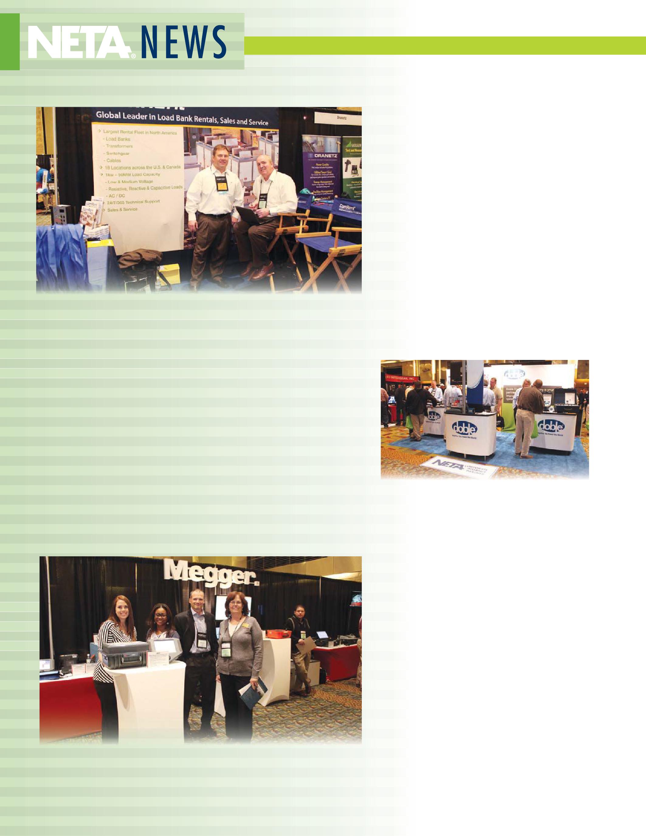
www.comrent.com
Witness Test Reporting through Power Quality Monitoring Systems
IEEE 1547.1 and UL1741 define the standard conformance test procedures for equipment interconnecting distributed resources with electric power systems. Mandatory witness testing is becoming more common for the interconnection test for distributed energy sources. This new requirement places a heavy burden on utility engineers as more local power systems are developed and come online. ComRent has developed a unique service package utilizing an advance power quality monitor that generates reports formatted to meet IEEE 1547 and UL1741 requirements. This new service allows third party testing so that utility engineers can review and verify conformance from the generated test reports.
www.doble.com
Doble F6052 Universal Time Synchronizer
The Doble Delphi Portable Analyzer is a portable DGA device designed to provide timely and actionable information on key dissolved gases in insulating oil. Quickly sample and analyze oil on-site. The Doble F6052 Universal Time Synchronizer is a lightweight, portable time source when you need a time reference or time stamp, but do not have access to reliable time sources or GPS signals due to space, distance, or security. The Doble DFA300 Surveyor is a handheld, in-service partial discharge testing tool which uses both RFI and acoustic technology. It can be used in many different substation applications.
www.megger.com
Megger MRCT
Cut CT testing time in half with the new MRCT The new Megger MRCT represents an evolution in instrument transformer testing technology. This unit will simultaneously measure voltages on all taps during CT saturation, ratio, and polarity tests, as well as calculating knee points and ratios on all windings.
www.omicronusa.com
OMICRON’s latest innovations
OMICRON’s latest innovations include the CIBANO 500, first circuit breaker test system to combine a precise micro-ohmmeter, a multichannel timing analyzer, and a powerful coil and motor supply; the VOTANO 100, a highly accurate instrument transformer testing and calibration system; the DANEO 400, a distributed hybrid measurement system that records and analyzes all conventional signals; the ISIO 200, a binary I/O terminal for substation automation systems with IEC 61850 GOOSE interface; and the OMICRON Academy, a state-of-the-art, air-conditioned training facility with the ability to test various apparatus such as a 10 MVA power transformers, circuit breakers, and distribution automation and a hands-on protection relay testing lab.
www.weidmann-diagnostics.com
WEIDMANN Insulogix® Monitoring Products- featuring InsuLogix B®
WEIDMANN Insulogix® Monitoring Products provide economical and simple monitoring solutions that help you manage your transformer fleet operation. Our design approach is to make our devices easy to install, operate, and maintain. We provide simple tools and directions along with comprehensive training and education about normal and faulty transformer operation. The newest monitor in our fleet is the InsuLogix B. It measures a transformer’s bushing insulation power factor while under load continuously and in all weather conditions directly on the bushing. It also provides accurate and early indication of incipient bushing failure. Other monitors in our fleet are InsuLogix® T, InsuLogix® H and InsuLogix® HM.
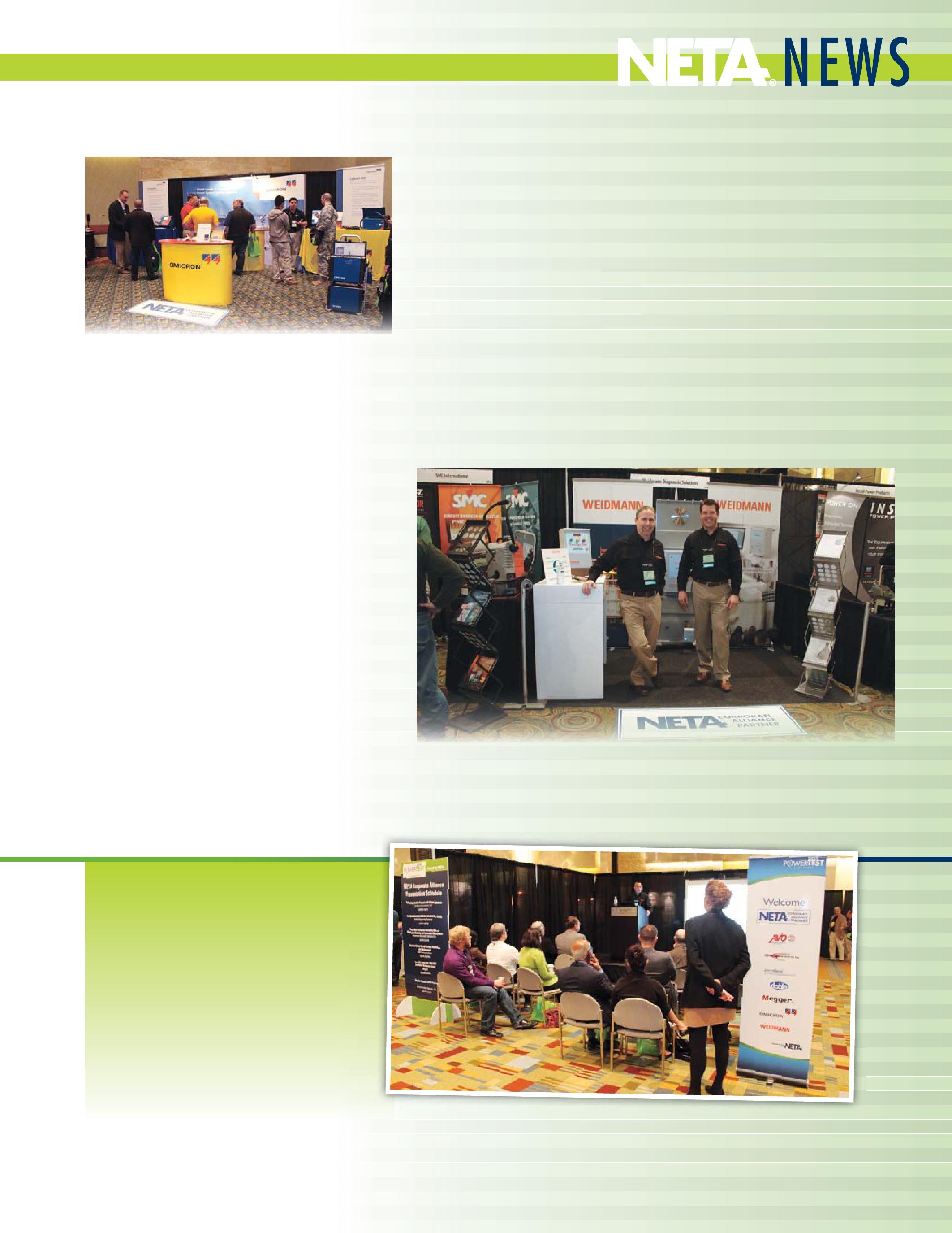
On behalf of all the NETA Accredited Companies, we thank the NETA Corporate Alliance Partners for their commitment to NETA and joining in the important work of educating and advancing the electrical power industry. We look forward to an exciting and inspiring year to come!





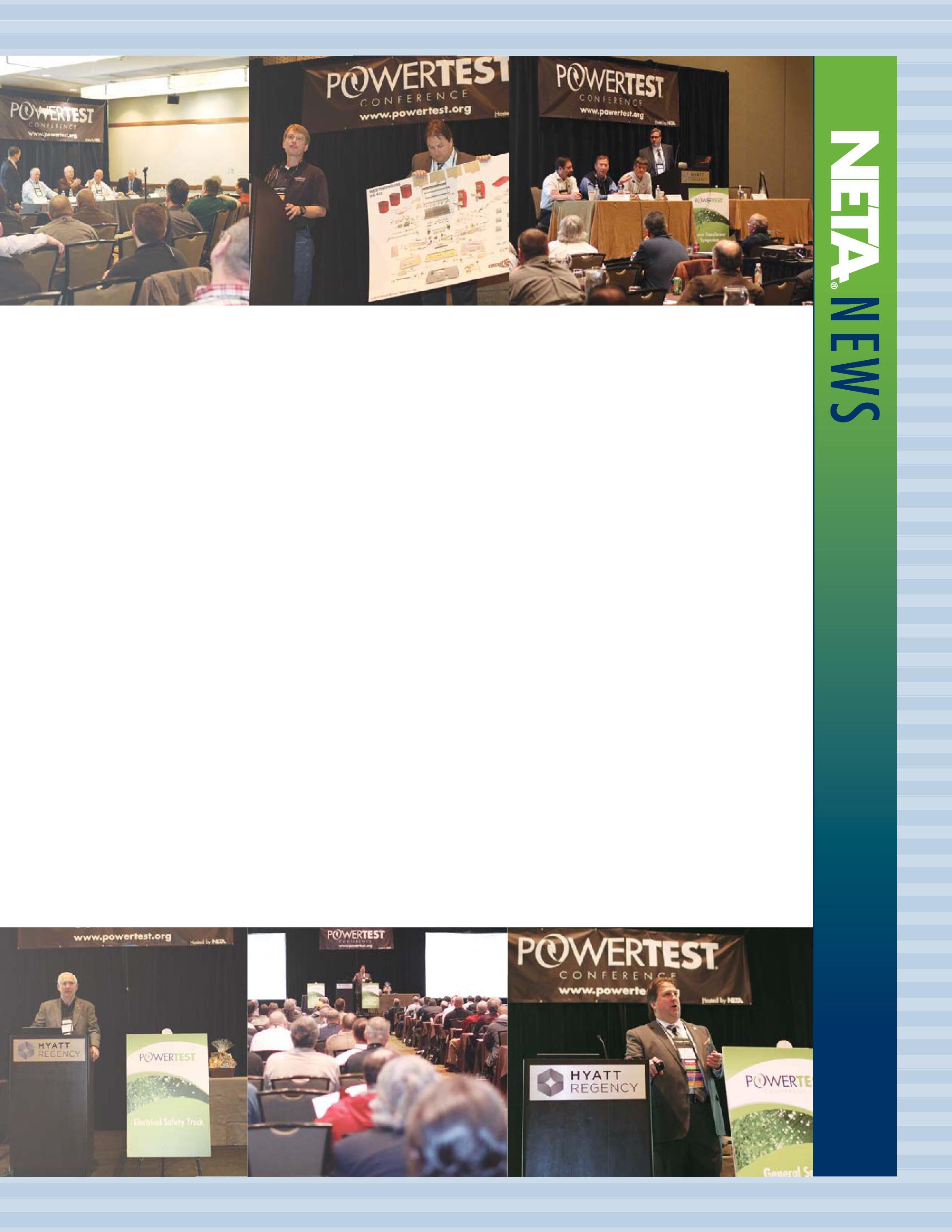
Electrical testing professionals know that their time is well-spent at PowerTest, with each hour of the day occupied by a carefully planned event.
From the delicious breakfasts sponsored by generous supporters to each technical presentation, panel session, and seminar that takes place during business hours and into the evenings with a multitude of networking opportunities that take smart phones and computers out of the equation and let people connect on-on-one, there is no other electrical
maintenance and safety event that can match the energy at PowerTest. NETA’s recipe for success is no secret: all you have to do is look around to see that the attendees, presenters, and sponsors are the ingredients to an award-winning production that is second-to-none. Read on to learn how 2014 raised the bar even higher.
In 2014, attendees were given a new tool to help them plan, schedule, and navigate the conference – the PowerTest mobile app. Sponsored by Shermco Industries, this application was lauded by attendees, presenters, and exhibitors alike for its ease of use and helpful information including biographical information about each presenter, abstracts for each presentation, and a rating system for each event. Early Monday morning, attendees made their way to the conference chair’s welcoming address where they were greeted by the keynote speaker via webcam from his office where he was held captive by the brutal winter weather that gripped this country this year.
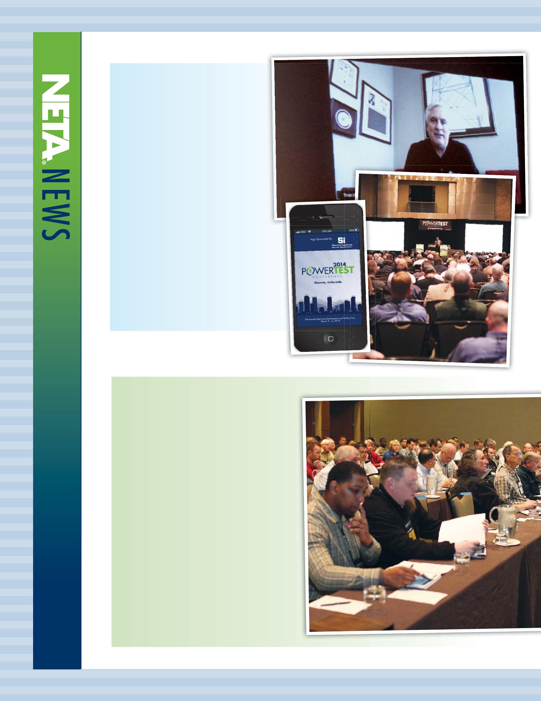
A full day of technical presentations that allowed attendees to immerse themselves in topics ranging from transformers to case studies, equipment, reliability, and safety followed. Attendees took note of their favorite presentations, submitting ballots with their votes for the best paper in each track, as well as for the best overall paper. After the garnering new knowledge during the technical presentations, most attendees made their way to the New Product Forum to begin planning their attack for the trade show on Tuesday all the while listening to 30 exhibitors explain why attendees should stop by their booths the next day. From there, attendees made their way to the hospitality suites featuring interactive games, live music, delicious bites of food, and some themed cocktails ranging from hurricanes to local craft beer.
Tuesday kept up the steady stream of learning and interaction with morning panel sessions where attendees had access to groups of subject matter experts in electrical safety, circuit breakers, transformers, and relays. The experts fielded questions and facilitated discussions with attendees, who also contributed to the discussion by relating their personal experiences from the field. Without missing a beat, attendees transitioned from the panel sessions to the bustling trade show floor where over 100 exhibitors showcased the latest technologies, services, and products. There was even a Spotlight Stage for the NETA Corporate Alliance Partnership Program that gave alliance partners a unique opportunity to reach attendees. Food and drinks were plentiful and kept those attending the show fueled up as they made the rounds. This year there were many lucky attendees who won door prizes at the trade show, including two NETA prizes in the form of $500 in cash and a Microsoft® Surface.
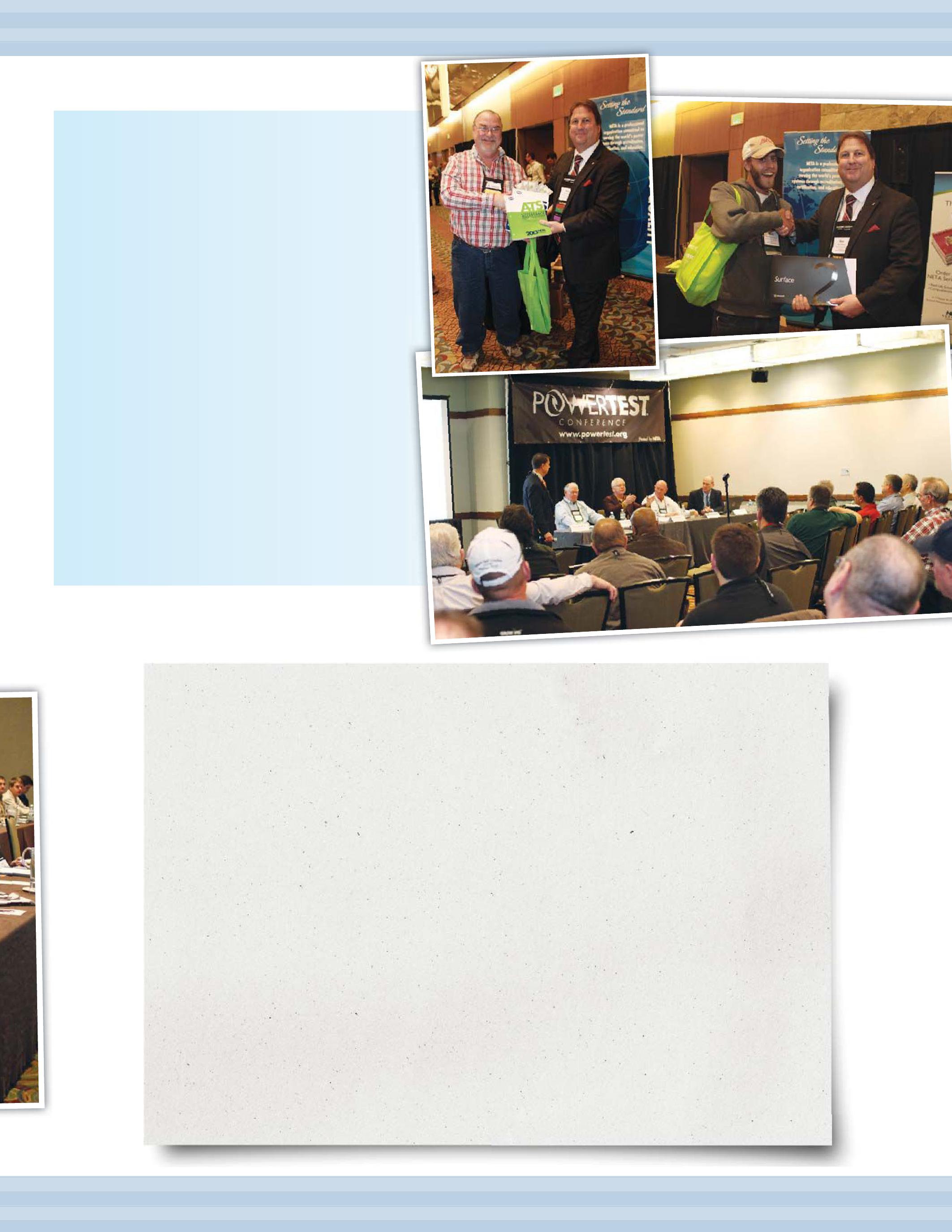
POWERTEST 2014 ATTENDEES SUBMITTED BALLOTS GIVING THE NOD TO THEIR FAVORITE TRADE SHOW DISPLAYS, HOSPITALITY SUITES, AND PAPER TRACK PRESENTATIONS. HERE ARE THE RESULTS:
BEST OF TRADE SHOW
MOST INNOVATIVE: IRISS, INC.
MOST VISITED: CIRCUIT BREAKER ANALYZER, INC. BEST IN SHOW: HAEFELY HIPOTRONICS
BEST OF HOSPITALITY SUITES
MOST TECHNICAL: PROTEC
MOST APPETIZING: MONSTER FUSES
MOST HOSPITABLE: SHERMCO INDUSTRIES
MOST CREATIVE: MEGGER
MOST ENTERTAINING: ELECTRO RENT GLOBAL
BEST OF POWERTEST PAPER TRACK PRESENTATIONS
ELECTRICAL SAFETY: VERIFY PERFORMANCE AND SAFETY OF ARC-FLASH DETECTION SYSTEMS BY WILLIAM KNAPEK, OMICRON ELECTRONICS CORP., USA
RELIABILITY: KEEPING THE LIGHTS ON – UPDATE ON TESTING MEDIUM-VOLTAGE CABLE AND SWITCHGEAR SYSTEMS BY ASHLEY HARKNESS, ELECTRICAL RELIABILITY SERVICES
CASE STUDIES: A NEW APPROACH TO CIRCUIT BREAKER ANALYSIS BY JOHN CADICK, CADICK CORPORATION AND FINLEY LEDBETTER, GROUP CBS
EQUIPMENT: A SYSTEMATIC APPROACH TO HIGH-VOLTAGE CIRCUIT BREAKER TESTING BY CHARLES SWEETSER, OMICRON ELECTRONICS CORP., USA
TRANSFORMERS: DECISION SCIENCES – WILL THIS BE ON THE TEST? BY NICHOLAS PERJANIK, WEIDMANN DIAGNOSTIC SOLUTIONS
BEST OVERALL TECHNICAL PRESENTATION: KEEPING THE LIGHTS ON – UPDATE ON TESTING MEDIUM-VOLTAGE
CABLE AND SWITCHGEAR SYSTEMS BY ASHLEY HARKNESS, ELECTRICAL RELIABILITY SERVICES
Tuesday marked the midpoint of the technical events that take place during the week, so that is when everyone gathered at PowerBash to celebrate the first two successful days of learning before delving into the more in-depth seminars that take place on Wednesday and Thursday. The PowerBash awards recognized the best of the technical presentations, trade show exhibits, and hospitality suites, and everyone enjoyed a great meal and drinks thanks to the sponsor of the event, Megger. Karl Zimmerman and his band kept people’s toes tapping and friends dancing thanks to the band sponsor, PRIT Service, Inc. It was another fantastic evening at PowerTest, but that’s no surprise considering the incredible group of people who attend each year.

While PowerTest seems to come and go all too quickly each year, each event is the culmination of thousands of hours of preparation by volunteers who donate their time and talents to educate attendees through each of the events that take place throughout the week. None of this would be possible without the many sponsors who generously provide funding for the food, drinks, programs, materials, and the many perks that make PowerTest such a favorite event with conference goers. It is NETA’s goal to make every year at PowerTest better than the year before. With the help of our attendees, speakers, volunteers, and sponsors, PowerTest 2015 is going to rock Music City (Nashville), Tennessee to its core. So, get ready. It’s just around the corner!


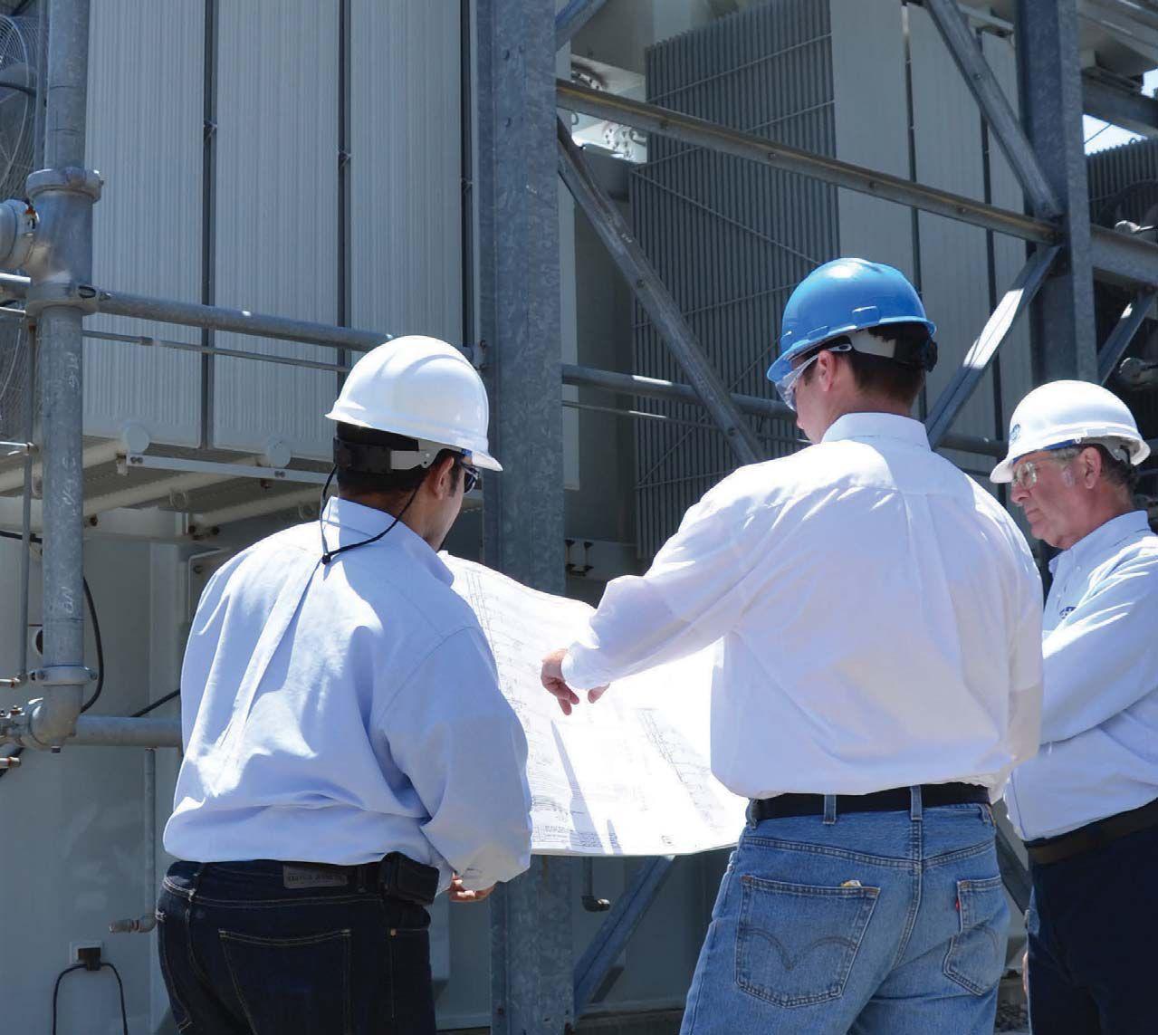

It’s a powerful statement. You made an investment in your test equipment, and you want to know that it will be in service for a long time.
Raytech’s equipment is made for the harsh environments of the testing industry. That’s why 99% of the equipment sold over our 17 years in business is still in service today, and how we can offer a 5-year standard warranty at no additional charge.
Raytech stands behind its custom-made, highquality measuring and testing equipment developed and produced for the international power industry.

YOU ASKED FOR IT — YOU GOT IT!
Our web site was totally redesigned with our customers’ needs in mind.
We’ve added more product information and more downloadable firmware and software. It is easy to navigate and find exactly what you need.
New updates and information will be added regularly, so visit us often!
PowerTest is the largest NETAhosted event that takes place each year, and in keeping with the spirit of doing things big, NETA Accredited Companies and NETA Alliance Partners showed up en masse to the many special events designed just for them that take place at and around PowerTest.
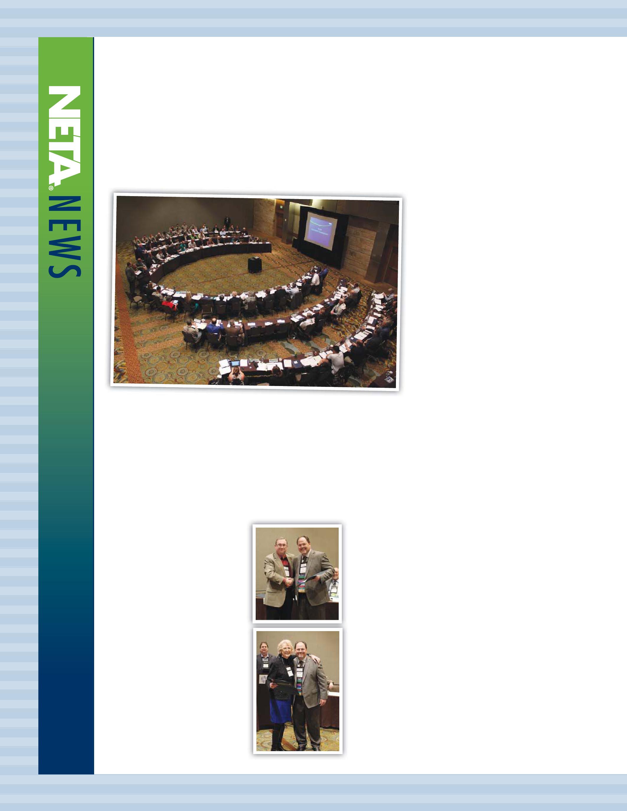
The first opportunity for NETA Accredited Companies to join forces takes place on the Sunday before PowerTest officially begins during the NETA Member and Alliance Meeting. This meeting allows each NETA company’s accredited representative to elect the leadership for the coming year. All employees of NETA Accredited Companies are also welcome to attend, and there is always a lot to learn about the various programs that the association has in place just for members. One of the highlights each year is the presentation of Certificates of Recognition, which are distributed to each person who wears one, or many, of the hats belonging to NETA volunteers. There are a lot of smiles, laughs, handshakes, and hugs as people claim their certificates from the NETA President.
Recently, NETA decided that if one group of highly professional, dedicated individuals is good,
then adding more groups made of similar kinds of people would be even better. Hence, the inclusion of the NETA Alliance Partners, NETA Gold Alliance Partners, and NETA Corporate Alliance Partners to the second half of the meeting on Sunday. This portion of the meeting covers the many technical resources available to members and alliance partners such as NETA publications, training, the online NETA discussion forum at engtips.com, and the online technical library at electricalmanuals.net. This year’s meeting also included some brief presentations from the NETA Corporate Alliance Partners, who each shared new technology or developments within their segment of the electrical power systems industry. Saving the best for last, each technical representative present at the meeting is given the opportunity to share the most recent developments taking place in the many industry standards to which NETA has representation, such as NFPA 70, NFPA 70E, NFPA 70B, IEEE C57, IEEE C37, IEEE C62, ICEA, ICC, and so forth. This particular segment of the meeting usually creates on open dialogue with questions and technical discussion that is hard to find outside of the face-to-face forum.
Monday is a busy day at PowerTest, filled with technical presentations, the afternoon symposium, and an evening


of hospitality for all attendees. In the midst of this packed schedule, members and alliance partners are able to find a little time to sit, relax, and enjoy a meal together during the NETA Member and Alliance Luncheon. This event features relevant technical round table discussions that are summarized and reported on during dessert. This is also the venue that hosts the annual NETA Alliance Recognition Award for an alliance partner who has demonstrated exceptional dedication to bettering the industry through service to NETA. This year Vicki Warren of Iris Power LP was called to the stage and recognized for her many contributions. Last, but certainly not least, the NETA Outstanding Achievement Award is presented to a NETA member who, despite his daily responsibilities at his day job, manages to create time in his schedule to keep NETA moving forward as an organization. These contributions can be technical or organizational, and are often times both. Ken Bassett, president of Potomac Testing, Inc., humbly accepted this award for his role as Membership Chair, work on

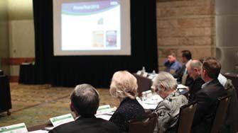
the NETA Board of Directors, and his other gifts of time and talent.

Taking a moment to pause and honor these individuals reminds everyone that the best way to improve the world around us it to do something to affect change, no matter how small it may seem. Every attendee should celebrate the fact that they are present at events like PowerTest; while technology like webcasts, conference calling, email, and social media are more a part of today’s professional landscape than ever, there is no substitution for sitting side-by-side with peers and learning from each other. NETA would like to thank all of the NETA Accredited Companies, NETA Certified Testing Technicians, personnel, and NETA Alliance Partners who attended this year’s event for making it the best PowerTest conference yet. Save the date for PowerTest 2015 located in Nashville, Tennessee on March 2–5, 2015. It just wouldn’t be the same without you there.


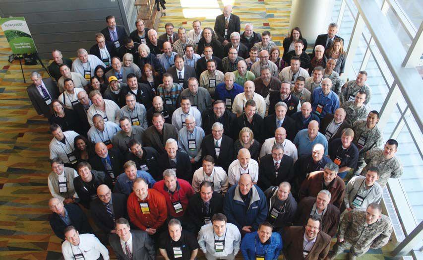

The Best Method of Measuring Concentric Neutral Integrity vital to maintaining system stability, reliability, and safety
The Ω-Check™ Tester is a unique and very useful product. It injects an AC current through a live cable neutral and measures the voltage drop to calculate the resistance of the neutral to determine the level of deterioration: how many strands have opened due to corrosion. It is a vital tool for URD systems, offering many needed applications.
Severe problems can occur if the neutral has corroded to where it cannot perform its many critical functions, like preventing fire hazards from fault currents jumping to other utilities, residential shock hazards, compromised relay protection systems, fluctuating voltage, and more.
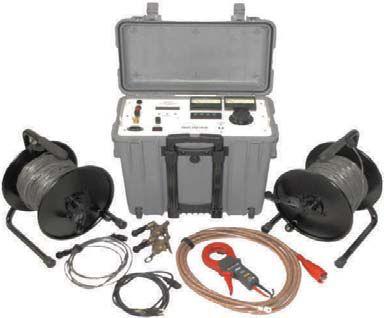
Uses for the Ω-Check™ Tester are many:
IEEE 1617-2007 IEEE 81-2012
ISO 9001 : 2008
www.hvinc.com




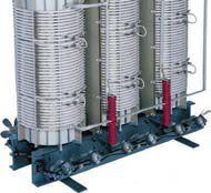


Pub crawls are typically characterized by a leisurely pace and do not necessarily bring to mind images of people with a go-getter attitude. Well, this was not your mama’s pub crawl. This was a pub crawl, NETA-style. Sponsored by Potomac Testing, Inc., the Rock the Rockies pub crawl was a combination of team spirit and heated competition and a test of creativity, resourcefulness, and the will to win at any cost.
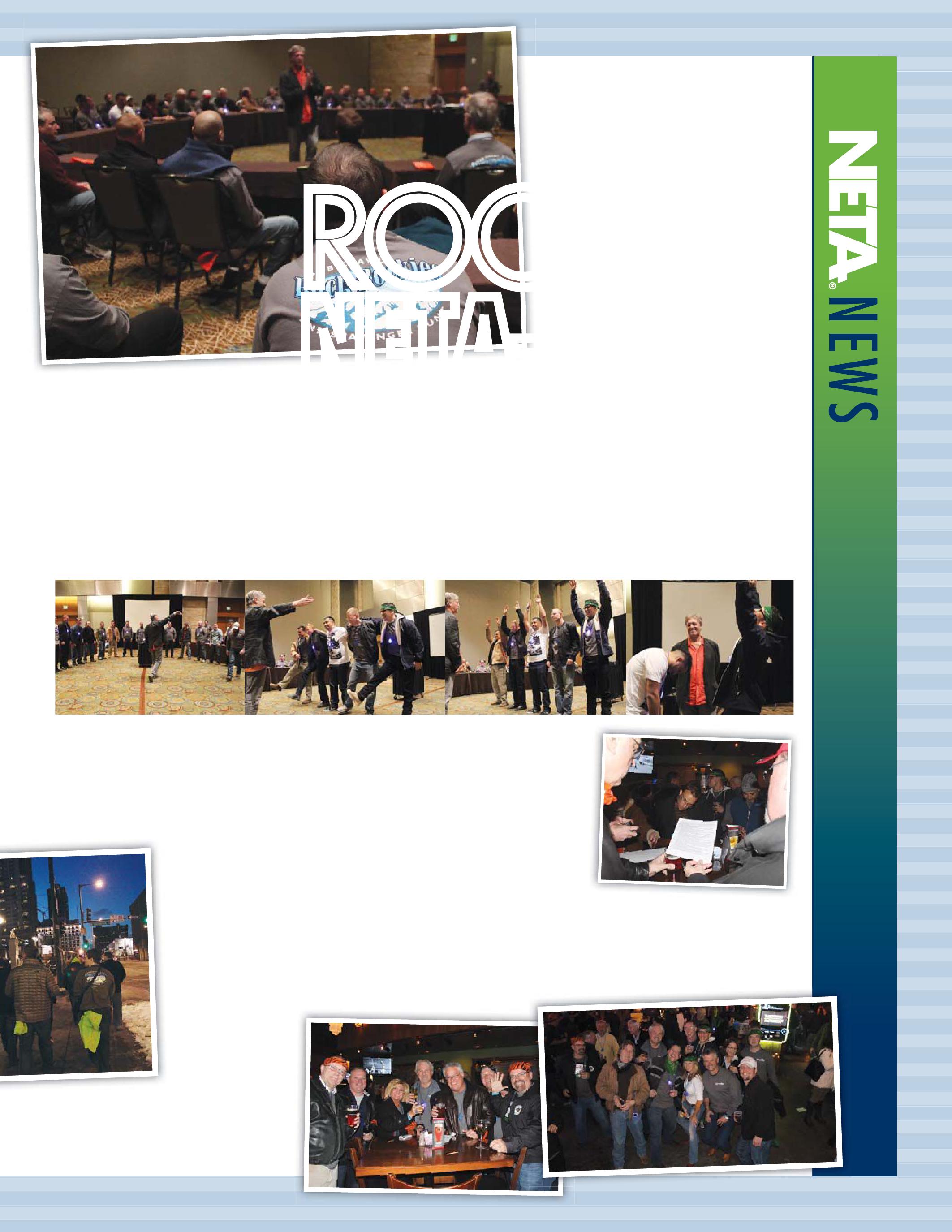
It started out innocently enough, with the most heated battle of Simon Says in the history of the sport. Not surprisingly, it came down to two highly disciplined individuals whose nose-foot coordination was impeccable.
After this warm-up exercise, teams were united under colorful bandanas, team photos were taken, and participants headed out into the cool night air to seek their fortunes. Each team navigated a maze of scavenger hunt clues that lead them from pub to pub where they were rewarded with respite, food, and drink at each stop along the way. They solved clues while quenching their thirst with frosty brews, huddled together around bar food and beers, jotting
notes in the cool glow of smart phone screens.
It was no surprise that the team that drafted the Simon Says victor triumphed, taking home the coveted first place prize: bragging rights for the coming year. It is safe to say that if one was ever to be faced with an impossible situation, the green team would be the one to call on for back-up. Congratulations, Team Green!


1. Since induction motors were specified, loss-of-field and sync-check would not be useful. The correct answer is d.


2. The best answer in this grouping is c. Many large induction motors will draw 6 to 8 times their full-load current during locked rotor conditions.
3. D is probably the best answer, but modern microprocessor relays generally have start limitations, thermal algorithms more sophisticated than simple thermal memory, RTDs that provide temperature limits as well as biasing of the thermal algorithm, negative sequence current calculations that alter the overload point, and other protection functions. The I2t (thermal) characteristic applies to almost any current-based protective relay. Figure 1 shows a typical thermal damage/ limit characteristic curve. Any time-current that exceeds the thermal damage characteristic will cause some thermal damage. This damage is cumulative and will add to any previous thermal degradation. Eventually the insulation becomes brittle and will fail due to electrical or mechanical forces.
4. The correct answer for this question is c. All the other protective functions are preventing the motor temperature from exceeding either the rotor thermal limit or the stator thermal limit.
5. Locked-rotor current is the current that flows in a motor when rated voltage is applied to the motor when the rotor is at a standstill. As it turns out, nearly that same current occurs through most of the motor’s acceleration period. The correct answer is a.


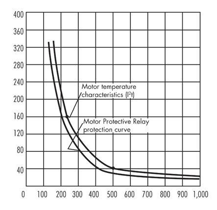
Figure 1: Thermal Damage Characteristic Courtesy Omron Industrial Automation
NFPA Disclaimer: Although Jim White is a member of the NFPA Technical Committee for both NFPA 70E “Standard for Electrical Safety in the Workplace” and NFPA 70B “Recommended Practice for Electrical Equipment Maintenance,” the views and opinions expressed in this message are purely the author’s and shall not be considered an official position of the NFPA or any of its technical committees and shall not be considered to be, nor be relied upon as, a formal interpretation or promotion of the NFPA. Readers are encouraged to refer to the entire text of all referenced documents.
A&F Electrical Testing, Inc.
80 Lake Ave. South, Ste. 10 Nesconset, NY 11767 (631) 584-5625 Fax: (631) 584-5720 kchilton@afelectricaltesting.com www.afelectricaltesting.com
Kevin Chilton
A&F Electrical Testing, Inc.
80 Broad St. 5th Floor
New York, NY 10004 (631) 584-5625 Fax: (631) 584-5720 afelectricaltesting@afelectricaltesting.com www.afelectricaltesting.com
Florence Chilton
ABM Electrical Power Solutions
3602 East Southern Ave., Ste. 1 & 2 Phoenix, AZ 85040 (602) 796-6583 www.ABM.com
Ben Thomas
ABM Electrical Power Solutions
9800 E. Geddes Avenue, Unit A-150 Englewood, CO 80112 (303) 524-6560 Fax: (303) 524-6581 www.ABM.com
Ben Thomas
ABM Electrical Power Solutions 2142 Rheem Drive Pleasanton, CA 94588 www.ABM.com
ABM Electrical Power Solutions
3711 Saunders Ave. Richmond, VA 23227 (804) 253-9079 Fax: (804) 254-5799 www.ABM.com
Barry Maitland
ABM Electrical Power Solutions
6280 South Valley View Blvd., Ste. 618 Las Vegas, NV 89118 (702) 216-0982 Fax: (702) 216-0983 www.ABM.com
Ben Thomas
ABM Electrical Power Solutions
814 Greenbrier Circle, Ste. E Chesapeake, VA 23320 (757) 548-5690 Fax: (757) 548-5417 www.ABM.com
Mark Anthony Gaughan, III
ABM Electrical Power Solutions
3700 Commerce Dr. #901-903 Baltimore, MD 21227 (410) 247-3300 Fax: (410) 247-0900 www.ABM.com
Bill Hartman
ABM Electrical Power Solutions
710 Thomson Park Dr. Cranberry Township, PA 16066-6427 (724) 772-4638 Fax: (724) 772-6003 william.mckenzie@abm.com www.ABM.com
William (Pete) McKenzie
ABM Electrical Power Solutions
5805 G Departure Dr. Raleigh, NC 27616 (919) 877-1008 Fax: (919) 501-7492
www.ABM.com
Rob Parton
ABM Electrical Power Solutions
4390 Parliament Place, Ste. Q Lanham, MD 20706 (301) 967-3500 Fax: (301) 735-8953 www.ABM.com
Frank Ceci
ABM Electrical Power Solutions
3600 Woodpark Blvd., Suite G Charlotte, NC 28206 (704) 273-6257 Fax: (704) 598-9812 ernest.goins@abm.com www.ABM.com
Ernest Goins
ABM Electrical Power Solutions
720 S. Rochester Ave., Suite A Ontario, CA 91761 (951) 522-8855 Fax: (909) 937-6798 www.ABM.com
Ben Thomas
Absolute Testing Services 6829 Guhn Rd. Houston, TX 77040 (832) 467-4446 Fax: (713) 849-3885 rgamble@absolutetesting.com www.texasats.com
Richard Gamble
Advanced Testing Systems 15 Trowbridge Dr. Bethel, CT 06801 (203) 743-2001 Fax: (203) 743-2325 pmaccarthy@advtest.com www.advtest.com
Pat MacCarthy
American Electrical Testing Co., Inc. 480 Neponset St., Building 6 Canton, MA 02021-1970 (781) 821-0121 Fax: (781) 821-0771 sblizard@aetco.us www.99aetco.com
Scott A. Blizard
American Electrical Testing Co., Inc. 34 Clover Dr. South Windsor, CT 06074 (860) 648-1013 Fax: (781) 821-0771 jpoulin@aetco.us www.99aetco.com
Gerald Poulin
American Electrical Testing Co., Inc. 76 Cain Dr. Brentwood, NY 11717 (631) 617-5330 Fax: (631) 630-2292 mschacker@aetco.us www.99aetco.com
Michael Schacker
American Electrical Testing Co., Inc. 50 Intervale Rd., Ste. 1 Boonton, NJ 07005 (973) 316-1180 Fax: (781) 316-1181 jsomol@aetco.us www.99aetco.com
Jeff Somol
American Electrical Testing Co., Inc. 4032 Park 65 Dr. Indianapolis, IN 46254 (317) 487-2111 Fax: (781) 821-0771 scanale@aetco.us www.99aetco.com
Stephen Canale
American Electrical Testing Co., Inc. Green Hills Commerce Center 5925 Tilghman St., Ste. 200 Allentown, PA 18104 (215) 219-6800 jmunley@aetco.us www.99aetco.com
Jonathan Munley
American Electrical Testing Co., Inc. 12566 W. Indianola Ave. Avondale, AZ 85392 (480) 383-9242 dmadaglia@aetco.us www.99aetco.com
Donald Madaglia
AMP Quality Energy Services, LLC 4220 West Schrimsher SW Site W1 P.O. Box 526, Huntsville, AL 35804 (256) 513-8255
Brian Rodgers
Apparatus Testing and Engineering PO Box 984, Folsom, CA 95763 (916) 853-6280 Fax: (916) 853-6258 jlawler@apparatustesting.com www.apparatustesting.com
James Lawler
Apparatus Testing and Engineering 7083 Commerce Circle, Ste. H Pleasanton, CA 94588 (925) 454-1363 Fax: (925) 454-1499 info@apparatustesting.com www.apparatustesting.com
Harold (Jerry) Carr
Applied Engineering Concepts 1105 N. Allen Ave. Pasadena, CA 91104 (626) 398-3052 Fax: (626) 398-3053 michel.c@aec-us.com www.aec-us.com
Michel Castonguay
Burlington Electrical Testing Co., Inc.
300 Cedar Ave. Croydon, PA 19021-6051 (215) 826-9400 (221) Fax: (215) 826-0964 waltc@betest.com www.betest.com
Walter P. Cleary
C.E. Testing, Inc. 6148 Tim Crews Rd. Macclenny, FL 32063 (904) 653-1900 Fax: (904) 653-1911 cetesting@aol.com
Mark Chapman
CE Power Solutions, LLC 4500 W. Mitchell Ave. Cincinnati, OH 45232 (513) 563-6150 Fax: (513) 563-6120 info@cepowersol.net www.cepowersol.com
Rhonda Harris
CE Power Solutions of Wisconsin, LLC 3100 East Enterprise Ave. Appleton, WI 54913 (920) 968-0281 Fax: (920) 968-0282 rob.fulton@cepower.com
Rob Fulton
Control Power Concepts
353 Pilot Rd; Ste. B Las Vegas, NV 89119 (702) 448-7833 Fax: (702) 448-7835 www.controlpowerconcepts.com
John Travis
Dude Electrical Testing LLC
145 Tower Dr., Unit# 9 Burr Ridge, IL 60527 (815) 293-3388 Fax: (815) 293-3386 scott.dude@dudetesting.com www.dudetesting.com
Scott Dude
DYMAX Service, Inc.
46918 Liberty Dr. Wixom, MI 48393 (248) 313-6868 Fax: (248) 313-6869 www.dymaxservice.com
Bruce Robinson
DYMAX Service, Inc.
4213 Kropf Ave. Canton, OH 44706 (330) 484-6801 Fax: (740) 333-1271 www.dymaxservice.com
Gary Swank
Eastern High Voltage 11A South Gold Dr. Robbinsville, NJ 08691-1606 (609) 890-8300 Fax: (609) 588-8090 joewilson@easternhighvoltage.com www.easternhighvoltage.com
Joseph Wilson
ELECT, P.C.
7400-G Siemens Rd., P.O. Box 2080 Wendell, NC 27591 (919) 365-9775 Fax: (919) 365-9789 btyndall@elect-pc.com www.elect-pc.com
Barry W. Tyndall
Electric Power Systems, Inc.
21 Millpark Ct. Maryland Heights, MO 63043-3536 (314) 890-9999 Fax: (314) 890-9998 www.eps-international.com
Electric Power Systems, Inc.
557 E. Juanita Ave., #4 Mesa, AZ 85204 (480) 633-1490 Fax: (480) 633-7092 www.eps-international.com
Electric Power Systems, Inc.
4436 Parkway Commerce Blvd. Orlando, FL 32808 (407) 578-6424 Fax: 407-578-6408 www.eps-international.com
Electric Power Systems, Inc.
7000 E. 47th Avenue Drive, Suite 100 Denver, CO 80216 (720) 857-7273 Fax: 303-928-8020 www.eps-international.com
Electric Power Systems, Inc.
23823 Andrew Rd. Plainfield, IL 60585 (815) 577-9515 Fax: (815) 577-9516 www.eps-international.com
Electric Power Systems, Inc. 2601 Center Rd., # 101 Hinckley, OH 44233 (330) 460-3706 Fax: (330) 460-3708 www.eps-international.com
Electric Power Systems, Inc.
56 Bibber Pkwy #1 Brunswick, ME 04011 (207) 837-6527 www.eps-international.com
Electric Power Systems, Inc. 4100 Greenbriar Dr., Ste. 160 Stafford, TX 77477 (713) 644-5400 www.eps-international.com
Electric Power Systems, Inc. 11861 Longsdorf St. Riverview, MI 48193 (734) 282-3311 www.eps-international.com
Electric Power Systems, Inc. 827 Union St., Salem, VA 24153 (540) 375-0084 Fax: (540) 375-0094 www.eps-international.com
Electric Power Systems, Inc. 915 Holt Ave., Unit 9 Manchester, NH 03109 (603) 657-7371 Fax: 603-657-7370 www.eps-international.com
Electric Power Systems, Inc. 146 Space Park Dr. Nashville, TN 37211 (615) 834-0999 Fax: (615) 834-0129 www.eps-international.com
NETA ACCREDITED COMPANIES
Electric Power Systems, Inc. 8515 Cella Alameda NE, Ste. A Albuquerque, NM 87113 (505) 792-7761
www.eps-international.com
Electric Power Systems, Inc. 319 US Hwy. 70 E, Unit E Garner, NC 27529 (919) 322-2670
www.eps-international.com
Electric Power Systems, Inc. 1090 Montour West Industrial Blvd. Coraopolis, PA 15108 (412) 276-4559 www.eps-international.com
Electric Power Systems, Inc. 6141 Connecticut Ave. Kansas City, MO 64120 (816) 241-9990 Fax: (816) 241-9992 www.eps-international.com
Electric Power Systems, Inc. 2495 Boulevard of the Generals Norristown, PA 19403 (610) 630-0286 www.eps-international.com
Electric Power Systems, Inc. 1129 East Hwy. 30 Gonzalez, LA 70817 (225) 644-0150 Fax: (225) 644-6249 www.eps-international.com
Electrical & Electronic Controls 6149 Hunter Rd. Ooltewah, TN 37363 (423) 344-7666 (23) Fax: (423) 344-4494 eecontrols@comcast.net
Michael Hughes
Electrical Energy Experts, Inc. W129N10818, Washington Dr. Germantown, WI 53022 (262) 255-5222 Fax: (262) 242-2360 bill@electricalenergyexperts.com www.electricalenergyexperts.com
William Styer
Electrical Equipment Upgrading, Inc. 21 Telfair Place, Savannah, GA 31415 (912) 232-7402 Fax: (912) 233-4355 kmiller@eeu-inc.com www.eeu-inc.com
Kevin Miller
Electrical Maintenance & Testing Inc. 12342 Hancock St., Carmel, IN 46032 (317) 853-6795 Fax: (317) 853-6799 www.emtesting.com
Brian K. Borst
Electrical Reliability Services 1057 Doniphan Park Circle, Ste. A El Paso, TX 79922 (915) 587-9440 Fax: (915) 587-9010 www.electricalreliability.com
Electrical Reliability Services 1775 W. University Dr., Ste. 128 Tempe, AZ 85281 (480) 966-4568 Fax: (480) 966-4569 www.electricalreliability.com
Electrical Reliability Services 1426 Sens Rd. Ste. 5 Houston, TX 77571 (281) 241-2800 Fax: (281) 241-2801 www.electricalreliability.com
Electrical Reliability Services 4099 SE International Way, Ste. 201 Milwaukie, OR 97222-8853 (503) 653-6781 Fax: (503) 659-9733 www.electricalreliability.com
Electrical Reliability Services 5810 Van Allen Way Carlsbad, CA 92008 (760) 804-2972 www.electricalreliability.com
Electrical Reliability Services 8500 Washington Pl. NE, Ste. A-6 Albuquerque, NM 87113 (505) 822-0237 Fax: (505) 822-0217 www.electricalreliability.com
Electrical Reliability Services 1380 Greg Street, Ste. 217 Sparks, NV 89431 (775) 746-8484 Fax: (775) 356-5488 www.electricalreliability.com
Electrical Reliability Services 2275 Northwest Pkwy SE, Ste. 180 Marietta, GA 30067 (770) 541-6600 Fax: (770) 541-6501 www.electricalreliability.com
Electrical Reliability Services 7100 Broadway, Ste. 7E Denver, CO 80221-2915 (303) 427-8809 Fax: (303) 427-4080 www.electricalreliability.com
Electrical Reliability Services 348 N.W. Capital Dr. Lee's Summit, MO 64086 (816) 525-7156 Fax: (816) 524-3274 www.electricalreliability.com
Electrical Reliability Services 6900 Koll Center Parkway, Ste. 415 Pleasanton, CA 94566 (925) 485-3400 Fax: (925) 485-3436 www.electricalreliability.com
Electrical Reliability Services 10606 Bloomfield Ave. Santa Fe Springs, CA 90670 (562) 236-9555 Fax: (562) 777-8914 www.electricalreliability.com
Electrical Reliability Services 14141 Airline Hwy., Bldg 1; Ste. X Baton Rouge, LA 70817 (225) 755-0530 Fax: (225) 751-5055 www.electricalreliability.com
Electrical Reliability Services 121 Highway 108 East Sulphur, LA 70665 (337) 583-2411 Fax: (337) 583-2410 www.electricalreliability.com
Electrical Reliability Services 11000 Metro Pkwy., Ste. 30 Ft. Myers, FL 33966 (239) 693-7100 Fax: (239) 693-7772 www.electricalreliability.com
Electrical Reliability Services 2222 West Valley Hwy. N., Ste 160 Auburn, WA 98001 (253) 736-6010 Fax: (253) 736-6015 www.electricalreliability.com
Electrical Reliability Services 3412 South 1400 West, Unit A West Valley City, UT 84119 (801) 975-6461 www.electricalreliability.com
Electrical Reliability Services 6351 Hinson St., Ste. B Las Vegas, NV 89118 (702) 597-0020 Fax: (702) 597-0095 www.electricalreliability.com
Electrical Reliability Services 610 Executive Campus Dr. Westerville, OH 43082 (877) 468-6384 Fax: (614) 410-8420 info@electricalreliability.com www.electricalreliability.com
Electrical Reliability Services 9636 St. Vincent, Unit A Shreveport, LA 71106 (318) 869-4244 www.electricalreliability.com
Electrical Reliability Services 6135 Lakeview Rd., Ste 500 Charlotte, NC 28269 (704) 441-1497 www.electricalreliability.com
Electrical Testing, Inc. 2671 Cedartown Hwy. Rome, GA 30161-6791 (706) 234-7623 Fax: (706) 236-9028 steve@electricaltestinginc.com www.electricaltestinginc.com
Electrical Testing Solutions
2909 Green Hill Ct. Oshkosh, WI 54904 (920) 420-2986 Fax: (920) 235-7136 tmachado@electricaltestingsolutions.com www.electricaltestingsolutions.com Tito Machado
Elemco Services, Inc.
228 Merrick Rd. , Lynbrook, NY 11563 (631) 589-6343 Fax: (631) 589-6670 courtney@elemco.com www.elemco.com
Courtney O'Brien
EnerG Test
204 Gale Lane
Bldg. 2 - 2nd Floor
Kennett Square, PA 19348 (484) 731-0200 Fax: (484) 713-0209 kbleiler@energtest.com www.energtest.com
Katie Bleiler
Energis High Voltage Resources, Inc.
1361 Glory Rd. Green Bay, WI 54304 (920) 632-7929 Fax: (920) 632-7928 info@energisinc.com www.energisinc.com
Mick Petzold
EPS Technology
29 N. Plains Hwy., Ste. 12 Wallingford, CT 06492 (203) 679-0145 www.eps-technology.com
Grounded Technologies, Inc.
1855 W. Union Avenue, Ste. E Englewood, CO 80110 P-(303) 781-2560 F- (303) 781-5240 jodymedina@groundedtech.com www.groundedtech.com
Jody Medina
Grubb Engineering, Inc.
3128 Sidney Brooks San Antonio, Tx 78235 (210) 658-7250 Fax: (210) 658-9805 joy@grubbengineering.com www.grubbengineering.com
Robert D. Grubb Jr.
Hampton Tedder Technical Services 4571 State St. Montclair, CA 91763 (909) 628-1256 x214 Fax: (909) 628-6375 matt.tedder@hamptontedder.com www.hamptontedder.com
Matt Tedder
Hampton Tedder Technical Services 4920 Alto Ave. Las Vegas, NV 89115 (702) 452-9200 Fax: (702) 453-5412 www.hamptontedder.com
Roger Cates
Hampton Tedder Technical Services 3747 West Roanoke Ave. Phoenix, AZ 85009 (480) 967-7765 Fax: (480) 967-7762 www.hamptontedder.com
Harford Electrical Testing Co., Inc. 1108 Clayton Rd. Joppa, MD 21085 (410) 679-4477 Fax: (410) 679-0800 testing@harfordtesting.com www.harfordtesting.com
Vincent Biondino
High Energy Electrical Testing, Inc. 515 S. Ocean Ave. Seaside Park, NJ 08752 (732) 938-2275 Fax: (732) 938-2277
hinrg@comcast.net www.highenergyelectric.com
Charles Blanchard
High Voltage Maintenance Corp.
24 Walpole Park South Dr. Walpole, MA 02081 (508) 668-9205 www.hvmcorp.com
High Voltage Maintenance Corp. 941 Busse Rd. Elk Grove Village, Il 60007 (847) 640-0005 www.hvmcorp.com
High Voltage Maintenance Corp. 7200 Industrial Park Blvd. Mentor, OH 44060 (440) 951-2706 Fax: (440) 951-6798 www.hvmcorp.com
High Voltage Maintenance Corp.
3000 S. Calhoun Rd.
New Berlin, WI 53151 (262) 784-3660 Fax: (262) 784-5124 www.hvmcorp.com
High Voltage Maintenance Corp. 8320 Brookville Rd. #E Indianapolis, IN 46239 (317) 322-2055 Fax: (317) 322-2056 www.hvmcorp.com
High Voltage Maintenance Corp. 1250 Broadway, Ste. 2300 New York, NY 10001 (718) 239-0359 www.hvmcorp.com
High Voltage Maintenance Corp.
355 Vista Park Dr. Pittsburgh, PA 15205-1206 (412) 747-0550 Fax: (412) 747-0554 www.hvmcorp.com
High Voltage Maintenance Corp.
150 North Plains Industrial Rd. Wallingford, CT 06492 (203) 949-2650 Fax: (203) 949-2646 www.hvmcorp.com
High Voltage Maintenance Corp. 9305 Gerwig Ln., Ste. B Columbia, MD 21046 (410) 309-5970 Fax: (410) 309-0220 www.hvmcorp.com
High Voltage Maintenance Corp. 24371 Catherine Industrial Dr, Ste. 207 Novi, MI 48375 (248) 305-5596 Fax: (248) 305-5579 www.hvmcorp.com
High Voltage Maintenance Corp. 5100 Energy Dr. Dayton, OH 45414 (937) 278-0811 Fax: (937) 278-7791 www.hvmcorp.com
High Voltage Service, Inc. 4751 Mustang Circle St. Paul, MN 55112 (763) 717-3103 Fax: (763) 784-5397 www.hvserviceinc.com
Mike Mavetz
HMT, Inc. 6268 Route 31 Cicero, NY 13039 (315) 699-5563 Fax: (315) 699-5911 jpertgen@hmt-electric.com www.hmt-electric.com
John Pertgen
Industrial Electric Testing, Inc. 11321 West Distribution Ave. Jacksonville, FL 32256 (904) 260-8378 Fax: (904) 260-0737 gbenzenberg@bellsouth.net www.industrialelectrictesting.com
Gary Benzenberg
Industrial Electric Testing, Inc. 201 NW 1st Ave. Hallandale, FL 33009-4029 (954) 456-7020 www.industrialelectrictesting.com
Industrial Electronics Group 850369 Highway 17 South P.O. Box 1870 Yulee, FL 32041 (904) 225-9529 Fax: (904) 225-0834 butch@industrialgroups.com www.industrialgroups.com Butch E. Teal
Industrial Tests, Inc. 4021 Alvis Ct., Ste. 1 Rocklin, CA 95677 (916) 296-1200 Fax: (916) 632-0300 greg@indtest.com www.industrialtests.com
Greg Poole
Infra-Red Building and Power Service 152 Centre St. Holbrook, MA 02343-1011 (781) 767-0888 Fax: (781) 767-3462 tom.mcdonald@infraredbps.com www.infraredbps.com
Thomas McDonald Sr.
Longo Electrical-Mechanical, Inc. One Harry Shupe Blvd., Box 511 Wharton, NJ 07885 (973) 537-0400 Fax: (937) 537-0404 jmlongo@elongo.com www.elongo.com
Joe Longo
Longo Electrical-Mechanical, Inc. 1625 Pennsylvania Ave. Linden, NJ 07036 (908) 925-2900 Fax: (908) 925-9427 jmlongo@elongo.com www.elongo.com
Joe Longo
Longo Electrical-Mechanical, Inc. 1400 F Adams Rd. Bensalem, PA 19020 (215) 638-1333 Fax: (215) 638-1366 jmlongo@elongo.com www.elongo.com
Joe Longo
M&L Power Systems, Inc. 109 White Oak Ln., Ste. 82 Old Bridge, NJ 08857 (732) 679-1800 Fax: (732) 679-9326 milind@mlpower.com www.mlpower.com
Milind Bagle
Magna Electric Corporation 1033 Kearns Crescent, Box 995 Regina, SK S4P 3B2 Canada (306) 949-8131 Fax: (306) 522-9181 kheid@magnaelectric.com www.magnaelectric.com
Kerry Heid
Magna Electric Corporation 3430 25th St. NE Calgary, AB T1Y 6C1 Canada (403) 769-9300 Fax: (403)769-9369 cgrant@magnaelectric.com www.magnaelectric.com
Cal Grant
Magna Electric Corporation 851-58th St. East Saskatoon, SK S7K 6X5 Canada (306) 955-8131 Fax: (306) 955-9181 ajaques@magnaelectric.com www.magnaelectric.com
Adam Jaques
Magna Electric Corporation 1375 Church Ave. Winnipeg, MB R2X 2T7 Canada (204) 925-4022 Fax: (204) 925-4021 cbrandt@magnaelectric.com www.magnaelectric.com
Curtis Brandt
Magna Electric Corporation 3731-98 Street Edmonton, AB T6E 5N2 Canada (780) 436-8831 Fax: (780) 463-9646 fgranacher@magnaelectric.com www.magnaelectric.com
Franz Granacher
Magna IV Engineering 1103 Parsons Rd. SW Edmonton, AB T6X 0X2 Canada (780) 462-3111 Fax: (780) 450-2994 info@magnaiv.com www.magnaiv.com
Dave Emerson
Magna IV Engineering 200, 688 Heritage Dr. Calgary, AB T2H 1M6 Canada (403) 723-0575 Fax: (403) 723-0580 info.calgary@magnaiv.com
Virginia Balitski
Magna IV Engineering 8219D Fraser Ave. Fort McMurray, AB T9H 0A2 Canada (780) 791-3122 Fax: (780) 791-3159 info.fmcmurray@magnaiv.com
Ryan Morgan
Magna IV Engineering 96 Inverness Dr. East, Unit R Englewood, CO 80112 (303) 799-1273 Fax: (303) 790-4816 info.denver@magnaiv.com
Aric Proskurniak
Magna IV Engineering Avenida del Condor #590 Oficina 601 Huechuraba, Santiago 8580676 Chile +(56) 9-9-517-4642 info.chile@magnaiv.com
Cristian Fuentes
Magna IV Engineering 1040 Winnipeg St. Regina , SK S4R 8P8 Canada (306) 585-2100 Fax: (306) 585-2191 info.regina@magnaiv.com
Andrew Westerman
Magna IV Engineering 106, 4268 Lozells Ave. Burnaby, BC VSA 0C6 Canada (604) 421-8020
William Kulsky
Magna IV Engineering 1005 Spinney Dr. Dawson Creek, BC V1G 1K1 Canada (780) 462-3111 Fax: (780) 462-9799 info@magnaiv.com
David Limb
National Field Services 649 Franklin St. Lewisville, TX 75057 (972) 420-0157 www.natlfield.com
Eric Beckman
Nationwide Electrical Testing, Inc. 6050 Southard Trace Cumming, GA 30040 (770) 667-1875 Fax: (770) 667-6578
Shashi@N-E-T-Inc.com www.n-e-t-inc.com
Shashikant B. Bagle
North Central Electric, Inc. 69 Midway Ave. Hulmeville, PA 19047-5827 (215) 945-7632 Fax: (215) 945-6362 ncetest@aol.com
Robert Messina
Northern Electrical Testing, Inc. 1991 Woodslee Dr. Troy, MI 48083-2236 (248) 689-8980 Fax: (248) 689-3418 ldetterman@northerntesting.com www.northerntesting.com
Lyle Detterman
Orbis Engineering Field Services Ltd. #300, 9404 - 41st Ave. Edmonton, AB T6E 6G8 Canada (780) 988-1455 Fax: (780) 988-0191 lorne@orbisengineering.net www.orbisengineering.net
Lorne Gara
Pacific Power Testing, Inc. 14280 Doolittle Dr. San Leandro, CA 94577 (510) 351-8811 Fax: (510) 351-6655 steve@pacificpowertesting.com www.pacificpowertesting.com
Steve Emmert
Pacific Powertech, Inc. #110, 2071 Kingsway Ave. Port Coquitlam, BC V3C 1T2 Canada (604) 944-6697 Fax: (604) 944-1271 jkonkin@pacificpowertech.ca www.pacificpowertech.ca
Josh Konkin
Phasor Engineering
Sabaneta Industrial Park #216 Mercedita, PR 00715 Puerto Rico (787) 844-9366 Fax: (787) 841-6385 rcastro@phasorinc.com
Rafael Castro
Potomac Testing, Inc. 1610 Professional Blvd., Ste. A Crofton, MD 21114 (301) 352-1930 Fax: (301) 352-1936 kbassett@potomactesting.com www.potomactesting.com
Ken Bassett
Potomac Testing, Inc. 11179 Hopson Rd., Ste. 5 Ashland, VA 23005 (804) 798-7334 Fax: (804) 798-7456 www.potomactesting.com
Power & Generation Testing, Inc. 480 Cave Rd. Nashville, TN 37210 (615) 882-9455 Fax: (615) 882-9591 mose@pgti.net www.pgti.net
Mose Ramieh
Power Engineering Services, Inc. 9179 Shadow Creek Lane Converse, TX 78109 (210) 590-4936 Fax: (210) 590-6214 engelke@pe-svcs.com www.pe-svcs.com
Miles R. Engelke
POWER PLUS Engineering, Inc. 46575 Magallan Dr. Novi, MI 48377 (248) 344-0200 Fax: (248) 305-9105 smancuso@epowerplus.com www.epowerplus.com
Salvatore Mancuso
Power Products & Solutions, LLC 12465 Grey Commercial Rd. Midland, NC 28107 (704) 573-0420 x12 Fax: (704) 573-3693 ralph.patterson@powerproducts.biz www.powerproducts.biz
Ralph Patterson
Power Products & Solutions, LLC 13 Jenkins Ct. Mauldin, SC 29662 (800) 328-7382 ralph.patterson@powerproducts.biz www.powerproducts.biz
Raymond Pesaturo
Power Services, LLC 998 Dimco Way, P.O. Box 750066 Centerville, OH 45475 (937) 439-9660 Fax: (937) 439-9611 mkbeucler@aol.com
Mark Beucler
Power Solutions Group, Ltd. 425 W. Kerr Rd. Tipp City, OH 45371 (937) 506-8444 Fax: (937) 506-8434 bwilloughby@powersolutionsgroup.com www.powersolutionsgroup.com
Barry Willoughby
Power Solutions Group, Ltd. 135 Old School House Rd. Piedmont, SC 29673 (864) 845-1084 Fax:: (864) 845-1085 fcrawford@powersolutionsgroup.com www.powersolutionsgroup.com
Anthony Crawford
Power Solutions Group, Ltd. 670 Lakeview Plaza Blvd. Columbus, OH 43085 (614) 310-8018 sspohn@powersolutionsgroup.com www.powersolutionsgroup.com
Stuart Spohn
Power Systems Testing Co. 4688 W. Jennifer Ave., Ste. 108 Fresno, CA 93722 (559) 275-2171 ext 15 Fax: (559) 275-6556 dave@pstcpower.com www.powersystemstesting.com
David Huffman
Power Systems Testing Co. 600 S. Grand Ave., Ste. 113 Santa Ana, CA 92705-4152 (714) 542-6089 Fax: (714) 542-0737 www.powersystemstesting.com
Power Systems Testing Co. 6736 Preston Ave, Ste. E Livermore, CA 94551 (510) 783-5096 Fax: (510) 732-9287 www.powersystemstesting.com
Power Test, Inc. 2200 Highway 49 Harrisburg, NC 28075 (704) 200-8311 Fax: (704) 455-7909 rich@powertestinc.com www.powertestinc.com
Richard Walker
POWER Testing and Energization, Inc. 14006 NW 3rd Ct., Ste. 101 Vancouver, WA 98685 (360) 576-4826 Fax: (360) 576-7182 chris.zavadlov@powerte.com www.powerte.com
Chris Zavadlov
POWER Testing and Energization, Inc. 731 E. Ball Rd., Ste. 100 Anaheim, CA 92805 (714) 507-2702 www.powerte.com
POWER Testing and Energization, Inc. 22035 70th Ave. South Kent, WA 98032 (253) 872-7747 www.powerte.com
Powertech Services, Inc. 4095 South Dye Rd. Swartz Creek, MI 48473-1570 (810) 720-2280 Fax: (810) 720-2283 kirkd@powertechservices.com www.powertechservices.com
Kirk Dyszlewski
Precision Testing Group 5475 Highway 86, Unit 1 Elizabeth, CO 80107 (303) 621-2776 Fax: (303) 621-2573 glenn@precisiontestinggroup.com
Glenn Stuckey
NETA ACCREDITED COMPANIES
PRIT Service, Inc.
112 Industrial Dr., P.O. Box 606 Minooka, IL 60447 (815) 467-5577 Fax: (815) 467-5883
Rod.Hageman@pritserviceinc.com www.pritserviceinc.com Rod Hageman
Reuter & Hanney, Inc.
149 Railroad Dr.
Northampton Industrial Park Ivyland, PA 18974 (215) 364-5333 Fax: (215) 364-5365 mikereuter@reuterhanney.com www.reuterhanney.com
Michael Reuter
Reuter & Hanney, Inc. 4270-I Henninger Ct. Chantilly, VA 20151 (703) 263-7163 Fax: 703-263-1478 www.reuterhanney.com
Reuter & Hanney, Inc.
11620 Crossroads Circle, Suites D-E Middle River, MD 21220 (410) 344-0300 Fax: (410) 335-4389 www.reuterhanney.com
Michael Jester
REV Engineering, LTD
3236 - 50 Ave. SE Calgary, AB T2B 3A3 Canada (403) 287-0156 Fax: (403) 287-0198 rdavidson@reveng.ca www.reveng.ca
Roland Nicholas Davidson, IV
Saber Power Services 9841 Saber Power Lane Rosharon, TX 77583-5188 (713) 222-9102 info@saberpower.com www.saberpower.com
Phil Collins
Scott Testing Inc. 1698 5th St. Ewing, NJ 08638 (609) 882-2400 Fax: (609) 882-5660 rsorbello@scotttesting.com www.scotttesting.com
Russ Sorbello
Shermco Industries 2425 E. Pioneer Dr. Irving, TX 75061 (972) 793-5523 Fax: (972) 793-5542 rwidup@shermco.com www.shermco.com
Ron Widup
Shermco Industries 1705 Hur Industrial Blvd. Cedar Park, TX 78613 (512) 267-4800 Fax: (512) 258-5571 kewing@shermco.com www.shermco.com
Kevin Ewing
Shermco Industries 33002 FM 2004 Angleton, TX 77515 (979)848-1406 Fax: (979) 848-0012 mfrederick@shermco.com www.shermco.com
Malcom Frederick
Shermco Industries 1357 N. 108th E. Ave. Tulsa, OK 74116 (918) 234-2300 jharrison@shermco.com www.shermco.com
Jim Harrison
Shermco Industries 796 11th St. Marion, IA 52302 (319) 377-3377 Fax: (319) 377-3399 Lhamrick@shermco.com www.shermco.com
Lynn Hamrick
Shermco Industries 2100 Dixon St., Ste. C Des Moines, IA 50316 (515) 263-8482 LHamrick@shermco.com www.shermco.com
Lynn Hamrick
Shermco Industries Boulevard Saint-Michel 47 1040 Brussels Brussels, Belgium
+32 (0)2 400 00 54 Fax: +32 (0)2 400 00 32 PIdziak@shermco.com www.shermco.com
Paul Idziak
Shermco Industries 12000 Network Blvd., Bldg D, Ste. 410 San Antonio, TX 78249 (512) 267-4800 Fax: (512) 267-4808 kewing@shermco.com www.shermco.com
Kevin Ewing
Sigma Six Solutions, Inc. 2200 West Valley Hwy., Ste. 100 Auburn, WA 98001 (253) 333-9730 Fax: (253) 859-5382 jwhite@sigmasix.com www.sigmasix.com
John White
Southern New England Electrical Testing, LLC 3 Buel St., Ste. 4 Wallingford, CT 06492 (203) 269-8778 Fax: (203) 269-8775 dave.asplund@sneet.org www.sneet.org
David Asplund, Sr.
Southwest Energy Systems, LLC 2231 East Jones Ave., Ste. A Phoenix, AZ 85040 (602) 438-7500 Fax: (602) 438-7501 bob.sheppard@southwestenergysystems.com www.southwestenergysystems.com
Robert Sheppard
Taurus Power & Controls, Inc. 9999 SW Avery St. Tualatin, OR 97062-9517 (503) 692-9004 Fax: (503) 692-9273 robtaurus@tauruspower.com www.tauruspower.com
Rob Bulfinch
Taurus Power & Controls, Inc. 6617 S. 193rd Place, Ste. P104 Kent, WA 98032 (425) 656-4170 Fax: (425) 656-4172 jiml@tauruspower.com www.tauruspower.com
Jim Lightner
3C Electrical Co., Inc. 40 Washington St. Westborough, MA 01581 (508) 881-3911 Fax: (508) 881-4814 jim@three-c.com www.three-c.com
Jim Cialdea
3C Electrical Co., Inc. 72 Sanford Dr. Gorham, ME 04038 (800) 649-6314 Fax: (207) 782-0162 jim@three-c.com www.three-c.com
Jim Cialdea
Tidal Power Services, LLC 4202 Chance Lane Rosharon, TX 77583 (281) 710-9150 Fax: (713) 583-1216 monty.janak@tidalpowerservices.com www.tidalpowerservices.com
Monty C. Janak
Tidal Power Services, LLC 8184 Highway 44, Ste. 105 Gonzales, LA 70737 (225) 644-8170 Fax: (225) 644-8215 www.tidalpowerservices.com
Darryn Kimbrough
Tidal Power Services, LLC 1056 Mosswood Dr. Sulphur, LA 70663 (337) 558-5457 Fax: (337) 558-5305 www.tidalpowerservices.com
Steve Drake
Tony Demaria Electric, Inc. 131 West F St. Wilmington, CA 90744 (310) 816-3130 (310) 549-9747 neno@tdeinc.com www.tdeinc.com
Nenad Pasic
Trace Electrical Services & Testing, LLC 293 Whitehead Rd. Hamilton, NJ 08619 (609) 588-8666 Fax: (609) 588-8667 jvasta@tracetesting.com www.tracetesting.com
Joseph Vasta
Utilities Instrumentation Service, Inc. 2290 Bishop Circle East Dexter, MI 48130 (734) 424-1200 Fax: (734) 424-0031 GEWalls@UISCorp.com www.uiscorp.com
Gary E. Walls
Utility Service Corporation 4614 Commercial Dr. NW Huntsville, AL 35816-2201 (256) 837-8400 Fax: (256) 837-8403 apeterson@utilserv.com www.utilserv.com
Alan D. Peterson
Western Electrical Services, Inc. 14311 29th St. East Sumner , WA 98390 (253) 891-1995 Fax: (253) 891-1511 dhook@westernelectricalservices.com www.westernelectricalservices.com
Dan Hook
Western Electrical Services, Inc. 3676 W. California Ave., #C, 106 Salt Lake City, UT 84104 (253) 891-1995 Fax: (253) 891-1511 rcoomes@westernelectricalservices.com www.westernelectricalservices.com
Rob Coomes
Western Electrical Services, Inc. 5680 South 32nd St. Phoenix, AZ 85040 (602) 426-1667 Fax: (253) 891-1511 carcher@westernelectricalservices.com www.westernelectricalservices.com
Craig Archer
Western Electrical Services, Inc. 4510 NE 68th Dr., Ste. 122 Vancouver, WA 98661 (888) 395-2021 Fax: (253) 891-1511
Tasciutto@westernelectricalservices.com www.westernelectricalservices.com
Tony Asciutto


successor to the industry leading AC-PRO
The AC-PRO-II is fully backwards compatible with the CTs, actuators and wiring harnesses of the original AC-PRO
55% smaller then the original AC-PRO, with double the features.
RS-485 Modbus RTU communications is standard
Sluggish Breaker™ detection to determine if the breaker mechanism needs service.



This issue’s advertisers are identified below. Please thank these advertisers by telling them you saw their advertisement in YOUR magazine –NETA World.


The NEW MI 2892 PowerMaster is a hand-held three phase power quality analyzer with a large easy-to-read graphical color display enabling the user to detect harmonics, phasors and waveform anomalies in the installation simply by connecting the device. The instrument is designed for long term recording, as well as for troubleshooting power quality problems in three-phase and singlephase power distribution systems.

Easily select a variety of measurement functions including Oscilloscope, Phase Diagram, Power, and Energy.
PowerView software is a powerful platform for downloading, analyzing recorded data and creation of power quality test reports.




Simple recorders require no complex configuration. Up to 32GB memory on removable MicroSD Card.
is the exclusive distributor of Metrel products in the USA. Located in Perkasie, PA, AVOX Technologies offers a complete sales, service, and traceable certification facility for all your equipment and service needs.

Dad says that with 33 lbs the compact VOTANO 100 is the first mobile voltage transformer test device to also offer high accuracy. He can simply carry it with him to each test site and his back doesn’t even hurt. And VOTANO 100 is fast.
The measured results are automatically assessed immediately after the test in accordance with IEEE and IEC standards. VOTANO 100 uses a similar modeling method like the one Dad already knows from OMICRON’s CT Analyzer. The results are reliable, he says.
The unit controls a separate 4 kV amplifier, VBO1, which is placed in the dangerous high-voltage environment from where it provides the necessary test voltages. This ensures Dad’s safety as he conducts the test remotely with VOTANO 100.
Mobile, accurate and safe...Dad’s really enthusiastic!