
Where multi-tap meets multi-task.
For 5 times faster CT testing!
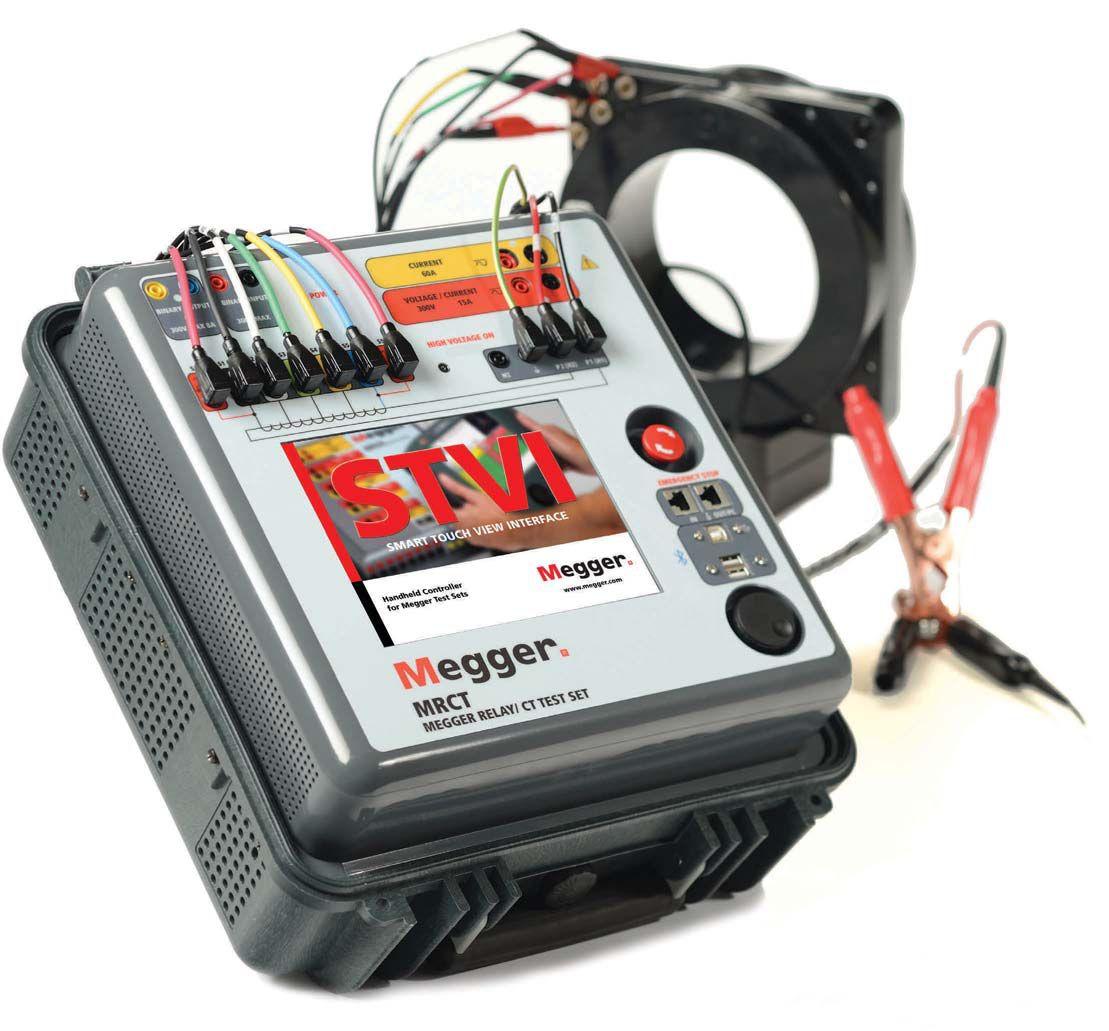
Now test all taps simultaneously, 5 times faster, with the new MRCT from Megger. Now you can measure saturation, ratio, polarity, winding resistance, burden and voltage simultaneously on all taps with absolutely no lead changes. And with integrated insulation and singlephase relay testing, demagnetization functionality and automated test sequences, the MRCT is a small solution that creates big time savings.
Join us for 5 tips to 5x faster CT testing
March 4, 2014, 10:30am CST or March 5, 2014. 10:30am CST
Webinar registration: megger.com/mrct6
COVER STORY
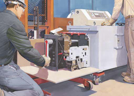

18 Field Testing Techniques for Low-Voltage Circuit Breakers
Bruce M. Rockwell, American Electrical Testing Co.
Modern technology continues to rapidly drive advancement of low-voltage circuit breaker design. While application of new technology to reduce cost is always a product manufacturing consideration, the goal of achieving faster fault clearing times is producing frequent design change of lowvoltage circuit breakers. The frequency of change represents a persistent challenge for technicians and engineers who have to keep up with new field test techniques and to maintain an accurate library of trip curve characteristics. This article identifies and illustrates emerging circuit breaker technology enhancements that require new knowledge and new field test techniques.
FEATURES
7 President’s Desk
David Huffman, Power Systems Testing Co. NETA President
60 Testing and Certifying Modern Protection Schemes for Low-Voltage Circuit Breakers – Part 2
Dan Hook, Western Electrical Services, Inc.
68 New Requirements In Circuit Breaker Diagnostics
Radenko Ostojic and Budo Milovic, DV Power, Sweden

10 The NFPA 70E and NETA
How OSHA and NFPA 70E Work Together
Ron Widup and Jim White, Shermco Industries
Tech Quiz
Field Testing Techniques for Low-Voltage Circuit Breakers
Jim White, Shermco Industries 18 Niche Market
Testing Low-Voltage Breakers
Lynn Hamrick, Shermco Industries
28 Testing Rotating Machinery
Dielectric Characteristic AC Tests
Vicki Warren, Iris Power LP.
Safety Corner
Safety Tips for Qualified Persons
Jim White, Shermco Industries
Tech Tips
Substation Grounding and Personnel Safety
Jeff Jowett, Megger
86 Why You Should Use the Guard Circuit
James R. White, Shermco Industries
Testing Rotating Machinery
Polarization/Depolarization Current (PDC)
Vicki Warren, Iris Power LP
106 The NFPA 70B – One of the Industries Best-Kept Secrets
Ron Widup and Jim White, Shermco Industries
ADVANCEMENTS IN TECHNOLOGY
82 Microprocessor-Based Relays Out with the Old, in with the New Dennis Moon, AVO Training Institute
Shermco Acquires Magna Electric Corporation
NETA and ARCOM Collaborate on MasterSpec® Electrical Testing Requirements 50 NETA Snowbirds Flock to St. Lucia
Kristen Wicks, NETA
NETA Welcomes Control Power Concepts as a NETA Accredited Company
NETA Presents at TechCon North America: Where Technology and Innovation Meet
NETA Welcomes Seven NETA Corporate Alliance Partners
Introducing the NETA Handbooks, Series II
PowerTest 2014 Sponsorship Thank You
PowerTest 2014 Attendees Get Ready to Energize Their Futures
PowerTest 2014 New Product Forum
NETA NEWS – IMPORTANT LISTS
NETA Accredited Companies
Advertiser List



3050 Old Centre Avenue, Suite 102
Portage, MI 49024
Toll free: 888.300.NETA (6382)
Phone: 269.488.NETA (6382)
Fax: 269.488.6383
neta@netaworld.org
www.netaworld.org
EXECUTIVE DIRECTOR: Jayne Tanz, CMP
NETA Officers
PRESIDENT: David Huffman, Power Systems Testing Co.
FIRST VICE PRESIDENT: Ron Widup, Shermco Industries
SECOND VICE PRESIDENT: Jim Cialdea, Three-C Electrical Co., Inc.
SECRETARY: Walt Cleary, Burlington Electrical Testing Co., Inc.
TREASURER: John White, Sigma Six Solutions
NETA Board of Directors
Ken Bassett (Potomac Testing, Inc.)
Scott Blizard (American Electrical Testing Co., Inc.)
Jim Cialdea (Three-C Electrical Co., Inc.)
Walt Cleary (Burlington Electrical Testing Co., Inc.)
Roderic Hageman (PRIT Service, Inc.)
Kerry Heid (Magna Electric Corporation)
David Huffman (Power Systems Testing)
Alan Peterson (Utility Service Corporation)
Mose Ramieh (Power & Generation Testing, Inc.)
Bob Sheppard (Southwest Energy Services, LLC)
John White (Sigma Six Solutions)
Ron Widup (Shermco Industries)
NETA World Staff
TECHNICAL EDITOR: Roderic L. Hageman
ASSOCIATE EDITORS: Diane W. Hageman, Resa Pickel
MANAGING EDITOR: Jayne Tanz, CMP
ADVERTISING MANAGER: Jill Howell
DESIGN AND PRODUCTION: Hour Custom Publishing
NETA Committee Chairs
CONFERENCE: Ron Widup; MEMBERSHIP: Ken Bassett; PROMOTIONS/MARKETING: Scott Blizard; SAFETY: Scott Blizard and Jim White; TECHNICAL: Alan Peterson; TECHNICAL EXAM: Ron Widup; WORLD ADVISORY: Diane Hageman; CONTINUING TECHNICAL DEVELOPMENT: David Huffman; TRAINING: Kerry Heid; FINANCE: John White; NOMINATIONS: Alan Peterson; STRATEGY: Mose Ramieh; ALLIANCE PROGRAM: Jim Cialdea
© Copyright 2014, NETA
NOTICE AND DISCLAIMER
NETA World is published quarterly by the InterNational Electrical Testing Association. Opinions, views and conclusions expressed in articles herein are those of the authors and not necessarily those of NETA. Publication herein does not constitute or imply endorsement of any opinion, product, or service by NETA, its directors, officers, members, employees or agents (herein “NETA”).
All technical data in this publication reflects the experience of individuals using specific tools, products, equipment and components under specific conditions and circumstances which may or may not be fully reported and over which NETA has neither exercised nor reserved control. Such data has not been independently tested or otherwise verified by NETA.
NETA MAKES NO ENDORSEMENT, REPRESENTATION OR WARRANTY AS TO ANY OPINION, PRODUCT OR SERVICE REFERENCED OR ADVERTISED IN THIS PUBLICATION. NETA EXPRESSLY DISCLAIMS ANY AND ALL LIABILITY TO ANY CONSUMER, PURCHASER OR ANY OTHER PERSON USING ANY PRODUCT OR SERVICE REFERENCED OR ADVERTISED HEREIN FOR ANY INJURIES OR DAMAGES OF ANY KIND WHATSOEVER, INCLUDING, BUT NOT LIMITED TO ANY CONSEQUENTIAL, PUNITIVE, SPECIAL, INCIDENTAL, DIRECT OR INDIRECT DAMAGES. NETA FURTHER DISCLAIMS ANY AND ALL WARRANTIES, EXPRESS OF IMPLIED, INCLUDING, BUT NOT LIMITED TO, ANY IMPLIED WARRANTY OF FITNESS FOR A PARTICULAR PURPOSE.
ELECTRICAL TESTING SHALL BE PERFORMED ONLY BY TRAINED ELECTRICAL PERSONNEL AND SHALL BE SUPERVISED BY NETA CERTIFIED TECHNICIANS/ LEVEL III OR IV OR BY NICET CERTIFIED TECHNICIANS IN ELECTRICAL TESTING TECHNOLOGY/LEVEL III OR IV. FAILURE TO ADHERE TO ADEQUATE TRAINING, SAFETY REQUIREMENTS, AND APPLICABLE PROCEDURES MAY RESULT IN LOSS OF PRODUCTION, CATASTROPHIC EQUIPMENT FAILURE, SERIOUS INJURY OR DEATH.


Today’s protection systems are more complex than ever, offering better reliability and safety. They also present increasing challenges. . .
I recently came across arc-flash protection that relied on both arc-flash sensors and zone interlocking on a low-voltage system. This was not the typical circuit breaker testing I may have seen 15 years ago, or even much more recently. It has also given rise to a greater need for electrical acceptance and maintenance testing by qualified, third party, independent testing entities.
By the time you’re reading this, the 2013 summer and the first 2014 exam periods have come and gone, the World Series and Super Bowl has a victor and the March Board and Membership meetings at the 2014 NETA Conference in Denver are upon us. I’m looking forward to seeing many of you there. I thank the presenters, attendees, panel members, exhibitors, sponsors, members, Individual and Corporate Alliance Partners, and all of the NETA supporters, volunteers and Staff. Each year, these groups come forward to make the NETA Conference all that it is and strive to make it the best ever.
NETA is currently working on the latest revision of the Maintenance Specification (ANSI/NETA-MTS 2014) and the specification for the Electrical Test Technician (ANSI/NETA ETT-2015). The NETA staff and the Standard’s Review Counsel (SRC) are working diligently to ensure these standards meet the stringent requirements of re-validation.
I would like to take this opportunity to thank each corporation, partnership, and the companies of the industry that support the association. It’s what makes bringing the leading edge of electrical safety and testing and the associated standards to you possible. I sincerely thank you.
Let us take a turn of the page to see what awaits us. . . .
Sincerely,
David Huffman President InterNational Electrical Testing Association




WORK TOGETHER OSHA AND NFPA 70E HOW
BY RON WIDUP AND JIM WHITE, Shermco Industries

In 1970, President Richard Nixon signed into law the Occupational Safety and Health Act (OSHA). At that time 14,000 work-related fatalities and 2.5 million disabling injuries were reported each year. The workforce was approximately one-half what it is today, maybe a bit less.
Yet still today, according to the latest data from the Bureau of Labor Statistics, 4,690 workers were killed on the job in 2010, an average of 13 workers per day.
The cost of job-related injuries and illnesses is a staggering 250 billion dollars to 300 billion dollars per year.
With data from the U.S. Bureau of Labor Statistics and compiled by the Electrical Safety Foundation International, electrical-related fatalities have shown decreases since 1992, the first year data was available. See Figure 1.
In 2010 there were 163 fatalities resulting from contact with electricity, a huge decrease from 1994 when there were 348 fatalities. This is not to downplay the significance of those fatalities. No worker should be given the death sentence for the crime of working. This is to point out the change in the electrical culture that has been taking place over the last 20 years. The combination of OSHA


enforcement and the implementation, and probably more significantly, a better understanding of NFPA 70E, Standard for Electrical Safety in the Workplace accounts for a good portion of the improvement.
HOW DID THE 70E COME TO BE?
In the 1970’s OSHA decided that an industrybased consensus process would be the best method for developing such a highly-technical regulation regarding a hazardous substance. In 1976 OSHA called upon the National Fire Protection Association (NFPA) to develop an industry consensus standard for electrical safe work practices. In 1979 the first edition of NFPA 70E was published. In 1990 OSHA issued a new standard (1910.331-.335) on electrical safetyrelated work practices for general industry. The intent was for this regulation to complement existing electrical installation standards and included requirements for work performed on

or near exposed energized and deenergized parts of electric equipment, use of electrical protective equipment, and the safe use of electric equipment. The 70E provided much of the basis for the new OSHA reg ulation, modif ying the lang uage to fit the regulatory requirements. Since that time the NFPA 70E has been updated to reflect the latest thinking and findings on the subject of electrical safe work practices. Where the OSHA reg ulations must use broad reg ulatory, nonprescriptive lang uage, NFPA 70E can be very prescriptive and by design is such a document


THE NFPA 70E AND NETA
As an example, 29CFR1910.335 states, “Employees working in areas where there are potential electrical hazards shall be provided with, and shall use, electrical protective equipment that is appropriate for the specific parts of the body to e be protected and for the work to be performed.” This broad language does not actually identify any specific PPE, only that the PPE chosen be appropriate. Contrast that statement with NFPA 70E, Article 130, which provides very specific recommendations for what PPE the worker is to use and also provides requirements for the construction, wear and rating s of arcrated and shock PPE. As the industry matures and new information is evaluated, NFPA 70E will also change to keep pace. The OSHA reg ulations take much long er to chang e, which they should, and since OSHA regulations are federal law, they should not be subject to trends, opinions or outside influences.


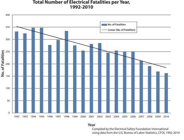
Figure 1: Trending of Electriccal Fatalities Courtesy Safety Foundation International
tags if the disconneccting means i is adjacent t to the conductor or circuit t parts, is cleaarly visible e to the qualified individual l p performing the work and the work does not extennd beyond onne shift OSHA did not think much h of the Indiividual Qualified Employee Control Procedure

Duty Clause (5)(A)(1) Citations on Multi-
That being said, O OSHA has posted on n their website a Letter of Interpreetation, General Duty Clause (5)((AA)(1) Citattions on MultiEmployer Worksittes ; NFPA 70E Eleectrical Safety Requirements and Perrsonal Proottective Equipment, dated d 07-25-20003, that states t “Industr y consensuus s standards, , such as NFPA 70E, can be used d by emplooyers as g uides to making the assessments and equiipm p ent selections required by the stanndard. Simmilarly, in OSHA enforcement actionns, the y can be used as evidence of w whether the e employer r acted reasonably.” OSHA A uses the 700E as a g uide for justification of its ci c tations, as N NFPA 70E E is the industry safe work practices stanndard.
M O VING FOR WA R D
or adjusting without the placement of locks and
OSHA has representation on the NFPA 70E technical committee. Currently it is David M. Wallis, Director, OSHA Directorate of Standards and Guidance, Office of Engineering Safety; Washing ton, DC. The OSHA representatives provide insight to the technical committee on OSHA’s views about proposals and comments being considered by the committee, as well as advising the committee when their actions don’t exactly line up with OSHA’s mandates. One such example was eliminated in the 2012 edition. Previous editions of NFPA 70E had a lockout/ tagout procedure called the “Individual Qualified Employee Control Procedure”. Essentially, this procedure allowed for minor servicing, repair or locks and


NFPA 70E is on a three-year c ycle, althoouug h it was delayed for a yeeaar from the 2 2004 to thhe 2009 edition. This delay was caused by some se s rious amonng the commmittee members
disagreement among the committee members


THE NFPA 70E AND NETA

concerrnning the Hazard/Risk k Categor y Tables, similar r to some o of the discusssio i ns concerning the tables in the 20115 c ycle. The e issues in the 2015 c ycle w were settled d among the com o mittee members withouut any interrvention by the NFPA , but in the 2009 c y ycle extra committee meeting s had to be conduccted to resoolve the issuees. s
NFPA A 70E is a coonsensus stanndard, which means t w wo -thirds o its commiitt t ee must approvve e the channges before it t can be approved. The makeup of the technical committee has changeed some ovver the years, , and the committee has grrow o n someewhat. The NFPA is careful to appoinnt a techniical committte t e that represents the diifffferent innterests and d a comprehensive over view e within n industr y and n to not let one interest become dominant. And while there have bee e n strong differences of o opinion bet ween the varrious commmittee members, it is clear that all memmbers have e a common go g al and interest at heart––pprotecting g the electrical worker

S UMMAR Y
and the rules
Althoug h there is more to
formation of OSHA

Proteccti t ng the electrical worker is the single most important factor that makes the 70E techniccal committtee the best t we have served on.
that two-thirds of its committee members must monetary advantage; if it is the right thing to do,
No member or innterest seeks to use the 70E for monetary advantage ; if it is thhe right to do, we all can agree to it And whi h le sometimes how to do t the right t thing is not t completely agreed upon, t the commmittee voting g on proposals and commen e ts this c cycle shows almost unanimous agreemment among g its members on virtually every issue. That is not t to say the proopo p sals or comments were acc c epted carrte blanche…quite the opposite!
role in the reduction of fatalities and injuries and will continue to do so as more and workers understand and it.
Workplace fatalities from all causes have been decreasing steadily over the years, and like it or not, this is due to the formation of OSHA and the rules they mandate for the workplace. Although there is more to be done, electricallyrelated fatalities have dropped considerably. StricterenforcementofOSHAregulationsdefinitely helps. NFPA 70E has certainly played a huge role in the reduction of fatalities and injuries and will continue to do so as more companies and workers understand and adopt it.
OSHA and the 70E – not a bad combination.


Ron Widup and Jim White d are NETA’S e representatives to NFPA Technical Committee 70E (Electrical Safety Requirements for Employee Workplaces). Both gentlemen are employees of Shermco Industries in Dallas, Texas, a NETA Accredited Company. Ron Widup is President of Shermco and has been with the company since 1983. He is a Principal member of the Technical Committee on “Electrical Safety in the Workplace” (NFPA 70E) and a Principal member of the National Electrical Code (NFPA 70) Code Panel 11. He is also a member of the technical committee “Recommended Practice for Electrical Equipment Maintenance” (NFPA 70B), technical
skills and training in the electrical power systems

The committee d the merits and shhortcominggs of each and n every proposal, modified the lanng uage when necessar y to meet the connsensus, annd then voted as a group
The committee discussed and debated the merits

He is Shermco Industries, and has the last twenty involved in technical skills and training electrical power
is a member NFPA 70B representing NETA’s a member ASTM F18 Committee “Electrical Protective for Workers”.
and a member of the NETA Board of Directors and Standards Review Council. Jim White is nationally recognized for technical skills and safety training in the electrical power systems industry. He is the Training Director for Shermco Industries, and has spent the last twenty years directly involved in technical skills and safety training for electrical power system technicians. Jim is a Principal member of NFPA 70B representing Shermco Industries, NETA’s alternate member of NFPA 70E, and a member of ASTM F18 Committee “Electrical Protective Equipment for Workers”.

3 year warranty supported in the USA by ProgUSA LLC
Best support in the industry The most powerful portable devices on the market
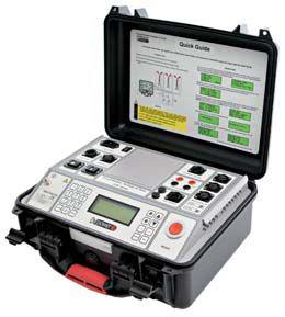
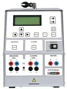
Series - Circuit Breaker Analyzer & Timer
Series - Three-Phase Transformer Turns Ratio Testers

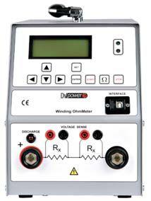
- Tap Changer & Winding Analyzers

James R. (Jim) White is the Training Director of Shermco Industries, Inc., in Dallas, Texas. He is the principal member on the NFPA technical committee “Recommended Practice for Electrical Equipment Maintenance” (NFPA 70B). Jim represents NETA as an alternate member of the NFPA Technical Committee “Electrical Safety in the Workplace” (NFPA 70E) and represents NETA on the ASTM F18 Committee “Electrical Protective Equipment For Workers”. Jim is an IEEE Senior Member and in 2011 received the IEEE/PCIC Electrical Safety Excellence award. Jim is a past Chairman (2008) of the IEEE Electrical Safety Workshop (ESW).
 BY JIM WHITE, Shermco Industries

FIELD TESTING TECHNIQUES FOR LOW-VOLTAGE CIRCUIT BREAKERS
Low-voltage circuit breaker testing technology is moving forward, albeit at a relaxed pace, it seems. Field testing can include a number of different test methods and types of test equipment. Your task, if you choose to accept it, will be to successfully answer the Tech Quiz questions this issue. As always, choose the most correct answer.
1. Figure 1 shows a jumper cable used to:
a. defeat the zone selective interlocking function.
b. increase the bias current through the programmer.
c. change the phase angle of the primary injection current.
d. defeat the ground fault function.
2. When the thermal memory is switched on for digital overcurrent protective devices (OCPDs) used on low-voltage circuit breakers, what effect will it have on the long time delay (LTD) operating time?
a. It has no effect on LTD.
b. It will decrease LTD somewhat.
c. It will increase LTD somewhat.
d. It will cause the trip unit to operate on the instantaneous element.
3. When performing primary injection testing of a circuit breaker that has zone selective interlocking, current is injected into individual phases on the tested breaker. What should be the result?
a. The breaker should trip by its short-time delay (STD) function.
b. The breaker should trip instantaneously and send blocking signals from its ZSI OUT terminals.
c. The breaker should trip and send a text saying it has operated.
d. The breaker should set an alarm and, if the current continues, trip after a set time delay.
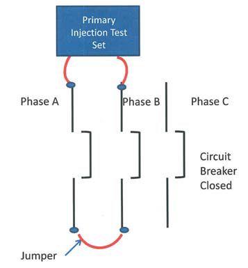
Figure 1: Low-Voltage Circuit Breaker Testing Scheme
4. What type of light source can be used to field test arc-flash detection relays?
a. Compact point-and-shoot camera flash
b. 200W light bulb or LED
c. Professional-style flash
d. Lighting a book of matches all at once
5. The light source used to field test arc-flash detection relays generally needs to have an output duration of ____ ms, or more.
a. 1
b. 2
c. 3
d. 4

Remanufacturing,
Reverse

THE EXPERTS IN ELECTRICAL RELIABILITY
ComprehensiveElectricalTesting
EngineeringServices PowerSystemandCoordination
PredictiveandPreventive
PartialDischargeTestingand


Failure is not an option. Ensuring the reliability of your electrical distribution system.
As the leading independent electrical testing, maintenance, and engineering service company, you can rely on Emerson’s High Voltage Maintenance to exceed your electrical equipment performance goals. From testing for problems that could disable your system, to complete turnaround execution, you’ll quickly understand how we are your single source solution for all of your electrical reliability needs. With a network of more than 12 service locations, our service team puts experienced professionals where and when you need them.
NETA ACCREDITED COMPANY

TESTING LOW-VOLTAGE BREAKERS
BY LYNN HAMRICK, Shermco Industries
During its 20-40 year service life, a circuit breaker must be constantly prepared to operate. Typically, long periods of inactivity often elapse during which the breaker’s mechanical and electrical components never move. The circuit breaker is the active link in a fault clearance situation.
When a fault occurs on the electrical system, the associated fault current must be interrupted quickly and reliably. This action is referred to as fault clearing. If a breaker fails to clear a faulted circuit, the resulting damage can be very serious in terms of both personnel injury and equipment damage. Even though circuit breakers are comparatively reliable, circuit breaker failures can and do occur; therefore, circuit breakers must be tested and maintained to ensure proper operation during these faults.
Many circuit breakers provide longer service lives than expected. If you can ascertain that a breaker is in good condition, you can continue to use it rather than replace it at its expected end-of-life. For the remainder of this discussion, we will concentrate on low-voltage power circuit breakers.
DIFFERENT MAINTENANCE STRATEGIES
There are three basic maintenance strategies that are typically applied to circuit breakers:
Corrective Maintenance
With this strategy, maintenance is performed after the breaker fails to operate. Although considered short-sighted by most maintenance professionals, this is a prevalent maintenance philosophy in most medium to small industrial facilities. Justifying the performance of preventive maintenance is a comparative exercise which typically involves comparing short-term savings in maintenance costs to potential repair costs and production losses. The unfortunate result in applying this maintenance strategy is that there may be inoperable circuit breakers in the electrical system. When older circuit breakers are part of the electrical system, there is a high probability that some of these breakers are inoperable.
Time Interval-Based Maintenance
With this strategy, maintenance activities are performed at a predetermined frequency, regardless of the conditions under which a circuit breaker operates. If this method is applied too strictly, however, it may lead to excessive work efforts and costs.
Condition-Based Maintenance
With this strategy, the condition of a circuit breaker is evaluated through maintenance testing and inspection. The results, supplemented with statistical data and cumulative experience, are then used for maintenance planning. Condition-based maintenance provides excellent opportunities to improve reliability and cut costs, but it requires effective diagnostic methods, like the performance of an infrared (IR) survey.
SUGGESTED ELECTRICAL TESTS
Many circuit breakers provide longer service lives than expected. If you can ascertain that a breaker is in good condition, you can continue to use it rather than replace it. There are some basic electrical tests that should be performed on low-voltage circuit breakers.
Contact resistance
This test should be performed from line-toload terminals for each phase with the breaker closed. The values should be within 50 percent of each other and comparable to similar circuit breakers.
Insulation resistance
This test should be performed phase-to-phase and phase-to-ground (i.e., case, if applicable) with the breaker closed. For 480 volt breakers, acceptable values should be greater than 100 megohms.
In addition to these basic tests, either primary injection testing or secondary injection testing should also be performed. To perform either test, the circuit breaker being tested must be de-energized and isolated from other breakers and circuitry. Many 480 volt breakers have trip units associated with them. These trip units can consist of any or all of the following trip setting capabilities:

NICHE MARKET TESTING


• Long-Time Pickup and Delay – These settings are associated with circuit and equipment protection from an overload condition. The time delay is provided to mitigate spurious operations.
• Short-Time Pickup and Delay – These settings are associated with circuit and equipment protection from overcurrent conditions, typically in excess of 300 percent of rating. The time delay is provided to mitigate spurious operations and nuisance tripping associated with larger motor starts, etc.


NICHE MARKET TESTING


• Instantaneous Pickup – This setting is associated with circuit and equipment protection from fault conditions. This trip function protects against phase-tophase and phase-to-ground faults.
• Ground-Fault Pickup and Delay – These settings are associated with circuit and equipment protection from ground fault conditions. The time delay is provided to mitigate spurious operations.
Primary Injection Testing

For primary injection testing of low-voltage circuit breakers, high current is injected at a low voltage (typically 5 to 10 V) at each phase of the breaker. The level of current to be injected is either per manufacturer’s recommendations or in accordance with the manufacturer’s published time-current curves. The associated testing circuit path is typically supplied through the line contacts and returned through the load contacts of the circuit breaker for each phase. Proper operation of the components within the circuit breaker—current transformers, conductors, connection points, trip unit operation and mechanical trip mechanisms— is encompassed by performing the primary injection test for each phase of the breaker. Based on the time-current curve for the breaker, each test current level will have a required time response for determining acceptability.

Primary injection testing has been the preferred method for circuit breaker testing since it verifies the sensors, wiring, and trip device as well as the conduction path in the breaker. Primary injection testing is typically performed by experienced test technicians using specially-engineered injection test sets with integral measurement equipment and a transformer which makes the test sets very heavy and difficult to move around. They also require a relatively large power source for proper operation. Primary injection testing has also been described as potentially destructive since it involves applying large currents to the breaker. The concern is that the stress of large currents on the breakers could eventually lead to premature failure
of the breaker. Unfortunately, primary injection testing may be the only means of testing some low-voltage circuit breakers, (i.e., molded-case, thermal and thermal magnetic breakers).
Secondary Injection Testing
Some trip units allow for testing the trip functions of the breaker utilizing a secondary injection test. Secondary injection testing is different from primary injection testing in that high currents are not applied through the line and load contacts of the breaker. Secondary injection testing normally involves disconnecting the trip unit from its normal monitoring circuitry and connecting it to a specialized test set that can inject, measure, and record the operation of the circuit breaker. The advantage of secondary injection testing is that the testing process does not include injecting high currents to operate the trip unit and trip the circuit breaker. A perceived disadvantage of secondary injection testing is that the current transformers and some of the connection points are not tested.
Specialty test equipment from the breaker manufacturers is usually required. Knowledgeable test technicians are still required for performing secondary injection testing. The test technician must have significant knowledge of the actual protection scheme and philosophy. Furthermore, disconnecting and reconnecting the trip unit should only be performed by a qualified test technician.
Secondary Injection Testing with Primary Verification

Secondary injection testing, when it can be applied, is a much safer and faster way to test breakers in the field. If one could develop a testing methodology which utilizes secondary injection testing and verifies proper operation of the current transformers and the other connection points of the circuit breaker, it would allow the industry to safely perform this valuable testing more economically. With the advent of electronic trip units which include a power monitoring capability and display, a testing methodology is available to accommodate this testing process.
NICHE MARKET TESTING

1. Inspections and contact resistance testing is performed to verify conductors and some connection points.
2. Secondary injection testing is performed to test and verify the proper operation of the trip unit and the mechanical trip mechanism.
3. Low current primary injection (at ~25% and 50% of full load rating) is performed with a more portable current test set to verify proper operation of the current transformers and remaining connection points.
4. If deemed necessary, CT saturation tests could also be performed to provide verification of CT capability during a fault condition.

This methodology, secondary injection testing with primary verification, provides a safe and reliable process for determining circuit breaker health without the induced stress of high current primary injection. This testing methodology will not be applicable to all installations.
In conclusion, even though circuit breakers are comparatively reliable when compared to other electrical devices, circuit breaker failures occur. When a breaker fails to operate, the resulting damage can be very serious in terms of both personnel injury and equipment damage. Therefore, circuit breakers must be tested and maintained to ensure proper operation during these faults.


Lynn Hamrick brings over 25 years of working knowledge in design, permitting, construction, and startup of mechanical, electrical, and instrumentation and controls projects as well as experience in the operation and maintenance of facilities.
Lynn is a Professional Engineer, Certified Energy Manager and has a BS in Nuclear Engineering from the University of Tennessee.


National Switchgear has millions of new, surplus and repurposed electrical circuit breaker & switchgear products. And now, with a suite of e-commerce solutions , we’re making it easier than ever for you to find the part that’s perfect for you. You can browse, filter results by category, manufacturer or specs, see your pricing level, and more – 24/7. Just go to nationalswitchgear.com and see our latest innovations. It’s the fastest lane to our massive inventory. If you’re ordering parts from anyone else, it’s time to switch.
800-322-0149 nationalswitchgear.com
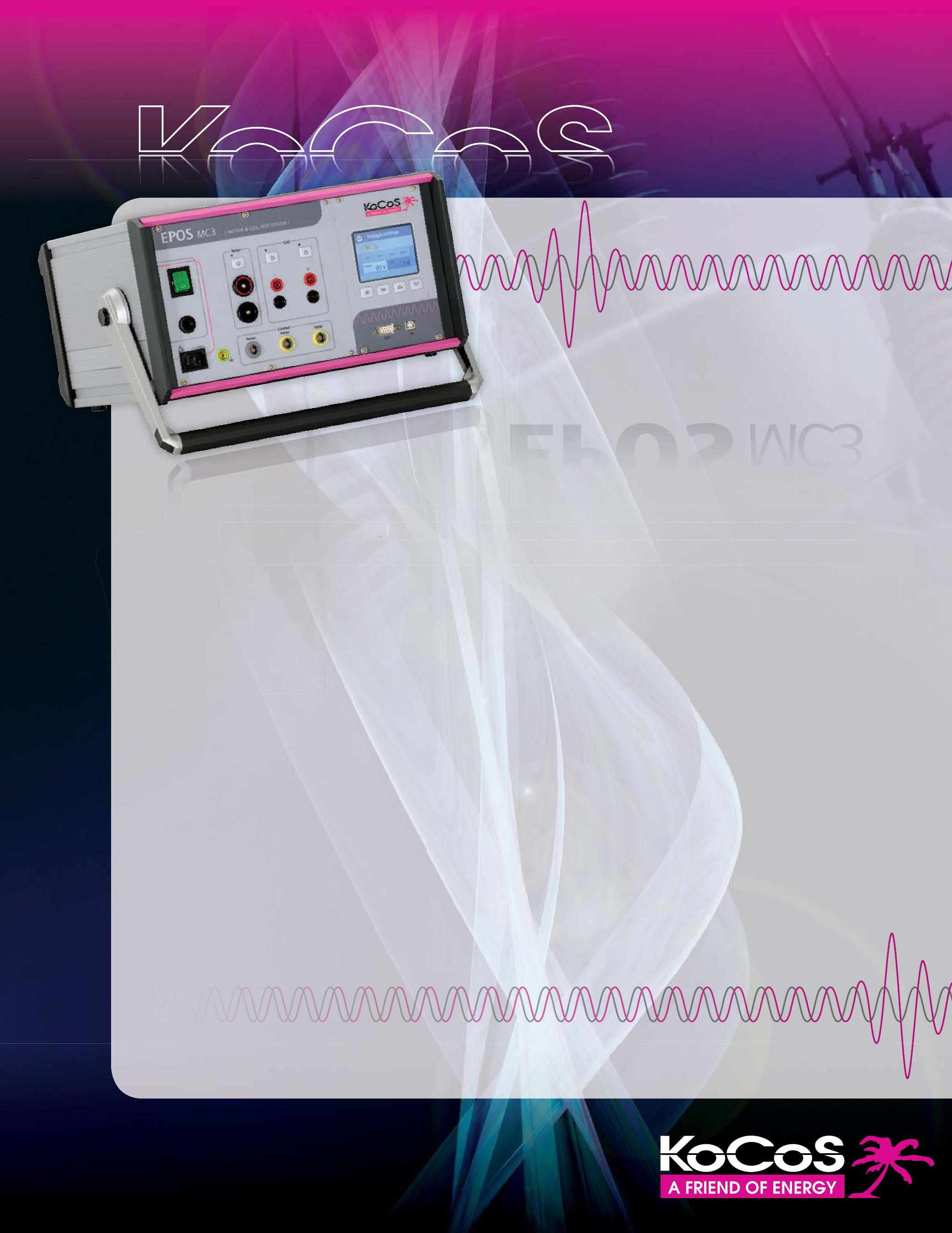
EPOS MC3
The powerful solution for circuit breaker testing
power ful solution
Compact, powerful AC/DC source for powering and field testing motors and release coils of switchgear devices. The system guarantees informative analysis, maximizing operating times, and minimizing maintenance work.
Compact, AC DC source for pow of devices The system guarant times, and minimizing maintenance work.
Powerful voltage source
Powerful voltage source
· 270 VAC/300 VDC
270 VDC
· 40 A
· DC, 16 2/3, 50, 60 Hz
Measurement functions
· Motor and coil current evaluation
Coil resistance
· Minimum operating voltage
· Undervoltage release
Innovative touch screen
Display and evaluation of motor and coil signatures
Unlimited output duration
Stand-alone operation and/or use with ACTAS switchgear test systems
NETA PRESENTS AT TECHCON NORTH AMERICA:
WHERE TECHNOLOGY AND INNOVATION MEET
NETA participated in the TechCon North America Expo along with an impressive gathering of industry partners, demonstrating new technologies, products, and services that are valuable in supplying and sustaining power quality in the utility industry. TechCon North America’s annual conference is hosted by TJH2b Analytical Services of Sacramento. This year’s educational and networking event took place in Glendale, Arizona, February 3-6, 2014. On behalf of NETA, Ken Peterson, Hampton Tedder, presented Developing Generator and Transmission Maintenance and Testing Plans to Conform with NERC and WECC Standards to a welcoming audience of over 150 representatives from the utility industry. The show hosted attendees from United States, Canada, and Mexico, as well as 60 international delegates from other parts of the world.
Recent NERC regulations requiring routine utility maintenance planning, testing, and reporting drew attendees to the NETA presentation and piqued interest in the ANSI/NETA MTS Standard for Maintenance Testing Specifications for Electrical Power Equipment and Systems. The ANSI/NETA MTS-2011 was cited as a reliable resource when developing maintenance plan specifications and schedules. This document has been used extensively by utilities when creating documentation and maintenance schedules for NERC compliance. Utilities can apply the ANSI standard themselves through in-house service personnel or outsource these services to NETA Accredited Companies.
NETA companies can help utilities remain up-to-date with the newest NERC requirements by offering everything from consulting services to full-service maintenance and testing by NETA Certified Test Technicians. Many NETA Accredited Companies also offer training services to utilities that plan to perform routine maintenance themselves. While some utilities might perform many of their routine inspections and maintenance with in-


house personnel, many outsource larger projects and maintenance to NETA Accredited Companies.
Relying on a NETA Accredited Company can provide a financial relief for a utility company trying to minimize maintenance expenses. Rather than incurring expenses for the necessary training and continuing education of personnel and the purchase and routine calibration of test equipment, the utility company can rely on a NETA Accredited Company. A NETA Accredited Company comes prepared to perform the job and provide a comprehensive report with the necessary information that is critical to an effective and on-going maintenance program.
In September 2013, NETA attended TechCon North America’s sister event, TechCon Canada, held in Calgary, Alberta. NETA’s presence affirmed the organization’s reputation as an advocate for quality, safety, and reliability across the electrical power systems industry. “TechCon worldwide conferences and expos are excellent forums for NETA to connect with utility professionals and share information and ideas,” said Jayne Tanz, NETA’s Executive Director. “These conferences seek to offer solutions to improve key, high-voltage maintenance programs and asset management strategies for the aging electrical grid infrastructure, as well as build toward a stronger future. NETA Accredited Companies offer many pieces that will help solve the complex puzzles of power quality management and maintenance for utilities, no matter the type of utility service provided.”


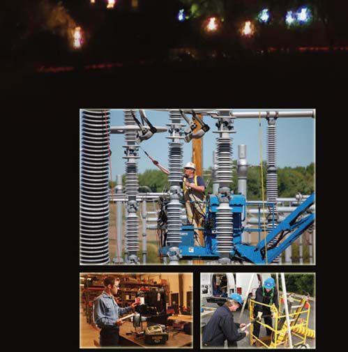







From Apollo 7 to Today’s Smart Grid

Services:
Preventative Maintenance

Acceptance Testing
High Potential Testing


Utility Service Corporation has been providing electrical and technical services for government and industry since 1962.
Solving complex problems, testing under difficult and unusual circumstances and servicing the commissioning and maintenance needs of today’s electrical power systems both new and aged.
Commissioning Services
System Studies Arc Flash Analysis
Engineering & Consulting
Construction Supervision
System Trouble Shooting
(256) 837-8400


DIELECTRIC AC TESTS
BY VICKI WARREN, Iris Power LP.Generators and motors typically enjoy 20 years or more of operation in utility and industrial applications before either the rotor or stator windings need to be replaced. However, if the machine is overloaded or subjected to a polluted environment, or was poorly constructed, failure may occur in just a few years due to premature aging.
Over the past several years, off-line dc and ac tests have been used to locate and determine the severity or risk of failure, and whether repairs are possible. Off-line tests have the advantages of accessibility, noisefree environments, ease of repair, and test variety. The disadvantages are that there are abnormal mechanical, thermal, and electrical stresses, and they require a machine outage which can be time-consuming.

With direct-voltage (dc), the voltage distribution is based on insulation resistance, while with an alternating voltage (ac); the voltage distribution is based on capacitance. Therefore, dc tests are suitable for locating cracks and contamination, whereas, ac tests are used to evaluate how well the insulation system is consolidated during manufacturing and the impact of thermal aging. A thorough condition assessment evaluation should include dc and ac testing as well as a visual inspection.

DIELECTRIC CHARACTERISTIC AC TESTS
Capacitance
Insulation systems are by design a capacitor with a dielectric of organic resin, glass, and mica that separates the copper conductors from the core iron. As an insulation system ages, the organic resin is slowly replaced with air-filled voids that change the dielectric constant, or capacitance, of the insulation system. In older, pre-1970 machines, the change in the dielectric constant was often significant enough that it was possible to detect the effects of aging by measuring the total capacitance of a winding. Though still possible on severely deteriorated newer windings, the change in capacitance is often so subtle that until the winding is nearing failure it is difficult to observe any changes. The capacitance can be measured at a low voltage and best done with a bridge that will eliminate the effect of the stray capacitance of the test supply.
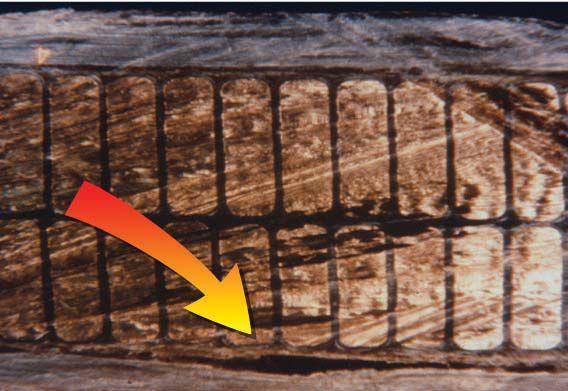

• delamination capacitance decreases (1% change) [Figure 1]
• moisture contamination capacitance increases (5% change) [Figure 2]
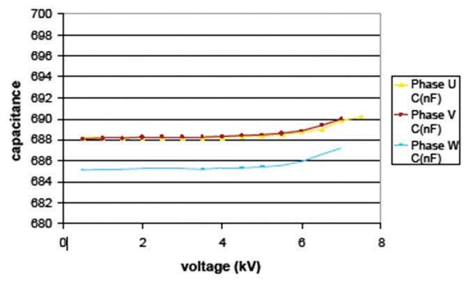
A variation on the capacitance test is the capacitance tip-up test, which is performed on complete windings or preferably individual winding phases with an accurate capacitance bridge. At a relatively high voltage, the gas within voids ionizes to produce sufficiently high conductivity to short the void out causing partial discharge. This produces an increase in capacitance between low- and high-voltage tests. The capacitance Clv is measured at 0.2E where E is the rated phase-to-phase voltage and also Chv is measured at line-to-ground voltage which is about 0.58E. The capacitance tip-up is:
ΔC = (Chv – Clv)/Clv
TESTING ROTATING MACHINERY

high void content. However, if the results are trended against time, an increase in ΔC may give a true indication of increased void content in the groundwall insulation.
Dissipation Factor/Power Factor
Dissipation Factor (DF or tan δ)
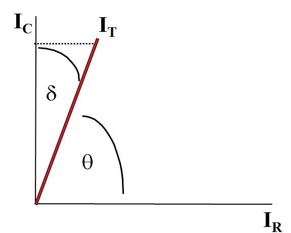
Like the capacitance test, the dissipation factor test also looks for changes in the insulation system of the winding. This test, however, is done at high voltage steps that increase from zero to normal line-to-ground voltage. The test compares the real power loss (IR) due to the presence of voids in a delaminated insulation as a ratio to the capacitance power (IC), or the tangent of δ (IR / IC) as shown in Figure 4. The absolute value of the dissipation factor is also useful in determining the extent of curing in a new insulation system.

The higher ΔC is, the more voids there are in the winding groundwall. For a well bonded groundwall insulation:
ΔC < 1% for modern epoxy mica insulation ΔC < 3 or 4% for older asphaltic mica windings
It should be noted that if the coils have semiconducting and grading voltage stress control layers, these influence the results of this test. At the higher voltage, the grading layers of silicon carbide material conduct to increase the effective surface area and thus the capacitance of the sections of winding being tested, and so may give a false indication of

ΔC = (Chv – Clv)/Clv
ΔC = (690 – 688)/688 = 0.3%

Figure 3: Capacitance Tip-Up (W-phase is notably lower than the other two phases indicating minor delamination on this phase)


TESTING ROTATING MACHINERY

IC = capacitance current
IT = total current
IR = resistive current
DF = Tan δ = IR / IC
PF = Cos θ = IR / IT

DF = tan δ = mW / mVar = IR / IC
• delamination tan δ increases
• moisture contamination tan δ increases
DFepoxy ≤ 0.5%
DFasphaltic ≤ 3 to 5%
Trending the results against time makes the best use of this test. As with the Δ capacitance test, voltage stress coatings can lead to ambiguous results obtained at high voltage.
Power Factor (PF or cos θ)
Similar to the dissipation-factor test (tan δ) the power factor (cos θ) test is looking for any changes in the insulation system of the winding. The test compares the real power loss (IR) due to the presence of voids in a delaminated insulation as a ratio to the total power (IT), or the cosine of θ (IR / IT) as shown in Figure 4. The test is normally done at a specific applied voltage that makes it possible for comparing the results to other machines. This is a valuable test for determining the extent of curing in new coils or winding. Because the presence of the voltage stress control in a complete winding greatly affects the results, tests on complete windings can be ambiguous.
PF = cos θ = mW / mVA = IR / IT
• delamination cos θ increases

• moisture contamination cos θ increases
PFpolyethylene ≤ 0.01%
PFepoxy ≤ 0.5%
PFasphalt ≤ 3 - 5%

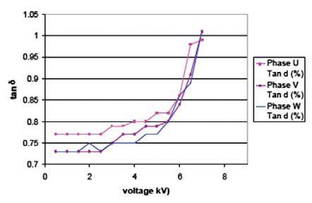
ΔDF = (1 – 0.74)/0.74 = 35%
Tip-Up Tests
The tip-up test (Δ tan δ or Δ cos θ ) done at two voltages, one below the inception of partial discharge activity (25% line-toground) and one at line-to-ground voltage may provide some information regarding the integrity of the stator insulation system [Figure 5]. The intention of the test is to observe the increase in real power loss (ΔI R) due to partial discharges within voids of a delaminated insulation, and therefore investigate the quality of the resin bond. This test is widely used by manufacturers of resin rich and individual VPI coils as a quality check. As with the capacitance tip-up test, the results of this test are influenced by the presence of voltage stress coatings on the coils, since at high line-to-ground voltage currents flow through it to produce additional power losses. Because this test method measures total energy it is only sensitive to widespread delamination and not how close the winding is to failure (worst spot).
• Tip-up = DF/PF high - DF/PF low (typicalresults: 0.5% for epoxy)
• High at 100% line-to-ground rated voltage (above partial discharge inception voltage - PDIV)
• Low at 25% line-to-ground rated voltage (below PDIV)
Voltage 11 kV
KVA 16,629
Insulation Class F

Cooling Air/water
Date Manufactured 2008
Off-line Test Effectiveness AC vs DC
The winding is global VPI design meaning that the winding was placed in the core in a green or resin free-state and then the entire winding and core subjected to a vacuumpressure-impregnation process to consolidate the winding insulation layers and anchor the winding in the core.
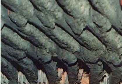
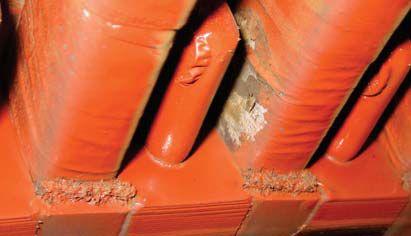
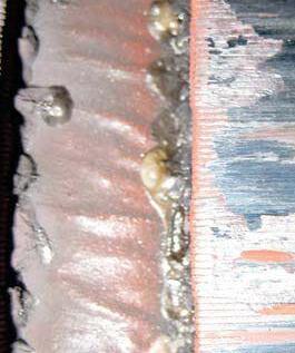
As shown in the table below, the dc test results for the IR/PI and dc insulation tests were acceptable, but both the power-factor and tipup tests were elevated. A visual inspection of the winding revealed notable damage to the voltage stress coatings (Figure 6) as well as possible areas of coil overheating (Figure 7). This suggests dc tests were not adequate to fully evaluate the condition of the winding and the need for ac dielectric characteristic tests.
TESTING ROTATING MACHINERY
Test
Insulation Resistance (IR) at 5kV
Polarization Index (PI) at 5kV
DC Insulation Test at 25kV
Power Factor at 2kV
Power Factor Tip-up (2kV to 6kV
2013 Results IEEE reference (acceptable limit)
U17 GΏ
V17.2 G Ώ
W17.1 G Ώ
U5.01
V5.04
W4.26
UPass
VPass
WPass
U1.00%
V0.99%
W0.98%
U0.65%
V0.66%
W0.65%



IEEE43 -2000 (100M Ώ)
IEEE43 -2000 (>2)
IEEE 95 – 2002 (Pass)
IEEE 286 – 2002 (0.5%)
IEEE 286 – 2002 (0.5%)

Vicki Warren, Senior Product Engineer, Iris Power LP. Vicki is an electrical engineer with extensive experience in testing and maintenance of motor and generator windings. Prior to joining Iris in 1996, she worked for the U.S. Army Corps of Engineers for 13 years. While with the Corps, she was responsible for the testing and maintenance of hydrogenerator windings, switchgear, transformers, protection and control devices, development of SCADA software, and the installation of local area networks. At Iris, Vicki has been involved in using partial discharge testing to evaluate the condition of insulation systems used in medium- to high-voltage rotating machines, switchgear and transformers. Additionally, she has worked extensively in the development and design of new products used for condition monitoring of insulation systems, both periodical and continual. Vicki also actively participated in the development of multiple IEEE standards and guides and was Chair of the IEEE 43-2000 Working Group.


SUBSTATION MAINTENANCE I
DALLAS, TX
Jan 6-10
Feb 3-7
Mar 3-7
Apr 21-25
May 12-16
PASADENA, CA
Feb 3-7
Apr21-25
PORTLAND, OR
Jan 6-10
Mar 17-21
May 5-9
VALLEY FORGE, PA
Feb 17-21
Mar 17-21

SUBSTATION MAINTENANCE II
DALLAS, TX
Jan 13-17
Feb 10-14
Mar 10-14
Apr 28-May 2
May 19-23
PASADENA, CA
Feb 10-14
Apr 28-May 2
PORTLAND, OR
Jan 13-17
Mar 24-28
May12-16
VALLEY FORGE, PA
Feb 24-28
Mar 24-28
*NETA Continuing Technical Development (CTDs) units are required of NETA Certified Technicians.
BATTERY MAINTENANCE & TESTING
DALLAS, TX
Jan 6-9
Mar 17-19
PORTLAND, OR Apr 14-17
VALLEY FORGE, PA
Feb 3-6
PROTECTIVE RELAY MAINTENANCE BASIC
DALLAS, TX
Jan 6-10
Feb 17-21
Mar 31-Apr 4
PORTLAND, OR
Feb 3-7
Apr 28-May 2
VALLEY FORGE, PA
Mar 17-21
YOUNGSVILLE, NC
Apr 21-25
PROTECTIVE RELAY MAINTENANCE ADVANCED
DALLAS, TX
Feb 24-28
Apr 7-11
PORTLAND, OR
Feb 10-14
VALLEY FORGE, PA
Mar 24-28
TRANSFORMER MAINTENANCE & TESTING
DALLAS, TX
Jan 20-24
May 20-24
VALLEY FORGE, PA
Mar 31-Apr 4
NEC CODE 2014
DALLAS, TX
Jan 13-16
Feb 3-6
Apr 22-25
VALLEY FORGE
Jan 6-9
Feb 24-27
Mar 17-20
May 13-16
PORTLAND, OR
Jan 27-30
Mar 3-6
CIRCUIT BREAKER MAINTENANCE, MEDIUM-VOLTAGE
DALLAS,TX
Feb 3-6
Apr 1-4
VALLEY FORGE, PA
Jan 13-16
Mar 3-6
May 5-8
CIRCUIT BREAKER MAINTENANCE, LOW-VOLTAGE
DALLAS, TX
Jan 13-17
Mar 10-14
May 12-16
VALLEY FORGE, PA
Feb 10-14
Apr 7-11

SHERMCO ACQUIRES MAGNA ELECTRIC CORPORATION
Two companies that have been critical to the growth and success of NETA have joined forces to create the largest independent electrical maintenance and testing organization in North America. Shermco Industries of Irving, Texas, headed up by CEO and former NETA President Ron Widup has acquired Magna Electric Company (MEC) based in Regina, Saskatchewan. Shermco and MEC have collaborated in the past on several major projects, including the TransCanada Pipeline, Hurricane Sandy disaster recovery efforts, and several major industrial turn-around projects with large manpower requirements. “MEC shares or focus on maintaining an exceptional safety culture and providing outstanding customer service,” said Widup. “We are thrilled to be joining forces with MEC to establish Shermco Industries as a global leader in the electrical power maintenance and service industry.”
The full MEC team, including CEO Kerry Heid, remain with MEC and will be a part of the Shermco

organization that now has 13 locations spanning from Alberta to Texas. “There are tremendous opportunities being created as Canadian companies work to meet strong demand for energy and electrical reliability across North America. By joining forces, we will be better positioned to help our customer meet those critical needs,” said Heid. The combined company offers a wide range of services including electrical engineering and consulting, field testing and commissioning, and construction and maintenance. Shermco also has a large ISO 9001:2008 motor/ generator remanufacturing facility in Texas, switchgear and circuit breaker remanufacturing operations in multiple locations, and specialty electrical equipment manufacturing in Canada.
Shermco and MEC have been very active with NETA, and both Ron and Kerry look forward to continuing their company’s involvement in advancing NETA and the electrical testing and maintenance industry.

WHEN PASS-FAIL ISN’T ENOUGH

WORLD’S FIRST VACUUM INTERRUPTER TEST SYSTEM CAPABLE OF PREDICTING REMAINING LIFE
WORLD’S FIRST TEST SYSTEM CAPABLE OF TESTING VACUUM INTERRUPTERS IN BOTH THE SHOP AND FIELD
BASED ON SAME OEM LEAK-RATE TEST PERFORMED AT THE FACTORY
MEASURES ACTUAL ION CURRENT AGAINST KNOWN VALUES TO DETERMINE VACUUM INTERRUPTER INTERNAL PRESSURE





SAFETY TIPS FOR QUALIFIED PERSONS
BY JIM WHITE, Shermco Industries
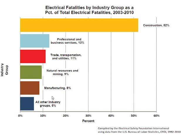
According to the U.S. Bureau of Labor Statistics 52% of electrical fatalities occur in the construction industry, Figure 1. As electrical contractors, we face many safety challenges that other trades may not. Electrical shock, arc flash burns, arc blast, projectiles, high acoustic levels; makes me wonder why I ever decided to go into this area.
The truth is, it was the fact that most people would say, “Not a chance” to a job they would find hazardous that first attracted me to electrical work. I don’t think I’m alone, even though I don’t have any statistical data to back me up. People that enjoy electrical work are, to some degree, risk takers (some more than others), which is why electrical safety needs to be at the top of your list and your supervisor’s list. If we weren’t risk takers, we’d be laying brick or cutting 2 x 4s. Maybe that’s part of the reason it can be so difficult to get electrical workers to change their evil ways.
Once a person learns a task “his way”, it is very difficult to get him to change. After all, he figured this thing out on his own, has done it like that for years and now some Bozo comes along and tries to change it. Who
needs that? If you want to keep your job, you do. Whether you get on board the safety train or step off it, companies are taking electrical safety much more seriously than they used to. Here are a few tips to get the old brain cells percolating:

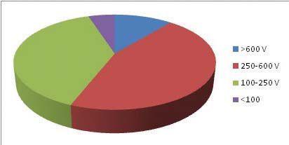
1. I had a student once who said “Low voltage doesn’t worry me. High voltage does.” I asked him the reasoning behind that statement and he replied “If you get hit with low voltage, everyone can come by your coffin and say how natural you look. With high voltage, they have to close the coffin.” I really hope he was kidding. H. Landis Floyd and Danny Liggett once presented the slide in Figure 2 as part of their presentation. This slide was only for industrial plants and did


not account for utility workers. It clearly shows that, even though 277/480 V is the most lethal, 120/208/240 V is right behind it! When we are shocked, it is usually a handto-foot exposure. We have added resistance, due to our shoes, socks and carpet, tile or dry concrete, dropping the current that would flow through us.
The only difference between being shocked at a higher voltage and a lower voltage is how long it takes to kill you. Low voltage just takes a bit longer, but as Figure 2shows, is every bit as lethal. Dr. Charles Dalziel conducted a study in 1960 where he subjected student volunteers to electrical shocks of varying strength/ current. Dr. Dalziel demonstrated that a 75mA electrical shock to an average-sized man could cause him to go into ventricular fibrillation in about 5 seconds. That sounds like a long time, unless you cannot extract yourself. Dr. Dalziel also showed that women have a greater risk of injury from electrical shock, due to their lower body resistance. Lower body resistance equals more current flow through the body. This means female technicians need to be even more cautious working with electricity, as the shock they receive will cause more damage than it would to a man.

One example of this is the “no-let-go” threshold (where a person cannot release an electricallyenergized conductor or circuit part). For the average woman it would be about 10mA, while for the average man it would be about 16mA. 100mA of current flowing through the body can cause fibrillation in 3 seconds, while a 2.5A contact could cause fibrillation in about 4 milli-seconds. Figure 3 shows a hand injury caused by not being able to let go of a 110 V portable electric power tool. Due to muscular contractions, this worker could not release the tool and received a serious burn from the current flow.
Safety Tip 1 - Don’t be the guy that has to learn everything by experience. As my Dad would often say “Experience is what you get just after you need it”. Be smart; accept new
safety practices and change whatever bad habits you might have.
Safety Tip 2 - Be aware that a low-voltage electrical shock can be fatal, especially if you have an undiagnosed health condition.
2. “I’ve got 17 years on the job. Of course I’m qualified”. Well, maybe not. Certainly your years of experience are important, and that knowledge and skills you’ve developed are critical to being a qualified person, but technical skills are only half the equation. You have to meet OSHA’s definition of a qualified person, “Qualified person. One who has received training in and has demonstrated skills and knowledge in the construction and operation of electric equipment and installations and the hazards involved.” 29CFR1910.332 and .333 provide minimum required safety skills and knowledge, and NFPA 70E Section 110.2 gives more detail.
There are three parts to being a qualified person; a) Receive training in the technical skills required.
b) Having knowledge of the construction and operation of electric equipment (the

SAFETY CORNER

technical side) and installations and the hazards involved (the safety side).
c) Demonstrating those skills and knowledge (Practical demonstrations)
There are two ways companies can provide inadequate initial training for qualified persons – 1) try to use video or computerbased training and 2) conduct one-day training sessions. These are the people I like to call “Box Checkers”. Just do something, anything so I can check off the box. Either they don’t have a grasp on the OSHA/NFPA 70E requirements or they just can’t be bothered to do it properly. OSHA, in a Letter of Interpretation dated 11/22/94 says, “In OSHA’s view, self-paced, interactive computer-based training can serve as a valuable training tool in the context of an overall training program. However, use of computer-based training by itself would not be sufficient to meet the intent of OSHA’s training requirements……………” Stand-up instructor-led training by a qualified instructor is required to meet this requirement.
important is the use of hands-on training and exercises to provide trainees with an opportunity to become familiar with equipment and safe practices in a non-hazardous setting.” Again, demonstration of skills is needed to become a qualified person. The minimum electrical safety training has to cover:
Demonstrating knowledge and skills in:
• Determining nominal voltage
• Determining what conductors or circuit parts are energized or not
• Minimum safe approach distances for shock (and arc flash)
• Use of special precautionary techniques
• Use of insulating materials and shielding
• Use of insulated hand tools
“Use of” doesn’t mean to just pick up something and use it. “Use of” includes:

OSHA goes on to say “OSHA urges employers to be wary of relying solely on generic, “packaged” training programs in meeting their training requirements. For example, training under HAZWOPER includes site-specific elements and should also, to some degree, be tailored to workers’ assigned duties.” OSHA applies this LOI to any hazardous job, including qualified persons.
Another excerpt from that same LOI, “Equally
• Choosing the proper tool, clothing or PPE
• Inspecting it to ensure it is safe to use
• Using the tool safely or wearing the protective clothing and PPE properly
• Storing it safely so it does not get damaged
• Caring for it, including any testing, calibration and maintenance required
NFPA 70E Article 110 provides more clarity on these requirements:
• Safety-related work practices and procedures necessary to protect them while performing hazardous tasks
• Identify and understand the relationship between electrical hazards and possible injury
• Methods of release from contact with energized conductors or circuit parts
• First-aid and emergency procedures, such as CPR
• Decision-making process necessary to determine the degree and extent of the hazard, PPE and job planning to perform the task safely
• Select the proper voltage detector and verify the absence of voltage, interpreting its indications and the limitations of each specific device.


Do you really think that can be done in a oneday session?
Safety Tip 1 - to be qualified you have to have the technical skills and experience, as well as safety training and skills.
Safety Tip 2 – Don’t be a Box Checker. Get training that meets OSHA and NFPA 70E minimum training requirements. If OSHA investigates an accident, the first thing they look at are the training records.
3. “Your job title or description has to say “electrician” before you’re required to be a qualified person”. Reality check - OSHA doesn’t care what your job title is. It’s what you do on the job that OSHA looks at to determine who needs to be qualified. Anyone who works on or near exposed, energized electrical circuits or conductor parts rated above 50 volts is required to be a qualified person. That could include Instrumentation & Control technicians, HVAC technicians, electrical engineers or others who may not think of themselves as having that requirement.
Safety Tip 1 - The magic number is 50 volts, not 100 volts nor 120 volts.
a hydraulic jack. It’s good advice, especially when wearing PPE. Always wear your PPE, but work like you don’t have any on.

Safety Tip 2 - If you have exposure to exposed energized conductors or circuit parts, you probably need to be qualified to 29CFR1910.332 and .333 and NFPA 70E Article 110.
4. “I’m protected if I wear me PPE”. Sounds good; even has a certain ring of logic to it, but that statement is flat false. PPE does not eliminate the hazard, nor does it eliminate the risk. PPE can reduce the risk, but the hazard will remain the same, whether PPE is used or not. OSHA does not accept that working energized with PPE is as safe as working deenergized.
Safety Tip 1 - Never trust your life to a mechanical device. My dad would say this when I would be under a car supported by
Safety Tip Number 2 - Turn it off! The only way to work safely is to work deenergized. Once the equipment or circuit is tested and found absent of voltage, no PPE is needed and the risk disappears. OSHA and NFPA 70E tell us to do just that. So the three most important rules of electrical safety are1) turn it off, 2) turn it off and 3) turn it off.
5. “I hear so much about arc flash, it has to be the biggest hazard for electrical workers”. Looking at the Bureau of Labor Statistics (BLS) data, shock is the greater hazard by about a two-to-one margin. In some industries it is higher.
James Cawley presented a paper titled, “Trends in Electrical Injury” at the 2006 IEEE/IAS Petroleum and Chemical Industry Committee (PCIC). Figure 4 is from that presentation. The “Electrical Burns” numbers include internal electrical burns caused by current flow through the body (contact burns), as well as arc flash (non-contact) thermal burns.

Safety Tip - arc flash injuries often cause more serious injuries than electrical shock. The

SAFETY CORNER
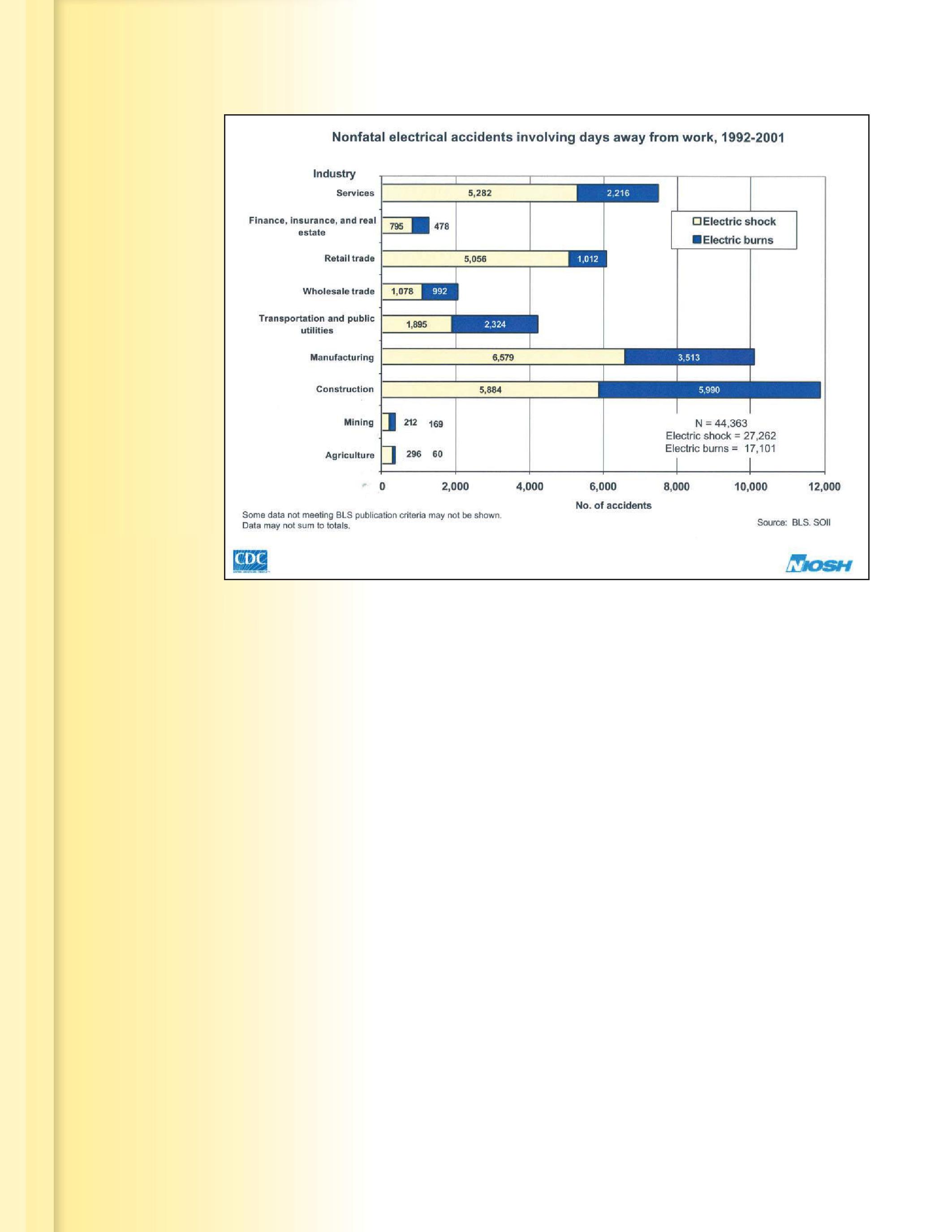
Figure 5. Shock vs. Burn Injuries
Figguurre 5. S Shhoocck k v vss. B Burn
F Frrom m “ “Trreenndds s i in n Eleecctriical
From “Trends in Electrical Injury”
injuries in Figure 4, though, represent losttime injuries, so the shock injuries were still very serious, not just a little “buzz”.
6. “I only work on low-voltage, low-energy lighting panels and the like, so arc flash isn’t a problem for me”. I guess it isn’t, if you don’t want to be able to use your fingers or hands. One of the Rules-of-Thumb for incident energy is that incident energy decreases by the inverse square of the distance. As you move away from an arc source, the heat created by an electrical arc flash will reduce very quickly. The opposite is also true; incident energy increases by the square of the distance as you move closer to an arc source. If I receive 1 cal/cm2 incident energy to my face and chest area (which is where incident energy is calculated to) my hands will be much closer. In some cases my hands may only be one or two inches from an arc source. My hands could very easily be exposed to enough incident energy to cause severe second and third-degree burns.
Safety Tip 1 – Don’t think that you cannot be seriously injured at lower voltages. There are several reported incidents where a worker received serious injuries to the hands and arms from “safe” voltages.
Safety Tip 2 – NFPA 70E recommends wearing leather gloves if hands will be exposed to an arc flash. Even lighting panels can cause severe burns to unprotected hands and fingers.
7. “I’m a Journeyman/Master/EE”. “I’ve done it this way for years and never had a problem.” Because we are risk-takers, we tend to downplay risks and hazards. We become accustomed to working on electrical equipment and we feel comfortable. Our experience and field knowledge tell us how to evaluate those risks and we tend to trust them. The problem is, one day, maybe years from now something will not be as it seems. The insulation may be weakened. Someone may not have tightened the lug properly during the

last maintenance cycle. The contractor who installed the equipment may have had a bad day. These are factors completely outside your control. Any one of these, not to mention dozens more can cause an accident and when it occurs, there’s usually nowhere to go.
Safety Tip 1 – Follow safety procedures and safe work practices, such as NFPA 70E not because you know something is going to happen, but because we don’t know when it is going to happen. If not for yourself, think of the grief and loss your family would experience if you were seriously injured or killed. Think of the impact on your children.
Safety Tip 2 – Don’t over-estimate your skills. Being lucky is not the same as being skilled.
SUMMARY
I’ve found that the vast majority of workers performing electrical tasks want to do what is right. But we get task-focused, losing sight of the fact that if there is an accident, not only
SAFETY CORNER

could we (or someone close by) be injured or killed, but whatever we were working on will probably be damaged to the point it must be replaced. Companies that have really committed to working only deenergized have found that, once the initial adjustment period is over, turning electrical equipment and circuits off doesn’t have nearly the impact on operations as they had feared. Be smart –follow the OSHA regulations and NFPA 70E.

James R. (Jim) White is the Training Director of Shermco Industries, Inc., in Dallas, Texas. He is the principal member on the NFPA technical committee
“Recommended Practice for Electrical Equipment Maintenance” (NFPA 70B). Jim represents NETA as an alternate member of the NFPA Technical Committee “Electrical Safety in the Workplace” (NFPA 70E) and represents NETA on the ASTM F18 Committee “Electrical Protective Equipment For Workers”. Jim is an IEEE Senior Member and in 2011 received the IEEE/PCIC Electrical Safety Excellence award. Jim is a past Chairman (2008) of the IEEE Electrical Safety Workshop (ESW).


NETA
AND ARCOM COLLABORATE
ON MASTERSPEC® ELECTRICAL TESTING REQUIREMENTS
In February of 2013, the InterNational Electrical Testing Association (NETA) and ARCOM launched a collaboration to incorporate enhanced requirements for electrical testing in The American Institute of Architects (AIA) MasterSpec® master guide specification sections.
NETA is excited to share that beginning next year, selected MasterSpec electrical equipment specification sections will include sections of the ANSI/NETA ATS Standard for Acceptance Testing Specifications for Electrical Power Equipment and Systems, referred to as ANSI/NETA ATS. The sections from the ANSI/NETA ATS will replace existing electrical testing requirements in MasterSpec with a suite of field tests and inspections that are used to assess the suitability of electrical equipment for initial energization and final acceptance of electrical power equipment and systems.
NETA's ATS is recognized as an American National Standard and is the industry standard to which field tests and inspections are performed to assess the suitability for initial energization and final acceptance of electrical power equipment and systems. NETA volunteers and ARCOM specification writers worked together to identify portions of the ANSI/NETA ATS to integrate into MasterSpec.
Incorporation of the ANSI/NETA ATS into MasterSpec specifications will provide ARCOM's clients with the ability to specify comprehensive electrical equipment testing that is up-to-date with industry standards.
"I am very pleased to announce this collaborative effort between ARCOM and NETA,” said Michael King, Vice President of Engineering Specifications at ARCOM. “The integration of the ANSI/NETA ATS into our electrical equipment guide specification sections is a first for any master
guide specification system and will provide MasterSpec clients with an up-to-date and enforceable set of testing procedures."
Dave Huffman, President of NETA, works closely with ARCOM specification writers. He appreciates ARCOM’s detailed review process and said, “The updates to the MasterSpec specifications, which focus on acceptance testing, have been an important effort towards advancing the safety and reliability of electrical power equipment and systems across the industry.”
ABOUT ARCOM
ARCOM is the leader in specifications and exclusively publishes MasterSpec® for The American Institute of Architects (AIA) for use by architects, engineers, landscape architects, specification writers, and design professionals involved in building projects. MasterSpec is also exclusively endorsed by the American Council of Engineering Companies (ACEC) and the National Society of Professional Engineers (NSPE).
ARCOM owns and publishes SpecText for use by civil, environmental, and structural engineers for infrastructure projects, including water, wastewater, and sanitary engineering.
ARCOM also publishes SpecWare® and SpecAgent®. SpecWare is a suite of specification productivity software tools that dramatically simplifies specification creation and use, from easy-to-use Masterworks to BIM integration. SpecAgent is a web-based resource designed to work with MasterSpec and SpecText that streamlines the process of construction product research and manufacturer selection.


AND PERSONNEL SAFETY SUBSTATION GROUNDING
BY JEFF JOWETT, Megger

Grounding protection and ground-related performance are vital functions all across the electrical system, from generation to commercial or residential user. A critical element in the system is the substation ground. Although not universal, many electrical systems operate with a grounded neutral. This parallels the end user with the ground grid of the station feeding the site, and so extends the function of the grid from the utility to the customer. What occurs at the substation is of more than just passing interest to the end user!
The ground grid serves familiar functions:
It protects equipment by limiting the magnitude of fault currents.
It provides a solid connection to earth to dissipate lightning and switching surges.
It provides a low-resistance path to aid sufficient current flow in order to operate overcurrent protective devices that clear faults.


It facilitates operation of voltage-sensitive, high-impedance control equipment by preventing spurious signals in grid connections.
And most important, it protects personnel from injury during fault conditions by equalizing potentials.
Grounding conductors are sized according to the Onderdonk Equation in order to prevent fusing during fault conditions:
A = KI√S
Where:
A = cable size (circular mils)
K = connector factor
S = maximum fault time (seconds)
I = maximum fault current (amps)

Conductor size, then, depends on magnitude and duration of available fault current and on the type of connections utilized in the grounding system. Table 1 shows some typical values of K.


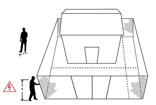
Personnel safety is based on the concepts of step and touch potentials (Figure 1). These provide the means by which substation safety parameters can be precisely calculated against maximum available fault current rather than left to the presumption that the system is merely grounded. Substations are at the limit of demand on safety requirements for two reasons:
There is a high probability that the earth itself will be part of ground-fault current return, in parallel with the familiar metallic return paths within utilization systems.


There is a substantial possibility of employees being present in the switchyard at the time of faults.
As a consequence, there must exist a system of grounding electrodes paralleled together with interconnecting cables so as to provide sufficiently low ground electrode system impedance. This impedance must be low enough to maintain the voltage drop within the system at a tolerable level and maintain the voltage drop within zones which personnel might subtend at less than hazardous potential differences.
Where:
t = time of duration of shock in seconds
Ik = rms current through the body in amperes
The calculated current relates to passage between both hands, or from hand to foot or hand to both feet. In cases where passage is between both feet, a current ten times as high may be tolerated. However, this is still enough to initiate involuntary leg contractions that could cause a fall and result in contact with the hands to the voltage source.
It is instructive to consider the manner in which current distributes itself through the earth. Current flow creates a voltage drop at the earth’s surface. A person standing on the surface will therefore develop a voltage


Hazard to the human body is a function of current, not voltage. A harmless carpet shock can be thousands of volts. But the limit of tolerable current magnitude (that will not cause ventricular fibrillation in a 110-pound person) is determined to be:
Ik = 0.1116/√t amperes




Where:
R = resistance
P = characteristic resistivity of the material
l = path length
a = cross-sectional area of the conductive path


drop between the feet, and this can be of a dangerous magnitude. This is what is referred to as step potential. Remember, current traveling in earth does not have to follow a straight path, as in a circuit, but can radiate in all directions (360°). As it does, voltage drop diminishes across a given distance, but in nonlinear fashion. Recall the basic formula for resistance of a conductor:
R = ρ (l/a)
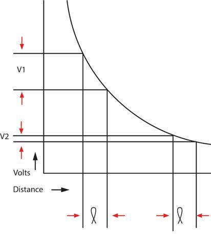


3: Step Potential Voltage/Distance Curve: Note V2 << V1
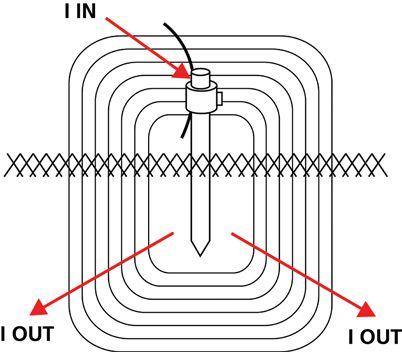
For a wire, a is the gauge and, therefore, another constant. But with a current injected into the earth, a changes continuously. For illustrative purposes, imagine the electrode as being surrounded by concentric shells of earth. These shells become progressively larger with distance from the electrode (Figure 2). Therefore, a increases while the resistance increments in l are becoming progressively smaller. Eventually, a point is reached where the outer shell has such a large surface area that any additional increase adds little to the total resistance. At this point, resistance can be considered constant and voltage drop is negligible (Figure 3). For the consideration of personnel safety, a person standing or walking near the point where the fault current enters the earth may have a large and injurious potential difference from foot to foot. The potential difference across the


Figure 4: Fault Can Apply Voltage Across Worker’s Body



same span will be less and less with distance from the entry point. Substation grounding, then, must maintain this potential below injurious levels.


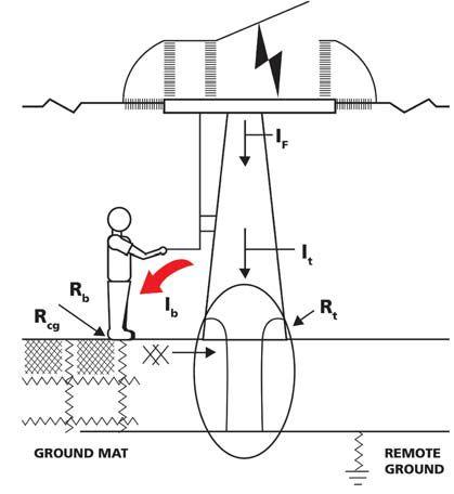
Similarly, touch potential represents the possible danger that could arise from a person contacting any part of the substation structure, both inside or outside the fence, with an injurious potential being applied across the body. A common example is that of a worker operating a disconnect switch
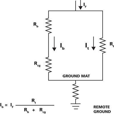
with the remote possibility of the switch faulting to the structure (Figure 4). With a fault condition as shown in Figure5, the worker would be in parallel with the tower and a portion of the fault current shunted through the body. Some typical values can be used to illustrate how the worker could be protected from injury. Good grounding connections could limit the tower-toground mat resistance (Rt) to 0.5 mΩ. A similarly reasonable assumption would fix the operator’s contact to ground (Rcg) at 50 Ω, based on a ground resistivity of 35 Ω. The fault current will be assumed to be 50,000


A. Utilizing these assumptions through the circuit described in Figure 6, the current through the operator’s body (Ib) would be 50,000 X 0.0005/550 = 45 mA. This would be a safe value for 500 milliseconds (30 cycles). The critical component here is Rt. Increasing the resistance of the connection to the ground mat to a mere 5 mA would endanger the operator.


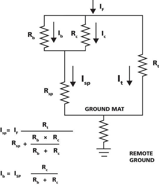


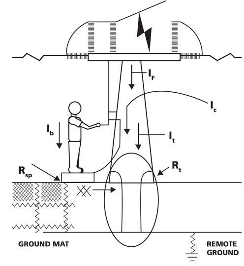
A method to further reduce the potential danger would be to have the operator standing on a small metal platform connected by a low-resistance cable (Rc, 4/0 copper) to the operating handle (Figure 7). Now, current to ground is divided between the operator’s body and the short cable, which has a typical resistance of 0.2 mΩ. Further reasonable assumptions can be made that each connector has a resistance of 0.15 mΩ, making a total resistance of 0.5 mΩ, plus a 1Ω resistance for the platform to ground (Rsp). Calculation via the circuit described in Figure 8 shows that:
a reduction by a factor of nearly 2000! So it can be seen that Ib, the current through the operator’s body, is dramatically affected by resistances Rt, Rc, and Rsp. The first two increase Ib when they increase, the last decreases Ib when it increases. Worst cases are Rc increasing to infinity due to a broken connection, Rt becoming high due to broken or bad connection to the ground mat, and Rsp approaching zero. The system must be such that it limits current through the operator’s body to a safe value. The platform cable may be sacrificed in the operation, but that will be readily detectable visually.
The next column will review some of the details of construction, connections, and testing of a grounding system that will meet the rigorous yet essential requirements described here.


I sp = 50,000 X 0.0005/1.0010 = 25 A
While:
Ib = 25 X 0.0005/500 = 25 μA
This step has reduced the current through the operator’s body from 45 mA to 25 μA,

Jeffrey R. Jowett is a Senior Applications Engineer for Megger in Valley Forge, Pennsylvania, serving the manufacturing lines of Biddle, Megger, and multi-Amp for electrical test and measurement instrumentation. He holds a BS in Biology and Chemistry from Ursinus College. He was employed for 22 years with James G. Biddle Co. which became Biddle Instruments and is now Megger.


Substation Testing As Easy As
Spend More Time Testing, Less Time Training
Vanguard’s precision substation testing instruments are designed to be intuitive and easy to use so that you can focus on testing instead of wasting time in training. Our versatile instruments offer a built-in thermal printer and on-board test record storage so that tests can be conducted in stand-alone mode in the field. A computer interface is also offered so that tests can be easily conducted from a PC.
And all of our instruments are competitively priced to provide cost-effective accuracy. For a virtual experience of our instruments, check out the interactive demos on our site at:
www.vanguard-instruments.com/demos


NETA Snowbirds Flock TO ST. LUCIA
BY KRISTEN WICKS, NETANETA’s members and Board of Directors winged their way south again this winter for their respective meetings, traveling to St. Lucia for a good mix of business and pleasure, as many members extended their stay to enjoy the tropical climate.
A full slate of business greeted the board and members at both meetings. Policy review, new program development, and oversight of existing programs took center stage. NETA’s membership continues to grow steadily and reviewing the active applications is an important and detail-oriented undertaking. Thankfully the Membership Chair is always equal to the task. NETA is fortunate to have many talented individuals leading the association, all of whom are devoted to applying their skills and strengths to their specific areas with enthusiasm.
The Board of Directors concluded their meeting on Thursday, January 16th, and rolled right in to the member meeting on Friday, January 17th. The members present listened to updates on the many programs and benefits available to them, including
hearing more details on the newly drafted ANSI/ NETA ECS Electrical Commissioning Standard for Electrical Power Equipment and Systems that is slated for release in the spring of 2015. They also got more information about the technical lineup at PowerTest 2014 in Denver, Colorado, also the site of the next NETA Member and Alliance Partner meeting on Sunday, March 2, 2014, from 12:00 PM – 5:00 PM.
NETA thanks all of the members who were able to schedule the time to travel for this meeting in the midst of busy holiday schedules and the neverceasing demands of your more-than-full-time jobs. The work of a volunteer is never done, especially with kind souls like the ones at NETA.
FIELD TESTING TECHNIQUES FOR
LOW VOLTAGE CIRCUIT BREAKERS
BY BRUCE M. ROCKWELL, P.E., American Electrical Testing Co.Modern technology continues to rapidly drive advancement of low-voltage circuit breaker design. While application of new technology to reduce cost is always a product manufacturing consideration, the goal of achieving faster fault clearing times is producing frequent design change of lowvoltage circuit breakers. The frequency of change represents a persistent challenge for technicians and engineers who have to keep up with new field test techniques and to maintain an accurate library of trip curve characteristics. This article identifies and illustrates emerging circuit breaker
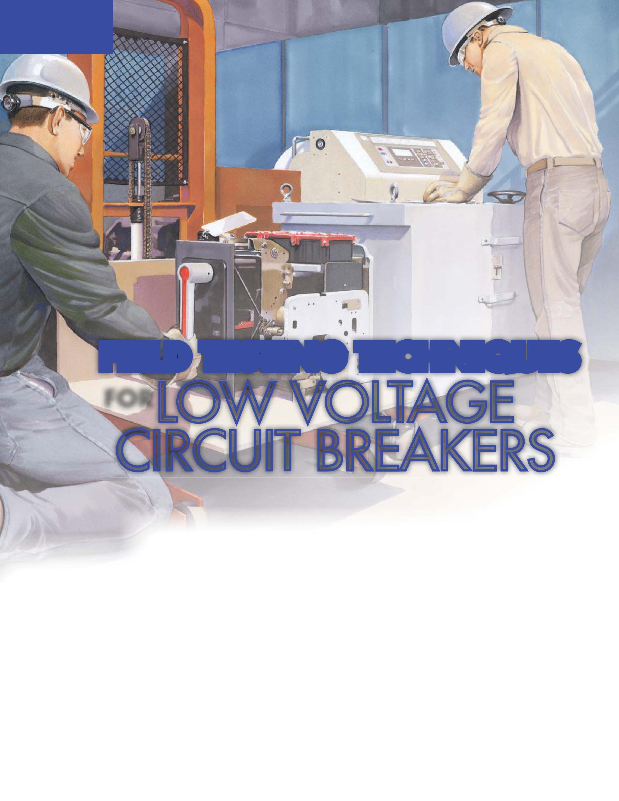
technology enhancements that require new knowledge and new field test techniques.
A primary driver of change is development of many new products and their subsequent rapid refinement to address arc-flash hazard reduction. In comparison, ground fault circuit interrupters were developed and have become commonplace for safeguarding against electric shock hazard. These devices have evolved and continue to evolve facilitating widespread application. Ground fault detection and trip schemes are just one subset of the many techniques employed to address arc-flash hazard reduction.

BREAKER RATING AND TYPE
Low-voltage (molded case) (< 1000 V) (integral trip) 1.50.025
Low-voltage (insulated case) (< 1000 V) power circuit breaker (integral trip or relay operated) 3.00.050
This table does not include the external relay trip times
When considering low-voltage circuit breakers, one must understand the type of circuit breaker to be tested. Identifying the circuit breaker type is a first step in confirming the appropriate maintenance and test procedures as well as the appropriate test equipment. Reviewing and considering the breaker’s use and application is helpful in determining expected test results. The variety of low-voltage circuit breakers is constantly expanding due to technological innovations. Keeping things simple helps when testing, so first a breaker under test should be identified by classification such as molded-case, insulated-case, or low-voltage power.


An often misunderstood aspect of lowvoltage circuit breakers is the clearing time. This is sometimes referred to as fault clearing time, total clearing time, or breaker operating time. Since technology is driving faster clearing times, having a good understanding of operating time is important. Low-voltage circuit breakers may use direct acting, integral electronic, or relay tripping. IEEE standard 1015 provides some insight into expected breaker operating times and maintainability for the three types of low-voltage circuit breakers:
Molded-Case (rated and tested to UL 489)
“Virtually all MCCBs are interrupt fast enough to limit the amount of prospective fault current let-through, and some are fast enough and limiting enough to be identified

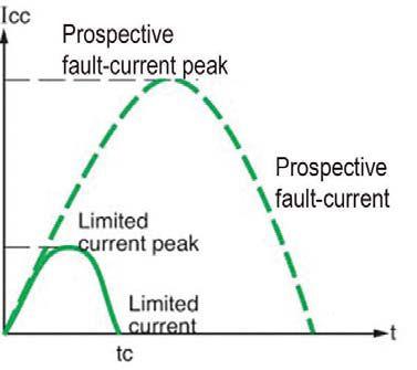
as current-limiting circuit breakers. MCCBs are not designed to be field maintainable.”
Insulated-Case (rated and tested to UL 489)
“Fast in interruption, but normally not fast enough to qualify as current-limiting circuit breakers. They are partially field maintainable.”
Low-Voltage Power (rated and tested to ANSI C37)


“Used primarily in drawout switchgear, they are not fast enough in interruption to qualify as current-limiting. LVCBs are designed to be field maintainable in the field.”
Table 1 is a partial excerpt from IEEE 1584 (2002). This table implies that no low voltage


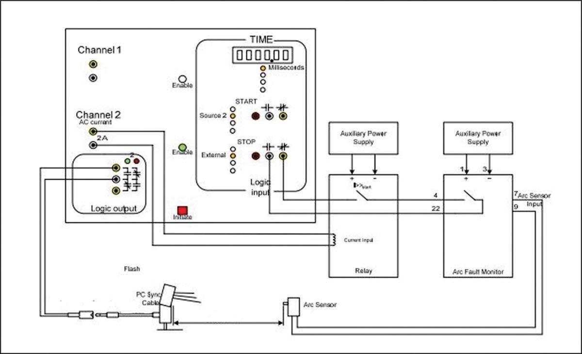


circuit breaker can operate in less than onehalf cycle. However, IEEE 1015 and UL 489 speak to the fact that there are special purpose molded-case circuit breakers that are defined as current-limiting circuit breakers.
A circuit-breaker that does not employ a fusible element and that when operating within its current limiting range, limits the let-through (I2t) to a value less than the I2t of a ½ cycle wave of the symmetrical prospective current within the first half-cycle is by definition current-limiting. Current- limiting circuit breakers are generally available from 15 - 1200 amperes, rated to 600 volts, have interrupting ratings up to 200 kA, and can clear a fault within the first half cycle (Figure 1).
Applying current-limiting devices (fuses, fused circuit breakers or current-limiting
circuit breakers) is one method to dramatically reduce arc-flash hazard. While low-voltage power circuit breaker themselves are not current-limiting, they are routinely applied with integral fusing as a currentlimiting protective device assembly.
The use of a fault clearing time of two seconds is suggested in Annex B (informative) of IEEE 1584 and also in Informative Annex D of NFPA 70E, when favorable conditions of egress exist. It is important to note that this statement is offered up with a clear warning that this two second clearing time is not applicable to all cases and should not be used arbitrarily for determining arc-flash hazards. However, it can be implied to represent a desired upper limit for clearing time durations. Field testing accuracy of circuit breakers with trip functions set to clear in


two seconds (or less) is critical with regard to verifying and validating arc flash hazard calculations. When testing current-limiting circuit breakers, the timing range precision and accuracy of the test set in the fractional cycle range is even more crucial.
The total clearing time of a circuit breaker is the time for the circuit breaker to sense a fault, actuate tripping, and break the current arc. The operating time for lowvoltage circuit breakers will range from less than one-half cycle to three cycles. The operating time for the tripping device needs to be added to this time to arrive at the total fault clearing time. Note that, for lowvoltage circuit breakers, the manufacture’s time-current-curves include both the trip device delay time and the circuit breaker clearing time.

Modern technology has not only focused on means to achieve current-limiting circuit breakers it is also focused on reducing the initiate trip time for the sensing and actuation device. Circuit breakers that are not direct acting have conventionally relied on fault sensing using current transformers in the phase to sense a short circuit. This can work well for high level bolted faults, especially when applied with current-limiting breakers. However, when arcing faults occur, the resultant fault current can be of such a reduced level that phase current sensing will not respond or will have a delayed response until the fault morphs into a bolted fault due to local ionization of the air.
A ground fault sensing scheme has traditionally been applied to fill the gap to avoid delayed fault clearing response, or no response, to a line-to-ground fault. These faults tend to be arcing faults, and due to the high impedance of the fault the current drawn may be closer to a load or overload current than a short circuit current value. This delays clearing and results in high arcflash incident energy hazards.
Application of ground fault tripping schemes and/or high resistance grounding can be very effective at reducing arc-flash hazards. Again, the importance of correct installation and testing of the ground fault protection is crucial for safety. Manufacturer’s drawings and literature should be thoroughly examined to confirm the available and asinstalled schemes and the test procedure. The manufacturer will provide detailed test procedures for testing these ground fault protection schemes. These schemes may require disabling the ground fault protection while performing phase fault trip testing.
Following are some test techniques that can be applied to verify ground fault tripping integrity. When nuisance tripping occurs or needs to be investigated for a ground fault scheme, a likely cause is existence of a false ground trip signal. This can result if the scheme is using three summing CTs and the CTs do not have identical electrical characteristics, the same ratings, and/or the same tap settings. Another condition that may cause a false trip is a disconnection between a sensor and the trip unit. Pointto-point wiring checks should be made using the manufacturer’s wiring drawings. The sensors can also be verified by measuring and comparing their resistance values. Typical sensor resistance ranges are generally provided in the manufacturer’s literature; however, all sensors of the same rating should have similar resistance.


Modern technology is now reaching beyond improved circuit breaker operating speeds and improved current tripping methods (ground fault and adjustable instantaneous trip functions) seeking alternate protection schemes or sensors. Solid-state trip circuit breakers can be tested by secondary current injection or primary current injection. Secondary current injection testing only tests the solid-state trip unit. In order to test and verify the integrity of the entire protective device, primary injection should be used. This verifies integrity of current


sensors, wiring, and breaker current interrupting components. Where critical systems are concerned, review of the design, application, and test methods applied should be comprehensive and uncompromised.
When using secondary injection test methods, it is important to verify the manufacturer’s procedures. Many times settings need to be adjusted to specific values for testing. In some cases, specific separation is required between trip function settings in order to achieve valid test results. Always record as found settings and trip flags prior to testing and reconfirm that settings and trip devices have been correctly reset. In the case of relays, reading the initial as-found setting file and reading the as-left setting file should be performed and printouts or file comparison utilities used to confirm the settings have been left in the proper condition and to be able to provide a documented record. Modern technology has spawned protective devices with an ever increasing list of settings and configuration parameters that need to be set or documented as not used.


Not long after the codification of arc-fault hazard protection requirements appearing in the National Electrical Code, a new term, reduced energy let-through was coined. This is characterized with two independent instantaneous settings being installed, the normal condition setting and the maintenance condition setting. Thus, testing techniques need to address verifying this new scheme applied as another means to reduce arc-flash hazards. In this case, the alternate setting may be initiated and disabled by a local switch, via communication using an output contact, or by a remote switch. This is sometimes referred to as an arc-flash switch or a maintenance switch. In some cases a flashing indicator is used to signal that the alternate setting is engaged, and this indication becomes part of the scheme verification requirement. Either way, the alternate setting should be disabled after testing and the system placed into normal protection mode. Verification of this
reinstatement should be part of the test documentation.
Instantaneous zone selective interlocking is another new protection scheme that is gaining more application momentum due to its ability to address arc-flash hazard. There are various zone interlocking schemes. However, they generally interlock upstream and downstream circuit breakers via a communication link. This allows overlapping of instantaneous trip functions while not sacrificing selectivity. Thus, this is a win-win as it allows lower instantaneous settings to be applied to reduce arc flash hazard while also improving selective coordination via a communication link. Test techniques need to simulate faults simultaneously for the upstream and downstream device in order to prove the desired selectivity is achieved.

These schemes typically utilize a three- or five-wire system to communicate phase and ground fault conditions in the zones. If a fault is seen by the downstream device and if it exceeds the short time pickup, it signals the upstream device to block high speed tripping that may occur from the instantaneous setting. If the downstream device fails to trip for a fault, the upstream device will override the blocking signal and trip instantaneously applying a slight (3-cycle) delay.
One of the most recent technological advances is the application of an arc fault sensor to initiate tripping to compliment the current sensing / tripping devices. This sensor operates by detecting an arc flash light signal when an arc flash occurs and then initiates a fast trip using fiber optic communications. Several relay and circuit breaker manufacturers have systems on the market. Testing of this protection scheme can be performed using a standard relay test set to initiate a trip. It is necessary to secure an optical fault sensor that can be used with the relay test set as the pickup device to detect the arc-flash event. A flash device is used to simulate the arc light so that the pickup device can actuate and send


a trip signal. Where practical, the arc light simulator should be used to signal the actual installed arc-flash pickup devices to verify system integrity. These systems are easily deployed using multiple arc sensors. The advantage of this new arc-flash detection technology is that an arc-flash event can be detected and a trip can be initiated in as fast as two ms (1/8 of a cycle).
It is important to keep in mind that currentlimiting is desirable. However, this requires use and application of a verified UL 489 currentlimiting circuit breaker (or a fused low-voltage power circuit breaker). In this case it is imperative to maintain the circuit breaker in order to maintain operating times and validate arc-flash hazard calculations. Although many times circuit breakers are applied that are not current limiting, endeavoring to reduce fault clearing time is desirable. This can be achieved by conducting periodic testing and maintenance and application of new technology. Achieving faster operating times of the trip devices and the circuit breakers will result in safer installations by reducing the arcflash hazard. As technology continues to drive rapid change, it is increasingly difficult, and yet vitally important, to keep up with the latest test methods and equipment characteristics.


Bruce Rockwell holds an MBA from Monmouth University, West Long Beach, New Jersey, and a BSEE from New Jersey Institute of Technology. Bruce has 30 years of engineering experience working for electrical equipment manufacturers and electric utility companies and operating CTI Power Systems. He has extensive experience in the design of T&D substations, industry, utility, and commercial power systems. Bruce routinely performs engineering studies and forensic engineering investigations of failed equipment. Bruce is also a New Jersey State certified continuing education instructor for electrical contractors, having developed over forty topicspecific training courses.
Currently Bruce is the Director of Engineering at American Electrical Testing Company, Inc. and is a member of IAEI, IEEE, NFPA, NJECA, and NSPE.


Get empowered with Doble.
Doble is proud to be a NETA Corporate Alliance Partner. Find out how you benefit! Visit www.doble.com/NETA And come see the Doble team at Booth 603 during PowerTest 2014.
For nearly a century, Doble has been amassing an unprecedented amount of knowledge and experience. We’re sharing it with our partners and customers through products, services and learning programs. We make sure you have the tools and information you need to ensure power system safety and reliability.
Empowering the industry with services, solutions and unmatched knowledge.







TESTING AND CERTIFYING

Modern

PROTECTION SCHEMES
FOR LOW-VOLTAGE CIRCUIT BREAKERS – PART 2
BY DAN HOOK, WESTERN ELECTRICAL SERVICES, INC.


This article is the second installment of a two-part commentary covering many of the protection schemes available in low-voltage switchgear. This first part, which can be read in the Winter 2013 Edition of NETA World, covered the basic theories and motivations for a handful of the capabilities of modern, lowvoltage circuit breaker trip units. This second part will attempt to suggest a methodology for testing and certifying these increasingly complex systems. Ever y capability of the many trip units available will not be covered, but some specific examples will be addressed.
Most readers will recognize the difference and importance of three distinct levels of electrical testing as it applies to electrical systems. Component testing, functional testing, and commissioning are recognized as three levels, increasing in complexity and documentation, in readying a system for turnover to an owner.
ANSI/NETA Maintenance and Acceptance
Testing Specifications are the industry recognized requirements for component testing and functional testing.
Low-voltage trip units have progressed with microprocessor technology and capabilities to a point where the line of demarcation between them and complex medium- and

high-voltage protective relays has all but disappeared. Many of the features available are present on both types of equipment. Commensurate with that fact, the technician responsible for certifying these systems must increasingly have a similar frame of mind with respect to the methodology used to prove these devices.

Some of the features addressed in part one of this article in the last edition of NETA World can be adequately addressed with component testing. Some will require functional testing with varying levels of complexity to confidently conclude that the system will operate as designed and installed. And


finally some protection schemes and other features involve a multitude of components, installation techniques, communications, and perhaps programming such that integrated system testing, included as a component of overall commissioning, is the only way to certify the system is free from discrepancies. Even when a component test is an adequate way to correctly evaluate a protective feature, there are commonly pitfalls or nuances of the testing process that must be considered to ensure correct evaluation in determining suitability for initial energization or continued service. Listed below are some examples of different features that may be considered for the different levels of certification, as well as some that may in fact be a feature of a lowvoltage breaker, not necessarily subjected to a test routine, but lie more in the design certification arena.
COMPONENT TESTING

a zone interlocking feature by simulating a restraint signal and documenting the performance and then removing the restraint signal and documenting the performance. Often this restraint signal can be achieved with a simple jumper on the secondary disconnect contacts to feed the breaker’s own restraint signal into its restraint input.
Thermal Memory


Most of the ANSI/NETA ATS and MTS
Sections 7.6.1.1 and 7.6.1.2 address component type testing requirements for low-voltage circuit breakers. Primary injection testing is called for specifically by trip function: long time, short time, instantaneous, and ground fault. The manifold of other protective features available are not as specifically addressed, but may present real challenges to the technician.
I2t/I4t Functionality
In my experience and with consideration to executing a valid repeatable test these functions are often disabled during testing by selecting “OFF” or “OUT” on the applicable trip function. This allows a more easily decipherable trip time range as read on the time-current characteristic curve and can curb the effects of test current ramp-up time on the time value observed. Increasingly, I have experienced customer specifications and expectations that low-voltage circuit breakers be tested at the settings provided in the protective device coordination curve.
Zone Selective Interlocking

Many technicians will have not so fond memories of their first experience testing a circuit breaker with thermal memory functionality. Often the first phase of testing goes well, and during the next phase of testing the results appear to change perhaps just in or out of the specified range. By the last phase of testing it is clear that something may be awry. It is often at this point when a technician will refer to the manufacturer’s instructions or seek help from another technician and learn that a thermal memory function may be the culprit. If this is the case, the trip unit is working exactly as designed, and the overload conditions experienced during the first two phases of testing have dictated the next overload event to trip the breaker in a shorter period of time. Some manufacturers allow for defeating of the thermal memory with a dial or dip switch, others use a jumper inside the trip unit, and still others may require the use of the manufacturer’s test device to override or defeat this function to allow for efficient testing. Depending on the manufacturer, the time to fully reset the thermal memory algorithm can be 5-15 minutes.


Under/overvoltage
A single circuit breaker can be tested and verified to operate correctly with respect to


Voltage element testing can be very straightforward and efficient; however, care must be taken when determining where to inject test signals. Also remember that in many cases a variable voltage source may not be on the standard list of test equipment necessary when a technician is assigned lowvoltage circuit breaker testing. Insulation resistance testing is worth mentioning as well. As new trip unit designs are released and voltage sensing, display, and protection capability are becoming more commonplace,


extreme care must be taken to ensure that dielectric testing performed does not damage the trip unit components. Often removing a rating plug or removing voltage sensing leads or fuses will be required.
Under/overfrequency
As was mentioned with voltage testing above, the actual testing of frequency elements may not present a large challenge technically or even time wise, however a variable frequency source again may not be in the technician’s mind when preparing for lowvoltage circuit breaker testing.
Reverse
Power




Simultaneous injection of voltage and current either primary or secondary to the current transformers will be required. Depending on the manufacturer one may be able to be accomplish this in a single-phase test; however, three-phase capabilities for both current and voltage sources may be required if the feature is being used by the trip unit.
Alarms
There are many trip functions that can be accompanied with a corresponding alarm type condition at a threshold level set in such a way that the alarm will actuate prior to a trip event. Some examples may be overcurrent, undervoltage, imbalance, and underfrequency. Expectations for testing each of these alarms must be clearly communicated prior to the testing session.

Event Recording and Diagnostics: This type of capability of a low voltage trip unit may be used for a wide variety of functions. Simple trip current level indication may be provided; the phase of the sensed condition may also be presented. Full waveform type event recording is available on at least one manufacturer’s lowvoltage trip unit line of products. Self check circuitry is commonly a part of microprocessor devices and may output an error signal as well.
FUNCTIONAL TESTING
Specifically parts 7.6.1.1.2.11 and 7.6.1.2.2.11 of the ANSI/NETA ATS and MTS mention verifying the functionality of various features or schemes. Section 8 addresses the development and execution of a functional testing plan to prove the aspects of the system installed.


Reduced Energy Let-Through, Quick-Trip, Arc-Flash Reduction Maintenance System, Dynamic Arc-Flash Reduction System, Alternate Maintenance Setting


Metering Indications
Many micro-processor based trip units have consolidated metering capabilities that may have been present elsewhere on the switchgear or cubicle to the trip unit itself. This is an efficiency gain in that duplicate instrument transformers and indicating devices are not required. However these capabilities require testing and certification no matter where they are contained and are an example of another case in which the traditional short list of test equipment required for low voltage circuit breaker testing must grow when dealing with microprocessor trip units onboard.


These features, with all their varied nomenclature, endeavor to accomplish the same goal of reduced arc-flash hazard energy downstream of the subject low-voltage circuit breaker. Some manufacturers utilize a simple switch providing a dry contact type input to the trip unit to assert the alternate protective settings, while others use more complex methods. One manufacturer utilizes a separate 24 Vdc power supply and associated wiring to insert a signal into the low voltage trip unit and apply the alternate set points. For trip units with complex communication capability in facilities with a direct digital control system, the feature can be activated over that communications network. One may be able to perform the actual trip verification during the component testing via primary injection, but the functional testing steps will likely focus on verifying the input used to cause the change in state in the trip unit. At this time ANSI/NETA testing specifications do not call for primary injection testing to prove these substitute set points. The manufacturer’s method of triggering of the system installed will dictate how to develop the functional test


plan to alternately activate and deactivate the scheme as desired.

Zone Selective Interlocking


Different test methods are available depending on the specific manufacturer of the system installed. In general the direct-wired connections, polarity sensitive in most cases, must be fully verified to ensure the proper operation of the feature as designed. This verification can be accomplished with an integrated test feature, if installed, by following the manufacturer’s instructions. If no integrated test feature is installed the best way to certify this system is to fully install all applicable circuit breakers in the system that are part of the scheme and primary inject current levels to simulate faults in the different zones of protection to verify correct operation of the responsible circuit breaker. This method is certainly more time consuming and may require a written method of procedure; however, it may be the only way to fully validate the installation.
COMMISSIONING (INTEGRATED SYSTEM TESTING)
Communications/Alarms and Indications

As mentioned above, modern low-voltage devices have communication capabilities not limited to just local alarms and indications. They can be controlled over a facility’s direct digital control system, and the level of control can include operation as well as safety devices. The correct programming, testing, and verification of these features can best be accomplished by an integrated system test. Multiple devices are necessarily involved, as well as interconnecting wiring, possibly even wireless devices, and the complex addressing and communication device programming required, dictate that a comprehensive commissioning plan be developed, approved, and executed.

Metering/Power Quality/Load Power Flow
The instrument transformer inputs for modern low-voltage trip units allow for complex metering including power quality and power flow calculations. Often component testing, and

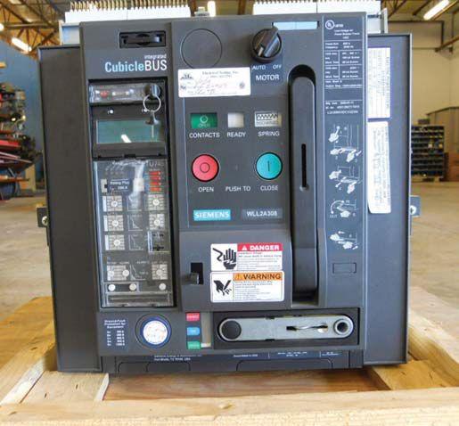


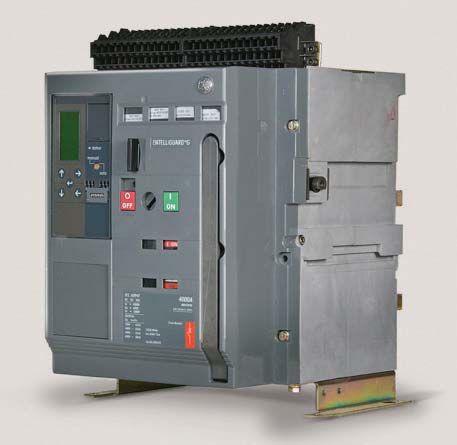

Unit with no dials and instead LCD screen display


in some cases simple functional testing, fails to reveal a polarity reversal on a current transformer, or a potential transformer design or installation error in which delta-wye configuration is not correct. Interconnecting wiring configurations can be used to physically accomplish a phasor addition or cancellation. A common method used as a final proofing step covering all of the sources and loads in an electrical system involves a temporary load bank configuration, available with unity and capacitive or inductive power factors, connected to the equipment followed by a systematic manipulation of the sources and power flow arrangements to prove all components of the system and their interrelation.
reader in the future by answering some of the questions that arise.

Design features not necessarily practical or expected as a part of a field-testing routine:
Instantaneous Selectivity
As covered in the first part of this article in the previous edition of NETA World Journal, this characteristic is a result of manufacturer’s design testing of certain breakers arranged in a series configuration. If questions arise concerning a specific application related to instantaneous selectivity of the installed system, the manufacturer’s provided tables should be referenced, or in their absence the manufacturer consulted.
Small molded-case breakers that traditionally had thermal magnetic or simpler solid-state trip devices are commonly being equipped with mini-microprocessor based trip units with many, if not all, of the features of the larger power circuit breaker trip units. No longer can the smaller panel boards filled with molded-case breakers be expected to be a quick long time and instantaneous primary injection test with a contact resistance test and insulation resistance test. Programming and feature testing may dictate much more effort in the future.

Instantaneous Fault Discrimination/Making Current Release


At least one manufacturer offers a mediumvoltage circuit breaker with an onboard trip unit. To my knowledge there is still a difference in that the current transformers are not contained onboard the breaker as in the low voltage application; however, insulating material advancements may allow for them to be located on the breaker themselves. With remote current transformers and onboard medium voltage trip units, is primary injection still the preferred method for testing, and what challenges will that cause in test setups?

This feature of most low-voltage circuit breakers involves very high current associated with short circuit currents. Personally I have never encountered a situation where the testing of this feature was even discussed, nor can I foresee a reason in the future, outside of forensic testing or other specific data gathering routine that is outside the scope of acceptance or maintenance testing.
During the course of writing this article I discovered or was reminded of some other interesting items that in some way apply to the subject matter. These are worth mentioning as potential products, techniques, or methods that may assist the


The vast range of features, and their associated required settings, onboard modern low voltage trip units when combined with the communication capabilities for connection to the modern test technician’s laptop with appropriate software could add another level of complexity to the testing of low-voltage circuit breakers. If the day has not come yet, it may not be far off where a list of required set points for the circuit breakers listed on a settings sheet will not be sufficient. Trip logic and interlocks between devices may require comprehensive set point files to be generated and uploaded as is the case for many microprocessor-based medium voltage protective relays.
Increasingly, project specifications require the protective device acceptance testing to be performed at the specified set points as dictated in the protective device coordination study. It is imperative to be able to meet this


requirement that the study be performed and approved well in advance such that they testing agency can plan for the methods, procedures, and test equipment necessary.


As I said in the first article, worthy of stating again, no matter whether you are an engineer, technician, contractor, or facility owner, this article should reinforce the importance of reviewing and understanding the manufacturer’s specific instructions. I would add to the list, the protective device coordination study, the owner’s project requirements, and a test plan that may be complex enough to be written and approved prior to the testing mobilization.


Dan Hook is the Chief Operating Officer of Western Electrical Services Inc. He joined the group in 2004 and has been in the electrical industry for over 18 years with the US Navy and civilian experience. Daniel holds a Bachelors Degree in Nuclear Engineering and a Masters degree in Electric Power Engineering from Rensselaer Polytechnic Institute in Troy, New York, and he maintains his professional engineer’s license in Washington State and Arizona. He is a Certified Journeyman Electric Motor/Generator Repairman (US Department of Labor, US Department of the Navy). The Inter-National Electrical Testing Association (NETA) certifies him to Level III Technician. The National Institute for Certification in Engineering Technologies (NICET) certifies him to Level III in the area of Electrical Testing Engineering Technology. Dan spent over a decade in the US Navy as an Electrician’s Mate maintaining and testing all aspects of generation, distribution, control equipment, and system protection as it applied to nuclear submarines.




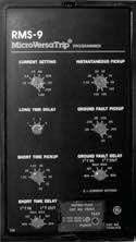


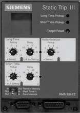
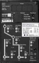
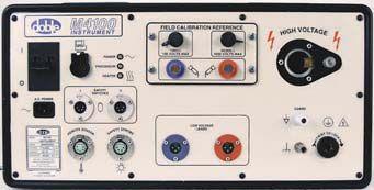

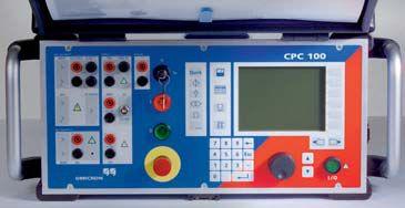


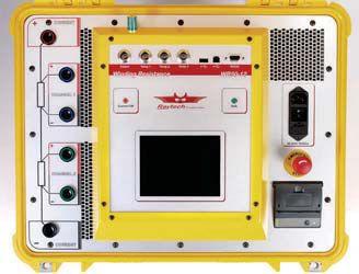

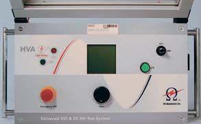


the test equipment answer
Relay and Protection Systems
Switchgear and Breakers (Low, Medium and High Voltage)
Cable and Bus
Transformers
Batteries
Motors and Rotating Apparatus
Watthour Metering
Power Quality and Consumption
Analysis


NEWREQUIREMENTS IN CIRCUIT BREAKER DIAGNOSTICS

INTEGRATION OF NEW CIRCUIT BREAKER TEST METHODS
BY RADENKO OSTOJIC AND BUDO MILOVIC, DV Power, Sweden
ABSTRACT


The paper describes recent developments in circuit breaker diagnostic testing. Improved safety and more accurate assessment of circuit breaker contacts are discussed. In addition, the paper presents standard methods for circuit breaker diagnostics. Examples are given for some of the test methods showing the existence of a defect in a circuit breaker. Special attention is paid to the requirements for a CB analyzer to integrate all of the test methods described and at the same time test most of the existing types of circuit breakers.
INTRODUCTION


Reliability of circuit breakers is crucial for the reliability of the entire power system. Whenever a fault occurs in a system, that section must be isolated from the rest of the system. This is where circuit breaker comes to its most important task, to interrupt fault currents and thus protect electric and electronic equipment. The interruption and the subsequent reconnection should be carried out in such a way that normal operation of the network is quickly restored in order to maintain system stability.
In order to detect any incipient problem as early as possible, regular tests should be performed on a circuit breaker during its life. More recently, in addition to standard tests, new methods are applied to more precisely diagnose the circuit breaker condition. This contributes to reducing the cost and time associated with testing and maintenance.
CIRCUIT BREAKER TESTING
There are several diagnostic tests applicable to a circuit breaker. The resistance of the main circuit is measured to check whether its value exceeds the specified value due to the contact wear or for other reasons. Increased resistance can cause unacceptable heating during operation that can further cause severe damage in the interrupting chamber. Excessive wear often occurs on the arcing contacts because they are subjected to heat and high energy produced by the arc during the circuit interruption. Arcing contacts are in the current circuit during a portion of the operating cycle only, and detection of the wear levels requires a special method - the dynamic resistance measurement (DRM).


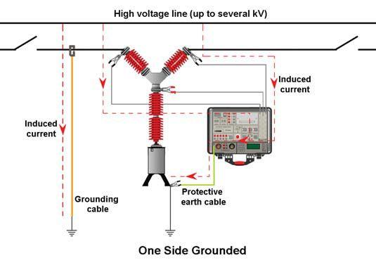
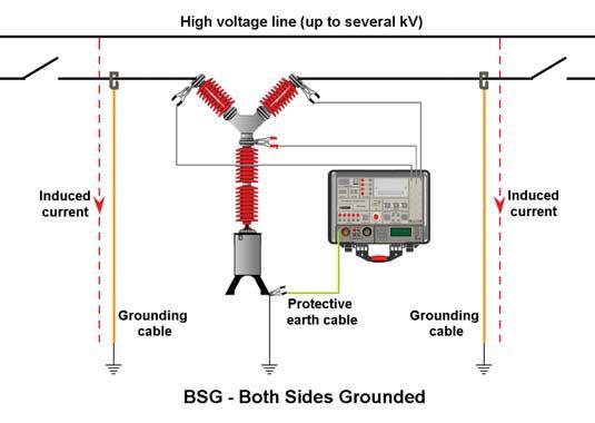

Friction and wear affects performance of moving parts. Insufficient storage of driving energy in an operating mechanism (e.g., due to a leakage in the hydraulic and pneumatic operating mechanism or unadjusted springs in motor-spring mechanism) can cause improper operation or increased switching times. Defective damping devices shorten the service life of a circuit breaker. Timing and motion tests are performed to detect these problems. To obtain information about the condition of the coil and latch mechanism, it is necessary to record the coil current waveform. Recording the coil current waveform can help in revealing the potential failure of the elements in the auxiliary (control) circuit of the circuit breaker.


NEW TEST METHODS FOR CIRCUIT BREAKER TESTING
Safe and fast testing of the circuit breaker with both sides grounded (BSG) Safety in high-voltage substations is the highest priority for all personnel involved. IEEE Standard 510-1983 IEEE Recommended Practices for Safety in High-Voltage and HighPower Testing states that “all underground terminals of the test equipment or apparatus under test should be considered as energized” and recommends grounding of all exposed terminals. If the breaker is not grounded on both sides there is a risk of induced high voltages (as shown in the Figure 1. left).


Eliminating this risk improves safety of the test personnel and the instrument itself. This leads to a requirement for the modern circuit breaker analyzer to detect a main contact’s state and to measure the operation time of the contacts when both circuit breaker terminals are grounded (as shown in the Figure 1. right).


If both sides are grounded, applying conventional main contact state detection methods is not possible because there is a parallel circuit through ground cables and the ground network. Modern test methods use a main circuit resistance measurement for the main contact state detection during a circuit breaker operation with both sides grounded. When the circuit breaker is open, there is closed circuit through the grounding cables and grounding system. Commonly the resistance of this circuit amounts to tens of mΩ. The resistance of main circuit (closed main contacts) is typically up to 100 μΩ, which means that these resistances are not difficult to distinguish. Therefore, even the state of the main contacts can be detected. However, arcing contacts are first to close and last to open the main circuit, so actually they define closing and opening time of the circuit breaker. The resistance of arcing contacts is in a range from a couple of hundreds μΩ to a couple of mΩ, so this resistance is still possible to distinguish from the grounding


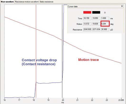
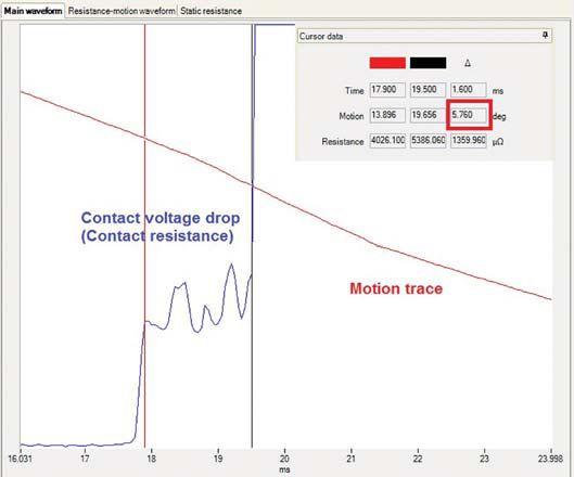


resistance and based on it to determine the state of the main circuit. Unlike conventional methods using only the voltage sources, this method requires additional current sources with ampacity of a few amperes only.
Dynamic resistance measurement
Arcing contacts are important parts of the high voltage circuit breakers too. The arcing contact is the first to make contact during a closing operation, and the last to break contact during opening. Therefore, circuit breaker arcing contact wear occurs during normal operation as well as when interrupting fault currents. If the arcing contacts are damaged, the breaker becomes unreliable very soon. Main contact surfaces can be deteriorated by arcing resulting in increased resistance and excessive heating and in a worst-case scenario – lead to a failure. Arcing contacts’ condition can’t be assessed by conventional timing tests, so a new method has been looked into.


One of the methods to detect the condition of the arcing contacts without dismantling the breaker is to inject a high dc current (a couple of hundreds amperes) and measure a voltage drop as well as the contact motion during the breaker operation – the so called dynamic resistance measurement. It is known as an

effective technique for assessing the condition of power circuit-breaker main contacts and arcing contacts. The DRM method measures variations in contact resistance (contact voltage drop) during the breaker operation. When the breaker contact motion is measured simultaneously with resistance, the results can be used to assess the wear or reduced length of the arcing contact.
Car batteries were initially used as a power source to produce a pure dc current. Transportation and other technical reasons prevented wide use of lead-acid and other rechargeable batteries for DRM testing. Today, digitally controlled power sources are normally used for this purpose. For proper diagnostics, the DRM test also requires a circuit breaker analyzer with high measurement resolution.


EXAMPLES OF CIRCUIT BREAKER FAILURE DETECTION
Contact wear detection by applying DRM test
This example illustrates how the contact system condition can be accurately assessed by applying the DRM test. An ASEA lowvoltage air circuit breaker with rated voltage of 600 V and rated current of 1600 A was tested using a modern digital circuit breaker analyzer.


This circuit breaker has a contact system with rotary movement of the moving contacts. Figure 2 (left), presents the graphic result of the DRM test performed at a test current of 200 A. During the arcing contact’s overlap, there is a sudden change in the arcing contact’s resistance (indicated as a voltage drop). This pointed to a potential defect of arcing contacts and a likelihood of contact system wear. Since there was no reference recording of a previous DRM test, it could not be concluded with certainty that this was a defect. However, after replacing the old arcing contacts with a new set and tightening the contact mechanical links, the situation was much improved, as shown in Figure 2 (right). The DRM test was performed again with a current of 200 A. There were no sudden changes in the arcing contact’s voltage drop (resistance) and their voltage drop was much lower too. In addition, the arcing contact overlapping distance was measured as 6.264 degrees (motion measurement performed with rotary transducer), compared to the 5.76 degrees (Figure 2) before installing the new arcing contacts. All these indicators led to the conclusion that the old arcing contacts were worn out.
Antipumping relay failure


To prevent multiple and unwanted breaker operations, it is equipped with an antipumping relay device. The relay prevents excessive breaker closing and opening events when, for example, a fault occurs during a regular closing command execution by an operator. While the operator’s closing command is being executed, a fault will engage a protection relay which will attempt to open the breaker. Without an antipumping relay, the breaker will operate multiple times depending on how long the operator maintains the closing command. This can damage the closing mechanism of the breaker and in extreme cases cause catastrophic failure. The antipumping relay prevents this by ensuring that the breaker closes only once for each continuous close command from the control device.

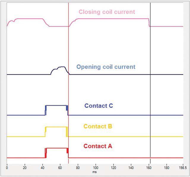


Looking at the graphics of the main contacts state (Figure 3) it can be seen that the operation was performed correctly. However, looking at the coil current waveforms, it can be observed that closing coil current appeared twice where the second time the current was interrupted at 160 ms (Figure 3, black cursor position). This means the CB analyzer stopped the current, since the length of the current pulse given to the closing coil by the analyzer was 160 ms. Although the second close operation was initiated, it was not successfully executed because the closing spring was discharged. Closing coil current is not allowed to appear the second time in the C-O operation. Here it is obvious the antipumping relay was defective since it was supposed to interrupt the closing coil circuit after C-O operation.
Incomplete O-0.3s-CO operation


On the same ASEA low-voltage circuit breaker, a close-open (C-O) operation was performed.
The most important task of a circuit breaker is to interrupt a short circuit when a fault occurs. The circuit breaker’s operating mechanism task is to store energy sufficient to carry out


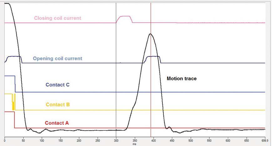


an opening operation. Lack of driving energy could cause inability of a circuit breaker to break its rated current.


An O-0.3s-CO operation attempt was performed on the high-voltage circuit breaker (123 kV) with a pneumatic operating mechanism. The graphs of the contact states (Figure 4, contacts A, B and,C) show that the circuit breaker opened but did not close which means that the operation was not completed. Since the closing coil current was initiated at the appropriate time (after a 300 ms pause beginning at the black cursor position), it means that the close operation was initiated and the failure was not in the control circuit of the circuit breaker. However, the motion curve shows that the movement of the mechanism did not reach the end position before the opening operation started. At the red cursor see that the opening coil current already had started the opening process and the motion reversed to opening. This was the reason the contacts did not touch.. The actual cause was that the mechanism did not have enough speed to reach the end position and complete the closing operation before initiation of the opening operation. This indicated lack of driving energy. Further investigation showed that the lack of energy was caused by leakage in the pneumatic mechanism.

REQUIREMENTS FOR TESTING OF VARIOUS CIRCUIT BREAKER TYPES
There is a huge number of circuit breaker types and, as mentioned above, various tests have to be performed. This fact imposes a lot of requirements on modern test instruments to support these test methods.
Since many high-voltage circuit breakers are made with up to four breaks per phase, the solution is to implement up to 12 timing channels in a single device to support timing measurement for as many circuit breaker types as possible. For timing measurements under BSG conditions, additional current sources are required in addition to voltage sources.


There are two types of circuit breakers with respect to the number of operating mechanisms: three-pole operated (with one mechanism) and independent-pole operated (with 3 mechanisms). To support a motion measurement on both types of circuit breakers three motion channels need to be implemented. Channels need to support the two most commonly used types of motion transducers: linear (analog) and rotary (digital).


To monitor station battery voltage, coil supply voltage, and coil and motor currents, multiple analog channels need to be implemented. Using appropriate transducers these channels could also be used for monitoring other types of relevant analog signals (e.g., motion or pressure).

A circuit breaker is activated by actuating coils. The circuit breaker analyzer should be able to initiate operation of both three-pole operated and independent-pole operated circuit breakers. A control cubicle of the independentpole-operated circuit breaker provides access to terminals of each of the three separate opening coils and the common terminal for the three closing coils. Therefore, a solution with four coil control outputs (three for trip and one for close) is enough to meet these requirements.


Sometimes the test cannot be initiated from the CB analyzer. For instance, the “first trip” test is performed when a circuit breaker is on-line. In that case the test has to be initiated remotely from a control room. For that reason an analyzer has to have an external measurement triggering feature, as well.
the resistance following the Ohm’s law, R=U/I. A powerful current source is specially required for the DRM to provide an easier detection of small changes of the resistance.
Dead tank circuit breakers have current transformers (CTs) mounted externally on the circuit breaker bushings. Current transformer cores can become magnetized by dc current applied during resistance measurement of the main circuit or DRM testing of the circuit breaker. Residual magnetism can cause serious problems when the CT is energized again. For example, protective relay action could be slow or incorrect during operation. To avoid these potential problems, a demagnetization function needs to be provided by the analyzer.
CONCLUSION


Requirements for testing various types of circuit breakers are very extensive. Also, taking into account all described test methods and new requirements, a modern CB analyzer needs to integrate a huge number of various functions. In addition a need to have an integrated current source with high and low ampacity becomes an imperative as well.

The circuit breaker auxiliary contacts support several functions. The most important functions are: providing signal contacts for relay protection, serving as main contact indicators, and protecting the coils from burnout. Since it is necessary to measure operation times of at least three contacts of type “a” and three contacts of type “b” on the independent-pole operated circuit breakers (one of type “a” and “b” per pole ), six auxiliary timing channels should be implemented in a modern analyzer.
To provide accurate and reliable contact resistance measurement (dynamic and static) the current source with high ampacity output (two hundred amperes or more) should be provided. The contact resistance measurement is based on the well known Kelvin bridge. A common approach is to inject a dc current through the closed circuit breaker contacts, measure the voltage drop between the terminals of the circuit breaker, and calculate


Radenko Ostojic is a test engineer at DV Power, Sweden, working on the improvement of the circuit breaker testing equipment and development of the new methods for circuit breaker testing. E-mail: radenko@dv-power.com, Tel: +46 70 0925 000.
Budo Milovic is a senior test engineer at DV Power, Sweden. Since graduating in electrical engineering, he has been working on HV diagnostics and substation testing methods. E-mail: budo@dv-power.com, Tel: +46 70 0925 000.


VLF-34E 34 kV VLF Tester
VLF & DC Output | Sheath Testing | Cable Burning
The VLF-34E is a new generation VLF AC Hipot that uses a solid state design with microprocessor controls. It meets the requirements of applicable world standards regarding cable testing up to 25kV class maintenance testing. It is light, compact, rugged, and very portable. Its sine wave output is suitable for using external TD and PD detection equipment. Using a TD and PD option, the VLF-34E is all that is needed for nearly all cable testing up to 25kV class.
Easy to use controls. Programmable test sequences & manual control, USB port for downloading data and for unlimited test report capture, wireless computer interface to control and download Tan Delta diagnostics and for remote control operation via laptop.

Tan Delta TD-34E
VLF-TD Cable Diagnostic Testing
The TD-34E, along with the HVI VLF-34E AC hipot, is the latest in design using current electronic technology. Together they permit the user to perform all VLF and VLF-TD tests possible and offer the best wireless operation and data collection, aided by the HVI custom application software written solely for the two devices. There is no better alternative. HVI has been supplying the world with VLF and Tan Delta technology since 1998, with more models, greater voltage range, and higher power capability, all with the superior sales and service that HVI is well known for worldwide.
NETA WELCOMES CONTROL POWER CONCEPTS AS A NETA ACCREDITED COMPANY
Control Power Concepts (CPC Inc), a veteran-owned power engineering and technical field services company, is proud to be acknowledged by our peers as a NETA Accredited Company.
Founder and president John A Travis began his successful power-industry career in the US Navy’s nuclear power program. He started CPC in 2006 by being a significant contributor to the power systems technologies being deployed within the hotel and casino resorts in the SAR of Macau. Eight short years later, we have clients from many industries, including some of the largest power generating stations in the nation. In addition to the full array of NETArelated power equipment testing and maintenance services, CPC also provides a comprehensive list of engineering services related to our clients’ power-related concerns.
With an internal culture of client advocacy, ownership,

and expertise, CPC’s technicians and engineers pride themselves on their high level of specialized knowledge which allows them to service a growing and loyal client base.
Current staff members at Control Power Concepts who have contribed to this achievement is Zeb K. Fettig, PE, Vice President, Engineering; Nancy G. Vargas, Vice President, Business Operations; Octavio Gonzalez, EHS Coordinator; and William Holland, Director of Field Operations. CPC’s headquarters of operation is located in Las Vegas, Nevada. CPC looks forward to working with NETA to promote our industry.

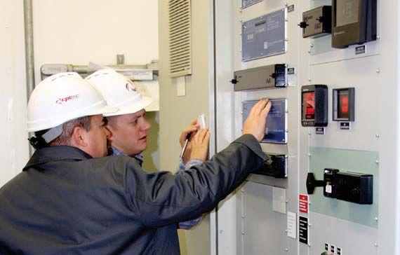

Power System Acceptance Testing
Commissioning and Start-up
Maintenance
Life-Cycle Extension
Troubleshoot and Repair
Training and Engineering Services
Planning and Operations Support
Project Management






Protective Relay Repair and Calibrating
Medium Voltage Starter Repairs
Solid State Trip Unit Repair and Programming


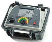

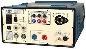




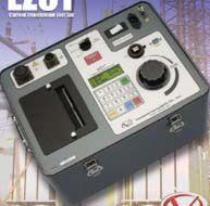
NETA WELCOMES SEVEN NETA CORPORATE ALLIANCE PARTNERS, COMMITTED TO ADVANCING QUALITY, SAFETY, AND RELIABILITY
NETA Accredited Companies are but one component in the business of creating
and
maintaining a successful power supply. The NETA Corporate Alliance Program is a way for all facets the electrical power industry to come into better alignment and become a more efficient force when it comes to safety and serving clients’ needs.
NETA’s vision for the NETA Corporate Alliance Program is to create opportunities for exchanging information, ideas, and strategies across subsets of the electrical power systems industry. This foundation of key companies and individuals will support the mission of NETA Accredited Companies to create safe and reliable power systems by developing synergy between standards developers, manufacturers of electrical components and electrical test equipment, architects and engineers, facility management companies, and many others responsible for large power systems and equipment.
The first set of NETA Corporate Alliance Partners have demonstrated leadership in the industry and support for NETA by providing products and services that aid NETA Accredited Companies in performing electrical testing to ANSI/NETA standards.
NETA welcomes its first NETA Corporate Alliance Partners:
▶ AVO Training Institute
▶ Circuit Breaker Sales Co., Inc.
▶ ComRent International, LLC
▶ Doble Engineering Company
▶ Megger Group Limited ▶ OMICRON electronics Corp. ▶ WEIDMANN Diagnostics Solutions Inc.

For more than 40 years, NETA has been a leader in the electrical power systems industry, advocating electrical acceptance procedures, maintenance, and testing as critical steps in safeguarding the health of electrical systems and, most importantly, the personnel working on and around those systems. Field technicians, electrical engineers, electrical inspectors, electrical contractors, and facility managers have relied on the NETA standards and NETA Accredited Companies to assist in the verification of newly installed electrical systems and components and to assure continued service and longevity of existing power systems and components.
For the last 20 years, NETA has invited individuals who are not NETA Certified Test Technicians or affiliated with NETA Accredited Companies to align themselves with NETA’s mission and vision, continuing to raise the bar for safety and reliability. This program has generated a network of professionals and volunteers who support NETA’s endeavors and strive for advancement as professionals within their organizations and throughout the industry. NETA is excited to see where these new relationships will take the association and looks forward to reporting on them here in NETA World Journal.


ADVANCEMENTS IN TECHNOLOGY NOLOG


ADVANCEMENTS IN TECHNOLOGY
The NETA World Journal announces a new regular section: Advancements in Technology.
To encourage and enhance collaboration across the many business segments that support the electrical power testing industry, NETA World is pleased to include Advancements in Technology in each upcoming issue. This new section will feature contributions from the NETA Corporate Alliance Partners presenting information on research and development and insights from their respective areas of expertise with the goal of improving quality, safety, and reliability within the electrical power industry.

Be engaged, inquire, and share perspectives…


MICROPROCESSOR - BASED

RELAYS

OUT WITH THE OLD, IN WITH THE NEW
BY DENNIS MOON, AVO Training InstituteThe question is often asked by both technicians and engineers, “Why are we replacing perfectly good electromechanical protective relays with microprocessor-based devices?” The answer is both multifaceted and interesting.
It can be easily shown that electromechanical relays operate as fast as, and in some cases faster than, microprocessor-based relays.

Electromechanical relays can detect complex system abnormalities and take sophisticated actions. Electromechanical relays have been in service at every level of power generation and delivery for many years, so why replace
them? Here are some of the reasons that electromechanical and electronic relays are going away and why microprocessor-based relays are being specified as replacements and in new builds.
First and foremost is the vast amount of data that can be retrieved from microprocessor-
based relays that can be used to determine what prefault, fault, and postfault conditions exist at a specific relay and how those conditions affect larger system operating parameters. As system reliability becomes more and more important (think Smart Grid), more and more data is necessary to ensure constant and reliable power delivery. We can now retrieve fault data not only in numeric form, but also in sinusoidal and phasor formats. In most cases, the relay is capable of determining where system faults occurred and how far from the relay the fault was located. Highly accurate timing data can be measured because the relay can be connected to a system time clock that provides synchronization to other system devices. In this way, breaker operations, breaker reclosing, communications signals, and other timing information is correct and in proper sequence. Other information that can be gleaned from microprocessor-based relays is real time quantities such as complete system voltage, amperage, frequency, associated angles, watts, vars, power, and breaker status. This data can be sent to dispatch centers in real time to be used for load calculations, power flow, and other desired uses. Multiple events can be stored, recalled, and even replayed on modern test equipment. Relay data in now the king of system protection.
Next is the economic impact of microprocessorbased relays. For the cost of a single mechanical impedance relay, a microprocessor-based relay can be specified which will replace a complete panel of line protection at one fifth the cost or less. Five microprocessor-based relays mounted in a single nineteen-inch rack mount panel replace as many as ten full panels in a typical substation. This significantly reduces the per foot cost of a facility and allows scarce money to be spent on other needs. The maintenance needs of microprocessor based relays are also substantially less than their electromechanical counterparts, and the maintenance period can be extended thus reducing the man hours needed to test, calibrate, and maintain the relay. The FERC and NERC standard for microprocessor-based relay testing requires
ADVANCEMENTS IN TECHNOLOGY
only tests of the metering functions, inputs and outputs, and a check of the settings.
Microprocessor relays can play a vital role in arcflash hazard mitigation as well. These relays may implement a change in device settings via front panel push buttons so that, when technicians are working on a protected bus, arc-flash incident energy can be reduced.

As grid stability becomes more and more important, the versatility of microprocessorbased relays becomes increasingly more vital. The availability of multiple settings groups, the precise and accurate measurement of system quantities, and the ability of the relay to communicate data between stations and control centers makes the microprocessor-based relay the best option for system protection and control.
In summary, microprocessor-based relays are the absolute present and future of system protection and reliability. Accurate and plentiful data, significant cost savings, arc-flash protection, and versatility are just a few of the reasons that combine to make these relays the choice of protection for engineers and technicians. We will see more and more of these relays as older relays become obsolete and are retired. Equipment specifications will nearly always be designed for microprocessor-based devices so new installation will be almost one hundred percent digital.


Dennis Moon has over 32 years of experience in the electrical industry. He has been an electronic instrument repair technician, maintenance electrician, senior relay technician, and senior training specialist. Additional areas of expertise include the repair and calibration of oscilloscopes, ammeters, frequency generators, voltmeters, ohmmeters, and flatwave meters. He has also worked on the development and implementation of computerized relay testing programs to fit testing and calibration needs and development, marketing, and presentation of AVO Training Institute’s specialized courses.


Ground


We got your back.
No matter where you are, no matter what you run, if it’s electrical, Shermco’s the one.
Power plants? No problem. Utility substations? We can handle ‘em. Wind farms? Absolutely. Data centers? Just say where and when. The fact is, Shermco has the growing capacity to support your utility or electrical power needs in virtually any location, with all the manpower, equipment and technical knowledge it takes to get the job done and done safely!
While other companies are sending their equipment and workforces out to pasture, we’re upgrading ours and sending them into the field. Call Shermco for anything. Fromlarge-scale engineering projects and planned facility outages, to new system acceptance testing and safe start-up, one company does it all. Shermco. We got your back.

WHY YOU SHOULD USE THE
GUARD CIRCUIT
BY JAMES R. WHITE, Shermco Industries, Inc.WHAT’S IN A NAME?
Every field technician knows what a megohmmeter is. Usually we just refer to it as a megger, although that’s like calling all tissue paper Kleenex or all copiers Xerox machines. The correct name is megohmmeter as Megger is a trademark.
Whatever you want to call it, megger, insulation resistance test set, or megohmmeter, it is the most commonly-used insulation test set in the field. Small, lightweight, and relatively easy to use, various models of megohmmeters produce voltages from 250 to 15,000 volts so that the quality of insulation can be measured and trended. One of the problems in the common use of this little wonder is that the third terminal on the test set, known as the guard circuit, is rarely used because many people do not understand its function. Figure 1 shows a typical megohmmeter with a range from 500 volts to 5,000 volts. It is suitable for testing smaller insulation systems including motors, control wiring, instrument transformers, and small dry-type power transformers of up to about 15 kV, depending on the mass of the insulation system. A megohmmeter can also be used on larger transformers and liquid-insulated transformers, but typically an insulation power-factor test set is also used.
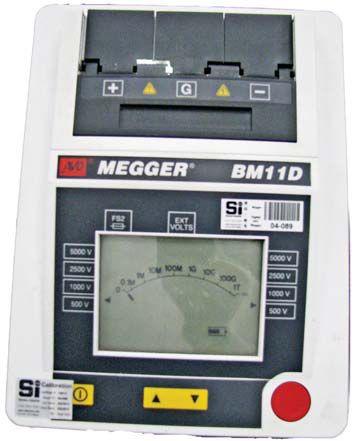
Figure 1: Typical Megohmmeter with a Guard Circuit Marked as Terminal G

VERIFYING INSTRUMENT FUNCTION
At a customer’s site we were preparing to perform field testing of a small transformer as part of the training. The customer brought out his megohmmeter which looked as if it had been run over by a pickup truck. When asked if it worked, he proceeded to operate it, causing sparks to fly to the extent that I started looking for a fire extinguisher. I suggested we try a simple test to see if it really worked. The megohmmeter, of course, had no output. The customer exclaimed that they had been using it for years and had always gotten good readings; no wonder! The test described below takes only a few minutes and will prove whether the megohmmeter actually works, and if it does, what its output voltage is. By the way, many thanks to Mark Lautenschlager for showing me this little trick many years ago.

A typical Fluke DVOM has an internal resistance of 10 megohms, while a Simpson 260 has 20 megohms. Connect the megohmmeter to the highest voltage terminal on the DVOM/VOM and set the megohmmeter output voltage to match. Do not exceed the DVOM/VOM’s maximum voltage or you will get a brand new meter – at a cost, of course.
In the example shown in Figure 2, a Simpson 260 is being used with a 1,000-volt maximum voltage rating. The megohmmeter’s output voltage is set to 1,000 volts and turned on. The DVOM/VOM should read 1,000 volts and the megohmmeter should read 20 megohms (or whatever the input impedance should be).


This test requires a volt/ohmmeter, such as a DVOM or even an analog VOM. I often use a Fluke or Simpson 260. The actual meter does not matter, but the input impedance should be known. All meters of this type use a resistor behind the input terminal. Less expensive meters may have an input impedance of just a few thousand ohms, while more expensive meters may have input impedances of 10 megohms to 20 megohms. Meters with high input impedances limit current flow through them, preventing problems when troubleshooting.
In the example shown in Figure 2 the megohmmeter is connected from the “-“ terminal (marked as LINE) to the “-“ terminal of the VOM. The “+” (marked as EARTH) terminal on the megohmmeter is connected to the “+” terminal on the VOM. Those of us in our declining years remember using megohmmeters marked LINE and EARTH and assumed EARTH was the negative terminal. Actually, the negative terminal should be connected to the conductor under test and the positive terminal should be connected to ground.
As a double-check, reduce the output voltage from the megohmmeter to 500 volts. The DVOM/VOM should read 500 volts, but the megohmmeter should still read 20 megohms. The input impedance will not change unless the terminal is changed to the 500 V input terminal on the DVOM/VOM as there is a different resistor behind that terminal. In the case of a Simpson 260 the 500 V terminal has a 10 megohms input impedance. Be aware


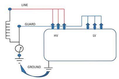

that line and battery-powered megohmmeters will have voltage outputs close to their ratings, but hand-cranked megohmmeters will not. This is due to the clutch used on handcranked megohmmeters to limit their output. They will often have an output voltage of 90 percent to 95 percent of their rating. This does not affect the test, but can cause some concern if you are not ready for it.
WHAT DOES THE GUARD DO?
The guard circuit is a means to eliminate unwanted return currents from the measure-
ments being taken. It is very similar to the unmetered return on dc high-potential test sets. Any test current that returns via the guard terminal bypasses the measurement circuit. This allows a much more accurate measurement to be taken. There are two ways a guard can be used, by dividing the insulation system into smaller pieces and by eliminating surface leakage.
ELIMINATING SURFACE LEAKAGE
Another very practical use for the guard circuit is to eliminate the effects of surface leakage on bushings. Figure 3 shows a bushing with a guard connected to a conductive collar located beneath the top petticoat. Any surface leakage current is now diverted above the meter by the guard. By daisy-chaining the collars around the bushings on the energized winding, all of the bushings can be guarded against surface leakage and a more accurate test can be made (see Figure 4). The conductive collars do not have to be the rubber collars included in the Doble® insulation power-factor test sets. Tie wire, screw-type hose clamps, or, in a pinch, aluminum foil, can be used. However, the closer the guard collar conforms to the surface of the bushing, the better.
In Figure 4, not only are the bushings guarded from surface leakage, but the guard is also being used for testing the transformer. Multiple Guards can be tied together and any return current from the guard circuit is routed above the metering and not measured. At this point, you should be slapping yourself in the forehead and making a Homer Simpson-like sound.
Circuit breakers can also benefit from using the guard circuit. When performing the dc overpotential or insulation resistance tests when humidity is high, using the guard can provide more accurate results. Figure 5 shows the guard circuit used when testing a circuit breaker. The guard collars are placed just below the primary disconnect (on the insulator), daisy-chained, then connected to the guard terminal. On a high potential test set, this would be the unmetered return terminal.

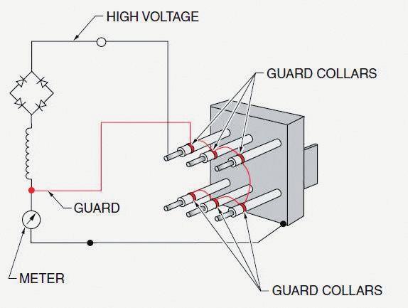

to ground, not left floating. Why not leave the untested winding ungrounded? The energized winding will induce a charge into the untested winding and could present a safety hazard or affect the test results by discharging at some point during the test. Always ground the untested winding.
When using a guard the connections are somewhat different. Any leakage current returning through the guard circuit is routed around the metering and is not measured. Figures 6, 7, and 8 illustrate the connections for using a guard when testing a two-winding transformer.
SMALLER SECTIONS OF INSULATION EQUALS BETTER TEST RESULTS
A two-winding transformer can be tested with or without using a guard. The standard test connections for testing a two-winding transformer are:
• HV winding to LV winding and ground
• LV winding to HV winding and ground

• LV winding and HV winding to ground
Note that the untested winding is connected

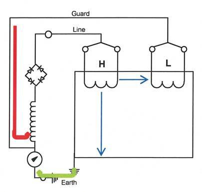

In Figure 6, the leakage current has two paths: from winding-to-winding and then windingto-ground. The guard is connected to the low-voltage winding, and any current to that winding is routed above the metering and is not measured. Only the current from the highvoltage winding to ground is measured. In Figure 7 the low-voltage winding is energized and any leakage current from the high-voltage winding is routed above the metering by the guard and is not measured. Figure 8 shows the winding-to-winding test. The guard is connected to ground, and the transformer is tested from the high-voltage winding to the low-voltage winding. Everything seems to


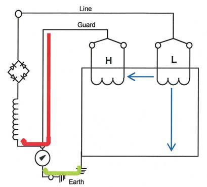


INDUSTRY TOPICS

be going swimmingly, but when the guard is connected to ground the meter reads zero. What’s up with that?
THERE ARE GUARDS, AND THEN THERE ARE GUARDS
There are two types of guard circuits that may be found on megohmmeters, the hot guard and the cold guard. The hot guard terminal on the megohmmeter is at or near line voltage, while the cold guard terminal is at or near zero volts. Why does this matter? The hot guard cannot be connected to ground, since it shorts out the meter. This means the high-to-low, ground guard test cannot be performed with a hot guard megohmmeter. The easiest method for determining whether your megohmmeter has a hot or cold guard circuit is to connect the guard to ground and turn on the megommmeter. If your meter goes to zero, you have a hot guard. An open meter reading (or one of these ∞) indicates a cold guard. Cold guard circuits require the use of an isolation transformer, so they will not be found on inexpensive megohmmeters.
SUMMARY
Guards are useful for testing most types of insulation systems. The next time an insulation resistance test is needed, think about the return paths and see if the guard can cut that insulation system into smaller pieces. If you are measuring lower insulation resistance values than you think should be read, use the guard to eliminate leakage from affecting the measurements. The guard can make your insulation testing a little easier and more accurate.

Figure 8: High-Voltage to Low-Voltage, Ground Guarded

James R. (Jim) White is the Training Director of Shermco Industries, Inc., in Dallas, Texas. He is the principal member of the NFPA technical committee “Recommended Practice for Electrical Equipment Maintenance” (NFPA 70B). Jim represents the National Electrical Testing Association (NETA) as an alternate member of the NFPA Technical Committee “Electrical Safety in the Workplace” (NFPA 70E and represents NETA on NEC Code Making Panel 13 and ASTM F18 Committee “Electrical Protective Equipment For Workers”. Jim is the past Chairman of the 2008 IEEE Electrical Safety Workshop, an IEEE Senior Member, and the 2011 recipient of the IEEE/PCIC Electrical Safety Excellence Award. Jim was presented with NETA’s Outstanding Achievement Award in 2012. A regular contributor to trade journals, Jim is a columnist for NETA World magazine’s “Tech Quiz” and coauthor of “NFPA 70E and NETA”. Jim is the author of the books “Significant Changes to NFPA 70E – 2012 Edition” and “A Practical Guide to OSHA and NFPA 70E”, both published by American Technical Publishers.

RENT POWER TEST GEAR
Protective Relay Test Sets · VLF/AC/DC Hipots · Tan Delta
Primary Current Injection · Thumpers · Circuit Breakers
Relay Testers · TTR Test · Megohmmeters · Partial Discharge
Oil Dielectric Test · TDR · Battery Test · Cable Fault Locators
Power Analyzers and more! SWITCHGEAR
Megger · Omicron · Hipotronics · High Voltage Inc.
Fluke · Phenix · SKF/Baker · Tettex · Doble · AEMC Rosemount/Hart · Vanguard and more...
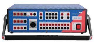
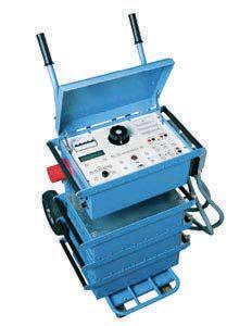
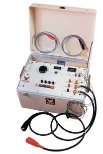


The NEW MI 2892 PowerMaster is a hand-held three phase power quality analyzer with a large easy-to-read graphical color display enabling the user to detect harmonics, phasors and waveform anomalies in the installation simply by connecting the device. The instrument is designed for long term recording, as well as for troubleshooting power quality problems in three-phase and singlephase power distribution systems.

Recorder Selection
Simple recorders require no complex configuration. Up to 32GB memory on removable MicroSD Card.
PowerView Software
PowerView software is a powerful platform for downloading, analyzing recorded data and creation of power quality test reports.
AVOX



Measurement Selection
Easily select a variety of measurement functions including Oscilloscope, Phase Diagram, Power, and Energy.
is the exclusive distributor of Metrel products in the USA. Located in Perkasie, PA, AVOX Technologies offers a complete sales, service, and traceable certification facility for all your equipment and service needs.


TESTING ROTATING MACHINERY /POLARIZATION
BY VICKI WARREN, Iris Power LPThe insulation
resistance
(IR)


CURRENT (PDC)

and polarization index
(PI) tests [IEEE Std. 43-2000, ANSI/NETA ATS/MTS], should be done prior to application of any high voltage tests or return to service to assure that the winding is not wet or dirty enough to pose a risk of failure that might be averted by a cleaning and drying-out procedure.
IR/PI is a useful indicator of contamination and moisture on the exposed insulation surfaces of a winding, especially when there are cracks or fissures in the insulation. These tests are easily done (see NETA World Winter 2011 and Spring 2012 issues). Since squirrel cage induction motor rotor windings are not insulated, these tests are not appropriate.
Resistance testing is principally a pass/fail criterion and cannot be relied upon to predict the condition of the main insulation except when the insulation has already faulted. Experience has shown that IR/PI is a useful indicator of contamination and moisture on the exposed insulation surfaces of a winding, especially when there are cracks or fissures in the insulation. However, as discussed in IEEE 43, the IR/PI test does not seem to be sensitive to many other stator winding insulation problems such as:


• Loose coils in the slot that lead to insulation abrasion
• Delamination of the insulation due to operation at high temperature
• Separation of the copper from the groundwall insulation due to load cycling
• Deterioration of the stress relief coatings
• Partial discharge (PD) between coils in different phases due to insufficient spacing in the endwindings

AC tests, such as partial discharge (described in NETA World Winter/Spring 2013) are effective in finding these issues, but are cumbersome to do in an offline configuration due to the need of a large ac power supply; therefore, more sophisticated dc tests that some have proposed may detect more kinds of problems than the simple IR/PI test. Included in the NETA World Spring 2012 issue was a section about the dielectric response analysis (DRA) or polarization/depolarization current-measurement (PDC). This measures the charging and discharging currents of the winding insulation of stator or rotor winding. Reportedly, the results of the measurement provide information about the condition of machine insulation (cleanliness, humidity, ageing, corrosion, resin decomposition, and similar characteristics).


THEORY

The new draft standard (IEEE Std. 43 draft revision 2012) has an annex that deals with additional information that can be obtained by applying a stable dc voltage to a complete stator winding or individual phases for 1000 to 2000 seconds and recording the polarizing current IP versus time. The voltage is then removed and the discharge current ID is monitored as a function of time using a suitable discharge circuit. When the voltage is removed, reverse current flows and the molecules in the insulation become disorientated and the space charge dissipates. This discharge current ID has two main components: a capacitive discharge current component, which decays nearly instantaneously, depending upon the discharge resistance; and the absorption discharge current, which will decay from a high initial value to nearly zero with the same characteristics as the initial charging current but with the opposite polarity.

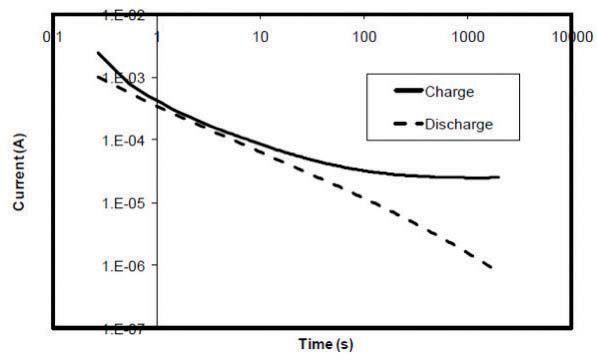

Normally, neither the surface leakage IL nor the conduction current IG affects the discharge current. Differences in the IP and ID [Figure 1] may indicate winding lack of curing, moisture absorption, surface contamination, damage to the voltage stress coatings, or severe thermal deterioration of the bulk of the insulation.

EXAMINATION OF THE PDC TEST
Since the IEEE 43 standard suggests that the PDC test is valid for testing windings for thermal deterioration, tests were done on a motor stator rated 13.2 kV, 6000 HP known to be thermally aged, but clean and dry. Both the PDC test and the ac offline partial discharge test were done, as the latter has proven to be effective for evaluating insulation delamination. The stator had an asphaltic mica insulation system and was several decades old. The three
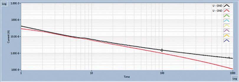


Figure 2: PDC plot for A-phase with a 10 kV charge cycle (other phases were identical). The charge current is the upper line and the discharge current is the bottom line. The logarithmic vertical scale goes from 0.1 μA to 1000 μA and the horizontal axis ranges from 1 to 1000 seconds.


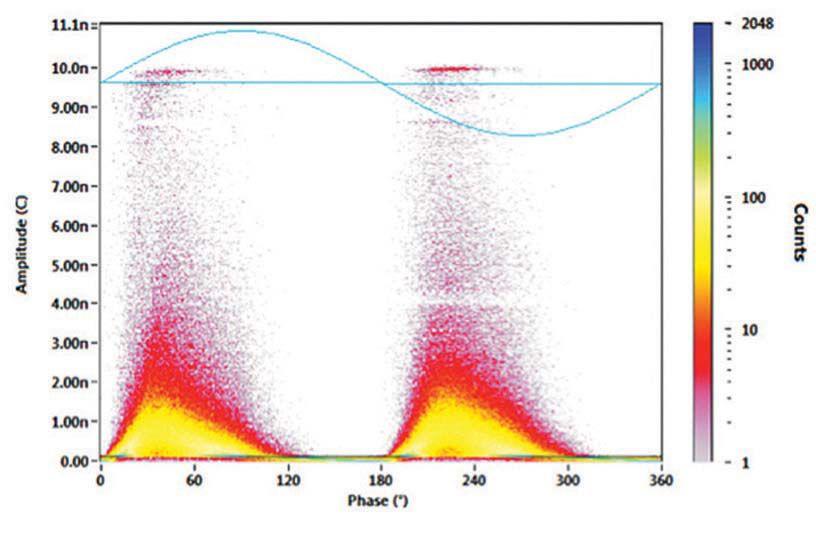


Note that the polarity of the PD plotted between 0 and 180 degrees has been inverted. The linear scale ranges from 0 to 11 nC.
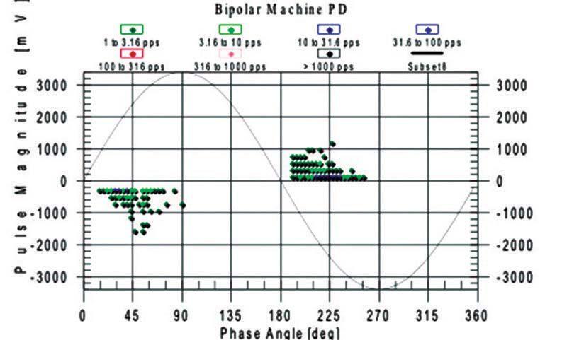

phases in the stator could be isolated from each other to facilitate testing of each phase.
Polarization/Depolarization Test


For these tests, a PDTech DRA 3 was used to record the polarizing and depolarizing dc currents. It applies a positive dc voltage to the test object at a selected voltage (usually 5 or 10 kV for these experiments) and for a selected time (usually 1000 s – about 16.7 minutes), while measuring the charging current. The dc supply is then removed from the test object and the test object is grounded. The discharge current-to-ground is then measured for the same amount of time. Software records these currents, inverts the discharge current, and displays both the charge and discharge currents in the same plot against time, with the plot time origin starting from either the start of the charge cycle, or the start of the discharge cycle (Fig. 2). The difference in the charge and absolute value of the discharge current can also be displayed. The instrument also calculates the IR and PI. All tests were done at 20°C.
Partial Discharge Test

Partial discharge tests were conducted using a conventional IEC 60270 PD detector, a PDTech DeltaMaxx, working in the low frequency (<3 MHz), broadband range. This instrument automatically converts the measured pulse magnitude in mV into pC, per the procedure in IEC 60270. The PD was also measured in the VHF range (30-300 MHz) range with an Iris Power TGA-B, more typically used for on-line PD monitoring. This device does not perform an automatic normalization, instead it reports the PD magnitudes in mV. The PD tests were performed at rated line-to-ground voltage, and the data was recorded after stabilization at the test voltage for 10 minutes. The low frequency (LF) and VHF phase-resolved PD plots for the worst phase (A-phase) are shown in Figures 3 and 4, respectively.


Table 1: Summary of Diagnostic Results for the Motor Stator Winding
Conclusion

Table I shows a summary of the test results for each phase of the winding. PDC plots for each phase are shown in Fig. 2. When all three phases are super-imposed, all the charge currents and all the discharge currents overlap completely.
REFERENCES
1. IEEE, Recommended Practice for Testing Insulation Resistance of Rotating Machinery , IEEE std. 43-2000
2. ANSI/NETA, Standard for Acceptance Testing Specifications for Electrical Power Distribution Equipment and Systems , 2009 edition
It is clear from Table I that A phase has the highest PD in both frequency ranges. Since the positive and negative PD is about the same (within +/- 25%), then based on normal PD interpretation rules (see IEEE 1434 or IEC 60034-27), one suspects the PD is due to groundwall delamination, and when compared to the instrument manufacturer’s database would be ranked as Very High.

3. ANSI/NETA, Standard for Maintenance Testing Specifications for Electrical Power Distribution Equipment and Systems, 2007 edition

PDC has been proposed as an off-line tool that can detect issues besides contamination and moisture absorption, such as something that can be used to confirm the diagnosis of insulation condition obtained from on-line PD testing, without having to use a large ac transformer to energize the winding for an off-line PD or tip-up test. The comparison tests described here did not produce consistent results. Clearly more tests are required to determine its efficacy.


4. Stone, G., and Sasic, M., Experience with DC PolarizationDepolarization Measurements on Stator Winding Insulation, Electrical Insulation Conference (EIC), Ottawa, Ontario, March 2014.
5. IEC 60034-27, “Off-line partial discharge measurements on the stator winding insulation of rotating electrical machines”

Vicki Warren, Senior Product Engineer, Iris Power LP. Vicki is an electrical engineer with extensive experience in testing and maintenance of motor and generator windings. Prior to joining Iris in 1996, she worked for the U.S. Army Corps of Engineers for 13 years. While with the Corps, she was responsible for the testing and maintenance of hydrogenerator windings, switchgear, transformers, protection and control devices, development of SCADA software, and the installation of local area networks. At Iris, Vicki has been involved in using partial discharge testing to evaluate the condition of insulation systems used in medium- to high-voltage rotating machines, switchgear and transformers. Additionally, she has worked extensively in the development and design of new products used for condition monitoring of insulation systems, both periodical and continual. Vicki also actively participated in the development of multiple IEEE standards and guides and was Chair of the IEEE 432000 Working Group.





INTRODUCING THE NETA HANDBOOKS, SERIES II
NETA is proud to announce that the NETA Handbooks, Series II, are now available, giving electrical power system industry professionals more reference and training options. More than 14,000 copies of the first NETA Handbooks series, covering subjects like circuit breakers, protective relays, transformers, arc-flash safety, and online diagnostics, were sold.
The material contained in the handbooks is a collection of more than 200 of the best articles published in past issues of NETA World and the most well-received technical presentations from PowerTest, the premier electrical maintenance and safety event, which is hosted by NETA.
NETA Handbooks, Series II, provide a valuable resource for two major groups of individuals in the power system industry. First, they serve as a reference tool for new employees needing a solid overview of the industry and for technicians preparing for the NETA exam. Second, NETA Handbooks, Series II, assist electrical engineers working for consulting firms, manufacturer sales representatives, and facility management engineers.
NETA Handbooks, Series II, content covers the most up-to-date and relevant information from standard testing procedures to troubleshooting and every day, real-life situations applicable in the field. The new series is made possible thanks to the following sponsors who are dedicated to education and improvement throughout the industry: Ampteks, CBS ArcSafe, Circuit Breaker Analyzer, Shermco Industries, Intellirent, IRISS, Megger Distributor Group, Raytech USA, Inc., SMC International, Tony Demaria Electric, Inc., and Vacuum Interrupters, Inc.
NETA Handbooks, Series II, are being offered at $15.00 per volume or $195.00 for the entire 13-volume set (plus shipping and handling). Subscribers to the NETA Alliance Program, (NETA’s nontesting professional network) receive 20 percent off the regular price.
NETA is an association dedicated to quality in the industry. NETA has a wide variety of training options available. For more information, contact the NETA office at 888.300.6382 or www.netaworld.org.

It’s real world learning at your fingertips. These handbooks deliver relevant information on the electrical power systems industry, including testing procedures, troubleshooting and real-life solutions encountered in the field every day.
You’ll discover page after page of the most comprehensive, component-specific, technical resources for both training and reference purposes.
The NETA Handbooks bring together a collection of over 200 of the very best articles from past issues of NETA World Journal and the most well received technical presentations from NETA’s PowerTest conferences.
195* For the 13 volume set $15* For each issue * Additional cost for shipping and handling
For more information on the NETA Handbooks or other NETA publications visit the NETA bookstore at www.netaworld.org or 888-300-6382 (NETA).



ANSI/NETA STANDARDS UPDATE

ANSI/NETA MTS-201X REVISION IN PROCESS


On April 19, 2013, NETA published notice of intent to revise ANSI/ NETA Standard for Maintenance Testing Specifications for Electrical Power Equipment and Systems as a revised American National Standard. This document contains specifications which cover the suggested field tests and inspections that are available to assess the suitability for continued service and reliability of electrical power equipment and systems. The purpose of these specifications is to assure that tested electrical equipment and systems are operational and within applicable standards and manufacturers’ tolerances and that the equipment and systems are suitable for continued service.
ANSI/NETA ETT-201X REVISION IN PROCESS
This document is due to be published as a revised standard in 2015. A PINs notice was published in ANSI Standards Action on November 29, 2013, with the 45 day public comment period closing on January 13, 2014. The ANSI/NETA Standard for Certification of Electrical Testing Technicians was approved as a




revised American National Standard on January 8, 2010. This standard establishes minimum requirements for qualifications, certification, training, and experience for the electrical testing technician. It also provides criteria for documenting qualifications for certification and details the minimum qualifications for an independent and impartial certifying body to certify electrical testing technicians.
ANSI/NETA ECS-201X INITIAL DRAFT IN PROCESS


NETA is announcing the intent to draft a new standard that will submitted as an ANSI candidate standard. The PINs for this document appeared in the December 6, 2013, edition of ANSI Standards Action with a closing date of January 20, 2014. These specifications describe the systematic process of documenting, and placing into service newly–installed or retrofitted electrical power equipment and systems. This document shall be used in conjunction with the most recent edition of the ANSI/NETA Standard for Acceptance Testing Specifications for Electrical Power Equipment and Systems. The individual electrical components shall be subjected to factory and field tests, as required, to validate the individual components. It


is not the intent of these specifications to provide comprehensive details on the commissioning of mechanical equipment, mechanical instrumentation systems, and related components.
ANSI/NETA ATS-2013
The ANSI/NETA Standard for Acceptance Testing Specifications for Electrical Power Equipment and Systems was approved as an American National Standard on January 25, 2013. These specifications cover the suggested field tests and inspections that are available to assess the suitability for initial energization of electrical power equipment and systems. The purpose of these specifications is to assure that tested electrical equipment and systems are operational, are within applicable standards and manufacturers’ tolerances, and are installed in accordance with design specifications.

PARTICIPATION
Comments and suggestions on any of the standards are always welcome and should be directed to the NETA office at neta@ netaworld.org or 888-300-6382. To learn more about the NETA standards review and revision process, to purchase these standards, or to get involved, please visit www.netaworld.org or call 888-300-6382.





CBS ArcSafe’s remote racking and remote switching solutions reduce arc-flash dangers and technician fatigue durin g dangerous operations. g
Remote Racking Solutions
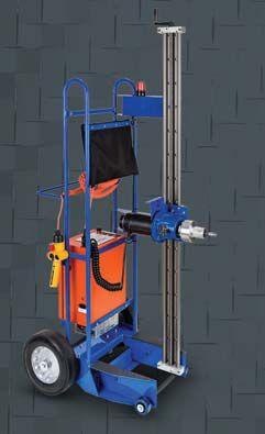


All CBS ArcSafe remote racking and remote actuation solutions are battery- or AC-powered portable units that do not require any modifications to your electrical equipment.
Out the New Tablet


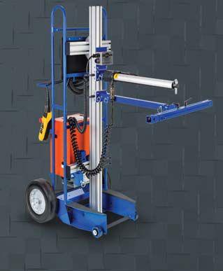





Remote racking solutions reduce the need for full-body arc-flash hazard suits by taking technicians outside the arc-flash boundary. Universal remote racking solutions offer adjustable height settings. No equipment modifications required.
Remote Switching Solutions
Remote switching solutions keep technicians outside the arc-flash boundary during dangerous operations. No modifications required due to magnetic latching.

Remote switching solutions are available for virtually any style or piece of electrical equipment.
or piece of elect


Use your Windows 7-compatible tablet, PC or iPhone with the CBAnalyzer™ system to test your circuit breakers. Tests can be performed without removing the breaker from the cubicle and without any electrical connections. Operate the breaker in any sequence you desire: for example, trip — charge — close. The vibration data created by the breaker operation is captured and analyzed, and the result is instantly returned to your device. The data is saved in your online account for equipment management, trending, and further analysis options, including specialized issue diagnosis.
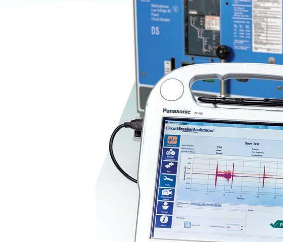



SPECIFICATIONS AND STANDARDS

THE NFPA 70B – ONE OF THE INDUSTRY'S BEST-KEPT SECRETS
BY RON WIDUP AND JIM WHITE, Shermco IndustriesAs NETA members we are all familiar with the ANSI/NETA Standard for Maintenance Testing Specifications. The current edition of the MTS was published in 2011 and is due for revision in 2015. While many NETA members may have heard of NFPA 70B, and some even involved with its periodic revision, all should be intimately familiar with it, what it contains, and how it can augment the ANSI/NETA MTS.
NFPA 70B, Recommended Practice for Electrical Equipment Maintenance is a document every NETA Accredited Company should have on its shelves. While the ANSI/NETA MTS does an excellent job of covering the electrical testing and maintenance requirements for virtually every piece of electrical equipment in an electrical power system, by design it is a what to do specification and not a how to do it document. That is where NFPA 70B comes in to help bridge the gap on electrical maintenance requirements.
NFPA 70B covers maintenance philosophies, short-circuit studies, power quality, testing and test methods, maintenance of electrical equipment including recommendations on frequency of maintenance, recommendations on maintenance for electrical power system equipment such as switchgear, circuit breakers, transformers, UPS, and rotating equipment, vibration. It even has sections on portable
electric equipment and equipment located in classified areas. Other chapters include how to implement a reliability-centered maintenance (RCM) program, electrical disaster recovery (new), photovoltaic systems (new), electric vehicle charging equipment (new), and wind power electric systems and equipment (new).
Whew! That’s a bunch! There are also sixteen annexes that contain information on conducting walk-through inspections, NEMA configurations, RCM, and energy efficiency of motors….just to name a few.
ORIGIN OF DEVELOPMENT OF NFPA 70B
[Note: this information is taken verbatim from the latest version of NFPA 70B, the 2013 edition] In the fall of 1967, the Board of Directors of the National Fire Protection Association authorized the formation of an Ad Hoc Committee on Electrical Equipment Maintenance to determine the need for the development of a suitable document on this subject. The purpose of the document would be to give recommendations on the maintenance of various types of electrical installations, apparatus, and equipment usually found in industrial and large commercial-type installations. A diversified group representing various interests and organizations was invited to participate.


SPECIFICATIONS AND STANDARDS


At a meeting of the Ad Hoc Committee held January 10, 1968, in New York, with 31


representatives attending, it was pointed


out that several requests had been made to the National Electrical Code Committee to include maintenance recommendations in the National Electrical Code®. The subject had been discussed by the Correlating Committee of the National Electrical Code Committee, and the decision was made that the Code was not the proper document in which to cover the maintenance of electrical equipment. However, the committee recognized that “lackof maintenance” frequently resulted in serious injuries and fatalities as well as high monetary damage. Electrical equipment maintenance was a subject requiring attention.
It was noted at that time that electrical safety information broke down logically into four main subdivisions: (1) design or product standards, (2) installation standards (as covered by the National Electrical Code and the National Electrical Safety Code), (3)

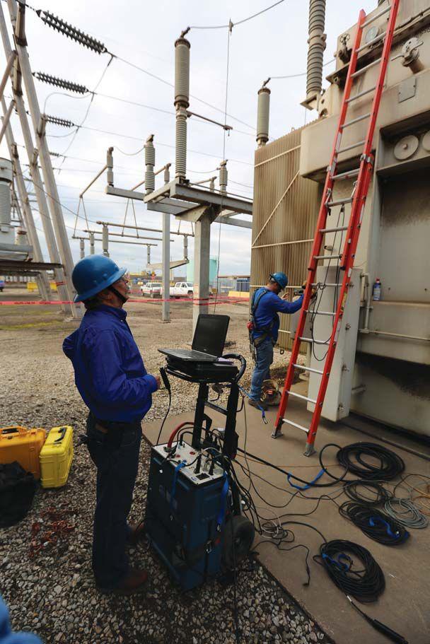


maintenance recommendations, and (4) use instructions. The NFPA had not yet started work on NFPA 70E®, Standard for Electrical Safety in the Workplace. The problem was to explore whether something more should be done in the interest of electrical safety on the maintenance of electrical equipment and what form activity in this field should take. It was recognized that much had been done to enunciate maintenance needs for specific types of equipment by the equipment manufacturers,


SPECIFICATIONS AND STANDARDS ACTIVITY


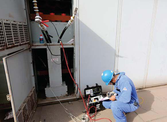


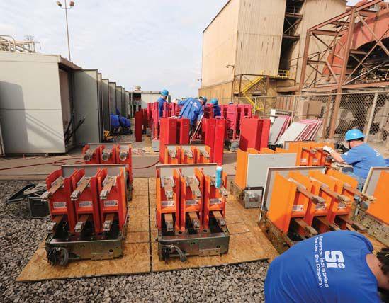


and that guidance was available on the general subject from a number of sources. Therefore, it was determined that bringing together that guidance in the form of general guidelines in a single document under the NFPA procedure was advantageous. The stature of the document would be enhanced by becoming associated with the National Electrical Code. To this end, a tentative scope was drafted for presentation to the Board of Directors of the National Fire Protection Association with a recommendation that an NFPA Committee on Electrical Equipment Maintenance be authorized.
On June 27, 1968, the NFPA Board of Directors authorized the establishment of an NFPA Committee on Electrical Equipment Maintenance with the following scope: “To develop suitable texts relating to preventive maintenance of electrical systems and equipment used in industrial type applications with the view of reducing loss of life and property. The purpose is to correlate generally applicable procedures for preventive maintenance that have broad application to the more common classes of industrial electrical systems and equipment without duplicating or superseding instructions that manufacturers normally provide. Reports to the Association through the Correlating Committee of the National Electrical Code Committee.”


The committee was formed, and an organizational meeting was held December 12, 1968, in Boston. Twenty-nine members or representatives attended. The Recommended Practice for Electrical Equipment Maintenance represented the cumulative effort of the entire committee.
The development of NFPA 70B follows the standard NFPA process, with committee members from different interests and industries. NETA members to the committee are Dave Huffman (Power Systems Testing Company), who officially represents NETA on the committee, and Jim White and Ron Widup who represent Shermco as an installer/ maintainer member of the committee, independent of NETA.


The technical committee reports to the same oversight committee as the NFPA 70E and is considered to be a sister document to the 70E. This is due to the fact that, as NFPA 70E states in section 130.5 IN No. 1, “Improper or inadequate maintenance can result in increased opening time of the overcurrent protective device, thus increasing the incident energy” and Section 200.1, Scope states, “(3) For the purpose of Chapter 2, maintenance shall be defined as preserving or restoring the condition of electrical equipment


SPECIFICATIONS AND STANDARDS ACTIVITY
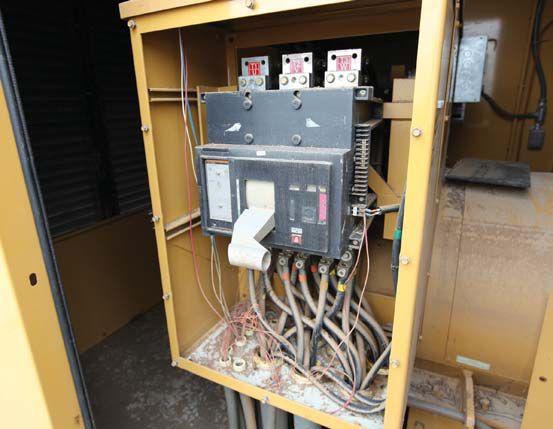


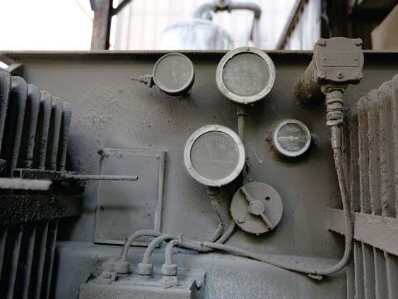
Figure 5: Without local indication when was it last tested or maintained?


and installations, or parts of either, for the safety of employees who work where exposed to electrical hazards.” Electrical power systems and equipment cannot be considered to be safe unless they are properly installed and maintained. Even more emphasis will be placed on maintenance in the 2015 edition of NFPA 70E.
CONDITION OF MAINTENANCE:
How Do I Determine if the Equipment I am About to Work on Has Been Properly Maintained?


One of the sticking points during the revision for the 2015 edition of NFPA 70E was how to verify condition of maintenance. When a technician or engineer enters a facility to perform testing or maintenance or to operate an electrical power system, how can he know when the last maintenance was performed? How can that same worker determine its condition of maintenance? One answer is to request the report from the last maintenance shutdown or PM that was performed. This may not be a very satisfactory answer as those records are not always available and, really, who has the time to pour through a huge stack of documents? A better solution was added to the 2013 edition of NFPA 70B

in Section 11.27, Test or Calibration Decal System . Tim Crnko of Cooper-Bussmann proposed this system, and it is based on one that Shermco and other NETA-Accredited Companies have used for years.
11.27 states, “ 11.27.1. General. After equipment testing, device testing, or calibration, a decal on equipment, in conjunction with test records, can communicate the condition of electrical equipment to maintenance and service personnel. This can be important for assessing the hazard identification and risk assessment for electrical safety procedures as well as the condition of electrical equipment.


11.27.2 Decal. After a piece of electrical equipment or device is tested and/or calibrated, a color-coded decal should be attached on the exterior enclosure to that particular equipment. The decal should include the following:
(1) Date of test or calibration
(2) Person or outside company who performed the testing or calibration


(3) Color coding indicating the service classification as described in 11.27.3.”
Simply put, there are three color-coded labels: red, yellow and white. Red indicates there

SPECIFICATIONS AND STANDARDS ACTIVITY


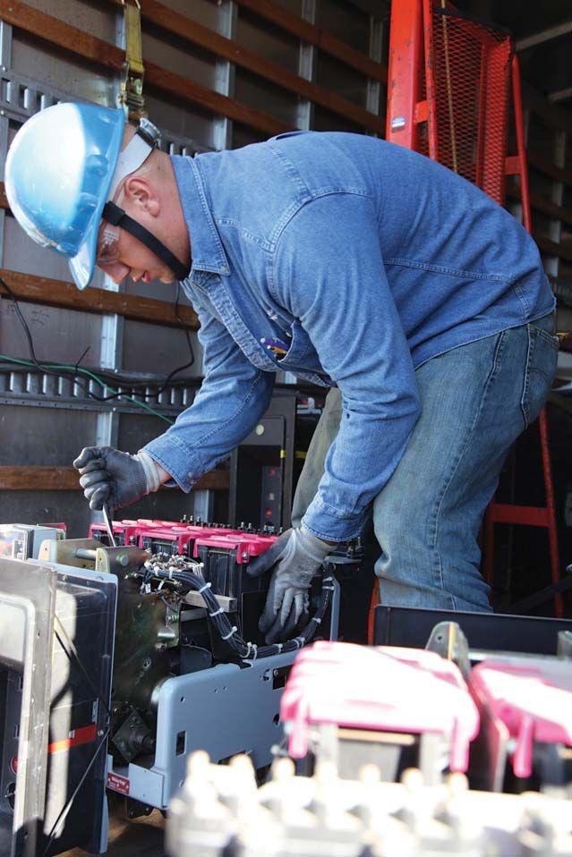

in black and white, the labels are in grayscale, not color.

We have only heard one negative comment when this system is discussed with others. That person said, “You mean you put a label on every piece of equipment? That would mean hundreds of labels!” Actually, it can be thousands of labels in a large shutdown. These are small, unobtrusive labels and do not interfere with the larger safety-oriented labels that may be required by manufacturing standards, OSHA, and NFPA 70E.


The biggest advantage to the three-color labeling system is that it allows instant verification of the state of equipment maintenance and when that maintenance was performed. Wading through reams of paper or databases is not needed to determine if the electrical device has been maintained within recent and reasonable time frames, which then helps the worker determine if it is safe to proceed with that test or to operate that piece of equipment. However, it does not eliminate the need for common sense! Just because a label is in place and indicates the equipment was safe for continued service when it was applied does not relieve the worker from correctly assessing the current state of the equipment or to do a proper JHA. There is no autopilot mode when working on or near energized electrical equipment.


is a major defect and the equipment should either not be placed into service or should be removed immediately from service. Yellow means there is a minor defect that does not directly affect the serviceability or safety of the equipment, but it should be addressed as soon as possible. White means there were no defects found and the equipment is fully ready for continued service. Figure 1a and 1b show how the labels look in NFPA 70B and in the field. Since NFPA 70B is printed

Shermco has used this labeling system for years with great success. Our customers appreciate being able to quickly determine the electrical power system’s condition and work with our technicians during shutdowns and turnarounds to make their personal notes on what equipment needs immediate attention and which will need further work at another time. If the equipment cannot be repaired during the shutdown, the labels provide a reminder system that encourages that the defects be addressed as soon as possible. It is a great customerservice feature that all facilities and test and maintenance companies should employ. Its inclusion into NFPA 70B provides access to


SUMMARY
SPECIFICATIONS AND STANDARDS
all companies and its [soon to be] reference in the 2015 NFPA 70E (Chapter 2, Section 200.1, Scope, Informational Note) should encourage more companies to demand it.

NFPA 70B is one of the best how to maintenance references a company can have. It is a great companion to ANSI/NETA MTS and covers information that is not in the ANSI/ NETA standard. As new types of electrical systems and new requirements for maintenance are being added, NFPA 70B grows ever larger. There are 283 pages stuffed full of maintenance techniques, safety cautions, and forms. The 2006 edition was 227 pages, so it is easy to compare how much new information has been added in the last two editions.


NETA Accredited Companies as well as industry will benefit from using NFPA 70B, as it does not merely repeat the contents of ANSI/NETA MTS, but provides differing and expanded views of maintenance and testing requirements which can assist in tailoring services to the customer and provide insight on newer technologies and systems.
NETA’s customers can benefit from NFPA 70B by learning what PM, PdM and RCM are used for and how they are best implemented.
NFPA 70B has an inherent value and purpose for the NFPA. The NFPA’s primary mission is to reduce the worldwide burden of fire and other hazards by providing and advocating consensus codes and standards, research, training, and education. By implementing and executing the electrical power system tests as specified by NETA, coupled with the guidance for maintenance and safety provided by NFPA 70B and NFPA 70E, the owners, users, and workers of electrical equipment are in a better position to manage the challenges associated with all of it.
Ron Widup and Jim White are NETA’S representatives to NFPA Technical Committee 70E (Electrical Safety Requirements for Employee Workplaces). Both gentlemen are employees of Shermco Industries in Dallas, Texas, a NETA Accredited Company. Ron Widup is President of Shermco and has been with the company since 1983. He is a Principal member of the Technical Committee on “Electrical Safety in the Workplace” (NFPA 70E) and a Principal member of the National Electrical Code (NFPA 70) Code Panel 11. He is also a member of the technical committee “Recommended Practice for Electrical Equipment Maintenance” (NFPA 70B), and a member of the NETA Board of Directors and Standards Review Council. Jim White is nationally recognized for technical skills and safety training in the electrical power systems industry. He is the Training Director for Shermco Industries, and has spent the last twenty years directly involved in technical skills and safety training for electrical power system technicians. Jim is a Principal member of NFPA 70B representing Shermco Industries, NETA’s alternate member of NFPA 70E, and a member of ASTM F18 Committee “Electrical Protective Equipment for Workers”.


And that is truly a win-win situation.










POWERTEST 2014 ATTENDEES GET READY TO ENERGIZE THEIR FUTURES
With the Rocky Mountains towering in the background, PowerTest 2014 will provide field technicians, engineers, construction professionals, architects, facility managers, and others with the opportunity to expand their knowledge and embrace new challenges. The adventure begins on March 3, 2014.
NETA has gathered the industry’s leading experts as presenters, panelists, and moderators to facilitate open discussions about real world challenges. Learning will take place through 27 technical paper tracks, four expert panels, a host of seminars, and more. Learning about the newest technology and products available to electrical professionals is paramount to attendees at the Trade Show, the largest of its kind in the industry with over 100 major electrical vendors exhibiting.
PowerTest announced the debut of its mobile app for Apple and Android smartphone and tablet users last month. Attendees in 2014 will be able to customize their PowerTest experience as never before, to access conference and speaker information and trade show and hospitality suite maps, set reminders for themselves, and much more – all from their smartphones or tablets. It is also a great tool for people to use before they register, as it allows users to view abstract information, bookmark, and save favorites to a custom schedule.
NETA extends a special thank you to its mobile app sponsor, Shermco Industries, Inc., for making this advancement possible.

Shermco is joined as a PowerTest 2014 premium sponsor by National Switchgear and Intellirent. The level of commitment by these leading firms is helpful in making the learning experiences at PowerTest top-notch.
Other firms in the industry that continue to demonstrate interest in safety and education through ongoing support of NETA and PowerTest include AVO Training Institute, American Electrical Testing Co., Inc., Arbiter Systems, Inc., CBS ArcSafe, CBS ArcSafe--Circuit Breaker Analyzer, Circuit Breaker Sales Co.,Inc., ElectroRent, Emerson Network Power, Haefely Hipotronics, Megger, PRIT Service, Inc., Potomac Testing,Inc., Power & Generation Testing, Inc., Sunbelt Transformer, Raytech USA, Inc., Southwest Energy Systems, Tony Demaria Electric, Inc., Utility Relay Company, Vacuum Interrupters, Inc., and Western Electrical Services, Inc.
For those looking to the future, PowerTest 2015 is set for Nashville, Tennessee. Sponsorships are available now! Reserve your sponsorship for next year by inquiring at the PowerTest 2014 registration desk or by contacting Missy Richard at mrichard@netaworld.org.

AEMC
www.aemc.com
2014 – NEW PRODUCT FORUM
Power Quality Analyzer PowerPad®
AEMC®’s newest Power Quality Analyzer PowerPad®
The Model 8435 is a three-phase power quality analyzer that is IP67 waterproof rated for outdoor use. It is easy to use, compact, and shock resistant. It has direct measurement of four voltage and four current inputs including neutral voltage and current. It captures and records trend, transients, events, and waveforms simultaneously with two GB of memory for data storage. You can store up to 50 screen snapshots, up to 210 captured transients that contain four cycles for each active input, and 10,000 alarm events from up to 40 different parameters. Six direct access function buttons let you quickly see waveforms, harmonics, transients, alarms, power analyses, and trend recordings. DataView® software is included. Visit www.aemc.com for more information.
BASLER ELECTRIC
www.basler.com
BESTCOMSPlus® and BESTLOGIC™Plus
Announcing New, Easy, and Powerful Enhancements added to the BE1-11 Multifunction Protection System and the latest BESTCOMSPlus® release. Complex logic schemes are now easily simulated in the New Offline Simulator in BESTLOGIC™Plus prior to putting the settings in the relay. This allows commissioning surprises related to relay logic schemes to be eliminated. The Offline Simulator helps identify and troubleshoot the logic without the high cost of additional hardware. In today’s fast paced world, Basler Products and Software help users to eliminate false operations, minimize training time for personnel, and makes it easy to program and test protective relays.
CBS ARCSAFE, INC.
www.cbsarcsafe.com
RRS-2 Tooling For GE AK-1-25
The CBS ArcSafe® tooling for GE AK-1-25 low voltage circuit breaker enables service personnel to automate the racking process while simultaneously eliminating all potentially hazardous manual contact with the gear and allows users to remain outside of the arc flash boundary from an increased distance of up to 300 feet, reducing or eliminating the need for a full body arc flash hazard suit. This lightweight, portable tooling is compatible with all GE AK-1-25 style breakers in up to a four high configuration. The quick installation and removal of the tooling requires absolutely no modification to the existing circuit breaker or switchgear.
CIRCUIT BREAKER ANALYZER, INC.
www.circuitbreakeranalyzer.com
CBAnalyzer™
The CBAnalyzer™ for Windows 7 tests the mechanical condition of circuit breakers by utilizing vibration analysis, internet data transfer, and sophisticated, condition-based analysis. CBAnalyzer for Windows 7 is unlike all testing units on the market because it performs tests without removing the breaker from the cubicle and without electrical connections. Vibration data is captured, analyzed, and the result is instantly returned to the device. Data is saved in your online account for equipment management, data trending, and further analysis, including specialized issue diagnosis. Additional features include Fourier Transform and vector graphs, a manual comparison tool, and a vacuum interrupter test.
CIRCUIT BREAKER SALES CO.
www.circuitbreaker.com
B2B Website
Circuit Breaker Sales Co., Inc. is pleased to announce our new B2B website specifically designed for service and testing professionals. In addition to discounted pricing for all NETA members, our expanded website will also offer exploded views of all circuit breakers to assist in identifying replacement components. We have created an environment where customers can shop for parts and pieces online 24 hours a day. Also, as part of a recent acquisition, we can now supply or repair all American made electromechanical relays and devices. These too are all online. Visit us today at www.CircuitBreakerStore.com!
COMRENT
www.comrent.com
Witness Test Reporting through Power Quality Monitoring Systems
IEEE 1547.1 and UL1741 define the standard conformance test procedures for equipment interconnecting distributed resources with electric power systems. Mandatory witness testing is becoming more common for the interconnection test for distributed energy sources. This new requirement places a heavy burden on utility engineers as more local power systems are developed and come online. ComRent has developed a unique service package utilizing an advance power quality monitor that generates reports formatted to meet IEEE 1547 and UL1741 requirements. This new service allows third party testing so that utility engineers can review and verify conformance from the generated test reports.
DOBLE ENGINEERING COMPANY
www.doble.com
Doble F6052 Universal Time Synchronizer
TheDobleDelphiPortableAnalyzerisaportableDGAdevicedesigned to provide timely and actionable information on key dissolved gases in insulating oil. Quickly sample and analyze oil on-site. The Doble F6052 Universal Time Synchronizer is a lightweight, portable time source when you need a time reference or time stamp, but do not have access to reliable time sources or GPS signals due to space, distance, or security. The Doble DFA300 Surveyor is a handheld, in-service partial discharge testing tool which uses both RFI and acoustic technology. It can be used in many different substation applications.
ECP
www.ecpsales.com
ECP TracerSM
Do you find yourself looking for that three-phase relay test set, power factor unit, VLF or power analyzer and wondering why you’re renting one when you already own five? Are you familiar with the power of new tracking technologies? Equipment coordination challenges are something every service firm faces. Let ECP TracerSM help you track your high value assets and maximize their utilization to immediately save you time and money. Save on leases that were never needed, insurance cost, shipping costs, time spent locating assets, lost revenue from idle equipment, buying more equipment than you really need, and recovery of lost or stolen assets. Learn about the benefits you can gain from our innovative equipment coordination program.
ELECTRO RENT
www.electrorent.com
Electro Rent introduces new inventory
Established in 1965, Electro Rent Corporation adds new products to its rental inventory every month. Recent additions include Doble’s F6150SV relay test set, OMICRON’s 256plus relay test set, AEMC’s 8335 Power Profiler, and SKF/Baker’s PP40 motor impulse test set. Electro Rent’s calibration lab is A2LA ISO/IEC 17025: 2005 certified to ensure your equipment is calibrated correctly when you receive it. For daily and monthly test equipment rentals, please call our experienced staff at 800688-1111 (USA) or 800-268-0216 (Canada). E-mail us at sales@ electrorent.com.
2014 – NEW PRODUCT
ELECTROSWITCH
www.electroswitch.com
TD-CSR
Breaker Control Switch Relay with Time Delay Trip and Close Provides Arc-Flash Mitigation Protection
The time delay control switch relay (TD-CSR) provides a means of arc-flash mitigation by allowing personnel time to clear the arc flash area during local breaker operation. The TD-CSR with standard ten-second time delay and intuitive push button design simplifies training and requires no special installation wiring as do standard CSRs. Other features include local LED indication, a remote SCADA contact alarm, a single or dual trip coil monitoring, and safety interlock (turn-to-latch) option. Please stop by to see us at booth #401.
FLIR SYTEMS
www.flir.com
FLIR CM83
The new FLIR CM83 is a rugged power clamp meter with advanced power analysis features including harmonics mode to find noise from different electrical sources, phase rotation to confirm phase orientation of three-phase systems to streamline motor diagnostics/installations, and inrush current to detect start-up related transients. The FLIR CM83 also has VFD mode for analyzing nonsinusoidal waveforms and noisy signals on VFD-controlled equipment. This new clamp meter also offers remote viewing of test data through Bluetooth® connectivity to Android™ devices, the ability to embed test data into IR images captured by METERLiNK®-enabled FLIR thermal cameras, and a bright dual-LED worklight.
2014 – NEW PRODUCT FORUM
GE ENERGY- INDUSTRIAL SOLUTIONS
www.geindustrial.com/services/aftermarket-solutions
ArcWatch™ technology best-in-class arch flash protection for new equipment or Aftermarket Retrofit/Retrofil into existing equipment
ArcWatch™ technology is included in specific low voltage GE trip units and breakers that allow the breakers to be set for better arc flash protection without sacrificing selective coordination. Setting the instantaneous pick-up value on a breaker sufficiently below the predicted arcing current allows the breaker to clear arcing faults using the breaker’s fastest speed. Traditionally, lower pick-up settings could lead to reduced selective coordination. ArcWatch™ solves this dilemma by maintaining selective operation in the instantaneous region even when the time current curves overlap. Products featuring this technology include GE switchgear, switchboards, panel boards, or anywhere EntelliGuard Trip Units are used. EntelliGuard G Circuit Breakers, Spectra with microEntelliGuard, Entellisys with EntelliGuard E Circuit Breakers, and even legacy and non-GE circuit breakers retrofitted with EntelliGuard Trip Units use ArcWatch™ technology to lower arc flash energy.
GRACE ENGINEERED PRODUCTS
www.graceport.com
R-3F Series Voltage Indicator
The R-3F Series voltage indicator meets 254 V standard in the ANSI C37.20.1 switchgear specification by incorporating a zero-energy optical light cable that transmits the voltage indicating LEDs to the outside of the enclosure. The zeroenergy thru-panel adaptor provides workers with visual status of L1, L2, L3, and GRD without exposure to voltage. The R-3F operates between 20-600 Vac/30-1000 Vdc and can be installed anywhere in your low-voltage power system. The potted construction, redundant circuit design, UL/IEC 6101001 and CAT IV/III rating, integral 72” lead wires, and optical cable lengths of up to 72” (144” total length) allow thru-panel installation close to the voltage sources.
HAEFELY HIPOTRONICS
www.hipotronics.com
2293
The 2293 is an automatic winding analyzer, optimized for three-phase power and distribution transformer measure-ments. It uniquely combines winding resistance measurement, turns ratio measurement, core demagnetization, transformer type detection, and heat run test (cooling curve) in the fastest single instrument solution on the market. A simple one-time connection system drastically reduces measuring time. Once connected, all test can be done in a row without any reconnection. The built-in simultaneous winding magnetization method guarantees fast and reliable resistance measurements. Stable measurements are reached even on large power transformers with delta windings on the low voltage side.
INOLECT
www.inolect.com
inoRAC2-P™ Portable Device
inoLECT’s remote racking units operate your circuit breakers while operators are a safe distance away eliminating the risk of arc-flash injury. The inoRAC2-P™portable version consists of an aluminum base and two cases. The base is similar to the original device, but all computerized pieces are placed in portable cases for easy relocation. The cases contain the Portable Control Unit drive operation hardware and the touchscreen operation panel. They are connected with cables at any specified length required. The inoRAC2-P™ monitors torque and breaker position during processes to protect against breaker damage and can operate major manufacturers’ low- and medium-voltage breakers.
IRIS POWER-QUALITROL
www.irispower.com
End-winding
Vibration Accelerometer
New end-winding vibration accelerometer:
• More flexibility – smaller sensor head size – 30x9x9 mm
• Easier installation – less fiber optic cables – one per axis
• Suitable for modern insulation systems – wider temperature rating – -50 to 230°C
The purpose of end-winding vibration monitoring is to directly measure if the stator end-windings are vibrating excessively during normal operation so that any incipient vibration can be detected and corrected well before failure. On-line measurements require the permanent installation of accelerometers which can be retrofitted during a machine outage after some disassembly or installed on new machines in the factory. The Iris Power end-winding vibration accelerometers are application-specific fiber optic accelerometers ideal for installation in air- or hydrogen-cooled machines.
IRISS
www.iriss.com
Flex-IR
Permanent electrical safety devices (PESDs) optimize longterm integrity of critical electrical assets in the power generation industry allowing constrained budgets to be focused where resources are needed. Recognizing that isophase-buses and barbuses are electrical assets in need of a protection plan, IRISS is releasing its newest line of infrared (IR) windows: Flex-IR. For the first time, maintenance technicians utilizing Flex-IR windows have a data collection point to safely inspect the uninspectable without waiting for outages to perform visual and infrared inspections. Flex-IR also provides maintenance access points. Constructed with high-grade gaskets, the air-tight windows come equipped with online temperature monitoring systems to further improve performance.
JAKOB MARKETING PARTNERS
www.jakobmp.com
My eToolbox
My eToolbox - a web-based business solution designed for the service industry
My eToolbox helps field service companies leverage technology to efficiently manage their marketing, sales, scheduling and dispatch, operations, inventory, and finances. Our software helps service companies run their business more efficiently by utilizing tablets in the field to help streamline and automate all of the back office processing, and facilitate quick and accurate communication throughout the organization. Our system is address centric, very flexible, and intuitive and can be customized to meet your specific products and services.
MEGGER
www.megger.com
Megger MRCT
Cut CT testing time in half with the new MRCT
The new Megger MRCT represents an evolution in instrument transformer testing technology. This unit will simultaneously measure voltages on all taps during CT saturation, ratio and polarity tests, as well as calculating knee points and ratios on all windings.
2014 – NEW PRODUCT
N4L-NEWTONS4TH
www.newtons4th.com
SFRA45
Introducing the SFRA45, a low-cost, ultra-portable swept frequency response analyzer, offering the best gain/phase accuracy available, able to compare results in real time as the graph progresses. SFRA45 is the first instrument to fully meet the IEC70076 standard, to feature an integrated 3-cable BNC reel, to have embedded software (No Windows OS), and to offer the fastest measurement process. No PC connection is required, but free software with database is available. N4L is a highly respected manufacturer of power analysis and frequency response analyzers and peripheral equipment for the electronics market.
OFIL LTD.
www.ofilsystems.com
UVollé-C
UVollé-C is a daytime corona camera that meets reliability engineering and condition-based maintenance criteria for performance, weight, and price.
Performance: solar blind, allows detecting corona during daytime, optimized to scan electrical apparatuses such as insulators, bushings, motors, generators, transformers, and switchgears Weight: compact handheld camera with a large transflective LCD Price: affordable testing equipment matches small and big organizations’ budgets
Features: clear view of corona and emitters; photons counting; zoom; integrated flashlight; extended battery life; large LCD; GPS and humidity/temperature meter plug and play.
UVollé-C sees in real time partial discharges and reveals early stages of failures.
2014 – NEW PRODUCT FORUM
OMICRON
www.omicronusa.com
OMICRON’s latest innovations
OMICRON’s latest innovations include the CIBANO 500, first circuit breaker test system to combine a precise micro-ohmmeter, a multi-channel timing analyzer, and a powerful coil and motor supply; the VOTANO 100, a highly accurate instrument transformer testing and calibration system; the DANEO 400, a distributed hybrid measurement system that records and analyzes all conventional signals; the ISIO 200, a binary I/O terminal for substation automation systems with IEC 61850 GOOSE interface; and the OMICRON Academy, a state-of-the-art, air-conditioned training facility with the ability to test various apparatus such as a 10 MVA power transformers, circuit breakers, and distribution automation and a hands-on protection relay testing lab.
POWERDB
www.powerdb.com
PowerDB Pro Software announces support for the new Megger MRCT, SPI, and S-1568/1068 test instruments
PowerDB Pro Software announces support for the new Megger MRCT, SPI, and S-1-568/1068 test instruments. In addition to updates to many existing product features the application now provides active directory support, jobless application style, auto-complete data entry, and a user interface to compare your database forms library to the software’s latest version. So that your results can be used outside the application we provide an Application Programming Interface as well as an optional data warehouse. To assist with your data management, the application includes new asset views, results views, and optional compliance status view.
POWER DIAGNOSTIC SERVICES CO. LTD.
www.pdservice.com
PDSimply
and PDSolution
PDS provides a variety of products, specialized in the measurement of PD activity. PDSimply and PDSolution are two advanced products that meet your needs.
PDSimply is an economical solution for an on-line continuous monitoring system. Based on extensive field experience, PDSimply adopts two characteristics making on-line partial discharge measurement easily. One is the state of art UHF PD detection technology, and the other is the rule of thumb in identification of partial discharge signals.
Based on the requirements of on-site partial discharge analysis, PDSolution is a special analysis system integrating spectrum analyzer, oscilloscope, and general partial discharge measurement instruments. Moreover, the 5-GS/s-sampling-rate enables PDSolution to be applied on various high-voltage equipment.
POWER MONITORING AND DIAGNOSIS TECHNOLOGY LTD.
www.powermdt.com
PDetector Kit 1
The PDetector Kit 1 has proven to be an all-star for a conditionbased maintenance program by employing partial discharge detection. It integrates TEV, UHF, AE ultrasonic, and HFCT sensors and detects the PD activity as numerical values, displays readable amplitude, and period spectrums. It is a universal ideal partner for multiple types of high voltage electrical equipment such as MV switchgear, power cables, GIS, and transformers.
Features
• HD LCD screen
• Wireless sensor technology
• Onboard data storage
• Analysis software
• Fast detection and suitable for daily monitoring
• Light weight, handheld, and easy to use
SCHAEFER INC. (POWER QUALITY GROUP)
www.schaeferpower.com
Schaefer Electronics Inc. is proud to introduce three new products lines
#1. The PB series of Active Harmonic Filters, with ultrafast (21μs) compensation for harmonics mitigation, phase displacement correction (PF), and phase balance. This family is scalable and offers a cost-effective solution for improving power quality for a wide range of industrial applications.
#2 The LW series of Electronic Loads are liquid cooled and customizable to high voltage/power levels (AC or DC).
#3 The PowerStack building block series are configurable, hot swappable, & liquid cooled. Power ranges from 250KW to 100MW+ (AC/DC, AC/AC, DC/AC, high-end AC Drives, & grid-tie systems.).
SMC INTERNATIONAL
www.smcint.com
Raptor System
SMC is proud to showcase a new paradigm in the testing arena with the release of the Raptor System. A true innovation offering multiple testing abilities in a unique user-friendly, field-ready design with the ability to test circuit breakers, CTs reclosers, switchgear, sectionalizers, ground grids, heat runs, and much more! Benefits include automatic output regulation, free lifetime updates, expandable for increased power needs, complete onboard measurement section, and loop through concept, eliminating the need for taps and stabs. It is literally four sets in one system! SMC is the right choice for all your testing needs. Visit booth #512.
UTILITY RELAY
www.utilityrelay.com
AC-PRO-II and AC-PRO-MP-II
Utility Relay Company is excited to introduce the next generation of low voltage retro-fit trip units, the AC-PROII and the AC-PRO-MP-II, the Masterpact MP direct replacement. The AC-PRO-II is smaller than the original, but with a lot more to offer. It is backwards compatible with all of the previous URC kits. A few of the new features are time stamping of events, wave form capture, patented sluggish breaker detection, standard RS485 communication with optional Wi-Fi, and zone select interlock with patented error detection. The AC-PROMP-II has been upgraded with wireless communication, power analysis, voltage measurement, and many other features.
2014 – NEW PRODUCT
VACUUM INTERRUPTERS, INC.
www.vacuuminterrupters.com
MAC-TS4
Vacuum Interrupters, Inc. introduces the MAC-TS4 vacuum interrupter tester. The third generation test can easily determine the pressure inside a vacuum interrupter and, along with wear and number of operations, predict the usable life of the vacuum interrupters used in your circuit breakers and contactors. Until now, this type of testing could only be done at the assembly plant. Testing with our MAC test sets can prevent unnecessary damage to your circuit breakers and contactors. So if you're looking for a meaningful vacuum interrupter test, take a look at the capabilities of our new test set, the MAC-TS4.
WEIDMANN DIAGNOSTIC SOLUTIONS
www.weidmann-diagnostics.com
WEIDMANN Insulogix® Monitoring Products- featuring InsuLogix B®
WEIDMANN Insulogix® Monitoring Products provide economical and simple monitoring solutions that help you manage your transformer fleet operation. Our design approach is to make our devices easy to install, operate, and maintain. We provide simple tools and directions along with comprehensive training and education about normal and faulty transformer operation. The newest monitor in our fleet is the InsuLogix B®. It measures a transformer’s bushing insulation power factor while under load continuously and in all weather conditions directly on the bushing. It also provides accurate and early indication of incipient bushing failure. Other monitors in our fleet are InsuLogix® T, InsuLogix® H and InsuLogix® HM.

ANSWERS
ANSWERS

1. D. Figure 1 shows a test connection designed to defeat the trip unit ground fault (GF) function by injecting current in one phase and out in the opposite direction through a second phase. This causes the GF element to see a net current of zero. There are various methods to defeat GF, depending on manufacturer, model and generation of the OCPD. Older GF elements were often defeated by placing a jumper between two terminals on the trip unit. Later, a cable was needed to defeat the GF element. Some manufacturers required using a secondary injection test set. A better way to defeat GF during primary injection is similar to that in Figure 1, except that the return is through the two other poles in parallel. The reason to go through the extra work is to cause test current in other poles to be substantially lower than the one being tested.
I might be jaded, but I see a trend of increasing costs for no additional benefit. The loop method will defeat the GF on any circuit breaker OCPD. Bus bar may be required instead of cable.
2. B. Thermal memory in modern circuit breaker trip units provides a tripping characteristic similar to bimetallic thermal trips. The bimetal element in a molded-case circuit breaker inherently has thermal memory. This characteristic allows the bimetal element to respond to current on the same basis that the conductor will be heated by the current. As the current passes through the bimetal element, it will begin to deflect, based on the value of the current. If the current drops (such as in a motor starting) the bimetal will slow, then reset to an appropriate level for the current. If the current stays at that higher level, it may stop or, if the current magnitude is high enough, continue to deflect until it trips the breaker. Older solid-state OCPDs did not incorporate any method to mimic this characteristic and would not trip for load fluctuations above and below the trip point, because they would instantaneously reset when the current dropped below the trip level.
3. B. Zone Selective Interlocking should cause the breaker that is supposed to trip change from a STD function to an Instantaneous one, while it also sends a blocking signal to upstream breakers. If it does not trip, the next breaker upstream will operate.

4. C. Some manufacturers have a field test module that synchronizes a burst of light with an overcurrent that is injected into the overcurrent control relay. Even in those field test modules, it is necessary to supply the light source, which is recommended to be a professional style camera flash. Pointand-shoot cameras apparently do not have the intensity to trigger the light detector.
5. A. One of the characteristics listed in several of the manufacturer’s test specifications for the light source is that it must have a minimum duration of 1ms.
NFPA Disclaimer: Although Jim White is a member of the NFPA Technical Committee for both NFPA 70E “Standard for Electrical Safety in the Workplace” and NFPA 70B “Recommended Practice for Electrical Equipment Maintenance,” the views and opinions expressed in this message are purely the author’s and shall not be considered an official position of the NFPA or any of its technical committees and shall not be considered to be, nor be relied upon as, a formal interpretation or promotion of the NFPA. Readers are encouraged to refer to the entire text of all referenced documents.


NETA ACCREDITED COMPANIES Setting the
A&F Electrical Testing, Inc.
80 Lake Ave. South, Ste. 10 Nesconset, NY 11767 (631) 584-5625 Fax: (631) 584-5720 kchilton@afelectricaltesting.com www.afelectricaltesting.com
Kevin Chilton
A&F Electrical Testing, Inc.
80 Broad St. 5th Floor
New York, NY 10004 (631) 584-5625 Fax: (631) 584-5720 afelectricaltesting@afelectricaltesting.com www.afelectricaltesting.com
Florence Chilton
ABM Electrical Power Solutions
3602 East Southern Ave., Ste. 1 & 2 Phoenix, AZ 85040 (602) 796-6583
www.ABM.com
Jeff Militello
ABM Electrical Power Solutions
6280 South Valley View Blvd., Ste. 618 Las Vegas, NV 89118 (702) 216-0982 Fax: (702) 216-0983 www.ABM.com
Jeff Militello
ABM Electrical Power Solutions
814 Greenbrier Circle, Ste. E Chesapeake, VA 23320 (757) 548-5690 Fax: (757) 548-5417 www.ABM.com
Mark Anthony Gaughan, III
ABM Electrical Power Solutions
3700 Commerce Dr. #901-903 Baltimore, MD 21227 (410) 247-3300 Fax: (410) 247-0900 www.ABM.com
Bill Hartman
ABM Electrical Power Solutions
710 Thomson Park Dr. Cranberry Township, PA 16066-6427 (724) 772-4638 Fax: (724) 772-6003 william.mckenzie@abm.com www.ABM.com
William (Pete) McKenzie
ABM Electrical Power Solutions 5805 G Departure Dr. Raleigh, NC 27616 (919) 877-1008 Fax: (919) 501-7492 www.ABM.com
Rob Parton
ABM Electrical Power Solutions 4390 Parliament Place, Ste. Q Lanham, MD 20706 (301) 967-3500 Fax: (301) 735-8953 www.ABM.com
Frank Ceci
ABM Electrical Power Solutions 3600 Woodpark Blvd., Suite G Charlotte, NC 28206 (704) 273-6257 Fax: (704) 598-9812
ernest.goins@abm.com www.ABM.com
Ernest Goins
ABM Electrical Power Solutions
720 S. Rochester Ave., Suite A Ontario, CA 91761 (951) 522-8855 Fax: (909) 937-6798 www.ABM.com
Ben Thomas
Absolute Testing Services 6829 Guhn Rd. Houston, TX 77040 (832) 467-4446 Fax: (713) 849-3885 rgamble@absolutetesting.com www.texasats.com
Richard Gamble
Advanced Testing Systems 15 Trowbridge Dr. Bethel, CT 06801 (203) 743-2001 Fax: (203) 743-2325 pmaccarthy@advtest.com www.advtest.com
Pat MacCarthy
American Electrical Testing Co., Inc.
480 Neponset St., Building 6 Canton, MA 02021-1970 (781) 821-0121 Fax: (781) 821-0771 sblizard@aetco.us www.99aetco.com
Scott A. Blizard
American Electrical Testing Co., Inc. 34 Clover Dr. South Windsor, CT 06074 (860) 648-1013 Fax: (781) 821-0771 jpoulin@aetco.us www.99aetco.com
Gerald Poulin
American Electrical Testing Co., Inc.
76 Cain Dr. Brentwood, NY 11717 (631) 617-5330 Fax: (631) 630-2292 mschacker@aetco.us www.99aetco.com
Michael Schacker
American Electrical Testing Co., Inc.
50 Intervale Rd., Ste. 1 Boonton, NJ 07005 (973) 316-1180 Fax: (781) 316-1181 jsomol@aetco.us www.99aetco.com
Jeff Somol
American Electrical Testing Co., Inc. 4032 Park 65 Dr. Indianapolis, IN 46254 (317) 487-2111 Fax: (781) 821-0771 scanale@aetco.us www.99aetco.com
Stephen Canale
American Electrical Testing Co., Inc. Green Hills Commerce Center 5925 Tilghman St., Ste. 200 Allentown, PA 18104 (215) 219-6800 jmunley@aetco.us www.99aetco.com
Jonathan Munley
American Electrical Testing Co., Inc. 12566 W. Indianola Ave. Avondale, AZ 85392 (480) 383-9242 dmadaglia@aetco.us www.99aetco.com
Donald Madaglia
AMP Quality Energy Services, LLC 4220 West Schrimsher SW Site W1 P.O. Box 526 Huntsville, AL 35804 (256) 513-8255
Brian Rodgers
Apparatus Testing and Engineering PO Box 984 Folsom, CA 95763 (916) 853-6280 Fax: (916) 853-6258 jlawler@apparatustesting.com www.apparatustesting.com
James Lawler
Apparatus Testing and Engineering 7083 Commerce Circle, Ste. H Pleasanton, CA 94588 (925) 454-1363 Fax: (925) 454-1499 info@apparatustesting.com www.apparatustesting.com
Harold (Jerry) Carr
Applied Engineering Concepts 1105 N. Allen Ave. Pasadena, CA 91104 (626) 398-3052 Fax: (626) 398-3053 michel.c@aec-us.com www.aec-us.com
Michel Castonguay
Burlington Electrical Testing Co., Inc. 300 Cedar Ave. Croydon, PA 19021-6051 (215) 826-9400 (221) Fax: (215) 826-0964 waltc@betest.com www.betest.com
Walter P. Cleary
C.E. Testing, Inc. 6148 Tim Crews Rd. Macclenny, FL 32063 (904) 653-1900 Fax: (904) 653-1911 cetesting@aol.com
Mark Chapman
CE Power Solutions, LLC 4500 W. Mitchell Ave. Cincinnati, OH 45232 (513) 563-6150 Fax: (513) 563-6120 info@cepowersol.net
Rhonda Harris
CE Power Solutions of Wisconsin, LLC 3100 East Enterprise Ave. Appleton, WI 54913 (920) 968-0281 Fax: (920) 968-0282 rob.fulton@cepower.net
Rob Fulton
Control Power Concepts
353 Pilot Rd; Ste. B Las Vegas, NV 89119 (702) 448-7833 Fax: (702) 448-7835 www.controlpowerconcepts.com
John Travis
Dude Electrical Testing LLC
145 Tower Dr., Unit# 9 Burr Ridge, IL 60527 (815) 293-3388 Fax: (815) 293-3386 scott.dude@dudetesting.com www.dudetesting.com
Scott Dude
DYMAX Holdings, Inc.
4751 Mustang Circle St. Paul, MN 55112 (763) 717-3150 Fax: (763) 784-5397 gphilipp@dymaxservice.com www.dymaxservice.com
Gene Philipp
DYMAX Service Inc.
46918 Liberty Dr. Wixom, MI 48393 (248) 313-6868 Fax: (248) 313-6869 www.dymaxservice.com
Bruce Robinson
DYMAX Service Inc. 4213 Kropf Ave. Canton, OH 44706 (330) 484-6801 Fax: (740) 333-1271 www.dymaxservice.com
Gary Swank
Eastern High Voltage 11A South Gold Dr. Robbinsville, NJ 08691-1606 (609) 890-8300 Fax: (609) 588-8090 joewilson@easternhighvoltage.com www.easternhighvoltage.com
Joseph Wilson
ELECT, P.C.
7400-G Siemens Rd., P.O. Box 2080 Wendell, NC 27591 (919) 365-9775 Fax: (919) 365-9789 btyndall@elect-pc.com www.elect-pc.com
Barry W. Tyndall
Electric Power Systems, Inc. 21 Millpark Ct. Maryland Heights, MO 63043-3536 (314) 890-9999 Fax: (314) 890-9998 www.eps-international.com
Electric Power Systems, Inc.
557 E. Juanita Ave., #4 Mesa, AZ 85204 (480) 633-1490 Fax: (480) 633-7092 www.eps-international.com
Electric Power Systems, Inc.
4436 Parkway Commerce Blvd. Orlando, FL 32808 (407) 578-6424 Fax: 407-578-6408 www.eps-international.com
Electric Power Systems, Inc.
6753 E. 47th Avenue Dr., Unit D Denver, CO 80216 (720) 857-7273 Fax: 303-928-8020 www.eps-international.com
Electric Power Systems, Inc.
23823 Andrew Rd. Plainfield, IL 60585 (815) 577-9515 Fax: (815) 577-9516 www.eps-international.com
Electric Power Systems, Inc.
2601 Center Rd., # 101 Hinckley, OH 44233 (330) 460-3706 Fax: (330) 460-3708 www.eps-international.com
Electric Power Systems, Inc.
56 Bibber Pkwy #1 Brunswick, ME 04011 (207) 837-6527 www.eps-international.com
Electric Power Systems, Inc. 4100 Greenbriar Dr., Ste. 160 Stafford, TX 77477 (713) 644-5400 www.eps-international.com
Electric Power Systems, Inc. 11861 Longsdorf St. Riverview, MI 48193 (734) 282-3311 www.eps-international.com
Electric Power Systems, Inc. 827 Union St. Salem, VA 24153 (540) 375-0084 Fax: (540) 375-0094 www.eps-international.com
Electric Power Systems, Inc. 915 Holt Ave., Unit 9 Manchester, NH 03109 (603) 657-7371 Fax: 603-657-7370 www.eps-international.com
Electric Power Systems, Inc.
146 Space Park Dr. Nashville, TN 37211 (615) 834-0999 Fax: (615) 834-0129 www.eps-international.com
Electric Power Systems, Inc. 8515 Cella Alameda NE, Ste. A Albuquerque, NM 87113 (505) 792-7761 www.eps-international.com
Electric Power Systems, Inc. 319 US Hwy. 70 E, Unit E Garner, NC 27529 (919) 322-2670 www.eps-international.com
Electric Power Systems, Inc. 1090 Montour West Industrial Blvd. Coraopolis, PA 15108 (412) 276-4559 www.eps-international.com
Electric Power Systems, Inc. 6141 Connecticut Ave. Kansas City, MO 64120 (816) 241-9990 Fax: (816) 241-9992 www.eps-international.com
Electric Power Systems, Inc. 2495 Boulevard of the Generals Norristown, PA 19403 (610) 630-0286 www.eps-international.com
Electric Power Systems, Inc. 1129 East Hwy. 30 Gonzalez, LA 70817 (225) 644-0150 Fax: (225) 644-6249 www.eps-international.com
Electrical & Electronic Controls 6149 Hunter Rd. Ooltewah, TN 37363 (423) 344-7666 (23) Fax: (423) 344-4494 eecontrols@comcast.net
Michael Hughes
Electrical Energy Experts, Inc. W129N10818, Washington Dr. Germantown, WI 53022 (262) 255-5222 Fax: (262) 242-2360 bill@electricalenergyexperts.com www.electricalenergyexperts.com
William Styer
Electrical Equipment Upgrading, Inc. 21 Telfair Place Savannah, GA 31415 (912) 232-7402 Fax: (912) 233-4355 kmiller@eeu-inc.com www.eeu-inc.com
Kevin Miller
Electrical Maintenance & Testing Inc. 12342 Hancock St. Carmel, IN 46032 (317) 853-6795 Fax: (317) 853-6799 www.emtesting.com
Brian K. Borst
NETA ACCREDITED COMPANIES
Electrical Reliability Services 1057 Doniphan Park Circle, Ste. A El Paso, TX 79922 (915) 587-9440 Fax: (915) 587-9010 www.electricalreliability.com
Electrical Reliability Services 1775 W. University Dr., Ste. 128 Tempe, AZ 85281 (480) 966-4568 Fax: (480) 966-4569 www.electricalreliability.com
Electrical Reliability Services 1426 Sens Rd. Ste. 5 Houston, TX 77571 (281) 241-2800 Fax: (281) 241-2801 www.electricalreliability.com
Electrical Reliability Services 4099 SE International Way, Ste. 201 Milwaukie, OR 97222-8853 (503) 653-6781 Fax: (503) 659-9733 www.electricalreliability.com
Electrical Reliability Services 5810 Van Allen Way Carlsbad, CA 92008 (760) 804-2972
www.electricalreliability.com
Electrical Reliability Services 8500 Washington Pl. NE, Ste. A-6 Albuquerque, NM 87113 (505) 822-0237 Fax: (505) 822-0217 www.electricalreliability.com
Electrical Reliability Services 1380 Greg Street, Ste. 217 Sparks, NV 89431 (775) 746-8484 Fax: (775) 356-5488 www.electricalreliability.com
Electrical Reliability Services 2275 Northwest Pkwy SE, Ste. 180 Marietta, GA 30067 (770) 541-6600 Fax: (770) 541-6501 www.electricalreliability.com
Electrical Reliability Services 7100 Broadway, Ste. 7E Denver, CO 80221-2915 (303) 427-8809 Fax: (303) 427-4080 www.electricalreliability.com
Electrical Reliability Services 348 N.W. Capital Dr. Lee's Summit, MO 64086 (816) 525-7156 Fax: (816) 524-3274 www.electricalreliability.com
Electrical Reliability Services 6900 Koll Center Parkway, Ste. 415 Pleasanton, CA 94566 (925) 485-3400 Fax: (925) 485-3436 www.electricalreliability.com
Electrical Reliability Services 10606 Bloomfield Ave. Santa Fe Springs, CA 90670 (562) 236-9555 Fax: (562) 777-8914 www.electricalreliability.com
Electrical Reliability Services 14141 Airline Hwy., Bldg 1; Ste. X Baton Rouge, LA 70817 (225) 755-0530 Fax: (225) 751-5055 www.electricalreliability.com
Electrical Reliability Services 121 Highway 108 East Sulphur, LA 70665 (337) 583-2411 Fax: (337) 583-2410 www.electricalreliability.com
Electrical Reliability Services 11000 Metro Pkwy., Ste. 30 Ft. Myers, FL 33966 (239) 693-7100 Fax: (239) 693-7772 www.electricalreliability.com
Electrical Reliability Services 2222 West Valley Hwy. N., Ste 160 Auburn, WA 98001 (253) 736-6010 Fax: (253) 736-6015 www.electricalreliability.com
Electrical Reliability Services 3412 South 1400 West, Unit A West Valley City, UT 84119 (801) 975-6461 www.electricalreliability.com
Electrical Reliability Services 6351 Hinson St., Ste. B Las Vegas, NV 89118 (702) 597-0020 Fax: (702) 597-0095 www.electricalreliability.com
Electrical Reliability Services 610 Executive Campus Dr. Westerville, OH 43082 (877) 468-6384 Fax: (614) 410-8420 info@electricalreliability.com www.electricalreliability.com
Electrical Reliability Services 9636 St. Vincent, Unit A Shreveport, LA 71106 (318) 869-4244 www.electricalreliability.com
Electrical Reliability Services 6135 Lakeview Rd., Ste 500 Charlotte, NC 28269 (704) 441-1497 www.electricalreliability.com
Electrical Testing, Inc. 2671 Cedartown Hwy. Rome, GA 30161-6791 (706) 234-7623 Fax: (706) 236-9028 steve@electricaltestinginc.com www.electricaltestinginc.com
Electrical Testing Solutions 2909 Green Hill Ct. Oshkosh, WI 54904 (920) 420-2986 Fax: (920) 235-7136 tmachado@electricaltestingsolutions.com www.electricaltestingsolutions.com Tito Machado
NETA ACCREDITED COMPANIES
Elemco Services, Inc.
228 Merrick Rd. Lynbrook, NY 11563 (631) 589-6343 Fax: (631) 589-6670 courtney@elemco.com www.elemco.com
Courtney O'Brien
EnerG Test
204 Gale Lane
Bldg. 2 - 2nd Floor
Kennett Square, PA 19348 (484) 731-0200 Fax: (484) 713-0209 kbleiler@energtest.com www.energtest.com
Katie Bleiler
Energis High Voltage Resources, Inc. 1361 Glory Rd. Green Bay, WI 54304 (920) 632-7929 Fax: (920) 632-7928 info@energisinc.com www.energisinc.com
Mick Petzold
EPS Technology
29 N. Plains Hwy., Ste. 12 Wallingford, CT 06492 (203) 679-0145 www.eps-technology.com
Grounded Technologies, Inc.
1855 W. Union Avenue, Ste. E Englewood, CO 80110 P-(303) 781-2560 F- (303) 781-5240 jodymedina@groundedtech.com www.groundedtech.com
Jody Medina
Grubb Engineering, Inc. 3128 Sidney Brooks San Antonio, Tx 78235 (210) 658-7250 Fax: (210) 658-9805 joy@grubbengineering.com www.grubbengineering.com
Robert D. Grubb Jr.
Hampton Tedder Technical Services 4571 State St. Montclair, CA 91763 (909) 628-1256 x214 Fax: (909) 628-6375 matt.tedder@hamptontedder.com www.hamptontedder.com
Matt Tedder
Hampton Tedder Technical Services 4920 Alto Ave. Las Vegas, NV 89115 (702) 452-9200 Fax: (702) 453-5412 www.hamptontedder.com
Roger Cates
Hampton Tedder Technical Services 3747 West Roanoke Ave. Phoenix, AZ 85009 (480) 967-7765 Fax: (480) 967-7762 www.hamptontedder.com
Harford Electrical Testing Co., Inc. 1108 Clayton Rd. Joppa, MD 21085 (410) 679-4477 Fax: (410) 679-0800 testing@harfordtesting.com www.harfordtesting.com
Vincent Biondino
High Energy Electrical Testing, Inc. 515 S. Ocean Ave. Seaside Park, NJ 08752 (732) 938-2275 Fax: (732) 938-2277 hinrg@comcast.net www.highenergyelectric.com
Charles Blanchard
High Voltage Maintenance Corp. 24 Walpole Park South Dr. Walpole, MA 02081 (508) 668-9205 www.hvmcorp.com
High Voltage Maintenance Corp. 941 Busse Rd. Elk Grove Village, Il 60007 (847) 640-0005 www.hvmcorp.com
High Voltage Maintenance Corp. 7200 Industrial Park Blvd. Mentor, OH 44060 (440) 951-2706 Fax: (440) 951-6798 www.hvmcorp.com
High Voltage Maintenance Corp. 3000 S. Calhoun Rd. New Berlin, WI 53151 (262) 784-3660 Fax: (262) 784-5124 www.hvmcorp.com
High Voltage Maintenance Corp. 8320 Brookville Rd. #E Indianapolis, IN 46239 (317) 322-2055 Fax: (317) 322-2056 www.hvmcorp.com
High Voltage Maintenance Corp. 1250 Broadway, Ste. 2300 New York, NY 10001 (718) 239-0359 www.hvmcorp.com
High Voltage Maintenance Corp. 355 Vista Park Dr. Pittsburgh, PA 15205-1206 (412) 747-0550 Fax: (412) 747-0554 www.hvmcorp.com
High Voltage Maintenance Corp. 150 North Plains Industrial Rd. Wallingford, CT 06492 (203) 949-2650 Fax: (203) 949-2646 www.hvmcorp.com
High Voltage Maintenance Corp. 9305 Gerwig Ln., Ste. B Columbia, MD 21046 (410) 309-5970 Fax: (410) 309-0220 www.hvmcorp.com
High Voltage Maintenance Corp. 24371 Catherine Industrial Dr, Ste. 207 Novi, MI 48375 (248) 305-5596 Fax: (248) 305-5579 www.hvmcorp.com
High Voltage Maintenance Corp. 5100 Energy Dr. Dayton, OH 45414 (937) 278-0811 Fax: (937) 278-7791 www.hvmcorp.com
High Voltage Service, Inc. 4751 Mustang Circle St. Paul, MN 55112 (763) 717-3103 Fax: (763) 784-5397 www.hvserviceinc.com
Mike Mavetz
HMT, Inc. 6268 Route 31 Cicero, NY 13039 (315) 699-5563 Fax: (315) 699-5911 jpertgen@hmt-electric.com www.hmt-electric.com
John Pertgen
Industrial Electric Testing, Inc. 11321 West Distribution Ave. Jacksonville, FL 32256 (904) 260-8378 Fax: (904) 260-0737 gbenzenberg@bellsouth.net www.industrialelectrictesting.com
Gary Benzenberg
Industrial Electric Testing, Inc. 201 NW 1st Ave. Hallandale, FL 33009-4029 (954) 456-7020 www.industrialelectrictesting.com
Industrial Electronics Group 850369 Highway 17 South P.O. Box 1870 Yulee, FL 32041 (904) 225-9529 Fax: (904) 225-0834 butch@industrialgroups.com www.industrialgroups.com
Butch E. Teal
Industrial Tests, Inc. 4021 Alvis Ct., Ste. 1 Rocklin, CA 95677 (916) 296-1200 Fax: (916) 632-0300 greg@indtest.com www.industrialtests.com
Greg Poole
Infra-Red Building and Power Service 152 Centre St. Holbrook, MA 02343-1011 (781) 767-0888 Fax: (781) 767-3462 tom.mcdonald@infraredbps.com www.infraredbps.com
Thomas McDonald Sr.
Longo Electrical-Mechanical, Inc. One Harry Shupe Blvd., Box 511 Wharton, NJ 07885 (973) 537-0400 Fax: (937) 537-0404 jmlongo@elongo.com www.elongo.com
Joe Longo
Longo Electrical-Mechanical, Inc. 1625 Pennsylvania Ave. Linden, NJ 07036 (908) 925-2900 Fax: (908) 925-9427 jmlongo@elongo.com www.elongo.com
Joe Longo
Longo Electrical-Mechanical, Inc. 1400 F Adams Rd. Bensalem, PA 19020 (215) 638-1333 Fax: (215) 638-1366 jmlongo@elongo.com www.elongo.com
Joe Longo
M&L Power Systems, Inc. 109 White Oak Ln., Ste. 82 Old Bridge, NJ 08857 (732) 679-1800 Fax: (732) 679-9326 milind@mlpower.com www.mlpower.com
Milind Bagle
Magna Electric Corporation 1033 Kearns Crescent, Box 995 Regina, SK S4P 3B2 Canada (306) 949-8131 Fax: (306) 522-9181 kheid@magnaelectric.com www.magnaelectric.com
Kerry Heid
Magna Electric Corporation 3430 25th St. NE Calgary, AB T1Y 6C1 Canada (403) 769-9300 Fax: (403)769-9369 cgrant@magnaelectric.com www.magnaelectric.com
Cal Grant
Magna Electric Corporation 851-58th St. East Saskatoon, SK S7K 6X5 Canada (306) 955-8131 x 5 Fax: (306) 955-9181 lwilson@magnaelectric.com www.magnaelectric.com
Luis Wilson
Magna Electric Corporation 1375 Church Ave. Winnipeg, MB R2X 2T7 Canada (204) 925-4022 Fax: (204) 925-4021 cbrandt@magnaelectric.com www.magnaelectric.com
Curtis Brandt
Magna Electric Corporation 3731-98 Street Edmonton, AB T6E 5N2 Canada (780) 436-8831 Fax: (780) 463-9646 fgranacher@magnaelectric.com www.magnaelectric.com
Franz Granacher
Magna IV Engineering 1103 Parsons Rd. SW Edmonton, AB T6X 0X2 Canada (780) 462-3111 Fax: (780) 450-2994 info@magnaiv.com www.magnaiv.com Virginia Balitski
Magna IV Engineering 200, 688 Heritage Dr. Calgary, AB T2H 1M6 Canada (403) 723-0575 Fax: (403) 723-0580 info.calgary@magnaiv.com Virginia Balitski
Magna IV Engineering 8219D Fraser Ave. Fort McMurray, AB T9H 0A2 Canada (780) 791-3122 Fax: (780) 791-3159 info.fmcmurray@magnaiv.com
Ryan Morgan
Magna IV Engineering
96 Inverness Dr. East, Unit R Englewood, CO 80112 (303) 799-1273 Fax: (303) 790-4816 info.denver@magnaiv.com Aric Proskurniak
Magna IV Engineering Avenida del Condor #590 Oficina 601 Huechuraba, Santiago 8580676 Chile +(56) 9-9-517-4642 info.chile@magnaiv.com
Cristian Fuentes
Magna IV Engineering 1040 Winnipeg St. Regina , SK S4R 8P8 Canada (306) 585-2100 Fax: (306) 585-2191 info.regina@magnaiv.com
Peter Frostad
Magna IV Engineering 106, 4268 Lozells Ave. Burnaby, BC VSA 0C6 Canada (604) 421-8020
William Kulsky
Magna IV Engineering 1005 Spinney Dr. Dawson Creek, BC V1G 1K1 Canada (780) 462-3111 Fax: (780) 462-9799 info@magnaiv.com
National Field Services 649 Franklin St. Lewisville, TX 75057 (972) 420-0157 www.natlfield.com
Eric Beckman
Nationwide Electrical Testing, Inc. 6050 Southard Trace Cumming, GA 30040 (770) 667-1875 Fax: (770) 667-6578 Shashi@N-E-T-Inc.com www.n-e-t-inc.com
Shashikant B. Bagle
North Central Electric, Inc. 69 Midway Ave. Hulmeville, PA 19047-5827 (215) 945-7632 Fax: (215) 945-6362 ncetest@aol.com
Robert Messina
Northern Electrical Testing, Inc. 1991 Woodslee Dr. Troy, MI 48083-2236 (248) 689-8980 Fax: (248) 689-3418 ldetterman@northerntesting.com www.northerntesting.com
Lyle Detterman
Orbis Engineering Field Services Ltd. #300, 9404 - 41st Ave. Edmonton, AB T6E 6G8 Canada (780) 988-1455 Fax: (780) 988-0191 lorne@orbisengineering.net www.orbisengineering.net
Lorne Gara
Pacific Power Testing, Inc. 14280 Doolittle Dr. San Leandro, CA 94577 (510) 351-8811 Fax: (510) 351-6655 steve@pacificpowertesting.com www.pacificpowertesting.com
Steve Emmert
Pacific Powertech, Inc. #110, 2071 Kingsway Ave. Port Coquitlam, BC V3C 1T2 Canada (604) 944-6697 Fax: (604) 944-1271 jkonkin@pacificpowertech.ca www.pacificpowertech.ca
Josh Konkin
Phasor Engineering Sabaneta Industrial Park #216 Mercedita, PR 00715 Puerto Rico (787) 844-9366 Fax: (787) 841-6385 rcastro@phasorinc.com
Rafael Castro
Potomac Testing, Inc. 1610 Professional Blvd., Ste. A Crofton, MD 21114 (301) 352-1930 Fax: (301) 352-1936 kbassett@potomactesting.com www.potomactesting.com
Ken Bassett
NETA ACCREDITED COMPANIES
Potomac Testing, Inc. 11179 Hopson Rd., Ste. 5 Ashland, VA 23005 (804) 798-7334 Fax: (804) 798-7456 www.potomactesting.com
Power & Generation Testing, Inc. 480 Cave Rd. Nashville, TN 37210 (615) 882-9455 Fax: (615) 882-9591 mose@pgti.net www.pgti.net
Mose Ramieh
Power Engineering Services, Inc. 9179 Shadow Creek Lane Converse, TX 78109 (210) 590-4936 Fax: (210) 590-6214 engelke@pe-svcs.com www.pe-svcs.com
Miles R. Engelke
POWER PLUS Engineering, Inc. 46575 Magallan Dr. Novi, MI 48377 (248) 344-0200 Fax: (248) 305-9105 smancuso@epowerplus.com www.epowerplus.com
Salvatore Mancuso
Power Products & Solutions, Inc. 12465 Grey Commercial Rd. Midland, NC 28107 (704) 573-0420 x12 Fax: (704) 573-3693 ralph.patterson@powerproducts.biz www.powerproducts.biz
Ralph Patterson
Power Products & Solutions, Inc. 13 Jenkins Ct. Mauldin, SC 29662 (800) 328-7382 ralph.patterson@powerproducts.biz www.powerproducts.biz
Raymond Pesaturo
Power Services, LLC 998 Dimco Way, P.O. Box 750066 Centerville, OH 45475 (937) 439-9660 Fax: (937) 439-9611 mkbeucler@aol.com
Mark Beucler
Power Solutions Group, Ltd. 425 W. Kerr Rd. Tipp City, OH 45371 (937) 506-8444 Fax: (937) 506-8434 bwilloughby@powersolutionsgroup.com www.powersolutionsgroup.com
Barry Willoughby
Power Solutions Group, Ltd. 135 Old School House Rd. Piedmont, SC 29673 (864) 845-1084 Fax:: (864) 845-1085 fcrawford@powersolutionsgroup.com www.powersolutionsgroup.com
Anthony Crawford
Power Solutions Group, Ltd. 670 Lakeview Plaza Blvd. Columbus, OH 43085 (614) 310-8018
sspohn@powersolutionsgroup.com www.powersolutionsgroup.com
Stuart Spohn
Power Systems Testing Co. 4688 W. Jennifer Ave., Ste. 108 Fresno, CA 93722 (559) 275-2171 ext 15 Fax: (559) 275-6556 dave@pstcpower.com www.powersystemstesting.com
David Huffman
Power Systems Testing Co. 600 S. Grand Ave., Ste. 113 Santa Ana, CA 92705-4152 (714) 542-6089 Fax: (714) 542-0737 www.powersystemstesting.com
Power Systems Testing Co. 6736 Preston Ave, Ste. E Livermore, CA 94551 (510) 783-5096 Fax: (510) 732-9287 www.powersystemstesting.com
Power Test, Inc. 2200 Highway 49 Harrisburg, NC 28075 (704) 200-8311 Fax: (704) 455-7909 rich@powertestinc.com www.powertestinc.com
Richard Walker
POWER Testing and Energization, Inc. 14006 NW 3rd Ct., Ste. 101 Vancouver, WA 98685 (360) 576-4826 Fax: (360) 576-7182 chris.zavadlov@powerte.com www.powerte.com Chris Zavadlov
POWER Testing and Energization, Inc. 731 E. Ball Rd., Ste. 100 Anaheim, CA 92805 (714) 507-2702 www.powerte.com
POWER Testing and Energization, Inc. 22035 70th Ave. South Kent, WA 98032 (253) 872-7747 www.powerte.com
Powertech Services, Inc. 4095 South Dye Rd. Swartz Creek, MI 48473-1570 (810) 720-2280 Fax: (810) 720-2283 kirkd@powertechservices.com www.powertechservices.com
Kirk Dyszlewski
NETA ACCREDITED COMPANIES
NETA ACCREDITED COMPANIES
Precision Testing Group
5475 Highway 86, Unit 1 Elizabeth, CO 80107 (303) 621-2776 Fax: (303) 621-2573 glenn@precisiontestinggroup.com
Glenn Stuckey
PRIT Service, Inc.
112 Industrial Dr., P.O. Box 606 Minooka, IL 60447 (815) 467-5577 Fax: (815) 467-5883 Rod.Hageman@pritserviceinc.com www.pritserviceinc.com
Rod Hageman
Reuter & Hanney, Inc.
149 Railroad Dr. Northampton Industrial Park Ivyland, PA 18974 (215) 364-5333 Fax: (215) 364-5365 mikereuter@reuterhanney.com www.reuterhanney.com
Michael Reuter
Reuter & Hanney, Inc.
4270-I Henninger Ct. Chantilly, VA 20151 (703) 263-7163 Fax: 703-263-1478 www.reuterhanney.com
Reuter & Hanney, Inc.
11620 Crossroads Circle, Suites D-E Middle River, MD 21220 (410) 344-0300 Fax: (410) 335-4389 www.reuterhanney.com
Michael Jester
REV Engineering, LTD
3236 - 50 Ave. SE Calgary, AB T2B 3A3 Canada (403) 287-0156 Fax: (403) 287-0198 rdavidson@reveng.ca www.reveng.ca
Roland Nicholas Davidson, IV
Saber Power Services
9841 Saber Power Lane Rosharon, TX 77583-5188 (713) 222-9102 info@saberpower.com www.saberpower.com
Ron Taylor
Scott Testing Inc. 1698 5th St. Ewing, NJ 08638 (609) 882-2400 Fax: (609) 882-5660 rsorbello@scotttesting.com www.scotttesting.com Russ Sorbello
Shermco Industries
2425 E. Pioneer Dr. Irving, TX 75061 (972) 793-5523 Fax: (972) 793-5542 rwidup@shermco.com www.shermco.com
Ron Widup
Shermco Industries 1705 Hur Industrial Blvd. Cedar Park, TX 78613 (512) 267-4800 Fax: (512) 258-5571 kewing@shermco.com www.shermco.com
Kevin Ewing
Shermco Industries 33002 FM 2004 Angleton, TX 77515 (979)848-1406 Fax: (979) 848-0012 mfrederick@shermco.com www.shermco.com
Malcom Frederick
Shermco Industries 1357 N. 108th E. Ave. Tulsa, OK 74116 (918) 234-2300 jharrison@shermco.com www.shermco.com
Jim Harrison
Shermco Industries 796 11th St. Marion, IA 52302 (319) 377-3377 Fax: (319) 377-3399 Lhamrick@shermco.com www.shermco.com
Lynn Hamrick
Shermco Industries 2100 Dixon St., Ste. C Des Moines, IA 50316 (515) 263-8482 LHamrick@shermco.com www.escoenergyservice.com
Lynn Hamrick
Shermco Industries Boulevard Saint-Michel 47 1040 Brussels Brussels, Belgium +32 (0)2 400 00 54 Fax: +32 (0)2 400 00 32 PIdziak@shermco.com www.shermco.com
Paul Idziak
Shermco Industries 12000 Network Blvd., Bldg D, Ste. 410 San Antonio, TX 78249 (512) 267-4800 Fax: (512) 267-4808 kewing@shermco.com www.shermco.com
Kevin Ewing
Sigma Six Solutions, Inc. 2200 West Valley Hwy., Ste. 100 Auburn, WA 98001 (253) 333-9730 Fax: (253) 859-5382 jwhite@sigmasix.com www.sigmasix.com
John White
Southern New England Electrical Testing, LLC 3 Buel St., Ste. 4 Wallingford, CT 06492 (203) 269-8778 Fax: (203) 269-8775 dave.asplund@sneet.org www.sneet.org
David Asplund, Sr.
Southwest Energy Systems, LLC 2231 East Jones Ave., Ste. A Phoenix, AZ 85040 (602) 438-7500 Fax: (602) 438-7501 bob.sheppard@southwestenergysystems.com www.southwestenergysystems.com
Robert Sheppard
Taurus Power & Controls, Inc. 9999 SW Avery St. Tualatin, OR 97062-9517 (503) 692-9004 Fax: (503) 692-9273 robtaurus@tauruspower.com www.tauruspower.com
Rob Bulfinch
Taurus Power & Controls, Inc. 6617 S. 193rd Place, Ste. P104 Kent, WA 98032 (425) 656-4170 Fax: (425) 656-4172 jiml@tauruspower.com www.tauruspower.com
Jim Lightner
Three-C Electrical Co., Inc. 40 Washington St. Westborough, MA 01581 (508) 881-3911 Fax: (508) 881-4814 jim@three-c.com www.three-c.com
Jim Cialdea
Three-C Electrical Co., Inc. 72 Sanford Dr. Gorham, ME 04038 (800) 649-6314 Fax: (207) 782-0162 jim@three-c.com www.three-c.com
Jim Cialdea
Tidal Power Services, LLC 4202 Chance Lane Rosharon, TX 77583 (281) 710-9150 Fax: (713) 583-1216 monty.janak@tidalpowerservices.com www.tidalpowerservices.com
Monty C. Janak
Tidal Power Services, LLC 8184 Highway 44, Ste. 105 Gonzales, LA 70737 (225) 644-8170 Fax: (225) 644-8215 www.tidalpowerservices.com
Darryn Kimbrough
Tidal Power Services, LLC 1056 Mosswood Dr. Sulphur, LA 70663 (337) 558-5457 Fax: (337) 558-5305 www.tidalpowerservices.com
Steve Drake
Tony Demaria Electric, Inc. 131 West F St. Wilmington, CA 90744 (310) 816-3130 x 111 (310) 549-9747 tde@tdeinc.com www.tdeinc.com
Anthony Demaria
Trace Electrical Services & Testing, LLC 293 Whitehead Rd. Hamilton, NJ 08619 (609) 588-8666 Fax: (609) 588-8667 jvasta@tracetesting.com www.tracetesting.com
Joseph Vasta
Utilities Instrumentation Service, Inc. 2290 Bishop Circle East Dexter, MI 48130 (734) 424-1200 Fax: (734) 424-0031 GEWalls@UISCorp.com www.uiscorp.com
Gary E. Walls
Utility Service Corporation 4614 Commercial Dr. NW Huntsville, AL 35816-2201 (256) 837-8400 Fax: (256) 837-8403 apeterson@utilserv.com www.utilserv.com
Alan D. Peterson
Western Electrical Services, Inc. 14311 29th St. East Sumner , WA 98390 (888) 395-2021 Fax: (253) 891-1511 dhook@westernelectricalservices.com www.westernelectricalservices.com
Dan Hook
Western Electrical Services, Inc. 3676 W. California Ave., #C, 106 Salt Lake City, UT 84104 (888) 395-2021 Fax: (253) 891-1511 rcoomes@westernelectricalservices.com www.westernelectricalservices.com
Rob Coomes
Western Electrical Services, Inc. 5680 South 32nd St. Phoenix, AZ 85040 (602) 426-1667 Fax: (253) 891-1511 carcher@westernelectricalservices.com www.westernelectricalservices.com
Craig Archer
Western Electrical Services, Inc. 4510 NE 68th Dr., Ste. 122 Vancouver, WA 98661 (888) 395-2021 Fax: (253) 891-1511
Tasciutto@westernelectricalservices.com www.westernelectricalservices.com
Tony Asciutto


We Buy, Sell, Trade, Calibrate, Repair
Featuring quality, reliable, on-time service and support for all brands and types of solid state power electronics.
Power electronics are our business
Let us suppoort you with our quality repair, calibration and servicing of your solid state equipment. We also buy, sell and trade:
•Communications devices for power equipment
•Protective relays
•Circuit breaker trip devices
•Motor overload relays
•Rating plugs


This issue’s advertisers are identified below. Please thank these advertisers by telling them you saw their advertisement in YOUR magazine –NETA World. INDEPENDENT NETA ACCREDITED COMPANIES
EnerG
118 South 2nd Street Perkasie, PA 18944
Phone: 267 404 2676 Toll Free: 888 484 3779
Fax: 267 404 2685
Three Phase Transformer Turns Ratiometer TR-Mark III*
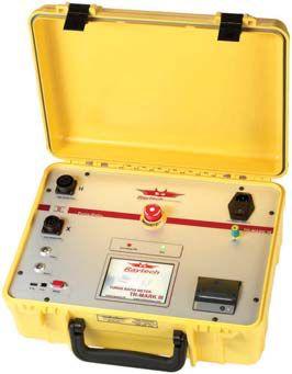
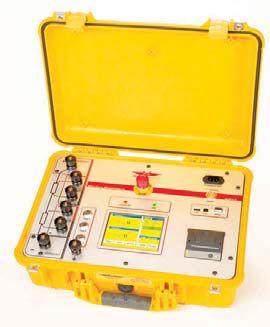
ACCURACY (RESOLUTION 5 DIGITS) :
Range 0.8 … 2000 ± 0.06% at 100V or 40V
Range 2001 … 4000 ± 0.1% at 100V or 40V
FEATURES:
Range 4001 … 13000 ± 0.3% at 100V or 40V
Range 13001 … 16000 ± 0.4% at 100V or 40V
*TR-Mark III-250 Range Up to 45,000 ± 0.4% at 250V
Automatic measurements of voltage, turns ratio, current, and phase displacement
Measures power transformers PTs and CTs
Displays deviation from a nominal ratio
Displays % error vs. name plate value
Bright full color touch-screen for easy data entry
Test voltages of 100V, 40V, 10V, and 1V (for CT Testing)
Graphical tap changer display
Automatic phase vector detection
Enhanced heavy-duty protection circuitry
Data exchange with USB-Key
Built-in printer
*Also available: TR-Mark III-250
Winding Resistance Meter with Demagnetization WR14
ACCURACY:
Range 100 mAmp … 15 Amp ± 0.1% Rdg 5 Digit Resolution
Range <25 mAmp 1.2k…10k ± 0.1% Rdg 5 Digit Resolution
Range <25 mAmp 10k…100k ± 0.5% Rdg 4 Digit Resolution
FEATURES:
Core Demagnetizing Circuit (world exclusive)
Charges inductive loads up to 1500 Henry
2 independent measuring channels
Heavy-duty protection circuitry
High power DC supply (15A/30V)
Resistance range from 0.05 μ to 100 k
Battery or line voltage powered
Visible and audible indicator for discharge status
Data exchange with USB-Key
Simple touch screen operation
Built-in printer
Single Phase Ratiometer TR-1 & TR-1P
ACCURACY:
Range 0.8 … 4000 ± 0.08% with 40 Volts (PT Mode)
Range 0.8 …100 ± 0.08% with 1V…5V (Auto) (CT Mode)
FEATURES:
Operates on rechargeable batteries or line voltage
Can be recharged with line voltage or optional
DC car adapter
Reverse polarity test
Continuity test
Test current up to 1A for CT testing
Internal storage of the last 50 test results
RS-232 interface with optional adapter
Over 1000 measurements without recharging
TR-1P model includes built-in printer
protective relays My dad tests

Over the last 20 years, OMICRON has helped my dad do a great job – and thanks to the following products, his life is going to get even easier:
My dad´s new protection test set CMC 356 is the universal solution for testing all types of protection relays. By controlling it with the powerful Test Universe PC software he can test everything from high-burden electromechanical relays to the latest IEC 61850 IEDs. He can also save a lot of time by using the test templates from the free Protection Testing Library (PTL)
For speedy manual tests, Dad now also has an easy-to-use front panel control utilizing an intuitive touch screen user interface and a control wheel. He can use his CMControl either as a front panel control or as a handheld controller for his CMCs.


