Where

Now test all taps simultaneously, 5 times faster, with the new MRCT from Megger. Now you can measure saturation, ratio, polarity, winding resistance, burden and voltage simultaneously on all taps with absolutely no lead changes. And with integrated insulation and singlephase relay testing, demagnetization functionality and automated test sequences, the MRCT is a small solution that creates big time savings.
Join us for 5 tips to 5x faster CT testing January 14, 2014, 9:30am CST , or January 17, 2014, 9:30am CST
Webinar registration: megger.com/mrct5
The word “Megger” is a registered trademark WWW.MEGGER.COM/US
multi-task. For
CT testing! WINTER 2013 ADVERTISEMENT
multi-tap meets
5 times faster
Megger Best Practices Seminar
Explore new technologies that advance electrical testing efficiency. Join us for a complimentary one day seminar before the 2014 PowerTest Conference.
How can you create a more effective testing program? That’s what Megger’s Best Practices Seminars are all about. We’ll be bringing together product and application engineers from across the globe to explain and debate new revolutionary testing methods that can make your job easier. And the best part? You. We invite you to join the discussion and influence the evolution of Megger testing technology. You’ll hear about...
Instrument transformer testing
Circuit breaker analysis
Cable fault location
Power transformer commissioning
Switchgear troubleshooting
Test data management
And more
This one-day event is complimentary, but seating is limited Attendees will receive up to 6 hours of NETA CTD’s. For a full agenda, speaker details and to register please visit megger.com/bps
The word “Megger” is a registered trademark
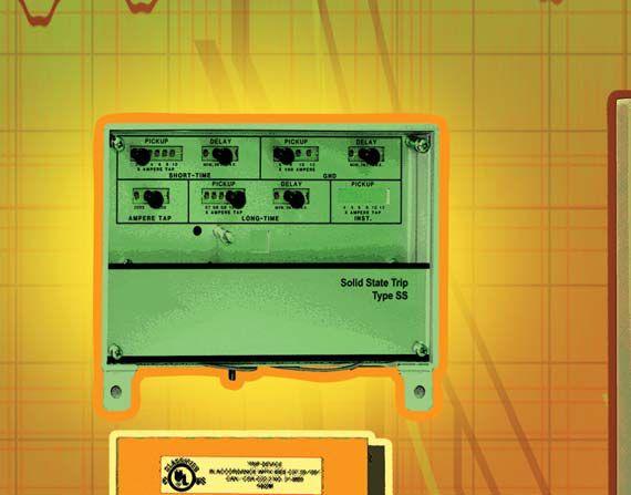
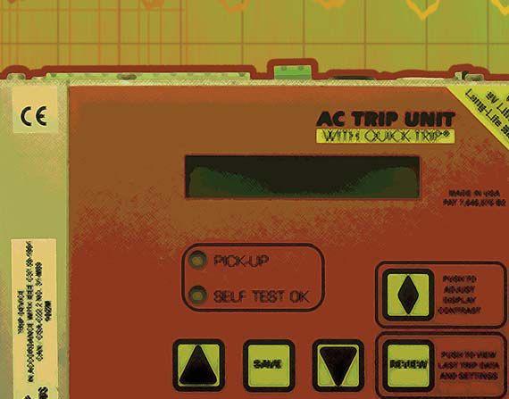


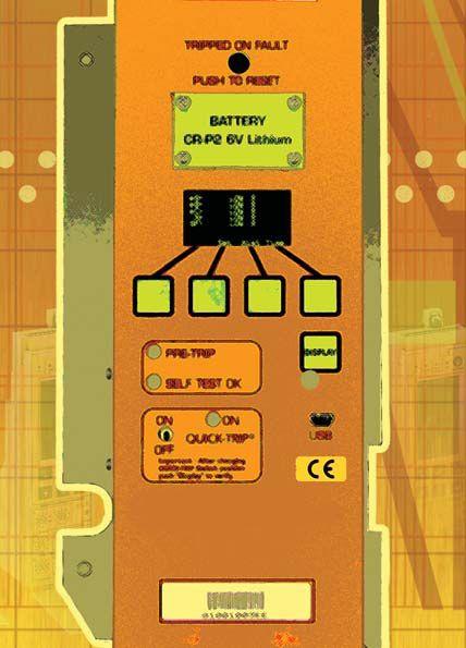







REGISTISTR ATION O N OPEN N N NOW ISSN2167-3594NET ISSN 2167-3594 NETAWORLDJOURNALPRINT A WORLD JOURNAL PRINT ISSN2167-3586NET ISSN 2167-3586 NETAWORLDJOURNALONLINE A WORLD JOURNAL ONLINE WINTER 2013 MODERN PROTECTION SCHEMES CIRCUIT BREAKERS PAGE 54 I N S I D E ! SPECIAL PREVIEW GUIDE
The quickest path from A to B is the STVI.


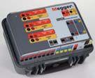
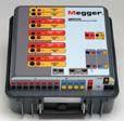
With the STVI® you can confirm relay settings changes faster than ever before. Power up, select the pre-loaded curve or characteristics, then with a few simple touches you can be ready to test the operation of your new settings. All results are exportable to PowerDB to help you meet NERC reporting requirements. Megger’s series of SMRT relay testers take the mystery and misery out of testing microprocessor relays.
Want to learn more? Download 3 Easy Ways to Save Time Testing Microprocessor Relays Guide at megger.com/stvi
WWW.MEGGER.COM/US
The word “Megger” is a registered trademark
MARCH 3–6, 2014 HYATT REGENCY
Plan Your PowerTest 2014 Schedule Choose Your Sessions See Exhibitor Previews Make the Most of PowerTest 2014


POWERTEST 2014 PREVIEW GUIDE
The Premier Electrical Maintenance and Safety Event
ENERGIZE YOUR FUTURE! Now Available! Download the new PowerTest App.
DENVER, COLORADO


March 3-6, 2014
Hyatt Regency Denver Denver, Colorado
PowerTest heads to Denver, Colorado, in 2014
Join us at PowerTest 2014 and Energize your Future at the premier electrical acceptance, maintenance, and safety conference in Denver, Colorado. PowerTest 2014 will leverage expertise within the industry, providing countless opportunities for professionals to expand their knowledge, examine new ideas, and shape not only their future, but that of the electrical power systems industry as well. Denver is a city that has inspired many to seek new challenges, advance their knowledge, examine new ideas, and shape the future. A perfect fit for PowerTest 2014.
Keynote Address
The Transition to Mandatory Standards – Six Years and Counting, Time for the Adolescent Clumsiness to End!
Nicholas A. Brown, President and Chief Executive Officer
Southwest Power Pool
Nick Brown serves as President and CEO of SPP. He has held several engineering positions since joining the company in 1985 and began his career as a planning engineer at Southwestern Electric Power Company.

Nick has served on the Board of Directors of the Electric Power Research Institute and has served on numerous organizational groups of the North American Electric Reliability Corporation over the past 30 years.

Rock the Rockies Pub Crawl and Scavenger Hunt
Get ready to rock in downtown Denver! Find clues on the ground and high in the sky with the mile-high pub crawl and scavenger hunt along the famous 16th Street Mall. The hunt includes stops at the Rock Bottom Brewery, Hard Rock Café, and Coyote Ugly. Refreshments and food are included. Rock on!
Sunday, March 2, 5:30 PM – 8:30 PM
Sign up when you register on-line. $150 per person.
Sponsored by


Day One:
MONDAY
We’ve gathered leaders in the industry and staged a full day of engaging, 45-minute presentations and a power transformer focused symposium which is sure to expand your thinking and generate new ideas.
Choose From 27 technical paper tracks and the transformer symposium.
TECHNICAL PRESENTATIONS:
ELECTRICAL SAFETY
9:30 - 10:15
Industrial Electrical Safety Compliance Assessments
Dennis Neitzel, AVO Training Institute, Inc.
10:30 - 11:15
Verify Performance and Safety of Arc-Flash Detection Systems
William Knapek, OMICRON electronics Corp. USA
11:30 - 12:15
Determining Maintenance Intervals for Safe Operation of Circuit Breakers
Jim White, Shermco Industries
2:15 - 3:00
Productively Safer Lock-Out Tag-Out Procedures with Permanent Electrical Safety Device
Philip Allen, Grace Engineered Products
3:15 - 4:00
The Electrical Safety Trifecta
Terry Becker, Electrical Safety Program Solutions, Inc.
4:15 - 5:00
Developing an Electrical Multiworker Worksite Protection Program
Don Brown, Shermco Industries
RELIABILITY Sponsored by Southwest Energy Systems, LLC
9:30 - 10:15
Keeping the Lights On – Update on Testing MediumVoltage Cable and Switchgear Systems
Ashley Harkness, Electrical Reliability Services
10:30 - 11:15
How to Implement Symmetrical Components Into Relay Testing
Jason Buneo, Megger
11:30 - 12:15
Consideration Testing Transformer Protection
Schemes Nestor Casilla, Doble Engineering
2:15 - 3:00
Experience with DC Polarization-Depolarization Measurements on Stator Winding Insulation
Vicki Warren, IRIS Power-Qualitrol
3:15 - 4:00
How to Perform a Power Survey
Ross Ignall, Dranetz Technologies
4:15 - 5:00
A Practical Approach to Line Current Differential Testing
Karl Zimmerman and David Costello, Schweitzer Engineering Laboratories
EQUIPMENT Sponsored by Raytech
9:30 - 10:15
Process Analysis – Your Intel to System Knowledge
Noah Bethel, PdMA Corporation
10:30 - 11:15
Simplified Motor Relay Testing
Chris Werstiuk, Manta Test Systems
11:30 - 12:15
Optimize Stator End-Winding Vibration Monitoring With Impact Testing
John Letal and Vicki Warren, IRIS Power
2:15 - 3:00
A Systemic Approach to High-Voltage Circuit Breaker Testing
Charles Sweetser, OMICRON electronics Corp. USA
3:15 - 4:00
Current Transformer Saturation and Residual Magnetism
William Knapek, OMICRON electronics Corp. USA
4:15 - 5:00
Influence of the Test Voltage Wave Shape on the PD Characteristics of Typical Defects in MediumVoltage Cable Accessories
Henning Oetjen, Megger
CASE STUDIES Sponsored by Electrical Reliability Services
9:30 - 10:15
Failure Investigation Case Studies
Wally Vahlstrom, Electrical Reliability Services
10:30 - 11:15
Smaller Commissioning Assignments Require Greater Attention
Brian Moores, TRC Companies
11:30 - 12:15
Optimization of Transformer Drying in the Field
Thomas Prevost, OMICRON electronics Corp. USA
3
Day One: MONDAY (CONT.)
2:15 - 3:00
Deploying Thermal Imagers at the Technician Level to Increase Safety, Reduce Downtime, and Save Money
Brad Risser, FLIR Systems
3:15 - 4:00
Low-Voltage Metal Enclosed Bus Duct Wetting Events
Dan Hook, Western Electrical Services
4:15 - 5:00
A New Approach to Circuit Breaker Analysis
John Cadick, Cadick Corporation
Finley Ledbetter, Group CBS
TRANSFORMERS
9:30 - 10:15
I Know How to Add the Numbers – But What is the Power Factor Telling Me?
William Keith Hill, Doble Engineering
10:30 - 11:15
Decision Sciences – Will This Be On the Test?
Nicholas Perjanik, Weidmann Diagnostic Solutions
11:30 - 12:15
Water Distribution and Migration in Transformer Insulation Systems and Assessment of Paper Water
Content David Koehler and Lance Lewand, Doble Engineering
SYMPOSIUM ON POWER TRANSFORMERS
2:15 - 5:00
Power Transformer Predictive Analysis: A Technology Overview
Moderator: Pat Beisert, Shermco Industries
Hospitality Suites
Mingle with a host of leaders at Monday night’s Hospitality Suites. Talk with the experts, find solutions for your business, and catch up on the latest products and services as each sponsoring company shares its own brand of hospitality.
Day Two:
TUESDAY MORNING
Join in the discussion during the Tuesday morning Panel Sessions. Select two of the four panel topics and get ready to learn from experts and peers alike.
PANELS:
8:00 AM - 9:45 AM & 10:15AM - 12:00 PM
SAFETY
Moderator: Jim White, Shermco Industries
CIRCUIT BREAKERS
Moderator: Dan Hook, Western Electrical Services
TRANSFORMERS
Moderator: Pat Beisert, Shermco Industries
RELAYS
Moderator: Rod Hageman, PRIT Service, Inc.
TUESDAY AFTERNOON
POWERTEST 2014 TRADE SHOW
PowerTest 2014 features more than 100 exhibits from top-tier electrical power vendors. No other show brings together this many companies focused on electrical safety and maintenance. See you on Tuesday!
PowerBash 2014
PowerBash 2014 will be held Tuesday evening. It is the culmination of two days of intense conference sessions and marks the commencement of an additional two days of high-impact seminars. Awards for best Technical Presentation, Trade Show Booth and Hospitality Suite will be presented.
Sponsored by


4
POWERTEST 2014 GOES MOBILE!
For the first time ever, PowerTest attendees will be able to revolutionize their experience with a brand new, customized mobile app for Apple and Android phones and tablets!
Customize and set your own schedule for the sessions you want to see
Set reminders for your next session
See session content abstracts and speaker bios
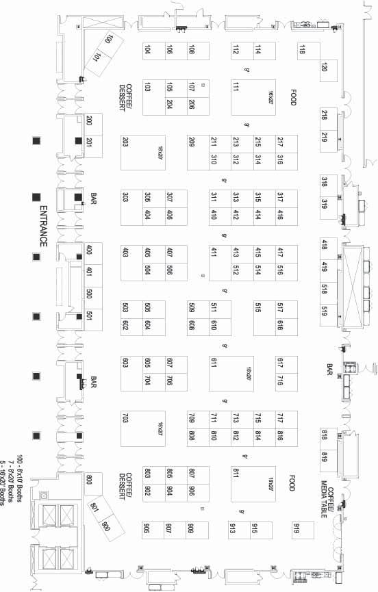
Complete facility maps including Trade Show layout and booth information
Search PowerTest in the App Store and Google Play or download now.
Now Available! Download the new PowerTest Mobile App

March 3 – 6, 2014
Hyatt Regency Denver Denver, Colorado
r
5
The Premier Electrical Maintenance and Safety Event
Introducing the MOBILE APP
6 PowerTest 2014 Exhibitors
PowerTest 2014 Exhibitors
COMPANY..............................BOOTH#
ABB ............................................218
AEMC Instruments..........................104
Arbiter .........................................509
Astro Controls, Inc. ........................108
AVO Training ................................602
Basler Electric ...............................206
BCS Switchgear ............................604
CBS ArcSafe ................................607
CE Power Solutions, LLC .................405
Circuit Breaker Analyzer .................808
Circuit Breaker Sales ......................103
ComRent ......................................410
Doble Engineering .........................603
Dranetz .......................................412
Electrical Reliability Services ............511
Electro Rent ..................................311
Electroswitch.................................401
ENOSERV ....................................519
Exiscan ........................................406
FLIR Systems .................................517
GE Digital Energy ..........................201
Grace Engineered Products .............617
HAEFELY HIPOTRONICS ................203
High Voltage ................................704
Hioki USA ....................................305
HV Diagnostics, Inc. ..............814/816
inoLECT, LLC. ................................800
Instel Power Products ......................516
Intellirent ..............................805/803
IRIS Power - Qualitrol......................217
IRISS, Inc. ....................................703
Kinectrics Inc. ...............................807
KoCos America LLC .......................610
COMPANY..............................BOOTH#
Manta Test Systems Inc. ..................417 Megger ...............310, 312, 314, 316
Monster Fuses .......................118/120
N4L- Newtons4th ..........................204
National Switchgear ......................303
ndb Technologies ..........................616
North American Switchgear ............919
OFIL ............................................706
OMICRON ..........................100/101
Phenix Technologies, Inc. ................716 Power Substation Services ...............605
PROGUSA- DV Power ....................801
ProTec Equipment Resources ............209
Quality Switchgear ........................400
Raytech ...............................709/711
RB Sales ......................................404
RESA Power Solutions .....................319
Rocky Mountain Breaker Services .....717
ROMAC ......................................414
Salisbury by Honeywell ..................317
Schweitzer Engineering ..................413
Shermco Industries .................403/503
Solid State Exchange & Repair Co....106
Southland Electrical Supply ..............611
Sunbelt ........................................608
Technitrol .....................................505
TJH2b Analytical ...........................200
Tony Demaria Electric .....................307
TRS-RenTelco .................................515
Utility Relay ..........................504/506
Vacuum Interrupters ........................407
Voyten Electric and Electronics .........818
Widespread Electrical Sales ............416
7


EXHIBITOR SPOTLIGHT AVO TRAINING — #602 ................................................................PAGE 9 www.avotraining.com HIGH VOLTAGE INC. — #704.........................................................PAGE 9 www.hvinc.com FLIR — #517 ................................................................................PAGE 10 www.flir.com HAEFELY HIPOTRONICS — #203 ..................................................PAGE 10 www.haefely.com INOLECT — #800 .........................................................................PAGE 11 www.safetyracking.com AEMC — #104 .............................................................................PAGE 11 www.aemc.com SHERMCO (TO COME) — #403/503 ............................................PAGE 12 website MONSTER CONTROLS — #118/120 ............................................PAGE 12 www.monstercontrols.com
Don’t Miss these technology and training highlights at the PowerTest 2014 Exhibition
TRADE SHOW SPOTLIGHT
TRADE SHOW SPOTLIGHT
VLF and Tan Delta: Ideal for testing cables rated up to 25 kV
VLF-34E 34 kV VLF Tester
VLF & DC Output | Sheath Testing | Cable Burning
The VLF-34E is a new generation VLF AC Hipot that uses a solid state design with microprocessor controls. It meets the requirements of applicable world standards regarding cable testing up to 25kV class maintenance testing. It is light, compact, rugged, and very portable. Its sine wave output is suitable for using external TD and PD detection equipment. Using a TD and PD option, the VLF-34E is all that is needed for nearly all cable testing up to 25kV class.
Easy to use controls. Programmable test sequences & manual control, USB, XBEE® wireless, RS-232/422 port for downloading data and for unlimited test report capture, wireless computer interface to control and download Tan Delta diagnostics and for remote control operation via laptop.

Tan Delta TD-34E
VLF-TD Cable Diagnostic Testing
The TD-34E, along with the HVI VLF-34E AC hipot, is the latest in design using current electronic technology. Together they permit the user to perform all VLF and VLF-TD tests possible and offer the best wireless operation and data collection, aided by the HVI custom application software written solely for the two devices. There is no better alternative. HVI has been supplying the world with VLF and Tan Delta technology since 1998, with more models, greater voltage range, and higher power capability, all with the superior sales and service that HVI is well known for worldwide.
9 ISO 9001 : 2008
Ground VLFHVOutput To Test Cable Optional HVI: The World’s VLF Source All HVI Products are Made in the USA INTRODUCING THE NEW For 5 – 25 kV cable: VLF-34E & TD-34E TD-34E Tan Delta Transducer
VISIT US AT BOOTH 704

NEW FLIR EX SERIES THERMAL CAMERAS
IDEAL FOR MAINTAINING & TROUBLESHOOTING UTILITY EQUIPMENT AND SYSTEMS
To get a clearer picture of the condition of mission-critical electrical transmission components, more utility service crews ar e being equipped with a key diagnostic tool: FLIR thermal IR cameras. The all-new FLIR Ex Series IR cameras simplify the job of detecting proble m areas by giving utility crews the valuable tools they need to pinpoint hot spots and faulty systems. Compact, rugged and user-friendly, the new FLIR E4, E5, E6 and E8 cameras are perfect for utility crews that are limited to scanning electrical equipment and lines from a dist ance because of limited access or safety concerns.
Combining class-leading features with real-world affordability, FLIR Ex Series IR cameras feature a 3-inch color LCD display, w ide-angle lens, intuitive controls and menus, on-board digital camera, as well as FLIR’s exclusive MSX® technology, which uses detail areas fro m digital photos to create highly defined thermal images. MSX is ideal for showing exactly where problems exist, and the included FLIR To ols® software is perfect for creating easy-to-understand documentation and reports.
Visit us at PowerTest 2014, booth # 517
And let us demonstrate the New FLIR Ex Series IR Camera for you!
10
AC Dielectric Test System 700 SERIES We are committed to providing the most safe and reliable test equipment to utilities and contractors around the globe. UTILITY PRODUCT LINE ASK ABOUT OUR COMPLETE www.haefely.com www.hipotronics.com New York, USA +1 845 279 3644 Basel, Switzerland +41 61 373 4111 Beijing, China +86 10 8578 8099 AC / DC Hipot Testers Liquid Dielectric Testing Transformer Testing Winding Analyzers Cable Fault Locators AC Dielectric Testing Secondary Power Restoration Automatic Transformer Winding Analyzer 2293 NEW Touch Screen PLC Controller (TS-PLC) Now with TURNS RATIO measurement BOOTH 203 C 70 EW on N NE E C Co A AC 9 m n N R om i 2 Auto Wi 2 TRADE SHOW SPOTLIGHT

11 EASY-TO-USE COMPACT SHOCK RESISTANT WEATHERPROOF www.aemc.com Model 8435 is a three-phase power quality analyzer that has direct measurement of four voltage and four current inputs including neutral voltage and current. It captures and records trend, transients, events, inrush and waveforms simultaneously with 2GB of memory for data storage. APPLICATIONS RAT ING SAF ETY IP Rated 67 cover closed VISIT US BOOTH #104 TRADE SHOW SPOTLIGHT

12 Shermco Oil Analytics and Electrical Safety Training: A Complete Solution To a NETA Accredited Workflow Visit us at booth 403 & 503 TRADE SHOW SPOTLIGHT

Subscription
Place
13 Join the NETA Alliance Program! ALLIANCE PROGRAM Gold Alliance Benefits: Complimentary PowerTest Registration Complimentary ANSI/NETA Standard Standard Alliance Benefits: 20% discount on PowerTest 2014 50% discount on one ANSI/NETA Standard Annual NETA World Journal subscription 20% discount on NETA publications
to the NETA technical community Seat at the NETA Annual Meeting
Access
to the NETA Alliance Newsletter
announcements in the NETA Alliance Newsletter Also included in Gold Alliance Benefits Join Today and Attend PowerTest 2014 Hyatt Regency Denver Denver, Colorado March 3-6, 2014 Go to www.powertest.org or give us a call at 888-300-6382 (NETA) THE “GO-TO” STANDARDS FOR ELECTRICAL SAFETY AND RELIABILITY The ANSI/NETA Standards for Acceptance and Maintenance Testing Specifications for Electrical Power Equipment and Systems! ANSI/NETA MTS-2011 STANDARD FOR MAINTENANCE TESTING SPECIFICATIONS FOR ELECTRICAL POWER EQUIPMENT AND SYSTEMS Order Your Copy of the ANSI/NETA Standards Today! Become a NETA Alliance Partner and Save! To order: visit www.netaworld.org Or call 888-300-NETA (6382) ANSI/NETA ATS-2013 S T ANDARD FOR ACC E P T ANC E TESTING SPECIFICATIONS FOR ELECTRICAL POWER EQUIPMENT AND SYSTEMS TRADE SHOW SPOTLIGHT
Days Three and Four:
WEDNESDAY - THURSDAY
Take advantage of a unique opportunity to choose from 12 in-depth, 4-hour seminars on Wednesday and Thursday.
SEMINAR TITLES:
WEDNESDAY AM
8:00-11:45
Battery Maintenance and Testing
Rod VanWart, AVO Training Institute, Inc.
The Practical Application of the NFPA 70E in Routine Work Tasks
Jim White, Shermco Industries
Basic Power Factor Theory
William Keith Hill, Doble Engineering
WEDNESDAY PM
1:15-5:00
Do I Need Training or an Assessment?
Christopher Pavese, Salisbury by Honeywell
“Condition of Maintenance”: A Practical Overview to Understanding and Compliance within the Industry
Jim White, Shermco Industries
Evolving Protective Relay Testing
Karl Zimmerman and David Costello, Schweitzer Engineering Laboratories
THURSDAY AM
8:00-11:45
Partial Discharge Testing of Electrical Equipment: Understanding and Implementing Existing Technologies and Methods
Tom Sandri, Shermco Industries
Transformer Power Factor Theory
William Keith Hill and Rick Youngblood, Doble Engineering
The Six Components of Transformer Diagnostics Using Fluid Test Data
Melvin Wright, LICA Transformer Consulting
THURSDAY PM
1:15-5:00
Cellulose Mechanical Condition Assessment in Transformers – Use of Direct and Indirect Tests
Lance Lewand and David Koehler, Doble Engineering
Power Quality Investigation, Diagnostics, and Case Studies
Bruce Rockwell, American Electrical Testing Co., Inc.
Specialty Transformer Testing – Dry Types, Rectifiers, and Instrument Transformers
William Keith Hill and Rick Youngblood, Doble Engineering

See the many sites around town like the Clock Tower

Enjoy the nightlife!

Enjoy one of many local hiking trails.
14
SPONSORS
Sunday, March 2, 9:00 AM – 4:00 PM
Megger Best Practices Denver
Megger’s seminar will address many of the critical and costly aspects of substation maintenance. The interactive session will feature practical presentations on current methods and practices to help ensure the reliability of high-voltage circuit breakers, power transformers, and batteries. You must preregister for this event by contacting Megger: 214.330.3539
Monday, March 3, 12:00 PM – 2:00 PM
PowerDB User Group
Free user’s group meeting open to all users of PowerDB software. You must preregister for this event by contacting Megger: 214.330.3539.
New Product Forum
Monday, March 3, 5:00 PM – 6:00 PM
Attendees will have the opportunity to learn about
dozens of the latest products and innovations, major expansions, and significant improvements by leading industry-specific manufacturers and suppliers at the Tuesday Trade Show. Stay until the end for the chance to win an exclusive prize! Must be present to win.
Spouse/Guest Pass
A special lounge exclusively for spouses and guests of PowerTest attendees, stocked daily with light refreshments and information on local activities. Includes lunch voucher and admission to Hospitality Suites, Tuesday Trade Show, and PowerBash reception. $75 per person.
Social Pass
The Social Pass includes admission to the Hospitality Suites, Trade Show, and the PowerBash Reception. $40 per person.
15
TM ® ®
Voltage Premium
Medium
Voltage Low Voltage General
High
Early Bird Registration Is Now Open!
PowerTest 2014 Registration

Register On-line:
To register for PowerTest 2014, save time by registering on-line. You‘ll find a complete brochure and registration form available at www.powertest.org.
Join & Save
Join the Gold Alliance Program for $800 and your PowerTest 2014 conference registration is included! Standard Alliance Program participants can upgrade to Gold Alliance status for only $625 to receive a complimentary PowerTest conference registration!
Hotel Reservations:
Hyatt Regency Denver at the Convention Center 1.888.421.1442
650 15th Street Denver, Colorado 80202
Reservation Deadline: January 30, 2014 Group Name: NETA/PowerTest Group Rate: $199
Payment:
NETA accepts all major credit cards. Save time and register on-line at www.powertest.org or call 888-300-6382 (NETA).
Extras:
PowerTest 2014 Technical Papers - Registered conference attendees will receive all PowerTest technical presentations on a USB drive on site in their registration bag.
Easy Steps for Registration:
1. Go to www.powertest.org and review the complete PowerTest 2014 on-line brochure.
2. Decide the number of days you will attend the conference.
3. Tuesday attendees select up to two panels. (Cost of panels included in registration fees.)
4. Wednesday attendees register for up to two seminars. (Cost of seminars is in addition to the registration fees.)
5. Thursday attendees register for up to two seminars. (Cost of seminars is in addition to the registration fees.)
6. Register for two or more seminars and receive 15% off. Use code SEM2014–PT to receive this discount.
7. Sign up for the Rock the Rockies Pub Crawl and Scavenger Hunt. Space is limited, so register early. (Cost is in addition to the registration fees.)
8. Sign up for Spouse/Guest Passes. (Cost of passes is in addition to the registration fees.)
9. Sign up for PowerTest 2014 conference polo shirts and select size. (Cost of polo shirts is in addition to the registration fees.)
16
on-line at: www.powertest.org
888-300-6382 (NETA)
Register
Or call:
Nonmembers NAC Members Full Conference: $789$729 Single Day: $530$500 Seminars: $289 $269
Register Today!
COVER STORY
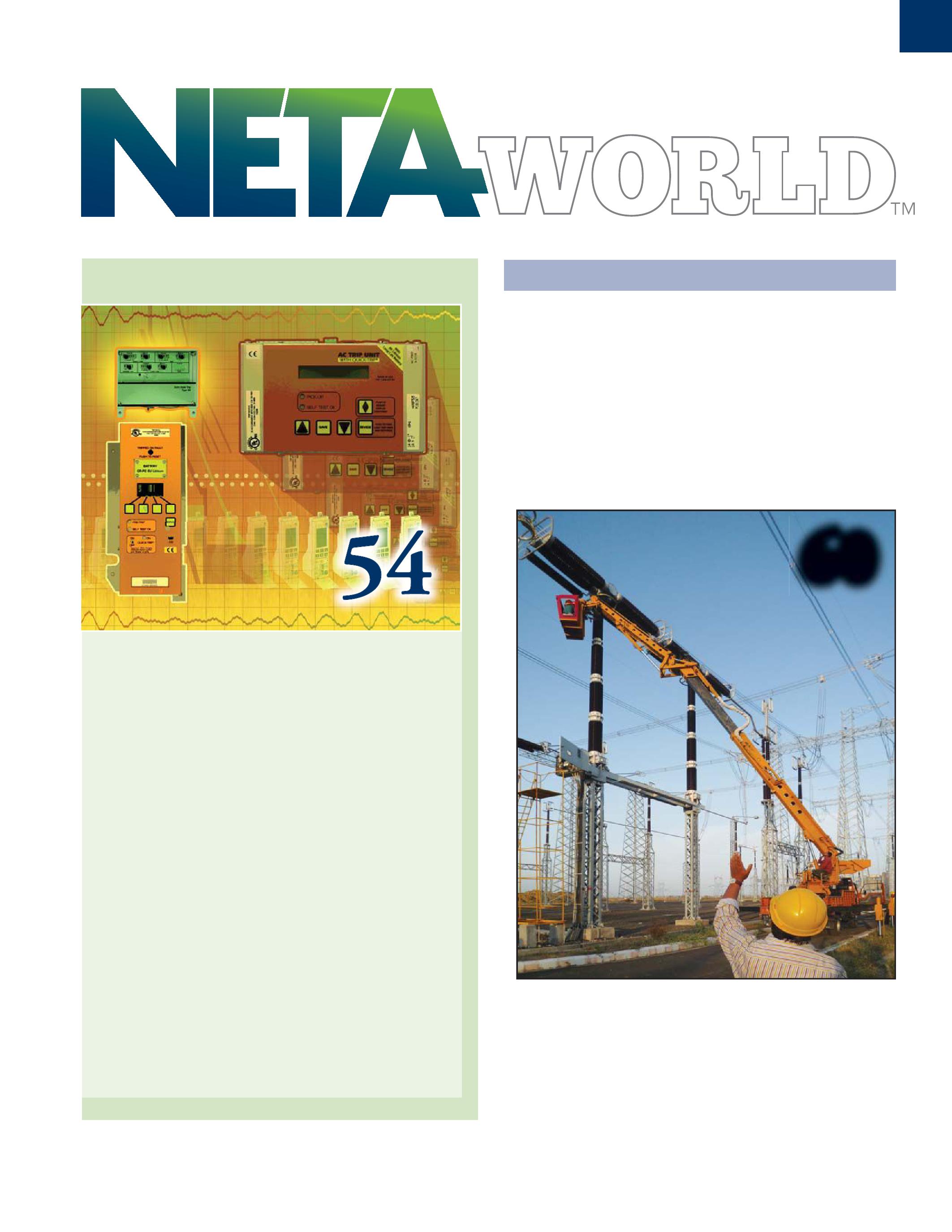
54 Modern Protection Schemes for Low-Voltage Circuit Breakers
By Dan Hook, Western Electrical Services, Inc.
This article will be the first of a two-part series covering many of the protection schemes available in low-voltage switchgear. This first part will be a simplified description of the schemes and some of the basic theories applied to accomplish the intended goals.
FEATURES
7 President’s Desk
David Huffman, Power Systems Testing Co. NETA President
60 The Criticality of Circuit Breaker Testing: Performance Matters
By Elsa Cantu and Dr. Diego Robalino, Megger
68 Service Entrance Switchboards
By Robert P. Hansen, General Electric
TABLE OF CONTENTS TABLE OF CONTENTS NETAWORLD 3
60
IN EVERY ISSUE
11 The NFPA 70E and NETA
The Process Moves Along!
Ron Widup and Jim White, Shermco Industries
16 Tech Quiz
Protection Schemes for Low-Voltage Circuit Breakers
Jim White, Shermco Industries
20 Niche Market Testing
Remanufactured Low-Voltage Breakers
Lynn Hamrick, Shermco Industries
30 Testing Rotating Machinery
Best Practices for Stator Endwinding
Impact Bump Testing
Vicki Warren and John Letal, Iris Power LP.
38 Safety Corner
Methods To Limit Arc-Flash Exposure
On Low-Voltage Systems
Scott Blizard, American Electrical Testing Co.
44 Tech Tips
Special Considerations for Grounding
Jeff Jowett, Megger
INDUSTRY TOPICS
85 Understanding Insulation Test Results of a Transformer with a Grounded Electrostatic Shield
Michelle Ward, Doble Engineering Company
90 Extending the Life of Existing Switchgear
Miklos J Orosz, Schneider Electric
99 The Importance of a Periodic Maintenance Route
Lynn Hamrick, Shermco Industries, Inc.
107 Electrical Hazard Facts
James R. White, Shermco Industries, Inc.
SPECIFICATIONS AND STANDARDS
119 ANSI/NETA Standards Update
NETA NEWS
36Magna Electric Corporation (MEC) Announces Edmonton Expansion
50The Windy City Hosts NETA
76NETA Welcomes Saber Power Services as a NETA Accredited Company
116 NETA Welcomes Longo Electrical Mechanical as a NETA Accredited Company
NETA NEWS – SETTING THE STANDARD
26 NETA and University Curriculum:
Electrical Test Technicians – From the Classroom to the Field
Jill Howell, NETA
80 Charles K. Blizard, Sr.: Celebrating 29 Years of Service to NETA
Kristen Wicks, NETA
NETA NEWS – IMPORTANT LISTS
124 NETA Accredited Companies
130 Advertiser List
4 WINTER 2013 TABLE OF CONTENTS
TABLE OF CONTENTS
Introducing a really big idea: “Rent it”

What makes it work at Protec, better than other options?
What’s next? Make us prove we care.

Delivering Powerful Reliability Solutions
Power System Acceptance Testing
Commissioning and Start-up
Maintenance
Life-Cycle Extension
Troubleshoot and Repair
Training and Engineering Services
Planning and Operations Support
Project Management
Sigma Six Solutions, Inc.
2200 West Valley Hwy North, Suite 100 | Auburn, WA 98001 |


3050 Old Centre Avenue, Suite 102
Portage, MI 49024
Toll free: 888.300.NETA (6382)
Phone: 269.488.NETA (6382)
Fax: 269.488.6383
neta@netaworld.org
www.netaworld.org
EXECUTIVEDIRECTOR: Jayne Tanz, CMP
NETA Officers
PRESIDENT: David Huffman, Power Systems Testing Co.
FIRSTVICEPRESIDENT: Ron Widup, Shermco Industries
SECONDVICEPRESIDENT: Jim Cialdea, Three-C Electrical Co., Inc.
SECRETARY: Walt Cleary, Burlington Electrical Testing Co., Inc.
TREASURER: John White, Sigma Six Solutions
NETA Board of Directors
Ken Bassett (Potomac Testing, Inc.)
Scott Blizard (American Electrical Testing Co., Inc.)
Jim Cialdea (Three-C Electrical Co., Inc.)
Walt Cleary (Burlington Electrical Testing Co., Inc.)
Roderic Hageman (PRIT Service, Inc.)
Kerry Heid (Magna Electric Corporation)
David Huffman (Power Systems Testing)
Alan Peterson (Utility Service Corporation)
Mose Ramieh (Power & Generation Testing, Inc.)
Bob Sheppard (Southwest Energy Services, LLC)
John White (Sigma Six Solutions)
Ron Widup (Shermco Industries)
NETA World Staff
TECHNICALEDITOR: Roderic L. Hageman
ASSOCIATEEDITORS: Diane W. Hageman, Resa Pickel
MANAGINGEDITOR: Jayne Tanz, CMP
ADVERTISINGMANAGER: Jill Howell
DESIGNANDPRODUCTION: Hour Custom Publishing
NETA Committee Chairs
CONFERENCE: Ron Widup; MEMBERSHIP: Ken Bassett; PROMOTIONS/MARKETING: Scott Blizard; SAFETY: Scott Blizard and Jim White; TECHNICAL: Alan Peterson; TECHNICALEXAM: Ron Widup; WORLDADVISORY: Diane Hageman; CONTINUINGTECHNICALDEVELOPMENT: David Huffman; TRAINING: Kerry Heid; FINANCE: John White; NOMINATIONS: Alan Peterson; STRATEGY: Mose Ramieh; ALLIANCEPROGRAM: Jim Cialdea
© Copyright 2013, NETA
NOTICE AND DISCLAIMER
NETA World is published quarterly by the InterNational Electrical Testing Association. Opinions, views and conclusions expressed in articles herein are those of the authors and not necessarily those of NETA. Publication herein does not constitute or imply endorsement of any opinion, product, or service by NETA, its directors, officers, members, employees or agents (herein “NETA”).
All technical data in this publication reflects the experience of individuals using specific tools, products, equipment and components under specific conditions and circumstances which may or may not be fully reported and over which NETA has neither exercised nor reserved control. Such data has not been independently tested or otherwise verified by NETA.
NETA MAKES NO ENDORSEMENT, REPRESENTATION OR WARRANTY AS TO ANY OPINION, PRODUCT OR SERVICE REFERENCED OR ADVERTISED IN THIS PUBLICATION. NETA EXPRESSLY DISCLAIMS ANY AND ALL LIABILITY TO ANY CONSUMER, PURCHASER OR ANY OTHER PERSON USING ANY PRODUCT OR SERVICE REFERENCED OR ADVERTISED HEREIN FOR ANY INJURIES OR DAMAGES OF ANY KIND WHATSOEVER, INCLUDING, BUT NOT LIMITED TO ANY CONSEQUENTIAL, PUNITIVE, SPECIAL, INCIDENTAL, DIRECT OR INDIRECT DAMAGES. NETA FURTHER DISCLAIMS ANY AND ALL WARRANTIES, EXPRESS OF IMPLIED, INCLUDING, BUT NOT LIMITED TO, ANY IMPLIED WARRANTY OF FITNESS FOR A PARTICULAR PURPOSE.
ELECTRICAL TESTING SHALL BE PERFORMED ONLY BY TRAINED ELECTRICAL PERSONNEL AND SHALL BE SUPERVISED BY NETA CERTIFIED TECHNICIANS/ LEVEL III OR IV OR BY NICET CERTIFIED TECHNICIANS IN ELECTRICAL TESTING TECHNOLOGY/LEVEL III OR IV. FAILURE TO ADHERE TO ADEQUATE TRAINING, SAFETY REQUIREMENTS, AND APPLICABLE PROCEDURES MAY RESULT IN LOSS OF PRODUCTION, CATASTROPHIC EQUIPMENT FAILURE, SERIOUS INJURY OR DEATH.


Every industry goes though quantum leaps now and then, some greater than others. I wonder if the electrical power industry is going through that now. Let’s take a look inside and see some of the changes that are taking place on low voltage circuit protection.
I’ve long felt that technical advances in electrical power equipment generally happened over greater periods of time than they do in other areas, such as electronics. But changes in electrical power equipment seem to have picked up the pace recently. This edition of NETA World focuses on some of those changes.
I’m in Michigan writing this while at an SRC meeting. The weather is changing; the leaves are turning color; and soon it will be time for turkey and holiday decorations. I do love this time of year. It’s also the time, however, that many NETA companies have shutdowns and long work days. With any luck, work won’t interfere with family festivities.
There are so many terrific people I have had the opportunity to work with over the years, and I’d like to take this time to thank one in particular. Thank you, former NETA President David Haines. Dave is one of the owners of Power Systems Testing, has been wonderful to work for, and I appreciate the support over the years.
Thank you to all the NETA staff, contributors, and editors. To those who have set aside the time and dedicated the resources to research and put forth articles such as NETA World has published, the Association appreciates you.
Happy holidays and warm wishes!
Sincerely,
David Huffman President InterNational Electrical Testing Association


PRESIDENT’SDESK PRESIDENT’S DESK PRESIDENT’S DESK

CBS ArcSafe’s remote racking and remote switching solutions reduce arc-flash dangers and technician fatigue during dangerous operations.
Remote Racking Solutions
Remote racking solutions reduce the need for full-body arc-flash hazard suits by taking technicians outside the arcflash boundary.
Universal remote racking solutions offer adjustable height settings.
Remote Switching
Solutions
Remote switching solutions keep technicians outside the arc-flash boundary during dangerous operations.
ed due tions ar
gnetic latching
No modifications required due to magnetic latching.
Remote switching solutions are available for virtually any style or piece of electrical equipment.
of electrical equipment.
Visit www.CBSArcSafe.com/ catalog to download our free 220-page product solutions catalog!
dur ing da d ngerous o
www.CBSArcSafe.com (472-3389) TOLL FREE e to ma
e available for w ww. CBSArcS af e .com (472 -338 9) ) ( 8 3 3 9 2 7 4L L O T E E R F (877) 4-SAFETY All CBS ArcSafe remote racking and remote actuation solutions are battery- or AC-powered portable units that do not require any modifications to your electrical equipment.

From Apollo 7 to Today’s Smart Grid

Services:
Preventative Maintenance


Acceptance Testing
High Potential Testing

Utility Service Corporation has been providing electrical and technical services for government and industry since 1962.
Solving complex problems, testing under difficult and unusual circumstances and servicing the commissioning and maintenance needs of today’s electrical power systems both new and aged.
Commissioning Services
System Studies
Arc Flash Analysis
Engineering & Consulting
Construction Supervision
System Trouble Shooting (256)

837-8400
SUBSTATION MAINTENANCE I
DALLAS, TX
Jan 6-10
Feb 3-7
Mar 3-7
Apr 21-25
PASADENA, CA
Feb 3-7
Apr21-25
PORTLAND, OR
Jan 6-10
Mar 17-21
VALLEY FORGE, PA
Feb 17-21
Mar 17-21
SUBSTATION MAINTENANCE II
DALLAS, TX
Jan 13-17
Feb 10-14
Mar 10-14
Apr 28-May 2
PASADENA, CA
Feb 10-14
Apr 28-May 2
PORTLAND, OR
Jan 13-17
Mar 24-28
VALLEY FORGE, PA
Feb 24-28 Mar 24-28
*NETA Continuing Technical Development (CTDs) units are required of NETA Certified Technicians.
BATTERY MAINTENANCE & TESTING
DALLAS, TX
Jan 6-9
Mar 17-19
PORTLAND, OR Apr 14-17
VALLEY FORGE, PA
Feb 3-6
PROTECTIVE RELAY MAINTENANCE BASIC
DALLAS, TX
Jan 6-10
Feb 17-21
Mar 31-Apr 4
PORTLAND, OR
Feb 3-7
Apr- May 2
VALLEY FORGE, PA Mar 17-21
YOUNGSVILLE, NC Apr 21-25
PROTECTIVE RELAY MAINTENANCE ADVANCED
DALLAS, TX
Feb 24-28
Apr 7-11
PORTLAND, OR
Feb 10-14
VALLEY FORGE, PA
Mar 24-28
TRANSFORMER MAINTENANCE & TESTING
DALLAS, TX
Jan 20-24
VALLEY FORGE, PA
Mar 31-Apr 4
CIRCUIT BREAKER MAINTENANCE, LOW-VOLTAGE
DALLAS, TX
Jan 13-17
Mar 10-14
VALLEY FORGE, PA
Feb 10-14
Apr 7-11
CIRCUIT BREAKER MAINTENANCE, MEDIUM-VOLTAGE
DALLAS,TX
Feb 3-6
Apr 1-4
VALLEY FORGE, PA
Jan 13-16
Mar 3-6
NEC CODE 2014
DALLAS, TX
Jan 13-16
Feb 3-6
VALLEY FORGE
Jan 6-9
Feb 24-27
PORTLAND, OR
Jan 27-30
Mar 3-6
Your One-Stop for Many Hands-On Safety And Maintenance Training Courses Eligible for NETA CTDs.*
TO ENROLL VISIT WWW.AVOTRAINING.COM OR CALL US AT 877-714-9787 MOST COURSES AVAILABLE ON-SITE. CALL TODAY FOR A QUOTE.
2015 NFPA 70E:
THE PROCESS MOVES ALONG!
BY RON WIDUP AND JIM WHITE, Shermco Industries
As this column for NETA World is being penned, the balloting on the Second Revision (formerly Report on Comments) for the 2015 edition of NFPA 70E is well under way. This is always a critical juncture for the 70E, as this is one of the last major steps to completing the rewrite and improvement of the document, a process that has taken many months and countless hours of discussion and lively debate on what should or should not be done to improve electrical safety for the worker. It is important to point out that everyone on the committee is very passionate about making this document the very best electrical safety standard on the planet. This is a fact that resonates throughout all the discussions.
One item extensively focused on during this revision of the standard was improvements to the arc-flash PPE tables. And it also happens that when they get to this point in the process committeememberstendtoreviewandthink committee members tend to review and think about their rationale for voting the way they did during the committee meetings. It’s a bit like buyer’s remorse… and this has been especially true where the new [proposed] arc-flash PPE table is concerned. The changes proposed are so fundamental that it is good to rethink the concept and make sure it is as good as we can make it….and so as the process gets beyond any “tweaking” points, it is what it is and it cannot be materially changed at this point of the process.
What you will see in the new arc-flash PPE tables (assuming it all gets approved) will be a vast improvement in the ease of use and understanding of field conditions when approaching a piece of energized electrical equipment. But as with any change, there are

periods of understanding and education. So as we navigated the ins and outs of the proposed change, we had a few committee members who suggested going back to the old version of the table because they believed the new table had flaws they found unacceptable. However, the committee debated these same issues, modified it, and voted (as we remember) unanimously to move forward with the new table layout.
During a lively email exchange, one committee member likened the new table to “going back to the 1950s in safety,” because the new table does not require arc-rated PPE for operating certain 480-volt equipment. But looking at the existing 2012 table, no such PPE is currently required; only cotton clothing and safety only glasses. Hearing protection is required if inside the arc-flash boundary, but that would not apply to normal operation of equipment. So is this really a change? Not to us, nor to the majority
NETAWORLD 11 2015NFP 2015 NFPA70E:THEPROCESSMOVESALONG! A 70E: THE PROCESS MOVES ALONG! THENFPA70EANDNETA THE NFPA 70E AND NETA
THENFPA70EANDNETA THE NFPA 70E AND NETA

ofthecommitteememberswediscussedthis of the committee members we discussed this with.R with. RememberthatwebelievetheNFPA emember that we believe the NFPA 70E presents minimum acceptable safety requirements, not best work practices. To make NFPA 70E a best safe work practices it would be one page long. In the middle of that page it would say:
TurnItOff. Turn It Off.
Endofdocument.H End of document. Heck, we could say eck, turn it off in several languages and make it an international it standardforalltouse. standard for all to use.
Unfortunately, that is not always possible or nfortunately, practical. Is it realistic to expect an entire facility to be idled in order to operate a breaker oraswitch?Ofcoursenot.Electricalworkand or a switch? Of course not. Electrical work and electrical equipment have an inherent risk in the use and operation of it, so we have to prepare a plan to perform tasks while the equipment is energized. Wenowhavetodecidewhatan e now have to decide what an electrical safety standard should require.
This, in our opinion, has been where core debates on written guidance on electrical safety originate. The details of the table or any other aspect of NFPA 70E are affected by the basic concept of what NFPA 70E should be.
Should NFPA 70E present best safe work practices or should it present minimum safe work practices? Is one concept right and the other wrong? Neither is right or wrong, which is why NFPA uses the national consensus process it does.B does. By using this consensus process the NFPA y allows the middle ground to be explored and debated, eventually coming to agreement as to the best ideas and requirements to incorporate into the standard. Some may argue that sometimes the committee doesn’t get it exactly right, but in reality NFPA 70E is a relatively young standard. While it hasn’t been around as long as the NEC, both documents are continuously maturing and improving. It is with a high degree of certainty thatwebelievethe2018editionofNFPA70E that we believe the 2018 edition of NFPA 70E will be an improvement over the 2015 edition. It is an evolutionary process that some may think takes two steps forward and one back at times,
butthereislittledebatethattheendresultisthat but there is little debate that the end result is that the standard constantly improves.
Whilewedebatedthecontentwithinthe While we debated the content within the process as it happened, and occasionally it got pretty intense to the point that things were stated that bruised some feelings, it is all part of the development of a premier document. When opinions on a subject are strong, people can lose their perspective. So why do we believe the new arc-flash PPE table is a big improvement? Below elow is a summary of the enhancements.
ThenewtableeliminatesHR The new table eliminates HRC 0, and it C eliminatesthedozensofrisk-basedreductions eliminates the dozens of risk-based reductions inarc-flashPPE.ThereductioninHR in arc-flash PPE. The reduction in HRClevels C levels based on the perceived risk has been an issue for the last several cycles. That is now gone. If there is an arc-flash risk, properly rated arcflash PPE is required. HRC 0 provides no arcflash protection, and it is misleading to have it inatablethataddressesthearc-flashhazard. in a table that addresses the arc-flash hazard. Removing HRC 0 is a safety enhancement.
For the first time ever in NFPA 70E, the table requires the worker to ensure the equipment is properly installed and properly maintained, all equipment doors are closed and secured, all covers are in place and secured, and there is no evidence of impending failure. Even though previous editions of NFPA 70E required that equipment be properly installed and maintained, the proposed additions fill in the gaps in evaluating the equipment about to be operated or serviced.
There are significant revisions to tasks in the table including clarification that thermography by itself does not require arc-rated PPE (if certain conditions are met), and the task of thermography does not include opening doors orcovers.H or covers. However, the person opening doors or covers for the thermographer will require the use of properly rated arc-flash PPE.
The new table is easier to apply in the field, which means that it will be more widely used. Any time a standard can be simplified, it is a simplified, step forward. The current version of the table is
12 WINTER 2013 2015NFP 2015 NFPA70E:THEPROCESSMOVESALONG! A 70E: THE PROCESS MOVES ALONG!
cumbersome and difficult to interpret correctly for many workers. In the new table there is either a perceived arc-flash risk or there is not. If not, no further requirements are imposed. If there is an arc-flash risk, full-rated arc-flash PPE mustbeworn.SincewebelieveNFPA70E must be worn. Since we believe NFPA 70E should present minimum safe work practices, this concept is workable. It does not prevent a worker from using arc-rated PPE if that is what he/she believes is needed; it just does not mandate the use of that PPE. Every specific situation has to be evaluated independently of any other for each piece of equipment. The way the new table is proposed, it allows for flexibility in the field at the specific job location.
LAST THOUGHTS
NFPA 70E is far from perfect, but it has done more to improve electrical safety awareness than any other single factor in the industry. It continues to move the electrical safety culture forward and is responsible for companies and workers alike to look at electrical safety as a more comprehensive, and proactive system of interconnecting ideas and concepts that make working on or near energized electrical systems and equipment safer. It is the model other countries are using to develop and implement their own electrical safety standards and regulations. It is the best there is.
As the process moves on, based on the discussions that have taken place there appears to be strong support for the actions taken in this cycle. What has been agreed to by the committee is rational and logical and will be accepted by the electrical community as a huge improvement over previous editions. Lookforthe2015editionofNFPA70E ook for the 2015 edition of NFPA 70E in October 2014 – you will be most impressed with the improvements.
Or just turn it off.

Ron Widup and Jim White areNETA’S are NETA’S representatives to NFPA Technical Committee 70E (Electrical Safety Requirements for Employee Workplaces). Both gentlemen are employees of Shermco Industries in Dallas, Texas, a NETA Accredited Company. Ron Widup is President of Shermco and has been with the company since 1983. He is a Principal member of the Technical Committee on “Electrical Safety in the Workplace” (NFPA 70E) and a Principal member of theNationalElectricalCode(NFPA70) the National Electrical Code (NFPA 70) Code Panel 11. He is also a member of thetechnicalcommittee“Recommended the technical committee “Recommended Practice for Electrical Equipment Maintenance” (NFPA 70B), and a member of the NETA Board of Directors and Standards Review Council. Jim White is nationally recognized for technical skills and safety training in the electrical power systems industry. He is the Training Director for Shermco Industries, and has spent the last twenty years directly involved in technical skills and safety training for electrical power system technicians. Jim is a Principal member of NFPA 70B representing Shermco Industries, NETA’s alternate member of NFPA 70E, and a member of ASTM F18 Committee “Electrical Protective Equipment for Workers”.
NETAWORLD 13 THENFPA70EANDNETA THE NFPA 70E AND NETA 2015NFP 2015 NFPA70E:THEPROCESSMOVESALONG! A 70E: THE PROCESS MOVES ALONG!
Ron Widup
Jim White

ZERO HERTZ DC TREE ZERO HERTZ DC TREE Where is that AK-1-15 KIT? AC-PRO TREE AC-PRO TREE ® ® 888-289-2864 www.utilityr elay.com Utility Relay Company LG-3000 LK-42 LG-1600 KPE-32 KPE-16 K-3200S K-3200M K-3000S K-DON-2000S K-2000S K-DON-1600S K-1600S K-1600Black K-800S K-800M K-DON-800 K-DON-600 K-600S K-600 WP-40WPX-32 WPX-20 WPX-16 WPX-16 WP-08 AKR75 AL-2-50 AKRU30S AKJ50 AKR30S AKRU50 AKRU30 AKR50 AKRT50 AKR100 AKRU100 AKRU75 TC THC TP TUP WPS-08 WPX-08 WP-16 WPS-16 THP WP-32 WPS-32 WPS-40 WPX-40 WP-20 K-225 KDON225S K-DON-600S K-225M K-225S K-DON-225 K-800 K-DON-800S K-2000 K-1600Red K-DON-1600 K-1600M K-DON-2000 K-2000M K-3000 K-3000M K-4000 K-4000-M K-4000-S KP-32 WPS-20 KBE-600 KD-3000 KDA-3000 KE-4000 KC-1600 KP-16 KCG-1600 LG1000 LG-2000 LG-2500 6LK-1 LK-20 LK-25 LK-32 LK-40 LK-8 DSL206 DK-15 CN2-1250 CN2-800 SED-3000 SED-800 DSA2500STR-38SSTR-28D STR-18M HD-50A HD-50 BD-50A DNA800 AND0002 STR-58U DNA1600 LX400 MB-32 LX-800 000LG-4 LX-1600 LG-5000 LG-6000 LX-400 LX-600 LX-1000 MB-8 MBE-8 MB-16 MBD-16 MBE-16 MB-20 MB-25 MB-25 MB-40 F50 H30 H30 H40 DNA1000 STR-18M STR-28DSTR-38S BD-50 BD-50B BD-50B HD-50B HD-75 RS-15A RS-25A 2500 STR-58U PB-1600 SEF-800 SEF-2000 SEF-1200 SEF-2500 SEF-3000 SEF4000 SED-2500 SED-1200 DA50 DA75 DB15 DBL15 SCB2000 DK-25 DS206 DS206H LA2001 AKR30 AK-1-100AK-2-75 FP-100 AK-3-100 AKT-3A-50 AKU-3-50 AKU2A50 AKT-2A-50 AKU-2-50 AK-3-50 AK-2 A-50 AKT-1-50 AKU-3A-25 AKU-2-25 AK-3A-25 AKU-3-25 AKU-2A-25 AKU-2-15 FM-50 AK-1-25 AE-1B H14 FPSX-50 FPS-50 FPS-100 FPS-25 FP-50 DMB-25 CLS47 RLE-3200 RL-4000 RLE-2000 RL-1600 RLE-3200 RLE-1600 RLE-800 RL-800 RLF-800 LAF-800 LAF-600 LA-600 5ALA-1LA-25 G-25 G-50 LA-15 LA-25A LA-50 LAF-50 LA-50A LA-75 LAF-50A LA-800 LA-1600LAF-1600 LA-3000 LA-3200 LA-4000 RLX-800 RLF-1600 RLX-1600 RL-2000 RLH-800RL-3200 RLE-4000 RL-4200 DMB-15DMB-50 FP-25 FP-75 FPSX-25 FPS4-30 FPS4-50 FPS5-50 FPS-75 FM-25 FPS5-30 H21 H33 AE15 AE25 H27 AK-1-15 AK-2-15 AK-2-25 AK-2A-25 AK-3-25 AK-1-50 AK-2-50 AKT-2-50 AK-4-25 AKU-3A-50 AKT-3-50 AK-1-75 AK-3-75 AK-2-100 AL-2-75


2014 Electrical Maintenance and Safety Event March 3-6, 2014

Hyatt Regency Denver Denver, Colorado


EARLY BIRD REGISTRATION NOW OPEN!
REGIST REGISTER R TODAY!
Featuring:


James R. (Jim) White is the Training Director of Shermco Industries, Inc., in Dallas, Texas. He is the principal member on the NFPA technical committee
“Recommended Practice for Electrical Equipment Maintenance” (NFPA 70B). Jim represents NETA as an alternate member of the NFPA Technical Committee


No.104 No. 104


PROTECTION SCHEMES FOR LOW-VOL TAGE CIRCUIT BREAKERS
BY JIM WHITE, Shermco Industries


“Electrical Safety in the Workplace” (NFPA 70E) and represents NETA on the ASTM F18 Committee “Electrical Protective Equipment For Workers”. Jim is an IEEE Senior Member and in 2011 received the IEEE/PCIC Electrical Safety Excellence award. Jim is a past Chairman (2008) of the IEEE Electrical Safety Workshop (ESW).
Back in the day, circuit breaker protection schemes meant long-time delay (LTD), short-time delay (STD) and maybe ground fault. The concept of integrating lowvoltage circuit breakers into a protection scheme was on the horizon, but all through the 1960’s and 1970’s, even into the 1980’s, low-voltage circuit breakers were pretty much stand-alone devices. With new technology comes new methods of applying circuit breakers, and this Tech Quiz will see what your IQ is on the subject.
1. Identify the low-voltage protection scheme shown in Figure 1:
a. Residual ground fault
b. Percentage differential protection
c. Zone selective interlocking
d. Directional carrier blocking
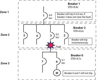
Figure 1: Low-Voltage Circuit Breaker Protective Scheme
2. Thermal-magnetic molded-case circuit breakers have an inherent characteristic known as:
a.Thermal imaging
b. Thermal memory
c. Reactance recovery
d. Shunt tripping
3. In the protection scheme shown in Figure 1, label the action taken by each circuit breaker. Possible actions are trip and restrain.
a. Circuit breaker number 1 __________
b. Circuit breaker number 2 __________
c. Circuit breaker number 3 __________
4. Reduced current let-through can be accomplished by which two technologies (one older and one newer)? Mark two answers.
a. Magnetic repulsion of the contacts
b. Shorter opening distances for contacts
c. Lowered pickup setting on the instantaneous
d. Current-limiting fuses
5. Thermal imaging is used by what type of overcurrent protective device (OCPD)?
a. Thermal-magnetic
b. Oil dashpot
c. Digital/microprocessor
d. Air dashpot
See answers on page 120.
16 WINTER 2013 TECHQUIZ TECH QUIZ
Substation Testing As Easy As

Spend More Time Testing, Less Time Training
Vanguard’s precision substation testing instruments are designed to be intuitive and easy to use so that you can focus on testing instead of wasting time in training. Our versatile instruments offer a built-in thermal printer and on-board test record storage so that tests can be conducted in stand-alone mode in the field. A computer interface is also offered so that tests can be easily conducted from a PC.
And all of our instruments are competitively priced to provide cost-effective accuracy. For a virtual experience of our instruments, check out the interactive demos on our site at:
www.vanguard-instruments.com/demos
1520 S Hellman Avenue Ontario, CA 91761 USA PHONE 909.923.9390 FAX 909.923.9391 EMAIL sales@vanguard-instruments.com Vanguard Instruments Company, Inc. Transformer Turns-Ratio Meters Circuit Breaker Analyzers Capacitor Voltage Transformer Tester Winding Resistance Meters Current Transformer Testers Relay Test Equipment Vacuum Bottle Testers www.vanguard-instruments.com Reliability Through Instrumentation. NEW!
Knowledge

Today’s solutions built on a century solutions built on a century of innovation and expertise of innovation and
Knowledge. It’s what helps you make the next right decision about critical assets. And it’s what Doble uses to develop market-leading diagnostic tools and solutions that give you the information you need, when you need it. Better yet, we make sure you have that information quickly and cost effectively to ensure power system safety and reliability. Right now.
contact us: www.doble.com
now in
We put the
Assuring Electrical Performance

Shop Services
Medium and Low Voltage Breaker Repairs and Retrofitting
Protective Relay Repair and Calibrating
Medium Voltage Starter Repairs
Solid State Trip Unit Repair and Programming
Power Products & Solutions, Inc.


POWER PRODUCTS &SOLUTIONS INC.
NEW SOUTH CAROLINA LOCATION!


REMANUFACTURED LOW-VOLTAGE
BY LYNN HAMRICK, Shermco Industries


This article will concentrate on low-voltage power breakers, which I will define as breakers that are nominally rated at 600 Vac but typically used at 480 Vac and have a frame rating of 800 A or above. They are typically rack-in and rack-out style breakers but can be provided in a bolt-in style, as well. They also include a trip unit that is adjustable and can be provided with long-time, short-time, instantaneous, and/or ground fault (i.e., L, S, I, and G) tripping capabilities.
Low-voltage power breakers have evolved over the last 30 years. Much of this evolution is due to the consolidation of providers throughout the industry. In the last 30 to 40 years, the list of original equipment manufacturers (OEMs) has gone from many (ABB, Allis-Chalmers, BBC, CutlerHammer, Federal Pacific, GE, ITE, Siemens, Square D, and Westinghouse) to a few (ABB, Eaton, GE, Siemens, and Square D). During this evolution, the space, cost, quality, technology, and sales considerations have resulted in a variation of new breaker designs and options from these remaining OEMs. It has also resulted in a large installed base of equipment that is now obsolete and, in most cases, no longer supported by the remaining OEMs. Most electrical equipment, like low voltage breakers, is designed for a 25-year life. Because of these realities, end users are faced with the daunting task of replacing this obsolete equipment which can be a very expensive and disruptive proposition.


To be more specific, examples of the equipment we are talking about are provided on the following page.
This circumstance of equipment obsolescence combinedwithfewerOEMshascreateda combined with fewer OEMs has created a niche of third party remanufacturers, which specialize in upgrading existing, obsolete breakers to extend the life cycle of the equipment while maintaining the reliability and operability of the equipment. From a financial perspective, OEMs typically profit more from new sales of currently manufactured equipment. So, even though they often offer remanufacturing services, they focus on selling replacement equipment in lieu of remanufacturing equipment. This has resulted in a growing list of third party remanufacturers.

Unfortunately for the end user, not all remanufactured equipment is equal. To discuss this further, we will consider the following definitions:
20 WINTER 2013 REMANUFACTUREDLOW-VOLTAGEBREAKERS REMANUFACTURED LOW-VOLTAGE BREAKERS NICHEMARKETTESTING NICHE MARKET TESTING
Retrofitting – adding of new technology or features to older systems
Refurbishing/Reconditioning – servicing and/or renovating older or damaged equipment to bring it to a workable or better looking condition. This includes readjusting, and recalibrating equipment to bring it to a near-new or near-original operational level.
Remanufacturing – rebuilding, repairing, and restoring equipment to meet or exceed original equipment manufacturer (OEM) performance specifications. It requires the repair or replacement of worn out or obsolete components and modules. Parts subject to degradation affecting the performance or the expected life of the equipment are also replaced.
Many third party suppliers vary in their efforts to providing replacement equipment. There is a significant difference between a retrofittedbreakerandaremanufactured retrofitted breaker and a remanufactured
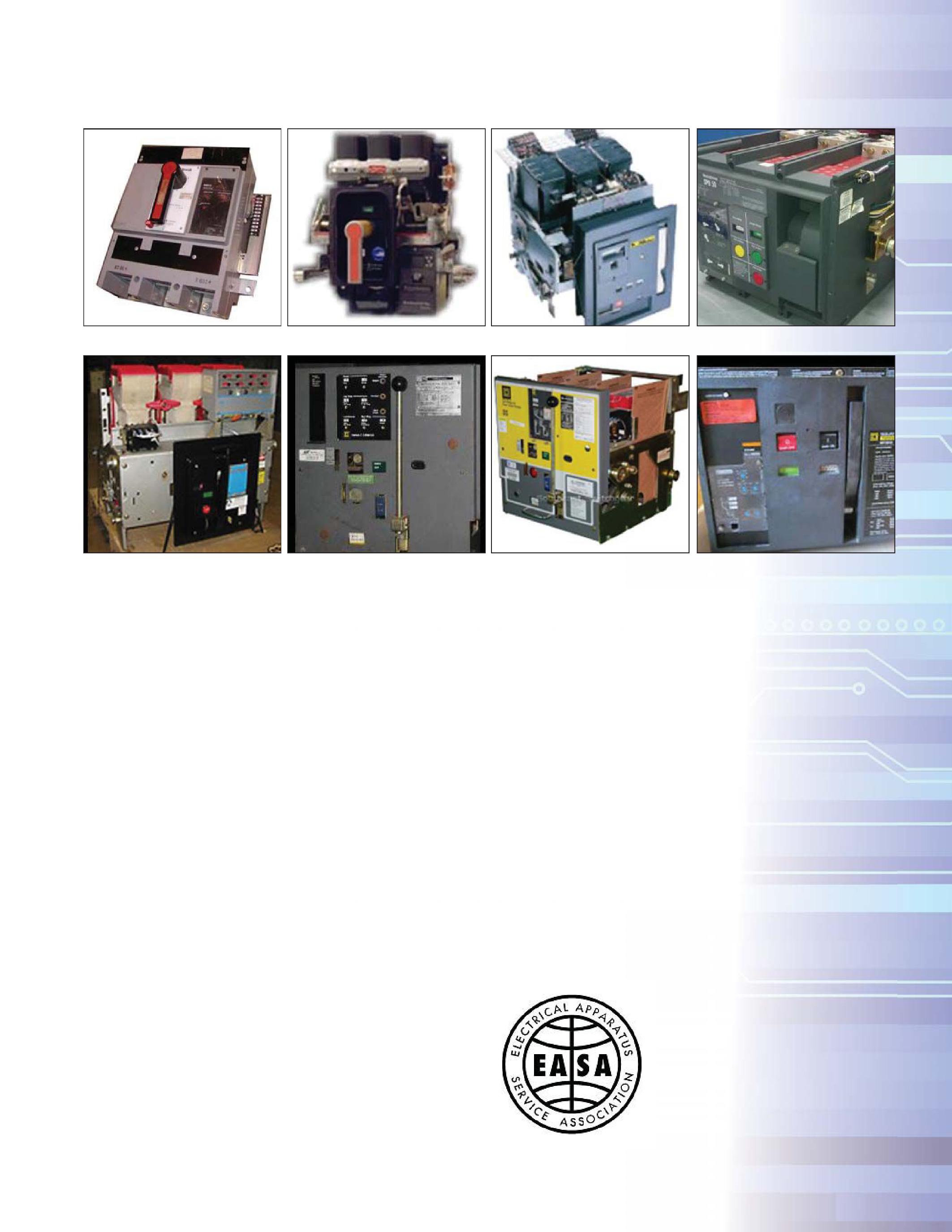
breaker, even though they may look the same. A retrofitted breaker may have a new trip unit and may be cleaned up to look new. Theremanufacturedbreakerwillhaveanew The remanufactured breaker will have a new trip unit and be cleaned up; however, it will also have new arc chutes, new finger clusters, replated current carrying surfaces, and new bearings on selected pivot points within the breaker. If the end user does not specify the extent of the remanufacturing process, he may think he is getting a remanufactured breaker, while he is really getting a retrofitted breaker. This could result in the end user not meeting expectations with respect to extending the life of his electrical equipment and resolving his equipment obsolescence issue.
REMANUFACTUREDLOW-VOLTAGEBREAKERS REMANUFACTURED LOW-VOLTAGE BREAKERS NETAWORLD 21 NICHEMARKETTESTING NICHE MARKET TESTING
GE PowerBreak
ITE/BBC/ABB K-Line
GEAK/AKR GE AK/AKR
Square D DS
GEWavePro GE WavePro
Square D DSII
Westinghouse SBD
Square D Masterpact
NICHEMARKETTESTING
MARKET TESTING
To combat this possibility, many industrial groups are developing technical standards to assist in remanufacturing equipment. For the electrical equipment, groups like PEARL and EASA are leading the way to ensure that the end users are getting what they want. These groups require certified remanufacturers to have adequate training, test equipment, documentation, and follow established best practices.
They also require that all retrofitted, refurbished/ reconditioned, and remanufactured equipment be tested for functionality and defects. From PEARL’swebsite: PEARL’s website:
“Electrical apparatus bearing a blue PEARL seal with a unique identification number means that apparatus has been fully [remanufactured] by a qualified PEARL member company following PEARL Reconditioning Standards. This guarantees that the device performs to specifications set by the OEM during original manufacture. PEARL companies may sell new, surplus, or used electrical equipment, any of which may or may not have been remanufactured based on the customer's request. This is why customers should look for product bearing PEARL seals so they know the device will operate exactly as designed, regardless of whether the device was ever previously placed into service.”
Typically, this equipment is sold and serviced by third parties, but actually carries a warranty similar to or exceeding the warranty originally provided by the OEM.
For obsolete low-voltage breakers, it is always recommended that the trip units be replaced. Technological advances have resulted in improved operability and reliability in the trip units from both third party suppliers and the OEMs. Most units have digital readouts. They include protection capabilities for LSIG and have additional protective capabilities for phase unbalance and instantaneous selectivity, which can be used in support of arc flash mitigation during the performance of maintenance. Most trip units now also have optional communication capabilities that are very useful to the end user when integrated into existing power monitoring systems.
For the environmentally conscious end users, remanufacturing in lieu of replacing with new equipment is also environmentally friendly:
“If a durable product can be made to have a longer useful life, several benefits accrue to society. The value of the labor, materials, energy, and capital equipment that goes into making the product is not prematurely discarded. The drain on human, natural, and
22 WINTER 2013
NICHE
REMANUFACTUREDLOW-VOLTAGEBREAKERS REMANUFACTURED LOW-VOLTAGE BREAKERS
technological resources is thereby reduced. The costs of solid waste disposal are reduced. Living standards can be higher for the same amountofresourceuse…Remanufacturers amount of resource use … Remanufacturers typically recoup 85% to 95% of the energy and materials in the products they rebuild. If a product with a normal lifetime of eight years can be given an additional eight-year life, the demand on energy and material resources to maintain the population of that product can be cut by 40% to 45%. The doubling of the lifetime of any durable product is likely to accomplish savings of this magnitude. [1]”
SUMMARY
Much of the installed base of low-voltage power breakers is now obsolete and, in most cases, no longer supported by the remaining OEMs. Most electrical equipment, like lowvoltage breakers, is designed for a 25-year life. Because of these realities, end users are faced with the daunting task of replacing this obsolete equipment, which can be a very expensive and disruptive proposition.
Fortunately, there is a niche of third party remanufacturers, which specialize in upgrading

existing, obsolete breakers to extend the life cycle of the equipment while maintaining the reliability and operability of the equipment. Unfortunately for the end user, not all remanufactured equipment is equal, so the end user should specify remanufacturing expectations to the supplier. Additionally, it is recommended that the remanufacturing process includes the replacement of the trip unit at a minimum. Further, all retrofitted, refurbished/ reconditioned, and remanufactured equipment should be tested for functionality and defects prior to implementation.
[1] “The Remanufacturing Industry: Anatomy of a Giant, A View of Remanufacturing in America Based on a Comprehensive Survey Across the Industry,” William Hauser, Robert T. Lund, Department of Manufacturing Engineering, Boston University, June 2003.
Lynn Hamrick brings over 25 years of working knowledge in design, permitting, construction, and startup of mechanical, electrical, and instrumentation and controls projects as well as experience in the operation and maintenance of facilities.
Lynn is a Professional Engineer, Certified Energy Manager and has a BS in Nuclear Engineering from the University of Tennessee.
NETAWORLD 23 NICHEMARKETTESTING NICHE MARKET TESTING
REMANUFACTUREDLOW-VOLTAGEBREAKERS REMANUFACTURED LOW-VOLTAGE BREAKERS





ACCURATE VACUUM MEASUREMENT IN SHOP OR FIELD
BASED ON OEM LEAK-RATE TEST DURING MANUFACTURE
PREDICTS REMAINING VACUUM INTERRUPTER LIFETIME, NOT JUST PASS-FAIL
SYSTEM DOES CALCULATIONS BASED ON MEASUREMENTS OF 3,000 VACUUM INTERRUPTERS

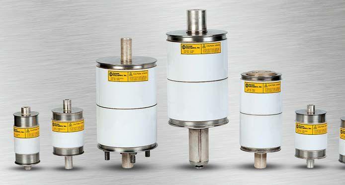

Vacuum interrupter replacements rated up to 38kV, 3000A Replacements for all major OEM interrupters, including GE, Eaton, CH, Westinghouse, ABB, Siemens,
many more Pole assemblies, parts,
design/manufacturing
vacuum
replacement
Rental vacuum breakers available
are being serviced Vacuum Interrupters, Inc. has the world’s widest selection of: 3414 MIDCOURT ROAD, #112 | CARROLLTON, TEXAS 75006 | MOBILE: 940-736-0943 | INFO @ VACUUM INTERRUPTERS INC .COM 214-442-5877 www. Vacuum Interrupters Inc .com WORLD’S FIRST PORTABLE
FOR VACUUM INTERRUPTERS
and
and components Custom
services for obsolete interrupters and breakers Field and in-shop
interrupter
services
while yours
FIELD-TESTING SYSTEM
Trust Magnetron Atmospheric Condition (MAC) testing to predict the remaining life of your vacuum interrupters LET US HELP YOU WITH YOUR VACUUM INTERRUPTER TESTING AND REPLACEMENT NEEDS MAC-TS1 & MAC-TS2 TEST SYSTEMS FROM VACUUM INTERRUPTERS, INC.
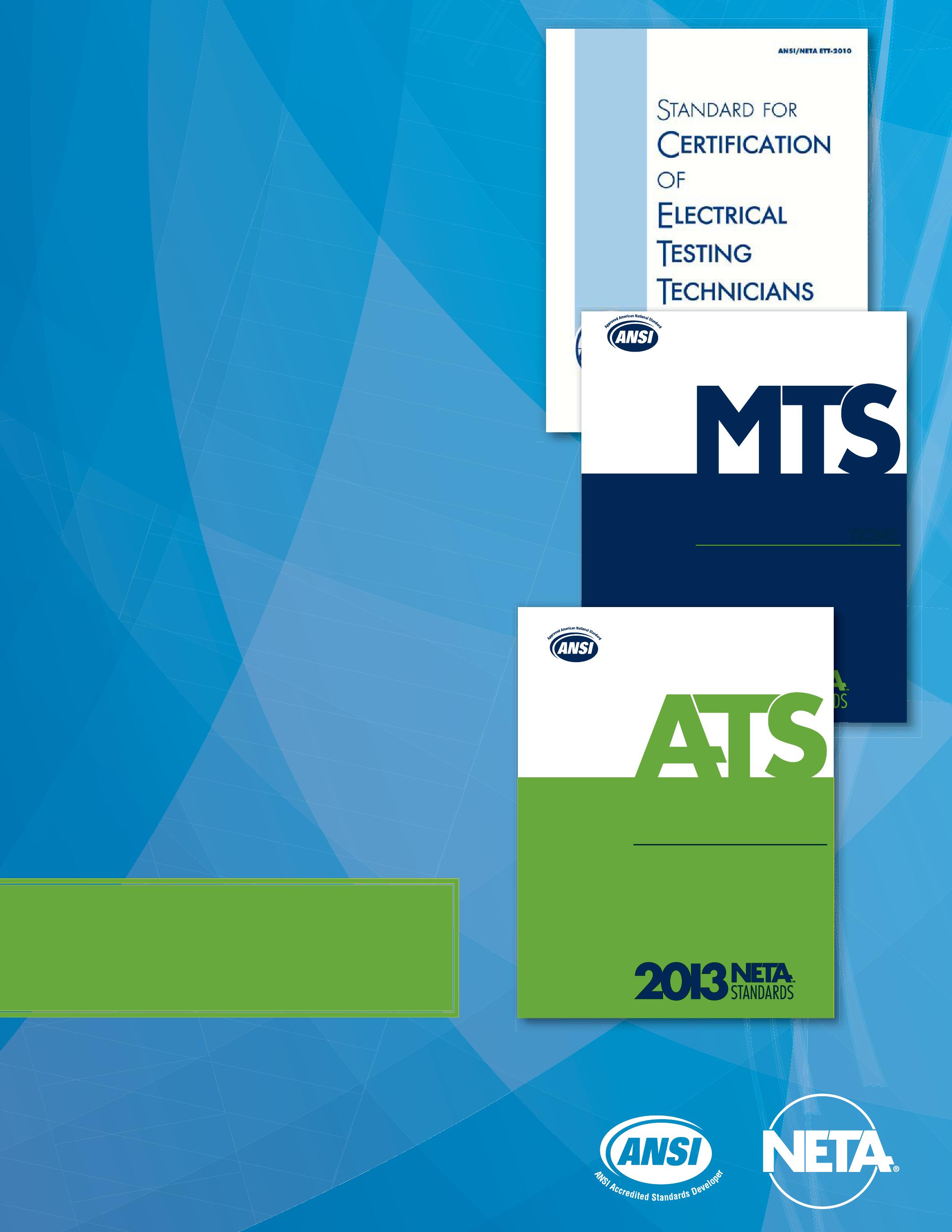
The ANSI/NETA Standards for Acceptance and Maintenance Testing Specifications for Electrical Power Equipment and Systems!
ANSI/NETA ATS-2013 - New Edition
This standard should always be referenced in design specifications or when performing acceptance testing on power system installations.
ANSI/NETA MTS-2011 -
This standard should always be referenced when writing maintenance specifications or performing routine testing on electrical power systems.
ANSI/NETA ETT-2010
This standard ensures that your acceptance and maintenance tests are being preformed by qualified technicians who are certified in accordance with ANSI/NETA ETT requirements.
Available in Bound, CD ROM, or PDF
THE “GO-TO” STANDARDS FOR ELECTRICAL SAFETY AND RELIABILITY Order Your copy of the ANSI/NETA Standards Today!
Become a NETA Alliance member and Save! To order: visit www.netaworld.org Or call 888-300-NETA (6382) ANSI/NETA MTS-2011 S T ST A N D AND A R D F O R ARD FOR MAINTENANCE AINTENANCE TESTING SPECIFIC SPECIFICATIONS F O R E L E C T R I C A L P O W E R FOR ELECTRICAL POWER E Q U I P M E N T A N D S Y S T E M S EQUIPMENT AND SYSTEMS ANSI/NETA ATS-2013 S T AND ARD FOR A C C E P T ANC E TESTING SPECIFICATIONS FOR ELECTRICAL POWER EQUIPMENT AND SYSTEMS
NETA AND UNIVERSITY CURRICULUM: ELECTRICAL TEST TECHNICIANS – FROM THE CLASSROOM TO THE FIELD
BY JILL HOWELL, NETA
I Have Some Good News… and Some More Good News!
IntheWinter2012issueof In the Winter 2012 issue of NETA World Journal ( Vol. 34, No. 4), NETA reported on the tremendous growth and change taking place in the electrical power industry and the growing shortage of trained testing technicians required to meet the immediate and escalating demand for power system engineers and field service technicians.
The good news is that acceptance and maintenance testing of electrical power systems is becoming more widely recognized as a means of reducing downtime while improving reliability

and safety. Although this places additional pressure on the existing work force, there is more good news. The industry is responding to meet the challenge. Training entities are moving quickly to expand course and curriculum offerings.
Companies like AVO Training, OMIC RON, D oble Engineering, S.D. Meyers, Shermco Industries, Magna . Electric Corporation, and many others have added courses and opened new laboratory facilities in recent months.
In addition, NETA has been actively communicating with
NETAANDUNIVERSITYCURRICULUM:ELECTRICALTEST NETA AND UNIVERSITY CURRICULUM: ELECTRICAL TEST TECHNICIANS–FROMTHECLASSROOMTOTHEFIELD TECHNICIANS – FROM THE CLASSROOM TO THE FIELD 26 WINTER 2013

universities, colleges, and vocational technical schools throughout the UnitedStatesand nited States and Canada that are asking for assistance in broadening their curriculums by adding power courses to their electrical engineering programs. NETA and two NETA Accredited Companies, Southwest Energy Systems andW and Western Electrical Services, have been working with EV IT (East Valley Institute of Technology), Mesa, Arizona, since May 2013 to develop an electrical power curriculum that offers post graduates a one-year, 600hour, electrical engineering technician program. The EV IT electrical power program willcombineasevencoursecurriculumwith will combine a seven course curriculum with hands-on laboratory training to provide instruction on the core competencies required by the L evelIINETAAssistantTechnician evel II NETA Assistant Technician examination as specified in the ANSI/NETA Standard for Certification of Electrical Testing Technicians .TheE . The EV IT electrical engineering technician program is expected to host its first students in January 2014.
The National Science Foundation recently awardedSuffolkU awarded Suffolk University, B oston, Massachusetts, a $617,751.00 grant to be used for scholarships for B ostonPublic oston Public School graduates who wish to study electrical engineering. Suffolk University will host a niversity Power Engineering Day later this year, with ay the goal of introducing high school students to careers in electrical power. NETA will participate in a planning meeting on October 4, 2013, and discuss the opportunity for Suffolk University to incorporate the aforementioned niversity electrical testing technician program into itscurriculum. its curriculum.
As 2014 unfolds, NETA will continue to look for opportunities to work with academic institutions to expand their power curriculums, to promote testing to the ANSI/NETA Standards, and to fill the growing demand for trained testing technicians needed for a future of electrical power reliability and safety.
Keeping the Winds of Change to Our Back.
The electrical power industry is in the midst of tremendous growth and change. Along with it, many experienced technicians and industry professionals are retiring. This threatens to create a challenging shortage of talent, knowledge, and experience. All of these factors point to a greater need for industry professionals to collaborate and organize to share knowledge, experiences, and resources. The strength of the electrical power industry’s future is dependent on the industry’s collective ability to produce the needed manpower, respond so that historical knowledge is assimilated with new ideas, and improve safety and reliability in the years ahead.
Growth: “Electricity usage in the United States is projected to grow more than twice as fast as committed resources over the next 10 years. Unless additional resources are brought into service, some areas could fall below their target capacity margins within two or three years. In parts of Western Canada, demand is projected to outpace resource growth within about two years. We are at the stage where emergency situations are becoming more frequent,” said Rick Sergel, president and CEO of NERC.(1)
Change: Wind, solar, and nuclear generation are an important part of the electrical power industry’s future. Today’s power systems require collaboration between veteran technicians with historical experience and new technicians, educated in alternative technologies to address the challenge of reliably integrating remotely located wind, solar and nuclear resources into the bulk power system.(1)
Additionally in the industrial sector, thousands of electrical power systems that have been in place for 20-30 years are in desperate need of maintenance and/or replacement all while new systems are being installed at an accelerated rate. Now more than ever before, industry professionals rely on continuing education programs, technical conferences, training organizations, and professional networks to keep them current with today’s technology and practices in order to obtain the answers and experience required to service both the old and the new electrical power systems in place today.
(1) Excerpt from: Keeping the Winds of Change to our Back, NETA World Journal, Winter 2012, page 18, by Jill Howell, NETA
NETAWORLD 27 NETAANDUNIVERSITYCURRICULUM:ELECTRICALTEST NETA AND UNIVERSITY CURRICULUM: ELECTRICAL TEST TECHNICIANS–FROMTHECLASSROOMTOTHEFIELD TECHNICIANS – FROM THE CLASSROOM TO THE FIELD












BEST PRACTICES FOR IMPACT BUMP TESTING
BY VICKI WARREN AND JOHN LETAL, Iris Power LP.
Common off-line tests of stator windings, insulation resistance with polarization index (lR/PI), dc high-potential, partial discharge (PD), power factor, etc. overlook one large aspect of the stator winding: the overhang winding from the slot exit to the end caps or the stator endwinding.
Because stator endwinding problems are a result of excessive motion, common off-line electrical tests are not suitable for evaluation, and vibration testing on the bearings and shaft are not usually sensitive to problems in the stator endwinding area. As machines age, the endwinding support materials loosen resulting in components being more prone to vibration problems. In extreme cases the endwinding support structure may be in a resonant condition resulting in excessive vibration amplitudes that can be catastrophic if left uncorrected and fail. This is unfortunate, since most endwinding problems can be identified early and using nonintrusive measures canbecorrected. can be corrected.
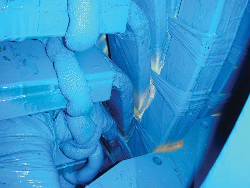
Determining which stator endwindings may beatriskofdeteriorationduetovibrationcan be at risk of deterioration due to vibration can be assessed with impact (or bump) and modal testing. The goal is to establish the endwinding structure natural frequencies and determine if they may be resonant during operation causing amplified vibration levels. This amplification can result in insulation fretting (as shown on the right), greasing, high cycle copper conductor fatigue, series connection failure (see Figure 1).
DEFINITIONS
component vibrates
structure will vibrate if deflected and then let go
of the electromechanical forces of a generator determined by power frequency and rotational speed; vibration of a generator will tend to be at frequencies related to these
forcing frequencies of the generator influence the natural frequency of the endwinding structure
known force
the frequency response (rate of vibration) during operation or due to a force hammer
PART 1 – TEST PREPARATION Theory
The main forces on a generator stator endwinding are primarily due to the electromagnetic forces at twice line frequency (120 Hz in
30 WINTER 2013 BEST PRACTICES FOR STATOR ENDWINDING IMPACT BUMP TESTING TESTINGROTATINGMACHINERY TESTING ROTATING MACHINERY
North America) as well as the rotational force at turning speed (60 Hz for two-pole machines, 30 Hz for four-pole machine, etc, in North America). These generally act in the radial direction due to the rotor pull on the stator and between the top and bottom bars in the winding. Additionally, there are smaller components in the tangential direction which is the result of the force between two adjacent bars circumferentially around the endwinding.
If the natural frequencies of the endwinding identified during impact testing correlate with these operational forces, then the online response will resonate, or reach what is called resonant condition. Depending on the sensitivity (or amplification factor), these vibration levels can be devastating and cause rapid deterioration of the endwinding support and the windings themselves.
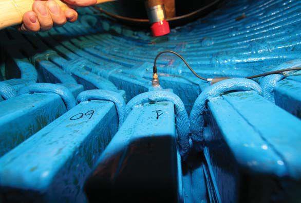
To excite the natural frequencies of a stator endwinding when the machine is off-line the field technician/engineer can strike the


structurewithacalibratedforceandmeasure structure with a calibrated force and measure the resulting response. Many tools are readily available for these tests, but important factors needtobeconsidered. need to be considered.


BEST PRACTICES FOR STATOR ENDWINDING IMPACT BUMP TESTING NETAWORLD 31 TESTINGROTATINGMACHINERY TESTING ROTATING MACHINERY
Equipment
Figure 1: Insulation Fretting
Figure 2: Force Hammer – Impact Test Setup

ForceHammer Force Hammer
Aforcehammerisusedtoexcitethestator A force hammer is used to excite the stator windings so the measured response in acceleration can be compared. The advantages of using a force hammer are the speed of testing, ease of setup, portability, and cost. These factors make a force hammer highly suitable for field workwhereasashakerismoresuitableforlab work whereas a shaker is more suitable for lab testing. This is a comparison, manual test so repeatable hammer strikes are required. This can be achieved by ensuring to strike with the entire hammer tip surface (for an even strike), avoiding double impacts (for one strike), and ensuring enough energy is generated to excite the structure (for a solid strike). An experienced field technician/engineer will have a calibrated swing resulting in excellent repeatability –solid, single, even strikes.


A precaution when using a force hammer is toavoid to avoid driving the system by overexciting or impacting too hard. This can result in frequency shifts. The aim of impact testing is to measure the natural frequencies of the endwinding structure itself and any changes in dynamics due to improper test procedures will result in inaccuracy.
Accelerometer
Anaccelerometerisusedtomeasurethe An accelerometer is used to measure the response due to the excitation by the force hammer. Locations with higher acceleration response due to the same force can be expected to vibrate at higher amplitudes during operation. Considerations when selecting a sensor for this testing are type, axis, and mounting.
Type
Conventional piezoelectric accelerometers are suitable for this testing as the machine is off-line and there is no risk of compromising electrical clearances with metallic components in a high voltage area that is found during machine operation. The frequency range of the accelerometer is governed by the natural frequency of the sensor itself. Generally, the smaller the physical size of the sensor the higher the natural frequency. Considering we
are locating frequencies in the few hundred Hz range, general purpose accelerometers with maximum frequency ranges of a few kHz or more are suitable and readily available.
Axis
Single axis accelerometers are easier to work with, but triaxial accelerometers provide more information by collecting data in 3 directions simultaneously. Because we are interested in natural frequencies in the radial and tangential directions in stator endwindings this decision becomes a balance of time (more time with single axis) and bookkeeping (more data with triaxial).
Mounting

Poor mounting techniques of the accelerometer can result in poor results. The main requirement is for close mechanical contact between the accelerometer and the surface to which it is being attached. This will ensure the excitation forces are completely transmitted from the component surface to the accelerometer. Additionally the response from the accelerometer’s natural frequency should not be measured within the endwinding structure natural frequency range. The type of sensor mount affects the accelerometer’s natural frequency. The more rigid (stiff) the mount, the closer the measured natural frequency will be to the accelerometer’s calibrated value. This can be achieved by stud or cement mounting; however, general purpose accelerometers typically have a natural frequency in the 5-10 kHz which far exceeds the frequency range of interest for stator endwinding impact testing. With this in mind, a more practical mount for stator endwinding testing is beeswax. Even though wax results in a reduced usable frequency range the frequencies we are interested in are in the few hundred Hz range and still well within the usable range of a waxmounted, general purpose accelerometer. Wax provides a quick mount on a variety of surfaces. The cleaner the surface the better the wax will stick. The only other consideration is at higher temperatures (>100°F) the wax can become soft and not stick.
32 WINTER 2013 TESTINGROTATINGMACHINERY TESTING ROTATING MACHINERY
BEST PRACTICES FOR STATOR ENDWINDING IMPACT BUMP TESTING

SUMMARY
Impact testing is an off-line test that can be used to assess whether stator endwindings are likely to vibrate in resonance with operational forces. When performing any off-line test on electrical machinery, it is important to choose the right tools for the job. For impact testing, a calibratedforcehammerisusedtomeasurethe calibrated force hammer is used to measure the excitation input and an accelerometer is used to measure the response output. Appropriate practices should be implemented when collecting data. Garbage in = garbage out. Avoid frequency shifts from mounting errors to ensure good correlation between the force hammerandtheaccelerometer. hammer and the accelerometer.
Part 2 of this article will discuss test setups and interpretation of impact testing on stator endwindings.
ABOUT THE AUTHORS
John Letal is a rotating machines engineer at Iris Power responsible for supporting rotating machine mechanical monitoring initiatives including stator endwinding vibration. Prior to Iris, he spent most of his career as a field service engineer troubleshooting large rotating equipment using such tools as vibration analysis, force response measurements, and modal analysis. He was also involved in the implementation and execution of vibration analysis programs. John holds a Bachelor of Science degree in Manufacturing Engineering from the University of Calgary and is registered as a professional engineer.
Vicki Warren, Senior Product Engineer, IrisPowerLP.Vickiisanelectrical Iris Power LP. Vicki is an electrical engineer with extensive experience in testing and maintenance of motor and generator windings. Prior to joining Iris in 1996, she worked for the U.S. Army Corps of Engineers for 13 years. While with the Corps, she was responsible for the testing and maintenance of hydrogenerator windings, switchgear, transformers, protection and control devices, development of SCADA software, and the installation of local area networks. At Iris, Vicki has been involved in using partial discharge testing to evaluate the condition of insulation systems used in medium- to high-voltage rotating machines, switchgear and transformers. Additionally, she has worked extensively in the development and design
TESTINGROTATINGMACHINERY TESTING ROTATING MACHINERY NETAWORLD 33
BESTPRACTICESFORSTATORENDWINDINGIMP BEST PRACTICES FOR STATOR ENDWINDING IMPACTBUMPTESTING ACT BUMP TESTING
the test equipment answer
Test Equipment
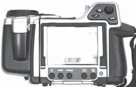

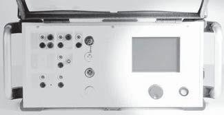


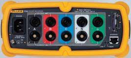


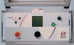


T 972.317.0479 | www.intellirentco.com | contact us at info@intellirentco.com
Rental
1000 New Durham Road Edison, New Jersey 08817 sales@dranetz.com www.dranetz.com Company 1.800.372.6832 A Solve your Power Quality and Energy Management puzzles with Dranetz Technologies. Dranetz Is Your Missing Piece! NETA-Accredited Company 1.877.425.3885 | www.powerte.com POWER TESTING AND ENERGIZATION can provide you with acceptance and maintenance testing of electrical system equipment, 480 V through 500 kV, helping to ensure the continued operation, reliability and integrity of your electrical system. Nationwide Services Include: » Commissioning Electrical Systems » Acceptance & Maintenance Testing » Protective Relay Systems » Troubleshooting & Repairs » Electrical Equipment Upgrades » NERC Compliance Support » Short Circuit / Coordination / Arc Flash Studies
Safety / Commissioning / Operation & Maintenance Program Development
Online Partial Discharge Testing
»
»
MAGNA ELECTRIC CORPORATION (MEC) ANNOUNCES EDMONTON EXPANSION




The staff at the Edmonton, Alberta office of MEC stands ready to serve!
With existing offices in Saskatoon, Regina, Winnipeg and Calgary, MEC is excited to announce its expansion in the Northern Alberta market with the opening of the Edmonton Operations office. The office officially opened for business July 8, 2013, and is fully functional to support our customer’s needs.
MEC recognizes that Northern Alberta’s robust market is a place where it needed to expand its footprint. Being situated in Edmonton will only strengthen service abilitieswithcurrentandfuturecustomers.This abilities with current and future customers. This expansion shows MEC’s dedication to the industrial and utility sectors along with the city of Edmonton and province of Alberta.
Handling the operational duties are three individuals with over 100 years of electrical industry experience in the Edmonton area. This market knowledge, combined
with their key industry contacts, makes them an ideal trio to support MEC’s growth strategy. Please feel free to reach out to them as they will be more than willing to assist you.
ABOUT MEC
Witha With a One Source, One Solution approach to its customers, MEC provides industrial and utility power system solutions. Services include engineering, field services, and training focusing on the oil and gas, mining and utility sectors.
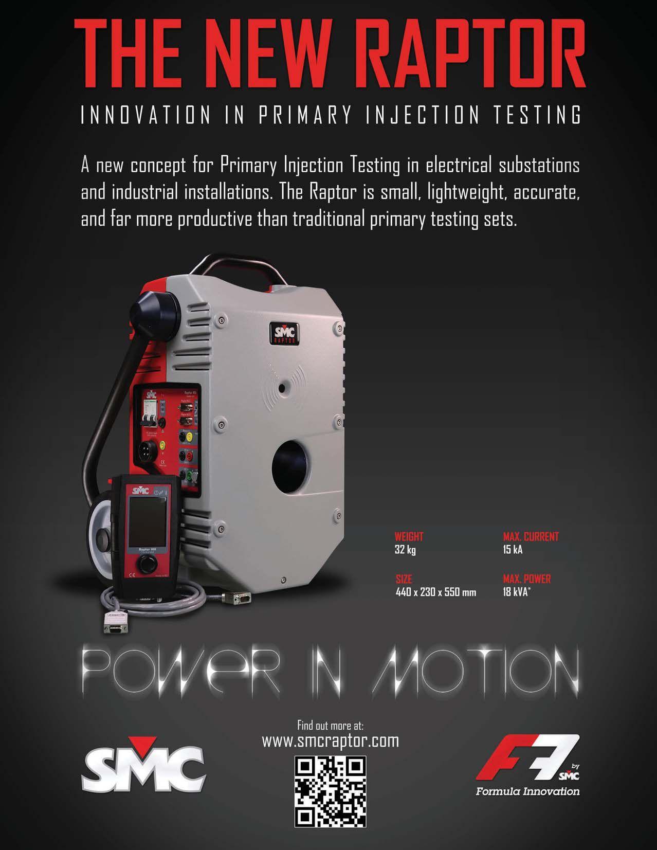


METHODS TO LIMIT ARC-FLASH ON LOW -VOL TAGE SYSTEMS
BY SCOTT BLIZARD, American Electrical Testing Co.
As the electrical industry addresses arc-flash safety concerns, the industry is realizing the high risks associated with what used to be normal maintenance tasks. In many cases, the excessively high arc-flash incident energies make it so all maintenance must be done with equipment deenergized, which is not always feasible. The methods discussed below
will address several ways to significantly lower arc-flash incident energy exposure by new system design and products, retrofits, equipment modifications, and alternate protection settings, etc. In most cases, NFPA 70E-2012 Hazard Risk Category 2 or lower canbeobtained. can be obtained.
One of the best and most efficient ways to lower the incident energy, which inherently lowers the Hazard Risk Category of electrical equipment, is to clear the fault quicker by making the protective device trip faster. Some of the methods to reduce the clearing time of an electrical fault using various protective devicesandschemesaredescribedbelow: devices and schemes are described below:
Implementation of a bus differential scheme increases the speed to trip the circuit which will reduce the arc-flash hazards. The concept

of bus differential protection (87B) scheme has been around for a very long time. Because of the space and cost constraints, it was typically only used for high-voltage or medium-voltage applications. The scheme measures 100 percent of the current into and out of a bus. It requires three additional current transformers on every breaker. Simply put:
IN =100%I = 100% IOUT, then do not trip.
IN ≠100%I ≠ 100% IOUT, then trip all bus breakers instantaneously.
Zone selective interlocking (ZSI) improves the level of protection in a power distribution system. ZSI is a control logic system communicating between feeder breakers and upstream feeder breakers or the main breaker. The main breaker is zone 1 and subsequent
38 WINTER 2013 SAFETYCORNER SAFETY CORNER
RNER N R E R
METHODSTOLIMITARC-FLASHEXPOSUREONLOW-VOLTAGESYSTEMS METHODS TO LIMIT ARC-FLASH EXPOSURE ON LOW-VOLTAGE SYSTEMS
downstreambreakersestablishoneormore downstream breakers establish one or more additional zones. The control system is built into the electronic and digital trip units of low-voltage breakers. Its design functionality and use have grown over the last 20+ years. Assuming a high level short circuit occurs on the load side of a feeder breaker, digital trip units on the main breaker and the feeder breakersensethefault.Thefeederbreaker breaker sense the fault. The feeder breaker sends a blocking signal to the main breaker letting it know that the fault is in the feeder breaker’s zone of protection or in a lower zone. The blocking signal tells the main breaker to delay tripping per the trip unit’s time delayed settings (backup to the feeder breakers) while the feeder breaker trips with no intentional delay.
When a fault occurs in the switchgear on a primary side of a feeder breaker, no blocking signal is sent to the main breaker. Since the mainbreakersensesthefaultbutdoesnot main breaker senses the fault but does not receive a blocking signal, its control logic bypasses the short time or ground fault time delay setting characteristics and trips almost instantly as described for the feeder breaker in the paragraph above. It lowers its time delay settings to approximately two cycles, just enough time delay to assure nuisance tripping doesnotoccur. does not occur.
When applying ZSI, as an arc-flash solution, one must be aware of the following:
1. It is automatic - no special precautions are required.
2. It only affects the short time delay and ground fault time delay setting characteristics.
3. The arcing fault current must be above the short time pickup settings or ground fault pickup settings for ZSI to be initiated and to reduce the arc-flash incident energy.
4. It adds two to three cycles maximum to the breaker clearing time of three cycles compared to an instantaneous trip resulting in five to six cycles total clearing time (83 ms – 100 ms).

5. It requires slightly different breaker testing procedures during maintenance testing and calibration to prove the integrity of the system.
A very effective way to lower arc-flash incident energy is to apply a maintenance switch. This option can be retrofitted or purchased new in low-voltage and medium-voltage protective devices. An external override switch and circuitry are connected to a breaker’s trip unit and is adjustable between 2.5X - 10X the breaker rating. The basic operation of the maintenance switch is to lower incident energy at downstream protective devices. When performing maintenance, the maintenance switch is closed. This automatically
NETAWORLD 39 SAFETYCORNER SAFETY CORNER
METHODSTOLIMITARC-FLASHEXPOSUREONLOW-VOLTAGESYSTEMS METHODS TO LIMIT ARC-FLASH EXPOSURE ON LOW-VOLTAGE SYSTEMS
SAFETYCORNER

overrides all of the breaker’s delay functions and causes the breaker to trip without any intentional delay when a fault is detected. Upon completion of the maintenance, the maintenance switch is manually opened and all previous trip unit settings are again reactivated without need forrecalibration. for recalibration.
Another method of reducing arc-flash incident energy is arc-detection sensors which provide a visual measurement of an arc flash. The light emitted during an arc flash event is significantly brighter than the normal substation light background. The light surge is available from the initiation of the arc flash and is easily detected using proven technology.
The most common sensors are lens point sensors and bare fiber optic sensors. The light ischanneledfromthesensortothedetector is channeled from the sensor to the detector located in the protective relay. Monitoring of the system integrity is accomplished using a fiber optic loop. In the case of the lens sensors, each lens has an input and output connection. The input is connected to a transmitter in the relay, and the output is connected to a detector in the relay. This loop connection allows periodic testing of the system by injecting light from the transmitter through the loop and back to the detector. This loop connection system works witheitherthelenssensororthebarefiber with either the lens sensor or the bare fiber sensor. The bare fiber sensor consists of a high quality plastic fiber optic cable without a jacket. The clear fiber cable becomes a lens, bringing in light from the area. Using a bare fiber sensor makes detection in large areas possible using only one sensor. The cable is constructed of a one millimeter plastic material that can withstand a 25 millimeter bending radius without damage. The cable can be cut to length in the field and fit to the application without excess cable.
Arc detection systems typically use a combinationoflensandbarefibersensors combination of lens and bare fiber sensors returning to a single relay. Proper installation of the sensors and relays provides logical detection and trip points in any system. Sensors should be located where arc detection for the specific
sensor will trip the corresponding upstream circuit breaker. Using more than one sensor provides 100 percent coverage even during one millisecond testing intervals. Installation of sensors varies depending on the switchgear manufacturer, type of gear, and number of sections. Multiple sensor inputs provide coverage and sectioning options. One bare fiber sensor can provide excellent coverage of the entire bus section. Using lens sensors allows better control in small, confined spaces.
One obstacle in using light sensors is the need to measure and adjust for changing ambient light levels. Measuring light and current in the protective relay can make use of the analog measurements and event reporting capabilities in the relay. By monitoring the incoming light as an analog signal, the user is able to view and set the normal light levels for the application. The event reporting also provides a troubleshooting tool with time-tagged events including arc-sensor light levels. Tracking the arc light intensity provides the detail needed toreachtherootcauseofanevent.Theadded to reach the root cause of an event. The added advantage of processing the arc-flash detection in the protective relay is the ability to use a true overcurrent measurement as a supervising element to improve security.
In order to reach the fastest trip times, some arc-detection systems use a current setting level below the normal expected load to enable the arc-flash detector as the trip mechanism. Using current in this manner removes any time lag determining if a fault exists but sacrifices selectivity and makes the system dependent on light detection alone. Superior security can be obtained using a high speed overcurrent element in conjunction with the light sensor without sacrificing trip speeds.
In the system presented above, a true high speed overcurrent element is used in parallel withthearc-flashdetector.Thecurrentusedto with the arc-flash detector. The current used to trigger a trip is derived by sampling the feeder current and using a fast detection algorithm to signal that a fault has occurred. This fault is
40 WINTER 2013 METHODSTOLIMITARC-FLASHEXPOSUREONLOW-VOLTAGESYSTEMS METHODS TO LIMIT ARC-FLASH EXPOSURE ON LOW-VOLTAGE SYSTEMS
SAFETY CORNER
then compared with the trip levels of the arcdetectionsensorstodetermineifanarc-flash detection sensors to determine if an arc-flash trip is warranted. Many standard overcurrent elements have response times between six and 20 milliseconds. This delay is unacceptable for arc-flash detection supervision. To avoid introducing additional delay, the high-speed overcurrent protection must act as quickly asthearcdetection.Thecombinationoffast as the arc detection. The combination of fast overcurrent and flash detection must be present at the same instant; the combined security is much higher than either system alone. Adding arc-flash sensors reduces the total fault clearing time.Thetimereductionhasadramaticeffect time. The time reduction has a dramatic effect on arc-flash energy.
These are just some of the methods being used today to reduce arc-flash energy in electrical switchgear. Compliance with arc-flash hazard work rules, as defined by OSHA, NFPA 70E (Standard for Electrical Safety in the Workplace)
and NFPA 70, (NationalElectricalCode National Electrical Code) requires evaluation of arc-flash hazards and subsequent posting of the hazard on electrical equipment. All of the methods described above require the electrical system to be maintained to assure proper operation. It is always best to work on de-energized equipment when possible. When you must work on energized equipment, make sure you wear the appropriate personal protective equipment to perform the task.

ScottBlizard Scott Blizard hasbeentheVicePresident has been the Vice President and Chief Operating Officer of American Electrical Testing Co., Inc. since 2000. During his tenure, Scott acted as the Corporate Safety Officer for nine years. In addition, he has over 25 years of experience in the field as a master electrician, journeyman, wireman. Scott isaNETALevelIVSeniorTechnician. is a NETA Level IV Senior Technician.
NETAWORLD 41 SAFETYCORNER SAFETY CORNER METHODSTOLIMITARC-FLASHEXPOSUREONLOW-VOLTAGESYSTEMS METHODS TO LIMIT ARC-FLASH EXPOSURE ON LOW-VOLTAGE SYSTEMS


SE Replacement Charging Handles

Use your smart phone with the CBAnalyzer ™ app to test your circuit breakers. Tests can be performed without removing the breaker from the cubicle and without any electrical connections. Operate the breaker in any sequence you desire: for example, trip – charge – close. The vibration data created by the breaker operation is captured and can be analyzed on your smart phone or transferred to your online CBAnalyzer Account Manager for storage and further analysis, including comparing the results with a known good breaker profile.
There’s an App for that! EMAIL info@CBAnalyzer.com 972-290-0074 CircuitBreakerAnalyzer.com
Ampteks, Inc., Northern California's premier facility dedicated to the service, repair, and tes olt e cir eakers is pleased t er eplacement char e D SE frame cir eakers. 265 RICKENBACKER CIRCLE, LIVERMORE, CA 94551 PHONE: 925-493-7150 FAX: 925-493-7151 email: mclark@ampteks.com f om/ampteks orks 3D CAD In stock, ships same day Improv v


SPECIALCONSIDERATIONSFOR SPECIAL CONSIDERATIONS


FOR GROUNDING

LIGHTNING


 BY JEFF JOWETT, Megger


It is well known that lightning strokes are a major threat to the function and integrity of electrical systems (Fig. 1), and are not limited just to the hazards of electrocution and the ignition of building fires. To varying degree depending on locale, all electrical plants must be actively protected from lightning strokes.
Merely counting on the oft-quoted chance that lightning won’t strike is foolhardy, as the threat is not confined to the area directly hit but is spread for miles over the electrical grid. A nearby hit can produce magnetic induction or capacitive coupling that drive large voltage impulses. Capacitive coupling can also be produced by cloud-charge buildup. Thirdly, ringing phenomena can occur in a tuned cable picking up similar frequencies from the radiatedstroke. radiated stroke.



Benjamin Franklin invented the lightning rod in 1749, and since that time most lightning protection systems have been made up of the Franklin air terminal, Faraday Cage (vertical and horizontal conductors), or combinations of both (Fig. 2). As would be expected, recent times have seen the introduction of new, less passive technologies, including active and dissipative air terminals. But regardless of the technology employed, all must rely on the grounding electrode to effectively dissipate lightning energy into the earth. A lightning protection system cannot function properly without a good ground. To be fully effective, a grounding system must provide a low impedance and not just a low resistance. To understand why, an examination of the nature of a lightning stroke isinorder. is in order.
SPECIALCONSIDERATIONSFORLIGHTNINGGROUNDING SPECIAL CONSIDERATIONS FOR LIGHTNING GROUNDING TECHTIPS TECH TIPS 44 WINTER 2013
Figure 1: Lightning strokes cause extensive damage to electrical systems.
R O F S N O I T AT R E D I S N O C L A I C E P S
A lightning stroke is comprised of both highand low-frequency components, with the wave shape of the impulse characterized by a steep rise in both voltage and current followed by a long trailer of excess current (Fig. 3). Typical rise times vary between one to ten microseconds (μs) for the first stroke and 0.1 to 1 μs subsequently. The high-frequency component occurs in the fastrising front while the long, high- energy trailer comprises the low frequency. The steep rise in current makes the inductance of the grounding system an important consideration. The voltage rise ground potential rise or GPR) is dependent onboththeresistanceandinductanceofthe on both the resistance and inductance of the system and is expressed by the formula:
V = iR + L(di/dt)
…where L is the inductance in microhenrys and di/dt is the current rate to peak in kiloamperes per μs.
The threat here is the real possibility of the voltage reaching such a level as to produce flashover, arcing to adjacent metallic conductors. This in turn can have the effect of redirecting the energy of the lightning stroke into the electrical system rather than away from it. The injection point can reach hundreds of thousands of volts, and even go into the megavolt range! The inductance combined with the rapid rate of current is the prime factor responsible for such voltage rise and necessitates a low-impedance grounding system. The goal of system design, then, is to minimize

potential rise in the surrounding earth while maximizing the rate of fall from the injection point. Equipotential bonding is used throughout the facility in order to eliminate damage from differential ground potentials. Accordingly, the National Electric Code® (NEC®) requires that all systems, such as power, telephone and lightning protection, be bonded together.
So it can be seen that simply driving a ground rod may not be sufficient. It is not uncommon for ground rods to be blown out of the earth by lightning strokes. In addition, even complex subterranean grids can be significantly damaged, out of sight and out of mind. Robust construction from the proper materials is the order of the day. Inductance and skin effects are important considerations in the selection of conductors and connectors and in design. Skin effect is the tendency for alternating current at high frequency to flow with maximum density near the surface and to diminish with depth in the conductor. This effectively reduces the cross sectionoftheconductorandincreasesresistance. section of the conductor and increases resistance. One recommended remedy is to install radials of wire or flat strip, proven effective in reducing GPR and directing lightning energy away from the injection point. This construction can be further enhanced by adding short radials from each main radial, typically at a 45° angle from the main radial and pointing away from the injection point. The radials may also be embedded in ground enhancement material such as bentonite. Length of radial is governed
NETAWORLD 45 SPECIALCONSIDERATIONSFORLIGHTNINGGROUNDING SPECIAL CONSIDERATIONS FOR LIGHTNING GROUNDING TECHTIPS TECH TIPS
Figure 2: Typical lightning protection design.
by a law of diminishing returns so that the effectiveness is limited to about 50 to 75 feet, after which it drops off. Exothermic welds provide the recommended connections in that they afford the lowest inductance path while maintaining reliability and corrosion resistance.
Soil resistivity is an important element in ground design. Resistance to remote earth is directly proportional to soil resistivity. Resistance to remoteearthisthetermusedtodescribethe remote earth is the term used to describe the resistance relationship between the buried electrode (single rod or complex system) and the surrounding soil. The expression, remote earth, seen commonly in the literature means a distance great enough to have overcome the effect of the immediate environment, where earth has become spacious enough to contribute noadditionalmeasurableresistance.Soil no additional measurable resistance. Soil resistivity is a measure of the conductivity of the soil, its ability to conduct electric current. It is dependent on the structure of the local soil itself, independent of buried electrodes. Resistivity is most commonly measured by the Wenner method, where four equidistantly spaced test probes from a ground resistance tester are driven into the ground, a measurement taken, and a simple formula applied that converts the reading toavolumetricmeasurement. to a volumetric measurement.1 Thenwhat? Then what?
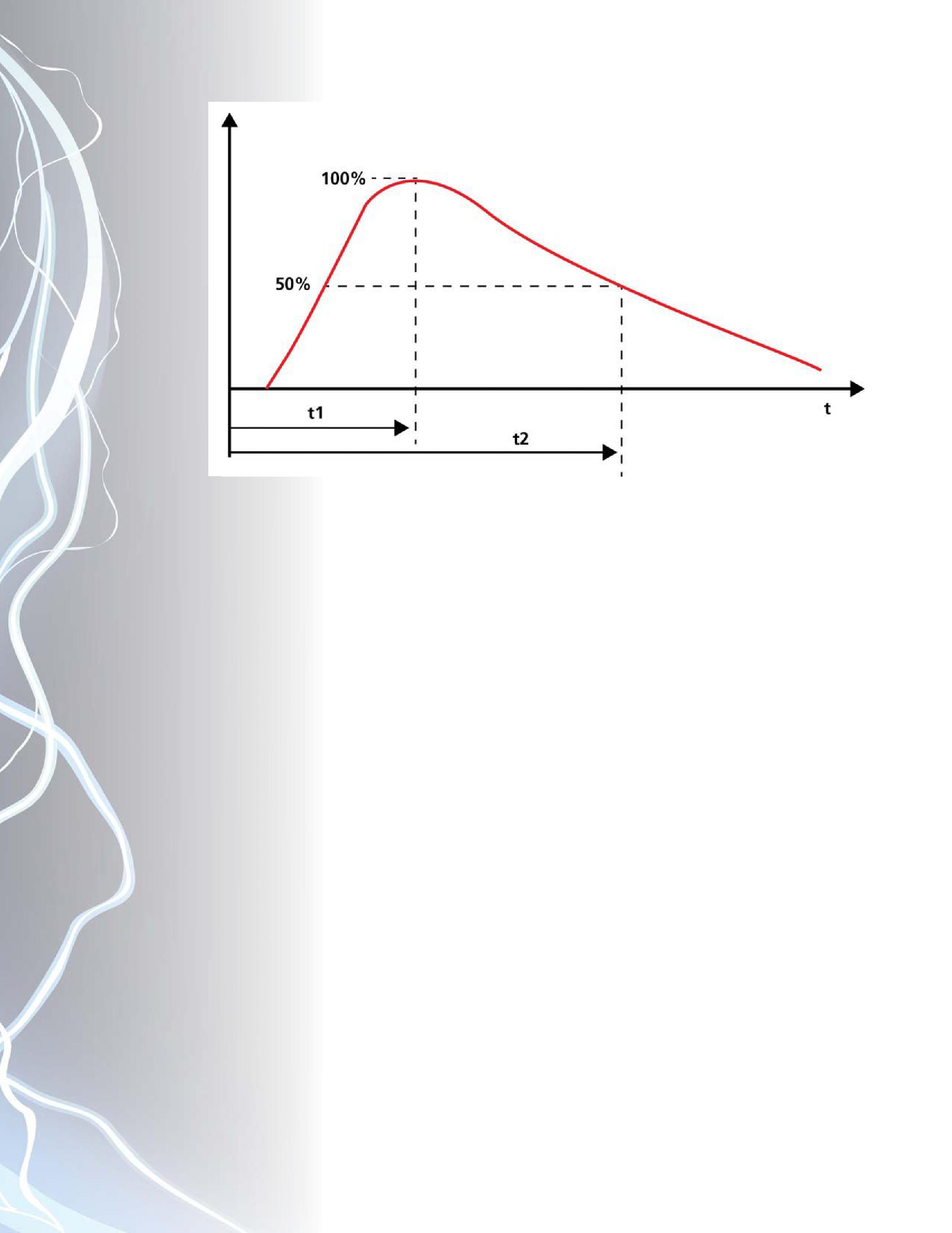
Resistancetoremoteearthisavaluabletestand Resistance to remote earth is a valuable test and must be part of a grounding system’s installation and maintenance testing. Grounding systems are involved with a lot more than just lightning protection. But resistance measurement doesn’t provide a complete assessment of a grounding system’s true effectiveness under the impulse conditions of a lightning stroke. Ground resistance testers normally operate at a frequency of a hundred or so hertz. This is to simulate performance as defined by the power grid, with exact frequencies chosen just a bit off of harmonic frequencies (120, 240, etc.) so as to provide the tester with a clear signal. This is a good design for assessing the electrode against most of its duties. However, testing at low frequency does not indicate true surge impedance. For openers, establishing a low resistance provides a valuable first step, but not necessarily the end of the process. A useful industry standard is five ohms to remote earth.2 Then, soil resistivity measurements can be used to implement an effective design.
The upper layer of soil is most important in lightning dissipation, and if it is poorly conductive, knowledge of soil conductivity aids the designer in applying what is known about conductors and electrodes. For poorly
46 WINTER 2013 TECHTIPS TECH TIPS
SPECIALCONSIDERATIONSFORLIGHTNINGGROUNDING SPECIAL CONSIDERATIONS FOR LIGHTNING GROUNDING
Figure 3: Wave shape of typical lightning stroke.

conductive upper layers, larger radial wire or strips will reduce the inductance between ground rods. Spacing between rods is decreased. These adjustments are made to accommodate the reduced capacity of poorly conductive soil to shunt radial inductance. High resistivity promotes a high concentration of charge in thefieldaroundtheelectrode.Thisinturn the field around the electrode. This in turn can lead to arcing in the soil, a condition that promotes both high-frequency ringing in the supposedly protected electrical system and in nearby systems. Effective separation distances can be calculated using a value of 0.5 kV/cm forthesoilbreakdownmechanism. for the soil breakdown mechanism.3 The high temperature of an arc can fuse minerals in the soil into glass formations called fulgurites. The material of fulgurites is not conductive and can act as an insulator around the grounding electrode, effectively defeating its function.
It is unwise to be cavalier about lightning protection. The popular line “…about as much chance as getting hit by lightning” does not apply! Fatalities in the continental US for the period 1990 to 2003 were reported as 759, or about 54 per year (Alaska and Rhode I. had none; Florida hadmorethandoublethenextnearestwith had more than double the next nearest with 126!).4 The US Lightning Detection Network reports about 20 million flashes annually.5 Damage is variously estimated at $70 million by the US National Weather Service5 while the National Lightning Safety Institute includes further damage by brushfires, power losses, and the like in their figure of $10 billion.5 Damage results from heat, electromagnetic fields, voltage differentials, and mechanical forces. Average stroke current is 30 kA, and some have been measured over 100 kA. Temperature is typically 50,000°F, or five times that of the sun!6 Much of the ensuing damage can be attributed to insufficient strike protection. A combination of design and testing are recommended in order
to assure a fully protective grounding system. The design phase should include resistivity measurements and the inclusion of appropriately robust and up-sized construction materials in accordance with industry best practices. Strong, effective bonding to create an equipotential plane is essential. The inclusion of transient voltage surge suppression protection provides an additional safeguard against ringing damage. Resistancemeasurementbecomesessentialasan Resistance measurement becomes essential as an installation proof and subsequently as part of the electrical maintenance program to assure that the electrode is maintaining its initial effectiveness. The dual measures of construction and testing will afford maximum grounding protection.
Sourcesofinformation: Sources of information: 2Curt Stidham, Harger Lightning & Curt Grounding, Grayslake, IL; Grounding for Lightning Protection
NFPA®(NationalFireProtectionAss’n®)780;UL NFPA® (National Fire Protection Ass’n®) 780; UL (Underwriters’Laboratories)96&96A (Underwriters’ Laboratories) 96 & 96A
1IEEEStandard81-2012:I IEEE Standard 81-2012: I EEE Guide for Measuring Earth Resistivity, Ground Impedance, and Earth Surface Potentials of a Grounding System
3Mousa,A.; Mousa, A.; Breakdown Gradient of the Soil Under Lightning Discharge Conditions
4Figures compiled by Nat’l Weather Service and Nat’l Oceanic Figures and Atmospheric Admn., reported by Nat’l Lightning Safety Institute
5ManfredKaiser,manfredkaiser.com Manfred Kaiser, manfredkaiser.com
6Uman,M.; Uman, M.; All About Lightning
Jeffrey R. Jowett is a Senior Applications Engineer for Megger in Valley Forge, Pennsylvania, serving the manufacturing lines of Biddle, Megger, and multi-Amp for elec electricaltestandmeasurementinstrumentation. trical test and measurement instrumentation. He holds a BS in Biology and Chemistry from Ursinus College. He was employed for 22 years with James G. Biddle Co. which became Biddle Instruments and is now Megger.
NETAWORLD 47 TECHTIPS TECH TIPS
SPECIALCONSIDERATIONSFORLIGHTNINGGROUNDING SPECIAL CONSIDERATIONS FOR LIGHTNING GROUNDING
2
THE EXPERTS IN ELECTRICAL RELIABILITY
Comprehensive Electrical Testing and Maintenance
Commissioning and Startup Services
Engineering Services
Power System and Coordination Studies
Predictive and Preventive
Maintenance
Partial Discharge Testing and Monitoring
24/7 Emergency Service
Failure is not an option. Ensuringthe reliability of your electrical distribution system.
As theleadingindependent electrical testing, maintenance, andengineering service company, you canrely on Emerson’s High VoltageMaintenance to exceed yourelectricalequipment performance goals. From testing for problems that coulddisable your system, to complete turnaround execution, you’llquickly understandhowweare your single source solution forall of yourelectricalreliability needs. With a network of more than12 service locations, our service teamputs experiencedprofessionals whereand when youneed them.
For more information: High Voltage Maintenance (866) HVM-TEAM ® FLEXIBLE / COLLAPSIBLE AIR-CELLS
-DAY AVERAGE! STANDARD SIZES PLUS CUSTOM AIR-CELLS TO FIT ANY TRANSFORMER INSTALLATION! ® MADE IN AMERICA - 40 YEARS STRONGTOLL FREE: TELEPHONE: WEB: U S E D B Y: USED BY: WAUKESHA, CALPINE, TVA, AUTHORITY & MANY MORE! COLLAPSED BLADDER PILLOW TANKS FOR DIELECTRIC OIL, TOO!

WORLD PREMIERE
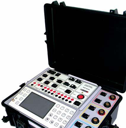
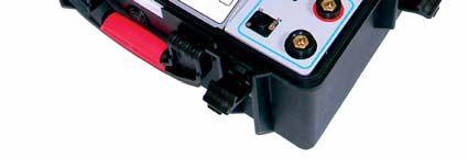


Reliable test devices for reliable electric power systems www.dv-power.com HQ: Orlando FL tel: 407 332 8678, info@progusa.net Exclusive distributor for USA:
The most advanced Circuit Breaker Analyzer on the market “All inclusive” unit made by DV Power providing: CAT500
The Windy City Hosts NETA
FOR FALL BOARD AND MEMBER MEETINGS
NETA’s Board of Directors and membership met in Chicago, Illinois, on September 26th and 27th, and enjoyed perfect Midwestern fall weather at one of the best member turnouts at a fall meeting in some time.
TheB The Board of Directors met the day prior to the membership to prepare for the member meeting as well as to conduct regular board business, including a lengthy strategy discussion that took into account the many facets of assuring NETA’s continued growth and success.
Membership was presented with the opportunity to review a proposal to revise the membership dues structure for NETA Accredited Companies. This proposal was the result of four years of ad hoc committeeworkandresearchtoassurethatthe committee work and research to assure that the proposal will achieve the desired outcome without adversely impacting the most valuable asset of the organization, NETA Accredited Companies. There were some questions from members present, but after those questions were addressed, the

revised structure was approved with a unanimous vote of approval for the changes.
In addition to the aforementioned action item, committee initiatives, standards activities, and opportunities for members to participate by reaching out to their clients with support from the NETA office, was reviewed. NETA also welcomed a new member at this meeting, EnerGTestofK G Test of Kennett ennett Square, Pennsylvania. Members thanked Past PresidentMose President Mose RamiehofPower& amieh of Power & Generation Testing, Inc., for his service as President of the NETA for the two terms spanning 2011-2013.
To round out the experience, S&C Electric hosted NETA for a tour of their facilities. The tour proved insightful and members appreciated the hospitality extended by S&C Electric.
A NETA delegation was invited to tour Chicago’s S&C Electric Company following the September Member Meeting.
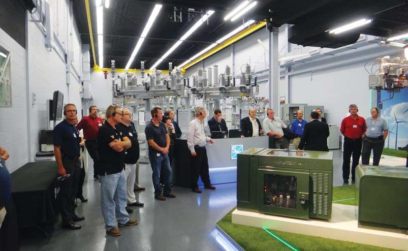
The group toured S&C’s smart grid demonstration area, an interactive display of modern power distribution equipment.
NETA Membership turned out in large numbers for the September meeting.

Preceding the official NETA business meetings was the IEEE IAS PCIC conference where NETA continues to host a hospitality suite in conjunction with NETA Accredited Companies Magna Electric Corporation and Shermco Industries. This was an opportunity for NETA to educate attendees regarding the services offered by NETA Accredited Companies, the ANSI/NETA Standards, PowerTest Electrical Maintenance and Safety Conference, as well as publications and training opportunities available through NETA. This year’s theme was A Night at the Ballpark, complete with red hots, nachos, and frosty brews. A few lucky attendees went home with some great giveaways such as iPads and a Surface Pro. NETA will be back again next year for the PCIC event in San Francisco, California, September 8-10, 2014.
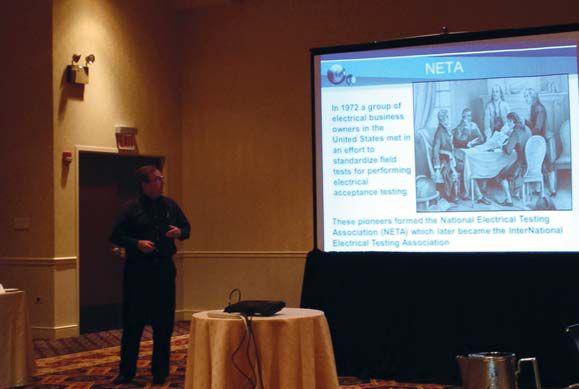
A presentation by John White at the membership meeting supplemented the traditional written reports.
Electrical Distribution System
24 Hour Emergency Services (937) 439-9660
118South 2nd Street Perkasie, PA 18944
Phone: 267 404 2676 Toll Free:888 484 3779
Fax: 267 404 2685
Three Phase Transformer Turns Ratiometer TR-Mark III*
ACCURACY (RESOLUTION 5 DIGITS) :
Range 0.8 … 2000 ± 0.06% at 100V or 40V
Range 2001 … 4000 ± 0.1% at 100V or 40V
FEATURES:
Range 4001 … 13000 ± 0.3% at 100V or 40V
Range 13001 … 16000 ± 0.4% at 100V or 40V
*TR-Mark III-250 Range Up to 45,000 ± 0.4% at 250V
Automatic measurements of voltage, turns ratio, current, and phase displacement
Measures power transformers PTs and CTs
Displays deviation from a nominal ratio
Displays % error vs. name plate value
Bright full color touch-screen for easy data entry
Test voltages of 100V, 40V, 10V, and 1V (for CT Testing)
Graphical tap changer display
Automatic phase vector detection
Enhanced heavy-duty protection circuitry
Data exchange with USB-Key
Built-in printer
*Also available: TR-Mark III-250
Winding Resistance Meter with Demagnetization WR14
ACCURACY:
Range 100 mAmp … 15 Amp ± 0.1% Rdg 5 Digit Resolution
Range <25 mAmp 1.2k…10k ± 0.1% Rdg 5 Digit Resolution
Range <25 mAmp 10k…100k ± 0.5% Rdg 4 Digit Resolution
FEATURES:
Core Demagnetizing Circuit (world exclusive)
Charges inductive loads up to 1500 Henry
2 independent measuring channels
Heavy-duty protection circuitry
High power DC supply (15A/30V)
Resistance range from 0.05 μ to 100 k
Battery or line voltage powered
Visible and audible indicator for discharge status
Data exchange with USB-Key
Simple touch screen operation
Built-in printer
Single Phase Ratiometer TR-1 & TR-1P
ACCURACY:
Range 0.8 … 4000 ± 0.08% with 40 Volts (PT Mode)
Range 0.8 …100 ± 0.08% with 1V…5V (Auto) (CT Mode)
FEATURES:
Operates on rechargeable batteries or line voltage
Can be recharged with line voltage or optional
DC car adapter
Reverse polarity test
Continuity test
Test current up to 1A for CT testing
Internal storage of the last 50 test results
RS-232 interface with optional adapter
Over 1000 measurements without recharging
TR-1P model includes built-in printer
AllRaytech Products Include a Standard 5 Year Warranty
www.raytechusa.com


MODERN PROTECTION SCHEMES
FOR LOW-VOLTAGE CIRCUIT BREAKERS
 BY DAN HOOK, Western Electrical Services, Inc.
BY B D AN H OO K, , Western Electr t ical Ser r vices, , Inc l
This article will be the first of a two-part series covering many of the protection schemes available in low-voltage switchgear. This first part will be a simplified description of the schemes and some of the basic theories applied to accomplish the intended goals.
Manufacturers frequently change the protection schemes available in low-voltage power, insulated-case, and molded-case circuit breakers. Some of these changes are in response to new requirements in standards such as NFPA 70, NFPA 70E, UL, and

others. Other changes are simply improved methods to help a manufacturer garner a larger market share. Different manufacturers identify many similar functions and features with different names. Where possible, the known terminology for the same or similar features is presented.
This article does not attempt to cover all the options available from the major manufacturers but rather be an overview of some of the more common and misunderstood schemes available today. No matter whether
FEATURE
54 WINTER 2013 MODERN PROTECTION SCHEMES FOR LOW-VOLTAGE CIRCUIT BREAKERS

you are an engineer, technician, contractor, or facility owner, this article should reinforce the importance of reviewing and understanding the manufacturers specific instructions.
2 4t Response
- Motivation: Allowforbettercoordi Allow for better coordina tion with devices having inherent characteristics that present coordination and protection challenges.
- Simple description: By default digital electronic devices have an on/off type nature. For example, in a low-voltage breaker trip unit when a short-time set point is reached, the trip unit goes into pickup, and the timing circuit starts the countdown to the trip time based on the short-time delay setting. The result is a very discrete and square time-current curve across all protective functions. In the case of a power system engineer coordinating the protective device settings of multiple devices with digital electronic protection features, the work is fairly straight forward as allofthecharacteristiccurveswill all of the characteristic curves will have the same discrete shape and relatively narrow tolerance bands. If, however, a protective device or power system component is present which has another shape of characteristic curve, the challenge is increased. By nature a thermal magnetic trip device in a molded case breaker, for instance, has a smoother shaped inverse time currentcharacteristiccurve.Thecurve current characteristic curve. The curve represents the physical properties of perhaps a bimetallic strip, in which an increaseincurrentflowwillincreasethe increase in current flow will increase the heating rate in an analog fashion.
- Theory: The challenge lies in fitting a discrete digital device to an analog device curve. This challenge has been met by most, if not all, major manufacturers of low-voltage trip units by providing an option for inserting an algorithm into the long time, short-time, and ground fault protective functions to shapethe timecurrentcharacteristiccurvetomore time current characteristic curve to more closely match an analog device or piece
of equipment, especially in the areas of the coordination plots where conflicts are common. Two common algorithms aretheI are the I2tandI t and I4t functions, referring t to a shape that mimics the product of current squared and time, and another time, that mimics the products of current to the fourth power and time. Thermal magnetic trip devices were mentioned as one device characterizing these smooth curve shapes. A fuse is another example of a protective device that has these characteristics by the nature of it’s physical properties. Likewise, the thermal damage curves of power system equipment can alsohavethesecharacteristics.This also have these characteristics. This standstoreasoninthecaseofcablesand stands to reason in the case of cables and transformers as they are heated as a result ofcurrentflowinamannersimilartothat of current flow in a manner similar to that of a thermal magnetic trip unit or fuse. The actual curve shape can change based on cooling capability and other design capability other characteristics; however, in most cases the I2t function is designed to allow easier t coordination with thermal magnetic trip units and fuses, while the I4t function is designed to accommodate coordination with upstream transformers and fuses. These algorithms are applied in a variety of ways.
Two hemisphere dial adjustments, one half with the function(s) inserted, one half without Dip switches to select between I2tor t or I4tinorout t in or out
LCD screen toggling and selection during setup
(See Figure 1).
- Motivation: Limit the time to trip to the absolute minimum to protect equipment and personnel without sacrificing selective coordination. This method is recognized in NEC article 240.87 as an acceptable alternative to instantaneous tripping.
- Simple Description: Zoneinterlock Zone interlocking ing is designed to segregate an electrical
NETAWORLD 55 FEATURE
MODERNPROTECTIONSCHEMESFORLOW-VOLTAGECIRCUITBREAKERS MODERN PROTECTION SCHEMES FOR LOW-VOLTAGE CIRCUIT BREAKERS AT R
system into zones, and through use of communication between low-voltage breakers, ensure that the breaker responsible for that zone of protection is the device used to interrupt a fault. Withtheaddedinformationavailableto With the added information available to the system, circuit breaker tripping times can be reduced to less than programmed settings without fear of a nuisance trip resulting in de-energizing more of the system than necessary. Communication is accomplished from feeder breakers to main breaker through secondary
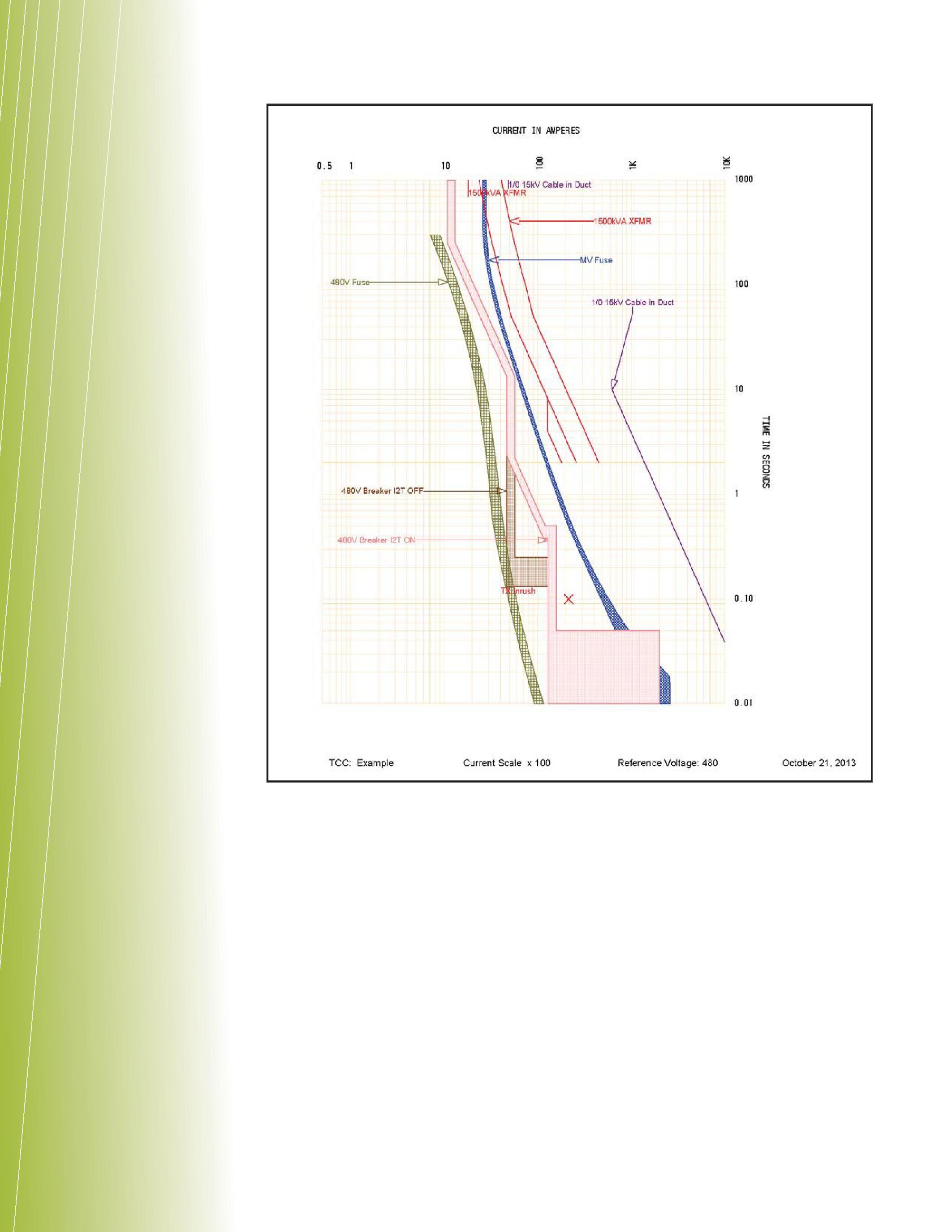
disconnect connections into the trip units themselves or through an intermediate zone interlock module taking inputs from all circuit breakers and outputting the restraint commands as necessary.
- Theory: In a simple system with one maincircuitbreakerandseveralfeeders main circuit breaker and several feeders configured with zone interlocking, the feederbreakerscommunicatewith feeder breakers communicate with the main circuit breaker through a dedicatedhard-wiredconnection.In dedicated hard-wired connection. In thecaseofafaultdownstreamofone the case of a fault downstream of one of the feeders, that feeder will detect
FEATURE
56 WINTER 2013 MODERNPROTECTIONSCHEMESFORLOW-VOLTAGECIRCUITBREAKERS MODERN PROTECTION SCHEMES FOR LOW-VOLTAGE CIRCUIT BREAKERS
E
Figure 1: TCC showing curve shape difference in a short-time function
the fault and send a restraint signal to the main breaker to prevent a trip whilethefeederbreakerclearsthe while the feeder breaker clears the fault.Intheothercasewhereafault fault. In the other case where a fault occursbetweenthemainandfeeder occurs between the main and feeder breakers, the main will sense the fault and receive no restraint signals from the feeders, as they do not sense the fault.Inthiscasethemainbreaker fault. In this case the main breaker can trip without delay, as it knows the fault is in zone 1 or, put another way, it is the device responsible for clearing the fault (see Figure 2).
- Motivation: Protectsdistribution Protects distribution system components from damage tem due to repeated intermittent overload events and periodic ground fault events. Advanced thermal memory functionality requires more accurate input parameters and algorithms tomodelthethermalcondition to model the thermal condition of conductors. The latter may be required in situations where cyclical loads dictated the disabling of standard thermal memory to eliminate nuisance tripping.
- Simple description: Recallthe Recall the earlier discussion covering the discrete nature of digital electronic devices. When applied again to the long time trip function designed to protect equipment from overload conditions, the trip unit will go into pickup and
begin timing as soon as the sensed current exceeds the long time pickup value.Intheinstantthesensed value. In the instant the sensed current drops below the pickup value the timing circuit stops the timeout as desired. However, if the current increases again above the pickup value in a short period of time, the trip unit starts its timeout to trip again, butdoesn’trememberthatthecircuit but doesn’t remember that the circuit was just subjected to a brief overload and the resulting heating. In this fashionaseriesofbriefoverloadsthat fashion a series of brief overloads that do not reach the timeout setting can cause damage to circuit parts without tripping the circuit breaker responsible for protection of that circuit. The

Figure 3: Intermittentoverloadswithandwithout Intermittent overloads with and without thermal memory
FEATURE
NETAWORLD 57 MODERNPROTECTIONSCHEMESFORLOW-VOLTAGECIRCUITBREAKERS MODERN PROTECTION SCHEMES FOR LOW-VOLTAGE CIRCUIT BREAKERS
Figure 2: Zone 1 fault and Zone 2 fault diagram
AT R
thermal memory feature was developed to allow a digital electronic trip unit to mimic the performance of a thermal magnetic circuit breaker. It is important to note that a thermal magnetic trip unit has an integral thermal memory feature as part of it physical characteristics. It actually heats up and cools down in a manner similar to the devices that it protects. Just as a cable would not instantly cool off, a thermal magnetic circuit breaker will not as well. Only an electronic trip unit needs to be taught to remember to what the circuit was recently subjected. In cases where loads are cyclical and near the overcurrent setting, a standard thermal memory function can result in nuisance tripping. Attempts have been made to improve the algorithm through the use of more accurate input parameters to allow use of the thermal memory function in these specific circuit applications. Thermal imaging is a term used by one manufacturer to describethisadvancementonthesame describe this advancement on the same thermal memory concept (see Figure 3).

- Reducethearc-flashhazard educe the arc-flash hazard severity that a worker downstream may be exposed to in the event of a fault. Thismethodisdescribedasoneofthe This method is described as one of the acceptable methods per NEC 240.87 to accomplish an increased level of worker safety specifically on circuit breakers that do not have instantaneous trip functionality.
- The four major contributing factors to the severity of anarc-flasheventare: an arc-flash event are:
Faultcurrentlevel ault current level
Clearing time for the upstream protective device, or how long the fault persists before being extinguished
Distance from the fault to a subject istance worker
Physical characteristics of the equipment subjected to the arc-flash event.
- Thisfeatur This featureshortensthetimethatan e shortens the time that an arc-flash event persists by adjusting the time delay to trip and/or overcurrent pickup set points. These changes to the settings are applied temporarily while activities are performed on an energized system downstream of the subject circuit breaker. It is commonly activated with a toggle switch or button. The settings must be predetermined by an engineering study and preprogrammed into the trip deviceforselectionwhendesired. device for selection when desired.
- Selectivecoordinationisa Selective coordination is a not a protection scheme per se but rather atermthatdescribes“localizationofan a term that describes “localization of an overcurrent condition to restrict outages to the circuit or equipment affected, accomplished by the choice of overcurrent protective devices and their ratings or settings” per the NEC. The coordination of protective devices has unique challenges as it applies in the instantaneous region.
- By definition an instantaneous trip is a trip of a circuit breaker with no intentional time delay. The differing design and construction of various circuitbreakermodelsandsizesresultsin circuit breaker models and sizes results in clearing times that vary as well. Further the tolerance region on instantaneous trip events can be much greater than other trip functions. Some manufacturers provide tables showing instantaneous selectivity at higher fault current levels based on their own testing data.
- Increase personnel protection by enabling an instantaneous trip in the case of closing in on a faulted circuit.
- If high current levels are generated immediately upon closing a circuit breaker, it is possibly indicative of faulty conductor installation or a downstream fault of relatively low impedance. Manufacturers can apply an instantaneous trip feature upon closing, on
58 WINTER 2013 MODERNPROTECTIONSCHE MODERN PROTECTION SCHEMES FORLOW-VO FOR LOW-VOLTAGE AGE CIRCUITBREAKER IRCUIT BREAKERS FEATURE
theorderof12x-25xofthecircuitbreaker the order of 12x-25x of the circuit breaker sensor/plug rating, to immediately reopen if necessary. The intent is to limit equipment damage and the severity of any downstream arc flash event that may be generated by these elevated currents. The making current release functionality is active for only a short period oftimeafterthecircuitbreakerisclosed. of time after the circuit breaker is closed.
After this short preset time, the normal fault protection set points applied to the trip unit arerestored. are restored.
cessor-based trip units on low-voltage circuit sor-based breakers, the number of protective features available to be implemented is really only limited by the number and nature of inputs that can be provided. There are protection options for undervoltage, overvoltage, imbalance in current and voltage values, underfrequency, overfrequency, and reverse power. Additionally there are alarms, indications and diagnostics available certainly numbering in the tens and perhaps approaching the hundreds.

into the theory as it applies to testing and certifying of these systems to ensure they will operate as designed and installed. Stay tuned.
DanHook Dan Hook is the Chief Operating Officer of Western Electrical Services Inc. He joined the group in 2004 and has been in the electrical industry for over 18 years with the US Navy and civilian experience. Daniel holds a Bachelors Degree in Nuclear Engineering and a Masters degree in Electric Power Engineering from Rensselaer Polytechnic Institute in Troy, New York, and he maintains his professional engineer’s license in Washington State and Arizona. He is a Certified Journeyman Electric Motor/Generator Repairman (US Department of Labor, US Department of the Navy). The Inter-National Electrical Testing Association (NETA) certifies him to Level III Technician. The National Institute for Certification in Engineering Technologies (NICET) certifies him to Level III in the area of Electrical Testing Engineering Technology. Dan spent over a decade in the US Navy as an Electrician’s Mate maintaining and testing all aspects of generation, distribution, control equipment, and system protection as it applied to nuclear submarines.
Go Retro To Be Modern
FEATURE
AT R PGTI.net PGTI
Retrofitting trip units with more modern upgrades just makes loads of sense. Contact PGTI for necessary trip unit upgrades and get increased reliability, more accurate data and lower Arc Flash hazards from your equipment. Safe, Smart, Right! Power & Generation Testing, Inc. 480 Cave Road – Nashville, TN 37210 615.882.9455

THE OF CIRCUIT BREAKER PERFORMANCE MATTERS
BY E LS A CA
BY ELSA CANTU AND DR. DIEGO ROBALINO, Megger
Unequivocally, one of the most important components of a substation is the circuit breaker. The circuit breaker is critical to saving “the life” of expensive equipment, and also to saving the lives of workers operating a substation. Most often the circuit breaker is idle, allowing for continuous current flow. But when the circuit breaker is called upon to operate, e.g., a power surge, it must trip or open the circuit within milliseconds. This criticality demands meticulous testing and maintenance.
CIRCUITBREAKERTYPES
CIRCUIT BREAKER TYPES
There are many types of circuit breaker designs, which are usually classified by the insulation media used to extinguish the arcing during open/close operation: vacuum, sulfur hexafluoride (SF6), oil and air blast.
Vacuum circuit breakers can be used for up to 70kV; they utilize vacuum as insulation betweenthemaincontactswhenthecircuit between the main contacts when the circuit breaker is opened. These breakers have two contact plates inside a vacuum bottle that are separated by a very small distance, usually between11-17mm. between 11-17mm.
SF6circuitbreakersareusedfrommedium SF6 circuit breakers are used from medium and high voltages all the way up to 1100kV.
There are two main construction types, selfblast and puffer. Both types use SF6 gas to blow over the arc, cooling and extinguishing it. Self-blast uses the energy of the arc to generate pressure to blow out the arc. The puffer type has to generate its own pressure to blow out the arc, thus requiring a larger mechanism.SF6circuitbreakerscanbeof mechanism. SF6 circuit breakers can be of live tank or dead tank design.
In live tank circuit breakers, the interrupter is housed in a tank that is at line voltage. One of the advantages of live tank circuit breakers is that, because there is no need to insulate from high voltage to a grounded tank, only a small amount of SF6 gas is used (see Figure 1).
60 WINTER 2013 THECRITICALITYOFCIRCUITBREAKER THE CRITICALITY OF CIRCUIT BREAKER TESTING:PERFORMANCEMATTERS TESTING: PERFORMANCE MATTERS 3201 ER B T RCUUITCIRC C TICICACAALLITTY TICRRIT C O A A R R RS MAT ANNCE C FORORMA NGG: NG EST ATTEERS TER CE PERERRFO PE TESTI TE O A A : R R R P
U
D
DI EG O RO BA LI NO , N N N O O G C S I L A B R E I D R D A T A L Y B Megger
NT
AN
DR
FEATURE

In contrast, dead tank circuit breakers house the interrupter in a grounded or “dead” tank. Since these require insulating from the high voltage to ground, they use much more SF6 gas than live tank circuit breakers. Since the interrupters and the bulk of the weight are closer to the ground than live tank circuit breakers, dead tank circuit breakers are commonly used in high seismic areas. In the U.S. the majority of SF6 circuit breakers are dead tank with live tank becoming more prevalent. In Europe only live tank style breakers are used for high voltage applications (see Figure 2).
Oil circuit breakers use oil to quench the arc and extinguish it. Oil circuit breakers are slowly being phased out and replaced by SF6 circuit breakers. They are no longer manufactured, but there are still a large number in the field that require testing and maintenance (see Figure 3).
Airblastcircuitbreakersuseairtoblowover Air blast circuit breakers use air to blow over the arc and extinguish it, requiring several very noisy breaks-per-phase.
THE IMPORTANCE OF TESTING CIRCUITBREAKERS CIRCUIT BREAKERS
Your circuit breaker should be tested many times throughout its life. The benchmark tests are performed at the factory before the customerreceivesthecircuitbreaker.Once customer receives the circuit breaker. Once the circuit breaker is delivered, it should be tested before being put into service. This is known as a commissioning test. After the circuit breaker is commissioned and put into service, there are additional tests that should be performed at various intervals. Consult the manual or manufacturer specifications for the proper testing intervals. Generally, the commissioning-type tests should be performed every three to five years for routine maintenance.Circuitbreakersmanufactured maintenance. Circuit breakers manufactured within the past five years require less maintenance.Asaresultthemanufacturer maintenance. As a result the manufacturer recommends testing and maintenance based on the number of operations rather than time intervals. Importantly, the circuit breaker shouldbetestedafterithasseenasevere should be tested after it has seen a severe fault, or, if it is suspected of faulty operation.
NETAWORLD 61 THECRITICALITYOFCIRCUITBREAKER THE CRITICALITY OF CIRCUIT BREAKER TESTING:PERFORMANCEMATTERS TESTING: PERFORMANCE MATTERS ER EAKEKERBRREA B T RCUUITCIRC C O TICICACAALLITTYCRRITTI C A R R R R RS MAT NC ANCORMA O NGG: EST ATTEERS TER CE PERERRFO PE TESTI TE A A : R R R P FEATURE
Figure 1: LivetankSF6circuitbreaker Live tank SF6 circuit breaker
Figure 2: Deadtankcircuitbreaker Dead tank circuit breaker
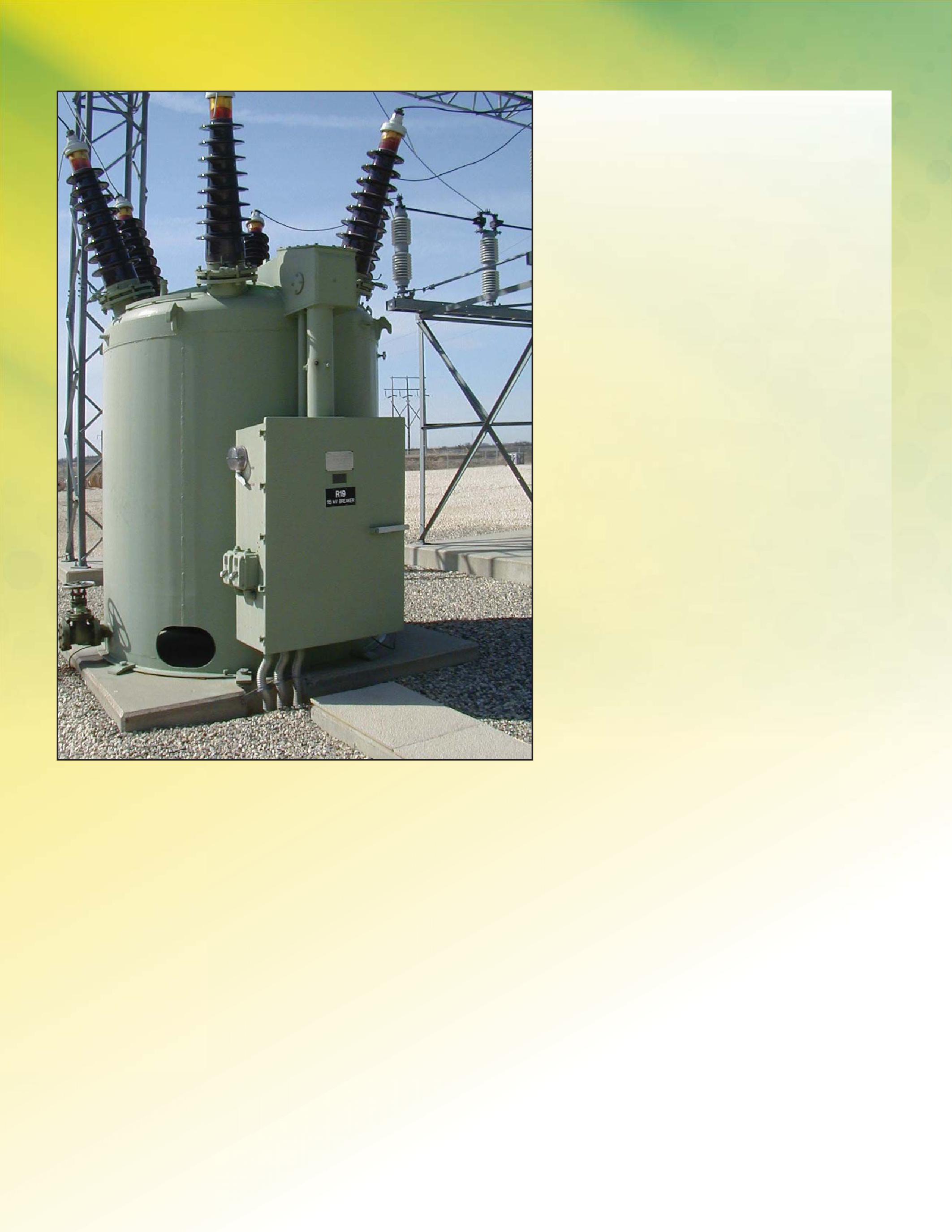
COMPONENTS THAT REQUIRE TESTING
Although there are a variety of tests that can be performed on a circuit breaker, there are three main components to focus on: insulation, resistance and the mechanical operation of the breaker.
SAFETY
Safety is, and must always be, the number one priority in a substation. The circuit breaker should be isolated and grounded before any testing begins. When possible, take
advantage of equipment that allows testing of the circuit breaker while it is grounded onbothsidestominimizeriskofelectrical on both sides to minimize risk of electrical shock. The operating mechanism can store energy and voltage levels up to 480V in the control cabinet, so caution must be used when working inside the control cabinet or mechanism housing. When testing with high voltages, all personnel must stay clear of the circuit breaker. National, state, and local safety practices must always be observed when working in a substation.
TESTING INSULATION
Insulation can be tested using a variety of methods. A common practice is to perform a DC insulation resistance (IR) test. When performing this test, close the circuit breaker and test from one phase to the other and also from each phase to ground. Open the circuit breaker and test from one pole to the other on the same phase; and repeat for the other two phases. In addition to the DC resistance test, a power factor test (PF) can be performed. When performing PF, the same ninemeasurementsshouldbemadethat nine measurements should be made that weretakenwiththeDCinsulationresistance were taken with the DC insulation resistance test. A hi-pot test can also be performed, but this is more commonly performed in a factory rather than in the field. These tests can be performed on all circuit breakers but some additional tests can also be performed, depending on the type of circuit breaker. For vacuum bottles, check the vacuum integrity with a hi-pot tester. This is a go/no-go (pass or fail) test. For oil circuit breakers, take an oil sample to test the quality of the oil. For SF6 circuit breakers, take a gas sample to test for purity and moisture in the gas.
TESTING RESISTANCE
The circuit breaker spends most of its life in the closed position letting current flow through its contacts. In order to efficiently allowelectriccurrenttoflowitneedstohave allow electric current to flow it needs to have very little contact resistance, typically in thelowhundredsofmicro-ohmstoundera the low hundreds of micro-ohms to under a hundred micro-ohms. To test the resistance, amicro-ohmmetershouldbeused.This a micro-ohm meter should be used. This
62 WINTER 2013 FEATURE THECRITICALITYOFCIRCUITBREAKER THE CRITICALITY OF CIRCUIT BREAKER TESTING:PERFORMANCEMATTERS TESTING: PERFORMANCE MATTERS
Figure 3: Oilcircuitbreaker Oil circuit breaker

test may also be referred to as a Digital Low Resistance Ohm meter (DLRO) or Ductor™ test. The basic principle is to inject a DC current, measure the voltage drop, and then calculate the resistance. IEEE standard 4.3.6 statesthattheresistanceshouldbemeasured states that the resistance should be measured with at least 100A, and should not exceed the current rating of the circuit breaker. The test should be performed on each phase individually with the circuit breaker in the closed position. The values should meet the specifications indicated by the manufacturer. If the manufacturer’s specifications are not available, compare the values from phase to phase and look for a deviation.
TESTING OPERATION
To ensure the breaker is opening and closing correctly, a time and travel analyzer should be used. Important parameters to measure include: the contact opening and closing times, contact travel length or stroke, and velocity of the interrupter. For time and travel analysis the number of breaks-perphase of the circuit breaker, the number of operating mechanisms, and the type of transducer(s) are needed.
MEASURING TIME
There are five different operations that should be measured with the analyzer: close, open, close-open, open-close and open-close-open. Theclosetimeisthetimefromwhenthe The close time is the time from when the close coil sees voltage until the first metalon-metalcontactofthecircuitbreaker. on-metal contact of the circuit breaker. When measuring the close time of the circuit breaker, be aware of the X-Y relay scheme in the control circuit. Because the closing time ismeasuredfromtheinstancetheclosecoil is measured from the instance the close coil sees voltage, subtract from the pickup time of the X relay. The open or trip time is the time from when the open coil sees voltage untilthelastmetalcontactsofthecircuit until the last metal contacts of the circuit breaker separate. The close-open time, also known as the dwell time, is the duration that the metallic contacts are touching when performing a close operation followed immediately by an open operation. Note: the open operation should be initiated during
the close operation. A common practice is to send the open pulse 10ms after the close pulse has been initiated at time zero. The purpose of the close-open test is to make sure the circuit breaker will still be able to open and interrupt current if it closes in on a fault. The open-close or reclose test records the time it takes from when the contacts separate until the contacts touch again on an open operation, followed by a close operation after a short delay of 300ms. It should be noted that the 300ms delay is the minimum and this can be set longer, if desired. During normal operation of the circuit breaker, a reclose may be utilized when the circuit breaker sees a temporary fault such as a lightning strike. Thefaultwilloccurandthecircuitbreaker The fault will occur and the circuit breaker will trip to clear it. Shortly afterwards, the circuitbreakerwillclosebackin.Ifthefault circuit breaker will close back in. If the fault is gone, then the circuit breaker will stay closed. If the above scenario occurs, but the fault is still open, then the circuit breaker will need to trip one more time and stay in the open position. This function is checked by the open-close-open test.
X-YRELAY X-Y RELAY SCHEME
The X-Y relay scheme, also known as the anti-pump circuit, is in the control circuitry for the close operation to prevent the circuit breaker from closing immediately after it opens. When this occurs, it is referred to as “pumping the breaker” and, depending on the design, this can cause severe damage. When the X-Y scheme is in the circuit, the X relay must pick up before the close coil can be energized. Once the circuit breaker is closed, the Y relay picks up and cuts off power to the X relay. The Y relay is then continuously energized until the close pulse is removed. This is known as a self-sealing contact.Inordertoclosethecircuitbreaker contact. In order to close the circuit breaker again, remove the power from the Y relay. A typical X relay will add 10-20ms to the close timeofthecircuitbreaker. time of the circuit breaker.
TRANSDUCERS
The type of transducer is dependent on the design of the circuit breaker. The two common
NETAWORLD 63 FEATURE THECRITICALITYOFCIRCUITBREAKER THE CRITICALITY OF CIRCUIT BREAKER TESTING:PERFORMANCEMATTERS TESTING: PERFORMANCE MATTERS
types of transducers are linear and rotary. Always consult the manufacturer of the circuit breaker, but there are a few generalities that often apply. For live tank circuit breakers, it is common to use a rotary transducer. For dead tank circuit breakers and bulk oil circuit breakers, it is more commontousealineartransducer.Forvacuum common to use a linear transducer. For vacuum circuit breakers, try to connect a small linear transducertothebottomofthevacuumbottle. transducer to the bottom of the vacuum bottle. Please note that these are general guidelines andeachcircuitbreakershouldbeevaluated and each circuit breaker should be evaluated forthebesttransducerconnection.Thereare for the best transducer connection. There are alsocircuitbreakerswhereeitheralinearor also circuit breakers where either a linear or a rotary transducer can be used. When using a rotary transducer, the stroke is measured in degrees, so a conversion table will be necessary toobtainalinearmeasurementofthestroke. to obtain a linear measurement of the stroke. Contact the circuit breaker manufacturer to get the appropriate conversion table for the circuit breaker. If no conversion table is available, makeameasurementwithatransducerand make a measurement with a transducer and use this as a footprint from which to compare futuremeasurements.Recordstrokevaluesin future measurements. Record stroke values in degrees and speed values in degrees per second (see Figure 4).
TRAVELCURVEPARAMETERS TRAVEL CURVE PARAMETERS
There are multiple parameters that can be obtainedfromthetravelcurve.Someofthe obtained from the travel curve. Some of the most common include: stroke, over-travel,

rebound, penetration and under-travel. The interrupter velocity is also calculated from themotiontrace.Thestrokeisthedistance the motion trace. The stroke is the distance that the interrupter travels from its initial resting position before the operation to its final resting position after the operation. Overtravelismeasuredontheclose Overtravel is measured on the close operation and it is the maximum distance that the interrupter travels past the closed position. Rebound is the distance that the interrupter returns past the closed position after an overtravel. Penetration or wipe is the distancefromwherethecontactsfirsttouch distance from where the contacts first touch until the final closed position. Undertravel is measured on the open operation and it is the maximum distance that the interrupter travels past the open position. Some circuit breakers are equipped with a dashpot that can be adjusted if the overtravel or undertravel is too large.
CALCULATION POINT SPEED
Thereareseveraldifferentreferencesthat There are several different references that can be used to determine the speed of the contacts. A few examples include: percentage of stroke, distance below closed or above open, contact touch or separation and time before or after the reference point. Always refer to the manufacturer’s guidelines for the proper reference points. If no information is given, the points will have to be chosen by the person carrying out the test. When choosing speed calculation points there are a few things to consider. Make sure they are on the linear portion of the travel curve and measure the speed in the arcing zone of thecircuitbreaker.Somestandardreference the circuit breaker. Some standard reference points include: “contact touch” for the upper point and “10ms before upper point” for the close operation; and then on the open operation “contact separation” for the upper point and “10ms after upper point” for the lower point.
RECOMMENDED ADVANCED TESTS
With an SF6 circuit breaker, it is recommended to perform a Dynamic Resistance Measurement (DRM) to evaluate the arcing contacts of the circuit breaker. To perform this test,
64 WINTER 2013 FEATURE
THECRITICALITYOFCIRCUITBREAKER THE CRITICALITY OF CIRCUIT BREAKER TESTING:PERFORMANCEMATTERS TESTING: PERFORMANCE MATTERS
Figure 4: Motiontransducer Motion transducer
ransducer c sd

makealowresistancemeasurementwhile make a low resistance measurement while operating the circuit breaker. By evaluating the change in resistance values, obtain the start of main contacts movement, main contact separation, and arcing contact separation. The distance between main contact separation and arcing contact separation is the length of the arcing contact. As the breaker ages and sees more interruptions, the arcing contacts can wear out. DRM analysis will allow evaluation of the arcing contact without dismantling the breaker for inspection. An increasingly popular test, the first trip test records the coil current trace of the trip coil when pulling the circuitbreakeroutofservice.Thecoiltrace circuit breaker out of service. The coil trace is analyzed and compared to previous values to reveal the condition of the trip coil and trip latch. Special caution must be observed since the breaker is on-line during this test. Modern techniques can also be applied to test a circuit breaker with both sides grounded. This can be very beneficial in Gas Insulated Switchgear (GIS) with an integrated isolating and grounding switch. The adjacent breaker often needs to be de-energized to properly isolate from line voltage when removing the ground on one side of a GIS breaker. With certain dual ground methods the breaker can be left grounded on both sides and still perform the test. This allows faster and safer circuit breaker testing than possible using traditional techniques.
ANALYZING RESULTS
Thecircuitbreakermanufacturershould The circuit breaker manufacturer should specify acceptable values for certain parameters such as timing and contact resistanceinthemanual.Thesevaluesshould resistance in the manual. These values should also be trended, comparing the latest results to the previous values. A slower closing time but normal opening time can indicate that the closing latch system is binding and/or the spring is weakening. If the condition is reversed, the opening latch and/or spring should be investigated. Refer to several different standards, depending on location and affiliation. In the U.S. IEEE/ANSI C37 and the ANSI/NETA Acceptance Testing Specifications can be used as a reference. As wellasIEC62271canbeused. well as IEC 62271 can be used.
CONCLUSION
Circuitbreakersarecriticalassetsinan Circuit breakers are critical assets in an electrical substation that help safeguard the lifetime of expensive equipment and of workers.Circuitbreakersmustbemaintained workers. Circuit breakers must be maintained andtestedtoensuretheircontinued and tested to ensure their continued proper operation. Minimal testing involves insulation, resistance and mechanical operation. Advanced test methods should beconductedwhenthecircuitbreakeris be conducted when the circuit breaker is protecting critical assets, or, if the circuit breaker has experienced a major fault. National, state and local safety procedures should always be followed to minimize risk to personnel and equipment.
Director of Marketing at Megger in Dallas for the last six years, ElsaCantu Elsa Cantu hasmore has more than fifteen years of experience in the electrical and electronic engineering sectors. In her present role, she is responsible for the development of efficient and effective marketing plans to support Megger’s extensive product range. This features some of the world’s most innovative test equipment for use in the power transmission and distribution sectors, including circuit-breaker analyzers, protection relay test sets, insulation diagnostic testers and cable fault locators.
Before joining Megger, Elsa worked for a public utility that supplies electricity to over ten million consumers in North Texas, and for two of the USA’s largest telecommunications companies. Her educational achievements include a BA in liberal arts from Texas A&M in College Station, and an MBA from Our Lady of the Lake University in San Antonio, Texas.
Elsa is a long-time member of the National Association of Hispanic MBAs.
Diego Robalino currently works for Megger as a senior applications engineer, where he specializes in the diagnosis of complex diagnosis electrical testing procedures. While doing research in power system optimization with a focus on aging equipment at Tennessee Technological University, Robalino received his electrical engineering Ph.D. degree from that institution. Robalino has many years of management responsibility in the power systems, oil and gas, and research arenas managing the design, construction and commissioning of electrical and electromechanical projects. Dr. Robalino is an active member of IEEE, ASTM and PMI with multidisciplinary engineering interests.
NETAWORLD 65 FEATURE THECRITICALITYOFCIRCUITBREAKER THE CRITICALITY OF CIRCUIT BREAKER TESTING:PERFORMANCEMATTERS TESTING: PERFORMANCE MATTERS
The multi-functional measuring system SHERLOG CRX
captures and analyzes all the processes in an electrical supply system precisely and reliably - even under extreme conditions!
No moving parts – no fans, no hard drive
2 GB of static memory
Compact – 19” rack holds 32 analog, 128 binary inputs
IEC 61850 compliant
Phasor Measurement Unit
Power Quality Analyzer
On site, Plug and play configuration
Continuous Data Recorder
Sequence of events Recorder

KoCoS and its subsidiaries are a group of companies with a global presence which develop, manufacture and sell measuring and test systems for equipment in electricity supply systems and quality monitoring inspection systems for the semi-conductor, automobile, and food industries.
Multi-functional relay test systems for commissioning, maintenance, and service. Compact and powerful relay test systems with four voltage and six current sources for 3-phase tests for all types of relays, including differential relays.
Extremely compact and light
Stand alone operation with 3.5“ touch screen or software base with ARTES V4
Up to 6x32A, 3X64A, or 1x96A
Capable of testing IEC 61850-compliant protection equipment
KoCoS America LLC 136 Oak Street, Suite A Westerly, RI 02891 Phone +1 401 213 6518 · www.kocos.com Follow us on twitter: http://twitter.com/kocos_america
560 LOG CRRX electricaal nder
Follow us on facebook http://twitter.com/KoCoS_America n Nothing escapes SHERLOG ... i f Relay testing at its BEST ...
CRX

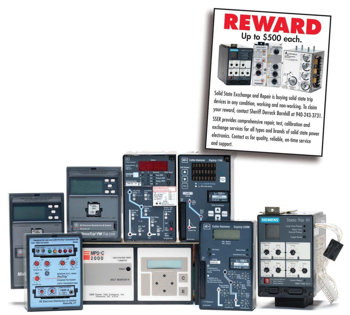
We Buy, Sell, Trade, Calibrate, Repair Power electronics are our business “SOLID STATE” INDUSTRIAL ELECTRONICS “SOLID STATE” INDUSTRIAL ELECTRONICS Toll Free 877-TRIP-FIX NOWRENTING TESTEQUIPMENT
Service ENTRANCE SWITCHBOARDS
DESIGN CONSIDERATIONS TO ENHANCE SAFETY AND RELIABILITY
BY ROBERT P. HANSEN, P.E., PhD, General Electric
INTRODUCTION
Switchboards are a widely used type of equipment in low voltage electrical distribution systems. They are typically used as the service entrance equipment for a variety of facility types. While consideration of safety and reliability must be given to all parts of an electrical distribution system design, the impact of choosing the correct design options to enhance safety and reliability is magnified at aserviceentrance.Thisarticlewilldiscuss a service entrance. This article will discuss simple switchboard configuration and equipment options that, when incorporated in the design phase of a project, can cost-effectively reduce arc flash incident energy or reduce worker exposure to arc flash energy without reducing reliability.
The scope of NPFA 70E (reference 1) does not include design of distribution systems, but it does contain references to design practices and equipment options aimed at reducing arc flash energy or worker exposure.
Hazards
130.5 Arc Flash Hazard Analysis, informational note #3: “... Equipment and design practices are available to minimize
the energy levels and the number of at-risk procedures that require an employee to be exposed to high energy sources…”
Design Requirements
O.1.2 “… The facility owner or manager, or the employer, should choose design options that eliminate or reduce exposure risks and enhance the effectiveness of safety related work practices…”
O.2.3 Arc Energy Reduction. “Where a circuit breaker that is rated for, or can be adjusted to, 1000 amperes or more is used, one of the following or equivalent means has proven to be effective in reducing arc flash energy:

withalocalstatusindicator with a local status indicator
An energy-reducing maintenance switch allows a worker to set a circuit breaker trip unit to operate faster while the worker is working within an arc flash boundary, as
68 WINTER 2013 FEATURE SERVICEENTRANCESWITCHBOARDS SERVICE ENTRANCE SWITCHBOARDS DESIGNCONSIDERATIONSTOENHANCESAFETYANDRELIABILITY DESIGN CONSIDERATIONS TO ENHANCE SAFETY AND RELIABILITY
defined in NFPA 70E, and then to set the circuit breaker back to a normal setting after the potentially hazardous work is complete.”
This article will describe some of the design practices and options that can be applied to commonly used non-compartmented, service entrance switchboards. The application of zone selective interlocking (ZSI), including the newer instantaneous ZSI, and maintenance switching will be among the specific strategies discussed.
BACKGROUND
In the one-line below (figure 1), a utility, or end-user owned, transformer is connected to a serviceentranceswitchboard.Theswitchboard service entrance switchboard. The switchboard has a main breaker, and any number of group or individually mounted feeder breakers. The overcurrent protective device (OCPD) that is upstream of the transformer would typically be a fused switch or a MV breaker. The protection settings (in the case of the MV breaker), or fixed time-current characteristics (in the case of the MV fuse) determine how quickly an arcing fault will be cleared on the transformer secondary side down to the LV main device terminals. For a given system, that upstream device clearing time will determine the arc flash energy on the line-side oftheLVmainbreaker.TheLVmainbreaker of the LV main breaker. The LV main breaker protection settings are typically chosen to protect the bus on its load side, and back-up the protection afforded by the feeder breakers to parts of the system below the switchboard. The LV main breaker settings will determine how quickly a load-side arcing fault will be cleared, which in turn influences the amount of arc flash energy on the load-side bus. In many cases, the low voltage main device line-side and load-side arc flash energies are of different values, in some cases by a large amount, with the line-side energy being the higher of the two.
impedance, the LV main breaker can limit incident energy to below 4 cal/cm 2 whenthe when the LV main breaker is allowed to clear arcing faults using its instantaneous response 1.The . The incident energy on the LV main breaker line-side would be over 130 cal/cm2, and , have a corresponding arc flash boundary of 36 feet when the transformer primary is protected by a fuse 1. For non-compartmented . switchboards, the highest incident energy calculated anywhere within the switchboard would typically be reflected on the arc flash labelsforallsectionsinthatcontinuouslinelabels for all sections in that continuous lineup. This can render the entire switchboard unapproachable while it is energized.
A complete approach for safe design will attempt to minimize both the line-side and load-side arc flash energies. In cases where theowneroftheserviceentranceswitchboard the owner of the service entrance switchboard ownsthetransformeranddecideswhat owns the transformer and decides what primary protection to apply, protection
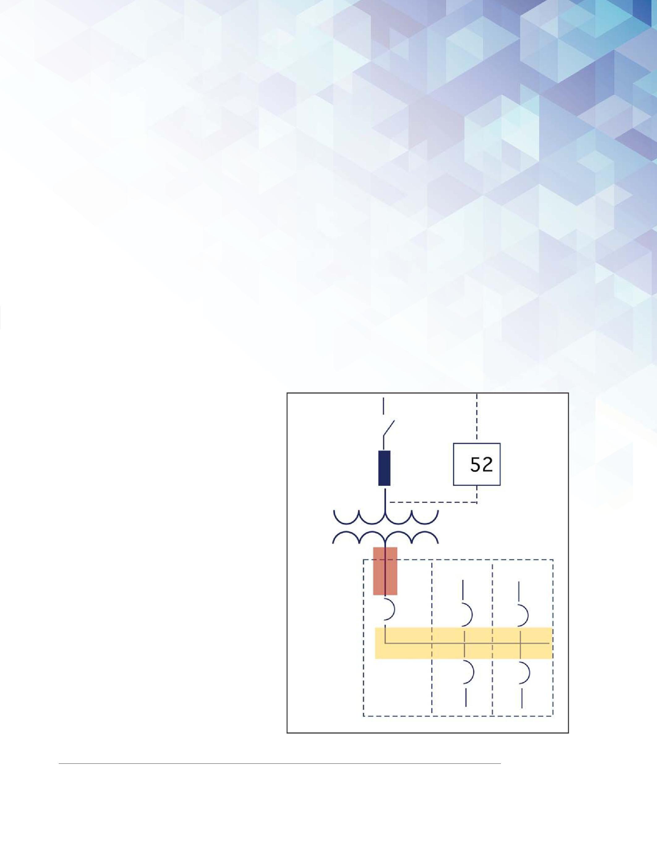
Line-side Load-side
As an example, on a 480V service entrance fed by a 2000kVA transformer with standard
1 IEEE 1584 calculation using the following inputs: 4160V primary voltage, 50kA utility fault current available, 350A 9F62 series EJO-1 primary fuse (clearing time limited to 2 seconds per IEEE-1584), 2000kVA transformer with 5.75% impedance, 2500A Entelliguard G LV main beaker (50ms clearing time), 32mm switchboard bus gap, 18” working distance.
NETAWORLD 69 SERVICE ENTRANCE SWITCHBOARDS DESIGN CONSIDERATIONS TO ENHANCE SAFETY AND RELIABILITY FEATURE
Figure 1: Typical Service Entrance.

strategies as explained in reference 2 can be used to reduce the line-side arc flash energy. Inallothercaseswheretheserviceentrance In all other cases where the service entrance switchboard owner may not have authority to select the substation transformer primary protection device/settings, the strategy of placing the low voltage main section remote from the feeder sections, as discussed in the next section, can be used to reduce worker exposure to the higher line-side arc flash energy. Independent of the substation transformer primary protection ownership, the equipment options (ZSI and maintenance switching) discussed in the following section can be used to enhance safety for workers.
Inthecaseofaserviceentranceswitchboard In the case of a service entrance switchboard with no main device (a “six handle rule” service entrance per NEC Article 230.71), the distinctionbetweenline-sideandload-sidearc distinction between line-side and load-side arc flash energy as described above is lost. The low voltage arcing fault clearing time of the protective device upstream of the transformer will determine the amount of arc flash energy fortheentireserviceentrancebus.Forservice for the entire service entrance bus. For service entrance switchboards without main devices, the protection techniques needed to minimize arc flash energy at the low voltage service entrance bus are beyond the scope of this article. References 2 and 3 describe some of the options that could be used.
Inaconventionalswitchboardservice In a conventional switchboard service entrance design, the main breaker and the feeder breakers are connected by hard bus suchthatthemainsectionisinacontinuous such that the main section is in a continuous line-up with the feeder section(s). While this is convenient from the perspective of installation, it does have disadvantages when the arc flash energy at the line-side of the main breaker is greater than the load-side arc flash energy. High line-side arc flash energy can increase risks to workers interacting with other parts of the switchboard that are not part of the incoming section. The arc flash boundary for sufficiently high line-side arc flash energy can easily extend past the feeder sections. Main circuit breaker trip unit settings or temporary settings, such as used by a maintenance switch, only influence
the load-side. The elevated line-side energy potentially increases the frequency and duration of exposure for personnel who interact only with feeder sections. In the conventional configuration there is greater impetus to employ line-side energy reduction methods. The following section will discuss some options for improving upon the conventional switchboard design.
OPTIONS FOR IMPROVING THE CONVENTIONAL DESIGN
Many users now recognize the simplicity and effectiveness of employing a switchboard with aremotemaincircuitbreakersection.Inthis a remote main circuit breaker section. In this design strategy, the section that receives the incoming feed from the utility transformer contains only the main circuit breaker, and this single breaker section is cabled to a separate line-up containing the feeder breakers. The concept is to provide distance between the higher arc flash energy normally found on the line-side of the low voltage main device and thesectionsontheload-side.Withsufficient the sections on the load-side. With sufficient distancebetweenthemainsectionandthe distance between the main section and the feeder sections, the feeder breaker sections canbeoutsideofthemainsection’sline-side can be outside of the main section’s line-side arc flash boundary. This reduces the risk to personnel who interact with the feeder sections, when the main breaker is appropriately set to clear arcing fault currents, and allows workers within the arc flash boundary of the feeder sections to wear personal protective equipment (PPE) appropriate for the incident energy at that location. When interacting with the remote main breaker section, the appropriate PPE for the higher line-side incident energy is still required.
Aremotemainbreakersectioncanalso A remote main breaker section can also be used in a retrofit situation. For an existing switchboard using a conventional layout with a main device, a new main breaker section can be inserted between the transformer secondary and the existing main. The protection settings of the new main breaker will determine the amount of arc flash energy at switchboard sections of
FEATURE
SERVICE ENTRANCE SWITCHBOARDS DESIGN CONSIDERATIONS TO ENHANCE SAFETY AND RELIABILITY 70 WINTER 2013

the original conventional line-up. A service entrance with a main-lug-only switchboard (“six handle rule”) can be converted to a single disconnect service entrance by adding aremotemainsection. a remote main section.
For new construction or retrofit situations, using a circuit breaker in the remote main section helps the owner to take advantage of maintenance switching and zone selective interlocking (with circuit breaker feeders). Electrical operation of the main breaker with remote control is also an option to reduce exposure of personnel to arc flash energy.
Line-side arc flash energy reduction methods can be applied to the remote main section to further enhance safety for anyone interacting with the incoming section. Even if no personnel interact with the remote main section while it is energized, line-side arc flash energy reduction can be desirable to help protect the equipment.
Maintenance Switching
A maintenance switch controls a temporary protection setting on a circuit breaker electronic trip unit and can provide benefits for any switchboard configuration. The temporary setting can be enabled to reduce the arc flash energy of an arcing fault on theLVbusdownstreamofthebreakerthat the LV bus downstream of the breaker that hasthemaintenanceswitchfunction.A has the maintenance switch function. A maintenance switch is typically enabled when an operator has to perform a task inside of the arc flash boundary. When the task is complete, the switch is set back to its default position which turns off the temporary protection setting. The temporary setting is a second instantaneous pick-up setting that must be pre-selected by the user. An arc flash study would determine the appropriate pickup level for the maintenance setting. Because the maintenance setting should be set to a lower instantaneous pick-up relative to the normal instantaneous setting, coordination is generally reduced while the maintenance setting is enabled. The local status indicator (or optional remote status indicator) provides visual confirmation (usually in the form of a
light) of the maintenance setting state.
Maintenance switching can be used on the mainbreakerintheconventionalorremote main breaker in the conventional or remote main switchboard layouts. Maintenance settings can also be used on feeder breakers to improve protection on other downstream switchboards, motor control centers, or panelboards. The switch can be provided on the face of the switchboard section, or wiredtoalocationoutsideofthearcflash wired to a location outside of the arc flash boundary. On trip units that communicate with monitoring and control software, the maintenance setting may also be enabled ordisabledoverthenetwork.Theamount or disabled over the network. The amount of incident energy reduction that is achieved by using a maintenance mode is dependent on the particular system and on the breaker protection settings before the maintenance modeisenabled.Amaintenanceswitch mode is enabled. A maintenance switch can be provided with new equipment or retrofit to existing equipment with a trip unit upgrade.
General
Zone-selective interlocking (ZSI) is available as an optional feature on selected electronic trip units in specific breakers. For arc flash safety, the two forms of low voltage ZSI of primary interest are short-time ZSI and instantaneous ZSI. Each form may be used individually, or concurrently with each other. Both forms of ZSI are a specialized protection scheme between two breakers in series, such as a main and a feeder. Multiple feeders may be in a ZSI scheme with one main. The ZSI scheme may also be extended to main-tie-main configurations. Similar to the maintenance switch, ZSI can be provided in new equipment or in a retrofit to existing equipment.
The safety benefit of a ZSI scheme is its potential to reduce arc flash energy on the system between the upstream and downstream breakers in the scheme. An arc flash study is needed to determine the appropriate protection settings to achieve the maximum benefit from the scheme.
NETAWORLD 71 FEATURE
SERVICE ENTRANCE SWITCHBOARDS DESIGN CONSIDERATIONS TO ENHANCE SAFETY AND RELIABILITY

While maintenance switching is designed as a temporary arc flash energy reduction method (applied at specific times when operators interact with the equipment), ZSI is intended to be active continuously. The details of any ZSI implementation will be specific to the particular vendor and the particular generation of equipment. In the context of a switchboard, a ZSI scheme createdbetweenthemainbreakerand created between the main breaker and feeder breakers will allow lower pick-ups (and delays in the case of short-time ZSI) tobesetonthemainbreakerwithoutloss to be set on the main breaker without loss of selectivity. If the feeder breaker senses a fault within the pick-up range of the ZSI scheme, a signal informs the main breaker and it will adjust its protection response, allowing the downstream breaker to clear the fault first and preserve selective coordination in the range of fault current where the ZSI is employed. The arc flash energy reduction potential of ZSI is derived from the lower settings (relative to traditional nesting techniques) that can be used on the main breaker. These lower settings allow for the main breaker to respond quicker to arcing faultsontheswitchboardbus. faults on the switchboard bus.
Short-timeZSI Short-time ZSI
WhiletheNFPA-70EreferencetoZSI While the NFPA-70E reference to ZSI doesnotdifferentiatebetweenshortdoes not differentiate between shorttime and instantaneous ZSI, there are important differences. A trip unit on the upstream breaker with short-time ZSI will use two short-time delay bands that are set by the user. One of these bands is the normal short-time delay band called the unrestrained position. The second shorttime band, called the restrained position, is a longer delay band that does not overlap theunrestrainedband.Ifthedownstream the unrestrained band. If the downstream breaker senses a fault within the range of the short-time pick-up, it sends a signal that switches the short-time delay band of the upstream breaker to the restrained position. When applied to a main and a feeder, this allows the main breaker unrestrained shorttime delay to be set at a low band without loss of coordination. This can facilitate a
lower arc flash energy for arcing faults on the switchboard bus, compared to using coordinated short-time settings without ZSI. The amount of arc flash energy reduction possible is, in part, limited by the intentional time delay in the unrestrained short-time delay band. While the short-time ZSI can enhance protection without affecting the short-time coordination, it has no effect on any lack of selective coordination that may exist in the instantaneous range.Disabling the instantaneous response of the main breaker is not an option for switchboards that do not have a 30-cycle withstand rating. Thus, using short-time ZSI by itself in a typical switchboard still leaves the designer with theissueofhowtocoordinatethemainand the issue of how to coordinate the main and feeder breakers in the instantaneous region.
InstantaneousZSI Instantaneous ZSI
InstantaneousZSIcoordinatesthe Instantaneous ZSI coordinates the instantaneous response of the breakers in the ZSI scheme. The upstream breaker in an instantaneousZSIschemeusesitsnormal instantaneous ZSI scheme uses its normal (unrestrained) instantaneous protection setting (without intentional delay) when there are no faults on the system or a fault occursinthezonebetweenthebreakers occurs in the zone between the breakers in the ZSI scheme. The upstream breaker response moves from instantaneous to a fixed short-time delay band (restrained position) only if the downstream breaker senses a fault in the instantaneous range of pick-up. The restrained position of the upstream breaker gives the downstream breaker time to clear a fault before the upstream breaker commits to tripping. In this way, instantaneous ZSI provides for improved safety by helping the mainbreakertoclearafaultonthemain main breaker to clear a fault on the main bus at its instantaneous clearing speed, while improving instantaneous coordination with feeder breakers by shifting the main breaker response if the fault is below the feeder.
As described above, a ZSI scheme manages the delays used by the upstream breaker. In the case of instantaneous ZSI, the instantaneous response of the upstream breaker moves from no delay to a delay
FEATURE SERVICE ENTRANCE SWITCHBOARDS DESIGN CONSIDERATIONS TO ENHANCE SAFETY AND RELIABILITY 72 WINTER 2013

whenthedownstreambreakeralsosenses when the downstream breaker also senses the fault. In the case of short-time ZSI, the upstream breaker response moves from one delay band to a longer delay band when the downstreambreakeralsosensesthefault. downstream breaker also senses the fault. In the traditional implementation of ZSI, the instantaneous and short-time pick-ups of the upstream breaker would normally be set above the corresponding pick-ups of thedownstreambreakersintheschemeto the downstream breakers in the scheme to maintain selectivity (the pick-ups would be nested). This nesting of pick-ups forces the upstream breaker to be less sensitive to dangerous arcing currents. A recent new development in ZSI permits the nominal pick-up settings of the upstream breaker to besettothesamevalueasthedownstream be set to the same value as the downstream breaker without loss of selectivity (reference 4). In the context of a service entrance switchboard, this means the pick-ups (shorttime, instantaneous, or both) of the main breaker can overlap the corresponding pick-ups of the downstream breaker where ZSI is enabled. In most systems, this will help the main breaker instantaneous to be set low enough to clear load-side arcing faults predicted by an arc flash study in the shortest amount of time possible for that main breaker. For a given system, clearing an arcing fault on instantaneous results in lower arc flash energy compared to clearing using short-time. The most comprehensive application of ZSI would use short-time and instantaneous ZSI simultaneously. Additionalinformationaboutinstantaneous Additional information about instantaneous ZSI, including application examples, may be foundinreferences4and5. found in references 4 and 5.
SUMMARY
Each of the design options discussed can be considered as a discrete layer of improvement to the conventional switchboard design. The options can be applied individually or combined in various ways to best meet the needs of a particular situation. This article has elaborated on just a few of the design choices and equipment options that can be used to enhance the safety and reliability of service entrance switchboards. Options such
as draw-out mounting with remote racking, remote breaker operation, and remote monitoring should also be considered. Whileserviceentranceswitchboardshave While service entrance switchboards have been the focus of the article, the strategies discussed here can also be applied to nonservice entrance switchboards to improve safety and reliability.
REFERENCES
1.NationalFireProtectionAssociation,NFPA-70E, 1. National Fire Protection Association, NFPA-70E, Standard for Electrical Safety in the Workplace ,2012Edition. , 2012 Edition.
2.MauriceD’Mello,“ 2. Maurice D’Mello, “ Arc Flash Hazard Reduction on Incoming Terminals of LV Equipment ”,IEEEPCIC2014,SanFran ”, IEEE PCIC 2014, San Francisco, CA, to be published September 2014.
3. Clapper, M., “ GE Arc Vault Protection System ”,GEWhite ”, GE White Paper, http://www.geindustrial.com/publibrary/checkout/Arc Absorber?TNR=White%20Papers|ArcAbsorber|generic
4. Valdes, M., Dougherty, J., “ Advances in Protective Device Interlocking for Improved Protection and Selectivity ”,IEEE ”, IEEE PCIC 2013-30, September 2013.
5. Wright, B., D’Mello, M., Cuculic, R., “ Zone Selective Interlocking On Instantaneous (I-ZSI) and Waveform Recognition (WFR) ”, GE White Paper, http://www.geindustrial.com/publibrary/checkout/IZSI-WFR?TNR=White%20Papers|IZSI library/checkout/IZSI-WFR?TNR=White%20Papers|IZSIWFR|generic
RobertHansen Robert Hansen is a Specification Engineer for GE’s Industrial Solutions business, working in Overland Park, Kan.Hehasbeeninthisrolesince Kan. He has been in this role since 2007 and provides application and technical support for engineers designing commercial and industrial power distribution systems throughout his area of responsibility which includes Kansas, Missouri, Oklahoma, and parts of ArkansasandIllinois. Arkansas and Illinois.
Robert has more than 30 years of design experience and 26 years active military service which includes teaching undergraduate engineering for six years at the United States Military Academy. Robert graduated from the United States Military Academy, West Point, N.Y. in 1981 with a Bachelor of Science degree, and also graduated from the Pennsylvania State University with an Master of Science degree in aerospace engineering (1992) and a PhD in mechanical engineering (2001). His academic work was heavily focused on numerical simulation using high performance computers. He is an IEEE member and a licensed professional engineer (P.E.).
NETAWORLD 73
FEATURE SERVICE ENTRANCE SWITCHBOARDS DESIGN CONSIDERATIONS TO ENHANCE SAFETY AND RELIABILITY

Join the NETA Alliance Program! ALLIANCE PROGRAM Gold Alliance Benefits: Complimentary PowerTest Registration Complimentary ANSI/NETA Standard Standard Alliance Benefits: 20% discount on PowerTest 2014 50% discount on one ANSI/NETA Standard Annual NETA World Journal subscription 20% discount on NETA publications Access to the NETA technical community Seat at the NETA Annual Meeting Subscription to the NETA Alliance Newsletter Place announcements in the NETA Alliance Newsletter Also included in Gold Alliance Benefits Join Today and Attend PowerTest 2014 Hyatt Regency Denver Denver, Colorado March 3-6, 2014 Go to www.powertest.org or give us a call at 888-300-6382 (NETA) (310) 816-3130 www.tdeinc.com 131 West F Street Los Angeles, CA 90744 Fax (310) 549-9747 # 315448
NETA WELCOMES SABER POWER SERVICES AS A NETA ACCREDITED COMPANY
Saber Power Services was founded in 2010 and has been on track for aggressive growth since. Saber provides electrical testing, commissioning, electrical maintenance, engineering studies, and high voltage substation services. Its employees work throughout Texas, acrossthe across the US, and internationally as well, recently finishing jobs in the Dominican Republic and Mexico. The customer base includes petrochem, pipeline companies, offshore rigs, utilities, and large commercial and electrical contractors. In addition to field services, Saber provides full shop services including breaker repair and upgrades for molded case breakers, insulated case breakers, air case air frame breakers, vacuum upgrades, MCCs, and medium voltage starters.

Saber offers field service on all power equipment from batteries to high voltage substations, and voltages ranging from 120 volts to 550 kV. It provides full oil services, SF6 work, industrial shutdowns, and shutdowns, commissioning on new equipment. Saber has a full fleet of bucket trucks, digger trucks, and crane trucks to support substation and pole line activities.
Saber has recently built a new 50K square foot headquarters building on 16 acres in Rosharon, Texas, just south of Houston. This allows room for future growth. Saber is most proud of its safety record with no lost time accidents in the history of the company and an experience modifier rate of .75. Saber has activated its emergency response team and is well positioned to respond to any hurricane recovery activities along the gulf coast.
Saber Power Services Headquarters in Rosharon, Texas.


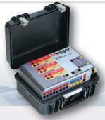





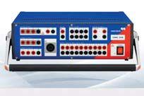
RENTRELAY RENT RELAY TESTERS FR OM E L ECTR O RENT Large inventory includes equipment from motor testers to borescopes Immediately Available for Delivery Megger SMRT36Doble F6150SVManta MTS-5100OMICRON CMC356 Cost effective daily, weekly and monthlyrentals . Electro Rent’s inside application representatives have 15+ years average experience and are ready to help you get what you want. Visit our informative website: Industrial.ElectroRent.com 800-304-4744 sales@electrorent.com

How Do You Ensure Safety and Reliability? Hire a NETA Accredited Company! NETA has been connecting designers, specifiers, architects and users of electrical power equipment and systems with independent, third-party electrical testing companies since 1972. NETA Accredited Companies test the complete system in accordance with industry codes and standards to provide accurate test reports you can count on every time. For more informationon NETA or our ANSI/NETA Standards giveus acall at 888-300-NETA (6382) For a complete listingof NETA Accredited Companies turn to page 124 or visit www.netaworld.org.

www.powertest.org 888-300-6382 (NETA) Join 400+ electrical testing professionals Leading decision makers looking for new products and services For attendee profile and additional information visit www.powertest.org WON’TANEVENTYOUWANTTOMISS! March 3-6, 2014 Hyatt Regency Denver Denver, Colorado The Premier Electrical Maintenance and Safety Event The Premier Electrical Maintenance and Event NEVENTYOUANTTOMIS CALLFOR EXHIBITORS
CHARLES K. BLIZARD, SR.: CELEBRATING 29 YEARS OF SERVICE TO NETA
BY KRISTEN WICKS, NETA
It is always a good day when one has the privilege of recognizing someone who has devoted a lifetime to pursuing his passions. It is with gratitude for decades of service that NETA announces the resignation of Charles K. Blizard, Sr. from the NETA Standards Review Council.
Charlie has shepherded NETA from nearly every leadership position over his tenure with NETA from President to Membership Chair to Secretary to Standards Review Council. Charlie’s legacy within NETA is only eclipsed by the legacy he began within the electrical testing firm he founded: American Electrical Testing Company, Inc. Charlie’s depth and breadth of technical expertise and commitment to maintaining the highest level of integrity in all aspects of his life are hallmarks

of his personality. His tough New England exterior, forged by the will to succeed, is tempered by compassion and heart that endearhimtothosearoundhim. endear him to those around him.
In addition to the ten years Charlie spent reviewing minutes and developing policies as NETA’s Secretary, Charlie played a substantial role in the technical development of NETA. CharlieisachartermemberoftheStandardsReviewCouncil. Charlie is a charter member of the Standards Review Council.
CHARLES K. BLIZARD, SR.: CELEBRATING 29 YEARS OF SERVICE TO NETA 80 WINTER 2013
He rolled up his sleeves and applied the necessary amount of elbow grease required when it was time to write and review the NETA Specifications, a taskthatisnotforthefaintofheart. task that is not for the faint of heart.
Even with all the time, energy, and resources Charlie has contributed to his business and to NETA, he has always put his family first. Charlie and his wife, Norma, are devoted to their children and grandchildren. The warmth that emanates from this love for family embraces all those fortunate enough to spend a little time getting to know these intelligent, funny, and charismatic people.
In 2008, Charlie announced his retirement from American Electrical Testing Company, Inc., which is now under the leadership of his sons who continue to exceed expectations in both business and pwhilanthropic pursuits. Following his retirement, Charlie continued to serve actively on the NETA Standards Review Council until the fall of 2014, when he tendered his resignation with dreams of a retirement freefromdeadlinesandfilledwiththeloveof free from deadlines and filled with the love of grandchildren and family.
An open letter to NETA written by Mary Jordan, former Executive Director of NETA and longtime friend of the Blizard family, in honor of Charlie’s retirement in 2008 still rings true today, “If you are NETA Certified… if you own a NETA Company or have used a NETA Company… if you use the NETA Specifications or reference them… if you are involved in the electrical industry in any way… you should be thanking Charles Blizard.”
Thank you, Charlie, for everything.

Charlie represents AETCO, Inc. at PowerTest.
Standards quality assurance program through the years. C A P
NETAWORLD 81 CHARLES K. BLIZARD, SR.: CELEBRATING 29 YEARS OF SERVICE TO NETA
NETA = Family
NETA
Keep smiling, Charlie.
N as h th

We got your back.
No matter where you are, no matter what you run, if it’s electrical, Shermco’s the one.
Power plants? No problem. Utility substations? We can handle ‘em. Wind farms? Absolutely. Data centers? Just say where and when. The fact is, Shermco has the growing capacity to support your utility or electrical power needs in virtually any location, with all the manpower, equipment and technical knowledge it takes to get the job done and done safely!
While other companies are sending their equipment and workforces out to pasture, we’re upgrading ours and sending them into the field. Call Shermco for anything. Fromlarge-scale engineering projects and planned facility outages, to new system acceptance testing and safe start-up, one company does it all. Shermco. We got your back.
For more information, contact Shermco Industries at 1.888.743.7626 or visit www.shermco.com www.shermco.com


Don’t Let This Happen to You It takes a split second to lose power ...and a lifetime to live it down. Advanced Test Equipment Rentals has everything you need to make sure this doesn’t happen to you. ® Established 1981 Advanced Test Equipment Rentals 800-404-2832 www.Atecorp.com





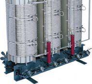


www.BurlingtonSafety.com info@BurlingtonSafety.com Buy Online Now! Metro NY/NJ/PA 800-220-2120 Calif (SF) 888-817-1412 Calif (LA) 800-296-2803 And Your Source for NFPA 70E Compliant Protective Gear 228 Merrick Road Lynbrook, NY 11563 (631) 589-6343/Fax (516) 596-3680 601 Union Street Brooklyn, NY 11215 (718) 786-4900
UNDERSTANDING INSULATION TEST RESULTS OF A WITH A GROUNDED ELECTROSTATIC SHIELD
BY MICHELLE WARD, Doble Engineering Company
INTRODUCTION
Ashieldedtransformerisatransformerthat A shielded transformer is a transformer that has a grounded electrostatic plate (shield) between the high-voltage and low-voltage windings (Figure 1). The grounded shield provides a low impedance path to ground by capacitive coupling which prevents unwanted high frequency signals contained in the source voltage from reaching the transformer secondary. This is valuable in protecting sensitive equipment from common-mode electrical noise and transients generated on the sourcesideofthetransformer. source side of the transformer.
The shield is not always represented on a transformer nameplate. This can be very troublesometoatestersincetestresultsfor troublesome to a tester since test results for a shielded transformer will be very different compared to the expected nonshielded results.
BODY
Figure 2 shows electrical representations of a two-winding transformer (A) and a two-winding transformer with an electrostatic shield (B). As shown in B of Figure 2 the grounded shield
provides a low impedance path to ground by capacitive coupling between it and the high- and low-voltage windings.
The best way to test the insulation in a transformeristobreakdownthetransformer transformer is to break down the transformer intothesmallesttestableunits.Dobledoes into the smallest testable units. Doble does this by using test cir-cuits or paths within the transformer and breaks the insulation testing to three separate sections:
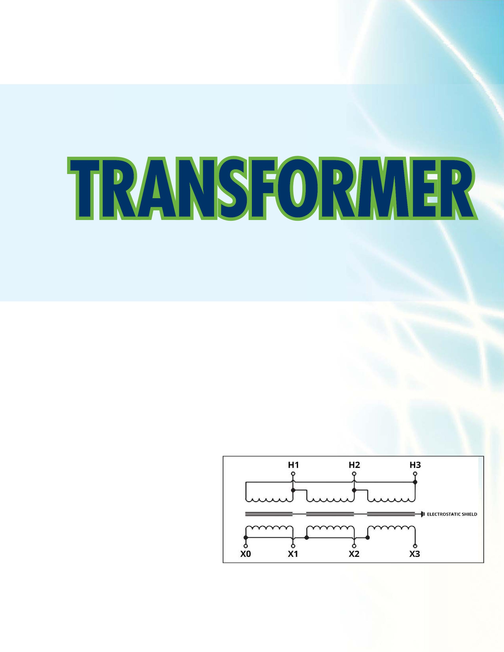
Figure 1: Nameplate Representation of a 2 Winding Transformer withGroundedElectrostaticShield. with Grounded Electrostatic Shield.
NETAWORLD 85 UNDERSTANDINGINSULATIONTESTRESULTSOFA UNDERSTANDING INSULATION TEST RESULTS OF A TRANSFORMERWITHAGROUNDEDELECTROSTATICSHIELD TRANSFORMER WITH A GROUNDED ELECTROSTATIC SHIELD INDUSTRYTOPICS INDUSTRY TOPICS


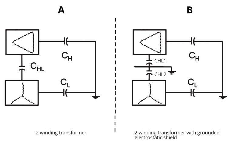


CH: The insulation between the high side winding and the tank wall.

CHL: Inter-winding insulation. The insulation between the low- and high-voltage windings.
CL: The insulation between the low-voltage winding and the core.
Test three insulation components of the twowinding transformer: CH, CL, and CHL. If a transformer has a grounded shield between the high- and low-voltage windings, the internal test circuits change. The figures below will illustrate the difference in circuits using the overall test for transformers with and without a grounded electrostaticshield. electrostatic shield.

Looking at B of figures 3 and 4, the same insulation (CH+1/2 CHL) is measured for both the ground and the guard circuits. Figure 5 illustrates the third test circuit, the UST test circuitwhichismeanttotesttheCHLintercircuit which is meant to test the CHL interwinding insulation.
Now that there is an understanding of a shielded transformer and the test circuits, let’s look at some results.Belowaretestresultsoftransformers results. Below are test results of transformers with and without a grounded electrostatic shield.

UNDERSTANDINGINSULATIONTESTRESULTSOFA UNDERSTANDING INSULATION TEST RESULTS OF A TRANSFORMERWITHAGROUNDEDELECTROSTATICSHIELD TRANSFORMER WITH A GROUNDED ELECTROSTATIC SHIELD 86 WINTER 2013 INDUSTRYTOPICS INDUSTRY TOPICS
Figure 3: Ground Test Configuration – Measures Current from Energized Winding to Ground and Interwinding Current.
Figure 2: Dielectric Representation of 2 Winding Transformer with and without Grounded Electrostatic Shield.


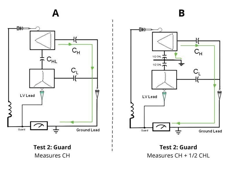


Figure 4: Guard Test Configuration – Measures Current from Energized Winding to Ground and Guards Inter-winding Current.
Table 1 has typical Power Factor results for a 2 winding transformer.
Table2showstheresultsforatransformer Table 2 shows the results for a transformer with a grounded electrostatic shield between the high and low side windings. Notice the mA, Capacitance and Watts values of the “CHL+CH”and“CH”AND“CHL+CL” “CHL+CH” and “CH” AND “CHL+CL” and “CL” tests are very similar (the mA are highlighted in the table). Also the mA and Wattsvaluesforallofthe“CHL”resultsare Watts values for all of the “CHL” results are very low. It is also apparent the Power Factor for the “CHL (UST) results are low and it is not uncommon to see a negative power factor for any CHL value.


CONCLUSION
Power-factor test results of a two-winding transformer with a grounded electrostatic shield will differ greatly from a two-winding transformerwithoutashield.Youwillsee transformer without a shield. You will see that the [CH +CHL and CH] test results are

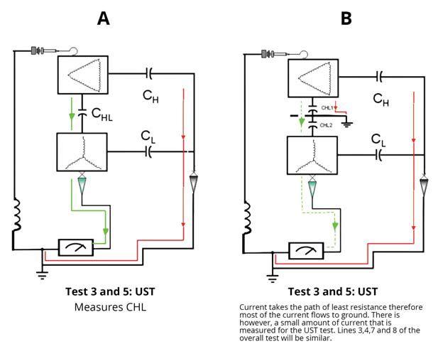
Figure 5: UST Test Configuration – Measures Inter-winding Current and Guards Current from Energized Winding to Ground.

NETAWORLD 87 UNDERSTANDINGINSULATIONTESTRESULTSOFA UNDERSTANDING INSULATION TEST RESULTS OF A TRANSFORMERWITHAGROUNDEDELECTROSTATICSHIELD TRANSFORMER WITH A GROUNDED ELECTROSTATIC SHIELD INDUSTRYTOPICS INDUSTRY TOPICS


Table1: Table 1: Unshielded Transformer GE 161KV/13.2KV 61 MVA

Table2: Table 2: Transformer with Grounded Electrostatic Shield GE 161KV/13.2KV 76 MVA


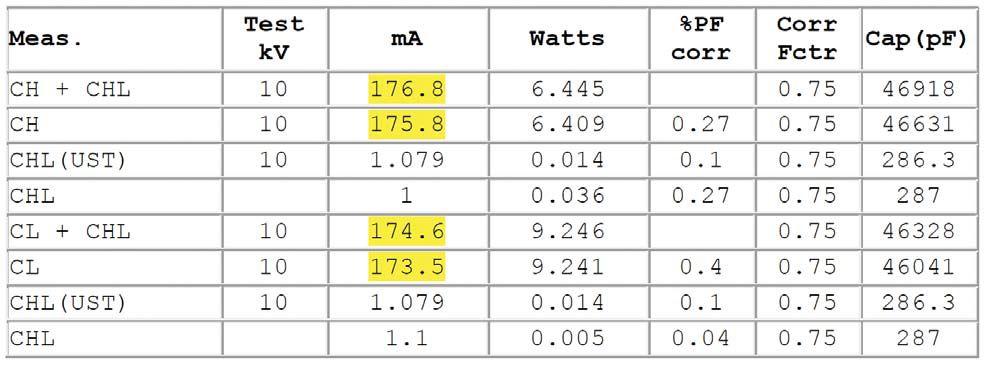
almost equal and also the [CL+CHL and CL] test results are almost equal. The CHL values are very low and can even be negative.


These results can be confusing if you do not know that you are testing a shielded transformer. Some nameplates do not show the grounded electrostatic shield. You now know what results of this type indicate. If you knowthatthetransformerisshieldedtheabove know that the transformer is shielded the above results will be expected.
REFERENCES
1.IEEEStdC57.110-1998 1. IEEE Std C57.110-1998 IEEE Recommended Practice for Establishing Transformer Capability When Supplying Nonsinusoidal Load Currents
2.IEEEStd519-1992 2. IEEE Std 519-1992 IEEE Recommended Practices & Requirements for Harmonic Control in Electrical Power Systems


MichelleWard Michelle Ward received a Bachelor of Science in Electrical Engineering from Northeastern University in Boston, Massachusetts.ShehasworkedatDoble Massachusetts. She has worked at Doble Engineering Company, Watertown, Massachusetts for nine years with four years at her current position of Senior Client Service Engineer. Michelle is Secretary of Doble Engineering’s Bushings, Insulators, and Instrument Transformers Committee and is a member of the IEEE Power Engineering Society.

UNDERSTANDINGINSULATIONTESTRESULTSOFA UNDERSTANDING INSULATION TEST RESULTS OF A TRANSFORMERWITHAGROUNDEDELECTROSTATICSHIELD TRANSFORMER WITH A GROUNDED ELECTROSTATIC SHIELD 88 WINTER 2013
INDUSTRYTOPICS INDUSTRY TOPICS


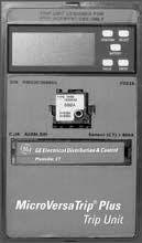
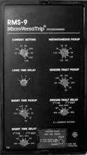


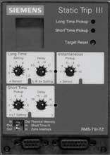
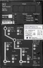
30 Years of Repair & Testing Excellence Now repairing: Siemens SB Type TL Square D MICROLOGIC Series B trip units Merlin Gerin ST & STR Units Call for all RMS-9 rating Plug needs Eddie Tate – Owner Damian Hobson – Lead Technician Phone: 601-856-9798 Fax: Thyritronics has been providing quality and timely trip unit repair to the electrical industry for over 30 years. We wish to thank all our fine customers for their loyalty and many referrals. AllMajor Manufacturers Calibration usingMulti-Amp’s Epoch System Extensive Test Report Non-RMSUnits — $300 RMSUnits — $500 Test Only Services — $100 OneDay Rush Capabilities Thyritronics, Inc. Industry Leader in Trip UnitRepairs SEE OUR WEBSITE for all our services: www.thyritronics.com
OF EXISTING
 BY MIKLOS J OROSZ, Schneider Electric
The rapid growth of utilities and heavy industry, such as steel manufacturing and oil refineries, has increased the need for more, better, and reliable power distribution and control. Loss of power in today’s manufacturing environment could mean the total loss of production and equipment. According to studies published by the Hartford Steam Boiler Insurance Company and FM Global, “Electrical equipment failures account for millions of dollars in damage and lost business every year.”
SWITCHGEAR CONSTRUCTION 101
Electrical switchgear is composed of passive and active components. The switchgear’s frame, enclosure, and horizontal and vertical bus sections make up the passive elements of the equipment. Circuit breakers and fusible switching devices have an active role in the equipment’s operation which includes protecting the electrical assets downstream, disconnecting the circuit, and reducing or eliminating the arc-flash hazards associated with switching high magnitude currents.
This article will primarily focus on the most commonly utilized active component in switchgear, the circuit breaker. As such it plays a vital part in determining the best way to extend the life of your switchgear.
Medium-voltage switchgear can consist of one of four types of circuit breakers based on the arc quenching medium: air, vacuum, oil, or SF6 gas. These circuit breakers are
typically draw-out type, a design which facilitates removal from the power source and simplifies maintenance. Air, vacuum, oil, and SF6 gas circuit breakers require similar maintenance; however, each has unique characteristics and testing procedures.
MAINTENANCE REQUIREMENTS
Major electrical equipment manufacturers generally require annual maintenance for power circuit breakers to ensure proper operation and to maintain equipment warranties.Thismaintenanceconsistsof warranties. This maintenance consists of cleaning and lubrication of the primary and secondary disconnects, racking mechanisms, and cell interlocks. A thorough on-site maintenance work scope for power circuit breakersincludes: breakers includes:
EXTENDINGTHELIFEOFEXISTINGSWITCHGEAR EXTENDING THE LIFE OF EXISTING SWITCHGEAR 90 WINTER 2013
INDUSTRYTOPICS INDUSTRY TOPICS

The use of new or refurbished parts or subassemblies may be required to return a circuit breaker to its designed operating condition.
A more intensive maintenance option for circuit breakers is in-shop reconditioning. With this option, the breaker is initially testedtorelevantANSIstandardsand tested to relevant ANSI standards and then completely disassembled, cleaned and inspected. Damaged parts are refurbished or replaced, and pivot points are cleaned andlubricatedbeforethecircuitbreaker and lubricated before the circuit breaker isreassembled.Thereconditionedbreaker is reassembled. The reconditioned breaker is retested to relevant ANSI standards, including primary current injection and timing tests.
Even with annual maintenance, however, power circuit breakers may need additional upkeep or upgrades. Factors to consider include the operating environment, availability of spare parts, reliability, and the cost of ongoing maintenance. There may also be the need to increase the switchgear’s short-circuit or continuous-current rating, or the desire to upgrade technology. As a result, facility managers are often faced with the choice of maintaining aging (or obsolete) equipment or replacing it with a new switchgear lineup to take advantage of current technology.
FINANCIAL CONSIDERATIONS WHEN REPLACING SWITCHGEAR
Inadditiontotheinitialcostofnew In addition to the initial cost of new switchgear, it is important to consider the potential disruption to the facility’s processes and workflow during the course of changing out the equipment. Unless process loads can be rerouted temporarily during the demolition of old equipment and
installation of the new switchgear, the cost of lost production can be substantial.
Anotherconsiderationthatisoften Another consideration that is often overlooked is conduit placement. Installing new switchgear (which is usually smaller than the older/obsolete equipment it is designed to replace) requires that existing conduit above and below the equipment be moved. Cabling may need to be replaced or spliced. This is an expensive and time-consuming process, often costing more in labor and material than the cost of the new equipment.
Facility managers now have another option to consider for the repair vs. replace dilemma. New design capabilities exist to modernize and extend the life of the active components, i.e., circuit breakers, while leaving the existing passive switchgear structure intact. All things considered, extending the life of existing switchgear in this way is most often a real advantage.
WHYUPDATE? WHY UPDATE?
Modern power circuit breakers are designed using state of the art materials and arcextinguishing technology. Since power circuit breakers provide such a vital function in protecting the electrical system, as well as reducing or eliminating arcing fault hazards, these design improvements are a quantum leap forward in equipment and operating personnel protection. In addition, they have lower maintenance requirements than the older design circuit breakers.
With this in mind, following are eight reasons to extend and optimize the life of your electrical switchgear equipment and improve its reliability:
Rating Upgrades -Astheneedformore - As the need for more and more power at many industrial facilities increases so does the need for improved and increased protection of the electrical system. In most cases the switchgear bus, bracing, frame, or enclosure are usually higher rated than the circuit breakers, but if not they
NETAWORLD 91 EXTENDINGTHELIFEOFEXISTINGSWITCHGEAR EXTENDING THE LIFE OF EXISTING SWITCHGEAR INDUSTRYTOPICS INDUSTRY TOPICS

typically can be upgraded. The circuit breaker used in the switchgear also can be upgraded at least one class, for example, from 25 kA short-circuit interrupting capability to 40 kA, and in some cases, even up to 50 kA. The continuous-current carrying capability also can be increased by reviewing the existing switchgear bus design and updating it. Modern vacuum circuit breakers are also faster, most having short-circuit current-interrupting ratings of three cycles or less, compared to the older circuit breakers with interrupting time of five cycles, eight cycles or even more.
Environmental Upgrades – Many old design air magnetic circuit breakers used asbestos-based arc chutes, oil used in the oil circuit breakers may contain hazardous chemicals, and SF6 gas was recently classified as a greenhouse gas. By replacing these designs with the new technology of vacuum interrupters, environmental concerns can beresolved. be resolved.
Performance and Safety Upgrades –Circuit – Circuit breaker and switchgear upgrades can offer enhancements for performance and improved safety. Integrating new state of the art, arcresistant technology into the retrofit can increase protection for both personnel and equipment. As an added benefit, because the short-circuit interruption and opening time is generally faster, the upgraded circuit breaker is better suited for load transfer applications.
Upgrading can also increase the capabilities of circuit breakers and switchgear.
- Newcircuitbreakersareavailablewith New circuit breakers are available with higher ratings
- In most cases the interruption capacity of the entire switchgear can be increased with an engineering study and a circuit breaker upgrade or replacement
newcircuitbreakers new circuit breakers
Upgrades to Meet the Latest ANSI Standards – A major improvement in circuit breaker design is that vacuum circuit breakers are operating with the voltage factor K=1, which means that the interrupting capability is not affected by the system voltage. A vacuum circuit breaker with an assigned short-circuit current interrupting capability will function at any voltage level without reducing the assigned short-circuit interrupting rating. This allows the user to be more flexible concerning interchangeability ofthenewcircuitbreakers. of the new circuit breakers.
Improved Reliability – Aging materials reduce equipment reliability due to the dielectric breakdown of insulating components and the degradation of aging mechanical parts. Electromechanical trip devices on existing circuit breakers may not trip at all. Those that do trip are not repeatable and may be well outside the time-current coordination parameters.
ReducedMaintenanceCosts Reduced Maintenance Costs – By using upgraded vacuum circuit breakers as retrofits, the circuit breaker maintenance cycle can be extended to five years or more. There are state of the art circuit breaker designs that utilize a virtually maintenance free operating system. Compare this with these facts:
extensive periodic maintenance and overhaul which is expensive and time consuming:
- Lengthens outages
- May require extensive outside support
circuit breakers are no longer available:
- The quantity and quality of used or reconditioned parts is decreasing and unreliable
- Prices of replacement parts are increasing
Upgrades Reduce Size and Weight of the CircuitBreaker Circuit Breaker – Typically a 30 percent to 60 percent weight reduction can be achieved by using the new vacuum technology. This
92 WINTER 2013
communication
INDUSTRYTOPICS INDUSTRY TOPICS EXTENDINGTHELIFEOFEXISTINGSWITCHGEAR EXTENDING THE LIFE OF EXISTING SWITCHGEAR
can improve access for maintenance and transportability.
Upgrade/Retrofit Cost Considerations –
There are several factors influencing the cost when considering upgrades, repairs, or retrofit solutions, compared to acquiring new equipment as follows:
cost to retrofit/upgraded equipment personnel
See Figure 1.

CHOOSING THE CIRCUIT BREAKER/SWITCHGEAR SOLUTION
Retrofitting is a general term that is used to define any process which allows for modernizationandlifeextensionofelectrical modernization and life extension of electrical equipment. Direct replacement and retrofill solutions are two different retrofit strategies to adapt modern circuit breakers into existing low-voltage or medium-voltage switchgear. The switchgear structure, conduits, cabling, and footprint are left intact which saves time and money.
breaker fits into the existing cubicle withlittle-to-nomodificationtothe with little-to-no modification to the switchgear cell. This option reduces downtime since there is minimal (if any) outage on the equipment bus.
NETAWORLD 93
INDUSTRYTOPICS INDUSTRY TOPICS EXTENDINGTHELIFEOFEXISTINGSWITCHGEAR EXTENDING THE LIFE OF EXISTING SWITCHGEAR
Figure 1: The original air magnetic circuit breaker with asbestos based arc chutes shown on the left and the direct replacement modern vacuum circuit breaker shown on the right.

and bus are modified to accept the new circuit breaker. This process usually requires a longer bus outage, during whichtimetheinternalcircuitbreaker which time the internal circuit breaker cell is modified to accept the new circuitbreaker. circuit breaker.
CASESTUDY CASE STUDY:MEDIUM: MEDIUMVOLTAGE RETROFILL
An automotive facility’s personnel were concerned about a lengthy and costly downtime because of outdated switchgear operating in this automotive manufacturing plant. The facility’s two primary switchgear lineups were installed in the early 1950s. Though they were still operational, the age of the circuit breakers connected to the 2,000 ampere bus in both lineups, along with the elevator-like system used to remove them from the switchgear for maintenance, made for an outdated system that raised concerns of reliability and posed an increased risk of hazard for the plant’s electricians.
After much investigation, facility management selected a retrofill solution to upgrade all 19 circuit breakers with new medium-voltage circuit breakers. Existing switchgear cubicles were reconfigured to accept the new circuit breakers, leaving the switchgear structure and footprint intact. The retrofill solution also included installation of solid-stage digital relays, a new exterior door (where the relays resided) and an interior sub-plate positioned beyond the circuit breaker to minimize possible exposure to the energized bus. The elevator racking system was also replaced with a new cradle assembly for each cubicle. As a result, the physical action of racking out a breaker would be accomplished with the exteriordoorclosed. exterior door closed.
With the circuit breakers and relays installed, the plant has a more reliable electrical distribution system. This solution met the facility management’s goal of upgrading the equipment extending its useful life, minimizing downtime, and enhancing workplace safety for the plant’s electricians.
Though direct replacement and retrofill solutions have different processes, both have the same end result: improved power system reliability and lower lifecycle costs.
CONCLUSION
Electrical equipment and power distribution systems have never been designed to be or intended to remain perpetually energized without interaction by the owner. If maintenance has not been regularly performed, this less-than-satisfactory condition may be entered prematurely and a shortened useful life of the components may be the result.
Modernization solutions present a viable alternative to purchasing new equipment. The most obvious benefit of upgrading existing electrical switchgear is the significant savings on costs that would have been dedicated to buying new equipment — and not just the physical equipment, but the time and labor involved in specification, procurement, installation, testing, recabling and commissioning. With careful consideration and proper implementation of the points covered in this article, the life and reliability of switchgear can be maximized.
Mike Orosz, Sr. Staff Mechanical Engineer at Schneider Electric Company has 40 years industry experience (36 years with Schneider Electric). His areas of expertise include: medium-voltage switchgear and circuit breaker design, mediumvoltage motor starter design, field problem investigation and work, SF6 interrupter, vacuum interrupter, ANSI IEC testing, mechanism design, materials, plastic moldings, heat treating and finishing and sheet metal design. Mike is a member of IEEE, PES, ASM and IEC TAG.
94 WINTER 2013
INDUSTRYTOPICS INDUSTRY TOPICS EXTENDINGTHELIFEOFEXISTINGSWITCHGEAR EXTENDING THE LIFE OF EXISTING SWITCHGEAR

NETA Training Opportunities for the Electrical Power Systems Industry TRAINING Online Training Courses Self-Paced Technical Seminars (SPTS) Electrical Safety Training System (ESTS) Ask about continuing education credits. To learn more, visit www.netaworld.org/training or call 888-300-6382 (NETA) Learn at your own pace. Advance your knowledge.
BRINGING MORE SMARTS TO GETTING YOU YOUR PARTS.


National Switchgear has millions of new, surplus and repurposed electrical circuit breaker & switchgear products. And coming soon, with a suite of e-commerce solutions , we’re making it easier than ever for you to find the part that’s perfect for you. You’ll be able to browse, filter results by category, manufacturer or specs, see your pricing level, and more – 24/7. Just go to nationalswitchgear.com and see our latest innovations. It’s the fastest lane to our massive inventory. If you’re ordering parts from anyone else, it’s time to switch.
800-322-0149 nationalswitchgear.com
HAVING MILLIONS OF PARTS IS ONLY PART OF THE STORY.

MARCH 2–5, 2015 SPONSORSHIPS ARE NOW AVAILABLE! Reach hundreds of leading decision–makers at the conference Receive free advertising and press reaching 24,000+ industry professionals before, during, and after the event Available in all price ranges The Premier Electrical MAIN T ENAN C E AND SA FE T Y Event neta@netaworld.org www.powertest.org Energize your future

800-258-7044 www.three-c.com Serving the Northeast U.S. CAN YOUR TESTING COMPANY PASS THIS TEST? Why leave the reliability of your electrical equipment to chance? Trust the experts at Three-C Electrical with your generation and power distribution equipment. The Power Systems Specialists Independent Electrical Testing and Preventive Maintenance PROFESSIONAL SERVICES 609-890-8300 www.easternhighvoltage.com
BY LYNN HAMRICK, ShermcoIndustries Shermco Industries
THE OF A ROUTE
Physical Inspections should be performed on electrical equipment. The most cost-effective form of inspection is a periodic walk-through to evaluate general equipment condition and changes to operating parameters. For critical equipment, this should take the form of a periodic maintenance route to ensure that an adequate physical inspection is performed.
While performing the inspection, the inspector shouldbeawareofthevisualevidenceassociated should be aware of the visual evidence associated with installation errors, equipment subassembly failures, poor equipment condition, overheating, and corona. Further, where indicators of physical parameters are available, the inspector should regularly monitor and trend status and other available data for system condition.
BACKGROUND – TRANSFORMER MAINTENANCE ROUTE
Liquid-filled transformers are a typical example of critical equipment that should have a specific maintenance route. Most liquid-filled transformers have liquid level, temperature, and pressure indicators. These should be monitored periodically to ensure that the transformer is operating within acceptable parameters. In addition, the route should include inspections for oil leaks and spills.
Most transformers have an oil temperature gauge that measures the actual top oil temperature. Top
oil temperatures should be routinely observed to see whether the transformer is operating within normal temperature limits. For temperature, the level of the high temperature indicator should
transformer, a typical temperature of 55° C or 65° C (131° F or 149° F, respectively) is stated as the operating temperature limit of the
NETAWORLD 99 THEIMPORTANCEOFAPERIODICMAINTENANCEROUTE THE IMPORTANCE OF A PERIODIC MAINTENANCE ROUTE
INDUSTRYTOPICS INDUSTRY TOPICS
PHOTO COURTESY OF QUALITROL
Figure 1: Transformer Temperature Gauge

windings. It should benotedthatthe be noted that the top oil temperature is probably lower than the winding temperature. A photograph of a typical oil temperature gauge is provided in Figure 1.
Most transformers also have a pressure gauge that measures the pressure of the nitrogen blanket the above the oil. The gauge usually indicates negative or positive pressure. The pressure can vary from slightly negative to slightly positive due to ambient temperature and operating conditions. For sealed transformers, it is recommended that is the pressure always be maintained at a slightly positive pressure. This is indicative of a proper sealandalsoensuresthatmoisturefromtheair seal and also ensures that moisture from the air does not leak into the nitrogen-filled gap at the top of the transformer. A photograph of a typical oil pressure gauge is provided in Figure 2.
An oil level gauge is also provided so that the correctoillevelcanbemaintained.Thereis correct oil level can be maintained. There is usually a mark on the gauge that indicates the 25° C level, which is the proper oil level for the transformer at that temperature. Maintaining the proper oil level is extremely important because if the oil level falls below the level of the radiator inlet, flow through theradiatorwillceaseandthetransformer the radiator will cease and the transformer will overheat. A very low oil level can also expose energized and current-carrying components that are designed to operate in oil and could result in overheating or an electrical flashover. If the oil level is too high, it could cause over pressurization as the oil expands when heated due to heavy loading conditions. A photograph of a typical oil level gauge is
provided in Figure 3.
When combined with periodic oil sampling and IR surveys, this maintenance route can be very useful in identifying issues with a transformer before the issues become major problems resulting in a catastrophic failure of the transformer. The case below is a good example of this.
CASE STUDY – TRANSFORMER MAINTENANCE ROUTE
While performing a maintenance route for the transformers at a large industrial company, amaintenanceworkernotedthattheoil a maintenance worker noted that the oil temperature gauge for two of the transformers (designated A and B for this discussion) had a higher than normal high oil temperature indicationofbetween45°Cand50°C. indication of between 45° C and 50° C. All other operating indications for both transformers were in the normal ranges. An investigation of the cause of these potential problems was initiated.
A review of the most recent oil sample reports indicated no problem for Transformer A. However, for Transformer B, higher than 2 levels suggested an overheating condition. The insulation type for the transformer has a rating of 65° C. Trending of the past routing information for Transformer B showed that the Top Temp for Transformer B was typically 50° C. This temperature was at least 10° C higher than any other transformer. This higher operating temperature is prob2 levels are so high. The
100 WINTER 2013 THEIMPORTANCEOFAPERIODICMAINTENANCEROUTE THE IMPORTANCE OF A PERIODIC MAINTENANCE ROUTE INDUSTRYTOPICS INDUSTRY TOPICS
PHOTO COURTESY OF QUALITROL
Figure 2: Transformer
Pressure Gauge
PHOTO COURTESY OF QUALITROL : e 2 sfo msfor er or r rm fTrrans a G e
Figure 3: Transformer Level Gauge
Gauug

transformer has been operating under these conditions for the last one to two years with no trending up of the other key gases.
Inanefforttosecuremoreinformationon
In an effort to secure more information on the transformers without a shutdown, it was suggested that an IR survey be performed of theoutsideofthetransformersinaneffort the outside of the transformers in an effort to adequately understand the problems. With a proper IR survey of the outside of the transformer, an experienced and qualified worker can evaluate the natural cooling aspects of the transformer as well as the oil levelwithinthetransformer. level within the transformer.
As can be seen in Figure 4, a transformer with a correctly operating, natural-circulation cooling system will have a typical heat signature of the radiators with a gradual temperature rise from the bottom to the top of the cooling fins. The oil level will also be above the top of the tubes of the radiators for proper oil circulation.
The IR survey can also be useful in evaluating other equipment associated with the transformer cooling system. Figure 5 is indicative of a correctly operating cooling fan that supports the oil cooling features of thetransformer.Notethatthefanmotoris the transformer. Note that the fan motor is running and that the cooling fins also have the correct temperature signature for natural circulationoftheoil. circulation of the oil.
the IR survey of transformer A is provided in Figure 6. The outside skin temperature is 20° to 30° F above the other transformers at 121° F. It appears that there is oil circulation, but the cooling fan is not running. Transformer cooling fans are controlled with thermostats such that they turn on and off based on the temperature settings. Further investigation revealedthatthethermostatforthefan revealed that the thermostat for the fan was not operating correctly. Replacing the thermostat and implementing the proper temperature settings resolved this transformer issue. More importantly, an outage was not
required to implement corrective action for transformerA. transformer A.
the IR survey of transformer B is provided in Figure 7. The outside skin temperature is ~ 30° F above the other transformers at ~127° F. This transformer has 3 sets of cooling radiators, west, north and east. Figure 7 is a
NETAWORLD 101 THEIMPORTANCEOFAPERIODICMAINTENANCEROUTE THE IMPORTANCE OF A PERIODIC MAINTENANCE ROUTE
INDUSTRYTOPICS INDUSTRY TOPICS
Figure 4: Typical Transformer IR Survey – Radiator
Figure 5: Typical Transformer IR Survey – Fan Motor
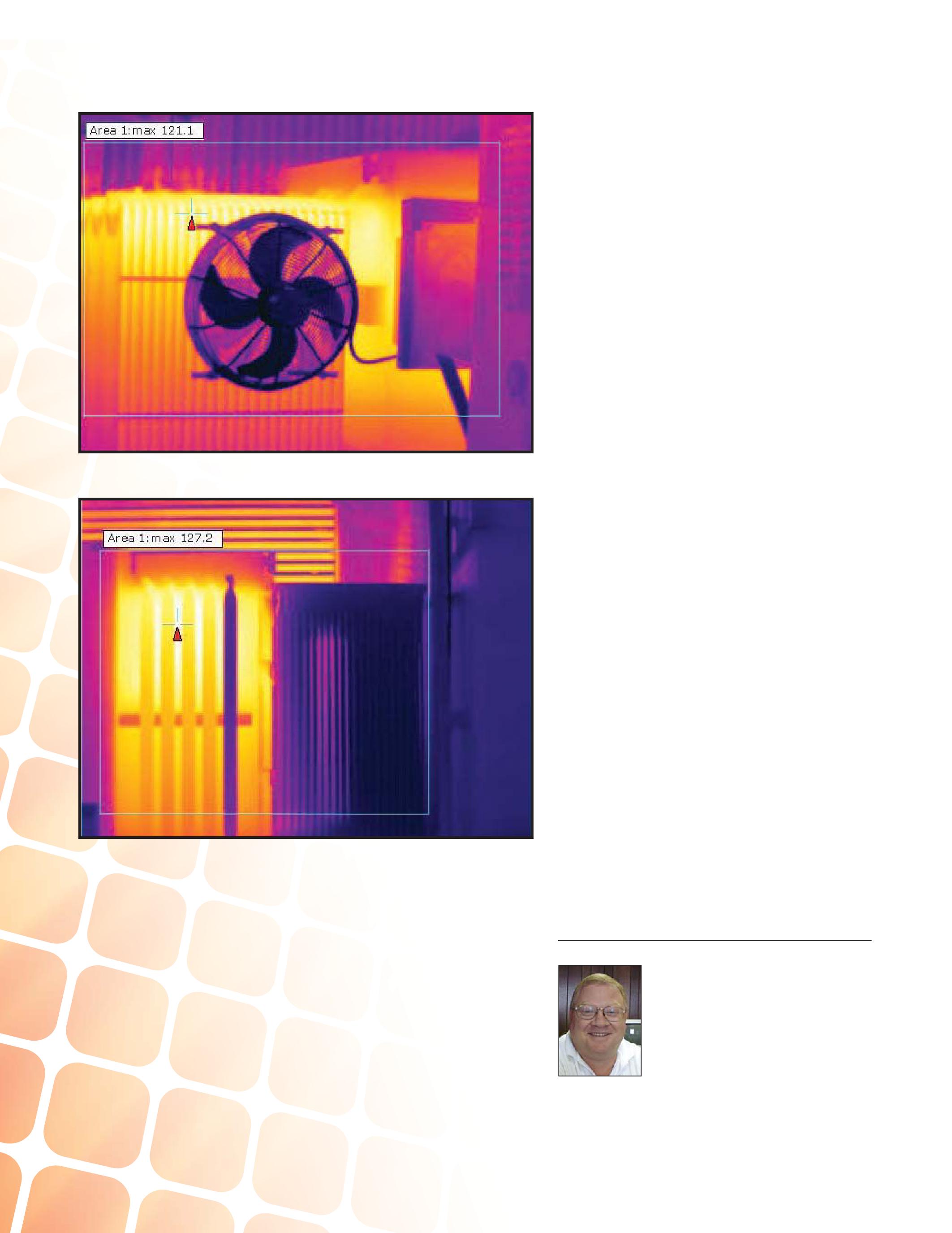
photograph of the east and north cooling fins.
Based on the IR survey, the oil does not appear to be circulating through the north radiator and is minimally circulating through the west radiator. There was oil circulating through the east radiator, except for the northern most set of tubes. Further investigation revealed that thetransformerwasnotlevel.Thetransformer the transformer was not level. The transformer basehadsettledsuchthatthesouth-east base had settled such that the south-east cornerofthetransformerwastwoorthree corner of the transformer was two or three incheslowerthanthenorthwestcorner.This inches lower than the northwest corner. This
problem with the transformer being not level resultedintheleveloftheoilforthewestand resulted in the level of the oil for the west and north sets of fins being inadequate to maintain proper natural circulation of the oil in the cooling fins. At the next available outage, the transformerwasleveledandoilwasaddedto transformer was leveled and oil was added to ensurecorrectoilcirculationwasrestored. ensure correct oil circulation was restored.
Based on the results of this investigation, more attention is being provided to the performance and review of periodic maintenance routes for transformers. Additionally, IR surveys of the outsideoftheirtransformershasbeenaddedto outside of their transformers has been added to the transformer maintenance route. Further, themaintenanceworkershavebeentrained the maintenance workers have been trained in correct performance of the transformer maintenance route, oil samples, and IR surveys as well as the collective review of the information provided through these activities.
SUMMARY
This case study suggests the following key attributes for implementing a periodic maintenance route, particularly for transformers:
tool for monitoring and maintaining critical electrical equipment health.
maintenance route and other predictive maintenance activities can provide indicators of impending equipment problems and, thus, be usedtoaccommodatecost-effectivecorrective used to accommodate cost-effective corrective action and proper maintenance planning.
qualified workers is critical to the success of any maintenance program.
is also critical to the success of any preventive maintenance program.
Lynn Hamrick brings over 25 years of working knowledge in design, permitting, construction, and startup of mechanical, electrical, and instrumentation and controls projects as well as experience in the operation and maintenance of facilities.
Lynn is a Professional Engineer, Certified Energy Manager and has a BS in Nuclear Engineering from the University of Tennessee.
102 WINTER 2013 THEIMPORTANCEOFAPERIODICMAINTENANCEROUTE THE IMPORTANCE OF A PERIODIC MAINTENANCE ROUTE INDUSTRYTOPICS INDUSTRY TOPICS
Figure 6: Transformer A – Fan Motor Not Running
Figure 7: Transformer B – Cooling Problem
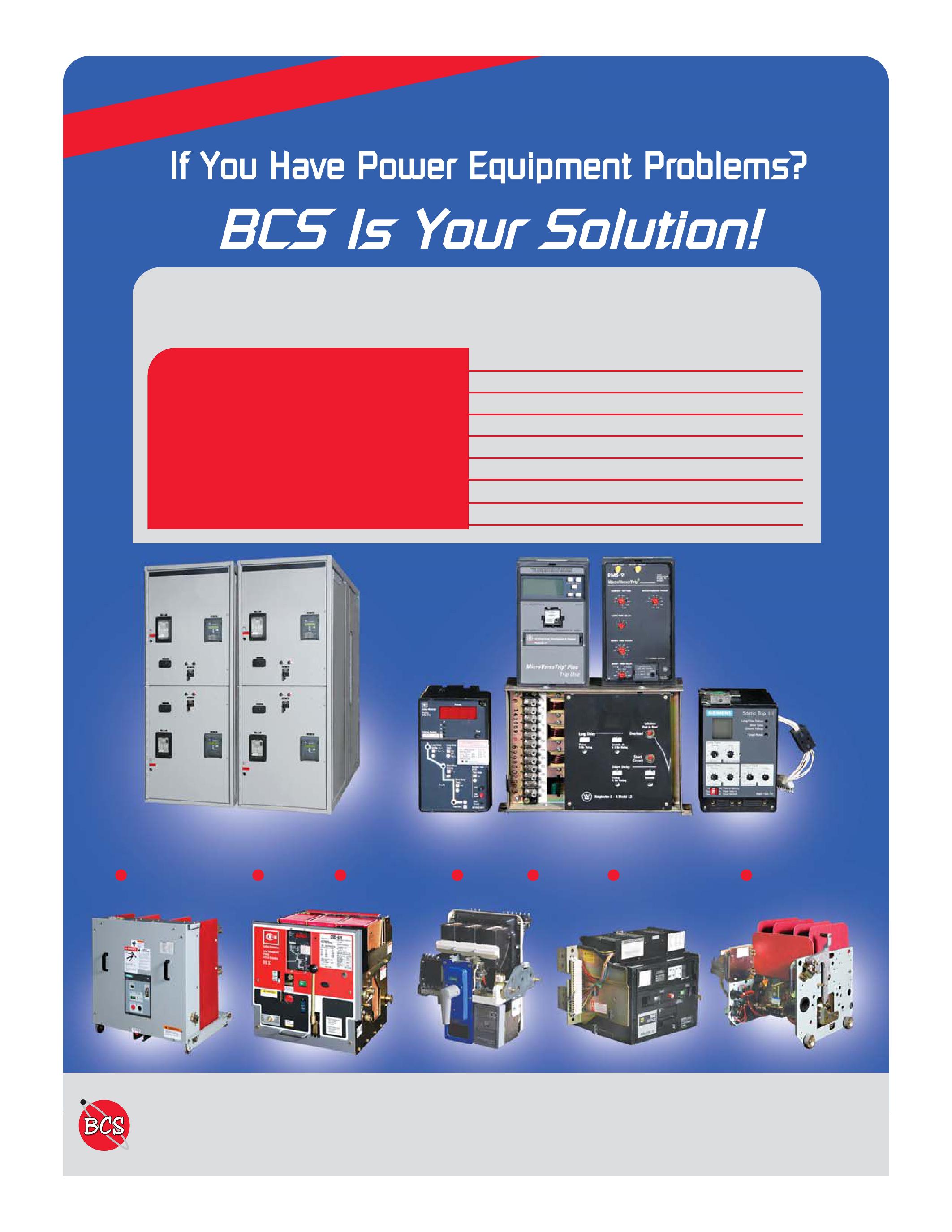
ABB GENERAL ELECTRIC ITE GOULD WESTINGHOUSE SIEMENS SQUARE D ALLIS CHALLMERS FEDERAL PACIFIC MoldedCaseBreakers Molded Case Breakers InsulatedCaseBreakers Insulated Case Breakers AirCircuitBreakers Air Circuit Breakers Medium Voltage Breakers
Vacuum Breakers
Vacuum Contactors/Starters
Switchgear BCS Switchgear, Inc. is one of the largest stocking distributors and repair facilities of quality equipment. New Used Obsolete Reconditioned BCS SWITCHGEAR, INC. www.bcsswitchgear.com 24-HourServiceToll-Free: 24-Hour Service Toll-Free: 888-599-0486 Fax: 940-365-1808 OurNewAddress: Our New Address: 4790 Hwy 377 South Krugerville, TX 76227 TEXASOFFICE TEXAS OFFICE VIRGINIAOFFICE VIRGINIA OFFICE 24-HourService: 24-Hour Service: 276-945-9555 Fax: 276-945-9552 WE’VE MOVED
VacuumBreakers
VacuumContactors/Starters
Switches

RENT SECONDA RENT SECONDARY RY CURRENT TEST SETS F FROM ROM ELECTR ELECTRO RENT O Cost effective daily, weekly and monthly rentals. Our calibration labs are A2LA accredited ISO/ IEC17025:2005 Cutler Hammer 140D481G03 Square D S33595Siemens PTS-4Utility Relay AC-PRO Large inventory includes equipment from power factor test sets to power & demand analyzers Immediately Available for Delivery Immediately Available for Delivery 800-304-4744 sales@electrorent.com Visit our informative website: Industrial.ElectroRent.com CHOOSE BETWEEN KEEPING MAINTENANCE COSTS DOWN AND KEEPING UP WITH PRODUCTION DEMAND…OR DO BOTH. THAT’S THE CRITICAL DIFFERENCE. NETA certified experts at Electrical Reliability Services will keep you in perfect balance. To ensure the reliability of your electrical power, you have to balance the need to reduce maintenance costs with the need to perform regular maintenance. Only the team from Electrical Reliability Services delivers cost-effective services and system expertise to keep you up and running 24/7. Emerson, Business-Critical Continuity, Emerson Network Power and the Emerson and Double Helix Design are trademarks and service marks of Emerson Electric Co. ElectricalReliability.com

Reverse
CBS stocks every low- and medium-voltage circuit breaker made in America since 1945.
parts and ppqpequipment
retrofits, and upgrades
Replacement
Remanufacturing,
engineering, 3D printing of obsolete parts With more than 5 million breakers and parts in our 200,000-square-foot warehouse including switchgear, transformers, substations, protective relays, loadbreak switches, electrical contacts, motor controls and centers, vacuum interrupters, and more — Circuit Breaker Sales has you covered. Visit thecircuitbreakersales. blogspot.com and identify this month’s “Mystery Part” picture contest to win a cash prize! Areyouanelectricalgenius? formation about Group CBS and its affiliate companies, visit For mo re infnform ati at on www.GroupCBS.c oup p CBS c .co m Circuit Breaker Sales Co., Inc. | 1315COLUMBINE | GAINESVILLE,TEXAS76241 | 940-665-4444 | INFO @ CBSALES.COM (800) 232-580 9 w ww.c i rcu i t b rea ker.com TOLL FREE
ELECTRICAL HAZARD FACTS
BY JAMES R. WHITE, Shermco Industries, Inc.
INTRODUCTION
The Bureau of Labor Statistics reports that some 14,000 job-related fatalities annually, with 2.5 million disabling injuries. In 2011, there were 4,693 fatalities in the workplace, while there were 908,300 lost time injuries. The workforce has more than doubled in size
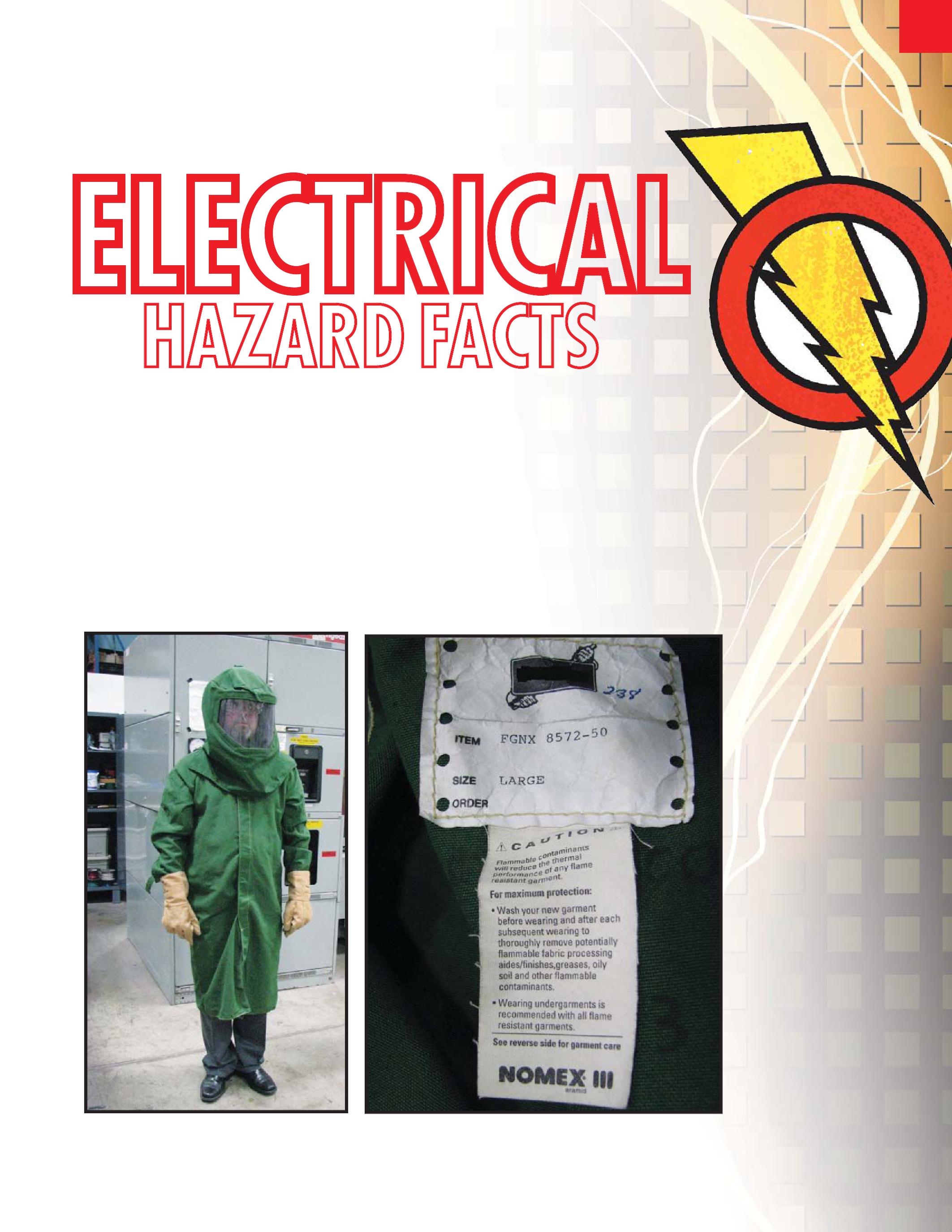
since 1970, which means the rates for fatalities and injuries has dramatically fallen since then. As an example, the 1980 fatality rate was 7.7 per 100,000 workers; in 2011 it was 3.5 per 100,000 workers. Even though that decrease is very significant, one might choose to look at these statistics in another way: 4,693 workers were given capital punishment for the crime
NETAWORLD 107 ELECTRICAL HAZARD FACTS
INDUSTRYTOPICS INDUSTRY TOPICS
Figure 1: Obsolete Arc-Flash Protective Clothing and PPE.

of going to work. When it is put in those terms, this statistic doesn’t sound nearly as good, does it?
Pre-1996 Arc Flash PPE Inadequate
The three primary hazards of electricity have beenwellknownfordecades.Thehazard been well known for decades. The hazard ofelectricalshockhasbeenknownsince of electrical shock has been known since the first electrical devices were designed in the1800’s.Arcflashandarcblasthavealso the 1800’s. Arc flash and arc blast have also been recognized, but due to the inability to quantify these two hazards, there was nothing that could be done to effectively protect the worker from them. In the late 1980’s the first arc-flash suits began to appear. Most were windows.Itwasfoundlaterthatthe windows. It was found later that the polycarbonate windows would actually fail at a very low value of incident energy, causing the window to melt. Figures 1a and 1b show an example of the early, unrated arc-flash PPE
in the hood. The other is the lack of required markings (ATPV, ASTM F1506 1 (1) andNFPA and NFPA 70E 2 (2))onthelabel. ) on the label.
This type of flash suit is still used by uninformedtechniciansandcontractorsand uninformed technicians and contractors and presents a very real threat to their well-being. All arc flash protective clothing and PPE must have a label giving the arc rating and show that it complies with ASTM F1506 and NFPA 70E. If it does not, do not allow the person possessing it to work on or near any electrical power system or device that may be energized. Therearearc-ratedflashsuitsthathavea There are arc-rated flash suits that have a similar appearance, but meet the requirements above. These would be sufficient to perform tasks on or near energized conductors and circuit parts.
In 1996 the first arc testing of clothing and PPE took place and it was soon discovered that the existing PPE and clothing were inadequate, especially for higher values of incident energy. As the industry was then able to determine the hazard created by an
electrical arc flash, protective equipment was designed to provide that protection, and NFPA 70E (in the 2000 edition) provided the first generally available guide to choosing PPE to protect workers from the arc-flash hazard. In this author’s opinion, Table 130.7(C)(9)(a) [now 130.7(C)(15)(a)] did more to increase workers’ awareness of the arc-flash hazard and how to protect themselves than any other single factor.
Advancements have been made, both in our understanding of the arc-flash hazard as well as how to design more effective PPE and clothing that provides a higher level of protection and is more comfortable to wear. This includes lighter weight arc-flash clothing and arc-rated windows and face shields and hood windows that have better light transmission through them. These two factors have increased the acceptance by workers of the provided arc-rated PPE and clothing and encouraged their usage.
THE HAZARDS OF ELECTRICITY
The three recognized hazards of electricity are shock, arc flash and arc blast.
The Department of Labor estimates that there are 4,000 nondisabling and 3,600 disabling injuries in the workplace due to electrical shock each year. A nondisabling injury is one which is a lost-time injury, but the person can return to work doing his/her normal job. A disabling injury means the person either could not return to work or could not return to work in the position held prior to the injury. Another 2,000 traumatic electrical burn injuries are estimated to occur each year. The term traumatic indicates that there is a second-degree burn on more than 50
mean that there are approximately 10,000 serious injuries from electrical shock and arcflash events each year. Arc-blast injuries and or the Bureau of Labor Statistics.
108 WINTER 2013 ELECTRICAL HAZARD FACTS
INDUSTRYTOPICS INDUSTRY TOPICS
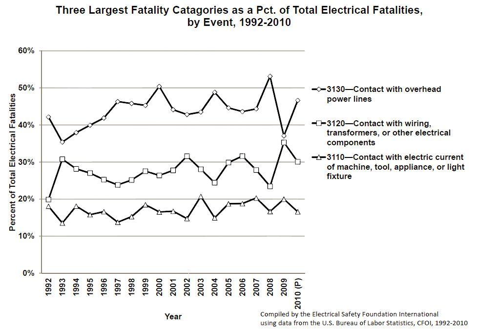
THE ELECTRICAL SHOCK HAZARD
When exposed, energized electrical conductors or circuit parts are contacted by an unprotected part of the body, electrical current flows through the person to either ground or some nearby grounded object such as a metal enclosure. Phase-to-phase contact is rare, but substantially increases the shock hazard and injury. The pathway the electrical current takes through the body plays an important part in determining the seriousness of the resulting injury. The most common pathway is from the hand to the foot followed by hand-to-hand contact. Head-to-hand or head-to-foot contact is much less likely, but since the electrical current passes through the stem of the brain, serious injury can occur at much lower voltages.
The Most Recent Available Data


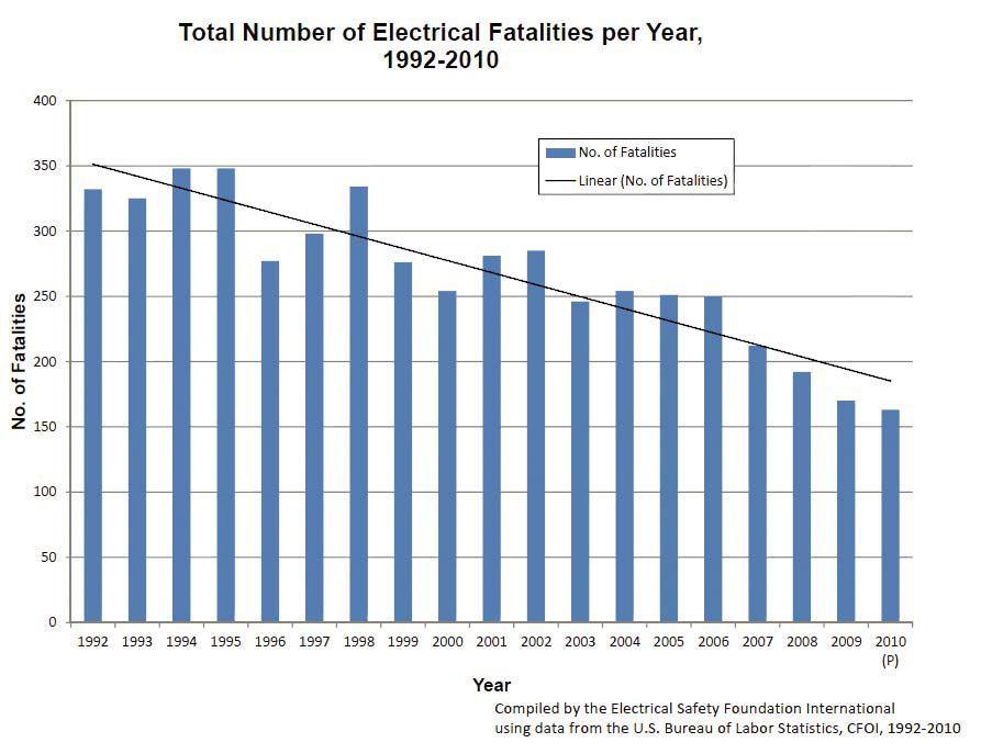

ESFI (Electrical Safety Foundation Interna(3) of electrical shock injuries and fatalities over a ten-year period. (See Figure 2.) The event that causes the greatest number of electrocutions in the workplace is contact with an overhead power line (42%), followed by contact with transformers, wiring, or other electrical devices (26%) and contact with machines, tools or appliances (16%). In the event category of contact with overhead power lines, approximately half of those fatalities were from cranes, bucket trucks, and other types of mechanical equipment making contact. The other 50 percent is from people making contact by long dimensional objects such as conduit or making accidental contact


NETAWORLD 109 ELECTRICAL HAZARD FACTS
INDUSTRYTOPICS INDUSTRY TOPICS
Figure 2: Primary Causes of Electrocution.
Figure 3: General Trend for Electrical Fatalities.
Table1: able 1: Effects of ElectricalC lectrical Current
From om DeleteriousEffectsofE eleterious Effects of ElectricS lectric Shock, Dr.Char . CharlesD les Dalziel, 1961.
mA Current
0.5to3SlightTingling
3+MayBePainful 10+
30+RespiratoryParalysis
75+
4+AmpsHeartParalysis
5+Amps
during the performanceoft e of their jobd b duties.I . Itis t is cleart r thatt t thet he threem e majorc r causesofele ses of electrocution haver e remainedv d virtually unchang edd d during this periodoft d of time. (SeeF e Fig ure 3.)
ele ctrica lw l workers 4 (4), it wa sfou s foundt nd that 24 p ercent oft of thelos he lost-timei me injuries/f ata l itiesw ies wered e duet ue to troublesho oting andv nd volta g et e testing activities, wh ile 19 p ercentoft t of ther he re corde de d e vents o ccurre dd d during norma lo l op erationofele n of ele ctrical mach ines, to ols, ora r appliances .E . Eig hte en p ercentoft t of ther he re corde de d e ventso s o ccurre dd d duet ue to repa iro r orr r repa ir-relate dact d activities .
Table2: able 2: Effect of ElectricalS lectrical Shock; Menv en vs. Women
From om DeleteriousEffectsofE eleterious Effects of ElectricS lectric Shock, Dr.Char . CharlesD les Dalziel, 1961.
There are several factors contributing to the severity of electrical shock:
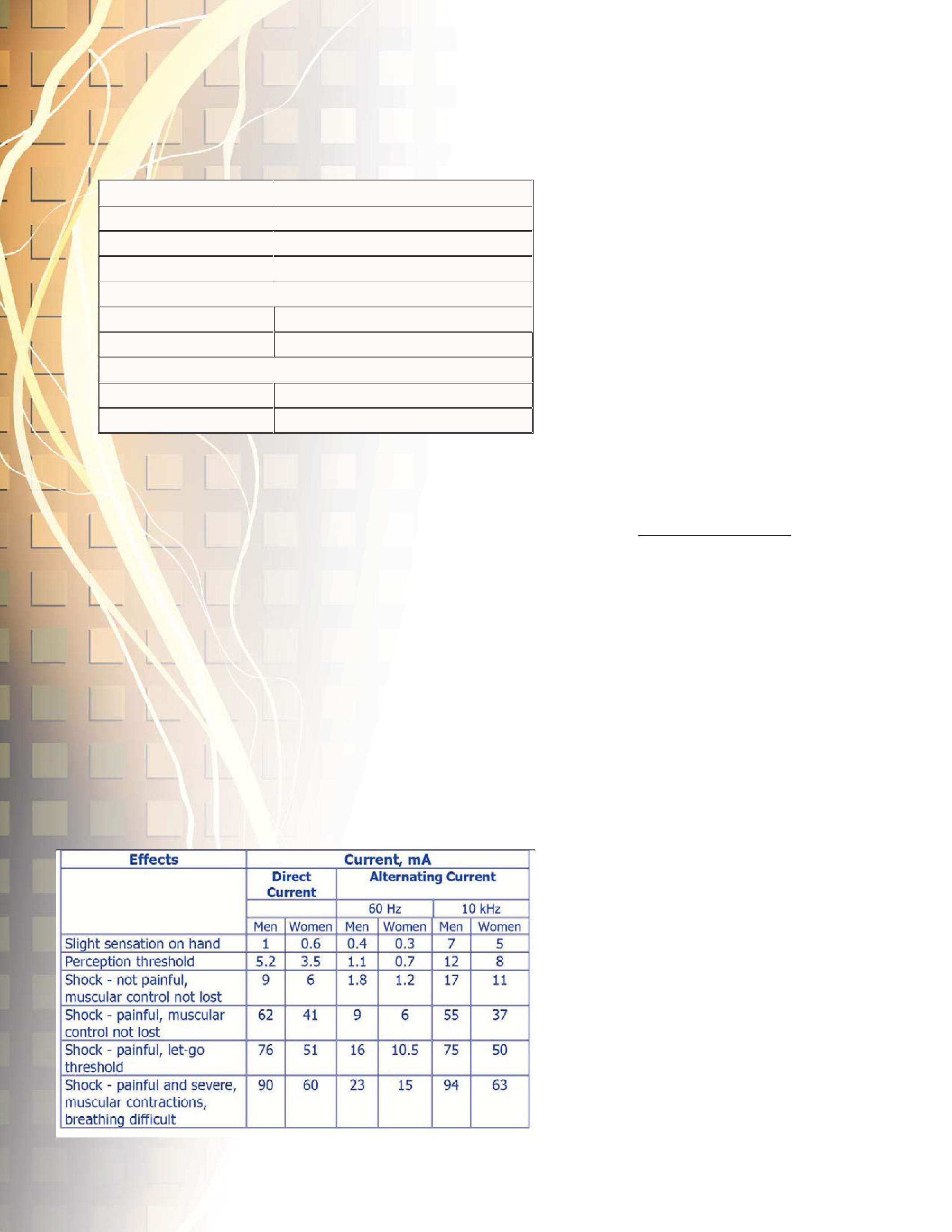
being shocked
Electrical current is what actually causes damage to the body. The voltage is the force that pushes the current. As the voltage increases, more current will flow through the body. This relationship to voltage, current and the body’s resistance is explained through
Current though the body =
Resistance of Body
The Differences That Electrical Shock Has on Men Versus Women
According to IEEE standard 80, Guide for Safety in AC Substation Grounding, the average resistance of a man’s body is approximately 1,000 ohms. This will vary some (but not much) depending on a person’s weight. For 1,000 ohms body resistance contacting a 120-volt conductor, the resulting current is 120 mA through the body. This current is usually lower, as the most common path is for electricity to flow from hand-tofoot. Shoes, so cks, flooring (car pet, wood, tile, and dry concrete) all provide some additional resistance. Women have about 2/3 the body resistance, due to factors such as size, bone mass and body composition. This means that for the same exposure, women face a greater risk of injury from the shock hazard. Instead of having approximately 120 mA current pass through them for a 120-volt shock, they would have approximately 160 mA passing through them.
In 1961, Dr. Charles Dalziel presented a paper (5) describing the results of experiments
110 WINTER 2013 ELECTRICAL HAZARD FACTS
I N D U S T R Y T O P I C S Voltage
he had conducted on student volunteers at the University of California, Berkeley. The results are summarized in Table 1.
The second part of the equation is that when shocked, women are more likely to suffer injury, and their injury is likely to be greater than what a man would be expected to receive. Table 2 is also from Dr. Dalziel’s experiments and shows the relationship between ac and dc, as well as men vs. women. Look at the last example effect shown on Table 2, Shock, Painful and Severe, Muscular Contractions, Breathing Difficult. A 60 Hz contact with 23 mA of current is required to cause this effect for a man, but only 15mA of current is required to produce the same effect for a woman. Female technicians need to be aware that they are more susceptible to injury than their male counterparts if they make contact with exposed energized conductors or circuit parts.
Electrical shock kills and injures more than twice as many people each year as electrical arc flash. That being said, arc flash injuries are often more serious and, on average, require much more hospitalization and recovery time
ELECTRICAL ARC FLASH
An electrical arc occurs when an energized conductor or circuit part makes contact with either a grounded object or, much more rarely, another conductor. Approximately 97 percent of all electrical arcs begin as phase-to-
initial contact is made, the intense heat of the electrical arc ionizes the surrounding air, creating a pathway from the grounded object to the energized conductor or circuit part. If the arc occurs inside a metal enclosure, the arc plasma will reflect off the back and sides of the enclosure, enveloping the other two phases which may not have been originally involved. This will cause the arc to develop from a single-phase arc to a three-phase arc substantially increasing the incident energy. If the voltage is less than 240 volt, the arc is
usually self-extinguishing, although, if it is fed from a large source, the available short circuit current could establish the arc. At higher voltages, the arc is able to establish itself and will continue until the circuit is deenergized
There are five primary factors that determine the severity of an injury from an electrical arc:
clothing worn

TheDistancefromtheArc The
Distance from the Arc
Theheatofanelectricalarcisreferredtoas The heat of an electrical arc is referred to as the incident energy. This is because the heat is made up of the radiated heat (infrared) and convection heat (heat flow through air). Incident energy decreases by the inverse square of the distance. In other words, as a person moves away from an arc, the heat will decrease rapidly. This aspect is critical to understanding how to protect oneself from an arc. Body position is a primary factor to consider when
no closer to the device than necessary in order to perform the work effectively because the incident energy that person will receive if there isanarcflasheventincreasesasonemoves is an arc flash event increases as one moves closer to the device. The standard working distance for power systems of less than 600 volts is typically 18”, while that of 2.4 kV to 15 kV is a 36” working distance.
The Coefficient of Clothing Worn
The type and fabric weight of clothing being wornaffectstheheatthatistransferredto worn affects the heat that is transferred to the body. NFPA 70E recommends wearing either flammable, non-melting clothing as underlayers (cotton, wool, or silk) or arcrated underlayers for additional protection. The general rule of thumb is that each layer of clothing under arc-rated clothing reduces the heat to the body by approximately 50 percent. Flammable underlayers do not
NETAWORLD 111 ELECTRICAL HAZARD FACTS
INDUSTRYTOPICS INDUSTRY TOPICS


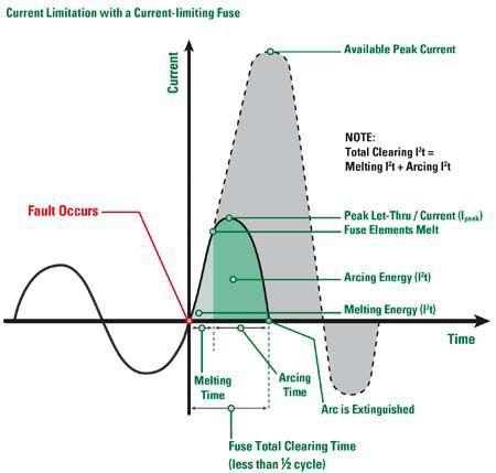


increase the arc rating of a clothing system, but will reduce the probability of a burn underneath arc-rated clothing.
The Arc Temperature
The temperature of an electrical is arc is significantly affected by the power available to create it (instantaneous power levels in the megawatt range are present within many types


an arc flash for 0.08 seconds, he would receive twice the incident energy as an arc of the same magnitude that lasted 0.04 seconds. This is why the NFPA 70E technical committee inserted
protective devices shall be maintained in accordance with the manufacturers' instructions or industry consensus standards.”
include electrode material and shape, length of arc travel, constraints on arc volume, etc.
TheArcDuration The Arc Duration
Thearcdurationisthesecondmostcritical The arc duration is the second most critical factor in an arc-flash event. Incident energy is proportional to time. If a person is exposed to

Poorly-maintained circuit breakers and malfunctions, it will increase the time it takes to clear and extinguish the fault. Even though this may be only fractions of a second, it can effectively double or triple the incident energy received by a worker.
112 WINTER 2013
INDUSTRYTOPICS INDUSTRY TOPICS ELECTRICAL HAZARD FACTS
Figure 4: Typical Current-Limiting Fuse Characteristic. Courtesy Cooper-Bussman.

The Arc Length
The arc length becomes a factor at higher voltages (>600 V). It has been demonstrated that, with all other factors being the same, a longer arc creates more incident energy than a shorter arc. Low-voltage power systems cannot sustain a longer electrical arc, as arc resistance causes a voltage drop of approximately 75 to 100 V/inch.
The Onset of a Second-Degree Burn
Unprotected skin has a very low tolerance for heat. A temperature rise of 176°F for 1/10 th second will produce the onset of a second degree burn. This is the point at which NFPA 70E requires arc flash protective clothing and PPE to be worn. This level of injury is considered to be non-life threatening as the skin is still mostly whole and not uniformly blistered; therefore, the risk of infection is less than a second-degree burn, which will have uniform blistering.
ELECTRICAL ARC BLAST
Electrical arc blast refers to the pressure wave created by the rapidly expanding vaporized metal (arc plasma ball) when an arc occurs inside metal-enclosed equipment. This pressure wave can distort the enclosure, causing it to rupture, create shrapnel from parts and components that are broken loose, and cause injury or death by impacting a person’s body.
At this time there are no equations to calculate the pressure wave that would be created by electrical arc blast as there are for the arc-flash hazard. IEEE and NFPA are conducting a joint collaboration project(6) to develop the needed equations, but those results have not been released as of this date. It has been shown that as the short circuit available current increases, the pressure wave also increases. The pressure wave has been measured at greater than 2,160 lb/ft 2 .
At about the same instant in time as the pressure wave is created, an acoustic wave is also created. The acoustic wave is created by the near
instantaneous heating of the air surrounding the electrical arc, similar to the way lightning is created. This sound intensity has been measured at greater than 160dB. This level of intensity will cause instantaneous hearing loss.
Current-Limiting Devices – Not a Cure-All
Current-limiting fuses have been found to be an effective method of reducing both the incident energy and potential pressure wave by limiting available short circuit current from the system and by greatly reducing the duration of the arc (Figure 4). When properly applied, current-limiting fuses will have a clearing time of less than ½ cycle. Current-limiting fuses cannot be applied in all circumstances, and, if the short circuit current does not push the fuse into its current-limiting region, it will act as a dual-element time delay fuse. Some manufacturers produce current-limiting circuit breakers for low-voltage protection thathavesimilarcharacteristicsascurrentthat have similar characteristics as currentlimiting fuses.
SUMMARY
In 1999, the 2000 edition of NFPA 70E was released containing the first method of choosing arc-flash protective clothing and PPE. In 2002, IEEE 1584, Guide for Performing Arc Flash Hazard Calculations was released. Together, these two standards provide guidelines for companies to protect theirworkersfromthehazardsassociatedwith their workers from the hazards associated with an arc-flash event. The equations developed inIEEE1584willbefurtherrefinedonce in IEEE 1584 will be further refined once the members of the IEEE/NFPA joint collaborationfinishtheirwork.Theeffects collaboration finish their work. The effects ofverticalvshorizontalbuswillfurther of vertical vs horizontal bus will further revise the equations used by IEEE 1584, and equations for calculating the effects of a dc arc flashwillbeavailable. flash will be available.
A solid understanding of the hazards of electricity is important to working safely.
writtenbeforethehazardsofarcflashand written before the hazards of arc flash and blast were as well known as they are today, but they were written in such a way that they are
NETAWORLD 113 INDUSTRYTOPICS INDUSTRY TOPICS ELECTRICAL HAZARD FACTS

still relevant and enforceable today. Sometimes it seems as though the hazard of electrical shock has been forgotten, or overshadowed by the hazard of electrical arc flash. This is unfortunate, as electrical shock injures and kills twice as many workers as arc flash. This is not to downplay the arc-flash hazard, as the injuries receivedfromanarcflashareoftenmoreserious received from an arc flash are often more serious andresultinmoremedicalinterventionthan and result in more medical intervention than shock. The important point is that one should neither forget nor minimize either of these lifethreatening hazards.
Thearc-blasthazardismuchlessunderstood. The arc-blast hazard is much less understood. The IEEE/NFPA joint collaboration is just now finishing some of the field tests it has been a means of calculating the pressure wave that is likely to be created during an arc event. Until that information is compiled and released, the arc-blast hazard will remain an incompletely defined quantity.
REFERENCES
1.ASTMF1506, 1. ASTM F1506, Standard Performance Specification for Flame Resistant Textile Materials for Wearing Apparel for Use by Electrical Workers Exposed to Momentary Electric Arc and Related Thermal Hazards
Standard for Electrical Safety in the Workplace”, 2000and2012editions 2000 and 2012 editions
3a. James Cawley and Gerald Homce, Trends in Electrical Injury, IEEEPCIC,2006 IEEE PCIC, 2006
3b. Workplace Electrical Injury and Fatality Statistics – Additional Charts 2003 – 2010, Electrical Safety Foundation International
4.Kowalski-Trakofler,Ph.D.Kathleen, 4. Kowalski-Trakofler, Ph.D. Kathleen, Non-Contact Electric ArcInduced Injuries in the Mining Industry; a Multi-Disciplinary Approach, IEEE/IAS Electrical Safety Workshop, 2004
5.Dr.CharlesF.Dalziel,“ 5. Dr. Charles F. Dalziel, “ Deleterious Effects of Electric Shock”, Meeting of Experts on Electrical Accidents and Related Matters, Geneva,Switzerland,1961 Geneva, Switzerland, 1961
6. IEEE/NFPA Joint Collaboration on the Arc Flash Hazard Reports
James R. (Jim) White is the Training Director of Shermco Industries, Inc., in Dallas, Texas. He is the principal member of the NFPA technical committee “Recommended Practice for Electrical Equipment Maintenance” (NFPA 70B). Jim represents the National Electrical Testing Association (NETA) as an alternate member of the NFPA Technical Committee “Electrical Safety in the Workplace” (NFPA 70E and represents NETA on NEC Code Making Panel 13 and ASTM F18 Committee “Electrical Protective Equipment For Workers”. Jim is the past Chairman of the 2008 IEEE Electrical Safety Workshop, an IEEE Senior Member, and the 2011 recipient of the IEEE/ PCIC Electrical Safety Excellence Award. Jim was presented with NETA’s Outstanding Achievement Award in 2012. A regular contributor to trade journals, Jim is a columnist for NETA World magazine’s “Tech Quiz” and coauthor of “NFPA 70E and NETA”. Jim is the author of the books “Significant Changes to NFPA 70E –2012 Edition” and “A Practical Guide to OSHA and NFPA 70E”, both published by American Technical Publishers.
114 WINTER 2013 INDUSTRYTOPICS INDUSTRY TOPICS ELECTRICAL HAZARD FACTS





NETA WELCOMES LONGO ELECTRICAL-MECHANICAL AS A NETA ACCREDITED COMPANY
The Wharton, New Jersey-based Longo Electrical-Mechanical is proud to be certified by NETA (the InterNational Electrical Testing Association). Longo has been serving the northeast with line to load solutions for over 65 years. The testing and servicing of switchgear and other related power equipment has become a substantial component of the company’s motor and pump business. Longo’s technical expertise in these areas was particularly valuable after Hurricane Sandy.
This certification is a welcomed validation of Longo’s long-time tradition of field service power systems testing and technical skill development. This has been a constant focus of Longo’s overall pursuit for safety and accuracy. The rigorous NETA testing standards have provided Longo with certified technicians at multiple levels of proficiency supporting efforts to maintain the highest levels of training as well as substantial hands on experience. Having grown to be the largest independent electricalmechanical sales and service company in the Northeast,

Longo has more than 100 employees, with headquarters in Wharton, New Jersey.
Longo thinks it is important to also be one of the best. Longo also thinks its NETA certification provides existing and future customers with a consistent source of credibility for its testing qualifications and technicians’ which Longo has maintained since 1994. Longo was the first apparatus service organization in the USA to
For more information on Longo’s NETA certification and full capabilities visit www.elongo.com.
Longo offered technical expertise in the wake of Hurricane Sandy.


Jan. 28 – 30, 2014 Henry B. Gonzalez Convention Center San Antonio, Texas http://utilityproductsexpo.com owned & produced by:supporting publications:media sponsor:host utility: presented by: ATTEND UTILITY PRODUCTS CONFERENCE & EXPOSITION AND: Gain new insight into cutting edge utility products The program is now available! Check out the workshops and product The program is now available! Check out the and demonstrations online! demonstrations Register online http://utilityproductsexpo.com, Use coupon code NETA when registering ATTEND UTILITY PRODUCTS CONFERENCE & EXPOSITION FOR ONLY $75!
ANSI/NETA STANDARDS UPDATE

ANSI/NETA MTS-20XX REVISION IN PROCESS
ofintenttoreviseANSI/NETA of intent to revise ANSI/NETA Standard for Maintenance Testing Specifications for Electrical Power Equipment and Systems asarevisedAmericanNationalStandard. as a revised American National Standard. This document contains specifications which cover the suggested field tests and inspections that are available to assess the suitability for continued service and reliability of electrical power equipment and systems. The purpose of these specifications is to assure that tested electrical equipment and systems are operational and within applicable standardsandmanufacturers’tolerances standards and manufacturers’ tolerances and that the equipment and systems are suitableforcontinuedservice.Itisavailable suitable for continued service. It is available in hard copy, PDF, and CD Rom formats. The revised edition will be published in 2015, with the 2011 edition remaining themostcurrenteditionuntilthattime. the most current edition until that time.
at www.netaworld.org.
ANSI/NETA ATS-2013
TheANSI/NETA The ANSI/NETA Standard for Acceptance Testing Specifications for Electrical Power Equipment and Systems was approved as an American National Standard on January 25, 2013. These specifications cover the suggested field tests and inspections that are available to assess the suitability for initial energization of electrical power equipment and systems. The purpose of these specifications is to assure that tested electrical equipment and systems are operational, are within applicable standards and manufacturers’ tolerances, andareinstalledinaccordancewith and are installed in accordance with design specifications.
ANSI/NETA ETT-2010
TheANSI/NETA The ANSI/NETA Standard for Certification of Electrical Testing Technicians was approved as an American National Standard on January 8, 2010. The document was originally approved as an ANSIstandardin2000.Thisstandard ANSI standard in 2000. This standard establishes minimum requirements for qualifications, certification, training, and experience for the electrical testing technician. It also provides criteria for documenting qualifications for certificationanddetailstheminimum certification and details the minimum qualifications for an independent and impartial certifying body to certify electrical testing technicians.
PARTICIPATION
Comments and suggestions on any of the standards are always welcome and should be directed to the NETA office at neta@ netaworld.org or 888-300-6382. To learn more about the NETA standards review and revision process, to purchase these standards, or to get involved, please visit www.netaworld.org or call 888-300-6382.
NETAWORLD 119 ANSI/NETA STANDARDS UPDATES SPECIFICATIONS AND STANDARDS ACTIVITY


ANSWERS


ANSWERS

1. C. Zone selective interlocking requires that the circuit breakers in a downstream zone communicate with breakers in the next upstream zone. If the downstream breaker sees fault current, it sends a restraint signal to all breakers in the next upstream zone. The restraint signal keeps the breaker receiving it from tripping with no intentional delay (instantaneously) and that breaker will trip in its set time delay, if the downstream breaker fails to clear the fault. A breaker seeing fault current, but not receiving a restraint signal, will trip instantaneously, regardless of its delay setting.
2. B. The bimetal element in a molded-case circuit breaker has a characteristic known as thermal memory. This characteristic allows the bimetal element to respond to current on the same basis that the conductor will be heated by the current. As the current passes through the bimetal element, it will begin to deflect, based on the value of the current. If the current drops (such as in a motor starting), the bimetal will slow, then reset to an appropriate level for the current. If the current stays at that higher level, it may stop or, if the current magnitude is high enough, continue to deflect until it trips the breaker.
to mimic this characteristic and could false trip if the load fluctuated.
3. A. Breaker 1 will restrain. Breaker 2 will communicate with it and send a restraint signal, telling Breaker 1 that it sees the fault current.
B. Breaker 2 will trip instantaneously. It does not receive a restraint signal from Breaker 3, since Breaker 3 does not see the fault current.
C. Breaker 3 will restrain. It does not see the fault current and the absence of a restraint signal from it allows Breaker 2 to trip instantaneously.


Breaker 1 will go into STD mode, and if Breaker 2 does not trip, it will trip after the set delay. Breaker 2 will trip on Instantaneous mode as it is the breaker closest to the fault. The advantage of zone selective interlocking is that there can be a time delay for protective devices coordination, but the breaker closest to the fault will function as an instantaneous trip breaker. Since Breaker 3 does not see any fault current, it will restrain and not trip.
4. A and D. Current-limiting circuit breakers often use the magnetic force of the fault current to blow the contacts apart. The greater the fault current, the more magnetic force is applied to the parting of the contacts. This action limits both the operating time and short circuit pass-through current. At lower-level currents the breaker acts like a normal LTD function breaker. Although old technology, currentlimiting fuses provide a highly reliable method of decreasing operating time and the short circuit pass-through current. With both technologies, the short-circuit current has to be great enough to be in the current-limiting characteristic or they will respond as time delay devices.
5.
thermal imaging to mimic thermal memory that is a characteristic of thermal bimetal breakers.
NFPA Disclaimer: Although Jim White is a member of the NFPA Technical Committee for both NFPA 70E “Standard for Electrical Safety in the Workplace” and NFPA 70B “Recommended Practice for Electrical Equipment Maintenance,” the views and opinions expressed in this message are purely the author’s and shall not be considered an official position of the NFPA or any of its technical committees and shall not be considered to be, nor be relied upon as, a formal interpretation or promotion of the NFPA. Readers are encouraged to refer to the entire text of all referenced documents.
TECH QUIZ ANSWERS
No.104
104
No.
120 WINTER 2013 TECHQUIZ
The Premier Electrical Maintenance and Safety Event
POWERTEST 2014 GOES MOBILE!
For the first time ever, PowerTest attendees will be able to revolutionize their experience with a brand new, customized mobile app for Apple and Android phones and tablets!
Customize and set your own schedule for the sessions you want to see
Set reminders for your next session
See session content abstracts and speaker bios
Complete facility maps including Trade Show layout and booth information
Search PowerTest in the App Store or Google Play. Available in early December, 2013

March 3 – 6, 2014
Hyatt Regency Denver Denver, Colorado
MOBILE
Introducing the
APP
VLF-34E 34 kV VLF Tester
VLF & DC Output | Sheath Testing | Cable Burning
The VLF-34E is a new generation VLF AC Hipot that uses a solid state design with microprocessor controls. It meets the requirements of applicable world standards regarding cable testing up to 25kV class maintenance testing. It is light, compact, rugged, and very portable. Its sine wave output is suitable for using external TD and PD detection equipment. Using a TD and PD option, the VLF-34E is all that is needed for nearly all cable testing up to 25kV class.
Easy to use controls. Programmable test sequences & manual control, USB port for downloading data and for unlimited test report capture, wireless computer interface to control and download Tan Delta diagnostics and for remote control operation via laptop.

Tan Delta TD-34E
VLF-TD Cable Diagnostic Testing
The TD-34E, along with the HVI VLF-34E AC hipot, is the latest in design using current electronic technology. Together they permit the user to perform all VLF and VLF-TD tests possible and offer the best wireless operation and data collection, aided by the HVI custom application software written solely for the two devices. There is no better alternative. HVI has been supplying the world with VLF and Tan Delta technology since 1998, with more models, greater voltage range, and higher power capability, all with the superior sales and service that HVI is well known for worldwide.
ISO 9001 : 2008
Ground VLFHVOutput To Test Cable Optional
THE NEW For 5 – 25 kV cable: VLF-34E & TD-34E
HVI: The World’s VLF Source All HVI Products are Made in the USA INTRODUCING

Relevant information on the electrical power systems industry, from testing procedures and troubleshooting to every day real-life solutions encountered in the field. It’s real world learning at your fingertips.
Discover page after page of the most comprehensive, component-specific, technical resources for both training and reference purposes.
These Handbooks bring together a collection of over 200 of the very best articles from past issues of NETA World Journal and the most well received technical presentations from NETA’s PowerTest conferences.
195* For the 13 volume set $15* For each issue
For more information on the NETA Handbooks or other NETA publications visit the NETA bookstore at www.netaworld.org or 888-300-6382 (NETA).
* Additional cost for shipping and handling
$
NETA ACCREDITED COMPANIES Setting the
A&F Electrical Testing, Inc.
80 Lake Ave. South, Ste. 10 Nesconset, NY 11767 (631) 584-5625 Fax: (631) 584-5720 kchilton@afelectricaltesting.com www.afelectricaltesting.com
Kevin Chilton
A&F Electrical Testing, Inc.
80 Broad St. 5th Floor
New York, NY 10004 (631) 584-5625 Fax: (631) 584-5720 afelectricaltesting@afelectricaltesting.com www.afelectricaltesting.com
Florence Chilton
ABM Electrical Power Solutions
3602 East Southern Ave., Ste. 1 & 2 Phoenix, AZ 85040 (602) 796-6583 www.ABM.com
Jeff Militello
ABM Electrical Power Solutions
6280 South Valley View Blvd., Ste. 618 Las Vegas, NV 89118 (702) 216-0982 Fax: (702) 216-0983 www.ABM.com
Jeff Militello
ABM Electrical Power Solutions
814 Greenbrier Circle, Ste. E Chesapeake, VA 23320 (757) 548-5690 Fax: (757) 548-5417 www.ABM.com
Mark Anthony Gaughan, III
ABM Electrical Power Solutions
3700 Commerce Dr. #901-903 Baltimore, MD 21227 (410) 247-3300 Fax: (410) 247-0900 www.ABM.com
Bill Hartman
ABM Electrical Power Solutions
710 Thomson Park Dr. Cranberry Township, PA 16066-6427 (724) 772-4638 Fax: (724) 772-6003 william.mckenzie@abm.com www.ABM.com
William (Pete) McKenzie
ABM Electrical Power Solutions 5805 G Departure Dr. Raleigh, NC 27616 (919) 877-1008 Fax: (919) 501-7492 www.ABM.com
Rob Parton
ABM Electrical Power Solutions 4390 Parliament Place, Ste. Q Lanham, MD 20706 (301) 967-3500 Fax: (301) 735-8953 www.ABM.com
Frank Ceci
Absolute Testing Services 6829 Guhn Rd. (832) 467-4446 Fax: (713) 849-3885
rgamble@absolutetesting.com www.texasats.com
Richard Gamble
Advanced Testing Systems
15 Trowbridge Dr. Bethel, CT 06801 (203) 743-2001 Fax: (203) 743-2325 pmaccarthy@advtest.com www.advtest.com
Pat MacCarthy
American Electrical Testing Co., Inc. 480 Neponset St., Building 6 Canton, MA 02021-1970 (781) 821-0121 Fax: (781) 821-0771 sblizard@aetco.us www.99aetco.com
Scott A. Blizard
American Electrical Testing Co., Inc. 34 Clover Dr. South Windsor, CT 06074 (860) 648-1013 Fax: (781) 821-0771 jpoulin@aetco.us www.99aetco.com
Gerald Poulin
American Electrical Testing Co., Inc.
76 Cain Dr. Brentwood, NY 11717 (631) 617-5330 Fax: (631) 630-2292 mschacker@aetco.us www.99aetco.com
Michael Schacker
American Electrical Testing Co., Inc.
50 Intervale Rd., Ste. 1 Boonton, NJ 07005 (973) 316-1180 Fax: (781) 316-1181 jsomol@aetco.us www.99aetco.com
Jeff Somol
American Electrical Testing Co., Inc. 4032 Park 65 Dr. Indianapolis, IN 46254 (317) 487-2111 Fax: (781) 821-0771 scanale@aetco.us www.99aetco.com
Stephen Canale
American Electrical Testing Co., Inc.
Green Hills Commerce Center 5925 Tilghman St., Ste. 200 Allentown, PA 18104 (215) 219-6800 jmunley@aetco.us www.99aetco.com
Jonathan Munley
American Electrical Testing Co., Inc. 12566 W. Indianola Ave. Avondale, AZ 85392 (480) 383-9242 dmadaglia@aetco.us www.99aetco.com
Donald Madaglia
AMP Quality Energy Services, LLC 4220 West Schrimsher SW Site W1 Huntsville, AL 35804 (256) 513-8255
Brian Rodgers
Apparatus Testing and Engineering
Folsom, CA 95763 (916) 853-6280 Fax: (916) 853-6258 jlawler@apparatustesting.com www.apparatustesting.com
James Lawler
Apparatus Testing and Engineering 7083 Commerce Circle, Ste. H Pleasanton, CA 94588 (925) 454-1363 Fax: (925) 454-1499 info@apparatustesting.com www.apparatustesting.com
Harold (Jerry) Carr
Applied Engineering Concepts 1105 N. Allen Ave. Pasadena, CA 91104 (626) 398-3052 Fax: (626) 398-3053 michel.c@aec-us.com www.aec-us.com
Michel Castonguay
Burlington Electrical Testing Co., Inc. 300 Cedar Ave. Croydon, PA 19021-6051 (215) 826-9400 (221) Fax: (215) 826-0964 waltc@betest.com www.betest.com
Walter P. Cleary
C.E. Testing, Inc. 6148 Tim Crews Rd. Macclenny, FL 32063 (904) 653-1900 Fax: (904) 653-1911 cetesting@aol.com
Mark Chapman
CE Power Solutions,LLC 4500 W. Mitchell Ave. (513) 563-6150 Fax: (513) 563-6120 info@cepowersol.net
Rhonda Harris
CE Power Solutions of Wisconsin,LLC 3100 East Enterprise Ave. Appleton, WI 54913 (920) 968-0281 Fax: (920) 968-0282 rob.fulton@cepower.net
Rob Fulton
Control Power Concepts 353 Pilot Rd; Ste. B Las Vegas, NV 89119 (702) 448-7833 Fax: (702) 448-7835 zfettig@ctrlpwr.com www.controlpowerconcepts.com
Zeb Fettig
Dude Testing 145 Tower Dr., Ste. 9 Burr Ridge, IL 60527 (815) 293-3388 Fax: (815) 293-3386 scott.dude@dudetesting.com www.dudetesting.com
Scott Dude
DYMAX Holdings, Inc.
4751 Mustang Circle St. Paul, MN 55112 (763) 717-3150 Fax: (763) 784-5397 gphilipp@dymaxservice.com www.dymaxservice.com
Gene Philipp
DYMAX Service Inc. 46918 Liberty Dr. Wixom, MI 48393 (248) 313-6868 Fax: (248) 313-6869 www.dymaxservice.com
Bruce Robinson
DYMAX Service Inc. 4213 Kropf Ave. (330) 484-6801 Fax: (740) 333-1271 www.dymaxservice.com
Gary Swank
Eastern High Voltage 11A South Gold Dr. Robbinsville, NJ 08691-1606 (609) 890-8300 Fax: (609) 588-8090 joewilson@easternhighvoltage.com www.easternhighvoltage.com
Joseph Wilson
ELECT, P.C.
Wendell, NC 27591 (919) 365-9775 Fax: (919) 365-9789 btyndall@elect-pc.com www.elect-pc.com
Barry W. Tyndall
Electric Power Systems, Inc. 21 Millpark Ct. (314) 890-9999 Fax: (314) 890-9998 www.eps-international.com
Electric Power Systems, Inc. 557 E. Juanita Ave., #4 Mesa, AZ 85204 (480) 633-1490 Fax: (480) 633-7092 www.eps-international.com
NETA ACCREDITED COMPANIES
Standard
124 WINTER 2013
Electric Power Systems, Inc. 4436 Parkway Commerce Blvd.
(407) 578-6424 Fax: 407-578-6408 www.eps-international.com
Electric Power Systems, Inc.
6753 E. 47th Avenue Dr., Unit D
(720) 857-7273 Fax: 303-928-8020 www.eps-international.com
Electric Power Systems, Inc.
23823 Andrew Rd. Plainfield, IL 60585 (815) 577-9515 Fax: (815) 577-9516 www.eps-international.com
Electric Power Systems, Inc. 2601 Center Rd., # 101
(330) 460-3706 Fax: (330) 460-3708 www.eps-international.com
Electric Power Systems, Inc.
56 Bibber Pkwy #1 Brunswick, ME 04011 (207) 837-6527 www.eps-international.com
Electric Power Systems, Inc. 4100 Greenbriar Dr., Ste. 160
(713) 644-5400 www.eps-international.com
Electric Power Systems, Inc. 11861 Longsdorf St. Riverview, MI 48193 (734) 282-3311 www.eps-international.com
Electric Power Systems, Inc. 827 Union St. Salem, VA 24153 (540) 375-0084 Fax: (540) 375-0094 www.eps-international.com
Electric Power Systems, Inc. 915 Holt Ave., Unit 9 Manchester, NH 03109 (603) 657-7371 Fax: 603-657-7370 www.eps-international.com
Electric Power Systems, Inc. 146 Space Park Dr. Nashville, TN 37211 (615) 834-0999 Fax: (615) 834-0129 www.eps-international.com
Electric Power Systems, Inc. 8515 Cella Alameda NE, Ste. A Albuquerque, NM 87113 (505) 792-7761 www.eps-international.com
Electric Power Systems, Inc. 319 US Hwy. 70 E, Unit E Garner, NC 27529 (919) 322-2670
www.eps-international.com
Electric Power Systems, Inc. 1090 Montour West Industrial Blvd. Coraopolis, PA 15108 (412) 276-4559 www.eps-international.com
Electric Power Systems, Inc. 6141 Connecticut Ave. (816) 241-9990 Fax: (816) 241-9992 www.eps-international.com
Electric Power Systems, Inc. 2495 Boulevard of the Generals Norristown, PA 19403 (610) 630-0286 www.eps-international.com
Electrical & Electronic Controls 6149 Hunter Rd. (423) 344-7666 (23) Fax: (423) 344-4494 eecontrols@comcast.net
Michael Hughes
Electrical Energy Experts, Inc. W129N10818, Washington Dr. Germantown, WI 53022 (262) 255-5222 Fax: (262) 242-2360 bill@electricalenergyexperts.com www.electricalenergyexperts.com
William Styer
Electrical Equipment Upgrading, Inc. 21 Telfair Place Savannah, GA 31415 (912) 232-7402 Fax: (912) 233-4355 kmiller@eeu-inc.com www.eeu-inc.com
Kevin Miller
Electrical Maintenance & Testing Inc. 12342 Hancock St. Carmel, IN 46032 (317) 853-6795 Fax: (317) 853-6799 www.emtesting.com
Brian K. Borst
Electrical Reliability Services 1057 Doniphan Park Circle, Ste. A (915) 587-9440 Fax: (915) 587-9010 www.electricalreliability.com
Electrical Reliability Services 1775 W. University Dr., Ste. 128 Tempe, AZ 85281 (480) 966-4568 Fax: (480) 966-4569 www.electricalreliability.com
NETA ACCREDITED COMPANIES
Electrical Reliability Services 1426 Sens Rd. Ste. 5 (281) 241-2800 Fax: (281) 241-2801 www.electricalreliability.com
Electrical Reliability Services 4099 SE International Way, Ste. 201 (503) 653-6781 Fax: (503) 659-9733 www.electricalreliability.com
Electrical Reliability Services 5810 Van Allen Way Carlsbad, CA 92008 (760) 804-2972 www.electricalreliability.com
Electrical Reliability Services 8500 Washington Pl. NE, Ste. A-6 Albuquerque, NM 87113 (505) 822-0237 Fax: (505) 822-0217 www.electricalreliability.com
Electrical Reliability Services 1380 Greg Street, Ste. 217 Sparks, NV 89431 (775) 746-8484 Fax: (775) 356-5488 www.electricalreliability.com
Electrical Reliability Services 2275 Northwest Pkwy SE, Ste. 180 Marietta, GA 30067 (770) 541-6600 Fax: (770) 541-6501 www.electricalreliability.com
Electrical Reliability Services 7100 Broadway, Ste. 7E (303) 427-8809 Fax: (303) 427-4080 www.electricalreliability.com
Electrical Reliability Services 348 N.W. Capital Dr. (816) 525-7156 Fax: (816) 524-3274 www.electricalreliability.com
Electrical Reliability Services 6900 Koll Center Parkway, Ste. 415 Pleasanton, CA 94566 (925) 485-3400 Fax: (925) 485-3436 www.electricalreliability.com
Electrical Reliability Services 10606 Bloomfield Ave. Santa Fe Springs, CA 90670 (562) 236-9555 Fax: (562) 777-8914 www.electricalreliability.com
Electrical Reliability Services
Baton Rouge, LA 70817 (225) 755-0530 Fax: (225) 751-5055 www.electricalreliability.com
Electrical Reliability Services 121 Highway 108 East Sulphur, LA 70665 (337) 583-2411 Fax: (337) 583-2410 www.electricalreliability.com
Electrical Reliability Services 11000 Metro Pkwy., Ste. 30 Ft. Myers, FL 33966 (239) 693-7100 Fax: (239) 693-7772 www.electricalreliability.com
Electrical Reliability Services 2222 West Valley Hwy. N., Ste 160 Auburn, WA 98001 (253) 736-6010 Fax: (253) 736-6015 www.electricalreliability.com
Electrical Reliability Services 3412 South 1400 West, Unit A West Valley City, UT 84119 (801) 975-6461 www.electricalreliability.com
Electrical Reliability Services 6351 Hinson St., Ste. B Las Vegas, NV 89118 (702) 597-0020 Fax: (702) 597-0095 www.electricalreliability.com
Electrical Reliability Services 610 Executive Campus Dr. (877) 468-6384 Fax: (614) 410-8420 info@electricalreliability.com www.electricalreliability.com
Electrical Reliability Services 9636 St. Vincent, Unit A Shreveport, LA 71106 (318) 869-4244 www.electricalreliability.com
Electrical Reliability Services 6135 Lakeview Rd., Ste 500 Charlotte, NC 28269 (704) 441-1497 www.electricalreliability.com
Electrical Testing, Inc. 2671 Cedartown Hwy. Rome, GA 30161-6791 (706) 234-7623 Fax: (706) 236-9028 steve@electricaltestinginc.com www.electricaltestinginc.com
Electrical Testing Solutions 2909 Green Hill Ct. (920) 420-2986 Fax: (920) 235-7136 tmachado@electricaltestingsolutions.com www.electricaltestingsolutions.com Tito Machado
NETA
ACCREDITED COMPANIES
Setting the Standard NETAWORLD 125
NETA ACCREDITED COMPANIES
Elemco Services, Inc.
228 Merrick Rd. Lynbrook, NY 11563 (631) 589-6343 Fax: (631) 589-6670 courtney@elemco.com www.elemco.com
EnerG Test
204 Gale Lane
Bldg. 2 - 2nd Floor
Kennett Square, PA 19348 (484) 731-0200 Fax: (484) 713-0209 kbleiler@energtest.com www.energtest.com
Katie Bleiler
Energis High Voltage Resources, Inc. 1361 Glory Rd. Green Bay, WI 54304 (920) 632-7929 Fax: (920) 632-7928 info@energisinc.com www.energisinc.com
Mick Petzold
EPS Technology
29 N. Plains Hwy., Ste. 12 Wallingford, CT 06492 (203) 679-0145 www.eps-technology.com
Grubb Engineering, Inc.
3128 Sidney Brooks San Antonio, Tx 78235 (210) 658-7250 Fax: (210) 658-9805 joy@grubbengineering.com www.grubbengineering.com
Robert D. Grubb Jr.
Hampton Tedder Technical Services 4571 State St. Montclair, CA 91763 (909) 628-1256 x214 Fax: (909) 628-6375 matt.tedder@hamptontedder.com www.hamptontedder.com
Matt Tedder
Hampton Tedder Technical Services 4920 Alto Ave. Las Vegas, NV 89115 (702) 452-9200 Fax: (702) 453-5412 www.hamptontedder.com
Roger Cates
Hampton Tedder Technical Services 3747 West Roanoke Ave. Phoenix, AZ 85009 (480) 967-7765 Fax: (480) 967-7762 www.hamptontedder.com
Harford Electrical Testing Co., Inc. 1108 Clayton Rd. Joppa, MD 21085 (410) 679-4477 Fax: (410) 679-0800 testing@harfordtesting.com www.harfordtesting.com
Vincent Biondino
High Energy Electrical Testing, Inc.
Seaside Park, NJ 08752 (732) 938-2275 Fax: (732) 938-2277 hinrg@comcast.net www.highenergyelectric.com
Charles Blanchard
High Voltage Maintenance Corp.
24 Walpole Park South Dr. Walpole, MA 02081 (508) 668-9205 www.hvmcorp.com
High Voltage Maintenance Corp. 941 Busse Rd. Elk Grove Village, Il 60007 (847) 640-0005 www.hvmcorp.com
High Voltage Maintenance Corp. 7200 Industrial Park Blvd. (440) 951-2706 Fax: (440) 951-6798 www.hvmcorp.com
High Voltage Maintenance Corp.
3000 S. Calhoun Rd. New Berlin, WI 53151 (262) 784-3660 Fax: (262) 784-5124 www.hvmcorp.com
High Voltage Maintenance Corp. 8320 Brookville Rd. #E Indianapolis, IN 46239 (317) 322-2055 Fax: (317) 322-2056 www.hvmcorp.com
High Voltage Maintenance Corp. 1250 Broadway, Ste. 2300 New York, NY 10001 (718) 239-0359 www.hvmcorp.com
High Voltage Maintenance Corp.
355 Vista Park Dr. Pittsburgh, PA 15205-1206 (412) 747-0550 Fax: (412) 747-0554 www.hvmcorp.com
High Voltage Maintenance Corp.
150 North Plains Industrial Rd. Wallingford, CT 06492 (203) 949-2650 Fax: (203) 949-2646 www.hvmcorp.com
High Voltage Maintenance Corp. 9305 Gerwig Ln., Ste. B Columbia, MD 21046 (410) 309-5970 Fax: (410) 309-0220 www.hvmcorp.com
High Voltage Maintenance Corp. 24371 Catherine Industrial Dr, Ste. 207 Novi, MI 48375 (248) 305-5596 Fax: (248) 305-5579 www.hvmcorp.com
High Voltage Maintenance Corp. 5100 Energy Dr.
(937) 278-0811 Fax: (937) 278-7791 www.hvmcorp.com
High Voltage Service, Inc. 4751 Mustang Circle St. Paul, MN 55112 (763) 717-3103 Fax: (763) 784-5397 www.hvserviceinc.com
Mike Mavetz
HMT, Inc. 6268 Route 31 Cicero, NY 13039 (315) 699-5563 Fax: (315) 699-5911 jpertgen@hmt-electric.com www.hmt-electric.com
John Pertgen
Industrial Electric Testing, Inc. 11321 West Distribution Ave. Jacksonville, FL 32256 (904) 260-8378 Fax: (904) 260-0737 gbenzenberg@bellsouth.net www.industrialelectrictesting.com
Gary Benzenberg
Industrial Electric Testing, Inc. 201 NW 1st Ave. Hallandale, FL 33009-4029 (954) 456-7020 www.industrialelectrictesting.com
Industrial Electronics Group 850369 Highway 17 South
Yulee, FL 32041 (904) 225-9529 Fax: (904) 225-0834 butch@industrialgroups.com www.industrialgroups.com
Butch E. Teal
Industrial Tests, Inc. 4021 Alvis Ct., Ste. 1 Rocklin, CA 95677 (916) 296-1200 Fax: (916) 632-0300 greg@indtest.com www.industrialtests.com
Greg Poole
Infra-Red Building and Power Service 152 Centre St. Holbrook, MA 02343-1011 (781) 767-0888 Fax: (781) 767-3462 tom.mcdonald@infraredbps.com www.infraredbps.com
Thomas McDonald Sr.
Longo Electrical-Mechanical, Inc. Wharton, NJ 07885 (973) 537-0400 Fax: (937) 537-0404 jmlongo@elongo.com www.elongo.com
Joe Longo
Longo Electrical-Mechanical, Inc. 1625 Pennsylvania Ave. Linden, NJ 07036 (908) 925-2900 Fax: (908) 925-9427 jmlongo@elongo.com www.elongo.com
Joe Longo
Longo Electrical-Mechanical, Inc. 1400 F Adams Rd. Bensalem, PA 19020 (215) 638-1333 Fax: (215) 638-1366 jmlongo@elongo.com www.elongo.com
Joe Longo
M&L Power Systems, Inc. (732) 679-1800 Fax: (732) 679-9326 milind@mlpower.com www.mlpower.com
Milind Bagle
Magna Electric Corporation 1033 Kearns Crescent, Box 995 Regina, SK S4P 3B2 Canada (306) 949-8131 Fax: (306) 522-9181 kheid@magnaelectric.com www.magnaelectric.com
Kerry Heid
Magna Electric Corporation 3430 25th St. NE Calgary, AB T1Y 6C1 Canada (403) 769-9300 Fax: (403)769-9369 cgrant@magnaelectric.com www.magnaelectric.com Cal Grant
Magna Electric Corporation 851-58th St. East
Canada (306) 955-8131 x 5 Fax: (306) 955-9181 lwilson@magnaelectric.com www.magnaelectric.com
Luis Wilson
Magna Electric Corporation 1375 Church Ave.
Canada (204) 925-4022 Fax: (204) 925-4021 cbrandt@magnaelectric.com www.magnaelectric.com
Curtis Brandt
Magna Electric Corporation 3731-98 Street Edmonton, AB T6E 5N2 Canada (780) 436-8831 Fax: (780) 463-9646 fgranacher@magnaelectric.com www.magnaelectric.com
Franz Granacher
NETA ACCREDITED COMPANIES
Setting the Standard
126 WINTER 2013
Magna IV Engineering 1103 Parsons Rd. SW Canada (780) 462-3111 Fax: (780) 450-2994 info@magnaiv.com www.magnaiv.com Virginia Balitski
Magna IV Engineering 200, 688 Heritage Dr. Calgary, AB T2H 1M6 Canada (403) 723-0575 Fax: (403) 723-0580 info.calgary@magnaiv.com Virginia Balitski
Magna IV Engineering 8219D Fraser Ave. Fort McMurray, AB T9H 0A2 Canada (780) 791-3122 Fax: (780) 791-3159 info.fmcmurray@magnaiv.com
Ryan Morgan
Magna IV Engineering 96 Inverness Dr. East, Unit R (303) 799-1273 Fax: (303) 790-4816 info.denver@magnaiv.com Aric Proskurniak
Magna IV Engineering Avenida del Condor #590
Huechuraba, Santiago 8580676 Chile +(56) 9-9-517-4642 info.chile@magnaiv.com Cristian Fuentes
Magna IV Engineering 1040 Winnipeg St. Regina , SK S4R 8P8 Canada (306) 585-2100 Fax: (306) 585-2191 info.regina@magnaiv.com
Peter Frostad
Magna IV Engineering 106, 4268 Lozells Ave. Burnaby, BC VSA 0C6 Canada (604) 421-8020
William Kulsky
Magna IV Engineering 1005 Spinney Dr. Dawson Creek, BC V1G 1K1 Canada (780) 462-3111 Fax: (780) 462-9799 info@magnaiv.com
National Field Services 649 Franklin St. (972) 420-0157 www.natlfield.com
Eric Beckman
Nationwide Electrical Testing, Inc. 6050 Southard Trace Cumming, GA 30040 (770) 667-1875 Fax: (770) 667-6578
Shashi@N-E-T-Inc.com www.n-e-t-inc.com
Shashikant B. Bagle
North Central Electric, Inc. 69 Midway Ave. Hulmeville, PA 19047-5827 (215) 945-7632 Fax: (215) 945-6362 ncetest@aol.com
Robert Messina
Northern Electrical Testing, Inc. 1991 Woodslee Dr. Troy, MI 48083-2236 (248) 689-8980 Fax: (248) 689-3418 ldetterman@northerntesting.com www.northerntesting.com
Lyle Detterman
Orbis Engineering Field Services Ltd. #300, 9404 - 41st Ave. Edmonton, AB T6E 6G8 Canada (780) 988-1455 Fax: (780) 988-0191 lorne@orbisengineering.net www.orbisengineering.net
Lorne Gara
Pacific Power Testing, Inc. 14280 Doolittle Dr. San Leandro, CA 94577 (510) 351-8811 Fax: (510) 351-6655 steve@pacificpowertesting.com www.pacificpowertesting.com
Steve Emmert
Pacific Powertech, Inc. #110, 2071 Kingsway Ave. Port Coquitlam, BC V3C 1T2 Canada (604) 944-6697 Fax: (604) 944-1271 chite@pacificpowertech.ca www.pacificpowertech.ca
Cameron Hite
Phasor Engineering
Sabaneta Industrial Park #216 Mercedita, PR 00715 Puerto Rico (787) 844-9366 Fax: (787) 841-6385 rcastro@phasorinc.com
Rafael Castro
Potomac Testing, Inc. 1610 Professional Blvd., Ste. A Crofton, MD 21114 (301) 352-1930 Fax: (301) 352-1936 kbassett@potomactesting.com www.potomactesting.com
Ken Bassett
NETA ACCREDITED COMPANIES
Potomac Testing, Inc. 11179 Hopson Rd., Ste. 5 Ashland, VA 23005 (804) 798-7334 Fax: (804) 798-7456 www.potomactesting.com
Power & Generation Testing, Inc. 480 Cave Rd. Nashville, TN 37210 (615) 882-9455 Fax: (615) 882-9591 mose@pgti.net www.pgti.net
Mose Ramieh
Power Engineering Services, Inc. 9179 Shadow Creek Lane (210) 590-4936 Fax: (210) 590-6214 engelke@pe-svcs.com www.pe-svcs.com
Miles R. Engelke
POWER PLUS Engineering, Inc. 46575 Magallan Dr. Novi, MI 48377 (248) 344-0200 Fax: (248) 305-9105 smancuso@epowerplus.com www.epowerplus.com
Salvatore Mancuso
Power Products & Solutions, Inc. 12465 Grey Commercial Rd. Midland, NC 28107 (704) 573-0420 x12 Fax: (704) 573-3693 ralph.patterson@powerproducts.biz www.powerproducts.biz
Ralph Patterson
Power Products & Solutions, Inc. 13 Jenkins Ct. Mauldin, SC 29662 (800) 328-7382 ralph.patterson@powerproducts.biz www.powerproducts.biz
Raymond Pesaturo Power Services, LLC (937) 439-9660 Fax: (937) 439-9611 mkbeucler@aol.com
Mark Beucler
Power Solutions Group, Ltd. 425 W. Kerr Rd.
(937) 506-8444 Fax: (937) 506-8434 bwilloughby@powersolutionsgroup.com www.powersolutionsgroup.com
Barry Willoughby
Power Solutions Group, Ltd.
Piedmont, SC 29673 (864) 845-1084 Fax:: (864) 845-1085 fcrawford@powersolutionsgroup.com www.powersolutionsgroup.com
Anthony Crawford
Power Solutions Group, Ltd. 670 Lakeview Plaza Blvd. (614) 310-8018 sspohn@powersolutionsgroup.com www.powersolutionsgroup.com
Stuart Spohn
Power Systems Testing Co. 4688 W. Jennifer Ave., Ste. 108 Fresno, CA 93722 (559) 275-2171 ext 15 Fax: (559) 275-6556 dave@pstcpower.com www.powersystemstesting.com
David Huffman
Power Systems Testing Co. 600 S. Grand Ave., Ste. 113 Santa Ana, CA 92705-4152 (714) 542-6089 Fax: (714) 542-0737 www.powersystemstesting.com
Power Systems Testing Co. 6736 Preston Ave, Ste. E Livermore, CA 94551 (510) 783-5096 Fax: (510) 732-9287 www.powersystemstesting.com
Power Test, Inc. 2200 Highway 49 Harrisburg, NC 28075 (704) 200-8311 Fax: (704) 455-7909 rich@powertestinc.com www.powertestinc.com
Richard Walker
POWER Testing and Energization, Inc. 14006 NW 3rd Ct., Ste. 101 Vancouver, WA 98685 (360) 576-4826 Fax: (360) 576-7182 chris.zavadlov@powerte.com www.powerte.com Chris Zavadlov
POWER Testing and Energization, Inc. 731 E. Ball Rd., Ste. 100 Anaheim, CA 92805 (714) 507-2702 www.powerte.com
POWER Testing and Energization, Inc. 22035 70th Ave. South Kent, WA 98032 (253) 872-7747 www.powerte.com
Powertech Services, Inc. 4095 South Dye Rd. Swartz Creek, MI 48473-1570 (810) 720-2280 Fax: (810) 720-2283 kirkd@powertechservices.com www.powertechservices.com Kirk Dyszlewski
NETA ACCREDITED COMPANIES
Setting the Standard NETAWORLD 127
NETA ACCREDITED COMPANIES
Precision Testing Group 5475 Highway 86, Unit 1
(303) 621-2776 Fax: (303) 621-2573 glenn@precisiontestinggroup.com
Glenn Stuckey
PRIT Service, Inc.
Minooka, IL 60447 (815) 467-5577 Fax: (815) 467-5883 Rod.Hageman@pritserviceinc.com www.pritserviceinc.com
Rod Hageman
Reuter & Hanney, Inc. 149 Railroad Dr. Northampton Industrial Park Ivyland, PA 18974 (215) 364-5333 Fax: (215) 364-5365 mikereuter@reuterhanney.com www.reuterhanney.com
Michael Reuter
Reuter & Hanney, Inc. 4270-I Henninger Ct. Chantilly, VA 20151 (703) 263-7163 Fax: 703-263-1478 www.reuterhanney.com
Reuter & Hanney, Inc. 11620 Crossroads Circle, Suites D-E Middle River, MD 21220 (410) 344-0300 Fax: (410) 335-4389 www.reuterhanney.com
Michael Jester
REV Engineering, LTD
3236 - 50 Ave. SE Calgary, AB T2B 3A3 Canada (403) 287-0156 Fax: (403) 287-0198 rdavidson@reveng.ca www.reveng.ca
Roland Nicholas Davidson, IV
Saber Power Services 9841 Saber Power Lane (713) 222-9102 info@saberpower.com www.saberpower.com
Ron Taylor
Scott Testing Inc. 1698 5th St. Ewing, NJ 08638 (609) 882-2400 Fax: (609) 882-5660 rsorbello@scotttesting.com www.scotttesting.com
Russ Sorbello
Shermco Industries 2425 E. Pioneer Dr. (972) 793-5523 Fax: (972) 793-5542 rwidup@shermco.com www.shermco.com
Ron Widup
Shermco Industries 1705 Hur Industrial Blvd. (512) 267-4800 Fax: (512) 258-5571 kewing@shermco.com www.shermco.com
Kevin Ewing
Shermco Industries 33002 FM 2004
(979)848-1406 Fax: (979) 848-0012 mfrederick@shermco.com www.shermco.com
Malcom Frederick
Shermco Industries 1357 N. 108th E. Ave. (918) 234-2300 jharrison@shermco.com www.shermco.com
Jim Harrison
Shermco Industries 796 11th St. Marion, IA 52302 (319) 377-3377 Fax: (319) 377-3399 Lhamrick@shermco.com www.shermco.com
Lynn Hamrick
Shermco Industries 2100 Dixon St., Ste. C Des Moines, IA 50316 (515) 263-8482 LHamrick@shermco.com www.escoenergyservice.com
Lynn Hamrick
Shermco Industries Boulevard Saint-Michel 47 1040 Brussels Brussels, Belgium
+32 (0)2 400 00 54 Fax: +32 (0)2 400 00 32 PIdziak@shermco.com www.shermco.com
Paul Idziak
Shermco Industries 12000 Network Blvd., Bldg D, Ste. 410 (512) 267-4800 Fax: (512) 267-4808 kewing@shermco.com www.shermco.com
Kevin Ewing
Sigma Six Solutions, Inc. 2200 West Valley Hwy., Ste. 100 Auburn, WA 98001 (253) 333-9730 Fax: (253) 859-5382 jwhite@sigmasix.com www.sigmasix.com
John White
Southern New England Electrical Testing, LLC 3 Buel St., Ste. 4 Wallingford, CT 06492 (203) 269-8778 Fax: (203) 269-8775 dave.asplund@sneet.org www.sneet.org
David Asplund, Sr.
Southwest Energy Systems, LLC 2231 East Jones Ave., Ste. A Phoenix, AZ 85040 (602) 438-7500 Fax: (602) 438-7501 bob.sheppard@southwestenergysystems.com www.southwestenergysystems.com
Robert Sheppard
Taurus Power & Controls, Inc. 9999 SW Avery St. (503) 692-9004 Fax: (503) 692-9273 robtaurus@tauruspower.com www.tauruspower.com
Rob Bulfinch
Taurus Power & Controls, Inc. 6617 S. 193rd Place, Ste. P104 Kent, WA 98032 (425) 656-4170 Fax: (425) 656-4172 jiml@tauruspower.com www.tauruspower.com
Jim Lightner
Three-C Electrical Co., Inc. 190 Pleasant St. Ashland, MA 01721 (508) 881-3911 Fax: (508) 881-4814 jim@three-c.com www.three-c.com
Jim Cialdea
Three-C Electrical Co., Inc. 79 Leighton Rd., Ste. 9 Augusta, ME 04330 (800) 649-6314 Fax: (207) 782-0162 jim@three-c.com www.three-c.com
Jim Cialdea
Tidal Power Services, LLC 4202 Chance Lane (281) 710-9150 Fax: (713) 583-1216 monty.janak@tidalpowerservices.com www.tidalpowerservices.com
Monty C. Janak
Tidal Power Services, LLC 8184 Highway 44, Ste. 105 Gonzales, LA 70737 (225) 644-8170 Fax: (225) 644-8215 www.tidalpowerservices.com
Darryn Kimbrough
Tidal Power Services, LLC 1056 Mosswood Dr. Sulphur, LA 70663 (337) 558-5457 Fax: (337) 558-5305 www.tidalpowerservices.com
Steve Drake
Tony Demaria Electric, Inc. 131 West F St. Wilmington, CA 90744 (310) 816-3130 x 111 (310) 549-9747 tde@tdeinc.com www.tdeinc.com
Anthony Demaria
Trace Electrical Services & Testing, LLC 293 Whitehead Rd. Hamilton, NJ 08619 (609) 588-8666 Fax: (609) 588-8667 jvasta@tracetesting.com www.tracetesting.com
Joseph Vasta
Utilities Instrumentation Service, Inc. 2290 Bishop Circle East Dexter, MI 48130 (734) 424-1200 Fax: (734) 424-0031 GEWalls@UISCorp.com www.uiscorp.com
Gary E. Walls
Utility Service Corporation 4614 Commercial Dr. NW Huntsville, AL 35816-2201 (256) 837-8400 Fax: (256) 837-8403 apeterson@utilserv.com www.utilserv.com
Alan D. Peterson
Western Electrical Services, Inc. 14311 29th St. East Sumner , WA 98390 (888) 395-2021 Fax: (253) 891-1511 dhook@westernelectricalservices.com www.westernelectricalservices.com
Dan Hook
Western Electrical Services, Inc. 3676 W. California Ave., #C, 106 Salt Lake City, UT 84104 (888) 395-2021 Fax: (253) 891-1511 rcoomes@westernelectricalservices.com www.westernelectricalservices.com
Rob Coomes
Western Electrical Services, Inc. 5680 South 32nd St. Phoenix, AZ 85040 (602) 426-1667 Fax: (253) 891-1511 carcher@westernelectricalservices.com www.westernelectricalservices.com
Craig Archer
Western Electrical Services, Inc. 4510 NE 68th Dr., Ste. 122 Vancouver, WA 98661 (888) 395-2021 Fax: (253) 891-1511
Tasciutto@westernelectricalservices.com www.westernelectricalservices.com
Tony Asciutto
NETA ACCREDITED COMPANIES
Setting the Standard 128 WINTER 2013


130 WINTER 2013 ADVERTISERS This issue’s advertisers are identified below.
thank these advertisers
them
their
YOUR magazine
World. INDEPENDENT NETA ACCREDITED COMPANIES American Electrical Testing Co., Inc. ................. 9 Apparatus Testing and Engineering 48 Burlington Electrical Testing Co., Inc. ...............77 Eastern High Voltage...............................98 Electrical Energy Experts, Inc........................52 Electrical Reliability Services .......................105 Elemco Services, Inc. ...............................84 EnerG Test ........................................59 Harford Electrical Testing Co., Inc. .................115 High Voltage Maintenance Corp. ..................122 Industrial Electrical Testing, Inc. ....................75 Infra-Red Building and Power Service ................6 Nationwide Electrical Testing, Inc ..................122 North Central Electric, Inc. .........................35 ..............104 Potomac Testing, Inc. ..............................29 Power & Generation Testing, Inc. ...................59 Power Products & Solutions, Inc. ....................19 Power Services, LLC ...............................52 Power Systems Testing Co. ..........................42 ..............35 PRIT Service, Inc. .................................83 Scott Testing, Inc. ..................................77 Shermco Industries. ................................82 Sigma Six Solutions .................................6 Taurus Power & Controls, Inc. .....................115 Three-C Electrical Co. Inc. .........................98 Tony Demaria Electric, Inc. .........................74 Trace Electrical Services & Testing, LLC .............75 Utility Service Corporation .........................9 MANUFACTURERS AND OTHER SERVICE PROVIDERS Advance Test Equipment Rentals (ATE Corp) ...............83 Aero Tec Laboratories ...................................... 48 Ampteks .................................................. 43 Arbiter Systems, Inc. ...................................... 115 .................................. 10 Avox Technologies .......................... Inside Back Cover BCS Switchgear, Inc. ...................................... 103 Belyea Company, Inc. ...................................... 19 Burlington Safety Laboratory, Inc. ...........................84 CBS ArcSafe ............................................... 8 CBS ArcSafe - Circuit Breaker Analyzer. ..................... 43 CBS Vacuum Interrupters, Inc. . ............................. 24 DV Power ................................................. 49 Doble ..................................................... 18 Dranetz ................................................... 35 Electric Service Co. ..................................... 52, 84 ElectroRent ........................................... 77, 105 Group CBS, Inc. .......................................... 106 High Voltage, Inc........................................... 48 HV Diagnostics, Inc. ....................................... 42 Intellirent ................................................. 34 IEEE/ESW. .............................................. 129 IRISS .....................................................28 KoCos America, LLC ...................................... 66 Megger ....................................Inside Front Cover Monster Fuses ............................................ 104 National Switchgear ........................................ 96 NETA Alliance Program ................................... 74 NETA ATS .............................................. 123 NETA Mobile App ....................................... 121 NETA PowerTest Call for Exhibitors ........................79 NETA PowerTest Call for Sponsors. ......................... 97 NETA PowerTest Register Now .............................15 NETA SPTS ............................................. 117 NETA/ANSI Standards .................................... 25 NETA Training ............................................ 95 NETA Why Hire NAC? ................................... 78 .................Back Cover Phenix Technologies, Inc. .................................. 104 Protec Equipment Resources .................................5 Quality Switchgear, Inc. ..................................... 8 Raytech ...................................................53 Solid State Exchange & Repair Co........................... 67 Technitrol, Inc. ............................................89 Thyritronics, Inc............................................89 Utility Relay Company .....................................14 Utility Products Conference & Expo . ...................... 118 Vanguard Instrument Co., Inc. .............................. 17
Please
by telling
you saw
advertisement in
–NETA
ADVERTISERS


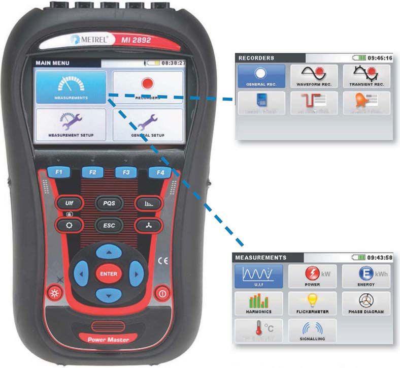


protective relays My dad tests

Over the last 20 years, OMICRON has helped my dad do a great job – and thanks to the following products, his life is going to get even easier:
My dad´s new protection test set CMC 356 is the universal solution for testing all types of protection relays. By controlling it with the powerful Test Universe PC software he can test everything from high-burden electromechanical relays to the latest IEC 61850 IEDs. He can also save a lot of time by using the test templates from the free Protection Testing Library (PTL)
For speedy manual tests, Dad now also has an easy-to-use front panel control utilizing an intuitive touch screen user interface and a control wheel. He can use his CMControl either as a front panel control or as a handheld controller for his CMCs.


www.omicronusa.com | 1-800-OMICRON


 BY DAN HOOK, Western Electrical Services, Inc.
BY B D AN H OO K, , Western Electr t ical Ser r vices, , Inc l


 BY MIKLOS J OROSZ, Schneider Electric


