


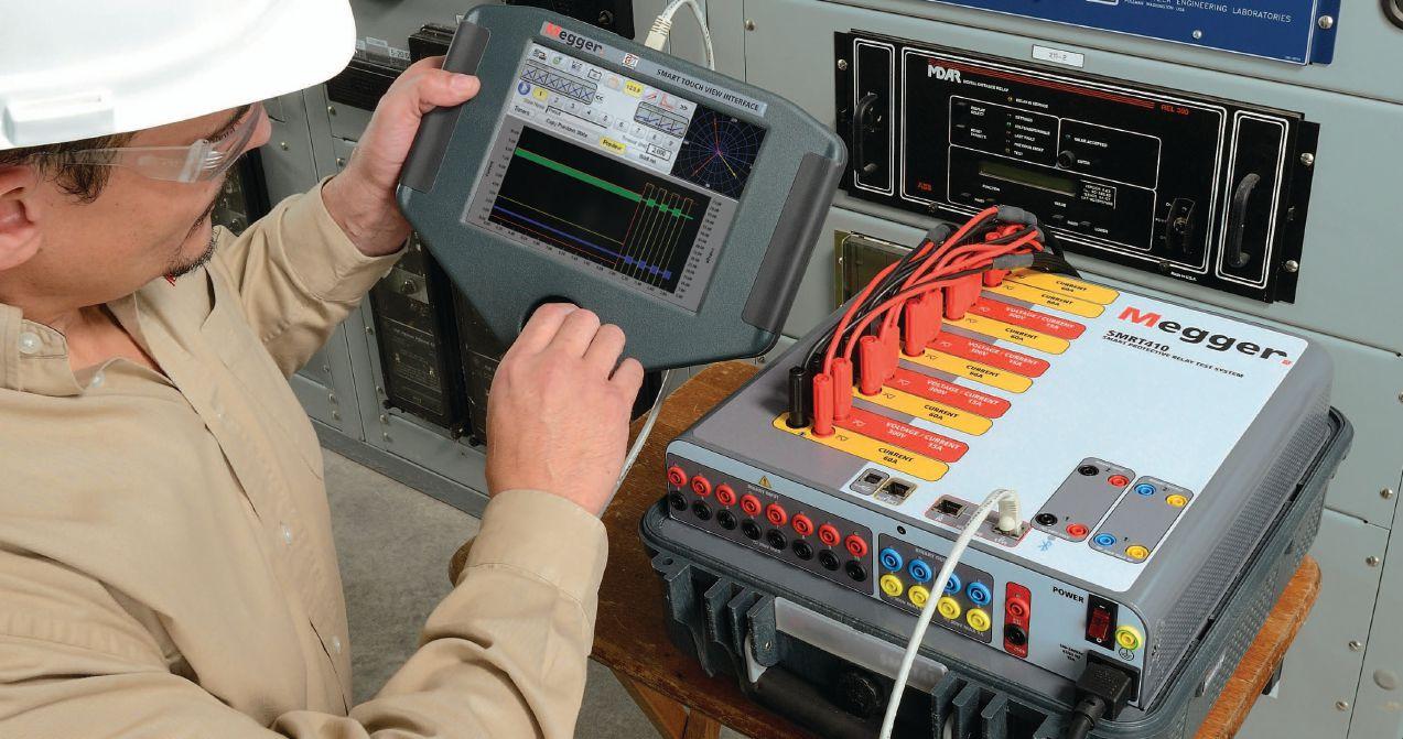
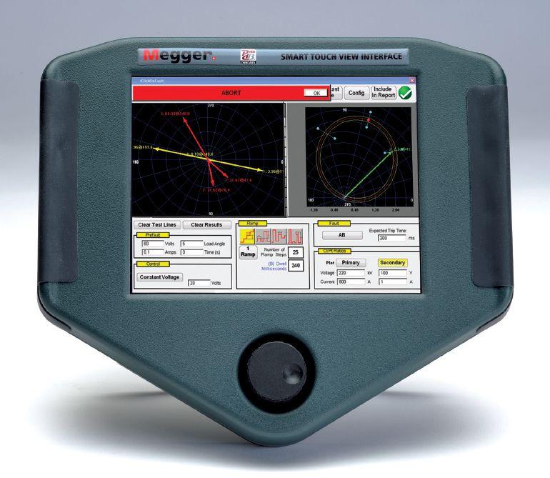
Megger continues to listen to the industry and improve the company’s SMRT relay testing equipment adapting to the immediate needs of utilities and manufacturers as the electrical smart grid evolves.
The SMRT system (SMRT1, SMRT36, and SMRT410) now offers overall adaptations as well as a devilish look at the firmware details, which make all the difference out in the field. In the all-important details category, Megger has adapted the SMRT36 current channels in a “push-push-push” series configuration that will provide up to 150 volts at four amps for testing high impedance loads, while improving general calibration at test currents down to 100 mA. Megger has added communications support for the SMRT410 double current generator (DIGEN) as well as the voltage-only generator (VGEN), making the SMRT series even more interoperable and cost-effective. The STVI now has a new sequencer test screen with end-to-end dynamic test capabilities making the STVI and SMRT systems the easiest-to-use test instruments available on the market today.
If you would like a free download of Megger’s new IEC61850 operability booklet please go to www.megger.com/netaiec
4271 Bronze Way sales@megger.com Dallas, TX 75237-1019 1-800-723-2861
Enhance


50 Wind Farm Collector System Predictive Maintenance Practices
By Paul Idziak, Shermco IndustriesPower generating facilities, and more specifically wind power generation facilities, avoid downtime to maintain consistent output of their prized product: electricity. Some of the facilities will stay on line for extended time frames skipping recommended maintenance cycles until an outage occurs. Within the wind farm owner’s key performance indicators, availability and production are at or near the top of the list. So how can wind farm owners perform necessary maintenance on their collector system and reduce downtime? How can wind generation sites develop an acceptable maintenance strategy using national consensus standards?
7 President’s Desk
Mose Ramieh, Power & Generation Testing, Inc. NETA President
62 Wind Turbine Generator Electrical Failures By William Chen, TECO Westinghouse Motor Company
70 Up-Tower Electrical Testing of Wind Turbine Generator Stator and Rotor Main Windings
By Kevin Alewine and Casey Gilliam, Shermco Industries

11 The NFPA 70E and NETA
Do I Need to Wear Arc-Rated PPE When Working Around Energized Equipment?
Ron Widup and Jim White, Shermco Industries
16 Tech Quiz
Wind Power
Jim White, Shermco Industries
20 Niche Market Testing
Data Center Maintenance – Part 3 –
Battery and Backup Generator Maintenance
Lynn Hamrick, Shermco Industries
26 Testing Rotating Machinery
Synchronous Rotor Winding Common
Electrical Tests
Vicki Warren, Iris Power LP.
32 No-Outage Inspection Corner
Maintenance Testing of Wind Farm Distribution Systems – A No-Outage Approach
Don A. Genutis, No-Outage Electrical Testing, Inc.
36 Safety Corner
Globally Harmonized System of Classification and Labeling of Chemicals
Paul Chamberlain, American Electrical Testing Co.
42 Tech Tips
Ground Testing on Wind Farms
Jeff Jowett, Megger
INDUSTRY TOPICS
91 Electrical Power System Testing
A Quantum Change in our Field has Arrived
John Hodson
98 The One Minute No-Outage Safety Checklist
Don Genutis, No-Outage Electrical Testing, Inc.
101 ANSI/NETA Standards Update
108 NEC Code Making Panel Committee Report
CMP-10
Scott Blizard, American Electrical Testing Co., Inc.
114 NEC Code Making Panel Committee Report CMP-13
Jim White, Shermco Industries
76 NETA’s 2013 Outstanding Achievement Award
Richard Piet, NETA
84 NETA Honors Outstanding NETA
Alliance Partner
Jill Howell, NETA
102 NETA’s Steel Magnolia
Kristen Wicks, NETA
110 NETA Standards Review Council
Welcomes Lorne Gara
Kristen Wicks, NETA
118 IEEE-IAS Electrical Safety Workshop –The Best Yet!
NETA NEWS – SETTING THE STANDARD
48 NETA Alliance Partners Convene at PowerTest 2013
58 PowerTest 2013: Energizing Your Future
The New Orleans Way!
Richard Piet, NETA
NETA NEWS – IMPORTANT LISTS
124 NETA Accredited Companies
130 Advertiser List
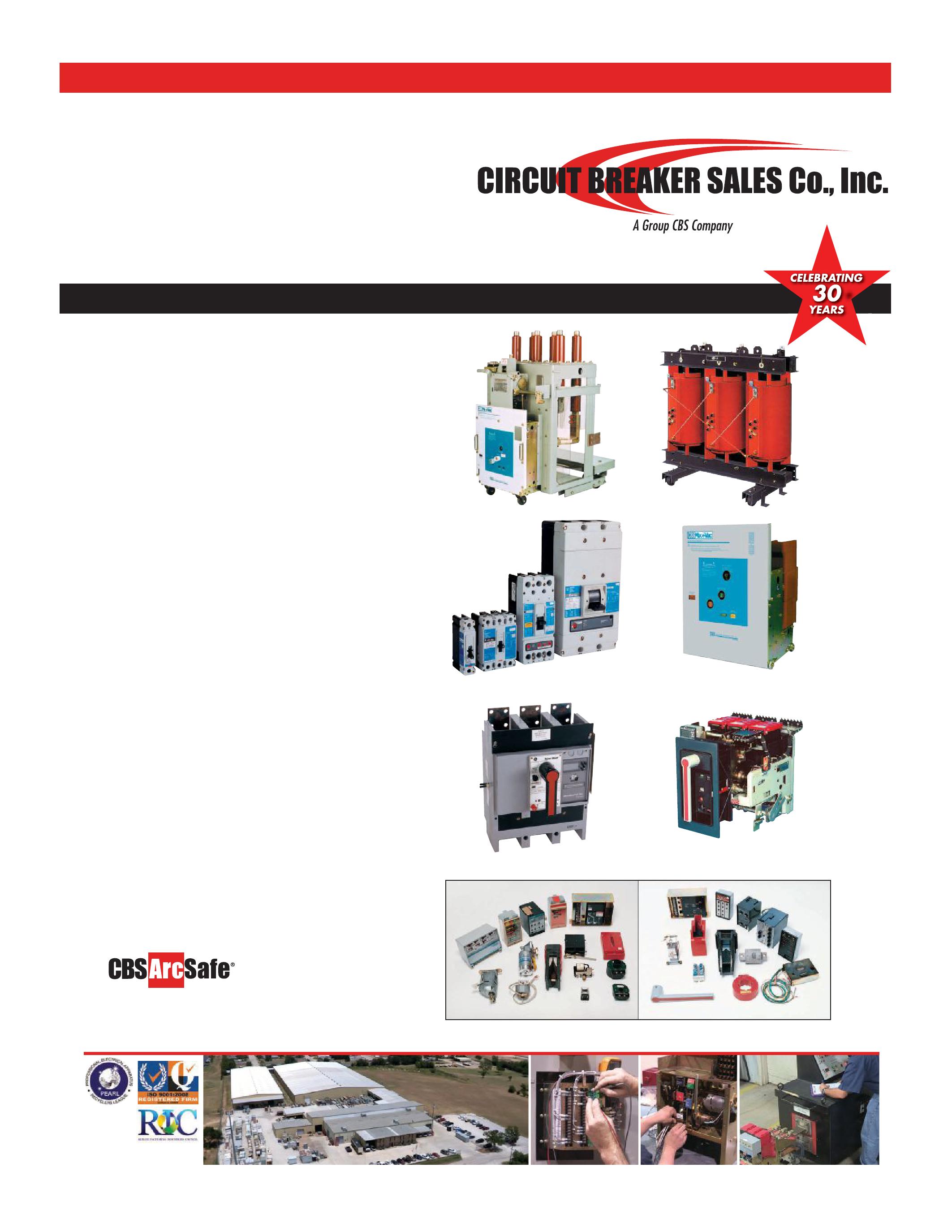
CIRCUIT BREAKERS – LOW/MEDIUM
TRANSFORMERS – 1000–5000 KVA
Dry type/cast resin transformers from stock Load break switch & fuse LIFE EXTENSION
Vacuum retrofill/retrofit
Solid state conversion
Vacuum motor control upgrades
MOLDED CASE CIRCUIT BREAKERS
LOW VOLTAGE MOTOR CONTROL
Circuit breakers
Motor control components
Upgraded buckets
Panel mount switches
SWITCHGEAR – 480V-38KV NEW AND SURPLUS
New General Electric switchgear in 4 weeks
Match existing lineup
Reconditioned from stock
Complete Indoor/outdoor unit substations available
RENEWAL PARTS –
SWITCHGEAR & CIRCUIT BREAKER PARTS
All low & medium voltage renewal parts, 1945–today
Obsolete vacuum interrupter in stock www.circuitbreakerpartsonline.com
MEDIUM VOLTAGE MOTOR CONTROL
AIR & VACUUM MOTOR CONTROL
New General Electric available from stock
Reconditioned starters and contactors
SERVICE & REPAIR
Field service and testing
Shop repair of all switchgear and circuit breakers ISO 9001 and 14001 Certified



3050 Old Centre Avenue, Suite 102
Portage, MI 49024
Toll free: 888.300.NETA (6382)
Phone: 269.488.NETA (6382)
Fax: 269.488.6383
neta@netaworld.org
www.netaworld.org
EXECUTIVE DIRECTOR: Jayne Tanz, CMP
NETA Officers
PRESIDENT: Mose Ramieh, Power & Generation Testing, Inc.
FIRST VICE PRESIDENT: David Huffman, Power Systems Testing Co.
SECOND VICE PRESIDENT: Ron Widup, Shermco Industries
SECRETARY: Walt Cleary, Burlington Electrical Testing Co., Inc.
TREASURER: John White, Sigma Six Solutions
NETA Board of Directors
Ken Bassett (Potomac Testing, Inc.)
Scott Blizard (American Electrical Testing Co., Inc.)
Jim Cialdea (Three-C Electrical Co., Inc.)
Walt Cleary (Burlington Electrical Testing Co., Inc.)
Roderic Hageman (PRIT Service, Inc.)
Kerry Heid (Magna Electric Corporation)
David Huffman (Power Systems Testing)
Alan Peterson (Utility Service Corporation)
Mose Ramieh (Power & Generation Testing, Inc.)
John White (Sigma Six Solutions)
Ron Widup (Shermco Industries)
NETA World Staff
TECHNICAL EDITOR: Roderic L. Hageman
ASSOCIATE EDITORS: Diane W. Hageman, Resa Pickel
MANAGING EDITOR: Jayne Tanz, CMP
ADVERTISING MANAGER: Jill Howell
DESIGN AND PRODUCTION: Hour Custom Publishing
NETA Committee Chairs
CONFERENCE: Ron Widup; MEMBERSHIP: Ken Bassett; PROMOTIONS/MARKETING: Kerry Heid; SAFETY: Lynn Hamrick; TECHNICAL: Alan Peterson; TECHNICAL EXAM: Ron Widup; WORLD ADVISORY: Diane Hageman;
CONTINUING TECHNICAL DEVELOPMENT: David Huffman; TRAINING: Kerry Heid; FINANCE: John White; NOMINATIONS: Alan Peterson; STRATEGY: Mose Ramieh; ALLIANCE PROGRAM: Jim Cialdea
© Copyright 2013, NETA
NETA World is published quarterly by the InterNational Electrical Testing Association. Opinions, views and conclusions expressed in articles herein are those of the authors and not necessarily those of NETA. Publication herein does not constitute or imply endorsement of any opinion, product, or service by NETA, its directors, officers, members, employees or agents (herein “NETA”).
All technical data in this publication reflects the experience of individuals using specific tools, products, equipment and components under specific conditions and circumstances which may or may not be fully reported and over which NETA has neither exercised nor reserved control. Such data has not been independently tested or otherwise verified by NETA.

NETA MAKES NO ENDORSEMENT, REPRESENTATION OR WARRANTY AS TO ANY OPINION, PRODUCT OR SERVICE REFERENCED OR ADVERTISED IN THIS PUBLICATION. NETA EXPRESSLY DISCLAIMS ANY AND ALL LIABILITY TO ANY CONSUMER, PURCHASER OR ANY OTHER PERSON USING ANY PRODUCT OR SERVICE REFERENCED OR ADVERTISED HEREIN FOR ANY INJURIES OR DAMAGES OF ANY KIND WHATSOEVER, INCLUDING, BUT NOT LIMITED TO ANY CONSEQUENTIAL, PUNITIVE SPECIAL, INCIDENTAL, DIRECT OR INDIRECT DAMAGES. NETA FURTHER DISCLAIMS ANY AND ALL WARRANTIES, EXPRESS OF IMPLIED, INCLUDING, BUT NOT LIMITED TO, ANY IMPLIED WARRANTY OF FITNESS FOR A PARTICULAR PURPOSE.
ELECTRICAL TESTING SHALL BE PERFORMED ONLY BY TRAINED ELECTRICAL PERSONNEL AND SHALL BE SUPERVISED BY NETA CERTIFIED TECHNICIANS/ LEVEL III OR IV OR BY NICET CERTIFIED TECHNICIANS IN ELECTRICAL TESTING TECHNOLOGY/LEVEL III OR IV. FAILURE TO ADHERE TO ADEQUATE TRAINING, SAFETY REQUIREMENTS, AND APPLICABLE PROCEDURES MAY RESULT IN LOSS OF PRODUCTION, CATASTROPHIC EQUIPMENT FAILURE, SERIOUS INJURY OR DEATH.


Ah the wind, that ever moving and wondrous energy source of the past and future.
This issue focuses on how we in NETA can be and are involved in this emerging technology. I recently took a trip to the Texas Gulf Coast and was amazed at the number and size of the wind farms we passed. Currently there is much activity in coastal states to site wind farms within sight of shore. These activities will provide many opportunities to NETA companies. If your company is not involved in wind now, it soon will be.
We had a great conference in New Orleans. Besides being a great venue for extracurricular activities, the program and seminars were excellent. Make your plans now to attend PowerTest next year in Denver.
During the past two years we have accomplished much. We have added 10 accredited companies and increased our technician count by 15 percent. We have created the NAMO Program. Through the aggressive marketing campaign, we have increased NETA’s presence to architects, engineers, and constructors and increased our influence and impact on the electrical industry as a whole. Thanks to the staff and the board of directors for making my term as president successful. A special thank you to all of the members that have offered suggestions, volunteered, and worked hard to make NETA the driving force in our industry.
This is my last message as President of NETA but not the last you will hear from me. As the Strategic Chair I will be involved in the continued setting of direction and evolution of our association. I need your input and direction to ensure that we continue to evolve in a manner that best serves our membership.
It has been an honor and privilege to serve as your President these past two years. I look forward to many more years of involvement with this dynamic association.
Mose Ramieh NETA President



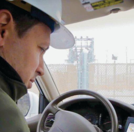
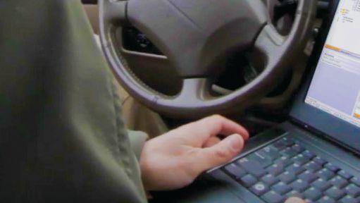

Install in your reclosers, voltage regulators, and substations to communicate wirelessly from over 300 feet away guaranteed to work from —40° to +185°F (—40° to +85°C). Pair with your laptop or smartphone. It’s always secure, thanks to BLUETOOTH v2.1 + EDR encryption and authentication. Avoid hazardous areas, reduce arcflash exposure, and save time opening cabinets, doors, and gates.
Learn more at www.selinc.com/BLUETOOTH. Call SEL today, and put this new technology to work.




At this year's IEEE Electrical Safety Workshop several people asking the same question, "Do I need to wear arc-rated PPE when working around energized electrical equipment?" This question seems to come up frequently, so there must be some confusion in the industry about when to wear arc-rated PPE.
In each case the people asking the question referred to 130.7(C)(15) Informational Note No.2whichstates: "The collective experience ofthe task group is that, in most cases, closed doors do not provide enough protection to eliminate the need for PPE for instances where the state ofthe equipment is known to readily change (for example, doors open or closed, rack in or rack out)." ( Remember that Article 130.7(C)(15) is Selection ofPersonal Protective Equipment When Required for various Tasks.) The rationale was that if the doorsdonotprovideprotection,thereexistsan arc-flashhazardevenifthedoorsareclosed.
Thereareseveralthingswrongwiththislineof reasoning. Thefirstisthatelectricalequipment withthedoorsclosedandproperlylatchedand secured is considered guarded. This means theyare not accessible and, therefore, do not normallypresentarisktopeoplearoundthem. Thesecondproblemwiththislineofreasoning is theinformationalnote (IN) attachedtothe definitionof arc-jlash hazard in Article 100,
whichstates, 'Informational Note No.1: An arc flash hazard may exist when energized electrical conductors or circuit parts are exposed or when they are within equipment in a guarded or enclosed condition, provided a person is interacting with the equipment in such amanner that could causean electric arc. Under normal operating conditions, enclosed energized equipment that has been properly installed and maintained is not likely to pose an arcflash hazard." Thisinformational note contains important information which isintendedtoclarifywhenanarc-flashhazard mayormaynotbepresent.Anarc-flashhazard may be present when energized electrical equipmentisinaguardedcondition,ifaworker interacts with it in a manner that could causeanelectricalarc. Electrical equipment that is operating normally and is not being interacted with is notdesignedtocreate anelectricalarc.



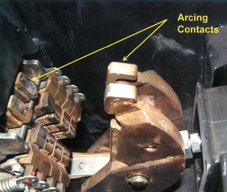


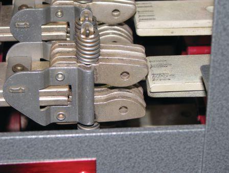
An electrical arc could occur during abnormal operations or during periods of interaction such as inserting or removing a circuit breaker (racking), or installing or removing fuses, or whenever a device is connected or disconnected to an energized source (MCC buckets, bus duct fuses, circuit breakers, etc). The risk of an arc flash is increased during these operations because the equipment has no arc extinguishers at the circuit breaker-to-bus connection. If an arc were to occur, it most likely would be a serious event. Contrast that with the operation of a circuit breaker or switching device, which is designed to operate under load. These devices have arcing contacts and arc extinguishers that contain the arc, stretch it and cool it, and then extinguish it (see Figures 1a and 1b), whereas the bus connection (primary disconnect) that makes during racking operations is more like an electrical disconnect and is not designed to operate under load (see Figure 2).
The second part of IN No. 1 in 130.7(C) (15) states that equipment that is properly installed and maintained is not likely to pose an arc flash hazard under normal operating conditions. This means that if it is operating normally and has been installed and maintained in accordance with local and national codes and standards, it presents no increased risk of failure and arc-flash hazard. It also means that if the equipment is operated in the manner that the manufacturer designed it to operate such as starting, stopping, opening, and closing – no increased risk of an arc flash is present. Some people have difficulty with this, as they believe opening and closing a switch or circuit breaker is interacting with equipment. It is, but it is not interacting in a manner that could cause failure such as racking or the other tasks that could cause an arc flash.
To illustrate this fact further, Article 130.6(K) states, “(K) Routine Opening and Closing of Circuits. Load rated switches, circuit breakers, or other devices specifically designed as disconnecting means shall be used for the opening, reversing, or closing of circuits under load conditions. Cable connectors not of the load-break type, fuses, terminal lugs, and
cable splice connections shall not be permitted to be used for such purposes, except in an emergency.” Switches and circuit breakers are load rated devices and are specifically designated by the 70E for the purpose of opening and closing of circuits while energized. To further clarify what is meant, the 70E Committee added 130.7(A) Informational Note No. 2, “Informational Note No. 2: It is the collective experience of the Technical Committee on Electrical Safety in the Workplace that normal operation of enclosed electrical equipment, operating at 600 volts or less, that has been properly installed and maintained by qualified persons is not likely to expose the employee to an electrical hazard.” This is virtually the same language used in the informational note for the definition of an arc- flash hazard.
So the informational note in 130.7(A) references 600-volt and below equipment, but what about electrical equipment rated above 600 volts? Higher voltage electrical equipment can present additional risks that are not present with 600-volt class equipment. The higher voltages stress insulation to a greater degree, and if there is an arc flash, chances are it could be more severe. Many older installations, or newer installations that have been modified after initial construction, may not have adequate clearances between the switchgear and walls or other structures. The 70E Committee decided to err on the safe side with the higher voltage equipment and not put forth the same assertion as stated with the 600-volt rated equipment.
NFPA 70E provides minimum safe work practices. We would never tell workers not to wear additional protection if the worker feels it might be needed. Circuit breakers and switches have been known to fail, even though they appear to be normally operating. If we were operating higher amperage circuit breakers or switches, we would have HRC-2 arc-rated PPE and clothing on, just in case. NFPA 70E does not require this level of protection, but for
peace of mind it would be our choice. What level of discomfort does this really present? Not much, really – in fact it is likely that we already have arc-rated coveralls on (many companies already require HRC-2 daily work wear), a balaclava, and arc-rated face shield along with hearing protection and rubber insulating gloves/protectors. The wearing of this level of PPE is preferable to spending weeks or months in a hospital recovering from an arc-flash event. NFPA 70E cannot possibly foresee any and all risks, nor can it account for any and all circumstances. It is the worker about to perform the tasks(s) that has to make judgment calls as to what is needed.
Companies are responsible for the safety of their employees and may require any level of protection, or institute any safe work practice they believe necessary to provide a safe workplace. Workers may or may not agree with these work rules, but OSHA will hold companies to them if they are part of the company’s safe work practices. Several companies require workers to wear rubber


insulating gloves if they are within 18 inches of energized conductors or circuit parts. NFPA 70E says 12 inches. Who is correct? The company, as it has the responsibility for worker safety at its site. Any work practice that meets or exceeds NFPA 70E minimum requirements is acceptable.


If a worker approaches energized electrical equipment and does not believe it is normally operating, for any reason, that worker should reevaluate what protective equipment is required. In most cases that equipment should be shut down before working on it if there is any doubt that it is safe to proceed. If a worker receives a trouble call about a piece of equipment and has to operate it, he/she should be wearing the all arc-rated PPE and clothing required, as it is no longer normally operating. Any type of troubleshooting task requires full arc-rated PPE and clothing. Electrical equipment that is out-of-date for maintenance, equipment that is visibly deteriorated, or equipment that has no maintenance labels attached and has no record of its last maintenance is not to be considered normally operating.

Everyone likes to hit the EASY button. The problem is, when working on or around energized electrical equipment there is no EASY button. Each task and each device has to be evaluated at the time the work is to take place in order to proceed. What was true last year, last month or even earlier in the day may not hold true at the moment you are about to perform a task on equipment. Things change rapidly in the real world, and we need to be alert to those changes. Being alert also means being alert to faulty Job Hazard Analysis information, lockout/tagout processes, other workers who may demonstrate a lack of concentration or focus, or any other potential issues in and around the equipment. Don’t be myopic when viewing safety, and don’t be lazy. Arc flash doesn’t kill as many workers as electrical shock, but the injuries are much more substantial and may require months of rehabilitation to recover. Don’t be a statistic, be smart, work smart. It’s that easy.


Ron Widup and Jim White are NETA’S representatives to NFPA Technical Committee 70E (Electrical Safety Requirements for Employee Workplaces). Both gentlemen are employees of Shermco Industries in Dallas, Texas a NETA Accredited Company. Ron Widup is President of Shermco and has been with the company since 1983. He is a Principal member of the Technical Committee on “Electrical Safety in the Workplace” (NFPA 70E) and a Principal member of the National Electrical Code (NFPA 70) Code Panel 11. He is also a member of the technical committee “Recommended Practice for Electrical Equipment Maintenance” (NFPA 70B), and a member of the NETA Board of Directors and Standards Review Council. Jim White is nationally recognized for technical skills and safety training in the electrical power systems industry. He is the Training Director for Shermco Industries, and has spent the last twenty years directly involved in technical skills and safety training for electrical power system technicians. Jim is a Principal member of NFPA 70B representing Shermco Industries, NETA’s alternate member of NFPA 70E, and a member of ASTM F18 Committee “Electrical Protective Equipment for Workers”.

Comprehensive Electrical Testing and Maintenance
Commissioning and Startup Services
Engineering Services
Power System and Coordination Studies
Predictive and Preventive Maintenance
Partial Discharge Testing and Monitoring
24/7 Emergency Service

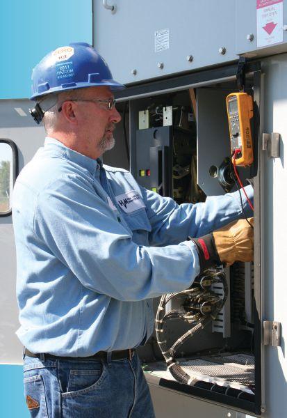
Failure is not an option. Ensuring the reliability of your electrical distribution system.
As the leading independent electrical testing, maintenance, and engineering service company, you can rely on Emerson’s High Voltage Maintenance to exceed your electrical equipment performance goals. From testing for problems that could disable your system, to complete turnaround execution, you’ll quickly understand how we are your single source solution for all of your electrical reliability needs. With a network of more than 12 service locations, our service team puts experienced professionals where and when you need them.


James R. (Jim) White is the Training Director of Shermco Industries, Inc., in Dallas, Texas. He is the principal member on the NFPA technical committee “Recommended Practice for Electrical Equipment Maintenance” (NFPA 70B). Jim represents NETA as an alternate member of the NFPA Technical Committee “Electrical Safety in the Workplace” (NFPA 70E) and represents NETA on the ASTM F18 Committee “Electrical Protective Equipment For Workers”. Jim is an IEEE Senior Member and in 2011 received the IEEE/PCIC Electrical Safety Excellence award. Jim is a past Chairman (2008) of the IEEE Electrical Safety Workshop (ESW).
Wind power generation sites have become common throughout the U.S. Wind generation presents some unique challenges for maintenance personnel, as well as for safety concerns.
1. Which state has the most wind generation capacity (in MW)?
a. Illinois
b. California
c. Iowa
d. Texas
2. The most common cause of failure in a wind turbine is:
a. Gearboxes
b. Blades
c. Control system
d. Electrical system
3. The largest commercially-available wind generator produces:
a. 8.0 MW
b. 7.6 MW
c. 6.6 MW
d. 5.0 MW

4. On average, wind generators produce power ___ % of the time.
a. 30
b. 50
c. 60
d. 90
5. The cost to install a wind generator is approximately ___ to ___ per MW of installed nameplate capacity.
a. $800,000 to $1,200,000.
b. $1,000,000 to $1,300,000.
c. $1,500,000 to $2,000,000.
d. $1,300,000 to $2,200,000.



THIS ARTICLE IS PART 3 OF A FOUR-PART SERIES ON DATA CENTER MAINTENANCE.
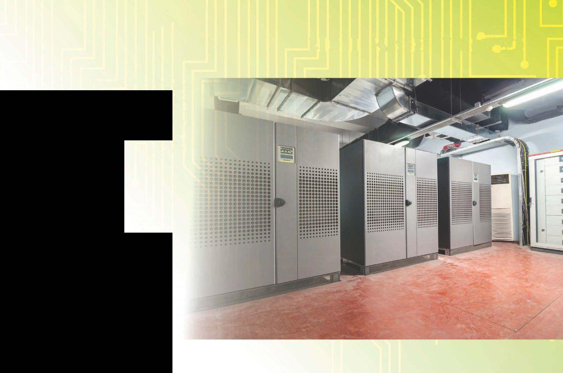
BY LYNN HAMRICK, Shermco IndustriesKey electrical systems for most data centers are the UPS systems and their battery systems and the backup generation systems. The UPS systems are designed to provide primary power to downstream equipment with immediate switching to battery systems with loss of power. Failed or discharged batteries mean the data center’s UPS won’t be able to supply the temporary backup power needed in the event of a power sag or outage. Even though UPSs are not designed to keep the data center running during a long-term outage, they do provide the carry-over capability that accommodates a seamless transfer to an alternate power source like a backup generator.
This article will focus on the key attributes of battery and backup generation maintenance and how they can affect data center reliability.
The battery is by far the most vulnerable and failure-prone part of a UPS system. Because of this, much time and effort is allocated to maximizing a battery’s reliability and life within the data center. At a minimum, annual testing, verification, and inspection of a battery system should be performed. As with all electrical systems, infrared thermographic surveys should also be performed on battery systems on at least an annual basis. Additional quarterly or semi-annual inspections should be performed if the age and condition of the battery warrant the activity.

Watering is the single most important factor in maintaining a flooded lead acid battery. The frequency of watering depends on usage, charge method, and operating temperature. A new battery should be checked every few weeks to determine the watering requirement. This prevents the electrolyte from falling below the plates. Avoid exposed plates at all times, as exposed plates will sustain damage, leading to reduced capacity and lower performance.
Battery charging is probably the second most important factor in maintaining a battery
system. A correctly functioning battery charging system with a healthy battery condition will result in a fully charged and reliable battery system that is available when calledupon for service. Thefollowingchecks areaquickwayofdeterminingacorrectlyand fullychargedbattery:
• Stabilizedchargingcurrents
• Stabilizedchargingvoltage
• Consistentspecificgravity
• Normalgassing
An excessive amount of charge results in high battery temperature and a reduced battery service life. To obtain maximum service life from a battery, it should be charged and operated within temperature ranges recommended by the manufacturer. Overheating can damage the battery and shorten its normal expected service life. The extent of the damage and service life loss depends on the higher temperature, how often the overheating occurs, and how long the batteries are subjected to high temperatures. A healthy battery charged on a correctly functioning charger will have a 10 to 20 0 F rise in temperature when fully charged. This temperature rise is affected by severalvariablefactors:
• Battery ageandcondition
• Battery temperatureversusambient temperature
• Charger rate
• Charger voltagelevel
In support of good battery health, the electrical maintenance program for the batterysystemshouldincludethefollowing:
• Visualinspectionofthebatterycells
• Verifybatterychargingperformance
• Cleaningbatterypostsandconnections
• Periodicelectricaltesting
Batteriesshouldbe visually inspected under normalfloatconditions.
• Inspect the electrolyte level. Flooded cells have translucent or transparent jars, so the electrolyte level can easilybe comparedtoarecommendedlevelthatis markedonthecells.
• Inspect the positive plates. The positive plates are typically the first to wear out and are located toward the center of the jar. They should be dark brown or black. Sparkle is evidence of sulfation or undercharge. Lookforcracks, breaks, and pieces hanging on the side. This indicates that the cell may need to be replaced and that other cells may also haveasimilarproblem.

• Inspectthenegativeplates. Thenegative plates are thinner than the positive plates and sit toward the outside of the jar. These should have a clean lead color from top to bottom. Pink discoloration indicatescoppercontamination.

• Look at the sediment. Inspection of the sediment should provide a general idea of the battery conditional trend from the last inspection. Accumulation of gray material under the negative plates accompanied by sparse black sediment is indicativeofanunderchargingcondition. Excess black sediment under the positive plates with little negative sediment is indicative of an overcharging condition or excess temperature. If excess sediment covers the bottom of the jar, the battery has been cycled heavily or operated at high temperature.
• Inspect the outside of thejar. A crusty trail or accumulation is evidence of electrolyte leakage. Signs of corrosion on the terminal connections, intercellconnections, andracks arealsoindicativeofelectrolyteleakage.
• VerifY presence and condition of flame arresters.
• VerifYbatteryareaventilationisoperableand thatsuitableeyewashequipmentispresent.
ThereismoretoverifYingbatterychargingperformancethanjustrecordingthevoltage levels.
• Measure each cell voltage and the total battery voltage. The cell voltage value should be in accordance with manufacturer's published data. Low cell voltage is indicative of a problem with the cell.
• VerifY appropriate charger float and equalizing voltage levels. Charger float voltage is the typical voltage output for a normal charging process. This voltage should be in accordance with the manufacturer's recommendations but may need to be increased as the battery ages or degrades. An equalizing charge
is nothing more than forced overcharge. Applying an equalizing charge periodically brings all cells to similar levels by increasing the voltage to � 10 percent higher than the recommended float voltage. This process removes sulfation that may have formed during low-charge conditions. One method of evaluating sulfation is to compare the specificgravityreadingsontheindividual cells of a flooded lead acid battery. Only apply equalization if the specific gravity difference between the cells is greater than 0.030. During equalizing charge, check the changes in the specific gravity readingeveryhourandstoptheequalizing charge when the specific gravity no longer rises. This is the time when no further improvement is possible, and a continued charge will cause damage. The battery must be kept cool and under close observation for unusual heat rise and excessive venting. Some venting is normal and the hydrogen emitted is highly flammable.


• Test each cell for specific gravity and temperature. Specific gravity is useful in evaluating charger float voltage, as well as cell internal health. For most UPSrelated battery systems, a specific gravity of 1.250 is typical for each cell. If the specific gravity drops by 0.015 to 0.020 from these values, it is usually indicative of inadequate charger float voltage or a problem with a cell holding a charge. Remember, specific gravity should always be adjusted for internal cell temperature differences from 25 degrees C at a rate of 0.001 for every 1.67 degrees C difference. Also, electrolyte levels should be taken into consideration when evaluating specific gravity. Cells with low electrolyte levels typically need water added and, therefore, will have a higher specific gravity.

Before cleaning, note the condition of posts and connectors. Except for a light coating of grease, these should look new. Consider the following colors:
• Black. This is lead peroxide, indicating an acid leak around the positive post.
• Green. This is corroded copper, indicating connectors need cleaning and close inspection - they may no longer be serviceable.
• White. This is lead hydrate, indicating a leak around the negative post.
The jars surfaces can be cleaned any time, but cleaning connectors and posts requires opening the batterycircuit. If thecleaningrequiresthatthe battery be taken out of service without a parallel system, the UPS will not respond to a power loss. Therefore, cleaning should be coordinated with the operator. This following cleaning procedure should be performed when required.
• Wipethe grease offthe posts and connectors, and then neutralize them with a suitable solution like baking soda and water.
• Clean with a scouring pad or brass brush until clean lead is exposed. Do not clean too vigorously or with a steel wire brush because it may remove too much lead.
• Degrease the bolts, washer, and nuts. Neutralize electrolyte with a suitable solution. Replace corroded hardware. Replace lock washers, regardless of condition. Use only lead-plated or 316-stainless steel bolts, washers, and nuts.
• Regrease posts and contact areas of connectors with a light layer of antioxidant grease approved for battery use.
• Retorque connections to manufacturer's specifications. Turn the nut, not the bolt, if possible.
• Check post-to-post resistance with a micro-ohmmeter. If resistance is high, check the torque- overtorquing degrades the connection. If the torque is correct but the value is high, disassemble and inspect contact surfaces for correct polishing.
In addition to theperiodic visual inspections and battery system checks discussed above, specific electrical tests should beperformed. The addition of an occasional load test of the battery system should be considered as the battery system ages or other problems are identified. In support of this recommendation for load testing, there are some other more sophisticated testing methods that can and should be performed more regularly to accurately determine battery health. These methodsmeasure theinternalohmic valuesof the battery or associated cells.
Ohmic measurement using a dc voltage is one of the oldest and most reliable test methods for batterysystems.Acell'sinternalresistanceprovides usefulinformationindetecting problems and can be used for indicating when a battery or battery cell should be replaced. However, resistance alone does not provide a linear correlation to the battery's capacity The increase of cell resistance only relates to aging and provides some failure indications. Rather than relying on an absolute resistance reading, service technicians take a snapshot of the cell resistances when the battery is installed and then measure the subtle changes as the cells age. An increase in resistance of 25 percent over an initial baseline (100 percent) or compared to similar cells indicates a performance drop to about 80 percent.


• Install washers with the sharp side facing away from the connector. If possible, install lock washers on the nut side, not the bolt side.
Ohmic measurement using ac voltage is also a generally accepted test method for battery systems. From this method the batteries conductance is derived in terms of mhos, or siemens. A major benefit to using conductance

without performing an extensive discharge or correlates linearly with its ability to deliver current. As conductance declines, so does a
and supply energy. A decrease in conductance of 25 percent over an initial baseline (100 percent) or compared to similar cells indicates a performance drop to about 80 percent.
Backup generators should be checked and tested periodically to ensure that they will function as designed and when required. As with the UPS batteries, this testing should include occasional load testing. Backup generators are usually stationary units that are interconnected into the data center’s electrical infrastructure. Automatic transfer switches (ATS) are the most common type of interconnection device used for these applications. An ATS can provide a signal for the generator to start and transfer the load from the normal supply to the generator.
Incorrectly or poorly maintained backup generator sets are more prone to failure and are more likely to fail when needed most. The most common engine failures can be attributed to the starting, cooling, lubrication, or fuel delivery systems. These types of failures can be minimized or prevented by implementing regularly scheduled, comprehensive, enginegenerator maintenance and testing programs.
The key components of a good backup generation maintenance program include: surrounding area, and fluid levels
lubrication, coolant, and fuel on a regular basis system, including the batteries
The engine generator should be run under a load on a periodic basis. During dynamic testing engine parts become lubricated, oxidation is prevented, old fuel is consumed, and overall functionality is ensured. Therefore, periodic operation of the generator at a load of at least 30 percent of the nameplate rating for no shorter than 30 minutes should be performed. The generator should be operated for a minimum of one hour at 100 percent of the nameplate capacity at least annually. When testing a stationary unit, testing should be done through the ATS to ensure the entire system works correctly. If it is not possible or practical to use a site load for the test, a load bank should be used.
Sometimes problems only become noticeable during operation; therefore, it is important that maintenance personnel remain attentive for unusual circumstances, e.g. abnormal sights, sounds, vibration, excessive smoke, or changes in fuel consumption.
The area around the engine generator should always be kept free of debris to ensure sufficient ventilation during operation; therefore, periodic inspections should be performed. The radiator should be cleaned regularly to remove any dust and/or debris, taking care not to damage the fins. These inspections should also be performed to ensure fluids, such as oil and coolant, are not leaking. Further, there should be inspections of the exhaust system, including the manifold, muffler, and exhaust pipe with all connecting gaskets, joints, and welds being checked for potential leaks. Also, check that the engine jacket water heater is operating correctly by monitoring the discharge temperature.
The fuel delivery system should also be inspected periodically for leaks and correct pressure during exercise. This includes checking fittings and connections; tighten them as needed. Drain and clean fuel filters

on a regular basis. Where applicable, examine charge-air piping and supply hoses for leaks, holes, and damaged seals. The fuel system and charge-air cooler should also be free of dirt and debris.
Fuel maintenance is another important aspect of generator maintenance. Diesel fuel degrades over time, separating and even growing microbiological organisms. A fuel sample, taken from the bottom and from the supply line, should be visually examined monthly. The fuel should look like new fuel; otherwise it should be filtered or replaced. Fuel tanks should be sized so that the fuel is turned over on a regular basis. As a rule of thumb diesel fuel should be turned over or replaced on an annual basis. This maintenance should also include fluids, such as oil and coolant, are at the correct mix and levels.
Electrical connections should be tight and free from corrosion. Batteries should also be checked to make sure they are fully charged. The batteries must be tested under load. Simply checking the voltage is an inaccurate method of testing power, as batteries change internally over time. Where appropriate, check the specific gravity and electrolyte levels. All engine wiring should have tight connections and be free of manufacturer for their recommended battery and wiring practices, cleaning agents, and solutions.
Key electrical systems for most data centers are the UPS systems and their battery systems and the backup generation systems. The UPS systems are designed to provide primary power to downstream equipment with immediate switching to battery systems with loss of power. The UPSs and battery systems are typically designed to keep the data center running long enough for a seamless transfer to an alternate power source like a backup generator.
The battery is by far the most vulnerable and failure-prone part of a UPS system. Because of this, much time and effort should be allocated to maximizing a battery’s reliability and life within the data center. At a minimum, annual testing, verification, and inspection of a battery system should be performed. Backup generators should also be inspected and tested periodically to ensure that they will function as designed and when required. As with the UPS batteries, this testing should include occasional load testing.
Lynn Hamrick brings over 25 years of working knowledge in design, permitting, construction, and startup of mechanical, electrical, and instrumentation and controls projects as well as experience in the operation and maintenance of facilities. Lynn is a Professional Engineer, Certified Energy Manager and has a BS in Nuclear Engineering from the University of Tennessee.


When the motor application requires low speed, power-factor control, high-operating efficiency, direct connection to low-speed equipment or high horsepower, a synchronous motor may be appropriate. The primary difference between a squirrel-cage induction motor and a synchronous motor is the rotor construction. A synchronous rotor winding has insulated pole windings, and, if it has laminated poles, a damper winding embedded in the pole tips. The damper winding is similar to that of a squirrel-cage rotor type.


It is used during starting to create asynchronous torque and to damp out oscillations from an unsteady load during normal operation. If the motor has solid steel poles the pole tips act as a crude damper winding for starting. The field winding is excited from a dc source, which in modern machines is a brushless exciter and provides additional electromagnetic flux to lock the stator’s rotating field to the rotor.
The two most common types of rotor designs found in medium- to high-voltage synchronous motors are salient pole and round (or cylindrical) rotor. The round rotor design is used for two-pole motors because it has the ability to withstand the very high “g’ forces imposed on the rotor winding by centrifugal forces. On the other hand for four poles and above, the salient pole design is suitable for motor ratings up to at least 60 MW. This article describes some of the common tests used for salient pole rotor windings in synchronous motors.
This test should be performed in accordance with IEEE Std. 43 [1] to confirm that the rotor winding is clean and dry and that there are no major flaws in its ground insulation on the coils and leads. Since operating voltage of most insulated rotor windings is less than 1000 V, the recommend test voltage is 500 V dc. Per IEEE 43, the minimum acceptable values are 100 megohms for form-wound armatures and 5.0 megohms for random wound types when corrected to 40° C.
The test voltage should be applied for one minute, and the insulation resistance recorded at that time. It may take a number of cleaning and baking cycles to bring the insulation resistance up to an acceptable value. Carbon should be removed before performing this test. If a winding does not have an acceptable insulation resistance reading, it is inadvisable to perform electrical tests that can potentially stress the insulation (such as the growler, high-potential or surge-comparison tests).
CAUTION: A successful 500V IR test between the rotor winding and shaft should be performed before conducting additional tests.
The resistance of the armature winding shall be measured between the leads to the brushgear assembly, with all brushes down. This measurement shall be taken with a resistance bridge, digital microhmmeter, or low resistance digital ohmmeter having four-digit accuracy. The recorded values shall be within 2.0% of the prerepair, or factory test values.
The voltage drop test is used to identify shorts between turns in dc field coils of salient pole rotors. It can be performed by exciting the coils with ac or dc, then measuring the voltage between adjacent turns. The equipment required for this test is an ac or dc source and an accurate voltmeter (or millivoltmeter) and current meter. The energizing source must be capable of providing enough current to produce a measurable voltage between turns. For this reason an ac source is preferred.
A low voltage (usually 120 V) ac voltage is applied across the complete winding and the voltage across each pole winding is measured. Since the impedance of a pole winding reduces much more than its resistance when a turn short is present, if there are turn-to-turn shorts, the ac voltage drop will be significantly less. If no shorted turns exist, the measured voltage across each coil should be within the tolerances given in Table 1 below.
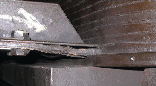
If the motor has brushless excitation, then the field winding has to be disconnected from the rotating rectifier for this test. One limitation of this test is that it may not detect turn shorts that are only present when operating centrifugal forces are present. This may be overcome by mounting the rotor horizontally and performing the test with it in four positions, 90° apart.
When there are significant differences in the iron distribution around the coils, the results of an ac drop test may be misleading. In those cases, a dc drop test is useful to determine whether the ac results are due to shorted turns or interaction with the iron. Using higher frequencies (120 hz to 400 hz) can be very beneficial in that the current requirements are greatly reduced.
When the condition of pole windings is being considered, an alternative test can be used where the power factor or losses in the coils are measured. This is a comparative test where the power factor or losses in each coil are compared. When a coil is identified with higher losses, it likely has a shorted turn. Equipment requirements for the powerfactor test are a power supply and a watt meter or pentameter capable of measuring low power factors.


The surge test may detect shorted turns, groundfaults, andhighresistanceconnections in salient pole and wound rotor windings. This test requires the same type of surge tester asis usedto detectshortedturnsin multi-turn stator coils. Since a complete winding will have a large number of turns to be effective, this test should be performed on individual coils. The test involves injecting fast risetime pulses with a peak voltage magnitude indicated in Table 2 into each end of the coil and overlaying the resulting waveforms to check for similarity in accordance with IEEE Std 522 [IJ. The pulse rise time and repetition rate produce a resonant response in the coil. A series of pulses is injected into a coil, and if the resonant damped sine wave response is stable as the test voltage is increased, the coil does not have any shorts. When the resonant response or ringing increases in frequency or decays very rapidly, a shorted turn is likely in the coil.

Comparison of surge voltage waveforms for all coils of the same type can be effective, but may not detect shorted turns if the impulse dissipates too quickly or only exist when under the influence of centrifugal forces during rotor operation. When comparison is made, the responses should match exactly if the coils do not have shorts. If there are differences in the waveformfrequencies, an experienced operator can determine the type of fault present.
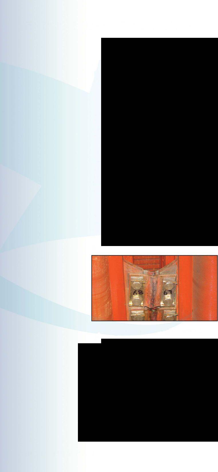
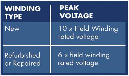
This test should be performed on all new field windings and those that have been repaired. A 1.0 minutetestshallbeperformedatthevoltage levels indicated in Table 3. When a dc high potential test is performed, usually in voltage steps, the result of each step must be assessed (IEEE 95 [4J). This means plotting the curve of insulation resistance (or leakage current, in microamperes) versus applied voltage. If the plotted valueatanystepbeginstotrendupward, indicating excessive nonlinear current (or drop in insulation resistance in a nonlinear manner), the test should be aborted immediately.
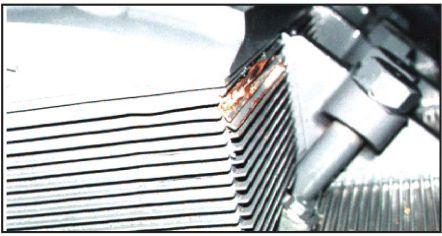 Figure 2: Fatigue and Thermal Damage (Salient Pole)
Table 3: Field Winding AC and DC High Potential Test Values [2]
WINDING DC VOLTAGE RATING
New Windings 240 Volts
New Windings > 240 Volts
Refurbished Windings 240 Volts
Refurbished Windings > 240 Volts
V +
Times Rated Winding Voltage)
[1] IEEE Std. 43-2000, IEEE Recommended Practice for Testing Insulation Resistance of Rotating Machinery
[2] IEEE Std. 522-2004, IEEE Guide for Testing Turn Insulation Testing of Form-Wound Stator Coils for Alternating-Current Electric Machines
[3] Electric Power Research Institute’s (EPRI’s) Large Electric Motor Users Group (LEMUG) Repair and Reconditioning Specification Guidelines for AC Squirrel-Cage and Salient Pole Synchronous Motors with Voltage Ratings of 2.3 to 13.2 kV Report 1000897 (dated July 2008)
[4] IEEE Std. 95-2002, IEEE Recommended Practice for Insulation Testing of AC Electric Machinery (2300 V and Above) with High Direct Voltage

Vicki Warren, Senior Product Engineer, Iris Power LP. Vicki is an electrical engineer with extensive experience in testing and maintenance of motor and generator windings. Prior to joining Iris in 1996, she worked for the U.S. Army Corps of Engineers for 13 years. While with the Corps, she was responsible for the testing and maintenance of hydrogenerator windings, switchgear, transformers, protection and control devices, development of SCADA software, and the installation of local area networks. At Iris, Vicki has been involved in using partial discharge testing to evaluate the condition of insulation systems used in medium- to high-voltage rotating machines, switchgear and transformers. Additionally, she has worked extensively in the development and design of new products used for condition monitoring of insulation systems, both periodical and continual. Vicki also actively participated in the development of multiple IEEE standards and guides and was Chair of the IEEE 43-2000 Working Group.


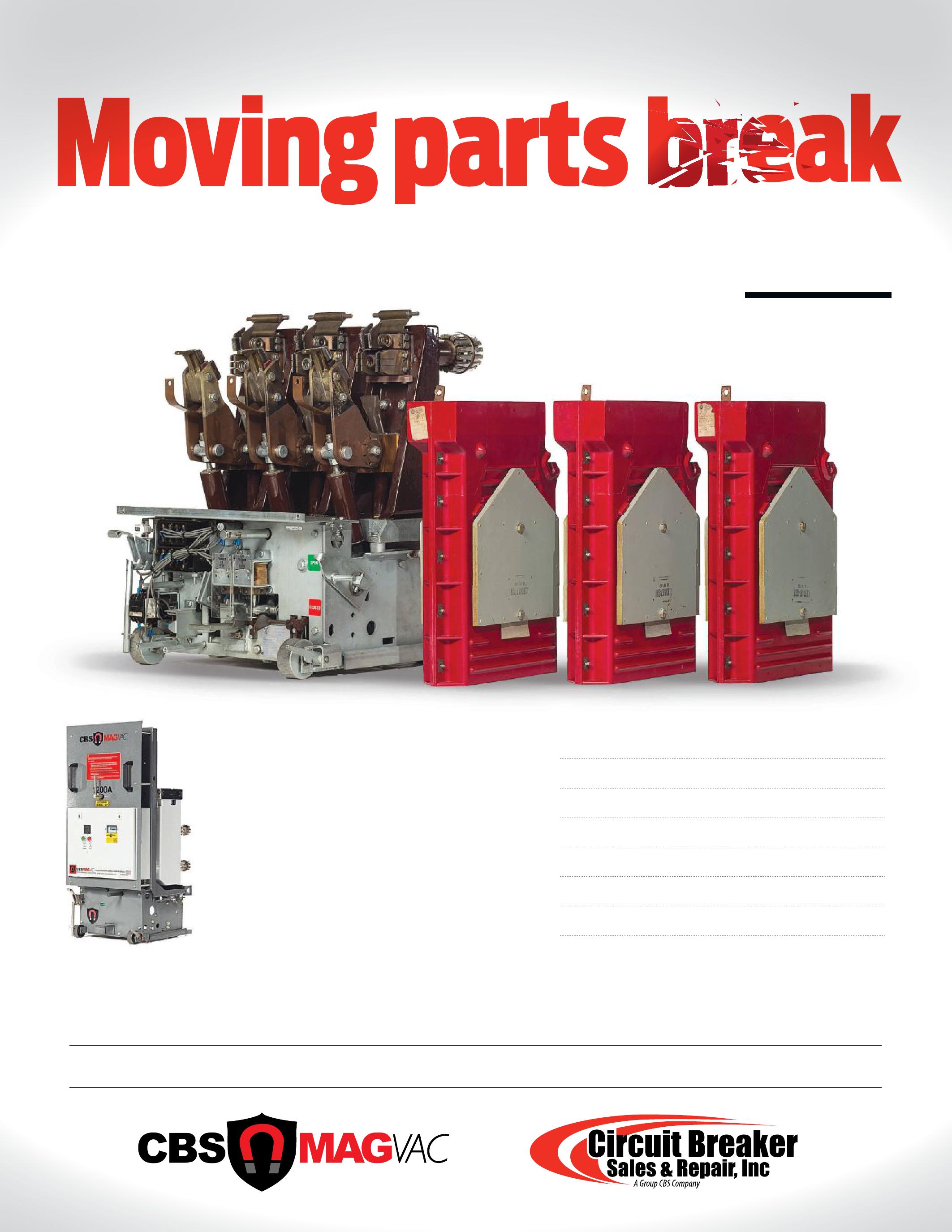
Learn how CBS MagVac’s latest
magnetic-latching medium-voltage circuit breakers use mono-stable magnetic actuators and a direct linear axis of travel within the breaker element to eliminate virtually all moving parts. This gives the CBS MagVac the ability to perform continuous switching without maintenance.
No operating mechanism
No trip coil
No charging motor
Less than a dozen moving parts
Virtually zero maintenance
Guaranteed to 30,000 operations
5-Year Warranty!

Wind farm electrical distribution system design is quite unique in comparison to typical power plants, and these systems, therefore, require a nontraditional maintenance testing approach. This article examines how a cost effective, no-outage testing program can be implemented to reduce failures and increase reliability.
Wind farm distribution design can vary but in the US the typical design utilizes low-voltage wind turbines to generate power. The low-voltage output is connected to a pad-mounted, fluid-filled distribution transformer located near the base of each turbine tower which steps up the voltage to 34.5 kV. The output of the transformer is then connected to the next turbine transformer using a three-wire, direct-buried, underground cable segment. Molded-cable accessories are used to terminate the cables to the transformers.
Additional transformers are successively cascaded on the same string, and the cable load increases as it makes its way towards the collector substation. The load continues to increase until the maximum standard cable size is reached. The last segment of the string is usually quite lengthy in order to reach the substation, since the strings are far apart physically and thus often require several splices.
Several strings typically terminate into one large collector substation which then steps up the voltage to subtransmission or transmission voltages. These substations consist of various designs but can include 35 kV switchgear or substation breakers, large power transformers, lightning arresters, instrument transformers, and often high voltage breakers with sophisticated protective relaying.
The transformers located at the base of each turbine are critical to the operation of the string. If the transformer located near the collector substation fails, the entire string is down until repairs can be performed which often requires replacement. If a spare is not available, it may be best to replace the damaged transformer with a transformer located as close as possible to the far end of the string, thus getting as many turbines as possible back in operation.
The best overall way to ensure the reliability of these transformers is to perform regular fluid testing in accordance with the NETA Standard for Maintenance Testing Specifications. These relatively routine tests reveal a great deal of information related to both the condition of the fluid and internal transformer components in a cost effective manner.
The medium-voltage cable system is next to be considered. Ideally, a robust acceptance testing program including partial discharge testing in accordance with the NETA Standard for Acceptance Testing Specifications would have been performed so that problems are much less likely. However, failures will occur because of many factors, and regular testing is essential to maintaining integrity.
A cable failure near the collector substation can take down an entire string the same as a pad-mounted transformer failure can, but it is likely that the cable failure will take much longer to repair, especially if it occurs somewhere along the final lengthy segment route to the collector substation. Failures here usually occur at splices and require bringing in an outside specialty splicing contractor equipped with cable fault locating instruments to precisely determine the exact failure point. Once identified, excavation would be necessary before repairs can begin. Although regular on-line cable partial discharge testing may be effective for ensuring good cable condition, it may be better to consider using offline VLF partial discharge cable testing to evaluate the condition of the segment nearest the substation as the long cable lengths can make on-line PD location difficult.
Besides the splices, cable system failure is common at the terminations which connect to the pad-mounted transformers. The condition of these terminations can be determined accurately by on-line cable PD test methods using radio frequency sensors. Unfortunately the turbine output converter electronics create massive noise signals that interfere with the on-line PD test results, so it becomes necessary to temporarily take a string of turbines off-line while this test is performed. Performing on-line cable PD testing also has the advantage of testing the other components immediately connected to the terminations including the transformer bushing well inserts, surge arresters, the internal transformer switch and bus insulation, and the transformer itself.
Recent testing was performed at a major wind farm in Minnesota using handheld PD testing instruments equipped with transient earth voltage (TEV) sensors. The TEV sensor was placed on the outside of the pad-mounted transformer enclosure as shown in Figure 1 to obtain an immediate health condition indication. The TEV test data was then compared to parallel on-line cable PD test results and found to correlate very well as shown in Figure 2. These results are very encouraging because it proves that terminations and all other connected components within the enclosure can be routinely and efficiently test-
ed nonintrusively using the TEV method. If a problem is detected using the handheld detector, additional testing using on-line or off-line testing methods can be used to pinpoint the precise defect location so that appropriate repairs can be planned well before complete failure occurs.
Collector substations are usually similar to traditional generation substations, so typical no-outage testing technologies usually apply.
Outdoor open bus connections should be inspected with infrared imaging equipment and RFI surveys should be performed with antenna-based instruments to detect partial discharge activity inside bushings, substation breakers, instrument transformers, lightning arresters and insulators. External insulation surface tracking can be detected using airborne ultrasonics, corona cameras or RFI techniques.
Outdoor switchgear insulation condition should be surveyed using ultrasonic and TEV sensors, while infrared cameras should be used to inspect connection integrity.
Finally, transformer fluid should be sampled and tested regularly, and high voltage SF6 breakers should have gas samples taken and tested regularly as well.
Wind farm distribution system design offer some unique differences compared to traditional power plant design, and these differences present some unique maintenance testing challenges. Employing a maintenance program consisting of no-outage testing techniques will minimize outages and provide the owner with increased reliability.

Don A. Genutis received his BSEE from Carnegie Mellon University. He was a NETA Certified Technician for 15 years and is a Certified Corona Technician. Don’s technical training and education are complemented by twenty-five years of practical field and laboratory electrical testing experience. Don serves as President on No-Outage Electrical Testing, Inc., a member of the EA technology group.





This past March 2012, the Occupational Safety and Health Administration revised the Hazard Communication Standard (29 CFR 1910.1200) to conform to the United Nations Globally Harmonized System of Classification and Labeling of Chemicals or GHS. This recent change to a longstanding regulation will require employers, manufacturers, and distributors to make changes to the way they present information and training regarding the use of chemicals in the workplace.
During the Earth Summit of 1992, the United Nations instituted a system that could be used worldwide by developing nations to better identify chemicals. GHS is similar in many ways to the old OSHA Hazard Communication Standard (HCS) which was created in 1983, but with significant changes. In fact, the GHS was based upon the Hazard Communication Standard utilized here in the United States and those used in other developed nations.
The updated HazComm 2012 standard has incorporated three significant changes of which employers must be aware. Implementing these changes requires companies to retrain employees in chemical safety.
The definitions of hazard have been changed to provide specific criteria for classification of health and physical hazards, as well as classification of mixtures. These specific criteria will help ensure that evaluations of hazardous effects are consistent across manufacturers and that labels and safety data sheets are more accurate.
Chemical manufacturers and importers will be required to provide a label that includes a harmonized signal word, a pictogram, and a hazard statement for each hazard class and category. Precautionary statements must also be provided.
Will have a specified 16 section format and Material has been dropped from the acronym.
OSHA intends that by December 1, 2013, employers will have trained their employees on the changes that will take place on the Material Safety Data Sheets, now called Safety Data Sheets or SDS in the updated standard. Additionally, employees must be trained in the new pictogram format.
OSHA requires all Chemical manufacturers, importers, distributors, and employers to fully comply with the new standard by June 1,2015. Additionally, distributors are not to ship containers labeled by the chemical manufacturer or importer unless it has a new GHS label.


By June 1, 2016, all employers must update alternative workplace labeling and hazard communication programs as necessary and provide additional employee training for newly identified physical or health hazards.
Any changes in the hazard classification of a chemical will significantly change the labels and safety data sheets required for chemicals in use. This influences the need for replacement of the existing MSDS for the new updated SDS. Although formulation of the chemical will not change, the way it is evaluated will.


Under both the 1983 and 2012 Hazard Communication Standard, an evaluation of chemical hazards must be performed considering the available scientific evidence concerning such hazards. Under the current HCS, the hazard determination provisions have definitions of hazard and the evaluator determines whether or not the data on a chemical meet those definitions. It is a performance-oriented based approach that provides parameters for the evaluation but not specific, detailed criteria.
The hazard classification approach in the 2012 HCS is quite different. The revised HCS has specific criteria for each health and physical hazard along with detailed instructions for hazard evaluation and determinations as to whether mixtures or substances are covered. It also establishes both hazard classes and hazard categories for most of the effects. The classes are divided into categories that reflect the relative severity of the effect. The 1983 HCS does not include categories for most of the health hazards covered, so this new approach provides additional information that can be related to the appropriate response to address the hazard. OSHA has included the general provisions for hazard classification in paragraph (d) of the revised rule, and added extensive appendices (Appendices A and B) that address the criteria for each health or physical effect.
Under the 1983 Hazard Communication Standard, the label preparer must provide the identity of the chemical and the appropriate hazard warnings. The method to convey this information is left to the preparer.
Under the 2012 HCS, once the hazard classification is completed, the standard specifies what information is to be provided for each hazard class and category. Labels will require the following elements:
• Pictogram
A symbol plus other graphic elements, such as a border, background pattern, or color that is intended to convey specific information abour the hazards of a chemical. Each pictogram consists of a
different symbol on a white background within a red square frame set on a point (i.e., a red diamond). There are nine pictograms under the GHS. However, only eight pictograms are required under the OSHA HCS.
• Signal Words
A signal word used to indicate the relative levelofseverityofhazardandalertthereader to apotential hazardon thelabel.Thesignal words used are danger and warning. Danger is used for the more severe hazards, while warning is used for less severe hazards.
• Hazard Statement
A statement assigned to a hazard class and category that describes the nature of the hazard(s) of a chemical, including, where appropriate, the degree of hazard.
• Precautionary Statement
A phrase that describes recommended measurestobetakentominimizeorprevent adverse effects resulting from exposure to a hazardous chemical or improper storage or handling of a hazardous chemical.
Employers must train employees about the changes in the SDS format. There will no longer be the standard 8 section MSDS sheet but a 16 section SDS sheet. Employees will most likely not be surprised by this change, since many international manufacturers have already adopted this format. Most of the sections included on the new SDS format are the same or very similar to those on the old MSDS format. The new format of the 16-section SDS should include the following sections:
Section 1. Identification
Section 2. Hazard(s) identification
Section 3. Composition/information on ingredients
Section 4. First-aid measures
Section 5. Firefighting measures
Section 6. Accidental release measures
Section 7. Handling and storage
Section 8. Exposure controls/personal protection
Section 9. Physical and chemical properties
Section 10. Stability and reactivity
Section 11. Toxicological information
Section 12. Ecological information
Section 13. Disposal considerations
Section 14. Transport information
Section 15. Regulatory information
Section 16. Other information, including date of preparation or last revision
Sections 12-15 may be included in the SDS but are not required by OSHA.
OSHA expects that the modifications to the 1983 Hazard Communication Standard will result in increased safety and health for the affected employees. It will reduce the number of accidents, fatalities, injuries, and illnesses associated with exposure to hazardous chemicals. The GHS revisions to the HCS will enable all employees exposed to workplace chemicals to quickly and easily obtain and understand information about the hazards associated with those chemicals. In addition, the revisions to the HCS are expected to improve the use of appropriate work practices and control chemical exposure, thus reducing safety and health risks associated with hazardous chemicals.
OSHAestimatesthattherevisedHCSwillgreatly impact the prevention of fatalities, illnesses, and injuries on an annual basis. This translates to the prevention of an estimated 43 fatalities and 585 injuries and chronic illnesses annually (specifically, 318 not lost-workday injuries and illnesses, 203 lost-workday injuries and illnesses, and 64 chronic illnesses). The monetized value of this reduction in occupational risks is an estimated savings of $250 million per year.
OSHA estimates that the revised HCS will result in savings of $475.2 million from productivity
improvements forhealth and safety managersand logisticspersonnel, $32.2 millionduring periodic updating of SDSs and labels, and $285.3 million from simplified hazard communication training.
In conclusion, by December 1, 2013, employers will need to train their employees on the following significant changes in the 2012 Hazard Communication Standard:
1. "MSDS" or Material Safety Data Sheet is now referred to as simply and SDS or Safety Data Sheet. The new SDS will show changes in the classification of chemicals.
2. Pictograms and key words will be used to label and classify containers.
3. The goal of the change in format to the new SDS is to conform to the Globally Harmonized System of Classification and Labeling of Chemicals and mitigate chemical related injuries.
Employers need to discuss these changes with their personnel as soon as possible as companies will soon be receiving the new labels and SDS's if not already dealing with international manufacturers. For more information and more specific guidance on how these changes will affect your organization, please visit http://www.osha.gov/dsg/hazcom/index.html.
Paul Chamberlain is the Safety Manager for American Electrical Testing Company Inc. since 2009. He has been in the safety fieldfor the past 12 years, workingfor various companies and in various industries. He received a Bachelor ofScience Degreefrom Massachusetts Maritime Academy.


Vanguard’s precision substation testing instruments are designed to be intuitive and easy to use so that you can focus on testing instead of wasting time in training. Our versatile instruments offer a built-in thermal printer and on-board test record storage so that tests can be conducted in stand-alone mode in the field. A computer interface is also offered so that tests can be easily conducted from a PC.
And all of our instruments are competitively priced to provide cost-effective accuracy. For a virtual experience of our instruments, check out the interactive demos on our site at:
www.vanguard-instruments.com/demos
 BY JEFF JOWETT, Megger


Like most electrical facilities, wind farms benefit notably from good grounding. And like all grounding, it should be regularly maintained. An established program of testing is integral to the maintenance process. Fortunately, equipment and technique do not depart radically from general ground testing, with only some reasonable accommodations to the application.



“Out of sight, out of mind” is an adage that well pertains to grounding sites, and possibly even more so with wind farms. With the blades turning overhead and the generators humming in the nacelles, who is likely to think about what is buried underfoot? In addition, wind energy is largely a young industry with relatively new equipment and a focus on the future. Aged and deteriorating equipment is not likely to be the first order of the day, but studies of installed electrodes by a grounding materials company found corrosion in extreme cases in as little as two years, with four years more the norm.1 Even a young industry would be well served to pay attention. Grounding systems corrode away below grade. Northern climes that experience freezing and thawing add an extra hazard. The physical pressures associated with these sometimes dramatic shifts in the electrode’s environment can literally break apart joints and welds, disrupting grid integrity, and a particular hazard on wind farms is, of course, inadequate lightning protection. Just because a known stroke has been cleared without damage to the electrical plant does not mean that the electrode is still in prime condition. Yes, it was when the stroke occurred, but the demanding job of fault clearance can break apart a grid below grade…out of sight…out of mind.

electrical maintenance program in order to be assured that no such damage or deterioration has occurred. Additionally, a well-maintained ground has numerous other benefits. Another significant issue on wind farms is mitigation of noise and harmonics. Ground resistance is a critical factor here. Add to that fault clearance by protective devices in required time, protection from groundpotential rise and the associated shock hazard from step and touch potentials and inductive voltages, and ESD (electrostatic discharge) protection.


Ground testing should be an integral part of the
How, then, is the grounding system tested and what equipment is required? It is important to keep in mind that dedicated equipment and procedures are necessary; trying to adapt multimeters and other generic pieces of test equipment is not the order of the day. Remember that a ground test does not involve a discrete object, like a motor or circuit. What is actually being tested is the resistance of an indeterminate volume of soil around the buried electrode. Accordingly, a ground tester affords separate current and voltage measurement circuits by which the soil can be accurately profiled across the critical resistance zone around the electrode. By a long lead and probe, a test current is established through the soil. By the same means, the voltage is measured at a series of designated points and the resistance is graphed. This method is distinct from any other

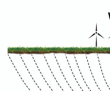
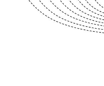
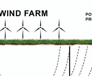
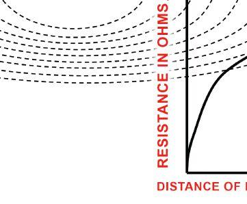
type of electrical testing, and is known as fall-ofpotential. The equipment is specialized and the procedure detailed and precise. It is generic and applies to all grounding electrodes, but there are some special considerations that apply to wind farm testing, as will be seen.
Another popular type of test equipment specialized to ground testing is the clamp-on ground tester. These are simpler to operate and require less procedure, but have serious limitations in wind farm application that must be understood and observed.
While it has been observed that fall-of-potential applies to ground resistance testing in general, the principle concern on a wind farm is the enormity of the ground grid. With each individual tower ground paralleled together, the total system is at the same potential and can cover acres! In order to be accurate, the measurement must be taken beyond the physical limit of the ground field’s electrical footprint in the surrounding soil. (In the literature, this is referred to as “remote earth,” i.e., a reasonable approximation to the resistance exerted by the whole planet.) At the same time, the measurement must not include additional resistance from the electrical field surrounding the current probe. If a single ground rod were being measured, this is fairly easy to accomplish. But the electrical field of a wind farm ground can
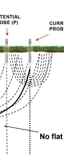

extend for prohibitive distances! Lead lengths to test probes are typically on the order of four to five times the maximum grid dimension. It can be easily seen how this requirement can present a problem. Phone lines have been rented and used as test leads! Yes, as radical as it sounds, this practice is actually done. It can be accomplished because ground testers have very little power and operate with a square wave test signal that can travel harmlessly on a phone line.
Fortunately, there are more agreeable alternatives. Procedure is as important as equipment in ground testing, and many different methods have been devised in order to meet any demanding situation. For grids that would require impractically or even impossibly long test leads in order to be measured by fall-of-potential, there are the slope and intersecting curves methods. The former employs a mathematical proof to separate extraneous current probe resistance from the resistance of the test grid in cases where the two overlap and a fallof-potential graph cannot be properly interpreted (Fig. 1). This means that the current probe doesn’t have to be as far away (typically two to three times maximum grid dimension) and the test may be completed within workable distances. Should the electrical field of the test ground be so large as to extend beyond the current probe, the mathematics become incoherent and the operator knows to find more room or switch to another method.


In that case, the intersecting curves method may be substituted. This can work conveniently within distances as little as half again the maximum grid dimension, and employs superimposed graphing based on assumptions in order to find the grid resistance. Only at the true measurement distance do the graphs converge. Both methods have been described fully in prior editions of NETA World
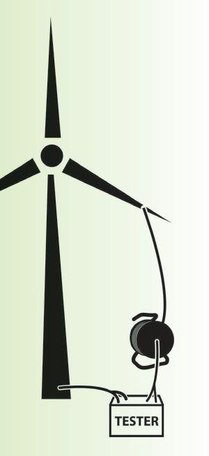
2: Blade Continuity Can Be Tested From Ground After Installation With Special Leads.
Ground testing is also performed at time of installation, but in this instance, the parameters are notably different. Installation is the only practical time at which the elements of the grounding system can be tested individually; that is to say, without the extreme difficulty and cost of excavation. While the final grid will have all elements paralleled and exhibit the same resistance from any point, it is also valuable to check individual elements as they go in. This is for exactly the reason stated in the previous sentence; once the grid is complete, trying to locate problem spots takes a quantum leap in difficulty. It is, therefore, a good idea to go the extra mile and perform sectional testing as the grid goes in. It will reduce the amount of time and money spent later.
As the grid is assembled and interconnected, continue to test each larger segment. Keep thorough records. Software programs may be available from equipment manufacturers, and these will prove invaluable to effective recordkeeping. Although this extra step may seem tedious at the time of implementation, it will pay for itself in convenience for later testing and maintenance. Include in stored information the exact locations where current and potential probes were placed to perform the tests. Again, this may seem like extra work at the time, but it will greatly speed subsequent maintenance
testing, especially if performed by a different crew with less familiarity with the site. They will be able to operate quickly, be less prone to human error, and the readings will be readily comparable and simple to evaluate.
A testing problem peculiar to wind farms stems from static buildup on the blades. As they rotate through the air, the blades develop considerable static charge. This will eventually discharge spontaneously and do so through whatever is most convenient. That could be some part of the electrical system with resultant damage. Add to that the vulnerability to lightning hits. The solution is a conductor through the blade, from tip to hub, and then continuous low impedance down the tower to the grid below. This conductor can take considerable wear (especially from lightning!) and should be routinely tested for continuity (Fig. 2).
Ground testers can be employed in two-terminal configuration, but industry standard calls for a 10 ampere test current. This requires a low-resistance ohmmeter of appropriate current rating. The test itself is easy enough to perform. Low-resistance ohmmeters are Kelvin bridges, with two current and two potential terminals. Just connect across opposite ends of the conductor under test and press the test button (Fig. 3). The measurement (industry standard <25 mΩ) appears.2
The difficult part here is the distance the leads must traverse, from tip to hub and then to ground. The test(s) can be made tip to hub and then hub to ground, or tip to ground all in one. Bucket trucks can be used to connect the leads from the ground, or they can be connected from the nacelle by suspension from ropes (Fig. 4). Either way it is not
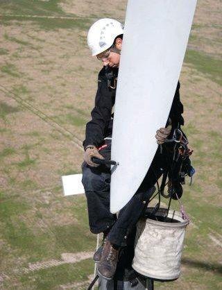
easy, so it is a good idea to have the best possible lead set so as not to impair the progress of the test or the confidence in the results. Attention must be given to wire gauge and firm metal-tometal connections. This is one test you don’t want to have to repeat, so getting it right the first time is paramount.
Finally to be considered is the evaluation of the grid structure itself. This can be done after installation by the use of a grid tester. The major difference between a grid tester and a ground tester has to do with current. A ground test is performed with only milliamperes of current because that is all that is necessary to make a measurement, and the operator is kept safe. A grid tester, on the other hand, uses a lot of current, typically several hundred amps. The grid structure can be subjected to enormous amperages during a lightning stroke, and so it must be confirmed that the structure is capable of accommodating high currents without damage or deterioration. The grid tester injects the current through a reference ground into the grid being tested (Fig. 5). Welding cable makes good test leads. Whereas ground tests take only a few seconds of operating the tester, a grid test runs for several minutes. A clamp-on ammeter measures current at critical points, and the tester indicates the associated voltage drop. A value of no more than 1.5 volts per 50 feet of straight line ground path should be measured. As a redundant quality check, current returning via the ground path is also measured and should be at least half of output. It is expected that current will concentrate along lines of low resistance including
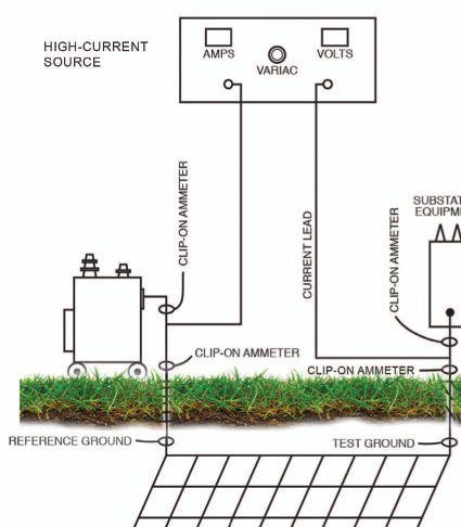

the structure of the grid. Substantial loss between measurement points indicates diversion by highresistance flaws in the structure. In addition, ground cables, clamps, and ferrules can be tested prior to installation using the same equipment, and a bad product can be intercepted before it goes into the ground. Operation of the grid tester has also been fully described in a prior edition.
Anyone familiar with basic ground testing can make the straightforward adaptations to wind farm requirements without difficulty. The next edition will examine some further complications and special testing considerations on wind farms.
1 Lyncole XIT Grounding, Electrical Equipment Testing and Maintenance, A. S. Gill, Prentice Hall
2 Information courtesy Vestas Wind Systems, Ringkøbing, Denmark & David Danner, MEGGER®, Chandler, AZ

Jeffrey R. Jowett is a Senior Applications Engineer for Megger in Valley Forge, Pennsylvania, serving the manufacturing lines of Biddle, Megger, and multi-Amp for elec-trical test and measurement instrumentation. He holds a BS in Biology and Chemistry from Ursinus College. He was employed for 22 years with James G. Biddle Co. which became Biddle Instruments and is now Megger.


We are excited to announce that the growth of Ampteks, Inc. over the past few years has us expanding beyond the capacity of our current facility.
Ampteks, Inc., Northern California's premier facility dedicated to the service, repair, and tes ng of low and medium voltage circuit breakers has moved
to a new facility.
The new facility is located at 265 Rickenbacker Circle, Livermore, CA 94551. It is directly o W 4 and W 5 and ad acent to the Livermore Airport.
Over the last 6 months the new facility situated on 2 ks has been built out to our stringent speci ca ons and o ers s of class A o ce space and over 6 s of work area. We now have the capacity of 2 kA current and 1 k output and will support our con nued growth.
ANSI/NETA ATS-2013
ANSI/NETA Standard for Acceptance Testing Specifications for Electrical Power Equipment and Systems
This document specifies field tests and inspections used to assess the suitability for initial energization of electrical power equipment and systems.
ANSI/NETA ATS-2013 covers equipment such as:
Switchgear
Transformers
Cables
Switches
Circuit breakers
Protective relays
Rotating machinery
Motors
Capacitors and reactors
Regulating apparatus
Grounding systems
Batteries
Emergency systems and more...
ANSI/NETA ATS-2013 provides the most up-to-date references to other industry standards such as ASTM, EASA, ICEA, IEEE, NECA, NEMA, NFPA, UL, and others.
Join NETA’s Alliance Program today for savings on ANSI/NETA ATS-2013
Receive additional discounts on other NETA publications
Visit: 888-300-NETA (6382) Email: neta@netaworld.org

NETA Members and Alliance Luncheon.
Every year PowerTest attendees come to this premier electrical maintenance and safety event, which offers over 45 unique educational sessions and a trade show that gathers the industries best, to expand their knowledge, share insights, and connect with customers and colleagues.
This year’s event was truly one of the best! PowerTest 2013 hosted over 800 conference and tradeshow guests, with over 250 NETA Alliance Partners in attendance.
NETA Alliance Partners represented a diverse group of professionals: project managers, engineers, inspectors, company officers, technicians, support personnel, and many others from every business segment engaged in supporting electrical power system safety and reliability.
PowerTest attendees represented a wide range of industry including engineering consulting firms, utilities, facility management firms, equipment manufacturers, testing equipment manufacturers, building contractors, construction companies, petro chemical companies, training groups, technical universities, as well at the U.S. Corp of Engineers. Of course NETA Accredited Companies had a presence and included 169 representatives.
SUNDAY, FEBRUARY 17, 2013
PowerTest 2013 provided NETA Alliance Partners their first opportunity to participate in what will become NETA’s Annual Member and Alliance Meeting.
The Annual Member and Alliance Meeting was held on Sunday, February 17, 2013, and welcomed seven Alliance Partners, including representatives from ComRent International, Doble Engineering, GE Industrial, Megger, and TUV Rheinland of NA.
NETA Members and Alliance Meeting.
The meeting’s agenda covered the following topics:
To download the NETA Annual Member and Alliance Meeting agenda and report documents, visit netaworld.
Member & Alliance Meeting.
MONDAY, FEBRUARY 18, 2013
Amidst the excitement of the first day of conference, NETA Members and Alliance Program participants gathered in the Armstrong Ballroom to honor this year’s recipients of the NETA Outstanding Achievement
men and their contribution to NETA and the industry while guests enjoyed their lunch. During the event, guests were also introduced to NETA’s new Electrical Safety Training System, an online training resource that provides the latest in safety training through an online portal. A demonstration of the Electrical Safety Training System can be viewed at www.netatraining.org.
The success of this premier event is the direct result of the extraordinary contributions made by the many volunteers, industry expert presenters, our generous sponsors, exhibitors, and all of the attendees committed to expanding



Power generating facilities, and more specifically wind power generation facilities, avoid downtime to maintain consistent output of their prized product: electricity. Some of the facilities will stay on line for extended time frames skipping recommended maintenance cycles until an outage occurs. Within the wind farm owner’s key performance indicators, availability and production are at or near the top of the list. So how can wind farm owners perform necessary maintenance on their collector system and reduce downtime? How can wind generation sites develop an acceptable maintenance strategy using national consensus standards?
Reliability-centered maintenance (RCM) and predictive maintenance (PdM) are two key maintenance concepts used to reduce downtime while providing the level of maintenance needed to keep generators on line and producing power. Developing a maintenance program based on these two concepts is not an easy task and will be revised constantly. A task that is even more difficult is finding the personnel with the needed skills and training to perform the maintenance. Figure 1 illustrates the issues the industry faces with a rapidly aging workforce. Where are skilled replacement workers going to come from?
RCM enables sites to monitor, assess, predict, and generally understand the working of their physical assets which are their generators, strings, and substations. The initial part of the RCM process is to identify how the equipment is operated, define its purpose, and write a failure mode effects and criticality analysis (FMECA). The second part of the process is to determine the appropriate maintenance tasks for the identified failure modes in the FMECA. Once those tasks are identified for all elements in the FMECA, the resulting list of maintenance tasks is given specific maintenance intervals and bundled together. RCM reduces costs by concentrating on the monitoring and correction of root causes of equipment failures (also known as root cause analysis). This will help establish


engineering, and technical resources


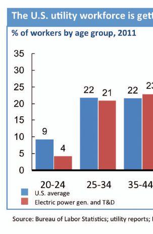

As was presented in the keynote address at PowerTest 2013, Jim O'Neil, chief executive officer of Quanta Services, Inc., discussed the issues the industry faces with a rapidly aging workforce, which Figure 1 illustrates. Where are skilled replacement workers going to come from?


minimum levels of maintenance, point to required changes to operating procedures, and guide the development of capital maintenance regimens and plans.


PdM is the process of evaluating the condition of equipment by performing periodic or online continuous equipment monitoring. PdM is based on performing the right maintenance at the right time using on-line continuous monitoring techniques, whereas preventive (or phased) maintenance (PM) is performed strictly based on time. PdM is used as a part of a RCM program. One example of PdM is the use of partial discharge/acoustic emissions testing. The detection equipment is installed on cables or equipment and continuously monitors the system. Partial discharge (PD) is a localized electrical discharge that only partially bridges the insulation between conductors. PD is a phenomenon caused by imperfections inside cable insulation resulting from cable aging, thermal, mechanical, and electrical stresses, or manufacturing defects.
Figure 2: NETA, NFPA and IEEE all Have Standards that will Assist in Developing a Maintenance Program

Numerous factors need to be considered while developing an RCM program. Some of these factors include:

agreement with local utility
Long-term trending, auditing, and staying current with changes in standards and methods of testing and evaluation must also be considered.
These programs should be based on national

consensus standards to bring credibility to the program. Sources such as NFPA 70B, Recommended Practice for Electrical Equipment Maintenance, the InterNational Electrical Testing Association (NETA) MTS2011, Standard for Maintenance Testing Specifications for Electrical Power Equipment and Systems, and several IEEE standards should be referenced. The NETA testing standard also offers guidelines for the frequency of maintenance tests within Annex B of the document. Figure 2 shows some available standards, although there are many more that should be consulted.
Monthly and quarterly checks on the collector system make up part of the PdM/RCM program. These tasks can be performed by inhouse personnel if they are qualified or by a third party contractor if the work is beyond the abilities and training of the in-house personnel. On-line testing can present additional risks and hazards with which inhouse personnel may not be familiar. However, the overall impact to operations is minimal, and typically outages and down-time are not required.
In order to have a successful PdM program the wind generation site must employ trend analysis of the data. By trending such factors as generator heat, vibration, and oil data
patterns over time, it is possible to determine when issues are beginning and plan for the required maintenance long in advance of failure. This results in minimum downtime and disruption to generation.

Technicians performing electrical tests and inspections should be trained and qualified to understand the hazards associated with operating, switching, and maintaining electrical power equipment. Utilizing an independent, third party contractor can provide the necessary expertise required to perform on-line testing, interpret and trend the data, and create an RCM program. Selection of a qualified contractor with an industry-recognized electrical testing accreditation such as NETA Accredited Companies will help ensure that a qualified and competent testing organization will perform the needed testing. Regardless of which contractor is chosen, due diligence to the testing contractor’s capabilities and qualifications is essential. The wind generation site’s owners and third party contractors need to be cautious of the arc-flash hazard particularly on padmount transformers, wear proper PPE, and employ a qualified safety backup, if necessary.
issues involving electrical components such as the step-up transformer insulating oil flow/ level, collector cabling connections/ terminations, and generator circuit breaker connections.


Infrared scanning (IR) accurately identifies the presence of abnormal heat in electrical and mechanical systems which can help predict equipment trouble. The infrared (thermographic) survey gives a detailed thermal and photographic record of any problems detected, so action can be taken before breakdowns occur. Infrared inspections routinely discover issues with loose cable and control wire terminations, electrical connections, and electrical insulation. This same technology can be used in the turbine as well as the collector system to identify thermal
Infrared cameras have come down in cost significantly over the last few years, so many sites are purchasing cameras for in-house, routine scanning of the equipment. Training and qualifying the part-time thermographer is usually performed by the manufacturer’s representative in a few hours. Infrared scanning of these machines and collector equipment on at least an annual basis is extremely important. If the reliability requirement is higher than average an infrared survey can be performed more often. Biannual or even quarterly infrared surveys are often justified. Figure 3 is an example of an infrared image. ANSI/NETA MTS-2011 provides infrared guidelines in Table 100.18.


An infrared camera is unable to see electrical corona, which is the ionization of the air surrounding a high voltage component.


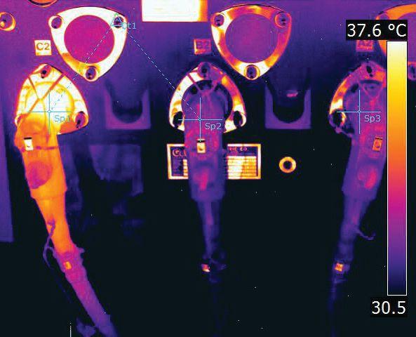


Note the Temperature Variation Between C2 and the Other Phases.


Several factors can affect a conductor’s electrical surface gradient and its corona performance, including conductor voltage, shape, diameter, and surface irregularities, such as scratches, nicks, dust, or water drops. Corona cameras can detect insulation and connection issues associated with the higher voltage equipment in the collector substation and interconnection substation by detecting corona emissions.


temperature and is constantly changing. Oil quality and dissolved gas analysis (DGA) tests are tools to determine the suitability of the oil for continued service. DGA measures the levels and ratios of dissolved combustible gasses in electrical insulating fluids. It is a very effective tool to diagnose potential problems in the transformer caused by loose connections, overloading, arcing, hot spots, and case or seal leaks that let moisture or air into the unit.

Annual corona scanning is the minimum recommended frequency for detection of corona issues. Corona scanning combined with any ultrasound and partial discharge analysis yields valuable data about the health of the insulation system.

The majority of power transformers in operation at wind generation sites are filled with mineral oil. The primary function of the oil is to provide a high dielectric insulating material and provide an efficient method of cooling to dissipate heat.


The effectiveness of the oil as an insulating material is reduced as the moisture level increases, while cooling is reduced as the oil deteriorates. Paper insulation absorbs moisture from the oil. The balance of moisture between the oil and paper insulation is affected by


Transformer insulating fluid sampling, testing, and analysis is another inexpensive line item in the maintenance budget. The average cost for oil quality tests and DGA ranges from $150.00 to $250.00 dollars per sample plus the cost of obtaining the sample. The variance in prices is based on which tests are included in the testing program. It is recommended that collector transformers be sampled on an annual basis, while the substation transformers should be tested twice annually, and possibly even three times per year, based on the number of load tapchanger operations. Figure 4 shows a typical oil-filled, pad-mounted transformer.

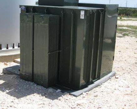

Because a significant percentage of cable failures are associated with partial discharge, cable systems are typically tested after installation for manufacturing defects, improper installation and other related problems that can cause partial discharge. On-line PD testing provides crucial information on the integrity of an electrical system on a continuous basis. Using the appropriate equipment and techniques, partial discharge can be located, measured, and recorded, identifying cables, switchgear, and transformers that are beginning to fail.
On-line PD testing is performed while the equipment is energized at normal operating voltages. At various times a snapshot sample
is pulled and sent to a third party expert for analysis. The testing is conducted during real operating conditions, under typical temperature, voltage stresses, and vibration levels. On-line PD is a nondestructive test and does not use overvoltages that could adversely affect the equipment. On-line partial discharge testing is relatively inexpensive compared to off-line testing that requires interruption of service and production. PD is most often used to detect and locate accessory and cable defects, but it can also detect failures in other areas (i.e., switchgear and bus).
Similar hazards exist as discussed earlier in the on-line generator testing discussion. Direct interaction of personnel with an energized and operating generation system is extremely hazardous and the qualifications of the testing contractor or employee cannot be overstated. Prior installation of PD sampling boxes or cable/equipment test access panels will reduce the risk of exposure and expedite the on-line testing program. These boxes allow the routing of the cable/equipment shields or RF current transformers leads outside the equipment and mitigates exposure to the electrical hazards. They create a low risk environment to perform the sampling.
Just like any power generating facility, electrical maintenance of the wind farm is essential to high performance. While it is difficult to create and implement a RCM program, national consensus standards such as ANSI/NETA MTS 2011 can guide the wind generation site owner. Implementing predictive maintenance strategies are important to reducing downtime and maintenance costs. Even more important is maintaining the RCM schedule and comparing results with baseline values.
By performing a predictive maintenance plan, the generation site will be able to take minimum planned outages to perform maintenance instead of experiencing
expensive, unplanned outages. A predictive maintenance plan will also ensure the safety of the site’s personnel, along with maintaining compliance requirements on the site.
A qualified third party contractor will be able to perform the required testing and provide recommendations for the equipment when in-house personnel do not have the expertise.

O’Neil, Jim, “Industry Trends Impacting Maintenance & Testing of Electrical Assets”
Keynote address at 2013 NETA PowerTest Conference

Paul Idziak is the Director of Renewable Energy Services of Shermco Industries, a leader in maintenance and repair of electrical machines and electrical power systems in the renewable energy industry. Paul’s responsibilities include the promotion of safety and reliability-centered repair and maintenance practices of renewable energy systems to include wind, biomass, geothermal and wind energy generation, collection and substations. Paul is also a qualified electrical worker, trainer, and consultant working with OEM’s, O&M’s, and electrical construction contractors that provide reliability-centered construction and repair services.


SYSTEM DOES CALCULATIONS BASED ON MEASUREMENTS OF 3,000 VIs Trust Magnetron Atmospheric Condition (MAC) testing to
MAC-TS1 & MAC-TS2 SYSTEMS FROM VACUUM INTERRUPTERS, INC.
WORLD’S FIRST PORTABLE FIELDTESTING SYSTEM FOR VACUUM INTERRUPTERS
ACCURATE IN SHOP OR FIELD
BASED ON OEM LEAK-RATE TEST DURING MANUFACTURE
PREDICTS REMAINING VI LIFETIME, NOT JUST PASS-FAIL



Utility Service Corporation has been providing electrical and technical services for government and industry since 1962.
Solving complex problems, testing under difficult and unusual circumstances and servicing the commissioning and maintenance needs of today’s electrical power systems both new and aged.
Each year, PowerTest takes place in a city in which attendees are inspired by their surroundings. If there is a city anywhere in America whose citizens, amidst enormous challenges, have embraced the power to build anew, it is New Orleans, Louisiana.
PowerTest 2013 attendees tapped into that inspiration as they gathered for another tremendously successful learning and networking event from February 18-21, 2013.
Leading into PowerTest, NETA Accredited Companies gathered for the annual meeting on Sunday to reflect on the prior year, receive an update on association initiatives and learn about
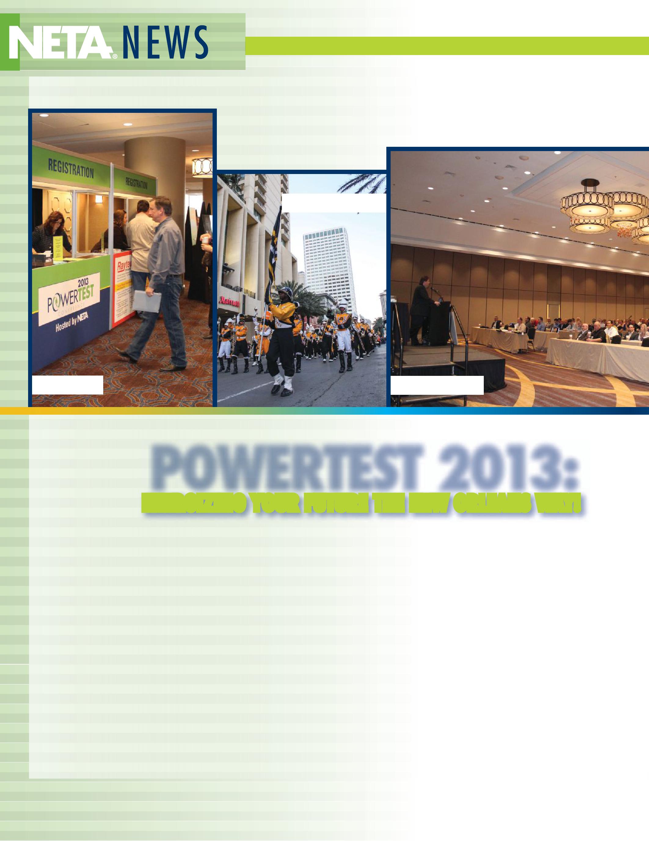
plans for the coming year. For the first time, NETA Alliance Partners were welcomed to attend, and learned about updates to the NETA Alliance Program benefits, new technical resources, technical reports, and marketing activities.
Following the annual meeting, PowerTest officially kicked off with a Sunday evening networking event. About 125 people joined
their fellow PowerTest attendees and NETA staff in the exciting second line parade, featuring a grand marshall, 40-piece band, and costumed characters. The parade, sponsored by Potomac Testing, departed from the Sheraton, and in traditional New Orleans style, marched all the way to Bourbon Street for a special, private dinner.
The first day of engaging presentations at PowerTest on Monday began with a motivating keynote speech from Jim O’Neil, Chief Executive Officer at Quanta Services. The audience then began a full day of 45-minute presentations from some of the best presenters and experts in the industry who helped provoke thought and power up new ideas.
Monday’s Annual Member and Alliance Lunch afforded yet another opportunity for lunchtable discussions of ideas and challenges technicians are facing, along with a top line on association activities from the association
president, Mose Ramieh. Also, special honors were announced as Jim White was awarded the NETA Outstanding Achievement Award and Jean-Pierre Wolff received the NETA Alliance Recognition Award. The luncheon was sponsored by AVO Training Institute.
Hospitality suites provided a great backdrop for Monday night mingling with the experts at PowerTest, with themed suites offering food, drink, and plenty of conversation. NETA thanks suite sponsors GE, Megger, Monster Fuses, Protec, and Shermco Industries.
Tuesday’s panel sessions delivered on a promise to engage participants with valuable information, both from panel speakers as well as from peers in the audience. That gave way to Tuesday’s all-afternoon PowerTest Trade Show where more than 100 top-tier electrical power equipment vendors showed off their wares and talked solutions with visitors.

PowerTest 2013, the industry’s premier electrical safety and maintenance conference, staged 43 technical learning sessions, product exhibitions, and numerous networking events.
MEMBER/ALLIANCE LUNCHEON
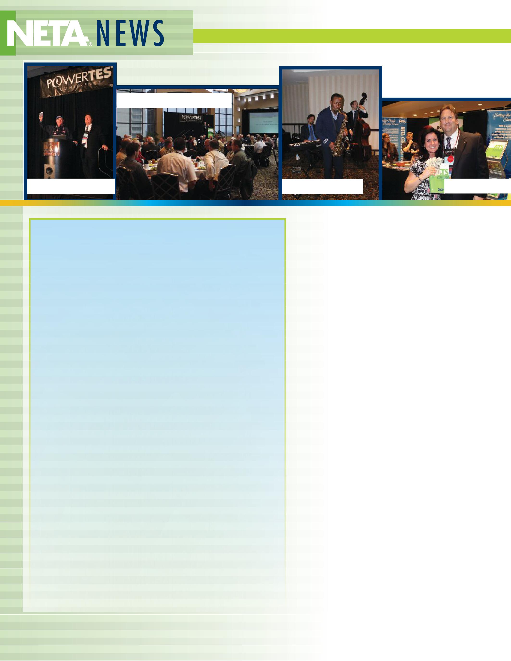
More than 700 PowerTest 2013 attendees and trade show visitors were asked to vote for their favorite presenters, hospitality suites, and trade show exhibitors.
POWERTEST AWARDS WENT TO:
TECHNICAL PRESENTATIONS
Safety – DENNIS NEITZEL, AVO TRAINING INSTITUTE, FOR ELECTRICAL SAFETY THROUGH DESIGN, INSTALLATION, AND MAINTENANCE
Relays – JASON BUNEO, MEGGER, FOR UTILIZING GROUND FAULT RESISTANCE TO TEST DISTANCE
Reliability – ANDREW SAGL, MEGGER, FOR DETECTING COMMON POWER QUALITY ISSUES
Equipment – WILLIAM KEITH HILL, DOBLE ENGINEERING, FOR I HAVE A LOT OF NUMBERS, WHAT DO THEY MEAN? BASIC INTERPRETATION OF TWO-WINDING TRANSFORMER DATA
Circuit Breakers – BRET HAMMONDS AND ROBERT FOSTER, MEGGER, FOR TESTING AND TROUBLESHOOTING LOW-TO-MEDIUMVOLTAGE CIRCUIT BREAKERS
EXHIBITORS
Most Innovative: CIRCUIT BREAKER ANALYZER, INC. FOR THE CB ANALYZER TM APP
Most Visited: SALISBURY BY HONEYWELL
Best in Show: MEGGER
HOSPITALITY SUITES
Most Technical: PROTEC
Most Hospitable: SHERMCO INDUSTRIES
Most Creative: MONSTER FUSES
Most Entertaining: MEGGER
NETA CONGRATULATES ALL THE POWERTEST 2013 WINNERS!
PowerTest 2013 attendees gathered to connect with leaders, learn from the best and laugh with new and old friends.
PowerBash on Tuesday evening, sponsored by Megger and Shermco Industries, capped a two-day marathon of high-impact learning by offering a relaxed environment with great food, mingling, and awards (see inset).
Wednesday and Thursday at PowerTest 2013 afforded those who stayed a little longer the chance to attend in-depth seminars. Participants chose from 12 different seminar opportunities, presented by AVO Training Institute, Canada Training Group, Doble Engineering, Dranetz, HV Diagnostics, Iris Power LP, Megger, Schweitzer Engineering Laboratories, and Shermco Industries.
NETA thanks all PowerTest 2013 speakers, exhibitors and sponsors, with special acknowledgement to premium sponsors National Switchgear, Potomac Testing, and Shermco Industries.
PowerTest 2014 heads to Denver, Colorado, and will be held downtown at the Hyatt Regency Denver from March 3-6, 2014. For more information see www.powertest.org.
 BY WILLIAM CHEN, TECO Westinghouse Motor Company

Utility scale wind turbines have been a growing part of the global landscape for 20 years or more, but the industry is still maturing. The application for the generator itself is demanding, and the conditions are varied and complex. A quantitative review of the failure modes of over 1200 wind turbine generators repaired or replaced from 2005 to 2010 has uncovered that fewer than half of the failures were electrical in nature and the majority of those were due to mechanical failures of the insulation support structure that probably would not have been located using traditional testing methods. Many of the failures appear to be of a serial nature due to inadequate original design of the machine and/or the insulation system. These generators are exposed, at least in some part, to the typical voltage irregularities and mechanical stresses of any machine that operates 100 meters in the atmosphere in a wide variety of weather conditions. However, they are also sometimes affected by poor power quality from the IGBT based converters used in most turbines. These failures could result from voltage stresses created by the converter in the turbine or from neighboring turbines or, as has been suggested, even from neighboring wind parks.
Several common failure modes for these generators have been identified, many of which can be traced to identifiable root causes. However, many failures remain difficult to trace as minor failures can lead to catastrophic electrical failures not directly related to the root cause. Understanding the types of failures and how often they might occur in a fleet of turbines is instrumental to developing a proper maintenance procedure and testing regimen. By reviewing these failures, we have been able to isolate the electrical material failures from the pure mechanical failures.
The study covered damaged generators from a wide variety of manufacturers and represented a fairly reasonable sample of the industry. Three categories were set up based on the nameplate rating of the machine. As turbines have generally gotten larger as the industry developed, it can
be assumed the largest category represents the more current designs. The failure modes identified represent the best estimate of the initial failure, keeping in mind that the root cause might be varied.
The modes collected were:
(strand/turn/ground)
(strand/turn/ground)
Earlier designed, smaller machines show a high number of failures in rotor insulation. These are due to both electrical and mechanical failure of the conductors and the failure of the banding as designed. Many stator winding failures were actually due to contamination and issues with under designed bracing.
The occurrence of bearing failures in generators between 1 and 2 MW is dramatically illustrated. These generators are generally more robust than their antecedents, but proper installation and good maintenance practices are critical to good reliability. The root cause of the majority of these failures is improper maintenance, although early failures could have also resulted from transient shaft currents. Very few insulation failures were recorded, and most were due to overheating issues created by improper cooling system design. Most wind energy generators have output voltages of 550-690 V ac. Some in the 1.5-2 MW class are high voltage machines ranging from 12-13.8 kV ac, but no statistics are available regarding specifically HV related failures.
Again, in the class of generators greater than 2 MW, the bulk of the failures are from bearings for the same reasons as the 1-2 MW machines, but there is a dramatic rise in stator failures resulting from the loss of magnetic wedges utilized to improve the size/output functionality of the generator. Where this failure mode has been seen in industrial applications, it is almost a universal failure point across manufacturers in this class of turbines.
Based on new, unpublished data being compiled by Dr. Peter Tavner and his team at Durham University, Durham, UK, bearing damage is the leading root cause of failure in both wind and industrial rotating electrical machinery. In fact, with these large studies, there is actually little variation in types of major failure, only in specific machine design areas of vulnerability.
It is thought that many of the older wind turbines and generators were originally designed
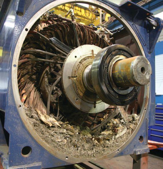
to operate at 50 Hz, but were placed in service in North America at 60 Hz without proper redesign based on the increased electrical and
very common. This has been rare in the newer generator designs, and several redesigns of the older machines appear to have alleviated the problem. For remanufacturing purposes, most have also been redesigned using additional banding and other reinforcing materials, and this failure is no longer common among remanufactured machines (see Figures 1 and 2).
The loss of conductive slot wedges results in both grounding failures due to the conductive nature of the wedge material as well as mechanical damage to the coils. Both penetration of the coil by shards of wedge material as well as loose coil damage have been observed as causes of immediate and dramatic failures. As a general observation, several additional styles of generators have surfaced with this problem since the statistics were gathered, and this is becoming a serious problem for the industry. It is assumed that since the wedges have a high ferrous content, they react to the revolving electrical fields and will vibrate or shift under the influence. All of the machines studied appear to be manufactured using very low viscosity epoxy or polyesterimide resins. If the coil dimensions and slot filling materials are designed to fit too loosely in the slot, the wedge is very dependent on the resin to hold
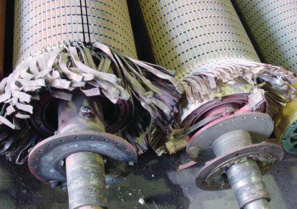
it in place. The ferrous nature of these wedges allows for oxidation where moisture and especially corrosive salts are present, and this may have contributed to the bond failures (see Figure 3).
Since most wind generators are typically enclosed inside a not-so-spacious nacelle along with many other components, ventilation can be hindered. Both rotor and stator windings need adequate ventilation in order to keep them cool and functioning correctly, especially if air-cooled design is used. Poor ventilation might lead to higher winding temperatures which in turn reduces the service life of those generators. Therefore, in addition to proper design considerations, the cooling/ventilation system should also be inspected and maintained on a regular basis.
A characteristic design for the popular doublefed induction generators (DFIG) is that the power converter is connected directly to the rotor winding through lead wires that pass through the hollow rotor shaft over which the bearing inner housing is fitted. The coupling effects of these and other harmonics can create an electrical current that passes along the shaft and through uninsulated bearing creating premature bearing failures. Also, peak voltage spikes generated from converters can reach several times the rated voltage and could cause flashover at the rotor leads. These effects require that the shaft grounding system design

be more robust than is normally required for machines designed for normal operating conditions. In addition, because the entire generator is mounted at an angle from the horizontal plane, additional thrust force might act on the bearing structures. All these lead to higher bearing temperatures, or even bearing failure, which create enough heat to severely damage rotor leads, leading to eventual generator failures. Improper lubrication and normal bearing failure modes can also create this type of failure.
Extreme hot or cold conditions can dramatically affect machine service life. Unfortunately, those temperature extremes are quite common in many areas of the world where the wind blows the strongest. In addition, as opposed to most traditional motor/generator operations, wind generators experience frequent load changes due to the very dynamic nature of wind. As a result, those generator windings are often subjected to higher thermal cycling and mechanical stresses. Insulation materials, winding structures (such as lead connection/crimping), carbon brushes, etc., all sustain higher stresses and require higher standards in order to maintain their design integrities during operation. Therefore, extra allowance for all those conditions must be taken into consideration during the design process.
Voltage irregularities, either from traditional grid related sources or from converter failures have continued to create issues with the generators. Proper protection from these problems as well as effective grounding of electrical system is critical. These phenomena might also contribute to the loss of magnetic wedges described earlier. As mentioned previously, many wind generators are connected to the grid through power converters. Although the rated operation voltage of the rotor winding is generally low (such as 690 V for most DFIG machines), those power converters will generate much
higher peak voltage spikes (up to 2.5 kV peak and several kHz switching frequency). These greater stresses affect rotor winding insulation (including turn-to-turn, phase-to-phase, and main insulation) significantly. Proper design allowance and adequate protection should be implemented in order to achieve the optimal service life.
Typically, wind turbines are operated in remote and difficult-to-control environments, and they typically are not totally enclosed. At those high elevations (many towers are around 100 meters high) and with unpredictable wind directions, moisture, dust, and sand can penetrate into the nacelle or even inside the generator frame. As a result, failures will occur. Proper materials and processes should be selected during the design and manufacturing of these machines in order
course, regular checkups and maintenance are key elements of strategies to prolong service life.
Another issue to be addressed here is the effect of saline contaminated environments such as those of offshore or near shore. Those corrosive conditions are generally bad for materials with ferrous content such as the generator frame, steel core laminations, or even the magnetic wedges. If left unprotected, those oxidation processes might lead to possible problems or even rapid failures; therefore, an adequate protective coating should be used to help for protection.
Proper maintenance is critical to all rotating machinery. However, from some industry sources, incorrect lubrication of bearings leads to more service calls and catastrophic failures than all other factors combined. Following the manufacturers’ suggestion to use the correct lubricant is quite important. In addition, all lubrication equipment needs to be monitored, serviced, and properly adjusted on a regular basis to assure predictable performance. Although lubrication overflow on the windings may not be damaging on its own, it does attract other contaminates, including conductive particles that may shorten the expected life of the system.
Several of the failure modes of wind turbine generators might be trended and predictable, but most seem to be immediate and catastrophic. New monitoring schemes and more advanced vibration testing or even visual inspections might be required to adequately predict potential failures in time to schedule repairs. As the size of wind turbine generators continues to grow from the current 3.0 MW to the proposed 10-12 MW offshore behemoths, new challenges will be encountered involving the design and execution of proper electrical insulation systems. Larger machines, although they seem to be more robust and reliable, actually suffer from different failure modes but not necessarily fewer failures. The mechanical stresses of the newer machines are higher than in the first few generations of turbines. Some of today’s 2.5 MW generators are not much larger than the 660 kW machines of five years ago. High-voltage, synchronous generators with output voltage of up to 13.8 kV will bring their own issues although they have had a long successful history in industrial and commercial applications. Whatever direction the industry takes in the next few years, predictive and proactive maintenance will be required to assure profitable operations.

William Chen holds degrees in material science and chemical engineering from the University of Utah and the University of Texas at Austin, respectively. He joined TECO-Westinghouse Motor Company in 1996 and has extensive experience in several departments. He is currently an Advanced Insulation System Engineer at its R&D Headquarters. William specializes in insulation development, qualification, and testing for large motors and generators and is a member of several IEEE standards working groups.

CHOOSE BETWEEN KEEPING MAINTENANCE COSTS DOWN AND KEEPING UP WITH PRODUCTION DEMAND…OR DO BOTH.
NETA certified experts at Electrical Reliability Services will keep you in perfect balance. To ensure the reliability of your electrical power, you have to balance the need to reduce maintenance costs with the need to perform regular maintenance. Only the team from Electrical Reliability Services delivers cost-effective services and system expertise to keep you up and running 24/7.

I
first met Harold Orum in 1999. I had just begun a new job for a NETA testing firm in Southern California and had been tasked to negotiate a billing dispute with Harold's company related to a project completed prior to me joining the firm. As an experienced testing guy, I had met my share of pipe bender contractor customers and confidently entered the meeting at Harold’s office fully expecting an easy debate. Little did I know that I was up against an encyclopedia of electrical knowledge. I’m pretty sure Harold won that debate, but I held my own and won a close friendship that lasted for over a decade.


If you met this unassuming, humble, courteous gentlemen at any of the NETA PowerTest conferences (he attended every single one and always sat in the front row, unless I caused him to be late) chances are that you would have never known that his education and career dreams were interrupted while still in his teens to raise two younger brothers. You wouldn't know how hard the man worked and how persistent he was or how clever he was and that he started as a grunt for an electrical contractor and in less than 10 years, owned the company. In its hay day, Harold’s firm ran 350 electricians building the high rises in Los Angeles and Harold served as President of both the Electrical Inspectors Association and Illumination Engineers Society and as I quickly found out—Harold knew an awful lot about electrical testing. Harold would never accept an answer but would instead need to understand why, every detail and he was never afraid to challenge and to think of a better solution. Harold proved that the whole was always greater than the sum of the parts and a cube has twelve sides.
Harold’s intelligence and creativity were surpassed only by his character and integrity. He had a heart of gold and would do anything to help. “If you need any help, just ask” he would often say. He shared equipment, manpower, materials, and other resources, but perhaps most of all Harold shared his knowledge and experience. He was a great leader and teacher. Most of the experiences that he shared with me were technical in nature, but he also had many great war stories of adventure and hijinks.

One of my favorites was the time that he was installing a generator for a hospital. He advised the hospital to keep their old genset, but they insisted that he get rid of it and gave him a change order to do so. A month later, the hospital had a need for another generator and Harold sold theirs back to them. Shortly thereafter, during an expansion at the same hospital, Harold reluctantly again found himself owner of the same generator. Once again, Harold sold the same generator back to the hospital for a second time. Incredibly, the process repeated itself for yet a third.
Then there was the story of how Harold helped a fellow contractor against an unscrupulous high rise owner who refused to pay for his generator installation once it was safely locked behind an alarmed security gate on his property. This resulted in a perfectly planned and executed swashbuckling helicopter snatching caper to reacquire the generator!
One of the sayings that he often expressed in a difficult situation was “don't worry, the world won't come to an end.” Those words help me understand that the world will indeed continue on but it won't be quite the same without him. I don’t know if heaven has any unique power quality challenges, but Harold will be there to solve them if they do. If I am fortunate enough to make it there myself, I would be honored to have a role on his troubleshooting team.
So long my friend, I will miss you.
Don Genutis, EA Technology Harold listens and particpates in one of NETA’s panel sessions at PowerTest.As the wind turbine fleet in North America ages and the equipment moves out of the manufacturer’s warranty period, owner/operators are beginning to learn how to maintain the turbines to optimize their uptime performance. Wind turbines are, by their very nature, a series of mechanical and electrical components (see Figure 1). Although the root causes of many wind turbine generator failures are mechanical in nature (alignment, vibration, lubrication, etc.), some are electrical in nature, and normal end-of-life events nearly always result in dielectric breakdown of the electrical insulation or related supporting materials. Given the wide variety of generator types and sizes currently in use, it is difficult to establish predictable failure modes across the industry, but certain tests can be performed while the unit is in service (on and off line) that will prove useful to the maintenance crew in predicting and minimizing downtime in order to improve profitability.
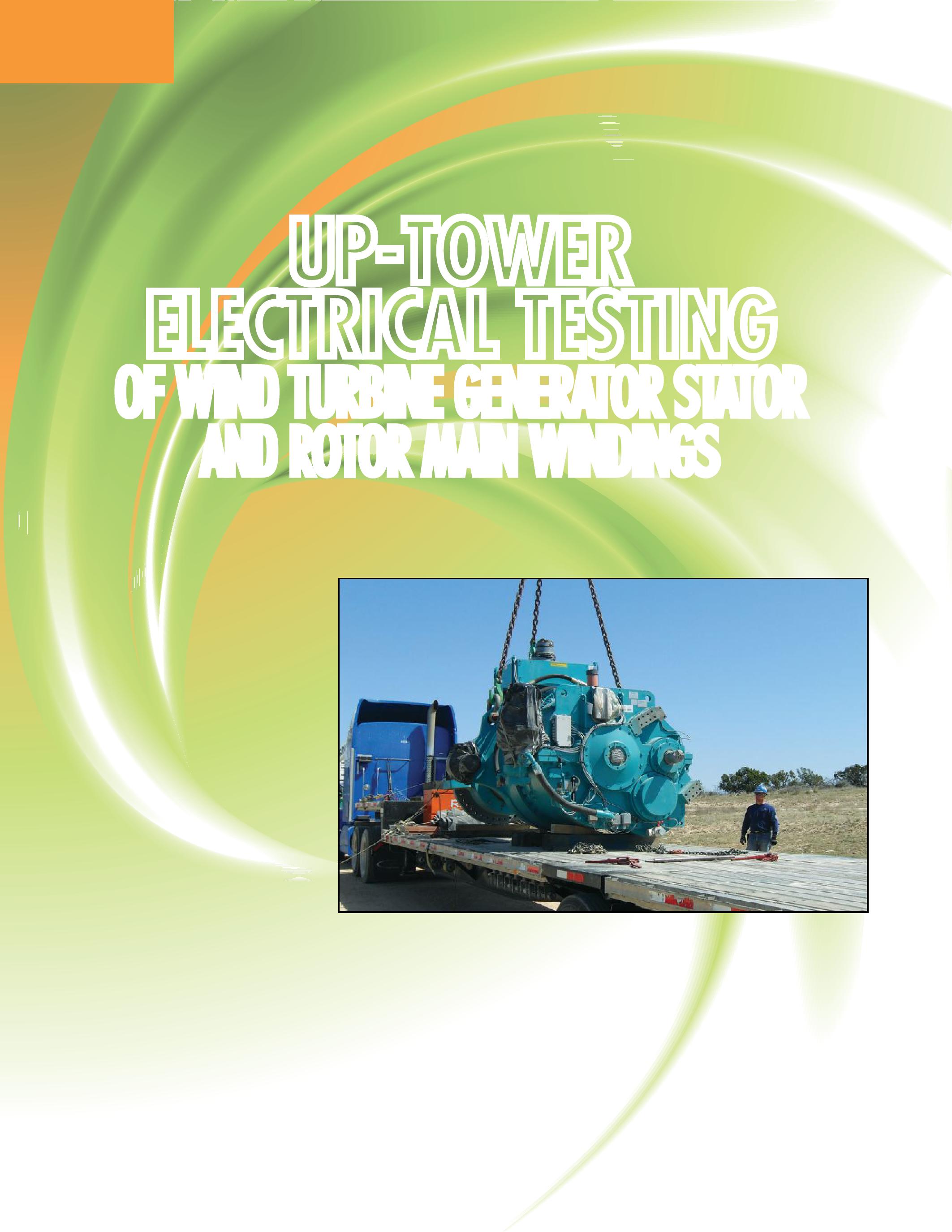
A standard insulation-resistance test is the normal protocol for the wind turbine technician, but what are they looking for and what do they do if they find it? In fact, is it even a helpful test on an operational wind turbine generator? And when you
are 80-100 meters in the air, the electrical test results to determine overall health of the machine become even more important (see Figure 2).
This article helps explain what testing might be performed as part
of scheduled maintenance and what further testing can be done to determine whether the status of a generator is at a critical point. It is typically better to identify issues as early as possible and schedule a generator change out at a convenient time rather than undergo an unexpected and possibly spectacular generator failure. Let’s start with a quick review of what we are testing – the electrical insulation system of the generator.
Most wind turbine generators operate in the low-voltage range (less than 1000 volts). The windings of the generators come in two styles: random-wound (using many small, round conductors in parallel) or in form-wound coils where larger rectangular conductors are preformed and, normally, insulated with ground wall insulation before being inserted into the stator or rotor (see Figures 3 and 4).
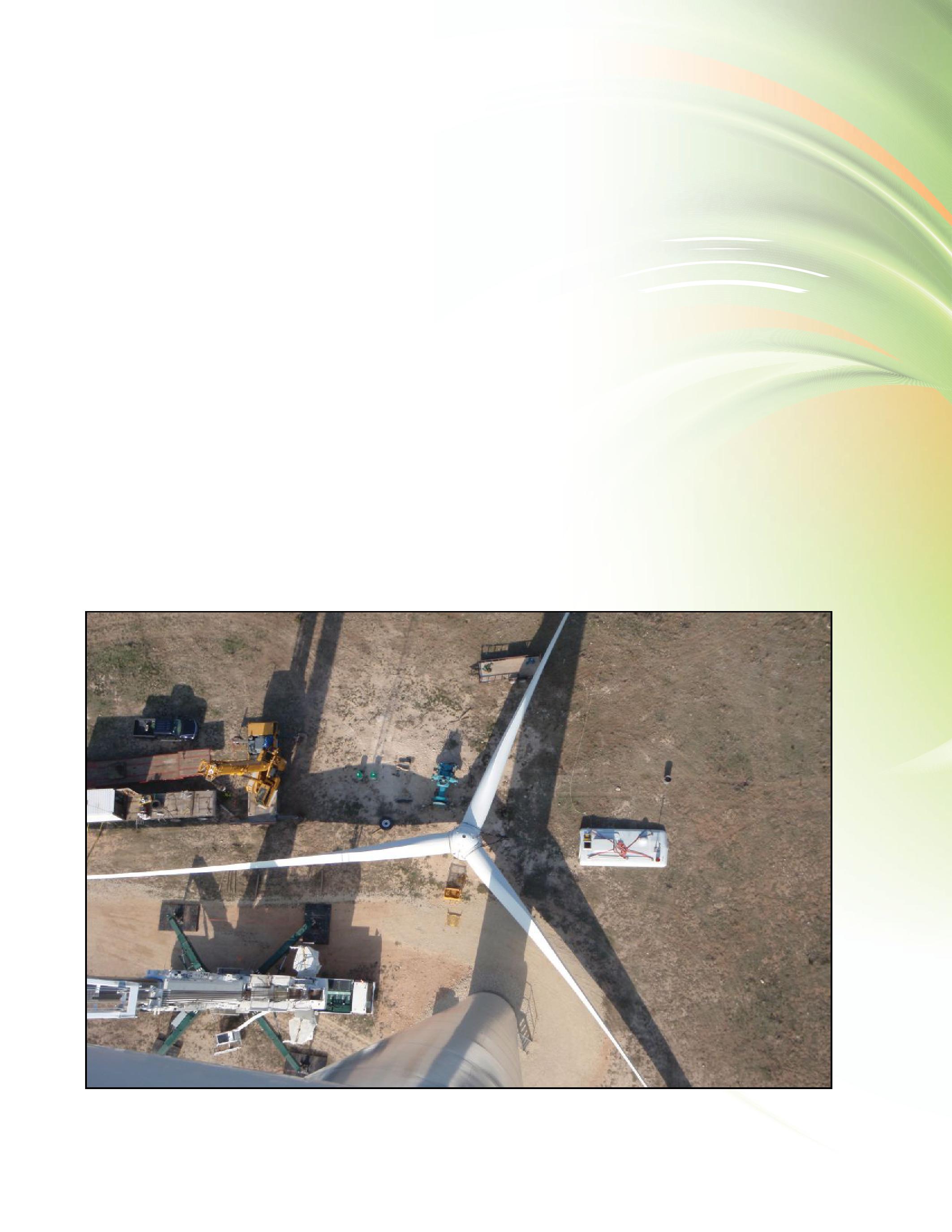
Random-wound machines normally use enamel insulated conductors which are wound into coils and inserted into slots which are already insulated with an appropriate high temperature paper or laminated material. Phase insulation of the same or similar material is placed between the coils in the slots as well as on the overhanging portions. The coils are then wedged into place, reinforced with cords and blocking materials, connected, and finally varnished with a high temperature resin. While most machines using this insulation system design are less that 1,000 kW, there are a few up to a rating of 2.0 MW that will use random-wound coils in the stator only. Almost all rotors above 660 kW are designed using form-wound systems.
In a form-wound system the larger insulated conductors are often insulated with a mica paper/ polyester film tape that is common in European and Asian designs for high voltage machines.
In the USA, it is also common to use enameled conductors, sometimes with a glass filament covering. These conductors are shaped into coils, then additional layers of tape are applied over the bundled conductors to provide both phase and ground insulation. These tapes are normally a laminate of mica paper with some combination of polyester film, polyester fleece, or glass cloth. These finished coils are then inserted into the stator or rotor core with or without additional ground insulation. They are wedged into place, tied, and otherwise supported and then varnished, typically utilizing a vacuum and pressure cycle impregnation system.
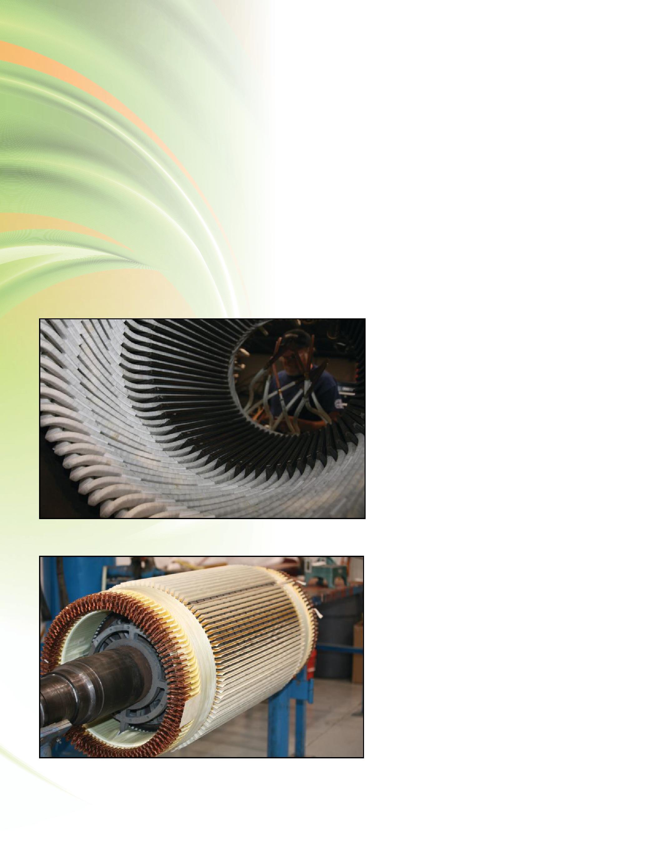
All of these insulation and conductor components (and there are actually many more ancillary materials utilized in the winding process) are designed to function together as an electrical insulation system (EIS) to provide long lasting, reliable performance at a designed and tested operating temperature. The thermal life expectancy is normally calculated for 20,000 operating hours and includes thermal cycling, vibration, and electrical stress testing. In normal end-of-life events, the insulation has broken down at some tiny point due to mechanical abrasion or thermal weight loss so that it is no longer functional. These natural and foreseeable failures can be accelerated by environmental conditions including moisture and chemical contamination, high machinery vibration levels, and electrical surges. The basic concept of periodic electrical testing of the EIS is to monitor and/or trend the factors that lead to premature failures. Let’s consider the basic testing that can be done at regular maintenance checks.
Firstly, safe work practices concerning electrical devices, whether in operation or under test, are paramount. All LOTO and arc-flash rules should be carefully followed, and only qualified electrical workers should undertake this testing. Additional hazards may exist due to the small work space and close clearances with the turbine nacelle (see Figure 5). The InterNational Electrical Testing Association and National Fire Protection Association, as well as other organizations, have recommended guidelines for safely testing electrical components and should be consulted if there are any questions regarding safety.
Insulation resistance (IR) testing is one of the oldest maintenance procedures developed for the electrical industry and is covered in detail in IEEE Standard 43-2000. This test is fairly simple to perform and can provide information regarding the condition of the electrical insul-

ation in the generator as well as contamination and moisture. It is recommended that this test be performed before energizing a machine that has been out of service or where heating elements have failed to keep the winding temperature above the dew point, which might have resulted in condensation on the windings. Insulationresistance testing is also useful whenever there is doubt as to the integrity of the windings and before any overvoltage testing is performed. An accurate IR test requires a correction factor for the winding temperature to create useful data. The methods and expected result data for this test are listed in the IEEE standard.
While the test results from IR testing are not normally trended, it is possible to do so to illustrate a gross degradation of the insulation systems. It is, however, very important that the duration of the test, the temperature of the windings, and relative humidity be consistent for the trend data to be meaningful.
Another test described in IEEE Standard 432000 is the polarization index that is useful in some applications to identify contaminated and moist windings. In most modern machines, however, where the insulation resistance is above 5000 megohms, the test might not prove meaningful. Recently there has also been a consideration of collecting depolarization data as well as analyzing the shape of the polarization curve. Refer to the IEEE standard for additional applications and details.
If the results gathered during a periodic testing cycle are inconclusive or out of the normal range, additional testing is recommended. Normally a generator specialist, either internal or from a consulting service company, is called in to perform these advanced tests as there are some possibilities of further damage to the windings if they are not carefully tested. Some electrical testing is by nature destructive and should only be performed for diagnostics reasons.
The normal advanced test for analyzing the insulation integrity is based on fairly innocuous testing performed by electrically stressing the insulation at a reduced voltage level and recording anomalies between phases of the insulation. This surge comparison testing can be performed manually; however, automated test equipment with digital reporting is available. This is not a trending test, nor does it answer all of the possible questions, but it provides a snapshot of the current condition that can support a decision to remove the generator for repair.
High-Potential Testing
If testing is required to make an immediate decision regarding replacement of a generator, high-voltage testing, normally dc high-potential testing, is useful, but care should be taken as insulation weaknesses (cracking, contamination, carbon tracking, etc.) can be advanced to failure. Sometimes referred to as overpotential testing, the high-potential test is designed to stress the electrical insulation beyond its normal operating voltages to expose potential failures at a convenient time. The dc test methods are described in IEEE Standard 95. Trending is possible with this test, but it is considered a destructive test and probably should be used sparingly and only if the site is prepared to repair or replace the machine.
Using the same equipment as used for the highpotential test, the step overvoltage test stresses

the insulation at rising levels of voltage over a set time scale. This is a very useful trending test and can be used in periodic predictive maintenance testing. The same concerns exist as for high-potential testing.
Although power-quality testing can be performed for energy from the generator as well as excitation power to the rotor, in the near future, simplified on-line testing of electrical circuits will become more available, and acceptable standards of performance will be better defined. Based on either SCADA information versus industry standards or on actual measurements of power quality into and out of the generator, these tests will allow first line maintenance teams to monitor and trend data more effectively from the ground and provide more root cause failure information than is currently available. As most generators currently in use are double fed induction types, the quality of the power from the converter IGBTs feeding the rotor as well as voltage issues from the grid can be questionable, and either could be a major contributor to early insulation failure.
Most wind turbine generators operate at 575 or 690 V ac (a very few are in the 12 kV range) and do not normally generate partial discharges (corona) in the range to be monitored. However, in conjunction with the surge comparison test, there is auxiliary equipment available to ride the high-voltage impulse signal and collect PD information at the peak of the signal. In the future, this data might be useful as a trending tool to help predict normal end-of-life conditions or to identify damage too small for other detection methods.
All good testing stratagems are designed to assure the profitability of the operation. Periodic electrical testing, vibration testing, and alignment of the drive train are time consuming operations and are sometimes difficult to perform on a regular basis. However, the cost of unplanned outages including cranes, staffing and emergency generator repairs can also dramatically affect the bottom line. Good planning, proper testing methods, and clear decisions regarding the condition of the equipment will always pay off with reduced overall maintenance costs.
Kevin Alewine is currently Director of Renewable Energy Services at Shermco Industries with a focus on business development in the wind energy business sector. He has extensive global experience with the application of electrical insulation materials, systems, and processes for both the manufacture and repair of electrical machinery. Kevin is an active member of several IEEE and American Wind Energy Association working groups including chairing the AWEA Operations and Maintenance Working Group developing recommended practices for wind energy asset maintenance.
Casey Gilliam has thirteen years of experience in the mechanical industry that includes testing, maintenance and management. He has worked in both field and shop setting in his career. As a technician he has a background in quality improvement, troubleshooting, and repairs while mentoring and leading a team. Casey is currently the Sweetwater Service Center Manager at Shermco Industries.


Remote
Reduces
Use
Use
Qu
Over-Rack


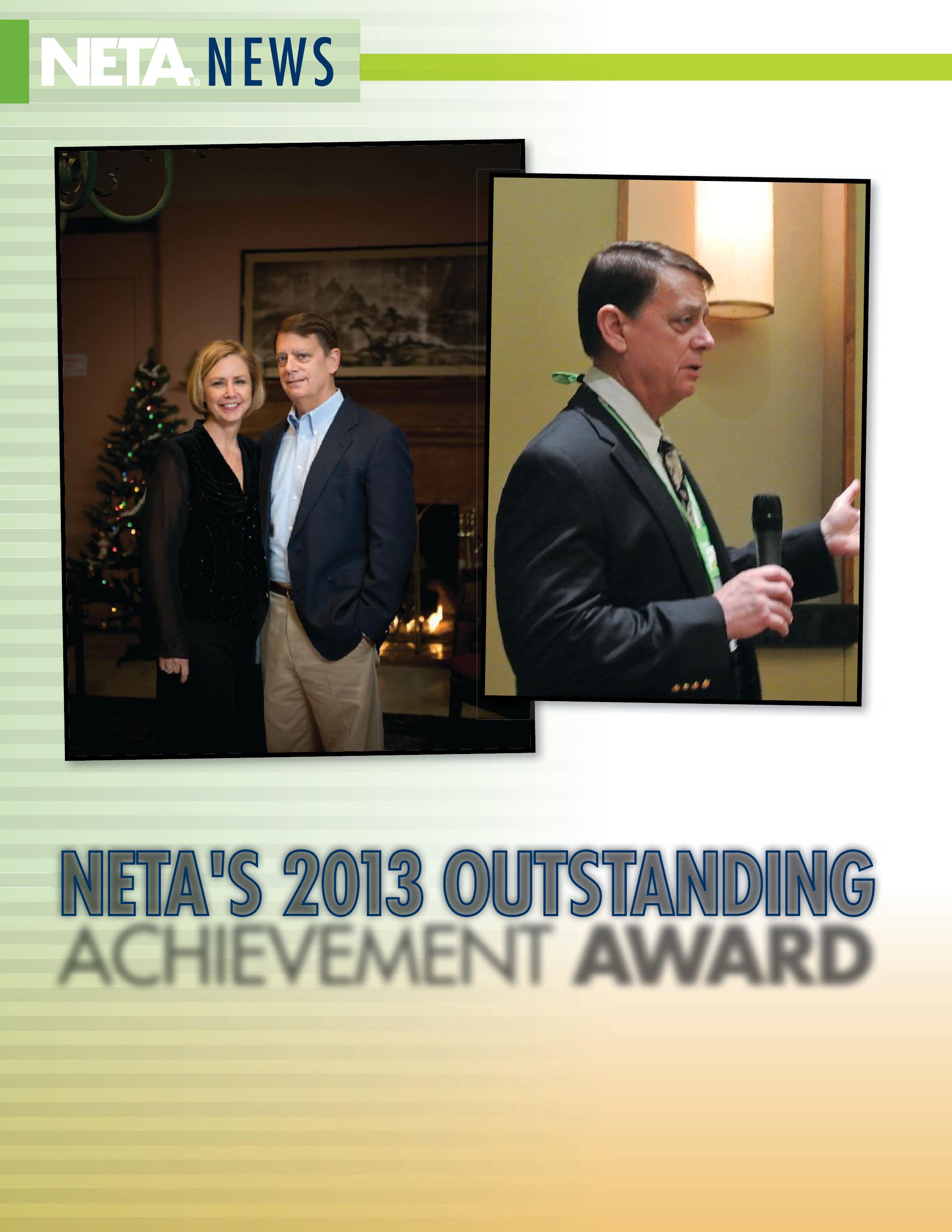 BY RICHARD PIET, NETA

Looking around at a PowerTest Conference – or even at a list of those active in NETA –a person is liable to find an esteemed group of professionals whose expertise in the industry is significant. Trying to choose a certain individual from such a group who has displayed a special commitment to NETA and its mission can be difficult .
Fact is, it is a challenge.
But often, once the President of NETA starts considering who that individual could be, the proverbial light goes on, and a person fitting the bill stands out.
This year, while Shermco Industries’ Jim White mingled and networked with his fellow New Orleans PowerTest attendees at the Member and Alliance Luncheon, he had no idea that before lunch was over, he would be introduced as the 2013 Outstanding Achievement Award recipient.
There was even some surveillance going on before the announcement was made, as NETA Member Relations Associate Faith Cervin was charged with keeping an eye on Jim to make sure he didn’t leave the room – or see his wife Vickie waiting just outside for the big announcement.
Vickie was told the day before that Jim would be honored at the lunch and that it would be a surprise. She did not have any trouble keeping the news to herself. “I like him to be surprised,” she said. “I wasn’t going to spoil it for him.” And surprised he was. “It was completely unexpected,” Jim White said. “You don’t do stuff like this expecting to be recognized. You do it because you want to help and be part of things,” he said.
Ask folks who know Jim to talk about him, and they describe him in clearly defined terms. “Competent, dedicated,” member of the NETA Board of Directors John White – last year’s Outstanding Achievement Award recipient – said about Jim. “A real educator,” he added. “Straightforward, knowledgeable,” former
president of the NETA Board of Directors Dave Huffman said. And “good humored.” Current NETA President Mose Ramieh called Jim “personable, tireless,” and “dedicated.” There seems to be a pretty clear reason why, too. “I love what I do,” Jim said.
After a training career elsewhere, Jim joined Shermco Industries in 2001 as the company’s new training director. At the time, Shermco was embarking on a new commitment toward training and safety. That appealed to Jim.
“There was a commitment there,” he said. “The other companies I talked to [about employment] said ‘we’ll give it a shot,’ Shermco said ‘this is something we actually want to do.’”
Shermco’s training department started out with just Jim. Today, Shermco has two dedicated salespeople and four staff instructors supporting his efforts to assist the industry to stay in OSHA compliance – and to stay focused on safety.
“Anyone can do training,” Jim said. “The issue becomes quality.” Jim is frank about his observations of quality training with a safety focus in the industry. “A lot of companies will purchase training based on price,” he said. “I like to call those companies ‘box checkers’ – they do it as cheaply as they can. Other companies…understand what’s needed [and] care about their people. Those are the kind of people we do training with.” Jim’s reputation and commitment to safety and training are well known in NETA circles.
“Jim holds the conviction that the electrical power industry is best served by enhancing the overall safety of electrical workers and educating people in the care of electrical equipment and safe work practices,” Huffman said. John White said Jim is “perceived as an expert in safety in the workplace…professional, knowledgeable, friendly, and willing to help.” Jim’s involvement
with NETA began in 1986, “mostly at a sales level” he said, meaning his participation within NETA was a chance to network and perhaps gain new clients. But that changed.
“Back in ’86, these were wild guys,” Jim said, referring to the party atmosphere that often accompanied NETA functions of the time. But partying was not the driving force overall. “There was a core group of guys who had a vision,” he said. “I could see that vision.” Jim was energized by that foresight. “I wanted to be a part of making it happen. The industry needed stability and quality companies who had a set of standards. I saw NETA as the path,” he remembers.
That energy translated into a commitment that has lasted more than 26 years. “Jim has been dedicated to NETA,” John White said. “He has been a leader in the area of safety and his presentations and general presence at NETA has earned him a very strong reputation…” Mose Ramieh agrees. “Jim is a strong supporter

of NETA in every way. He is always available to lend a hand even on short notice,” Ramieh said.
Today, Jim believes NETA has gone way beyond the original target, “well beyond anything I thought would ever happen back then,” he said. “Who knew NETA would be an ANSI standards-writing organization?!”
Those active in NETA are not the only ones who have been affected by Jim’s passion for the industry and safety. His own sons have been, as well.
Jim and Vickie’s oldest son, Jason, has been employed by Shermco for seven years, in the circuit breaker shop. Their youngest son, Justin, who will soon complete his studies in electrical power technologies and instrumentation at Texas State Technical College, has an eye on Shermco, too. “My youngest is keenly interested in working for Shermco,” Jim said.
Jim sees his sons as part of an industry that, in the future, will look different. “I see it going to a certification of all electrical personnel; I don’t see how we can get away from it,” he said. “Because of the hazards involved in the work, I think you’re going to see some type of universal certification.” He believes professionals in the industry now with lots of institutional memory and expertise will have to play a leading role in building the next generation.
“The new people coming in don’t have the same level of qualifications as in the past,” Jim said. “They will require more nurturing, mentoring, and training and be treated differently. They have a different set of values.” He also thinks that means more automated test equipment in the industry; something he believes has already begun. Those who know Jim probably will not be surprised that he wants a front row seat in helping to shape the future. “I’d like to see NETA come to the forefront on that,” he said, referring to universal certification.

Safety and training are not the only things at the forefront of Jim’s life. He and Vickie have been married for 37 years this year, and in addition to their sons, have a daughter Jodie (from Jim’s first marriage), and three grandchildren. Some time before he met Vickie, though, Jim had been out in the world, having served in the United States Air Force during the Vietnam War. He served at different duty stations around the country.
In 1972, he was deployed to the Phu Cat Air Force Base in Vietnam. Jim left the Air Force and was back in the U.S. some time before Phu Cat was seized by the Vietnamese army in 1975. Faced with a decision about what direction he would choose after the military, Jim fell back on some experience he had in industrial construction, gained before his Air Force experience. He remembers coming home from the military and having a difficult time after the dissolving of his first marriage. At 22, he was back home, unsure of his direction, living with his parents.
He remembers his folks had an extra bedroom in their home, but his dad offered up the family sofa for Jim. “’You can stay, but I don’t want you comfortable!’” Jim remembers his dad saying. He also remembers his dad encouraging him to attend church, which Jim says “wasn’t on my radar” while he was working construction and “drinking and partying…doing the things single guys usually do,” he said. But, he got the message, and decided to attend a service – and it “made a huge difference,” Jim said. He happened to attend on the day a visiting minister addressed the congregation.
The minister “spoke to my heart,” Jim said. The experience changed his life, and he became a Christian. Six months later, he met Vickie at church. Vickie, who is now a real estate professional in Fort Worth, remembers her parents were not too fond of the idea of she and Jim dating, mostly because she was only seventeen. Jim was five years older, separated and a father. “I was just a young little thing
when I met Jim,” she said. “My parents were not thrilled.” So, the two dated until Vickie’s parents said it was okay for them to get married. “When you’re a teenager, you say ‘what is the big deal?’” she said. “Now I understand!”
Eventually, Jim gained some testing expertise while working at refrigeration facilities for the government. That led to a position with the firm that was to become AVO Training Institute. Jim climbed the ladder there, having become a training manager in 1986 and then director of training in 1992.
After leaving AVO in 1996, he eventually landed at an Ohio firm where he became the manager of electrical field services/compliance manager. “That’s where the theoretical became the actual, and I became involved with the safety aspect of things,” he said, having fully transitioned into a role where he became responsible for the safety of several employees.
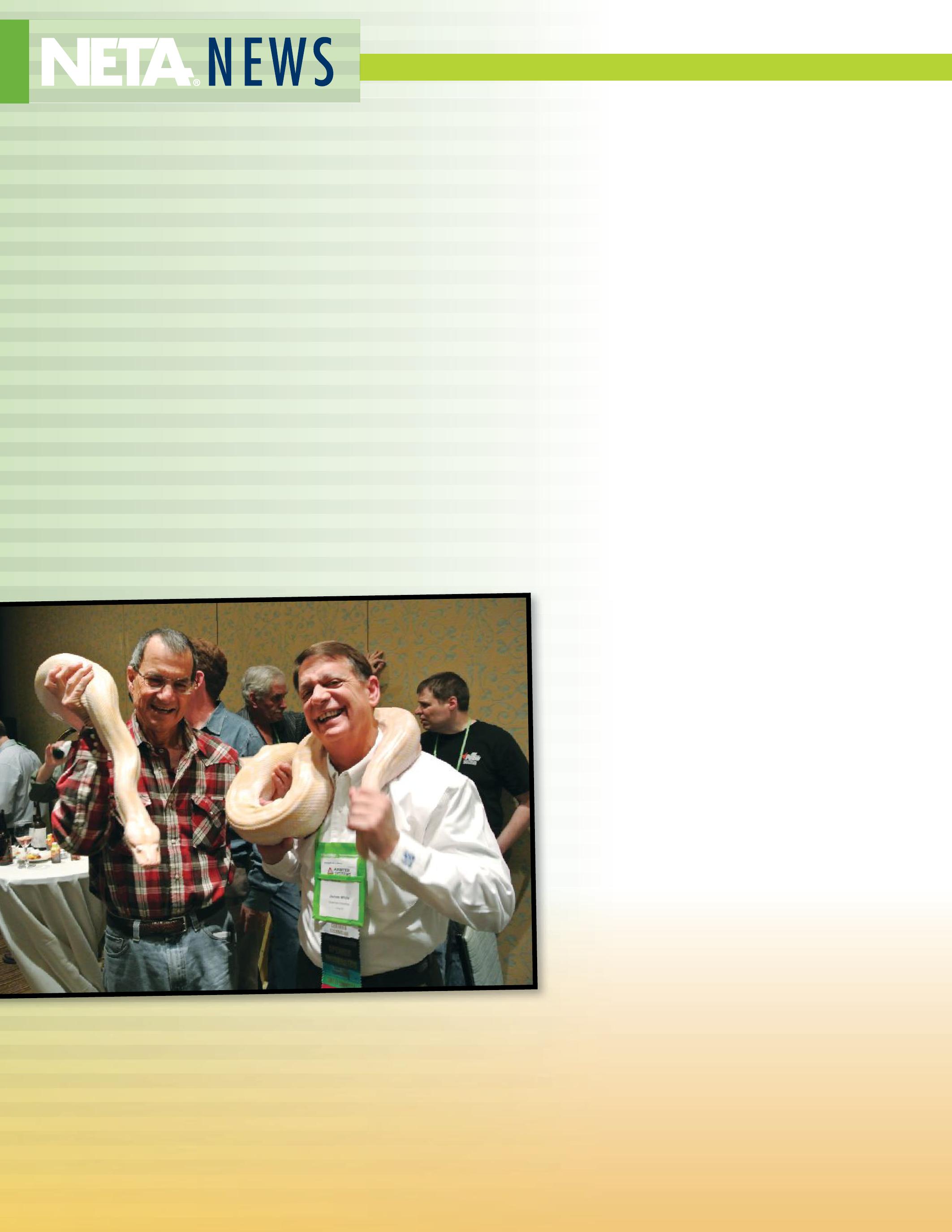
Then, Shermco entered into the picture, where Jim remains today.
In their free time, Jim and Vickie like to travel. Among their memorable trips were those they took to the Hawaiian Islands. “Vickie threatened to stay there,” Jim said. “Common sense prevailed!” They also like to take cruises, with an Alaskan cruise on their wish list. Jim tries to get a few rounds of golf in during his free time, though he spends more time lifting weights and restoring Corvettes. His pride and joy is a 1990 Corvette ZR1 he hopes to enter into an award competition with the National Corvette Restorers Society this year.
Jim calls his NETA Outstanding Achievement Award honor “doubly sweet because it was so unexpected.” He added “I think receiving this award at the same time Jean-Pierre received his – he’s someone I greatly respect – was really great,” referring to former NETA Board Member Jean-Pierre Wolff, 2013 recipient of the NETA Alliance Recognition Award.
Vickie White is a proud wife. “[Jim] tends to downplay anything he gets,” she said. “It’s really exciting for me to see him be acknowledged in the industry where he’s worked so hard.” So, what’s next?
How about retirement? “He says he’s never going to retire,” Vickie said. “As long as he lets me retire, I’m fine with it,” she jokes. But Jim and Vickie will likely spend their free time the same way they do now: traveling, enjoying their Corvette and “grandkids,” Jim said.
Looking back on the PowerTest luncheon when his name was announced as the Outstanding Achievement Award recipient, Jim is a little worried about what happened next. “I babbled like an idiot at the podium, my thoughts were so disorganized. I think I even blacked out for a second,” he jokes. But ultimately, he is modest. “It really touched me.”
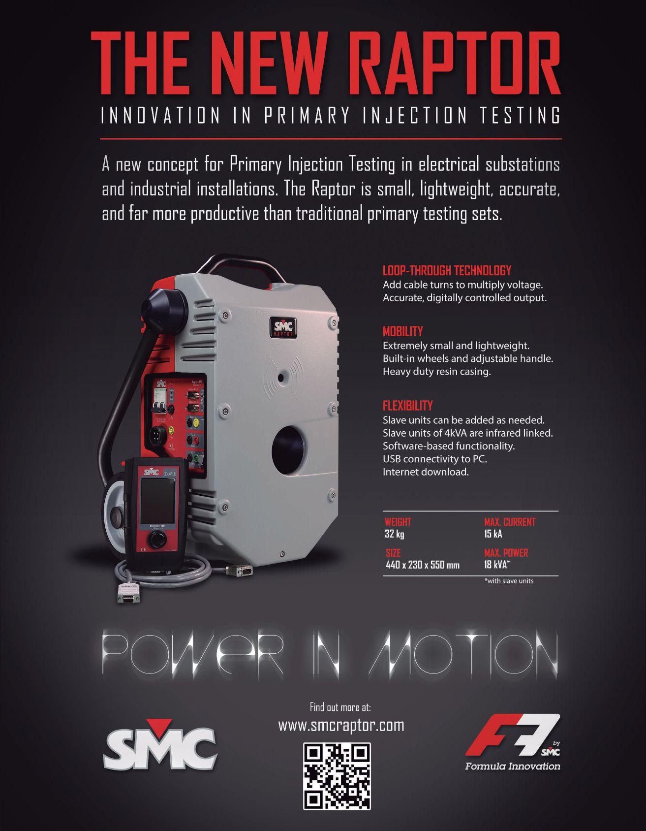
Power System Acceptance Testing
Commissioning and Start-up
Maintenance
Life-Cycle Extension
Troubleshoot and Repair
Training and Engineering Services
Planning and Operations Support
Project Management
Sigma Six Solutions, Inc.
2200 West Valley Hwy North, Suite 100 | Auburn, WA 98001
f e 2 9 0 | Sales 2 29 12 9




All types of Electrical
Maintenance, Testing & Repair
Install, Test, and Commission
all types of Relays & Protection Systems
Troubleshooting Electrical
Controls & Electrical Systems
www.youtube.com/tdeinc2
www.twitter.com/tdeinc
www.facebook.com/tdeinc
www.linkedin.com/company/tony-demaria-electric
Substation & Generating Plant Design, along with Power Systems Audits
National Certified Cable Splicing, Complete
Cable Testing & Analysis using VLF, VLF-TAN
Delta, and Partial Discharge
Large Motor, Generator & Transformer
Maintenance, Testing, Repair & Troubleshooting
Electrical Safety for Qualified Electrical Workers
Understanding NFPA 70E & Arc Flash Awareness
Electrical Safety Refresher with Advanced Switching & Racking Techniques

There are many NETA Alliance Partners who give freely of their time without looking for recognition. Therefore, it is truly a difficult task choosing just one to be honored with NETA’s 2013 Alliance Recognition Award. This year’s recipient is one of NETA’s Life-Time Alliance Partners who regularly contributes his time and resources to NETA and is a tireless promoter of safety and reliability within the electrical power industry.
NETA is pleased to honor this year’s recipient, JeanPierre Wolff, owner and esteemed Vintner of Wolff Vineyards, San Luis Obispo, California. Jean-Pierre is a longtime contributor to and friend of NETA and has been a champion for safety since the days when he was a NETA Board Member and accredited representative to NETA for ETI - Electro Test Inc., out of Danville, California. Since then, Jean-Pierre opened Wolff Vineyards which today regularly produces award winning, regional wines and is recognized by the Central Coast Wine Growers’ Association as a leader in wine grape growing sustainability.
Notwithstanding, in the fourteen years since Jean-Pierre traded in full-time employment in the electrical testing industry, he remains a champion for the ANSI/NETA standards and advocate for safety. He has been a consultant to NETA as well as

The NETA Alliance Program is open to all individuals who are involved in, or support the electrical testing industry, serve the industry through the development and use of consensus standards in the electrical power industry, and are focused on providing the highest level of safety and reliability. These individuals include people from all areas of the electrical testing field and include consulting engineers, architects, and individuals who work for manufacturers, utilities, hospitals, and universities, etc. In additional to their regular jobs, many of these individuals volunteer their expertise and have become fixtures in the world of standards creation, training, education, and industry publications.
to a number of NETA Accredited Companies working on specific projects and initiatives. Currently Jean-Pierre consults for NETA Accredited Company, Applied Engineering Concepts. He has also done work for the Electric Power Research Institute on a nuclear power plant life extension program and serves on standard review panels in the electrical power field and the agricultural field.
When Jean-Pierre is not lending his expertise to advance the electrical power industry or harvesting next year’s wine selection, he is continually engaged in ventures that make a difference and inspire and lift the spirits. Currently he serves as Vice-Chair of the Coastal San Luis Resource Conservation District which is a non-regulatory public agency, a subdivision of the State of California government district, dedicated to enhancing and maintaining the natural resources.
A couple of years ago, Jean-Pierre formed a rock band called the Crush Tones in which he plays a mean harmonica and leads the group. The band members are all local wine-makers or directly related to the wine industry. They play local events and are the featured band at the Rockin’ Harvest Celebration, an annual event sponsored by San Luis Obispo Wine Country Association. Jean-Pierre’s energy, creativity, and commitment to every endeavor are acknowledged among all who know him.
Colleague and long time friend John White of Sigma Six Solutions recognizes Jean-Pierre’s passion for excellence and appreciates his broad understanding and contribution to the electrical power industry; “JeanPierre’s knowledge comes from having been with an electrical equipment manufacturer and then with a NETA Accredited Company for so many years. His experience and understanding of sales and marketing and the associated details have been a tremendous support to NETA. He has served as a valued consultant to the association many times.”
Jean-Pierre’s strategic approach to problem solving, his ability to see ideas from all angles, and his excellent training skills are what make him a highly sought after candidate within NETA and among IEEE, IAEI, and many other industry associations, serving as an advisor, trainer, writer, and regular presenter.
A genuine-person with such a breadth of knowledge and dedicated in everything he does. Definitely a person you would like to have on your team.
When asked to describe Jean-Pierre in three words, Michel Castonguay, President of Applied Engineering Concepts replied “Integrity, tireless, and a great man overall.That’s more than three words, but we would not be where we are today without him. He has become a great mentor and friend.”
In addition to receiving the NETA Alliance Recognition Award, Jean-Pierre also received a Life-Time Alliance Partnership award. The Life-Time Alliance Partnership
Jean-Pierre and His Wife Elke, are Welcoming Hosts to Many Vineyard Guests; Where Everyone Joins in the Fun!

Jean-Pierre has always brought a unique perspective into the association, from the days of being involved as a NETA Accredited Company in the old “ETI” days, to the subsequent years of Association participation as an outside consultant. And because he knows our industry from both vantage points, with the views of the smaller independent companies to those of larger firms we are well represented in his opinions and contributions.
Now as an Alliance Partner, it’s nice having a person who knows all sides of the electrical testing and maintenance business while making such a big contribution to the industry. And it never hurts that he is a vintner as well to help supplement his electrical expertise….
Ron Widup Shermco IndustriesAward is given to individuals who have contributed to NETA in multiple ways over the course of their careers. When JeanPierre left ETI and started Wolff Vineyards, NETA recognize him with the Life-Time Alliance Partnership Award for all that he had given to help shape the association. Jean-Pierre’s generosity continues today in a number of ways. In addition to being a regular presenter at PowerTest, he continues to provide invaluable counsel as NETA grows and evolves with the industry.
Jayne Tanz, NETA’s Executive Director, states, “In business and in friendship, JeanPierre is always generous and gracious. One of the most wonderful experiences I can remember was in 2011 when Jean-Pierre and his wife Elke invited the NETA Board to their home in San Luis Obispo. The evening was picturesque. The sun was setting over the rolling hills of Wolff Vineyards, and we gathered in the middle of the vineyard, near the Pinot Noir grapes to taste a selection of Jean-Pierre’s very best. We then met back at his home overlooking the vineyard where a local chief prepared an extraordinary
sampling of local fare. It was a wonderful evening with many laughs, storytelling, and good fellowship.”
Following the NETA Allinace Recognition Award ceremony on February 18, 2013, Jean-Pierre shared these thoughts: “There have been a lot of deserving people over the years, some who have gone on to the big substation in the sky. I think of Pat Herbert, and I cannot be in New Orleans without remembering Chuck Kirsh. I am honored. It means a lot to be recognized by your peers. With so many involved over the years, I am pleased to continue the legacy.”
NETA thanks Jean-Pierre for his contribution to the association and his commitment to advancing the electrical power industry. As we look to 2014, NETA welcomes those involved with NETA’s Alliance Program to contact the NETA office with their suggestions for future recipients. This honor will be bestowed each year at PowerTest during the Member and Alliance Luncheon. To learn more about becoming a NETA Alliance Partner, please visit www.netaworld.org.










 BY JOHN HODSON
I look back over 30 years involvement in the electrical testing industry and realize that many changes have occurred that are now the accepted norm. It is quite similar in our normal day to day activities….I still marvel at the day my 21 year old daughter could not find the remote for the TV and suggested we needed to get a new remote (or TV)…. she had no idea a television could be turned on at the screen.
Some of the lost skills or technology I remember as I reflect back in time:
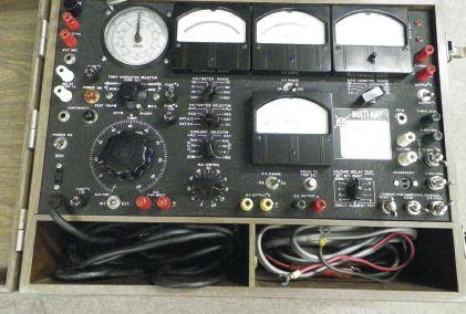


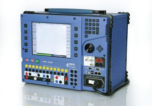


BACK TO THE FUTURE — DECADE TWO/CENTURY 21….



Figure 3: Often it is only through acceptance testing that power equiment recives a thorough inspection and appropriate testing.

ONLINE MAINTENANCE
DIAGNOSTIC OPTIONS
Temperature Monitoring
Gas in Liquid Monitoring
Fluid Chemical Analysis
Pressure
Voltage / Current
DC Voltage
Digital I/O
Power Factor / Capacitance
Partial Discharge

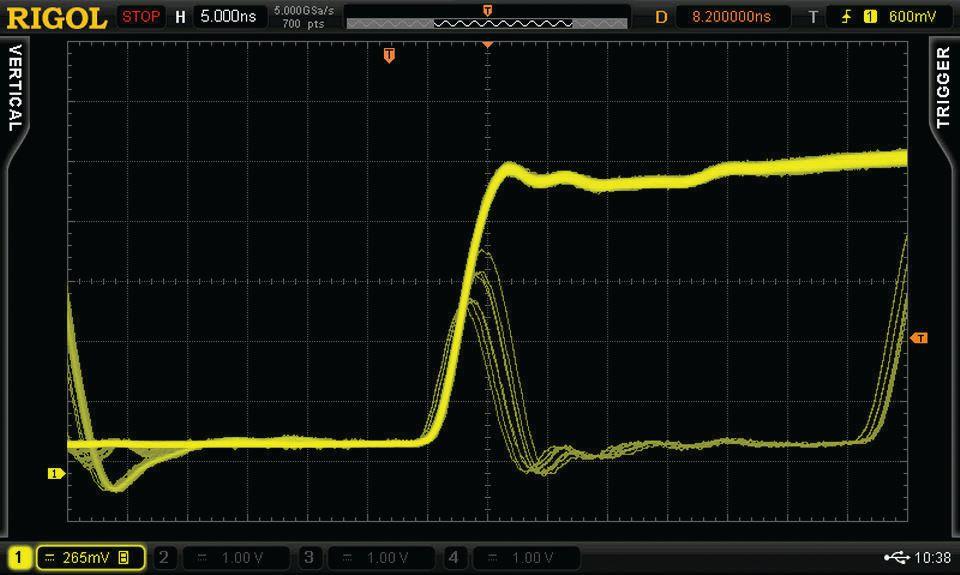


Ground Resistance
Arc and Pressure of the large inhibitors to this integration comes

CONVENTIONAL STATIC ACCEPTANCE AND MAINTENANCE TEST DATA FACTORY TESTING SITE DYNAMIC TESTING AND VENDOR SPECIFICATIONS
ON LINE DATA FROM DIGITAL METERING PROTECTION AND CONTROL
INVESTIGATIONS ROOT CAUSE ANALYSIS AND SUSPECT REVIEWS
SPECIALIZED DIAGNOSTIC INFORMATION FROM ON LINE PD. FLUID MONITORING, ACOUSTICS, THERMAL AND OTHER HARDWARE
MANUAL INPUTSITE SPECIFIC CONSIDERATIONS AND CUSTOMIZATION
PRE-DETERMINED REPORTINGQUERIES AND INVESTIGATION
EVALUATION BASED ON CONDITION AND CRTICALITY [CBM + RBM]
WORK ORDER TEST PROCEDURE SUGGESTED ACTIONS TIME AND EFFORTS EXPENDED FOR MAXIMUM EFFECT RESOURCES - RELIABILITY
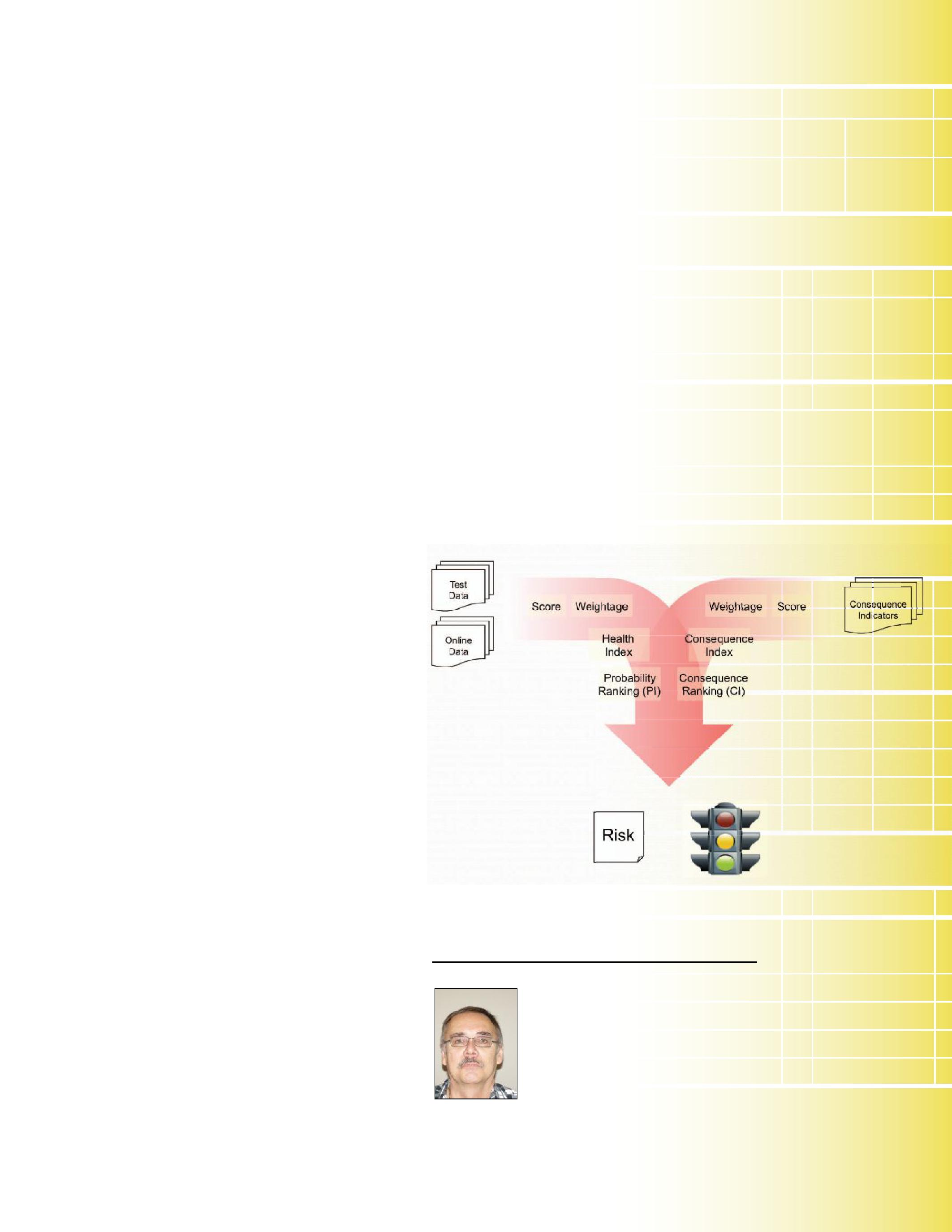
Figure 6: The CBM Traffie Lite = GO / INVESTIGATE / SHUT DOWN.
John Hodson has spent over 30 years in the field service industry with Magna IV Engineering Ltd. He served as the NETA representative for Magna Group of Companies for several years. He is still active in the industry by mentoring, training, and working to promote advanced diagnostics hardware and software and their integration.

After a disaster, your service shop needs expert help – fast. National Switchgear has literally millions of switchgear products, new and reconditioned. And we have the know-how to help you determine exactly what you need to get your clients’ equipment back up to speed. We’re available 24/7, and we’re here to help, whether you require a small component part, a switchgear lineup, shop resources, or anything else to restore equipment. So, if you’re thinking of calling anyone else, it’s time to switch.
800-322-0149 nationalswitchgear.com


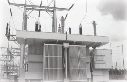






HIGH VOLTAGE, INC. serves the wind and utility industry by providing portable VLF .1Hz Very Low Frequency AC hipots and AC HV Test equipment for proof testing the medium voltage collector cable circuits and switchgear commonly used on Wind Farms. The VLF .1Hz testing of Wind Farm power cable feeders and collector cable circuits per IEEE- 400.2 is a simple, cost effective, and conclusive quality assurance test method. It definitively proves out the integrity of the workmanship, cable insulation and its associated accessories such as splices and joints.
A VLF AC withstand test is an excellent test method for insuring the cable laying and workmanship of the new installation is good and will provide reliable, long term power distribution to the distribution grid the Wind Farm serves.
High Voltage, Inc. also can supplement VLF withstand testing with Tan
delta testing diagnostics via a Tan delta bridge used in conjunction with a VLF AC Hipot. By monitoring the tan delta readings of a cable circuit over time, one can determine if a particular cable is beginning to show insulation degradation commonly caused by water trees possibly leading to a cable fault disrupting power delivery. By discovering a suspect cable before a catastrophic cable fault, plans can be made ahead of time to repair, rejuvenate or replace the cable and splices during a controlled repair outage minimizing power interruption and service failure. These two testing methods (VLF & Tan delta) are the easiest, most time proven, simple, and conclusive for Wind Farm managers and HV contractors to enhance and continuously provide a reliable installation and reliable generation of power. High Voltage, inc. is very familiar with all cable testing technologies, and knows cables.
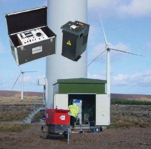

 BY DON GENUTIS, No-Outage Electrical Testing, Inc.

No-Outage inspection methods present some unique challenges that may not be applicable when performing other electrical tasks; therefore, a simple safety checklist has been created to help focus the technician on the work at hand when conducting these types of surveys.
Field testing activities can be strenuous, both physically and mentally. Environmental extremes such as heat, humidity, cold, rain, and snow may be encountered. Long hours, often during late nights and weekends, can be the norm. Heavy lifting may be required. The list can go on and on.
No-outage testing can present some additional challenges. First of all, the equipment must remain in service when the testing is conducted. This requires strict adherence to NFPA 70E safety guidelines including the proper use of PPE and complete mental focus when performing this type of work.
Additionally, it is often the case that the electrical equipment being surveyed is located in multiple areas which may require a great amount of walking about large campus-like facilities to get to the equipment. It is not unusual for some equipment to be located

upstairs or downstairs as well, requiring fitness challenges. All of this activity can cause a great deal of fatigue and makes it necessary for even greater concentration on the tasks at hand to ensure they are performed safely.
When encountering environmental extremes, take frequent breaks and keep hydrated. Use several clothing layers in cold conditions.
Invest in a good pair of shoes. Sturdy, lightweight, well-cushioned shoes go a long way towards helping fight fatigue when you are on your feet all day (and night).
Bring all of the instruments and tools that you may need to reduce trips back to your truck, but do not bring unnecessary tools. When panel cover removal is necessary, the cordless drill is man’s best friend, and it is good to have a wellprepared MacGyver-like partner around that has several spare battery packs on charge.
The following One Minute No-Outage Safety Checklist should be followed when approaching energized electrical equipment.
Use your senses. Listen for any unusual sounds or noises. Note if any excessive temperature or humidly is present. Be aware of abnormal odors. Any of these conditions could indicate a potentially serious problem.
2. Take a mental picture of all exit locations. Consider how you can quickly exit the room if the lights go off. The intensity of an arc-flash incident could temporarily reduce vision and an unexpected outage could knock out lighting, making it difficult to escape.

3. Closely examine the immediate surroundings. Observe the floor for possible slip and trip hazards or other objects near the electrical equipment. Look at overhead clearances and note any low hanging conduits, pipes, or other objects that could interfere with your inspections or cause you harm. Look for signs of water entrance from the ceiling; it could be that a puddle of water is sitting on top of the switchgear.
4. Take a good look at the switchgear or equipment to be surveyed. Is it dirty? Does the paint show signs of corrosion? Are recent test or calibration stickers present on the equipment? External signs of equipment neglect can be indications of an even more severe problem inside.
5. Finally, cautiously plan your next steps according to your observations. If something seems wrong, stop and discuss it first with your colleagues and then include the customer. If panel cover removal is necessary, the best option may very well be to postpone inspections until an outage can be obtained.
As new technologies continue to evolve, the implementation of no-outage surveys continue to grow as an integral part of successful maintenance programs worldwide. The unique challenges of performing no-outage testing require the utmost level of focus and concentration. Since safety is the single most important element of our jobs and daily life away from work, proper precautions must be followed at all times. Implementing the One Minute No-Outage Safety Checklist should help awareness and ensure safety.

Don A. Genutis received his BSEE from Carnegie Mellon University. He was a NETA Certified Technician for 15 years and is a Certified Corona Technician. Don’s technical training and education are complemented by twenty-five years of practical field and laboratory electrical testing experience. Don serves as President on No-Outage Electrical Testing, Inc., a member of the EA technology group.



The ANSI/NETA Standard for Acceptance Testing Specifications for Electrical Power Equipment and Systems was approved as an American National Standard on January 25, 2013. These specifications cover the suggested field tests and inspections that are available to assess the suitability for initial energization of electrical power equipment and systems. The purpose of these specifications is to assure that tested electrical equipment and systems are operational, are within applicable standards and manufacturers’ tolerances, and are installed in accordance with design specifications.







On April 19, 2013, NETA published notice of intent to revise ANSI/NETA Standard for Maintenance Testing Specifications for Electrical Power Equipment and Systems as a revised American National Standard. This document contains specifications which cover the suggested field tests and inspections that are available to assess the suitability for continued service and reliability of electrical power distribution equipment and systems. The purpose of these specifications is to assure that tested electrical equipment and systems are operational and within applicable standards and manufacturers’ tolerances and that the equipment and systems are suitable for continued service. It is available in hard copy, PDF, and CD Rom formats. The revised edition will be published in 2015, with the 2011 edition remaining the most current edition until that time. Order your copy today at www.netaworld.org.


The ANSI/NETA Standard for Certification of Electrical Testing Technicians was approved as an American National Standard on January 8, 2010. The document was originally approved as an ANSI standard in 2000. This standard establishes minimum requirements for qualifications, certification, training, and experience for the electrical testing technician. It also provides criteria for documenting qualifications for certification and details the minimum qualifications for an independent and impartial certifying body to certify electrical testing technicians.


Comments and suggestions on any of the standards are always welcome and should be directed to the NETA office at neta@ netaworld.org or 888-300-6382. To learn more about the NETA standards review and revision process, to purchase these standards, or to get involved, please visit www.netaworld.org or call 888-300-6382.


Diane dining on the Queen Mary with friends.

In a field traditionally dominated by men, Diane Hageman stands apart as a savvy business partner, accomplished editor, grammatical guru, and longtime volunteer with NETA. She also happens to be a Southern Belle who has the most beautiful lilting East Tennessee accent, can sing like a bird, and likes her Jack and water on the rocks when she’s not drinking Chardonnay. It is with a mixture of joy for a wellearned rest and reticence over the loss of a valuable asset that NETA wishes her well on her retirement from the Standards Review Council.

It was not taken lightly by the NETA Standards Review Council (SRC) when the announcement was made that Diane would be vacating her seat at the table. Each member of that committee expressed gratitude for her hard work and dedication to an often thankless but absolutely vital piece of NETA’s technical presence.
Diane’s service within the association has made an indelible impact on NETA’s reputation as a credible source for technical information. Her gift with the written word along with her tireless adherence to grammatical laws that many people have abandoned in the age of texting assure that the technical message is received by NETA’s audience clearly and correctly.
Ron Widup, fellow SRC member, explains, “NETA has evolved over the years into a recognized and trusted entity in the electrical power system testing arena. Whether the Association is recognized through its certification process of both companies and technicians or the recognition of what has arguably become the standard for electrical power system component assessment and verification (NETA’s acceptance and maintenance testing specifications), this recognition and trust within industry that the Association has obtained can be directly attributed to the most easily argued and contested aspect of NETA: the written word.”
“Diane has for years provided us not only hours and hours of volunteer time and effort for the Association, but she has done so while keeping the Association’s written words concise, technically accurate, and grammatically correct. And this is no easy task, especially with a group of Type A technical guys that all have opinions and differing viewpoints of how things should be. Diane always stood her ground and helped us create a technical presence and final product that has become the resource for electrical acceptance and maintenance testing.”
“Finding someone who can write well and can gently (or sometimes not so gently) convince
Diane relaxes in her backyard, a haven for gardening, grilling, and cocktails al fresco.
others of how it should be is a rarity, and to have her work with us for all these years has truly been an honor and a blessing. We will miss her expertise and special ability to keep the meetings technically sound and still fun. There aren’t many people out there like Diane – she’s one in a million.”
Charles Blizard, Sr. says of his good friend, “Diane has given her time unselfishly to help NETA gain it’s recognition as the world leader and promoter of electrical testing. She has been the person who ensures word usage and spelling agrees with national and international engineering standards. In addition to her editorial work she brought an aura of common sense to our meetings and our standards. We will sorely miss her.”
Dave Huffman remembers meeting Diane, “I first met Diane at a membership meeting, and my first thought was how elegant and refined she was; quite the contrast to us rough-around-the-edges field techs and engineers. It was refreshing. It wasn’t until years later that I worked with her and the rest of the SRC on a training course. Along with the technical expertise a group like that possesses, with Diane it also brought articulation and clarity to the written documents. There are some big shoes to be filled in this irreplaceable and essential component of the SRC, and the association as a whole.”
Her contributions make it easy to understand why Diane was the recipient of NETA’s Man of the Year Award in 1993. In an era of political correctness, there were some who felt that the award needed a more modern facelift – it was Diane’s win that precipitated a name change for that award to the title it bears today, the Outstanding Achievement Award. Diane’s husband Rod still likes to brag about his wife winning the Man of the Year; she laughs and says she likes that title just fine.
Diane possesses grace and poise that are seldom seen in younger generations. She is the type of person to whom young women aspire to become: intelligent, assertive, driven, strong-willed, hardworking, well-respected, good-natured, and very much a lady.
While Webster defines retirement as “withdrawal from one's position or occupation or from active working life,” observation of NETA’s finest would suggest that Webster hasn’t got it quite right, as many of NETA’s retirees continue to contribute on their own terms, albeit at times from a sandy beach instead of a meeting room. Cheers to Diane on her “retirement” (wink, wink).











CODE PANEL: 10
DESCRIPTION OF PANEL: CMP-10 deals primarily with Article 240, Overcurrent Protection.
MEETING DATE: December 3, 2012
MEETING PURPOSE: Report on Comments, 2014 Code
REPRESENTATION : Code Making Panel 10 Scott Blizard, Principal Bruce Rockwell, Alternate
ATTENDEES: NAME: Scott Blizard, Principal
NUMBER OF COMMENTS: 32
Accept: 16
Reject: 9
Accept in Principle: 4
REPRESENTING: NETA
Accept in Part: 2
Accept in Principle in Part: 1
DEFINITIONS:
Accept – The panel accepts the proposal exactly as written. Only editorial changes may be made. Reject – The proposal is rejected by the panel.
Accept in Principle – Accept the proposal with a change in wording.
Accept in Part – If part of a proposal is accepted without change and the remainder is rejected. The panel action must indicate what part was accepted and what part was rejected and the panel statement must indicate its reasons for rejecting that portion.
Accept in Principle in Part – This is a combination of “Accept in Principle” and “Accept in Part” as shown above.


CMP-10 is a very well organized and knowledgeable panel, with representation from many organizations including IAIE, IEC, IEEE, IBEW, EEI, ACC, NETA, UL, NEMA, and NECA. This diverse group brings various points of view to the code-making process.
For this cycle, Julian Burns has been appointed the chair of CMP-10. Julian is a member of the Independent Electrical Contractors, Inc., and was Chair of Code Panel 8 during the last code making cycle.
Due to significant effort by members of the panel in preparing suggested panel statements and Julian’s work in organizing the comments in a logical order, the panel was able to work through the 32 comments in just one day.


There were a few comments of particular interest to NETA members. Some of these were rejected unanimously by the panel and, therefore, will have no impact on NETA at this stage of the code-making process.
Comments on Proposals 10-16, 10-24, 10-50, 10-51 and 10-60 dealt with moving the high voltage rating from 600 volts to 1000 volts in sections 240.1, 240.13, 240.61, 240.83 and all of 240 part IX is the work of the “High Voltage Task Group” appointed by the Technical Correlating Committee. The task group consisted of the following members: Alan Peterson, Paul Barnhart, Lanny Floyd, Alan Manche, Donny Cook, Vince Saporita, Roger McDaniel, Stan Folz, Eddie Guidry, Tom Adams, Jim Rogers and Jim Dollard.


generating proposals to articles such as 690, specific to photovoltaic systems systems. These systems have moved above 600 V and are reaching 1000 V due to standard configurations and increases in efficiency and performance. The committee reviewed Chapters 1 through 8 and identified areas where the task group agreed that the increase in voltage was of minimal or no impact to the system installation. CMP 10 reaffirmed their support of the proposals submitted by the High Voltage Task Group during the comments stage.


There was one presentation from a manufacturer concerning proposal 10-53a which dealt with Article 240.87. Article 240.87 is new to the 2011 code and requires either zoneselective interlocking, differential relaying, or an energy-reducing maintenance switch on circuit breakers without an instantaneous trip. There were ten comments pertaining to proposal 10-53a: one was accepted, five were rejected, two were accepted in principle, one was accepted in part, and one was accepted in principle and in part. This resulted in a name change to better reflect the article, Arc Energy Reduction and a limitation of 1200 amperes to limit the number of circuit breakers affected by the article. The informational note 2 added in the proposal stage survived unchanged.

The Task Group identified the demand for increasing voltage levels used in wind generation and photovoltaic systems as an area for consideration to enhance existing NEC requirements to address these new common voltage levels. The task group recognized that general requirements in Chapters 1 through 4 need to be modified before identifying and


The committees work for this cycle is complete. The final vote on the work performed by the committee will take place at the NFPA’s annual meeting in June of 2013.

Scott Blizard is the Vice President and Chief Operating Officer of American Electrical Testing Co., Inc. During his tenure, Scott has acted as the Corporate Safety Officer for nine years. In addition, he has over 25 years of experience in the field as a Master Electrician, Journeyman, Wireman and NETA Level IV Senior Certified Technician.


The newest member of NETA’s Standards Review Council (SRC), Lorne Gara, Technical Manager for Orbis Engineering – Field Services and Engineering, was officially welcomed as a member of that committee on April 12, 2013, at its meeting in Boston, Massachusetts. Lorne has been working closely with Ron Widup, Shermco Industries, on a project dealing with electrical commissioning that the Board of Directors asked the SRC to champion. This project allowed the SRC to get to know Lorne and they quickly came to the determination that he would be a valued asset to the mission of this committee.
Ron says, “To be involved in a technical committee there is always a fine balance between technical abilities and cultural fit. Different technical committees, whether they are large, consensusbased standards or smaller, industry-specific technical committees… must have the right mixture of personalities and technical expertise if they are to be most successful. This is especially true of NETA’s technical committee, the Standards Review Council, as the information is not only technical in nature, but the group works on many different topics at any given time which all have varying degrees of difficulty, and the expectation of performance from each individual technical committee member is high.”
The Standards Review Council, though few in numbers, is mighty is knowledge and experience. The volume of material produced by this committee is evidence of an incredible amount of passion felt by each individual for his line of work, a depth and
breadth of knowledge, a philanthropic leaning, a conviction of beliefs, and a strong camaraderie that flows from the business of the day to the family-style dinners in the evening at the bi-annual meetings. Lorne brings with him knowledge of both American and Canadian standards, as well as sixteen years of experience in the electrical testing field. He graduated with Honors from the Northern Alberta Institute of Technology, and is an Interprovincial Journeyman Electrician and a Journeyman Power Systems Electrician.
Like many positions held within the organization, becoming part of this committee is an evolutionary process that occurs over time. Ron Widup explains, “While he didn’t know it, Lorne was put through several tests to see if he had not only the technical expertise, but the wherewithal to perform the tasks in a timely and thorough manner. He not only exceeded our expectations, he did so in a manner that was conducive to the group culture and high expectations of performance.
NETA is thankful that Lorne is willing to create time in his busy professional and personal life in order to join the many volunteers committed to fostering the growth of NETA and its programs.
Lorne and his wife, Lisa, high-school sweethearts married since December of 2003, are parents to Layla, two-and-a-half years old, and Lexie, ten-anda-half months old. Their furry family members are Lola and Lucy, black Labrador retrievers.
In closing, Ron shares, “I look forward to Lorne’s expertise on the SRC, and appreciate his contributions to date – and he will not have any shortage of SRC tasks to do in the future!”


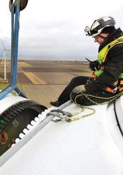


Staying on the forefront of the new energy economy requires cutting-edge information from authoritative voices. Each month, Wind Systems keeps its readers attuned to the latest innovations in the wind energy industry. Let us be your partner in driving sustainability— and your business—to new heights.



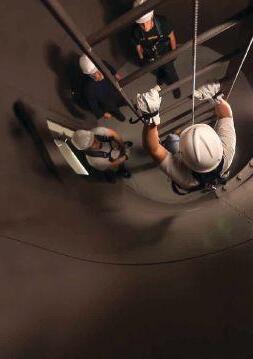







The NFPA hosted the Report on Comments (ROC) meeting of the National Electrical Code in Redondo Beach, California, from November 25, 2012 through December 8, 2012. There are 19 code making panels, which met at various times throughout that period. Code Making Panel 13 (CMP13) covers Articles 445, 480, 690, 695, 700, 701, 702, and 708, all of which cover emergency and standby systems such as battery systems and generators, both portable and permanently-installed.


The NEC is still under the old NFPA process of the Report on Proposals and Report on Comments. The new process, which the NFPA 70E committee uses (and the NEC will be using next code cycle) uses First Revision and Second Revision. The two processes are very different, and NFPA decided that since the NEC had started under the old process, it would continue using the old process for this cycle. The actions discussed in the column are overviews and do not contain all the details needed to incorporate the upcoming changes.
A good portion of the ROC meeting for CMP13 was spent on battery systems. The2012 edition of NFPA 70E, Chapter 3, Safety Requirements for Special Equipment had all references to battery system installation


requirements removed, because installation requirements should be in the NEC and not 70E. This left a very large gap concerning battery system installations. Steve McCluer, representing the IEEE Stationary Battery Committee, had submitted several proposals based on the NFPA 70E requirements that had been deleted. Most of these proposals were accepted in one form or fashion, although not without some modification. Overall, the purpose and intent of the submitter was met and the NEC now will have several new sections covering battery systems that should be helpful to people involved in that business.
Surprisingly (at least to me) was an extended discussion concerning concrete. Conduit connecting emergency systems, such as fire pumps, must be protected from the heat created by fire. In the past, a two-inch concrete thickness was considered adequate to perform that task. Some recent studies have shown that two inches of concrete will not provide the level of protection needed when the conduit is in walls and ceilings. The recommendation was to require four inches of concrete, which drew quite a bit of opposition due to the added costs involved. There were several presentations made to the panel on both sides of the argument. The


consensus of the panel was that two inches of concrete was sufficient when the conduit was on grade, but not adequate when in walls and ceilings. In the 2014 edition of the NEC walls and ceilings where emergency system conduit is located will be required to be four inches, instead of two inches. Conduit buried under the flooring may be two-inches thick.
Lighting is now required for locations where emergency generators are located to allow for operation and maintenance. Portable generators (less than 15 kW size) are now required to disable any outlet mounted to the generator when it is connected to a home or other structure that has a grounded system. Portable generators pose no shock hazard when they are used as a stand-alone power source such as for camping or powering electrical devices from their frame-mounted receptacles, as they are ungrounded. However, when they are connected to a home as a back-up generator, they become grounded through the home’s electrical system. A shock hazard could be present if the frame-mounted receptacles are used. An alternative is to have the framemounted receptacle be protected by a GFCI. There was some strong opposition to this requirement, but it was pointed out that many portable generators already utilize GFCIs.


A surge protection device (SPD) will be required for emergency system switchboards and panelboards. With the almost universal usage of solid-state and digital controls, surges and lightning protection is needed to ensure these systems remain available. Another big issue was a proposal to require professional engineers to perform electrical power system coordination studies. This requirement would have been too limiting to manufacturers and others that use someone who has experience and is qualified to perform such a study, but may not be a licensed professional engineer. The intent is that a PE will be required to approve

these studies, but they may be performed by someone who is qualified, but not necessarily a PE.


The high-voltage task group had made a recommendation which was accepted by the panel to change the definition of low voltage from 600 volts to 1,000. This follows industryaccepted practice due to the large 575-volt and 635-volt systems being installed.
With the ROC completed, the 2014 edition of the NEC is almost complete. Any NITMAMs (Notice of Intent to Make a Motion) will be completed May 3. If there are any appeals, they must be submitted by May 17. The NEC will be finalized at the June 10 National Convention and issued September 2013 as a 2014 edition.


Jim White is the Training Director of Shermco Industries, Inc., in Dallas, Texas. He is the principal member on the NFPA technical committee “Recommended Practice for Electrical Equipment Maintenance” (NFPA 70B). Jim represents NETA as an alternate member of the NFPA Technical Committee “Electrical Safety in the Workplace” (NFPA 70E) and represents NETA on the ASTM F18 Committee “Electrical Protective Equipment For Workers”. Jim is an IEEE Senior Member and in 2011 received the IEEE/ PCIC Electrical Safety Excellence award. Jim is a past Chairman (2008) of the IEEE Electrical Safety Workshop (ESW).


the test equipment answer
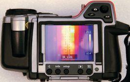

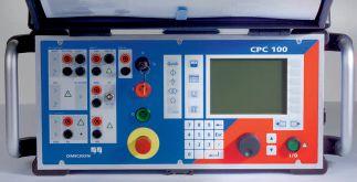





Q: Ever wonder what happens when you put 450 electrical engineers, electricians, health and safety professionals in a room for three to five days?
A: A Lot!
The 20th anniversary of the IEEE-IAS Electrical Safety Workshop (“ESW”) wrapped up in February to rave reviews by its attendees. “The best one yet” was the common chorus as people left the magnificent Dallas Hilton Anitole to fly back to their homes around the world.
The annual event is sponsored by the IEEE-IAS Electrical Safety Committee and features a full week of activities including standards committee meetings, tutorials, a full slate of technical papers, technical tours, a products and services expo, more than a little debate, and, of course, a lot of networking.
Key influencers in the industry began arriving on Sunday night to participate in two days of standards committee meetings. The ANSI/IEEE 1584, Guide for Performing Arc-Flash Hazard Calculations, featured an update about the ongoing arc flash research from Dr. Wei-Jin Lee of the IEEE/NFPA Collaboration Project. Two important emerging standards committees also met prior to the workshop: IEEE 1683 and IEEE 1814 standards. These strive to influence electrical equipment design to reduce or eliminate electrical hazards and reduce the likelihood of electrical injuries.
Next, attendees dove into the tutorials. There were nine topics to choose from, including Electrical Safety Management, Arcing Hazard Physics, Electrical Safety Basics, Training Unqualified Workers, Changes Coming to NFPA 70E, and more. Ray Crow, Tutorials Chair was very happy with the response from this year’s Tutorial Program. “Where else can people go to learn directly from a

collection of world-class presenters like we have here: Lanny Floyd, Danny Liggett, Dr. David Sweeting, Jim White, Mike Dougherty, John Nelson, Daniel Roberts, Daleep Mohla? We are so fortunate to have attracted that type of talent over the years, and our tutorial attendees revel in the opportunity.”
Dr. Laura Fiffick, former Senior Director of the Campbell Institute kicked off the Technical Program with an inspirational Keynote Address. Fiffick explained how “organizations at the leading edge of environmental, health, and safety (EHS) and business performance … share a set of approaches, strategies, and tactics that have been proven to prevent injuries, save lives, and improve the environment — and create long-term value and business vitality.”
The Technical Program spanned 2.5 days, filled with 45 minute papers, 15 minute case studies and two poster sessions. Topics covered a wide range of interests including: the dangers posed by overhead power lines, the potential long-term effects of electrical contact on the human body, grounding considerations, electrical safety program auditing, and advice regarding selling electrical safety throughout an organization. The mix of presentations reflected the full scope of concerns affecting electrical safety.
Fortunately, the workshop committee has taken heed of the adage “all work and no play….” The hospitality events were the perfect place to unwind and to network with a “Who’s Who” of electrical safety. If you have never had the difference between hazard and risk explained to you by a member of the 70E committee or had dinner with guys that have arc tested more switchgear or PPE than you could imagine, then you have never been to the Electrical Safety Workshop. This year was no different. First-timers and frequent fliers alike marveled at the invaluable contacts and friendships made during this one-week event.
Listening intently during the technical program
The laid-back atmosphere that runs through the conference has also made it a favorite for the ESW groupies. Close to 50 spouses and friends of attendees joined us at the receptions, and many helped out behind the scenes. (Of course there were unconfirmed reports of spa sessions, sightseeing, and shopping.) Judging by an unofficial head count we should plan on seeing most of the companions back in 2014. They are very excited about next year’s venue, the Sheraton San Diego Hotel and Marina!

Dr. David Sweeting delivers paper, “Protecting Your Staff from Arcing Hazards.”
If you are responsible for electrical safety in your organization, the ESW needs to be on your to-do list in 2014. Save the week of February 4th, and bring your companion to San Diego, California. Join over 500 other change-agents as we “change the culture of electrical safety.”
The IEEE-IAS Electrical Safety Committee would like to extend a special “Thank You” to Anthony Capkun of Electrical Business Magazine for the pictures and video he has shared with us and allowed us to use in this article.
ANSWER 1

1. Which state has the most wind generation capacity (in MW)?
d. Texas currently has the largest installed wind generation capacity at 10,929 MW, per Wikipedia. California has 4,570 MW, Iowa has 4,536 MW, and Illinois has 3,055 MW. The Alta Wind Energy Center in Kern County, California is the largest US wind site with 1,020 MW of generation, and the Roscoe Wind farm in Nolan County, Texas is second with 781 MW of generation.
ANSWER 2
2. The most common cause of failure in a wind turbine is:
d. Failure of the gearbox is a major concern due to the downtime involved, but the electrical system is the primary cause of failure for wind generators. Figure 1 shows relative failure rates of components based on a study performed by B. Hahn, Institut für Solare Energieversorgungstechnik in a paper titled Reliability Assessment of Wind Turbines in Germany. Other studies have shown a similar pattern.
ANSWER 3
3. The largest commercially-available wind generator produces:
b. Vestas is set to manufacture an 8 MW wind turbine in 2015, but the current winner goes to Enercon at 7.58 MW. It has a rotor diameter of 127 meters and is not used for offshore applications, although the Vestas turbine will be.
ANSWER 4
4. On average, wind generators produce power ___ % of the time.
a. In the US, wind generators produce power at about 30 percent of the time (source Energy Information Agency). In Europe, it is closer to 13 percent of the time. Once a wind generator’s speed falls below its optimum output speed, the power it produces falls rapidly. As an example, for every halving of wind speed a wind generator’s output falls by a factor of 8. Most wind generators produce maximum power at about 25 to 30 mph.
ANSWER 5
5. The cost to install a wind generator is approximately ___ to ___ per MW of installed nameplate capacity.
d. According to Windustry, the cost per MW of installed capacity is between $1,300,000 and $2,200,000. This cost has gone down substantially over the last few years. The larger the turbine, the more cost effective it becomes.
NFPA Disclaimer: Although Jim White is a member of the NFPA Technical Committee for both NFPA 70E “Standard for Electrical Safety in the Workplace” and NFPA 70B “Recommended Practice for Electrical Equipment Maintenance,” the views and opinions expressed in this message are purely the author’s and shall not be considered an official position of the NFPA or any of its technical committees and shall not be considered to be, nor be relied upon as, a formal interpretation or promotion of the NFPA. Readers are encouraged to refer to the entire text of all referenced documents.

Megger offers you a selection of transformer and insulation testing products to help you clear those maintenance hurdles.
IDAX300/350
Transformer moisture analysers
VAX20
High voltage amplifier

CDAX605
High-precision capacitance and dissipation factor measurement instrument
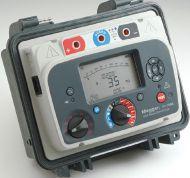
FRAX101/150
Oil Test Sets
60/80 kV portable oil test sets and 100 kV automatic laboratory test set adjustment and 3.5” color display
insulation oil breakdown voltage
S1 Series Insulation Resistance Testers: 5-10 kV
loads with CAT IV 600 V rating
Sweep frequency response analyzers
problems with signature waveform instrumentation
DELTA4000
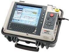
Insulation power factor test set

(patent pending)
(patent pending)


Whether you need to measure ratio, insulation moisture, oil or frequency response, Megger has a product that fits your needs. For more information, email today sales@megger.com, or call 1-800-723-2861.


If you would like a free download of Megger’s guide to Insulating Oil Dielectric Breakdown testing please go to www.megger.com/netaoil
Interested in learning more about transformer and advanced diagnostic testing? Register now at www.regonline.com/ Addison2013 for our complimentary one day event scheduled for September 10th in Dallas, Texas.
SHARED EXHIBIT FLOOR WITH DISTRIBUTECH.
ACCESS TO MORE THAN 10,000 ATTENDEES!

Jan. 28 – 30, 2014
Henry B. Gonzalez Convention Center San Antonio, Texas http://utilityproductsexpo.com
Don’t miss your chance to be a part of this unique event that shares an exhibit floor with DistribuTECH - attracting thousands of attendees. Book your 2014 exhibit space today for the best selection of exhibit locations. Showcase your newest solutions, products, vehicles and equipment for the workplace on the exhibit floor.
Meet face-to-face with purchasing decision-makers from: Electric Utilities
Book your exhibit space today!
TAKE YOUR BOOTH PRESENCE TO THE NEXT LEVEL. ASK ABOUT AVAILABLE SPONSORSHIPS.
Introducing a really big idea: “Rent it”

What makes it work at Protec, better than other options?
What’s next? Make us prove we care.
A&F Electrical Testing, Inc.
80 Lake Ave. South, Ste. 10 Nesconset, NY 11767 (631) 584-5625 Fax: (631) 584-5720 kchilton@afelectricaltesting.com www.afelectricaltesting.com
Kevin Chilton
A&F Electrical Testing, Inc.
80 Broad St. 5th Floor
New York, NY 10004 (631) 584-5625 Fax: (631) 584-5720 afelectricaltesting@afelectricaltesting.com www.afelectricaltesting.com
Florence Chilton
ABM Electrical Power Solutions
3602 East Southern Ave., Ste. 1 & 2 Phoenix, AZ 85040 (602) 796-6583
www.ABM.com
Jeff Militello
ABM Electrical Power Solutions
6280 South Valley View Blvd., Ste. 618 Las Vegas, NV 89118 (702) 216-0982 Fax: (702) 216-0983
www.ABM.com
Jeff Militello
ABM Electrical Power Solutions
814 Greenbrier Circle, Ste. E Chesapeake, VA 23320 (757) 548-5690 Fax: (757) 548-5417 www.ABM.com
Mark Anthony Gaughan, III
ABM Electrical Power Solutions
3700 Commerce Dr. #901-903 Baltimore, MD 21227 (410) 247-3300 Fax: (410) 247-0900 www.ABM.com
Bill Hartman
ABM Electrical Power Solutions
710 Thomson Park Dr. Cranberry Township, PA 16066-6427 (724) 772-4638 Fax: (724) 772-6003 william.mckenzie@met.lincfs.com www.ABM.com
William (Pete) McKenzie
ABM Electrical Power Solutions 5805 G Departure Dr. Raleigh, NC 27616 (919) 877-1008 Fax: (919) 501-7492 www.ABM.com
Rob Parton
ABM Electrical Power Solutions 4390 Parliament Place, Ste. Q Lanham, MD 20706 (301) 967-3500 Fax: (301) 735-8953 www.ABM.com
Frank Ceci
Absolute Testing Services 6829 Guhn Rd. Houston, TX 77040 (832) 467-4446 Fax: (713) 849-3885
rgamble@absolutetesting.com www.texasats.com
Richard Gamble
Advanced Testing Systems 15 Trowbridge Dr. Bethel, CT 06801 (203) 743-2001 Fax: (203) 743-2325 pmaccarthy@advtest.com www.advtest.com
Pat MacCarthy
American Electrical Testing Co., Inc.
480 Neponset St., Building 6 Canton, MA 02021-1970 (781) 821-0121 Fax: (781) 821-0771 sblizard@aetco.us www.99aetco.com
Scott A. Blizard
American Electrical Testing Co., Inc. 34 Clover Dr. South Windsor, CT 06074 (860) 648-1013 Fax: (781) 821-0771 jpoulin@aetco.us www.99aetco.com
Gerald Poulin
American Electrical Testing Co., Inc.
76 Cain Dr. Brentwood, NY 11717 (631) 617-5330 Fax: (631) 630-2292 mschacker@aetco.us www.99aetco.com
Michael Schacker
American Electrical Testing Co., Inc.
50 Intervale Rd., Ste. 1 Boonton, NJ 07005 (973) 316-1180 Fax: (781) 316-1181 trosato@aetco.us www.99aetco.com
Anthony Rosato
American Electrical Testing Co., Inc. 1811 Executive Dr., Ste. M Indianapolis, IN 46241 (317) 487-2111 Fax: (781) 821-0771 rramsey@99aetco.us www.99aetco.com
Rick Ramsey
American Electrical Testing Co., Inc.
Green Hills Commerce Center 5925 Tilghman St., Ste. 200 Allentown, PA 18104 (215) 219-6800 jmunley@aetco.us www.99aetco.us
Jonathan Munley
American Electrical Testing Co., Inc. 1672 SE 80th Bella Vista Dr. The Villages, FL 32162 (727) 447-4503 Fax: (727) 447-4984 rhoffman@aetco.us www.99aetco.us
Bob Hoffman
AMP Quality Energy Services, LLC 4220 West Schrimsher SW Site W1 P.O. Box 526 Huntsville, AL 35804 (256) 513-8255 brian@ampqes.com www.ampqes.com
Brian Rodgers
Apparatus Testing and Engineering 11300 Sanders Dr., Ste. 29 Rancho Cordova, CA 95742 (916) 853-6280 Fax: (916) 853-6258 jlawler@apparatustesting.com www.apparatustesting.com
James Lawler
Apparatus Testing and Engineering 7083 Commerce Circle, Ste. H Pleasanton, CA 94588 (925) 454-1363 Fax: (925) 454-1499 info@apparatustesting.com www.apparatustesting.com
Harold (Jerry) Carr
Applied Engineering Concepts 1105 N. Allen Ave. Pasadena, CA 91104 (626) 398-3052 Fax: (626) 398-3053 michel.c@aec-us.com www.aec-us.com
Michel Castonguay
Burlington Electrical Testing Co., Inc. 300 Cedar Ave. Croydon, PA 19021-6051 (215) 826-9400 (221) Fax: (215) 826-0964 waltc@betest.com www.betest.com
Walter P. Cleary
C.E. Testing, Inc. 6148 Tim Crews Rd. Macclenny, FL 32063 (904) 653-1900 Fax: (904) 653-1911 cetesting@aol.com
Mark Chapman
CE Power Solutions, LLC 4500 W. Mitchell Ave. Cincinnati, OH 45232 (513) 563-6150 Fax: (513) 563-6120 info@cepowersol.net
Rhonda Harris
CE Power Solutions of Wisconsin, LLC 3100 East Enterprise Ave. Appleton, WI 54913 (920) 968-0281 Fax: (920) 968-0282 rob.fulton@cepower.net
Rob Fulton
Dude Testing 145 Tower Dr., Ste. 9 Burr Ridge, IL 60527 (815) 293-3388 Fax: (815) 293-3386 scott.dude@dudetesting.com www.dudetesting.com
Scott Dude
DYMAX Holdings, Inc. 4751 Mustang Circle St. Paul, MN 55112 (763) 717-3150 Fax: (763) 784-5397 gphilipp@dymaxservice.com www.dymaxservice.com
Gene Philipp
DYMAX Service Inc. 46918 Liberty Dr. Wixom, MI 48393 (248) 313-6868 Fax: (248) 313-6869 www.dymaxservice.com
Bruce Robinson
DYMAX Service Inc. 4213 Kropf Ave. Canton, OH 44706 (330) 484-6801 Fax: (740) 333-1271 www.dymaxservice.com
Gary Swank
Eastern High Voltage 11A South Gold Dr. Robbinsville, NJ 08691-1606 (609) 890-8300 Fax: (609) 588-8090 joewilson@easternhighvoltage.com www.easternhighvoltage.com
Joseph Wilson
ELECT, P.C.
7400-G Siemens Rd., P.O. Box 2080 Wendell, NC 27591 (919) 365-9775 Fax: (919) 365-9789 btyndall@elect-pc.com www.elect-pc.com
Barry W. Tyndall
Electric Power Systems, Inc. 21 Millpark Ct. Maryland Heights, MO 63043-3536 (314) 890-9999 Fax: (314) 890-9998 www.eps-international.com
Electric Power Systems, Inc. 557 E. Juanita Ave., #4 Mesa, AZ 85204 (480) 633-1490 Fax: (480) 633-7092 www.eps-international.com
Electric Power Systems, Inc.
4436 Parkway Commerce Blvd. Orlando, FL 32808 (407) 578-6424 Fax: 407-578-6408 www.eps-international.com
Electric Power Systems, Inc.
6753 E. 47th Avenue Dr., Unit D Denver, CO 80216 (720) 857-7273 Fax: 303-928-8020 www.eps-international.com
Electric Power Systems, Inc.
23823 Andrew Rd. Plainfield, IL 60585 (815) 577-9515 Fax: (815) 577-9516 www.eps-international.com
Electric Power Systems, Inc. 2601 Center Rd., # 101 Hinckley, OH 44233 (330) 460-3706 Fax: (330) 460-3708 www.eps-international.com
Electric Power Systems, Inc.
1129 East Hwy 30 Gonzalez, LA 70737 (225) 644-0150 Fax: (225) 644-6249 www.eps-international.com
Electric Power Systems, Inc.
56 Bibber Pkwy #1 Brunswick, ME 04011 (207) 837-6527 www.eps-international.com
Electric Power Systems, Inc. 4100 Greenbriar Dr., Ste. 160 Stafford, TX 77477 (713) 644-5400 www.eps-international.com
Electric Power Systems, Inc. 11861 Longsdorf St. Riverview, MI 48193 (734) 282-3311 www.eps-international.com
Electric Power Systems, Inc. 827 Union St. Salem, VA 24153 (540) 375-0084 Fax: (540) 375-0094 www.eps-international.com
Electric Power Systems, Inc. 915 Holt Ave., Unit 9 Manchester, NH 03109 (603) 657-7371 Fax: 603-657-7370 www.eps-international.com
Electric Power Systems, Inc. 146 Space Park Dr. Nashville, TN 37211 (615) 834-0999 Fax: (615) 834-0129 www.eps-international.com
Electric Power Systems, Inc. 1090 Montour West Industrial Blvd. Coraopolis, PA 15108 (412) 276-4559 www.eps-international.com
Electric Power Systems, Inc. 6141 Connecticut Ave. Kansas City, MO 64120 (816) 241-9990 Fax: (816) 241-9992 www.eps-international.com
Electric Power Systems, Inc. 2495 Boulevard of the Generals Norristown, PA 19403 (610) 630-0286 www.eps-international.com
Electrical & Electronic Controls 6149 Hunter Rd. Ooltewah, TN 37363 (423) 344-7666 (23) Fax: (423) 344-4494 eecontrols@comcast.net
Michael Hughes
Electrical Energy Experts, Inc. W129N10818, Washington Dr. Germantown, WI 53022 (262) 255-5222 Fax: (262) 242-2360 bill@electricalenergyexperts.com www.electricalenergyexperts.com
William Styer
Electrical Equipment Upgrading, Inc. 21 Telfair Place Savannah, GA 31415 (912) 232-7402 Fax: (912) 233-4355 kmiller@eeu-inc.com www.eeu-inc.com
Kevin Miller
Electrical Maintenance & Testing Inc. 12342 Hancock St. Carmel, IN 46032 (317) 853-6795 Fax: (317) 853-6799 www.emtesting.com
Brian K. Borst
Electrical Reliability Services
1057 Doniphan Park Circle, Ste. A El Paso, TX 79922 (915) 587-9440 Fax: (915) 587-9010 www.electricalreliability.com
Electrical Reliability Services
1775 W. University Dr., Ste. 128 Tempe, AZ 85281 (480) 966-4568 Fax: (480) 966-4569 www.electricalreliability.com
Electrical Reliability Services
1426 Sens Rd. Ste. 5 La Porte, TX 77571 (281) 241-2800 Fax: (281) 241-2801 www.electricalreliability.com
Electrical Reliability Services
4099 SE International Way, Ste. 201 Milwaukie, OR 97222-8853 (503) 653-6781 Fax: (503) 659-9733 www.electricalreliability.com
Electrical Reliability Services
5810 Van Allen Way Carlsbad, CA 92008 (760) 804-2972 www.electricalreliability.com
Electrical Reliability Services
8500 Washington Pl. NE, Ste. A-6 Albuquerque, NM 87113 (505) 822-0237 Fax: (505) 822-0217 www.electricalreliability.com
Electrical Reliability Services
1380 Greg Street, Ste. 217 Sparks, NV 89431 (775) 746-8484 Fax: (775) 356-5488 www.electricalreliability.com
Electrical Reliability Services 2275 Northwest Pkwy SE, Ste. 180 Marietta, GA 30067 (770) 541-6600 Fax: (770) 541-6501 www.electricalreliability.com
Electrical Reliability Services 7100 Broadway, Ste. 7E Denver, CO 80221-2915 (303) 427-8809 Fax: (303) 427-4080 www.electricalreliability.com
Electrical Reliability Services
348 N.W. Capital Dr. Lees Summit, MO 64086 (816) 525-7156 Fax: (816) 524-3274 www.electricalreliability.com
Electrical Reliability Services 6900 Koll Center Parkway, Ste. 415 Pleasanton, CA 94566 (925) 485-3400 Fax: (925) 485-3436 www.electricalreliability.com
Electrical Reliability Services 10606 Bloomfield Ave. Santa Fe Springs, CA 90670 (562) 236-9555 Fax: (562) 777-8914 www.electricalreliability.com
Electrical Reliability Services 14141 Airline Hwy., Ste. W Baton Rouge, LA 70817 (225) 755-0530 Fax: (225) 751-5055 www.electricalreliability.com
Electrical Reliability Services 121 Louisiana Hwy., 108 East Sulphur, LA 70665 (337) 583-2411 Fax: (337) 583-2410 www.electricalreliability.com
Electrical Reliability Services 11000 Metro Pkwy., Ste. 30 Ft. Myers, FL 33966 (239) 693-7100 Fax: (239) 693-7772
www.electricalreliability.com
Electrical Reliability Services 2222 West Valley Hwy. N., Ste 160 Auburn, WA 98001 (253) 736-6010 Fax: (253) 736-6015 www.electricalreliability.com
Electrical Reliability Services 3412 South 1400 West, Unit A West Valley City, UT 84119 (801) 975-6461 www.electricalreliability.com
Electrical Reliability Services 6351 Hinson St., Ste. B Las Vegas, NV 89118 (702) 597-0020 Fax: (702) 597-0095 www.electricalreliability.com
Electrical Reliability Services 610 Executive Campus Dr. Westerville, OH 43082 (877) 468-6384 Fax: (614) 410-8420 info@electricalreliability.com www.electricalreliability.com
Electrical Testing, Inc. 2671 Cedartown Hwy. Rome, GA 30161 (706) 234-7623 Fax: (706) 236-9028 steve@electricaltestinginc.com www.electricaltestinginc.com
Steve C. Dodd Sr.
Electrical Testing Solutions 2909 Green Hill Ct. Oshkosh, WI 54904 (920) 420-2986 Fax: (920) 235-7131 tmachado@electricaltestingsolutions.com www.electricaltestingsolutions.com Tito Machado
Elemco Services, Inc. 228 Merrick Rd. Lynbrook, NY 11563 (631) 589-6343 Fax: (631) 589-6670 courtney@elemco.com www.elemco.com
Courtney O'Brien
EnerG Test
204 Gale Lane Bldg. 2 - 2nd Floor Kennett Square, PA 19348 (484) 731-0200 Fax: (484) 713-0209 kbleiler@energtest.com www.energtest.com
Katie Bleiler
Energis High Voltage Resources, Inc.
1361 Glory Rd. Green Bay, WI 54304 (920) 632-7929 Fax: (920) 632-7928 info@energisinc.com www.energisinc.com
Mick Petzold
EPS Technology
29 N. Plains Hwy., Ste. 12 Wallingford, CT 06492 (203) 649-0145 www.eps-technology.com
Grubb Engineering, Inc. 3128 Sidney Brooks San Antonio, Tx 78235 (210) 658-7250 Fax: (210) 658-9805 bobby@grubbengineering.com www.grubbengineering.com
Robert D. Grubb Jr.
Hampton Tedder Technical Services 4571 State St. Montclair, CA 91763 (909) 628-1256 x214 Fax: (909) 628-6375 matt.tedder@hamptontedder.com www.hamptontedder.com
Matt Tedder
Hampton Tedder Technical Services 4920 Alto Ave. Las Vegas, NV 89115 (702) 452-9200 Fax: (702) 453-5412 www.hamptontedder.com
Roger Cates
Hampton Tedder Technical Services 3747 West Roanoke Ave. Phoenix, AZ 85009 (480) 967-7765 Fax: (480) 967-7762 www.hamptontedder.com
Harford Electrical Testing Co., Inc. 1108 Clayton Rd. Joppa, MD 21085 (410) 679-4477 Fax: (410) 679-0800 testing@harfordtesting.com www.harfordtesting.com
Vincent Biondino
High Energy Electrical Testing, Inc. 515 S. Ocean Ave. Seaside, NJ 08752 (732) 938-2275 Fax: (732) 938-2277 hinrg@comcast.net www.highenergyelectric.com
James P. Ratshin
High Voltage Maintenance Corp. 24 Walpole Park South Dr. Walpole, MA 02081 (508) 668-9205 www.hvmcorp.com
High Voltage Maintenance Corp. 941 Busse Rd. Elk Grove Village, Il 60007 (847) 640-0005 www.hvmcorp.com
High Voltage Maintenance Corp. 7200 Industrial Park Blvd. Mentor, OH 44060 (440) 951-2706 Fax: (440) 951-6798 www.hvmcorp.com
High Voltage Maintenance Corp.
3000 S. Calhoun Rd. New Berlin, WI 53151 (262) 784-3660 Fax: (262) 784-5124 www.hvmcorp.com
High Voltage Maintenance Corp. 8320 Brookville Rd. #E Indianapolis, IN 46239 (317) 322-2055 Fax: (317) 322-2056 www.hvmcorp.com
High Voltage Maintenance Corp. 1250 Broadway, Ste. 2300 New York, NY 10001 (718) 239-0359 www.hvmcorp.com
High Voltage Maintenance Corp.
355 Vista Park Dr. Pittsburgh, PA 15205-1206 (412) 747-0550 Fax: (412) 747-0554 www.hvmcorp.com
High Voltage Maintenance Corp.
150 North Plains Industrial Rd. Wallingford, CT 06492 (203) 949-2650 Fax: (203) 949-2646 www.hvmcorp.com
High Voltage Maintenance Corp. 9305 Gerwig Ln., Ste. B Columbia, MD 21046 (410) 309-5970 Fax: (410) 309-0220 www.hvmcorp.com
High Voltage Maintenance Corp. 24371 Catherine Industrial Dr. Ste. 207 Novi, MI 48375 (248) 305-5596 Fax: (248) 305-5579 www.hvmcorp.com
High Voltage Maintenance Corp. 5100 Energy Dr. Dayton, OH 45414 (937) 278-0811 Fax: (937) 278-7791 www.hvmcorp.com
High Voltage Service, Inc.
4751 Mustang Circle St. Paul, MN 55112 (763) 717-3103 Fax: (763) 784-5397 www.hvserviceinc.com
Mike Mavetz
HMT, Inc. 6268 Route 31 Cicero, NY 13039 (315) 699-5563 Fax: (315) 699-5911 jpertgen@hmt-electric.com www.hmt-electric.com
John Pertgen
Industrial Electric Testing, Inc. 11321 West Distribution Ave. Jacksonville, FL 32256 (904) 260-8378 Fax: (904) 260-0737 gbenzenberg@bellsouth.net www.industrialelectrictesting.com
Gary Benzenberg
Industrial Electric Testing, Inc. 201 NW 1st Ave. Hallandale, FL 33009-4029 (954) 456-7020 www.industrialelectrictesting.com
Industrial Electronics Group P.O. Box 1870 850369 Highway 17 South Yulee, FL 32041 (904) 225-9529 Fax: (904) 225-0834 butch@industrialgroups.com www.industrialgroups.com
Butch E. Teal
Industrial Tests, Inc. 4021 Alvis Ct., Ste. 1 Rocklin, CA 95677 (916) 296-1200 Fax: (916) 632-0300 greg@indtests.com www.industrialtests.com
Greg Poole
Infra-Red Building and Power Service 152 Centre St. Holbrook, MA 02343-1011 (781) 767-0888 Fax: (781) 767-3462 tom.mcdonald@infraredbps.net www.infraredbps.com
Thomas McDonald Sr.
M&L Power Systems, Inc. 109 White Oak Ln., Ste. 82 Old Bridge, NJ 08857 (732) 679-1800 Fax: (732) 679-9326 milind@mlpower.com www.mlpower.com
Milind Bagle
Magna Electric Corporation 1033 Kearns Crescent, Box 995 Regina, SK S4P 3B2 Canada (306) 949-8131 Fax: (306) 522-9181 kheid@magnaelectric.com www.magnaelectric.com
Kerry Heid
Magna Electric Corporation 3430 25th St. NE Calgary, AB T1Y 6C1 Canada (403) 769-9300 Fax: (403)769-9369 ktaylor@magnaelectric.com www.magnaelectric.com
Ken Taylor
Magna Electric Corporation 851-58th St. East Saskatoon, SK S7K 6X5 Canada (306) 955-8131 x 5 Fax: (306) 955-9181 lwilson@magnaelectric.com www.magnaelectric.com
Luis Wilson
Magna Electric Corporation 1375 Church Ave. Winnipeg, MB R2X 2T7 Canada (204) 925-4022 Fax: (204) 925-4021 cbrandt@magnaelectric.com www.magnaelectric.com
Curtis Brandt
Magna IV Engineering 1103 Parsons Rd. SW Edmonton, AB T6X 0X2 Canada (780) 462-3111 Fax: (780) 450-2994 info@magnaiv.com www.magnaiv.com Virginia Balitski
Magna IV Engineering 200, 688 Heritage Dr. Calgary, AL T2H 1M6 Canada (403) 723-0575 Fax: (403) 723-0580 info.calgary@magnaiv.com Virginia Balitski
Magna IV Engineering 8219D Fraser Ave. Fort McMurray, AB T9H 0A2 Canada (780) 791-3122 Fax: (780) 791-3159 info.fmcmurray@magnaiv.com Virginia Balitski
Magna IV Engineering 96 Inverness Dr. East, Unit R Englewood, CO 80112 (303) 799-1273 Fax: (303) 790-4816 info.denver@magnaiv.com Aric Proskurniak
Magna IV Engineering Avenida del Condor #590 Oficina 601 Huechuraba, Santiago 8580676 Chile +(56) 9-9-517-4642 info.chile@magnaiv.com
Cristian Fuentes
Magna IV Engineering 1040 Winnipeg St. Regina , SK S4R 8P8 Canada (306) 585-2100 Fax: (306) 585-2191 info.regina@magnaiv.com
Peter Frostad
National Field Services 649 Franklin St. Lewisville, TX 75057 (972) 420-0157 www.natlfield.com
Eric Beckman
Nationwide Electrical Testing, Inc. 6050 Southard Trace Cumming, GA 30040 (770) 667-1875 Fax: (770) 667-6578
Shashi@N-E-T-Inc.com www.n-e-t-inc.com
Shashikant B. Bagle
North Central Electric, Inc. 69 Midway Ave. Hulmeville, PA 19047-5827 (215) 945-7632 Fax: (215) 945-6362 ncetest@aol.com
Robert Messina
Northern Electrical Testing, Inc. 1991 Woodslee Dr. Troy, MI 48083-2236 (248) 689-8980 Fax: (248) 689-3418 ldetterman@northerntesting.com www.northerntesting.com
Lyle Detterman
Orbis Engineering Field Services Ltd. #300, 9404 - 41st Ave. Edmonton, AB T6E 6G8 Canada (780) 988-1455 Fax: (780) 988-0191 lorne@orbisengineering.net www.orbisengineering.net
Lorne Gara
Pacific Power Testing, Inc. 14280 Doolittle Dr. San Leandro, CA 94577 (510) 351-8811 Fax: (510) 351-6655 steve@pacificpowertesting.com www.pacificpowertesting.com
Steve Emmert
Pacific Powertech, Inc. #110, 2071 Kingsway Ave. Port Coquitlam, BC V3C 1T2 Canada (604) 944-6697 Fax: (604) 944-1271 chite@pacificpowertech.ca www.pacificpowertech.ca
Cameron Hite
Phasor Engineering Sabaneta Industrial Park #216 Mercedita, PR 00715 Puerto Rico (787) 844-9366 Fax: (787) 841-6385 rcastro@phasorinc.com
Rafael Castro
Potomac Testing, Inc. 1610 Professional Blvd., Ste. A Crofton, MD 21114 (301) 352-1930 Fax: (301) 352-1936 kbassett@potomactesting.com www.potomactesting.com
Ken Bassett
Potomac Testing, Inc. 11179 Hopson Rd., Ste. 5 Ashland, VA 23005 (804) 798-7334 Fax: (804) 798-7456 www.potomactesting.com
Power & Generation Testing, Inc. 480 Cave Rd. Nashville, TN 37210 (615) 882-9455 Fax: (615) 882-9591 mose@pgti.net www.pgti.net
Mose Ramieh
Power Engineering Services, Inc. 9179 Shadow Creek Lane Converse, TX 78109 (210) 590-4936 Fax: (210) 590-6214 engelke@pe-svcs.com www.pe-svcs.com
Miles R. Engelke
POWER PLUS Engineering, Inc. 46575 Magallan Dr. Novi, MI 48377 (248) 344-0200 Fax: (248) 305-9105 smancuso@epowerplus.com www.epowerplus.com
Salvatore Mancuso
Power Products & Solutions, Inc. 12465 Grey Commercial Rd. Midland, NC 28107 (704) 573-0420 x12 Fax: (704) 573-3693 ralph.patterson@powerproducts.biz www.powerproducts.biz
Ralph Patterson
Power Products & Solutions, Inc. 13 Jenkins Ct. Mauldin, SC 29662 (800) 328-7382 ralph.patterson@powerproducts.biz www.powerproducts.biz
Raymond Pesaturo
Power Services, LLC P.O. Box 750066, 998 Dimco Way Centerville, OH 45475 (937) 439-9660 Fax: (937) 439-9611 mkbeucler@aol.com
Mark Beucler
Power Solutions Group, Ltd. 425 W. Kerr Rd. Tipp City, OH 45371 (937) 506-8444 Fax: (937) 506-8434 bwilloughby@powersolutionsgroup.com www.powersolutionsgroup.com
Barry Willoughby
Power Solutions Group, Ltd. 135 Old School House Rd. Piedmont, SC 29673 (864) 845-1084 Fax:: (864) 845-1085 fcrawford@powersolutionsgroup.com www.powersolutionsgroup.com
Frank Crawford
Power Solutions Group, Ltd. 670 Lakeview Plaza Blvd. Columbus, OH 43085 (614) 310-8018 sspohn@powersolutionsgroup.com www.powersolutionsgroup.com
Stuart Spohn
Power Systems Testing Co. 4688 W. Jennifer Ave., Ste. 108 Fresno, CA 93722 (559) 275-2171 ext 15 Fax: (559) 275-6556 dave@pstcpower.com www.powersystemstesting.com
David Huffman
Power Systems Testing Co. 600 S. Grand Ave., Ste. 113 Santa Ana, CA 92705-4152 (714) 542-6089 Fax: (714) 542-0737 www.powersystemstesting.com
Power Systems Testing Co. 2267 Claremont Ct. Hayward, CA 94545-5001 (510) 783-5096 Fax: (510) 732-9287 www.powersystemstesting.com
Power Test, Inc. 2200 Highway 49 Harrisburg, NC 28075 (704) 200-8311 Fax: (704) 455-7909 rich@powertestinc.com www.powertestinc.com
Richard Walker
POWER Testing and Energization, Inc. 14006 NW 3rd Ct., Ste. 101 Vancouver, WA 98685 (360) 576-4826 Fax: (360) 576-7182 chris.zavadlov@powerte.com www.powerte.com
Chris Zavadlov
POWER Testing and Energization, Inc. 731 E. Ball Rd., Ste. 100 Anaheim, CA 92805 (714) 507-2702 http://www.powerte.com
POWER Testing and Energization, Inc. 22035 70th Ave. South Kent, WA 98032 (253) 872-7747 www.powerte.com
Powertech Services, Inc. 4095 South Dye Rd. Swartz Creek, MI 48473-1570 (810) 720-2280 Fax: (810) 720-2283 kirkd@powertechservices.com www.powertechservices.com Kirk Dyszlewski
Precision Testing Group 5475 Highway 86, Unit 1 Elizabeth, CO 80107 (303) 621-2776 Fax: (303) 621-2573 glenn@precisiontestinggroup.com Glenn Stuckey
PRIT Service, Inc. 112 Industrial Dr., P.O. Box 606 Minooka, IL 60447 (815) 467-5577 Fax: (815) 467-5883 Rod.Hageman@pritserviceinc.com www.pritserviceinc.com Rod Hageman
Reuter & Hanney, Inc. 149 Railroad Dr. Northampton Industrial Park Ivyland, PA 18974 (215) 364-5333 Fax: (215) 364-5365 mikereuter@reuterhanney.com www.reuterhanney.com
Michael Reuter
Reuter & Hanney, Inc. 4270-I Henninger Ct. Chantilly, VA 20151 (703) 263-7163 Fax: 703-263-1478 www.reuterhanney.com
NETA ACCREDITED COMPANIES
Reuter & Hanney, Inc.
11620 Crossroads Circle, Suites D-E Middle River, MD 21220 (410) 344-0300 Fax: (410) 335-4389 www.reuterhanney.com
Michael Jester
REV Engineering, LTD
3236 - 50 Ave. SE Calgary, AB T2B 3A3 Canada (403) 287-0156 Fax: (403) 287-0198 rdavidson@reveng.ca www.reveng.ca
Roland Nicholas Davidson, IV
Scott Testing Inc. 1698 5th St. Ewing, NJ 08638 (609) 882-2400 Fax: (609) 882-5660 rsorbello@scotttesting.com www.scotttesting.com
Russ Sorbello
Shermco Industries
2425 E. Pioneer Dr. Irving, TX 75061 (972) 793-5523 Fax: (972) 793-5542 rwidup@shermco.com www.shermco.com
Ron Widup
Shermco Industries 1705 Hur Industrial Blvd. Cedar Park, TX 78613 (512) 259-4800 Fax: (512) 258-5571 kewing@shermco.com www.shermco.com
Kevin Ewing
Shermco Industries 33002 FM 2004 Angleton, TX 77515 (979)848-1406 Fax: (979) 848-0012 mfrederick@shermco.com www.shermco.com Malcom Frederick
Shermco Industries 1357 N. 108th E. Ave. Tulsa, OK 74116 (918) 234-2300 jharrison@shermco.com www.shermco.com
Jim Harrison
Shermco Industries 777 10th St. Marion, IA 52302 (319) 377-3377 Fax: (319) 377-3399 Lhamrick@shermco.com www.shermco.com
Lynn Hamrick
Shermco Industries
2100 Dixon St., Ste. C Des Moines, IA 50316 (515) 263-8482
LHamrick@shermco.com www.shermco.com
Lynn Hamrick
Shermco Industries
Boulevard Saint-Michel 47 1040 Brussels Brussels, Belgium +32 (0)2 400 00 54 Fax: +32 (0)2 400 00 32
PIdziak@shermco.com www.shermco.com
Paul Idziak
Shermco Industries
12000 Network Blvd., Bldg D, Ste. 410 San Antonio, TX 78249 (512) 267-4800 Fax: (512) 267-4808 kewing@shermco.com www.shermco.com
Kevin Ewing
Sigma Six Solutions, Inc.
2200 West Valley Hwy., Ste. 100 Auburn, WA 98001 (253) 333-9730 Fax: (253) 859-5382 jwhite@sigmasix.com www.sigmasix.com
John White
Southern New England Electrical Testing, LLC
3 Buel St., Ste. 4 Wallingford, CT 06492 (203) 269-8778 Fax: (203) 269-8775
dave.asplund@sneet.org www.sneet.org
David Asplund, Sr.
Southwest Energy Systems, LLC 2231 East Jones Ave., Ste. A Phoenix, AZ 85040 (602) 438-7500 Fax: (602) 438-7501 bob.sheppard@southwestenergysystems.com www.southwestenergysystems.com
Robert Sheppard
Taurus Power & Controls, Inc. 9999 SW Avery St. Tualatin, OR 97062-9517 (503) 692-9004 Fax: (503) 692-9273 robtaurus@tauruspower.com www.tauruspower.com Rob Bulfinch
Taurus Power & Controls, Inc. 6617 S. 193rd Place, Ste. P104 Kent, WA 98032 (425) 656-4170 Fax: (425) 656-4172 jiml@tauruspower.com www.tauruspower.com Jim Lightner
Three-C Electrical Co., Inc. 190 Pleasant St. Ashland, MA 01721 (508) 881-3911 Fax: (508) 881-4814 jim@three-c.com www.three-c.com Jim Cialdea
Three-C Electrical Co., Inc. 79 Leighton Rd., Ste. 9 Augusta, ME 04330 (800) 649-6314 Fax: (207) 782-0162 jim@three-c.com www.three-c.com Jim Cialdea
Tidal Power Services, LLC 4202 Chance Lane Rosharon, TX 77583 (281) 710-9150 Fax: (713) 583-1216 monty.janak@tidalpowerservices.com www.tidalpowerservices.com
Monty C. Janak
Tidal Power Services, LLC 8184 Highway 44, Ste. 105 Gonzales, LA 70737 (225) 644-8170 Fax: (225) 644-8215 www.tidalpowerservices.com
Darryn Kimbrough
Tital Power Services, LLC 1056 Mosswood Dr. Sulphur, LA 70663 (337) 558-5456 Fax: (337) 558-5305 www.tidalpowerservices.com
Steve Drake
Tony Demaria Electric, Inc. 131 West F St. Wilmington, CA 90744 (310) 816-3130 x 111 Fax: (310) 549-9747 tde@tdeinc.com www.tdeinc.com
Anthony Demaria
Trace Electrical Services & Testing, LLC 293 Whitehead Rd. Hamilton, NJ 08619 (609) 588-8666 Fax: (609) 588-8667 jvasta@tracetesting.com www.tracetesting.com
Joseph Vasta
Utilities Instrumentation Service, Inc. PO Box 981123 Ypsilanti, MI 48198-1123 (734) 482-1450 (14) Fax: (734) 482-0035 GEWalls@UISCorp.com www.uiscorp.com
Gary E. Walls
Utility Service Corporation 4614 Commercial Dr. NW Huntsville, AL 35816-2201 (256) 837-8400 Fax: (256) 837-8403 apeterson@utilserv.com www.utilserv.com
Alan D. Peterson
Western Electrical Services 14311 29th St. East Sumner , WA 98390 (253) 891-1995 Fax: (253) 891-1511 dhook@westernelectricalservices.com www.westernelectricalservices.com
Daniel Hook
Western Electrical Services 3676 W. California Ave. Bldg. C, Ste. 106 Salt Lake City, UT 84104 (888) 395-2021 Fax: (253) 891-1511 rcoomes@westernelectricalservices.com www.westernelectricalservices.com
Rob Coomes
Western Electrical Services 5680 South 32nd St. Phoenix, AZ 85040 (602) 426-1667 Fax: (253) 891-1511 carcher@westernelectricalservices.com www.westernelectricalservices.com
Craig Archer
Western Electrical Services 4510 NE 68th Dr., Ste. 122 Vancouver, WA 98661 (888) 395-2021 Fax: (253) 891-1511 Tasciutto@westernelectricalservices.com www.westernelectricalservices.com
Tony Asciutto



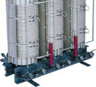


This issue’s advertisers are identified below. Please thank these advertisers by telling them you saw their advertisement in YOUR magazine –NETA World.


INDEPENDENT NETA ACCREDITED COMPANIES
American Electrical Testing Co., Inc. ................82
Apparatus Testing and Engineering ..................97
Burlington Electrical Testing Co., Inc. ................9
Eastern High Voltage...............................34
Electrical
Elemco Services, Inc. ...............................88
EnerGtest .........................................89
Hampton Tedder. .................................113
Harford Electrical Testing Co., Inc. ..................19
North Central Electric, Inc. ........................100 Orbis Engineering Field Services, Ltd. ...............31


MI 3121 SMARTEC
Insulation / Continuity




Metrel offers a wide variety of Single, and Multi-Function testers for measuring Insulation Resistance up to 10kV, Earth Resistance, Line Tracers, Continuity, Loop and Line Impedance, and Phase Rotation.

Technical demands require high performance measuring instruments capable of measuring polarization index (PI), dielectric absorption ratio (DAR), dielectric discharge (DD), time programmable step voltage test, insulation system's capacitance, etc. Metrel offers a line of 1kV, 5kV, and 10kV insulation resistance meters for these tests.


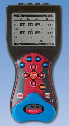


Metrel power quality analyzers are proven tools for expert designers of ltering systems, power correction equipment, over voltage protection and UPS systems. Wide range of testing possibilities are supported: voltage sags and swells, resonant states, high neutral conductor currents in 3-phase systems, asymmetry, transients, etc.
 MI 3200 TeraOhm 10kV
MI 2592 PowerQ4


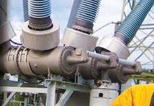



There are 3 instruments in Dad's new CIBANO 500: a micro-ohmmeter, a timing analyzer and even a circuit breaker supply. These help him to carry out all kinds of tests on all types of circuit breakers, quickly and with little wiring. Even better, it weighs only 20 kg / 44 lbs.


...Dad says circuit breaker testing has never been so easy!
The unique wiring concept makes his job safer and easier, as he doesn’t need to rewire between the single tests – and now that measured data can be transmitted digitally, interference is history.
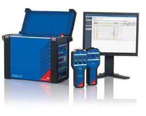
The Primary Test Manager (PTM) software installed on Dad’s computer also helps him with testing by giving one overall report of all his results
Since he has got his new CIBANO 500 Dad is at home earlier than ever! Check it out for yourself!