


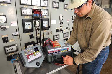
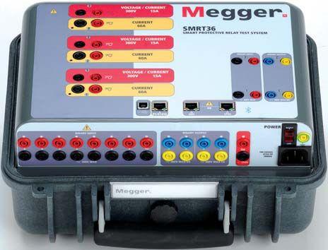
The SMRT36 is the smallest, lightest, highest output powered, complete 3-phase protective relay test system in the world today. This rugged test system may be customized by adding the voltage current generator modules needed for specific test applications. Manual operation is simple through the use of the Smart Touch View Interface (STVI), with a large color high resolution TFT LCD touch-screen.




Rugged, small and lightweight
High current, high power (60 Amps/300 VArms) per phase
Up to 6 currents with convertible channels
Thermally controlled fans for quiet operation
New Smart Touch View Interface (STVI) provides manual control New STVI Overcurrent Test includes hundreds of relay specific time-curves built-in
With these comprehensive capabilities and extensive testing options the SMRT36 is conceivably the easiest to use 3-phase protective relay test system available today. Join us at PowerTEST 2013 in New Orleans, February 18th-21st. Contact us at sales@megger.com to see a demo at the event and receive our newest booklet “IEC 61850 GOOSE-Interoperability New Problems and New Solutions”. Megger
4271 Bronze Way Dallas, Texas 75237-1019


18 Moisture Testing of SF6 Gas for Electrical Equipment
By Justin Palmer, DILO Company, Inc.
While the amount of moisture in a breaker has a minimal impact on the dielectric strength of the SF6, it is directly responsible for the creation of approximately 90 percent of arc by-products that are formed during an arcing event.
7
President’s Desk
Mose Ramieh, Power & Generation Testing, Inc. NETA President
32 Curb Circuit Breaker Performance Fear with Testing
By Roberts Neimanis, Robert Foster & Nils Wäcklén, Megger
62 First-Trip Testing
By Kenneth Elkinson, Matthew Lawrence, Tony McGrail, Doble Engineering Company
82 Oil Circuit Breaker Condition Assessment Utilizing Analytical Testing Techniques
By David Koehler, Paul Griffin, Rick Youngblood, Lance Lewand, Doble Engineering Company
98 Do You Know the True Condition of Your Circuit Breaker?
By Michael Skelton, Camlin Power


11 The NFPA 70E and NETA
Big Changes in 70E Tables Coming
Jim White & Ron Widup, Shermco Industries
28 Tech Quiz
Testing Circuit Breakers
Jim White, Shermco Industries
70 Maintainance Corner
Maintenance Strategies and Their Applications
Kerry Heid, Magna Electric Corporation
76 Testing Rotating Machinery
Partial Discharge Interpretation
Vicki Warren, Iris Power LP.
91 No-Outage Inspection Corner
Technologies for Outdoor Substation and Switchyard Testing
Don A. Genutis, No-Outage Electrical Testing, Inc.
106 Safety Corner
Medium Voltage Circuit Breaker Condition
Analysis Hazard Awareness
Scott Blizard and Paul Chamberlain, American Electrical Testing Co.
112 Tech Tips
Making a Choice In Instrument Technology
Jeff Jowett, Megger
INDUSTRY TOPICS
44 Determining Circuit Breaker Health Using Vibration Analysis
By John Cadick, PE (Cadick Corporation) and Finley Ledbetter, Group CBS Inc.
43 Celebrating a Life Well-Lived In Memory of Patrick R. Herbert
56 Shermco Industries Acquired by Oaktree’s GFI Energy Group
61 Welcomes Absolute Testing Services, Inc. as a NETA Accredited Company
68 Board of Directors and Member Meetings
96 Exam Committee and Standards Review Council Meetings
THE STANDARDS 25 NETA Releases 2013 Revision of ANSI/NETA ATS-2013
Kristen Wicks, NETA 38 Building a Community Based on Quality Jill Howell
You


3050 Old Centre Avenue, Suite 102
Portage, MI 49024
Toll free: 888.300.NETA (6382)
Phone: 269.488.NETA (6382)
Fax: 269.488.6383
neta@netaworld.org
www.netaworld.org
EXECUTIVE DIRECTOR: Jayne Tanz, CMP
NETA Officers
PRESIDENT: Mose Ramieh, Power & Generation Testing, Inc.
FIRST VICE PRESIDENT: David Huffman, Power Systems Testing Co.
SECOND VICE PRESIDENT: Ron Widup, Shermco Industries
SECRETARY: Walt Cleary, Burlington Electrical Testing Co., Inc.
TREASURER: John White, Sigma Six Solutions
NETA Board of Directors
Ken Bassett (Potomac Testing, Inc.)
Scott Blizard (American Electrical Testing Co., Inc.)
Jim Cialdea (Three-C Electrical Co., Inc.)
Walt Cleary (Burlington Electrical Testing Co., Inc.)
Roderic Hageman (PRIT Service, Inc.)
Kerry Heid (Magna Electric Corporation)
David Huffman (Power Systems Testing)
Alan Peterson (Utility Service Corporation)
Mose Ramieh (Power & Generation Testing, Inc.)
John White (Sigma Six Solutions)
Ron Widup (Shermco Industries)
NETA World Staff
TECHNICAL EDITOR: Roderic L. Hageman
ASSOCIATE EDITORS: Diane W. Hageman, Resa Pickel
MANAGING EDITOR: Jayne Tanz, CMP
ADVERTISING MANAGER: Jill Howell
DESIGN AND PRODUCTION: Newhall Klein, Inc.
NETA Committee Chairs
CONFERENCE: Ron Widup; MEMBERSHIP: Ken Bassett; PROMOTIONS/MARKETING: Kerry Heid; SAFETY: Lynn Hamrick; TECHNICAL: Alan Peterson; TECHNICAL EXAM: Ron Widup; WORLD ADVISORY: Diane Hageman;
CONTINUING TECHNICAL DEVELOPMENT: David Huffman; TRAINING: Kerry Heid; FINANCE: John White;
NOMINATIONS: Alan Peterson; STRATEGY: Mose Ramieh; ALLIANCE PROGRAM: Jim Cialdea
© Copyright 2013, NETA
NOTICE AND DISCLAIMER
NETA World is published quarterly by the InterNational Electrical Testing Association. Opinions, views and conclusions expressed in articles herein are those of the authors and not necessarily those of NETA. Publication herein does not constitute or imply endorsement of any opinion, product, or service by NETA, its directors, officers, members, employees or agents (herein “NETA”).
All technical data in this publication reflects the experience of individuals using specific tools, products, equipment and components under specific conditions and circumstances which may or may not be fully reported and over which NETA has neither exercised nor reserved control. Such data has not been independently tested or otherwise verified by NETA.

NETA MAKES NO ENDORSEMENT, REPRESENTATION OR WARRANTY AS TO ANY OPINION, PRODUCT OR SERVICE REFERENCED OR ADVERTISED IN THIS PUBLICATION. NETA EXPRESSLY DISCLAIMS ANY AND ALL LIABILITY TO ANY CONSUMER, PURCHASER OR ANY OTHER PERSON USING ANY PRODUCT OR SERVICE REFERENCED OR ADVERTISED HEREIN FOR ANY INJURIES OR DAMAGES OF ANY KIND WHATSOEVER, INCLUDING, BUT NOT LIMITED TO ANY CONSEQUENTIAL, PUNITIVE, SPECIAL, INCIDENTAL, DIRECT OR INDIRECT DAMAGES. NETA FURTHER DISCLAIMS ANY AND ALL WARRANTIES, EXPRESS OF IMPLIED, INCLUDING, BUT NOT LIMITED TO, ANY IMPLIED WARRANTY OF FITNESS FOR A PARTICULAR PURPOSE.
ELECTRICAL TESTING SHALL BE PERFORMED ONLY BY TRAINED ELECTRICAL PERSONNEL AND SHALL BE SUPERVISED BY NETA CERTIFIED TECHNICIANS/ LEVEL III OR IV OR BY NICET CERTIFIED TECHNICIANS IN ELECTRICAL TESTING TECHNOLOGY/LEVEL III OR IV. FAILURE TO ADHERE TO ADEQUATE TRAINING, SAFETY REQUIREMENTS, AND APPLICABLE PROCEDURES MAY RESULT IN LOSS OF PRODUCTION, CATASTROPHIC EQUIPMENT FAILURE, SERIOUS INJURY OR DEATH.


Depending upon your personal preference we are in the Big Easy, the Crescent City or New Orleans once again.
“Laissez les bons temps rouler” ! (Let the good times roll.)
PowerTest is in full swing and the best minds in the electrical testing business are gathered together. This once a year confluence of the best that test is a great opportunity to share our experience and knowledge with the rest of the industry. We are pleased to see you here!
This issue deals with circuit breaker condition. My message here and at the Membership Meeting will be about the condition of NETA. NETA is in great shape. We have new members, adequate funding, a great staff, and energetic volunteers. The Marketing Program is generating a new buzz in the industry and renewed interest in NETA and the services of NETA Accredited Companies (NAC) from A & E firms, constructors, inspectors, and even manufacturers.
Our emphasis is on NACs performing the tests prescribed by the ANSI/ NETA specifications. Plans for the future call for adding 35 new NACs over five years, continuing the revision of the ANSI/NETA specifications, a rejuvenated Alliance Program, increasing NETA’s influence, and the continued evolution of NETA. These and other plans will be addressed and expanded during the Membership Meeting. Plan to attend.
With all this activity we will need more volunteers if we are to continue our planned expansion of NETA’s influence. Now is the time for all NACs to review their support of the organization and lend a hand to keep us on the move. Your assistance can be in many areas from a constructive comment on the programs to providing technical/marketing expertise or volunteering for one of the many committees required to keep things moving. If you are unsure how you can help see the executive director or me.
Thanks for your support.
Mose Ramieh NETA President

Introducing a really big idea: “Rent it”

What makes it work at Protec, better than other options?
What’s next? Make us prove we care.
Power System Acceptance Testing
Commissioning and Start-up
Maintenance
Life-Cycle Extension
Troubleshoot and Repair
Training and Engineering Services
Planning and Operations Support
Project Management
Six Solutions, Inc.
2200 West Valley Hwy North, Suite 100 | Auburn, WA 98001





www.pgti.net
Utility Service Corporation has been providing electrical and technical services for government and industry since 1962.
Solving complex problems, testing under difficult and unusual circumstances and servicing the commissioning and maintenance needs of today’s electrical power systems both new and aged.


Arguably one of the most utilized, as well as the most controversial, aspects of NFPA 70E is the Hazard/Risk Tables in Article 130.7. The tables provide the user of the document a reference for common work tasks associated with AC and DC equipment, and the tables provide a means to determine a hazard/risk category.
It should be noted that the tables were created based on a consensus of experience of the Technical Committee. However, the members of the committee do not purport to address specific risk associated with the task. The worker and his supervisor must determine the risk associated with the specific task. Regardless, the tables continue to be discussed as both a positive and a controversial aspect of the 70E.
There are some people we refer to as table haters. Their primary issue with Table 130.7(C)(15) (a) is that the Hazard/Risk Category number is reduced by 1, 2, or even 3 numbers, based on the perceived risk and argue that it makes no sense. While their point might have an argument of validity, if the tables are removed from NFPA 70E, what do people use for PPE requirements that have not had the benefit of an arc-flash hazard analysis?
The typical answer is that everyone would be forced to do an engineering study and put arcflash warning labels on their equipment. Arcflash studies can be legislated, but what happens if they are not actually performed? In the 2012 cycle a proposal was brought up that would require all facilities built after January 1, 2012 to have an arc-flash hazard analysis performed and
warning labels installed. The 70E committee was told by the oversight committee (the NFPA Technical Correlating Committee) that it could not write Code (installation requirements).
For those of us who routinely work in facilities lacking arc-flash studies, there are few options beyond the tables. The problem with the tables has always been trying to assign risk to a task and equipment. Risk and hazard are two parts of the same problem. The hazard is what can cause injury or death. This is a combination of voltage, short-circuit current, incident energy, and working distance. Risk is the probability of injury or death occurring. Often, when people discuss the hazard involved in a specific task, they really mean the risk. The hazard doesn’t change. If a piece of switchgear has a particular voltage and available short-circuit current, and its protective devices are set for a certain delay, and the working distance is set, the hazard is determined and is not going to change regardless of what task is being performed. The tables in the 2012 version of NFPA 70E assume a reduction in risk depending on the specific task. Racking a circuit breaker has a much higher risk than reading a panel board meter. The problem with risk-based criteria is that, if an incident occurs despite the fact that it is not likely, the hazard level still exists. The other side of this discussion is that
the tables seem to provide a reasonable level of safety, based on 13 years of table experience. The tables actually seem to do a good job protecting workers from the arc flash hazard.
Since its introduction, Table 130.7(C)(15) (a) has changed very little. The 2012 edition of NFPA 70E provides limits on its use by specifying the maximum available short-circuit current and operating time of the overcurrent protective device, and also gives the potential arc-flash boundary at those limits. If any of these limits are exceeded, the tables cannot be used, and an incident energy analysis must be performed. Figure 1 shows a portion of Table 130.7(C)(15)(a).
It can be seen in Figure 1 that even though the hazard remains the same (as stated in the limits), the Hazard/Risk Category Number (HRC) ranges from HRC0 to HRC2. In the example above, operating a panel board meter is much less risky than performing an infrared survey. When performing an infrared survey, the worker is exposed to energized conductors and circuit parts, whereas when operating a panel board meter the worker would not be exposed. The issue is that for tasks such as voltage testing, if there is an accident, the worker will be exposed to the full available incident energy for that circuit. However, the HRC number is reduced by two (to HRC2), based on the risk. Other tasks, such as racking a circuit breaker, will have the maximum HRC number, which is HRC4.
Whether a worker uses the tables in NFPA 70E or follows the arc-flash warning labels, the actual risk at the time of work must be evaluated carefully and the correct level of PPE chosen based on those factors. Table 130.7(C)(15)(a)is based on equipment that is normally operating, has been correctly installed in accordance with all codes and standards, and has been correctly maintained. If any one of those conditions is not met, the tables cannot be used, and an engineering study must be performed. The tendency is to look up the equipment and task in the table, and not consider that more PPE than the table indicates may be needed. As an example, to perform voltage testing on a 480-volt circuit with the parameters listed in the table, arc-rated PPE and clothing at HRC2 is required. The most common reason to perform voltage testing, however, is when troubleshooting a circuit or equipment.
These types of situations can create problems in applying the tables correctly. When the tables were introduced in 1999, they were the only guidance for choosing arc-rated PPE (there was no IEEE 1584). Companies were not yet on board with the idea of wearing arc-rated PPE and OSHA had very little guidance on what that arc-rated PPE should consist of. The 2000 edition of NFPA 70E provided that guidance and opened up a lot of eyes to the fact that arc flash was a serious hazard to worker’s well-being. It was the best available information for that period of time.

Things have changed and incident energy can now be predicted, although there are major changes coming to the 1584 method as well. Attitudes about wearing arc-rated PPE have evolved, and OSHA is citing companies for failing to provide adequate PPE and training to workers exposed to that hazard
The NFPA 70E technical committee has agreed to a new format for choosing arc-rated PPE in the first draft. This is the same stage in the process that we would have called the Report on Proposals (ROP) under the old process. The first draft will go out for public comment, and those comments will be considered, just like we did for the Report on Comments (ROC) meeting.
The old Table 130.7(C)(15)(a) will be split into two tables. The first table is used to determine if an arc-flash hazard exists. This new format resolves the issue concerning having tasks that are not arc-flash hazards listed on the table. If
no arc-flash hazard exists, the task should not be in the table.
Figure 2 shows a portion of the proposed table for the 2015 NFPA 70E. No arc-flash hazard means nothing further is required. If there is an arc-flash hazard, use the second (new) table and choose the arc-flash category for the recommended PPE. This is based on the same limits as the current table and the categories remain the same. The difference is that there is no risk factored in. Risk is still a factor, but it is not a part of the table. Risk must be determined based on conducting a risk assessment for that specific task on that specific piece of equipment, but only for tasks that pose an arc-flash hazard.
In the new table, if the equipment is correctly installed and properly maintained and there is no evidence of impending failure on some of the listed tasks, there is no perceived arc-flash hazard. This is critical, as these factors have to be part of the risk assessment required by NFPA 70E. To finish the earlier point made, if troubleshooting electrical equipment, it is no
Table 130.7(C)(15)(a)— Arc-Flash Hazard Identification for Alternating Current (AC) Systems (Note 1)
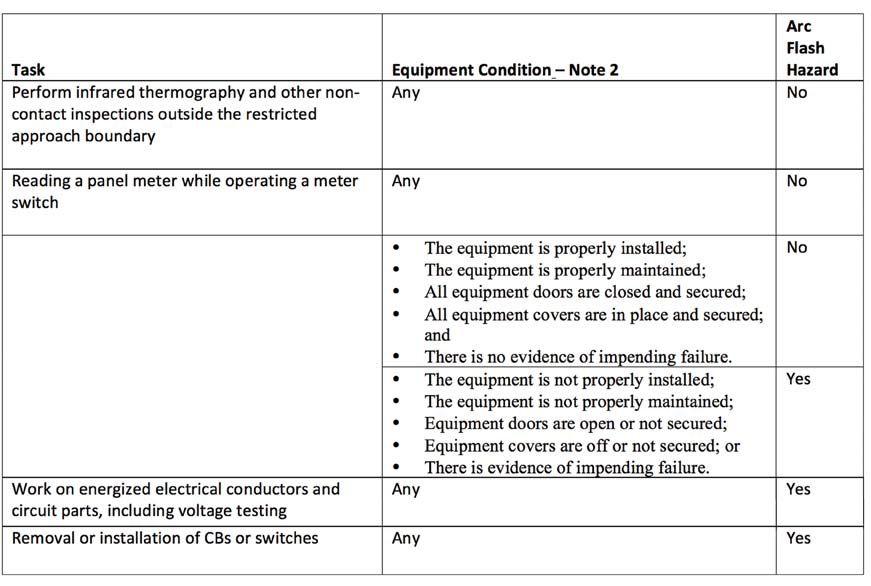
Figure 2: Proposed Table 130.7(C)(15)(a), Partial
Table 130.7(C)(15)(b)— Arc-Flash Hazard PPE Categories

longer normally operating. It is in distress, and arc-flash protective equipment must be worn to operate it or to perform any other task on it or with it. If an arc-flash hazard is present, the second new table is used to determine arcrated PPE. Figure 3 shows a portion of the new proposed table.
The arc-flash category of the arc-rated PPE is still determined by the type of equipment and has the same limits, but is no longer task-based. The term Hazard/Risk Category will no longer be used in the 2015 edition of NFPA 70E. The Arc-Flash Boundaries (AFB) are rounded up to the nearest foot, and working distances are the same as in the current table. Risk is removed as a determining factor in the table, although risk must be determined by the user. The one problem I see in this new table is that by rounding up the Arc-Flash Boundaries, someone is going to point out that the back of the head now appears to be within the AFB for a Category 1 exposure and therefore a balaclava is required. Not so, since these values are all based on estimates and the tables are very conservative. No balaclava is needed for Category 1.
The proposed tables in the 2015 edition of NFPA 70E represent a clean sheet approach to the difficult task of choosing arc-flash protective PPE. Although it may not be perfect in its proposed form, it is a major step forward in ensuring worker safety. By eliminating risk from the tables, the objections to the tables have been largely removed. This new table method should provide better flexibility in its application, be simpler to apply in the field, and should
eliminate some of the grey area concerns that the current method introduces.
The NFPA will be publishing the first draft of the 2015 edition of the 70E sometime in February or March and the first draft meeting will be in June. Public comments on the proposed changes to NFPA 70E are welcomed by NFPA and the 70E technical committee. Forms for submitting comments are available on the NFPA website (www.nfpa.org).


Ron Widup and Jim White are NETA’S representatives to NFPA Technical Committee 70E (Electrical Safety Requirements for Employee Workplaces). Both gentlemen are employees of Shermco Industries in Dallas, Texas a NETA Accredited Company. Ron Widup is President of Shermco and has been with the company since 1983. He is a Principal member of the Technical Committee on “Electrical Safety in the Workplace” (NFPA 70E) and a Principal member of the National Electrical Code (NFPA 70) Code Panel 11. He is also a member of the technical committee “Recommended Practice for Electrical Equipment Maintenance” (NFPA 70B), and a member of the NETA Board of Directors and Standards Review Council. Jim White is nationally recognized for technical skills and safety training in the electrical power systems industry. He is the Training Director for Shermco Industries, and has spent the last twenty years directly involved in technical skills and safety training for electrical power system technicians. Jim is a Principal member of NFPA 70B representing Shermco Industries, NETA’s alternate member of NFPA 70E, and a member of ASTM F18 Committee “Electrical Protective Equipment for Workers”.


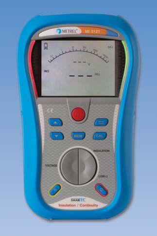
MI 3121 SMARTEC
Insulation / Continuity
Metrel offers a wide variety of Single, and Multi-Function testers for measuring Insulation Resistance up to 10kV, Earth Resistance, Line Tracers, Continuity, Loop and Line Impedance, and Phase Rotation.


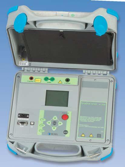
Technical demands require high performance measuring instruments capable of measuring polarization index (PI), dielectric absorption ratio (DAR), dielectric discharge (DD), time programmable step voltage test, insulation system's capacitance, etc. Metrel offers a line of 1kV, 5kV, and 10kV insulation resistance meters for these tests.


Metrel power quality analyzers are proven tools for expert designers equipment, over voltage protection and UPS systems. Wide range of testing possibilities are supported: voltage sags and swells, resonant states, high neutral conductor currents in 3-phase systems, asymmetry, transients, etc.

 MI 3200 TeraOhm 10kV
MI 2592 PowerQ4

SYSTEM DOES CALCULATIONS BASED ON MEASUREMENTS OF 3,000 VIs Trust Magnetron Atmospheric Condition (MAC) testing to
MAC-TS1 & MAC-TS2 SYSTEMS FROM VACUUM INTERRUPTERS, INC.
WORLD’S FIRST PORTABLE FIELDTESTING SYSTEM FOR VACUUM INTERRUPTERS
ACCURATE IN SHOP OR FIELD
BASED ON OEM LEAK-RATE TEST DURING MANUFACTURE
PREDICTS REMAINING VI LIFETIME, NOT JUST PASS-FAIL


While the amount of moisture in a breaker has a minimal impact on the dielectric strength of the SF6, it is directly responsible for the creation of approximately 90 percent of arc by-products that are formed during an arcing event. When SF6 is heated to temperatures above 380°F – such as during an arcing event - the individual sulfur and fluorine molecules separate (disassociate). The fluorine absorbs the heat and carries it away from its source and by doing so quenches the arc. Once the heat source has been extinguished, all the individual molecules reassociate (self healing) back to pure SF6. A temperature exceeding 1,200°C is needed to cause permanent thermal breakdown of the SF6. In theory SF6 could be exposed to limitless arcing events without any permanent breakdown, as the temperature generally experienced during a fault in a circuit breaker is far below the 1,200°C necessary for this type of reaction. However, in the presence of moisture, only a temperature of roughly 380°F is needed to cause the SF6 to start to decompose. When moisture is present during an arcing event, the individual hydrogen and oxygen molecules also disassociate. Once the arc is quenched, all molecules want to become neutral as quickly as possible: hydrogen combining with fluorine, sulfur with oxygen, etc., leading to the formation of arc or decomposition by-products.


Given that moisture is namely a primary fuel source for arc by-products, it is the most important of all available SF6 quality checks. On the surface, moisture testing is quite simple. Connect a dew point/moisture analyzer to the gas sampling port and wait for a stable reading. With advancements in technology, analyzers have become very easy to operate. Since the GIE (gas insulated equipment) generally has to be kept extremely dry, it is important to understand that even the slightest error during the testing procedure can have a tremendous impact on the result. Unfortunately any contamination of the sample will result in the analyzer displaying a higher than actual moisture reading.
Let’s face it, moisture can be found in most environments and materials. Moisture intrusion into the SF6 gas is generally due to one (or a combination) of the following events: materials contamination, leakage, and/or handling error.
Even new SF6 contains small amounts of moisture. Generally the moisture levels in new SF6 are less than 8 PPMv in the liquid phase (ASTM 2472). Additionally all materials that are used to manufacture GIE – metals, polymers, etc.- contain some moisture. Over time the moisture will work its way from those materials into the gas compartment due to desorption, a natural off-gassing of moisture due to temperature changes. Normally this type of contamination is not a major area of concern, as the desiccant bags used in most all GIE are capable of removing any resulting moisture intrusion.
Whenever GIE is not completely sealed, allowing SF6 to leak, moisture is going to enter the gas compartment through the same leakage point. Moisture is always going to migrate from a wet to a dry environment regardless of the pressure/ temperature/gravity, etc. If comparing moisture levels in two pieces of GIE, with only one of them leaking SF6, one could expect a steady increase in moisture levels on the leaker once it has saturated its desiccant.
Based on anecdotal evidence, a major source of moisture contamination in GIE and moisture tests is related to improper handling. There are various ways to accidentally contaminate the SF6 with moisture, including incorrect hose preparation, saturated dryer filters, using leaky equipment, or simply putting wet gas in by mistake.
It is extremely important to understand the impact of gas temperature when sampling GIE for moisture. This is due to the fact that at low temperatures moisture will start to condensate and eventually freeze, leaving the vapor space. At the operating pressures in most breakers, moisture freezes at approximately 14°F (-10°C). Therefore, it is expected that testing for moisture in SF6 on a warm day will be more representative of the actual moisture content.
Careful attention should be paid to the materials being used for moisture sampling. Typically test equipment comes with stainless steel fittings and Teflon™ or Tygon™ type hoses. Rubber hoses and regulators using rubber diaphragms should be avoided as they are moisture permeable.
Lastly, when performing a moisture test, be sure not to contaminate your sample by improperly handling the fittings and hoses being used. Some common mistakes include touching one of the adapter couplings (with sweaty hands); and surface moisture on sampling ports of breakers and/or adapter fittings. In the event that this happens, compressed air/N2 and/ or denatured alcohol can be used to clean and dry surfaces.
In addition to following correct sampling practices, it is also important to understand how the device being used to test for moisture works and to know its limitations. Be aware that field level devices do not offer the same level of accuracy as laboratory grade equipment. There may be some variance from test to test, but as long as they are within a certain range from each other, all is well. Since GIE manufacturers typically set pass/fail values for the SF6, splitting hairs is not necessary. The following sections will discuss the

pros and cons, normal specifications, and signs that the sensor has drifted out of calibration for each sensor type.
There are three commonly used moisture sensors in field level devices: capacitive polymer, aluminum oxide, and chilled mirrors.
Due to their robust nature and repeatability in the middle to upper range of moisture testing (greater than -40°C dew point/greater than 122 PPM; the normal range of moisture found within GIE), capacitive polymer sensors are a popular and cost effective means of monitoring moisture levels. The measuring range of most devices using this sensor type is +20°C to -60°C with an accuracy rating of +/- 2°C to 3°C above -40°C and +/- 3° to 4°C on dryer SF6 with moisture levels less -40°C. While their strength lies on wetter gas, they do tend to struggle a bit when testing extremely dry gas, for example new SF6 The important thing to note is that accuracy on very dry gas is not critical. If the gas is dry, it’s dry. The threshold for most GIE/Breakers is less than 200 PPM.
When using this type of sensor it should be noted that this sensor is exposed to ambient moisture when not in use so the readings will start off at ambient humidity levels and the SF6 is used to dry the sensor and provide a reading. Some common signs that this sensor has drifted out of calibration include excessively wet readings on all gas tested, the device will get to a certain level of moisture and not go below it, or erratic results. Devices are commonly examined at field level using gas of known quality or sent in to the manufacturer for inspection and/or calibration as needed.
Although an older design type, aluminum oxide sensors are also commonly used. Unlike capacitive polymer sensors, this type tends to work better on really dry gas. Outside of measuring GIE, this type of sensor is frequently used to test N2 blankets on transformers. This sensor type also has a similar measuring range of +20°C to -70°C with an accuracy rating of +/- 3°C to 4°C.
This type of sensor is kept in a dry environment (desiccant chamber), vs. wet, and moisture is introduced into the chamber by removing the sensor from the desiccant and flowing SF6 through it. A common issue with this sensor is due to the very dry environment in which it is kept. The sensor is very porous, much like a light bulb filament, and the SF6 that is left in the test chamber tends to become lodged in the pores of the sensor causing it to display false dry readings. The dry environment also causes the sensor to become brittle over time, also causing false dry readings. When using this type sensor, it is a very good idea to remove the desiccant chamber from the sensor and expose it to ambient moisture once or twice a year, or more often depending on usage, to help alleviate the problem.
In regards to field level devices, the chilled mirror device is the most accurate type of device available. These sensors offer the highest level of accuracy and repeatability of all field level moisture analyzers. The measuring range is typically +20°C to -50°C with an accuracy rating of +/- 0.2°C.
These devices measure humidity in the gas sample utilizing a thermally conductive mirror (typically silver or copper plated with another metal to prevent tarnishing and oxidation), a cooling system, and a beam of light. Despite their high level of accuracy, these devices are significantly more delicate than other dew point measuring devices and must be handled as such. High ambient temperatures can also present challenges for the cooling system making it difficult for the mirror to obtain the proper temperatures for condensation to occur. Lastly the surface of the mirror must be kept clean which can prove to be quite difficult with the number of particulates present at field level.
A number of laboratories also offer complete analysis of the SF6 which includes testing the moisture content of the gas. Due to its relatively high cost and the inconvenience of having to wait as long as a week for test results, field level testing is typically preferred.
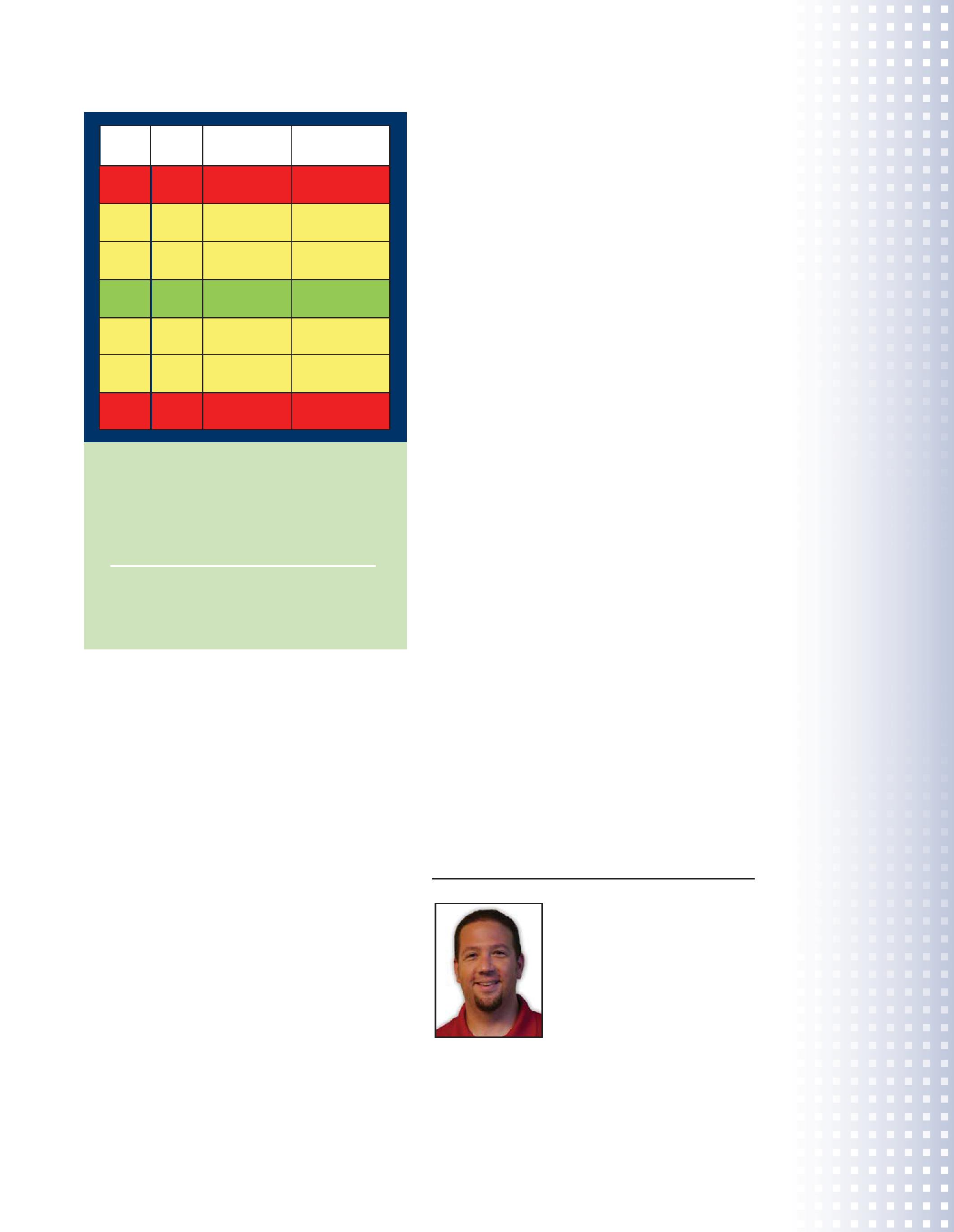
Moisture Content Conversion Chart for SF6 at atmospheric pressure
This chart is an example of the acceptable accuracy range of a capacitive polymer sensor. The range is based on a +/- 2°C @ > -40°C accuracy zone.
Green: Actual moisture content of the SF6
Yellow: Readings within the acceptable range of the capacitive polymer sensor
Red: Reading out of range
Most GIE OEM’s have adopted the maximum tolerable contaminant level for moisture at 200 PPMv (originally established by CIGRE and now, also, per IEC 60480) as their pass/fail point. Some manufacturers allow for different values (some as high as 500 PPMv). In summary, the best course of action is to always check the manual for the GIE to determine if the moisture levels are within specification.
The previous paragraphs focus mainly on testing the moisture levels in GIE. A few extra precautions are needed when testing the moisture contained in SF6 cylinders. The specification for SF6 generally calls for the gas to meet ASTM 2472. This standard requires the moisture levels in the liquid phase to be less than 8 PPM. On average, a new cylinder contains approximately 2/3 liquefied SF6, with the top 1/3 of the space containing gaseous SF6. During storage the moisture will migrate to the top of a cylinder. This,
of course, results in initial moisture levels generally being much higher than the specified ASTM requirements of 8 PPMv whenever gas from new cylinders is tested. Under these conditions, moisture levels of slightly more than 50 PPM are the norm and should be expected. At this time there is no standard for the vapor space on top of a cylinder.
Quite often there is a need to test specific types of GIE that operate at low pressures (7-10 PSIG) or circuit breakers at shipping pressures (3-5 PSIG). Most test equipment requires a minimum input pressure of .5 bar (7.25 PSI) to operate correctly. There is a significant challenge to testing at such low pressures because of the minimal gas flow across the sensor. This can effectively make the test take three to five times longer than it normally would and still likely end in an incorrect reading and typically elevated moisture readings. In the event this happens, on a new circuit breaker especially, remember that there is only about 1520 percent of the total gas volume inside and it will be filled with new, very dry gas. Note that an external compressor can be used to transfer SF6 to the analyzer to overcome gas flow issues.
This should illustrate that despite great advances in test equipment technology, testing for moisture from both GIE as well as gas cylinders is still a rather difficult task. Understanding the challenges of testing for extremely dry moisture levels in the field, combined with the known limitations of test equipment, should serve as a guide to having realistic expectations whenever tasked to test SF6 from different sources.
Justin Palmer, DILO US Sales Manager, is responsible for managing the sales and training efforts of the sales and on-site maintenance staff. A six year veteran of DILO, he works directly with the OEM customers and a significant portion of USA and Canada clientele.
Vanguard’s precision substation testing instruments are designed to be intuitive and easy to use so that you can focus on testing instead of wasting time in training. Our versatile instruments offer a built-in thermal printer and on-board test record storage so that tests can be conducted in stand-alone mode in the field. A computer interface is also offered so that tests can be easily conducted from a PC.
And all of our instruments are competitively priced to provide cost-effective accuracy. For a virtual experience of our instruments, check out the interactive demos on our site at:
www.vanguard-instruments.com/demos


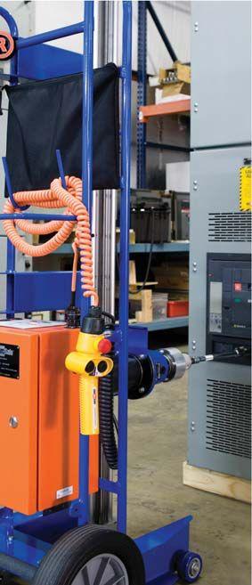
Remote operation outside the arcflash boundary
Reduces the need for a full-body arcflash hazard suit
Use with low/medium voltage circuit breakers
Use with air, SF and vacuum circuit breakers
Drive is easily adjusted
Quick release drive shafts
Over-Racking protection is provided
AC/DC power for continuos operation


20%
Annual
20%
Access
Seat
Subscription
Place
NETA is an organization built on the belief that gathering and disseminating information in the form of standardized procedures is vital to the success of providing quality products and services. NETA’s tagline, Setting the Standard, was an early hallmark of the association. NETA’s founding fathers prided themselves and their technicians on their education as well as the invaluable field experience that continues to set NETA’s technicians apart, setting the standard both metaphorically and literally through NETA’s participation in the American National Standards process. This knowledge was distilled into NETA’s first specification for electrical testing, the Acceptance Testing Specifications for Electrical Power Distribution Equipment and Systems (ATS), published in 1972. It was NETA’s first step down a road that led to becoming an ANSI Accredited Standards Developer and to eventually gaining recognition for three American National Standards.
The ANSI process of creating standards is one that demands due process, ensuring that the documents bearing that designation have been given every opportunity for consensus by those affected by its contents. Over the years, there has been a gradual evolution of the NETA standards, some in formatting and some in test procedures, test values, and reference material. Since the 2009

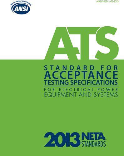
edition of the ATS was published, there has been a thorough review of the document and over 200 comments submitted by the ANSI ballot pool during the revision process. These comments were given consideration by the NETA Standards Review Council, and some of them resulted in alteration to the document that will be submitted as the 2013 revision of the ANSI/NETA ATS.
Some of these changes may appear to be insignificant in that there is a subtle shift in language, or a slight increase or decrease in values, but NETA stresses the importance of maintaining a current library of standards materials to assure that the most relevant information is used when creating the acceptance testing specifications for a project. NETA marks all of its standards in the margins with a vertical line next to any sections that have undergone a revision since the last edition. This practice started in 2009 with the ATS at the request of users of this document. It allows the user to cross-reference the new edition with the previous edition to more easily identify those sections that may need to be addressed in their own company standards, bid documents, etc.
NETA thanks all of those volunteers who have donated their time and expertise to creating and maintaining the NETA library, and for assuring that NETA will continue Setting the Standard.
Field
Acceptance Testing
Protective Relay Testing and Calibration
Infrared Scanning
Medium Voltage Cable Terminations and Testing
Transformer Testing, Repairs, and Oil Analysis
Ground System Testing
Preventative Maintenance
UPS and Battery Testing and Maintenance
Medium and Low Voltage Breaker Testing
TAN DELTA Cable Diagnostic
Electrical Equipment Start-Up and Commissioning


James R. (Jim) White is the Training Director of Shermco Industries, Inc., in Dallas, Texas. He is the principal member on the NFPA technical committee
“Recommended Practice for Electrical Equipment Maintenance” (NFPA 70B). Jim represents NETA as an alternate member of the NFPA Technical Committee “Electrical Safety in the Workplace” (NFPA 70E) and represents NETA on the ASTM F18 Committee “Electrical Protective Equipment For Workers”. Jim is an IEEE Senior Member and in 2011 received the IEEE/ PCIC Electrical Safety Excellence award. Jim is a past Chairman (2008) of the IEEE Electrical Safety Workshop (ESW). No. 101

Circuit breakers must be tested to ensure that they function in accordance with the manufacturer’s specifications. This issue of the NETAWorld Journal covers many of the newer technologies for proving that circuit breakers will function when called upon.
1. First-Out Timing is performed to ensure:
a. the circuit breaker that should trip first will do so. It’s also known as selective coordination .
b. the circuit breaker will rack out smoothly and without hesitation.
c. the circuit breaker will open within specifications after being closed for an extended period of time.
d. all phases of the circuit breaker open within 25milli-seconds of each other.
2. What two quantities are usually measured with a circuit breaker motion analyzer?
a. Velocity and displacement.
b. Speed and direction.
c. Distance and force.
d. Angle and pressure.
3. Partial discharges are created by:
a. ionization of air pockets within the insulation.
b. moisture that is trapped within the insulation.
c. deep discounting at the Dollar General store.
d. carbon deposits vibrating within the insulation.

4. What test will indicate the serviceability of a medium-voltage vacuum interrupter?
a. Vacuum Bottle Integrity Test
b. Magnetron Atmosphere Condition Test
c. Insulation Power Factor (Doble)
d. Partial Discharge Testing
5. When performing insulation power factor tests on medium-voltage circuit breakers, what quantity is normally measured?
a. Watts loss
b. Percent power factor
c. Total amperage
d. Cosine of the angle theta
the test equipment answer








Circuit breakers are not the life of the substation. In fact, they spend a lot of time quiet, unused, waiting in anticipation. There will come a moment, however, when that circuit breaker needs to perform flawlessly—and to do so instantly. If the circuit breaker does not work as expected, disturbances can cascade, and the results can be catastrophic.
Technicians and substation managers can quell fears about circuit breaker performance through testing. Circuit breakers provide protection for equipment that is necessary to the infrastructure and expensive to replace. Keeping them maintained prevents outages which saves a utility customer and personnel headaches as well as money. Additionally, there is a true public service component in ensuring the reliable supply of power and preventing business downtime and customer dark time.

Proper functioning of a breaker relies on a number of individual components which must be calibrated and tested at regular intervals. The trigger for maintenance intervals differs greatly between power utilities, but the intervals are often based on time since the last test, number of operations, or severity of fault-current operations. Environmental considerations such as humidity and temperature (whether the breaker is located in a desert or coastal region) also play into the maintenance scheme.
One additional factor is that the testing plan should be based on related standards for high-voltage circuit breaker design and operation such as:
High-Voltage Switchgear and Controlgear
dards for circuit breakers, switchgear, relays, substations, and fuses
High-voltage switchgear and controlgear— The use of electronic and associated technologies in auxiliary equipment of switchgear and controlgear
Overall, an adequate testing scheme reveals the condition and potential performance quality of circuit breakers. This will help those in charge of circuit breakers to be confident that, when called upon to operate, the circuit breaker will not fail.
The general function of the circuit breaker is to close and open the circuit, to be able to remove faults, and connect or disconnect objects and parts of the electricity network. The majority of the switching operations of a circuit breaker are normal load operations.
Breakers are complicated, mechanically sophisticated devices requiring periodic adjustments. Sometimes a technician can notice these needs with a visual overview, and the problem can be solved without testing. However, with most circuit breaker issues, testing will be required.
When maintaining a circuit breaker, technicians should start with timing and motion measurements. In fact, if the technician only has time for a single measurement, that measurement should be timing.
A note on timing: It is vital that circuit breakers open and close within the time the manufacturer has specified. Times that range longer than manufacturer’s specifications, especially during

the process of switching short-circuit currents, lead to longer arcing time between contacts. That longer arcing time results in excessive wear (in the best case scenario) and can also cause an equipment emergency, namely the melting of contacts. If those contacts melt, that breaker will require service or replacement. However, contact melting is not the worst case scenario in these situations; a potential explosion is.
Technicians should be aware that, without proper timing, the potential results are not just expensive, they can be explosive.
Additionally, along with long opening and closing timing issues, correct synchronization is imperative, both between phases and, in case of more than one break per phase, between elements of the same phase. Sometimes those complicated interplays can reveal unique issues. For example, if the tripping time is normal during testing but the closing time is slower, there has been a change in

the characteristics of the closing system, perhaps from poor lubrication. On breakers with multiple trip springs, one could be broken, resulting in less energy for tripping but a faster closing time. A slower tripping time due to that broken trip spring, paired with a faster closing time should tell a technician testing the circuit breaker that a broken trip spring could be one possibility. (See the Timing Table 1., for more examples of timing issues and their effects.)
Timing measurement tests should be performed at the time of installation as well as during the service life of the circuit breaker.
Motion measurements allow for assessment of contact travel during breaker operation, close and open speeds, contact stroke and penetration, damping dynamics, velocity, and acceleration at different stages. The measurement can be illustrated by Figure 1.


A high-voltage breaker is designed to interrupt a maximum short-circuit current, and it is required to operate at a given speed in order to build up an adequate cooling stream of air, oil, or gas depending on the type of breaker. This stream quenches the electric arc sufficiently to interrupt the current at the next zero-crossover. It is important to interrupt the current in such a way that the arc will not restrike before the breaker contact has entered the damping zone.
Speed is calculated between two points on the motion curve. The upper point is defined as a distance in length, degrees, or percentage of movement from the breaker’s closed position or the contact closure or contact separation point. The lower point is determined based on the upper point. It can either be a distance below the upper point or a time before the upper point.
The time that elapses between these two points ranges from 10 to 20 milliseconds, which correspond to 1-2 zero crossovers.
The distance throughout which the breaker’s electric arc must be extinguished is usually called the arcing zone. (See Figure 1.)
Motion measurement tests should be performed as part of a regular maintenance routine.

Along with timing and motion measurements, a good and time-effective way to check the condition of a circuit breaker is to document its behavior at the first open operation after it has been idle for long time. The measurement and connections to the circuit breaker are carried out while it is still in service, and all of the connections are made inside the control cabinet.
The biggest benefit of using first trip is to test actual operating conditions. If the circuit breaker has not operated for years, first-trip testing will reveal if the circuit breaker is slower due to problems in the mechanism linkages or coil armatures caused by corrosion or dried grease. With traditional methods, the testing is carried out after the circuit breaker has been taken out of service and has been operated once or even twice. On a gang-operated breaker, a breaker with a common operating mechanism, one coil current is measured, while on an independent pole-operated breaker, three coil currents are measured. Analyzing the coil current signatures gives information about the condition of the circuit breaker.
Auxiliary contact timing can also be measured. Opening times can be measured by monitoring the protection current transformer’s secondary cur-
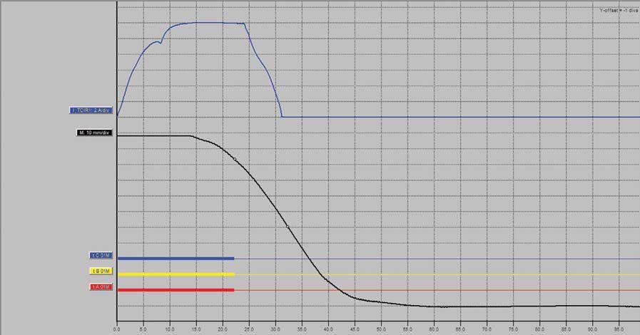
rent; however, the arcing time will then be included. If there is a parallel current path available, the opening times can be more accurately determined since the arcing is minimized.
A more advanced approach to first-trip testing is to additionally measure vibration. This addition provides detailed information of the status of the circuit breaker. Extra caution must be taken since there are live circuits in the control cabinet and the mechanism is fully charged. The breaker can operate at any time a fault condition occurs.
When testing circuit breakers, one area that may be routinely overlooked deals with the details within the growing number of medium-voltage vacuum breakers. While the long life and durability of these circuit breakers make them valuable to utilities, small cracks in the interrupter enclosure may be difficult to spot.
Vacuum breakers are used in circuits with voltage up to 70 kV. Because there is no gas to ionize to form the arc, the insulating gap is smaller than in other types of circuit breakers. An arc does form from the vaporized contact material. The insulation distance in a vacuum breaker is about 11-17 millimeters between plates. Normally there is one break per phase, but there can be two interrupters in series.
The contact plates are formed to conduct the current in a way that creates a magnetic field that causes the arc to rotate and extinguish. The benefits with a rotating arc include uniform heat distribution and even erosion of the contacts.
Other advantages with vacuum breakers are their relatively long operational life time and their relatively limited impact on the environment since they are designed without poisonous gases and relatively few components. Vacuum circuit breakers also suffer less wear on the main contact than air and oil circuit breakers.
Vacuum breakers are based on high breakdown strength of vacuum. There are not many particles to be moved in the vacuum. However, if the vacuum seal is broken and air enters, a problem with
the interrupter chamber can be expected since the breakdown of air is much lower than vacuum.
The vacuum bottles on a breaker are usually tested with high ac or dc voltage at least 2.5 times higher than nominal. The electrical resistance of the vacuum in a breaker is identical in behavior for ac and dc voltage. The main difference is that ac is additionally sensitive to the capacitance of the breaker. The dc (resistive) current component is 100 to 1000 times lower in magnitude than the ac (capacitive) current component, depending on the individual bottle capacitance. It is, therefore, difficult to distinguish the resistive leakage current when testing using ac. As a result of the higher capacitive current, ac requires much heavier equipment for testing compared to dc test instruments. (Refer to standards ANSI/IEEE 37.20.2-1987, IEC 60604 or ANSI C37.06.)


Regular circuit breaker maintenance depends on many variables like voltage level, type, age, significance of breaker in the network, and the owner’s view on maintenance. This article has discussed three of the most valuable tests, namely timing, motion, and first-out testing of circuit breakers. There are many more variables involved in testing and many more testing options to evaluate the condition of circuit breakers such as power-factor, contact resistance, and insulation resistance. Nevertheless, the one test that should always be performed is main contact timing. Timing should be the beginning of all maintenance testing programs.



Roberts Neimanis is an applications engineer with Megger’s Täby, Sweden office.
Robert Foster is an applications engineer with Megger U.S.
Nils Wäcklén is the TM1700 circuit breaker analyzer product manager with Megger’s Täby, Sweden office.


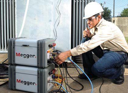
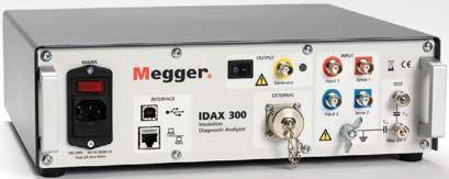
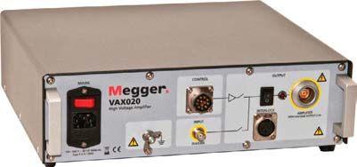
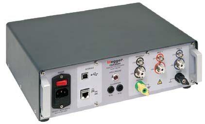
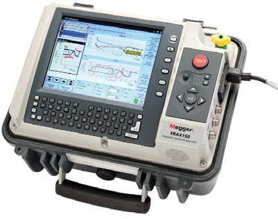
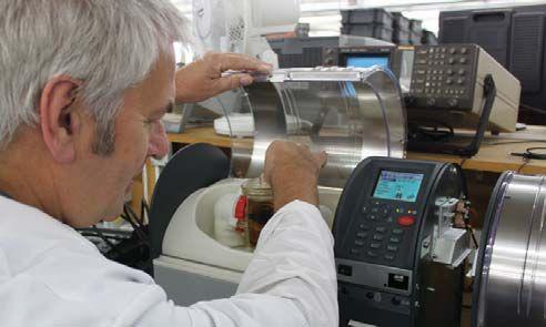
Megger offers a bevy of transformer and insulation testing products to help you clear those maintenance hurdles. Whether you need to measure ratio, insulation moisture, oil or frequency response, Megger has a product that fits your needs to a T.

DELTA4000 INSULATION PF (TAN ) TEST KIT (10 kV) (DELTA4110, DELTA4310)



 LIGHTEST IN THE INDUSTRY


Facility
Training
There are many business sectors that supply products and services as well as influence construction and maintenance decisions on electrical power systems worldwide. It is these business sectors that are represented among the NETA Alliance Program participants.
NETA’s Accredited Companies are focused on ensuring that electrical systems operate at the highest level of safety and reliability. To accomplish this, each NETA Accredited Company works with many different types of organizations and businesses that support these ideals and assist them in providing the highest quality of electrical testing. NETA Accredited Companies look to these other entities within the world of electrical systems to provide test equipment, electrical components, support services, training, and feedback that is incorporated into the daily field work of a typical NETA Certified Technician. Their knowledge is based on years of their own experiences and training, coupled with the network of technical support created by all of the different participants involved in acceptance, commissioning, and maintenance of electrical systems. This information is critical when evaluating the performance, reliability, and safety of each component in the system as well as the system as a whole.
The NETA Alliance Program provides a networking community for professionals from many diverse companies and organizations to come together to exchange information that can be used to refine products and services, improve safety and reliability, and thereby strengthen the electrical power systems industry.
NETA asked those participating on the NETA Alliance Committee, the committee responsible for creating and fueling the Alliance Program initiatives, to share their
reasons for joining and volunteering to help shape and expand this program.
Marc Burke, Solutions Manager, Client Services for Doble Engineering , explains how his organization works with many of NETA’s Accredited Companies through an open dialogue. “This exchange results in growth and improvements on both sides. Doble incorporates information learned from interaction with NETA Accredited Companies to advance and expand our services and consider new technologies. NETA Accredited Companies look to companies like us to provide testing equipment and services and training support on testing equipment and parts.”
Engineering firms like Burns and MacDonnell look to NETA Accredited Companies specifically for third-party, independent testing. With their clients’ best interests in mind, engaging the services of an independent testing firm to verify and confirm that the electrical system is installed and is functioning within design and manufacturer’s specifications goes a long way to ensure short-term and long-term client satisfaction and safety.
Matt Papes, Electrical Engineer, Energy Group, Burns and MacDonnell , says that their goal is to stay connected and maintain an understanding of the standards, new testing equipment, and procedures as they become available. By joining the NETA Alliance Program and getting involved with NETA, Burns and MacDonnell engineers have access to the information necessary when specifying electrical testing and counseling their clients. This relationship is also beneficial for NETA, as NETA gains a better understanding of how to support electrical engineers as they design new systems, develop bid specifications, and interface with owners, builders, contractors, and inspectors.

The relationship between utilities and NETA is cooperative in many ways. Utility companies often interface with manufacturers, data centers, healthcare facilities, municipalities, and other large facilities that require a direct connection to a substation. These constituents often rely on the services of NETA Accredited Companies to assure that all electrical systems within their facilities are tested and maintained to the ANSI/NETA standards for electrical testing. It is incumbent upon both the utility provider and the NETA Accredited Company to assure a consistent and safe supply of energy to each facility. Additionally, NETA Accredited Companies serve as a testing resource to utilities as they expand their service footprint, update old systems, or need to outsource acceptance and maintenance testing for other reasons spanning from budgetary considerations as well as in response to natural and man-made disasters.
Ray Curry, Commissioning Engineer, American Transmission Company , points out that, “We all have a common theme of safety and reliability. We operate under the same regulations and oversight. As a utility expert, I can serve as a tactical resource in the area of power transmission. Together we can support each other as technical resources. Utilities can offer support in the area of power transmission and NETA in the area of training and education for new technicians. There is a growing attrition of senior technicians in the field. NETA and the Alliance Program participants share in the ongoing commitment to attract new engineers and technicians to the field and develop new talent.”
The power generation industry is continually working to improve their technology, distribution infrastructure, reliability, and safety. An exchange of information helps create better equipment, results in better standards, and ultimately makes the distribution of petrochemical products safer and more reliable.
Mike Cooper, Aftermarket Leader, GE , talks about the many standards associations in which he and his colleagues participate. Mike shares, “The whole purpose is to create an exchange of information around testing, the standards, and how together we can improve the industry. Being a part of the NETA Alliance Program helps facilitate that exchange.”
The petrochemical industry, like many manufacturing industries recognizes that consistent safe and reliable power means uninterrupted operation, production efficiency, and employee and facility safety. Michael Griffin, Chief Electrical Engineer, BP Products, joined the NETA Alliance Program and volunteers on the NETA Alliance Committee with the goal of becoming more involved with the ANSI/NETA Standards and helping to expand the understanding of how they relate to petrochemical industry applications. Michael is looking to gain an understanding of how the ANSI/NETA standards can be utilized in their company’s processes. “We are aligned on the same safety and efficiency objective,” says Griffin, “and we would like to help with testing integration within the industry.”
NETA Alliance Committee Chair Jim Cialdea, General Manager of Three-C Electrical, a NETA Accredited Company , says, "We all sit on different standards committees. If we work together and communicate with each other we can advance the industry as a whole as well as raise the bar within each of our industry segments.”
NETA Accredited Companies are vested in growing NETA’s Alliance Program network and encourage the participation of all who are equally vested in advancing the electrical power systems industry.
If you are interested in joining the NETA Alliance Program or would like additional information on how you can become more involved, please contact Jill Howell at jhowell@netaworld.org.
“The whole purpose is to create an exchange of information around testing, the standards, and how together we can improve the industry. Being a part of the NETA Alliance Program helps facilitate that exchange.”
Mike
Cooper, Aftermarket Leader, GE



All types of Electrical
Maintenance, Testing & Repair
Install, Test, and Commission
all types of Relays & Protection Systems
Troubleshooting Electrical
Controls & Electrical Systems
www.youtube.com/tdeinc2
www.twitter.com/tdeinc
www.facebook.com/tdeinc
www.linkedin.com/company/tony-demaria-electric
Substation & Generating Plant Design, along with Power Systems Audits National Certified Cable Splicing, Complete Cable Testing & Analysis using VLF, VLF-TAN Delta, and Partial Discharge
Large Motor, Generator & Transformer
Maintenance, Testing, Repair & Troubleshooting

Electrical Safety for Qualified Electrical Workers
Understanding NFPA 70E & Arc Flash Awareness
Electrical Safety
Refresher with Advanced Switching & Racking Techniques
315448


NETA thanks Mr. Herbert and his family for their years of dedication...

and service to the creation of NETA
and is proud to be a part of his legacy.
NETA celebrates the life of Patrick R. Herbert, 82, who passed away Sunday, November 25, 2012. Born October 17, 1930, in Altoona, Pennsylvania, he was a cofounder of NETA and a member of the National Electrical Code Panel. He was also a member of the I.B.E.W. and a recreational pilot and stock car racer. He was the beloved husband to his wife of 25 years, Peggy (nee Bates) TownsonHerbert; loving father of Lynne (Mike) Swerbinsky, Richard L. (Terri) Herbert, Jeffrey A. (Debbie) Herbert, Patrick G. (Arlene) Herbert, Michael S. (Heather) Herbert and Teri (Rick) Kuntz; stepfather of Guy (Debbie) Townson, Russ Townson and Brad (Ginger) Townson; stepfather-in-law of Linda Feskanin; and a grandfather and great-grandfather of many. The family suggests that donations in his name be made to the Lake County Humane Society, 7564 Tyler Blvd., Mentor, OH 44060.
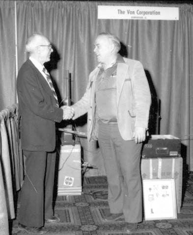
 Left; Pat Herbert at the NETA Conference, 1982. Above; Some of NETA’s Founding Fathers: Thad Brown, Bill Heffner, and Pat Herbert at the NETA Booth in 1982.
All objects can be characterized by their response to physical stimuli. When struck by its clapper, a bell will ring with a certain fundamental frequency and numerous overtones (harmonics). The frequencies of the fundamental and the overtones are determined by the size and geometry of the bell as well as the material from which it is made.
Imperfections such as cracks will cause the bell to respond at different frequencies and/or different amplitudes. If the normal frequencies and amplitudes are known, it is theoretically possible to determine the type, size, and location of an imperfection.
These basic physical facts have led to the well proven scientific method of vibration analysis (VA), which is used extensively for determining existing or impending problems in rotating equipment such as motors or generators. Past attempts to use VA for circuit breakers have met with only limited acceptance, primarily because of the size and complexity of the test equipment, added expense, and the lack of good vibration signatures for comparison purposes.
This paper discusses a new VA method that is being used successfully for determining the mechanical condition (and thus the electrical performance) of circuit breakers. Using a marriage of compact and modern communications equipment, internet data transfer, and sophisticated condition based maintenance algorithms (CBMA) offers a number of valuable features such as:
1) Extreme portability
2) Easy transmission of data to a central location
3) Capture of first trip data1
4) A basic comparison method of analysis based on a vibration envelope and/or a detailed mathematical analysis of results
5) Ability to perform testing during routine switching
6) Reduces the risk of human error (and thus provides additional safety) since it requires no modification or removal of the circuit breaker.
Field tests on circuit breakers have long provided diagnostic and prognostic data for the electrical components. Since the majority of circuit breaker failures are mechanical in nature, this new method helps to fill the toolbox of test methods available to field technicians.
For the remainder of this paper, this new method of vibration analysis will be referred to as CBVA This acronym is a simple three letter contraction of Circuit Breaker Vibration Analyzer or Circuit Breaker Vibration Analysis.
The CBVA provides a holistic, single-signature graph in three dimensions. The graph can be analyzed for quantitative information concerning the breaker operation and condition. The following points illustrate why the CBVA can be an important addition to the existing suite of circuit breaker test procedures.
Consider the following facts:
depend upon correct lubrication to operate correctly.
operations for years or even tens of years.
“protective devices shall be properly maintained to adequately withstand and interrupt available fault current.” An information note immediately below Article 210.5 states that, “failure to properly maintain protective devices can have an adverse effect on the arc flash hazard analysis incident energy values.”
The three facts taken together define the importance of a breaker’s first trip operation because studies performed during the last fifty years have shown that fully 50 percent of unmaintained circuit
breakers will fail to operate correctly after being in service for a period of five years or longer. An excellent paper by Neitzel and Neesoni provides background on this.
In the past, the first thing that was done when preparing to perform maintenance on a circuit breaker was to open the breaker and then start the maintenance, thus losing any information about the initial trip. With this new technique, the trip information can be captured when the breaker is first opened providing invaluable information as to the efficacy of the ongoing maintenance plan.
One of the complicating factors of maintenance efforts is the need to have a shutdown before any maintenance can be performed. CBVA allows a quick vibration check during routine switching operations; furthermore, since the test involves simply attaching the test device and operating the breaker, maintenance personnel can be easily trained to perform the test quickly and safely.
Time-travel analyses (TTA) in conjunction with thorough visual-mechanical inspections (VMI) provide a wealth of information as to the mechanical condition of the breaker. A good vibration analysis of the circuit breaker will provide most of the information that the TTA and VMI yield together.
This is not to say that equipment owners and service providers should stop TTA or VMI in favor of performing vibration analysis. Any good maintenance and testing regimen should include all three because CBVA can be performed multiple times between normal maintenance cycles at little or no additional cost. Using all three provides a much more comprehensive picture of a breaker’s mechanical condition.
During operation the vibration signature peaks at the moment of trip, the moment of spring charging, and the moment of close. As will be shown later in the paper, a careful analysis of the signature can be used to determine trip time and close time. The CBVA trip time signature displays the vibration events from mechanism motion and mechanism stop. Thus it captures the entire time, not just the time that the contacts open or close.
Safety is enhanced in at least two ways:
test can be performed when the technician is well outside the arc-flash boundary.
much higher probably of failure than when it is just sitting. This new test does not require that the breaker be racked.
When any real object is subjected to physical stress, the object will tend to deform. If the stress is great enough, the object’s deformation may be partially or totally permanent. Consider the dent in your fender when that post jumped out and struck it. The stress (force) of the impact was so great that it permanently deformed the fender.
If the force of the impact is small enough, the fender will deform, but then it will spring back into shape leaving little or no permanent damage. This is because virtually all materials have some degree of elasticity. As long as the deformation does not cross the threshold of elasticity2, the material will spring back into shape.
All physical objects in motion have the property of inertia3. So after the object springs back into shape, it tends to go past the undeformed state to another deformed position. The object will do this several times until the back-and-forth oscillations are reduced to zero by the natural damping4 effect. This leaves the object in its original shape.
If the object has a large damping factor, the oscillations will taper off very quickly. The damping factor for any object is a function of its mass and geometry as well as the material of which it is made. Thus if the geometry of the object changes or if the object is changed or damaged in some way, its damping factor will change consequently changing the frequency and waveform of the vibrations.
A simple object, such as a tuning fork, will have very pure vibration signature. That is, the oscillations will have few overtones, and the waveform will tend to be more sinusoidal. This is why the sound that a vibrating tuning fork makes sounds so pure.
A more complex object with many different parts will tend to have a very complex vibration pattern. As a result, when the object is stressed, each individual part will contribute to the overall vibration waveform.
A circuit breaker is a very complex mechanical mechanism. It has a huge variety of parts including springs, lever arms, sheet metal, pivots, rubber stops, contacts, and many other such items. This means that the vibration signature of a circuit breaker will be very complex. Figure 1 shows such a vibration signature.
There are three different waveforms – one each for the x, y, and z axes. Note that the trace on each of the axes is similar but not identical to the others. This is because the breaker will not vibrate exactly the same in each of the three directions.
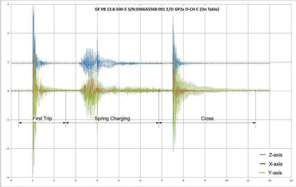
The Z axis is displaced by one G from the other two. This is because the G axis is the vertical axis and is always subjected to the force of gravity – 9.8 m/sec2 (32.2 ft/sec2). The other two axes are horizontal; therefore, gravity has little effect on them.
Considering just one of the traces, notice that there are three major segments. The first segment is the vibration signature created when the breaker trips, the second segment shows the vibration created when the charging mechanism resets the closing springs, and the third segment shows the vibration created when the breaker is reclosed.
The decreasing magnitude of the vibration in each segment is caused by the damping factor of the entire breaker mechanism. Any damage to
the components, loose hardware, or failure of lubrication will cause the vibration signature to change. Given that this signature is a known good profile (KGP), any subsequent changes will show up as changes in the signature. With more research and experience, analysis techniques will be able to identify the causes of those small changes.
PARAMETERS
There are at least four different parameters that are used in analyzing the performance of a circuit breaker – vibration, travel distance (also called displacement or amplitude), travel velocity, and travel acceleration.

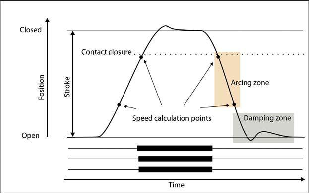
Figure 2 shows a time-travel curve taken for a breaker captured by the type of time-travel analyzer shown in Figure 3. The motion curve is taken by a transducer and fed into the test set. The test set plots the position of the contacts as the breaker moves from closed to open.
Once of the key pieces of information shown by the motion curve is found in its smoothness. There are no large jumps in the curve as the mechanism moves. This indicates that there is no binding anywhere in its travel.
Figure 4 shows a drawing of another type of circuit breaker motion curve. In this example the breaker is first closed and then tripped. Note that at the end of the close cycle, the mechanism overtravels slightly. This is normal operation unless the overtravel exceeds a manufacturer’s specification or it differs significantly from the average of previous tests.
The same phenomenon is seen in the trip motion curve. Note that there is some oscillation at the end of the trip stroke. This is also normal. Some overtravel on trip creates less stress on the operating mechanism.
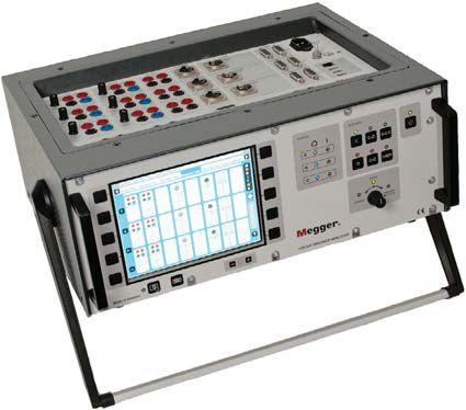
The slope is relatively constant in the sections between the points labeled Speed calculation points. This means that the velocity remains constant between those points. The speed of the close or open operation can be calculated by taking the difference between the positions and dividing it by the time between those two positions.
This velocity information is compared to a manufacturer’s specification and/or the average of previous tests. Any deviation could indicate some sort of problem, such as weakened springs or friction.
The slopes of the curves in Figure 2 and Figure 4 change throughout the operating cycle. Since a change of slope indicates a change in velocity, these parts of the curve represent acceleration or deceleration.
Changes in slope are expected; however, if the change occurs in a part of the curve where there should be no change, a problem is indicated.
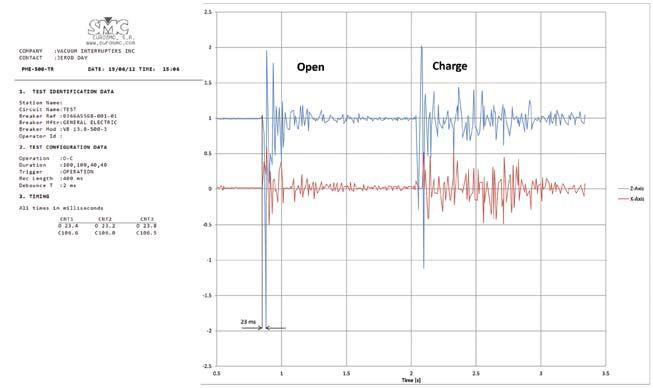
The final parameter, and the main one of interest for this paper, is vibration. Figure 1 shows a vibration signature taken with the CBVA. The vibration analysis creates a signature that is a comprehensive view of the condition of the entire breaker. As Figure 5 shows, it can even be used to calculate contact parting (or closing) time by observing the distance between the first two major vibration excursions.
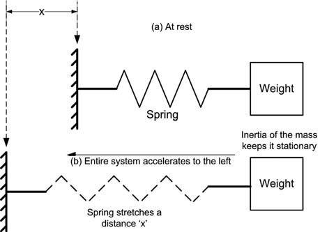
Figure 6 shows a diagram of a simple accelerometer. When the system is stationary, as shown in 6(a), the spring is in its relaxed position. When the system accelerates to the left, 6(b), the inertia of the mass tends to hold it in place. This means that the spring will stretch. How far it will stretch is dependent on the mass of the weight (m), the spring constant (k), and the acceleration (a).
To analyze this, we start with Hookes law which states:
F = –kx (Eq 1)
Where:
F is the force applied to the spring, k is spring constant, and
x is the distance the spring stretches.
Since the mass5 and the applied acceleration are known, Newton’s second law can be used to determine the force:
F = ma (Eq 2)
Since the two forces are equal we can write ma = –kx (Eq 2)
Solving for a gives
a = –kx (Eq 3)
m
ger, Inc. www.megger.com)
5:
and Charging Signature compared to Time-Travel Data (Courtesy of Group CBS, Inc.)
Since k and x are known, we can calculate the applied acceleration.
Accelerometers used in modern, more sophisticated equipment are built on a silicon chip just like any integrated circuit. They do not use weights and springs; rather, they rely on sophisticated techniques that are beyond the scope of this article. Furthermore they may be sensitive to motion in 1, 2, or 3 directions. The acceleration is usually calculated using a small onboard microprocessor and printed out graphically as shown in Figures 1 and 5.
Since the performance of vibration analysis depends on an accelerometer, the question is:
Where can I find an accelerometer?
As it turns out, millions of people throughout the world are carrying an accelerometer in their pocket (Figure 7) – the ubiquitous iDevice67. Did you ever wonder how an iDevice knows

whether you are holding it horizontally or vertically or how the service tech knows if you have dropped it when you take it in for service? It has a builtin, three-axis accelerometer. Any force applied to a mass causes the mass to accelerate. The force of gravity is no exception. The internal accelerometer in an iDevice is acted on by the force of gravity. If the iDevice is held vertically, the accelerometer senses the pull of

gravity and orients the screen so it is displayed in portrait mode. If the iDevice is held horizontally, the accelerometer and its attendant software rotate the screen to a landscape view.
Other software applications use the accelerometer for other purposes. Many game apps ask the user to shake the device as an input response.
Does software exist to use the iDevice as a CBVA device?
There’s an app for that!
As you might expect, the use of an iDevice for a circuit breaker test device has involved a substantial amount of research and development – including development of an iDevice app named the CBAnalyzer. ©™ 8
Figure 8 is a montage of screen captures from CBAnalyzer. Starting from the upper left and moving counterclockwise the shots show:
1. The screen that appears showing a countdown timer. When it reaches 0, the user intiates breaker operation.
2. The initial main menu that appears after the user has logged in.
3. A screen that allows the user to tell the app whether the breaker is closed or open before the test is initiated.
4. The screen that appears after the test cycle is completed. It shows the total elapsed time for the test.
The app is designed to take the user with little or no breaker service experience step-by-step through the entire process. Inexperienced maintenance personnel and highly experienced technicians alike will find the app very user friendly.
The iDevice is attached to the circuit breaker magnetically using a special case designed for the purpose. Figure 9 shows the iDevice incorrectly applied (9a) and correctly applied (9b).
The location and orientation of the iDevice is
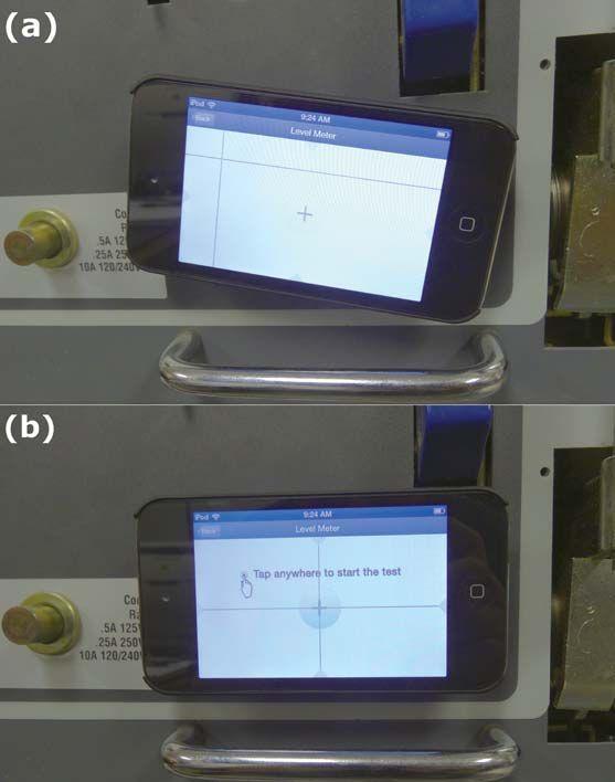
very important. First, since the circuit breaker is a complex assembly, the vibration signature will be different depending on where the iDevice is placed. Therefore, it must be located in approximately the same location for the initial and all subsequent tests. The app asks the user to identify the breaker type that is being tested. It then allows the user to bring up a photograph showing the recommended location of iDevice placement.
Second, the iDevice must be level and oriented in the same manner every time. Research has shown that attaching it horizontally provides excellent results. It must also be attached in such a way that the navigation button of the iDevice is placed to the right for all tests. This keeps the x, y, and z axes in the same orientation for each test.
In Figure 9a you see that the iDevice is not level. Notice the two level lines in the upper left area of
that screen. To be sure that the iDevice is leveled, the technician adjusts it until the level lines are over the cross hairs as shown in 9b.
Actually performing the test is quite straightforward.
1. Position and orient the phone as previously described.
2. When the Start button turns blue, press it and a countdown from 10 begins.
3. When the countdown reaches 0, the iDevice goes into Record mode and waits for the first vibration to occur.
4. The tester initiates whatever test is being performed (trip, charge, close, or any combination by actually operating the breaker).
5. The iDevice senses the start of the test and begins recording the vibration signature.
6. After the test is finished, the tester presses the Stop button. The data is saved and sent to a data-
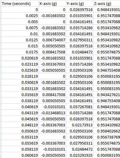
base which analyzes the results. Note that if the tester is distracted and forgets to stop the test, the app will stop taking data after a short time period.
Figure 1 and Figure 5 show the basic structure of two types of tests. The data itself is captured digitally by the app. Figure 10 shows a partial data list. The left column shows the time of the data capture after the event started. The next three columns list the acceleration of x, y, and z axes respectively. Note that the acceleration data is given in terms of g, minus the acceleration due to gravity.
After the data table is stored in the test device, it is sent as a CSV file to an online website which receives it, interprets it, and graphs it using Microsoft EXCEL.® 9 If there is no internet service, the data will be cached and sent to the CBVA website when the iDevice comes in contact with a suitable network.
An experienced analyst can capture some information by simple inspection and comparison of current vibration signature graph versus a KGP. Such an inspection can identify obvious problems such as those caused by a major mechanical problem. However research shows that a more sophisticated method will provide a wealth of information.
The visual inspection can be made by using the additional data or the trace showing an envelope (Figure 11).
During the breaker operation, data can be sampled by the iDevice (or other data acquisition devices) at rates from 100 Hz to 400 Hz depending on which version of the device is being used. Even the lowest rate is suitable for the purposes of CBVA.
To create the envelope curve, the peaks of the signature curve are captured and connected by astraight line.
Pattern recognition software (PRS) is employed feeding the raw data file to the CBAnalyzer. The PRS captures the peaks and valleys of the data and compares it to a KGP. The PRS will identify differences from the KGP to such fine detail that a problem can even be traced to a worn or missing tooth in a gear, bad or failing lubrication, or even misalignment of mechanism parts.
The PRS discussed above works well for many existing problems. Research is currently underway to use very powerful CBMAs to provide predictive information. While this particular research is in its infancy, the algorithms being used are proven in other applications, and it is expected that very good predictions will be possible.
SUMMARY AND CONCLUSION
Research has been underway on this new method for several years. Recent breakthroughs have allowed the project to progress into the development stage. At the time of this writing
(late September 2012) the beta release of the app is deployed. Several test sites are starting to use the app, with preliminary results being excellent.
The existing circuit breaker tests such as timetravel analysis yield excellent data. The cost and ease of implementation of this new approach to vibration analysis makes it very attractive to add to the arsenal of test tools. The CBVA approach using the iDevice offers the following:
1. Simplicity in application
2. Easily implemented during routine switching operations yielding easy spot checks
3. Provides quantitative data that can be analyzed, thus pinpointing problems
4. Although no pricing structure has even been investigated at the time of the writing, the cost of the test set itself (an iDevice or iPod Touch) is extremely low by the standards of other test equipment.
5. Easy first trip data collection
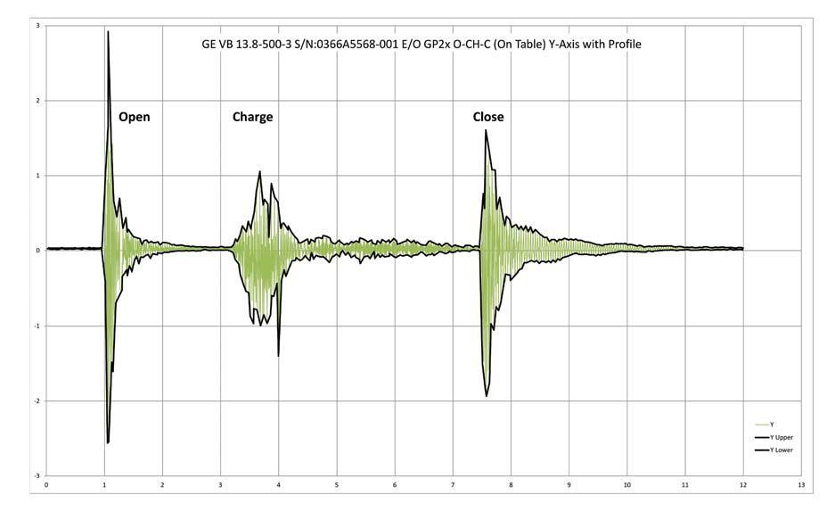
Figure 11: A vibration signature showing the calculated envelope (Courtesy of Group CBS, Inc.)
6. Since this is a noninvasive test, the chance of accidental damage to the breaker during maintenance is reduced.
7. Web-based analysis tools allow an almost instantaneous condition report
8. Test results can also be used to time the open and close of the breaker contacts.
9. Data is stored for easy retrieval and future comparison against subsequent tests.
10. Added safety since the test can be accomplished with the tester(s) located a safe distance away using remote switching devices
11. Easily established baseline data when breaker is first commissioned
12. Allows scanning of breakers quickly, and then the reconditioning or heavy maintenance focus can be on only the breakers with anomalies in their CBVA test results.
13. It is expected that this test method will welcomed by insurance providers because of the ease of implementation and the quality of the results
14. Results can be qualitatively analyzed by visual inspection of the signature graphs or quantitatively analyzed using pattern recognition software and/or CBMA.
By the time this paper appears in print a great deal of empirical data will have been gathered in the field. The authors believe that this new method will be of great value to the testing industry.
The conclusion – a simple new device for efficiently determining circuit breaker condition using CBVA has been developed to allow maintenance personnel the ability to focus attention on the breakers that need it the most.
The advantages for incorporating this new instrument into existing maintenance testing programs promises to be of great benefit.

Finley Ledbetter has worked in the field of power engineering for 20 years, including serving as an applications engineer and instructor for the Multi-Amp Institute. He was the founder of Shermco Engineering Services Division, a NETA Full Member company. Mr. Ledbetter is also the founder of Group CBS, Inc., which owns twelve circuit breaker service shops in the United States and Puerto Rico. He is a member of IEEE, an Affiliate of NETA, and a charter member and past president of Professional Electrical Apparatus Recycler’s League (PEARL).

A registered professional engineer and the founder and president of Cadick Corporation, John Cadick has specialized for more than three decades in electrical engineering, training, and management. His consulting firm based in Garland, Texas, specializes in electrical engineering and training and works extensively in the areas of power system design and engineering studies, condition-based maintenance programs, and electrical safety. Prior to creating Cadick Corporation and its predecessor Cadick Professional Services, he held a number of technical and managerial positions with electric utilities, electrical testing companies, and consulting firms. In addition to his consultation work in the electrical power industry he is the author of Cables and Wiring, The Electrical Safety Handbook, and numerous professional articles and technical papers.
Dennis Neitzel and Dan Neeson, Preventive Maintenance and Reliability of LowVoltage Overcurrent Protective Devices, Pulp and Paper Industry Technical Conference, 2007, Conference Record, PP 164-169
1 First trip is defined as the first time a circuit breaker opens after an extended time in service.
2 The quality or state of being flexible : flexibility, bendability, ductility, elasticity, flexibleness, give, limberness, malleability, plasticity, pliancy, resilience, suppleness.
– Excerpted from American Heritage Talking Dictionary Copyright © 1997 The Learning Company, Inc. All Rights Reserved.
3 The tendency of an object to stay in motion unless it is acted on by an external force.
4 The action of a substance or of an element in a mechanical or electrical device that gradually reduces the degree of oscillation, vibration, or signal intensity, or prevents it from increasing.
5 Here we are assuming that the mass of the spring and all other components are negligible compared to the weight’s mass.
6 Throughout this paper the term iDevice shall mean iPhone®, iPad®, or iPod Touch®. All three are registered trademarks of Apple, Inc.
7 Although all three iDevices can be used, size and weight make the iPhone® or the iPod Touch the obvious choices.
8 CBAnalyzer is Copyrighted and Trade Marked by CBS ArcSafe.
9 EXCEL is a registered trademark of Microsoft


Long-time NETA Accredited Company Shermco Industries recently announced that it has been acquired by funds managed by the GFI Energy Group of Oaktree Capital Management, L.P. Oaktree acquired Shermco in partnership with its existing management team, a team that will continue to serve in the same capacity and be led by Shermco CEO Ron Widup.
Ron commented, “We have always been very proud of our growth and reputation in the NETA community, and it is directly attributed to all of the great people we have working for us. This new chapter in the Shermco book makes for exciting times, as our new-found partners at Oaktree bring additional capabilities and resources to help us achieve bigger and better things for our employees and the industry.”
As a platform for growth, Shermco plans to extend its service model throughout North America. In addition to continuing to grow organically, Sherm-
co will pursue targeted acquisitions of companies which offer a strategic fit with Shermco’s existing business. Ron went on to say, “All of us here at Shermco…we like to work hard and do so with a high regard for the safety and well being of everyone around us, and an important aspect of a work hard/work safe attitude is to have a little fun along the way. It’s nice to bundle it all up and extend that culture across the industry as we continue to grow our company.”
Based in Los Angeles, California, the GFI Energy Group of Oaktree Capital Management focuses on control investments in companies that provide equipment, services, software and infrastructure used in the North American electric power and natural gas industries. Oaktree is a leading global investment management firm focused on alternative markets, with $81.0 billion in assets under management as of September 30, 2012.


Providing low voltage circuit breaker retrofit kits with a tradition of quality products and exceptional customer service for over 15 years

Over 1000 different kits
Microcontroller based, true RMS and 16-character display
Intuitive programming and easy retrieval of last trip data
3 Different types of actuators available
Modbus communications available
Quick-Trip™ for arc flash reduction during maintenance
UL and CE labels
Over 95 different kits
Microcontroller based with 16-character display

Modbus communications available Now available with Quick-Trip for arc flash reduction during maintenance
Easy to install
AC-PRO trip units are Quick-Trip ready and only require the addition of
Provides arc flash reduction during maintenance per 2011 NEC Article 240.87
Plug-in direct replacement for Merlin Gerin & Square D Masterpact MP, IEC or UL rated breakers
User programmed to replace the STR-18M, 28D, 38S or 58U trip units
Same protective functions, settings and time-current-curves as the original STR trip unit
Information and alarm functions are standard
No physical rating plug required
Easy to read OLED display in low or high ambient light
A security code protects against unauthorized changes to settings
Trip events are time and date stamped USB port and secondary injection test port
Quick-Trip for arc flash reduction is built in, nothing additional is required





Absolute Testing Services, Inc. is an independent, third party, testing organization, performing testing per equipment manufacturer’s specification’s and NETA’s standards for acceptance and maintenance testing. Absolute solves some of the most critical and demanding electrical power challenges for hospitals, data centers, manufacturers, and industrial and commercial businesses. All services are performed by expert, certified, and factory-trained technicians.
Contractors, maintenance managers, commissioning agents, and others responsible for providing safe, warranty-worthy, and optimally functioning power systems can rely on Absolute Testing Services, Inc. to provide scheduled and emergency services 24/7. We understand that success depends on having every component of the electrical power systems working safely, efficiently, and with minimal disruption. That takes ingenuity,

knowledge of equipment capabilities and limitations, and attention to detail. It requires trained and dedicated experts who can function in the most time-critical situations, quickly assess and remedy troubled areas, and develop solutions for extending the life of a facility and its equipment.
Absolute’s fast-response field service teams are guided by 30+ years of electrical power systems experience for low-, medium-, and high-voltage facilities. Tuned in to the most advanced testing, maintenance, repair, and commissioning methods, Absolute Testing Services, Inc. will deliver superior service along with peace of mind.
advanced testing, maintenance, repair, and commissioning methods, Absolute Services, Inc. will superior service with of mind.
Power Systems Testing, Commissioning, and Maintenance – Be Certain with Absolute.
Fax: 713-849-3855 and power systems can rely on Absolute Services, Inc. to scheduled and on ever y component the electrical power systems and That takes
Absolute Testing Services, Inc. 6829 Guhn Road, Houston, TX 77040 Phone: 832-467-4446
Power Systems Testing, Commissioning, and Testing Inc. 6829 Guhn Houston, TX 832-467-4446

 BY KENNETH ELKINSON, MATTHEW LAWRENCE, TONY MCGRAIL, Doble Engineering Company
It is common knowledge in the electrical power industry that outages are increasingly difficult to get. Systems and assets are being pushed closer to, and even beyond, their rated limits more now than ever before. When this is combined with cuts to the testing and maintenance budget, it becomes obvious that taking circuit breakers out of service to test them does not happen as often as it should. Circuit breakers, particularly higher-voltage, transmission circuit breakers, tend to sit in open or closed positions for long periods of time, often carrying load without any operations. This is generally considered good for customer satisfaction as it is an indication that no system faults have been seen on that circuit. The question is will that same breaker operate successfully, at expected speed, clearing the next unforeseen fault when called upon to do so?
Ideally, when testing a circuit breaker, the off-line tests performed will measure travel, speed, and timing characteristics of the breaker. These tests are looking at the mechanical performance of the circuit breaker and are not focused on the dielectric integrity. First-trip testing can help the test technician determine if the circuit breaker mechanism is operating correctly by capturing the breaker’s mechanism operational characteristics and providing a graphical representation of how the circuit breaker performed in an as-found state since its last operation, no matter how long ago. From the data captured in the first-trip test, the following problems can be identified:
(dirty, burned, etc.)
charger problems
contamination issue
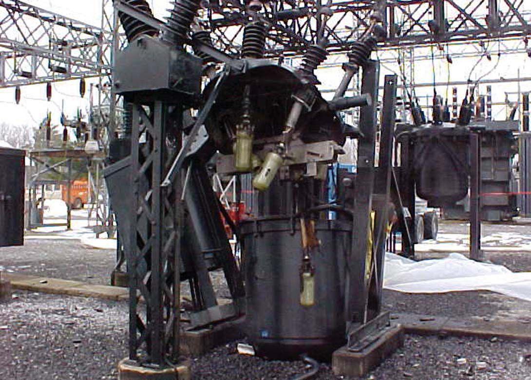

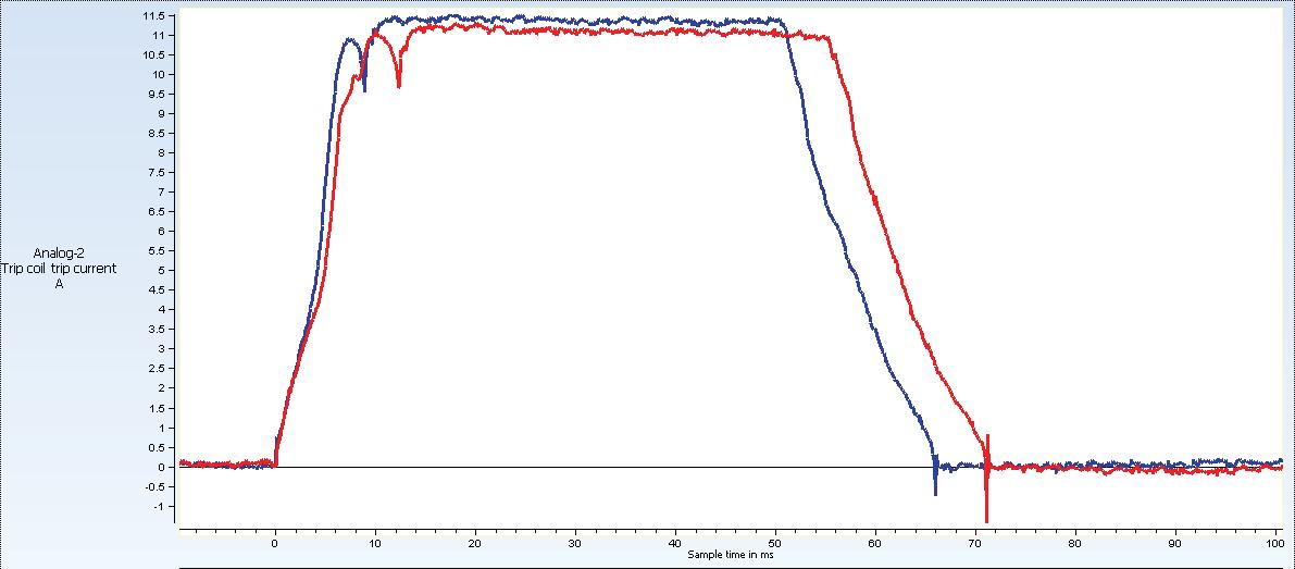


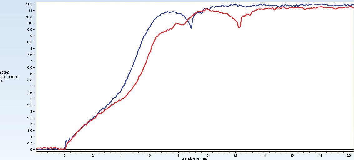

Circuit breakers, especially their mechanisms, are complex mechanical devices. As in all mechanical devices, any portion of the circuit breaker that is required to move needs to be exercised and correctly lubricated in order to be expected to operate in a dependable manner when called upon. When these movable parts do not move for long periods of time, the lubrication tends to dry out and gum up, which causes moving parts to stick. Circuit breakers are engineered to very tight tolerances with regards to distances that contacts should move and the speed with which they are to move. If any of these parts stick for any reason, it can cause the circuit breaker to function outside of the acceptable tolerances. This can lead to severe problems including circuit breaker failure. Circuit breaker failure definition includes not correctly opening to clear a fault or closing to pick up load or even worse, insulation failure causing arcing and severe damage to the circuit breaker and possibly surrounding equipment. (See Figure 1)
With this in mind, maintenance engineers are very interested in how a circuit breaker will operate if it has not been operated for a long period of time. First-trip testing is effective because it gives the engineer a glimpse of how the breaker operates in just this type of condition. Lubricated parts of the circuit breaker will typically have a greater friction on the first trip as compared to subsequent trips, so it is important to capture
this information in an as- found condition rather than after the breaker has been switched out of service for maintenance. (See Figure 2)
All of the normal test parameters are captured including trip and close coil currents, main current and auxiliary voltages, and power supply voltage. When performing the first-trip testing, these values may differ slightly from normal testing results but still need to be considered, as it is the closest test to actual in service conditions. The key is to establish a baseline and track the performance of the breaker. The knowledge can be applied to other breakers in the same family with similar mechanisms. (See Figure 3)
Another valuable aspect of the first-trip test is that it is a very fast, simple test to perform. As previously mentioned, testing and maintenance resources are scarce and need to be optimized as much as possible. If the maintenance engineer performing the test can analyze the results on the spot, the results should provide guidance as to whether additional testing is required, whether additional maintenance is required, or if the breaker can go back in service as is. This, of course, would require having previous first-trip testing results for comparison or expected results from similar type mechanisms on hand while the test is being performed. Increasingly, crews are being instructed to avoid intrusive maintenance on circuit breakers unless there is evidence
It IS necessary. First-trip testing can provide first hand evidence that this type of maintenance is or is not necessary.
The key here is the result of the test and having an understanding of what is being tested in the first place. Circuit breaker motion testing requires interpretation of the results, as what the results mean may not always be obvious. Adequate training and an understanding of the mechanical nature of circuit breakers are two key building blocks to analyzing the information the test is providing. Managing the results across a fleet of circuit breakers becomes the next consideration. Circuit breakers of similar make and model tend to have similar travel and timing test results. The value in these types of tests is fully realized when the results from a fleet of circuit breakers can be managed to allow for appropriate intervention, using today's timing results to identify which breakers are still within specification, and predict which look slower and which are already out of specification. This allows for planning of intervention and maximizing resources.
Typically, first-trip testing will provide information about trip coil currents including opening time analysis, arcing contact current measurements, contact separation, auxiliary contact timing, and battery voltage. Documentedcase studies have diagnosed lubrication issues, plunger problems, and mechanical mechanism and linkage issues. Aswith alltesting,first-triptestingisanother tool in the maintenance engineer'stoolbox to help justify tough decisions that must be made quickly. Of course, first-trip testing may provide the engineer with results that are not clear, in which case additional testing of the breaker will be required, including the normal time and travel testing, power-factor testing, contact-resistance testing, and dielectric quality.

Kenneth R. Elkinson, P.E., received his Bachelor ofScience in Electrical Engineering Degreeftom the University of Massachusetts at Lowell. Kennethhas held a number ofpositions at Doble Engineering, as field Engineer, client service engineer,andnowapparatusanalytics engineer. Previously, Kenneth worked withNational Gridinthe USas a substation engineer. Mr. Elkinson is a licensed proftssional engineer in the state ofMassachusetts.
Matthew B. Lawrence is the Solutions Manager for SFRA and circuit breaker diagnostics at Doble Engineering, focusing on diagnostic testing solutions. Before joining Doble in 2011, Matthew held positions in substation maintenance and operations and equipmentmaintenanceengineering departments at National Grid and its New England based legacy companies. His most recent role was Manager of SubstationO&MServices. Mr. LawrenceisamemberofIEEE, Affiliate ofthe IEEE Transformer Committee, and a member and past chair ofthe Doble Engineering SFRA Users Group Committee. He holds an Associates ofScience in Electronics Engineeringftom New England Institute ofTechnology and attended Worcester Polytechnic Institute School ofIndustrial Management. HealsoholdsanElectriciansLicenseintheState ofRhodeIsland.

Tony McGrail is the Doble Engineering Solutions Manager for On-Line Diagnostics, providing condition, criticality, and risk analysis for utility companies. Previously Tony has spent over 10 years with National Grid in the UK and the US. He has been both a substation equipment specialist and has also taken on the role ofsubstation asset manager and distribution asset manager Tony is a Fellow ofthe JET, a member ofthe IEEE, ASTM, CIGRE and the JAM, and is currently on the executive ofthe Doble Client Committee on Asset and Maintenance Management His initial degree was in physics. He has an MS and a PhD in EE and an MBA. Tony is anAdjunctProftssorat WorcesterPolytechnicInstitute, Massachusetts, leadingcoursesinpowersystemsanalysis.


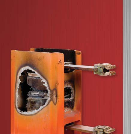




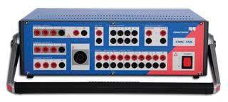
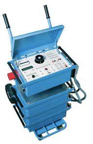
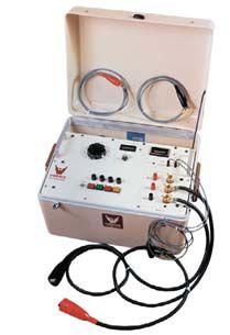


The NETA Board of Directors met on January 17, 2013 followed by the member meeting on January 18, 2013, at the Grand Cayman Marriott Beach Resort. The board continued to discuss strategic direction for the association, reviewed new member applications as well as those in progress, and reviewed the financials for the first two fiscal quarters of the year.
The members met for updates on the progress made with many association programs including the continued development of relationships with architect and engineering firms, refinement of the marketing message as it relates to NETA Accredited Companies, a report on the status of the ANSI/NETA standards, as well as many technical reports from NETA’s various representatives to external standards committees such as NFPA, CSA, and IEEE.


 BY KERRY HEID, Magna Electric Corporation
Electrical equipment maintenance is crucial for a number of reasons. First and foremost, maintenance and testing of critical protection systems is required to ensure that worker safety is not in jeopardy. Also, electrical maintenance is critical in ensuring that uptime is maximized and that electrical power system equipment reaches its intended life cycle. Many approaches can be taken toward the various equipment and systems, and this article will take a look at five varying strategies and their applications.
Reactive Maintenance is sometimes called run to fail and allows systems and equipment to operate with little or no maintenance.
The advantage to reactive maintenance is that maintenance dollars will not be expended until something fails. This means while the equipment is running, a smaller maintenance staff will be required and equipment can operate without the need to organize maintenance outages.
There are some disadvantages to reactive maintenance. When power system equipment fails, the failure is often catastrophic and usually requires much capital and labor hours including overtime to make the repairs. The failure often cascades into surrounding equipment as well. These failures can create a major disruption to production or uptime within the facility.
It should be noted that reactive maintenance is not recommended for critical switching and protection schemes in electrical power system applications.
Some application examples are noncritical systems or systems with built in redundancy
Preventative Maintenance uses a time-based or machine run-based schedule to predetermine degradation with the aim of extending the useful
life. Expending time and resources to increase the system reliability, control degradation, and extend equipment life are main goals.
There are a number of advantages to the preventative maintenance approach. The equipment life will be extended if the manufacturer’s maintenance requirements are heeded. Also, time-based maintenance allows for maintenance work to be scheduled for flexibility in maintenance periods.
Some disadvantages of preventative maintenance are that catastrophic failures are still possible. Also, this maintenance approach is labor intensive and often includes activities that are unnecessary.
Preventative maintenance works well with a skilled maintenance staff and equipment that can be regularly shut down to perform the work.
Predictive maintenance or condition-based maintenance uses measurements to detect failure at the onset of degradation. This allows for small issues to be eliminated or controlled prior to system failure. Predictive maintenance uses tools to determine maintenance task requirements based on quantifiable equipment conditions.
This type of maintenance has many advantages. This approach pinpoints what activities are required and then allows those activities to be scheduled. This increases uptime and reduces
unnecessary maintenance while optimizing the operation of the equipment.
Disadvantages are the initial costs associated with diagnostic equipment and training of maintenance personnel. Another disadvantage is that management may not see all the benefits in the initial investment of personnel and equipment.
This has wide application in the electrical power system business. Transformer oil analysis and switchgear partial discharge analysis are just two of the many applications.
The approach to reliability centered maintenance (RCM) uses a number of factors including the probability of equipment failure and a combination of other maintenance practices including predictive maintenance. RCM provides a high level of reliability and cost effectiveness by using a systematic approach to the facility’s equipment and resources.
There are many advantages to RCM. This approach recognizes that not all equipment in a facility is of equal importance. It also recognizes that some equipment is more reliable and requires a different methodology. RCM also strives to optimize the available personnel and financial resources.
There are some disadvantages of the RCM method. The cost for training, equipment, and startup are significant before the real savings can be appreciated.
The RCM approach works best where a mix of philosophies will bring the most benefit to the facility’s budget and resource availability.
Risk Based Maintenance (RBM) uses a process where risk can be quantified and prioritized so other types of maintenance can be established. Owners use risk assessment and criticality to manage the maintenance and inspection programs involving reactive, preventative and predictive philosophies.
RBM has a few advantages particularly from a business perspective. This approach allows the asset owners to maximize the resources and can be the most cost effective manner to establish a maintenance program. Maintenance is based on risk factor and vitality.
RBM requires special expertise to assess the risk. This process requires extensive data and failure calculations to effectively apply.
Electrical maintenance is critical for worker safety, facility uptime, and for equipment to reach its full life cycle. Many approaches can be taken based on the availability of equipment outages, facility design, and the availability of resources. However, electrical power system equipment such as critical switching and isolation devices as well as protective relaying systems should always be given a high priority for maintenance as the safety of personnel depend on its correct operation.

Kerry Heid is the President of Magna Electric Corporation, a Canadian-based electrical projects group providing NETA Certified Test Technicians and related products and solutions for electrical power distribution systems. Kerry is a past President of NETA (InterNational Electrical Testing Association) and has been serving on its board of directors since 2002. Kerry is chair of NETA’s training committee and is a Senior Certified Test Technician Level IV. Kerry was awarded NETA’s 2010 Outstanding Achievement Award for his contributions to the association.
Kerry is the chair of CSA Z463 Technical Committee on Maintenance of Electrical Systems. He is also a member of the executive on the CSA Z462 technical committee for Workplace Electrical Safety in Canada and is chair of Working Group 6 on safety-related maintenance requirements as well as a member of the NFPA 70E – CSA Z462 harmonization working group.
Kerry has performed electrical engineering, testing, maintenance, commissioning, and training activities throughout North America for the past 23 years with Westinghouse Service and Magna Electric Corporation. He resides in Regina, Saskatchewan, with wife Pam and sons Brendan and Colby.

National Switchgear has a broad line of new, used and remanufactured electrical switchgear products. And literally millions of parts, new and used. But that’s only part of the story. We also have the willingness to listen, the experience to know what you need, the capacity to have it in stock, and the responsiveness to get it to you fast. Plus, the additional value of full-service electrical testing and onsite maintenance services.
So, if you’re still calling anyone else for power distribution equipment, maybe it’s time to switch. 800-322-0149 nationalswitchgear.com
ANSI/NETA Standard for Acceptance Testing Specifications for Electrical Power Equipment and Systems
FOR ELECTRICAL POWER EQUIPMENT AND SYSTEMS
Join NETA’s Alliance Program today for savings on ANSI/NETA ATS-2013
Receive additional discounts on other NETA publications Visit www.netaworld.org
This document specifies field tests and inspections used to assess the suitability for initial energization of electrical power equipment and systems.
ANSI/NETA ATS-2013 covers equipment such as:
Switchgear
Transformers
Cables
Switches
Circuit breakers
Protective relays
Rotating machinery
Motors
Capacitors and reactors
Regulating apparatus
Grounding systems
Batteries
Emergency systems and more...
ANSI/NETA ATS-2013 provides the most up-to-date references to other industry standards such as ASTM, EASA, ICEA, IEEE, NECA, NEMA, NFPA, UL, and others.

See the Previous issue for information about what causes partial discharge (PD).
Partial discharges (PD) are small electrical sparks that occur when voids exist within or on the surface of high-voltage insulation of stator windings in motors and generators. These PD pulses can occur because of the thermal deterioration, manufacturing/installation processes, winding contamination, or stator bar movement during operation.
Permanently mounted PD sensors block the ac power signal (50/60 Hz) but pass the high frequency PD pulses (50-250 MHz). The type of sensor installation and test instrument depends on the machine or equipment being monitored.
The first step of PD detection is the placement of a sensor somewhere near the source of the PD. Two types of sensors referenced in IEEE

1434-2000 and IEC/TS 60034-27-2 are:
(EMC) - for motors, hydros, and small turbos. [Figure 1, Figure 2]
(>100 MW). [Figure 3]
During normal operation, a continuous PD monitoring or portable PD instrument connected to the sensors separates noise and correctly classifies the PD. Until recently such an on-line PD test had been difficult to implement due to the presence of electrical disturbances that have PD-like characteristics. This can lead to healthy windings being misdiagnosed as deteriorated, which lowers confidence in the test results. “Noise is defined to be nonstator winding signals that clearly are not pulses.” [IEC/TS 60034-27-2] Electrical noise from power tool operation, corona from the switchgear and RF sources, etc., is easily confused with PD from the machine windings.
“Disturbances are electrical pulses of relatively short duration that may have many of the characteristics of stator winding PD pulses –but in fact are not stator winding PD.” [IEC/ TS 60034-27-2] Some of these disturbances are synchronized to the ac cycle, and some are not. Sometimes synchronized disturbance pulses can be suppressed based on their position with respect to the ac phase angle.
A good on-line PD test reduces the influence of noise and disturbances, leading to a more reliable indication of machine insulation condition. Three methods of noise and disturbance separation include:
1. Band-pass filtering of PD between 50-300 MHz, whereas noise is less than 35 MHz. [Figure 4]
2. Separation based on direction-of-arrival to two sensors connected to a single phase [Figure 5, Figure 6]
3. Separation based on pulse characteristics [Figure 7]
Although the magnitude of the PD pulses cannot be directly related to the remaining life of the winding, if the rate of PD pulse activity increases rapidly, or the PD levels are high

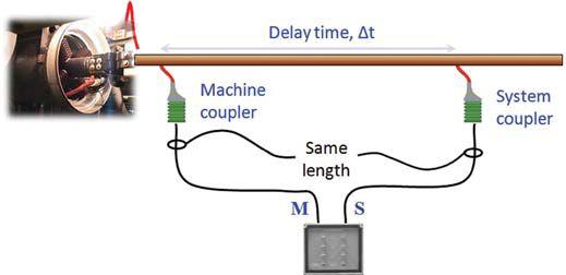

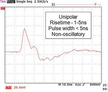
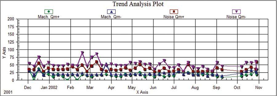
compared to other similar machines, this is an indicator that visual inspections and/or other testing methods are needed to confirm the insulation condition [IEEE 1434-2000].
If the unit operating parameters – voltage, load, winding temperature, and gas pressure –are similar to those of the previous test, then a direct comparison can be made between the two test results. Environmental conditions such as humidity may have a very noticeable impact, especially if the surface contamination becomes to some extent conductive when damp, so it should be recorded from one test to the next. When a trend line is established for PD tests taken over a period of time, it will be obvious that most show small up and down variation between successive tests [Figure 8]; however, a sustained upward trend indicates developing problems.
If the PD magnitudes by the same test method from several similar windings are compared, the windings exhibiting higher PD activity are generally closer to failure. Due to the influence of the test arrangement on the results, the test setup (sensors and test instrument) must be the same for all comparisons.
One example is the statistical summaries of the peak magnitude, Qm, values based on the most recent Iris Power database that contains several thousands of test results. Each table shows the average, maximum, and the 25th, 50th, 75th, 90th, and 95th percentile ranks [Table 1]. The 25th percentile is the Qm magnitude for which 25 percent of the test results are below, similarly for the other percentiles. Normally, there is concern for a winding if the Qm in
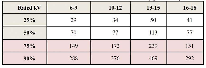
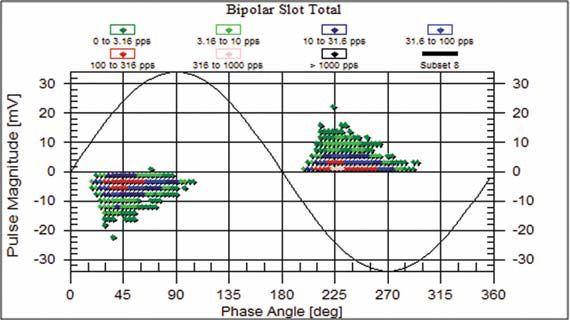
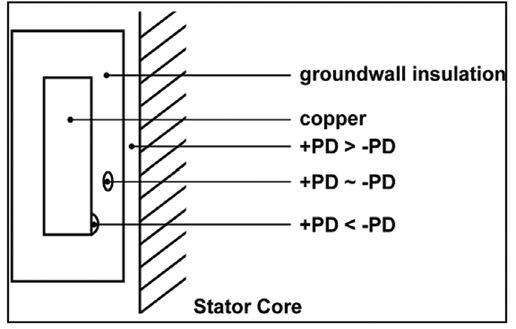
a machine is higher than the 75th percentile and increasing.
The pulse distribution with respect to the ac phase position in the 3D plots can assist in determining the source of any problems in the stator winding. Normal pulse distributions are Gaussian, negative pulses clustered between 0-90° and positive pulses between 180-270°, and are indicative of spherical shaped voids within the slot section of the core [Figure 9].
Due to space charge effects, a pulse will occur in a specific direction based on the proximity of the void to a metallic substance [Figure 10]. No polarity predominance is normally the result of internal delamination (overheating) of the insulation system that has forced the organic bonding material of the insulation to lose its adhesive strength. Negative PD predominance may be the result of voids created due to either improper manufacturing or thermal cycling that has stressed the bonds between the conductor and the first layers of insulating tape. Due to pulse behavior, positive PD predominance normally indicates PD originating on the surface of the insulation system, such as slot discharge, endwinding tracking, and gradient or semicon coating deterioration. Surface PD happens when a coil does not have intimate contact with the core due to shrinkage, improper installation, bar/ coil movement, or perhaps degradation of the voltage stress control coatings.
When using a PD measuring system that adequately separates noise and disturbances, monitoring of the PD activity in a running motor or generator stator winding can be as simple as evaluating the trend, comparing to a statistical database, and evaluating the polarity predominance of the pattern. With this configuration, monitoring for most of the failure mechanisms common to stator winding insulation can be quickly and easily evaluated while the machine is subjected to normal thermal, electrical, ambient and mechanical stresses.

Vicki Warren, Senior Product Engineer, Iris Power LP. Vicki is an electrical engineer with extensive experience in testing and maintenance of motor and generator windings. Prior to joining Iris in 1996, she worked for the U.S. Army Corps of Engineers for 13 years. While with the Corps, she was responsible for the testing and maintenance of hydrogenerator windings, switchgear, transformers, protection and control devices, development of SCADA software, and the installation of local area networks. At Iris, Vicki has been involved in using partial discharge testing to evaluate the condition of insulation systems used in medium- to highvoltage rotating machines, switchgear and transformers. Additionally, she has worked extensively in the development and design of new products used for condition monitoring of insulation systems, both periodical and continual. Vicki also actively participated in the development of multiple IEEE standards and guides and was Chair of the IEEE 43-2000 Working Group.






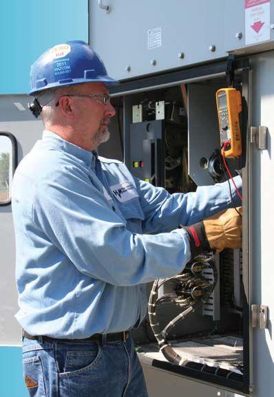



Oil circuit breakers (OCBs) were first used by Boston Electric Light Company in 1898 in which initial versions were operated to open and close the electrical circuit. As with any new technology, numerous changes were made over the years to improve both the design and functionality of breakers, eventually resulting in the oil circuit breakers that are still in use today (see Figure 1). 1
As the result of the proliferation of SF6 breakers, the use of bulk oil circuit breakers has declined over time and a new OCB has not been manufactured for more than twenty years. However, there are still thousands of OCBs in use and they are still a critical part of power management systems. These breakers are utilized to open and close the electrical circuit as needed and involve both movable and stationary contacts that are prone to wear. Over time, these contacts as well as other components degrade, necessitating the need for preventative maintenance activities.
Insulating oils are used in breakers to assist with extinguishing the arc generated when the electrical circuit
BY DAVID KOEHLER, PAUL GRIFFIN, RICK YOUNGBLOOD, LANCE LEWAND Doble Engineering Companyis opened or closed and to dissipate heat from the arcing source. In addition to arcing, other incipient fault conditions may cause degradation of breaker components. Wear by-products from the use and aging of the components are mostly contained in the insulating oil of the OCB. Through the use of applicable laboratory testing programs, an overall equipment condition assessment can be provided by using a ranking or code to manage a population of in-service OCBs.
Appropriate oil and electrical test results may be used to determine abnormal conditions, applying diagnostics based on knowing the materials of construction of OCBs. Typical issues found in oil circuit breakers include the following:
metal components
free water
Through experience, it has been found that high ethylene, ethane, and methane gas levels are indicative of overheating issues in a breaker. Oil circuit breakers that show higher than expected levels of acetylene can be indicative of abnormal arcing conditions with excessive arc extinction durations. The ethylene to acetylene ratio is utilized to distinguish between overheating of the arcing contacts, excessive arcing, and normal operation. Overheating of the arcing contacts can occur due to poor alignment between the stationary and mobile contacts, excessive wear, and loose connections in the breaker along with other issues.
Since oil circuit breakers typically operate close to ambient temperature, Ostwald solubility coefficients reported at 25°C can then be used as a guide to determine partitioning of gases between the oil and gas space. Some of the dissolved gasses have a greater propensity to remain in the insulating fluid while others have a greater tendency to escape into the headspace region of a breaker and vent to the atmosphere.
By reviewing the data provided in Table 1, it can be seen that hydrogen, nitrogen, carbon monoxide,

and oxygen gases have relatively low solubility in the insulating fluid. Acetylene, ethylene, and ethane gases have a relatively high solubility in the insulating fluid. For this reason, hydrogen and oxygen gas levels are used to help determine if there is a plugged or narrowed vent on the oil circuit breaker. Plugged vents can be caused by birds, insects, etc. This is typically observed by DGA results showing high levels of hydrogen being present in the insulating fluid, along with decreases in oxygen levels.
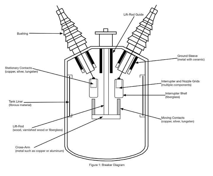
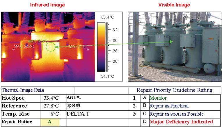
Dissolved gas analysis is the most critical test offered in our industry to identify incipient fault conditions in oil-filled electrical equipment. Infrared thermography is also used to detect overheating in oil circuit breakers as shown in Figure 2. Once a unit is identified as being a concern via thermography, the unit is already in trouble and most likely will require prompt inspection and removal from service to help minimize the chances of failure. This helps to further demonstrate the importance of regular OCB fluid testing to promote planned outages rather than forced outages.
Even though the priority rating indicates only monitoring is required, it is very obvious which tank was in trouble. If the DGA and oil quality analysis indicated that the tank required inspection, there would be no hesitation to perform this task.
A variety of tests can be used to ascertain the condition of the fluid quality in an OCB and, hopefully, the condition as well. Through experimentation and research, Doble has come to rely on a certain subset of tests which has provided good information on the condition of the breaker without duplicating the effort. The tests that Doble uses are discussed in the following commentary. In regards to measurement of dielectric breakdown voltage
on OCB fluids, the ASTM D-1816 test with a one mm gap is preferred over ASTM method D-877 method. D-1816 test values are more sensitive to the various impurities that can be dissolved, suspended, or in contact with the insulating fluid.
Free water is very detrimental to the dielectric strength of insulating fluids and can lead to a dielectric failure. Evaluation of relative saturation of water in oil is an effective means to review how much moisture is present relative to how much the oil can hold. For oil circuit breakers, ambient temperature and relative humidity will be the drivers for the relative saturation level of water in the insulating fluid. If a desiccant is not utilized on an oil circuit breaker, the relative saturation of water in the oil will be very similar to the relative humidity of the ambient environment assuming that the temperature inside the oil circuit breaker and that of the ambient environment are constant for a period of time. Conditions where the ambient temperature is below 0°C can form ice within the oil circuit breaker.
Because of the qualities of ice in oil, ice can be found floating in the fluid or it can also be found blocking sampling ports and oil piping at the bottom of an oil circuit breaker where it can rupture the tank. For this reason it is important when the weather turns cold to remove free water that might condense in OCBs. For the dielectric
breakdown voltage of OCBs, lower limits are used in comparison to transformers because of the breathing to atmosphere and influence of local humidity. Comparison of the results of the three phases provides useful information.
Oxidation is one of the key chemical reactions that causes insulating fluids and solid insulation to age. The initial stage of oxidation will produce polar molecules such as aldehydes and ketones. The presence of these molecules will result in a lowering of the interfacial tension value of the insulating fluid. As these polar molecules are further oxidized, acidic molecules, such as carboxylic acids, are formed. These acid molecules are also polar in nature, thus further decreasing the IFT of the insulating fluid, while showing an increase in the neutralization number. IFT values for OCBs can be used as a guide to determine the extent of polar compounds in the insulating fluid. However, since the neutralization number measures the later stages of the oxidation process, this value is important to help determine the end of life of the insulating fluid. It has also been found that since OCBs have much less solid cellulose insulation than transformers, the amount of energy required to generate the same neutralization number is much greater in OCBs, and thus limits for this particular parameter are more strict.
Particle count testing of OCB insulating fluids is very useful in determining the overall cleanliness of the fluid, and with helping to identify the amount of OCB wear particles and contact degradation. Particles greater than 50 microns tend to have a significant impact on the dielectric strength of the insulating fluid. Ratios are used to compare the various particle size ranges to help determine the severity of degradation of components.
Particles suspended in the insulating fluid can be examined by obtaining a representative sample of the fluid in the laboratory and passing it through a 0.45 micron filter. The filter is examined to determine the relative amounts of carbon, fibers, and other particles present in the fluid. Abnormal
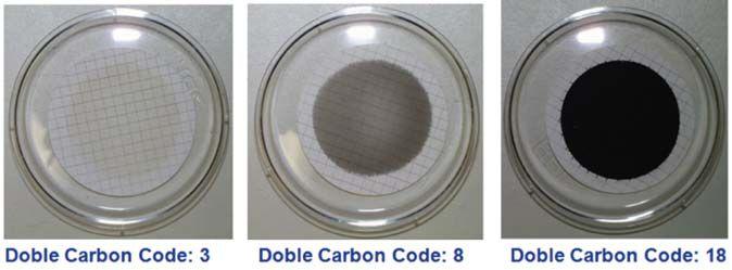
levels and types of contaminants on the filter are noted. This test is also useful to compare with the amount of particles found during the quantitative particle count analysis.
The Doble carbon code provides a simple qualitative analysis of the degree of carbon contamination found when filtering the insulating fluid through a 0.45 micron filter. Insulating fluids tends to be dark when sampled from an in-service breaker because of the carbon created in the extinguishing of an arc. Larger amounts of carbon may be normal but that depends on the circumstance (See Figure 3).
Iron, lead, copper, silver, and silicon are some of the critical metals and elements used to monitor the condition of an OCB.
Likely sources of the above mentioned metals are:
operating mechanism
Lead: Contamination with soldered materials
wear indicating a severely worn or misaligned contact(s) that should be monitored, or indicative of degradation of the cross-arm assembly
that should be monitored
component made of fiberglass, such as a liftrod or the interrupter shell.
The Doble Breaker Analysis Program utilizes a 15-point system to develop the appropriate condition code. DGA results have the most impact on the point scale followed by water, dielectric strength, neutralization number, and the particle count results and concentration ratios between the different micron class sizes. Metalsin-oil results are utilized if the concentrations of key metals are higher than established threshold levels. Condition codes range from a 1 (worst case) to 5 with most equipment ranking a 4 or 5 as shown in Table 2.
Over the years, as more data comes into the database, the percentages of each condition code have slightly changed, but it has never been more than one percent for a condition code of 1 and two percent for a condition code 2. Table 2 provides quite a bit of useful and interesting information. It shows that with this condition-based technique, it is possible to prioritize those OCBs that really need work (those having a condition code of 1 or
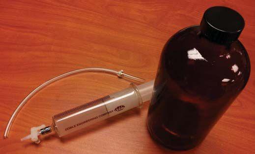
2), only 5 to 10 percent need closer monitoring and that over 90 percent require no maintenance at all thus providing a much more manageable work load. In addition, it is applicable across all service territories or customers.
Probably the single most vital aspect of a conditionbased oil sampling program is to provide a sample that reflects the bulk oil of an OCB. Because of the way that OCBs are designed and plumbed, it is easy to retrieve a sample that is not representative and thus have results that lead to a false positive (an indication that an OCB needs work when it really does not). In order to obtain a representative oil sample, Doble recommends the following:
if the tank has less than 300 gallons (1135 liters) of fluid.
if the tank has 300 or more gallons of fluid. plastic bottle for samples. being sampled.
sampling in syringes.
performed to establish new baseline. An example of some of the materials required for sampling is shown in Figure 4.
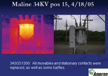
CASE STUDY #1
Infrared thermography and high concentrations of hydrocarbon gases indicated a problem. The combustible gas generation rate and ratio of ethylene to acetylene also indicated a thermal problem was developing.
In all the cases presented, the scoring of the condition code was performed after the fact but
CASE STUDY
Infrared thermography confirmed the overheating and associated coking within tanks 1 and 3 based on the DGA results. Elevated copper levels were confirmed by internal inspection showing degraded movable contacts.
The ratings for these tanks are as follows:
Tank 1
Condition Code: 1
Action: Remove from service Immediately
Remedial Action: All stationary and movable contacts were replaced
it does show how the Breaker Analysis Program would have rated the oil results.
Condition Code: 2
Action: Investigate immediately
Remedial Action: All stationary and moveable contacts were replaced, along with some interrupters
Tank 2
Condition Code: 3
Action: Monitor – Resample in three months
Remedial Action: All stationary and movable contacts were replaced
Tank 3
Condition Code: 2
Action: Investigate Immediately
Remedial Action: All stationary and movable contacts were replaced

Pictures of the inspection and findings are shown in Figures 6 through 9.
Findings: this breaker. mography scan. clear indication of contact overheating (wear), especially in Tanks 1 and 4. count levels.
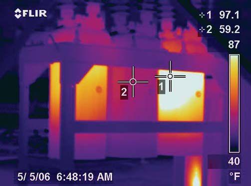
6: Infrared Thermography

Figure 8: Coking and Degradation of 345G’s Stationary Contact
In this case the ethylene to acetylene ratios were elevated for all three tanks, but especially for tanks 1 and 3. These ratio levels were confirmed by evidence of coking during internal inspection. Poor contact compression and higher than expected operation count were the main cause of abnormal DGA results. Metal results and particle count data were slightly elevated for this type of breaker.
[see Table 5]
The ratings for these tanks are as follows:
Tanks 1, 2 and 3
Condition Code: 1
Action: Remove from service Immediately
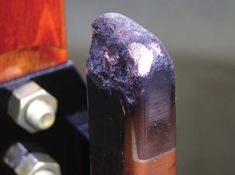
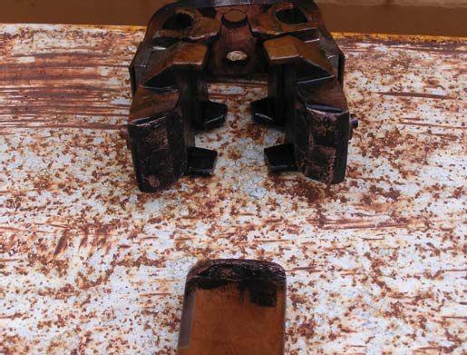
Figure 9: Stationary and Movable Contact for 345G
Remedial Action: Replaced components that were either broken or those not operating properly
[See Figures 10 & 11]
Findings:
intermediate contacts recent line construction and 3 were the most severe.
Figure of 345G
Analytical testing of mineral oils used in oil circuit breakers is a cost effective way to identify necessary condition-based maintenance. Failure and forced outages can be minimized by implementing an effective oil circuit breaker maintenance program resulting in significant savings. This paper presented information on the key analytical tests used to identify abnormal conditions within oil circuit breakers and as detailed by the three case studies. Strong correlation exists between analytical testing techniques and findings in the field. By examining analytical test data, effective inspection and maintenance intervals can be established along with resampling frequencies.


The authors wish to thank Ameren Missouri for the case study data and pictures.
1 “IEEE PES Circuit Breaker Tutorial”, Pittsburgh, PA, July 24, 2003.
2 “Annual Book of ASTM Standards Volume 10.03”, 236 pp, 2012.
David Koehler is the Manager of Doble’s Laboratory in Indianapolis. He received a Bachelor’s Degree in Chemistry from Indiana University and an M.B.A. from Indiana Wesleyan University. He has more than 14 years experience in the testing of insulating fluids and management of analytical laboratories. David has provided numerous technical presentations at various power industry conferences. David is Chair of the IEEE-Central Indiana Section and IEEE Region 4 East Area Chair. He serves on ASTM D-27 Technical Committee on Electrical Insulating Liquids and Gases and is a past Executive Committee Member of the Indiana American Chemical Society.

Paul Griffin is Doble Engineering Company’s Vice President of Consulting and Testing Services. Prior to his current role, he has held various positions including Laboratory Manager and Vice President of Laboratory Services. Since joining Doble, Mr. Griffin has published more than 50 technical papers pertaining to testing of electrical insulating materials and electric apparatus diagnostics. He is a Fellow of ASTM and a member of Committee D-27 on Electrical Insulating Liquids and Gases. He was formerly ASTM Subcommittee Chairman on Physical Test, ASTM Section Chairman on Gases in Oil, and the Technical Advisor to the U.S. National Committee for participation in the International Electrotechnical Commission, Technical Committee 10, Fluids for Electrotechnical Applications. Mr. Griffin is a member of the IEEE Insulating Fluids Subcommittee of the Transformer Committee.

Rick Youngblood is a Principal Engineer at Doble Engineering Company. He graduated from Indiana State University with a BS in Electrical Technology in 1973. Rick joined Cinergy Corporation in 1982 as an entry level engineer working in their electric shop. Rick served as project engineer after receiving his BSEE from Purdue University in 1985. In 1987 Rick became the Manager of Technical Services in their Northern Division responsible for construction, maintenance, and metering. Rick was later responsible for implementing Cinergy’s CMM System Maximo and creation of their predictive and preventive maintenance programs. In 2000 Rick became supervising engineer for substation services where he remained until taking early retirement in 2004. Rick joined American Electrical Testing Company in August of 2004 as Regional Manager heading up their Midwest office located in Indiana. He became a NETA Certified Test Technician, Level 3. Rick moved in 2010 to his present position as Principal Engineer in the Client Service Group for Doble Engineering Company where he shares responsibilities for the western half of the Great Lakes Region.

Lance Lewand is the Laboratory Director for the Doble Insulating Materials Laboratory and is also the Product Manager for the Doble DOMINO®, a moisture-in-oil sensor. Since joining Doble in 1992, he has published more than 75 technical papers pertaining to testing and sampling of electrical insulating materials and laboratory diagnostics. Mr. Lewand was formerly Manager of Transformer Fluid Test Laboratory and PCB and Oil Field Services at MET Electrical Testing Company in Baltimore. Mr. Lewand received his Bachelor of Science Degree from St. Mary's College of Maryland. He is actively involved in the American Chemical Society and is a representative of the U.S. National Committee for TC10 of the International Electrotechnical Commission and ISO TC28, ASTM D-27 and is the subcommittee chair 06 on Chemical Tests, secretary of the Doble Committee on Insulating Materials, and the newest recipient of the ASTM Award of Merit for Committee D-27.



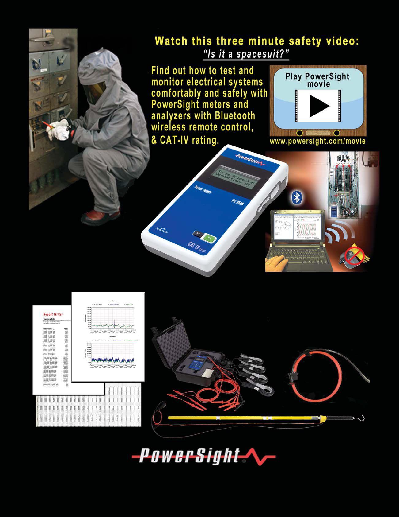



Nearly all utilities and many major facilities utilize open-bus outdoor substation equipment to distribute power. A combination of thermographic, ultrasonic, corona camera, and radio-frequency antenna technologies can be used effectively to detect various problems before they cause failure. This article will review the advantages of these technologies to help determine the best solution for finding problems.
Although several no-outage technologies exist for outdoor equipment, the following short list summarizes the most popular and successful instruments used today.
Thermographic – Infrared imaging is a very good tool for the detection of thermal problems, especially those related to poor connections (see Figure 1). This technology does well for detecting problems with high resistance under load but does not detect voltage (insulation) problems very well if at all.
Airborne Ultrasonic – Listening to ultrasonic signals from substation equipment surfaces can help detect potential insulation problems. By adding a parabolic dish to concentrate the signals, distant objects can also be surveyed (see Figure 2). One difficulty with this technology is the inability to distinguish between serious insulation defects and benign corona occurring from sharp protrusions on conductors or hardware.
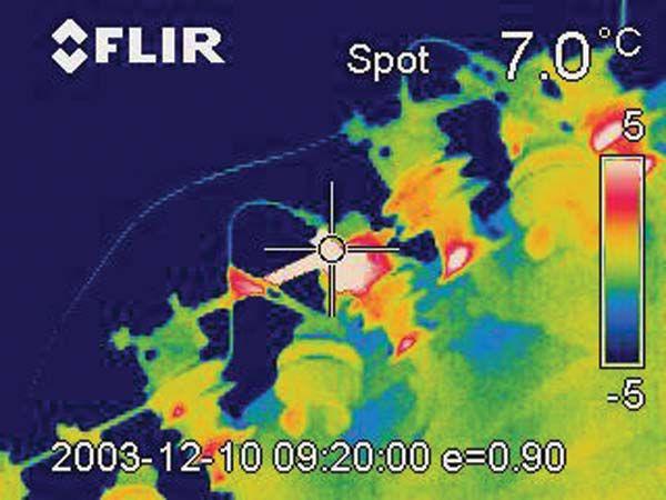
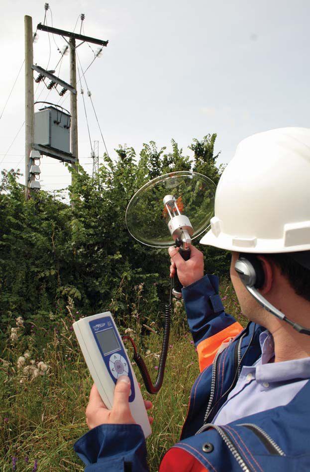
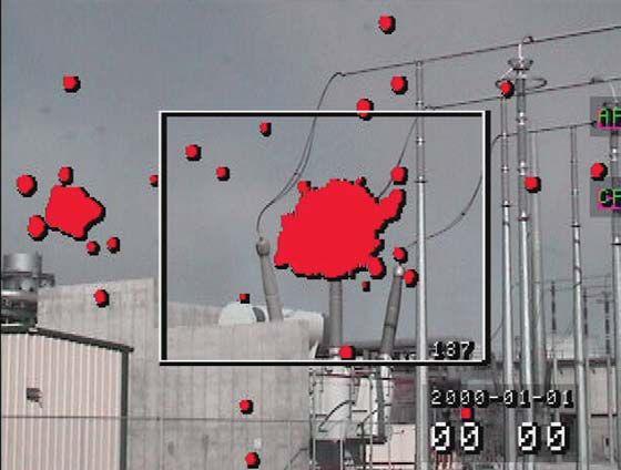
Figure 3: The Red Cloud at the Top of the Center Bushing Represents Ionized Air as Seen in this Corona Camera Image.
CORONA CAMERA – This technology detects the ultraviolet light associated with surface partial discharge or corona and provides an image of the precise location of the activity (See Figure 3). Unlike airborne ultrasonic instruments, benign corona can be distinguished from more serious problems using the corona camera. These instruments are very directional, and defects can be hidden from detection if they occur underneath or on rear component surfaces. Therefore, airborne ultrasonics should be used to supplement corona camera surveys. Except for contact ultrasonics, none of the above instruments can detect internal defects.
CONTACT ULTRASONICS – Placement of ultrasonic sensors against oil-filled equipment tanks has been successful in detecting internal insulation problems. However, this technique is often unreliable due to noise created by normal mechanical vibration. Additionally, internal components may obstruct the signal so that it cannot reach the sensor. One approach to remove greater amounts of noise is to use higher frequency sensors. Another approach is to utilize multiple sensors to triangulate the PD source in order to obtain better location.
RF ANTENNA TECHNOLOGY – Antenna based instruments, such as the one shown in Figure 4 have been developed using a variable-frequency, wide-band, electromagnetic signal receiver connected to a unique directional antenna assembly to detect and pinpoint internal and surface defects in outdoor, open-bus substation and switchyard equipment. This instrument has helped fill some of the gaps left open by the other instruments by having the unique capability to detect internal problems. Used as a stand-alone technology or better yet in combination with the other technologies, a new level of reliability can be achieved.
RF antenna instruments are lightweight and relatively easy to use. To survey a substation, the technician merely walks through the yard while point-

ing the instrument at the various equipment while listening for partial discharge (PD) activity and observing the phase resolved display for PD activity patterns.
In substations and switchyards where a lot of benign corona activity exists, a frequency can be selected above the level in which the majority of corona activity ceases. This allows the technician to only detect defects while ignoring benign corona.
Smaller substations can be quickly scanned in minutes, often from outside of the fence, while large switchyards require briefly walking around the equipment in a pattern to ensure nothing is missed.
By utilizing a combination of technologies, it is possible to identify all common types of equipment failure modes in outdoor substations and switchyards including thermal related, corona,
surface tracking, and internal partial discharge defects. Reliability will be increased and operating costs will be reduced significantly by employing a condition-based maintenance strategy that implements these supplemental instruments.

Don A. Genutis received his BSEE from Carnegie Mellon University. He was a NETA Certified Technician for 15 years and is a Certified Corona Technician. Don’s technical training and education are complemented by twenty-five years of practical field and laboratory electrical testing experience. Don serves as President on No-Outage Electrical Testing, Inc., a member of the EA technology group.


Measures
Measures









The NETA Exam Committee and Standards Review Council (SRC) met in Chicago, Illinois, on October 25-27, 2012, to continue work on their respective projects. The NETA Exam Committee drafted new questions and reviewed them as a committee before presenting them to the SRC for approval. The committee had some additional assistance from Lorne Gara of Orbis Engineering, who provided many new Canadian codes and standards questions. Strategies for producing more exam questions were also discussed, as the average length of time spent on developing one solid Level IV question is approximately one hour to assure that the question is technically sound, has appropriate references, and conforms to the NETA guidelines for question writing.
The SRC met following the NETA Exam Committee to approve the new exam questions written the previous day. The primary focus of the

meeting was the review of comments submitted during the initial balloting of the ANSI/NETA Standard for Acceptance Testing Specifications for Electrical Power Equipment and Systems (ANSI/ NETA ATS). This process assures that there is consensus among the SRC members as to the response to each comment submitted. These responses were circulated to the ballot pool for review in November, 2012. The conclusion of the public review period on January 7, 2013, marks one of the last steps in this document being issued as a revised American National Standard. The ANSI/NETA ATS covers the suggested field tests and inspections that are available to assess the suitability for initial energization of electrical power equipment and systems. The purpose of these specifications is to assure that tested electrical equipment and systems are operational, within applicable standards and manufacturers’ tolerances, and are installed in accordance with design specifications.


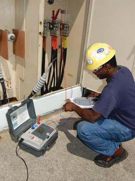


of your
equipment to chance? Trust the experts at Three-C Electrical with your
and power distribution equipment.



With substations regularly overloaded and equipment often near the end of its life, electric grid operators are challenged to improve overall system reliability. Our mission is to provide our clients with that can be used to better manage the overall life cycle of their critical electrical assets in a manner that is convenient, easy to understand, and assists in critical decision-making.
WEIDMANN DIAGNOSTIC SOLUTIONS INC. provides the vital knowledge you need to help you lower risk and improve your electrical system’s reliability. We provide through our extensive range of diagnostic products and services.
WEIDMANN DIAGNOSTIC SOLUTIONS INC. is a leader in developing condition assessment methods for transformers and all oil- lled electrical equipment, such as OCB’s, LTC’s, regulators, recti ers, and network units.


One of the most critical devices on any electricity network is the circuit breaker which can be described as the silent sentinel, standing guard over the network and only being called into action when a fault occurs.


The circuit breaker needs to operate within its composite tripping time (relay trip time + circuit breaker main contact opening time) to ensure correct discrimination with upstream circuit breakers and, therefore, minimize the number of customers disconnected during a fault operation. A slow tripping circuit breaker will not only result in unnecessary disruptions to electricity supplies, but maintaining high fault currents for extended durations can stress the network and cause damage to plant and equipment. Traditional diagnostic testing procedures usually require the circuit breaker to be isolated and removed from service; therefore, not only has the opportunity to detect the cause of the defect been missed, but also the tests do not focus on the condition of the operating mechanism apart from overall speed of operation.
Conventional testing usually requires removing the circuit breaker from service. However, isolating the circuit breaker is time consuming, as it requires a planned outage involving switching instructions and safety documents, and will often involve several engineers or technicians on site.
This process results in vital information relating to the first trip not being captured, and often the problem that caused a slow trip in a circuit breaker is temporarily cleared during this first trip operation.
When a slow trip operation occurs, the focus tends to be on timing tests to determine if the problem lies within the protection relay or the circuit breaker operating mechanism. Rarely are the problems due to slow operation of the protection relay especially if they are the electronic or microprocessor type. Occasionally problems occur with the older electromechanical type relays due to friction in the moving parts such as the induction disc. However, this is usually revealed during secondary injection tests of the relays. Timing of the circuit breaker main contacts from initiation of a trip to main contact opening merely indicates the circuit breaker is operating within its design specification. Therefore, the ini-
tial tests are inconclusive, so the focus then turns to inspecting the main operating mechanism and lubricating the numerous mechanical components. In some cases this further compounds the problem if the wrong type of lubricant is used, especially with the advent of spray penetrants which could be liberally applied. This causes an organic chemical reaction between the solvent and propellant (within the penetrant) and the soap (within the grease), resulting in varnish which causes the mechanism to stick. Instead of fixing the problem that causes the slow trip, the effort in testing and maintaining the circuit breaker is largely counterproductive.
The failure of conventional timing tests to diagnose the causes of slow tripping circuit breakers led to the search for a technique that would pinpoint the cause during the critical first trip. Although timing tests can confirm that a circuit breaker’s overall operation is within set limits, it was discovered that monitoring the current flowing through the trip coil provides a very powerful methodology for analysing the readiness of a circuit breaker to trip. Trip coil profiling was developed as a condition monitoring technique where deviation from a standard profile could help to pinpoint a potential problem within either the trip coil or circuit breaker’s main operating mechanism.
The trip coil has an electric and magnetic circuit due to the action of a plunger moving within an energized coil. This electromagnetic circuit has reluctance in the magnetic part as well as inductance and resistance in the electrical part. Normally, in most electrical circuits, we can think of the inductance as being fixed. However, in the trip coil, as the plunger moves the reluctance of the magnetic circuit is reducing which means the inductance in the electric circuit is increasing. The applied voltage, which is a constant (apart from a small voltage drop), is proportional to the rates of change of both current and inductance.
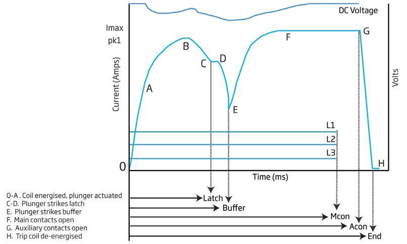
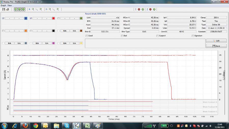
So, as the rate of change of inductance goes up the rate of change of current must go down, and viceversa. Hence an instantaneous drop in the rate of rise of the inductance, due to the plunger striking the latch or the end-stop, will cause an instantaneous rise in the rate of change of current.
Diagram 1 shows a typical trip coil profile with its distinct shape where each stage of the trip coil mechanism can be identified through its
operation and problems identified if the profile deviates from a signature trace
Table 1 provides examples of what will cause a deviation in any section of the profile curve. These examples are not exhaustive and can be simulated on a trip coil mechanism by varying the parameters that cause deviations, capturing the current profile and overlaying it on a signature profile. Each type of circuit breaker will have
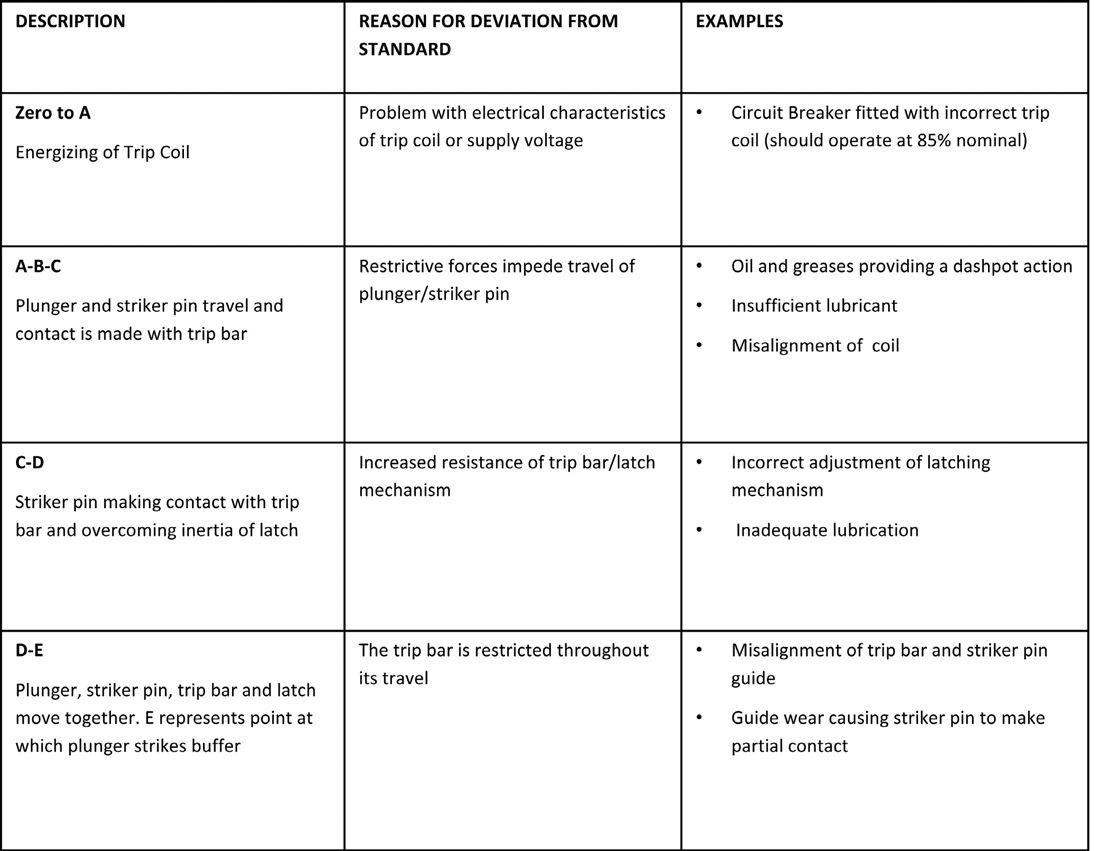
its own characteristic profile and therefore it is essential that this signature profile is acquired. Comparisons can then be made with profiles captured during on-site testing of the first trip operation and subsequent trip operation to identify potential defects.
Using First Trip Profiling to Minimize Arc-Flash Hazards
Working close to live equipment when an arc flash occurs due to an electrical fault can result in serious injury unless adequate precautions are taken. These will include selection of the right
personal protective equipment and working distances which require an arc-flash hazard analysis. A key parameter in determining the available energy from an arc flash is its duration which is directly related to the tripping time for the upstream protection device; therefore, it is vital to know that the circuit breaker will clear the fault within the specified time as a slow tripping circuit breaker will significantly increase the arcflash energy.
This is another example of where capturing the first trip and knowing how the circuit breaker will perform during fault conditions is absolutely critical.
The development of portable, light weight, hand-held devices with non-invasive connections to monitor the key current and voltage parameters has revolutionized the testing of circuit breakers.
Initially the monitoring of trip coil profiles required the hard wiring of equipment into the circuit breaker; however, this was cost prohibitive and could only be justified for circuit breakers located at extremely critical nodes on the network. The development of portable, light weight, handheld devices with non-invasive connections to monitor the key current and voltage parameters has revolutionized the testing of circuit breakers. The process of testing a circuit breaker only takes a few minutes, enabling a condition assessment of the operating mechanism to be obtained during the first trip operation. As well as indicating the health of the circuit breaker’s trip and close
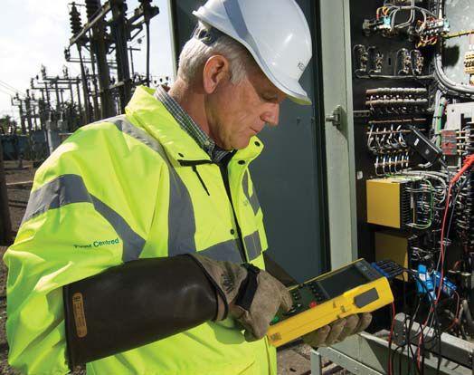
coil mechanisms, other useful parameters are obtained which include: operating time
circuit wiring
Furthermore, this information is immediately available for on-site analysis, and corrective maintenance can be targeted at a defect.
It is becoming increasingly important to make connections within the circuit breaker cubicle to
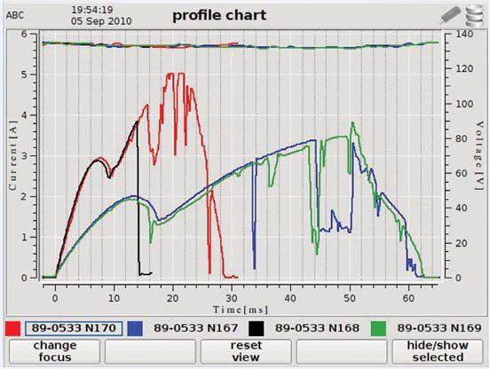

ensure that the right circuits are being monitored. Some modern circuit breakers use capacitive charged power supplies, so it is important that the current probe which monitors the dc current to the trip coil is connected close to the trip coil.
The advantage of a portable, hand-held device that can be used at any circuit breaker location can be considered as an invaluable addition to the maintenance technician’s toolkit.

Michael Skelton works for Camlin Power and is the Product Manager for the Profile P3 first trip circuit breaker analyzer.
He previously worked in Northern Ireland Electricity (NIE) for 33 years and has extensive experience in design of rural protection schemes for the 11kV overhead network, low voltage cable fault location, testing and commissioning of distribution switchgear, high voltage network planning, and general operational experience on the 11 kV and low voltage distribution network.
In his role as Director of Network Operations for NIE, one of his key targets was to reduce customer minutes lost. He fully appreciates the importance of a correct circuit breaker operation during faults to minimize the number of customers disconnected.
HVI is the source for both VLF withstand testing and cable fault location on all sizes of power cable and collector cables used on wind farms, especially for 33 kV and 35 kV cable circuits. Portable Substation and Switchgear hv test equipment available also. Buy individual products or let us design a complete VLF cable care test & locate package.

Learn how CBS MagVac’s latest magnetic-latching medium-voltage circuit breakers use mono-stable magnetic actuators and a direct linear axis of travel within the breaker element to eliminate virtually all moving parts. This gives the CBS MagVac the ability to perform continuous switching without maintenance.
No operating mechanism
No trip coil
No charging motor
Less than a dozen moving parts
Virtually zero maintenance
Guaranteed to 30,000 operations
5-Year Warranty!
When performing a circuit breaker condition analysis on medium-voltage circuit breakers located in metal clad switchgear, it is necessary to be aware of all possible hazards involved with the task. The individual must be qualified to perform the task, have a solid understanding of each hazard, and ways to mitigate risks.
In order to better understand the hazards involved with the analysis, testing, and maintenance of medium voltage breakers, let’s look at what contributes to each hazard.
Failure to properly perform lockout/tagout contributes to many injuries every year when performing maintenance on medium-voltage breakers. The source electrical energy that the breaker controls is the first and most obvious hazardous energy source that could cause injury.
Be aware of the breaker compartment layout. Many injuries and incidents occur while opening the breaker and visually verifying that it is open. Typically the compartment may be isolated, and the operating devices may be located in one compartment and the breaker located in another. The operating device may be located in the same compartment. Check the markings
for each to ensure how it is arranged. As a secondary method to verify there is no load, you may be able to utilize an ammeter within the switchgear, if one is associated with that equipment. During this step, electrical and mechanical energy become potential hazards depending upon the type of breaker. It is also necessary to isolate the electrical source, and discharge any of its stored energy. Ensure that the breaker is not removed from service while in a closed position. Always check that the breaker is open prior to racking.
Electrically de-energize the breaker from its primary energy source and ensure the breaker is disconnected from all sources of power, both ac and dc, if applicable. Once de-energized, verify that the breaker is at a zero energy state using the manufacturer’s approved method. Verify that the voltage detection or voltage measuring device is working using a known, live source, then check for zero voltage on the de-energized equipment. Test the detection equipment again with a known, live

source. This will verify that it was functional during the entire check. This is frequently known as the three step method for testing for the absence of potential.
Testing for voltage will require its own level of personal protective equipment (PPE) depending upon the voltage and test procedure. See NFPA 70E 2012 Table 130.7(C)(15)(a) - Hazard/Risk Category Classifications and Use of Rubber Insulating Gloves and Insulated and Insulating Hand Tools-Alternating Current Equipment (Formerly Table 130.7(C)(9) in the NFPA 2009. It may also be necessary to lock out and tag out the compartment the breaker has been removed from to avoid having another breaker installed in the cubicle.
However, electrical energy isn’t the only energy that requires lockout/tagout. Breakers also contain a high level of stored (potential) mechanical energy in the close charging springs and a lesser amount in the opening springs. This energy must be dissipated prior to servicing or serious injury could occur. Once the breakers have been discharged, it is also advisable to lock out and tag out the charging mechanism, if feasible. Ensure that remote operating handles are tagged in a local or manual mode.

Refer to OSHA (29 CFR 1910.269) and NFPA 70 for specific guidance on grounding locations. Use ASTM F-855 for sizing of grounds required for the task. On overhead line work, grounds must always be applied upstream and downstream of the equipment and as close to the work as possible. For switchgear, an equipotential zone is created by grounding and bonding all electrical equipment that workers can come in contact with. Always ensure that correct grounding techniques are used and that the grounds are removed once the work is complete.

Gas and hydraulic operating mechanisms may be pressurized. Ensure that the unit is depressurized and/or discharged and the source of the pressure is disabled. Once disabled this source must also be locked out and tagged out prior to performing mechanical maintenance.
Gravity is also an energy that needs to be controlled. The sheer size and weight of medium-voltage breakers makes them difficult to rack in and out or to maneuver around. When available, utilize remote racking equipment. Mechanical lifting devices may be necessary to move the breaker to an area where it can be serviced.
After verification that the breaker is electrically deenergized, rack out the breaker. In some cases this may be accomplished through remote racking and un-racking means. Ensure that proper PPE is utilized for the class of breaker that will be serviced. If an arc-flash study has been performed recently, use the information on the switchgear arc-flash labels to determine PPE, otherwise refer to the NFPA 70E 2012 - Table 130.7(C)(15)(a) again. It will indicate what level of protection is required for the class of breaker being worked on which will prevent electrical shock and protect personnel from arc-flash. However, this table provides information based upon maximum values of the short-circuit current available, the maximum clearing time in seconds and cycles, and the minimum working distance. See the information listed under Parameters in the heading of each type of equipment. If those factors are unknown, more information must be gathered prior to performing the work in order to ensure personnel safety.
Below is an example of the PPE requirements per the NFPA when racking out a breaker on 1kV
Barricading a hazardous work zone prevents other workers from inadvertently entering your work area. This will ensure that maintenance and testing is conducted in an area under your control.


through 38 kV class metal clad switchgear that has the parameters of a maximum of 35 kA shortcircuit current available, a maximum of up to 0.2 second (12 cycles) fault clearing time, and a minimum 36 inches of working distance. There is a potential arc-flash boundary with exposed, energized conductors or circuit parts of 422 inches using the prior parameters.
The NFPA 70 E states that a Category 4 arc-flash protection is required. This includes some combination of the clothing indicated in the chart below, which is taken from the NFPA 70E 2012 – Table 130.7(C)(16).
Chemicals can be a hazard, depending upon the type of breaker. Sulfur hexaflouride (SF6) gas is used as an insulator in some breakers. Caution
130.7 (15) (a)

must be taken with damaged breakers that exhibited arcing, because this can form disulfur decaflouride, a gas that is extremely toxic. Additionally, SF6 is denser than air, so it displaces oxygen in lower lying areas, such as cable pits. Ventilation must be used to avoid SF6 gas from displacing air in these areas.
Some lubricants and cleaners may pose a respiratory and skin irritant if used in enclosed areas or on bare skin. Knowledge of the material, reading its label, and checking the Material Safety Data Sheet is advised to identify any potential health effects from its use. Once again, use of proper PPE is necessary when using some cleaners and lubricants. For example, nitrile gloves, safety glasses, face-shield, and even in some cases respiratory protection may be needed.


Human error, simply put, is a person (or persons) making a mistake. To prevent an error, follow a procedure or checklist while performing the task. If one doesn’t exist, create one.
Identification should be verified and re-verified upon approaching a piece of equipment. Perform a self-check and a peer-check to ensure that the task is being performed on the correct component.
Utilize markings such as flagging when working around similar looking pieces of equipment to identify the components that should not be touched. Flagging can take several forms depending upon the company or client’s policy and procedures. Do not forget to identify, mark, then lock out and tag out all associated equipment (i.e., associated cables and compartments). Flagging could be utilized to indicate a component that is not operating normally.
Barricading a hazardous work zone prevents other workers from inadvertently entering your work area. This will ensure that maintenance and testing is conducted in an area under your control. Utilize a test stand in this area if applicable. Ensure that any control voltage required to operate the breaker during testing is within your secured area.

There are many things to be aware of when performing maintenance and testing on a breaker.
1. Obtain all service bulletins, maintenance documents, arc-flash studies, and equipment manuals prior to beginning work for that specific device.
2. Review all prints and one-line drawings associated with the equipment.
3. Establish a safe work area and barricade off the work area.
4. Perform a pre-job brief with all on-site employees.

5. Wear proper PPE.
6. If applicable, verify that there is zero energy (three-step method) and discharge all stored energy, including pressurized gasses.
7. If possible, lock out and tag out mechanical and electrical energy sources.
8. Connect grounds where and if applicable.
9. Identify, visually mark and/or flag the equipment being worked on.
Following these steps can lead to a safer work environment while performing maintenance and testing of medium-voltage breakers.


Scott Blizard is the Vice President and Chief Operating Officer of American Electrical Testing Co., Inc. During his tenure, Scott has acted as the Corporate Safety Officer for nine years. In addition, he has over 25 years of experience in the field as a Master Electrician, Journeyman, Wireman and NETA Level IV Senior Certified Technician.

Paul Chamberlain is the Safety Manager for American Electrical Testing Company Inc. since 2009. He has been in the safety field for the past 12 years, working for various companies and in various industries. He received a Bachelor of Science Degree from Massachusetts Maritime Academy.







A difficult and annoying task that routinely confronts the electrician, contractor, electrical maintenance department, testing service, or purchasing agent is in the selection of an instrument for a defined application from a seemingly bewildering host of offerings. But at least where ground testing instrumentation is concerned, the choices are fairly simple and understandable, once a few basic parameters are established. Some dedicated individuals may enjoy the challenge of effectively sifting through a hundred options, but for those who appreciate simplicity and time saved, the thanks can be given to the IEEE (The Institute of Electrical and Electronics Engineers, Inc.).
That is because ground testing, due to the considerable variability and uncertainty of earthing conditions, must be well defined in order to provide effective and comparable measurements. Accordingly, the IEEE has published Standard 81, Guide for Measuring Earth Resistivity, Ground Impedance and Earth Surface Potentials of a Grounding System. The document describes, among many other things, the proper instrument design and testing procedures for performing a ground measurement. Manufacturers of instrumentation then must fit within these guidelines in order to have a viable product, and this in turn lays the groundwork in fairly cohesive terms.
In outline form, to be considered are types of instrumentation (basically, three), tests to be accommodated (again, basically three), and broad application (two). These in turn have some subheadings, and will be discussed in order.
Instrumentation breaks down into traditional fall of potential-style testers that operate with terminals and clamp-on testers. The former in turn may have three or four terminals. These testers operate with long leads and probes by which a test current is circulated through the soil between a remote current probe at a considerable distance (the term remote earth is frequently seen in the literature) and the test ground. Meanwhile, a second probe measures the voltage drop of the soil resistance to the point of placement, and then these two parameters calculate resistance to that same point. By moving the test probes, the entire area can be profiled in order to recognize anomalies and interfering factors (See Figure 1). This technology is somewhat labor intensive, but provides a means of obtaining a measurement that is thoroughly reliable and has the backing of the IEEE standard. By manipulating the test probes, the operator is in complete control of the setup and of what is actually measured. This is in contrast to clamp-on measurements as will be explained. Three- and four-terminal testers

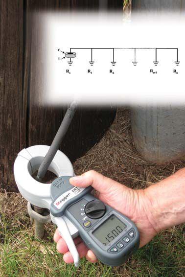
afford a thoroughly rigorous test and one that will stand scrutiny. Correctly operated, they can meet the challenge of virtually all situations. If something is wrong, the experienced operator will see it in the results and can take appropriate corrective action. The critical determination between the number of terminals will be discussed under the heading of tests.
Clamp-on tests are easy to make. That is virtually the whole story. The operator clamps the jaws of the tester around an appropriate point in the grounding system and voilà! A measurement is displayed. It couldn’t be easier (See Figure 2). But there are conditions which can be compared to the properties of terminal testers as described above. The operator is not in control; the tester is. It induces the test current onto the grounding system and measures the voltage drop around the loop. It then calculates the series loop resistance. The test current goes where it is best accommodated, not through a defined circuit that the operator has established by placement of a current probe, as described above. This is one of the critical limitations of the technology. The test circuit may or may
not include the earth! By definition, a ground test must include the soil. But if the current can find a short circuit, that is what will be measured. Large grounding electrodes, such as grids or rings, are typically connected to the electrical system at multiple points. Test current can circulate through metal, to the next connection, back up to the ground bus and back to the tester, without entering the soil. It will give a nice, low reading, but it is not a ground resistance test. In order to avoid this, the operator needs to have a working knowledge of the grounding system, not always easy or even possible.
By extension, it is obvious that the technology does not accommodate all situations. There must also be an existing return circuit. With a terminal tester, the leads and probes define the entire test setup. With a clamp-on, a complete return circuit must already be in place. This is typically provided by having the system connected to the utility. The grounded neutral provides a convenient path for the induced test current. Obviously, then, a commissioning test on an isolated ground that has just been installed
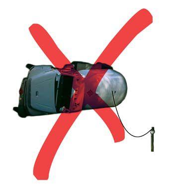
cannot be performed by a clamp-on meter. Similarly, applications where no return path exists, such as safety grounding of overturned tank trucks, cannot be accommodated by a clamp-on (See Figure 3).
Clamp-on measurements are reliable, but within their own set of parameters which the operator must understand. Simply going in blind and clamping on whatever is convenient may lead to incorrect results. Scrutiny by a third party can be difficult because there is no way to actually prove the result; what the tester says must be accepted. If the operator understands the system and where the test current goes, the result is reliable. Otherwise, it is just accepted. This contrasts with traditional testing, where the manipulation of probes enables a rigorous test that can be proven, as by graphing of results, for instance. Finally, the clamp-on method does not (as yet) have the endorsement of the IEEE standard. A revision should be available later this year that addresses this technology, which did not exist at the time of the present revision.
Next to be considered are the tests being performed. There are three. Obviously, the raison d’etre of any ground tester is the performance of a resistance test on a grounding electrode. But the corollary to grounding is bonding. That is to say, the elements of the electrical system must be continuously bonded at low imped-
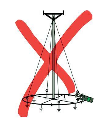
ance to the grounding electrode. What good is a low-resistance electrode in the soil if fault currents are impeded by high-resistance connections in the grounding conductors? Fortunately, this is a fairly easy test to perform with either a three- or four-terminal tester. The terminals are shunted into a two-terminal configuration and leads run to opposite ends of the grounding conductor being tested. This could be from a motor head to the ground bus, for instance. The long leads that are standard and the alternating square wave of the test current that is also standard readily accommodate this test. Modern testers also have two-pole selector positions so that terminals no longer have to be physically shunted with jumpers.
Clamp-ons are even simpler in that they perform a basic bonding test simultaneously with the ground test, by virtue of the necessity for a return current path. The experienced operator can spot this readily. An unusually high reading…one that is unlikely to have been produced by the electrode under test…indicates a weak or corroded bond, joint or weld somewhere in the return path, and that can be investigated accordingly. Various bonding conductors can be investigated by clamping different parts of the electrical system, but remote terminations that do not have a return circuit in place cannot be tested. They will simply show as an open.
The third test that may be performed by a ground tester is soil resistivity. This is the measurement of the electrical properties of the soil itself, independent of any installed grounding structure. The data is used, among other things, to design and install electrodes that will meet specifications. Here, a fourterminal model is a necessity. Various test configurations exist and are described in the literature, but they typically call for two current probes to establish an even test current over a designated area and two potential probes to measure the voltage drop within the designated zone; hence, four terminals.
The two broad areas of application are electrical and geophysical. This article has focused on the electrical: grounding electrodes, the bonding of the system to them, and the conductance of the surrounding soil. Geophysical testing is considerably different, involving applications such as the inhibition of corrosion along pipelines and deep vertical prospecting for changes in resistivity that may indicate deposits of ore and the like. Testers for this application are comparatively heavy-duty, often requiring higher voltages and currents in order to permeate large spheres of influence. Testers for the electrical arena, by contrast, can be limited to safe levels of voltage and current for operator safety because they have sufficient sensitivity to get the job done. Such testers may also be used in geophysical applications, but the operator needs to know their limitations.
In approaching the selection of a tester, first determine whether for geophysical or electrical and then proceed to the appropriate market. If electrical, the next determination is whether it is to be used exclusively on an existing plant. If so, a less expensive three-terminal model will do fine. But consider the future. If situations may arise where prospecting new ground or designing a new system may occur, then a four-terminal is a must. Clamp-on testers are excellent time savers, but do not meet all situations. Be sure to avoid opens (not connected to the power system), shorts (multiple
connections from the system to the grounding electrode), and requirements for proof of test and standards conformance. If these conditions are met, then the ease-of-operation of a clampon may make it the preferable choice.
One additional consideration is worth noting. Grounding grids themselves may sometimes require testing; that is to say, the actual physical integrity of the grid itself below grade, and not just its resistance to remote earth. This function can be performed in part by models already mentioned, but not rigorously or thoroughly. A terminal tester may be connected in a twoterminal configuration between various points of access and give some indication of the integrity of the connection below. A clamp-on can be applied judiciously to various points around a system and give an idea of the continuity between those points. This may be enough as a spot check. But for rigorous proofing of belowgrade integrity, there exist dedicated high-current testers that can be connected at all accessible points and test the ability to pass current around the grid. Look for a grid tester, not a ground tester, for such requirements.
Once these fundamental considerations have been met, the refined selection can be made on the remaining distinctions between models, such as noise suppression, range of measurement, safety conformance, field readiness, result storage, and the like. These are largely a matter of operator preference or organizational requirements and are easily addressed.

Jeffrey R. Jowett is a Senior Applications Engineer for Megger in Valley Forge, Pennsylvania, serving the manufacturing lines of Biddle, Megger, and multi-Amp for electrical test and measurement instrumentation. He holds a BS in Biology and Chemistry from Ursinus College. He was employed for 22 years with James G. Biddle Co. which became Biddle Instruments and is now Megger.

ANSWER 1
1. First-Out Timing is performed to ensure:


c. Circuit breakers often sit for extended periods of time without operating. As they sit, current is flowing through them, drying out their lubricants. When they are called on to operate, maybe they will or maybe they won’t. The problem is that they will often work just fine after a few operations, but what will they do on that very first trip? That’s the one that really counts.
ANSWER 2
2. What two quantities are usually measured with a circuit breaker motion analyzer?
a. Circuit breaker time/travel analyzers can measure many things; contact bounce, overtravel and contact wipe. Their primary purpose though, is to measure the distance the contacts travel (displacement) and how fast they move (velocity).
ANSWER 3
3. Partial discharges are created by:
a. Voids and air pockets in insulation can have electrical discharges (ionization) when they are in high-voltage fields. This discharge can be measured and monitored, either while the equipment is energized (for continuous monitoring) or during specific tests.
4. What test will indicate the serviceability of a mediumvoltage vacuum interrupter?
a. Vacuum bottle integrity test. The vacuum bottle integrity test will detect vacuum bottles that have insufficient vacuum to safely interrupt fault-level current.
ANSWER 5
5. When performing insulation power factor tests on medium-voltage circuit breakers, what quantity is normally measured?
a. Because the device is mostly resistive, the specimen’s watts loss is usually recorded, instead of percent power factor.

NFPA Disclaimer: Although Jim White is a member of the NFPA Technical Committee for both NFPA 70E “Standard for Electrical Safety in the Workplace” and NFPA 70B “Recommended Practice for Electrical Equipment Maintenance,” the views and opinions expressed in this message are purely the author’s and shall not be considered an official position of the NFPA or any of its technical committees and shall not be considered to be, nor be relied upon as, a formal interpretation or promotion of the NFPA. Readers are encouraged to refer to the entire text of all referenced documents.
NETA certified experts at Electrical Reliability Services will keep you in perfect balance. To ensure the reliability of your electrical power, you have to balance the need to reduce maintenance costs with the need to perform regular maintenance. Only the team from Electrical Reliability Services delivers cost-effective services and system expertise to keep you up and running 24/7.
ACTAS P3 is the versatile, compact solution for carrying out automatic tests on high-voltage and medium-voltage switchgear equipment.
The P3 can be used as standalone test system (front panel control, no PC) or in conjunction with ACTAS test software. Weighing in at only 5.5 pounds, this compact test system can do all the tests needed on a breaker. The ACTAS P3 is the perfect solution for all gang operated breakers.
Ultra-compact timing analyzer
Standalone or PC operation
On-site operation and display of online values using just 4 function keys and LC display
Professional software package for measurement configuration and detailed analysis
Simple and reliable determination of operating times
Control outputs for external voltage sources
Inputs for incremental travel sensors KoCoS


www.aemc.com
Power & Energy Loggers Models PEL 102 & PEL 103
AEMC® Introduces Two New Single/Three-Phase Power & Energy Data Loggers
Models PEL 102 & PEL 103
The PEL 100 series is a low cost, simple to use, power and energy data logger for single- and three-phase use. It is available in two models, Model PEL 102 (no display) or Model PEL 103 (with a backlit digital display). Energy and cost can be monitored over the internet from anywhere in the world. USB and Bluetooth communication is also standard.
This product is ideal for electricians, engineers, and contractors doing work in the area of building and system monitoring and upgrades as well as residential energy audits. The PEL 100 series offer all the essential functions for logging power/ energy data from most electrical power networks in use today. www.aemc.com
BASLER ELECTRIC
www.basler.com
Basler Electric is a global company headquartered in Highland, Illinois, with locations in Texas, France, Mexico, China, and Singapore. Founded in 1942, Basler designs and manufactures protective relays, voltage regulators, genset and engine controllers, excitation control systems, and custom transformers. Retrofit relays are economical, direct plug and play replacements for failed electrometrical relays that require no rewiring or panel modifications and offer arc flash protection. The new DECS-250 digital excitation control system provides precise generator control. Multifunctional relays for motor, generator, transformer, feeder and intertie applications have been enhanced with a new S-1 sized case featuring increased inputs and outputs; larger, brighter displays; and now differential for complete generator protection.
www.beckwithelectric.com
Beckwith Electric M-7679
Beckwith Electric’s M-7679 Smart Grid Advanced Recloser Control and Protection System is compatible with most distribution reclosers and offers complete automated protection with advanced metering and recording capabilities. Designed for ease of use by utility crews, system operators, and service technicians, it features over 20 protection functions, user programmable inputs/outputs, real-time power quality harmonic metering, detection of sags and swells, and load profile trending. The M-7679 supports multiple communication protocols including optional 61850. SCADA communication allows service restoration operations, function control, faulted phase location, and access to other critical information. The control meets NERC cyber security requirements and offers upload/download capability via local or remote communications or SD card.
www.canada-training-group.ca Mobile Training Lab #4
Canada Training Group now has a fourth lab for instrumentation and process control. The first three labs are Lab 1 with 480-V to 25-kV breakers, transformers, cables, and test equipment for all NETA tests; Lab 2 designed for electrical operation, switching, isolating, locking, tagging, and racking with 480-V to 24-kV switchgear with cutaways; and Lab 3 with 480-V switchgear, over 50 motors, and student stations with motor control panels, starters and VFDs. These labs give us the ability to provide 75 percent of the hands-on training needed by operators, electricians, and engineers in four teams of two anywhere in North America.
www.candura.com
PQPro™ with Continuous Waveform Storage
Candura Instruments is pleased to announce the new Continuous Waveform Storage feature for its popular PQPro™ power quality analyzer/data recorder. Waveforms are sampled at 256 samples per cycle and every single sample, with no gaps, is saved to an SD card. 3.3 days of continuous waveforms on a 64G card stored circularly so that when recording is stopped the last 3.3 days of data is available. RMS values are updated
every ½ cycle with minimum, maximum, and average rms values stored every 0.2 second.
From the rms minimum/maximum data you will be able to quickly detect where there are potential power system issues. Candura’s PVII™ software will enable you to go right to the waveforms at the point of interest.
PQPro™ with PVII™ are the ideal tools to use when testing power converter designs, commissioning equipment, or troubleshooting power system issues.
See for yourself, visit us at booth 712.
www.cbsarcsafe.com
RRS-3-EMX
RRS-3-EMX: Single Application Portable Remote Racking System Designed Specifically For ABB Sace E-Max (E1-E6) Insulated-Case Circuit Breakers:
The RRS-3-EMX is designed to rack the ABB Sace E-Max (E1-E6) insulated case circuit breaker (ICCB) safely and remotely. Installation of the RRS-3-EMX is simple and straightforward – requiring no modification to the existing equipment and taking only seconds to perform. In addition, operation is quite intuitive, utilizing an elegant user interface and control scheme which puts the operator in control of all aspects of the operation from up to 150 feet away. Dual redundant overracking protection differentiates this product from all others on the market and means that there are two independent systems in place to protect the switchgear racking mechanism from damage during operation. The lightweight and compact design of the RRS-3-EMX make it ideal for hard to access areas such as catwalks, remote substations, and enclosed areas. As well as providing a safe operating boundary, the RRS-3-EMX reduces operator fatigue by replacing all manual contact with the ICCB during the racking operation, thus increasing worker productivity. Contact CBS ArcSafe® for more details regarding this or any other product needs.
www.cbsmagvac.com
Introducing the Future of Circuit Breakers – The CBS MAGVAC.
This revolutionary new product features vacuum interrupting technology mated to a linear magnetic latching mechanism. The MAGVAC is the solution to your maintenance problems – a breaker with virtually no moving parts and almost zero maintenance. Imagine a 5 kV or 15 kV breaker with no charging motor, no closing or trip coils, and no springs. The MAGVAC is stronger, lighter, and more durable than the original air breakers and vacuum retrofits. MAGVAC directly replaces existing equipment with no cell modifications. MAGVAC guarantees 30,000 trouble free operations with only minimum maintenance – and a five-year parts and service warranty. For more info: www.cbsMagVac.com!
www.circuitbreakeranalyzer.com
Thanks to the pervasiveness of smart phones and other sophisticated personal electronics, the average modern person has at his disposal a tremendous number of scientific instruments wrapped in a portable, intuitive, and familiar package. By tapping into the instrument package in a modern smart-phone, the internet, and a tailored condition base maintenance algorithm, we are now able to put the power of industry-tested vibration analysis into anyone's hands. This will enable fast, simple, noninvasive data gathering and mathematical analysis on electrical circuit breakers, allowing easy capture of first trip data, contact timing, and overall mechanical health of a breaker with one simple test.
www.electrorent.com
Established in 1965, Electro Rent Corporation adds new products to its rental inventory every month. Recent additions include Doble’s new F6150SV relay test set, Omicron transformer test sets, Omicron recloser interfaces, and several new secondary current test sets. Electro Rent’s calibration lab is A2LA ISO/IEC 17025: 2005 certified to ensure your equipment is calibrated correctly when you receive it. For daily and monthly test equipment rentals, please call our experienced staff at 800.688.1111 (USA) or 800.268.0216 (Canada). Email us at sales@electrorent.com.
www.flir.com
FLIR Systems has introduced MSX™, a patent-pending thermal fusion technology now onboard new T440 and T640 thermography cameras. A major breakthrough in infrared clarity, MSX™ virtually etches thermal video and stills with visible spectrum definition. By applying highfidelity details from the T-Series digital camera to its matching IR image in real time, MSX™ produces incredible depth and texture. This allows users to instantly see labels, signs, and physical features on thermal images of problem equipment for quicker identification and locating. Fullyradiometric, MSX™ JPEG images can easily be edited and post-processed using FLIR Tools reporting software.
www.hipotronics.com
X-WAVE
Hipotronics’ new X-WAVE is a 10 kV sectionalizing primary cable fault locator. It is the most advanced, safest, and powerful cable fault-locating tool on the market for sectionalizing URD loop feed installations. The controller is microprocessor-based with large weather tight push buttons and an optical encoder knob. It also features user-friendly sequencing for ease of operation. The integrated emergency stop button, isolated return, and unique mechanical design ensures user safety. The Hipotronics X-WAVE is specifically designed to shorten restoration time and increase productivity for today’s utilities, resulting in an improved SAIDI index.
www.inolect.com
inoRAC2
inoLECT is proud to announce the release of their new remote racking device, the inoRAC2. The unit has newly available features and accessories that enhance the safety, usability, and functionality of this life-saving product. The inoRAC2 eliminates the risk of arc-flash injury for employees, protects valuable equipment, and reduces costly downtime. The device has a high-definition color touchscreen with easy-to-follow directions for use. It monitors torque to protect against breaker damage and displays breaker status during the racking
process. It is capable of storing hundreds of breaker profiles and is compatible with all major manufacturer’s breakers and racking procedures.
www.megger.com
Megger Relay and Protection Test Series
SMRT1 SMRT36 & SMRT410
The SMRT1 is a single-phase relay system that tests electromechanical, solid-state and microprocessor-based overcurrent relays. It incorporates high current and high power in one package (75 A, 400 VA rms) and provides IEC 61850 test capabilities (GOOSE and sample values).
The SMRT36 three-phase relay test system triples output current and VA for high-instantaneous or high-burden overcurrent relays. Like the SMRT1, it also incorporates high current and high power (60 A, 300 VA rms) and provides the same IEC 61850, GOOSE and sample value options.
The SMRT410 offers all the options listed with the SMRT1 and SMRT36, along with providing up to four voltage and ten current channels.
For more information on the SMRT Relay and Protection Test series please go to www.megger.com/us.
NOVINIUM
www.novinium.com
As insulated 46-kV and 69-kV cables age and porcelain potheads start to leak or crack, circuit owners have been reluctant to make repairs, because they did not want to replace the pothead without replacing the cable. With the introduction of 3M cold shrink terminations and splices for 46-kV to 69-kV insulated cables, Novinium has introduced cable rejuvenation for 46-kV to 69-kV which generally allows the replacement of the pothead without having to shorten the cable and extend minimum approach distances.
www.omicronusa.com
Announced at PowerTest 2013!
OMICRON’s latest product will be announced at PowerTest 2013. This new product joins OMICRON’s suite of innovative solutions for power system test and measurement including CMC test sets for relays, meters, SCADA, PQ and IEC 61850 devices and the powerful CMC 356 (3x64A) test cable packages for testing recloser and sectionalizers; CPC for CTs, VTs, resistance and power-factor; and analyzers for diagnostic measurements on power transformers.
www.powerdb.com
PowerDB Software
PowerDB Pro Test Data Management Software facilitates NERC PRC-005 and other regulatory reporting. Easily generate audit reports detailing assets both in and out of compliance, report test date history, and detailed inspection results based on asset location. PowerDB Pro Software now supports 10GB field databases with SQL Express LocalDB. A new Data Warehouse product allows for generic SQL queries across all collected data. Significant functionality has been added for the Megger SMRT/STVI relay test instrument. New instrument support includes Megger SPI, MLR10, MRCT and Vanguard VCBA S2 software.
www.salisburybyhoneywell.com
Salisbury Assessment Solutions
Salisbury Assessment Solutions is uniquely qualified to provide independently positioned engineering services and assessments. We offer a full engineering staff, led by a team of licensed professional engineers. SAS can provide accurate, timely facility assessments and studies to help ensure system integrity BEFORE problems arise. Assessments are customized to meet individual client needs. Upon completion of the assessment, SAS will provide a full summary and suggest practices to improve your organization’s safety program. SAS assists clients at every step to ensure compliance to the new NFPA 70E arc-flash requirements. Take the fear out of labeling and training requirements by contacting SAS.
www.selinc.com
SEL-2924/2925 BLUETOOTH®
Serial Adapters
Carry the portable SEL-2924 Adapter in your toolbox, or install the SEL-2925 Adapter on a relay, controller, or other device. Use the built-in BLUETOOTH® wireless capability of a laptop, smartphone, or other device to communicate over 10 meters (32 feet) with the SEL-2924 or over 100 meters (328 feet) with the SEL-2925 via a secure wireless link. Visit SEL experts at booth 411 to check them out!
www.vacuuminterrupters.com
Portable Magnetron Atmospheric Condition
Until now, the accepted field service test for vacuum interrupters has been a simple go/no-go test performed with an ac/dc high potential tester. Utilizing the Penning Discharge Principal, our portable Magnetron Atmospheric Condition (MAC) test equipment can determine the pressure inside a vacuum interrupter and help to predict the remaining usable life of your vacuum interrupters. In the past, this type of testing could only be done at the VI assembly plant. This condition-based maintenance will help eliminate unnecessary damage to your circuit breakers and contactors caused by failed vacuum interrupters.


A&F Electrical Testing, Inc.
80 Lake Ave. South, Ste. 10 Nesconset, NY 11767 (631) 584-5625 Fax: (631) 584-5720
kchilton@afelectricaltesting.com www.afelectricaltesting.com
Kevin Chilton
A&F Electrical Testing, Inc.
80 Broad St. 5th Floor
New York, NY 10004 (631) 584-5625 Fax: (631) 584-5720 afelectricaltesting@afelectricaltesting.com www.afelectricaltesting.com
Florence Chilton
ABM Electrical Power Solutions
3602 East Southern Ave., Ste. 1 & 2 Phoenix, AZ 85040 (602) 796-6583
www.met-test.com
Jeff Militello
ABM Electrical Power Solutions
6280 South Valley View Blvd., Ste. 618 Las Vegas, NV 89118 (702) 216-0982 Fax: (702) 216-0983
www.met-test.com
Jeff Militello
ABM Electrical Power Solutions
814 Greenbrier Circle, Ste. E Chesapeake, VA 23320 (757) 548-5690 Fax: (757) 548-5417
www.met-test.com
Mark Anthony Gaughan, III
ABM Electrical Power Solutions
3700 Commerce Dr. #901-903 Baltimore, MD 21227 (410) 247-3300 Fax: (410) 247-0900 www.met-test.com
Bill Hartman
ABM Electrical Power Solutions
710 Thomson Park Dr. Cranberry Township, PA 16066-6427 (724) 772-4638 Fax: (724) 772-6003 william.mckenzie@met.lincfs.com www.met-test.com
William (Pete) McKenzie
ABM Electrical Power Solutions
5805 G Departure Dr. Raleigh, NC 27616 (919) 877-1008 Fax: (919) 501-7492 www.met-test.com
Mark Robinson
ABM Electrical Power Solutions
4390 Parliament Place, Ste. Q Lanham, MD 20706 (301) 967-3500 Fax: (301) 735-8953 www.met-test.com
Frank Ceci
Absolute Testing Services 6829 Guhn Rd. Houston, TX 77040 (832) 467-4446 Fax: (713) 849-3885 rgamble@absolutetesting.com www.texasats.com
Richard Gamble
Advanced Testing Systems
15 Trowbridge Dr. Bethel, CT 06801 (203) 743-2001 Fax: (203) 743-2325 pmaccarthy@advtest.com www.advtest.com
Pat MacCarthy
American Electrical Testing Co., Inc.
480 Neponset St., Building 6 Canton, MA 02021-1970 (781) 821-0121 Fax: (781) 821-0771 sblizard@aetco.us www.99aetco.com
Scott A. Blizard
American Electrical Testing Co., Inc. 34 Clover Dr. South Windsor, CT 06074 (860) 648-1013 Fax: (781) 821-0771 jpoulin@aetco.us www.99aetco.com
Gerald Poulin
American Electrical Testing Co., Inc.
76 Cain Dr. Brentwood, NY 11717 (631) 617-5330 Fax: (631) 630-2292 mschacker@aetco.us www.99aetco.com
Michael Schacker
American Electrical Testing Co., Inc.
50 Intervale Rd., Ste. 1 Boonton, NJ 07005 (973) 316-1180 Fax: (781) 316-1181
trosato@aetco.us www.99aetco.com
Anthony Rosato
American Electrical Testing Co., Inc. 1811 Executive Dr., Ste. M Indianapolis, IN 46241 (317) 487-2111 Fax: (781) 821-0771 rramsey@99aetco.us www.99aetco.com
Rick Ramsey
American Electrical Testing Co., Inc.
Green Hills Commerce Center 5925 Tilghman St., Ste. 200 Allentown, PA 18104 (215) 219-6800 jmunley@aetco.us www.99aetco.us
Jonathan Munley
American Electrical Testing Co., Inc. 1672 SE 80th Bella Vista Dr. The Villages, FL 32162 (727) 447-4503 Fax: (727) 447-4984 rhoffman@aetco.us www.99aetco.com
Bob Hoffman
AMP Quality Energy Services, LLC 4220 West Schrimsher SW Site W1 P.O. Box 526 Huntsville, AL 35804 (256) 513-8255 brian@ampqes.com www.ampqes.com
Brian Rodgers
Apparatus Testing and Engineering 11300 Sanders Dr., Ste. 29 Rancho Cordova, CA 95742 (916) 853-6280 Fax: (916) 853-6258 jlawler@apparatustesting.com www.apparatustesting.com
James Lawler
Apparatus Testing and Engineering 7083 Commerce Circle, Ste. H Pleasanton, CA 94588 (925) 454-1363 Fax: (925) 454-1499 info@apparatustesting.com www.apparatustesting.com
Harold (Jerry) Carr
Applied Engineering Concepts 1105 N. Allen Ave. Pasadena, CA 91104 (626) 398-3052 Fax: (626) 398-3053 michel.c@aec-us.com www.aec-us.com
Michel Castonguay
Burlington Electrical Testing Co., Inc. 300 Cedar Ave. Croydon, PA 19021-6051 (215) 826-9400 (221) Fax: (215) 826-0964 waltc@betest.com www.betest.com
Walter P. Cleary
C.E. Testing, Inc. 6148 Tim Crews Rd. Macclenny, FL 32063 (904) 653-1900 Fax: (904) 653-1911 cetesting@aol.com
Mark Chapman
CE Power Solutions, LLC 4500 W. Mitchell Ave. Cincinnati, OH 45232 (513) 563-6150 Fax: (513) 563-6120 info@cepowersol.net
Rhonda Harris
CE Power Solutions of Wisconsin, LLC 3255 W. Highview Dr. Appleton, WI 54914 (920) 968-0281 Fax: (920) 968-0282 jimvh@cepowersol.net
James Van Handel
Dude Testing 145 Tower Dr., Ste. 9 Burr Ridge, IL 60527 (815) 293-3388 Fax: (815) 293-3386 scott.dude@dudetesting.com www.dudetesting.com
Scott Dude
DYMAX Holdings, Inc. 4751 Mustang Circle St. Paul, MN 55112 (763) 717-3150 Fax: (763) 784-5397 gphilipp@dymaxservice.com www.dymaxservice.com
Gene Philipp
DYMAX Service Inc. 46918 Liberty Dr. Wixom, MI 48393 (248) 313-6868 Fax: (248) 313-6869 www.dymaxservice.com
Bruce Robinson
DYMAX Service Inc. 4213 Kropf Ave. Canton, OH 44706 (330) 484-6801 Fax: (740) 333-1271 www.dymaxservice.com
Gary Swank
Eastern High Voltage 11A South Gold Dr. Robbinsville, NJ 08691-1606 (609) 890-8300 Fax: (609) 588-8090 joewilson@easternhighvoltage.com www.easternhighvoltage.com
Joseph Wilson
ELECT, P.C.
7400-G Siemens Rd., P.O. Box 2080 Wendell, NC 27591 (919) 365-9775 Fax: (919) 365-9789 btyndall@elect-pc.com www.elect-pc.com
Barry W. Tyndall
Electric Power Systems, Inc. 21 Millpark Ct. Maryland Heights, MO 63043-3536 (314) 890-9999 Fax: (314) 890-9998 www.eps-international.com
Electric Power Systems, Inc.
557 E. Juanita Ave., #4 Mesa, AZ 85204 (480) 633-1490 Fax: (480) 633-7092 www.eps-international.com
Electric Power Systems, Inc.
4436 Parkway Commerce Blvd. Orlando, FL 32808 (407) 578-6424 Fax: 407-578-6408 www.eps-international.com
Electric Power Systems, Inc.
6753 E. 47th Avenue Dr., Unit D Denver, CO 80216 (720) 857-7273 Fax: 303-928-8020 www.eps-international.com
Electric Power Systems, Inc. 23823 Andrew Rd. Plainfield, IL 60585 (815) 577-9515 Fax: (815) 577-9516 www.eps-international.com
Electric Power Systems, Inc.
2601 Center Rd., # 101 Hinckley, OH 44233 (330) 460-3706 Fax: (330) 460-3708 www.eps-international.com
Electric Power Systems, Inc. 1129 East Hwy 30 Gonzalez, LA 70737 (225) 644-0150 Fax: (225) 644-6249 www.eps-international.com
Electric Power Systems, Inc. 56 Bibber Pkwy #1 Brunswick, ME 04011 (207) 837-6527 www.eps-international.com
Electric Power Systems, Inc. 4100 Greenbriar Dr., Ste. 160 Stafford, TX 77477 (713) 644-5400 www.eps-international.com
Electric Power Systems, Inc. 11861 Longsdorf St. Riverview, MI 48193 (734) 282-3311 www.eps-international.com
Electric Power Systems, Inc. 827 Union St. Salem, VA 24153 (540) 375-0084 Fax: (540) 375-0094 www.eps-international.com
Electric Power Systems, Inc. 915 Holt Ave., Unit 9 Manchester, NH 03109 (603) 657-7371 Fax: 603-657-7370 www.eps-international.com
Electric Power Systems, Inc. 146 Space Park Dr. Nashville, TN 37211 (615) 834-0999 Fax: (615) 834-0129 www.eps-international.com
Electric Power Systems, Inc. 1090 Montour West Industrial Blvd. Coraopolis, PA 15108 (412) 276-4559 www.eps-international.com
Electric Power Systems, Inc. 6141 Connecticut Ave. Kansas City, MO 64120 (816) 241-9990 Fax: (816) 241-9992 www.eps-international.com
Electric Power Systems, Inc. 2495 Boulevard of the Generals Norristown, PA 19403 (610) 630-0286 www.eps-international.com
Electrical & Electronic Controls 6149 Hunter Rd. Ooltewah, TN 37363 (423) 344-7666 (23) Fax: (423) 344-4494 eecontrols@comcast.net
Michael Hughes
Electrical Energy Experts, Inc. W129N10818, Washington Dr. Germantown, WI 53022 (262) 255-5222 Fax: (262) 242-2360 bill@electricalenergyexperts.com www.electricalenergyexperts.com
William Styer
Electrical Equipment Upgrading, Inc. 21 Telfair Place Savannah, GA 31415 (912) 232-7402 Fax: (912) 233-4355 kmiller@eeu-inc.com www.eeu-inc.com
Kevin Miller
Electrical Maintenance & Testing Inc. 12342 Hancock St. Carmel, IN 46032 (317) 853-6795 Fax: (317) 853-6799 www.emtesting.com
Brian K. Borst
Electrical Reliability Services 1057 Doniphan Park Circle, Ste. A El Paso, TX 79922 (915) 587-9440 Fax: (915) 587-9010 www.electricalreliability.com
Electrical Reliability Services
1775 W. University Dr., Ste. 128 Tempe, AZ 85281 (480) 966-4568 Fax: (480) 966-4569 www.electricalreliability.com
Electrical Reliability Services 1426 Sens Rd. Ste. 5 La Porte, TX 77571 (281) 241-2800 Fax: (281) 241-2801 www.electricalreliability.com
Electrical Reliability Services 4099 SE International Way, Ste. 201 Milwaukie, OR 97222-8853 (503) 653-6781 Fax: (503) 659-9733 www.electricalreliability.com
Electrical Reliability Services 5810 Van Allen Way Carlsbad, CA 92008 (760) 804-2972 www.electricalreliability.com
Electrical Reliability Services 8500 Washington Pl. NE, Ste. A-6 Albuquerque, NM 87113 (505) 822-0237 Fax: (505) 822-0217 www.electricalreliability.com
Electrical Reliability Services 1380 Greg Street, Ste. 217 Sparks, NV 89431 (775) 746-8484 Fax: (775) 356-5488 www.electricalreliability.com
Electrical Reliability Services 2275 Northwest Pkwy SE, Ste. 180 Marietta, GA 30067 (770) 541-6600 Fax: (770) 541-6501 www.electricalreliability.com
Electrical Reliability Services 7100 Broadway, Ste. 7E Denver, CO 80221-2915 (303) 427-8809 Fax: (303) 427-4080 www.electricalreliability.com
Electrical Reliability Services 348 N.W. Capital Dr. Lees Summit, MO 64086 (816) 525-7156 Fax: (816) 524-3274 www.electricalreliability.com
Electrical Reliability Services 6900 Koll Center Parkway, Ste. 415 Pleasanton, CA 94566 (925) 485-3400 Fax: (925) 485-3436 www.electricalreliability.com
Electrical Reliability Services 10606 Bloomfield Ave. Santa Fe Springs, CA 90670 (562) 236-9555 Fax: (562) 777-8914 www.electricalreliability.com
Electrical Reliability Services 14141 Airline Hwy., Ste. W Baton Rouge, LA 70817 (225) 755-0530 Fax: (225) 751-5055 www.electricalreliability.com
Electrical Reliability Services 121 Louisiana Hwy., 108 East Sulphur, LA 70665 (337) 583-2411 Fax: (337) 583-2410 www.electricalreliability.com
Electrical Reliability Services 11000 Metro Pkwy., Ste. 30 Ft. Myers, FL 33966 (239) 693-7100 Fax: (239) 693-7772 www.electricalreliability.com
Electrical Reliability Services 2222 West Valley Hwy. N., Ste 160 Auburn, WA 98001 (253) 736-6010 Fax: (253) 736-6015 www.electricalreliability.com
Electrical Reliability Services 3412 South 1400 West, Unit A West Valley City, UT 84119 (801) 975-6461 www.electricalreliability.com
Electrical Reliability Services 6351 Hinson St., Ste. B Las Vegas, NV 89118 (702) 597-0020 Fax: (702) 597-0095 www.electricalreliability.com
Electrical Reliability Services 610 Executive Campus Dr. Westerville, OH 43082 (877) 468-6384 Fax: (614) 410-8420 info@electricalreliability.com www.electricalreliability.com
Electrical Testing, Inc. 2671 Cedartown Hwy. Rome, GA 30161 (706) 234-7623 Fax: (706) 236-9028 steve@electricaltestinginc.com www.electricaltestinginc.com
Steve C. Dodd Sr.
Electrical Testing Solutions 2909 Green Hill Ct. Oshkosh, WI 54904 (920) 420-2986 Fax: (920) 235-7131 tmachado@electricaltestingsolutions.com www.electricaltestingsolutions.com Tito Machado
Elemco Services, Inc. 228 Merrick Rd. Lynbrook, NY 11563 (631) 589-6343 Fax: (631) 589-6670 courtney@elemco.com www.elemco.com
Courtney O'Brien
Energis High Voltage Resources, Inc. 1361 Glory Rd. Green Bay, WI 54304 (920) 632-7929 Fax: (920) 632-7928
info@energisinc.com www.energisinc.com
Mick Petzold
EPS Technology
29 N. Plains Hwy., Ste. 12 Wallingford, CT 06492 (203) 649-0145 www.eps-technology.com
Grubb Engineering, Inc.
3128 Sidney Brooks San Antonio, Tx 78235 (210) 658-7250 Fax: (210) 658-9805 bobby@grubbengineering.com www.grubbengineering.com
Robert D. Grubb Jr.
Hampton Tedder Technical Services
4571 State St. Montclair, CA 91763 (909) 628-1256 x214 Fax: (909) 628-6375
matt.tedder@hamptontedder.com www.hamptontedder.com
Matt Tedder
Hampton Tedder Technical Services 4920 Alto Ave. Las Vegas, NV 89115 (702) 452-9200 Fax: (702) 453-5412 www.hamptontedder.com
Roger Cates
Hampton Tedder Technical Services
3747 West Roanoke Ave. Phoenix, AZ 85009 (480) 967-7765 Fax: (480) 967-7762 www.hamptontedder.com
Harford Electrical Testing Co., Inc.
1108 Clayton Rd. Joppa, MD 21085 (410) 679-4477 Fax: (410) 679-0800 harfordtesting@aol.com
Vincent Biondino
High Energy Electrical Testing, Inc. 515 S. Ocean Ave. Seaside, NJ 08752 (732) 286-4088 Fax: (732) 286-4086 hinrg@comcast.net www.highenergyelectric.com
James P. Ratshin
High Voltage Maintenance Corp. 24 Walpole Park South Dr. Walpole, MA 02081 (508) 668-9205 www.hvmcorp.com
High Voltage Maintenance Corp. 941 Busse Rd. Elk Grove Village, Il 60007 (847) 228-9595 www.hvmcorp.com
High Voltage Maintenance Corp. 7200 Industrial Park Blvd. Mentor, OH 44060 (440) 951-2706 Fax: (440) 951-6798 www.hvmcorp.com
High Voltage Maintenance Corp. 3000 S. Calhoun Rd. New Berlin, WI 53151 (262) 784-3660 Fax: (262) 784-5124 www.hvmcorp.com
High Voltage Maintenance Corp. 8320 Brookville Rd. #E Indianapolis, IN 46239 (317) 322-2055 Fax: (317) 322-2056 www.hvmcorp.com
High Voltage Maintenance Corp. 1250 Broadway, Ste. 2300 New York, NY 10001 (718) 239-0359 www.hvmcorp.com
High Voltage Maintenance Corp.
355 Vista Park Dr. Pittsburgh, PA 15205-1206 (412) 747-0550 Fax: (412) 747-0554 www.hvmcorp.com
High Voltage Maintenance Corp.
150 North Plains Industrial Rd. Wallingford, CT 06492 (203) 949-2650 Fax: (203) 949-2646 www.hvmcorp.com
High Voltage Maintenance Corp. 9305 Gerwig Ln., Ste. B Columbia, MD 21046 (410) 309-5970 Fax: (410) 309-0220 www.hvmcorp.com
High Voltage Maintenance Corp. 24371 Catherine Industrial Dr. Ste. 207 Novi, MI 48375 (248) 305-5596 Fax: (248) 305-5579 www.hvmcorp.com
High Voltage Maintenance Corp. 5100 Energy Dr. Dayton, OH 45414 (937) 278-0811 Fax: (937) 278-7791 www.hvmcorp.com
High Voltage Service, Inc. 4751 Mustang Circle St. Paul, MN 55112 (763) 717-3103 Fax: (763) 784-5397 www.hvserviceinc.com
Mike Mavetz
HMT, Inc. 6268 Route 31 Cicero, NY 13039 (315) 699-5563 Fax: (315) 699-5911 jpertgen@hmt-electric.com www.hmt-electric.com
John Pertgen
Industrial Electric Testing, Inc. 11321 West Distribution Ave. Jacksonville, FL 32256 (904) 260-8378 Fax: (904) 260-0737 gbenzenberg@bellsouth.net www.industrialelectrictesting.com
Gary Benzenberg
Industrial Electric Testing, Inc. 201 NW 1st Ave. Hallandale, FL 33009-4029 (954) 456-7020 www.industrialelectrictesting.com
Industrial Electronics Group P.O. Box 1870 850369 Highway 17 South Yulee, FL 32041 (904) 225-9529 Fax: (904) 225-0834 butch@industrialgroups.com www.industrialgroups.com
Butch E. Teal
Industrial Tests, Inc. 4021 Alvis Ct., Ste. 1 Rocklin, CA 95677 (916) 296-1200 Fax: (916) 632-0300 greg@indtests.com www.industrialtests.com
Greg Poole
Infra-Red Building and Power Service 152 Centre St. Holbrook, MA 02343-1011 (781) 767-0888 Fax: (781) 767-3462 tom.mcdonald@infraredbps.net www.infraredbps.com
Thomas McDonald Sr.
M&L Power Systems, Inc. 109 White Oak Ln., Ste. 82 Old Bridge, NJ 08857 (732) 679-1800 Fax: (732) 679-9326 dan@mlpower.com www.mlpower.com
Darshan Arora
Magna Electric Corporation 1033 Kearns Crescent, Box 995 Regina, SK S4P 3B2 Canada (306) 949-8131 Fax: (306) 522-9181 kheid@magnaelectric.com www.magnaelectric.com
Kerry Heid
Magna Electric Corporation 3430 25th St. NE Calgary, AB T1Y 6C1 Canada (403) 769-9300 Fax: (403)769-9369 ktaylor@magnaelectric.com www.magnaelectric.com
Ken Taylor
Magna Electric Corporation 851-58th St. East Saskatoon, SK S7K 6X5 Canada (306) 955-8131 x 5 Fax: (306) 955-9181 www.magnaelectric.com
Luis Wilson
Magna Electric Corporation 1375 Church Ave. Winnipeg, MB R2X 2Y7 Canada (204) 925-4022 Fax: (204) 925-4021 cbrandt@magnaelectric.com www.magnaelectric.com
Curtis Brandt
Magna IV Engineering 4103 - 97th St., N.W. Edmonton, AB T6E 6E9 Canada (780) 462-3111 Fax: (780) 462-9799 jwentzell@magnaiv.com www.magnaiv.com
Jereme Wentzell
Magna IV Engineering Unit 10, 10672- 46 St. S.E. Calgary, AB T2C 1G1 Canada (403) 723-0575 Fax: (403) 723-0580 info.calgary@magnaiv.com Jereme Wentzell
Magna IV Engineering 8219D Fraser Ave. Fort McMurray, AB T9H 0A2 Canada (780) 791-3122 Fax: (780) 791-3159 info.fmcmurray@magnaiv.com Jereme Wentzell
Magna IV Engineering 96 Inverness Dr. East, Unit R Englewood, CO 80112 (303) 799-1273 Fax: (303) 790-4816 info.denver@magnaiv.com Jereme Wentzell
Magna IV Engineering
Oficina 1407 Torre Norte 481 Nueva Tajamar Las Condes, Region Metropolitana 7550099 Chile +(56) 9-9-517-4642 info.chile@magnaiv.com
Jereme Wentzell
Magna IV Engineering 1040 Winnipeg St. Regina , SK S4R 8P8 Canada (306) 504-6501 Fax: (306) 729-4897 info.regina@magnaiv.com
Jereme Wentzell
National Field Services 649 Franklin St. Lewisville, TX 75057 (972) 420-0157 www.natlfield.com
Eric Beckman
Nationwide Electrical Testing, Inc. 6050 Southard Trace Cumming, GA 30040 (770) 667-1875 Fax: (770) 667-6578 Shashi@N-E-T-Inc.com www.n-e-t-inc.com
Shashikant B. Bagle
North Central Electric, Inc. 69 Midway Ave. Hulmeville, PA 19047-5827 (215) 945-7632 Fax: (215) 945-6362 ncetest@aol.com
Robert Messina
Northern Electrical Testing, Inc. 1991 Woodslee Dr. Troy, MI 48083-2236 (248) 689-8980 Fax: (248) 689-3418 ldetterman@northerntesting.com www.northerntesting.com
Lyle Detterman
Orbis Engineering Field Services Ltd. #300, 9404 - 41st Ave. Edmonton, AB T6E 6G8 Canada (780) 988-1455 Fax: (780) 988-0191 lorne@orbisengineering.net www.orbisengineering.net
Lorne Gara
Pacific Power Testing, Inc. 14280 Doolittle Dr. San Leandro, CA 94577 (510) 351-8811 Fax: (510) 351-6655 steve@pacificpowertesting.com www.pacificpowertesting.com
Steve Emmert
Pacific Powertech, Inc. #110, 2071 Kingsway Ave. Port Coquitlam, BC V3C 1T2 Canada (604) 944-6697 Fax: (604) 944-1271 chite@pacificpowertech.ca www.magnaiv.ca
Cameron Hite
Phasor Engineering
Sabaneta Industrial Park #216 Mercedita, PR 715 Puerto Rico (787) 844-9366 Fax: (787) 841-6385 rcastro@phasorinc.com
Rafael Castro
Potomac Testing, Inc. 1610 Professional Blvd., Ste. A Crofton, MD 21114 (301) 352-1930 Fax: (301) 352-1936 kbassett@potomactesting.com www.potomactesting.com
Ken Bassett
Potomac Testing, Inc. 11179 Hopson Rd., Ste. 5 Ashland, VA 23005 (804) 798-7334 Fax: (804) 798-7456 www.potomactesting.com
Power & Generation Testing, Inc. 480 Cave Rd. Nashville, TN 37210 (615) 882-9455 Fax: (615) 882-9591 mose@pgti.net www.pgti.net
Mose Ramieh
Power Engineering Services, Inc. 9179 Shadow Creek Lane Converse, TX 78109 (210) 590-4936 Fax: (210) 590-6214 engelke@pe-svcs.com www.pe-svcs.com
Miles R. Engelke
POWER PLUS Engineering, Inc. 46575 Magallan Dr. Novi, MI 48377 (248) 344-0200 Fax: (248) 305-9105 smancuso@epowerplus.com www.epowerplus.com
Salvatore Mancuso
Power Products & Solutions, Inc. 12465 Grey Commercial Rd. Midland, NC 28107 (704) 573-0420 x12 Fax: (704) 573-3693 ralph.patterson@powerproducts.biz www.powerproducts.biz Ralph Patterson
Power Products & Solutions, Inc. 13 Jenkins Ct. Mauldin, SC 29662 Fax: (800) 328-7382 ralph.patterson@powerproducts.biz www.powerproducts.biz
Raymond Pesaturo
Power Services, LLC P.O. Box 750066, 998 Dimco Way Centerville, OH 45475 (937) 439-9660 Fax: (937) 439-9611 mkbeucler@aol.com
Mark Beucler
Power Solutions Group, Ltd. 425 W. Kerr Rd. Tipp City, OH 45371 (937) 506-8444 Fax: (937) 506-8434 bwilloughby@powersolutionsgroup.com www.powersolutionsgroup.com
Barry Willoughby
Power Solutions Group, Ltd. 135 Old School House Rd. Piedmont, SC 29673 (864) 845-1084 Fax:: (864) 845-1085 fcrawford@powersolutionsgroup.com www.powersolutionsgroup.com
Frank Crawford
Power Solutions Group, Ltd. 670 Lakeview Plaza Blvd. Columbus, OH 43085 (614) 310-8018 sspohn@powersolutionsgroup.com www.powersolutionsgroup.com
Stuart Spohn
Power Systems Testing Co. 4688 W. Jennifer Ave., Ste. 108 Fresno, CA 93722 (559) 275-2171 ext 15 Fax: (559) 275-6556 dave@pstcpower.com www.powersystemstesting.com
David Huffman
Power Systems Testing Co. 600 S. Grand Ave., Ste. 113 Santa Ana, CA 92705-4152 (714) 542-6089 Fax: (714) 542-0737 www.powersystemstesting.com
Power Systems Testing Co. 2267 Claremont Ct. Hayward, CA 94545-5001 (510) 783-5096 Fax: (510) 732-9287 www.powersystemstesting.com
Power Test, Inc. 2200 Highway 49 Harrisburg, NC 28075 (704) 200-8311 Fax: (704) 455-7909 rich@powertestinc.com www.powertestinc.com
Richard Walker
POWER Testing and Energization, Inc. 14006 NW 3rd Ct., Ste. 101 Vancouver, WA 98685 (360) 576-4826 Fax: (360) 576-7182 chris.zavadlov@powerte.com www.powerte.com Chris Zavadlov
POWER Testing and Energization, Inc. 731 E. Ball Rd., Ste. 100 Anaheim, CA 92805 (714) 507-2702 http://www.powerte.com
POWER Testing and Energization, Inc. 22035 70th Ave. South Kent, WA 98032 (253) 872-7747 www.powerte.com
Powertech Services, Inc. 4095 South Dye Rd. Swartz Creek, MI 48473-1570 (810) 720-2280 Fax: (810) 720-2283 kirkd@powertechservices.com www.powertechservices.com
Kirk Dyszlewski
Precision Testing Group 5475 Highway 86, Unit 1 Elizabeth, CO 80107 (303) 621-2776 Fax: (303) 621-2573 glenn@precisiontestinggroup.com
Glenn Stuckey
PRIT Service, Inc. 112 Industrial Dr., P.O. Box 606 Minooka, IL 60447 (815) 467-5577 Fax: (815) 467-5883 Rod.Hageman@pritserviceinc.com www.pritserviceinc.com
Rod Hageman
Reuter & Hanney, Inc. 149 Railroad Dr. Northampton Industrial Park Ivyland, PA 18974 (215) 364-5333 Fax: (215) 364-5365 mikereuter@reuterhanney.com www.reuterhanney.com
Michael Reuter
Reuter & Hanney, Inc. 4270-I Henninger Ct. Chantilly, VA 20151 (703) 263-7163 Fax: 703-263-1478 www.reuterhanney.com
Reuter & Hanney, Inc.
11620 Crossroads Circle, Suites D-E Middle River, MD 21220 (410) 344-0300 Fax: (410) 335-4389 www.reuterhanney.com
Michael Jester
REV Engineering, LTD
3236 - 50 Ave. SE Calgary, AB T2B 3A3 Canada (403) 287-0156 Fax: (403) 287-0198 rdavidson@reveng.ca www.reveng.ca
Roland Nicholas Davidson, IV
Scott Testing Inc. 1698 5th St. Ewing, NJ 08638 (609) 882-2400 Fax: (609) 882-5660 rsorbello@scotttesting.com www.scotttesting.com
Russ Sorbello
Shermco Industries
2425 E. Pioneer Dr. Irving, TX 75061 (972) 793-5523 Fax: (972) 793-5542 rwidup@shermco.com www.shermco.com
Ron Widup
Shermco Industries 1705 Hur Industrial Blvd. Cedar Park, TX 77515 (512) 259-3060 Fax: (512) 258-5571 kewing@shermco.com www.shermco.com
Kevin Ewing
Shermco Industries 1357 FM 2004 Angleton, TX 78613 979)848-1406 Fax: (979) 848-0012 mfrederick@shermco.com www.shermco.com Malcom Frederick
Shermco Industries 1357 N. 108th E. Ave. Tulsa, OK 74116 (918) 234-2300 jharrison@shermco.com www.shermco.com
Jim Harrison
Shermco Industries 777 10th St. Marion, IA 52302 (319) 377-3377 Fax: (319) 377-3399
Lhamrick@shermco.com www.shermco.com
Lynn Hamrick
Shermco Industries
2100 Dixon St., Ste. C Des Moines, IA 50316 Fax: (515) 263-8482 DesMoines@shermco.com www.shermco.com
Lynn Hamrick
Shermco Industries
Boulevard Saint-Michel 47 1040 Brussels Brussels, Belgium
+32 (0)2 400 00 54 Fax: +32 (0)2 400 00 32 cperry@shermco.com www.shermco.com
Chris Perry
Shermco Industries
12000 Network Blvd., Bldg D, Ste. 410 San Antonio, TX 78249 (512) 267-4800 Fax: (512) 267-4808 kewing@shermco.com www.shermco.com
Kevin Ewing
Sigma Six Solutions, Inc. 2200 West Valley Hwy., Ste. 100 Auburn, WA 98001 (253) 333-9730 Fax: (253) 859-5382 jwhite@sigmasixinc.com www.sigmasixinc.com
John White
Southern New England Electrical Testing, LLC
3 Buel St., Ste. 4 Wallingford, CT 06492 (203) 269-8778 Fax: (203) 269-8775 dave.asplund@sneet.org www.sneet.org
David Asplund, Sr.
Southwest Energy Systems, LLC 2231 East Jones Ave., Ste. A Phoenix, AZ 85040 (602) 438-7500 Fax: (602) 438-7501
bob.sheppard@southwestenergysystems.com www.southwestenergysystems.com
Robert Sheppard
Taurus Power & Controls, Inc. 9999 SW Avery St. Tualatin, OR 97062-9517 (503) 692-9004 Fax: (503) 692-9273 robtaurus@tauruspower.com www.tauruspower.com
Rob Bulfinch
Taurus Power & Controls, Inc. 6617 S. 193rd Place, Ste. P104 Kent, WA 98032 (425) 656-4170 Fax: (425) 656-4172 jiml@tauruspower.com www.tauruspower.com
Jim Lightner
Three-C Electrical Co., Inc. 190 Pleasant St. Ashland, MA 01721 (508) 881-3911 Fax: (508) 881-4814 jim@three-c.com www.three-c.com Jim Cialdea
Three-C Electrical Co., Inc. 79 Leighton Rd., Ste. 9 Augusta, ME 04330 (800) 649-6314 Fax: (207) 782-0162 jim@three-c.com www.three-c.com
Jim Cialdea
Tidal Power Services, LLC 4202 Chance Lane Rosharon, TX 77583 (281) 710-9150 Fax: (713) 583-1216 monty.janak@tidalpowerservices.com www.tidalpowerservices.com
Monty C. Janak
Tidal Power Services, LLC 8184 Highway 44, Ste. 105 Gonzales, LA 70737 (225) 223-5677 Fax: (225) 208-1013 www.tidalpowerservices.com
Darryn Kimbrough
Tital Power Services, LLC 1056 Mosswood Dr. Sulphur, LA 70663 (337) 558-5476 Fax: (337) 558-5305 www.tidalpowerservices.com
Steve Drake
Tony Demaria Electric, Inc. 131 West F St. Wilmington, CA 90744 (310) 816-3130 x 111 Fax: (310) 549-9747 tde@tdeinc.com www.tdeinc.com
Anthony Demaria
Trace Electrical Services & Testing, LLC 293 Whitehead Rd. Hamilton, NJ 08619 (609) 588-8666 Fax: (609) 588-8667 jvasta@tracetesting.com www.tracetesting.com
Joseph Vasta
Utilities Instrumentation Service, Inc. PO Box 981123 Ypsilanti, MI 48198-1123 (734) 482-1450 (14) Fax: (734) 482-0035 GEWalls@UISCorp.com www.uiscorp.com
Gary E. Walls
Utility Service Corporation 4614 Commercial Dr. NW Huntsville, AL 35816-2201 (256) 837-8400 Fax: (256) 837-8403 apeterson@utilserv.com www.utilserv.com
Alan D. Peterson
Western Electrical Services 14311 29th St. East Sumner , WA 98390 (253) 891-1995 Fax: (253) 891-1511 dhook@westernelectricalservices.com www.westernelectricalservices.com
Daniel Hook
Western Electrical Services
3676 W. California Ave. Bldg. C, Ste. 106 Salt Lake City, UT 84104 (253) 891-1995 info@westernelectricalservices.com www.westernelectricalservices.com
Bruce Archer
Western Electrical Services 5680 South 32nd St. Phoenix, AZ 85040 (253) 891-1995 info@westernelectricalservices.com www.westernelectricalservices.com
Craig Archer
Western Electrical Services 4510 NE 68th Dr., Ste. 122 Vancouver, WA 98661 (253) 891-1995 Fax: (253) 891-1511 info@westernelectricalservices.com www.westernelectricalservices.com
Anthony Asciutto



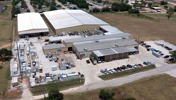
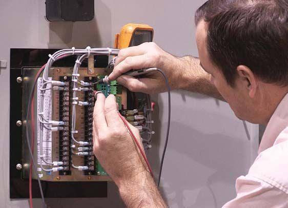
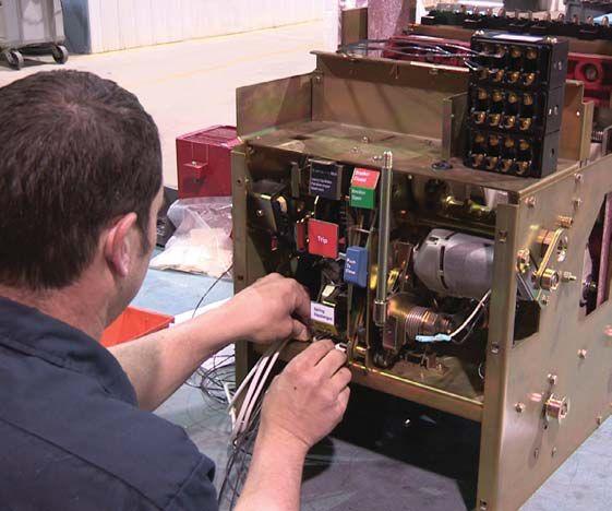
CIRCUIT BREAKERS – LOW/MEDIUM VOLTAGE major manufacturers
TRANSFORMERS – 1000–5000 KVA resin transformers from break switch & fuse
LIFE EXTENSION state motor
MOLDED CASE CIRCUIT BREAKERS LOW VOLTAGE MOTOR CONTROL breakers buckets mount switches
SWITCHGEAR – 480V-38KV NEW AND SURPLUS in 4 weeks from stock unit substations
RENEWAL PARTS –SWITCHGEAR & CIRCUIT BREAKER PARTS & vacuum in stock www.circuitbreakerpartsonline.com
MEDIUM VOLTAGE MOTOR CONTROL AIR & VACUUM MOTOR CONTROL from stock starters contactors
SERVICE & REPAIR service of circuit breakers ISO 9001 and 14001 Certified
circuit breaker remote switch circuit breaker


NETA has been connecting designers, speci ers, architects and users of electrical power equipment and systems with independent, third-party electrical testing companies since 1972.
NETA Accredited Companies test the complete system in accordance with industry codes and standards to provide accurate test reports you can count on every time.
This issue’s advertisers are identified below. Please thank these advertisers by telling them you saw their advertisement in YOUR magazine –NETA World.


American Electrical Testing Co., Inc. ................15
Apparatus Testing and Engineering ..................10
Elemco Services, Inc. ..............................111
Hampton Tedder. ...................................5


...and with the CT Analyzer and the new CT SB2 it’s all automated!
The new CT SB2 Switch Box has been designed for OMICRON’s CT Analyzer to enable automated testing of multiratio CTs with up to 6 taps.
Dad especially likes the wiring check to ensure that the correct taps are connected. The accuracy of the CT Analyzer allows Dad to test even metering class
CTs up to 0.15 class – that’s pretty impressive.
The device automatically assesses all results according to IEC 60044 or IEEE C57.13 for protection class CTs, which saves Dad so much time!
My Dad is even able to attach the CT SB2 to the CT Analyzer. With a combined
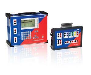
weight of only 24 lbs, the CT Analyzer together with the CT SB2 Switch Box is the most lightweight and automated testing solution for multi-ratio protection or metering class CTs.
Come and check it out for yourself on the OMICRON Roadshow Bus or at PowerTest Booth #314-315.