EARLYBIRD EARLY BIRD REGISTRATION OPEN NOW! CONFEREN CONFERENCE BRO E BROCHURE INS HURE INSIDE DE PAGE 50 PAGE DISTANCE PROTECTIVE IED APPLICATION OF A MULTIFUNCTIONAL in a 15kVDistribution Network ISSN2167-3594NETAWORLDJOURNALPRINT ISSN 2167-3594 NETA WORLD JOURNAL PRINT ISSN2167-3586NETAWORLDJOURNALONLINE ISSN 2167-3586 NETA WORLD JOURNAL ONLINE FALL 2013

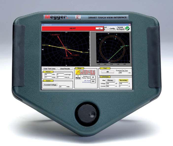
Megger continues to listen to the industry and improve the company’s SMRT relay testing equipment adapting to the immediate needs of utilities and manufacturers as the electrical smart grid evolves.
The SMRT system (SMRT1, SMRT36, and SMRT410) now offers overall adaptations as well as a devilish look at the firmware details, which make all the difference out in the field. In the all-important details category, Megger has adapted the SMRT36 current channels in a “push-push-push” series configuration that will provide up to 150 volts at four amps for testing high impedance loads, while improving general calibration at test currents down to 100 mA. Megger has added communications support for the SMRT410 double current generator (DIGEN) as well as the voltage-only generator (VGEN), making the SMRT series even more interoperable and cost-effective. The STVI now has a new sequencer test screen with end-to-end dynamic test capabilities making the STVI and SMRT systems the easiest-to-use test instruments available on the market today.
Want to get SMRTer? Contact us at the Texas A&M Relay Conference, April 8th-12th, or at the Georgia Tech Protective Relaying Conference, May 8th-10th, where our relay application engineers will answer your questions on the latest upgrades to the Megger SMRT series. 4271 Bronze Way sales@megger.com Dallas, TX 75237-1019 1-800-723-2861
Enhance your system reliability with Megger’s updated SMRT series.
The word “Megger” is a registered trademark WWW.MEGGER.COM/US

Denver, Colorado | Hyatt Regency | March 3– 6, 2014 The Premier Electrical Maintenance and Safety Event
your sense of adventure
through boundaries
new challenges ENERGIZE YOUR FUTURE! Early Bird Registration Now Open
Indulge
Push
Embrace
March 3-6, 2014
Hyatt Regency Denver Denver, Colorado
PowerTest heads to Denver, Colorado, in 2014
Join us at PowerTest 2014 and Energize your Future at the premier electrical acceptance, maintenance, and safety conference in Denver, Colorado. PowerTest 2014 will leverage expertise within the industry, providing countless opportunities for professionals to expand their knowledge, examine new ideas, and shape not only their future, but that of the electrical power systems industry as well. Denver is a city that has inspired many to seek new challenges, advance their knowledge, examine new ideas, and shape the future. A perfect fit for PowerTest 2014.
Keynote Address
The Transition to Mandatory Standards – Six Years and Counting, Time for the Adolescent Clumsiness to End!
Nicholas A. Brown, President and Chief Executive Officer
Southwest Power Pool
Nick Brown serves as President and CEO of SPP. He has held several engineering positions since joining the company in 1985 and began his career as a planning engineer at Southwestern Electric Power Company.

Nick has served on the Board of Directors of the Electric Power Research Institute and has served on numerous organizational groups of the North American Electric Reliability Corporation over the past 30 years.

Rock the Rockies Pub Crawl and Scavenger Hunt
Get ready to rock in downtown Denver! Find clues on the ground and high in the sky with the mile-high pub crawl and scavenger hunt along the famous 16th Street Mall. The hunt includes stops at the Rock Bottom Brewery, Hard Rock Café, and Coyote Ugly. Refreshments and food are included. Rock on!
Sunday, March 2, 5:30 PM – 8:30 PM
Sign up when you register on-line. $150 per person.
Sponsored by


 White logo
Day One: MONDAY
We’ve gathered leaders in the industry and staged a full day of engaging, 45-minute presentations and a power transformer focused symposium which is sure to expand your thinking and generate new ideas. Choose from 27 detailed technical paper track topics. Participate in the afternoon Transformer Symposium. Pat Beisert of Shermco Industries and expert panelists help audience participants navigate open discussions on current challenges,insights, and a general technology overview related to power transformer predicitve analysis.
TECHNICAl PRESENTATIONS:
ElECTRICAl SAfETY
• Industrial Electrical Safety Compliance Assessments
Dennis Neitzel, AVO Training Institute, Inc.
• Verify Performance and Safety of Arc-flash Detection Systems
William Knapek, OMICRON electronics Corp. USA
• Determining Maintenance Intervals for Safe Operation of Circuit Breakers
Jim White, Shermco Industries
• Productively Safer lock-Out Tag-Out Procedures with Permanent Electrical Safety Device
Phillip Allen, Grace Engineered Products
• The Electrical Safety Trifecta
Terry Becker, Electrical Safety Program Solutions, Inc.
• Developing an Electrical Multiworker Worksite Protection Program
Mike Moore, Shermco Industries
RElIABIlITY Sponsored by Southwest Energy Systems, llC
• Keeping the lights On – Update on Testing MediumVoltage Cable and Switchgear Systems
Ashley Harkness, Electrical Reliability Services
• How to Implement Symmetrical Components Into Relay Testing
Jason Buneo, Megger
• Consideration Testing Transformer Protection Schemes
Nestor Casilla, Doble Engineering
• Power Quality and Reliability Problems Require a Comprehensive Approach
Jim Timberlake, Electro Rent Corporation
• How to Perform a Power Survey
Ross Ignall, Dranetz Technologies
• A Practical Approach to line Current Differential Testing
Karl Zimmerman and Dave Costello, Schweitzer Engineering Laboratories
EQUIPMENT Sponsored by Raytech
• Process Analysis – Your Intel to System Knowledge
Noah Bethel, PdMA Corporation
• Simplified Motor Relay Testing
Chris Werstiuk, Manta Test Systems
• Optimize Stator End-Winding Vibration Monitoring With Impact Testing
John Letel and Vicki Warren, IRIS Power
• A Systemic Approach to High-Voltage Circuit Breaker Testing
Charles Sweetser, OMICRON electronics Corp. USA
• Current Transformer Saturation and Residual Magnetism
William Knapek, OMICRON electronics Corp. USA
• Investigations on a Combined Resonance Vlf/HV Test System
Henning Oetjen, Megger
CASE STUDIES Sponsored by Electrical Reliability Services
• failure Investigation Case Studies
Wally Vahlstrom, Electrical Reliability Services
• Smaller Commissioning Assignments Require Greater Attention
Brian Moores, TRC Companies
• Optimization of Transformer Drying in the field
Thomas Prevost, OMICRON electronics Corp. USA
• Deploying Thermal Imagers at the Technician level to Increase Safety, Reduce Downtime, and Save Money
Mark Boccella, FLIR Systems
• low-Voltage Metal Enclosed Bus Duct Wetting Events
Dan Hook, Western Electrical Services
• A New Approach to Circuit Breaker Analysis
John Cadick, Cadick Corporation
Finley Ledbetter, Group CBS
TRANSfORMERS
• I Know How to Add the Numbers – But What is the Power factor Telling Me?
William Keith Hill, Doble Engineering
• Decision Sciences – Will This Be On the Test?
Nicholas Perjanik, Weidmann Diagnostic Solutions
• Water Distribution and Migration in Transformer Insulation Systems and Assessment of Paper Water Content
David Koehler and Lance Lewand, Doble Engineering
SYMPOSIUM ON POWER TRANSfORMERS
Power Transformer Predictive Analysis:
A Technology Overview
Moderator: Pat Beisert, Shermco Industries
Day Two:
TUESDAY MORNING
Join in the discussion during the Tuesday morning Panel Sessions. Select two of the four panel topics and get ready to learn from experts and peers alike.
PANElS:
SAfETY
Moderator: Jim White, Shermco Industries
CIRCUIT BREAKERS
Moderator: Dan Hook, Western Electrical Services
TRANSfORMERS
Moderator: Pat Beisert, Shermco Industries
RElAYS
Moderator: Rod Hageman, PRIT Service, Inc.
TUESDAY AfTERNOON
POWERTEST 2014 TRADE SHOW
PowerTest 2014 features more than 100 exhibits from top-tier electrical power vendors. No other show brings together this many companies focused on electrical safety and maintenance. See you on Tuesday!
TUESDAY EVENING
POWERBASH 2014
Sponsored by

PowerBash 2014 is the culmination of two days of intense conference sessions and marks the commencement of an additional two days of high-impact seminars. Awards for best Technical Presentation, Trade Show Booth and Hospitality Suite will be presented.

Days Three and Four:
WEDNESDAY - THURSDAY
Take advantage of a unique opportunity to choose from 12 in-depth, 4-hour seminars on Wednesday and Thursday.
SEMINAR TITlES:
• Battery Maintenance and Testing
Rod VanWart, AVO Training Institute, Inc.
• The Practical Application of the NfPA 70E in Routine Work Tasks
Mike Moore and Jim White, Shermco Industries
• Basic Power factor Theory
William Keith Hill, Doble Engineering
• “Condition of Maintenance”: A Practical Overview to Understanding and Compliance within the Industry
Jim White, Shermco Industries
• Evolving Protective Relay Testing
Karl Zimmerman and Dave Costello, Schweitzer Engineering Laboratories
• Do I Need Training or an Assessment?
Christopher Pavese, Salisbury by Honeywell
• Transformer Power factor Theory
William Keith Hill and Rick Youngblood, Doble Engineering
• Partial Discharge Testing of Electrical Equipment: Understanding and Implementing Existing Technologies and Methods
Tom Sandri, Shermco Industries
• The Six Components of Transformer Diagnostics Using fluid Test Data
Melvin Wright, LICA Transformer Consulting
• Specialty Transformer Testing – Dry Types, Rectifiers, and Instrument Transformers
William Keith Hill and Rick Youngblood, Doble Engineering
• Cellulose Mechanical Condition Assessment in Transformers – Use of Direct and Indirect Tests
Lance Lewand and David Koehler, Doble Engineering
• Power Quality Investigation, Diagnostics, and Case Studies
Bruce Rockwell, American Electrical Testing Co., Inc.
Hospitality Sui tes
Mingle with a host of leaders at Monday night’s Hospitality Suites. Talk with the experts, find solutions for your business, and catch up on the latest products and services as each sponsoring company shares its own brand of hospitality.
SPONSORS

Sunday, March 2, 9:00 AM – 4:00 PM
Megger Best Practices Denver
Megger’s seminar will address many of the critical and costly aspects of substation maintenance. The interactive session will feature practical presentations on current methods and practices to help ensure the reliability of high-voltage circuit breakers, power transformers, and batteries. You must preregister for this event by contacting Megger: 214.330.3539
Monday, March 3, 12:00 PM – 2:00 PM
PowerDB User Group
Free user’s group meeting open to all users of PowerDB software. You must preregister for this event by contacting Megger: 214.330.3539.
New Product Forum
Monday, March 3, 5:00 PM – 6:00 PM
Attendees will have the opportunity to learn about dozens of the latest products and innovations,
major expansions, and significant improvements by leading industry-specific manufacturers and suppliers at the Tuesday Trade Show. Stay until the end for the chance to win an exclusive prize! Must be present to win.
Spouse/Guest Pass
A special lounge exclusively for spouses and guests of PowerTest attendees, stocked daily with light refreshments and information on local activities. Includes lunch voucher and admission to Hospitality Suites, Tuesday Trade Show, and PowerBash reception. $75 per person.
Social Pass
The Social Pass includes admission to the Hospitality Suites, Trade Show, and the PowerBash Reception. $40 per person.
Medium Voltage Low Voltage General TM ® ® High Voltage Premium
Early Bird Registration Is Now Open!
PowerTest 2014 Registration

Register On-line:
To register for PowerTest 2014, save time by registering on-line. You‘ll find a complete brochure and registration form available at www.powertest.org.
Join & Save
Join the Gold Alliance Program for $800 and your PowerTest 2014 conference registration is included! Standard Alliance Program participants can upgrade to Gold Alliance status for only $625 to receive a complimentary PowerTest conference registration!
Hotel Reservations:
Hyatt Regency Denver at the Convention Center 1.888.421.1442
650 15th Street Denver, Colorado 80202
Reservation Deadline: January 30, 2014 Group Name: NETA/PowerTest Group Rate: $199
Payment:
NETA accepts all major credit cards. Save time and register on-line at www.powertest.org or call 888-300-6382 (NETA)
Extras:
PowerTest 2014 Technical Papers - Registered conference attendees will receive all PowerTest technical presentations on a USB drive on site in their registration bag.
Easy Steps for Registration:
1. Go to www.powertest.org and review the complete PowerTest 2014 on-line brochure.
2. Decide the number of days you will attend the conference.
3. Tuesday attendees select up to two panels. (Cost of panels included in registration fees.)
4. Wednesday attendees register for up to two seminars. (Cost of seminars is in addition to the registration fees.)
5. Thursday attendees register for up to two seminars. (Cost of seminars is in addition to the registration fees.)
6. Register for two or more seminars and receive 15% off. Use code SEM2014–PT to receive this discount.
7. Sign up for the Rock the Rockies Pub Crawl and Scavenger Hunt. Space is limited, so register early. (Cost is in addition to the registration fees.)
8. Sign up for Spouse/Guest Passes. (Cost of passes is in addition to the registration fees.)
9. Sign up for PowerTest 2014 conference polo shirts and select size. (Cost of polo shirts is in addition to the registration fees.)
White logo Register on-line at: www.powertest.org Or call: 888-300-6382 (NETA)
Nonmembers NAC Members Full Conference: $789 $729 Single Day: $530 $500 Seminars: $289 $269
Register Today!
COVER STORY

50 Application of a Multifunctional pplication
DistanceProtectiveIEDina Distance Protective IED in a 15 kV Distribution Network
By Jack Chang (ABB Inc.), Lorne Gara (Orbis Engineering), Yordan Kyosev (EPCOR) and Peter Fong (Sequence Instruments Inc.)
EPCOR Utilities Inc. is the electric utility company in Edmonton, Alberta, Canada. One of EPCOR’s capital upgrade projects is to replace obsolete protective relays for their 15 kV distribution substations. Eight ofEPCOR’s15kVdistributionsubstations of EPCOR’s 15 kV distribution substations have obsolete feeder relays that are starting to fail and raise concerns regarding system reliability and safety.
FEATURES
7 President’s Desk
David Huffman, Power Systems Testing Co. NETA President
62 Energy-Based Tripping and Its Effects on Selective Coordination
By John Carlin, Schneider Electric Engineering Services

TABLE OF CONTENTS TABLE OF CONTENTS NETAWORLD 3
62
11 The NFPA 70E and NETA
What (Might) Be Coming Up in the 2015 NFPA 70E
Ron Widup and Jim White, Shermco Industries
16 Tech Quiz
Overcurrent Coordination
Jim White, Shermco Industries
20 Niche Market Testing
Data Center Maintenance – Part 4 –
Electrical Distribution System Maintenance
Lynn Hamrick, Shermco Industries
28 Testing Rotating Machinery
Synchronous Rotor Winding Common
Electrical Monitoring
Vicki Warren, Iris Power LP.
34 No-Outage Inspection Corner
Switchgear Partial Discharge Location
Don A. Genutis, No-Outage Electrical Testing, Inc.
38 Safety Corner
Safety Aspects of Breaker Protection and Coordinations
Bruce M. Rockwell, P.E., American Electrical Testing Co.
44 Tech Tips
Addressing Problems in Wind Farm Testing
Jeff Jowett, Megger
86 Field Testing of Arc Furnace Transformers
Jim Macdonald, Client Service Field Engineer, Doble Engineering Company
97 The Overwhelming Need for Electrical Maintenance
Glen Brown, Rimac Technologies
102 Why Test to the ANSI/NETA Standards?
Bob Sheppard, Southwest Energy Systems, LLC 106 Interconnection Issues
James G. Cialdea, P.E., Three-C Electrical Co., Inc.
SPECIFICATIONS
AND STANDARDS
109 ANSI/NETA Standards Update
112 Insulated Conductor Committee News
Ralph Patterson, Power Products and Solutions
NETA NEWS
48EnerG Test, LLC, Joins the Ranks as a NETA Accredited Company
72NETA Marks 17th Anniversary as an ANSI Accredited Standards Developer
74The 249th Engineer Battalion
Kristen Wicks, NETA
82 “…A Great Team Player…” Mose Ramieh, Outgoing President
Richard Piet, NETA
NETA NEWS – SETTING THE STANDARD
76 NETA – Setting the Standard Jill Howell, NETA
116 PowerTest 2014: Energize Your Future NETA NEWS –
124 NETA Accredited Companies 130 Advertiser List
4 FALL 2013 TABLE OF CONTENTS
TABLE OF CONTENTS
IN EVERY ISSUE
INDUSTRY TOPICS
IMPORTANT LISTS








3050 Old Centre Avenue, Suite 102
Portage, MI 49024
Toll free: 888.300.NETA (6382)
Phone: 269.488.NETA (6382)
Fax: 269.488.6383
neta@netaworld.org
www.netaworld.org
EXECUTIVEDIRECTOR: Jayne Tanz, CMP
NETA Officers
PRESIDENT: David Huffman, Power Systems Testing Co.
FIRSTVICEPRESIDENT: Ron Widup, Shermco Industries
SECONDVICEPRESIDENT: Jim Cialdea, Three-C Electrical Co., Inc.
SECRETARY: Walt Cleary, Burlington Electrical Testing Co., Inc.
TREASURER: John White, Sigma Six Solutions
NETA Board of Directors
Ken Bassett (Potomac Testing, Inc.)
Scott Blizard (American Electrical Testing Co., Inc.)
Jim Cialdea (Three-C Electrical Co., Inc.)
Walt Cleary (Burlington Electrical Testing Co., Inc.)
Roderic Hageman (PRIT Service, Inc.)
Kerry Heid (Magna Electric Corporation)
David Huffman (Power Systems Testing)
Alan Peterson (Utility Service Corporation)
Mose Ramieh (Power & Generation Testing, Inc.)
Bob Sheppard (Southwest Energy Services, LLC)
John White (Sigma Six Solutions)
Ron Widup (Shermco Industries)
NETA World Staff
TECHNICALEDITOR: Roderic L. Hageman
ASSOCIATEEDITORS: Diane W. Hageman, Resa Pickel
MANAGINGEDITOR: Jayne Tanz, CMP
ADVERTISINGMANAGER: Jill Howell
DESIGNANDPRODUCTION: Hour Custom Publishing
NETA Committee Chairs
CONFERENCE: Ron Widup; MEMBERSHIP: Ken Bassett; PROMOTIONS/MARKETING: Scott Blizard; SAFETY: Scott Blizard and Jim White; TECHNICAL: Alan Peterson; TECHNICALEXAM: Ron Widup; WORLDADVISORY: Diane Hageman; CONTINUINGTECHNICALDEVELOPMENT: David Huffman; TRAINING: Kerry Heid; FINANCE: John White; NOMINATIONS: Alan Peterson; STRATEGY: Mose Ramieh; ALLIANCEPROGRAM: Jim Cialdea
© Copyright 2013, NETA
NOTICE
AND DISCLAIMER
NETA World is published quarterly by the InterNational Electrical Testing Association. Opinions, views and conclusions expressed in articles herein are those of the authors and not necessarily those of NETA. Publication herein does not constitute or imply endorsement of any opinion, product, or service by NETA, its directors, officers, members, employees or agents (herein “NETA”).
All technical data in this publication reflects the experience of individuals using specific tools, products, equipment and components under specific conditions and circumstances which may or may not be fully reported and over which NETA has neither exercised nor reserved control. Such data has not been independently tested or otherwise verified by NETA.
NETA MAKES NO ENDORSEMENT, REPRESENTATION OR WARRANTY AS TO ANY OPINION, PRODUCT OR SERVICE REFERENCED OR ADVERTISED IN THIS PUBLICATION. NETA EXPRESSLY DISCLAIMS ANY AND ALL LIABILITY TO ANY CONSUMER, PURCHASER OR ANY OTHER PERSON USING ANY PRODUCT OR SERVICE REFERENCED OR ADVERTISED HEREIN FOR ANY INJURIES OR DAMAGES OF ANY KIND WHATSOEVER, INCLUDING, BUT NOT LIMITED TO ANY CONSEQUENTIAL, PUNITIVE, SPECIAL, INCIDENTAL, DIRECT OR INDIRECT DAMAGES. NETA FURTHER DISCLAIMS ANY AND ALL WARRANTIES, EXPRESS OF IMPLIED, INCLUDING, BUT NOT LIMITED TO, ANY IMPLIED WARRANTY OF FITNESS FOR A PARTICULAR PURPOSE.
ELECTRICAL TESTING SHALL BE PERFORMED ONLY BY TRAINED ELECTRICAL PERSONNEL AND SHALL BE SUPERVISED BY NETA CERTIFIED TECHNICIANS/ LEVEL III OR IV OR BY NICET CERTIFIED TECHNICIANS IN ELECTRICAL TESTING TECHNOLOGY/LEVEL III OR IV. FAILURE TO ADHERE TO ADEQUATE
TRAINING, SAFETY REQUIREMENTS, AND APPLICABLE PROCEDURES MAY
RESULT IN LOSS OF PRODUCTION, CATASTROPHIC EQUIPMENT FAILURE, SERIOUS INJURY OR DEATH.

It’s my honor to kick off this edition of NETA World. As I’m writing this, many of the summer 2013 committee meetings are wrapping up and the July NETA Exam period is underway. So much effort goes into this Association and the production of this Journal, I’m proud to be a part of it.
It has been said that a clean desk is the sign of a sick mind. Well, I appear to be healthy. I hope this finds you safe and healthy as well.
Perhaps you received this edition of NETAWorld NETA World at your office and are reading it there. Maybe you took it with you on assignment and are reading it between downloading IB’s in a hotel room for tomorrow’s work. In any event, I hope you enjoy the articles in this edition.
Thecurrentthemeiscoordinationschemesandelectricalfault The current theme is coordination schemes and electrical fault isolation.Ihavefound isolation. I have found NETAWorld NETA World andPowerTesttobetwo and PowerTest to be two of the best resources for technical information on this topic, and many other topics. It has included everything from simple interlocks to zone interlocking to preferred bus transfer all the way up to IEC 61850 protocol.
In the previous President’s Message, Mose touched base on all that had been achieved. The increase in NETA Accredited Companies and NETA Certified Technicians has strengthened the association’s core. The board and several committees have just concluded the strategic planning and promotions meeting, and we look forward to the continued strengthening of the association. ANSI/NETA ATS-2013 has been released, and NETA has been reaffirmed as a specification writer. All of this thanks to the outstanding staff at the NETA office and the tireless volunteers throughout the association.
As with nearly every edition of NETAWorld NETA World, there are also safety subjects. In every work task, safety is a first priority. Work safely out there, and thank you for taking the time to read this.
Sincerely,
DavidHuffman David Huffman President InterNationalElectrical Testing Association
PRESIDENT’SDESK PRESIDENT’S DESK PRESIDENT’SDESK PRESIDENT’S DESK
Angeles,
90744 Fax (310) 549-9747

315448
ARTES 460
Sets new standards for compact devices in relay testing. This new relay test set can handle any challenge you face in practice. Six current and four voltage outputs allow testing for all relays. Test your relays fast and efficiently with front panel control or software templates. Total weight is only 22 pounds!
Characteristics
Automatically tests for all types of protection relays
Freely configurable three-phase function generator
IEC 61850-compliant protection equipment
“Play back” function for fault records
Ergonomic menu and intuitive operation
ARTES 100
Is the first relay test set to address the difficult high burden relays. Three built-in sources and a very high output power: up to 1500 VA. In addition to carrying out secondary test on protection relays, the high output current (up to 250 A) makes ARTES 100 capable of a wide variety of tasks, including primary tests for commissioning and maintenance.
Characteristics
High test current 250 A
Total output power of up to 1500 VA, one current, two voltage sources both convertible Front panel or software controlled
ARTES V4 Software
Powerful, ergonomic, and versatile: Easy to use template reduces testing time. It leads the market with a brand new graphical interface!
Characteristics
Testing IEC 61850-compliant protection equipment
Automatic determination of tripping characteristics
Watches function for all types of test sequences
Results correlate to the installation locations of different instrument transformers
Reproduction of 1-pole and 3-pole automatic reclosing operations (ARCs)
visit: www.kocos.com
KoCoS America LLC 136 Oak Street, Suite A · Westerly, RI 02891 · Phone +1 401 213 6518 · gwasfy@kocos.com · Follow us on twitter: http://twitter.com/kocos_america
BEST! THE ARTES
BY KOCOS
RELAY TESTING AT ITS
SERIES
For more information,
(310) 816-3130 www.tdeinc.com 131
Los
#
West F Street
CA


the test equipment answer
Test Equipment







T 972.317.0479 | www.intellirentco.com | contact us at info@intellirentco.com
Rental
WHAT (MIGHT) BE COMING UP
 BY RON WIDUP AND JIM WHITE, Shermco Industries
In this column we take a look at a recent meeting of the NFPA 70E technical committee, as we just finished the Second Draft meeting. You may recall these meetings being previously referred to as the Report on Comments meetings. The purpose of the session was to process and vote on any public comments made related to the First Draft (formerly Report on Proposals) meeting. The Second Draft meeting took place in Savannah, Georgia (hey y’all!).
The software NFPA uses to develop its standards has been changed to Terraview™. This changeover has created some headaches, but they seem to be diminishing with time. NFPA also changed the process by which they develop the standards to mesh with the new software (or is it the other way around)? At the Public Input (PI) stage the committee has free reign to make any changes to the standard it believes are necessary. PI’s are considered, but the committee is not bound by the content of the PI to make a change. This is a very significant change, and the committee had a bit of a time using this to its fullest advantage. Now that we are familiar with the process, the next round (2018 edition) should be a much smoother process.
TheSecondD The Second Draft meeting is different in that the committee is bound by the First Draft and public comments (PC’s) received. No new material can be introduced.NowthattheSecondD introduced. Now that the Second Drafthasbeen raft has been completed, the standard will be balloted. There were several close votes on comments, although the committee pretty much held to the work it did on theFirstD the First Draft.U raft. Until balloting is completed, the actual content of the 2015 70E is still somewhat up in the air. This is another way of saying we are not responsible for what we are about to write.
THE BIG THREE
Of the PI’s and PC’s received and acted on, therearethreethatstandout: there are three that stand out:
1. NewPPEtables New PPE tables
2. EliminationofH Elimination of Hazard Risk Category “0” inthestandard in the standard
3. Elimination of Prohibited Approach Boundary
Let’s take a look at each one of these proposed et’s actions.
NEW PPE TABLES
Of all the actions taken for the 2015 cycle, this is the one we see as a gamechanger. The existing tableforselectionofPPEwastaskbased.The table for selection of PPE was taskbased. The Hazard Risk Category (HRC) was chosen by the task being performed. There were set limits, but theHR the HRC could be reduced by 1, 2, or 3 numbers depending on the perceived risk in performing the task. The primary argument against the table was that it could lead to someone being underprotected in some situations. And while that arguably is a possibility, it should be noted there have been no reports to the 70E committee or its members that
NETAWORLD 11 WHAT (MIGHT) BE COMING UP IN THE 2015 NFPA70E A 70E THENFPA70EANDNETA THE NFPA 70E AND NETA
THENFPA70EANDNETA THE NFPA 70E AND NETA

ForThoseAboutto For Those About to Rock:AC/DCTables! Rock: AC/DC Tables!
this has been the case. Still, the state of the safety culturewithintheU culture within the U.S. workplace has changed .S. significantly over recent years. Whereas in 2001, Ray Jones, the chair of the 70E committee at ones, that time, stated that our job was to get workers intoPPE….evenifwedidn’thaveallthefactsto into PPE….even if we didn’t have all the facts to determine the exact level or maybe it wasn’t exactly the right PPE, some PPEwasbetterthannone! PPE was better than none! Now, workers are more accustomed to using the arc-rated PPE and ancillary PPE protection, and we are more sophisticated in choosing what to use and when to use it. (Note to Ray Jones: See, you ones: were right – it can be done!)
Figure 1 shows a partial PPE Table 130.7(C)(15) (A)(a), Arc-Flash Hazard Identification for Alternating Current (ac) and Direct Current (dc) Systems By the title, it can be seen that y theacanddctableswerecombined.Itmakes the ac and dc tables were combined. It makes the table longer, but puts all the information on selectionofPPEintoonetable.Italsomakes selection of PPE into one table. It also makes both tables consistent, improving usability. The term“HR term “HRC” is going away, also. The categories will now be referred to as PPE Categories, which is more in line with their purpose.
there is no arc-flash hazard, no arc-flash PPE is required. This is one reason HRC 0 went away. If there is no arc-flash hazard, it really didn’t belong on a table used to select arc-flash PPE. Also, when the tables were first developed, cotton was considered to have some protective properties if it was the correct fabric weight (12 oz/yd2). Later, it was found that that any weight of cotton could burst into flames. Putting workers into cotton was better than polyblends, but may have given some a false sense of security. This was corrected in later editions of NFPA 70E by removing cotton as a recommended fabric up to HRC 1 and reserving it only for HRC 0, which meant a person was outsidetheArc-FlashB outside the Arc-Flash Boundary.
With the new table, there is either an arc-flash hazard or there is not. Some tasks, such as “Work on energized electrical conductors or circuit parts, including voltage testing” always present a risk of an arc flash. Other tasks, such as “Voltage testing on individual battery cells or individualmulticellunits individual multicell units” may not if certain conditionsexist.B conditions exist. But it should be noted, when using the table you have to ask yourself these four critical questions and be able to answer them with a high degree of certainty. The conditions are always the same for each task and are: TASK Reading a panel
Oneofthebenefitsofthenewtableisthatit
One of the benefits of the new table is that it should simplify the PPE selection process. If
Table1: Table 1: New PPE Selection Table (Partial)
12 FALL 2013 WHAT (MIGHT) BE COMING UP IN THE 2015 NFPA70E A 70E
meter switch
a circuit breaker (CB), switch, contactor, or starter NO NO YES Any All of the following: One or more of the following: EQUIPMENT CONDITION*ARC-FLASH PPE REQUIRED
meter while operating a
Normal operation of
andsecured and secured
There is no reduction for PPE category when using the new tables. If there is an arc-flash hazard, the PPE rating is selected by using the second table, Arc-Flash Hazard PPE Categories for Alternating Current (AC) Systems, shown in Figure 2.
The type of equipment is selected first. The types of equipment are the same as on the existing table. If the equipment falls below the limits given, the Arc-Flash PPE Category is chosen from the table. If not, an arc-flash study has to be performed to determinewhatPPEisneeded.Thelimitsused determine what PPE is needed. The limits used
EQUIPMENT

for the equipment types are all the same as in the previous table 130.7(C)(15)(a). Note that there is no PPE 0 category. If there is no arc-flash hazard, thePPEwillnotbeselectedfromthistable.That the PPE will not be selected from this table. That does not mean PPE is not needed. There is always a minimum amount of PPE required for any type of field work. Safety glasses or goggles, gloves, and hearing protection may all be needed, but these items are covered by other sections within the 70E.Thesetablesfocusonthearc-flashhazard. 70E. These tables focus on the arc-flash hazard.
Thearc-flashboundariesinthistablewererounded The arc-flash boundaries in this table were rounded up for clarity, except for PPE Category 1. If the AF Boundary was rounded up to 2’ it would have given the impression that the back of the head was within theAF the AF Boundary. This would have necessitated oundary. the use of a balaclava for PPE Category 1, which the committee thought was unnecessary. This may make the table appear a bit inconsistent, but the alternativewastouse1.58’.Thatwouldbedifficult alternative was to use 1.58’. That would be difficult to interpret in the field for most workers, so the
Panelboards or other equipment rated 240 V and below
455 mm (18 in.)
Panelboards or other equipment rated > 240 V and up to 600 V
455 mm (18 in.)
600-V class motor control centers (MCCs)
455 mm (18 in.)
600-V class motor control centers (MCCs)
455 mm (18 in.)
NETAWORLD 13 THENFPA70EANDNETA THE NFPA 70E AND NETA
WHAT (MIGHT) BE COMING UP IN THE 2015 NFPA70E A 70E
Table2: Table 2: Arc Flash Hazard Categories Table (Partial)
485 mm (19 in) 900 mm (3 ft) 1.5 m (5 ft) 4.3 m (14 ft) 1 2 2 4 ARC-FLASH PPE CATEGORY ARC-FLASH BOUNDARY

inconsistency between inches for PPE Category 1 and the other categories is not so bad.
ELIMINATION OF HRC 0
This is one that may upset some people, but in the opinion of the 70E committee, it, like the Prohibited Approach Boundary, had served its purpose. The driving force behind HRC 0 going away was the new PPE tables, which only specify PPEforworkwithintheArc-FlashB PPE for work within the Arc-Flash Boundary.
ELIMINATION OF PROHIBITED APPROACH BOUNDARY
Thisisonethatcouldmakeacomebackin This is one that could make a comeback in 2018, at least for voltages above 1,000 volts. The70Ecommitteelookedattheboundaries The 70E committee looked at the boundaries for shock and decided that a boundary should provide some trigger for an action. The L imited Approach B oundary is the limit for unqualified persons to approach exposed, energized conductors or circuit parts. The R estricted Approach B oundary is the point where qualified persons would have to use shock protective PPE. The Prohibited Approach Boundary was more of a oundary watchout watch out boundary. It did not require anything different from the R estricted Approach Boundary and was, for oundary many workers, not easily remembered. The committee was of the opinion that it added a layer of complexity without giving any tangible benefittotheworker. benefit to the worker.
SUMMARY
Which of the proposed changes to NFPA 70E constitutethe constitute the big three to you will depend on how those changes affect you and your company’s work practices. Your big three may our be different than the ones shown in this column,
buttheseareonesthatwefeltwouldhavethe but these are ones that we felt would have the biggest impact on the users of NFPA 70E.
The new table format is huge. Over the previous 70E cycles the primary complaint about the HRC table was that it was too subjective and might leave someone underprotected. The new format shouldeliminatethatconcernandshouldmake should eliminate that concern and should make the table method easier to implement in the field. ItwilltakeawhileforthemanufacturersofarcIt will take a while for the manufacturers of arcrated clothing and PPE to begin using the PPE Category instead of the HRC, but the fact that C, they represent the same basic ratings should ease that process along. A PPE Category 2 will have the same arc rating as HRC2. C 2.
At the meeting we looked ahead to the 2018 Edition.W Edition. We are all very interested in what the results of the NFPA/IEEE collaborative project onarc-flashwillbe.W on arc-flash will be. We are going to take a closer e look at PPE, Chapter 3, Annex F and Annex K just to name a few of the anticipated projects!
NFPA 70E has come a long way since its first edition in 1979. It has played a major role in changing the electrical safety culture, not only intheU in the US but around the world. It has provided S guidance on electrical safe work practices and theselectionofshockandarc-ratedPPEand the selection of shock and arc-rated PPE and clothing, and is one of the most significant standards in the world. As a standard, NFPA 70E is still ever evolving, in that serious public review and interpretation of it has [arguably] only been in place since the 2000 edition was published.
It will continue to improve, and it will continue to guide companies and workers to a safer work environment. So read it, understand it, and read implement its valuable guidance to all of the workers exposed to electrical hazards.
Ron Widup and Jim White are NETA’S representatives to NFPA Technical Committee 70E (Electrical Safety Requirements for Employee Workplaces). Both gentlemen are employees of Shermco Industries in Dallas, Texas, a NETA Accredited Company. Ron Widup is President of Shermco and has been with the company since 1983. He is a Principal member of the Technical Committee on “Electrical Safety in the Workplace” (NFPA 70E) and a Principal member of the National Electrical Code (NFPA 70) Code Panel 11. He is also a member of the technical committee “Recommended Practice for Electrical Equipment Maintenance” (NFPA 70B), and a member of the NETA Board of Directors and Standards Review Council. Jim White is nationally recognized for technical skills and safety training in the electrical power systems industry. He is the Training Director for Shermco Industries, and has spent the last twenty years directly involved in technical skills and safety training for electrical power system technicians. Jim is a Principal member of NFPA 70B representing ting Shermco Industries, NETA’s alternate member of NFPA 70E, and a member of ASTM F18 Committee “Electrical Protective Equipment for Workers”. Ron Widup Jim White
14 FALL 2013
THE NFPA 70E AND NETA
THENFPA70EANDNETA
WHAT (MIGHT) BE COMING UP IN THE 2015 NFPA70E A 70E



No.103 No. 103

James R. (Jim) White is the Training Director of Shermco Industries, Inc., in Dallas, Texas. He is the principal member on the NFPA technical committee “Recommended Practice for Electrical Equipment Maintenance” (NFPA 70B). Jim represents NETA as an alternate member of the NFPA Technical Committee “Electrical Safety in the Workplace” (NFPA 70E) and represents NETA on the ASTM F18 Committee “Electrical Protective Equipment For Workers”. Jim is an IEEE Senior Member and in 2011 received the IEEE/PCIC Electrical Safety Excellence award. Jim is a past Chairman (2008) of the IEEE Electrical Safety Workshop (ESW).


OVERCURRENT COORDINATION
BY JIM WHITE, Shermco Industries

This Tech Quiz looks at alternatives to overcurrent protective relaying due to coordination issues. Depending on the specific type of system, there can be many choices.
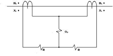
1. Differential protective relay schemes typically have their zones established by current transformers. In the figure below, at the instant current flows into _____, it also flows out of _____.
a. H1 – X2
b. H2 – X1
c. H1 – X1
d. H2 – X2
2. Calculate the following values for a percentage differential relay with a 25 percent slope characteristic:
3. Pilot wire relay schemes are a form of:
a. Directional overcurrent
b. Impedance relaying
c. Differential relaying
d. Zone interlocking

4. Directional overcurrent relays have a characteristic known as the maximum torque angle. How is the MTA determined during testing?
a. Find the zero torque angles and divide by two.
b. Plot the characteristic circle and find the minimum current to close the contacts.
c. Apply rated voltage and increase the current slowly until contact closure.
d. Maintain the restraint current and increase the operating current until contact closure.
5. Directional overcurrent relays must see two conditions in order to operate. What are they?
a. Current below the overcurrent unit set point and the polarizing quantity at an angle that closes the directional unit contact.
b. Current above the overcurrent unit set point and the polarizing quantity at an angle that opens the directional unit contact.
c. Current below the overcurrent unit set point and the polarizing quantity at an angle that opens the directional unit.
d. Current above the overcurrent unit set point and the polarizing quantity at an angle that closes the directional unit.
See answers on page 120.
16 FALL 2013 TECHQUIZ TECH QUIZ

Electrical Insulation Safety MI 3121 SMARTEC Insulation / Continuity High Voltage Insulation Diagnostics MI 3200 TeraOhm 10kV MI 2592 PowerQ4 Single and Three Phase Power Quality Analysis MI3121SMARTEC 2 Pow www.avoxtechnolgies.com sales@avoxtechnologies.com Avox has Moved to Better Serve You! 118 S. 2nd Street, Perkasie, PA 18944 Tel: 267 Toll Free 800-272-2818
breaker test solution







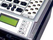


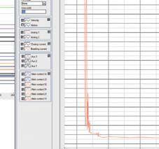
Circuit Breaker Analyzer & Timer
Our family of premium breaker analysers includes simpler versions priced under $12K US
Both sides grounded feature
(No additional modules needed)
Powerful micro ohmmeter for DRM testing and static contact resistance measurement
Up to 52 measurement channels
(timing, motion, coil, DRM, auxilary, analog)
Demagnetization of CT on Dead Tank CB after DC test
Minimum trip voltage test
Breaker coils and spring charging motors supply

inclusive” circuit
Reliable test devices for reliable electric power systems www.dv-power.com HQ: Orlando FL tel: 407 332 8678, info@progusa.net Exclusive distributor for USA:
”All

0-200 kVac@6kVA AC Hipots Nearly half the size of others One piece shielded cable output up to 50 kV Most rugged design Guard / Ground circuit Anti-static meters 10 kVac - 300 kVac ISO 9001 : 2008 ® FLEXIBLE
AIR-CELLS 2-DAY AVERAGE! STANDARD SIZES PLUS CUSTOM AIR-CELLS TO FIT ANY TRANSFORMER INSTALLATION! ® MADE IN AMERICA - 40 YEARS STRONGTOLL FREE: TELEPHONE: WEB: U S E D B Y: USED BY: WAUKESHA, CALPINE, TVA, AUTHORITY & MANY MORE! COLLAPSED BLADDER PILLOW TANKS FOR DIELECTRIC OIL, TOO!
/ COLLAPSIBLE
PART 4

ELECTRICAL DISTRIBUTION SYSTEM MAINTENANCE
BY LYNN HAMRICK, Shermco Industries
This article is Part 4 of a 4-part series on data center maintenance. In Part 3, we discussed electrical maintenance activities associated with the key electrical systems for most data centers: UPS systems and their battery systems and the backup generation systems. In Part 4, we will discuss maintenance activities associated with the electrical distribution system that ties all of these key systems together: cables, transformers, breakers, and automatic transfer switches.
This article will focus on electrical tests that should be performed during scheduled predictive and preventive maintenance activities.
PREDICTIVEMAINTENANCE PREDICTIVE MAINTENANCE
ThePredictiveMaintenanceactivitiesbelow The Predictive Maintenance activities below will be the basis for implementing a conditionbased maintenance program. These activities are to be performed while the facility is operating. Toobtainmaximumbenefitfromthese To obtain maximum benefit from these inspections, samples, and surveys, knowledge of the equipment, systems, and indications of potential failure modes is required.
Physical Inspections
Physical Inspections should be performed on high and low voltage equipment. The inspectorshouldbeawareofthevisualevidenceas tor should be aware of the visual evidence associated with installation errors, equipment subassembly failures, poor equipment condition, overheating, and corona. Further, where digital readouts of electrical parameters are available (i.e., solid-state protective relays, trip units, power-quality meters, etc.), the inspector should regularly monitor status and other
available data for system condition. In addition, periodic walk-throughs should be performed to evaluate general equipment condition and changes to operating parameters. For some equipment, a periodic maintenance route should be developed to ensure that an adequate physical inspection is performed:
Transformers – Most liquid-filled transformers have liquid level, temperature, and pressure indicators. These should be monitored periodically to ensure that the transformer is operating within acceptable parameters. For temperature, the high temperature indicator should be noted and reset. For pressure, the value should always be slightly positive. In addition, the route should include inspections for oil leaks and spills.
Breakers – Protective settings for breakers should be periodically reviewed to ensure that the appropriate settings are in place.
DATA CENTER MAINTENANCE – P ART4–ART 4 –
20 FALL 2013 DATACENTERMAINTENANCE–PART4–ELECTRICALDISTRIBUTIONSYSTEMMAINTENANCE DATA CENTER MAINTENANCE – PART 4 – ELECTRICAL DISTRIBUTION SYSTEM MAINTENANCE NICHEMARKETTESTING NICHE MARKET TESTING
Oil Sample Analysis
Oil sample analysis, including a dissolved gas analysis, should be performed on all liquidfilledtransformersandoilcircuitbreakers. filled transformers and oil circuit breakers. To obtain maximum benefit from this analysis, a qualified person should pull the samples and the samples should be sent to a qualified laboratory for analysis. As a minimum, the analysis should include testing for dielectric breakdown, acid neutralization number, interfacial tension, color, moisture, and dissipation or power factor.
Suggested quality limits for mineral oil are provided in IEEE C57.106-1991 Guide for Acceptance and Maintenance of Insulating Oil in Equipment, Table 5. Additionally, the dissolved gas analysis (DGA) should be performed in accordance with ASTM D3612/IEC 60567. Suggested key gas limits are provided in ANSI/ IEEE C57.104. Once the key gas limits are exceeded, the ratios of many of the key gases provided through a DGA are indicative of the type of issue you may have internal to the transformer. The suggested key gas ratio limits are provided in the attached Table 1.
TheratioofCO2/COissometimesusedas The ratio of CO2/CO is sometimes used as an indicator of the thermal decomposition of cellulose. The rate of generation of CO2 typically runs 7 to 20 times higher than CO. Therefore, it would be considered normal if theCO2/COwasabove7.IftheCO2/CO the CO2/CO was above 7. If the CO2/CO ratio is 5 or less, there is probably a problem. If cellulose degradation is the problem, CO, H2, CH4, and C2H6 will also be increasing significantly. At this point, it is recommended that additional furan testing be performed. If the CO2/CO ratio is 3 or under with increased furans, severe and rapid deterioration of cellulose is occurring and consideration should be given for taking the transformer out-of-service for further inspection.
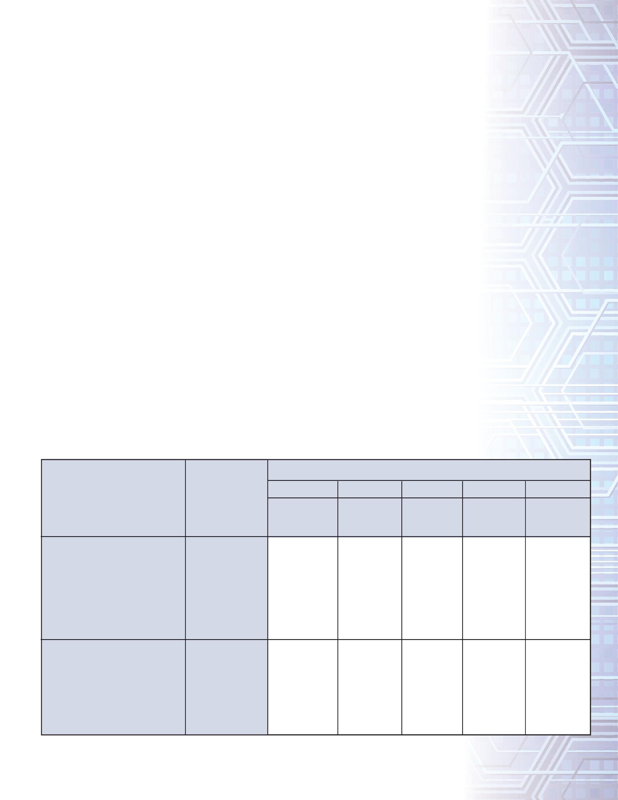
Table1: Table 1: Key Gas Ratio Limits for Service Aged Insulating Fluids
When cellulose insulation decomposes due to overheating, chemicals, in addition to CO and CO2, are released and dissolved in the oil. These chemical compounds are known as furanic compounds, or furans. In healthy transformers, there are no detectable furans in the oil (<100 ppb). As the cellulose degrades, thefuranlevelswillincrease.Furanlevelsof the furan levels will increase. Furan levels of 500 to 1000 ppb are indicative of accelerated RATIO
Doernenberg Ratios
R1 - Methane/Hydrogen
R2 - Acetylene/Ethylene
R3 - Acetylene/Methane
R4R4 - Ethane/Acetylene
Rogers Ratios
R1 - Methane/Hydrogen
R2 - Acetylene/Ethylene
R5R5 - Ethylene/Ethane
C2H2/C2H4
C2H2/CH4
C2H6/C2H2
C2H2/C2H4
C2H4/C2H6
DATACENTERMAINTENANCE–PART4–ELECTRICALDISTRIBUTIONSYSTEMMAINTENANCE DATA CENTER MAINTENANCE – PART 4 – ELECTRICAL DISTRIBUTION SYSTEM MAINTENANCE NETAWORLD 21 NICHEMARKETTESTING NICHE MARKET TESTING
DESCRIPTIONGAS RATIO FAULT TYPE T1T2T3D1D2 Thermal Fault < 300˚ C Thermal Fault 300-700˚ C Thermal Fault > 700˚C Low Energy/ Partial Discharge High Energy Discharge
CH4/H2
CH4/H2
1.0 < R1 R2 < 0.1 1.0 < R5 < 3.0 1.0 < R1 R2 < 0.75 R3 < 0.3 R4 < 0.4 1.0 < R1 R2 < 0.1 1.0 < R5 < 3.0 1.0 > R1 R2 < 0.1 3.0 < R5 R1 < 0.1 R3 < 0.3 0.4 < R4 R1 < 0.1 R2 < 0.1 R5 < 1.0 0.1 < R1 < 1.0 0.75 < R2 0.3 < R3 R4 < 0.4 0.1 < R1 < 1.0 1.0 < R2 < 3.0 3.0 < R5

NICHEMARKETTESTING
MARKET TESTING
cellulose aging, with furan levels >1500 ppb having a high risk of insulation failure.
Infrared Inspection
Infrared Inspections, or thermographic surveys, should be performed on high- and low-voltage equipment. The survey will include surveying electrical equipment for thermal differences or high limits, which are indicative of problems that could result in equipment failures. Suggested actions based on temperature rises are available in ANSI/NETA MTS-2011. This type of survey is very useful in identifying loose orbadconnectionsandterminationsand or bad connections and terminations and overloading conditions and should be applied to electrical equipment (i.e., breakers, transformers, automatic transfer switches, buses, and cable terminations). Additionally, this survey is useful in confirming liquidfilledtransformerlevel. filled transformer level.
Ultrasonic Emission (UE) Surveys
UE surveys should be performed on high-voltage equipment, only. The survey will include surveying electrical equipment for ultrasonic variations which are indicative of problems that could result in equipment failures. This type of survey is very useful in identifying possible corona and arcing conditions. A UE survey is considered an optional test that can be performed in support of further investigation of identified issues.
Partial Discharge (PD) Testing
The integrity of high-voltage insulation systems can be assessed through partial discharge testing and analysis on-line. PD is an electrical phenomenon that causes insulation deterioration. Partial discharge can be described as an electrical pulse or discharge in a gas-filled void or on a dielectric surface of a solid or liquid insulation system. This pulse or discharge partially bridges phase-to-ground insulation or phase-to-phase insulation in an electrical apparatus.
PD testing and analysis can be the foundation for a viable predictive maintenance program for high-voltage equipment. Periodic use of
the technology allows the identification of problem areas with higher voltage terminations and splices prior to failure.
PREVENTIVEMAINTENANCE PREVENTIVE MAINTENANCE
The preventive maintenance activities below should be scheduled and performed in conjunction with a condition-based maintenance program. These activities are to be performed during a planned outage while associated portions of the data center areshutdown.Toobtainmaximumbenefit are shutdown. To obtain maximum benefit from these electrical tests, knowledge of the equipment, systems, and indications of potential failure modes is required. It is important that job plans and procedures indicate acceptance criteria to the inspector and that as-found and as-left reports are recorded. To determine test voltage levels and the acceptability of the electrical test results, itisrecommendedthateithermanufacturer’s it is recommended that either manufacturer’s recommendations or ANSI/NETA MTS-2011, Standard for Maintenance Testing Specifications for Electrical Power Equipment and Systems, recommendationsareused. recommendations are used.
CABLES
VLFTanDeltaTest VLF Tan Delta Test
Very low frequency (VLF) testing can be performed to verify a cable’s ac voltage withstand capability. It is simply a pass/fail ac stress test using an instrument with a 0.1 HZ (or lower) output frequency rather than 50/60 Hz. A tan delta test is a diagnostic test that indicates the degree of cable insulation degradation. Rather than using only a VLF instrument to perform a go/no-go proof test, the tan delta unit, used in conjunction with a VLF source, permits the user to grade the deterioration level of many cables in order to prioritize replacement or rejuvenation, or to determine what additional tests may be useful. It is recommended that the voltage levels presented in IEEE 400.2, IEEEGuide IEEE Guide for Field Testing of Shielded Power Cable Systems Using Very Low Frequency (VLF), be used for thistest. this test.
22 FALL 2013
NICHE
DATACENTERMAINTENANCE–PART4–ELECTRICALDISTRIBUTIONSYSTEMMAINTENANCE DATA CENTER MAINTENANCE – PART 4 – ELECTRICAL DISTRIBUTION SYSTEM MAINTENANCE

TRANSFORMERS
Dielectric Absorption Ratio (DAR)/ Polarization Index (PI)
DAR and PI tests are used for determining insulation condition for apparatus with complex insulation systems, such as transformers. The polarization index is performed to judge the rate of disappearance of charging and absorption currents. The DAR is the ratio of the insulationresistanceattheendofoneminute insulation resistance at the end of one minute to that at the end of 30 seconds at a constant voltage. The PI is a ratio of the insulation resistanceattheendof10minutestothat resistance at the end of 10 minutes to that attheendofoneminuteataconstantvolt at the end of one minute at a constant voltage. For transformers, a polarization index of greater than 1.0 is acceptable. However, the higher the value, the better.
Power Factor/Dissipation Factor
Thistestmeasurestheinsulation’sacdielectric This test measures the insulation’s ac dielectric loss (consists of dielectric absorption, conductivity, and ionization loss components) and power factor and provides a measure of the overall condition of an apparatus’s insulation system. The power-factor test is the most effective field test for evaluating the conditionofanoil-filledtransformer’ssolidinsu tion of an oil-filled transformer’s solid insulation and its bushings. The test is useful in detecting moisture, contamination, and/or insulation deterioration. Test data is typically evaluated by comparison to prior results from similar equipment and/ or databases. One of the largest equipment power-factor databases andrelatedtechnicalinformationisthatac and related technical information is that acquired and maintained by Doble Engineering Company. Because of this it is often referred to as Doble testing.
Winding Resistance
Winding resistance measurements for transformersareusedtodetermineifthe transformers are used to determine if the connectionsarecorrectandifthereare connections are correct and if there are any severe mismatches or opens within the transformer. Electrical testing instruments are basically digital low-resistance ohmmeters (DLROs). Regardless of the transformer configuration (i.e, either wye or delta), the winding resistance measurements are
made phase-to-phase and are considered acceptable if all readings are within 1 percent ofeachother.Becauseoftheenormous of each other. Because of the enormous amount of energy that can be stored in a magnetic field, precautions should be taken before disconnecting the test leads from the transformerthatisundertest.Neverremove transformer that is under test. Never remove the leads during the testing process and always allow for enough time to completely discharge the transformer being tested. Large transformers can require several minutes to discharge.
TurnsRatioTest Turns Ratio Test
The purpose of a transformer turns ratio (TTR) test is to measure the turns ratio and exciting current of windings in transformers. A transformer’s turns ratio is equal to the ratio of turns of wire in the primary winding ofatransformertothenumberofturns of a transformer to the number of turns of wire in the secondary winding. Deviations in turns-ratio readings indicate problems in one or both windings or the magnetic core circuitofatransformer.Theratiomeasured circuit of a transformer. The ratio measured with this test includes the losses normally found in the transformer, which will result in a ratio greater than that of the physical turns but reflects the real voltage ratio expected for the transformer. ANSI Standard C57.12 specifies that turns ratio be no more than 0.5 percent from nameplate rating of thetransformer. the transformer.
BREAKERS
InsulationResistance Insulation Resistance
The purpose of measuring insulation resistance is to determine if the equipment’s insulation system is suitable for operation or even for a high potential test. An insulation resistance test set (typically referred to as a Megger) must be used to perform this test. This test should be performed phase-tophase and phase-to-ground with the breaker contacts closed and across the open contacts. Evaluating and trending insulation resistance is important in identifying deterioration as quickly as possible so you can take the necessary corrective measures.
NETAWORLD 23 NICHEMARKETTESTING NICHE MARKET TESTING
DATACENTERMAINTENANCE–PART4–ELECTRICALDISTRIBUTIONSYSTEMMAINTENANCE DATA CENTER MAINTENANCE – PART 4 – ELECTRICAL DISTRIBUTION SYSTEM MAINTENANCE
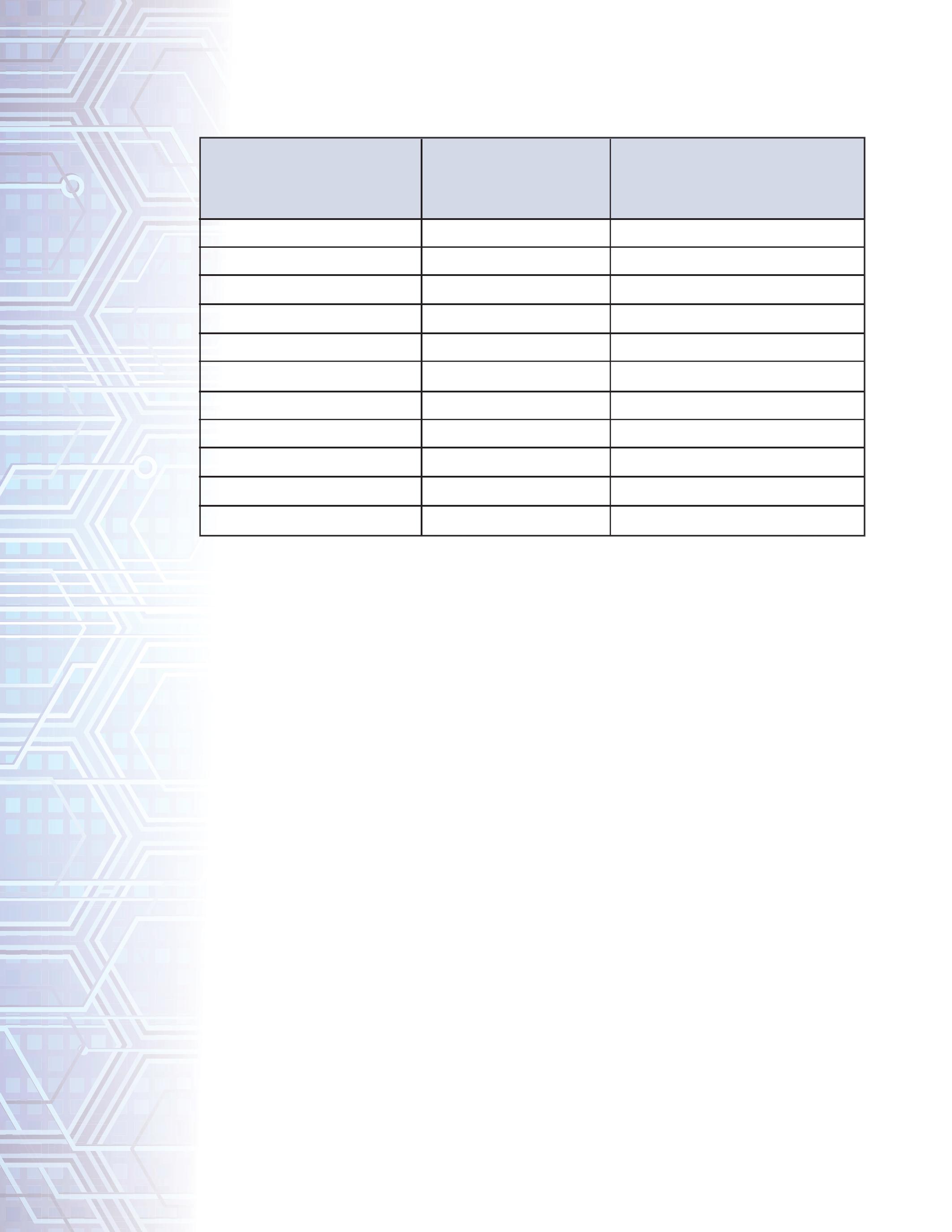
Table2: Table 2: Insulation Resistance Test Values Electrical Apparatus and Systems
Reference:
IEEE Std 43-2000 Recommended Practice for Testing Insulation Resistance of Rotating Machinery (mahybe
Transformers pg. 50)
Testing voltages and acceptable test results are provided in the attached Table 2.
A cautionary note, insulation resistance measurement is temperature sensitive; therefore, ambient temperatures should be considered when evaluating test results. A suggested temperature correction table is included in ANSI/ NETAMTS-2011. NETA MTS-2011.
Contact/ConnectionResistance Contact/Connection Resistance
The purpose of measuring contact and connection resistance is to verify that contacts, or associated circuit segments, in the electrical distribution system are at a low resistance. A digital low-resistance ohmmeter (DLRO also known as a Ductor) must be used to perform this test. This test should be performed from line-to-loadterminalsofthecontactswiththe line-to-load terminals of the contacts with the breakerclosed.Thevaluesshouldbewithin breaker closed. The values should be within 50 percent of each other and comparable to
similar devices. The resistance values vary with the size of the breaker with typical values of less than 100 microhms, with some manufacturers suggesting values of less than 30 microhms. Evaluating and trending contact resistance is important in identifying contact deterioration as quickly as possible so you can take the necessary corrective measures.
Vacuum Bottle Integrity
For medium- and high-voltage vacuum breakers (>1000 V), overpotential tests have proven successful in detecting vacuum bottle integrity. The test should be performed across each vacuum bottle with the contacts in the open position. Additionally, this test should only be performed after an insulation resistance test has been performed successfully to ensure adequate contact separation prior to performing an overpotential test. Use of ac high potential test sets is typically recommended by manufacturers. If a dc high
NICHEMARKETTESTING NICHE MARKET TESTING 24 FALL 2013
MINIMUM TEST VOLTAGE, DC RECOMMENDED MINIMUM INSULATION RESISTANCE IN MEGOHMS NOMINAL RATING OF EQUIPMENT IN VOLTS 250 600 1,000 2,500 5,000 8,000 15,000 25,000 35,000 46,000 500 1,000 1,000 1,000 2,500 2,500 2,500 5,000 15,000 15,000 15,000 25 100 100 500 1,000 2,000 5,000 20,000 100,000 100,000 100,000
DATACENTERMAINTENANCE–PART4–ELECTRICALDISTRIBUTIONSYSTEMMAINTENANCE DATA CENTER MAINTENANCE – PART 4 – ELECTRICAL DISTRIBUTION SYSTEM MAINTENANCE

potential test set is used, a full-wave rectified model is to be used; a half-wave rectified test set can potentially create peak voltages which can damage the vacuum bottle.
Electrical Operability Test, Adjustment, Calibration
Electrical operability testing shall be provided for each device which can be electrically operated. This means that for breakers, switches, starters, etc., which can be operated using remote devices (i.e., are equipped with shunt trips, protective relays, or trip units) the electrically operated circuitry should be tested for operability. For protective relays and trip units this will require the use of test equipment test which either primary injects (the tested circuitry includes associated instrument transformers, control wiring, and trip unit) or secondary injects (the trip circuitry only includes the control wiring and trip unit) currents and/or voltages to simulate various trip conditions for each applicable operating mode. It is preferred that device-specific, timecurrent-curves (TCCs) for the equipment being tested are developed and used to evaluate the acceptability of the results. Where a a power system study has been performed using a modeling software (i.e., SKM), the devicespecific TCCs should be readily available. Whennomanufacturer’srecommendations When no manufacturer’s recommendations are provided, information available in ANSI/ NETA MTS-2011 can be used for evaluating evaluating breaker performance. Care shall be taken shall taken to note and reinstall appropriate set points, adjustments, and calibration information for each device prior to placing back in service.
Mechanical Operability Test, Adjustment, Lubrication
Mechanical operability testing shall be provided for each device. For electrical equipment with mechanical components, most mechanical problems are due to the environmental conditions, improper or lack of cleaning, and improper lubrication of the device. Cleaning activities should include complete removal of existing lubricating greases and deposits from moving parts and
contact surfaces. Cleaning surfaces should not include the use of solvents which may leave residuesonsurfacesortheuseofabrasive residues on surfaces or the use of abrasive cloths (i.e., emery cloths, etc.) due to the potentially harmful effects on the surfaces. In most cases, the electrical contact surfaces are plated and using abrasive materials to clean the surfaces may remove or damage that plating. Application of a very thin layer of new lubricant should be provided in accordancewithmanufacturer’srecommended accordance with manufacturer’s recommended instructions using recommended lubricants. Wherenolubricantrecommendationsare Where no lubricant recommendations are specified by the manufacturer, use Mobilgrease 28® on both the contact surfaces and the hinge points of the device. Further, blade alignment, blade penetration, and the mechanical open/ trip and close operations should be verified. Most manufacturers recommend opening and closing these devices at least annually as part of the preventive maintenance activities.
AUTOMA TICTRANSFER TIC TRANSFER SWITCH (A TS)
Automatictransferswitchesareinstalled Automatic transfer switches are installed inadatacentertotransfertheelectrical in a data center to transfer the electrical loads from the normal power sources to the standby and emergency power sources upon failure of normal power. The ATS must transfer and retransfer the load automatically. Maintenance programs for transfer switches include checking of connections, inspection or testing for evidence of overheating and excessive contact erosion, removal of dust and dirt, and replacement of contacts when required. The maintenance procedure and frequency should follow those recommended by the manufacturer. Automatic transfer switches should also be operated periodically. The periodic test consists of electrically operating the transfer switch from the normal position to the emergency position and then a return to the normal position.
SUMMARY
For data centers, the electrical distribution system ties together the key electrical systems and consists of cables, transformers, breakers,
NETAWORLD 25 NICHEMARKETTESTING NICHE MARKET TESTING
DATACENTERMAINTENANCE–PART4–ELECTRICALDISTRIBUTIONSYSTEMMAINTENANCE DATA CENTER MAINTENANCE – PART 4 – ELECTRICAL DISTRIBUTION SYSTEM MAINTENANCE
NICHEMARKETTESTING NICHE MARKET TESTING

and automatic transfer switches. Maintaining this distribution system should include the performance of scheduled predictive and preventive maintenance activities.
The predictive maintenance activities should be the basis for implementing a conditionbased maintenance program. These activities are performed while the facility is operating. Toobtainmaximumbenefitfromthese To obtain maximum benefit from these inspections, samples, and surveys, knowledge of the equipment, systems, and indications of potential failure modes is required. The preventive maintenance activities should be scheduled and performed based on and in conjunction with the condition-based maintenance program. These activities should be performed during a planned outage while associated portions of the data centerareshutdown.Toobtainmaximum center are shut down. To obtain maximum benefit from these electrical tests, knowledge of the equipment, systems, and indications
of potential failure modes is required. It is important that job plans and procedures indicate acceptance criteria to the inspector and that as-found and as-left reports are recorded. To determine test voltage levels and the acceptability of the electrical test results, itisrecommendedthateithermanufacturer’s it is recommended that either manufacturer’s recommendationsorANSI/NETAMTSrecommendations or ANSI/NETA MTS2011, Standard for Maintenance Testing Specifications for Electrical Power Equipment and Systems recommendationsareused. recommendations are used.
Lynn Hamrick brings over 25 years of working knowledge in design, permitting, construction, and startup of mechanical, electrical, and instrumentation and controls projects as well as experience in the operation and maintenance of facilities.
Lynn is a Professional Engineer, Certified Energy Manager and has a BS in Nuclear Engineering from the University of Tennessee.
26 FALL 2013
DATACENTERMAINTENANCE–PART4–ELECTRICALDISTRIBUTIONSYSTEMMAINTENANCE DATA CENTER MAINTENANCE – PART 4 – ELECTRICAL DISTRIBUTION SYSTEM MAINTENANCE
Introducing a really big idea: “Rent it”

What makes it work at Protec, better than other options?
What’s next? Make us prove we care.

TESTINGROTATINGMACHINERY TESTING ROTATING MACHINERY
SYNCHRONOUS ROTOR WINDING COMMON ELECTRICAL MONITORING ELECCTRICCAAL
BY VICKI WARREN, Iris Power LP.
The rotor windings of synchronous motors and generators are usually very reliable. However, the turn insulation in such machines will eventually degrade and puncture due to thermal aging, load cycling and/or contamination. Although turn shorts do not directly lead to machine failure, they can lead to high bearing vibration, may damage synchronizing systems within brushless motors, and may limit output.
Off-linetestsareavailabletodetectrotor Off-line tests are available to detect rotor winding shorted turns; however, they may be unreliable since the rotor is not spinning for the test. If only a few shorts are present, the shorts may disappear once the rotor is spinning (or vice versa). In the last edition of the NETA World, severalofthecommonoff-lineelectricaltests several of the common off-line electrical tests for synchronous rotors were described. This article will explain flux monitoring, which is a common on-line condition monitoring test for both round and salient pole synchronous rotors.
1. SHORTED TURNS
Shortedturnsaretheresultoffailedinsulation Shorted turns are the result of failed insulation between individual windings in generator rotors.Theseshortedturnscancause: rotors. These shorted turns can cause:

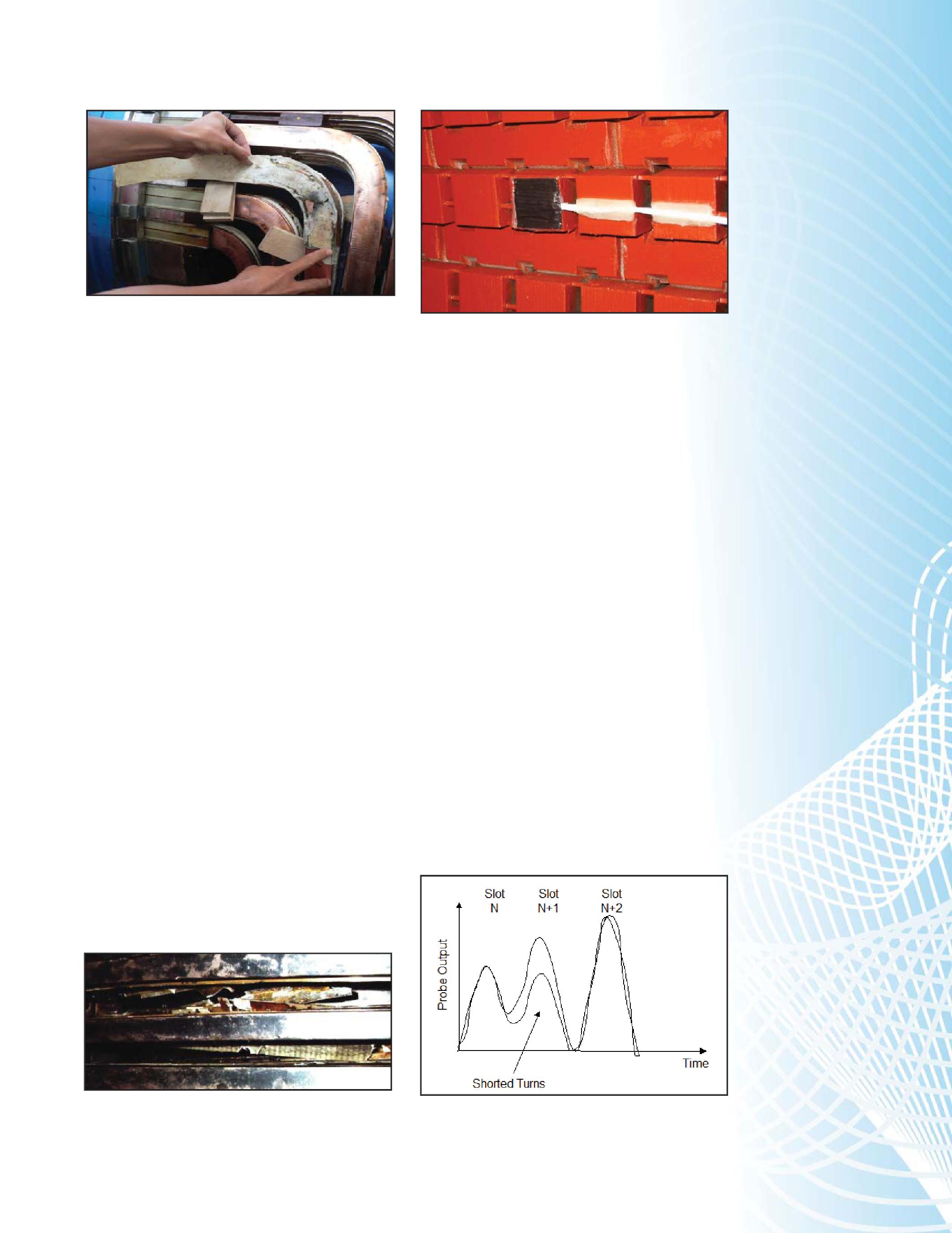
When an insulation system is exposed to overheating, the bonding material tends to lose its mechanical strength and the insulation layers delaminate.Astheinsulationbondweakens delaminate. As the insulation bond weakens and the layers delaminate, the conductors can become free enough to move with respect to each other. This weakened bonding affects not only
the mechanical stability of the field winding, but any vibration or movement will result in mechanical abrasion and may lead to strand/turn shorts and eventually ground insulation failure. Additionally, thermal aging can lead to shrinkage of bracing materials causing winding looseness.
Insulation breakdown from simple thermal overheating may take years depending on the temperature and thickness of the insulation. Thermaldeteriorationcanoccurasaresult Thermal deterioration can occur as a result of overloads, defective cooling, unbalanced phase voltages, overexcitation and poor design/ manufacture. [Figure 1]
The following are the most common causes of thermal aging in rotor windings: [1]
1. Overloading leading to operating temperatures well above expected design values. Rotors always run hotter than the stator winding.
2. High cooling temperatures or inadequate cooling which can be general, e.g., insufficient cooling air or cooling water, or local dead spots (especially at the blocking between poles) due to poor design, manufacturing or maintenance procedures.
3. The use of materials that have inadequate thermal properties and consequently deteriorate at an unacceptable rate when
28 FALL 2013 SYNCHRONOUSROTORWINDINGCOMMONELECTRICALTESTS SYNCHRONOUS ROTOR WINDING COMMON ELECTRICAL TESTS
operated within design temperature limits.
4. Overexcitation of rotor windings for long periods of time.
5. Negative sequence currents in rotor windings due to system voltage unbalance, etc.
Duetothedifferentlinearcoefficientsofthermal Due to the different linear coefficients of thermal expansion for the materials in insulated rotor windings, one of the negative impacts of frequent changes to a machine’s load or starts and stops are the cyclical shear stresses placed on the insulation. As the copper linearly expands due to the increase in temperature from I2R losses, the insulation, which is bonded to the copper and wedged between the conductor and the pole body, tends not to follow the copper due to a lower coefficient of thermal expansion and lower temperature. This stress can cause a weakening of the bond between the copper and the insulation or between the pole body and the insulation. Relative movement between the two, over time, can lead to turn shorts or the field grounding to the rotor. [Figure 2]
When any kind of conductive contamination from moisture, oil, chemicals, dust/dirt pollutes a machine, or a mixture of these, it is possible for electrical tracking to develop between conductors
and ground in salient pole and round rotor windings. Severe contamination and some chemicals can results in both turn and ground insulation failures from tracking as well as winding overheating. Abrasive particles such as coal dust, sand, and iron ore can enter the interior of motors with open enclosures. When these particles impinge on the rotor winding they wear away the insulation and can cause both turn and ground faults.
Oiltendstodissolveandlooseninsulation Oil tends to dissolve and loosen insulation system components and can attract dust that reduces heat transfer from the winding surface and reduces insulation life. In open enclosure machines, oil in combination with dust can clog up rotor cooling air passageways to cause winding overheating. Salient pole rotor windings, especially the strip-on-edge type, can experience turn-to-turn shorts and ground faults from contamination that cause tracking. Also, if a salient pole motor has slip rings brush dust, which is conductive, it can contaminate both the stator and rotor windings.
SYNCHRONOUSROTORWINDINGCOMMONELECTRICALTESTS SYNCHRONOUS ROTOR WINDING COMMON ELECTRICAL TESTS NETAWORLD 29 TESTINGROTATINGMACHINERY TESTING ROTATING MACHINERY
Figure 1: Thermally damaged turn insulation
Figure 2: Damage from thermal expansion
Figure 3: Flux probe
Figure 4: Flux difference of shorted turn
2. FLUX MONITORING OF ROUND ROTORS
Round (or cylindrical) rotor poles are used in large two-pole or four-pole synchronous motors and generators. The round rotor field windings have concentric windings made from rectangular copper strips with turn insulation consisting of strips of insulation such as Nomex™, fiberglass/ resin laminate, flake mica sheets, or Kapton™ sheets. The slot ground insulation is usually molded “L” shaped pieces made from epoxy or polyester/glass.
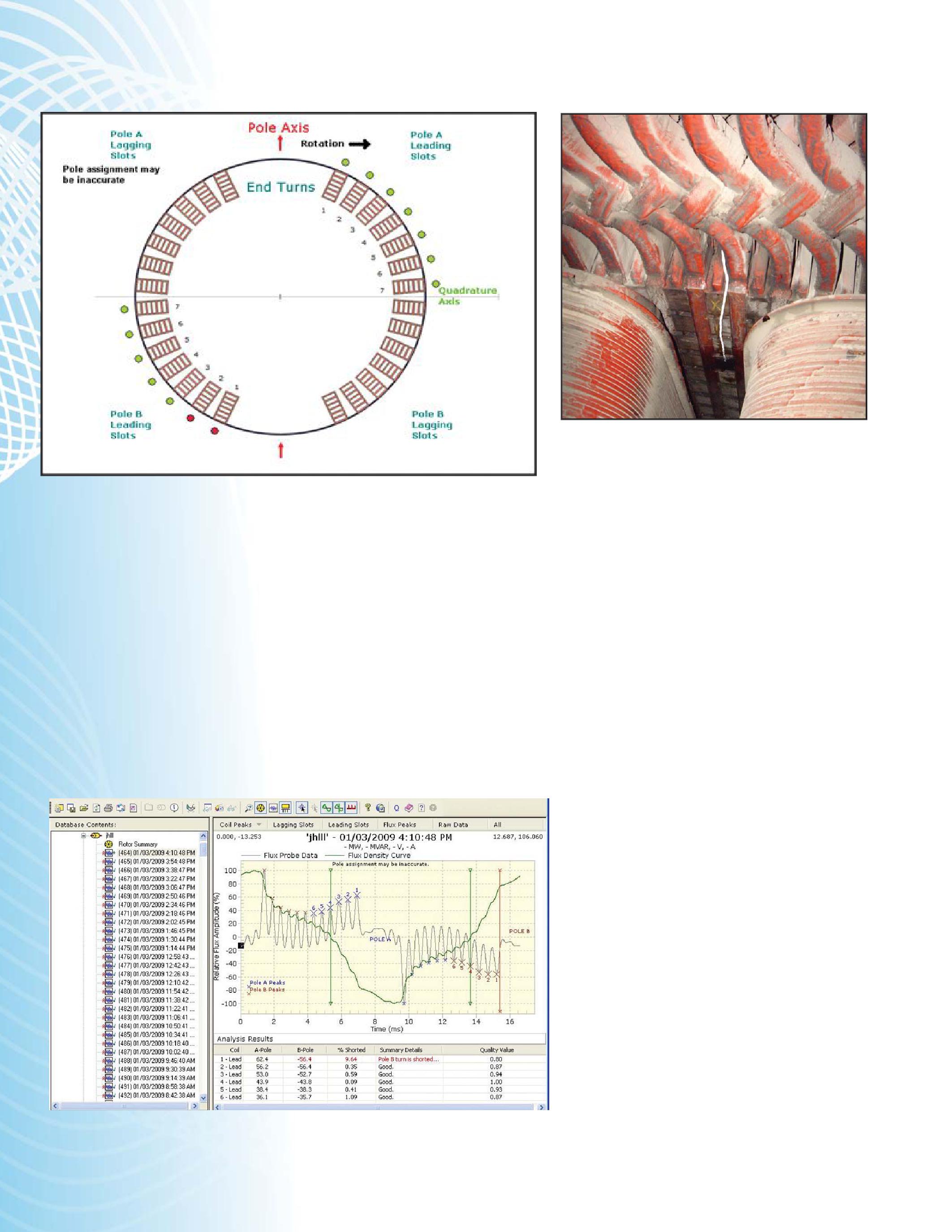
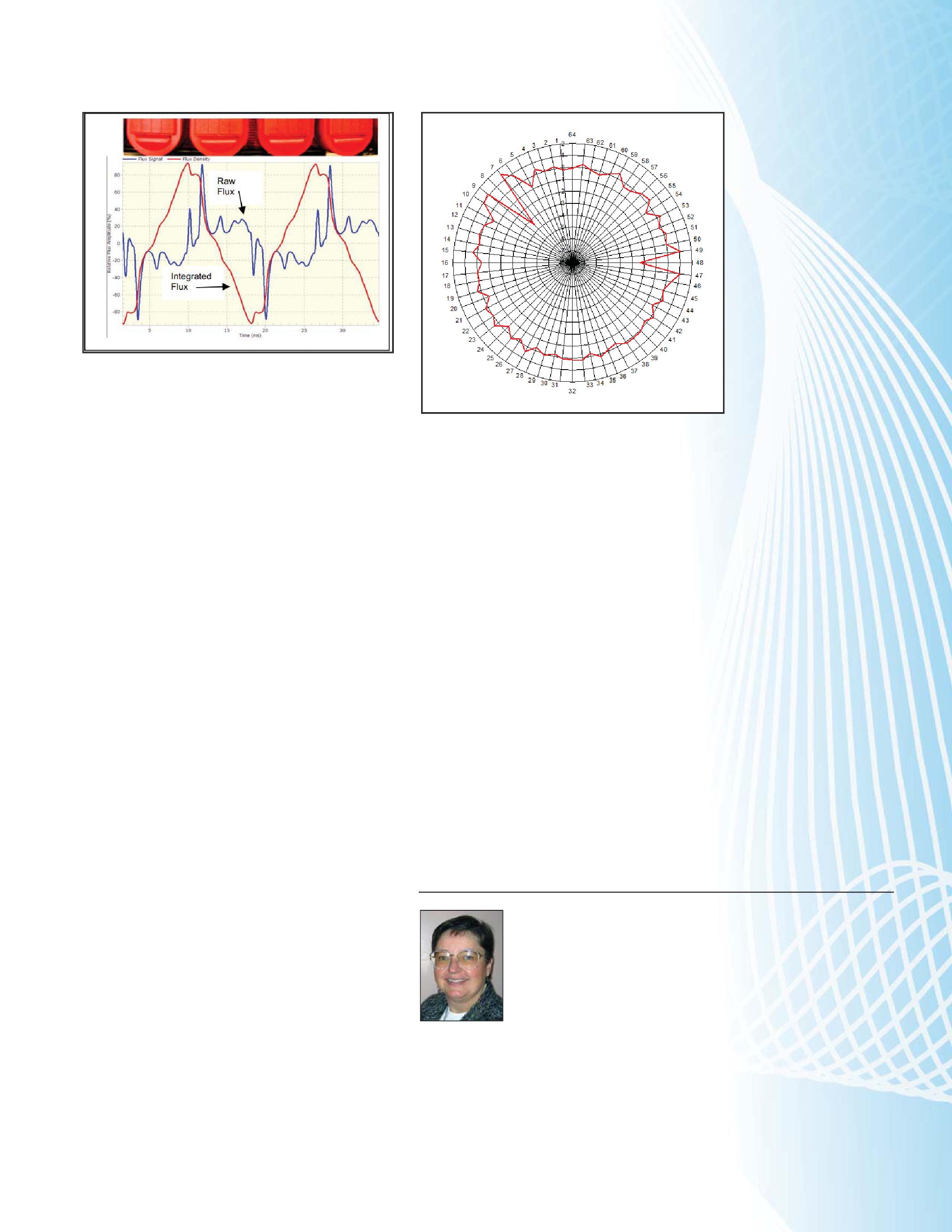
Flux probes have long been used to measure the voltage signal created by the flux surrounding each slot in each rotor pole on synchronous motors and generators rated 4160 volt and above. [2] The radial magnetic flux is detected by means of a flat coil (or probe) consisting of several dozen turns that is glued to stator teeth. [4] [Figure 3] As each rotor pole sweeps by the flux probe, a voltage is induced in the coil that is proportional to the flux from the pole that is passing the coil. By analyzing the waveforms and comparing them pole to pole, it is possible to identify slots with shorted turns. Any turn short in a pole reduces the effective ampere-turns of that pole and thus the signal from the flux probe. Usually, coils that have peak-to-peak difference larger than 3 percent compared to the same coil on another pole, are considered to have shorted turns. [Figure 4]
Historically, for a thorough analysis, it was imperative that flux data be collected at various output load conditions. [2] As such, it was often necessary for the data collector to invest long hours, often at odd times, to gather data during generator startup or shutdown. Recently, a second generation of rotor flux analyzers has emerged with the advantage that, in most cases, it is no longer required to maneuver the load from 0 to full power. [4] Thismakesthetestmucheasier This makes the test much easier and cheaper to do. [Figure 5 and Figure 6]
30 FALL 2013 TESTINGROTATINGMACHINERY TESTING ROTATING MACHINERY
SYNCHRONOUSROTORWINDINGCOMMONELECTRICALTESTS SYNCHRONOUS ROTOR WINDING COMMON ELECTRICAL TESTS
Figure 6: Fluxdata–RoundRotor Flux data – Round Rotor
Figure 7: Flux Probe for a Salient Pole rotor
Figure 5: Fluxdata–RoundRotor Flux data – Round Rotor
3. FLUX MONITORING OF SALIENT POLE ROTORS
Salient pole rotors are used in machines with slow speeds that make cylindrical (round) rotors impractical. Each field pole consists of laminated steel core, which looks rectangular when viewed from the rotor axis. Around the periphery of each pole core are the copper windings.
Each field pole is an electromagnet, and the rotor winding is made by mounting the poles in pairs on the rotor rim. The poles are then electrically connected to the dc supply (normally up to a few hundred volts) in such a way as to create alternating north and south poles around the rim. The inside shape of stacked turns conforms approximately to the width, length, and height of the pole body. The winding has turn insulation while pole body insulation may simply be air.
Similar to the round rotor, rotor flux monitoring involves measuring the magnetic flux in the generator or motor air gap to determine if field winding shorts have occurred in the rotor poles. [Figure 7] As each rotor pole sweeps by the flux probe, a voltage is induced in the coil that is proportional to the flux from the pole that is passing the coil. [Figure 8] The voltage is measured by electronic instruments. In a salient pole machine, the radial magnetic flux profile across each rotor pole depends on the MW and MVAr loading of the machine. After corrections for variations in the air-gap, any change in the flux profile within a pole at a given load must be due toshortedturns. to shorted turns. [6] Changes in the flux pattern and differences from those from other poles gives
9: ShortedturnsinPoles8&48 Shorted turns in Poles 8 & 48
an indication of the presence and number of shorted turns. [Figure 9].
REFERENCES
[1] G.Stoneetal. G. Stone et al. Using Magnetic Flux Monitoring To Detect Synchronous Machine Rotor Winding Shorts IEEEPCIC2011-17. IEEE PCIC 2011-17.
[2] D. R. Albright Interturn Short-Circuit Detector for TurbineGenerator Rotor Windings,IEEETransactionsonPower , IEEE Transactions on Power Apparatus and Systems, Vol. PAS-90 Number 2, March/April 1971.
[3] M.P. Jenkins, D.J. Wallis Rotor Shorted Turns: Description and Utility Evaluation of a Continuous On-line Monitor,EPRIPredictive , EPRI Predictive Maintenance and Refurbishment Conference, December 1993.
[4] M. Sasic, B. Lloyd, A. Elez Finite Element Analysis of Turbine Generator Rotor Winding Shorted Turns IEEETransactionson IEEE Transactions on Energy Conversion, Vol. 27, Number. 4, December 2012
[5] S. Campbell et al. Detection of rotor winding shorted turns in turbine generators and hydrogenerators CIGREA12062010 CIGRE A1_206_2010
[6] M.Sasicetal. M. Sasic et al. Tools for Monitoring Generators, Hydro Review Worldwide, Oct 2009, pp 12-19.
Vicki Warren, Senior Product Engineer, Iris Power LP. Vicki is an electrical engineer with extensive experience in testing and maintenance of motor and generator windings. Prior to joining Iris in 1996, she worked for the U.S. Army Corps of Engineers for 13 years. While with the Corps, she was responsible for the testing and maintenance of hydrogenerator windings, switchgear, transformers, protection and control devices, development of SCADA software, and the installation of local area networks. At Iris, Vicki has been involved in using partial discharge testing to evaluate the condition of insulation systems used in medium- to high-voltage rotating machines, switchgear and transformers. Additionally, she has worked extensively in the development and design of new products used for condition monitoring of insulation systems, both periodical and continual. Vicki also actively participated in the development of multiple IEEE standards and guides and was Chair of the IEEE 43-2000 Working Group.
TESTINGROTATINGMACHINERY TESTING ROTATING MACHINERY NETAWORLD 31
SYNCHRONOUSROTORWINDINGCOMMONELECTRICALTESTS SYNCHRONOUS ROTOR WINDING COMMON ELECTRICAL TESTS
Figure 8: FluxmeasuredinSalientPole Flux measured in Salient Pole
Figure
RECOVER FROM DISASTER,FASTER.

HAVING MILLIONS OF PARTS IS ONLY PART OF THE STORY. After a disaster, your service shop needs expert help – fast. National Switchgear has literally millions of switchgear products, new and reconditioned. And we have the know-how to help you determine exactly what you need to get your clients’ equipment back up to speed. We’re available 24/7, and we’re here to help, whether you require a small component part, a switchgear lineup, shop resources, or anything else to restore equipment. So, if you’re thinking of calling anyone else, it’s time to switch. 800-322-0149 nationalswitchgear.com

Electrical Distribution System
24 Hour Emergency Services (937) 439-9660

SWITCHGEAR PARTIAL DISCHARGE LOCATION
BY DON GENUTIS, No-Outage Electrical Testing, Inc.
INTRODUCTION
More and more service companies are finding success with no-outage field partial discharge (PD) testing and monitoring methods. As the use and awareness of these techniques continue to expand, it becomes important to determinethelocationofthePDsourcesoit determine the location of the PD source so it can be eliminated. In this article, we will review the three basic types of PD sensors used for switchgear testing and monitoring, discuss how probable PD location can be identified on-line, and how it can be pinpointed off-line.
TYPES OF PD SENSORS
Airborneultrasonicsensorsarethemost Airborne ultrasonic sensors are the most sensitive type of sensor for detecting surface insulationPD.Thesesensorsdetecttheminute insulation PD. These sensors detect the minute pressure waves which are created from the PD sparking activity. Switchgear vents or openings must be present in order for the pressure wave to reachthesensorfromoutsideoftheenclosure. reach the sensor from outside of the enclosure. Ultrasonic sensors also cannot detect problems internal to components.
Transient earth voltage (TEV) sensors detect electromagnetic signals created by internal PD activity through capacitive coupling. The TEV sensor consists of a metal plate assembly, which when placed against the switchgear, forms a temporary capacitor with the enclosure acting as the other plate of the capacitor. This test method compliments the ultrasonic sensor by allowing the detection of internal component PD flaws or detection of surface discharges that ultrasonicsensorscannotseeduetoinhibited ultrasonic sensors cannot see due to inhibited airway access paths. Since the ultrasonic sensor
is more sensitive to surface PD, the TEV sensor will often pickup when surface activity becomes moresevere. more severe.
High frequency current transformer (HFCT) sensors consist of a split core CT with high frequency characteristics that detect conducted electromagnetic signals from cable PD by placing the sensor around the cable shield. This sensordetectsPDatthecableterminationand sensor detects PD at the cable termination and candetectPDfurtherdownthecableaswell. can detect PD further down the cable as well.
WHAT DO THE SENSORS TELL T US ON-LINE?
By examining the diagram we can see what each sensor alone and collectively tell us in regards to PD location in switchgear. For this example, the sensors can be either permanently mounted, in the case of monitors, or temporarily mounted in the case of spot testing.
The H-circle represents the HFCT sensor, the T-circle represents the TEV sensor and the U-circle represents the ultrasonic sensor. Nonintersecting circles are straight forward to figure out: H by itself represents a cable problem, T by itself represents an internal switchgear problem and U by itself represents a surface switchgear problem.
WhereisthePDlocatediftwosensorsindicate Where is the PD located if two sensors indicate a problem? Taking a look at the diagram again, the area labeled HU displays a condition where both the HFCT (H) and the ultrasonic (U) sensors pick up PD signals. This would beindicativeofasurfacecabletermination be indicative of a surface cable termination problem. HT represents an internal termination
SWITCHGEARPARTIALDISCHARGELOCATION SWITCHGEAR PARTIAL DISCHARGE LOCATION 34 FALL 2013 NO-OUTAGEINSPECTIONCORNER NO-OUTAGE INSPECTION CORNER

problem and UT represents a severe surface switchgear problem - the surface tracking has reached a point where TEV signals are being generated as well as explained above.
Finally, the HUT part of the diagram indicates the condition of all three sensors picking up PD signals. This is likely related to a severe surface termination problem.
It should be noted at this time that once any sensor picks up an abnormal signal, it should be investigated. Do not wait until multiple sensors alarm before taking action. This is especially true for the ultrasonic sensor as surface PD damage can escalate rapidly and the signal path can be impeded by obstructions.
HOW DO WE PINPOINT PD LOCATION OFF-LINE?
Very valuable information can be obtained when equipment is being shut down for maintenance and this applies to a much broader scope than just PD alone. For instance, obtaining breaker first-trip condition allows valuable mechanical conditiondatatoberecordedwhichalsoties condition data to be recorded which also ties in protective device coordination and arc-flash compliance. Tripping medium-voltage breakers from protective relays can ensure correct function of the trip circuit, battery, wiring, and associated components including the breaker trip coil and linkage.
For pinpointing PD, an orderly shutdown or selective switching can help rule out components by the process of elimination. Let’s take a typical medium-voltage switchgear assembly for instance, where PD has been located in one cell. Begin by tripping the breaker (don't forget to record the firsttrip data, if possible), then check to see if the PD is gone. If so, the activity is located on the load side of the breaker which usually would involve cable terminationsorloadsidebusinsulationandcould terminations or load side bus insulation and could involvebreakerloadsideconnectioninsulation.If involve breaker load side connection insulation. If the PD persists, the next step is to rack out the breaker using a remote breaker racking device to ensure personnel safety. Once the breaker has been racked out, check for PD activity. If gone, the problem is in the breaker. If the problem remains, it is associated with bus insulation
orlinesidebreakerconnecor line side breaker connectioninsulation. tion insulation.
After the switchgear has been completely deenergized, locked out, tagged out, and grounded, visual inspections can proceed. Keep in mind that unless ultrasonic signals are detected, the problem is likely to be internal to a component or deep in the switchgear where the airborne signals cannot escape. Look for surface tracking, the presence of white powder or other color powder buildup, discoloration, corrosion or other usual signs.
If the problem is internal or if it is difficult to visually locate a surface problem, carefully energize individual components using a PD-free ac high potential test set and use the applicable PD sensor(s) to identify the faulty component through the process of elimination.
CONCLUSION
Switchgear should operate PD-free, and detecting the presence of switchgear PD activity is the first step in the process of ensuring reliability. The next step of the process is to locate the PD source on-line using information gleaned from the different types of sensors available. The next step is to perform selective switching to further locate the problem area through the process of elimination of components and the final step involves outage-based inspection and testing to pinpoint the faulty component. By utilizing this simple step-by-step methodology, PD can be detected, located, pinpointed, and eliminated.
DonA.Genutis Don A. Genutis received his BSEE from Carnegie Mellon University. He was a NETA Certified Technician for 15 years and is a Certified Corona Technician. Don’s technical training and education are complemented by twenty-five years of practical field and laboratory electrical testing experience. Don serves as President on No-Outage Electrical Testing, Inc., a member of the EA technology group.
SWITCHGEARPARTIALDISCHARGELOCATION SWITCHGEAR PARTIAL DISCHARGE LOCATION NETAWORLD 35 NO-OUTAGEINSPECTIONCORNER NO-OUTAGE INSPECTION CORNER H T U HU UT HUT HT

We Buy, Sell, Trade, Calibrate, Repair Power electronics are our business “SOLID STATE” INDUSTRIAL ELECTRONICS “SOLID STATE” INDUSTRIAL ELECTRONICS Toll Free 877-TRIP-FIX NOWRENTING TESTEQUIPMENT






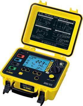


Current Measurement Environmental Testers Ground Resistance Testers Power Quality Analyzers is your is your ONE SOURCE for all your for all your Electrical Measurement Tool needs! 200 Foxborough Blvd. Foxborough, MA 02035 (508) 698-2115 FAX (508) 698-2118 sales@aemc.com Technical Hotline (800) 343-1391 PGTI.net PGTI PGTI is the Business for Your Power. Your partner for Acceptance Testing, Preventative Maintenance and Emergency Response. NICET and NETA certified technicians available 24/7/365. Safe, Smart, Right! Power & Generation Testing, Inc. 480 Cave Road – Nashville, TN 37210 615.882.9455 Protect your facility’s power system from unplanned power outages. of electrical power systems. MD DC PA DE NJ 3915 Benson Road Phone: 410.368.3981 Resources. Experience.

OF BREAKER PROTECTION AND COORDINA TION
BY BRUCE M. ROCKWELL, P.E., American Electrical Testing Co.
OVERCURRENT COORDINATION
Compliance with arc-flash hazard work rules, as defined by OSHA, NFPA 70E, Standard for Electrical Safety in the Workplace, and NFPA 70, National Electrical Code, requires evaluation of arc-flash hazards and subsequent posting of the hazard on electric equipment. The arc-flash hazard can be dramatically affected by the overcurrent protective device settings. Faster response and trip times can significantly reduce the hazard. Acceptance and periodic maintenance testing serve to confirm the arcflash hazard analysis predictions based on NFPA 70E and IEEE 1584, Guide for Performing Arc Flash Hazard Calculations.
This article reviews protection schemes and application methods that can be applied to enhance time-overcurrent (TOC) protection to improve safety such as: directional overcurrent, bus differential, partial differential, zone interlocking, blocking, and other schemes. Historically, TOC settings that were once acceptable to protect equipment are no longer suitable as they may not provide adequate protection of personnel. More recent changes in worker safety standards challenge protection professionals to further optimize settings. Advances in protective device technology allow application of enhanced protection that can reduce fault clearing time without compromising selective coordination or sensitivity.
Changes in industry practice are also driving change. The decision to remove instantaneous protection settings was widely adopted in the
1980’s and 1990’s by some utilities as a means to stop customer complaints for blinking digital clocks. Today, where continuity of service is critical to business operations, the application and use of the instantaneous function is a very important consideration. In 2011, the NEC added article 240.87 in an attempt to address increased hazards on power systems that operate without instantaneous protection.
Basic TOC protection coordination operates based on a time-current curve (TCC). Multiple TOC protective devices, connected in series, are generally applied to protect the power system. TOC elements may have fixed response curves or may require selection of one or more current and time delay pickup setting pairs: long time, short time, and ground fault that allow piecewise continuity of various time bands and selection of multiple response curves. The time delay associated with the TOC element can produce slower than desired response since it is applied for protection over a wide range of fault current values.
Identifying faults sooner or sending a trip signal faster can reduce arc-flash hazard energy during faults. The goal is to reduce I2T by responding quicker to reduce the time and/or quick enough to reduce the fault current. An understanding of the available fault current(s) should be sought prior to engaging work such that the desired range of settings or number and type of schemes to be applied can be fully considered. This can be accomplished by preparing or reviewing an existing short-circuit study. Industry standards recommend an updated study every five years.
SAFETYASPECTSOFBREAKERPROTECTIONANDCOORDINATION SAFETY ASPECTS OF BREAKER PROTECTION AND COORDINATION 38 FALL 2013 SAFETYCORNER SAFETY CORNER
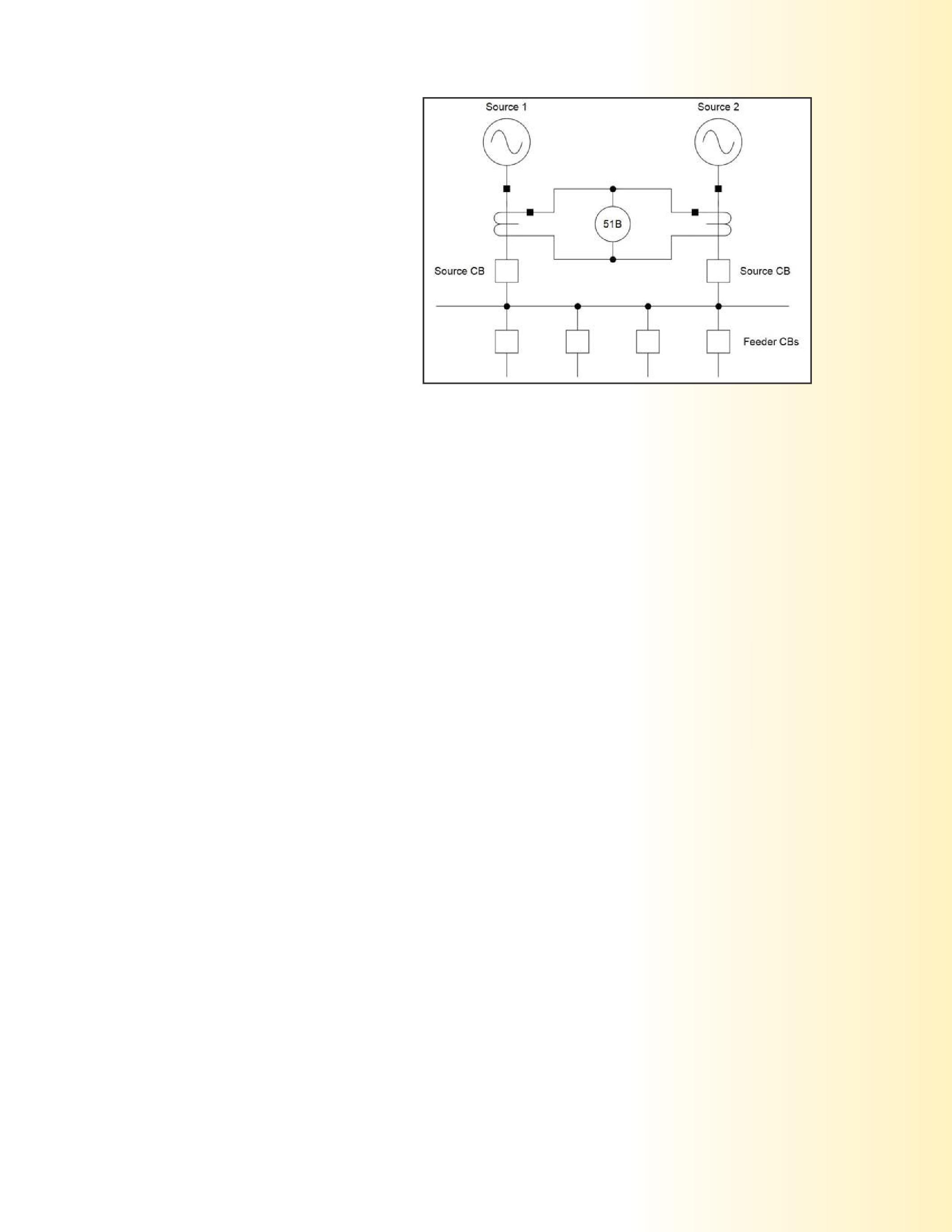
Bolted three-phase and line-ground faults as well as reduced fault currents that may occur from arcing faults should be considered. Being able to recognize the possible range of fault current values and how they affect trip time response and production of arc-flash energy is necessary to work safely.
The following information should be obtained prior to working on a protection system:
Bus Configuration and Operational Sequence
DesiredProtectionScheme Desired Protection Scheme
MinimumThree-PhaseFaultCurrent Minimum Three-Phase Fault Current
MaximumThree-PhaseFaultCurrent Maximum Three-Phase Fault Current
MinimumLine-to-GroundFaultCurrent Minimum Line-to-Ground Fault Current
MaximumLine-to-GroundFaultCurrent Maximum Line-to-Ground Fault Current
Cu Current Transformer Location, Ratio, Accuracy Class, Saturation Curve
Relay Type and TCC’s
Setting Calculations
For some protection schemes, such as some of the differential schemes, unequal performance of CTs is important to define as an offset will need to be applied to the settings. Modern relays tend to eliminate this concern; thus, it is important to understand that all differential schemes are not created equal.
PARTIALDIFFERENTIALSCHEME ARTIAL DIFFERENTIAL SCHEME
This scheme may also be referred to as a bus overload or selective backup scheme. It is considered a variation of the differential scheme, yet one or more circuits are not included in the phasor summation of current to the relay. This scheme is typically applied for differential backup, primary protection for stations with fused feeders, and local backup protection for feedercircuitbreakers. feeder circuit breakers.
One such scheme is shown in Figure 1. In this scheme, only the sources are differentially connected using a high set TOC relay. The CTs protecting the feeders are not included. Sometimes this scheme is applied to save on the cost of CTs. This scheme provides TOC bus protection with feeder backup protection. The sensitivity and speed are not as good as a differentialscheme. differential scheme.
Figure 1: Partial Differential Scheme
In modern multifunction numerical relays this scheme can be applied using communications to apply protection to the source and feeder breakers. Feeders can be equipped with nontripping low set instantaneous time overcurrent (IOC) set just above the maximum load. The sources have IOC with a slight delay setabovethemaximumloadofthebusanduse set above the maximum load of the bus and use status inputs from the feeder breakers.
For a feeder fault, the low set IOC operates and sends a block to the source relay. The IOC of the source relay operates but does not trip due to blocking. The TOC element for the source breaker is not affected, and the backup protection remains active.
For a bus fault the block signal is absent, and the source breaker trips at high speed. Some schemes use distance relays to achieve faster and more sensitive operation than the TOC scheme.
DIFFERENTIALSCHEMES DIFFERENTIAL SCHEMES
There are many types of differential schemes. Here we will consider the following differential schemes: Bus differential with TOC relays, improved TOC, comparator, multirestraint, and high impedance.
Bus Differential with TOC Relays
This scheme uses TOC relays. A typical scheme is shown in figure 2. CTs are connected in parallel with the relay. Aux CTs can be used to match ratios, but, should be avoided in this scheme. A critical issue for setting the relay is
SAFETYASPECTSOFBREAKERPROTECTIONANDCOORDINATION SAFETY ASPECTS OF BREAKER PROTECTION AND COORDINATION NETAWORLD 39 SAFETYCORNER SAFETY CORNER
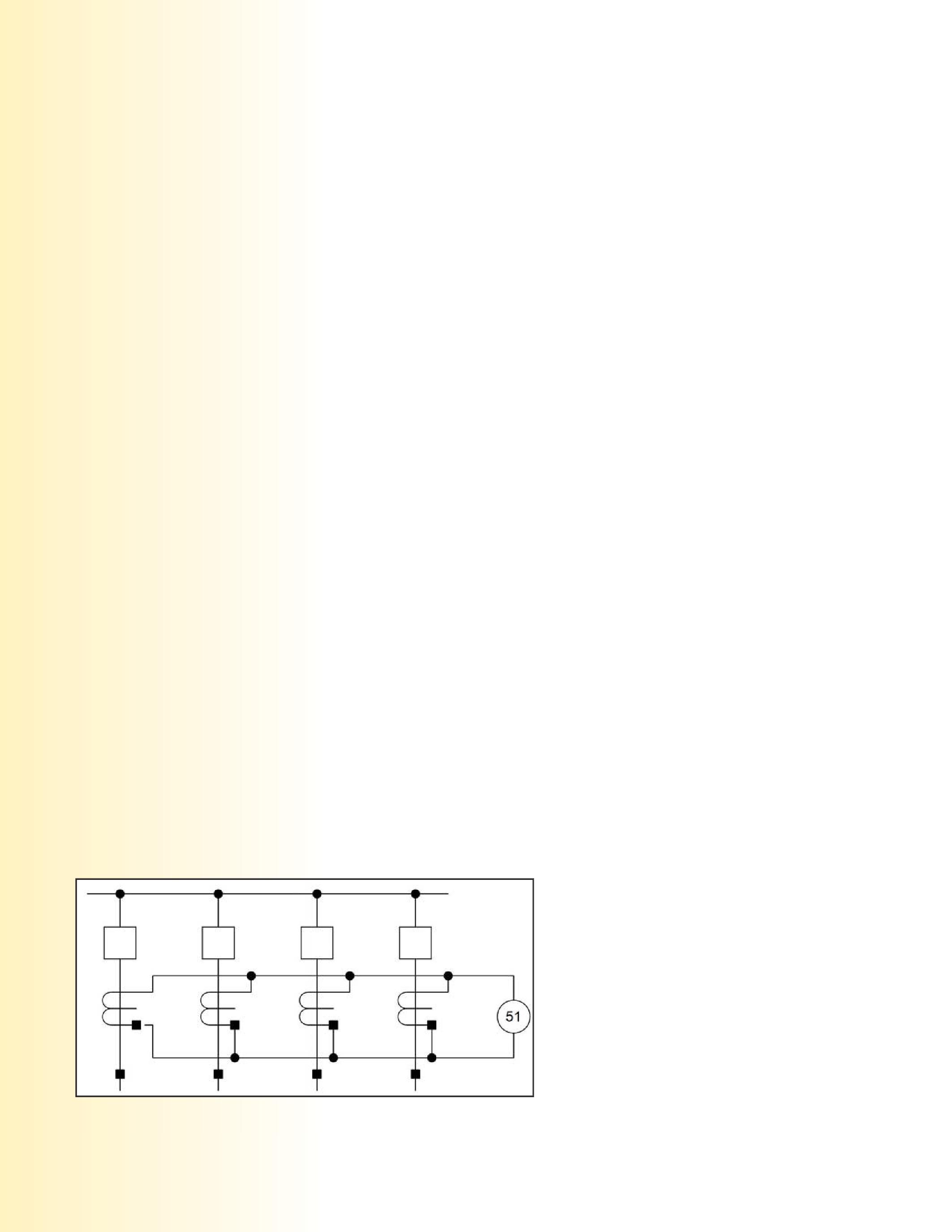
that the maximum CT error for a fault (phase and ground) needs to be established. Also, the time delay selected needs to be set such that it delays tripping if CTs are saturated by the dc component of the primary current. To achieve this, the CT primary rating is selected suchthatthemaximumexternalfaultcurrent such that the maximum external fault current magnitude, If, is less than 20 times the CT , rating, and for this fault value, the CT burden can be no more than its relay accuracy class voltage divided by 100.
The relay operating time cannot be less than three primary time constants and the current pickup setting should be greater than the exciting current of the CT for If . Typical settings are a current pickup of 10 amperes or more and a time delay not less than 18 cycles.
This scheme is not suitable for expensive systems or for enhanced safety. Faster tripping for this scheme is achieved by applying TOC relays with extremely inverse TCC response. This allows for relay trip times of eight cycles.
Improved Bus Differential Scheme with TOC Relays
The scheme can be improved by applying a stabilizing resistor in series with each overcurrent relay. If an external feeder fault causes the feeder CT to saturate, the CT excitation reactance approaches zero and the CT error current that flows through the relay can be defined. Applying aresistortothecircuitallowsreductionoftheCT a resistor to the circuit allows reduction of the CT error and thus improves the scheme sensitivity. This allows for lowering of the current pickup and thus faster relay trip response.
Multi-RestraintDifferentialScheme Multi-Restraint Differential Scheme
This scheme is very sensitive and secure for externalfaultsasitaddressestheCTerrorand external faults as it addresses the CT error and CT saturation issues. It is reasonably fast and responds well even when applying auxiliary CTs. It tends to be inflexible in applications where the system may be expanded as all the circuit wiring needs to be brought back form the switchyard to the relay house.
High Impedance Differential Scheme
This scheme uses a high impedance voltage element instead of a low impedance current elementandresistor.Thisschemeiseffectivein element and resistor. This scheme is effective in forcing the CT error current through the CTs in lieu of the relay operating coil. This scheme achieves high speed operation and can respond with a trip signal in 25 milliseconds (1.5 cycles).
When using this scheme an important safety issue is to make sure that all CTs are applied at their full tap position to avoid induced high voltage that can appear on any unused tap positions if a lower tap position is applied.
Differential Comparator Scheme
This scheme achieves the fastest trip response speed. It can operate in 9 - 16 milliseconds (1/2 to 1 cycle). This scheme is very secure against misoperation for external faults. This scheme is indicative of the enhanced protection that can be achieved using modern numerical relays. The scheme is shown in figure 3.
DIRECTIONAL OVERCURRENT SCHEME
In some medium-voltage distribution systems and most high-voltage transmission systems faultscanoccurintwodirections.Forthese faults can occur in two directions. For these systems, the directional overcurrent scheme can be applied for protection. This relay is not useful in a system with only one source.
This protection scheme uses a TOC relay that incorporates the phase relationship of voltage and current to identify the direction of a fault. Numerical relays use sequential components or quadrature voltage to sense fault direction. They also use memory to address close-into-fault protection where voltage is nearly zero. This
40 FALL 2013 SAFETYASPECTSOFBREAKERPROTECTIONANDCOORDINATION SAFETY ASPECTS OF BREAKER PROTECTION AND COORDINATION SAFETYCORNER SAFETY CORNER
Figure 2: Bus Differential w/ TOC Relay
protection system scheme, when applied with a numerical relay, can achieve four to six cycle trip response time.
This relay is sometimes applied with blocking schemes to perform sequential tripping.
ZONE INTERLOCKING SCHEME
Zone interlocking schemes are readily available in low-voltage and medium-voltage trip units and can be easily applied using modern relays. This protection scheme is based on using communication between protective devices to improve (speed up) protection. The scheme also improves selective coordination by applying a blocking signal to delay upstream tripping.
Downstreamdevicescommunicatewith Downstream devices communicate with upstream devices if the downstream relay detects fault current. The main (disconnect) service trip deviceisidentifiedasZone1witheachlevelof device is identified as Zone 1 with each level of downstream protection being assigned a new Zonelevelnumber. Zone level number.
These schemes typically utilize a three- or five-wire system to communicate phase and ground fault conditions in the zones. If a fault is seen by the downstreamdeviceandifitexceedstheshorttime downstream device and if it exceeds the short time pickup, it signals the upstream device to block high speed tripping that may occur from the instantaneous setting. If the downstream device fails to trip
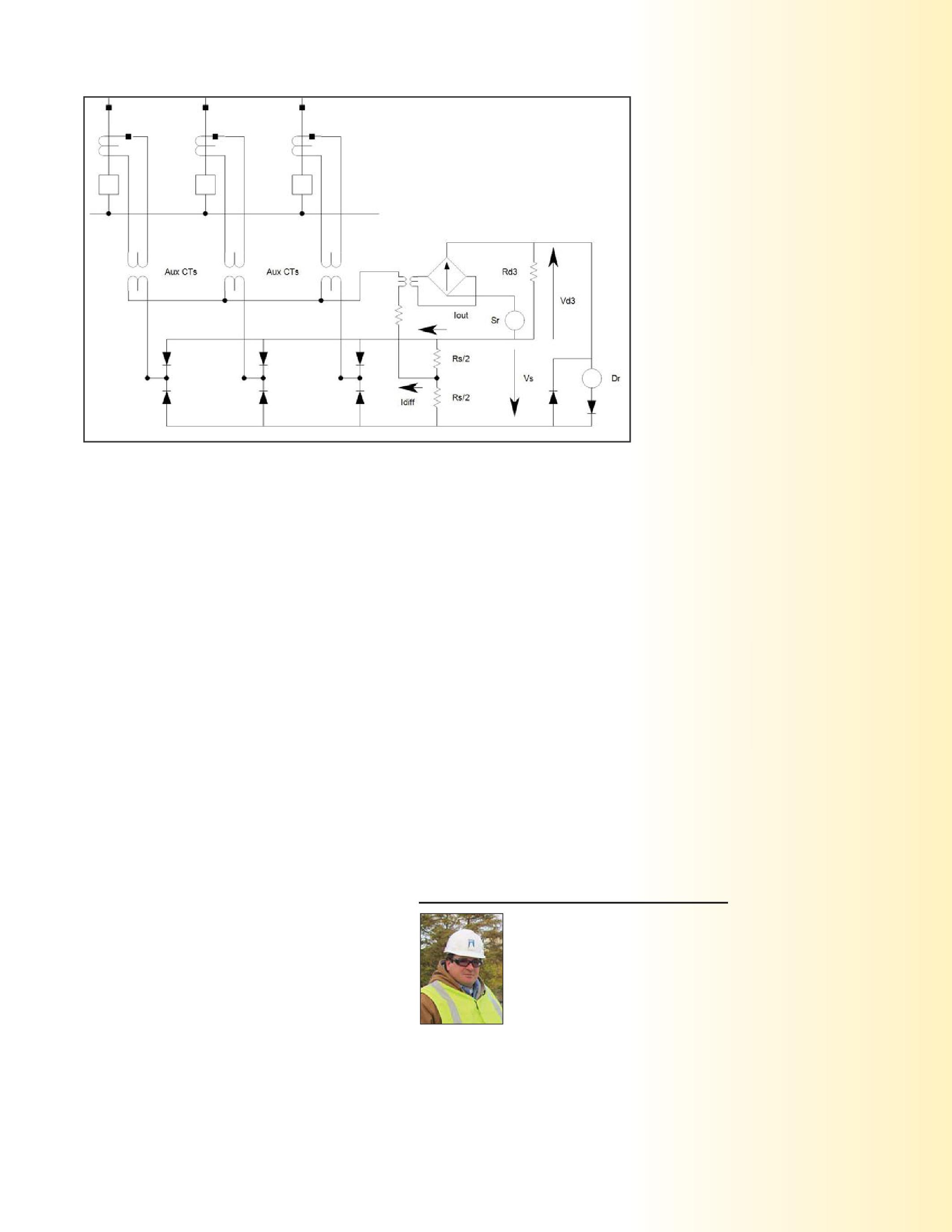
for a fault, the upstream device will override the blocking signal and trip instantaneously applying a slight (three cycle) delay.
Continuity of power system operations and worker safety are competing objectives when designing power system protection schemes and applying device settings. Modifying protection schemes and / or applying newer technology allow the designer to improve protection to enhance safety. This improved safety is achieved by the application of faster responding protection schemes and devices as well as taking advantage of the multiple protection elements and logic in numerical relays. Communication features are also available to enhance protection schemes by using logic that can applying blocking signals or release blocking signals to further enhance speed, selectivity and reliability of protection system operation.
BruceRockwell Bruce Rockwell, P.E. has been Director of American Electrical Testing’s Engineering Division for the last nine years. He has over thirty years of business development, management, construction and engineering experience; specializing in the T&D utility sector. Bruce holds an MBA from Monmouth University and received his BSEE from New Jersey Institute of Technology. Bruce is a Certified Co-Generation Professional with the Association of Energy Engineers and a Continuing Education Instructor for the State of New Jersey.
NETAWORLD 41 SAFETYASPECTSOFBREAKERPROTECTIONANDCOORDINATION SAFETY ASPECTS OF BREAKER PROTECTION AND COORDINATION SAFETYCORNER SAFETY CORNER
Figure 3: Differential Comparator




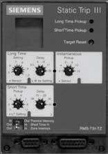
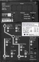
30 Years of Repair & Testing Excellence Now repairing: Siemens SB Type TL Square D MICROLOGIC Series B trip units Merlin Gerin ST & STR Units Call for all RMS-9 rating Plug needs Eddie Tate – Owner Damian Hobson – Lead Technician Phone: 601-856-9798 Fax: Thyritronics has been providing quality and timely trip unit repair to the electrical industry for over 30 years. We wish to thank all our fine customers for their loyalty and many referrals. AllMajor Manufacturers Calibration usingMulti-Amp’s Epoch System Extensive Test Report Non-RMSUnits — $300 RMSUnits — $500 Test Only Services — $100 OneDay Rush Capabilities Thyritronics, Inc. Industry Leader in Trip UnitRepairs SEE OUR WEBSITE for all our services: www.thyritronics.com


ADDRESSING PROBLEMS IN
 BY JEFF JOWETT, Megger
The previous article reviewed grounding and ground testing on wind farms from the basics. The considerations don’t depart markedly from general ground testing industry-wide, but there are some special issues endemic to wind power. In a comparatively young industry like wind power, the grounding system may not be receiving primary attention.
But factors like corrosion, weather, and lightning may be exerting unwanted effects, and these can become severe. The requisite instrumentation was described in previous articles. So were the specialized test methods that address the biggest issue with wind farm ground testing; that is, the enormous sizes of grids. Effective test regimes were outlined, both during construction and continuing maintenance. The special problems of lightning damage and static buildup on blades, and how to mitigate them were described. Finally, the maintenance of the grid structure itself was reviewed. This sequel will further examine some special problems.
Testing for maintenance and testing for conformance should be essentially the same, but may have different goals and can produce conflicting results and interpretations. Utility maintenance teams may be responsible for maintaining a wind farm. At the same time, wind turbine manufacturers may be interested in investigating issues that occur during the warranty period. Many newer facilities are coming to the end of the standard fiveyear warranty period and manufacturer’s maintenance support will be disappearing from the site. If the baton is to be passed from one
maintenance authority to the next, it is desirable to make this as seamless as possible. In addition, there may be safety monitors with their own criteriatobemet.Somecommonissueswillbe criteria to be met. Some common issues will be reviewedasfollows: reviewed as follows:
Second only to enormous grid size, the next biggest challenge is to know what is actually being measured. The system may in fact be a lot larger than thought. Initial design considerations focus on the turbine as an entity. But once daisy-chained or interconnected in a star configuration, the associated grounding system takes a quantum leap. Phase cables have grounding sheaths connected to common buses, and communication cables have their own grounded conductors as well. At some stage in construction, it becomes impossible to isolate the grounding of an individual turbine. Design criteria for a single turbine then have to be related to the total system. Furthermore, lightning protection systems use a different set of criteria than power grounding, based on the needtoaccommodateenormouscurrentsand need to accommodate enormous currents and high frequencies.
There may be cross-connection between faultclearance and lightning protection systems and between different parts of the installation. This
ADDRESSINGPROBLEMSINWINDF ADDRESSING PROBLEMS IN WIND FARMTESTING ARM TESTING TECHTIPS TECH TIPS 44 FALL 2013
connection may be intentional or inadvertent. Fault protection grounding is often shallowly buried, less than a meter below grade, and may be ineffective. The design of the wind farm may have been done piecemeal, even by different consultants, with different design considerations making up various elements of the total grounding. System design is separate from installation and commissioning, which have different economic perspectives and are performed by different subcontractors. Maintenance and performance monitoring are separate from design and installation, and, again, are performed by different subcontractors. System design schematics may not match what was actually installed, as contractors may adjust this to make their jobs easier. Grounding connections are sometimes conveniently made to a nearby conductor and do not necessarily accord with the electrical pattern of the daisy chain of turbines. Shortcuts of this sort are frequently performed to save money. As a result, each individual installation canlookdifferentfromthelast.Asreviewedin can look different from the last. As reviewed in the previous article on this subject, traditional testing methods can become impractical to implement because of the long length of test leads (typically 6 times the diagonal dimension of the grounding system) required by even smaller facilities. Accordingly, an inordinate amount of time can be wasted at large sites merely in the travel from one installation toanother. to another.
Ground testing upon installation is frequently far from rigorous or comprehensive. Not only should traditional three-pole ground tests be performed at different stages of construction, but thorough and accessible written records should be kept. As an example, tests can be performed on inner and outer grounding rings as they are installed and then on the complete turbine. By contrast, one sample site visited, a 140 turbine farm, had performed only a single test, with the current probe at about 1300 feet. This is a long distance for testing a residential or small commercial ground, butnotonawindfarm!Thedirectionof but not on a wind farm! The direction of the test had not been recorded, so a useful comparison test could not be effectively
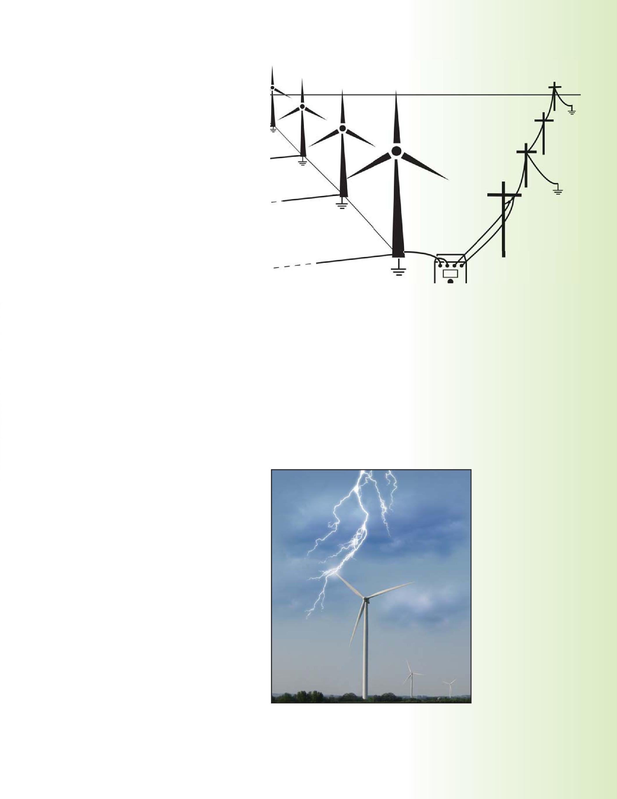
1: The scale of wind farm ground grids can make conventional testing prohibitive, requiring extensively long test leads.
run. This example illustrates a common dual problem that should be judiciously avoided: tests being both inadequate and unrepeatable. A frequent compromise practiced by wind engineers is to discount the use of fall-ofpotential testing because of the impractically long lead lengths required. Instead they work within agreeable distances and use the results merely for comparative purposes. It is especially important in such situations to
NETAWORLD 45 ADDRESSINGPROBLEMSINWINDF ADDRESSING PROBLEMS IN WIND FARMTESTING ARM TESTING TECHTIPS TECH TIPS
Figure
Figure 2: Good grounding is the best protection against lightning damage.
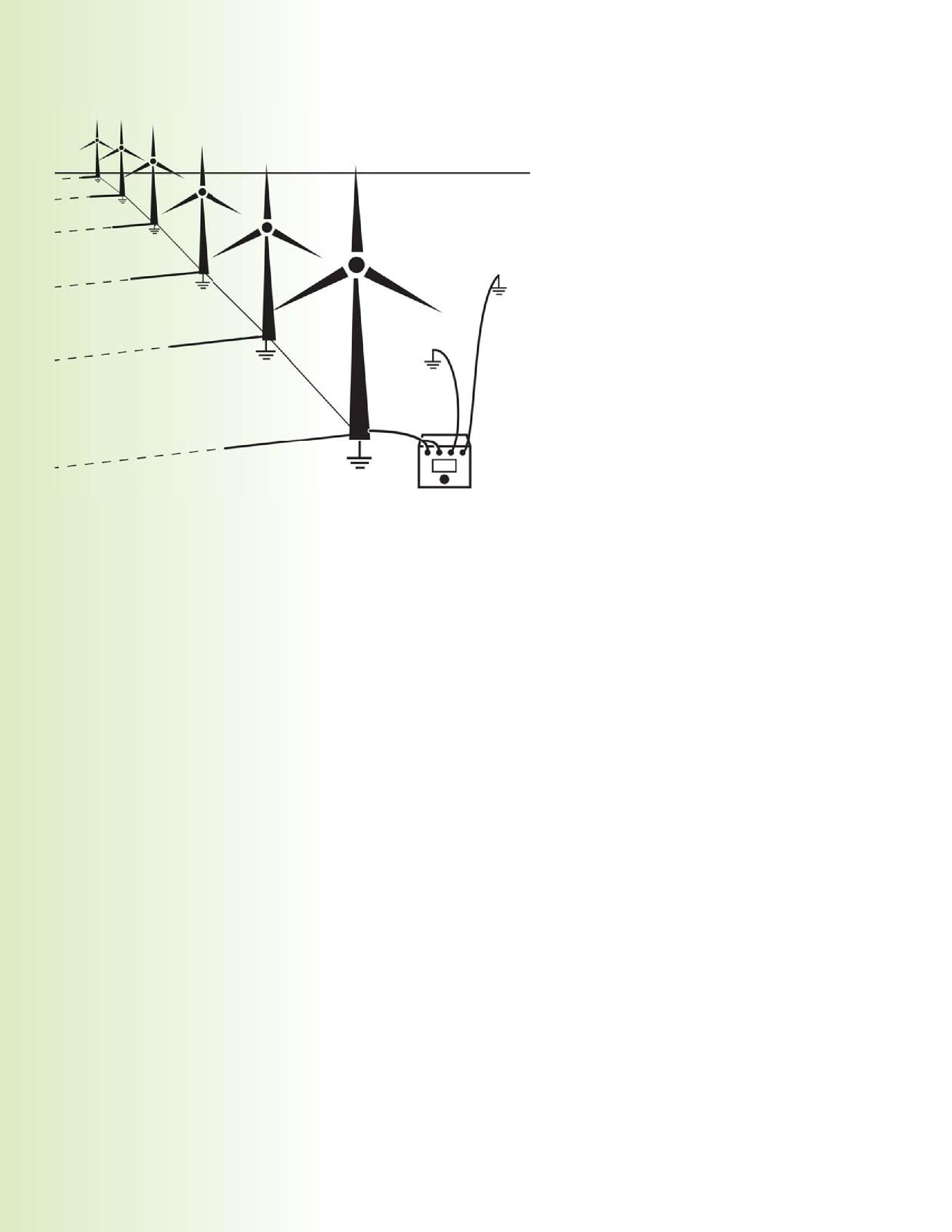
record the exact placement of current and potential probes so that the repeat tests will be precise duplicates and comparisons for trending purposes will be reliable. An added complication at wind farms (as if there weren’t enough already from the grid size and multiple parallel paths!) is the possibility of coupling between nearby grounding elements. In most other situations, this is not a threat, because systems are fairly discrete. But with so much metal in the ground at wind farms, grounded cables nearby can provide a convenient lowresistance path that shorts out the propagation of test current evenly throughout the soil. This is why precise records of probe positions are necessary if tests are to be repeated. On subsequent tests, the actual measurements are not considered as significant, only the departure from previous records.
A major concern on wind farms is cable theft. Remote location and large amounts of relatively accessible shallow-buried copper make theft an ongoing problem. Typical specifications call for cable to be buried 0.5 to 1 meter depth, but this is often applied only to high-voltage and data link cables. Grounding conductors can be
found at depths of less than a foot. Additionally, such shallow burial invites exposure through erosion of the thin layer of soil, which not only implements theft but enhances corrosion. This makes grounding cables the easiest to locate and remove, often by organized operations utilizing a trailer with winding equipment. At least the robber crew may have been considerate enough to leave a clearly visible trench. But if the theft was more surreptitious, it may require some detective work. Otherwise, it will only appear when a fault causes a system failure. Theft mitigation can be integrated into the general maintenance program. Here is where a clampon ground tester may be effectively utilized.
Abriefreviewofinstrumentationisinorder. A brief review of instrumentation is in order. Traditional ground testers operate via terminals (three or four), long leads, and probes. On wind farms, these are requisite for measuring ground resistance. Clamp-on testers, which operate similar to current clamps by encircling the ground rod or conductor, are of little or no use on wind farms for measuring ground resistance. But they can be a convenient help for measuring continuity. The reason they are not amenable to measuring ground resistance comes down to the standard electrical problems of shorts and opens. During the construction process, the elements of the grid are not connected to the electrical system and therefore an open exists; the clamp-on tester cannot establish a test current by induction because there is no circuit in place. Once the construction is completed, the multiple interconnections create numerous shorts; i.e., parallel paths by which inductive test current can complete its circuit entirely by remaining within the metallic structure of the grid. It will not give a ground resistance reading to remote earth, as is required in the definition. But it will give a useful continuity measurement of the grid structure, and that’s where its practical value lies.
The clamp-on is a convenient instrument for determining if a circuit is actually intact or if there is an uncommonly high reading that indicates some problem. If the grounding system has been co-opted by theft, clamping at the relevant point will reveal this as an open
46 FALL 2013 TECHTIPS TECH TIPS
ADDRESSINGPROBLEMSINWINDF ADDRESSING PROBLEMS IN WIND FARMTESTING ARM TESTING
Figure 3: Cross connections in wind farm grids can make it difficult to know exactly what is being tested.

or high resistance. Potential shortcomings do exist, however. Ac to dc conversion technology is generally in use at a wind farm, and these converters generate earth leakage currents with significant harmonic content that can negatively affect clamp-on readings. On-board current sources in the testers operate at high frequency, typically ~1200 – 1500 Hz. Additionally, leakage current increases dramatically with turbine output. Therefore, such tests are best performed when the wind farm is in a shutdown period or when wind speed and turbine output arelow.Bonusesareoftenbasedonturbine are low. Bonuses are often based on turbine availability, so these operations must proceed quickly. If these conditions cannot always be realized, be prepared with a tester that exhibits quality noise suppression capabilities. A reliable noise indicator feature on the display is a useful function in warning the operator that the readings may have interference content and perhaps should be taken at a quieter time.
Be careful to avoid random placement for taking clamp readings. Make use of reliable schematics of the grounding system and determine where the ideal test points are located. Set up a testing regime that is thorough. One complication that can make this difficult is the presence of parallel paths. These situations may just have to be dealt with as best as is reasonably practical. Most parallel paths result from interconnection of lightning protection and fault clearance grounding. An example of a practical application is to check the interconnection of the HV cable ground sheaths.Withthethreesheathsofthethree sheaths. With the three sheaths of the three phases connected together at the ground bus, the resultant loops can be measured periodically to check for sheath damage orcorrosion. or corrosion.
Wind farm grounding installation and maintenance provide some unique challenges, related especially to the size and interconnectivity of the grids. Although it may appear a tall order, standardizationwouldbemostvaluableinthe standardization would be most valuable in the long run. While much more dramatic than the issues discussed here, a recent example from the nuclear industry may afford some insight.
Pursuant to the earthquake disaster in Japan, it has been suggested that a universal plan be established by which all nuclear generating stations are built to the same specifications. This would promote maximum speed and efficiency in disaster clearance, as teams could go to work immediately with no time wasted in coping with the individualities of the site. Perhaps the stakes aren’t as high anywhere else as they are in nuclear, but the concept certainly has merit outside that industry. A dedicated maintenance plan should be adopted, layered testing implemented during installation, and design to include not only consideration of lightning and fault protection, but maintenance and ease of testing as well.
Jeffrey R. Jowett is a Senior Applications Engineer for Megger in Valley Forge, Pennsylvania, serving the manufacturing lines of Biddle, Megger, and multi-Amp for elec electricaltestandmeasurementinstrumentation. trical test and measurement instrumentation. He holds a BS in Biology and Chemistry from Ursinus College. He was employed for 22 years with James G. Biddle Co. which became Biddle Instruments and is now Megger.
NETAWORLD 47 TECHTIPS TECH TIPS
ADDRESSINGPROBLEMSINWINDF ADDRESSING PROBLEMS IN WIND FARMTESTING ARM TESTING
EnerG Test, LLC,
JOINS THE RANKS AS A NETA ACCREDITED COMPANY

EnerG Test is based in Kennett Square, Pennsylvania, about 13 miles northwest of Wilmington, Delaware.
The employees of EnerG Test, LLC, feel honored that their company has become a NETA Accredited Company. EnerG Test has joined an association with other leading electrical testing companies who strive to advance the industry’s standards for power system acceptance and maintenance testing in order to ensure the highest level of reliability and safety.
For the past ten years, some of the most discerning companies from the Northeast through the MidAtlantic states have come to rely on Ener GTestfortheir G Test for their electrical maintenance testing. Having a reputation of being a highly trained and qualified electrical testing and service company has allowed Ener GTesttocount G Test to count Delmarva Power, PEPCO, The DuPont Company, W. L.G . Gore & Associates, and Astra Zeneca among our ore among clients. Our exemplary safety record is another reason
clientslikethesetrustEner clients like these trust Ener G Test for reliable power system solutions.
Our services include start-up assistance including infra-red thermography scanning where appropriate, acceptance testing and commissioning, predictive services, and emergency response. Ener GTest G Test also offers engineering and diagnostic assistance to completely service all of our customer’s electrical system needs. Safety, quality, and reliability have always been paramount values at Ener G Test, which is why we have always followed the standards set forth by NETA. We recognized early on that these standards not only e benefitEner benefit Ener G Test but more importantly, our clients.
We look forward to growing our relationship withNETA.Ener with NETA. Ener G Test is fully committed to the vision that every act of service this company provides to its clients will be performed to the highest of NETAstandards. NETA standards.
E GT i bd iKS Plib13ilhfWiliDl f 3 Wi S G l l h l b l d b D 1 P K T i i i i i


BYJACKCHANG BY JACK CHANG ABBI ABB Inc., LORNE GARA OrbisE rbis Engineering, YORDAN KYOSEV EPCOR OR ANDPETERFONG AND PETER FONG Sequence InstrumentsI uments Inc.
FEATURE
IN
APPLICATIONOF A MULTIFUNCTIONAL DISTANCE PROTECTIVE IED
A 15 KV DISTRIBUTION NETWORK
50 FALL 2013 APPLICATION OF A MULTIFUNCTIONAL DISTANCE PROTECTIVE IED IN A 15 kV DISTRIBUTION NETWORK
BACKGROUND
EPCOR Utilities Inc. is the electric utility company in Edmonton, Alberta, Canada. One of EPCOR’s capital upgrade projects is to replace obsolete protective relays for their 15 kV distribution substations. Eight of EPCOR’s15kVdistributionsubstationshave EPCOR’s 15 kV distribution substations have obsolete feeder relays that are starting to fail and raise concerns regarding system reliability and safety.
Thedistributionfeedersforthesesubstations The distribution feeders for these substations consistofacombinationofcablesandaerial consist of a combination of cables and aerial lines. The existing relays protecting these feeders are equipped with overcurrent and reclosing elements.
As there are many functions and options available in modern microprocessor based relays, EPCOR decided to include distance and overcurrent protection for the new relays. Distance protection is primarily utilized for transmission lines, but can be applied to distribution networks with many benefits. The new relays will provide the protection as wellastheeventinformationtoSCADAand well as the event information to SCADA and the engineering department.
The concern in this new application is the
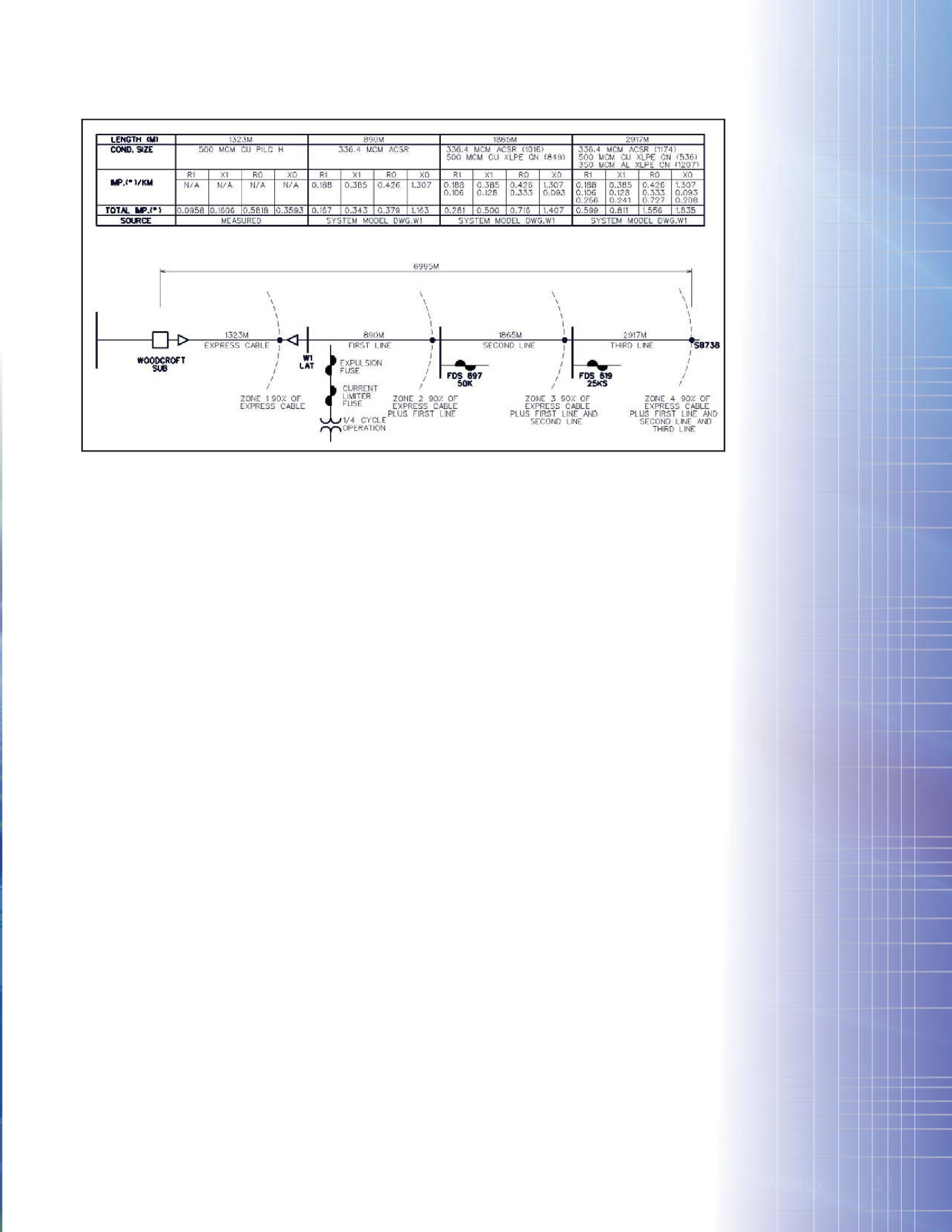
accuracy of the cable/line impedance data needed for relay setting calculation. As EPCOR has the test equipment available to measure these impedances, the decision was made to measurethecablesectionsofthedistribution measure the cable sections of the distribution network that are easily isolated for the tests.
ENGINEERING CONSIDERA TIONS AND IMPLEMENT A TION
EPCOR’sWoodcroftsubstationisoneofthe EPCOR’s Woodcroft substation is one of the many 15 kV distribution substations connected to the utility’s 72 kV sub-transmission network. The 15 kV bus, feeding 18 aerial feeders, is sourced by three 30 MVA two-winding transformers. A typical feeder, supplying various residential and industrial loads, consists of a short underground cable section up to a lateral take-off structure before joined by multiple sections of overhead conductors. There are usually several overhead line sections with transformer taps typically connected to thefirstoverheadsectionandotherline the first overhead section and other line branches connected to the remaining sections. The transformer taps are protected by a combination of current limiting and expulsion fuses while the line branches are protected by expulsion fuses only.
NETAWORLD 51 FEATURE
APPLICATIONOFAMULTIFUNCTIONALDISTANCE APPLICATION OF A MULTIFUNCTIONAL DISTANCE PROTECTIVEIEDINA15kVDISTRIBUTIONNETWORK PROTECTIVE IED IN A 15 kV DISTRIBUTION NETWORK W D T U R 1 E
Figure 1: Simplified Single Line Diagram of Feeder W1
EXISTING OVERCURRENT PROTECTION SCHEME DEFICIENCIES
EPCOR’s distribution system adopts the fuseburning philosophy whenever possible so protection coordination is mandatory to allow downstream fuses to burn first before disrupting other upstream customers unnecessarily.
Autoreclosing on an underground cable is not a desired practice as these faults are permanent in nature and reenergizing the fault during
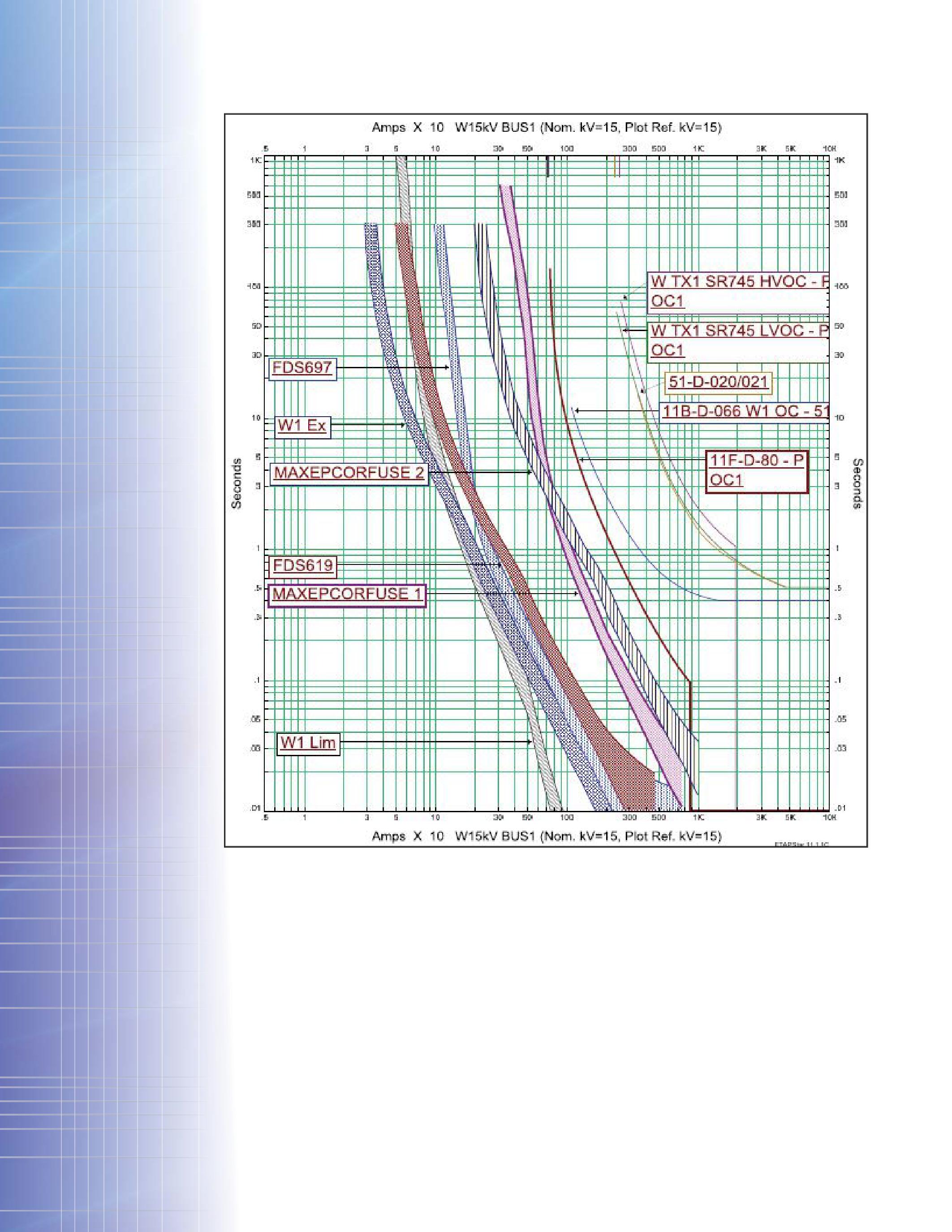
reclosing could cause serious damages to the cable and unnecessary through faults for the transformer. EPCOR policy dictates setting up a high-set instantaneous OC element (50) whenever possible to detect high fault current on the cable and block autoreclosing when the element operates. However, for a cable that is too short (subject to short-circuit study), the 50 element cannot effectively protect the cable with sufficient sensitivity and fault coverage. Consequently, the time-delayed 51 element must clear the faults in the cable, but allow
FEATURE
APPLICATIONOFAMULTIFUNCTIONALDISTANCE APPLICATION OF A MULTIFUNCTIONAL DISTANCE PROTECTIVEIEDINA15kVDISTRIBUTIONNETWORK PROTECTIVE IED IN A 15 kV DISTRIBUTION NETWORK
52 FALL 2013
Figure 2: Existing OC Protection Time Coordination Curve
autoreclosing to follow. This unfavorable operating condition warrants a more selective andreliablemeanstodetectcablefaultsand and reliable means to detect cable faults and block all autoreclosing on the cable.
The high-short circuit level combining with the delay could shorten the life span of the supplying power transformers and cause damages in the cablethatareotherwiseavoidable. cable that are otherwise avoidable.
One safety concern throughout power distributionutilitiesinNorthAmericahas distribution utilities in North America has
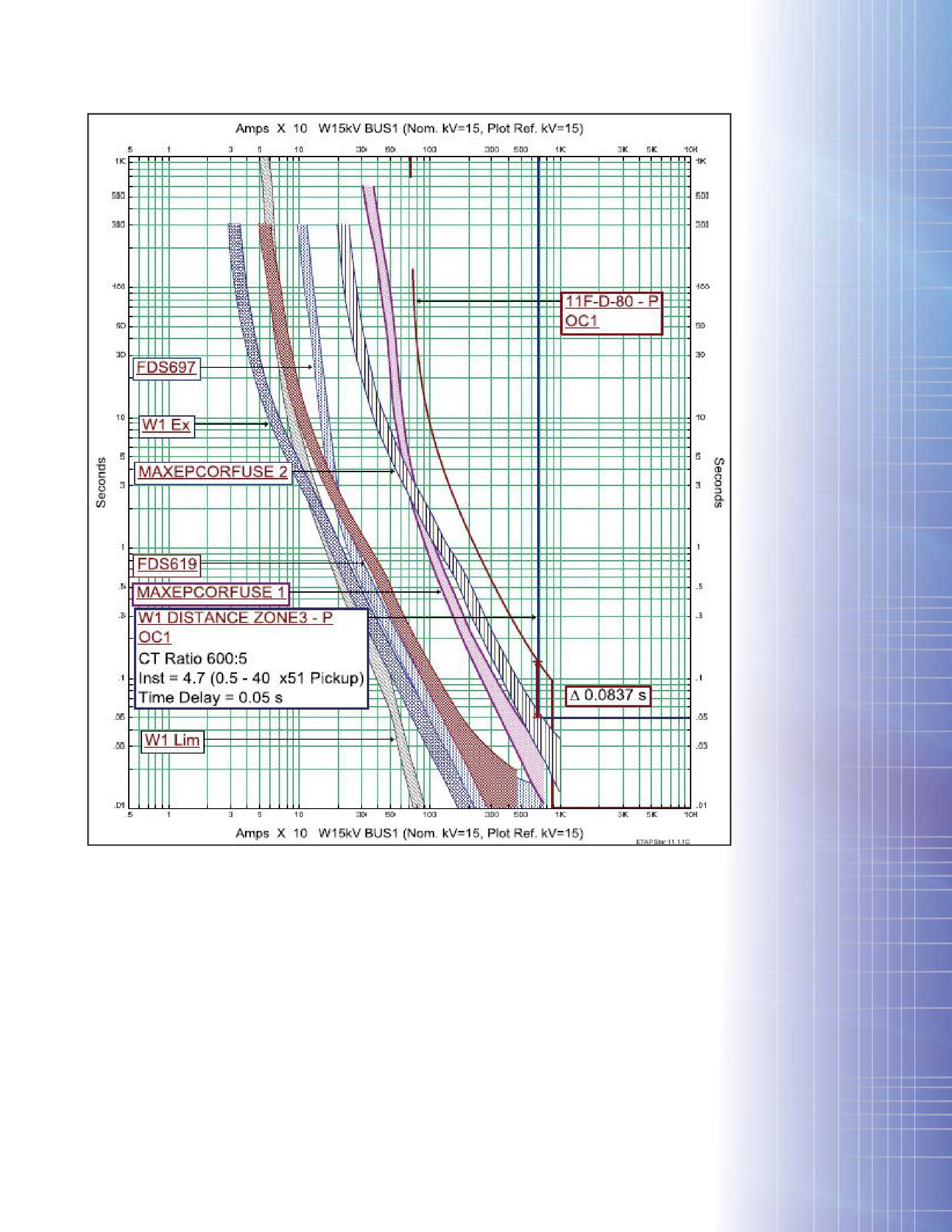
always been the sensitive and timely detection of fallen conductor on high resistive surfaces (eg., concrete or ice). Due to the high-resistive natureofcurrentdistributionincombination nature of current distribution in combination with a high pickup set point for the 51G element, a fallen conductor is likely left undetected by the overcurrent detection method. Modern numerical IEDs now employ special algorithms to detect broken conductor conditions and can generate alarms to the control center for prompt remedial actions.
FEATURE
APPLICATIONOFAMULTIFUNCTIONALDISTANCE APPLICATION OF A MULTIFUNCTIONAL DISTANCE PROTECTIVEIEDINA15kVDISTRIBUTIONNETWORK PROTECTIVE IED IN A 15 kV DISTRIBUTION NETWORK NETAWORLD 53
Figure 3: Zone 3 Time Coordination
DISTANCE ELEMENT SETTING GUIDELINES
Multiple zones of quadrilateral phase and ground element are configured depending on the number of feeder sections and the physical length of each section. In general, each distance zone is set up to protect up to the end of each section with security margin, but a protection zone will not be implemented if a given line section is too short.
Zone1 Zone 1
Zone 1 of the distance element is set up to provide high speed protection to the express cable section and at the same time, block autoreclosing. To improve relay setting and measurement accuracy, the cable impedance and ground compensation factor (Kn) were measured using primary injection technique (see section on cable testing).
Zone 1 coverage is generally constant such that it is not under the influence of varying source impedance. This is an improvement over the existing OC scheme (50/51) by assuring constant protection sensitivity, high speed operation, and reliable blocking of autoreclosing on the cable to prevent further damages.
Zone2 Zone 2
Zone 2 of the distance element is set up to detect faults up to the first branch fuse (FDS 697) in
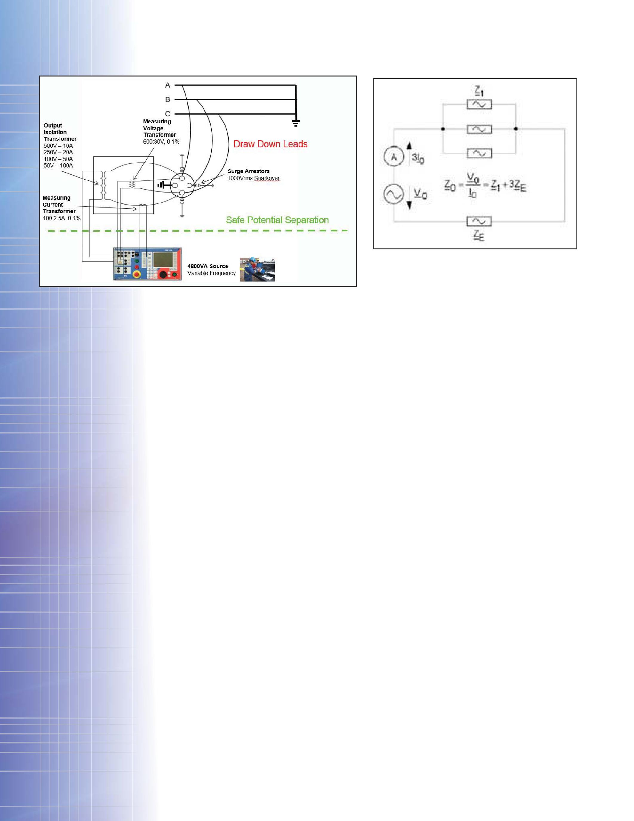
Figure 1. Coordination with a pad-mounted transformer tapped off this line section is not of major concern because of the high speed nature of the current limiting fuses for close-in faults on the tap. Downstream faults are not visible to the distance relay due to the large transformer impedance. The fault coverage of the zone is consequently set to the length of the cable and 90 percent of the First Line section to avoid reaching into the first branch fuse. Zone 2 operation is delayed for 33 milliseconds for added security margin and to avoid racing Zone 1 when initiating autoreclosing.
Zone 3
Zone 3 distance element is set up to cover all preceding cable and line sections plus 90 percent of the Second Line while coordinating with branch fuse FDS697. Because Zone 3 reaches into at least one fused branch, it is the Utility’s intention to ensure coordination by blocking its operation whenever the time OC (51) elements pick up. For high resistance fault types not detected by OC elements, Zone 3 may provide a more sensitive coverage.
The resistive reach settings of Zone 1 to 3 have been approximated to four times the corresponding reactive reach settings as rules of thumb. Phase and ground resistive reach settings are set equally for convenience.
Zone4 Zone 4
Zone4distanceelementissettocoverthe Zone 4 distance element is set to cover the entire feeder length. The reactive reach of
APPLICATIONOFAMULTIFUNCTIONALDIST TION OF A MULTIFUNCTIONAL DISTANCE ANCE PROTECTIVEIEDINA15kVDISTRIBUTIONNETWORK PROTECTIVE IED IN A 15 kV DISTRIBUTION NETWORK 54 FALL 2013 FEATURE
Figure 5: Z0 Impedance Model
Figure 4: Line Impedance Measurement Setup
Zone 4 is set up to detect faults down to the end of the feeder sections (Figure 1). The operation and coordination guideline to the highest rated branch fuse is similar to that of Zone 3 mentioned previously. The expected maximumfeederloadisaround600Aat15 maximum feeder load is around 600 A at 15 kV, corresponding to approximately 14 ohms with 10 percent voltage margin.
EPCOR decides to set the ground resistive reach to 30 ohms per fault loop, and for setting convenience, the phase resistive reach is set initially to match the ground setting.
OVERCURRENT FUNCTIONS
EPCOR applies stage 1 and stage 2 of the fourstage OC function in the selected IED to mimic the existing timed and instantaneous OC functions (DPU curve in Figure 2). The time OC curve type is modified to ANSI extremely inverse to attain a faster operation as shown in Figure 2 curve 11F-D-80. At this moment both OCfunctionsandtheZone1distanceelement OC functions and the Zone 1 distance element are enabled to trip the circuit breakers.
InthefuturetheOCelementswillactas In the future the OC elements will act as
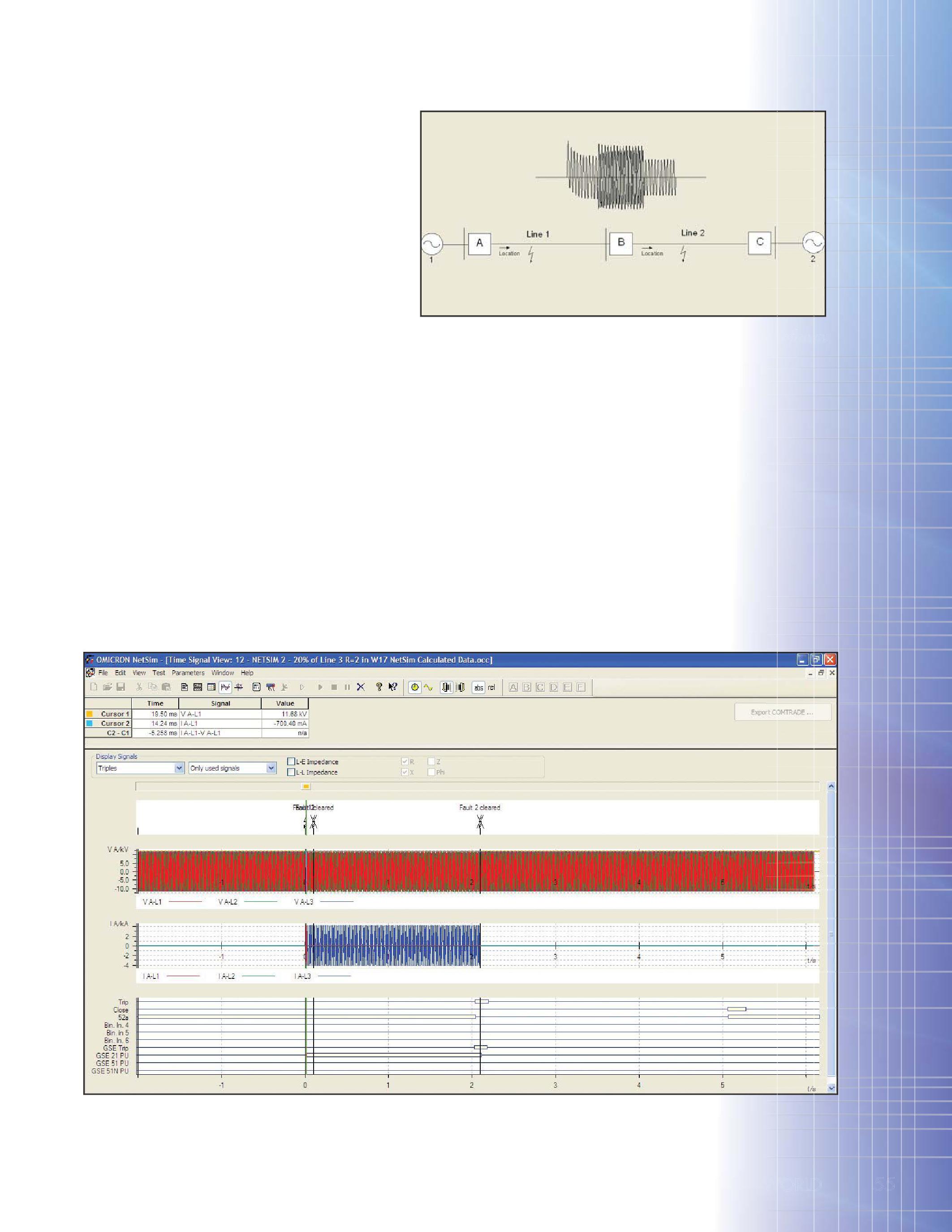
backup protections to distance Zone 1 and 2 and block time-delayed distance elements (Zones 3 and 4) when picked up to ensure coordinationwithbranchfuseswhenthefault coordination with branch fuses when the fault current is high. When the fault current is too low for the OC element to detect, the timedelayed distance elements will operate.
BENEFITS OF APPLYING MODERN NUMERICAL MUL TIFUNCTIONAL IED
As alluded to in the previous subsections, the benefits attained by applying the multifunctional
FEATURE F E AT U R E NETAWORLD 55
Figure 6: System Modeling with Network Simulator Software
APPLICATIONOFAMULTIFUNCTIONALDISTANCE APPLICATION OF A MULTIFUNCTIONAL DISTANCE PROTECTIVEIEDINA15kVDISTRIBUTIONNETWORK PROTECTIVE IED IN A 15 kV DISTRIBUTION NETWORK W S D a 5
Figure 7: Result of Network Simulation Testing

numericaldistanceIEDcanbesummarizedbelow: numerical distance IED can be summarized below:
Time Saving on Cable and Downstream Faults
Due to the relatively constant fault coverage of distance measurement, instantaneous operations can be assured for Zone 1 on the express cable section and most of Zone 2 without sacrificing speed to downstream coordination requirements. The reduction in fault clearing time improves personnel safety and prevents damages to critical equipment. The application of Zones 3 and 4 will provide the sensitive fault detection required for high resistance faults.
Autoreclose Blocking
Zone 1 distance element can be set up to reliably block autoreclosing on the express cable section to prevent damages and costly repair. The fast operate time and reclose blocking will also reduce the through fault currentsforthetransformersandextend currents for the transformers and extend transformer life. On the contrary the existing high-set OC scheme has not been an effective method to block autoreclosing due to its varying sensitivity and other application constraints.
SensitiveDetectionofBrokenConductor Sensitive Detection of Broken Conductor or High Impedance Faults
TheselectedmultifunctionaldistanceIED The selected multifunctional distance IED employs a proven broken conductor algorithm operating on the basis of detecting the asymmetry between the three phases. The function continuously measures the three phase current and compares the difference between the highest and the lowest phase current against a set point. This function is implemented to alarm for broken conductor conditions. The high resistive reachofZone4alsoaidsthedetectionof reach of Zone 4 also aids the detection of conductor fallen on high resistive surfaces that cannot be picked up by the broken conductor
functionorothercurrentbaseddetection
function or other current based detection methods. An undetected fallen conductor poses serious health and safety hazards to civilians and threats to the utility’s reputation.
Hot-line Applications
Modern numerical IEDs offer multiple setting groups and programmable logic capability to dynamically switch setting groups following different system conditions. During energized line work, a different set point can be switched to speed up protection operation to mitigate the arc-flash hazard and improve personnel safety. In this project, the hot-line control from local (mechanical switch) and remote (SCADA via RTU) locations are used to turn on/off a dedicated instantaneous OC element for high speed operation on faults and block/unblock autoreclosing. The pickup setting of the instantaneouselementissensitizedtomatch instantaneous element is sensitized to match the pickup of the phase time OC element (120 percent emergency load) during hot line work.
Other Ancillary Functions
Modern numerical IEDs offer many ancillary supporting functions such as apparatus control, multiposition selector switches, programmable push buttons, LED annunciation, SCADA communication and event, and disturbance handling functionality, to name a few. The following ancillary functionsareusedintheselectedIED: functions are used in the selected IED:
CABLE IMPEDANCE TESTING
Distance relays use positive-sequence and zero-sequence impedance (Z1 andZ and Z0) of the )
APPLICATIONOFAMULTIFUNCTIONALDISTANCE APPLICATION OF A MULTIFUNCTIONAL DISTANCE PROTECTIVEIEDINA15kVDISTRIBUTIONNETWORK PROTECTIVE IED IN A 15 kV DISTRIBUTION NETWORK FEATURE
E AT E F 56 FALL 2013
Figure 8: Sample Relay Operation Test
line as a reference for the zone settings. Typically, these impedance values are calculated using various line parameters provided by the cable manufacturer. Furthermore, the calculation of Z0 requires the soil resistivity of the ground return path. A Zone 1 setting of 80 percent of the line impedance allows for inaccuracies of these impedance calculations.
Comparison studies by various utilities [4] suggest that in most cases, the calculated Z1 is less than 20 percent of the measured Z1 value. However, due to the complexity in getting an accurate model for ground returns, the calculatedZ calculated Z0 normally has higher errors, sometimes higher than the 20 percent margin offered by Zone 1.
In order to achieve the 90 percent setting of Zone 1 for this project, an accurate measurement ofZ of Z1 andZ and Z0 of the cables using primary injection is required. The measurement method used is a frequency shift method in which the impedance ismeasuredat40Hzand80Hzandthenthe is measured at 40 Hz and 80 Hz and then the 60 Hz result is obtained through a linear interpolation of these two values. This method ensures that any 60 Hz noise be rejected by themeasurement. the measurement.
In performing the test, one end of the cable must be shorted to ground, and the other end opened for connection to the test source. As a
safety precaution, an isolation transformer is used for both the output and the measuring inputs of the test set, so that there is no direct connectionbetweenthecableundertestand connection between the cable under test and the test equipment. Figure 4 shows a simplified connection diagram of the test setup.
As the test equipment provides only a singlephase source, in order to calculate Z1, the three line-to-line fault loops must be tested (i.e. A-B, B-C, C-A) in order to obtain ZAB, ZBC, and ZCA Z1 is then derived from the following formula:
Z1 = ½ * (ZAB +Z + ZBC +Z + ZCA)/3
Thefactorof½isduetothefactthatforlineThe factor of ½ is due to the fact that for lineto-line measurement we are actually measuring twice the line length.
ForZ For Z0, the three-phases must be shorted and then , measured against the ground return as shown in Figure 7. The measured impedance Z0´is ´ is
Z0’=V03I0=(ZA//ZB//ZC) +ZE=Z = Z13+ZE
and by definition:
Z0=V0I0
Therefore,
Z0=3×Z0’=Z1+3ZE
(three times the measured impedance)
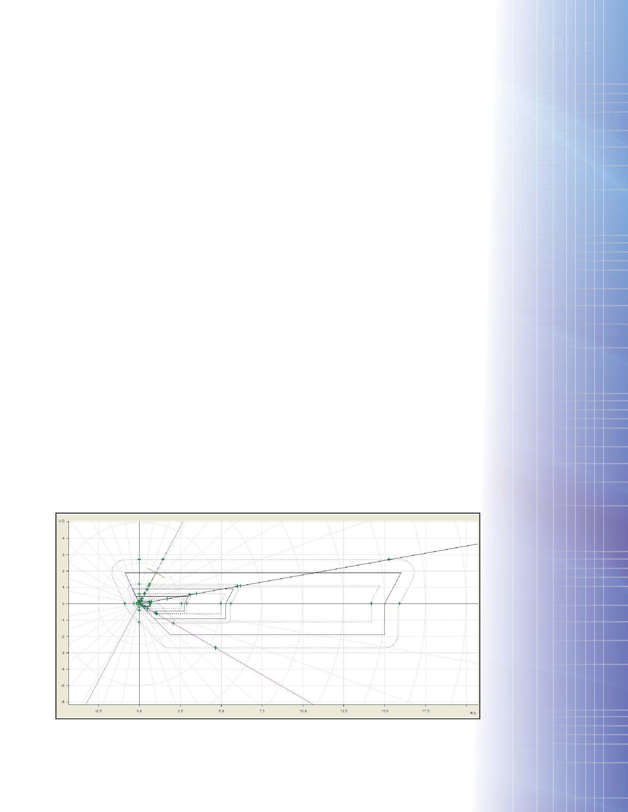
Figure 9: Sample Distance Characteristics Test Result
APPLICATIONOFAMULTIFUNCTIONALDISTANCE APPLICATION OF A MULTIFUNCTIONAL DISTANCE PROTECTIVEIEDINA15kVDISTRIBUTIONNETWORK PROTECTIVE IED IN A 15 kV DISTRIBUTION NETWORK FEATURE
T U R E NETAWORLD 57
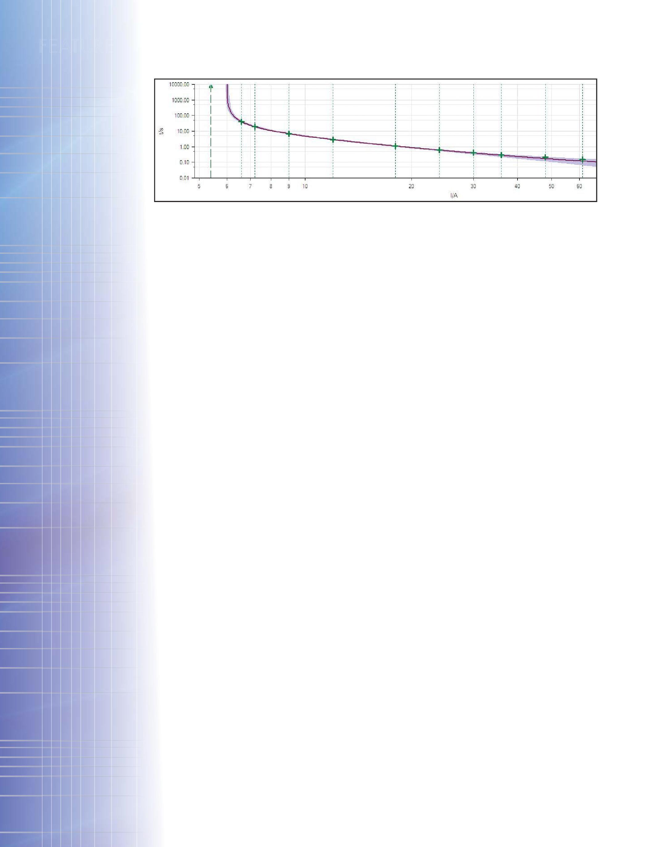
WiththemeasuredZ With the measured Z1 andZ and Z0, the relay zone , settings and also the ground compensation factor (k0) could then be set very accurately for this project. Different relay manufacturers represent the k0 setting in a slightly different way. The typical formula for the k0 factor is:
IED FUNCTIONAL TESTING
The initial product evaluation, preliminary relay testing, and the commissioning of the installed protection was performed using modern relay test equipment and software. Networksimulationsoftwarewasutilizedin Network simulation software was utilized in ordertosimulateactualfaultvaluesbasedon order to simulate actual fault values based on system models and the measured line impedances. The IEC-61850 SCADA points were tested using both the communication gateway device and the relay test equipment.
Thenetworksimulatorsoftwareallowsthe The network simulator software allows the IED to be tested using calculated fault values based on system impedances as well as the measured line impedances. The transient voltages and currents are calculated from a digital network model (Figures 6 and 7). This provides the optimum approximation of the real events in the system to evaluate relay settings for complex protection applications.
Thenetworksimulatorsoftwarewasusedto The network simulator software was used to simulate faults at different locations along the entire feeder. For each feeder, we carried out multiple tests to simulate faults along the entirefeeder.AsthefeedersinWoodcroftare entire feeder. As the feeders in Woodcroft are radial, the source 2 impedance was set to maximum and source 1 impedance was set to
the substation calculated values acquired from the engineering short-circuit study.
The results of each test (Figure 8) were analyzed to verify the IED indications, annunciation, operation, and timing. The IED operation was tested to verify accurate distance and OC characteristic, fault location algorithm, and trip/reclose functionality. The IED event records were analyzed and compared with the test equipment waveforms.
The advanced relay test modules were used to verify the parameter settings and characteristics of distance (Figure 9) and OC (Figure 10) elements.
Further functional tests to verify vendor prebuilt logics such as broken conductor and switch-on-to-fault were performed. User customized configurations including blocking, various tripping logics, reclose initiation/ blocking logics, hot-line operation, and variousalarmswerealltestedindetail. various alarms were all tested in detail.
Final commissioning consists of wiring checks, cursory functional tests of all relay elements on-site, functional testing of all control and annunciation including its communication to the station HMI, and energizing check.
CONCLUSION
At the moment of writing this paper, all 16 distance IEDs procured for this project have been commissioned and put in service. Zones 2, 3, (if applicable) and 4 are not currently enabled as tripping zones, but their behaviors under real-life system operating conditions are being closely monitored. The dedicated
k0=(Z0-Z1)3Z1
APPLICATIONOFAMULTIFUNCTIONALDISTANCE APPLICATION OF A MULTIFUNCTIONAL DISTANCE PROTECTIVEIEDINA15kVDISTRIBUTIONNETWORK PROTECTIVE IED IN A 15 kV DISTRIBUTION NETWORK
FEATURE E AT E F 58 FALL 2013
Figure 10: Sample OC Characteristics Test Result

communication gateway for engineering analysis has not been installed at this point, but any pickup signals can still be recorded and waveform captured locally in the IED buffer so that the distance reach settings can be fine-tuned to ensure service reliability.
The successful completion of this project was contributed by the joint efforts of the IED manufacturer for their product knowledge and technical support, the IED setting calculation, configuration and simulation workattributedtotheEPCORteamandthe work attributed to the EPCOR team and the test set vendor’s solution and support in accurate cable impedance testing.
The application of a modern multifunctional distance IED improves operating time and personnel safety working near various sections of the distribution feeders, reliably senses closein cable faults and blocks autoreclosing, dynamically controls hot-line protection mode and provides sensitive protection to high resistive ground faults and alarms for circuit troubles withlowcurrent.IEC-61850communication with low current. IEC-61850 communication protocol is used for GOOSE messaging and status and analog measurement reports. Other annunciationandevent/disturbancefeatures annunciation and event/disturbance features complement the main protection functions in the IED. All protection and control functionality has been verified before procurement and validated again during commissioning with a close-loop test system to verify the sensitivity, timing, annunciation, and other ancillary functionality against the design.
Ongoing efforts remaining in this project include continuous monitoring of IED protection status, improvement of current protection settings to ensure more secure operations, and selecting a substation gateway dedicated for the ultimate goal of engineering monitoring and post-event analysis.
REFERENCES
[1] L. J. Blackburn and T. J. Domin, Protective Relaying: Principles and Applications,Thirded.,CRCPress,2007. , Third ed., CRC Press, 2007.
[2] W.A.Elmore, W. A. Elmore, Protective Relaying: Theory and Applications, NewYork:MarcelDekker,Inc.,2004. New York: Marcel Dekker, Inc., 2004.
[3] ABB,SubstationAutomationProducts, ABB, Substation Automation Products, Line Distance Protection 650, Technical Manual,Vasteras,Swedan,2011. , Vasteras, Swedan, 2011.
[4] U. Klapper, A. Apostolov, D. Tholomier and S. Richards, K-Factor * Mutual Coupling on Asymmetrical Overhead Lines for Optimum Reliability of Distance Protection,inCIRED,2008. , in CIRED, 2008.
JACK CHANG is a Regional Technical Manager for ABB Inc. in the Substation AutomationProductsbusinessunit Automation Products business unit serving customers in western Canada and northern regions. He provides engineering, commissioning and troubleshooting support to customers applying ABB’s high-voltage protective and automation devices. Prior to joining ABB, Jack worked as a substation P&C project engineer in two specialized consulting firms and also as an engineering consultant to a public owned utility in their transmission expansion and upgrade ission projects. Jack is a registered professional engineer in the province of Alberta, Canada.
LORNEGARA LORNE GARA is a Technical Manager for Orbis Engineering. He provides technical support for the engineering, field services, and automation departments of Orbis and many of its Clients. Lorne has a wide range of experience in engineering, commissioning, maintenance, fault analysis, and start-up of utility and industrial power systems across North America. He has extensive experience with protective relay setting development, commissioning, and testing protection and control systems.
YORDANKYOSEV YORDAN KYOSEV is a Manager of EPCOR protection team. He is accountable for the performance of protection and control systems of the company including capital planning, project execution, asset management and operational support. Prior to joining EPCOR he worked as a P&C engineer in Bulgarian National Electric Company and as a power systems engineer in Schlumberger, Canada. Yordan is a registered professional engineer in the province of Alberta, Canada.
PETERFONG PETER FONG is a professional engineer registered in the province of British Columbia. Peter was previously an application engineer with OMICRON electronics Corp. USA and has vast experience with relay and substation testing equipment. Peter is a member of IEEE and has given papers at various technical conferences. He is currently General Manager of Sequence Instruments Inc. in Vancouver, Canada.
APPLICATIONOFAMULTIFUNCTIONALDIST TION OF A MULTIFUNCTIONAL DISTANCE ANCE PROTECTIVEIEDINA15kVDISTRIBUTIONNETWORK PROTECTIVE IED IN A 15 kV DISTRIBUTION NETWORK
FEATURE T U R E NETAWORLD 59

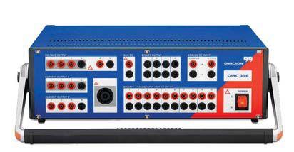
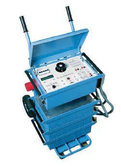

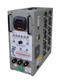
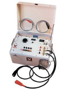
Advanced Test Equipment Rentals Call Now 800-404-ATEC (2832) Visit our site www.Atecorp.com RENT POWER TEST GEAR CALL TODAY. TEST TOMORROW. Protective Relay Test Sets · VLF/AC/DC Hipots · Tan Delta Primary Current Injection · Thumpers · Circuit Breakers Relay Testers · TTR Test · Megohmmeters · Partial Discharge Oil Dielectric Test · TDR · Battery Test · Cable Fault Locators Power Analyzers · Loads · and more... Megger · Omicron · Hipotronics · High Voltage Inc. Fluke · Phenix · SKF/Baker · Tettex · Biddle · ETI AEMC · Rosemount/Hart · and more... SWITCHGEAR POWER INFRASTRUCTURE MOTOR DIAGNOSTICS ENERGY STUDIES
THE EXPERTS IN ELECTRICAL RELIABILITY
Comprehensive Electrical Testing and Maintenance
Commissioning and Startup Services
Engineering Services
Power System and Coordination Studies
Predictive and Preventive Maintenance
Partial Discharge Testing and Monitoring
24/7 Emergency Service


Failure is not an option. Ensuringthe reliability of your electrical distribution system.
As theleadingindependent electrical testing, maintenance, andengineering service company, you canrely on Emerson’s High VoltageMaintenance to exceed yourelectricalequipment performance goals. From testing for problems that coulddisable your system, to complete turnaround execution, you’llquickly understandhowweare your single source solution forall of yourelectricalreliability needs. With a network of more than12 service locations, our service teamputs experiencedprofessionals whereand when youneed them.


For more information: High Voltage Maintenance (866) HVM-TEAM
ENERGY-BASED SELECTIVE COORDINATION TRIPPING AND ITS EFFECTS ON
BY JOHN CARLIN, Schneider Electric Engineering Services
INTRODUCTION
Changes to the 2005 and 2008 National Electric Code (NEC) forced more careful examination of overcurrent protective device (OCPD) selective coordination, particularly at high fault current levels approaching system maximum bolted three-phase values. This paper examines selective coordination methods for circuit breakers, beyond the traditional plotting of time-current curves (TCCs) alone, for high fault currents. Specifically, an energy-based circuit breaker tripping system, which can provide improved selectivity, series rated combinations, and favorable arc flash performance, is presented andexamined. and examined.
BACKGROUND AND HISTORY
The2011NECincludessixreferencesto The 2011 NEC includes six references to selective coordination, which have driven more rigorous examination of OCPD performance and interaction – Articles 100, 517, 620, 700, 701, and 708 all mention “coordination”or“selectivecoordination”. “coordination” or “selective coordination”. The general definition in Article 100 defines selective coordination as, “Localization of an overcurrent condition to restrict outages to the circuit or equipment affected, accomplished by the choice of overcurrent protective

devices and their ratings or settings”. Articles 700, 701, and 708 further emphasize the requirements for selective coordination for particular systems when fed by an alternative source or sources. Article 517, for Health Care Facilities, extends the requirements of Article 700 to apply to the Health Care Facility essential electrical systems (life safety, critical care, and equipment branches). Article 620 requires selective coordination for elevators, dumbwaiters, escalators, moving walks, wheelchair lifts, and stairway chair lifts “where more than one driving machine disconnecting means is supplied by a single feeder”.Whiletherationaleforselective feeder”. While the rationale for selective coordination is self-evident – clearing and isolating faults as quickly as possible without disturbing the unaffected portions of the system – the methods for determining OCPD to OCPD selectivity are not as apparent. Industry standards which define deviceto device selectivity for their full operating ranges do not exist and no consensus has been developed among protection engineers or inspecting authorities for device-to-device selectivity thresholds. Discussions continue over the “practicable” selectivity criteria –years of engineers overlaying time-current characteristicsofOCPDstodetermine characteristics of OCPDs to determine
62 FALL 2013 FEATURE
ENERGY-BASEDTRIPPINGANDITSEFFECTSONSELECTIVECOORDINA ENERGY-BASED TRIPPING AND ITS EFFECTS ON SELECTIVE COORDINATION
selectivity complicated by examining the current-limiting interactions of OCPDs atmaximumavailablefaultcurrents–it at maximum available fault currents – it is against this background that various alternativeselectivecoordinationcriteriahave alternative selective coordination criteria have beenintroduced. been introduced.
COMPARISON OF TIME-CURRENT CURVES
Time-currentcurvesforOCPDsshow Time-current curves for OCPDs show how long it will take the device to operate underovercurrentconditions.Thesecurves under overcurrent conditions. These curves are typically developed by conducting interruption tests on sample devices at variousovercurrentlevels–overloadand various overcurrent levels – overload and faultcurrents.Thedevicecurvesaccountfor fault currents. The device curves account for manufacturing tolerances and are plotted under specific conditions – standalone operation and at a given ambient temperature. Typical circuit breaker time-current curves
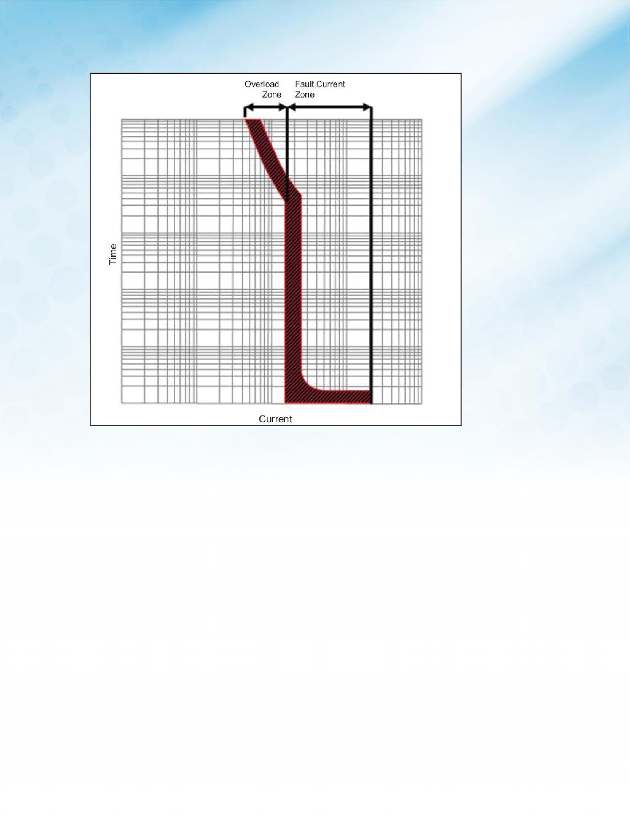
can be divided into two distinct protection zones–overloadandfaultcurrentasshown zones – overload and fault current as shown in Figure 1. (This protection zone concept is not common in North America; however, it helps to clarify the remaining discussion.) Circuit breakers respond to overcurrents differently in the two protection zones. In the overload protection zone, the circuit breaker has an inverse-time operating characteristic, indicating the circuit breaker trip time decreasesastheoverloadcurrentincreases.In decreases as the overload current increases. In the fault protection zone, the circuit breaker operates with no intentional delay in the case of thermal-magnetic trip circuit breakers or with well-defined short-time segment delays in the case of electronic circuit breaker trip units as shown Figure 2.
Comparing time-current characteristics of two or more OCPDs on a single graph is the traditional method for determining selective
NETAWORLD 63 ENERGY-BASEDTRIPPINGANDITSEFFECTSONSELECTIVECOORDINA ENERGY-BASED TRIPPING AND ITS EFFECTS ON SELECTIVE COORDINATION FEATURE
Figure 1: Circuit Breaker Time-Current Curve Operating Zones
coordination. The relative position of individualdevicetolerancebandsonaTCC individual device tolerance bands on a TCC can illustrate the degree of coordination anditiscommonfortheinstantaneous and it is common for the instantaneous trip characteristics to overlap one another. Visually an engineer may conclude that these circuit breakers do not selectively coordinate up to the maximum available fault current when in fact they do, given more precise examination of circuit breaker operation. While TCCs are required to verify the coordinationofcircuitbreakertolerance coordination of circuit breaker tolerance bands in the overload protection zone, new examination methods will be presented to verify total selectivity in the fault protection zone even though on a TCC they do not appear to selectively coordinate.
TOTAL SELECTIVE COORDINATION
Total selective coordination can be defined by modifying 2011 NEC Article 100 language
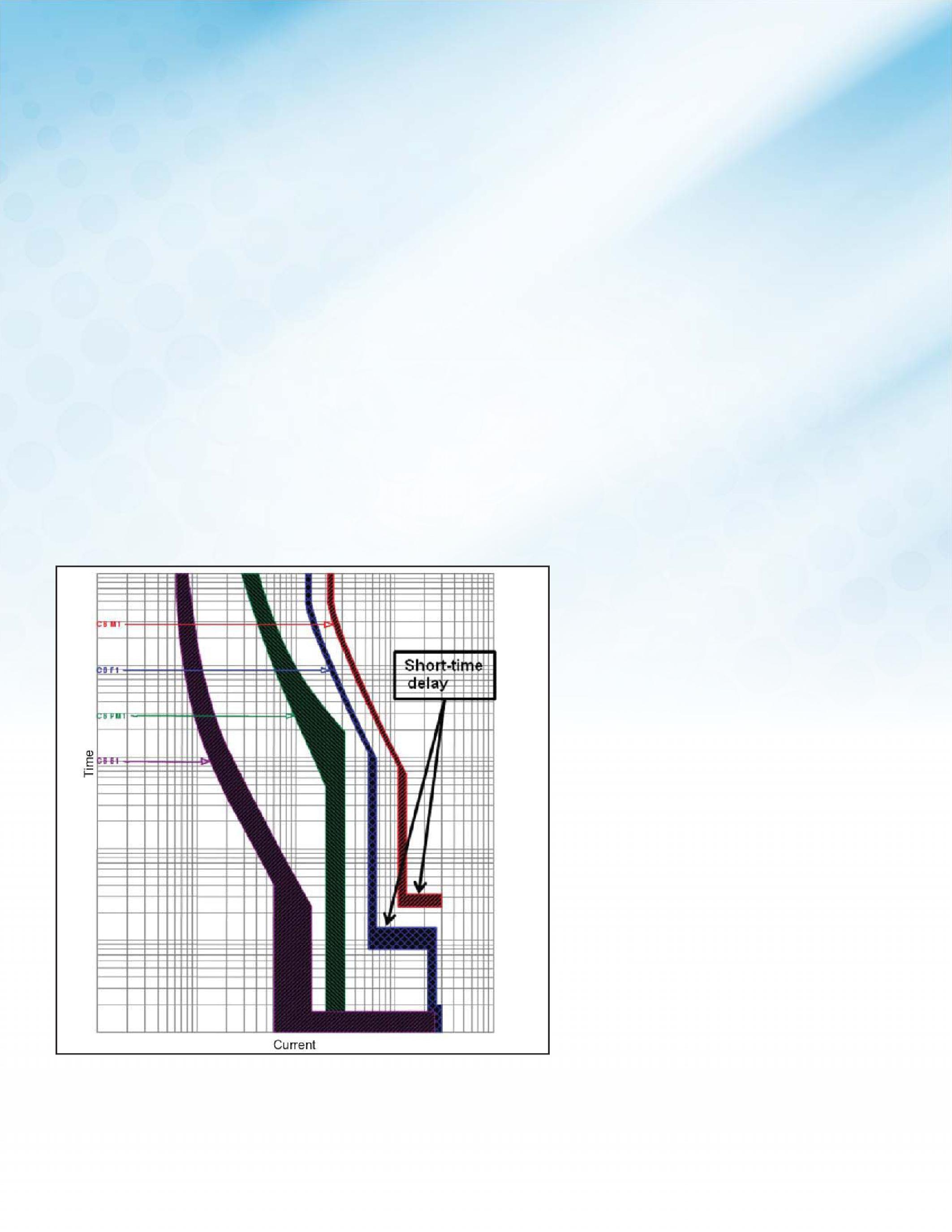
to include the entire operating ranges of the OCPDs up to the maximum available fault currents. In the system shown in Figure 3, only the loads affected by fault (If) shall be taken out of service by CB4, the circuit breaker directly upstream of the fault. All other linesidecircuitbreakersshallremainclosed.This side circuit breakers shall remain closed. This prevents the interruption of power to all equipment where no fault occurred.
Commondefinitionsofselectivecoordination
Common definitions of selective coordination have been interpreted as either 0.1 seconds, involving comparing time-current curves, or total selectivity, which includes time-current curves but also requires comparing OCPD behaviorsandinteractionforfaultcurrents behaviors and interaction for fault currents orshort-circuitcurrents.Therearevariations or short-circuit currents. There are variations on how total selectivity is described [e.g., 0.01 seconds], but the intent is selectivity for the entire operating range of the OCPDs up tothemaximumfaultcurrent.WhileTCCs to the maximum fault current. While TCCs are excellent analytical tools for determining selectivity among devices in the long-time and short-time regions of the circuit breaker operating characteristics, additional methods are required to determine total selectivity. Selective coordination may be required in a variety of systems which are discussed in NEC Articles 517, 620, 700, 701, & 708. Various adoptions, clarifications, and enforcement practices exist in the US; as such, interpretation of the NEC is out of the scope of this paper. Only circuits that have already been determined to require total selectivecoordinationshallbediscussed. selective coordination shall be discussed.
CONSIDERATIONS OUTSIDE OF SCOPE OF PAPER
Ground Faults Certain instances of the NEC, Article 517.17(B) for example, require multiple levels of ground fault protection in health care facility installations. While coordination among ground fault devices is desirable, only the overload and fault protection zones of phase overcurrent devices is considered to be in the scope of this paper. Fault conditions otherthanoverloadsandshort-circuitswere other than overloads and short-circuits were not considered. Arcing Faults Arc flash analysis and mitigation are not considered in this paper.
64 FALL 2013 FEATURE
Figure 2: Short-Time Delays for Solid-State Trip
ENERGY-BASEDTRIPPINGANDITSEFFECTSONSELECTIVECOORDINA ENERGY-BASED TRIPPING AND ITS EFFECTS ON SELECTIVE COORDINATION
CircuitBreakers Circuit Breakers
If the duration of an arc flash event is limited, then the amount of incident energy produced by the event will also be reduced. Protective devices should be set as low as possible to limit incident energy to a minimum level while still providing selective coordination. While circuit breaker settings can be intentionally set to mitigate incident energy levels, which results in a system that is not coordinated, selective coordination for the system was determined to be of paramount importance for the purposes of this paper, given that the NEC does not allow for any circumstances to sacrifice coordination. The energy-based method described can provide high levels of selectivity while lowering incident energy levels.
NEW EXAMINATION METHODS FOR DETERMINING SELECTIVITY CONSIDERATION OF LOADSIDE OCPD LET-THROUGH
AND DYNAMICIMPEDANCE DYNAMIC IMPEDANCE
Inordertounderstandthenewexamination In order to understand the new examination methods, a mastery of interpreting TCCs is first required. Once TCC fundamentals have been mastered, further exploration of the TCC will reveal limitations in determining selective coordination. A more precise examination of circuit breaker operation is required to properly apply the new selective coordinationexaminationmethods. coordination examination methods.
REVIEW OF TIME-CURRENT CURVES AND METHODOLOGY FOR PLOTTING
TCCsshowhowacircuitbreakerwill TCCs show how a circuit breaker will respond to I2t in the overload region and to peak current in the fault current regions, on a log-log graph. Ideally an OCPD could be set precisely to trip at an exact value; however, due to various limitations for OCPD’s, tolerance bands must be plotted instead of lines to showthevaluesatwhichadevicecould show the values at which a device could possibly trip. These values are conservative and can have a broad range of trip times for various current levels for different types of circuit breakers. Historically, electronic trip circuitbreakershavebeenshowntohave circuit breakers have been shown to have smaller tolerances than thermal-magnetic
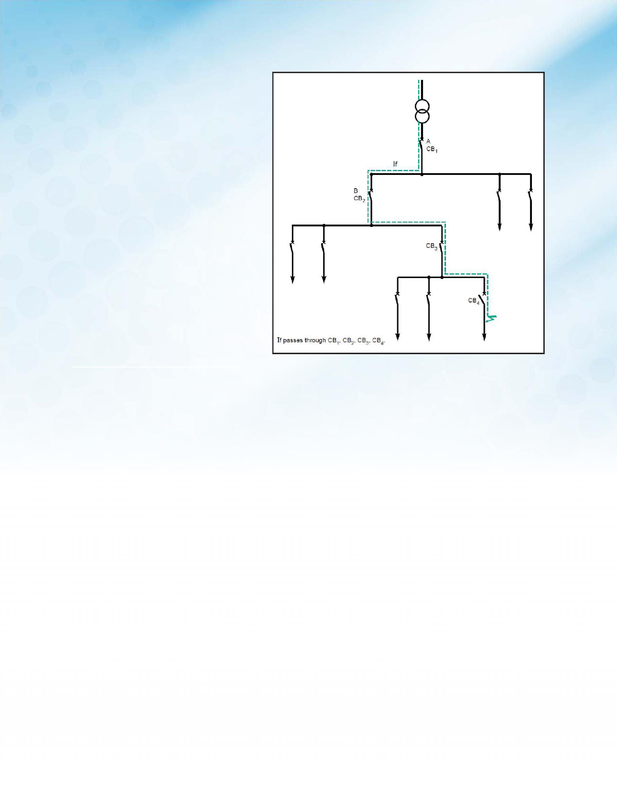
3: CB4 Operate to Clear Fault without Disturbing the Rest of the System Up to the Maximum Available Fault Current (Total Selectivity)
trip circuit breakers as shown in Figure 4; CB1 and CB2 are electronic trip circuit breakers while CB3 and CB4 are thermalmagnetic circuit breakers.
The device curves shown on TCCs, produced by power system analysis software, are taken from manufacturer published curves developed from lab tests that show the tolerance bands of trip values when exposed to three-phase bus faults in the overload zone andinthefaultcurrentzone.Thecurves and in the fault current zone. The curves plotted by the software do not account for the current-limiting capabilities that may be available in some circuit breaker trip units. An engineer could conclude that two circuitbreakersdonotcoordinateinthe circuit breakers do not coordinate in the fault current zone, albeit based on limited informationcontainedintime-current information contained in time-current curves, when in fact they do.
The current-limiting effects of circuit breakers can play a large role in the response of other OCPDs to fault currents throughout
NETAWORLD 65 FEATURE
ENERGY-BASEDTRIPPINGANDITSEFFECTSONSELECTIVECOORDINA ENERGY-BASED TRIPPING AND ITS EFFECTS ON SELECTIVE COORDINATION
Figure
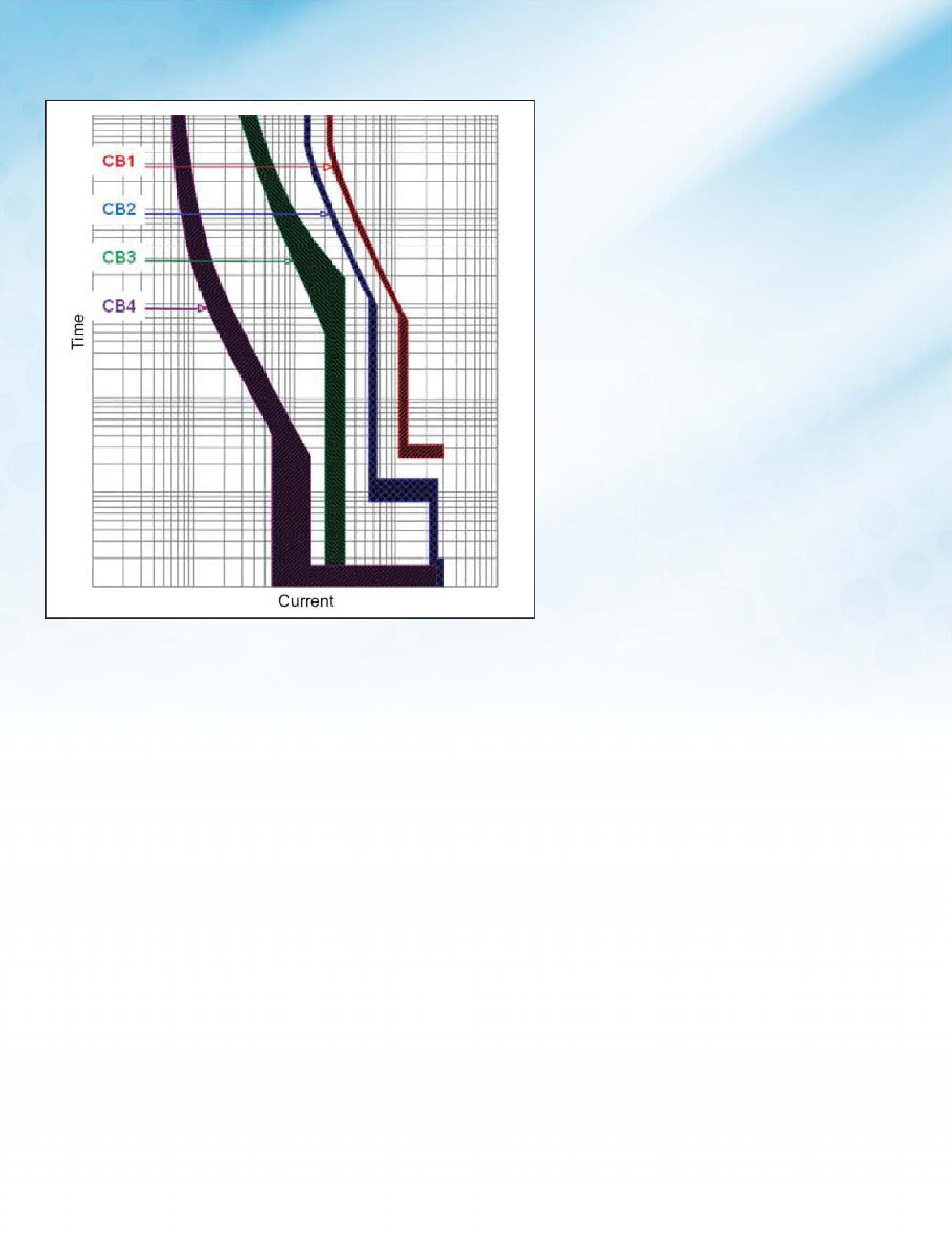
an electrical system. For the purposes of this discussion, only the current-limiting effects oftwocircuitbreakersandtheirinteraction of two circuit breakers and their interaction with each other will be considered. Referring again to the system in Figure 3, we will only consider CB3 and CB4. When the downstream circuit breaker, CB4, operates anarcwillformwhichintroducesan an arc will form which introduces an element of impedance to the system that did not previously exist. The amount of this impedance is based on environmental, mechanical and electrical conditions, and can vary for different circuit breakers. This is referred to as dynamic impedance. Dynamic impedance can greatly reduce the amount of fault current detected by the upstream circuit breaker, CB3. The time is also increased to trip for the amount of current that is let-through by the downstream circuit breaker. The current detected by CB3, for a fault on the load-side of CB4, is referred
to as let-through current. This currentlimiting behavior is advantageous when determining total selective coordination; it is a more accurate description of circuit breaker interactions operating on fault level currents in their instantaneous trip region. It is important to differentiate and not confuse this dynamic impedance current-limitation from UL-defined current-limitation, which is limiting I2t let-through to less than ½-cycle wave of the maximum prospective faultcurrent. fault current.
Overload trip times can range from seconds to hours but typical device TCC characteristics are cut off at 1000 seconds. TCCs provide avisualindicationthatcoordinationhas a visual indication that coordination has been achieved for three-phase faults and though these circuit breakers are subject to the same dynamic impedance discussed earlier, for practical purposes the devices are said to coordinate if it can be visually verifiedonaTCC.Becausetimedifferences verified on a TCC. Because time differences in the overload zone are seconds, not cycles, establishing overload zone coordination with TCCs is not nearly as difficult.
Some circuit breakers can be equipped with trip units that have an intentional time delay, when a fault is detected, to allow the downstream circuit breaker to interrupt a fault.Whentheseshort-timefunctionsare fault. When these short-time functions are used, it can be easily observed from a TCC thatcoordinationhasbeenachievedwhen that coordination has been achieved when there is no overlap in the device bands for the short-time region of the devices. Compare CB1 and CB2 in Figure 2.
The instantaneous regions of the device bands tend to show an overlap on a TCC for many circuit breakers because the curves have beenbasedonthestandalonecharacteristics been based on the standalone characteristics for maximum three-phase bus fault values. If dynamic impedance is considered for this region, then the fault current observed at the upstream circuit breaker may not be high enough to cause a trip before the downstream circuit breaker reaches its maximum trip timeforthemanufacturer’stolerancesfor time for the manufacturer’s tolerances for instantaneousfaults.Differentcombinations instantaneous faults. Different combinations
66 FALL 2013
FEATURE
ENERGY-BASEDTRIPPINGANDITSEFFECTSONSELECTIVECOORDINA ENERGY-BASED TRIPPING AND ITS EFFECTS ON SELECTIVE COORDINATION
Figure 4: Solid-State (CB1 & CB2) and Thermal-Magnetic (CB3 & CB4) Trip Characteristics

ofcircuitbreakerscanbeevaluatedtoshow of circuit breakers can be evaluated to show coordinationatorbelowcertainfaultvalues coordination at or below certain fault values even though the TCC device bands overlap each other in the instantaneous region.
PEAK CURRENT LET-THROUGH CONSIDERATIONS
TCC curves cannot accurately account for dynamic system impedance, so another methodwillneedtobeusedtodetermineif method will need to be used to determine if two circuit breakers coordinate. As long as the let-through current of the downstream circuitbreakerislessthantheminimum circuit breaker is less than the minimum value at which the upstream circuit breaker may trip the two circuit breakers selectively coordinate. Two methods of calculating the levelofselectivecoordinationbetweena level of selective coordination between a pair of circuit breakers are discussed further. These methods are: (1) the peak current point method and (2) the peak let-through curve method. Some assumptions must be madeinordertousethesemethods.Ifthe made in order to use these methods. If the upstream circuit breaker has an adjustable instantaneous setting, it is assumed that it is set at its highest value. If an electronic trip circuit breaker is used, then it is assumed the long and short time functions being used are set to coordinate throughout the long and short time region of both devices. Given some circuit breakers are equipped with an instantaneous override, which must also be taken into account. Lastly, the loadside circuit breaker current let-through values, for circuit breakers not UL-defined as current-limiting, are not typically published; insteadcircuitbreakermanufacturers instead circuit breaker manufacturers instead publish tables listing line- and loadside circuit breaker combinations, and the maximumfaultcurrentleveltowhichthose maximum fault current level to which those combinationsareselective. combinations are selective.
PEAK CURRENT POINT METHOD
The peak current point method calculations are based on peak currents so the minimum instantaneous trip level of the upstream circuit breaker must calculated for peak fault conditions. Many instantaneous trip settings are based on RMS values; therefore, the continuous rating must increased by a factor of 1.4142. For example, a thermal-magnetic
circuit breaker rated at 250A may have a maximum setting of 10 times the continuous current rating of the circuit breaker. UL 489 requires a minimum tolerance for this circuit breakerof80%. breaker of 80%.
The peak minimum instantaneous trip for thiscircuitbreakerwouldbe: this circuit breaker would be:
250A x 10 x 0.8 x 1.4142 = 2,828A
Other considerations and adjustments must be taken into account for more complex circuit breaker functions and testing conditions such as power factor and X/R ratio.Thisinformationcanbeobtainedfrom ratio. This information can be obtained from UL 489 interrupting tests.
If the peak let-through current of the downstreamcircuitbreakerislessthanthe downstream circuit breaker is less than the peak minimum instantaneous trip level of the upstream circuit breaker, then the selectivecoordinationlevelisthelesserof selective coordination level is the lesser of the upstream and downstream circuit breaker interrupting ratings (in RMS). If the peak letthrough current of the downstream circuit breaker is greater than the peak minimum instantaneous trip level of the upstream circuit breaker, then the selective coordination level is the minimum instantaneous trip level of the upstream circuit breaker (in RMS). This method uses data readily available to circuit breaker manufacturers (and, for UL-classified current-limiting circuit breakers, the data is published), but it yields conservatively low selectivity results.
PEAK LET-THROUGH CURVE METHOD
The other peak current comparison method is the peak let-through curve method, which also involves converting the minimum instantaneous trip level of the upstream circuit breaker from RMS to peak current, as described in the peak current point method. The value can be plotted as a horizontal line on the same graph as the peak let-through curveofthedownstreamcircuitbreaker curve of the downstream circuit breaker which can be obtained from data test points. The intersection point of these two lines indicatesthelevelofselectivecoordination. indicates the level of selective coordination.
NETAWORLD 67
FEATURE ENERGY-BASEDTRIPPINGANDITSEFFECTSONSELECTIVECOORDINA ENERGY-BASED TRIPPING AND ITS EFFECTS ON SELECTIVE COORDINATION
As shown on the peak let-through curve of the particular circuit breaker in Figure 5 the actualselectivecoordinationlevelismuch actual selective coordination level is much higher than it would have been assumed to be when a non-current-limiting circuit breaker would have been used. The dynamic impedance introduced by the currentlimiting circuit breaker forces the fault current to be greater than 40kA to allow the let-through current to reach the minimum instantaneous trip of the upstream circuit breakerat20kA. breaker at 20kA.
ENERGY-BASED TRIP SYSTEM
An energy-based tripping system, while it reliesonload-sidecircuitbreakercurrent relies on load-side circuit breaker current limitation, is able to discriminate between load-side faults and loadside let-throughs of other circuit breakers. This method employs two trip systems working in conjunction – a conventional circuit breaker trip and a specially designed primary trip system. The primary trip system will not trip during the first half-cycle of a fault regardless of the fault current level. This delay is accomplished by using various methods. One method uses a weight and spring system to block the
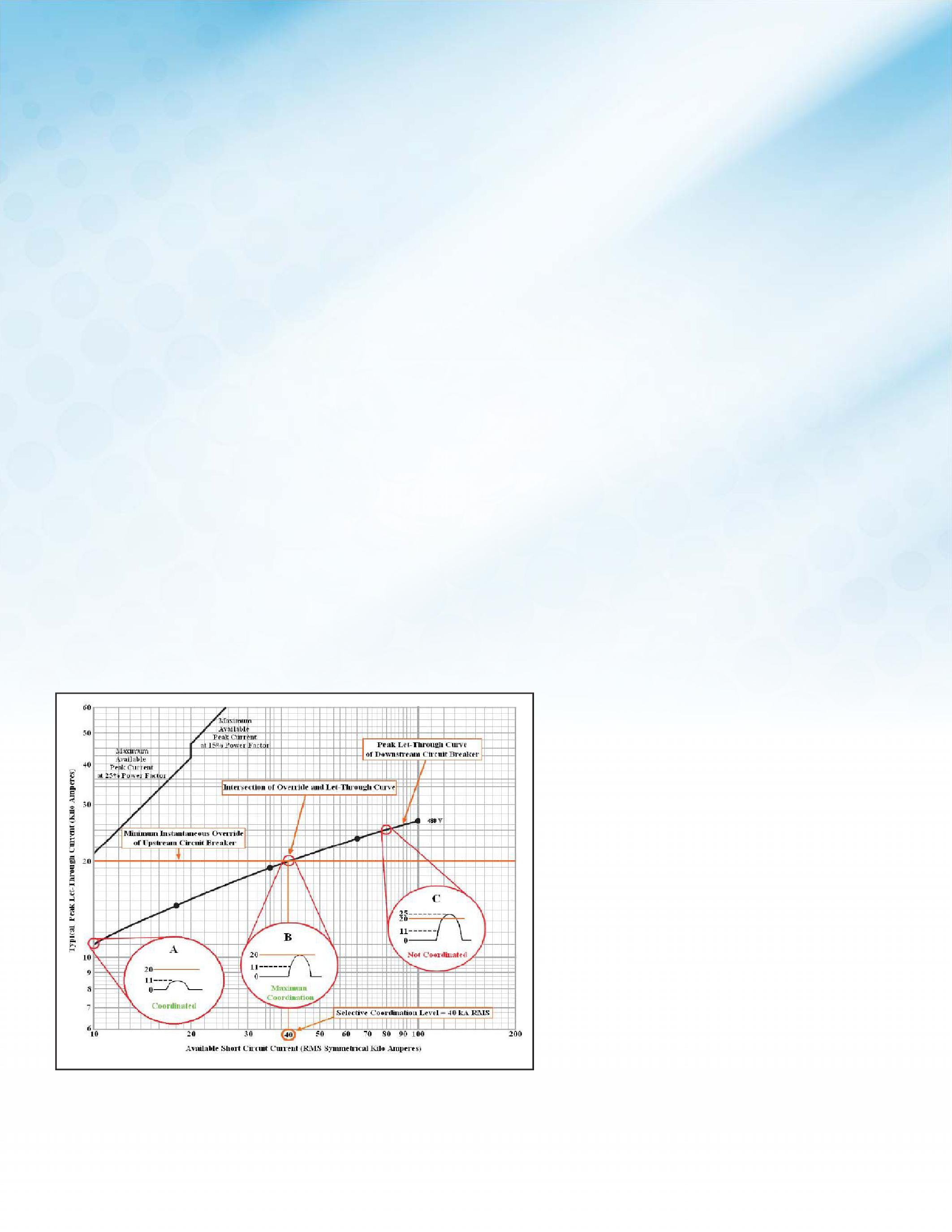
Figure 5: Peak Let-Through Current Curve Selectivity-for a
electro-magnetic forces that would otherwise be used to immediately trip the circuit breaker.Anotherusesanelectronicunitto breaker. Another uses an electronic unit to determinethedurationofthefaultandthen determine the duration of the fault and then trips accordingly if the fault has existed too long. The delay allows the power contacts to “pop”, or open, due to magnetic repulsion andthenreclose. and then reclose.
This develops impedance which limits the peak let-through current and energy to line-side OCPDs. In typical trip units, this reclosing action is prevented, because it can erode the circuit breaker power contacts over time. For this reason a supplemental trip system is used to monitor the energy let-through and trip the circuit breaker if necessary. Tripping due to let-through energy is called REFLEX tripping because the circuit breaker is protecting itself by reacting to energy levels that can damage it.
Twodifferentmethodscanbeusedto Two different methods can be used to measureI2tvalues.Onemethodusesa measure I2t values. One method uses a pressure trip system that is connected to the arc chamber through exhaust valves shown in Figure 6. When the contacts pop, the arc created generates heat as the current passes through the air. The heat erodes the ablativematerialinsidethearcchamberina ablative material inside the arc chamber in a controlled manner, which releases gases and creates pressure. The pressure trip system detects an increase in pressure and can be calibrated to trip at certain pressure levels, whichcanbecorrelatedtoI2t.Another which can be correlated to I2t. Another method to measure the energy let-through is by electronic means, by which the sensor continually monitors the level of energy letthrough during a fault. If a certain level of energy is exceeded, the trip unit is activated to prevent the contacts from reclosing.
Figure 7 shows how energy-based selectivity works. A fault on a branch circuit (A) will eventually rise to a level that will pop the contactsofthebranchandmaincircuit contacts of the branch and main circuit breaker. Due to the relative sizes and designs of the circuit breakers, the branch circuit breaker contacts will separate more than those of the main. The greater the distance
68 FALL 2013
FEATURE
Line-Side CircuitBreakerwitha20kAInstantaneousOverride Circuit Breaker with a 20 kA Instantaneous Override ENERGY-BASEDTRIPPINGANDITSEFFECTSONSELECTIVECOORDINA ENERGY-BASED TRIPPING AND ITS EFFECTS ON SELECTIVE COORDINATION
the arc must travel, the more impedance it introduces into the system, which in turn also generates more heat. When enough heat and pressure is built up, the supplemental trip system in the branch circuit breaker is activated.Forelectronicversionsofthese activated. For electronic versions of these trip units, the total energy reaches a certain level and the trip system is activated. Once the trip system is activated the branch circuit breaker contact is open and prevented from reclosing, clearing the fault. The main circuit breakerdidnotreachasufficientlevelof breaker did not reach a sufficient level of energy to trip and remains closed; however, the contact separation in the main provides additional impedance that reduces stresses in other parts of the electrical system and allows an upstream circuit breaker to assist in clearing a fault downstream and remain closed, providing continuous service to other branchcircuits.Becausebothcircuitbreakers branch circuits. Because both circuit breakers are working together to clear the fault a series rating can also be achieved for circuit breakers with a supplemental trip unit. The energy that these circuit breakers will letthrough during interruption is typically moreconsistentthanstandardcircuit more consistent than standard circuit breakers, because the actual trip is activated by a more consistent and measureable quantity – the loadside energy, rather than a peak current. Since the energy let-through is more predictable, coordinating these circuit breakers with others that trip based on the
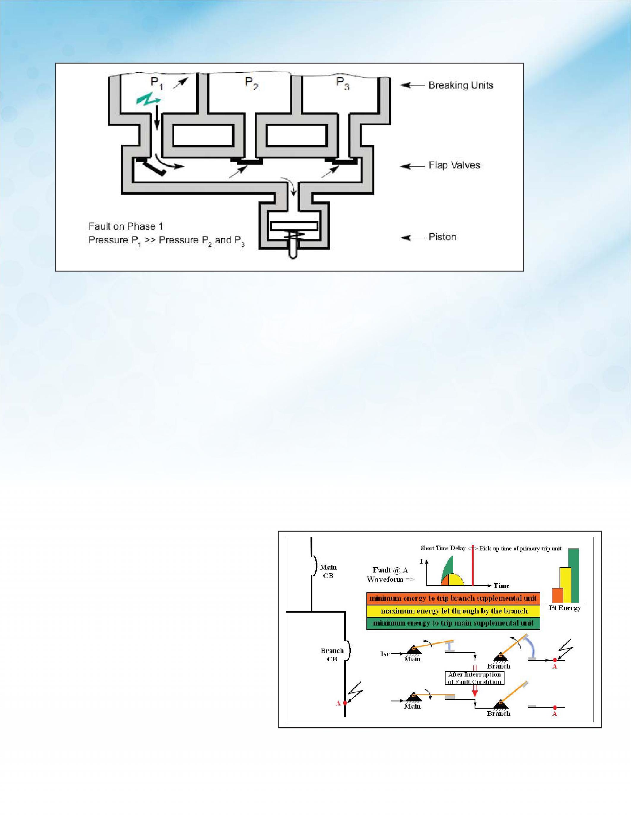
same principle is easier. The energy-based tripping circuit breakers can also selectively coordinate to higher fault current levels with load-side standard circuit breakers, due to the current-limiting capabilities of standard circuitbreakersdiscussedearlier. circuit breakers discussed earlier.
The energy-based method with its loadside energy consistency, allows the line-side circuit breaker to effectively distinguish between load-side faults and let-throughs of load-side breakers operating on faults further downstream. The intentional delay that allows the reflex tripping to see loadside energy does not reduce overall clearing time, resulting in higher levels of selective
NETAWORLD 69
FEATURE
Figure 7: Energy-Based Selective Coordination Diagram
ENERGY-BASEDTRIPPINGANDITSEFFECTSONSELECTIVECOORDINA ENERGY-BASED TRIPPING AND ITS EFFECTS ON SELECTIVE COORDINATION
Figure 6: Mechanical Pressure Trip System

coordination without necessarily unleashing higher levels of fault energy, including arc flash incident energy.
As a rule of thumb, line-side breakers should beselectedthatare2timesthecurrent be selected that are 2 times the current rating of the downstream device to achieve coordination.Iffaultcoordinationcanbe coordination. If fault coordination can be verified using one of the methods discussed in this paper and overload coordination can be visually confirmed by a TCC, then the devices will achieve total selectivity. This simple rule and the use of the supplemental trip units discussed not only greatly simplifies coordination studies and system design, but also reduces the stress and possible damage experienced during a fault in the system. Thesebenefitscanbecascadedoverseveral These benefits can be cascaded over several levels of a power system to provide even greater protection and coordination.
SUMMARY
To achieve total selective coordination, as required by some authorities having jurisdiction enforcing the specific NEC articles, additional criteria beyond traditional circuitbreakertime-currentcurvesmust circuit breaker time-current curves must be applied. This paper discussed methods used to accomplish total selectivity at high fault current levels - methods that recognize circuit breaker current-limiting capabilities, evenforcircuitbreakersnotdefinedas even for circuit breakers not defined as current-limiting by UL. Most importantly, an energy-based tripping method was described, which provides consistency by using load-side energy and achieves high levels of fault selectivity. In addition, energybased tripping is easy to apply (the results are compiled in look-up tables and on-line tools) and does not introduce additional fault clearing times or increase system arc flash incident energy levels.
REFERENCES
1. Short-Circuit Selective Coordination by Gavin Button and Mike Tobin, Schneider Electric internal, September 24, 2008
2. A New Approach to Low-Voltage Circuit Breaker Short-Circuit Selective Coordination by Ed Larsen, IEEE ICPS08XP21
3. Energy-based discrimination for LV protective devices by Marc Serpinet and Robert Morel, Schneider Electric Cahier Technique ECT167
John Carlin, PE, is an Engineering Supervisor with Schneider Electric Engineering Services Central Studies group in Lexington, Kentucky. He received a BS degree in electrical engineering from University of Arkansas in 1987. John’s experience includes 19 years with the Central Studies group performing medium- and lowvoltage power system studies for commercial, industrial, and institutional projects, both new construction and existing facilities. Analysis types performed include fault, coordination, arc flash, load flow, harmonics and dynamic motor starting. Facilities analyzed include automotive manufacturing, automotive testing, oil refineries, utility power stations, military weapon destruction plant, water/wastewater treatment plants, and other commercial and institutional projects.
Reprinted with permission of Square D by Schneider Electric; copyright 2013. All rights reserved.
70 FALL 2013 FEATURE
ENERGY-BASEDTRIPPINGANDITSEFFECTSONSELECTIVECOORDINA ENERGY-BASED TRIPPING AND ITS EFFECTS ON SELECTIVE COORDINATION

Rent Secondary Current Test Sets From Electro Rent 800-304-4744 sales@electrorent.com daily, weekly monthly A2LA accredited ISO/IEC17025:2005 Industrial.ElectroRent.com Cutler Hammer 140D481G03 Square DS33595Siemens PTS-4Utility Relay AC-PRO Large inventory includes equipment from power factor test sets to power & demand analyzers Immediately Available for Delivery
SETTING THE STANDARD – NETA MARKS 17TH ANNIVERSARY AS AN ANSI ACCREDITED STANDARDS DEVELOPER
BY KRISTEN WICKS, NETA
Standardization of processes may not be the most glamorous topic, but it is one that is at the core of most industries in the world today. Consensus, safety, and quality assurance lie at the heart of every organization that seeks to create the gold standard for their industry.
NETA is involved in many ways in the standards process – as an organization that has established an accreditation program for third-party, independent electrical testing firms, as a body of volunteers who participate in the creation and maintenance of electrical industry standards like IEEE, ICEA, ICC, NFPA, and CSA to name a few, and proudly as an ANSI Accredited Standards Developing Organization.
Most organizations with an accreditation program require that those accredited demonstrate their continued compliance with the organization’s requirements for accreditation. Every five years, NETA undergoes an audit of its standards development which includes an in-depth review of every standard currently maintained as an ANS (American National Standard). This audit assures that ANSI Accredited Standards Developers are creating and issuing standards that have met the ANSI Essential Requirements for standards development as well as the association’s unique development criteria, in this case the NETA Operating Principles and Procedures. It is an opportunity to recognize the association’s commitment to meeting the highest level of integrity while allowing for improvement in practices that are due for revision or correction with regard to the most current development guidelines; ANSI is to standards developers what NETA is to electrical testing firms.
NETA officially became reaccredited as an ANSI Accredited Standards Developer on May 31, 2013. This markstheconclusionofthethirdauditsinceNETA marks the conclusion of the third audit since NETA became an ANSI Accredited Standards Developer in 1996. NETA thanks each of the members that supports and participates of this pillar of the association – it truly sets us apart. The 2012 Audit was closed on June 4, 2013.
NETA is proud to bear the ANSI Accredited marks as an organization and on its three ANSI standards.
e at y. e ks y. ds n nt o al N
K TANET
, N S C W I

How Do You Ensure Safety and Reliability? Hire a NETA Accredited Company! NETA has been connecting designers, specifiers, architects and users of electrical power equipment and systems with independent, third-party electrical testing companies since 1972. NETA Accredited Companies test the complete system in accordance with industry codes and standards to provide accurate test reports you can count on every time. For more informationon NETA or our ANSI/NETA Standards giveus acall at 888-300-NETA (6382) For a complete listingof NETA Accredited Companies turn to page 124 or visit www.netaworld.org.

THE 249TH ENGINEER BATTALION – KEEPING THE LIGHTS ON FOR YOU
BY KRISTEN WICKS, NETA
A few times a year, our nation thanks those who aided in battle as well as those who continue to serve today.
NETAsalutestheservicemenandwomenwho NETA salutes the servicemen and women who bravely set aside their personal safety and comfort to defend the ideals so hard won many years ago.
NETA has the special privilege of serving a unique branch of the armed forces, the 249th Engineer Battalion (Prime Power) through its NAMO (NETA Approved Military Organization) program. The 249th is a versatile power generation battalion assigned to the U.S. Army Corps of Engineers that provides commercial-level power to military units and federal relief organizations during full-spectrum operations. Additionally, thecommanderservesastheCommandantofthe the commander serves as the Commandant of the U.S. Army Prime Power School, the institution responsible for the development of Army and Navy power generation specialists. The organization is charged with the rapid provision of Army generators to support worldwide requirements.
Each platoon has the capability of producing approximately three megawatts of power at 4160 volts (medium voltage). The newly fielded individual generator size is 840 kilowatts. These mediumvoltage generators require transformers to convert the voltage to a user level (120/208/277/480 volts).
The battalion offers a variety of services including: electrical power requirement assessment; power production; transformer inspection and test analysis; maintenance and repair of power plants, substations, and government owned or managed transmission and distribution systems; circuit breaker and relay maintenance; infrared surveys;
medium-voltage electrical contractor oversight; and training for personnel to operate and maintain prime power distribution and generation equipment. This close alignment with NETA’s missionmakesPrimePoweranexcellentmember mission makes Prime Power an excellent member of the NAMO program.
Prime Power participated in operations Iraqi Freedom, Enduring Freedom, Noble Eagle, New York City and Pentagon Terrorist Attacks, Just Cause, Desert Storm, Desert Shield, Provide Comfort, Provide Hope, Uphold Democracy, Support Hope, Joint Endeavor and Joint Guard, andnumerousdisasterreliefmissions.TheBattalion and numerous disaster relief missions. The Battalion has earned three Superior Unit Awards for disaster relief operations, 1992; for worldwide missions support, 1995; and for participation in Task Force Eagle Implementation Force, 1996.
ThesebraveSoldiersareoftensomeofthefirst These brave Soldiers are often some of the first on the ground, working to generate life-saving power to supply troops on the ground. They are also heavily relied upon when disaster strikes our homeland, being deployed to provide aid following catastrophic events like Hurricane Sandy. We live in a country where it is easy to take small things for granted, things like safety, freedom, and even the creature comforts provided by electricity and the infrastructure it supports. NETA thanks its NETA Accredited Companies for supporting the NAMO program, and all of the soldiers who have decided to raise the bar even higher by becoming NETA Certified Technicians. When the lights go out, it’s good to know that there are trained and qualified people to turn them back on again.
THE249THENGINEERBA THE 249TH ENGINEER BATTALION–KEEPINGTHELIGHTSONFORYOU ALION – KEEPING THE LIGHTS ON FOR YOU 74 FALL 2013






NETA – SETTING THE STANDARD
BY JILL HOWELL, NETA
In the early 1970s, there were few standards for electrical testing. NFPA had authorized a committee in 1968 to create NFPA 70B, Recommended Practice for Electrical Equipment Maintenance. This standard addressed electrical equipment maintenance practices. It also touched on acceptance testing, advised on equipment, type of tests, and how often tests should be performed.
However, it did not provide specifications for standardized electrical testing procedures for medium- to high-voltage systems or qualification requirements for test technicians. This meant that when electrical testing was performed, it was conducted by a wide variety of types of companies not necessarily specialists in the field of electrical testing. This wide array of companies with different electrically-related disciplines created opportunity for inconsistent test practices, acceptable test values, and maintenance testing procedures. Additionally, there were no standardized requirements for a test technician’s knowledge or experience, leaving that to the end user to be defined. Consequently, test methods and procedures,

the type of test equipment used, and safety procedures were all conducted at the discretion of the company providing the testing services.
It was during this time that a group of electricalbusinessownersintheUnitedStates electrical business owners in the United States recognized the need to standardize field tests in order to significantly improve safety and power system reliability. In 1972, these pioneers formed NETA, the National Electrical Testing Association, later to become the InterNational Electrical Testing Association, with the goal of working with industry stakeholders to create uniformity by establishing uniform testing procedures for electrical equipment and apparatus. Diligent work toward its mission resulted in the publication of the NETA Acceptance Testing Specifications in 1973 now known as ANSI-NETA Standard for Acceptance Testing Specifications for Electrical Power Equipment and Systems. In 1979, NETA introducedthefirst introduced the first Maintenance Testing Specifications for Electrical Power Distribution Equipment and Systems.
NETA had long set its sights on becoming an accredited standards developer under theAmericanNationalStandardsInstitute the American National Standards Institute (ANSI). In 1996 NETA earned designation as

an Accredited Standards Developer, and the ANSI/NETA Standard for the Certification of Electrical Testing Technicians was approved as an American National Standard on March 15, 2000. Other smaller sections of the maintenance document followed, with the entire ANSI/ NETA MTS becoming an approved ANSI standard in 2007, and the ANSI/NETA ATS in 2009.
The ANSI/NETA Standard for Certification of Electrical Testing Technicians was created to codify the experience, education, and training requirements necessary for an individual to obtain a level of competency as an electrical test technician. Furthermore, NETA carefully examines the qualification of each NETA Accredited Company (NAC) in addition to certifying the individual technician employed by that NAC. This ensures that not only is the test technician qualified to perform power system and electrical equipment testing in accordance with industry standards, but that the company supporting those technicians is also qualified, providing them with the necessary correctly calibrated test equipment, a safety program that is sound in practice and meets minimum requirements, review of test reports by a professional engineer, and that guidelines are met with regard to the test report provided at the conclusion of their services. One aspect often overlooked is the quality of the test report itself; although those performing the tests need to be qualified, it is important the technicians are also able to deliver a quality report, since those reports are used as the basis for continuance of maintenance programs.
THE NETA CERTIFIED TECHNICIAN IS UNIQUELY QUALIFIED
A NETA Certified Technician has earned a Level III or Level IV NETA Certification in electrical power systems testing and brings the knowledge and field experience necessary to perform testing as specified in the ANSI/ NETA standards. NETA also offers a Level II, Assistant Technician designation.
“ANSI/NETA standards require: …the on-site crew A leader shall hold a current certification, Level III or higher, in electrical testing. This certification shall be in accordance with ANSI/NETA ETT-2010, Standard for A Certification of Electrical Testing Technicians.”
The scope of the ANSI/NETA Standard for Certification of Electrical Testing Technicians specifies the following:
requirements for qualification and certification of the electrical testing technician (ETT). -
ing and experience requirements for electrical testing technicians and provides criteria for documenting qualifications and certification.
qualifications for an independent and impartial certifying body to certify electrical testing technicians.
WHAT IT TAKES TO BECOME A NETA CERTIFIED TECHNICIAN
A NETA Certified Technician must advance through three levels of classifications defined in terms of the skills and knowledge required in a given method or methods to perform
“ALevelIVNET “A Level IV NETA Certification means more today as the industry moves more and more towards specifying testing to ANSI/NETA Standards. Data Centers often demand they A haveaLevelIVNET have a Level IV NETA Certified Technician running the job. Because of this, more of our technicians are working toward getting their Level IV Certification. It’s an accomplishment. I know other Level IV technicians, and we all have a lot of respect for each other.”
Craig Griffin Power Products Solutions, Inc., NETA Level IV Certified Technician since September 2006.
specific electrical testing maintenance activities. Advancement is earned through the NETA Certification Program requiring minimum levels of training across 22 categories, specified years of testing experience, and the passing of electrical testing examinations at each level, administered by a certifying body as defined by ANSI/NETA ETT Standard for Certification of Electrical Testing Technicians.
This provides a brief overview of the NETA TestTechnicianCertificationLevelsandtheir Test Technician Certification Levels and their Respective Requirements:
ETTTRAINEELEVELI ETT TRAINEE LEVEL I – Offers an entry –level gateway into the electrical testing industry
Dutiesinclude: Duties include: technicians and disassembly tests under direct supervision
Requirements: diploma (GED)
ETTASSIST ETT ASSIST ANTLEVELII ANT LEVEL II –Hassufficient – Has sufficient knowledge and experience to be qualified for assuring the safety of him/her.
Dutiesinclude: Duties include: work while requiring direct supervision
Requirements: electrical testing industry
understanding of lockout/tagout procedures and requirements, arc-flash and shock hazard analyses, and other facets of hazardous electrical energy control procedures to certification element categories examination administered by a certifying
“TobecomealevelIVNET “To become a level IV NETACertified A Certified Technician you really need both field experience and a firm understanding of power engineering principles. Passing the Level IV exam was challenging, as challenging as passing my P.E.exam. .E. exam. Themostdifficultsectionoftheexam The most difficult section of the exam deals with very specific scenarios thatdemandtheoreticalaswellas that demand theoretical as well as practical, hands on experience. In preparing for the exam, the study guide provided by NETA was very A helpful. Reviewing the NETATechnical A Technical QuizzesandtheNET Quizzes and the NETAHandbooks A Handbooks were also good tools for review. If you’re going to lead other technicians you don’t ask people to do something you don’t do yourself. We recently hired a level III technician, and he is now inspired to earn his level IV certification.”
DanielHook Daniel Hook Western Electrical Services, NETALevelIVCertifiedTechnician A Level IV Certified Technician since January 2012
body as defined in this standard (See ANSI/NETA ETT – 2010, Annexes A, B, and C contain specific requirements)
ETTCER ETT CER TIFIEDLEVELIII TIFIED LEVEL III – Is capable of supervising ETT Trainee Level I and ETT AssistantlevelII. Assistant level II.
Dutiesinclude: Duties include: and moderately complex tasks and projects.

electrical testing
Requirements:
experience in electrical testing industry
documented safety training
additional documented training related to the certification of element categories for Level III
examination administered by a certifying body as defined in this standard (See ANSI/NETA ETT – 2010, Annexes A, B, and C contain specific requirements)
ETT SENIOR CERTIFIED LEVEL IV –
Supervises large projects and multiple crews and can work independently.
Duties include:
and evolution and prepare written reports as needed
Requirements:
electrical testing industry training
training related to the certification element categories for Level IV
examination administered by a certifying body as defined in this standard (Annexes A, B, and C contain specific requirements)
For each NETA Certification level there is a specified number of years of experience recognizing that in addition to knowledge, a skilled technician must be regularly engaged in the process of testing and evaluating electrical systems to ensure they can apply their knowledge at any given time in any testing situation. In addition, each level has specific training requirements. The training is progressive and ensures that the technician is updating his/ her knowledge throughout his/her career. If a technician wishes to advance to higher certification levels, the training is structured so as to build on current knowledge.
For a detailed overview of Annexes A and B, see Tables 1 and 2. For a complete reference of NETA Certified Technician requirements refer to Annexes A, B, and C in the ANSI/NETA Standard for Certification of Electrical Testing Technicians.
For additional information on becoming a NETA Accredited Company or about NETA Certified Technicians please contact the NETA office at 888-300-6382 or email at neta@ netaworld.org.The ANSI/NETA Standards can be purchased at netaworld.org.
ABB GENERAL ELECTRIC ITE GOULD WESTINGHOUSE SIEMENS SQUARE D ALLIS CHALLMERS FEDERAL PACIFIC MoldedCaseBreakers Molded Case Breakers InsulatedCaseBreakers Insulated Case Breakers AirCircuitBreakers Air Circuit Breakers Medium Voltage Breakers
Vacuum Breakers
Vacuum Contactors/Starters
Switchgear BCS Switchgear, Inc. is one of the largest stocking distributors and repair facilities of quality equipment. New Used Obsolete Reconditioned BCS SWITCHGEAR, INC. www.bcsswitchgear.com 24-HourServiceToll-Free: 24-Hour Service Toll-Free: 888-599-0486 Fax: 940-365-1808 OurNewAddress: Our New Address: 4790 Hwy 377 South Krugerville, TX 76227 TEXASOFFICE TEXAS OFFICE VIRGINIAOFFICE VIRGINIA OFFICE 24-HourService: 24-Hour Service: 276-945-9555 Fax: 276-945-9552 WE’VE MOVED
VacuumBreakers
VacuumContactors/Starters
Switches
800-258-7044 www.three-c.com Serving the Northeast U.S. CAN YOUR TESTING COMPANY PASS THIS TEST? Why leave the reliability of your electrical equipment to chance? Trust the experts at Three-C Electrical with your generation and power distribution equipment. The Power Systems Specialists Independent Electrical Testing and Preventive Maintenance PROFESSIONAL SERVICES 609-890-8300 www.easternhighvoltage.com

“…A GREAT TEAM PLAYER…”
MOSE RAMIEH, OUTGOING PRESIDENT
BY RICHARD PIET, NETA
With all the tasks a person must attend to on a daily basis first at home, then at work and various other commitments, many of us could use more hours in the day to get it all done. How about adding to that to-do list by taking on the task of becoming a champion for the industry in which an individual works?
Many people would have difficulty feeling comfortable saying yes to extracurricular or industry-related activities. Fortunately for NETA, those who are active in the organization have overlooked the fact they could be home tending to their to-do lists, maybe enjoying a tropical vacation, and leaving the worries of advancing the industry tosomeoneelse. to someone else.
NETA is also fortunate in that among those making a commitment to improving the standards of the industry are those with an excess of passion for that goal; people like the NETA Board of Directors, and in particular, itsPresident. its President.
“It’s an interesting position,” NETA Past President John White said. “Everyone on the Board is a leader in their own right, and leaders sometimes struggle trying to be led.
OUTGOINGPRESIDENT OUTGOING PRESIDENT 82 FALL 2013

That’s one of the big challenges — to keep all the people engaged and on the same track.”
Yet, it gets done. And, perhaps amazingly, every two years a person steps up and makes the commitment to lead the entire organization in accomplishing its mission. Two years ago, that was Mose Ramieh. Talking about Mose, White said he fits the role of NETA President extremely well, being “hardworking, experienced, knowledgeable,” and, like every well rounded leader, is “always ready to have a good time!” But he does not lose sight of the goal. “He’s a very dedicated guy,” White said. “He’s always willing to work, always willing to do what it takes. He’s never short of an opinion and yet he delivers his opinions in a very professional, friendly manner. That makes him a great team player.”
Inhisfirst In his first NETAWorld NETA World message as President, Mose said he was looking “to the future with excitement about what we are doing and the impact it will have, not just on NETA, but the entire electrical industry.” Mose has spent more than 40 years in the industry, and has a base of experience from which to draw. After retiring from the U.S. Navy, he founded Power and Generation Testing, Inc. in Nashville in 1996, and remains its president today.
Being involved in NETA – especially as its President – Mose is seeing change happen, and it is pushing him back in his seat. “As we look to the future it is apparent to me that our evolution will come at a faster pace than any of us can imagine,” he wrote. “If NETA is to continue its growth and standing in the electrical community, we must continue to keep pace with the ever changing needs of the industry.”
NETA Executive Director Jayne Tanz believes that pace is a direct result of the commitment Mosehasshown. Mose has shown.
“It’s a reflection of his willingness to put
tough discussion points on the table and allow any and all dialogue to ensue,” she said. “As president, he encouraged the board to remain focused on strategy as much as the business of the association. New steps are sure to be takenashecontinueshisinvolvementasthe taken as he continues his involvement as the Strategic Chair, with the betterment of the industry in mind.”
Mose actually believes it is more than just “change.” Mose explains, “We are in the midst of a new era in our industry and our association.” To that end, Mose is particularly proud of the accomplishments during his tenure. Mose says, “We have added 10 NETA Accredited Companies and increased our NETA Certified Technician count by 15 percent.” The NETA Approved Military Organization (NAMO) program was also createdunderhistermasPresident. created under his term as President.
Now that he is a NETA past president, Mose could enjoy more time on the links or baiting a hook. But, just because he has slipped out of theNETAdriver’sseatdoesnotmeanhewill the NETA driver’s seat does not mean he will not be along for the ride, and he encourages members to do the same. “As the Strategic Chair, I will be involved in the continued setting of direction and evolution of our association,” he wrote in his final NETAWorld NETA World message as President. But, he will not be doing it alone. Mose says, “Remember, NETA’s best resourceisourvolunteers.” resource is our volunteers.”
NETAWORLD 83 OUTGOINGPRESIDENT OUTGOING PRESIDENT

Rent Relay Testers From Electro Rent Large inventory includes equipment from motor testers to borescopes Immediately Available for Delivery Megger SMRT36Doble F6150SVManta MTS-5100Omicron CMC356 daily, weekly monthly 800-304-4744 sales@electrorent.com Industrial.ElectroRent.com
CIRCUIT BREAKERS – LOW/MEDIUM
TRANSFORMERS – 1000–5000 KVA
Dry type/cast resin transformers from stock Load break switch & fuse
LIFE EXTENSION
Vacuum retrofill/retrofit
Solid state conversion
Vacuum motor control upgrades
MOLDED CASE CIRCUIT BREAKERS
LOW VOLTAGE MOTOR CONTROL
Circuit breakers
Motor control components
Upgraded buckets
Panel mount switches
SWITCHGEAR – 480V-38KV NEW AND SURPLUS
New General Electric switchgear in 4 weeks
Match existing lineup
Reconditioned from stock
Complete Indoor/outdoor unit substations available
RENEWAL PARTS –
SWITCHGEAR & CIRCUIT BREAKER PARTS
All low& medium voltage renewal parts, 1945–today
Obsolete vacuum interrupter in stock www.circuitbreakerpartsonline.com
MEDIUM VOLTAGE MOTOR CONTROL
AIR & VACUUM MOTOR CONTROL
New General Electric available from stock
Reconditioned starters and contactors
SERVICE & REPAIR
Field service and testing
Shop repair of all switchgear and circuit breakers ISO 9001 and 14001 Certified
VOLTAGE
major
All
manufacturers
Universal circuit breaker remote racking system Remote switch and circuit breaker operators 24 Hour Emergency Service 800-232-5809 www.circuitbreaker.com | info@cbsales.com 1315 Columbine Dr., Gainesville, TX76240 PROVIDING ELECTRICAL SOLUTIONS WORLDWIDE Circuit Breaker Sales is a charter member of the Professional Electrical Apparatus Recyclers League
FIELD TESTING OF TRANSFORMERS
BY JIM MACDONALD, Client Service Field Engineer, Doble Engineering Company
Arc furnace transformers are found in industrial settings to step down voltage to provide power for arc furnaces used for production of steel and iron. These transformers can come in a variety of types and configurations. Often times the secondary may have multiple windings per phase that are in parallel with each other. In many cases, each end of each individual secondary winding is brought out through the tank wall to a low voltage bushing, and a delta connection of the windings is made externally to the transformer via a bus delta enclosure. This paper will describe some of the issues these unique configurations can pose when testing in the field and what options one has when performing testing on this apparatus.
OVERALL TEST
The first step is to isolate the high-voltage and low-voltage windings from any bus and cable connectionsandmakesurethetransformer connections and make sure the transformer is correctly grounded. If multiple separate windings per phase are present on the secondary and each end of each individual winding is brought out to a bushing, the most direct way to perform the overall test is to electrically short circuit all secondary bushings together (in addition to shorting the high-voltage bushings together). Then perform the test the same way a standard two-winding transformer would be tested. However, keep in mind that it is always ideal, if possible, to break an insulation system down into the smallest components possible. Often times a problem could be masked

when taking a measurement of a number of insulation components lumped together, while it may show up when solely testing one of the individual components. Breaking the insulation into the smallest portions possible will also allow one to troubleshoot a bad reading obtained while testing the transformer as a two-winding transformer with insulation components lumped together. Below is a detailed description of how to break up the insulation into smaller pieces.
The example shown in Table 1 and Figures 1-3 is a transformer with two separate windings per phase on the secondary (total of six low voltage windings). Each end of these six windings is accessible and brought out to an individual
FIELDTESTINGOFARCFURNACETRANSFORMERS FIELD TESTING OF ARC FURNACE TRANSFORMERS 86 FALL 2013
INDUSTRYTOPICS INDUSTRY TOPICS 3201 FALL A OV O V Th e T h lo w o l con n o c isc s c i win w i n seco o s c e win w i n mo o m is t s i bus s u b th e t h pe r p e two w o t Ho w if p f i dow d w o Of t O ft f B Y J Ar vool ste co con per of wa ma wiil wh
INDUSTRYTO P N S T Y T O U R D I
tes es

Table1: able 1: Test Procedure for a Seven-Winding Transformer (Six Completely Isolated Secondary Windings – Two Low-Voltage Windings Per Phase)
ENERGIZE
GUARDUSTGNDINSULATION
U+V+W+X+Y+Z


H+V+W+X+Y+Z
H+U+W+X+Y+Z
GST-Guard
V+W+X+Y+Z
U+W+X+Y+Z
U+V+X+Y+Z
U+V+W+Y+Z
U+V+W+X+Z
U+V+W+X+Y
H+W+X+Y+Z
H+V+X+Y+Z
H+V+W+Y+Z
H+V+W+X+Z
H+V+W+X+Y
H+U+X+Y+Z
H+U+W+Y+Z
H+U+W+X+Z
H+U+W+X+Y
H+U+V+X+Y+Z

H+U+V+W+Y+Z

H+U+V+Y+Z
H+U+V+X+Z
H+U+V+X+Y
H+U+V+W+Z
H+U+V+W+Y
H+U+V+W+X+Z
H+U+V+W+X+Y
bushing. The six low-voltage windings have been completely separated from each other so that the low-voltage side is no longer delta connected (the delta connection external to thetransformerhasbeenremoved).Thefirst the transformer has been removed). The first thing one must do is check for continuity between secondary bushings to identify which
H+U+V+W+X
GST-Guard

GST-Guard

GST-Guard UST UST
GST-Guard
GST-Guard
pair of bushings forms a winding. Adjacent low-voltage bushings may not always be the ends of the same winding. Once this has been done, each secondary winding should be electrically shorted individually (in addition to electrically shorting the high-voltage bushings together).


NETAWORLD 87 FIELDTESTINGOFARCFURNACETRANSFORMERS FIELD TESTING OF ARC FURNACE TRANSFORMERS INDUSTRYTOPICS INDUSTRY TOPICS
H H H H H H H U U U U U U V V V V V W W W W X X X Y Y Z
---
---
--
--
-
-
U V W X Y ZV W X Y ZW X Y ZX Y ZY ZZ-
-
-
-
-
-
CH CHU CHV CHW CHX CHY CHZ CU CUV CUW CUX CUY CUZ CV CVW CVX CVY CVZ CW CWX CWY CWZ CX CXY CXZ CY CYZ CZ
UST UST UST UST UST UST
UST UST UST UST UST
GST-Guard UST UST UST UST
UST UST UST
UST
TEST
MEASURED
MODE


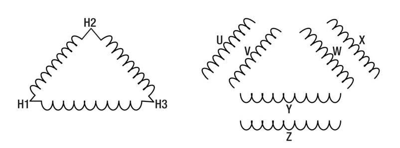

In Table 1 the Energize column shows which winding will be energized with the test set during the test. The two low-voltage measurement leads are placed on the windings under the Guard, GND and UST columns respectively. UST stands for ungrounded specimen test and is referring to a measurement being made to an ungrounded winding with the low-voltage test lead. GND refers to the windings that must be grounded, and Guard refers to any windings that are not included in the measurement. Any current flowing to a winding under the Guard column bypasses the meter in the test set (via the low-voltage test lead) and is not included in the measurement. Note that in order to guard or ground several windings at once, additional wire must be used
to electrically short these windings together. While breaking down the insulation into smaller portions can be advantageous, it will add more complexity to testing a transformer. Multiple additional tests will be added to the test procedure for each separate individual winding that is accessible. In some cases this can add many steps to the procedure, as some arc furnace transformers can have as many as 12 low-voltage windings (four parallel windings per phase). Since it can be more complex to test each individual insulation piece, it is generally accepted to test an arc furnace transformer with multip le separate accessible windings as a two-winding transformer. If a problem is shown while performing this test,

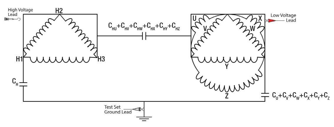


88 FALL 2013
INDUSTRYTOPICS INDUSTRY TOPICS
Figure 1: Transformer from Table 1 with six completely isolated windings on the secondary
FIELDTESTINGOFARCFURNACETRANSFORMERS FIELD TESTING OF ARC FURNACE TRANSFORMERS
Figure 2: Test setup for line #1 from table 1, GST-Guard Test
then the insulation pieces can be broken down further and tested to help identify where the problem may lie.
Analysis
Regardless of how many windings one chooses to include in the test procedure, the analysis is similar to a standard two-winding transformer. Any significant changes in capacitance and power factor should be investigated. Currently thereisnotsufficienttestdataavailableto there is not sufficient test data available to conduct a comprehensive tabulation of power factorsforarcfurnacetransformers.Itisthe factors for arc furnace transformers. It is the author’s recommendation to use the generally accepted power-factor limits of power transformers for both the high-voltage winding insulation and interwinding insulation (less than0.5%).Itisnotuncommontohave than 0.5%). It is not uncommon to have higher power factors for the low-voltage winding insulation. In many cases the lowvoltage winding insulation may have elevated power factors due to the multiple low-voltage bushings connected to the low-voltage windings. These low-voltage bushings are often made of a solid dielectric which may exhibit higher power factors than an oil impregnated paper condenser type bushing.
SFRA
Three sets of sweep frequency response analysis (SFRA) measurements are to be performed: high-voltage open circuit traces,
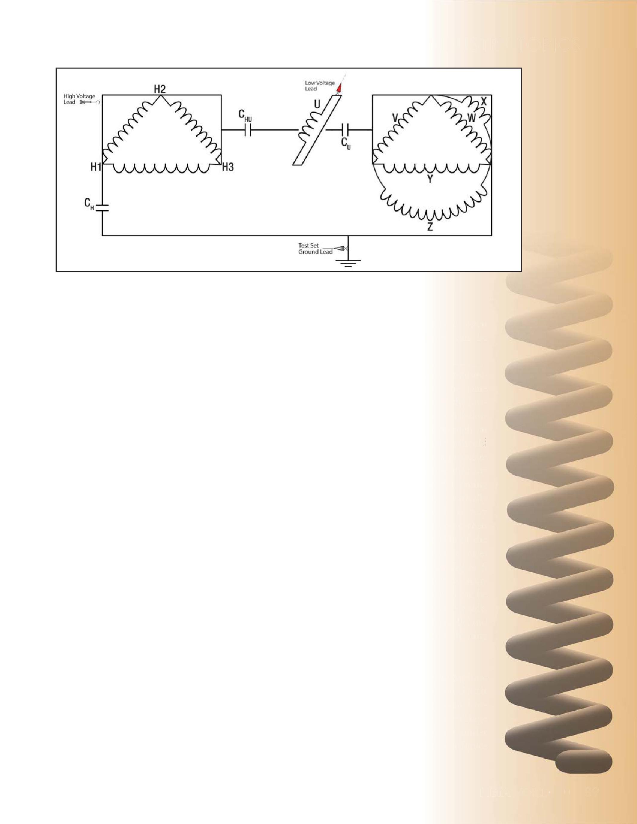
short-circuit traces, and low-voltage open circuittraces.Thesemeasurementscanbe circuit traces. These measurements can be performed in two ways.
Option 1: When performing these measurements, the secondary should be in the same configuration as it is when in service. If the lowvoltage side is an open delta, as shown below in Figure 4, but is normally closed through an external bus delta enclosure, then the delta should be closed by electrically shorting the appropriate bushings. In addition, one must ensure that any windings that are normally in parallel during service are connected in parallel by electrically shorting the appropriate bushings. It is very important to be careful and very consistent when electrically shorting the low-voltage side of the transformer in order to get representative traces for future comparison. As shown in Figure 5 and Figure 6, the low-voltage side can have many bushings placed side by side. As a result it can be difficult to electrically short the low-voltage side, so that the appropriate windings are in parallel and the delta is closed, without electrically shorting individual windings inadvertently.
A measurement across each high-voltage phase will be taken for the high-voltage open circuit traces, and a measurement across each lowvoltage phase will be taken for the low-voltage open circuit traces. Any bushings not under test and not electrically shorted to configure
NETAWORLD 89
INDUSTRYTOPICS INDUSTRY TOPICS
FIELDTESTINGOFARCFURNACETRANSFORMERS FIELD TESTING OF ARC FURNACE TRANSFORMERS AWO WORLD n e ee ww n d te y g y y n e es 5 y e e, d g e t i we r er e TRYTOPICS S C O P I T Y R T
Figure 3: Test setup for line #2 from table 1, UST Test
the secondary properly are left floating during open circuit measurements. When performing the short circuit traces, simply electrically short all the low-voltage bushings together. Then take a measurement across each highvoltage phase.
Option 2: A second option when performing the open circuit tests is to leave the lowvoltage windings completely isolated from each other. In this case, one must take an open circuitmeasurementacrosseachindividual circuit measurement across each individual low-voltage winding.
It is important to document how one performs the test to ensure future tests are performed the same way for comparison. It is recommended for an acceptance test to get a baseline set of measurements for both options described above. For routine testing, it is recommended to test using option 1. Below is an example of theactualtestconnectionsforthetransformer the actual test connections for the transformer shown in Figures 4-6 with the secondary in its in-service configuration (see Tables 2-4).
Analysis
The methodology for the analysis of an arc furnace transformer is the same as any other transformer. It is best to compare traces to abaselinesetoftracesforthetransformer. a baseline set of traces for the transformer. Shifts in resonant frequencies and significant changes in the amplitude of a trace at a given frequency should be investigated. If no baselinetraceisavailablethenextalternative baseline trace is available the next alternative option is to compare the traces to a similar unit of the same manufacturer. Lastly, a
Table2: able 2: High-Voltage OpenCircuit Test
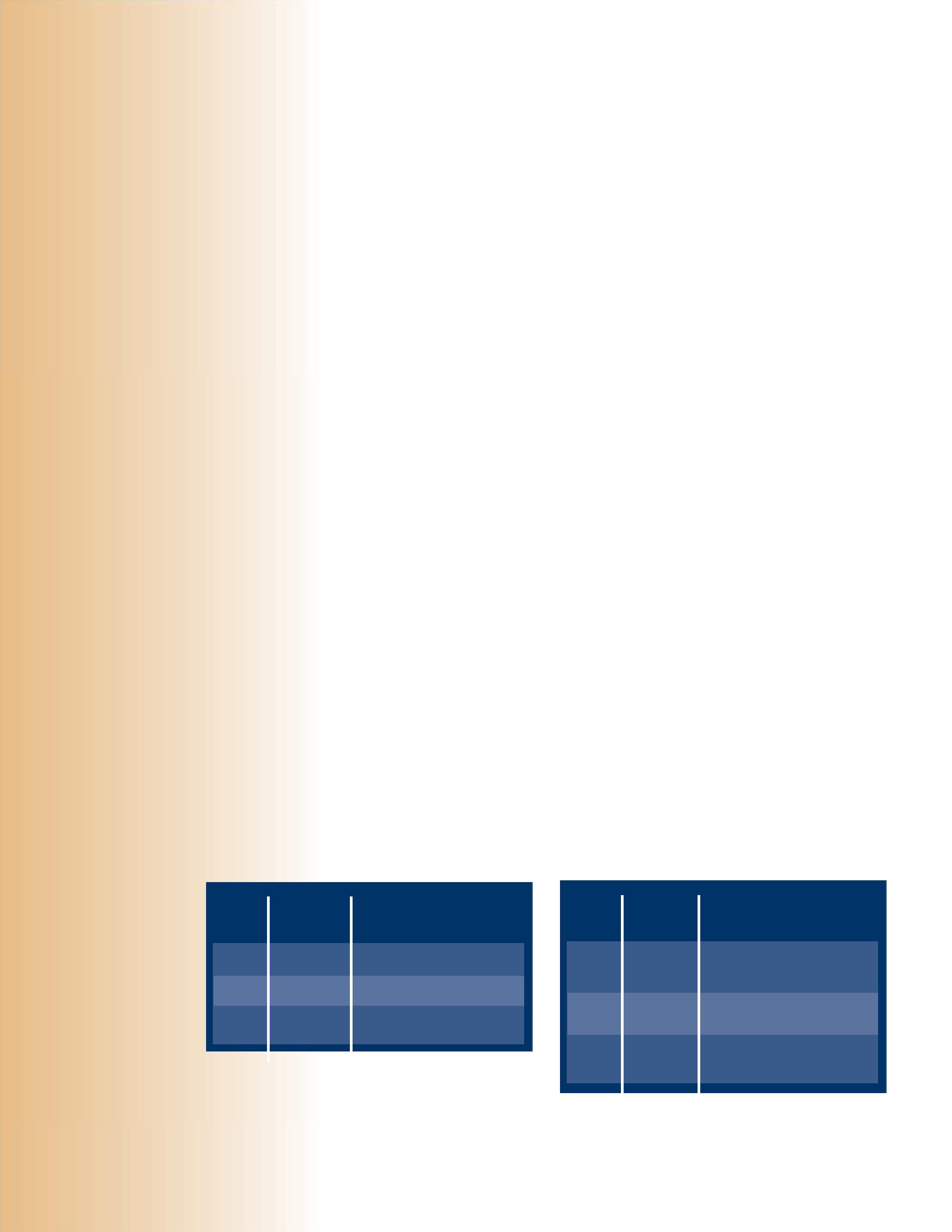
*X4-X2, X5-X3, X6-X1 *X4-X2, X-5-X3, X6-X1 *X4-X2, X5-X3, X6-X1
*Delta is now closed. Additionally, bushings may need to be shorted to put separate windings per phase into parallel with each other.
comparison amongst phases is made on the currentsetoftraces. current set of traces.
EXCITING CURRENT
Exciting current tests are performed the same way one would perform these tests on a standard two winding transformer. Test connections are made at the high-voltage side of the transformer and all other bushings are left floating. Table 5 provides a description ofthetestconnectionsforthetransformer of the test connections for the transformer shown in Figures 4, 5, and 6.
Analysis
Results that are typical for a standard two winding transformer apply here. In general a pattern of two similar high readings and one lower reading should be obtained for both current and watts readings on a given tap position for an inductive specimen.
WINDING RESISTANCE
Winding resistance is performed on the highvoltage side by simply taking a measurement across each high-voltage phase. There are many different possible ways to perform winding resistance on the low-voltage side based on different configurations. Winding resistance can be performed across each individual winding if there are multiple individual windings accessible per phase. If multiple windings are connected in parallel, but the delta is open, one can perform a winding resistance measurement across each phase with multiple windings in parallel. If the delta is closed, winding resistance can be
Table 3: Short-CircuitTest Short-Circuit Test
All
terminals shorted together
All low-voltage terminals shorted together
90 FALL 2013
FIELDTESTINGOFARCFURNACETRANSFORMERS FIELD TESTING OF ARC FURNACE TRANSFORMERS INDUSTRYTOPICS INDUSTRY TOPICS RED LEAD H3 H1 H2 H1 H2 H3
BLACK LEAD SHORTED TERMINALS RED LEAD H3 H1 H2 H1 H2 H3 All low-voltage terminals shorted together
low-voltage
BLACK LEAD SHORTED
TERMINALS
Table4: able 4: Low-Voltage OpenCircuit Test
RED LEAD
X5-X3
X6-X1
X4-X2
BLACK LEAD SHORTED TERMINALS
X6-X1
X4-X2
X5-X3
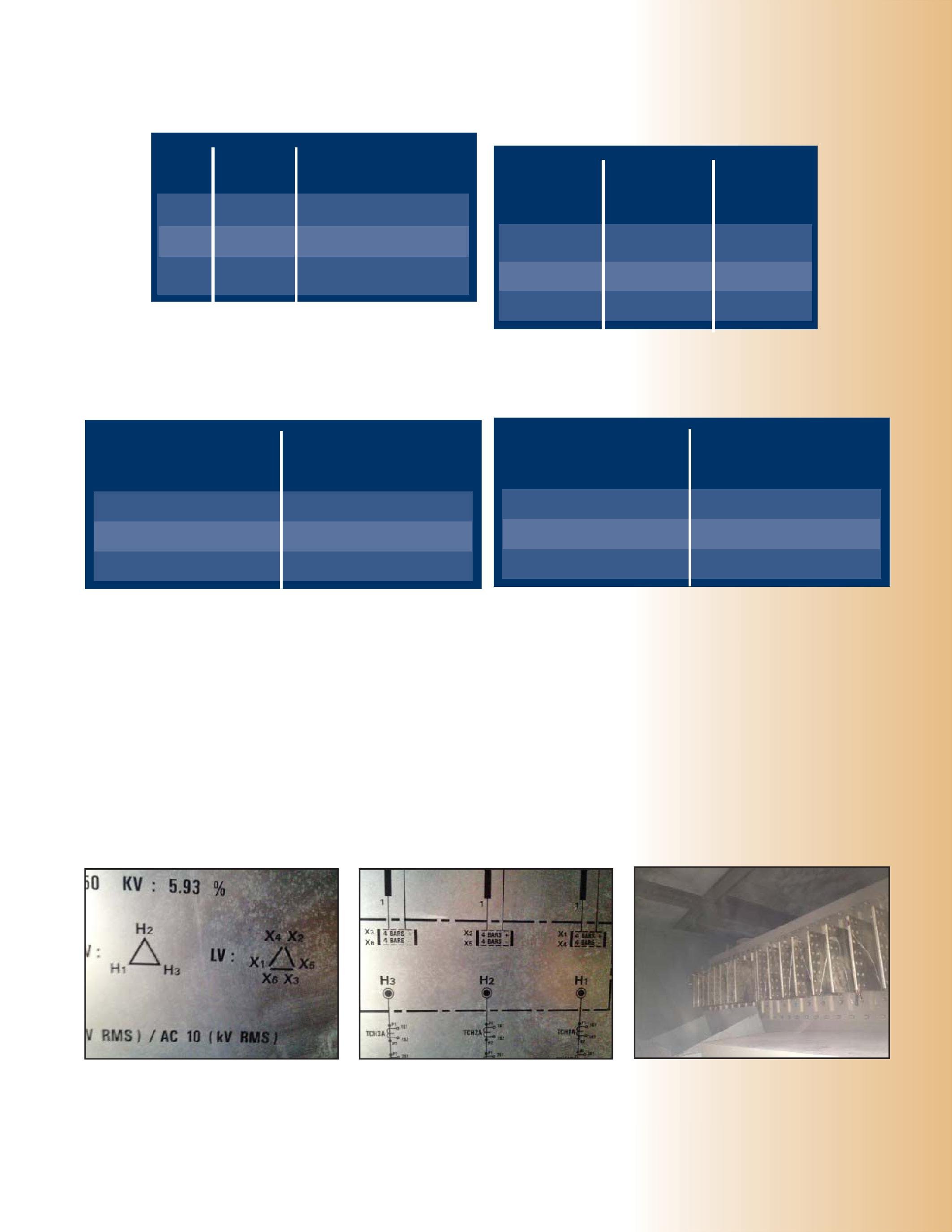
*X4-X2, X5-X3, X6-X1
*X4-X2, X-5-X3, X6-X1
*X4-X2, X5-X3, X6-X1
*Delta is now closed. Additionally, bushings may need to be shorted to put separate windings per phase into parallel with each other.
Table 6: High-Voltage Winding Measurement
Table 5: Description of the test connections for the transformer shown in Figures 4, 5, and 6.
VOLTAGE HOOK
VOLTAGE LEAD GROUND
Table7: able 7: Low-Voltage Winding Measurement
performed as well. It is important to make sure to document how one is performing the test and stay consistent with previous test methods to ensure comparison of similar data. Below is an example of how to perform the test on the transformer in Figures 4, 5, and 6, assuming one has taken the necessary steps in electrically shorting the appropriate bushings on the low-voltage side to ensure multiple windings per phase are connected in parallel andthatthedeltaconnectionhasbeenmade. and that the delta connection has been made.
Analysis
Results should be comparable among phases and compared to previous results. Depending on the standard, a deviation of less than 1 to 5 percent is considered acceptable [1,2].
LEAKAGE REACTANCE
The per phase test should be performed on arc furnace transformers. The per phase test is performed to get a comparison among phases and to use as a baseline for comparison of future tests to determine winding deformation.
Figure 4: Vector Diagram on an Arc Furnace Transformer Nameplate
Figure 5: Physical Layout on the Nameplate Showing the Low-Voltage Arrangement
Figure 6: Low-Voltage Bushings Showing Multiple Windings Brought Out in an Open Delta Arrangement
NETAWORLD 91 FIELDTESTINGOFARCFURNACETRANSFORMERS FIELD TESTING OF ARC FURNACE TRANSFORMERS INDUSTRYTOPICS INDUSTRY TOPICS
HIGH-
H3 H1 H2 H1 H2 H3 H2 H3 H1 LOW-
POSITIVE
CURRENT
VOLTAGE LEADS H3 H1 H2 NEGATIVE
CURRENT AND VOLTAGE LEADS H1 H2 H3 POSITIVE
CURRENT AND VOLTAGE LEADS X5-X3 X6-X1 X4-X2 NEGATIVE POLARITY CURRENT AND VOLTAGE LEADS X6-X1 X4-X2 X5-X3
POLARITY
AND
POLARITY
POLARITY
When performing the per phase test, all separate individual windings per phase on the lowvoltage side must be connected in parallel and thedeltamustbeclosed.Threemeasurements the delta must be closed. Three measurements are then made across the high-voltage phases, similar to how this test is performed on any other transformer. Only one low-voltage phase is electrically shorted during each measurement. The phase that is electrically shorted corresponds to the same phase that is being measured on the high voltage side. Below an example of the test connectionsisshownforthetransformerin connections is shown for the transformer in Figures 4, 5, and 6. (See Table 8).
Table 8: PerPhaseTest Per Phase Test
REFERENCES
1. IEEE Guide for Diagnostic Field Testing of Electric Power Apparatus-Part 1: Oil Filled Power Transformers, Regulators, and Reactors ,IEEEStd62-1995 , IEEE Std 62-1995
2. Standard for Maintenance Testing Specifications for Electrical Power Distribution Equipment and System s,ANSI/NETA s, ANSI/NETA MTS-20011
Jim Macdonald isaClientService is a Client Service Engineer with Doble Engineering Company. Prior to joining the Doble team in April 2010, he worked for a testing company in the northeast performing electrical testing in substations, as well as commissioning of power plants. He graduated from the University of Massachusetts – Amherst with a degree in Electrical Engineering.
*X5-X3-X6-X1, X4-X2
*X4-X2-X6-X1, X5-X3
*X4-X2-X5-X3, X6-X1 NEGATIVE CURRENT AND SENSE LEADS SHORTED TERMINALS
*Delta is now closed, but all three phases are not shorted together. Additionally, bushings may need to be shorted to put separate windings per phase into parallel with each other.
Analysis
The per phase test is performed as part of an acceptance test and performed for subsequent tests as well. Deviation from previous readings of more than two percent should be investigated as well as a three percent deviation from the average of all three per phase readings.
92 FALL 2013
INDUSTRYTOPICS INDUSTRY TOPICS FIELDTESTINGOFARCFURNACETRANSFORMERS FIELD TESTING OF ARC FURNACE TRANSFORMERS
POSITIVE CURRENT AND SENSE LEADS H3 H1 H2 H1 H2 H3












WE’VE MOVED!
We are excited to announce that the growth of Ampteks, Inc. over the past few years has us expanding beyond the capacity of our current facility.
Ampteks, Inc., Northern California's premier facility dedicated to the service, repair, and tes ng of low and medium voltage circuit breakers has moved
to
The new facility is located at 265 Rickenbacker Circle, Livermore, CA 94551. It is directly o W 4 and W 5 and ad acent to the Livermore Airport.
Over the last 6 months the new facility situated on 2 ks has been built out to our stringent speci ca ons and o ers s of class A o ce space and over 6 s of work area. We now have the capacity of 2 kA current and 1 k output and will support our con nued growth.
***PLEASE UPDATE OUR RECORDS***





Analyzer A Group CBS Company A new methodology utilizing vibration analysis 214-446-1636 Info@CBAnalyzer.com CircuitBreakerAnalyzer.com
NEW ADDRESS AND P ONE NU ERS: 265 RIC EN ACKER CIRCLE, LI ER ORE, CA 94551 P ONE: 925 49 15 A : 925 49 151 E ER ENC 24 : 4 9 6 14 ALL E AIL ADDRESSES RE AIN T E SA E
a new facility.

www.powertest.org 888-300-6382 (NETA) Join 400+ electrical testing professionals Leading decision makers looking for new products and services For attendee profile and additional information visit www.powertest.org WON’TANEVENTYOUWANTTOMISS! March 3-6, 2014 Hyatt Regency Denver Denver, Colorado The Premier Electrical Maintenance and Safety Event The Premier Electrical Maintenance and Event NEVENTYOUANTTOMIS
THE OVERWHELMING
 BY GLEN BROWN, Rimac Technologies
This one may be from the Ripley’s Believe It or Not files, but it shows and proves that a knowledgeable technician with the confidence to believe in his equipment and skills can be invaluable.
Recently, during an industrial plant shutdown, it became even clearer to me as a technical person, that our jobs are never done. The industry’s need for quality technical maintenance personnel is as important as it ever has been. During this project in the late evening, and after working a long, typical shutdown day, one of our crewmembers discovered a unique insulation measurement. During a routine insulation-resistance test on a 600 volt MCC, a short-to-ground was discovered--not uncommon but not good, or easy to explain, when the system was energized just moments before.
The crew left the cables directly connected to the MCC for testing, including the cables in the test, due to the time constraints and the difficulty of removing the cables from the MCC and the main breaker feeding the MCC. The test was conductedat1000voltswithalltheMCCloads conducted at 1000 volts with all the MCC loads open. The results showed an almost dead shortto-ground which was concerning as the system was in service just prior to the testing with no indication of problems. No alterations had been made to the system during the test procedure other than de-energizing the equipment and isolating the MCC loads. We rechecked the loads
ontheMCCtoensurethatallthedisconnects on the MCC to ensure that all the disconnects were open and the main bus and cables were all that was involved in the test. We opened all the upper compartments to ensure that there were no additional connections to the bus, which would bus, lead to our test results. It appeared as if some resistively grounded load was connected to the system. Our suspicions were a load bank, heater, possibly a surge pack, or artificial neutral. Night was upon us and the client wanted the system put back into service since we had changed nothing and the system had been energized just prior to testing. It was hard to convince the client that there was a serious problem that deserved further investigation. After some discussion, the client indicated that he could get away without that turning the unit area back on until the next day. Perfect, we could look at this with fresh brains in the morning after a hasty late meal and short hotel sleep, one of the many benefits of being a fieldservicetechnician. field service technician.
The next morning we came in with a sense that we were going to tackle this with a fresh look. First step, sectionalize, remove all cabling to isolate the problem and determine if it is with the MCC or cable system. It was the cable. A digital volt ohmmeter was used to determine
NETAWORLD 97 THEOVER THE OVERWHELMINGNEEDFORELECTRICALMAINTENANCE WHELMING NEED FOR ELECTRICAL MAINTENANCE
INDUSTRYTOPICS INDUSTRY TOPICS

thevalueofresistanceforthisshortcircuit.The the value of resistance for this short circuit. The digital volt ohmmeter indicated a resistance value of about 5000 ohms phase-to-phase, and we were unable to get a reliable reading phaseto-ground, despite the short circuit with the insulation resistance meter….. strange to say the least? What could represent 5000 ohms in an electrical power system? It did not represent any load we could identify. We were all unsure as to what to do next; we could chase it down or let it go. It did not feel right to just let it go, but the client needed to understand this was something outside the norm. After some discussion, the client told us we must do everything we felt reasonable to try and find out what might be connected in the system that would cause such a strange reading.
Through further investigation, we discovered the breaker that was supposed to be feeding the MCC on which we were working was mislabeled. This feeder had, in fact, been labeled incorrectly for many years and even senior staff was unaware of this discrepancy. The potential hazard here is obvious because if proper safety protocol is not followed, (electrically safe work condition and test before you touch) theoutcomecouldbeseriousshockand/or the outcome could be serious shock and/or burns and potentially death depending on the operating voltage and arc-flash hazard. To not have reliable breaker designation and a reliable single-line drawing is beyond comprehension in a post NFPA 70E/CSA Z463 world.
We discovered still another problem upon questioning the lead electrician. We determined that a new MCC had been installed to replace an old one at sometime in the past. We took a look at the MCC again, and when all the cables were removed, we discovered that there was a parallel feed at the MCC. Only one set of three phase cables were connected at the MCC feeder breaker, but two sets of cables were connected at the MCC, a real stretch for single-line clarity. Where did those other cables go? After a brief search, the energized cable ends were found buried in the ground, insidethesubstationinasandfilledareanext inside the substation in a sand filled area next
to the 600 volt feeder breaker compartment! The extra parallel cables from the MCC were terminated at the MCC, but only one set was connectedatthefeederbreaker. connected at the feeder breaker.
We could not determine how long the energized cable ends had been this way, but the site electrician said at least three years (since the MCC installation) and possibly much longer. The critical acknowledgement here is that with these energized cables buried in the ground and the level of energy expended, as evidenced by the crystallization of the sand, a potential catastrophe was impending the entire time. Luck was a significant factor here as step and touch potential hazards were likely off the chartsnottomentionanimminentfaultif charts not to mention an imminent fault if the conductivity to ground or phase had been altered by a little moisture. To say no one was hurt and the techs involved in the investigation were successful in diverting a potential problem, would be a huge understatement in most books. I believe we earned our money that day.
Let us consider some potential payback by the way of commercial consideration, something everyone understands—dollars. Some quick math would say amperes equals 600/5000 or 120 milliamperes (1.732) ~ 200 milliamperes continuous 3-phase load or about 120 watts. Over 3 years this equates to ~ 19000 hours give or take, 120 watts (19,000) is over 2 megawatts. Simple math at about $0.10 $0.10/ kwh is about $228.00. This assuming that the ground resistance value is never changed by temperature, moisture levels, or other seasonal variables. Let’s be real here and realize the 9 Vdc battery in the digital volt ohmmeter and a 600 volt three-phase power source are not likely to yield similar reliable resistance values. Rememberthe1000voltinsulationresistance Remember the 1000 volt insulation resistance meterindicatedadeadshort.Therealnumber meter indicated a dead short. The real number could easily be 10 or 100 times this, but the consequences of an injury could have been 1000’s of times again. By most measurements, this was a job well done and a feather in the cap ofthefieldservicecrew. of the field service crew.
98 FALL 2013 THEOVER THE OVERWHELMINGNEEDFORELECTRICALMAINTENANCE WHELMING NEED FOR ELECTRICAL MAINTENANCE
INDUSTRYTOPICS INDUSTRY TOPICS
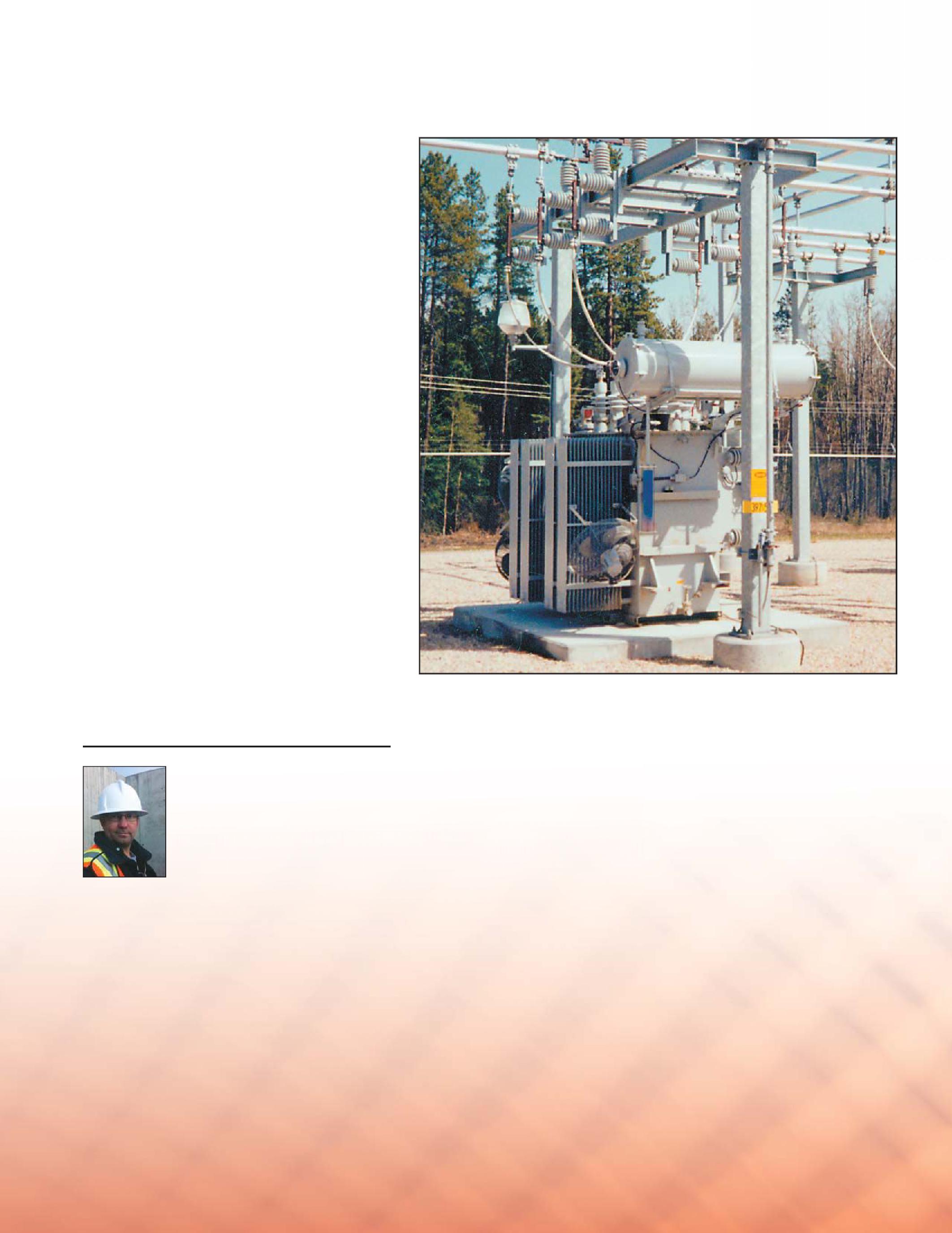
The customer usually has a budget for maintenance, and this money has to be expended in an efficient manner. In this case the value of an experienced team with leadership thatcaresaboutthefinaloutcomeandhasa that cares about the final outcome and has a true interest in evaluating system condition proved invaluable. A less experienced crew, withoutthebenefitofNETAaccreditationand without the benefit of NETA accreditation and training may have just noted this as a system anomaly and an unexplained reading. This condition could have gone on for many more years and possibly indefinitely. It pays to have a professional testing firm that is experienced, knowledgeable, and engaged in making your power system the best it can be. This is only a small example of system problems discovered and corrected during this shutdown. It was one of the most interesting, challenging, and highly visible shutdowns, as several annual shutdowns in the past had failed to raise any flags regarding thecondition. the condition.
This type of work and dedication to our craft raises thebarandinstillsconfidenceinourclientsasto the bar and instills confidence in our clients as to our abilities, not to mention guaranteed work for the foreseeable future. Finding these things is one of the reasons many of us are so dedicated to our field, and sharing with likewise dedicated professionals is a lot of fun.
GlenBrown Glen Brown hasbeeninvolvedinthearea has been involved in the area of electrical maintenance and testing of electrical power systems for over 16 years. He is a power system electrician [PSE] and a certified electrical technologist [CET] and has learned his trade working with various larger NETA firms in Western Canada. Most recently he has started his own personal services personal company Rimac Technologies. He has built up an extensive network of clients and associates and continues to provide high level services in the power system industry.
NETAWORLD 99 THEOVER THE OVERWHELMINGNEEDFORELECTRICALMAINTENANCE WHELMING NEED FOR ELECTRICAL MAINTENANCE
INDUSTRYTOPICS INDUSTRY TOPICS




1000 New Durham Road Edison, New Jersey 08817 sales@dranetz.com www.dranetz.com Company 1.800.372.6832 A Solve your Power Quality and Energy Management puzzles with Dranetz Technologies. Dranetz Is Your Missing Piece!


WHY TEST TO THE ANSI/NETA STANDARDS?
BY BOB SHEPPARD, Southwest Energy Systems, LLC
AsaNET As a NETAA A Accredited Company wear e are often asked to answer questions like why is electric testing important? Why test to the ANSI/NETA Standards? What is third-party, independent electrical testing? Electrical testing can be described as the science of providing a series of approved, recognized and unbiased tests methods to evaluate the overall condition and acceptability of an electrical device or power system.
Ab A b ig p a r tofele t of ele ctric a lt l t esting is p icking up w heret e them he ma nuf act urerlef r lef toff t off , a ndaf nd af t ert r the e q u i p menth t ha sb s b e endel n del ivere da d a ndi nd insta l le d
Ma nuf act urersof rs of t en p l ac esh e sh i p p ing mat eria ls desig ne dt d t om o m in im izesh ize sh i p p ing d a ma g ei e into their p ro d ucts .I . Ifele f ele ctric a le l e qu i p mentis t is p l ac e di d inse n ser vic ew e w itht h thesh he sh i p p ing c o nstr a ints
o rot r otherm r mat eria lsi ls in p l ac e, substa ntia ld l d a ma g e
o rfi r firem e may o c cur.W . Wo rse yet, the p ro b lemm m may notsho not showu w up imme d iately a ndm nd may c o ntinue lo ng af t era r a ny insta l l atio no n o rse r ser vic ew e wa rr a nt y ha sex s exp ire d .H . Howm w ma ny ele ctric a lf l f a il ures hap p end n d uet ue tom o ma nuf act urersdefe rs defe ctso s o r deficienciesl ncies l in ke dt d t oi o inc o rre cti ct insta l l atio n o rsh r sh i p p ing ?P ? Perhaps a b et t er questio nm n may b e :H : Howm w muchw uch w il litc l it c ostifm t if my c o mp a ny exp erienc esa es a nu n unexp e ct e d p owerlos r losso s o r cata strop h i c f a i lure ?
Asc As c o nsumersw rs web e b el ie vet e thate t e ver y p ro d uct we purcha sew se wa st s t est e di d inso n so mem me ma nner.I . In rea l it y, ma ny ma nuf act urerst rs t estr t r a ndo m sa mp lesfr les fro mt m thea he a ssemb ly l ine.A ne. Act ua lt l t ests r atiosc ios c a nr n r a ng efr e fro m 10 p erc entt t t oa o a sfe s fe w a s .001 p erc ent.T t. Thereisar e is a rea lo l o p p o r t un it y fo re r erro r, w hen1de n 1 de vic ei e in 10, o r1de r 1 de vic ei e in 1000h 1000 ha sact s act ua l ly b e ent n throug hat h a tho roug h a ndc nd c o mp let e p ro d uctac uct ac c epta nc et e t esta t att t the f acto r y b efo reitissh e it is sh i p p e dt d t oac o a c o nsumer

Know ing thato t o n ly a sma l l p o r tio n of p ro d ucts (not justele t ele ctric a l ) a ret e t este da d att t thef he f acto r y shou ldb ld b er e rea so ne n enoug ht h t oh o h ireat e a th ird-p a r t y, indep endentt t t esting c o mp a ny.F . Fur thermo re, have you e verr r re c eive dso d so meth ing int n them he ma il thatw t wa sd s d a ma g e do d o rh r hadso ad so meth ing insta l le d inc o rre ctly thate t e ventua l ly f a ile d justou t outside oft of thew he wa rr a nt y p erio d ?
If you a re g o ing tobu o bu ildane ild a ne wf w f acil it y, you w il l undoubt e d ly wo rkw k w itha h a ne n eng ine ero r o rfi r firmt m to a ssistw t w itht h the desig na n a nds nd sp e cific atio nssot s so that itme it me ets yourex r exp e ctatio ns .Whe . When you fina l ize the p l a ns, a g ener a lc l c o ntr acto rissele r is sele cte da d a nd thens n sub c o ntr acto rsa rs a reh e h ire dfo d fo rt r thed he d ifferent tr ades .T . The g o a lu l up o nc n c o mp letio noft n of the p roj e ctist ct is that you re c eive de d e ver y th ing that you hade ad eng ine ere da d a nd p l a nne d .A . Atav t a ver y m in imum, a l loft l of theele he ele ctric a le l e qu i p menta t a nd otherde r de vic esw es w il lf l f unctio nc n c o rre ctly fro mt m the ver y firstd t d ay.H . How do you know if you rea l ly g otw ot what you sp e cifie d ?W ? Wa st s the ele ctric a l e qu i p menti t insta l le dt d t ome o me ett et thee he eng ine er ’ s sp e cific atio ns ?W ? Wa st s therea e a ne n eng ine ering st udy p rovide dt d t oide o identif y the p ro p erci r circu it b rea kerset r set ting s so you do n’th t haven e nu isa nc e tri p p ing o rot r otherc r c o nc erns ?T ? Thesea hese a ndm nd ma ny mo rea e a rea e a l l q uestio nst s thatne t ne e dt d t ob o b ea e a ske d
WHY TEST? WHY TEST TO THE ANSI/NETAST A STANDARDS? 102 FALL 2013
I N D U S T R Y T O P I C S

HOW IS TESTING PERFORMED?
Electrical testing is performed to industry recognized standards and guidelines (NETA, NFPA, ANSI, IEEE, NEC or others) usually identified and specified by the engineer of record.Thesetestsarenondestructivein record. These tests are nondestructive in nature and provide you with a high level of assurance that your equipment will perform as designed. Items may include circuit breakers, transformers, generators, switchgear, grounding and many others. Testing can be beneficial in identifying deficiencies or potential warranty issues prior to occupying the facility and the warranty clock starts ticking. Experienced testing companies can identify potential problems before they actually turn into major problems. Another benefit of electrical testing is baseline information when equipment is new. This information can be compared against other similar devices to identify life cycle information as well as provide useful data sothatabaselinecanbeestablishedwhichcan so that a baseline can be established which can be compared against future data.
Insurance companies are realizing the importance of a good preventative and predictive testing prog ram because they are the ones who are typically on the hook for the damages, repairs, and lost production due to the failure. Some insurance companies have offered financial incentives for companies that have a regular comprehensive testing program. Insomecasestheinsuranceincentivesmore In some cases the insurance incentives more thanoffsetthefinancialoverallcostofthe than offset the financial overall cost of the testing program. Insurance companies recognize that companies that effectively maintain their equipment are typically safer to work at and there is less potential for liability.
THIRD-P ARTYVS. ARTY VS. MANUFACTURER TESTING
The flip side of third-party, independent testing is manufacturer’s testing. Manufacturers will often times offer (usually for a fee) to have their own group of technicians people perform the initial testing. Many projects have a number of different manufacturers in the same facility which may then put any single manufacturer at a disadvantage. Equipment integration is often betweentwoormoremanufacturerswhich between two or more manufacturers which sometimes can create problems. Manufacturer’s
testing groups may not be as proficient with field testing as a third-party, independent testing company, and there may be shipping or there be installation related issues that may not even be noticed. NETA Accredited Companies offer third-party, independent testing providing highly trained technicians with the experience to test, inspect, and provide specialized testing on numerous different manufacturers’ designs, models, and configurations. They provide a high level of quality service and unbiased results.
The InterNational Electrical Testing Association (NETA) is an ANSI standards developer for the electrical power testing industry. The ANSI/NETA Standards set the highest level of testing standards for electrical test technicians as well as independent electrical testing companies.
Organizations that have earned NETA Accredited status from NETA have gone through a rigorous application process to ensure they meet the specifications outlined in the ANSI/NETA standards. Additionally, NETA Certified Technicians have undergone extensive training and passed a level III or higher examination as specified in the ANSI/ NETAStandardforCertificationofElectrical NETA Standard for Certification of Electrical Testing Technicians. When you think of all the ways in which electricity affects our lives and where we would be without it, one can certainly understand the importance of testing to the highest level of safety and reliability. NETA is committed to setting the standard for the electrical power testing industry.
Bob Sheppard is a member of the NETA Board of Directors, serving on the NETA Training Committee, and is Principal of Southwest Energy Systems, LLC headquartered in Phoenix, Arizona.
NETAWORLD 103 WHY TEST? WHY TEST TO THE ANSI/NETA STANDARDS? INDUSTRYTOPICS INDUSTRY TOPICS
Knowledge

Today’s solutions built on a century solutions built on a century of innovation and expertise of innovation and expertise
Knowledge. It’s what helps you make the next right decision about critical assets. And it’s what Doble uses to develop market-leading diagnostic tools and solutions that give you the information you need, when you need it. Better yet, we make sure you have that information quickly and cost effectively to ensure power system safety and reliability. Right now.
contact us: www.doble.com
We put the now in
NETA Training Opportunities for the Electrical Power Systems Industry TRAINING Online Training Courses Self-Paced Technical Seminars (SPTS) Electrical Safety Training System (ESTS) Ask about continuing education and NETA CTD credits. To learn more, visit www.netaworld.org/training or call 888-300-6382 (NETA) Learn at your own pace. Advance your knowledge. www.BurlingtonSafety.com info@BurlingtonSafety.com Buy Online Now! Metro NY/NJ/PA 800-220-2120 Calif (SF) 888-817-1412 Calif (LA) 800-296-2803 And Your Source for NFPA 70E Compliant Protective Gear 228 Merrick Road Lynbrook, NY 11563 (631) 589-6343/Fax (516) 596-3680 601 Union Street Brooklyn, NY 11215 (718) 786-4900
INTERCONNECTION
BY JAMES G. CIALDEA, P.E., Three-C Electrical Co., Inc.
There has been a significant increase in green energy projects with the biggest growth in wind, solar, and cogeneration. These projects are typically built to reduce electrical demand from the local utility resulting in some cost savings and increasing green power. Unfortunately, lack of understanding of interconnection requirements have delayed and increased costs on these projects.
In many cases, the developers of these projects do not realize that there are specific requirements to run any type of generation that is connected to the utility – even deep within an existing system. These requirements can stop a project, usually at a very late stage with substantial capital tied up, until they are met. Insufficient protection design adds unplanned costs to the project. Many testing companies have received calls from their customers saying “We are trying to start-up our new energy project and the utility is telling us that they need approved settings and witness testing. Can you do that… right now?”
The issue is that the testing company probably can do it right away, but the utility cannot. The utility has too many interconnection applications and not enough engineers to turn around an application quickly. The utility will perform a design review, particularly focusing on the interconnection protection and may require additional studies. In fact, the Federal Energy Regulatory Commission (FERC) has created a standard procedure and time line for the process: Small Generator Interconnect Procedure (SGIP) – less than 20 MW. There are different processes in the standard depending on the size and type of project: less than 10 kW and less than 2 MW. Some of the processes can take up to 180 business days, almost a year.
SGIP defines the steps that are necessary to get an interconnection agreement (IA) from the local utility. This agreement is required for the generation to go on-line. The steps include design criteria, utility studies, and commissioning. For a successful project these steps must be understood and included in the project plan from the start.
We have found projects ready to go on-line that the local utility has denied interconnection due to the developer not meeting the requirements of SGIP. This includes design criteria such as IEEE 1547, Standard for Interconnecting Distributed Resources with Electric Power Systems. In some cases, for projects as small as 500 kW, redundant relaying and direct communication with utility SCADA is required. This additional equipment needs to be procured, approved, installed, and commissioned. This delays the project interconnection as well as adds unplanned costs. Up front planning and understanding of the standards, preliminary meeting with local utility, and early involvement of a qualified testing company, preferably working directly for the owner, are the keys to a successful project.
1. Federal Energy Regulatory Commission’s Office of Energy Projects., June 2012
James Cialdea isVicePresidentand is Vice President and Director of Engineering for Three-C Electrical Co., Inc., Ashland, MA where he has performed installation, testing, maintenance, troubleshooting, design services, and studies on electrical distribution systems for industrials, municipals, institutions, utilities, and power plants throughout ies, New England for over 25 years. He holds a Bachelor of Science in Electrical Engineering, Power Option, from Worcester Polytechnic Institute and has graduate courses from Rensselear Polytechnic Institute’s Center for Electric Power Engineering. He is a Registered Professional Engineer, Master Electrician, and Licensed Construction Supervisor. He is a member of the Commonwealth of Massachusetts Electrical Code Advisory Committee (6 years), Member IEEE (25 years), Associate Member NETA (10 years), Member Massachusetts Electrical Contractors Association (18 years, 12 years on State Board of Directors, and 2 years as President)
INTERCONNECTIONISSUES INTERCONNECTION ISSUES 106 FALL 2013
INDUSTRYTOPICS INDUSTRY TOPICS





ACCURATE VACUUM MEASUREMENT IN SHOP OR FIELD
BASED ON OEM LEAK-RATE TEST DURING MANUFACTURE
PREDICTS REMAINING VACUUM INTERRUPTER LIFETIME, NOT JUST PASS-FAIL
SYSTEM DOES CALCULATIONS BASED ON MEASUREMENTS OF 3,000 VACUUM INTERRUPTERS

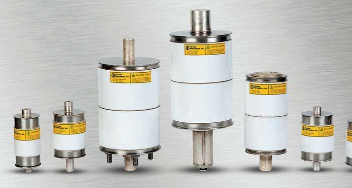

Vacuum interrupter replacements rated up to 38kV, 3000A Replacements
GE,
Vacuum Interrupters, Inc. has the world’s widest selection of: 3414 MIDCOURT ROAD, #112 | CARROLLTON, TEXAS 75006 | MOBILE: 940-736-0943 | INFO@VACUUM INTERRUPTERSINC.COM 214-442-5877 www.VacuumInterruptersInc.com WORLD’S FIRST
FOR VACUUM INTERRUPTERS
for all major OEM interrupters, including
Eaton, CH, Westinghouse, ABB, Siemens, and many more Pole assemblies, parts, and components Custom design/manufacturing services for obsolete interrupters and breakers Field and in-shop vacuum interrupter replacement services Rental vacuum breakers available while yours are being serviced
PORTABLE FIELD-TESTING SYSTEM
Trust Magnetron Atmospheric Condition (MAC) testing to predict the remaining life of your vacuum interrupters LET US HELP YOU WITH YOUR VACUUM INTERRUPTER TESTING AND REPLACEMENT NEEDS MAC-TS1
TEST SYSTEMS FROM VACUUM INTERRUPTERS, INC.
& MAC-TS2
Delivering Powerful Reliability Solutions
Power System Acceptance Testing
Commissioning and Start-up
Maintenance
Life-Cycle Extension
Troubleshoot and Repair
Training and Engineering Services
Planning and Operations Support
Project Management
Sigma Six Solutions, Inc.
2200 West Valley Hwy North, Suite 100 | Auburn, WA 98001
f e 2 9 0 | Sales 2 29 12 9 www sig asi o




ANSI/NETA STANDARDS UPDATE

ANSI/NETA ATS-2013
TheANSI/NETA
The ANSI/NETA Standard for Acceptance Testing Specifications for Electrical Power Equipment and Systems was approved as an American National Standard on January 25, 2013. These specifications cover the suggested field tests and inspections that are available to assess the suitability for initial energization of electrical power equipment and systems. The purpose of these specifications is to assure that tested electrical equipment and systems are operational, are within applicable standards and manufacturers’ tolerances, andareinstalledinaccordancewith and are installed in accordance with design specifications.
ANSI/NETA MTS-20XX REVISION IN PROCESS
On April 19, 2013, NETA published noticeofintenttoreviseANSI notice of intent to revise ANSI/ NETA Standard for Maintenance Testing Specifications for Electrical Power Equipment and Systems asa as a revisedAmericanNationalStandard. revised American National Standard. This document contains specifications which cover the suggested field tests and inspections that are available to assess the suitability for continued service and reliability of electrical power equipment and systems. The purpose of these specifications is to assure that tested electrical equipment and systems are operational and within applicable standardsandmanufacturers’tolerances standards and manufacturers’ tolerances and that the equipment and systems aresuitableforcontinuedservice.Itis are suitable for continued service. It is available in hard copy, PDF, and CD ROMformats.Therevisededitionwill ROM formats. The revised edition will be published in 2015, with the 2011 edition remaining the most current edition until that time. Order your copy of the 2011 edition today at www. netaworld.org.
ANSI/NETA ETT-2010
TheANSI/NETA The ANSI/NETA Standard for Certification of Electrical Testing Technicians wwas approved as an American National Standard on January 8, 2010. The document was originally approved as an ANSIstandardin2000.Thisstandard ANSI standard in 2000. This standard establishes minimum requirements for qualifications, certification, training, and experience for the electrical testing technician. It also provides criteria also for documenting qualifications for certificationanddetailstheminimum certification and details the minimum qualifications for an independent and impartial certifying body to certify electrical testing technicians.
PARTICIPATION
Comments and suggestions on any of the standards are always welcome and should be directed to the NETA office at neta@ netaworld.org or 888-300-6382. To learn more about the NETA standards review and revision process, to purchase these standards, or to get involved, please visit www.netaworld.org or call 888-300-6382.
NETAWORLD 109 ANSI/NETA STANDARDS UPDATES SPECIFICATIONS AND STANDARDS ACTIVITY
ANSI/NETA Standards for Acceptance and Maintenance Testing Specifications for Electrical Power Equipment and Systems!
ANSI/NETA ATS-2013 - New Edition
This standard should always be referenced in design specifications or when performing acceptance testing on power system installations.
ANSI/NETA MTS-2011 -
This standard should always be referenced when writing maintenance specifications or performing routine testing on electrical power systems.
ANSI/NETA ETT-2010
This standard ensures that your acceptance and maintenance tests are being preformed by qualified technicians who are certified in accordance with ANSI/NETA ETT requirements.
Available in Bound, CD ROM, or PDF
THE “GO-TO” STANDARDS FOR ELECTRICAL SAFETY AND RELIABILITY Order Your copy of the ANSI/NETA Standards Today!
The
Become a NETA Alliance member and Save! To order: visit www.netaworld.org Or call 888-300-NETA (6382) ANSI/NETA MTS-2011 S T ST A N D AND A R D F O R ARD FOR MAINTENANCE AINTENANCE TESTING SPECIFIC SPECIFICATIONS F O R E L E C T R I C A L P O W E R FOR ELECTRICAL POWER E Q U I P M E N T A N D S Y S T E M S EQUIPMENT AND SYSTEMS ANSI/NETA ATS-2013 S T AND ARD FOR A C C E P TANC E TESTING SPECIFICATIONS FOR ELECTRICAL POWER EQUIPMENT AND SYSTEMS
POWER PRODUCTS &SOLUTIONS INC.
Field Services
Acceptance Testing
Protective Relay Testing and Calibration
Infrared Scanning
Medium Voltage Cable Terminations and Testing
Transformer Testing, Repairs, and Oil Analysis
Ground System Testing
Preventative Maintenance
UPS and Battery Testing and Maintenance
Medium and Low Voltage Breaker Testing

TAN DELTA Cable Diagnostic
Electrical Equipment Start-Up and Commissioning



Assuring Electrical Performance Now Providing TAN DELTA Cable Diagnostic!!
Power Products & Solutions, Inc.
INSULATED CONDUCTOR
BY RALPH PATTERSON, Power Products and Solutions
During April 28, 2013, through May 1, 2013, the working groups met in Pittsburgh for the Spring 2013 IEEE/ICC meeting.
This is an ongoing opportunity for the InterNational Electrical Testing Association to be recognized and to offer a field testing perspective to the working groups as documents are developed. The working groups are set up of cable manufacturers,
utilities, test equipment manufacturers, and endusers. end users.
SUBCOMMITTEE F ON FIELD TESTING AND DIAGNOSTICS
Nigel Hampton and Jacques Cote are the Chair and Vice Chair respectively. As newmaterialbecomesavailableadditional new material becomes available additional changes and methodologies are incorporated into the IEEE specifications.
SPRING 2013 BREAKOUT WORKING GROUPS/DISCUSSION GROUPS MEETINGS
Partial Discharge Testing in the Field (P400.3)
Damped AC Voltage Testing (P400.4)
Diagnostic Testing for Cable Joints & Terminations
Constant Voltage AC Field Testing of Cable Systems
Power Cable Standards
Discussion on new contributions ot the next revision of the PD Guide
Discuss draft document for Damped AC testing
Presentations: Diagnostic Testing of Cable Accessories
Presentations on Experiences with ac Withstand Testing of MV, HV and EHV Cable Systems
ICEA and AEIC

JIANG/HAYDEN
FENGER/DENMON
SMALLEY/RICHARDSON
INSULATEDCONDUCTORCOMMITTEENEWS INSULATED CONDUCTOR COMMITTEE NEWS 112 FALL 2013 SPECIFICATIONS AND STANDARDS ACTIVITY
GROUP NO. GROUP NAME ACTIVITY CHAIRS F04W F05W F10D F11D A14D
LEVINE/WALTON GULSKI/PATTERSON
SPECIFICATIONS AND STANDARDS
DISCUSSION
IEEE400 IEEE 400
Omnibus has been approved as a final document.
IEEE400.2 IEEE 400.2
Has been approved as a final document.
IEEE 400.3
Working group is active and presently collecting information along with methodologies for incorporation into the document.
IEEE400.4 IEEE 400.4
Working group reviewed Draft 5 as comprised by the writing group and discussed Draft 6 as presented by Jacques Cote. The working group has reviewed Draft 5 and is currently working on releasing Draft 6 to the working group prior to the Fall 2013 Meeting.
A14D
Power cable standards discussion group (A14D) was presented with the latest ICEA revisions along with AEIC direction as an ongoing process for the ICC to be active in ICEAdirection. ICEA direction.
ICC

Ralph Patterson is President of Power Power Products and Solutions, located in Charlotte, North Carolina. NC. His professional background includes working as a design engineer of transformers and as a specifying engineer of insulated conductors. He has more than 25 years in power engineering particularly in insulation diagnosis and evaluation of electrical distribution equipment. He serves on the NETA Standards Review He Council and Board or Directors, is the NETA liaison for the IEEE Insulated Conductor Committees working groups and received NETA’s 2001 Outstanding Achievement Award.
TheInsulatedConductorsCommittee
The Insulated Conductors Committee (ICC) is a professional organization within the Power Engineering Society (PES) of theInstituteofElectricalandElectronics the Institute of Electrical and Electronics Engineers (IEEE).
The 2013 Spring Meeting in Pittsburgh was a great success. We look forward to the next meeting at the 2013 Fall Meeting in Dallas.
INSULATEDCONDUCTORCOMMITTEENEWS INSULATED CONDUCTOR COMMITTEE NEWS NETAWORLD 113
ACTIVITY
CHOOSE BETWEEN KEEPING MAINTENANCE COSTS DOWN AND KEEPING UP WITH PRODUCTION DEMAND…OR DO BOTH.
NETA certified experts at Electrical Reliability Services will keep you in perfect balance. To ensure the reliability of your electrical power, you have to balance the need to reduce maintenance costs with the need to perform regular maintenance. Only the team from Electrical Reliability Services delivers cost-effective services and system expertise to keep you up and running 24/7.



CRITICAL DIFFERENCE.
THAT’S THE
Emerson, Business-Critical Continuity, Emerson Network Power and the Emerson and Double Helix Design are trademarks and service marks of Emerson Electric Co. ElectricalReliability.com
Substation Testing As Easy As
Spend More Time Testing, Less Time Training
Vanguard’s precision substation testing instruments are designed to be intuitive and easy to use so that you can focus on testing instead of wasting time in training. Our versatile instruments offer a built-in thermal printer and on-board test record storage so that tests can be conducted in stand-alone mode in the field. A computer interface is also offered so that tests can be easily conducted from a PC.
And all of our instruments are competitively priced to provide cost-effective accuracy. For a virtual experience of our instruments, check out the interactive demos on our site at:
www.vanguard-instruments.com/demos
1520 S Hellman Avenue Ontario, CA 91761 USA PHONE 909.923.9390 FAX 909.923.9391 EMAIL sales@vanguard-instruments.com Vanguard Instruments Company, Inc. Transformer Turns-Ratio Meters Circuit Breaker Analyzers Capacitor Voltage Transformer Tester Winding Resistance Meters Current Transformer Testers Relay Test Equipment Vacuum Bottle Testers www.vanguard-instruments.com Reliability Through Instrumentation. NEW!
ENERGIZE YOUR FUTURE
PowerTest 2014 Challenges Attendees to Push through Boundaries, Embrace New Challenges, and be Safe
Below the scenic backdrop of the Rocky Mountains, NETA will welcome new attendees and old friends to Denver, Colorado, and PowerTest 2014, the premier electrical maintenance and safety event on March 3-6, 2014. Field technicians, engineers, construction professionals, architects, facility managers, and others will all benefit from the educational and safety-focused sessions covering a number of modern challenges and solutions.
It all starts Monday morning with the keynote, “The Transition to Mandatory Standards – Six Years and Counting, Time for the Adolescent Clumsiness to End!” by Nicholas A. Brown, President and CEO of Southwest Power Pool.
NETA will gather the industry’s leading experts as presenters, panelists, and moderators to facilitate open discussions about insights and solutions to real world challenges. After Monday’s keynote, attendees can choose from 27 unique technical paper tracks. On Tuesday, four expert panels on various topics allow for more learning from subject matter experts.
PowerTest also offers networking opportunities at several hospitality suites on Monday night after the day’s technical presentations before moving on to another full day of activity on Tuesday. Tuesday
“IknowthatwhenIinvestthetimeand “I know that when I invest the time and money to go myself or send technicians that the training classes will be focused and concise on the subject matter. Youwon’tbe ou won’t be spending hours in class getting trained on topics you do not need or want…”
Russ Sorbello, Projects Manager and NETA Accredited Representative Scott Testing, Inc., Ewing, New Jersey
afternoon, the PowerTest Trade Show offers a chance to mingle and network with peers and amongst more than 100 exhibits from top-tier electrical vendors.
For some, the reason to attend is simple: the sharing of ideas and solutions.
“PowerTest and the NETA organization always create an incredible setting for numerous networking opportunities for organizations such as Megger. PowerTestandNETA est and NETA encourage the expansion of the testing industry and give vendors the ability to play a vital role in that expansion.”

“Excellent presentations of applied technology for new equipment and upgrading of existing power systems” is why Manager and NETA Accredited Representative at Northern Electrical Testing, Inc., Lyle Detterman will make the trek to Denver, Colorado, all the way from Troy, Michigan. And are there other reasons he attends? “The four-hour seminars on specific topics which fit our organization,” he said. At PowerTest 2014, seminars focus on battery maintenance and testing, evolving protective relay testing, and transformer power factor theory-to name only a few. PowerTest 2014 actually features a dozen different seminars on current industry topics and solutions. Early Bird Registration for PowerTest 2014 is now open. See www.powertest.org for more details, and learn how to join the NETA Gold Alliance Program and receive one free PowerTest registration. Energize your future. Register for PowerTest 2014 today!
Elsa Cantu, Director of Marketing Megger Dallas, Texas


EARLY BIRD REGISTRATION NOW OPEN!
REGIST REGISTER R TODAY!
2014 Electrical Maintenance and Safety Event March 3-6, 2014 Hyatt Regency Denver Denver, Colorado
Featuring:




EC&M has partnered with Mike Holt, one of the most popular and knowledgeable NEC experts in the electrical construction industry, to offer 2-day training events that review the most important changes being made to the 2014 Edition of the NEC.
Conference Locations and Dates
St. LouisOctober 21-22, 2013
Philadelphia November 18-19, 2013
Seattle December 16-17, 2013
Boston January 13-14, 2014
For more information visit: http://ecmweb.com/catalog/19301
-is certi ed as an approved provider by the National Council of Examiners for Engineering and Surveying (NCEES) through that organization's Registered Continuing Education Program (RCEPP). If you are a registered professional engineer and attend one of our 2014 NEC Code Change Conferences, you will be granted 16 Professional Development Hours (PDHs) to help you meet your state's requirement for re-licensing.
ur Code change conference program is also certi ed as an approved provider of NEC training by those states requiring continuing education for re-licensing of journeyman, master electricians, and electrical contractors. By attending one of our conferences, you will receive continuing education hours, pending nal approval and adoption. States: (16) R
CODE COnferences CHANGE GE
Continuing Education. The Instructional Arm of The Workplace Learning Center at EC&M
C (16) DE (10) F ( ) (4) ID (16) (6) M (1 ) M mendments (1. ) ME (1 ) MN (16) M (16) NC (16) ND (16) NE (16) NM (16) H (1 ) R (16) SD (16) (4) (16) (1 ) (16) I (16) and (16).
(16)
The Workplace Learning Center at
Sign Up Today!..EC&M’s 2014 NEC Code Change Conferences. Don’t Miss This Unique Opportunity Register Now! Attend EC&M’s 2014 Code Change Conferences
Mike Holt, Educator
SUBSTATION MAINTENANCE I
DALLAS, TX:
Sep 9-13
Oct 7-11
Nov 4-8
Dec 9-13
PASADENA, CA:
Sep 16-20
Dec 2-6
PORTLAND, OR: Oct 21-25
VALLEY FORGE, PA:
Sep 30-Oct 4
Dec 2-6

SUBSTATION MAINTENANCE II
DALLAS, TX:
Sep 16-20
Oct 14-18 Nov 11-15
Dec 16-20
PASADENA, CA: Sep 23-27 Dec 9-13
PORTLAND, OR: Oct 28-Nov 1
VALLEY FORGE, PA: Oct 7-11 Dec 9-13
*NETA Continuing Technical Development (CTDs) units are required of NETA Certified Technicians.
POWER FACTOR TESTING
DALLAS, TX: Sep 4-6 Nov 25-27
BATTERY MAINTENANCE & TESTING
DALLAS, TX: Oct 21-24 Dec 16-19
PORTLAND, OR: Sep 10-13 Nov 18-21
VALLEY FORGE, PA: Sep 23-26 Nov 12-15
PROTECTIVE RELAY MAINTENANCE BASIC
DALLAS, TX
Sep 16-20 Oct 14-18 Nov 18-22
PASADENA, CA
Oct 21-25
PORTLAND, OR
Sep 23-27
VALLEY FORGE, PA
Sep 9-13
Nov 18-22
Dec 9-13
YOUNGSVILLE, NC
Dec 2-6
TRANSFORMER MAINTENANCE & TESTING
DALLAS, TX
Sep 23-27 Nov 18-22
VALLEY FORGE, PA
Oct 14-18 Dec 16-20
CIRCUIT BREAKER MAINTENANCE, LOW-VOLTAGE
DALLAS, TX
Sep 9-13
Oct 7-11
Nov 11-15
PASADENA, CA Oct 7-11
CIRCUIT BREAKER MAINTENANCE, LOW-VOLTAGE
DALLAS,TX
Sep 9-13 Oct 7-11
Nov 11-15
PORTLAND, OR Oct 7-11
CIRCUIT BREAKER MAINTENANCE, MEDIUM-VOLTAGE
DALLAS, TX
Sep 16-19
Oct 29-Nov 1
Nov 18-21
VALLEY FORGE, Sep 9-12 Oct 21-24
Your One-Stop for Many Hands-On
Maintenance
Eligible for NETA CTDs.*
Safety And
Training Courses
TO ENROLL, VISIT WWW.AVOTRAINING.COM OR CALL US AT 877-714-9787 MOST COURSES AVAILABLE ON-SITE CALL TODAY FOR A QUOTE.


ANSWERS


No.103 No. 103

ANSWERS

1. Differential protective relay schemes typically have their zones established by current transformers. In the figure below, at the instant current flows into _____, it also flows out of _____.
c. H1 – X1. It’s the rule of instantaneous current flow. Current in the electrical system changes direction instantaneously 120 times each second (60 cycles). As it changes direction it does so throughout the entire system. As current flows into H1, it flows out of X1 on the positive half-cycle. On the next half-cycle, it flows into H2 and out X2, maintaining the relative instantaneous polarity of the differential scheme.
2. Calculate the following values for a percentage differential relay with a 25 percent slope characteristic: The operating current is the difference between the two restraining currents (differential), so it would be 25A. The calculated imbalance (percent slope) of this example would be:

Under these conditions the relay would close its contacts since the percent slope characteristic has been exceeded.
3. Pilot wire relay schemes are a form of:
c. Pilot wire relays are a form of differential relaying.


4. Directional overcurrent relays have a characteristic known as the maximum torque angle. How is the MTA determined during testing?
a. A typical directional overcurrent relay has a directional unit and an overcurrent unit. Both units must close their contacts in order to cause a trip. The directional unit is frequently constructed to have maximum closing torque when the voltage and current are in quadrature, i.e. 90 degrees apart. Theoretically, the closing zone of the directional unit is +/- 90 degrees from the maximum torque angle. From a practical standpoint, the closing zone is dependent on the maximum available test current. Thus, the maximum torque angle can be calculated as being in the center of the two extreme closing angles.

5. Directional overcurrent relays must see two conditions in order to operate. What are they?
d. Directional overcurrent relays must have sufficient current to close the overcurrent contact and at an angle relative to the applied polarizing quantity to cause the directional unit to close its contact.
NFPA Disclaimer: Although Jim White is a member of the NFPA Technical Committee for both NFPA 70E “Standard for Electrical Safety in the Workplace” and NFPA 70B “Recommended Practice for Electrical Equipment Maintenance,” the views and opinions expressed in this message are purely the author’s and shall not be considered an official position of the NFPA or any of its technical committees and shall not be considered to be, nor be relied upon as, a formal interpretation or promotion of the NFPA. Readers are encouraged to refer to the entire text of all referenced documents.
TECH QUIZ ANSWERS
120 FALL 2013 TECHQUIZ

From Apollo 7 to Today’s Smart Grid

Preventative Maintenance


Acceptance Testing
High Potential Testing

Utility Service Corporation has been providing electrical and technical services for government and industry since 1962.
Solving complex problems, testing under difficult and unusual circumstances and servicing the commissioning and maintenance needs of today’s electrical power systems both new and aged.
Commissioning Services
System Studies
Arc Flash Analysis
Engineering & Consulting
Construction Supervision
System Trouble Shooting






(256) 837-8400 Services:


Remote Racking Solutions
Remote operation outside the arcflash boundary
Reduces the need for a full-body arcflash hazard suit
Use with low/medium voltage circuit breakers
Use with air, SF and vacuum circuit breakers
6
Drive is easily adjusted
Quick release drive shafts
Over-Racki
AC/DC power for continuos operati



ng protection is provided
940.382.4411 2616 Sirius Road Denton, TX 76208 To discuss your application please contact Info@CBSArcSafe.com See demonstration video & catalog at CBSArcSafe.com Patent Pending UL & CUL Rated
on





ZERO HERTZ DC TREE ZERO HERTZ DC Where is that AK-1-15 KIT? AC-PRO TREE AC-PRO TREE 888-289-2864 www.utilityr elay.com Utility Relay Company LG-3000 LK-42 LG-1600 KPE-32 KPE-16 K-3200S K-3200M K-3000S K-DON-2000S K-2000S K-DON-1600S K-1600S K-1600Black K-800S K-800M K-DON-800 K-DON-600 K-600S K-600 WP-40WPX-32 WPX-20 WPX-16 WPX-16 WP-08 AKR75 AL-2-50 AKRU30S AKJ50 AKR30S AKRU50 AKRU30 AKR50 AKRT50 AKR100 AKRU100 AKRU75 TC THC TP TUP WPS-08 WPX-08 WP-16 WPS-16 THP WP-32 WPS-32 WPS-40 WPX-40 WP-20 K-225 KDON225S K-DON-600S K-225M K-225S K-DON-225 K-800 K-DON-800S K-2000 K-1600Red K-DON-1600 K-1600M K-DON-2000 K-2000M K-3000 K-3000M K-4000 K-4000-M K-4000-S KP-32 WPS-20 KBE-600 KD-3000 KDA-3000 KE-4000 KC-1600 KP-16 KCG-1600 LG1000 LG-2000 LG-2500 6LK-1 LK-20 LK-25 LK-32 LK-40 LK-8 DSL206 DK-15 CN2-1250 CN2-800 SED-3000 SED-800 DSA2500STR-38SSTR-28D STR-18M HD-50A HD-50 BD-50A DNA800 AND0002 STR-58U DNA1600 LX400 MB-32 LX-800 000LG-4 LX-1600 LG-5000 LG-6000 LX-400 LX-600 LX-1000 MB-8 MBE-8 MB-16 MBD-16 MBE-16 MB-20 MB-25 MB-25 MB-40 F50 H30 H30 H40 DNA1000 STR-18M STR-28DSTR-38S BD-50 BD-50B BD-50B HD-50B HD-75 RS-15A RS-25A 2500 STR-58U PB-1600 SEF-800 SEF-2000 SEF-1200 SEF-2500 SEF-3000 SEF4000 SED-2500 SED-1200 DA50 DA75 DB15 DBL15 SCB2000 DK-25 DS206 DS206H LA2001 AKR30 AK-1-100AK-2-75 FP-100 AK-3-100 AKT-3A-50 AKU-3-50 AKU2A50 AKT-2A-50 AKU-2-50 AK-3-50 AK-2 A-50 AKT-1-50 AKU-3A-25 AKU-2-25 AK-3A-25 AKU-3-25 AKU-2A-25 AKU-2-15 FM-50 AK-1-25 AE-1B H14 FPSX-50 FPS-50 FPS-100 FPS-25 FP-50 DMB-25 CLS47 RLE-3200 RL-4000 RLE-2000 RL-1600 RLE-3200 RLE-1600 RLE-800 RL-800 RLF-800 LAF-800 LAF-600 LA-600 5ALA-1LA-25 G-25 G-50 LA-15 LA-25A LA-50 LAF-50 LA-50A LA-75 LAF-50A LA-800 LA-1600LAF-1600 LA-3000 LA-3200 LA-4000 RLX-800 RLF-1600 RLX-1600 RL-2000 RLH-800RL-3200 RLE-4000 RL-4200 DMB-15DMB-50 FP-25 FP-75 FPSX-25 FPS4-30 FPS4-50 FPS5-50 FPS-75 FM-25 FPS5-30 H21 H33 AE15 AE25 H27 AK-1-15 AK-2-15 AK-2-25 AK-2A-25 AK-3-25 AK-1-50 AK-2-50 AKT-2-50 AK-4-25 AKU-3A-50 AKT-3-50 AK-1-75 AK-3-75 AK-2-100 AL-2-75
NETA ACCREDITED COMPANIES Setting the
A&F Electrical Testing, Inc.
80 Lake Ave. South, Ste. 10 Nesconset, NY 11767 (631) 584-5625 Fax: (631) 584-5720 kchilton@afelectricaltesting.com www.afelectricaltesting.com
Kevin Chilton
A&F Electrical Testing, Inc.
80 Broad St. 5th Floor
New York, NY 10004 (631) 584-5625 Fax: (631) 584-5720 afelectricaltesting@afelectricaltesting.com www.afelectricaltesting.com
Florence Chilton
ABM Electrical Power Solutions
3602 East Southern Ave., Ste. 1 & 2 Phoenix, AZ 85040 (602) 796-6583
www.ABM.com
Jeff Militello
ABM Electrical Power Solutions
6280 South Valley View Blvd., Ste. 618 Las Vegas, NV 89118 (702) 216-0982 Fax: (702) 216-0983 www.ABM.com
Jeff Militello
ABM Electrical Power Solutions
814 Greenbrier Circle, Ste. E Chesapeake, VA 23320 (757) 548-5690 Fax: (757) 548-5417 www.ABM.com
Mark Anthony Gaughan, III
ABM Electrical Power Solutions
3700 Commerce Dr. #901-903 Baltimore, MD 21227 (410) 247-3300 Fax: (410) 247-0900 www.ABM.com
Bill Hartman
ABM Electrical Power Solutions
710 Thomson Park Dr. Cranberry Township, PA 16066-6427 (724) 772-4638 Fax: (724) 772-6003 william.mckenzie@abm.com www.ABM.com
William (Pete) McKenzie
ABM Electrical Power Solutions 5805 G Departure Dr. Raleigh, NC 27616 (919) 877-1008 Fax: (919) 501-7492 www.ABM.com
Rob Parton
ABM Electrical Power Solutions 4390 Parliament Place, Ste. Q Lanham, MD 20706 (301) 967-3500 Fax: (301) 735-8953 www.ABM.com
Frank Ceci
Absolute Testing Services 6829 Guhn Rd. Houston, TX 77040 (832) 467-4446 Fax: (713) 849-3885 rgamble@absolutetesting.com www.texasats.com
Richard Gamble
Advanced Testing Systems
15 Trowbridge Dr. Bethel, CT 06801 (203) 743-2001 Fax: (203) 743-2325 pmaccarthy@advtest.com www.advtest.com
Pat MacCarthy
American Electrical Testing Co., Inc. 480 Neponset St., Building 6 Canton, MA 02021-1970 (781) 821-0121 Fax: (781) 821-0771 sblizard@aetco.us www.99aetco.com
Scott A. Blizard
American Electrical Testing Co., Inc. 34 Clover Dr. South Windsor, CT 06074 (860) 648-1013 Fax: (781) 821-0771 jpoulin@aetco.us www.99aetco.com
Gerald Poulin
American Electrical Testing Co., Inc.
76 Cain Dr. Brentwood, NY 11717 (631) 617-5330 Fax: (631) 630-2292 mschacker@aetco.us www.99aetco.com
Michael Schacker
American Electrical Testing Co., Inc.
50 Intervale Rd., Ste. 1 Boonton, NJ 07005 (973) 316-1180 Fax: (781) 316-1181 trosato@aetco.us www.99aetco.com
Anthony Rosato
American Electrical Testing Co., Inc. 1811 Executive Dr., Ste. M Indianapolis, IN 46241 (317) 487-2111 Fax: (781) 821-0771 rramsey@99aetco.us www.99aetco.com
Rick Ramsey
American Electrical Testing Co., Inc.
Green Hills Commerce Center 5925 Tilghman St., Ste. 200 Allentown, PA 18104 (215) 219-6800 jmunley@aetco.us www.99aetco.us
Jonathan Munley
American Electrical Testing Co., Inc. 1672 SE 80th Bella Vista Dr. The Villages, FL 32162 (727) 447-4503 Fax: (727) 447-4984 rhoffman@aetco.us www.99aetco.us
Bob Hoffman
AMP Quality Energy Services, LLC 4220 West Schrimsher SW Site W1 P.O. Box 526 Huntsville, AL 35804 (256) 513-8255 brian@ampqes.com www.ampqes.com
Brian Rodgers
Apparatus Testing and Engineering 11300 Sanders Dr., Ste. 29 Rancho Cordova, CA 95742 (916) 853-6280 Fax: (916) 853-6258 jlawler@apparatustesting.com www.apparatustesting.com
James Lawler
Apparatus Testing and Engineering 7083 Commerce Circle, Ste. H Pleasanton, CA 94588 (925) 454-1363 Fax: (925) 454-1499 info@apparatustesting.com www.apparatustesting.com
Harold (Jerry) Carr
Applied Engineering Concepts 1105 N. Allen Ave. Pasadena, CA 91104 (626) 398-3052 Fax: (626) 398-3053 michel.c@aec-us.com www.aec-us.com
Michel Castonguay
Burlington Electrical Testing Co., Inc. 300 Cedar Ave. Croydon, PA 19021-6051 (215) 826-9400 (221) Fax: (215) 826-0964 waltc@betest.com www.betest.com
Walter P. Cleary
C.E. Testing, Inc. 6148 Tim Crews Rd. Macclenny, FL 32063 (904) 653-1900 Fax: (904) 653-1911 cetesting@aol.com
Mark Chapman
CE Power Solutions,LLC 4500 W. Mitchell Ave. Cincinnati, OH 45232 (513) 563-6150 Fax: (513) 563-6120 info@cepowersol.net Rhonda Harris
CE Power Solutions of Wisconsin,LLC 3100 East Enterprise Ave. Appleton, WI 54913 (920) 968-0281 Fax: (920) 968-0282 rob.fulton@cepower.net
Rob Fulton
Dude Testing 145 Tower Dr., Ste. 9 Burr Ridge, IL 60527 (815) 293-3388 Fax: (815) 293-3386 scott.dude@dudetesting.com www.dudetesting.com
Scott Dude
DYMAX Holdings, Inc. 4751 Mustang Circle St. Paul, MN 55112 (763) 717-3150 Fax: (763) 784-5397 gphilipp@dymaxservice.com www.dymaxservice.com
Gene Philipp
DYMAX Service Inc. 46918 Liberty Dr. Wixom, MI 48393 (248) 313-6868 Fax: (248) 313-6869 www.dymaxservice.com
Bruce Robinson
DYMAX Service Inc. 4213 Kropf Ave. Canton, OH 44706 (330) 484-6801 Fax: (740) 333-1271 www.dymaxservice.com
Gary Swank
Eastern High Voltage 11A South Gold Dr. Robbinsville, NJ 08691-1606 (609) 890-8300 Fax: (609) 588-8090 joewilson@easternhighvoltage.com www.easternhighvoltage.com
Joseph Wilson
ELECT, P.C.
7400-G Siemens Rd., P.O. Box 2080 Wendell, NC 27591 (919) 365-9775 Fax: (919) 365-9789 btyndall@elect-pc.com www.elect-pc.com
Barry W. Tyndall
Electric Power Systems, Inc. 21 Millpark Ct. Maryland Heights, MO 63043-3536 (314) 890-9999 Fax: (314) 890-9998 www.eps-international.com
Electric Power Systems, Inc. 557 E. Juanita Ave., #4 Mesa, AZ 85204 (480) 633-1490 Fax: (480) 633-7092 www.eps-international.com
NETA ACCREDITED COMPANIES
Standard
124 FALL 2013
Electric Power Systems, Inc. 4436 Parkway Commerce Blvd. Orlando, FL 32808 (407) 578-6424 Fax: 407-578-6408 www.eps-international.com
Electric Power Systems, Inc.
6753 E. 47th Avenue Dr., Unit D Denver, CO 80216 (720) 857-7273 Fax: 303-928-8020 www.eps-international.com
Electric Power Systems, Inc.
23823 Andrew Rd. Plainfield, IL 60585 (815) 577-9515 Fax: (815) 577-9516 www.eps-international.com
Electric Power Systems, Inc. 2601 Center Rd., # 101 Hinckley, OH 44233 (330) 460-3706 Fax: (330) 460-3708 www.eps-international.com
Electric Power Systems, Inc. 56 Bibber Pkwy #1 Brunswick, ME 04011 (207) 837-6527 www.eps-international.com
Electric Power Systems, Inc. 4100 Greenbriar Dr., Ste. 160 Stafford, TX 77477 (713) 644-5400 www.eps-international.com
Electric Power Systems, Inc. 11861 Longsdorf St. Riverview, MI 48193 (734) 282-3311 www.eps-international.com
Electric Power Systems, Inc. 827 Union St. Salem, VA 24153 (540) 375-0084 Fax: (540) 375-0094 www.eps-international.com
Electric Power Systems, Inc. 915 Holt Ave., Unit 9 Manchester, NH 03109 (603) 657-7371 Fax: 603-657-7370 www.eps-international.com
Electric Power Systems, Inc. 146 Space Park Dr. Nashville, TN 37211 (615) 834-0999 Fax: (615) 834-0129 www.eps-international.com
Electric Power Systems, Inc. 8515 Cella Alameda NE, Ste. A Albuquerque, NM 87113 (505) 792-7761 www.eps-international.com
Electric Power Systems, Inc. 319 US Hwy. 70 E, Unit E Garner, NC 27529 (919) 322-2670 www.eps-international.com
Electric Power Systems, Inc. 1090 Montour West Industrial Blvd. Coraopolis, PA 15108 (412) 276-4559 www.eps-international.com
Electric Power Systems, Inc. 6141 Connecticut Ave. Kansas City, MO 64120 (816) 241-9990 Fax: (816) 241-9992 www.eps-international.com
Electric Power Systems, Inc. 2495 Boulevard of the Generals Norristown, PA 19403 (610) 630-0286 www.eps-international.com
Electrical & Electronic Controls 6149 Hunter Rd. Ooltewah, TN 37363 (423) 344-7666 (23) Fax: (423) 344-4494 eecontrols@comcast.net
Michael Hughes
Electrical Energy Experts, Inc. W129N10818, Washington Dr. Germantown, WI 53022 (262) 255-5222 Fax: (262) 242-2360 bill@electricalenergyexperts.com www.electricalenergyexperts.com
William Styer
Electrical Equipment Upgrading, Inc. 21 Telfair Place Savannah, GA 31415 (912) 232-7402 Fax: (912) 233-4355 kmiller@eeu-inc.com www.eeu-inc.com
Kevin Miller
Electrical Maintenance & Testing Inc. 12342 Hancock St. Carmel, IN 46032 (317) 853-6795 Fax: (317) 853-6799 www.emtesting.com
Brian K. Borst
Electrical Reliability Services 1057 Doniphan Park Circle, Ste. A El Paso, TX 79922 (915) 587-9440 Fax: (915) 587-9010 www.electricalreliability.com
Electrical Reliability Services
1775 W. University Dr., Ste. 128 Tempe, AZ 85281 (480) 966-4568 Fax: (480) 966-4569 www.electricalreliability.com
NETA ACCREDITED COMPANIES
Electrical Reliability Services
1426 Sens Rd. Ste. 5 La Porte, TX 77571 (281) 241-2800 Fax: (281) 241-2801 www.electricalreliability.com
Electrical Reliability Services 4099 SE International Way, Ste. 201 Milwaukie, OR 97222-8853 (503) 653-6781 Fax: (503) 659-9733 www.electricalreliability.com
Electrical Reliability Services 5810 Van Allen Way Carlsbad, CA 92008 (760) 804-2972 www.electricalreliability.com
Electrical Reliability Services
8500 Washington Pl. NE, Ste. A-6 Albuquerque, NM 87113 (505) 822-0237 Fax: (505) 822-0217 www.electricalreliability.com
Electrical Reliability Services
1380 Greg Street, Ste. 217 Sparks, NV 89431 (775) 746-8484 Fax: (775) 356-5488 www.electricalreliability.com
Electrical Reliability Services 2275 Northwest Pkwy SE, Ste. 180 Marietta, GA 30067 (770) 541-6600 Fax: (770) 541-6501 www.electricalreliability.com
Electrical Reliability Services 7100 Broadway, Ste. 7E Denver, CO 80221-2915 (303) 427-8809 Fax: (303) 427-4080 www.electricalreliability.com
Electrical Reliability Services 348 N.W. Capital Dr. Lees Summit, MO 64086 (816) 525-7156 Fax: (816) 524-3274 www.electricalreliability.com
Electrical Reliability Services 6900 Koll Center Parkway, Ste. 415 Pleasanton, CA 94566 (925) 485-3400 Fax: (925) 485-3436 www.electricalreliability.com
Electrical Reliability Services 10606 Bloomfield Ave. Santa Fe Springs, CA 90670 (562) 236-9555 Fax: (562) 777-8914 www.electricalreliability.com
Electrical Reliability Services 14141 Airline Hwy., Ste. W Baton Rouge, LA 70817 (225) 755-0530 Fax: (225) 751-5055 www.electricalreliability.com
Electrical Reliability Services 121 Louisiana Hwy., 108 East Sulphur, LA 70665 (337) 583-2411 Fax: (337) 583-2410 www.electricalreliability.com
Electrical Reliability Services 11000 Metro Pkwy., Ste. 30 Ft. Myers, FL 33966 (239) 693-7100 Fax: (239) 693-7772 www.electricalreliability.com
Electrical Reliability Services 2222 West Valley Hwy. N., Ste 160 Auburn, WA 98001 (253) 736-6010 Fax: (253) 736-6015 www.electricalreliability.com
Electrical Reliability Services 3412 South 1400 West, Unit A West Valley City, UT 84119 (801) 975-6461 www.electricalreliability.com
Electrical Reliability Services 6351 Hinson St., Ste. B Las Vegas, NV 89118 (702) 597-0020 Fax: (702) 597-0095 www.electricalreliability.com
Electrical Reliability Services 610 Executive Campus Dr. Westerville, OH 43082 (877) 468-6384 Fax: (614) 410-8420 info@electricalreliability.com www.electricalreliability.com
Electrical Reliability Services 9636 St. Vincent, Unit A Shreveport, LA 71106 (318) 869-4244 www.electricalreliability.com
Electrical Testing, Inc. 2671 Cedartown Hwy. Rome, GA 30161 (706) 234-7623 Fax: (706) 236-9028 steve@electricaltestinginc.com www.electricaltestinginc.com
Electrical Testing Solutions
2909 Green Hill Ct. Oshkosh, WI 54904 (920) 420-2986 Fax: (920) 235-7131 tmachado@electricaltestingsolutions.com www.electricaltestingsolutions.com Tito Machado
Elemco Services, Inc.
228 Merrick Rd. Lynbrook, NY 11563 (631) 589-6343 Fax: (631) 589-6670 courtney@elemco.com www.elemco.com
Courtney O'Brien
NETA
ACCREDITED COMPANIES
Setting the Standard NETAWORLD 125
NETA ACCREDITED COMPANIES
EnerG Test
204 Gale Lane
Bldg. 2 - 2nd Floor
Kennett Square, PA 19348 (484) 731-0200 Fax: (484) 713-0209 kbleiler@energtest.com www.energtest.com
Katie Bleiler
Energis High Voltage Resources, Inc.
1361 Glory Rd. Green Bay, WI 54304 (920) 632-7929 Fax: (920) 632-7928 info@energisinc.com www.energisinc.com
Mick Petzold
EPS Technology
29 N. Plains Hwy., Ste. 12 Wallingford, CT 06492 (203) 649-0145 www.eps-technology.com
Grubb Engineering, Inc.
3128 Sidney Brooks San Antonio, Tx 78235 (210) 658-7250 Fax: (210) 658-9805 bobby@grubbengineering.com www.grubbengineering.com
Robert D. Grubb Jr.
Hampton Tedder Technical Services 4571 State St. Montclair, CA 91763 (909) 628-1256 x214 Fax: (909) 628-6375 matt.tedder@hamptontedder.com www.hamptontedder.com
Matt Tedder
Hampton Tedder Technical Services 4920 Alto Ave. Las Vegas, NV 89115 (702) 452-9200 Fax: (702) 453-5412 www.hamptontedder.com
Roger Cates
Hampton Tedder Technical Services 3747 West Roanoke Ave. Phoenix, AZ 85009 (480) 967-7765 Fax: (480) 967-7762 www.hamptontedder.com
Harford Electrical Testing Co., Inc. 1108 Clayton Rd. Joppa, MD 21085 (410) 679-4477 Fax: (410) 679-0800 testing@harfordtesting.com www.harfordtesting.com
Vincent Biondino
High Energy Electrical Testing, Inc. 515 S. Ocean Ave. Seaside, NJ 08752 (732) 938-2275 Fax: (732) 938-2277 hinrg@comcast.net www.highenergyelectric.com
James P. Ratshin
High Voltage Maintenance Corp. 24 Walpole Park South Dr. Walpole, MA 02081 (508) 668-9205 www.hvmcorp.com
High Voltage Maintenance Corp. 941 Busse Rd. Elk Grove Village, Il 60007 (847) 640-0005 www.hvmcorp.com
High Voltage Maintenance Corp. 7200 Industrial Park Blvd. Mentor, OH 44060 (440) 951-2706 Fax: (440) 951-6798 www.hvmcorp.com
High Voltage Maintenance Corp. 3000 S. Calhoun Rd. New Berlin, WI 53151 (262) 784-3660 Fax: (262) 784-5124 www.hvmcorp.com
High Voltage Maintenance Corp. 8320 Brookville Rd. #E Indianapolis, IN 46239 (317) 322-2055 Fax: (317) 322-2056 www.hvmcorp.com
High Voltage Maintenance Corp. 1250 Broadway, Ste. 2300 New York, NY 10001 (718) 239-0359 www.hvmcorp.com
High Voltage Maintenance Corp.
355 Vista Park Dr. Pittsburgh, PA 15205-1206 (412) 747-0550 Fax: (412) 747-0554 www.hvmcorp.com
High Voltage Maintenance Corp. 150 North Plains Industrial Rd. Wallingford, CT 06492 (203) 949-2650 Fax: (203) 949-2646 www.hvmcorp.com
High Voltage Maintenance Corp. 9305 Gerwig Ln., Ste. B Columbia, MD 21046 (410) 309-5970 Fax: (410) 309-0220 www.hvmcorp.com
High Voltage Maintenance Corp. 24371 Catherine Industrial Dr. Ste. 207 Novi, MI 48375 (248) 305-5596 Fax: (248) 305-5579 www.hvmcorp.com
High Voltage Maintenance Corp. 5100 Energy Dr. Dayton, OH 45414 (937) 278-0811 Fax: (937) 278-7791 www.hvmcorp.com
High Voltage Service, Inc. 4751 Mustang Circle St. Paul, MN 55112 (763) 717-3103 Fax: (763) 784-5397 www.hvserviceinc.com
Mike Mavetz
HMT, Inc. 6268 Route 31 Cicero, NY 13039 (315) 699-5563 Fax: (315) 699-5911 jpertgen@hmt-electric.com www.hmt-electric.com
John Pertgen
Industrial Electric Testing, Inc. 11321 West Distribution Ave. Jacksonville, FL 32256 (904) 260-8378 Fax: (904) 260-0737 gbenzenberg@bellsouth.net www.industrialelectrictesting.com
Gary Benzenberg
Industrial Electric Testing, Inc. 201 NW 1st Ave. Hallandale, FL 33009-4029 (954) 456-7020 www.industrialelectrictesting.com
Industrial Electronics Group P.O. Box 1870 850369 Highway 17 South Yulee, FL 32041 (904) 225-9529 Fax: (904) 225-0834 butch@industrialgroups.com www.industrialgroups.com
Butch E. Teal
Industrial Tests, Inc. 4021 Alvis Ct., Ste. 1 Rocklin, CA 95677 (916) 296-1200 Fax: (916) 632-0300 greg@indtests.com www.industrialtests.com
Greg Poole
Infra-Red Building and Power Service 152 Centre St. Holbrook, MA 02343-1011 (781) 767-0888 Fax: (781) 767-3462 tom.mcdonald@infraredbps.net www.infraredbps.com
Thomas McDonald Sr.
M&L Power Systems, Inc. 109 White Oak Ln., Ste. 82 Old Bridge, NJ 08857 (732) 679-1800 Fax: (732) 679-9326 milind@mlpower.com www.mlpower.com
Milind Bagle
Magna Electric Corporation 1033 Kearns Crescent, Box 995 Regina, SK S4P 3B2 Canada (306) 949-8131 Fax: (306) 522-9181 kheid@magnaelectric.com www.magnaelectric.com
Kerry Heid
Magna Electric Corporation 3430 25th St. NE Calgary, AB T1Y 6C1 Canada (403) 769-9300 Fax: (403)769-9369 ktaylor@magnaelectric.com www.magnaelectric.com
Ken Taylor
Magna Electric Corporation 851-58th St. East Saskatoon, SK S7K 6X5 Canada (306) 955-8131 x 5 Fax: (306) 955-9181 lwilson@magnaelectric.com www.magnaelectric.com
Luis Wilson
Magna Electric Corporation 1375 Church Ave. Winnipeg, MB R2X 2T7 Canada (204) 925-4022 Fax: (204) 925-4021 cbrandt@magnaelectric.com www.magnaelectric.com
Curtis Brandt
Magna Electric Corporation 3731-98 Street Edmonton, AB T6E 5N2 (780) 436-8831 Fax: (780) 463-9646 fgranacher@magnaelectric.com www.magnaelectric.com
Franz Granacher
Magna IV Engineering 1103 Parsons Rd. SW Edmonton, AB T6X 0X2 Canada (780) 462-3111 Fax: (780) 450-2994 info@magnaiv.com www.magnaiv.com
Virginia Balitski
Magna IV Engineering 200, 688 Heritage Dr. Calgary, AL T2H 1M6 Canada (403) 723-0575 Fax: (403) 723-0580 info.calgary@magnaiv.com
Virginia Balitski
Magna IV Engineering 8219D Fraser Ave. Fort McMurray, AB T9H 0A2 Canada (780) 791-3122 Fax: (780) 791-3159 info.fmcmurray@magnaiv.com
Virginia Balitski
Magna IV Engineering
96 Inverness Dr. East, Unit R Englewood, CO 80112 (303) 799-1273 Fax: (303) 790-4816 info.denver@magnaiv.com Aric Proskurniak
NETA ACCREDITED COMPANIES
Setting the Standard
126 FALL 2013
Magna IV Engineering Avenida del Condor #590 Oficina 601 Huechuraba, Santiago 8580676
Chile +(56) 9-9-517-4642 info.chile@magnaiv.com
Cristian Fuentes
Magna IV Engineering 1040 Winnipeg St. Regina , SK S4R 8P8 Canada (306) 585-2100 Fax: (306) 585-2191 info.regina@magnaiv.com
Peter Frostad
National Field Services 649 Franklin St. Lewisville, TX 75057 (972) 420-0157 www.natlfield.com
Eric Beckman
Nationwide Electrical Testing, Inc. 6050 Southard Trace Cumming, GA 30040 (770) 667-1875 Fax: (770) 667-6578
Shashi@N-E-T-Inc.com www.n-e-t-inc.com
Shashikant B. Bagle
North Central Electric, Inc. 69 Midway Ave. Hulmeville, PA 19047-5827 (215) 945-7632 Fax: (215) 945-6362 ncetest@aol.com
Robert Messina
Northern Electrical Testing, Inc. 1991 Woodslee Dr. Troy, MI 48083-2236 (248) 689-8980 Fax: (248) 689-3418 ldetterman@northerntesting.com www.northerntesting.com
Lyle Detterman
Orbis Engineering Field Services Ltd. #300, 9404 - 41st Ave. Edmonton, AB T6E 6G8 Canada (780) 988-1455 Fax: (780) 988-0191 lorne@orbisengineering.net www.orbisengineering.net
Lorne Gara
Pacific Power Testing, Inc. 14280 Doolittle Dr. San Leandro, CA 94577 (510) 351-8811 Fax: (510) 351-6655 steve@pacificpowertesting.com www.pacificpowertesting.com
Steve Emmert
Pacific Powertech, Inc. #110, 2071 Kingsway Ave. Port Coquitlam, BC V3C 1T2 Canada (604) 944-6697 Fax: (604) 944-1271 chite@pacificpowertech.ca www.pacificpowertech.ca
Cameron Hite
Phasor Engineering Sabaneta Industrial Park #216 Mercedita, PR 00715 Puerto Rico (787) 844-9366 Fax: (787) 841-6385 rcastro@phasorinc.com
Rafael Castro
Potomac Testing, Inc. 1610 Professional Blvd., Ste. A Crofton, MD 21114 (301) 352-1930 Fax: (301) 352-1936 kbassett@potomactesting.com www.potomactesting.com
Ken Bassett
Potomac Testing, Inc. 11179 Hopson Rd., Ste. 5 Ashland, VA 23005 (804) 798-7334 Fax: (804) 798-7456 www.potomactesting.com
Power & Generation Testing, Inc. 480 Cave Rd. Nashville, TN 37210 (615) 882-9455 Fax: (615) 882-9591 mose@pgti.net www.pgti.net
Mose Ramieh
Power Engineering Services, Inc. 9179 Shadow Creek Lane Converse, TX 78109 (210) 590-4936 Fax: (210) 590-6214 engelke@pe-svcs.com www.pe-svcs.com
Miles R. Engelke
POWER PLUS Engineering, Inc. 46575 Magallan Dr. Novi, MI 48377 (248) 344-0200 Fax: (248) 305-9105 smancuso@epowerplus.com www.epowerplus.com
Salvatore Mancuso Power Products & Solutions, Inc. 12465 Grey Commercial Rd. Midland, NC 28107 (704) 573-0420 x12 Fax: (704) 573-3693 ralph.patterson@powerproducts.biz www.powerproducts.biz
Ralph Patterson
NETA ACCREDITED COMPANIES
Power Products & Solutions, Inc. 13 Jenkins Ct. Mauldin, SC 29662 (800) 328-7382 ralph.patterson@powerproducts.biz www.powerproducts.biz
Raymond Pesaturo
Power Services, LLC P.O. Box 750066, 998 Dimco Way Centerville, OH 45475 (937) 439-9660 Fax: (937) 439-9611 mkbeucler@aol.com
Mark Beucler
Power Solutions Group, Ltd. 425 W. Kerr Rd. Tipp City, OH 45371 (937) 506-8444 Fax: (937) 506-8434 bwilloughby@powersolutionsgroup.com www.powersolutionsgroup.com
Barry Willoughby
Power Solutions Group, Ltd. 135 Old School House Rd. Piedmont, SC 29673 (864) 845-1084 Fax:: (864) 845-1085 fcrawford@powersolutionsgroup.com www.powersolutionsgroup.com
Frank Crawford
Power Solutions Group, Ltd. 670 Lakeview Plaza Blvd. Columbus, OH 43085 (614) 310-8018 sspohn@powersolutionsgroup.com www.powersolutionsgroup.com
Stuart Spohn
Power Systems Testing Co. 4688 W. Jennifer Ave., Ste. 108 Fresno, CA 93722 (559) 275-2171 ext 15 Fax: (559) 275-6556 dave@pstcpower.com www.powersystemstesting.com David Huffman
Power Systems Testing Co. 600 S. Grand Ave., Ste. 113 Santa Ana, CA 92705-4152 (714) 542-6089 Fax: (714) 542-0737 www.powersystemstesting.com
Power Systems Testing Co. 6736 Preston Ave, Ste. E Livermore, CA 94551 (510) 783-5096 Fax: (510) 732-9287 www.powersystemstesting.com
Power Test, Inc. 2200 Highway 49 Harrisburg, NC 28075 (704) 200-8311 Fax: (704) 455-7909 rich@powertestinc.com www.powertestinc.com
Richard Walker
POWER Testing and Energization, Inc. 14006 NW 3rd Ct., Ste. 101 Vancouver, WA 98685 (360) 597-2800 Fax: (360) 576-7182 chris.zavadlov@powerte.com www.powerte.com
Chris Zavadlov
POWER Testing and Energization, Inc. 731 E. Ball Rd., Ste. 100 Anaheim, CA 92805 (714) 507-2702 http://www.powerte.com
POWER Testing and Energization, Inc. 22035 70th Ave. South Kent, WA 98032 (253) 872-7747 www.powerte.com
Powertech Services, Inc. 4095 South Dye Rd. Swartz Creek, MI 48473-1570 (810) 720-2280 Fax: (810) 720-2283 kirkd@powertechservices.com www.powertechservices.com Kirk Dyszlewski
Precision Testing Group 5475 Highway 86, Unit 1 Elizabeth, CO 80107 (303) 621-2776 Fax: (303) 621-2573 glenn@precisiontestinggroup.com Glenn Stuckey
PRIT Service, Inc. 112 Industrial Dr., P.O. Box 606 Minooka, IL 60447 (815) 467-5577 Fax: (815) 467-5883 Rod.Hageman@pritserviceinc.com www.pritserviceinc.com Rod Hageman
Reuter & Hanney, Inc. 149 Railroad Dr. Northampton Industrial Park Ivyland, PA 18974 (215) 364-5333 Fax: (215) 364-5365 mikereuter@reuterhanney.com www.reuterhanney.com
Michael Reuter
Reuter & Hanney, Inc. 4270-I Henninger Ct. Chantilly, VA 20151 (703) 263-7163 Fax: 703-263-1478 www.reuterhanney.com
NETA ACCREDITED COMPANIES
Setting the Standard NETAWORLD 127
NETA ACCREDITED COMPANIES
Reuter & Hanney, Inc.
11620 Crossroads Circle, Suites D-E Middle River, MD 21220 (410) 344-0300 Fax: (410) 335-4389 www.reuterhanney.com
Michael Jester
REV Engineering, LTD
3236 - 50 Ave. SE Calgary, AB T2B 3A3
Canada (403) 287-0156 Fax: (403) 287-0198 rdavidson@reveng.ca www.reveng.ca
Roland Nicholas Davidson, IV
Saber Power Services
9841 Saber Power Lane Rosharon, TX 77583 (713) 222-9102 info@saberpower.com www.saberpower.com
Ron Taylor
Scott Testing Inc.
1698 5th St. Ewing, NJ 08638 (609) 882-2400 Fax: (609) 882-5660 rsorbello@scotttesting.com www.scotttesting.com
Russ Sorbello
Shermco Industries
2425 E. Pioneer Dr. Irving, TX 75061 (972) 793-5523 Fax: (972) 793-5542 rwidup@shermco.com www.shermco.com
Ron Widup
Shermco Industries
1705 Hur Industrial Blvd. Cedar Park, TX 78613 (512) 259-4800 Fax: (512) 258-5571 kewing@shermco.com www.shermco.com
Kevin Ewing
Shermco Industries 33002 FM 2004 Angleton, TX 77515 (979)848-1406 Fax: (979) 848-0012 mfrederick@shermco.com www.shermco.com
Malcom Frederick
Shermco Industries 1357 N. 108th E. Ave. Tulsa, OK 74116 (918) 234-2300 jharrison@shermco.com www.shermco.com
Jim Harrison
Shermco Industries 777 10th St. Marion, IA 52302 (319) 377-3377 Fax: (319) 377-3399
Lhamrick@shermco.com www.shermco.com
Lynn Hamrick
Shermco Industries
2100 Dixon St., Ste. C Des Moines, IA 50316 (515) 263-8482
LHamrick@shermco.com www.shermco.com
Lynn Hamrick
Shermco Industries
Boulevard Saint-Michel 47 1040 Brussels Brussels, Belgium +32 (0)2 400 00 54 Fax: +32 (0)2 400 00 32
PIdziak@shermco.com www.shermco.com
Paul Idziak
Shermco Industries
12000 Network Blvd., Bldg D, Ste. 410 San Antonio, TX 78249 (512) 267-4800 Fax: (512) 267-4808 kewing@shermco.com www.shermco.com
Kevin Ewing
Sigma Six Solutions, Inc.
2200 West Valley Hwy., Ste. 100 Auburn, WA 98001 (253) 333-9730 Fax: (253) 859-5382 jwhite@sigmasix.com www.sigmasix.com
John White
Southern New England Electrical Testing, LLC
3 Buel St., Ste. 4 Wallingford, CT 06492 (203) 269-8778 Fax: (203) 269-8775 dave.asplund@sneet.org www.sneet.org
David Asplund, Sr.
Southwest Energy Systems, LLC
2231 East Jones Ave., Ste. A Phoenix, AZ 85040 (602) 438-7500 Fax: (602) 438-7501
bob.sheppard@southwestenergysystems.com www.southwestenergysystems.com
Robert Sheppard
Taurus Power & Controls, Inc. 9999 SW Avery St. Tualatin, OR 97062-9517 (503) 692-9004 Fax: (503) 692-9273
robtaurus@tauruspower.com www.tauruspower.com
Rob Bulfinch
Taurus Power & Controls, Inc. 6617 S. 193rd Place, Ste. P104 Kent, WA 98032 (425) 656-4170 Fax: (425) 656-4172 jiml@tauruspower.com www.tauruspower.com
Jim Lightner
Three-C Electrical Co., Inc. 190 Pleasant St. Ashland, MA 01721 (508) 881-3911 Fax: (508) 881-4814 jim@three-c.com www.three-c.com
Jim Cialdea
Three-C Electrical Co., Inc. 79 Leighton Rd., Ste. 9 Augusta, ME 04330 (800) 649-6314 Fax: (207) 782-0162 jim@three-c.com www.three-c.com
Jim Cialdea
Tidal Power Services, LLC 4202 Chance Lane Rosharon, TX 77583 (281) 710-9150 Fax: (713) 583-1216 monty.janak@tidalpowerservices.com www.tidalpowerservices.com
Monty C. Janak
Tidal Power Services, LLC 8184 Highway 44, Ste. 105 Gonzales, LA 70737 (225) 644-8170 Fax: (225) 644-8215 www.tidalpowerservices.com
Darryn Kimbrough
Tidal Power Services, LLC 1056 Mosswood Dr. Sulphur, LA 70663 (337) 558-5457 Fax: (337) 558-5305 www.tidalpowerservices.com
Steve Drake
Tony Demaria Electric, Inc. 131 West F St. Wilmington, CA 90744 (310) 816-3130 x 111 (310) 549-9747 tde@tdeinc.com www.tdeinc.com
Anthony Demaria
Trace Electrical Services & Testing, LLC 293 Whitehead Rd. Hamilton, NJ 08619 (609) 588-8666 Fax: (609) 588-8667 jvasta@tracetesting.com www.tracetesting.com Joseph Vasta
Utilities Instrumentation Service, Inc. PO Box 981123 Ypsilanti, MI 48198-1123 (734) 482-1450 (14) Fax: (734) 482-0035 GEWalls@UISCorp.com www.uiscorp.com
Gary E. Walls
Utility Service Corporation 4614 Commercial Dr. NW Huntsville, AL 35816-2201 (256) 837-8400 Fax: (256) 837-8403 apeterson@utilserv.com www.utilserv.com
Alan D. Peterson
Western Electrical Services 14311 29th St. East Sumner , WA 98390 (253) 891-1995 Fax: (253) 891-1511 dhook@westernelectricalservices.com www.westernelectricalservices.com
Daniel Hook
Western Electrical Services 3676 W. California Ave. Bldg. C, Ste. 106 Salt Lake City, UT 84104 (888) 395-2021 Fax: (253) 891-1511 rcoomes@westernelectricalservices.com www.westernelectricalservices.com
Rob Coomes
Western Electrical Services 5680 South 32nd St. Phoenix, AZ 85040 (602) 426-1667 Fax: (253) 891-1511 carcher@westernelectricalservices.com www.westernelectricalservices.com
Craig Archer
Western Electrical Services 4510 NE 68th Dr., Ste. 122 Vancouver, WA 98661 (888) 395-2021 Fax: (253) 891-1511 Tasciutto@westernelectricalservices.com www.westernelectricalservices.com
Tony Asciutto
NETA ACCREDITED COMPANIES
Setting the Standard 128 FALL 2013








This issue’s advertisers are identified below. Please thank these advertisers by telling them you saw their advertisement in YOUR magazine –NETA World.


INDEPENDENT NETA ACCREDITED COMPANIES
American
Elemco
EnerGtest .........................................37
130 FALL 2013 ADVERTISERS
Electrical
108
19
Electrical
High Voltage...............................81
Testing Co., Inc. ...............
Apparatus Testing and Engineering
Burlington
Testing Co., Inc. ................6 Eastern
Experts,
.......................33
Services .......................114
Electrical Energy
Inc.
Electrical Reliability
Services, Inc. ..............................105
Nationwide
Hampton Tedder. ..................................43 Harford Electrical Testing Co., Inc. ..................94 High Voltage Maintenance Corp. ...................61 Industrial Electrical Testing, Inc. ...................114 Infra-Red Building and Power Service ..............108
Electrical Testing, Inc ...................61 North Central Electric, Inc. ........................100 Orbis Engineering Field Services, Ltd. ...............71
Generation Testing, Inc. ...................37
...................111
LLC ...............................33
Systems Testing Co. .........................101
Testing
Inc. .............111 PRIT
Testing,
...................................6 Shermco
Sigma Six Solutions ...............................108 Taurus
Inc. ......................94
Electrical Co. Inc. .........................81 Tony Demaria Electric, Inc. ..........................8 Trace Electrical Services & Testing, LLC ..............9 Utility Service Corporation .......................121 MANUFACTURERS AND OTHER SERVICE PROVIDERS Advance Test Equipment Rentals (ATE Corp) ...............60 AEMC Instruments ........................................37 Aero Tec Laboratories ...................................... 19 Ampteks .................................................. 95 Arbiter Systems, Inc. ....................................... 94 AVO Training Institute . ................................. 119 Avox Technologies ......................................... 17 Basler Electric .............................................33 BCS Switchgear, Inc. ....................................... 80 Belyea Company, Inc. ..................................... 111 Burlington Safety Laboratory, Inc. ..........................105 CBS ArcSafe ............................................. 122 CBS ArcSafe - Circuit Breaker Analyzer. ..................... 95 DV Power ................................................. 18 Doble .................................................... 104 Dranetz .................................................. 100 Electric Service Co. .....................................9, 121 ElectroRent ........................................... 71, 84 Group CBS, Inc. ........................................... 85 High Voltage, Inc........................................... 19 HV Diagnostics, Inc. ...................................... 101 Intellirent ................................................. 10 IRISS .....................................................93 KoCos America, LLC ....................................... 8 MAC Testing, Vacuum Interrupters, Inc. ....................107 M&L Power Systems ...................................... 100 Megger ....................................Inside Front Cover Monster Fuses ............................................. 71 National Switchgear ........................................ 32 NETA Alliance Program .................................. 129 NETA PowerTest Call for Exhibitors ........................96 NETA PowerTest Register Now ............................117 NETA SPTS .............................................. 75 NETA/ANSI Standards ................................... 110 NETA Training ........................................... 105 NETA Why Hire NAC? ................................... 73 OMICRON electronics Corp. USA.................Back Cover Penton/EC&M Magazine ................................. 118 Phenix Technologies, Inc. ................................... 84 Protec Equipment Resources ................................27 Quality Switchgear, Inc. ................................... 122 Raytech .................................... Inside Back Cover SMC International/Noram-SMC ........................... 15 Solid State Exchange & Repair Co........................... 36 Technitrol, Inc. ............................................42 Thyritronics, Inc............................................42 Utility Relay Company ....................................123 Vanguard Instrument Co., Inc. ............................. 115
Potomac Testing, Inc. ...............................5 Power &
Power Products & Solutions, Inc.
Power Services,
Power
POWER
and Energization,
Service, Inc. .................................60 Scott
Inc.
Industries. ................................49
Power & Controls,
Three-C
ADVERTISERS







The CT Analyzer provides fast and costeffective testing and verification of current transformers for protection and metering applications. It automatically determines all relevant current transformer values and compares the results with the selected IEEE or IEC standard.
Your Benefits:
>Test a multi-ratio CT in less than 2 minutes with a one-time connection
>Test metering CTs up to accuracy class 0.15 / 0.15S
>Auto assessment according to IEEE C57.13 / C57.13.6 and IEC 60044
>Auto report generation in variety of formats
>Lightweight (less than 17.4 lbs / 8kg)
www.omicronusa.com/CTApaper
Download the free article ‘A Revolution in Current Transformer Testing’ by scanning the QR Code or visit the link
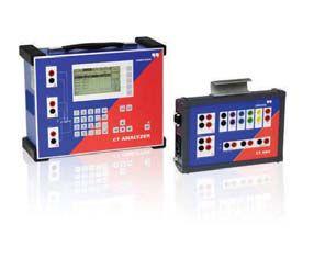
Me and my brand−new CT Analyzer Love, Dad
www.omicronusa.com | 1-800-OMICRON My
multi−ratio current transformers
dad tests


 White logo


 BY RON WIDUP AND JIM WHITE, Shermco Industries


 BY JEFF JOWETT, Megger


 BY GLEN BROWN, Rimac Technologies


