



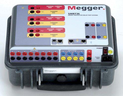
The SMRT36 is the smallest, lightest, highest output powered, complete 3-phase protective relay test system in the world today. This rugged test system may be customized by adding the voltage current generator modules needed for specific test applications. Manual operation is simple through the use of the Smart Touch View Interface (STVI), with a large color high resolution TFT LCD touch-screen.


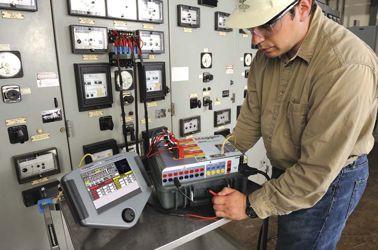


n Rugged, small and lightweight
n High current, high power (60 Amps/300 VArms) per phase
n Up to 6 currents with convertible channels
n Thermally controlled fans for quiet operation
n New Smart Touch View Interface (STVI) provides manual control
n New STVI Overcurrent Test includes hundreds of relay specific time-curves built-in
With these comprehensive capabilities and extensive testing options the SMRT36 is conceivably the easiest to use 3-phase protective relay test system available today.
For more information on the SMRT36 relay test set contact us today at 1-800-723-2861 or email us at sales@megger.com to receive a SMRT36 brochure and 2011 Megger Power Catalog.
Megger
4271 Bronze Way Dallas, Texas 75237-1019



22 TODAY’S MICROPROCESSOR RELAYS EXPAND THE APPLICATION POSSIBILITIES OF SYMMETRICAL COMPONENT THEORY
By Roy Moxley, Schweitzer Engineering Laboratories, Inc..The use of sequence quantities has increased dramatically since the introduction of microprocessor relays. Sensitivity to faults, especially unbalanced faults, has increased while security has also increased. Motors, feeders, transmission lines, and generators have all benefited from the capability of applying new measuring techniques based on sequence components.
7 PRESIDENT’S DESK
Mose Ramieh, Power & Generation Testing, Inc.
NETA President
10 GRATITUDE – IT’S NOT JUST FOR THE HOLIDAYS
14 COLLECTIVE MEMORIES–NETA’S PAST, PRESENT AND FUTURE
Jill Howell and Kristen Wicks, NETA
35 MULTI-FUNCTION NUMERICAL PROTECTION RELAYS USING SYMMETRICAL COMPONENTS FOR MORE RELIABLE AND SECURE PROTECTION
Steve Turner, Beckwith Electric Co., Inc
63 MODERN PROTECTIVE RELAY TECHNIQUES: USING A 94-YEAROLD CONCEPT TO PROTECT ELECTRICAL EQUIPMENT
Suparat Pavavicharn, Basler Electric Company
72 AN IMPROVED CONSTANT SOURCE IMPEDANCE TESTING METHOD FOR MHO DISTANCE RELAYS
Jason Buneo and Rene Aguilar, Megger
28 MAINTENANCE CORNER
Relay Maintenance Has Changed, Hasn’t It?
Kerry Heid, Magna Electric Corp.
42 TECH QUIZ
Symmetrical Components and Protective Relaying
Jim White, Shermco Industries
47 THE NFPA 70E AND NETA
A New NFPA Process and a Few Words on the 70E Annexes
Jim White and Ron Widup, Shermco Industries
52 NICHE MARKET TESTING
Newer Solid-State Relays Offer Enhanced Flexibility for SCADA Solutions in the Municipal Environment
Lynn Hamrick and Owen Wyatt, Shermco Industries
59 TECHNICAL BRIEF
Instantaneous Ground Fault Relays (50GS) and Zero-Sequence CTs Powell Technical Brief #68
Baldwin Bridger
82 NO-OUTAGE
INSPECTION CORNER
Condition Based Risk Management (CBRM) the Big Picture for Electrical Asset Management and Planning
Don A. Genutis, No-Outage Electrical Testing, Inc.
88 TESTING ROTATING MACHINERY
Polarization Test
Vicki Warren and Ian Culbert, Iris Power LP.
94 SAFETY CORNER
Industry Advisory – NERC,
Relay Safe Work Practices
Scott Blizard, American Electrical Testing Co.
101 TECH TIPS
A Closer Look at Soil
Jeff Jowett, Megger
SPECIFICATIONS AND STANDARDS ACTIVITY
116 CSA UPDATES
Kerry Heid, Magna Electric Corp.
118
INDUSTRY TOPICS
12 REAL WORLD LEARNING AT YOUR FINGERTIPS
NETA Handbooks
32 NETA ACCREDITED COMPANY MAGNA ELECTRIC CORPORATION RECEIVES HIGH MARKS FOR SETTING HIGH STANDARDS
105 NETA TECHNICAL SUPPORT–QUALITY CONTROL WITH THE SRC AND EXAM COMMITTEE
122 NETA ACCREDITED COMPANIES
128 ADVERTISER LIST




3050 Old Centre Avenue, Suite 102
Portage, MI 49024
Toll free: 888.300.NETA (6382)
Phone: 269.488.NETA (6382)
Fax : 269.488.6383
neta@netaworld.org
www.netaworld.org
EXECUTIVE DIRECTOR: Jayne Tanz, CMP
NETA Officers
PRESIDENT: Mose Ramieh, Power & Generation Testing, Inc.
FIRST VICE PRESIDENT: David Huffman, Power Systems Testing Co.
SECOND VICE PRESIDENT: Ron Widup, Shermco Industries
SECRETARY: Walt Cleary, Burlington Electrical Testing Co., Inc.
TREASURER: John White, Sigma Six Solutions
NETA Board of Directors
Ken Bassett (Potomac Testing, Inc.)
Scott Blizard (American Electrical Testing Co., Inc.)
Jim Cialdea (Three-C Electrical Co., Inc.)
Walt Cleary (Burlington Electrical Testing Co., Inc.)
Roderic Hageman (PRIT Service, Inc.)
Kerry Heid (Magna Electric Corporation)
David Huffman (Power Systems Testing)
Alan Peterson (Utility Service Corporation)
Mose Ramieh (Power & Generation Testing, Inc.)
John White (Sigma Six Solutions)
Ron Widup (Shermco Industries)
NETA World Staff
TECHNICAL EDITOR: Roderic L. Hageman
ASSOCIATE EDITOR: Diane W. Hageman
MANAGING EDITOR: Jayne Tanz, CMP
ADVERTISING MANAGER: Jill Howell
DESIGN AND PRODUCTION: Newhall Klein, Inc.
NETA Committee Chairs
CONFERENCE: Ron Widup; MEMBERSHIP: Ken Bassett; PROMOTIONS/MARKETING: Kerry Heid; SAFETY: Lynn Hamrick; TECHNICAL: Alan Peterson; TECHNICAL EXAM: Ron Widup; WORLD ADVISORY: Diane Hageman;
CONTINUING TECHNICAL DEVELOPMENT: David Huffman; TRAINING: Kerry Heid; FINANCE: John White; NOMINATIONS: Alan Peterson; STRATEGY: Mose Ramieh; AFFILIATE PROGRAM: Jim Cialdea
© Copyright 2012, NETA
NOTICE AND DISCLAIMER
NETA World is published quarterly by the InterNational Electrical Testing Association. Opinions, views and conclusions expressed in articles herein are those of the authors and not necessarily those of NETA. Publication herein does not constitute or imply endorsement of any opinion, product, or service by NETA, its directors, officers, members, employees or agents (herein “NETA”).
All technical data in this publication reflects the experience of individuals using specific tools, products, equipment and components under specific conditions and circumstances which may or may not be fully reported and over which NETA has neither exercised nor reserved control. Such data has not been independently tested or otherwise verified by NETA.
NETA MAKES NO ENDORSEMENT, REPRESENTATION OR WARRANTY AS TO ANY OPINION, PRODUCT OR SERVICE REFERENCED OR ADVERTISED IN THIS PUBLICATION. NETA EXPRESSLY DISCLAIMS ANY AND ALL LIABILITY TO ANY CONSUMER, PURCHASER OR ANY OTHER PERSON USING ANY PRODUCT OR SERVICE REFERENCED OR ADVERTISED HEREIN FOR ANY INJURIES OR DAMAGES OF ANY KIND WHATSOEVER, INCLUDING, BUT NOT LIMITED TO ANY CONSEQUENTIAL, PUNITIVE, SPECIAL, INCIDENTAL, DIRECT OR INDIRECT DAMAGES. NETA FURTHER DISCLAIMS ANY AND ALL WARRANTIES, EXPRESS OF IMPLIED, INCLUDING, BUT NOT LIMITED TO, ANY IMPLIED WARRANTY OF FITNESS FOR A PARTICULAR PURPOSE.
ELECTRICAL TESTING SHALL BE PERFORMED ONLY BY TRAINED ELECTRICAL PERSONNEL AND SHALL BE SUPERVISED BY NETA CERTIFIED TECHNICIANS/ LEVEL III OR IV OR BY NICET CERTIFIED TECHNICIANS IN ELECTRICAL TESTING TECHNOLOGY/LEVEL III OR IV. FAILURE TO ADHERE TO ADEQUATE TRAINING, SAFETY REQUIREMENTS, AND APPLICABLE PROCEDURES MAY RESULT IN LOSS OF PRODUCTION, CATASTROPHIC EQUIPMENT FAILURE, SERIOUS INJURY OR DEATH.


As you read this message PowerTest 2012 will be in full swing in Ft. Worth. I am looking forward to seeing you all there.
During this PowerTest Conference, we will be celebrating NETA’s 40th Anniversary. As your President I am truly honored to preside over this latest milestone event in the history of NETA. As we look back at the past 40 years there are pictures from the past in the fall issue of NETA World and in this issue. Note the changes in hair styles, clothes, faces, and most of all the growth of the association. In early 1972, a group of Charter Member Companies came together to form what is now a 70-company with more than1400 technicians association. Could the founders have imagined where NETA would be 40 years later? Where do you imagine we will be in the evolution of NETA just five years from now?
We are in the midst of a new era in our industry and our association. The ever changing landscape of equipment and regulations with which we deal has caused major shifts in the way NETA Accredited Companies (NAC) are organized, staffed, and operate. We are no longer an association of companies that test components and systems. We have evolved to a higher level of involvement in the overall project scheme. This evolution has occurred not by accident but by the electrical industry’s recognition of the expertise that exists in our member companies. The services we now provide are more sophisticated than those provided in the early 70’s. NACs are now involved with all aspects of projects from specifying equipment, design considerations, project management, engineering studies, commissioning, and many other areas that were once the exclusive realm of the engineer and constructer.
As we look to the future it is apparent to me that our evolution will come at a faster pace than any of us can imagine. If NETA is to continue its growth and standing in the electrical community, we must continue to keep pace with the ever changing needs of the industry. As your President and Strategic Chair I welcome input from all members as to the direction in which this organization should proceed.
NETA is only as viable and strong as you, the members, make it. This is your association, and we need your input and support.
Mose Ramieh NETA President



National Switchgear has a broad line of new, used and remanufactured electrical switchgear products. And literally millions of parts, new and used. But that’s only part of the story. We also have the willingness to listen, the experience to know what you need, the capacity to have it in stock, and the responsiveness to get it to you fast. Plus, the additional value of full-service electrical testing and onsite maintenance services. So, if you’re still calling anyone else for power distribution equipment, maybe it’s time to switch. 800-322-0149 nationalswitchgear.com


It really doesn’t take very long to learn that NETA’s volunteers are the living definition of gratitude
The air is chillier; snow is falling in many places across the country; and life just seems to encourage us all to slow down a little, take in our surroundings, and be grateful for the many blessings that surround us. Sure, there is the ever-present pressure of locating the perfect gifts for loved ones, chiseling out time for holiday parties, and for those in certain professions, like electrical testing, the seasonal rush to help all of our clients prepare for the winter ahead. Still, there is no denying that one would have to be living under a rock to avoid feeling a little of that nostalgic, seasonal magic associated with giving, generosity, and gratitude.
Working with volunteers is an especially rewarding job, as one realizes that people are making time to write really great articles for NETA World, edit those articles, prepare a year in advance to present technical content at PowerTest, and traverse the continent to attend grueling code panel meetings, all while being savvy business people, little league coaches, caregivers, and friends, just to name a few other hats. On a tough day, it is energizing to think that NETA is blessed with an astounding number of incredible human beings who have probably never worked nine-to-five jobs a day in their lives and wouldn’t have it any other way.
These people have such amazing stories to share; their lives are filled with monumental achievements. They are generous with all their resources, time being the most precious of these. Many of NETA’s volunteers participate in charitable missions close to their hearts; one being a NETA member who goes on mission trips to the heart of the jungle in a dugout canoe, delivering large batteries to villages so the indigenous people are able to provide a better quality of life to their community. Most of these giving people go quietly about their lives and even become a little bashful when commended for their efforts. It really doesn’t take very long to learn that NETA’s volunteers are the living definition of gratitude; it is reflected in all of their contributions as employers, employees, mothers, fathers, grandparents, and friends.
So, from each of us at the NETA office, thank you to all of our volunteers for all that you do. Your partnership in our daily mission of providing quality service and excellent experiences for all involved with NETA is a gift for which we are grateful all year round.


Featuring quality, reliable, on-time service and support for all brands and types of solid state power electronics.
Power electronics are our business
Let us suppoort you with our quality repair, calibration and servicing of your solid state equipment. We also buy, sell and trade:
•Communications devices for power equipment
•Protective relays
•Circuit breaker trip devices
•Motor overload relays
•Rating plugs


In 2012 NETA celebrates 40 years of service to the electrical systems industry – Establishing industry standards and delivering leading-edge technical information and educational resources based on real-world experience.


NETA was founded with the goal of advancing the industry’s focus on safety and reliability. The Association’s contribution is fullfilled through the development of the ANSI/NETA Standards and the creation of educational and training resources that include the NETA Self-Paced Technical Seminars, the annual PowerTest conferences, the quarterly NETA World Journal, as well as a 14 volume series of NETA Handbooks.
Accredited Companies, and NETA’s technical community seeking a comprehensive, subjectspecific technical resource to use for training and reference materials.
All NETA technical materials, publications, and events are authored by industry experts – leadingedge, highly knowledgeable individuals who have many years of experience in the field. NETA is extremely grateful for their contributions.


The NETA Handbooks were first released as a series in 2009. They are a go-to source for highly relevant information about testing procedures, troubleshooting, and real-life solutions to situations encountered everyday in the field. The Handbooks were initially created in response to requests from the electrical industry, the general public, NETA
The NETA Handbooks bring together a collection of over 200 of the very best articles from past issues of NETA World Journal and the most well- received technical presentations from past PowerTest events.


Join us in Celebrating

For each of us there is a mission that guides us, a vision that inspires us, a camaraderie that tie us, a heart - driven professionalism that aligns us. We continually strive for the highest standards in electrical power system safety and reliability. We salute the accomplishments oF our members – past, present, and Future.
neta’s 40th birthday and Powertest 2012 Welcome reception
Date: Monday, February 27, 2012
Time: 6:30 PM - 10:30 PM
Location: Dallas Cowboys Stadium
RSVP: Call 888-300-6382 (NETA) — Transportation Provided


In the last issue of NETA World, we looked back at the history of NETA and compared the world that saw the first years of the InterNational Electrical Testing Association to the world in which NETA exists today, forty years since being founded in 1972. After looking at the organization as a whole, it seemed only right to talk with the people who comprise the heart and soul of NETA. Across the geographical locations and generations of NETA members, some common themes were mentioned; themes like collaboration, electrical expertise, standards, community, and volunteerism all featured prominently in NETA’s collection of stories. Individual stories are woven together like threads to create the brilliant tapestry of NETA’s past, present, and future. Settle in and read on to learn about some of the favorite memories, infamous moments, and hopes for NETA’s future shared by some of the many faces of NETA.





are so many people with
When asked about what first comes to mind when thinking of NETA, Mose Ramieh, NETA’s current President, said without hesitation, “Good Friends. It’s more than just good friends. It’s comrades in arms; people who know where I’ve been and been through the same thing. The bond is very close. The best thing about this organization is that there are so many people with mutual interests focused on the same goals. Even though we are competitors, we are friendly competitors who are happy to lend a hand if someone needs it.” Dave Huffman, President of Power Systems Testing, a fellow NAC, agrees with Mose, saying that he thinks of his peers as “heart-driven professionals” aligned by the belief that “good enough isn’t good enough.” He is happy to have this group of people that he can relate to both professionally and personally. and been through the same thing. The bond is very close.
“Good friends, comrades in arms”


Because Power Systems Testing is a long-standing member of NETA, Dave Huffman inherited his affiliation with NETA when he began working there as a field technician in 1988. His technical prowess, skills at managing projects and people helped him along the way to his current position as President of Power Systems Testing. Even though his company was previously affiliated with NETA, Dave worked to increase awareness of NETA and how valuable time spent volunteering can be: “An interesting side-effect of volunteering with NETA Is that it has made our company more well-known within the industry. In general, it has been good for our business and our brand.” Being involved in the industry from a young age gives Dave a birds-eye view of the shifting landscape of electrical testing, most notably, “the industry’s awareness that electrical distribution equipment does not run forever. There is a higher awareness of this fact now than there was ten years ago. I believe this is directly related to the work of NETA at its members promoting safety, developing standards, getting involved in the code panels. NETA provides the world with a group of experts that know something about taking care of your electrical equipment.”


“Heart driven professionals”


 NETA President Power Generation & Testing, Inc.


Change and evolution are inevitable in life, and the life of an organization is no exception to that rule. At times, change comes easily; at others, one may be acutely awareness of growing pains. Lyle Detterman of Northern Electrical Testing believes that the greatest growth for NETA has taken place with PowerTest, the annual technical conference.


Lyle would know, as he was an attendee at the very first NETA conference at Dunfey’s Hotel in Dallas, Texas in 1977. Lyle remembers that the first conference was organized by Thad Brown, who ran the show without the infrastructure and staff that NETA enjoys today. That first conference was a great leaping-off point for today’s events. Lyle says, “Today’s conference is excellent, better than it has ever been. The current team of volunteers and staff has taken it way beyond where it was in the past.”


Mike Moore, Shermco Industries, says “I came from a non-NETA company. When I first joined Shermco, I became educated on the differences, and now I am spreading the word.Before I was a part of NETA, it seemed like a group that could gang up and keep you out of a job. Now, having been a part of NETA for the past ten years, I know it’s not like that at all. NETA levels the playing field for all competitors and establishes a good base-level of knowledge, experience, and quality of service.” When asked what NETA means to him, he says, “It means a standard of quality and commitment. A commitment to NETA and everything it takes to be a NETA Accredited Company: training, certification, calibration of equipment, knowledge, experience – all the things you have to do to become a NETA member and the ongoing work to maintain that status.”





“NETA–it means a standard of quality and commitment”


 NETA Member Northern Electrical Testing


Another newer face to the NETA family is Eric Beckman of National Field Services. When asked what it means to be a part of NETA, he said, “One and a half years ago we joined NETA, and it has really meant a lot. It’s been a long standing thing, wanting to be a part of NETA. The requirements for accreditation are very stringent; it was a big moment for our company when we got to that point. It will continue to open up more opportunities for our business, allows us to bid on more projects, and provides us with the prestige that NETA accreditation brings.” When asked about what he sees for the future, Eric comments, “NETA will still be the baseline against which everyone is measured. The ANSI/NETA Standards are so well-recognized now and will keep influencing other industry standards and government specifications.”


“NETA–The baseline against which everyone is measured.”
In the early days of NETA, membership was focused solely on electrical testing. As time passed and technology advanced, electrical testing came to include more services, allowing wider diversity among companies eligible to become accredited with NETA. As President, Mose wrestles with the question, “Who is NETA today?” He has participated and led discussions about this topic, driven by a desire to ensure that everyone from the little guy on up to the largest NETA member is given equitable representation and responsibility within the organization. When Mose and his company joined NETA, NETA was a moving force in the industry. He always knew that he wanted to join NETA and that when that time came he wanted to assure that he and his company would be active contributors to movement. While there are no clear answers yet, Mose is “for change”, acknowledging that to stay alive you have to adapt while keeping quality and standards in sight.


Kerry Heid, of Canadabased Magna Engineering Corporation (MEC), talks about MECs growth when it comes to NETA. “Magna has been a member for ten years now. Originally we joined seeking credibility. NETA did provide that through the application process and the certification of our technicians. In the middle years of our membership, there was a steep learning curve on how NETA works. In the present, it is a valuable technical community of friends. It’s great to know that I can land in ten or 20 different American cities and call a friend up for dinner. It’s a great network to have.” One of NETA’s social butterflies, Kerry recalls many happy times with his fellow members. When asked about NETA’s social atmosphere, more than one person interviewed for this article mentioned Camden, Maine. Details were not as forthcoming. Dave Huffman added, “Montana was a lot of fun. That’s all I’ll say.” So as we know, all have survived NETA’s many excursions intact, if not unscathed. Kerry sees NETA’s future as, “a bit of a wild card.” He says, “When I was President of NETA, I was interested in relaxing the membership requirements to allow more people access to become NETA Accredited. I think it will be a slow and steady growth. While there are many great testing firms out there that would be excellent candidates for membership, not every guy that loads up a van can be a NETA guy.”


One thing is certain; the core of NETA will always be the individuals whose expertise and personality bring light and life to this organization.


Bob White, President of Elemco Services, Inc., has been involved with NETA since 1986 when his company joined as an Accredited Company. At that time, Bob recalls, “The association was still in its infancy, fostering the growth of independent testing companies. Years passed and focus shifted from growing the association to where we are now; maintaining the standards that have been established and fought for since 1972.” Bob went on to tell some hair-raising tales of pirate ships, tall, dark intruders, impromptu parade





participation, and the best way to get the bar tender’s




attention (also known as the quickest route to the doghouse). Names have been excluded to protect the innocent, or mostly innocent. To sum it up Bob says, “NETA is camaraderie and fellowship and being on


uniqu


Jayne Tanz, NETA’s Executive Director says, “What really makes this organization unique is the people that breathe life into NETA. The simple fact remains that we are only where we are today because individuals cared enough to start down the path less traveled, and those individuals have been succeeded by likeminded people that want to be involved in something greater than turning a profit. These subject matter experts have gathered together to define not only the practice of electrical testing, but also to establish what makes an individual qualified to perform said tests. Over the course of forty years, these NETA standards have been carved out from practical knowledge, field experience, the school of hard knocks, as well as those on the cutting edge of new technologies. While tests may change, theories shift, and new methods develop, NETA is able to, by the virtue of its volunteers, keep a finger on the pulse of that change.”


“We are only where we are today because individuals cared...”
the forefront of electrical testing technology.” association started. once sought industry. and for technical


One of the most common recurring themes of the interviews was the ANSI/NETA standards. A NETA staff member describes these documents as, “the glue that holds the association together,” or as being, “the keystone and the cornerstone, at the same time.” Lyle recalls, “NETA was just breaking the ground of having standards when my company got started. The purpose of creating the standards was to create a collection of testing knowledge, procedure, and practice that would establish confidence in the testing industry. There has been a huge amount of work done over the years to bring what was once a rather limited set of specifications to where they stand today.” NETA certification and accreditation are sought after throughout the electrical industry. End users value the expertise and assurance brought to their investments; engineering firms are beginning to plan and design with testing in mind; and individuals value the security of a company that has exhibited strength as an employer along with the ability to gain recognition for their technical knowledge and experience.
Happy Birthday, NETA, and many happy returns of the day.


Sets new standards for compact devices in relay testing. This new relay test set can handle any challenge you face in practice. Six current and four voltage outputs allow testing for all relays. Test your relays fast and efficiently with front panel control or software templates. Total weight is only 22 pounds!
Characteristics
n Automatically tests for all types of protection relays
n Freely configurable three-phase function generator
n IEC 61850-compliant protection equipment
n “Play back” function for fault records
n Ergonomic menu and intuitive operation

Is the first relay test set to address the difficult high burden relays. Three built-in sources and a very high output power: up to 1500 VA. In addition to carrying out secondary test on protection relays, the high output current (up to 250 A) makes ARTES 100 capable of a wide variety of tasks, including primary tests for commissioning and maintenance.
Characteristics
n High test current 250 A
n Total output power of up to 1500 VA, one current, two voltage sources both convertible n Front panel or software controlled
Powerful, ergonomic, and versatile: Easy to use template reduces testing time. It leads the market with a brand new graphical interface!
Characteristics
n Testing IEC 61850-compliant protection equipment
n Automatic determination of tripping characteristics
n Watches function for all types of test sequences
n Results correlate to the installation locations of different instrument transformers
n Reproduction of 1-pole and 3-pole automatic reclosing operations (ARCs)




Three-phase power systems make up the bulk of electric power transport and usage because they create a balanced system, and balanced systems produce smooth torque in motors and minimize losses in power lines. An unbalanced system, such as one produced by faults, is an entirely different matter. Coupling between phases makes analysis cumbersome and complicates meeting the need for sensitivity and security in protective relays.


Symmetrical components provide relay designers with three decoupled networks with which to analyze power system conditions: positive-, negative-, and zero-sequence. The advent of microprocessor relays has expanded the application possibilities of this powerful tool even further.
Symmetrical components provide a relatively simple way of looking at the three-phase power system without having to consider the coupling between phases. The identities of the sequence components of current are as follows (voltage has similar identities):

In these equations, the “a” operator rotates the quantity by 120 degrees. In this case, all sequence quantities are referenced to phase A and apply to ABC phase rotation.
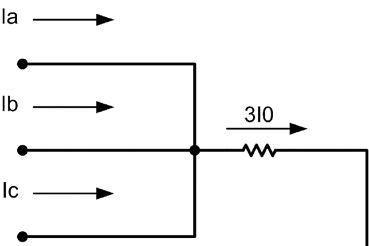
In the physical world, zero sequence involves ground, negative sequence involves a system unbalance (phase-to-phase or phase-toground), and positive sequence involves balanced three-phase faults and load. Because the calculation of zero-sequence quantities does not require phase rotation, it has been used for a long time for ground fault detection. Simply connecting the three phases in parallel, as shown below, provides zero-sequence current.

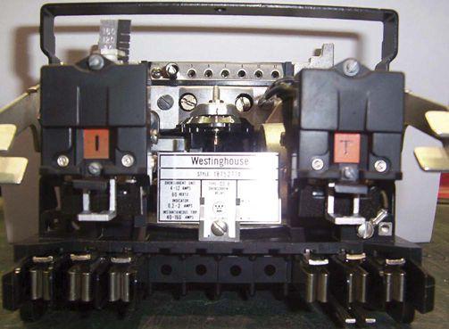
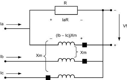
Some older electromechanical relays, such as the Westinghouse IRQ type, used negativesequence directional elements for applications where ground directional was not practical, but the construction was complex and the application difficult.
Microprocessor relays have the capability to directly calculate sequence components without complicated filtering. This makes the use of all sequence components not only feasible but simple. For example, the popular cosine filter, with a sampling rate of four samples per cycle, calculates the phasor in the following way:

Equations for Calculating Negative Sequence Current in a Microprocessor Relay
Simple calculations instead of expensive filters make the application of sequence components in microprocessor relays practical for operating quantities, polarizing quantities, and numerous combined elements. Sensitivity and selectivity become tools for the relay designer and protection engineer.
Despite some complexity, it is easy to take advantage of the increased sensitivity offered by negative sequence overcurrent relays. In a 1992 paper by Dr. Edmund O. Schweitzer III, an early pioneer in microprocessor relays, coordinating negative sequence overcurrent relays with downstream phase overcurrent relays in radial systems was described. By multiplying the downstream phase element pickup by √3, and using the same time delay and curve shape, coordination is achieved. Load current need not be considered in setting a negative-sequence relay, so tapped loads and branches on distribution feeders do not need to increase pickup for unbalanced faults.
Detecting the direction of ground faults is an ideal application for sequence-based relays. Because of the calculating capabilities of modern microprocessor relays, it is possible to not only use sequence quantities to polarize directional elements but also select from multiple available quantities to ensure adequate sensitivity. A patented technology in relays by Schweitzer Engineering Laboratories (SEL) referred to as Best Choice Ground Directional Element® logic selects from negative- or zero-sequence voltage or zero-sequence current polarizing. This overcomes problems with polarizing sources that may depend on available sources, such as transformer neutrals.
Consider the system diagram below:

3

In this case, a fault on Line 1 is considered forward for the relays on Line 1 and reverse for the relays on Lines 2 or 3. Looking only at negative-sequence voltage and current for Lines 2 and 3, we have a measuring network, as shown below with Z1s and Z1r as the positive-sequence source impedances at the two ends, and Z1L as the positive-sequence line impedance.
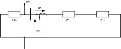
In this case, the ratio of V2/I2 = + (Z1L + Z1r). If this ratio, as measured at the relay, is positive, then the fault is behind the relay. If it is negative, then the fault is in front of the relay. The sign of the ratio becomes the directional element. For a fault in the reverse direction, the relay measures at least the line impedance.
In the negative-sequence network, the angles of the impedance are highly predictable; they are basically reactance. This makes the negative-sequence directional element application simpler for all networks as opposed to zero-sequence directional elements that may need to consider the grounding of the system for their operation. The negative-sequence directional element reliably determines the direction of all fault types in the power system, except the three-phase fault. This makes the element highly attractive for modern relays that need to provide phase fault protection and ground fault protection. A ground directional element can be designed with zero-sequence quantities. It can be based on impedance or on the traditional phasor comparison of the zero-sequence voltage and the zerosequence current.
The directional element is used to supervise another measuring unit, such as current or distance. This provides coordination with otherrelays on the system.
Negative-sequence currents in rotating machines have the effect of producing a counter-rotating flux in the air gap between the stator and rotor. This has no effect on the stator, but it induces a double-frequency current in the rotor. This applies to both generators and motors. Because of the skin effect, that is, the tendency of current to flow more on the surface of conductors at higher frequency, negativesequence current causes far more heating than positive-sequence or load current. Generator manufacturers will typically provide either a negative-sequence current withstand curve or values for their generator. While negativesequence overcurrent protection was an expensive addition in single-function generator or motor protection, in modern microprocessor relays, this is a simple setting within the relay.
It should be noted, and can be seen from the first set of equations in this article, that single-phase testing of relay elements involving sequence quantities is problematic at best. An input to only phase “a” of three amperes, will produce one ampere of zero-, positive-, and negative-sequence current. This may become important if checking a fully configured relay for phase pickup, while a sensitive zero- or negative-sequence element is looking at unbalance or neutral current. Care needs to be taken to avoid inadvertently picking up elements not directly being tested. This could cause contact closures and misreading of pickup levels.
Another consideration is whether the setting of a sequence quantity is 3I0, 3I2, or I0, I2 Because the common connection shown earlier for the zero-sequence filter produces 3I0, it is reasonable to use this as the basis for setting a relay. Some manufacturers do not multiply the quantity by three in the setting, but instead use the sequence current directly in the setting and measurement. This can cause confusion and misoperations if not considered when setting and testing relays from different manufacturers.
The use of sequence quantities has increased dramatically since the introduction of microprocessor relays. Sensitivity to faults, especially unbalanced faults, has increased while security has also increased. Motors, feeders, transmission lines, and generators have all benefited from the capability of applying new measuring techniques based on sequence components. Recognizing these capabilities and testing and application considerations will continue to provide engineers and technicians with advanced tools for solving power system problems.

Roy Moxley received his B.S. in electrical engineering from the University of Colorado. He joined Schweitzer Engineering Laboratories, Inc. (SEL) in 2000 as marketing manager for transmission system products. He is now marketing manager for power systems. He has authored and presented numerous papers at protective relay and utility conferences. Prior to joining SEL, he was with General Electric Company as a relay application engineer, transmission and distribution (T&D) field application engineer, and T&D account manager. He is a registered professional engineer in the state of Pennsylvania and a member of IEEE and CIGRE.

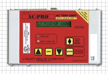
❏ Over 1000 different kits
❏ Microcontroller based, true RMS and 16-character display
❏ All functions included: LT, ST, Instantaneous, GF, Phase Unbalance, QT-GF and QT-Inst with off setting for all (except LT & QT-Inst)
❏ Intuitive programming and easy retrieval of last trip data
❏ 3 Different types of actuators available
❏ Modbus communications available
❏ Quick-Trip™ for arc flash reduction during maintenance
❏ UL and CE labels
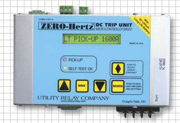
❏ Over 95 different kits
❏ Microcontroller based with 16-character display
❏ Provided with Hall Effect transducers or optionally accepts a 50mV or 100mV shunt input
❏ All functions included: LT, ST, Instantaneous, GF, Reverse Current, QT-GF and QT-Inst with off setting for all (except LT & QT-Inst)
❏ Modbus communications available
❏ Now available with Quick-Trip for arc flash reduction during maintenance
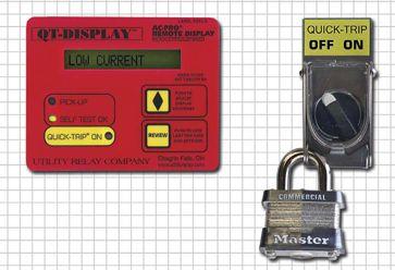
❏ Reduces Arc Flash Hazard during maintenance
❏ The QT-Instantaneous and QT-GF settings are fully adjustable
❏ Easy to install
❏ AC-PRO trip units are Quick-Trip ready and only require the addition of a Quick-Trip Display and a lockable QT ON/OFF selector switch
❏ ZERO-Hertz trip units are now available with Quick-Trip and only require the addition of a lockable QT ON/OFF selector switch with integral indicating light
❏ Provides arc flash reduction during maintenance per 2011 NEC Article 240.87

❏ Plug-in direct replacement for Merlin Gerin & Square D Masterpact MP, IEC or UL rated breakers
❏ User programmed to replace the STR-18M, 28D, 38S or 58U trip units
❏ Same protective functions, settings and time-current-curves as the original STR trip unit
❏ Information and alarm functions are standard
❏ No physical rating plug required
❏ Easy to read OLED display in low or high ambient light
❏ A security code protects against unauthorized changes to settings
❏ Trip events are time and date stamped
❏ USB port and secondary injection test port
❏ Quick-Trip for arc flash reduction is built in, nothing additional is required







In the area of protective relay maintenance, it is well understood that electromechanical relays require servicing to remain within expected pickup and operating specifications. Although electromechanical relays have protected electrical systems for many years, the physical integrity of relays can deteriorate over time. The required frequency of relay calibration and maintenance depends on the type of environment to which the protection is subjected. In harsher environments, the induction disc may need to be cleaned more often so as not to impede the electromechanical action of the magnet on the disc and affect the operation of the relay during a fault.

Photo 1: An Example of a 50/51 Electromechanical Relay.
In years past, it was common to calibrate relays and their various components. This meant adjusting springs, cleaning contacts, and adjusting magnets to ensure the relay operated as designed. This work is still required on existing systems where older, vintage equipment is in service.
With the advent of solid state relays, one might question the value in performing maintenance testing of a protective relay that does not require any form of calibration. Although the manuals for relays from various manufacturers state that specific routine tests are not required, the operation standards for facilities may require regular testing. Most relay manufacturers have various self-testing functions that report any software issues within the relay. As such, routine relay testing is required for the purposes of validating reliability, possible liability, and risk assessment evaluations for insurance purposes. The condition of the output contacts of a solidstate relay cannot necessarily be assessed by the relay’s self-checking feature. The self-check programming within a relay looks at internal PCB trace voltages, processor chip checks, etc. These error checks do not analyze the state of a damaged output contact that could either be welded closed from a previous dc arc or a permanently open contact due to damage to the relay. Obviously these types of hardware failures can severely compromise the integrity of a protection system, and verification of correct operation of the outputs and inputs ofa solidstate relay is well warranted.
Although bench testing of a relay can prove that the protection elements are operating according to manufacturer’s specifications, it is extremely important to perform functionality testing in the field before energizing. Additional testing of relay communications and custom designed control logic can reveal deficiencies in the desired protection scheme. A proactive approach would be to perform testing on the relay to definitively know that all systems are functioning correctly. This is in contrast to assuming that all relay protection systems are operating perfectly and possibly being subjected to a rare relay failure that could remain unnoticed until after a catastrophic fault that was not cleared by the same failed protection relay.
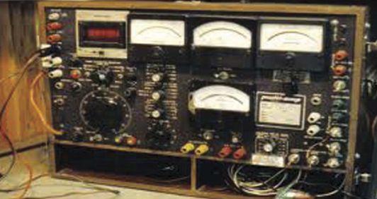
Photo 2: Remember the SR-51? A fabulous machine set up to test a variety of electrical protection components; a bit of a blast from the past for us older techs.
One thing is for sure, relay protection system maintenance is performed considerably differently and more efficiently than in years past. Digital technology has brought about an entirely new way of performing maintenance and in some cases a different philosophy as well.
One of the major challenges is to remove multifunction relays from service. Single phase or individual functional relays of electromechanical style can be safely removed with the power system on line. This is not necessarily the case with multifunction relays as every function is being defeated with the relay out of service.
Even with the advent of new technology, the importance of performing protection system maintenance has not changed. Asset management, system reliability, and personnel safety all hinge on the protection scheme operating according to the coordination study requirements. During power system faults, incident energy is in direct proportion to the amount of time the system takes to operate. Incident energy values are determined using an arc-flash hazard analysis and are based on the equipment working according to the time current characteristics. These TCCs are based on an operating value when the equipment is new from the factory. As time goes on, the maintenance of the protective devices becomes very critical to ensure the operating times found in the study match the times in the field. Service-aged equipment has been found to be unreliable and in some cases even inoperable which creates an obvious variance from the expected operation.
Relay protection maintenance is critical to ensuring that major equipment damage and injury to personnel are not encountered. Maintenance also drives reliability. The frequency and type of relay maintenance depends on a number of factors including criticality, environment, and type of relay system.

Kerry Heid is the President of Magna Electric Corporation, a Canadian based electrical projects group providing NETA certified testing and related products and solutions for electrical power distribution systems. Kerry is a past President of NETA and has been serving on its board of directors since 2002. Kerry is chair of NETA’s training committee and its marketing committee. Kerry was awarded NETA’s 2010 Outstanding Achievement Award for his contributions to the association and is a NETA senior certified test technician level IV.
Kerry is the chair of CSA Z463 Technical committee on Maintenance of Electrical Systems. He is also a member of the executive on the CSA Z462 technical committee for Workplace Electrical Safety in Canada and is chair of working group 6 on safety related maintenance requirements as well as a member of the NFPA 70E – CSA Z462harmonization working group.

NETA and our NETA Accredited Companies invite YOU to become a part of NETA’s technical community and take advantage of the many benefits of becoming a NETA Gold or Standard Affiliate.
As a NETA Affiliate you can participate in NETA’s Technical Working Committee, qualify for substantial discounts, and access industry leading experts and technical resources.
Call or go online to sign up for your NETA Affiliate Subscription today! Go to www.netaworld.org or give us a call at 888-300-NETA (6382).








Kerry Heid, President of Magna Electric Corporation (MEC), a NETA Accredited Company, recently shared some very exciting news with the NETA office. MEC has been recognized by multiple organizations for its outstanding business and employment practices, stepping into the Saskatchewan and Canadian spotlights in the last couple of years by earning some impressive titles. MEC has been named one of Saskatchewan’s top 20 employers for three years running (2010 to 2012) as well as the Saskatchewan Applied Science Technologists and Technicians Outstanding Employer for 2011. On a national level, they have been awarded one of Canada’s Top 100 Employers for 2012.


These employment awards show MEC’s commitment to their employees and the desire to create a positive and rewarding work environment. The Saskatchewan Chamber of Commerce has featured MEC in its “On Track” Campaign which promotes Saskatchewan business success stories (www.ontracksk. ca). MEC is also featured in Saskatchewan Business Magazine’s top 100 Saskatchewan companies for 2011 and has officially gained the number one ranking of electrical services provider in the province.




In speaking about these awards, Kerry stated, “One award the company is very proud of is the 2010 Safe Employer Award received from the Workers Compensation Board,” which is open to all Saskatchewan companies. Kerry says, “MEC showed why we are a true leader in Saskatchewan when it comes to workplace safety. Safety is top priority for MEC and it shows!”
In addition to these honors, Saskatoon Achievement in Business Excellence Awards granted Magna Electric Corporation the Growth and Expansion Award for 2011. In a similar vein, MEC was awarded, on November 19, 2011, the Growth and Expansion Award as well as the Business of the Year Award at the ABEX awards, which is a prestigious province-wide award within Saskatchewan.
Last, but not least, Magna Electric Corporation recently discovered they have been chosen as one of Canada’s 50 Best Managed Companies. Kerry is incredibly gratified at this recognition, noting that this is also an award that is sought after by hundreds of great companies across Canada. Kerry closes by saying, “Magna Electric Corporation is building a future of continued growth and expansion while keeping a firm grip on the high quality and safety standards that have brought us to our current height of success.” NETA is proud to be represented by Magna Electric Corporation as one of its Accredited Companies and looks forward to more stories of success in the future!


Multi-function protection relays calculate and use symmetrical components to enhance their performance during system faults. Three examples are presented in this article:
• Zero-sequence current elimination for transformer differential protection
• Positive-sequence voltage polarization for mho phase distance elements
• Negative-sequence current detection to inhibit out-of-step blocking
ZIGZAG TRANSFORMER INSIDE TRANSFORMER DIFFERENTIAL ZONE
A shunt connected zigzag transformer provides a zero-sequence current sink for ungrounded systems such as the one shown in Figure 1 by establishing a connection from ground to neutral. Zero-sequence current (I0) flows up through the neutral of the zigzag transformer during ground faults. Therefore, it is simple to apply non-directional overcurrent protection for the detection of single line-to-ground faults. If the system is left ungrounded, high voltage appears on the unfaulted phases during single line-to-ground faults and conventional ground overcurrent protection is useless.
A zigzag transformer consists of three 1:1 ratio transformers. Each leg of the zigzag transformer consists of two windings that are 120 degrees out of phase. Windings are wound around the core such that zero-sequence current flows through the bank when there is system unbalance (i.e., ground fault). Only exciting current flows through a zigzag transformer during balanced system conditions. The grounding transformer appears as the leakage reactance of the core when a ground fault occurs and zero-sequence current flows splitting evenly into the three phases.
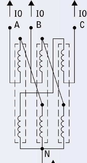

Three-Line Diagram
A grounding resistor is sometimes used since the transformer alone equates to reactance grounding. Typically, the zigzag transformer is sized such that its impedance is 100 percent on its own base. For the 10-second rating, 400 amps primary is commonly applied in the United States.


FIGURE 2: Ungrounded System with Zigzag Transformer for Ground Current
If the zigzag transformer is located inside the zone of transformer differential protection such as for the delta connected windings as shown in Figure 2 above then the zerosequence current contribution during external ground faults must be eliminated or else a misoperation can occur. Here is one method in which numerical transformer protection relays can reliably remove the ground current.

The currents shown are taken directly from the CT secondary and have been divided by the tap setting for the delta winding to convert them into per unit. If zero-sequence current elimination is selected (see Figure 3 as an example), then the relay calculates the ground current as follows:
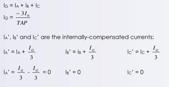
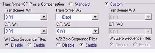
3: Zero-Sequence Current Elimination
Figure 4 shows the transformer differential operating characteristic. Point A is the filtered operating point for an external ground fault and Point B is unfiltered.
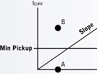
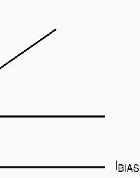
FIGURE 4: Transformer Differential Operating Characteristic
DISTANCE PROTECTION PRE-FAULT POSITIVE-SEQUENCE MEMORY VOLTAGE POLARIZATION
Distance elements applied for the protection of high-voltage transmission lines often use positive-sequence voltage as the polarizing signal or reference. These two equations show a classic method to create a mho distance element:
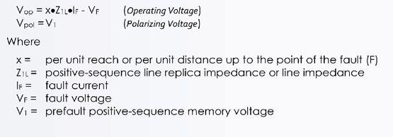
Figure 5 shows the A-Phase-to-B-Phase loop measurement for a phase mho distance element. Note that there are corresponding loops for B-Phase-to-C-Phase and C-Phaseto-A-Phase as well. The mho phase distance element measures the impedance up to the point of the fault (F) for that loop. IAB and VAB are the fault loop current and fault voltage measured by the relay during the fault.


The corresponding mho phase distance element is generated as follows using two internally-calculated potentials:

An A-Phase-to-B-Phase fault is internal with respect to the mho element when the absolute value of Ѳ is 90 electrical degrees or less (see Figure 6).
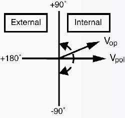
Mho Distance Element Directional Diagram
VAB1 is the voltage recorded prior to the fault (i.e., pre-fault) and is stored in a buffer. If there is no reference signal (e.g., bolted three-phase fault at the secondary terminals of the voltage transformer) then the mho distance element can misoperate during an external fault - this is one of the main reasons for using pre-fault memorized voltage as the polarizing quantity. Note that only positive-sequence quantities are present during balanced system conditions such as pre-fault load flow. The length of the buffer to store the memory voltage should be short enough that a skew is not introduced in Ѳ which can also lead to misoperation. Typically 30 cycles is sufficient. Ѳ is the angle between the two voltage signals and whenever this is equal to 90°, it describes a point along a circle as shown in Figure 7. Some other advantages to using positive-sequence memory voltage as the reference signal are as follows:
• Greater expansion of the mho characteristic along the resistive axis
• Reliable operation for close-in zero voltage faults • Security for close-in reverse phase-to-phase faults
• Security during single pole tripping
Figure 7 shows both the static and expanded dynamic mho distance operating characteristics in the voltage plane which is obtained by multiplying the impedance diagram by the fault current. Expansion along the resistive axis is a direct function of the apparent source impedance behind the relay; i.e., the weaker the source, the greater the expansion.
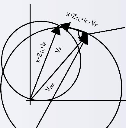


Static and Expanded Mho Distance Operating Characteristics
FIGURE 5: Phase A-to-Phase B Fault LoopCertain protection functions are typically only intended to operate during balanced three-phase conditions:
• Rate-of-change-of-frequency (81R)
• Loss-of-fi eld (40)
• Out-of-step tripping|blocking (78)
• Under-voltage load shedding
If negative-sequence current (I2) is detected, this is an indication that an unbalanced disturbance is in progress. Figure 8 shows the oscillographic record captured by a relay for the simulation of a large generator that slipped three poles; the event then evolved into a resistive ground fault. Figure 9 shows two large generating units at one plant that are interconnected one substation away via the transmission system. If either machine was to go unstable, then the desired sequence of events is to trip only the runaway generator while
blocking the distance relays protecting the local transmission line terminals. This criterion prevents cascading outages from occurring and preserves the integrity of offsite power sources to the plant. For this particular case, the desired end result would be to unblock the distance protection so as to clear the ground fault as shown in Figure 9.
Figure 10 shows the trajectory of an unstable swing that passes through both the generator out-of-step (OST) tripping characteristic and a transmission line relay Zone 1 operating characteristic. Note that the point O in Figure 10 corresponds to the generator voltage transformer terminals. Such a swing could operate both the line protection and the generator outof-step tripping function–thereby illustrating one case why power swing blocking is required for the transmission line protection. Phase distance protection can also operate during a stable swing–also shown in Figure 10.
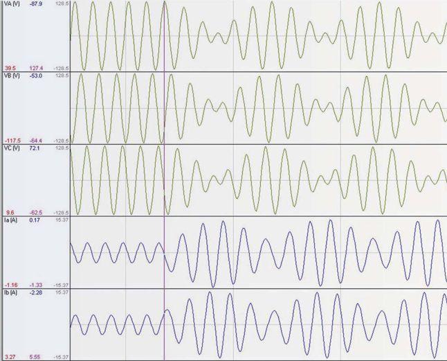

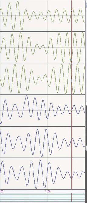


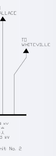
FIGURE 9: Two Large Generating Units Interconnected via the Transmission Grid
Figure 11 is a simple logic diagram that illustrates how to use negative-sequence current detection (46) to unblock the distance protection (21) after it has been inhibited by power swing blocking logic (78_PSB).
FIGURE 10: Unstable Swing passes through Zone 1 and OST
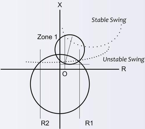

FIGURE 11: Negative-Sequence Current Unblocking
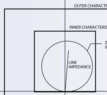
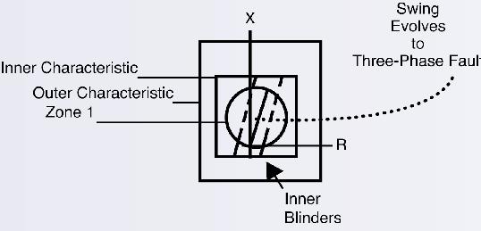
Another post-swing disturbance that is even harder to detect is if a three-phase fault were to occur on one of the transmission lines terminated at the plant following the first pole slip since there is no negative-sequence current present. Figure 12A shows a typical power swing blocking (PSB) characteristic. If the impedance trajectory passes relatively slowly (e.g., three cycles or more) through the outer characteristic to the inner characteristic, then a power swing is detected and the phase distance protection is blocked. If there is a fault then the measured impedance will quickly (e.g., two cycles or less) jump from the pre-fault location to a point on the faulted power system. A pair of inner blinders is required to detect when a swing evolves into a three-phase fault as shown in Figure 12B. If a balanced line fault occurs, then the measured impedance drops in between the blinders and remains there. Thus, the blinders can detect this condition and quickly unblock the phase distance protection.


Out-of-step tripping and blocking characteristics operate on the measured positive-sequence impedance since a power swing is a balanced three-phase phenomenon. The positivesequence impedance can be calculated as follows:

This article presented several examples that illustrate how multi-function protection relays calculate and use symmetrical components to enhance their performance during system faults. The use of symmetrical component quantities help to provide protection that is more reliable and secure.

Steve Turner is a Senior Applications Engineer at Beckwith Electric Company. His previous experience includes working as an application engineer with GEC Alstom, an application engineer in the international market for SEL, focusing on transmission line protection applications. Steve worked for Progress Energy, where he developed a patent for double-ended fault location on transmission lines.
Steve has both a BSEE and MSEE from Virginia Tech University. He has presented at numerous conferences including: Georgia Tech Protective Relay Conference, Western Protective Relay Conference, ECNE and Doble User Groups, as well as various international conferences. Steve is a senior member of IEEE.
test equipment answer




■ VLF and Tan Delta (30 and 60kV Systems)
■ Off Line Partial Discharge
■ DC Hipot Testing (To 200kV)
■ Power Factor / Capacitance and Dissipation
■ Insulation Analyzers (To 15kV)



■ Cable Fault and Route Location
■ Fiber Optic TDR
■ Circuit Tracers


Jim White is the Training Director for Shermco Industries and the principal Shermco representative on the NFPA 70B committee. Jim is the alternate NETA representative on the NFPA 70E committee and serves as the NETA representative on the IEEE/ NFPA Arc-Flash Hazard Work Group (RTPC) Ad Hoc Committee. He served as the Chairman of the 2008 IEEE Electrical Safety Workshop. Jim is a NETA Certified Level IV Electrical Testing Technician and a member of the NETA Safety Committee.
1. What is a phasor?
a. Last seen on Star Trek, the Search for Spock, a phasor is a weapon that can be set for stun or kill.
b. Similar to a vector, a phasor is used to indicate both amplitude and phase angle. Phasors can represent any quantity that can be represented by a sinusoid.
c. An instrument used to determine the phase angle between voltage and current.
d. The angular difference between the voltage and current commonly referred to as theta.
2. A negative sequence relay is used to:
a. determine if the generator is supplying an unbalanced load.
b. determine when current flow is in the incorrect direction within an intertied bus system.
c. determine when the phase rotation of a motor is incorrect.
d. determine when the impedance of a generator’s rotor increases to above normal values.
3. A three-phase bolted fault will primarily produce what type of current?
a. Positive sequence current
b. Zero sequence current
c. Negative sequence current
d. Midrange sequence current
4. The diagram below shows a core-balance CT. What is another name for this type of CT?
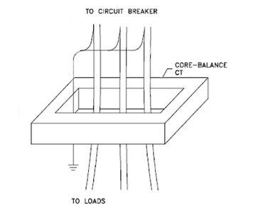
a. Positive sequence
b. Negative sequence
c. Zero sequence
d. Phase fault protection
5. Identify the following three currents:
a. IO
b. I2
c. I1

• 50V & 100V Megohmmeters: For testing insulation resistance of phone cables, data cables and power cables
• 500V Megohmmeters: For testing the quality of insulation on equipment powered from sources up to 240Vac
• 1000V Megohmmeters: For testing equipment powered from sources up to 480Vac
• 5000V Megohmmeters: For testing large motors, generators, transformers, cables and other large rotating machinery
• Computer Controlled Models: AC powered, battery powered or hand-cranked models
• Choose from analog, digital or graphical displays
• Perform insulation resistance tests into the GΩ and TΩ ranges


AccurAcy (resolution 5 Digits):
Range 0.8 … 2000 ± 0.06% at 100V or 40V
Range 2001 … 4000 ± 0.1% at 100V or 40V
FeAtures:
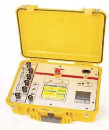
• Automatic measurements of voltage, turns ratio, current, and phase displacement
• Measures power transformers PTs and CTs
• Displays deviation from a nominal ratio
• Displays % error vs. name plate value
• Bright full color touch-screen for easy data entry
Range 4001 … 13000 ± 0.3% at 100V or 40V
Range 13001 … 16000 ± 0.4% at 100V or 40V
• Test voltages of 100V, 40V, 10V, and 1V (for CT Testing)
• Graphical tap changer display
• Automatic phase vector detection
• Enhanced heavy-duty protection circuitry
• Data exchange with USB-Key
• Built-in printer

AccurAcy:
Range 100 mAmp … 15 Amp ± 0.1% Rdg 5 Digit Resolution
Range <25 mAmp 1.2kΩ …10kΩ ± 0.1% Rdg 4 Digit Resolution
Range <25 mAmp 10kΩ …100kΩ ± 0.5% Rdg 4 Digit Resolution
FeAtures:
• Core Demagnetizing Circuit (world exclusive)
• Charges inductive loads up to 1500 Henry
• 2 independent measuring channels
• Heavy-duty protection circuitry
• High power DC supply (15A/30V)
• Resistance range from 0.05 μΩ to 100 kΩ
• Battery or line voltage powered
• Visible and audible indicator for discharge status
• Data exchange with USB-key
• Simple touch-screen operation
• Built-in printer

AccurAcy:
Range 0.8 … 4000 ± 0.08% with 40 Volts (PT Mode)
Range 0.8 … 100 ± 0.08% with 1V … 5V (Auto) (CT Mode)
FeAtures:
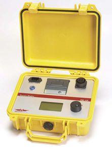
• Operates on rechargeable batteries or line voltage
• Can be recharged with line voltage or optional
DC car adapter
• Reverse polarity test
• Continuity test
• Test current up to 1A for CT testing
• Internal storage of the last 50 test results
• RS-232 interface with optional adapter
• Over 1000 measurements without recharging
• TR-1P model includes built-in printer

From big cit y to small town, east to west, Nor th America to Europe, we are expanding our resources and ser vice center locations to better ser ve you.
Contac t Shermco Industries for safe, reliable testing, repair, professional training, maintenance and analysis of rotating apparatus or elec trical power distribution systems for all market segments, including industrial, commercial, petrochemical, utilities and more.
 BY JIM WHITE AND RON WIDUP, Shermco Industries


One of the benefits of the new process is the new, on-line workflow, as the technical committee report will be available and published on the NFPA Standards Development Web Site as a true on-line publication with hyperlinking, legislative text, and other features, including downloading and printing capabilities. This will make reviewing the standards easier as they are being revised and/or developed.
In conjunction with the new process there will also be a new schedule with a closing date of June 22, 2012, for Public Input (PI), previously referred to as Proposals. The June date is several months earlier than the November closing date to which we have become accustomed under the old process and schedule. Public comments and proposals need to be in soon for the 2015 edition of the 70E, as June 2012 is not that far away!


The National Fire Protection Association (NFPA) has announced a new process for its technical committees starting with the 2013 cycle. Renamed Regulations Governing the Development of NFPA Standards, these new regulations will be in effect for standards reporting beginning with the fall 2013 revision cycle and all subsequent revision cycles. The NFPA 70E, Electrical Safety in the Workplace, will be revised under the new process for the upcoming 2015 edition.


Many members may be familiar with NFPA terms such as ROC (Report on Comments) and ROP (Report on Proposals); therefore, it is noteworthy that those terms will change with the new process.


Proposal (includes Public and Committee Proposals) will now be called Input (includes Public, Committee, and Technical Correlating Committee input; and the Proposal Stage will be called the Input Stage
Comment (includes Public and Committee Proposals), including the Comment Stage terms, remains unchanged.
Accept, Reject, Accept in Principle, and similar terms will now be Agreeing or Disagreeing (with Public Inputs). If one Agrees with a PI, one is accepting or accepting in principle a public comment.

Changes in the text of proposed new or revised NFPA Standards that result from actions of the Committee or Correlating Committee will now be called Revisions and Correlating Revisions (which includes First Revisions and Second Revisions).

Following is a list of some of the more common terms and concepts used in the NFPA process and a description of how they will be changed for the new procedures:

Preprint, which is a complete draft of a proposed new or revised NFPA standard (often published in the ROP or ROC stage), will now be called Draft (includes the First Draft showing all First Revisions and the Second Draft showing the First Draft as further revised by Second Draft Revisions).


Report on Proposals (ROP) will now be called First Draft Report.
Report on Comments (ROC) will now be called Second Draft Report.
Technical Committee Report, which includes the Report on Proposals and the Report on Comments and is published as two publications, will still be called Technical Committee Report and will include the First Draft Report and the Second Draft Report.
The next edition of NFPA 70 (National Electrical Code) will be the 2014 edition and will be completed under the new procedures. The due date for NEC proposals (input) to the 2014 edition has already passed as the cutoff for inputs was November 4, 2011.
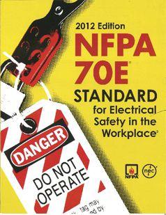
The original deadline for proposals for the 2015 NFPA 70E was November 2, 2012. The new deadline is June 22, 2012.
A complete description of the new process is available for review at www.nfpa.org/newregs.
Annexes in NFPA 70E are used to supplement the information in the standard and are not part of the standard insomuch as they are not mandatory. The new title for the annex section is Informative Annexes. While people do not often review the annexes, perhaps because they do not recognize their importance, the annexes help readers to better understand the standard and the reasons the NFPA 70E committee has made some of its decisions.
Annex A is a listing of all standards referenced by NFPA 70E. This list includes ANSI standards, IEEE standards, ICRP standards, ASTM standards, IEC standards, and the NEC. The most recent versions (as of the ROC/ Second Draft meeting) are used as references for each standard.
Annex B contains a listing of informational references, which may also include standards. The primary difference between Annex A and Annex B is that the standards within Annex A are considered part of the standard and thus include mandatory elements, and the documents listed in Annex B are informational only.
Annex C has information about limits of approach. Information contained within Articles 110 and 130 are expanded upon in Annex C, and more detail is provided about the shock approach boundaries. As an example, C.2.1 discusses the following:
• The distances in columns 2 through 5 of Tables 130.4(C)(a) and (b) were derived from the basic minimum air insulation distances in IEEE Standard 4, Standard Techniques for High Voltage Testing, Appendix 2B for voltages 72.5 kV and less, while IEEE Standard 516, Guide for Maintenance Methods on Energized Power Lines was used for voltages above 72.5 kV).
• Column 2, Limited Approach Boundary (Exposed Movable Conductor), uses OSHA’s requirement stated in 29 CFR 1910.333(c)(3)(i).
• Column 3, Limited Approach Boundary (Exposed Fixed Circuit Part) comes from NEC Table 110.26(A)(1) for 151 volts to 600 volts, NEC Table 110.34(A) for 750 volts to 145 kV and OSHA 1910.333 for voltages above 145 kV.
• Column 4, Restricted Approach Boundary, primarily comes from the National Electrical Safety Code, ANSI C2 and
• Column 5, Prohibited Approach Boundary, is from a combination of experience and NEC Tables 230.51(C) and 490.24.
Annex D, Incident Energy and Arc Flash Boundary Calculation Methods, has information concerning several methods that can be used to calculate incident energy and the arc flash boundary with IEEE 1584, Guide for Performing Arc-Flash Hazard Calculations being one of them. Each method discussed has limitations of use, and in some cases, one may be more appropriate than another.
As an example, IEEE 1584 can only be used to determine incident energy for voltages from 208 volts through 15,000 volts in metalenclosed equipment (arc-in-a-box) with short-circuit currents between 700 amperes to 106,000 amperes.
The Doughty/Neal method can be used to determine incident energy for three-phase systems of 600 volts and less, when the shortcircuit current is between 16,000 amperes and 50,000 amperes.
The Ralph Lee method is used for determining incident energy on a three-phase system above 15,000 volts in open air. The text portion of IEEE 1584 is included as part of Annex D for reference. Table D.2 contains very useful information, in that it estimates the arc-flash boundaries for various system voltages and short-circuit currents in a large petrochemical plant. This should be of use to almost anyone who works in a large facility and wants to know the risk of an arc-flash burn, even though the table applies specifically to petrochemical plants.
Some of the arc-flash boundaries are eyeopening, and one should take the time to read and understand Annex D.
One change to Annex D is in D.6 Calculation of Incident Energy Exposure Greater Than 600 V for an Arc Flash Hazard Analysis. Often the soft ware for arc-hazard studies is set at a twosecond maximum fault duration, which is normally satisfactory for the purposes of arcflash analysis. The fault duration is based on the belief that in two seconds the worker is either on his way out of the room or the exposure has passed, but that may not always be the case.
For example, a person working inside a cabinet or in an area that has restricted access such as a bucket truck as described in the following example may be exposed to an arc for longer than two seconds. In situations such as this, the worker has little choice other than to do the best he can to protect himself until the danger passes. Fortunately, most such incidents would probably be from a single-phase fault; therefore, the incident energy would be reduced from a three-phase arc. However, the incident energy is proportional to time, so the longer the arc lasts, the more heat is produced.
The wording for this new section is “If the arcing time, t, in Equation D.7.3(c) is longer than 2 seconds, consider how long a person is likely to remain in the location of the arc flash. It is likely that a person exposed to an arc flash will move away quickly if it is physically possible, and 2 seconds is a reasonable maximum time for calculations. Sound engineering judgment should be used in applying the 2-second maximum clearing time, because there could be circumstances where an employee’s egress is inhibited. For example, a person in a bucket truck or a person who has crawled into equipment will need more time to move away.”
Although there are many more informative and important annexes within the 70E, space restrictions unfortunately prevent us from detailing each one. Readers should take the time to study and understand the remaining annexes.

Information in the 70E standard and the annexes is constantly changing. The NFPA is moving to an on-line submission and review system to streamline the process, and the 70E changes approximately every three years.
Proposals (Public Input) must be submitted before the new closing date of June 22, 2012. Some items could use editing for clarification, and reader suggestions are welcome to help improve this edition. After all, this is your safety standard. Help make it a better by providing constructive inputs for change.
Ron Widup and Jim White are NETA’S representatives to NFPA Technical Committee 70E (Electrical Safety Requirements for Employee Workplaces).Both gentlemen are employees of Shermco Industries in Dallas, Texas a NETA Accredited Company. Ron Widup is President of Shermco and has been with the company since 1983. He is a Principal member of the Technical Committee on “Electrical Safety in the Workplace” (NFPA 70E) and a Principal member of the National Electrical Code (NFPA 70) Code Panel 11. He is also a member of the technical committee “Recommended Practice for Electrical Equipment Maintenance” (NFPA 70B), and a member of the NETA Board of Directors and Standards Review Council. Jim White is nationally recognized for technical skills and safety training in the electrical power systems industry. He is the Training Director for Shermco Industries, and has spent the last twenty years directly involved in technical skills and safety training for electrical power system technicians. Jim is a Principal member of NFPA 70B representing Shermco Industries, NETA’s alternate member of NFPA 70E, and a member of ASTM F18 Committee “Electrical Protective Equipment for Workers”.






Shermco Industries recently completed a project that upgraded multiple generator control systems and main and feeder breaker control relays as well as provided an upgraded Supervisory Control and Data Acquisition (SCADA) system for an electric municipal utility. To meet customer requirements, the system had to be capable of communicating with and controlling several different protective devices while retaining the potential to expand in the future. In addition to communicating with various protective devices for data input, the SCADA system also had to be user friendly with control being accomplished through a simple touch-screen monitor.


The distribution system for this electric municipal utility consists of one main 15 kV distribution bus fed by a 69 kV to 15 kV transformer through a main breaker. The main bus is also fed individually by multiple generator sets, each with separate generator controls and a generator breaker. Feeder breakers are also tied to the bus for distributing electricity to the town. The two buses then distribute power to the community via 15 kV feeders. Adding complexity to the system is the recent addition of a single wind turbine to one of the distribution feeders. For this project, the utility required the capability of automating the 15 kV main and feeder breakers, as well as the various generators, through the SCADA system while using the SCADA system as a monitoring system for their generation capability.


The overall system architecture consists of a variety of SEL relays that control and monitor the 15 kV class breakers. Additionally, a combination of SEL relays and Woodward generator controls are provided for the generators including the wind turbine. To facilitate communication with all the devices, an Ethernet switch and an SEL Real-Time Automation Controller (RTAC) were installed in a star pattern (see Figure 1) for the system communication. By configuring the system in this star pattern, each relay has its own channel to the system communications controller as opposed to a multidrop network where each node must wait in turn to send data. Utilizing the RTAC with IEC 61850 protocol, each SEL relay can broadcast information to the entire SCADA system, thus enhancing data access throughput and speeding up response times.
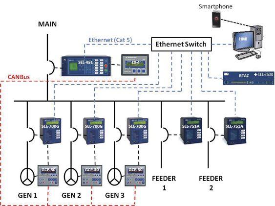
Figure 1: Typical System Communication Diagram
The SEL RTAC provides a real-time operating system with the functionality of sophisticated communication and data handling required for advanced power system integration projects. The RTAC features secure communications, advanced data concentration, high-speed logic processing, flexible engineering access, and protocol conversion capabilities between multiple built-in client/server protocols. The RTAC also gives integrators the necessary tools to easily integrate and concentrate information from the wide variety of microprocessor-based devices found in today’s substations.
Breaker protection and control is provided using the SEL-451 relay for the main breaker and SEL-751A relays for the feeder breakers. The SEL-451 relay has capabilities to monitor power, including thermal or rolling interval demand, as well as peak demand on positive-, negative-, and zero-sequence current. It also provides sufficient programming capabilities to eliminate the need for a separate programmable logic controller (PLC) to control the various operating scenarios associated with the generation system. The SEL-751A relays provide complete feeder protection with overcurrent, overvoltage, undervoltage, and frequency elements. Both relays also accommodate Ethernet-based communication with IEC 61850 communication protocol for the SCADA system. The SEL-451 accommodates hard-wired digital and analog inputs to communicate with the Woodward LS-4 device.
Generator protection and control is provided using a combination of SEL-700G relays and Woodward’s GCP-30 series of generator controllers. The SEL-700G provides a complete protection and synchronization solution for synchronous generators. They also accommodate Ethernet-based communication with IEC 61850 communication protocol for the SCADA system. The SEL-700G also accommodates hard-wired digital and analog inputs to communicate with the Woodward generator controllers.
For coordinated generator operation and control, the Woodward LS-4 was utilized. The LS-4 is a breaker control and protection module that enables the user to control, synchronize, and protect the main bus in multiple generator applications. It accommodates an automatic adjustment in frequency, voltage, and load for multiple GCP-30 series generator controllers in a networked application using CANBus communication. Woodward’s GCP-30 Series generator controllers coordinate information with the engine controllers and provide load management features including automatic base loading/peak shaving, import/export control, and emergency power/backup power generation.
Operator interface and control is provided either through the front panel of each device or through a human machine interface (HMI) that consists of a PC-based workstation. The workstation also interfaces and communicates with the SCADA system via Ethernet connection. The HMI package that was implemented was the Wonderware InTouch software system. Utilizing a tool inside the Wonder-Ware InTouch software, an electrical historian is integrated into the SCADA system for each feeder and main interconnection point that records the amperes, volts, kVA, kW and kvar. A method of manipulating the historian chart has been developed that allows the user to zoom in and out of specific sections of time, allowing the characteristics of each feeder to be analyzed over minutes, days, and even weeks.
As part of the control features of the SCADA system, the ability to operate the breakers and circuit generators is also included on the individual breaker screens. After selecting a distribution system device and requesting a device operation to trip or close the breaker, the SCADA system queries the user to go through a verification process prior to actually operating the device to mitigate accidental operations. Once verified that the operation is intended, the SCADA master


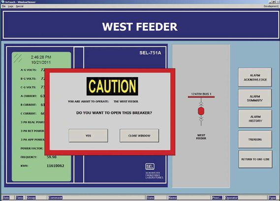


then sends a permissive command using IEC 61850 communication protocol and the associated relay initiates the operation when the protective features, such as synch-check, will allow. This utility chose to also provide automated synch-check for their generation breakers; therefore, a permissive-to-close bit was developed within the generator breaker relays to ensure that the relays will not initiate a close out-of-synchronization or into an existing fault. The SCADA system is a very effective way to operate devices without having personnel directly next to the device while it is operating. This eliminates the need for a remote operating panel.


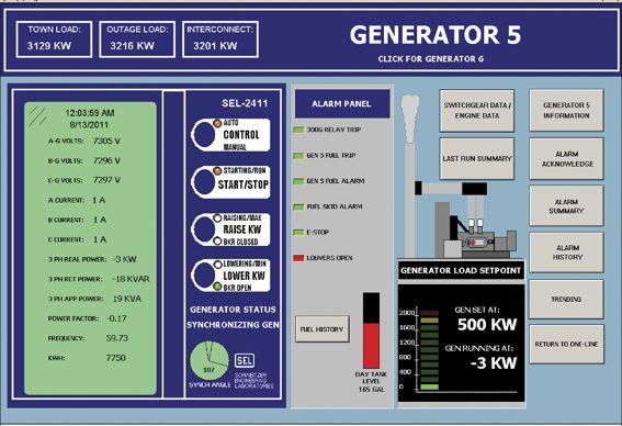
Another feature added to the system utilized the alarming capability included within the SEL relays themselves. When an alarm condition occurs, the SCADA system flags the alarm and alerts the utility’s personnel of the situation. By looking at the main one-line screen of the SCADA system, the utility’s personnel can quickly identify the specific feeder and relay that indicated the alarm condition. As an example, the SCADA alarms are triggered in the event of a breaker tripping due to any one of the protective features. With this alarming feature, the utility is made aware of any breaker operations that have occurred while its personnel were not present at the main substations.
Using available remote desktop applications, the system can be interrogated and operated remotely through a secure internet connection from a wireless laptop computer. Due to the enhanced capabilities of today’s smart phones, the SCADA system can also be interrogated and operated remotely via cell phone with full function capabilities.
Technological advances in microprocessorbased protective relays and generator controllers have resulted in enhanced flexibility for implementing SCADA systems for utilities. A SCADA system allows the utility’s personnel to quickly react to transient situations. The system also assists personnel in performing their daily activities. With the protective relays
that have the capability to communicate with other devices, data can easily be gathered and analyzed in order to mitigate or respond to problems within the distribution system. Utility personnel can oversee the entire electrical grid for a municipality remotely using a laptop or a smartphone.

Lynn Hamrick brings over 25 years of working knowledge in design, permitting, construction, and startup of mechanical, electrical, and instrumentation and controls projects as well as experience in the operation and maintenance of facilities.
Lynn is a Professional Engineer, Certified Energy Manager and has a BS in Nuclear Engineering from the University of Tennessee.

Owen Wyatt is a Level 2 NETACertified Test Technician and is a licensed professional engineer in the State of Iowa. Owen has experience in performing design activities associated with electrical substations, protective relay systems, SCADA systems, and electrical infrastructure systems in accordance with NEC requirements. Owen has also performed numerous power system studies to include fault current, protective device coordination and arc flash analysis. Additionally, he is experienced in commissioning electrical systems in accordance with NETA specifications. These commissioning activities include relay testing, medium-voltage switchgear testing, and associated control system testing to NETA specifications.


...Makes a radical breakthrough with its extreme light weight (2.2 lbs) and high current output (220 A). The MOM2 is like no other micro-ohmmeter on the market today! Unique features include:
n Handheld and lightweight — easy to use in hard-to-reach places
n Ultra capacitor technology (patent pending) — generates high current in a handheld unit
n 220 A high current output — compliant with IEC/IEEE standards
n Rechargeable batteries — convenient and portable
n Wireless connection — store and transfer data to PC via Bluetooth
n DualGroundTM method— allows testing with both sides grounded
The MOM2 has no equivalent competitor in terms of size, weight and capabilities. So, be different… radically different… with the new MOM2 Micro-ohmmeter from Megger. It’s the revolutionary choice for high current – low contact resistance measurements. terms

Call 866-254-0962 or email vfmarcom@megger.com for your free copy of Megger’s 2011 Electrical Test Instruments Catalog. Reference code- NETA_OCT when ordering.

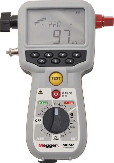


Just as its name implies, Wind Systems magazine addresses all aspects of this booming industry, providing information pertinent to landowners and managers, site developers, maintenance workers, economic development professionals, construction companies, tower and component-parts designers and manufacturers—in short, everyone involved in the systems central to and surrounding wind power generation. Brought to you by Media Solutions, Inc., publishers of Gear Solutions magazine (www.gearsolutions.com).
Subscribe today at:





“At Arc Flash Study Pro we’ll help you achieve compliance fast and efficiently.
You’ll work with one highly trained specialist from start to finish, from surveying through analysis, engineering, reporting and training. You have my commitment!”
Curtis Latzo, President and Owner, Arc Flash Study Pro Our STUDIES will provide you with FULL COmPLIAnCE of nFPA 70E and OSHA 1910 Arc Flash Regulations


We previously discussed the problem of low-ratio CTs used on systems with high fault current and mentioned the IEEE working group report on this subject. Because of the emphasis in this report on making sure that CTs do not saturate, a number of people expressed concern about the operation of instantaneous ground fault relays connected to zero-sequence, or core balance, CTs. Because of this concern, Powell recently ran a series of tests to check the operation of typical CTrelay combinations. Two different relays were tested with each of two CTs. The relays were the GE HFC and the ABB IT. Electromechanical relays were chosen for the test because their higher burden places a greater load on the CTs. The CTs used were both made by ITI. The first was Model 141-500, 50/5, C10 accuracy. The second was Model 143-500, 50/5, C20 accuracy. The test results are presented in the table below.

Both of these relays operated correctly and reliably with both CTs. However, we also tested a third relay, the ABB ITH, a high dropout version of the IT. We found that this relay was not reliable in this service. It picked up at quite low values, and operated well with primary currents up to about 150 amperes. At currents of 600 amperes and higher, it chattered badly and did not close its contacts long enough to operate a circuit breaker. Upon asking around, we found that this relay had been recommended for 50 GS service in the past, but its manufacturer (Westinghouse at that time) changed the recommendation when the chattering problem was discovered. Based on this information and the tests, Powell strongly recommends that the ITH relay not be used as a 50GS relay. Summarizing, both the HFC and the IT work quite well at primary ground fault currents up to 1800 amperes, even though the CTs are badly saturated at that current level. This circuit, with these CTs and relays, should not be used on solidly-grounded systems with high ground fault current. For these systems, residually-connected relays should be used, or the zero-sequence CTs should have higher ratios.
Baldwin Bridger is retired Technical Director of Powell Electrical Manufacturer Co., Houston, Texas. He has worked as an engineer and engineering manager in the design of low- and medium-voltage voltage switchgear since 1950, first at GE and since 1973 at Powell. He is a Fellow of IEEE and a past president of the IEEE Industry Applications Society.




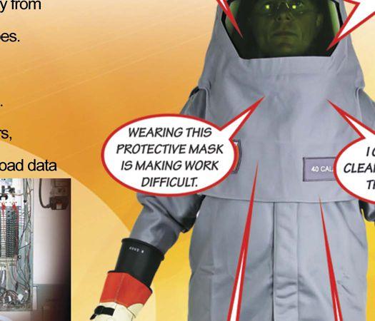





In a normally balanced three-phase system, unbalanced fault conditions generally cause unbalanced currents and voltages to exist in each of the phases. Calculating unbalanced voltage and current levels through the elements of a power system is very complex. Using Fortescue’s method, the unbalanced system conditions can be mathematically changed into three easy to calculate balanced systems. After the three balanced systems are calculated, the result is then, with simple addition, changed back into the actual unbalanced levels at each location of the power system. In fact, most numerical protective relays operate from symmetrical component quantities.


An extremely powerful tool for analyzing unbalanced three-phase circuits is the method of symmetrical components introduced by Charles Legeyt Fortescue. In 1918, Fortescue presented a paper entitled Method of Symmetrical Coordinates Applied to the Solution of Polyphase Networks, which demonstrated that any set of n unbalanced phasors could be expressed as the sum of n symmetrical sets of balanced phasors. The n phasors of each set of components are equal in length, and the angles between adjacent phasors of the set are equal.
method, there are three equivalent circuits for each element of a three-phase system. Figure 1 assumes ABC system rotation. The balanced sets of components for a three phase system are the following:

By organizing the separate equivalent components into networks according to the interconnections of the elements, we arrive at the concept of three sequence networks. Solving the balanced sequence networks for the fault conditions is relatively easy. The solution gives symmetrical current and voltage components which can be summed together to reflect the effects of the original unbalanced fault on the overall system. According to Fortescue’s


1. Positive-sequence components consisting of three phasors equal in magnitude, displaced from each other by 120° in phase, and having the same phase rotation sequence as the original phasors.
2. Negative-sequence components consisting of three phasors equal in magnitude, displaced from each other by 120° in phase, and having the phase sequence rotation opposite to that of the original phasors.
3. Zero-sequence components consisting of three phasors equal in magnitude and with zero phase displacement from each other.
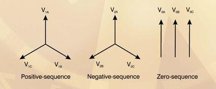


Figure 1: Positive-Sequence, Negative-Sequence, and Zero-Sequence Components


The three sets of symmetrical components are designated by a subscript 1 for the positivesequence components, a subscript 2 for the negative-sequence components, and a subscript 0 for the zero-sequence components. The positive-sequence set is the only one present during perfectly balanced system operation. The presence of negative-sequence and zerosequence components indicates unbalanced operation of the power system and/or power system faults.

All three-phase quantities in a power system can be represented by the sum of the symmetrical components. Let’s take voltages as an example. These three-phase voltages can be expressed in terms of the sequence components as shown in equations (1), (2), and (3).

The quantity
Adding VA, VB, and VC and solving for each of the symmetrical components, with A-phase quantities yields


The A-phase components are the reference; therefore, the suffix “A” is dropped and the components are denoted by V0, V1, and V2. Currents can be determined in a similar manner; the resulting sequence currents are I0, I1, and I2.

The unknown quantities can be reduced by making use of the fact that the positive and negative sequence components always have exactly 120° between them. So we define an operator Using this “a” operator, we simplify equations (2) and (3) in equation (4) below.

We also know by definition that V0A =V0B =V0C
Substituting equation (4) in equations (1), (2), and (3)


Zero-sequence components and negativesequence components are both measurable indications of unbalanced conditions. Obtaining zero-sequence quantities with electromechanical relays has not been a problem because the component does not require phase shifting by the “a” operator. See equation (8). The sum of the phase quantities is proportional to the zerosequence component. Conversely, the negativesequence component has been more difficult and costly to obtain with electromechanical relays due to the high cost of techniques required to filter negative-sequence components.
Modern numerical protective relays include a number of advantages and functions associated with simple, accurate calculation of symmetrical components from phase quantities. The numerical protective relay turns the analog voltage and current levels into digital values with a magnitude and phase angle. After the A/D conversion, determining the symmetrical components is accomplished by the mathematical capabilities of the modern microprocessor. As a result, numerical protective relays can derive easily the positive-, negative-, and zero-sequence quantities. Numerical protective relays also provide the tools for the relay engineers to analyze sequence components recorded in oscillography files.


Directional overcurrent relays (67) can use the phase relationship of voltage and current to determine the direction to a fault. To determine the direction to a fault, the angular relationship is the only concern. Usually, the angle setting of the directional relay is referred to as the maximum torque angle (MTA). The simple concept of detecting fault direction in these relays is that there is an approximate 180° difference of calculated sequence impedances Z0, Z1, and Z2 for faults in the two directions from the relay location in faulted conditions. This high variation in phase angle is a reliable indication of the direction to a fault.


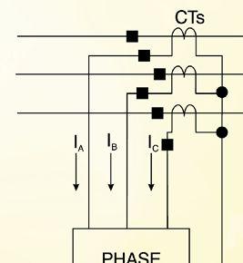
The three-phase voltage drop equation for a system that can be represented by voltages at two defined locations, system voltage VS and fault voltage VF, is the following:


Figure 2: Zero-Sequence Current Components used for Ground Fault Protection

When the impedances are closely balanced, equations (11), (12), and (13) can be expressed in symmetrical component quantities as shown in equations (14), (15), and (16).

Modern numerical protective relays use the angular relationships of symmetrical component currents and voltages and the resultant angular nature of sequence impedance Z0 , Z1, and Z2 to determine the direction to a fault. These three impedances are used to create three directional assessments; 67ZERO , 67POS, and 67NEG respectively, in modern numerical protective relays. The common process in these relays is to measure the impedance angle and compare it to a window of the MTA ±90° as forward or reverse.


A ground fault current can be considered a zerosequence current as it passes through the system to reach the location of the ground fault. (See Figure 2.) This zero-sequence current may be supplied from different sources and delivered to the particular zone involving ground fault. A zero-sequence current also can be caused by an imbalance in impedances and sources within the power system that has multiple groundings or it could be a triplin (3, 6, 9, 12, etc.) harmonic current. These currents would not necessarily involve a ground fault. In these circumstances, we would not want ground fault protective relays to cause false tripping.
With numerical protective relays, protection against a phase-to-ground fault is less difficult. A ground fault protective relay must detect all phase-to-ground faults within its defined zone of protection. The well-known method of detecting ground faults is to use a numerical protective relay that responds only to the zerosequence current of the system.


The relay simply measures the sum of the three-phase currents. See equation (17). Under balanced conditions, the sum equates to zero. Note that zero-sequence current is also known as residual current.

Ground fault protection elements should not be set more sensitive than the normal system unbalance. There are two types of current transformer connections to measure zerosequence current in the system as shown in Figure 3 and Figure 4.
The connection in Figure 4 is also known as flux summation. The conductor cables pass through the center hole of the core-balance current transformer. Unbalanced flux in the A, B, and C conductors will induce current flow in the secondary of the CT. This produces secondary current in the system known as zerosequence current.


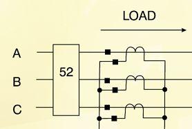
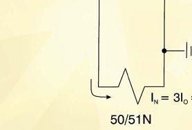
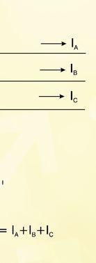
Figure 3: Residual CT Connection
The available fault current for a single-phaseto-ground fault is very limited for ungrounded systems. That makes it difficult to detect zerosequence current in a ground fault protective relay that responds to only zero-sequence current. In this case, sensitive voltage relays can be used to detect ground fault where the fault currents are very small.

The setting of the ground fault protective relay in Figure 3 should be above the line maximum unbalance current to avoid nuisance tripping and to accommodate for initial asymmetrical motor starting currents.
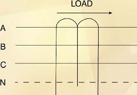


4: Core-Balance CT Connection

A set of voltage transformers is wired with a grounded wye on a primary side and a broken delta on a secondary side. The 59N element of the relay is connected across the broken delta. It is necessary to connect a resistor across the broken delta to avoid ferroresonance.
See Figure 5.


Figure 5. Zero-Sequence Voltage Components used for Ground Fault Protection in Ungrounded 3-Phase, 3-Wire System


Grounded wye/broken delta voltage transformers act as zero-sequence filters. The relay measures the sum of the three-phase voltages. See equation (18). Under balanced conditions, the sum equates to zero. When a ground fault occurs, the relay will detect the presence of the secondary zero-sequence voltage (3V0).

In the case of motors, the primary cause of motor failure is excessive heat. If sustained over a long period of time, this excessive heat condition will result in motor burn out and also reduce the life span of the motor. Usually, overheating is caused by overcurrent conditions, which can be overloads, locked-rotor conditions, undervoltage, phase failure, repetitive starts, or phase unbalance.
Unbalance in the feeder phase voltages or motor winding impedance causes unbalanced currents to flow to the motor. Current unbalance is a major factor in temperature increase in motors. Current unbalance in a motor can be represented by the presence of an excessive negative-sequence component in the motor current. The negativesequence current (I2) from unbalance causes rotor heating and additional copper losses in the stator windings. It is necessary to protect motors against excessive negative-sequence overcurrent.
tripping in 40 seconds. It is common to use current unbalance to provide an alarm first so that corrective action can be taken before removing the motor from service.
There is an inverse-time overcurrent element (51) that uses negative-sequence current as the operating quantity. The curve characteristic should be a straight line on log-log scales, corresponding to I22 • t = K and should be set to match the motor running mode characteristic.


For generators, protection is based on the same principle as motors where excessive heating from unbalanced stator currents will result in generator damage. In addition, the negativesequence current produced by unbalanced conditions induces double-frequency currents into the rotor, causing overheating. The continuous unbalance current capability of a cylindrical-rotor synchronous generator is defined in IEEE/ANSI C50.13 and of a salient pole generator is defined in IEEE/ANSI C50.12, as shown in Table 1.

Current unbalance (46) measurement in numerical protective relays is easy to implement. Measuring algorithms includes the true negativesequence measurement and the difference between the maximum and minimum phase currents. The current unbalance measuring elements have an I22 • t = K characteristic that makes the time delay settings easier to apply than with the voltage element. The worstcase unbalance occurs for an open phase at full load. In this case, the negative-sequence current equates to the positive-sequence current. If K = 40, the time dial should be set to cause


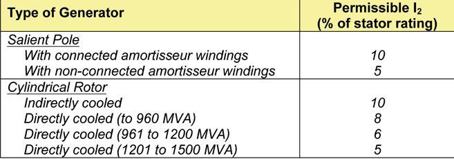
There are several causes of unbalanced threephase currents in a generator. The most common causes are system asymmetries, unbalanced loads, unbalanced system faults, and open circuits. The highest source of negative-sequence current is the generator phase-to-phase fault.


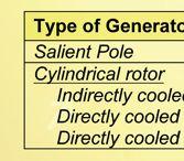

The short time (unbalanced fault) negativesequence capability of a generator is defined in ANSI C50.13 as shown in Table 2 below.


Modern numerical protective relays provide negative-sequence inverse-time protection using an I22 • t characteristic shaped to match the short-time withstand capability of the generator. The relay time units can be set to protect generators with K values of 10 or less. An alarm setting associated with these relays can provide detection for negative-sequence currents as small as 0.3 percent of a generator’s rating. The trip pickup can be set at the continuous negativesequence capability of the generator operating at full output.


Normally, the protection against negativesequence current is connected to trip the main generator breaker(s) and the field breaker. An alarm should be provided for indicating when the generator’s continuous capability is exceeded.
Modern numerical protective relays include a number of advantages and functions associated with the simple and accurate calculation of symmetrical components from phase quantities. Hardware sequence filters in predecessor technologies have been replaced with simple mathematical techniques that implement the equations for symmetrical components with the mathematical capabilities of the microprocessor and the digitized quantities. In particular, zerosequence and negative-sequence based relay elements extend protection options for finding fault direction and providing both ground fault and motor/generator protection.


Suparat Pavavicharn is a Senior Application Engineer with Basler Electric Company. Pavavicharn is a 1997 graduate of Khon Kaen University, Thailand, with a Bachelor of Science Degree in Electrical Engineering. She also received a Master of Science in Sustainable Energy and Management from Flensburg University, Germany, in 2003. Pavavicharn brings 14 years of experience in power station, electric utility, and industrial sectors. Her experience over the last eight years has focused on all facets of protection including design, fault studies, setting and testing, and on-site commissioning.








CHOOSE BETWEEN KEEPING MAINTENANCE COSTS DOWN AND KEEPING UP WITH PRODUCTION DEMAND…OR DO BOTH.

NETA certified experts at Electrical Reliability Services will keep you in perfect balance. To ensure the reliability of your electrical power, you have to balance the need to reduce maintenance costs with the need to perform regular maintenance. Only the team from Electrical Reliability Services delivers cost-e ective services and system expertise to keep you up and running 24/7.



Over the years, the methodology for testing distance relays has been slowly progressing from steady state to simulating real system conditions. Steady-state testing is a tried and true method for distance relays, but it does not address the system’s source impedance. The source impedance of the system influences the dynamic expansion of the mho characteristic and changes the apparent reach of the relay which is not observed in steady-state testing. By taking into account the system’s source impedance, the true behavior of the relay can be observed.


Testing distance relays is often seen as a difficult procedure. One of the difficulties for test technicians is choosing the correct method of testing distance elements. However, definition of correct is subjective and can change depending on who is speaking. Some may insist that a constantvoltage method is the way to go, while others will argue that a constant current is best. Still others may suggest calculating the sequence components of the expected fault and deriving the secondary test currents so that constant source impedance is kept. All three methods are in wide general use throughout the electrical industry. This paper will discuss those methods and outline a simplified method of testing using the sequence components

When testing distance relays, one should have a general understanding of the power system the relays are protecting. For this article, the power system discussed is modeled in Figure 1.


Unlike the systems considered in most papers on this topic, which use two sources, the system modeled here uses a single source. Using a singlesource model helps to simplify the calculations required to determine the secondary voltages and currents from the test equipment. This can be advantageous when testing in the field where different system scenarios are encountered. The system shown in Figure 1 has the single source feeding a transmission line that terminates at a bus. The distance relay shown is the zone 1 protection for the line. The relay can be either electromechanical or microprocessor based.


In North America, it is common for the phase protection of transmission line relays to utilize the mho element. Figure 2 shows the mho element with typical test points. The vertical axis is the reactive impedance, and the horizontal axis is the resistive impedance. The line angle of the relay is represented by ѲL, which is measured in degrees, while the reach of the relay is represented by the length, ZLMag, and is measured in ohms.
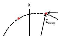


Determining what constitutes a short line or a moderate level of impedance is often a subjective decision. The determining factor is the relay test equipment being used. As much as electrical technology has progressed in the last one hundred years, it is still not possible to manufacture a test set that can output infinite voltage and infinite current and be suitable for every single test scenario. Consequently, it is usually the output current limit of the test set that determines the method of test for distance relays. If output current of the test set is the determining factor, a short line would be one in which the constant voltage method requires the test set to exceed its output current capability. The constant current method could then be used to overcome this shortcoming. By keeping the current at a fault level that can be handled by the relay test equipment, the user can ramp the voltage until the desired impedance is seen by the relay.


As stated earlier, there are various methods that can be used to test the distance element. They are referred to as constant voltage, constant current, and constant impedance methods. The reach setting of the distance element determines the method most likely to be used. For long lines that have a moderate to high magnitude of impedance, a constant voltage method may be used to determine the trip points. This method involves keeping the fault voltage constant and ramping the magnitude of current so that the ratio of voltage to current is equal to the impedance pickup point. In contrast, the constant current method is accomplished by keeping the fault level of current constant while ramping the voltage. The voltage is ramped until the ratio of voltage to current is equal to the impedance pickup point. The constant current method is generally used for short lines.


These two methods have been the most common methods of testing distance relays for many years. The test procedures have been developed mainly from using homespun components such as variable autotransformers and phase shifters to produce appropriate voltages and currents. After this homespun approach, came the first generation of test sets, but these were little more than discrete homespun components in a single box. Later, the test equipment became more and more sophisticated, but the test methods did not evolve. In the early days, it took significant effort to obtain current lagging voltage by 60 degrees. Today, it is not a problem to obtain current lagging voltage by 80.21 degrees. Just as test technicians used the old equipment to approximate fault values to the best of its capability, they should continue to use this approach for modern equipment. When early methods of testing are used with modern test equipment, they are commonly referred to as steady-state testing whereby one quantity remains steady while the other is varied. With today’s modern equipment, a new method of testing known as dynamic testing has been developed. This allows both the voltage and current to be varied during a test. In order to understand why this is significant, one must first understand what a relay is actually seeing when a steady-state test is performed.


When steady-state testing is performed on a relay, either current or voltage is varied. By changing only one quantity, the characteristic of the mho circle will change and expand. This expansion is caused in part by the equivalent source impedance behind the protective relay. By varying either voltage or current but not both, the test technician allows the source impedance to change for each test point on the characteristic curve. Figure 3 shows the steady-state characteristic as the dotted line. During testing by a steady-state method, the actual characteristic varies and is represented by the overlapping circles. Note how the trip points of the overlapping circles intersect with the steadystate characteristic. This usually happens around the line angle of the relay. If the test points are far from the line angle, then the overlapping circles and the steady-state characteristic trip points will no longer intersect. It is at this point that the test technician may notice overreaching of the relay when using steady-state test methods. In order to test the true characteristic of the relay, dynamic methods must be employed.


testing possible. One of the most popular methods of testing distance relays is utilizing COMTRADE files captured by digital fault recorders or by the protective relays themselves. These files allow the test technician to play back actual faults that have occurred in the field and verify that the relay operates correctly. By default, these files will contain a constant source impedance as well as other parameters, such as dc offset, which will affect the behavior of the relay. The downside to this method is that a fault must occur before the file can be captured and played back.







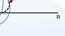

Simulation soft ware offers an alternative to waiting for faults to occur. Depending on the soft ware package, very detailed models of transmission systems are possible and various fault conditions can be simulated and exported to COMTRADE files. The soft ware simulation packages can also include effects from parallel lines, series compensated lines, and multisource line models, among others. The test scenarios possible with many of the soft ware programs are limitless. This is ideal for commissioning before the relays are placed in service, as the test technician can be sure that the different scenarios will lead to correct relay operation. Unfortunately, after commissioning, most testing crews do not have a limitless amount of time available to test the relays once they are in service. The number of tests performed is therefore reduced, but they still need to demonstrate that the relay will operate correctly if a fault occurs.


In recent years, a method of testing has been develped that tries to more accurately represent true system conditions while testing. This is referred to as dynamic testing. One of the characteristics of dynamic testing is that the equivalent source impedance seen by the relay remains constant. In other words, the mho circle does not change continuously when dynamic test methods are used. Modern relay test equipment has made dynamic

In this situation, the relay needs to be tested in a relatively short time. Instead of attempting to test the endless scenarios, many companies opt to scale down testing to include only the most likely situations. These situations reflect the types of faults that are most likely to occur. Examples are a three-phase bolted fault, a line-to-line fault, a lineto-ground fault, and a double line-to-ground fault. By calculating these faults using their sequence components, the test technician can produce fairly accurate testing scenarios. However, it should be noted that this method is not as accurate as a full system simulation.


No discussion of fault conditions would be complete without a brief consideration of symmetrical components. Symmetrical components were first described in a paper by Dr. C. L. Fortescue entitled, Method of Symmetrical Coordinates Applied to the Solution of Polyphase Networks. Dr. Fortescue stated that unbalanced three-phase voltages or currents could be transformed into three sets of balanced three-phase components. To achieve this, the symmetrical components method uses a variable called the “a” operator. This variable is a vector with a magnitude of 1 and an angle of 120°. In a three-phase system, the “a” operator is applied to the reference voltage or current. By applying the “a” operator to the reference voltage and current phases, they are each rotated counter clockwise by 120°. To get a 240° displacement, the “a” operator is squared. This is shown in Figure 4 below where the B-phase and C-phase voltages are expressed in terms of A-phase voltage. This same procedure also applies to current.
Mathematically, the sequence components can be broken down into the following equations:
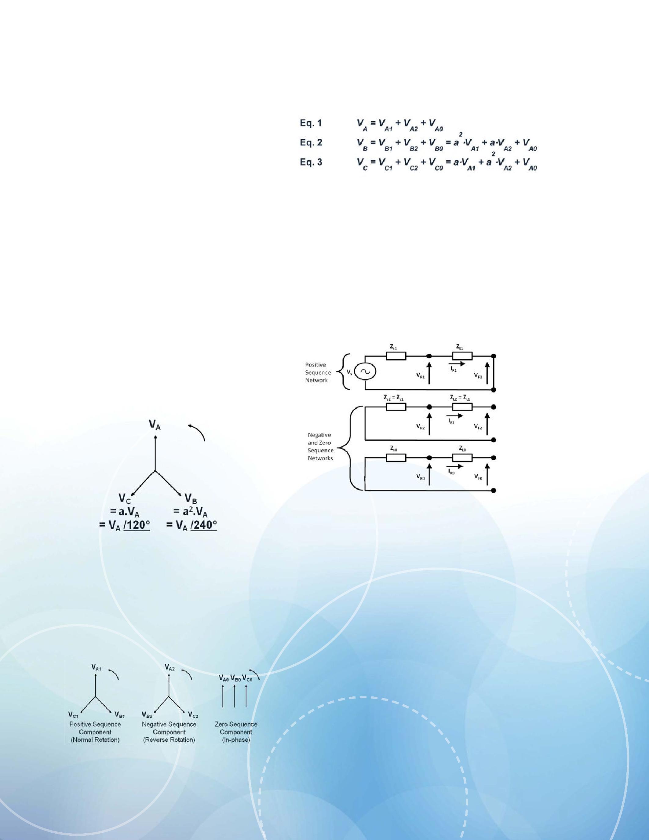
After each of the phases is expressed in terms of a common reference, they can be broken down further into their actual sequence components. Each of the three phases will contain three components called positive, negative, and zero sequence as shown in Figure 5.
To put these equations in perspective, one must consider what each of the sequence components tells us about the condition of the power system. The power system from Figure 1 can be broken down into an equivalent circuit diagram where each of the sequence components is represented in a way that depends on the conditions the system is experiencing. Figure 6 illustrates the sequence component network under normal operating conditions.
Figure 5: Positive, Negative, and Zero Sequence Components
From Figure 6, the closed path of the top circuit shows that only the positive sequence components are present during normal balanced operation. The circuits for negative and zero sequence are left open because there are no imbalances present. However, it should be noted that, in reality, there will be small values of negative and zero sequence components even during normal conditions. For the purposes of this paper, the system is being treated as an ideal system. With a three-phase bolted fault, only positive sequence values will be present since the system is still balanced.
When the power system experiences imbalance, such as a phase-to-phase fault, the equivalent circuits change. The negative sequence component is introduced and needs to be accounted for. With a phase-to-phase fault, the fault currents of the two faulted phases will be flowing into one another. This configuration will also make their sequence components equal and opposite in direction. Figure 7 shows the inclusion of the negative sequence network due to a phase-to-phase fault.

Finally, when the power system experiences an imbalance due to a line-to-ground fault, the zero sequence component is also taken into account. In a single line-to-ground fault, there is an unbalance between the phases, and a current path to ground. The representation of this type of fault is shown in Figure 8. Unlike the phaseto-phase fault, all sequence component current values flow in the same direction.
After the sequence components have been defined for the system, the secondary test currents can be calculated. A line-to-ground fault will be calculated so that positive, negative, and zero sequence components will be present. We can begin by determining the source impedance of the system. If the source impedance is unknown, then an educated guess can be made to simulate different types of systems. It is easiest to determine the source impedance in terms of its ratio to line impedance because this is a quantity that will probably be known. The smaller the percentage of source impedance to line impedance, the stronger the system and the less the expansion. The opposite is true for a weak system. The larger the percentage of source impedance to line impedance, the greater the expansion. By controlling the magnitude of the source impedance, one controls how much expansion the mho circle will experience in the relay. Figure 9 illustrates how the expansion of the mho circle is tied to the source impedance. The red circle represents the dynamic expansion. A weak system usually has a large source impedance, so its mho expansion is big. A strong system has a small source impedance. Its mho expansion is smaller and approaches the size of the steady-state characteristic.
To begin calculating the secondary fault values, one must define the parameters needed. To illustrate this example, the fault values for a zone 1 characteristic are shown in Table 1.
In Table 1, the only quantities arbitrarily chosen are the source impedance, ZS , and the source angle, ZsAng , other quantities should be available from the relay settings. The source impedance, Zs, is determined by using 1.6 percent of the positive sequence line impedance. The source impedance angle was chosen to be equivalent to the positive sequence line impedance so that the system would remain homogeneous. By using a homogeneous system, one simplifies the calculation of the mho expansion. Figure 10 illustrates how the expansion of the mho circle can be calculated.
Using geometric principles, one can determine the dynamic reach of the mho circle using the settings of the protective relay. The zone 1 reach, ZLMag, and source impedance, ZS, are plotted as two vector quantities. When the source impedance angle, ZSang, and the line impedance angle, ZLang, equal one another, a straight line is formed through the center of the mho circle. Because the expansion is due to a line-toground fault, the ground impedance also needs to be considered. There will be a change in the apparent reach and apparent line angle as seen by the relay. The k0 factor assists in calculating how the ground impedance will affect the reach and angle of the apparent impedance seen by the relay. The zero sequence magnitude and angle compensation are expressed in equations 4 and 5.

The zero sequence magnitude and angle compensation are then applied to the original line impedance and angle. The source impedance magnitude is chosen as a percentage of the line impedance and the line and source angles are set equal to one another as shown in equations 6 – 9.
Because the line and source impedances are vector quantities, they can be broken down into their real and imaginary components. Then, the center point along the mho circle can be found as shown in equations 10 – 15.
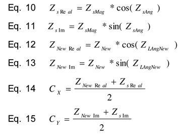
After the center point of the circle has been found, the radius of the circle and compensation angle can be determined. The compensation angle is the apparent line angle that the relay sees during the ground fault. Next, an adjustment for the position of the mho circle is determined. Finally, the new total apparent reach, Ztot and line angle, Zang, can be determined. This is shown in equations 16 – 23.


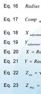
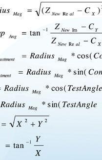
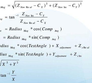


When using these equations, one must note that a correction to the line angle, Zang, may be necessary to keep the line angle in the correct quadrant. This correction is determined after solving for X and Y. The following relations show what corrections are necessary:

Using the relay settings and the previous equations, one can determine the apparent reach, ZTot, and line angle, ZAng, are 1.095Ώ and 77.2° respectively. After the new reach and line angle are known, the secondary currents and voltages to be applied to the relay can be computed. First, the K factor needs to be determined:
The following expression is then derived by adding all of the impedances of the sequence network in Figure 8:
This can be simplified to:
From here, the fault currents can be expressed:

By solving for the sequence components in each phase, one can calculate the final secondary currents. These are shown in Eqs. 28 – 30:
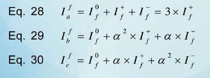


The voltages are found in a similar manner. The fault voltages can be expressed by the following equations:

These quantities are converted to each of the phase quantities:
With the increasing capabilities of today’s relay test equipment and soft ware, steady-state methods are becoming replaced by more accurate forms of testing. Computer simulations and appropriate equipment can quickly and easily provide realistic scenarios that will thoroughly test protective relays before they are put into service. However, once in service, these same relays must be periodically tested. The dynamic methods are scaled back from a full simulation to values calculated from the systems sequence components. This article has illustrated a method by which this can be performed.
The final calculated test voltages and currents are shown in Table 2.
Table 2: Calculated Secondary Voltages and Currents
The values calculated will simulate a system with constant source impedance precisely at the edge of the mho characteristic. To find the values that are slightly outside and slightly inside the operating characteristic, one must perform the previous series of calculations for each new test point. Fortunately, soft ware programs that can perform these calculations quickly for the user are readily available.
C.L. Fortescue, Method of Symmetrical Co-ordinates Applied to the Solution of Polyphase Networks, Annual Convention of the American Institute of Electrical Engineers, Atlantic City, NJ, 1918
A. T. Guilante, Dynamic Relay Testing, ATG Consulting
Rene Aguilar received his B.S. in Electrical Engineering from the University of Texas at Austin. He worked on APPDS (Automatic Protection Detection System) used for detecting coordinating issues between devices in a distributed generated system. In 2006, he joined Megger as an application engineer in the technical support group. Rene is in charge of developing automatic testing for numerical relays as well as the implementation of IEC 61850 on various Megger products. Rene has extensive experience in the testing and commissioning of electrical schemes and multivendor device applications of IEC 61850. He is a member of IEEE and and an active member of the Power System Relay Committee.
Jason Buneo received his B.S and M.S in Electrical Engineering from the University at Buffalo in 2001 and 2005, respectively. In 2005, he joined GE Energy Services as a field service engineer. He specialized in arc-flash and coordination studies, protective relay testing and calibration, and low- and medium-voltage switchgear repair. In 2008 he joined Megger as an Applications Engineer specializing in protective relay evaluation and testing. He is also a participating member of the IEEE Power Systems Relaying Committee.







•
•
•






The management of asset replacement programs is usually a matter for engineers; however, to effectively communicate current and future risk with senior decision makers, one must be able to express engineering decisions in terms of financial cost/ benefit. Recent developments in Condition Based Risk Management (CBRM) help with this task, empowering engineers and decision makers alike with the data needed to drive effective asset management policy.
The CBRM methodology provides an effective link from available asset information, engineering knowledge, and experience to the investment planning and implementation processes for any company with significant electrical assets.
A typical study begins by analyzing the equipment owner’s collective knowledge and experience relating to degradation, failure, condition assessment, performance and the influence of environment, duty, operational policy, and specification for assets. This can be combined with industry-wide experience to define a health index and ageing rate for each asset under consideration. Historical fault and performance data is then analyzed to determine the relationship between the health index and the probability that an asset will continue to function properly. This alone provides a powerful engineering tool to enable the existing and future probability of failure of assets to be reliably modeled.
In order to quantify performance in financial terms, one can express the outcome in terms of financial risk. This is a combination of the probability of an event occurring and the resulting financial consequence if the event occurs.
Once the probability of each asset continuing to function correctly (or not) has already been determined, the consequences of failure for each asset can be quantified. To do this, the consequences should be analyzed in terms of tangible quantities within specified categories, typically performance and environmental, safety, and financial consequences.
In the past, risk has been estimated using the probability and average measurable consequences of a single outcome, e.g., a disruptive circuit breaker failure. However, the failure of an asset may result in a range of possible outcomes. Using circuit breaker failure as an example, the consequences could range from failure to operate (with minimal loss) to catastrophic failure (entailing significant loss).
In addition to considering the relative criticality of an asset, one must also consider the range of possible failure scenarios. This is done by taking the average consequences of each failure mode and weighing it according to the relative probability of each failure mode.
The above method enables the highest-risk assets to be clearly identified. However, the degree of asset replacement is usually a matter of budget and policy. This is commonly based on past experience, rather than on a forward-assessment of the level of risk. It is still necessary to determine whether or not the level of proposed investment the correct one.
After risk is defined and quantified in monetary terms, it is possible to make a direct assessment of the financial value obtained from different proposed investment programs by considering the investment cost against risk on a present value (PV) basis. This can be used to determine the financially optimum (i.e., lowest PV) replacement program.
The PV of the investment required to replace an asset can be calculated for future years by compound discount of the current replacement cost.
The optimum year for the replacement of a given asset is determined on the basis of delta risk. This represents the differences among the future risks associated with an asset.
For a given asset, the total cost of replacement in year t is the summation of its PV investment cost and PV cumulative delta risk. A minimum occurs in the year when the increase in asset risk exceeds the reduction in cost by not replacing the asset. This is the financially optimum replacement point for the asset.
The following snapshots show results from this process using source data taken from a sample population of 916 15 kV circuit breakers.
Figure 1 shows a typical profile of existing health indices. In this example, new assets are given a health index of 0.5 and those at end-of-life (i.e., presenting an unacceptable probability of failure) are given a health index of 7. A typical distribution of relatively few new assets (HI <1) can be seen, with a larger number of assets in ageing but serviceable condition (HI 3-6).

Using the calculated ageing factors for each asset, we can look into the future to see how the health indices will change. Figure 2 shows the health indices for the same assets after 10 years with no investment.
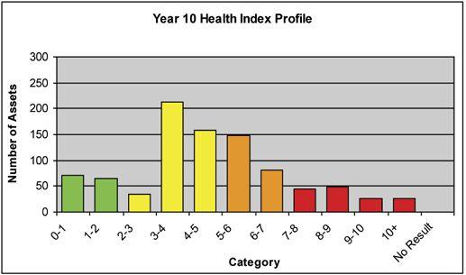
10)
The health indices indicate that a number of assets will require replacement before year 10. Initially, the CBRM model can be used to determine the required replacement rate in order to keep the overall level of risk constant. In this example, the rate was calculated to be 2.9 percent (or just over 26 units per year, representing 1-2 complete primary switchboards per year). The resulting annual risk profile is compared with no investment and reduced investment (1.5 percent replacement rate) options in Figure 3.
At the proposed replacement rate, the risk is maintained at a fairly constant level throughout the time period, despite a large number of assets reaching their end-of-life. The effect of any proposed variation from the optimum level of replacement (e.g. the reduced investment scenario) can quickly be assessed.
Figure 3 shows the annual risk, and demonstrates that the effect of prolonged risk is cumulative. To determine the actual difference in cost of the different scenarios, a PV analysis can be performed.
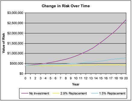
A PV risk optimization can be used to determine the optimum replacement strategy and the additional costs incurred by deviating from that strategy. An analysis of an ageing substation is shown in Figure 4.

While the investment cost falls with time, the condition-related risk increases rapidly. As this switchgear is approaching the end of its life, the lowest replacement cost occurs within four years. Delaying the replacement of this switchgear would result in greater overall cost.
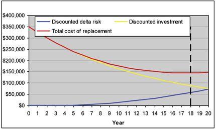
The profile for another substation is shown in Figure 5. In this case, the switchgear still has a useful amount of remaining life. The minimum overall cost is achieved by replacement in year 18.
Finally, the individual optimizations represented by Figures 4 and 5 can be combined to recommend the lowest overall cost investment program, taking risk into account. Such a program is shown in Figure 6.
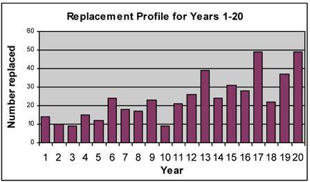
This information can be used directly as the basis of a regulatory submission or future budgetary plan.
By applying the process to all major asset groups, one can quantify the current overall risk and the optimum future overall risk.
The above calculations have been incorporated into a financial model that enables the optimum replacement program to be quickly identified. This enables:
• The representation of engineering knowledge and experience in clear financial terms of the benefits of improved asset management techniques and policies can be demonstrated.
• The generation of well-researched, defensible capital investment programs for asset replacement can help to ensure that asset risk is managed appropriately even when resources are constrained.
• Visibility of the asset risk profile over five, 10, or even 20 years is essential to help longterm investors determine their strategy.
• Direct linkage of the investment program to the condition and performance of the asset base allow investment plans to be quickly revised.
• Immediate visibility of the likely effect of overinvesting or underinvesting in the assets can be clearly identified.
How does no-outage testing fit in with CBRM? The suite of no-outage tests can be imperative in determining health index values for the assets. Using switchgear partial discharge testing as an example, studies have determined that more than 85 percent of medium-voltage switchgear failures are the result of partial discharge activity. In order to determine switchgear health indices, one must have accurate switchgear condition information available. If recent partial discharge test results do not exist, the client needs to perform this testing or accurate health index information cannot be determined. Other no-outage tests should also be applied so that the health indexes can be calculated with high levels of confidence.. The other steps of the CBRM program can then progress accurately.
A risk-based approach to asset management has been recommended for a number of years. However, the tools with which to deploy such an approach have long been hampered by the data and resource requirements needed to produce useable results, making the value of such techniques rather subjective. Through CBRM, effective risk-based asset management decisions can be made using existing data sources while demonstrating quantifiable benefits.
Such an approach also enables senior management and decision makers to engage fully with the asset management process and derive clear and tangible financial benefits from its adoption.

Don A. Genutis received his BSEE from Carnegie Mellon University. He was a NETA Certified Technician for 15 years and is a Certified Corona Technician. Don’s technical training and education are complemented by twenty-five years of practical field and laboratory electrical testing experience. Don serves as President on No-Outage Electrical Testing, Inc., a member of the EA technology group.
NETA Standard for Maintenance Testing Specifications for Electrical Power Equipment and Systems!
This document specifies field tests and inspections used to assess the suitability for continued ser vice and reliability of electrical power equipment and systems.
e Join NETA’s Affiliate Program today for Savings on MTS – 2011.
Receive additional discounts on PowerTest 2013 and all NETA publications
Go to www.netaworld.org or call 888-30 0-NETA (6382)
MTS – 2011 covers equipment such as:
✔ Switchgear
✔ Transformers
✔ Cables
✔ Switches
✔ Circuit breakers
✔ Protective relays
Also included:
✔ Rotating machiner y
✔ Motors
✔ Batteries
✔ Capacitors and reactors and more
• New section on Nickel-Cadmium Batteries
• Document references applicable industr y standards

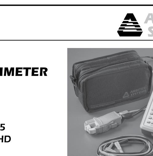



The polarization index (PI) test [IEEE Std. 43-2000], is a variation on the direct current (dc) insulation resistance test. PI is a useful indicator of contamination and moisture on the exposed insulation surfaces of a winding, especially when there are cracks or fissures in the insulation. The test is easily done and is usually conducted in conjunction with the insulation-resistance (IR) test (see NETA World Winter 2012 issue). Note: Because squirrel cage induction motor rotor windings are not insulated, this test is not appropriate for such windings.
The IR and/or the PI test should be done prior to application of any high voltage tests to assure that the winding is not so wet or dirty as to pose a risk of failure that might be averted by a cleaning and drying procedure. However, resistance testing is principally a pass/fail criterion and cannot be relied upon to predict the condition of the main insulation except when the insulation has already faulted. That is, because the PI test is insensitive to internal insulation problems, a high or low reading does not imply that the winding is in good condition.
The IR is the ratio of the dc voltage applied between the winding copper and ground to the resultant current. When a dc voltage is applied, four current components flow: a geometric capacitance charging component (IC) into the capacitance of the winding; a polarization or absorption current (IA) involving various molecular mechanisms in the insulation; a conductance linear current (IG) that is a property of the insulation material; and a surface leakage component (IL) over the surface between exposed conductors and ground (the creepage path) which is highly dependent on the state of dryness of the winding. Two current components, IC and IA, decay with time because they are essentially capacitances. For epoxy/ mica insulation systems, the conductance current, IG, is almost zero. For asphalt and polyester/mica, it is slightly higher but constant with time. The leakage current, IL, is constant with time.
The PI was developed to make interpretation less sensitive to temperature. PI is a ratio of the IR at two different times, after one minute and after 10 minutes (PI = R10/R1). If we assume that R10 and R1 were measured with the winding at the same temperature, which is usually very reasonable, then the temperature correction factor will be the same for both R1 and R10, and will be ratioed out. Thus PI is relatively insensitive to temperature.
Furthermore, PI effectively allows the use of the absorption current IA as a yard stick to see if the leakage and conduction currents are excessive. If these latter currents are much larger than the absorption current, the ratio will be about one. Experience shows that if the PI is about one, then the leakage IL and conduction currents IG are large enough that electrical tracking will occur. Conversely, if the leakage IL and conduction currents IG are low compared to the absorption current IA after one minute, then PI will be greater than two, and experience indicates that electrical tracking problems are unlikely. Thus, if we can see the decay in the total current in the interval between one minute and 10 minutes, then this decay must be due to the absorption current (since the leakage IL and conduction currents IG are constant with time), with the implication that the leakage and conduction currents are minor. A new draft standard (IEEE Std. 43 draft revision Oct 2010) also recognizes that, in Roebel bar transposition, stator windings with grading material that extend to the outer ends of the conductors and is in contact with them, the surface current IL may be much larger than the absorption current IA, and if so, the total current IT will be approximately constant with a PI around 1.0. Therefore, for these configurations, PI cannot be used as a condition assessment tool. There are potential problems with this type of end-winding grading system in that the incorrect application or degradation of grading material used in this system may eventually lead to surface electrical tracking.
Techniques have been developed to permit the polarization index to be determined with good accuracy [IEEE Std. 43-2000, IEEE Std. 62-1995, IEEE Std. 95-2002, ANSI/NETA ATS-2009, ANSI/NETA MTS-2011].
Connections -If practical, it is recommended to isolate the phases and test each phase individually. This allows for phase comparisons. To test the stator winding, one must isolate the phase leads as well as the neutral lead (if accessible). The test instrument is connected between one of the phase leads (or the neutral lead) and the machine frame. In water-cooled windings, the water must normally be drained and any hoses thoroughly dried by pulling a vacuum. (This is not possible if a vacuum pump is not available. In this case, another option is to remove the hoses to perform the tests.) When doing a PI test, the test leads should be clean and dry.
Instrument - The IR is measured with a high voltage dc supply and a sensitive ammeter. The dc supply must have a well-regulated voltage; otherwise a steady state capacitive charging current will flow.


Connections - The test instrument is connected between field winding leads and the rotor body. The brushes must be lifted or the rotor diodes disconnected.


Instrument - Use a true insulation resistance tester (megohmmeter) with a voltage selector and wellregulated voltage output. For motors and generators rated 4 kV and above, 1000 V is often used for the rotor winding test voltage.
The PI is the slope of the IR plotted over time, typically PI = IR10 min / IR1 min, but other values are also used.
Because the PI value is normally obtained when the winding is at the same temperature and humidity, it is less affected by ambient conditions than the IR value. See TABLE 1 for recommended PI levels based on thermal class ratings of the winding. For old thermoplastic windings, a high PI can indicate that the insulation is dried out and brittle due to thermal deterioration.

If the IR1min is above 5,000 megohms, the calculated PI may not be meaningful. In such cases, the PI may be disregarded as a measure of winding condition.
The new draft standard (IEEE Std. 43 draft revision Oct 2010) has an annex that deals with additional information that can be obtained by applying a stable dc voltage to a complete stator winding or individual phases for 1000 to 2000 s and recording the polarizing current IP versus time. The voltage is then removed and the discharge current ID is monitored as a function of time using a suitable discharge circuit. During the time the voltage is applied, the winding insulation is said to be polarizing. When the voltage is removed, reverse current flows, and the molecules in the insulation become disorientated and the space charge dissipates. This discharge current ID has two main components: a capacitive discharge current component which decays nearly instantaneously, depending upon the discharge resistance; and the absorption discharge current, which will decay from a high initial value to nearly zero with the same characteristics as the initial charging current but with the opposite polarity.
Normally, neither the surface leakage IL nor the conduction current IG affects the discharge current. If the traces of IP and ID versus time are compared, some stator winding insulation conditions such as contamination and voltage stress control material degradation can be identified. Differences in the IP and ID [Figure 1] may indicate winding surface contamination, damage to the voltage stress coatings, or severe thermal deterioration of the bulk of the insulation.

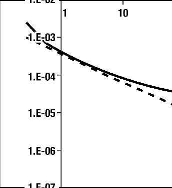
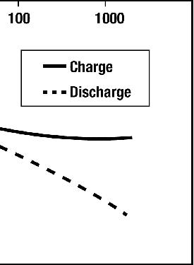

This new annex indicates that by using information obtained during a PI test, the IR versus time can be plotted in discreet increments (such as five seconds) over a specified time period (typically 10 minutes), resulting in a graph which may be referred to as an insulation resistance profile or IRP. In addition to the standard IR value and the PI value, an IRP may provide useful information as to the condition of the insulation system especially when the IR exceeds 5000 megohms. The condition of the insulation system will typically fit one of four profiles: normal, moisture, contamination, or embrittlement. Example curves for healthy [Figure 2] and moisture contaminated stator winding insulation [Figure 3] are provided.
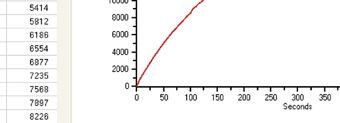


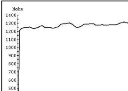



The subject of variants in the polarization index test was introduced into the IEEE Std. 43-2000 version and deals with PI values in more modern insulation systems for form-wound stators, and especially in random-wound machines. The absorption current may decay to nearly zero in two to three minutes for these machines. Thus, for modern insulation, some users calculate a variant of the conventional PI for second resistance measurements taken in less than 10 minutes, for example after five minutes where PI = IR5 ⁄IR1
There are, however, limitations in applying these other ratios:
a) There is no standard for what time intervals the IR values are to be recorded.
b) Different organizations use different ratios.
c) There is no agreed upon pass-fail criteria as has been established for the traditional PI.




Ms. Vicki Warren, Senior Product Engineer, Iris Power LP. Ms. Warren is an Electrical Engineer with extensive experience in testing and maintenance of motor and generator windings. Prior to joining Iris in 1996, she worked for the U.S. Army Corps of Engineers for 13 years. While with the Corps she was responsible for the testing and maintenance of hydrogenerator windings, switchgear, transformers, protection and control devices, development of SCADA software, and the installation of local area networks. At Iris, Ms. Warren has been involved in using partial discharge testing to evaluate the condition of insulation systems used in medium- to high-voltage rotating machines, switchgear and transformers. Additionally, Ms. Warren has worked extensively in the development and design of new products used for condition monitoring of insulation systems, both periodical and continual. Ms. Warren also actively participated in the development of multiple IEEE standards and guides and was Chair of the IEEE 43-2000 Working Group.
Ian Culbert has been a rotating machines specialist at Iris Power L.P since April 2002. Before joining Iris Power he was a motor and small generator specialist with Ontario Hydro/Ontario Power Generation from 1977 to 2002 and prior to then a motor designer with Parsons Peebles, Scotland, and Reliance Electric, Canada. Ian is a Registered Professional Engineer in the Province of Ontario, Canada and a Senior Member of IEEE. He has coauthored two books on electrical machine insulation design, evaluation, aging, testing, and repair and is principal author of a number of Electric Power Research Institute reports on motor repair. Ian has also coauthored a number of papers on motor electrical component on-line and off-line motor diagnostics testing.

3464_NETA_VLF-34E_Spring_2012.pdf 1 1/31/12 3:03 PM



The VLF-34E is a new generation VLF AC Hipot that uses a solid state design with microprocessor controls. It meets the requirements of applicable world standards regarding cable testing up to 25kV class maintenance testing. It is light, compact, rugged, and very portable. Its sine wave output is suitable for using external TD and PD detection equipment. Using a TD and PD option, the VLF-34E is all that is needed for nearly all cable testing up to 25kV class.
Easy to use controls. Programmable test sequences & manual control, USB port for downloading data and for unlimited test report capture, wireless computer interface to control and download Tan Delta diagnostics and for remote control operation via laptop.
Cable Testing Standards met: IEEE 400.2-2004, IEEE 400-2001, NS 161-2004 VDE DIN 0276-620/621, CENELEC HD 620/621, IEC 60060-3



Vanguard’s precision substation testing instruments are designed to be intuitive and easy to use so that you can focus on testing instead of wasting time in training. Our versatile instruments offer a built-in thermal printer and on-board test record storage so that tests can be conducted in stand-alone mode in the field. A computer interface is also offered so that tests can be easily conducted from a PC.
And all of our instruments are competitively priced to provide cost-effective accuracy. For a virtual experience of our instruments, check out the interactive demos on our site at:
www.vanguard-instruments.com/demos
NORTH AMERICAN ELECTRIC RELIABILITY CORPORATION REDUCING HUMAN PERFORMANCE ERRORS BY THE USE OF CONFIGURATION CONTROL PRACTICES
While preparing an outline and gathering research for an article for the spring addition of World I received an email from one of our senior relay technician at AETCO. In the email was an attached Industry Advisory from NERC (North American Electric Reliability Corporation) titled “Reducing Human Performance Errors by use of Configuration Control Practices” at first I thought this advisory would be just another research document for the article. Upon further deliberation I felt the real life examples used in this advisory and the control practices recommended for mitigation of human error not only apply to Bulk Power Systems but are good tools to be applied to all facilities within our industry when Acceptance and Maintenance Testing of Relays and protection systems employed on Transmission, Generation and Distribution system industry wide. Instead of paraphrasing the advisory I felt this advisory should be shared in its entirety with the NETA community.
Initial Distribution: November 08, 2011
This alert applies only to non-cyber assets.
• Primary Interest Groups:
System Operators
System Operators – System Protection


NERC and the Regional Entities have observed inadequate configuration control procedures being employed during Protection System construction or maintenance activities. Entities can further reduce the bulk power system’s (BPS) exposure to these reliability risks by considering these examples and suggested barriers and if warranted, augmenting their existing configuration control practices during construction and maintenance activities.
System Operations – Transmission
Engineering
Generation Engineering
Transmission Planning


While the vast majority of Protection System construction and maintenance activities take place without negatively impacting the BPS, NERC and the Regional Entities are aware of situations where entities inadequately employed configuration control practices, resulting in unnecessary BPS equipment outages. The impact of these situations highlights the need for improvement in configuration control procedures during Protection System construction and maintenance. Effective configuration control procedures include the evaluation, approval, and management of changes to an established equipment configuration. By developing and implementing proper configuration control, entities can reduce exposure to the inherent risk of human performance errors that occur during the maintenance and testing of Protection Systems.
This document does not intend to prescribe or define all aspects of a configuration control program. Instead, it is intended to highlight a few key elements of a configuration control program that, if properly implemented, could have prevented these incidents. The goal is to improve awareness of common industry practices that, if employed, can help reduce the risks associated with the construction and maintenance of Protection Systems. Below are a few real-world examples of incidents that emphasize the need for better configuration control procedures during Protection System construction and maintenance. Each of these examples demonstrates the risk to BPS reliability when adequate configuration control procedures are not observed.
A relay technician performing scheduled maintenance on a protective relay system established the proper clearance and isolation procedures to perform the work. These procedures included opening several test switches that would provide an electrical barrier between the isolated equipment and any in-service equipment. After completion of the work, the technician began restoring the test switches to the closed position; however, he overlooked one of the switches in the process, leaving that test switch open. The open switch happened to block the only trip signal to one of the circuit breakers. The technician released his clearance on the equipment and exited the substation. Sometime later, a fault occurred on the BPS and the open test switch prevented a trip signal from tripping the circuit breaker and from initiating the breaker failure scheme. Because the circuit breaker did not trip, the fault continued to be fed through the closed breaker until it was cleared by remote, timedelayed backup relaying. The result was an undesirable increase in the scope of the BPS equipment outage.
During a substation project, the construction team failed to use the latest version of a construction document to complete the installation of a protective relay system. The most recent version of the document had incorporated a configuration change to the CT ratio for the protective relays. Because the team used outdated documentation, the incorrect CT ratio was configured for the relaying. During commissioning, the team failed to detect the error, since their testing reference was to the outdated documents. The Protection System equipment was placed into service with the wrong CT ratio and then sometime later tripped improperly during a system disturbance.
A relay technician is performing a preventive maintenance activity on a transmission line protective relay and makes a temporary setting change in order to perform a calibration check. Upon completion of the work, the technician fails to restore the temporary setting to its original value. The equipment was inadvertently placed back in service with the temporary setting installed. The incorrect setting did not immediately produce an improper response; however, weeks later, the relay operated incorrectly for a fault on an adjacent transmission line. The improper line trip resulted in the outage of more BPS equipment than was necessary to clear the fault.
A relay technician is working inside a transmission line relay panel, with the necessary work clearance and equipment isolation already established. The technician discovers a need for some additional documentation and steps out of the relay panel and walks over to a nearby file cabinet. Upon his return to the relay panel, the technician is distracted and inadvertently enters a different but identical panel with relaying protecting a BPS element that is in service. Unaware that he has entered the wrong panel, the technician resumes working and eventually crosses two wires that sends a transfer trip signal to a remote substation, tripping an in-service 345Kv transmission line.
A technician accidentally opens the wrong current shorting switch for one contribution to a differential relay protecting an in-service transformer, causing the transformer to trip.
The above cases are examples of human performance errors that may have been prevented had adequate barriers and configuration control been applied.
Below are examples of some configuration control practices that are being applied in the maintenance and testing of protection systems. Employing these or similar practices can help entities reduce the risks of human performance errors.
• Maintenance Alteration Log (MAL) -
A record of all manipulations of equipment during a construction or maintenance activity. This document requires the owner to initial each manipulation once when it is performed, and again when the item is restored to its normal state. Proper use of a MALcould have prevented the human error incidents in Examples 1 and 3 above.
• Isolation Card -
A laminated plastic card placed by technicians on the physical equipment at points of isolation during maintenance or testing activities. Each technician has a personalized set of numbered isolation cards. Individual cards are placed on the physical equipment at points of isolation (e.g. test switch, control switch, or control panel) and often in a one-to-one association with entries on the MAL. After the technician has completed the work, and all items on the MAL have been restored to normal, the full set of isolation cards should
have been collected. If cards are missing, the technician works to resolve the discrepancy before releasing his clearance on the equipment. By employing practices that include proper use of a MAL and Isolation Cards, entities can reduce the risk of the human performance incidents such as in Examples 1 and 3.
•
Colored electrical tape or rubber blankets are examples of soft barriers used to cover or protect exposed, energized components to prevent undesired electrical connections during maintenance. A device used to deter the operation of a control switch during a maintenance activity is an example of a rigid barrier. Soft barriers, such as safety tape, can be used as a visual barrier and placed across the openings of in-service equipment panels during maintenance to help prevent personnel from inadvertently entering these panels during a maintenance activity. Use of visual barriers could have been used to help prevent the technician from inadvertently entering an in-service relay panel as in Example 4.
Signage, safety tape, or any device used to attract the attention of personnel. Flagging can be used to identify equipment that is within the technician’s zone of protection or to identify equipment that is outside the zone of protection. Flagging could have been used to help attract the attention of the technician prior to his entering the wrong relay panel, as in Example 4.
• Controls for distributing project documentationRevised documentation should be distributed to personnel responsible for the construction, installation and testing, as well as those affected by the change. Old documents should be removed and filed or discarded, as appropriate. After documents have been approved, they should be available at all locations for which they are designated, used, or otherwise necessary, and all obsolete documents should be promptly removed from all points of use to prevent unintended use. Some entities apply such controls by establishing a single source of record for protection information. Proper document distribution controls, including timely distribution of updated documentation and destruction of outdated documentation, could have prevented the incident in Example 2.
•
A detailed list of equipment isolation points used to electrically isolate the equipment under test during a maintenance or construction activity. Examples of items that would appear on an equipment isolation list are individual test switch poles, control switch positions, circuit breakers, etc. A technician should develop an equipment isolation list and have a peer check it prior to starting the job.
•
The peer check is an independent review, by qualified personnel, to validate the technicians’ equipment isolation list. The peer check should be provided by someone other than the technician performing the work or by members of a team that peer check each other’s work. Peer review may be effectively used in conjunction with other practices, such as when
relay settings have been modified in the field for testing or installation purposes by downloading or documenting the setting left on the relay and having an independent reviewer compare the setting with the office record.
• Self Check –
Self checking is the process of pausing to review one’s own actions prior to executing error-likely tasks. It is a four-step mental process to prevent errors, particularly on critical tasks or an irreversible procedure or step. Using the acronym STAR: Stop and take the time to eliminate external distractions, focus on the task at hand with 100% undivided and focused attention. Think, verify that no critical conditions have changed, consider the impact of your immediate action and question anything that you have uneasy feelings about or are uncertain. Act, without losing physical or visual contact with the device, remain poised and attentive to your actions. Lastly, Review, verify that you got only the specific results that you expected and wanted. By implementing self-checking skills, the technician could have avoided opening the incorrect test switch in Example 5.
• Place-keeping –
A physical marker, either temporary or permanent, that helps one keep his/her place when reviewing sequential lines or columns. Using a straight edge or consistent marking methods, one can mark sequential progress when executing long and detailed procedures. These methods are essential when interruptions or delays prevent fluid movement through a process. Consistent procedures in place-
keeping allow smooth transitions and handoffs for events that involve multiple persons to interact on the same or related procedures. Detailed place-keeping also provides a historical record for procedures that occur over extended time periods.
• Pre-job briefing
A pre-job briefing, also referred to as a tailgate or tailboard meeting, is helpful for providing clarity prior to a job start. These are usually carried out by the supervisor or more experienced personnel who understand details of the work and can point out the potential perils personnel may encounter during construction or maintenance. Some entities document the pre-job briefing in writing and have the document signed by each employee or contractor present on the job site. Pre-job briefings may be appropriate on a daily basis or multiple times during the day depending on the complexity of the work being performed.
The ES-ISAC estimates that the risk to BPS reliability from this vulnerability is HIGH, due to the daily exposure of the BPS to the adverse consequences of human performance errors during protection system maintenance and testing.
The analysis of BPS events frequently identifies human performance errors during protection system maintenance as a root cause or contributing cause of the event.
Earl
ShockleyDirector of Reliability Risk Management Office: (404) 446-2570
earl.shockley@nerc.net
To report any incidents related to this alert, contact:
ES-ISAC 24-hour hotline (609) 452-1422
esisac@nerc.com
Prior to testing relays and protection systems, a pre job brief should be performed outlining not only the work to be performed, identify all hazards associated with the work, identify circuits that will be affected and identify the proper level of PPE required to be worn in accordance with NFPA 70E to perform the work. Test for the presence of current, ac voltage and dc voltages prior to servicing equipment.
Exercise extreme caution when performing modifications, maintenance, and testing in current transformer secondary circuits. Current transformers act as constantcurrent sources to whatever load is applied on the secondary. This means that the voltage changes to provide the same current, no matter what the impedance is in the secondary circuit. When the secondary is open circuited the voltage becomes extremely large. This high voltage may destroy the insulation, causing a fault that can destroy the CT, damage other equipment, and be hazardous to personnel. Extreme care must be taken to ensure that a reasonable secondary burden is always present or that the CT secondary’s have been shorted to prevent high voltages when the primary is energized.
Be safe; when in doubt, always err on the side of caution.



Megger, the first to bring you Dc insulation testing in 1890 now brings you the latest in Ac insulation with the DeLTA4000 Series, a fully automatic 12-kV insulation power/ dissipation factor test set.
Smarter!
n NEW built-in intelligent temperature correction (patent pending) allows you to estimate the actual temperature dependence on the test object.
n Generates own test signal independent of line frequency enabling a clean, reliable signal and the highest accuracy.
n Lightweight, rugged two-piece design with unit weights of 31 lb and 48 lb.

n Easily transportable and convenient for field use, yet built sturdy and robust.
Faster!


n Quick test times - dynamic noise suppression minimizes measurement time in situations with low interference.
n Advanced signal acquisition and noise suppression circuitry results in 25-50% shorter measurement times.
n PRIORITY ACCESS provides guaranteed support and other valuable services to ensure that you get the best out of your investment in Megger DELTA Power Factor Test Equipment.
n Accurate and repeatable measurement results with high noise suppression.
n Easy to use with automatic and manual operation.
Want to know more? To learn more about the new Megger DELTA4000 Series contact us today at 1 800-723-2861 or email us for a copy of our new 2012 Power catalog at: sales@megger.com. Megger 4271 Bronze Way Dallas, Texas 75237-1019 USA.


Fort Worth, Texas
February 27th - March 01st 2012
Booth 422
Compact & powerful Visit us at
Powerful, compact, easy to use.
The new BAUR VLF testing and diagnostics devices viola TD and frida TD.
Highly reliable assessment of the cable condition through VLF (Very Low Frequency) truesinus®
viola TD
Testing up to 42 kVrms/60 kVpeak
Integrated tan delta diagnostics
Cable sheath testing

frida TD
Testing up to 24 kVrms/34 kVpeak
Integrated tan delta diagnostics
Cable sheath testing
Fully automatic test and diagnostic sequence


During the pioneering stage of the development of electrical applications, it was often thought that the earth could be employed as an effective return conductor. Such practice is largely discontinued since it has been determined that soil has many failings as a conductor. The initial concept was based on the idea that, even though soil does not have the electrical properties of familiar metals like copper, the vastness of the earth would provide the determining factor in contributing negligible resistance to current flow. A problem initially overlooked, however, was the issue of getting current from an electrical system into and out of the earth. Electrodes of widely varying design and extent came into being, but are of practical use only for the modified applications that grounding systems serve today. As the use of the earth in an electrical system was more practically adapted, two types of measurement were devised: resistance and resistivity. The former describes the relationship of an electrode to the surrounding soil, and the latter measures the electrical properties of the soil itself.
BY JEFF JOWETT, Megger


Viewed separately, soils and rocks when completely dry are nonconductors. Certain mineral bodies with a high metallic content provide exceptions, as do soils of unusually high ionic (salt) content. But common soils and rocks become conductors only with the presence of moisture content and then remain poor conductors when compared to metals. To give an idea of the magnitude, the resistivity of pure copper 1.6 µΩ-cm, is whereas a quite typical value for soil is 10,000 Ω-cm. Conduction through soil is essentially conduction through water held in the soil, and therefore, is electrolytic in nature. Critical factors, which will be examined successively, are soil type, chemical composition of dissolved salts, concentration of dissolved salts, moisture content, temperature, grain size and distribution, packing and pressure.


Soil types are not narrowly defined and hence the mere naming, such as clay, loam, etc., does little to describe the soil’s quality as a grounding material. Electrical properties can be measured from collected soil samples or on site, with an undisturbed mass being the preferable choice. Moisture content is equally variable and dependent on a number of factors including weather, season, and depth of water table (if any). To again give an idea of magnitude, one pioneering study compared red clay of about five percent moisture content to the same soil with 22 percent moisture. Resistivity fell from 2,340,000 Ω-cm to 6,800. A similar study of a layered soil showed the topsoil falling from 180,000 Ω-cm to 7,500, while a subsoil of sandy loam dropped from 42,000 to 5,000 Ω-cm. When graphed, these and other studies show the resistivity falling precipitously at initial increases in moisture but leveling off around 14 – 18 percent. (See Figure 1.) This generally represents the maximum amount that the material can hold. A practical example of this can be found in soils of high sand content, where what may superficially appear to be a high moisture content actually passes through without sufficient retention to promote good conductivity. The lesson therefore is not to depend on a single factor but to examine a given soil type or grounding site from every relevant aspect.


Salt content exhibits a similar effect and is just as pronounced. It is commonly known that de-ionized water can be employed as an effective insulator, but the addition of only small amounts of salt ionizes the solution and dramatically increases current flow. Further, different salts each exhibit their own characteristic effect, so that the same general soil type from different areas can vary considerably in conductivity based on the kind of salts present. (See Figure 2.)








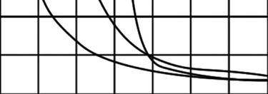

Variation in Soil Resistivity with Moisture Content.

If the structure of the soil is composed of comparatively large grains, moisture is primarily held by surface tension at the points of contact with the grains. If the soil is of a heterogeneous structure, smaller grains can fill spaces between the larger ones, and resistivity is reduced accordingly. Put into an academic context for comparative purposes, the grains can be considered as of a spherical shape, with the most orderly arrangement being one in which the lines joining the centers of the spheres form an equilateral parallelopiped having face angles of 60° and 120°. In this arrangement, pore volume amounts to 25.95 percent of the total and is independent of grain size. In least compact manner, the lines joining the centers form cubes, and in this case the pore volume is 47.64 percent of the total. Of course, these are idealized arrangements not to be
encountered in field work but give valuable insight into the mechanics of soil conductivity. Such knowledge is of use, then, in devising man-made grounding materials of which many exist on the market for the purpose of permanently embedding grounding electrodes in a most effective and steady environment.
In a similar manner, it would seem logical that pressure, as by tamping the earth, would reduce pore volume and lower resistivity. But experimental evidence has not established a clear body of support for this conclusion. The importance of compacting the earth, as in the accepted practice of waiting one to two weeks after installation before making a ground resistance test, has to do with the effectiveness of the interface between electrode and soil rather than the composition of the soil in the surrounding area at large.
A potentially troublesome condition to be noted is that in some rock/soil formations, resistivity may not be the same in all directions (anisotropy). This phenomenon is difficult to interpret but not unexpected in a stratified medium such as rock and soil that is laid down in layers, and it has been investigated and confirmed. In one investigation of a stratified outcrop of broken clay, resistivity parallel to the bedding surface was 2.1 times the resistivity perpendicular to the bedding surface. In another study of hard laminated shale interbedded with sandstone of the Benton formation, resistivity parallel to the bedding surface and with test probes in the sandstone seam was 14.7 times the perpendicular resistivity. These findings are difficult to interpret or generalize, and anisotropy can be caused by factors other than stratification. The effect can be quantized by the anisotropic coefficient (α), defined as the ratio of the apparent parallel resistivity to the apparent normal resistivity. It may range from 0 to 10, and in homogeneous isotropic soil α=1.
With so many variables, and not all of them well understood, predicting grounding performance in a given environment is speculative at best. The best thing to do is to test. Results are often unexpected. Nonetheless, knowledge of soil behavior and its influences is an indispensable tool for grounding an electrical system and testing its capabilities. It never hurts to know what is occurring, and the knowledge can be useful in diagnosing problems, spotting anomalies, and devising remedies.
Source of information: Earth Resistances by G. F. Tagg, George Newnes Ltd, London
B. McCollum & K. H. Logan, “Electrolytic Corrosion of Iron in Soils”, Bureau of Standards (NIST) Technologic Paper #25.
P. J. Higgs, “An Investigation of Earthing Resistances”, Journal I.E.E. #68
Sylvain J. Pirson, “Effect of Anisotropy on Apparent Resistivity Curves”, Bulletin of the American Association of Petroleum Geologists, Vol. 19, #1.


Jeffery R. Jowett is a Senior Applications Engineer for Megger in Valley Forge, Pennsylvania, serving the manufacturing lines of Biddle, Megger, and multi-Amp for electrical test and measurement instrumentation. He holds a BS in Biology and Chemistry from Ursinus College. He was employed for 22 years with James G. Biddle Co. which became Biddle Instruments and is now Megger.


CirCuit Breakers
Low & MediuM VoLtage
• General Electric • Westinghouse
• Cutler Hammer • Siemens
• Allis Chalmers • ITE/ABB
• Federal Pacific • Square D
transforMers
1000 – 5000 kVa
• Dry type transformers from stock
• Cast resin from stock
• Load break switch & fuse
Life extension
Let us design a prograM to extend the Life of your switChgear
• Vacuum retrofill
• Vacuum retrofit
• Solid state conversion
• Vacuum motor control upgrades
MoLded Case CirCuit
Breakers & Low
VoLtage Motor ControL
• Circuit breakers
• Motor control components
• Upgraded buckets
• Panel mount switches
switChgear
480V – 38kV new and surpLus
• New General Electric switchgear in 4 weeks
• Match existing lineup
• Reconditioned from stock
• Complete unit substations
• Indoor and outdoor available
renewaL parts
switChgear & CirCuit Breaker parts
• All low & medium voltage renewal parts, 1945–today
• Obsolete vacuum interrupter in stock
• www.circuitbreakerpartsonline.com
air & VaCuuM Motor ControL
• New General Electric available from stock
• Reconditioned starters and contactors
serViCe & repair
• Field service and testing
• Shop repair of all switchgear and circuit breakers
• Universal circuit breaker remote racking system
• Safety switch for remote switchgear operation
A chain is only as strong as its weakest link. So, how does an association go about locating, repairing, and adding to the many technical links in the chain? By recruiting talented minds to test out those links and make sure that people can rest assured that their chain of technical information is as strong as possible. The leader of NETA’s technical chain gang is the NETA Standards Review Council (SRC), the organization’s body of volunteers responsible for the production and maintenance of technical content. The SRC met this past November in Dallas, Texas, for an extended joint session with the NETA Exam Committee. These committees work together to maintain the massive bank of NETA certification examination questions, a job that is never done.
On Thursday, November 17, 2011, the Exam Committee was joined by several other local subject matter experts to put pen to paper and generate additional Level III and Level IV questions to augment the current bank as well as to replace some stale questions with references to outdated technology. This review and revision process is ongoing, ensuring the technical diversity and relevance of NETA certification. As difficult as it is to take and pass these examinations, the question generation is an even more taxing process requiring references, solutions, and review periods to be noted for each question, which must also pass muster with at least three to four other subject matter experts. After a question is deemed acceptable, it is classified by topic, level, and difficulty before being entered into rotation within the exams actually taken by technicians. This stringent process ensures that people who pass these exams should be incredibly proud, as it is a true accomplishment to be someone that holds a designation as a NETA Certified Technician.
The NETA Standards Review Council met the following three days to review all the new questions and put a final stamp of approval on each one and even drafted some new questions. Review of the ANSI/NETA Standard for Acceptance Testing Specifications continued with comments submitted by the council members and other interested individuals. The first ballot for this document is expected to circulate in late spring or early summer of 2012, with a projected revised edition released in January, 2013. Comments on the ANSI/NETA standards are always welcome, and persons interested in participating as members of the ballot pool should contact Kristen Wicks, NETA’s Technical Services Manager, at kwicks@netaworld.org.
It really can’t ever be said enough: the volunteers who give so freely of their time and energy are the lifeblood of this association. NETA is fortunate to have, within its ranks of supporters, incredibly talented members as well as generous friends who are lifelong champions for NETA’s mission. Keep up the great work!


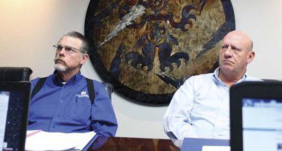







1. What is a phasor?


98


b. Similar to a vector, a phasor is used to indicate both amplitude and phase angle. Phasors can represent any quantity that can be represented by a sinusoid. My personal answer would be A, but that’s not correct. The correct answer is B. A phasor is used to show amplitude (magnitude) and phase angle. Using phasors to analyze a three-phase system is much easier than trying to use sine waves.
ANSWER 2
2. A negative sequence relay is used to: a. determine if the generator is supplying an unbalanced load. Negative sequence relays detect unbalanced currents and can cause a trip operation to prevent overheating of the generator.

3. A three-phase bolted fault will primarily produce what type of current?

a. Positive sequence current
A three-phase bolted fault will produce primarily positive sequence currents, while a phase-to-ground fault will cause equal values of positive, negative, and zero sequence current. Any imbalance in the electrical system causes some negative sequence current.
ANSWER 4
4. The diagram below shows a corebalance CT. What is another name for this type of CT?

c. Zero sequence
A core-balance CT is often referred to as a zero-sequence CT.

5. Identify the following three currents:
a. IO – zero sequence current
b. I2 – negative sequence current

c. I1 – positive sequence current
Although we have used current as the example in these questions, positive, negative and zero sequence voltages can also be present in the electrical system.
NFPA Disclaimer: Although Jim White is a member of the NFPA Technical Committee for both NFPA 70E “Standard for Electrical Safety in the Workplace” and NFPA 70B “Recommended Practice for Electrical Equipment Maintenance,” the views and opinions expressed in this message are purely the author’s and shall not be considered an official position of the NFPA or any of its technical committees and shall not be considered to be, nor be relied upon as, a formal interpretation or promotion of the NFPA. Readers are encouraged to refer to the entire text of all referenced documents.

www.arcsafe.net
RRS-3MBII
The RRS-3MB II is a universal remote racking device for Magne Blast breakers that operates 5 kv to 15 kv switch-gear racking mechanisms. The RRS-3MBII is compatible with all elevating motor voltages and utilizes the preexisting control circuit for raise and lower operations. This unit requires no modifications to the switchgear, and the operator can be 30 to 150 feet away while removing and installing the breaker. We offer an optional tilt switch to alert you of unsafe breaker tilt conditions and radio remote option to be 150 feet away. The RRS-3MBII requires no soft ware programming.
www.candura.com
PQPro™
Candura Instruments is pleased to introduce the PQPro™, its latest portable 8 channel power quality recorder/analyzer, at the 2012 PowerTest Conference. The PQPro™ captures voltage transients as fast as 16 microseconds at the same time as recording trend data. All channels can measure both ac and dc signals.
In Continuous data storage mode the PQPro™ can record every cycle (256 samples per cycle) of voltage and current for 28 minutes. With continuous and circular data storage the PQPro™ will keep recording until the user stops recording with the last 28 minutes of data saved. This is the ideal tool to use when testing power converter designs, commissioning equipment or troubleshooting power system problems.
See for yourself; visit us at booth 222.
www.flir.com/neta IR Windows
FLIR now offers a unique, new line of IR windows that puts added safety between electricians and energized equipment, eliminating the need to open enclosures for visual and IR inspections. FLIR’s IRW-Series includes a quick access, permanently-hinged cover that can’t be dropped or misplaced; simple one-hole installation featuring FLIR’s PIRma-Lock™ self-grounding ring nut; and a broadband crystal lens that works with all thermal cameras and supports visual inspections and fusion features. Also new is FLIR Remote, a Wi-Fi app for Apple® devices that allows streaming video and remote control connectivity withT640/T620 cameras for safer viewing from a distance.
www.ge.com
EntelliGuard®
Helps make the most of your existing equipment. GE’s EntelliGuard® R Retrofill provides a streamlined solution to update your legacy circuit breakers with a new EntelliGuard G breaker, to give your existing switchgear a new lease on life. In addition to providing a host of new features, the EntelliGuard R Retrofill solution offers the option to include the EntelliGuard TU trip unit for both arc flash protection and selectivity at the same time. The EntelliGuard R offers a means to increase reliability and enhance the protection of your existing electrical system.
www.megger.com/us
DELTA4000 New Product Item
Designed specifically for condition assessment of electrical insulation in high-voltage apparatus, the new DELTA4000 series range of 12 kV insulation diagnostic systems from Megger offers timesaving fully automatic power factor/ tan delta and tip-up testing. Also provided are facilities for manual measurements to cater to special testing requirements. Accurate individual temperature correction can be applied to test results using data acquired from a separate dielectric frequency response (DFR) test, and automatic voltage dependence detection, often a useful indicator of incipient insulation problems, is also supported. DELTA4000 test sets are compatible with Megger’s PowerDB software, which offers extensive facilities for data management and archiving. For more information please go to www.megger.com/us.
www.ndbtech.com
With the ART-3D series ratio testers, high accuracy measurements have never been easier handling wide ranges of transformers (CT’s, VT’s or even the larger GSU’s). Its real three-phase output (8, 40, 100, and 275 V) enables smooth testing, even for difficult phase shifting type transformers. Its high test voltage enables higher excitation currents for a greater flux, and this is of particular interest because it allows one to obtain accurate measurements on large transformers with auxiliary/tertiary windings. The ART-3DX’ offers great testing experiences with primary , secondary, and tertiary winding connections; large color transflective-touch screen; USB thumb drive, and Ethernet ports! These units include the unique anti-induction circuit eliminating unwanted influence of nearby energised high voltage equipment.
www.novinium.com
Novinium participated in the development of the IEEE P1816 Cable Preparation Guide, which was developed by the IEEE Insulated Conductor Subcommittee B19W. Novinium has subsequently developed an e-learning course which is available on our website that teaches field electrical workers the correct way to prepare cable ends for terminations and splices to insure high reliability.
www.ofilsystems.com
Luminar – New Corona Testing Equipment
Ofil’s 2012 innovative corona testing experience, Luminar, is a daytime imager that serves the need for light weight and user friendly equipment with uncompromised performance. As NDT equipment, Luminar provides in real time pinpointed clear imaging of corona and its emissive source including severity, location, and ambient conditions.
With DayCor® technology implemented, Luminar includes:
• Highest sensitivity to UV signals
• Bi-Spectral imaging
• Full solar blindness
• Real corona imaging
• Precise location of emitting sources
• Interchangeable fields of view
• Effective powerful zoom
• High resolution LCD
• Videos and images capturing and playback
www.phenixtech.com
New Model PM15-4A Multifunction
Insulation Analyzer
Phenix Technologies, with over 35 years providing superior quality test equipment to the electrical service industry, is pleased to introduce the new model PM15-4A Multifunction Insulation Analyzer.
The PM15-4A can be operated as a conventional Megohmmeter /high potential test set or in automatic modes to perform a dielectric absorption ratio test, polarization index (PI) test or step voltage test. The test set provides up to 15 kVdc and performs all necessary calculations to accurately determine the results. Test results can be viewed on the display or printed out via the built in printer or downloaded via the software package.
We welcome you to visit Phenix Technologies at Booth 416 to discuss your testing requirements!
POWERDB
www.powerdb.com
POWERDB VERSION 10
The new version 10 of Megger’s renowned PowerDB test data management software package offers many enhancements including new instrument interfaces. The appearance of the user interface can be changed using three new global settings: a gray background for test forms which makes data entry fields stand out clearly, a distinctive indicator for drop-down list fields, and a rectangular border on all data entry fields. The built-in address book has been updated and, with guidelines for data access becoming increasingly strict, a new set of properties for individual user accounts has been added. Six new asset properties (one NERC, five generic) aid regulatory compliance. For more information please go to www.powerdb.com.
www.progusa.net
RMO-60TD
ProgUSA will introduce a new combo tester for power transformers. The RMO-60TD made by DV-Power from Sweden is a three-in-one portable tester. With 60A dc (60V drive) source it is a fast winding resistance tester. It also is a demagnetizer with an automatic SAFE Demag function and this 60TD also offers the new technology of an OLTC dynamic tester. As an OLTC tester it measures the timing components well as the step values for a tap changer and displays in a graphic format. This gives the user an insight into the performance or lack thereof, of the LTC mechanism without opening the cabinet or draining oil.
www.salisburybyhoneywell.com
Light Weight 40 cal/cm2 Arc Flash Protection Suit
Salisbury by Honeywell’s NEW Premium Light Weight 40 cal/cm2 Arc Flash Protection suit has a total fabric weight of 11 oz/yd2. This is much lighter than Salisbury’s standard HRC 4 suit with a total fabric weight of 18.5 oz/yd2.
This material is the lightest available and meets all the necessary standards to keep you safe from arc flash. Keep cooler and improve worker comfort without compromising safety. Better products mean better work performance. Trust Salisbury to always provide the best possible products available.
www.sdmyers.com
Transformer Specialist Certification Program
The SD Myers’ Transformer Specialist Certification Program is designed to meet the technical training and continuing education needs of NETA Certified Electrical Testing Technicians. Three levels of certification feature technical content ranging from fundamental to advanced, offering Continuing Technical Development credits (CTDs) valued at 40 units each for a total of 120 CTDs. The unique blended learning format includes formal training in a dynamic learning environment and supporting on-line classroom materials. Upon completion all accredited students become members of the SD Myers Alumni Center, an on-line technical resource center that provides ongoing access to other alumni and their course instructors.
www.shermco.com
Mobil Circuit Breaker Shop
Shermco Industries introduces its Mobil Circuit Breaker Shop to all other NETA Accedited Members who want to expand their on-site circuit breaker testing, maintenance, repair and remanufacturing capabilities. This new 52’ climate controlled and intrinsically safe rolling shop has the same capabilities as a stationary breaker shop including compressed air, overhead cranes, parts polishers, bead blasters, multiple work stations and an administrative area. Shermco can assist any customer with a major disaster recovery project to complete testing, repair, limited overhauls and even remanufacturing of lowand medium-voltage circuit breakers while on the job site.
www.sunbeltusa.com
Oil Sample Tap (Patent Pending)
Sunbelt’s arc flash Oil Sample Tap (Patent Pending) allows the user to have the ability to pull an oil sample and monitor gas pressure without being in contact with energized parts.
•Durable
•Padloackable
•Time Saver
The arc flash Oil Sample Tap (Patent Pending) is sold separately or can be combined with Sunbelt’s Infrared Window. This can be installed in padmount transformers and switchgear and allows the user to keep safe distances for view and monitoring termination points between live parts. Sunbelt Transformer is committed to promoting Safety First! For more information please call, 1-800-433-3128 or email sales@sunbeltusa.com .
www.vacuuminterruptersinc.com Vacuum Interrupters
Until recently, lubricating and preventative maintenance were the only means of preserving vacuum breaker life. Vacuum interrupters that are approaching the end of their usable life can catastrophically fail at any time resulting in unnecessary downtime and damage to surrounding equipment. The majority of vacuum interrupters were installed in the 1980’s and given an original life expectancy of 20 years. The current accepted field service test for vacuum interrupters is a simple go/no-go ac potential test. By method of Penning Discharge Principle, MAC testing can prevent unnecessary damage to breakers by predicting usable life of vacuum interrupters. The status of most vacuum interrupters can be determined using MAC testing while installed in a breaker making it practical for field applications.



Knowledge is Power
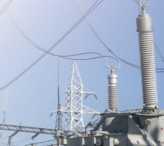
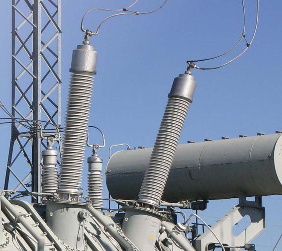


Innovative solutions backed by Doble’s 90 year history.
For over 90 years, Doble has partnered with our utility, industrial and testing company clients to improve operations and optimize system performance. Doble offers diagnostic instruments, services and the world’s premier library of statistically significant apparatus test results for the benefit of energy generation, transmission, delivery, industrial and related companies worldwide. With a comprehensive suite of testing solutions, Doble has simplified asset management, infusing new technology with almost a century of knowledge, data and experience. The industry’s knowledge

Rely on Doble for the equipment you need to safely, accurately and efficiently assess the assets under your watch. Whether you need to test a single transformer or monitor an entire substation, Doble has the answer - from our time-tested M and F Series products through our innovative survey tools.
Doble testing solutions include: PDS100 – Partial Discharge Surveyor PD-Smart – Partial Discharge Analyzer
Domino USS – Portable Sampling System
DFA100 – Dielectric Fault Analyzer
As well as our M Series for transformer diagnostics, F Series for protection testing and TDR Series for circuit breakers. Survey, Detect and Monitor with Doble Products



NFPA 70E and CSA Z462 are technically harmonized in most regards. This was done intentionally to assist multinational companies that operate on both sides of the Canadian--US border. However, there are a few instances where the documents are slightly different, and the CSA document has additional information, primarily in the annexes, that is not found in the NFPA document. A paper on the differences between CSA Z462 and NFPA 70E will be featured at the next IEEE workshop in Florida.
Here are some of the differences that may be of interest to NETA companies:


In the Equipment Maintenance section of CSA Z462 (clause 5.2.3) (Article 200 in 70E) a couple of informational notes were added to highlight the importance of maintenance. None of these additions create new technical requirements. Rather, as noted, the intent was to emphasize the critical nature of maintenance to these system components.
The Protective Device sections (clause 5.3.5) was expanded to ensure that maintenance of the device included testing, where applicable, to ensure that it functions within the designed operating times.


CSA Z462-12 has five annexes not found in NFPA 70E-12:
• Annex B – Safety-Related Electrical Maintenance
• Annex P – Arc Rating, Arc Th ermal Performance Value, and Break Open Threshold Energy
• Annex Q – Arc-Flash and Shock Warning Labels
• Annex R – High Voltage Substations

The Switching Device section (clause 5.3.6) was added to emphasize the critical nature of maintaining these devices as they establish an electrically-safe work condition.

• Annex S – Guidance for Preventing Shock Injuries from Electrostatic Discharges in Manufacturing Operations
This table was modified in both standards as follows:
• Th e parameters permitting use of the table were moved from the notes at the end of the table to the appropriate header of each section,
• Parameters were provided where none previously existed in the last four sections of the table.
• Th e parameters were used to provide a worst-case arcflash boundary.


According to the note at the end of the NFPA table, the parameters were derived by performing two sets of equations: 35 kA short circuit current and 0.2 second operating time and 26 kA short-circuit current and 0.2 second operating time. The 0.2 second was obtained by adding the typical maximum total clearing time of the circuit breaker to an estimated value for relay operation to coincide with the IEEE 1584 values of 0.18 second operating time and 0.08 second tripping time rounded off. A short-circuit current of 35 kA was used as a maximum (HRC-4 @ ~ 40 cal/cm2) and 26 kA was used to compare the effects of lowering the short-circuit current (HRC-4 @ ~ 30 cal/cm2). Working distance used was (909mm) 36" arc gap was (455mm) 6", protective device type 0 for all.


The CSA Z462 technical committee noted the following issues with these parameters:
1. Conductor spacing of six inches is not 455 mm, it is 153 mm. The note for the CSA table has been modified accordingly.


2. According to the note, the 0.2 second fault clearing time was derived by adding the typical maximum total clearing time of the circuit breaker to an estimated value for relay operation to coincide with the IEEE 1584 values of 0.18 second operating time and 0.08 tripping time rounded off. However, IEEE 1584 section 4.6 indicates that the relay operation is noted as being 0.16 second, not 0.18 second. When adding 0.16 second relay operating time and a 0.08 second breaker clearing time results in 0.24 second. The CSA Z462 technical committee decided to round the figure to 0.25 second.
3. A 36 inch working distance was specified in the note as this is typical of the type of equipment covered by this table. However, in the supporting documentation provided with the comment that resulted in the addition of these new parameters, the distance used to estimate incident energy of approximately 40 calories/cm2 was 72 inches. Incident energy estimated at a working distance of 36 inches for 38 kV equipment will be approximately 160 calories/cm2. These incident energy estimations were derived using the Ralph Lee method, as the IEEE 1584 method does not apply when system voltage exceeds 15 kV. Incident energy is estimated to be approximately 15 calories/cm2 for equipment rated 1 kV to 15 kV when using the IEEE 1584 method with parameters of 35 kA maximum available short circuit current, 0.25 seconds maximum fault clearing time, and 36 inch (910 mm) working distance. The arc-flash boundary is approximately 495 inches.


Based on the foregoing, the CSA Z462 technical committee decided to revise the parameters for the last four sections of the hazard/risk category table as noted above. The committee did not revise any of the tasks in the table, nor did they revise any of hazard/risk category numbers. Those tasks identified as hazard/risk category 4 remain as such. The CSA Z462 technical committee recognized that protective value of at least 40 calories/ cm2 afforded by personal protective equipment used for hazard/risk category 4 tasks may seem excessive when compared to the worst-case estimated incident energy of approximately 15 calories. However, it was assumed that most users of the hazard/risk category method employ the simplified two-category clothing approach of Annex H, where workers are wearing personal protective equipment with an arc rating of approximately 8 calories/cm2, or 40 calories/cm2


CSA Z463 on Electrical Systems Maintenance had their third meeting October 27 and 28, 2011, in Saskatoon, Saskatchewan. The nine working groups presented their progress and all are on schedule for a 2013 release date. The next meeting is scheduled for March 2012.


Kerry Heid is the President of Magna Electric Corporation, a Canadian based electrical projects group providing NETA certified testing and related products and solutions for electrical power distribution systems. Kerry is a past President of NETA and has been serving on its board of directors since 2002. Kerry is chair of NETA’s training committee and its marketing committee. Kerry was awarded NETA’s 2010 Outstanding Achievement Award for his contributions to the association and is a NETA senior certified test technician level IV.









The ANSI/NETA Standard for Acceptance Testing Specifications for Electrical Power Equipment and Systems is scheduled to be published as a revised document in 2013. These specifications cover the suggested field tests and inspections that are available to assess the suitability for initial energization of electrical power equipment and systems. The purpose of these specifications is to assure that tested electrical equipment and systems are operational, are within applicable standards and manufacturer's tolerances, and are installed in accordance with design specifications. Work on this document began in the spring of 2011. Once completed, this standard will carry the designation of ANSI/NETA ATS2013. New applications for the ballot pool are being accepted at this time. Applications will be reviewed and applicants accepted as space allows.





If you have any questions about the ANSI/ NETA Standards, including how to specify testing to the ANSI/NETA Standards, please contact the NETA office at neta@netaworld.org or call 888-300-6382.

On May 16, 2011, NETA received notification that the ANSI/NETA Standard for Maintenance Testing Specifications for Electrical Power Equipment and Systems was approved as a revised American National Standard. This document contains specifications which cover the suggested field tests and inspections that are available to assess the suitability for continued service and reliability of electrical power distribution equipment and systems. The purpose of these specifications is to assure that tested electrical equipment and systems are operational and within applicable standards and manufacturer’s tolerances and that the equipment and systems are suitable for continued service. It is available in hard copy, PDF, and CD Rom formats. Order your copy today at www.netaworld.org.


The ANSI/NETA Standard for Certification of Electrical Testing Technicians was approved as an American National Standard on January 8, 2010. The document was originally approved as an ANSI standard in 2000. This standard establishes minimum requirements for qualifications, certification, training, and experience for the electrical testing technician. It also provides criteria for documenting qualifications and certification and details the minimum qualifications for an independent and impartial certifying body to certify electrical testing technicians.


Comments and suggestions are always welcome on any of the standards and should be directed to the NETA office at neta@netaworld.org or 888-300-6382. To learn more about the NETA standards review and revision process, purchase these standards, or to get involved, please visit www.netaworld.org or call 888-300-6382.




With substations regularly overloaded and equipment often near the end of its life, electric grid operators are challenged to improve overall system reliability. Our mission is to provide our clients with actionable information that can be used to better manage the overall life cycle of their critical electrical assets in a manner that is convenient, easy to understand, and assists in critical decision-making.
WEIDMANN DIAGNOSTIC SOLUTIONS INC. provides the vital knowledge you need to help you lower risk and improve your electrical system’s reliability. We provide actionable information through our extensive range of diagnostic products and services.
WEIDMANN DIAGNOSTIC SOLUTIONS INC. is a leader in developing condition assessment methods for transformers and all oil-lled electrical equipment, such as OCB’s, LTC’s, regulators, rectiers, and network units.
• Analytical Testing Services
• Specialized Diagnostic Programs
• Engineering Diagnostic Evaluations

• Engineering Consulting Services
• AIM 2.0 Customer Information Portal
• Education Services
• InsuLogix® Monitoring Products
WEIDMANN DIAGNOSTIC SOLUTIONS INC. One Gordon Mills Way, PO Box 799, St. Johnsbury, VT 05819-0799, USA T +800 811 2284, +916 455 2284, F +916 455 0191, www.weidmann-electrical.com


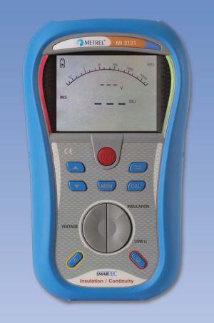
/ Continuity


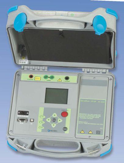


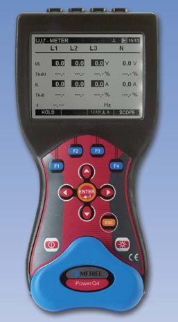

Metrel offers a wide variety of Single, and Multi-Function testers for measuring Insulation Resistance up to 10kV, Earth Resistance, Line Tracers, Continuity, Loop and Line Impedance, and Phase Rotation.



Technical demands require high performance measuring instruments capable of measuring polarization index (PI), dielectric absorption ratio (DAR), dielectric discharge (DD), time programmable step voltage test, insulation system's capacitance, etc. Metrel offers a line of 1kV, 5kV, and 10kV insulation resistance meters for these tests.
Metrel power quality analyzers are proven tools for expert designers of filtering systems, power correction equipment, over voltage protection and UPS systems. Wide range of testing possibilities are supported: voltage sags and swells, resonant states, high neutral conductor currents in 3-phase systems, asymmetry, transients, etc.
 MI 3121 SMARTEC Insulation
‐

‐
rry y m m e e a a n nss N N O O
e e x xtte e n nssi i o o n n cco orrd dss. .
• • B B u uiil ltt‐‐iin n rre e p p o orrt t p prri i n ntte err
• • R R e essu ullt tss sst t o orra a g g e e & & d d o o w w n nllo o a a d d
• • N N e e e e d d T Trra a v v e ell? ? N N o o p prro o b blle e m m,, a a d d d d iit t w w h h e e n n y y o o u u n n e e e e d d iit t u ussi i n n g g A A N N Y Y ttr r a a n nssd d u ucce err. . A Alll l ffo orr LLE E S S S S tth h a a n n w w h h a att
Download full specifications at www.noramsmc.com or call (918‐622‐5725)




A&F Electrical Testing, Inc.
80 Lake Ave. South, Ste. 10 Nesconset, NY 11767 (631) 584-5625 Fax: (631) 584-5720 kchilton@afelectricaltesting.com www.afelectricaltesting.com
Kevin Chilton
A&F Electrical Testing, Inc.
80 Broad St. 5th Floor New York, NY 10004 (631) 584-5625 Fax: (631) 584-5720 afelectricaltesting@afelectricaltesting.com www.afelectricaltesting.com
Florence Chilton
Advanced Testing Systems 15 Trowbridge Dr. Bethel, CT 06801 (203) 743-2001 Fax: (203) 743-2325 pmaccarthy@advtest.com www.advtest.com
Pat MacCarthy
American Electrical Testing Co., Inc.
480 Neponset St., Building 6 Canton, MA 02021-1970 (781) 821-0121 Fax: (781) 821-0771 sblizard@aetco.us www.99aetco.com
Scott A. Blizard
American Electrical Testing Co., Inc. 34 Clover Dr. South Windsor, CT 06074 (860) 648-1013 Fax: (781) 821-0771 jpoulin@aetco.us www.99aetco.com
Gerald Poulin
American Electrical Testing Co., Inc. 76 Cain Dr. Brentwood, NY 11717 (631) 617-5330 Fax: (631) 630-2292 mschacker@aetco.us www.99aetco.com
Michael Schacker
American Electrical Testing Co., Inc. 50 Intervale Rd., Ste. 1 Boonton, NJ 07005 (973) 316-1180 Fax: (781) 316-1181 trosato@aetco.us www.99aetco.com
Anthony Rosato
American Electrical Testing Co., Inc. 1811 Executive Dr., Ste. M Indianapolis, IN 46241 (317) 487-2111 Fax: (781) 821-0771 rramsey@99aetco.us www.99aetco.com
Rick Ramsey
American Electrical Testing Co., Inc. Green Hills Commerce Center 5925 Tilghman St., Ste. 200 Allentown, PA 18104 (215) 219-6800 jmunley@aetco.us www.99aetco.us
Jonathan Munley
American Electrical Testing Co., Inc. 1672 SE 80th Bella Vista Dr. The Villages, FL 32162 (727) 447-4503 Fax: (727) 447-4984 rhoffman@aetco.us www.99aetco.com
Bob Hoffman
Apparatus Testing and Engineering
11300 Sanders Dr., Ste. 29 Rancho Cordova, CA 95742 (916) 853-6280 Fax: (916) 853-6258 jlawler@apparatustesting.com www.apparatustesting.com
James Lawler
Apparatus Testing and Engineering 7083 Commerce Circle, Ste. H Pleasanton, CA 94588 (925) 454-1363 Fax: (925) 454-1499 info@apparatustesting.com www.apparatustesting.com
Harold (Jerry) Carr
Applied Engineering Concepts 1105 N. Allen Ave. Pasadena, CA 91104 (626) 398-3052 Fax: (626) 398-3053 michel.c@aec-us.com www.aec-us.com
Michel Castonguay
Burlington Electrical Testing Co., Inc.
300 Cedar Ave. Croydon, PA 19021-6051 (215) 826-9400 (221) Fax: (215) 826-0964 waltc@betest.com www.betest.com
Walter P. Cleary
C.E. Testing, Inc. 6148 Tim Crews Rd. Macclenny, FL 32063 (904) 653-1900 Fax: (904) 653-1911 cetesting@aol.com
Mark Chapman
CE Power Solutions, LLC
4500 W. Mitchell Ave. Cincinnati, OH 45232 (513) 563-6150 Fax: (513) 563-6120 info@cepowersol.com
Mark McCloy
CE Power Solutions of Wisconsin, LLC
3255 W. Highview Dr. Appleton, WI 54914 (920) 968-0281 Fax: (920) 968-0282 jimvh@cepowersol.com
James Van Handel
DYMAX Holdings, Inc.
4751 Mustang Circle St. Paul, MN 55112 (763) 717-3150 Fax: (763) 784-5397 gphilipp@dymaxservice.com www.dymaxservice.com
Gene Philipp
High Voltage Service, Inc.
4751 Mustang Circle St. Paul, MN 55112 (763) 717-3103 Fax: (763) 784-5397 www.hvserviceinc.com
Mike Mavetz
DYMAX Service Inc.
23426 Industrial Park Ct. Farmington Hills, MI 48335-2854 (248) 477-6066 Fax: (248) 477-6069 www.dymaxservice.com
Bruce Robinson
DYMAX Service Inc. 4213 Kropf Ave. Canton, OH 44706 (330) 484-6801 Fax: (740) 333-1271 www.dymaxservice.com
Gary Swank
Eastern High Voltage 11A South Gold Dr. Robbinsville, NJ 08691-1606 (609) 890-8300 Fax: (609) 588-8090 joewilson@easternhighvoltage.com www.easternhighvoltage.com
Joseph Wilson
ELECT, P.C.
7400-G Siemens Rd., P.O. Box 2080 Wendell, NC 27591 (919) 365-9775 Fax: (919) 365-9789 btyndall@elect-pc.com www.elect-pc.com
Barry W. Tyndall
Electric Power Systems, Inc. 21 Millpark Ct. Maryland Heights, MO 63043-3536 (314) 890-9999 Fax: (314) 890-9998
cfr@eps-international.com www.eps-international.com
Steve Reed
Electric Power Systems, Inc. 557 E. Juanita Avenue, #4 Mesa, AZ 85204 (480) 633-1490 Fax: (480) 633-7092 www.eps-international.com
Louis G. Gilbert
Electric Power Systems, Inc. 4436 Parkway Commerce Blvd. Orlando, FL 32808 (407) 578-6424 Fax: 407-578-6408 www.eps-international.com
Doug Pacey
Electric Power Systems, Inc. 6753 E. 47th Avenue Dr., Unit D Denver, CO 80216 (720) 857-7273 Fax: 303-928-8020 www.eps-international.com
Thomas C. Reed
Electric Power Systems, Inc. 23823 Andrew Rd. Plainfield, IL 60585 (815) 577-9515 Fax: (815) 577-9516 www.eps-international.com
George Bratkiv
Electric Power Systems, Inc. 2601 Center Rd., # 101 Hinckley, OH 44233 (330) 460-3706 Fax: (330) 460-3708 www.eps-international.com
Garth Paul
Electric Power Systems, Inc. 1129 East Hwy 30 Gonzalez, LA 70737 (225) 644-0150 Fax: (225) 644-6249 www.eps-international.com
C.J. Theriot
Electric Power Systems, Inc. 56 Bibber Parkway #1 Brunswick, ME 04011 (207) 837-6527 www.eps-international.com
Jerry Jones
Electric Power Systems, Inc. 4100 Greenbriar Dr., Ste. 160 Stafford, TX 77477 (713) 644-5400 www.eps-international.com
Rob Alter
Electric Power Systems, Inc.
827 Union St. Salem, VA 24153 (540) 375-0084 Fax: (540) 375-0094 virginia@eps-international.com www.eps-international.com
Bruce Eppers
Electric Power Systems, Inc. 915 Holt Ave., Unit 9 Manchester, NH 03109 (603) 657-7371 Fax: 603-657-7370 www.eps-international.com
Cindy Taylor
Electric Power Systems, Inc.
146 Space Park Dr. Nashville, TN 37211 (615) 834-0999 Fax: (615) 834-0129 www.eps-international.com
Larry Christodoulou
Electric Power Systems, Inc.
1090 Montour West Industrial Blvd. Coraopolis, PA 15108 (412) 276-4559 www.eps-international.com
Ed Nahm
Electric Power Systems, Inc. 6141 Connecticut Ave. Kansas City, MO 64120 (816) 241-9990 Fax: (816) 241-9992 www.eps-international.com
Joe Dillon
EPS Technology
29 N. Plains Hwy., Ste. 12 Wallingford, CT 06492 (203) 649-0145 www.eps-technology.com
Chris Myers
Electrical & Electronic Controls 6149 Hunter Rd. Ooltewah, TN 37363 (423) 344-7666 (23) Fax: (423) 344-4494 eecontrols@comcast.net
Michael Hughes
Electrical Energy Experts, Inc. W129N10818, Washington Dr. Germantown, WI 53022 (262) 255-5222 Fax: (262) 242-2360 bill@electricalenergyexperts.com www.electricalenergyexperts.com
William Styer
Electrical Equipment Upgrading, Inc. 21 Telfair Place Savannah, GA 31415 (912) 232-7402 Fax: (912) 233-4355 kmiller@eeu-inc.com www.eeu-inc.com
Kevin Miller
Electrical Maintenance & Testing Inc.
7301 N. Georgetown Rd., Ste. 212 Indianapolis, IN 46268 (317) 471-8600 Fax: (317) 471-8605 www.emtesting.com
Brian K. Borst
Electrical Reliability Services
1057 Doniphan Park Circle, Ste. A El Paso, TX 79922 (915) 587-9440 Fax: (915) 587-9010 www.electricalreliability.com
Electrical Reliability Services
1775 W. University Dr., Ste. 128 Tempe, AZ 85281 (480) 966-4568 Fax: (480) 966-4569 www.electricalreliability.com
Electrical Reliability Services
1455 East Sam Houston Parkway S., Ste. 190 Pasadena, TX 77503 (281) 241-2800 Fax: (281) 241-2801 www.electricalreliability.com
Electrical Reliability Services
4099 SE International Way, Ste. 201 Milwaukie, OR 97222-8853 (503) 653-6781 Fax: (503) 659-9733 www.electricalreliability.com
Electrical Reliability Services
5810 Van Allen Way Carlsbad, CA 92008 (760) 804-2972 www.electricalreliability.com
Electrical Reliability Services
8500 Washington St. NE, Ste. A-6 Albuquerque, NM 87113 (505) 822-0237 Fax: (505) 822-0217 www.electricalreliability.com
Electrical Reliability Services
1380 Greg Street, Ste. 217 Sparks, NV 89431 (775) 746-8484 Fax: (775) 356-5488 www.electricalreliability.com
Electrical Reliability Services
2275 Northwest Parkway SE, Ste. 180 Marietta, GA 30067 (770) 541-6600 Fax: (770) 541-6501 www.electricalreliability.com
Electrical Reliability Services 7100 Broadway, Ste. 7E Denver, CO 80221-2915 (303) 427-8809 Fax: (303) 427-4080 www.electricalreliability.com
Electrical Reliability Services 348 N.W. Capital Dr. Lees Summit, MO 64086 (816) 525-7156 Fax: (816) 524-3274 www.electricalreliability.com
Electrical Reliability Services 6900 Koll Center Parkway, Suite 415 Pleasanton, CA 94566 (925) 485-3400 Fax: (925) 485-3436 www.electricalreliability.com
Electrical Reliability Services 10606 Bloomfield Ave. Santa Fe Springs, CA 90670 (562) 236-9555 Fax: (562) 777-8914 www.electricalreliability.com
Electrical Reliability Services 14141 Airline Hwy, Bldg. 1, Ste. X Baton Rouge, LA 70817 (225) 755-0530 Fax: (225) 751-5055 www.electricalreliability.com
Electrical Reliability Services 121 E. Hwy. 108 Sulphur, LA 70665 (337) 583-2411 Fax: (337) 583-2410 www.electricalreliability.com
Electrical Reliability Services 5580 Enterprice Parkway Ft. Myers, FL 33905-5507 (239) 693-7100 Fax: (239) 693-7772 www.electricalreliability.com
Electrical Reliability Services 2222 West Valley Hwy. N., Ste 160 Auburn, WA 98001 (253) 736-6010 Fax: (253) 736-6015 www.electricalreliability.com
Electrical Reliability Services 3412 South 1400 West, Unit A West Valley City, UT 84119 (801) 975-6461 www.electricalreliability.com
Electrical Reliability Services 6351 Hinson St., Ste. B Las Vegas, NV 89118 (702) 597-0020 Fax: (702) 597-0095 www.electricalreliability.com
Electrical Reliability Services 610 Executive Campus Dr. Westerville, OH 43082 (877) 468-6384 Fax: (614) 410-8420 info@electricalreliability.com www.electricalreliability.com
Elemco Services, Inc. 228 Merrick Rd. Lynbrook, NY 11563 (631) 589-6343 Fax: (631) 589-6670 BobW@elemco.com www.elemco.com
Robert J. White
Electrical Testing, Inc. 2671 Cedartown Hwy Rome, Ga 30161 (706) 234-7623 Fax: (706) 236-9028 steve@electricaltestinginc.com www.electricaltestinginc.com
Steve C. Dodd Sr.
Grubb Emgineering, Inc. 3128 Sidney Brooks San Antonio, Tx 78235 (210) 658-7250 Fax: (210) 658-9805 bobby@grubbengineering.com www.grubbengineering.com
Robert D. Grubb Jr.
Hampton Tedder Technical Services 4571 State St. Montclair, CA 91763 (909) 628-1256 x214 Fax: (909) 628-6375 matt.tedder@hamptontedder.com www.hamptontedder.com
Matt Tedder
Hampton Tedder Technical Services 4920 Alto Ave. Las Vegas, NV 89115 (702) 452-9200 Fax: (702) 453-5412 www.hamptontedder.com
Roger Cates
Hampton Tedder Technical Services 3747 West Roanoke Ave. Phoenix, AZ 85009 (480) 967-7765 Fax: (480) 967-7762 www.hamptontedder.com
Harford Electrical Testing Co., Inc. 1108 Clayton Rd. Joppa, MD 21085 (410) 679-4477 Fax: (410) 679-0800 harfordtesting@aol.com
Vincent Biondino
High Energy Electrical Testing, Inc. 2119 Orien Rd. Toms River, NJ 08755-1366 (732) 286-4088 Fax: (732) 286-4086 hinrg@comcast.net www.highenergyelectric.com
James P. Ratshin
High Voltage Maintenance Corp. 24 Walpole Park South Dr. Walpole, MA 02081 (508) 668-9205 www.hvmcorp.com
High Voltage Maintenance Corp. 941 Busse Rd. Elk Grove Village, Il 60007 (847) 228-9595 www.hvmcorp.com
High Voltage Maintenance Corp.
7200 Industrial Park Blvd. Mentor, OH 44060 (440) 951-2706 Fax: (440) 951-6798 www.hvmcorp.com
High Voltage Maintenance Corp.
3000 S. Calhoun Rd. New Berlin, WI 53151 (262) 784-3660 Fax: (262) 784-5124 www.hvmcorp.com
High Voltage Maintenance Corp.
8320 Brookville Rd. #E Indianapolis, IN 46239 (317) 322-2055 Fax: (317) 322-2056 www.hvmcorp.com
High Voltage Maintenance Corp. 1250 Broadway, Ste. 2300 New York, NY 10001 (718) 239-0359 www.hvmcorp.com
High Voltage Maintenance Corp.
355 Vista Park Dr. Pittsburgh, PA 15205-1206 (412) 747-0550 Fax: (412) 747-0554 www.hvmcorp.com
High Voltage Maintenance Corp.
150 North Plains Industrial Rd. Wallingford, CT 06492 (203) 949-2650 Fax: (203) 949-2646 www.hvmcorp.com
High Voltage Maintenance Corp. 9305 Gerwig Ln., Ste. B Columbia, MD 21046 (410) 309-5970 Fax: (410) 309-0220 www.hvmcorp.com
High Voltage Maintenance Corp. 1455 Jamike Dr., Ste. 5 Erlanger, KY 41018 (859) 371-5355 Fax: (859) 371-5399 www.hvmcorp.com
High Voltage Maintenance Corp. 24371 Catherine Industrial Dr. Ste. 207 Novi, MI 48375 (248) 305-5596 Fax: (248) 305-5579 www.hvmcorp.com
High Voltage Maintenance Corp. 5100 Energy Dr. Dayton, OH 45414 (937) 278-0811 Fax: (937) 278-7791 www.hvmcorp.com
HMT, Inc. 6268 Route 31 Cicero, NY 13039 (315) 699-5563 Fax: (315) 699-5911 jpertgen@hmt-electric.com www.hmt-electric.com
John Pertgen
Industrial Electric Testing, Inc. 11321 West Distribution Ave. Jacksonville, FL 32256 (904) 260-8378 Fax: (904) 260-0737 gbenzenberg@bellsouth.net www.industrialelectrictesting.com
Gary Benzenberg
Industrial Electric Testing, Inc. 201 NW 1st Ave. Hallandale, FL 33009-4029 (954) 456-7020 www.industrialelectrictesting.com
Industrial Electronics Group P.O. Box 1870 850369 Highway 17 South Yulee, FL 32041 (904) 225-9529 Fax: (904) 225-0834 butch@industrialgroups.com www.industrialgroups.com
Butch E. Teal
Industrial Tests, Inc. 4021 Alvis Ct., Ste. 1 Rocklin, CA 95677 (916) 296-1200 Fax: (916) 632-0300 greg@indtests.com www.industrialtests.com
Greg Poole
Infra-Red Building and Power Service 152 Centre St. Holbrook, MA 02343-1011 (781) 767-0888 Fax: (781) 767-3462 tom.mcdonald@infraredbps.net www.infraredbps.com
Thomas McDonald Sr.
M&L Power Systems, Inc. 109 White Oak Ln., Ste. 82 Old Bridge, NJ 08857 (732) 679-1800 Fax: (732) 679-9326 dan@mlpower.com www.mlpower.com
Darshan Arora
Magna Electric Corporation 1033 Kearns Crescent, Box 995 Regina, SK S4P 3B2 Canada (306) 949-8131 Fax: (306) 522-9181 kheid@magnaelectric.com www.magnaelectric.com
Kerry Heid
Magna Electric Corporation 3430 25th St. NE Calgary, AB T1Y 6C1 Canada (403) 769-9300 Fax: (403)769-9369 ppetrie@magnaelectric.com www.magnaelectric.com
Pat Petrie
Magna Electric Corporation 851-58th St. East Saskatoon, SK S7K 6X5 Canada (306) 955-8131 x 5 Fax: (306) 955-9181 www.magnaelectric.com
Luis Wilson
Magna Electric Corporation 1375 Church Ave. Winnipeg, MB R2X 2Y7 Canada (204) 925-4022 Fax: (204) 925-4021 cbrandt@magnaelectric.com www.magnaelectric.com
Curtis Brandt
Magna IV Engineering 4103 - 97th St., N.W. Edmonton, AB T6E 6E9 Canada (780) 462-3111 Fax: (780) 462-9799 jwentzell@magnaiv.com www.magnaiv.com Jereme Wentzell
Magna IV Engineering Unit 10, 10672- 46 St. S.E. Calgary, AB T2C 1G1 Canada (403) 723-0575 Fax: (403) 723-0580 info.calgary@magnaiv.com Jereme Wentzell
Magna IV Engineering 8219D Fraser Ave. Fort McMurray, AB T9H 0A2 Canada (780) 791-3122 Fax: (780) 791-3159 info.fmcmurray@magnaiv.com Jereme Wentzell
Magna IV Engineering 96 Inverness Dr. East, Unit R Englewood, CO 80112 (303) 799-1273 Fax: (303) 790-4816 info.denver@magnaiv.com Jereme Wentzell
Magna IV Engineering Oficina 1407 Torre Norte 481 Nueva Tajamar Las Condes, Region Metropolitana 7550099 Chile +(56) 9-9-517-4642 info.chile@magnaiv.com
Jereme Wentzell
Magna IV Engineering 1040 Winnipeg St. Regina , SK S4R 8P8 Canada (306) 504-6501 Fax: (306) 729-4897 info.regina@magnaiv.com
Jereme Wentzell
MET Electrical Testing LLC
3602 East Southern Ave., Ste. 1 & 2 Phoenix, AZ 85040 (602) 796-6583 Fax: www.met-test.com
Mike Ferguson
MET Electrical Testing LLC
6280 South Valley View Blvd., Ste. 618
Las Vegas, NV 89118 (702) 216-0982 Fax: (702) 216-0983 www.met-test.com
Terry Travelstead
MET Electrical Testing LLC 814 Greenbrier Circle, Ste. E Chesapeake, VA 23320 (757) 548-5690 Fax: (757) 548-5417 www.met-test.com
Mark Anthony Gaughan, III
MET Electrical Testing LLC
3700 Commerce Dr. #901-903 Baltimore, MD 21227 (410) 247-3300 Fax: (410) 247-0900 www.met-test.com
Bill Hartman
MET Electrical Testing LLC
710 Thomson Park Dr. Cranberry Township, PA 16066-6427 (724) 772-4638 Fax: (724) 772-6003 william.mckenzie@met.lincfs.com www.met-test.com
William (Pete) McKenzie
MET Electrical Testing LLC
5805 G Departure Dr. Raleigh, NC 27616 (919) 877-1008 Fax: (919) 501-7492 www.met-test.com
Mark Robinson
MET Electrical Testing LLC
4390 Parliament Place, Ste. Q Lanham, MD 20706 (301) 967-3500 Fax: (301) 735-8953 www.met-test.com
Frank Ceci
National Field Services
649 Franklin St. Lewisville, TX 75057 (972) 420-0157 www.natlfield.com
Eric Beckman
Nationwide Electrical Testing, Inc.
6050 Southard Trace Cumming, GA 30040 (770) 667-1875 Fax: (770) 667-6578 Shashi@N-E-T-Inc.com www.n-e-t-inc.com
Shashikant B. Bagle
North Central Electric, Inc. 69 Midway Ave. Hulmeville, PA 19047-5827 (215) 945-7632 Fax: (215) 945-6362 ncetest@aol.com
Robert Messina
Northern Electrical Testing, Inc. 1991 Woodslee Dr. Troy, MI 48083-2236 (248) 689-8980 Fax: (248) 689-3418 ldetterman@northerntesting.com www.northerntesting.com Lyle Detterman
Orbis Engineering Field Services Ltd. #300, 9404 - 41st Ave. Edmonton, AB T6E 6G8 Canada (780) 988-1455 Fax: (780) 988-0191 lorne@orbisengineering.net www.orbisengineering.net
Lorne Gara
Pacific Power Testing, Inc. 14280 Doolittle Dr. San Leandro, CA 94577 (510) 351-8811 Fax: (510) 351-6655 steve@pacificpowertesting.com www.pacificpowertesting.com
Steve Emmert
Pacific Powertech, Inc. #110, 2071 Kingsway Ave. Port Coquitlam, BC V3C 1T2 Canada (604) 944-6697 Fax: (604) 944-1271 chite@pacificpowertech.ca www.magnaiv.ca
Cameron Hite
Phasor Engineering Sabaneta Industrial Park #216 Mercedita, PR 715 Puerto Rico (787) 844-9366 Fax: (787) 841-6385 rcastro@phasorinc.com
Rafael Castro
Potomac Testing, Inc. 1610 Professional Blvd., Ste. A Crofton, MD 21114 (301) 352-1930 Fax: (301) 352-1936 kbassett@potomactesting.com www.potomactesting.com
Ken Bassett
Potomac Testing, Inc. 11179 Hopson Rd., Ste. 5 Ashland, VA 23005 (804) 798-7334 Fax: (804) 798-7456 www.potomactesting.com
Power & Generation Testing, Inc. 480 Cave Rd. Nashville, TN 37210 (615) 882-9455 Fax: (615) 882-9591 mose@pgti.net www.pgti.net
Mose Ramieh
Power Engineering Services, Inc. 9179 Shadow Creek Lane Converse, TX 78109 (210) 590-4936 Fax: (210) 590-6214 engelke@pe-svcs.com www.pe-svcs.com
Miles R. Engelke
POWER PLUS Engineering, Inc. 46575 Magallan Dr. Novi, MI 48377 (248) 344-0200 Fax: (248) 305-9105 smancuso@epowerplus.com www.epowerplus.com
Salvatore Mancuso
Power Products & Solutions, Inc. 12465 Grey Commercial Rd. Midland, NC 28107 (704) 573-0420 x12 Fax: (704) 573-3693 ralph.patterson@powerproducts.biz www.powerproducts.biz
Ralph Patterson
Power Products & Solutions, Inc. 13 Jenkins Ct. Mauldin, SC 29662 Fax: (800) 328-7382 ralph.patterson@powerproducts.biz www.powerproducts.biz
Raymond Pesaturo
Power Services, LLC P.O. Box 750066, 998 Dimco Way Centerville, OH 45475 (937) 439-9660 Fax: (937) 439-9611 mkbeucler@aol.com
Mark Beucler
Power Solutions Group, Ltd. 425 W. Kerr Rd. Tipp City, OH 45371 (937) 506-8444 Fax: (937) 506-8434 bwilloughby@powersolutionsgroup.com www.powersolutionsgroup.com
Barry Willoughby
Power Solutions Group, Ltd. 135 Old School House Rd. Piedmont, SC 29673 (864) 845-1084 Fax:: (864) 845-1085 fcrawford@powersolutionsgroup.com www.powersolutionsgroup.com
Frank Crawford
Power Solutions Group, Ltd. 670 Lakeview Plaza Blvd. Columbus, OH 43085 (614) 310-8018 sspohn@powersolutionsgroup.com www.powersolutionsgroup.com
Stuart Spohn
Power Systems Testing Co. 4688 W. Jennifer Ave., Ste. 108 Fresno, CA 93722 (559) 275-2171 ext 15 Fax: (559) 275-6556 dave@pstcpower.com www.powersystemstesting.com
David Huffman
Power Systems Testing Co. 600 S. Grand Ave., Ste. 113 Santa Ana, CA 92705-4152 (714) 542-6089 Fax: (714) 542-0737 www.powersystemstesting.com
Power Systems Testing Co. 2267 Claremont Ct. Hayward, CA 94545-5001 (510) 783-5096 Fax: (510) 732-9287 www.powersystemstesting.com
Power Test, Inc. 2200 Highway 49 Harrisburg, NC 28075 (704) 200-8311 Fax: (704) 455-7909 rich@powertestinc.com www.powertestinc.com
Richard Walker
POWER Testing and Energization, Inc. 14006 NW 3rd Ct., Ste. 101 Vancouver, WA 98685 (360) 576-4826 Fax: (360) 576-7182 chris.zavadlov@powerte.com www.powerte.com
Chris Zavadlov
POWER Testing and Energization, Inc. 731 E. Ball Rd., Ste. 100 Anaheim, CA 92805 (714) 507-2702 http://www.powerte.com
POWER Testing and Energization, Inc. 22035 70th Ave. South Kent, WA 98032 (253) 872-7747 www.powerte.com
Powertech Services, Inc. 4095 South Dye Rd. Swartz Creek, MI 48473-1570 (810) 720-2280 Fax: (810) 720-2283 jbrown@powertechservices.com www.powertechservices.com
Jean A. Brown
Precision Testing Group 18590 Wedemeyer Rd. Kiowa, CO 80117 (303) 621-2776 Fax: (303) 621-2573 glenn@precisiontestinggroup.com Glenn Stuckey
PRIT Service, Inc. 112 Industrial Dr., P.O. Box 606 Minooka, IL 60447 (815) 467-5577 Fax: (815) 467-5883
Rod.Hageman@pritserviceinc.com www.pritserviceinc.com
Rod Hageman
Reuter & Hanney, Inc.
149 Railroad Dr. Northampton Industrial Park Ivyland, PA 18974 (215) 364-5333 Fax: (215) 364-5365 mikereuter@reuterhanney.com www.reuterhanney.com
Michael Reuter
Reuter & Hanney, Inc.
4270-I Henninger Ct. Chantilly, VA 20151 (703) 263-7163 Fax: 703-263-1478 www.reuterhanney.com
Reuter & Hanney, Inc.
1371 Brass Mill Rd., Unit E Belcamp, MD 21017 (410) 297-9566 Fax: (410) 297-9984 www.reuterhanney.com
Michael Jester
REV Engineering, LTD
3236 - 50 Ave. SE Calgary, AB T2B 3A3 Canada (403) 287-0156 Fax: (403) 287-0198 rdavidson@reveng.ca www.reveng.ca
Roland Nicholas Davidson, IV
Scott Testing Inc.
1698 5th St. Ewing, NJ 08638 (609) 882-2400 Fax: (609) 882-5660 rsorbello@scotttesting.com www.scotttesting.com
Russ Sorbello
Shermco Industries 2425 E. Pioneer Dr. Irving, TX 75061 (972) 793-5523 Fax: (972) 793-5542 rwidup@shermco.com www.shermco.com
Ron Widup
Shermco Industries 1705 Hur Industrial Blvd. Cedar Park, TX 78613 (512) 259-3060 Fax: (512) 258-5571 kewing@shermco.com www.shermco.com
Kevin Ewing
Shermco Industries 33002 FM 2004
Angleton, TX 77515 (979) 848-1406 Fax: (979) 848-0012
mfrederick@shermco.com www.shermco.com
Malcom Frederick
Shermco Industries 1357 N. 108th E. Ave. Tulsa, OK 74116 (918) 234-2300 jharrison@shermco.com www.shermco.com
Jim Harrison
Shermco Industries 777 10th St. Marion, IA 52302 (319) 377-3377 Fax: (319) 377-3399 Lhamrick@shermco.com www.shermco.com
Lynn Hamrick
Shermco Industries 2100 Dixon St., Ste. C Des Moines, IA 50316 Fax: (515) 263-8482 DesMoines@shermco.com www.shermco.com
Lynn Hamrick
Shermco Industries Boulevard Saint-Michel 47 1040 Brussels Brussels, Belgium
+32 (0)2 400 00 54 Fax: +32 (0)2 400 00 32 cperry@shermco.com www.shermco.com
Chris Perry
Sigma Six Solutions, Inc. 2200 West Valley Hwy., Ste. 100 Auburn, WA 98001 (253) 333-9730 Fax: (253) 859-5382 jwhite@sigmasixinc.com www.sigmasixinc.com
John White
Southern New England Electrical Testing, LLC 3 Buel St., Unit 2 Wallingford, CT 06492 (203) 269-8778 Fax: (203) 269-8775 dave.asplund@sneet.org www.sneet.org
David Asplund, Sr.
Southwest Energy Systems, LLC 2231 East Jones Ave., Ste. A Phoenix, AZ 85040 (602) 438-7500 Fax: (602) 438-7501 bob.sheppard@southwestenergysystems.com www.southwestenergysystems.com
Robert Sheppard
Taurus Power & Controls, Inc. 9999 SW Avery St. Tualatin, OR 97062-9517 (503) 692-9004 Fax: (503) 692-9273 robtaurus@tauruspower.com www.tauruspower.com
Rob Bulfinch
Taurus Power & Controls, Inc. 6617 S. 193rd Place , Ste. P104 Kent, WA 98032 (425) 656-4170 Fax: (425) 656-4172 jiml@tauruspower.com www.taruspower.com
Jim Lightner
Three-C Electrical Co., Inc. 190 Pleasant St. Ashland, MA 01721 (508) 881-3911 Fax: (508) 881-4814 jim@three-c.com www.three-c.com
Jim Cialdea
Three-C Electrical Co., Inc. 79 Leighton Rd., Ste. 9 Augusta, ME 04330 (800) 649-6314 Fax: (207) 782-0162 jim@three-c.com www.three-c.com
Jim Cialdea
Tidal Power Services, LLC 4202 Chance Lane Rosharon, TX 77583 (281) 710-9150 Fax: (713) 583-1216 monty.janak@tidalpowerservices.com www.tidalpowerservices.com
Monty C. Janak
Tony Demaria Electric, Inc. 131 West F St. Wilmington, CA 90744 (310) 816-3130 x 111 Fax: (310) 549-9747 tde@tdeinc.com www.tdeinc.com
Anthony Demaria
Trace Electrical Services & Testing, LLC 293 Whitehead Rd. Hamilton, NJ 08619 (609) 588-8666 Fax: (609) 588-8667 jvasta@tracetesting.com www.tracetesting.com
Joseph Vasta
Utilities Instrumentation Service, Inc. PO Box 981123 Ypsilanti, MI 48198-1123 (734) 482-1450 (14) Fax: (734) 482-0035 GEWalls@UISCorp.com www.uiscorp.com
Gary E. Walls
Utility Service Corporation 4614 Commercial Dr. NW Huntsville, AL 35816-2201 (256) 837-8400 Fax: (256) 837-8403 apeterson@utilserv.com www.utilserv.com
Alan D. Peterson
Western Electrical Services 14311 29th St. East Sumner , WA 98390 (253) 891-1995 Fax: (253) 891-1511 dhook@westernelectricalservices.com www.westernelectricalservices.com
Daniel Hook
Western Electrical Services 5680 South 32nd St. Phoenix, AZ 85040 (253) 891-1995 dhook@westernelectricalservices.com www.westernelectricalservices.com
Daniel Hook






This issue’s advertisers are identified below. Please thank these advertises by telling them you saw their advertisement in YOUR magazine –NETA World.


PCMU. Modernize your relay installations without slowing down.
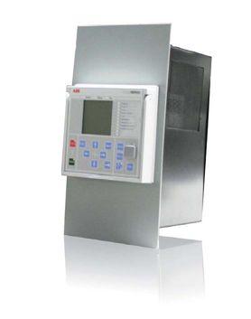
ABB’s Pre-Configured Matching Units (PCMU) offer a cost-effective and quick way to replace existing DPU245, DPU445, and other ABB distribution legacy relays. The rear terminal layout is the same as in your existing relay to ensure minimal wiring time. New optional protective features including high impedance fault detection and arc flash can now be added to your system. PCMUs offer the same advantages and benefits of the Relion ® 615 Series, such as three standard communication protocols (IEC61850, Modbus, and DNP 3.0) and a common look and feel of HMI and software across the family of protection relays. www.abb.com/substationautomation
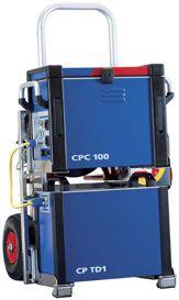

With the multifunctional CPC 100 testing system Dad can perform traditional transformer tests such as power factor and capacitance, exciting current, transformer ratio, leakage reactance, and DC winding resistance. He can also perform additional tests such as variable frequency power factor (15 Hz to 400 Hz), frequency response of stray losses, and dynamic LTC diagnostics.



The CP SB1 switch box makes the CPC 100 testing system faster and safer than ever before. Dad saves a lot of time because rewiring is now a thing of the past.
With the PTM software my Dad is able to manage all his asset data and carry out extensive tests in no time at all. The active, intuitive user interface and easy-to-understand
test procedures really make his life easy by reducing potential user errors in the application, and speeding up the work flow.
Book the OMICRON Roadshow Bus in your area and see for yourself what OMICRON offers for transformer diagnostics solutions.