

LIFE EXTENSIONS & SAFETY UPGRADES

smrT36 The smrT solution for your testing needs.

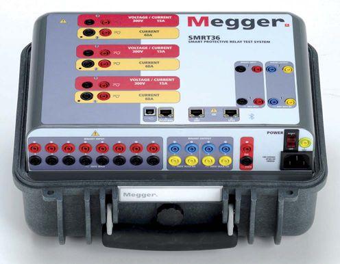
The SMRT36 is the smallest, lightest, highest output powered, complete 3-phase protective relay test system in the world today. This rugged test system may be customized by adding the voltage current generator modules needed for specific test applications. Manual operation is simple through the use of the Smart Touch View Interface (STVI), with a large color high resolution TFT LCD touch-screen.


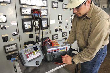


n Rugged, small and lightweight
n High current, high power (60 Amps/300 VArms) per phase
n Up to 6 currents with convertible channels
n Thermally controlled fans for quiet operation
n New Smart Touch View Interface (STVI) provides manual control
n New STVI Overcurrent Test includes hundreds of relay specific time-curves built-in
With these comprehensive capabilities and extensive testing options the SMRT36 is conceivably the easiest to use 3-phase protective relay test system available today.
For more information on the SMRT36 relay test set contact us today at 1-800-723-2861 or email us at sales@megger.com to receive a SMRT36 brochure and 2011 Megger Power Catalog.
Megger
4271 Bronze Way Dallas, Texas 75237-1019 USA.


 Rick Gardner & Peter Stoppello
David
Geraldo Rocha, Schweitzer Engineering Laboratories, Inc.

Overhead

“Lanny” Floyd, DuPont
LOOK FOR A WAY TO GET HURT A SHOCKING CHALLENGE
Don Brown, Shermco Industries
Testing for Rural Electric Cooperatives
Partial Discharge Measurement Pays Big Dividends
Don A. Genutis, No-Outage Electrical Testing, Inc. & Neil Davies, EA Technology
CORNER Survey Says! Maintenance is Critical as part of your Electrical Safety Program.
Kerry Heid, Magna Electric Corporation
A Report on January 2011 IEEE Electric
Replacing Older Medium-Voltage Circuit Breakers with Vacuum Circuit Breakers Baldwin Bridger
Jeff Jowett, Megger

3050 Old Centre Avenue, Suite 102
Portage, MI 49024
Toll free: 888.300 NETA (6382)
Phone: 269.488.NETA (6382)
Fax : 269.488.6383
neta@netaworld.org
www.netaworld.org
EXECUTIVE DIRECTOR: Jayne Tanz, CMP
NETA Officers
PRESIDENT: John White, Sigma Six Solutions
FIRST VICE PRESIDENT: Mose Ramieh, Power & Generation Testing, Inc.
SECOND VICE PRESIDENT: David Huffman, Power Systems Testing
SECRETARY: Walt Cleary, Burlington Electrical Testing Co., Inc.
TREASURER: Ken Bassett, Potomac Testing, Inc.
NETA Board of Directors
Ken Bassett (Potomac Testing, Inc.)
Scott Blizard (American Electrical Testing Co., Inc.)
Walt Cleary (Burlington Electrical Testing Co., Inc.)
Roderic Hageman (PRIT Service, Inc.)
Kerry Heid (Magna Electric Corporation)
David Huffman (Power Systems Testing)
Ralph Patterson (Power Products & Solutions, Inc.)
Alan Peterson (Utility Service Corporation)
Mose Ramieh (Power & Generation Testing, Inc.)
John White (Sigma Six Solutions)
Ron Widup (Shermco Industries)
NETA World Staff
TECHNICAL EDITOR: Roderic L. Hageman
ASSOCIATE EDITOR: Diane W. Hageman
MANAGING EDITOR: Jayne Tanz, CMP
ADVERTISING MANAGER: Jill Howell
DESIGN AND PRODUCTION: Newhall Klein, Inc.
NETA Committee Chairs
CONFERENCE: Ron Widup; MEMBERSHIP: Ken Bassett; PROMOTIONS/MARKETING: Kerry Heid; SAFETY: Lynn Hamrick; TECHNICAL: Alan Peterson; TECHNICAL EXAM: Ron Widup; WORLD ADVISORY: Diane Hageman;
CONTINUING TECHNICAL DEVELOPMENT: David Huffman; TRAINING: Kerry Heid; FINANCE: John White; NOMINATIONS: Alan Peterson; STRATEGY: Mose Ramieh
© Copyright 2011, NETA
NOTICE AND DISCLAIMER
NETA World is published quarterly by the InterNational Electrical Testing Association. Opinions, views and conclusions expressed in articles herein are those of the authors and not necessarily those of NETA. Publication herein does not constitute or imply endorsement of any opinion, product, or service by NETA, its directors, officers, members, employees or agents (herein “NETA”).
All technical data in this publication reflects the experience of individuals using specific tools, products, equipment and components under specific conditions and circumstances which may or may not be fully reported and over which NETA has neither exercised nor reserved control. Such data has not been independently tested or otherwise verified by NETA.
NETA MAKES NO ENDORSEMENT, REPRESENTATION OR WARRANTY AS TO ANY OPINION, PRODUCT OR SERVICE REFERENCED OR ADVERTISED IN THIS PUBLICATION. NETA EXPRESSLY DISCLAIMS ANY AND ALL LIABILITY TO ANY CONSUMER, PURCHASER OR ANY OTHER PERSON USING ANY PRODUCT OR SERVICE REFERENCED OR ADVERTISED HEREIN FOR ANY INJURIES OR DAMAGES OF ANY KIND WHATSOEVER, INCLUDING, BUT NOT LIMITED TO ANY CONSEQUENTIAL, PUNITIVE, SPECIAL, INCIDENTAL, DIRECT OR INDIRECT DAMAGES. NETA FURTHER DISCLAIMS ANY AND ALL WARRANTIES, EXPRESS OF IMPLIED, INCLUDING, BUT NOT LIMITED TO, ANY IMPLIED WARRANTY OF FITNESS FOR A PARTICULAR PURPOSE.
ELECTRICAL TESTING SHALL BE PERFORMED ONLY BY TRAINED ELECTRICAL PERSONNEL AND SHALL BE SUPERVISED BY NETA CERTIFIED TECHNICIANS/ LEVEL III OR IV OR BY NICET CERTIFIED TECHNICIANS IN ELECTRICAL TESTING TECHNOLOGY/LEVEL III OR IV. FAILURE TO ADHERE TO ADEQUATE TRAINING, SAFETY REQUIREMENTS, AND APPLICABLE PROCEDURES MAY RESULT IN LOSS OF PRODUCTION, CATASTROPHIC EQUIPMENT FAILURE, SERIOUS INJURY OR DEATH.


NETA firms have always brought the strength of proof through testing when debating the results of certain electrical occurrences. There certainly is no need to speculate about something that an electrical test can prove. Calculations or analysis may be fundamental tools we all use, but they often start with an assumption. Testing by applying a voltage or a current and measuring the outcome develops a conclusion that is normally more evident than calculations. We rely heavily on the accuracy of measurements we perform; hence NETA standards require instruments to be regularly calibrated and traceable to the National Institute of Standards and Technology.
So I was intrigued recently having read an article about measurements, specifically that the kilogram weight is changing. What you say? Well the official kilogram definition is that it is directly defined by a physical artifact (the last of the SI base units to be defined as such) rather than a property of nature. This artifact is a platinum-iridium cylinder stored in a vault near Paris. Scientists have discovered that the prototype (kept in the vault) is changing when compared to its official copies. This concern has resulted, earlier this year, in a gathering of such scientists to discuss changing its definition to something more fundamental in the laws of nature. Now we electrical types take interest in so much as the volt is one of the SI derived units that is linked to the kilogram (being derived from the ampere and kilogram, amongst other units). So our world is changing, even the NETA WORLD.
Not only has this publication changed (you might have recognized that an issue ago) but there are other changes this year. We have released the 2011 version of the ANSI/NETA Maintenance Testing Specifications. We even revised our brand look as part of a progressing marketing initiative.
But most importantly, I’m proud to welcome in a new NETA President, Mose Ramieh II. Mose has served on the Board for several years and has participated in or has lead several committees; so he takes on the presidency with a wealth of knowledge about our organization. Mose is a good friend and having worked closely with him, I have no doubt that the future of NETA is solid and will be taken to new heights. If you are a NETA member, please plan on joining us at the fall meeting this September to have a chance to talk with our new leader.

After having served as your president for the past three years, I can truly say that this organization is strong and in the hands of competent people. I want to thank the Board of Directors, the various committee chairs and their members, our membership, and in particular Jayne Tanz and the rest of the NETA staff. They all work very hard for our organization and have made my NETA life most enjoyable.
John White, P.E. Sigma Six Solutions NETA President


REAL WORLD LEARNING AT YOUR FINGERTIPS


In 2012 NETA celebrates 40 years of service to the electrical systems industry – Establishing industry standards and delivering leading-edge technical information and educational resources based on real-world experience.


NETA was founded with the goal of advancing the industry’s focus on safety and reliability. The Association’s contribution is fullfilled through the development of the ANSI/NETA Standards and the creation of educational and training resources that include the NETA Self-Paced Technical Seminars, the annual PowerTest conferences, the quarterly NETA World Journal, as well as a 14 volume series of NETA Handbooks.
Accredited Companies, and NETA’s technical community seeking a comprehensive, subjectspecific technical resource to use for training and reference materials.
A SALUTE TO NETA’S MANY AUTHORS
All NETA technical materials, publications, and events are authored by industry experts – leadingedge, highly knowledgeable individuals who have many years of experience in the field. NETA is extremely grateful for their contributions.


The NETA Handbooks were first released as a series in 2009. They are a go-to source for highly relevant information about testing procedures, troubleshooting, and real-life solutions to situations encountered everyday in the field. The Handbooks were initially created in response to requests from the electrical industry, the general public, NETA
The NETA Handbooks bring together a collection of over 200 of the very best articles from past issues of NETA World Journal and the most well- received technical presentations from past PowerTest events.





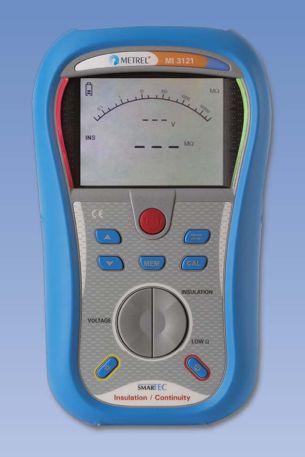
MI 3121 SMARTEC
Insulation / Continuity
Electrical Insulation Safety
Metrel offers a wide variety of Single, and Multi-Function testers for measuring Insulation Resistance up to 10kV, Earth Resistance, Line Tracers, Continuity, Loop and Line Impedance, and Phase Rotation.
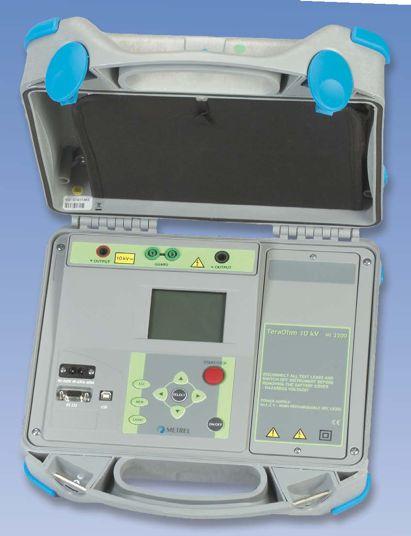


High Voltage Insulation Diagnostics
Technical demands require high performance measuring instruments capable of measuring polarization index (PI), dielectric absorption ratio (DAR), dielectric discharge (DD), time programmable step voltage test, insulation system's capacitance, etc. Metrel offers a line of 1kV, 5kV, and 10kV insulation resistance meters for these tests.


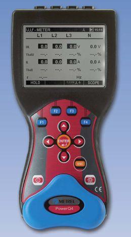

Single and Three Phase Power Quality Analysis
Metrel power quality analyzers are proven tools for expert designers of filtering systems, power correction equipment, over voltage protection and UPS systems. Wide range of testing possibilities are supported: voltage sags and swells, resonant states, high neutral conductor currents in 3-phase systems, asymmetry, transients, etc.


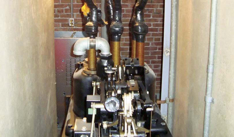
FIGURE 1:
Aged Switchgear –
5 kV oil breaker

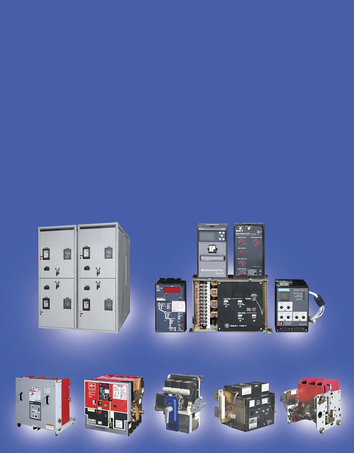
LIFE EXTENSIONS AND SAFETY UPGRADES FOR AGING DISTRIBUTION EQUIPMENT
RICK GARDNER – Sales & Marketing Manager, ABB MV Service
PETER STOPPELLO – Product Manager, ABB MV Service
HELP!


We just had an arc-flash incident. What can we do to protect our operators? The cost of keeping this gear on line is adding up. Is there a more cost effective approach than replacing the equipment?
With much of our electrical distribution equipment approaching or beyond the end of its originally intended life and new safety requirements in place, many of us that have vintage equipment are faced with a similar dilemma.
In many cases, with equipment that has reached the end of its expected life, one will have some or perhaps all of the following concerns:
• Switchgear and breakers are now causing reliability issues.
• Existing breaker technology is obsolete and maintenance is challenging. • Replacement parts are diffi cult or impossible to locate.
• Counterfeit or used parts do not meet specifications and tend to only compound the problem.
• Arc chutes may contain asbestos, causing environmental and health concerns.
• Mechanisms are complicated and difficult to lubricate effectively without a comprehensive overhaul.
• Operator safety is a concern – arc flash hazards, training gaps, improper tools to do required maintenance, PPE requirements, etc., all raise serious safety issues.
• Forced outages due to poor equipment reliability can have huge financial impacts.
• Workforce attrition has made maintenance support more difficult. The technicians that knew this equipment have retired and left a new challenge.
We are all asking the same questions: What are the most cost effective options for improving reliability while extending the life of installed distribution equipment? How can we improve safety and reduce the PPE requirements?
Do we have any exposure to financial or legal liability if we do not make any improvements?
If you have distribution equipment that is over thirty years old you have probably been asking yourself some of these same questions. What are the right answers to address the issues of an aging distribution system?
Low- and medium-voltage distribution systems are complex and involve a wide variety of electrical and mechanical components. Therefore, life extension of these systems can be a complex decision. All of the elements of the switchgear must be considered as well as overall system design. When comparing the expense to upgrade the aging equipment to a wholesale system or equipment change out, complex decision parameters that require a structured evaluation are required. For example, what is the impact of the outage time needed for each alternative?
The issues associated with extending the life of existing switchgear can be grouped into three categories. These categories and some of the variables that need to be considered will help to determine cost effective solutions which meet your performance improvement expectations.
MAINTENANCE
Maintenance of aging equipment can become both more intensive and expensive. Aging alone may result in degradation of mechanical and electrical performance. Depending on the availability of life cycle support, some system components may no longer be maintainable. Options are to repair, to refurbish/overhaul, or to replace.
• Maintenance cost – have O&M costs for this equipment gotten out of control?
• In house talent for maintenance – In many cases all the talent exited the building at the last retirement party; therefore, your options are limited to the following:
• Outsourcing
• Training new people
• Improving the reliability through upgrades.
• Parts – if purchasing new equipment or upgrading the existing gear, there is an opportunity to reduce and standardize on equipment that requires less maintenance and fewer, more readily available replacement parts.
COVER STORY
SUITABILITY
The equipment met the requirements when it was purchased decades ago, but several question should be answered in the evaluation of a life extension decision:
• Is the gear rated for current fault levels?
• Has the feeder to the switchgear been reconfigured since it was installed?
• Have technological developments resulted in new capabilities that would improve the safety, reliability, or capability of your system?
• Can the existing equipment be enhanced or upgraded to meet your current requirements?
• Are the current PPE requirements so high the maintenance employees are complaining the conditions are making it difficult to perform their jobs?
When addressing these questions, areas for improvement with respect to reliability, safety, and reducing cost can also be reviewed.
• Training – documents and repeatable training for present and future generations that may have to operate or maintain the updated equipment.
• Safety upgrade requirements – there are several after-market options to improve the safety of your older gear and in many cases offer a more cost effective approach than new gear. Examples include arc-mitigation relays, remote racking, IR ports, replacement breakers, and relay upgrades.
• Arc-flash concerns – old gear cannot be converted to arc-resistant gear, so what are the expectations and what can the organization live with? There are several options to reduce clearing times or to remove operators from harm’s way.
• Engineering impacts – in all cases there will be engineering cost to incorporate the upgrades or to redesign replacement equipment into the system.
• Down time – upgrading or replacing requires a window of time and typically the upgrades will take less time to complete and be less disruptive across all departments.
RISK MANAGEMENT
The risk management decision-making approach provides the ability to prioritize action, forecast expenditures over the projected life of the switchgear, and create visibility of the alternatives to everyone throughout the organization.
• Life extension goal – Is it short term or long term?
• Long term cost of the decisions – the cumulative cost over the targeted life extension period.
• Litigation exposure – The arc-flash studies are done. The incident energy levels and PPE requirement are known. Can one afford to do nothing?
• Budgets – Cost will drive the decision as much as the other needs.
• Unplanned outages – What has the financial impact been due to unplanned outages, around the clock maintenance, expediting charges, and lost production.
There are many things to take into consideration. A set of tools to help create a decision model can be employed.
EQUIPMENT ASSESSMENT
The first step is to perform a system and equipment assessment. The objectives of an assessment are to develop a risk profile of the asset base and provide a risk mitigation plan with priorities for action. This will identify the critical issues of the system and provide the basis for establishing cost parameters and evaluating the impact of varying levels of expenditure.
The assessment tool establishes:
• The condition of each individual asset and types of assets
• The importance of the asset in the system
• Risk profile for assets and the system as a whole
• Prioritization of recommended actions based on the condition and importance evaluations
Switchgear lineups are often feeding critical loads, and the financial consequences of their failure can easily exceed their actual asset value. Equipment assessment has a modular structure, allowing the level of investigation and solutions implemented to be adapted to specific needs and budget.
Assessments are an intelligence-based service, allowing the most cost-effective course of action for asset management that prioritizes the right actions at the right time and budget to be determined. They provide insight that can improve the performance, availability, predictability, and safety of switchgear and motor control centers.
The output of a comprehensive equipment assessment study is a report that identifies and prioritizes the critical risks in a system. Generally the reports will spell out specific data and give a health rating for each breaker, MCC bucket, transformer, etc. The assessment will also indicate which parts of the system need to be addressed immediately. In many cases, while the assessment is being performed, the technicians can easily perform some basic maintenance and in turn raise the health of the equipment to an improved as-left condition.
Recommended actions can take the form of repair, replacement, upgrade, maintain or monitor based on condition, importance, and cost.
• Maintenance spending can be prioritized to more effectively focus limited maintenance budgets.
• “What if” analysis can be applied to determine the impact on varying levels of expenditure on the overall risk profile.
• An action plan can be developed for the proposed extended life of the equipment which meets the specified objectives.
Not only is there now a solid basis for comparing the cost of extending the life of existing equipment to alternatives, if life extension is the way to go you there is now a game plan.
FIGURE 2: Capital cost expense for decision purposes
COST/BENEFIT ANALYSES
Now that the condition of the equipment is known there is a list of specific upgrades needed to reach the established life extension and safety and performance goals, the next step is to run a return on investment analysis.
There are tools available that allow owners/operators to evaluate the options they desire as safety and life extension upgrades and compare that to the cost of a complete change out of existing gear with new equipment. These tools take into consideration the key variables as they apply to each unique situation. These can be any combination of influences such as environmental, maintenance cycle times, labor rates, talent levels of technicians, budget constraints, safety expectations, or life extension goals.
The typical analysis will allow the evaluator to play out some “what if scenarios.” The evaluations will begin with inputting several key variables. The primary drivers will be labor burden rates, PM cycles, refurbishment cycles, age of equipment, equipment upgrades, and life extension expectations. Additional selections include safety upgrades like arc-mitigation relays, remote racking, and IR ports.
EXAMPLE
This example is of a (10) frame line up of medium-voltage gear that is 35 years old. The expectation is to extend the life another thirty years. After including all the engineering, maintenance and refurbishment cycles along with selected safety upgrades that are typical across all options, the following results can be expected:
Cost Comparison
Cost
• Typical evaluations have shown that the most cost effective approach is utilizing replacement breaker technology with added safety upgrades. This approach results in a cost which is less than 45 percent of the cost of replacement with arc-resistant gear.
Keep in mind, as stated previously, vintage gear cannot be converted to arc-resistant gear. With that said, we are not comparing apples to apples – we are making a cost and cycle time decision. What can be accomplished at the end of the day is to upgrade the equipment to effectively have another thirty plus years of life while improving safety to very highly desired levels. The improved clearing times utilizing arc-mitigation relays and increasing operator distance from the gear with remote racking systems will improve the safety of the operator. The breaker refurbishment approach was considered but the lower cost was so minor it did not justify the offset of the other benefits of new technology, training materials, reduced parts and improved reliability that were associated with the replacement breaker option.
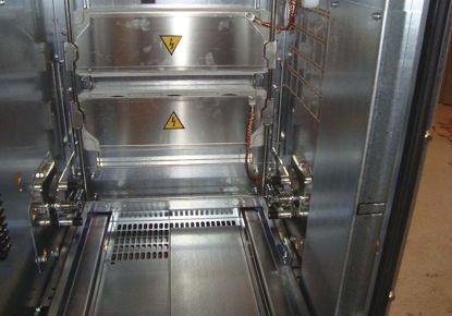
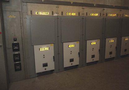
CONCLUSION
While situations and results will vary, many of us will be facing the same issues and dilemmas in our decisions regarding aging distribution equipment. While there are lots of variables to consider in the distribution equipment life extension decision, fortunately, there are tools and help available to guide the decisions and justify the best approach for the situation. The process can be structured to become a valuable exercise in determining your needs over the future extended life. By categorizing the factors and considerations while employing risk assessment and cost benefit analysis tools, the life extension decision process can provide a clear roadmap for optimizing maintenance and upgrade expenditures over the desired extended life and greatly improve the ability to meet performance objectives.

Rick Gardner received his MBA from Crummer Graduate School of Rollins College and has been with ABB for over 33 years. During his career Rick has held various positions in switchgear operations and switchgear marketing for his first 28 years with ABB. During the past five years he has been the Sales and Marketing Manager for Low and Medium Voltages Services where he assists customers to address their needs for safety upgrades and life extension solutions for their existing equipment.

Peter Stoppello received both his BS and MBA in Finance and International Business from the University of California Berkeley’s Haas School of Business. He joined ABB in 2004 with the acquisition of a company he co-founded. He has more than 35 years’ experience in the electrical distribution business, primarily in low and medium voltage switchgear and circuit breakers and is currently Product Manager for Low & Medium Voltage Services where he is responsible for the ANSI products and services portfolio offering of this ABB service group.
NETA Standard for Maintenance Testing Specifications for Electrical Power Equipment and Systems!

Join NETA’s Affiliate Program today for Savings on MTS – 2011. Receive additional discounts on PowerTest 2012 and all NETA publications Go to www.netaworld.org or call 888-300-NETA (6382)
Order by May 31st and Receive FREE Shipping
This document specifies field tests and inspections used to assess the suitability for continued ser vice and reliability of electrical power equipment and systems.
MTS – 2011 covers equipment such as:
✔ Switchgear
✔ Transformers
✔ Cables
✔ Switches
✔ Circuit breakers
✔ Protective relays
Also included:
✔ Rotating machiner y
✔ Motors
✔ Batteries
✔ Capacitors and reactors and more...
• New section on Nickel-Cadmium Batteries
• Document references applicable industr y standards
THE CURRENT METHOD OF TESTING CIRCUIT BREAKERS
BACKGROUND
One of the most critical devices on any electricity network is the circuit breaker which can be described as the silent sentinel, standing guard over the network and only being called into action when a fault occurs.
The circuit breaker needs to operate within its composite tripping time (relay trip time plus circuit breaker main contact opening time) to ensure correct discrimination with upstream circuit breakers and, therefore, minimize the number of customers disconnected during a fault operation. A slow tripping circuit breaker will not only result in unnecessary disruptions to electricity supplies, but maintaining high fault currents for extended durations can stress the network and cause damage to plant and equipment. Often the problem that caused a slow trip is temporarily cleared during the first trip operation because friction in the mechanism is reduced by spreading lubrication during the motion of tripping. Traditional diagnostic testing procedures usually require the circuit breaker to be isolated and removed from service; therefore, not only has the opportunity to detect the cause of the defect been missed but also the tests do not focus on the condition of the operating mechanism apart from overall speed of operation.
CONVENTIONAL CIRCUIT BREAKER TESTING
Conventional testing has normally required removing the circuit breaker from service. However, isolating the circuit breaker is time consuming as it requires a planned outage involving the issue of switching instructions and safety documents and will often involve several engineers or technicians on site.
This process resulted in vital information relating to the first trip not being captured and often the problem that caused a slow trip in a circuit breaker was temporarily cleared during this first trip operation.
When a slow trip operation occurred the focus tended to be on timing tests to determine if the problem lay within the protection relay or the circuit breaker operating mechanism. Rarely were the problems due to slow operation of the protection relay, especially if they were the electronic or microprocessor based type. Occasionally problems occurred with the older electromechanical type relays due to friction in the moving parts such as the induction disc which would be revealed during secondary injection tests. Timing of the circuit breaker main contacts from initiation of a trip to main contact opening merely indicated the circuit breaker was operating within its design specification. Therefore, the initial tests were inconclusive, so the focus then turned to inspecting the main operating mechanism and lubricating the numerous mechanical components. In some cases this further compounded the problem as the wrong type of lubricant was used, especially with the advent of spray penetrants which could be liberally applied. This caused an organic chemical reaction between the solvent and propellant (within the penetrant) and the soap (within the grease) resulting in varnish which caused the mechanism to stick. Instead of fixing the problem that caused the slow trip, the effort in testing and maintaining the circuit breaker was largely counterproductive.
BY MICHAEL SKELTON KelvatekDIAGNOSTIC TESTING FOR SLOW TRIPPING CIRCUIT BREAKERS
The failure of conventional timing tests to diagnose the causes of slow tripping circuit breakers lead to the search for a technique that would pinpoint the cause during the critical first trip. Although timing tests can confirm that a circuit breaker’s overall operation is within set limits, it was discovered that monitoring the current flowing through the trip coil provided a very powerful methodology for analyzing the readiness of a circuit breaker to trip. Trip coil profiling was developed as a condition monitoring technique where deviation from a standard profile could help to pinpoint a potential problem within either the trip coil or the circuit breaker’s main operating mechanism.
ANALYSIS OF A TRIP COIL PROFILE
The trip coil has both electric and magnetic circuits. Tripping action is typically due to the action of a plunger moving within an energized coil. This electromagnetic circuit has reluctance in the magnetic part as well as inductance and resistance in the electrical part. Normally, in most electrical circuits, we can think of the inductance as being fixed. However, in the trip coil, as the plunger moves, the reluctance of the magnetic circuit is reducing which means the inductance in the electric circuit is increasing. The applied voltage, which is a constant (apart from a small voltage drop), is proportional to the rates of change of both current and inductance. As the rate of change of inductance goes up the rate of change of current must go down and vice-versa. Hence, an instantaneous drop in the rate of rise of the inductance due to the plunger striking the latch or the end-stop will cause an instantaneous rise in the rate of change of current.
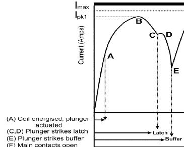
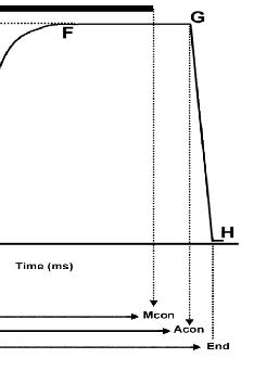
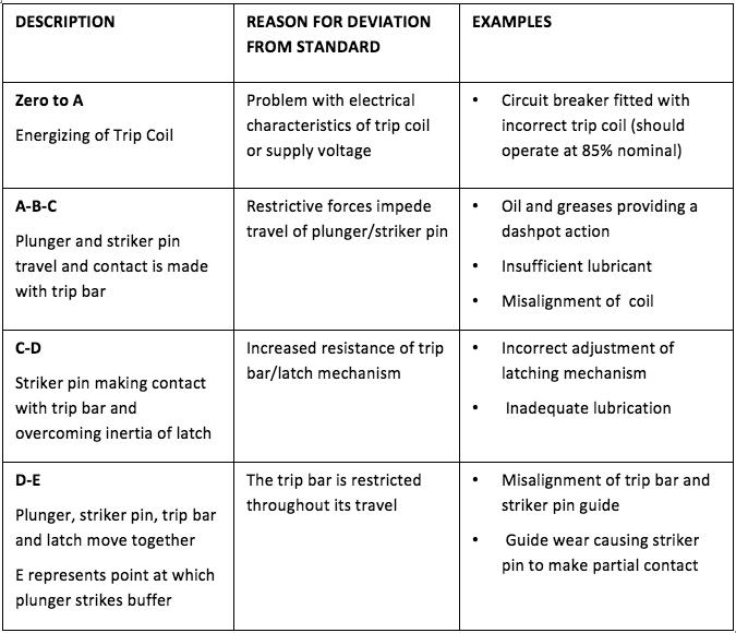
Diagram 1 shows a typical trip coil profile with its distinct shape where each stage of the trip coil mechanism can be identified through its operation and problems identified if the profile deviates from a signature trace.
Table 1 provides examples of what would cause a deviation in any section of the profile curve. These examples are not exhaustive and can be simulated on a trip coil mechanism by varying the parameters that cause deviations, capturing the current profile, and overlaying it on a signature profile. Each type of circuit breaker will have its own characteristic profile; therefore, it is essential that this signature profile is acquired. Comparisons can then be made with profiles captured during on-site testing of the first trip operation and subsequent trip operations to identify potential defects.
TRIP COIL PROFILE ANALYSIS
DEVELOPMENT OF PORTABLE TECHNOLOGY FOR MEASURING TRIP COIL PROFILES
Initially the monitoring of trip coil profiles required the hard wiring of equipment into the circuit breaker; however, this was cost prohibitive and could only be justified for circuit breakers located at extremely critical nodes on the network. The development of portable, light weight, handheld devices with noninvasive connections to monitor the key current and voltage parameters has revolutionized the testing of circuit breakers. The process of testing a circuit breaker only takes a few minutes, enabling a condition assessment of the operating mechanism to be obtained during the first trip operation.
As well as indicating the health of the circuit breaker trip and close coil mechanisms, other useful parameters are obtained which include:
• measuring the main contact operating time
• measuring the auxiliary contact operating time
• checking the integrity of control circuit wiring
• indicating problems with dc supply TABLE 1
FEATURE
Furthermore, this information is immediately available for on-site analysis, and corrective maintenance can be targeted at a defect.
It is becoming increasingly important to make connections within the circuit breaker cubicle to ensure that the right circuits are being monitored. Some modern circuit breakers use capacitive charged power supplies, so it is important that the current probe which monitors the dc current to the trip coil, is connected close to the trip coil.
The advantage of a portable handheld device means that it can be considered as an invaluable addition to the maintenance technician’s toolkit that can be used at any circuit breaker location.
Michael Skelton is the Product Manager for the Profile P3. He previously worked at Northern Ireland Electricity (NIE) for 33 years and has extensive experience in the following areas: design of rural protection schemes for the 11 kV overhead network, low voltage cable fault location, testing and commissioning of distribution switchgear, high voltage network planning, and general operational experience on the 11 kV and low voltage distribution network.
In his role as Emergency Response Manager for NIE, he was responsible for implementing an emergency response business which included centralized call handling and dispatch, dedicated fault restoration and repair teams, the amalgamation of the three distribution control centres into one new control centre supported by fully integrated network management, control room display, and SCADA systems.




SWITCHGEAR & CIRCUIT BREAKERS


 BY JIM WHITE Shermco Industries
Many companies don’t maintain their switchgear in the manner they should which can lead to problems and safety issues. We have seen instances where the protective relays have been calibrated, but the switchgear and circuit breakers have not been maintained. A lot of maintenance is driven by insurance company dictates, but that does not ensure a safe or efficient electrical system. The following questions will help sharpen your maintenance knowledge:
Jim White is the Training director for Shermco Industries and the principal Shermco representative on the NFPA 70B committee. Jim is the alternate NETA representative on the NFPA 70E committee and serves as the NETA representative on the IEEE/ NFPA Arc-Flash Hazard Work Group (RTPC) Ad Hoc Committee. He served as the Chairman of the 2008 IEEE Electrical Safety Workshop. Jim is a NETA Certified Level IV Electrical Testing Technician and a member of the NETA Safety Committee.
1. You are a facility maintenance manager and you have several sections of mediumvoltage switchgear. This equipment has a high reliability requirement and is in good condition. According to ANSI/NETA MTS-2011, how often should it be electrically tested and maintained?
a. 6 months
b. 12 months
c. 18 months
d. 24 months
2. Cable connected to bus using lugs is always an issue. My experience has been that when checked for tightness every three years, roughly 50 percent of the connections require retorquing. What three methods does ANSI/NETA MTS-2011 recommend for checking for connection problems?
a. _______________
b. _______________
c. _______________
3. Using ANSI/NETA ATS-2009 as a reference, what is the minimum voltage to be used for performing a dc overpotential test on 15 kV switchgear?
a. 15 kV
b. 25 kV
c. 27 kV
d. 37 kV
4. ANSI/NETA ATS-2009 recommends what maximum value of leakage current when performing the dc overpotential test on 15 kV switchgear?
a. 1 Megohm/kV test voltage plus 1 Megohm
b. 1.0 microampere
c. 100 microamperes
d. No failure of insulation
5. What is the minimum insulation resistance of control wiring in switchgear based on ANSI/NETA MTS-2007?
a. 1 Megohm
b. 2 Megohm
c. 4 Megohm
d. No failure of insulation
See answers on page 107.


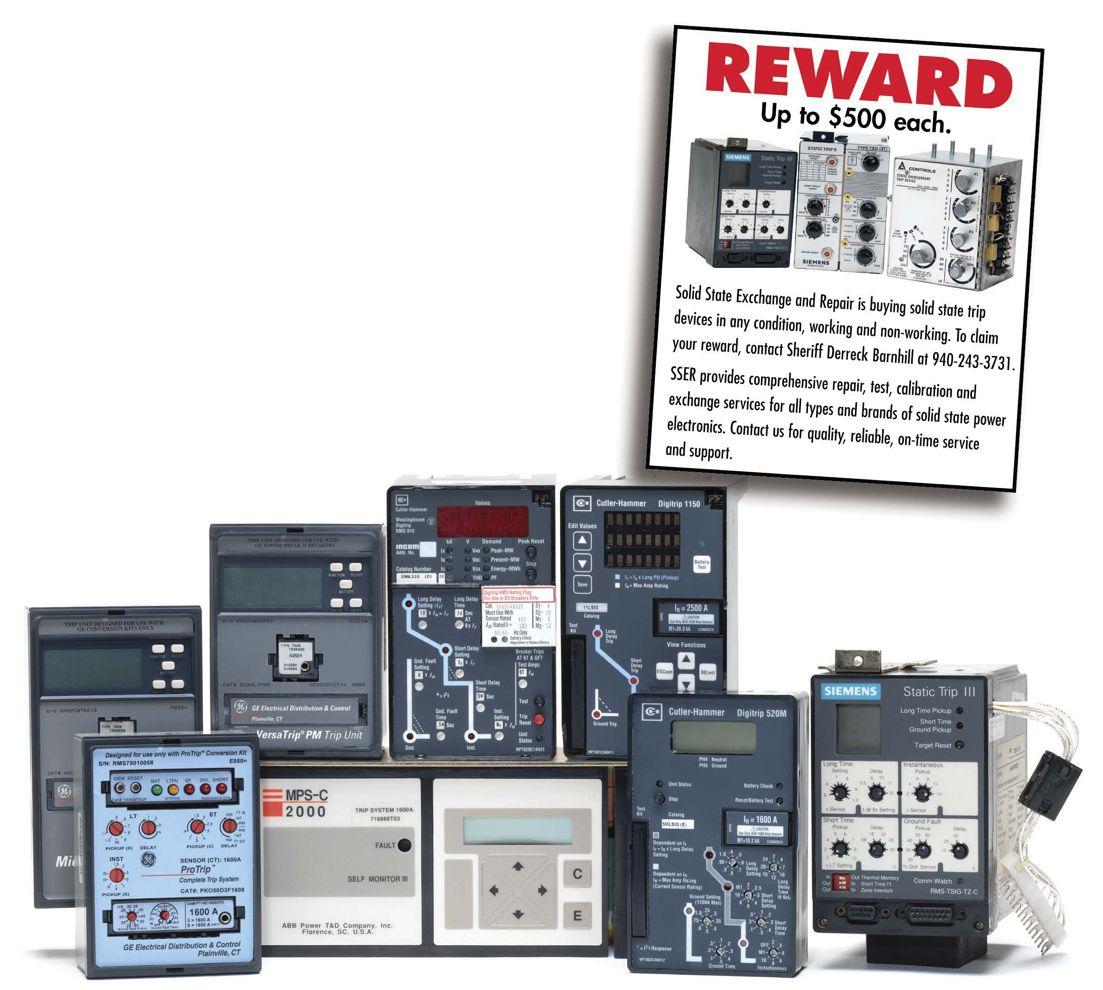
We Buy, Sell, Trade, Calibrate, Repair
Featuring quality, reliable, on-time service and support for all brands and types of solid state power electronics.
Power electronics are our business
Let us suppoort you with our quality repair, calibration and servicing of your solid state equipment. We also buy, sell and trade:
•Communications devices for power equipment
•Protective relays
•Circuit breaker trip devices
•Motor overload relays
•Rating plugs


OVERHEAD LINES:
THE ELECTRICAL DANGER ABOVE
Do you know what to do around overhead power lines? What if one falls to the ground? What if one falls across your car? Do you know what step potential is? Can you quickly and safely react to a downed power line event?
The goal of this article is to provide you with facts to better understand the hazards of overhead power lines…
INTRODUCTION
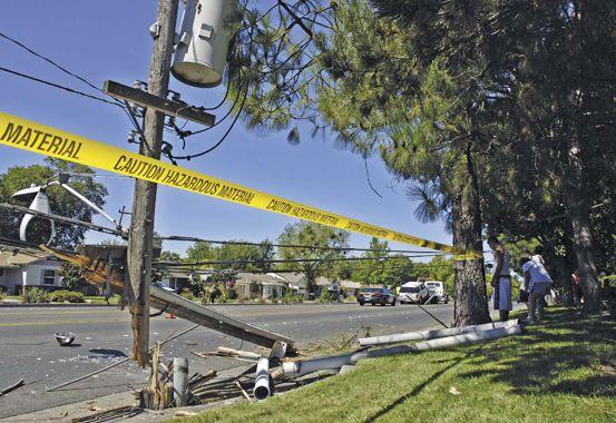
Sadly, many people every year, both on and off the job, are seriously injured or killed from contact with overhead lines, and many times the incidents involve overhead lines that have fallen and are lying on the ground or lying on an object that has become energized. Understanding the hazards associated with overhead lines and knowing what to do (or what NOT to do) can literally mean the difference between life and death.
 BY JIM WHITE & RON WIDUP, Shermco Industries
CASE STUDY: A FAMILY TRAGEDY IN CALIFORNIA
On January 14, 2011, three family members were electrocuted in San Bernardino, California—a father (age 44), a mother (age 43), and their son (age 21). Based on information obtained from the Los Angeles Times, the details of the tragedy are:
• During high winds, at about 5:45 a.m., they heard a loud “pop” in the backyard.
• A 12,000-volt line had fallen to the ground.
• Several small fires had started in the back and front yards.
• The father and his stepson went to investigate in the back yard.
• The mother went to the front yard and heard a loud explosion.
• Her husband and son were lying on the ground, deceased.
• She reached out to help them and was electrocuted. Knowing about the dangers of overhead power lines, especially downed power lines, can mean the difference between life and death.
THE NFPA 70E AND NETA
OVERHEAD LINES IN THE WORKPLACE
NFPA 70E
NFPA 70E covers “work within the limited approach boundary of uninsulated overhead lines” in Article 130.5. This is the section of the 70E that deals with many of the hazards associated with work in locations near overhead lines. Everyone should take the time to understand and comply with the requirements and guidance located within Article 130.5.
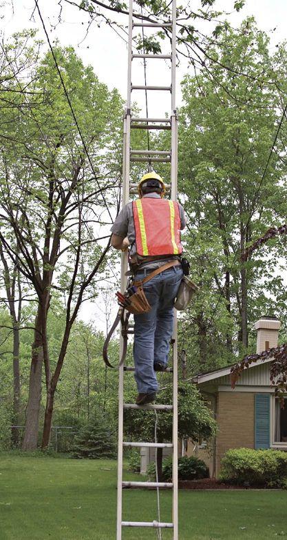
The second leading cause of worker deaths in construction (after falls) is electrocution, and the primary cause for the electrocutions is contact with overhead lines. Many times the incidents involve a nonelectrical person doing tasks such as operating a mobile crane, moving a metal ladder, unloading supplies, or accessing a roof.
Ladders can be particularly hazardous, as a NIOSH review of the Bureau of Labor Statistics (BLS) Census of Fatal Occupational Injuries (CFOI) data from 1992–2005 identified at least 154 electrocution deaths that resulted from contacting overhead power lines with portable metal ladders (excluding truck-mounted and aerial ladders) [NIOSH 2007a].
OSHA Regulations
Current OSHA regulations require employers to take precautions when cranes and boomed vehicles are operated near overhead power lines. Any overhead power line shall be considered energized unless the owner of the line or the electric utility company indicates that it has been de-energized and it is visibly grounded [29 CFR 1926.550 (a)(15)(vi)]. The OSHA regulations are summarized as follows:
Employers shall ensure that overhead power lines are de-energized or separated from the crane and its load by implementing one or more of the following procedures:
De-energize and visibly ground electrical distribution and transmission lines. 29 CFR 1910.333(c)(3); 29 CFR 1926.550(a) (15)
Use independent insulated barriers to prevent physical contact with the power lines. 29 CFR 1910.333(c)(3); 29 CFR 1926. 550(a)(15)
Maintain minimum clearance between energized power lines and the crane and its load. 29 CFR 1910.333(c)(3)(iii); 29 CFR 1926.550(a)(15)(i), (ii), (iii)
Where it is difficult for the crane operator to maintain clearance by visual means, a person shall be designated to observe the clearance between the energized power lines and the crane and its load 29 CFR 1926.550(a)(15)(iv)
The use of cage-type boom guards, insulating links, or proximity warning devices shall not alter the need to follow required precautions.
29 CFR 1926.550 (a)(15)(v)
You should familiarize yourself with all of the OSHA rules concerning overhead line safety.
When power lines fall to the ground you have to be concerned with “step potential.” Think of a rock dropping in a bucket of water and the resulting ripples. The same thing happens with electricity – it flows through the ground like ripples of water. The voltage in the ground near the downed power line will be greatest and will decrease as a person moves away from it. If your feet are apart, one foot will be at a higher voltage than the other. If that difference in voltage (potential) is great enough, it could force current through your body.
That same electricity can enter into your body if you are walking on the ground near the source and the ground becomes energized. Electricity can flow between your feet and through your body and that flow of electricity can lead to ventricular fibrillation (affecting the heart)…and the results can be deadly.
It takes very little current flow through the body to cause problems: muscle contraction, suffocation, heart stoppage - all real possibilities when involved in a downed power line event and step potential becomes a factor.
If you are around a downed power line: DO THE SHUFFLE! Shuffle your feet and keep them close together, and after you are clear, keep everyone away and call 911!
But what if you are involved in a vehicle accident and a power line comes down on or around your vehicle – don’t get out of your car!! Only get out if there is a life-threatening situation if you stayed in your car… and if you do have to get out – JUMP! as far as you can!

Don’t touch the car and the ground at the same time and keep your feet close together (remember about step potential).
SUMMARY
ALL of the incidents involving injury from overhead power lines can be prevented if a little education and understanding of the hazards of electricity, along with an awareness of your surroundings, are put into place and followed.
Remember – electricity is a very toxic thing – and beware of the overhead line!
If you would like to receive a short PowerPoint presentation entitled Overhead Lines: The Electrical Danger Above to use at work, at school, at Boy Scouts, etc… or even at home with the kids – send an email to overheadline@shermco.com and we will send it to you for your use and grant permission to freely distribute the information.
James R. White and Ron A. Widup are NETA’S representatives to NFPA Technical Committee 70E (Electrical Safety Requirements for Employee Workplaces). James R. White is nationally recognized for technical skills and safety training in the electrical power systems industry. He is currently the Training Director for Shermco Industries, a NETA Accredited Company. Jim has spent the last twenty years directly involved in technical skills and safety training for electrical power system technicians.

• Complete Substatio n Maintenance, Testing & Repair
• Generating Plant Maintenance Testing & Repair
• Simple, Complex & Microprocessor Relays
TDE SPECIALTIES
• Online Motor Testing & Analysis
• Cable Splicing, Testing & Analysis, VLF & VLF-TAN Delta
• Field Work: Motor, Generator & Transformer Maintenance, Testing & Repair TRAINING
• Arc Flash Training
• Safe Electric Practices
• Recommended Maintenance and Operation Practices
• Regulator y Compliance Program


WHERE:
electricalmanuals.net
WHEN:
Founded in 2008
WHO:
Created by Jonathan Hulsman, former field technician
WHAT:
Started with 4,700 electrical manuals
Grown to over 9,513 documents to date
Catalogued by subject No duplicates
BENEFITS:
Free to join
Free to download
Free to upload Free discussion forums
Supported by donations and advertising
JOIN TODAY: Visit electricalmanuals.net
Create a free account Start searching, downloading, and sharing
WHERE DO YOU GO WHEN INDUSTRY STANDARDS DON’T HAVE THE ANSWER YOU ARE LOOKING FOR?
It’s a common problem faced by those in the electrical industry, whether in operations management, architecture and engineering, electrical field testing, or really just about any position that requires one to be responsible for electrical equipment. These individuals devote hours, weeks, and years of their lives studying, learning, applying, and relearning the labyrinthine rabbit hole created by industry codes and standards, and they do a pretty darn good job of making sense out of these incredibly detailed documents. They understand when to pick up the NEC 70E versus the NFPA 70B, the IEEE C-57 and not the IEEE C-37, or the ANSI/NETA ATS rather than the ANSI/NETA MTS. Even with this knowledge, it seems that at times the search for test values take’s a person from one standard’s reference to the next, ultimately leading to a common phrase, “Test values shall be in accordance with the manufacturer’s published data.”
This sounds like a simple enough request. All that remains is to locate the operator’s manual for that relay that has been in service for the last fift y years. Yeah, right. Where is the valiant seeker of knowledge to turn? In the past, one might get out the Rolodex and start calling people to track down a copy of the elusive document. With the evolution of the internet, things started looking up, but nothing was centralized in one searchable location.
One person, a former field technician, decided that the time had come to address this issue.
Three years ago, Jonathan Hulsman started electricalmanuals.net, a site dedicated to the open exchange of electrical information. He began with a collection of roughly 4,700 manuals that he methodically gathered, scanned, and catalogued according to subject matter. Jonathan said that in the last three years, the number of manuals on the site has doubled. At the time this article was written, an impressive 9,513 manuals in 2,636 unique categories are housed in the database. This growth can be attributed to the fact that electricalmanuals.net is free to join, hosts discussion forums for registered users, and allows users to help out their fellowman by uploading their own documents for inclusion in the site. Each document is scanned to ensure that there are not duplicates, and Jonathan
individually catalogues each one before it is placed on the site. The site is supported through donations and a small number of ads that keep clutter to a minimum.
After searching in vain to find documents, users offer feedback to Jonathan after locating documents. He said that the most requested manuals seem to be for breakers and relays from the 1960’s and 1970’s, citing that after 30 years or so, many facilities scrap the old manuals since these types of equipment tend not to wear out if maintained correctly. Since beginning a partnership with NETA two years ago and attending PowerTest, a NETA hosted event, Jonathan reported that membership to the site has increased dramatically as have the number of resources uploaded and shared with others. NETA is happy to be aligned with someone dedicated to creating a solution to a real-world problem faced by countless people every day, and who understands that sometimes one person can make a difference if that person is willing to share their time and talents with others.
To become a registered user, visit www. electricalmanuals.net and create a free account. From there you can search files, download, upload, chat with your peers, and donate to this worthy cause.





 BY LYNN HAMRICK, Shermco Industries
TESTING FOR RURAL ELECTRIC COOPERATIVES
The Rural Electrification Act of 1936 provided federal loans for installation of electrical distribution systems to serve rural areas of the United States. The funding was channeled through cooperative electric power companies, most of which still exist today. These memberowned cooperatives purchased power on a wholesale basis and distributed it using their own network of transmission and distribution lines. These rural electric cooperatives (RECs) still rely heavily on the federal government for funding through an electric program administered through the United States Department of Agriculture (USDA). Loans are made to corporations, states, territories and subdivisions and agencies such as municipalities, people’s utility districts, and cooperative, nonprofit, limited-dividend, or mutual associations that provide retail electric service needs to rural areas. Through the Electric Programs of USDA, the federal government is the majority note holder for approximately 700 electric system borrowers in 46 states.
To be compliant with USDA requirements, the USDA issued Rural Utilities Service (RUS) Bulletin 1724E-300, Design Guide for Rural Substations. The latest issue of this bulletin was in 2001. Additionally, RUS Bulletin 1724E300 provides details that RECs must meet with regard to electrical testing requirements for their substations. These requirements include combinations of visual inspections, electrical tests, and other periodic maintenance activities.
SUBSTATION INSPECTIONS
To ensure power system reliability, it is essential that inspections of substation equipment, structures, and other devices be made periodically. General guidelines for the required inspections for substation equipment, structures, and other devices are discussed below. They should be tailored to meet the requirements of a specific site as well as for the equipment at the site. Visual inspections should be performed and should encompass the total substation including the control house and all equipment and structures. This inspection should be performed with the substation energized. Therefore, all inspections should be made from ground level to ensure adequate safety clearances from energized parts. Binoculars may be used to view buses and other equipment located on structures. Since a high voltage could develop across any gap created between a ground cable and a piece of equipment, particularly under fault conditions, special care should be used when ground connections are inspected. For this reason, ground connections should not be removed for any reason while the substation is energized.
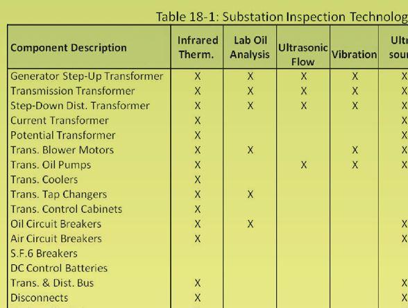
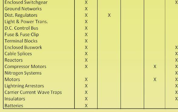
In addition to these periodic inspections, other predictive maintenance tests may be required to ascertain the cause of particular problems, when equipment is placed in service or when the substation, or portions thereof, are taken out of service. The attached Table 18-1 from RUS 1724E-300 is provided for information.
ELECTRICAL TESTS

Tests of substation equipment are required to fulfill at least the following functions:
1. To prove the integrity of a piece of equipment at the time of acceptance.
2. At periodic intervals, to verify the continued availability of the equipment.
3. At the time of failure of a piece of equipment, to be able to determine the specific requirements for repair.
The types of tests to be performed for each of the above categories vary. For additional information and references, International Electrical Testing Association’s (NETA)’s ANSI/NETA ATS-2009, Acceptance Testing Specifications for Electrical Power Equipment and Systems and ANSI/NETA MTS2007, Maintenance Testing Specifications for Electrical Power Distribution Equipment and Systems, should be utilized. In all cases, specific equipment manufacturers’ recommendations should be observed and factored into the testing procedures. In addition, scheduled outages should be used to the greatest extent possible since certain equipment is unavailable for test unless large portions of the substation are de-energized. The attached tables from RUS 1724E-300, Table 19-1 on acceptance tests and Table 19-2 on maintenance tests, are provided for information.
NICHE MARKET TESTING
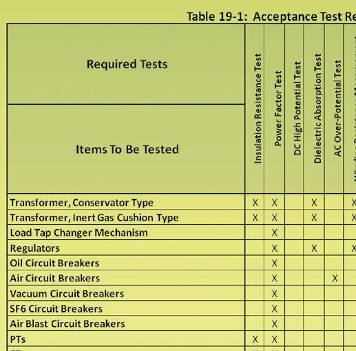
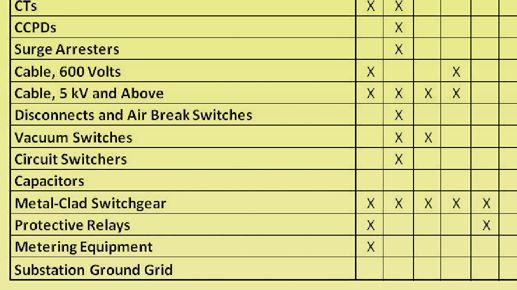
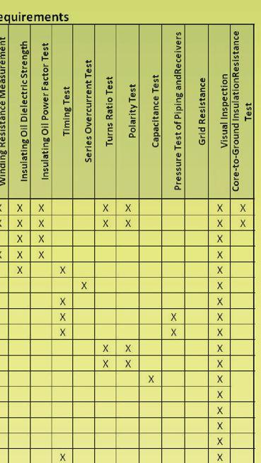


Upon completion of tests, provisions should be made to follow-up with repeat tests where required and make repairs where the need is indicated by the test results.
PREVENTIVE MAINTENANCE
Periodic or time interval-based maintenance procedures, more commonly referred to as preventive maintenance, should be performed in an attempt to minimize unscheduled service interruptions. The degree of success of such procedures is generally reflected by the REC’s ability to balance system reliability with accepted levels of risk of failure or system outage.
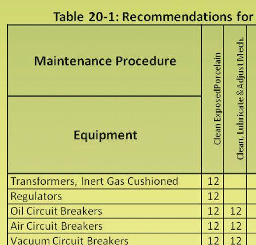
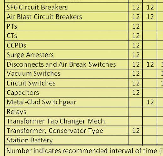
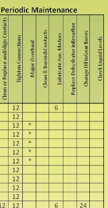
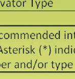
Specific details for the performance of periodic maintenance vary considerably depending on the make, model, age, load profile, etc. of the specific equipment. In addition, a maintenance program developed for substation equipment should consider site environmental conditions, site location and access, and priority of the substation equipment to overall system reliability. Refer to manufacturers’ instruction books for all equipment requirements. The attached Table 20-1 from RUS 1724E-300 is provided for information.
NICHE MARKET TESTING

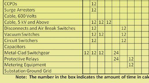


In addition to USDA requirements, RECs must also meet National Electric Reliability Council’s (NERC’s) Standard PRC-005-1, Transmission and Generation Protection System Maintenance and Testing, issued in 2006. This standard requires that owners of generation protection systems shall have a maintenance and testing program for all protection devices that affect the reliability of the Bulk Electric System (BES). This program must include a maintenance and testing interval for each type of device and the basis used for determining that interval. The program must also provide the evidence that each protection system device was maintained and tested within the defined intervals including the last tested/maintained date. The owner must provide documentation of its system maintenance and testing program and the implementation of that program to its regional reliability organization on request within 30 calendar days.
In summary, RECs are required to perform acceptance testing of their substations. Additionally, periodic inspections, maintenance testing, and other preventive maintenance activities are required to ensure associated electric system reliability. These requirements are provided in USDA’s RUS Bulletin 1724E-300 and NERC’s Standard PRC-005-1.
NICHE MARKET TESTING



Lynn Hamrick brings over 25 years of working knowledge in design, permitting, construction, and startup of mechanical, electrical, and instrumentation and controls projects as well as experience in the operation and maintenance of facilities.
Lynn is a Professional Engineer, Certified Energy Manager and has a BS in Nuclear Engineering from the University of Tennessee.



Find yourself testing in tight situations?
Need a low-maintenance instrument that’s easy to use? Is safety important in your ground testing routine?
If you answered YES to any of these questions, consider the NEW DET14C and DET24C digital clamp-on ground testers from Megger.
Megger has taken ground tester technology to a new level. Here are a few of the advanced features of the DET14C/24C:
n A large elliptical jaw that allows testing at any angle and on the largest ground rods.
n Smooth mating surfaces on clamp head means no interlocking teeth.
n CATIV 600 V operation is the highest level of user safety available.
n Intelligent data hold function increases ease of use in difficult locations.
n Data storage reduces potential for error in recording results.
n Noise filter function provides the best immunity to noise current.
n Ultra-long battery life reduces the cost of ownership.
So you want big improvements with little effort? The Megger DET14C/24C digital clamp-on ground testers are all you need for your ground testing applications.

SWITCHGEAR LIFE EXTENSION:
REPLACEMENT OF ELECTROMECHANICAL
OVERCURRENT RELAYING

UPDATING SWITCHGEAR RELAYS
Electromechanical overcurrent relays such as the IAC and CO are the historical backbone of power system protection. These relays use delicate mechanisms and precision components to develop their operating characteristics and are subject to misoperation and failure resulting from contamination, corrosion, and simple aging. As a result, frequent testing and recalibration are required to ensure proper operation. As the relays continue to age, failing internal insulation and increasing cost associated with maintenance and repair of the relays makes it increasingly difficult to ensure reliable operation. Reliable operation is essential for personal safety and the prevention of unnecessary outages and/or extensive damage due to overloads and faults.
One solution to this problem is to upgrade the relays which will easily extend the life of the switchgear 10 to 20 years with minimal financial investment and very little labor. Upgrading reduces the need for maintenance and increases protection reliability which is very valuable during times of limited maintenance budgets. At the same time, upgrades often improve accuracy which is increasingly important because many systems are operating with less margin than planned for in their original design.
The technology available in modern relay systems allows one device to replace what once took many separate devices to accomplish. Phase and ground protection are available in one box, along with ancillary features such as metering, data capture, advanced communications, and post fault analysis. What is sometimes overlooked is the value that newer technology can add by simply providing the same functionality as existing relays with less maintenance, less system burden, better precision, and greater reliability. There are several options for extending the life of switchgear by upgrading to newer technology, retrofit relays.
BY TODD MARTIN, Basler Electric CompanyOne option is to replace existing relays with plug and play relays that require no wiring changes. The second option is to upgrade in place which means that a retrofit relay will fit the existing panel cutout. Some rewiring for the upgrade relay is required, but the existing panel does not have to be replaced. The first option benefits from being easier. It requires no down time and often can be done as part of routine maintenance and testing. The second option requires slightly more work and down time, but provides an avenue to add immediate benefits such as metering, event reporting, remote communications, and future automation.
PLUG AND PLAY RELAY UPGRADE
When facing electromechanical overcurrent relay obsolescence, a chemical facility in the Midwest chose to upgrade with plug and play relays. Their facility had 72 General Electric IAC relays that were to be replaced. For the upgrade, they selected the Basler BE1-50/51B-214 time overcurrent relays. The relay, a direct plug and play replacement for the IAC relay, is installed with no wiring or case change. The BE150/51B-214 has selectable time curves that emulate the majority of IAC variations, and it has less CT burden than the IAC model. This makes for a simple, economical way to upgrade from aging relays without the expense of completely redesigning and rewiring the systems to accept currently available functional replacements.
The retrofit kit consists of a relay cradle, an adapter plate, and a cover. The kit allows plugin installation in an existing lAC case. In order to prepare for the retrofit process, the facility’s test and maintenance personnel received a day of on-site training. Fifteen employees spent most of the day learning about the relay. The training covered the relay basics, specifics of the 214 retrofit version, the retrofit process, and relay setup and testing. The identified process contained six steps:
• STEP 1: Set the relay to the desired pickup and timing settings. An available spreadsheet provided the necessary information to convert the electromechanical time curves to the correct equivalent curve on the replacement relay.
• STEP 2: Remove the existing relay.
• STEP 3: Attach the cover adapter with four provided screws.
• STEP 4: Install the new relay.
•
STEP 5: Reinstall the existing connection plug.
• STEP 6: Install the new relay cover.
The newly trained personnel were able to test and install the relays at a rate of three relays per hour. At this pace, replacement of all 72 relays was completed in only a few days. The retrofit was accomplished with minimal down time, minimal work, and most importantly, minimal expense. Because the new relays are solid state, they have no critical moving parts that can affect their performance and they require minimal maintenance. They also meet all ANSI/IEEE standards for operation in harsh power system environments.
The benefits continued well after the installation. During periodic maintenance or troubleshooting, an electromechanical relay’s timing characteristics must be checked and calibrated. Correct pickup and timing need to be determined by test in an iterative process. Settings in the relays are made by front panel switch settings. There is no calibration. These relays are not subject to drift or change in performance, so recalibration is never necessary. This can save valuable time in an outage emergency and save money in periodic maintenance costs on an ongoing basis. The savings in maintenance costs alone easily justify the cost of the new relays.
NUMERIC RETROFIT UPGRADE
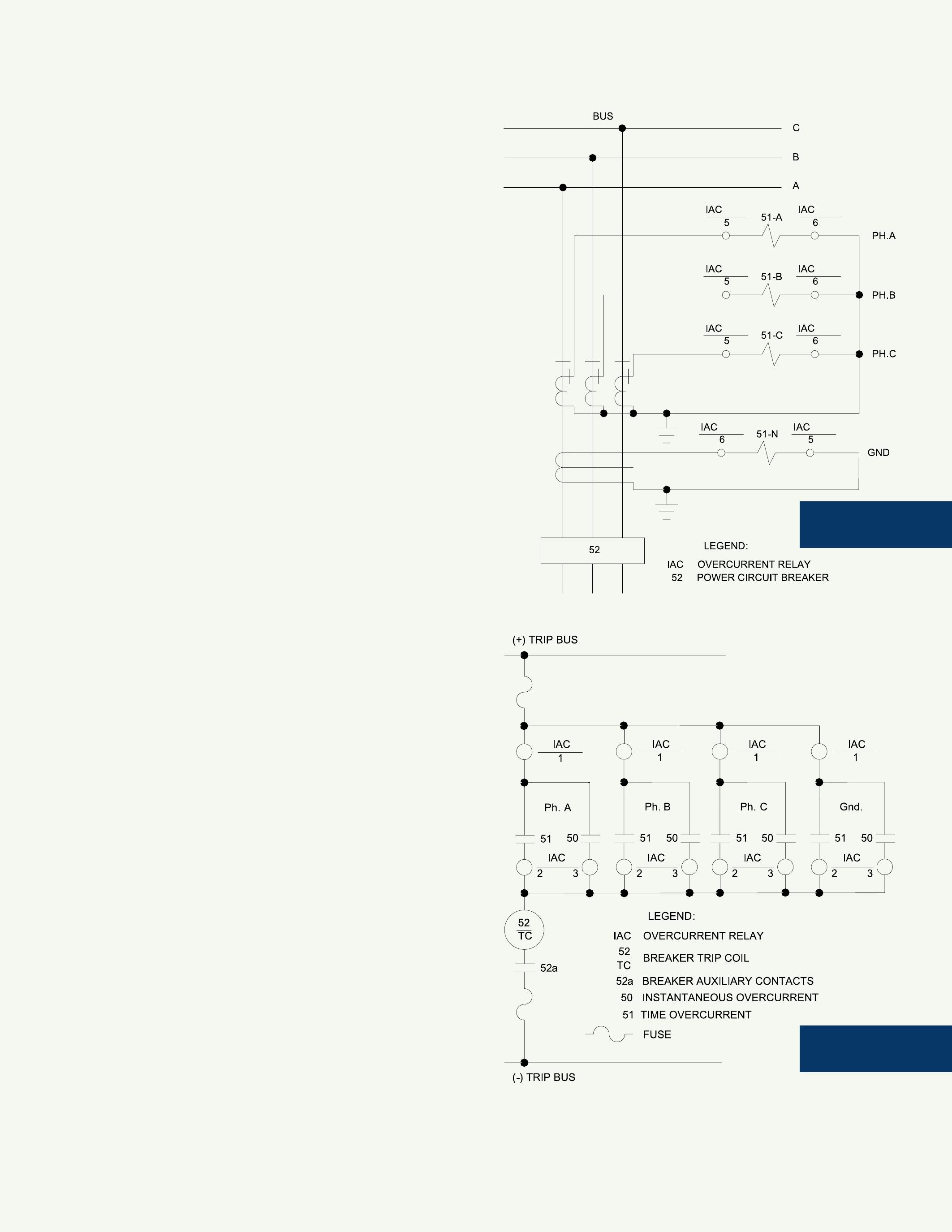
Plug and play relays are not the only easy solution for accomplishing life extension of switchgear. The chemical facility could have chosen an alternate solution: a numeric retrofit installation. The IAC relays being replaced were simple devices with only instantaneous (50) and time (51) overcurrent elements. Any numeric relay far exceeds the protection available from the IAC relay. Just because the numeric relays provide multiple 50s, 51s, and a variety of other protective and control elements, does not mean the installer must use them. Remember, the goal was not to reengineer the switchgear, but to remove the existing relays that provided 50 and 51 protection and install one or more devices to provide the same protection to improve precision, increase reliability, and reduce maintenance. The solution of installing numeric retrofit required some wiring changes. Figure 1 shows the CT connections for a typical installation with three phase and neutral IAC relays.
Figure 2 shows the DC circuit for the same typical system. The two diagrams show four relays with one each for phase A, phase B, phase C, and ground. Each relay has time and instantaneous outputs. All outputs are paralleled together to provide voltage to the 52 trip coil in the case of a fault.
The process is a little different from the process of installing the plug and play but is still an easy install. Steps one (setting the relay) and two (wiring the relay) are the key differences. The list of steps is as follows.
• STEP 1: Set the relay to the desired pickup, timing settings, and logic. An available spreadsheet provided the information needed to convert the electromechanical time curves to the correct equivalent curve on the replacement relay.
• STEP 2: Remove the existing relay and case, taking care to label the wires before detaching.
• STEP 3: Install the new relay case in the panel.
• STEP 4: Wire up the new case.
• STEP 5: Install the new connection (paddle) plug.
• STEP 6: Install the relay cover that came with the new relay.
In this example, the BE1-851 is selected for the retrofit because it is available in the same S1 case size as the IAC. Although setting the 851 relay involves a few more steps than the BE1-50/51, it is still straightforward.
Setting the relay includes setting the pickup and timing, connecting 50 and 51 elements to an output, and enabling the elements. Figure 3 shows the pickup settings.
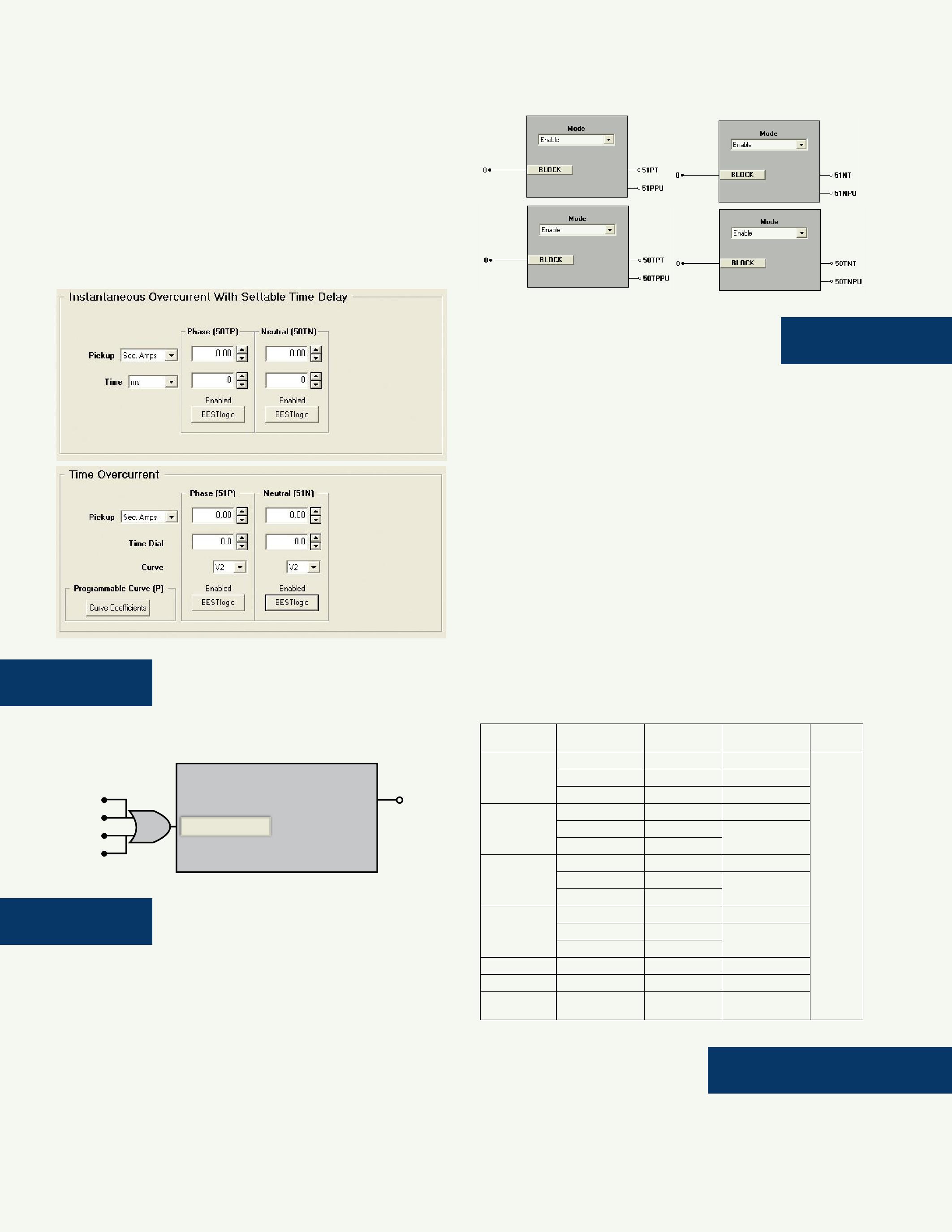
4: Shows the 50 and 51 elements connected to output 1.
5: Shows the enable settings for each element.
Wiring the relays, a necessary step in the plug and play replacement, is not difficult if broken down into a series of simple tasks. The relay has four CTs, one for each phase and one for ground. Each CT is wired where the corresponding IAC CT was wired previously. The next step involves wiring out the trip contact. The 851 solution requires just one contact whereas the IAC solution had eight contacts. The wires from any one of the IAC contacts will be connected to the previously set up relay’s output contact. The remaining wires will be removed or safely insulated and moved aside. The final wiring task is to bring station battery and chassis ground to the relay. This is necessary because the new relay is not line powered. Table 1 shows the wiring for the original and the new relay.
The only remaining task is to install three metal fill panels since four relays were removed and only one installed.
Again, the retrofit was accomplished with a small amount of down time, a small amount of work, and most importantly, at reduced expense. Because the 851 is a digital relay system, it has no critical moving parts that can affect performance and will require minimal maintenance. It also meets all ANSI standards for operation in harsh power system environments. The same benefits gained with the plug and play relay continue well after the installation with the retrofit. The numeric relay provides the possibility of additional benefits. The metering allows for quick verification that the relay is still measuring correctly without taking the relay out of service. If desired, communications can provide increased monitoring with future SCADA upgrades.
SUMMARY
Upgrading relays is an economical way to extend the life of switchgear. With proper planning it can be done with little down time, minimal (if any) engineering effort, and at low cost. The initial cost will be recouped in a short time as a result of reduced periodic maintenance and reduced down time. A key decision to be made is whether to use a plug and play relay, or a numeric retrofit upgrade. Table 2 shows key characteristics of each option.

TABLE 2 - PLUG AND PLAY VS. NUMERIC RETROFIT
Todd Martin is Product Line Manager, Protection, for Basler Electric Company. He has been employed by Basler for 18 years, with more than 15 years of engineering experience in digital, analog, and firmware design for protective relays. Todd received a BSEE from the Southern Illinois University at Edwardsville, Illinois, and is a member of IEEE.
Why leave the reliability of your electrical equipment to chance? Trust the experts at Three-C Electrical with your generation and power distribution equipment.
Simply make one call to Three-C for all of your electrical testing, maintenance and engineering needs 24 hours a day, 7 days a week



Preventive & Predictive
Customized Multi-Year
gineering Design
System Studies
and Regulatory Services Repair & Upgrades

Our exclusive partner for the US
Compact, easy to use, essential.
HV testing and cable diagnostics device.
Reliable operations and targeted investments minimize costs for your cable network
frida TD
Testing up to 24 kVrms
Integrated tan delta diagnostics
Cable sheath testing
Data management with



EXISTING SUBSTATION INFORMATION


DRIVES EQUIPMENT LIFE EXTENSION, MODERNIZATION, AND RETROFITTING
DAVID DOLEZILEK AND GERALDO ROCHA, Schweitzer Engineering Laboratories, Inc.I. INTRODUCTION
Much of the power system equipment in use today is nearing or has passed its predicted operating life, and we are pushing equipment to increasingly higher levels to meet demands. Injuries, failed equipment, unscheduled downtime, and loss of production are concerns that require knowledge of in-service power system apparatus. This is coupled with the competitiveness of the electrical energy market. The prevention of faults and defects in substation primary equipment is considered a major differentiating factor in the quality of power delivered by utilities. The reduction of faults and defects that cause interruptions in the supply of electrical energy significantly improves service performance rates.
The only way to truly know the actual health, performance, and history of apparatus is to observe them in service. Condition-based maintenance and replacement strategies are developed with decision-making information collected from the substation that tells the present state and the history of the primary equipment. It is essential that we enhance, automate, and reduce the cost of collecting and acting on this decision-making information.

To achieve this objective, more efficient and intelligent maintenance practices are required and material, human, and financial resources must be invested correctly. The rules and requirements of the modern market no longer permit numerous corrective maintenance procedures or periodic maintenance practices.

have created new ways of collecting and reacting to data and using these data to create
control, monitoring, and analysis. Using PCM IEDs as the source of information to
A substation automation system (SAS) is the collection of protection, control, and monitoring (PCM) intelligent electronic devices (IEDs) that comprise a system that monitors, controls, and protects the power system. Innovative PCM IED developments have created new ways of collecting and reacting to data and using these data to create information. When communications to and among the IEDs allow real-time data collection, the SAS is capable of supporting all aspects of electric power protection, automation, control, monitoring, and analysis. Using PCM IEDs as the source of information to understand the health and performance of substation apparatus makes the implementation of a monitoring system economical and technically attractive.


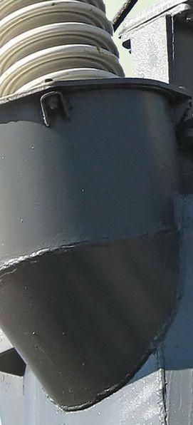

FEATURE
II. ASSET MANAGEMENT PARAMETERS
The concepts of health, availability and reliability, and performance (HARP) are familiar terms within today’s utility. Many companies strive to achieve reduced expenses, 100 percent reliability, increased performance, and, through reliability-centered maintenance practices, better system health. When applied, reliability-centered maintenance practices move the utility from reactive to preventative maintenance and, with better data collection, from preventative to predictive maintenance. Reduced expenses, improved performance, improved reliability, or improved health each individually promises reduced costs and increased customer satisfaction. However, we must not overlook the dynamic and economic impact of one on the other and thereby undercapitalize on short- and long-term profit opportunities.
A. DEFINITION OF HARP TERMS
1) Health
Health is the measure of the fitness of an apparatus to perform its intended function. Apparatus health becomes a variable that can be manipulated to improve return on investment.
2)
Availability and Reliability
A failure exists any time that the power system is unable to perform its intended purpose, which is to generate revenue by constantly providing quality power to consumers. Reliability is the measure of the percentage of time (out of the required 24 hours a day, seven days a week) that the power system or apparatus is available to perform its intended function. Reliability is expressed as a percentage of the total possible availability. Using reliability information, we can change procedures and designs to create more available systems and predict the expense of dealing with unscheduled repairs. The knowledge of the availability of apparatus and devices helps prioritize maintenance and replacement schedules to optimize use of resources.
3) Performance
The performance of a system or device is the comparison of its actual operation to ideal operating parameters. Performance is a value that represents the effectiveness of the power system or apparatus in service. Effectiveness can also be manipulated to improve revenue, customer satisfaction, and, eventually, return on investment. Actual performance is expressed as a percentage of optimal performance.
4) Net Installed Value
Net installed value (NIV) is the present value of an in-service asset. NIV is the aggregate of expenses and the HARP variables. Actual NIV is expressed as a percentage of the optimal NIV. Predicted NIV is a prediction of the result of manipulating the HARP variables and understanding their effect on one another.
5) Net Revenue
Net revenue (NR) is defined as the total customer billings minus annual expenses (scheduled and unscheduled). Future considerations related to net revenue include intangible costs, such as cost to customer, customer satisfaction, and litigation. Many utilities have not calculated these intangible costs, but those that do can factor them in.
6) Net Potential Revenue
Net potential revenue (NPR) is the sum of the following variables:
• Unserved is the loss in profit because of an outage and/or real load that could be served if a breaker, transformer, or wire is under capacity.
• Growth is future or planned unused capacity. It might be more cost-effective in the long term to invest in new equipment or overload existing equipment than to minimize cost and underserve present and future demand.
• Reduced operations and maintenance cost is the potential to reduce costs (thereby increasing revenue) through life extension of apparatus and targeted replacement of obsolete and poorly performing equipment with newer, more efficient equipment or through modified maintenance practices. Typically, operations and maintenance costs are predicted, but with real-time and historical operating data, these costs are measured and dramatically improved.
Looking at the overall HARP NIV for an existing breaker versus the HARP NIV of a new breaker with the fiscal economic backdrop of net revenue and net potential revenue, the result of the evaluation might be:
(NIV existing breaker + [NPR – NR]) < (NIV new breaker + [NPR – NR])
In order to enhance the performance of existing systems and new designs, electric utilities must fully understand the current state of the power system as well as predict future capabilities and system expansion to increase reliability and performance.
Increased global competition, deregulation, availability demands, and pricing pressures are forcing the electric utility industry to reduce operation costs while increasing reliability. Utilities often need to push equipment to higher loading levels to meet demands.
B. PCM IED MONITORING FUNCTIONS
The IEDs used in the digitalization of distribution substations include protection, automation, control, and communications functionalities. They also collect and create important analytical data by monitoring the devices and the surroundings that the IEDs protect. This information is used to calculate the HARP variables.
Each main device of a substation has at least one associated IED receiving voltage, current, status, and other signals that are used to make precise diagnoses in real time. Because IEDs are connected to the dc system of a substation, they also provide important information for the monitoring and diagnosis of the substation dc battery system.
In this way, the information available in an IED is used to monitor disconnect switches, power transformers, dc battery systems, and circuit breakers.
The maintenance of circuit breakers, for example, is usually based on regular time intervals or the number of operations performed. The methods based on this philosophy present drawbacks because within the predetermined maintenance interval, there could be an abnormal number of operations or a small number of operations with high-level currents.
The IEDs monitor the following: Contact Wear
The circuit breaker manufacturer provides a maintenance curve listing the number of close-to-open operations and the interruption current levels. The function of this curve is to predict the breaker contact wear, as the example shows in Figure 1. It is possible to configure some of the points of this curve, where normally the highest and lowest number of operations and an average point are chosen. For each operation, the IED integrates the interrupted current with the operation number to update the contact wear value. This parameter is crucial to estimate the need for maintenance.
Total Number of Operations
Incremental counters for close-to-open operations are implemented to make that information available to the system history.
Mechanical Operating Time
The mechanical operating time of the circuit breaker can be calculated by measuring the time interval between the trip command or the close command and the asserting of the digital inputs of the IED connected to the circuit breaker status contacts. Deviations in this value may indicate problems in the drive mechanism.
Electrical Operating Time
Similar to the mechanical operating time, this measures the time interval between the trip or the close command and the clearing or normalization of current measurements in the circuit breaker. If this parameter tends to increase over time, it could indicate failures in the contacts.
Inactivity Time
By monitoring the activity of the number of operations, it is possible to calculate the number of days in which the breaker has been inactive. Long periods of inactivity degrade its reliability for the protection system.
Spring-Loading Time
Just after the circuit breaker closes, the time to assert the digital inputs of the IED connected to the breaker loaded spring contact is measured. If this time increases as the number of operations increases, it may predict a problem in the springloading mechanism.
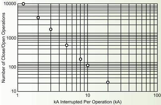
Figure 1: Circuit breaker maintenance curve
The monitoring functions presented here are performed with traditional protection potential transformers (PTs) and current transformers (CTs). No additional stand-alone sensor is necessary for the equipment monitoring system, as shown in the basic connection diagram in Figure 2.
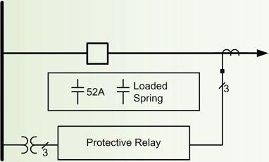
Figure 2: Basic connection diagram for monitoring of circuit breakers
An example of the knowledge of the health and performance of a breaker, calculated by a PCM IED and documented as a breaker monitoring report retrieved from that IED, is shown in Figure 3.
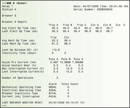
Figure 3: Breaker monitoring report
III. ADD SUBSTATION MONITORING TO YOUR SUBSTATION AUTOMATION SYSTEM
Investments in substation monitoring systems are essential for creating reliable predictive maintenance; however, standalone systems are complicated and expensive and are only viable for large substations, even though they are becoming essential for smaller distribution substations.
A substation monitoring system (SMS) can use the information supplied by IEDs and take advantage of communications network structures already in place or provided for the substation SAS. The same IEDs used for command, measurement, protection, and control form the basis of the system. They are more rugged and dependable than other monitoring devices such as sensors or programmable logic controllers. They create information and send it to the maintenance server which in turn performs calculations and feeds the database. These functions are executed because the IEDs are coupled with the main equipment via CTs, PTs, resistance temperature detectors, and so on.
Using an in-service SAS system enables the building of an economically viable SMS that is developed by using the network structure and data provided while maintaining the same reliability, regardless of the size of the facility. Figure 4 illustrates the basic structure for an SMS as part of the SAS.
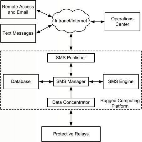
Figure 4: Basic data structure of SMS
A variety of communications ports and protocols allows a broad application of hardware and easy integration with any communications system existing in the substation. Fig. 5 shows the local maintenance server containing the integrated SMS without any change in the communications network.
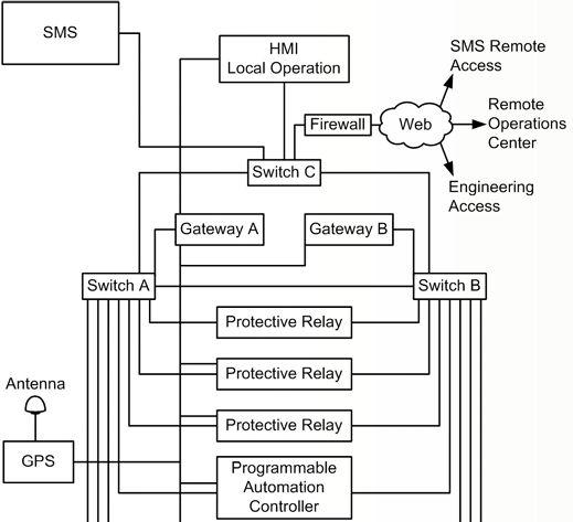

5: Example of SMS integrated in the substation
The engineers and those responsible for the maintenance of this equipment access the information locally on the maintenance server or remotely through the web via intranet or Internet. Considering the access through the maintenance center, the installation of additional soft ware is not necessary because the SMS is created independently of the operational system. A modern SMS uses Ethernet network communications and is in compliance with the IEC 61850 standard. It also adapts to substations that are not in compliance with the standard because of the flexibility and multiprotocol structure existing in the system.
IV. ESSENTIAL INFORMATION TO CHOOSE LIFE EXTENSION OR REPLACEMENT
Consider the typical substation illustrated in the one-line diagram shown in Fig. 6.
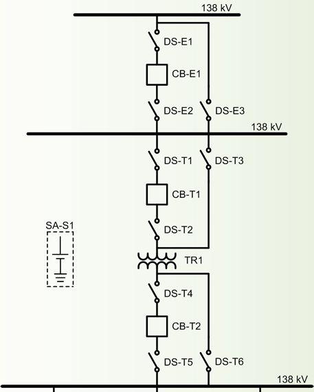

The monitored health and performance parameters necessary to decide between life extension or replacement of the power system equipment from Figure 6 are shown in Table I.
CONCLUSIONS
Monitoring systems are essential tools that allow distribution companies to increasingly modernize maintenance techniques and migrate to intelligent and optimized predictive maintenance. Investments that are made in the acquisition of substation equipment monitoring systems add additional costs to maintenance and operation, so the minimization of these costs is a huge challenge.
The SMS is a low-cost solution for the implementation of communications infrastructure in substations using IEC 61850 protocols, where Ethernet cabling already exists, enabling its application in substations of any size and voltage level.
A cost analysis shows that the investment to add an SMS to an SAS network to modernize maintenance practices amounts to a small incremental cost of 10 to 15 percent of the initial cost of digitalization of a small distribution substation. For a larger and more complex substation, the investment to implement the SMS is an even smaller incremental cost.
Adding the SMS technology to an in-service SAS system is an incrementally small investment that provides a wealth of information about the power system. When used to calculate HARP variables, this information enables informed decisions about life extension or replacement of in-service primary equipment.
V. REFERENCES
L. Ayers and D. Dolezilek, “Using Dynamic Real-Time Substation Information to Reinvent Asset Management,” proceedings of the 3rd Annual Western Power Delivery Automation Conference, Spokane, WA, April 2001.
D. Dolezilek, “Understanding, Predicting, and Enhancing the Power System Through Equipment Monitoring and Analysis,” proceedings of the 2nd Annual Western Power Delivery Automation Conference, Spokane, WA, April 2000.
R. Bernardes and F. Ayello, “PQMS – Power Quality Monitoring System: Improve Power Systems Through IEDs,” proceedings of the 20th Annual International Conference on Electricity Distribution, Prague, Czech Republic, June 2009.

David Dolezilek received his BSEE from Montana State University and is the technology director of Schweitzer Engineering Laboratories, Inc. He has experience in electric power protection, integration, automation, communications, control, SCADA, and EMS. He has authored numerous technical papers and continues to research innovative technology affecting the industry. David is a patented inventor and participates in numerous working groups and technical committees. He is a member of the IEEE, the IEEE Reliability Society, CIGRE working groups, and two International Electrotechnical Commission (IEC) technical committees tasked with global standardization and security of communications networks and systems in substations.

Geraldo Rocha received his BSEE from Universidade Estadual Paulista Campus de Bauru, Brazil, in 2001 and specialized in electrical power systems protection at Universidade Federal do Rio de Janeiro. He worked as a protection and automation engineer for CPFL Geração de Energia S.A., where his responsibilities included maintenance, commissioning, specification, and studies of protection and automation of hydroelectric plants. In 2007, he joined Schweitzer Engineering Laboratories, Inc. as an application engineer covering the entire country of Brazil. His responsibilities include training and assisting customers in substation protection and automation efforts related to generation, transmission, and distribution areas.
Set. Test. Troubleshoot.
Power System Protection for Technicians Program
SEL University’s Power System Protection for Technicians program is designed for those responsible for setting, testing, and troubleshooting protective relays. Students will explore the methods and devices used in power system protection, learn relay testing basics, practice methods for testing SEL relays, and earn continuing education credits.


PARTIAL DISCHARGE MEASUREMENT PAYS
BIG DIVIDENDS
Don A. Genutis, No-Outage Electrical Testing, Inc. & Neil Davies, EA TechnologyINTRODUCTION
Just like people, electrical assets age and deteriorate; and as with human medicine, there have been tremendous advances in recent years in the ability to diagnose in the early stages ailments suffered by assets, enabling us to keep them healthy and productive longer.
The revolution in asset management is being driven by two factors which are inextricably linked: new techniques for accurately measuring the condition of live assets, plus new methodologies for managing assets more effectively, based on their actual condition.
There are many techniques available for assessing the condition of live assets including transformer oil analysis and thermal imaging. But the most useful is the detection, location, and measurement of partial discharge (PD) activity in medium- and high-voltage assets, which are typically found in substations.
The collection of condition data using PD instruments has become standard practice in the UK electricity industry, an innovation which has been driven in large part by the need for operators to provide detailed evidence of the state of their assets to the electricity regulator, Ofgem. In other parts of the world, notably the Middle East, China, and Singapore, PD investigations have been taken up with great enthusiasm as a cost-effective means of improving network reliability and performance (see examples below).
Surprisingly, however, detailed PD measurement as the basis of condition-based asset management is still in its infancy in many parts of the developed world, including the USA. Many operators still have no clear information on the condition of their assets until they fail completely and must be replaced. Unlike the world’s most efficient network operators, such as Singapore’s SP Powergrid, they accept unpredicted asset failures and loss of customer service as a fact of life.
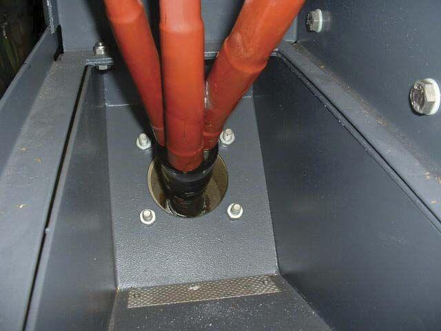
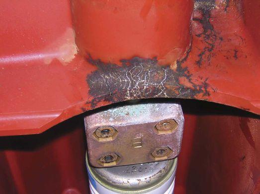
What is PD?
A partial discharge is an electrical discharge or spark that bridges a small portion of the high voltage insulation between two conducting electrodes or a conducting electrode and earth. Partial discharge can occur at any point in the insulation system where the electric field strength exceeds the breakdown strength of the insulating material.
Partial discharge can occur in voids within solid insulation, across the surface of insulating material due to contaminants or irregularities, within gas bubbles in liquid insulation, or around an electrode in gas (corona activity).
What causes PD?
There are many causes of breakdown in insulation which lead to PD activity including design and manufacturing defects, incorrect installation of components, faulty materials, mechanical damage, and even vandalism. Even well designed and installed assets start to exhibit PD activity as they deteriorate with age and usage.
Environmental factors also play a role in the development of PD activity including temperature, humidity, atmospheric pressure, vibration, and other mechanical stresses.
PD Failure Process
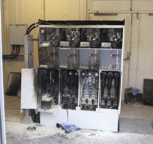
Once present, partial discharge always increases, but the way in which it increases is both measurable and predictable.
Industry experience of working with network assets for more than 30 years shows that PD activity is a factor in 85 percent of disruptive substation failures. It has thus become increasingly apparent that the ability to detect and measure PD is the key to assessing the health of assets.
PD activity provides clear evidence that an asset is deteriorating in a way that is likely to lead to failure. The process of deterioration can propagate and develop until the insulation is unable to withstand the electrical stress, leading to flashover.
The ultimate failure of medium- and high-voltage assets is often sudden and catastrophic. The best case scenario is that growing PD activity causes protection systems to trip out unexpectedly resulting in outages. The worst case scenario is an explosive release of energy, causing major damage, injury, and death.
PD DETECTION & MEASUREMENT
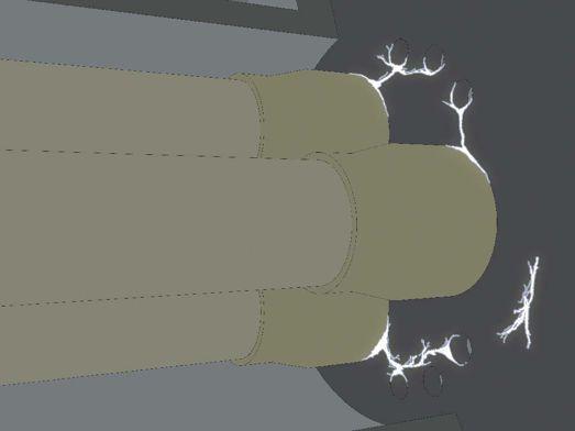
Figure 4: PD activity across insulator voids in gas insulated switchgear (GIS)
Partial discharges emit energy, the effects of which can be detected, located, measured, and monitored:
• Electromagnetic emissions in the form of radio waves, light, and heat
• Acoustic emissions in the audible and ultrasonic ranges • Ozone and nitrous oxide gases
NO-OUTAGE INSPECTION CORNER
The most effective techniques for detecting and measuring PD activity in live assets are based on quantifying the following:
Transient Earth Voltages (TEVs)
The importance of TEV effects (discharges of radio energy associated with PD activity) was first identified by EA Technology researchers in the 1970s Measuring TEV emissions is the most effective way to assess internal PD activity in metal-clad, medium-voltage switchgear.
Ultrasonic Emissions
PD activity creates emissions in both the audible and ultrasonic ranges. The latter is by far the most valuable for early detection and measurement. Measuring airborne ultrasonic emissions is the most effective way to assess surface PD activity, where there is an air passage, e.g., vents or doors in the enclosure of an asset. Where chambers are completely sealed, ultrasonic contact probes can be used although these are less sensitive than the airborne microphones.
UHF Emissions
PD activity can also be measured in the UHF range and is particularly useful in monitoring extra high voltage (EHV) assets.
PD MEASUREMENT INSTRUMENTS AND SYSTEMS
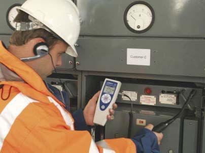
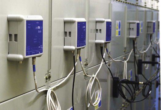
6: New multiple sensor systems continuously monitor assets for critical PD activity, record data, and automatically trigger alarms if activity exceeds acceptable thresholds
First Generation Instruments
The first generation of PD measurement instruments appeared in the 1980s and was mostly based on measuring TEV effects. Several specific instruments were required to detect, locate, and monitor PD activity, and by present standards they were cumbersome and expensive. Some relatively simple ultrasonic instruments were also developed.
Second Generation Instruments
2003 saw the launch of the first hand-held PD detector, which measured PD activity using both ultrasonic and TEV sensors. This was followed by more sophisticated dual sensor instruments, capable of gathering detailed quantitative data on PD activity, together with fixed PD alarm systems.
Third Generation Systems
Third generation PD products have developed over the last two years into multiple sensor systems with unprecedented abilities to detect, locate, measure, quantify, and record PD activity. They effectively combine all the technologies of the earlier generation instruments into packages which are easier to use, more versatile, and provide far greater depth of condition data at lower cost.
NO-OUTAGE INSPECTION CORNER
For example, the latest portable PD location system embraces no fewer than six sensor technologies: measuring ultrasonic emissions, TEV effects, temperature, humidity, and atmospheric pressure, together with a radio frequency current transformer (RFCT) sensor which specifically measures PD activity in cables.
The latest PD monitoring systems also use multiple sensors and are designed to provide permanent or semipermanent monitoring of mission critical assets. A single system can simultaneously monitor hundreds of assets, recording and analyzing PD activity over time to give a comprehensive picture of condition. The systems also function as 24/7 alarms, automatically generating alerts if PD activity exceeds set limits. A specific variant has also been developed for gas insulated switchgear (GIS) assets.
THE VALUE OF PARTIAL DISCHARGE DATA
The latest PD instruments and systems are extremely valuable for identifying faults as they develop at an early stage preventing them from developing into failures – the quick health check approach. But the information they gather is also playing a major part in transforming the industry’s approach to asset management from one based on time-scheduled maintenance and replacement to one based on a detailed understanding of the condition of the asset base.
Maximizing the value of PD data is essentially carried out at two levels:
Asset Condition Registers
Expert analysis and interpretation of PD activity readings gives a clear indication of the condition of assets including accurate predictions of when they are likely to fail. This is based on a unique database, built up over more than 30 years, which shows how tens of thousands of asset types have deteriorated over time.
This approach enables operators to develop registers of assets in which each asset is accorded a health index showing its present condition, its predicted date of failure, and/or its remaining service life.
There is strong evidence that basing maintenance and replacement on actual condition is far more cost effective than time-scheduled interventions or a running until failure approach. This is because condition based regimes:
• Prevent expensive, unexpected failures.
• Prevent needless invasive maintenance, which is costly, disruptive and often creates more faults.
• Enables operators to prioritize expenditure on a strictly as needed basis.
Condition Based Risk Management (CBRM)
The ability to measure the condition of live assets is the key to CBRM, a comprehensive new methodology which takes condition based asset management to a higher level, enabling managers to make more intelligent decisions on asset renewal strategies.
The effectiveness of CBRM derives from factoring together probability (based on asset condition) and consequences (based on quantifiable losses) of asset failure to determine risk in terms of financial cost.
CBRM provides the answers to the key questions:
• If an asset costing $XX fails, what will be the consequential loss to the business?
• If an asset is refurbished or replaced at a cost of $YY, what will be the benefit to the business?
• Therefore, where should we prioritize our asset renewal spending?
EXAMPLES: Operators Using PD Measurement as Part of Condition-Based Asset Management
SP Powergrid, Singapore
SP Powergrid’s network includes nearly 10,000 substations, 40,000 switchgear sets, 14,000 transformers and 30,000 km of cable. Since incorporating condition monitoring into its systems, it has dramatically improved an already excellent performance. The company’s system average interruption duration Index (SAIDI) averaged less than 1 minute pa over a recent three year period.
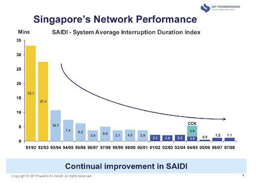
Figure 7: NB: The blip in 2004/5 was caused by a third party supply issue outside SP Powergrid’s control.
SP Powergrid estimates that over the eight financial years to 2008, condition monitoring enabled it to avert 450 network failure incidents with a net financial saving of US$29 million. In addition to improving customer service, it has been able to pass cost savings on to them.
CLP Hong Kong
The China Light and Power network in Hong Kong includes nearly 13,000 substations and 22,000 km of overhead lines and underground cables serving 2.26 million customers.
As a result of focusing over the last 10 years on condition based maintenance, to predict faults and improve reliability, it has reduced its SAIDI figures from more than 40 to 2.68 minutes lost per year.
Demand from customers has continued to grow, but in recent years, greater operating efficiencies have enabled CLP to reduce tariffs.
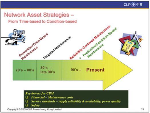
CONCLUSION
The ability to assess the condition of medium- and highvoltage assets by measuring PD activity is increasingly driving a step change in power asset management. At its simplest level, it enables operators to identify and fix faults before they develop into failures. Used to its full extent, it is one of the technologies behind much more effective management of whole networks, based on greater understanding of asset condition. The result: greater network efficiency, availability, reliability and safety, with lower capital and revenue costs.

Don Genutis founded and acts as President of No-Outage Electrical Testing, Inc. (www.NoOutageElectricalTesting.com) which focuses on new inspection technologies that are performed while the equipment remains in service.
Special thanks to Neil Davies, Director of International Business Development for EA Technology for contributing this paper. Based in the UK, EA Technology has offices in Shanghai, Abu Dhabi, Australia and the USA, together with more than 30 distribution partners serving 80 countries.
El E ctrical t E st E rs For r ent
Exp E rt a dvic E For Free
electro rentthe right choice
Electro rent has been renting complete lines of electrical test equipment since 1965. Our experienced sales associates can assist you in selecting the right tool for your job and we usually deliver it to you within 24 hours. We offer daily, weekly and monthly rentals at prices that fit your budget. let us help you achieve success!
rent what you need when you need it. call us or visit us online for a free quote.
Products
From leading manuFacturers
Baker, Biddle, doble, dranetz, Flir, Fluke, High voltage, Hioki, Megger, Multi-amp, Yokogawa and more. Electro rent also rents and leases an assortment of laN cable certifiers, Otdrs, fusion splicers and light sources.
the most Flexible Finance Programs in the industry
For projects with a projected term of 12 to 48 months, Electro rent has an exceptional financing program that offers significant budget benefits while it provides immediate access to products without waiting for capital. You can also purchase your equipment as funds become available.
Key Features include:
• Lower rate for a longer committed term
• Addition of non-hardware items, such as service or software
• Flexible contract options, such as early termination, upgrades and trade-ups

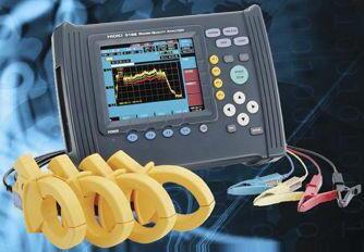
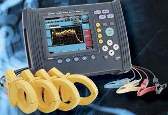


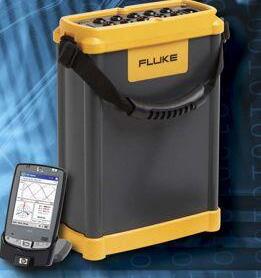
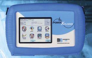


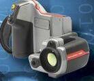

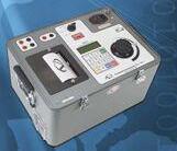
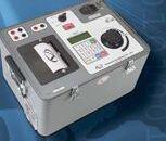

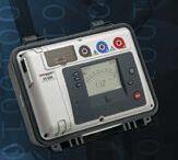
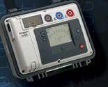

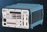


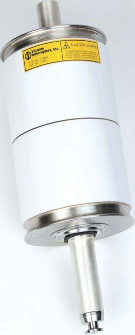


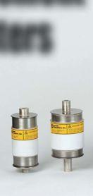
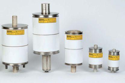
DIAGNOSTIC SOLUTIONS • ENHANCING TRANSFORMER RELIABILITY
With substations regularly overloaded and equipment often near the end of its life, electric grid operators are challenged to improve overall system reliability. Our mission is to provide our clients with actionable information that can be used to better manage the overall life cycle of their critical electrical assets in a manner that is convenient, easy to understand, and assists in critical decision-making.
WEIDMANN DIAGNOSTIC SOLUTIONS INC. provides the vital knowledge you need to help you lower risk and improve your electrical system’s reliability. We provide actionable information through our extensive range of diagnostic products and services.
WEIDMANN DIAGNOSTIC SOLUTIONS INC. is a leader in developing condition assessment methods for transformers and all oil-lled electrical equipment, such as OCB’s, LTC’s, regulators, rectiers, and network units.
• Analytical Testing Services
• Specialized Diagnostic Programs
• Engineering Diagnostic Evaluations

• Engineering Consulting Services
• AIM 2.0 Customer Information Portal
• Education Services
• InsuLogix® Monitoring Products

WELCOME RECEPTION
SPOUSE/GUEST LOUNGE


TRADE SHOW

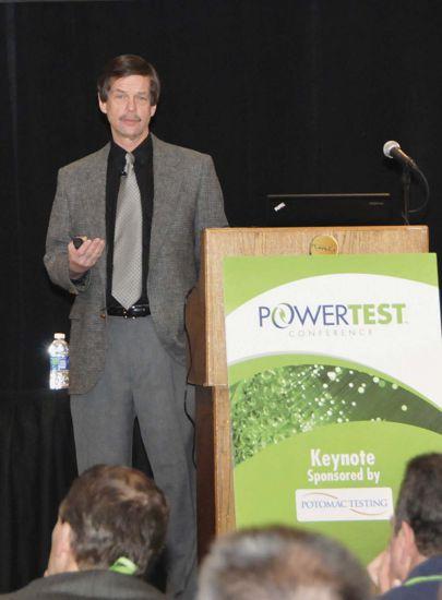

GENERAL SESSION
MEMBER LUNCHEON PAPER

POWERTEST 2011 IN WASHINGTON, D.C. this past February was the most well attended NETA hosted event to date. A record breaking number of attendees, incredible sponsors, and a power house Tradeshow kept things rocking all week long in our Nation’s Capitol.
In addition to the already stellar class of attendees, NETA was proud to welcome the Army Corps of Engineers’ Prime Power School from Fort Belvoir, Virginia, to this year’s event. Enjoy the memories in the next few pages and mark your calendars for next year in Fort Worth, Texas, because everything’s bigger in Texas!



PANEL SESSIONS

New trick.
You can get older equipment to take advantage of new technology, with the EntelliGuard® TU trip unit. It improves arc flash protection, reducing the HRC level to 1 or 2, depending on available fault current.
Neat trick, isn’t it?
The EntelliGuard TU retrofits quickly and easily, too –via plug-and-play on legacy GE low-voltage breakers or with a kit for those from other manufacturers.
See for yourself. Call 1-800-431-7867 and press “2” for dedicated technical support. Email geelectrical@ge.com. Or visit geelectrical.com/industrial. You’ll be impressed.

EntelliGuard is a registered trademark of the General Electric Company.
 BY KERRY HEID, A.S c .T Magna Electric Corporation
SURVEY SAYS!
Maintenance is Critical as Part of your Electrical Safety Program.
When 10.5 percent of electrical equipment doesn’t operate, it is not hard to understand why it is widely touted that electrical maintenance of power distribution equipment is paramount to worker safety. This includes the correct operation of virtually any device such as relaying protection, fuses, and circuit breakers that are required to operate during a fault condition. These devices are required to operate according to their time-current characteristic curves to ensure that a calculated arc-flash hazard analysis is valid. Even a slight variation between theoretical and actual operating characteristics can mean a drastic change in incident energy levels.
NFPA 70E LANGUAGE
205.3 Equipment Maintenance. Electrical equipment shall be maintained in accordance with manufacturer’s instructions or industry consensus standards to reduce the risk of failure and the subsequent exposure of employees to electrical hazards. [ROC 70E-293]
“ROC 70E-293 This language is from the comment stage of the current NFPA 70E revision cycle.”
2008 SURVEY
A 2008 survey was conducted by NETA on the performance of electrical protective devices. A national survey of field performance on approximately 340,000 protective devices was reviewed, and the results of those findings are quite alarming. Understanding these key areas of performance, the dilemma it creates with arc-flash incident energy exposures, and the overall impact of the performance to personnel will help the owners and users of the electrical equipment provide a safer workplace.
Based on the results of the survey, approximately 23 percent of the circuit breakers tested had an issue affecting the protective device operation. This data closely correlates with failure data presented in IEEE Std. 493-2007, Table 5-1 in the fair (18.1%) to poor (32.8%) maintenance quality category. With percentages in these ranges, approximately one in four of the devices in the field will not operate as indicated on the time current curves. The impact to personnel in the field is that in most cases incident energies will significantly increase due to the defective equipment.
Another alarming statistic was the fact that on average 10.5 percent of the devices did not function at all when tested. This means that when overload or short circuit current is applied to the device, it was found to be inoperable. If a fault were to occur, it would severely impact personnel safety when working on or near that particular piece of equipment. Of the units with issues affecting performance, 42.8 percent were mechanical issues, and 26.7 percent had issues related to electrical diagnostic testing. Lubrication issues were the predominant mechanical failure at 51.4 percent. This has been a long-standing problem within industry and is often vetted during preventive maintenance operations.
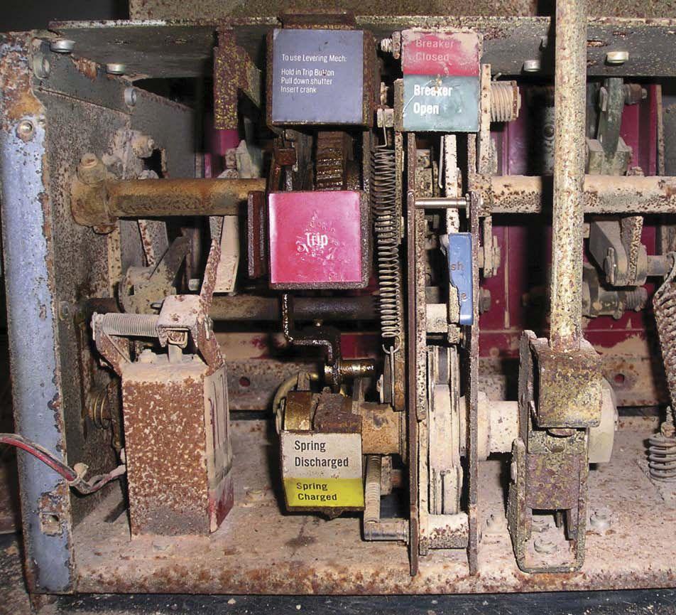
Figure 1 shows a circuit breaker that would not operate due to mechanical problems. This breaker could not be opened even with major force to the tripping mechanism. Due to these problems, this device would not have operated during any short circuit, overload, or ground fault. Any downstream equipment would be subjected to possible meltdown and personnel would be exposed to large values of incident energy. Units in this condition are commonly found during maintenance testing and either replaced or repaired immediately.
2011 SURVEY
NETA continues its research into this topic and will be presenting a paper at the IEEE PCIC in Toronto in September this year. Further data on root cause of failures including operating environments, duty cycle, and other contributing factors will be reviewed. NETA is expecting to create a test sheet program to facilitate the process of collecting and disseminating information directly from work performed in the field by NETA Accredited Companies. This will allow for actual data from the field to be interpreted over a wide range of operating environments.

Figure 1: Example Circuit BreakerMechanically Inoperable, Found in Service
MAINTENANCE CORNER
MAINTENANCE CRITICALITY AND IMPACT TO PERSONNEL
Proper performance of electrical power equipment is paramount if calculated values of incident energies are to be accurate. The results of the findings illustrate that adequate personnel protection cannot be achieved and accurate PPE assessment cannot be performed without accurate and reliable data including the probability of correctly functioning protective devices.
If protective equipment does not function as designed or intended, the results can be disastrous. The results of engineering studies for protective device clearing times as well as safety-related data such as arc-flash studies can become invalid as clearing times become an unknown element. It is common for facilities to perform an arc-flash hazard analysis using commercially produced soft ware that relies on the published trip times of the protective devices. When possible, the existing protective device settings are modified to decrease incident energies and hazard labels are applied to indicate the circuit parameters. If electrical protective devices do not function as designed, the arc-flash study is not valid and severe increases in incident energies can be obtained which could render the PPE assessment inadequate.
Determining risk categories and PPE requirements using the tables in NFPA 70E / CSA Z462 assume that the equipment is actually functioning. Pay close attention to the footnotes in the tables and the specific reference to clearing times. The condition of the equipment and the latest test or calibration records should be considered when determining the risk category and performing the overall hazard risk assessment.
CONCLUSIONS
Electrical devices must be regularly maintained according to the latest available standards. Field test data shows that lack of or improper maintenance severely affects protective device operation, thus affecting the overall arc-flash data. Risk categories determined by using the 70E / Z462 task tables to perform arc-flash studies, calculate incident energy, and assess PPE requirements become invalid with improper operation of protective devices. Schedule a maintenance testing shutdown today, and hire a NETA Accredited Company to perform critical testing work.

Kerry Heid is the President of Magna Electric Corporation, a Canadian based electrical projects group providing NETA certified testing and related products and solutions for electrical power distribution systems. Kerry is a past President of NETA and has been serving on its board of directors since 2002. Kerry is chair of NETA’s training committee and its marketing committee. Kerry was awarded NETA’s 2010 Outstanding Achievement Award for his contributions to the association and is a NETA senior certified test technician level IV.
Kerry is the chair of CSA Z463 Technical committee on Maintenance of Electrical Systems. He is also a member of the executive on the CSA Z462 technical committee for Workplace Electrical Safety in Canada and is chair of working group 6 on safety related maintenance requirements as well as a member of the NFPA 70E – CSA Z462 harmonization working group.
Substation Testing As Easy As
Spend More Time Testing, Less Time Training
Vanguard’s precision substation testing instruments are designed to be intuitive and easy to use so that you can focus on testing instead of wasting time in training. Our versatile instruments offer a built-in thermal printer and on-board test record storage so that tests can be conducted in stand-alone mode in the field. A computer interface is also offered so that tests can be easily conducted from a PC.

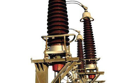
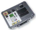


And all of our instruments are competitively priced to provide cost-effective accuracy. For a virtual experience of our instruments, check out the interactive demos on our site at:
www.vanguard-instruments.com/demos
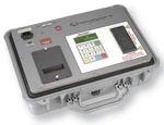

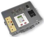

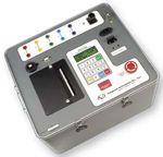


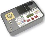


CirCuit Breakers
Low & MediuM VoLtage
• General Electric • Westinghouse
• Cutler Hammer • Siemens
• Allis Chalmers • ITE/ABB
• Federal Pacific • Square D
transforMers
1000 – 5000 kVa
• Dry type transformers from stock
• Cast resin from stock
• Load break switch & fuse
Life extension
Let us design a prograM to extend the Life of your switChgear
• Vacuum retrofill
• Vacuum retrofit
• Solid state conversion
• Vacuum motor control upgrades
MoLded Case CirCuit
Breakers & Low
VoLtage Motor ControL
• Circuit breakers
• Motor control components
• Upgraded buckets
• Panel mount switches
switChgear
480V – 38kV new and surpLus
• New General Electric switchgear in 4 weeks
• Match existing lineup
• Reconditioned from stock
• Complete unit substations
• Indoor and outdoor available
renewaL parts
switChgear & CirCuit Breaker parts
• New General Electric available from stock
• Reconditioned starters and contactors
serViCe & repair
• Field service and testing
• Shop repair of all switchgear and circuit breakers

• Universal circuit breaker remote racking system
• Safety switch for remote switchgear operation

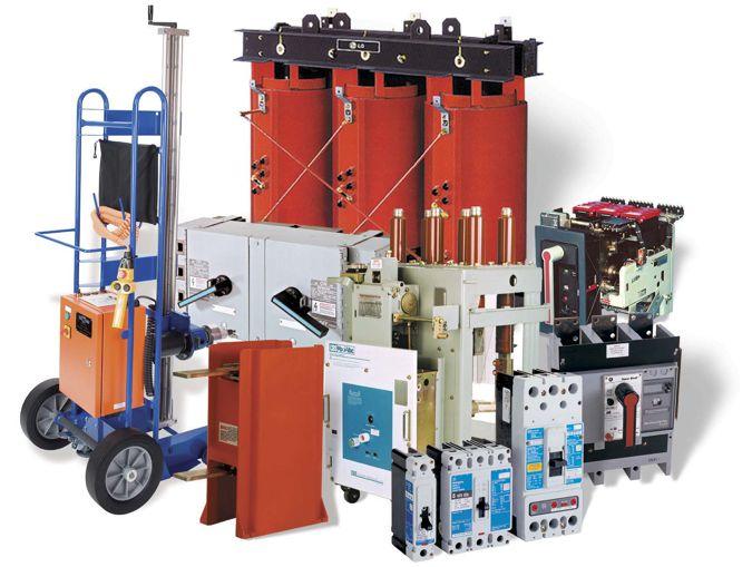
• All low & medium voltage renewal parts, 1945–today
• Obsolete vacuum interrupter in stock
• www.circuitbreakerpartsonline.com


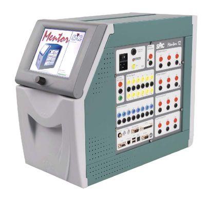

While other manufacturers develop new sets, the Mentor will continue to EVOLVE meaning that you will always have the state of the art testing abilities.
FIELD UPGRADABLE
Need more power or ready to add GPS? No Problem! The Mentor is ready to go in minutes with Plug-n- Play.
FIELD SERVICEABLE
If your Mentor needs attention, no need to send it anywhere, SMC will handle it on the spot.

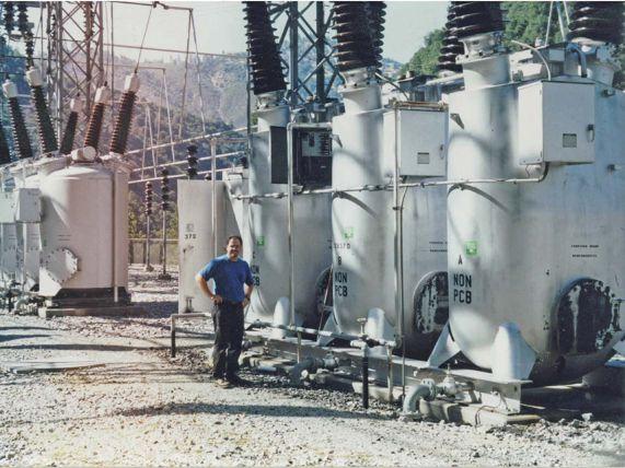






NETA’S 2010 OUTSTANDING ACHIEVEMENT AWARD –HONORING NETA’S MOST VALUABLE ASSET
BY KRISTEN WICKS NETA
Each year NETA’s President is given the difficult task of selecting one of NETA’s many volunteers as the recipient of the Outstanding Achievement Award. This person demonstrates selflessness, drive, dedication, loyalty, and leads by example. This person is someone who balances family, friends, work, and philanthropy on a knife’s edge and does it with a smile, often looking around to say, “What else can I do?” It is for these reasons that the sentiment, “Volunteers don’t get paid, not because they’re worthless, but because they’re priceless,” aptly describes the individual that is acknowledged by this award.
This year’s recipient is no less deserving than any who have held the honor before him. Dave Huffman, President of Power Systems Testing Company in Fresno, California, fits this description to a “T”. Dave serves on the NETA Board of Directors, NETA Standards Review Council, NETA Exam Committee, NETA Continuing Technical Development Committee, NETA Member Application Review Committee, NETA Training Committee, NETA Nominations Committee, and represents NETA on the NFPA 70B Committee as the Alternate Representative. Dave’s kind nature, easy smile, and warm chuckle instantly endear him to everyone he meets. His sincerity ensures lasting friendships despite busy schedules and great geographical distances between many NETA members.
While some people in the electrical testing field get a glazed look in their eyes as they try to recall how it is that they got involved in this highly-technical and potentially hazardous line of work, Dave had his heart set on becoming an electrical engineer from a young age. In Dave’s last semester of college,
one of his classmates asked him to go in his place to a job interview. Dave agreed, and the rest, as they say, is history. He began work for Power Systems Testing as the low man on the totem pole like every good test technician – running the vacuum, unrolling the cords, and rerolling the cords. It is no surprise that Dave is such a valued member of every committee on which he participates. He has a from-the-ground-up approach to his thought process; he is able to quickly assess information and apply it based on his in-depth experiences collected over a long career as an electrical testing technician.
Mose Ramieh, fellow Board Member and incoming President of NETA, says of Dave, “One thing about Dave is that he is always smiling. He’s just an all-around good guy and supporter of NETA. He takes his work very seriously and carries a great deal of respect for his fellow NETA members; when he took over the position of Nominations Chair for Al Peterson, he said he was trying to follow hearing the Voice of God speaking. He has done an admirable job.”
Board Member Kerry Heid has had many opportunities to work closely with Dave on the Training Committee. “He is an obvious choice to me,” says Kerry. “He is an amazing guy that does so much work behind the scenes for NETA without ever looking for the accolades. Any task he is given he always knocks it out of the park. He really stepped up to help the Training Committee with the development of the Instrument Transformer Course. His work is always done on time, correctly, and thoroughly. To top it all off, he is a great guy to kick back and have a beer with. He is so friendly and willing to share his experiences. You can always learn something when you talk with him.”
for a job which required test equipment that the company did not yet own and he had never used. His resourcefulness and ability to self-teach has served him well over the years, allowing him to take on new challenges.


Dave credits his involvement with NETA for much of his successful navigation of tricky situations encountered in the field. “I give my technicians a hard time when they come to me with questions – I ask them who they think I call when I need to find something out. Really, I know that I can rely on Rod Hageman, Al Peterson, Ralph Patterson, and any of the NETA guys to help me work through a problem or provide me with suggestions and experiences of theirs,” says Dave. “I learned quickly that being a part of NETA is about a lot more than just having the logo and carrying a certification card. It’s about participation and giving back. My life has been so full of positive experiences for my family and me because of my involvement with NETA.”
With a lifetime of experiences behind him, Dave’s favorite aspect of his career has been being able to travel and experience different places, cultures, and people. He really enjoys learning how other people handle technical challenges within electrical systems. When asked which project stuck out as being the most memorable, Dave replied without hesitation, “Guam. It’s this isolated location in the middle of the Pacific Ocean completely cut off from everything else. It is a completely selfcontained location that is a microcosm of selfsufficiency. When that system malfunctions half the island goes down. It was really interesting to see how they protected against failure and how quickly they went in to repair mode.”


As the President of Power Systems Testing, Dave still finds himself working in the field in addition to running the operational and strategic aspects of the company. He has proven his ability to rise to a challenge, recalling one situation early in his career when Power Systems was the winning bidder
reward when

Dave’s wife Johnnie and his daughter Makenna have joined him on many NETA trips over the years. Johnnie shares Dave’s belief in the positive impact of putting your heart in your work. The greatest reward of her work is when one of the at risk youths she has worked with comes back to her
and thanks her for being so hard on them and demanding that they give all they had to give to bettering themselves. Makenna, whose name means ‘peaceful’ in Hawaiian, is looking forward to college where she plans to pursue a creative field in the arts. She must have inherited at least a little of that talent from her father, an avid photographer since he was nine. Dave loves traveling with NETA where he gets the opportunity to capture some amazing sights with his camera.
NETA’s Executive Director, Jayne Tanz, knows those that volunteer for NETA like family. She has worked with them for nearly twenty years, and in that time she has grown to appreciate each personality as much as she appreciates their contributions. Jayne reflects, “I suspect that his family values and ethics propel his selfless contributions to NETA. He is the epitome of a volunteer. It is a tricky thing to balance the many aspects of one’s life and to choose to volunteer; his dedication in managing on-time delivery of commitments is honorable and sheds light on the serious nature in which he holds himself accountable. Don’t’ let that fool you though, Dave is always present with a smile and enjoys a good laugh with his friends, family, and peers.”
It seems that the only person taken unaware by John White calling Dave’s name was Dave himself. Smile on his face, he calmly proceeded to the front of the room to accept the eagleemblazoned disk presented to each outstanding individual to receive this honor. Staying true to form, Dave says, “I was completely surprised. I was thinking about all the guys who have stood there before me, and how deserving they have all been. Whether they meant to or not, each of those people has
been my mentor through the years, and to stand where they stood is very humbling. This is such a positive group; rather than focusing on your weaknesses, they instead point out your strengths and help to make you stronger.”
Winston Churchill said, “We make a living by what we get, but we make a life by what we give.” Dave has made an incredible life for himself through his generous spirit, willing attitude, and strong work ethic. It’s easy to see that a man like Dave is driven not by getting, but by giving; he is in good company with the rest of the NETA bunch.


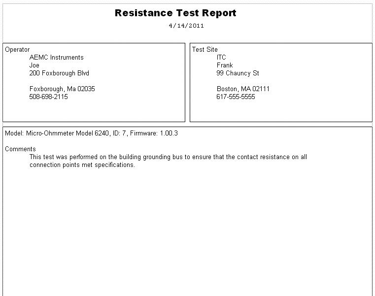
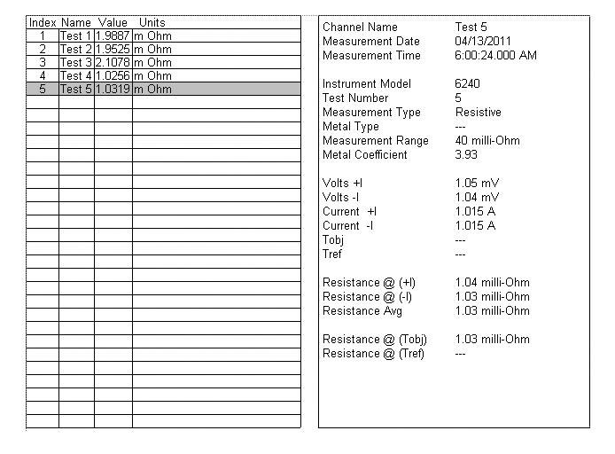


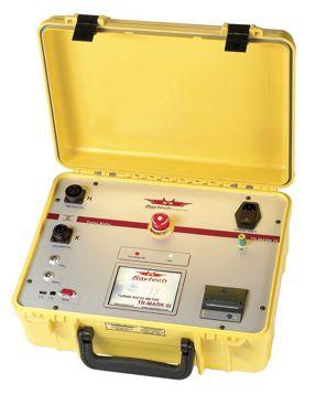
Three Phase Ratiometer
TR-Mark III
AccurAcy (resolution 5 Digits):
Range 0.8 … 2000 ± 0.06% at 100V or 40V
Range 2001 … 4000 ± 0.1% at 100V or 40V
FeAtures:
• Automatic measurements of voltage, turns ratio, current, and phase displacement
• Measures power transformers PTs and CTs
• Displays deviation from a nominal ratio
• Displays % error vs. name plate value
• Bright full color touch-screen for easy data entry

AccurAcy:
Winding Resistance Meter WR14
Range 100 mAmp … 15 Amp ± 0.1% Rdg 5 Digit Resolution
Range <25 mAmp 1.2kΩ …10kΩ ± 0.1% Rdg 4 Digit Resolution
Range <25 mAmp 10kΩ …100kΩ ± 0.5% Rdg 4 Digit Resolution
FeAtures:
• Core Demagnetizing Circuit (world exclusive)
• Charges inductive loads up to 1500 Henry
• 2 independent measuring channels
• Heavy-duty protection circuitry
• High power DC supply (15A/30V)
• Resistance range from 0.05 μΩ to 100 kΩ
• Battery or line voltage powered
• Visible and audible indicator for discharge status
• Data exchange with USB-key
• Simple touch-screen operation
• Built-in printer All Raytech Products Include a Standard 5 Year Warranty
Range 4001 … 13000 ± 0.3% at 100V or 40V
Range 13001 … 16000 ± 0.4% at 100V or 40V
• Test voltages of 100V, 40V, 10V, and 1V (for CT Testing)
• Graphical tap changer display
• Automatic phase vector detection
• Enhanced heavy-duty protection circuitry
• Data exchange with USB-Key
• Built-in printer

AccurAcy:
Single Phase Ratiometer
TR-1 & TR-1P
Range 0.8 … 4000 ± 0.08% with 40 Volts (PT Mode)
Range 0.8 … 100 ± 0.08% with 1V … 5V (Auto) (CT Mode)
FeAtures:
• Operates on rechargeable batteries or line voltage
• Can be recharged with line voltage or optional
DC car adapter
• Reverse polarity test
• Continuity test
• Test current up to 1A for CT testing
• Internal storage of the last 50 test results
• RS-232 interface with optional adapter
• Over 1000 measurements without recharging
• TR-1P model includes built-in printer
JOHN WHITE OUTGOING PRESIDENT
BY KRISTEN WICKS, NETANETA is an organization of leaders. NETA Accredited Companies lead the way in electrical testing with their work every day in the field for their clients, through participating in the development of industry standards and by sharing knowledge and experience with their peers in an effort to incite improvement by constantly raising the bar and helping those around them learn to meet that new expectation. NETA’s leadership structure is by no means unique, but the people that fill the ranks as committee members and officers are all studies in breaking the mold. Each new President brings his own leadership style to the position, but one thing remains constant: bringing years of knowledge and experience to the table when one holds the gavel. John White’s term as President comes to a close on May 31, 2011; it is a term that his fellow NETA members recall with smiles.
John White, of Sigma Six Solutions, is respected by his fellow NETA members as a man of character, principle, intelligence, wisdom, and humor. He knows how to run a meeting at a pace that allows each issue enough time for thorough consideration, and when the discussion hits a roadblock he steers everyone back on course. Kerry Heid, fellow Board Member and Accredited Representative says of John, “When I met John for the first time in 2003, his combination of personality and business acumen made an instant

impression. I always have one hundred percent confidence in the information he presents. His ability to interpret and apply data keeps things moving along in the board room, saving us all valuable time and allowing for more action to take place.” It’s not just John’s skill as a leader that has made such an impression on his peers. Kerry continues, “John and Bev are such a great couple. They are so easy to get along with and so hospitable – they just make everyone feel welcome.”


Mose Ramieh, NETA’s incoming President had a lot to say about John. “Besides being a very good friend and wonderful President of the organization, he has been a great teacher. I have learned a lot by watching him and how he conducts himself as the President. I think he will help me be a better leader in the coming years.” Mose remembers time spent with John and Bev in their home on Puget Sound, Washington, “They have always been very supportive friends to me, especially through some difficult years. It was wonderful to be able to visit with them in their home, go crabbing, enjoy some great food and wine. Anyone can see that they are just allaround great people. NETA is a mixed bag when it comes to each person’s background, but for all the differences we are a close knit group of people because we all share the same philosophy of high standards and high expectations. That’s what makes it work.” Dave Huffman admires John’s unassuming and humble nature, “He has a very sharp wit but you have to listen carefully to what he is saying to pick up on it. He is sharp as a tack, but doesn’t broadcast that.”
“John is a true testament to living life with warmth, laughter, grace, and balance.
Jayne Tanz, NETA’s Executive Director, holds John in high regard. Effective, efficient, clear, concise, directed are some of the first words that come to mind when she reflects on her time by his side as President. Jayne says, “John is a true testament to living life with warmth, laughter, grace, and balance. You can always count on John to drill to the heart of the matter. Rather than dictating, he asks questions and inspires those around him to work together to find the best solution to create a collective vision.”
~ Jayne Tanz ~
Abraham Lincoln said, “Nearly all men can stand adversity, but if you want to test a man’s character, give him power.” John has proven his character as NETA’s President, continuing to grow new friendships while cultivating old ones. NETA will always be in a constant state of change; people come and go, initiatives change with the evolution of the industry, but one thing remains constant. The caliber of the individuals contributing to the organization continue to be the kind of people that everyone is happy to know, and is better for having known.
the test equipment answer
Test Equipment Rental
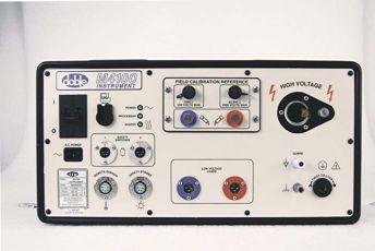

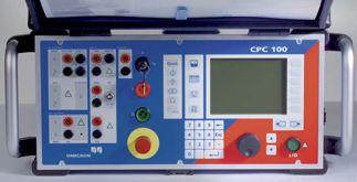

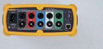


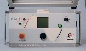
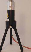


LESSONS FOR ELECTRICAL SAFETY AND RELIABILITY
 H. LANDIS
“LANNY” FLOYD, DuPont
FROM THE BRINK OF DISASTER
LESSONS FOR ELECTRICAL SAFETY AND RELIABILITY

Engineering advancements throughout the 20th century enabled tremendous benefits to modern society and our way of life. Sometimes the evolution of technology advancements outpaced development of understanding and knowledge in how to apply new technology safely. Unfortunately, high profile disasters exhibiting gaps in managing risks, including Texas City (1947), Flixborough (1974), Three Mile Island (1979), Bhopal (1984), Chernobyl (1986), Challenger (1986), Piper Alpha (1988), Texas City (2005) and Deepwater Horizon (2010) have been so severe to garner international attention. These high profile industrial/technical disasters were investigated with exceptional rigor to help assure identification of the contributing causes that resulted in high losses in human life, impact on the environment, and billions of dollars in property losses and liability damages. The lessons from these disasters have had wide impact on codes, standards, and regulations impacting systems design, reliability and maintenance systems, safety management, and operating discipline. Beyond their initial investigations, these disasters spawned numerous third party articles and books to further advance understanding of how these events occurred and what can be done to prevent them. How effectively have we applied these lessons to maintenance of critical electrical equipment and electrical safety in the workplace? This paper explores opportunities to apply key learnings from these disasters to compliment widely recognized best practices in managing electrical systems maintenance and personnel safety in the workplace.
First, it may be useful to share a bit of background on DuPont, the oldest Fortune 500 company. French immigrant Eleuthère Irénée du Pont founded the company in 1802 to make black powder to supply gunpowder and explosives used in farming, mining, and construction in the expanding United States. For nearly 150 years, the manufacture of explosives was the primary business of the DuPont Co. This was an inherently hazardous business. In 1818, a massive explosion destroyed much of the powder mills, killed or injured more than half of the employees and injured Mrs. du Pont. This catastrophe solidified E.I. du Pont’s philosophy in safety management. His words, “We must seek to understand the hazards with which we live,” became the foundation of the company’s approach to managing the design, construction, and operation of facilities for manufacturing highly hazardous materials. In the early 20th century, the company began diversifying into chemicals, which like gunpowder and explosives, involve inherently hazardous materials and manufacturing processes. In the mid 1980s, an effort began to apply experience in managing safety of inherently highly hazardous processes to the unique hazards of electricity. That effort continues today and is the focus of this paper – applying lessons from high profile disasters to the unique hazards of electricity.
LESSONS
During the 20th century, the combination of emerging technologies and machines and processes brought together massive quantities of energy and hazardous materials.
Energy densities took on massive scale, and when something went wrong, the consequences were far reaching. Very detailed investigative reports are available for each of these disasters. Hundreds of books have been written that expand on the official reports. Documentary films have been produced on some of these disasters. It is not possible to capture the full breadth and depth of the lessons learned within the scope of this paper. However, we will see there are ways we can help assure that the full scope of these lessons are applied to electrical safety. Electrical accidents seldom involve more than one or two victims and typically do not generate such attention. But the lessons from the disasters that receive extensive scrutiny can be applied to electrical safety. It is critical that those of us involved in electrical safety understand this, as it can help accelerate improvements and change in how equipment and systems are designed, how electrical hazards are managed, and in changing cultural beliefs and attitudes on risks and consequences of electrical accidents. The key learning or learnings noted with each are only a small selection from the hundreds of recommendations developed form the investigation of each of these events.
1937 – NEW LONDON SCHOOL DISASTER
On March 18, 1937, a natural gas leak caused an explosion that destroyed a public school building in New London, Texas. The explosion killed more than 295 students and teachers. Of the 640 people in the building at the time, only 130 escaped without injury. The area was rich in oil and natural gas resources and the school district was one of the wealthiest in the US. Built in 1932, the original plans called for a central boiler for heating the building; however, the school board opted to install 72 gasfired heaters instead. In 1937, the school board cancelled its contract with the natural gas supplier and tapped into a waste gas line from a local refinery. The waste gas was odorless and colorless, and leaks went undetected. Although some students had been complaining of headaches, no action was taken. It is believed that a switch on an electric sander caused a spark that ignited the gas-air mixture. This disaster led to worldwide standards requiring mercaptan additives to all natural gas supplies. The strong odor makes leaks quickly detectable. Decades later, the renowned news anchor Walter Cronkite, who as a young reporter was on site, commented that he never covered a news event that was more disturbing.
A key learning: The hazard (much like electricity) could not be detected with human senses.
1947 – TEXAS CITY EXPLOSION
On the morning of April 16, 1947, the worst industrial disaster in the US began unfolding in Texas City, Texas. A small fire on board the SS Grandcamp, loaded with ammonia nitrate escalated to involve nearby refineries, chemical plants and the explosion on April 17 of a second vessel, the SS High Flyer, also loaded with ammonia nitrate. Within a 24 hour period, nearly 600 people were dead, more than 100 missing and never accounted for, 3500 people injured, 1519 houses destroyed, more than 2500 people homeless, major port facilities destroyed, a Monsanto chemical plant destroyed, and total property losses exceeded $700 million in 1947 dollars. Adjusted to 2011, the property financial loss alone exceeded $6.9 billion.
A key learning: The first responders on board the SS Grandcamp and the disaster response team at the port did not understand the hazard and its potential for catastrophe.
LESSONS FOR ELECTRICAL SAFETY AND RELIABILITY
1972 – EASTERN FLIGHT 401
On December 29, 1972, Eastern Airlines flight 401 from New York to Miami crashed in the Florida Everglades. With 176 people on board, 101 were killed. The Lockheed L1011 Tristar was the first wide body jet crash in the US, and at that time it was the deadliest crash of a commercial flight in the US. In preparation for landing, an indicating light for the front landing gear did not illuminate, and the flight was diverted to give the crew time to investigate. The plane was put on autopilot while the flight crew, including the captain, first officer, second officer and an engineer from Eastern began investigating the problem. While investigating the landing gear situation, it is believed a control was accidently bumped, sending the plane into a gradual, imperceptible descent. There were no ground lights in the Everglades to give visual warning of the planes close proximity to the ground. The investigation team coined a new phrase, CFIT – controlled flight into terrain. Preoccupation with the nose landing gear indicator malfunction distracted the four highly qualified, competent crew and they failed to notice and respond to six different altitude warning alarms.
A key learning: Qualification and competency alone will not prevent errors having catastrophic consequences. Highly qualified persons can and will make mistakes that put themselves and others at high risk.
1974 – FLIXBOROUGH, ENGLAND EXPLOSION
On June 1, 1974, an explosion at the Nypro chemical plant in Flixborough, England killed 28 and injured 36 workers. An additional 53 people in the surrounding community were injured. The explosion occurred on a weekend when there was minimal staff on site. If it had been during the week, it was estimated that more than 500 workers would have been killed. 1500 buildings within a mile radius were damaged. Plant maintenance personnel had modified the plant process piping by building a 20 inch diameter bypass line around an out of service reactor. A crack developed in the bypass line, creating a vapor cloud that ignited, exploded, and destroyed the plant facilities. Fires burned for 10 days.
Key learnings included: The importance of minimizing inventories of hazardous materials, the need for documented procedures, and the need for engineering analysis of plant designs and modifications.
1976 – SEVESO, ITALY DISASTER
The largest exposure of dioxins to human and animal populations occurred on July 10, 1976, in Seveso, Italy. Within a few days of a leak at a chemical plant, more than 3300 farm animals had died. Subsequently, more than 80,000 animals were slaughtered to prevent dioxin from entering the food chain. 220,000 people were monitored for long term health effects. In 1982, the European Union passed extensive industrial safety regulations, known as the Seveso Directives.
A key learning: Nearby residents, political authorities, and public health officials were unaware of the presence of a hazard.
1979 – THREE MILE ISLAND
The worst accident in the history of the US commercial nuclear industry occurred on March 28, 1979. The #2 unit at Three Mile Island generating station near Harrisburg, Pennsylvania, suffered a partial meltdown. A series of minor equipment malfunctions, coupled with human error, resulted in a major accident. Although there were no casualties directly related to this incident, it halted any further development of commercial nuclear power generation in the U.S.
A key learning: The reactor operators were not trained to operate the reactor under abnormal conditions.
LESSONS FOR ELECTRICAL SAFETY AND RELIABILITY
1984 – BHOPAL CATASTROPHE
The Bhopal disaster is considered the world’s worst industrial catastrophe. The official immediate death toll was 2259. Government agencies estimate more than 15,000 subsequent fatalities and 558,125 injuries from a leak of a toxic chemical, methyl isocyanate, from a Union Carbide chemical plant. The leak occurred on the night of December 2-3, 1984. Contributing factors included hidden failures in safety systems due to inadequate maintenance, lack of an emergency response plan, and storage of large quantities of highly hazardous materials in a heavily populated area.
A key learning: Hidden failures in engineering controls critical to safety can have catastrophic consequences.
1986 – CHALLENGER EXPLOSION
At 11:39AM on January 28, 1986, 73 seconds into its flight, the space shuttle Challenger exploded, killing all seven crew members. The disaster was captured live on national TV news. The Rogers Commission, appointed by President Reagan identified flaws in NASA safety management systems that contributed to the disaster. Most disturbing was the finding that maintaining schedule had taken priority over flight safety in decision making processes.
A key learning: Top management had created a culture that allowed cost and schedule to override safety concerns
1986 – CHERNOBYL NUCLEAR DISASTER
The accident that occurred on April 26, 1986, at the Chernobyl nuclear power plant in the Ukraine is considered the worst nuclear power plant accident in history. There were 56 deaths onsite. More than 350,000 people were relocated from the nuclear contaminated areas. It is estimated that 4000 deaths will result from increased cancer risk due to radiation exposure. The investigation found flaws and deficiencies in every aspect of the facility. The poor quality of operating procedures and instructions put a heavy burden on the operating crew, creating high degree of vulnerability to human error.
A key learning: The safety culture did not include understanding of the risks associated with the hazards, not only at the Chernobyl plant, but throughout the Soviet design, operating, and regulatory organizations for nuclear power that existed at that time.
1988 – PIPER ALPHA EXPLOSION
The explosion of the Piper Alpha offshore gas platform on July 6, 1988, is the worst offshore oil disaster in terms of lives lost and impact on the industry. 167 workers were killed. At the time of the disaster, Piper Alpha accounted for 10 percent of North Sea gas production. The fire burned for three weeks before being extinguished by a team under direction of Red Adair. The government inquiry made 106 recommendations for change in safety procedures, all which became standard in the oil and gas industry.
A key learning: Lack of coordination of multiple maintenance activities compromised emergency safety systems
LESSONS FOR ELECTRICAL SAFETY AND RELIABILITY
1999 – INSTITUTE OF MEDICINE REPORT
This is not a singular incident as are the other disasters noted in this paper; however, this study has brought great attention to the prevalence of human error in critical situations.
In 1999, the US National Academies Institute of Medicine issued a landmark report on patient safety in the US healthcare systems. The report, titled To Err is Human, stated that 98,000 avoidable deaths occurred annually largely due to human error, making medical errors the 5th leading cause of death in the US. The report cited deficiencies in safety management systems spanning, government oversight, communication processes, incident reporting and sharing practices, equipment designs, team management, planning processes, education, and licensing.
A key learning: Highly qualified and competent personal can and will make mistakes that place others in jeopardy.
2005 – TEXAS CITY EXPLOSION
On March 23, 2005, an explosion at a refinery in Texas City, Texas, killed 15 workers and injured more than 170. The US Chemical Safety Board recommended the company commission an independent panel to investigate the safety culture and management systems. The panel was led by former US Secretary of State James W. Baker III. The panel’s principal finding was that management had not distinguished between occupational safety (i.e., slips-trips-and-falls, driving safety, etc.) and process safety (i.e., design for safety, hazard analysis, material verification, equipment maintenance, process upset reporting). The metrics, incentives, and management systems focused on measuring and managing occupational safety while ignoring process safety.
A key learning: The company had confused improving trends in occupational safety statistics for a general improvement in all types of safety.
2010 – DEEPWATER HORIZON EXPLOSION
On April 20, 2010, an explosion on the deep water oil platform, Deepwater Horizon, killed 11 workers, injured 17, and caused the largest offshore oil spill in US history. The platform sank on April 22. This event will likely spawn significant changes in government regulations and industry standards. Initial findings point to deficiencies in risk management and safety management systems.
EMERGENCE OF SAFETY MANAGEMENT SYSTEMS STANDARDS
The high profile disasters in the 1970s and 1980s set the stage for the movement to identify best practices and establish standards for effective safety management systems to minimize risk to workers, the public and the environment. Some companies had already developed proprietary safety management standards that align with or go beyond industry standards that have since emerged. The first consensus standard addressing these needs appeared in 1995, with the publication of ISO 14001, Environmental Management Systems. In 1999, a collaboration of international safety organizations published OHSAS 18001, Occupational Safety and Health Management Standard. A similar standard, ILO Guidelines for Occupational Safety and Health Management Systems was published by the International Labour Organization in 2001. Implementation of these standards includes rigorous certification processes, similar to the ISO 9000 quality certification process. More recently, ANSI Z10 Occupational Health and Safety Management Systems, and CSA Z1000, Occupational Health and
LESSONS FOR ELECTRICAL SAFETY AND RELIABILITY
Safety Management were first published in 2005 and 2006 respectively. These two standards are well harmonized with each other and with the other safety management systems standards noted above, but can be applied without the rigorous certification requirements.
LINKING NFPA 70E 2009 AND CSA Z462-2008 TO SAFETY MANAGEMENT SYSTEMS
Continuing its evolution since first published in 1979, the 2009 edition of NFPA 70E and the first edition of CSA Z462-2008 for the first time made reference to safety management systems standards. The referenced management systems standards focus on the strategic levels of management policy and implementation processes to help establish management commitment and support necessary for planning, implementing, and assuring sustainable and continuous improvement in safety performance. Better understanding the role of safety management systems in planning and implementing changes in an electrical safety program may be one of the most critical factors in the success of the electrical safety program, no matter what stage of implementation or its level of maturity. An organization just beginning to apply the requirements of NFPA 70E or CSA Z462, an organization that has a mature safety management system and electrical safety program, but hasn’t assessed integration effectiveness, and the organization that has a mature integration of the electrical safety program may all benefit from a critical review of their electrical safety programs and safety management systems. Unique to CSA Z462-2008 is Annex A, “Aligning Implementation of Z462 with Occupational Health and Safety Standards.” A key statement in Annex A underscores the importance of collaboration and integration:
“The most effective design and implementation of an electrical safety program can best be achieved through a joint effort involving electrical subject matter experts and safety professionals knowledgeable in safety management systems. This collaboration can help assure proven safety management principles and practices applicable to any hazard in the workplace are appropriately incorporated in the electrical safety program. This annex provides guidance on implementing CSA Z462 within the framework of CSA Z1000 and other recognized or proprietary comprehensive occupational safety and health management system standards.”
WHERE TO GO FROM HERE
Those who have been involved in the development and implementation of NFPA70E and CSA Z462 need to take on the challenge and educate ourselves on safety management systems and how effective electrical safety programs are dependent on integration within these systems. We need to actively seek ideas outside the box of electrical safety, learn how management of other hazards is continually improving and translate these learnings to the unique hazards of electricity.

H. Landis “Lanny” Floyd II received his BSEE from Virginia Tech and joined DuPont in 1973. For the past 25 years, his responsibilities have largely focused on electrical systems reliability and electrical safety in the construction, operation, and maintenance of DuPont facilities worldwide. He is currently Principal Consultant, Electrical Safety & Technology. He has published or presented more than 100 technical papers, magazine articles, tutorials and workshop presentations on electrical safety and electrical technology. He is an IEEE Fellow, a professional member of American Society of Safety Engineers, a member of NFPA NEC panel 1 and 70E Task Group on Maintenance Requirements, a member of CSA Z462 Technical Committee, a board director of Electrical Safety Foundation International, a Certified Safety Professional, a Certified Maintenance & Reliability Professional, and a registered professional engineer in Delaware.
A REPORT ON THE JANUARY 2011 IEEE ELECTRICAL SAFETY WORKSHOP
Many NETA-accredited companies (NAC) were represented at the recent IEEE IAS Electrical Safety Workshop (ESW) conference held on January 24-28, 2011, in Toronto, Ontario. This report is being provided to present observations of the NAC representatives at the workshop that you may use to improve electrical safety in your workplace. This report is also being provided to inspire you to participate in the ESW in January 2012 in Daytona Beach, Florida.
are exempt from NFPA 70E but have adopted it anyway because it is the correct thing to do.”
At the ESW conference, presentations are made to clarify existing codes, standards, rules, and regulations, as well as to provide insight into new regulations and information being considered. Presentations are also made on specific techniques and methodologies that can be used to enhance electrical safety in the workplace.


Since its inception in Toronto in September 1991, the ESW has provided a forum for electrical workers and professionals to enable and accelerate change in the electrical safety culture and push the envelope on what is possible in minimizing electrical hazards and preventing workplace injuries. To give some insight into ESW, Gary Donner of Tony Demaria Electric, an IEEE Fellow and long-time attendee of ESW, adds that “(t)he IEEE ESW was started by the IEEE PCIC (Petroleum and Chemical Industry Committee) Safety Committee in 1992 as a forum to exchange ideas and practices to increase electrical safety in the petroleum industry. Throughout the years, the workshop attendance has expanded to cover all users of electricity. This year’s conference, held in Toronto, Canada, had the widest range of industries ever represented. They ranged from the oil industry to mining and electric utilities who
Kerry Heid of Magna Electric Canada, who is also a NETA Board member and a committee member of Canada’s Safety Standard CSA Z462, was one of the panel speakers at this year’s ESW. In his statements he noted that, “Each year safety awareness gets much higher. That’s good. There are still some people that need to get involved. Small contractors seem to be an area where there is a huge gap.” He suggested that we need to “put NFPA 70E and CSA Z462 into school curriculum and start to enable the new entries into the electrical workforce to be on the cutting edge of safety. Most schools say it’s up to the employers but let’s make that change now.” Jim White of Shermco Industries is a NETA-sponsored participant in the NFPA 70E Committee and past president of the 2008 IEEE ESW conference. Jim adds that “Electrical safety is a never-ending learning experience. If you know all there is to know about it, that just means you’ve decided to stop learning.” Electrical safety training is obviously a key component to achieving electrical safety in the workplace.


Tony Demaria of Tony Demaria Electric and the NETA Safety Committee Chairman adds, “The goal of electrical workplace safety is clear… no injuries. The path to get there is very difficult, expensive, time consuming, and frequently confusing. No field worker can turn difficult and confusing information into safe work practices. Our job is to make clear, concise, and consistent safety policies and procedures. It is hard to make difficult things simple. I am going to do my best to have clear policies at our workplace.” Tony adds that “You can have the best safety policies and procedures in the universe. You can have the most extensive safety training program in the country. If you are not field-verifying that the workers are following the policies and procedures, you do not have a safety program.” Tony further suggests “assigning one of (y)our top technicians to a full time safety position at (y)our company to field verify compliance with safety policies and procedures. This person will report to (y)our company’s safety committee, which includes top management. Their findings will be incorporated into (y)our never ending commitment to improve (y)our safety policies and procedures.” Dennis Green, Safety Director of Tony Demaria Electric, adds that “It is a slow road to get the customer, the engineer, and some contractors to start pushing arc-rated equipment, remote racking, and remote switching. It shows that the mentality of the industry is far behind and that education, regulations, policy, and procedures still need to change. Until people are educated on the fact that these changes are for the better, will keep people alive, and lower their exposure, no changes will occur.” Further, Dennis Green observes that “(w)e are not the only company struggling with the problem of changing human behavior, as presented in the paper titled,
A Serious Near Miss. To me, the near miss incident in the paper was caused by look-alike equipment. I believe that look-alike equipment can be a killer and needs to be taken extremely seriously. In this case, it was luck that no one was hurt.” Jim White adds that “Just because you cut corners and did not immediately die does not mean that it is now the right way to do things.” Safety procedures and policies are also a key component to a successful safety program. However, just having safety policies and procedures in place is not enough. You must also perform safety program audits and have a continuous improvement process in place for your safety policies and procedures.
This conference also included active discussions on electrical safety hazards and risk management. Tony Demaria observed that “there is much disagreement and much confusion as to the definitions and differences between the words hazard and risk. Until we come to an industry-wide agreement as to the definitions of these words, we will have a serious gap in our understanding of how to communicate safety to each other.” Kerry Heid adds that “hazard and risk are two entirely different things and many people don’t understand it. Eliminate, control, protect. PPE is the last solution. It’s like driving your car without any driver training or any concern for the road signs because “I have an airbag”. Maintenance is the trump card. All bets are off if it doesn’t work the way it was designed. Equipment condition needs to be formally written into the risk assessment
process.” Dennis Green adds, “As an industry, we still blindly put men in places where they have no business being. Why have PPE that has a breakout value of 50 percent, why not go for the 100 percent? That’s how I see it when they talk about the breakout value on arc-rated PPE.” Dennis Green learned some other things from this conference, “We should be sending anyone that receives an electrical shock to the doctor to be checked out. Dr. Joel spoke about the invisible injury, which is a great name since electricity is invisible.” Dennis also “found that many companies have problems with bidding procedures. When awarding bids without understanding what the risk and hazards are, workers will continue to be hurt or killed. A bid should be awarded based on, 1) safety records, 2) qualifications and experience, and 3) the dollar amount. What is not understood is that the lowest bid is not always the best bid. Make sure your contractors are qualified to do what they say they can do.” With regard to electrical safety, a dialogue on hazard and risk assessment will continue.
Given the range of participation in the ESW conference, attending companies are introduced to information and technology that can be transferred into techniques and procedures that will make the workplace safer. Gary Donner stated that “(a) very practical screening tool was explained in one of the workshops. It was an ultrasonic hand-held instrument that can scan enclosed electrical apparatus prior to opening the door. This method can detect arcing, tracking, and corona in low and high voltages. By detecting one of these problems you may decide to shut the equipment down prior to opening the door. The life you save might be yours. We are going to purchase several more of these instruments and incorporate their use in our procedures.” There are new technologies that can be implemented to enhance safety in the workplace.
The IEEE ESW conference is held each year to present ideas that may be put into practice to improve electrical safety in the workplace. From the recent ESW conference, the following summarizes some of the presentations that were notable to the NAC participants:
• Electrical safety training is a key component in achieving electrical safety in the workplace.
• Safety procedures and policies are also key components in a successful safety program. However, just having safety policies and procedures in place is not enough. Safety program audits and a continuous improvement process for safety policies and procedures must also be included.
• A dialogue on hazard and risk assessment will continue.
• Th ere are new technologies that can be implemented to enhance safety in the workplace.
It is obvious from this report that issues associated with electrical safety in the workplace are still actively being discussed and dealt with in various affected industries. There is much we can learn as a collective group to deal with these issues. As Tony Demaria explains it, “Safety is a journey, not an end. None of us can do everything, but each of us can do something to make a difference.” NETA encourages each NAC to become active participants in conferences like IEEE ESW and then share the experience and information with others in the industry so that all can benefit.
•
•
•
•
•
•

•
•
•
•
•
•








REPLACING OLDER MEDIUM-VOLTAGE CIRCUIT BREAKERS WITH VACUUM CIRCUIT BREAKERS
By Baldwin Bridger
Baldwin Bridger is retired Technical Director of Powell Electrical Manufacturing Co., Houston, Texas. He has worked as an engineer and engineering manager in the design of low- and medium-voltage switchgear since 1950, first at GE and since 1973 at Powell. He is a Fellow of IEEE and a past president of the IEEE Industry Applications Society
Many older installations of metal-clad switchgear are candidates for modernizing or upgrading. The interrupting duty may have grown past the interrupting capacity of the existing circuit breakers, maintenance costs may be getting out of hand, or circuit breaker parts may no longer be available.
Modernization may be accomplished by either of two methods, conversion of the existing equipment or replacement of the circuit breaker with a new, modern vacuum breaker. In some cases, modernization may involve conversion of the switchgear equipment and replacement of the circuit breaker. Modernization may also involve an increase in one or more ratings of the switchgear and/or circuit breaker.
In any case, users should insist that modernization be done in accordance with applicable industry standards to insure that the modernized switchgear meets the required ratings. For replacement circuit breakers, this is fairly simple. The breakers should be tested in accordance with ANSI/IEEE C37.09 and ANSI/IEEE C37.20.2, just like any other new circuit breaker that is used in metal-clad switchgear. The only caution is that certain tests, including continuous current, momentary current, and BIL should be performed in a switchgear cell of the basic design in which the breaker will be used. All of these tests involve interaction between the cell and the circuit breaker. For instance, we have performed full wave impulse (BIL) tests where both the breaker alone and the cell alone passed the test, but the combination would not pass, requiring additional work to the breaker to achieve the desired result.

ANSI standard, ANSI/IEEE C37.59, IEEE Standard Requirements for Conversion of Power
Switchgear Assemblies, covers conversion of both switchgear equipment and power circuit breakers. This standard specifies the design and testing requirements for conversion, including uprating, of existing equipment. Requirements for new documentation, including nameplates and instructions, are included. Any user considering converting low-voltage or medium-voltage switchgear equipment should review this standard and insist that vendors conform to it.


A STRANGER’S GIFT REFUELS HER FAITH IN THE WORLD
Erin Warchol sat in her car and cried. She was an hour from home Monday, nearly out of gas in Belmont. She had forgotten her wallet and the gas station attendant refused to accept a credit card over the phone from her husband.
She heard the beep-beep-beep- of a big white work truck backing up toward her with two men inside. The driver motioned for her to lower her window. Warchol, 29, was already upset and now two strange men were approaching. She hesitated.
The passenger got out.
“Honey, he asked her, are you out of gas?”
“Almost.”
BY ELIZABETH LELAND, Courtesy of the Charlotte ObserverShe mentioned that her Samaritan’s name was on the receipt. Craig Griffin. The observer located him in Alabama. He’s an electrical technician and, no, he doesn’t go around handing out money.

And then he did the most unexpected thing. He handed her a receipt from the gas station for $25 worth of gas, and said: “I just fi gured you needed some help.”
Warchol was stunned. She asked for his name and address to repay him, but he said that wasn’t necessary.
“Can I give you a hug?”
That he did accept. Then off he drove.
He was such an angel to my day,” she said. She went into the store and asked the attendants whether they knew him. She said they told her they thought he was her husband.

On Monday morning, he said, it just felt like the right thing to do.This is the best kind of story to share, one of selflessness and caring. Ralph Patterson, Accredited Representative and Owner of Power Products and Solutions forwarded this anecdote about one of his NETA Certified Electrical Testing Technicians to the NETA office. Hopefully the warmth and compassion shown to a stranger inspires more of the same.

“I’ve never wanted for anything in my life,” Warchol said. “It just opened my eyes to what that could be like in a very minute manner. In that instant, I really needed help. I didn’t have to ask him.”
Because he wouldn’t accept repayment, she donated $50 Tuesday to a leukemia fundraiser. Then she called the Observer, because she wanted the rest of us to know that with so many bad things going on in the world, a good thing happened.


SOME ADDITIONAL METHODS FOR RESISTIVITY TESTING
Soil resistivity is the property that defines the ability of soil to conduct current and hence whether a given soil type can be expected to provide a good or a poor ground (high or low resistance). By contrast, earth resistance defines the relationship of a grounding electrode to its immediate environment. They are two different measurements, performed in two different ways, and expressed in two different units. Resistivity measurements are useful data for the design and installation of the electrode. The principal method for measuring resistivity is known as the Wenner Method and has been previously described in this series. Other methods are also practiced in situations where Wenner is not the most suitable, and some of these will be described next.
By Jeff Jowett MeggerSome studies have indicated that earth potential gradients inside or near an electrode (currents returning to the source) are primarily a function of the resistivity of the surface layer, except in extremely high resistivity soils, while electrode resistance is more a function of deep soil. Transmission-line impedances are sensitive to layers of different resistivities at power frequency, while high frequencies, including surge frequencies, establish impedance only in the top few meters. Therefore, both surface and layered resistivities to considerable depths are of concern to grounding and ground resistance measurement.
A common practice is the testing of soils in sample boxes in laboratories. This can be done by connecting an earth tester to a specially made box containing a soil sample. A volumetric measurement can thus be obtained. However, this technique is more applicable to abstract research than practical field work such as grounding design. It is difficult to obtain a useful approximation of resistivity by this method for several reasons. Obtaining a truly representative
sample of site conditions in a small volume commensurate with the dimensions of a test box is a challenge. In addition, it is difficult to accurately replicate moisture content and in particular compaction in a laboratory sample.
Another highly limited but sometimes useful method is an adaptation of the resistance method (3-point test) to resistivity testing. This method is adapted to small areas where space limitations preclude the larger distances across the test probes that the standard Wenner Method requires, and can be called a variation of depth method. Repeated resistance measurements are made of a test rod driven to increasing depths, using familiar methods derived from fall of potential. Resistance would be expected to diminish with increased depth, so interpretation of results is difficult and makes good use of experience. But an uncharacteristic or unexpected change can indicate a change in resistivity, as with another layer of different soil type. Such data isn’t detailed enough for practical use in software design programs, but can provide a useful indication of on-site conditions with
respect to soil layering. The vicinity of the test rod affected by this method is about five to ten times rod length. Larger sites can also be tested for lateral changes in resistivity by relocating the rod to a number of points, but where sufficient space is available, this application is better served by the traditional Wenner Method.
Variation of Depth method can be enhanced by the use of some mathematical formulae. The basic resistance formulae involved are:
R = [ρ/2πl]ln[2l/r] and
R = [ρ/2πl][ln(4l/r) – 1]
These rearrange to:
Ρa = [R2πl] / [ln(4l/r) – 1]
Where R = measured resistance at various depths
Ρa = resistivity calculated
l = test rod depth
r = test rod radius
Accordingly, a series of resistivities can be calculated from resistance readings at various depths and plotted against those depths. If the graph resembled Fig. 1A, it could reasonably be concluded that the tested soil consists of two layers, one at a shallow depth of relatively high resistivity and one at greater depth that is much more conductive. It might reasonably be concluded, then, that the additional investment in a deeper-driven permanent rod would be justified. In Fig. 1B, however, the shallow resistivity can be determined to be relatively conductive, but the deeper layer cannot be clearly determined.

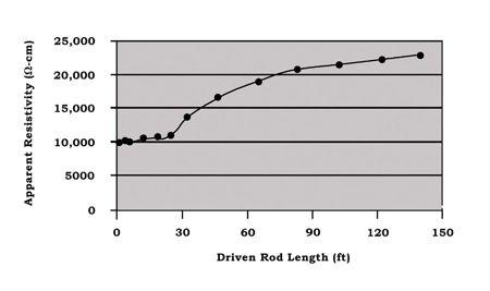
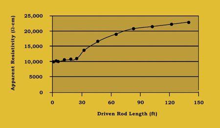
The traditional Wenner Method uses four equally-spaced probes, which thereby measure to a depth equivalent to the spacing between any pair. The current probes are positioned on the outside. This is so that the current will have escaped the localizing effects of the probesoil interface and established a uniform field across the inner probes which sense potential. This arrangement is conducive to maximum accuracy. An alternative method, called the Schlumberger Palmer Method, utilizes unequal spacing. This method is designed to address a problem that can arise with Wenner (equal probe spacing) where spacing has increased to considerably large distances: the drop in magnitude of potential between the voltage (inner) probes to a degree that the instrument cannot adequately measure. To counteract this problem, Schlumberger-Palmer brings the potential probes closer to the current probes (Fig. 2). The formula describing the resistivity measurement in this configuration is:
ρ = πc(c + d)R/d
where c = spacing between current and potential probe
d = spacing between potential probes
R = resistance reading from tester
TECH TIPS
The depth of penetration of the test probes is assumed to be small; Wenner calls for a 1/20 ratio between depth and spacing. Buried conductive sources like power lines and pipes could be causing interference with the measurement, or lateral changes in resistivity could render a specific location nonrepresentative of the general area. Therefore, it is recommended to take additional measurements at different locations on the same site, or at least to make the same measurement 90° relative to the first.
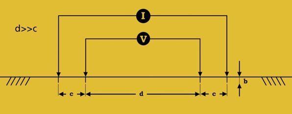
Four-point methods can provide data to be plotted similarly to the three-point methods described above. Measured resistivities are plotted against depth, as has been shown. Clarity of interpretation as to the depth of various layers and the attendant soil structure, however, is often not so well defined as in Fig. 1A. Various authors have offered rules for determining the depth of individual layers. One guideline is that any break in the curvature of the graph indicates a separation of layers at the depth corresponding to that probe spacing. Another prefers 2/3 the probe spacing at which a point of inflexion occurs as representing the separation between layers. Similarly, it has been suggested that change in apparent, or calculated, resistivity always occurs at probe spacings larger than the depth of the actual change; hence, the graph of apparent resistivity is always to the right of the actual. This interpretation further suggests that such graphs do not correspond to the actual depths or magnitudes of change in soil layers. However, they can be used as models of relative differences and so provide a guideline for more exhaustive testing and calculation that will be described in a later edition.
Always remain aware that anomalies in test results can occur from sources of interference. These interference sources can be both passive conducting bodies and active electrical elements. Passive sources can be metallic fences, buried conductive objects such as water pipes, building foundations, and pole grounds, as well as others that may be completely unexpected. Parallel transmission and distribution lines and communication services can act as live sources of interference. Passive conductive objects can provide a short circuit that distorts the earth potentials that are being measured as part of the testing process. Similarly, active sources can provide current that is added to, or subtracted from, the test current. Remember that an earth tester employs two test circuits, current and potential, in order to make the measurement. Both of these can, therefore, be subject to distortion by interfering sources. Finally, the test leads, which can be stretched out to considerable lengths, can develop a serious shock potential by inductive coupling with parallel currentcarrying lines.
So many different methods, often with conflicting interpretations, can be a source of confusion. However, their presence indicates the wide degree to which variables affect ground measurements, including the enormous span of the resistivity scale, the problems associated with spatial variations, the difficulty in recognizing distinct soil layers, and the possible influence of complicating factors like interference. Looked at another way, the numerous methods give the operator a chance to examine a situation from several perspectives and look for the most pertinent consistencies. Soil layering and modeling will be explored in a future edition.
SOURCES OF INFORMATION:
Wenner, F., A Method of Measuring Resistivity, National Bureau of Standards, Scientific Paper no. S-258
Palmer, L. S., Examples of Geoelectric Surveys, IEE Vol. 106, Part A
Gish, O. H., & W. J. Rooney, Measurement of Resistivity of Large Masses of Undisturbed Earth; Terrestrial Magnetism and Atmospheric Electricity
Lancaster-Jones, E., The Earth-Resistivity Method of Electrical Prospecting; The Mining Magazine, June 1930
Zohdy, A. A. R., A New Method for the Automatic Interpretation of Schlumberger and Wenner Sounding Curves
The Institute of Electrical and Electronics Engineers, Inc., IEEE Guide for Measuring Earth Resistivity, Ground Impedance, and Earth Surface Potentials of a Ground System, ANSI/IEEE Standard 81-1983

Jeffery R. Jowett is a Senior Applications Engineer for Megger in Valley Forge, Pennsylvania, serving the manufacturing lines of Biddle, Megger, and multi-Amp for electrical test and measurement instrumentation. He holds a BS in Biology and Chemistry from Ursinus College. He was employed for 22 years with James G. Biddle Co. which became Biddle Instruments and is now Megger.



ANSWER 1


ANSWERS

1. You are a facility maintenance manager and you have several sections of medium-voltage switchgear. This equipment has a high reliability requirement and is in good condition. According to ANSI/NETA MTS-2011, how often should it be electrically tested and maintained?
a. 6 months
b. Using Appendix B, switchgear with a high reliability requirement and in good condition would have a multiplication factor of 0.5. The recommended interval for electrical testing and maintenance is 24 months, so it would be 0.5 x 24 months = 12 months.
c. 18 months
d. 24 months
ANSWER 2


2. Cable connected to bus using lugs is always an issue. My experience has been that when checked for tightness every three years, roughly 50 percent of the connections require retorquing. What three methods does ANSI/NETA MTS2011 recommend for checking for connection problems?
a. Using a microhmmeter
b. Using a calibrated torque wrench
c. Performing a thermographic survey
ANSWER 3
3. Using ANSI/NETA ATS-2009 as a reference, what is the minimum voltage to be used for performing a dc overpotential test on 15 kV switchgear?
a. 15 kV
b. 25 kV
c. 27 kV
d. 37 kV

ANSWER 4
4. ANSI/NETA ATS-2009 recommends what maximum value of leakage current when performing the dc overpotential test on 15 kV switchgear?

a. 1 Megohm/kV test voltage plus 1 Megohm
b. 1.0 microampere
c. 100 microamperes
d. No failure of insulation
ANSWER 5
5. What is the minimum insulation resistance of control wiring in switchgear based on ANSI/NETA MTS-2007?
a. 1 Megohm
b. 2 Megohm
c. 4 Megohm
d. No failure of insulation
NFPA Disclaimer: Although Jim White is a member of the NFPA Technical Committee for both NFPA 70E “Standard for Electrical Safety in the Workplace” and NFPA 70B “Recommended Practice for Electrical Equipment Maintenance”, the views and opinions expressed in this message are purely the author’s and shall not be considered an official position of the NFPA or any of its Technical Committees and shall not be considered to be, nor be relied upon as, a formal interpretation or promotion of the NFPA. Readers are encouraged to refer to the entire text of all referenced documents.


LOOK FOR A WAY TO GET HURT A SHOCKING CHALLENGE
I challenge you to do this – go to work and look for a way to get hurt today. Really. Look for a way to hurt yourself. Don’t ignore anything. Find a way that you could get injured and then write it down. Then look for another one.
Every day workers head out to their jobs to make a living for their families, unaware of what they are facing. It does not matter what your career path or your trade is. There is something out there that will bite you if you don’t pay attention. Electricity seems to be getting a lot of attention lately because of the arc-flash hazards and the severity of the injuries sustained if exposed to one. On the other hand, shock is still the most common hazard that workers face today.
Whether you are in the electrical industry or you are the receptionist in an office building, the possibility of electric shock exists and you are exposed. Many electricians expect to get shocked while in the performance of their duties. They say “It is just part of the job.” But it isn’t. There are safeguards in place that can keep you from getting shocked. Job hazard analysis, job safety assessments, pretask plans, whatever you call it, it means the same thing. You are trying to identify the hazards to which you are being exposed in order to mitigate them. If you can not eliminate the hazard, you need to take special precautions and select the proper protective equipment to keep yourself safe so you can return home at the end of the day.
There are approximately 4,000 nondisabling injuries sustained in the workplace each year that are reported. That works out to nearly 20 each day. Add to that the other 16 to 18 per day that receive disabling injuries and you have over 7,500 workers that are injured at work each year with electrical-related injuries. That could come from shock, arc-flash burns, injuries sustained from arc blast, as well as other secondary injuries such as falls, concussions, lacerations, and broken bones. Some of these don’t even fall into the category of electrical injuries but are a result of the exposure.
Over the past four years of talking to electricians in the field, nearly all of them have, at one time or another, admitted to receiving an electric shock. But when pushed to answer the question as to whether or not they reported it, very few have done so. This is absolutely unacceptable. Each of the electricians that I have spoken to admitted to getting shocked, but not reporting it for fear of reprisal from their supervisor, being heckled by their co-workers, or not seeming to be macho.
Most of these shocks happen while the electrician is troubleshooting electrical systems.
 DON BROWN Senior Training Specialist Shermco Industries
A SHOCKING CHALLENGE
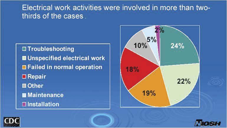
It is impossible to measure voltage and current while the power is turned off, so troubleshooting is done while the system is energized. The problem occurs when the electrician gets to the location only to find out that a critical system is not operating, a production line is down, or another worker creates a distraction because the other worker wants to watch what the electrician is doing. All of these create an unsafe atmosphere in which the electrician sometimes forgets to follow safe work practices. Instead of getting the proper safety equipment, he or she is pressured into just getting it back on line no matter what it takes. This leads to performing the work unprotected and under pressure, and not necessarily thinking about the task at hand.


It only takes one little distraction to make a mistake and the result can be devastating. Maybe it is contact with live parts that results in an electrical burn. Maybe it results in falling off a ladder. Or even worse yet, it results in the inability to release the energized part and a fatality occurs. Whatever the case, it is something that can be avoided. Taking the extra minute to put on the protective equipment needed to do the job safely and setting up a safe work zone can, and will, result in your safety.
Something as simple as putting on rubber insulating gloves, using the proper tester for checking voltage, and using insulated tools can go a long way in preventing an electric shock. Don’t let pressure or poor work practices get you hurt. If you are training another worker, make sure that both of you have the proper protective equipment as well as the proper tools and test equipment. In some instances electricians think low voltage means low hazard. Systems below 600 volts are often considered to be low risk situations; therefore, PPE is not going to be required. Ask the three workers that were sent to the hospital after the accident in the picture below how low risk 480 volts really is!
A SHOCKING CHALLENGE
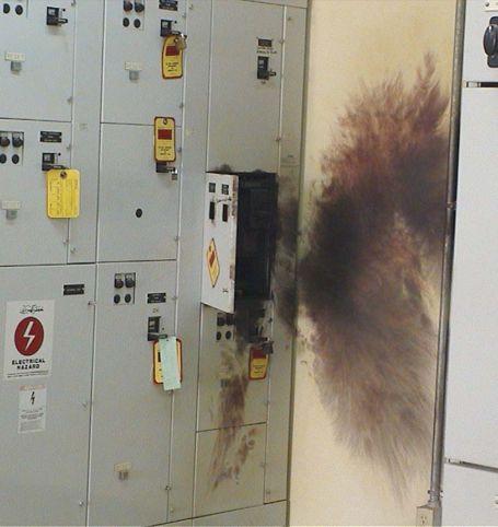
None of them had any PPE on except a hardhat. You can see the burns on the wall and the melted ski mask on the floor along with the smoke damage on two of the three hardhats. Now try to imagine the burns to their hands and faces. All three spent time in the hospital because they neglected to wear the proper PPE. This is one time that they won’t be going home after work.
In addition to their injuries, what are some of the other impacts due to this type of incident?
First, there has to be an investigation into the accident. There has to be additional down time to the motor control center to make repairs, and that means other equipment will be down as well. Lost production, lost revenue, increased insurance costs, worker’s compensation claims, hospital expenses, other employees having to do additional work to cover the lost time of the three workers – all these are the result of not wearing the proper protective equipment. If the correct PPE had been worn, much of this would not have happened.
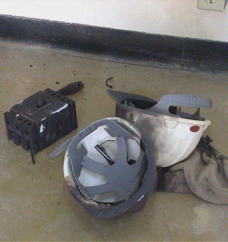
Now let’s look at the impact on the families of these workers. These three men were providing for their families. There is no dad at home to play with the children. An unnecessary burden is now put on the rest of the family, just because someone took a shortcut and didn’t choose to work safely. Think of the impact that you have on others working with you. If you get hurt, you hurt yourself and your family. If you cause someone else an injury, you impact their families as well.
Don’t be that person that says “it will only take a minute” or “I’ve been doing this for over 20 years and I know what I am doing.” Look for a way that you can get hurt today, and a way that you might hurt someone else while at work. Take the time to look for the hazards and find another way to do the job. At the end of the day, we all want to go home to our families.
Don Brown has been involved in the electrical industry for over 35 years – 15 of those specific to electrical testing. He was a master electrician, safety consultant, and business owner. He has consulted for companies such as Intel, Air Liquide, Bell Helicopter, and Chesapeake Energy. Don now serves Shermco Industries as a Senior Training Specialist.







RALPH PATTERSON OUTGOING BOARD MEMBER
BY KRISTEN WICKS, NETAAuthor Elizabeth Andrew says, “Volunteers do not necessarily have the time; they just have the heart.” While this phrase certainly applies to all the generous and talented individuals that give so freely of their time and resources, Ralph Patterson truly embodies this sentiment. Ralph is the owner of Power Products and Solutions in Charlotte, North Carolina, a NETA Accredited Company. He has been a longtime supporter of NETA, and has remained loyal to the organization through the years as the landscape of NETA has changed with the times.
Ralph is a quiet sort of individual, highly intelligent and humbly modest about his contributions and achievements. He is well respected in his field, especially when it comes to anything having to do with cables. A NETA Board Member multiple times, his most recent service to the Board started in 2002 and will come to a close at the end of May this year. Ralph also serves as a member of the NETA Standards Review Council, the body responsible for all technical oversight for the Association. NETA will continue to reap the benefits of his extensive knowledge through his participation with this particular committee and with his representation to IEC and ICC for the organization.
Fellow SRC Member Dave Huffman says of Ralph, “He is one of those individuals that raises the technical expertise of the Association overall. Everyone can see the level of dedication that he has to NETA. Not only is he highly intelligent, he is so approachable and friendly. As I have gotten to know him over the years, I have developed a lot of respect for his technical abilities as well as how he lives his life outside the office. He is very involved in humanitarian work in Mexico through his church, and has helped to orchestrate community improvements with the introduction of a power system fueled by massive batteries that have to be taken in by boat one at a time – a lot of work.”
Kerry Heid agrees that when it comes to heart and the willingness to give, Ralph stands apart from the crowd. “He’s kind of a quiet guy, but he is always willing to give his time even though he is running a company that requires daily involvement on his part to keep things running smoothly. He is out in the field; and when he is at a meeting he is on his phone at every break or getting his emails. Even with all of that he stays on top of everything and gets it all done.”
NETA’s Executive Director, Jayne Tanz, states, “Ralph operates from a place of respect and consideration of others. He has an eagerness to offer assistance where he knows his strengths lie and is always willing to listen and hear another person’s point of view. Ralph is a quiet individual with steadfast family values. NETA looks forward to his continued involvement with the organization.”
Even with his volunteerism and business obligations, Ralph’s family takes precedence over all else; he and his wife Sallie have many children and grandchildren that they treasure dearly. Ralph carries photos with him which he happily shares with his NETA friends, smiling in agreement when they say how adorable the kids are. NETA is so thankful to have had the benefit of his presence on the Board of Directors, and is pleased that he will continue to contribute to the technical prowess through his work on the Standards Review Council. The world is certainly a better place for having people with heart like his.

NETA BOARD AND MEMBER MEETING
February in Washington, D.C. conjures thoughts of blustery days, politicians, and national treasures. It’s also the time of year that the Board of Directors and NETA Members gather for one of the most heavily attended meetings of the year at PowerTest, a NETA hosted event. This February’s meetings were especially exciting as the NETA Brand renovation was unveiled in its entirety for the first time. NETA Accredited Representatives, technicians, and personnel were treated to a site not seen on this earth since 1979 – the NETA Board of Directors and Staff decked out in their finest polyester, love beads, and fringe. Just a laugh at the expense of some good natured participants? Not in the least.
NETA was established as an association in 1972 with the goal of creating standards for electrical testing. Since then, NETA has grown and evolved, expanding its sights to certification of electrical testing technicians; accreditation of third-party, independent, electrical testing; NETA World Journal; PowerTest; technical representation to other industry standards developing organizations; and ANSI Accreditation. The Association has earned its place alongside other industry leaders like IEEE, NFPA, IEC, and ASTM. Just like bellbottoms and platform shoes, NETA had a place in the 1970’s, and while it was a great look, it’s just not who NETA is today.
Everyone enjoyed the Branding Presentation, enthusiastically flipping through the redesigned NETA World Journal and talking about how they would transition to the new NETA logo. Members also greeted new program initiatives that will be rolled out over the next year with approval. Times, they are a changin’.

CSA UPDATE
NETA
SPECIFICATIONS AND STANDARDS ACTIVITY
BY KERRY HEID, Magna Electric Corporationmembers are participating in four major CSA standards.


CSA M421 is the Canadian mining electrical installation standard and Jarret Solberg (NETA Level 4, Magna Electric Corporation, Regina) has been the representative throughout the latest revision cycle. The public review period is over, and the document will be released later this year. Many discussions centered around the requirements for maintenance and acceptance testing, and references to the NETA standards were included in the latest revision.

CSA Z462 is in a revision cycle and will be scheduled for release early in 2012. This document is closely aligned with NFPA 70E and much activity was created in the revision process of both documents.
A building commissioning guideline, CSA Z320 is being produced. NETA testing guidelines are being used extensively to create the backbone of the electrical system acceptance testing and commissioning. This document is currently being finalized and will be released later in 2011. The standard is used in the startup of large commercial facilities like airports and universities.


The latest CSA document, Z463 “Maintenance of Electrical Systems”, is being created. Kerry Heid is chair of this committee. The inaugural meeting was held in Toronto during March 1- 2, 2011. This standard will use a number of reference documents to produce a guideline for industry on electrical maintenance programs and all the various requirements including the recommendations found in the NETA standards. This document is expected to take 18 months to develop.
PROPOSED CONTENTS:


case studies, facility specific programs, etc.


Kerry Heid is the President of Magna Electric Corporation, a Canadian based electrical projects group providing NETA certified testing and related products and solutions for electrical power distribution systems. Kerry is a past President of NETA and has been serving on its board of directors since 2002. Kerry is chair of NETA’s training committee and its marketing committee. Kerry was awarded NETA’s 2010 Outstanding Achievement Award for his contributions to the association and is a NETA senior certified test technician level IV.
Kerry is the chair of CSA Z463 Technical committee on Maintenance of Electrical Systems. He is also a member of the executive on the CSA Z462 technical committee for Workplace Electrical Safety in Canada and is chair of working group 6 on safety related maintenance requirements as well as a member of the NFPA 70E – CSA Z462 harmonization working group.


SPECIFICATIONS
ANSI/NETA STANDARDS UPDATES





ANSI/NETA MTS-2011 REVISION
Review and revision of the ANSI/NETA Standard for Maintenance Testing Specifications for Electrical Power Equipment and Systems was completed on April 15, 2011. This document is scheduled to be published as a revised American National Standard in 2011. These specifications cover the suggested field tests and inspections that are available to assess the suitability for continued service and reliability of electrical power distribution equipment and systems. The purpose of these specifications is to assure that tested electrical equipment and systems are operational and within applicable standards and manufacturer’s tolerances and that the equipment and systems are suitable for continued service. The revision is expected to be published in the spring of 2011 and will carry the designation of ANSI/NETA MTS-2011. Order your copy today at www.netaworld.org.





ANSI/NETA ATS-2009


In keeping with NETA’s branding initiative, the covers of all three ANSI/NETA Standards have undergone revision and all future editions will reflect the new cover designs. If you have any questions about the ANSI/NETA Standards, including how to specify testing to the ANSI/ NETA Standards, please contact the NETA office at neta@netaworld.org or call 888-300-6382.


ANSI/NETA ETT-2010
The ANSI/NETA Standard for Acceptance Testing Specifications for Electrical Power Equipment and System is scheduled to be published as a revised document in 2013. These specifications cover the suggested field tests and inspections that are available to assess the suitability for initial energization of electrical power equipment and systems. The purpose of these specifications is to assure that tested electrical equipment and systems are operational, are within applicable standards and manufacturer’s tolerances, and are installed in accordance with design specifications. Work on this document will officially begin in 2011. Once completed, this standard will carry the designation of ANSI/NETA ATS-2013.
PARTICIPATION


The ANSI/NETA Standard for Certification of Electrical Testing Technicians was approved as an American National Standard on January 8, 2010. The document was originally approved as an ANSI standard in 2000. This standard establishes minimum requirements for qualification, certification, training, and experience of the electrical testing technician. It also provides criteria for documenting qualifications and certification and details the minimum qualifications for an independent and impartial certifying body to certify electrical testing technicians.

Comments and suggestions are always welcome on any of the standards and should be directed to the NETA office at neta@netaworld.org or 888-300-6382. To learn more about the NETA standards review and revision process, purchase these standards, or to get involved, please visit www.netaworld.org or call 888-300-6382.


From big cit y to small town, east to west, Nor th America to Europe, we are expanding our resources and ser vice center locations to better ser ve you.
Contac t Shermco Industries for safe, reliable testing, repair, professional training, maintenance and analysis of rotating apparatus or elec trical power distribution systems for all market segments, including industrial, commercial, petrochemical, utilities and more.
Since arcflash potential is directly related to breaker clearing time, the QUICK-TRIP system provides an easy and safe method to reduce fault-clearing time without opening a cubicle door to reprogram the trip unit.
The QUICK-TRIP system is activated by means of a padlockable selector switch. When enabled, two additional settings are activated in the AC-PRO trip unit to provide enhanced protection:
❏ QT Instantaneous
❏ QT Ground Fault
These two individally programmable settings are designed to provide faster clearing times in the event of a fault.
Practical Example
A technician needs to rack out a feeder breaker for maintenance. In so doing, he is the minimum 18” away from any potential arc flash source in the cubicle. As the breaker is being racked out, a 12,000 amp arcing fault occurs inside the cubicle. The 2000A main breaker sees the fault and trips, subsequently clearing the fault in the feeder breaker cubicle. The two graphs below illustrate the dramatic impact that arc-clearing time has on incident energy levels.
Given that: F = 12kA and D = 18 in.
Graph 1:
QUICK-TRIP: OFF shows the trip time characteristics of the main breaker.
❏ The AC-PRO will cause the main breaker to clear the 12kA fault in .556 seconds (based on a ShortTime Delay of .20 seconds with I2t ON). The resulting arc duration will be: t = .556
❏ The resulting incident energy is: EI = 25.8022
❏ The Hazard Risk Category is: 4
Graph 2:
QUICK-TRIP: ON shows the trip time characteristics of the main breaker.
❏ The AC-PRO will now cause the main breaker to clear the 12kA fault .05 seconds (based on the Instantaneous QT or I QT Pick-Up setting of 8000 amps). The resulting arc duration will be: t = .05
❏ The resulting incident energy is: EI = 2.3203
❏ Hazard Risk Category reduced to: 1
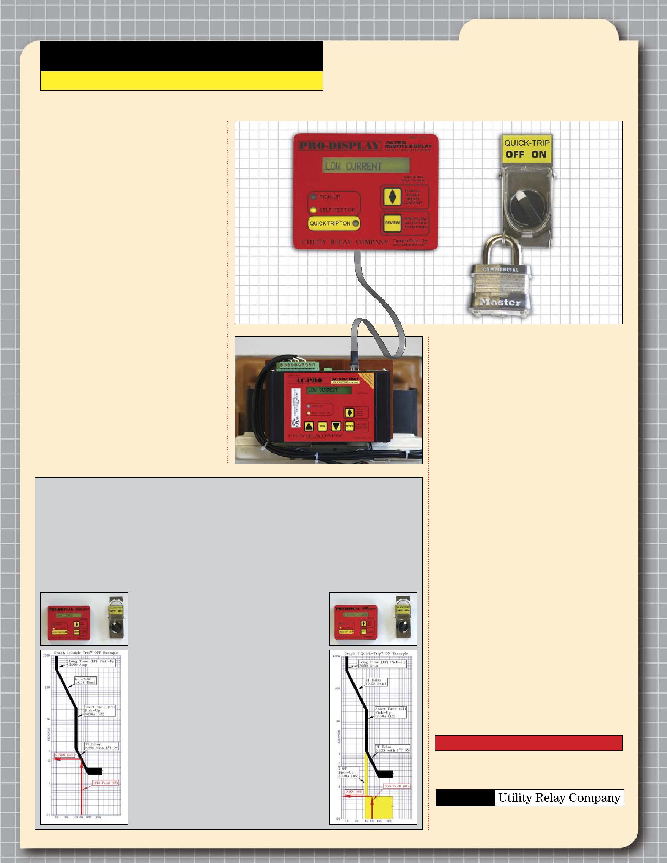
System Features
The QUICK-TRIP system is as easy to use as it is to install, with the additional personnel safety features:
❏ Installation uses standard punches.
❏ Wires in minutes without cutting into existing wiring harness.
❏ QT settings are only active when the selector switch is in the ON position (during maintenance).
❏ Reduction in arc flash incident energy levels may permit lower PPE clothing for maintenance personnel.
❏ Padlocking switch can be incorporated into a lock-out tag-out procedure.
❏ QUICK-TRIP ON LED confirms operation.
❏ SELF-TEST LED verifies trip unit operation.
❏ PICK-UP LED indicates overcurrent situations.
❏ QUICK-TRIP settings can be reviewed on the external PRO-DISPLAY.
❏ Last Trip Data and all settings can be reviewed on the PRO-DISPLAY.
❏ 3-phase currents are displayed continuously on the PRO-DISPLAY.
❏ The system is fully powered by the trip unit’s CTs. No aux power or batteries.
❏ Extra contacts on the selector switch are available for external annunciation.
WESTERN ELECTRICAL SERVICES, INC. (WES)
IS PROUD TO JOIN THE RANKS OF THE NETA ACCREDITED COMPANIES.
WES is truly a one-stop electrical solutions provider for the entire Western United States. We are dedicated to providing the highest quality services and solutions from Sumner, Washington, to our new corporate headquarters and newly expanded operations in Phoenix, Arizona, and coming soon field service operations in Salt Lake City, Utah. With NETA accreditation, WES is now poised to expand our satisfied customer base throughout the West.
Our service centers include a field service division for acceptance testing, outage maintenance, and 24-hour emergency recovery. The shop service division provides complete circuit breaker and
switchgear reconditioning, remanufacturing, and retrofitting. Our manufacturing service division provides custom CAD fabricating and machining capabilities, including flexible bus connectors, replacement contacts, and parts.
We are committed to a common sense, results oriented approach to our customer’s needs offered at fair and competitive prices. Our professional recommendations are supported by engineering data and industry standards to provide superior customer satisfaction and ensure successful and long-term relationships. At Western Electrical Services, Inc. we put our good name on the line for every valued customer.

NETA ACCREDITED COMPANIES
A&F Electrical Testing, Inc.
80 Lake Avenue South, Suite 10 Nesconset, NY 11767 (631) 584-5625 Fax: (631) 584-5720 kchilton@afelectricaltesting.com http://www.afelectricaltesting.com
Kevin Chilton
A&F Electrical Testing, Inc.
80 Broad St, 5th Floor New York, NY 10004 (631) 584-5625 Fax: (631) 584-5720 afelectricaltesting@afelectricaltesting.com http://www.afelectricaltesting.com
Florence Chilton
Advanced Testing Systems 15 Trowbridge Dr Bethel, CT 06801 (203) 743-2001 Fax: (203) 743-2325 pmaccarthy@advtest.com http://www.advtest.com
Pat MacCarthy
American Electrical Testing Co., Inc.
480 Neponset Street, Building 3 Canton, MA 02021-1970 (781) 821-0121 Fax: (781) 821-0771 sblizard@aetco.us http://www.99aetco.com
Scott A. Blizard
American Electrical Testing Co., Inc. 34 Clover Drive South Windsor, CT 06074 (860) 648-1013 Fax: (781) 821-0771 jpoulin@aetco.us http://www.99aetco.com
Gerald Poulin
American Electrical Testing Co., Inc. 76 Cain Drive Brentwood, NY 11717 (631) 630-2260 Fax: (631) 630-2292 mschacker@aetco.us http://www.99aetco.com
Michael Schacker
American Electrical Testing Co., Inc. 50 Intervale Road, Suite 1 Boonton, NJ 7005 (973) 316-1180 Fax: (781) 316-1181 trosato@aetco.us http://www.99aetco.com
Anthony Rosato
American Electrical Testing Co., Inc. 1811 Executive Drive, Suite M Indianapolis, IN 46241 (317) 487-2111 Fax: (781) 821-0771 rramsey@99aetco.us http://www.99aetco.com
Rick Ramsey
American Electrical Testing Co., Inc.
Green Hills Commerce Center 5925 Tilghman St. Suite 200 Allentown, PA 18104 (215) 219-6800 jmunley@aetco.us http://www.99aetco.us
Jonathan Munley
American Electrical Testing Co., Inc. 1672 SE 80th Bella Vista Dr. The Villages, FL 32162 (727) 447-4503 Fax: (727) 447-4984 rhoffman@aetco.us http://www.99aetco.com
Bob Hoffman
Apparatus Testing and Engineering
11300 Sanders Dr. Suite 29 Rancho Cordova, CA 95742 (916) 853-6280 Fax: (916) 853-6258 jlawler@apparatustesting.com http://www.apparatustesting.com
James Lawler
Apparatus Testing and Engineering 7083 Commerce Circle, Suite H Pleasanton, CA 94588 (925) 454-1363 Fax: (925) 454-1499 info@apparatustesting.com http://www.apparatustesting.com
Harold (Jerry) Carr
Applied Engineering Concepts 1105 N. Allen Ave Pasadena, CA 91104 (626) 398-3052 Fax: (626) 398-3053 michel.c@aec-us.com http://www.aec-us.com
Michel Castonguay
Burlington Electrical Testing Co., Inc.
300 Cedar Avenue Croydon, PA 19021-6051 (215) 826-9400 (221) Fax: (215) 826-0964 waltc@betest.com http://www.betest.com
Walter P. Cleary
C.E. Testing, Inc. 6148 Tim Crews Road Macclenny, FL 32063 (904) 653-1900 Fax: (904) 653-1911 cetesting@aol.com
Mark Chapman
CE Power Solutions of Wisconsin, LLC 3255 W. Highview Dr. Appleton, WI 54914 (920) 968-0281 Fax: (920) 968-0282 jimvh@cepowersol.com
James Van Handel
DYMAX Holdings, Inc.
4751 Mustang Circle St. Paul, MN 55112 (763) 717-3150 Fax: (763) 784-5397 gphilipp@dymaxservice.com http://www.dymaxservice.com
Gene Philipp
High Voltage Service, Inc.
4751 Mustang Circle St. Paul, MN 55112 (763) 717-3103 Fax: (763) 784-5397 http://www.hvserviceinc.com
Mike Mavetz
DYMAX Service Inc.
23426 Industrial Park Court Farmington Hills, MI 48335-2854 (248) 477-6066 Fax: (248) 477-6069 http://www.dymaxservice.com
Bruce Robinson
DYMAX Service Inc.
4213 Kropf Ave. Canton, OH 44706 (330) 484-6801 Fax: (740) 333-1271 http://www.dymaxservice.com
Gary Swank
Eastern High Voltage 11A South Gold Drive Robbinsville, NJ 08691-1606 (609) 890-8300 Fax: (609) 588-8090 http://www.easternhighvoltage.com
Joseph Wilson
ELECT, P.C.
7400-G Siemens Road, P.O. Box 2080 Wendell, NC 27591 (919) 365-9775 Fax: (919) 365-9789 btyndall@elect-pc.com http://www.elect-pc.com
Barry W. Tyndall
Electric Power Systems, Inc. 21 Millpark Court Maryland Heights, MO 63043-3536 (314) 890-9999 Fax: (314) 890-9998 cfr@eps-international.com http://www.eps-international.com
Steve Reed
Electric Power Systems, Inc. 557 E. Juanita Avenue, #4 Mesa, AZ 85204 (480) 633-1490 Fax: (480) 633-7092 http://www.eps-international.com
Louis G. Gilbert
Electric Power Systems, Inc. 4436 Parkway Commerce Blvd. Orlando, FL 32808 (407) 578-6424 Fax: 407-578-6408 http://www.eps-international.com
Doug Pacey
Electric Power Systems, Inc. 6753 E. 47th Avenue Drive, Unit D Denver, CO 80216 (720) 857-7273 Fax: 303-928-8020 http://www.eps-international.com
Thomas C. Reed
Electric Power Systems, Inc. 23823 Andrew Road Plainfield, IL 60585 (815) 577-9515 Fax: (815) 577-9516 http://www.eps-international.com
George Bratkiv
Electric Power Systems, Inc. 2601 Center Road, # 101 Hinckley, OH 44233 (330) 460-3706 Fax: (330) 460-3708 http://www.eps-international.com
Garth Paul
Electric Power Systems, Inc. 1129 East Hwy 30 Gonzalez, LA 70737 (225) 644-0150 Fax: (225) 644-6249 http://www.eps-international.com
C.J. Theriot
Electric Power Systems, Inc. 827 Union Street Salem, VA 24153 (540) 375-0084 Fax: (540) 375-0094 Virginia@EPS-International.com http://www.eps-international.com
Bruce Eppers
Electric Power Systems, Inc. 915 Holt Ave., Unit 9 Manchester, NH 3109 (603) 657-7371 Fax: 603-657-7370 http://www.eps-international.com
Cindy Taylor
Electric Power Systems, Inc. 146 Space Park Drive Nashville, TN 37211 (615) 834-0999 Fax: (615) 834-0129 http://www.eps-international.com
Larry Christodoulou
Electric Power Systems, Inc. 1090 Montour West Industrial Blvd. Coraopolis, PA 15108 (412) 276-4559 http://www.eps-international.com
Ed Nahm
Electric Power Systems, Inc. 6141 Connecticut Ave. Kansas City, MO 64120 (816) 241-9990 Fax: (816) 241-9992 http://www.eps-international.com
Joe Dillon
EPS Technology
29 N Plains Hwy, Suite 12 Wallingford, CT 6492 (203) 649-0145
http://www.eps-technology.com
Chris Myers
Electrical & Electronic Controls
6149 Hunter Road Ooltewah, TN 37363 (423) 344-7666 (23) Fax: (423) 344-4494 eecontrols@comcast.net
Michael Hughes
Electrical Energy Experts, Inc. W129N10818, Washington Dr. Germantown, WI 53022 (262) 255-5222 Fax: (262) 242-2360 bill@electricalenergyexperts.com http://www.electricalenergyexperts.com
William Styer
Electrical Equipment Upgrading, Inc. 21 Telfair Place Savannah, GA 31415 (912) 232-7402 Fax: (912) 233-4355 kmiller@eeu-inc.com http://www.eeu-inc.com
Kevin Miller
Electrical Maintenance & Testing Inc.
7301 N. Georgetown Road, Suite 212 Indianapolis, IN 46268 (317) 471-8600 Fax: (317) 471-8605 http://www.emtesting.com
Brian K. Borst
Electrical Reliability Services
1057 Doniphan Park Circle, Suite A El Paso, TX 79922 (915) 587-9440 Fax: (915) 587-9010 http://www.electricalreliability.com
Electrical Reliability Services 1775 W. University Drive, Ste. 128 Tempe, AZ 85281 (480) 966-4568 Fax: (480) 966-4569 http://www.electricalreliability.com
Electrical Reliability Services 1455 East Sam Houston Parkway S. Suite 190 Pasadena, TX 77503 (281) 241-2800 Fax: (281) 241-2801 http://www.electricalreliability.com
Electrical Reliability Services
4099 SE International Way Ste. 201 Milwaukie, OR 97222-8853 (503) 653-6781 Fax: (503) 659-9733 http://www.electricalreliability.com
NETA ACCREDITED COMPANIES
Electrical Reliability Services
5810 Van Allen Way Carlsbad, CA 92008 (760) 804-2972
http://www.electricalreliability.com
Electrical Reliability Services 8336 Washington Place NE Albuquerque, NM 87113-1666 (505) 822-0237 Fax: (505) 822-0217
http://www.electricalreliability.com
Electrical Reliability Services
1380 Greg Street, Suite 217 Sparks, NV 89431 (775) 746-8484 Fax: (775) 356-5488
http://www.electricalreliability.com
Electrical Reliability Services
5555 Oakbrook Pkwy., Ste. 180 Norcross, GA 30093 (770) 729-9744 Fax: (614) 410 0919
http://www.electricalreliability.com
Electrical Reliability Services
7100 Broadway, Suite 7E Denver, CO 80221-2915 (303) 427-8809 Fax: (303) 427-4080 http://www.electricalreliability.com
Electrical Reliability Services
348 N.W. Capital Drive Lees Summit, MO 64086 (816) 525-7156 Fax: (816) 524-3274 http://www.electricalreliability.com
Electrical Reliability Services
6900 Koll Center Parkway, Suite 415 Pleasanton, CA 94566 (925) 485-3400 Fax: (925) 485-3436 http://www.electricalreliability.com
Electrical Reliability Services
10606 Bloomfield Ave. Santa Fe Springs, CA 90670 (562) 236-9555 Fax: (562) 777-8914 http://www.electricalreliability.com
Electrical Reliability Services
14141 Airline Hwy, Bldg. 1, Ste. X Baton Rouge, LA 70817 (225) 755-0530 Fax: (225) 751-5055 http://www.electricalreliability.com
Electrical Reliability Services
121 E. HWY 108 Sulphur, LA 70665 (337) 583-2411 Fax: (337) 583-2410 http://www.electricalreliability.com
Electrical Reliability Services
5580 Enterprice Parkway Ft. Myers, FL 33905-5507 (239) 693-7100 Fax: (239) 693-7772 http://www.electricalreliability.com
Electrical Reliability Services
2222 West Valley Hwy. N., Suite 160 Auburn, WA 98001 (253) 736-6010 Fax: (253) 736-6015 http://www.electricalreliability.com
Electrical Reliability Services
3412 South 1400 West, Unit A West Valley City, UT 84119 (801) 975-6461 http://www.electricalreliability.com
Electrical Reliability Services 6351 Hinson Street, Suite B Las Vegas, NV 89118 (702) 597-0020 Fax: (702) 597-0095 http://www.electricalreliability.com
Electrical Reliability Services 610 Executive Campus Drive Westerville, OH 43082 (877) 468-6384 Fax: (614) 410-8420 info@electricalreliability.com http://www.electricalreliability.com
Elemco Services, Inc. 228 Merrick Road Lynbrook, NY 11563 (631) 589-6343 Fax: (631) 589-6670 BobW@elemco.com http://www.elemco.com
Robert J. White
Hampton Tedder Technical Services 4571 State Street Montclair, CA 91763 (909) 628-1256 x214 Fax: (909) 628-6375 matt.tedder@hamptontedder.com http://www.hamptontedder.com
Matt Tedder
Hampton Tedder Technical Services 4920 Alto Ave. Las Vegas, NV 89115 (702) 452-9200 Fax: (702) 453-5412 http://www.hamptontedder.com
Roger Cates
Hampton Tedder Technical Services 3747 West Roanoke Ave. Phoenix, AZ 85009 (480) 967-7765 Fax: (480) 967-7762 http://www.hamptontedder.com
Harford Electrical Testing Co., Inc. 1108 Clayton Road Joppa, MD 21085 (410) 679-4477 Fax: (410) 679-0800 harfordtesting@aol.com Vincent Biondino
High Energy Electrical Testing, Inc. 2119 Orien Rd. Toms River, NJ 08755-1366 (732) 286-4088 Fax: (732) 286-4086 hinrg@comcast.net http://www.highenergyelectric.com James P. Ratshin
High Voltage Maintenance Corp. 24 Walpole Park South Dr. Walpole, MA 02081 (508) 668-9205 http://www.hvmcorp.com
High Voltage Maintenance Corp. 7200 Industrial Park Blvd. Mentor, OH 44060 (440) 951-2706 Fax: (440) 951-6798 http://www.hvmcorp.com
High Voltage Maintenance Corp. 3000 S. Calhoun Road New Berlin, WI 53151 (262) 784-3660 Fax: (262) 784-5124 http://www.hvmcorp.com
High Voltage Maintenance Corp. 8320 Brookville Rd. #E Indianapolis, IN 46239 (317) 322-2055 Fax: (317) 322-2056 http://www.hvmcorp.com
High Voltage Maintenance Corp. 1250 Broadway, Suite 2300 New York, NY 10001 (718) 239-0359 http://www.hvmcorp.com
High Voltage Maintenance Corp. 355 Vista Park Dr. Pittsburgh, PA 15205-1206 (412) 747-0550 Fax: (412) 747-0554 http://www.hvmcorp.com
High Voltage Maintenance Corp. 150 North Plains Industrial Rd. Wallingford, CT 6492 (203) 949-2650 Fax: (203) 949-2646 http://www.hvmcorp.com
High Voltage Maintenance Corp. 9305 Gerwig Lane, Suite B Columbia, MD 21046 (410) 309-5970 Fax: (410) 309-0220 http://www.hvmcorp.com
High Voltage Maintenance Corp. 1455 Jamike Drive, Suite 5 Erlanger, KY 41018 (859) 371-5355 Fax: (859) 371-5399 http://www.hvmcorp.com
NETA ACCREDITED COMPANIES
High Voltage Maintenance Corp.
24371 Catherine Industrial Drive Suite 207 Novi, MI 48375 (248) 305-5596 Fax: (248) 305-5579 http://www.hvmcorp.com
High Voltage Maintenance Corp.
5100 Energy Drive Dayton, OH 45414 (937) 278-0811 Fax: (937) 278-7791 http://www.hvmcorp.com
HMT, Inc.
6268 Route 31, Cicero, NY 13039 (315) 699-5563 Fax: (315) 699-5911 jpertgen@hmt-electric.com http://www.hmt-electric.com John Pertgen
Industrial Electric Testing, Inc. 11321 West Distribution Ave. Jacksonville, FL 32256 (904) 260-8378 Fax: (904) 260-0737 gbenzenberg@bellsouth.net http://www.industrialelectrictesting.com Gary Benzenberg
Industrial Electric Testing, Inc.
201 NW 1st Ave. Hallandale, FL 33009-4029 (954) 456-7020 http://www.industrialelectrictesting.com
Industrial Electronics Group P.O. Box 1870 850369 Highway 17 South Yulee, FL 32041 (904) 225-9529 Fax: (904) 225-0834 butch@industrialgroups.com http://www.industrialgroups.com
Butch E. Teal
Industrial Tests, Inc. 4021 Alvis Ct., Suite 1 Rocklin, CA 95677 (916) 296-1200 Fax: (916) 632-0300 greg@indtests.com http://www.industrialtests.com Greg Poole
Infra-Red Building and Power Service 152 Centre St. Holbrook, MA 02343-1011 (781) 767-0888 Fax: (781) 767-3462 tom.mcdonald@infraredbps.net http://www.infraredbps.com
Thomas McDonald Sr.
M&L Power Systems, Inc. 109 White Oak Ln., Ste 82 Old Bridge, NJ 8857 (732) 679-1800 Fax: (732) 679-9326 dan@mlpower.com http://www.mlpower.com
Darshan Arora
Magna Electric Corporation 2361 Industrial Drive, Box 995 Regina, SK S4P 3B2
Canada (306) 949-8131 Fax: (306) 522-9181 kheid@magnaelectric.com http://www.magnaelectric.com
Kerry Heid
Magna Electric Corporation 3430 25th Street NE Calgary, AB T1Y 6C1
Canada (403) 769-9300 Fax: (403)769-9369 ppetrie@magnaelectric.com http://www.magnaelectric.com
Pat Petrie
Magna Electric Corporation 851-58th Street East Saskatoon, SK S7K 6X5
Canada (306) 955-8131 x 5 Fax: (306) 955-9181 http://www.magnaelectric.com
Luis Wilson
Magna Electric Corporation 1683 Church Ave. Winnipeg, MB R2X2Y7 Canada (204) 925-4022 Fax: (204) 925-4021 cbrandt@magnaelectric.com http://www.magnaelectric.com
Curtis Brandt
Magna IV Engineering 4103 - 97th Street N.W. Edmonton, AB T6E 6E9 Canada (780) 462-3111 Fax: (780) 462-9799 jwentzell@magnaiv.com http://www.magnaiv.com
Jereme Wentzell
Magna IV Engineering Unit 10, 10672- 46 St S.E. Calgary, AB T2C 1G1 Canada (403) 723-0575 Fax: (403) 723-0580 info.calgary@magnaiv.com
Jereme Wentzell
Magna IV Engineering 8219D Fraser Ave. Fort McMurray, AB T9H 0A2 Canada (780) 791-3122 Fax: (780) 791-3159 info.fmcmurray@magnaiv.com
Jereme Wentzell
Magna IV Engineering
96 Inverness Drive East, Unit R Englewood, CO 80112 (303) 799-1273 Fax: (303) 790-4816 info.denver@magnaiv.com
Jereme Wentzell
Magna IV Engineering
Oficina 1407 Torre Norte 481 Nueva Tajamar Las Condes, Region Metropolitana 7550099
Chile +(56) 9-9-517-4642 info.chile@magnaiv.com
Jereme Wentzell
Magna IV Engineering 1040 Winnipeg St. Regina , SK S4R 1J5 Canada (306) 504-6501 Fax: (306) 729-4897 info.regina@magnaiv.com
Jereme Wentzell
Magna IV Engineering (BC) Ltd. #110, 2071 Kingsway Ave. Port Coquitlam, BC V3C 1T2 Canada (604) 944-6697 Fax: (604) 944-1271 chite@magnaiv.ca http://www.magnaiv.ca
Cameron Hite
MET Electrical Testing LLC
3602 East Southern Ave., Suite 1 & 2 Phoenix, AZ 85040 (602) 796-6583 Fax: http://www.met-test.com
Mike Ferguson
MET Electrical Testing LLC
6280 South Valley View Boulevard, Suite 618
Las Vegas, NV 89118 (702) 216-0982 Fax: (702) 216-0983 http://www.met-test.com
Terry Travelstead
MET Electrical Testing LLC 814 Greenbrier Circle, Ste. E Chesapeake, VA 23320 (757) 548-5690 Fax: (757) 548-5417 http://www.met-test.com
Mark Anthony Gaughan, III
MET Electrical Testing LLC
3700 Commerce Drive #901-903 Baltimore, MD 21227 (410) 247-3300 Fax: (410) 247-0900 http://www.met-test.com
Bill Hartman
MET Electrical Testing LLC
710 Thomson Park Drive Cranberry Township, PA 16066-6427 (724) 772-4638 Fax: (724) 772-6003 william.mckenzie@met.lincfs.com http://www.met-test.com
William (Pete) McKenzie
Carolina Electrical Testing Co. 5805 G Departure Drive Raleigh, NC 27616 (919) 877-1008 Fax: (919) 501-7492
http://www.met-test.com
Mark Robinson
Substation Test Co.
4390 Parliament Place, Suite Q Lanham, MD 20706 (301) 967-3500 Fax: (301) 735-8953 http://www.met-test.com
Frank Ceci
National Field Services
649 Franklin Street Lewisville, TX 75057 (972) 420-0157 http://www.natlfield.com
Eric Beckman
Nationwide Electrical Testing, Inc. 6050 Southard Trace Cumming, GA 30040 (770) 667-1875 Fax: (770) 667-6578
Shashi@N-E-T-Inc.com http://www.n-e-t-inc.com
Shashikant B. Bagle
North Central Electric, Inc. 69 Midway Avenue Hulmeville, PA 19047-5827 (215) 945-7632 Fax: (215) 945-6362 ncetest@aol.com
Robert Messina
Northern Electrical Testing, Inc. 1991 Woodslee Dr. Troy, MI 48083-2236 (248) 689-8980 Fax: (248) 689-3418 ldetterman@northerntesting.com http://www.northerntesting.com
Lyle Detterman
Orbis Engineering Field Services Ltd. #300, 9404 - 41st Ave. Edmonton, AB T6E 6G8 Canada (780) 988-1455 Fax: (780) 988-0191 lorne@orbisengineering.net http://www.orbisengineering.net
Lorne Gara
Pacific Power Testing, Inc. 14280 Doolittle Drive San Leandro, CA 94577 (510) 351-8811 Fax: (510) 351-6655
steve@pacificpowertesting.com http://www.pacificpowertesting.com
Steve Emmert
Phasor Engineering
Sabaneta Industrial Park #216 Mercedita, PR 715 Puerto Rico (787) 844-9366 Fax: (787) 841-6385 rcastro@phasorinc.com
Rafael Castro
Potomac Testing, Inc.
1610 Professional Blvd., Suite A Crofton, MD 21114 (301) 352-1930 Fax: (301) 352-1936 kbassett@potomactesting.com http://www.potomactesting.com
Ken Bassett
Potomac Testing, Inc.
704 Main St., Suite 104 Windber, PA 15963 (814) 509-6156 Fax: (301) 352-1930 pti@potomactesting.com http://www.potomactesting.com
Potomac Testing, Inc.
11179 Hopson Road, Suite 5 Ashland, VA 23005 (804) 798-7334 Fax: (804) 798-7456 http://www.potomactesting.com
Power & Generation Testing, Inc.
480 Cave Road Nashville, TN 37210 (615) 882-9455 Fax: (615) 882-9591 mose@pgti.net http://www.pgti.net
Mose Ramieh
Power Engineering Services, Inc.
9179 Shadow Creek Lane Converse, TX 78109 (210) 590-4936 Fax: (210) 590-6214 engelke@pe-svcs.com http://www.pe-svcs.com
Miles R. Engelke
POWER PLUS Engineering, Inc. 46575 Magallan Drive Novi, MI 48377 (248) 344-0200 Fax: (248) 305-9105 smancuso@epowerplus.com http://www.epowerplus.com
Salvatore Mancuso
Power Products & Solutions, Inc. 12465 Grey Commercial Road Midland, NC 28107 (704) 573-0420 x12 Fax: (704) 573-3693 ralph.patterson@powerproducts.biz http://www.powerproducts.biz
Ralph Patterson
NETA ACCREDITED COMPANIES
Power Products & Solutions, Inc. 13 Jenkins Court Mauldin, SC 29662 Fax: (800) 328-7382 ralph.patterson@powerproducts.biz http://www.powerproducts.biz
Raymond Pesaturo
Power Services, LLC
P.O. Box 750066, 998 Dimco Way Centerville, OH 45475 (937) 439-9660 Fax: (937) 439-9611 jbydash@att.net
Gerald Bydash
Power Systems Testing Co. 4688 W. Jennifer Ave. Ste. 108 Fresno, CA 93722 (559) 275-2171 ext 15 Fax: (559) 275-6556 dave@pstcpower.com http://www.powersystemstesting.com
David Huffman
Power Systems Testing Co.
600 S Grand Ave Ste 113 Santa Ana, CA 92705-4152 (714) 542-6089 Fax: (714) 542-0737 http://www.powersystemstesting.com
Power Systems Testing Co. 2267 Claremont Ct. Hayward, CA 94545-5001 (510) 783-5096 Fax: (510) 732-9287 http://www.powersystemstesting.com
Power Test, Inc. 2200 Highway 49 Harrisburg, NC 28075 (704) 200-8311 Fax: (704) 455-7909 rich@powertestinc.com http://www.powertestinc.com
Richard Walker
POWER Testing and Energization, Inc. 14006 NW 3rd Court, Suite 101 Vancouver, WA 98685 (360) 576-4826 Fax: (360) 576-7182 chris.zavadlov@powerte.com http://www.powerte.com
Chris Zavadlov
POWER Testing and Energization, Inc.
731 E. Ball Road, Suite 100 Anaheim, CA 92805 (714) 507-2702 http://www.powerte.com
POWER Testing and Energization, Inc. 22035 70th Ave. South Kent, WA 98032 (253) 872-7747 http://www.powerte.com
Powertech Services, Inc. 4095 South Dye Road Swartz Creek, MI 48473-1570 (810) 720-2280 Fax: (810) 720-2283 jbrown@powertechservices.com http://www.powertechservices.com
Jean A. Brown
Precision Testing Group 18590 Wedemeyer Rd. Kiowa, CO 80117 (303) 621-2776 Fax: (303) 621-2573 glenn@precisiontestinggroup.com
Glenn Stuckey
PRIT Service, Inc. 112 Industrial Drive, P.O. Box 606 Minooka, IL 60447 (815) 467-5577 Fax: (815) 467-5883 Rod.Hageman@pritserviceinc.com http://www.pritserviceinc.com
Rod Hageman
Reuter & Hanney, Inc. 149 Railroad Dr. Northampton Industrial Park Ivyland, PA 18974 (215) 364-5333 Fax: (215) 364-5365 mikereuter@reuterhanney.com http://www.reuterhanney.com
Michael Reuter
Reuter & Hanney, Inc. 4270-I Henninger Court Chantilly, VA 20151 (703) 263-7163 Fax: 703-263-1478 http://www.reuterhanney.com
Reuter & Hanney, Inc. 1371 Brass Mill Rd., Unit E Belcamp, MD 21017 (410) 297-9566 Fax: (410) 297-9984 http://www.reuterhanney.com
Michael Jester
REV Engineering, LTD 3236 - 50 Avenue SE Calgary, AB T2B 3A3 Canada (403) 287-0156 Fax: (403) 287-0198 rdavidson@reveng.ca http://www.magnaivengineering.com
Roland Nicholas Davidson, IV
Scott Testing Inc. 1698 5th Street Ewing, NJ 8638 (609) 882-2400 Fax: (609) 882-5660 rsorbello@scotttesting.com http://www.scotttesting.com Russ Sorbello
Shermco Industries 2425 E. Pioneer Drive Irving, TX 75061 (972) 793-5523 Fax: (972) 793-5542 rwidup@shermco.com http://www.shermco.com
Ron Widup
Shermco Industries 1705 Hur Industrial Blvd. Cedar Park, TX 78613 (512) 259-3060 Fax: (512) 258-5571 kewing@shermco.com http://www.shermco.com
Kevin Ewing
Coastal Switchgear & Controls A Shermco Industries Company 33002 FM 2004 Angleton, TX 77515 (979) 848-1406 Fax: (979) 848-0012 mfrederick@shermco.com http://www.shermco.com
Malcom Frederick
Shermco Industries 1357 N 108th E. Ave. Tulsa, OK 74116 (918) 234-2300
jharrison@shermco.com
http://www.shermco.com
Jim Harrison
Shermco Industries 777 10th Street Marion, IA 52302 (319) 377-3377 Fax: (319) 377-3399
Lhamrick@shermco.com http://www.shermco.com
Lynn Hamrick
Shermco Industries 2100 Dixon St., Suite C Des Moines, IA 50316 Fax: (515) 263-8482 sales@theescogroup.com http://www.escoenergyservice.com
Lynn Hamrick
Shermco Industries Boulevard Saint-Michel 47 1040 Brussels Brussels, Belgium
+32 (0)2 400 00 54 Fax: +32 (0)2 400 00 32 cperry@shermco.com
http://www.shermco.com
Chris Perry
Sigma Six Solutions, Inc. 2200 West Valley Highway, Suite 100 Auburn, WA 98001 (253) 333-9730 Fax: (253) 859-5382
jwhite@sigmasixinc.com
http://www.sigmasixinc.com
John White
NETA ACCREDITED COMPANIES Setting
Sigma Six Solutions, Inc. 1004 Wurzbach Road, #226 San Antonio, TX 78230
info@sigmasixinc.com http://www.sigmasixinc.com
Southern New England Electrical Testing, LLC
3 Buel St., Unit 2 Wallingford, CT 6492 (203) 269-8778 Fax: (203) 269-8775 dave.asplund@sneet.org http://www.sneet.org
David Asplund, Sr.
Southwest Energy Systems, LLC
2231 East Jones Avenue, Suite A Phoenix, AZ 85040 (602) 438-7500 Fax: (602) 438-7501 bob.sheppard@southwestenergysystems.com http://www.southwestenergysystems.com
Robert Sheppard
Taurus Power & Controls, Inc. 9999 SW Avery Street Tualatin, OR 97062-9517 (503) 692-9004 Fax: (503) 692-9273 robtaurus@tauruspower.com http://www.tauruspower.com
Rob Bulfinch
Taurus Power & Controls, Inc. 6617 S. 193rd Place , Suite P104 Kent, WA 98032 (425) 656-4170 Fax: (425) 656-4172
jiml@tauruspower.com http://www.taruspower.com
Jim Lightner
Three-C Electrical Co., Inc.
190 Pleasant Street Ashland, MA 1721 (508) 881-3911 Fax: (508) 881-4814
jim@three-c.com http://www.three-c.com
Jim Cialdea
Three-C Electrical Co., Inc.
79 Leighton Road, Suite 9 Augusta, ME 4330 (800) 649-6314 Fax: (207) 782-0162
jim@three-c.com
http://www.three-c.com
Jim Cialdea
Tidal Power Services, LLC 4202 Chance Lane Rosharon, TX 77583 (281) 710-9150 Fax: (713) 583-1216
monty.janak@tidalpowerservices.com http://www.tidalpowerservices.com
Monty C. Janak
Tony Demaria Electric, Inc. 131 West F Street Wilmington, CA 90744 (310) 816-3130 x 111 Fax: (310) 549-9747 tde@tdeinc.com http://www.tdeinc.com
Anthony Demaria
Trace Electrical Services & Testing, LLC
293 Whitehead Road Hamilton, NJ 8619 (609) 588-8666 Fax: (609) 588-8667 jvasta@tracetesting.com http://www.tracetesting.com
Joseph Vasta
Utilities Instrumentation Service, Inc. PO Box 981123 Ypsilanti, MI 48198-1123 (734) 482-1450 (14) Fax: (734) 482-0035
GEWalls@UISCorp.com http://www.uiscorp.com
Gary E. Walls
Utility Service Corporation 4614 Commercial Dr. NW Huntsville, AL 35816-2201 (256) 837-8400 Fax: (256) 837-8403
apeterson@utilserv.com http://www.utilserv.com
Alan D. Peterson
Western Electrical Services 14311 29th Street East Sumner , WA 98390 (253) 891-1995 Fax: (253) 891-1511
dhook@westernelectricalservices.com http://www.westernelectricalservices.com
Daniel Hook

This issue’s advertisers are identified below. Please thank these advertises by telling them you saw their advertisement in YOUR magazine –NETA World.


INDEPENDENT NETA ACCREDITED COMPANIES
National Field Service.
Potomac Testing, Inc.
PRIT Service, Inc.
Scott Testing, Inc.
Shermco Industries, Inc.

Relion ® . The perfect choice for every application.
ABB’s Relion ® family covers the widest range of products for the protection, control, measurement and supervision of power systems for any transmission and distribution application, ensuring security and reliability regardless of the operating environment. The comprehensive portfolio offers both ready-to-use solutions and customization possibilities and is entirely based on the IEC 61850 standard. A common tool from application and communication configuration to disturbance record handling ensures engineering efficiency. Backed by ABB technology, global application knowledge and an experienced support network – with Relion you have a complete product family you can rely on. www.abb.com/relion

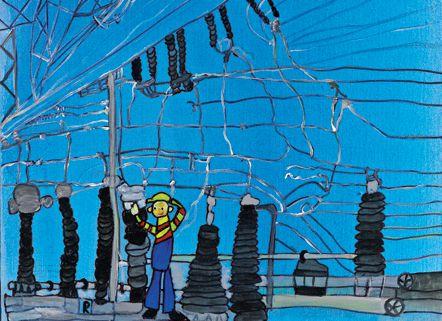


The Colorful World of Power System Testing
The refreshingly different pictures of OMICRON’s advertising campaignĐ.
The scenes show blue, red, and yellow transformers, orange cable drums, dark blue substations, and other fixtures from the field of power supply in colorful artistry. Familiar images – in multicolored scenes.
The refreshingly different pictures have appeared in OMICRON advertisements in magazines, professional journals, and on the internet throughout the world since 2008. They were painted by artists from the Austrian region of Vorarlberg who work in the ARTelier “Brockenhaus,”
a painting workshop that is part of the Lebenshilfe Vorarlberg organization.
Creativity, passion, innovative spirit, but also the courage to tread an unorthodox path – it was clear that these multicolored pictures reflected the central values of OMICRON’s own corporate philosophy. It was at an exhibition opening that the members of the OMICRON Marketing Communications team had the idea to ask the artists to paint the world of OMICRON testing solutions – from their very own perspective.
OMICRON placed an order with the ARTerlier Brockenhaus, which was the beginning of an equally unusual and successful cooperation for both parties. Since this unique partnership began almost three years ago, more than forty advertising motifs have been created - each as individual and distinctive as the artist who painted them.
A thank you is in order to our friends at the ARTelier Brockenhaus, who managed to render the already colorful world of OMICRON even more brightly colored.
