



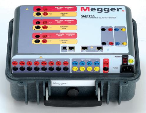
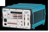
The SMRT36 is the smallest, lightest, highest output powered, complete 3-phase protective relay test system in the world today. This rugged test system may be customized by adding the voltage current generator modules needed for specific test applications. Manual operation is simple through the use of the Smart Touch View Interface (STVI), with a large color high resolution TFT LCD touch-screen.
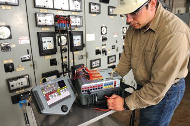
n Rugged, small and lightweight
n High current, high power (60 Amps/300 VArms) per phase
n Up to 6 currents with convertible channels
n Thermally controlled fans for quiet operation
n New Smart Touch View Interface (STVI) provides manual control
n New STVI Overcurrent Test includes hundreds of relay specific time-curves built-in
With these comprehensive capabilities and extensive testing options the SMRT36 is conceivably the easiest to use 3-phase protective relay test system available today.
For more information on the SMRT36 relay test set contact us today at 1-800-723-2861 or email us at sales@megger.com to receive a SMRT36 brochure and 2011 Megger Power Catalog.
Megger 4271 Bronze Way Dallas, Texas 75237-1019 USA.

a realistic goal.
Techniques for reducing exposure of your personnel to high arc-energy levels fall into three categories:
• Reducing the available arc-energy by designing/redesigning your power system
• Reducing personnel exposure by designing/ redesigning your power system
• Reducing personnel exposure by modifying – and enforcing – working procedures
PRESIDENT’S DESK
PE Sigma Six Solutions President
EVOLUTION OF NETA and Kristen Wicks, NETA
ARC-FLASH
PROTECTION SYSTEM Clapper, GE Specification Engineer
COMTRADE RECORDS
TEST PROTECTIVE RELAYS Turner, Beckwith Electric Co., Inc.
ARC-FLASH HAZARD MITIGATION THROUGH RELAYING Electric Co.
MITIGATION
THREE-STEP APPROACH Cochran, I-Gard
Jim
Electrical Testing for Airports
Lynn Hamrick, Shermco Industries
CORNER
Condition Assessment
Don A. Genutis, No-Outage Electrical Testing, Inc. 22 TECH QUIZ
Arc-Flash Mitigation
Jim White, Shermco Industries
90 SAFETY CORNER
Hazards of Establishing an Electrically Safe Work Condition
Tony Demaria & Dean Naylor, Tony Demaria
Electric, Inc., Mose Ramieh, III, Power & Generation Testing, Inc.
TECHNICAL BRIEF
Arc-Resistant Switchgear Tested to ANSI C37.20.7 and NFPA 70E
Jim Bowen 100 TECH TIPS
Specialized Testing for Line Towers
Jeff Jowett, Megger
SPECIFICATONS & STANDARDS ACTIVITY
ASTM F18 Committee Report
Jim White, Shermco Industries
Insulated Conductor Committee News
Ralph Patterson, Power Products & Solutions ANSI/NETA Standards Update
Jim White and Ron Widup, Shermco Industries
NOMOGRAM FOR INTERPRETATION OF LTC DGA DATA
Fredi Jakob & Karl Jakob, WEIDMANN Diagnostic Solutions, Inc, James Dukarm, Delta-X Research, Inc.


From big city to small town, east to west, North America to Europe, we are expanding our resources and service center locations to better serve you.
Contact Shermco Industries for safe, reliable testing, repair, professional training, maintenance and analysis of rotating apparatus or electrical power distribution systems for all market segments, including industrial, commercial, petrochemical, utilities and more.
3050 Old Centre Avenue, Suite 102
Portage, MI 49024
Toll free: 888.300 NETA (6382)
Phone: 269.488.NETA (6382)
Fax: 269.488.6383 neta@netaworld.org www.netaworld.org

executive DiRectOR: Jayne Tanz, CMP
NETA Officers
pResiDent: John White, Sigma Six Solutions
fiRst vice pResiDent: Mose Ramieh, Power & Generation Testing, Inc.
secOnD vice pResiDent: David Huffman, Power Systems Testing
secRetaRy: Walt Cleary, Burlington Electrical Testing Co., Inc.
tReasuReR: Ken Bassett, Potomac Testing, Inc.
NETA Board of Directors
Ken Bassett (Potomac Testing, Inc.)
Scott Blizard (American Electrical Testing Co., Inc.)
Walt Cleary (Burlington Electrical Testing Co., Inc.)
Roderic Hageman (PRIT Service, Inc.)
Kerry Heid (Magna Electric Corporation)
David Huffman (Power Systems Testing)
Ralph Patterson (Power Products & Solutions, Inc.)
Alan Peterson (Utility Service Corporation)
Mose Ramieh (Power & Generation Testing, Inc.)
John White (Sigma Six Solutions)
Ron Widup (Shermco Industries)
NETA World Staff
technicaL eDitOR: Roderic L. Hageman
assOciate eDitOR: Diane W. Hageman
managing eDitOR: Jayne Tanz, CMP
aDveRtising manageR: Jill Howell
Design anD pRODuctiOn: Newhall Klein, Inc.
NETA Committee Chairs
cOnfeRence: Ron Widup; membeRship: Ken Bassett; pROmOtiOns/maRketing: Kerry Heid; safety: Tony Demaria; technicaL: Alan Peterson; technicaL exam: Ron Widup; WORLD aDvisORy: Diane Hageman; cOntinuing technicaL DeveLOpment: David Huffman;
tRaining: Kerry Heid; finance: John White; nOminatiOns: Alan Peterson; stRategy: Mose Ramieh
© Copyright 2011, NETA
NETA World is published quarterly by the InterNational Electrical Testing Association. Opinions, views and conclusions expressed in articles herein are those of the authors and not necessarily those of NETA. Publication herein does not constitute or imply endorsement of any opinion, product, or service by NETA, its directors, officers, members, employees or agents (herein “NETA”).
All technical data in this publication reflects the experience of individuals using specific tools, products, equipment and components under specific conditions and circumstances which may or may not be fully reported and over which NETA has neither exercised nor reserved control. Such data has not been independently tested or otherwise verified by NETA.
NETA MAKES NO ENDORSEMENT, REPRESENTATION OR WARRANTY AS TO ANY OPINION, PRODUCT OR SERVICE REFERENCED OR ADVERTISED IN THIS PUBLICATION NETA EXPRESSLY DISCLAIMS ANY AND ALL LIABILITY TO ANY CONSUMER, PURCHASER OR ANY OTHER PERSON USING ANY PRODUCT OR SERVICE REFERENCED OR ADVERTISED HEREIN FOR ANY INJURIES OR DAMAGES OF ANY KIND WHATSOEVER, INCLUDING, BUT NOT LIMITED TO ANY CONSEQUENTIAL PUNITIVE SPECIAL INCIDENTAL DIRECT OR INDIRECT DAMAGES NETA FURTHER DISCLAIMS ANY AND ALL WARRANTIES, EXPRESS OF IMPLIED, INCLUDING, BUT NOT LIMITED TO, ANY IMPLIED WARRANTY OF FITNESS FOR A PARTICULAR PURPOSE
ELECTRICAL TESTING SHALL BE PERFORMED ONLY BY TRAINED ELECTRICAL PERSONNEL AND SHALL BE SUPERVISED BY NETA CERTIFIED TECHNICIANS/ LEVEL III OR IV OR BY NICET CERTIFIED TECHNICIANS IN ELECTRICAL TESTING TECHNOLOGY/LEVEL III OR IV. FAILURE TO ADHERE TO ADEQUATE TRAINING, SAFETY REQUIREMENTS, AND APPLICABLE PROCEDURES MAY RESULT IN LOSS OF PRODUCTION CATASTROPHIC EQUIPMENT FAILURE SERIOUS INJURY OR DEATH
We are the InterNational Electrical Testing Association, formerly known as the National Electrical Testing Association and always referred to as NETA for short. Have you ever introduced NETA to someone unaware of our organization and found yourself explaining why the letters N-E-T-A don’t exactly match the abbreviation of the name? I certainly have. I guess the need to explain comes from the desire to be exactly correct, something that exists in a lot of technical people.
If you’ve been around the NETA community for a long that the name was changed from “National” to “International” outside the US boundaries joined the organization. That change technically correct. But then to help understand why the acronym the abbreviation, the full name was written as InterNational Association, cleverly capitalizing a letter in the middle of making a connection back to the acronym.
NETA has become very well known in North America. And transition period where people don’t even wonder if NETA longer name. We no longer care that 3M or IBM once had And how many people still remember that the word “laser” Amplification by Stimulated Emission of Radiation?” The is becoming one and the same as the full name.
Our strong name recognition and logo equity are part of Marketing Committee will leverage as they work on a initiative for our organization. This initiative will help the industry understand how the highest level of reliability and in electrical systems can be achieved through the use of our Accredited Companies who test to our ANSI accredited standards.
So be on the lookout for a new, modern image of organization. We’re embarking on the journey that takes NETA to the next level, and it’s all about electrical reliability and safety.
John White, P.E. Sigma Six Solutions NETA President


 By Jill Howell & Kristen w icks, neta
“The
great thing in the world is not so much where we stand, as in what direction we are moving.”
If you met NETA as a person on the street, what would you learn about him? You would learn that NETA is business-minded, qualitydriven, customer-service oriented, philanthropic, entrepreneurial, the life of the party, and loyal. That’s nothing new; NETA has always embodied these admirable traits. The great thing about aging and evolution is that though the outward appearance might change, the characteristics and personality of an individual only get more clearly defined over the course of time. NETA has matured quite a bit since its inception, and the Board of Directors determined it was time
Oliver Wendell Holmes
to refine the look and feel of NETA’s visual presence so that the outstanding qualities of the organization are positioned to take the next step in the evolutionary process.
NETA, the organization, was born thirty-nine years ago as a collaboration of like-minded individuals who believed that the world needed a set of standards to govern the business of electrical testing. These individuals, NETA’s Charter Members, spent a great deal of time and energy defining what the ideal electrical testing company should look like, how it should operate, and what services should be offered.
“NETA Quality” and “Setting the Standard” became the catch phrases of the organization. While the faces of those still carrying the NETA standard forward have changed over the past few decades, these core principles remain the same.
NETA’s branding was in its infancy in the 1970’s. Without the benefit of a large budget, NETA relied heavily on grassroots efforts rather than traditional marketing to promote the association. Word of mouth, social networking,
and relationships with clients were the means responsible for getting the organization off the ground and turning it into a thriving community. NETA’s tenant that electrical testing should be performed by third-party, independent electrical testing firms with certified, field-experienced technicians shook up the old way of thinking about electrical testing, but the philosophy quickly gained a large following of supporters, satisfied clients, and testing firms interested in membership in this elite organization.
NETA’s earliest logo has remained the core logo of the organization for the past thirtynine years, with slight variations depending on its use. The slanted block-lettering of the acronym “NETA” stands strongly against a stylized oscilloscope background, graphically representing the forward motion of the association and the circular unity of those focused on bettering society through their volunteer efforts. These graphic elements hold the key to the visual equity that signifies the reputation for quality service that NETA’s Accredited Companies have created for themselves and the association over the years.
This equity is something felt so strongly among the NETA Accredited Companies, NETA Affiliates, Subscribers, and International Associates, that when the NETA Board of Directors began exploring the idea of updating NETA’s brand identity, there was some concern about losing so many years of history. Thankfully, a very talented group of marketing and branding experts joined the effort. Under their guidance, the NETA Board of Directors and a subcommittee formed specifically to work on the rebranding effort went to work. They asked questions, a lot of questions. The committee gave answers, which prompted more great questions. Eventually, these questions provided the Board with a set of design concepts, a brand statement, and a brand promise. NETA’s facelift was nearly complete.
The only step that remains is unveiling NETA’s new look to the world. The new NETA logo takes all of the vintage logo’s best elements and presents them in a modern way. The forward momentum and energy embodied by the vintage tilted lettering is communicated through the updated use of color; the solid presence and dependability remains in the use of the block lettering; an uncluttered, clean approach is taken with a unifying outer circle. This is a logo that will see NETA well into the future while maintaining the vital connection to the past. PowerTest, NETA World, the NETA Affiliate Program, and each piece of visual collateral that comes from the NETA office underwent the process of drilling down and uncovering the essence of the program’s strength and purpose.
The issue of NETA World you hold in your hands is a tangible result of all those hours, introspective conversations, and discussions about which words in the English language best communicate to the world at large all that NETA is and all that it strives to be. Thankfully, NETA’s founders built such a solid foundation all those years ago; an older logo did not mean the association was in danger of becoming extinct. While the rebranding of NETA was a lot of work, the hardest work is still done by the NETA Accredited Companies and their certified technicians every day in the field for their valued clients. NETA is proud of each accredited company that bears the NETA logo as a symbol of their quality of service. With its powerful heritage and new image, NETA is poised to lead this next generation of individuals committed to safety and reliability.
Maintaining the equity from NETA’s longstanding, well recognized logo was a key consideration in evolving the new NETA corporate identity.
NETA’s new indentity presents itself in two forms: first with the circle symbolizing unification on the issues of safety and reliability, and second using only the letters standing for InterNational Electrical Testing Association.

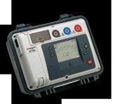
• 50V & 100V Megohmmeters: For testing insulation resistance of phone cables, data cables and power cables
• 500V Megohmmeters: For testing the quality of insulation on equipment powered from sources up to 240VAC
• 1000V Megohmmeters: For testing equipment powered from sources up to 480VAC
• 5000V Megohmmeters: For testing large motors, generators, transformers, cables and other large rotating machinery
• Computer Controlled Models: AC powered, battery powered or hand-cranked models
• Choose from analog, digital or graphical displays
• Perform insulation resistance tests into the GΩ and TΩ ranges
and


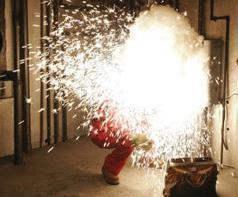
OK – you’ve done the engineering study and you know the arc-energy levels at all of your switchgear, panelboards, and other such equipment. Some of the locations in your facility have unacceptably high incident energy levels. What this means to any given facility depends somewhat on local philosophy; however, it is a safety imperative to reduce incident energy levels to the lowest possible value and/or eliminate the exposure of your workers.
Ideally you would like all incident energy levels to be zero – not a realistic goal. Some would like to have no incident energies above 8 cal/cm2 or some other low goal. Unfortunately, your study shows some locations with incident energy levels of well over 15 cal/cm2, and some locations are over 40 cal/cm2
This article describes several techniques of reducing exposure of your personnel to high arc-energy levels. The several methods described all fall into the following three, broad categories:
• Reducing the available arc-energy by designing/redesigning your power system
• Reducing personnel exposure by designing/redesigning your power system
• Reducing personnel exposure by modifying – and enforcing – working procedures.
You will probably find some of these techniques to be useful in your system, building, or plant. Others will not be feasible for you because of work rules, physical plant limitations, and/or economics. In any event this article presents several common and not-so-common techniques that should be considered by you and/or your engineering consultant.
Reducing the available incident ene R gy by modifying/ R eenginee R ing you R powe R system
Take a close look at equation 1. This equation is taken from the 2009 edition of NFPA 70E
– Standard for Electrical Safety in the Workplace.
Equation 1:

Where:
EMB = maximum incident energy received from an arc occurring in a 20 in. cubic box (cal/cm2)
DB = distance from arc electrodes in inches (for distances 18 in. and greater)
tA = arc duration in seconds
F = short circuit current in kiloamperes (for the range of 16 kA to 50 kA)
Equation 1 is one of several formulas that have been developed by creating arcs in various controlled environments and measuring the resulting heat energy. Research in the area is ongoing and will undoubtedly lead to changes in the equations that we use; however, the basic relationships will remain the same – available incident energy decreases as:
• time of exposure (tA) decreases
• arcing short-circuit current (F) decreases
For protective devices with adjustable operating times, the engineer can often select a faster tripping time, thus reducing the available incident energy. If the engineer is able to reduce the tripping time from 2 seconds to 1 second, equation 1 shows that the available incident energy will be cut in half.
Prior to about 1995, the time delay settings for protective devices were primarily based on two criteria. The first criteria was the requirement that tripping times be fast enough so that noninvolved equipment would not be damaged by carrying excessive fault current for too long. Transformers, for example, overheat and may be damaged if they are required to carry fault-level currents for too long.
Refer to Figure 1 Short circuits that occur in zones 2 or 3 must be cleared by either the transformer secondary breakers (Sec Bkrs) or other protective devices below the Sec Bkrs (not shown). Since faster tripping times will provide better protection for the transformer, the ideal approach is to set all protective devices in zones 2 and 3 to trip instantaneously. This solution will also decrease the available incident energy – a seemingly perfect solution.
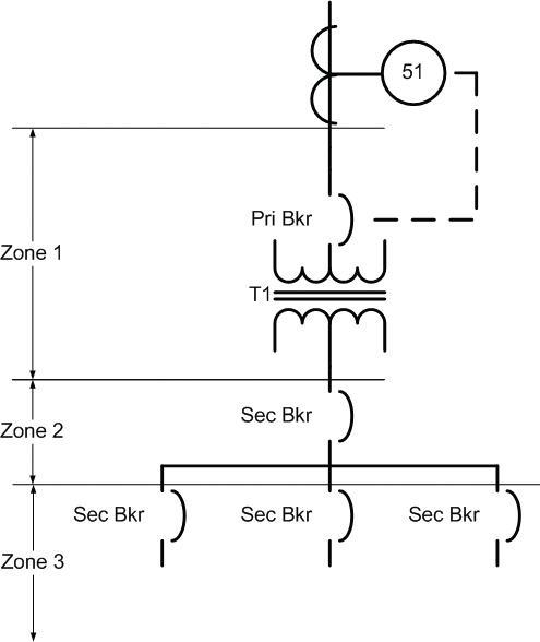
However, tripping times should also provide selective tripping. Selective tripping is defined as tripping the closest protective device upstream of the location of the short circuit. A fault that occurs below one of the transformer feeder breakers (Zone 3) should trip the feeder breaker – not the main secondary breaker. This means the following:
• Pri Bkr should clear faults in Zone 1
• The secondary main breaker should clear faults in Zone 2
• The feeder breakers should clear faults in Zone 3
Prior to 1995, the criterion for time settings was to set them as fast as possible to protect the transformer while still providing selective tripping. Since 1995 the reduction of incident energy has become a third important element. In some cases the settings may have to be based on the likelihood of a worst case short circuit. That is, you may wish to set your tripping times to provide selective tripping for the lower fault currents and sacrifice coordination for higher current/higher energy short circuits. Since the worst case short circuit is a very rare occurrence, you will optimize your selective tripping at the same time you reduce the available incident energy.
In low-voltage systems (less that 1000 V) the use of current-limiting devices (fuses and breakers) will also help to accomplish the desired goal. Fault currents that fall into the current limiting region of such devices can provide tripping times, including arc quenching, of less than 17 milliseconds.
Reducing tripping time is much easier if the engineering is done before the system is built. This allows the engineer to select protective devices that will fit the needed requirements. But what about new or existing systems wherein the devices cannot be adjusted to reduce the arc energies to the lowest possible value?
In such cases the installation of current limiting reactors is advisable. The reactance of these devices increases the system impedance and, correspondingly, reduces the magnitude of the available fault current. While somewhat expensive, this approach may be the only way that a given system’s available incident energy can be reduced to acceptable levels.
There are at least two side effects that must be taken into account when adding additional impedance.
First, a reduction in available fault current will cause the protective devices to operate more slowly. This must be taken into consideration because slower operating times increase available incident energy offsetting the effect of reduced current. This situation is especially pronounced if the reduced fault current causes the protective device to trip in a slower time characteristic.
Assume that the calculated fault current without the reactors will cause a low-voltage power circuit breaker to trip in its STD (short time delay) of less than 0.5 second. Further assume that the calculated fault current with the reactors will trip the same device in a long time delay characteristic. This could increase the trip time to several seconds (or more) resulting in a large increase in incident energy. Clearly, the selection of current limiting reactors must take reduced tripping times into account.1
Second, increasing the system impedance will reduce the system voltage even when operating normally. If the reduction in voltage is objectionable to operations, transformer voltage taps may have to be changed. If transformer taps are not available a second method is to contact the electrical supplier to ask if they can increase their supply voltage slightly. If neither of these methods work, and the voltage reduction is unacceptable, other incident energy reduction approaches must be used.
Experience shows that a significant percentage of arcing incidents occurs during equipment operation. Activities such as opening, closing, and racking put physical stress on the equipment that is not normally present. This can lead to equipment failure and an arc-flash event.
There are at least two ways of reducing personnel incident energy exposure by design and/or redesign.
• Install remote control rooms to allow all switching to be performed remotely
• Install or retrofit arc-resistant switchgear
1 This same problem can crop up when engineers try to determine the worst case scenario. Many assume that the maximum fault current will coincide with the maximum incident energy. For the same reasons as those given above, this is not necessarily true.
2 This is why workers should always be taught to stand to the side of a breaker or switch when it is operated.
3 Many are surprised to learn that in classic designs an arc blast is usually not taken into account for doors and/or panels.
Some facilities choose to install enclosed control rooms that allow remote electrical operation of switching equipment. This approach is especially suitable for new installations, but many companies are retrofitting the rooms in existing systems. Unfortunately not all equipment can be operated electrically. Manually operated protective equipment requires either a remote control appliance (discussed in the next section) or physical presence of the worker.

Permanently installed remote control rooms are very effective and strongly recommended because they put distance and at least one wall between the worker and the arc blast. While an excellent way to reduce exposure during opening and closing, remote control rooms only cover half of the hazard. After the breakers or switches have been opened, personnel must still approach the gear. A viable solution to this exposure is available in the form of arc-resistant switchgear.
Prior to the advent of arc-resistant switchgear, virtually all gear was incapable of enclosing the worst case arcing event. That is to say, if the worst case arc were to occur, the switchgear could sustain a rapid, noncoherent disassembly. It could blow up. The failure point is usually the front and/or back of the gear.2 Sometimes, it didn’t even take the worst case fault to cause a failure.
Modern arc-resistant gear incorporates at least three major features that greatly reduce the possibility of such an explosive failure.
1. The internal bus structures are better insulated to reduce the probability of a sustained arcing event.
2. The construction materials and methods are much sturdier than older designs. Stronger metals, thicker walls, interlocking corners, and heavy duty fasteners and hinges3 are all employed. Figure 2 shows the door construction used by one manufacturer for their arc-resistant gear.
3. The gear has an internal venting system that directs the by-products of the arc away from the personnel. Usually it is directed up and back.
Of course, arc-resistant gear is effective only when it is closed with all fasteners and latches in place. After the breaker or breakers have been opened, the gear must be opened to perform any work that requires access to the internal equipment, thus exposing the worker to the arc-flash hazard.
Unless the bus has been de-energized, the system is still hot; consequently, a failure can occur if the breaker or switch is racked in our out with the door open. External (door closed) racking systems greatly help in the reduction of this hazard. However, even then, if the bus is energized there is a possibility of an arc occurring.
The solution to this problem lies in the use of appropriate safety procedures.
Reducing pe R sonnel exposu R e by modifying – and enforcing –wo R king p R ocedu R es
Increasing distance from the arc location will greatly reduce the incident energy. From equation 1 we see that an increase in distance will reduce the incident energy by the 1.4738 power.4

Figures 3 and 4 show two types of equipment that can and should be employed so that workers can operate gear from a remote distance. These types of mechanisms are less expensive than installing separate control rooms, and they provide a very good level of protection. Of course, nothing can be better than having a block wall between the operator and the equipment.
Figure 3 is the Chicken Switch.5 This was one of the earliest and most popular of the remote operating mechanisms. As you can see from the photo, the operating mechanism is mounted on the door of the breaker to be operated. The control box is connected to the mechanism via a long, spiral control cable. Use of this device allows the operator to stand at a safe distance (up to 25 feet or more) while opening or closing the breaker.

Figure 4 shows the CBS ArcSafe® remote switching device. This somewhat more elaborate equipment includes not only open or close operation, but also can be set up to physically rack circuit breakers and other such equipment remotely. Although more expensive than the many open/close devices that are on the market, such equipment adds enhanced safety by allowing opening, closing, and racking from a remote location.
There are many, many electrical safety training options in the marketplace today. They range from classroom/laboratory presentations that require participants to demonstrate their ability to work safely around electricity to simple video-tape/computerbased training packages.
Although employers are always looking for ways to get the greatest bang for the buck, I recommend that more comprehensive training methods be used. Workers should certainly be required to take cognitive skill enhancement training, but they also should be required to include demonstration of their safety skills. A person remembers something they have done much more completely than something they have heard or read.
4 Theory predicts an inverse square relationship for a point source of energy. The slower energy reduction in the real world is caused by the focusing effect of switchgear and arc geometry.
5 Chicken Switch is a registered trademark of MarTek, Ltd.

6 Some are even more conservative and draw the line at locations over 8 cal/cm2 If this is feasible in the given situation, I concur.
Even in late 2010, I am amazed at how many companies are still unaware of the potential for arc injuries. Unfortunately, such companies very often are unaware of their obligation to provide the necessary worker protection.
Simple, easy-to-enforce procedures can go a long way towards preventing electrical accidents. Methods such as:
• Stand to the side when operating a breaker (See Figure 5).
• Always test before you touch (test the meter, test the circuit, retest the meter).
• When testing, wear all appropriate PPE. Remember that it isn’t dead until it’s measured.
• Always wear and/or use properly rated PPE (See Figure 6).
• Observe the shock and flash boundaries. Do not cross them without proper PPE.
• Put signs, barriers, or safety watch personnel in place to keep out unqualified personnel.
• Whenever possible apply equipotential safety grounds in the work area.
• De-energize the system from a location that has relatively low incident energy.


I believe that any location with incident energy over 15 cal/cm2 should be reviewed for possible mitigation solutions.6
Usually solutions exist to reduce the maximum incident energy at an exposure location in a power system. For example, some say that it is impossible to reduce the incident energy of a fault occurring between a transformer secondary and the first secondary protective device. In fact the normally high, incident energy in these locations can be mitigated. Protective schemes such as transformer differential or zone-interlocking protection will provide instantaneous tripping for transformer secondary faults. The cost of mitigation may be high, but the cost of a single injury or fatality will be much higher.
Some consultants, as a normal part of an arc-flash study, will recommend changes in protective device settings in areas where high incident energies are present. In fact, system owners should insist on this as a part of a contracted study.
However, major redesign efforts are usually beyond the scope of a contracted study. Adding current limiting reactors, designing remote control rooms, and checking the effects of different protective devices are examples of such out-of-scope efforts.
If a study reveals locations where a simple setting change is not sufficient, the system owner should commission an engineering review to determine which of the several design options will provide the optimal incident energy mitigation.
Procedural and PPE considerations should be based on the results of an arc-flash study. The use of PPE tables in NFPA 70E should be limited to those locations where a study has not been performed. However, for a given location, this should be a temporary fix. The best and safest approach is the arc-flash study.
Finally, do not forget electrical shock hazards. In the midst of focusing on arc flash it is sometimes easy to forget that shock hazard should also be investigated. Voltage level is certainly the first criteria in selecting proper insulating equipment. However, the overall shock hazard should be investigated to properly assess the need.
John Cadick is a registered professional engineer and the founder and president of Cadick Corporation, John Cadick has specialized for more than three decades in electrical engineering, training, and management. His consulting firm based in Garland, Texas, specializes in electrical engineering and training and works extensively in the areas of power system design and engineering studies, conditionbased maintenance programs, and electrical safety. Prior to creating Cadick Corporation and its predecessor Cadick Professional Services, he held a number of technical and managerial positions with electric utilities, electrical testing companies, and consulting firms. In addition to his consultation work in the electrical power industry he is the author of Cables and Wiring, The Electrical Safety Handbook, and numerous professional articles and technical papers.
Indu S tr I al t e S t S , In C a S a neta aCC red I ted Company
Industrial Tests, Inc. is pleased to announce that it is now a NETA Accredited Company after satisfying the stringent requirements to become a full member. Industrial Tests, Inc. was established by former Westinghouse Engineering Service employees in 1976 and is now an independent, third party testing company which serves the western states and beyond.
Located in Rocklin, California, Industrial Tests, Inc. has been providing start-up and acceptance testing services for the utility,
industrial, and commercial industries for over 30 years. Industrial Tests, Inc. proudly employs a professional team of degreed engineers who are highly trained and experienced in performing specification and maintenance testing in compliance with NETA standards.

Industrial Tests, Inc. looks forward to becoming an active member of NETA and sharing the many benefits of the association with its technical staff and clients. For additional information, please visit the website at www.industrialtests.com.
the test equipment answer



The topic of electrical arc flash has been an important issue for several years now. Engineers have been creating and manufacturers are producing innovative new solutions for this life-threatening problem. This month’s Tech Quiz will cover issues related to electrical arc flash.

Jim White is the Training director for Shermco Industries and the principal Shermco representative on the NFPA 70B committee. Jim is the alternate NETA representative on the NFPA 70E committee and serves as the NETA representative on the IEEE/ NFPA Arc-Flash Hazard Work Group (RTPC) Ad Hoc Committee. He served as the Chairman of the 2008 IEEE Electrical Safety Workshop. Jim is a NETA Certified Level IV Electrical Testing Technician and a member of the NETA Safety Committee.
1. Electrical systems rated less than 240 volts fed by a transformer with a capacity of <125 kVA are not considered an arc-flash hazard.
a. True, according to IEEE 1584
b. False
2. Arc -flash protective clothing and equipment are rated to:
a. Provide protection to the value indicated as the “arc rating” or “ATPV”
b. Provide a 50% probability of a burn at the arc rating or ATPV
c. Provide protection in excess of the arc rating or ATPV
d. Allow a person to safely work on an energized electrical power system
3. Which of the following is NOT a rule-of thumb concerning arc flash:
a. Incident energy decreases by the inverse square of the distance
b. Incident energy is proportional to time
c. Each layer of clothing under arc-rated reduces the heat to the body by ~ 50%
d. Incident energy is inversely proportional to short circuit current
4. At what voltage does the arc flash hazard not exist?
a. 480 volts
b. 277 volts
c. 208 volts
d. None of the above
5. When wearing an arc-rated face shield, what is the correct body position when operating electrical equipment?
a. Extend the left arm and turn the face away from the hazard
b. Extend the right arm and turn the face away from the hazard
c. Extend either arm and turn your face towards the hazard
d. Get an apprentice to do it for you
See answers on page 105.





Joint Colla B o R ation pR o J e C t on the aRC
At this year’s NFPA 70E ROC (Report on Comments) meeting, an update on the IEEE/NFPA Joint Collaboration Project was presented by Dr. Wei-Jen Lee of the University of Texas at Arlington. Dr. Wei-Jen Lee is the Project Manager for the IEEE/ NFPA Joint Collaboration Project. NETA is always looking for ways to improve its worker’s safety and is a major contributor to this project.
By Jim White & Ron Widup Shermco IndustriesDr. Lee began by stating the goals of the project, which are to determine the arc-flash effects, including heat, blast pressures, light intensity, and sound intensity. These effects are to be quantified and equations developed through executing approximately 2500 tests. These tests are being conducted at five different test laboratories around the US and Canada.
The initial series of tests (Phase 1), which have been completed, were to determine instrument functionality, overall accuracy, repeatability and consistency of the various test laboratories. Six calorimeters will be used for testing, and the electrodes will be placed horizontally for some tests and vertically in others. The horizontal electrode placement was to address concerns raised by Dr. David Sweeting who had written a paper pointing out that his research showed that horizontal electrodes could produce arc jets which produce higher incident energy values than when the electrodes are placed vertically. The equations for IEEE 1584, Guide for Performing Arc-Flash Hazard Calculations, will be updated to reflect the new information from these tests once they are completed and analyzed. Dr. Sweeting is also on the technical committee for this project. IEEE 1584 applies only to 208-volt through 15 kV three-phase
systems in enclosures. Higher voltages and single-phase systems are covered using Ralph Lee’s equations (no relation to Dr. Lee).
Five series of tests were performed for Phase 1, during both cold and warm weather, to gauge the effects of ambient temperature on the test results. The video recorders being used can capture (depending on the laboratory) between 600 fps to 1900 fps. Calorimeters can capture between 200 to 5K samples/second and the pressure sensors can capture between 20K to 50K samples per second. Sound is captured at 20K samples per second. I often get questioned about the need for hearing protection for HRC 0 and HRC 1 levels. Dr. Lee pointed out that their tests so far have shown sound levels at 120 db to 130 db for a 480-volt, 5 kA fault and between 130 db to 164 db at 480 volts and 20 kA. These are very substantial acoustic values and can cause damage to a worker’s hearing if he is not protected. As a side note, these sound levels were measured at a distance of 2 to 3 meters from the arc, as the instrument’s sensors were damaged if they were placed closer. This means the actual sound levels were probably greater than that indicated.

At this time the project has almost completed the 480 V testing. During the Spring and Summer of 2011, Dr. Lee hopes to complete testing at the 4.16 kV level, complete the 480-volt to 600-volt testing, analyze their data and possibly conduct some testing at the 208-volt level. It will take a considerable amount of time to properly analyze all the data produced by these tests, so don’t expect any usable information to be forthcoming anytime soon. Testing on 7.2 kV and 13.8 kV is scheduled to be conducted during the Fall and Winter of 2011.
A question was asked about dc voltages and Dr. Lee replied that they will look at dc voltages depending on funding once all the ac tests have been completed. At this time it appears as though there are no definite plans to conduct dc testing, but there are contingent plans if funding becomes available.
James R. White and Ron A. Widup are NETA’S representatives to NFPA Technical Committee 70E (Electrical Safety Requirements for Employee Workplaces). James R. White is nationally recognized for technical skills and safety training in the electrical power systems industry. He is currently the Training Director for Shermco Industries, a NETA Accredited Company. Jim has spent the last twenty years directly involved in technical skills and safety training for electrical power system technicians.




The Report on Comments (ROC) meeting of the NFPA 70E committee is always interesting and always has some surprises. This one was conducted in Savannah, Georgia and was no different. The ROC meeting actually ran seven full days due to several task groups meeting on Saturday and Sunday. The task group meetings lasted nine and eight hours, respectively. Task groups are formed to smooth the process and present recommendations to the full committee in order to reach consensus (hopefully) more quickly. Each proposal still has to be discussed by the full committee, but if the task group is large enough, it usually speeds things up. Usually. But not this time.
The Tables Task Group met on Saturday, and there was a large number of participants. With such a large task group, the results of the vote would normally indicate where the full committee would vote. In the ROP (Report on Proposals) meeting there was very strong support for adding two columns into Table 130.7(C)(9), one for the available short-circuit current and clearing time of the OCPD and one for the estimated Arc-Flash Boundary at the maximum estimated short-circuit current and clearing time. The full committee directed the task group [Ron and Jim were members and it was chaired by Jim Dollard (IBEW)] to develop the values for inclusion into the tables.
On Saturday, the values the task working group had developed were discussed, some modifications were made and sample tables were prepared. During the full committee meeting the entire concept was thrown out the window, and it was decided to move the notes from the bottom of the tables into the headers and not use a two column format. This will mean the headers will be quite a bit larger and contain the maximum short circuit current, clearing time, Arc-Flash Boundary, and working distance. The full committee had concerns that the two column format would lead to some confusion, especially with the 600 V class motor control center section which has more than one note. As I said, many surprises.
On Sunday, the Article 130 task group met. Again, Ron and Jim were on this task group which was chaired by Daleep Mohla. Article 130 (Work Involving Electrical Hazards) generates a lot of interest from the public, and it actually took this task group Sunday as well as Monday and Tuesday evenings to finish its work. Due to the sometimes extensive and protracted discussions involving the comments received, the regular committee meetings ran from 8 am to 5pm, at which point the task groups worked until 6 pm to 7 pm, depending on the day.
A number of significant changes were proposed for the 2012 edition of the NFPA 70E. Bear in mind that these changes have not yet been approved by the Technical Correlating Committee (TCC), nor by the Standards Review Council of the NFPA. Until they are approved they are not part of the standard.
One very significant change was the addition of Kenneth Mastrullo (Region I OSHA) as the alternate representative to David Wallis, who is the principle OSHA representative. Ken was formerly with the NFPA and acted as the liaison for the NFPA 70E committee. Ken co-authored the 2009 edition of the NFPA 70E Handbook with Ray Jones. Ken brings a new insight to the committee based on his experience both from the NFPA side as well as from the OSHA enforcement side. David provides insight on how the standards evolve and OSHA’s view of certain issues. A couple of times a commenter stated he did not think the 70E committee should be driven by OSHA. We believe the 70E should harmonize with federal law, so how OSHA perceives actions taken by the committee is very pertinent. Even though the principle OSHA representative has a full vote on the committee, he abstains from the vote so that it is not influenced.
Everyone is interested in the tables. The 2012 edition of the 70E will see several new tables being added, so the numbering of everything in the 70E will change. Table 130.7(C)(9) will now become 130.8(C)(15)(1) and 130.8(C)(15)(2). Two tables are for hazard/ risk category of clothing, one for ac power systems and one for dc power systems. Table 130.2(C) (approach distance for shock protection) will now be numbered 130.4(C)(1) and 130.4(C)(2), one for ac systems and one for dc systems. Another new table that will appear in the 2012 edition will be Table H.3 which provides recommendations for arc-flash PPE and clothing when an Arc-Flash Hazard Analysis has been performed. In past editions of the 70E there was no guidance for choosing
arc-flash PPE and clothing when an arc-flash study had been performed. Table 130.7(C)(10) was only to be used when using Table 130.7(C)(9), although that was routinely ignored in the field. The 70E committee generally believed that when an arc-flash study had been performed, the tables were not required and that using Table 130.7(C)(10) could lead to choosing PPE and clothing that may not be appropriate in some cases.
Two other tables in Annex H are also new. Tables H.4.1(Low-Voltage Systems) and H.4.2 (High-Voltage Systems) offer guidance for choosing arc-flash PPE and clothing when the short-circuit current and clearing time of the OCPD is known. These two tables are based on the two-level clothing system (8cal/cm2 and 40cal/cm2). For each voltage level there are maximum short-circuit currents that either 8 or 40 cal/cm2 PPE can be used at several different clearing times for OCPD. These tables should be especially useful when a company uses a two-category PPE system.
Table 130.7(C)(11) is being eliminated. Changes made to Table 130.7(C)(10) made the information contained in Table 130.7(C)(11) redundant, so the committee thought it was no longer necessary.
More information on what to expect from the 2012 edition of the 70E will be included in next issue of NETA World magazine.
James R. White and Ron A. Widup are NETA’S representatives to NFPA Technical Committee 70E (Electrical Safety Requirements for Employee Workplaces). James R. White is nationally recognized for technical skills and safety training in the electrical power systems industry. He is currently the Training Director for Shermco Industries, a NETA Accredited Company. Jim has spent the last twenty years directly involved in technical skills and safety training for electrical power system technicians.

Reliable functioning of airport lighted visual aids is essential to airport safety, capacity, and operation especially for low visibility operations. Therefore, it is essential that a preventive maintenance (PM) program be established to ensure reliable service and proper equipment operation. FAA Advisory Circular AC No. 150/5340-26A, Maintenance of Airport Visual Aid Facilities, provides recommended guidelines for maintenance of civilian airport visual aid facilities. MIL-HDBK-1023/4, Maintenance of Visual Air Navigation Facilities, provides recommended guidelines for maintenance of military airport visual aid facilities. These systems include the following:
• Airport lighting vault and series lighting circuits
• Constant current regulators
• Runway and taxiway elevated edge lighting systems
• Runway and taxiway in-pavement lighting systems
• Runway guard lights and stop bar lights
• Illuminated runway and taxiway signs
• Rotating beacons
• Lighted wind cone assemblies
• Precision Approach Path Indicator (PAPI) system
• Visual Approach Slope Indicator (VASI)
• Runway End Identifier Lights (REIL) and Omni Directional Approach Light System (ODALS)
• Medium Intensity Approach Light System (MALS, MALS/F, MALS/R)
• Hazard beacons and obstruction lights
• Standby engine generator systems
The following table represents some of the recommended electrical tests associated with compliance to AC No. 150/5340-26A and MIL-HDBK-1023/4. The recommended testing frequency varies by system from monthly to annually.
Most lighted navigational aids are exposed to weather and moisture and may develop electrical shock hazards through damage from lightning or insulation deterioration from exposure. Because of their design and operational nature, airport runway and taxiway lighting circuits can be very dangerous. This is especially true when working on constant current series circuits because these airport lighting circuits can operate at potentials of several thousand volts depending on the size of the regulator driving the circuit and the load. As an example, a series circuit connected across a 50 kW, 20.0-ampere regulator may have a full load voltage of 2,500 volts. However, the momentary surge before the open-circuit protection device actuates will approach 5,000 volts. Constant current regulators come in two basic types, air cooled and liquid filled. The two basic types of regulators can be further classified as either magnetic or electronic. Magnetic types typically utilize either a resonant circuit or a saturated reactor principal. In a resonant network circuit the current output is proportional to the input voltage and is independent of the impedance of the load. Most resonant network regulators are only manufactured in sizes less than 10 kW. For regulators that are oil filled, an oil sample should be taken to ensure adequate dielectric strength of the oil. A normal range for oil being tested should be 26-30 kV with 22 kV as the minimum acceptable level. For the regulator, a short-circuit test, an open-circuit test, and an overcurrent test should be performed.

It is recommended that manufacturer’s literature on the operations, theory of operation, and recommended maintenance testing procedures for the particular regulator being used be obtained and reviewed prior to performing any maintenance on these devices.
Specialty test equipment, or test equipment not normally owned by an airport or used by the airport’s maintenance electricians, is required for some of the recommended testing. When considering tools and test equipment, an average electrician may have little day-to-day use for anything more than an analog volt-ohm-milliammeter (VOM) or a digital multimeter (DMM). However, when maintaining airport lighting series circuits, the voltage levels (i.e., greater than 1000 V) typically exceed the design of the VOM or the DMM. That means it is dangerous to use the VOM or DMM for troubleshooting these circuits. A specially designed, high voltage meter is required for this application. Additionally, VOMs and DMMs are of little use when performing insulation testing (i.e., megohmmeter, or Megger™, testing of equipment and cables) or low resistance testing (i.e., measuring ground resistance).
In general, insulation-resistance tests should be performed on all field circuits to verify no ground faults exist. For series circuits, the insulation resistance may be measured by simply removing the ends of the loop from the power supply. For parallel circuits, all connections must be removed before insulation resistance may be measured. Whenever possible, these tests should be performed when the ground is thoroughly wet. Circuits which pass insulation- resistance tests during dry weather may fail after a heavy rain. All readings should be compared to previous results. A 10 to 20 percent annual decrease in insulation resistance value (in megohms) is normal. An annual decline of over 50 percent indicates the existence of a problem where further troubleshooting should be performed.
The ground resistance tester is used to measure the effectiveness of grounding systems. The grounding system may be used for beacon towers, lighting vaults, engine generators, and for other lighted navigational aids, or it may be a counterpoise system for underground cables. Ground resistance measurements for each item of equipment should be performed on at least an annual basis. The measurements should be recorded and compared with previous readings in an effort to discover deterioration in the grounding system. The lower the resistance value, the better; a value of 5 to 10 ohms is desirable. If the resistance is greater than 25 ohms, immediate action should be taken to lower the resistance.
When specialty test equipment and experience are required for performing maintenance, it is preferred that a testing company be utilized for performing the work safely and effectively. Accredited companies that are uniquely qualified to perform this type of work should be used. The companies should be accredited based on electrical testing experience and have expertise in working with higher voltage equipment and systems. Their test technicians should be
certified through a standardized testing process and have been trained in the technical and safety aspects (i.e., PPE requirements, safety work practices, etc.) associated with equipment of the type installed in airports.

Lynn Hamrick brings over 25 years of working knowledge in design, permitting, construction, and startup of mechanical, electrical, and instrumentation and controls projects as well as experience in the operation and maintenance of facilities.
Lynn is a Professional Engineer, Certified Energy Manager and has a BS in Nuclear Engineering from the University of Tennessee.

Vanguard’s precision substation testing instruments are designed to be intuitive and easy to use so that you can focus on testing instead of wasting time in training. Our versatile instruments offer a built-in thermal printer and on-board test record storage so that tests can be conducted in stand-alone mode in the field. A computer interface is also offered so that tests can be easily conducted from a PC.


And all of our instruments are competitively priced to provide cost-effective accuracy. For a virtual experience of our instruments, check out the interactive demos on our site at:
www.vanguard-instruments.com/demos



electro rentthe right choice
Electro rent has been renting complete lines of electrical test equipment since 1965. Our experienced sales associates can assist you in selecting the right tool for your job and we usually deliver it to you within 24 hours. We offer daily, weekly and monthly rentals at prices that fit your budget. let us help you achieve success!
rent what you need when you need it. call us or visit us online for a free quote.
From leading manuFacturers
Baker, Biddle, doble, dranetz, Flir, Fluke, High voltage, Hioki, Megger, Multi-amp, Yokogawa and more. Electro rent also rents and leases an assortment of laN cable certifiers, Otdrs, fusion splicers and light sources.
most
For projects with a projected term of 12 to 48 months, Electro rent has an exceptional financing program that offers significant budget benefits while it provides immediate access to products without waiting for capital. You can also purchase your equipment as funds become available.
Key Features include:
• Lower rate for a longer committed term
• Addition of non-hardware items, such as service or software
• Flexible contract options, such as early termination, upgrades and trade-ups




To address the increasing concerns and standards around arcing faults, GE challenged our Global Research Center to develop a new, “active” method of detecting and removing an arcing fault. The goal was to develop a technology that would, in simple terms, reduce the potential for injury and equipment damage. The result is an innovative product called the Arc Vault™ Protection System. This article will outline some basic arc-flash mitigation techniques and culminate with a description of the new GE technology. It should be noted from the onset that this technology is currently in the prototype phase and that the discussion covers applications of 600 V and below.
Arcing F A ults – Why the i ndustry c oncern?
Simply put, the effects may result in serious injury, death, equipment damage, and downtime. Unlike the bolted fault, an arcing fault uses ionized air as the conductor. The cause of the fault normally burns away during the initial flash and the arc is sustained by the establishment of a highly conductive, intensely hot plasma arc. The intense heat vaporizes conductors and barriers and superheats the surrounding air resulting in an explosive volume-metric increase within the space. The consequence is an intense pressure wave, deafening sound, blinding light, toxic gases, molten metal and shrapnel. This is often referred to as the arc blast. Unless action is
taken to either quickly remove the fault or redirect the arc blast, the brunt of these items will impact people, equipment, or both. The magnitude of the arcing fault is only 43-57% of a bolted fault, so traditional overcurrent protection may not detect and clear the fault before the full impact of the arc develops and causes damage or injury.
To gain a better understanding of how to deal with an arcing fault, let’s consider what the contributing variables are and the corresponding incident energy calculations that help categorize them. A complete discussion on arc-flash calculations can be found in IEEE 1584 – “Guide for Performing Arc-Flash Hazard Calculations”.
There are many items that can initiate an arcing fault. Rather than focusing on what the ignition sources can be, the system factors associated with how we quantify the arcing fault will be considered. With the benefit of this information, mitigation techniques can be outlined and categorized. Figure 1 illustrates some of the basic parameters that factor into an incident energy calculation that in turn leads to the Hazard Risk Category labeling.

Clearly, there are many variables that factor into the incident energy calculation. Some are specific to equipment types while others are tied to system parameters or maintenance practices. Each variable plays a particular role in how we categorize the arc-flash hazard and each is briefly touched upon below:
• Voltage – The ability to sustain the arc. Arcing faults are generally limited to systems where the bus voltage is greater than 120 V.
• Available bolted fault current – The punch behind the arc fault magnitude. Recall that the magnitude of a low-voltage arcing fault is approximately 43-57% of the bolted fault value. This implies that systems with significant bolted fault currents will have elevated arcing current levels. The reverse is also true; lower bolted fault levels will lead to lower arcing-fault energies. Items such as system impedance, transformer sizing, utility, motor, and generator contributions establish the available fault current.
• Arc clearing time – This includes detection and protective device operating time. It is tied to the operating characteristics of a specific protective device for a given level of arcing current. Reducing clearing time is critical to reducing the impacts of arcing fault.
• Conductor gap distance – Defines the distance between conductors that an arc must cross. Varies by equipment type and manufacturer, but is fixed for a specific piece of equipment.
• Working distance – The distance from a potential arc source to a worker’s face and chest. Typically assumed to be 18”. Items such as remote monitoring and racking can be implemented to remove the operator from the flash zone for routine maintenance tasks.
• System configuration – Solidly grounded, resistance grounded, etc. This category also takes into consideration whether the arc environment is enclosed or open.
Given a basic understanding of what variables contribute to an incident energy calculation, the next logical question is to ask what the engineer can do to reduce this energy or exposure to it? Since energy is a function of current, voltage and time, there are several strategies that can be explored:
• Reducing the available fault current
• Reducing the arcing time
• Transferring the energy into a less damaging form or place quicker than it could otherwise be interrupted
The paragraphs that follow will highlight several of these strategies.
Over the years, different methods to limit arc flash exposure and incident energy have been introduced and can be divided into two general categories: active and passive. Passive mitigation is defined to be an equipment
option or type that either contains and redirects the arc blast or helps to eliminate the potential of a flash event (i.e., insulated main bus). This type of mitigation does not require any actions or settings by an operator to implement. On the opposite end of the spectrum is active mitigation. Active mitigation takes a proactive approach to reducing both incident energy and the exposure to arcing faults through the active use of technology, design, and maintenance practices. The simplest example of active mitigation is to not approach or work on live electrical equipment. Figure 2 contains a list of passive and active items.
Passive Active
Reduce exposure with equipment options
• Insulated/ isolated bus
• IR scanning windows
• Closed door drawout of breakers
• Side section barriers
• Hinged vs. bolted doors
• Heaters
Reduce exposure with equipment types
• Arc resistant structures
Technology to reduce arcing time & incident energy
• Arc absorber
• ZSI of instantaneous
• Crow bar
• Bus differential (87B)
• Maint settings (RELT)
• Current limiting devices
Design practices to reduce arcing time & incident energy
• Consider fault currents
• Transformer sizes
• Grounding
• Single or double ended
Others?
Reduce exposure via maintenance practices
• Follow NFPA 70E
• No live maintenance
• Remote switching
• Remote racking
• Remote monitoring
• Remove contaminants
• Training & labeling
• Use of proper PPE
One clear distinction between the passive and active methods is that the passive method does nothing in the way of detecting or removing an arcing fault. It is focused solely on containing the arc blast or eliminating a potential starting point for an arc flash via equipment options. One should not employ passive techniques
without thinking through items such as thermal scanning. Equipment options like insulated main bus and isolated phase bus are good preventative measures; however, they present an issue to performing thermal scans of items other than load connections.
The active methods seek to attack on both fronts, incident energy reduction and reduced exposure. The newest technology on the active side is the GE arc absorber protection system. To highlight the application of this new system the following paragraphs will contrast the active arc absorption system vs. the passive, arc resistant structure. The remaining items are listed for reference and will not be covered in detail.
Typical low voltage metal enclosed switchgear is designed and tested to withstand the mechanical forces associated with bolted faults (nonarcing). It is not constructed to contain and re-direct the arc blast away from the operator. The standard construction must be able to withstand (carry) the bolted fault current from the line side of the main breaker through the load terminations on the feeders and is short circuit tested to ensure compliance with the applicable ANSI standards. During a short circuit interruption, there may be some out gassing of arc by-products from the breaker but not to the violent extent of the arcing fault.
An arc resistant line of low-voltage switchgear is also designed to withstand and interrupt a bolted fault, however it provides a level of protection to arcing faults that is not incorporated in the standard design. Arc resistant structures have been around for 30 plus years and can trace their roots back to IEC standards. In North America, this type of structure is tested & categorized to ANSI C37.20.7 (Refer to Figure 3.)The term arc resistant implies that no arc-fault emissions/ blast will occur in the areas described by each category. For example, with a properly installed Type 1 design, an operator could approach the front of a switchgear lineup and not be
exposed to the arc blast if an arcing fault were to occur. If the operator were standing to the side of this design, the same protection would not be provided.
ANSI Type Comments – arc resistant construction applies to
Type 1 The front only.
Type 1C The front, as well as between compartments of the same or adjacent cells.
Type 2 The front, back and sides of the enclosure.
Type 2C The front, back, sides as well as between compartments of the same or adjacent cells.
Figure 3: Arc-Resistant Structure Categories
To function properly, arc-resistant structures have several distinguishing characteristics not found in traditional gear.
• Reinforced construction is used to withstand and contain the pressure wave. Front and rear doors, section barriers, etc., may be reinforced and gasketed depending on the ANSI type.
• Exhaust chambers are employed within the structure to safely redirect the arcing fault by products away from the operator and toward the vent flaps.
• Vent flaps that open due to increased pressure vent the arc blast, typically out the top.
• Figures 4 illustrates the redirection and venting of the arcing fault.
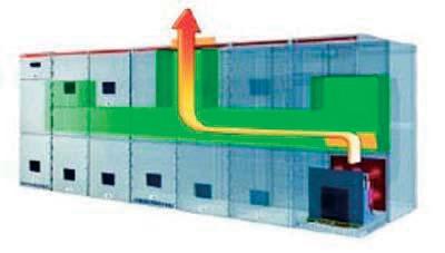
Figure 4: Illustration of Arc-Resistant Venting
The arc-resistant structure does an excellent job of protecting the operator from an arc-flash event; however, it is not a panacea. As noted earlier, this passive technique seeks only to contain the arc blast, but nothing to reduce incident energy or remove the arcing fault, which can result in substantial equipment damage and downtime. Like all products, the application of arc-resistant structures requires consideration and awareness of items that are specific to the construction. Several items are listed below for consideration.
What type of downtime will the owner experience for an arcing fault? It is reasonable to expect some structural damage that will require repair as a result of the arc blast. Bus, doors, and barriers are likely candidates for repair. Are there other mitigation methods that can provide operator protection and help reduce equipment damage at the same time?
The protection afforded by the arc-resistant structure can be negated if a door is not properly secured or if the maintenance task requires the operator to open a door or compartment. What are the impacts to operator safety, maintenance practices, etc.?
Where does the effluent go when it is vented from the structure? Does the room size need to be increased? Does a restricted area need to be developed and labeled? Is placement of the structure limited to certain areas?
What are the cost and size impacts associated with the structure itself? Does the room size need to be increased?
The arc-resistant structure cannot be retrofit onto existing equipment.
The comments above are not meant to disparage the arc resistant design. Rather they are meant to highlight that with all products there are application considerations that must be taken into account. Items such as live maintenance, equipment damage, room size, and venting are real concerns that need to be thought through and contrasted against other mitigation techniques.
p and a logic controller.
arallel-connected containment dome, light sensors
The arc absorption is an active mitigation technique and aspires to the same basic goal as the arc-resistant structure; to protect the operator. However it does so in a much different fashion than arc-resistant structures. Instead of containing and venting the arc-flash effluent, it seeks to limit incident energy via the identification and removal of an arcing fault before it escalates into the signature arc blast and elevated hazard risk categories. The result is a solution that addresses three key areas:
• Reduction of the arc-flash hazard
• Improved equipment uptime/ reduced damage
The current sensor looks for the signature of an arcing fault while the light sensor looks for a simultaneous optical event. The combination of the two is fed into a logic controller which makes the decision on whether to engage the absorber or not.
At this point you may be thinking that this is a crow bar. Rest assured, it is not, please read on.
The arc absorber has no moving parts and makes use of a plasma gun and containment chamber. When the logic controller activates the absorber, two simultaneous actions take place. A trip signal is sent to the main breaker, and the absorber is activated. When activated, the absorber triggers the plasma gun to break down the dielectric in the air gap within the absorption chamber. The resulting arc creates a lower impedance, phase-to-phase path than the “in equipment” arcing fault presents to the system. This low impedance path is not a bolted fault and in turn redirects/absorbs fault current originally flowing towards the arcing fault within the controlled environment of the containment chamber. The arc within the containment chamber is then safely cooled and vented. The open air or “in equipment” arc is extinguished as the bus voltage decreases due to the low impedance path within the absorber. The time required to quench the open-air arc is 8 ms. The event is brought to conclusion when the main protective device opens and eliminates current flow within the absorption chamber.

Figure 5 - Architecture
figure 5: Architecture
• Ability to retrofit existing switchgear
he current sensor looks for the signature of an arcing fault while ks for a imultaneous optical event. The combination of the r not.
T the light sensor loo s two is fed into a logic controller which makes the decision on whether to engage the absorber o
The architecture for the absorber is depicted in Figure 5 and consists of a current sensor, a parallel-connected containment dome, light sensors, and a logic controller.
At this point you may be thinking that GE has created a crow bar. Rest assured, we have not, p
lease read on.
The Arc Absorber has no moving parts and make use of a plasma g W simultaneous actions take place. A trip signal is
s
un and containment chamber. hen the logic controller activates the absorber, two
It is important to note that since this system works at arcing fault current levels, as opposed to bolted fault levels, there is a significant energy reduction. The result is 63% less energy, and considerably less stress on the system, when compared to crowbar type systems. This energy reduction applies to not just the local switchgear but also to other system components like transformers.
The prototype of the arc absorber containment dome is about the size of an 800 AF breaker and is rated for applications of 100 kA at 480 volts.
The arc absorber protection system will contain an arc fault in less than 8 ms with the circuit breaker compartment doors open during operation and maintenance. The incident energy in accordance with IEEE 1584 at 24" from the arc event will be less than 1.2cal/cm2, which is equivalent to HRC0, for a 480 V HRG system with available fault currents up to 100 kA.
In addition to incident energy/HRC reduction, eliminating the arcing fault, reducing equipment damage, and eliminating arcing fault effluent. The arc absorber offers the following benefits not found in traditional arc resistant structures:
New and retrofit applications
The arc absorber can be implemented in new or existing low-voltage switchgear platforms while the arc resistant structure is tied to new installations only.
The arc absorber will be reusable, with minor maintenance or parts replacement, depending on the available fault currents where it is applied. Arc-resistant structures will in all likelihood sustain some form of damage and require repair to place them back into service.
The arc absorber does not depend on doors being closed to provide arc-flash protection. Hence the established Hazard Risk Category does not change whether the doors are open or closed.
No need for increased ceiling heights or the creation of restricted areas to avoid potential exposure to redirected effluent.
There are many techniques that can be employed to help mitigate the damaging effects of arcing faults. This article has introduced the concept of the arc absorber as a feasible alternative to arc-resistant structures. It can at minimum offer the same or similar Hazard Risk Category (HRC) protection as the arc resistant structure but far exceeds the structure in the areas of equipment protection, uptime, reuse and others. GE presented this concept on the arc absorber to the IEEE Petroleum and Chemical Conference Technical Conference in September of 2009.
Refe R en C es
IEEE 1584 – Guide for Performing Arc-Flash Hazard Calculations
IEEE C37.20.7: “Guide for Testing Medium-Voltage Metal-Enclosed Switchgear for Internal Arcing Faults.”

Mark Clapper is a Specification Engineer for the Industrial Solutions division of GE Energy. He has 20 years of power distribution experience and holds a degree in electrical engineering from Michigan State University.

You can get older equipment to take advantage of new technology, with the EntelliGuard® TU trip unit. It improves arc flash protection, reducing the HRC level to 1 or 2, depending on available fault current.
Neat trick, isn’t it?
The EntelliGuard TU retrofits quickly and easily, too –via plug-and-play on legacy GE low-voltage breakers or with a kit for those from other manufacturers.
See for yourself. Call 1-800-431-7867 and press “2” for dedicated technical support. Email geelectrical@ge.com. Or visit geelectrical.com/industrial. You’ll be impressed.

EntelliGuard is a registered trademark of the General Electric Company.

This purpose of this paper is to demonstrate how to use COMTRADE records to test protective relays. COMTRADE records that have been captured by numerical relays and digital fault records during actual system events are of particular interest since these provide the ability to test protection for critical faults or disturbances such as an out-of-step condition that are hard to create using off the shelf test set software. Utilities and other customers can build a library of test cases.
d iffe R ential Relay o pe R ation du R ing tR ansfo R me R e ne R gization
The first example is the case of transformer differential protection operating during energization due to low second harmonic current content in the inrush current. This event was recorded by the numerical relay protecting a 400 MVA 230/115 kV autotransformer that was energized from the high side while the low side was open. The autotransformer is connected to a 230 kV straight bus through a motorized disconnect switch. The CTs are wye connected on both sides. The 230 kV CTs are on the transformer bushings connected with the full ratio (1200:5). Note that a tertiary winding feeds the station service load but does not have CTs connected to the bank differential.

Figure 1: Autotransformer Energization from High Side
This is an excellent case to use the COMTRADE record captured by the relay since you can test transformer differential protection to ensure it does not operate during inrush for many applications; that is most two winding transformers and autotransformer banks with five ampere rated CT secondary values on the high side.

Figure 2: High Side CT Secondary Fundamental versus 2nd Harmonic Current
Figure 2 shows there was very little restraint current and high magnitude differential current in B-phase during the transformer energization. The trip occurred when the ratio of B-phase 2nd harmonic to fundamental current dropped too low.
The relevant current phasors measured by the relay at the time of the trip along with the 2nd harmonic contents are listed to the right in Figure 3.
The numerical transformer differential relay that tripped uses internal zero-sequence current compensation to prevent unwanted operations during external ground faults, since the current transformers are connected wye and the transformer is an autotransformer bank.
Calculating the phase-to-phase current automatically eliminates zero-sequence current as follows:
I a = I1 + I2 + I0
Ib = a2 I1 + a I2 + I0
I c = a I1 + a2 I2 + I0
Iab
I
If the transformer differential relay uses phase-to-phase current to eliminate zero-sequence current then Ibc is the most depleted of 2nd harmonic content and also corresponds to the phase that actually tripped (B-Phase). Figure 5 illustrates the following:
• Ibc
• fundamental component
• 2nd harmonic content
• ratio of 2nd harmonic to fundamental
The ratio decreases in magnitude over the first two cycles following energization. The relay tripped at the point when the ratio dropped to 14 percent. Note that transformer differential relays are typically set to restrain at 15 percent.
Ratio = diff nd diff I I 2 100%

Figure 3: Current Phasors Measured at the Relay with 2nd Harmonic Current

Figure 4: Current 2nd Harmonic Restraint Logic

Figure 5: Current Phasors Measured at the Relay with 2nd and 4th Harmonic Current
t est Requi R ements
You will need a three-phase test set that can playback COMTRADE records. Three current channels are required. Connect the three-phase test set to the relay as shown in Figure 6A (See following page).
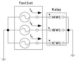

Figure 6B shows off-the-shelf software available to play back this particular COMTRADE record through the test set to the relay.
t est pR ocedu R e
1. First play back the inrush case to the relay with harmonic restraint disabled.
2. The relay should trip when harmonic restraint is disabled.
3. If the relay trips then play back the inrush case again with harmonic restraint enabled.
4. The relay should not trip when harmonic restraint is enabled. (See Figure 7)

a dvanced t est – a djusting the l evel of 2nd h a R monic c ontent
It is possible to reduce the amount of 2nd harmonic content present in the inrush current during the injection test. You can reduce the level of 2nd harmonic current until the restraint no longer blocks the differential protection. For example, 10 percent is typically the minimum level acceptable to set the 2nd harmonic restraint; otherwise, if it were set lower, tripping might be significantly delayed for heavy internal faults due to harmonics generated by CT saturation. The software shown below in Figure 8 illustrates this process:
1. First isolate the fundamental component and 2nd harmonic component in B-Phase current (IB).
2. Next multiply the 2nd harmonic content by a factor to reduce its magnitude to the pickup level selected for the 2nd harmonic restraint. For this particular case the minimum pickup is 10 percent. Therefore, the multiplication factor is 0.7 (i.e., ).
3. Reassemble the B-Phase current by adding the fundamental and 2nd harmonic back together (Depleted IB in the case of the figure below).
4. Finally inject the adjusted current into the relay.

l oss-of- f ield g ene R ato R pR otection o pe R ation
The second example is an actual loss-of-field event captured by a numerical generator protection relay. The event is shown in Figure 9 below.

The numerical relay that tripped and captured the event was configured for 115 volts line-to-line and 5 amperes secondary. The maximum current measured by the relay during the event was 1.9 amperes secondary. Figure 10 shows the impedance trajectory (ZAB) corresponding to the loss of field. It is simpler to view one phase-to-phase impedance since the loss of field is a balanced three-phase event. Note that the scale in the impedance diagram is kiloohms. Figure 10 shows the corresponding points in time in the current channels. Table 1 shows the corresponding timeline. Note that the impedance trajectory does not have a constant velocity.
Figure 10: Loss-of-Field Impedance Trajectory
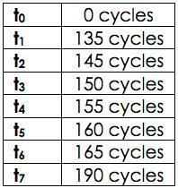
table 1: Loss-of-Field Timeline
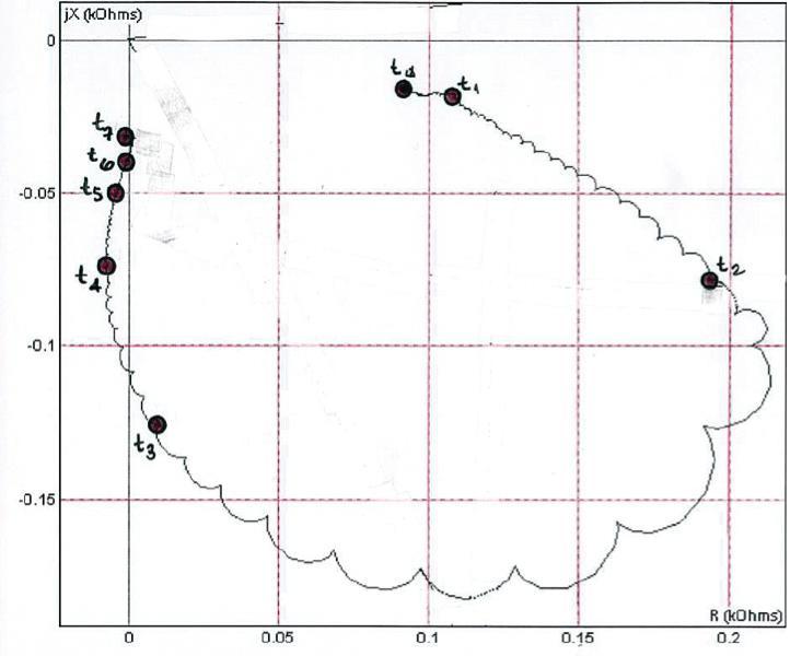
Figure 11: Loss-of-Field Current Channels


Figure 12: Loss-of-Field Impedance Function Characteristic and Impedance Trajectory
Figure 12 above shows a loss-of-field impedance characteristic superimposed on the trajectory. The characteristic has an offset equal to three ohms secondary and a diameter of 32.5 ohms secondary.

13: Loss-of-Field Zone 2 Impedance Settings

This purpose of this paper is to demonstrate how to use COMTRADE records to test protective relays. COMTRADE records that have been captured by numerical relays and digital fault records recorded during actual system events are of particular interest since these provide the ability to test protection for critical faults or disturbances such as an out-ofstep condition that are hard to create using off the shelf test set software. Utilities and other customers can build a library of test cases.
The first case uses a COMTRADE record captured by a numerical transformer relay to ensure your protection does not operate during inrush. This case is suitable for many applications; that is most two winding transformers and autotransformer banks with five ampere rated CT secondary values on the high side.
The second example is an actual loss-of-field event captured by a numerical generator protection relay.
You will need a three-phase test set that can play back COMTRADE records. Three voltage channels and three current channels are required. Connect the three-phase test set to the relay as shown in Figure 14 above:
1. Configure the relay so that one output closes when the 78 function first picks up (O1) and another closes when the 78 function trips (O2).
2. Connect the two outputs to the test set such that O1 starts the timer and O2 stops the timer.
3. Playback the out-of-step case to the relay.
4. You can measure the time required for the function to operate, which should be 18 cycles plus the time delay.

Steve Turner is a Senior Applications Engineer at Beckwith Electric Company. His previous experience includes working as an application engineer with GEC Alstom, an application engineer in the international market for SEL, focusing on transmission line protection applications. Steve worked for Progress Energy, where he developed a patent for double-ended fault location on transmission lines.
Steve has both a BSEE and MSEE from Virginia Tech University. He has presented at numerous conferences including: Georgia Tech Protective Relay Conference, Western Protective Relay Conference, ECNE and Doble User Groups, as well as various international conferences. Steve is a senior member of IEEE.


Since arcflash potential is directly related to breaker clearing time, the QUICK-TRIP system provides an easy and safe method to reduce fault-clearing time without opening a cubicle door to reprogram the trip unit.
The QUICK-TRIP system is activated by means of a padlockable selector switch. When enabled, two additional settings are activated in the AC-PRO trip unit to provide enhanced protection: These two individally programmable settings are designed to provide faster clearing times in the event of a fault.
A technician needs to rack out a feeder breaker for maintenance. In so doing, he is the minimum 18” away from any potential arc flash source in the cubicle. As the breaker is being racked out, a 12,000 amp arcing fault occurs inside the cubicle. The 2000A main breaker sees the fault and trips, subsequently clearing the fault in the feeder breaker cubicle.
The two graphs below illustrate the dramatic impact that arc-clearing time has on incident energy levels.
Given that: F = 12kA and D = 18 in.
Graph 1:
QUICK-TRIP: OFF shows the trip time characteristics of the main breaker.
❏ The AC-PRO will cause the main breaker to clear the 12kA fault in .556 seconds (based on a ShortTime Delay of .20 seconds with I2t ON). The resulting arc duration will be: t = .556
❏ The resulting incident energy is: EI = 25.8022
❏ The Hazard Risk Category is: 4
Graph 2:
QUICK-TRIP: ON shows the trip time characteristics of the main breaker.
❏ The AC-PRO will now cause the main breaker to clear the 12kA fault .05 seconds (based on the Instantaneous QT or I QT Pick-Up setting of 8000 amps). The resulting arc duration will be: t = .05
❏ The resulting incident energy is: EI = 2.3203
❏ Hazard Risk Category reduced to: 1
The QUICK-TRIP system is as easy to use as it is to install, with the additional personnel safety features:
❏ Installation uses standard punches.
❏ Wires in minutes without cutting into existing wiring harness.
❏ QT settings are only active when the selector switch is in the ON position (during maintenance).
❏ Reduction in arc flash incident energy levels may permit lower PPE clothing for maintenance personnel.
❏ Padlocking switch can be incorporated into a lock-out tag-out procedure.
❏ QUICK-TRIP ON LED confirms operation.
❏ SELF-TEST LED verifies trip unit operation.
❏ PICK-UP LED indicates overcurrent situations.
❏ QUICK-TRIP settings can be reviewed on the external PRO-DISPLAY.
❏ Last Trip Data and all settings can be reviewed on the PRO-DISPLAY.
❏ 3-phase currents are displayed continuously on the PRO-DISPLAY.
❏ The system is fully powered by the trip unit’s CTs. No aux power or batteries.
❏ Extra contacts on the selector switch are available for external annunciation.


ThisDon A. Genutis No-Outage Electrical Testing, Inc.
column focuses on electrical inspection methods and technologies that are performed while the electrical system remains energized. Although no-outage inspections can be very valuable tools,
always remember to comply with proper safety guidelines when conducting energized On-Line inspections.
It was a cool, overcast morning in the Mid-Atlantic region of the US. The Chevy Tahoe we were riding in had just crested a small hill along the transmission line right-of-way path that we had been following through the woods, when suddenly our driver shouted “Look at that!” We peered through the windshield with our vision slightly obstructed from the light mist of drizzle that was accumulating. Twenty yards ahead, we had surprised a small herd of sleeping deer that were now clumsily scrambling to their feet. We stopped and stared in silence, and the deer stared back for a moment before leaping off.
We were working for a major electrical utility that was concerned with the integrity of their existing 30-year old transmission line. A key component to the overall tower integrity is the tower foundation. The customer operated a 10-mile long stretch of line that was slated for future conductor upgrading in order to accommodate the greater projected regional power demand. Since the new, heavier conductor would place greater stress on the tower and foundation, transmission engineers needed data to ensure that the foundation condition was adequate. A number of factors can contribute to diminish foundation integrity including but not limited to:
• Natural aging process – the cement will degrade over time
• Earth settling – over years, the earth may settle and place stress on the foundations
• Freeze/thaw cycling – this constant natural cycle is more severe in northern climates
• Floods – soil erosion may create abnormal foundation stresses
• High intensity winds – tornadoes or microbursts can create mechanical tower stresses
• Earthquakes – can cause sudden shifting of the earth or create mechanical stresses by sudden accelerations
• Vegetation roots – neglected ground vegetation clearing can cause foundation stresses
• Improper installation – inadequate foundation depths or dimensions can cause greater stress
These forces can cause the foundation to crack or crumble and may partially expose the steel tower leg below the earth’s surface to moisture penetrating through the surrounding soil. The moisture can cause corrosion of the steel which even further diminishes the tower’s structural integrity. The diminished foundation can lead to complete failure of the tower structure and result in a major outage especially when subjected to abnormal weather conditions.

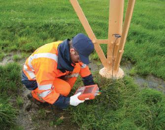
In the past, aging towers were simply ignored or surveyed by excavating a random sampling of tower legs and performing careful visual inspections to identify foundation problems. This method was fairly intrusive and could actually cause damage to the foundation or the supporting earth structure. The method was also very expensive and presented potential safety concerns. Since it was just too impractical to sample all of the legs, a problem foundation could easily be left undiscovered. To overcome these shortcomings, EA Technology developed an efficient and inexpensive nonintrusive test method that reliably determines the integrity of all tower foundations.
Two methods are safely used to test the foundations while the circuit remains energized. One method tests the integrity of the foundation while the other tests for corrosion of the steel tower leg.
The foundation integrity test is performed by carefully tapping the top of the foundation (see Figure 1) with a special hammer equipped with accelerometers. The accelerometer outputs feed a battery powered handheld instrument that measures and records the intensity and timing data of the acoustical impulse and the arrival time of the reflected signal as it returns after reaching the bottom of the foundation. The time and amplitude data can be analyzed later to determine foundation integrity.
Steel integrity is tested by using a battery powered, belowground corrosion meter. One instrument lead is attached to the tower leg, and the other leads are placed in the ground (see Figure 2). The equipment determines the presence and degree of steel corrosion using linear polarization resistance techniques which are related to the corrosion current flow to the earth.
Using the collective data produced by these two methods, the below-ground tower foundation integrity can be determined and summarized in a risk-assessment report which indicates the condition of each tower leg. This information has been proven to be very useful to asset managers who can schedule repairs to the faulty foundations which results in greater transmission reliability and maximizes asset lifetime As greater reliability is sought while our assets continue to age, efficient nonintrusive, condition-based asset management methods such as these will be vital in meeting the future demands.

Don A. Genutis received his BSEE from Carnegie Mellon University. He was a NETA Certified Technician for 15 years and is a Certified Corona Technician. Don’s technical training and education are complemented by twenty-five years of practical field and laboratory electrical testing experience. Don serves as President on No-Outage Electrical Testing, Inc., a Group CBS affiliate that focuses on new inspection technologies performed while the equipment remains in service.


Intro D uct I on
Very significant progress has been made since our previous publication on the interpretation of dissolved gas analysis (DGA) data for on-line load tap changers (LTCs). Since then an IEEE working group has made advances in its development of a simple statistical DGA method for detecting abnormal LTC conditions. The LTC DGA nomogram published earlier has now been redesigned for the use of both gas concentration and gas ratio limits.
f re DI Jakob & k ar L Jakob WEIDMANN
Diagnostic Solutions, Inc.
James Dukarm, Delta-X Research, Inc.
II. Detect I on of Problem ltc s
IEEE Transformers Committee working group C57.139 has developed a guide for the interpretation of LTC DGA data. Key concepts expressed in the guide are:
• Many LTC abnormalities can be detected by means of statistically derived limits for combustible gas concentrations and combustible gas concentration ratios.
• Derivation of generic fault detection limits for all LTCs is not possible because of the wide variation in LTC design, breathing configuration, and operating conditions. Limits must be derived for specific models of LTCs.
Documentation for the IEEE C57.139 working group’s statistical method for derivation of caution and warning limits can be obtained by contacting the authors.
The origin of the gases found in LTCs has been discussed in our previous publication, which provides a good understanding of the gas production process.
Gas concentration ratios that have proven useful for LTC condition diagnostics are listed in Table 1. Note that ratios that include hydrogen as an arcing gas are no longer recommended. This is because hydrogen’s ability to diffuse rapidly out of the oil and escape through the LTC breather into the atmosphere tends to make the hydrogen concentration and the ratios using hydrogen unreliable.

Table 1: Diagnostic gas concentration ratios
Nitrogen and oxygen are not fault gases, but their concentrations in oil are shown in DGA reports. The ratio of nitrogen to oxygen in the atmosphere is 3.76, but in air-saturated oil the ratio is about 2 due to the different solubilities of these gases in oil. In a free-breathing LTC, dissolved oxygen is replaced as fast as it is consumed, so the N2/O2 ratio value typically
remains near 3. If an LTC breathes through a desiccator and the desiccator is blocked, the ratio increases as oxygen is consumed without replacement. Consumption of oxygen by the oil results in the production of compounds that coat LTC contacts and lead to the formation of coke.
iii . gR aphical d ata i nte R p R etation m ethods
Several graphical methods have been published for interpretation of DGA results for power transformers. These methods are well documented and widely used. One of these methods, the Duval Triangle, has been modified for LTC-DGA data. We have previously published a nomogram for power transformers and a separate nomogram for LTCs. An improved nomogram has now been developed for LTCs.
iv. n omog R am d esign
The original gas ratio nomogram for LTCs employs two vertical logarithmic scales, one for each fault gas involved in the ratio. A line is drawn connecting the two gas concentrations as reported for an oil sample. The slope of this line represents the ratio of the two gas concentrations, which is correlated with fault type and severity.
The improved nomogram, shown in Figures 1 and 2, has three vertical logarithmic scales. The two leftmost scales represent the numerator and denominator gas concentrations, and the rightmost scale represents the numeric value of the ratio. Note that for geometrical reasons the ratio value scale is inverted, with the largest values at the bottom.
This arrangement permits the subdivision of the scales into Normal, Caution, and Warning zones according to the limits provided for the gas concentrations and the gas ratio. When a line is plotted on the nomogram representing a specific case, it is immediately apparent whether any limits have been exceeded.
A case study illustrates the design and application of the nomogram. For this example, nomograms are shown for ethylene/acetylene and nitrogen/ oxygen. Similar gas ratio nomograms can be plotted, as required, for the other diagnostically useful gas ratios mentioned in Table 1. The example LTC has a single compartment with oil-immersed arcing contacts. Table 2 lists the DGA history of this unit. The applicable fault detection limits for this population of LTCs are as shown in Table 3.
Table 2. DGA history for LTC case history

Table 3. Applicable fault detection limits for the example Caution Warning
Ethylene 1157 2020
Ethylene/Acetylene ratio 0.3 0.4
Oxygen/Nitrogen ratio 7
table 3: Applicable fault detection limits for the example
Figure 1 is a nomogram for the ethylene/acetylene ratio. The gray dashed line joining all three scales represents the January 21, 2005, oil sample which, with 1858 ppm of acetylene and 439 ppm of ethylene, is similar to the previous samples. From the nomogram, it is evident that the gas concentrations and the ratio value for that sample are within their normal ranges.
The colored, dashed line represents the June 20, 2005, sample, with 1251 ppm of acetylene and 523 ppm of ethylene. In this case, the ethylene/acetylene ratio value falls inside the Warning range on the ratio value scale. An excessively high value of that ratio in LTCs of this type is usually a sign of an arcing contact problem, such as coking,
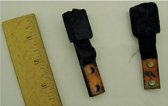
which greatly increases the amount of heat produced per operation. This LTC was kept in service until much worse DGA results were obtained in February 2006. Internal inspection revealed severe coking of the reversing switch contacts, as shown in Illustration 1.
Figure 2 is a nomogram for the nitrogen/ oxygen ratio. The gray, dashed line represents the January 21, 2005, oil sample, with 86993 ppm of nitrogen and 29483 ppm of oxygen and a nitrogen/oxygen ratio of 2.95. The colored, dashed line represents the June 20, 2005, sample, with 62041 ppm of nitrogen and 14846 ppm of oxygen and a ratio value of 4.18, which does not exceed the limit of 7 but in connection with the ethylene/acetylene result could raise the question of whether the oil condition is deteriorating.
Jakob, F., Jakob, K., Jones, S. And Youngblood, R. “A Nomograph for Interpretation of LTC-DGA Data”, NETA Conference, San Antonio, Texas, March 15, 2004.
Duval, Michel, “A Review of Faults Detectable by Gas-in-Oil Analysis in Transformers”, IEEE Electrical Insulation Magazine May/June 2002, Vol. 18 No. 3, pp. 8-17
Duval, Michel, “The Duval Triangle for Load Tap Changers, Non-Mineral Oils , and Low Temperature Faults in Transformers”, IEEE Electrical Insulation Magazine, Vol. 24, No. 6, Nov-Dec 2008
Church, J.O., Haupert, T.J. and Jakob, F., Electrical World, Vol. 201, No. 10, October 1987, pp. 40-44
Pruente, John, Personal Communication
Dr. Fredi Jakob is a consultant for Weidmann Diagnostic Solutions Inc. He organizes courses and conferences for Weidmann Diagnostic Solutions. He has also been an instructor for the previous courses offered by the Weidmann Education Division. Dr. Jakob is a long-term member of ASTM and IEEE and author of over 50 published articles. He is a traveling lecturer to private and governmental agencies and has been invited to speak at Doble and AVO conferences, NETA, EPRI and American Public Power meetings and ASTM symposia. Prior to his current position with Weidmann, Fredi Jakob was the founder and Laboratory Director of Analytical ChemTech International, Inc. (ACTI). He served as Professor of Analytical Chemistry at California State University, Sacramento for 36 years. Over the years he was a visiting professor at the following institutions: University of Wisconsin, Madison; Oregon State University, Corvallis; Victoria University, Wellington, N.Z.; University of Wollongong, Australia; University of California, Davis; and University of Utah, Salt Lake City. He was a visiting scientist at Lawrence Laboratories at University of California, at both Berkeley and Livermore. Dr. Fredi Jakob received his B.S. Degree in Chemistry from CCNY and a Ph.D. Degree in Analytical Chemistry from Rutgers, the State University of New Jersey.

Karl Jakob is the Director of Business Development for Weidmann Diagnostic Solutions Inc. He holds a Bachelor of Science in Electrical and Electronic Engineering from California State University, Sacramento, and is a Registered Electrical Engineer in the State of California. Karl was a cofounder of Analytical ChemTech International (ACTI) and has coauthored several papers on oil diagnostic applications which have been published in trade journals and presented at technical conferences such as EPRI, NETA, Doble, etc. Mr. Jakob is an active member of the IEEE Transformers Committee.



ENSURING THE FLOW.
Compact, easy to use, essential.
HV testing and cable diagnostics device. Reliable operations and targeted investments minimize costs for your cable network
frida TD
Testing up to 24 kVrms
Integrated tan delta diagnostics
Cable sheath testing Data management with Our exclusive partner for the US HV TECHNOLOGIES, Inc., • +1-703-365-2330 hvsales@hvtechnologies.com • www.hvtechnologies.com
BAUR worldwide: BAUR Prüf- und Messtechnik GmbH T +43 5522 4941-0 · headoffice@baur.at · www.baur.at





January always marks a gathering of the NETA Board and members somewhere a little further south, far from the bitter cold of the arctic blasts that sweep across much of North America this time of year. This January brought the NETA group to St. Thomas in the US Virgin Islands where they enjoyed the hospitality of the staff at Frenchman’s Reef and Morning Star Marriot Beach Resort. One of the most exciting agenda items was the unveiling of NETA’s new image, comprised of new logos for NETA, PowerTest, the NETA Affiliate Program, and a complete redesign of the NETA World Journal, the first issue being spring 2011. The new visual components are accompanied by a brand statement and a brand promise. While there were many different reactions and opinions expressed during the brand preview, the overwhelming feeling is that of excitement for this new look. Getting down to business during the day still provided ample time for social networking in the evenings, with seasoned NETA members welcoming the newer members with gusto.
• Acceptance Testing
• Planned Electrical Testing and Preventive Maintenance Programs
• Power Generation Systems Testing
• Cable Testing
• Relay & Meter Calibration
• Ground Resistance Testing

• Transformer Oil Analysis, Vacuum Degassing and Repair
• Emergency/Normal Power Generator System Testing
• Load and Power Quality Recording/Analysis
• Chiller Systems Testing
• Infrared Inspections


•
Arc-flash hazard awareness is a critical topic for those responsible for the management of electrical power systems. NFPA 70E requires an evaluation of the arc-flash hazard level at each piece of electrical equipment and a listing of the personal protective equipment (PPE) necessary if the equipment is to be worked on while energized. NFPA 70E and IEEE Standard 1584-2002 provide the means to calculate the hazard level in terms of incident energy of the arc. In the evaluations used in both standards, the hazard level becomes a function of available bolted fault current at the point being evaluated and the time that a fault might be allowed to persist before some portion of the protective system clears the fault. Reducing either the bolted fault current or the clearing time will reduce the arc flash-hazard, and a sufficient reduction of the hazard will allow use of less restrictive PPE. The magnitude of the available fault current is dependent on the configuration of the system, the sources available, and other factors beyond the scope of the protective system. The clearing time, on the other hand, is directly controlled by the protective system. This application note provides suggestions for how to use relaying techniques to reduce clearing time without compromising the existing protection, including selectivity.
a r C -Fla SH
mI t I gat I on t H roug H r elay I ng
Figures 1 and 2 show representative one-line and relay connection diagrams to illustrate many of the techniques mentioned. These techniques can be used individually or in combination. The one-line in Figure 1 represents an industrial system, served at medium-voltage from the utility (bus 1 in room 1), that has a second medium voltage switchgear location (bus 2 in room 2), and a transformer stepping down the voltage to 480 V for utilization at bus 3. It is likely that a real-world system would be much larger but would have similar features. Figure 2 illustrates connections among numeric multifunction relays discussed below.
Typically, a system using numeric relays has multiple settings groups, and this capability can provide a means for arc-flash mitigation without the need for additional relays. One method for using settings groups for arcflash mitigation is to have one group provide normal, fully coordinated protection with the high hazard level associated with the normal protection. By using switches at the entrance to each switchgear room, the relays can be switched to a different settings group, which can provide faster clearing times and allow work on energized equipment with a lower level of PPE than the normal settings.
Arc-flash hazard awareness is a critical topic for those responsible for the management of electrical power systems.
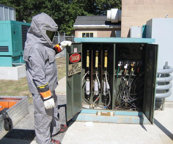
The switch would be wired to an input on each relay and used to control which of the two settings groups is active. With the switch in the “normal” settings group position, there would be no change from the settings previously in use. With the switch in the “hot work” settings group position, each relay would have an instantaneous element set no more than 150% of maximum load, with an allowance for any starting inrush currents that might occur while workers are performing hot work. This instantaneous setting will not necessarily coordinate with downstream devices but is only used while energized equipment is being serviced.
Ideally, the change in settings groups also would be applied to the relay of the breaker supplying the gear in question, because the reduced hazard only applies for faults beyond the CTs connected to the relay with “hot work” settings applied. If the supply breaker is in the switchgear in question, that section of the gear will not have the same lower hazard level associated with the remainder of the gear.
Figures 1 and 2 show an example of this application. In Figure 1, note the location of relays 1, 2, and 3; and, in Figure 2, note the connections to input IN3 of each of these relays. Relay 1 is on the main breaker on the incoming line from the utility to switchgear bus 1 in room 1. Relay 2 is in the same gear as relay 1 and protects the feeder to switchgear bus 2. Relay 3, at switchgear bus 2, is on a feeder supplied by bus 2. A switch at the entrance to switchgear room 1 would activate IN3 on relays 1 and 2 to change the settings groups of these relays. Unfortunately, there is no means to increase the speed of the utility protection ahead of relay 1, so the fast tripping will not apply for faults on the supply side of the main breaker; that section will have a higher incident arc energy than the remainder of the gear. A switch at the entrance to switchgear room 2 controls relay 3 and other relays in that gear, as well as relay 2 in switchgear room 1 on the feeder to switchgear bus 2. To allow the control switches at each room to control relay 2 through the same input, the diodes shown are used to block the signal from traveling beyond the intended relays. That way, when the switch for room 2 is on, relay 3 and the other relays in that room are in the “hot work” settings group as is relay 2 in room 1. The upper diode prevents the signal from reaching relay 1 and other relays on that bus, leaving the coordinated protection active.
One thing to consider when contemplating this approach is how the relay responds to the command to change settings groups. Some relays make the change from one settings group to another between ¼ cycle scans and are never off-line. Other relay manufacturers are known to go off-line during the time the settings groups are changing, and the relay does not provide any protection during that time.
In many cases, the greatest reduction in arcflash hazard can be achieved through the use of additional relays, particularly differential relays. The beauty of differential relaying from an arc-flash mitigation standpoint is that each differential relay protects a clearly defined zone within the system and does not require any delay to coordinate with protection for other portions of the system.
Bus differential protection provides a means to respond to faults on a bus without the need for any delay to coordinate with other portions of the system; trip decisions can be made in less than one cycle from the onset of the fault to the trip contact closing. Adding in breaker time, a bus fault can be cleared in 6 cycles or less (0.10 sec at 60 Hz). This is a vast improvement over conventional overcurrent protection times that can extend into the seconds or even tens of seconds. One caution when using bus differential for arc-flash mitigation with metalclad switchgear is that, with the CTs mounted on the breaker bushings, as is the typical installation method, the zone of protection ends at the CTs and a fault at the line terminals will not be cleared by the bus differential.
In Figure 1, a BE1-87B is shown with CTs paralleled from each line in and out switchgear bus 1. Not shown in the diagram is the tripping connection between the relay and the breakers in the gear. Typically, that tripping connection would be through a lockout relay with a trip contact for each breaker. If a bus differential relay were applied at switchgear bus 2, CTs would be needed on the incoming feeder, and the lockout relay for this gear would need to trip the supply breaker associated with relay 2.
Transformer differential relays can be useful in arc-flash hazard mitigation, particularly if the zone of protection is expanded from the usual zone of protection. Often, transformer differential relays are applied with the CTs at the terminals of the transformer, and this limits the zone of protection to the transformer itself. If, on the other hand, the CTs of the transformer
differential are installed at the breakers on each side of the transformer, the zone of protection will extend to the switchgear. With the transformer differential CTs on the bus side of the breakers and the bus differential CTs on the line side of the breakers, the zones will overlap and there will not be locations where a fault could persist for longer periods of time while waiting for a time overcurrent element to time out.
Figure 1 shows a BE1-CDS relay around the transformer, with the CTs located at the gear at each end of the circuit.
In many industrial installations, lines are short enough that two terminal differential relays can be used for line differential with the CTs at both ends of the line brought to the relay. Used this way, careful analysis of the burden of the CT circuits can help avoid CT saturation. The relay burden is low enough that the burden seen by the CT secondary is essentially the impedance of the conductors to the relay.

If the BE1-CDS relay shown around the transformer were to be connected on the feeder between the two pieces of switchgear, faults on the feeder could be cleared instantaneously.
Communications between relays can greatly reduce the relay time without the need for additional relays, although it does require the use of numeric relays. In the simplest implementation (see Figure 1), consider two relays on a radial circuit, one upstream of the other. In addition to the normal time and instantaneous overcurrent settings, we will add an additional low set definite time (instantaneous with time delay) setting on each relay. We will also connect an output of the downstream relay to an input of the upstream relay. For each relay, this new setting will be set above load, for example 150% of load, but does not necessarily need to coordinate with inrush or other transient events. The upstream relay may be set less sensitively as it may serve more load than the downstream relay, or they may be set nominally the same if they see the same load, but in no case should the upstream relay be set more sensitively than the downstream relay. To avoid inadvertent lack of coordination, the upstream relay should be set less sensitively than the downstream relay by at least twice the relay/CT tolerance. The downstream relay logic will be set to activate the output whenever the low set element is picked up.
The upstream relay will receive, through its input, a signal that the downstream relay sees something unusual. The NOT of this signal will be ANDed with the trip of the low set element in the upstream relay.
Knowing that the fault or other abnormality is beyond the next relay downstream, the upstream relay does not need to trip. If the upstream relay low set element picks up but the blocking signal is not received, it can trip after a delay long enough to allow receipt of the blocking signal, plus some margin, as it will have been determined that the fault is located between the relays. With relays directly connected, the delay time can be three cycles or less; with an interposing relay the delay time can be four cycles. Testing during system commissioning can determine the nominal signal time, and the protection engineer can add the desired margin to arrive at the time setting. With this technique, it is helpful to use a very short recognition time and a very long debounce time for the input on the upstream relay. The short recognition time is desired to ensure than the signal is recognized as soon as possible, thereby allowing a shorter delay time. The long debounce time is desired to keep the blocking signal in place until after the element on the upstream relay has dropped out. Making these adjustments to the input processing times increases the security of this scheme.
The scheme can be extended to include more relays upstream and downstream of the two considered above. As with the bus differential, if this scheme is used only within one piece of switchgear, there will be very fast clearing for faults on the bus itself, but faults that occur on the cable terminals of outgoing feeders will be beyond the CTs of the downstream relay. Communications from the next switchgear or from the load will extend the scheme and provide complete protection.
1 BE1 Relay at main breaker; could be BE1-851, BE1-951, BE1-1051, or BE1-IPS100.
2 BE1 Relay at feeder breaker in main board; could be any of the relays listed above.
3 BE1 Relay at feeder breaker in sub-board.
4 BE1-87B Bus Differential Relay.
5 BE1-CDS220 or BE1-CDS240 Transformer Differential Relay.
6 Contact of switch at entrance of Switchgear Room 1.
7 Contact of switch at entrance of Switchgear Room 2.
8 Diodes used to allow two switches to control the same relay input without mixing signals.
9 Connections to relay from switch at room entrance.
10 Blocking signal input to relay room downstream relays.
11 Blocking signal output from relay to upstream relay.
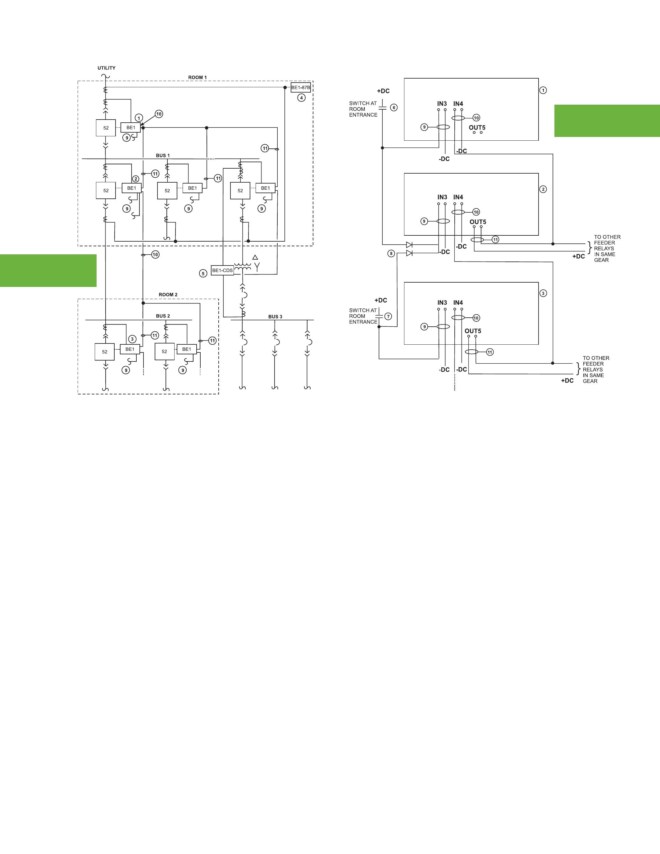
This scheme is illustrated in the figures with the connections detailed in Figure 2. Starting with relay 3, OUT5 closes whenever the low set picks up. This signal becomes an input to relay 2, shown as IN4 in this example. The signal from OUT5 is paralleled with outputs of other relays at the same level in the system so that any relay can provide the blocking signal. Relay 2 receives the blocking signal from relay 3 and also has sent a blocking signal upstream to relay 1. If a fault occurred on bus 2 (Figure 1), the low set element on relays 1 and 2 would pick up; relay 1 would receive a blocking signal and would not trip. Relay 3 would not see the fault current, so no blocking signal is sent to relay 2 resulting in a high speed trip to clear the fault. The tripping decision would be made in 3 to 4 cycles, significantly less than using coordinated time-overcurrent elements.
In Figure 1, the connection shown between the BE1-CDS and the upstream relay can be used similarly. An overcurrent element operating on the CTs on the secondary of the transformer can provide a blocking signal which indicates that the fault has occurred on the 480V system rather than somewhere between the medium-voltage gear and the lowvoltage gear.
In all protection schemes, the boundary of the zone of protection is defined by the location of the CT. Traditionally, switchgear has been designed to allow CT installation on the bushings of the circuit breakers. This provides a convenient location for the installation of the CTs and provides good physical protection of the CTs (See Figure 2). Also, at this location there are no concerns of cable shields interfering with correct measurement of the current. As previously discussed, this location can create the situation of faults within the switchgear being seen as beyond the zone of the switchgear. If the CTs are moved to the cable compartment, the zone of protection can be extended to include the cable terminations. Unfortunately, in this location it will be necessary to provide support for the CTs, run the cable shields back through the CT to cancel any current flowing on the shield, and find a path for the CT secondary circuit from the cable compartment to the control compartment.
All of the protection ideas discussed to this point assume that the intended breaker will trip at the correct time, but what happens if that assumption is false? The possibility of a breaker failing to trip is accounted for in conventional coordinated time overcurrent settings where each device is backed up by all devices further upstream; failure of one device to clear a fault means that the next device will have an opportunity to clear the fault after the set time delay. The fact that times for this backup protection can get into the seconds becomes a serious issue if failure of one interrupting means is considered when evaluating arc flash hazard. Using the breaker failure protection features of the Basler numeric relays, it is possible to have backup protection operate within a few cycles of a breaker failure rather than a few seconds.
In Figure 1, if relay 3 sent a trip signal to its breaker, but the breaker failure logic of the relay indicated that the breaker did not open to interrupt the current, the relay would try to retrip the breaker. Simultaneously, or with a user-selected delay, it also would send a trip signal to the breaker associated with relay 2 to clear the fault at that location. Using breaker failure protection, the breaker at relay 2 will be tripped to clear a fault beyond the faulted breaker at relay 3, and that tripping can occur with a delay of less than 20 cycles after the initial attempt to trip the breaker at relay 3.
Historically, protection systems have relied on time coordinated overcurrent protection for selective clearing of system faults. The need for selectivity has resulted in clearing times that become progressively longer the further upstream in a system the fault occurs. When arc- flash hazards are considered, this increased time results in increased levels of required PPE, until the hazard becomes so great that there is not an adequate level of PPE available. Using the relaying techniques discussed above, it is possible to significantly reduce the clearing time for faults at any location in the system while maintaining full selectivity. It is a realistic goal to achieve primary clearing times of less than 10 cycles and backup clearing times of less than 20 cycles for an entire system while maintaining full selectivity for all primary protection.
As published by Basler Application Notes#PC-ARCFLASH


CIRCUIT BREAKERS
LOW & MEDIUM VOLTAGE
• General Electric
• Cutler Hammer
• Allis Chalmers
• Federal Pacific
TRANSFORMERS
1000 – 5000 KVA
• Westinghouse
• Siemens
• ITE/ABB
• Square D
• Dry type transformers from stock
• Cast resin from stock
• Load break switch & fuse
LIFE EXTENSION
LET US DESIGN A PROGRAM TO EXTEND THE LIFE OF YOUR SWITCHGEAR
• Vacuum retrofill
• Vacuum retrofit
• Solid state conversion
• Vacuum motor control upgrades
MOLDED CASE CIRCUIT BREAKERS & LOW VOLTAGE MOTOR CONTROL
• Circuit breakers
• Motor control components
• Upgraded buckets
• Panel mount switches
SWITCHGEAR
480V – 38kV NEW AND SURPLUS
• New General Electric switchgear in 4 weeks
• Match existing lineup
• Reconditioned from stock
• Complete unit substations
• Indoor and outdoor available
RENEWAL PARTS
SWITCHGEAR & CIRCUIT
• All low & medium voltage renewal parts,
• Obsolete vacuum interrupter in stock
• www.circuitbreakerpartsonline.com

• New General Electric available from stock
• Reconditioned starters and contactors
SERVICE & REPAIR
• Field service and testing
• Shop repair of all switchgear and circuit breakers

• Universal circuit breaker remote racking system
• Safety switch for remote switchgear operation

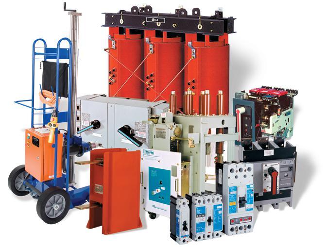





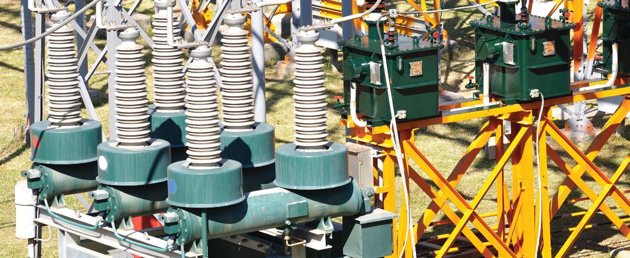
 By John Hodson
t e CH n I que S F or t H e 21 S t Century
histo R ical R eview
Normally in any major facility, no matter whether utility or industrial, a significant commercial investment exists in the electrical system. These assets are in the form of transformers, cables, circuit breakers, contactors, switchgear, motors and instrumentation and protection. This is the most basic review and dependent on process many more specialized components can exist. The complexity and variance of the distribution equipment is as wide and varied as the facilities themselves.
A common and still used rule-of-thumb for equipment longevity is 25 years. Practical experience shows this life cycle can be well exceeded with nominal maintenance and attention to environmental and operational considerations. More extensive maintenance plans combined with a focused repair and upgrade program can easily result in significant extension regarding these industry expectations.
A step change is occurring in how and when we maintain our electrical equipment and in fact all our more costly assets. Case in point and one we can all relate to is the family car. In the old days we maintained our car based on a rigid chronological or distance driven equation, or as circumstances dictated...it stopped working. New vehicles take into consideration a plethora of information from built in sensors, stored data, mathematical algorithms, and in some cases even customized input from the owner. The car now makes a determination based on defined real time operational conditions regarding what should be done and when. Of course, nothing is perfect and we can all still rely on the “stopped working” circumstance for service.

Most of us are certainly aware of the “grey-power exodus” and the aversion of some of the new alpha generation(s) to accepting the old way of doing things. As the knowledge base changes and in some cases diminishes, we have to keep track of information in a new way. The nuts and bolts way of reviewing things is changing to a computer version of the same idea. Computer information is usually overwhelming and difficult to interface with on a human level. This can be especially true when dealing with copious amounts of technical data.
The reality is that a large portion of the expertise and knowledge built up over the last 40 years regarding electrical equipment maintenance and testing is disappearing. The inherent and sometimes almost intuitive understanding of problem cause, effect, and solution which was developed over this period and handed down through mentorship is depleted. In final analysis we are losing our experience.
It will take only a recent request for professional home appliance service or expert advice at the local hardware store to drive home the point as to how fast and how deep the drain on experience is occurring. When you still have that grey hair connection… hang on to it.
As our lives and systems become more complicated and time or lack of it becomes more critical, we are seeing an ever increasing push towards less down time. In the electrical sense this means reduced outage time to perform off-line maintenance procedures and tests. In some cases, outage intervals have been mandated to every five years which by measure of chronological or time-based maintenance is an eternity.
Many new initiatives and concepts are being brought forward regarding what to do and how to do it. The driving forces for these are many, not the least of which is commercial benefit to the underwriting promoter of the idea.
Up to now many attempts have been made to harness archived information and bring forward meaningful reports and predictive intervention. Some success stories exist such as dielectric oil testing, cable testing, and the longlived Doble Engineering resource experience. In fact, much more information ends up in back office bookshelves or old and forgotten archived software files. There is a multitude of useful and valuable information that can be put to use under the right conditions.
Credible and meaningful data is key! Regardless of whether the information comes from factory or acceptance testing, archived maintenance records or current and future off-line testing, it must be credible or it skews the analysis. This is why on-line data acquisition is gaining such popularity; it is real time, it is continuous, it is non-interpretive in its basic format, and it is reliable all things being equal.
Some new buzz words and acronyms are making the rounds such as risk based maintenance (RBM) or reliability based maintenance and the one I prefer, condition based maintenance (CBM). The one thing these buzz words have in common is that they all take into consideration and evaluation much more criteria than our tried and true time based maintenance (TBM).
CBM software needs input and the more reliable and accurate the information input, the more useful and effective the resultant reporting will be. The quantity of test data will not always be the most critical criteria, but consistent and controlled process is necessary to assure reliable output.
Historical tried and true shutdown testing and inspection will provide a huge amount of information regarding equipment condition. To reiterate, it is important that all data input is accurate based on consistently performed tests in a controlled and structured process. Corrupt or erroneous information will definitely cause a less than optimum evaluation. A precursory human filter is usually advisable to assure that input data is relevant.

As the digital world expands and infuses all parts of our lives, we are experiencing more and more intelligent, real-time / on line equipment analyzing the condition and performance of our electrical systems. Some of the first steps were with smart metering and now just about every recently installed protection and control device includes some level of monitoring and data acquisition capability.

Further to this we are now seeing dedicated devices to continuously evaluate costly and critical equipment and provide warnings regarding incipient failure. For the most part these are product and vendor specific. That is you buy a brand X transformer and you get a brand X monitor. Lately other more generic products are being seen in both utility and large industrial installations. We are also seeing specifications requiring the consideration of more sophisticated monitoring hardware based not only on the high cost of these assets but the extremely long repair or replacement time in the event of premature failure. A list of some of the more widely accepted and unique of these types of on-line monitoring devices can be reviewed at the PSAMS website.
Products to take analog and digital input from these numerous devices exist and are being
continuously refined and improved to allow for new entries. The best of these are generic in concept and will interface between any field device and the client’s data storage files. The protocol converts all information to a file standard that can be interpreted by the client’s CBM management system.
The successful execution of off-line testing and the implementation of reliable on-line monitoring has its own set of challenges. The key is to assure that all the information gathered is credible and reliable.
Once you have established that either or both information paths are necessary, the task is now to review and analyze these sometimes copious amounts of information and establish a condition report. In the past for the most part this was left to the experts who usually were responsible for the execution of the testing in the first place. Not to suggest this was not and is not effective, but some potential overlap regarding responsibility and accountability would be likely raised by prudent audit.
The reality is that unless continuation of expertise and both equipment and procedural standards are maintained, the potential for error cannot be overlooked. This has been for the most part overcome by long standing and trusted relationships whereby the field service company becomes an integral part of the company’s engineering resources. In some cases a specific testing technician almost becomes a permanent part of the client’s maintenance team. In this way the report and evaluation have continuity and feedback and over the years a reliable system for evaluation and mitigation of in-service failure has been developed.
The future of these long term relationships is at risk, and, in fact, some are evaporating as we speak as the grey power exodus continues on both sides of the relationship. The new replacements are expected to have up to five career changes in the first ten years of meaningful employment which is not

conducive to either field service companies maintaining expertise or the building of long term technical relationships that we have seen in the past.
The way of the future will likely include some modified derivative of the past melded with the technology of the future. One concept that I believe is getting more and more acceptance and will have a prominent place in well thought out maintenance plans is CBM. This process takes into consideration all the key parameters regarding equipment service reliability including age, critical risk, vendor specific criteria, environment, operational considerations, and historical data.
The CBM software model adds the element of real-time diagnostics with connected hardware and, more importantly, the necessary algorithms to continuously analyze and update equipment condition and reliability. This continuous and real time analysis is the key to the future and success of this technology.
The facility manager or engineer who has the most efficient asset management plan balanced with cost effective maintenance will have an enviable position in industry. A simple to use system covering all major electrical components with accurate and concise reporting of not only condition but suggested remedial action should condition dictate is the goal of this technology.
Some utilities have already taken serious steps towards the reality of a CBM asset management system. They have utilized internal knowledge, leveraged external expertise, and are working towards beta system development. The majority of these endeavors are equipment vendor driven so are product specific. Continued development will trickle through and feed more main stream efforts.
Electrical power system specialists will likely be the main driving force for more general based software that will accept generic input
data. The inception of customer-driven, opencommunication protocol (IEC 61850) for all equipment vendors will help greatly in this area. Certain companies will show leadership and, in fact, are working in partnership to bring forward viable hardware and software options as we speak.
Potential customers need to investigate options regarding this technology and choose to engage or wait based on their specific situation and requirements. It will be prudent as always to gain education and information regarding this opportunity and seek reputable expert assistance. This will allow for responsible parties to evaluate and trim input information that is either not pertinent or flawed for some reason. Past history dictates that any plan, complicated or simple, requires invested ownership to work nearly as well as conceived.
Early adopters should see benefit quite early, if only in the management of valuable data that in the past has realized little or limited longer term value. A continued investment should lead to a reliable and automated diagnostic tool akin to a traffic stop light. Green = equipment in reliable condition and only routine requirements necessary. Yellow = equipment requires some defined remedial action within a predescribed period of time to ensure continued reliability and Red = equipment is in need of immediate intervention to prevent potential in-service failure.

John Hodson spent almost 30 years with the Magna Group of Companies. He is presently involved in technical training and client support and operates as a consultant providing expert services as requested. He is also supporting a line of protective relays from Finland - VAMP and as well PSAMS a CBM and technical training company based in Calgary, Alberta Canada. He continues to promote the services of an electrical safety and a transformer service company he was instrumental in founding.You can reach John at j.hodson@shaw.ca and phone at 403-312-8500.


Insulation / Continuity
Metrel offers a wide variety of Single, and Multi-Function testers for measuring Insulation Resistance up to 10kV, Earth Resistance, Line Tracers, Continuity, Loop and Line Impedance, and Phase Rotation.

Technical demands require high performance measuring instruments capable of measuring polarization index (PI), dielectric absorption ratio (DAR), dielectric discharge (DD), time programmable step voltage test, insulation system's capacitance, etc. Metrel offers a line of 1kV, 5kV, and 10kV insulation resistance meters for these tests.

PA 19094
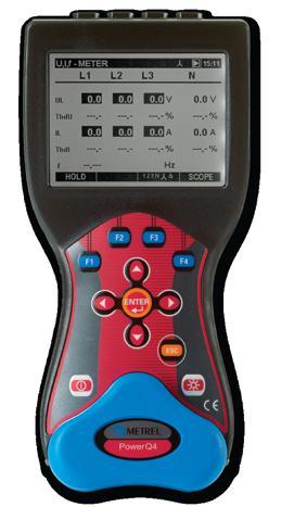
Metrel power quality analyzers are proven tools for expert designers of filtering systems, power correction equipment, over voltage protection and UPS systems. Wide range of testing possibilities are supported: voltage sags and swells, resonant states, high neutral conductor currents in 3-phase systems, asymmetry, transients, etc.
MI 3121 SMARTECFebruary 27- March 1, 2012
Omni Fort Worth, Fort Worth, Texas

Communicate Your Knowledge
Assist the Industry
Gain Visibility
Abstracts Due April 15, 2011 Submit at www.powertest.org Step Up and Be Heard!
Presentations sought:
• Review of Basics
• Specific Industry Skills
• Insights into New Methods, Technologies, and Advancements
• New Testing Procedures, Safety Procedures, and OSHA Laws
• New Types of Electrical Power Equipment
• Uptime and Reliability Issues

Reprinted with permission of IAEI News by a ndrew Cochran
With any hazard there is a definable risk and a definable impact and it is no different for the arc-flash hazard. Quite often the impact in business interruption far outweighs the physical damage to equipment and industry statistics would suggest that the average physical equipment damage is around $50,000 and the business interruption cost around $85,000 per incident.
However, there is a significant human cost to this hazard, and arc-flash victims may suffer from chronic pain and scarring. Workers may also have difficulty re-integrating into the community and may experience anxiety, depression, or other psychological symptoms. The social and economic costs may also be high. Workers’ Compensation pays only a portion of lost wages. Some workers may not be able to return to their pre-injury job. Employers bear the costs associated with lost productivity, reduced competitiveness, employee rehiring and retraining, as well as being subject to increases in Workers’ Compensation premiums.
Published data from Washington State notes that from September 2000 through December 2005, 350 Washington workers were hospitalized for serious burn injuries occurring at work. Of these, thirty (nine percent) were due to arc-flash/blast explosions. Total costs associated with these thirty claims exceeded $1.3 million, including reimbursement for almost 1,800 days of lost work time. The typical approach from an insurance perspective is to define the peril (fire, electrical injuries, etc.), quantify the likelihood of an event, and quantify the total business impact of the hazard and from this calculate the exposure. The big questions are: What drives losses? Where does one focus loss prevention efforts?

The key for engineers, safety professional, and business leaders is to adopt a similar approach and to deploy technology that will reduce the frequency of the hazard, employ technology that will provide an opportunity to take preventative action to avoid the hazard, and, finally, as a last step, utilize technology that will mitigate the damage from the hazard.
r educe the Frequency o F the hA z A rd
In practice, the majority of electrical faults experienced in industrial low-voltage systems are phase-to-ground faults. For solidlygrounded wye systems, the IEEE Red Book (Std 141-1993, Section 7.2.4) states that “A safety hazard exists for solidly-grounded systems from the severe flash, arc burning, and blast hazard from any phase-to-ground fault.”
The same standard recommends a solution to resolve this issue. Section 7.2.2 of the IEEE Red Book states that when using high resistance
grounding, “There is no arc-flash hazard, as there is with solidly grounded systems, since the fault current is limited to approximately 5 A.” The Red Book is referring here to phaseto-ground faults.
While high-resistance grounding as a technology was originally applied to power distribution systems in industries as diverse as food processing, mining, petrochemical, and even commercial installations such as airports, data centers, etc., to enhance the reliability and uptime of power distribution equipment, it is also proven effective in significantly reducing the frequency and severity of arc-flash accidents. With between 90 percent and 98 percent of electrical faults being phase-to-ground faults, by limiting the fault current to between five amperes and 10 amperes, there is insufficient fault energy for the arc to restrike. It self-extinguishes and the hazard frequency is reduced.
In fact, in the most recent edition of the NFPA 70E it states in section 130.2 FPN No.3, “Proven designs such as arc-resistant switchgear,…high-resistance grounding and current limitation….are techniques available to reduce the hazard of the system.”
While high-resistance grounding prevents the propagation of many ground faults into full-fledged, three-phase arcing faults, high resistance grounding has no affect on the magnitude of a phase-to-phase or three-phase arcing fault if phase-to-phase or three-phase faults are initiated.
Empirical data analyzed for cause from actual arcing events suggest that between 60 percent–80 percent of all arcing events within switchboards are caused by faulty electrical connections. If there were a way to measure an output from these faulty connections and to measure rate of change of the condition, a mechanism could be created to provide an alarm of a pending hazard and corrective action implemented.
One of the quantifiable and measurable outputs from the faulty connections is smoke and gas, and, in fact, the US Navy has been using technology based on commercially available radioactive ionization chambers, similar to that employed in commercially available smoke detectors, since 1991 to continuously monitor thermal conditions of connections. It has been determined that a detector set between 150° Celsius and 300° Celsius will provide indication of a hot and loose connection. This is well below the 1083°C required to melt copper and create an inline arc.
In a 2003 IEEE Transcript it is noted that test results would indicate that this set point of 150°C to 300°C will give a warning of a few minutes to several hours before the connection will develop into an arc fault.
An arc is developed in milliseconds and leads to the discharge of enormous amounts of energy. The energy discharged in the arc is directly proportional to the square of the short-circuit current and the time the arc takes to develop, i.e., energy = I2t

Figure 1. progress of pressure & temperature under arcing
The damage resulting from the arc depends on the arcing current and time, and of these two factors time is the most easily controlled and managed. Rules of thumb for different arcburning times are:
• 35 ms or less – no significant damage to persons or switchgear which can often be returned to use after checking for insulation resistance.
• 100 ms – small damage to switchgear that requires cleaning and possibly some minor repair. Personnel could be at risk of injuries.
• 500 ms – catastrophic damage to equipment and personnel are likely to suffer serious injuries.
The goal of arc-mitigation technology is to protect personnel and property, and to effectively accomplish this we must first detect the arc and then cut the flow of current to the arc in as short a time as possible. As noted above, the target is to achieve a total reaction time of 100 ms or less from detection of the arc to isolation of the circuit.
An arc is accompanied by radiation in the form of light, sound, heat, and as such the presence of an arc can be detected by analyzing visible light, sound waves, and temperature change.
To avoid erroneous trips it is normal to use a short-circuit current detector along with one of the aforementioned arc indicators, and the most common pairing in North America is current and light.
The burning of the arc heats up the ambient air causing it to expand and create a measurable increase in pressure inside the switchgear. In Europe it has become common practice to use the combination of light and pressure as positive indicators of an arc. The pressure sensor has an operating time between eight ms and 18 ms. When combined with a circuit breaker with an operating time between 35 ms and 50 ms, we have achieved our goal of 100 ms or less.
However, many older circuit breakers operate closer to 80 ms and these must be paired with a faster acting arc detection device. Arcs produce light in the ultraviolet spectrum and at intensity levels in excess of 20,000 lux, and this can be detected through special optical sensors. These sensors are connected to a relay system that has a typical operating time under one ms and is the fastest arc-flash detection technology currently available. The operating time is independent of the fault current magnitude since any current detector elements are used only to supervise the optical system.
With optical arc protection technology installed the relay operating time is essentially negligible compared to the circuit breaker operating time. The cost is fairly low since current transformers are only needed on the main breakers. Again, if we sum up the circuit breaker operating time and the optical arc detection time, we are well below the goal of 100 ms, regardless of the age and speed of the circuit breaker, and have mitigated the damage to a more reasonable level.
The combined use of high resistance grounding for protection from ground faults and its ability to prohibit the escalation of the fault, the use of continual thermal monitoring to detect early signs of loose and faulty connections, and arc-mitigation technology including pressure sensors and optical arc detection for phaseto-phase and three-phase arcing faults is an effective engineering approach to minimizing the arc-flash hazard.

Andrew Cochran is the president of I-Gard, a company that provides technical support in the application of groundfault protection and resistance grounding products. He has been with I-Gard twelve years, having spent time in an operations capacity previously with Polaroid, Stanley, and ITT. He was educated in the UK in manufacturing and production engineering and has a post graduate diploma in business studies.


w r I tten By t ony d emar I a & d ean n aylor, Tony Demaria Electric, m o S e r am I e H , III, Power Generation & Testing

When working around electrical equipment, the preferred working condition includes the equipment being put in an electrically safe work condition or turned off, locked out, and tagged out. This is stated in both OSHA and NFPA 70E requirements. Unfortunately, there are electrical hazards which must be dealt with while achieving this electrically safe work condition. These hazards could involve switching, equipment racking, voltage testing, and applying grounds to assure an electrically safe work condition. This paper will focus on the safety requirements associated with placing equipment in an electrically safe work condition.
As a precursor to this discussion, it has been noted by some that OSHA and NFPA 70E requirements can be confusing and cumbersome. It has been said that “Common sense is the knack of seeing things as they are, and doing things as they ought to be done.” It is time to apply some common sense to electrical hazards. Here are some common sense ideas for electrical safety that are unfortunately, not so common.
1. Distance is your friend. The farther you are away from the hazard, the safer you will be and the less PPE you will be required to wear.
2. Bigger equipment is usually more dangerous.
3. When removing equipment covers, removing a household light switch does not typically require an arc-flash suit for protection but removing the cover from an industrial substation typically does.
4. Shock–related PPE requirements and arc-flash related PPE requirements should be determined separately and added together.
With regard to electrical safety, to do things as they ought to be done means distancing yourself, and others, from the shock and arcflash hazards while establishing an electrically safe work condition. In order to do this, the whole process needs to be thought through and planned ahead of time. Before equipment is turned off, check the condition of the gear. Are there any panel meters or voltage indicators present? Do they appear to be working properly? Are the correct panel lights lit? In what order should the equipment be shut down? Can the loads be turned off remotely or further upstream or downstream where the hazards may be lower? Are there any additional hazards that could be introduced by turning this equipment off? If an action is likely to cause an arc-flash event, then how do you avoid injury?
Frequently, many people use the last method that should be applied. That method is to suit up in arc-flash protective clothing including leather gloves and face shield or flash-suit hood. PPE should always be a last resort when implementing a safety policy. In any unsafe situation, the goal is to remove the hazard so that the use of PPE is minimized.
When turning equipment on or off, there are several options. There are engineered options such as using computer control to operate breakers from a distant operations center. Mimic panels can be used to operate the equipment from outside of the protection boundaries or outside of the room. There are aftermarket options that attach onto the front of the switchgear and will operate switches while allowing the operator to stand away from the switchgear.
When none of these options are available, there is also an old tried and true rope-andpulley system (See Figure 1). This is not known or used by many people. It does not work for all applications but excels in switching load interrupter switches, many medium-voltage starters, and many older style OCBs. Using the rope and pulley system, a rope is attached to the operating handle or pull ring and run through a pulley(s), if necessary. In this way the operator can stand away from, and to the side of, the equipment while operating the equipment. This method is inexpensive, easy to set up, and available to everybody. This can be seen being demonstrated on a motor starter in the Fall 2010 issue of NETA World Magazine in Tony Demaria’s article, Safety and Medium Voltage Starters.
If you must stand in front of the equipment to operate it, there are a few other things you can do to mitigate being injured. Stand to one side of the equipment being operated and always wear protective gloves. When wearing a face shield and balaclava instead of a full hood, face the equipment to avoid collecting a fireball inside the shield. Arc-rated blankets can be used to redirect the blast as well.
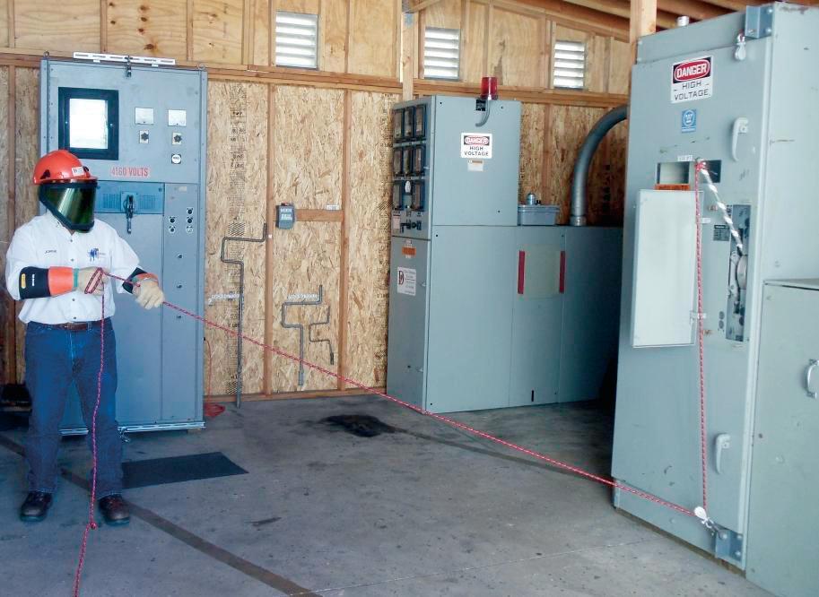
Racking out a breaker before you work on it is strongly advised and usually the only way to provide adequate separation from a hazard and establish an electrically safe work condition. Unfortunately, racking out equipment can be very hazardous. Again, there are many methods that can be used to distance yourself from the hazards. Some equipment may have builtin, electrically-operated racking mechanisms that will allow the operator to rack-in or rack-out the equipment while maintaining a safe distance. There are also many aftermarket products or robots which may be employed to rack breakers either at the end of a long control cord, or remotely via wireless control. Some of the remote racking devices come with a remote camera, or may be fitted with one at a later date.
Figure 1: Medium-Voltage Load Interrupter Switch Operation with Rope and Pulley System
If you must rack the breaker out locally, there are additional things to remember. Use closed door racking whenever possible. Wear the proper arc-flash rated PPE and stand to the side, if at all possible. If using a hand crank, use an extension on the crank handle to increase your distance from the equipment and possible arcing location. You can weld an additional section onto your factory-furnished crank handle (See Figure 2). Even an additional few feet can drastically reduce the incident energy exposure. As an example, a 42 cal/cm2 exposure at 36 inches on medium-voltage switchgear can be reduced to 21 cal/cm2 at 72 inches.

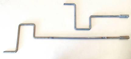

Factory Racking
Handle With Two Foot Extension
Welded On
The next task that must be accomplished is to open covers in order to test for absence of voltage. This seemingly easy task can introduce additional hazards. The cover can slip and fall into the gear. There may be loose hardware that is leaning against the cover that could fall when the cover is moved. PPE will be necessary for this task when crossing the shock or arc-flash boundaries.
First, a determination of the shock-related PPE requirements should be performed. This involves identifying the voltage to be worked on and the shock boundary to be applied. The shock boundaries are voltage dependent boundaries and vary by system nominal voltage. They are outlined in NFPA 70E, Table 130.2(C) and
in IEEE C2, Table 441-1. These are defined as the Limited, Restricted, and Prohibited Approach Boundaries and are considered the distance from exposed, energized conductors. The distances stated in these tables are irregular and may be difficult to memorize. NFPA 70E, Table 130.2(C) lists 14 voltage ranges in five columns, or up to 70 distances. We believe that over 90 percent of the electrical workers in the U.S. and Canada have not studied these standards and could not tell you these distances from memory for every voltage level presented in these tables. Further, they could not tell you the definitions of Limited, Restricted and Prohibited Boundaries. The following is an example of a way that your company can create a safety policy that will cover the great majority of electrical workers for shock protection. It uses common sense, and promotes an easy way to memorize the distances. Keep in mind that this is an example of a safety policy for shock protection only.
1. When working on or near exposed, energized, fixed circuits up to 750 volts, you should wear voltage-rated gloves and use voltage-rated tools, if you are going to get closer than three feet six inches. If there is a possibility that you might fall into the hazard, you should also wear voltage-rated sleeves. No part of the unprotected body should get closer than your arms can reach. A hard hat and electrical face shield should also be used to prevent contact in tight areas.
2. When working on or near exposed, energized circuits over 750 volts to 15 kV, you should wear voltage-rated gloves, voltage-rated sleeves and voltage-rated tools if you are going to get closer than five feet. No part of the unprotected body may get closer than your arms can reach. A hard hat with an electrical face shield must be worn.
3. Any other voltages or situations should require specialized personnel who are qualified for the higher voltages.
These distances should apply when the covers are off and before the circuits have been deenergized, locked out, tested, and grounded, if necessary. The arc-flash boundary applies any time there are exposed, energized conductors as well as any time anyone is interacting with the equipment in such a manner that could cause an electric arc. This interaction includes operating and racking breakers, removing covers, voltage testing, and applying grounds.
When opening hinged covers, care should be taken not to position yourself so that you are in the path of the arc flash or blast. Keep the door between yourself and the exposed conductors until the cover has been fully opened with no incident. When removing a cover without hinges, get some help to remove the cover. Suction cups can be very helpful when removing covers without handles. Make sure the suction cups are placed on a clean, dry, flat surface. These cups are very inexpensive and can be used to avoid dropping the cover into the equipment. Lean the cover out slowly at first and listen for any unexpected noises. Any scraping against the cover from loose parts, or the hissing or crackling of ionized air is a warning sign that more trouble could be coming. This should be investigated before continuing with the task.
In order to test for voltage, the live-dead-live method should always be employed. Panel meters or auxiliary voltage indicators may be used as additional verification. Do the panel meters that you looked at before de-energizing the equipment show an absence of voltage now? Have the voltage indicators that were lit beforehand been extinguished? Even with these checks, it is necessary to use a tested meter to check the circuit. Shock-related PPE and arcflash related PPE are necessary if crossing the shock or arc-flash boundaries, respectively.
When testing medium-voltage equipment, the meter should be attached to a hot stick. As a general recommendation, use a measuring device designed for the job and the voltage level. Do not select test equipment based on price alone. Using a hot stick will allow you to distance yourself from the hazard while performing the test. Always extend the hot stick to the fullest length that is practical. Always test all three phases. Start with the voltage range setting for the expected voltage, then gradually lower the voltage range setting to the minimum range to confirm that there is no voltage present. A contact-making meter should be used even after a proximity tester has indicated an absence of voltage in order to test for trapped charge, since proximity testers do not respond to dc voltage. Always use gloves rated for the full system voltage for this task when crossing either the restricted or prohibited approach boundaries. Test all three phases-to-ground as well as phase-to-phase.
Now that absence of voltage has been verified, grounds may be applied. Grounds should always be used when working on equipment that has high fault current capacity., once again, the goal is to protect yourself and others from the hazard.
With this in mind, there is another way to apply grounds remotely. Grounding and test devices have been around for some time, but they are not in common use. They are a common sense approach to applying grounds safely. However, it is imperative that the grounding and test device be tested for insulation integrity and the correct stab position chosen for the ground cables. Some cubicles may be energized on the top stabs and others on the bottom stabs. This is especially typical in tie breakers. Using a grounding device with the wrong side grounded could lead to catastrophic damage.
The grounding device may be inserted into a cubicle and then operated remotely from system controls or mimic panels or, if necessary, from a robot operator. Keep in mind, if it needs to be racked into the cubicle, this should also be done remotely, if possible. If not, follow the same precautions as discussed earlier for racking equipment out.
If grounding cables or clusters must be applied manually, use a hot stick. Remember again, distance is your friend. When applying ground sets, assume the circuit is energized even after the circuit has been voltage tested and verified to be de-energized. This means wear the appropriate PPE for the hazard. This is common sense as many an experienced electrician can relate a story of applying grounds and having the unfortunate experience of touching an energized conductor with the ground cluster. Not a pretty picture! The good news is, if the grounding cluster has been sized properly and is being installed correctly, it usually trips the upstream breaker with possible damage to equipment. Once again, use hot sticks at the longest practical lengths and position your body so that you are not in the line of fire. Don’t stand in the path of the hazard!
By thinking through and planning each step, the process of establishing an electrically safe work condition can be done safely and without exposing yourself to unnecessary hazards. Once the equipment is de-energized, locked out, tagged out, tested for voltage, and grounded, if necessary, an electrically safe work condition has been established. Now that this has been done safely and the electrical hazards have been removed, the original work task(s) may begin.



Tony Demaria worked for the Los Angeles Department of Water and Power in substation maintenance prior to starting his own company. He has owned and operated Tony Demaria Electric for over 25 years, specializing in maintenance and testing of switchgear and large motors for industrial facilities. Tony Demaria Electric is a NETA Accredited Company, and Tony serves as the NETA Safety Committee Chair.
Dean Naylor completed the NJATC Apprenticeship in Baton Rouge, LA before earning his degree in electrical engineering at the University of Tennessee at Chattanooga. He has 20 years of electrical experience in electrical system operating, installation, maintenance, analysis and testing. He is a member of IEEE 1584 and 1814 Committees as well as a Certified Maintenance and Reliability Professional and a NETA Level III Technician.
Mose Ramieh, III has ten years of experience in the electrical power field. He is certified as a Level II Thermographer, a NICET Certified Level III Electrical Testing Technician, and a NETA Certified Level IV Technician. His expertise covers industrial and utility power systems from 480 volts to 161 kV and all controls associated with these systems.





The intent of the 2004 version of NFPA 70E, Standard for Electrical Safety in the Work Place, is to minimize the “at-risk” procedures used by operators of electrical equipment. The first step is to minimize risk by having operators perform work with the equipment only in an electrically safe condition. The second step is to design the hazard out of the normal work procedures, and the third step is to rely on personal protective equipment to minimize the risk to the individual performing the task.
Jim Bowen graduated from Texas A&M University in 1976 with a BSEE. He has worked for SIP Engineering as a power engineer and for Exxon in all facets of electrical engineering in the petrochemical process. He held the position of regional engineer for Exxon Chemicals Europe for three years. In January of 1997, Jim joined Powell Electrical Manufacturing Company as Technical Director, providing leadership, training, and mentoring to both internal and external electrical communities.
Arc-resistant switchgear can assist with the first step effort by providing enhanced safety conditions when the operator task involves energized equipment and possible exposure to an arcing fault. Tasks in this category include:
• Racking a medium-voltage circuit breaker to or from the bus connected position
• Racking a VT or CPT roll-out to or from the bus connected position
• Opening and closing a circuit breaker
• Calibrating and troubleshooting devices within the instrument compartment
The purpose of arc-resistant switchgear certified to ANSI C37.20.7 is to eliminate the risk from the arc blast and the by-products (heat, pressure, shrapnel, and molten copper) during normal tasks performed on the equipment. During arc-fault design tests, the energy release by an arcing fault is monitored by mounting racks of a black cotton material in panels covering the surface of the switchgear. This material is similar to 4.5oz/yd untreated t-shirt material identified as Hazard/ Risk Category 0 per NFPA 70E Table 130.7(c) (11). The panels are mounted at 3.9 inches from all possible seams and one of the many acceptance criteria of ANSI C37.20.7 is that none of the cotton indicators ignites during or following a test.
While the focus of NFPA 70E is the heat from the arc in medium-voltage switchgear, it is the pressure wave associated with the arc fault that dictates the design of the switchgear. The switchgear designed for arc-resistant protection requires heavy reinforcing of the entire structure.
In conclusion, arc-resistant switchgear designs the hazard out of the tasks and reduces the level of risk for normal tasks to a zone 0 category. The result is a reduced need for PPE. The design focus of arc-resistant switchgear is to provide the necessary enhanced safety features while requiring no addition maintenance, calibration, or final element tests to assure functionality.



Need a low-maintenance instrument that’s easy to use? Is safety important in your ground testing routine?
If you answered YES to any of these questions, consider the NEW DET14C and DET24C digital clamp-on ground testers from Megger.
Megger has taken ground tester technology to a new level. Here are a few of the advanced features of the DET14C/24C:
n A large elliptical jaw that allows testing at any angle and on the largest ground rods.
n Smooth mating surfaces on clamp head means no interlocking teeth.
n CATIV 600 V operation is the highest level of user safety available.
n Intelligent data hold function increases ease of use in difficult locations.
n Data storage reduces potential for error in recording results.
n Noise filter function provides the best immunity to noise current.
n Ultra-long battery life reduces the cost of ownership.
So you want big improvements with little effort? The Megger DET14C/24C digital clamp-on ground testers are all you need for your ground testing applications.

Because the functions are narrowly defined, ground testing instrumentation exists in only a few fundamental designs. The basic tests performed are ground resistance, soil resistivity, and bonding, or the continuity of the grounding conductors connecting equipment to ground. Traditionally designed testers perform two or all three of these tests, depending on whether 3- or 4-terminal models. The latter add soil resistivity to the repertoire; the former do not. Clamp-on testers are a later addition, designed mainly for speed and ease of use. They do not require walking out hundreds of feet with leads and probes in order to connect the terminals to ground. Clamp-ons perform ground resistance and have a limited continuity function (they can indicate if the return circuit is open or high resistance, but have no means to test specific points). They cannot do soil resistivity. Another later addition doesn’t replace either of these technologies but enhances the capabilities of the traditional terminal design. This is the incorporation of a current clamp into a 3- or 4-terminal tester so that test current can be selected (by clamp placement) between various components of a parallel system, and hence the resistance of that component alone can be measured separate from the total resistance of the parallel system of grounds.

These few basic choices cover nearly all ground testing applications. But not all. A particularly difficult challenge is presented by the grounding
of transmission line towers. Grounding is particularly important for lightning protection not only because of the potential for local damage but because the attendant voltage spikes and surges can travel on the lines and provide a source of widespread damage for miles around. But tower grounds present some unique problems to their testing: they are large, there are four of them, and they are paralleled with the whole transmission line through the overhead wire. Towers are grounded at all four legs, and a grounding conductor elevated above the phase conductors connects each tower to its neighbors and is intended to divert lightning strokes harmlessly to ground rather than striking the lower phase conductors. This construction thwarts ground testing by standard means, and will be examined next against each technology.
Performing a ground test by the familiar fallof-potential method, or any of its related procedures that involve extending leads and probes out into the soil, will be defeated by the overhead wire that parallels the entire transmission line. Test current is not confined, as it should be, to the specific tower, but divides down the line of grounded towers. Any attempt at measurement will probably run off the low end of the tester’s range. Disconnecting the overhead, of course, is not a practical option. Neither is clamp-on technology a solution. One of the major benefits of clampon testing is that it uses parallel grounds as part of a minimal-resistance return path for the induced test current, thereby eliminating the problem of having to isolate the ground under test. Tower footing is much too large, however, to be accommodated by the jaws of a handheld tester, which are meant for clamping a rod or conductor. Flexible CTs are available that can encircle the largest footing, but that’s not the issue. All four legs are grounded in parallel. Test current would merely travel to the other legs to complete the feedback loop, producing an essentially meaningless reading. The technology works well for an application like pole grounds because there is only one per pole. Test current must traverse an expanse of soil to the next pole, and on down the line, in order to complete a circuit. For towers, current wouldn’t have to go to the next tower, merely across to the other legs, making the method essentially useless.
What to do? The problem appears unsolvable, and it is…by conventional testers. But specialized applications of technology have been developed to deal with this imperative. The prime solution is to employ a highfrequency test signal. Standard ground testers normally utilize a square wave test current at a frequency close to, but a little off from, a prevalent power harmonic. A common example would be 128 Hz. This frequency is close to the second harmonic of a 60 Hz system, but a little offset. The idea is to approximate the frequency of a fault current while at the same time giving the tester something distinctive to recognize as
its own signal. Thereby, interference from other sources will be avoided. Clamp-ons, on the other hand, employ a high frequency, in units of a few kHz. This derives strictly from the design necessities of an oscillator creating an induced test current from a handheld unit, and is not an attempt to simulate any real-world condition on the test item. For specialized tower testing, even higher frequencies are employed than in clamp-ons, in the range of 20-30 kHz.
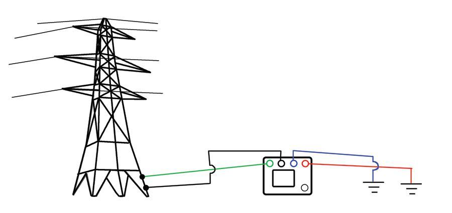
The desired effect of a high-frequency test is to choke the test current to the remote grounds and localize the test onto the designated tower. The variation of Ohm’s law that accounts for impedance shows why. By this rendering, I = E/Z, current equals voltage divided by impedance. So an increase in impedance causes a decrease in current. And inductive impedance increases with frequency. The long runs of overhead ground wire that connect transmission towers in a continuous chain typically offer sufficient inductive impedance to choke off current at frequencies like 20+ kHz. Consequently, the tester will only “see” test current flowing on the specific tower to which it is connected, the desired effect. A ground test can be conducted without disrupting the protective conductor overhead. As an added benefit, the test frequency can also be considered as simulating the frequencies associated with a lightning stroke and thereby giving a better indication of how the tower’s grounding system will perform its primary function, lightning protection.
A high-frequency tester otherwise operates the same as a general-purpose model, with current and potential terminals to which are connected long leads and probes extended far enough to perform fall-of-potential and all related tests (See Figure 1 on previous page). It represents a vast improvement, but still has some limitations in that while it significantly reduces the effects of adjacent towers, it doesn’t necessarily completely eliminate that contingency. There are uncontrolled variables, including the proximity of neighboring towers and the length of wire connecting them, that could still allow some leakage of test current and introduce some extraneous element into the reading.
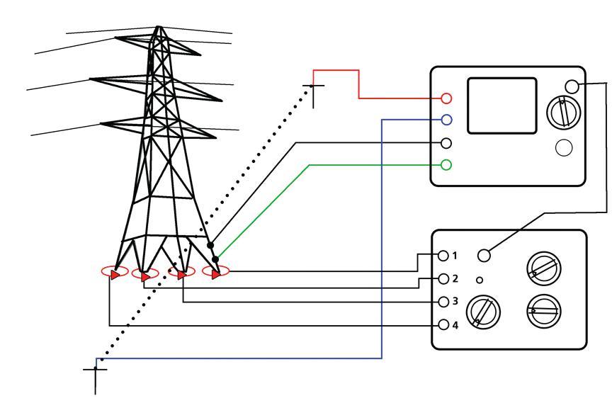
An extension of the technology incorporates a possibility that has already been suggested: clamping the legs with flexible CTs. A type of instrumentation has been developed that can incorporate four flexible current sensors, one for each tower leg, into a single measuring unit. Flexible CTs up to 30 feet are available, and these will encircle an eight-foot diameter footing. Both the footing and its associated grounding electrode should be encircled. With a quality model, the sensors can be calibrated individually against the measurement module and always used in the same relative positions so as to assure accuracy and repeatability of
test results. The tester should accommodate multiple turns of the CTs (typically up to four), with a matching selector switch, so as to maximize sensitivity to both test current and leakage current.
Just as a high-frequency model performs the rest of its functions in standard four-terminal manner, so does a flexible-sensor model (Figure 2). But the positioning of test connections is critical. One pair of current and potential leads is attached to a tower leg in order to establish test current through the structure and sense the requisite voltage drop. In this application, the tower footing is the item under test, and so one side of the test connections are made to the tower just as they would be to a ground rod. The essential element of this connection is to make it above a CT so that current will be monitored going to ground. For the return side of the test, two probes are driven into the ground on opposite sides of the tower and at a substantial distance (100 feet or more). It is best to install these probes at a right angle to the transmission line where possible in order to minimize interference. The current probe completes the test circuit from the tower leg, through the soil, and back to the tester. The potential probe senses voltage drop. In this manner, the tester behaves as a standard ground tester, but with the specialized positioning of the probes around the tower. If the two probes cannot be positioned on opposite sides, then it is best to rely on the familiar 62 percent rule in locating the potential with respect to the current, at least at a 30° angle off the power line to minimize interference.
When the tester is energized, the flexible current sensor measures the current going to ground on a particular leg, and makes its measurement based only on that accommodation. So far, this is essentially the same as the tester-withcurrent-clamp function described in the opening paragraph. There are three more legs, and if only one were clamped, the information would only yield the grounding condition of that leg. This would mean little in the overall evaluation of the tower. But as we have seen, this
highly specialized and sophisticated technology addresses this issue thoroughly. With all four legs encircled simultaneously, a selector switch enables the measurement to be taken on any one of them, any combination, or all four together, from one setup. Thus, the operator is provided a complete look at the effective ground resistance of the tower while still energized and without disconnecting the overhead ground or the counterpoise. Frequency selection and sweep enable assessment of tower condition and the connections to neighboring towers as well. By utilizing power frequency and moving a flexible sensor above the lead connections, current is measured going up the tower and the quality of the bond to the overhead ground wire can be assessed. Measuring current at different frequencies can also indicate the amount of leakage from the system to different legs and aid in evaluating the overall grounding condition of the tower.
This advanced technology illustrates how various functions initially intended to serve more general usage can be integrated into a single application to produce previously unattainable results. Next, we will move from instrumentation to technique and examine some procedures for determining earth resistivity.
Sources of information:
AEMC® Instruments, Dover, NH MEGGER®, Getting Down To Earth Megabras Industria Electronica LTDA, Sao Paulo, Brazil
Jeffery R. Jowett is a Senior Applications Engineer for Megger in Valley Forge, Pennsylvania, serving the manufacturing lines of Biddle, Megger, and multi-Amp for electrical test and measurement instrumentation. He holds a BS in Biology and Chemistry from Ursinus College. He was employed for 22 years with James G. Biddle Co. which became Biddle Instruments and is now Megger.


B - FALSE – I get this question a lot. Just because the IEEE 1584 says that calculations may not be necessary, that does not automatically mean there is no hazard concerning arc flash. Firstly, that portion of the 1584 guide only applies to three-phase power systems fed by a transformer rated less than 125 kVA and less than 240 volts. A single-phase transformer can have more arc energy. Secondly, there is a hazard to the hands and arms, even at the lower energy levels, not to mention the hazard of flying molten metal that could be ejected from the equipment. The hazard is reduced, not eliminated. These calculations are less than convincing, especially at the lower voltages. The new IEEE/NFPA Joint Collaboration Project should shed some new light on this area.
B – According to ASTM F1959, arc-rated clothing and equipment are rated to allow a 50 percent probability of a second-degree burn if that clothing is exposed to the rated incident energy for 1/10th second. Some clothing could experience breakopen at its rating.
D – The other three are good rules-ofthumb to keep in mind when working on exposed, energized electrical conductors or circuit parts. Keep in mind that if the incident energy decreases by the inverse square of the distance, it will also increase by the square of the distance as you go nearer to an arc source.
D – Trick question! At the October NFPA 70E ROP meeting David Wallis with OSHA presented two instances where people suffered serious injury at 120/240 volts. One worker received significant third-degree burns to his chest, hand, and arm.
C – Actually, I would go for “d”, but apprentices can be in short supply at times. I like to follow what I call the hinge-side rule. I stand on the side with the hinge, extend whichever arm is appropriate, face the hazard and operate the equipment. Some people fault that approach, reasoning that the PPE is designed to protect you, but I would say arc-rated PPE is designed to protect you if its rating is not exceeded. Who knows if the OCPD is going to function correctly? The door will probably blow open and could strike the operator, causing injury. However, I will take a concussion or broken arm over being crispy-fried. Main point, face the hazard so the face shield does not become a heat scoop.
nFpA disclaimer: Although Jim White is a member of the NFPA Technical Committee for both NFPA 70E “Standard for Electrical Safety in the Workplace” and NFPA 70B “Recommended Practice for Electrical Equipment Maintenance”, the views and opinions expressed in this message are purely the author’s and shall not be considered an official position of the NFPA or any of its Technical Committees and shall not be considered to be, nor be relied upon as, a formal interpretation or promotion of the NFPA. Readers are encouraged to refer to the entire text of all referenced documents.


Alber
www.alber.com
BDSU-120 Battery Monitor
The new BDSU-120 is Albér’s newest battery monitor that supports monitoring of up to 320 cells or jars, and up to 32 strings. This modular design allows for plug and play replacement and real time viewing during a discharge, and it easily integrates with the BMS. The BDSU-120 checks the state of health and temperature of each cell, using a proactive, patented resistance test. Automating the PRC-005 requirements for dc systems will save time and money. The BDSU-120 provides automatic collection of required data and proactively identifies bad batteries and connections before they become a point of failure. Albér tests the batteries’ complete conduction path with every resistance test.
Arcteq r el Ays l td
www.arcteq.fi
Arc Protection Series AQ 100 & Arc Quenching System AQ 2000
The AQ 100 utilizes a new arc light point sensor technology for detecting an arcing fault within LV or MV switchgear or control gear. This technology enables series connection of three arc light point sensors. The new arc light point sensor AQ 01 includes a photodiode monitoring light pulse along with other more traditional 24/7 selfsupervision features. The AQ 2000 extinguishes an arcing fault in less than 6 ms minimizing the arc incident energy. When detecting an internal arc-flash fault, the AQ 2000 creates a parallel low impedance path for the fault current to flow, thus removing the energy from the arc fault. The AQ 2000 is rated up to 17.5 kV, 50 kA for one second and BIL 95 kV.
AVO t r A ining i nstitute
www.avotraining.com
Differential Relay Training Course
Differential protection schemes are a very reliable method of protecting generators, transformers, buses, motors, and transmission cables from the effects of internal faults. Understanding differential systems is essential for troubleshooting, determining winding configurations, phase relationships, and sequences, etc. This new hands-on course is designed for experienced technicians responsible for installation, application, and troubleshooting of differential schemes.
Visit www.avotraining.com for more info.
In only 3 days, students will learn:
• Applications for transformers, generators, and buses
• Differential relay calculations including tap, slope, and harmonic restraint
• CT theory, connections, calculations, and applications
• Differential scheme troubleshooting including vector analysis, phasing, and phase shift
www.basler.com
BE1-11m – Motor Protection System
The new BE1-11m is a multifunction system providing comprehensive and easy to use motor protection, monitoring and control for medium, large and critical process motors. Offering a complete thermal model, current, voltage, frequency, power and differential protection elements, the BE1-11m also provides users with oscillography, sequential events recording, starting and running data, and breaker- and trip-circuit monitoring data for metering maintenance and operational analysis. Additionally, the BE1-11m continues Basler’s retrofit capabilities, designed to be mounted in existing S-1 cutouts to replace many of the existing motor protection relays found in service without modifying or replacing the panel.
Dranetz
www.dranetz.com
Encore Series IEC61850 & OPC Communications
Dranetz announces new IEC61850 and OPC support for our Encore Series PQ, demand and energy monitoring system. Available in Q2 2011, IEC61850 will be part of the 61000 instrument family. IEC61850 is now common in new and refurbished substations, and this feature will allow Encore Series to work well in this new environment. Dranetz also announces a new OPC gateway for our Encore Series Software. OPC is common in industrial, utility, data center, and other applications and is used to share data among systems. Encore’s OPC gateway is available today and enables Dranetz systems to be used with your existing software.
e lectro r ent www.electrorent.com
SF6/gas leak detector
Established in 1965, Electro Rent Corporation adds new products to its rental inventory every month. Recent additions include a SF6/gas leak detector, SFRA (swept frequency response analyzer), insulation diagnostic analyzer, secondary current test set, and vibration analyzer. Electro Rent’s calibration lab is A2LA ISO/IEC 17025: 2005 certified to ensure your equipment is calibrated correctly when you receive it. For daily and monthly test equipment rentals, please call our experienced staff at 800.688.1111 (USA) or 800.268.0216 (Canada).
HV tec H nolo GI e S, Inc. www.hvtechnologies.com
BAUR’s frida TD - Compact Cable Diagnostics
For companies needing to perform cable testing on medium-voltage cables, HV TECHNOLOGIES, Inc., as the US distributor for BAUR Prüf- und Messtechnik GmbH (Austria), is announcing expanded diagnostic capabilities for the portable cable tester, “frida TD.” This
tester combines VLF cable testing and TD (Tangent Delta) diagnostics functions into a compact device without external items that can be easily damaged or lost. The TD diagnostics capabilities lets the users determine the ageing state of medium-voltage cables quickly and accurately. With a peak output of 34 kV, automated test series across several voltage levels can be performed on site. This allows for reliable reports about the insulation quality of polyethylene and other cable types and therefore, provides an indication if required maintenance is needed. Like the normal VLF tests, the TD or dissipation-factor measurements are carried out with an ideal 0.1 Hz sine wave.
KelVate K
www.kelvatek.com
Profile P3
The Profile P3 from Kelvatek enables on-site analysis of circuit breaker defects during the critical first trip operation. This portable, light weight, hand-held device uses nonintrusive connections to monitor the key current and voltage parameters while the circuit breaker is still on line.
The Profile P3 offers many new features including:
• Overlay of multiple profiles on a color screen
• Streamlined GUI interface
• Upload of previous records for comparison
• USB firmware upload and record download
• Automated capture of multiple breaker operation
This portable device is an invaluable addition to the maintenance technician’s tool kit.
Me GG er
www.megger.com
SMRT36
The SMRT36 produces a compliance voltage of 50 volts at 4 amperes constant power output to 30 amperes continuous, 60 amperes 300 VA per phase for 1.5 seconds. Three currents provide 180 amperes single phase. The ‘PowerV™,
voltage amplifier provides constant power output from 30 to 150 Volts, providing higher power at low test voltages. For six-phase current, the voltage channels convert to 0-5 amperes continuous, up to 15 amperes for 1.5 seconds. The new Smart Touch View Interface™ provides manual and automatic control. The large, color, high resolution, LCD touch-screen is intuitive and easy to use.
Novi N ium
www.novinium.com
For longer cable runs when the cable must quickly be put back into service, Novinium has developed a live front cable injection device called a Quick Disconnect Injection Adaptor (QDIA) and a Quick Disconnect Injection Tool (QDIT). It only requires one outage of the circuit to install both of these devices. When the injection is complete, the QDIT can be removed with a hot stick and no second outage is required.
o F i L
www.ofilsystems.com
UVolle-Vi - Compact Daytime Corona
Video Camera
2011 new generation corona cameras: UVollé-Vi is a compact bi-spectral UV-Visible video camera for pinpointing corona and arcing during daytime. UVolle-Vi is a hand-held high performance camera incorporating Ofil’s proprietary UV optical sensors. Designed to be comfortable and easy to operate, UVolle-Vi renders direct access to functions through a joystick and a swift dial-button. Zooming, corona magnification, photon counting and autofocus provide clear and immediate information of the detected corona emitters and the discharge relative severity. The inspected scene is displayed on a color LCD with an option to record, add voice annotations and play back the outcome.
omi CR o N e L e C t R o N i C s
Co R p. us A
www.omicronusa.com
Six New Products
OMICRON has released six new products to help you in your testing needs. First is our CMC 356 relay test set. It has three high power outputs and uses all of the well known Test Universe Software. If you do not want to use a laptop to run your test set, OMICRON has introduced its CMControl, a front panel control with a touch screen. For IEC61850 testing we introduced the CM850, dedicated to testing the new standard for substation communication protocol. We have also introduced our Primary Test Manager for our power factor test set which makes testing and report generation a dream. To complement our PTM software we have a switch box for transformer testing. One connection and you can perform ratio and resistance testing on transformers, and it is automated. For testing multiratio CT’s, check out our CT analyzer with our switch box SB2.
See these and other products at our booth #30.
p owe R m o N ito R s
www.powermonitors.com Revolution®
The Cell Revolution® from Power Monitors is a rugged, allweather, wireless recorder 600 V CAT IV rated with up to 1GB of memory. Remotely measure incoming voltage and every PQ parameter, including transient capture with up to one million samples per second. Wirelessly download and quickly compile data for analysis using built-in or custom graphs and reports included with Revolution’s free ProVision® software. Monitor, measure, document and report power quality data faster and more accurately with the Revolution from Power Monitors, the smallest most powerful recorder in the world.
Raytech US a , Inc
www.raytechusa.com
Model TR-Mark III – Three Phase Transformer Ratio Meter
Raytech USA, a recognized leader in quality test and measurement equipment, introduces the new TR-Mark III, enhanced three phase transformer turns ratio meter. The new TR-Mark III features a full color LCD backlight touch screen with soft-keyboard for easier control and data entry. Two USB interfaces make it easy to store measurements on external memory devices, and transfer to a PC. Test reports can be printed on the internal or external USB printer or from the PC.
As with all Raytech products, the TR-Mark III comes standard with a five-year warranty.
Sal IS b UR y by h oneywell
www.salisburybyhoneywell.com
Salisbury Assessment Solutions
Salisbury by Honeywell is pleased to offer expert assessment services and safety compliance/education solutions to organizations worldwide. Our experts are highly educated, trained, and certified and have a long history in the safety community along with numerous professional safety affiliations. SAS provides a wide range of services and can cater the solutions to your needs. Salisbury Assessment Solutions (SAS) is part of Salisbury’s ongoing commitment to safety education and service improvement. We are proud to offer our newest service enhancement.
Salisbury Assessment Solutions (SAS) can ease the burden of meeting all the necessary safety standards and requirements, such as NFPA 70E and OSHA, through the individualized assessment services and training solutions.
Sat I n a me RI can c o R po R at I on www.satinamerican.com
Kits for Square D/Merlin Gerin Masterpact™ LV Breakers
Since 1922, Satin American has provided parts to maintain low- and medium-voltage power distribution equipment that is no longer supported by the original manufacturer. Satin maintains one of the largest inventories of used equipment and can provide any breaker made by a US manufacturer between the 1930’s and the present.
Satin also produces its own line of retrofit kits for lowvoltage breakers and recently introduced an adaptation for Square D/Merlin Gerin Masterpact™ breakers. Retrofit kits offer mechanical auto-reset actuators, defeatable LSIG protection, flashSAFE arc-flash mitigation, and a remotemountable display.
Schwe I tze R e ng I nee RI ng
l abo R ato RI e S , Inc. www.selinc.com
Arc-Flash
Schweitzer Engineering Laboratories, Inc. (SEL) announces the new SEL-4520 Arc-Flash Detection Test Module. Used in conjunction with a standard relay test set, this device produces a synchronized light flash and current signal to simulate an arc-flash event. The SEL-4520 provides a convenient way to test the operation of arc-flash detection relays installed in metal-clad and metal-enclosed switchgear. Use the SEL-4520 to test the SEL-751A feeder protection relay and other arc-flash detection relays that detect arc-flash events by sensing light and overcurrent.
Sec Uc ont R ol www.secucontrol.com
FTL - Fully Insulated Test Block, Low Resistance
The FTL is a new, fully insulated, low resistance alternative to conventional FT switches. FTL ensures automatic CT
shorting for current circuits and provides superior contact insulation. Perform tests with a convenient test plug or through banana jacks directly installed in the face of the test block (in the FTL plus version). FTL fits standard FT switch cut-outs and is a perfect retrofit solution. SecuControl’s new CT test probe for the FTL facilitates safe and easy current measurement.
The Snell Group
www.thesnellgroup.com
When people hear “The Snell Group,” one thing typically comes to mind—the world leader in infrared thermography knowledge.
Our knowledge offerings have expanded to include electric motor testing (EMT). Both our EMT Static (De-Energized) and Dynamic (Energized) Motor Testing Courses are eligible for 32 CTDs with NETA. In addition to earning credit, participating in our EMT courses will expose you to the newest reliability technology available today for increasing the uptime of rotating assets. We have public, on-site and on-line offerings for our courses.
T e GAM
www.tegam.com
Microhm Meters
Come and try TEGAM’s new line of rugged microhm meters. The first public appearance of these products is at PowerTest 2011 Electrical Maintenance and Safety Conference. Being featured are three unique microhm meters. The R1L-BR is a microhm meter and bond tester with a rugged case. The R1L-C is a ground tesistance test system designed to measure grounding system resistance with 2/3/4 wire modes and the R1L-D1 is a high precision microhm meter/RTD monitor for measuring low-resistance values with low excitation currents. Visit TEGAM in Booth 59.
Tyco e lec T ronic S
www.energyte.com
Expanded Cable Accessories
Tyco Electronics Energy Division has expanded the line of cable accessories available to you to include cold applied solutions as well as enhancements to our proven line of heat applied accessories. Our cold applied and heat shrink terminations and splices have features to make installation easier while improving electrical performance. In addition, you now have a new source for 600 ampere elbows as well as EHV splices and terminations to 145 kV. There are too many new solutions to include here. Visit us at the New Product Forum and at Booth 82 for more information.
uT ili T y r el Ay c o M p A ny
AC-PRO-MP Trip Unit
Utility Relay Company (URC) announces the introduction of the AC-PRO-MPTM trip unit. The AC-PRO-MPTM is a direct replacement for the STR trip unit on the Merlin Gerin and Square D Masterpact MP, IEC or UL rated breakers. The AC-PRO-MPTM is user programmed to emulate the STR-18M, 28D, 38S or 58U trip units. The protective functions, settings, time-current curves, load monitoring contacts and pretrip alarm contact are the same as the STR. The AC-PRO-MPTM has many additional features such as time stamped last trip data, no rating plug and self-test. In addition Quick-Trip™, arc-flash reduction, is standard with the AC-PRO-MPTM.


On Monday the general committee meeting took place. ASTM has decided not to submit comments to the NFPA 70E, although it will try to clarify its position on some proposals.
ASTM will probably propose a new standard for arc-flash testing PPE using arc-plasma jets as opposed to the arc cage that is currently used. Dr. David Sweeting demonstrated that the hazards posed by “stab-in” equipment can be greater due to the arc plasma jets. This will probably be brought up at the April 2011 meeting.
F18.65 – Monday afternoon was devoted to voting on negatives that were raised during the last meeting for the proposed standard on arc-flash testing of hand protection. This is an important standard that has been through a number of revisions.
Other standards actiOns included:
F18.35.37 – Live-line tools (F711). The endto-end testing method was removed, as it was felt it was not being used. Several manufacturers stated they did use the method, so it will probably be added back in. It was stated that for tools used at 345 kV and above, end-to-end testing was the only valid test method.
F18.35.38 – Insulated rope (F1701). No US manufacturer of rope meets current ASTM standard. The proposed standard would subject the rope to 99 percent humidity for 16 hours, then test, which more closely meets actual in-service usage. The rope would be weighed to measure moisture soaking, and be tested within 15 minutes. The rope would be tested at 50 kV/ft, with a maximum current leakage of 250 µA. Rope tested in this manner usually shows leakage of about 60 µA. The rope under test tended to dry out if the test lasted more than two minutes.
F18.35 .40 – Insulated hand tools (F1505). The intent of the ASTM standard was to require a visual examination once a year by a competent person, competent person meaning someone at a higher skill level than a worker. If the tool shows damage, it would be required to be retested using the basic dielectric test found in the standard. Some changes were made to the in-service guide (Appendix X4).
A new test method for fiberglass booms was discussed and demonstrated. The method is currently in use by the DOD and the FAA. A copy of the presentation is attached to this report. The sample is bathed in a 5G Hz signal. Energy reflected back will vary depending on the type of material and creates a voltage. The voltages are graphed and mapped and can be colorized, grey-scale or 3-D. Voltages are assigned a color by the software. Since the test set uses a milliwatt output, no guarding is required. This test can detect a ¼ inch round void with approximately 98 percent accuracy. Manufacturers stated they had hand-held units as well as units that could be strapped to the boom or pipe. The test method does not work on metallic objects.
I think the arc flash testing for gloves is likely to be passed at the next meeting. It has been in the works for six years.
 Jim White Shermco Industries
The ASTM F18 committee met in Scottsdale, Arizona October 17–20, 2010. The meeting schedule through 2011 is:
Apr. 10-13, 2011 Anaheim, California
Oct. 23-26, 2011 Naples, Florida
Apr. 15-18, 2012 Phoenix, Arizona

Jim White is the Training director for Shermco Industries and the principal Shermco representative on the NFPA 70B committee. Jim is the alternate NETA representative on the NFPA 70E committee and serves as the NETA representative on the IEEE/NFPA Arc-Flash Hazard Work Group (RTPC) Ad Hoc Committee. He served as the Chairman of the 2008 IEEE Electrical Safety Workshop. Jim is a NETA Certified Level IV Electrical Testing Technician and a member of the NETA Safety Committee.


During October 17-20, 2010, engineers and scientists of the ICC Working Groups met in Fountain Hills, Arizona, for the fall 2010 IEEE/ICC meeting.
This is an ongoing opportunity for the International Electrical Testing Association to be recognized and to offer a field testing perspective in the working groups as ICC documents are developed. The working groups are comprised of representatives of cable manufacturers, utilities, test equipment manufacturers, and end users.
John Densley and Nigel Hampton are the chair and vice-chair, respectively. As new material becomes available, additional changes and methodologies are incorporated in the IEEE specifications.
Fall 2010 Breakout Working Groups /Discussion Groups Meetings
Group No.
F01W
F02W
F03W
F04W
Group Name
Guide for Field Testing and Evaluation of Shielded Cables. IEEE 400 (Omnibus)
Guide for Field Testing of Laminated Dielectric, Shielded Power Cable Systems Rated 5 kV and Above with High Direct Current Voltage. (400.1 – 2007)
Guide for Field Testing of Shielded Power Cable Systems Using Very Low Frequency (VLF). (400.2-2004)
Guide for Partial Discharge Testing of Shielded Power Cable Systems in a Field Environment. (400.3 – 2006)
F05W Damped AC Voltage Testing
F07W
Activity
Chairmen
Continue Working Draft 10 Wen/Côté
Approved 2007 No Activity Larzelere/Buchholz
Address Comments on Latest Draft Densley/Schlesinger
Review of Laboratory test results and field applications Levine/Walton
Review of Draft and Presentations Gulski/Patterson
IEEE Guide for Detection, Mitigation, and Control of Concentric Neutral Corrosion in Medium-Voltage Underground Cables (16172007) No Activity Buchholz
F10W Diagnostic Testing for Cable Joints & Terminations No Activity Orton/Boggs

WG F01W - IEEE 400, IEEE Guide for Field Testing and Evaluation of the Insulation of Shielded Power Cable Systems Rated 5 kV and above
The working group continued to review revisions by the writing group that includes a new section, “Evaluation of Results,” This new section is intended to offer guidelines on the interpolation of results. Draft 10 was presented with revisions and approved by the working group.
WG F03D IEEE 400.2, IEEE Guide for Field Testing of Shielded Power Cable Systems Using Very Low Frequency (VLF)
The discussion group continued to review new data and the recommended 30 minute test duration. A significant number of installation problems can be identified with the longer duration. The discussion group will continue to review new data as it becomes available.
WG F04D IEEE 400.3, IEEE Guide for Partial Discharge Testing of Shielded Power Cable Systems in a Field Environment.
Partial discharge testing has gained acceptance as a valid diagnostic tool for condition assessment of cable insulation. PD testing is a valuable tool in most cable asset management programs. Details of a laboratorytype test suitable for a partial discharge detection system were reviewed.
WG F05W Damped AC Voltage Testing (400.4)
Damped ac voltage testing has gained some acceptance and is presently a working group with a PAR date of December 2014. Discussion continued on the initial draft with revisions and additional data was presented to the working group for review. Damped AC Voltage Testing will be the topic of a paper presentation at the 2011 PowerTest Conference in Washington, DC.
WG F06 Ad Hoc DC Field Testing of Extruded Cable Systems
This ad hoc committee is inactive at this time as no additional material has been presented.

Ralph Patterson is President of Power Products and Solutions, located in Charlotte NC. His professional background includes working as a design engineer of transformers and as a specifying engineer of insulated conductors. He has more than 25 years in power engineering particularly in insulation diagnosis and evaluation of electrical distribution equipment. He serves on the NETA Standards Review Council and Board or Directors, is the NETA liaison for the IEEE Insulated Conductor Committees working groups and received NETA’s 2001 Outstanding Achievement Award.

Review and revision of the ANSI/ NETA Standard for Maintenance Testing Specifications for Electrical Power Equipment and Systems is well underway, with the second public comment period closing on January 31, 2010, and the first recirculation ballot closing January 9, 2011. This document is scheduled to be published as a revised American National Standard in 2011. These specifications cover the suggested field tests and inspections that are available to assess the suitability for continued service and reliability of electrical power distribution equipment and systems. The purpose of these specifications is to assure that tested electrical equipment and systems are operational and within applicable standards and manufacturer’s tolerances and that the equipment and systems are suitable for continued service. The revision is expected to be completed in the spring of 2011 and will carry the designation of ANSI/NETA MTS-2011.
The ANSI/NETA Standard for Acceptance Testing Specifications for Electrical Power Equipment and System is scheduled to be published as a revised document in 2013. These specifications cover the suggested field tests and inspections that are available to assess the suitability for initial energization of electrical power equipment and systems. The purpose of these specifications is to assure that tested electrical equipment and systems are operational, are within applicable standards and manufacturer’s tolerances, and are installed in accordance with design specifications. Work on this document will officially begin in 2011. Once completed, this standard will carry the designation of ANSI/NETA ATS-2013.


The ANSI/NETA Standard for Certification of Electrical Testing Technicians was approved as an American National Standard on January 8, 2010. The document was originally approved as an ANSI standard in 2000. This standard establishes minimum requirements for qualification, certification, training, and experience requirements of the electrical testing technician. It also provides criteria for documenting qualifications and certification and details the minimum qualifications for an independent and impartial certifying body to certify electrical testing technicians.

Comments and suggestions are always welcome on any of the standards and should be directed to the NETA office at neta@netaworld.org or 888-300-6382. To learn more about the NETA standards review and revision process, purchase these standards, or to get involved, please visit www.netaworld.org or call 888-300-6382.

AccurAcy (resolution 5 Digits):
Range 0.8 … 2000 ± 0.06% at 100V or 40V
Range 2001 … 4000 ± 0.1% at 100V or 40V
FeAtures:
• Automatic measurements of voltage, turns ratio, current, and phase displacement
• Measures power transformers PTs and CTs
• Displays deviation from a nominal ratio
• Displays % error vs. name plate value
• Bright full color touch-screen for easy data entry
AccurAcy:
Range 100 mAmp … 15 Amp ± 0.1% Rdg 5 Digit Resolution
Range <25 mAmp 1.2kΩ …10kΩ ± 0.1% Rdg 4 Digit Resolution
Range <25 mAmp 10kΩ …100kΩ ± 0.5% Rdg 4 Digit Resolution
FeAtures:
• Core Demagnetizing Circuit (world exclusive)
• Charges inductive loads up to 1500 Henry
• 2 independent measuring channels
• Heavy-duty protection circuitry
• High power DC supply (15A/30V)
• Resistance range from 0.05 μΩ to 100 kΩ
• Battery or line voltage powered
• Visible and audible indicator for discharge status
• Data exchange with USB-key
• Simple touch-screen operation
• Built-in printer

Range 4001 … 13000 ± 0.3% at 100V or 40V
Range 13001 … 16000 ± 0.4% at 100V or 40V
• Test voltages of 100V, 40V, 10V, and 1V (for CT Testing)
• Graphical tap changer display
• Automatic phase vector detection
• Enhanced heavy-duty protection circuitry
• Data exchange with USB-Key
• Built-in printer
AccurAcy:
Range 0.8 4000 ± 0.08% with 40 Volts (PT Mode)
Range 0.8 100 ± 0.08% with 1V 5V (Auto) (CT Mode)
FeAtures:
• Operates on rechargeable batteries or line voltage
• Can be recharged with line voltage or optional
DC car adapter
• Reverse polarity test
• Continuity test
• Test current up to 1A for CT testing
• Internal storage of the last 50 test results
• RS-232 interface with optional adapter
• Over 1000 measurements without recharging
• TR-1P model includes built-in printer
The NETA Exam Committee met in Kalamazoo, Michigan, on November 13-14, 2010, for a routine review of the NETA Certification Exam Bank. These reviews assess the exam questions based on many criteria including reference material, technical relevance, and compliance with the ANSI/NETA ETT Standard for Certification of Electrical Testing Technicians. The NETA Exam Committee is comprised of volunteers that report to the NETA Standards Review Council. Their diligence and commitment to quality assures that every individual bearing the designation of NETA Certified Technician has met the rigorous standards set forth by the Association and approved by ANSI. To learn more about becoming a NETA Certified Technician, please visit us on the web at www.netaworld.org, contact the NETA office at 888.300.6382, or e-mail neta@netaworld.org.

a&f electrical testing, inc.
80 Lake Avenue South, Suite 10 Nesconset, NY 11767 (631) 584-5625 Fax: (631) 584-5720 kchilton@afelectricaltesting.com http://www.afelectricaltesting.com
Kevin Chilton
a&f electrical testing, inc.
80 Broad St, 5th Floor New York, NY 10004 (631) 584-5625 Fax: (631) 584-5720 afelectricaltesting@afelectricaltesting.com http://www.afelectricaltesting.com
Florence Chilton
advanced testing systems 15 Trowbridge Dr Bethel, CT 06801 (203) 743-2001 Fax: (203) 743-2325 pmaccarthy@advtest.com http://www.advtest.com
Pat MacCarthy
american electrical testing co., inc. 480 Neponset Street, Building 3 Canton, MA 02021-1970 (781) 821-0121 Fax: (781) 821-0771 sblizard@aetco.us http://www.99aetco.com
Scott A. Blizard
american electrical testing co., inc. 34 Clover Drive South Windsor, CT 06074 (860) 648-1013 Fax: (781) 821-0771 jpoulin@aetco.us http://www.99aetco.com
Gerald Poulin
american electrical testing co., inc. 1811 Executive Drive, Suite K Indianapolis, IN 46241 (317) 487-2111 Fax: (781) 821-0771 rramsey@aetco.us http://www.99aetco.com
Rick Ramsey
american electrical testing co., inc. 50 Intervale Road, Suite 1 Boonton, NJ 07005 (973) 316-1180 Fax: (781) 316-1181 trosato@aetco.us http://www.99aetco.com
Anthony Rosato
american electrical testing co., inc. 76 Cain Drive Brentwood, NY 11717 (631) 630-2260 Fax: (631) 630-2292 pnocerino@aetco.us http://www.99aetco.com
Patrick Nocerino
american electrical testing co., inc. 34 Hemlock Drive Pottsville, PA 17901 (215) 219-6800
jmunley@aetco.us http://www.99aetco.com
Jonathan Munley
american electrical testing co., inc. 1672 SE 80th Bella Vista Dr The Villages, FL 32162 (727) 447-4503 Fax: (727) 447-4984 http://www.99aetco.com
Bob Hoffman
apparatus testing and engineering 11300 Sanders Dr. Suite 29 Rancho Cordova, CA 95742 (916) 853-6280 Fax: (916) 853-6258 jlawler@apparatustesting.com http://www.apparatustesting.com
James Lawler
apparatus testing and engineering 7083 Commerce Circle, Suite H Pleasanton, CA 94588 (925) 454-1363 Fax: (925) 454-1499 info@apparatustesting.com http://www.apparatustesting.com
Harold (Jerry) Carr
applied engineering concepts 1105 N. Allen Ave Pasadena, CA 91104 (626) 398-3052 Fax: (626) 398-3053 michel.c@aec-us.com http://www.aec-us.com
Michel Castonguay
burlington electrical testing co., inc. 300 Cedar Avenue Croydon, PA 19021-6051 (215) 826-9400 (221) Fax: (215) 826-0964 waltc@betest.com http://www.betest.com
Walter P. Cleary
c.e. testing, inc 6148 Tim Crews Road Macclenny, FL 32063 (904) 653-1900 Fax: (904) 653-1911 cetesting@aol.com
Mark Chapman
ce power solutions of wisconsin, llc 3255 W. Highview Dr. Appleton, WI 54914 (920) 968-0281 Fax: (920) 968-0282 jimvh@cepowersol.com
James Van Handel
dymax holdings, inc. 4751 Mustang Circle St. Paul, MN 55112 (763) 717-3150 Fax: (763) 784-5397 gphilipp@dymaxservice.com http://www.dymaxservice.com
Gene Philipp
dymax service inc. 23426 Industrial Park Court Farmington Hills, MI 48335-2854 (248) 477-6066 Fax: (248) 477-6069 http://www.dymaxservice.com
Bruce Robinson
high voltage service, inc. 4751 Mustang Circle St Paul, MN 51122 (763) 717-3103 Fax: (763) 784-5397 http://www.hvserviceinc.com
Mike Mavetz
dymax service inc. 4213 Kropf Ave Canton, OH 44706 (330) 484-6801 Fax: (740) 333-1271 http://www.dymaxservice.com
Gary Swank
eastern high voltage 11a South Gold Drive Trenton, NJ 08691-1606 (609) 890-8300 Fax: (609) 588-8090
joewilson@easternhighvoltage.com http://www.easternhighvoltage.com
Joseph Wilson
electrical testing, inc. 2671 Cedartown Highway Rome, GA 30161-6791 (706) 234-7623 Fax: (706) 236-9028 steve@electricaltestinginc.com http://www.electricaltestinginc.com
Steve C. Dodd Sr
electrical maintenance & testing inc 7301 N. Georgetown Road, Suite 212 Indianapolis, IN 46268 (317) 471-8600 Fax: (317) 471-8605 http://www.emtesting.com
Brian K. Borst
electric power systems, inc. 21 Millpark Court Maryland Heights, MO 63043-3536 (314) 890-9999 Fax: (314) 890-9998
cfr@eps-international.com http://www.eps-international.com
Steve Reed
electric power systems, inc. 827 Union Street Salem, VA 24153 (540) 375-0084 Fax: (540) 375-0094
Virginia@EPS-International.com http://www.eps-international.com
Bruce Eppers
electric power systems, inc. 915 Holt Ave, Unit 4 Manchester, NH 03109 (603) 657-7371 Fax: 603-657-7370 http://www.eps-international.com
electric power systems, inc. 2601 Center Road, #101 Hinckley, OH 44233 (330) 460-3706 Fax: (330) 460-3708
electric power systems, inc. 42522 LA Highway 621 Gonzalez, LA 70737 (225) 644-0150 Fax: (225) 644-6249
http://www.eps-international.com
Robert K. Alter
electric power systems, inc. 23823 Andrew Road Plainfield, IL 60585 (815) 577-9515 Fax: (815) 577-9516 http://www.eps-international.com
George Bratkiv
electric power systems, inc. 146 Space Park Drive Nashville, TN 37211 (615) 834-0999 Fax: (615) 834-0129 http://www.eps-international.com
Larry Christodoulou
electric power systems, inc. 4436 Parkway Commerce Blvd Orlando, FL 32808 (407) 578-6424 Fax: 407-578-6408 http://www.eps-international.com
eps technology
29 N Plains Hwy, Suite 12 Wallingford, CT 06492 (203) 649-0145 http://www.eps-technology.com
Chris Myers
electric power systems, inc. 6141 Connecticut Ave. Kansas City, MO 64120 (816) 241-9990 Fax: (816) 241-9992 http://www.eps-international.com
Joe Dillon
electric power systems, inc. 1090 Montour West Industrial Blvd Coraopolis, PA 15108 (412) 276-4559 http://www.eps-international.com
Ed Nahm
electric power systems, inc.
557 E. Juanita Avenue, #4 Mesa, AZ 85204 (480) 633-1490 Fax: (480) 633-7092 http://www.eps-international.com
electric power systems, inc.
6753 E. 47th Avenue Drive Unit D Denver, CO 80216 (720) 857-7273 Fax: 303-928-8020 http://www.eps-international.com
Thomas C. Reed
electrical & electronic controls 6149 Hunter Road Ooltewah, TN 37363 (423) 344-7666 (23) Fax: (423) 344-4494 eecontrols@comcast.net
Michael Hughes
electrical energy experts, inc. W129N10818 Washington Dr Germantown, WI 53022 (262) 255-5222 Fax: (262) 242-2360 bill@electricalenergyexperts.com http://www.electricalenergyexperts.com
William Styer
elect, p.c.
7400-G Siemens Road P.O. Box 2080 Wendell, NC 27591 (919) 365-9775 Fax: (919) 365-9789 btyndall@elect-pc.com http://www.elect-pc.com
Barry W. Tyndall
electrical equipment upgrading, inc. 21 Telfair Place Savannah, GA 31415 (912) 232-7402 Fax: (912) 233-4355 kmiller@eeu-inc.com http://www.eeu-inc.com
Kevin Miller
electrical Reliability services 610 Executive Campus Drive Westerville, OH 43082 (877) 468-6384 Fax: (614) 410-8420 info@electricalreliability.com http://www.electricalreliability.com
electrical Reliability services 14141 Airline Hwy Bldg 1, Ste X Baton Rouge, LA 70817 (225) 755-0530 Fax: (225) 751-5055 http://www.electricalreliability.com
electrical Reliability services
348 N.W. Capital Drive Lees Summit, MO 64086 (816) 525-7156 Fax: (816) 524-3274
http://www.electricalreliability.com
electrical Reliability services
6900 Koll Center Parkway, Suite 415 Pleasanton, CA 94566 (925) 485-3400 Fax: (925) 485-3436
http://www.electricalreliability.com
electrical Reliability services
10606 Bloomfield Ave. Santa Fe Springs, CA 90670 (562) 236-9555 Fax: (562) 777-8914
http://www.electricalreliability.com
electrical Reliability services
5580 Enterprise Parkway Ft. Myers, FL 33905 (239) 693-7100 Fax: (239) 693-7772 http://www.electricalreliability.com
electrical Reliability services
121 E. HWY 108 Sulphur, LA 70665 (337) 583-2411 Fax: (337) 583-2410
http://www.electricalreliability.com
electrical Reliability services
5555 Oakbrook Pkwy, Ste 180 Norcross, GA 30093 (770) 729-9744 Fax: (614) 410 0919
http://www.electricalreliability.com
electrical Reliability services
7100 Broadway Suite 7E Denver, CO 80221-2915 (303) 427-8809 Fax: (303) 427-4080 http://www.electricalreliability.com
electrical Reliability services
1380 Greg Street, Suite 217 Sparks, NV 89431 (775) 746-8484 Fax: (775) 356-5488 http://www.electricalreliability.com
electrical Reliability services
2222 West Valley Hwy. N., Suite 160 Auburn, WA 98001 (253) 736-6010 Fax: (253) 736-6015 http://www.electricalreliability.com
electrical Reliability services
6351 Hinson Street, Suite B Las Vegas, NV 89118 (702) 597-0020 Fax: (702) 597-0095 http://www.electricalreliability.com
electrical Reliability services
3412 South 1400 West Unit A West Valley City, UT 84119 (801) 975-6461
http://www.electricalreliability.com
electrical Reliability services
1775 W. University Drive, Ste 128 Tempe, AZ 85281 (480) 966-4568 Fax: (480) 966-4569 http://www.electricalreliability.com
electrical Reliability services 1057 Doniphan Park Circle Suite A El Paso, TX 79922 (915) 587-9440 Fax: (915) 587-9010 http://www.electricalreliability.com
electrical Reliability services
1455 East Sam Houston Parkway S. Suite 190 Pasadena, TX 77503 (281) 241-2800 Fax: (281) 241-2801 http://www.electricalreliability.com
electrical Reliability services
5810 Van Allen Way Carlsbad, CA 92008 (760) 804-2972 http://www.electricalreliability.com
electrical Reliability services
8336 Washington Place NE Albuquerque, NM 87113-1666 (505) 822-0237 Fax: (505) 822-0217 http://www.electricalreliability.com
electrical Reliability services
4099 SE International Way, Ste 201 Milwaukie, OR 97222-8853 (503) 653-6781 Fax: (503) 659-9733 http://www.electricalreliability.com
elemco services, inc. 228 Merrick Road Lynbrook, NY 11563 (631) 589-6343 Fax: (631) 589-6670 bobw@elemco.com
Robert J. White
hampton tedder technical services 4571 State Street Montclair, CA 91763 (909) 628-1256 x214 Fax: (909) 628-6375 matt.tedder@hamptontedder.com http://www.hamptontedder.com
Matt Tedder
hampton tedder technical services 3747 West Roanoke Ave Phoenix, AZ 85009 (480) 967-7765 Fax: (480) 967-7762 http://www.hamptontedder.com
hampton tedder technical services 4920 Alto Ave Las Vegas, NV 89115 (702) 452-9200 Fax: (702) 453-5412 http://www.hamptontedder.com
Roger Cates
harford electrical testing co., inc. 1108 Clayton Road Joppa, MD 21085 (410) 679-4477 Fax: (410) 679-0800 harfordtesting@aol.com
Vincent Biondino
high energy electrical testing, inc. 2119 Orien Rd Toms River, NJ 08755-1366 (732) 286-4088 Fax: (732) 286-4086 hinrg@comcast.net http://www.highenergyelectric.com
James P. Ratshin
high voltage maintenance corp. 5100 Energy Drive Dayton, OH 45414 (937) 278-0811 Fax: (937) 278-7791 eric.nation@emerson.com http://www.hvmcorp.com
Eric Nation
high voltage maintenance corp. 1250 Broadway, Suite 2300 New York, NY 10001 (718) 239-0359 http://www.hvmcorp.com
high voltage maintenance corp. 355 Vista Park Dr Pittsburgh, PA 15205-1206 (412) 747-0550 Fax: (412) 747-0554 http://www.hvmcorp.com
Mike Quince
high voltage maintenance corp. 8320 Brookville Rd #E Indianapolis, IN 46239 (317) 322-2055 Fax: (317) 322-2056 http://www.hvmcorp.com Steve Park
high voltage maintenance corp. 3000 S. Calhoun Road New Berlin, WI 53151 (262) 784-3660 Fax: (262) 784-5124 http://www.hvmcorp.com
Dave VandeCassteele
high voltage maintenance corp. 9305 Gerwig Lane, Suite B Columbia, MD 21046 (410) 309-5970 Fax: (410) 309-0220 http://www.hvmcorp.com
high voltage maintenance corp.
24371 Catherine Industrial Drive Suite 207
Novi, MI 48375 (248) 305-5596 Fax: (248) 305-5579
http://www.hvmcorp.com
Brian Ellegiers
high voltage maintenance corp.
150 North Plains Industrial Rd
Wallingford, CT 06492 (203) 949-2650 Fax: (203) 949-2646 http://www.hvmcorp.com
Peter Dobrowolski
high voltage maintenance corp.
7200 Industrial Park Blvd Mentor, OH 44060 (440) 951-2706 Fax: (440) 951-6798
http://www.hvmcorp.com
Greg Barlett
high voltage maintenance corp. 1455 Jamike Drive, Suite 5 Erlanger, KY 41018 (859) 371-5355 Fax: (859) 371-5399
http://www.hvmcorp.com
Eric Nation
high voltage maintenance corp.
24 Walpole Park South Dr. Walpole, MA 02081 (508) 668-9205
http://www.hvmcorp.com
Jeffrey Freelove
hmt, inc.
6268 Route 31 Cicero, NY 13039 (315) 699-5563 Fax: (315) 699-5911 jpertgen@hmt-electric.com http://www.hmt-electric.com
John Pertgen
industrial electric testing, inc. 11321 West Distribution Ave. Jacksonville, FL 32256 (904) 260-8378 Fax: (904) 260-0737 gbenzenberg@bellsouth.net http://www.industrialelectrictesting.com
Gary Benzenberg
industrial electric testing, inc. 201 NW 1st Ave Hallandale, FL 33009-4029 (954) 456-7020
http://www.industrialelectrictesting.com
industrial electronics group P.O. Box 1870 850369 Highway 17 South Yulee, FL 32041 (904) 225-9529 Fax: (904) 225-0834 butch@industrialgroups.com http://www.industrialgroups.com
Butch E. Teal
infra-Red building and power service
152 Centre St. Holbrook, MA 02343-1011 (781) 767-0888 Fax: (781) 767-3462
tom.mcdonald@infraredbps.net http://www.infraredbps.com
Thomas McDonald Sr
industrial tests, inc. 4021 Alvis Ct., Suite 1 Rocklin, CA 95677 (916) 296-1200 Fax: (916) 632-0300 greg@indtests.com http://www.industrialtests.com
Greg Poole
m&l power systems, inc. 109 White Oak Ln, Ste 82 Old Bridge, NJ 08857 (732) 679-1800 Fax: (732) 679-9326 dan@mlpower.com http://www.mlpower.com
Darshan Arora
magna electric corporation 2361 Industrial Drive, Box 995 Regina SK S4P 3B2
Canada (306) 949-8131 Fax: (306) 522-9181 kheid@magnaelectric.com http://www.magnaelectric.com
Kerry Heid
magna electric corporation 1683 Church Ave Winnipeg MB R2X2Y7 Canada (204) 925-4022 Fax: (204) 925-4021 cbrandt@magnaelectric.com http://www.magnaelectric.com
Curtis Brandt
magna electric corporation 851-58th Street East Saskatoon SK S7K 6X5 Canada (306) 955-8131 x 5 Fax: (306) 955-9181 http://www.magnaelectric.com
Luis Wilson
magna electric corporation 29555 Costello Drive New Hudson, MI 48165 (248) 486-7370 Fax: (248) 486-7380 reynon@mangaelectric.com http://www.magnaelectric.com
Rick Eynon
magna electric corporation 3430 25th Street NE Calgary AB T1Y 6C1 Canada (403) 769-9300 Fax: (403)769-9369 ppetrie@magnaelectric.com http://www.magnaelectric.com
Pat Petrie
magna iv engineering 4103 97th Street Edmonton AB T6E 6E9 Canada (780) 462-3111 Fax: (780) 450-2994 jwentzell@magnaiv.com http://www.magnaiv.com Jereme Wentzell
magna iv engineering, ltd. - bc #110-2071 Kingsway Ave. Port Coquitlam BC V3C 1T2 Canada (604) 944-6697 Fax: (604) 944-1271 chite@magnaiv.ca http://www.magnaiv.ca
Cameron Hite
met electrical testing llc 710 Thomson Park Drive Cranberry Township, PA 16066-6427 (724) 772-4638 Fax: (724) 772-6003 william.mckenzie@met.lincfs.com http://www.met-test.com
William (Pete) McKenzie
substation test co. 4390 Parliament Place, Suite Q Lanham, MD 20706 (301) 967-3500 Fax: (301) 735-8953 http://www.met-test.com
Frank Ceci
met electrical testing llc 6280 South Valley View Boulevard Suite 618
Las Vegas, NV 89118 (702) 216-0982 Fax: (702) 216-0983 http://www.met-test.com
Terry Travelstead
met electrical testing llc 1457 Miller Store Road, Suite 105 Virginia Beach, VA 23455 (757) 548-5690 Fax: (757) 548-5417 http://www.met-test.com
Mark Anthony Gaughan, III
carolina electrical testing co. 5805 G Departure Drive Raleigh, NC 27616 (919) 877-1008 Fax: (919) 501-7492 http://www.met-test.com
Mark Robinson
met electrical testing llc 3602 East Southern Ave Suite 1 & 2 Phoenix, AZ 85040 (602) 796-6583 http://www.met-test.com
Mike Ferguson
met electrical testing llc
3700 Commerce Drive #901-903 Baltimore, MD 21227 (410) 247-3300 Fax: (410) 247-0900 http://www.met-test.com
Bill Hartman
nationwide electrical testing, inc. 6050 Southard Trace Cumming, GA 30040 (770) 667-1875 Fax: (770) 667-6578
Shashi@N-E-T-Inc.com http://www.n-e-t-inc.com
Shashikant B. Bagle
north central electric, inc. 69 Midway Avenue Hulmeville, PA 19047-5827 (215) 945-7632 Fax: (215) 945-6362 ncetest@aol.com
Robert Messina
northern electrical testing, inc. 1991 Woodslee Dr. Troy, MI 48083-2236 (248) 689-8980 Fax: (248) 689-3418 ldetterman@northerntesting.com http://www.northerntesting.com
Lyle Detterman
national field services 649 Franklin Street Lewisville, TX 75057 (972) 420-0157 http://www.natlfield.com
Eric Beckman
orbis engineering field services ltd. #300, 9404 - 41st Ave. Edmonton AB T6E 6G8 Canada (780) 988-1455 Fax: (780) 988-0191 lorne@orbisengineering.net http://www.orbisengineering.net
Lorne Gara
phasor engineering
Sabaneta Industrial Park #216 Mercedita, PR 00715 Puerto Rico (787) 844-9366 Fax: (787) 841-6385 rcastro@phasorinc.com
Rafael Castro
powertech services, inc. 4095 South Dye Road
Swartz Creek, MI 48473-1570 (810) 720-2280 Fax: (810) 720-2283
jbrown@powertechservices.com http://www.powertechservices.com
Jean A. Brown
precision testing group
18590 Wedemeyer Rd. Kiowa, CO 80117 (303) 621-2776 Fax: (303) 621-2573 glenn@precisiontestinggroup.com
Glenn Stuckey
pRit service, inc.
112 Industrial Drive P.O. Box 606 Minooka, IL 60447 (815) 467-5577 Fax: (815) 467-5883 Rod.Hageman@pritserviceinc.com http://www.pritserviceinc.com
Rod Hageman
power services, llc P.O. Box 750066 998 Dimco Way Centerville, OH 45475 (937) 439-9660 Fax: (937) 439-9611 jbydash@att.net
Gerald Bydash
pacific power testing, inc. 14280 Doolittle Drive San Leandro, CA 94577 (510) 351-8811 Fax: (510) 351-6655 steve@pacificpowertesting.com http://www.pacificpowertesting.com
Steve Emmert
potomac testing, inc. 1610 Professional Blvd Suite A Crofton, MD 21114 (301) 352-1930 Fax: (301) 352-1936 kbassett@potomactesting.com http://www.potomactesting.com Ken Bassett
potomac testing, inc. 11179 Hopson Road, Suite 5 Ashland, VA 23005 (804) 798-7334 Fax: (804) 798-7456 http://www.potomactesting.com
potomac testing, inc
704 Main St., Suite 104 Windber, PA 15963 (814) 509-6156 Fax: (301) 352-1930 pti@potomactesting.com http://www.potomactesting.com
power & generation testing, inc. 480 Cave Road Nashville, TN 37210 (615) 882-9455 Fax: (615) 882-9591 mose@pgti.net http://www.pgti.net
Mose Ramieh
power engineering services, inc. 9179 Shadow Creek Lane Converse, TX 78109 (210) 590-4936 Fax: (210) 590-6214
engelke@pe-svcs.com http://www.pe-svcs.com
Miles R. Engelke
poweR plus engineering, inc. 46575 Magallan Drive Novi, MI 48377 (248) 344-0200 Fax: (248) 305-9105 smancuso@epowerplus.com http://www.epowerplus.com
Salvatore Mancuso
power products & solutions, inc. 12465 Grey Commercial Road Midland, NC 28107 (704) 573-0420 x12 Fax: (704) 573-3693 ralph.patterson@powerproducts.biz http://www.powerproducts.biz
Ralph Patterson
power products & solutions, inc. 13 Jenkins Court Mauldin, SC 29662 (800) 328-7382 ralph.patterson@powerproducts.biz http://www.powerproducts.biz
Raymond Pesaturo
power systems testing co. 4688 W. Jennifer Ave. Ste. 108 Fresno, CA 93722 (559) 275-2171 ext 15 Fax: (559) 275-6556 dave@pstcpower.com http://www.powersystemstesting.com
David Huffman
power systems testing co. 2267 Claremont Ct Hayward, CA 94545-5001 (510) 783-5096 Fax: (510) 732-9287 http://www.powersystemstesting.com
power systems testing co. 600 S Grand Ave Ste 113 Santa Ana, CA 92705-4152 (714) 542-6089 Fax: (714) 542-0737 http://www.powersystemstesting.com
power test, inc. 2200 Highway 49 Harrisburg, NC 28075 (704) 200-8311 Fax: (704) 455-7909 rich@powertestinc.com http://www.powertestinc.com
Richard Walker
poweR testing and energization, inc. 14006 NW 3rd Court, Suite 101 Vancouver, WA 98685 (360) 576-4826 Fax: (360) 576-7182 chris.zavadlov@powerte.com http://www.powerte.com
Chris Zavadlov
poweR testing and energization, inc. 22035 70th Ave. South Kent, WA 98032 (253) 872-7747 http://www.powerte.com
poweR testing and energization, inc. 731 E. Ball Road, Suite 100 Anaheim, CA 92805 (714) 507-2702 http://www.powerte.com
Reuter & hanney, inc. 149 Railroad Dr. Northampton Industrial Park Ivyland, PA 18974 (215) 364-5333 Fax: (215) 364-5365 mikereuter@reuterhanney.com http://www.reuterhanney.com
Michael Reuter
Reuter & hanney, inc. 1371 Brass Mill Rd, Unit E Belcamp, MD 21017 (410) 297-9566 Fax: (410) 297-9984 http://www.reuterhanney.com
Michael Jester
Reuter & hanney, inc. 4270-I Henninger Court Chantilly, VA 20151 (703) 263-7163 Fax: 703-263-1478 http://www.reuterhanney.com
Rev engineering, ltd 3236 - 50 Avenue SE Calgary AB T2B 3A3 Canada (403) 287-0156 Fax: (403) 287-0198 rdavidson@reveng.ca http://www.magnaivengineering.com Mr. Roland Nicholas Davidson
scott testing inc. 1698 5th Street Ewing, NJ 08638 (609) 882-2400 Fax: (609) 882-5660 rsorbello@scotttesting.com http://www.scotttesting.com
Russ Sorbello
shermco industries
2425 E. Pioneer Drive Irving, TX 75061 (972) 793-5523 Fax: (972) 793-5542 rwidup@shermco.com http://www.shermco.com
Ron Widup
shermco industries
1705 Hur Industrial Blvd. Cedar Park, TX 78613 (512) 259-3060 Fax: (512) 258-5571
kewing@shermco.com http://www.shermco.com
Kevin Ewing
shermco industries 1357 N 108th E Ave
Tulsa, OK 74116 (918) 234-2300
jwaite@shermco.com
http://www.shermco.com
John Waite
shermco industries Boulevard Saint-Michel 47 1040 Brussels Brussels, Belgium
+32 (0)2 400 00 54 Fax: +32 (0)2 400 00 32
cperry@shermco.com http://www.shermco.com
Chris Perry
shermco industries
777 10th Street Marion, IA 52302 (319) 377-3377 Fax: (319) 377-3399
lynnhamrick@shermco.com http://www.shermco.com
Lynn Hamrick
shermco industries 2100 Dixon St, Suite C Des Moines, IA 50316 (515) 263-8482
sales@theescogroup.com http://www.escoenergyservice.com
Lynn Hamrick
coastal switchgear & controls a shermco industries company 33002 FM 2004 Angleton, TX 77515 (979) 848-1406 Fax: (979) 848-0012 mfrederick@shermco.com http://www.shermco.com Malcom Frederick
sigma six solutions, inc. 2200 West Valley Highway, Suite 100 Auburn, WA 98001 (253) 333-9730 Fax: (253) 859-5382
jwhite@sigmasixinc.com http://www.sigmasixinc.com
John White
sigma six solutions, inc. 1004 Wurzbach Road, #226 San Antonio, TX 78230 info@sigmasixinc.com http://www.sigmasixinc.com
Southern New England Electrical Testing, LLC
3 Buel Street, Unit 2 Wallingford, CT 06492 (203) 269-8778 Fax: (203) 269-8775
dave.asplund@sneet.org http://www.sneet.org
David Asplund
Southwest Energy Systems, LLC
2231 East Jones Avenue, Suite A Phoenix, AZ 85040 (602) 438-7500 Fax: (602) 438-7501
bob.sheppard@ southwestenergysystems.com http://www.southwestenergysystems.com
Robert Sheppard
Southwest Energy Systems, LLC 5740 South Arville Street, #202 Las Vegas, NV 89118 (702) 254-6088 Fax: (702) 254-9495
bob.sheppard@ southwestenergysystems.com
Robert Sheppard
Taurus Power & Controls, Inc. 9999 SW Avery Street Tualatin, OR 97062-9517 (503) 692-9004 Fax: (503) 692-9273
robtaurus@tauruspower.com http://www.tauruspower.com
Rob Bulfinch
Taurus Power & Controls, Inc. 6617 S. 193rd Place, Suite P104 Kent, WA 98032 (425) 656-4170 Fax: (425) 656-4172
jiml@tauruspower.com http://www.taruspower.com
Jim Lightner
Three-C Electrical Co., Inc. 190 Pleasant Street Ashland, MA 01721 (508) 881-3911 Fax: (508) 881-4814 jim@three-c.com http://www.three-c.com
Jim Cialdea
Three-C Electrical Co., Inc.
79 Leighton Road, Suite 9 Augusta, ME 04330 (800) 649-6314 Fax: (207) 782-0162
jim@three-c.com
http://www.three-c.com
Jim Cialdea
Tony Demaria Electric, Inc. 131 West F Street Wilmington, CA 90744 (310) 816-3130 x 111 Fax: (310) 549-9747
tony@tdeinc.com http://www.tdeinc.com
Anthony Demaria
Trace Electrical Services & Testing, LLC 293 Whitehead Road Hamilton, NJ 08619 (609) 588-8666 Fax: (609) 588-8667
jvasta@tracetesting.com http://www.tracetesting.com
Joseph Vasta
Tidal Power Services, LLC 4202 Chance Lane Rosharon, TX 77583 (281) 710-9150 Fax: (713) 583-1216 monty.janak@tidalpowerservices.com http://www.tidalpowerservices.com
Monty C. Janak
Utilities Instrumentation Service, Inc. 306 North River Street Ypsilanti, MI 48198-2809 (734) 482-1450 (14) Fax: (734) 482-0035
GEWalls@UISCorp.com http://www.uiscorp.com
Gary E. Walls
Utility Service Corporation 4614 Commercial Dr NW Huntsville, AL 35816-2201 (256) 837-8400 Fax: (256) 837-8403 apeterson@utilserv.com http://www.utilserv.com
Alan D. Peterson


Featuring quality, reliable, on-time service and support for all brands and types of solid state power electronics.
Power electronics are our business
Let us suppoort you with our quality repair, calibration and servicing of your solid state equipment. We also buy, sell and trade:
• Communications devices for power equipment
• Protective relays
• Circuit breaker trip devices
• Motor overload relays
• Rating plugs
magazine –NETA


A large installed base of breakers, coupled with our talent and technology, perfectly positions ABB fully to support your service needs. ABB’s worldwide leadership and manufacturing excellence allow ABB to provide a variety of aftermarket solutions and services for nuclear and conventional applications. www.abb.us/mvservice
ABB aftermarket solutions for:
- roll-in replacement breakers
- retrofit solutions & factory refurbishment
- match-in-line switchgear
- authentic parts for ABB and legacy brands
- protection and control upgrades
- safety upgrades
- field service and support

... and OMICRON is his New Standard in Transformer Diagnostics!
The OMICRON CPC 100 + CP TD1 is a multifunctional test system which can perform a wide range of standard diagnostic tests including:
• Overall Power Factor and Capacitance
• Exciting Current
• Transformer Turns Ratio
• Leakage Reactance
• DC Winding Resistance
• Bushings, Surge Arresters
You can also perform advanced transformer diagnostic tests including:
• Advanced Power Factor
Variable Frequency (15 HZ - 400 Hz)
• Dynamic Winding Resistance
OLTC Tap Check (Ripple and Slope)
• Advanced Leakage Reactance
FRSL (Frequency Response Stray Losses)
Now with the OMICRON Primary Test Manager (PTM) software application, you can manage your entire workflow during transformer diagnostic testing while being guided through the process step-by-step.
Benefits include: Asset Data Management, Dynamic Test Generation, Guided Test Procedures, and Comprehensive Reports.
OMICRON offers you a NEW choice in Transformer Diagnostics.