SERVICE MANUAL
Part number 84605841
1st edition English May 2012
system
Fan and drive
Selective Catalytic Reduction (SCR) exhaust treatment
Powershift transmission
Powershift transmission external controls
Powershift transmission internal components Four-Wheel Drive (4WD) system
Contents INTRODUCTION Engine . . . . . . . . . . . . . . . . . . . . . . . . . . . . . . . . . . . . . . . . . . . . . . . . . . . . . . . . . . . . . . . . . . . . . . . . . . . . . . . . . . . . . . . Engine and crankcase Air cleaners and lines . . . . . . . . . . . . . . . . . . . . . . . . . . . . . . . . . . . . . . . . . . . . . . . . . . . . . . . . . . . . . . . . . . . . . 10.202 Engine lubrication system . . . . . . . . . . . . . . . . . . . . . . . . . . . . . . . . . . . . . . . . . . . . . . . . . . . . . . . . . . . . . . . . 10.304 Aftercooler . . . . . . . . . . . . . . . . . . . . . . . . . . . . . . . . . . . . . . . . . . . . . . . . . . . . . . . . . . . . . . . . . . . . . . . . . . . . . . . . 10.310
Engine cooling
Engine
sub-group . . . . . . . . . . . . . . . . . . . . . . . . . . . . . . . . . . . . . . . . . . . . . . . . . . . . . . . . . . . . . . . 10.AAA T ransmission . . . . . . . . . . . . . . . . . . . . . . . . . . . . . . . . . . . . . . . . . . . . . . . . . . . . . . . . . . . . . . . . . . . . . . . . . . . . . .
generic
. . . . . . . . . . . . . . . . . . . . . . . . . . . . . . . . . . . . . . . . . . . . . . . . . . Drive shaft . . . . . . . . . . . . . . . . . . . . . . . . . . . . . . . . . . . . . . . . . . . . . . . . . . . . . . . . . . . . . . . . . . . . . . . . . . . . . . . . 23.314 Front axle system . . . . . . . . . . . . . . . . . . . . . . . . . . . . . . . . . . . . . . . . . . . . . . . . . . . . . . . . . . . . . . . . . . . . . . . Powered front
bevel
drive hub,
. . . . . . . . . . . . . . . . . . . . . . . . . . . . . . . . . . . . . . . . . . . 25.108 Rear axle system . . . . . . . . . . . . . . . . . . . . . . . . . . . . . . . . . . . . . . . . . . . . . . . . . . . . . . . . . . . . . . . . . . . . . . . .
. . . . . . . . . . . . . . . . . . . . . . . . . . . . . . . . . . . . . . . . . . . . . . . . . . . . . . . . . . . . . . . . . . . . . . . . 27.100
axle Front
gear set and dif ferential Final
steering knuckles, and shafts
Powered rear axle
ferential . . . . . . . . . . . . . . . . . . . . . . . . . . . . . . . . . . . . . . . . . . . . . . . . . . . . . . 27.106
and final
. . . . . . . . . . . . . . . . . . . . . . . . . . . . . . . . . . . . . . . . . . . . . . . . . . . . . . . . . . . . . . . . . 27.120 Brakes and controls . . . . . . . . . . . . . . . . . . . . . . . . . . . . . . . . . . . . . . . . . . . . . . . . . . . . . . . . . . . . . . . . . . . .
service brakes . . . . . . . . . . . . . . . . . . . . . . . . . . . . . . . . . . . . . . . . . . . . . . . . . . . . . . . . . . . . . . . . . 33.202 Hydraulic systems . . . . . . . . . . . . . . . . . . . . . . . . . . . . . . . . . . . . . . . . . . . . . . . . . . . . . . . . . . . . . . . . . . . . . . . 84605841 14/05/2012
Rear bevel gear set and dif
Planetary
drives
Hydraulic
Hydraulic systems V ariable displacement pump . . . . . . . . . . . . . . . . . . . . . . . . . . . . . . . . . . . . . . . . . . . . . . . . . . . . . . . . . . . . . 35.106
system
Pilot
Main control valve
loader arm
. . . . . . . . . . . . . . . . . . . . . . . . . . . . . . . . . . . . . . . . . . . . . . . . . . . . . . . 35.701 Steering . . . . . . . . . . . . . . . . . . . . . . . . . . . . . . . . . . . . . . . . . . . . . . . . . . . . . . . . . . . . . . . . . . . . . . . . . . . . . . . . . . . . . Auxiliary steering . . . . . . . . . . . . . . . . . . . . . . . . . . . . . . . . . . . . . . . . . . . . . . . . . . . . . . . . . . . . . . . . . . . . . . . . . 41.910 Wheels . . . . . . . . . . . . . . . . . . . . . . . . . . . . . . . . . . . . . . . . . . . . . . . . . . . . . . . . . . . . . . . . . . . . . . . . . . . . . . . . . . . . . . Front wheels . . . . . . . . . . . . . . . . . . . . . . . . . . . . . . . . . . . . . . . . . . . . . . . . . . . . . . . . . . . . . . . . . . . . . . . . . . . . . . 44.51 1 Cab climate control . . . . . . . . . . . . . . . . . . . . . . . . . . . . . . . . . . . . . . . . . . . . . . . . . . . . . . . . . . . . . . . . . . . . . Air conditioning . . . . . . . . . . . . . . . . . . . . . . . . . . . . . . . . . . . . . . . . . . . . . . . . . . . . . . . . . . . . . . . . . . . . . . . . . . . 50.200 Electrical systems . . . . . . . . . . . . . . . . . . . . . . . . . . . . . . . . . . . . . . . . . . . . . . . . . . . . . . . . . . . . . . . . . . . . . . . Electrical system . . . . . . . . . . . . . . . . . . . . . . . . . . . . . . . . . . . . . . . . . . . . . . . . . . . . . . . . . . . . . . . . . . . . . . . . . 55.000 Fuel tank system 1 Engine cooling system Engine control system . . . . . . . . . . . . . . . . . . . . . . . . . . . . . . . . . . . . . . . . . . . . . . . . . . . . . . . . . . . . . . . . . . . . 55.015 Service brake electrical system . . . . . . . . . . . . . . . . . . . . . . . . . . . . . . . . . . . . . . . . . . . . . . . . . . . . . . . . . . 55.030 Parking brake electrical system Hydraulic system control Steering control system Heating, V entilation, and Air-Conditioning (HV AC) control system . . . . . . . . . . . . . . . . . . . . . . . 55.050 Cab Heating, V entilation, and Air-Conditioning (HV AC) controls . . . . . . . . . . . . . . . . . . . . . . . . . 55.051 Harnesses and connectors Engine starting system Cold start aid Alternator Battery . . . . . . . . . . . . . . . . . . . . . . . . . . . . . . . . . . . . . . . . . . . . . . . . . . . . . . . . . . . . . . . . . . . . . . . . . . . . . . . . . . . . 55.302 External lighting . . . . . . . . . . . . . . . . . . . . . . . . . . . . . . . . . . . . . . . . . . . . . . . . . . . . . . . . . . . . . . . . . . . . . . . . . . 55.404 84605841 14/05/2012
Auxiliary hydraulic valves and lines Front
hydraulic system
External lighting switches and relays W
harnesses and connectors
Cab controls
Cab lighting
Wiper/W asher system
Cab brake controls
Cab controls (Lift Dipper , Bucket) Selective Catalytic Reduction (SCR) electrical system
arning indicators, alarms,
. . . . . . . . . . . . . . . . . . . . . . . . . . . . . . . . . . . . . . . . . . . . . 55.408 Loader arm and bucket
. . . . . . . . . . . . . . . . . . . . . . . . . . . . . . . . . . . . . . . . . . . . . . . . . . . 55.415
and instruments
control system
Cab/Platform
F AUL T CODES . . . . . . . . . . . . . . . . . . . . . . . . . . . . . . . . . . . . . . . . . . . . . . . . . . . . . . . . . . . . . . . . . . . . . . . . . . 55.DTC Platform, cab, bodywork, and decals . . . . . . . . . . . . . . . . . . . . . . . . . . . . . . . . . . . . . . . . . . . . . operator seat . . . . . . . . . . . . . . . . . . . . . . . . . . . . . . . . . . . . . . . . . . . . . . . . . . . . 90.124 Cab . . . . . . . . . . . . . . . . . . . . . . . . . . . . . . . . . . . . . . . . . . . . . . . . . . . . . . . . . . . . . . . . . . . . . . . . . . . . . . . . . . . . . . . 90.150 84605841 14/05/2012

INTRODUCTION 84605841 14/05/2012 1
Contents INTRODUCTION T orque – 621F T orque Specifications . . . . . . . . . . . . . . . . . . . . . . . . . . . . . . . . . . . . . . . . . . . . . . . . . . . . . . . . . . . 3 621F 621F T orque – 721F T orque Specifications 5 721F 721F Capacities . . . . . . . . . . . . . . . . . . . . . . . . . . . . . . . . . . . . . . . . . . . . . . . . . . . . . . . . . . . . . . . . . . . . . . . . . . . . . . . . . . . . . . . 7 621F 621F 721F 721F Consumables - Biodiesel Fuel Hydraulic contamination 84605841 14/05/2012 2
INTRODUCTION
T orque – 621F T orque Specifications
621F 621F Axle Wheel mounting nuts 640 - 720 N·m ( 472 - 531 ) Front axle mounting bolts 651 - 678 ( 480 - 500 ) Rear axle trunnion pin bolts 325 - 353 N·m ( 240 - 260 ) Chassis Cab mounts 773 - 854 ( 570 - 630 ) Exhaust stack hood - N·m ( - ) Counterweight mounting bolts 955 - 1075 N·m ( 704 - 793 ) Articulation pivot pin bolts 224 - 278 N·m ( 165 - 205 ) Articulation mount pin retainer bolts ( ) Seat mounting bolts - N·m ( - ) Steering wheel retaining nut N·m ( ) Hydraulic oil filter mounting bolts - N·m ( - ) Steering cylinder base end pin retaining bolt 290 - 375 ( 214 - 277 ) Steering cylinder rod end pin retaining bolt Bolts must turn freely Horn mounting bolt - N·m ( - ) Hood - rear grill bolts 9 - 1 1 ( 7 - 8 ) Hood hinge bolts - ( - ) Steps - lower entry strap bolts - N·m ( - ) Cooling Fan fan hub - ( - ) Fan hub motor shaft (no impact tools) - N·m ( - ) Radiator hose clamps - 1 N·m ( - ) Hydraulic tank cover nuts - N·m ( - ) Hydraulic tank sight gauge 2.75.5 ( 2.04.1 ) Diesel Exhaust Fluid (DEF) System Heater valve bolts - N·m ( - ) Dosing module bolts 7 - 8 ( - ) DEF control module / pump assembly mounting bolts - N·m ( - ) Driveshafts Coupling flywheel - ( - ) Driveshaft coupling - ( - ) Front driveshaft yoke nut 339 - 373 N·m ( 250 - 275 ) Carrier bearing mounting bolts - 128 N·m ( - ) 550R U - joints - ( - ) 410R U - joints - N·m ( - ) Dust cover mounting bolts - N·m ( - ) 84605841 14/05/2012 3

Engine Engine mounting brackets 1 - 133 N·m ( - ) Engine rubber isolator mounts (Qty 244 - 298 ( 180 - 220 ) Brake pump engine mounting - N·m ( - ) Brake pump gear nut (no impact tools) - N·m ( - ) T urbo turbo exhaust elbow clamp 5 N·m ( 4 ) Muf fler turbo elbow exhaust clamp - ( - ) Front muf fler bracket engine block 1 - 133 N·m ( - ) Muf fler brackets muf fler 1 - 128 N·m ( - ) Charge Air Cooler (CAC) hose clamps (Qty - 1 N·m ( - ) Air cleaner turbo hose clamp 10.1 - 1 1.3 ( 7.48.3 ) Alternator pulley (no impact tools) - N·m ( - ) Starter mounting nuts - N·m ( - ) Loader loader linkage bolts 650 - 732 N·m ( 479 - 540 ) guide link nuts 240 - 305 N·m ( 177 - 225 ) Loader link pin keeper 325 - 373 N·m ( 240 - 275 ) T ransmission T ransmission rubber isolator mounts (Qty 890 - 1000 N·m ( 656 - 738 ) T ransmission upper mounting bracket bolts 251 - 319 N·m ( 185 - 235 ) T ransmission lower mounting bracket bolts (Qty 481 - 590 ( 355 - 435 ) Hydraulic pump transmission mounting 335 - 375 N·m ( 247 - 277 ) Cooler clamps 10.1 - 1 1.3 N·m ( 7.48.3 ) Hydraulic pump suction hose clamp flange - N·m ( - ) Steering priority manifold pump - ( - ) T ransmission fill tube bolts - N·m ( - ) T ransmission sight gauge bolts - N·m ( 2 - 4 ) Wheels Wheel nuts Initial torque: 298 ( 220 ) Final torque: 640 - 720 N·m ( 472 - 531 ) RCPH10WHL320AAH 1 the following initial and final torque procedures: T ighten wheel nuts initial torque 298 ( 220 ) sequence shown figure T ighten wheel nuts a final torque 640 - 720 N·m ( 472 - 531 ) sequence shown figure 84605841 14/05/2012 4
INTRODUCTION
INTRODUCTION
T orque – 721F T orque Specifications
721F 721F Axle Wheel mounting bolts 640 - 720 N·m ( 472 - 531 ) Front axle mounting bolts 765 - 855 ( 564 - 631 ) Rear axle trunnion pin bolts 651 - 678 N·m ( 480 - 500 ) Chassis Cab mounts 773 - 854 ( 570 - 630 ) Exhaust stack hood - N·m ( - ) Counterweight mounting bolts 955 - 1075 N·m ( 704 - 793 ) Articulation pivot pin bolts 224 - 278 N·m ( 165 - 205 ) Articulation mount pin retainer bolts ( ) Seat mounting bolts - N·m ( - ) Steering wheel retaining nut N·m ( ) Hydraulic oil filter mounting bolts - N·m ( - ) Steering cylinder base end pin retaining bolt 290 - 375 ( 214 - 277 ) Steering cylinder rod end pin retaining bolt Bolts must turn freely Horn mounting bolt - N·m ( - ) Hood - rear grill bolts 9 - 1 1 ( 7 - 8 ) Hood hinge bolts - ( - ) Steps - lower entry strap bolts - N·m ( - ) Cooling Fan fan hub - ( - ) Fan hub motor shaft (no impact tools) - N·m ( - ) Radiator hose clamps - 1 N·m ( - ) Hydraulic tank cover nuts - N·m ( - ) Hydraulic tank sight gauge 2.75.5 ( 2.04.1 ) Diesel Exhaust Fluid (DEF) System Heater valve bolts - N·m ( - ) Dosing module bolts 7 - 8 ( - ) DEF control module / pump assembly mounting bolts - N·m ( - ) Driveshafts Coupling flywheel - ( - ) Driveshaft coupling - ( - ) Front driveshaft yoke nut 339 - 373 N·m ( 250 - 275 ) Carrier bearing mounting bolts - 128 N·m ( - ) 550R U - joints - ( - ) Dust cover mounting bolts - N·m ( - ) Flex plate flywheel bolts - N·m ( - ) Carrier bearing bolt 150 - 164 N·m ( 1 1 1 - 121 ) Drive line mounting bolts 136 - 149 ( 100 - 1 ) 84605841 14/05/2012 5
Engine Engine mounting brackets 1 - 133 N·m ( - ) Engine rubber isolator mounts (Qty 244 - 298 ( 180 - 220 ) Brake pump engine mounting - N·m ( - ) Brake pump gear nut (no impact tools) - N·m ( - ) T urbo turbo exhaust elbow clamp 5 N·m ( 4 ) Muf fler turbo elbow exhaust clamp - ( - ) Muf fler bracket muf fler 1 - 128 N·m ( - ) Charge Air Cooler (CAC) hose clamps (Qty - 1 N·m ( - ) Air cleaner turbo hose clamp - 1 N·m ( - ) Alternator pulley (no impact tools) - ( - ) Starter mounting nuts - N·m ( - ) Loader loader linkage bolts 650 - 732 ( 479 - 540 ) guide link nuts 240 - 305 N·m ( 177 - 225 ) Loader link pin keeper 325 - 373 N·m ( 240 - 275 ) T ransmission T ransmission rubber isolator mounts (Qty 890 - 1000 ( 656 - 738 ) T ransmission upper mounting bracket bolts 251 - 319 N·m ( 185 - 235 ) T ransmission lower mounting bracket bolts (Qty 481 - 590 N·m ( 355 - 435 ) Cooler clamps 10.1 - 1 1.3 ( 7.48.3 ) Hydraulic pump suction hose clamp flange - N·m ( - ) Steering priority manifold pump - N·m ( - ) T ransmission fill tube bolts - N·m ( - ) T ransmission sight gauge bolts 2.75.5 ( 2 - 4 ) Wheels Wheel bolts Initial torque: 298 N·m ( 220 ) Final torque: 640 - 720 ( 472 - 531 ) RCPH10WHL320AAH 1 the following initial and final torque procedures: T ighten wheel bolts initial torque 298 N·m ( 220 ) sequence shown figure T ighten wheel bolts a final torque 640 - 720 ( 472 - 531 ) . sequence shown figure 84605841 14/05/2012 6
INTRODUCTION
Capacities
621F 621F 721F 721F
621F
NOTE: Machines are shipped from the factory with break -
INTRODUCTION
and Specifications Engine T ype oil CASE A KCELA E NGINE OIL 15WCapacity (with filter change) 13.25 l ( 14.0 ) T otal system capacity 15.1 l ( ) Cooling System System capacity 26.8 l ( 28.4 ) Hydraulic System T ype fluid CASE A KCELA - TRAN® U LTRA ™ HYDRAULIC TRANSMISSION OIL T otal system capacity l ( gal ) Reservoir capacity 90.8 l ( 24.0 gal ) Fuel System System capacity 246 l ( 65.0 gal ) T ransmission T ype oil CASE A KCELA NEXPLORE™ FLUID Service capacity (with filter change) 26.7 l ( 28.2 ) Axles T ype oil CASE A KCELA NEXPLORE™ FLUID Standard front axle l ( 23.2 ) Standard rear axle l ( ) Optional front axle l ( 37.0 ) Optional rear axle l ( 37.0 ) Diesel Exhaust Fluid (DEF) T otal capacity l ( gal ) Grease Fittings required CASE A KCELA M OLY GREASE
Capacities
84605841 14/05/2012 7
721F Capacities and Specifications
NOTE: Machines are shipped from the factory with break -
INTRODUCTION
Engine T ype oil CASE A KCELA E NGINE OIL 15WCapacity (with filter change) 13.25 l ( 14.0 ) T otal system capacity 15.1 l ( ) Cooling System System capacity 28.4 l ( 30.0 ) Hydraulic System T ype fluid CASE A KCELA - TRAN® U LTRA ™ HYDRAULIC TRANSMISSION OIL T otal system capacity l ( gal ) Reservoir capacity l ( gal ) Fuel System System capacity 253 l ( 66.8 gal ) T ransmission T ype oil CASE A KCELA NEXPLORE™ FLUID Service capacity (with filter change) l ( 35.9 ) Axles T ype oil CASE A KCELA NEXPLORE™ FLUID Standard front axle l ( 37.0 ) Standard rear axle l ( ) Optional front axle l ( ) Optional rear axle l ( 37.0 ) Diesel Exhaust Fluid (DEF) T otal capacity l ( gal ) Grease Fittings required CASE A KCELA M OLY GREASE
84605841 14/05/2012 8
NOTE: Use engine oil pan heater engine coolant heater may required when operating temperatures are W inter Arctic conditions.


INTRODUCTION Engine Oil V iscosity / T emperature Range
1WHL023F 1
RCPH1
T ransmission Oil V iscosity / T emperature Range
2 84605841 14/05/2012 9
RCPH10WHL453BAH
Hydraulic / Brake System T emperature Range
RCPH10WHL006EAL 3
Coolant Solution
Only use ethylene - glycol coolant solution the cooling Use good quality ethylene - glycol that has a high boiling point with additives prevent leakage. not use non - approved anti - rust additives.
NOTICE: Anti - rust additives and ethylene - glycol can mix and work against each other , reducing anti - corrosion forming deposits the cooling and causing damage the cooling system and radiator Contact your dealer who can supply you with the suitable coolant solution.
Anti - freeze / Anti - corrosion
Use anti - freeze all seasons protect the cooling system from corrosion and risk freezing. For areas where the ambient temperature over - ( - ) use a blend % ethylene - glycol based anti -
For areas where the temperature below - (32.8 ) - advisable use a blend % water and % anti -

Fuel
• Use diesel fuel suitable for the ambient temperature conditions (ASTM - D -
• Use fuel which ASTM (American Society for T esting and Materials) D975
• Use grade 2 The use other types fuel can result a loss power the engine and may cause high fuel
• For very low ambient use a mixture fuels 1 and 2 necessary Consult your fuel supplier for appropriate fuel supply
• the temperature falls below the fuel cloud point (point which wax begins form, the wax crystals will cause power loss will prevent the engine from
• cold weather , fill the fuel tank the end the work order prevent the formation
Fuel Storage
Prolonged storage fuel can lead the accumulation impurities and condensation the Engine trouble can often traced the presence water the
The storage tank must placed outside and the temperature the fuel should kept low Drain f water and impurities regularly
INTRODUCTION
84605841 14/05/2012
Hydraulic Fluid
CASE A KCELA - TRAN® U LTRA ™ HYDRAULIC TRANSMISSION OIL specifically designed for high pressure tions and for Case hydraulic Y our Case Dealer can provide hydraulic fluid fulfill dif ferent climate / ature Refer the charts the beginning this
T
ransmission Component Oil
Extreme pressure oil should used for enclosed transmission Choose oil that manufactured for your climate / temperature conditions such CASE A KCELA NEXPLORE™ FLUID See charts the beginning this
Grease
The type grease use depends ambient temperature such as: CASE A KCELA M OLY GREASE
Environment
Before servicing machine and disposing and follow all environmental not drain oil fluids the ground into containers that leak. Check with your local environmental recycling center your dealer for correct disposal
Engine Oil

CASE A KCELA E NGINE OIL 15W - recommended for your This oil insures correct lubrication your gine all working See charts the beginning this section choose the correct oil for climate /
CASE A KCELA E NGINE OIL 15W - cannot use only oil the API SER VICE - 4 category
NOTE: not put any Performance Additive other ditive the Oil change intervals shown this ual are based tests carried out utilizing Case
RCPH10WHL012AAD 4
INTRODUCTION
84605841 14/05/2012 1 1
Consumables - Biodiesel Fuel
Fatty Acid Methyl Ester Biodiesel (Biodiesel Fuel) consists a family fuels derived from vegetable oils treated with methyl
NOTICE: Biodiesel fuel blends are approved for your engine only they comply with Specification Standards 14214 ASTM
NOTICE: V erify with your local dealer which blends are approved for your engine. Use biodiesel fuel that does not comply with the Standards EN14214 ASTM D6751 could lead severe damage engine and fuel Use non - approved biodiesel fuels may void warranty
Biodiesel Fuel Usage Conditions
Biodiesel fuels must purchased from a trusted supplier that understands the product and maintains good fuel quality Biodiesel fuels must pre - blended the supplier Mixing biodiesel fuels site can result incorrect mixture which can damage engine and fuel
Engine performance fected the use biodiesel There may percent reduction power torque depending the blend
NOTICE: NOT modify the engine and / fuel injection pump settings recover reduced
The reduced power must accepted using any biodiesel fuel
NOTICE: The use high biodiesel fuel blends not recommended cold weather
Using biodiesel fuels may require changing engine engine oil and fuel filter elements more frequently Biodiesel fuels can remove rust and other particles that adhere the inside the fuel These particles are trapped vehicle filters and may cause shortened filter life filter Blockages are more common cold weather conditions. Consult your dealer for information cold weather operation and proper maintenance intervals when using any biodiesel fuel
Biodiesel fuel may degrade natural rubber gaskets and hoses, more solvent than petrodiesel. Frequently inspect hoses and other engine components when using biodiesel
NOT allow water collect the fuel storage Biodiesel fuel attracts moisture from the Keep fuel tanks and storage tanks full possible limit the amount air and water may necessary drain machine fuel filter more frequently Potential oxidation and stability could create a problem with fuel stored the machine.
Biodiesel Storage
NOTICE: NOT store machines for more than three months with biodiesel blends the fuel NOT store biodiesel fuel - site storage tanks for more than three months.
long periods storage are run the machine for hours using regular diesel fuel flush the biodiesel fuel from the engine fuel system.
NOTICE: Biodiesel fuels must not stored - site storage tanks for more than 3 months. Any spillage biodiesel fuels must cleaned immediately before can cause damage the environment the paint finish the Before using biodiesel fuel you should consult with your dealer receive full information about the approved blend for your machine and any detailed conditions its Failure follow the requirements and conditions biodiesel fuel usage will void your s warranty
NOTE: B7 the highest biodiesel (7% blend) that should used this
INTRODUCTION
84605841 14/05/2012
Hydraulic contamination
Contamination the hydraulic system a major cause the malfunction hydraulic Contamination any foreign material the hydraulic Contamination can enter the hydraulic system several
(A) When you drain the oil disconnect any line.
(B) When you disassemble a
(C) From normal wear the hydraulic
(D) From damaged worn
(E) From a damaged component the hydraulic
All hydraulic systems operate with some contamination. The design the components this hydraulic system mits ficient operation with a small amount increase this amount contamination can cause problems the hydraulic The following list includes some these
(A) Cylinder rod seals
(B) Control valve spools not return
(C) Movement control valve spools dif ficult.
(D) Hydraulic oil becomes too
(E) Pump and other parts wear rapidly
(F) Relief valves check valves held open
(G) Quick failure components that have been
(H) Cycle times are slow; machine does not have enough power .
your machine has any these check the hydraulic oil for There are two types contammicroscopic and
Microscopic contamination occurs when very fine particles foreign material are suspension the hydraulic These particles are too small see Microscopic contamination can found identification the following problems testing a laboratory Examples the problems:
(A) Cylinder rod seal
(B) Control valve spools not return NEUTRAL.
(C) The hydraulic system has a high operating
V isible contamination foreign material that can found sight, touch, odor . V isible contamination can cause a sudden failure Examples visible contamination:
(A) Particles metal dirt the
(B) Air the
(C) The oil dark and
(D) The oil has odor burned oil.
(E) W ater the
you find use a Portable Filter clean the hydraulic
INTRODUCTION
84605841 14/05/2012
CONSUMABLES INDEX Consumable P AGE CASE Akcela Engine oil 15WCapacities 7 CASE Akcela - TRAN® Ultra™ hydraulic transmission oil Capacities 7 CASE Akcela NEXPLORE™ fluid Capacities 7 CASE Akcela NEXPLORE™ fluid Capacities 7 CASE Akcela Moly grease Capacities 7 CASE Akcela Engine oil 15WCapacities 8 CASE Akcela - TRAN® Ultra™ hydraulic transmission oil Capacities 8 CASE Akcela NEXPLORE™ fluid Capacities 8 CASE Akcela NEXPLORE™ fluid Capacities 8 CASE Akcela Moly grease Capacities 8 CASE Akcela - TRAN® Ultra™ hydraulic transmission oil Capacities 1 1 CASE Akcela NEXPLORE™ fluid Capacities 1 1 CASE Akcela Moly grease Capacities 1 1 CASE Akcela Engine oil 15WCapacities 1 1 CASE Akcela Engine oil 15WCapacities 1 1 84605841 14/05/2012

SER VICE MANUAL Engine 621F 721F 84605841 14/05/2012
Contents EngineEngine and crankcase . . . . . . . . . . . . . . . . . . . . . . . . . . . . . . . . . . . . . . . . . . . . . . . . . . . . . . . . . . . . . . . . . . . . . . 10.001 621F , 721F Air cleaners and lines . . . . . . . . . . . . . . . . . . . . . . . . . . . . . . . . . . . . . . . . . . . . . . . . . . . . . . . . . . . . . . . . . . . . . . . 10.202 621F , 721F Engine lubrication system 621F , 721F Aftercooler 621F , 721F Engine cooling system 621F , 721F Fan and drive 621F , 721F Selective Catalytic Reduction (SCR) exhaust treatment 621F 621F 721F 721F Engine generic . . . . . . . . . . . . . . . . . . . . . . . . . . . . . . . . . . . . . . . . . . . . . . . . . . . . . . . . . . . . . . . . . 10.AAA 621F , 721F 84605841 14/05/2012
CONSUMABLES INDEX Consumable P AGE DEF / AdBlue® Engine - Remove 10.001 / DEF / AdBlue® Engine - Remove / DEF / AdBlue® Engine - Remove / DEF / AdBlue® Engine - Remove / DEF / AdBlue® Engine - Remove / DEF / AdBlue® Engine - Install / DEF / AdBlue® Engine - Install / DEF / AdBlue® Engine - Install / DEF / AdBlue® Engine - Install / DEF / AdBlue® Engine - Install / CASE Akcela Engine oil 15WEngine - Install / Loctite® 242 Radiator - Install / DEF / AdBlue® Diesel Exhaust Fluid 10.500 / DEF / AdBlue® Diesel Exhaust Fluid / DEF / AdBlue® Diesel Exhaust Fluid / DEF / AdBlue® Diesel Exhaust Fluid 10.500 / DEF / AdBlue® Diesel Exhaust Fluid / DEF / AdBlue® Diesel Exhaust Fluid / DEF / AdBlue® Diesel Exhaust Fluid / DEF / AdBlue® Diesel Exhaust Fluid / DEF / AdBlue® Diesel Exhaust Fluid 10.500 / DEF / AdBlue® Diesel Exhaust Fluid / DEF / AdBlue® Diesel Exhaust Fluid / DEF / AdBlue® Diesel Exhaust Fluid 10.500 / DEF / AdBlue® Diesel Exhaust Fluid / DEF / AdBlue® Diesel Exhaust Fluid / DEF / AdBlue® Diesel Exhaust Fluid / DEF / AdBlue® Coolant control valve - Remove / DEF / AdBlue® Coolant control valve - Remove / DEF / AdBlue® Coolant control valve - Install / 84605841 14/05/2012
84605841 14/05/2012
EngineEngine and crankcase - 001 621F 721F 84605841 14/05/2012 10.001 / 1
Contents EngineEngine and crankcase - 001 SER VICE Engine Remove 4 Install 84605841 14/05/2012 10.001 / 2
CONSUMABLES INDEX Consumable P AGE DEF / AdBlue® Engine - Remove 10.001 / DEF / AdBlue® Engine - Remove / DEF / AdBlue® Engine - Remove / DEF / AdBlue® Engine - Remove / DEF / AdBlue® Engine - Remove / DEF / AdBlue® Engine - Install / DEF / AdBlue® Engine - Install / DEF / AdBlue® Engine - Install / DEF / AdBlue® Engine - Install / DEF / AdBlue® Engine - Install / CASE Akcela Engine oil 15WEngine - Install / 84605841 14/05/2012 10.001 / 3
Engine - Engine and crankcase

1 Place a bar pipe through the strap loop inside the hood and attach the strap a suitable lifting Then raise the hood with the strap release tension the lifting motor


T and disconnect the camera wire harness (if chine equipped with a camera.)
RAPH12WEL0601AA
Cut wire ties and remove camera wire harness from Then place f the side a safe (If machine equipped with a camera.)
RAPH12WEL0602AA
RAPH12WEL0600AA 1 1
84605841 14/05/2012 10.001 / 7
14. Remove mount bolt (1) and backup alarm wiring ness clamp from cooler Then tag and move hood ground wire (2) from cooler
T and disconnect hood wiring harness connector from rear chassis wiring harness connector
Have another person balance the hood and LOOSEN the hood hinge mounting bolts (arrows) from the cooler frame.


NOTE: not remove the hood hinge mounting bolts this

Engine - Engine and crankcase
RAPH12WEL0603AA
RAPH12WEL0604AA
84605841 14/05/2012 10.001 / 8
RAPH12WEL0605AA
17. Remove the pin from the bottom the lifting motor cylinder where attaches the loader


RAPH12WEL0606AA
Put the master disconnect switch the Then, retract the lifting motor cylinder (2) , replace pin and disconnect wiring harness (1)
RAPH12WEL0062AA
Put master disconnect switch (1) OFF Remove the battery cover and disconnect ground lead from the batteries (2) . Y may replace battery cover desired give you a place
RAPH12WEL0608AA
- Engine
Engine
and crankcase
84605841 14/05/2012 10.001 / 9
Have another person balance the hood and remove the hood hinge mounting bolts (arrows) from the cooler frame.

Carefully raise and remove hood from loader Lower hood onto suitable platform and disconnect lifting
NOTE: Radiator overflow hose may interfere with left hand hood hinge movement and hood

T and disconnect engine wiring harness connector from air filter restriction
Engine - Engine and crankcase
RAPH12WEL0605AA
RAPH12WEL0609AA
84605841 14/05/2012 10.001 /
RAPH12WEL0610AA
Engine - Engine and crankcase


T and disconnect engine wiring harness connector from air inlet humidity sensor

Loosen clamp (1) the crankcase ventilation hose (2) and disconnect hose.
RAPH12WEL0612AA
Loosen clamps turbocharger and air filter
Then remove the intake air Cover turbocharger inlet prevent debris entry .
RAPH12WEL0613AA
RAPH12WEL061 1AA
84605841 14/05/2012
/ 1 1
10.001
26. Loosen the clamp the turbocharger for the after cooler inlet elbow


Loosen the clamp the hose the after cooler inlet and remove the tube.
Loosen clamp the air inlet hose the air filter
Engine - Engine and crankcase
RAPH12WEL0614AA
RAPH12WEL0615AA
84605841 14/05/2012 10.001 /
RAPH12WEL0616AA
29. Remove bolts from the cooler box (1) and the ter support bracket (2) securing the air inlet hose Then remove air inlet hose and
RAPH12WEL0617AA
Remove four the bolts securing the air filter housing the mounting support bracket. Then remove air filter
RAPH12WEL0618AA
Remove the four mounting bolts from the belt cover Then remove the cover
NOTE: After removing the belt cover , remove the cover mounting bracket from the left rear side machine frame.


RAPH12WEL0619AA

Engine - Engine and crankcase
84605841 14/05/2012 10.001 /
32. Remove the drive belt from the engine.


loader equipped with air identify , tag, and disconnect the engine wiring harness nectors from air compressor clutch connector (1) and high pressure switch (2) Then remove the three mounting bolts (3) for the compressor and carefully set the left battery cover
T and disconnect the wiring from the alternator

Engine - Engine and crankcase
RAPH12WEL0620AA
RAPH12WEL0621AA
84605841 14/05/2012 10.001 /
RAPH12WEL0622AA
35. Remove SCR coolant return line.
RAPH12WEL0623AA
T and remove the wires from the starter solenoid (1) , the ground cable (2) , and ground strap (3) from the starter


NOTE: Move the starter cables away from the
RAPH12WEL0624AA Remove bolts securing wiring harness clamps
RAPH12WEL0625AA
Engine - Engine and crankcase
84605841 14/05/2012 10.001 /
38. Remove ground wires from the engine.


NOTE: Move the wiring harness away from the
the machine unplug the engine block heater and set aside.
Loosen the exhaust clamp from the turbocharger
Engine - Engine and crankcase
RAPH12WEL0625AA
RAPH12WEL0626AA
84605841 14/05/2012 10.001 /
RAPH12WEL0627AA
Suggest:
If the above button click is invalid.
Please download this document first, and then click the above link to download the complete manual.
Thank you so much for reading

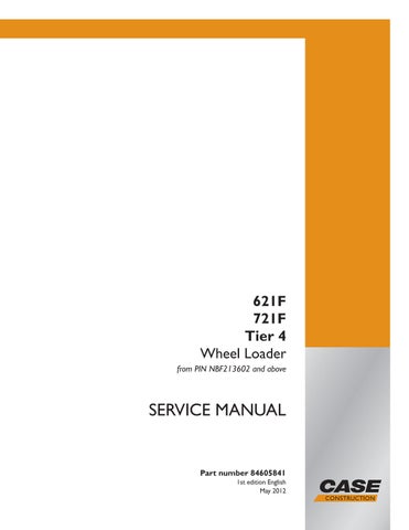
41. Disconnect the engine coolant vent hose from the
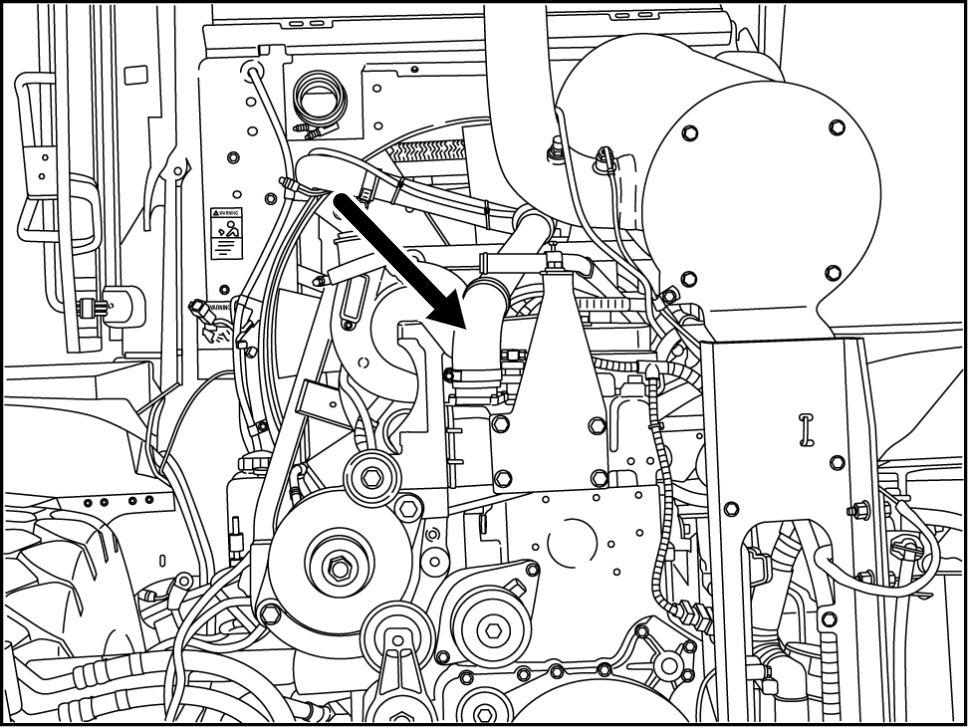
RAPH12WEL0628AA Loosen clamps and remove lower coolant hose from the engine.
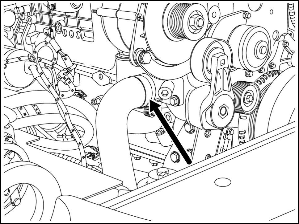
RAPH12WEL0629AA Remove the radiator hose from the
RAPH12WEL0630AA
84605841 14/05/2012
Engine - Engine and crankcase
10.001 /