
Shutdown SIS
Previous Screen
Product: EXCAVATOR
Model: 326F LN EXCAVATOR HCJ
Configuration: 326F L & 326F LN Excavators HCJ00001-UP (MACHINE) POWERED BY C7.1 Engine
Disassembly and Assembly
326F, 329F and 330F Excavators Machine Systems
Travel Motor - Assemble
SMCS - 4351-016
Assembly Procedure
Required Tools
Install O-ring seal (35) onto the housing of the travel motor.
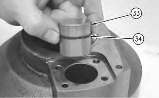
Install seal (34) and piston actuator (33). Lubricate the surfaces of piston actuator (33) with lubricant that is being sealed.
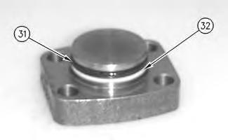
Install backup ring (32) and seal (31).
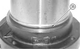 Illustration 1
g00887762
1.
Illustration 2
g00887754
2.
Illustration 3
g00887729
3.
Illustration 1
g00887762
1.
Illustration 2
g00887754
2.
Illustration 3
g00887729
3.
Illustration 4 g00887619
4. Install cover (30) and bolts (29). Tighten bolts (29) to a torque of 28 ± 7 N·m (21 ± 5 lb ft).
Illustration 5
g00887589
5. Apply Tooling (G) to the mating surface of lip seal (28). Use Tooling (E) in order to install lip seal (28). Lubricate the sealing lip of lip seal (28) with lubricant that is being sealed.
6. Use Tooling (F) in order to install retaining ring (27).
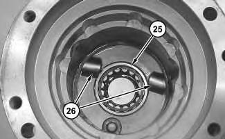
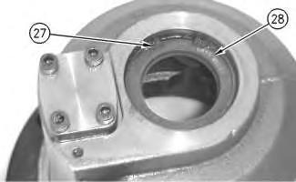
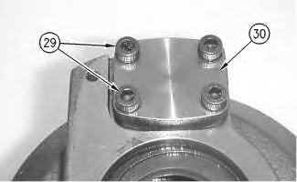
Illustration 6 g02107975
7. Rotate the housing.
8. Install keys (26) and locating pins (not shown) into the body of the travel motor.
9. Install bearing (25).
Improper assembly of parts that are spring loaded can cause bodily injury.
To prevent possible injury, follow the established assembly procedure and wear protective equipment.
10. Install springs (24) into the barrel assembly. Install ball (23) onto springs (24). Lubricate ball (23) with lubricant that is being sealed.
11. Lubricate the piston assemblies with lubricant that is being sealed. Install piston assemblies and retainer plate (22) into barrel assembly (21).
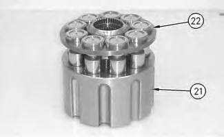
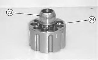 Illustration 7
g00887558
Illustration 8
g00887520
Illustration 7
g00887558
Illustration 8
g00887520
Note: Take note of the mark on the piston assembly and the barrel assembly. The pistons must be returned to the same position.
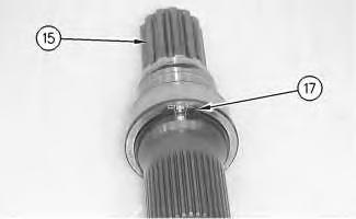
Illustration 9
g00887501
12. Lubricate cam plate (20) with lubricant that is being sealed. Install cam plate (20) onto barrel assembly (21).
Illustration 10
g00888697
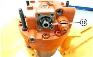
13. Install shaft (15) into a suitable press. Install bearing race (19) onto shaft (15).
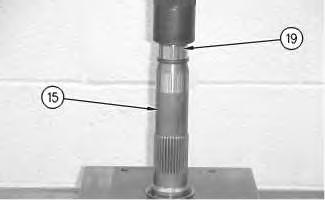
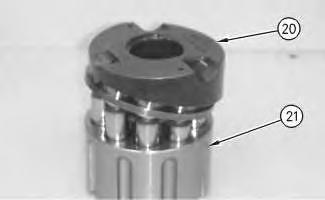
Illustration 11
g00887426
14. Rotate shaft (15) in the suitable press. Use Tooling (D) to install retaining ring (17) onto shaft (15).
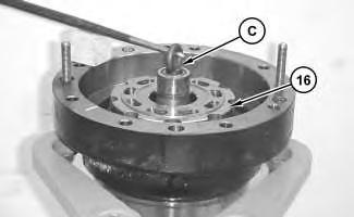
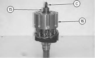
Illustration 12
15. Install bearing race (18) onto shaft (15).
g00888710
Note: Bearing race (18) must contact retaining ring (17).
g00887405
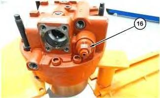
16. Install Tooling (C) into shaft (15). Install shaft (15) into rotating assembly (16).
17. Place the pump housing into Tooling (A).
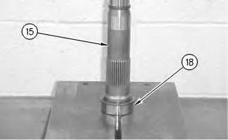 Illustration 13
Illustration 14 g03431399
18. Use Tooling (C) in order to install rotating assembly (16) into the housing.
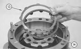
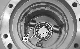
Illustration 15 g00887501
Illustration 16 g03431402
19. The notches in cam plate (20) must align with keys (26). The keys (26) are located in the bottom of the housing of the travel motor.
Illustration 17 g00887355
20. Install plates (13) and friction discs (14) into the housing.
Note: Install the plates and the discs alternately.
Illustration 18
g00887336
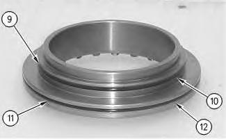
21. Install backup ring (12) and seal (11) onto the brake piston.
22. Install backup ring (10) and seal (9) onto the brake piston.
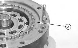
Illustration 19
23. Rotate brake piston (8).
24. Install brake piston (8) into the housing.
g00888967
Note: Brake piston (8) must be level upon installation. The brake piston must be level in order to prevent damage to the O-ring seals.
25. Install springs (7) and O-ring seals (6).
26. Lubricate port plate (4) with lubricant that is being sealed. Install O-ring seal (3), port plate (4), and bearing (5).
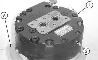
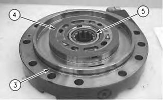
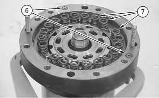 Illustration 20
g00887311
Illustration 21
g00887302
Illustration 22
g00887295
Illustration 20
g00887311
Illustration 21
g00887302
Illustration 22
g00887295
Improper assembly of parts that are spring loaded can cause bodily injury.
To prevent possible injury, follow the established assembly procedure and wear protective equipment.
27. Install head (2) onto the body of the travel motor.
Note: During the installation of head (2) onto the travel motor, be careful not to damage the mating surfaces of the components.
28. Install bolts (1). Tighten bolts (1) to a torque of 177 ± 18 N·m (131 ± 13 lb ft).
End By:
a. Install the travel motor.
Copyright 1993 - 2020 Caterpillar Inc. All Rights Reserved. Private Network For SIS Licensees.
Previous Screen
Product: EXCAVATOR
Model: 326F LN EXCAVATOR HCJ
Configuration: 326F L & 326F LN Excavators HCJ00001-UP (MACHINE) POWERED BY C7.1 Engine
Disassembly and Assembly
326F, 329F and 330F Excavators Machine Systems
Travel Motor - Assemble
SMCS - 4351-016
S/N - B321-UP
S/N - EBK1-UP
S/N - ERL1-UP
S/N - FBR1-UP
S/N - GGJ1-UP
S/N - GHT1-UP
S/N - HBT1-UP
S/N - HCA1-UP
S/N - HCJ1-UP
S/N - HCK1-UP
S/N - JFR1-UP
S/N - JHF1-UP
S/N - KFA1-UP
S/N - LBN1-UP
S/N - LCG1-UP
S/N - MBX1-UP
Shutdown SIS
S/N - RCN1-UP
S/N - TMR1-UP
S/N - TPG1-UP
S/N - WBA1-UP
S/N - WGL1-UP
S/N - XFK1-UP
S/N - YHA1-UP
Assembly Procedure
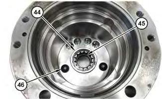
3. Install shaft (43) and springs (42).
4. Install pistons (41).
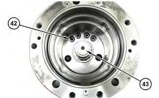
5. Install swashplate (40) into housing (26).
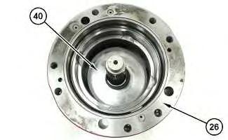
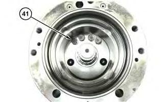 Illustration 2 g06343793
Illustration 3 g06343788
Illustration 4 g06343786
Illustration 2 g06343793
Illustration 3 g06343788
Illustration 4 g06343786
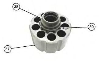
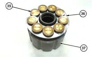
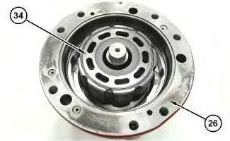 Illustration 5
g06343783
6. Install springs (39) and hold down ball (38) into barrel (37).
Illustration 6
g06343777
7. Install retainer (36) and piston (35) into barrel (37).
Illustration 7
g06343638
8. Install rotating group (34) into housing (26).
Illustration 5
g06343783
6. Install springs (39) and hold down ball (38) into barrel (37).
Illustration 6
g06343777
7. Install retainer (36) and piston (35) into barrel (37).
Illustration 7
g06343638
8. Install rotating group (34) into housing (26).
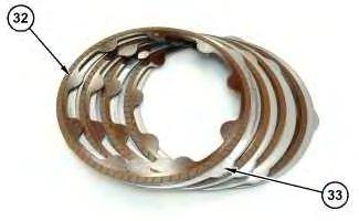
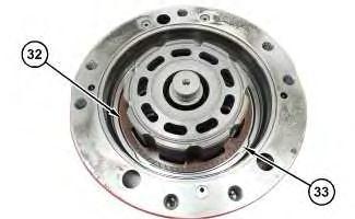
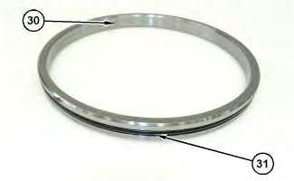 Illustration 8 g06343469
Illustration 9 g06343466
9. Install plates (33) and friction discs (32) in the orientation determined in the disassembly.
Illustration 10 g06343464
10. Install O-ring seal (31) into brake piston guide (30).
Illustration 8 g06343469
Illustration 9 g06343466
9. Install plates (33) and friction discs (32) in the orientation determined in the disassembly.
Illustration 10 g06343464
10. Install O-ring seal (31) into brake piston guide (30).
Illustration 11 g06343462
11. Install brake piston guide (30).
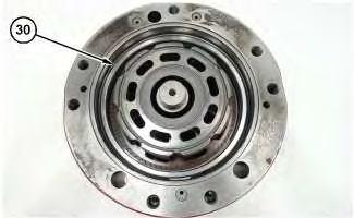
Illustration 12 g06343437
12. Install O-ring seals (29) and back up rings (28) into brake piston (27).
Illustration 13 g06343877
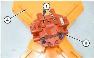
13. Use Tooling (D) and a suitable lifting device to position housing (26) onto Tooling (A) and (B). The weight of housing (26) is approximately 43 kg (95 lb).
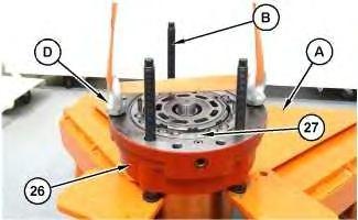
14. Remove Tooling (D) and install brake piston (27).
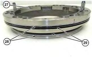
Illustration 14
15. Install O-ring seals (25) and (24).
16. Install springs (23) and pins (22).
Illustration 15
17. Install bearing (21) and control plate (20) into head assembly (18).
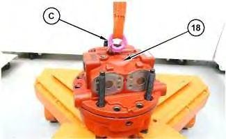
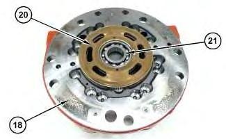
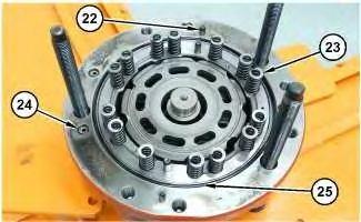
Illustration 16
18. Use Tooling (C) and a suitable lifting device to install head assembly (18) onto the housing. The weight of head assembly (18) is approximately 21 kg (47 lb).
g06343381 g06343374 g06343366Improper assembly of parts that are spring loaded can cause bodily injury.
To prevent possible injury, follow the established assembly procedure and wear protective equipment.
19. Install bolts (19). Tighten bolts (19) to a torque of 205 ± 10 N·m (151 ± 7 lb ft).
20. Install the bolts of Tooling (B)
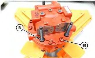 Illustration 17
g06343887
Illustration 18
g06343315
Illustration 17
g06343887
Illustration 18
g06343315
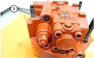
Illustration 19 g06343314
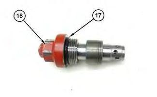
21. Install O-ring seal (17) onto relief valve (16).
22. Install relief valve (16) into the head assembly. Tighten relief valve (16) to a torque of 570 ± 20 N·m (420 ± 14 lb ft). Repeat for the opposite side.
23. Install spool (15).
Illustration 20 g06342009 Illustration 21 g06342005Improper assembly of parts that are spring loaded can cause bodily injury.
To prevent possible injury, follow the established assembly procedure and wear protective equipment.
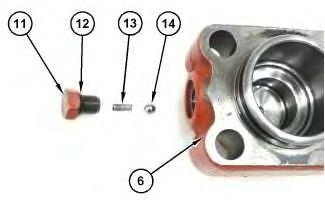
24. Install O-ring seal (12) onto plug (11).
25. Install ball (14), spring (13), and plug (11) into cap (6). Repeat for the opposite side.
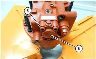
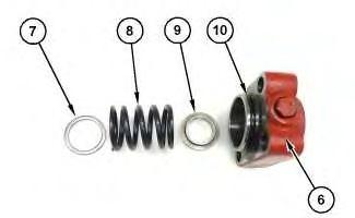 Illustration 22 g06342000
Illustration 23 g06341942
Improper assembly of parts that are spring loaded can cause bodily injury.
Illustration 22 g06342000
Illustration 23 g06341942
Improper assembly of parts that are spring loaded can cause bodily injury.
To prevent possible injury, follow the established assembly procedure and wear protective equipment.
26. Install O-ring seal (10) onto cap (6).
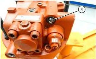
27. Install washer (7), spring (8), guide (9), and cap (6) into the head assembly.
28. Repeat for the opposite side.
Illustration 24 g06341917 29. Install spool (4). Illustration 25 g06341915 30. Install spring (3).Improper assembly of parts that are spring loaded can cause bodily injury.
To prevent possible injury, follow the established assembly procedure and wear protective equipment.
31. Install plug (2A). Tighten plug (2A) to a torque of 54 ± 5 N·m (40 ± 4 lb ft). Repeat for the opposite side.
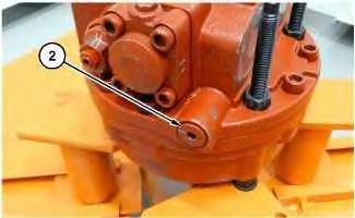
Install plug (2) and the O-ring seal. Tighten plug (2) to a torque of 53 ± 2 N·m (39 ± 1 lb ft).
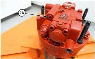 Illustration 26
g06341912
Illustration 27
g06344110
32.
Illustration 26
g06341912
Illustration 27
g06344110
32.
Illustration 28
33. Install plugs (1) and the O-ring seals.
g06341880
34. Remove the travel motor from Tooling (A) and (B). The weight of the travel motor is approximately 70 kg (154 lb).
End By: a. Install the travel motor.
Suggest:
If the above button click is invalid.
Please download this document first, and then click the above link to download the complete manual.
Thank you so much for reading

Shutdown SIS
Previous Screen
Product: EXCAVATOR
Model: 326F LN EXCAVATOR HCJ
Configuration: 326F L & 326F LN Excavators HCJ00001-UP (MACHINE) POWERED BY C7.1 Engine
Disassembly and Assembly
326F, 329F and 330F Excavators Machine Systems
Travel Motor - Install
SMCS - 4351-012
Installation Procedure Table 1
Required Tools
Care must be taken to ensure that fluids are contained during performance of inspection, maintenance, testing, adjusting, and repair of the product. Be prepared to collect the fluid with suitable containers before opening any compartment or disassembling any component containing fluids.
Refer to Special Publication, NENG2500, "Dealer Service Tool Catalog" for tools and supplies suitable to collect and contain fluids on Cat products.
Dispose of all fluids according to local regulations and mandates.
1. Thoroughly clean the mating surfaces of the travel motor and the final drive.