Selected Works 2021-2023
Justice Owusu Mensah
Justice Owusu Mensah
THE OHIO STATE UNIVERSITY
THE OHIO STATE UNIVERSITY
ARCHITECTURAL PORTFOLIO 2020-2023
ARCHITECTURAL PORTFOLIO 2020-2023
Undergraduate Academic Project II, Katy Viccellio Studio Section, Spring 2022
BIM Assistant Published Project I, Fall 2022
BIM Assistant Published Project II, Fall 2022
Undergraduate Academic Project I, Katy Viccellio Studio Section, Spring 2022
Undergraduate Academic Project I, Anastasia Congdon Studio Section, Fall 2021
BIM Assistant Published Project III, Fall 2022
Undergraduate Academic Project II, Anastasia Congdon Studio Section, Fall 2021
AUDITORIUM (0403) SHISLER
APPLEWOOD VILLAGE
01 02 03 04 05
Table of ConTenTs FISHER
CENTER (0679)
- HOLLY COURT, 1050-1060 (8063)
LIVE-WORK HOUSING OLD NORTH COLUMBUS LIBRARY 06
COWORKING TOWER
2
OWENS RECREATIONAL CENTER 07
JESSE
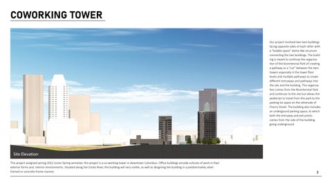
COWORKING TOWER
Site Elevation
This project assigned sprinig 2022 Junior Spring semester, this project is a co-working tower in downtown Columbus. Office buildings encode cultures of work in their exterior forms and interior environments. Situated along the Scioto River, the building will very visible, as well as desgining the building in a predominately steelframed or concrete-frame manner.
Our project involved two twin buildings facing opposite sides of each other with a “bubble space” dome-like structure connecting the two buildings. The building is meant to continue the organization of the bicentennial Park of creating a pathway or a “cut” between the twin towers especially in the lower floor levels and multiple pathways to create different entryways and pathways into the site and the building. This organization comes from the Bicentennial Park and continues to the site but allows the pedetrian to travel from the park to the parking lot space on the otherside of Cherry Street. The building also includes an undergound parking space, to which both the entryway and exit points comes from the side of the building, going underground.

3
First Floor plan involves the public spaces with variety of programs such as the open art gallery, shopping, restaurant, open lounge area, as well as an indoor park extension. The “cut” and pathways is to allow pedestrian flow and mobility throughout the site and also the different programming spaces, therefore allowing multiple entrances to the site.
Second Floor plan, is a continuation from the indoor park extension, unto the kids area, while the other building involves the gym, spa, daycare, for the children. Due to the safety of the children, the doors are designed in a manner where they face the cores in case of an emergency such as fire, or any hazardous warnings
Seventeenth Floor plan addresses the co-working spaces and the different programs in those spaces, such as the conference spaces, closed co-working, and the cafe. The working spaces located near the window systems addresses the typical skyscraper of those programs facing the light/outdoor views, while the central space addresses the free open spaces for relaxation and hangout
Twenty-ninth floor level includes similar floor plans and organization to the co-working spaces, with the exception to the open terraces. The open terrace spaces on one building faces the park and the Scioto river, while the other faces W. Main St. The building with the terrace facing the park includes an access to the rooftop acting as open space for relaxation, and also focuses on the views
Display Display Display Mechanical Janitor Storage 5 3 2 1 4 1. Quiet Lounge 2. Indoor Park Extension 3. Arts Gallery Space 4. Shopping 5. Restaurant/Cafe PLAN Level 0’ 1’ 5’ 10’ SCALE: 1/16” 1’- 0” PLAN Level 0’ 1’ 5’ 10’ SCALE: 1/16” 1’- 0” 1. Indoor Park Extension 2. Play Area 3. Sta Lounge 4. Cafeteria 5. Infants area 6. Toddler 7. Sleeping Area 8. Kitchen 9. Gym 10. Spa 5 1 4 2 8 7 6 9 10 3 3 PLAN Level 17 0’ 5’ 10’ SCALE: 1/16” 1’- 0” 1. Cafe 2. Closed Conference 3. Open Co-working 4. Open Group 5. Terrace 6. Hangout Area 5 1 2 2 3 3 2 6 4 PLAN Level 29 1’ 10’ SCALE: 1/16” 1’- 0” 1. Terrace 2. Open Roof Access 3. Open Co-Working 4. Closed Conference 4 4 1 3 2
4
Diagram II showcasing separation between the spaces in the floors. The 2D diagrams are then transformed into 3D in creating the final design of the model.
Diagram I showcasing the structure to the Tower. The building comprises of exterior vertical bracing in the skin, with two twin cores in each building. The building also consist of an aluminum and curtain wall system, while the twin building contains various vertical columns used as structural support system in floor levels.
STRUCTURE EXTERIOR BRACING SYSTEM COVERING ALL THREE SIDES OF THE BUILDING GLASS SYSTEM THE FACADE OF THE BUILDING IS COVERED BY ALUMINUM AND CURTAIN WALL SYSTEM CORE TWO CORES PLACES ON THE CORNERS OF THE TWIN TOWERS AND EACH CORE CONTAINS SIX ELEVATORS, EXCLUDING THE SEVENTEENTH FLOOR ON THE SHORTER BUILLDING WITH IT BEING ONLY THREE CONE THIS SPACE CONNECTS BOTH TWIN TOWERS AND ACTS AS A FREE AND OPEN AREA FOR CO-WORKERS COLUMN VARIOUS VERTICAL COLUMNS USED AS STRUCTURAL SUPPORT SYSTEMS IN FLOOR LEVELS From 2D to 3D Diagram Final Outlook 3D Massing Box Divison within box Separation
5
A partial Section on the ground Levels, showcasing the public activities 6
Cross-Section


 Indoor Perspective showcasing the view inside the “Bubble Space”, where co-workers and employees can meet up, hangout, and relax.
Outdoor perspective showcasing the view from Bicentennial Park into the main “cut” entrance into the site from 2nd street.
Indoor Perspective showcasing the view inside the “Bubble Space”, where co-workers and employees can meet up, hangout, and relax.
Outdoor perspective showcasing the view from Bicentennial Park into the main “cut” entrance into the site from 2nd street.
7
Indoor Perspective showcasing the view inside the indoor park extension, showcasing the trees and the family oriented benches along the grand stairs into the second floor. The view faces the street of 2nd street and towards Bicentennial Park and the Scioto River for better views.
As a BIM intern for FITS (Facilities Information and Technology Services) during the summer of 2022, this was one of the buildings that I was tasked with capturing and measuring the dimensions of the facility and document any changes and or revisions of the building. For this particular assigned building, the changes occured in it’s interior spaces, where additional spaces that were not documented prior, in both used and unused spaces were documented. These changes were then implemented on the updated floor plans based on the current conditions of the building in Revit. Prior to completing and making sure that all calculations and dimensions were accurate, a rendered exterior view of the building was completed and captured to signal the completion and the publication of the project to the Ohio State University.

FISHER AUDITORIUM


8
Revit Model completed by Justice Owusu and Rendering completed by Daqi Bao
Initial Stages prior to taking images and documenting measurements is first calculating the square footages of the facility in AutoCad, and then recording AutoCads dimensions before comparing that to the actual dimensions of the building when visiting the site. Prior to the revisions and calculations, there were only three floor plans, but after vising the building and taking measurements, additional floor plan (the Mezzanine Level) were documented along with the roof floor plan for a total of five floor plans. Majority of the changes of the measurements were from the first floor where some spaces like the library spaces, or additional office spaces were not documented.
139T 140 107T 105T 111 117T 119T 118T 121 123 123A 126C 124 123B 123C 126A 127 136A 137 128 135 146T 147 132J 133 134J 112A 112B 112 120 X142S 116J X143S 126B 126 142 141 143144145 149M X105C X100L X106C 104 103 115M X144S X126 X102L 136 DOCK X108C WALKWAY WALKWAY WALKWAY RAMP WALKWAY 138 B001M X044S 204 208T 201A 203M 202M 201 X242S X243S 207M FIRST FLOOR ROOF OPEN TO BELOW 203A 205M M203 OPEN TO BELOW FIRST FLOOR ROOF OPEN TO BELOW OPEN TO BELOW OPEN TO BELOW OPEN TO BELOW
9
East to West Section
A grid-floor plan and sections of the first and second floor level that showcases where the columns and beams (Wide Flang Beam) within the walls takes place.


A B C 5 4 3 2 1 C1 C2 C3 C4 C5 C6 CA CB 139T 140 107T 105T 111 117T 119T 118T 121 123 123A 126C 124 123B 123C 126A 127 136A 137 128 135 146T 147 132J 133 134J 112A 112B 112 120 X140S X141S X142S 116J X143S 126B 126 142 141 143144145 149M X105C X100L X106C X107C 104 103 115M X144S X126 X101L X102L 136 DOCK X108C RAMP WALKWAY WALKWAY WALKWAY RAMP WALKWAY 138 01 -First Floor 1052' -0" 02 -Second Floor 1066' -0" 0B -Basement Floor 1039' -0" 03 -Roof 1086' -4" 02M -Second Floor Mezzanine 1073' -0" 01 -First Floor 1052' -0" 02 -Second Floor 1066' -0" 0B -Basement Floor 1039' -0" 03 -Roof 1086' -4" 02M -Second Floor Mezzanine 1073' -0"
10
North to South Section


01 -First Floor 1052' -0" 02 -Second Floor 1066' -0" 0B -Basement Floor 1039' -0" C4 02M -Second Floor Mezzanine 1073' -0" 01 -First Floor 1052' -0" 02 -Second Floor 1066' -0" 0B -Basement Floor 1039' -0" C2 01 -First Floor 1052' -0" 02 -Second Floor 1066' -0" 0B -Basement Floor 1039' -0" A B C E CA CB 03 -Roof 1086' -4" 02M -Second Floor Mezzanine 1073' -0" 01 -First Floor 1052' -0" 02 -Second Floor 1066' -0" 0B -Basement Floor 1039' -0" A B C E CA CB 03 -Roof 1086' -4" 02M -Second Floor Mezzanine 1073' -0" 11 0B. Basement Floor 01. First Floor 02. Second Floor RF. Roof Level
Shisler Center was another set of buildings that I was tasked with, which was next to the Fisher Auditorium, in Wooster, Ohio. Both buildings are constructed with similar masonry types, but Shisler appears more modern as it was constructed later after Fisher. There is a direct entry to the building but one can enter through shisler from Fisher by exiting out into the hallway. The building is one Floor Level but unlike Fisher, has no assess to the roof.
SHISLER CENTER

While both Buildings are constructed with similar masonry, Shisler, incorporates more concrete in its walls, especially at the south end of the the building, and on top of the building. It also incoporates limestones both above and below the window sills. There are heavy glass construction in the hallway and through the direct entry way into the building.

12
Revit Model completed by Justice Owusu and Rendering completed by Daqi Bao
A grid-plan and a view of the interior is shown here highlights the locations of column and beam types incorporated in the building. The current building utilizes a round yellow column but most importantly, a HSS Hollow structural column joined within the wall both in the exterior and interior.


A B D C G H J L L N N P P R R S S 1 3 4 5 8 9 10 12 13 14 15 16 Q X101L 159 157 155A 155B 155 X108C 100B 100A 104 110 116 112 120 122 X105C 119 117M 149J 115 145T 125T 128 X107C 130A 130B X106C X109C 101 148 150 154 144M 138 136M 134 130 DOCK RAMP STAGE 100 X111C X100L 01 02 0304 H.5 K M F E 2 6 9.7 11 12.1 L.1 R.9 T X110C FISHER AUDITORIUM (0403) P.1 P.2
13


1049' -6" 1049' -6" 01 -First Floor 1049' -6" B C H P R Q RF -Roof 1075' -6" H.5 K L.1 R.9 P.1 P.2 01 -First Floor 1049' -6" B C H N S Q RF -Roof 1075' -6" H.5 M L.1 R.9 P.1 P.2 14
01. First Floor
RF. Roof Level


15 5 16 01 -First
1049'
A B D C G H J L N P R S Q RF -Roof 1075' -6" H.5 K M F E L.1 R.9 T P.1 P.2
Floor
-6"
OLD NORTH COLUMBUS LIBRARY

This project during the spring semester of 2022 aims to tackle an important question, “how can I design buildings that embrace the many benefits and contradictions of urban life”. To develop that answer, the first project is a new branch for the Columbus Metropolitan Library (CML).

16
View from E. Arcadia Ave
The project site is a 3.5 acre land on the west side of North High Street, directly north of the intersection with Kinnear Drive/East Arcadia Avenue. In the sites Eastern Portion, sits onvertop of the canalized Glen Echo Stream, while its Western portion is in the Glen Echo Ravine, a short distance to the Olegtangy River. Therefore to explore the site and its surrounding context, I decided to create Swote Analysis and its urban context to get a better understanding of the site.


17
One factor that made an impact on the built project was creating a residential entrance for the residential buildings in north street. Anotherfactor that played a part on the project was coming up with an outdoor activity for the children seeing as there were not a single outdoor activity in the nearby neighborhood. These challenges helps shaped my building to not just be about a library, but how it can blend into the neighborhood an solve some of the surrounding sites problems.
drawing of the built project is inspired by the Architectural Firm NBBJ’s artwork of the Columbus Metropol-

Library at the Dublin Branch. This isometric view aims to showcase some parts of the interior spaces, while also showing the overall site context and its importance to my project. Such context includes the greenery and landscape, parking space and the entry to the playground. The roof garden is another zone that fits into the library as an escape for fresh air, and an outdoor space, but also helps blend the greenery and landscape. The view also showcases the interior space of the quiet zone, and the staffing room.

18
The Isometric
itan
Interior View of the Open Loounge in the First Floor
The Ground Floor Plan focuses on the entrances and landscape of the spaces and the playground. The overall building has a side entrance, which is the residential entrance to the playground in the central space. The Main entrance however is through the cylindrical space, which also becomes a sitting zone. Entering through that space leads to the main lobby, where cafe/and coffee shops are located. Since this buildings goal is a separation between teens and kids zone, the children’s zones are on the left side, where their computing and kindergarten areas are located.
The First Floor Plan, deals mostly with quiet and reading areas. The circulation from the Ground Floor Level to the First Floor in the cylindrical space is through spiral ramps. This zone in the First Floor Plan is the quiet zone. This space compared the the second Floor Level is more noisy since its theres more zone and more people leading to more talking. The Cylindrical space is connected to an elevated space, which becomes another reading zone leading to the kids zone on the left of the site. The Stacks zone takes place on the other-side of the elevated reading zones.
The final Floor Plan is the Second Floor, and it involves the cylindrical space that acts as the reading/ and quiet zone, with a back entry to the roof garden. Another entry to the roof garden is by the meeting rooms, which is occupied by formal and informal group and one-on-one meeting rooms. Each room is also occupied by their own terraces that faces the ravine towards the Olengtangy River.

Main Entrance Residential Entry 1. Open Lounge Bathroom 3. Lobby Cafe 5. Teen/Adult Hangout 6. Janitor 7. Playground 8. Kids Zone (kindergarten/Play area) 9. kids/Help-desk/ 1-on-1 10. Storage 4 9 10 0’ 1’ 5’ 10’ SCALE: 1/16” = 1’- 0” Door 0’ 1’ 5’ 10’ SCALE: 1/16” 1’- 0” Quiet Lounge 2. Reception/Welcome Zone Reading Hall 4. Teen Computing Sta Zone Sta Zone Kids (Reading) Kids Computing Bathroom 10. Stacks 1 2 3 4 5 6 8 9 10 19
0’ 1’ 5’ 10’ SCALE: 1/16” = 1’- 0” 20
Sectional Cut showcasing the floor levels, but specifically the dome’s Lounge spaces in each floor.
LIVE-WORK HOUSING


This project assigned sprinig 2022 Junior Spring semester, explores a series of opposite conditions-live/work, public/private,inside/outside, light/dark-through the design of an assemblage of live/work spaces. The used site that is assaigned is located in Franklington, near the scioto river, in downtown Columbus.

21
The form of my projects involves shifting (“in-and-out), allowing for one to capture the essence of light and views of downtown. The site plan illustrates five apartments/complex that rotates one side and mirrors to the other. In-between the mirrored units, are walkable spaces for entry into the units. They’re also spaces for outdoor activities such as sitting, playing, etc.


S Gift St W Rich St Mc Dowell St Project Live-Work Housing, High-Density Urbanism Site Plan W Rich St W Rich St SITE PLAN
22
Floor Plan II is incorporates living spaces with balconies, facing either street or the backyard. Circulation occurs in the center, making it easier and simple to enter each unit, giving that they’re joined together
Floor Plan III is a continuation of Floor Plan II, where it’s living units, with one room being dedicate for a working space.
0’ 1’ 5’ 10’ SCALE: 1/8” = 1’- 0” PLAN Level 1 Live-work Housing UP 0’ 1’ 5’ 10’ SCALE: 1/8” 1’- 0” PLAN Level Live-work Housing UP UP Live-work Housing 0’ 1’ 5’ 10’ SCALE: 1/8” = 1’- 0” PLAN Level UP UP
Floor Plan I is assigned as working spaces.
23
The process in constructing the units was through several steps. Step one was by taking a rectangle, and then stacking. With the units being three stories high, three rectangles were stacked. The next step was shifting the boxes. From there glass was implemented on the spaces where the shifting occured for balcony space. The final step involves glass based on the opposite end of the balcony, where the public space occurs.
Rectangle Stacking (Two Rectangles) Stacking (Three Rectangles)
Shifting of boxes
Implementation of Glass material on Open Spaces Final Look of Unit
24
A closer look at the sectional perspective of the units. The third and first flor levels are facing the street, with the third floor level balcony facing the sidewalks on the site. The second Floor levels balcony would face West Rich Street, but the living room space, would also face that direction.

25
APPLEWOOD VILLAGE - HOLLY COURT, 1050-1060
Student Housing was another assigned building as a BIM assistant in Wooster, Ohio. Applewood Village - Holly Court, 1050-1060, is a two story student housing on Wooster Campus and the building consists of four units with floor plans that mirror and reflect each other. The entirety of the facade includes brick with green doors in its entrance and in its storage, followed by front roof porch.


26


1056D1056D 1056M1056M 1058S1058S 1056S1056S 1054S1054S 1052S1052S X141S 1056C1056C 10561056 1054C1054C 1054D1054D 1054M1054M 10541054 X142S 1052M1052M 1052B1052B 1052A1052A 1050S1050S 1052T1052T X143S 1052D1052D 10521052 1052C1052C WALKWAY1060T1060T 1060C1060C 1060B1060B 1060A1060A 1060M1060M 1060D1060D 10601060 1056T1056T 1056F1056F 1056G1056G 1056B1056B 1056E1056E 1056A1056A 1054E1054E 1054A1054A 1054T1054T 1054F1054F 1054G1054G 1054B1054B 1050D1050D 1050T1050T 1050C1050C 1050A1050A 1050B1050B 1050M1050M 10501050 X240S X243S X241S X242S FIRST FLOOR ROOF FIRST FLOOR ROOF FIRST FLOOR ROOF AutoCAD Drawing of the First Floor Level AutoCAD Drawing of the Second Floor Level 27


01 -First Floor 1051' -9 5/8" 02 -Second Floor 1061' -0 1/2" RF -Roof 1081' -0" 01 -First Floor 1051' -9 5/8" 02 -Second Floor 1061' -0 1/2" RF -Roof 1081' -0" 28


01 -First Floor 1051' -9 5/8" 02 -Second Floor 1061' -0 1/2" RF -Roof 1081' -0" 01 -First Floor 1051' -9 5/8" 02 -Second Floor 1061' -0 1/2" RF -Roof 1081' -0" 01 -First Floor 1051' -9 5/8" 02 -Second Floor 1061' -0 1/2" RF -Roof 1081' -0" 01 -First Floor 1051' -9 5/8" 02 -Second Floor 1061' -0 1/2" RF -Roof 1081' -0" 29 01. First Floor 02. Second Floor RF. Roof Level
JESSE OWENS RECREATIONAL CENTER
The project assigned during the spring semester of 2021, occupy the site of the old Jesse Owens North Recreation Facility in the Ohio State University Campus.

Site Elevation 30
The theme for my project tries to form circulation in the middle (base) of the building, with variety of programs being on the sides (Left and Right) sides of the building, that will be shown in the plans and programmatic diagram. There are two entrances to the buidling, with one being from the campus and one being from Lane avenue into the building. The elevatorial cores happen in the central space as well that leads to the second floor level.


31
First Floor Level shows the circulation but also the central space, which would serve as the public gathering space. Glass were implemented on both sides to issue transparency and light. On one side, there is the a basketball court, while the other side, shows the lockerroom, yoga, ad classrooms.
The Second Floor level, includes programs such as boxing, gymnasium and a swimming facility on the right. The central space also serves as a public “hangout” area.
Recreation Center 0’ 1’ 5’ 10’ SCALE: 1/8” = 1’- 0” PLAN Level 1 Recreation Center 0’ 1’ 5’ 10’ SCALE: 1/8” = 1’- 0” PLAN Level 2
Swimming Pool (6,959 ft²) Open Space (5,850 ft²) Boxing (1,713 ft²) Gym (1,713 ft²) Wet Spaces (2,442 ft²) Basketball (4,556 ft²) Lobby (5,850ft²) Yoga (1,284 ft²) Kids Play Area (807 ft²) Wet Spaces (2,74 8ft²) 32


LANE AVE 1 2 2 3 3
An Interior view in the lobby space showcasing the cafe, furniture, but most importantly the transparency looking into the building.
33
An Exterior view from campus into the lobby space.
Thank you for your consideration! ARCHITECTURAL PORTFOLIO 2023 Thank you for your consideration! ARCHITECTURAL PORTFOLIO 2023 References Phone: +1 (614)-869-8521 Email: owusumensah.1@osu.edu Alternate: justice9owusu@gmail.com