International Research Journal of Engineering and Technology (IRJET) e-ISSN: 2395-0056

Volume: 09 Issue: 09 | Sep 2022 www.irjet.net p-ISSN: 2395-0072

International Research Journal of Engineering and Technology (IRJET) e-ISSN: 2395-0056
Volume: 09 Issue: 09 | Sep 2022 www.irjet.net p-ISSN: 2395-0072
1M.Tech Student in control and Automation, Department of Electrical Engineering, AU Engineering college, Andhra University, Visakhaptnam, Andhra Pradesh, India
2Associate Professor, Department of Electrical Engineering, AU Engineering college, Andhra University, Visakhaptnam, Andhra Pradesh, India ***
Abstract -: Quadcopter is an unmanned aerial vehicle, which can be implemented in different applications. In paper it will be represented a development of a quadcopter system. In The paper we will demonstrate how to model a basic physical quadcopter, then increase the complexity of the plant model, and finally demonstrate how the model can be implemented in MATLAB/Simulink.). The advantages of utilizing MATLAB/Simulink to create and implement these models come from the tool's processing power as well as the simplicity with which Simulink models may be applied to hardware.
Key Words: model, state variables, quadcopter, plant, sensor
Quadcopters are an emerging technology gaining in popularity. Most users purchase quadcopters fully assembledwitheverythingthat’sneededtofly.Oneofthe most interesting aspects of quadcopters that may make flyingthemevenmoreamazingisunderstandinghowthey work. Believe it or not, users have the ability to install their owncontrol system in order tohavethe quadcopter fly exactly how they want, depending on hardware of course. Many users are limited by the controller that comes preinstalled on quadcopters. A custom control system, depending on the complexity of the system, can allow the quadcopter to have automatic functions. These functions could include flips, or inverted flight. However, to do this, a plant model of the quadcopter is needed to simulateflightto provethe control systemworksprior to installing on the quadcopter. Creating a plant model and simulating it provides a prediction of what the real-world quadcopterwilldo.Quadcopterplantmodelscanincrease in accuracy depending on how involved the modelling process is. The idea of controlling and creating plant model of a quadcopter is rather complex but can be broken down significantly so it can be easily understood. Control systems and plant models can be seen almost everywherewithoutknowingit.Thethreepiecesrequired to create a model are the control system, a plant model andsensors.Sincethecontrolsystemandplantmodelofa quadcopter can be complex, the paper will demonstrate howtomodelthebasicphysicalquadcopter,thenincrease the plant model’s complexity and then demonstrate how
value:
the model can be implemented in MATLAB\Simulink. It also demonstrates how to build and tune controllers that re able to control a quadcopter’s roll, pitch, yaw, altitude and motor dynamic. The benefits of using MATLAB\Simulink to create and implement these models come from the computing power of the software tool, along with ease of implementation of Simulink models to hardware. document is template. We ask that authors follow some simple guidelines. In essence, we ask you to make your paper look exactly like this document. The easiestwaytodothisissimplytodownloadthetemplate, and replace(copy-paste) the content with your own material. Number the reference items consecutively in squarebrackets(e.g.[1]). However,theauthorsnamecan be used along with the reference number in the running text. The order of reference in the running text should matchwiththelistofreferencesattheendofthepaper.
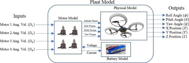
With the use of quadcopter in outdoor applications, researchersareinterestedinevaluatingtheperformanceof modelling and controlling of the quadcopter. To understand the quadcopter system modelling the block seeninFigure1canbeused.
The quadcopter model is a system of equations at generate outputs based upon inputs, parameters, and system states. Within the broad plant model of the quadcopter there are separate plant models such as the body dynamics, motor, and battery models. There is somewhat of a flow of variables within the plant model. The system starts with the inputs, which in this case are motor angular velocity commands. With these commands, states within the plant model angular velocity, and axial velocity. Parameters are constants that effect the states,
International Research Journal of Engineering and Technology (IRJET) e-ISSN: 2395-0056
Volume: 09 Issue: 09 | Sep 2022 www.irjet.net p-ISSN: 2395-0072
suchasthefrictioncoefficientofthemotors.Theoutputsof theplantarebasedonthepreviousstates,parameters,and inputs. Lastly, it is important to note that the states dependent on the frame of reference, or where the zero pointistheidealplantmodelwouldsimplybethephysical model, assuming instant thrust, no disturbances, and unlimited state values. A real-world model would include motorandbatterydynamicsalongwithstatelimitation
Quadcopters inherently have six degrees of freedom. This means the device can travel in the X, Y and Z direction, as well as rotate in roll, pitch and yaw directions. These terms are generally related to most aircraft, subs, and robotics as not many other platforms are able to control all 6 degrees. The roll and pitch are what allow the quadcopter to move in the X and Y directions.RollcanbedefinedastherotationaroundtheX axis,pitchcanbedefinedastherotationaroundtheYaxis andyawcanbedefinedastherotationaroundZaxis.With this, the axis of rotation for the quadcopter and state variables can be defined. State variables are the physical dynamics of the quadcopter that include angles and positions. Many of the states are dependent on other states and user input. The reference frame of the quadcopter will be local NED. Which is why the Z axis is pointeddown.
Symbol Description Unit Observability
Pitch Euler Angle ������ StereoVision
Pitch Euler Angular Velocity
Pitch Euler Angular Accel.
������/�� Gyroscope
������/��2 -
��
Roll Euler Angle ������ StereoVision
Roll Euler Angular Velocity
Roll Euler Angular Accel.
������/�� Gyroscope
������/��2 -
��
Yaw Euler Angle ������ StereoVision
Yaw Euler Angular Velocity
������/�� Gyroscope
Yaw Euler Angular Accel.
������/��2 -
�� PositioninX �� StereoVision
VelocityinX ��/��Accel.inX ��/��2 Accelerometer
�� PositioninY �� StereoVision
VelocityinY ��/��Accel.inY ��/��2 Accelerometer
�� PositioninZ �� StereoVision
VelocityinZ ��/��Accel.inZ ��/��2 Accelerometer
Ω1 Motor 1 Angular Velocity
Ω2 Motor 2 Angular Velocity
Ω3 Motor 3 Angular Velocity
Ω4 Motor 4 Angular Velocity
������/�� Voltage/Current/Optical
������/�� Voltage/Current/Optical
������/�� Voltage/Current/Optical
������/�� Voltage/Current/Optical
-Theta (/they-tuh/), ��-Phi (/fi/), ��-Psi (/sai/), Ω-Omega (/ohmega/)
Beforegeneratingtheplantmodel equationsofmotion, Parameterneedtobedefined.Itisimportanttoknowthe difference between states and parameters. States are dynamics of the quadcopter, where parameters are constants associated with the quadcopter. The first parameters to be defined are the moment of inertia in each axis. The moment of inertia is the amount of torque needed for a desired angular acceleration around a rotation axis. These relies heavily on the physical design and components of the quadcopter. These are generated through various methods which mostly include estimates fromlengths/diametersandmassesofthequadcopter.The rotor inertia, which is the total rotational moment of inertia around the propeller axis is another parameter used in the equations of motion. The distance from the rotor axis to the center of the quadcopter also can be defined,alongwiththethrustanddragcoefficients.These canbeseeninTable2below
International Research Journal of Engineering and Technology (IRJET) e-ISSN: 2395-0056
Volume: 09 Issue: 09 | Sep 2022 www.irjet.net p-ISSN: 2395-0072
Symbol Description Unit ������,������,������
Inertiamoments ������2 ���� Rotorinertia ������2
Rotoraxistocoptercenterdistance �� �� Thrustcoefficient ��/��2 �� Dragcoefficient ����/��2
The next set of parameters have to do with the quadcopter and environment. In the real world, quadcopters experience aerodynamical effects, namely from air resistance and wind. Air resistance can be thought of as a drag on the quadcopter, opposing the motionofthequadcopter.Thisiswhatmakesquadcopters slow down when no actuator force is acting on them. To envision air resistance, one can simply drop a piece of paper, and a pencil from the same height. Since air resistanceeffectsthequadcopterinall3axialdirections,a coefficientisneededforeach.Measuringtheairresistance is extremely complex, so in most cases estimates suffice. The values used for the plant model were 0.1 kg/s for the resistance in each axis. The parameters can be seen in Table3below.
Table -3: environmentalparameters
Symbol Description Unit
Airresistanceineachaxis ����/��
BeforethequadcopterismodeledinMATLAB/Simulink the mathematical equations need to be generated. To do thisafewassumptionsaremade[1].
Thedroneisarigidstructure
Theairframeandcomponentsaresymmetric
The center of gravity and air frame origin coincide
Thrustanddragareproportionaltothesquare ofpropellerspeed
There are no external disturbances to the quadcoptersuchaswind,temperature,etc.
Next,Thephysicaleffectsonthequadcopterneedtobe considered.Theseincludeaerodynamiceffectsfromthe propellers, inertial counter-torques from changes in propeller speed, gravity and gyroscopic effects from changesinbodyorientation.Theseallplayaroleinthe equations of motion of the quadcopter. The internal
plant model equations of the system can now be described. There are four main thrust equations, vertical thrust, roll thrust, pitch thrust and yaw thrust withthe“+”coordinatewhichcanbeseenintablefour.
Table -4: inputEquationsinthe“+”orientation
Input Thrust Equation Description
��1+ ��(Ω12 +Ω22 +Ω32 +Ω42) GeneralThrust
��2+ ��(−Ω22 +Ω42) RollThrust
��3+ ��(Ω12 Ωw32) PitchThrust
��4+ ��(Ω12 Ω22 +Ω32 Ω42) YawThrust
The quadcopter inputs can also be defined in the “X” orientation[2].Theseinputequationscanbeseenintable 5below.
Table -5: inputEquationsinthe“x”orientation
Input Thrust Equation Description
��1+ ��(Ω12 +Ω22 +Ω32 +Ω42) GeneralThrust
��2+ ���� �� (Ω12 -Ω22 -Ω32 +Ω42) RollThrust
��3+ ���� �� (Ω12 +Ω22 -Ω32 +Ω42) PitchThrust
��4+ ��(Ω12 Ω22 +Ω32 Ω42) YawThrust
The overall angular velocity of the all propellers can also be defined. This will be used in angular acceleration equations.Thepositivesandnegativesinequation(9)are used because of the direction the propeller is spinning. In most cases the opposite side motors are spinning in the samedirection,and2and4inthesamedirection).
Ω�� =Ω1 Ω2 +Ω3 Ω4 (9)
Table -6: Plantmodelequations
Rolling Torque
Pitching Torque
Yawing Torque �� �� ��(�� �� ) ��
International Research Journal of Engineering and Technology (IRJET) e-ISSN: 2395-0056
Volume: 09 Issue: 09 | Sep 2022 www.irjet.net p-ISSN: 2395-0072
Yaw Ang. Accl. �� ��(�� �� ) �� ��
Xforce ���� �� �� �� �� �� �� ��
XAccl.
Y
Figure2QuadcopterPlantfeedbacksystem 2.2 Basic Simulation Results

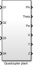
Now that the basic equations of motion have been generated, the Simulink plant model can now be formed. First,abasicscriptthatdefinestheinertiamoments,rotor inertia moments, rotor inertia, length, mass, thrust, and drag coefficients need to be created. Then the Simulink model is created. Starting a fresh Simulink model block diagram,Firstdefine thesolver options. On thetop bar of Simulink hit Simulation. Then Model configuration parameters. Under solver option, make sure the type is variablestep, and thesolveris on Auto.A newsubsystem cannowbedefined.Thesubsystemhasfourinputs (Ω1,Ω2, Ω3, Ω4) and six outputs (X, Y, Z, roll, pitch, yaw). At this pointthemodelshouldbelookinglikethefollowingfigure below
Figure3RollPlantSimulation
After implementing the previous mathematical equations, wegetthefollowingquadcopterplantfeedbacksystem
Figure4ThrustPlantSimulation
International Research Journal of Engineering and Technology (IRJET) e-ISSN: 2395-0056
Volume: 09 Issue: 09 | Sep 2022 www.irjet.net p-ISSN: 2395-0072
[3]Carrillo,L.R.,Lozano,R.,&PégardC.(2013).Modeling the Quad-Rotor Mini-Rotorcraft. Advances in Industrial Control Quad Rotorcraft Control 23-34 doi:10.1007/978-1-4471-4399-4_2.
[4] Horn, G. (2009, March 17). The Aerospace Euler Angles.RetrievedNovember06,2017
[5] P.-J. Bristeau, P. Martin, E. Salaun, and N. Petit, “The role of propeller aerodynamics in the model of a quadrotor,” in European Control Conference, (Budapest,Hungary),2009.
[6]W.KhanandM.Nahon,“Apropellermodelforgeneral forward flight conditions,” Inter J of Intelligent Systems,2015.
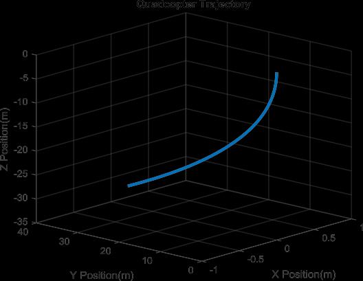
Figure5QuadcopterTrajectorySimulation
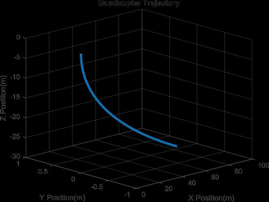
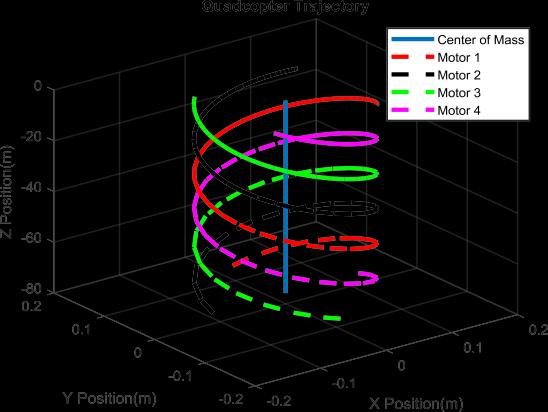
Quadcopters with accelerating industry are an interesting platform to perform different modelling strategies. The goal was to develop a simple modelling approach using MATLAB-Simulink. The vehicle’s Simulink model was made, based on derived differential Simulink model simulated perfectly depending on the equations of motion. This research shows how the original complex modelofquadcopterismodelizedtakingintoaccountwind effects.
[1] B. Fares, P. Apkarian, D. Noll, An Augmented Lagrangian Method for A class of LMI–Constraint Problems in Robust Control Theory. Int. J. Control. 2001.
[2] Carrillo, L. R., López, A. E., Lozano, R., & Pégard, C. (2013). Modeling the Quad-Rotor Mini-Rotorcraft. Advances in Industrial Control Quad Rotorcraft Control,23-34.doi:10.1007/978-1-4471-4399-4_2
2022, IRJET | Impact Factor value: 7.529 | ISO 9001:2008 Certified Journal |