International Research Journal of Engineering and Technology (IRJET) e ISSN: 2395 0056

Volume: 09 Issue: 07 | July 2022 www.irjet.net p ISSN: 2395 0072

International Research Journal of Engineering and Technology (IRJET) e ISSN: 2395 0056
Volume: 09 Issue: 07 | July 2022 www.irjet.net p ISSN: 2395 0072
Sowmyashree N1 , Akhilesh V2 , Chandan Raj M R3, Sanjana V4, Vinay M B5
1 Assistant Professor, Dept. Electrical and Electronics, SJCE, JSSS&TU, Karnataka, India 2,3,4,5 Student, Dept. Electrical and Electronics, SJCE, JSSS&TU, Karnataka, India ***
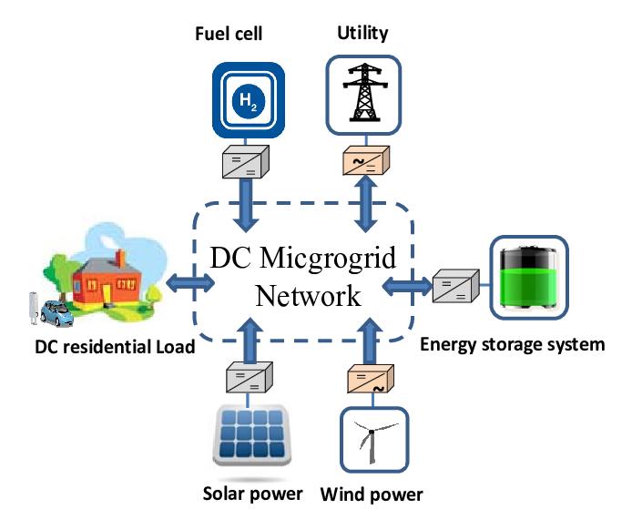
Abstract A microgrid is a self sufficient energy system that serves a discrete geographic footmark, such as a college campus, hospital and business center. With the development of computer network and automation technology, precise monitoring of microgrid parameters has become an essential part. Different methods are used to monitor the performance of a microgrid. An IoT based automated DC Microgrid system is represented in this paper. The main motive of the developed system is to monitor the performance of a DC microgrid and automatically isolate the load on detection of over voltage and under voltage condition. It mainly focuses on generating power using renewable energy resource such as solar energy and wind energy, monitoring the power supply and load voltages using Blynk Application
Key Words: DC Microgrid, Automation, Internet of Things (IoT), Blynk Application.
Theincreaseindemandforenergyisevidentwiththefact thatduringthefiscalyear(FY)2019 20,thegrosselectricity generated by utilities in India was 1,383.5 TWh and the grosselectricityconsumptioninFY2019was1,208kWhper capita.Suchnumberssignifytherequirementforrenewable energyresourcesbesidestraditionalones.Theproperusage ofrenewableenergysourcesisataskinthecurrentscenario. A microgrid is a modern distributed power system using localsustainablepowerresourcesdesignedthroughvarious smart grid initiatives. Microgrid combines distributed power, load, energy storage devices and management devices, forming a single and manageable power supply system. As a localized power grid, microgrid has its own generation sources, and definable load systems. It additionallyworkswithrenewableenergysourcesforpower generation that tends to the usage of storage resources accordingtotherequirement.Theytendtoprovidevarious benefits such as improving energy efficiency, minimizing overall energyconsumption andimprovesthequalityand reliabilityofpowersupply.
A great challenge lies in the protection of the grid as it shouldrespondtothefaultofautilitygridandrenewable sources. The early identification of faults and removal of faultsisalsoanenormoustaskinMicrogrids.Withgrowing rapid development and dependency on renewable energy resources in microgrid, its protection and command are resolvedwiththehelpofInternetofThings(IoT).TheIoT grants the system an advantage to remotely observe and supervisethenetwork.Henceasystemisdevelopedusing IoT that monitors the power flow in DC Microgrid and protects the grid from undervoltage and overvoltage conditions.
Microgrids, operating in either grid connected mode or islandedmode,enablelocalintegrationofenergygeneration, distribution and storage at the consumer level for better power system efficiency and control of demand. DC microgrids are highly efficient, reliable and economic as powerqualityissuessuchasreactivepowerandskineffect arenotpresent.Manymethodsandtechniquesareemployed toautomatetheDCMicrogrid.
Toovercomethechallengesassociatedwithmonitoringof Microgrid, researchers developed a system that uses B/S architecture to implement real time monitoring and adjustingthevalueoftheenvironmentfactordata[1].The studyprovidedamethodforgridenergyoptimizationforDC
International Research Journal of Engineering and Technology (IRJET) e ISSN: 2395 0056
Volume: 09 Issue: 07 | July 2022 www.irjet.net p ISSN: 2395 0072
microgrids including distributed energy resources and residential building,usinga Supervisory Control and Data Acquisition (SCADA) system. The inclusion of SCADA providesthecommoncommunicationforallcomponentsof the microgrid to interconnect with the control room via wirelesssmartsensorstoupdatethepowersetting[2].The IoTbasedBatteryMonitoringSystemwhichisdevelopedin thestudyconsistsofacommunicationchannelfromandto the Intelligent Electronic Device [IED], data acquisition, cloud system and Human Machine Interface (HMI). All battery parameters have been created into an embedded system that functions as an IoT to enable communication from and to the IED, as well as data acquisition and an internetgateway,allowingforthestorage,processingand accesstoallparametersthroughcloudsystem[3].Thepaper presents a novel event triggered distributed secondary control strategy for single bus DC microgrid. Through the event triggeringmechanism,eachconvertercandecideand chooselocallywhentotransmitsignalstoitsneighbors.In this way, there is significantly reduction in the communication burden among converters [4]. The paper presentedasystemthatallowsthesourcecodeportabilityof device drivers between different system. PIC microcontrollers is interfaced with UART, interfaced with LCDtocontroltheoperationofPICcontrollerusingMPLab IDE.TheIoTmoduledetectsthelocation,numberofloads operating, amount of energy consumed from supply, microgridandsensorvalues[5].
Thedrawbackoftheobservedsystemsisthatforthedata display,LCDareusedandincaseoffaults,analertmessage isnotdisplayed.Thesuggestedworksolvesthepreviously mentioned issues. The main objective of the developed systemistoimplementasystemfortherealtimemonitoring of DC microgrid using IoT technology and to analyse the performance of the system and rectify over voltage and undervoltageconditions
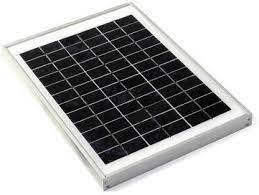
Solar panels are used for the harnessing of solar energy. Solarpanelsare madeupof numerous solarcellsthatare linkedinaseriesofparallellines.P typeandn typesilicon are the two types of semiconductors used in solar cells. Electronsinthesiliconareejectedwhensunlightstrikesa solar cell. If this happens in the electric field, then the electronswilltravelfromthen typelayertothep typelayer throughtheexternalwirecreatingaflowofelectricity.The solar power then generated can be stored for future use. 12W, 21V rated solar panel is used in our prototype to supplypowertoa12VDCload.
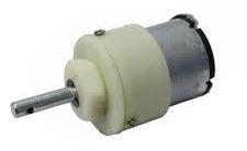
ThesemotorsaresimpleDCMotorsfeaturingMetalgearson theshaftforobtainingthebestperformancecharacteristics. TheyareknownasCentreShaftDCGearedMotorsastheir shaftextendsthroughthecentreoftheirgearboxassembly. ThisDCMotor 150RPM 12Voltsfindsitsapplicationin all terrainrobotsandavarietyofroboticapplications.These motorshavea3mmthreadeddrillholeinthemiddleofthe shaftthusmakingitsimpletoattachittothewheelsorother mechanicalassemblies.
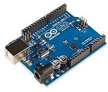
Arduino Unois a microcontroller board based on 8 bit ATmega328Pmicrocontroller.AlongwithATmega328P,it consistsothercomponentssuchascrystaloscillator,serial communication, voltage regulator, etc. to support the microcontroller. Arduino Uno has 14 digital input/output pins(outofwhich6canbeusedasPWMoutputs),6analog inputpins,aUSBconnection,APowerbarreljack,anICSP headerandaresetbutton.
International Research Journal of Engineering and Technology (IRJET) e ISSN: 2395 0056
Volume: 09 Issue: 07 | July 2022 www.irjet.net p ISSN: 2395 0072
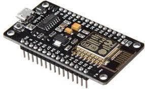
TheNodeMCUESP8266developmentboardcomeswiththe ESP 12E module containing the ESP8266 chip having Tensilica Xtensa 32 bit LX106 RISC microprocessor. This microprocessor supports RTOS and operates at 80MHz to 160 MHz adjustable clock frequency. NodeMCU has 128 KiloByteRAMand4MBofFlashmemorytostoredataand programs. Its high processing power with in built Wi Fi / BluetoothandDeepSleepOperatingfeaturesmakeitideal for IoT projects. NodeMCU is powered using a Micro USB jack and VIN pin (External Supply Pin). It supports UART, SPI,andI2Cinterface
Each channel on a 5V 4 channel relay interface board requires15 20mAdrivercurrent.Itcanbeusedtocontrola varietyofhighcurrentappliancesanddevices.Ithashigh currentrelaysthatworkunderAC250V10AorDC30V10A. It features a standard interface that can be controlled directlybymicrocontroller.
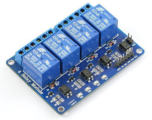
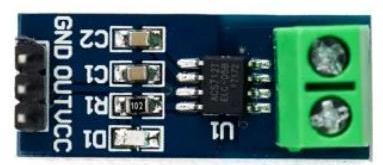
Fig-5 :Wi-fiModule
The5ArangeCurrentSensorModuleACS712consistsofan explicit, low offset, linear Hall circuit with a copper conduction path placed near the surface of the die This ACS721currentmoduleisbasedontheACS712sensor,that canaccuratelydetectACorDCcurrent.ThemaximumACor DC which can be detected can reach 5A, and the present currentsignalcanbereadviaanalogI/OportofArduino.
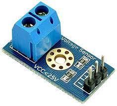
Avoltagesensorisasensorusedtocalculateandmonitor the amount of voltage in an object. Voltage sensors can determinetheACvoltageorDCvoltagelevel.Theinputof thissensoristhevoltage,whereastheoutputistheswitches, analogvoltagesignal,acurrentsignaloranaudiblesignal. The input voltage range is 0V 25V whereas the voltage detectionrangeis0.02445Vto25V.
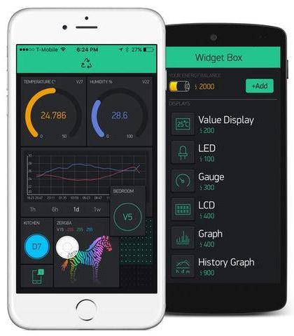
Blynk is a Platform that enables Internet based control of deviceslikeArduino,RaspberryPiandotherusingIOSand androidapps.Bysimplydragginganddroppingwidgets,you maycreateagraphicinterfaceforyourprojectonadigital dashboard.WithBlynkanyonecanconnecttheirhardware to the cloud and create a no code iOS, Android, and web applicationstoanalyzereal timeandhistoricaldatacoming fromdevices,remotelycontrolthemfromanywhereinthe world,receiveimportantnotifications,andmuchmore.
International Research Journal of Engineering and Technology (IRJET) e ISSN: 2395 0056
Volume: 09 Issue: 07 | July 2022 www.irjet.net p ISSN: 2395 0072
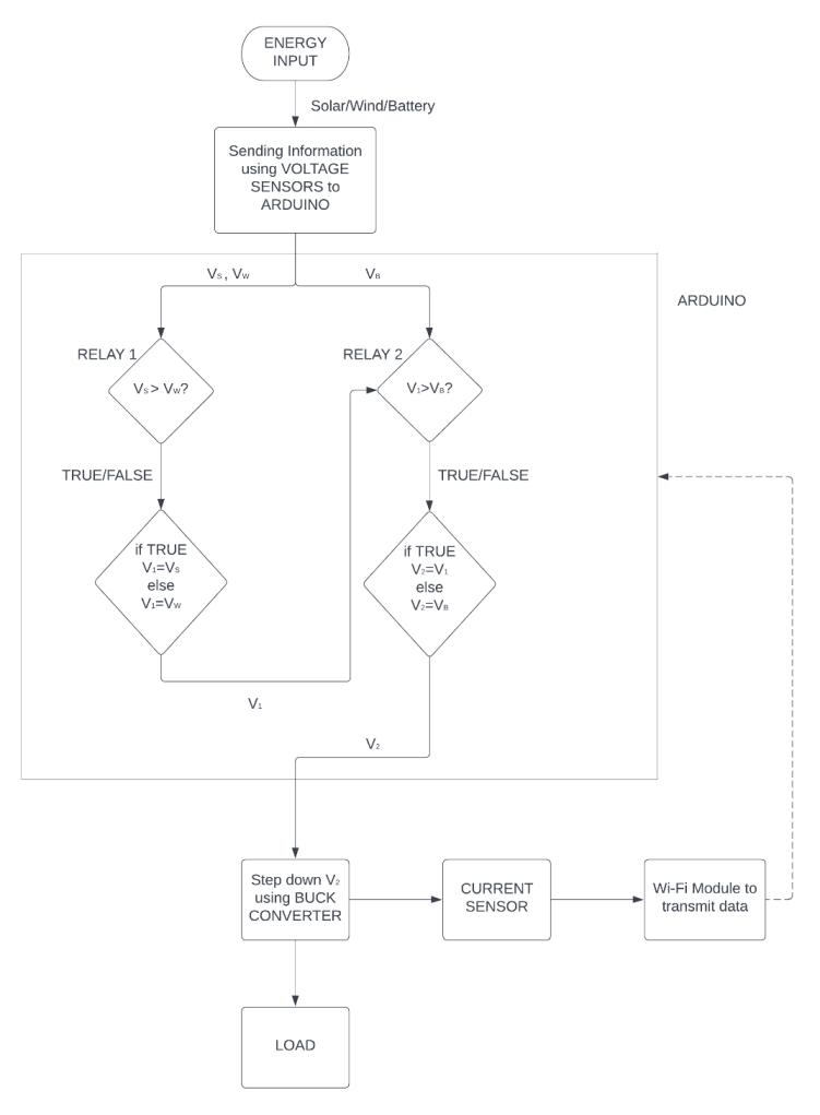
Figure 11 represents the flowchart of the DC Microgrid automation system. Three power sources are considered. The voltage sensor after sensing the source voltage value, feedsthevaluetotheArduino.Basedonthevaluesreceived, the relay unit is set to select the value that has optimum voltageandhencesourceselectiontakesplace.Theselected source power flowing through buck converter is fed to current sensor that senses the current value and this measuredcurrentvalueissenttowi fimoduleviaArduino. The received voltage and current values are displayed on Blynkapp.
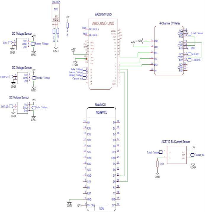
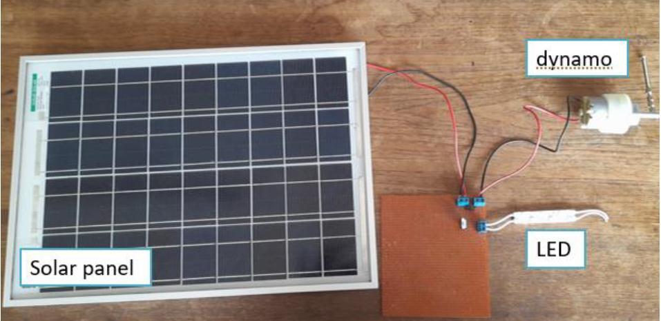
A hybrid power generation system consists of two renewableenergysourcessuchassolarandwind(DCgeared Motor).Thisincreasestheefficiencyandpowerreliabilityof thesystem.Solarpanelofrating21Visusedtocapturesolar energy and Hand driven 150RPM Dynamo is used to representwindpower.Thebatterybackupisusedtomeet the load demand when power from solar and DC geared motor(representingwind)isnotsufficient.Eachsourceis providedwithvoltagesensorforpurposeofcollectingvalues of voltage at source end. The data is fed to Arduino UNO microcontroller. Current sensor is added at load end to measure current entering the load. Microcontroller is connectedtoBlynkserverthroughNodeMCUthat actsas bidirectional serial communicator. The circuit diagram of developedsystemisshowninfigure10.
Fig 10 : Circuitdiagramofdevelopedsystem
Fig 11 :Flowchartofthesystem
International Research Journal of Engineering and Technology (IRJET) e ISSN: 2395 0056
Volume: 09 Issue: 07 | July 2022 www.irjet.net p ISSN: 2395 0072
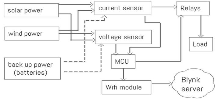
Figure12showstheblockdiagramofthesystem.
The load is also switched to a different source when the powerdemandishigherthantheparticularsourcewhichit canhandle.Incaseoftotalpoweroutageorverylargepower demandwhichnoneofthesourcescanhandle,theloadis completelyisolatedbyallthesourcesthusensuringsafety.
Theproposedsystemconsistsoftwopartsi.ehardwareand software.Thehardwareconsistsofsolarpanel,DCGeared motor, voltage sensor, current sensor, Arduino UNO, ESP8266 wi fi module and relay. The software consists of ArduinoIDEandBlynkApp.
Theproposedsystemincorporatesamicrogridautomation systemwhichconsistsofvariouspowersources,sensorunit, controlunit,relayingunitandInternetofThings(IoT)based mobileapplicationwithauserinterface.Thepowerisdrawn from solar and wind energy sources. The system also consists of a battery unit which can be utilized in case of power outage. The sensor unit consists of voltage and current sensors. The control unit is composed of microcontroller,Wi Fimoduleandasetofrelayssuitablefor theapplication.
The voltage and current sensors measure the respective voltages using the voltage divider method across all the sources.Thesevaluesarefedtothemicrocontrollerwhich makesdecisionsaccordingtotheprogramwrittentoit.The currentsensormeasuresthecurrentconsumedbytheload usingtheHalleffectmethodwhichgivesanideaaboutthe demand and sends the same to the microcontroller. The relaysaretriggeredbythemicrocontrollerwhichswitches theloadtodifferentsourcesorisolatestheloadincaseof anomaly.Alltheseoperationscanbeviewedbytheuserwith thehelpofamobileapplicationwhichgivesthelivedataon thedashboard.ThisisdonewiththehelpofaWi Fimodule whichisconnectedtothemicrocontrollerthatfeedsallthe data to the IoT mobile application. The application also allowstheusertosetvariousthresholdsandlimits.
Theusercansethighvoltage,lowvoltagelimitsintheBlynk app.Alongwiththat,the maximumloadthata sourcecan withstandisalsospecifiedbytheuser.Whenthevoltageofa sourceisbelowthelowvoltagethresholdorabovethehigh voltage threshold for the particular source, the microcontrollerselectsadifferentsourcebyswitchingthe load through relays. In case, neither solar nor turbine has sufficientvoltage,theloadisswitchedtothebatterybackup.
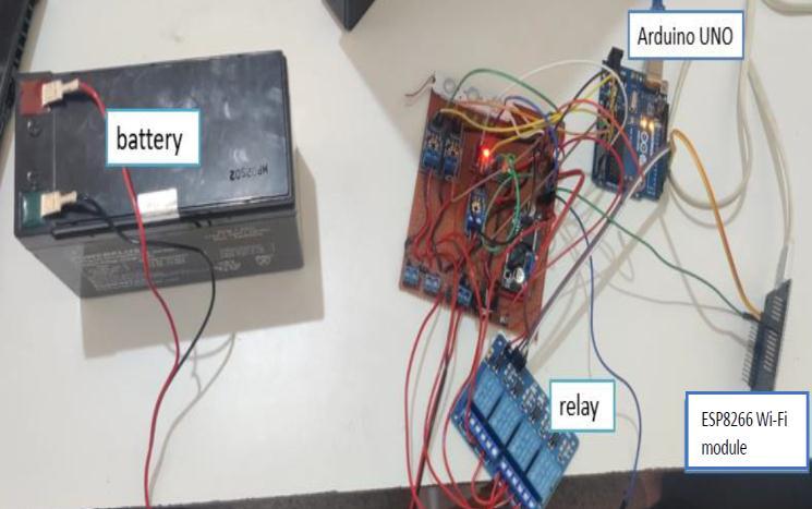
Fig 13 :Circuitconnectionofhybridpowergeneration setup
Fig 14 :BatteryrunDCmicrogridautomationcircuit
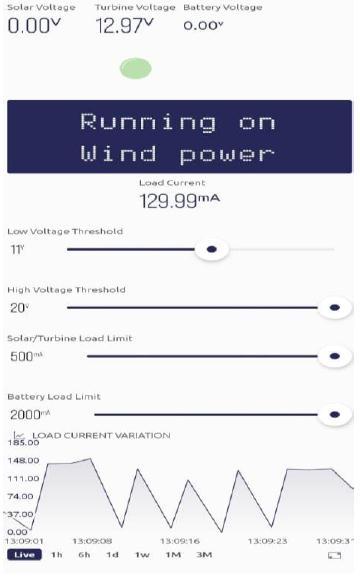
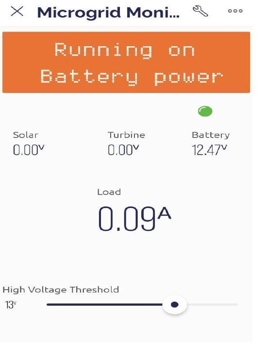
When, the battery power is consumed by the load, Blynk applicationdisplaysthemodefromwhichpowerissupplied. Thevoltagevalueofsourceandcurrentsuppliedtoloadis alsoillustratedasshowninfigure15.
International Research Journal of Engineering and Technology (IRJET) e ISSN: 2395 0056
Volume: 09 Issue: 07 | July 2022 www.irjet.net p ISSN: 2395 0072
power,theloadisisolatedfromsystem.Analertmessageof “anomalydetected,loadisolated!”isnotifiedtouser.
Fig 15 :Blynk
TheBlynkapplicationallowstheusertosetvaluesforhigh voltagethreshold.Inonecase,highvoltagethresholdwasset to12V.Whenbatterysuppliedavoltageof12.50Vthereby exceeding the set limit, the load was isolated and an alert messageof“Anomalydetected,loadisolated”wasnotifiedto userinBlynkasshowninfigure16.
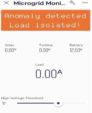
Fig 17 :Analertmessageforundervoltagecondition
Similarly,withtheuseofBlynkapplicationthevoltageand currentvaluesfedtoloadoveratimeof1hour,6hourand3 monthssoon,arerecordedandvisualizedingraphform.As shown in figure , the variation graph for values measured duringwindpowergenerationareobtained.
Fig 16 :DisplayinBlynkserverduringovervoltage condition
Figure17 showsthelimitsetupofvariousdatastreamsuch as low voltage threshold, solar/turbine load limit, battery loadlimitvalueslimit.Thelowvoltagethresholdlimitisset to10V.Whenallpowersourcesareturnedoffdepictingthe situationofallpowersourcesfailingtosupplythedemanded
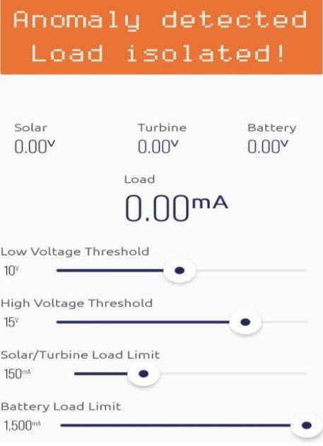
Fig 18 :GraphicalDisplayofloadcurrentvariation.
International Research Journal of Engineering and Technology (IRJET) e ISSN: 2395 0056
Volume: 09 Issue: 07 | July 2022 www.irjet.net p ISSN: 2395 0072
Thesystemdevelopedenhancestheperformanceofthe existingDCmicrogrid.Thehybridpowergenerationadopted inthemodel showcasedthe applicationofsolarand wind power in producing electricity thereby giving more importancetorenewableenergyusage.
TheBlynkapplicationusedintheworkallowstheuserto viewrealtimedatacollectedfromthegridbuilt.Italsohelps theuserinsettingupthresholdlimitstovariousdatastream and in isolating the load during over voltage and over current condition. An alert message is generated in Blynk app to notify the user about the condition of microgrid. These features automate the Microgrid system thereby removingtheneedformanualisolationofloadduringfaulty condition.Astheloadisisolatedwithverylessdelayafter fault detection, it increases system reliability and performance.Inthisway,theinternetofthingscanbeused invariouswaytoexploretheproblemsoccurringinDCand ACmicrogridsandtoprovidesolutionforthesame.
Withthemodifications,modelpresentedinthisworkcan beextendedforautomationofACMicrogrids.Thevarious otherfaultsinDCmicrogridsuchasarcfaults,shortcircuit faults can be rectified by adopting some changes in built system.
[1] Zhuang, J., Shen, G., Yu, J., Xiang, T., & Wang, X. “The design and implementation of intelligent microgrid monitoringsystembasedonWEB”,ProcediaComputer Science,107(2017).
[2] Chauhan, K & Chauhan, R. K, “Optimization of grid energyusingdemandandsourcesidemanagementfor DC microgrid”, Journal of Renewable and Sustainable Energy,2017.
[3] Friansa,K.,Haq,I.N.,Santi,B.M.,Kurniadi,D.,Leksono, E., & Yuliarto, B, “Development of battery monitoring systeminsmartmicrogridbasedoninternetofthings (IoT)”,Procediaengineering,2017.
[4] Xing,L.,Xu,Q.,Guo,F.,Wu,Z.G.,&Liu,M.“Distributed secondarycontrolforDCmicrogridwithevent triggered signaltransmissions”,IEEETransactionsonSustainable Energy,2021.
[5] Vanitha, R., & Kalpana, P. M. “IOT Based Microgrid Automation”,IJLTES,2019.
[6] https://www.researchgate.net/figure/Structure of an residential DC microgrid_fig1_304411960
2022, IRJET | Impact Factor value: 7.529 | ISO 9001:2008 Certified