International Research Journal of Engineering and Technology (IRJET) e ISSN: 2395 0056

Volume: 09 Issue: 07 | July 2022 www.irjet.net p ISSN: 2395 0072

International Research Journal of Engineering and Technology (IRJET) e ISSN: 2395 0056
Volume: 09 Issue: 07 | July 2022 www.irjet.net p ISSN: 2395 0072
Manikandan C1 , Ramesh K2 , Shoban Babu3 , Kulandaivel.D 4
1 Department of Mechanical Engineering PG, M.E. Thermal Engineering, Government College of Technology, Coimbatore 641 013, Tamil Nadu, India,
2 Professor Department of Mechanical Engineering, Government College of Technology, Coimbatore 641 013, Tamil Nadu, India.
3 Department of Mechanical Engineering, Government College of Technology, Coimbatore 641 013, Tamil Nadu, India.
4 Assistant Professor Department of Mechanical Engineering, Government College of Technology, Coimbatore 641 013, Tamil Nadu, India. ***
Abstract – This work involved the numerical simulation of an integrated ramjet engine that included a nozzle, a subsonic combustor, and supersonic diffuser. The results are reported in this paper. These findings include analyses of cold flow and the addition of heat to the combustion chamber and nozzle. These results include cold flow studies, heat addition in the combustion chamber along with the nozzle. This study uses computational fluid dynamics to quantitatively predict the combustion characteristics of a ramjet engine used with a symmetric inlet (CFD). For a 15:1 air fuel ratio with kerosene as the fuel, two examples of combustor layouts are examined. The blockage ratio is kept between 30 and 40 percent in all setups. While the combustion efficiency and other performance characteristics remain the same, Case 1 reduced blockage ratio results in a pressure loss of about 2%. It is advised to use the Case 2 configuration, which has a combustion efficiency of about 80 and a lower blockage ratio, in the ram jet combustor design.
Key Words: Ramjet engine, air intake, combustor, numerical simulation, internal flow, air/fuel ratio
Propulsion,inabroadsense,istheactofmodifyingthe motionofthebody.Propulsionmechanismssupplyaforceto move a body across a medium. That changes originally resting bodies by pushing them. Overcomes restraining forces, or gains velocity. In a gas turbine cycle, the combustion process is crucial. The reason for this is that throughoutthisprocess,thechemicalenergyofthefuel is transformedtoheatenergy,whichtheturbinethenusesto producework[1].Itisfirstimportanttocombinefueland airinthegasturbinecombustionsysteminsuchawaythat theresultingflamecansustainitself.Asaresult,thedesign ofthecombustorincludesthecreationofaturbulencezone with the complexity of both aerodynamic and thermo chemicaleffects.Therefore,despitetheextensiveresearch oncombustion,flamestabilityinconstantflowcouldstillbe improved.Aramjetisatypeofair breathingjetenginethat
compresses incoming air without the use of a rotary compressorbymovingtheengineforward[2].Ramjetsare unabletogeneratethrustatzeroairspeed,hencetheyare unable to start an aircraft moving. Ramjets need a lot of forwardspeedtofunctionproperly,andthisclassoperates atitsbestefficiencyaroundMach3.Ramjetcanbeespecially helpful in applications like missiles that call for a tiny, straightforwardengineforusageathighspeeds.
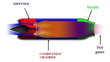
Diffuseroftheramjetsattempttotakeadvantageofthe extremelyhighdynamicpressureintheairasitapproaches the intake lip. Most of the freestream stagnation pressure, whichisneededtopromotethecombustionandexpansion processinthenozzle,willberecoveredbyaneffectiveintake. Thecombustor,likeotherjetengines,burnsfuelandairat nearlyconstantpressuretoproducehotair.Sincetheairflow throughajetengineistypicallyratherhigh,"flameholders" are used to prevent the flames from blowing out, creating shieldedcombustionzones.Sinceitspeedsupexhaustflowto providethrust,thepropellingnozzleisacrucialcomponent oftheramjetdesign[2].Exhaustflowisacceleratedthrougha convergingnozzleforaramjetrunningatasubsonicflight Mach number. Acceleration for supersonic flight is often accomplishedusingaconvergent divergentnozzle
Inordertosustaincontinuouscombustion,ramjetengines useapartcalledaflameholder.Aflameholderisrequired foreverycontinuous combustionjetengine[3].Anengine's low speededdyisproducedbyaflameholdertokeepthe flame from being blown out. A stable eddy and drag must coexist in harmony for the flame holder's design to work. Thecan typeflameholderisthesimplestdesign;itismade ofacanwithafewtinyholesinit.TheH gutterflameholder, whichhasacurvethatfacesandopposestheflowofairand isformedlikealetterH,ismuchmoreefficient.
International Research Journal of Engineering and Technology (IRJET) e ISSN: 2395 0056
Volume: 09 Issue: 07 | July 2022 www.irjet.net p ISSN: 2395 0072
In this paper, the numerical investigation of different ramjet combustion chamber as well asan entire ramjet is investigated.Itisassumedthatthefluidisviscid.RAMJET combustionchamberhasbeenselectedfromtheliterature. G.RajaSinghThangaduraietal.[1].Thecombinedanalysis of the supersonic air intake, combustion chamber, and nozzleaidsintheinvestigationoftherelationshipbetween theairintakeandthecombustionchamber.
The significance of ramjet combustion was noted by GordonL.Duggeretal.in[2].Ramjetenginesareemployedin research aircraft and missiles that are expected to have a significant impact in the next years. The increased temperature rise will affect the combustor material and overallengineperformanceevenifhypersonicflyingspeed vehiclesarestillbeingdeveloped.Ramjetpropulsioncouldbe utilizedtopowerup,accordingtorecenttrialsandanalysis.
Manyresearchersareinterestedintheramjetengineas one of the most useful propulsionsystems ofthefuture.It moves field of a ramjet combustor Utilizing numerical simulation,theV gutterflameholdertheconnectedexplicit NSequationsintwodimensions,theUndertwoindependent operatingconditions,theconventionalk eturbulencemodel and the finite rate/eddy dissipation reaction model for capturethecoldflowandengineignitionaretwoexamplesof circumstances. On various dump combustor geometries without a central jet, Shahaf et al. [3] studied two dimensionalliquidfuelcombustionphenomenaanalytically andempirically.JonesandWhitelawwentintogreatlength abouthowtocalculateturbulentreactingflows.Thesystem of vortices in the head area is essential for the steady operation of the combustor, according to Roy et al [4] experiential’stestingofthecombustorperformanceofagas generator ramjet with four side air inlets but no central injection.LiquidfuelinjectionwasusedbyStull,etal.[5]to investigatethedual side air inletdumpramjetcombustor.By alteringthepositionofthedomeplate,Stulletal.statistically examined the flow field properties of a three dimensional side air inletdumpcombustor.
Yenetal.studiedtheimpactofside inletangleontheflow fieldofathree dimensionaldumpcombustorwheretheside jetsarecompletelyoppositetooneanother[6].Inamura,et al., conducted an experimental study on the combustion characteristics of a ramjet combustor [7]. The spray combustionflowinaside dumpramjetcombustionchamber attached with four symmetric inlets was numerically investigatedbyJiangetal.in[8].Inordertoanticipatethe overall performance of the four stage ramjet combustion chambers,Grohensetal.[9]usedanovelnumericalmethod. First, a non reactive Reynolds averaged Navier Stokes (RANS)calculationwasdone,thenaliquidphaseLagrange calculation(fuel).Thetransportequationwasthensolved, and a chemical kinetic model was used to determine the
combustionefficiencyforanyequivalency.Aflowmodelthat maypredicttheimpactsoffueldropletsoncombustion,flame holders,anddiffuserforminthecaseofathree dimensional axisymmetric combustor has been created in the current study.
Ramjets are a particular kind of air breathing jet enginethatcompressesincomingairbymovingforwardas opposed to using a rotary compressor. Because they can't generate thrust at zero airspeed. Moving the ramjet therefore require an additional propulsion system to increasethevehicle'sspeedsothattheRamjetcanbeginto generate thrust. Ramjets are effective at Mach 2 or faster supersonic speeds According to the heat released in the combustor,asindicatedinfigure1.1,therearethreevarious situationsunderwhicharamjetenginediffusercanoperate. The operation is considered to be critical when the heat released in the combustor is just sufficient to allow the normalshocktobepositionedattheinletthroatsduetothe backpressureatthesubsonicdiffuser'sexitsection;thisis thedesigncondition.
The science of numerically resolving the equations governing these processes to predict heat transfer, fluid movement, mass transfer, chemical reactions, and other phenomenaisknownascomputationalfluiddynamics(CFD). Important engineering data from CFD simulations can be applied to conceptual design studies, problem solving, in depthproductdevelopment,andredesign.Tominimizethe total amount of work required in the lab, CFD analysis is utilizedinconjunctionwithresearchandtesting.Thestudyof utilizing a computational approach to solve the equations that control fluid flow is known as computational fluid dynamics(CFD).Variousprocedurestoforecastheattransfer, fluidflow,andphenomenasuchasmasstransport,chemical reactions, and others.CFD analyses produce useful engineering information that can be utilized in concept
2022, IRJET | Impact Factor value: 7.529 | ISO 9001:2008 Certified
International Research Journal of Engineering and Technology (IRJET) e ISSN: 2395 0056
research for fresh designs, thorough invention, troubleshooting,andredesignofproducts.
Computer aided design (CAD), computer aided manufacturing (CAM), computer aided engineering (CAE), PLM, and 3D are all applications included in the multi platform SolidWorks software suite. It provides a way to build, alter, and validate complex, novel shapes from industrial design to Class A surfacing using the ICEM surfacing technologies. It also offers solutions for shape design, styling, surfacing workflow, and visualization. Whethertheproductdesignprocessisinitiatedfromscratch or from 2D sketches, SolidWorks enables various stages. Ansymmetric inlet is present in the ramjet enginecombustionchamber.Therefore,CFDanalysesforcold flow simulations are performed using a two dimensional model. Regarding diffuser design and flame holder layout, various changes were done. Ultimately, 3 layouts were chosenbasedonafewfactors,including:Thevelocitymust be uniform at least 400 to 500 mm from the diffuser end There should be little total pressure loss over the combustion
Parameter Value Massand Momentum NoSlipWall WallRoughness SmoothWall HeatTransfer Adiabatic
Parameter Value
FlowRegime Supersonic Massand Momentum Openingpressure=1atm Turbulence MediumIntensity=4.5% HeatTransfer StaticTemperature= 300K
Energyequationisusedforheattransfer.Pressure Basesteadyflow ModelEnergyViscous RealizableK ϵStandard Mixturematerial:Kerosene Air idealgas TurbulenceChemistry:Finiterate/EddyDissipation Massflowinlet,InletTemperature:300K Pressureoutlet
SIMPLE Pressure velocity Coupling Discretization scheme.
Inlet Pressure and outlet temperature are monitored.
Followingtable1,2and3showstheinlet,outletandwall boundaryconditionsusedinthisstudy.
Table
Parameter Value
FlowRegime Subsonic MassandMomentum TotalPressure Turbulence Zerogradient HeatTransfer StaticTemperature=300K
FLUENT,oneofthemostflexiblesolversforHypersonic flow,isusedtocomputetheaforesaidmodelbecauseithasa well validated physical modelling capability to give quick, accurate results across the broadest spectrum of CFD and multi physics applications. A wide variety of physical flow problemsandotherphysicalphenomenacanbesolvedusing theANSYSFluentsoftware,includingheattransfer,external flow over a contour, internal flow in a cylinder or pipe, dynamicflowproblemslikeacoustics,andcomplexgeometry flowslikethoseinturbineandcompressorblades.Analyses for the 60 degree model were conducted while taking the periodicityofthegeometryintoconsideration.Torepresent theentiremodel,asymmetrymodelisappliedtothissector. Allofthesecombustorsunderwentreactingflowevaluations for the Sea Level altitude condition and a matching flying Mach of 2.6. At the combustor's input, the mass flow inlet conditionisset.Atthenozzle'sexit,theflowisstillchocked, orsupersonic,thereforethepressureisdeterminedbythe upstreamflowvalues.Intheprevioussectionprovidesthe corresponding boundary condition values. Fuel is injected fromtheprimaryinjectorinthefirsttwocasesatapressure of15bar Inthisapproachequationsaresolvedsequentially. Sincetheseequationsarenon linear,theyarefirstlinearized usinganexplicitmethod.
Volume: 09 Issue: 07 | July 2022 www.irjet.net p ISSN: 2395 0072 © 2022, IRJET | Impact Factor value: 7.529 | ISO 9001:2008 Certified Journal |
International Research Journal of Engineering and Technology (IRJET) e ISSN: 2395 0056
Volume: 09 Issue: 07 | July 2022 www.irjet.net p ISSN: 2395 0072
satisfiesthefollowingconditionsfordesiredcombustorand arechosenforreactiveflowanalysisamong2cases.
Case 1
Fig .2 Ramjet engine
Case 2
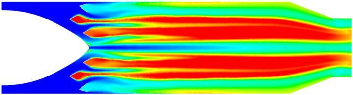
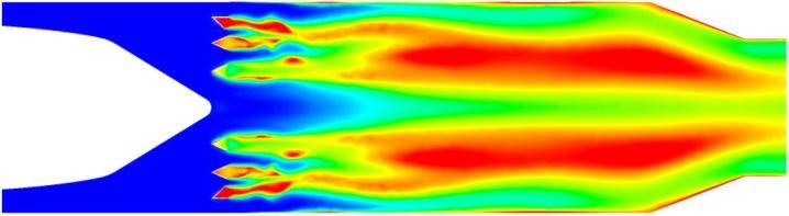
Fig: 5 Mach contour of various 2D combustor configurations
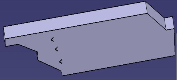
Fig .3 3D combustor
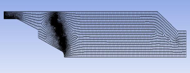
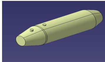
Fig .4 Meshing of combustion chamber
Theoutcomesofthetwo dimensionalcoldflowanalyses performed using the solver input conditions outlined in chapter4areshown.Massimbalanceandexitpressurewere observed during the convergence. Results from these analysesarediscussedintermsofMachnumberdistribution.
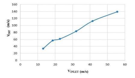
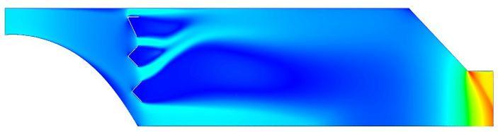
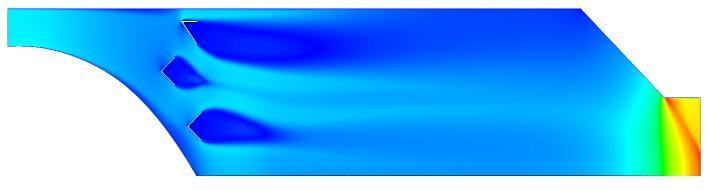
Figure 5 shows the Mach contours of few configurations2Ddesignmodificationswhichareanalyzed for cold flowconditions The problemsidentified withthis design is the formation of low velocity region over the diffuser which will lead to damage in material when combustionoccurs.Also,thedeflectorpresentsintheinlet produce recirculation zones behind it but difficult to construct and not desired for Ramjet engine. This led to change in diffuser shape to cone type and elimination of flameholderasshowninconfig.1.Thesetwoconfigurations
FromFigure6,Itisseenthatevenwithoutthecombustion processoccurringtheenginewasabletoacceleratetheexit flow to a higher value than the inlet. This implies that the designoftheramjetmeetsthestandardrequirements.
Fig: 6 Cold Flow Analysis Velocity Plot
Theanalysesproducedsecondordercorrectresults.We kept an eye on the convergence's inlet pressure and exit temperature. The design is created in a way that the complete mixing of air and fuel is accomplished at the conclusionoftheassembly.Theigniteristhereforeplaced behindthistobegincombustionmixingarea
To determine the mass proportion of exhaustproducts followingthecombustionevent,aplaneisconstructedatthe ramjets exit. Figure 7 static temperature contour demonstratesthereisnounburnedfuelbecausethefuelsare totally burned in the ramjet's exit. Finished combustion is characterizedbythepresenceofwaterandcarbondioxide Thisramjetaccomplishesthisdesign.Thecarbondioxideand methanemassfractioncontours Figure6displaysthewater vaporfromthecombustionmodelthattheamountofcarbon in the exhaust emissions is at its highest dioxide and vaporizedwater Theseprecedingdiagramsmakeitsimpleto understand how the ramjet engine behaves. These graphs showWecanthereforesaythattheRamjetEngineoperates effectively. However, the process in which the experimentally,asubsonicramjetenginewaspresentedand afewdifferentconsequencesthatoccurredarelistedinthis report'ssummary,whichwillbehelpfulforfuturestudy
Throughcomprehensiveenginesimulations,theoverall performanceofaramjetenginethatincludestheairintake, combustor, and nozzle has been studied. The relationship between the air intake and combustor is intensely highlightedbythecoupledstudy.Severalfactorsaffecttheair intakeperformance,includingbothbyitsgeometryandthe amountofheatreleaseduringcombustion.Theflowmodel that was created in the probable use of the current study Ramjet's design and development tool programmes for development.WiththereductionintheblockageratioinCase 1,around2%pressurelossisobtainedwhilethecombustion efficiency and other performance parameters remaining same.Finally,itcanbestatedthatCase2,configurationwith reducedblockageratioisrecommendedforimplementation intheramjetenginecombustorconfiguration.
[1] G. Raja Singh Thangadurai, B.S. Subhash Chandran, V. Babu and T. Sundararajan., May 2008, “Numerical AnalysisofIntegratedLiquidRamjetEngine”,Defense ScienceJournal,Vol.58,No.3,pp.327 337.
[2] Gordon L. Dugger., 2009, “Recent Advances in Ramjet Combustion",ARSJournal,Vol.29,No.11),pp.819 827.
[3] O. Dessornes., M. Bouchez., 2005, “Combustion ExperimentsofLiquidKeroseneandHydrogen/Methane MixinginaDualModeRamjetEngine” AIAA/CIRA13th International Space Planes and Hyper sonics Systems andTechnologies.
[4] Senapthi Krishnamachary., S. Krishna Mohan., JayaramanDesingou.,SunitaDeviJena.,R.Vivek.,Trivedi Darshan Kuma., and V. Ramanujacharic., 2014, “Polycyclic alkanes based high density hydrocarbon fuelspreparationandevaluationforLFRJapplication”, RSCAdvances.
[5] Shahaf,M.,Goldman,Y.&Greenberg,J.B.,March1980, “Aninvestigationofimpingingjetsinflowwithsudden expansion”. Proceedings of the 22nd Israel Annual ConferenceonAviationandAstronautics,IsraelMinistry ofTransport,TelAvivandHaifa,Israel,pp.100 106.
[6] Jones,W.P.&Whitelaw,J.H.,1982,“Calculationmethods forreactingturbulentflows:Areview”,Combustionand Flame,48,1 26.
[7] Roy, P.; Schlader, A.F. & Odgers, J., 1982 “Combustor modellingstudiesforramjets.RamjetsandRAMrockets forMilitaryApplications”,pp.31 1to31 10.ReportNo. AGARD CP 307.
[8] C.W.Foley,I.Chterev,J.SeitzmanandT.Lieuwen,“Flame Configurations in a Lean Premixed Dump Combustor WithanAnnularSwirlingFlow”,AIAA30332 0150,USA
[9] AdiSurjosatyo&Faridnasir,“Astudyofenhancingthe swirl burner performance on a small scale bio mass gasification”, International journal of engineering & technology,Vol.11No.04,pp.20 29.
[10] Claypole, TC & Syred, “The effect of swirl burner aerodynamics on NOx formation’, proceeding of the combustion institute”, Eighteenth symposium (International)oncombustion,thecombustioninstitute. pp.81 89.
[11] G.L. Morrison, M.T. Schobeiri, K.R. Pappu, “Five hole pressure probe analysis technique”, Mechanical EngineeringDepartment,TexasA&MUniversity,College Station,TX77843 3123,U.S.A.