123
4
International Research Journal of Engineering and Technology (IRJET) e ISSN: 2395 0056

Volume: 09 Issue: 05 | May 2022 www.irjet.net p ISSN: 2395 0072

123
4
International Research Journal of Engineering and Technology (IRJET) e ISSN: 2395 0056
Volume: 09 Issue: 05 | May 2022 www.irjet.net p ISSN: 2395 0072
Thepashree M1 , Srinivetha S2, Fouja A3, Surya prakash S4
***
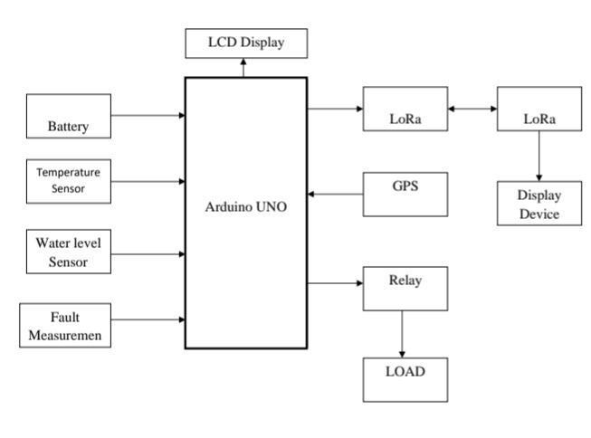
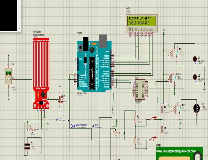
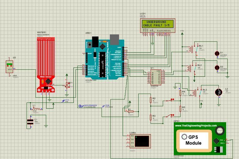
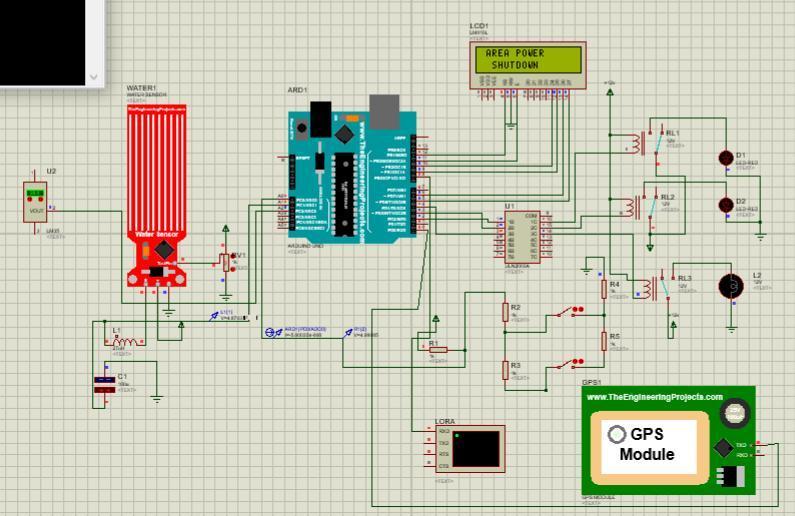
Abstract The goal of this work is to spot the particular location of a fault in underground cable lines from the supply station to the precise location of the fault in any unit, during this case kilometers. When a fault arises in an underground cable line for any cause, the mending method for that faulted cable becomes problematic because of the absence of a correct system for tracking the precise position of the fault and also the kind of fault that happened within the cable. For this, a system should be designed to find the precise position of the fault within the distribution line system for all 3 phases R, Y, and B, and for varied sorts of fault circumstances. Single line to ground, double line to ground, and 3 section faults are mentioned during this work. have been regarded A systems program a microprocessor, lcd|LCD|digital display|alphanumeric display} display, Fault Sensing Circuit Module, LoRa Module, and proper power supply arrangement with regulated power output is made in this project. As a result, if there's a short circuit within the kind of a line to ground in any phase/phases, the voltage across series resistors changes an, associate degreed an analogue signal within the variety of a dip is made by the fault sensing circuit of the introduced system, that is then fed to associate degree ADC built in within the already programmed microcontroller to make the precise digital knowledge, and once process the info, the output are going to be displayed within the connected liquid crystal display with the precise location of the fault. Correlating R, Y, B section with the measurement the gap wherever the fault occurred Through the connected IoT Wi Fi Module, a similar processed data output can show on the webpage. The AT Mega 328P microcontroller is employed during this system. the present sensing of circuits fashioned employing a combination of resistors is interfaced to the ATmega328 microcontroller exploitation associate degree internally enclosed ADC to produce digital knowledge to the microcontroller. The fault sensing circuit is formed of a series of resistors and a collection of switches adjacent to every resistance. The relay driver is answerable of the relays. The microcontroller is coupled to a 16x2 liquid crystal {display |LCD| digital display| alphanumeric display} display that displays the phase/phases data additionally because the location of the defect in kilometers.
Key Words: IOT, Fault Detection, LoraThe detection of faults is one of the biggest drawbacks of underground wires. Visual inspection procedures are ineffective because the cables are placed beneath the surface (directly or inside pressurized ducts). In the case ofOverheadLines,thisisnotthecase.We'llneedtocreate uniquemethodstodetectcablefailures.
•Faultwithanopencircuit
•Ashortcircuithasoccurred.
•Earthfaults
When moisture enters the insulation, the majority of the defects arise. Inside the cable, the paper insulation is highlyabsorbent.Mechanical loss duringtransit,thelying process,ornumerousstressesfacedbythewireduringits operational life are some of the other causes. The lead sheath is frequently destroyed, mainly as a result of atmospheric pollutants, soil, and water or, on rare occasions, caused by mechanical damage and lead crystallizationcausedbyvibration.
Isatypeoffaultthatoccurswhenacircuitissueiscaused byanopencircuitintheconductors, asthe name implies. Discontinuity occurs when one or more cable conductors (cores) break. Mechanical tension causes the cable to come out of its joint, causing this discontinuity. This is referredtoasanopencircuitfault.
It can only be found in multi cored cables. A short circuit occurs when two or more conductors of the same cable come into touch with each other. Visual detection is impossible without dismantling the cable. When the individual insulation of the cables is destroyed, a short circuitissuearises.Ameggercanalsobeusedtodetectit.
A.A.Khan,etAl[2012], Forelectricitydelivery,thepower distribution system must provide on a vast network of medium voltage (MV) underneath wires.
International Research Journal of Engineering and Technology (IRJET) e ISSN: 2395 0056
Volume: 09 Issue: 05 | May 2022 www.irjet.net p ISSN: 2395 0072
Condition basedtoolscan thus playanimportant role in seeking to pinpoint the cables that provide the greatest risk of failure. Most network owners are focused on maintaining or improving the reliability of their power sourcesatalowcost.
Condition monitoring provides the data required for safe and dependable operation, as well as replacement plan, and so improves system durability. Because of the increased demand for dependable power, alternative solutions such as condition based maintenance are being usedmorefrequently.Oneofthemostaccuratediagnostic toolsfordeterminingtheinsulationstatus ofMVcables is partial discharge (PD) monitoring. Online PD evaluations provided the data for this study can aid in determining impending failures in certain cable networks and even forecasting the insulation's remaining useful life. The condition monitoring and diagnostic approaches for buried power cables are discussed in this work. Power cables, which are the most critical component of the power system, are prone to failure owing to ageing or flawsthatdevelopovertime.Thecableiscommonlymade out of an aluminum or copper conductor wrapped in semiconductive and insulation layers, regardless of the workingvoltageorfrequency.Thegroundshieldisformed by a metallic screen over the insulating semi conductive layer,thatisencasedinanexterioroutercovering.
F. B. Ajaei and colleagues [2011] For modelling of CT to address the effects on digital protective relays, a current transformer (CT) is precisely modelled. The effects of CT saturation on the present Phasor calculation are investigated using simulated experiments performed on the PSCAD/EMTDC system. A new method for detecting and compensating CT saturation effects is also suggested, which is predicated on a lowest failure squares (LES)filter that estimatesthe phasor variables of the CT secondary current; a new saturation sensing methodthatusestheoutputoftheLESfilterforsaturation detection; and a minimum acceptable average error tracking approach that improves the Phasor estimation precision. The suggested saturation identification method is unaffected by CT settings, burden, or other factors. The electrical system The findings of the study reveal that the suggested algorithm: 1) reproduces the deformed current waveformwiththeappropriateprecisionandspeedunder dc and ac saturation situations, and 2) operates satisfactorily under inductive burden and deep and mild saturation states. Saturation of the current transformer (CT) results in erroneous current measurements, which mightcausesafetyrelaystofail.1)dcsaturationduetothe high fading dc source of the fault current and/or the CT core's premagnetization, and 2) ac saturation due to the enormous ac current magnitude. If adequate mechanisms for saturation detection and/or correction are not used, a protective relay is practically exposed to maximize the
valueoftherelatedCT,whichhasanegativeimpactonthe efficiency.
S. Kucuksari et. Al [2010] Optical current transformers (OCTs) are available from several vendors to replace magnetic current transformers (CTs). The efficiency of certaincurrentlyavailableopticalandconventionalCTsis comparedinthisresearch.Inalaboratory,thesteadyand transientreactionsofthetwosystemsareevaluated.Field data is also collected and analyzed to ensure that optical systems may take the role of traditional instrument transformers. In addition, the impact of ambient temperature on OCT performance and OCT step response have been examined. Optical CTs are more than available to replace conventional CTs, according to the findings. In addition, the findings reveal that OCT has a better frequency response than traditional CT. The differences between field and lab readings are due to experimental mistakes. Unlike traditional CTs, the OCT may produce a digitaloutputthatadherestotheIEC61850standard.The frequency amplitude characteristic of the OCT's digital outputisevaluated.Duetothelimitedsamplingrategiven in a UCA guide to IEC61850 9 2, the digital output of the OCT has a smaller bandwidth than the low energy analogue output. The steady state and transient characteristics of conventional magnetic and optical current transformers are compared in this research. The highvoltagelaboratoryatASUwasusedforallofthetests. The reactions of both current transformers were compared under real world settings (load current and fault current). A step function was used to assess the OCT's transient performance. The effect of increased temperatures on OCT measurements was investigated. Increasedsensorheadtemperaturewasusedtodetermine theimpactofgreatertemperatureonOCTmeasures.
LaxmiGoswami etAl [2020].Undergroundcables, rather thanabovetransmissionlines,areemployedindowntown areas. It's difficult to find the exact location of the flaws. India's reputation as a progressive country is growing by the day, and the civilized field is expanding as well. Undergroundlinesarebeatingunderthesameconditions, and their use is increasing as a consequence of clear advantages like fewer line losses, lower maintenance costs, and less vulnerability to severe climate influences. Because it is unclear, it goes to great lengths to pinpoint the source of the problem. We are attempting to address this issue in this suggested study by offering a strategy thatissuitableforthedigital age.Inthispaper,we'll look at with the help of the Node MCU Wi Fi Module, we used an IOT based approach with a Google database for defect detection in this work. It is entirely based on the Internet ofThings.NodeMCUwasusedtoconnectArduinosensors to the Internet. We had set up a communication hotspot using a router. We linked each MCU Module to a transformer and checked the condition of the transformersusinga Googledatabase. Whencompared to
International Research Journal of Engineering and Technology (IRJET) e ISSN: 2395 0056
Volume: 09 Issue: 05 | May 2022 www.irjet.net p ISSN: 2395 0072
previous strategies, our proposed method is more accurateandefficient.
Hans, M. R., et Al [2017] As India evolves as a developed country, the amount of civilized land grows. Since underground cables perform best in these kinds of situations,theiruseisincreasingduetoclearbenefitslike as less transmission losses, lower maintenance costs, and reduced susceptibility to the effects of severe weather, among others. However, it has some drawbacks, such as highinstallationcosts andtheinabilitytodetectdefective locations. It's impossible to pinpoint the specific location of the defect because it's not apparent. We provide two techniquesinthisstudythatwillbeparticularlybeneficial in finding the precise distance of an underground system fault from of the base station. Murray is one of the approaches. Murray loop method and Ohm's Law method are two of the ways available. The Murray loop approach employs the whetstone bridge to calculate the exact distance of the fault location from the base station and provides that information to the user's mobile device. WhenusingtheOhm'slawmethod,thevoltagedropvaries based on the length of the fault in the cable since the current varies. Under LG, LL, and LLL faults, both approaches require a voltage converter, microcontroller, andpotentiometertolocatethefault.
Heena Sharma and colleagues [2013]: This paper is primarilyconcernedwiththecauses,types,andlocationof cable faults. The document depicts various disturbance andfault states ata given period. Thegoal of this work is totackletheproblemoffaultlocation,whichis utilized to prevent unwelcome outages, cable damage, and failure. Thisresearchalsoexaminesthevoltage timeandcurrent time relationships in both normal and abnormal conditions. Simulation with PSCAD software is used to evaluate the proposed condition. It has been tested and foundtohaveafaultlocationerroroflessthan5%.
This paper presents a fault location example for undergroundpowercablebyusingtheInternetofThings, which is dependent on the internet, signifying that information will be delivered via the internet. The idea of this technique is to determine the distance in kilometers between a cable fault and a base station, as well as the location of the cables fault. The simple notion of Current Transformer Theory is used in this study (CT Theory). When a fault develops, such as a short circuit, the voltage drop varies based on the length of the issue in the cable; because the current fluctuates, a current transformer is used to calculate the fluctuating current. The signal modifiermanipulatesthevoltagechange,andtherequired computationsareperformedbya microcontroller.So that LoRA devices can indicate the fault distance These fault information are then broadcast over the internet to any
access point and displayed. While current is flowing through the fault sensing circuit module, the current variesdependingonthelengthofthecablefromthepoint offaultifthereisashortcircuitfaultwiththesinglelineto groundfault,doublelinetogroundfault,orthreephaseto ground fault, according to the system's operation. The voltage drop across the series resistors changes as a result, and the fault signal is subsequently sent to the microcontroller's internal ADC for development of digital data. The digital data is then processed by the microcontroller, and the outcome is presented. In kilometers and phase according to the fault conditions, LCDattachedtoArduinocontroller.
The Arduino Software (IDE) comprises a message box, a text console, a text editor for writing code, a toolbar with buttons for basic functions, and a set of menus. It communicates with the Arduino and Genuino devices by connecting to them and uploading code. The Arduino Software (IDE) created with Sketches are programs . The message part contains faults issues and gives feedback when storing and sending. The Arduino Software (IDE) outcome to the console, which covers the described error messages and other information. The window's bottom right corner shows the configured board and serial port . You may verify and upload programs, create, open, and save sketches, and the toolbar buttons contain the serial monitortobeopen.
The power force is a critical component of any electronic circuit. This circuit necessitates a constant 5 V voltage,
International Research Journal of Engineering and Technology (IRJET) e ISSN: 2395 0056
Volume: 09 Issue: 05 | May 2022 www.irjet.net p ISSN: 2395 0072
henceavoltagecontrollerisrequired.WeusedtheIC7805 asa voltagecontrollerin thisproject. Avoltagecontroller generates a preset fixed affair voltage that remains constantregardlessofchangesinitsinputvoltageorcargo conditions. Direct and switching voltage controllers are the two types of voltage controllers. Then a direct controllerisused,whichusesanactivepassdevice(series or shunt) operated by a high speed discrimination AL amplifier.Itadjuststhepassdevicetomaintainaconstant affairs voltage by comparing the affair voltage to an unresisting reference voltage and a precise reference voltage.
TheLiquidCrystalDisplay(TV)isanAlphabeticDisplay,it candisplayBasics,Figures,andSpecialSymbols,makingit a slacker Display device that can be used to display colourful dispatches rather than the seven member display, which can only display figures and some of the basic fundamentals. The only drawback of a television over a seven member display is that a seven member displayismoreresilientandcanbeimagedfromagreater distance than a television. Then we utilised alphanumeric screenswitharesolutionof16x2.
A relay is a switch that is controlled by electricity. Many relays employ an electromagnet to manually activate a switch, but they can also use alternative operating principles,suchassolid staterelays. Relays areemployed when a circuit has to be controlled by a separate low power signal or when multiple circuits need to be controlled by a single signal. The early relays were employedasamplifiersinlong distancetelegraphcircuits, repeatingthesignalfromonecircuitandtransmittingiton another. Relays were widely employed to conduct logical operationsintelephoneexchangesandearlycomputers.A contractor is a type of relay that can manage the high powerrequiredtocontrolanelectricmotororotherloads directly. Solid state relays use a semiconductor device to switch power circuits rather than a moving tunnel to control them. To protect electrical circuits from load or failures, relays with calibrated operating characteristics andoccasionallyseveraloperationalcoilsareemployed;in innovative and modern electric power systems, similar functions are fulfilled by digital instruments still referred toas"defensiverelays."
The LM35 is a temperature detector with a precession Integrated circuit whose affair voltage fluctuates depending on the temperature around it. It's a compact, low costICthatcanmonitortemperaturesfrom 55to150 degrees Celsius. For every degree Celsius increase in temperature,thevoltagewillclimbby0.01V(10mV).
Therearetenexposedbobbytracesonthedetector,fiveof which are power traces and five of which are sensing traces. These traces are combined so that each pair of powertraceshasonesensetrace.Whensubmerged,these tracesareusuallynotconnectedbutarecrossedbywater.
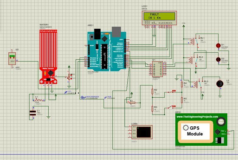
Fig 2 : Initialize the Sensors
Fig 3 : Fault in 1 km
Fig 4 : Area power shutdown
International Research Journal of Engineering and Technology (IRJET) e ISSN: 2395 0056
Volume: 09 Issue: 05 | May 2022 www.irjet.net p ISSN: 2395 0072
transmissioncircuits’,IEEETrans.PowerDelivery,vol.11, no.3,pp.1407 1418.
[5]Frolec,J.andHusak,M.(2010)‘Wirelesssensorsystem for overhead line ampacity monitoring’, in Proc. 2010 8th International Conference on Advanced Semiconductor Devices&Microsystems,Smolenice,Slovakia.
[6] Gungor, V. C. and Hancke, G. P. (2009) ‘Industrial wireless sensor networks: challenges, design principles, and technical approaches’, IEEE Trans. on Industrial Electronics,vol.56,no.10.
Fig - 5 : Cable Degrade
The underground string fault discovery system has been successfully designed and tested. This system is intended to descry the circuit fault in the underground lines by using Arduino microcontroller. The Arduino microcontroller works grounded on the affair of the detectorvalues.ByusingArduinoregulatorfindout exact faultposition.Oncefaultsdointhestring,the displayunit displays the exact fault position. In this system, the measured current is detected as being in the small or mediumcurrentrange.TheRMSvaluepercurrentcycleis transmitted to a back end covering system to negotiate real time monitoring. This system detects only the position of short circuit fault in underground string line, anddescrythepositionofopencircuitfault,todescrythe open circuit fault capacitor is used in ac circuit which measurethechangeinimpedance&calculatethedistance offault.
[1]Ajaei,F.B.,Sanaye Pasand,M.,Davarpanah,M.,Rezaei Zare, A. and Iravani, R. (2011) ‘Compensation of the current transformer saturation effects for digital relays’, IEEE Trans. on Power Delivery, vol. 26, no. 4, pp. 2531 2540.
[2]Cai, D., Regulski, P., Osborne, M.and Terzija, V. (2013) ‘Wide area inter area oscillation monitoring using fast nonlinear estimation algorithm’, IEEE Trans. Smart Grid, vol.4,no.3,pp.1721 1731.
[3] Chen, K. L. and Chen, N. (2011) ‘A new method for power current measurement using a coreless Hall Effect current transformer’, IEEE Trans. Instrumentation and Measurement,vol.60,no.1,pp.158 169.
[4] Douglass, D. A. and Edris, A. (1996) ‘Real time monitoring and dynamic thermal rating of power
[7] Gungor, V. C., Lu, B. and Hancke, G. P. (2010) ‘Opportunitiesandchallengesofwirelesssensornetworks in smart grid’, IEEE Trans. on Industrial Electronics, vol. 57,no.10,pp.3557 3564.
[8]Han,J.,Lee,H.andPark,K.(2009)‘Remotecontrollable and energy saving room architecture based on ZigBee communication’,IEEETrans.onConsumerElectronics,vol. 55,no.1,pp.264 268.
[9] JRee, D. L., Centeno, V., Thorp, J. S. and Phadke, A. G. (2013)‘Synchronizedphasormeasurementapplicationsin power systems’, IEEE Trans. Smart Grid, vol. 1, no. 1, pp. 20 27.
[10] Kang, M. S., Ke, Y. L. and Kang, H. Y. (2011) ‘ZigBee wireless network for transformer load monitoring and temperature sensitivity analysis’, in Proc. 2011 IEEE Industry Applications Society Annual Meeting, Orlando, USA.
[11]Khan,A.A.,Malik,N.,Al Arainy,A.andAlghuwainem, S. (2012) ‘A review of condition monitoring of underground power cables’, in Proc. 2012 rms DC peak rms DC peak rms Condition Monitoring and Diagnosis, Bali,Indonesia,pp.909 912,Sept.23 27.
[12] Kirkham, H. (2009) ‘Current measurement methods for the smart grid’, in Proc, IEEE Power & Energy Society GeneralMeeting,Calgary,Canada,Jul.26 3.
[13] Kojovic, L. (2002) ‘Rogowski coils suit relay protection and measurement of power systems’, IEEE ComputerApplicationsinPower,vol.10,no.3.
[14]Kondrath,N.,azimierczuk,M.K.(2009)‘Bandwidthof current transformers’, IEEE Trans. Instrumentation and Measurement,vol.58,no.6,pp.2008 2016.
[15] Kucuksari, S. and Karady, G. G. (2010) ‘Experimental comparison of conventional and optical current transformers’, IEEE Trans. on Power Delivery, vol. 25, no. 4,pp.2455 2463