International Research Journal of Engineering and Technology (IRJET) e-ISSN:2395-0056

Volume: 09 Issue: 12 | Dec 2022 www.irjet.net p-ISSN:2395-0072

International Research Journal of Engineering and Technology (IRJET) e-ISSN:2395-0056
Volume: 09 Issue: 12 | Dec 2022 www.irjet.net p-ISSN:2395-0072
1
, Dr. P.A. Dode2 , Dr. S.A. Rasal31Post Graduate Student, Datta Meghe College of Engineering, Navi Mumbai, Maharashtra, India
2Professor & Head, Department of Civil Engineering, Datta Meghe College of Engineering, Navi Mumbai, Maharashtra, India
3Professor, Department of Civil Engineering, Datta Meghe College of Engineering, Navi Mumbai, Maharashtra, India***
Abstract: For a robust design of ERSS as recommended by many authors and references i.e., CIRIA C517, CIRIA C760, the One strut failure (OSF) case is an important criterion to analyse. OSF condition is a condition when any one strut, anchor, or tieback of an ERSS system at any one location fails, then the additional load from this failed strut, shall be safely undertaken by other part of the structure and thus the temporary earth support system remains stable and the catastrophic action can be safely avoided. This paper undertakes comparative analysis of ERSS system adopted for cut and cover station works of underground Metro project in Mumbai. The OSF condition is simulated in the structural model where a single strut at a level is deactivated and structure is analysed and similarly, stimulating the same condition at other respective levels for the study of force distribution in the whole system. The analysis results of 3 different models are compared to understand the increased load distribution, due to the failure of one strut, to the adjacent struts. The results obtained can further be analysed to optimize project timeline and cost at sites where it becomes difficult to carry out the construction with the ‘struts in position” . This idea was recommended in one of the research papers, but no study related to this is found.
Keywords:EarthRetainingandStabilizingSystem(ERSS),Onestrutfailure(OSF)
In April 2004 inSingapore,a catastrophicdisaster happened due to collapseof 33.3m deep excavation. The failure of 9th level strut was the reason of collapse (Whittle and Davis, 2006). This failure condition termed as one strut failure (OSF) design condition was introduced in Singapore and Malaysia for any deep excavation works. For the underground excavationsespeciallyfortheMetroprojectsthemainconcernliesaboutthestabilityoftheexcavatedsurfacetocarryout the construction activities uninterrupted for a long duration till construction progresses to Ground level. The design of deepexcavationshallbesuchastoaccommodatethepossiblefailureofanystrut,structuralmember,orconnectionatany stage of construction works. The wall and remaining support system shall be capable to stand safe and be able to carry additional load transferred due to failed strut/ connection. This leads to the special design condition called as one strut failurecase.
TheERSSsystemshouldbesuchthatgivessufficientredundancytoavoidanycatastrophiccollapseofthesystemdueto overloading locally or failure of any particular support element. Overall failure of the system occurs due to inadequate struttingorpassivesoilfailureifthewallembedment/key-indepthisinadequate.Theinadequacyofthestruttingsystem mayalsobeduetobadconnectiondetailsofstruttowalerorwalertowallcausingdisproportionateloaddistributionin the system. Due to failure of a single strut the load of the failed strut is redistributed to the adjacent struts (vertical, horizontalandtodiagonalstruts)whichmayexceedthesectiondesigncapacitythusresultingintheprogressivefailureof wholestruttingsystem.Andtherefore,leadingtotheincreasedcostoftheproject.Thispaperpresentstheanalyticalstudy ofMumbaiundergroundMetrodeepexcavationandsoilsupportsystemtounderstandthelateralforcedistributioninthe strut using the software STAAD and WALLAP. The design comparison is made for the two analysis conditions – normal caseandOSFcase.TheargumentgenerallycomesacrossisthecostimpactontheprojectduetoOSFdesigncondition,this aspectisanalysedandpresentedbyperformingthesectiondesigncapacitycheckasperCodalrequirements.
Initialstudieswerefocusedonanalysingdeepexcavationsoilsupportsystemforclay,sandetc,Thenother parameters affectingthesoisupportsystemsaypilediameter,wall/pileembedmentdepthsetc.wereanalysedandpresented.
International Research Journal of Engineering and Technology (IRJET) e-ISSN:2395-0056
Volume: 09 Issue: 12 | Dec 2022 www.irjet.net p-ISSN:2395-0072
Peck(in1969) Presentedthatlateralearthpressureistheloadforanalysisanddesignofdeepexcavation LiaoandNeff(in1990) HighlightedlimitationsandenhancementofPeck'sfindings
Hashash and Whittle (in 2002)
Proposed a controlled mechanism for lateral earth pressure around braced excavation in clay
StilleandBroms(in1976) Presentedfailureanalysisoftheanchor. Puller(in2003)
K. F. Pong, S. L. Foo, C. G. Chinnaswamy,C.C.DNg&W. L.Chow(in2012)
Presented that overall failure could be due to inadequate strutting or passive soil failure duetoinadequateembedmentoftheretainingwall/pile
Presentedhis findingsby comparing theanalysisofOSF condition with3Dapproachand 2D plain strain analysis. Author concluded that1) Diaphragm wall design is governed by normal case and least affected with OSF condition
2)2Dnumericalanalysisthoughconservativeisappropriatetoconsider
DavidC.C.NgandSimonY.H. Low2(in2016)
A.T.C Goh3, Zhang Fan4, Liu Hanlong1.2, Zhang Wengang1.2 and Zhou Dong2 (in2018)
Proposed to omit one strut using observational approach to optimise the construction timeandcost.Instrumentationmonitoringandactual behaviorofsoilsupportsystemare instrumentalinthisapproachofOSF.
Presented numerical analysis strut responses under OSF condition in clay. 2D and 3D analysis is done for the comparison. Strut response due to OSF is demonstrated asLoad transfer (%) = Npost-Npre x 100% Nfail Where, Npost – strut load post the strut failure, Npre – strut load before the strut failure Nfail–loadonfailedstrutbeforestrutfailure
Kamchai Choosrithong and Helmut F. Schweiger (in 2018)
S. S. Gue, C. S. Gue and C. Y. Gue(in2018)
Hai K. Phan1, B. C. Hsiung1 , andJ.Huang2 (in2019)
Presented numerical investigation for OSF in soft soil using PLAXIS software forgeotechnicalanalysis.Diaphragmwallisanalysedfor2differentembedmentdepths–i) wall with uniform embedment along the wall length ii)wallwithunevenembedmentdepthsalongthewalllength
PresenteddesignprinciplesofERSSwithverticalrockexcavation.Authorconcludedthat1) due to failed strut the strut forces in adjacent struts increases by 50% 2) due to failed strut the BM in waler increases by 400% unlike increase in strut forces. 3)ifOSFcaseisconsideredintheanalysis,accidentalimpactcaseisnolongerrelevant.
1) also emphasized on OSF case analysis of the system as it can lead to overall failure of the deep excavation. 2) additional load due to failed strut to one strut above is 50% 3) if the strut is located at the corner the additional load due to failed strut to one strut aboveis110%,butthemagnitudeoftheforcestillremainsless.
Presentedapaperonnumericalinvestigationofsequentialstrutfailureonperformanceof deepexcavation.
Jianhua
Analysed the soil support system for 2 conditions1)failureofsinglestrut,strutsareremovedonebyonetostudyit'seffectonother struts 2) continuous failure of multiple struts, when the increased load of a strut exceeds it's designcapacitythestrutsstartsfailingoneafteranother.duetothisprogressivefailureof strutsthedisplacementofsurroundingsoilincreasessuccessively
Table1:SummaryofAuthorsfindings
International Research Journal of Engineering and Technology (IRJET) e-ISSN:2395-0056
Volume: 09 Issue: 12 | Dec 2022 www.irjet.net p-ISSN:2395-0072
Thispaperfocusesonfollowingobjectives-
Toprepareconstructionstagemodelfortheactualon-siteexcavation(forMumbaiundergroundproject)andavailablesoil datausingsoftwareWALLAP(isasoftwarebyGeosolveusedtoanalyzeretainingwallsincludingcantileverwall,anchored wall, and strutted excavations for cut and cover underground stations). From analysis will determine the magnitude of loadactingateachstrutandwalerlevel.
1) Thestructuralmodelwillbeanalysedfortwoconditions-normalcaseandonestrutfailure(OSF)case.
2) ToanalyticallydeterminethelateralforcedistributioninthestrutandwalerusingthesoftwareSTAAD.
3) Tooutlinetheforcescomparisonofstrutsandwalersundertwodifferentanalysiscases.
4) Todesignthestrutsectionsforobtaineddesignforcesfortwoconditionsforcomparisonofsectioncapacity.
TounderstandtheloaddistributionintheERSSsystemduetofailureofastrutatanylevelinthesystem,thestructureis analysed using software STAAD. The lateral load at each strut/ waler level for the STAAD analysis is evaluated from the GeotechnicalmodelpreparedinWALLAPusingonsiteexcavationdataandsoilparameters.
Geotechnicaldataofdeepexcavationworksofanundergroundmetrostationworksisusedtoanalysethestructurefor the2loadingconditionsasdescribedbelow.
3Danalysisoftheearthsupportsystemisanalysedwithsecantpilewalldepthuptotheembedmentdepth.Analysisis done for the part structure considering the repetition of the framing system along the length of the excavation which is approximately200m~230mandexcavationwidthisof25m~30m.Strutwithsplay,walerbeamandsecantpilewallis modeledasthebeammemberhavingrelevantmaterialpropertiesandthesize.
TwoconditionsareconsideredforstructuralanalysisinSTAAD–
1) ForcedistributionunderNormalcase Forthestrutatdifferentlevels Forthestrutatsamelevel Forthewalersatalllevels
2) ForcedistributionunderOSFcase Forthestrutverticallyabove/belowthefailedstrutlevel Forstruthorizontallyalongthefailedstrut Forthewalersatfailedstrutlevel
The data required for this analysis is referred from the underground excavations of the Cut and Cover Metro Stations. The typical framing plan of a model at Strut level 1 and Strut level 2 is shown in fig.1. Struts are placed at 9m c/c horizontallyalongthelengthoftheexcavation,thestrutsaresupportedadditionallybyplungecolumnsandendsupports are secant pile. Rectangular marked area is considered in STAAD analysis. Retaining wall is a concrete secant pile wall. Threemodelsof3differentlocationsareanalysedandresultantforcesarecomparedforthestudyofloaddistributionin theadjacentstrutsduetoafailedstrutatalevel.
International Research Journal of Engineering and Technology (IRJET) e-ISSN:2395-0056
Volume: 09 Issue: 12 | Dec 2022 www.irjet.net p-ISSN:2395-0072
Fig1:Planofasoilsupportsystem
Fig.2:Sectionofsoilsupportsystem
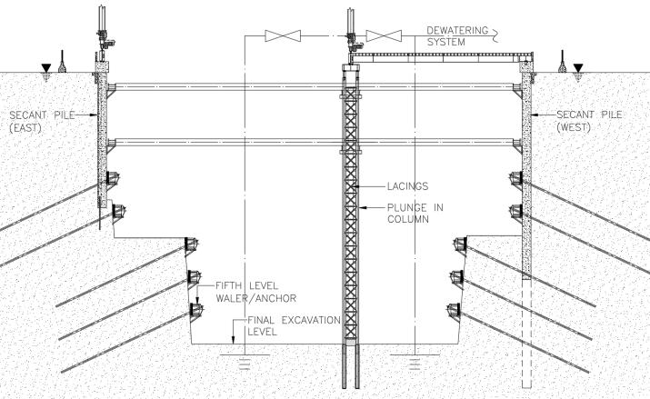
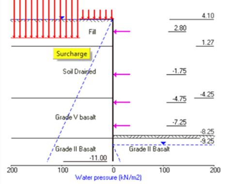
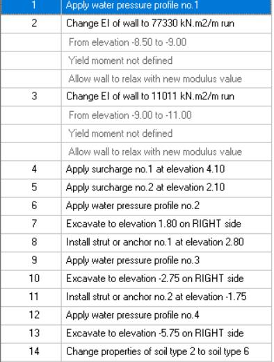
4.1 WALLAP MODEL: The WALLAP model is used depicting the soil strata of the excavation, construction sequence, applying soil parameters, secant wall properties, surcharge load, earth pressure and water pressure etc. The software checksthestabilityofthestructureandgivestheanalysisresultsasvaluesofstructuralforcesatallconstructionstages.
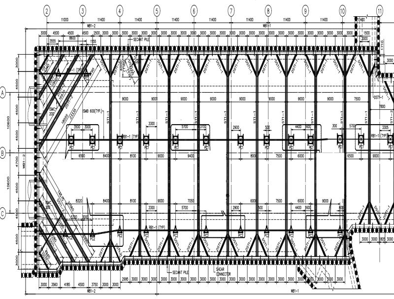
Fig 3:TypicalConstructionstagemodelforNormalCaseinWallap
International Research Journal of Engineering and Technology (IRJET) e-ISSN:2395-0056
Volume: 09 Issue: 12 | Dec 2022 www.irjet.net p-ISSN:2395-0072
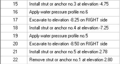
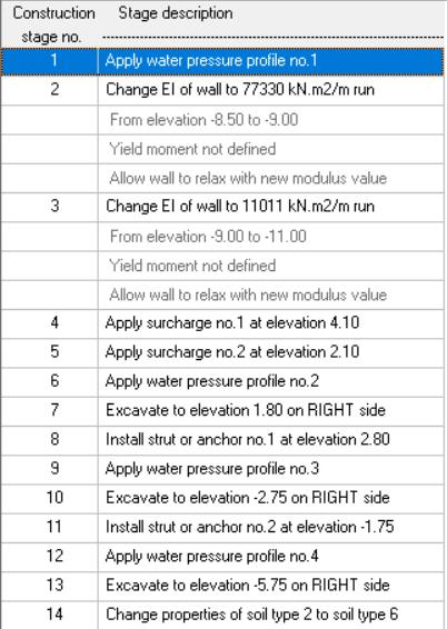
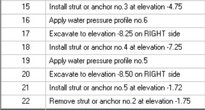
Fig.4:TypicalConstructionsequenceforOSFcasewith1stlevel
Fig.5:TypicalConstructionsequenceforOSFcasewith2nd levelstrutfailureinWallap strutfailureinWallap 4.2 Staad model data:
1) ExcavationDepth:of~15tm,12m,22.4m(depthuptoexcavationlevel)
2) ExcavationSizeinplan:widthof36m,21.4m,22.4mandlengthonlypartofthetotalexcavation(250m)
3) Secantpilediameter:800mm(bothprimaryandsecondarypiles)
4) Strut(withsplays):SteelUBSections,2strutlevelsat9mc/cwithanchorsspacedat2.6mc/catlowerleve;s
5) Waler:SteelUB/ISMBsection,spanning2.6mc/c
6) Soilparameters:aspertheGeotechnicalreport
7) WaterTable:aspertheGeotechnicalreport
International Research Journal of Engineering and Technology (IRJET) e-ISSN:2395-0056
Volume: 09 Issue: 12 | Dec 2022 www.irjet.net p-ISSN:2395-0072
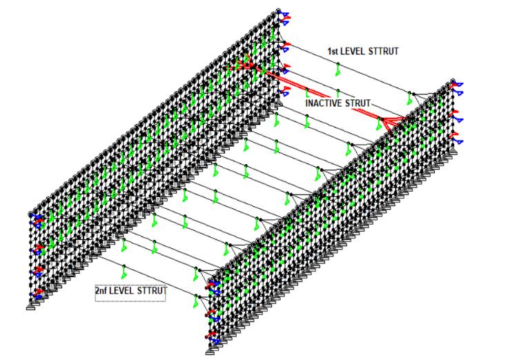
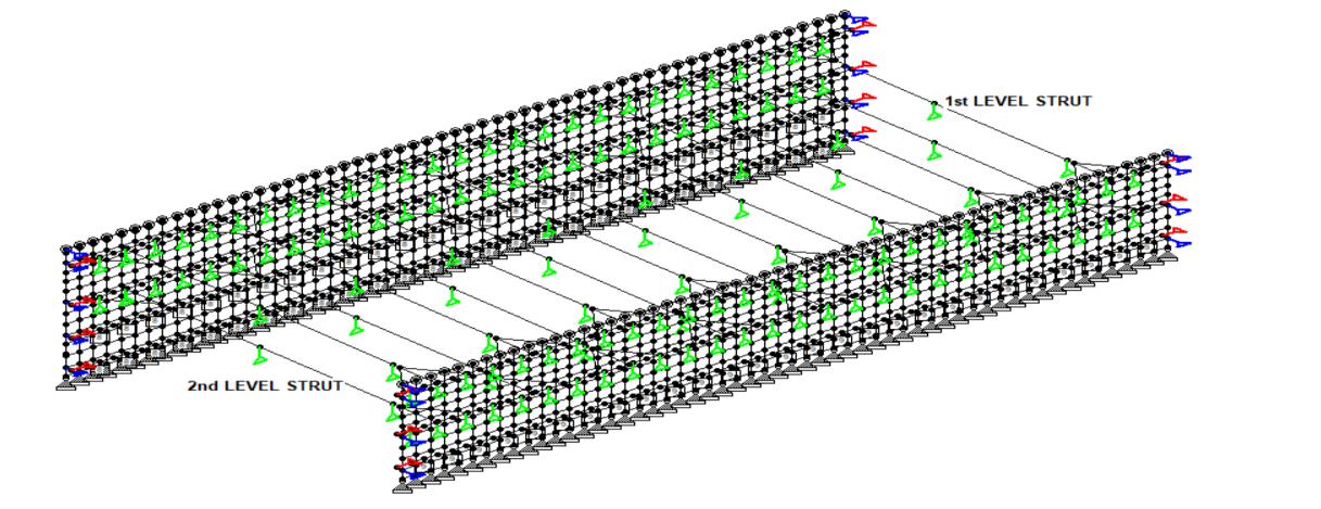
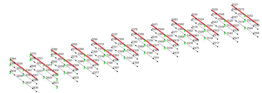
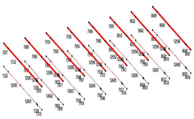
Fig6:StaadmodelforNormalcase Fig7:StaadmodelforOSFcase–1st levelstrutdeactivated Fig8:StaadmodelforOSFcase–2nd levelstrutdeactivated
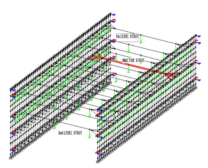
Differentloadsfortheanalysisofasoilsupportsystemarea) earthpressures b) groundwater c) materialdeadload,andgroundsurcharge d) liveload,eccentricload,surchargeload e) temperatureeffect f) accidentalimpactload g) one-strutfailure.
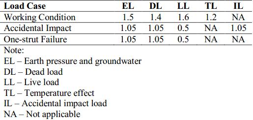
Table2:recommendedpartialsafetyfactorsforthememberdesign
Inthispaperforthecomparativeanalysisoftheloaddistribution duetoafailedstrutunderNormalcaseandOSFcase loadingconditionthetemperatureeffect,accidentalloadareignored.Moreover,whencheckingthesystemforthecritical caseofOSF,temperatureloadisnotapplicableasperTable2
International Research Journal of Engineering and Technology (IRJET) e-ISSN:2395-0056
Volume: 09 Issue: 12 | Dec 2022 www.irjet.net p-ISSN:2395-0072
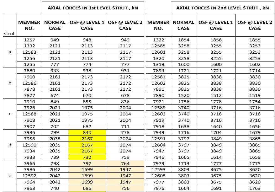
The members that are adjacent to the strut member considered deactivated in the analysis for both the conditions of OSFaretabulatedbelowtoreadtheforcesfromtheTable3,4&5
Table3:StrutmemberanalysisresultforModel-1fornormalcase,OSFcaseatlevel1,OSFcaseatlevel2
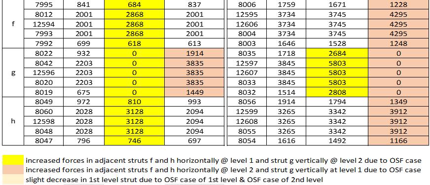
236450762350859623942632612631962838803819803774 32201254441251343223140714991408141832262659257326592701 23631254441251342393140714991408141828372659257326592701 235714421311144115242389177617591776181828301735173317351761 2372368037143223963005342943462840865606861929 322118620186218363224244943572449234332274507417445075574 237118620186218362395244943572449234328394507417445074517 235831903184032390469142747053028311579134015781672 238213311137133213852398131312671314118328422257227222561870 322212731634127311543225201421612013212432285170511451715574 238112731634127311542397201421612013212428415170511451715574 2359613757614680239116411613028321816180718151611 726513311330133210457272115811841160318272792417241924170 72841256108812576337285187218081872502672865481546854820 72641256108812576337271187218081872502672785481546854820 726360159860311947270976897147272771934194319330 7295931935933999730295494695782673092685267526842630 731413281382132712007315187419051873196173165040504050385499 729413281382132712007301187419051873196173085040504050385499 72931731731762737300109981093873071736172517341537 7337701704702714734410101016101210387351562566561611 735616091592161216037357247724682479235973582334232923352293 733616091592161216037343247724682479235973502334232923352293 7335322320319328734284784884586873499909919881051 737940540840638773868468468508217393788787789786 739816711676166416787399256425682558257774002168217021652211 737816711676166416787385256425682558257773922168217021652211 737761461261262573849559519579497391805803805810 742130730930528574288018037957867435702703695706 744016611659168216517441258725862604257574422074207320822085 742016611659168216517427258725862604257574342074207320822085 7419722721721744742610471045104110617433801801795818 746329329529327174707947958157767477657657671655 748217021703165317037483263526362588263574842003200319722013 746217021703165317037469263526362588263574762003200319722013 7461742742749764746810641062108910747475766766782776 750533433629531775128498506958367519659659618657 752416471647164516457525260726072707260575261918191820021921 750416471647164516457511260726072707260575181918191820021921 750370970968472775101071107092810817517747747706756 752939239311083827536838838082975436086081344606 754818171817315118177549276327640276475501956195633171958 752818171817315118177535276327640276475421956195633171958 752763563514056467534976975098275416646631435668 755354654753454475601020102087810177567722722688722 757214891488163914897573232423252488232575741616161617421615 755214891488163914897553232423252488232575661616161617421615 755163063161763475581063106292810647565726725689728
@level2andlevel3dueto OSFcasewhenstrutbat1stlevelismadeinactiveinstaad increasedforcesinadjacentstrutsjandlhorizontally@level2andstrutkvertically@level1andlevel3dueto OSFcasewhenstrutkat2ndlevelismadeinactiveinstaad
International Research Journal of Engineering and Technology (IRJET) e-ISSN:2395-0056
Volume: 09 Issue: 12 | Dec 2022 www.irjet.net p-ISSN:2395-0072
AXIAL FORCES IN 1st LEVEL STRUT , kN
Strut Name MEMBER NO. NORMAL CASE
OSF @ LEVEL 1 CASE
OSF @ LEVEL 2 CASE
OSF @ LEVEL 3 CASE
MEMBER NO. NORMAL CASE
OSF @ LEVEL 1 CASE
OSF @ LEVEL 2 CASE
OSF @ LEVEL 3 CASE
MEMBER NO. NORMAL CASE
OSF @ LEVEL 1 CASE
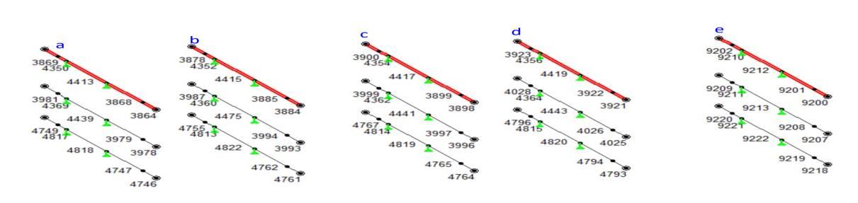
AXIAL FORCES IN 2nd LEVEL STRUT , kN AXIAL FORCES IN 2nd LEVEL STRUT , kN d e increased forces in adjacent struts a and c horizontally @ level 1 and strut b vertically @ level 2 and level 3 due to OSF case when strut b at 1st level is made inactive in staad increased forces in adjacent struts j and l horizontally @ level 2 and strut k vertically @ level 1 and level 3 due to OSF case when strut k at 2nd level is made increased forces in adjacent struts c and e horizontally @ level 3 and strut d vertically @ level 1 and level 2 due to OSF case when strut d at 3rd level is made
OSF @ LEVEL 3 CASE 3869 610 641 627 580 3981 1593 1640 1271 1617 4749 3142 971 1038 685 4350 992 1363 1045 863 4369 1165 1225 1539 1224 4817 3190 1109 1322 1964 4413 992 1363 1045 863 4439 1165 1225 1539 1224 4818 3141 1109 1322 1964 3868 992 1363 1045 863 3979 1165 1225 1539 1224 4747 3141 1109 1322 1964 3864 514 597 520 482 3978 1232 1200 1446 1277 4746 3140 1732 1750 2041 3878 433 0 967 392 3987 773 1446 0 1626 4755 3146 536 1483 0 4352 1607 0 2842 1617 4360 3897 5423 0 5952 4813 3186 4494 6493 0 4415 1607 0 2842 1617 4475 3897 5423 0 5952 4822 3152 4494 6493 0 3885 1607 0 2842 1617 3994 3897 5423 0 5952 4762 3151 4494 6493 0 3884 705 0 1282 698 3993 1072 1798 0 2176 4761 3150 1805 2973 0 3900 433 469 441 417 3999 1084 1084 943 1041 4767 3156 987 930 752 4354 1188 1511 1326 1149 4362 2514 2670 2685 2650 4814 3187 2540 2741 2983 4417 1188 1511 1326 1149 4441 2514 2670 2685 2650 4819 3155 2540 2741 2983 3899 1188 1511 1326 1149 3997 2514 2670 2685 2650 4765 3154 2540 2741 2983 3898 528 554 532 516 3996 781 778 671 726 4764 3153 722 633 332 3923 543 505 526 550 4028 905 904 923 926 4796 3167 696 706 737 4356 1553 1430 1500 1555 4364 2982 2907 2898 2924 4815 3188 3170 3108 3004 4419 1553 1430 1500 1555 4443 2982 2907 2898 2924 4820 3173 3170 3108 3004 3922 1553 1430 1500 1555 4026 2982 2907 2898 2924 4794 3170 3170 3108 3004 3921 599 558 583 600 4025 724 730 741 725 4793 3172 598 594 610 9202 678 684 679 679 9209 746 742 744 739 9220 5448 434 428 433 9210 1891 1912 1909 1901 9211 3451 3464 3457 3470 9221 5456 3761 3774 3769 9212 1891 1912 1909 1901 9213 3451 3464 3457 3470 9222 5454 3761 3774 3769 9201 1891 1912 1909 1901 9208 3451 3464 3457 3470 9219 5451 3761 3774 3769 9200 659 666 663 659 9207 591 589 590 580 9218 5453 505 495 504 slight decrease in 1st level strut due to OSF case of 1st level & OSF case of 2nd level
OSF @ LEVEL 2 CASE
Table5:StrutmemberanalysisresultforModel-3fornormalcase,OSFcaseatlevel1,OSFcaseatlevel2 TheStaadanalysisresultsaresummarizedinthetablebelowforthestrutmemberforcesforallthethreemodelsanalysed inStaad forNormal caseandOSF casewhenthestrutisinactiveatlevel 1,OSF casewhenthestrutisinactive at level 2, OSFcasewhenthestrutisinactiveatlevel3.
International Research Journal of Engineering and Technology (IRJET) e-ISSN:2395-0056
Volume: 09 Issue: 12 | Dec 2022 www.irjet.net p-ISSN:2395-0072
AXIAL FORCES IN 2nd LEVEL STRUT , kN Model No.
AXIAL FORCES IN 1st LEVEL STRUT , kN
Failedstrutgat1stlevel
Failedstrutgat2ndlevel
AXIALFORCESIN1stLEVELSTRUT,kN AXIALFORCESIN1stLEVELSTRUT,kN
d str
h str b str
f st c str
e str
AXIAL FORCES IN 3rd LEVEL STRUT , kN g str a str
Model1
Strut NORMAL CASE OSF@LEVEL1 CASE %Increasein load Strut NORMAL CASE OSF@LEVEL2 CASE %Increasein load f 2001 2868 43.3 f 2001 2001 0.0 h 2028 3128 54.2 h 2028 2094 3.3 d 2035 2167 6.5 g 2203 3835 74.1 e 2042 1699 -16.8 e 2042 1947 -4.7
AXIALFORCESIN2ndLEVELSTRUT,kN AXIALFORCESIN2ndLEVELSTRUT,kN
Strut NORMAL CASE OSF@LEVEL1 CASE %Increasein load Strut NORMAL CASE OSF@LEVEL2 CASE %Increase inload f 3734 3745 0.3 f 3734 4295 15.0 h 3265 3342 2.4 h 3265 3912 19.8 g 3845 5803 50.9 d 3797 3865 1.8 e 3803 3675 -3.4 e 3803 3620 -4.8
Fig9a:Strutnumbering-Model1 Table7a:Model1 Fig9b:Strutnumbering-Model2
Model2
International Research Journal of Engineering and Technology (IRJET) e-ISSN:2395-0056
Volume: 09 Issue: 12 | Dec 2022 www.irjet.net p-ISSN:2395-0072
Strut NORMAL CASE OSF@LEVEL1 CASE %Increasein load Strut NORMAL CASE OSF@LEVEL2 CASE %Increase inload Strut NORMAL CASE OSF@LEVEL3 CASE %Increase inload
a 507 623 22.9 j 1647 1645 -0.1 d 1331 1385 4.1 c 1273 1634 28.4 l 1489 1639 10.1 e 1328 1200 -9.6 d 1256 1088 -13.4 k 1817 3151 73.4 d 1331 1045 -21.5 g 1671 1676 0.3 i 1702 1653 -2.9 i 1702 1703 0.1
AXIAL
Strut NORMAL CASE OSF@LEVEL1 CASE %Increasein load Strut NORMAL CASE OSF@LEVEL2 CASE %Increase inload Strut NORMAL CASE OSF@LEVEL3 CASE %Increase inload a 1407 1499 6.5 j 2607 2707 3.8 c 2014 2124 5.5 c 2014 2161 7.3 l 2324 2488 7.1 e 1874 1961 4.6 b 2449 4357 77.9 h 2587 2604 0.7 d 1872 5026 168.5 e 1874 1905 1.7 i 2635 2588 -1.8 f 2477 2359 -4.8
AXIALFORCESIN3rdLEVELSTRUT,kN
Strut NORMAL CASE OSF@LEVEL1 CASE %Increasein load Strut NORMAL CASE OSF@LEVEL2 CASE %Increase inload Strut NORMAL CASE OSF@LEVEL3 CASE %Increase inload a 2659 2573 -3.2 j 1918 2002 4.4 c 5170 5574 7.8 c 5170 5114 -1.1 l 1616 1742 7.8 e 5040 5499 9.1 b 4507 4174 -7.4 k 1956 3317 69.6 b 4507 5574 23.7 f 2334 2329 -0.2 i 2003 1972 -1.5 g 2168 2211 2.0
Table7b:Model2 Fig9c:Strutnumbering-Model3
Table7c:Model3(Table7a,7b,7c:Summaryof analysisresultsofeachmodelfor%loadincreaseinstrutsadjacenttoa failedstrutatalevel.)
Model1 Model2
International Research Journal of Engineering and Technology (IRJET) e-ISSN:2395-0056
Volume: 09 Issue: 12 | Dec 2022 www.irjet.net p-ISSN:2395-0072
waler @ Level1 waler @ Level2 waler @ Level1 waler @ Level2 waler @ Level1 waler @Level Waler @ Level 1 Waler @ Level 2
Normal 295 777 396 815 100 331 - -
OSF@1stLevel 470 1159 545 1440 542 667 59.3 49.2 OSF@2ndLevel 579 926 857 566 405 466 96.3 19.2
waler @ Level1 waler @ Level2 waler @ Level waler @ Level1 waler @ Level2 waler @Level waler @ Level1 waler @ Level2 waler @ Level3 Waler @ Level 1 Waler @ Level 2 waler @ Level3
Normal 1094 1001 1091 487 346 702 1903 3123 2154 - - -
OSF@1stLevel 1207 1507 1174 420 359 543 2640 2857 2165 10.3 50.5 7.6
OSF@2ndLevel 1518 1367 1199 229 37 521 2641 2808 2178 38.8 36.6 9.9
OSF@3rdLevel 1177 1283 1114 485 360 821 1920 3167 2070 7.6 28.2 2.1
waler @ Level1 waler @ Level2 waler @ Level waler @ Level1 waler @ Level2
Model3
waler @Level 3 waler @ Level1 waler @ Level2 waler @ Level3 Waler @ Level 1 Waler @ Level 2 waler @ Level3
Normal 461 851 1831 502.6 347 652 740.2 960.6 954 - - -
OSF@1stLevel 533.1 879 1814 581.5 315 652 390 856.4 950 15.6 3.3 -0.9 OSF@2ndLevel 370 1183 1988 543 631 692 463 1053.1 930.7 -19.7 39.0 8.6
OSF@3rdLevel 226 921 2330.3 326 314 657 2520 937.2 1032.3 -51.0 8.2 27.3
Table8:Summaryof analysisresultsofeachmodelfor%loadincreaseinwalersadjacenttoafailedstrutatalevel
Model 1:strutgatlevel 1 when fails/ deactivated inanalysis,there is51%loadincrease inthestrutgatlevel 2exactly below the failed strut. And on average 49% increase in load horizontally at level 1 in f and h strut. Vice-versa when the level2strutgfails/madedeactivatedintheanalysis,the%loadincreaseinthestrutgatlevel1verticallyaboveitis74% whereasthereisnominalincreaseintheloadof strutsfandh,atlevel2 Thewalerbeamswhicharehorizontalmember alongtheperipheryofthesoilsupportsystem,has%increaseinBMby59%duetoOSFatlevel1andby96%duetoOSF atlevel2.
Model 2: strut b at level 1 when fails/ made deactivate in analysis, there is 78% load increase in the strut b at level 2 exactlybelowthefailedstrutandnochangeoradecreaseinloadisnotedinthestrutbatlevel3.Horizontalstrutswith% load increase are in range of 20~25%.Vice-versa when the level 2 strut b fails/ made deactivated in the analysis, the % loadincreaseofloadinstrutbatlevel1verticallyaboveitis73%and%increaseofloadinstrutbatlevel3is 70%.In casewhenthestrutb failsatlevel 3 the %increase inloadatlevel 1 is -21%andatlevel 2 is168.5%. Whilefor3strut system,the%increaseinwalerBMwasfoundtobeapprox.40%duetoOSFatlevel2forboththemodelsModel2and Model3.
Model 3: strut b at level 1 when fails/ made deactivate in analysis, there is 39% load increase in the strut b at level 2 exactly below the failed strut and no change or a decrease in load is noted in the strut b at level 3. Vice-versa when the level2strutbfails/madedeactivatedintheanalysis,the%loadincreaseofloadinstrutbatlevel1verticallyaboveitis 77%and%increaseofloadinstrutbatlevel3is106%.Incasewhenthestrutbfailsatlevel3the%increaseinloadat level1is0.6%andatlevel2is53%.
From the above results for 3 different model system, it is observed that force redistribution (increases) vertically in the struts aboveorbelowofthe failedstrut isintherangeof56.6%to 78%.However, inhorizontal direction i.e.,atlevel of failedstrutthereisnominal%increaseofrange15%to 30%intheadjacentstruts.
DuetoOSFconditionthespanofthewalerintheaxisofbending(majoraxis)becomeslaterallyunsupportedtherebythe tributaryareaofloadincreasesforwalerduetofailureofastrutandhencetheBMinwalerincreases.The%increasein waler BM is in the range of 20% to 60%. Whereas the impact of OSF on other level has an impact of 70% to 96%. That
International Research Journal of Engineering and Technology (IRJET) e-ISSN:2395-0056
Volume: 09 Issue: 12 | Dec 2022 www.irjet.net p-ISSN:2395-0072
means the impact in magnitude of load increase in strut is less compared to waler. Since the partial safety factors for normal case is 1.5 against 1.05 for OSF case, the increase in magnitude of load can be still within the design capacity Therefore, the OSF case shall always be examined for any temporary soil support system to rule out any catastrophic collapseandgivethesafeandstablerobustdesign.Fromtheanalysisresults,itcanbeoutlinedthatcostimplicationwith OSFcheckwillnothavemuchimpact.
1) EN1997-2Eurocode(groundinvestigationandtesting)
2) CIRIAreport104,Designofretainingwallsembeddedinstiffclays(C.J.PadfiledandR.J.MairCIRIA1984)
3) CIRIAreport580,Embeddedretainingwalls –guidanceforeconomicdesign(A.R.gaba,B.Simpson,W.Powrie,D.R. Beadman,CIRIA2003)
4) Design considerations for one strut failure according to TR26 - a practical approach for practising engineers ”, K.F. Pong**, S.L. Fooa, C. G. Chinnaswamya, C.C.D Nga & W.L. Chowb, The IES Journal Part A:Civil & Structural Engineering Vol.5,No.3,August2012,166-180
5) SingaporeCaseHistoriesonOmissionofStrutbyObservationApproachforCircleLineandDownTownLineProjects”, DavidC.C.Ng1andSimonY.H.Low2,GeotechnicalEngineeringJournaloftheSEAGS&AGSSEAVol.47No.3September 2016ISSN0046-5828
6) Numerical analysis on strut responses due to OSF for braced excavation in clays”, A.T.C Goh3, Zhang Fan4, Liu Hanlong1.2, Zhang Wengang1.2 and Zhou Dong2, Springer Nature Singapore Pte Ltd. and Zhejiang University Press 2018,Proceedingsofthe2ndInternationalsymposiumonAsiaUrbanGeoEngineering
7) Influence of Individual strut failure on Performance of Deep excavation in soft soil”, Kamchai Choosrithong and HelmutF.Schweiger,SpringerNatureSwitzerlandAG2018
8) Numerical investigation of Sequential strut failure on performance of Deep excavations in soft soil”, Kamchai Choosrithong1andHelmutF.Schweiger,Ph.D.2,Int.J.Geomech,2020,20(6):040420063
9) Challenges in Design and Construction of Deep Excavation”, S. S. Gue, C. S. Gue and C. Y. Gue, Email:ssgue@gnpgroup.com.my,2018
10) Behaviours and mechanism analysis of deep excavation in sand caused by one-strut failure”, Hai K. Phan1, B. C. Hsiung1, and J. Huang2, Procds. Of 16th Asian Regional Conference on Soil Mechanics and Geotechnical Engineering October14-18,2019,Taipei,Taiwan
11) Local failure and reliability analysis of Horizontal struts in Deep Excavation based on Redundancy theory”, Jianhua LIUa,ShaomingWUa,LinfengWANGb,c,1andXiaohanZHOUb,c,HydraulicandCivilEngineeringTechnologyVI,2021
12) Comparative Analysis Of Strut Systems For Deep Excavation In Complex Geotechnical Conditions”, H. Szabowicz1, J. Rybak2,