International Research Journal of Engineering and Technology (IRJET) e-ISSN:2395-0056

Volume: 09 Issue: 11 | Nov 2022 www.irjet.net p-ISSN:2395-0072

International Research Journal of Engineering and Technology (IRJET) e-ISSN:2395-0056
Volume: 09 Issue: 11 | Nov 2022 www.irjet.net p-ISSN:2395-0072
1Chaitra Goswami, 2Rakesh Chaudhary, 3Ankush Kumar Jain
1M.Tech Student, 2,3Assistant Professor, Civil Engineering Department Poornima University, Jaipur, India ***
Abstract - Lateral (i.e. wind) loads are unreliable loads that cause production, overturning moments, planechanges, etc., leadingto structural failure. A PEB consists of a series of 2D frames that repeat at regular distances. These frames are stabilized longitudinally by bracing. Cross frames support in-plane loads without longitudinal struts, so the columns act as bending supports, requiring large columns and large foundations. Unlike this arrangement, special roof support arrangements such as perimeter arrangements and harps can be used instead. In current work, STAAD Pro is used to perform dynamic analysis of 3D industrial structures with different support placement configurations to determine the suitability of support placement types and provide insight into the study of different types, media placement.
Three PEB hangars were simulated in this study: a bare-framePEB hangar (without supports), a PEBhangar withperimeter supports and a PEB hangar with harp supports. The framework is analyzed in terms of shear forces, bending moments, displacements, normal forces and steel mass. The results show that the perimeter reinforcement is relatively more effective than the barereinforcement and the harp reinforcement.
Keywords: PEB, Harp Bracing, Perimeter Bracing, Bare Frame, Steel Structure
Indiahasthesecondfastestgrowingeconomyintheworldandalotofitisduetoitsconstructionindustry,whichisrightnextto agricultureinitseconomiccontributiontotheregion.Initscontinuousdevelopment,theconstructionindustryhasdiscovered, invented and developed a number of technologies, systems and products, one of which is the design of pre-engineered buildings(PEBs).Incomparisontobeingassembledonsite,PEBsareshippedtothesitefromasinglesupplierwithasimple structuralsteelstructurewithattachedfactoryfinishedcladdingandroofingcomponentsasafullfinishedproduct.Bybolting the different building components together as per requirements, the structure iserected on the ground. Potential design softwareisusedtobuildPEBs.Conventionalbuildingdesignhasbeenrevolutionizedbytheonsetoftechnologicaldevelopment thatenables3Dmodelinganddetailingoftheplannedstructureandcoordination.Pre-EngineeredBuildings(PEB)areIndia's future.TheadvantagesofPEBshavejuststartedtobeunderstoodbymostoftheIndianbusinesscommunity.
Inthe1960s,thewordPre-engineeringbuildingScientificSoundingcameintobeing.Theideaofpre-engineeredbuildings requiressteelconstructionsystemsthatarepre-designedandprefabricated.ThefoundationofthedefinitionofthePEBliesin providingthesectionatalocationonlyasneededatthatlocation.Thesebuildingswerepre-designedintostandardsizes, spans,baysandheightsandusedstandarddetailsforrepairingcladding,roofing,gutters,flashing,windows,doors,etc.to economicallytakeadvantageofindustrialmassmanufacturingpracticesofcomponents.
Forvariousmaterialandequipmenthandlingactivitieswithin,“thesepre-engineeredbuildingscanbefittedwithoverheadcranes, semi-gentrycranes,wall-mountedcranes,monorailsandunder-slungcranes.Thesestructuresarebuiltforcranecapacitiesfrom 1MTto250MT.Thecranerunwaybeams(GantryGirders)aresimplysupportedbyformedpartswithandwithoutcapchannels andplatformsandladdersformaintenance”.
Forcranecapacitiesrangingfrom1megatonneto250megatonne,thesebuildingsareplanned.Thecranerunwaybeams(Gantry Girders)areprotectedbybuilt-upsectionswith/withoutcapchannelsandplatformsandladdersformaintenance.Aconcreteslab
International Research Journal of Engineering and Technology (IRJET) e-ISSN:2395-0056
Volume: 09 Issue: 11 | Nov 2022 www.irjet.net p-ISSN:2395-0072
iscastasafinishedsurfaceonthemetaldeck.Itisalsopossibletousesteelcheckeredplatesasthetopsurface.Suchmezzanines areusedincompaniesforofficespace,storageorequipmentsupport.
Variousstructuralaccessoriescanbefittedwithpre-engineeringsteelbuildings,includingmezzaninefloors,canopies,fascias, internalpartitions,etc.Fasciaisusedtocoverthebuilding'sgableroofslopPre-engineeringsteelbuildingcanbefittedwith variousstructuralaccessories.Thesteelbuildingwherevariouscomponentsofthebuildingarebuiltindetailandassembledin theplantisshippedtotheenderectedatthesite.
Asaresult,newperimetralbracingsystemwithahigherlevelofefficacyisrequired.Asuspendedbridge,or"harpbridge,"isused asametaphorforthesolutiontotheproblem(Fig.6).Thelargebendingmomentresistedbythedeckiscontrolledbyvarious partsworkingunderaxialtensiletensioninaharpbridge.Whenitcomestodimensioning,thisisthemostconservativestep.
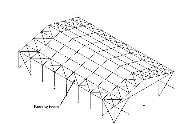
Others,incontrasttothepreviousdesign,demonstratebetteroverallstructurebehavior.Someauthors,suchasMonfort(1991) andGarcimartn(1998),advocatedtheuseofso-calledbracingbeams.Thesebeams,alongwithtypicalbracing,formanon-roof perimetralbracingsystemlinkedtoabracingendwallframe.Thegoalistoproducezeroeavedeflectioninthecolumn,resulting inareductionincolumnsectionandfoundationsize.Thebracingbeamisthenconnectedatitsextremestothebracingendwall frame,whichthusdirectsallhorizontalloadstothefoundations.
Fig.1.1RoofPerimetralBracing(Martínezetal.,2004)
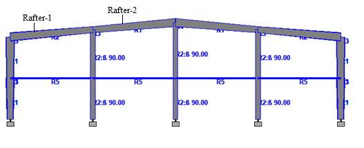
Industrialwarehouseismajorlyconstructedinsteelandareusedforstorageunitsorasworkshops.Itconsistsarecolumns, rafters,tiebeams,purlinsandcladding.Thecolumnandrafterconnectionaremomentresistingconnectionintheshedandall otherconnectionsareusuallyshearconnections.Claddingsactsasacoveringmaterialfortheroof.Thepresentindustrialware houseisapre-engineeredbuildingwherethesectionsusedarebuiltupsections.Thereare3typesofshedsconsideredforthe analysisinSTAADPRO,firstonebeing,bareframeshedwithnobracings.SecondisPEBshedwithperimeterbracingwhere bracingisintheperimeterofthebuilding.ThirdisPEBshedwithharpbracing.
Builtupsectionsareusedforthecolumnsandrafters.Fortiebeamsandbracingspipesectionsisconsidered.Sectionsproperties foraretabulatedinthebelowtable.Fixedsupportisappliedtothestructure.’
International Research Journal of Engineering and Technology (IRJET) e-ISSN:2395-0056
Volume: 09 Issue: 11 | Nov 2022 www.irjet.net p-ISSN:2395-0072
Table 2.1 Built Up Section
Description Dimensionofcolumnand Rafter-2(m) DimensionofRafter-1(m)
Depthofsectionatstartnode 0.45 0.6
Depthofsectionatendnode 0.6 0.45
Thicknessofweb 0.008 0.008
Widthoftopflange 0.35 0.35 Thicknessoftopflange 0.008 0.008 Properties
Table 2.2 Section Properties
Description Section property Bracings PIP889M PIP1016H PIP1397H
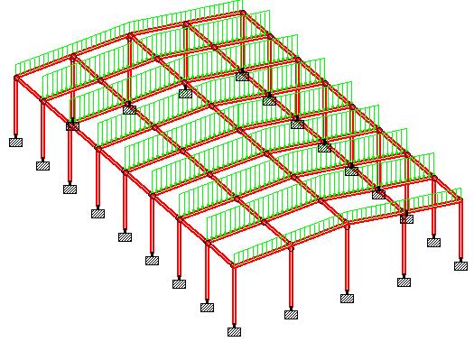
Figure 2.1 PEB Shed With Tapered Sections
Thedifferenttypesofloadsthatareappliedonthestructurearedeadloads,liveloadsandwindload.Allthethreemodels presentinourstudyareappliedwiththeseloadsandtheyareanalysed.
I. Dead load. II. Live load. III. Wind load.
2022, IRJET | Impact Factor value: 7.529 | ISO 9001:2008 Certified
International Research Journal of Engineering and Technology (IRJET) e-ISSN:2395-0056
Volume: 09 Issue: 11 | Nov 2022 www.irjet.net p-ISSN:2395-0072
3.1.1 Dead load:
Figure 3.1 Self Weight of the PEB
Figure 3.2 Sheeting Load on PEB
3.1.2 Live load:
Figure 3.3 Live Load on PEB
2022, IRJET | Impact Factor value: 7.529 | ISO 9001:2008 Certified
International Research Journal of Engineering and Technology (IRJET) e-ISSN:2395-0056
Volume: 09 Issue: 11 | Nov 2022 www.irjet.net p-ISSN:2395-0072
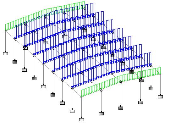
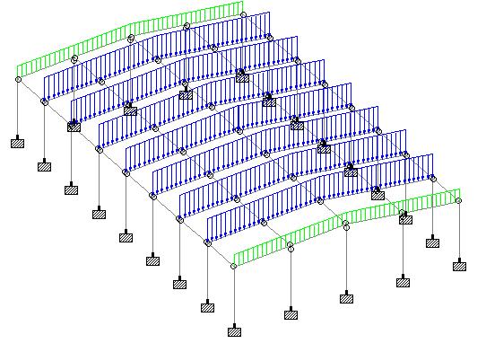
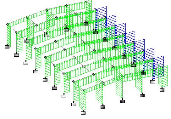
3.1.3Wind load:
Figure 3.4 Wind Load in +X Direction
Figure 3.5 Wind Load in -X Direction
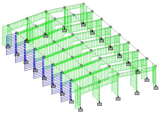
4.1 PEB with Bare Frame: Inthismodel,therearenobracingsmodelled.Thesecondbayofthemodelisselectedto tabulatetheresults.
Bending Moment in Rafters
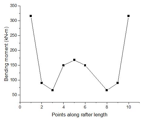
Figure 4.1 Bending Moment Variation along the Rafter in Model -1 Shear Force in Rafters
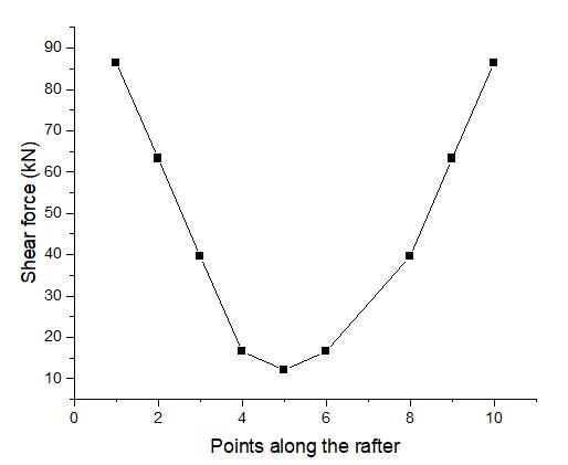
Figure 4.2 Shear Force Variations along the Rafter in Model-1
2022, IRJET | Impact Factor value: 7.529 | ISO 9001:2008 Certified Journal
International Research Journal of Engineering and Technology (IRJET) e-ISSN:2395-0056
Volume: 09 Issue: 11 | Nov 2022 www.irjet.net p-ISSN:2395-0072
Figure 4.3 Bending Moment Variation along the Column in Model -1 Axial Force in Column
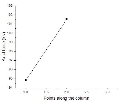
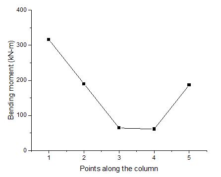
Figure 4.4 Axial Force Variations along the Column in Model-1
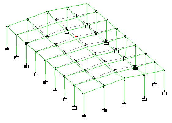
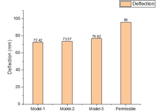
ThemaximumdeflectionofthePEBshedwithbareframeistabulatedfromtheenveloploadcombination.Theenvelopload combinationisfoundtobe1.5(DL+LL)andthemaximumdeflectionis72.42mmandallowabledeflectionaccordingtotheISis 96mmforthepresentstudy.Hence,PEBshedissafeunderdeflectioncriteria.Fromfigure4.5,highlightedpointgivesthe positionofmaximumdeflection.
ThePEBshedwasdesignedaccordingtotheIS-800codestandardsandtheutilizationratiowasfoundtobelessthan1 whichmeansallthemembersoftheshedarepassingandsamecanbeseeninfigure4.6.
2022, IRJET | Impact Factor value: 7.529 | ISO 9001:2008 Certified Journal
International Research Journal of Engineering and Technology (IRJET) e-ISSN:2395-0056
Volume: 09 Issue: 11 | Nov 2022 www.irjet.net p-ISSN:2395-0072
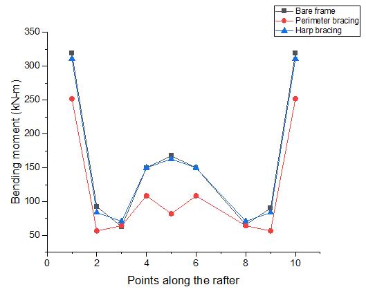
Figure4.7isagraphplottedtoshowvariationofbendingmomentinraftersamongallthreemodels.Itisevidentfromthe graphthatthebendingmomentislessforPEBwithperimeterbracingandmaximumforPEBwithbareframe.Thebending momentforPEBshedbareframeandPEBwithharpbracingdoesn’thavenoticeabledifference.
PEBshedwithperimeterbracingisfoundtobeefficientoutofallthreemodelswhenparameterlikebendingmomentinrafter isconsidered.
Figure4.8isagraphplottedtoshowvariationofshearforceinraftersamongallthreemodels.Wecanconcurfromthegraph thattheshearforceislessforPEBwithperimeterbracingandmaximumforPEBwithbareframe.TheshearforceforPEBshed bareframeandPEBwithharpbracingdoesn’thavenoticeabledifferenceandshearforceattheridgeishigherforthePEBshed withperimeterbracing.PEBshedwithperimeterbracingisfoundtobeefficientoutofallthreemodelswhenparameterlike shearforceinrafterisconsidered.
International Research Journal of Engineering and Technology (IRJET) e-ISSN:2395-0056
Volume: 09 Issue: 11 | Nov 2022 www.irjet.net p-ISSN:2395-0072
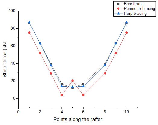
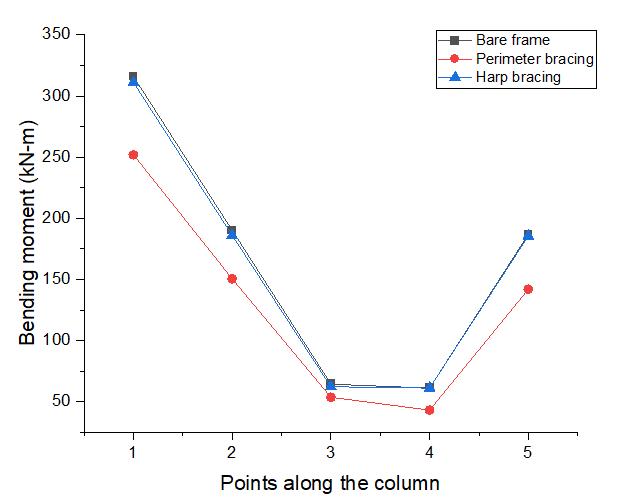
Figure4.9isagraphplottedtoshowvariationofbendingmomentincolumnamongallthreemodels.Itisevidentfromthe graphthatthebendingmomentislessforPEBwithperimeterbracingandmaximumforPEBwithbareframe.Thebending momentforPEBshedbareframeandPEBwithharpbracingdoesn’thavenoticeabledifference.
PEBshedwithperimeterbracingisfoundtobeefficientoutofallthreemodelswhenparameterlikebendingmomentin columnisconsidered.
International Research Journal of Engineering and Technology (IRJET) e-ISSN:2395-0056
Volume: 09 Issue: 11 | Nov 2022 www.irjet.net p-ISSN:2395-0072
Figure4.10isagraphplottedtoshowvariationofaxialforceincolumnamongallthreemodels.Wecanconcurfromthegraph thattheaxialforceislessforPEBwithperimeterbracingandmaximumforPEBwithbareframe.Theaxialforcevaluesof columnforPEBshedbareframeandPEBwithharpbracingarealmostsimilar.
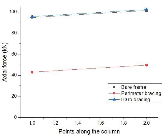
PEBshedwithperimeterbracingisfoundtobeefficientoutofallthreemodelswhenparameterlikeaxialforceincolumnis considered.
Deflectionoftheshediscomparedwithallthe3modelspresentinourthesis.Figure4.11isagraphplottedtoshowtotal deflectionoftheshedamongallthreemodelsandthepermissibledeflectionallowedaccordingtotheIndianstandards.
Onthebasisofdesignandanalysisofpre-engineeredstructurewithharpandperimetralbracingsubjectedtowindloading, manyinferencescanbeseen.
2022, IRJET | Impact Factor value: 7.529 | ISO 9001:2008 Certified
International Research Journal of Engineering and Technology (IRJET) e-ISSN:2395-0056
Conclusionsoftheresearchworkare:
Hence,aspertheabove-mentionedconclusionondifferentaspectsclearlyindicatingthattheperimeterbracinggiveseffective andsatisfactoryresultsandthiscanbeutilizedinfieldapplicationsofPEB.Further,nosignificantresultsareobtainedonPEB byusingharpbracingsoitisadvisedtoavoidsuchbracinginfieldapplication.
InthepresentstudyPEBshedwithPerimeterandharpbracingaremodeledandanalyzed.Variouspropertieslikeaxialforce, bendingmoment,shearforceoncolumnandrafterofallshedsarecompared.Basedonresultsvariousimportantconclusions aredrawnwhicharedescribedabove.However,fewissuesorparameterscanbeconsideredinfutureforresearchwhichis detailedasfollows:
•AspresentstudysuggeststhatPerimeterbracingismoreeffectiveascomparetoharpandbareframeincaseofwindloading, hencefurtheroptimizationoncostisstillneedresearch.
• Adetailedconnectionsdesignofshedisalsoconsideredforfurtherstudy.
•Further,theeffectivenessofPerimeterbracingcanalsobevalidatingincaseoftime-historyanalysis.
1.GM,Renuka.,SH,S.,Patange,R.,SP,M.,&CK,D.(2020).“TheDesignandAnalysisofIndustrialwarehouseusingSTAAD Pro”.InternationalJournalofFuturesResearchandDevelopment,1(1),99-113.
2.MitaaliJayantGilbile,S.S.Mane,(2020),“AReviewonComparativeStudyontheStructuralAnalysisandDesignofPreEngineered Building [PEB] with Conventional Steel Building [CSB]”, International Journal of Engineering Research and Technology(IJERT)Volume09,Issue09(September2020)
3.HarshilPatel,DhruvUpadhyay ,DivyangPatel.DesignOptimizationofBoxGirderinGantryCraneusingFiniteElement AnalysisSoftware.InternationalResearchJournalofEngineeringandTechnology(IRJET).2020.
4.ZhiqiangZhang,HaibinJin,XingLiandJinjinTianRigidDynamicLoadoftheCraneLiftingMechanismWhentheSeries ResistanceStarts.JournalofPhysics:ConferenceSeries.2020.
5.Sitthipong,S.,Meengam, C.,Chainarong,S.,& Towatana,P.(2018).DesignAnalysisofOverheadCraneforMaintenance Workshop.
6.ShivaniMeher,RuchitaNar,SadichhaJagadale,GautamiKalal,VirenChandanshive,2018,“DesignofIndustrialWarehouse” International Journal of Engineering Research and Technology (IJERT) Volume 07, Issue 02 (February 2018),http://dx.doi.org/10.17577/IJERTV7IS020170
7.HabiburRahaman,FaiyazAzam,MirzaAamirBaigSeismicriskassessmentofanindustrialsteelbuilding.International JournalofAdvanceResearch,IdeasandInnovationsinTechnology,2018.
8.Patil,Subodh&Jadhav,Raviraj&Mali,Pritam.A.&Bhanuse,Maheshkumar.(2017).“AnalysisandDesignOfPre-Engineed BuildingOfAnIndustrialWarehouse”.10.13140/RG.2.2.23069.77282.
9.Venkatesh,A.,Vignesh,S.,Iyappan,S.,VigneshKumar,P.,Tamilvanan,G.andVijayaSarathy,R.DESIGNOFANOVERHEAD PLATEGANTRYGIRDER.InternationalJournalofDevelopmentResearch,2016.
10.KavitaR.Kapadni,Prof.S.G.Ganiger.AReviewPaperonDesignandStructuralAnalysisofSimplySupportedGantryCrane BeamforEccentricLoading.InternationalResearchJournalofEngineeringandTechnology(IRJET)e-IS.2015
Volume: 09 Issue: 11 | Nov 2022 www.irjet.net p-ISSN:2395-0072 © 2022, IRJET | Impact Factor value: 7.529 | ISO 9001:2008 Certified Journal | Page231
11.NavyaP,Dr.Y.MManjunat.StructuralBehaviorofIndustrialStructureSubjectedtoLateralLoads.InternationalJournalof EngineeringResearch&Technology(IJERT).2015.
12.Kapadni,K.R.,&Ganiger,P.S.(2015).AReviewPaperonDesignandStructuralAnalysisofSimplySupportedGantryCrane BeamforEccentricLoading
13. Sagar gajanan kashid, prof. mr. pandit rangrao sawant, 2014, design and development of material handling crane, internationaljournalofengineeringresearch&technology(ijert)volume03,issue10(october2014),.
14. Mohamed H. Mabrouk, Sherif M. M. Abdelkhalek, 2014, Design and Implementation of a Light Duty Gantry Crane, INTERNATIONALJOURNALOFENGINEERINGRESEARCH&TECHNOLOGY(IJERT)Volume03,Issue12(December2014),
15.C.OktayAzeloglu,AyseEdincliler,AhmetSagirli,"InvestigationofSeismicBehaviorofContainerCraneStructuresbyShake Table Tests and Mathematical Modeling", Shock and Vibration, vol. 2014, Article ID 682647, 9 pages, 2014. https://doi.org/10.1155/2014/682647
16. Andrea GODOY, Frédéric BARBIER , Charisis CHATZIGOGOS, Nicolas BESSON, Alfred THIBON and Martin RAY. COMPARATIVE SEISMIC ANALYSIS OF OVERHEAD CRANE ON STEEL FRAME CARRYING STRUCTURE: EVALUATION OF ADEQUATEEQUIPMENT-STRUCTUREINTERACTIONMODELING.SecondEuropeonConferenceonEarthquakeEngineering. 2014.
17.SubhrakantMohakul,Dr.ShaikhYajdani,AbhayDhurde,August2014“Designofindustrialstorageshedandanalysisof stressesproducedonfailureofajoint”.InternationalJournalofCivilEngineeringandTechnology
18.Saleem,MuhammadUmair,etal.“MinimumWeightDesignofPreEngineeredSteelStructuresUsingBuilt-upSectionsand ColdFormedSections.”AdvancedMaterialsResearch,vol.684,TransTechPublications,Ltd.,Apr.2013,pp.125–129.Crossref, doi:10.4028/www.scientific.net/amr.684.125.
19.SyedFiroz,SarathChandraKumarB,S.KanakambaraRao,”DesignConceptofPreEngineeredBuilding”,IJERAVol.2,Issue 2,Mar-Apr2012,pp.267-272
20.C.M.Meera,June2013“Pre-EngineeredBuildingDesignofanIndustrialwarehouse”.InternationalJournalofEngineering SciencesandEmergingTechnologies.
1.IndianStandard:1893(Part1);2002.CriteriaforEarthquakeResistantDesignStructures:NewDelhi:BIS;2002.
2.IS875:Part1to5CodeOfPracticeForDesignLoads(OtherThanEarthquake)ForBuildingsandStructures,1stRevision, NewDelhi:BIS.
3.IndianStandard:801–1975;CodeOfPracticeForUseOfCold-FormedLightGaugeSteelStructuralMember‘sInGeneral BuildingConstruction,1stRevision,NewDelhi:BIS.
4IndianStandard:800–2007;GeneralConstructioninSteel CodeofPractice;3rdSRevision,NewDelhi:BIS.
1.MBMA:MetalBuildingManufacturersAssociation-2006,MetalBuildingSystemsManual.
2.Dr.N.Subramanian,‗Designofsteelstructures‘.
3.Dr.N.Subramanian(2008),―Pre-engineeredBuildingsSelectionofFramingSystem,RoofingandWallMaterials‖.
4.TechnicalManual,ZamilSteel,SaudiArabia,Pre-EngineeredBuildingsDivision.
International Research Journal of Engineering and Technology (IRJET) e-ISSN:2395-0056 Volume: 09 Issue: 11 | Nov 2022 www.irjet.net p-ISSN:2395-0072 © 2022, IRJET | Impact Factor value: 7.529 | ISO 9001:2008 Certified Journal | Page232