International Research Journal of Engineering and Technology (IRJET)
e-ISSN: 2395-0056
Volume: 07 Issue: 08 | Aug 2020
p-ISSN: 2395-0072
www.irjet.net
Design & Analysis of Wound Rotor Induction Motor Drive using Slip Power Recovery Scheme with Inverter Control for ID Fan in Power Plant Manish Kapse1, Pratik Ghutke2 1PG
Student, Dept. of Electrical Engineering, TGPCET Nagpur, Maharashtra, India Professor, Dept. of Electrical Engineering, TGPCET Nagpur, Maharashtra, India ----------------------------------------------------------------------***--------------------------------------------------------------------2Asst.
Abstract - Induction motors are used as industrial drive and for various fans in power plant due to their rugged and simple construction as well as low cost. The speed control of WRIM is proficient by slip power recovery scheme consisting of inverter control, chopper control, and rotor resistance control techniques. This paper presents the enhancement in the performance characteristics and energy saving of WRIM drive by GTO inverter and buck-boost chopper based slip power recovery scheme (SPRS). The simulation model of a WRIM drive using GTO inverter and GTO based buck-boost chopper control has been established in the Simulink platform. The simulation result using inverter and chopper control have been analyzed. The power factor, efficiency and total harmonic distortion have been taken as parameter for analyzing the enhancement in the performance of the WRIM drive and also find the energy saving by the drive. The simulation result has shown that GTO based inverter chopper control SPRS has good power factor, efficiency, lower Total Harmonic Distortion and large amount of energy saving.
controlled induction motors, the ratings of the rotor side converter, inverter and transformer circuit in SPRD is intended to be smaller and less expensive as these apparatuses have to deal with the slip power only. Enormous literature is available for slip power recovery drives. Many Authors presented motor performance using slip recovery systems, analysis of transient state of Kramer drives, and proposed new slip recovery scheme for improved power factor. Krause et al. 1988 presented reference study of slip power recovery drive. Akpinar and Pillai, 1990 presented modeling and performance of slip power recovery scheme for induction motor. A new energy recovery scheme for variable speed double fed induction motor was presented in (Fan et al., 1990). Many authors recommended, harmonic analysis, commutation angle analysis and performance enhancement of slip power recovery drive. 2. PERFORMANCE ANALYSIS OF THE DRIVE
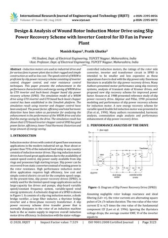
1. INTRODUCTION Induction motor drives with control of speed have enormous applications in the modern industrial set up. Near about or greater than 75% of the industrial load today in any country consists of induction motor drives. Slip ring induction motor drives have found great applications due to the availability of easiest speed control, slip power easily available from slip rings and possesses high starting torque. Slip power can be recovered from static converters instead of wasting power in the rotor resistance. High performance induction motor drive application requires high efficiency, low cost and simple control electric circuit for the complete speed range. At the present time, slip power recovery drives (SPRD), is widely used for the limited speed range applications such as large-capacity fan drives and pumps, ship-board variable speed/constant frequency system, variable-speed wind energy systems etc. A schematic diagram of a SPRD is shown in Figure 1. It consists of a slip ring induction motor, a diode bridge rectifier, a large filter inductor, a thyristor bridge inverter and a three-phase recovery transformer. A slip power recovery scheme drive transfer power that is normally dissipates in the rotor of an induction machine back to the ac mains supply to improve overall induction motor drive efficiency. In distinction with the stator-voltage-
© 2020, IRJET
|
Impact Factor value: 7.529
Figure -1: Diagram of Slip Power Recovery Drive (SPRD) Assuming negligible rotor leakage reactance and ideal filtering (Ld= ∞), the rotor currents are alternating square pulses of 2π /3 radians duration. The rms value of the rotor current I2 is π/3 times the rms value of the fundamental component I2f (Lavi et al. 1996). Ignoring the thyristors voltage drops, the average counter EMF, Vi of the inverter equals to
|
ISO 9001:2008 Certified Journal
|
Page 3123