
International Research Journal of Engineering and Technology (IRJET) e-ISSN: 2395-0056
Volume: 12 Issue: 06 | Jun 2025 www.irjet.net p-ISSN: 2395-0072
International Research Journal of Engineering and Technology (IRJET) e-ISSN: 2395-0056
Volume: 12 Issue: 06 | Jun 2025 www.irjet.net p-ISSN: 2395-0072
Mr. B.S. Swami1 , Prof. S.S. Kale2
1Mr. B. S Swami M-Tech Student of Mechanical Engineering Department, N.K. ORCHID College of Engineering and Technology, Solapur, Maharashtra, India.
2 Prof. S.S. Kale Mechanical Engineering Department, N.K. ORCHID College of Engineering and Technology, Solapur, Maharashtra, India.
Abstract - The performance and emission characteristics of compression ignition (CI) engines are critically influenced by fuel properties, among which fuel temperature plays a significant role. This research explores the potential of preheating diesel fuel using recovered engine exhaust heat as a passive strategy to enhance engine efficiency and reduce harmfulemissions. Acustom-designedheatexchangersystem was integrated into the fuel supply line to elevate the temperature of diesel without external energy input. The effectsofvaryingfueltemperatures(30°C,40°C,and60°C)and compression ratios (15, 17.5, and 18) were systematically studied under different engine load conditions. Experimental results indicate that engine performance significantly improveswith moderatepreheating.Theoptimalperformance was observed at 40°C fuel temperature and a compression ratio of 17.5, where brake power (1.81 kW), indicated power (4.41 kW), and thermal efficiency (30.02%) were maximized. Conversely, the lowest emissions of NO and CO were recorded at a higher temperature of 60°C and compression ratio of 18, indicating more complete combustion. These findings highlight a trade-off between performance and emission reduction, suggesting that the selection of operating parameters must be aligned with specific performance or environmentalobjectives.Overall,thestudydemonstratesthat exhaust-driven diesel preheating is a viable, energy-efficient method for improving combustion quality, fuel economy, and emission characteristics in conventional diesel engines.
Key Words: Diesel Engine, Fuel preheating, Performance testing, Knocking, Pollution.
1.INTRODUCTION
Internalcombustion(IC)engines,particularlydieselengines, continue to dominate the fields of transportation, agriculture,andpowergenerationduetotheirrobustness, high thermal efficiency, and fuel economy. Diesel engines operateontheprincipleofcompressionignition,wherethe fuelisinjectedintohighlycompressedairinthecombustion chamber, leading to spontaneous ignition. While diesel enginesarewidelyusedandwell-understood,thegrowing emphasisonreducingfuelconsumption,enhancingengine efficiency, and complying with increasingly stringent emissionnormshasrenewedinterestinoptimizingengine
operation through both mechanical and thermal interventions.
One of the critical factors affecting diesel engine performanceisignitiondelay,whichisdefinedasthetime intervalbetweenthestartoffuelinjectionandtheonsetof combustion. A prolonged ignition delay can lead to uncontrolledcombustionandhigherpeakpressures,causing knocking, increased mechanical stress, and emission of unburnedhydrocarbonsandnitrogenoxides(NOₓ).Several factorsinfluencetheignitiondelay,includingfuelproperties (suchasviscosity,volatility,andcetanenumber),intakeair conditions, enginetemperature,andinjectionparameters. Amongthese,fueltemperatureisasignificantyetrelatively underexploredvariablethatdirectlyaffectsfuelatomization, spraypenetration,andmixingwithair.
Diesel fuel, by its nature, has high viscosity and moderate volatility. At ambient temperatures, particularly in colder climates, these characteristics hinder proper atomization duringinjection,leadingtopoorair-fuelmixing,incomplete combustion,andreducedengineefficiency.Preheatingdiesel fuelcansignificantlyalteritsphysicalproperties lowering viscosityandincreasingvaporizationrate whichfacilitates better atomization and more uniform mixing in the combustionchamber.Theseimprovementspotentiallyresult in reduced ignition delay, more stable combustion, lower fuelconsumption,andreducedemissions.
Recent studies have shown that moderate preheating of diesel(typicallyintherangeof40°Cto100°C)canleadto measurableimprovementsincombustionqualityandengine performance.However,thedegreeofimprovementisoften context-specific and depends on engine type, fuel composition, heating method, and operating conditions. Additionally,excessive preheating can reduce fuel density andcalorificvalue,whichmayadverselyaffectenginepower output and thermal efficiency. Therefore, an optimal preheating temperature range must be determined experimentallyforeachengineconfiguration.
Inthisregard,utilizingwasteheatfromtheengineexhaust topreheatthefuelpresentsanattractivesolution,combining performance enhancement with energy recovery. By
International Research Journal of Engineering and Technology (IRJET) e-ISSN: 2395-0056
Volume: 12 Issue: 06 | Jun 2025 www.irjet.net p-ISSN: 2395-0072
channeling a portion of the exhaust heat through a heat exchangerintegratedintothefuelsupplyline,itispossible toelevatethe temperature ofthe incomingdiesel without requiring external energy input. This method aligns with sustainableengineeringpractices,asitreducesenergylosses andenhancestheoverallthermalefficiencyofthesystem.
Despitethepotentialbenefits,thereremainsaresearchgap insystematicallystudyingthecombinedeffectsofcontrolled dieselpreheatingonengineperformanceundervaryingload conditions using an exhaust heat-based system. Many existing works have either focused on biodiesel blends or electric heating systems, with limited data available on passive, exhaust-driven preheating in conventional diesel engines.
Theprimaryobjectiveofthisstudyistodesign,implement, andevaluateadieselfuelpreheatingsystemthatusesengine exhaustheatfortemperatureelevation.Thesystemwillbe integrated into a standard CI engine test rig. The experimentalworkwillinvolveperformancetestingofthe engine at different levels of fuel preheating and load conditions.Keyparameterssuchasbrakethermalefficiency (BTE), specific fuel consumption (SFC), exhaust gas temperature(EGT),andignitiondelaywillbemeasuredand comparedwithbaseline(unheatedfuel)performance.
Theoutcomeofthisresearchisexpectedtoprovidevaluable insights into the role of diesel preheating in improving IC engine performance and fuel economy, and to establish optimaloperatingconditionsforpracticalapplicationinrealworldsystems.
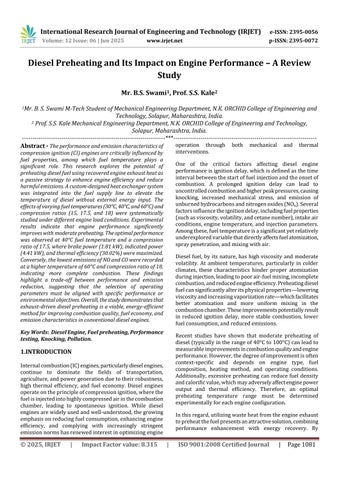
InthecurrentresearchCIengineisusedfortesting.Figure2 shows Experimental set up. Procedure for the experimentationisgivenbelow-
1) Ensure that all the nut bolts of engine, dynamometer, propellershaft,baseframeare properlytightened.
2) Ensure that sufficient lubrication oil is present in the enginesumptank.Thiscanbecheckedbymarkingonthe levelstick.
3) Ensuresufficientfuelinfueltank.Removeairinfuelline, ifany.
4) connecttheheatertopowersupplythoughtemperature indicator,keeptheheaterinfuel tank,keepmeasuring probe of temperature indicator in fuel tank,switch ON powersupply.Waituntilrequiredtemperatureisreached.
5) Switch on electric supply and ensure that PPU (Piezo poweringunit),DLU(Dynamometerloadingunit),Load indicatorandVoltmeterareswitchedon.
6) StartComputerandopen"EngineSoftLV"(Doubleclick "Engine Soft LV" icon on the desktop) Select "Engine Model" open "Configuration" in View. Check configure ration values & system constants with the values
displayedonenginesetuppanel."Apply"thechanges,if any.Clickon"PO-PVFigures"tab.
7) Start water pump. Adjust the flow rate of "Rotameter (Engine)"to250-350LPHand"Rotameter(Calorimeter)" to75-100LPHbymanipulatingrespectiveglobevalves provided at the rotameter inlet. Ensure that water is flowingthroughdynamometeratapressureof0.5to1 Kg/cm2.
8) KeeptheDLUknobatminimumposition.
9) Change the Fuel cock position from "Measuring" to "Tank"
10) Starttheenginebyhandcrankingandallowittorunat idlingconditionfor4-5minutes.
11) Clickon"ScanStart"onthemonitor.
12) Waittillcomputerindicatethatreadingsarenoted.
13) Clickon“GenerateReport”buttonandsavereportfiles.
14) Afterreportgenerating,achievenexttemperatureoffuel andtakereading.

International Research Journal of Engineering and Technology (IRJET) e-ISSN: 2395-0056
Table 1. Engine Specifications
Particulars Specifications
Product VCREnginetestsetup1cylinder,4stroke, Diesel(Computerized)
Engine
MakeKirloskar,Type1cylinder,4stroke Diesel,watercooled,power3.5kwat1500 rpm,stroke110mm,bore87.5mm.661cc, CRrange12to18
Dynamometer Typeeddycurrent,watercooled,with loadingunit
PropellerShafts Withuniversaljoints
FuelTank Capacity15litwithglassfuelmetering column
Calorimeter& Pump Pipeinpipe,Mono-blockPump
Crankangle sensor Resolution1Deg,Speed5500RPMwith TDCpulse
Temperature sensor TypeRTD,PT100andThermocouple,Type K
Loadindicator Digital,Range0-50Kg,Supply230VAC
Loadsensor Loadcell,typestraingauge,range0-50Kg
Rotameter Enginecooling40-400LPH;Calorimeter 25-250LPH
Overall dimensions W2000xD2500xH1500mm
This section presents the experimental findings on the impactofdieselfuelpreheating achievedviaexhaustheat recovery on the performance and emissions of a singlecylinderCIengine.Testswereconductedatthreepreheating temperatures(30°C,40°C,and60°C)andthreecompression ratios(15,17.5,and18),undervaryingloadconditions.
Key performance metrics including brake power (BP), indicated power (IP), brake thermal efficiency (BTE), and specificfuelconsumption(SFC)wereevaluated,alongwith emissionssuchasNO,NO₂, CO,CO₂,and O₂.Resultsshow that preheating at 40°C and a compression ratio of 17.5 yieldsthehighestthermal efficiencyandpoweroutput. In contrast, lower emissions were achieved at 60°C and compressionratio18,highlightingaperformance-emission trade-off.Thefollowingdiscussionanalyzestheseoutcomes indetail,offeringinsightsintooptimalengineoperationwith preheateddieselfuel.
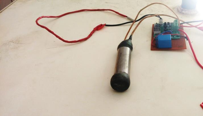
The graph in Figure 3 illustrates the variation of thermal efficiency (%) with respect to load (Kg) at different water inlettemperatures(30°Cto60°C).Asobserved,thethermal efficiencyincreaseswithincreasingloadupto12.1Kgforall temperatures, indicating improved energy utilization at higheroperationalloads.
Among the temperatures studied, the highest efficiency (\~31%)isachieved at 55°Cand 60°C at the highest load, suggesting that moderately higher temperatures enhance combustion efficiency and overall engine performance. Notably,at45°C,thethermalefficiencypeaksatthe9.1Kg loadpointanddropsat12.1Kg,possiblyduetoearlyonsetof thermallossesorincompletecombustionathigherloads.
Atlowertemperaturessuchas30°Cand35°C,theefficiency consistentlyriseswithloadbutremainscomparativelylower than that of higher temperatures. This trend implies that preheating(uptoanoptimalpoint)contributespositivelyby improving vaporization and mixing of fuel, thereby enhancingcombustion.
In conclusion, the graph indicates that thermal efficiency improveswithbothloadandinletwatertemperatureuptoa threshold, beyond whichfurther temperaturerisemay not yieldproportionalgains.Therefore,anoptimaltemperature around 55°C to 60°C appears ideal for maximum thermal efficiencyatfullload.
Volume: 12 Issue: 06 | Jun 2025 www.irjet.net p-ISSN: 2395-0072 © 2025, IRJET | Impact Factor
International Research Journal of Engineering and Technology (IRJET) e-ISSN: 2395-0056
Volume: 12 Issue: 06 | Jun 2025 www.irjet.net p-ISSN: 2395-0072
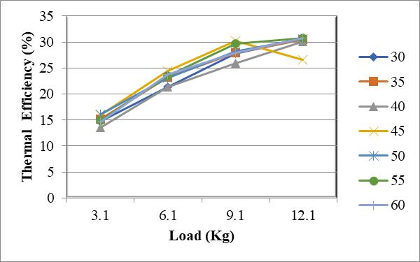
ThegraphinFigure4showstherelationshipbetweenLoad (Kg) and Brake Power (BP) in kW at different water inlet temperaturesrangingfrom30°Cto60°C.Asexpected,brake power increases linearly with increasing load across all temperaturesettings.Thisisbecausebrakepowerisdirectly proportionaltotheloadappliedontheengine greaterload demandsmoretorque,leadingtohigherpoweroutput.
Interestingly,theinfluenceoftemperatureonbrakepoweris minimal or negligible, as all curves corresponding to differenttemperaturesarenearlyoverlapping.Thisindicates thatwaterinlettemperaturehaslittletonodirecteffecton the brake power output of the engine under the test conditions. The slight variations visible are statistically insignificant and may be attributed to experimental fluctuationsormeasurementtolerances.
Insummary,brakepowerisdominantlyafunctionofload, and within the studied temperature range (30°C to 60°C), temperature has no substantial impact on BP. This consistent trend highlights that while temperature affects combustioncharacteristicsandefficiency(asseeninFigure 5.1), it does not significantly alter the mechanical power output(BP)atgivenloads.
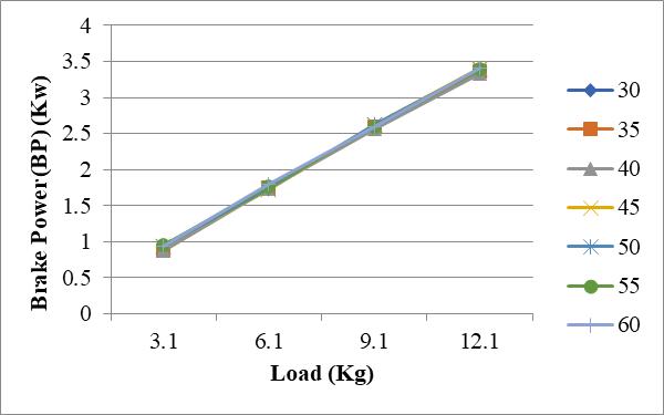
The graph in Figure 5 presents the variation of Indicated Power(IP)withrespecttoLoad(Kg)atdifferentwaterinlet temperatures ranging from 30°C to 60°C. As expected, indicated power increases with the applied load for all temperatures. This is due to the greater amount of fuel combustedathigherloads,whichgeneratesmorepressure insidethecylinder,therebyincreasingtheindicatedpower. At lower loads (3.1 Kg), the indicated power values are closer across all temperatures. However, as the load increases, the variation in IP with respect to temperature becomes more noticeable. For example, at 12.1 Kg, 35°C exhibitsthehighestindicatedpower(~5.0kW),while30°C and45°Calsoshowslightlyhighervaluescomparedto60°C and50°C.
Thedatasuggeststhatmoderatetemperatures(around30°C to40°C)tendtoproduceslightlybetterindicatedpowerthan eitherveryloworhightemperatures.Thiscouldbedueto optimalcombustioncharacteristicsandreducedheatlosses at moderate temperatures. At higher temperatures (e.g., 60°C), although fuel vaporization might be better, there could be increased heat losses to the coolant, slightly reducing the cylinder pressure and hence the indicated power.
In summary, indicated power increases with load, and moderate inlet temperatures seem to favor improved IP compared to extreme low or high temperatures. This reinforcestheideathatthereexistsanoptimaltemperature bandforachievingthebestengineperformanceintermsof powergenerationinsidethecylinder.

The graph in Figure 6 illustrates the variation of Thermal Efficiency (%) with Load (Kg) for different water inlet temperatures(30°Cto60°C)atafixedcompressionratioof 17.5. As evident, thermal efficiency increases significantly with increasing load for all temperature values, a trend consistentwithimprovedcombustionandreducedrelative heatlossesathigherengineloads.
International Research Journal of Engineering and Technology (IRJET) e-ISSN: 2395-0056
Volume: 12 Issue: 06 | Jun 2025 www.irjet.net p-ISSN: 2395-0072
Compared to earlier figures (such as Figure 5.1 at lower compression ratio), the thermal efficiency values in this grapharehigherateachloadlevel,confirmingthathigher compressionratiosimprovethermalefficiencyduetobetter fuel-airmixturecombustionandhigherpressureriseinthe cylinder.
Among the temperatures tested, 50°C and 55°C yield the highestthermalefficiency(~33–34%)atthemaximumload (12.1 Kg), indicating that this temperature range is most favorable for combustion under high compression. Meanwhile,atpartloads,temperaturesaround50°Cto60°C consistentlyperformbetterthanlowertemperatures.
At the lowest load (3.1 Kg), the efficiency values are clustered between 14% and 17%, with minor variations betweentemperatures.However,astheloadincreases,the performancegapwidens,highlightingthatthermalbenefits ofoptimalinlettemperaturearemoreprominentathigher loads.
In conclusion, thermal efficiency improves with both load and optimized inlet water temperature, and this effect is furtherenhancedatahighercompressionratioof17.5.The results underscore that operating the engine with inlet temperatures around 50–55°C under high compression conditionsprovidesthebestthermalefficiency,makingthis configurationidealforenergy-efficientperformance.

The graph in Figure 7 illustrates the variation of Brake Power(BP)withrespecttoLoad(Kg)atdifferentwaterinlet temperatures(30°Cto60°C)underacompressionratioof 17.5.Asobserved,thebrakepowerincreasesalmostlinearly withincreasingloadforalltemperaturesettings.Thistrend isexpected,asbrakepowerisadirectfunctionofloadand enginetorque.
Interestingly, the influence of water inlet temperature on brakepowerremainsnegligibleacrosstheloadrange.The data lines for all temperatures are nearly overlapping,
confirming that brake power is primarily governed by mechanical load and less sensitive to water inlet temperature,evenathighercompressionratios.
Although the compression ratio has been increased from earlier figures (e.g., from standard to 17.5), it does not significantly alter the brake power trend across temperatures. This indicates that while a higher compressionratiomayimprovecombustionefficiencyand indicated power, it does not directly impact brake power unlessaccompaniedbychangesinfuelproperties,ignition timing,orenginetuning.
Insummary,brakepowerincreaseslinearlywithload,and remains largely unaffected by variations in water inlet temperature,evenatahighcompressionratioof17.5.This furtherreinforcesthemechanicalnatureofBPasafunction of torque and load rather than temperature-based combustiondynamics.
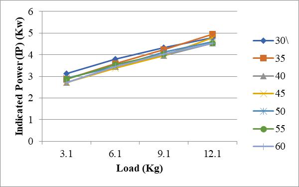
The graph in Figure 8 displays the variation of Indicated Power(IP)withrespecttoLoad(Kg)forvariouswaterinlet temperatures(30°Cto60°C)atacompressionratioof17.5. Theoveralltrendshowsthatindicatedpowerincreaseswith increasingloadforalltemperaturesettings,asmorefuelis combusted to meet the higher load demand, resulting in greatercylinderpressureand,consequently,higherIP.
At the lowest load (3.1 Kg), IP values range from approximately 2.7 kW (for 50°C) to 3.5 kW (for 40°C), indicating a noticeable variation in performance based on temperature. Interestingly, the 40°C temperature consistentlydelivershigherIPacrossallloads,peakingnear 5.0 kW at 12.1 Kg, which is the highest among all tested temperatures.
Thissuggeststhat40°Cmaybethemostthermodynamically favorableinlettemperatureunderahighcompressionratio, possiblyduetooptimalcombustionpressureandminimal heatlosses.Ontheotherhand,lower(30°C)andhigher(50–60°C)temperaturesyieldslightlylowerIPvalues,indicating
International Research Journal of Engineering and Technology (IRJET) e-ISSN: 2395-0056
Volume: 12 Issue: 06 | Jun 2025 www.irjet.net p-ISSN: 2395-0072
thatextremesininlettemperaturemaynotsustainthemost efficientin-cylindercombustion,evenathighcompression.
Moreover,theincreaseinIPwithloadisgenerallynonlinear, especially for lower temperatures, where the rise in IP is moregradual,indicatingthatcombustionqualitymayvary morewithtemperaturethanwithload.
In conclusion, indicated power improves with load, and moderateinlettemperatures,particularlyaround40°C,yield thebestperformanceunderacompressionratioof17.5.This highlightstheimportanceofinlettemperatureoptimization in maximizing engine performance through efficient incylinderpressuregeneration.
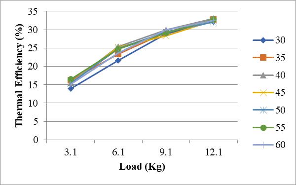
The graph in Figure 9 shows the relationship between ThermalEfficiency(%)andLoad(Kg)atvariouswaterinlet temperatures(30°Cto60°C)underacompressionratioof 18. As in earlier figures, thermal efficiency increases with loadacrossalltemperatures,duetoenhancedcombustion andreducedrelativeheatlossesathigherloadconditions.
Comparedtopreviousgraphswithlowercompressionratios (e.g.,Figures5.1and5.4),thethermalefficiencyherereaches its highest values, peaking around 33% at 12.1 Kg load, especiallyfor40°Cand55°C.Thishighlightsthatincreasing the compression ratio from 17.5 to 18 leads to a tangible improvement in thermal performance, consistent with thermodynamic principles higher compression ratios enable better fuel-air mixing, higher pressure and temperature during combustion, and lower unburnt fuel losses.
Atlowerloads(3.1Kg),thevariationinthermalefficiency acrosstemperaturesismoredistinct,rangingfrom~14%(at 30°C)to~17%(at55°C).However,thedifferencesbecome marginal at higher loads, where all temperature curves convergetowardthe31–33%range.
Notably, 40°C and 55°C inlet temperatures demonstrate slightly better thermal efficiency across most loads,
suggesting that these are near-optimal for achieving maximumcombustioneffectivenessatthishighcompression setting. Conversely, very low (30°C) and very high (60°C) temperatures perform marginally lower, possibly due to incomplete vaporization or increased heat losses respectively.

10 Load Vs. BP at Various Temperatures (o C) at compression ratio18
Figure10 showsthatBrakePower(BP)increaseswithload for all water inlet temperatures (30°C to 60°C) at a compression ratio of 18. The highest BP (~4.8–5.0 kW) is achievedat45°C,indicatingbettercombustionefficiencyat thistemperature.Whilevariationsexist,especiallyathigher loads, the impact of temperature is less pronounced comparedtoload.Overall,loadhasadominanteffect,and moderate temperatures (35°C–45°C) yield slightly better performanceatthishighcompressionratio.
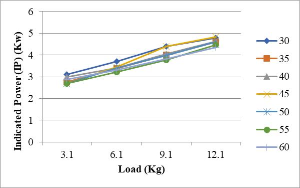
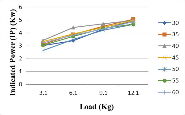
Figure 11 Load Vs IP at Various Temperatures (o C) at compression ratio18
Figure 11 shows that Indicated Power (IP) increases steadilywithloadatacompressionratioof18forallinlet temperatures (30°C–60°C). Among all, 45°C delivers the highestIPateachloadpoint,peakingnear4.9kWat12.1Kg. Thisindicatesthat45°Cisthemostfavorabletemperature forefficientcombustionathighcompression.Overall,load
International Research Journal of Engineering and Technology (IRJET) e-ISSN: 2395-0056
Volume: 12 Issue: 06 | Jun 2025 www.irjet.net p-ISSN: 2395-0072
hasadominanteffect,whiletemperaturefine-tunesIP,with moderatevalues(35–45°C)yieldingthebestresults.
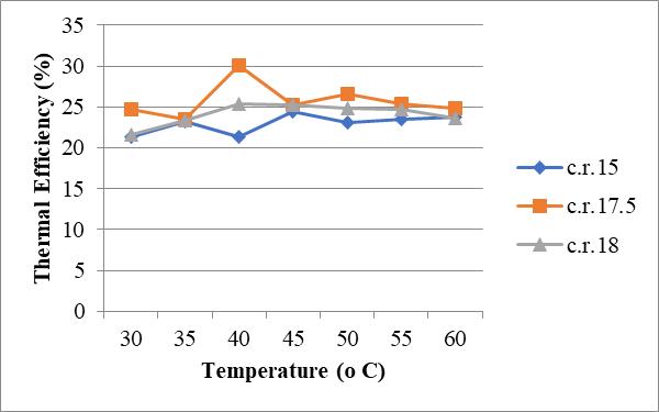
Figure12showsthatIndicatedPower(IP)increasessteadily with load at a compression ratio of 18 for all inlet temperatures (30°C–60°C). Among all, 45°C delivers the highestIPateachloadpoint,peakingnear4.9kWat12.1Kg. Thisindicatesthat45°Cisthemostfavourabletemperature forefficientcombustionathighcompression.Overall,load hasadominanteffect,whiletemperaturefine-tunesIP,with moderatevalues(35–45°C)yieldingthebestresults.
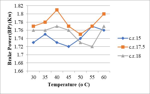
Figure13showsthatIndicatedPower(IP)increasessteadily with load at a compression ratio of 18 for all inlet temperatures (30°C–60°C). Among all, 45°C delivers the highestIPateachloadpoint,peakingnear4.9kWat12.1Kg. Thisindicatesthat45°Cisthemostfavorabletemperature forefficientcombustionathighcompression.Overall,load hasadominanteffect,whiletemperaturefine-tunesIP,with moderatevalues(35–45°C)yieldingthebestresults.
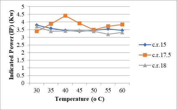
14 Temperature Vs IP at Various Compression Ratio
Figure 14 illustrates the variation of Indicated Power (IP) withtemperatureatdifferentcompressionratios(C.R.15, 17.5,and18).Fromthegraph,itisobservedthattheengine with a compression ratio of 17.5 delivers the highest indicatedpowercomparedtotheothertworatiosacrossthe temperaturerange.TheIPforC.R.17.5peaksaround4.4kW at40°C,indicatingoptimalperformanceatthistemperature. In contrast, the compression ratio of 15 shows relatively stablebutlowerIPvalues,rangingbetween3.4to3.7kW, suggesting consistent performance with less sensitivity to temperaturechanges.Ontheotherhand,theenginewitha compressionratioof18exhibitsthelowestindicatedpower output among the three, which may be attributed to increasedthermallossesorknockingathighercompression. Overall, the data suggest that a compression ratio of 17.5 provides the best balance between efficiency and power outputwithinthetestedtemperaturerange.

Figure 15 Compression Ratios Vs. Thermal Efficiency at Constant Temperature 60oC
Figure 15 shows the relationship between compression ratiosandthermal efficiencyata constanttemperature of 60°C.Thegraphindicatesthatthermalefficiencyincreases with compression ratio up to a certain point and then
International Research Journal of Engineering and Technology (IRJET) e-ISSN: 2395-0056
Volume: 12 Issue: 06 | Jun 2025 www.irjet.net p-ISSN: 2395-0072
decreases. The highest thermal efficiency, approximately 24.9%,isachievedatacompressionratioof17.5.Atalower compression ratio of 15, the thermal efficiency is around 23.8%,whileata highercompression ratioof18,it drops further to approximately 23.6%. This suggests that while increasingthecompressionratioinitiallyenhancesthermal efficiency,furtherincreasebeyondanoptimalvalue(inthis case,17.5)mayleadtoadeclineinefficiencyduetofactors suchasincreasedheatlossesorengineknocking.Hence,a compressionratioof17.5appearstobethemosteffective forachievingmaximumthermalefficiencyunderthegiven conditions.
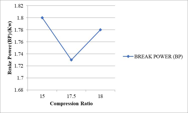
Figure 16 Compression Ratio Vs. BP, at Constant Temperature 60oC
Figure 16 shows the variation of Brake Power (BP) with compressionratioat60°C.ThehighestBPofabout1.8kWis observed at a compression ratio of 15. It drops to around 1.73 kW at 17.5, then slightly increases to 1.77 kW at 18. ThisindicatesthatBPishighestatlowercompressionand slightlyrecoversathigherratios,withC.R.15givingthebest performanceundertheseconditions.
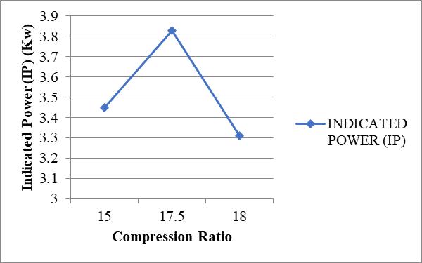
Figure 17 Compression Ratio Vs. IP at Constant Temperature 60oC
Figure 17 illustrates the variation of Indicated Power (IP) withcompressionratioataconstanttemperatureof60°C.
TheIPincreasesfromabout3.5kWatacompressionratioof 15toapeakof3.85kWat17.5,thendropstoaround3.3kW at 18. This indicates that the engine performs best at a compressionratioof17.5,withreducedpoweratbothlower andhigherratios.
Fromthepresentresearchwork,thefollowingconclusions can be drawn regarding engine performance and exhaust emissions under varying temperatures and compression ratios:
Theexperimentalstudyrevealsthatengineperformanceis stronglyaffectedbytemperatureandcompressionratio.Ata constantloadof6.1kg,theengineachieveditsbestoverall performance at a temperature of 40°C and a compression ratioof17.5,wherethethermalefficiencypeakedat30.02%, brake power (BP) reached 1.81 kW, and indicated power (IP)wasmaximumat4.41kW.Thisindicatesthatmid-range temperature and compression ratio provide the most favourable conditions for efficient combustion and power output. On the other hand, the lowest thermal efficiency (21.29%)wasrecordedatthesametemperature(40°C)but withacompressionratioof15,suggestingpoorcombustion atlowercompression.
At a constant temperature of 60°C, the thermal efficiency remainedhighestatcompressionratio17.5(24.89%),but interestingly, the brake power was highest at a lower compression ratio of 15, showing that thermal and mechanicalefficienciesmaynotalwaysalign.Theindicated powerwasalsohighestat17.5(3.83kW),furthersupporting itsoptimality.Ingeneral,thedatashowsthatcompression ratio17.5offersthebestbalancebetweenthermalefficiency and power output, while both lower (15) and higher (18) ratiosyieldcomparativelyreducedperformance.
Regarding emissions, it was observed that exhaust gases such as O₂, CO₂, NO, NO₂, and CO vary significantly with changes in compression ratio and temperature. Lower emissionsweregenerallyrecordedathighertemperatures (60°C) and higher compression ratios (especially 18). For instance,NOandCOconcentrationswereminimumat60°C andC.R.18,suggestingimprovedcombustionandreduced incompleteburningoffuelundertheseconditions.
Conversely, the highest levels of pollutants were found at lower temperatures (30°C) and lower compression ratios (15).Forexample,NOreachedupto510ppmandCOupto 0.14% under full load (12.1 kg) at 30°C and C.R. 15, indicating inefficient combustion and higher unburned emissions.Therefore,whileengineperformanceisoptimized
International Research Journal of Engineering and Technology (IRJET) e-ISSN: 2395-0056
Volume: 12 Issue: 06 | Jun 2025 www.irjet.net p-ISSN: 2395-0072
at40°CandC.R.17.5,thecleanestexhaustoutputisachieved at60°CandC.R.18.
This study highlights a trade-off between engine performanceandemissionlevels.Optimumengineoutputis achievedat40°Candcompressionratio17.5,whileminimal emissions occur at 60°C and compression ratio 18. Thus, selectionofengineoperatingparametersshouldbebasedon the intended application favoring power output or environmentalcomplianceaccordingly.
1. H. Hazar, H. Aydin, 2010 “Performance and emission evaluation of a CI engine fueled with preheated raw rapeseed oil (RRO) diesel blends”, Applied energy 87786-790.
2. P.Pradhan,H.Raheman,D.Padhee,2014“Combustion and performance of diesel engine with preheated JatrophaCurcasoilusingwasteheatfromexhaustgas”, Fuel115527-533.
3. M. Canakci, A. Ozsezen, A. Turkcan,2009 “Combustion analysis of preheated crude sunflower oil in an IDI(indirect injection) diesel engine”, Biomass and bioenergy33760-767.
4. A.Hossain,P.Davies,2012“Performance,emissionand combustioncharacteristicsofanindirectinjection(IDI) multi-cylinder compression ignition(CI) engine operatingonneatjatrophaandKaranjoilpreheatedby jacketwater”,Biomassandbioenergy33332-342.
5. N.Yilmaz,2012“Effects ofintakeair preheatandfuel blend ratio on a diesel engine operating on biodieselmethanolblends”,Fuel94444-447.
6. B.Chauhan,Y.Jun,K.Lee,N.Kumar,2010“Performance andemissionstudyofpreheatedJatrophaoilonmedium capacitydieselengine”,Energy352484-2492.
7. N. Yilmaz, B. Morton, 2011 “Effects of preheating vegetable oil on performance and emission characteristics of two diesel engine”, Biomass and bioenergy352028-2033.
8. D. Agarwal, A. Agarwal, 2007 “Performance and emissioncharacteristicsofJatrophaoil(preheatedand blends) in a direct injection compression ignition engine”,AppliedThermalengineering,272314-2323.
9. S.Bari,T.Lim,C.Yu,2002“Effectofheatingofcrudepalm oil(CPO)oninjectionsystem,performanceandemission ofdieselengine”,Renewableenergy,27339-351.
10. M.Pugazhvadivu,K.Jayachandran,2005“Investigationon performance and exhaust emissions of diesel engine
using preheated waste frying oil as fuel”, Renewable energy,302189-2202.
11. M. Kalam, H. Masjuki, 2004“Emission and deposit characteristicsofasmalldieselenginewhenoperated onpreheatedcrudepalmoil”,Biomassandbioenergy27 289-297.
12. A. Augustine, L. Marimuthu, S. Muthusamy, 2012 “Performance and Evaluation of DI Diesel engine by usingpreheatedcottonseedoilmethylester”,Procedia Engineering,38779-790.
13. S. Altun, H. Bulut, C. Oner, 2008 “The comparison of engine performance and exhaust emission characteristics of sesame oil-diesel fuel mixture with dieselfuelinadirectinjectiondieselengine”,Renewable energy,331791-1795.
14. D. Rakopoulos, 2013 “Combustion and emissions of cottonseedoilanditsbiodieselinblendswitheithernbutanolordiethyletherinHSDIdieselengine”,Fuel105 603-61.
15. Markov, V.A., Devyanin, S.N., Zykov, S.A., Vallejo, P.R., Ambawatte, H.C., Sa, B., Zherdev, A.A., Denisov, A.D., 2021. Investigation of the Performances of a Diesel EngineOperatingon
Blended and Emulsified Biofuels from Rapeseed Oil. Energies14(20),6661.
16. Aydin, H., 2021. An innovative research on variable compression ratio in RCCI strategy on a power generatordieselengineusingCNG-safflowerbiodiesel. Energy231(C).
17. Kodate, S.V., Raju, P.S., Kumar, G.N., Yadav, A.K., 2021. InvestigationofpreheatedDhupaseedoilbiodieselas an alternative fuel on the performance, emission and combustioninaCIengine.Energy231(C).
18. Smigins, R., Longwic, R., Gorski, K., 2020. Research on Physico-ChemicalPropertiesofDiethylEther/Linseed OilBlendsfortheUseasFuelinDieselEngines.Energies 13(24),6564.
19. Yunus,T.M.,2020.AReviewofPerformance-Enhancing InnovativeModificationsinBiodieselEngines.Energies 13(17),4395.
20. Yilbasi,Z.,Aslan,V.,Yesilyurt,M.K.,Cesur,C.,2020.The production of biodiesel from safflower (Carthamus tinctoriusL.)oilasapotentialfeedstockanditsusagein compressionignitionengine:Acomprehensivereview. RenewableandSustainableEnergyReviews119(C).
International Research Journal of Engineering and Technology (IRJET) e-ISSN: 2395-0056
Volume: 12 Issue: 06 | Jun 2025 www.irjet.net p-ISSN: 2395-0072
21. Hoang, A.T., 2019. Experimental study on spray and emissioncharacteristicsofa dieselenginefueledwith preheatedbio-oilsanddieselfuel.Energy171(C),795–808.
22. Gaitonde,U.N.,Shah,P.R.,Ganesh,A.,2018.Influenceof soy-lecithinasbio-additivewithstraightvegetableoilon CI engine characteristics. Renewable Energy 115(C), 685–696.
23. Rajkumar, S., Tamilselvan, P., Nallusamy, N., 2017. A comprehensivereviewonperformance,combustionand emission characteristics of biodiesel fuelled diesel engines. Renewable and Sustainable Energy Reviews 79(C),1134–1159.
24. Badescu,V.,Chiriac,R.,Aldhaidhawi,M.,2017.Ignition delay,combustionandemissioncharacteristicsofDiesel engine fueled with rapeseed biodiesel – A literature review. Renewable and Sustainable Energy Reviews 73(C),178–186.
25. No,S.-Y.,2017.Applicationofstraightvegetableoilfrom triglyceride based biomass to IC engines – A review. RenewableandSustainableEnergyReviews69(C),80–97.
26. Rahman, M.M., Kalam, M.A., Rashedul, H.K., Imdadul, H.K.,Masjuki,H.H.,Alabdulkarem,A.,2016.Studyofthe oxidation stability and exhaust emission analysis of Moringa olifera biodiesel in a multi-cylinder diesel engine with aromatic amine antioxidants. Renewable Energy94(C),294–303.
27. Kasiraman, G., Geo, E.V., Nagalingam, B., 2016. Assessmentofcashewnutshelloilasanalternatefuel forCI(Compression ignition)engines.Energy101(C), 402–410.
28. Panneerselvam, N., Subramaniam, D., Vijayakumar, C., Murugesan,A.,Kumaravel,A.,Avinash,A.,2015.Effects of injection timing on bio-diesel fuelled engine characteristics An overview. Renewable and SustainableEnergyReviews50(C),17–31.
29. Bari, S., Saad, I., 2015. Optimization of vane numbers throughsimulationandexperiment,andinvestigationof the effect on the performance and emissions of a CI (compression ignition) engine run with biodiesel. Energy79(C),248–263.


Mr. B.S. Swami
(M-TechStudentMechEngg. Dept.)N.K.ORCHIDCollegeof Engg.&Tech.,Solapur, Maharashtra,India
Prof. S.S Kale
(AssistantProfessorofMech, Engg.Dept.)N.K.ORCHIDCollege ofEngg.&TechSolapur, Maharashtra,India.