International Research Journal of Engineering and Technology (IRJET)
e-ISSN: 2395-0056
Volume: 07 Issue: 04 | Apr 2020
p-ISSN: 2395-0072
www.irjet.net
Comparative Assessment of Multi modular DC-DC Boost converter’s Calculated and Circuitry output Vora Nachiket Dineshkumar1, Patel Priyanshu Harishbhai1, Soni Ruchit R.2 1Student,
Department of Electrical Engineering, Indus University, Gujarat, India Professor, Department of Electrical Engineering, Indus University, Gujarat, India ---------------------------------------------------------------------***---------------------------------------------------------------------2Assistant
Abstract - This paper represents comparison between multi modular DC-DC boost converter’s calculated and circuitry output using MATLAB. For calculated output state-space method is used here. We used two modules here as an example, but it can also applied to more. Outputs of both are in represented in tabular mode to check the difference between calculated and circuitry output. Key Words: Boost converter, DC-DC model, Multi modular, switched power supply, State – space modelling
1. INTRODUCTION A DC-to-DC converter is an electronic circuit or electromechanical device that converts a source of direct current (DC) from one voltage level to another. It is a type of electric power converter. Power levels range from very low (small batteries) to very high (high-voltage power transmission).There are various types of DC-DC converters. Before the development of power semiconductors and allied technologies, one way to convert the voltage of a DC supply to a higher voltage, for low-power applications, was to convert it to AC by using a vibrator, followed by a step-up transformer and rectifier. For higher power an electric motor was used to drive a generator of the desired voltage (sometimes combined into a single "dynamotor" unit, a motor and generator combined into one unit, with one winding driving the motor and the other generating the output voltage). These were relatively inefficient and expensive procedures used only when there was no alternative, as to power a car radio (which then used thermionic valves/tubes requiring much higher voltages than available from a 6 or 12 V car battery).[1] The introduction of power semiconductors and integrated circuits made it economically viable to use techniques as described below. For example, to convert the DC power supply to high-frequency AC, use a transformer — small, light, and cheap due to the high frequency — to change the voltage, and rectify back to DC. Although by 1976 transistor car radio receivers did not require high voltages, some amateur radio operators continued to use vibrator supplies and dynamotors for mobile transceivers requiring high voltages although transistorized power supplies were available. While it was possible to derive a lower voltage from a higher with a linear electronic circuit or even a resistor, these methods dissipated the excess as heat; energy-efficient conversion only became possible with solid-state switch-mode circuits. Here we have used dual module boost type DC-DC converter. Circuit simulation and mathematical model is done by using MATLAB. For mathematical model state space method is used and final output variation at different duty cycle is measured.
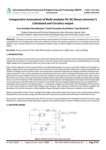
2. CIRCUITRY MODEL
Fig -1: MATLAB model of dual boost converter
© 2020, IRJET
|
Impact Factor value: 7.529
|
ISO 9001:2008 Certified Journal
|
Page 5745