Design and Validation of Efficient Flywheel Cup of Magneto to Improve the Thermal Behaviour
 Rakesh Narsayya Gundu1, Amol B. Gaikwad2, Atul Jain3, Kharad B.N.4
1Scholar, Dept. of Mechanical Engg, Vishwabharti Academy’s College of Engineering, Ahmednagar, Maharashtra, India
2Asst. Prof. Dept. of Mechanical Engg, Dr. D.Y. Patil School of Engineering, Pune, Maharashtra, India
3General Manager (R&D), Varroc Engineering Limited, Pune, Maharashtra, India

4Asst. Prof. Dept. of Mechanical Engg, Vishwabharti Academy’s College of Engineering, Ahmednagar, Maharashtra, India ***
Abstract – A flywheel magneto is an electromechanical device for generating AC electric power which is used to drive electrical loads in vehicles. The flywheel magneto is also responsible for generating signals for the ignition system of the vehicle. Flywheel magneto produces heat which makes thermal behaviour management complicated and very difficult. All losses from the flywheel magneto are converted into heat. The most of heat generated in magneto assembly due to winding copper losses & these losses increase the winding temperature.
This paper demonstrates the design and validationof efficient flywheel cupof magnetotoimprovethermalbehavior. The cup is designed with cooling holes in such a manner that those holes assist the cooling of the winding. To study the thermal performance (heat loss dissipation) duetoperipheral holes, the thermal analysis is performedusingAnsys software. The CFD analysis is performed for different scenarios, no flow (no holes on cup), maximum flow through axial holes and maximum flow through lateral holes aiming on the winding. CFD results are compared with physical testing results. The maximum air flow rate with lateral cooling holes condition indicates lower temperature generation compared to no flow with no cooling holes and maximum flow with axial holes of flywheel cup. The lower temperature achieved in copper winding ensures the winding insulation is not affected due to excess heat.
Key Words: flywheel magneto, electromechanical, thermal behaviour, flywheel cup, copper losses, efficiency, Ansys software, etc.
1. INTRODUCTION
A magneto is an AC power generator used for generatingACelectrical powerinautomobiles(two,three wheelers). Magneto is working as per faraday’s law of electromagnetic induction, which states that when a conductorisplacedinarotating(changing)magneticfield, e.m.f. is induced in it. Magneto is used in vehicles for electricalpowergenerationtodriveelectricalloadssuchas: lighting loads, horn & electrical circuits (Ignition Circuit, Speedometer Circuits etc.) Apart from electrical power generation,magnetoalsogeneratessignalswhichareused bytheignitioncircuitforthesparktiming,durationetc.The
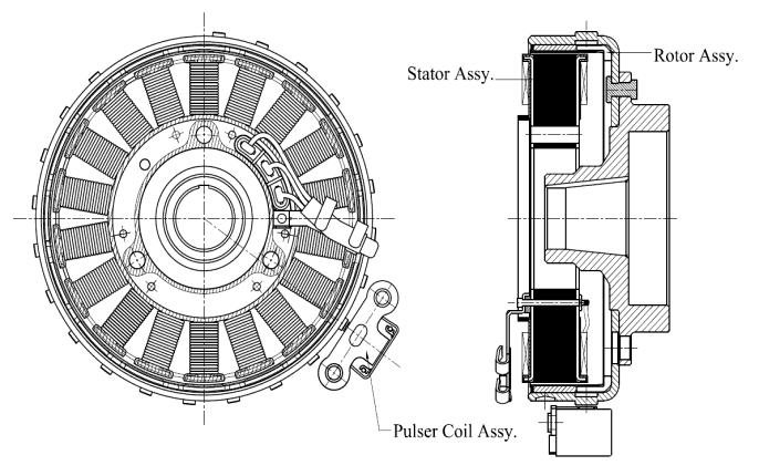
signals are also used by the speedometer for engine RPM display.Themagnetoisthesourceofenergygenerationin the magneto ignition system. Magneto generates AC electricalpowerwhichwillbeusedtodriveelectricalloads invehicles.TheACpowerfrommagnetowillbegoingtothe signalconditioningpartwhichismorepopularlyknownas regulator.Basedontheloadsthepowerisgettingprocessed in this signal conditioning & power is converted into Regulated DC, Regulated AC etc. The magneto is also responsible for generating signals for the ignition circuit. Magnetohasapulsercoilwhichactsasamagneticsensor& sensesthepositionoftherotorwiththehelpofpulserpip present on the rotor. As this function of the magneto of signal generation is directly related to the ignition of the vehicle, the same is very important. The components of magnetocausingthesignalgenerationaretobetreatedvery muchcarefullyasanydefectinthesecomponentswillmake the engine to stop & the vehicle will not start at all. A magnetoconsistsofarotorassembly&astatorassemblyas showninfig.1.1.Arotorassy.isapartwhichwillberotating with magnets fixed on it which will produce rotating magnetic field. Stator assy. will be a stationary part with conductor coils fixed on it. Because of rotating (changing) magneticfield,e.m.f.isinducedintheconductorplacedon thestator.
1.1 Flywheel Cup
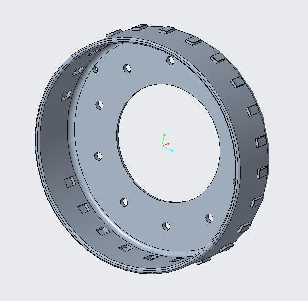
The flywheel cup is a primary component of rotor assy. which will be used to cover the stator assembly with magnetsasitwill be responsibleforholdingthemagnets. Theoverallconstructioncanbeunderstoodfromthefigure shown aside. Along with holding the magnets it also has pulserpipprojectedonitwhichwillberesponsibleforthe signalgenerationfrommagneto.
2.1 Objectives of the Project
The current project work aims to achieve the following objectives:
Designandoptimizationofnewcoolingpath.
To Analyse the thermal behaviour of existing and proposeddesigninCFD

To analyse the temperature difference of existing andproposeddesignwithexperimental
TocompareCFDresultwithexperimentalresult.
3. DESIGN CALCULATIONS
In flywheel cup design following material selection and mechanicalparametersareconsidered.
3.1 Material Selection:
Steel sheet/strip hot rolled; pickled & skin passed. Grade. EDDasperIS:1079-1994.
3.2 Mechanical Parameters
Selectionofmaterialsheetthicknessis3.2mm.
Fig -1.1: Flywheelcup
Thecupisgoingtobeapplicationdependentandcanhavea different construction; normallythe pulserpipcanhavea differentconstruction.Eveninsomecasesthepulserpipis notavailableonflywheelcup,insuchapplicationthesameis present on any other component of the rotor depending uponthedesignoftheMagneto.
2. PROBLEM DEFINITION
A magneto is an electrical generator that uses permanent magnets toproduce alternating current. Magnetosthatareadaptedtoproducepulsesofhighvoltage electricityareusedintheignitionsystemsofsomegasolinepoweredinternalcombustionenginestoprovideenergyto the spark plugs. However existing flywheel magneto produces substantial heat especially at high operating speeds and makes the thermal behaviour management of thesemachinesdifficultandcomplicated.Thetemperature rise in the flywheel magneto leads to damaged insulation, demagnetizationandreducedpoweroutputandefficiency. Powerlossescouldcauseanincreaseinthetemperatureof the windings and permanent magnets which reduces the efficiencyoftheflywheelmagneto.Toimprovethethermal behaviourofmagnetoplannedtodesignnewcoolingpathof flywheelcup.
Electricallyminimumthicknessis=or>3.2mm.Itis minimum thickness for flux of flow. (Considering magneticflux,material chemical composition-low carbonpercentage,eddycurrentlosses.)Thickness doesnotshowchangeinouterdiameter(Ø139.4) underrotationmovementathighspeed.
Flywheel cup OD related dimensions not crossing the limits set by the customer based on the fit & function of magneto i.e. (Ø70 & 37.5). While selecting Ø70, bush mating diameter to be considered.
CoolingHolesPCDaspercustomerrequirement.
The direction of piercing always from surface matingwithbosstoinnersurfaceofcup.
Pippositionbypunchingmethod,projectionisnot more than 1/3 of the sheet thickness used for flywheelcup.
Pipradiusaspercustomerrequirement.
Selection of size of rivet, rivet PCD & no. of rivets depends on customer requirement of shear strength.
Positionofrivetalwaysequalspaced.
Theminimumgapbetweentwoholesis1.5times sheetthicknessorminsheetthickness.
Position of magnet and location of spacer ring as perlayoutofrotorpole&statorpolealignmentat T.D.Ccondition.
3.3 Velocity Calculations
Speed–3000rpm
RadiusofCup=0.0697m
AngularVelocity(ω)=2X3.14X3000/60
ω=314.159rad/s2
CoolantVelocity(Vc)=ωXOuterradiusofcup(r)
Vc=21.896m/s
3.4 Proposed Flywheel Cup Design
4.1 FEA Results
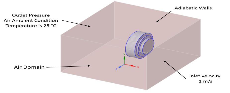
4.1.1 Boundary Conditions
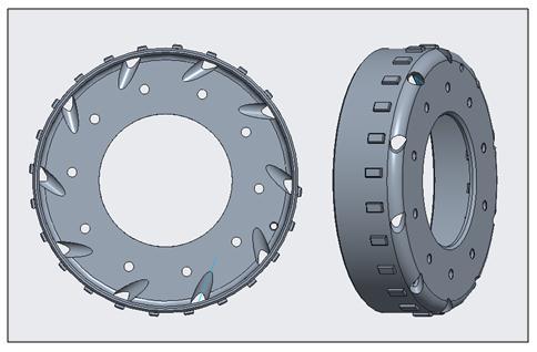
In proposed design lateral cooling holes provided with combiningtwodifferentanglesasshowninfigure3.4.These holesprovidedonperipheralsideofflywheelcup. Patternof holes directionshowninanticlockwisefromfrontview of cup.
4. FINITE ELEMENT ANALYSIS

In automobile applications on various areas of interest commonly encountered in engineering include structuralanalysis,opticalanalysis,heattransfer,fluidflow, mass transport, and electromagnetic potential. Addressed the problems typically involves solving the geometry boundary value problems are associated with the partial differentialequations.Byformulatingtheproblemsbyusing the finite element method, a system of sum algebraic equationsisobtainedasthesolution.
Fig
BoundaryConditions.
4.1.2 Baseline Design
Inbaselinedesignnocoolingholesprovidedonflywheelcup bottomface.
4.1.2.1 Baseline flywheel magneto assy. with no holes
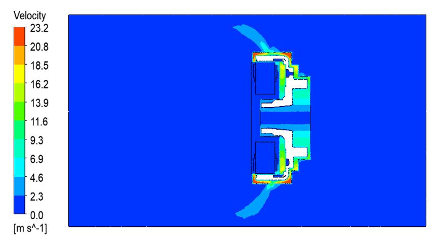
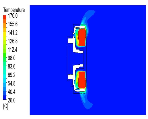
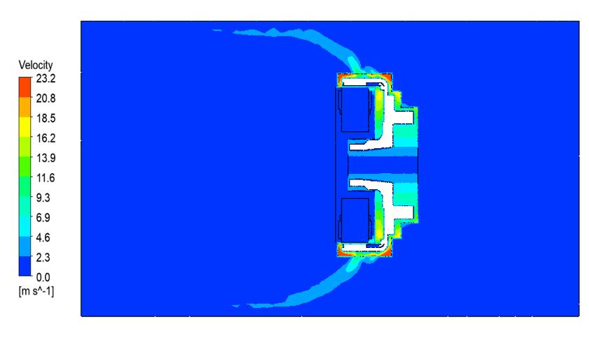
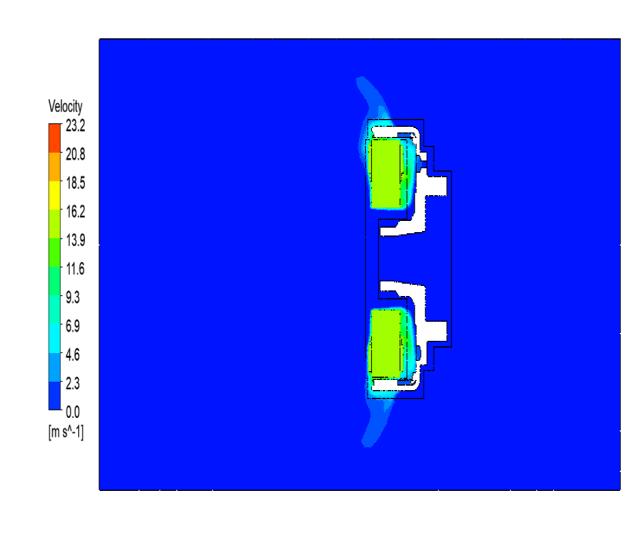
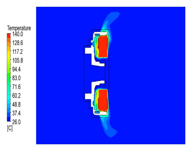
The thermal behaviorandvelocitydistribution in baseline flywheelmagnetoassy. (NoHoles)at3000RPMshownin figure4.1.2.1and 4.1.2.2Inthiscasemaximumtemperature found 170°C & maximum velocity 23.2 m/s observed in rotation movement because no cooling path provided on flywheelcup.
4.1.3 Flywheel magneto assy. with Ø12 mm axial cooling holes
4.1.4 Proposed Design
Inthisproposallateralholesprovidedonperipheralsidesof flywheelcup.
4.1.4.1 Flywheel magneto assy. with Ø8 mm lateral cooling holes
In this case axial holes are provided on bottom face of flywheelcup.Thethermalbehaviorandvelocitydistribution inflywheelmagnetoassy.withØ12mmcoolingholesat3000 RPMshowninfigure4.1.3.1and4.1.32Inthiscasemaximum temperaturefound140°Candmaximumvelocity23.2m/s observed because rotating speed is constant & amount of flow increased as compared to baseline flywheel magneto assemblywithoutholes.
Theminimumtemperatureobservedintheproposeddesign is131.68°Candcoolantvelocityobservedconstantis23.2 m/smax.Theairflowcirculationimprovedascomparedto baseline design and trails Ø12 mm axial holes proposal results.
5. EXPERIMENTAL VALIDATION

ForexperimentalvalidationproposedflywheelcupwithØ8 mmlateralholesprotosampleismanufacturedasperdesign dimensionsandthiscupassembledinrotorassembly.Stator assemblyusedexistingforexperimentaltesting.

5.1 Experimental Procedure for Testing

Theexperimentsareperformedusingaperformancetesting machinemfg.ByMEA,whereatemperaturetestisconducted at 3000 RPM. The Performance testing machine provides resultsthatarecomparedwiththeanalysisresultsobtained fromFiniteElementAnalysis(FEA).
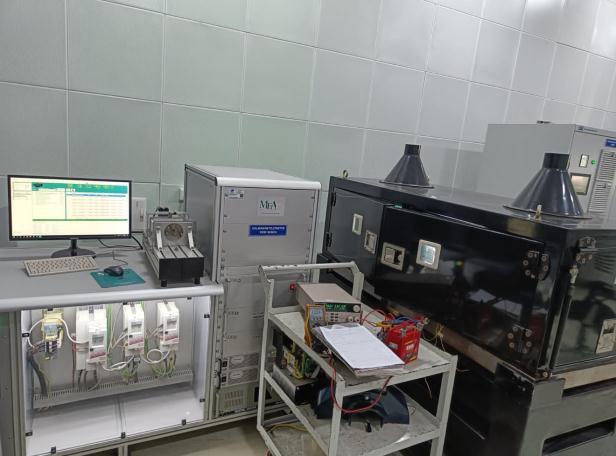
Figure5.1displays apictureofthecompleteexperimental setup and temperature values displayed on the digital ammeter.
5.3
6. RESULT AND DISCUSSION
The finite element analysis result table shown a comparison between the baseline, modified design and proposeddesignofflywheelmagnetoassy.Foranalysingthe results,thefollowingobservationscanbemade:
5.2 Experimental Result
Experimental test result shown in table 5.2, in this table clearly mentioned the maximum temperature shown at winding.
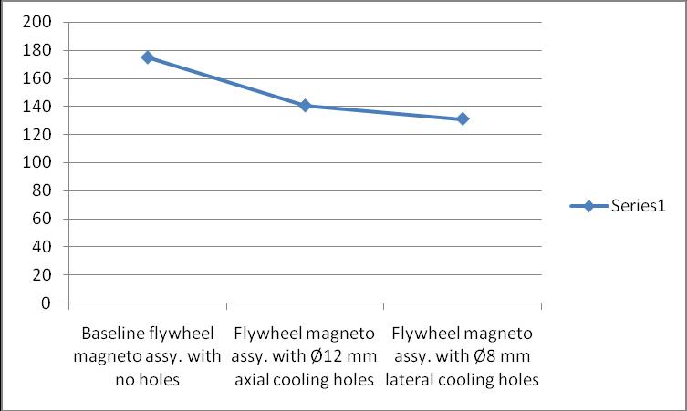
The summery table of the finite element analysis (FEA) results shows that the minimum temperature 131.68 °C observed in the proposed flywheel magneto assy. with Ø8 mm lateral cooling holes. The Experimental results also showsthattheminimumtemperature131°Cobservedinthe proposedflywheelmagnetoassy.withØ8mmlateralcooling holes.
Bothresultshowsproposedflywheelmagnetoassy.withØ8 mm lateral cooling holes are meets the results and found minimumtemperatureincopperwinding.
7. CONCLUSION
Thecupisdesignedwithcoolingholesinsuchamanner thatthoseholesassistthecoolingofthewinding.Tostudy the thermal performance (heat loss dissipation) due to peripheral holes, the thermal analysis is performed using Ansys software. The CFD analysis is performed for the differentscenarios,noflow(noholesoncup),maximumflow throughaxialholesandmaximumflowthroughlateralholes aiming on the winding. CFD results are compared with physical testing results. The maximum air flow rate with lateralcoolingholesconditionindicateslowertemperature generationcomparedtonoflowwithnocoolingholes and maximumflowwithaxialcoolingholeofflywheelcup.The lowertemperatureachievedincopperwindingensuresthe windinginsulationisnotaffectedduetoexcessheat.
REFERENCES
[1] Wei.Tong,MechanicalDesignofElectricMotors,1st Edition,CRCPress,BocaRaton,London,2017.
[2] GeneralElectric,EvaluationandApplicationofEnergy EfficientMotors, e- GEA-M1019,Book:GEIndustrial Systems,FortWayne,Indiana,2002.
[3] M. Benhaddadi, G. Olivier, R. Ibtiouen, J. Yelle, J. Tremblay,PremiumEfficiencyMotors,Abookchapter in book: Electric Machines and Drives, Miroslav Chomat,IntechOpen,DOI:10.5772/14893,2011.
[4] M.Murugesan,R.Balasubramanian,TheEffectofMass flow Rate on the Enhanced Heat Transfer Characteristics in A Corrugated Plate Type Heat Exchanger,Res.J.Engineeringsci.,Vol.1(6),pp22-26, 2016.
[5] Z. Rehman, K. Seong, Three-D Numerical Thermal Analysis of Electric Motor with Cooling Jacket, Energies,11(1)92,2018.
[6] S. Li, Y. Li, W. Choi, and B. Sarlioglu, High-Speed Electric Machines: Challenges and Design Considerations, in IEEE Transactions on TransportationElectrification,2(1)2-13,March2016.
[7] J.Schultz,ExaminingHowCoolingImpactstheTorque and Power of PMAC Motors, Parker Hannifin Corporation,ElectromechanicalandDrivesDivision.
[8] Aswin Inbaraj Jaison A and Karuppasamy K, Design and Optimization of Flywheel for Automobile Applications, International Journal of Mechanical EngineeringandResearch,ISSN0973-4562Vol.5No.1 (2015).
[9] ColinRichmond,RameshKuppuswamy,AzeemKhan, TheEffectofCoolantVelocityforEnhancingtheHighSpeed Permanent Magnet Generator Efficiency, ProcediaCIRP91(2020)21-26.
[10] Samarth Jain, Kedar Kanase and Phaneesh K, Improving Electrical Energy Consumption by ApplicationofIntegratedStarterGeneratorforSingle CylinderEngineApplications,IJERT,ISSN:2278-0181, Vol.9Issue03,March-2020.
[11] J.Nithinkumar,D.GopiChandandN.ChandraShekar, FiniteElementAnalysisofSheetMetalWorksforDeep Drawing in Manufacturing of Fly Wheel Cup, IJERT, ISSN2278-0181,Vol.3Issue9,September2014.
[12] Jan Szczypior and Rafal Jakubowski, Thermal CalculationsandTestingofExternalRotorPermanent Magnet Machine, Technical Transactions, Electrical Engineering, DOI 10.4467/235337XCT.15.058.3858, 2015.

