
IoT Based Battery Management System
1,2,3,4Dept. Electronics and Telecommunication VPKBIET College of Engineering Baramati, India. Professor4, Dept. of Electronics and Telecommunication VPKBIET College of Engineering Baramati, Maharashtra, India.

***
Abstract - An IoT-based batterymanagementsystem(BMS)is a technology that uses the internet of things (IoT) to monitor and control batteries in variousapplications.TheBMSconsists of sensors, microcontrollers, communication modules, and cloud-based servers that work together to collect data, analyze it, and optimize battery usage. The system allows for real-time monitoring of the battery's status, including its voltage, current, temperature, and state of charge, and provides early warning of potential battery failures. By using the data collected from the BMS, the system can optimize battery charging and discharging processes, extend battery life, and reduce maintenance costs. This abstract provides an overview of the IoT-based BMS technology and its benefits, including improved batteryperformance,increasedreliability, and reduced environmental impact.
Key Words: IncreasedtheBatteryLife,ShowthebatterySOC and Temperature, monitor battery health, Cell balancing, notifiedtotheusersremotelyanywhereintheworld.
1. INTRODUCTION
BMS is used in many contemporary and commercial frameworkstoimprovebatteryactivityandforevaluationin order to maintain the battery state, to the greatest extent possible,awayfromadisastrousconditionandtolengthen battery lifespan. The battery's charge, temperature, and currentarethereforecheckedusingavarietyofprocesses.
BMS framework assesses and shows the battery temperature, charging/releasing current, and SOC for the thoughtaboutmodelbattery.Forobserving,computerized andsimplesensorswithmicrocontrollersareutilized.The batterydataandtheacquiredoutcomesmakingsenseofthe framework's fundamental attributes are introduced on versatile,andafewexploratoryoutcomesaregivenonthe portable screen. In this demonstration, we'll build an Internet of Things weather station using a DHT11 temperatureandhumiditysensor,anESP8266development boardkit,andtheBlynkIoTCloudforremotemonitoring. The entiresystemispoweredbya single3.7Vlithium-ion battery. This battery has a 10 hour operating time for NodeMCU sheets. We wish to use the charging module TP4056torechargethebatteryonceagain.Butoccasionally Iforgettocharge,whichresultsinthecollapseoftheentire system.Inordertoovercomethisproblem,Ithoughtabout addingabatteryobservationframeworktoasimilarproject. In our previous battery status observing System, we can
major the battery voltage and rate. In any case, presently, with the assistance of the Blynk IoT, we can straightforwardlytelltheclientsremotelywhenthebattery rateisunderalimitesteem.WecanchecktheHumidityand Temperaturesensordataandthebatteryvoltageandbattery percentage.
Theremainingpaperisdividedintothefollowingsections. Section II discusses a review of the relevant literature. System Description is covered in Section III. Section IV discussesprototype-relatedhardwareandsoftwaredesign. Section V discusses analysis and outcomes from the implementation with a view to verifying our system. The ConclusionandFutureWorkareunderSectionVI
2. LITERAURE SURVAY
Thissectionwillprovideaquickoverviewoftheavailable literatureonEnergyManagementandSmartHomeSystems. IoT-basedautomatedtemperatureandhumiditymonitoring andcontrolsystemwasconstructedutilizingaraspberrypi in one of the research projects mentioned. Pi gets the detecteddatafortemperatureandhumidity,whicharethen transmittedtotheinternet.[1].HerecreatedanIoT-based energy management system where temperature and light intensity sensors are used, and readings are relayed to an Arduinomicrocontroller.TheArduinomicrocontrollerisset uptoregulatetheappliance'susageasnecessary.Alongwith managingapplianceusage,theRaspberryPi3calculateseach appliance'soverallpowerconsumptiononaregularbasisand plotstheresultsasagraphusingdatafromHallSensorsthat are wirelessly transmitted through a Wi-Fi module. All appliances with different climatic conditions have their graphicaldataonpowerusagevstimesenttoacloudserver [2].ThisIoTBasedBatteryManagementSystemdetectionof hydrogengasreleasedbybatterieshasbeencoveredinthis study. The fundamental battery parameters also assist in keeping track of the battery's health. The Battery ManagementSystemwillbenefitfromhavingcloudandIoT integrationsinceitwillmakedataanalysiseasier.ThisBMS alsohasaGPStracker,[3]whichmakesitpossibletotrack carsandhencegivefastassistance.[4]demonstratesafull batterymanagementsystemthatcontinuouslychecksvital indicators and balances a battery pack's active cells as needed. The BMS system has a microprocessor (MSP430) embeddedwithinitformonitoringandcontrollingunits.The BMSisanelectricalgadgetthatmaybeutilisedindailylife,as wehavediscovered.Thiscanraisethesystem'seffectiveness,
powerquality,andpowerfactor.[5]Itisdescribedhowwell thesensors,processor,andcommunicationsworkandhow accuratetheyare.Afterthat,aMATLAB-createdSOCestimate techniquecalledCo-estimatewasputintouseonthebattery hardware testbed. It is demonstrated that the developed battery hardware testbed can execute CoEstimation effectivelyandsuccessfullybycomparingtheresultsfromthe testbed with the results from the MATLAB simulation. [6] Additionally, it illustrates that the proposed hardware architecture may be used to implement the Co-Estimation method as a workable solution in EV applications. This research offers a PLC and IoT-based energy management solutionforVPPintheunifiedelectricitymarket.FortheDA market, it is predicted that university loads and solar generation would increase. The system makes use of automation that is PLC and IoT-based by managing the supply and loads of VPP for the best possible energy management.ThePLCandRaspberryPiareusedtomanage theusedsourceandloadsbysendingcontrolsignalstothe relay switches. The NodRed programming tool is used to programmedPLCs.
3. SYSTEM DESCRIPTION
We can check the Temperature & Humidity sensor data along with the battery voltage and battery percentage in boththecharginganddischargingonbothcases.Theyshow smartphonesorComputerdashboardsfromanywhereinthe world
3.1 Voltage Detection
Thecut-offvoltageofthebatteryis2.8V,whilethebattery's maximum voltage is 4.2V. The ESP8266 Analogue Pin will successfullysupportanyvoltagebelow3.3V.Wemustfirst descendfromthehighervoltagelevel.Two100Kresistors arepresent,andthesupplyvoltageis4.2V.Aresultof2.1V willoccurfromthis.Thebasevalueis2.8Vinessence,and the cut-off voltage drops down to 1.4V using the same voltage divider organisation. As a result, the ESP8266 AnaloguePinmaintainsboththehigherandlowervoltage.If the voltage rises beyond 4.2V, the automated supply of powerwillbecutoff.
3.1.1 Voltage Divider Network Calculations
Thecut-offvoltageofthebatteryis2.8V,whilethebattery's maximum voltage is 4.2V. The ESP8266 Analogue Pin can readilyaccommodateanyvoltagelowerthan3.3V.Wemust firstdescendtothehighervoltagelevel.
Two100Kresistorsarepresent,andthesupplyvoltageis 4.2V.Aresultof2.1Vwilloccurfromthis.Thebasevoltageis also2.8V,andthecut-offvoltagedropsdownto1.4Vusing the same voltage divider structure. Consequently, the ESP8266AnaloguePinmaintainsboththeupperandlower voltage.

Fig 1. VoltageDriverNetworkCalculationcircuitdiagram
3.2 Temperature and Humidity Detection
WewillplanaframeworktoscreenDHT11temperatureand dampness,batteryvoltage,alongsidechargingandreleasing status.Forthemicrocontroller,weuseNodeMCU,whichhas anESP8266Wi-Fi-empoweredchip.Youcanlikewiseutilize a more modest boardlike the Wemos D1Mini. This Wi-Fi chipcanassociatewiththeWi-Fiorganizationandroutinely transfer the information to the server. The Out pin of the DHT11sensorisassociatedwiththeD4pinoftheNodeMCU. SCL and SDA pins are associated with D1 and D2 pins. ThoughVCCandGNDofDHT11
3.2 CALCULATE BATTERY PERCENTAGE
We show the battery percentage on the Blynk template dashboard and show it on the mobile screen. Battery percentageshowinginbetween1to100.specialfeatureis BlynkIoTusercanaccessthedatadirectlyanywhereinthe world.ThemechanizedBatteryMonitoringSystemvehicle withdifferentcontrolcomponentscanbeworkedbymaking associations. For the microcontroller, we utilize the NodeMCU, which has an ESP8266 WIFI-empowered chip. YoucanlikewiseutilizemoremodestsheetsliketheWemos D1 Mini. This Wi-Fi chip can interface with a Wi-Fi organization and transfer information to the server routinely.
3.4 DETECT HARMFUL GASES
WeContinuouslymonitorthepresencegasesandinformto Raspberry pi. In case gas sensor detect the unwanted of flammabledangerousgasitinformstheuserandshutdown the System. Gas sensor detect the leakage gases of li-Ion battery.FordetectthegasesweusetheMQ17Gassensor.
This gas sensor measured the carbon monoxide, carbon dioxide,HydrogenandflammableGases.
3.5 CURRENT CALCULATION
TheHallsensorisusedtomeasurethecurrentflowinthe circuit.TheAllegro™ACS712isa Hallsensorimparting in yourpricerangeanduniqueanswerinindustries,business andverbalexchangestructures.Thehallsensorisutilisedto gaugecurrentflowinthecable.Thehallsensorcangauge the current by applying a rigid resistance to the wire. In ordertopasspastthecorridorsensor,aportionofthewire from the transistor that is heading to the appliance is cut down.Threepinsmakeupthecorridorsensor:avoltagepin, agroundpin,andanoutputpin.Theoutputpinisconnected totheanaloguepinwithintheArduino,andthevoltagepinis connectedtothe5-voltsupplyfromtheArduino.Thefloor pin is connected to the ground. The Arduino pin A1 is connectedtotheanaloguepinA2ofthehallsensor,which measuresthecurrentinthefan,andtheanaloguepinA2of thelightsensor,whichmeasuresthecurrentinthelight.
4. HARDWARE AND SOFTWARE DESIGN

Inthissectionweshortlydiscussedabouthowwillbework ourSystemandwhatisthecontributionofallcomponents.
4.1 HARDWARE
Instartingwhenoursystemwillinitializechargingisgoing on.ESP8266Wi-Fikitcontinuouslysendthesystemdatato Blynk cloud and also Raspberry pi 3. Pi continuously monitors the battery condition and SOC. In case battery chargingpercentagegoabove100percentorfixedcharging percentage. It will cut off the charging and send the notificationtotheuserandincasebatterypercentagegoing below 20 percentage it will be inform the user through notification.Wi-Fimodulecontinuouslymeasurethebattery surroundingTemperatureandHumidityforbatterybetter life.Incasebatterysurroundingtemperaturegoinghighor increasedcertainfixvalue.Piwillbestartingthecoolingfan formaintainthetemperature.WeusedDHT11Temperature sensor for measuring the temperature and Humidity. Gas sensorMQ7usedforsensethegasesofsurroundingbattery areaoralsomonitorsthebatteryleakagegases,sometimes causesofinternalLi-Ionbatterychemicalreactionbattery leakedtheharmfulandflammablegases.Foravoidingthis thereatweusethegassensor.
The circuit's current flow may be measured using a hall sensor. The ESP8266 will get information from the Hall sensor about how much current is being supplied to the appliance. After that, the raspberry pi will receive the current fromtheESP8266. The pi will receivethecurrent consumed,figureoutthepowerspent,postittoawebpage, and also draw a graph depending on the current consumption.
All system is connected with help of jumping wires. All component and each sensor are connected through the jumpingwire.Forchargingpurpose,weusedtheTP4056
Mobile app Blynk 2.0 is used for remotely monitor and operatetooursystem.wecanoperateoursystemanywhere this is the biggest advantage of Blynk 2.0. It continuously monitorsoursystemandshowtheuseraccuratedata.Using BlynkIoTAppwestartthechargingourbatteryorwecan stop the charging our battery. LED (light emitted diode) display we use for show the date of our system, just like Temperature, Humidity, Voltage, Current, etc. Blynk application is user friendly and easy to operate. It continuouslyplotsthegraphandshowthedataaccordingto systemchanges.Itplottedthegraphineveryminute
WholeBMSsystemisoperatedon3.7VolteLi-Ionbattery andthisbatterychargingwithTP4056chargingmodule.We usethetworesistorsfordividethevoltageandprovidethe safe voltage towards the battery better life. In the whole system ESP8266 is play the very essential and important roleforourBMS.Itcontinuallysendsthedatatothecloud database and Blynk cloud platform. The data are just like battery voltage, presence of gases surrounding battery, battery Temperature, battery current, battery charging percentage. Using Pi, we maintain the battery SOC and batterybalancingandcell charging Itinformedthewhole batterydataorinformationremotelytotheuser.
Name and specification of component
Node MCU
esp8266
Application of the component
AnESP8266Wi-FimoduleisaSOCcomputer chip chiefly utilized for the improvement of end-point IoT (Internet of things) applications. It is alluded to as an independentremotehandset,accessibleata smallcost.Itisutilizedtoempowertheweb association with different uses of installed frameworks.
TP4056
ChargingModule
DHT11 Temperature Sensor
The TP4056 chip is a lithium-Ion battery charger for a solitary cell battery, safeguardingthe cellfromoverandundercharging
This sensor is used in various applications suchas measuring humidity and temperature. values in heating, ventilation and air conditioningsystems.
Li-IonBattery Utilizations of battery incorporate giving reinforcement power during a blackout. At home, the batteries are regularly wired to electricalmachines.
JumperWires Jumper wires are simply cables with connectorpinsonbothendsthatmaybeused tolinktwofocuseswirelessly
Breadboard Theprimaryutilizationofabreadboardisto shapestraightforwardelectricalassociations among various parts with the goal that you can really look at your circuit prior to fasteningittotheboard
100kResistor 100K ohm(1/4W) Resistor Fixed Resistor (100000ohms5)Thecarbonfilmresistorisa kindoffixedresistorthatutilizescarbonfilm to restrict the electric current to a certain level.
CoolingFan (Motor)
DC5V2510CoolingFan.Thisminifanhasthe abilitytorunataspeedof6800~1300rpm
GasSensor The MQ-7 can detect CO-Gas concentration anywherefrom10to500ppm.
LEDDisplay LEDDisplayisusedtoshowthemeasuresof theproject
74HCT4051 analog multiplexer/demu ltiplexer
8-channel analogue multiplexer/demultiplexer (74HC4051; 74HCT4051) has three digital select inputs (S0toS2),active-LOWenableinput(E),eight independentinputs/outputs(Y0toY7),anda common input/output (Z). S0 to S2 choose (low impedance ON-state) one of the eight switcheswhenEisLOW.
4.2 SOFTWARE
For the software we use the Blynk IoT Platform. In this platformfirstyouneedcreateaccount,aftercreatingaccount define the parameters what you want. In this module we designedformeasurethetemperature,voltage,currentand presenceofgases.
4.2.1 CONFIGURING THE BLYNK IoT DASHBOARD
SettinguptheBlynkIoTClouddashboardisrequiredbefore youcanmonitorsensorandbattery dataontheBlynkIoT Server. Please go to https://blynk.cloud/ to configure the BlynkServer.Createanewaccountorsigninifonealready exists.
4.2.2 Making the Blynk Template
Atemplateisataskthatallowsustobuildawebandmobile dashboardforcertainhardware.ItisanIoTsmartdevicein ourscenario.YouneedtoselecttheNewTemplateinorder tostartaproject.
Enter atemplatename.IamGivingit“Smart IoT” .
Selectthehardwareboard(ESP8266).

TheconnectiontypewillbeWi-Fi.
You can add a description of your project.If required
Select"Done."
Thetemplatehasnowbeenmade.
HallSensor
The hall sensor is employed to gauge the amount of wire current. By attaching a set resistancetothewire,thehallsensorisableto measurethecurrent.
Youmaythenselectacategorybasedonyourprojectafter that.Don'tworryifyourcategoryisn'tonthelist;youmay selectanother.AtemperaturesensoriswhatI'mchoosing.
needtopickvirtualpinsforDataStream.ForTemperature, Humidity, Battery Voltage, Battery Current and Battery Percentage,presencesofgasesIpickvirtualpinsV1,V2,V3, V4,V5andV6separately.IpickthedatatypeasDouble.You likewise need toset units for DataStream accordingto the variable.Ipickadegreecentigradefortemperature.Therate for Humidity and Battery Percent then Volt for battery voltage.Likewise,setthebaseandgreatestqualitiesforthe informationstreams Wecanscreenthesensorinformation aswellasbatterycharging/releasingstatusalongsideBattery VoltageandPercentage.
4.2.3
Making Events for Notification Alerts on Blynk
Systems for notifying and alerting users use events. I'm makingeventsnowtotrackBatteryPercentage.Anoticeis deliveredtoyourmobilephoneandaneventistriggeredif thebatterypercentagefallsbelowthethresholdlevel.
Presstheaddeventbutton.
EntertheeventName.Forme,it’s“Battery Low“
Choose your event color. I am selecting Red.
Select the type of event. I am choosing Critical.
Enterthedescriptionofyourevent.
Nowgotothenotificationtabthenenable notification.

Then select push notification to device ownerevery1minute.
Clickonsave
4.2.4 Making a New Blynk DataStream
Aninformationstreamresemblesapipelineorchannel.The informationwillbesentorgottenthroughtheseinformation channels.

Inasolitarytaskorlayout,therecanbevariousDataStream. Inourtask,wegetfourinformation:Temperature,Humidity, BatteryVoltage,andBatteryPercentage.So,inthistask,we made Four DataStream. Click on the new DataStream. Presently pick a virtual pin. Presently you need to give a nameforeachdatumstream.Fromthatpointonward,you
So,wecanre-energizeitontime.Thiscanbeimmediately done utilizing a voltage divider circuit and the simple contribution on the NodeMCU ESP8266 board. Hall effect
sensor use for measure the current of battery. Using Hall sensor show the information about battery current for currentweusetheaboveDataStreamvariableandpresence of harmful gases or in case of battery internal chemical reaction battery leaked some flammable gases for that purposeweusetheMQ8sensoritsensesthehydrogengas intheenvironment.
5. IMPLEMENTATION RESULTS AND ANALYSIS

The complete hardware prototype of IoT based Energy Management system developed employing A ESP8266 as microcontroller unit. In addition, Temperature and Gas Sensors, Hall sensor these sensors are deployed on input side and output side we deploy the DC motor for cooling purpose and LED Display for data showing purpose. NodeMCUWi-FiModuleweuseforcommunicationpurpose. IttransmitsdataofallsensorsandsendtotheBlynkcloud platform on Blynk dashboard display the current drawn fromeachapplianceforcomputingtotalpowerconsumed and same plotted as graph. The results been updated as HTMLWebpageinCloudserver.Fig.5CircuitDiagramand Fig. 7 shows the complete IoT based Energy Management SystemPrototypewithallsensorsandconnection
Youcanalsocheckthewhenbatterytemperatureisgoing highcoolingfanisstartedautomatically.Also,younoticethe when battery charging percentage going below 20 it continuouslysendsthenotificationtotheusermobilephone. OneanotherBonaspointisitoperatedremotelyanywhere intheworldthatpointnecessaryintodayerasoweneedto workonit.
You can see the in fig8 it the update the gauge and graph accordingtosensordata.Itcontinuouslyplotsthegraphand showingeveryminuteofbatterystatus.

Fig 8. gaugeandgraphplottingondesktopscreen
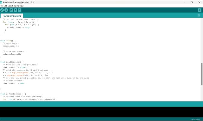
Inthebelowdiagramweshowyoucoddingofnodemcu.For coddingweusethevariouslibrariesrelatedtothesensors andoutputdevices.Inthiscodewriteaboutinstructionshow toperformworkstepbystep.

First,weinstallthelibrariesinArduinosoftwaretheninstall theesp8266boardaftercompletedthisprocess.Wecanstart thewritingcodeforBMS.Inafirstlinewedefinethesensor librariesandpackagesafterdefinepakegesandlibararies. we move the next step of code writing. In the code we

mentiontheoneloopforcontinuouslymeasurethecurrent andtemperaturehumidity.
workedontheproject,andtheycontinuetobesoasIfinish it.Iwillalwaysbethankfultoyouforthis.
I want to say that my batchmate and I finished this assignment fully on our own, without assistance from anybodyelse.
8. REFERENCES
[1] M.Lavanya,P.Muthukannan,Y.S.S.Bhargav,V.Suresh, “IoT Based Automated Temperature and Humidity Monitoring and Control”, Journal of Chemical and PharmaceuticalSciencesISSN:0974-2115.
[2] VigneshMani,Abhilasha,Gunasekhar,”IoTBasedSmart Energy Management System”, International Journal of AppliedEngineeringResearchISSN0973-4562Volume 12,Number16(2017)pp.5455-5462
6. CONCLUSON AND FURTHER WORK
It is very important for BMS to well-maintained the battery reliability and safety, the state monitoring and evaluation, cell balancing and charge control are well functional. Thus, this present paper is review on BMS, focussing study for optimization of BMS that will lead to reliabilityofBMSandoptimizepowerperformance.Monitor thebatteryanywhereintheworldusingIoT.It’stakingthe data from IoT embedded sensor and transmit the cloud. Providebetterperformancetouserenhancethebatterylife. This IoT based battery management system help us to monitorthebatteryconditionsandalsohelpustomonitor thebatteryhealth.
Further we added the more sensor for humidity management and finding the efficient option for battery temperature and battery colling. we think about battery coolingandforthatwewillusedsolidcollingmaterial.This material automaticallymeltswhenbatterygettinghotand afterbatterycold.Itwillagaingetagainit’sfirststagemeanit againgotitfirststagewhichwassolid.
WethinkaboutfullysystemismakeasAI.Wewantto made an AI Based Battery management system. In this AI fullysystemiscontrolledbyAI.Fewthingsonlyhandleby humanhand.
7. ACKNOWLEDGEMENT
IwanttopubliclythankMr.R.S.Piske,theprojectmanager, andDr.B.H.Patil,thedepartment headofelectronicsand telecommunications. I appreciate all they did to assist me finish my project on an IoT-based battery management system.
Iwanttospecificallythankourmentor,Mr.R.S.Piske,forall ofhishelpandsupportthispastyear.Yourhelpfultipsand recommendations were really beneficial to me while I
[3] HarishN1 ,PrashalV2andDr.D.Sivakumar3,”IOTBased BatteryManagementSystem”,InternationalJournalof AppliedEngineeringResearchISSN0973-4562Volume 13,Number8(2018)pp.5711-5714
[4] Abhay Shatrudhan Jha1, Anuj Kalkar2, Mandar Ghanekar3, Neeraj Pal4, Sangeeta kotecha5, "Battery ManagementSystem",InternationalResearchJournalof EngineeringandTechnology(IRJET)Volume:07Issue: 02|Feb2020.e-ISSN:2395-0056
[5] SeyedMahmoudSalamati*,CongShengHuang*,Bharat Balagopal*,andMo-YuenChow*,“ExperimentalBattery Monitoring System Design for Electric Vehicle Applications”, Electrical and Computer Engineering, North Carolina State University, Raleigh, U.S.A, IEEE 2018.
[6] PoushaliPal,A.K.Parvathy,K.R.Devabalaji,S.Joseph Antony, Simon Ocheme, Thanikanti Sudhakar Babu, HassanHaesAlhelou,T.Yuvaraj,”IoT-BasedRealTime EnergyManagementofVirtualPowerPlantUsingPLC forTransactiveEnergyFramewor”,IEEE|July-2021.