
Analysis of Highway Safety Barrier as FRP Material
Department of Mechanical Engineering, Smt. Indira Gandhi College of Engineering, Ghansoli, Maharashtra, India
Abstract - Due to the improvement in today’s world, increasing demand has been put forth regarding the safety measures in Highway Barriers along with their efficiency towards Price, Material Strengths Etc. This results in the requirement for changing the Barrier’s Material considering its weight ratio. The advent of automobiles that use fewer nonrenewable energy sources, as well as sacrificing the protection of occupants due to the minimized weight of the car, is a key problem for both the vehicle sector and the government. Henceforth, a Car, Mini Bus and Bus is designed with the utilization of Solid Works 2020 software which is a tool for modelling design exploiting FRP material. The car body crash analysis is performed in ANSYS 2022 R2 deploying an ANSYS LS-DYNA module utilizing the FEM approach. We are going to Analysis with Three Vehicles a Car, a Truck and a Heavy Truck which are Specified in Different Weights, Speeds and Angles of Impact on the Barrier. along with that, we are comparing the results of the Material which is used now which is Aluminum Alloy and the FRP Material. Testing is carried out with varying speeds and the analysis of stress generated by crashing; deformation of Safety Barrier is performed.
Key Words: Car Crash Analysis, Explicit Dynamics, LSDYNA, Finite Element Analysis
1.INTRODUCTION
At present, the type of highway bridge guardrails mainly consists of steel guardrails and concrete guardrails. For concrete guardrails, the stiffness of the concrete is particularly large, and the damage to the vehicle during a collisionissubstantial.Besides,theweightoftheconcrete guardrail is excessively large, which cannot be used in large-span bridges. Although the collision performance of thesteelguardrailisbetterthanthatofconcreteguardrail, theservicelifeofsteelguardrailisrelativelyshort,lasting approximately15yearsundernormalweatherconditions. In view of the serious environmental deterioration in recent years, particularly the occurrence of acid rain, salt fog, and other weather conditions, the service life of the steel guardrail used in bridges has become even shorter. Studies show that many steel guardrails have been seriously rusted before they reach the design service life, causing a high cost of maintenance and reinforcement. Therefore, a new type of bridge guardrail composed of new materials is necessary to be developed to innovate bridge guardrails.Inrecent years,the emergenceof fiberreinforced polymer (FRP) has expanded the strategies for the innovation of bridge guardrail materials. FRP is a
continuousfibercompositewitharesinmatrixandcanbe dividedintocarbonfiber-reinforcedpolymer(CFRP),glass fiber reinforced polymer (GFRP), aramid fiber-reinforced polymer (AFRP), basalt fiber-reinforced polymer (BFRP) and so on. The most significant characteristics of FRP are lightweight, high strength, strong resistance to corrosion and fatigue, and strong elastic deformation ability. At the beginning of the twenty-first century, Professor Bank and GentryinvestigatedthethermoplasticGFRPguardrail and foundthatitwassuperiortothetraditionalsteelguardrail in terms of energy absorption in the bending failure process.
2. PROBLEM DEFINITION
In the current scenario of Highway Crash Barriers, the Government allows the use of Steel Alloys like Aluminum Alloy, Chromium Steel Alloy etc. Here there are two main PossibilitiesofhowAccidentscanoccur:
CASE - 1: We know that car’s Speed is Nearly 60 to 80 km/h so as the car strikes the barrier will Break andthecarcancrosstheroadandstrikeothercars.
CASE-2:InCase2thecar’sSpeedcangiveastrong impactonthebarrier,thatbarrierwillnotbreakbut the car will get damaged and the Person sitting in that car will be injured or the maximum chance is Deathforthatperson.
3. LITERATURE REVIEW
J. Santhakumar et al. [1] [2020], made“Designandcrash analysisofcarbodyusingFRPmaterialsadoptingFEM”,it was published in the International Journal of Innovations inScientificandEngineeringResearch(IJISER).Thispaper is regarding an efficient design and analysis of a car crashing is investigated and a hatchback car designed utilizing solid works 2016 software. The car body crash analysis is performed in ANSYS 16 deploying an explicit dynamic module utilizing the FEM approach. Testing is carried out with varying speeds and the analysis of stress generatedbycrashing,deformedcarbodypartsaswellas strainareperformed.
Z. Butans et al. [4] [2016], a study on Road Safety Barriers, the Need and Influence on Road Traffic Accidents. This article views an example of a road traffic accident,whichisalsomodelledbythePC-Crashcomputer program. The given example reflects a road accident

mechanism in case of a car-to-barrier collision and provides information about the typical damage to the car and the barrier. This paper describes the impact of the road safety barrier type and its presence on the road traffic accident mechanism. Implementation and maintenance costs of different barrier types are viewed. This article presents a discussion on the necessity to use roadsafetybarriers,aswellastheiroptimalchoice.
Lee, Min-Chul et al. [3] [2011], a study about Performance Analysis of Steel-FRP Composite Safety Barrier by Vehicle Crash Simulation published in the Journal of the Korean Society for Advanced Composite Structures. In this study, the performance of a steel-FRP composite bridge safety barrier was evaluated through vehicle crash simulation. Surface veil, DB and Roving fibers were used for FRP. The MAT58 material model provided by LS-DYNA software was used to model FRP material. The spot weld option was used for modelling contact between steel and FRP beam. The structural strength performance, the passenger protection performance, and the vehicle behavior after the crash were evaluated corresponding to the vehicle crash manual.Astheresult,Asteel-FRPcompositesafetybarrier wassatisfiedwiththerequiredperformance.
Ali O. Atahan et al. [1] [2007], astudyonFiniteElement Simulation of a Strong Post W-Beam Guardrail System. In this study, an explicit three-dimensional nonlinear finite element code, LS-DYNA, is used to demonstrate the capabilities of computer simulations to supplement fullscale crash testing. After a failed crash test on a strong post guardrail system, LS-DYNA is used to simulate the system,determinethepotentialproblemswiththedesign, anddevelopanimprovedsystemthathasthe potential to satisfy current crash test requirements. After accurately simulating the response behaviour of the full-scale crash test,asecondsimulationstudyisperformedonthesystem withimproveddetails.Simulationresultsindicatethatthe system performs much better compared to the original design.
4.
ANSYSis a finiteelement analysissoftware forsimulating and analyzing engineering problems. In ANSYS, the experimental setup refers to the configuration of the simulation environment, including the Geometry, Materials, Meshing, Boundary Conditions, and Solver settings.
To set up an experiment in ANSYS, you typically start by creating or importing a 3D CAD model of the system you want to analyze. You can then assign material properties to each model part, define the loads and boundary conditions,andselecttheappropriatesolversettings.
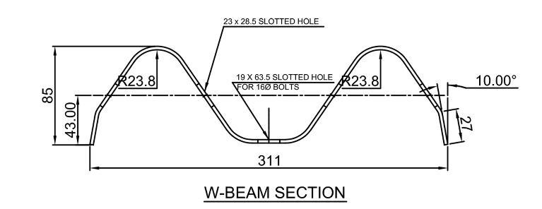
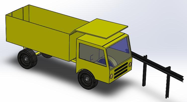
4.1 Geometry
4.3 Meshing
Afterassigningmaterialtoeachandeverypart,westarted with meshing. Meshing is nothing but dividing the given object into multiple smaller parts called elements. The finerthemesh,resultswillbemoreaccurate.Butthenthe time required for solution will be more. We took element size as 20 mm in our analysis as the mesh is finer which canseeinFig3,
Overall, meshing is a critical step in ANSYS simulations, and careful consideration must be given to the meshing parameters and methods to obtain accurate and reliable results.
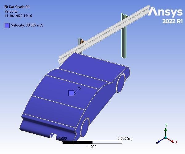

4.4.2 Initial Velocity
In the analysis, since it is an assembly, we used different boundary conditions in order to make a proper analysis. The task is performed in ANSYS workbench LS-Dyna module. The first boundary condition used is velocity. As per the design parameters, a velocity of 27.78 m/s is appliedinthedirectioncar.AsshownintheFig5
Fig 3-BodySizingMesh
4.4 Boundary Condition
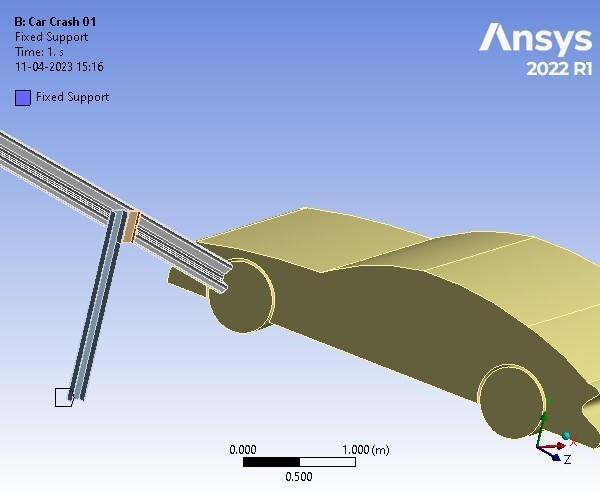
4.4.1 Fixed Support
In ANSYS, a fixed support boundary condition is used to restrict the degree of freedom of a node or an edge in a specific direction. This condition is used when a model is fixedataparticularlocation,preventingitfrommovingor rotating in a particular direction. We apply fixed support totheBottomoftheCchannelasShowninFig4
4.4.3 Analysis Setting
In Ansys LS-DYNA, the analysis setting refers to the parameters and options that are defined to control the simulation behaviour and accuracy. These settings are specified through various input files and keywords, and theyaffectthebehaviourofthesolver,theaccuracyofthe results, and the computational performance of the simulation. We have taken the end Time of 1 Sec, Time Safety Factor 0.9 Sec and Maximum Number of Cycles of 5,00000,asshowninTable4.


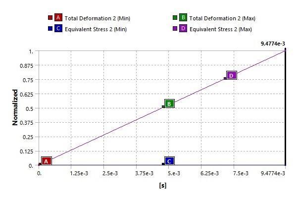
5.4 Result Comparison
We are Comparing the Results of Different vehicles with Different Materials. A comparison is shown below in tabularformat,
Inthisproject,thecomparisonismadeofthedeformation and stress generated in highway safety barriers when a car crashes into it to deduce which material is better to constructthebarrier.Acar,a truck,a Truck anda barrier are made in Solidworks software. The crash analysis is done in Ansys- Ls Dyna where barriers with 2 materials Fiber Reinforced Plastic (FRP) and Structural Steel are taken. All 3 models of cars are analyzed with the same velocitywhenthematerialofthebarrierisFRPandsteel
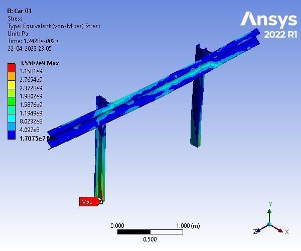
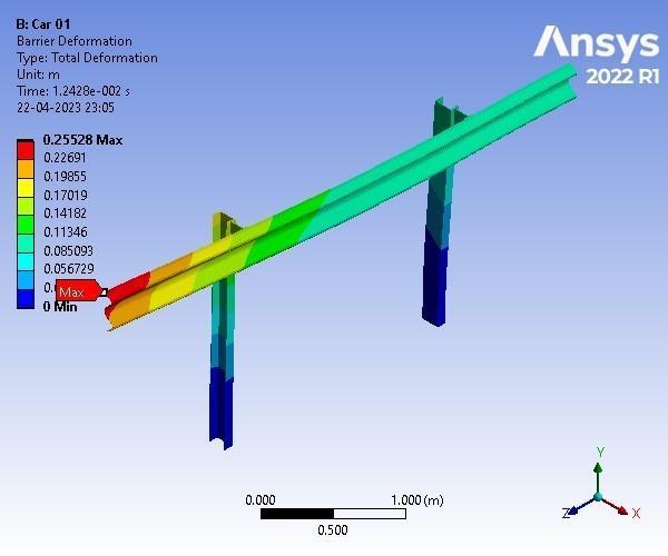
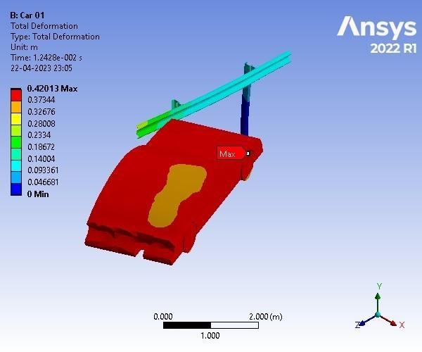
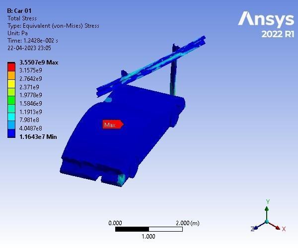
1. When we use Car and apply FRP Material to the Barrier it is observed that at Velocity 27.78 m/s
Maximum Equivalent Stress Developed in the Barrier is 3.5507e+009 Pa and Maximum Total Deformation Developed in the Barrier is 0.25528 m
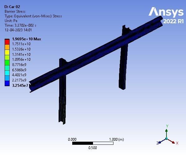
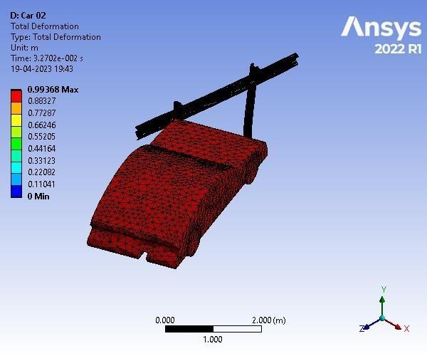
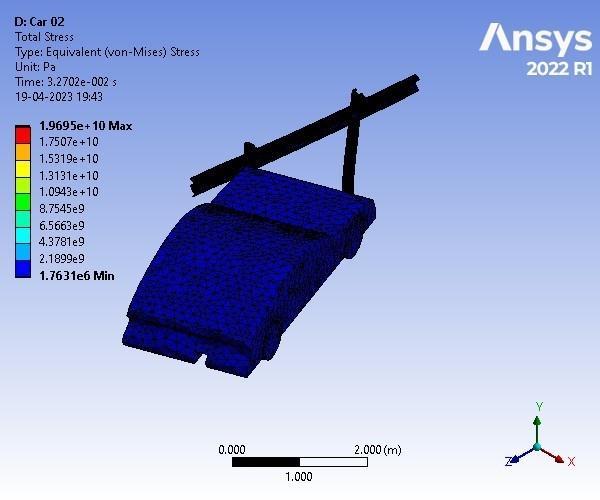
When we use Car and apply Steel Material to the Barrier it is observed that at Velocity 27.78 m/s
Maximum Equivalent Stress Developed in the Barrier is 1.9695e+010 Pa and Maximum Total Deformation Developed in the Barrier is 0.87639 m.
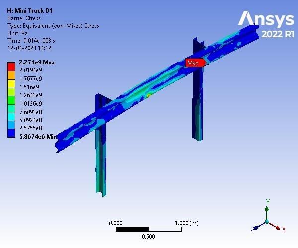
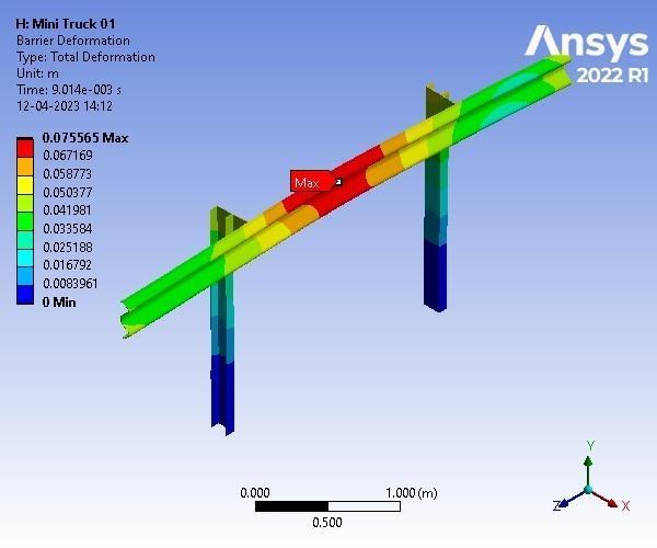
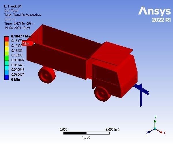
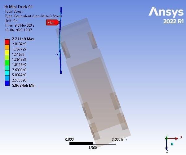
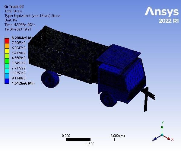
2. WhenweuseHeavy Truck andapply FRP Material to the Barrier it is observed that at Velocity 30.56 m/s Maximum Equivalent Stress Developed in the Barrier is 2.271e+009 Pa and Maximum Total Deformation Developed in the Barrier is 7.5565e002 m.
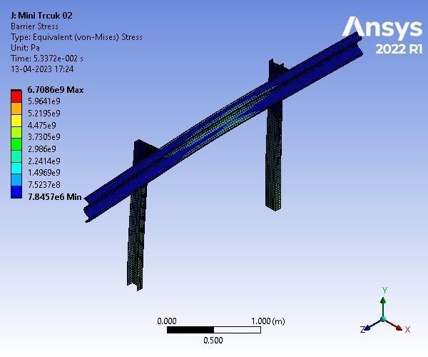
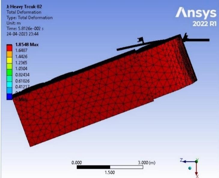
WhenweuseHeavyTruckandapply Steel Material to the Barrier it is observed that at Velocity 30.56 m/s Maximum Equivalent Stress Developed in the Barrier is 6.7086e+009 Pa and Maximum Total Deformation DevelopedintheBarrieris 1.0577 m.
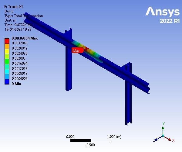
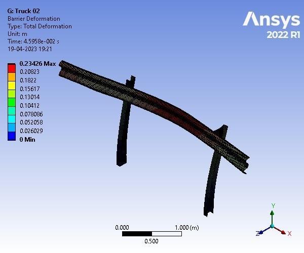
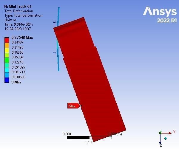
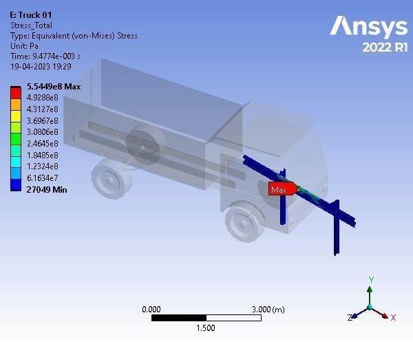
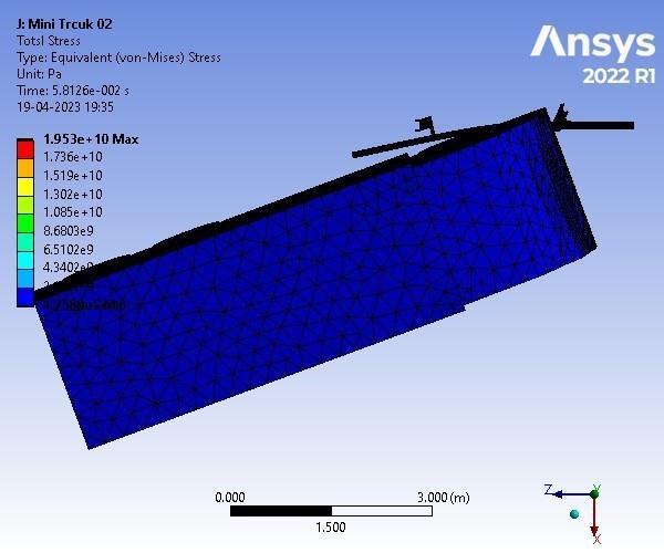
3. When we use Truck and apply FRP Material to the Barrier it is observed that at Velocity 19.44 m/s
Maximum Equivalent Stress Developed in the Barrier is 5.5449e+008 Pa and Maximum Total Deformation Developed in the Barrier is 3.6054e003 m.
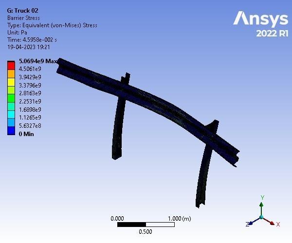
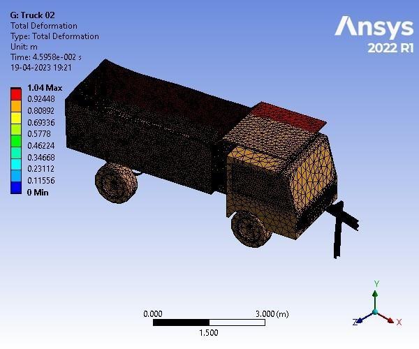
WhenweuseTruckandapply Steel Material tothe Barrier it is observed that at Velocity 19.44 m/s Maximum Equivalent Stress Developed in the Barrier is 5.0694e+009 Pa and Maximum Total Deformation Developed in the Barrier is 0.23426 m
From the results, it is observed that the deformation and stress in the safety barrier when it is constructed with steel is more than when it is with FRP. Barriers to redirecting out of-control vehicles on the road are undergoing several improvements. So, more lives can be saved when a car crashes into barriers. FRP material is stronger and more flexible than the regular steel with which the barrier is usually constructed. Therefore, FRP material is a better pick for constructing highway safety barriers.
7. REFERENCES
- AKSteel(formerlyArmco)genericizedtrademark
- “Guardrail”. Oxford Dictionary. Archived from the original on September 7, 2014. Retrieved 7 September2014.
- “crash barrier”. Oxford Dictionaries Online. ArchivedfromtheoriginalonDecember13,2013. Retrieved6September2015.
- “Barrier Need”. TxDOT RDM. 2010-05-01. Retrieved2011-01-11.
- Roadside Design Guide. American Association of State Highway Transportation Officials. 2002. pp. 1–3.
- “Barrier Need”. TxDOT RDM. 2010-05-01. Retrieved2011-01-11.
- Roadside Design Guide. American Association of State Highway Transportation Officials. 2002. pp. 1–3.
- “Cross Sectional Elements”. TxDOT RDM. 201005-01.Retrieved2011-01-11.
Online References
- https://forum.ansys.com/forums/topic/a nsys-ls-dyna-student-faqs/
- https://shorturl.at/eqsxP
- https://chat.openai.com/
- https://www.youtube.com/watch?v=0TB jPp3zko4t=612s
- https://shorturl.at/efiy6