
Software Development for Railway Bridge Deck Slab Using IRS Code
 Manmohan Sharma1, Shashikant Dhobale2
M.E Scholar1 , Assistant Professor2 Department of Civil Engineering, Jawaharlal Institute of Technology, Borawan, Khargone
Manmohan Sharma1, Shashikant Dhobale2
M.E Scholar1 , Assistant Professor2 Department of Civil Engineering, Jawaharlal Institute of Technology, Borawan, Khargone
ABSTRACT
Visual Basic has recently emerged as one of the most frequently utilized event-driven programming languages in the world. An event-driven language responds to events like as pressing a button, selecting an item from a list, navigating away from a control, and so on. Many programmes written in the Visual Basic programming language are effectively used in the banking and finance industries. The Visual Basic language has a lot of promise for developing software for the analysis and design of civil engineering structures. from traditional, linear programming approaches. The software is based on the idea that we must define the section, material of the bridge component, and apply the load that will have the most unfavorable effect on the component over its service life. The software will do calculations for stresses, deflection, and reinforcement. These stresses and deflections should be within the limits allowed by the appropriate IRS and IS codes. If the calculated values of stresses and deflection do not fall within acceptable limits, the section must be altered and the analysis procedure must be restarted. This exercise must be repeated until the safe section of the bridge component is reached.
Keywords– Railway bridge, IRS Code, software development.
INTRODUCTION
The deck slab of a railway bridge must be designed to meet the relevant wide gauge loading requirement. For analysisanddesignpurposes,thedeckslabisseparatedinto two parts: cantilever slab and internal panel. For concentrated loads due to PQRS loading, the cantilever sectionofthedeckslabmustbeassessedusingtheeffective widthapproachasspecifiedinclause24.3.2ofIS456:2000.
The inside panel of the deck slab is monolithic and continuous,madeofPSCgirderanddiaphragm.Theinside panelissusceptibletoconcentratedloadsfromtrainwheels aswellasderailmentloadsintheeventofatrainderailment overabridge.Therearetwowaysforanalysingsuchslabs: Pigeaud'stheoryandWestergaard'stheory.Pigeaud'stheory isusedtoassesstheinsidepanelinthisproject.Thesoftware wascreatedtoanalyseanddesigndeckslabs
OBJECTIVE
Software Development for Railway Bridge Deck Slab UsingIRSCODES
METHODOLOGY
Indefinesectionofsoftwarefollowinginputsareto beprovided.
(a) Design data
The following design data are to be provided as inputindefinesectionofthesoftware.Wehavetoclickthe Definebuttononmenubartoaccessthedefinesection.
•Lengthofspan
•Distancebetweencentrelineofbearings(Effectivespan)
•Overalllengthofdeckslab
• Centretocentrespacingofgirders
• No.ofdiaphragms
• Thicknessofenddiaphragm
• Thicknessofintermediatediaphragm
• Outtooutdistanceofgirderflanges
• Overallwidthofdeckslab
(b) Material properties
ThematerialpropertiesofConcreteareconsideredasper cl.5 of IRS Concrete Bridge code – 2004 and material properties of HYSD bars are considered as per IS 1786 –1985.
Thematerialspropertiesaretobedefinedindefinesection of the software. We have to click on Accept button on the Designdataformtoaccessthematerialpropertiesform.The GUIofmaterialpropertiesformisillustratedinFigure4.2. Wehavetoselectexposurecondition,gradeofconcreteand gradeofsteelfromcombobox.Thematerialpropertieswill beprovidedbydatabase.
(c) Section
Thesectionofdeckslabistobedefinedindefinesectionof the software. We have to click on Accept button on the materialpropertiesformtoaccessthesectionform.TheGUI
ofsectionformisillustratedinFigure4.7.Wehavetoenter dimensionsofdeckslab,ballastretainerininputboxes.
(d) Loading
As per cl. 2.1 of IRS Bridge Rules, the following loads are considered for the purpose of analysis and design of deck slab.
DeadLoad(DL)
SuperImposedDeadLoad(SIDL)
Superimposeddeadloadincludesloadduetotrack, ballast,wearingcoatandballastretainer.
LiveLoad(LL)
The live load is to be considered as per cl. 2.3.4.1 and cl. 2.3.4.2ofIRSBridgerulesforrelevantloadingstandard.
DynamicAugment(I)
Thedynamicaugmentisconsideredaspercl.2.4.2.1ofIRS Bridgerulesforrelevantloadingstandard.
Incaseofballasteddeckslabbridges, Coefficient of Dynamic Augment = [2-(d/0.9)] x [0.15 + 8/(6+L)]x0.5
Here,
d=depthofballastcushioninmetres
L=Loadedlengthofspaninmetres
PQRSloading
ThePQRSloadingisconsideredaspercl.2.15ofIRSBridge rulesforanalysisanddesignofcantileverslab
Derailmentload
The Derailment load is considered as per cl. 2.14 of IRS Bridgerulesforanalysisanddesignofinteriorpanel.
Theloadingondeckslabistobedefinedindefinesectionof the software. We have to click on Accept button on the sectionformtoaccessdefineloadingform.TheGUIofdefine loadingformisillustratedinFigure4.7.
(e) Analysis
On completion of define process, we have to click the Analysisbuttononmenubarandselectdeckslabtoaccess the analysis section of deck slab. In analysis section of softwareallcalculationsareperformedbythesoftwareon clickingofCalculatebutton.
Loadandmomentcalculations
TheGUIofLoadandmomentcalculationsformisillustrated inFigure5.1.ClickonCalculatebuttontocalculateLoadand moment.
ANALYSISANDDESIGNOFRCCDECKSLABANDDIAPHRAGM
GENERAL :The superstructure consists of the precastPSC (posttensioned) girderandcastin situdeckslab. The variousassumptionsmade in the design and specification used are asbelow
condition- moderate Grade of concrete usedforPSC girderandRCC deckslab= M- 40
IS
1985 Fe 415 Grade HYSD bars tobe usedforRCC works
VALIDATION OF SOFTWARE
A.3 ANALYSIS AND DESIGN OF DECK SLAB
A.3.1 Material properties
Concrete(Ref:cl.5ofIRSConcreteBridgecode–2004)
Exposurecondition-Severe
Characteristicscompressivestrength(fck)=40.0N/mm2
Unitweightofconcrete=25kN/m3
Modulusofelasticityofconcrete=31.0kN/mm2
HYSDsteel(Ref:IS1786–1985)
Characteristicsstrength/Yieldstrength(fy)=415.0N/mm2
A.3.2Design data
C/Cofgirder=2.300m
Overallwidthofdeckslab=4.800m
Thicknessofdeckslab=0.220m(Ref:cl.16.9.6.1ofIRSCon. Bridgecode-2004)
Widthofflange=0.750m
Thicknessofwebofgirder=0.300m(Ref:cl.16.9.6.2ofIRS Con.Bridgecode-2004)
A.3.3 Load calculations
A.3.3.1 Cantilever slab
Dead load (DL)
Deckslab=1x0.22x25=5.5kN/m
Super imposed dead load (SIDL)
Ballastretainer=0.15x0.75x25=2.81kN
Wearingcoat=1x0.08x22=1.76kN/m
Ballast=1x0.6x19=11.4kN/m

Live load (LL) due to PQRS
(Ref:IRSBridgeRulescl.2.3.4.2,cl.2.15andAppendix-X)
Calculations for section at B – B
Effectivewidthmethod(Ref:IS456:2000cl.24.3.2)
Concentratedload(W)=98.1kN
a1=0.211m, a=0.81m
bef=1.2a1+a=1.0632m
Distanceofconcentratedloadfromend(x1)=0.5m
Distancebetweenconcentratedloadsparalleltosupported edge(x2)=2.5m

Overhang(bef/2-x1)=0.0316m
Overlap(bef-x2)=0m
e=2bef-Overhang–Overlap=2.0948m
Effectiveloadincludingimpact(1.44W/e)=67.44kN.
A.3.3.2Interiorpanel
Deadload(DL)
Deckslab=1x0.22x25=5.5kN/m2

Superimposeddeadload(SIDL)
Wearingcoat=1x0.08x22=1.76kN/m2
Ballast=1x0.6x19=11.4kN/m2
Track=3.87kN/m2
Liveload(LL)duetoheaviestaxleofMBGloading
Concentratedload=245.2kN
Derailmentload
(Ref:IRSBridgeRulescl.2.14andAppendixIX)
Concentratedload=100.0kN
A.3.4 Bending moment calculations
A.3.4.1 Cantilever slab
Table A.23: Bending moment for cantilever slab
BM due to At section B - B
m1=0.04, m2=0.003
Momentalongshortspan=(m1+0.15xm2)W=10.97kNm
Momentalonglongspan=(m1x0.15+m2)W=2.44kN.
BendingmomentduetoLL(Pigeaud’stheory)
MBGLoading-withtype-Isleepers
(Ref:IRSBridgeRulescl.2.3.4.1andcl.2.3.4.2)
A.3.4.2Interiorpanel
BendingmomentduetoDLandSIDL(Pigeaud’stheory)
Panelsize L=6.02m, B=2.0m

Totaldeadload(W)=22.53x6.02x2.0=271.3kN
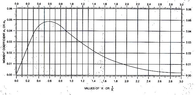
Constantkand(1/k)
k=(shortspan/longspan=B/L)=0.33
(1/k)=3.01
AssumingPoisson’sratio=0.15
m1andm2fromgraph
Panelsize L=6.02m, B=2.0m, U=2.0m, V=0.734m
Effective load on panel (W) = (245.2 x 1.44 x2.0/3.225) = 219.0kN
k=(shortspan/longspan=B/L)= 0.33
AssumingPoisson’sratio=0.15
m1 and m2 from graph for U/B = 1 and V/L = 0.12
m1=0.10, m2=0.05
Momentalongshortspan=(m1+0.15xm2)W=23.54kNm
Momentalonglongspan=(m1x0.15+m2)W=14.24kN–m
BendingmomentduetoDerailmentload(Pigeaud’stheory)
Panelsize L=6.02m, B=2.0m, U=0.48m, V=0.48m
Effectiveloadonpanel(W)=(1.44x100)=144.0kN
k=(shortspan/longspan=B/L)= 0.33
AssumingPoisson’sratio=0.15
m1andm2fromgraphforU/B=0.24andV/L=0.08
m1=0.22, m2=0.14
Momentalongshortspan=(m1+0.15xm2)W=34.70kNm
Momentalonglongspan=(m1x0.15+m2)W=24.91kN–m
A.3.5DesignofDeckslab
Overalldepthofslab=220mm
Clearcover=30mm
Diaofbar=12mm
Effectivedepthofslab(d)=184mm
Widthofslab(b)=1000mm

A.3.5.1Cantileverslab
DesignBMduetoultimateload(M)=43.0kN.m
(2SIDL+1.4DL+2LL)
Ultimate moment of resistance (0.15 fck b d2) = 203.14
kN.m
(Ref:IRSCon.Br.Codecl.15.4.2.2.1)
Theoveralldepthprovidedisadequateandsectionisunder reinforced.
Areaofmainreinforcement(As)=676mm2
C/Cspacingofmainbars=167.3mm
Provide12mmbar@150mmc/c
A.3.5.2Interiorpanel
Calculationofreinforcementalongshortspan
DesignBMduetoultimateload(M)=69.03kN.m
(2SIDL+1.4DL+2LL)
Ultimate moment of resistance (0.15 fck b d2) = 203.14 kN.m
(Ref:IRSCon.Br.Codecl.15.4.2.2.1)
Theoveralldepthprovidedisadequateandsectionisunder reinforced.
Areaofmainreinforcement(As)=1116mm2
C/Cspacingofmainbars=101.3mm
Provide12mm#bars@90mmc/c
Calculationofreinforcementalonglongspan
DesignBMduetoultimateload(M)=33.35kN.m
(2SIDL+1.4DL+2LL)
Ultimatemomentofresistance(0.15fckbd2)=177.5kN.m
(Ref:IRSCon.Br.Codecl.15.4.2.2.1)
Theoveralldepthprovidedisadequateandsectionisunder reinforced.
Areaofmainreinforcement(As)=560mm2
C/Cspacingofmainbars=202.0mm
Provide12mm#bars@120mmc/c
Shrinkage and temperature reinforcement (minimum reinforcement)
(Ref:IRSCon.Br.Codecl.15.9.9)
As>= Kr(Ac-0.5Acor)
Kr=0.005
Ac(Areaofgrossconcretesection)=220000mm2
Acor(Coreareaofconcrete)=0
As=1100mm2
Shrinkage and temperature reinforcement (minimum reinforcement) shall be distributed uniformly around the
perimeter of the concrete section and spaced at not more than150mm.
Areaofreinforcementrequiredateachfaceodeckslab(As/ 2)=550mm2
C/Cspacingof10#bars=142.80mm
CONCLUSION
The accuracy of software is primary requirement of any software development work. To validate the results of software, the analysis and design of 4.8-meter-wide deck slabPSCofrailwaybridgeisdonebyhandcalculationsand results are presented in paper. The analysis and design results for various components of this bridge are also obtained by the software. The results of software are in conformitywithresultsobtainedbyhandcalculations. Soit can be concluded that the accuracy of software is beyond doubt.Itispossibletodesignanotherbridgewithdifferent span, loading standard and design data, without rigorous hand calculations, with the help of software. The detailed designreportcanbeobtainedfromsoftwareandcanbeused withoutfurtherformatting.Itmeansthesoftwareisusefulin savingtimeandeffortduringaccurateanalysisanddesignof railwaybridges.
REFERENCES
1. Anil kumar H and B S Suresh Chandra (2015), “FlexuralBehaviourofLongitudinalGirdersofRCTBeamDeckSlabBridge”,Int.J.forSci.Res.&Develop., Volume3,Issue5,pp.639-642, Available at: http://www.ijsrd.com/articles/IJSRDV3I50447.pdf.
2. BudiRyantoWidjaja(1997),“AnalysisandDesignof Steel Deck– Concrete Composite Slabs”, Ph. D, Polytechnic Institute and State University, Virginia Tech., Available at: https://vtechworks.lib.vt.edu/handle/10919/30759.
3. Haymanmyintmaung and Kyawlinnhtat (2011), “InvestigationofIntegralBridgeEffectunderDynamic Loading”,Int.J.ofSci.andRes.Publi.,Volume7,Issue 5, pp. 567-574, Available at: http://www.ijsrp.org/research- paper-0517/ijsrpp6565.pdf.
4. IbrahimS.I.Harba (2011),“EffectofSkewAngleon Behavior of Simply Supported R. C. T-Beam Bridge Decks”, ARPN J. of Engg. and Appli. Sci., Volume 6, Issue 8, pp. 1-14, Available at:http://www.arpnjournals.com/jeas/research_pape rs/rp_2011/jeas_0811_532.pdf.
5. Kearthi. S, Kalpana Mohan Sivasubramanian.S. L, Deepan. R and Gopinath. M (2016), “Analysis of T –Beam Bridge Deck Slab”, Int.J. of Res. and Innov. in
Engg.Tech.,Volume 2,Issue12,pp.22–27,Available at:https://www.researchgate.net/publication/3051 13203_ANALYSIS_OF_T_-_BEAM_BRIDGE_DECK_SLAB.
6. Kalpana Mohan and S. P. Vijay Kumar (2016), “Analysis of Bridge Girder with Beam and Without Beam”,Int.J.ofCivilEngg.andTech.,Volume7,Issue 5,pp.337–346,Available at: http://www.iaeme.com/MasterAdmin/Journal_uploa ds/IJCIET/VOLUME_7_ISSUE_5/IJCIET_07_05_038.pdf.
7. Lindsay Edward Klein Piers (2006), “Finite Element AnalysisofaCompositeBridgeDeck”, Ph.D. dissertation, Dept. of Engineering & Surveying Research Project, University of Southern Queensland, Available at: https://core.ac.uk/download/pdf/11036283.pdf.\